Embed Size (px)
Citation preview
RSM Training HESM Instructional Materials for Training Purposes Only Module 5: GIS for RSM I – GMS, ArcGIS and Geodatabases
Hydrologic and Environmental Systems Modeling Page 5.1
Lecture 5: GIS for RSM I—GMS, ArcGIS and Geodatabases
This lecture reviews:
Use of the Groundwater Modeling System (GMS) for mesh creation Basic Geographic Information System (GIS) skills needed to create and modify features in the
Regional Simulation Model (RSM) geodatabase using ESRI ArcGIS 9.2 A brief introduction to geodatabases
GIS for RSM IGIS for RSM I
GMS, ArcGIS and GeodatabasesGMS, ArcGIS and Geodatabases

RSM Training HESM Instructional Materials for Training Purposes Only Module 5: GIS for RSM I – GMS, ArcGIS and Geodatabases
Page 5.2 Hydrologic and Environmental Systems Modeling
NOTE:
Additional Resources
A video is provided for those modelers who do not have access to ArcInfo GIS Software.
RSM GUI Manual
GMS Manual (2007)
RSM Training HESM Instructional Materials for Training Purposes Only Module 5: GIS for RSM I – GMS, ArcGIS and Geodatabases
Hydrologic and Environmental Systems Modeling Page 5.3
Exploring use of the Groundwater Modeling
System (GMS) for mesh creation and ArcGIS
for the RSM, requires a few fundamental
GIS manipulations and editing basic line
work. Geodatabases are closely linked to the
use of ArcGIS.
The GMS creates competent 2‐dimensional
(2D) meshes using the Seep2D model
option. The GMS software was developed
by the U.S. Army Corps of Engineers to
create meshes for the RSM. The software is
designed to create the input datasets for
several models.
This proprietary software is available to
federal agencies and their partners. The
South Florida Water Management District
Hydrologic and Environmental Systems
Modeling team has adapted the method for
creating a mesh used for the Seep2D model
for use with the RSM.
2
Lecture ObjectivesLecture Objectives
Groundwater Modeling System(GMS)
ArcGIS
ArcCatalog
ArcMap
Basic Arc editing
RSM Geodatabase
Groundwater Modeling System(GMS)
ArcGIS
ArcCatalog
ArcMap
Basic Arc editing
RSM Geodatabase
3
Groundwater Modeling System (GMS)Groundwater Modeling System (GMS)

RSM Training HESM Instructional Materials for Training Purposes Only Module 5: GIS for RSM I – GMS, ArcGIS and Geodatabases
Page 5.4 Hydrologic and Environmental Systems Modeling
“Adaptive tessellation” is a mesh generation technique used to fill the interior of a polygon.
A polygon is assigned to be adaptive tessellation in the Polygon Attributes dialog. And, the polygon
is filled using the Map to 2D Mesh command.
Adaptive tessellation uses the existing spacing on the polygons to determine the element sizes on the
interior. Any interior arcs and refine points are forced into the new mesh. If the input polygon has
varying node densities along its perimeter, the GMS attempts to create a smooth element size
transition between these areas of differing densities.
By altering the size bias, the user can indicate whether the GMS should favor the creation of large or
small elements. Decreasing the bias will result in smaller elements; increasing the bias will result in
larger elements. In either case, the elements in the interior of the mesh will honor the arc edges and
the element sizes specified at nodes. The bias simply controls the element sizes in the transition
region.
[Source: GMS Manual (2007)]
4
GMSGMS
2D Meshes can be created 3 different ways in GMS: Automatic meshing technique,
Manually entering the node locations and triangulating,
Converting a different GMS data type to a 2D Mesh.
Automated meshing Once a set of feature objects has been created for a
SEEP2D conceptual model,
• Map > 2D Mesh generates a 2D finite element mesh.
RSM Training HESM Instructional Materials for Training Purposes Only Module 5: GIS for RSM I – GMS, ArcGIS and Geodatabases
Hydrologic and Environmental Systems Modeling Page 5.5
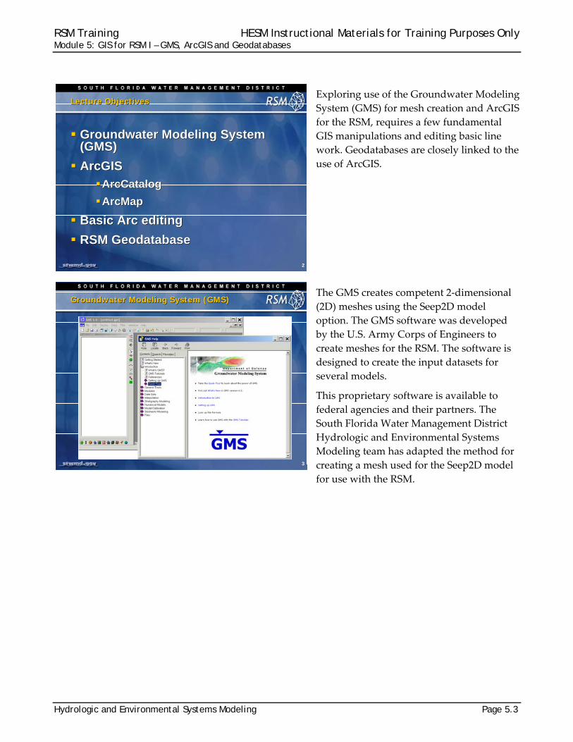
The process for making a mesh is relatively straightforward.
1. Create a new SEEP2D model in the GMS environment (as illustrated in the dialog box above). 2. Then, create a new Coverage Setup within the new model.
5
GMSGMS
1 2
RSM Training HESM Instructional Materials for Training Purposes Only Module 5: GIS for RSM I – GMS, ArcGIS and Geodatabases
Page 5.6 Hydrologic and Environmental Systems Modeling
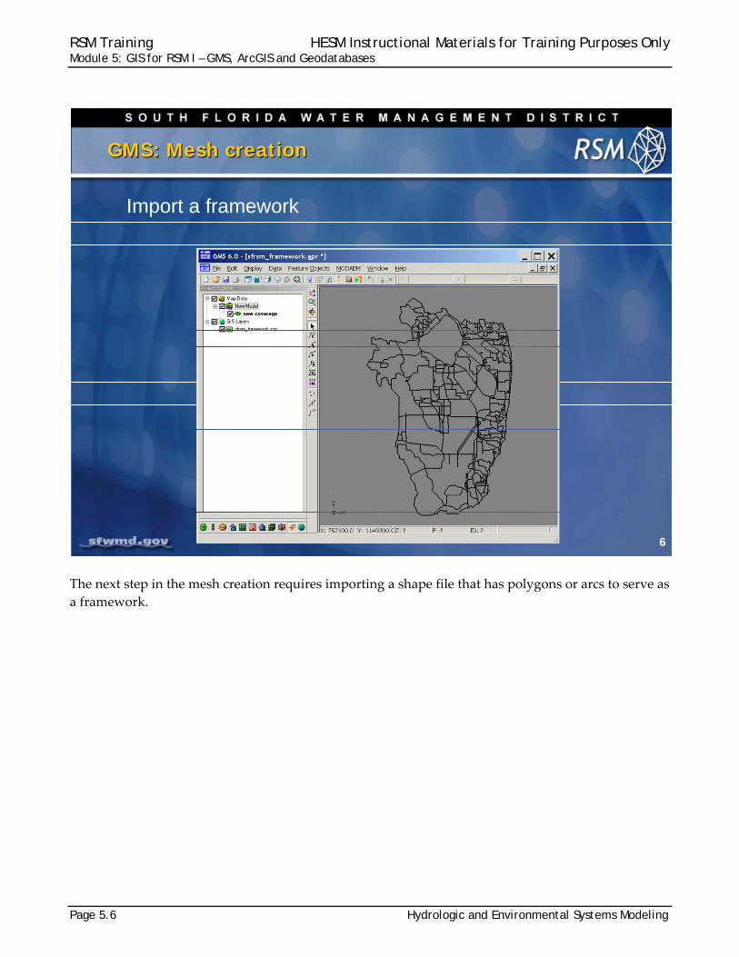
The next step in the mesh creation requires importing a shape file that has polygons or arcs to serve as
a framework.
6
GMS: Mesh creationGMS: Mesh creation
Import a framework
RSM Training HESM Instructional Materials for Training Purposes Only Module 5: GIS for RSM I – GMS, ArcGIS and Geodatabases
Hydrologic and Environmental Systems Modeling Page 5.7
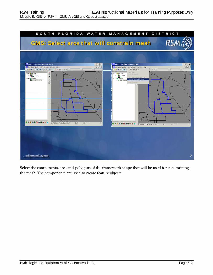
Select the components, arcs and polygons of the framework shape that will be used for constraining
the mesh. The components are used to create feature objects.
7
GMS: Select arcs that will constrain meshGMS: Select arcs that will constrain mesh
RSM Training HESM Instructional Materials for Training Purposes Only Module 5: GIS for RSM I – GMS, ArcGIS and Geodatabases
Page 5.8 Hydrologic and Environmental Systems Modeling
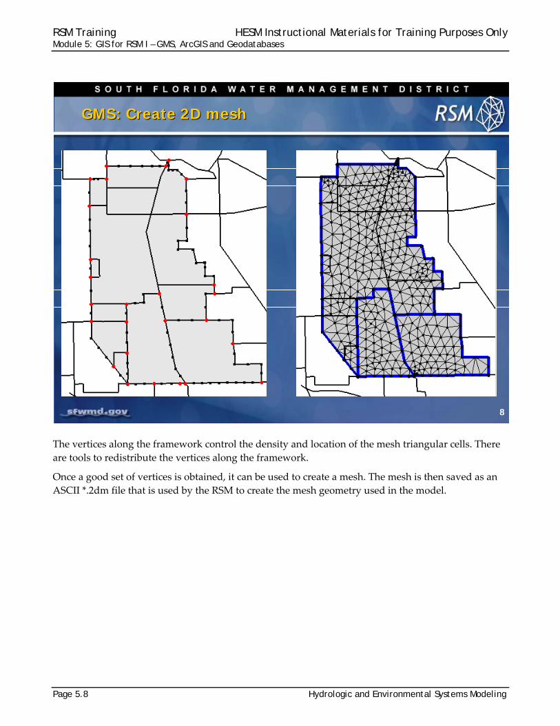
The vertices along the framework control the density and location of the mesh triangular cells. There
are tools to redistribute the vertices along the framework.
Once a good set of vertices is obtained, it can be used to create a mesh. The mesh is then saved as an
ASCII *.2dm file that is used by the RSM to create the mesh geometry used in the model.
8
GMS: Create 2D meshGMS: Create 2D mesh
RSM Training HESM Instructional Materials for Training Purposes Only Module 5: GIS for RSM I – GMS, ArcGIS and Geodatabases
Hydrologic and Environmental Systems Modeling Page 5.9
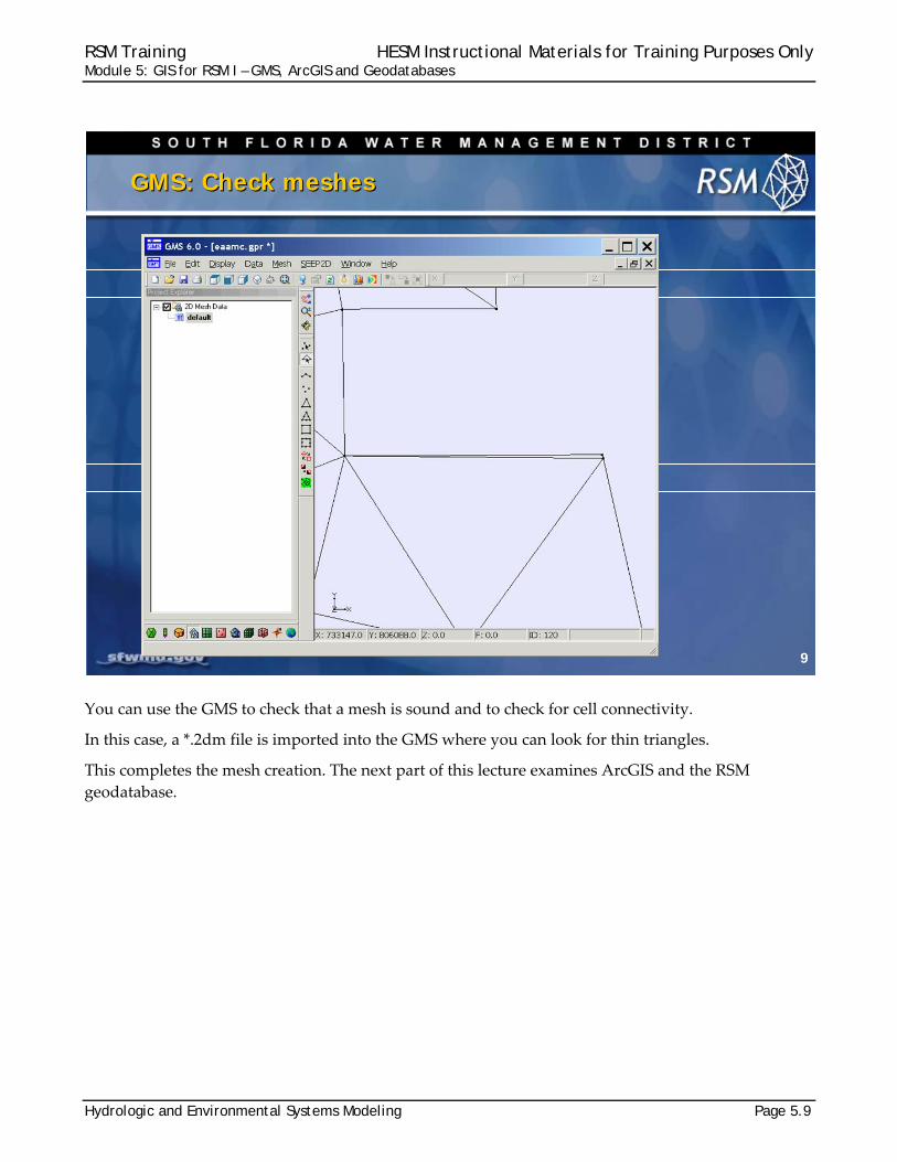
You can use the GMS to check that a mesh is sound and to check for cell connectivity.
In this case, a *.2dm file is imported into the GMS where you can look for thin triangles.
This completes the mesh creation. The next part of this lecture examines ArcGIS and the RSM
geodatabase.
9
GMS: Check meshesGMS: Check meshes
RSM Training HESM Instructional Materials for Training Purposes Only Module 5: GIS for RSM I – GMS, ArcGIS and Geodatabases
Page 5.10 Hydrologic and Environmental Systems Modeling
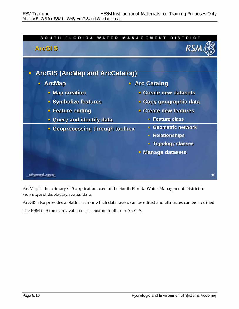
ArcMap is the primary GIS application used at the South Florida Water Management District for
viewing and displaying spatial data.
ArcGIS also provides a platform from which data layers can be edited and attributes can be modified.
The RSM GIS tools are available as a custom toolbar in ArcGIS.
10
ArcGIS ArcGIS
ArcGIS (ArcMap and ArcCatalog)
• ArcMap
Map creation
Symbolize features
Feature editing
Query and identify data
Geoprocessing through toolbox
ArcGIS (ArcMap and ArcCatalog)
• ArcMap
Map creation
Symbolize features
Feature editing
Query and identify data
Geoprocessing through toolbox
• Arc Catalog
Create new datasets
Copy geographic data
Create new features
• Feature class
• Geometric network
• Relationships
• Topology classes
Manage datasets
• Arc Catalog
Create new datasets
Copy geographic data
Create new features
• Feature class
• Geometric network
• Relationships
• Topology classes
Manage datasets
RSM Training HESM Instructional Materials for Training Purposes Only Module 5: GIS for RSM I – GMS, ArcGIS and Geodatabases
Hydrologic and Environmental Systems Modeling Page 5.11
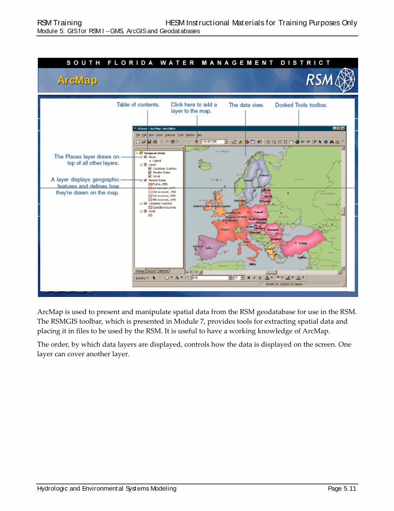
ArcMap is used to present and manipulate spatial data from the RSM geodatabase for use in the RSM.
The RSMGIS toolbar, which is presented in Module 7, provides tools for extracting spatial data and
placing it in files to be used by the RSM. It is useful to have a working knowledge of ArcMap.
The order, by which data layers are displayed, controls how the data is displayed on the screen. One
layer can cover another layer.
11
ArcMapArcMap
RSM Training HESM Instructional Materials for Training Purposes Only Module 5: GIS for RSM I – GMS, ArcGIS and Geodatabases
Page 5.12 Hydrologic and Environmental Systems Modeling
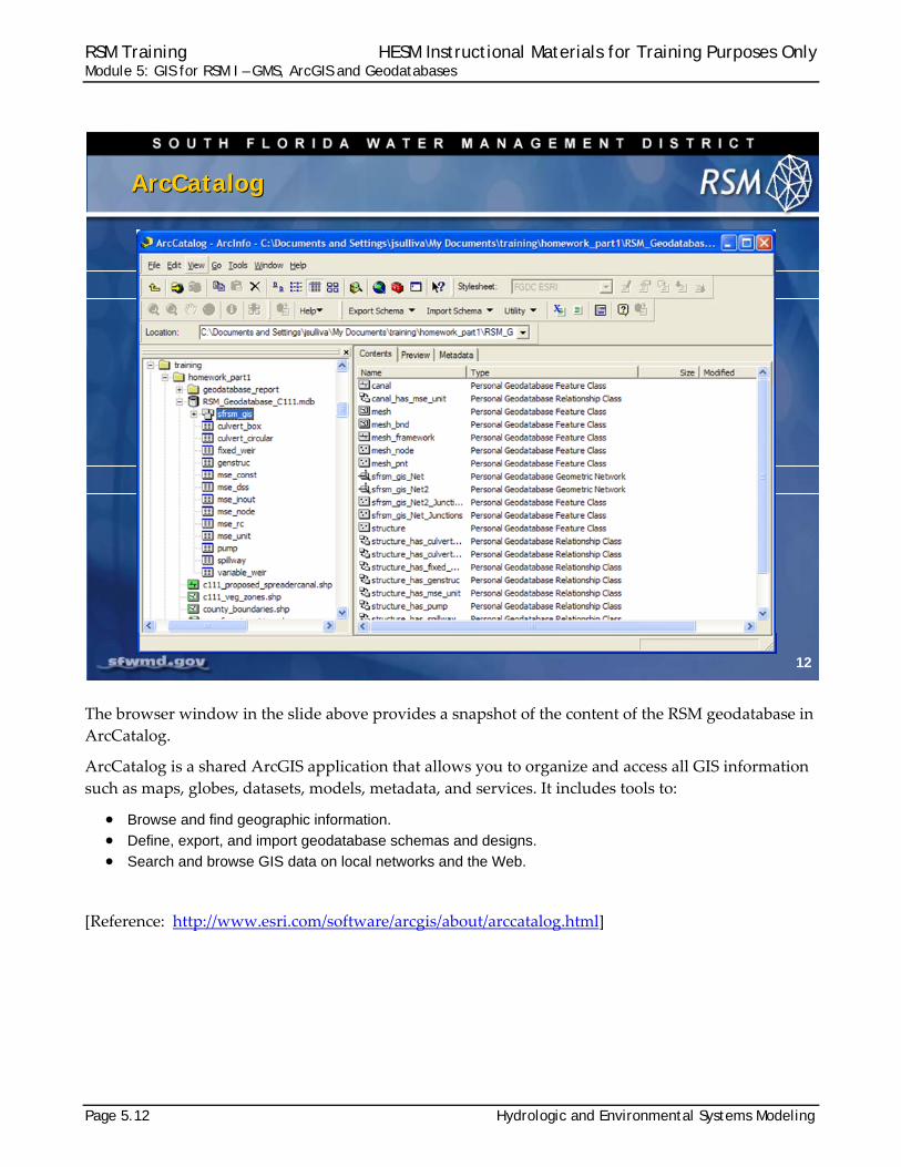
The browser window in the slide above provides a snapshot of the content of the RSM geodatabase in
ArcCatalog.
ArcCatalog is a shared ArcGIS application that allows you to organize and access all GIS information
such as maps, globes, datasets, models, metadata, and services. It includes tools to:
Browse and find geographic information. Define, export, and import geodatabase schemas and designs. Search and browse GIS data on local networks and the Web.
[Reference: http://www.esri.com/software/arcgis/about/arccatalog.html]
12
ArcCatalogArcCatalog
RSM Training HESM Instructional Materials for Training Purposes Only Module 5: GIS for RSM I – GMS, ArcGIS and Geodatabases
Hydrologic and Environmental Systems Modeling Page 5.13
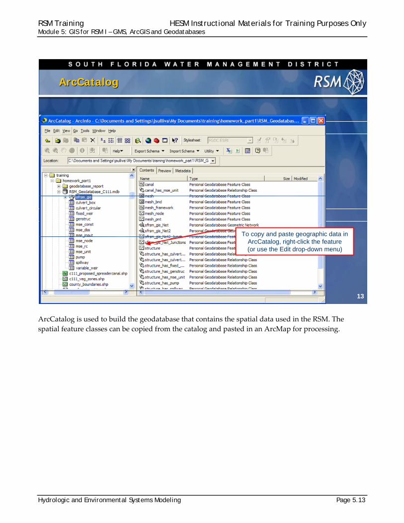
ArcCatalog is used to build the geodatabase that contains the spatial data used in the RSM. The
spatial feature classes can be copied from the catalog and pasted in an ArcMap for processing.
13
ArcCatalogArcCatalog
To copy and paste geographic data in ArcCatalog, right-click the feature (or use the Edit drop-down menu)
RSM Training HESM Instructional Materials for Training Purposes Only Module 5: GIS for RSM I – GMS, ArcGIS and Geodatabases
Page 5.14 Hydrologic and Environmental Systems Modeling
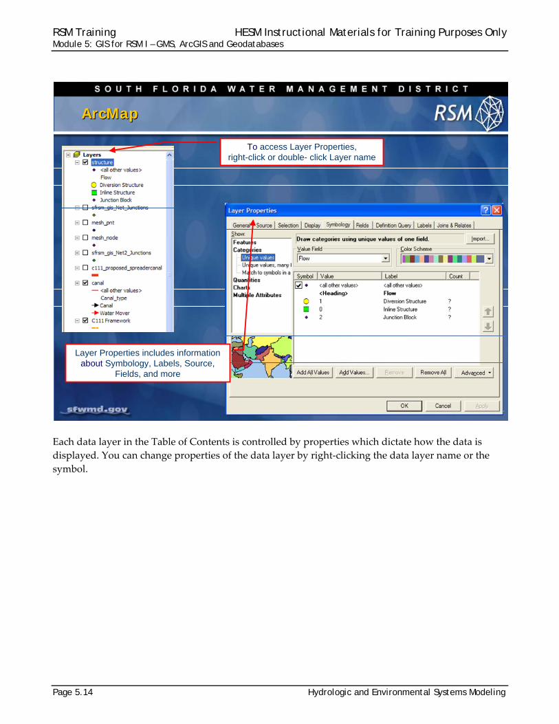
Each data layer in the Table of Contents is controlled by properties which dictate how the data is
displayed. You can change properties of the data layer by right‐clicking the data layer name or the
symbol.
14
ArcMapArcMap
To access Layer Properties,right-click or double- click Layer name
Layer Properties includes informationabout Symbology, Labels, Source,
Fields, and more
RSM Training HESM Instructional Materials for Training Purposes Only Module 5: GIS for RSM I – GMS, ArcGIS and Geodatabases
Hydrologic and Environmental Systems Modeling Page 5.15
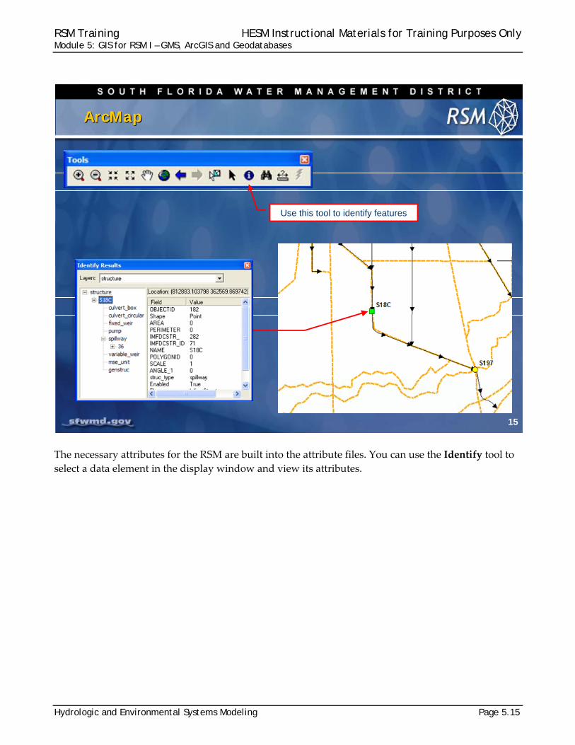
The necessary attributes for the RSM are built into the attribute files. You can use the Identify tool to
select a data element in the display window and view its attributes.
15
ArcMapArcMap
Access layer properties by right-click or double
click on layer name
Use this tool to identify features

RSM Training HESM Instructional Materials for Training Purposes Only Module 5: GIS for RSM I – GMS, ArcGIS and Geodatabases
Page 5.16 Hydrologic and Environmental Systems Modeling
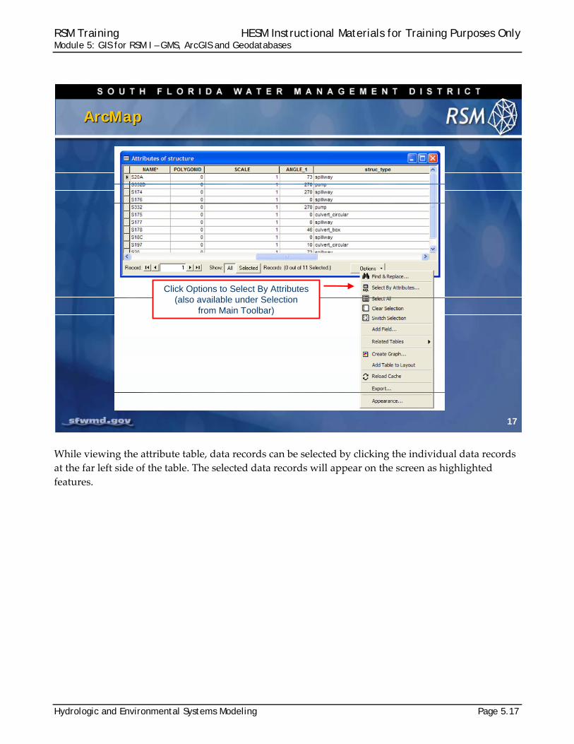
You may also view the Attributes of a structure by right clicking a data layer in the Table of Contents
and selecting Open Attribute Table for that layer.
At the bottom of the attribute table you can view the entire table or only the selected data elements.
Right‐click on the heading over any attribute in the table and sort the table.
16
ArcMapArcMap
Right-click Feature in Table of Contents to open Attribute Table
Attribute Table
RSM Training HESM Instructional Materials for Training Purposes Only Module 5: GIS for RSM I – GMS, ArcGIS and Geodatabases
Hydrologic and Environmental Systems Modeling Page 5.17
While viewing the attribute table, data records can be selected by clicking the individual data records
at the far left side of the table. The selected data records will appear on the screen as highlighted
features.
17
ArcMapArcMap
Click Options to Select By Attributes (also available under Selection
from Main Toolbar)
RSM Training HESM Instructional Materials for Training Purposes Only Module 5: GIS for RSM I – GMS, ArcGIS and Geodatabases
Page 5.18 Hydrologic and Environmental Systems Modeling
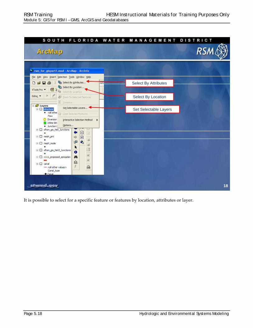
It is possible to select for a specific feature or features by location, attributes or layer.
18
ArcMapArcMap
Set Selectable Layers
Select By Attributes
Select By Location
RSM Training HESM Instructional Materials for Training Purposes Only Module 5: GIS for RSM I – GMS, ArcGIS and Geodatabases
Hydrologic and Environmental Systems Modeling Page 5.19
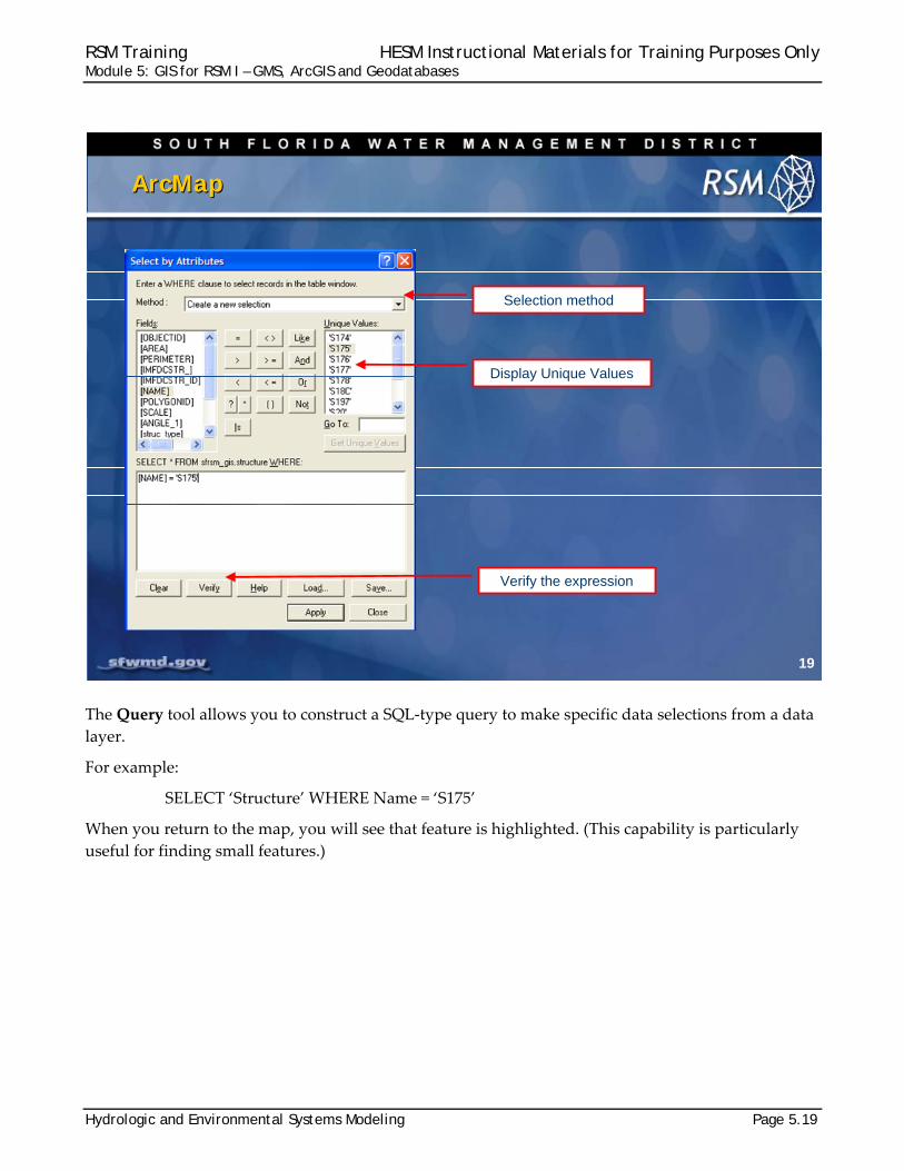
The Query tool allows you to construct a SQL‐type query to make specific data selections from a data
layer.
For example:
SELECT ‘Structure’ WHERE Name = ‘S175’
When you return to the map, you will see that feature is highlighted. (This capability is particularly
useful for finding small features.)
19
ArcMapArcMap
Display Unique Values
Verify the expression
Selection method
RSM Training HESM Instructional Materials for Training Purposes Only Module 5: GIS for RSM I – GMS, ArcGIS and Geodatabases
Page 5.20 Hydrologic and Environmental Systems Modeling
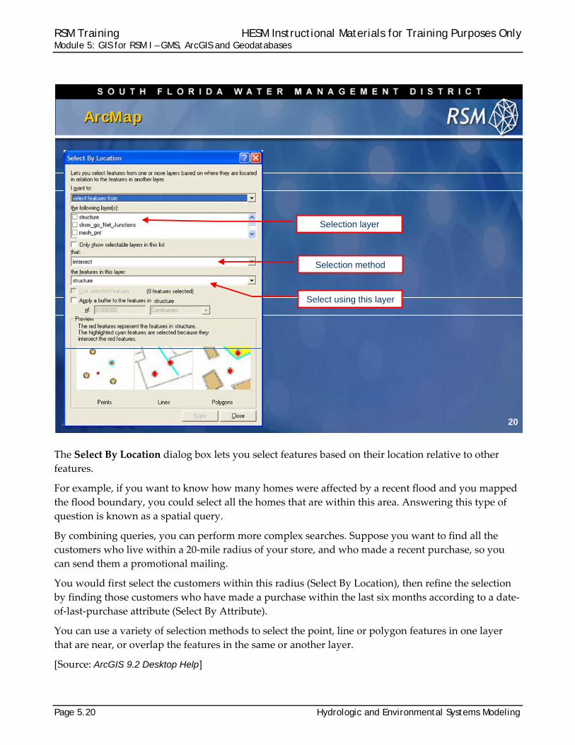
The Select By Location dialog box lets you select features based on their location relative to other
features.
For example, if you want to know how many homes were affected by a recent flood and you mapped
the flood boundary, you could select all the homes that are within this area. Answering this type of
question is known as a spatial query.
By combining queries, you can perform more complex searches. Suppose you want to find all the
customers who live within a 20‐mile radius of your store, and who made a recent purchase, so you
can send them a promotional mailing.
You would first select the customers within this radius (Select By Location), then refine the selection
by finding those customers who have made a purchase within the last six months according to a date‐
of‐last‐purchase attribute (Select By Attribute).
You can use a variety of selection methods to select the point, line or polygon features in one layer
that are near, or overlap the features in the same or another layer.
[Source: ArcGIS 9.2 Desktop Help]
20
ArcMapArcMap
Select using this layer
Selection layer
Selection method
RSM Training HESM Instructional Materials for Training Purposes Only Module 5: GIS for RSM I – GMS, ArcGIS and Geodatabases
Hydrologic and Environmental Systems Modeling Page 5.21
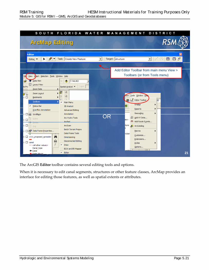
The ArcGIS Editor toolbar contains several editing tools and options.
When it is necessary to edit canal segments, structures or other feature classes, ArcMap provides an
interface for editing those features, as well as spatial extents or attributes.
21
ArcMap EditingArcMap Editing
Add Editor Toolbar from main menu View >
Toolbars (or from Tools menu)
OR
RSM Training HESM Instructional Materials for Training Purposes Only Module 5: GIS for RSM I – GMS, ArcGIS and Geodatabases
Page 5.22 Hydrologic and Environmental Systems Modeling
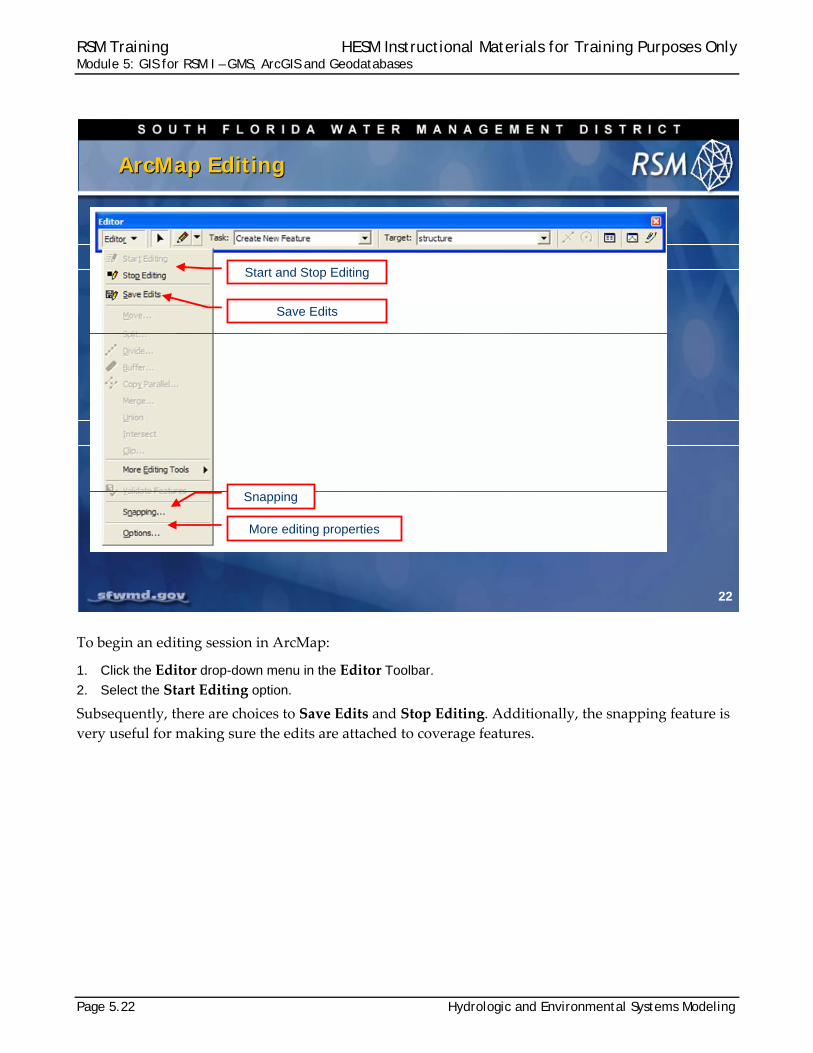
To begin an editing session in ArcMap:
1. Click the Editor drop-down menu in the Editor Toolbar.
2. Select the Start Editing option.
Subsequently, there are choices to Save Edits and Stop Editing. Additionally, the snapping feature is
very useful for making sure the edits are attached to coverage features.
22
ArcMap EditingArcMap Editing
Start and Stop Editing
Save Edits
Snapping
More editing properties
RSM Training HESM Instructional Materials for Training Purposes Only Module 5: GIS for RSM I – GMS, ArcGIS and Geodatabases
Hydrologic and Environmental Systems Modeling Page 5.23
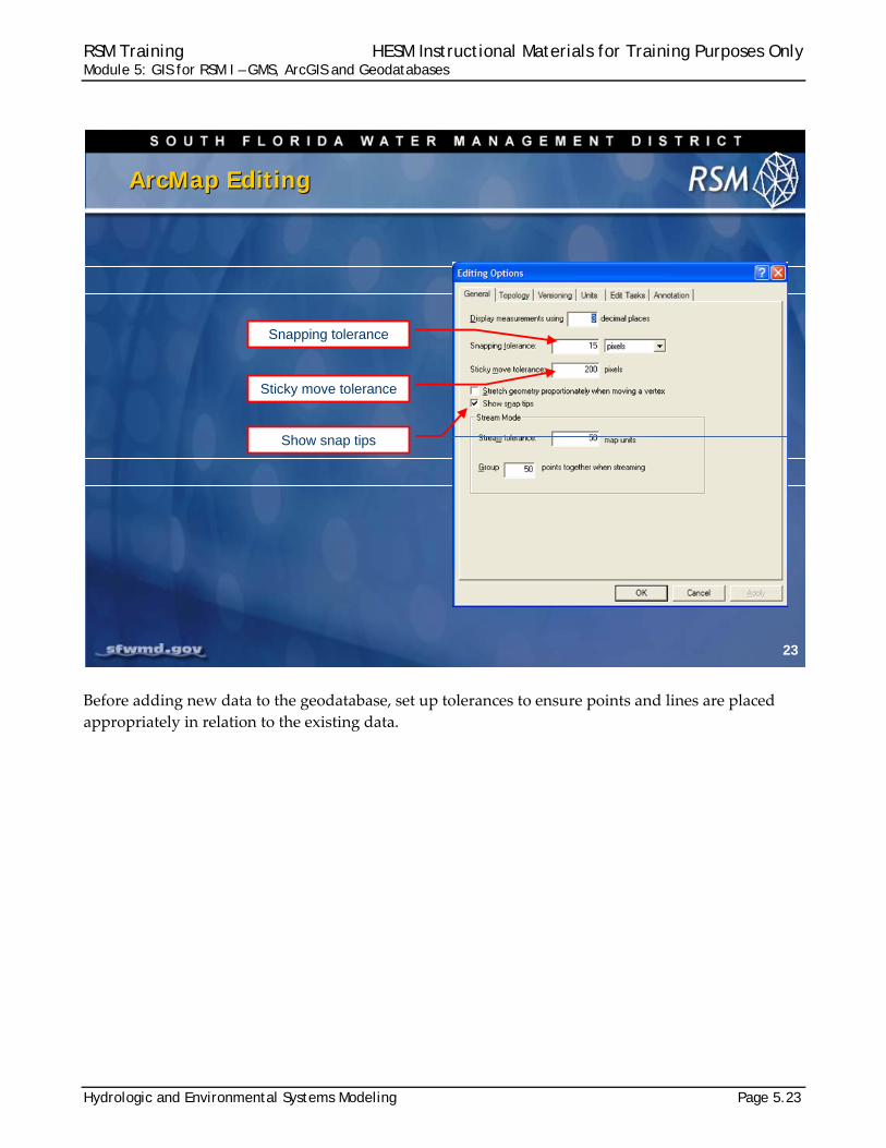
Before adding new data to the geodatabase, set up tolerances to ensure points and lines are placed
appropriately in relation to the existing data.
23
ArcMap EditingArcMap Editing
Snapping tolerance
Sticky move tolerance
Show snap tips
RSM Training HESM Instructional Materials for Training Purposes Only Module 5: GIS for RSM I – GMS, ArcGIS and Geodatabases
Page 5.24 Hydrologic and Environmental Systems Modeling
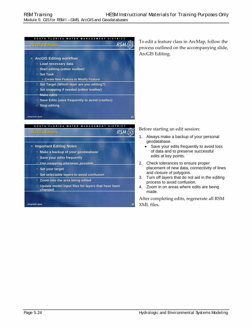
To edit a feature class in ArcMap, follow the
process outlined on the accompanying slide,
ArcGIS Editing.
Before starting an edit session:
1. Always make a backup of your personal geodatabase. Save your edits frequently to avoid loss
of data and to preserve successful edits at key points.
2. Check tolerances to ensure proper placement of new data, connectivity of lines and closure of polygons.
3. Turn off layers that do not aid in the editing process to avoid confusion.
4. Zoom in on areas where edits are being made.
After completing edits, regenerate all RSM
XML files.
24
ArcGIS Editing ArcGIS Editing
ArcGIS Editing workflow
• Load necessary data
• Start editing (editor toolbar)
• Set Task
Create New Feature or Modify Feature
• Set Target (Which layer are you editing?)
• Set snapping if needed (editor toolbar)
• Make edits
• Save Edits (save frequently to avoid crashes)
• Stop editing
ArcGIS Editing workflow
• Load necessary data
• Start editing (editor toolbar)
• Set Task
Create New Feature or Modify Feature
• Set Target (Which layer are you editing?)
• Set snapping if needed (editor toolbar)
• Make edits
• Save Edits (save frequently to avoid crashes)
• Stop editing
25
ArcGIS Editing ArcGIS Editing
Important Editing Notes
• Make a backup of your geodatabase
• Save your edits frequently
• Use snapping whenever possible
• Set your target
• Set selectable layers to avoid confusion
• Zoom into the area being edited
• Update model input files for layers that have been changed
Important Editing Notes
• Make a backup of your geodatabase
• Save your edits frequently
• Use snapping whenever possible
• Set your target
• Set selectable layers to avoid confusion
• Zoom into the area being edited
• Update model input files for layers that have been changed
RSM Training HESM Instructional Materials for Training Purposes Only Module 5: GIS for RSM I – GMS, ArcGIS and Geodatabases
Hydrologic and Environmental Systems Modeling Page 5.25
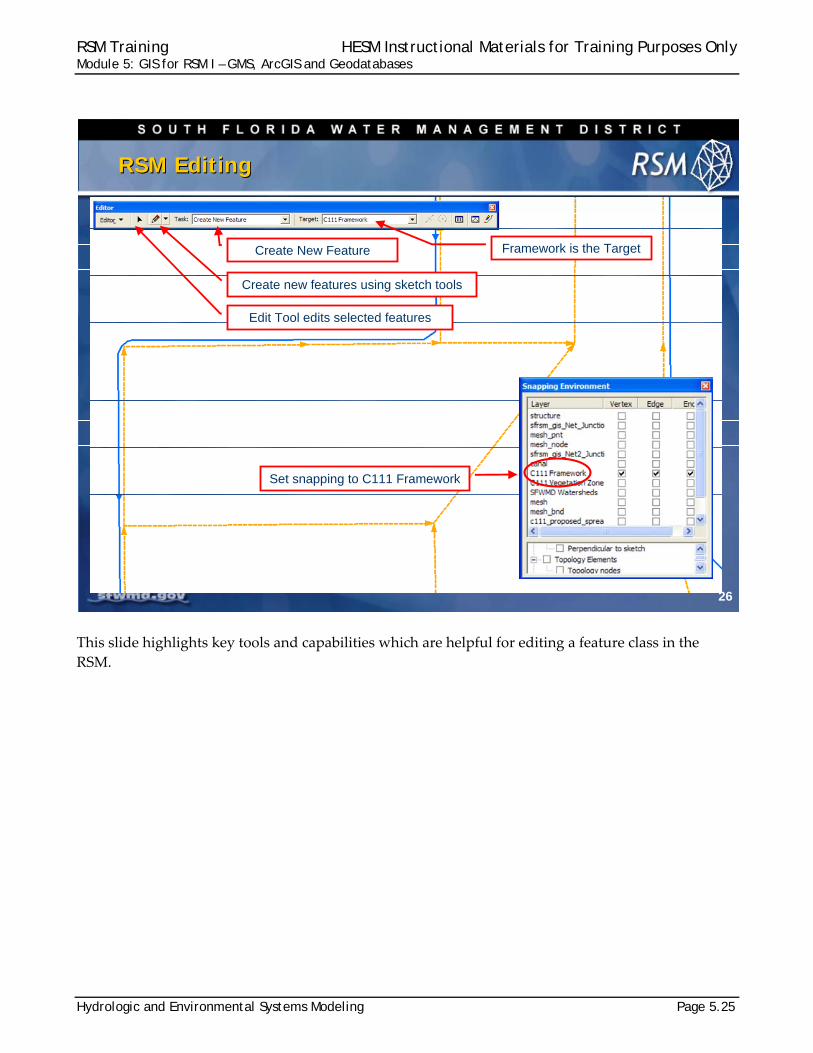
This slide highlights key tools and capabilities which are helpful for editing a feature class in the
RSM.
26
RSM EditingRSM Editing
Framework is the TargetCreate New Feature
Create new features using sketch tools
Set snapping to C111 Framework
Edit Tool edits selected features
RSM Training HESM Instructional Materials for Training Purposes Only Module 5: GIS for RSM I – GMS, ArcGIS and Geodatabases
Page 5.26 Hydrologic and Environmental Systems Modeling
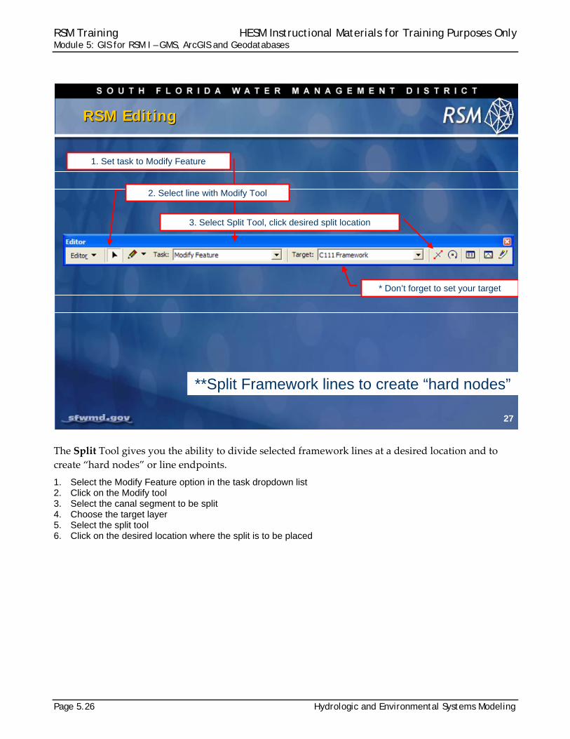
The Split Tool gives you the ability to divide selected framework lines at a desired location and to
create “hard nodes” or line endpoints.
1. Select the Modify Feature option in the task dropdown list 2. Click on the Modify tool 3. Select the canal segment to be split 4. Choose the target layer 5. Select the split tool 6. Click on the desired location where the split is to be placed
27
RSM EditingRSM Editing
1. Set task to Modify Feature
2. Select line with Modify Tool
3. Select Split Tool, click desired split location
* Don’t forget to set your target
**Split Framework lines to create “hard nodes”
RSM Training HESM Instructional Materials for Training Purposes Only Module 5: GIS for RSM I – GMS, ArcGIS and Geodatabases
Hydrologic and Environmental Systems Modeling Page 5.27
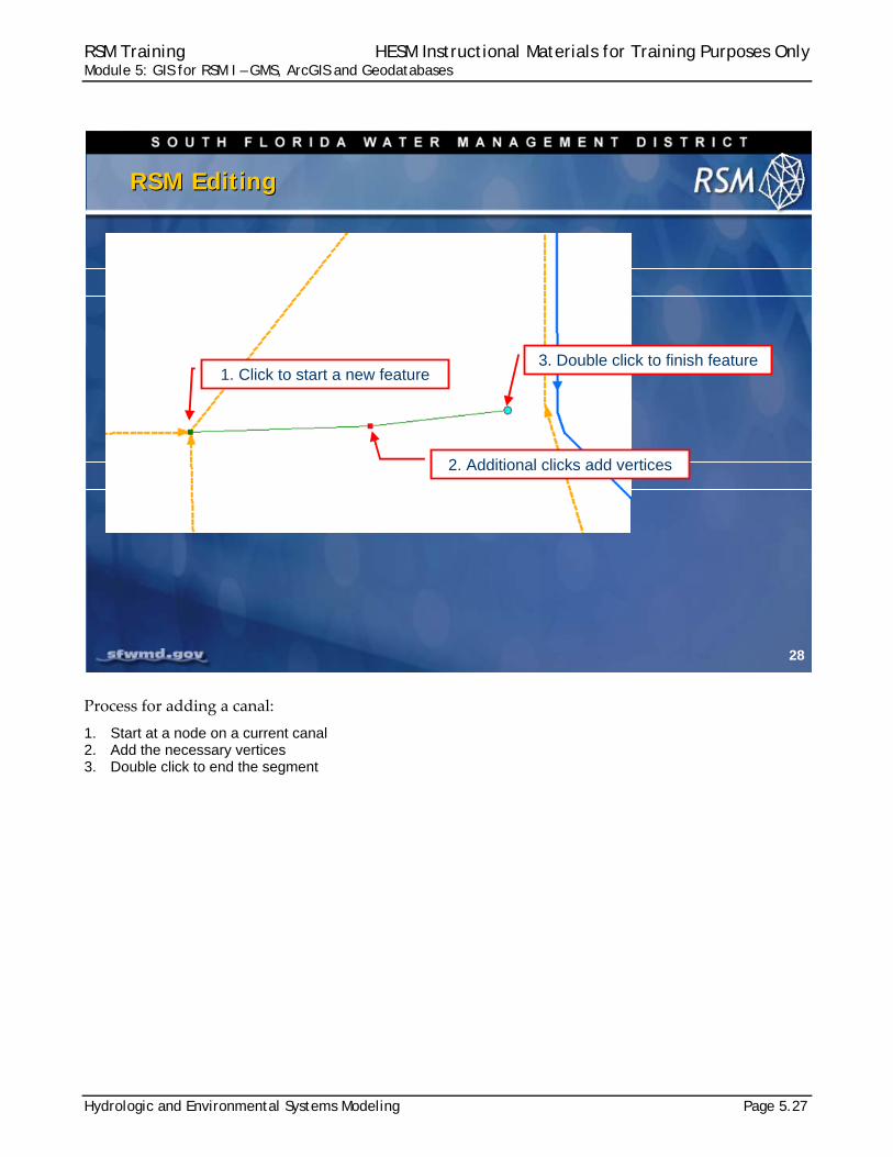
Process for adding a canal:
1. Start at a node on a current canal 2. Add the necessary vertices 3. Double click to end the segment
28
RSM EditingRSM Editing
3. Double click to finish feature
2. Additional clicks add vertices
1. Click to start a new feature
RSM Training HESM Instructional Materials for Training Purposes Only Module 5: GIS for RSM I – GMS, ArcGIS and Geodatabases
Page 5.28 Hydrologic and Environmental Systems Modeling
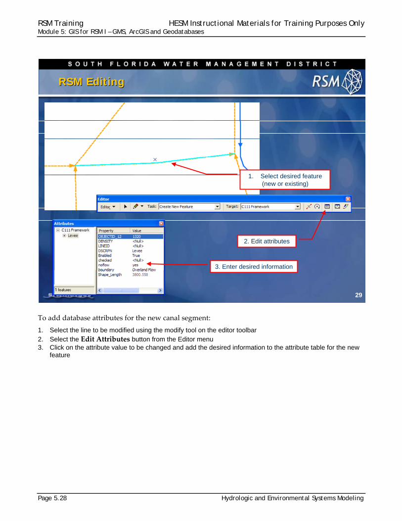
To add database attributes for the new canal segment:
1. Select the line to be modified using the modify tool on the editor toolbar 2. Select the Edit Attributes button from the Editor menu 3. Click on the attribute value to be changed and add the desired information to the attribute table for the new
feature
29
RSM EditingRSM Editing
1. Select desired feature (new or existing)
2. Edit attributes
3. Enter desired information
RSM Training HESM Instructional Materials for Training Purposes Only Module 5: GIS for RSM I – GMS, ArcGIS and Geodatabases
Hydrologic and Environmental Systems Modeling Page 5.29
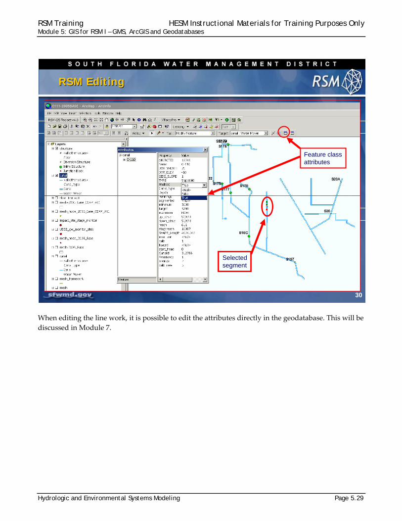
When editing the line work, it is possible to edit the attributes directly in the geodatabase. This will be
discussed in Module 7.
30
RSM EditingRSM Editing
Feature classattributes
Selectedsegment
RSM Training HESM Instructional Materials for Training Purposes Only Module 5: GIS for RSM I – GMS, ArcGIS and Geodatabases
Page 5.30 Hydrologic and Environmental Systems Modeling
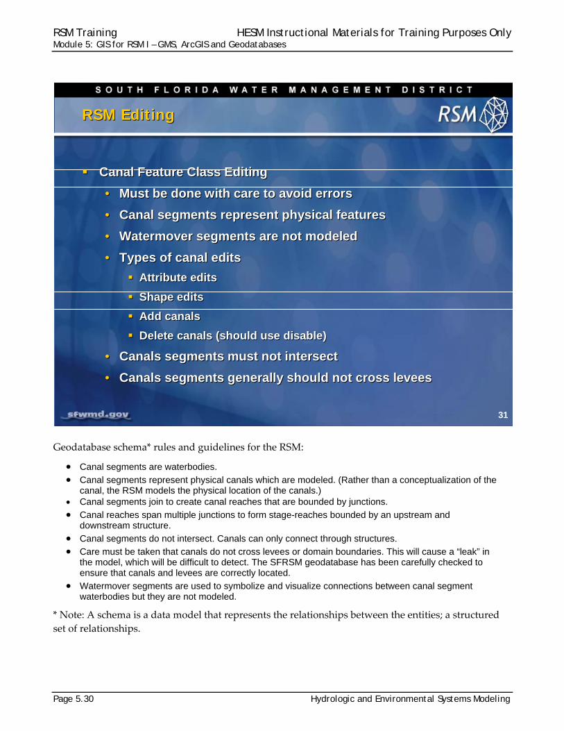
Geodatabase schema* rules and guidelines for the RSM:
Canal segments are waterbodies. Canal segments represent physical canals which are modeled. (Rather than a conceptualization of the
canal, the RSM models the physical location of the canals.) Canal segments join to create canal reaches that are bounded by junctions.
Canal reaches span multiple junctions to form stage-reaches bounded by an upstream and downstream structure.
Canal segments do not intersect. Canals can only connect through structures. Care must be taken that canals do not cross levees or domain boundaries. This will cause a “leak” in
the model, which will be difficult to detect. The SFRSM geodatabase has been carefully checked to ensure that canals and levees are correctly located.
Watermover segments are used to symbolize and visualize connections between canal segment waterbodies but they are not modeled.
* Note: A schema is a data model that represents the relationships between the entities; a structured
set of relationships.
31
RSM Editing RSM Editing
Canal Feature Class Editing
• Must be done with care to avoid errors
• Canal segments represent physical features
• Watermover segments are not modeled
• Types of canal edits
Attribute edits
Shape edits
Add canals
Delete canals (should use disable)
• Canals segments must not intersect
• Canals segments generally should not cross levees
RSM Training HESM Instructional Materials for Training Purposes Only Module 5: GIS for RSM I – GMS, ArcGIS and Geodatabases
Hydrologic and Environmental Systems Modeling Page 5.31
RSM Geodatabase schema rules and guidelines:
Feature classes are added through a change control process to ensure new layers are added to the RSM GIS tools and to ensure they do not break existing tools.
All RSM canals are trapezoidal. All canals and structures can be enabled and disabled. Rather than delete a canal for a selected
alternative, just disable the unnecessary canals and structures. Inline structures must be connected to one source and one destination segment. Diversion structures must be “on” a watermover segment. All structures are junctions, but not all junctions are structures. Domains help control the data expected to be present in each attribute.
32
RSM Editing RSM Editing
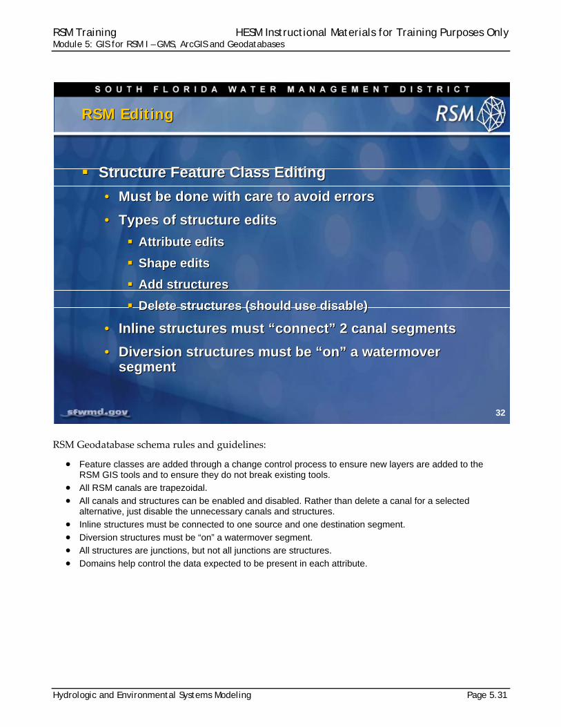
Structure Feature Class Editing
• Must be done with care to avoid errors
• Types of structure edits
Attribute edits
Shape edits
Add structures
Delete structures (should use disable)
• Inline structures must “connect” 2 canal segments
• Diversion structures must be “on” a watermoversegment
Structure Feature Class Editing
• Must be done with care to avoid errors
• Types of structure edits
Attribute edits
Shape edits
Add structures
Delete structures (should use disable)
• Inline structures must “connect” 2 canal segments
• Diversion structures must be “on” a watermoversegment
RSM Training HESM Instructional Materials for Training Purposes Only Module 5: GIS for RSM I – GMS, ArcGIS and Geodatabases
Page 5.32 Hydrologic and Environmental Systems Modeling
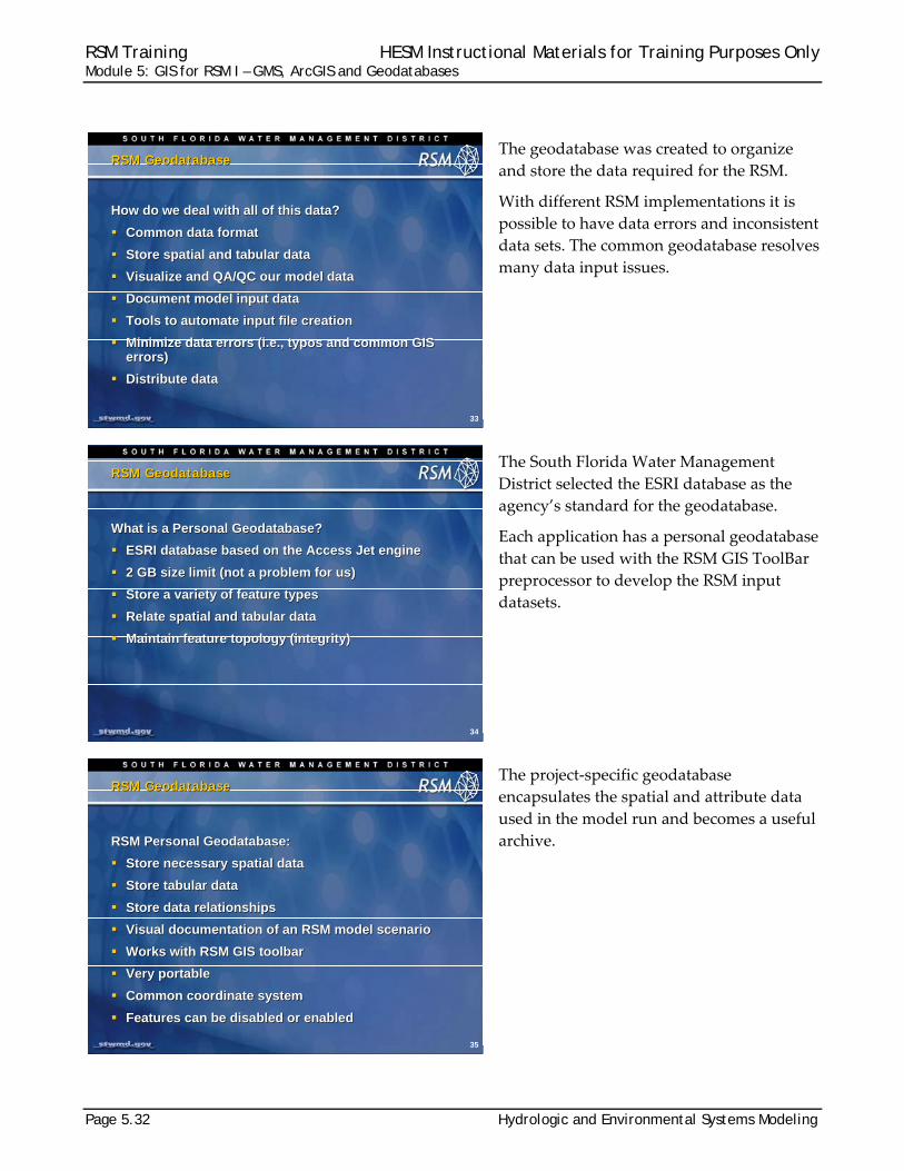
The geodatabase was created to organize
and store the data required for the RSM.
With different RSM implementations it is
possible to have data errors and inconsistent
data sets. The common geodatabase resolves
many data input issues.
The South Florida Water Management
District selected the ESRI database as the
agency’s standard for the geodatabase.
Each application has a personal geodatabase
that can be used with the RSM GIS ToolBar
preprocessor to develop the RSM input
datasets.
The project‐specific geodatabase
encapsulates the spatial and attribute data
used in the model run and becomes a useful
archive.
33
RSM GeodatabaseRSM Geodatabase
How do we deal with all of this data?
Common data format
Store spatial and tabular data
Visualize and QA/QC our model data
Document model input data
Tools to automate input file creation
Minimize data errors (i.e., typos and common GIS errors)
Distribute data
How do we deal with all of this data?
Common data format
Store spatial and tabular data
Visualize and QA/QC our model data
Document model input data
Tools to automate input file creation
Minimize data errors (i.e., typos and common GIS errors)
Distribute data
34
RSM GeodatabaseRSM Geodatabase
What is a Personal Geodatabase?
ESRI database based on the Access Jet engine
2 GB size limit (not a problem for us)
Store a variety of feature types
Relate spatial and tabular data
Maintain feature topology (integrity)
What is a Personal Geodatabase?
ESRI database based on the Access Jet engine
2 GB size limit (not a problem for us)
Store a variety of feature types
Relate spatial and tabular data
Maintain feature topology (integrity)
35
RSM GeodatabaseRSM Geodatabase
RSM Personal Geodatabase:
Store necessary spatial data
Store tabular data
Store data relationships
Visual documentation of an RSM model scenario
Works with RSM GIS toolbar
Very portable
Common coordinate system
Features can be disabled or enabled
RSM Personal Geodatabase:
Store necessary spatial data
Store tabular data
Store data relationships
Visual documentation of an RSM model scenario
Works with RSM GIS toolbar
Very portable
Common coordinate system
Features can be disabled or enabled
RSM Training HESM Instructional Materials for Training Purposes Only Module 5: GIS for RSM I – GMS, ArcGIS and Geodatabases
Hydrologic and Environmental Systems Modeling Page 5.33
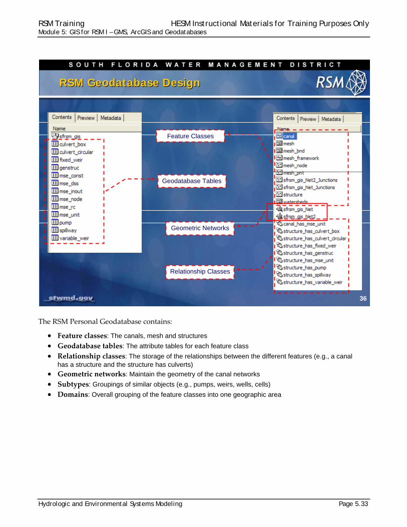
The RSM Personal Geodatabase contains:
Feature classes: The canals, mesh and structures Geodatabase tables: The attribute tables for each feature class Relationship classes: The storage of the relationships between the different features (e.g., a canal
has a structure and the structure has culverts) Geometric networks: Maintain the geometry of the canal networks Subtypes: Groupings of similar objects (e.g., pumps, weirs, wells, cells) Domains: Overall grouping of the feature classes into one geographic area
36
RSM Geodatabase DesignRSM Geodatabase Design
Geodatabase Tables
Relationship Classes
Feature Classes
Geometric Networks

RSM Training HESM Instructional Materials for Training Purposes Only Module 5: GIS for RSM I – GMS, ArcGIS and Geodatabases
Page 5.34 Hydrologic and Environmental Systems Modeling
The real world has a complex distribution of canals and structures. The modeled world captures the
canals, structures and landscape features and maintains the correct juxtaposition and connectivity
among the features.
37
RSM Geodatabase DesignRSM Geodatabase Design
RealWorld
vs.
ModeledWorld
RSM Training HESM Instructional Materials for Training Purposes Only Module 5: GIS for RSM I – GMS, ArcGIS and Geodatabases
Hydrologic and Environmental Systems Modeling Page 5.35
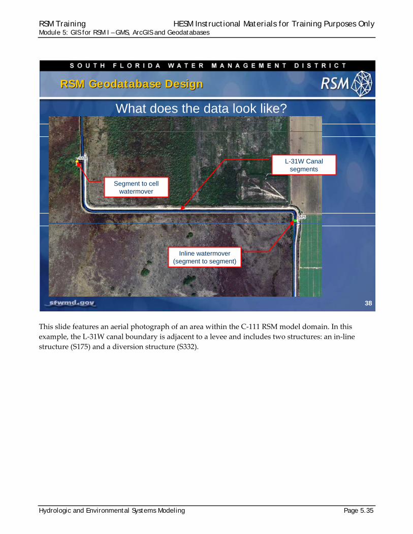
This slide features an aerial photograph of an area within the C‐111 RSM model domain. In this
example, the L‐31W canal boundary is adjacent to a levee and includes two structures: an in‐line
structure (S175) and a diversion structure (S332).
38
RSM Geodatabase DesignRSM Geodatabase Design
L-31W Canal segments
Inline watermover(segment to segment)
Segment to cell watermover
What does the data look like?
RSM Training HESM Instructional Materials for Training Purposes Only Module 5: GIS for RSM I – GMS, ArcGIS and Geodatabases
Page 5.36 Hydrologic and Environmental Systems Modeling
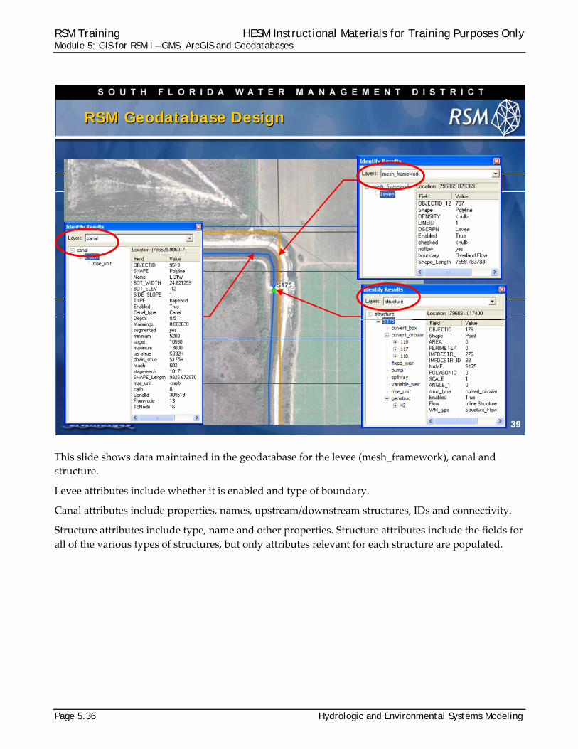
This slide shows data maintained in the geodatabase for the levee (mesh_framework), canal and
structure.
Levee attributes include whether it is enabled and type of boundary.
Canal attributes include properties, names, upstream/downstream structures, IDs and connectivity.
Structure attributes include type, name and other properties. Structure attributes include the fields for
all of the various types of structures, but only attributes relevant for each structure are populated.
39
RSM Geodatabase DesignRSM Geodatabase Design
L-31W Canal
S-175 StructureS-332 Structure
RSM Training HESM Instructional Materials for Training Purposes Only Module 5: GIS for RSM I – GMS, ArcGIS and Geodatabases
Hydrologic and Environmental Systems Modeling Page 5.37
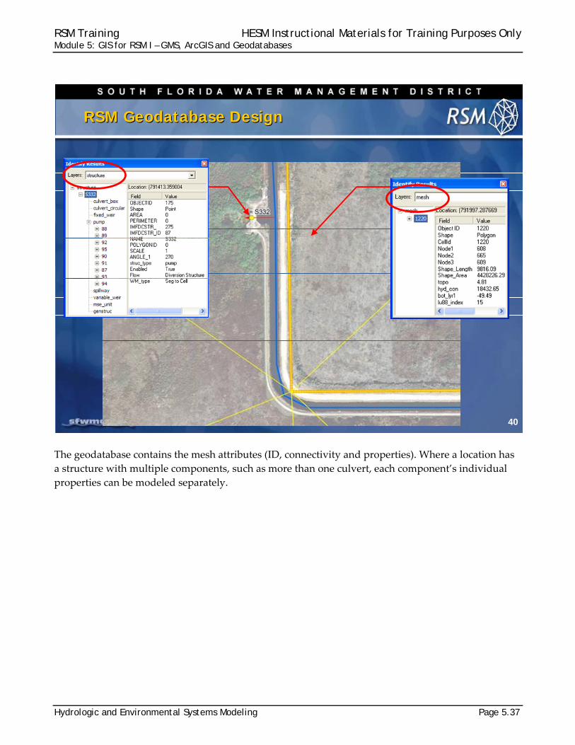
The geodatabase contains the mesh attributes (ID, connectivity and properties). Where a location has
a structure with multiple components, such as more than one culvert, each component’s individual
properties can be modeled separately.
40
RSM Geodatabase DesignRSM Geodatabase Design
S-175 StructureS-332 Structure
RSM Training HESM Instructional Materials for Training Purposes Only Module 5: GIS for RSM I – GMS, ArcGIS and Geodatabases
Page 5.38 Hydrologic and Environmental Systems Modeling
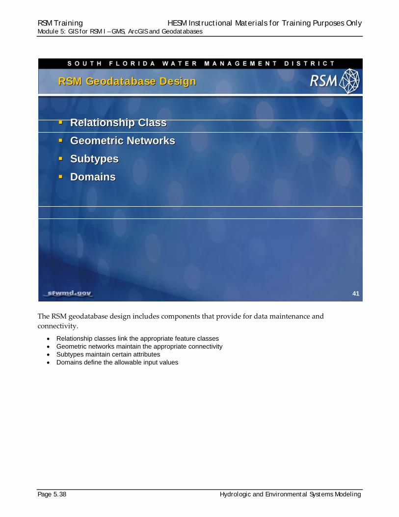
The RSM geodatabase design includes components that provide for data maintenance and
connectivity.
Relationship classes link the appropriate feature classes Geometric networks maintain the appropriate connectivity Subtypes maintain certain attributes Domains define the allowable input values
41
RSM Geodatabase DesignRSM Geodatabase Design
Relationship Class
Geometric Networks
Subtypes
Domains
Relationship Class
Geometric Networks
Subtypes
Domains
RSM Training HESM Instructional Materials for Training Purposes Only Module 5: GIS for RSM I – GMS, ArcGIS and Geodatabases
Hydrologic and Environmental Systems Modeling Page 5.39
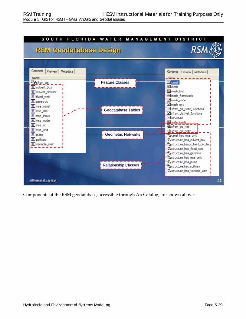
Components of the RSM geodatabase, accessible through ArcCatalog, are shown above.
42
RSM Geodatabase DesignRSM Geodatabase Design
Geodatabase Tables
Relationship Classes
Feature Classes
Geometric Networks
RSM Training HESM Instructional Materials for Training Purposes Only Module 5: GIS for RSM I – GMS, ArcGIS and Geodatabases
Page 5.40 Hydrologic and Environmental Systems Modeling
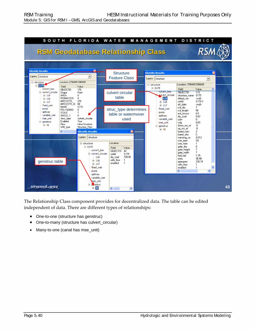
The Relationship Class component provides for decentralized data. The table can be edited
independent of data. There are different types of relationships:
One-to-one (structure has genstruc) One-to-many (structure has culvert_circular)
Many-to-one (canal has mse_unit)
43
RSM Geodatabase Relationship ClassRSM Geodatabase Relationship Class
Structure Feature Class
culvert circular table
genstruc table
struc_type determines table or watermover
used

RSM Training HESM Instructional Materials for Training Purposes Only Module 5: GIS for RSM I – GMS, ArcGIS and Geodatabases
Hydrologic and Environmental Systems Modeling Page 5.41
There are two networks maintained in the geodatabase, one for the canals and one for the mesh
nodes. These networks allow you to use the GIS tools to produce input datasets (XML files) and post‐
process the RSM output efficiently.
The networks also enable you to manage spatial relationships between points and lines, maintain
connectivity rules, and snap points to lines, when editing.
The canal network allows us to maintain the appropriate flow direction by using the “as digitized”
direction to represent the direction of flow in the canal.
44
RSM Geometric NetworkRSM Geometric Network
sfrsm_gis_Net (canals and structures) Keeps canals connected
Structure are connected to canals
Canal direction is maintained
Tools can access the network and gather information
sfrsm_gis_Net2 (framework and mesh nodes) Mesh nodes are snapped to framework
Tools can gather nodes along framework
Manage wall boundary conditions
Ex. Tide, levee, wall flow_bc, etc…
RSM Training HESM Instructional Materials for Training Purposes Only Module 5: GIS for RSM I – GMS, ArcGIS and Geodatabases
Page 5.42 Hydrologic and Environmental Systems Modeling
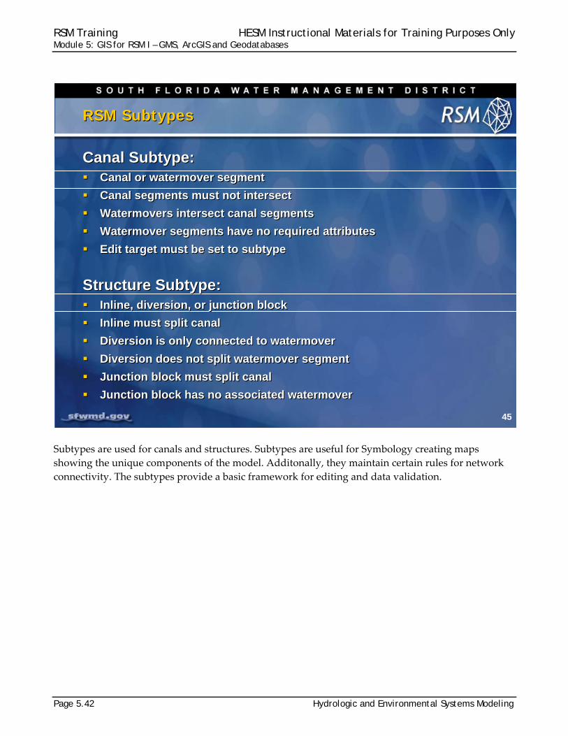
Subtypes are used for canals and structures. Subtypes are useful for Symbology creating maps
showing the unique components of the model. Additonally, they maintain certain rules for network
connectivity. The subtypes provide a basic framework for editing and data validation.
45
RSM SubtypesRSM Subtypes
Canal Subtype: Canal or watermover segment
Canal segments must not intersect
Watermovers intersect canal segments
Watermover segments have no required attributes
Edit target must be set to subtype
Structure Subtype: Inline, diversion, or junction block
Inline must split canal
Diversion is only connected to watermover
Diversion does not split watermover segment
Junction block must split canal
Junction block has no associated watermover

RSM Training HESM Instructional Materials for Training Purposes Only Module 5: GIS for RSM I – GMS, ArcGIS and Geodatabases
Hydrologic and Environmental Systems Modeling Page 5.43
Domains are used in the RSM geodatabase
to:
Avoid data input errors Maintain available attribute values Establish ranges for input variables
All of the necessary spatial and attribute
components for an RSM implementation
have been combined into an RSM
geodatabase template.
When a new mesh is created for a
subregional RSM implementation, it can be
imported into the geodatabase template and
the subregional geodatabase will have all of
the available data and necessary
relationships. (The relationships provide a
fixed framework for adding the required
attribute data.)
The RSM GIS ToolBar utilities work with the
standard geodatabase to extract the spatial and attribute information and create input data files for
the Regional Simulation Model.
46
RSM Geodatabase DomainsRSM Geodatabase Domains
RSM Geodatabase Domains:
Enabled domain (true or false)
Boundary domain (framework bc types)
Value domain (RC, DSS, constant)
WM_type domain (seg to cell, seg to seg, etc…)
Rc_domain (number range for rule curves)
RSM Geodatabase Domains:
Enabled domain (true or false)
Boundary domain (framework bc types)
Value domain (RC, DSS, constant)
WM_type domain (seg to cell, seg to seg, etc…)
Rc_domain (number range for rule curves)
47
RSM Geodatabase TemplatesRSM Geodatabase Templates
RSM Geodatabase Templates:
Regional Implementation mesh (approx. 27000 cells)
Regional Development mesh (approx. 5000 cells)
Bring your own mesh
• Import your mesh into RSM geodatabase
• All canal and structure data is maintained
• All relationships are maintained
• All RSM tools will work
RSM Geodatabase Templates:
Regional Implementation mesh (approx. 27000 cells)
Regional Development mesh (approx. 5000 cells)
Bring your own mesh
• Import your mesh into RSM geodatabase
• All canal and structure data is maintained
• All relationships are maintained
• All RSM tools will work

RSM Training HESM Instructional Materials for Training Purposes Only Module 5: GIS for RSM I – GMS, ArcGIS and Geodatabases
Page 5.44 Hydrologic and Environmental Systems Modeling

RSM Training HESM Instructional Materials for Training Purposes Only Module 5: GIS for RSM I – GMS, ArcGIS and Geodatabases
Hydrologic and Environmental Systems Modeling Page 5.45
Knowledge Assessment
(pre- and post-lecture quiz to assess efficacy of training materials)
1. What are the possible methods for creating a mesh for RSM? 2. What is the format of the mesh file used by RSM?
3. What are the input requirements to create a mesh in GMS?
4. How do we use GMS for RSM? 5. What information is contained in the ArcCatalog RSM geodatabase?
6. What is the difference in the mesh and network creation within RSM? 7. What is contained in the geodatabase network? 8. What are four advantages to maintaining the RSM Geodatabase?
9. Why is the RSM personal Geodatabase critical? 10. What does the enabling feature allow?

RSM Training HESM Instructional Materials for Training Purposes Only Module 5: GIS for RSM I – GMS, ArcGIS and Geodatabases
Page 5.46 Hydrologic and Environmental Systems Modeling
Answers 1. There are several methods for creating an RSM mesh: create by hand (small meshes),
USACE GMS mesh generator, import a mesh. 2. The accepted mesh format is an ASCII file following the GMS SEEP2D format. 3. GMS requires a framework shape file that contains the linework for constraining the
mesh and the required density of vertices for each framework line. 4. GMS provides a tool for checking modified meshes and meshes built using other
methods. 5. The RSM geodatabase contains feature classes, canal network, relationships and
topology classes. 6. Alternative meshes can be created for RSM but the canal network for south Florida is
part of the RSM geodatabase and is selected when the user-defined mesh is intersected with the RSM template geodatabase.
7. The RSM geodatabase network contains the canal and water control structure
topology and attributes. 8. There are several advantages for maintaining the RSM geodatabase including:
Common data format, Documentation of model input data sets, Automated input data creation, Minimize input data errors, Easy distribution of data, Enable/disable features, Data is connected to RSMGUI pre-processing tools
9. The geodatabase is critical for maintaining the exact location of the levees, canals and structures because they are located near each other and the RSM uses the exact locations for determining cell and segment connectivity.
10. The enabling feature allows the user to disable any canal or structure feature in an
RSM implementation without deleting the feature from the geodatabase. This provides considerable flexibility in building alternative project models.

RSM Training HESM Instructional Materials for Training Purposes Only Module 5: GIS for RSM I – GMS, ArcGIS and Geodatabases
Hydrologic and Environmental Systems Modeling Page 5.47
Lab 5: Editing RSM Features
Time Estimate: 2 hours
Training Objective: Gain familiarity with ArcGIS personal geodatabases
This lab is designed to provide you with an opportunity to investigate the Regional
Simulation Model (RSM) geodatabase.
The information necessary to create the parameters for RSM XML input files is
obtained from the geographic data. Diagnosing problems with an RSM
implementation frequently requires observing the spatial distribution of model
features. Therefore, you must be able to navigate among the feature classes and
attribute tables used to construct the input files.
This lab requires a general ability to understand and run ArcGIS.
GIS for RSM IGIS for RSM I
GMS, ArcGIS and GeodatabasesGMS, ArcGIS and Geodatabases
RSM Training HESM Instructional Materials for Training Purposes Only Module 5: GIS for RSM I – GMS, ArcGIS and Geodatabases
Page 5.48 Hydrologic and Environmental Systems Modeling
NOTE:
For ease of navigation, you may wish to set an environment variable to the directory where you install the RSM code using the syntax
setenv RSM <path>
For SFWMD modelers, the path you should use for the NAS is:
/nw/oomdata_ws/nw/oom/sfrsm/workdirs/<username>/trunk
setenv RSM /nw/oomdata_ws/nw/oom/sfrsm/workdirs/<username>/trunk
Once you have set the RSM environment variable to your trunk path, you can use $RSM in any path statement, such as:
cd $RSM/benchmarks
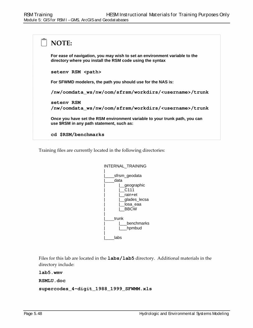
Training files are currently located in the following directories:
INTERNAL_TRAINING | |____sfrsm_geodata |____data | |__geographic | |__C111 | |__rain+et | |__glades_lecsa | |__losa_eaa | |__BBCW | |____trunk | |___benchmarks | |___hpmbud | |____labs
Files for this lab are located in the labs/lab5 directory. Additional materials in the
directory include:
lab5.wmv
RSMLU.doc
supercodes_4-digit_1988_1999_SFWMM.xls
RSM Training HESM Instructional Materials for Training Purposes Only Module 5: GIS for RSM I – GMS, ArcGIS and Geodatabases
Hydrologic and Environmental Systems Modeling Page 5.49
Activity 5.1: Investigate the Regional Simulation Model
Overview
Activity 5.1 includes two exercises:
Exercise 5.1.1 Explore a geodatabase Exercise 5.1.2 Explore geospatial data sources
You will examine some of the key features of the C111 geodatabase and the geospatial
datasets used to support it.
Exercise 5.1.1 Explore a geodatabase
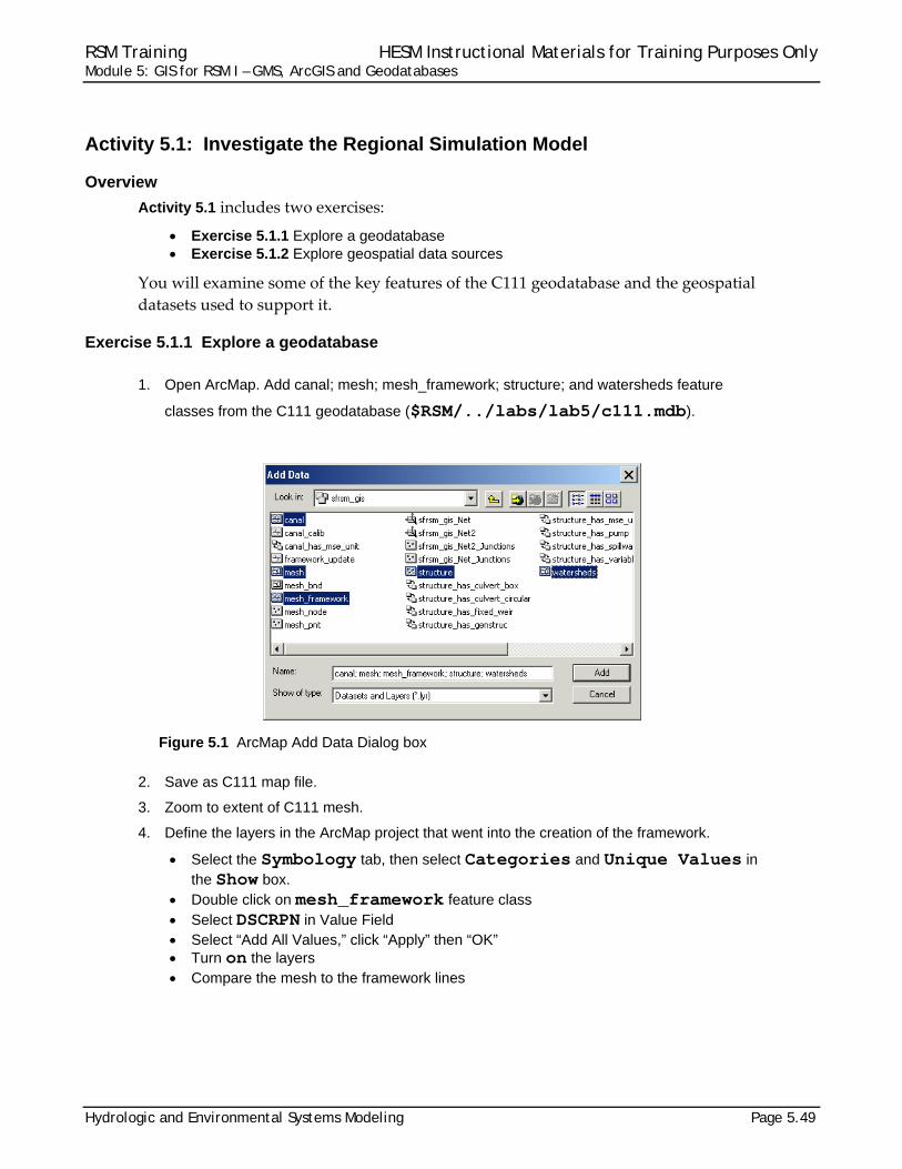
1. Open ArcMap. Add canal; mesh; mesh_framework; structure; and watersheds feature
classes from the C111 geodatabase ($RSM/../labs/lab5/c111.mdb).
Figure 5.1 ArcMap Add Data Dialog box
2. Save as C111 map file.
3. Zoom to extent of C111 mesh.
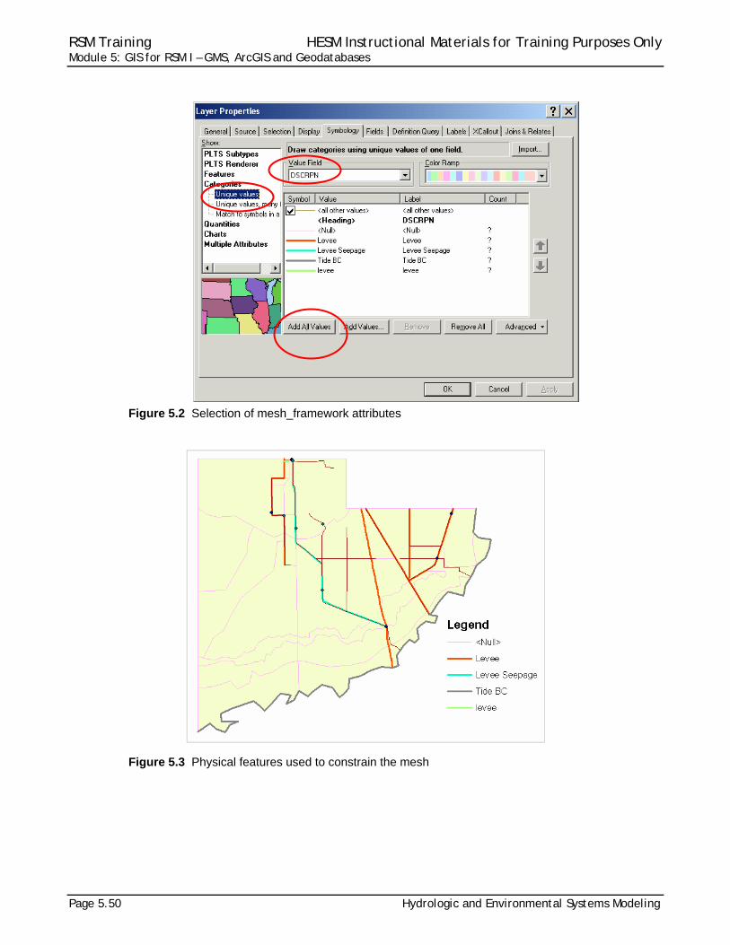
4. Define the layers in the ArcMap project that went into the creation of the framework.
Select the Symbology tab, then select Categories and Unique Values in the Show box.
Double click on mesh_framework feature class Select DSCRPN in Value Field Select “Add All Values,” click “Apply” then “OK” Turn on the layers Compare the mesh to the framework lines
RSM Training HESM Instructional Materials for Training Purposes Only Module 5: GIS for RSM I – GMS, ArcGIS and Geodatabases
Page 5.50 Hydrologic and Environmental Systems Modeling
Figure 5.2 Selection of mesh_framework attributes
Figure 5.3 Physical features used to constrain the mesh
RSM Training HESM Instructional Materials for Training Purposes Only Module 5: GIS for RSM I – GMS, ArcGIS and Geodatabases
Hydrologic and Environmental Systems Modeling Page 5.51
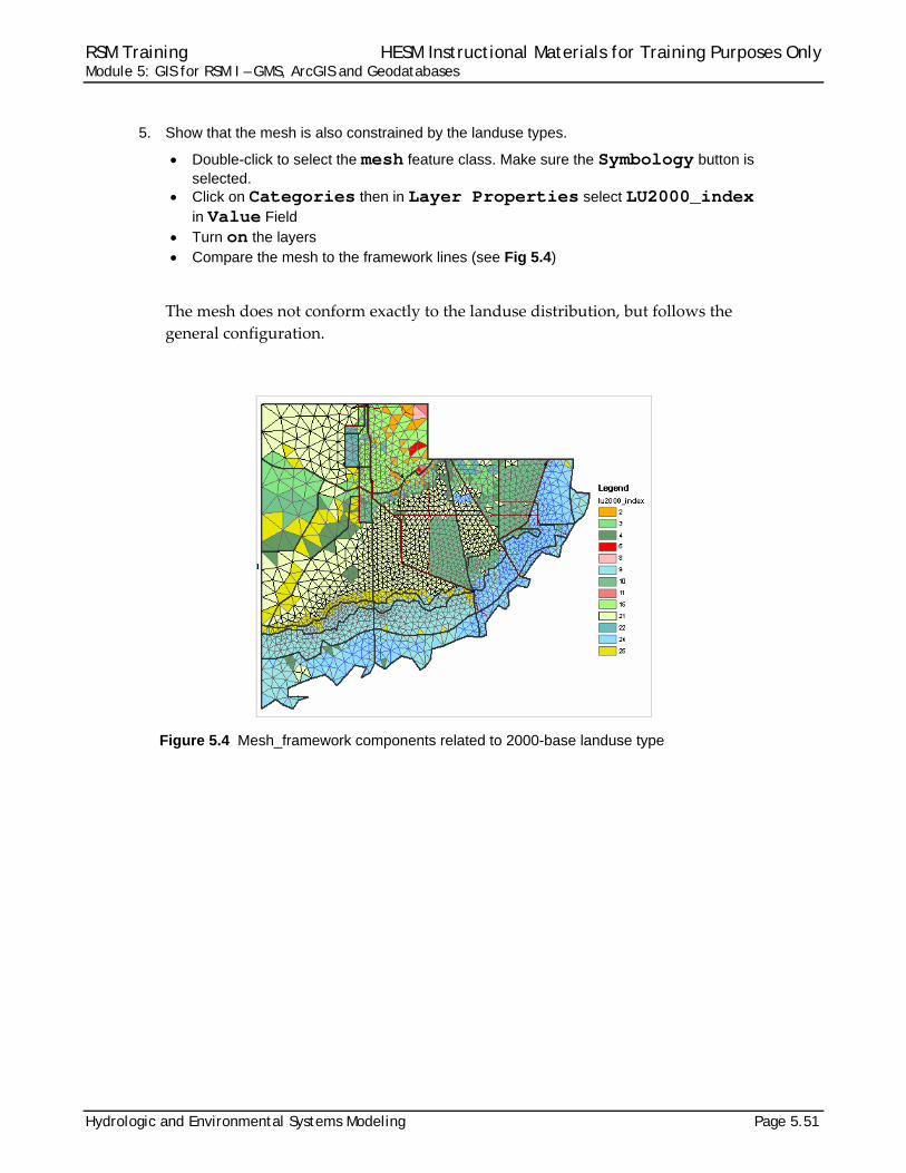
5. Show that the mesh is also constrained by the landuse types.
Double-click to select the mesh feature class. Make sure the Symbology button is selected.
Click on Categories then in Layer Properties select LU2000_index in Value Field
Turn on the layers Compare the mesh to the framework lines (see Fig 5.4)
The mesh does not conform exactly to the landuse distribution, but follows the
general configuration.
Figure 5.4 Mesh_framework components related to 2000-base landuse type

RSM Training HESM Instructional Materials for Training Purposes Only Module 5: GIS for RSM I – GMS, ArcGIS and Geodatabases
Page 5.52 Hydrologic and Environmental Systems Modeling
6. Identify structure properties of S18C from the C111 project.
Select and display the mesh, canals and structures
Figure 5.5. Mesh, canals and structures for the C111 project.
RSM Training HESM Instructional Materials for Training Purposes Only Module 5: GIS for RSM I – GMS, ArcGIS and Geodatabases
Hydrologic and Environmental Systems Modeling Page 5.53
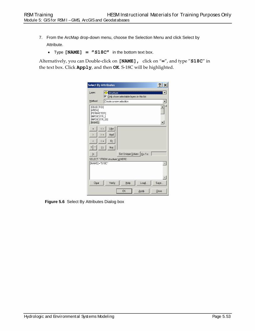
7. From the ArcMap drop-down menu, choose the Selection Menu and click Select by
Attribute.
Type [NAME] = ”S18C” in the bottom text box.
Alternatively, you can Double‐click on [NAME], click on “=”, and type ”S18C” in the text box. Click Apply, and then OK. S‐18C will be highlighted.
Figure 5.6 Select By Attributes Dialog box
RSM Training HESM Instructional Materials for Training Purposes Only Module 5: GIS for RSM I – GMS, ArcGIS and Geodatabases
Page 5.54 Hydrologic and Environmental Systems Modeling
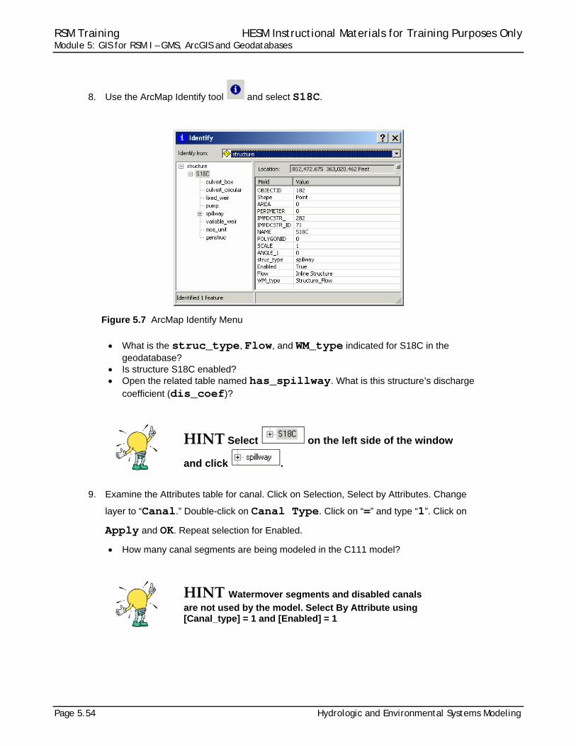
8. Use the ArcMap Identify tool and select S18C.
Figure 5.7 ArcMap Identify Menu
What is the struc_type, Flow, and WM_type indicated for S18C in the
geodatabase? Is structure S18C enabled? Open the related table named has_spillway. What is this structure’s discharge
coefficient (dis_coef)?
HINT Select on the left side of the window
and click .
9. Examine the Attributes table for canal. Click on Selection, Select by Attributes. Change
layer to “Canal.” Double-click on Canal Type. Click on “=” and type “1”. Click on
Apply and OK. Repeat selection for Enabled.
How many canal segments are being modeled in the C111 model?
HINT Watermover segments and disabled canals
are not used by the model. Select By Attribute using [Canal_type] = 1 and [Enabled] = 1
RSM Training HESM Instructional Materials for Training Purposes Only Module 5: GIS for RSM I – GMS, ArcGIS and Geodatabases
Hydrologic and Environmental Systems Modeling Page 5.55
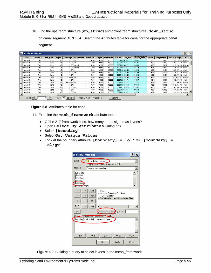
10. Find the upstream structure (up_struc) and downstream structures (down_struc)
on canal segment 309514. Search the Attributes table for canal for the appropriate canal
segment.
Figure 5.8 Attributes table for canal
11. Examine the mesh_framework attribute table.
Of the 217 framework lines, how many are assigned as levees? Open Select By Attributes Dialog box Select [boundary] Select Get Unique Values Look at the boundary attribute: [boundary] = 'ol' OR [boundary] =
'ol/gw'
Figure 5.9 Building a query to select levees in the mesh_framework
RSM Training HESM Instructional Materials for Training Purposes Only Module 5: GIS for RSM I – GMS, ArcGIS and Geodatabases
Page 5.56 Hydrologic and Environmental Systems Modeling
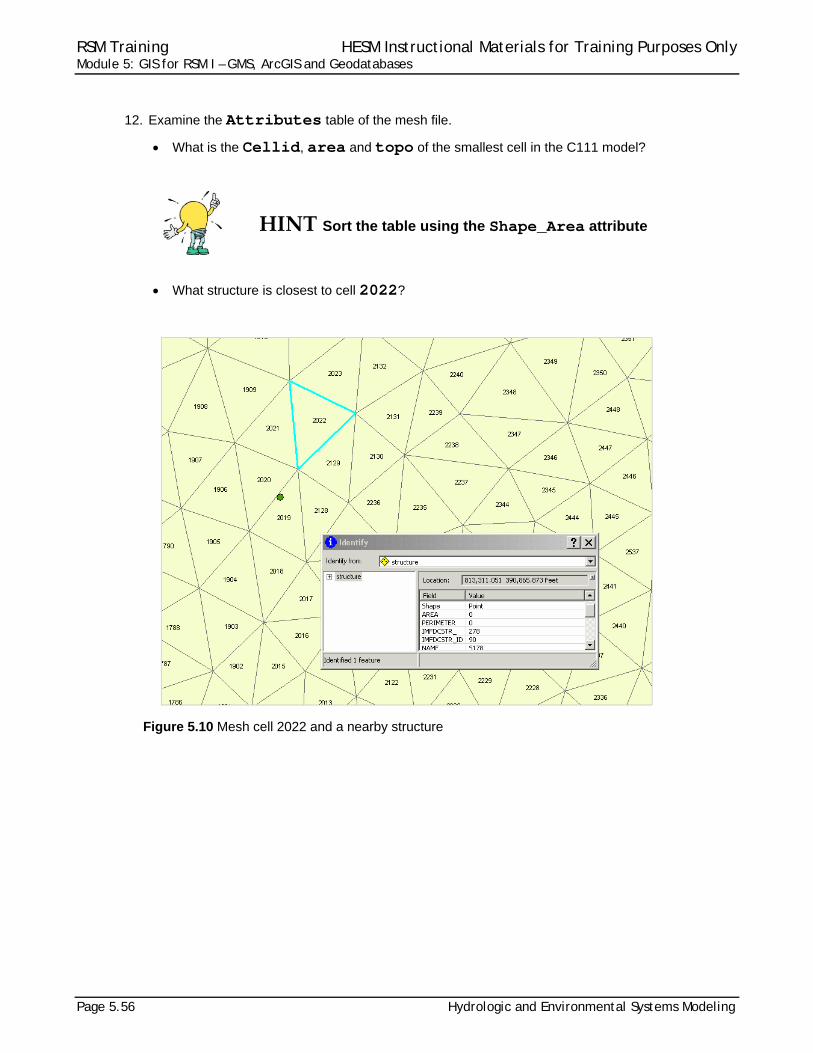
12. Examine the Attributes table of the mesh file.
What is the Cellid, area and topo of the smallest cell in the C111 model?
HINT Sort the table using the Shape_Area attribute
What structure is closest to cell 2022?
Figure 5.10 Mesh cell 2022 and a nearby structure
RSM Training HESM Instructional Materials for Training Purposes Only Module 5: GIS for RSM I – GMS, ArcGIS and Geodatabases
Hydrologic and Environmental Systems Modeling Page 5.57
Exercise 5.1.2 Explore geospatial data sources
The South Florida Water Management District has developed several geospatial
datasets to support the Regional Simulation Model. These data are used to provide
necessary attributes for RSM implementations. It is important to explore these datasets
to understand their content.
13. Open ArcMap
14. Open the SFRSM geodatabase:
$RSM/../sfrsm_geodata/sfrsm_geodata.mxd
15. Save the map in the labs/lab5 directory.
16. Add the Public Water Supply wells (PWS) to the map.
$RSM/../data/geographic/pws/pws_CalibVerif_v2
17. Add topographic data to the map:
$RSM/../data/geographic/topography/rsm_topo_v2
18. Add 1995 and 1988 land use/land cover data to the map:
$RSM/../data/geographic/landuse/lu95c $RSM/../data/geographic/landuse/RSM_Landuse.mdb/lu1988_v1
The values for the SFWMM landuse codes are available in a crosswalk table
(supercodes_4-digit_1988_1999_SFWMM.xls). The conversion table for the landuse codes used in the RSM are provided in RSMLU.doc. Both files are available in the labs/lab5 directory.
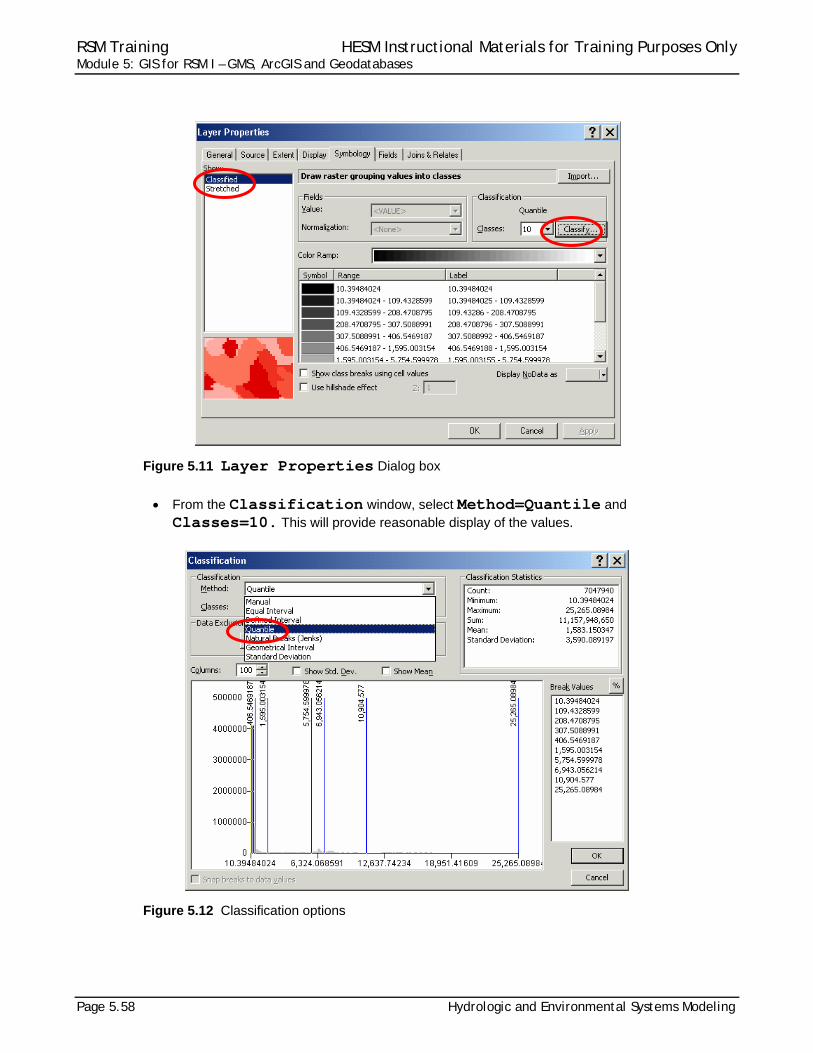
19. Add hydraulic conductivity data to the map:
$RSM/../data/geographic/geology/hyd_con_v2
What is the range in values? Modify the hydraulic conductivity dataset to provide additional visual
information. Highlight the hyd_con_v2 feature class and double click. From the Symbology tab, select Classified.
RSM Training HESM Instructional Materials for Training Purposes Only Module 5: GIS for RSM I – GMS, ArcGIS and Geodatabases
Page 5.58 Hydrologic and Environmental Systems Modeling
Figure 5.11 Layer Properties Dialog box
From the Classification window, select Method=Quantile and
Classes=10. This will provide reasonable display of the values.
Figure 5.12 Classification options
RSM Training HESM Instructional Materials for Training Purposes Only Module 5: GIS for RSM I – GMS, ArcGIS and Geodatabases
Hydrologic and Environmental Systems Modeling Page 5.59
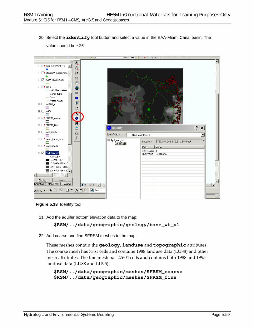
20. Select the identify tool button and select a value in the EAA-Miami Canal basin. The
value should be ~26
Figure 5.13 Identify tool
21. Add the aquifer bottom elevation data to the map:
$RSM/../data/geographic/geology/base_wt_v1
22. Add coarse and fine SFRSM meshes to the map.
These meshes contain the geology, landuse and topographic attributes. The coarse mesh has 7351 cells and contains 1988 landuse data (LU88) and other
mesh attributes. The fine mesh has 27604 cells and contains both 1988 and 1995
landuse data (LU88 and LU95).
$RSM/../data/geographic/meshes/SFRSM_coarse $RSM/../data/geographic/meshes/SFRSM_fine
RSM Training HESM Instructional Materials for Training Purposes Only Module 5: GIS for RSM I – GMS, ArcGIS and Geodatabases
Page 5.60 Hydrologic and Environmental Systems Modeling
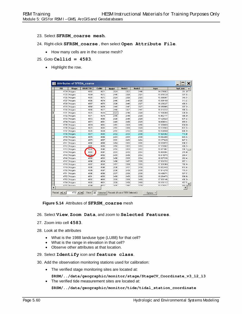
23. Select SFRSM_coarse mesh.
24. Right-click SFRSM_coarse , then select Open Attribute File.
How many cells are in the coarse mesh?
25. Goto Cellid = 4583.
Highlight the row.
Figure 5.14 Attributes of SFRSM_coarse mesh
26. Select View, Zoom Data, and zoom to Selected Features.
27. Zoom into cell 4583.
28. Look at the attributes
What is the 1988 landuse type (LU88) for that cell? What is the range in elevation in that cell? Observe other attributes at that location.
29. Select Identify icon and feature class.
30. Add the observation monitoring stations used for calibration:
The verified stage monitoring sites are located at:
$RSM/../data/geographic/monitor/stage/StageCV_Coordinate_v3_12_13 The verified tide measurement sites are located at:
$RSM/../data/geographic/monitor/tide/tidal_station_coordinate
RSM Training HESM Instructional Materials for Training Purposes Only Module 5: GIS for RSM I – GMS, ArcGIS and Geodatabases
Hydrologic and Environmental Systems Modeling Page 5.61
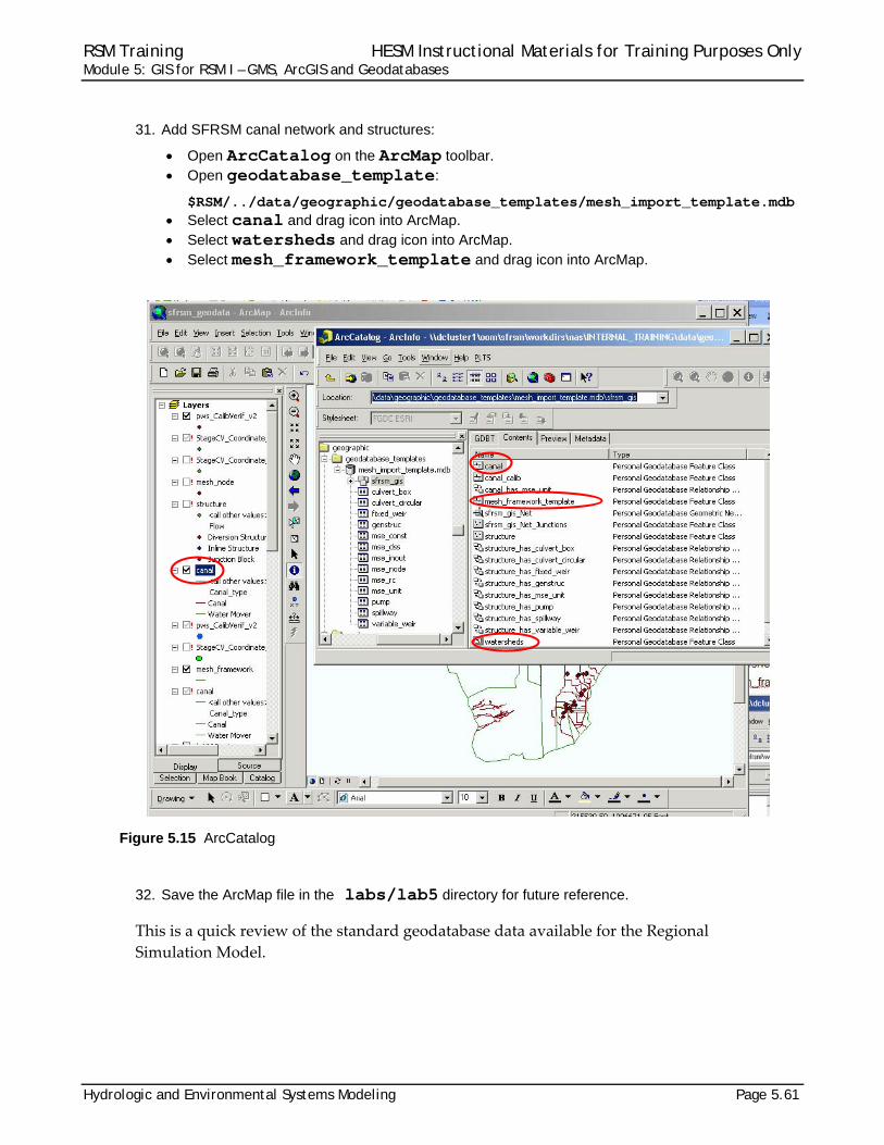
31. Add SFRSM canal network and structures:
Open ArcCatalog on the ArcMap toolbar. Open geodatabase_template:
$RSM/../data/geographic/geodatabase_templates/mesh_import_template.mdb Select canal and drag icon into ArcMap. Select watersheds and drag icon into ArcMap. Select mesh_framework_template and drag icon into ArcMap.
Figure 5.15 ArcCatalog
32. Save the ArcMap file in the labs/lab5 directory for future reference.
This is a quick review of the standard geodatabase data available for the Regional
Simulation Model.

RSM Training HESM Instructional Materials for Training Purposes Only Module 5: GIS for RSM I – GMS, ArcGIS and Geodatabases
Page 5.62 Hydrologic and Environmental Systems Modeling

RSM Training HESM Instructional Materials for Training Purposes Only Module 5: GIS for RSM I – GMS, ArcGIS and Geodatabases
Hydrologic and Environmental Systems Modeling Page 5.63
Answers for Lab 5
Exercise 5.1.1 8. struc_type = Spillway
Flow = Inline Structure
WM_type = Structure_flow
Structure S18C enabled/disabled = True (Enabled) + 5 watermover segments
Discharge coefficient = 2912
9. # canal segments = 88
11. # framework lines assigned as levees = 32
12. Cellid of smallest cell = 1947
area of smallest cell = 162618.630842
topo of smallest cell = 1.058204
closest structure to cell 2022 = 5178
Exercise 5.1.2 7. Range in hydraulic conductivity values = 10.3948 – 25,265.1
12. # cells in the coarse mesh = 7351
16. Land use type in 1988 for cell 4583 = 6
Range in elevation in cell 4583 = 16.1‐19.0 ft

RSM Training HESM Instructional Materials for Training Purposes Only Module 5: GIS for RSM I – GMS, ArcGIS and Geodatabases
Page 5.64 Hydrologic and Environmental Systems Modeling
RSM Training HESM Instructional Materials for Training Purposes Only Module 5: GIS for RSM I – GMS, ArcGIS and Geodatabases
Hydrologic and Environmental Systems Modeling Page 5.65
Index aquifer .................................................... 59 ArcCatalog ...................... 12, 13, 39, 45, 61 ArcGIS .......... 1, 3, 9, 10, 12, 20, 21, 24, 47 ArcMap .. 10, 11, 13, 21, 22, 24, 49, 53, 54,
57, 61 Identify tool .......................................... 54 toolbar ................................................. 61
attribute ... 4, 10, 15, 16, 17, 18, 20, 21, 28, 29, 31, 32, 33, 36, 38, 43, 46, 47, 53, 54, 55, 56, 57, 59, 60
attribute table .................. 16, 17, 28, 33, 47 BBCW, see also Biscayne Bay Coastal
Wetlands ............................................. 48 benchmark .............................................. 48 bias ........................................................... 4 C111 model .............. 35, 48, 49, 52, 54, 56 calibration ............................................... 60 canal ....... 30, 31, 33, 34, 41, 42, 46, 52, 54
network ............................. 33, 41, 46, 61 reach ................................................... 30 segment .......... 21, 26, 28, 30, 54, 55, 63
canal, see also WCD 21, 26, 27, 28, 30, 31, 33, 35, 36, 40, 41, 46, 49, 54, 55, 61, 63
cell connectivity ........................................... 9 ID ............................................ 56, 60, 63
cell, see also mesh 8, 9, 33, 46, 56, 59, 60, 63
coarse mesh ............................... 59, 60, 63 coefficient ............................................... 63 control ........................................... 8, 31, 46 coverage ................................................. 22 Coverage Setup ........................................ 5 datasets ................................ 12, 32, 46, 57 direction of flow ....................................... 41 discharge coefficient (dis_coef) .............. 54 distribution .................................. 34, 46, 51 downstream structures ..................... 36, 55 DSCRPN ................................................ 49 EAA ........................................................ 59 EAA-MC basin ........................................ 59 Editor toolbar .................................... 21, 22 environment variable .............................. 48 error ............................................ 32, 43, 46 ESRI ................................................... 1, 32
feature class . 13, 21, 24, 25, 33, 38, 46, 47, 49, 60 hydraulic conductivity .......................... 57
file format ASCII .............................................. 8, 46
fine mesh ................................................ 59 flood ....................................................... 20 flow ............................................. 41, 54, 63 framework .... 6, 7, 8, 26, 42, 43, 46, 49, 51,
55, 63 lines ............................. 26, 49, 51, 55, 63
geodatabase .. 1, 12, 13, 23, 24, 29, 32, 36, 37, 41, 43, 45, 46, 47, 49, 54, 61
geodatabase_template ........................... 61 geographic data ..................................... 47 geology ............................................. 57, 59 geospatial datasets .......................... 49, 57 GMS .......................... 1, 2, 3, 4, 5, 9, 45, 46 gw, see groundwater .............................. 55 has_spillways ......................................... 54 HINT ................................................. 54, 56 how to
create the parameters for RSM XML input files ......................................... 47
diagnose problems with an RSM implementation ................................ 47
observe the spatial distribution of model features ........................................... 47
open an attribute file ........................... 60 HPM ....................................................... 48
water budget ....................................... 48 hyd_con_v2 ............................................ 57 hydraulic conductivity ....................... 57, 63 inline structures ...................................... 31 input data
aquifer bottom elevation ..................... 59 mesh ............................................. 45, 56
input files ........................... 3, 32, 41, 43, 46 .2DM file ............................................... 4 map file ............................................... 49
landscape ............................................... 34 landuse ...................... 48, 51, 57, 59, 60, 63
codes .................................................. 57 LU88 ............................................. 59, 60 LU95 ................................................... 59 types ................................................... 51
RSM Training HESM Instructional Materials for Training Purposes Only Module 5: GIS for RSM I – GMS, ArcGIS and Geodatabases
Page 5.66 Hydrologic and Environmental Systems Modeling
Layer ................................................ 51, 58 Layer Properties ............................... 51, 58 levee ......................... 30, 35, 36, 46, 55, 63 LU2000_index ........................................ 51 make, see makefile ........................... 19, 24 mesh .... 1, 3, 4, 5, 6, 7, 8, 9, 33, 36, 37, 41,
43, 45, 46, 49, 51, 52, 55, 56, 59, 61 attributes ....................................... 37, 59 feature class, see also feature class ... 51 geometry ............................................... 8 node .................................... 4, 26, 27, 41
mesh and network .................................. 45 mesh_framework .................. 36, 49, 55, 61 mesh_framework attribute table ............. 55 Mesh_framework components related to
2000-base landuse type ...................... 51 mesh_framework_template .................... 61 metadata ................................................ 12 Method=Quantile .................................... 58 model input, see input data .................... 46 Modify Feature ........................................ 26 monitor ................................................... 60 network ....................................... 42, 45, 46 note .............................................. 2, 30, 48 observation monitoring stations .............. 60 output data ............................................. 41 Physical features used to constrain the
mesh ................................................... 50 pre-processing tools ............................... 46 pump, see also watermover.................... 33 pws ......................................................... 57 rainfall ..................................................... 48 Regional Simulation Model, see also RSM
................................ 1, 43, 47, 49, 57, 61 RSM
geodatabase 9, 11, 12, 38, 39, 43, 45, 46 implementation .................. 32, 43, 46, 57
RSM GUI .................................................. 2 GIS ToolBar ... 1, 2, 3, 10, 12, 31, 32, 41,
43 toolbar ................................................. 46
RSM, see also Regional Simulation Model ... 1, 2, 3, 8, 9, 10, 11, 12, 13, 15, 24, 25,
30, 31, 32, 33, 35, 38, 39, 41, 43, 45, 46, 47, 48, 49, 57, 59, 60, 61
segment, see also waterbody segment ........... 27, 30, 31, 46, 54, 55, 63
Select by Attribute ............................ 53, 54 Select by Attributes ................................ 54 Selected Features .................................. 60 Selection of mesh_framework attributes 50 setenv ..................................................... 48 SFRSM ............................ 30, 57, 59, 60, 61
geodatabase ................................. 30, 57 mesh ............................................. 59, 60
SFWMM ........................................... 48, 57 shape file ............................................ 6, 46 Shape_Area attribute ............................. 56 stage ................................................ 30, 60 standard geodatabase ...................... 43, 61 standard geodatabase data .................... 61 Start Editing ............................................ 22 Stop Editing ............................................ 22 struc_type ......................................... 54, 63 structure . 16, 21, 30, 31, 33, 34, 35, 36, 37,
40, 42, 46, 49, 52, 54, 56, 61, 63 properties ............................................ 52 S18C .................................. 52, 53, 54, 63
subregional models ................................ 43 template ..................................... 43, 46, 61 topo, see topography .................. 56, 57, 63 topography ....................................... 57, 59 upstream structure ................................. 55 USACE ................................................... 46 utilities .................................................... 43 verified stage monitoring sites ................ 60 verified tide measurement sites .............. 60 vertices ......................................... 8, 27, 46 water supply ........................................... 57 waterbody ............................................... 30 watermover ........................... 30, 31, 54, 63
type ............................................... 54, 63 watershed ......................................... 49, 61 weir ......................................................... 33 well ............................................. 21, 33, 57 Zoom Data ............................................. 60