Embed Size (px)
Citation preview

Installation • Operation • Care
Skyline® Gliding Window Panels
Manual Control Systems

CONTENTS
Questions?Call the Hunter Douglas Customer Information Center at
1-888-501-8364.
© 2013 Hunter Douglas. All rights reserved. All trademarks used herein are the property of Hunter Douglas.
Getting Started:Mounting Types and Window Terminology ...............................................................1
Unpack the Box .....................................................................................................1
Installation Components Required ........................................................................2
Optional Components ............................................................................................4
Tools and Fasteners Needed .................................................................................5
Product View — Skyline® Gliding Window Panels ...................................................6
Product View — Top Treatment Options .................................................................7
Installation:Inside and Ceiling Mount Applications .....................................................................8
Outside Mount Applications .................................................................................16
Metal Box Valance Installation ..............................................................................17
Fabric-Wrapped Large Cassette Installation
(Inside and Outside Mounts) ................................................................................21
Mount the Headrail ..............................................................................................23
Outside Mount Valance Installation (Optional) ........................................................26
Attach the Universal Cord Tensioner (Cord Loop Units Only) ..................................29
Fabric Panel Installation .......................................................................................30
Connect the Bottom Weights ................................................................................39
Install the Room Divider Kit (Optional) ...................................................................40
Operation:Operate the Panels..............................................................................................43
Adjustments .......................................................................................................44
Troubleshooting ..................................................................................................51
Care:Removal Procedures ...........................................................................................53
Cleaning Procedures ...........................................................................................56
Child Safety:Warning .............................................................................................................57
Cord Loop Panels ................................................................................................57

GETTING STARTED
1
Thank you for purchasing Hunter Douglas Skyline® Gliding Window Panels. With proper
installation, operation, and care, your new unit will provide years of beauty and performance.
Please thoroughly review this instruction booklet and enclosed packing list before beginning the
installation.
Mounting Types and Window Terminology
If the installation brackets are mounted correctly, the rest of the installation process fl ows easily.
To prepare for this important fi rst step, review the mounting types and basic window terminology
illustrated below.
Unpack the Box
■ Carefully remove the rolled up fabric panels and set aside. Locate the panels marked
“FRONT — INSTALL LAST” and “REAR — INSTALL FIRST.” Set them aside, separated
from the other panels. Do not unroll the panels until installation. Carefully remove the
headrail and optional valance from the packaging. Keep all packaging until the unit
operates to your satisfaction.
■ Save these instructions for care and cleaning, panel removal, unit removal, and
reinstallation procedures.
■ Check the Product Views on pages 6 and 7 to make sure you have all of the necessary
parts. Contents of the hardware package may vary depending upon how the unit was
ordered and how it will be mounted.
Outside Mount
Shade is mounted outsidewindow opening.
Inside Mount
Shade fits withinwindow opening.
Collectively, the sill andjambs are called the“window casement.”
Molding
Head Jamb
Sill
Jamb Jamb

2
GETTING STARTED
Installation Components Required
■ Installation Brackets. This style of installation bracket
is used for outside mounts. The number of installation
brackets required varies based on headrail width, as
shown in the table above.
■ Mounting Clips. This style of mounting clip is used for inside
mounts. The number of mounting clips required varies based
on headrail width, as shown in the table above.
■ Splice Clip. A splice clip allows a long headrail to be split
in half during shipping, and reconnected during installation.
Once installed, a spliced headrail functions seamlessly as if it
were one piece.
■ Valance Splice Clip. A splice clip allows a long valance to be
split in half during shipping, and reconnected during installation.
Once installed, a spliced valance functions seamlessly as if it were
one piece.
Valance and Headrail Installation Brackets
Width Brackets/Clips Required
28" – 32" 2
32 1/8" – 56" 3
56 1/8" – 80" 4
80 1/8" – 104" 5
104 1/8" – 128" 6
128 1/8" – 152" 7
152 1/8" – 176" 8
176 1/8" – 200" 9
Installation Bracket
MountingClip
SpliceClip
Valance Splice Clip

GETTING STARTED
3
■ Fabric-Wrapped Large Cassette Installation Bracket.
This style of installation bracket is used for Skyline® units ordered
with the fabric-wrapped large cassette. The brackets are used in
both inside and outside mount applications. The number of
installation brackets required varies based on headrail width, as
shown in the table below.
■ Fabric-Wrapped Large Cassette Splice Clip. This component is only
provided with Skyline units ordered specifi cally with a spliced headrail.
This clip joins two pieces of the cassette together. Once installed, a
spliced cassette functions seamlessly as if it were one piece. If you
have not ordered the Skyline unit with a spliced cassette, you will not
receive this component.
■ Fabric-Wrapped Large Cassette Splice Cover. This is the decorative
trim cover over the fabric seam in a spliced fabric-wrapped large
cassette. It will also be used when the fabric is seamed. The fabric
seaming is sometimes necessary to obtain the full width of the
cassette. In this case, the splice cover will be installed by the
fabricator. If you have not ordered the Skyline unit with a fabric-
wrapped large cassette, you will not receive this component.
■ Universal Cord Tensioner (UCT). The UCT functions as a safety
device that makes the cords less accessible to children and
pets for those units with a cord control. The cord control will
not function properly without the UCT installed correctly.
Fabric-WrappedLarge Cassette
Installation Bracket
Cassette Installation Brackets Required
Shade Width Brackets Required
Up to 36" 2
361/8" – 72" 3
721/8" – 90" 4
901/8" – 120" 5
1201/8" – 156" 6
1561/8" – 192" 8
Fabric-WrappedLarge Cassette
Splice Clip
Fabric-WrappedLarge CassetteSplice Cover
Universal Cord Tensioner

4
GETTING STARTED
Optional Components
■ Valance Brackets Inside Mount. The number of valance
brackets will be the same as the number of installation brackets
shown in the table on page 2.
■ Valance Brackets Outside Mount. The number of valance
brackets will be the same as the number of installation brackets
shown in the table on page 2.
■ Box Valance Brackets. A box valance wraps around the
entire headrail. The number of valance brackets will be the same
as the number of installation brackets shown in the table on
page 2.
■ Fabric Valance Installation Brackets. The number of
fabric installation brackets will be the same as the number
of installation brackets shown in the table on page 2. These
brackets are only used for outside mounts.
■ Room Divider Kit. This set of parts holds the
panels in place at each end of a Skyline® unit used as
a room divider.
Valance BracketsInside Mount
Valance BracketOutside Mount
Box ValanceBracket
Fabric ValanceMounting Bracket
Room Divider Kit

GETTING STARTED
5
Tools and Fasteners Needed
■ Flat blade and Phillips screwdriver
■ Level (laser level is recommended)
■ Measuring tape and pencil
■ Needle nose pliers
■ Power drill and drill bits (1∕4" hex
driver also recommended)
In addition, you will need fasteners designed to work with your specifi c mounting surface(s).
■ #6 Hex Head Screws (Provided). Two 11∕2" screws are provided per installation bracket.
■ Longer #6 Hex Head Screws (Not Provided). If using spacer blocks, use #6 screws
long enough for a secure attachment.
#6 x 1½"Hex Head Screw
(Provided)
Longer #6 Hex Head Screw For Use With Spacer Blocks
(Not Provided)
6
GETTING STARTED
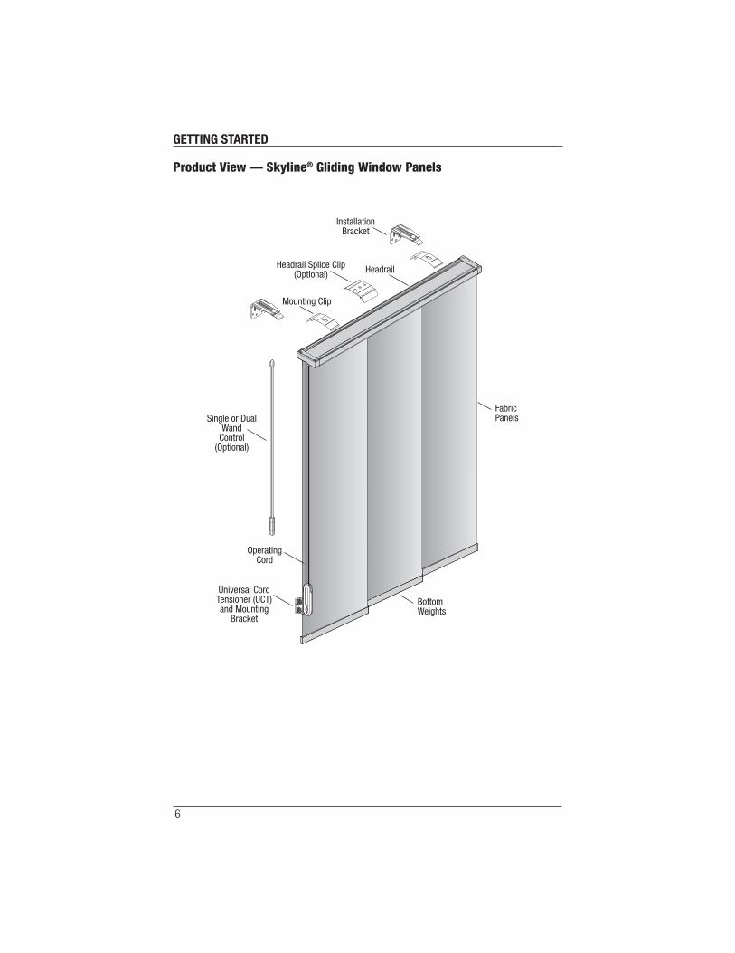
Product View — Skyline® Gliding Window Panels
FabricPanels
BottomWeights
InstallationBracket
Mounting Clip
OperatingCord
Headrail
Universal CordTensioner (UCT)and Mounting
Bracket
Single or DualWand
Control(Optional)
Headrail Splice Clip(Optional)
GETTING STARTED
7
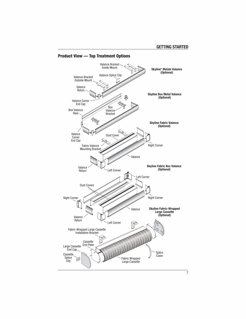
Product View — Top Treatment Options
ValanceReturn
Valance BracketOutside Mount
Valance CornerEnd Cap
ValanceCorner
End Cap
BoxValanceBracket
Box ValanceRear
Valance BracketInside Mount
Skyline Box Metal Valance(Optional)
Skyline Fabric-WrappedLarge Cassette
(Optional)
Skyline® Metals Valance(Optional)
Skyline Fabric Valance(Optional)
Skyline Fabric Box Valance(Optional)
Valance Splice Clip
Fabric ValanceMounting Bracket
Dust Cover
Valance
ValanceReturn
Dust Covers
Right Corner
Left Corner
Left Corner
Right Corner
Large CassetteEnd Cap
CassetteEnd Plate
Fabric-Wrapped Large CassetteInstallation Bracket
Fabric WrappedLarge Cassette
CassetteSpliceClip
SpliceCover
Valance
ValanceReturn Left Corner
Right Corner

INSTALLATION
8
Inside and Ceiling Mount Applications
For panel order without a valance continue below. If you ordered a valance, see “Inside and
Ceiling Mount Applications WITH A Valance” on page 9.
Inside and Ceiling Mount Applications WITHOUT a Valance
■ Mark the mounting clip locations on the ceiling or inside the window casement. Use the
fi gure below as a guide for locating the mounting clips.
■ Use a 3∕32" drill bit to drill holes for the screws.
CAUTION: Do not mount into drywall, only mount into wood.
■ Use a level to check that the mounting surface is level. Shim the brackets if necessary.
Shims are not provided.
■ Ensure the mounting clips are all facing
the same direction.
➤ Standard Mount — The release
tabs are toward to the window.
➤ Flush Mount — The release tabs
are toward the room to allow for a
fl ush mounting.
IMPORTANT: The mounting tabs
will be visible on a fl ush mount unless
concealed by a valance.
■ Use the hex head screws provided
to fasten the mounting clips to the
mounting surface.
■ Verify that the mounting clips are
mounted level and are aligned to
each other.
Proceed to “Mount the Headrail” on page 23.
2"-4" 18"-24" 2"-4"18"-24" 18"-24"Jamb Jamb
Flush Mount Option
Inside Mount (Standard)
Release TabToward Wall
Release TabToward RoomFor Closest
Wall Clearance
Ceiling/Top Sill
RoomWall
INSTALLATION
9
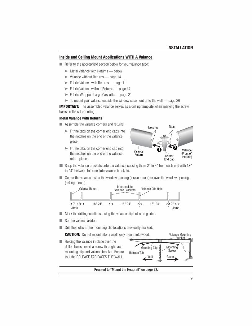
Inside and Ceiling Mount Applications WITH A Valance
■ Refer to the appropriate section below for your valance type:
➤ Metal Valance with Returns — below
➤ Valance without Returns — page 14
➤ Fabric Valance with Returns — page 11
➤ Fabric Valance without Returns — page 14
➤ Fabric-Wrapped Large Cassette — page 21
➤ To mount your valance outside the window casement or to the wall — page 26
IMPORTANT: The assembled valance serves as a drilling template when marking the screw
holes on the sill or ceiling.
Metal Valance with Returns
■ Assemble the valance corners and returns.
➤ Fit the tabs on the corner end caps into
the notches on the end of the valance
piece.
➤ Fit the tabs on the corner end cap into
the notches on the end of the valance
return pieces.
■ Snap the valance brackets onto the valance, spacing them 2" to 4" from each end with 18"
to 24" between intermediate valance brackets.
■ Center the valance inside the window opening (inside mount) or over the window opening
(ceiling mount).
■ Mark the drilling locations, using the valance clip holes as guides.
■ Set the valance aside.
■ Drill the holes at the mounting clip locations previously marked.
CAUTION: Do not mount into drywall, only mount into wood.
■ Holding the valance in place over the
drilled holes, insert a screw through each
mounting clip and valance bracket. Ensure
that the RELEASE TAB FACES THE WALL.
Proceed to “Mount the Headrail” on page 23.
Valance(Front of the Unit)
Tabs
ValanceReturn Corner
End Cap
Notches
12
IntermediateValance Brackets Valance Clip Hole
2"-4" 18"-24" 2"-4"18"-24" 18"-24"
Valance Return
JambJamb
RoomWall
Valance MountingBracket
Mounting Clip MountingScrew
Release Tab

INSTALLATION
10
Metal Valance without Returns
■ Snap the valance brackets onto the valance, spacing them 2" to 4" from each end with 18"
to 24" between intermediate valance brackets.
■ Center the valance inside the window opening (inside mount) or over the window opening
(ceiling mount).
■ Mark the drilling locations, using the valance clip holes as guides.
■ Set the valance aside.
■ Drill the holes at the mounting clip locations previously marked.
CAUTION: Do not mount into drywall, only mount into wood.
■ Holding the valance in place over the drilled holes insert a screw through each mounting
clip and valance bracket.
Proceed to “Mount the Headrail” on page 23.
IntermediateValance Brackets Valance Clip Hole
2"-4" 18"-24" 2"-4"18"-24" 18"-24"Jamb Jamb
RoomWall
Valance MountingBracket
Mounting Clip MountingScrew
Release Tab
INSTALLATION
11
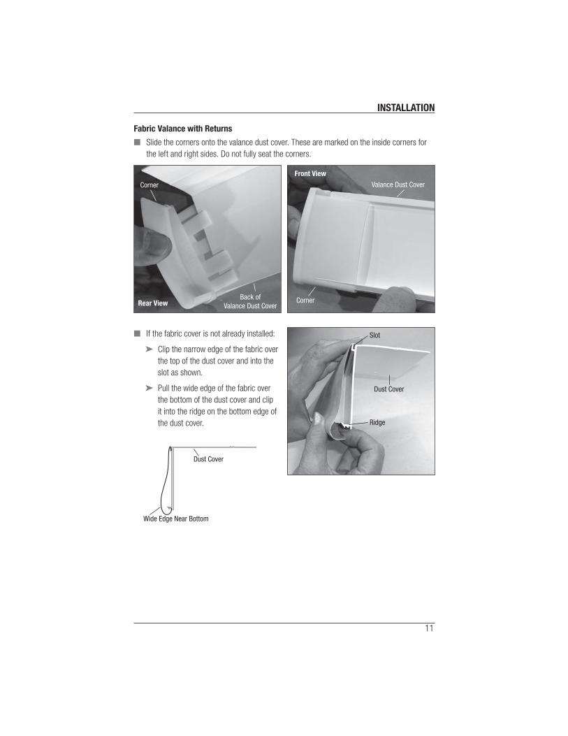
Fabric Valance with Returns
■ Slide the corners onto the valance dust cover. These are marked on the inside corners for
the left and right sides. Do not fully seat the corners.
■ If the fabric cover is not already installed:
➤ Clip the narrow edge of the fabric over
the top of the dust cover and into the
slot as shown.
➤ Pull the wide edge of the fabric over
the bottom of the dust cover and clip
it into the ridge on the bottom edge of
the dust cover.
Rear ViewBack of
Valance Dust Cover
Corner
Front View
Valance Dust Cover
Corner
Slot
Dust Cover
Ridge
Dust Cover
Wide Edge Near Bottom

INSTALLATION
12
■ Carefully push the corners fully into place
making sure that the fabric goes under the lip
of the corners.
■ Put the return fabric covers on the same
way as the main part of the fabric valance,
only slide them into place under the lip of the
corner.
■ Lay the dust cover upside down on a clean
working surface.
■ Place the mounting clips on the dust cover:
➤ The release tabs must be
facing away from the valance.
➤ The end mounting clips must
be 2" to 4" from the end of the
dust cover.
➤ Intermediate mounting
clips must be 18" to 24"
from each other or the end
mounting clips.
➤ The center line of the holes
in the mounting clips must be
1½" from the valance.
Lip
18"-24"
18"-24"
2"-4"
2"-4"
IntermediateMounting Clip
ReleaseTab
11/2"
Valance
DustCover
Note: Left ReturnRemoved for Clarity.

INSTALLATION
13
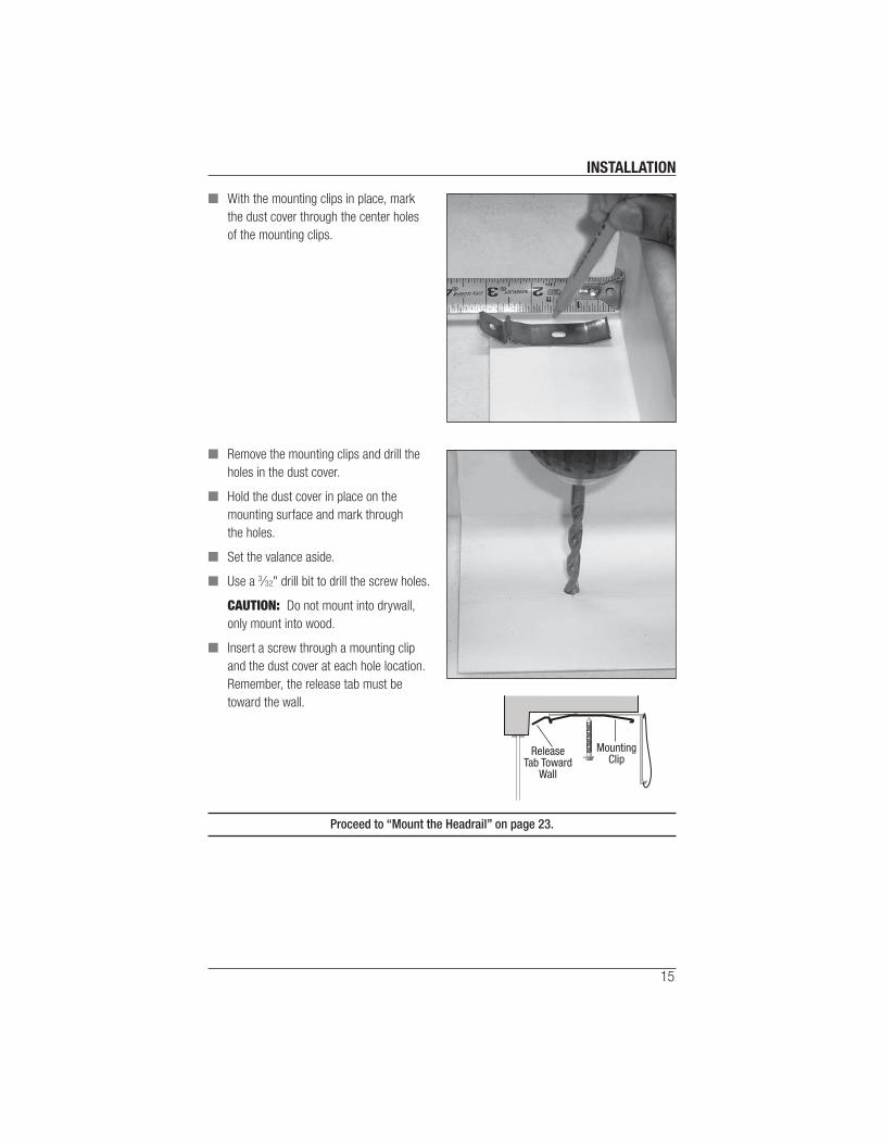
■ With the mounting clips in place, mark
the dust cover through the center holes
of the mounting clips.
■ Remove the mounting clips and drill the
holes in the dust cover.
■ Hold the dust cover in place on the
mounting surface and mark through
the holes.
■ Set the valance aside.
■ Use a 3∕32" drill bit to drill the screw holes.
CAUTION: Do not mount into drywall,
only mount into wood.
■ Hold the valance in place against the
mounting surface.
■ Insert a screw through a mounting clip
and the dust cover at each hole location.
Proceed to “Mount the Headrail” on page 23.
ReleaseTab Toward
Window
Return

INSTALLATION
14
Fabric Valance without Returns
■ If the fabric cover is not already installed:
➤ Clip the narrow edge of the fabric over
the top of the dust cover and into the
slot as shown.
➤ Pull the wide edge of the fabric over
the bottom of the dust cover and clip
it into the ridge on the bottom edge of
the dust cover.
■ Lay the dust cover upside down on a clean working surface.
■ Place the mounting clips on the dust cover:
➤ The release tabs must be facing away from the valance. (They face toward the wall.)
➤ The end mounting clips must be 2" to 4" from the end of the dust cover.
➤ Intermediate mounting clips must be 18" to 24" from each other or the end
mounting clips.
➤ The center line of the holes in the mounting clips must be 1½" from the valance.
Dust Cover
Slot
Ridge
Release Tab
11/2"
Dust Cover IntermediateValance ClipsValance
2"-4" 18"-24" 2"-4"18"-24" 18"-24"JambJamb
INSTALLATION
15
■ With the mounting clips in place, mark
the dust cover through the center holes
of the mounting clips.
■ Remove the mounting clips and drill the
holes in the dust cover.
■ Hold the dust cover in place on the
mounting surface and mark through
the holes.
■ Set the valance aside.
■ Use a 3∕32" drill bit to drill the screw holes.
CAUTION: Do not mount into drywall,
only mount into wood.
■ Insert a screw through a mounting clip
and the dust cover at each hole location.
Remember, the release tab must be
toward the wall.
Proceed to “Mount the Headrail” on page 23.
ReleaseTab Toward
Wall
MountingClip
INSTALLATION
16
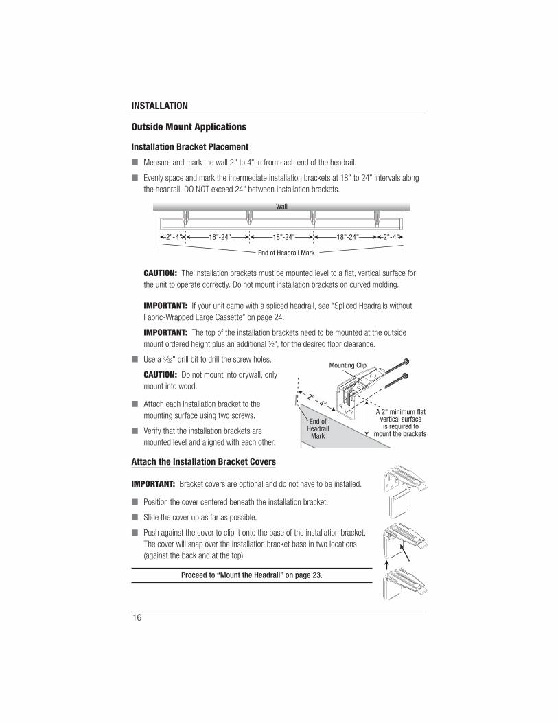
Outside Mount Applications
Installation Bracket Placement
■ Measure and mark the wall 2" to 4" in from each end of the headrail.
■ Evenly space and mark the intermediate installation brackets at 18" to 24" intervals along
the headrail. DO NOT exceed 24" between installation brackets.
CAUTION: The installation brackets must be mounted level to a fl at, vertical surface for
the unit to operate correctly. Do not mount installation brackets on curved molding.
IMPORTANT: If your unit came with a spliced headrail, see “Spliced Headrails without
Fabric-Wrapped Large Cassette” on page 24.
IMPORTANT: The top of the installation brackets need to be mounted at the outside
mount ordered height plus an additional ½", for the desired fl oor clearance.
■ Use a 3∕32" drill bit to drill the screw holes.
CAUTION: Do not mount into drywall, only
mount into wood.
■ Attach each installation bracket to the
mounting surface using two screws.
■ Verify that the installation brackets are
mounted level and aligned with each other.
Attach the Installation Bracket Covers
IMPORTANT: Bracket covers are optional and do not have to be installed.
■ Position the cover centered beneath the installation bracket.
■ Slide the cover up as far as possible.
■ Push against the cover to clip it onto the base of the installation bracket.
The cover will snap over the installation bracket base in two locations
(against the back and at the top).
Proceed to “Mount the Headrail” on page 23.
2"-4" 18"-24" 2"-4"18"-24" 18"-24"
Wall
End of Headrail Mark
Mounting Clip
A 2" minimum flatvertical surfaceis required to
mount the brackets.
2" – 4"
End ofHeadrail
Mark
INSTALLATION
17
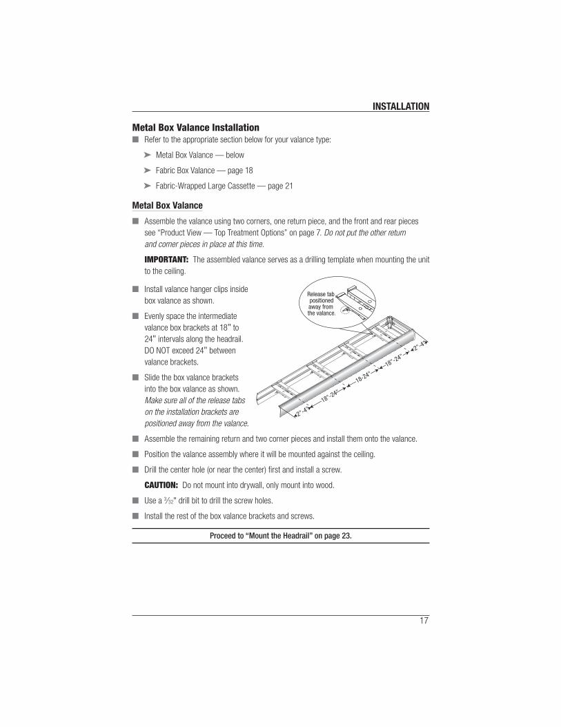
Metal Box Valance Installation ■ Refer to the appropriate section below for your valance type:
➤ Metal Box Valance — below
➤ Fabric Box Valance — page 18
➤ Fabric-Wrapped Large Cassette — page 21
Metal Box Valance
■ Assemble the valance using two corners, one return piece, and the front and rear pieces
see “Product View — Top Treatment Options” on page 7. Do not put the other return
and corner pieces in place at this time.
IMPORTANT: The assembled valance serves as a drilling template when mounting the unit
to the ceiling.
■ Install valance hanger clips inside
box valance as shown.
■ Evenly space the intermediate
valance box brackets at 18" to
24" intervals along the headrail.
DO NOT exceed 24" between
valance brackets.
■ Slide the box valance brackets
into the box valance as shown.
Make sure all of the release tabs
on the installation brackets are
positioned away from the valance.
■ Assemble the remaining return and two corner pieces and install them onto the valance.
■ Position the valance assembly where it will be mounted against the ceiling.
■ Drill the center hole (or near the center) fi rst and install a screw.
CAUTION: Do not mount into drywall, only mount into wood.
■ Use a 3∕32" drill bit to drill the screw holes.
■ Install the rest of the box valance brackets and screws.
Proceed to “Mount the Headrail” on page 23.
18"-24"
2"-4"
18-24"
18"-24"
2"-4"
Release tab positionedaway from the valance.
INSTALLATION
18
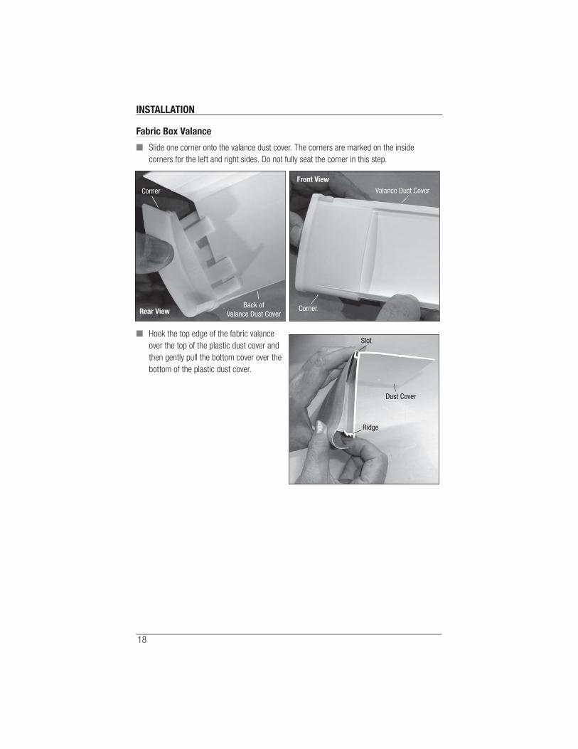
Fabric Box Valance
■ Slide one corner onto the valance dust cover. The corners are marked on the inside
corners for the left and right sides. Do not fully seat the corner in this step.
■ Hook the top edge of the fabric valance
over the top of the plastic dust cover and
then gently pull the bottom cover over the
bottom of the plastic dust cover.
Rear ViewBack of
Valance Dust Cover
Corner
Front View
Valance Dust Cover
Corner
Dust Cover
Slot
Ridge

INSTALLATION
19
■ Carefully push the corner fully into place
making sure the fabric goes under the lip of
the corner.
■ Put the return fabric cover on the same way as
the main part of the fabric valance, sliding it
into place under the lip of the corner.
■ This makes one half of the assembly. Repeat
this process for the other half.
■ Join the two halves together by carefully
inserting the fabric-covered return and valance
into their respective corners.
■ Turn the box valance assembly upside down.
IMPORTANT: On larger valances, use self-tapping #8 X 3/16" screws to hold the dust
covers together during installation.
■ Set the mounting clips in place. They are 2" to 4" from each end, and 18" to 24" between
intermediate mounting clips as shown.
■ Mark the mounting clip
attachment points (center hole
in the mounting clip). Note that:
➤ All mounting clip release
tabs must be on the same
side of the box valance
assembly.
➤ The holes in the mounting
clips are on a line 1½"
from the edge of the box
valance assembly.
➤ The mounting clips must
be in a straight line or the
headrail will not mount
correctly.
Lip
18"-24"
18"-24"
2"-4"
2"-4"
IntermediateMounting Clip
ReleaseTab
11/2"
Valance
DustCover
Note: Left Return andOther Side Removedfor Clarity.
Cloth Cover

INSTALLATION
20
■ Remove the mounting clips and drill the
holes in the dust cover.
■ Hold the box valance in place on the
mounting surface and mark through
the holes.
■ Set the box valance aside.
■ Use a 3∕32" drill bit to drill the screw holes.
CAUTION: Do not mount into drywall,
only mount into wood.
■ Holding the box valance in place, install a
mounting clip and screw. For box valances
with more than two mounting clips, start
near the center.
IMPORTANT: The release tab on all mounting clips
must face the same direction.
■ Install the rest of the mounting clips and screws.
Proceed to “Mount the Headrail” on page 23.
Release Tab
MountingClip

INSTALLATION
21
Fabric-Wrapped Large Cassette Installation (Inside and Outside Mounts)
Mount the Installation Brackets
■ Bracket spacing is the same for inside and
outside mounted panels.
■ Measure 2" in from where the ends of
the cassette will be located and mark the
bracket locations on the mounting surface.
➤ If more than two installation brackets
came with your order, make additional
marks to space the other bracket(s)
evenly between the two end brackets.
➤ The minimum mounting depth is 2¼". Fully recessed mounting depth is 4¼".
➤ Adjust bracket placement to gain clearance to avoid any obstructions, such as window
cranks or handles.
■ Center an installation bracket on each mark. Then mark where to drill holes for the screws.
IMPORTANT: The installation brackets must be mounted level to operate properly.
■ Secure bracket with two screws.
Cassette Mounting Bracket
Screw Holes for Inside/Ceiling Mount
Mounting Holes forOutside/Wall Mount
FrontMounting LipLower
Mounting Lip
Screwdriver Slot for Removal
Cassette End Marks
Window Opening
Space EvenlySpace Evenly2" 2"
2"
Outside Mount
2"
Inside Mount
2"
INSTALLATION
22
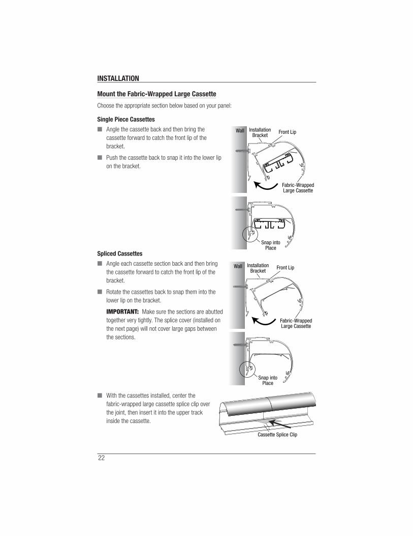
Mount the Fabric-Wrapped Large Cassette
Choose the appropriate section below based on your panel:
Single Piece Cassettes
■ Angle the cassette back and then bring the
cassette forward to catch the front lip of the
bracket.
■ Push the cassette back to snap it into the lower lip
on the bracket.
Spliced Cassettes
■ Angle each cassette section back and then bring
the cassette forward to catch the front lip of the
bracket.
■ Rotate the cassettes back to snap them into the
lower lip on the bracket.
IMPORTANT: Make sure the sections are abutted
together very tightly. The splice cover (installed on
the next page) will not cover large gaps between
the sections.
■ With the cassettes installed, center the
fabric-wrapped large cassette splice clip over
the joint, then insert it into the upper track
inside the cassette.
Front LipInstallationBracket
Fabric-WrappedLarge Cassette
Wall
Snap intoPlace
Front LipInstallationBracket
Fabric-WrappedLarge Cassette
Wall
Snap intoPlace
Cassette Splice Clip
INSTALLATION
23
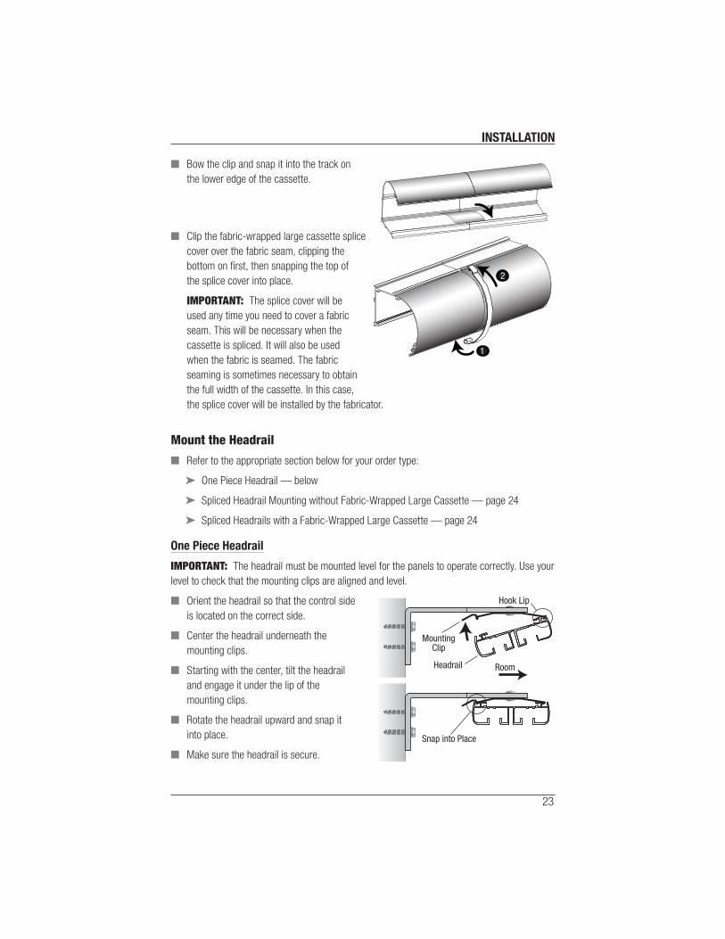
■ Bow the clip and snap it into the track on
the lower edge of the cassette.
■ Clip the fabric-wrapped large cassette splice
cover over the fabric seam, clipping the
bottom on fi rst, then snapping the top of
the splice cover into place.
IMPORTANT: The splice cover will be
used any time you need to cover a fabric
seam. This will be necessary when the
cassette is spliced. It will also be used
when the fabric is seamed. The fabric
seaming is sometimes necessary to obtain
the full width of the cassette. In this case,
the splice cover will be installed by the fabricator.
Mount the Headrail
■ Refer to the appropriate section below for your order type:
➤ One Piece Headrail — below
➤ Spliced Headrail Mounting without Fabric-Wrapped Large Cassette — page 24
➤ Spliced Headrails with a Fabric-Wrapped Large Cassette — page 24
One Piece Headrail
IMPORTANT: The headrail must be mounted level for the panels to operate correctly. Use your
level to check that the mounting clips are aligned and level.
■ Orient the headrail so that the control side
is located on the correct side.
■ Center the headrail underneath the
mounting clips.
■ Starting with the center, tilt the headrail
and engage it under the lip of the
mounting clips.
■ Rotate the headrail upward and snap it
into place.
■ Make sure the headrail is secure.
1
2
Room
Hook Lip
MountingClip
Headrail
Snap into Place

INSTALLATION
24
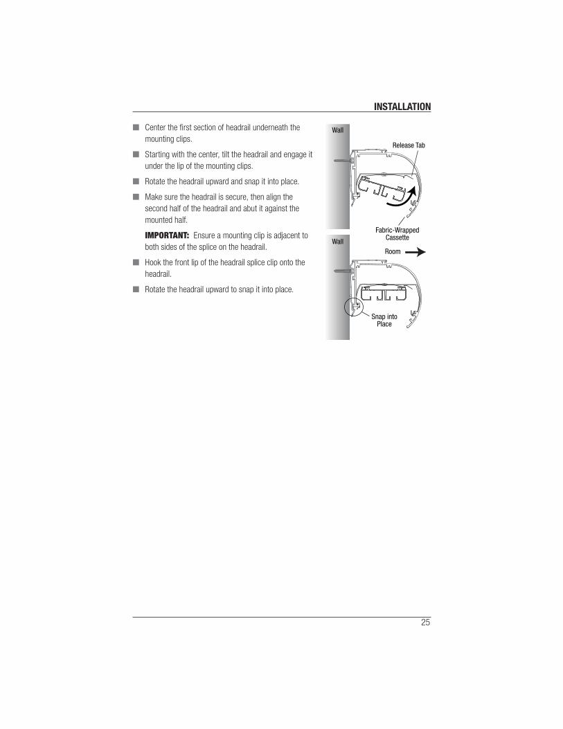
Spliced Headrails without Fabric-Wrapped Large Cassette
CAUTION: For spliced headrails, one person should hold each section.
■ Orient the headrail so that the control side is located on the correct side.
■ Mount the half with the attached headrail splice clip fi rst.
■ Center the fi rst section of headrail
underneath the mounting clips.
■ Starting with the center, tilt the headrail and
engage it under the lip of the mounting clips.
■ Rotate the headrail upward and snap it
into place.
■ Make sure the headrail is secure, then align
the second half of the headrail and abut it
against the mounted half.
IMPORTANT: Ensure a mounting clip is
adjacent to both sides of the splice on
the headrail.
■ Hook the front lip of the headrail splice clip onto the headrail.
■ Rotate the headrail upward to snap it into place.
Spliced Headrails with a Fabric-Wrapped Large Cassette
CAUTION: For spliced headrails, one person should hold each section.
■ Orient the headrail so that the control side is located on the correct side.
■ Mount the half with the attached headrail splice clip fi rst.
IMPORTANT: The headrail splice clip will need to be
attached prior to installation into the cassette, and the
clip will need to be oriented with the release tab
forward (into the room) as shown.
Room
Hook Lip
MountingClip
Headrail
Snap into Place
Room
Headrail Splice Clip Front Lip
First HearailSection
(Installed)
Second Headrail Section
HeadrailSplice Clip
Headrail
Release Tab
RoomWall
INSTALLATION
25
■ Center the fi rst section of headrail underneath the
mounting clips.
■ Starting with the center, tilt the headrail and engage it
under the lip of the mounting clips.
■ Rotate the headrail upward and snap it into place.
■ Make sure the headrail is secure, then align the
second half of the headrail and abut it against the
mounted half.
IMPORTANT: Ensure a mounting clip is adjacent to
both sides of the splice on the headrail.
■ Hook the front lip of the headrail splice clip onto the
headrail.
■ Rotate the headrail upward to snap it into place.
Fabric-WrappedCassette
Wall
WallRoom
Release Tab
Snap intoPlace
INSTALLATION
26
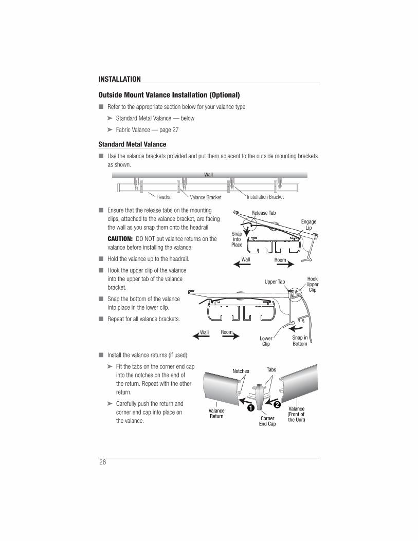
Outside Mount Valance Installation (Optional)
■ Refer to the appropriate section below for your valance type:
➤ Standard Metal Valance — below
➤ Fabric Valance — page 27
Standard Metal Valance
■ Use the valance brackets provided and put them adjacent to the outside mounting brackets
as shown.
■ Ensure that the release tabs on the mounting
clips, attached to the valance bracket, are facing
the wall as you snap them onto the headrail.
CAUTION: DO NOT put valance returns on the
valance before installing the valance.
■ Hold the valance up to the headrail.
■ Hook the upper clip of the valance
into the upper tab of the valance
bracket.
■ Snap the bottom of the valance
into place in the lower clip.
■ Repeat for all valance brackets.
■ Install the valance returns (if used):
➤ Fit the tabs on the corner end cap
into the notches on the end of
the return. Repeat with the other
return.
➤ Carefully push the return and
corner end cap into place on
the valance.
Wall
Installation BracketValance BracketHeadrail
EngageLip
Snapinto
Place
Release Tab
RoomWall
Snap inBottom
RoomWall
Upper Tab
LowerClip
HookUpperClip
Valance(Front of the Unit)
Tabs
ValanceReturn Corner
End Cap
Notches
12
INSTALLATION
27
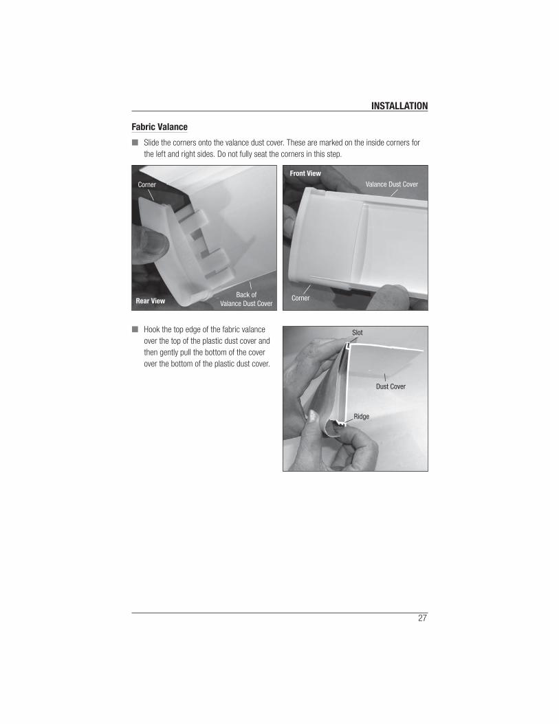
Fabric Valance
■ Slide the corners onto the valance dust cover. These are marked on the inside corners for
the left and right sides. Do not fully seat the corners in this step.
■ Hook the top edge of the fabric valance
over the top of the plastic dust cover and
then gently pull the bottom of the cover
over the bottom of the plastic dust cover.
Rear ViewBack of
Valance Dust Cover
Corner
Front View
Valance Dust Cover
Corner
Dust Cover
Slot
Ridge

INSTALLATION
28
■ Carefully push the corners fully into place
making sure the fabric goes under the lip of
the corners.
■ Put the return fabric covers on the same way
as the main part of the fabric valance, sliding
them into place under the lip of the corners.
■ Use the fabric valance brackets provided and place them next to the mounting brackets as
shown.
■ Ensure that the release tabs on the mounting
clips, attached to the fabric valance mounting
brackets, are facing the wall as you snap them
into place on the headrail.
■ Hold the valance assembly up to the headrail.
■ Slide the dust cover into the clips.
■ Push the assembly back until the returns touch
the wall.
Lip
Mounting Bracket
Valance Bracket
EngageLip
Snapinto
Place
Release Tab
RoomWall
RoomWall
Fabric Valance BracketDust Cover
INSTALLATION
29
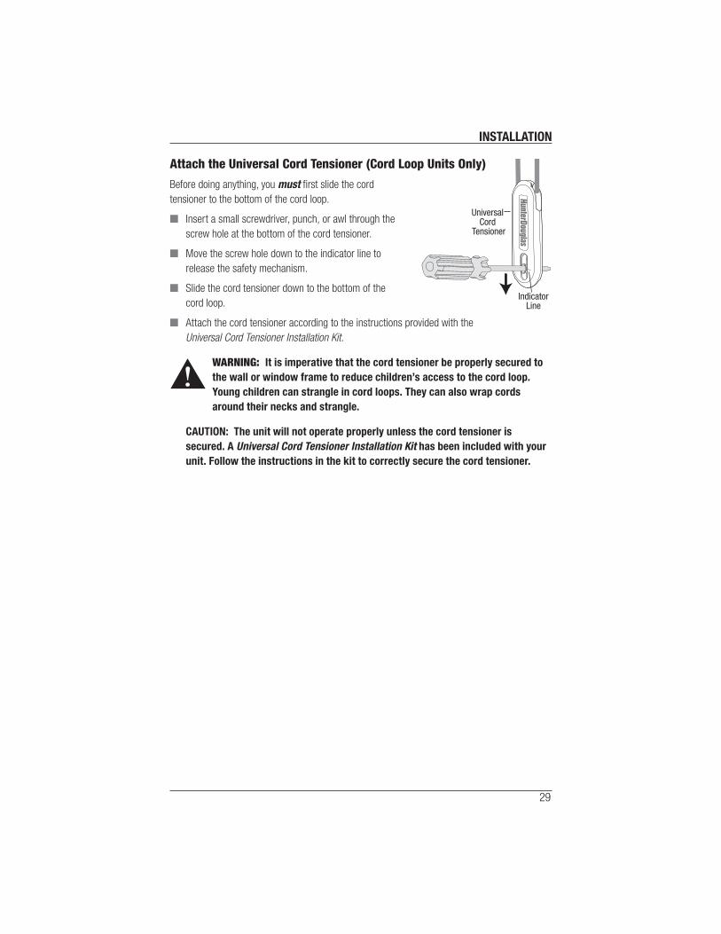
Attach the Universal Cord Tensioner (Cord Loop Units Only)
Before doing anything, you must fi rst slide the cord
tensioner to the bottom of the cord loop.
■ Insert a small screwdriver, punch, or awl through the
screw hole at the bottom of the cord tensioner.
■ Move the screw hole down to the indicator line to
release the safety mechanism.
■ Slide the cord tensioner down to the bottom of the
cord loop.
■ Attach the cord tensioner according to the instructions provided with the
Universal Cord Tensioner Installation Kit.
WARNING: It is imperative that the cord tensioner be properly secured to
the wall or window frame to reduce children’s access to the cord loop.
Young children can strangle in cord loops. They can also wrap cords
around their necks and strangle.
CAUTION: The unit will not operate properly unless the cord tensioner is
secured. A Universal Cord Tensioner Installation Kit has been included with your
unit. Follow the instructions in the kit to correctly secure the cord tensioner.
IndicatorLine
Universal Cord
Tensioner
INSTALLATION
30
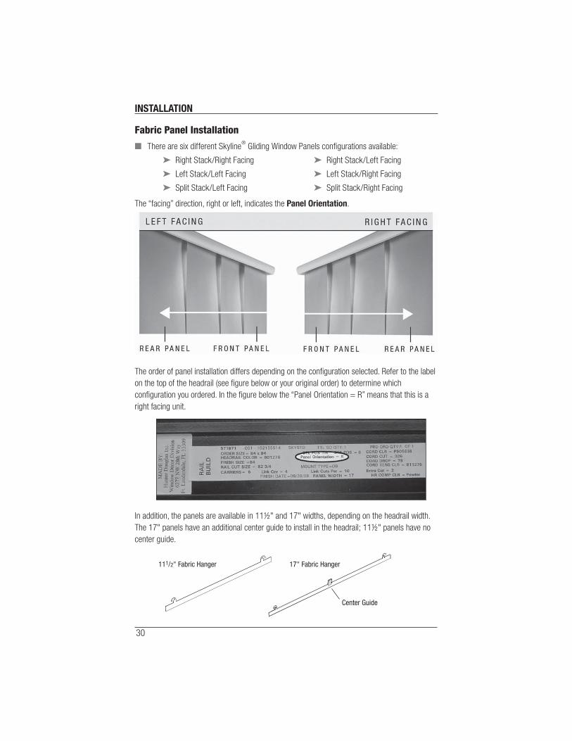
Fabric Panel Installation
■ There are six different Skyline® Gliding Window Panels confi gurations available:
➤ Right Stack/Right Facing ➤ Right Stack/Left Facing
➤ Left Stack/Left Facing ➤ Left Stack/Right Facing
➤ Split Stack/Left Facing ➤ Split Stack/Right Facing
The “facing” direction, right or left, indicates the Panel Orientation.
The order of panel installation differs depending on the confi guration selected. Refer to the label
on the top of the headrail (see fi gure below or your original order) to determine which
confi guration you ordered. In the fi gure below the “Panel Orientation = R” means that this is a
right facing unit.
In addition, the panels are available in 11½" and 17" widths, depending on the headrail width.
The 17" panels have an additional center guide to install in the headrail; 11½" panels have no
center guide.
11
1/2" Fabric Hanger 17" Fabric Hanger
Center Guide

INSTALLATION
31
■ Refer to the appropriate page below based on your shade order:
➤ Right Stack/Right Facing or Left Stack/Right Facing — see below
➤ Left Stack/Left Facing or Right Stack/Left Facing — page 33
➤ Split Stack/Left Facing — page 37
➤ Split Stack/Right Facing — page 34
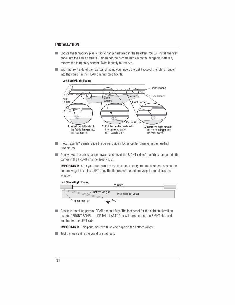
Right Stack/Right Facing or Left Stack/Right Facing Assembly
IMPORTANT: Use the wand or cord loop to traverse the unit open and closed to test for
proper operation.
■ Use the cord loop or wand to traverse the carriers to the stacked position.
■ Manually stack the free carriers in the front channel to the right end. Reposition these as
needed while installing each panel.
■ Locate the panel marked “REAR PANEL — INSTALL FIRST”. This is the fi rst panel to install.
■ Locate the temporary plastic fabric hanger installed in the headrail. You will install the fi rst
panel into the same carriers. Remember the carriers into which the hanger is installed,
remove the temporary hanger. Twist it gently to remove.
■ With the front side of the rear panel facing you, insert the LEFT side of the fabric hanger
into the carrier in the REAR channel (see No. 1).
■ If you have 17" panels, slide the center guide into the center channel in the headrail
(see No. 2).
Front Channel
Rear Channel
Rear Carrier CenterChannel
Center Guide
Front Carrier
1. Insert the left side of the fabric hanger into the rear carrier.
2. Put the center guide into the center channel (17" panels only).
3. Insert the right side of the fabric hanger into the front carrier.
Screw

INSTALLATION
32
■ Gently twist the fabric hanger inward and insert the RIGHT side of the fabric hanger into the
carrier in the FRONT channel (see No. 3).
IMPORTANT: After you have installed the fi rst panel, verify that the fl ush end cap on the
bottom weight is on the RIGHT side. The fl at side of the bottom weight should face the room.
■ Continue installing panels, rear channel fi rst. The last panel you install will be marked
“FRONT PANEL — INSTALL LAST.”
IMPORTANT: This panel has two fl ush end caps on the bottom weight.
■ Test traverse using the wand or cord loop.
Flush End Cap
Window
Room
Headrail (Top View)Bottom Weight
Right Stack/Right Facing

INSTALLATION
33
Left Stack/Left Facing Assembly or Right Stack/Left Facing
IMPORTANT: Use the wand or cord loop to traverse the unit open and closed to test for proper
operation.
■ Use the wand or cord loop to traverse the carriers to the stacked position.
■ Manually stack the free carriers in the front channel to the left end. Reposition these as
needed while installing each panel.
■ Locate the panel marked “REAR PANEL — INSTALL FIRST”. This is the fi rst panel to install.
■ Locate the temporary plastic fabric hanger installed in the headrail. You will install the fi rst
panel into the same carriers. Remember the carriers into which the hanger is installed,
remove the temporary hanger. Twist it gently to remove.
■ With the front side of the rear panel facing you, insert the RIGHT side of the fabric hanger
into the carrier in the REAR channel (see No. 1).
■ If you have 17" panels, slide the center guide into the center channel in the headrail
(see No. 2).
Front Channel
Rear Channel
Rear CarrierCenter Channel
CenterGuide
FrontCarrier
3. Insert the left side of the fabric hanger into the front carrier.
2. Put the center guide into the center channel (17" panels only).
1. Insert the right side of the fabric hanger into the rear carrier.
Screw

INSTALLATION
34
■ Gently twist the fabric hanger outward and insert the LEFT side of the fabric hanger into the
carrier in the FRONT channel (see No. 3).
IMPORTANT: After you have installed the fi rst panel, verify that the fl ush end cap on the
bottom weight is on the LEFT side. The fl at side of the bottom weight should face the room.
■ Continue installing panels, rear channel fi rst. The last panel you will install will be marked
“FRONT PANEL — INSTALL LAST.”
IMPORTANT: This panel has two fl ush end caps on the bottom weight.
■ Test traverse using the wand or cord loop.
Split Stack/Right Facing
IMPORTANT: Use the wand or cord loop to traverse the unit open and closed to test for proper
operation.
■ Use the wand or cord loop to traverse the carriers to the stacked position.
■ Manually stack the half of the free carriers in the front channel to the left end and the other
half to the right end. Reposition these carriers as needed while installing each panel.
■ Locate the panel (you had previously set aside) marked “REAR PANEL — INSTALL FIRST”.
You will have one for the RIGHT side and another for the LEFT side. This is the fi rst panel to
install.
■ Locate the temporary plastic fabric hanger installed in the headrail. You will install the fi rst
panel into the same carriers. Remember the carriers into which the hanger is installed,
remove the temporary hanger. Twist it gently to remove.
Flush End Cap
Window
Room
Headrail (Top View)
Left Stack/Left Facing
Bottom Weight

INSTALLATION
35
■ With the front side of the rear panel facing you, insert the LEFT side of the fabric hanger
into the carrier in the REAR channel (see No. 1).
■ If you have 17" panels, slide the center guide into the center channel in the headrail
(see No. 2).
■ Gently twist the fabric hanger outward and insert the RIGHT side of the fabric hanger into
the carrier in the FRONT channel (see No. 3).
IMPORTANT: After you have installed the fi rst panel, verify that the fl ush end cap on the
bottom weight is on the right side. The fl at side of the bottom weight should face the room.
■ Continue installing panels, rear channel fi rst. The last panel you install will be marked
“FRONT PANEL — INSTALL LAST”. You will have one for the RIGHT side and another for
the LEFT side.
IMPORTANT: This panel has two fl ush end caps on the bottom weight.
■ Test traverse using the wand or cord loop.
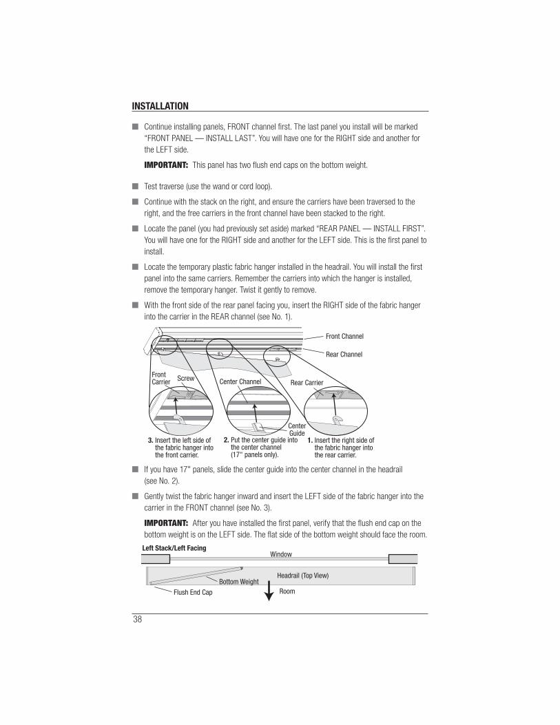
■ Continue with the stack on the left, and ensure the carriers have been traversed to the left,
and the free carriers in the front channel have been stacked to the left.
■ Locate the panel (you had previously set aside) marked “REAR PANEL — INSTALL FIRST”.
You will have one for the RIGHT side and another for the LEFT side. This is the fi rst panel to
install.
Front Channel
Rear Channel
Rear Carrier CenterChannel
Center Guide
Front Carrier
1. Insert the left side of the fabric hanger into the rear carrier.
2. Put the center guide into the center channel (17" panels only).
3. Insert the right side of the fabric hanger into the front carrier.
Screw
Flush End Cap
Window
Room
Headrail (Top View)Bottom Weight
Right Stack/Right Facing
INSTALLATION
36
■ Locate the temporary plastic fabric hanger installed in the headrail. You will install the fi rst
panel into the same carriers. Remember the carriers into which the hanger is installed,
remove the temporary hanger. Twist it gently to remove.
■ With the front side of the rear panel facing you, insert the LEFT side of the fabric hanger
into the carrier in the REAR channel (see No. 1).
■ If you have 17" panels, slide the center guide into the center channel in the headrail
(see No. 2).
■ Gently twist the fabric hanger inward and insert the RIGHT side of the fabric hanger into the
carrier in the FRONT channel (see No. 3).
IMPORTANT: After you have installed the fi rst panel, verify that the fl ush end cap on the
bottom weight is on the LEFT side. The fl at side of the bottom weight should face the
window.
■ Continue installing panels, REAR channel fi rst. The last panel for the right stack will be
marked “FRONT PANEL — INSTALL LAST”. You will have one for the RIGHT side and
another for the LEFT side.
IMPORTANT: This panel has two fl ush end caps on the bottom weight.
■ Test traverse using the wand or cord loop.
Left Stack/Right Facing
Front Channel
Rear ChannelRearCarrier
CenterChannel
Center Guide
Front Carrier
1. Insert the left side of the fabric hanger into the rear carrier.
2. Put the center guide into the center channel (17" panels only).
3. Insert the right side of the fabric hanger into the front carrier.
Flush End Cap
Window
Room
Headrail (Top View)
Left Stack/Right Facing
Bottom Weight

INSTALLATION
37
Split Stack/Left Facing
IMPORTANT: Use the wand or cord loop to traverse the unit open and closed to test for proper
operation.
■ Use the wand or cord loop to traverse the carriers to the stacked position.
■ Manually stack the half of the free carriers in the front channel to the left end and the other
half to the right end. Reposition these carriers as needed while installing each panel.
■ Locate the panel marked “REAR PANEL — INSTALL FIRST”. You will have one for the
RIGHT side and another for the LEFT side. This is the fi rst panel to install.
■ Locate the temporary plastic fabric hanger installed in the headrail. You will install the fi rst
panel into the same carriers. Remember the carriers into which the hanger is installed,
remove the temporary hanger. Twist it gently to remove.
■ With the front side of the rear panel facing you, insert the LEFT side of the fabric hanger
into the carrier in the FRONT channel (see No. 1).
■ If you have 17" panels, slide the center guide into the center channel in the headrail
(see No. 2).
■ Gently twist the fabric hanger inward and insert the RIGHT side of the fabric hanger into the
carrier in the REAR channel (see No. 3).
IMPORTANT: After you have installed the fi rst panel, verify that the fl ush end cap on the
bottom weight is on the LEFT side. The fl at side of the bottom weight should face the
window.
Right Stack/Left Facing
Front Channel
Rear Channel
Front Carrier Center Channel
CenterGuide
Rear Carrier
1. Insert the left side of the fabric hanger into the front carrier.
3. Insert the right side of the fabric hanger into the rear carrier.
2. Put the center guide into the center channel (17" panels only).
Flush End Cap
Window
Room
Headrail (Top View)
Right Stack/Left Facing
Bottom Weight
INSTALLATION
38
■ Continue installing panels, FRONT channel fi rst. The last panel you install will be marked
“FRONT PANEL — INSTALL LAST”. You will have one for the RIGHT side and another for
the LEFT side.
IMPORTANT: This panel has two fl ush end caps on the bottom weight.
■ Test traverse (use the wand or cord loop).
■ Continue with the stack on the right, and ensure the carriers have been traversed to the
right, and the free carriers in the front channel have been stacked to the right.
■ Locate the panel (you had previously set aside) marked “REAR PANEL — INSTALL FIRST”.
You will have one for the RIGHT side and another for the LEFT side. This is the fi rst panel to
install.
■ Locate the temporary plastic fabric hanger installed in the headrail. You will install the fi rst
panel into the same carriers. Remember the carriers into which the hanger is installed,
remove the temporary hanger. Twist it gently to remove.
■ With the front side of the rear panel facing you, insert the RIGHT side of the fabric hanger
into the carrier in the REAR channel (see No. 1).
■ If you have 17" panels, slide the center guide into the center channel in the headrail
(see No. 2).
■ Gently twist the fabric hanger inward and insert the LEFT side of the fabric hanger into the
carrier in the FRONT channel (see No. 3).
IMPORTANT: After you have installed the fi rst panel, verify that the fl ush end cap on the
bottom weight is on the LEFT side. The fl at side of the bottom weight should face the room.
Front Channel
Rear Channel
Rear CarrierCenter Channel
CenterGuide
FrontCarrier
3. Insert the left side of the fabric hanger into the front carrier.
2. Put the center guide into the center channel (17" panels only).
1. Insert the right side of the fabric hanger into the rear carrier.
Screw
Flush End Cap
Window
Room
Headrail (Top View)
Left Stack/Left Facing
Bottom Weight

INSTALLATION
39
■ Continue installing panels, REAR channel fi rst. The last panel you will install will be marked
“FRONT PANEL — INSTALL LAST”. You will have one for the RIGHT side and another for
the LEFT side.
IMPORTANT: This panel has two fl ush end caps on the bottom weight.
■ Test traverse using the wand or cord loop.
Connect the Bottom Weights
Once you are satisfi ed with the operation, connect the bottom weights together. The bottom
weights interconnect to stabilize the panels. Each bottom weight has a snap slide on the back
side, which connects to the adjacent bottom weight.
■ Use the wand or the cord loop to traverse the panels closed.
■ Starting at the back panel, push the snap slide of the next panel into the slot of the snap
slide end cap of the back panel (behind it). It should snap into place.
■ Progressing across the track, continue connecting the snap slide of each panel to the snap
slide end cap of the panel behind it.
■ Once all panels have been connected, carefully check the operation of the track by
traversing the panels open and closed.
■ If you experience any binding at the bottom, spray a small amount of silicone spray in the
groove on the back of the bottom weight.
Push Snap Slideinto Slot of SnapSlide End Cap
Snap Slide
Slot
REAR VIEW
Snap Slide End Cap

INSTALLATION
40
Install the Room Divider Kit (Optional)
IMPORTANT: The fl oor bracket and
snap slide can be mounted to the fl oor
in a position to hold the panels in directly
beneath the headrail. Once mounted, the
snap slide is free to move up and down
in its slot and can be attached to the last
moving panel. The wall plate and ball end
cap keep the panel adjacent to the wall
in place.
■ Locate the panel that will be adjacent
to the wall.
■ Remove the end cap pin from the
bottom weight.
Wall PlateBall End Cap
Snap Slide
Floor Bracket
Floor Bracket
Pane
l Adj
acen
t to
Wal
l
WallPlate
End Cap Pin

INSTALLATION
41
■ Pull out the bottom weight fl at end cap
(next to the wall).
■ Install the ball end cap in the end of the
bottom weight.
■ Reinstall the end cap pin.
■ Be sure the bottom weight is free hanging
to determine where the ball end cap aligns
on the wall.
■ Align the wall plate with the ball end cap,
and secure it to the wall with two #4 fl at
head screws (and anchors if necessary).
■ Insert the ball end cap into the slot in the
wall plate.

INSTALLATION
42
■ Insert the snap slide into the fl oor
bracket by aligning the slot of the
bracket with the grooves in the snap
slide. Be sure that the clip portion sits
inside the slot of the fl oor bracket. This
will allow the snap slide to slip into the
groove in the back of the panel bottom
weight if desired.
IMPORTANT: When the snap slide is snapped to the bottom weight, the panels will only
traverse the distance of one panel (see the fi gure on page 40). To completely traverse
the panels, disconnect the snap slide from the bottom weight.
■ Determine where you want the fl oor
bracket placed (somewhere along the fi rst
panel, see the fi gure on page 40).
■ Secure it in place with #6 fl at
head screws.
Clip Inside Bracket
OPERATION
43
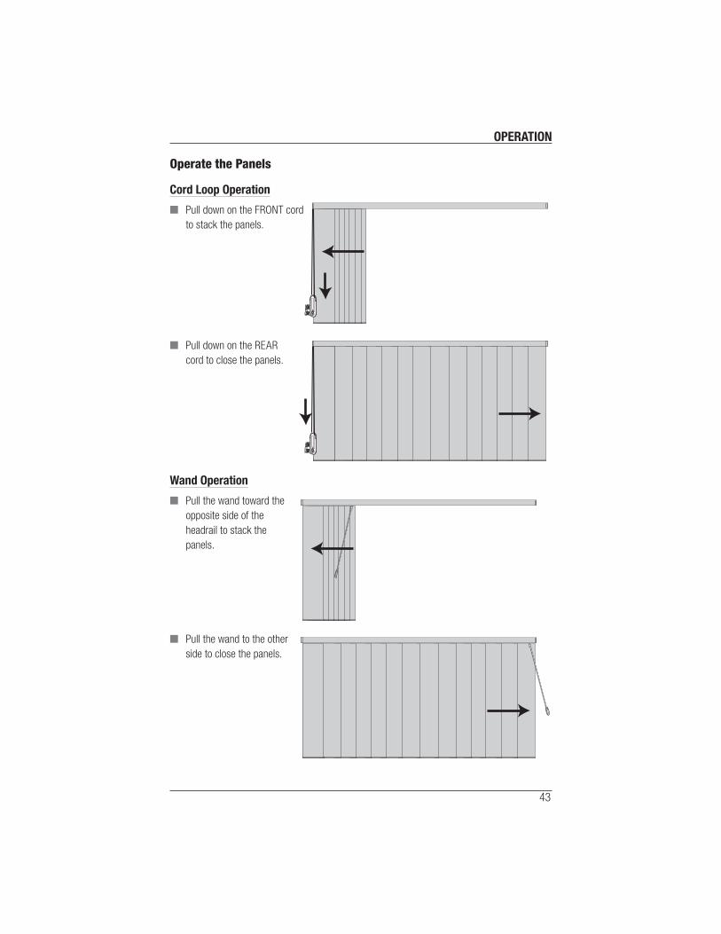
Operate the Panels
Cord Loop Operation
■ Pull down on the FRONT cord
to stack the panels.
■ Pull down on the REAR
cord to close the panels.
Wand Operation
■ Pull the wand toward the
opposite side of the
headrail to stack the
panels.
■ Pull the wand to the other
side to close the panels.

OPERATION
44
Adjustments
Adjust the Cord Length
The length of the cord can be shortened to allow you to attach the Universal Cord Tensioner
(UCT) in the desired position on the wall.
■ Mount the UCT to the wall in the desired position. Refer to the UCT installation kit for
instructions.
■ Pull each cord on the cord driver until you identify the one
that does NOT move the carriers when pulled. This is the
cord that can be adjusted.
IMPORTANT: The end to shorten will be dotted with a
black permanent marker (cannot be done on cocoa or
black cords).
IMPORTANT: Split stack panels have two cord drivers.
You must locate the cord driver WITHOUT the screw.
■ Using needle nose pliers, pull the cord knot from the cord driver (located in the headrail).
■ Pull out the cord until it is taut and the cord loop moves easily through the cord tensioner. If
the cord is not taut, it will not move through the cord tensioner.
■ Mark the top of the cord close to the cord driver
(cannot be done on cocoa or black cords).
■ Remove the UCT from the bracket or wall.
■ Tie a double knot at the mark on the cord and let it retract
into the cord driver.
■ Re-attach the UCT to the wall to ensure the cord is taut
and cord loop moves easily through the UCT. Repeat
steps above to adjust further, if necessary.
■ Once the cord is adjusted, cut the excess cord below the
knot hanging from the cord driver.
Cord Driver
Dot Cord Driver Without Screw

OPERATION
45
Adjust/Shorten Fabric Panel Length
CAUTION: Some units may not be able to reuse the plastic adhesive strip mentioned in this
process. If the strip will not stick in the new location, contact your Hunter Douglas dealer for a
replacement.
■ Measure and record the amount you want to shorten on a panel. Refer to this information
for any remaining panels you want to shorten.
■ If the bottom weights were connected together, disconnect them.
■ Carefully remove the panel by releasing the fabric hanger from the carriers. See “Remove
the Panels” on page 53.
■ Place the panel on a clean, fl at working surface. If it is not possible to spread the panel out
fl at, then carefully roll the panel up around the hanger (or preferably the shipping core), so
that the bottom weight is accessible.
■ Use a small fl at-blade screwdriver
to remove the end cap pin in the
bottom weight.
■ Slide out the snap slide end cap from
the bottom weight.
■ Slide the panel out of the bottom weight.
IMPORTANT: Note the folded fl ap at the
bottom of the panel and how it is folded.
Snap Slide End Cap End Cap Pin

OPERATION
46
■ Unfold the fabric and carefully remove the
plastic strip from the panel. Save it for
later use.
■ Holding the bottom end of the panel fl at,
mark the distance (previously recorded)
at several locations across the bottom of
the panel. Using a straight-edge, draw a
line connecting these marks.
■ Using a sharp pair of scissors, carefully cut straight across each panel along the line to
remove the desired length from each panel.
■ Replace the previously removed plastic adhesive strip along the bottom of the panel,
aligning the strip with the bottom edge of the panel. Push on the plastic adhesive strip so it
adheres to the panel.
■ Carefully crease the panel along the upper edge of the strip.
IMPORTANT: Make sure there are no ripples in the fabric panel.
■ Holding the folded panel and plastic
strip, carefully insert the panel into
the bottom weight until it is fully
seated within the bottom weight.
CAUTION: Be careful NOT to pull on
the fabric, as it can cause permanent
distortion or damage.
■ Re-install the snap slide end cap.

OPERATION
47
■ Insert the end cap pins back into in the
bottom weight and press into place.
■ Reinstall the fabric panel into
the headrail.
■ Repeat this process for the other panels.
■ Reconnect the bottom weights if
required.
■ Using the wand or cord loop, traverse the
shade open and closed to test for proper
operation.
Straighten Panel Fabric from Bottom Weight
If the panel fabric is creased or wrinkled at the bottom it can be adjusted and straightened.
CAUTION: Units made with the fabrics Point South, Del Sol, and Diamond Head may not be
able to reuse the plastic adhesive strip mentioned in this process. If the strip will not stick in the
new location, contact your Hunter Douglas dealer for a replacement.
■ Use a small fl at-blade screwdriver to
remove the end cap pin in the bottom
weight of the affected panel.
■ Slide out the snap slide end cap from the
bottom weight.
■ Slide the panel out of the bottom weight.
Snap SlideEnd Cap End Cap Pin
OPERATION
48
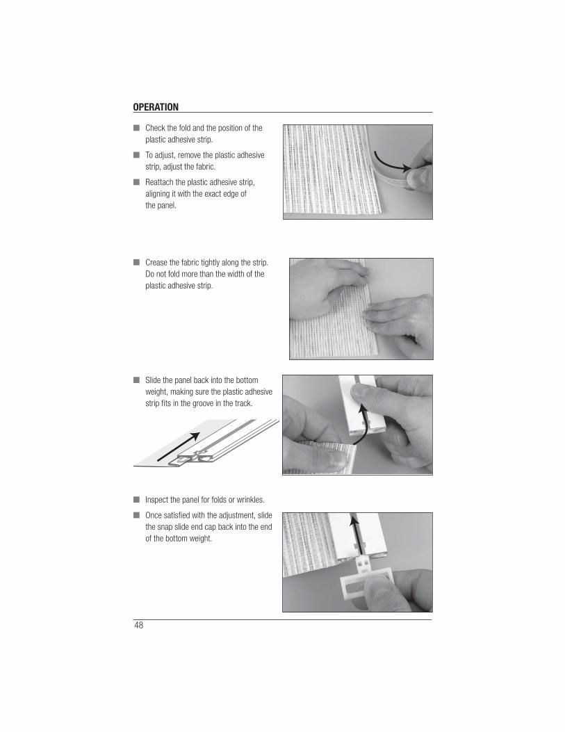
■ Check the fold and the position of the
plastic adhesive strip.
■ To adjust, remove the plastic adhesive
strip, adjust the fabric.
■ Reattach the plastic adhesive strip,
aligning it with the exact edge of
the panel.
■ Crease the fabric tightly along the strip.
Do not fold more than the width of the
plastic adhesive strip.
■ Slide the panel back into the bottom
weight, making sure the plastic adhesive
strip fi ts in the groove in the track.
■ Inspect the panel for folds or wrinkles.
■ Once satisfi ed with the adjustment, slide
the snap slide end cap back into the end
of the bottom weight.
OPERATION
49
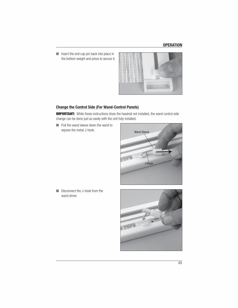
■ Insert the end cap pin back into place in
the bottom weight and press to secure it.
Change the Control Side (For Wand-Control Panels)
IMPORTANT: While these instructions show the headrail not installed, the wand control side
change can be done just as easily with the unit fully installed.
■ Pull the wand sleeve down the wand to
expose the metal J-hook.
■ Disconnect the J-hook from the
wand driver.
Wand Sleeve
J-Hook
OPERATION
50
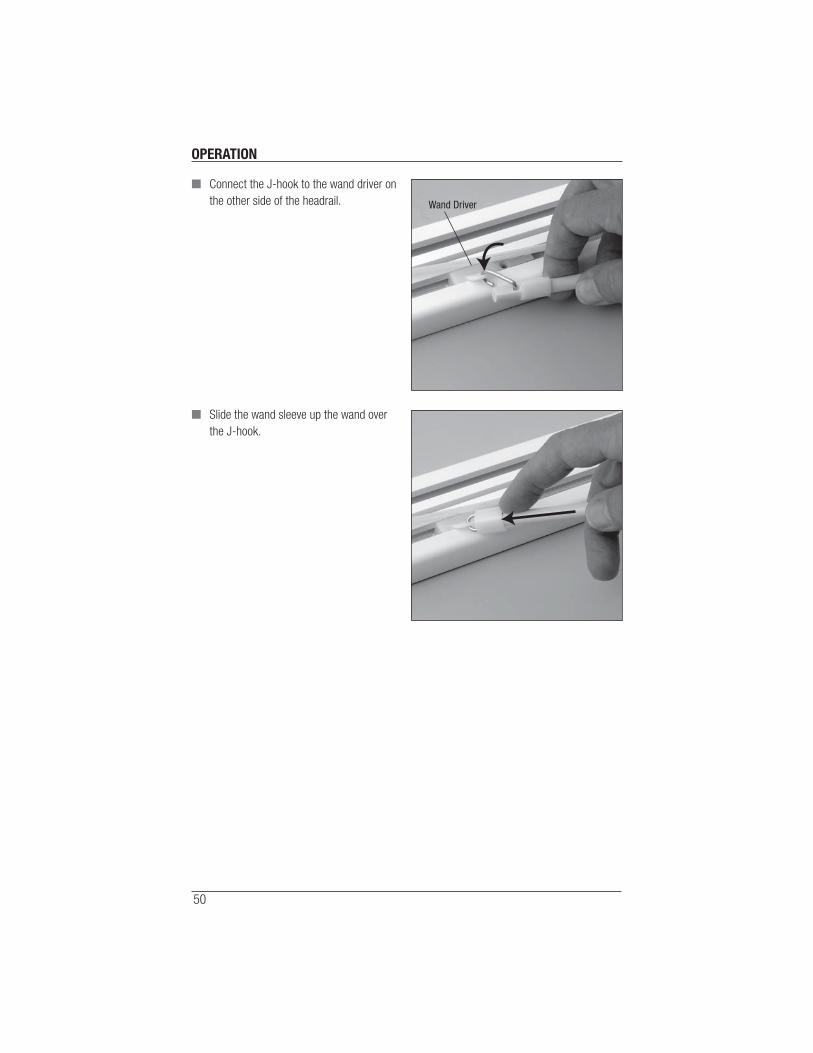
■ Connect the J-hook to the wand driver on
the other side of the headrail.
■ Slide the wand sleeve up the wand over
the J-hook.
Wand Driver
OPERATION
51
Troubleshooting
Problem How to determine unit panel orientation (whether it was made as right or left facing).
Solution The carriers in the headrail (where the panels hook in) will be WHITE for a right-
facing headrail, and GRAY for a left-facing headrail. Panels will fall out of the
headrail if installed improperly from the purchased confi guration.
Problem For cord loop panels only: the panel does not traverse or does not traverse easily.
Solution Check that the Universal Cord Tensioner is installed properly and the cord moves
freely through it.
Check that the panel is installed correctly. The panels should be angled
compared to the track, with each panel hanger connected to a carrier in both
the front and back channels.
Check that the bottom snap slides are installed correctly and operating correctly.
The weights should slide together easily when connected using the snap slide.
Check that the installation brackets are level, and the attached mounting clips
are aligned.
Check that there are no obstructions to the movement of the panels, such as a
cord caught in the brackets.
Lightly spray dry silicon lubricant inside the rail channels, as needed.
Problem The stack side is incorrect.
Solution Remove the panels and store fl at on a clean surface. Reverse the headrail then
re-install the headrail, panels, and cord tensioner. Refer to the Universal Cord
Tensioner Installation Instructions for cord tensioner installation. Lastly, change
the wand side if necessary.
IMPORTANT: Reversing the headrail will change the stack side only, not the
panel orientation.
OPERATION
52
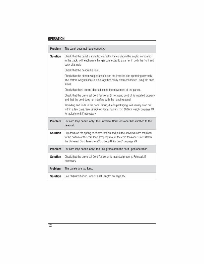
Problem The panel does not hang correctly.
Solution Check that the panel is installed correctly. Panels should be angled compared
to the track, with each panel hanger connected to a carrier in both the front and
back channels.
Check that the headrail is level.
Check that the bottom weight snap slides are installed and operating correctly.
The bottom weights should slide together easily when connected using the snap
slides.
Check that there are no obstructions to the movement of the panels.
Check that the Universal Cord Tensioner (if not wand control) is installed properly
and that the cord does not interfere with the hanging panel.
Wrinkling and folds in the panel fabric, due to packaging, will usually drop out
within a few days. See Straighten Panel Fabric From Bottom Weight on page 49,
for adjustment, if necessary.
Problem For cord loop panels only: the Universal Cord Tensioner has climbed to the headrail.
Solution Pull down on the spring to relieve tension and pull the universal cord tensioner
to the bottom of the cord loop. Properly mount the cord tensioner. See “Attach
the Universal Cord Tensioner (Cord Loop Units Only)” on page 29.
Problem For cord loop panels only: the UCT grabs onto the cord upon operation.
Solution Check that the Universal Cord Tensioner is mounted properly. Reinstall, if
necessary.
Problem The panels are too long.
Solution See “Adjust/Shorten Fabric Panel Length” on page 45.
CARE
53
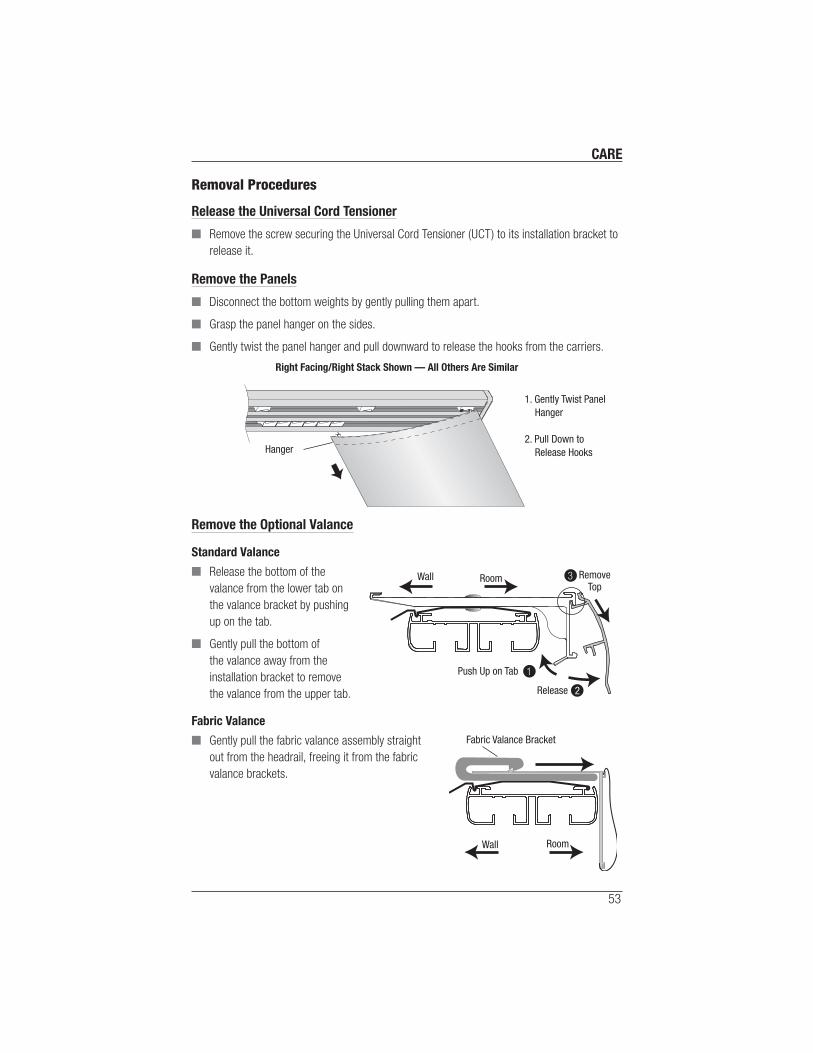
Removal Procedures
Release the Universal Cord Tensioner
■ Remove the screw securing the Universal Cord Tensioner (UCT) to its installation bracket to
release it.
Remove the Panels
■ Disconnect the bottom weights by gently pulling them apart.
■ Grasp the panel hanger on the sides.
■ Gently twist the panel hanger and pull downward to release the hooks from the carriers.
Remove the Optional Valance
Standard Valance
■ Release the bottom of the
valance from the lower tab on
the valance bracket by pushing
up on the tab.
■ Gently pull the bottom of
the valance away from the
installation bracket to remove
the valance from the upper tab.
Fabric Valance
■ Gently pull the fabric valance assembly straight
out from the headrail, freeing it from the fabric
valance brackets.
Right Facing/Right Stack Shown — All Others Are Similar
1. Gently Twist Panel Hanger
2. Pull Down to Release HooksHanger
RoomWall RemoveTop
Push Up on Tab
Release
1
2
3
RoomWall
Fabric Valance Bracket

CARE
54
Remove the Headrail
■ Locate the release tab on the mounting clip.
■ Firmly grasp the headrail.
■ Push up on the release tab to
release the headrail. Repeat for each
mounting clip.
■ Lift the headrail free from the
mounting clips.
Remove Panels with Fabric-Wrapped Large Cassette
One-Piece Headrail and Fabric-Wrapped Large Cassette
■ Insert the tip of a fl at head screwdriver into the
screwdriver slot provided on the bracket.
■ Press down to release the cassette.
■ Roll the cassette forward and then down
to remove.
Room
RemoveHeadrail
Push Upon Tab
Mounting ClipRelease Tab
Headrail
Insert a screwdriver to release
the cassette.
Front LipInstallationBracket
Fabric-WrappedLarge Cassette
Wall
1
2
Pull
Release
CARE
55
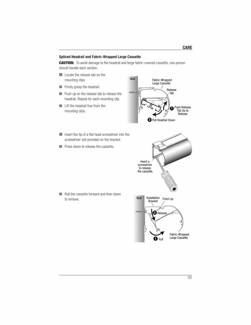
Spliced Headrail and Fabric-Wrapped Large Cassette
CAUTION: To avoid damage to the headrail and large fabric-covered cassette, one person
should handle each section.
■ Locate the release tab on the
mounting clips.
■ Firmly grasp the headrail.
■ Push up on the release tab to release the
headrail. Repeat for each mounting clip.
■ Lift the headrail free from the
mounting clips.
■ Insert the tip of a fl at head screwdriver into the
screwdriver slot provided on the bracket.
■ Press down to release the cassette.
■ Roll the cassette forward and then down
to remove.
ReleaseTab
Fabric-WrappedLarge Cassette
Wall
1
2 Pull Headrail Down
Push ReleaseTab Up toRelease
Insert a screwdriver to release
the cassette.
Front LipInstallationBracket
Fabric-WrappedLarge Cassette
Wall
1
2
Pull
Release

CARE
56
Cleaning Procedures
Dusting
■ Regular light dusting with a feather duster is all the cleaning that is needed in most
circumstances.
Vacuuming
■ Use a hand-held vacuum with low suction for more thorough dust removal.
Spot-Cleaning
■ Dampen a clean cloth with a solution of warm water and a mild detergent then wring it out.
■ Dab the spot with the dampened cloth until it is gone.
CAUTION: Keep all cleaning solutions away from the headrail system. Skyline® fabrics and
headrail should never be ultrasonically cleaned, injection/extraction cleaned, steam cleaned,
or immersed in water.
CAUTION: Do not steam panels in an attempt to remove wrinkles or cupping.
Compressed Air or Hair Dryer
■ Use to blow dust off the panels. Use a hair dryer on a cool setting.
Standard Skyline Metal Valance Cleaning
■ Wipe the valance with a damp cloth and a mild detergent solution.
Skyline Fabric-Wrapped Large Cassette Cleaning
■ Follow the same directions above for the fabric panels.
Product Notes and Disclaimers
■ Actual fabric color may vary slightly from the samples. All variations are within
established industry standards.
■ While opaque fabrics are blackout, due to the inherent light gaps between each panel,
the application is room darkening, not blackout.
■ Fabrics that contain patterns, stripes or rows when hung as panels will create random
alignment from panel to panel.
■ Many of the fabrics are fairly lightweight and will have varying levels of panel
movement when installed near air-conditioning vents or windows.
■ Depending on room conditions, wrinkles in product resulting from packaging should
hang out.
■ The standard panel overlap will prevent most tangling of panels. Based on individual
room conditions, some panel tangling may occur.
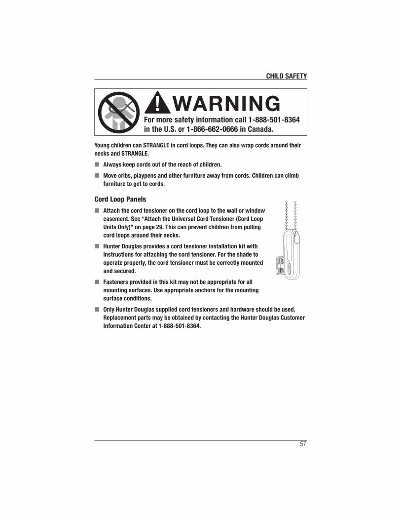
CHILD SAFETY
57
Warning
For more safety information call 1-888-501-8364
in the U.S. or 1-866-662-0666 in Canada.
WARNING
Young children can STRANGLE in cord loops. They can also wrap cords around their
necks and STRANGLE.
■ Always keep cords out of the reach of children.
■ Move cribs, playpens and other furniture away from cords. Children can climb
furniture to get to cords.
Cord Loop Panels
■ Attach the cord tensioner on the cord loop to the wall or window
casement. See “Attach the Universal Cord Tensioner (Cord Loop
Units Only)” on page 29. This can prevent children from pulling
cord loops around their necks.
■ Hunter Douglas provides a cord tensioner installation kit with
instructions for attaching the cord tensioner. For the shade to
operate properly, the cord tensioner must be correctly mounted
and secured.
■ Fasteners provided in this kit may not be appropriate for all
mounting surfaces. Use appropriate anchors for the mounting
surface conditions.
■ Only Hunter Douglas supplied cord tensioners and hardware should be used.
Replacement parts may be obtained by contacting the Hunter Douglas Customer
Information Center at 1-888-501-8364.
LIT777007 9/13
The Hunter Douglas® Lifetime Guarantee is an expression of our desire to provide a thoroughly satisfying experience when selecting, purchasing and living with your window fashion products. If you are not thoroughly satisfied, simply contact Hunter Douglas at (888) 501-8364 or visit hunterdouglas.com. In support of this policy of consumer satisfaction, we offer our Lifetime Limited Warranty as described below.
NOTE: In no event shall Hunter Douglas or its licensed fabricators/distributors be liable or responsible for incidental or consequential damages or for any other indirect damage, loss, cost or expense. Some states do not allow the exclusion or limitation of incidental or consequential damages, so the above exclusion or limitation may not apply to you. This warranty gives you specific legal rights, and you may also have other rights which vary from state to state.
Different warranty periods and terms apply for commercial products and applications.
Hunter Douglas (or its licensed fabricator/distributor) will repair or replace the window fashion product or components found to be defective.
COVEREDBY A LIFETIME LIMITED WARRANTY
• Hunter Douglas window fashion products are covered for defects in materials, workmanship or failure to operate for as long as the original retail purchaser owns the product (unless shorter periods are provided below).
• All internal mechanisms.
• Components and brackets.
• Fabric delamination.
• Operational cords for a full 7 years from the date of purchase.
• Repairs and/or replacements will be made with
like or similar parts or products.
• Hunter Douglas motorization components are covered for 5 years from the date of purchase.
NOT COVEREDBY A LIFETIME LIMITED WARRANTY
• Any conditions caused by normal wear and tear.
• Abuse, accidents, misuse or alterations to the product.
• Exposure to the elements (sun damage, wind, water/moisture) and discoloration or fading over time.
• Failure to follow our instructions with respect to measurement, proper installation, cleaning or maintenance.
• Shipping charges, cost of removal and reinstallation.
TO OBTAIN WARRANTY SERVICE
1. Contact your original dealer (place of purchase) for warranty assistance.
2. Visit hunterdouglas.com for additional warranty information, frequently asked questions and access to service locations.
3. Contact Hunter Douglas at (888) 501-8364 for technical support, certain parts free of charge, for assistance in obtainingwarranty service or for further explanation of our warranty.