Embed Size (px)
Citation preview
IEEE TRANSACTIONS ON POWER ELECTRONICS, VOL. 29, NO. 6, JUNE 2014 2817
Global Maximum Power Point Tracking of FlexiblePhotovoltaic Modules
Christos Konstantopoulos and Eftichios Koutroulis, Member, IEEE
Abstract—The flexible photovoltaic (PV) modules have the ad-vantage of easily fitting on curved surfaces, but in that case theirpower–voltage characteristic exhibits local maximum power points(MPPs) where the PV module power production is suboptimal.In this paper, the effect of geometrical installation parameters offlexible PV modules, such as the bending angle, tilt angle, andorientation, on the shape of the power–voltage characteristic isexperimentally investigated. Then, a new method of tracking theglobal MPP of flexible PV modules is proposed. An experimental,comparative study is also presented, which demonstrates that com-pared to the past-proposed MPP tracking (MPPT) techniques, thesystem proposed in this paper is capable to detect the global MPPof a flexible PV module with less search steps. Thus, the powerloss during the global MPPT process is minimized and the energyproduction of the flexible PV module is maximized.
Index Terms—Flexible, maximum power point tracking(MPPT), microcontroller, photovoltaic (PV) module.
I. INTRODUCTION
THE use of flexible photovoltaic (PV) modules has emergedduring the past few years for solar energy production on
portable, wearable, and mobile electronic devices, as well asaerospace and building-integrated PV (BIPV) systems [1]–[4].Flexible PV modules have the capability to fit on nonpla-nar surfaces, thus easily adapting to the architectural topol-ogy of the installation structure (e.g., roof tiles, facades, tents,etc.). They are fabricated using multiple, series-connected thinsolar cells (e.g., using monocrystalline or amorphous sili-con, Copper Indium Gallium Selenide (CIGS) semiconduc-tor, etc., of 2–100 μm typical thickness), which are encap-sulated within a flexible material (e.g., silicone gel) [5]–[7].They are capable to operate without loss of performance wheninstalled on curved surfaces [2] with a typical efficiency in therange of 13%–23%, depending on their manufacturing technol-ogy [2], [3], [5], [7]. Also, due to their rollable/foldable features,flexible PV modules enable easy transport and storage [5].
Typically, the commercially available flat-plate PV modulesconsist of multiple solar cells connected in series. A bypassdiode is connected in parallel to each module (or group ofcells within a module) for protection against hot-spot failure
Manuscript received March 28, 2013; revised June 20, 2013; accepted July 22,2013. Date of current version January 29, 2014. Recommended for publicationby Associate Editor C. A. Canesin.
The authors are with the Department of Electronic and Computer Engineering,Technical University of Crete, Chania GR-73100, Greece (e-mail: [email protected]; [email protected]).
Color versions of one or more of the figures in this paper are available onlineat http://ieeexplore.ieee.org.
Digital Object Identifier 10.1109/TPEL.2013.2275947
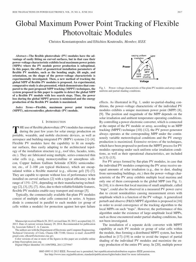
Fig. 1. Power–voltage characteristic of flat-plate PV modules and arrays underuniform and partial-shading conditions.
effects. As illustrated in Fig. 1, under no-partial-shading con-ditions, the power–voltage characteristic of the individual PVmodules exhibits a unique maximum power point (MPP) [8],[9]. The position and magnitude of the MPP depends on thesolar irradiation and ambient temperature operating conditions.By controlling a power electronic converter, which is connectedat the output of the PV module or array, according to an MPPtracking (MPPT) technique [10]–[12], the PV power-generatoralways operates at the corresponding MPP under the contin-uously variable meteorological conditions and the PV energyproduction is maximized. Extensive reviews of the techniques,which have been proposed to perform the MPPT process for PVmodules operating under such uniform solar irradiation condi-tions, as well as their operational characteristics, are includedin [13]–[15].
For PV arrays formed by flat-plate PV modules, in case thatthe individual PV modules comprising the PV array receive un-equal amounts of solar irradiation (e.g., due to dust, shadingfrom surrounding buildings, etc.) then the power–voltage char-acteristic of the PV array exhibits multiple local maxima andonly one of them corresponds to the global MPP (see Fig. 1).In [16], it is shown that local maxima of small amplitude, called“traps”, could also be observed in a measured PV power curvedue to circuit nonidealities causing measurement errors withamplitude which is a function of the PV voltage. A generalizedperturb and observe (P&O) MPPT algorithm is proposed in [16]in order to avoid convergence of the tracking algorithm to thelocal MPPs on such “traps”. However, the performance of thisalgorithm under the existence of large-amplitude local MPPs,such as those encountered under partial shading conditions, hasnot been investigated.
The installation of a separate dc/dc converter with MPPTcapability at each PV module or group of solar cells withinthe module, thus forming a distributed MPPT system, has beendescribed in [17]–[19] in order to avoid the impact of partialshading of the individual PV modules and maximize the en-ergy production of the entire PV array. In [20], multiple power
0885-8993 © 2013 IEEE. Personal use is permitted, but republication/redistribution requires IEEE permission.See http://www.ieee.org/publications standards/publications/rights/index.html for more information.
2818 IEEE TRANSACTIONS ON POWER ELECTRONICS, VOL. 29, NO. 6, JUNE 2014
switches, diodes, and capacitors are distributed among groups ofseries-connected solar cells within a PV module. In that scheme,the power switches are controlled such that in case of nonuni-form solar irradiation incidence among the individual groupsof solar cells, each of them still operates at its local MPP byredistributing the produced energy between the groups of so-lar cells through the use of an inductor. A similar topology isproposed in [21] in order to maximize the energy productionof PV sources which are connected in series at the input of amultilevel dc-link inverter under partial shading conditions. Inflat-plate PV module configurations, the power–voltage curveof the PV array may exhibit multiple local MPPs in case thatmultiple PV elements (cells or modules) are connected in seriesand the incident solar irradiation is nonuniform among them(see Fig. 1). However, as will be demonstrated in the followingsections of this paper, this effect also arises for the individualflexible PV modules, even in case that they are not connected inseries or parallel with other PV modules. Thus, the installationof a separate dc/dc converter at each flexible PV module is notadequate to guarantee that the maximum PV module power isproduced, unless a suitable global MPPT method is applied.
In [22], the position of the global MPP of a PV array op-erating under partial shading conditions is detected by chang-ing a voltage reference proportionally to the ratio of the PVarray open-circuit voltage and short-circuit current. The appli-cation of this method requires knowledge of the configurationof the PV modules within the PV array (i.e., number of PVmodules connected in series and parallel) and their operationalcharacteristics.
In [23], the global MPP is detected by iteratively modifying(with a fixed step) the duty cycle of a dc/dc power converter,which is connected at the output of the PV array, such that theentire power–voltage curve of the PV array is scanned. The sameprinciple is also applied in [24], where a switched-capacitordc/dc converter is used for continuously tracking the MPP ofa partially shaded PV array. The global MPP detection processis performed by periodically scanning the power–voltage curveof the PV array using a MOSFET power switch connected inparallel to the PV array, which is controlled a such that it isdriven from cutoff to saturation through the active region. Thus,the entire power–voltage characteristic of the PV array, from theopen-circuit voltage to the short-circuit current operating points,is scanned in order to derive the position of the global MPP.
A review of past-proposed techniques for the appropriate con-figuration of the electrical connections among the PV modulescomprising the PV array or their dynamic reconfiguration usinga matrix of power switches, in order to minimize the powerloss due to partial shading, is presented in [25]. However, thesemethods are not adequate to ensure maximum power productionunder all partial shading conditions. Furthermore, in case of thedynamic reconfiguration strategy, the switch matrix and asso-ciated wiring for performing the interconnections between thePV cells/modules result in increased hardware complexity [26].
The application of a radial basis function and a three layeredfeed-forward neural network is proposed in [27] for trackingthe global MPP. Using such an approach has the disadvantagethat the hardware resources required for implementing the con-
trol unit are increased. Also, intensive efforts are required bythe system designer in order to ensure that the neural networktraining process will be adequate to ensure convergence to theglobal MPP under any partial shading conditions. The globalMPPT scheme based on the DIviding RECTangles (DIRECT)optimization algorithm, which is presented in [28], does notguarantee that the global MPP detection process can be ac-complished in fewer steps than those required for sequentiallyscanning the power–voltage characteristic of the PV array.
A chaotic-search process based on two recursive functions(i.e., dual carrier), which produce possible positions of the globalMPP in the search space, is presented in [29] in order to track theglobal MPP under partial shading conditions and simultaneouslyimprove the efficiency of the conventional chaos-theory-basedsearch algorithm. In that work, a heuristic algorithm is proposedthat performs iterative fragmentations of the PV array power–voltage characteristic, utilizing sequences of numbers, whichare generated through the use of appropriate functions and cor-respond to alternative operating points on the power–voltagecharacteristic of the PV array. The global optimum is detectedby measuring and comparing the power generated by the PVarray at these positions.
The deployment of evolutionary algorithms (EAs) has beenproposed in order to detect the global MPP of partially shadedPV arrays, due to their ability to overcome the multiple localMPPs barrier and detect the global optimum MPP. Among theEAs, the particle swarm optimization (PSO) and differentialevolution (DE) algorithms have been proposed in [30]–[32],respectively, due to their implementation simplicity and robust-ness features.
In the standard PSO method, a swarm of particles moves ina search space with dimension equal to the number of decisionvariables of the optimization problem, by cooperating amongthem while searching for the global optimum point [31]. Thenext movement of each particle within the search space is influ-enced by its local best known position in combination with thebest known position among the entire set of particles. The useof deterministic PSO has been proposed in [33] to improve thetracking capability of the conventional PSO algorithm, mainlyby removing the randomness from the calculation of the PSOparticles velocity.
The DE algorithm is a stochastic, population-based optimiza-tion algorithm. The optimization process is conducted similarlyto genetic algorithms using the crossover, mutation, and selec-tion operators [32]. The main difference with genetic algorithmsis that the latter relies on crossover, while DE uses the mutationoperation as a search mechanism and the selection operation todirect the members of the population within the search spacetoward the regions where the fitness (i.e., objective) function ismaximized.
In commercially available flexible PV modules, bypass diodesare connected in parallel with the individual cells comprisingthe PV module. Targeting to a higher degree of integration indistributed MPPT applications, the incorporation of the dc/dcconverter into the structure of a flexible PV module using theback layer of the PV module as a substrate instead of a PCB, isdescribed in [34]. However, in case that a flexible PV module
KONSTANTOPOULOS AND KOUTROULIS: GLOBAL MAXIMUM POWER POINT TRACKING OF FLEXIBLE PHOTOVOLTAIC MODULES 2819
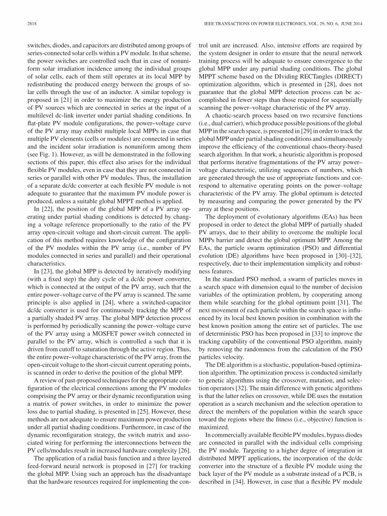
Fig. 2. Geometrical model of a flexible PV module under bending conditions.
is installed on a bended surface then different solar irradiationintensity is incident on each of the solar cells it comprises. Thus,as will be demonstrated next, its power–voltage characteristicmay exhibit local maxima (as those depicted in Fig. 1), althoughthe flexible PV module operates under no partial-shading condi-tions. The MPPT method applied in [35] for flexible PV modulesis characterized by increased implementation complexity, sinceknowledge of the incident solar irradiance, as well as the con-tour angle and open-circuit voltage of the flexible PV moduleare required for the detection of the global MPP. Until present,the issue of MPPT of flexible PV modules has not been studiedany further.
In this paper, the operational characteristics of flexible PVmodules are initially investigated in order to explore the impactof solar irradiation conditions and installation geometry on thecurrent–voltage and power–voltage characteristics of flexiblePV modules and derive the corresponding operational require-ments of a global MPPT algorithm, which is suitable for applica-tions of flexible PV modules. This issue is explored in this paperfor the first time in the existing research literature. Then, a newmethod for tracking the global MPP of flexible PV modules isproposed, which, compared to the past-proposed global MPPTtechniques, has the advantage of being able to detect the globalMPP in less search steps, thus minimizing the power loss dur-ing the global MPPT process. The proposed method is suitablefor incorporation in commercial PV power processing products,since it does not require knowledge of the operational charac-teristics of the flexible PV modules comprising the installedPV system. Such information is typically available during thePV system design process, which is performed after the MPPTdevice has been manufactured.
This paper is organized as follows: the operational charac-teristics of flexible PV modules are presented in Section II; theproposed global MPPT system is analyzed in Section III; finally,the experimental results are presented in Section IV.
II. OPERATIONAL CHARACTERISTICS
OF FLEXIBLE PV MODULES
The general installation geometry of a flexible PV moduleunder bending conditions is shown in Fig. 2. The PV moduleslope is defined by the angle β(◦) between the horizontal plane
and the chord of the arc formed by the bended PV module. Addi-tionally, the PV module is installed with an azimuth angle equalto α(◦) with respect to the north–south axis. A different amountof solar irradiation is incident on each point of the flexible PVmodule, since the angle of incidence of the solar irradiationvaries continuously along the PV module surface. Under bend-ing conditions, the flexible PV module forms an arc in a circle.The degree of bending of the flexible PV module is expressedby the central angle θ (in degrees, 0◦ ≤ θ ≤ 180◦), having itsvertex at the center of that circle and its sides passing throughthe edges of the flexible PV module. Applying geometrical cal-culations results that the length l (in meters) of the chord whichis formed between the two edges of the bended PV module (seeFig. 2) is given by
l =
⎧⎨
⎩
2L sin(θ/2)180◦
π · θ , for 0◦ < θ ≤ 180◦
L, for θ = 0◦(1)
where L (in meters) is the length of the arc formed by the flexiblePV module, which is also equal to the length of the PV module.
Until present, there is no suitable mathematical model avail-able in the existing research literature for calculating the outputcurrent and power of a flexible PV module as a function ofthe bending, azimuth and slope installation settings. Thus, inorder to explore the behavior of a flexible PV module undervarious installation conditions in this paper, its current–voltageand power–voltage characteristics were experimentally mea-sured using a suitable data-acquisition system, for various valuesof θ, β, and α during consecutive clear-sky summer days.
The current–voltage and power–voltage characteristics of asouth-facing flexible PV module (i.e., α = 0◦ in Fig. 2) withβ = 0◦ for various bending angles in the range θ = 0◦–180◦
are illustrated in Fig. 3. The current–voltage and power–voltagecharacteristics of the same flexible PV module with β = 45◦ at12:00 of consecutive clear-sky summer days for various valuesof θ and α are depicted in Fig. 4. The corresponding solar irra-diation and ambient temperature conditions are also indicatedin both of these figures. It is observed that the installation geom-etry relatively to the direction of sun rays, in terms of θ, α, andβ, affects the shape of the current–voltage and power–voltagecharacteristics. Compared to the case that θ = 0◦, increasingthe degree of bending of the flexible PV module (i.e., parame-ter θ) results in the development of local MPPs and/or regionswhere the power gradient tends to zero. The number of localMPPs varies from one hour to another, depending on the ex-tent of the nonuniform solar irradiation incidence across the PVmodule surface as time (i.e., solar angle) changes during theday. Both Figs. 3 and 4 reveal that the position of the globalMPP is not fixed, but changes according to time, installationgeometry of the flexible PV module in terms of θ, α, and β, aswell as the prevailing solar irradiation and ambient temperatureconditions, which result in different incident solar irradiationconditions among the individual solar cells comprising the flex-ible PV module. Thus, the development of a suitable MPPTsystem is required, which is capable to detect the global MPPof the flexible PV module under any installation geometry andmeteorological operating conditions.

2820 IEEE TRANSACTIONS ON POWER ELECTRONICS, VOL. 29, NO. 6, JUNE 2014
Fig. 3. Current–voltage and power–voltage characteristics of a south-facingflexible PV module (α = 0◦) with β = 0◦ under various bending conditionsduring clear-sky summer days: (a) θ = 0◦; (b) θ = 60◦; (c) θ = 120◦; and(d) θ = 180◦.
Fig. 4. Current–voltage and power–voltage characteristics of a flexible PVmodule with β = 45◦ at 12:00 of consecutive clear-sky summer days, for variousvalues of θ and α.
III. PROPOSED GLOBAL MPPT SYSTEM
FOR FLEXIBLE PV MODULES
A block diagram of the proposed global MPPT system forflexible PV modules is illustrated in Fig. 5. A boost-type dc/dcconverter is used in order to interface the power generated by theflexible PV module to a voltage source (either a battery bank or agrid-connected dc/ac inverter). The flexible PV module operatesunder bending conditions, as analyzed in Section II. An RS-232communication interface has been employed for transferring themeasurements acquired by the microcontroller to a computer, inorder to analyze the performance of the proposed system. Thevalue of the input inductor Lin (in henry) is calculated such thatthe dc/dc converter operates in the continuous conduction mode.
Fig. 5. Block diagram of the proposed global MPPT system for flexible PVmodules.
In this operating mode, the input/output voltage relationship isgiven by [36]
Vo
Vpv=
11 − D
(2)
where Vpv and Vo (in volts) are the input and output voltage,respectively, of the dc/dc converter and D is the duty cycle ofthe pulsewidth modulated (PWM) signal (0 ≤ D < 1), whichcontrols the power MOSFET of the dc/dc converter according tothe proposed global MPPT algorithm analyzed in the following.
The maximum permissible value of D in (2) depends on thespecifications of the dc/dc converter operating input- and output-voltage ranges, the period of the PWM control signal, as well asthe turn-on and turn-off delay times of the power semiconductordevices employed in the dc/dc converter. The values of the inputand output capacitors Cin and Co (in farad) are calculated as an-alyzed in [36] and [37], such that the peak-to-peak ripples of thePV module output current and dc/dc converter output voltage,respectively, are constrained to be less than the maximum per-mitted limits. A microcontroller unit executes the global MPPTalgorithm, using the measurements of the PV module outputvoltage and current Vpv and Ipv in Fig. 5, respectively, whichare acquired by an analog-to-digital converter (A/D), as ana-lyzed next.
As demonstrated in Section II, local maxima appear onthe power–voltage characteristic of flexible PV modules un-der bending conditions. During the execution of a global MPPsearch process, the PV module is iteratively set to operate atvarious nonoptimal power/voltage operating points. Thus, in or-der to minimize the power loss during the search process it isrequired to apply an efficient algorithm, which is capable totrack the global MPP with the minimum possible number ofsearch steps. In case of convergence to a local optimum, theconventional PSO algorithm performs a random reinitializationof the particles positions, which results in scattering the swarmover the entire power–voltage characteristic [31]. However, thisprocess is not always effective, since the time required for con-vergence to the global MPP is increased. During the executionof the chaotic-search algorithm, sequences of unequal numbers(chaotic sequences) are iteratively produced during successivetime steps according to special deterministic functions (chaoticmaps) [29], which results in a scattered search as dictated bythe chaotic maps. In contrast to these approaches, in this paperit is proposed to perform the global MPPT process using a com-bination of the dual-carrier (i.e., using two recursive functions)
KONSTANTOPOULOS AND KOUTROULIS: GLOBAL MAXIMUM POWER POINT TRACKING OF FLEXIBLE PHOTOVOLTAIC MODULES 2821
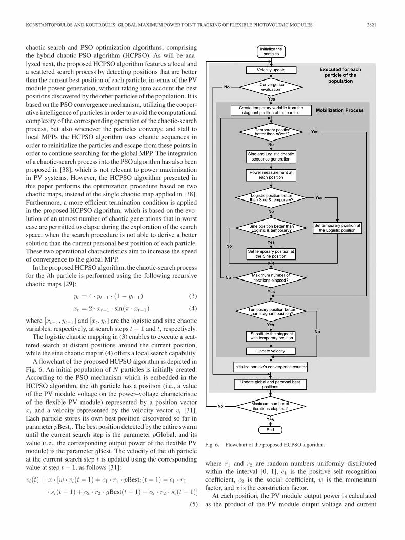
chaotic-search and PSO optimization algorithms, comprisingthe hybrid chaotic-PSO algorithm (HCPSO). As will be ana-lyzed next, the proposed HCPSO algorithm features a local anda scattered search process by detecting positions that are betterthan the current best position of each particle, in terms of the PVmodule power generation, without taking into account the bestpositions discovered by the other particles of the population. It isbased on the PSO convergence mechanism, utilizing the cooper-ative intelligence of particles in order to avoid the computationalcomplexity of the corresponding operation of the chaotic-searchprocess, but also whenever the particles converge and stall tolocal MPPs the HCPSO algorithm uses chaotic sequences inorder to reinitialize the particles and escape from these points inorder to continue searching for the global MPP. The integrationof a chaotic-search process into the PSO algorithm has also beenproposed in [38], which is not relevant to power maximizationin PV systems. However, the HCPSO algorithm presented inthis paper performs the optimization procedure based on twochaotic maps, instead of the single chaotic map applied in [38].Furthermore, a more efficient termination condition is appliedin the proposed HCPSO algorithm, which is based on the evo-lution of an utmost number of chaotic generations that in worstcase are permitted to elapse during the exploration of the searchspace, when the search procedure is not able to derive a bettersolution than the current personal best position of each particle.These two operational characteristics aim to increase the speedof convergence to the global MPP.
In the proposed HCPSO algorithm, the chaotic-search processfor the ith particle is performed using the following recursivechaotic maps [29]:
yt = 4 · yt−1 · (1 − yt−1) (3)
xt = 2 · xt−1 · sin(π · xt−1) (4)
where [xt−1 , yt−1] and [xt, yt] are the logistic and sine chaoticvariables, respectively, at search steps t − 1 and t, respectively.
The logistic chaotic mapping in (3) enables to execute a scat-tered search at distant positions around the current position,while the sine chaotic map in (4) offers a local search capability.
A flowchart of the proposed HCPSO algorithm is depicted inFig. 6. An initial population of N particles is initially created.According to the PSO mechanism which is embedded in theHCPSO algorithm, the ith particle has a position (i.e., a valueof the PV module voltage on the power–voltage characteristicof the flexible PV module) represented by a position vectorxi and a velocity represented by the velocity vector vi [31].Each particle stores its own best position discovered so far inparameter pBesti . The best position detected by the entire swarmuntil the current search step is the parameter pGlobal, and itsvalue (i.e., the corresponding output power of the flexible PVmodule) is the parameter gBest. The velocity of the ith particleat the current search step t is updated using the correspondingvalue at step t − 1, as follows [31]:
vi(t) = x · [w · vi(t − 1) + c1 · r1 · pBesti(t − 1) − c1 · r1
· si(t − 1) + c2 · r2 · gBest(t − 1) − c2 · r2 · si(t − 1)]
(5)
Fig. 6. Flowchart of the proposed HCPSO algorithm.
where r1 and r2 are random numbers uniformly distributedwithin the interval [0, 1], c1 is the positive self-recognitioncoefficient, c2 is the social coefficient, w is the momentumfactor, and x is the constriction factor.
At each position, the PV module output power is calculatedas the product of the PV module output voltage and current

2822 IEEE TRANSACTIONS ON POWER ELECTRONICS, VOL. 29, NO. 6, JUNE 2014
Vpv and Ipv , respectively, which are measured through the A/Dconverter (see Fig. 5).
Each particle decides about the direction toward to move next,considering its own experience (i.e., its own best past position)and the experience of the most successful particle in the swarm.Thus, the position of the ith particle at search step t si(t) iscalculated as the sum of its position at time step t − 1 and thenew velocity vi(t)
si(t) = si(t − 1) + vi(t). (6)
The positions of the particles correspond to 8-bit integer val-ues of the dc/dc converter duty cycle, D in (2) (i.e., 128-255),according to the following equation:
D = floor [si(t)] (7)
where the floor(·) function rounds down the calculated positionvalue.
In contrast to the approach applied in the PSO method, thevalues of the initial set of particles in the proposed HCPSOalgorithm are assigned based on the logistic chaotic variablesaccording to the following equation:
si(t = 0) = b + (a − b) · yi (8)
where si(t = 0) is the initial position of the ith particle (1 ≤ i ≤N), and a = 255 and b = 128 are the maximum and minimumvalues, respectively, of the possible positions range (i.e., 8-bitinteger values of the dc/dc converter duty cycle in the range of128–255) and yi is given by (3) by setting t = i.
The HCPSO algorithm considers that a particle is stagnant,thus not been able to discover better positions, whenever both ofthe following conditions apply for two consecutive time steps:
|vi(t)| < Δs (9)∣∣∣∣P (si(t)) − P (pBesti(t))
P (si(t))
∣∣∣∣ < ΔP (10)
where P (si(t)) and P (pBesti(t)) (in watts) are the PV powerproduced by the ith particle at positions si(t) and pBesti(t),respectively, and Δs and ΔP are the voltage and power stag-nancy limits, respectively, and their values are set by the MPPTsystem designer.
In order to overcome the particle’s stagnancy condition andretrigger the search process of the stagnant particle to explorethe position of the global MPP, the chaotic-search-based mo-bilization process illustrated in Fig. 6 is then executed for thestagnant particle. The local position of the stagnant particle isassigned to a temporary variable. Then, a close and a distantoperating point of the flexible PV module (i.e., positions on thepower–voltage characteristic) are generated according to thechaotic maps, with respect to the local position of the particle,which both explore for possible better positions in terms of thePV-generated power. In order to check whether there is any otherdistant area with a batch of better positions than the currentlyfocused area, the distant and close positions are compared withthe temporary position in terms of the power generated by theflexible PV module at each of these points. Then, the powergenerated by the flexible PV module is measured at positions
yLogt and xSint , which correspond to the distant and close po-sitions, respectively. These positions are generated by utilizingthe chaotic variables yt and xt at search step t, which are givenby the recursive chaotic maps in (3) and (4), respectively, asfollows:
yLogt = stemp + (a − b) · (k · yt − 0.5)/divLog (11)
xSint = stemp + (a − b) · (g · xt − 1.2)/divSin (12)
where stemp is the temporary position, while k, g,divSin ,divLogare scaling parameters and their values are determinedempirically.
Initially (i.e., for t = 0), the values of the chaotic variablesyt and xt are set equal to 0.6 and 0.9, respectively. The powergenerated at yLogt , xSint , as well as at the temporal position,are compared according to the following steps:
1) If the power generated at the position yLogt is higherthan the power produced at the temporary position and thepower generated at xSint , then the temporary position issubstituted by yLogt .
2) If the power generated at xSint is higher than the powerproduced at the temporary position and the power gener-ated at yLogt , then the temporary position is substitutedby xSint .
3) If the power generated at the temporary position resultingafter steps 1) and 2) is less than or equal to the power atpBesti , then the chaotic search procedure is repeated byproducing new logistic and sine chaotic variables usingthe temporary position of time step t − 1.
4) If the power generated at the temporary position whichresults after steps 1) and 2) is higher than pBesti , or amaximum permitted number of iterations G2 has elapsed,then the chaotic-search operation is suspended.
In case that after step 4) the mobilization process has dis-covered a temporary position which is better than the particle’sstagnant position before the mobilization process, then the stag-nant position is substituted with the position indicated by thetemporary position and the velocity of the particle is updated asfollows:
vi(t) = stemp − si(t) (13)
where stemp is the temporary position.The mobilization process described earlier performs two
changes of the power converter duty cycle within each itera-tion. When the execution of the mobilization process has beenaccomplished, then the variable that stores the number of suc-cessive generations that the specific particle is stagnant is resetto zero.
At the last step of the HCPSO global MPPT algorithm, theglobal as well as the personal best position of each particle ofthe population are updated as follows:
1) If P (si(t)) > P (pBest), then pBest = si(t).2) If P (si(t)) > P (gBest), then gBest = si(t).The HCPSO algorithm described earlier is executed for each
particle of the population and is repeated until a predefined num-ber of population generations G1 have evolved. The operatingpoint where the overall maximum power has been discovered to

KONSTANTOPOULOS AND KOUTROULIS: GLOBAL MAXIMUM POWER POINT TRACKING OF FLEXIBLE PHOTOVOLTAIC MODULES 2823
Fig. 7. Flexible PV module experimental setup for the performance evaluationof the proposed global MPPT system (in this example the bending angle isθ = 90◦).
be produced by the flexible PV module is stored in pGlobal andgBest, respectively, as described earlier, and it is considered tobe the global MPP of the PV power maximization procedure.
The position of the global MPP of the flexible PV moduleis derived by executing periodically the proposed HCPSO al-gorithm, with a repetition period of a few minutes. Then, aconventional MPPT algorithm [15] may be executed in orderto continuously track the short-term changes of the previouslydetected global MPP.
IV. EXPERIMENTAL RESULTS
A laboratory prototype of the proposed system (see Fig. 5) hasbeen designed and constructed in order to evaluate the perfor-mance of the proposed global MPPT method experimentally. Adc/dc boost converter is used to interface into a 48 V battery bankthe power produced by a UniSolar PVL-68 amorphous-siliconflexible PV module with 68 W/16.5 V MPP power and volt-age levels under standard test conditions (STC). Bypass diodesare connected in antiparallel with the solar cells comprising theflexible PV module. The dc/dc boost converter consists of anIRFZ44 power MOSFET and an MBR1060 diode, which op-erate with a 39 kHz switching frequency. An Lin = 160 μHinput inductance is used for continuous conduction of the dc/dcconverter down to an 1 A of dc input current, while the outputcapacitance Co has been set to 330 μF in order to achieve a 2%output voltage ripple. The Atmel ATmega 8535 microcontrollerunit, embedded in the STK500 development board, is used toexecute the MPPT algorithm and produce an 8-bit PWM sig-nal with the appropriate duty cycle, according to the HCPSOalgorithm described in Section III. The generated PWM controlsignal is then interfaced to the boost-type dc/dc power converterthrough an ICL7667 MOSFET driver IC. The PV module outputcurrent is measured using the LTSR6-NP Hall-effect-type cur-rent sensor with three turns. As illustrated in Fig. 5, the output ofthe Hall-effect sensor is interfaced to the A/D converter, which isavailable on the ATmega 8535 microcontroller chip, through anoperational-amplifier-based (LM358) amplifier. The PV moduleoutput voltage is measured using a differential amplifier basedon the LM358 operational amplifier. The experimental setupwhich was used to evaluate the performance of the proposedglobal MPPT system is illustrated in Fig. 7. A suitable sup-
TABLE IOPERATIONAL PARAMETERS OF THE HCPSO ALGORITHM
porting frame was constructed, enabling the adjustment of theangles of bending, tilt and orientation of the flexible PV moduleduring the test process, to the desired values.
The experimental setup described earlier was used to eval-uate the performance of the dual-carrier chaotic-search [29],PSO [31], DE [32], and HCPSO global MPPT algorithms underreal (i.e., outdoors) conditions. The maximum permitted num-ber of generations that each MPPT algorithm is executed was setaccording to simulation and experimental tests, such that con-vergence is ensured with the minimum number of search stepsin case that the PV module is installed at a horizontal position(i.e., θ = 0◦). However, since the PSO, DE and HCPSO algo-rithms execute random procedures in order to initialize and/ordirect the particles during the optimization process, the actualnumber of steps required for their convergence is not constantand these algorithms were executed several times in order toderive the most suitable number of generations. Thus, the PSOand DE algorithms were set to operate for 15 and 10 genera-tions, respectively. The values of the rest of the parameters ofthe chaotic-search, PSO, and DE algorithms were selected asdescribed in [29], [31] and [32], respectively. For comparisonpurposes, the proposed HCPSO global MPPT algorithm wasset to utilize the same basic parameters as the PSO algorithm,while the rest of the HCPSO algorithm parameters were se-lected experimentally such that convergence is achieved withthe minimum number of steps when θ = 0◦. The operationalparameters of the proposed HCPSO algorithm are shown inTable I. The maximum number of search iterations in case ofparticle stagnancy were set equal to G2 = 3, as a tradeoff be-tween the improvement capability of the particles to discoverbetter personal positions and the additional search steps thatthe chaotic-search mobilization procedure imposes (see Fig. 6),which increase the time until convergence to the global MPP hasbeen achieved. The process described earlier for the detectionof the MPPT algorithms operational-parameters values, was ap-plied only once, before the initiation of normal operation of theglobal MPPT system, where the flexible PV module was set tooperate under various solar irradiation and bending conditions,as analyzed in the following.
In order to evaluate the convergence speed of the globalMPPT algorithms under study, the total number of search stepshas been used as a metric, instead of the total convergencetime, since it is independent of design- and application-specificparameters, such as the type of the controller (e.g., proportional–integral (PI), proportional-integral-derivative (PID), fuzzy, etc.),the dc/dc converter power rating and input/output voltage speci-fications, etc. The accuracy of convergence was evaluated bycalculating the deviation of the PV-generated power at thefinal operating point, which has been derived as the globalMPP by each MPPT algorithm, from the power production atthe actual global MPP of the flexible PV module, which was

2824 IEEE TRANSACTIONS ON POWER ELECTRONICS, VOL. 29, NO. 6, JUNE 2014
detected by applying, prior to the execution of each MPPT al-gorithm, an exhaustive-search process with the maximum pos-sible resolution of the PWM control signal duty cycle. Duringthe exhaustive-search process, the entire power–voltage char-acteristic of the flexible PV module was scanned by iterativelymodifying the duty cycle of the boost-type dc/dc converter con-trol signal and measuring the power generated by the PV moduleat the resulting operating points. Since an 8-bit PWM signal isused to control the dc/dc power converter, then for the PV mod-ule/battery voltage ranges applied in this experimental setup,the power–voltage characteristic of the flexible PV module wasmeasured in 128 consecutive search steps by the exhaustive-search algorithm in order to detect the global MPP. The powerdeviation of the final operating point derived by each MPPTalgorithm as the global MPP, from the global MPP detected bythe exhaustive-search process depends on the operational effi-ciency of each optimization method, the power measurementerrors and the small-scale variations of the solar irradiation andambient temperature conditions during the exhaustive-searchand global MPPT processes, which slightly modify the power–voltage characteristic of the flexible PV module.
A critical parameter determining the performance of the PSO,chaotic-search, DE, and HCPSO global MPPT algorithms is thenumber of particles/genes comprising each generation. In orderto investigate the effect of this parameter, the performance of thePSO, chaotic-search, DE, and HCPSO global MPPT methodsunder study was initially evaluated in case that the flexible PVmodule is installed with θ = 0◦, such that its power–voltagecharacteristic exhibits a unique MPP, without additional localMPPs. The DE algorithm was tested for cases that it comprisesmore than four genes, since for lower values it was not able tosuccessfully detect the global MPP of the flexible PV module.The HCPSO, PSO, and DE algorithms successfully derived theglobal MPP, which has been measured using an exhaustive-search method as analyzed earlier, with a deviation of less than1.3%, except of the case of the DE algorithm with five geneswhere the deviation was increased to 17.7%. The chaotic-searchalgorithm was also executed for four particles, similarly to theproposed HCPSO algorithm, but it converged to a suboptimaloperating point. It was experimentally verified that in order tobe capable to track the global MPP successfully, more than eightparticles should be included in the chaotic-search algorithm, butthis results in higher computational complexity compared to theproposed HCPSO algorithm incorporating two to four particles,due to the sorting process employed. Thus, the performance ofthe chaotic-search technique was not explored any further.
The experimentally measured numbers of steps required forconvergence to the global MPP by each algorithm in case thatθ = 0◦, for various numbers of particles/genes in each genera-tion of the corresponding populations, are presented in Table II.The number of steps required by the DE method is significantlyhigher, since two search steps are executed for every gene of DEwithin the same generation, thus the operation of this algorithmusing a higher number of genes within each generation, beyondthe configurations illustrated in Table II, was not further inves-tigated. The number of search steps required by the proposedHCPSO algorithm are 6.7%–33.3% and 35.7%–84.1% less than
TABLE IIPERFORMANCE OF THE HCPSO, PSO, AND DE ALGORITHMS FOR VARIOUS
VALUES OF θ AND NUMBERS OF PARTICLES/GENES AT 13:00OF A CLEAR-SKY WINTER DAY
the corresponding numbers of steps required by the PSO (whenconfigured with equal numbers of particles with the HCPSOprocess) and DE algorithms, respectively.
Then, the bending angle of the flexible PV module was in-creased to θ = 60◦, 120◦, and 180◦, respectively and the previ-ous test process was repeated. By measuring the power–voltagecharacteristic of the flexible PV module it was detected that forthe specific meteorological and installation conditions of thistest process, it exhibits a unique MPP for θ = 60◦ and 120◦,while an additional local MPP is contained for θ = 180◦. Thecorresponding experimental results are summarized in Table II.The PSO algorithm is faster than the proposed HCPSO processby 6.3% only in case that they both employ three particles inorder to perform the MPPT process. In the rest of the cases in-vestigated, the number of search steps required by the proposedHCPSO algorithm are less than the search steps required bythe PSO (for the configurations with equal numbers of particleswith the HCPSO process) and DE algorithms by 0%–33.3%and 42.9%–84.1%, respectively. In contrast to the PSO- andDE-based global MPPT methods, the number of search stepsexecuted in the proposed HCPSO algorithm is not constant dueto the activation of the chaotic-search-based mobilization mech-anism for the particles under stagnancy (see Fig. 6). The averagevalue of the relative power deviation of the operating points de-tected as the global MPPs by the HCPSO-, PSO- and DE-basedmethods, from the global MPP derived using the exhaustive-search process, is 0.7%, 32.0%, and 11.1%, respectively, thusindicating the superiority of the proposed HCPSO algorithm tosuccessfully track the global MPP.
As analyzed in Section III, the operation of the proposedHCPSO algorithm is based on the convergence mechanism ofthe PSO optimization process, but it does not execute randomprocedures to reinitialize the particles in case of stagnancy.In contrast, the chaotic-search-based initialization of the par-ticles, which is performed in the proposed HCPSO algorithm,distributes them within the search space in a more efficientway, compared to the random initialization performed in the

KONSTANTOPOULOS AND KOUTROULIS: GLOBAL MAXIMUM POWER POINT TRACKING OF FLEXIBLE PHOTOVOLTAIC MODULES 2825
PSO-based approach. Thus, compared to the PSO algorithm,the HCPSO-based global MPPT method converges to operatingpoints which reside much closer to the global MPP. Also, accord-ing to the results presented in Table II, applying the proposedHCPSO method with two particles is the most effective ap-proach in terms of convergence speed, which also outperformedthe PSO and DE global MPP methods in case of power–voltagecharacteristics with either none or one local MPP.
Considering the power–voltage curves of the flexible PVmodule in Figs. 3 and 4, as well as the experimental results pre-sented in Table II, the performance of the HCPSO, PSO and DEmethods, in terms of the power deviation and number of steps,depends on: 1) the operating conditions of the flexible PV mod-ule (i.e., bending angle, solar irradiation intensity, etc.), whichdefine the shape of the power–voltage curve, and 2) the random-ness inherent in the operation of these global MPPT methods.The performance of the HCPSO and PSO algorithms with twoparticles and the DE algorithm with four genes, which are themost efficient configurations in terms of convergence speed ac-cording to the results presented in Table II, was also experimen-tally investigated by setting the flexible PV module at variousvalues of θ in the range 0◦–180◦ from 09:00 to 16:00 during twoconsecutive days. Thus, the impact of direction of the incidentsolar irradiation on the shape of the power–voltage characteristicof the flexible PV module when installed under bending con-ditions, as demonstrated in Section II, was also considered inthe performance evaluation of the global MPPT methods understudy. During the test process, the solar irradiation on horizon-tal plane and ambient temperature were measured to vary in therange of 320–740 W/m2 and 18.1–22.7 ◦C, respectively. The re-sulting experimentally measured power–voltage characteristicsof the flexible PV module are illustrated in Fig. 8(a), showingthat test cases are also included where the power–voltage char-acteristic of the flexible PV module exhibits a local MPP. Theaverage and standard deviation values of the deviation of the PVpower produced at the operating point derived by each algorithmas the global MPP, from the power at the global MPP, whichwas detected by the exhaustive search process, are presentedin Fig. 8(b). It is observed that the average power deviation ofthe proposed HCPSO algorithm from the global MPP detectedby the exhaustive-search process is less than the average powerdeviation of the PSO and DE techniques by 33.9% and 66.1%,respectively. The power deviation of the HCPSO algorithm ex-hibits a standard deviation, which is lower than that of the PSOand DE algorithms by 41.7% and 55.6%, respectively.
The average and standard deviation values of the number ofsteps required by each optimization method in order to convergeto the global MPP are illustrated in Fig. 8(c). The number of stepsrequired by the HCPSO algorithm in order to accomplish thecorresponding global MPPT processes were 20–28 with a stan-dard deviation of 3.53 steps, while the PSO and DE algorithmsrequire a constant number of search steps, since according tothe corresponding termination criteria employed, their operationis suspended after a predefined number of iterations. Also, theHCPSO algorithm accomplishes the global MPPT process with24.8% and 73.2% less average search steps compared to thePSO and DE algorithms, respectively. Thus, using the proposed
Fig. 8. Performance of the HCPSO, PSO, and DE algorithms: (a) power–voltage characteristics of the flexible PV module during the test process;(b) average and standard deviation of the power deviation from the globalMPP; and (c) average and standard deviation of the number of search steps.
HCPSO algorithm the PV power loss during the execution ofthe global MPPT process is minimized.
In all cases investigated in Table II and Fig. 8, the HCPSO,PSO, DE, and exhaustive-search algorithms have been appliedwith a 1/128 resolution of the PWM control signal duty cycle.However, the number of steps required by the HCPSO, PSO, andDE algorithms in order to derive the global MPP of the flexiblePV module is less than the 128 steps executed by the exhaustive-search algorithm. A common characteristic of the exhaustive-search, HCPSO, PSO, and DE algorithms is that, for a givenapplication, the duty-cycle resolution employed during theirexecution can be tailored to the dc/dc converter input/outputvoltage range and the operational characteristics of the flexiblePV module, such that the performance of the global MPPTsystem is optimized in terms of the accuracy of detecting theglobal MPP and the number of steps required until convergence.
In order to demonstrate the evolution of the global MPPTprocess, which is performed using the proposed HCPSO methodin case that local MPPs are exhibited by the power–voltagecharacteristic of the PV module, the experimentally measuredpower–voltage characteristic of the flexible PV module in casethat θ = 180◦ and β = α = 0◦ at 13:00 of a clear-sky winterday is shown in Fig. 9(a). The output power of the flexible PVmodule at each step of operation of the HCPSO algorithm withthree particles is also depicted in that figure. The experimentallymeasured trajectory of consecutive flexible PV module output

2826 IEEE TRANSACTIONS ON POWER ELECTRONICS, VOL. 29, NO. 6, JUNE 2014
Fig. 9. Experimental results of the HCPSO algorithm with three particles incase that θ = 180◦, β = α = 0◦, the incident solar irradiation is equal to 730W/m2 and the ambient temperature is 22.7 ◦C at 13:00 of a clear-sky winter day:(a) the power–voltage characteristic of the flexible PV module and the operatingpoints during the operation of the HCPSO algorithm and (b) the flexible PVmodule output power at each search step of the HCPSO algorithm for eachparticle.
power levels followed by each of the three particles during theoperation of the HCPSO algorithm is illustrated in Fig. 9(b). Asindicated in Fig. 9(b), the global MPPT process is accomplishedin 48 search steps and the chaotic-search-based mobilizationmechanism of the HCPSO algorithm (see Fig. 6) is activatedduring time steps 21–27, 32–38, and 39–45, respectively. It isobserved that the three particles of the HCPSO algorithm startedexploring the power–voltage search space from a completelydifferent position with respect to the area where the global MPPresides. However, they progressively moved toward the correctdirection by successfully discriminating the local and globalMPPs, although their power levels do not differ significantly.The position of the global MPP was detected by the secondparticle at step 29 with a power deviation of 0.55%.
Similarly, the experimentally measured power–voltage char-acteristic of the flexible PV module in case that θ = 180◦ andβ = α = 0◦ at 17:00 of a clear-sky summer day, as well asthe output power of the flexible PV module during the evo-lution of the proposed HCPSO algorithm with two particles,are presented in Fig. 10(a). The experimentally measured tra-jectory, which was followed by the two particles during theHCPSO global MPPT process are shown in Fig. 10(b). In thistest case, it was not required for the mobilization mechanismof the HCPSO algorithm (see Fig. 6) to be activated during theexecution time steps. Also, the initial positions of the HCPSOalgorithm particles were close to the area of a local MPP, whichextended over a relatively wide voltage range, but both particles
Fig. 10. Experimental results of the HCPSO algorithm with two particlesin case that θ = 180◦, β = α = 0◦, the incident solar irradiation is equal to440 W/m2 and the ambient temperature is 26.5 ◦C at 17:00 of a clear-skysummer day: (a) the power–voltage characteristic of the flexible PV module andthe operating points during the operation of the HCPSO algorithm and (b) theflexible PV module output power at each search step of the HCPSO algorithmfor each particle.
avoided to get trapped in that area. Thus, the global MPP wasdetected by the first particle at step 17 with a power deviation of0.22%, while the HCPSO algorithm terminated after executing20 search steps.
The experimental results indicate that using the same val-ues of the operational parameters, which were derived duringthe initial test process, the proposed global MPPT system wascapable to operate effectively over a wide range of solar irradia-tion conditions and bending-angle setups, without requirementto repeat the initial parameters-detection process. Each of theseoperating conditions resulted in different forms of the flexi-ble PV module power–voltage curves, which were not knowna priori. However, the proposed HCPSO algorithm was capableto successfully adapt to these different operational characteris-tics of the flexible PV module power source, which are typicallydetermined by the target application of the PV system, withoutrequiring any knowledge of them.
V. CONCLUSION
The use of flexible PV modules has emerged during the pastfew years due to their capability to easily adapt on nonplanarsurfaces. However, when installed on curved surfaces thepower–voltage characteristic of the flexible PV modules ex-hibits local MPPs. The experimental results presented in thispaper, for the first time in the existing literature, demonstratethat the number and position of local MPPs depends on the solarirradiation and ambient temperature conditions, as well as theinstallation geometry of the flexible PV module.
KONSTANTOPOULOS AND KOUTROULIS: GLOBAL MAXIMUM POWER POINT TRACKING OF FLEXIBLE PHOTOVOLTAIC MODULES 2827
A new method of tracking the global MPP of flexible PVmodules has also been proposed in this paper, which, comparedto the past-proposed MPPT techniques, has the advantage thatit is capable to detect the global MPP of flexible PV moduleswith less search steps. The performance superiority of the pro-posed global MPPT technique over the past-proposed methodshas been demonstrated with a comparative experimental studyunder real operating conditions. Applying the proposed HCPSOmethod with two particles was the most effective approach interms of convergence speed. Thus, using the proposed system,the power loss during the global MPPT process is minimized andthe energy production of the flexible PV module is maximized.
The boost-converter-based design, which has been presentedin the paper, is directly applicable to distributed MPPT architec-tures of PV systems comprising flexible PV modules [34]. Also,the microcontroller-based control unit can be easily modified tocontrol, according to the proposed HCPSO algorithm, alterna-tive dc/dc power converter topologies (e.g., buck, buck–boost,etc.) in order to adapt to specific operational requirements of thetarget PV application.
REFERENCES
[1] F. Boico and B. Lehman, “Multiple-input maximum power point trackingalgorithm for solar panels with reduced sensing circuitry for portableapplications,” Solar Energy, vol. 86, pp. 463–475, 2012.
[2] A. W. Blakers and T. Armour, “Flexible silicon solar cells,” Solar EnergyMater. Solar Cells, vol. 93, pp. 1440–1443, 2009.
[3] K. M. Trautz, P. P. Jenkins, R. J. Walters, D. Scheiman, R. Hoheisel,R. Tatavarti, R. Chan, H. Miyamoto, J. G. J. Adams, V. C. Elarde, andJ. Grimsley, “Mobile solar power,” IEEE J. Photovoltaics, vol. 3, no. 1,pp. 535–541, Jan. 2013.
[4] K. M. Edmondson, D. C. Law, G. Glenn, A. Paredes, R. R. King, andN. H. Karam, “Flexible III–V multijunction solar blanket,” in Proc. IEEE4th World Conf. Photovoltaic Energy Convers., vol. 2, 2006, pp. 1935–1938.
[5] E. Thomsen, J. Muric-Nesic, V. Everett, M. Brauers, E. Davies, T. Ratcliff,C. Samundsett, I. Skryabin, L. Xia, and A. Blakers, “Materials and manu-facturing processes for high-efficiency flexible photovoltaic modules,” inProc. 35th IEEE Photovoltaic Spec. Conf. (PVSC), 2010, pp. 2877–2882.
[6] E. A. Thomsen, J. Muric-Nesic, S. Rahman, Y. O. Mayon, D. Wang,T. Ratcliff, V. Everett, I. Skryabin, and A. Blakers, “Flexible sliver mod-ules,” 37th IEEE Photovoltaic Spec. Conf. (PVSC), pp. 3225–3230, 2011.
[7] P. Reinhard, A. Chirila, P. Blosch, F. Pianezzi, S. Nishiwaki, S. Buecheler,and A. N. Tiwari, “Review of progress toward 20% efficiency flexibleCIGS solar cells and manufacturing issues of solar modules,” IEEE J.Photovoltaics, vol. 3, no. 1, pp. 572–580, Jan. 2013.
[8] C. R. Sullivan, J. J. Awerbuch, and A. M. Latham, “Decrease in photo-voltaic power output from ripple: Simple general calculation and the effectof partial shading,” IEEE Trans. Power Electron., vol. 28, no. 2, pp. 740–747, Feb. 2013.
[9] L. V. Hartmann, M. A. Vitorino, M. B. R. Correa, and A. M. N. Lima,“Combining model-based and heuristic techniques for fast tracking themaximum power point of photovoltaic systems,” IEEE Trans. Power Elec-tron., vol. 28, no. 6, pp. 2875–2885, Jun. 2013.
[10] E. Dallago, D. G. Finarelli, U. P. Gianazza, A. L. Barnabei, andA. Liberale, “Theoretical and experimental analysis of an MPP detectionalgorithm employing a single-voltage sensor only and a noisy signal,”IEEE Trans. Power Electron., vol. 28, no. 11, pp. 5088–5097, Nov. 2013.
[11] G.-C. Hsieh, H.-I Hsieh, C.-Y. Tsai, and C.-H. Wang, “Photovoltaic power-increment-aided incremental-conductance MPPT with two-phased track-ing,” IEEE Trans. Power Electron., vol. 28, no. 6, pp. 2895–2911, Jun.2013.
[12] Y. Jiang, J. A. A. Qahouq, and T. A. Haskew, “Adaptive step size withadaptive-perturbation-frequency digital MPPT controller for a single-sensor photovoltaic solar system,” IEEE Trans. Power Electron., vol. 28,no. 7, pp. 3195–3205, Jul. 2013.
[13] A. K. Abdelsalam, A. M. Massoud, S. Ahmed, and P. Enjeti, “High-performance adaptive perturb and observe MPPT technique forphotovoltaic-based microgrids,” IEEE Trans. Power Electron., vol. 26,no. 4, pp. 1010–1021, Apr. 2011.
[14] A. M. Latham, R. Pilawa-Podgurski, K. M. Odame, and C. R. Sullivan,“Analysis and optimization of maximum power point tracking algorithmsin the presence of noise,” IEEE Trans. Power Electron., vol. 28, no. 7,pp. 3479–3494, Jul. 2013.
[15] B. Subudhi and R. Pradhan, “A comparative study on maximum powerpoint tracking techniques for photovoltaic power systems,” IEEE Trans.Sustainable Energy, vol. 4, no. 1, pp. 89–98, Jan. 2013.
[16] D. C. Jones and R. W. Erickson, “Probabilistic analysis of a generalizedperturb and observe algorithm featuring robust operation in the presence ofpower curve traps,” IEEE Trans. Power Electron., vol. 28, no. 6, pp. 2912–2926, Jun. 2013.
[17] P. S. Shenoy, K. A. Kim, B. B. Johnson, and P. T. Krein, “Differentialpower processing for increased energy production and reliability of pho-tovoltaic systems,” IEEE Trans. Power Electron., vol. 28, no. 6, pp. 2968–2979, Jun. 2013.
[18] R. C. N. Pilawa-Podgurski and D. J. Perreault, “Sub-module integrateddistributed maximum power point tracking for solar photovoltaic applica-tions,” IEEE Trans. Power Electron., vol. 28, no. 6, pp. 2957–2967, Jun.2013.
[19] S. M. MacAlpine, R. W. Erickson, and M. J. Brandemuehl, “Character-ization of power optimizer potential to increase energy capture in pho-tovoltaic systems operating under nonuniform conditions,” IEEE Trans.Power Electron., vol. 28, no. 6, pp. 2936–2945, Jun. 2013.
[20] L. F. L. Villa, T.-P. Ho, J.-C. Crebier, and B. Raison, “A power electronicsequalizer application for partially shaded photovoltaic modules,” IEEETrans. Ind. Electron., vol. 60, no. 3, pp. 1179–1190, Mar. 2013.
[21] I. Abdalla, J. Corda, and L. Zhang, “Multilevel DC-link inverter andcontrol algorithm to overcome the PV partial shading,” IEEE Trans. PowerElectron., vol. 28, no. 1, pp. 14–18, Jan. 2013.
[22] Y.-H. Ji, D.-Y. Jung, J.-G. Kim, J.-H. Kim, T.-W. Lee, and C.-Y. Won, “Areal maximum power point tracking method for mismatching compensa-tion in PV array under partially shaded conditions,” IEEE Trans. PowerElectron., vol. 26, no. 4, pp. 1001–1009, Apr. 2011.
[23] B. N. Alajmi, K. H. Ahmed, S. J. Finney, and B. W. Williams, “A maxi-mum power point tracking technique for partially shaded photovoltaic sys-tems in microgrids,” IEEE Trans. Ind. Electron., vol. 60, no. 4, pp. 1596–1606, Apr. 2013.
[24] P. K. Peter and V. Agarwal, “On the input resistance of a reconfig-urable switched capacitor DC–DC converter-based maximum power pointtracker of a photovoltaic source,” IEEE Trans. Power Electron., vol. 27,no. 12, pp. 4880–4893, Dec. 2012.
[25] A. Bidram, A. Davoudi, and R. S. Balog, “Control and circuit techniquesto mitigate partial shading effects in photovoltaic arrays,” IEEE J. Photo-voltaics, vol. 2, no. 4, pp. 532–546, Oct. 2012.
[26] J. P. Storey, P. R. Wilson, and D. Bagnall, “Improved optimization strategyfor irradiance equalization in dynamic photovoltaic arrays,” IEEE Trans.Power Electron., vol. 28, no. 6, pp. 2946–2956, Jun. 2013.
[27] S. Syafaruddin, T. Hiyama, and E. Karatepe, “Investigation of ANN per-formance for tracking the optimum points of PV module under partiallyshaded conditions,” in Proc. Conf. Proc. IPEC, 2010, pp. 1186–1191.
[28] T. L. Nguyen and K.-S. Low, “A global maximum power point trackingscheme employing DIRECT search algorithm for photovoltaic systems,”IEEE Trans. Ind. Electron., vol. 57, no. 10, pp. 3456–3467, Oct. 2010.
[29] L. Zhou, Y. Chen, K. Guo, and F. Jia, “New approach for MPPT controlof photovoltaic system with mutative-scale dual-carrier chaotic search,”IEEE Trans. Power Electron., vol. 26, no. 4, pp. 1038–1048, Apr. 2011.
[30] K. Ishaque, Z. Salam, M. Amjad, and S. Mekhilef, “An improved particleswarm optimization (PSO)-based MPPT for PV with reduced steady-stateoscillation,” IEEE Trans. Power Electron., vol. 27, no. 8, pp. 3627–3638,Aug. 2012.
[31] M. Miyatake, M. Veerachary, F. Toriumi, N. Fujii, and H. Ko, “Maximumpower point tracking of multiple photovoltaic arrays: A PSO approach,”IEEE Trans. Aerosp. Electron. Syst., vol. 47, no. 1, pp. 367–380, Jan. 2011.
[32] H. Taheri, Z. Salam, K. Ishaque, and S. Syafaruddin, “A novel maximumpower point tracking control of photovoltaic system under partial andrapidly fluctuating shadow conditions using differential evolution,” inProc. IEEE Symp. Ind. Electron. Appl. (ISIEA), 2010, pp. 82–87.
[33] K. Ishaque and Z. Salam, “A deterministic particle swarm optimizationmaximum power point tracker for photovoltaic system under partial shad-ing condition,” IEEE Trans. Ind. Electron., vol. 60, no. 8, pp. 3195–3206,Aug. 2013.

2828 IEEE TRANSACTIONS ON POWER ELECTRONICS, VOL. 29, NO. 6, JUNE 2014
[34] M. Acanski, J. Popovic-Gerber, and J. A. Ferreira, “Thermal modeling ofthe module integrated DC–DC converter for flexible thin-film PV mod-ules,” in Proc. 14th Eur. Conf. Power Electron. Appl. (EPE), 2011, pp. 1–10.
[35] P. Sharma, B. Patnaik, S. P. Duttagupta, and V. Agarwal, “Dynamic poweroptimization of contoured flexible PV array under non-uniform illumina-tion conditions,” in Proc. 35th IEEE Photovoltaic Spec. Conf. (PVSC),2010, pp. 968–972.
[36] N. Mohan, T. M. Undeland, and W. P. Robbins, Power Electronics: Con-verters, Applications, and Design, 2nd ed. New York, NY, USA: Wiley,1995.
[37] J. G. Kassakian, M. F. Schlecht, and G. C. Verghese, Principles PowerElectron., 2nd ed. Reading, MA, USA: Addison-Wesley, 1992.
[38] H. Meng, P. Zheng, R. Wu, X. Hao, and Z. Xie, “A hybrid particle swarmalgorithm with embedded chaotic search,” in Proc. IEEE Conf. Cybern.Intell. Syst., 2004, vol. 1, pp. 367–371.
Christos Konstantopoulos was born in Athens,Greece, in 1989. He received the B.Sc. degree in 2012from the Department of Electronic and ComputerEngineering, Technical University of Crete, Chania,Greece, where he is currently working toward theM.Sc. degree.
His current research interests include powerelectronics for renewable energy sources, energy har-vesting for wireless sensor networks, and electronicmeasurement systems.
Eftichios Koutroulis (M’10) was born in Chania,Greece, in 1973. He received the B.Sc., M.Sc., Ph.D.[in the area of power electronics and renewable en-ergy sources (RES)] degrees from the Departmentof Electronic and Computer Engineering, TechnicalUniversity of Crete, Chania, Greece, in 1996, 1999,and 2002, respectively.
He is currently an Assistant Professor in the De-partment of Electronic and Computer Engineering,Technical University of Crete. His current researchinterests include power electronics (dc/ac inverters,
dc/dc converters), the development of microelectronic energy management sys-tems for RES, and the design of photovoltaic and wind energy conversionsystems.