Embed Size (px)
Citation preview

Global Positioning System as a Master Clock and Reference Signal Application Note
IntroductionThe Global Positioning System (GPS) can be used for synchronization by obtaining timing information from a number of satellites orbiting the earth. The initial GPS system used 24 orbiting satellites and typically four or more of these satellite signals should be available in order for a GPS receiver to calculate position and time information. Each satellite transmits messages that provide a time the message was sent and the satellite’s position at the time of message transmission. The GPS receiver uses these messages from each of the satellites
to determine the transit time of each message from which the receiver can compute the distance to each satellite. Hence the GPS receiver can determine positional information and the time difference between internal time of the receiver and the time of day provided by the satellites. The internal GPS receiver within the SPG8000 or the GPS7 module of the TG8000 provides a 10 MHz clock along with a pulse once per second and time of day information that is used within the generator to lock the system timing and provide time of day information. In this way multiple locations around the world can all be locked to the same reference.
Application Note
www.tek.com/sync-pulse-generator2
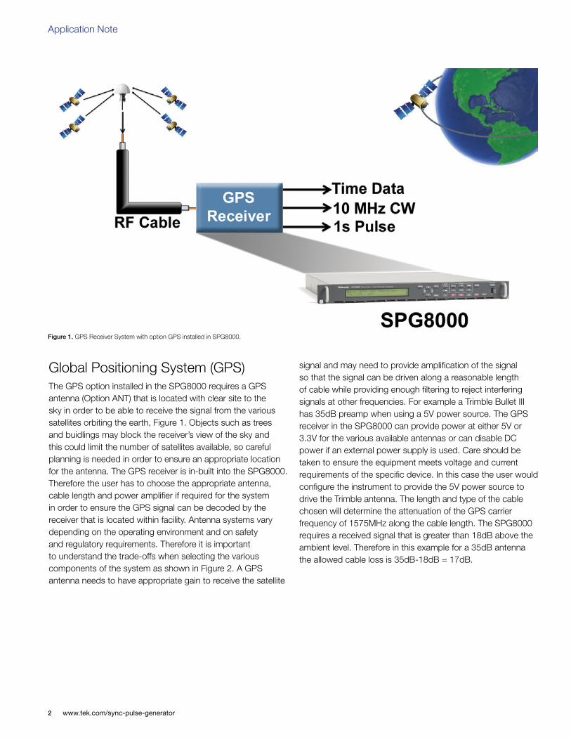
Global Positioning System (GPS) The GPS option installed in the SPG8000 requires a GPS antenna (Option ANT) that is located with clear site to the sky in order to be able to receive the signal from the various satellites orbiting the earth, Figure 1. Objects such as trees and buidlings may block the receiver’s view of the sky and this could limit the number of satellites available, so careful planning is needed in order to ensure an appropriate location for the antenna. The GPS receiver is in-built into the SPG8000. Therefore the user has to choose the appropriate antenna, cable length and power amplifier if required for the system in order to ensure the GPS signal can be decoded by the receiver that is located within facility. Antenna systems vary depending on the operating environment and on safety and regulatory requirements. Therefore it is important to understand the trade-offs when selecting the various components of the system as shown in Figure 2. A GPS antenna needs to have appropriate gain to receive the satellite
signal and may need to provide amplification of the signal so that the signal can be driven along a reasonable length of cable while providing enough filtering to reject interfering signals at other frequencies. For example a Trimble Bullet III has 35dB preamp when using a 5V power source. The GPS receiver in the SPG8000 can provide power at either 5V or 3.3V for the various available antennas or can disable DC power if an external power supply is used. Care should be taken to ensure the equipment meets voltage and current requirements of the specific device. In this case the user would configure the instrument to provide the 5V power source to drive the Trimble antenna. The length and type of the cable chosen will determine the attenuation of the GPS carrier frequency of 1575MHz along the cable length. The SPG8000 requires a received signal that is greater than 18dB above the ambient level. Therefore in this example for a 35dB antenna the allowed cable loss is 35dB-18dB = 17dB.
Figure 1. GPS Receiver System with option GPS installed in SPG8000.

www.tek.com/sync-pulse-generator 3
Global Positioning System as a Master Clock and Reference Signal
Attenuation varies significantly depending on the type of cable used. For example cable loss is about 13 dB/100 feet for a miniature coaxial cable like Belden 1855, while for a RG11 style cable like the Belden 7731, the loss is only 5.5 dB/100 feet. This correlates to an allowable length of 130 feet for the Belden 1855 cable, to over 300 feet for the Belden 7731 cable. A booster amplifier can be added if additional length of cable is needed, as shown in the optional block in the signal path system, Figure 2. The location of the amplifier can be critical as placing the amplifier just before the SPG8000 may result in the GPS signal been too attenuated and the amplification of signal at this point maybe too noisy to be decoded. If a 20 dB amplifier is added with the signal path, then 20 dB more cable loss can be accommodated. This equates to another 150 feet of Belden 1855 coax, or 360 feet of Belden 7731 coax for this example. Although the GPS input and most of the other components are 50 Ω, either 50 Ω or 75 Ω cables can be used in most installations. The reflections from the impedance mismatch will not cause significant changes in the system because the signal is narrow band and the cable loss is usually many dBs. However, you should not mix short cable lengths of different impedances, as this might create reflections with the potential to cause signal degradation. For complex systems, a variety of booster amplifiers, powered and passive splitters, DC blocks, and filters are available from a number of vendors to ensure transmission of the GPS signal to the receiver.
Once the configuration is complete and the GPS signal is connected to the Tektronix SPG8000 generator it can take several minutes for the signal quality to reach its nominal potential. How long the system takes depends on such things as antenna site, cable plant design, and available satellites. Typically it requires at least four satellites to correlate the timing information and the SPG8000 provides a Figure of Merit to provide a gauge of the receiver ability to decode the GPS signal. These Figure of Merit (FOM) numbers (Table 1) are a compendium of the GPS signal quality and the processes that occur as the instrument progresses through the states needed to lock on to the GPS signal. The FOM provides a simple scale
to evaluate the state of the GPS lock for the user. Additionally the user can verify the number of satellites that the receiver has acquired within the menu of the SPG8000. During the initial installation of the system it is important to monitor the figure of merit over several days to ensure correct operation of the system.
The user can configure the SPG8000 to use the GPS Signal as the reference source using the timing reference signals from the GPS receiver of 10 MHz and one pulse per second. Additional timing data derived from the UTC (Universal Time Code) can be used as a phase reference for video reference synchronization.
The GPS epoch is defined as 00:00:00 January 6th 1980 from which the GPS signal will report a timestamp in weeks and seconds. For instance a 06:25:00 UTC of November 5th 2008 will be reported as 1504 weeks and 282,314 seconds by the GPS system. The GPS signaling also provides information on the number of leap seconds, in this example 14 leap seconds would have occurred between January 6th 1980 and November 5th 2008.
In order to provide video system synchronization an adjustment between SMPTE epoch and GPS epoch should be made. The SMPTE epoch is defined as 0:00:00 of January 1st 1958 (TAI International Atomic Time) and is considered the “big bang” moment when all frames were aligned. From that moment there have been exactly 30,000 NTSC frames and 25,025 PAL frames every 1001 seconds. Therefore in our example we need to add an additional 8040 days plus 19 more leap seconds that is the difference between SMPTE Epoch (TAI) and GPS Epoch, producing a total of 1,604,557,533 seconds and corresponding to 96,177,274,705,2947 NTSC fields. From this calculation we can determine how may frames to adjust for the current time in order to achieve frame alignment within the SPG. This can be done by using Jam Sync that will align the reference signals quickly but will produce a shock to the system. Alternatively the clock can be slowly slewed to gradually provide alignment of the reference signals.
Figure 2. Simplified GPS Antenna system.

Application Note
www.tek.com/sync-pulse-generator4
When the GPS signal is lost the user can configure certain actions to be performed by the GPS Hold Over Recovery system:
Stay Legal: Adjusts the module timing to match the recovered GPS signal while staying within the specified frequency offset and frequency rate of change specifications for NTSC and PAL reference signals.
Jam Phase: Adjusts the module timing to match the recovered GPS signal immediately but will typically cause a sync “shock” to the system.
Fast Slew: Adjusts the module timing to match the recovered GPS signal at a rate 25 times faster than the legal rate without jumping.
Stay Legal would typically be used by a facility that in the event of a loss of GPS lock they would prefer to maintain
reference signal within specified limits and not cause a shock to the system when the GPS signal is decoded in order to maintain facility timing. Jam Phase may be used by an outside broadcast vehicle or mobile truck to quickly establish GPS lock when the system is powered up to help quickly establish lock of all systems within the vehicle and the user is not concerned about a sync shock to the system as each of the devices is powered up. Alternatively the user can use the Fast Slew mode that quickly will attain synchronization and lock without causing a major shock to the system. In this way the Tektronix SPG8000 can ensure a shock-free re-alignment of frequency and phase when the GPS signal is restored. Otherwise a typical SPG will return to the internal free run frequency of its oscillator when the synchronization signal was lost and will likely cause a shock to the system when the reference signal is reapplied.
Table 1. Figures of merit for signal quality.
Figure of Merit Indicator Description
0 No Signal This means that no usable satellite signals are detected. This is normal for a short time after the signal is applied, but if it lasts more than a minute or so, then it usually means one of the following: that there is a problem in the antenna or cable, the antenna is blocked from direct line of sight to the satellites, or the power is not getting to the antenna.
1 Low signal This means that some signal is detected, but that the signal quality is too low for extraction of useful timing or position information. This is a normal situation for a short duration, but if it persists, the causes are likely to be similar to those for FOM state 0.
2 Acquire satellites This means that the instrument is receiving data from the satellites and is determining which signals to use.
3 Bad position This means that the instrument detects that the stored position is different from the current position. In this case, the instrument will automatically go to FOM state 4 and reacquire the position.
4 Acquire position This means that the instrument is acquiring multiple fixes of the satellite position and averaging this into a new position to store in flash. This state will also be displayed if you manually perform a new position acquisition. This state normally lasts 60 seconds with good GPS signal quality.
5 Adjust phase This means that the instrument is adjusting the time base or frame timing to correctly line up with the GPS signal.
6 Locked > Signal quality is ≤ 16
These states indicate that the phase of the frame signals is within 150 ns of the GPS signal. The number of arrows indicates the signal quality. It is normal for this to vary with the time of day as the different satellites move through their orbits, as well as with changes in weather and other conditions.7 Locked >>
Signal quality is > 16
8 Locked >>> Signal quality is > 26
9 Locked >>>> Signal quality is > 42
10 Locked >>>>> Signal quality is > 68
11 Locked >>>>>> Signal quality is > 110

www.tek.com/sync-pulse-generator 5
Global Positioning System as a Master Clock and Reference Signal
When lock is achieved a solid green LED on the front panel will be illuminated. If this green LED is flashing then this is an indication that the FOM is below 6 and the user should check the Status display for additional information on the signal strength. Depending on the environment the GPS signal could be lost because of atmospheric conditions or limited number of satellites available and the user can setup alarms to be triggered on GPS signal quality.
ConclusionThe Global Positioning System is typically used for navigation and determining ones position on the earth relative to a number of satellites. Additionally GPS can provide a reliable means to provide master clock and timing reference signals from a sync pulse generator such as the Tektronix SPG8000 with the GPS option. This method of synchronization allows for multiple facilities around the world to all derive their reference signals from the same system. Care has to be taken in setting up this system to ensure reliable operation of the system. The Tektronix SPG8000 Hold Over Recovery function can ensure continued operation of these critical synchronization signals within the facility when the GPS signal is lost due to atmospheric or other conditions.

For Further InformationTektronix maintains a comprehensive, constantly expanding collection of application notes, technical briefs and other resources to help engineers working on the cutting edge of technology. Please visit www.tektronix.com
Contact Tektronix:ASEAN / Australia (65) 6356 3900
Austria* 00800 2255 4835Balkans, Israel, South Africa and other ISE Countries +41 52 675 3777
Belgium* 00800 2255 4835Brazil +55 (11) 3759 7627Canada 1 (800) 833-9200
Central East Europe and the Baltics +41 52 675 3777Central Europe & Greece +41 52 675 3777
Denmark +45 80 88 1401Finland +41 52 675 3777
France* 00800 2255 4835Germany* 00800 2255 4835
Hong Kong 400-820-5835Ireland* 00800 2255 4835
India +91-80-30792600Italy* 00800 2255 4835
Japan 0120-441-046Luxembourg +41 52 675 3777
Macau 400-820-5835Mongolia 400-820-5835
Mexico, Central/South America & Caribbean 52 (55) 56 04 50 90Middle East, Asia and North Africa +41 52 675 3777
The Netherlands* 00800 2255 4835Norway 800 16098
People’s Republic of China 400-820-5835Poland +41 52 675 3777
Portugal 80 08 12370Puerto Rico 1 (800) 833-9200
Republic of Korea +822-6917-5000Russia +7 495 664 75 64
Singapore +65 6356-3900South Africa +27 11 206 8360
Spain* 00800 2255 4835Sweden* 00800 2255 4835
Switzerland* 00800 2255 4835Taiwan 886-2-2656-6688
United Kingdom* 00800 2255 4835USA 1 (800) 833-9200
* If the European phone number above is not accessible, please call +41 52 675 3777
Contact List Updated June 2013
Copyright © 2014, Tektronix. All rights reserved. Tektronix products are covered by U.S. and foreign patents, issued and pending. Information in this publication supersedes that in all previously published material. Specification and price change privileges reserved. TEKTRONIX and TEK are registered trademarks of Tektronix, Inc. All other trade names referenced are the service marks, trademarks or registered trademarks of their respective companies.
01/14 EA/WWW 20W-29925-0


![Command Reference - cisco.com · Cisco ONS 15454 Reference Manual, R7.0 Appendix A Command Reference [no] clock auto [no] clock auto Use the clock auto command to determine whether](https://img.pdfslide.net/doc/110x75/5ca058bb88c993f0788c3519/command-reference-ciscocom-cisco-ons-15454-reference-manual-r70-appendix.jpg)