Embed Size (px)
Citation preview

GGlloobbaall SSyysstteemm ffoorr TTeelleemmaattiiccss
Release Operational Concept Description (OCD)
Author(s) Dimitar Valtchev (Prosyst), Erwin Vermassen (ERTICO), Hans-
Ulrich Michel (BMW), Hans-Joerg Voegel (BMW), Maarten Verhoeven (ADSE), Oene Kerstjens (ERTICO), Paul van
Koningsbruggen (TNO), Sofia Doncheva (ProSyst) with support of the Core Architecture Group
Date Contractual: 1.6.2004 Actual: 4.6.2004 Updated 06/11/2006
Chief Architect
Dave Marples Telcordia
Tel: +44 1623 42 86 89 E-Mail: [email protected]
IP Manager Peter Van der Perre ERTICO-ITS EUROPE
Tel: +32 2 400 07 36 E-Mail: [email protected]
Abstract This is the first IP-level deliverable in WP2 - Use cases and system
requirements. The Operational Concept Description (OCD) describes the proposed system in terms of the user needs it will fulfil, its relationship to existing systems or procedures, and the ways it will be used.
Keyword list Goals of GST, current situation, nature of required changes, system concept, IP-level use cases, expected GST impact.
Nature of deliverable
Report
Deliverable Number
DEL_IP_2_1
Dissemination PP
Project financially supported by

Operational Concept Description (OCD)
18/02/2007 II Version 1.9
European Union DG INFSO
Project number FP6-2002-IST-1-507033
Control sheet
Version history
Version number
Date Main author Summary of changes
1.0 15.3.2004 PvK, MV Initial version 1.1 31.3.2004 DV Document structure
finalised. 1.2 7.5.2004 SD, DV Initial set of Use
Cases created. 1.3 10.5.2004 SD, DV New use cases
added. 1.4 14.5.2004 SD, DV IP level UCs
finalised 1.5 17.5.2004 SD, DV Control Center
entities extended; new content added to Ch5 and Ch6; the business scenarios descriptions in Ch9 extended.
1.6 20.5.2004 SD Minor changes 1.7 1.6.2004 SD Minor changes 1.8 10.3.2005 Sophie Dupuis Minor changes 1.9 25.9.2006 AD, VV, AZ Added 11.7 on the
role and position of communication infrastructure providers
Approval
Name Date
Prepared Allard Zoutendijk 25.9.2006
Reviewed Peter Van der Perre 15.10.2006
Authorised Peter Van der Perre 15.10.2006
Circulation
Recipient Date of submission
Project partners 3.11.2006
European Commission 3.11.2006
Operational Concept Description (OCD)
18/02/2007 IV Version 1.9
Operational Concept Description (OCD)
18/02/2007 1 Version 1.9
Table of contents
Chapter 1 - Introduction ................................................................................. 6 1.1 Organisation ...............................................................................................6 1.2 Typographic conventions..........................................................................6 1.3 Objectives ...................................................................................................6
Chapter 2 - Executive summary .................................................................... 8
Chapter 3 - Goals of GST ............................................................................... 9 3.1 GST Vision ..................................................................................................9 3.2 GST Mission................................................................................................9 3.3 GST Philosophy..........................................................................................9 3.4 GST Goals ...................................................................................................9
Chapter 4 - Methodology for OCD............................................................... 12 4.1 Overall GST methodology .......................................................................12 4.2 Objectives of WP2 ....................................................................................12 4.3 Working process ......................................................................................13 4.4 Link between IP-level and SP-level documents.....................................14
4.4.1 Content of the OCD ..........................................................................................14 4.4.2 Content of the SP-level deliverable...................................................................14
4.5 Position of the OCD in the GST project..................................................15
Chapter 5 - Current situation ....................................................................... 18 5.1 First stage: single-function units (1990 – 1997) ...................................18
5.1.1 Character of the era..........................................................................................18 5.1.2 Telematics system............................................................................................18 5.1.3 Business process..............................................................................................19 5.1.4 The perspective ................................................................................................19 5.1.5 First phase looked upon from the angle of the GST Sub-Projects ...................19
5.2 Second stage: multi-function, connected units (1997 – 2002 ) ...........19 5.2.1 Character of the era..........................................................................................19 5.2.2 Telematics system............................................................................................19 5.2.3 Business process..............................................................................................19 5.2.4 Perspective.......................................................................................................19 5.2.5 Second phase looked upon from the point-of-view of the GST Sub-Projects....19
Operational Concept Description (OCD)
18/02/2007 2 Version 1.9
5.3 Third Stage: 2002 – now, open telematics systems.............................19 5.3.1 Overview...........................................................................................................19 5.3.2 Telematics system............................................................................................19 5.3.3 Business process..............................................................................................19 5.3.4 Perspective.......................................................................................................19 5.3.5 Third stage looked upon from GST Sub-project point of view ...........................19
Chapter 6 - Justification for and nature of required changes.................. 19 6.1 Overview ...................................................................................................19 6.2 High level description of the needed changes ......................................19 6.3 Description of the needed changes on high level per GST sub-project 19
6.3.1 Open systems...................................................................................................19 6.3.2 Security.............................................................................................................19 6.3.3 Certification.......................................................................................................19 6.3.4 Service Payment...............................................................................................19 6.3.5 Safety Channel .................................................................................................19 6.3.6 Enhanced Floating Car Data.............................................................................19 6.3.7 Rescue .............................................................................................................19
Chapter 7 - System concept ........................................................................ 19 7.1 Definition of terminology used................................................................19 7.2 The Operational Environment and its characteristics ..........................19
7.2.1 Context of GST.................................................................................................19 7.2.2 Environment of the GST Operational System ...................................................19 7.2.3 Environment of the GST Realization System....................................................19
7.3 Major system components and their interactions.................................19 7.3.1 GST System Hierarchy .....................................................................................19 7.3.2 GST Operational System..................................................................................19 7.3.3 GST Realization System...................................................................................19
7.4 Capabilities and functions.......................................................................19
Chapter 8 - IP-level user needs ................................................................... 19 8.1 Collection and presentation of user needs results ...............................19 8.2 Identification of user needs.....................................................................19
Chapter 9 - Examples of end-to-end business scenarios ........................ 19 9.1 General end-to-end business scenarios ................................................19 9.2 Examples for business use cases ..........................................................19
Operational Concept Description (OCD)
18/02/2007 3 Version 1.9
Chapter 10 - IP-level use cases ................................................................... 19 10.1 Collection and presentation of results ...................................................19 10.2 Identification of use cases (textual escriptions) ...................................19 10.3 Links between use cases and user needs .............................................19
Chapter 11 - Expected impact of GST ........................................................ 19 11.1 General value proposition .......................................................................19 11.2 Consumer value perspective ..................................................................19 11.3 Service Developer perspective ...............................................................19 11.4 Equipment Manufacturer perspective ....................................................19 11.5 Vehicle Manufacturer perspective ..........................................................19 11.6 Public agency perspective ......................................................................19 11.7 Communication infrastructure providers perspective..........................19
Operational Concept Description (OCD)
18/02/2007 4 Version 1.9
List of figures
Figure 1 - An open market for telematics services ........................................................9
Figure 2 - Interoperable service centers, control centers and vehicle clients ..............10
Figure 3 - Implementation example .............................................................................11
Figure 4 - Links between IP-level and SP-level deliverables ......................................13
Figure 5 - V-model for the realisation of the GST-concept plus the position of the Operational Concept Description (OCD) of GST.................................................15
Figure 6 - Three levels of interest and abstraction for the GST-concept .......................17
Figure 7 – Stand-alone devices/applications .................................................................18
Figure 8 – In the first phase every telematics system is an end-to-end solution .............19
Figure 9 - Conceptual illustration of the business clusters in the first period..............19
Figure 10 – Dual purpose or connected devices ..........................................................19
Figure 11 - Closed-system telematics solutions .............................................................19
Figure 12 - Conceptual illustration of business processes in the second period..........19
Figure 13 – “Open telematics” flexible units................................................................19
Figure 14 - Switch from closed vertical system pillars to open horizontal system layers 19
Figure 15 – Open telematics system concept ...............................................................19
Figure 16 – Open telematics system superstructure .....................................................19
Figure 17 – Illustration of cooperation between services to improve road safety .........19
Figure 18 – Conceptual illustration of the proposed business processes....................19
Figure 19 – Illustration of the rescue chain .................................................................19
Figure 20 - Context of GST System Hierarchy Diagram ............................................19
Figure 21 – GST Operational System Hierarchy Diagram..........................................19
Figure 22 – GST Realization System Hierarchy Diagram...........................................19
Figure 23 - Generic End-to-End View.........................................................................19
Figure 24 - BMW-centric End-to-End View ...............................................................19
Figure 25 - Associated Aggregator End-to-End View.................................................19
Figure 26 - Open Aftermarket End-to-End View .......................................................19
Figure 27 - Globally applicable use cases....................................................................19
Figure 28 - Single-TSA open system...........................................................................19
Figure 29 - GST-enabled multi-TSA open systems.....................................................19
Operational Concept Description (OCD)
18/02/2007 5 Version 1.9
List of tables
Table 1 - Objectives of WP2 deliverables ...................................................................13
Table 2 - Illustration of available communication channels ........................................19
Table 3 - Definition of terms used when collecting user needs ...................................19
Table 4 - User needs at IP-level ...................................................................................19
Table 5 - Definition of terms used when collecting use cases .....................................19
Table 6 - IP-level Use cases.........................................................................................19
Table 7 – Link between use cases and user needs .......................................................19
Table 8 - Definition of terms used when reviewing use cases.....................................19
Table 9 - Form for reviewing actors ............................................................................19
Table 10 - Form for reviewing user needs ...................................................................19
Table 11 - Definition of terms used when reviewing use cases...................................19
Table 12 - Form for reviewing entities ........................................................................19
Table 13 - Form for reviewing use cases .....................................................................19

Operational Concept Description (OCD)
18/02/2007 6 Version 1.9
Chapter 1 - INTRODUCTION
1.1 Organisation
This document consists of the following sections:
• Executive summary
• Goals of GST
• Methodology for OCD
• Current situation
• Justification for and nature of required changes
• System concept
• IP-level user needs
• Examples of end-to-end business scenarios
• IP-level use cases
• Expected impact of GST.
1.2 Typographic conventions
The following typographic conventions are used in this document:
A word starting with a capital letter Indicates a specific term explained by the appendix Terms and abbreviations (or for this deliverable, in Chapter 7 -)
Code Examples Code examples are printed in a courier font
C:\Project\MyCode.c Filenames are represented in a courier italic font
Locales Words that have a specific meaning are printed in an italic bold font
[1] Numbers in-between square brackets are references to publications mentioned in the appendix References.
1.3 Objectives
The objectives of this document are:
• To synthesise and clarify the goals of the GST project
Operational Concept Description (OCD)
18/02/2007 7 Version 1.9
• To establish a common terminology in the project
• To initiate and steer the work on user needs, use cases, and system requirements at SP-level in the project
• To consolidate the work on user needs and use cases at SP-level in the project
Operational Concept Description (OCD)
18/02/2007 8 Version 1.9
Chapter 2 - EXECUTIVE SUMMARY The Operational Concept Description (OCD) describes the proposed system in terms of the user needs it will fulfil, its relationship to existing systems or procedures, and the ways it will be used. The OCD guarantees consensus among the acquirer, developer, support, and user agencies on the operational concept of a proposed system. GST OCD communicates the user's needs to the developers who will be specifying the GST system in the next project phases but also present the GST ideas to the users and other interested parties.
The OCD deliverable is the first IP-level deliverable in WP2 Use cases and system requirements. Many concepts in the deliverable are further developed in the final IP-level deliverable for the WP, ie DEL_GST_2_2_Use cases and system requirements.
Operational Concept Description (OCD)
18/02/2007 9 Version 1.9
Chapter 3 - GOALS OF GST
3.1 GST Vision
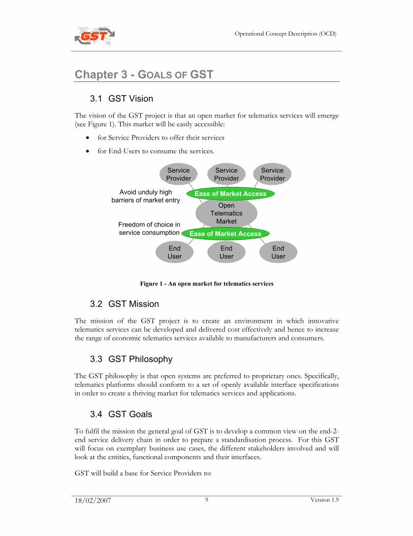
The vision of the GST project is that an open market for telematics services will emerge (see Figure 1). This market will be easily accessible:
• for Service Providers to offer their services
• for End-Users to consume the services.
Figure 1 - An open market for telematics services
3.2 GST Mission
The mission of the GST project is to create an environment in which innovative telematics services can be developed and delivered cost effectively and hence to increase the range of economic telematics services available to manufacturers and consumers.
3.3 GST Philosophy
The GST philosophy is that open systems are preferred to proprietary ones. Specifically, telematics platforms should conform to a set of openly available interface specifications in order to create a thriving market for telematics services and applications.
3.4 GST Goals
To fulfil the mission the general goal of GST is to develop a common view on the end-2-end service delivery chain in order to prepare a standardisation process. For this GST will focus on exemplary business use cases, the different stakeholders involved and will look at the entities, functional components and their interfaces.
GST will build a base for Service Providers to:
ServiceProvider
OpenTelematics
Market
ServiceProvider
ServiceProvider
EndUser
EndUser
EndUser
Ease of Market Access
Ease of Market Access
Avoid unduly highbarriers of market entry
Freedom of choice inservice consumption
Operational Concept Description (OCD)
18/02/2007 10 Version 1.9
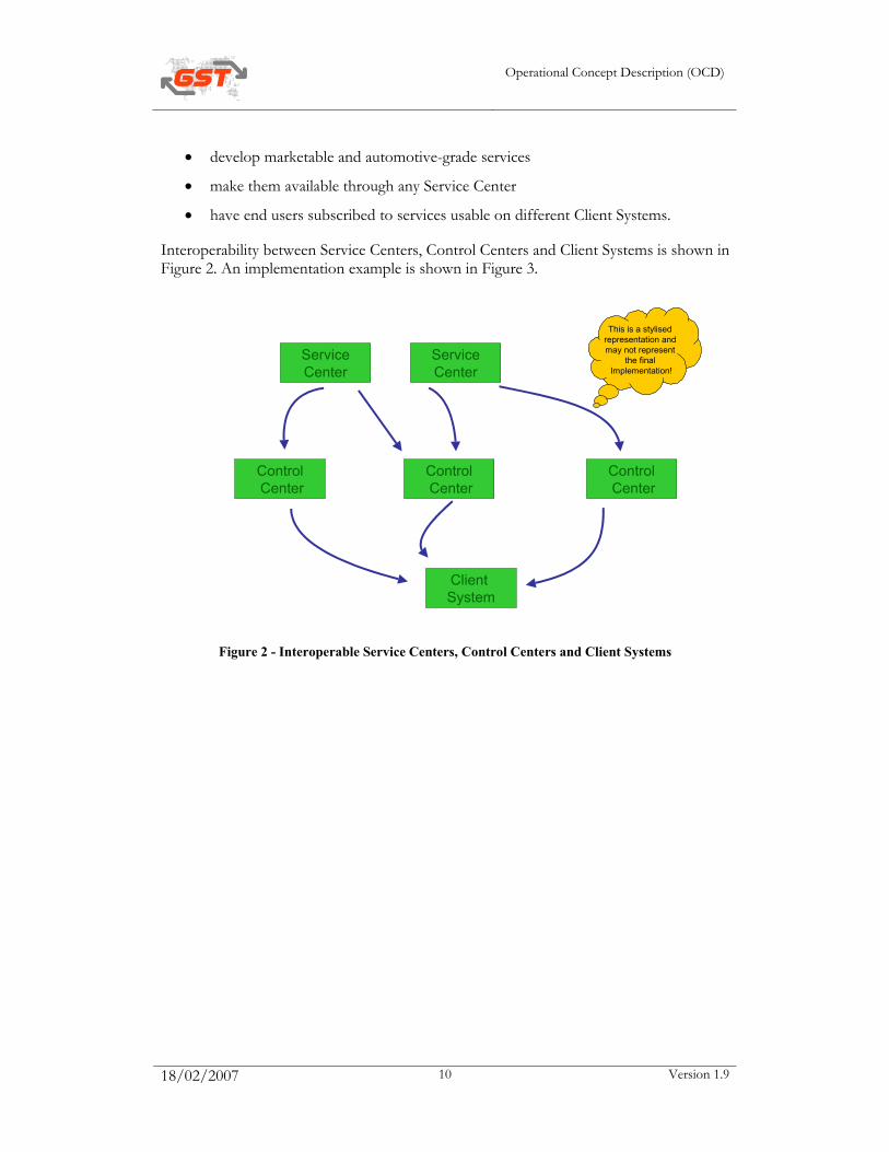
• develop marketable and automotive-grade services
• make them available through any Service Center
• have end users subscribed to services usable on different Client Systems.
Interoperability between Service Centers, Control Centers and Client Systems is shown in Figure 2. An implementation example is shown in Figure 3.
Figure 2 - Interoperable Service Centers, Control Centers and Client Systems
ControlCenter
ControlCenter
ControlCenter
Client System
ServiceCenter
ServiceCenter
This is a stylised representation and may not represent
the final Implementation!

Operational Concept Description (OCD)
18/02/2007 11 Version 1.9
Figure 3 - Implementation example
The goals of GST can be grouped in two areas:
• a technology-oriented area (technology-oriented SPs) and
• a service-oriented area (service-oriented SPs).
The goals of GST in the technology-oriented area are to further develop the state-of-the-art allowing service providers to rely on common (standardised):
• Security mechanisms
• Payment and billing mechanisms
• Certification mechanisms
• Service application delivery mechanisms
• Client device configuration mechanism
• Service Provisioning mechanism (interface Service tier – CC-tier)
• Access mechanisms to other devices in the vehicle.
The goals of GST in the service-oriented area are to further develop the state-of-the-art allowing to successfully deploy some key safety-enhancing service on the market:
• E-call services
• Enhanced Floating Car Data (EFCD) services
• Safety warning and information services.
Wireless wide-area communication
Wireless wide-area communication
Client System
ServiceCenter
ControlCenter
Client System
RoadsideInfrastructure
Wired communication
Wireless wide-area communication
Wireless wide-area communication
Wireless short-range communication
Operational Concept Description (OCD)
18/02/2007 12 Version 1.9
Chapter 4 - METHODOLOGY FOR OCD
4.1 Overall GST methodology
The GST methodology is based on the approach defined by CONVERGE [1]. CONVERGE provides a set of guidelines for R&D projects in the telematics sector. CONVERGE recommends the use of the V-lifecycle methodology and offers specific support for the collection of user needs and system requirements as well as for validation activities.
The practical implementation of CONVERGE by GST translates the V-shape model in a work flow of packages each implementing a part of the overall process. The chosen model of work defines a set of vertical (within SPs) and horizontal (at IP-level, across SPs) development iterations that ensure requirement driven design and implementation.
In GST, 7 SPs progress through 7 WPs, working towards SP-level deliverables that are mirrored by IP-level deliverables that are compiled by CAG. The IP-level deliverables play an initiating, steering and consolidating role.
For more information on the organisation and the general workflow in the project, please refer to the deliverable DEL_GST_1_1_Quality_plan at GST\WP1 – Project management\Deliverables on the OCT.
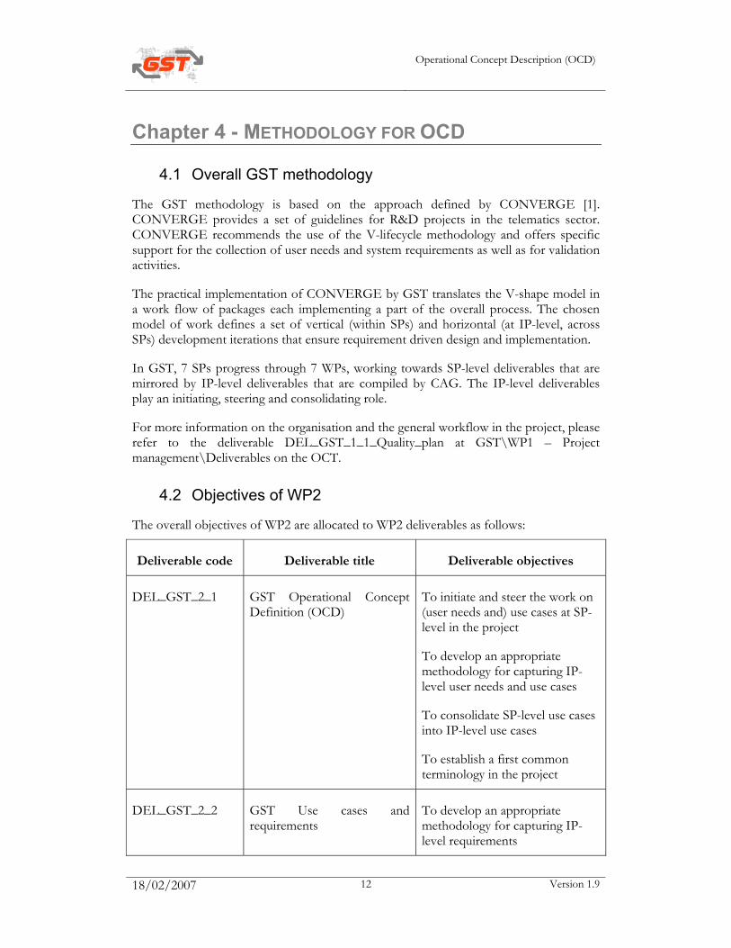
4.2 Objectives of WP2
The overall objectives of WP2 are allocated to WP2 deliverables as follows:
Deliverable code Deliverable title Deliverable objectives
DEL_GST_2_1 GST Operational Concept Definition (OCD)
To initiate and steer the work on (user needs and) use cases at SP-level in the project
To develop an appropriate methodology for capturing IP-level user needs and use cases
To consolidate SP-level use cases into IP-level use cases
To establish a first common terminology in the project
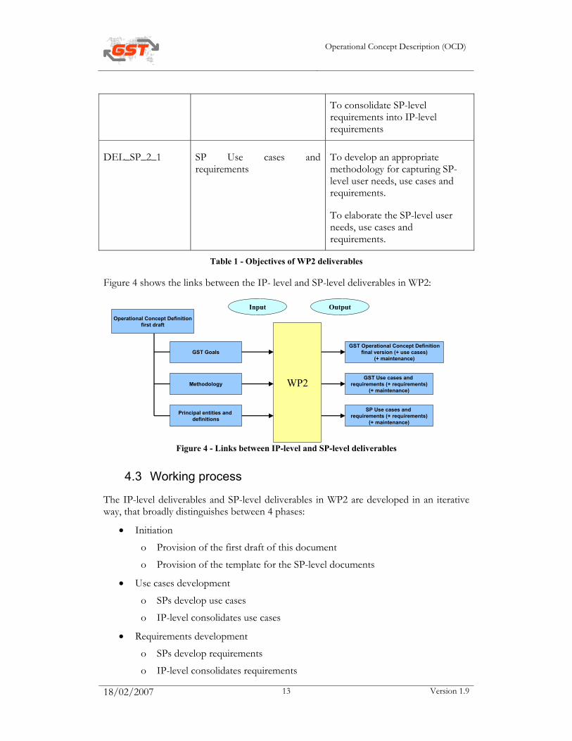
DEL_GST_2_2 GST Use cases and requirements
To develop an appropriate methodology for capturing IP-level requirements
Operational Concept Description (OCD)
18/02/2007 13 Version 1.9
To consolidate SP-level requirements into IP-level requirements
DEL_SP_2_1 SP Use cases and requirements
To develop an appropriate methodology for capturing SP-level user needs, use cases and requirements.
To elaborate the SP-level user needs, use cases and requirements.
Table 1 - Objectives of WP2 deliverables
Figure 4 shows the links between the IP- level and SP-level deliverables in WP2:
Figure 4 - Links between IP-level and SP-level deliverables
4.3 Working process
The IP-level deliverables and SP-level deliverables in WP2 are developed in an iterative way, that broadly distinguishes between 4 phases:
• Initiation
o Provision of the first draft of this document
o Provision of the template for the SP-level documents
• Use cases development
o SPs develop use cases
o IP-level consolidates use cases
• Requirements development
o SPs develop requirements
o IP-level consolidates requirements
WP2
GST Operational Concept Definitionfinal version (+ use cases)
(+ maintenance)
GST Use cases and requirements (+ requirements)
(+ maintenance)
GST Goals
Principal entities and definitions
Methodology
Input OutputOperational Concept Definition
first draft
SP Use cases and requirements (+ requirements)
(+ maintenance)
Operational Concept Description (OCD)
18/02/2007 14 Version 1.9
• Workshop and finalisation of document
o SPs finalise requirements
o IP-level consolidates requirements.
Detailed and up-to-date work plans showing the link between IP-level and SP-level activities are maintained on the OCT in MS Word and MS Project format:
• At IP-level, they are available at GST\WP 1 - Project management\Progress\Work plan
• At SP-level, they are available at SP\WP 1 - Project management\Progress\Work plan.
For WP2, the work plans are complemented by a version of the work plan focusing on the document flow between IP-level and SP-level (in MS Powerpoint format).
4.4 Link between IP-level and SP-level documents
4.4.1 Content of the OCD
This document is used as a starting point for SP-level deliverables. It contains:
• Goals of GST: this chapter sets the overall context in which the SPs develop user needs, use cases and system requirements
• Methodology: broadly explains the links between IP and SP-level deliverables and refers to detailed documents that show the planned co-ordination activities and flow of documents
• System concept: established a first common terminology for SPs at the level of stakeholders (actors) and entities
• IP-level user needs: shows how the SP-level user needs will be consolidated at IP-level
• IP-level use cases: shows how the SP-level use cases will be consolidated at IP-level
• SP-level user needs review template: shows how suggestions for improvement will be derived for the SP-level user needs
• SP-level use case review template: shows how suggestions for improvement will be derived for the SP-level use cases.
4.4.2 Content of the SP-level deliverable
This SP-level deliverable contains the detailed templates that will be used by the SPs throughout WP2:
• Methodology: detailed definitions of the terms user need, use case and system requirement, how they relate and how they will be captured
Operational Concept Description (OCD)
18/02/2007 15 Version 1.9
• System requirements: templates for collecting system requirements at SP-level (including their future link to IP-level).
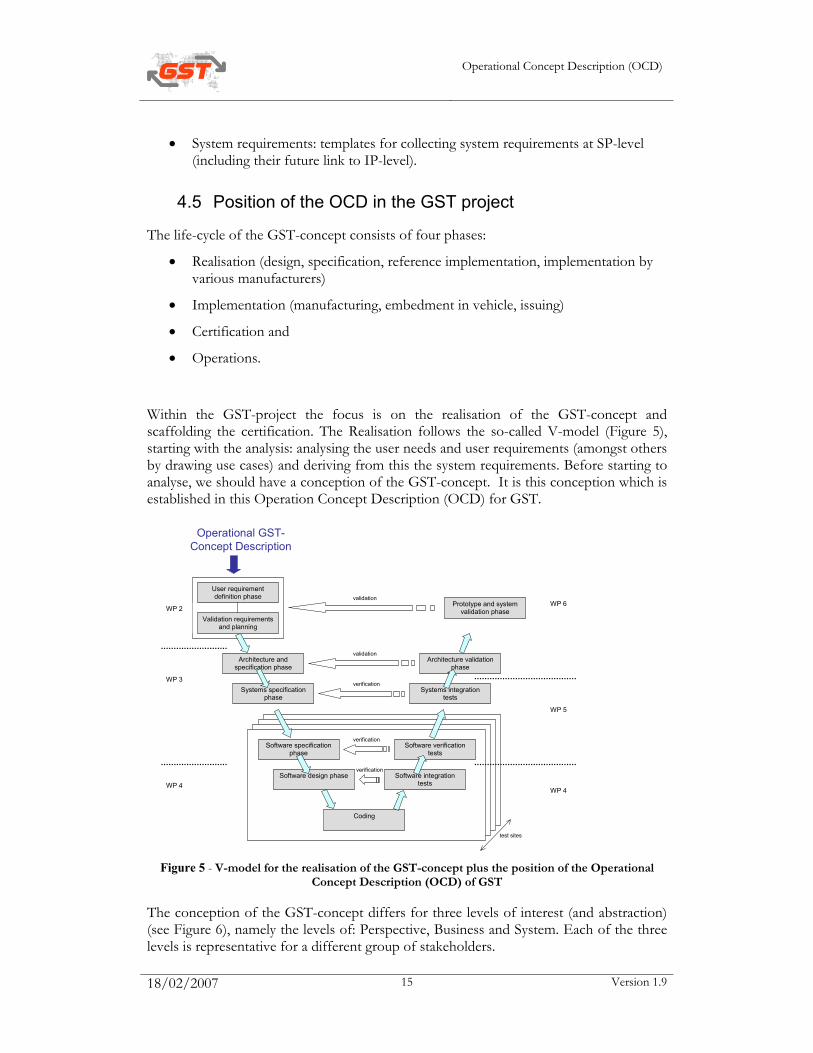
4.5 Position of the OCD in the GST project
The life-cycle of the GST-concept consists of four phases:
• Realisation (design, specification, reference implementation, implementation by various manufacturers)
• Implementation (manufacturing, embedment in vehicle, issuing)
• Certification and
• Operations.
Within the GST-project the focus is on the realisation of the GST-concept and scaffolding the certification. The Realisation follows the so-called V-model (Figure 5), starting with the analysis: analysing the user needs and user requirements (amongst others by drawing use cases) and deriving from this the system requirements. Before starting to analyse, we should have a conception of the GST-concept. It is this conception which is established in this Operation Concept Description (OCD) for GST.
verification
User requirement definition phase
Validation requirements and planning
Architecture and specification phase
Systems specification phase
Software specification phase
Software design phase
Coding
Software integration tests
Software verification tests
Systems integration tests
Architecture validation phase
validation
validation
verification
verification
test sites
WP 2
WP 3
WP 4 WP 4
WP 5
WP 6 Prototype and system validation phase
Operational GST-Concept Description
Figure 5 - V-model for the realisation of the GST-concept plus the position of the Operational
Concept Description (OCD) of GST
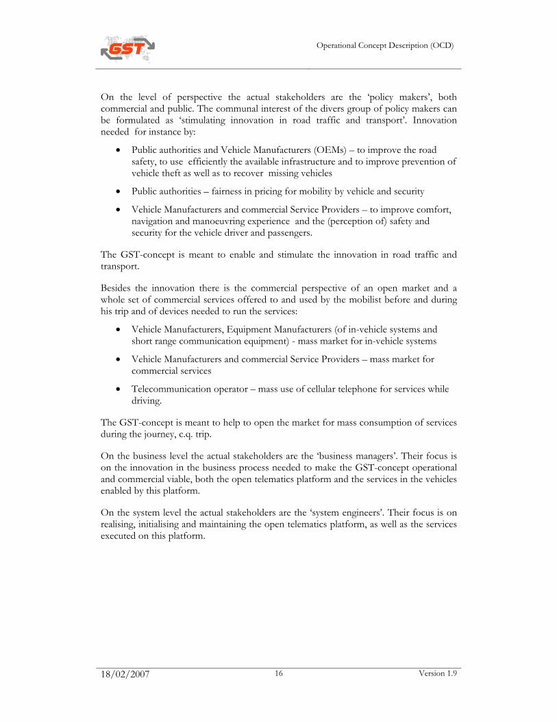
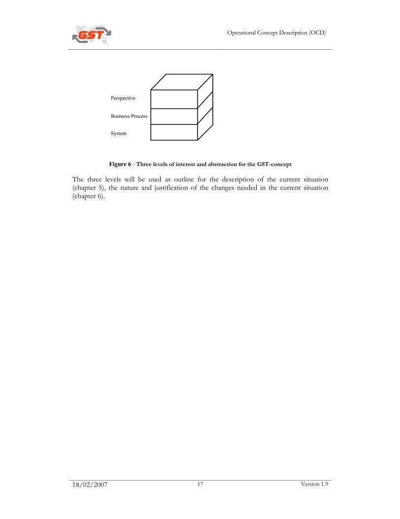
The conception of the GST-concept differs for three levels of interest (and abstraction) (see Figure 6), namely the levels of: Perspective, Business and System. Each of the three levels is representative for a different group of stakeholders.
Operational Concept Description (OCD)
18/02/2007 16 Version 1.9
On the level of perspective the actual stakeholders are the ‘policy makers’, both commercial and public. The communal interest of the divers group of policy makers can be formulated as ‘stimulating innovation in road traffic and transport’. Innovation needed for instance by:
• Public authorities and Vehicle Manufacturers (OEMs) – to improve the road safety, to use efficiently the available infrastructure and to improve prevention of vehicle theft as well as to recover missing vehicles
• Public authorities – fairness in pricing for mobility by vehicle and security
• Vehicle Manufacturers and commercial Service Providers – to improve comfort, navigation and manoeuvring experience and the (perception of) safety and security for the vehicle driver and passengers.
The GST-concept is meant to enable and stimulate the innovation in road traffic and transport.
Besides the innovation there is the commercial perspective of an open market and a whole set of commercial services offered to and used by the mobilist before and during his trip and of devices needed to run the services:
• Vehicle Manufacturers, Equipment Manufacturers (of in-vehicle systems and short range communication equipment) - mass market for in-vehicle systems
• Vehicle Manufacturers and commercial Service Providers – mass market for commercial services
• Telecommunication operator – mass use of cellular telephone for services while driving.
The GST-concept is meant to help to open the market for mass consumption of services during the journey, c.q. trip.
On the business level the actual stakeholders are the ‘business managers’. Their focus is on the innovation in the business process needed to make the GST-concept operational and commercial viable, both the open telematics platform and the services in the vehicles enabled by this platform.
On the system level the actual stakeholders are the ‘system engineers’. Their focus is on realising, initialising and maintaining the open telematics platform, as well as the services executed on this platform.
Operational Concept Description (OCD)
18/02/2007 17 Version 1.9
Perspective
Business Process
System
Figure 6 - Three levels of interest and abstraction for the GST-concept
The three levels will be used as outline for the description of the current situation (chapter 5), the nature and justification of the changes needed in the current situation (chapter 6).
Operational Concept Description (OCD)
18/02/2007 18 Version 1.9
Chapter 5 - CURRENT SITUATION To fully appreciate the current state of the telematics industry, a brief review of its evolution is needed. Evolutionary trends can be generally described in generations or stages, which uniquely characterize a particular era. While these trends may be broadly overlapping in time without clearly marked transition points, the central characteristics of each stage are observable. In automotive telematics, the stages of growth can be viewed as follows:
5.1 First stage: single-function units (1990 – 1997)
5.1.1 Character of the era
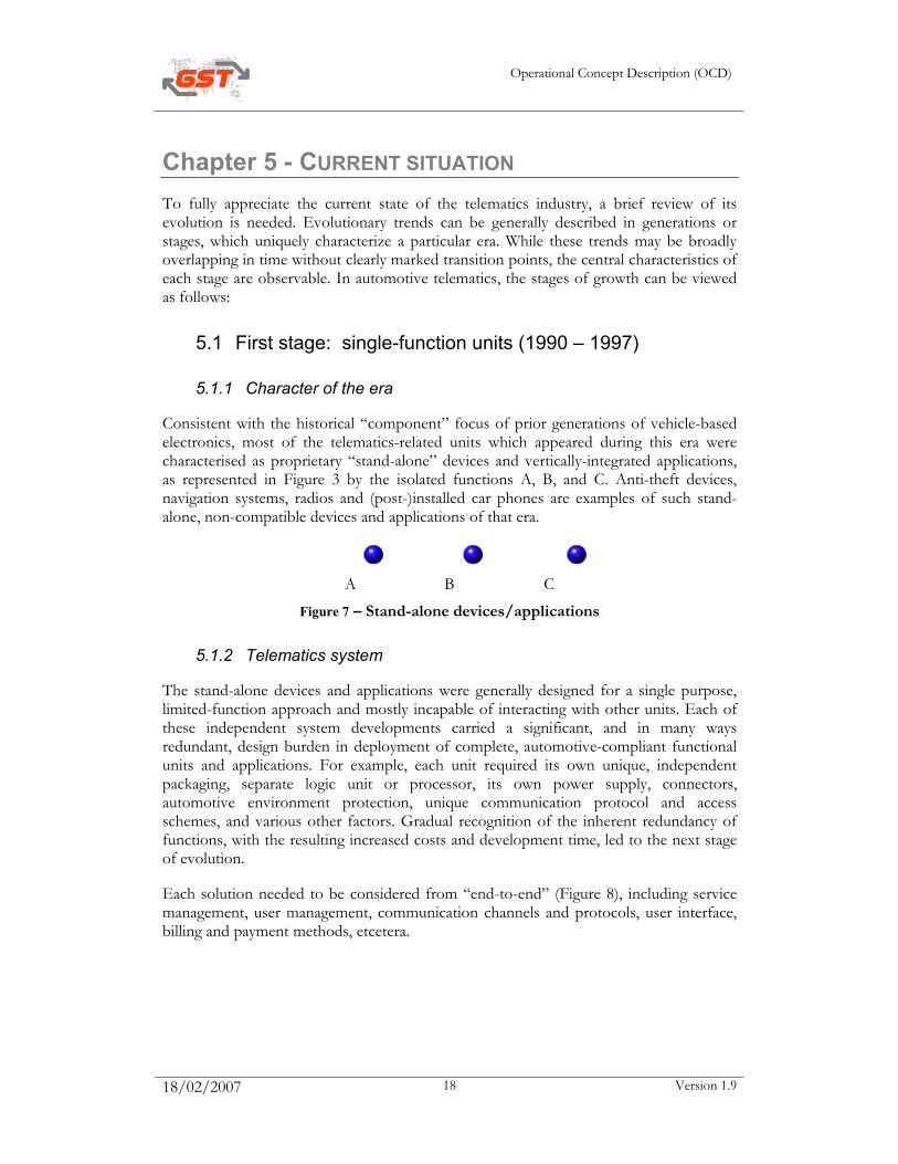
Consistent with the historical “component” focus of prior generations of vehicle-based electronics, most of the telematics-related units which appeared during this era were characterised as proprietary “stand-alone” devices and vertically-integrated applications, as represented in Figure 3 by the isolated functions A, B, and C. Anti-theft devices, navigation systems, radios and (post-)installed car phones are examples of such stand-alone, non-compatible devices and applications of that era.
A B C
Figure 7 – Stand-alone devices/applications
5.1.2 Telematics system
The stand-alone devices and applications were generally designed for a single purpose, limited-function approach and mostly incapable of interacting with other units. Each of these independent system developments carried a significant, and in many ways redundant, design burden in deployment of complete, automotive-compliant functional units and applications. For example, each unit required its own unique, independent packaging, separate logic unit or processor, its own power supply, connectors, automotive environment protection, unique communication protocol and access schemes, and various other factors. Gradual recognition of the inherent redundancy of functions, with the resulting increased costs and development time, led to the next stage of evolution.
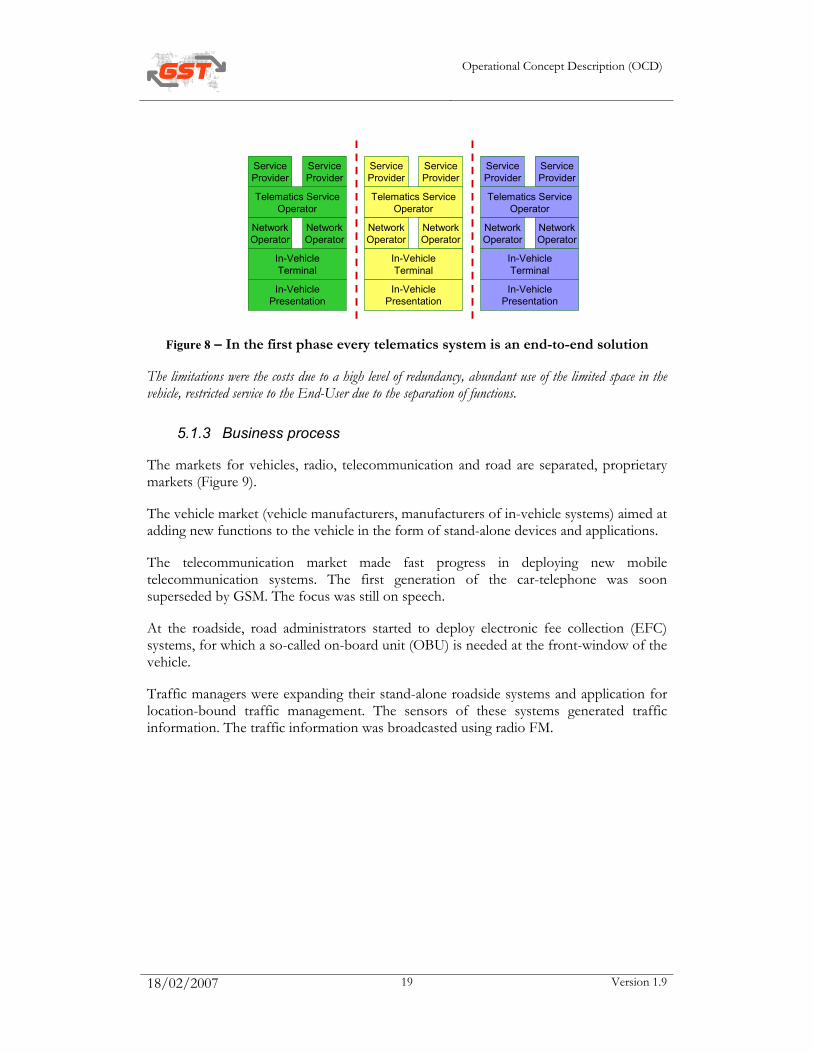
Each solution needed to be considered from “end-to-end” (Figure 8), including service management, user management, communication channels and protocols, user interface, billing and payment methods, etcetera.
Operational Concept Description (OCD)
18/02/2007 19 Version 1.9
Telematics ServiceOperator
NetworkOperator
NetworkOperator
ServiceProvider
ServiceProvider
In-VehicleTerminal
In-VehiclePresentation
Telematics ServiceOperator
NetworkOperator
NetworkOperator
ServiceProvider
ServiceProvider
In-VehicleTerminal
In-VehiclePresentation
Telematics ServiceOperator
NetworkOperator
NetworkOperator
ServiceProvider
ServiceProvider
In-VehicleTerminal
In-VehiclePresentation
Figure 8 – In the first phase every telematics system is an end-to-end solution
The limitations were the costs due to a high level of redundancy, abundant use of the limited space in the vehicle, restricted service to the End-User due to the separation of functions.
5.1.3 Business process
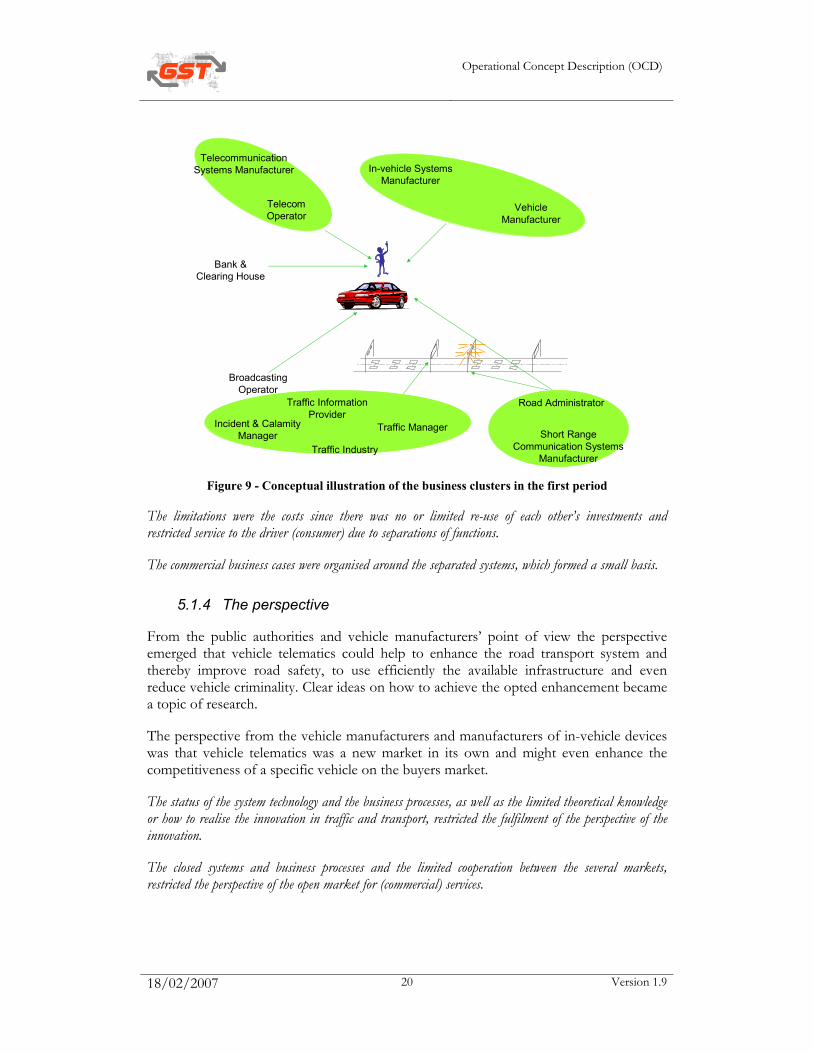
The markets for vehicles, radio, telecommunication and road are separated, proprietary markets (Figure 9).
The vehicle market (vehicle manufacturers, manufacturers of in-vehicle systems) aimed at adding new functions to the vehicle in the form of stand-alone devices and applications.
The telecommunication market made fast progress in deploying new mobile telecommunication systems. The first generation of the car-telephone was soon superseded by GSM. The focus was still on speech.
At the roadside, road administrators started to deploy electronic fee collection (EFC) systems, for which a so-called on-board unit (OBU) is needed at the front-window of the vehicle.
Traffic managers were expanding their stand-alone roadside systems and application for location-bound traffic management. The sensors of these systems generated traffic information. The traffic information was broadcasted using radio FM.
Operational Concept Description (OCD)
18/02/2007 20 Version 1.9
Vehicle Manufacturer
Telecom Operator
In-vehicle Systems Manufacturer
Telecommunication Systems Manufacturer
Broadcasting Operator
Road AdministratorTraffic Information Provider
Incident & Calamity Manager
Bank & Clearing House
Traffic ManagerShort Range
Communication Systems Manufacturer
Traffic Industry
Figure 9 - Conceptual illustration of the business clusters in the first period
The limitations were the costs since there was no or limited re-use of each other’s investments and restricted service to the driver (consumer) due to separations of functions.
The commercial business cases were organised around the separated systems, which formed a small basis.
5.1.4 The perspective
From the public authorities and vehicle manufacturers’ point of view the perspective emerged that vehicle telematics could help to enhance the road transport system and thereby improve road safety, to use efficiently the available infrastructure and even reduce vehicle criminality. Clear ideas on how to achieve the opted enhancement became a topic of research.
The perspective from the vehicle manufacturers and manufacturers of in-vehicle devices was that vehicle telematics was a new market in its own and might even enhance the competitiveness of a specific vehicle on the buyers market.
The status of the system technology and the business processes, as well as the limited theoretical knowledge or how to realise the innovation in traffic and transport, restricted the fulfilment of the perspective of the innovation.
The closed systems and business processes and the limited cooperation between the several markets, restricted the perspective of the open market for (commercial) services.
Operational Concept Description (OCD)
18/02/2007 21 Version 1.9
5.1.5 First phase looked upon from the angle of the GST Sub-Projects
Systems Sub-Projects:
• Open systems – See ‘telematics system’ and ‘business process’ above
• Service Payment – Payment was done in cash or by using pre- or post-payment devices (tolling, parking, petrol, et cetera). Public authorities or commercial advertising paid for traffic information via radio broadcasting
• Security - The systems were closed systems, security was not really an issue yet
• Certification – not relevant yet.
The limitations for open systems are described above. The limitation for service payment was that no commercial system for micro-payments was available, yet.
Services Sub-Projects:
• Safety Channel – the communication channels used were radio FM, GSM (and its predecessor the car radio), a variety of dedicated short range communication systems (not standardised) and road side actuators (like variable message signs (VMSs)). First steps towards the implementation of RDS/TMC were made
• Enhanced Floating Car Data – Traffic information service providers enriched the traffic information from road side sensors with information from, for instance, traffic ‘spies’ (mobilists communicating their actual experiences in traffic , employees of petrol stations, et cetera on voluntary basis). The traffic information was broadcasted using FM radio and RDS
• Rescue - Incident and Calamity information came from the incident detection of motorway traffic management systems as far as available and information on incidents form patrols of police and road services. The control centers of the different rescue operators (e.g. police, ambulance, firemen) were often still separated.
From the service side the limitations were that the services themselves, apart from the technology, were still not organised efficiently and effectively.
5.2 Second stage: multi-function, connected units (1997 – 2002 )
5.2.1 Character of the era During this era, multi-function capability or interconnected devices began to emerge, providing new levels of design effectiveness and user value. The vehicle-integrated phone with GPS capability combined with a simple human interface and logic processor established the first effective telematics capability, focused on safety and security. Most installed telematics units today are based on this in-vehicle platform concept, in many cases integrated further with the traditional vehicle radio system.
Operational Concept Description (OCD)
18/02/2007 22 Version 1.9
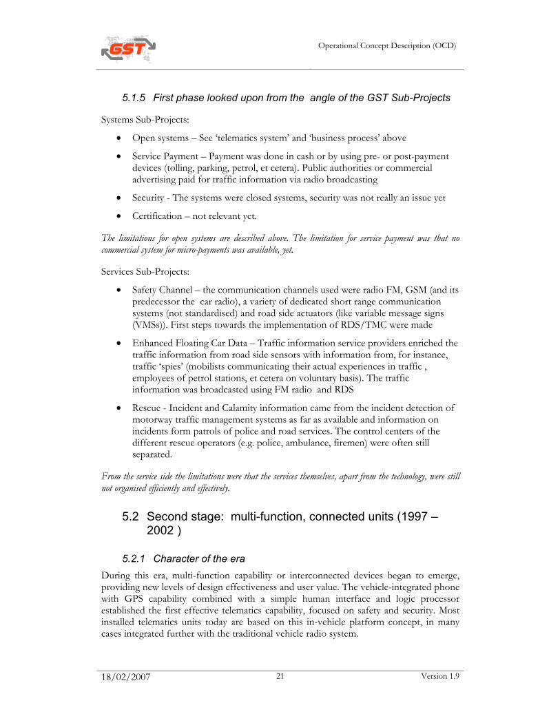
5.2.2 Telematics system In spite of the many improvements of the second stage, most designs were still based on the proprietary solutions of a few suppliers, maintaining the “closed”-solution approach with a resulting fixed functionality (Figure 10).
Second-generation telematics developments based on the GATS or ACP protocols have yet to live up to the expectations of enabling an open telematics market for the masses. The required depth of specification and the lack of standard adoption still resulted in closed, largely proprietary service implementations.
Figure 10 – Dual purpose or connected devices
The implications for overall telematics evolution during this stage were clear, given the general tendency for maintaining proprietary interest and rigid control over the vehicle design space. New concepts for service delivery would need to fit into the fixed design framework - and limitations - which were foreseen for the “preferred” devices planned for installation, under strict control of the “owners”. As a result, a series of development initiatives based on “closed” architectures emerged, each seeking to deliver a specific set of services to the target market segment. Each solution needed to be considered from “end-to-end” (see Figure 8), including service management, user management, communication channels and protocol, user interface, billing and payment methods, et cetera.
Predictably in this stage of evolution - which still constitutes the core of the telematics deployments today - the market remains confronted with a bewildering array of point-to-point solutions, using different device configurations, communication channels, and multiple protocols as graphically depicted in Figure 11 below:

Operational Concept Description (OCD)
18/02/2007 23 Version 1.9
Figure 11 - Closed-system telematics solutions
One set of limitations was the costs due to a high level of redundancy, abundant use of the limited space in the vehicle, restricted service to the driver (consumer) due to separations of functions. A new limitation was the rather inefficient variety in protocols to enable the new services.
5.2.3 Business process
The markets for vehicles, radio, telecommunication and road are separated, proprietary markets, although the vehicle and telecommunication markets grew to one another as shown by (Figure 12).
The vehicle market (vehicle manufacturers, manufacturers of in-vehicle systems) stepped beyond just adding new functions to the vehicle, and aimed at offering a whole range of on-line, dynamic services. However, the vehicle market was segmented by vehicle brand. Generally the market segments were regarded as the property of the vehicle brand, which meant that different segment requirements inevitably resulted in different, unique offerings. Opportunities for telematics service delivery were essentially limited to (controlled by) the business entities possessing a certain leverage or “ownership” of the in-vehicle real estate that was allocated for implementing telematics. Vehicle manufacturers and their selected electronics suppliers, in most cases the “traditional” suppliers of in-vehicle electronics units, became the primary gatekeepers for access to the vehicle telematics space.
Operational Concept Description (OCD)
18/02/2007 24 Version 1.9
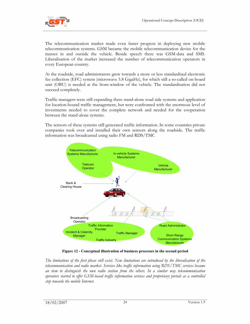
The telecommunication market made even faster progress in deploying new mobile telecommunication systems. GSM became the mobile telecommunication device for the masses in and outside the vehicle. Beside speech there was GSM-data and SMS. Liberalisation of the market increased the number of telecommunication operators in every European country.
At the roadside, road administrators grew towards a more or less standardised electronic fee collection (EFC) system (microwave 5.8 GigaHz), for which still a so-called on-board unit (OBU) is needed at the front-window of the vehicle. The standardisation did not succeed completely.
Traffic managers were still expanding there stand-alone road side systems and application for location-bound traffic management, but were confronted with the enormous level of investments needed to cover the complete network and needed for the cooperation between the stand-alone systems.
The sensors of these systems still generated traffic information. In some countries private companies took over and installed their own sensors along the roadside. The traffic information was broadcasted using radio FM and RDS/TMC
Vehicle Manufacturer
Telecom Operator
In-vehicle Systems Manufacturer
Telecommunication Systems Manufacturer
Broadcasting Operator
Road AdministratorTraffic Information Provider
Incident & Calamity Manager
Bank & Clearing House
Traffic ManagerShort Range
Communication Systems Manufacturer
Traffic Industry
Figure 12 - Conceptual illustration of business processes in the second period
The limitations of the first phase still exist. New limitations are introduced by the liberalisation of the telecommunication and radio market. Services like traffic information using RDS/TMC services became an item to distinguish the own radio station from the others. In a similar way telecommunication operators started to offer GSM-based traffic information services and proprietary portals as a controlled step towards the mobile Internet.
Operational Concept Description (OCD)
18/02/2007 25 Version 1.9
5.2.4 Perspective
In fact the perspective did not change. Public authorities and vehicle manufacturers’ were still exploring the possibilities to enhance the road transport system and thereby improve road safety and an efficient use of the available infrastructure. First successes were achieved.
The reduction of vehicle criminality on the other hand, was taken up by using contact breakers and commercial services for recovery of stolen vehicles.
Typical of this era was the internet-hype; there was a strong belief in a new economy where consumers were claiming to be served any moment, anywhere and were actually willing to pay for these services. One of the places where consumers would want to be served was in the vehicle, in the traffic while making a journey. A vision that clashed with the real economy and the experienced willingness of consumers to pay for services at the dawn of the new millennium.
The status of the system technology and the business processes, as well as the limited theoretical knowledge of how to realise the innovation in traffic and transport, still restricted the fulfilment of the perspective of the innovation.
The closed systems and business processes and the limited cooperation between the several markets, still restricted the perspective of the open market for (commercial) services.
5.2.5 Second phase looked upon from the point-of-view of the GST Sub-Projects
Systems:
• Open systems – See ‘system’ and ‘business process’ above
• Service-payment – Payment was done in cash or by using pre- or post-payment devices (tolling, parking, petrol, et cetera. New post-payment devices became available for the private driver to pay for his petrol, where it was limited to the drivers of truck companies and lease cars before. Public authorities or commercial advertising paid for traffic information via radio broadcasting. New was the introduction of the inter-sector electronic purse (IEP) by banks in different countries. First experiments with using this IEP in traffic and transport were not very successful
• Security - The systems were still closed systems, however the telecommunication channel made them open for attacks. Security became a hot issue; hackers’ knowledge became available for the man in the street via the Internet
• Certification – not relevant yet.
The limitations for open systems are described above. The limitation for service payment was that the commercial system for micro-payments was not designed for traffic and transport.
Services:
Operational Concept Description (OCD)
18/02/2007 26 Version 1.9
• Safety Channel – the communication channels used were radio FM, GSM, RDS/TMC, a variety of dedicated short range communication systems (not standardised) and road side actuators (like variable message signs (VMSs)). First plans and investments towards the implementation of GPRS and UMTS were both made and delayed. First plans towards the implementation of DAB were made
• Enhanced Floating Car Data – Traffic information service providers were organised in traffic information centers (TICS) where they still enriched the traffic information from roadside sensors with information from, for instance, traffic ‘spies’ (car drivers communicating their actual experiences in traffic, employees of petrol stations, et cetera on a voluntary basis). In some countries the distribution of the traffic information was organized separately resulting in niche-organisations that distributed traffic information using radio FM, RDS/TMC, internet and teletext. In other countries traffic information was outsourced to private companies completely. Similar to the TICS, traffic management was organised more and more in regional traffic management centers, starting to develop and deploy network wide traffic management strategies
• Rescue - Incident and Calamity information now was also coming from announcements by road users using their GSM. The control centers of the different rescue operators (e.g. police, ambulance, firemen) were more and more linked to each other.
From the service side the limitations were that the services themselves, apart from the technology, were still not transformed fully into the on-line, dynamic services that were asked for, although improvements were made.
5.3 Third Stage: 2002 – now, open telematics systems
5.3.1 Overview
Character of the era
Many lessons have been learned in the prior-generation attempts to integrate effective solutions of telematics into vehicles, while at the the same time striving to maintain a positive business case. Additional surprises emerged as companies tried to smoothly merge two fundamentally diverse product streams with vastly different lifecycles. Automobiles and their components are generally planned with a time cycle of 4-5 years, whereas electronics and telecommunication industries measure product lifetimes in terms of months. These lessons, along with emerging new technologies, have paved the way for the modern era, the third stage of telematics.

Operational Concept Description (OCD)
18/02/2007 27 Version 1.9
A B
Figure 13 – “Open telematics” flexible units
With the continuing pressure to realise better solutions and improved business models, a few leading visionaries of the industry have steadily pushed technology boundaries forward toward the new telematics era. In the last few years, telematics evolution has moved boldly into a third stage, characterized by solutions-based “open telematics” units and remote service management frameworks. This new open architecture supports flexible service capability by downloading needed software elements “on-demand” to the user device, while maintaining an open but controlled environment that enables integration of numerous third-party service offerings.
Empowered with an open telematics architecture as shown in Figure 13, a user may begin his service load with a low-cost set of relatively few services (A), and dynamically upgrade the services during the system life (B) for a rich complement of up-to-date services, all with the original hardware platform. This architecture considerably expands market opportunity to new service providers who seek access to the vehicle space with their telematics offerings. Furthermore, service providers have the opportunity for continuing upgrades of their services throughout the lifecycle by an efficient “over-the-air” version management process, a major cost reduction advantage for managing changes during the lifetime of a service.
5.3.2 Telematics system
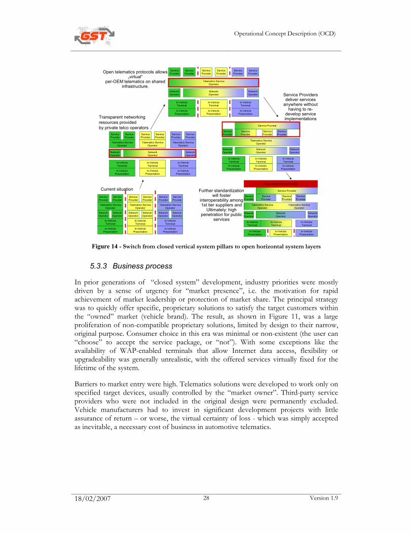
New technologies and perceptions makes it possible to come, step-by-step, to open-system telematics (Figure 14). The capabilities of open-system telematics architectures provide to the end user uncompromised access to many sources of content and service functions. Continuously upgradeable functionality at the vehicle shows great promise of achieving the features and flexibility desired by many parties involved in the telematics value chain, including 3rd party service providers, OEMs and others.
Operational Concept Description (OCD)
18/02/2007 28 Version 1.9
Telematics ServiceOperator
NetworkOperator
NetworkOperator
ServiceProvider
ServiceProvider
In-VehicleTerminal
In-VehiclePresentation
Telematics ServiceOperator
NetworkOperator
NetworkOperator
ServiceProvider
ServiceProvider
In-VehicleTerminal
In-VehiclePresentation
Telematics ServiceOperator
NetworkOperator
NetworkOperator
ServiceProvider
ServiceProvider
In-VehicleTerminal
In-VehiclePresentation
In-VehicleTerminal
In-VehiclePresentation
In-VehicleTerminal
In-VehiclePresentation
Telematics ServiceOperator
ServiceProvider
ServiceProvider
Telematics ServiceOperator
ServiceProvider
ServiceProvider
Telematics ServiceOperator
ServiceProvider
ServiceProvider
In-VehicleTerminal
In-VehiclePresentation
NetworkOperator
NetworkOperator
NetworkOperator
In-VehicleTerminal
In-VehiclePresentation
In-VehicleTerminal
In-VehiclePresentation
ServiceProvider
ServiceProvider
ServiceProvider
ServiceProvider
ServiceProvider
ServiceProvider
In-VehicleTerminal
In-VehiclePresentation
NetworkOperator
NetworkOperator
Telematics ServiceOperator
NetworkOperator
In-VehicleTerminalIn-Vehicle
Presentation
In-VehicleTerminalIn-Vehicle
Presentation
In-VehicleTerminal
In-VehiclePresentation
NetworkOperator
NetworkOperator
ServiceProvider
ServiceProvider
ServiceProvider
ServiceProvider
Telematics ServiceOperator
Service Provider
NetworkOperator
In-VehiclePresentation
In-VehiclePresentation
In-VehiclePresentation
In-VehicleTerminal
In-VehicleTerminal
In-VehicleTerminal
NetworkOperator
NetworkOperator
ServiceProvider
ServiceProvider
ServiceProvider
ServiceProvider
NetworkOperator
Telematics ServiceOperator
Telematics ServiceOperator
Service Provider
Public Sector Service Provider
Current situation
Transparent networking resources providedby private telco operators
Open telematics protocols allows „virtual“
per-OEM telematics on shared infrastructure.
Further standardization will foster
interoperability among 1st tier suppliers and
Ultimately: high penetration for public
services
Service Providers deliver services
anywhere withouthaving to re-
develop service implementations
Figure 14 - Switch from closed vertical system pillars to open horizontal system layers
5.3.3 Business process
In prior generations of “closed system” development, industry priorities were mostly driven by a sense of urgency for “market presence”, i.e. the motivation for rapid achievement of market leadership or protection of market share. The principal strategy was to quickly offer specific, proprietary solutions to satisfy the target customers within the “owned” market (vehicle brand). The result, as shown in Figure 11, was a large proliferation of non-compatible proprietary solutions, limited by design to their narrow, original purpose. Consumer choice in this era was minimal or non-existent (the user can “choose” to accept the service package, or “not”). With some exceptions like the availability of WAP-enabled terminals that allow Internet data access, flexibility or upgradeability was generally unrealistic, with the offered services virtually fixed for the lifetime of the system.
Barriers to market entry were high. Telematics solutions were developed to work only on specified target devices, usually controlled by the “market owner”. Third-party service providers who were not included in the original design were permanently excluded. Vehicle manufacturers had to invest in significant development projects with little assurance of return – or worse, the virtual certainty of loss - which was simply accepted as inevitable, a necessary cost of business in automotive telematics.
Operational Concept Description (OCD)
18/02/2007 29 Version 1.9
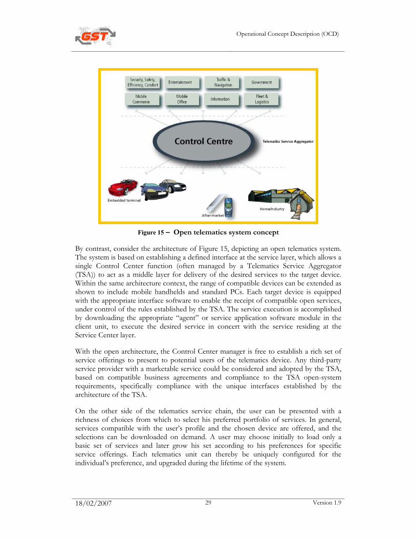
Figure 15 – Open telematics system concept
By contrast, consider the architecture of Figure 15, depicting an open telematics system. The system is based on establishing a defined interface at the service layer, which allows a single Control Center function (often managed by a Telematics Service Aggregator (TSA)) to act as a middle layer for delivery of the desired services to the target device. Within the same architecture context, the range of compatible devices can be extended as shown to include mobile handhelds and standard PCs. Each target device is equipped with the appropriate interface software to enable the receipt of compatible open services, under control of the rules established by the TSA. The service execution is accomplished by downloading the appropriate “agent” or service application software module in the client unit, to execute the desired service in concert with the service residing at the Service Center layer.
With the open architecture, the Control Center manager is free to establish a rich set of service offerings to present to potential users of the telematics device. Any third-party service provider with a marketable service could be considered and adopted by the TSA, based on compatible business agreements and compliance to the TSA open-system requirements, specifically compliance with the unique interfaces established by the architecture of the TSA.
On the other side of the telematics service chain, the user can be presented with a richness of choices from which to select his preferred portfolio of services. In general, services compatible with the user’s profile and the chosen device are offered, and the selections can be downloaded on demand. A user may choose initially to load only a basic set of services and later grow his set according to his preferences for specific service offerings. Each telematics unit can thereby be uniquely configured for the individual’s preference, and upgraded during the lifetime of the system.
Operational Concept Description (OCD)
18/02/2007 30 Version 1.9
For the terminal manufacturer, the telematics unit designed for open-system operation remains flexible and upgradeable to ensure user satisfaction, and therefore protected from early obsolescence due to new service offerings. This “future-proof” feature inherently perpetuates continuing customer satisfaction and also benefits the image of the vehicle brand.
5.3.4 Perspective
For the first time, the perspective of innovation in traffic and transport and of commercial interesting services and devices is within reach. However to fulfil the perspective major changes are still necessary. To initiate those changes (and overcome the remaining barriers) is in fact the main aim of the GST-project.
5.3.5 Third stage looked upon from GST Sub-project point of view
5.3.5.1 Open Systems
See paragraph 5.3.1
5.3.5.2 Service Payment
Services are paid for via a diversity of payment methods, namely:
• Bank – cash, credit cards, debit cards and IEPs
• Telecommunication Company – additional service fee to fee for making a phone call and/or sending data or SMSs
• Infrastructure Administrator – OBUs using pre- and post-payment methods to pay for use of a road or a parking lot.
None of these payment methods are strictly designed for payment of a wide range of services in traffic and transport. Lack of speed, costs for the micro-payments, limited billing methods, remaining limitations to the geographical area where the payment method is valid, and limited to non-existing possibilities to calculate the price to be paid for are main barriers for flexible payment for services in traffic and transport.
5.3.5.3 Security
With the rise of electronic banking, Internet banking and shopping, electronic dossiers, et cetera, security has become a major topic. Since the telematics systems in traffic and transport are in majority still closed systems, security in this playing field is not very mature; not mature enough for open telematics systems enabling a wide range of service offerings.
Operational Concept Description (OCD)
18/02/2007 31 Version 1.9
5.3.5.4 Certification
Since systems and services are still closed and proprietary. The experiences with in-vehicle system failures, or more general telematics and electronics system failures, initiated new approach to development aimed towards test laboratories and test procedures. Perhaps this development might be looked upon as the predecessor for certification.
5.3.5.5 Safety Channel
The absence of a coordinated approach towards the collection and forwarding of traffic and road related information leads to a rather chaotic and add hoc implementation of in-vehicle traffic warning systems. As to date no specifications exist which offer a standardised interface to content generation and content handling. This makes it very difficult to use a varying set of data sources as content providers. Data could be generated by well-established and rather fixed organisations such as weather and traffic centers but could also result from data captured by cars or roadside detection systems and forwarded to a central processing hub.
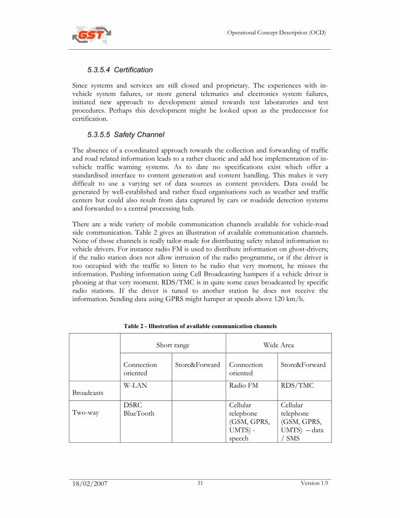
There are a wide variety of mobile communication channels available for vehicle-road side communication. Table 2 gives an illustration of available communication channels. None of those channels is really tailor-made for distributing safety related information to vehicle drivers. For instance radio FM is used to distribute information on ghost-drivers; if the radio station does not allow intrusion of the radio programme, or if the driver is too occupied with the traffic to listen to he radio that very moment, he misses the information. Pushing information using Cell Broadcasting hampers if a vehicle driver is phoning at that very moment. RDS/TMC is in quite some cases broadcasted by specific radio stations. If the driver is tuned to another station he does not receive the information. Sending data using GPRS might hamper at speeds above 120 km/h.
Table 2 - Illustration of available communication channels
Short range Wide Area
Connection oriented
Store&Forward Connection oriented
Store&Forward
Broadcasts W-LAN Radio FM RDS/TMC
Two-way DSRC BlueTooth
Cellular telephone (GSM, GPRS, UMTS) - speech
Cellular telephone (GSM, GPRS, UMTS) – data / SMS
Operational Concept Description (OCD)
18/02/2007 32 Version 1.9
Furthermore the performance of the information chain very often too low. For instance: detection of an incident or ghost-driver might take 30 s up to 3 min.; merging this event-detection into the traffic information might take 5 min, distributing the detected event might take another 4 min using the TMC carousel. All in all, it might take more the 10 minutes before the road users are warned.
In case the detected event will be projected on the digital map of the navigation system, there is a fair change that the chart projection used in the TIC, Traffic Control Center (TCC) or by the PSAP2 are not the same as the one in the navigation system.
5.3.5.6 Enhanced Floating Car Data
Currently, there is a large installed base of road bound sensors, like induction loops, radars, laser eyes and video cameras. Quite some sensors are used for traffic control only, other are used also for traffic monitoring.
There are algorithms available, which are used to produce traffic information using the data from the road bound sensors. However, the sensors used for traffic control do not always have an external interface, which makes it impossible to retrieve their data and use the data in the production of traffic information.
Experiments with floating car data (FCD) have shown the possibilities to use vehicles as mobile probes. Algorithms are available to produce traffic information from the FCD and even for merging first the FCD and data from road bound sensors. Deployment of FCD hampers due to the relatively high cost for communication to submit the data from the vehicle to the Traffic Information Center (TIC).
The possibilities to extract traffic information from the GSM network are explored and are on the edge of deployment.
The three markets described above (road bound data, FCD and data from the GSM network) are separated so far. This results in data redundancy in some regions and a lack of data in other regions. It also implies redundancy in investments by different stakeholders.
In some regions of Europe TICs have been realised, some on commercial basis and some by public authorities. The information is distributed using amongst others radio FM., RDS/TMC, GSM, teletext and the Internet.
Rescue information (see ‘Rescue - Creating a Safe Working Environment and Warning other Road Users for a Dangerous Situation’) and traffic management information (like the activated traffic management strategy, including e.g. the green-red cycles of the traffic lights) are not brought in the traffic information on a structural basis, yet.
5.3.5.7 Rescue
The current situation of rescue will be outlined following the rescue chain (see Figure 19).
Operational Concept Description (OCD)
18/02/2007 33 Version 1.9
5.3.5.8 Emergency call
Incident and Calamity information still comes from announcements by road users using their GSM or using emergency telephone along the roadside, or form announcements of patrol units.
Receive, visualise and transmit data at PSAP1
Currently there are a number of countries across Europe that can receive and visualise data from E-Call devices at PSAP 1 and transmit this to PSAP 2. However the data is received and handled in a number of different formats. This builds in time delays to the system and in countries where there is not a single PSAP 1 structure, has the potential to result in the voice and data information being sent to different PSAP 1’s resulting in confusion, delays and potential risk of lives.
Receive, visualise and transmit data at PSAP2
The methods for passing data from PSAP 1 to PSAP 2 range from: verbally (which requires operators to re key information with all the potential for errors) to screen-to-screen transfer or, in some cases, by direct transfer.
Currently there are a number of countries across Europe that can receive and visualise data from E-Call devices at PSAP 2 and have the potential to transmit that data to the emergency service vehicles.
Data streaming from PSAP 2 to one or more emergency vehicles, to include location and other data of the incident
In order for emergency service personnel to be fully informed and best prepared to deal with the incident they are attending, they need information. Historically this information has been passed verbally by radio transmission, which requires the operators to read out, at times large amounts of information and the personnel in the vehicle to remember it or write it down. This blocks radio channels, builds in the opportunities for errors, is not secure or effective. The other key issue is for this information to be updated and passed to other emergency services as more information becomes available. (There are often multiple calls to the same incident, each of which may provide some new information) The methods of passing data from PSAP 2, to the emergency vehicle includes: voice, data transfer to mobile data terminals in vehicles and in some cases to handheld data devices.
Route Guidance
Route guidance for emergency service vehicles has in the past relied on maps and local knowledge. More recently commercial mapping and route guidance systems have been introduced to emergency service vehicles to improve the situation. However these commercial systems are not specifically tailored to the emergency service requirements where high speeds are commonplace, which needs rapid update and greater degrees of accuracy.

Operational Concept Description (OCD)
18/02/2007 34 Version 1.9
The verbal route guidance systems can be very useful to the emergency service driver, but can also be very distracting if given at the wrong time, or if the information is inaccurate.
Free-way to Emergency Vehicles
When responding to incidents, emergency services currently use a combination of flashing lights and audible warning devices to make pedestrians and other road users aware of their approach. The Light systems use rotating beacons, and strobe lights to create a flashing light. Additionally vehicles headlights and rear lights can be made to flash to increase the warning effect. Audible devices include electronic wailers and sirens.
In some countries, emergency services have access to priority lanes or can adjust the priority of traffic signal phasing to assist their progress. Depending on the scheme this is activated from the PSAP or the vehicle (SCOOT, MIRT).
Creating a Safe Working Environment and Warning other Road Users for a Dangerous Situation
On arrival at an incident, the emergency services first duty is to make the scene a safe working environment. On high-speed roads in particular this is a very high-risk operation, requiring highly trained staff, specially equipped and liveried vehicles and personal protective equipment. The deployment of signs and cones to close off sections of road is a vital part of creating a safe working environment.
On roads equipped with variable message signs (VMS) and other traffic information signs, these facilities are used to assist the emergency services in providing road users information about the incident ahead.
There are several areas of extreme risk to emergency service personnel and the public in protecting the incident scene:
• On arrival setting up the initial scene protection and deploying cones and signs
• Protecting the end of the inevitable traffic queues to prevent traffic from colliding into the back of stationery traffic
• Removing the cones from the incident to clear the scene.
Currently the following technology is being used:
• Protective markings to vehicles, warning lights and high visibility clothing
• Traffic cones, portable traffic signs, laser devices to warn when vehicles are straying into the coned off area, variable matrix and traffic signs ( clear link with EFCD)
• RDS broadcasts and travel information ( clear link with EFCD and Safety Channel).
Exchange information whilst en route or on the spot
Operational Concept Description (OCD)
18/02/2007 35 Version 1.9
There is a growing trend to equip emergency services with the ability to send and receive data whilst away from their operating centers. This tends to be in two forms, namely handheld data (PDA or handset) and Mobile Data terminals fitted in vehicles. The volume of handheld data sent and received is currently fairly small but this is increasing rapidly. The volume of data sent to and from the emergency service vehicle is larger and increases rapidly. Currently, the data sent would include: incident messages, access to information databases, word processing, location data and mapping system.
Operational Concept Description (OCD)
18/02/2007 36 Version 1.9
Chapter 6 - JUSTIFICATION FOR AND NATURE OF REQUIRED CHANGES
6.1 Overview
The justification for the changes lies in the objectives strived for during the last decennia and the barriers that prevented us to fulfil these objectives. The dramatic results of this failure become more and more eminent and contribute even more to the burden of contemporary life.
Traffic safety. Each year approximately 41,000 people are killed on the roads of the European Union. In economic and human terms, traffic safety is even more important than congestion; e.g. the total cost of accidents in the EU is about €160 billion yearly which equals approximately 2% of GDP. This is in addition to the human cost of the loss of life and consequences of serious injuries both to the individual and society.
Congestion problems occur, especially on motorways and urban areas. In the Netherlands total delay costs amount to € 3 billion annually, approximately 1 % of GDP. At an EU level the total delay costs amount to 1 % of GDP. Typically, about 50% of the congestion is characterised as recurrent congestion due to excess demand. The other causes are of less predictable nature and non-recurrent such as incidents (amongst which are accidents), special events and road works.
Furthermore the commercial promise of on-line, dynamic services is still not fulfilled.
6.2 High level description of the needed changes
Telematics System
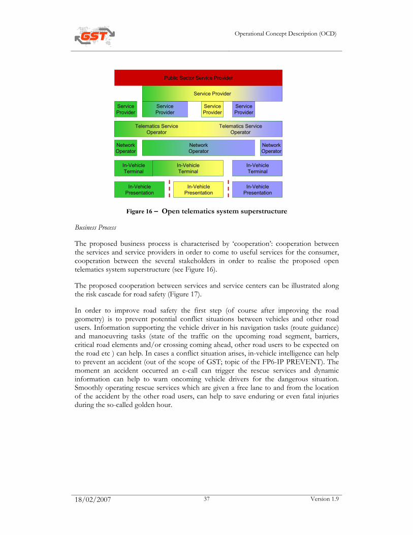
The proposed open telematics system superstructure is drawn in Figure 16. Characteristic of this system concept is the horizontal integration instead of the vertical integration of the first phase (Figure 8).
Operational Concept Description (OCD)
18/02/2007 37 Version 1.9
In-VehiclePresentation
In-VehiclePresentation
In-VehiclePresentation
In-VehicleTerminal
In-VehicleTerminal
In-VehicleTerminal
NetworkOperator
NetworkOperator
ServiceProvider
ServiceProvider
ServiceProvider
ServiceProvider
NetworkOperator
Telematics ServiceOperator
Telematics ServiceOperator
Service Provider
Public Sector Service Provider
Figure 16 – Open telematics system superstructure
Business Process
The proposed business process is characterised by ‘cooperation’: cooperation between the services and service providers in order to come to useful services for the consumer, cooperation between the several stakeholders in order to realise the proposed open telematics system superstructure (see Figure 16).
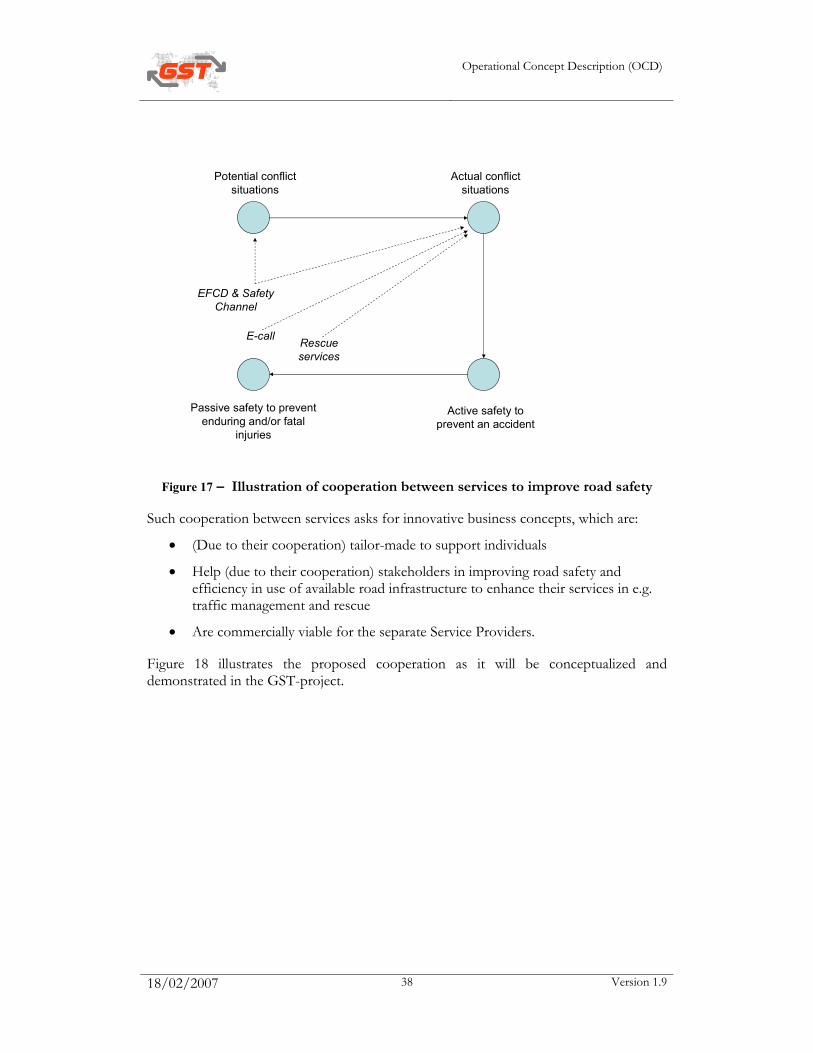
The proposed cooperation between services and service centers can be illustrated along the risk cascade for road safety (Figure 17).
In order to improve road safety the first step (of course after improving the road geometry) is to prevent potential conflict situations between vehicles and other road users. Information supporting the vehicle driver in his navigation tasks (route guidance) and manoeuvring tasks (state of the traffic on the upcoming road segment, barriers, critical road elements and/or crossing coming ahead, other road users to be expected on the road etc ) can help. In cases a conflict situation arises, in-vehicle intelligence can help to prevent an accident (out of the scope of GST; topic of the FP6-IP PREVENT). The moment an accident occurred an e-call can trigger the rescue services and dynamic information can help to warn oncoming vehicle drivers for the dangerous situation. Smoothly operating rescue services which are given a free lane to and from the location of the accident by the other road users, can help to save enduring or even fatal injuries during the so-called golden hour.
Operational Concept Description (OCD)
18/02/2007 38 Version 1.9
Potential conflict situations
Actual conflict situations
Active safety to prevent an accident
Passive safety to prevent enduring and/or fatal
injuries
E-call
EFCD & Safety Channel
Rescue services
Figure 17 – Illustration of cooperation between services to improve road safety
Such cooperation between services asks for innovative business concepts, which are:
• (Due to their cooperation) tailor-made to support individuals
• Help (due to their cooperation) stakeholders in improving road safety and efficiency in use of available road infrastructure to enhance their services in e.g. traffic management and rescue
• Are commercially viable for the separate Service Providers.
Figure 18 illustrates the proposed cooperation as it will be conceptualized and demonstrated in the GST-project.

Operational Concept Description (OCD)
18/02/2007 39 Version 1.9
Vehicle Manufacturer
Telecom Operator
In-vehicle Systems Manufacturer
Telecommunication Systems Manufacturer
Broadcasting Operator
Road AdministratorTraffic Information
Provider Incident & Calamity Manager
Bank & Clearing House
Traffic Manager
Short Range Communication Systems Manufacturer
Traffic Industry
Short range Communication
Operator
Control Centre
Figure 18 – Conceptual illustration of the proposed business processes
6.3 Description of the needed changes on high level per GST sub-project
6.3.1 Open systems
Open systems aims at interoperability. The definition of interoperability in the context of the GST-concept might be:
• Interface I1: the capability of a Service Provider to deploy and/or operate services in any Control Center without modifications to the services
• Interface I2: the capability of a client system to be provisioned by any Control Center without modifications to the services or the Client System
• Interface I3: the capability of a Client System to exchange data with the in-vehicle human-machine interface (HMI) and with the in-vehicle sensors and actuators
Note: The 3GT project under ERTICO, with support from the EC, organized the effort to promote “interoperability” between differing end-to-end telematics solutions, seeking to broaden the standards toward industry-wide interfaces for services and terminals. The focus was on the interfaces I1 and I2.
6.3.2 Security
Security should be guaranteed for any open system. For the GST-concept an architecture and security mechanism will be introduced to secure telematics applications.
Operational Concept Description (OCD)
18/02/2007 40 Version 1.9
6.3.3 Certification
The idea is to introduce a Reference Framework for the European certification of automobile telematics services and components. Certification of services and components should prevent unwanted interference with other safety critical components in the vehicle and data distributed via e.g. the safety channel.
Certification is necessary to guarantee that GST will help us to improve the road safety and is not a threat for road safety in itself.
6.3.4 Service Payment
The goal of Service Payment is to introduce methods to measure service related delivery data (e.g. quantity and/or quality), calculate prices based on user profiles and business/transaction rules, invoice the delivery of services and debit / credit customers accounts.
Service Payment should be available all over Europe, which requires roaming of the service. Service payment should be able to handle an enormous amount of micro-payments in a commercially viable way with respect to the transaction costs.
6.3.5 Safety Channel
The Safety Channel sub-project will as a major result provide an interface specification and procedure , which allows the integration of different sources of Safety Channel data in a standardized content delivery format. This delivery format abstracts the transport bearers from the process used to posses the input data into this Content stream. As a final result it becomes possible to use whatever suitable input source as part of a Safety Channel concept and distribute the obtained information by means of a common agreed on protocol or message format over a suitable peer to peer or broadcasting communication system. These specifications should take note of existing Traffic Messaging systems such as TMC and TPEG and integrate them into an encapsulating Safety Channel message structure.
The Safety Channel sub-project comes with a safety channel, which is tailor-made to distribute safety-related information, like:
• Changes in the road network due to e.g. construction works
• Calamities on or in the surroundings of the road
• Dangerous locations (e.g. given the geometry of the road or the condition of the road surface))or areas (e.g. black-ice or fog) on the road network
• Dynamic speed-alert
• Dangerous traffic situations (tail of a traffic jam, incidents and accidents)
• Ghost drivers
• Approaching emergency vehicles (see Rescue)
Operational Concept Description (OCD)
18/02/2007 41 Version 1.9
• Traffic situation at the location of an incident or accident (see Rescue)
• Etc.
The safety channel should have a data rate guaranteed for all this kind of information and should be independent from broadcasting companies and radio stations. The safety channel should also be independent from any commercial operator asking money from the End-User to receive information using this Safety Channel.
The safety channel should come with a digital chart specification, which guarantees a high hit rate when information projected on one chart is forwarded to and projected on another chart.
The safety channel in fact will be the communication channel over which End-Users will be warned for potential dangerous situations. Therefore the safety channel will enable us to improve road safety (by reducing incidents and accidents) and and to reduce traffic jams.
6.3.6 Enhanced Floating Car Data
The basic idea is to build an open traffic information center, in which traffic information is produced using data from all available sensors. The data should be merged in such a way that the quality of the information improves both at the presentation of the content and the geographical coverage. Merging the data can help to pinpoint the investments in specific sensors at those locations or to those situations where data from different sources is needed to meet the quality level or where other sensor types do not work properly. In other words, if GSM-generated data provides us with the appropriate data in rural areas, we do not need road bound sensors over there; if GSM can not generate appropriate data in dense urban areas, we should install new or open up existing road bound sensors.
Merging the data can help to reduce the communication costs for FCD. After all FCD should be submitted only in those situations where additional data is needed.
Beside the data generated by the sensors, information from PSAP2s (see rescue) and traffic managers should be merged with traffic information.
Traffic can be looked upon as a complex process, emerging from the movements and manoeuvres of individual End-Users with their own intentions and preferences. Improving road safety and efficiency by means of available road infrastructure implies that End-Users have to adjust their intentions and preferences to the evolving or foreseen traffic situation. Journey and traffic information can help to induce the End-Users to do so. Therefore the information should be dynamic and tailor made to the individual.
6.3.7 Rescue The changes required for rescue can be summarized as enhancing the rescue chain (Figure 19).
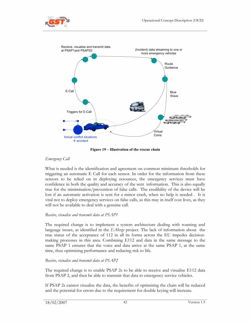
Operational Concept Description (OCD)
18/02/2007 42 Version 1.9
Actual conflict situations accident
E-Call
Triggers for E-Call
Receive, visualise and transmit data at PSAP1and PSAPS2 (Incident) data streaming to one or
more emergency vehicles
Route Guidance
Blue Wave
Virtual Coins
Figure 19 – Illustration of the rescue chain
Emergency Call
What is needed is the identification and agreement on common minimum thresholds for triggering an automatic E Call for each sensor. In order for the information from these sensors to be relied on in deploying resources, the emergency services must have confidence in both the quality and accuracy of the sent information. This is also equally true for the minimisation/prevention of false calls. The credibility of the device will be lost if an automatic activation is sent for a minor crash, when no help is needed . It is vital not to deploy emergency services on false calls, as this may in itself cost lives, as they will not be available to deal with a genuine call.
Receive, visualise and transmit data at PSAP1
The required change is to implement a system architecture dealing with roaming and language issues, as identified in the E-Merge project. The lack of information about the true status of the acceptance of 112 in all its forms across the EU impedes decision-making processes in this area. Combining E112 and data in the same message to the same PSAP 1 ensures that the voice and data arrive at the same PSAP 1, at the same time, thus optimising performance and reducing risk to life.
Receive, visualise and transmit data at PSAP2
The required change is to enable PSAP 2s to be able to receive and visualise E112 data from PSAP 2, and then be able to transmit that data to emergency service vehicles.
If PSAP 2s cannot visualise the data, the benefits of optimising the chain will be reduced and the potential for errors due to the requirement for double keying will increase.
Operational Concept Description (OCD)
18/02/2007 43 Version 1.9
If PSAP 2s cannot transmit data to the emergency vehicles, the benefits of optimising the chain will be reduced and the potential for errors due to the requirement for double keying/writing data on the move will increase.
If identified emergency service vehicles cannot visualise the data, the benefits of optimising the chain will be reduced and the potential for errors due to the requirement for double keying, writing data will increase.
A needed change is data streaming from PSAP 2 to one or more emergency vehicles to include location and other data from the incident.
Another needed change is Emergency Service Vehicles to be able to receive and visualise E112 and other incident data from PSAP 2.
Route Guidance
The needed change is to introduce a route guidance system that builds on the E-Merge Solution and which requires: linkage to active traffic management, provision of voice information when required, catering for the speed and accuracy required by the emergency services without distracting the driver.
Providing the emergency service driver with intelligent support information on the choice of the optimal route to the incident will reduce response times to the incident and will reduce driver distraction trying to plan routes, which will increase safety and security on route.
Free-way to Emergency Vehicles
A needed change here is to pass on increased, language independent information to road users indicating the approach of an emergency service vehicle, the direction the emergency vehicle is approaching from and the number of emergency vehicles involved.
Whilst warning signals have some effect, the increasing isolation of vehicle occupants from the outside environment reduces their impact and hence effectiveness. This has resulted in increased volumes for the sirens to overcome this.
The sirens have been improved to increase their directional ability, however experience shows that road users find difficulty in predicting where the emergency vehicle will come from. This makes drivers uncertain and provokes sudden dangerous and uncontrolled actions as a respose to the sirens. Very often this results in endangering themselves, other road users and the emergency service vehicles.
Creating a Safe Working Environment and Warning other Road Users for a Dangerous Situation
Operational Concept Description (OCD)
18/02/2007 44 Version 1.9
A required change is to introduce the ability to warn approaching road users of the presence of stationary emergency service vehicles on the road ahead, in a focussed and localised way. Provide information on what the road users is required to do in a language independent way, in order to increase the warning on the approach to the incident and to warn the emergency services when the road user is not complying.
The protection of life and property is the fundamental duty of the emergency services. Creating a safe working environment to protect the public involved in the incident, the staff working at the incident site and preventing further casualties from road users not involved in the incident is a fundamental requirement and is key to delivering road safety targets.
Exchange information whilst en route or on the spot
A required change is to introduce the ability to send and receive data to and from the car to third parties and to PSAP 2 in addition to the incident data messages. Examples would be: CCTV or photographs to and from the vehicle or scene, sending and receiving information from and to the incident scene to experts (e.g. doctors in hospitals, technical experts to provide specialist information), fingerprints and/or the sending of incident reports and crime reports allowing the experts to work mobile.
Providing information and pictures to those that have to make staffing decisions will greatly aid decision making in deploying resources to quickly resolve the incident and mitigate the effects. Pictures from the first unit to the scene streamed back to PSAP 2 allow the controllers to assess the scale of the incident and allocate the necessary resources.
Pictures and data from a patient to the hospital before leaving the scene, allows the hospital to prepare for the casualty and may allow treatment decisions and advice to be given prior to leaving the incident.
Allowing staff to complete the forms required to report an incident electronically and send this information from the scene means they do not have to return to base, and are therefore available to be deployed to other work more quickly. This increases efficiency, which can have a positive impact on saving lives.
Operational Concept Description (OCD)
18/02/2007 45 Version 1.9
Chapter 7 - SYSTEM CONCEPT This Chapter presents the System Concept of the GST System. The GST System is defined here as the main deliverable of the GST Project. It consists of a GST Operational System and a GST Realization System. The GST Operational System groups all Entities necessary for the operational use of GST compliant services and equipment, including content delivery, service delivery, service deployment and service fulfilment. The GST Realization System groups all Entities necessary for the development and certification of GST compliant services and equipment, including the hand-over to the GST Operational System.
The Chapter is structured in the following Sections:
- Section 7.1 explains the definitions of Entities, Actors and Roles as they will be used in this Chapter
- Section 7.2 describes the operational environment of the GST System
- Section 7.3 describes the system's major components
- Section 7.4 defines the main capabilities and functions of the GST System and allocates the Roles to the Entities and Actors
7.1 Definition of terminology used
This Section describes the definitions of Entity, Actor and Role as they are being used throughout this Chapter:
• An Entity is defined as an element of the GST world. An Entity can either exist inside or outside the GST System (in the GST Environment). Often it can be further decomposed in other entities. Examples of Entities are infrastructure, hardware and software modules
• An Actor is defined as a Human or as an External Entity that interacts with the GST System. A Human Actor can be an individual or an organization
• A Role is a (set of) function(s) or task(s) that can be performed by an Entity or an Actor in a particular situation or use case. Roles can be assigned to Entities inside and outside of the GST System. Each Entity or Actor can therefore have more than one Role
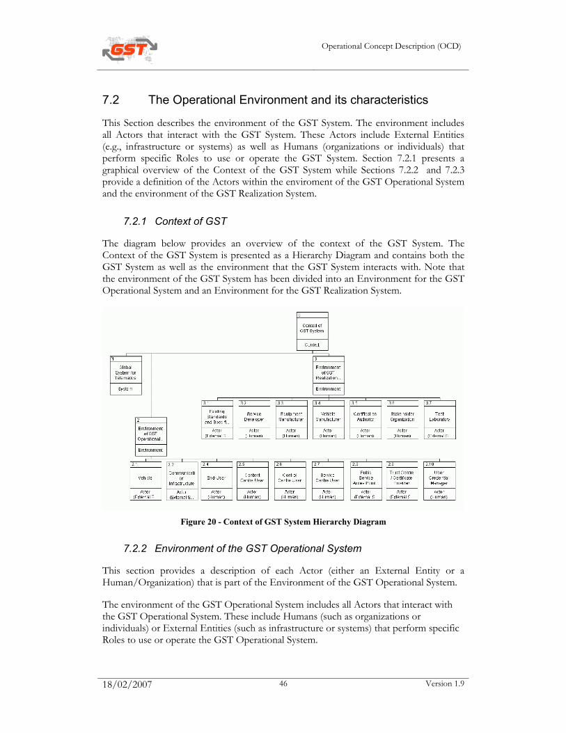
Operational Concept Description (OCD)
18/02/2007 46 Version 1.9
7.2 The Operational Environment and its characteristics
This Section describes the environment of the GST System. The environment includes all Actors that interact with the GST System. These Actors include External Entities (e.g., infrastructure or systems) as well as Humans (organizations or individuals) that perform specific Roles to use or operate the GST System. Section 7.2.1 presents a graphical overview of the Context of the GST System while Sections 7.2.2 and 7.2.3 provide a definition of the Actors within the enviroment of the GST Operational System and the environment of the GST Realization System.
7.2.1 Context of GST
The diagram below provides an overview of the context of the GST System. The Context of the GST System is presented as a Hierarchy Diagram and contains both the GST System as well as the environment that the GST System interacts with. Note that the environment of the GST System has been divided into an Environment for the GST Operational System and an Environment for the GST Realization System.
Figure 20 - Context of GST System Hierarchy Diagram
7.2.2 Environment of the GST Operational System
This section provides a description of each Actor (either an External Entity or a Human/Organization) that is part of the Environment of the GST Operational System.
The environment of the GST Operational System includes all Actors that interact with the GST Operational System. These include Humans (such as organizations or individuals) or External Entities (such as infrastructure or systems) that perform specific Roles to use or operate the GST Operational System.
Operational Concept Description (OCD)
18/02/2007 47 Version 1.9
7.2.2.1 Vehicle
In general a vehicle is a means of carrying or transporting something. In the context of GST a vehicle contains the Client System and is able to communicate with the external world.
7.2.2.2 Communication Infrastructure
The Communication Infrastructure provides wide-area network connectivity between the Service Platform and outside parties. Outside parties include the Control Center User and the Service Providers. In the case where the Service Platform is connected via the Internet, the Network Provider is assumed to include the Internet Service Provider (ISP) functionality. A Service Platform that connects to the Internet using DSL might have (in the aftermath of deregulation) five companies responsible for the various layers: the phone company responsible for the copper wires to the home, the DSL service provider responsible for the ATM connectivity, the ISP responsible for Internet connectivity, the Control Center User responsible for operation of the Service Platform, and finally the other Service Provider(s) responsible for the value added service(s) running. This model applies to both IP and non-IP network layers and to both continuous and intermittent availability. Every effort is made to avoid making assumptions that the network service is Internet (IP) or that it is continuously available.
7.2.2.3 End-User
An End-User is an actor using GST services on a Client System. Depending on the situation, this actor may take on various roles, which will be described in Section 7.4.
7.2.2.4 Content Center User
The Content Center User is an actor that interacts with the Content Center. Depending on the situation, this actor may take on various roles, which will be described in Section 7.4.
7.2.2.5 Control Center User
The Control Center User is an actor that interacts with the Control Center. Depending on the situation, this actor may take on various roles, which will be described in Section 7.4. For example a typical role of the Control Center User is that of the Control Center administrator.
7.2.2.6 Service Center User
The Service Center User is an actor that interacts with the Service Center. Depending on the situation, this actor may take on various roles, which will be described in Section 7.4.
7.2.2.7 Pubic Service Acces Point (PSAP)
Public Service Access Points are the Centers where 112 calls are received, assessed, routed and help is dispatched (in the RSQ subproject).
Operational Concept Description (OCD)
18/02/2007 48 Version 1.9
7.2.2.8 Trust Center / Certificate Provider
By using a Certificate Provider the entities of the GST Operational System can verify the authenticity of service applications and users.
7.2.2.9 User Credential Manager
The manager of the User Credential Store.
7.2.3 Environment of the GST Realization System
This section provides a description of each Actor (either an External Entity or a Human/Organization) that is part of the Environment of the GST Realization System.
7.2.3.1 Existing Standards and Specifications
Existing standards and specifications (if any) which must be met in order to develop GST compliant services/software and equipment.
7.2.3.2 Service Developer
The Service Developer is an actor that interacts with the Development Center and the Certification Center in order to develop GST-compliant service applications.
7.2.3.3 Equipment Manufacturer
The Equipment Manufacturer is an actor that interacts with the Development Center and the Certification Center in order to develop GST-compliant equipment.
7.2.3.4 Vehicle Manufacturer
The manufacturer of the vehicle.
7.2.3.5 Certification Authority
The Certification Authority is an actor that interacts with the Certification Center in order to validate compliancy of a GST Entity to the GST specifications..
7.2.3.6 Stakeholder Organization
Automotive Telematics Stakeholders
7.2.3.7 Test Laboratory
The laboratory where the compliance with the GST Services Level Agreements and Services Level Specifications is tested.
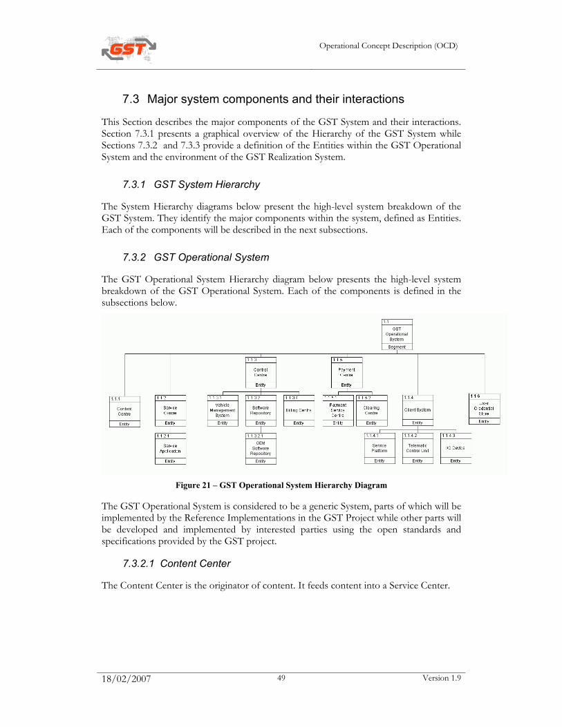
Operational Concept Description (OCD)
18/02/2007 49 Version 1.9
7.3 Major system components and their interactions
This Section describes the major components of the GST System and their interactions. Section 7.3.1 presents a graphical overview of the Hierarchy of the GST System while Sections 7.3.2 and 7.3.3 provide a definition of the Entities within the GST Operational System and the environment of the GST Realization System.
7.3.1 GST System Hierarchy
The System Hierarchy diagrams below present the high-level system breakdown of the GST System. They identify the major components within the system, defined as Entities. Each of the components will be described in the next subsections.
7.3.2 GST Operational System
The GST Operational System Hierarchy diagram below presents the high-level system breakdown of the GST Operational System. Each of the components is defined in the subsections below.
Figure 21 – GST Operational System Hierarchy Diagram
The GST Operational System is considered to be a generic System, parts of which will be implemented by the Reference Implementations in the GST Project while other parts will be developed and implemented by interested parties using the open standards and specifications provided by the GST project.
7.3.2.1 Content Center
The Content Center is the originator of content. It feeds content into a Service Center.

Operational Concept Description (OCD)
18/02/2007 50 Version 1.9
7.3.2.2 Service Center
The Service Center is the back-end infrastructure that a Service Provider constructs, deploys, and operates additionally to the Service Application. It frequently comprises remote server(s) and applications supporting and communicating with the Service Application on the Client System.
7.3.2.3 Service Application
A piece of software executable by the Service Platform. A Service Application is the actual implementation of the service frontend used within a Service Platform for a specific Client System. It may consist of a series of components each providing part of the functionality of the overall service.
7.3.2.4 Control Center
A Control Center manages multiple Client Systems and End-Users. It is responsible for registration of Client Systems, authentication, service provisioning, subscription and the subsequent download of service applications, service updates, remote administration and all other needed management procedures on a Client System.
A Control Center is a component which is decomposable in different entities representing organizational units within a layer between the Service Center and the Client System. The exact decomposition will require further study.
7.3.2.5 Payment Center
A Control Payment Center is a component which is decomposable in different entities representing organizational units like Payment Service Center, Clearing Center, etc. The exact decomposition will require further study.
7.3.2.6 Client System
A GST Client System is the physical device running one or more Service Platforms for executing applications. Client Systems include Telematics Control Units, Service Platforms and I/O devices.
7.3.2.7 Service Platform
The Service Platform is the software on the Client System to manage the execution life-cycle of Service Applications. Service Applications consist of software components that the Service Platform is capable of dynamically loading, activating, deactivating, updating, and unloading.
7.3.2.8 Telematics Control Unit
The Telematics Control Unit hosts one or more Service Platforms. It can be equipped with very specialized hardware suited for a specific application domain.

Operational Concept Description (OCD)
18/02/2007 51 Version 1.9
7.3.2.9 I/O Device
An I/O Device is the physical input/output device that is part of the GST environment inside of the vehicle. It provides access to the GST services.
7.3.2.10 Payment Service Center
This is the Service Center responsible for the invoicing, billing and payment for the usage of the different service applications. It contacts external Clearing Centers to do the billing.
A Payment Service Center authorizes payment transactions and collects records of these payment transactions. Frequently, a Payment Service Provider will also issue payment tokens, such as e.g. credit cards .
7.3.2.11 Clearing Center
A Clearing Center collects the records of transactions from all payment service providers and provides clearing services between Payment Service Providers and banking institutes.
7.3.2.12 User Credential Store
Database containing user credentials. This is the central database holding the "master record" of the user information. It is contacted by different Control Centers in case of "roaming" of the Client System of the End-User.
7.3.2.13 Vehicle Management System
This is part of the Control Center which takes care of the management of the Client System, the installation of software applications, the management of the vehicle profile etc.
7.3.2.14 Software Repository
Part of the Control Center that holds the client parts of the services – the Service Applications which have to be installed on the Client System so that a service can be consumed.
7.3.2.15 OEM Software Repository
Part of the Software Repository that contains the OEM software.
7.3.2.16 Billing Center
A Billing Center collects pre-processed logging data, i.e. usage information (frequently also called CDRs) and processes these to produce a consolidated cost statement and issue invoices, e.g. on a monthly basis.
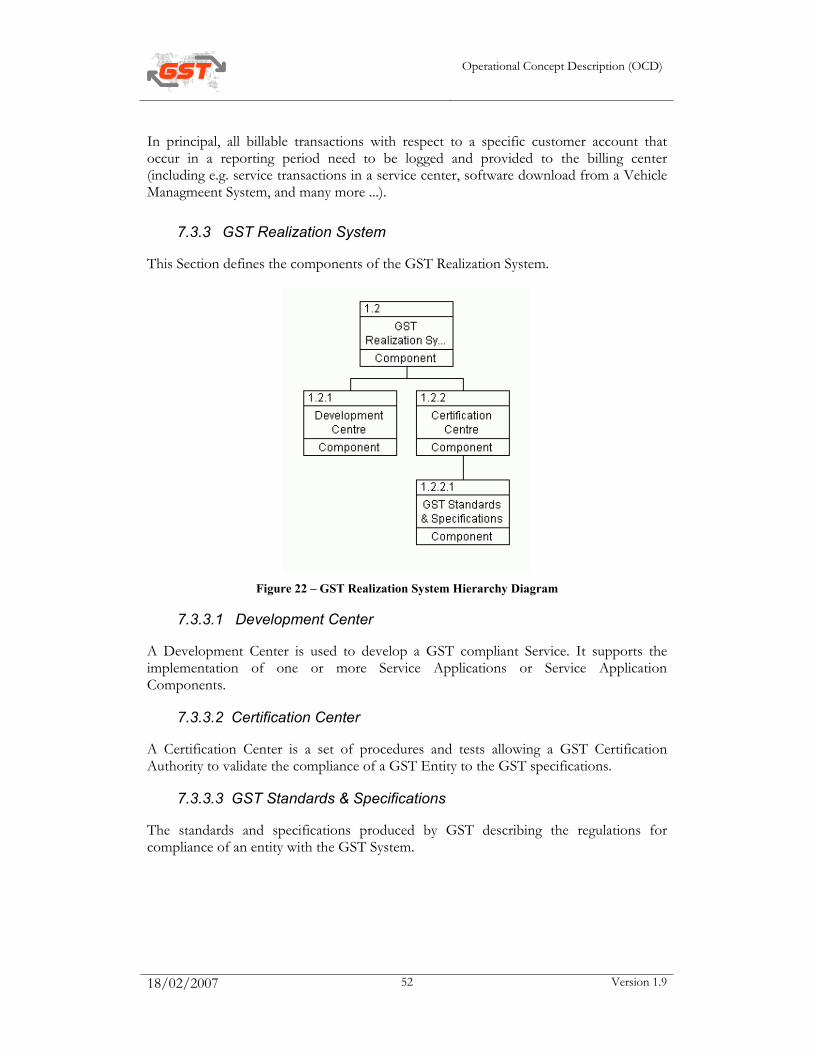
Operational Concept Description (OCD)
18/02/2007 52 Version 1.9
In principal, all billable transactions with respect to a specific customer account that occur in a reporting period need to be logged and provided to the billing center (including e.g. service transactions in a service center, software download from a Vehicle Managmeent System, and many more ...).
7.3.3 GST Realization System
This Section defines the components of the GST Realization System.
Figure 22 – GST Realization System Hierarchy Diagram
7.3.3.1 Development Center
A Development Center is used to develop a GST compliant Service. It supports the implementation of one or more Service Applications or Service Application Components.
7.3.3.2 Certification Center
A Certification Center is a set of procedures and tests allowing a GST Certification Authority to validate the compliance of a GST Entity to the GST specifications.
7.3.3.3 GST Standards & Specifications
The standards and specifications produced by GST describing the regulations for compliance of an entity with the GST System.

Operational Concept Description (OCD)
18/02/2007 53 Version 1.9
7.4 Capabilities and functions
This Section contains a lists with the agreed Roles that can be allocated to each Entity of the GST System and each Actor (either Human or External Entity) that is part of the GST Environment. )
• Service Provider, could be allocated to Service Center User
• Service Aggregator, could be allocated to a Control Center User
• Operator, could be allocated to the Control Center User
• Service Customer, could be allocated to the End-User. A Service Customer is an End User who subscribes for services and pays for them
• Service User, could be allocated to the End-User. A Service User is an End-User using GST services on a Client Device. Several Service Users can belong to one Service Customer and use a service that he pays for
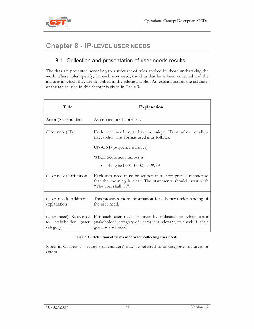
Operational Concept Description (OCD)
18/02/2007 54 Version 1.9
Chapter 8 - IP-LEVEL USER NEEDS
8.1 Collection and presentation of user needs results
The data are presented according to a strict set of rules applied by those undertaking the work. These rules specify, for each user need, the data that have been collected and the manner in which they are described in the relevant tables. An explanation of the columns of the tables used in this chapter is given in Table 3.
Title Explanation
Actor (Stakeholder) As defined in Chapter 7 -.
(User need) ID Each user need must have a unique ID number to allow traceability. The format used is as follows:
UN-GST-[Sequence number]
Where Sequence number is:
• 4 digits: 0001, 0002, … 9999
(User need) Definition Each user need must be written in a short precise manner so that the meaning is clear. The statements should start with “The user shall …”.
(User need) Additional explanation
This provides more information for a better understanding of the user need.
(User need) Relevance to stakeholder (user category)
For each user need, it must be indicated to which actor (stakeholder, category of users) it is relevant, to check if it is a genuine user need.
Table 3 - Definition of terms used when collecting user needs
Note: in Chapter 7 - actors (stakeholders) may be referred to as categories of users or actors.

Operational Concept Description (OCD)
18/02/2007 55 Version 1.9
8.2 Identification of user needs
The user needs identified at IP-level are as follows (stakeholders affected are crossed):
ID Definition Additional Explanation Relevance to stakeholder UN-GST-0001 The user shall be able to have access
to all services after single sign on. Login: the end-user provides credentials to the vehicle once (e.g. at startup) and then is automatically authenticated to all systems and services
2.4 End-User
2.6 Control Center User
2.7 Service Center User
UN-GST-0002 Multiple users shall be able to login to the same service platform.
Front-seat/Rear-seat service consumption: Multiple users should be able to be concurrently connected to the service platform.
2.4 End-User
2.6 Control Center User
2.7 Service Center User
UN-GST-0003 The integrity of the GST system needs to be maintained.
2.4 End-User
2.7 Service Center User
3.2 Service Developer
3.3 Equipment Manufacturer
3.4 Vehicle Manufacturer
UN-GST-0004 The user expects an appropriate level of privacy.
2.4 End-User
2.10 User Credential Manager
UN-GST-0005 The user shall expect an alert message in critical situations.
In order to support the driver in critical situations several driver assist
2.2 Communication Infrastructure
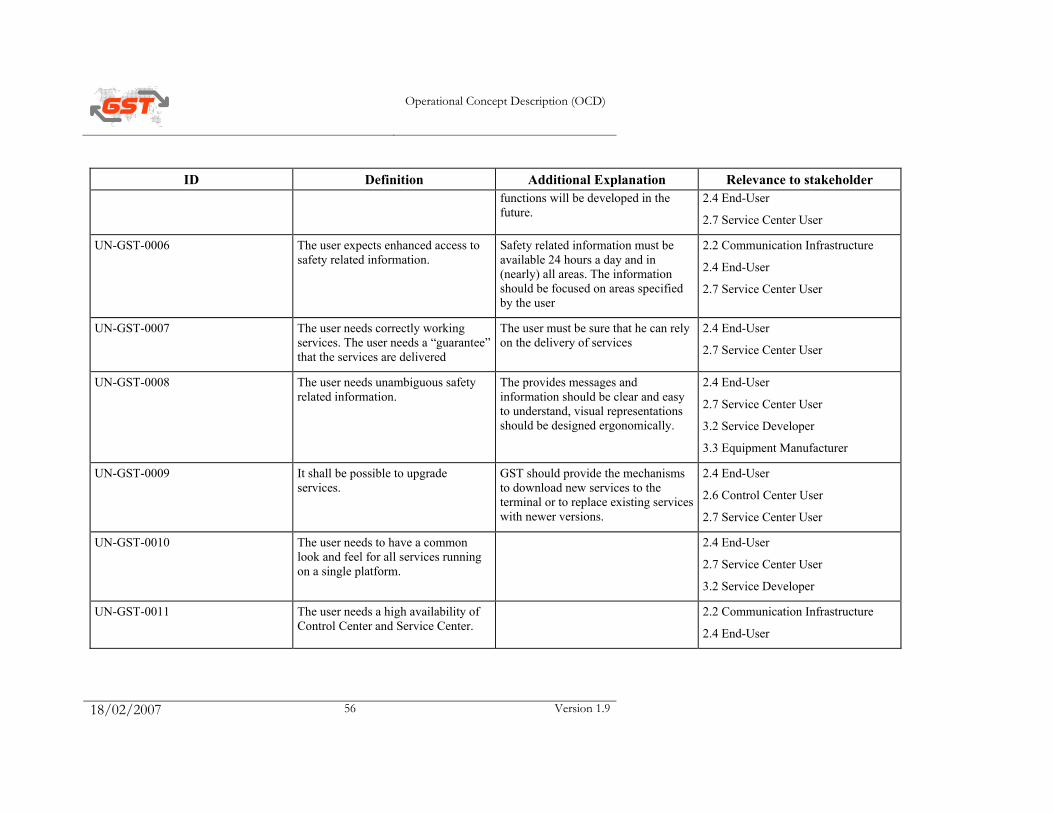
Operational Concept Description (OCD)
18/02/2007 56 Version 1.9
ID Definition Additional Explanation Relevance to stakeholder functions will be developed in the future.
2.4 End-User
2.7 Service Center User
UN-GST-0006 The user expects enhanced access to safety related information.
Safety related information must be available 24 hours a day and in (nearly) all areas. The information should be focused on areas specified by the user
2.2 Communication Infrastructure
2.4 End-User
2.7 Service Center User
UN-GST-0007 The user needs correctly working services. The user needs a “guarantee” that the services are delivered
The user must be sure that he can rely on the delivery of services
2.4 End-User
2.7 Service Center User
UN-GST-0008 The user needs unambiguous safety related information.
The provides messages and information should be clear and easy to understand, visual representations should be designed ergonomically.
2.4 End-User
2.7 Service Center User
3.2 Service Developer
3.3 Equipment Manufacturer
UN-GST-0009 It shall be possible to upgrade services.
GST should provide the mechanisms to download new services to the terminal or to replace existing services with newer versions.
2.4 End-User
2.6 Control Center User
2.7 Service Center User
UN-GST-0010 The user needs to have a common look and feel for all services running on a single platform.
2.4 End-User
2.7 Service Center User
3.2 Service Developer
UN-GST-0011 The user needs a high availability of Control Center and Service Center.
2.2 Communication Infrastructure
2.4 End-User
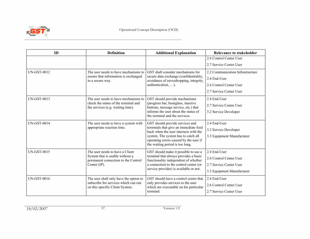
Operational Concept Description (OCD)
18/02/2007 57 Version 1.9
ID Definition Additional Explanation Relevance to stakeholder 2.6 Control Center User
2.7 Service Center User
UN-GST-0012 The user needs to have mechanisms to ensure that information is exchanged in a secure way.
GST shall consider mechanisms for secure data exchange (confidentiality, avoidance of eavesdropping, integrity, authentication, …).
2.2 Communication Infrastructure
2.4 End-User
2.6 Control Center User
2.7 Service Center User
UN-GST-0013 The user needs to have mechanisms to check the status of the terminal and the services (e.g. waiting time).
GST should provide mechanisms (progress bar, hourglass, inactive buttons, message service, etc.) that informs the user about the status of the terminal and the services.
2.4 End-User
2.7 Service Center User
3.2 Service Developer
UN-GST-0014 The user needs to have a system with appropriate reaction time.
GST should provide services and terminals that give an immediate feed back when the user interacts with the system. The system has to catch all operating errors caused by the user if the waiting period is too long.
2.4 End-User
3.2 Service Developer
3.3 Equipment Manufacturer
UN-GST-0015 The user needs to have a Client System that is usable without a permanent connection to the Control Center (IP).
GST should make it possible to use a terminal that always provides a basic functionality independent of whether a connection to the control center (or service provider) is available or not.
2.4 End-User
2.6 Control Center User
2.7 Service Center User
3.3 Equipment Manufacturer
UN-GST-0016 The user shall only have the option to subscribe for services which can run on this specific Client System.
GST should have a control center that only provides services to the user which are executable on his particular terminal.
2.4 End-User
2.6 Control Center User
2.7 Service Center User
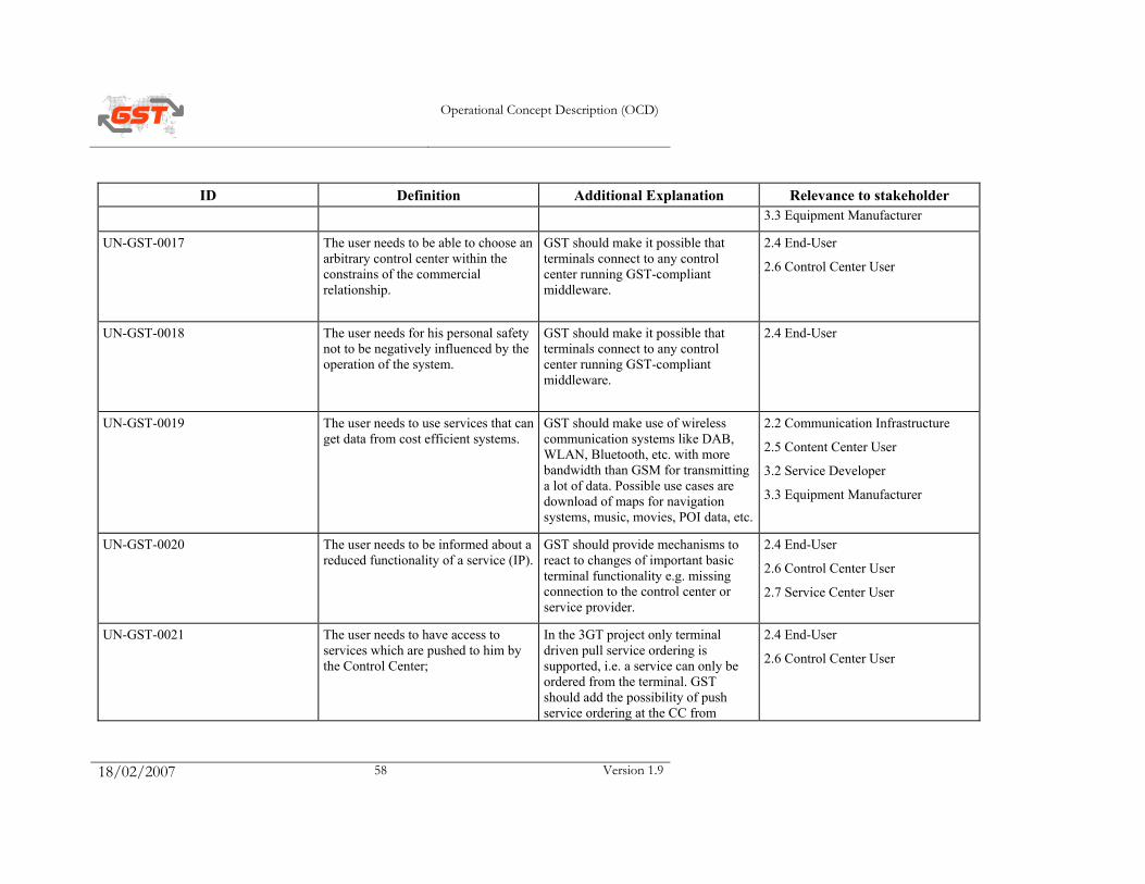
Operational Concept Description (OCD)
18/02/2007 58 Version 1.9
ID Definition Additional Explanation Relevance to stakeholder 3.3 Equipment Manufacturer
UN-GST-0017 The user needs to be able to choose an arbitrary control center within the constrains of the commercial relationship.
GST should make it possible that terminals connect to any control center running GST-compliant middleware.
2.4 End-User
2.6 Control Center User
UN-GST-0018 The user needs for his personal safety not to be negatively influenced by the operation of the system.
GST should make it possible that terminals connect to any control center running GST-compliant middleware.
2.4 End-User
UN-GST-0019 The user needs to use services that can get data from cost efficient systems.
GST should make use of wireless communication systems like DAB, WLAN, Bluetooth, etc. with more bandwidth than GSM for transmitting a lot of data. Possible use cases are download of maps for navigation systems, music, movies, POI data, etc.
2.2 Communication Infrastructure
2.5 Content Center User
3.2 Service Developer
3.3 Equipment Manufacturer
UN-GST-0020 The user needs to be informed about a reduced functionality of a service (IP).
GST should provide mechanisms to react to changes of important basic terminal functionality e.g. missing connection to the control center or service provider.
2.4 End-User
2.6 Control Center User
2.7 Service Center User
UN-GST-0021 The user needs to have access to services which are pushed to him by the Control Center;
In the 3GT project only terminal driven pull service ordering is supported, i.e. a service can only be ordered from the terminal. GST should add the possibility of push service ordering at the CC from
2.4 End-User
2.6 Control Center User
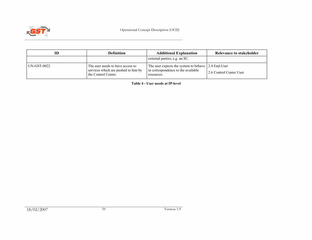
Operational Concept Description (OCD)
18/02/2007 59 Version 1.9
ID Definition Additional Explanation Relevance to stakeholder external parties, e.g. an SC.
UN-GST-0022 The user needs to have access to services which are pushed to him by the Control Center.
The user expects the system to behave in correspondence to the available resources.
2.4 End-User
2.6 Control Center User
Table 4 - User needs at IP-level
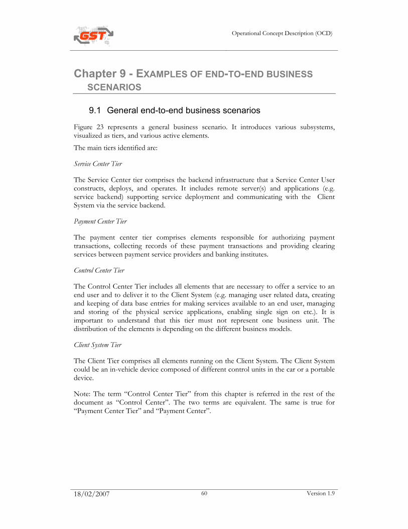
Operational Concept Description (OCD)
18/02/2007 60 Version 1.9
Chapter 9 - EXAMPLES OF END-TO-END BUSINESS SCENARIOS
9.1 General end-to-end business scenarios
Figure 23 represents a general business scenario. It introduces various subsystems, visualized as tiers, and various active elements.
The main tiers identified are:
Service Center Tier
The Service Center tier comprises the backend infrastructure that a Service Center User constructs, deploys, and operates. It includes remote server(s) and applications (e.g. service backend) supporting service deployment and communicating with the Client System via the service backend.
Payment Center Tier
The payment center tier comprises elements responsible for authorizing payment transactions, collecting records of these payment transactions and providing clearing services between payment service providers and banking institutes.
Control Center Tier
The Control Center Tier includes all elements that are necessary to offer a service to an end user and to deliver it to the Client System (e.g. managing user related data, creating and keeping of data base entries for making services available to an end user, managing and storing of the physical service applications, enabling single sign on etc.). It is important to understand that this tier must not represent one business unit. The distribution of the elements is depending on the different business models.
Client System Tier
The Client Tier comprises all elements running on the Client System. The Client System could be an in-vehicle device composed of different control units in the car or a portable device.
Note: The term “Control Center Tier” from this chapter is referred in the rest of the document as “Control Center”. The two terms are equivalent. The same is true for “Payment Center Tier” and “Payment Center”.
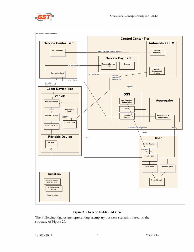
Operational Concept Description (OCD)
18/02/2007 61 Version 1.9
cd Generic End-to-End View
Client Device Tier
Control Center Tier
Service Payment
Suppliers
Aggregator
OSS
User
Vehicle
Automotive OEMService Center Tier
Serv ice Backend
Serv ice Frontend
Serv ice User
Authentication & Authorization
Billing
User Registry & Subscription
Softw are Repository
Serv ice Platform
Serv ice Customer
Vehicle Management
System
Serv ice Center
Vehicle Agent
User Token
Federation Manager
Telematic Control Unit Supplier
Token Supplier
Consumer HW Manuf.
Portable Devicee.g. PDA
Vehicle Interfaces
Payment token
Payment Serv ice Center
Clearing
Smart Card Reader
Trusted Module
Invoice
charge / settle
single sign on
execution:del iver service
runs on
optional
Uses
identi fy
S-PAY payment
1Has Member
0..*
(service)appl icationdeployment
deliver certi fied frontend software
manage
subscription management
Figure 23 - Generic End-to-End View
The Following Figures are representing exemplary business scenarios based on the structure of Figure 23.

Operational Concept Description (OCD)
18/02/2007 62 Version 1.9
The BMW Centric View: In this view the car manufacturer, e.g. BMW, is in charge of the client device that is controlled by the Vehicle Management System (VMS). BMW owns the customer data and authenticates the end user. The billing functionality and the federation manager, which enables single sign on, is delegated to a White Label operator (Operation Support System, OSS). Visa is responsible to handle service payment based on payment tokens, such as e.g. credit cards etc.
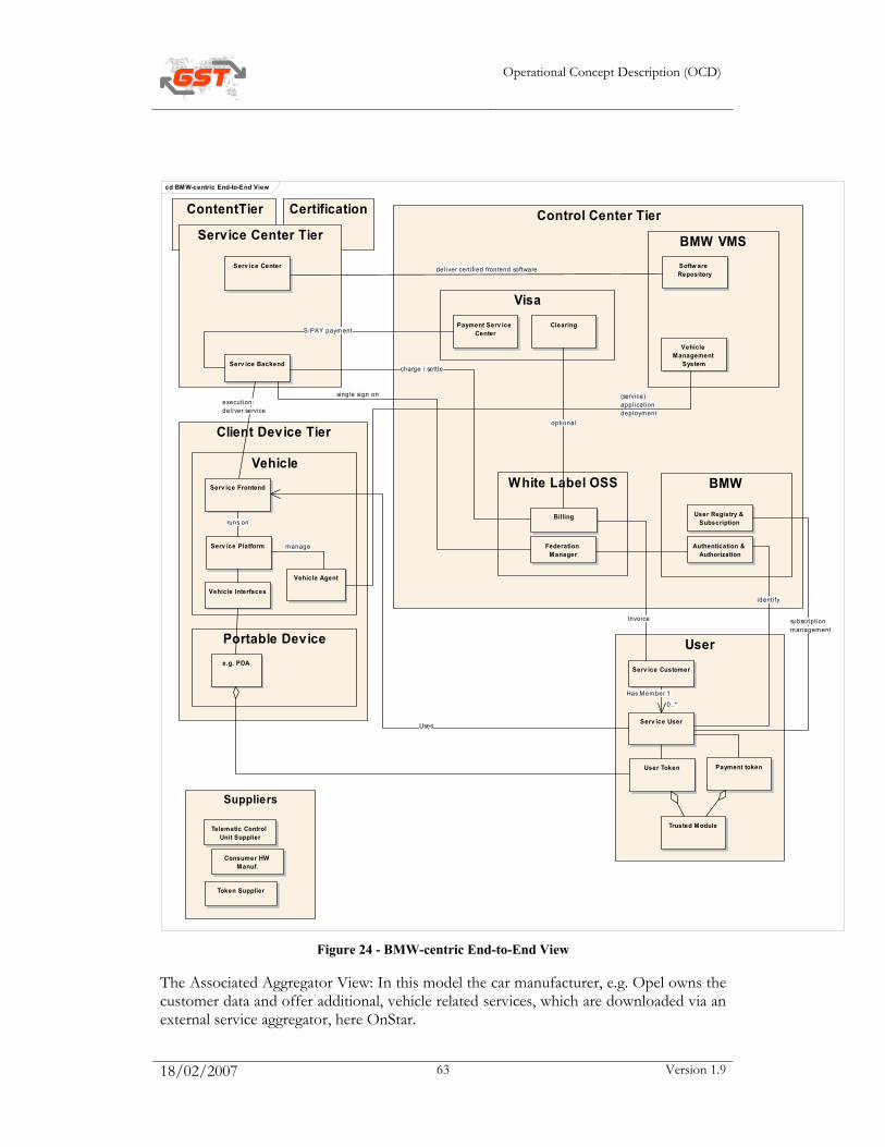
Operational Concept Description (OCD)
18/02/2007 63 Version 1.9
cd BMW-centric End-to-End View
CertificationContentTier
Client Device Tier
Control Center Tier
Visa
Suppliers
BMWWhite Label OSS
User
Vehicle
BMW VMSService Center Tier
Serv ice Backend
Serv ice Frontend
Serv ice User
Authentication & Authorization
Billing User Registry & Subscription
Softw are Repository
Serv ice Platform
Serv ice Customer
Vehicle Management
System
Serv ice Center
Vehicle Agent
User Token
Federation Manager
Telematic Control Unit Supplier
Token Supplier
Consumer HW Manuf.
Portable Devicee.g. PDA
Vehicle Interfaces
Payment token
Payment Serv ice Center
Clearing
Trusted Module
Invoice
charge / settle
single sign onexecution:del iver service
runs on
optional
Uses
identi fy
S-PAY payment
1Has Member
0..*
(service)appl icationdeployment
del iver certi fied frontend software
manage
subscriptionmanagement
Figure 24 - BMW-centric End-to-End View
The Associated Aggregator View: In this model the car manufacturer, e.g. Opel owns the customer data and offer additional, vehicle related services, which are downloaded via an external service aggregator, here OnStar.
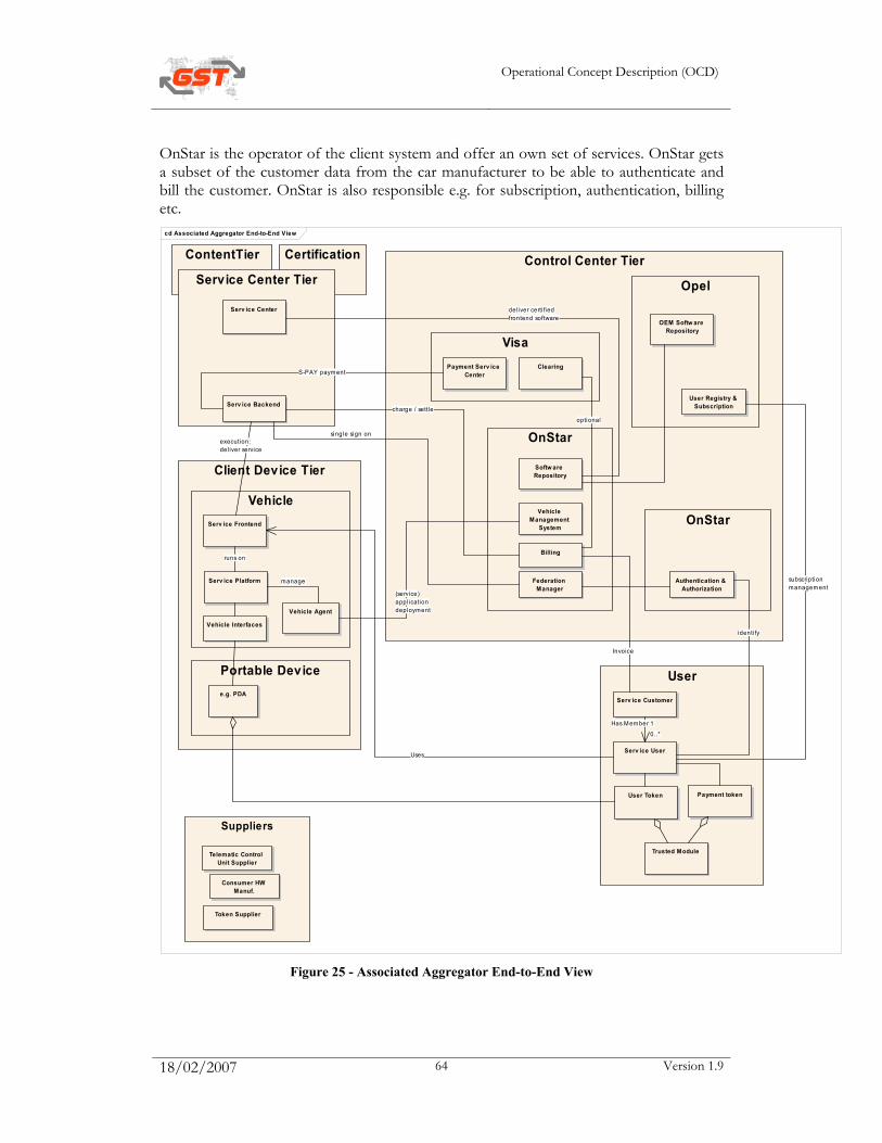
Operational Concept Description (OCD)
18/02/2007 64 Version 1.9
OnStar is the operator of the client system and offer an own set of services. OnStar gets a subset of the customer data from the car manufacturer to be able to authenticate and bill the customer. OnStar is also responsible e.g. for subscription, authentication, billing etc.
cd Associated Aggregator End-to-End View
CertificationContentTier
Client Device Tier
Control Center Tier
Visa
Suppliers
OnStar
OnStar
User
Vehicle
OpelService Center Tier
Serv ice Backend
Serv ice Frontend
Serv ice User
Authentication & Authorization
Billing
User Registry & Subscription
Softw are Repository
Serv ice Platform
Serv ice Customer
Vehicle Management
System
Serv ice Center
Vehicle Agent
User Token
Federation Manager
Telematic Control Unit Supplier
Token Supplier
Consumer HW Manuf.
Portable Devicee.g. PDA
Vehicle Interfaces
Payment token
Payment Serv ice Center
Clearing
Trusted Module
OEM Softw are Repository
charge / settle
single sign onexecution:del iver service
runs on
optional
Uses
identi fy
subscriptionmanagement
S-PAY payment
Invoice
1Has Member
0..*
(service)appl icationdeployment
del iver certi fiedfrontend software
manage
Figure 25 - Associated Aggregator End-to-End View
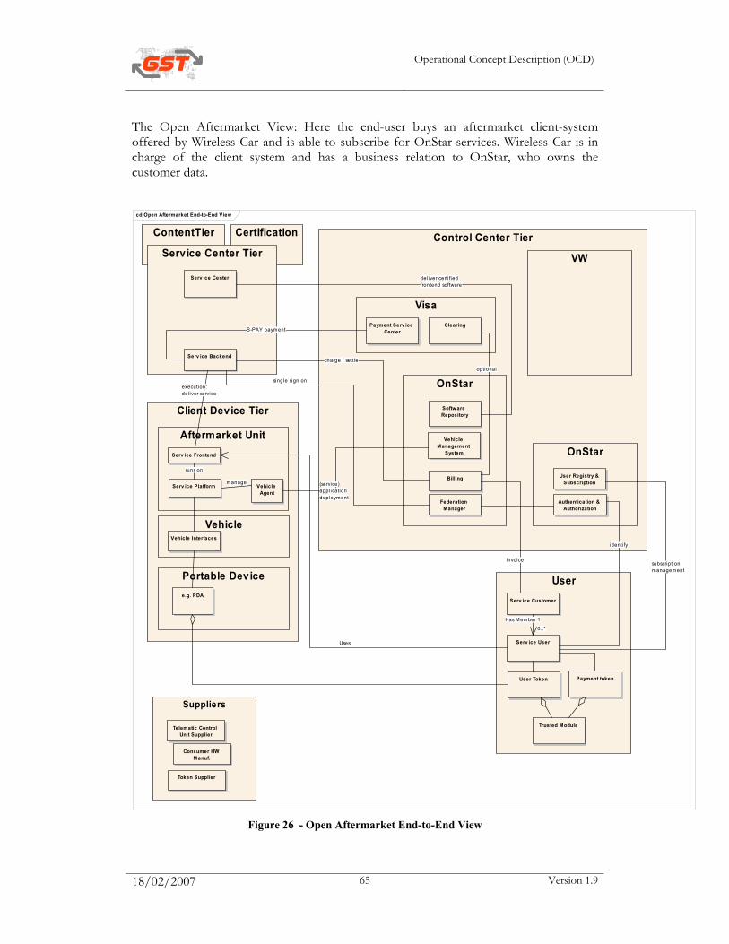
Operational Concept Description (OCD)
18/02/2007 65 Version 1.9
The Open Aftermarket View: Here the end-user buys an aftermarket client-system offered by Wireless Car and is able to subscribe for OnStar-services. Wireless Car is in charge of the client system and has a business relation to OnStar, who owns the customer data.
cd Open Aftermarket End-to-End View
Client Device Tier
Aftermarket Unit
CertificationContentTier Control Center Tier
Visa
Suppliers
OnStar
OnStar
User
Vehicle
VWService Center Tier
Serv ice Backend
Serv ice User
Authentication & Authorization
Billing User Registry & Subscription
Softw are Repository
Serv ice Platform
Serv ice Customer
Vehicle Management
System
Serv ice Center
Vehicle Agent
User Token
Federation Manager
Telematic Control Unit Supplier
Token Supplier
Consumer HW Manuf.
Portable Devicee.g. PDA
Vehicle Interfaces
Payment token
Payment Serv ice Center
Clearing
Trusted Module
Serv ice Frontend
Invoice
charge / settle
single sign onexecution:del iver service
runs on
optional
Uses
identi fy
S-PAY payment
1Has Member
0..*
(service)appl icationdeployment
del iver certi fiedfrontend software
manage
subscriptionmanagement
Figure 26 - Open Aftermarket End-to-End View
Operational Concept Description (OCD)
18/02/2007 66 Version 1.9
9.2 Examples for business use cases
Note: The following examples don’t have the intention to be complete. They don’t cover the full functionality of the GST specification – they are included only as examples of some possible uses of a GST system.
Example 1: Health Monitoring
• End-User accesses vehicle and authenticates itself
• Health monitoring Service Provider starts monitoring the End-User, through the Telematics Control Unit which interacts with a dedicated watch
• Incident occurs as blood glucose level gets below threshold, E112 call is originated automatically to the appropriate PSAP
• Vehicle is located, End-User parameters (patient history, medical files) are accessed. UC-SEC-0003 below is activated.
• Confidential health data are exchanged
• End-User is reminded to take sugar
• Blood glucose level remains below threshold, End-User is guided to the nearest parking lot
• End-User gets unconscious, e-call guides rescue personnel to his location; the Service Platform informs the Actor End-User about result of the activation and the status of the Authorisation (Validity period, etc.).
Example 2 : Remote Vehicle Localisation
• End User accesses vehicle and authenticates itself
• End User connects a series of telematics services (e.g. Navigation, Traffic info, …)
• A thief forces him out at a light and drives the vehicle away
• Vehicle is located, list of currently accessed services is determined
• End User alerts police which alerts Trust Federation Manager
• All active telematics services are de-activated
• Vehicle is monitored until it reaches a suitable situation where it can be indefinitely immobilised.
Operational Concept Description (OCD)
18/02/2007 67 Version 1.9
Example 3 : Family and Friends
• Families Toulemonde, Smith, Martin, decide to travel together with their three vehicles around Europe. John Vanhove is a friend of Mark Smith and joins their family. Prior to leaving, they set up an adhoc network capability (range of communication is 2 km)
• July Toulemonde, 12, Madeleine Smith, 14, and Linda Martin, 13 install a small private chat application which they download in a secure sandbox of the telematics control unit
• Florian Toulemonde, 14, Gilbert Smith, 17 install a communication software to allow interaction with their video game console
• All 3 cars have GPS. The 3 families download free software which accesses the adhoc network to display of the location of the 3 vehicles on the terminal control unit display. The 3 drivers no longer need to follow each other by eyesight
• John Vanhove is in Mark Smith vehicle. He accesses services he has subscribed to, since Mark Smith’s telematics control unit offers secure multi-user access.
Example 4 : Car parking reservation and payment
• A professional user drives a rental or shared car (Company Fleet) to go for a day meeting
• He has subscribed to the telematices services : navigation assistance with POIs, traffic information , car parking services
• When arriving near his destination, the system proposes to him a list of car parks with established prices
• He chooses one parking in the list and asks for a free place to be allocated for his car during the planned parking duration
• He receives a ticket with an access authorization (key) which will be presented at the park’s entrance gate. The system loads the updated itinerary to reach the parking.
• At the entry of the car park, the payment mode is chosen/checked (bank card, service card...) and the entry report information is stored in the smart-card (via the TCU smart-card interface)
• At the end of the day, the Customer takes his car and drives to the exit gate: he presents his card to the TCU reader and a payment transaction is proceeded by the car park’s exit gate. The Customer receives a receipt.
Operational Concept Description (OCD)
18/02/2007 68 Version 1.9
Example 5 : Car wash
• A European End-User selects the service “car wash” from a local terminal at a gas station
• The terminal connects to the in-vehicle system (Client System) and forwards the price for this service
• The End-User agrees to pay the price proposed by the Service Provider
• The Service Provider forwards the details to the payment provider
• The payment provider authorises the payment
• The in-vehicle system forwards the authorisation to the local terminal
• The End-User uses the service (here car wash)
• The Service Provider requests payment from the payment provider
• The payment provider debits the End-User’s account and credits the Service Provider’s account.
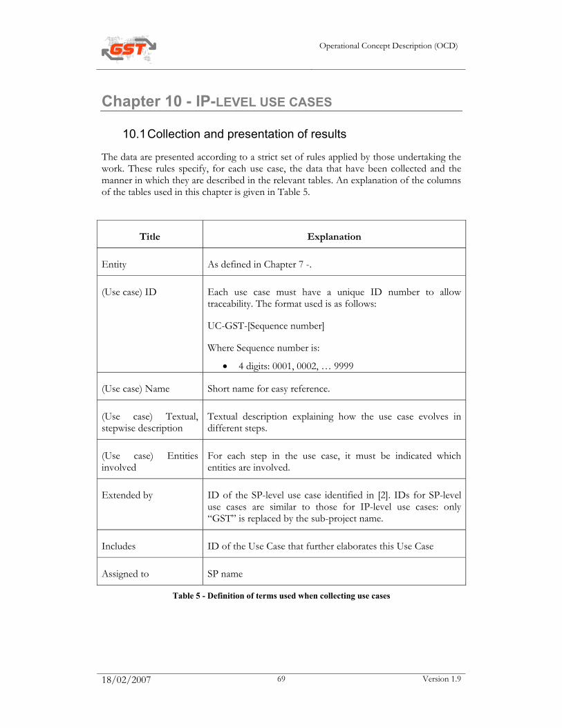
Operational Concept Description (OCD)
18/02/2007 69 Version 1.9
Chapter 10 - IP-LEVEL USE CASES
10.1 Collection and presentation of results
The data are presented according to a strict set of rules applied by those undertaking the work. These rules specify, for each use case, the data that have been collected and the manner in which they are described in the relevant tables. An explanation of the columns of the tables used in this chapter is given in Table 5.
Title Explanation
Entity As defined in Chapter 7 -.
(Use case) ID Each use case must have a unique ID number to allow traceability. The format used is as follows:
UC-GST-[Sequence number]
Where Sequence number is:
• 4 digits: 0001, 0002, … 9999
(Use case) Name Short name for easy reference.
(Use case) Textual, stepwise description
Textual description explaining how the use case evolves in different steps.
(Use case) Entities involved
For each step in the use case, it must be indicated which entities are involved.
Extended by ID of the SP-level use case identified in [2]. IDs for SP-level use cases are similar to those for IP-level use cases: only “GST” is replaced by the sub-project name.
Includes ID of the Use Case that further elaborates this Use Case
Assigned to SP name
Table 5 - Definition of terms used when collecting use cases

Operational Concept Description (OCD)
18/02/2007 70 Version 1.9
10.2 Identification of use cases (textual escriptions)
Figure 27 - Globally applicable use cases

Operational Concept Description (OCD)
18/02/2007 71 Version 1.9
The use cases identified at IP-level are as follows:
ID Name Description Entities involved
Includes Extended by
Assigned to
UC-GST-0001
Service Deployment 1. The Service Center User delivers the service application from the Service Center to the Control Center according to the chosen business model between the Service Center User and the Control Center User 2. The Service Center User makes all necessary configuration changes in the Control Center.3. The Control Center makes the service application available to appropriate provisioned Service Platforms.
Service Center
Service Application
Control Center
Control Center User
Service Center User
Open Systems (OS)
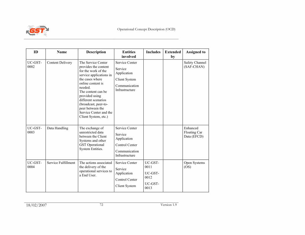
Operational Concept Description (OCD)
18/02/2007 72 Version 1.9
ID Name Description Entities involved
Includes Extended by
Assigned to
UC-GST-0002
Content Delivery The Service Center provides the content for the work of the service applications in the cases where online content is needed. The content can be provided using different scenarios (broadcast, peer-to-peer between the Service Center and the Client System, etc.)
Service Center
Service Application
Client System
Communication Infrastructure
Safety Channel (SAF-CHAN)
UC-GST-0003
Data Handling The exchange of unrestricted data between the Client Systems and other GST Operational System Entities.
Service Center
Service Application
Control Center
Communication Infrastructure
Enhanced Floating Car Data (EFCD)
UC-GST-0004
Service Fulfillment The actions associated the delivery of the operational services to a End User.
Service Center
Service Application
Control Center
Client System
UC-GST-0011
UC-GST-0012
UC-GST-0013
Open Systems (OS)
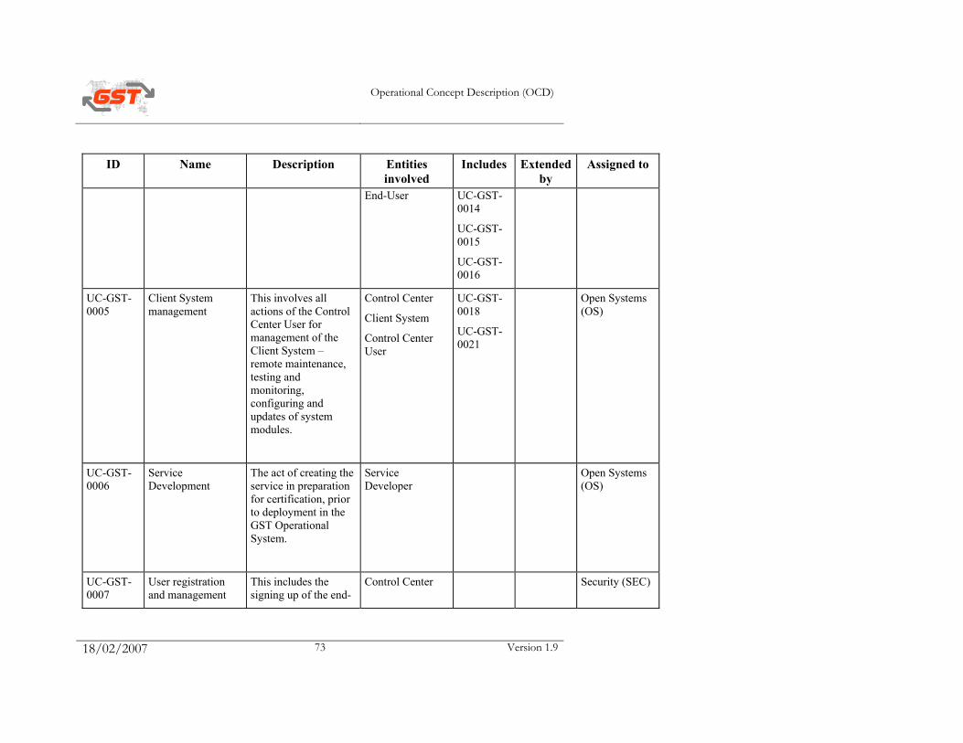
Operational Concept Description (OCD)
18/02/2007 73 Version 1.9
ID Name Description Entities involved
Includes Extended by
Assigned to
End-User UC-GST-0014
UC-GST-0015
UC-GST-0016
UC-GST-0005
Client System management
This involves all actions of the Control Center User for management of the Client System – remote maintenance, testing and monitoring, configuring and updates of system modules.
Control Center
Client System
Control Center User
UC-GST-0018
UC-GST-0021
Open Systems (OS)
UC-GST-0006
Service Development
The act of creating the service in preparation for certification, prior to deployment in the GST Operational System.
Service Developer
Open Systems (OS)
UC-GST-0007
User registration and management
This includes the signing up of the end-
Control Center Security (SEC)
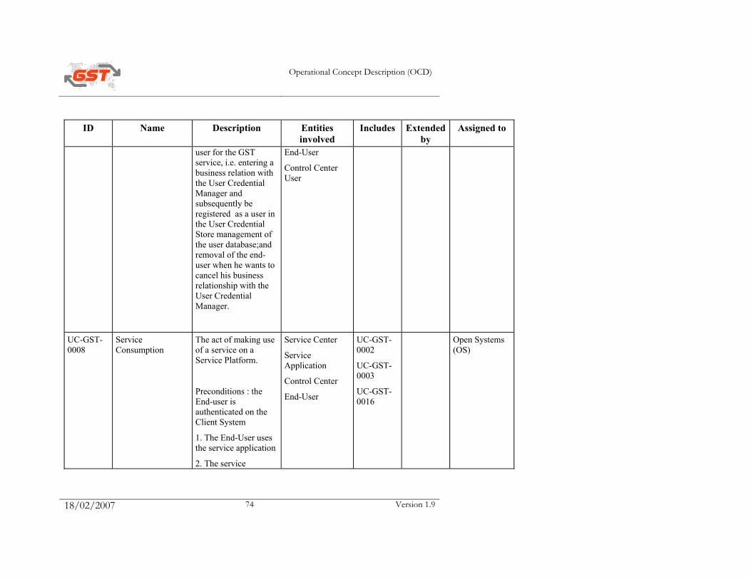
Operational Concept Description (OCD)
18/02/2007 74 Version 1.9
ID Name Description Entities involved
Includes Extended by
Assigned to
user for the GST service, i.e. entering a business relation with the User Credential Manager and subsequently be registered as a user in the User Credential Store management of the user database;and removal of the end-user when he wants to cancel his business relationship with the User Credential Manager.
End-User
Control Center User
UC-GST-0008
Service Consumption
The act of making use of a service on a Service Platform.
Preconditions : the End-user is authenticated on the Client System
1. The End-User uses the service application
2. The service
Service Center
Service Application
Control Center
End-User
UC-GST-0002
UC-GST-0003
UC-GST-0016
Open Systems (OS)

Operational Concept Description (OCD)
18/02/2007 75 Version 1.9
ID Name Description Entities involved
Includes Extended by
Assigned to
application contacts the Service Center directly or through the Control Center to get content if needed.
A backup of the end user data is done if needed
UC-GST-0009
Control Center Initiated Service Provisioning
The population of various data tables in the Control Center with the infomation required to deliver a service in response to a stimulus from a Control Center.
Control Center
Client System
Control Center User
Open Systems (OS)
UC-GST-0010
User Initiated Service Provisioning
The population of various data tables in the Control Center with the infomation required to deliver a service in response to a stimulus from the End-User.
Control Center
Service Platform
End-User
Open Systems (OS)

Operational Concept Description (OCD)
18/02/2007 76 Version 1.9
ID Name Description Entities involved
Includes Extended by
Assigned to
UC-GST-0011
Check for Resources on Client Device
Ensure that resources required to provide the service are available and accessable on the Client System.
Control Center
Client System
Control Center User
UC-GST-0029
Open Systems (OS)
UC-GST-0012
User Log-in Procedure by which an End-User makes his identity unambiguously known to the Client System and the Control Center in order to be able to use some capabilities of the GST Operational System.
Control Center
Client System
End-User
UC-GST-0017
UC-GST-0026
Security (SEC)
UC-GST-0013
Service Provisioning
The population of various data tables in the Control Center with the infomation required to deliver a service.
Control Center UC-GST-0009
UC-GST-0010
Open Systems (OS)
UC-GST-0014
Application Download
The delivery of the Service Application to the Client System.
Control Center
Client System
Open Systems (OS)
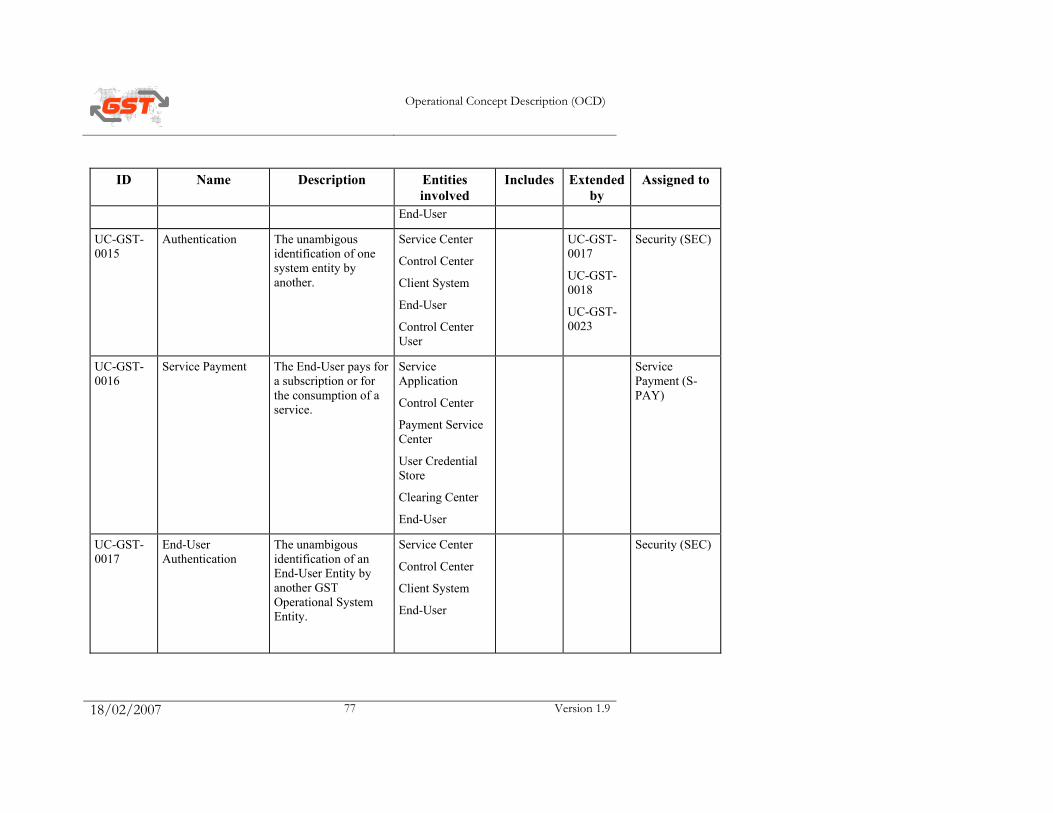
Operational Concept Description (OCD)
18/02/2007 77 Version 1.9
ID Name Description Entities involved
Includes Extended by
Assigned to
End-User
UC-GST-0015
Authentication The unambigous identification of one system entity by another.
Service Center
Control Center
Client System
End-User
Control Center User
UC-GST-0017
UC-GST-0018
UC-GST-0023
Security (SEC)
UC-GST-0016
Service Payment The End-User pays for a subscription or for the consumption of a service.
Service Application
Control Center
Payment Service Center
User Credential Store
Clearing Center
End-User
Service Payment (S-PAY)
UC-GST-0017
End-User Authentication
The unambigous identification of an End-User Entity by another GST Operational System Entity.
Service Center
Control Center
Client System
End-User
Security (SEC)
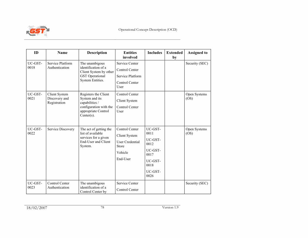
Operational Concept Description (OCD)
18/02/2007 78 Version 1.9
ID Name Description Entities involved
Includes Extended by
Assigned to
UC-GST-0018
Service Platform Authentication
The unambigous identification of a Client System by other GST Operational System Entities.
Service Center
Control Center
Service Platform
Control Center User
Security (SEC)
UC-GST-0021
Client System Discovery and Registration
Registers the Client System and its capabilities / configuration with the appropriate Control Center(s).
Control Center
Client System
Control Center User
Open Systems (OS)
UC-GST-0022
Service Discovery The act of getting the list of available services for a given End-User and Client System.
Control Center
Client System
User Credential Store
Vehicle
End-User
UC-GST-0011
UC-GST-0012
UC-GST-0017
UC-GST-0018
UC-GST-0026
Open Systems (OS)
UC-GST-0023
Control Center Authentication
The unambigous identification of a Control Center by
Service Center
Control Center
Security (SEC)
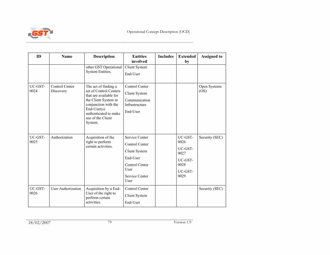
Operational Concept Description (OCD)
18/02/2007 79 Version 1.9
ID Name Description Entities involved
Includes Extended by
Assigned to
other GST Operational System Entities.
Client System
End-User
UC-GST-0024
Control Center Discovery
The act of finding a set of Control Centers that are available for the Client System in conjunction with the End-User(s) authenticated to make use of the Client System.
Control Center
Client System
Communication Infrastructure
End-User
Open Systems (OS)
UC-GST-0025
Authorization Acquisition of the right to perform certain activities.
Service Center
Control Center
Client System
End-User
Control Center User
Service Center User
UC-GST-0026
UC-GST-0027
UC-GST-0028
UC-GST-0029
Security (SEC)
UC-GST-0026
User Authorization Acquisition by a End-User of the right to perform certain activities.
Control Center
Client System
End-User
Security (SEC)
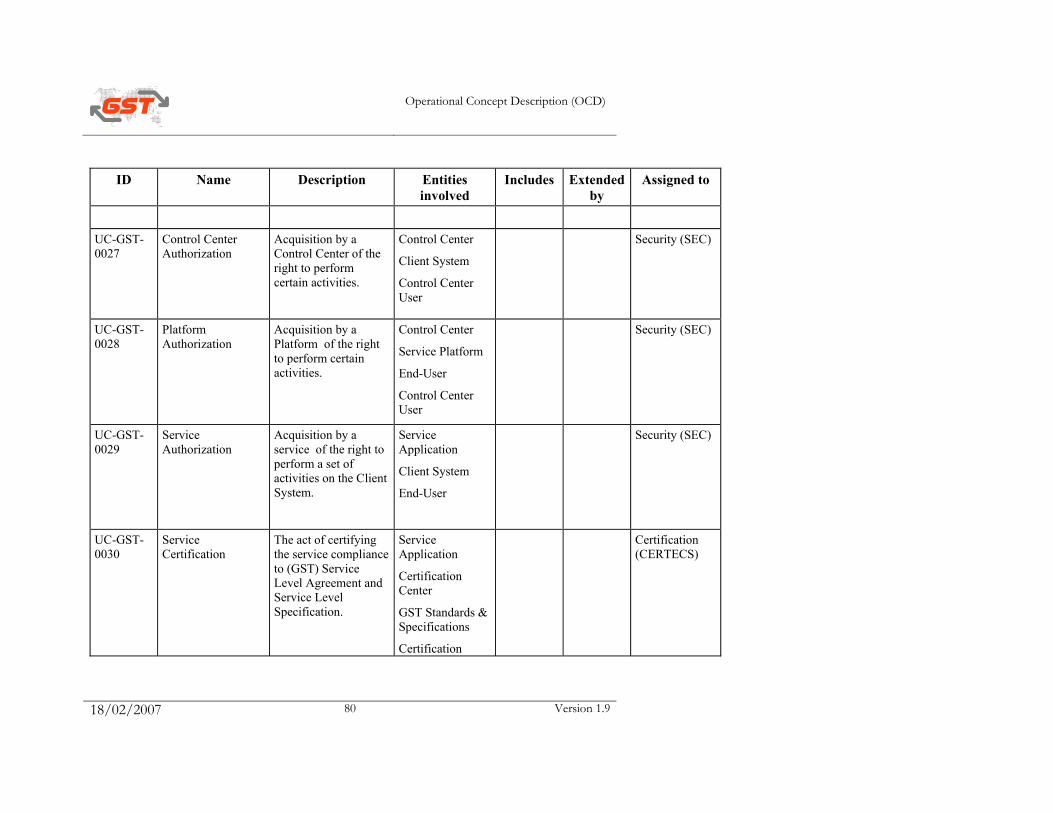
Operational Concept Description (OCD)
18/02/2007 80 Version 1.9
ID Name Description Entities involved
Includes Extended by
Assigned to
UC-GST-0027
Control Center Authorization
Acquisition by a Control Center of the right to perform certain activities.
Control Center
Client System
Control Center User
Security (SEC)
UC-GST-0028
Platform Authorization
Acquisition by a Platform of the right to perform certain activities.
Control Center
Service Platform
End-User
Control Center User
Security (SEC)
UC-GST-0029
Service Authorization
Acquisition by a service of the right to perform a set of activities on the Client System.
Service Application
Client System
End-User
Security (SEC)
UC-GST-0030
Service Certification
The act of certifying the service compliance to (GST) Service Level Agreement and Service Level Specification.
Service Application
Certification Center
GST Standards & Specifications
Certification
Certification (CERTECS)
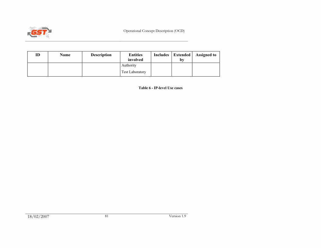
Operational Concept Description (OCD)
18/02/2007 81 Version 1.9
ID Name Description Entities involved
Includes Extended by
Assigned to
Authority
Test Laboratory
Table 6 - IP-level Use cases
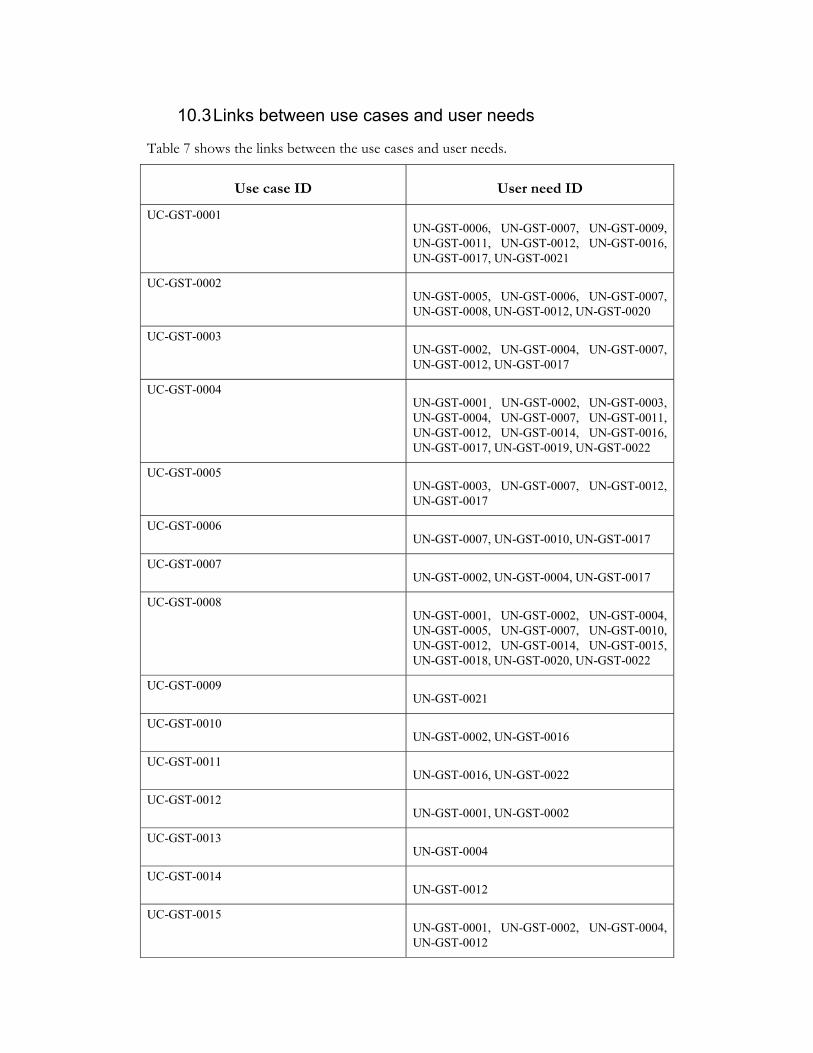
10.3 Links between use cases and user needs
Table 7 shows the links between the use cases and user needs.
Use case ID User need ID
UC-GST-0001 UN-GST-0006, UN-GST-0007, UN-GST-0009, UN-GST-0011, UN-GST-0012, UN-GST-0016, UN-GST-0017, UN-GST-0021
UC-GST-0002 UN-GST-0005, UN-GST-0006, UN-GST-0007, UN-GST-0008, UN-GST-0012, UN-GST-0020
UC-GST-0003 UN-GST-0002, UN-GST-0004, UN-GST-0007, UN-GST-0012, UN-GST-0017
UC-GST-0004 UN-GST-0001¸ UN-GST-0002, UN-GST-0003, UN-GST-0004, UN-GST-0007, UN-GST-0011, UN-GST-0012, UN-GST-0014, UN-GST-0016, UN-GST-0017, UN-GST-0019, UN-GST-0022
UC-GST-0005 UN-GST-0003, UN-GST-0007, UN-GST-0012, UN-GST-0017
UC-GST-0006 UN-GST-0007, UN-GST-0010, UN-GST-0017
UC-GST-0007 UN-GST-0002, UN-GST-0004, UN-GST-0017
UC-GST-0008 UN-GST-0001, UN-GST-0002, UN-GST-0004, UN-GST-0005, UN-GST-0007, UN-GST-0010, UN-GST-0012, UN-GST-0014, UN-GST-0015, UN-GST-0018, UN-GST-0020, UN-GST-0022
UC-GST-0009 UN-GST-0021
UC-GST-0010 UN-GST-0002, UN-GST-0016
UC-GST-0011 UN-GST-0016, UN-GST-0022
UC-GST-0012 UN-GST-0001, UN-GST-0002
UC-GST-0013 UN-GST-0004
UC-GST-0014 UN-GST-0012
UC-GST-0015 UN-GST-0001, UN-GST-0002, UN-GST-0004, UN-GST-0012
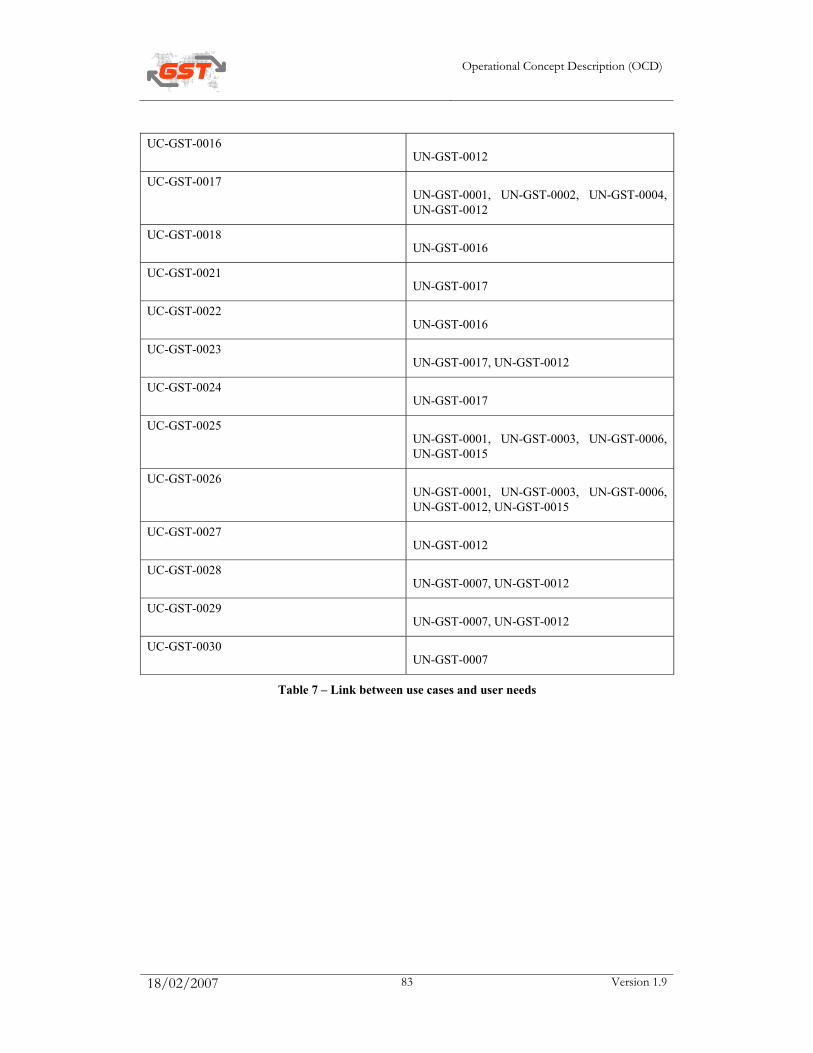
Operational Concept Description (OCD)
18/02/2007 83 Version 1.9
UC-GST-0016 UN-GST-0012
UC-GST-0017 UN-GST-0001, UN-GST-0002, UN-GST-0004, UN-GST-0012
UC-GST-0018 UN-GST-0016
UC-GST-0021 UN-GST-0017
UC-GST-0022 UN-GST-0016
UC-GST-0023 UN-GST-0017, UN-GST-0012
UC-GST-0024 UN-GST-0017
UC-GST-0025 UN-GST-0001, UN-GST-0003, UN-GST-0006, UN-GST-0015
UC-GST-0026 UN-GST-0001, UN-GST-0003, UN-GST-0006, UN-GST-0012, UN-GST-0015
UC-GST-0027 UN-GST-0012
UC-GST-0028 UN-GST-0007, UN-GST-0012
UC-GST-0029 UN-GST-0007, UN-GST-0012
UC-GST-0030 UN-GST-0007
Table 7 – Link between use cases and user needs
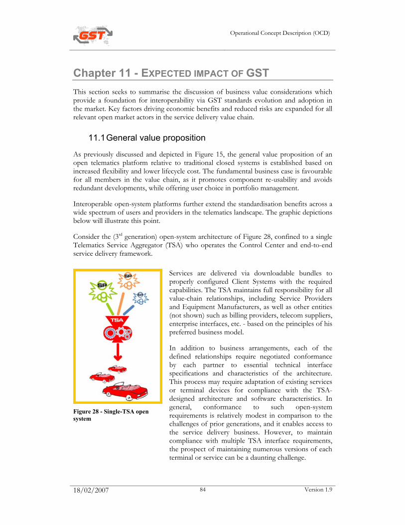
Operational Concept Description (OCD)
18/02/2007 84 Version 1.9
Chapter 11 - EXPECTED IMPACT OF GST This section seeks to summarise the discussion of business value considerations which provide a foundation for interoperability via GST standards evolution and adoption in the market. Key factors driving economic benefits and reduced risks are expanded for all relevant open market actors in the service delivery value chain.
11.1 General value proposition
As previously discussed and depicted in Figure 15, the general value proposition of an open telematics platform relative to traditional closed systems is established based on increased flexibility and lower lifecycle cost. The fundamental business case is favourable for all members in the value chain, as it promotes component re-usability and avoids redundant developments, while offering user choice in portfolio management.
Interoperable open-system platforms further extend the standardisation benefits across a wide spectrum of users and providers in the telematics landscape. The graphic depictions below will illustrate this point.
Consider the (3rd generation) open-system architecture of Figure 28, confined to a single Telematics Service Aggregator (TSA) who operates the Control Center and end-to-end service delivery framework.
Figure 28 - Single-TSA open system
Services are delivered via downloadable bundles to properly configured Client Systems with the required capabilities. The TSA maintains full responsibility for all value-chain relationships, including Service Providers and Equipment Manufacturers, as well as other entities (not shown) such as billing providers, telecom suppliers, enterprise interfaces, etc. - based on the principles of his preferred business model.
In addition to business arrangements, each of the defined relationships require negotiated conformance by each partner to essential technical interface specifications and characteristics of the architecture. This process may require adaptation of existing services or terminal devices for compliance with the TSA-designed architecture and software characteristics. In general, conformance to such open-system requirements is relatively modest in comparison to the challenges of prior generations, and it enables access to the service delivery business. However, to maintain compliance with multiple TSA interface requirements, the prospect of maintaining numerous versions of each terminal or service can be a daunting challenge.
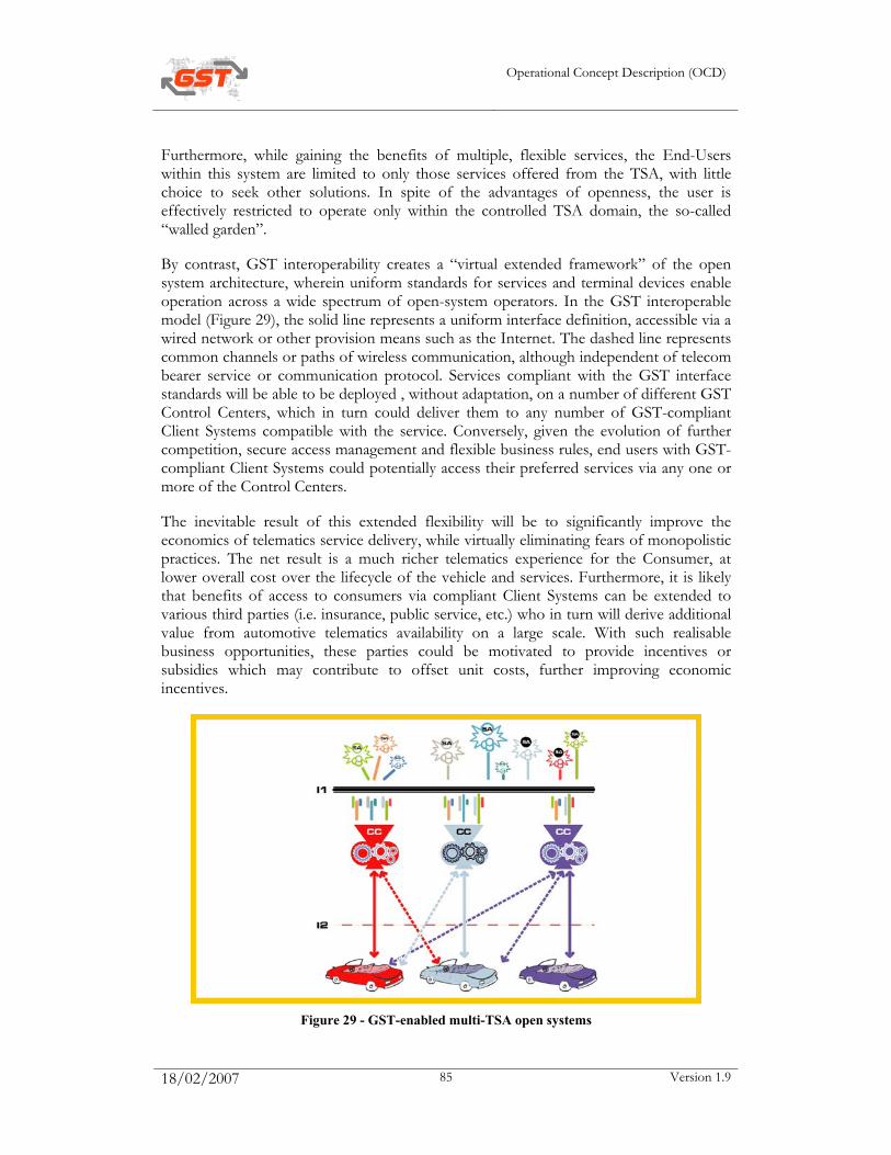
Operational Concept Description (OCD)
18/02/2007 85 Version 1.9
Furthermore, while gaining the benefits of multiple, flexible services, the End-Users within this system are limited to only those services offered from the TSA, with little choice to seek other solutions. In spite of the advantages of openness, the user is effectively restricted to operate only within the controlled TSA domain, the so-called “walled garden”.
By contrast, GST interoperability creates a “virtual extended framework” of the open system architecture, wherein uniform standards for services and terminal devices enable operation across a wide spectrum of open-system operators. In the GST interoperable model (Figure 29), the solid line represents a uniform interface definition, accessible via a wired network or other provision means such as the Internet. The dashed line represents common channels or paths of wireless communication, although independent of telecom bearer service or communication protocol. Services compliant with the GST interface standards will be able to be deployed , without adaptation, on a number of different GST Control Centers, which in turn could deliver them to any number of GST-compliant Client Systems compatible with the service. Conversely, given the evolution of further competition, secure access management and flexible business rules, end users with GST-compliant Client Systems could potentially access their preferred services via any one or more of the Control Centers.
The inevitable result of this extended flexibility will be to significantly improve the economics of telematics service delivery, while virtually eliminating fears of monopolistic practices. The net result is a much richer telematics experience for the Consumer, at lower overall cost over the lifecycle of the vehicle and services. Furthermore, it is likely that benefits of access to consumers via compliant Client Systems can be extended to various third parties (i.e. insurance, public service, etc.) who in turn will derive additional value from automotive telematics availability on a large scale. With such realisable business opportunities, these parties could be motivated to provide incentives or subsidies which may contribute to offset unit costs, further improving economic incentives.
Figure 29 - GST-enabled multi-TSA open systems
Operational Concept Description (OCD)
18/02/2007 86 Version 1.9
The full implementation of GST interoperability in a pan-European or global context will enable a variety of new business models, driven by the significant and compelling value generators of flexibility approaching that of modern telecom networks or the Internet itself. Even with such “openness”, however, the GST architecture preserves and enhances the ability for strict service management and security control. To fully appreciate what is possible in such an “expanded telematics world”, it is worth reviewing the value proposition of the GST extended business economic factors from a number of different partner perspectives.
11.2 Consumer value perspective
We begin with the telematics consumer, the End User and final point in the value chain, who will emerge as the undisputed winner and beneficiary of the evolution of GST standards-based telematics. This is both appropriate and desirable, as it is the Consumer who will generate the core demand to enable market growth. The most likely impact from the developments reflected in Figure 29 will be a potentially vast catalogue of available services from which he can choose items of specific interest to meet his needs. The Consumer will enjoy availability of quality services at much lower cost and greater flexibility than what he experienced in prior generations. In addition to personal configuration of services, other benefits include lifetime upgradeability on demand, experiencing services on a “trial” basis, multiple usage profiles (work, hobby, holiday, etc.), selectable personalised service features, and various others.
GST enables a further element of choice for the Consumer, in a manner unprecedented in prior telematics generations. Unlike the telecom world where consumers select providers independent of the handset they own and frequently switch from one to another, the earlier telematics service model has generally been based on a “lifetime” relationship between consumer and TSA, who is often closely associated with the Vehicle Manufacturer. In the GST-enabled world, the Consumer who seeks a better business arrangement or special services not available from his normal TSA will potentially have the freedom to explore alternative sources. New opportunities could be explored either on a temporary demand basis or on the basis of a new contract relationship, all without any need for new terminal hardware or reconfiguration. Depending on the structure of different payment models, the user may be able to maintain multiple relationships with independent TSA business entities. In essence, the consumer enjoys the opportunity for rich service options, as well as potential for multiple sources in choosing his TSA relationship. The freedom to escape the “walled garden” will further propel market growth, as it has in telecom and Internet businesses.
Operational Concept Description (OCD)
18/02/2007 87 Version 1.9
11.3 Service Developer perspective
Telematics Service Developers, including those with prior involvements as well as the entrepreneurial “newcomers”, will realise significant cost advantage from the commercial emergence of GST architectures. Inevitably, however, it will also motivate the emergence of strong competition. Service development and deployment will be possible on numerous platforms with much lowered development time and cost, since many of the advantages of WORA (Write Once, Run Anywhere) could be further realized with GST. Furthermore, with the centralization of many service delivery functions within the Control Center, a substantial reduction of effort and time to market in deploying new services will be possible.
A further advantage motivating service developers will be the “reachability” of a growing population of End-Users. Rather than be confined to a limited user base within a closed business model, the Service Provider with a preferred market offering can make his service available to many customers through their associated TSAs. Being assured of reaching an expanding base of subscribers and prospects, many Service Providers will be motivated to develop and deploy high-quality, high-demand services, taking advantage of a “first to market” opportunity. Competitive forces will naturally also seek similar advantage, and drive the potential catalogue of offerings toward a rich set of effective, high-quality services.
Market factors will ensure that the providers with the best services survive and are adopted by paying customers, while inferior offerings are weeded out. Such market dynamics could create temporary turbulence, but in the end a “telco-like” equilibrium will emerge to spur growth.
11.4 Equipment Manufacturer perspective
Driven by the need to establish strong brand differentiation for their automotive customers, telematics component suppliers have numerous cost challenges to overcome. One such challenge, a major cost driver for the traditional automotive electronics supplier, has been the many variations of product needed to support the numerous different vehicle configurations. Each variation of hardware/software may have a variety of unique properties, which means that production volumes for the component are generally limited to the vehicle type using that component. Also, change and version management of the units over the life of the vehicle is usually a costly proposition involving dealer upgrades, at considerable expense to the Consumer.
In the GST context, telematics Equipment Manufacturers will be able to have high assurance of “future-proof” capabilities, since most changes in services and software will be manageable over the air. The inherent flexibility of GST terminals also assures that units can be built on a much higher volume basis, while still preserving brand differentiation through different levels of HMI/display quality or the “special feature” branding of services to reflect the uniqueness of brand image. The remote management of configuration means that unit maintenance cost will be substantially lowered, further reducing the cost basis of the units.
Operational Concept Description (OCD)
18/02/2007 88 Version 1.9
As with Service Providers, telematics device manufacturers will realise a lower cost of development when their designs are based on GST-compliant, scaleable “smart-client” architectures. As market forces begin to move GST telematics architectures into mainstream markets, terminal suppliers will also compete aggressively to be first to market with these flexible offerings.
11.5 Vehicle Manufacturer perspective
In spite of significant investment in recent years, many vehicle manufactures have been disillusioned by their perception of failure of telematics in delivering the rewarding opportunities originally envisioned. Some see in-vehicle telematics as a necessary, but mainly unwelcome (and often uncontrollable) cost of doing business, i.e. needed for maintaining their market share or brand image. However, there is pressure to minimise the cost for this added capability, which usually means that telematics is limited to a small set of vehicle brands, or that capabilities are reduced to those essentials considered “important” to the vehicle brand, such as safety and trip planning services.
In the new era of GST telematics, the manufacturer can potentially realize truly low-cost yet powerful “smart-client” Client Systems based on standards, which in turn may justify rollout on many more vehicle platforms and spread the full investment over a large base of customers. Further, the ability to flexibly alter the service configurations or software properties could enable manufacturers to standardize one single platform concept across all car lines, keeping brand “differentiators” to the user interface or unique service areas. Lifecycle management of the in-vehicle terminals without frequent dealer service calls is also a major cost saver. With the further advantage of flexibility in contractual arrangements in services and Control Center operations, the Vehicle Manufacturer has strengthened his ability to maintain control over his business interest.
A renewed interest in open systems by some Vehicle Manufacturers has yielded various studies of possible “added value” flowing directly to the manufacturer by “data mining” of widely installed telematics units. In addition to the usual, well established interest in CRM (Customer Relationship Management), some have found potential for significant cost savings from remote diagnosis and pro-active maintenance, as well as possible version management of electronic devices in the vehicle, using telematics as the essential gateway. Cost reduction potential has even been foreseen in the vehicle manufacturing process, derived from the benefit of a smart-client terminal unit available early in the assembly phase to support production efficiencies.
Many new telematics experiments targeting value definition and validation will be defined in the coming years. The capabilities of GST-enabled smart-client terminals with their inherent flexibilities operating under real-world conditions will empower such experiments in orderly, realistic ways, serving as effective “pathfinders” for telematics initiatives and value definitions. These positive developments may yet again redefine the value proposition of telematics for Vehicle Manufacturers.
Operational Concept Description (OCD)
18/02/2007 89 Version 1.9
11.6 Public agency perspective
As previously indicated, the EC has established ambitious targets for safety and transportation management across the continent in the coming years – culminating in its well-know eSafety initiative of which GST is a part. While large investments are planned for roadway and infrastructure improvement, the focus will also be on leveraging the growing telematics base as critical elements of the overall system. A major obstacle to the realisation of these goals lies in the available access means to effectively reach both vehicle and driver in real-time situations. First- or second-generation solutions to achievement of the listed objectives are either technically infeasible or not cost-effective, due to the inherent lack of flexibility for incremental functions. GST-enabled systems, however, offer the promise for fulfilment of some or all of the objectives at low marginal costs.
As a simple example, consider the applications being actively pursued by various agencies of government. Although any of these could be realised with a fixed single or multi-point design, the cost of deployment to numerous types of vehicles and terminals would be prohibitive. Adding more tax burdens or additional charging schemes to the consumer or auto company would surely inhibit sales and further stifle market growth.
In the fully-deployed GST environment including GPS-equipped smart telematics units on all or nearly all vehicles, the incremental cost of adding this capability should be small or modest, given that the upgradeable core open platform terminal is already installed in the vehicle. With the inherent flexibility of the GST smart unit, one could download the “service” for the listed application to the existing platform, while still maintaining the core functionality of other services configured for that user and market segment.
Similar calculations based on incremental cost of implementation could be applied to the other target objectives of agencies and institutions, based on the wide-scale implementation of GST flexible telematics platforms. The full scope of benefit assessment will not be known for many years, and require focused feasibility studies and proof-of-concept experiments. For the purpose of such experimentation with relevant sample size, flexible architectures and smart clients will be essential to perform these “pathfinder” roles.
To promote uniformity of standards and motivation for adoption, government advocacy and possibly subsidies by various third parties could be considered. Instead of becoming a further tax burden to the market, it is likely that reasonable proposals to offset the in-vehicle Client System, either by tax incentive or by direct subsidies, could be a major industry motivator in the appropriate direction. Certain subsidies have been already proposed by third parties in areas such as using the vehicle for as a real-time probe for traffic flow, insurance risk reduction, etc. The aggressive exploitation of these collective opportunities will have a beneficial impact on the economics of modern telematics.
11.7 Communication infrastructure providers perspective
The link between onboard applications and the vast amount of location / situation or simply application related information is the wireless network that connects the on board equipment via a control center to service provider and in general the internet resources.
Operational Concept Description (OCD)
18/02/2007 90 Version 1.9
It strongly depend on the kind of application or service if the airtime or data volume may be relevant for the provider. Even if only small amounts of data are transferred, these may be “valuable bytes” for the user. This concept of “service oriented billing” will gain more and more importance .
Despite being the “data pipe” for 3rd party service provider, it may be valuable for infrastructure service provider to occupy more parts of the value chain. It even may add to the service quality to do so. One example may be the eCall. Here, a telco may act as communication provider, call center and call qualifier. The end user may have a contract with, for example, a vehicle manufacturer for an enhanced eCall service. The manufacturer contracts the CI provider to provide the eCall related services with a guaranteed quality and availability. As the provider is controlling the communication link, he is well informed and able to react if network problems occur.
If CI providers operate more than just a mobile network, for example fixed line and wireless hot spots as well, convergent service provision is a logical follow up. Seamless service usage is a great benefit for the end user and may lead to new revenue streams for CI and 3rd party provider. One example is the new class of nomadic devices that communicate via Bluetooth, WLAN and GSM/UMTS even at the same time, providing navigation, traffic information and other services sometime related to the vehicle, sometimes related to the users situation.
All stakeholders expect that services are provided with a common level of quality. The CI provider in his possible role as service aggregator may be the central instance to assure that level of trust and quality. He may act as a quality gate for 3rd party applications, ensuring for end user and car manufacturer a common user interface and guaranteed and tested service level.
For client system sellers, this co-operation offers many advantages:
o one interface for service provisioning
o proven procedure and quality control
o one partner for billing / accounting
As a summary, CI providers are facing new revenue opportunities by offering the basic communication means and to add on top of that higher levels of the service value chain. Ideally, this is done in co-operation with service providers and manufacturers to offer an integrated, optimised solution for the customer.
Operational Concept Description (OCD)
18/02/2007 91 Version 1.9
Appendix section
Operational Concept Description (OCD)
18/02/2007 92 Version 1.9
TERMS AND ABBREVIATIONS CAG Core Architecture Group
CT Core Team
DG INFSO Directorate-General Information Society
EC European Commission
FP6 Framework Programme 6
GA General Assembly
IP Integrated Project
IPM Integrated Project Management
IPWPM Integrated Project Work Package Manager (eg IPWP2M)
IPWPMT Integrated Project Work Package Managers Team (eg IPWP2MT)
OCT On-line Collaboration Tool
QP Quality Plan
SC Steering Committee
SP Sub-Project
TS Test Site
WP Work Package
Operational Concept Description (OCD)
18/02/2007 93 Version 1.9
REFERENCES
[1] Jesty P.H. at al., Guidance for the Development and Assessment of Intelligent Transport System Architecture, Framework IV Transport Telematics Project CONVERGE (TR1101, Deliverable 2.3, 1998)
[2] DEL_GST_SP_2_1_Use_cases_and_system_requirements

SP-LEVEL USER NEEDS REVIEW TEMPLATE (TO BE USED BY SP GODFATHERS)
The data are presented according to a strict set of rules applied by those undertaking the work. These rules specify, for each use case, the data that have been collected and the manner in which they are described in the relevant tables. An explanation of the columns of the tables used in this Appendix is given in Table 8.
Title Explanation
Actor (Stakeholder) See definition in [2]
(User need) ID See definition in [2]
(Use need) Name See definition in [2]
Reviewer initials Identification of reviewer
Comments Overall observations when reviewing the use case
Recommended actions Specific actions the godfathers suggests the SP to undertake
Status P - Provisional
A - Accepted by SP involved
Table 8 - Definition of terms used when reviewing use cases
The form that will be used for reviewing SP actors (and their definitions) is shown in Table 9:
Actor (Stakeholder)
Reviewer initials
Comments Recommended actions
Status
Table 9 - Form for reviewing actors
The form that will be used for reviewing SP user needs (and their definitions) is shown in Table 10:
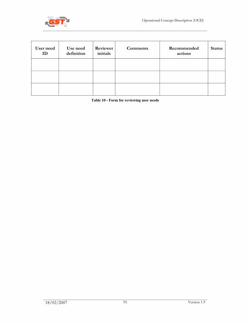
Operational Concept Description (OCD)
18/02/2007 95 Version 1.9
User need ID
Use need definition
Reviewer initials
Comments Recommended actions
Status
Table 10 - Form for reviewing user needs
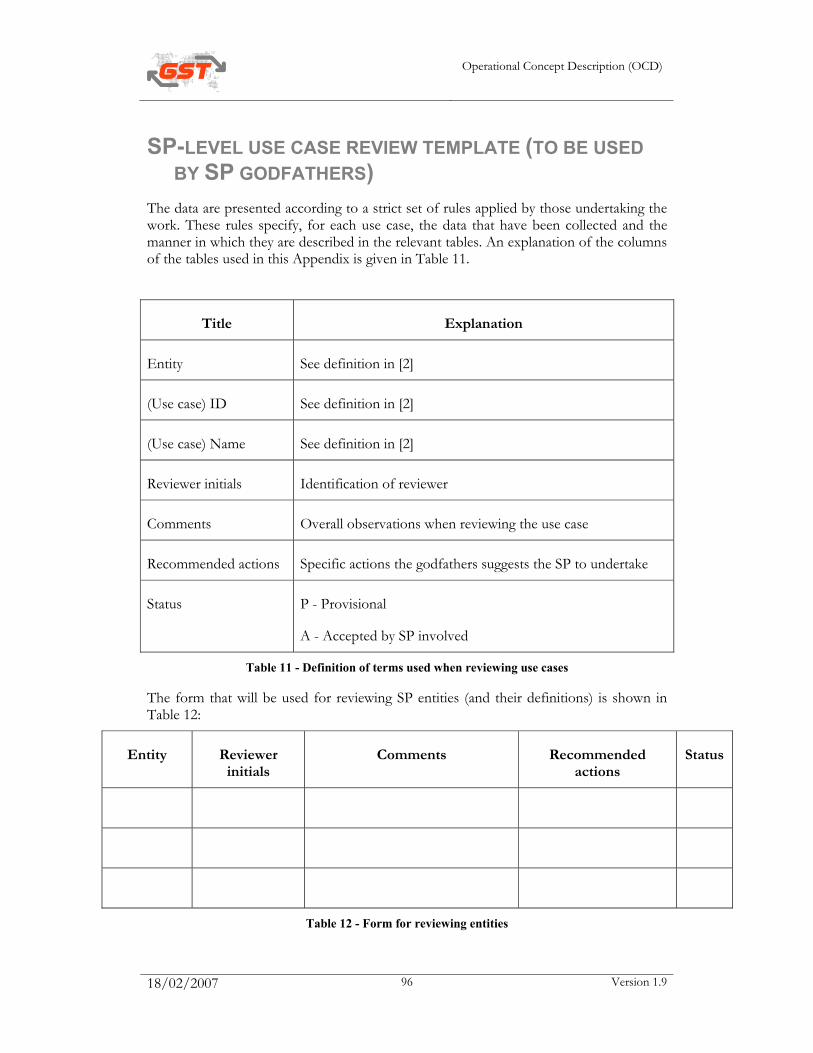
Operational Concept Description (OCD)
18/02/2007 96 Version 1.9
SP-LEVEL USE CASE REVIEW TEMPLATE (TO BE USED BY SP GODFATHERS)
The data are presented according to a strict set of rules applied by those undertaking the work. These rules specify, for each use case, the data that have been collected and the manner in which they are described in the relevant tables. An explanation of the columns of the tables used in this Appendix is given in Table 11.
Title Explanation
Entity See definition in [2]
(Use case) ID See definition in [2]
(Use case) Name See definition in [2]
Reviewer initials Identification of reviewer
Comments Overall observations when reviewing the use case
Recommended actions Specific actions the godfathers suggests the SP to undertake
Status P - Provisional
A - Accepted by SP involved
Table 11 - Definition of terms used when reviewing use cases
The form that will be used for reviewing SP entities (and their definitions) is shown in Table 12:
Entity Reviewer initials
Comments Recommended actions
Status
Table 12 - Form for reviewing entities
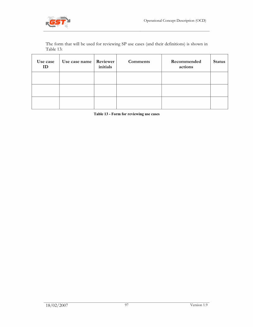
Operational Concept Description (OCD)
18/02/2007 97 Version 1.9
The form that will be used for reviewing SP use cases (and their definitions) is shown in Table 13:
Use case ID
Use case name Reviewer initials
Comments Recommended actions
Status
Table 13 - Form for reviewing use cases