Embed Size (px)
Citation preview
906.482.7535 www.glsv.com This entire document and its attachments are subject to the restrictions stated in the proprietary notice.
Author:
Date:
Job Number:
Title: Powertrain Mounting Overview
GLSV Capabilities Presentation
Steve Tarnowski, Steve Mattson
9 February 2016
906.482.7535 www.glsv.com This entire document and its attachments are subject to the restrictions stated in the proprietary notice.
2
Proprietary Notice
• PROPRIETARY WARNING
All data, illustrations, photos, and information contained in this presentation and communication is considered
proprietary to Great Lakes Sound & Vibration Inc (Hereafter GLSV). Information contained herein shall be held in
strict confidence. Furthermore, it shall not be distributed or disseminated to any third parties without written
consent from GLSV.
906.482.7535 www.glsv.com This entire document and its attachments are subject to the restrictions stated in the proprietary notice.
3
Isolation System: Fundamental Requirements
• Locate and support powertrain mass
• React external and internal forces without interference
• Isolate external and internal forces
• Must perform under severe conditions and provide fail safe
• Manufacturability
• Robustness
• Assembly/maintainability
• Weight and cost must meet program objectives
906.482.7535 www.glsv.com This entire document and its attachments are subject to the restrictions stated in the proprietary notice.
4Defense-Specific Engine Mounting
Challenges
• Power Dense Engine = Higher Forces reacted through less mass
• Tight deflection envelope
• Limited freedom/flexibility for isolator placement
• Substantial mobility, transportation and shock requirements
• Structural rigidity?
• Hardware delivery while design is still in-flux
• Aggressive exterior acoustic requirement, interior must be inhabitable.
906.482.7535 www.glsv.com This entire document and its attachments are subject to the restrictions stated in the proprietary notice.
5
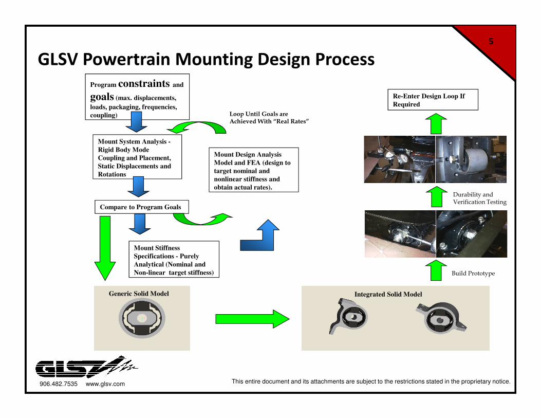
GLSV Powertrain Mounting Design Process
Mount System Analysis -
Rigid Body Mode
Coupling and Placement,
Static Displacements and
Rotations
Mount Design Analysis
Model and FEA (design to
target nominal and
nonlinear stiffness and
obtain actual rates).
Program constraints and
goals (max. displacements,
loads, packaging, frequencies,
coupling)
Generic Solid Model Integrated Solid Model
Mount Stiffness
Specifications - Purely
Analytical (Nominal and
Non-linear target stiffness)
Compare to Program Goals
Loop Until Goals are Achieved With “Real Rates”
Re-Enter Design Loop If
Required
Build Prototype
Durability andVerification Testing
906.482.7535 www.glsv.com This entire document and its attachments are subject to the restrictions stated in the proprietary notice.
6
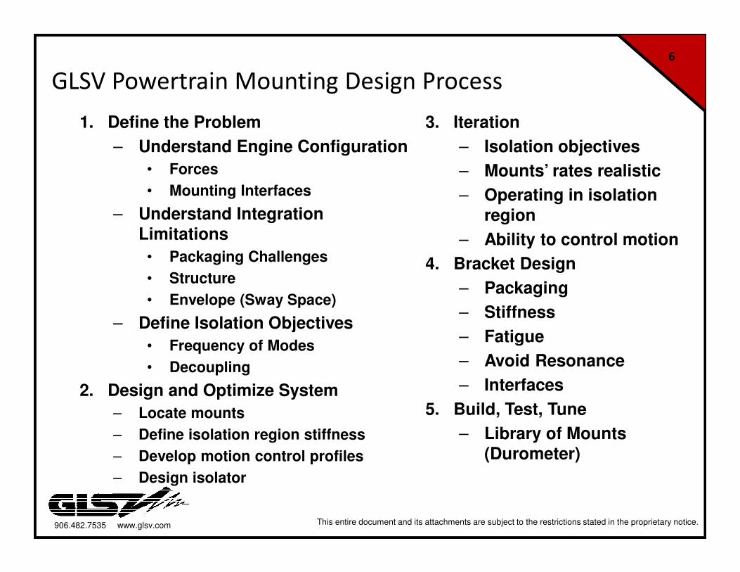
GLSV Powertrain Mounting Design Process
1. Define the Problem
– Understand Engine Configuration
• Forces
• Mounting Interfaces
– Understand Integration Limitations
• Packaging Challenges
• Structure
• Envelope (Sway Space)
– Define Isolation Objectives
• Frequency of Modes
• Decoupling
2. Design and Optimize System
– Locate mounts
– Define isolation region stiffness
– Develop motion control profiles
– Design isolator
3. Iteration
– Isolation objectives
– Mounts’ rates realistic
– Operating in isolation
region
– Ability to control motion
4. Bracket Design
– Packaging
– Stiffness
– Fatigue
– Avoid Resonance
– Interfaces
5. Build, Test, Tune
– Library of Mounts (Durometer)
906.482.7535 www.glsv.com This entire document and its attachments are subject to the restrictions stated in the proprietary notice.
7
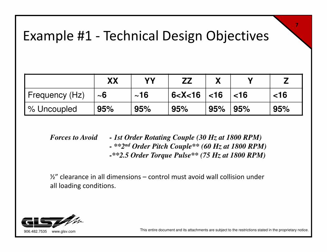
Example #1 - Technical Design Objectives
Forces to Avoid - 1st Order Rotating Couple (30 Hz at 1800 RPM)
- **2nd Order Pitch Couple** (60 Hz at 1800 RPM)
-**2.5 Order Torque Pulse** (75 Hz at 1800 RPM)
XX YY ZZ X Y Z
Frequency (Hz) ~6 ~16 6<X<16 <16 <16 <16
% Uncoupled 95% 95% 95% 95% 95% 95%
½” clearance in all dimensions – control must avoid wall collision under
all loading conditions.
906.482.7535 www.glsv.com This entire document and its attachments are subject to the restrictions stated in the proprietary notice.
8
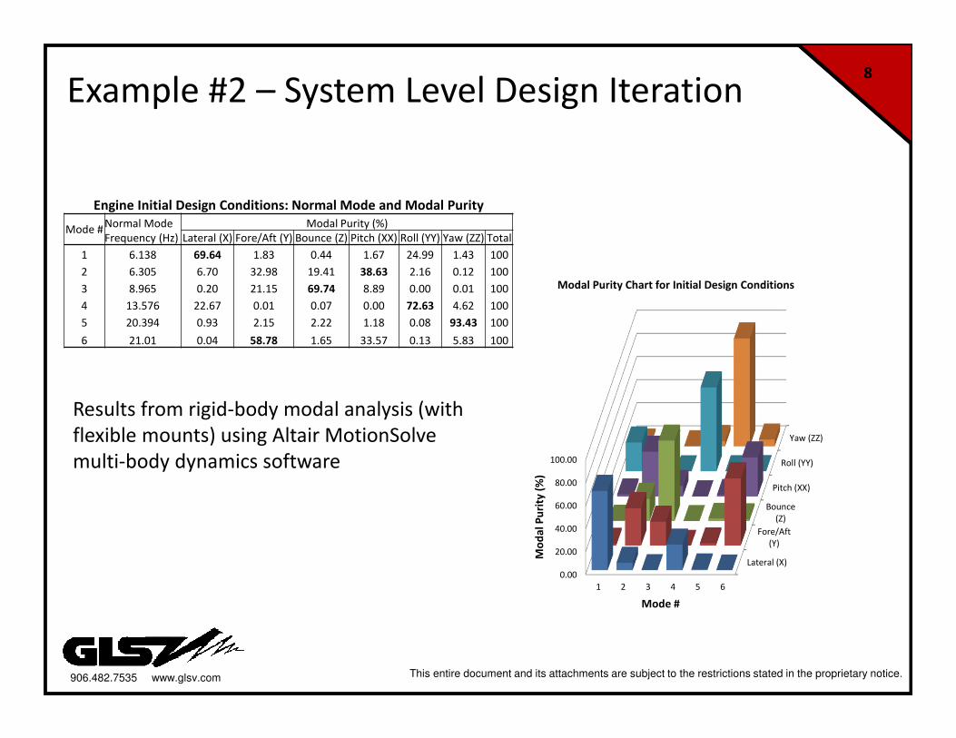
Example #2 – System Level Design Iteration
Lateral (X)
Fore/Aft
(Y)
Bounce
(Z)
Pitch (XX)
Roll (YY)
Yaw (ZZ)
0.00
20.00
40.00
60.00
80.00
100.00
1 2 3 4 5 6
Mo
da
l P
uri
ty (
%)
Mode #
Modal Purity Chart for Initial Design Conditions
Engine Initial Design Conditions: Normal Mode and Modal Purity
Mode #Normal Mode Modal Purity (%)
Frequency (Hz) Lateral (X) Fore/Aft (Y) Bounce (Z) Pitch (XX) Roll (YY) Yaw (ZZ) Total
1 6.138 69.64 1.83 0.44 1.67 24.99 1.43 100
2 6.305 6.70 32.98 19.41 38.63 2.16 0.12 100
3 8.965 0.20 21.15 69.74 8.89 0.00 0.01 100
4 13.576 22.67 0.01 0.07 0.00 72.63 4.62 100
5 20.394 0.93 2.15 2.22 1.18 0.08 93.43 100
6 21.01 0.04 58.78 1.65 33.57 0.13 5.83 100
Results from rigid-body modal analysis (with
flexible mounts) using Altair MotionSolve
multi-body dynamics software
906.482.7535 www.glsv.com This entire document and its attachments are subject to the restrictions stated in the proprietary notice.
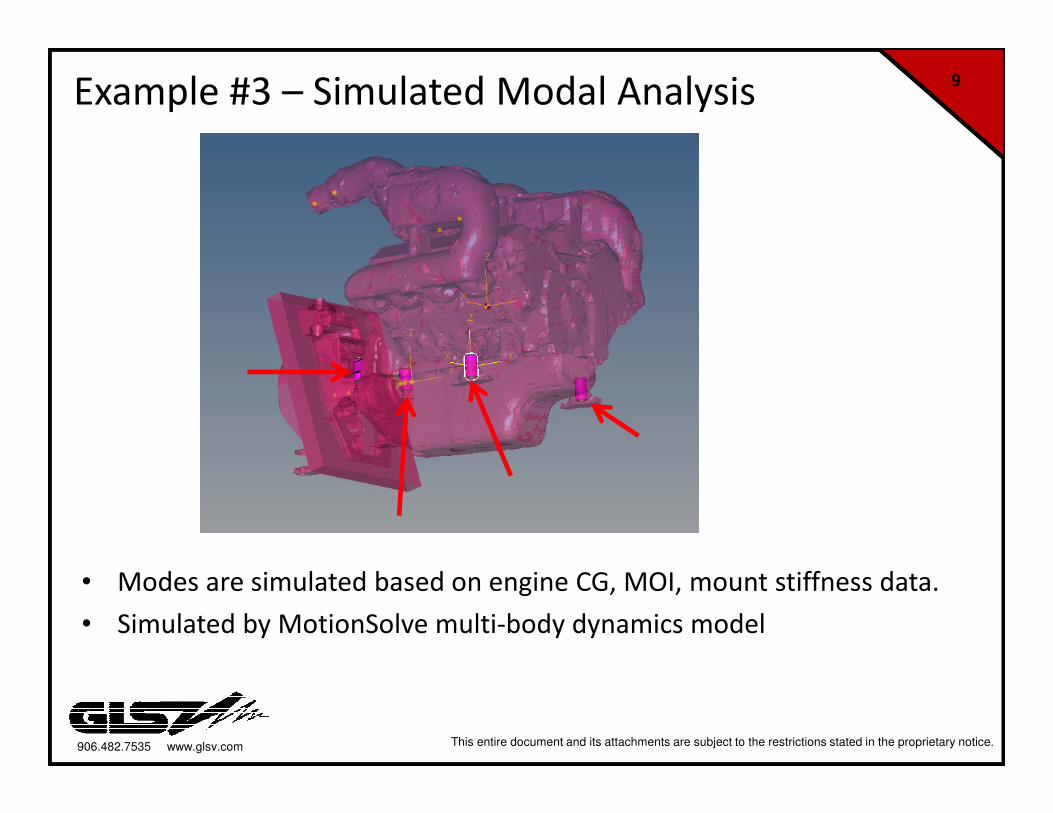
9Example #3 – Simulated Modal Analysis
• Modes are simulated based on engine CG, MOI, mount stiffness data.
• Simulated by MotionSolve multi-body dynamics model
906.482.7535 www.glsv.com This entire document and its attachments are subject to the restrictions stated in the proprietary notice.
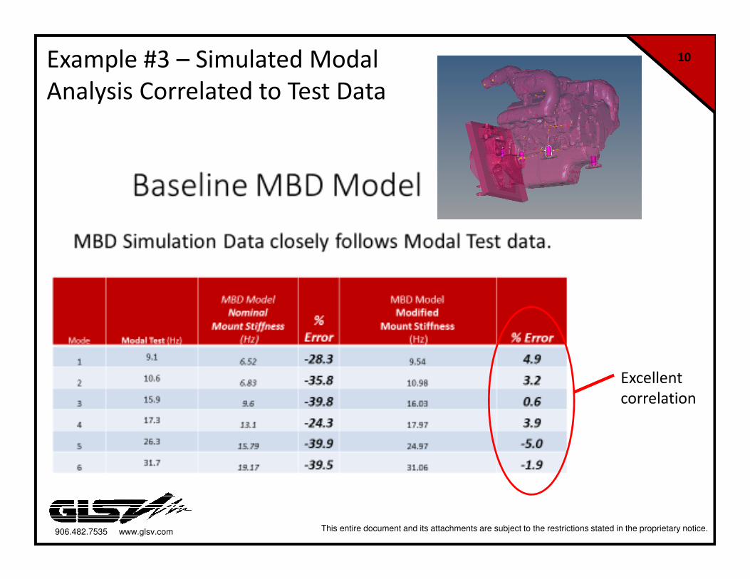
10Example #3 – Simulated Modal
Analysis Correlated to Test Data
Excellent
correlation
906.482.7535 www.glsv.com This entire document and its attachments are subject to the restrictions stated in the proprietary notice.
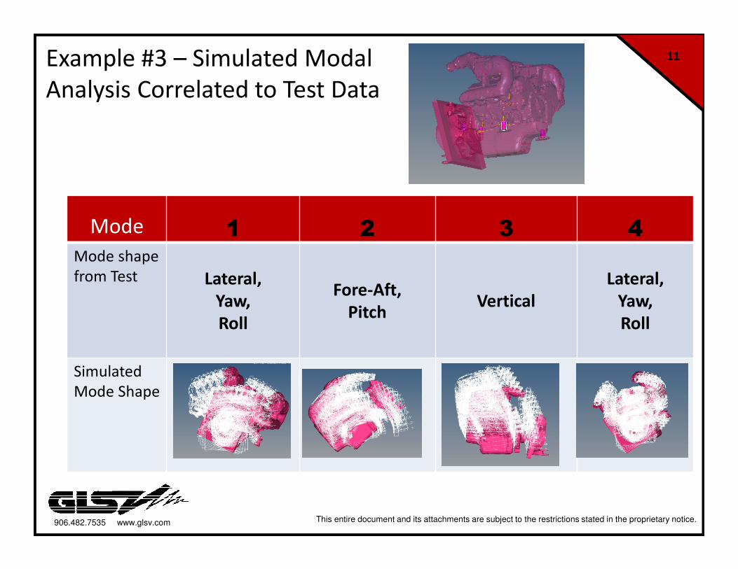
11Example #3 – Simulated Modal
Analysis Correlated to Test Data
Mode 1 2 3 4
Mode shape
from Test Lateral,
Yaw,
Roll
Fore-Aft,
PitchVertical
Lateral,
Yaw,
Roll
Simulated
Mode Shape
906.482.7535 www.glsv.com This entire document and its attachments are subject to the restrictions stated in the proprietary notice.
12
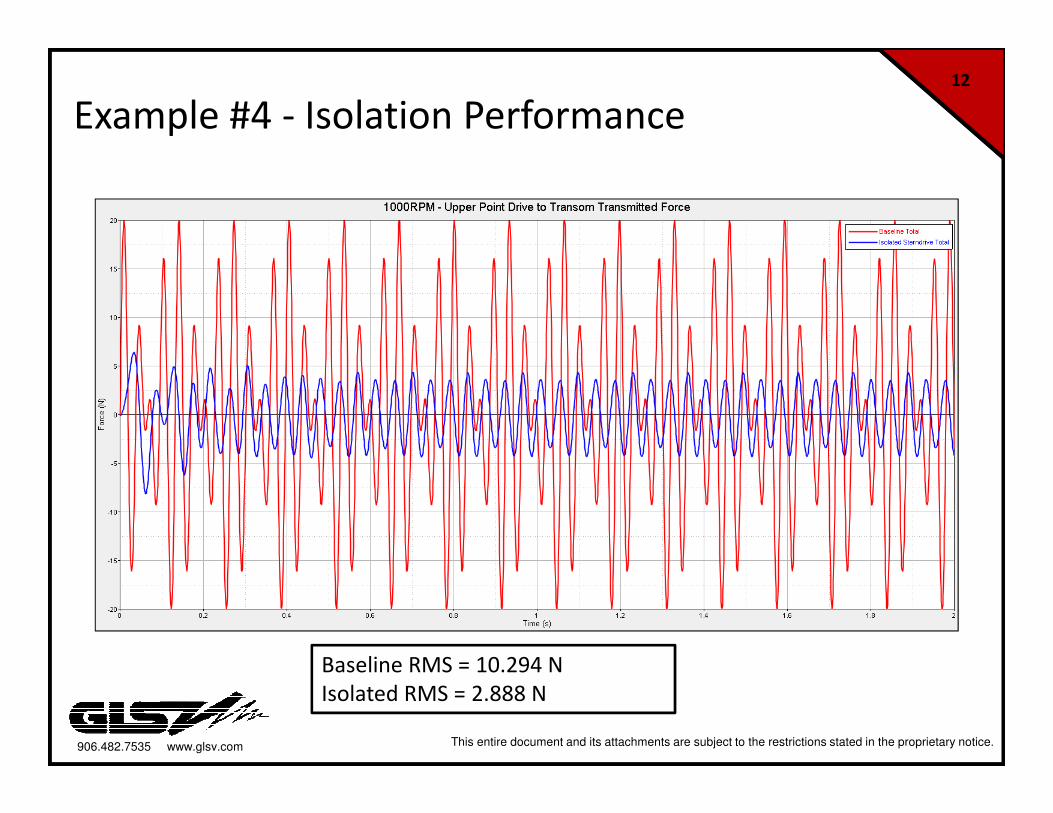
Example #4 - Isolation Performance
Baseline RMS = 10.294 N
Isolated RMS = 2.888 N
906.482.7535 www.glsv.com This entire document and its attachments are subject to the restrictions stated in the proprietary notice.
13
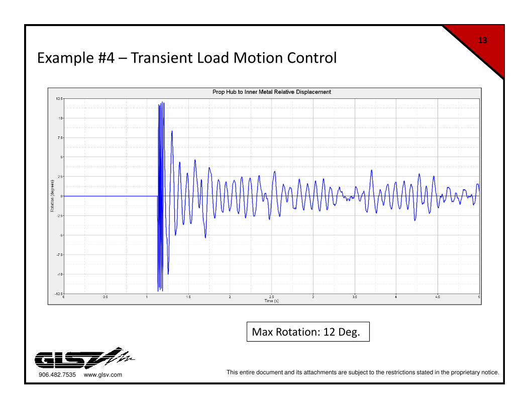
Example #4 – Transient Load Motion Control
Max Rotation: 12 Deg.
906.482.7535 www.glsv.com This entire document and its attachments are subject to the restrictions stated in the proprietary notice.
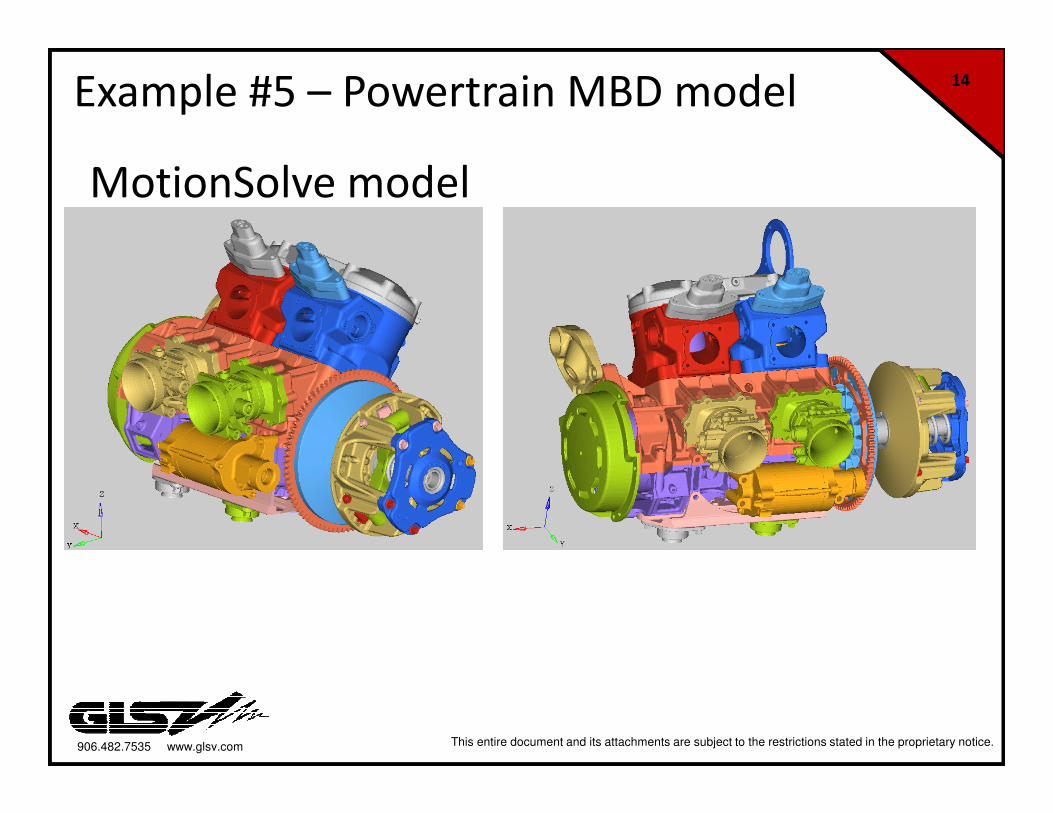
14Example #5 – Powertrain MBD model
MotionSolve model
906.482.7535 www.glsv.com This entire document and its attachments are subject to the restrictions stated in the proprietary notice.
15
System Optimization
• Perform Design of Experiments (DOE) to understand the
relationship between design variables and overall system
performance.
• Stochastic studies to assess reliability and robustness of designs
• Parameterize analysis models for design sensitivity studies
• Shape parameter definition using morphing technology
• Motion studies
• NVH studies
GLSV uses Altair HyperStudy software for
design exploration and optimization of
mechanical systems.
906.482.7535 www.glsv.com This entire document and its attachments are subject to the restrictions stated in the proprietary notice.
16
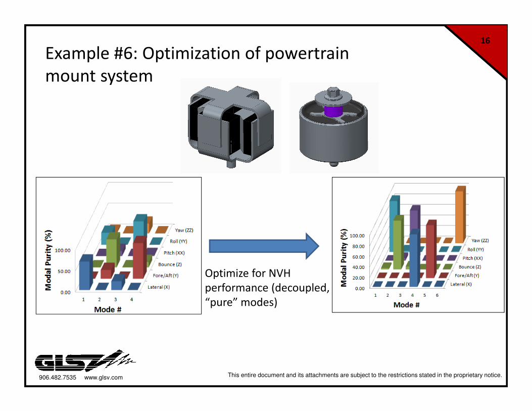
Example #6: Optimization of powertrain
mount system
Optimize for NVH
performance (decoupled,
“pure” modes)
906.482.7535 www.glsv.com This entire document and its attachments are subject to the restrictions stated in the proprietary notice.
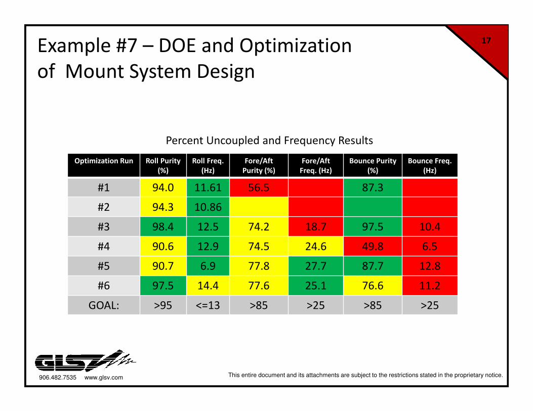
17Example #7 – DOE and Optimization
of Mount System Design
Optimization Run Roll Purity
(%)
Roll Freq.
(Hz)
Fore/Aft
Purity (%)
Fore/Aft
Freq. (Hz)
Bounce Purity
(%)
Bounce Freq.
(Hz)
#1 94.0 11.61 56.5 87.3
#2 94.3 10.86
#3 98.4 12.5 74.2 18.7 97.5 10.4
#4 90.6 12.9 74.5 24.6 49.8 6.5
#5 90.7 6.9 77.8 27.7 87.7 12.8
#6 97.5 14.4 77.6 25.1 76.6 11.2
GOAL: >95 <=13 >85 >25 >85 >25
Percent Uncoupled and Frequency Results
906.482.7535 www.glsv.com This entire document and its attachments are subject to the restrictions stated in the proprietary notice.
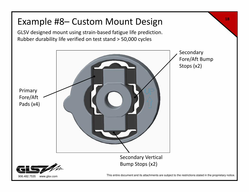
18Example #8– Custom Mount Design
Primary
Fore/Aft
Pads (x4)
Secondary
Fore/Aft Bump
Stops (x2)
Secondary Vertical
Bump Stops (x2)
GLSV designed mount using strain-based fatigue life prediction.
Rubber durability life verified on test stand > 50,000 cycles
906.482.7535 www.glsv.com This entire document and its attachments are subject to the restrictions stated in the proprietary notice.
19
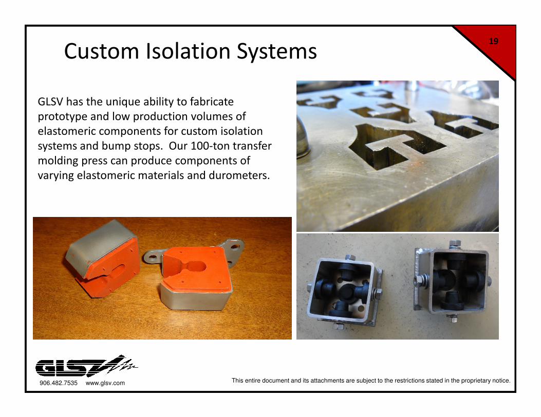
Custom Isolation Systems
GLSV has the unique ability to fabricate
prototype and low production volumes of
elastomeric components for custom isolation
systems and bump stops. Our 100-ton transfer
molding press can produce components of
varying elastomeric materials and durometers.
906.482.7535 www.glsv.com This entire document and its attachments are subject to the restrictions stated in the proprietary notice.
20GLSV Manufacturing• In-house Mold design
- multi-cavity molds
- transfer molding
- direct temperature measurement in the mold
- use of bonding agents
- design of internal (metallic) bonded components
• Mold materials
-Tool steel; carbon steel (for low production volumes)
-Designed and CNC-machined in house
• Typical elastomers
-EPDM (30, 40, 50 Durometer)
-Natural Rubber (30 – 80 Durometer)
-Silicone for high temperature applications
• Processing considerations (PLC control)
-time stamped data measurement
- real time process controls (pressure, temperatures)
- Q/A checks of durometer, curing, bonding
• GLSV works with GoldKey Processing (subsidiary of HEXPOL Compounding)
- rubber compounder
- PhD chemists on staff
906.482.7535 www.glsv.com This entire document and its attachments are subject to the restrictions stated in the proprietary notice.
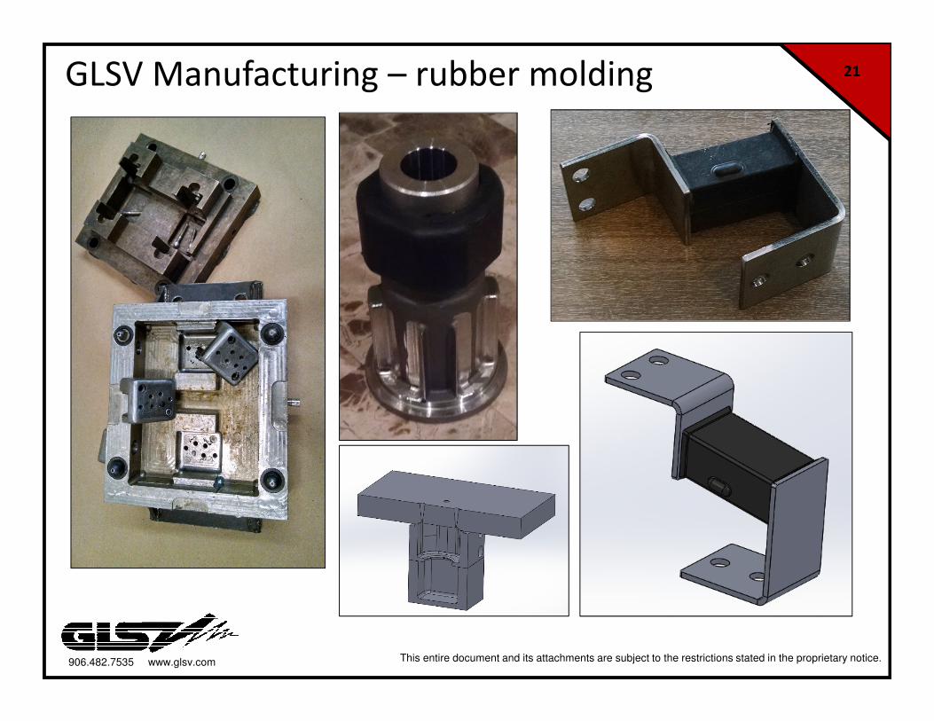
21GLSV Manufacturing – rubber molding
906.482.7535 www.glsv.com This entire document and its attachments are subject to the restrictions stated in the proprietary notice.
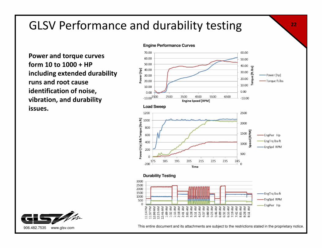
22GLSV Performance and durability testing
Power and torque curves
form 10 to 1000 + HP
including extended durability
runs and root cause
identification of noise,
vibration, and durability
issues.
Engine Performance Curves
Load Sweep
Durability Testing
906.482.7535 www.glsv.com This entire document and its attachments are subject to the restrictions stated in the proprietary notice.
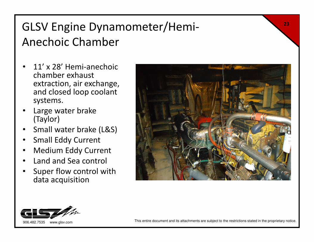
23GLSV Engine Dynamometer/Hemi-
Anechoic Chamber
• 11’ x 28’ Hemi-anechoic chamber exhaust extraction, air exchange, and closed loop coolant systems.
• Large water brake (Taylor)
• Small water brake (L&S)
• Small Eddy Current
• Medium Eddy Current
• Land and Sea control
• Super flow control with data acquisition
906.482.7535 www.glsv.com This entire document and its attachments are subject to the restrictions stated in the proprietary notice.
24
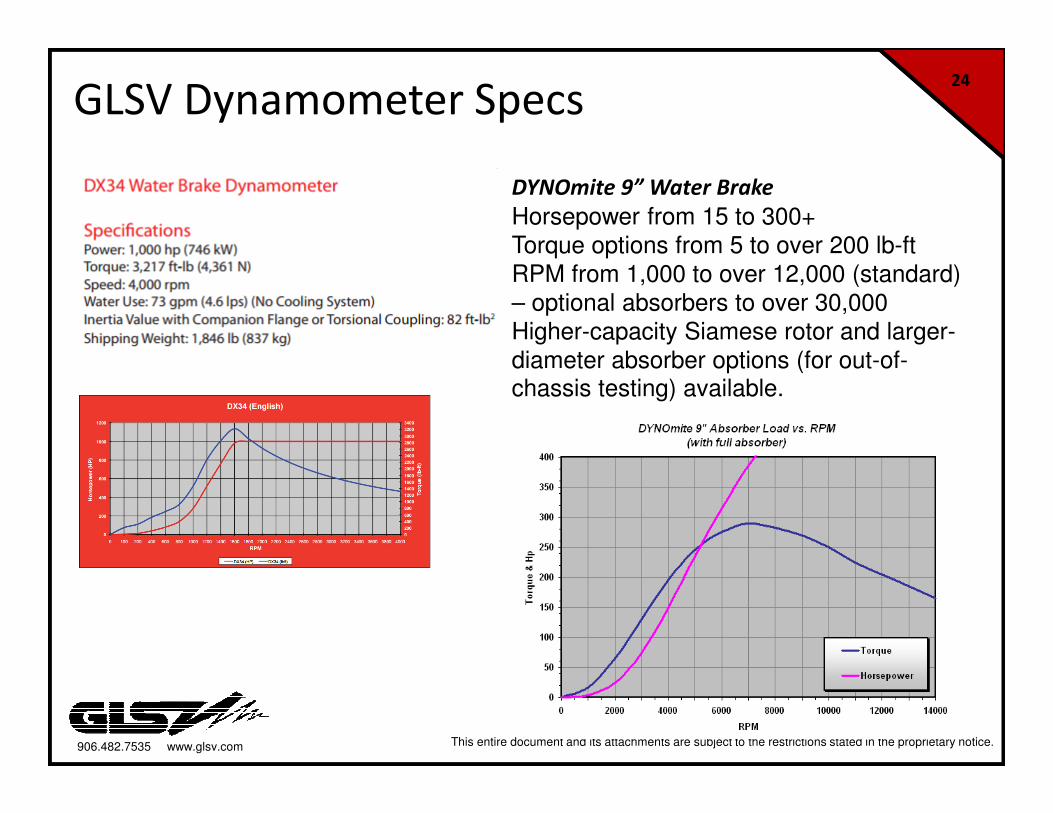
GLSV Dynamometer Specs
DYNOmite 9” Water Brake
Horsepower from 15 to 300+
Torque options from 5 to over 200 lb-ft
RPM from 1,000 to over 12,000 (standard)
– optional absorbers to over 30,000
Higher-capacity Siamese rotor and larger-
diameter absorber options (for out-of-chassis testing) available.