Embed Size (px)
Citation preview

O P E R A T I N G I N S T R U C T I O N S
InstallationStart-upMaintenance
GM32In-situ Gas AnalyzerMeasuring Probe Version

Document Information
Described ProductProduct name: GM32Variants: GM32 Probe (measuring probe)
Document IdentificationTitle: Operating Instructions GM32Part No.: 8012707Version: 1.3Release: 2009-03
PublisherSICK MAIHAK GmbHNimburger Str. 11 · D-79276 Reute · GermanyPhone: +49 7641 469-0Fax: +49 7641 469-11 49E-Mail: [email protected]
Guarantee InformationSpecified product characteristics and technical data do not serve as guarantee declarations.
© SICK MAIHAK GmbH. All rights reserved.
Glossary
CAN-Bus: Control Area Network. A field bus.CompactFlash®-Disc: Memory card.CUSUM board: Quality control chart (Data Sheet).Ethernet: Computer networking technology. Basis for network pro-tocols, e.g. TCP/IP.Check point: Test point at approx. 70% of the upper measuring range value.Check cycle: Test cycle with check of the zero and check point.OPC: Openness, Productivity, Collaboration. Standardized data interface (OPC FoundationTM).QAL3: Quality monitoring according to DIN EN 14181.Reference cycle: Test cycle with correction of internal drifts.SCU: Operating unit for the control of several analyzers with SCU capability.SOPAS (SICK Open Portal for Applications and Systems): SICK Parameter Setting and Data Calculation Software.SOPAS ET: SOPAS PC Engineering Tool. Configuration protocol.
2 GM32 Operating Instructions V 1.3 8012707 © SICK MAIHAK GmbH

Warning Symbols
Warning levels / Signal words
DANGERRisk or hazardous situation which will result in severe personal injury or death.
WARNINGRisk or hazardous situation which could result in severe personal injury or death.
CAUTIONHazard or unsafe practice which could result in personal injury or property damage.
NOTICEHazard which could result in material damage.
Information Symbols
Hazard (general)
Hazard by voltage
Hazard in potentially explosive atmospheres
Hazard by unhealthy substances
Hazard by high temperature or hot surface
Important technical information for this product
Important information on electrical or electronic func-tions
Nice to know
Supplementary information
Link to information at another place
GM32 Operating Instructions V 1.3 8012707 © SICK MAIHAK GmbH 3

Operat ing Instruct ionsInhaltsverzeichnis
1 Important Information . . . . . . . . . . . . . . . . . . . . . . . . . . . . . . . . . . . . . . . . . . . . . . . 7
1.1 Main instructions for operation . . . . . . . . . . . . . . . . . . . . . . . . . . . . . . . . . . . . . . . . . . . . . . . . 81.2 Intended use . . . . . . . . . . . . . . . . . . . . . . . . . . . . . . . . . . . . . . . . . . . . . . . . . . . . . . . . . . . . . . . . 81.2.1 Purpose of the device . . . . . . . . . . . . . . . . . . . . . . . . . . . . . . . . . . . . . . . . . . . . . . . . . . . . . . 81.3 Responsibility of user . . . . . . . . . . . . . . . . . . . . . . . . . . . . . . . . . . . . . . . . . . . . . . . . . . . . . . . . . 81.4 Additional documentation/information . . . . . . . . . . . . . . . . . . . . . . . . . . . . . . . . . . . . . . . . . 9
2 Product Description. . . . . . . . . . . . . . . . . . . . . . . . . . . . . . . . . . . . . . . . . . . . . . . . . . 11
2.1 Product identification . . . . . . . . . . . . . . . . . . . . . . . . . . . . . . . . . . . . . . . . . . . . . . . . . . . . . . . . 122.2 Product description . . . . . . . . . . . . . . . . . . . . . . . . . . . . . . . . . . . . . . . . . . . . . . . . . . . . . . . . . 122.2.1 Device variants . . . . . . . . . . . . . . . . . . . . . . . . . . . . . . . . . . . . . . . . . . . . . . . . . . . . . . . . . . . 122.2.2 Options . . . . . . . . . . . . . . . . . . . . . . . . . . . . . . . . . . . . . . . . . . . . . . . . . . . . . . . . . . . . . . . . . . 122.3 SOPAS ET (PC program) . . . . . . . . . . . . . . . . . . . . . . . . . . . . . . . . . . . . . . . . . . . . . . . . . . . . . . 132.4 Reference cycle . . . . . . . . . . . . . . . . . . . . . . . . . . . . . . . . . . . . . . . . . . . . . . . . . . . . . . . . . . . . . 132.5 Check cycle . . . . . . . . . . . . . . . . . . . . . . . . . . . . . . . . . . . . . . . . . . . . . . . . . . . . . . . . . . . . . . . . . 132.6 Design of GM32 . . . . . . . . . . . . . . . . . . . . . . . . . . . . . . . . . . . . . . . . . . . . . . . . . . . . . . . . . . . . 152.6.1 Measuring probe . . . . . . . . . . . . . . . . . . . . . . . . . . . . . . . . . . . . . . . . . . . . . . . . . . . . . . . . . 152.7 Purge air unit (for GMP measuring probe) . . . . . . . . . . . . . . . . . . . . . . . . . . . . . . . . . . . . . 15
3 Preparation on the Gas Duct Side . . . . . . . . . . . . . . . . . . . . . . . . . . . . . . . . 17
3.1 Preparation of sampling point . . . . . . . . . . . . . . . . . . . . . . . . . . . . . . . . . . . . . . . . . . . . . . . . 183.1.1 Checking the scope of delivery . . . . . . . . . . . . . . . . . . . . . . . . . . . . . . . . . . . . . . . . . . . . . 183.2 Overview of the installation steps (duct-side work). . . . . . . . . . . . . . . . . . . . . . . . . . . . . . 193.2.1 Work steps (overview) . . . . . . . . . . . . . . . . . . . . . . . . . . . . . . . . . . . . . . . . . . . . . . . . . . . . . 193.2.2 Installing the “flange with tube” on the gas duct . . . . . . . . . . . . . . . . . . . . . . . . . . . . . 203.3 Installing the connection unit . . . . . . . . . . . . . . . . . . . . . . . . . . . . . . . . . . . . . . . . . . . . . . . . . 203.4 Installing the purge air unit (for GMP probe) . . . . . . . . . . . . . . . . . . . . . . . . . . . . . . . . . . . 213.5 Laying the electrical connection lines . . . . . . . . . . . . . . . . . . . . . . . . . . . . . . . . . . . . . . . . . 223.5.1 General information. . . . . . . . . . . . . . . . . . . . . . . . . . . . . . . . . . . . . . . . . . . . . . . . . . . . . . . 233.5.2 Connecting I/O interfaces (option) . . . . . . . . . . . . . . . . . . . . . . . . . . . . . . . . . . . . . . . . . . 233.5.3 Laying the electrical connection lines to the SR-unit . . . . . . . . . . . . . . . . . . . . . . . . . . 233.5.4 Preparing the power supply . . . . . . . . . . . . . . . . . . . . . . . . . . . . . . . . . . . . . . . . . . . . . . . . 24
4 GM32 Operating Instructions V 1.3 8012707 © SICK MAIHAK GmbH
Operat ing Instruct ions
4 Start-up . . . . . . . . . . . . . . . . . . . . . . . . . . . . . . . . . . . . . . . . . . . . . . . . . . . . . . . . . . . . . . . . . 25
4.1 Necessary technical knowledge for start-up . . . . . . . . . . . . . . . . . . . . . . . . . . . . . . . . . . . . 264.2 Required material (not included in the scope of delivery) . . . . . . . . . . . . . . . . . . . . . . . . 264.3 Overview of assembly steps . . . . . . . . . . . . . . . . . . . . . . . . . . . . . . . . . . . . . . . . . . . . . . . . . . 274.4 Transport safety devices . . . . . . . . . . . . . . . . . . . . . . . . . . . . . . . . . . . . . . . . . . . . . . . . . . . . . 274.5 Installing the device flange on the purge air fixture . . . . . . . . . . . . . . . . . . . . . . . . . . . . . 294.6 Aligning the measuring probe in flow direction. . . . . . . . . . . . . . . . . . . . . . . . . . . . . . . . . . 304.6.1 When the probe alignment has to be set . . . . . . . . . . . . . . . . . . . . . . . . . . . . . . . . . . . . 304.7 For the GPP probe: Electric connection . . . . . . . . . . . . . . . . . . . . . . . . . . . . . . . . . . . . . . . . 314.8 SR-unit electric connection . . . . . . . . . . . . . . . . . . . . . . . . . . . . . . . . . . . . . . . . . . . . . . . . . . . 324.9 Switching on the power supply of the GM32 . . . . . . . . . . . . . . . . . . . . . . . . . . . . . . . . . . . . 324.10 For GMP probe: Start-up of the purge air supply . . . . . . . . . . . . . . . . . . . . . . . . . . . . . . . . 334.11 Installing the measuring probe in the gas duct . . . . . . . . . . . . . . . . . . . . . . . . . . . . . . . . . 344.12 Installing the SR-unit on the device flange . . . . . . . . . . . . . . . . . . . . . . . . . . . . . . . . . . . . . 354.13 Optical fine alignment of the SR-unit . . . . . . . . . . . . . . . . . . . . . . . . . . . . . . . . . . . . . . . . . . 35
5 Operation . . . . . . . . . . . . . . . . . . . . . . . . . . . . . . . . . . . . . . . . . . . . . . . . . . . . . . . . . . . . . . . 37
5.1 Recognition of an unsafe operational state . . . . . . . . . . . . . . . . . . . . . . . . . . . . . . . . . . . . 385.2 Operator panel (for the “Pro” variant) . . . . . . . . . . . . . . . . . . . . . . . . . . . . . . . . . . . . . . . . . . 395.2.1 Status indicators (LEDs) . . . . . . . . . . . . . . . . . . . . . . . . . . . . . . . . . . . . . . . . . . . . . . . . . . . 395.2.2 Assignment of buttons . . . . . . . . . . . . . . . . . . . . . . . . . . . . . . . . . . . . . . . . . . . . . . . . . . . . . 395.2.3 Contrast setting . . . . . . . . . . . . . . . . . . . . . . . . . . . . . . . . . . . . . . . . . . . . . . . . . . . . . . . . . . . 395.2.4 Language setting . . . . . . . . . . . . . . . . . . . . . . . . . . . . . . . . . . . . . . . . . . . . . . . . . . . . . . . . . 405.2.5 Menu tree . . . . . . . . . . . . . . . . . . . . . . . . . . . . . . . . . . . . . . . . . . . . . . . . . . . . . . . . . . . . . . . . 405.2.5.1 Diagnosis . . . . . . . . . . . . . . . . . . . . . . . . . . . . . . . . . . . . . . . . . . . . . . . . . . . . . . . . . . . . . 405.2.5.2 Alignment check (automatic optical alignment) (option) . . . . . . . . . . . . . . . . . . . . 415.2.5.3 Adjustments . . . . . . . . . . . . . . . . . . . . . . . . . . . . . . . . . . . . . . . . . . . . . . . . . . . . . . . . . . . 425.2.5.4 Maintenance . . . . . . . . . . . . . . . . . . . . . . . . . . . . . . . . . . . . . . . . . . . . . . . . . . . . . . . . . . 44
6 Putting Out of Operation . . . . . . . . . . . . . . . . . . . . . . . . . . . . . . . . . . . . . . . . . . . . 45
6.1 Putting out of operation . . . . . . . . . . . . . . . . . . . . . . . . . . . . . . . . . . . . . . . . . . . . . . . . . . . . . . 466.1.1 Putting out of operation . . . . . . . . . . . . . . . . . . . . . . . . . . . . . . . . . . . . . . . . . . . . . . . . . . . 466.1.2 Disassembly . . . . . . . . . . . . . . . . . . . . . . . . . . . . . . . . . . . . . . . . . . . . . . . . . . . . . . . . . . . . . . 466.2 Storage . . . . . . . . . . . . . . . . . . . . . . . . . . . . . . . . . . . . . . . . . . . . . . . . . . . . . . . . . . . . . . . . . . . . . 476.3 Environmentally compatible disposal/recycling . . . . . . . . . . . . . . . . . . . . . . . . . . . . . . . . 47
7 Maintenance . . . . . . . . . . . . . . . . . . . . . . . . . . . . . . . . . . . . . . . . . . . . . . . . . . . . . . . . . . . 49
7.1 Maintenance plan (operator) . . . . . . . . . . . . . . . . . . . . . . . . . . . . . . . . . . . . . . . . . . . . . . . . . 507.1.1 Recommended expendable and wearing parts for 2 years operation . . . . . . . . . . . 507.2 Preparation work . . . . . . . . . . . . . . . . . . . . . . . . . . . . . . . . . . . . . . . . . . . . . . . . . . . . . . . . . . . . 517.2.1 Swiveling out and removing the SR-unit . . . . . . . . . . . . . . . . . . . . . . . . . . . . . . . . . . . . . 517.3 Visual inspection . . . . . . . . . . . . . . . . . . . . . . . . . . . . . . . . . . . . . . . . . . . . . . . . . . . . . . . . . . . . 527.4 Cleaning the window . . . . . . . . . . . . . . . . . . . . . . . . . . . . . . . . . . . . . . . . . . . . . . . . . . . . . . . . . 527.5 Replacing the sender lamp . . . . . . . . . . . . . . . . . . . . . . . . . . . . . . . . . . . . . . . . . . . . . . . . . . . 537.6 Checking and replacing the drying agent cartridges . . . . . . . . . . . . . . . . . . . . . . . . . . . . . 547.7 Cleaning the purge air unit . . . . . . . . . . . . . . . . . . . . . . . . . . . . . . . . . . . . . . . . . . . . . . . . . . . 55
GM32 Operating Instructions V 1.3 8012707 © SICK MAIHAK GmbH 5

Operat ing Instruct ions
8 Clearing Malfunctions . . . . . . . . . . . . . . . . . . . . . . . . . . . . . . . . . . . . . . . . . . . . . . . 57
8.1 General hazard caused by electrical voltage . . . . . . . . . . . . . . . . . . . . . . . . . . . . . . . . . . . 588.2 Measured value blinks. . . . . . . . . . . . . . . . . . . . . . . . . . . . . . . . . . . . . . . . . . . . . . . . . . . . . . . 588.3 Error messages . . . . . . . . . . . . . . . . . . . . . . . . . . . . . . . . . . . . . . . . . . . . . . . . . . . . . . . . . . . . . 598.3.1 Example of an error message . . . . . . . . . . . . . . . . . . . . . . . . . . . . . . . . . . . . . . . . . . . . . . 598.3.2 Error messages . . . . . . . . . . . . . . . . . . . . . . . . . . . . . . . . . . . . . . . . . . . . . . . . . . . . . . . . . . . 608.4 Inadequate purge air supply (for GMP probe) . . . . . . . . . . . . . . . . . . . . . . . . . . . . . . . . . . 648.5 Malfunctions on the connection unit . . . . . . . . . . . . . . . . . . . . . . . . . . . . . . . . . . . . . . . . . . 64
9 Specifications . . . . . . . . . . . . . . . . . . . . . . . . . . . . . . . . . . . . . . . . . . . . . . . . . . . . . . . . . 65
9.1 Conformities . . . . . . . . . . . . . . . . . . . . . . . . . . . . . . . . . . . . . . . . . . . . . . . . . . . . . . . . . . . . . . . . 669.1.1 Electrical protection . . . . . . . . . . . . . . . . . . . . . . . . . . . . . . . . . . . . . . . . . . . . . . . . . . . . . . . 669.2 Technical data . . . . . . . . . . . . . . . . . . . . . . . . . . . . . . . . . . . . . . . . . . . . . . . . . . . . . . . . . . . . . . 67
6 GM32 Operating Instructions V 1.3 8012707 © SICK MAIHAK GmbH

Important Information
GM32
1 Important Information
Main safety informationMain instructions for operation
Intended useOwn responsibility
GM32 Operating Instructions V1.3 8012707 © SICK MAIHAK GmbH 7

Important Information
1 . 1 Main instructions for operation
1 . 2 Intended use
1.2.1 Purpose of the deviceThe GM32 serves exclusively for emission and process monitoring of gases in industrialplants.GM32 measures continuously directly in the gas duct (in-situ).
1 . 3 Responsibility of userDesignated usersThe GM32 may be operated by competent persons only who, based on their device-specifictraining and knowledge of the device as well as knowledge of the relevant regulations, canassess the tasks given and recognize the dangers involved.
Correct useUse the device only as described in these Operating Instructions. The manufacturer bears no responsibility for any other use.Perform the specified maintenance work.
⊗ Do not remove, add or modify any components to or on the device unless described and specified in the official manufacturer information. Otherwise:– Any warranty by the manufacturer becomes void.– The device could become dangerous.
Special local conditionsFollow all local laws, regulations and company-internal operating directives applicable at the respective installation location of the equipment.
Retention of documentsThese Operating Instructions:
Must be available for reference.Must be passed on to new owners.
WARNING: Danger resulting from escaping gas when the SR-unit is swiveled outExcess pressure in the gas duct can cause hot and/or noxious gases to escape when the SR-unit is swiveled out.
Swivel the SR-unit out only when you have taken suitable safety measures.
CAUTION: If the hinge pin has not been correctly inserted (→ p. 35, Figure 15), the SR-unit can drop when swiveled out.
Check whether the hinge pin is completely pressed down before the SR-unit is swiveled out.
CAUTION: Danger of contamination caused by purge air failure (for GM32 with GMP probe)
If a failure of the purge air supply occurs, take immediate measures to pro-tect the measuring system (→ p. 59, §8.3)
8 GM32 Operating Instructions V1.3 8012707 © SICK MAIHAK GmbH
Important Information
1 . 4 Additional documentation/informationPay attention to the supplied documents.
Additional instructions The following documents are applicable in addition to these Operating Instructions:● Technical Information GM32 (option)● Operating Instructions for purge air supply (for GMP probe)● Technical Information “Modular I/O System” (option)● Final inspection record● CD-Rom with SOPAS ET PC operating program
GM32 Operating Instructions V1.3 8012707 © SICK MAIHAK GmbH 9

Important Information
10 GM32 Operating Instructions V1.3 8012707 © SICK MAIHAK GmbH

Product Description
GM32
2 Product Description
Product identificationFunctional principle
CharacteristicsVariants
GM32 Operating Instructions V1.3 8012707 © SICK MAIHAK GmbH 11

Product Description
2 . 1 Product identification
2 . 2 Product descriptionThe GM32 gas analyzer serves for continuous measurement of the gas concentrations inindustrial plants.GM32 is an in-situ measuring system. Measurement is performed directly in the gas carry-ing duct.● Components: SO2, NO, NO2 and NH3 (device-specific) as well as the temperature and
pressure reference values. ● Measuring principle: Differential Optical Absorption Spectroscopy (DOAS).
2.2.1 Device variants
“Basic” variant● Reference cycle (→ p. 13, §2.4): Correction of internal drifts. Zero point check.● Automatic mirror tracking: Automatic adjustment of optical axis.● System messages are recorded in a logbook.● Ethernet interface with OPC standard.
“Pro” variantAs “Basic” variant. In addition:● “TÜV” tested for suitability.● Check cycle (→ p. 13, §2.5): Reference cycle (according to “Basic” variant) followed by a
cycle to check and output the zero and check point.The check cycle generates the QAL3 values. These can be displayed with SOPAS ET.
● Operator panel: Measured values, operating mode and malfunction message are dis-played in clear text on a monitor.
● QAL3 Tool (CUSUM chart)
2.2.2 Options● I/O modules (Analog Out, Digital Out, Digital In, Analog In).● Ethernet rail switch. Contains additional interfaces:
4 * Cu connection.1 * fiber optics connection (sender and receiver).
● SCU: Operating unit to control several analyzers with SCU capability (→ SCU Operating Instructions).
● Super Calibration: Several applications/calibrations. For example, for spare devices.
Product name GM32Product variant Version with measuring probeManufacturer SICK MAIHAK GmbH · Nimburger Str. 11
79276 Reute · Germany Location of type plates SR-unit: On the right and in the intermediate housing
For GMP probe: On the purge air fixtureFor GPP probe: On the flange attachment
12 GM32 Operating Instructions V1.3 8012707 © SICK MAIHAK GmbH
Product Description
2 . 3 SOPAS ET (PC program)SOPAS ET can be used to set the GM32 parameters and provides access to the GM32 log-book.SOPAS ET runs on an external PC connected via the Ethernet interface (→ p. 22, Figure 4) toGM32.
2 . 4 Reference cycleCorrection of internal drifts in an adjustable interval (standard: 1 hour, setting: SOPAS ET),via a command (with SOPAS ET) or via an external signal (option).Measured value output during the reference cycle: Last valid measured value.
2 . 5 Check cycleThe check cycle is made up of the reference cycle, followed by the check and output of thezero and check point (70% of upper measuring range value).It is performed in an adjustable interval (with SOPAS ET), via a command (with SOPAS ET)or via an external signal (option).With the check cycle, the device is capable of performing the check of the zero point and areference point for each component without feeding test gases. The check cycle meets therequirements of EN14181 and makes drift monitoring with test gases according to QAL3unnecessary.● Zero point
An internal zero point reflector is swiveled in time-controlled in adjustable intervals. The emitted light is reflected back in the sender/receiver unit to the detector, the zero spec-trum is evaluated with the calibration function and thus the zero points of all ducts measured and output. If the deviation from zero is > ±2% of the FS, Maintenance request is signaled.
● Check pointAn internal swivel element with two reference filters and an NO-filled cell is swiveled in during the check cycle in addition to the zero point reflector and the reference value or concentration value measured. These check values are scaled to 70% of the selected measuring range. Maintenance request is signaled if the deviation from the setpoint value is > ±2% of the FS.
More information on SOPAS ET:→ Technical Information GM32→ SOPAS ET Help menu
GM32 Operating Instructions V1.3 8012707 © SICK MAIHAK GmbH 13

Product Description
Figure 1 Check point
● Output of measured values during the check cycle: Last valid measured value.● Signal during the check cycle: Not_measuring. (Optionally digital output or OPC inter-
face).● The determined zero and reference values can be output on analog outputs depending
on the parameter settings:– Directly after the check cycle.– On request (via a digital input, option). – Signal during the output: Output_control_values. (Optionally digital output or OPC
interface). – First output of zero values for 90 s.– Then output of reference values for 90 s.– The Not_measuring signal is not active during the output.
● The zero and reference values of the last check cycle are displayed in SOPAS ET (menu: Diagnosis/Check values).The required QAL3 values can be read there.
Measuring
Zero point
Check
Zero pointreflector
Swivel element
Zero point
Control point(70% fsc)
Data recorder
14 GM32 Operating Instructions V1.3 8012707 © SICK MAIHAK GmbH

Product Description
2 . 6 Design of GM32The GM32 Probe version comprises● Sender/receiver unit (SR-unit)
The SR-unit contains optical and electronic subassemblies.The concentration calculation of the sample gas according to the absorption spectro-scope principle is performed in the SR-unit.
● Measuring probe with flange resp. purge air fixture (→ § 2.6.1)● Purge air unit (for GMP measuring probe) (→ § 2.7)
Figure 2 GM32 Probe (version shown: GMP measuring probe)
2.6.1 Measuring probeProbe types:● Measuring probe with open measuring gap (GMP probe)
GMP probes require a purge air supply to protect the window against contamination.● Gas diffusion probe (GPP probe) with gas permeable ceramic filter.
GPP probes are fitted with an automatically controlled heater to prevent condensate on the windows.
Both probe versions have an integrated temperature and pressure sensor.
2 . 7 Purge air unit (for GMP measuring probe)The purge air unit supplies filtered ambient air to the purge air fixtures and protects thewindows of the SR-unit from contamination and high gas temperatures.The purge air is blown into the gas duct through the “flange with tube”.
SR-unit GMP or GPP measuring probe
Measuring gap(active measuring path)
Operator panel(Option)
GMP probe: Purge air fixtureGPP probe: Flange attachment
Purge air unit (for GMP probe)
More information on the purge air unit → Technical Information of purge air unit.
GM32 Operating Instructions V1.3 8012707 © SICK MAIHAK GmbH 15

Product Description
16 GM32 Operating Instructions V1.3 8012707 © SICK MAIHAK GmbH

Preparation on the Gas Duct Side
GM32
3 Preparation on the Gas Duct Side
SetupInstallation
GM32 Operating Instructions V1.3 8012707 © SICK MAIHAK GmbH 17

Preparation on the Gas Duct Side
3 . 1 Preparation of sampling point
Determine the installation location.Observe the ambient conditions of the GM32 (→ p. 67, §9.2).Observe the space requirements for the SR-unit (→ p. 72, §).Provide for additional space for maintenance work (swiveling the housing door open, pulling the measuring probe out).Determine the installation location for the connection unit. Observe the maximum line lengths (→ p. 22, Figure 4 or as planned).Provide the power supply for the connection unit and, when necessary, for the GPP probe.Observe the power requirements (→ p. 67, §9.2).Lay the signal lines.For GMP probe: Determine the installation location for the purge air unit (→ p. 22, Figure 4 resp. as planned).Provide clearance for changing the filter element (→ Technical Data of purge air unit).
3.1.1 Checking the scope of delivery
Check the scope of delivery according to the order confirmation/delivery note.
● The basis for the determination of the sampling point is the preceding proj-ect planning (e.g. based on the SICK application questionnaire), the infor-mation in the final inspection record of the GM32 and the regulations of the local authorities.
● The equipment operator is responsible for the determination of the sam-pling point (e.g. the determination of a representative sampling point).
● The equipment operator is responsible for the preparation of the sampling point (e.g. load carrying capacity of the welded flange).
Compare the data of the final test record with the data of the order confir-mation - they must be identical.
18 GM32 Operating Instructions V1.3 8012707 © SICK MAIHAK GmbH

Preparation on the Gas Duct Side
3 . 2 Overview of the installation steps (duct-side work)
Figure 3 Installation overview
3.2.1 Work steps (overview)
30
L
50
470
Ø13
3
Weatherproof cover“Flange with tube”: L = 240 mm (standard)
Attachment (e.g. 4 steel pipes, 50 x 5 mm) for purge air unit
SR-unit
Approx. 1.5 m Min
. 700
mm
Angle: Approx. 1°
Step Procedure Reference1 Installing the “flange with tube” → p. 20, §3.2.22 Installing the connection unit → p. 20, §3.33 For GMP probe: Installing the purge air unit → p. 21, §3.44 Laying the electrical connection lines → p. 22, §3.5
GM32 Operating Instructions V1.3 8012707 © SICK MAIHAK GmbH 19

Preparation on the Gas Duct Side
3.2.2 Installing the “flange with tube” on the gas duct
1 Make a cut-out in the gas duct for the “flange with tube”.2 Insert the “flange with tube” so that the mark (TOP) ▴ points upwards vertically (irre-
spective of the gas duct angle) and attach the “flange with tube”.– The tube must project at least 30 mm into the gas duct.– Make sure the probe does not collide with other devices or fittings.– Tilt the tube slightly downwards (approx. 1°).
This allows any condensate to drain off.3 Now fix the “flange with tube” properly to the gas duct.
Make sure that the alignment of the flange does not change.4 If necessary, attach duct insulation (protect GM32 from heat).
3 . 3 Installing the connection unit● The length of the line to the GM32 complies with project planning.
Provide threaded bolts (4) to screw on the connection unit (→ p. 72, §31) and screw on the connection unit.
⊗ Do not make the electrical connection to the connection unit yet.
WARNING: Danger resulting from gases in the gas ductHot and/or noxious gases can escape during work on the gas duct, depending on the equipment conditions.
Work on the gas duct may only be performed by skilled persons who, based on their technical training and knowledge as well as knowledge of the rele-vant regulations, can assess the tasks given and recognize the hazards involved.
IMPORTANT: Observe the ambient temperature of the GM32When the gas duct is hot, insulate the duct and flanges so that the GM32 is protected from excess temperatures (→ p. 67, §9.2).
20 GM32 Operating Instructions V1.3 8012707 © SICK MAIHAK GmbH

Preparation on the Gas Duct Side
3 . 4 Installing the purge air unit (for GMP probe)● Maximum length of line to GM32 complies with project planning.
IMPORTANT: Adequate purge air pressureEnsure the purge air pressure is adequate to push the purge air into the gas duct.If required, please contact SICK Customer Service or your local representa-tive.
Installation of purge air unit → Data Sheet of purge air unit.
GM32 Operating Instructions V1.3 8012707 © SICK MAIHAK GmbH 21

Preparation on the Gas Duct Side
3 . 5 Laying the electrical connection lines
Figure 4 Electrical connection diagram
Sender/receiver unit (SR)Measuring probe
Purge air unit SLV 4(for GMP measuring probe)
Connection unit (AE)
Wiring and technical data, see Data Sheet SLV4
(3) (5) (4) (6)
(3) Connection: Purge air fixture
(4) Connection: Power supply
(5) Connection: CAN cable(6) Connection: PC (SOPAS
ET)
(3)
(1)
(4) (5)
(6)
For configuration and connections, see “Operating Instructions SCU”
SCU (option)
For on-site terminal connections (inputs/outputs), see Operating Instructions “Modular I/O System”
(7)
Power supply:100 ... 240 V AC, 50/60 Hz
Power supply (GPP):115 ... 230 V AC, 50/60 Hz
(2)
No. Signal cable for connection of Length Part No. Remarks(1) Filter monitoring 5 m 2032143 Included in the purge air fixture (probe)(2) GPP probe power supply 10 m 2017519 Included in the GPP probe(3) SR – purge air fixture (CAN cable) 0.8 m 2023704 Included in the purge air fixture (probe)(4) AU – SR (CAN cable) 10 m
20 m20287862045422
Order separately
(5) Power supply SR (standard) 10 m20 m
20465482046549
Order separately
(6) Ethernet cable – PC/network – No, on-site(7) CAN cable – SCU – No, on-site
Scope of deliveryOn-site wiring
22 GM32 Operating Instructions V1.3 8012707 © SICK MAIHAK GmbH
Preparation on the Gas Duct Side
3.5.1 General information
3.5.2 Connecting I/O interfaces (option)
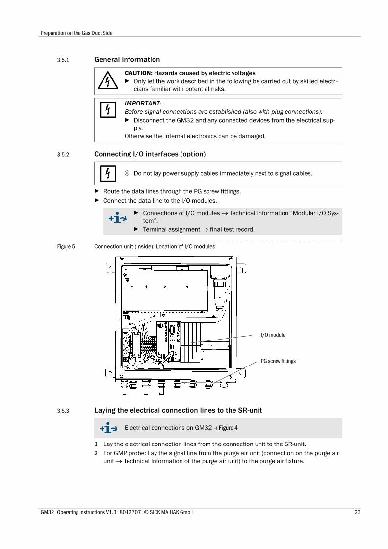
Route the data lines through the PG screw fittings.Connect the data line to the I/O modules.
Figure 5 Connection unit (inside): Location of I/O modules
3.5.3 Laying the electrical connection lines to the SR-unit
1 Lay the electrical connection lines from the connection unit to the SR-unit.2 For GMP probe: Lay the signal line from the purge air unit (connection on the purge air
unit → Technical Information of the purge air unit) to the purge air fixture.
CAUTION: Hazards caused by electric voltagesOnly let the work described in the following be carried out by skilled electri-cians familiar with potential risks.
IMPORTANT: Before signal connections are established (also with plug connections):
Disconnect the GM32 and any connected devices from the electrical sup-ply.
Otherwise the internal electronics can be damaged.
⊗ Do not lay power supply cables immediately next to signal cables.
Connections of I/O modules → Technical Information “Modular I/O Sys-tem”.Terminal assignment → final test record.
I/O module
PG screw fittings
Electrical connections on GM32 → Figure 4
GM32 Operating Instructions V1.3 8012707 © SICK MAIHAK GmbH 23

Preparation on the Gas Duct Side
3.5.4 Preparing the power supply
1 Provide separate external fuses for:– Connection unit (max. power input → p. 67, §9.2)– For GMP probe: Purge air unit (→ Technical Data of the purge air unit)– For GPP probe: Heater (max. power input → p. 67, §9.2)
2 Lay the electric lines of the power supply to the connection unit and connect the power supply in the connection unit.
Figure 6 Mains connection in the connection unit
3 For GMP probe: Lay the electric lines to the purge air unit.For GPP probe: Lay the electric lines for the probe heater.
Take precautions to prevent switching off the purge air supply accidentally.Attach a clearly visible warning against accidental switching off the separa-tion equipment for the purge air unit.
The power supply must remain switched off until the GM32 is to be put into operation.
Power supply100 .. 240 V / 50 .. 60 Hz
24 GM32 Operating Instructions V1.3 8012707 © SICK MAIHAK GmbH

Start-up
GM32
4 Start-up
PreparationAssemblyAlignment
GM32 Operating Instructions V1.3 8012707 © SICK MAIHAK GmbH 25

Start-up
4 . 1 Necessary technical knowledge for start-up
4 . 2 Required material (not included in the scope of delivery)
The following requirements must be met for the start-up:● You are basically familiar with GM32.● You are familiar with the local situation, especially the potential risks
caused by gases in the gas duct (hot/noxious). You are capable of recogniz-ing and preventing danger by possibly escaping gases.
● The specifications according to project planning have been complied with (→ final inspection record).
● The assembly location has been prepared according to → p. 17, »Preparation on the Gas Duct Side«.
If one of these requirements is not met: Please contact SICK Customer Service or your local representative.
WARNING: Hazard by voltageAll connectors of the power supply to the involved subassemblies or lines must be disconnected before the installation work.
WARNING: Danger resulting from gases in the gas ductHot and/or noxious gases can escape during work on the gas duct, depending on the equipment conditions.
Work on the gas duct may only be performed by skilled persons who, based on their technical training and knowledge as well as knowledge of the rele-vant regulations, can assess the tasks given and recognize the hazards involved.
Material required Part No. Required forOptical cleaning cloth 4003353 Cleaning the windowsPersonal protective equipment --- Protection when working on the
stack
26 GM32 Operating Instructions V1.3 8012707 © SICK MAIHAK GmbH

Start-up
4 . 3 Overview of assembly steps
4 . 4 Transport safety devices1 Remove the transport safety device of the SR-unit.
Figure 7 SR-unit transport safety device
Procedure ReferenceRemoving the transport safety devices → p. 27, §4.4Installing the device flange on the purge air fixture → p. 29, §4.5Aligning the measuring probe → p. 30, §4.6For the GPP probe: Electrical connection of heater → p. 31, §4.7SR-unit electric connection → p. 32, §4.8Switching on the power supply → p. 32, §4.9For GMP probe: Purge air supply start-up → p. 33, §4.10Installing the measuring probe in the gas duct → p. 34, §4.11Fitting the SR-unit on the device flange → p. 35, §4.12Optical fine alignment of the SR-unit → p. 35, §4.13
Transport safety device
GM32 Operating Instructions V1.3 8012707 © SICK MAIHAK GmbH 27

Start-up
2 Remove the probe transport safety device.The probe transport safety devices depend on the type of probe. a) Remove the protective stickers.b) Take out the plugs.
Figure 8 Probe transport safety devices (shown here on a GPP probe)
3 Store the transport safety devices.
Plugs Stickers
28 GM32 Operating Instructions V1.3 8012707 © SICK MAIHAK GmbH

Start-up
4 . 5 Installing the device flange on the purge air fixtureRemark on the GPP probe: The procedure for the GPP probe flange attachment corre-sponds to the procedure shown here for the purge air fixture. 1 Recommendation: For easier handling during installation:
Remove the SR-unit from the device flange before installation (→ p. 51, §7.2.1).2 Installation on the SR-unit side:
Figure 9 Installing the device flange on the purge air fixture
a) Plug 12 cup springs each, individually arranged opposite each other, onto the threaded bolts on the device flange.
b) Pull the sealing ring over the flange of the purge air fixture and hang it loosely over the purge air unit.
c) Plug the device flange onto the purge air fixture.d) Plug on the centering discs.
Notice: Observe the direction of the centering disc: The convex side must fit into the groove on the purge air fixture.
e) Tighten the self-locking nuts with a wrench (19 mm) so that the cup springs are slightly compressed and an even gap of 3...4 mm remains.
f) Install the sealing ring above the gap (→ Figure 9).
Device flange Purge air fixture
Gap: 3.5 ± 0.5 mm Sealing ring
12 cup springs
Centering disc
Nut
GM32 Operating Instructions V1.3 8012707 © SICK MAIHAK GmbH 29

Start-up
4 . 6 Aligning the measuring probe in flow directionThe fitting angle of the probe is already set before delivery when the gas flow direction hasbeen defined during project planning for the GM32.A sticker marks the setting.
Figure 10 Flow direction marking and setting
4.6.1 When the probe alignment has to be set● The measuring gap must be aligned in sample gas flow direction.● The SR-unit must be fitted vertically.Rotate the device flange to align the probe.To change the measuring probe alignment:1 Loosen the 4 screws on the mounting ring (→ Figure 10).2 Rotate the device flange:
– The measuring gap must point in flow direction.– The device flange must be positioned so that the SR-unit can be fitted in a vertical
position.3 Fasten the device flange in this position by tightening the screws on the mounting ring
again.
Flow direction sticker
Mounting ring screws (4 pcs.)
Device flange
30 GM32 Operating Instructions V1.3 8012707 © SICK MAIHAK GmbH

Start-up
4 . 7 For the GPP probe: Electric connection 1 Unscrew and take off the purge air fixture cover.2 Check the switch setting for swapping the voltage to the available mains voltage and
correct when necessary.
Figure 11 Switch to select voltage and fuses
3 Check the fuses according to the available mains voltage and replace when necessary.
4 Connect the power supply to the mains voltage.Line with three wires:– Green-yellow: PE– Blue: N– Brown: L1
Fuse holder
Switch to set voltage
IMPORTANT: The fuses depend on the available mains voltage.Only use the correct fuses.– 230 V: 1.6 A (slow)– 115 V: 2.5 A (slow)
IMPORTANT: Danger of condensationThe GPP probe must have reached its operating temperature before being inserted in the gas duct.
First fit the GPP probe during final installation in the gas duct (→ p. 34, §4.11).Attach clearly visible warnings against accidental switching-off to all switching devices where the GPP probe heater can be switched off.
GM32 Operating Instructions V1.3 8012707 © SICK MAIHAK GmbH 31

Start-up
4 . 8 SR-unit electric connection
1 Connect the electric lines from the connection unit to the SR-unit.2 For GMP probe: Connect the electric line from the purge air unit to the purge air fixture
(terminal: SLV filter).3 Screw the earthing conductor (2.5 mm2) of the equipment earth tight to the screw ter-
minal (→ Figure 12).
Figure 12 Connection of the earthing conductor at the bottom of the SR-unit
4 . 9 Switching on the power supply of the GM321 Switch on the power supply on the operator-side fuse of the connection unit.2 An initialization screen is shown on the operator panel (for the “Pro” variant).3 Measured values are then shown.
Ignore the displays until the start-up of the GM32 is complete.
Connecting diagram → p. 22, Figure 4
Earthing conductorconnection
32 GM32 Operating Instructions V1.3 8012707 © SICK MAIHAK GmbH

Start-up
4 . 1 0 For GMP probe: Start-up of the purge air supply
Figure 13 Connection of the purge air supply
1 Switch on the power supply of the purge air unit on the (operator-side) fuse of the purge air unit.– Check the function: A strong air flow must be noticeable.
If it is not noticeable: → Data Sheet of purge air unit.– Blow out the dust that may have entered the purge air hose.
2 Check the switch function of the pressure controller in the purge air unit, e.g. by partly closing the suction opening of the purge air unit.The “Purge air signal” warning must be shown.
3 Switch the power supply off again.4 Connect the purge air hose to the purge air connection with a hose clamp (→ Figure 13). If
necessary, remove the protective cap from the purge air connection.5 Switch the power supply of the purge air unit on.
SLV filter terminalPurge air connection(shown with protective cap)
The purge air supply protects the measuring system from contamination and overheating.
Ensure the purge air pressure is adequate to push the purge air into the gas duct.
The purge air supply may not be switched off while the measuring system is on the gas duct.
Attach clearly visible warnings against accidental switching-off to all switch-ing devices where the purge air supply can be switched off.
GM32 Operating Instructions V1.3 8012707 © SICK MAIHAK GmbH 33

Start-up
4 . 1 1 Installing the measuring probe in the gas duct
1 Insert the measuring probe with purge air fixture resp. flange attachment (without SR-unit) in the “flange with tube” on the channel side.– For GMP measuring probe: Do not interrupt the purge air feed.– For GPP measuring probe: Do not interrupt the power supply to the measuring
probe.2 Screw the measuring probe with purge air fixture resp. flange attachment tight to the
“flange with tube” (seal with 4 screws).
Figure 14 Fitting the probe in the gas channel
IMPORTANT: With the GPP probe: Danger of condensationThe GPP probe must have reached its operating temperature before the mea-suring probe is inserted in the gas duct.
Wait until the probe has reached its operating temperature before inserting the probe.
Do not switch the GPP probe heater off as long as the GPP probe measuring system is in the gas duct.
Attach clearly visible warnings against accidental switching-off to all switch-ing devices where the GPP probe heater could be switched off.
For GMP probe: Purge air fixtureFor GPP probe: Flange attachment
Seal “Flange with tube”
Screw Washer Spring sheet Nut
34 GM32 Operating Instructions V1.3 8012707 © SICK MAIHAK GmbH

Start-up
4 . 1 2 Installing the SR-unit on the device flange1 Installing the SR-unit:
a) Insert the SR-unit on the device flange into the hinge (swiveling-out direction prefer-ably to the “left”).
b) Insert the hinge pin from above.
Figure 15 Installing the SR-unit:
c) Check the window for cleanness and clean, if required (→ p. 52, §7.4).d) Check whether the drying agent cartridge is dry (→ p. 54, §7.6).e) Close the SR-unit with the 4 quick-release fasteners.f) For GMP probe: Set the lever on the purge air fixture to the “open” position.
Figure 16 Lever for the locking device (for GMP probe)
4 . 1 3 Optical fine alignment of the SR-unitOptical alignment of the SR-unit:
With SOPAS ET: → Leave this work to a skilled person familiar with SOPAS ET.With operating unit: → p. 42
IMPORTANT: If the hinge pin has not been correctly inserted, the SR-unit can drop when swiveled out.
Ensure that the hinge pin is fully inserted.
Hinge pinHinge Device flangeSR-unit
Lever of the locking device
“Open” resp. “close”marking
GM32 Operating Instructions V1.3 8012707 © SICK MAIHAK GmbH 35

Start-up
36 GM32 Operating Instructions V1.3 8012707 © SICK MAIHAK GmbH

Operation
GM32
5 Operation
OperationStatus messages
GM32 Operating Instructions V1.3 8012707 © SICK MAIHAK GmbH 37

Operation
5 . 1 Recognition of an unsafe operational stateCAUTION: Danger caused by unsafe operational stateIf the device is or could be in an unsafe state:
Take the device out of operation, disconnect from the mains voltage and signal voltage and secure against unallowed or accidental start-up.
Indication ActionSmoke escaping from the housing 1 Immediately put the device out of operation.
2 Have the device repaired.Gas escaping from the housing 1 Immediately check whether the gas is noxious or
combustible.2 If this is the case: Immediately check the local
Operating Instructions which control the behavior during uncontrolled escape of gas.
Examples of behavior: Trigger an alarm. Start emergency measures.Immediately evacuate all persons from the affected operational room.Use breathing protection.Stop the affected gas supply.Put the measuring system out of operation.
Water or a different liquid penetrates into the device
1 Immediately put the device out of operation.2 Locate and stop the liquid source. 3 Have the device repaired.
Humidity or moisture condensation on electrical connections
1 Put the device out of operation.2 Dry the connections.
Electric lines are damaged or broken 1 Put the device out of operation.2 Have the damage repaired.
Surface is damaged or deformed 1 Put the device out of operation.2 Have the device repaired.
If caused by heat from inside the device: Immedi-ately put the device out of operation.If caused by acute external influence: Locate the heat source and protect the device provisionally against heat.Otherwise: Have the device checked immediately by a skilled person.
Unusual noises can be heard inside the device 1 Check malfunction displays and malfunction mes-sages of the device.
2 Have the device checked by a skilled person.Malfunctions remain inexplicable despite
having been clearedContact the manufacturer's after-sales service department.
38 GM32 Operating Instructions V1.3 8012707 © SICK MAIHAK GmbH

Operation
5 . 2 Operator panel (for the “Pro” variant)The operator panel is located on the right side of the SR-unit housing.
Figure 17 Significance of display
5.2.1 Status indicators (LEDs)Significance of LEDs● The green LED goes on: Power supply is in order.● The yellow LED goes on: Maintenance request.● The red LED goes on: Malfunction.
5.2.2 Assignment of buttonsThe assignment of the buttons depends on the selected menu and is shown above therespective button.
5.2.3 Contrast setting1 Press the MEAS button for more than 3 seconds.2 Set the desired contrast level with both middle buttons and .
Operating mode
Status indicators (LEDs)(→ p. 40, §5.2.5.1)
Current menu with menu level (numeric display)
Menu level
Significance of button(→ § 5.2.2)
Contrast setting(→ § 5.2.3)
MEAS button(→ § 5.2.2)
Buttons
More information on the significance of the LEDs → p. 40, §5.2.5.1
Assignment of buttons SignificanceMEAS Back to the display of the measured value screen from any menu.
All inputs that have not been terminated with Save are discarded. If the MEAS button is depressed for more than 3 seconds: The contrast setting is displayed (→ p. 39, §5.2.3)
Menu Opens the main menu (menu tree)Diag Diag is shown only when there is a message.
When this button is pressed, the current message is shown.More information on diagnosis → p. 40, §5.2.5.1List of error messages → p. 59, §8.3
Enter Opens the selected menu level Save Saves the changed parametersStart Starts the displayed action
GM32 Operating Instructions V1.3 8012707 © SICK MAIHAK GmbH 39

Operation
5.2.4 Language settingThe texts of the menus are shown in English
5.2.5 Menu tree
5.2.5.1 DiagnosisThe “Diagnosis” menu shows the current error messages.
1 Diagnosis → p. 40, §5.2.5.11.1 Failure → p. 40, §5.2.5.11.2 Maintenance (request) → p. 40, §5.2.5.11.3 Uncertain → p. 40, §5.2.5.1
2 Alignment check → p. 41, §5.2.5.23 Adjustments → p. 42, §5.2.5.3
3.1 Alignment adjust → p. 423.2 Check cycle → p. 433.3 Reference cycle → p. 43
4 IP Configuration View the IP settings4.1 IP IP address4.2 M Subnetmask4.2 GW Gateway
5 Maintenance → p. 44, §5.2.5.4
The GM32 creates a logbook. Access to the logbook is performed exclusively via SOPAS ET → p. 13, §2.3.
The GM32 signals a malfunction or an unsafe operational state with status sig-nals (option) (→ electrical connection diagram).
List of error messages and measures for clearing malfunctions→ p. 59, §8.3
40 GM32 Operating Instructions V1.3 8012707 © SICK MAIHAK GmbH

Operation
Status messages, status indicators and system states
5.2.5.2 Alignment check (automatic optical alignment) (option)The optical alignment of GM32 is automatically adjusted in this menu.
Arrow buttons: Switch from “deviation” to “performed steps of tracking mirror”To exit the Menu item: Press the “Back” button.
Status Status indicators (LED)
Significance Measured value dis-play
Analogoutputs1
1 Option
Status sig-nal2,3
2 Option. Refer to the delivered System Documentation for the assignment of the status outputs.3 See SOPAS ET in the “Digital outputs” menu.
Power On Green Power supply is in order --- --- ---Uncertain Green, however,
measured value blinks
Measured value uncertain (e.g. outside calibration range)Cause: Press the DIAG buttonAll messages → SOPAS ET Logbook.Clearing malfunctions → p. 59, §8.3
Current Current According to setting
Maintenance request
Yellow Irregularities (e.g. gas temperature too high, deviation from check cycle too high) that require a review of the cause. The measured values are valid. Cause: Press the DIAG buttonAll messages → SOPAS ET Logbook.Clearing malfunctions → p. 59, §8.3
Current Current According to setting
Failure Red Device failure (e.g. lamp failed)Cause: Press the DIAG buttonAll messages → SOPAS ET Logbook.Clearing malfunctions → p. 59, §8.3
Last valid measured value held
Last valid mea-sured value held
According to setting
Perform this work only when the SR-unit is at operating temperature (in operation for at least 30 minutes).Automatic mirror adjustment - do not perform manual adjustments.
More information→ p. 42, §5.2.5.3
GM32 Operating Instructions V1.3 8012707 © SICK MAIHAK GmbH 41

Operation
5.2.5.3 Adjustments
Alignment adjustment (manual optical alignment)
Figure 18 Manual alignment of optical axis
Manual optical alignment of the GM32. 1 Press the “Start” button: The GM32 goes to a defined state.
A crosshair with a focal point and X/Y values is shown on the screen.2 Tolerances:
X: –0.05 ... +0.05Y: –0.05 ... +0.05.The focal point is then in the center of the crosshair.Adjustment:Adjust the optical alignment by turning both adjustment screws on the device flange of the SR-unit (19 mm wrench).
Perform this work only when the SR-unit is at operating temperature (in operation for at least 30 minutes).
Light energy
Focal point
Value XValue Y
The display on the monitor reacts to the adjustment with a delay.Perform adjustments slowly and wait for approx. 20 seconds until the display on the monitor has been updated.
42 GM32 Operating Instructions V1.3 8012707 © SICK MAIHAK GmbH
Operation
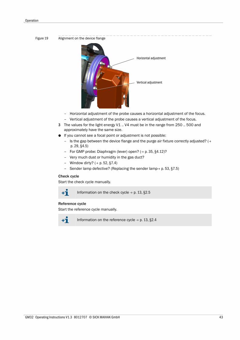
Figure 19 Alignment on the device flange
– Horizontal adjustment of the probe causes a horizontal adjustment of the focus.– Vertical adjustment of the probe causes a vertical adjustment of the focus.
3 The values for the light energy V1 .. V4 must be in the range from 250 .. 500 and approximately have the same size.
● If you cannot see a focal point or adjustment is not possible:– Is the gap between the device flange and the purge air fixture correctly adjusted? (→
p. 29, §4.5)– For GMP probe: Diaphragm (lever) open? (→ p. 35, §4.12)?– Very much dust or humidity in the gas duct?– Window dirty? (→ p. 52, §7.4)– Sender lamp defective? (Replacing the sender lamp→ p. 53, §7.5)
Check cycleStart the check cycle manually.
Reference cycleStart the reference cycle manually.
Horizontal adjustment
Vertical adjustment
Information on the check cycle → p. 13, §2.5
Information on the reference cycle → p. 13, §2.4
GM32 Operating Instructions V1.3 8012707 © SICK MAIHAK GmbH 43

Operation
5.2.5.4 MaintenanceThe operating mode “Maintenance” is signaled via this menu.● “Maintenance” is displayed in the operating mode line.● The “Maintenance mode active” message is displayed.● A continuous display of “*” is shown.● The “Maintenance” status signal (→ electric connection diagram) is set.
Figure 20 “Maintenance” screen
● Assignment of buttons:– “Back” : Show the “Measuring” menu - maintenance signal remains set.– “MEAS”: Show the “Measuring” menu - maintenance signal is reset.
44 GM32 Operating Instructions V1.3 8012707 © SICK MAIHAK GmbH

Putting Out of Operation
GM32
6 Putting Out of Operation
Putting out of operationStorage
Disposal
GM32 Operating Instructions V1.3 8012707 © SICK MAIHAK GmbH 45

Putting Out of Operation
6 . 1 Putting out of operation
6.1.1 Putting out of operationSwitch off the power supply of the connection unit.
The analyzer can remain on the gas duct as long as the purge air supply (for GMP probe)resp. the heater (for GPP probe) is in operation.
6.1.2 Disassembly
1 Disconnect all connections between connection unit and SR-unit. 2 Remove the SR-unit (→ p. 51, §7.2.1).
3 Unscrew the purge air fixture or flange fixture (→ p. 15, Figure 2) from the flange, pull out the probe and lay it down.
4 For GPP probe: Switch off the power supply of the heater.5 For GMP probe: Switch the purge air supply off and disconnect the purge air hose on
the device flange.6 Close off the flange on the gas duct with a cover.
WARNING: Danger resulting from gases in the gas ductHot and/or noxious gases can escape during work on the gas duct, depending on the equipment conditions.
Work on the gas duct may only be performed by skilled persons who, based on their technical training and knowledge as well as knowledge of the rele-vant regulations, can assess the tasks given and recognize the hazards involved.
IMPORTANT: Do not switch off the purge air immediately⊗ Do not switch the purge air unit off as long as the SR-unit is still on the gas
duct.
IMPORTANT: With the GPP probe: Danger of condensation⊗ Do not switch off the heater of the GPP probe as long as the probe is in the
gas duct.
IMPORTANT: In case of a failure, no message by the analyzerThe analyzer no longer outputs a message when the purge air supply resp. the heater fails.
Install suitable monitoring or remove the subassemblies.
Material required Part No. Required forPersonal protective equipment --- Protection when working on the stackFlange lid --- Covering the flange
WARNING: Hazards when removing the SR-unitObserve the information concerning the removal of the SR-unit (→ p. 51, §7.2.1).
WARNING: Measuring probe can be hotWhen the temperatures in the gas duct are high, the removed measuring probe is hot.
Wear suitable heat-resistant gloves.Provide a heat-resistant support.
46 GM32 Operating Instructions V1.3 8012707 © SICK MAIHAK GmbH

Putting Out of Operation
6 . 2 Storage1 Clean the exterior of all housings, the measuring probe and all further components
including the purge air unit (when fitted)) with damp cleaning cloths. A mild cleaning agent can be used.
2 Check the drying agent cartridges and replace, if required (→ p. 54, §7.6).3 Protect the openings of the SR-unit and measuring probe from atmospheric influences
(preferably with the transport safety devices, according to → p. 27, §4.4).4 Pack the GM32 for storage or transport (preferably in the original packing). 5 Store the GM32 in a dry, clean room.
6 . 3 Environmentally compatible disposal/recyclingThe GM32 can be disposed off as industrial waste.
The following subassemblies could contain substances that have to be disposed of sepa-rately:● Electronics: Capacitors, rechargeable batteries, batteries. ● Display: Liquid of LC display.● Probes: Probes can be contaminated with pollutants.
Observe the relevant local conditions for the disposal of industrial waste.
GM32 Operating Instructions V1.3 8012707 © SICK MAIHAK GmbH 47

Putting Out of Operation
48 GM32 Operating Instructions V1.3 8012707 © SICK MAIHAK GmbH

Maintenance
GM32
7 Maintenance
Maintenance planSpare parts, recommended
Maintenance workPreventative maintenance
GM32 Operating Instructions V1.3 8012707 © SICK MAIHAK GmbH 49

Maintenance
7 . 1 Maintenance plan (operator)
7.1.1 Recommended expendable and wearing parts for 2 years operation
Maintenance task Reference W1
1 W = weekly, Q = quarterly
Q1
Check if measured and control values (zero/test point) are valid x xVisual inspection → p. 52, §7.3 xCleaning the window → p. 52, §7.4 xChecking/drying agent cartridges, replace when necessary. Replace at the latest after 6 months.
→ p. 54, §7.6 x
Checking the purge air unit (for GMP probe) → p. 55, §7.7 xChecking optical alignment → p. 41, §5.2.5.2 x
Spare part Number Part No.1
1 Per piece
Sender lamp 2 pcs 2033796Drying agent cartridge 8 pcs 2010549Optical cleaning cloth 8 pcs 4003353Filter insert for purge air unit 8 pcs 5306091
50 GM32 Operating Instructions V1.3 8012707 © SICK MAIHAK GmbH

Maintenance
7 . 2 Preparation work
7.2.1 Swiveling out and removing the SR-unit
Figure 21 Swiveling out the SR-unit
1 For GMP probe: Set the lever on the purge air fixture to the “Close” position (→ p. 35, Figure 16).
2 Open the 4 quick-release fasteners of the SR-unit and swivel out the SR-unit.3 To remove the SR-unit:
Hold the SR-unit tight, pull out the hinge pin and take the SR-unit off
IMPORTANT: Some tasks cause GM32 to switch to malfunctionActivate the Maintenance mode before starting the work (→ p. 44).
IMPORTANT: Do not switch off the purge air⊗ Do not switch the purge air unit off as long as the SR-unit is still on the gas
duct.
IMPORTANT: With the GPP probe: Danger of condensation⊗ Do not switch off the heater of the GPP probe as long as the probe is in the
gas duct.
WARNING: Danger resulting from escaping gas when the SR-unit is swiveled outExcess pressure in the gas duct can cause hot and/or noxious gases to escape when the SR-unit is swiveled out.
Swivel the SR-unit out only when you have taken suitable safety measures.For GMP probe: Set the lever on the purge air fixture to the “Close” position (→ p. 35, Figure 16).
CAUTION: If the hinge pin (→ p. 35, Figure 15) has not been correctly inserted, the SR-unit can drop when swiveled out.
Check whether the hinge pin is completely pressed down before the SR-unit is swiveled out.
Hinge pinHinge Device flangeSR-unit
IMPORTANT: The SR-unit is heavyHold the SR-unit tight when pulling out the pin.
GM32 Operating Instructions V1.3 8012707 © SICK MAIHAK GmbH 51

Maintenance
7 . 3 Visual inspectionCheck the housings of the SR-unit housing and connection unit for mechanical damage.Clean the respective housings if contaminated.Check all cables for damage. Pay attention to chafe marks and kinks on cable ducts.Check flanges and screw fittings for firm seating.
7 . 4 Cleaning the window
Figure 22 SR-unit window
1 Swivel out the SR-unit out (→ p. 51, §7.2.1).2 Clean the window.
Use an optical cleaning cloth for cleaning.The cleaning cloth can be moistened with demineralized water. Do not use cleaning agents.
3 Close the SR-unit again. 4 For GMP probe: Set the lever on the purge air fixture to the “Open” position again.
Window
52 GM32 Operating Instructions V1.3 8012707 © SICK MAIHAK GmbH

Maintenance
7 . 5 Replacing the sender lamp1 Switch off the GM32 using the fuse on the operator side.2 Loosen 5 screws on the rear side of the SR-unit and swivel out the rear side.3 Pull out the lamp cover.
Figure 23 Lamp cover
Figure 24 Sender lamp
4 Loosen screw (Philips head screw) of the plug and disconnect the plug.5 Loosen 2 screws (5 mm Allen screw) on the sender lamp and loosen the sender lamp.
6 Remove the cap from the new sender lamp.7 Plug in new sender lamp and screw tight.8 Connect the plug and screw tight.9 Plug in the lamp cover.10 Screw the rear cover tight.Adjustment is not required.
Lamp cover
Screw of plug
Screws of sender lamp
WARNING: The sender lamp is hotWear suitable heat-resistant gloves.Provide a heat-resistant support.
GM32 Operating Instructions V1.3 8012707 © SICK MAIHAK GmbH 53

Maintenance
7 . 6 Checking and replacing the drying agent cartridges
Figure 25 Drying agent cartridges
1 Swivel out the SR-unit (→ p. 51, §7.2.1).2 The drying agent cartridge is light blue: The drying agent cartridge is dry.
The drying agent cartridge is white: Replace the drying agent cartridge.3 Replacing the drying agent cartridge:
a) Unscrew the drying agent cartridge.b) Screw in the new drying agent cartridge.
4 Close the SR-unit.5 For GMP probe: Set the lever on the purge air fixture to the “Open” position again.
2 drying agent cartridges
54 GM32 Operating Instructions V1.3 8012707 © SICK MAIHAK GmbH

Maintenance
7 . 7 Cleaning the purge air unit
The filter of the purge air unit must be exchanged at the latest when the low-pressure mon-itor on the filter outlet triggers.
PreparationIf the purge air unit is not immediately functional: Remove the SR-unit from the gas duct (swiveling out is sufficient for short-time work).
Procedure1 Put the purge air unit out of operation and completely remove the purge air hoses.2 Replace the air filter in the purge air unit and clean the inside of the purge air unit.
3 Fully swivel out the SR-unit so that any dust blown through the purge air hose is not deposited on the window.
4 Put the purge air unit back into operation → p. 33, §4.10.
IMPORTANT: Inadequate purge air supply can damage the measuring sys-tem.
The purge air unit must be in perfect condition.
Details → Data Sheet of purge air unit.
GM32 Operating Instructions V1.3 8012707 © SICK MAIHAK GmbH 55

Maintenance
56 GM32 Operating Instructions V1.3 8012707 © SICK MAIHAK GmbH

Clearing Malfunctions
GM32
8 Clearing Malfunctions
General malfunctionsMalfunction messages
Screen messages (for “Pro” variant)
GM32 Operating Instructions V1.3 8012707 © SICK MAIHAK GmbH 57
Clearing Malfunctions
8 . 1 General hazard caused by electrical voltage
8 . 2 Measured value blinksIf a measured value blinks: Measured value is “uncertain” (e.g. calibration rangeexceeded).For GMP probe: When all measured values blink: Is the lever for the diaphragm in the“open” position (→ p. 35, §4.12)?
CAUTION: General hazards caused by electrical voltageIf it is necessary to open the device for adjustment or repair: Disconnect the device from all power sources before starting work.If the open device must be live during work: This work has to be performed by skilled persons who are familiar with potential hazards. If it is necessary to remove or open internal components, live parts could be exposed.If liquids have penetrated electrical components: Take the device out of operation and disconnect the mains voltage externally (e.g. disconnect the mains cable). Then contact service technicians of the manufacturer or cor-respondingly trained skilled persons to have the device repaired.If hazard-free operation of the device is no longer possible: Take the device out of operation and secure against unauthorized start-up.Do not disconnect the protective conductor connections inside or outside the device.
IMPORTANT: Damage by voltageBefore signal connections are established (also with plug connections):
Disconnect the GM32 and any connected devices from the electrical sup-ply.
Otherwise the internal electronics can be damaged.
58 GM32 Operating Instructions V1.3 8012707 © SICK MAIHAK GmbH

Clearing Malfunctions
8 . 3 Error messages
8.3.1 Example of an error message
Figure 26 Example of an error message
Status (→ p. 41)
Message number/number of messages
Date (dd/mm)Time (hh:mm:ss)
Initiator (footnote → p. 63)
Error message (→ § 8.3.2)
GM32 Operating Instructions V1.3 8012707 © SICK MAIHAK GmbH 59

Clearing Malfunctions
8.3.2 Error messages
Initiator1 Text Classifi-cation
Description Possible clearance2
System EEPROM Failure EEPROM parameters corrupted or not com-patible after software upgrade.
Software upgrade: Reset parameters.Load saved parameters.Defect: Reload backup.Replace hardware, if possible.
Spectro com. Communication fault with spectrometer. Error in I2C connection with spectrometer. Check plug connector or hardware defect.
Zero com. Communication fault with zero point reflec-tor.
Error in I2C connection with zero point reflector. Check plug connector or hardware defect.
Temp control com.
Communication fault with temperature con-trol unit.
Error in I2C connection.Check plug connector or hardware defect.
Visor com. Communication fault with visor module. Error in I2C connection with visor module. Check plug connector or hardware defect.
Filter com. Communication fault with control filter ele-ment.
Error in I2C connection with control filter element. Check plug connector or hardware defect.
Mirror com. Communication fault with mirror tracking. Error in I2C connection with mirror tracking. Check plug connector or hardware defect.
Lamp com. Communication fault with lamp electronics. Error in I2C connection with lamp electronics. Check plug connector or hardware defect.
Visor fault Error of visor signals. Signal distorted or zero.
Check signals and parameters.
Visor values Visor signals outside the valid range. Hardware defect. Electronics not adjustable (amplification too high).
Visor no signal All 4Q signals below threshold parameter. Check alignment, reflector, contamination.Lamp fault Lamp does not go on. Lamp is defective. Replace the lamp (→ p. 53,
§7.5).Mirror adj. End Mirror tracking has reached maximum posi-
tion.Check alignment (→ p. 41, §5.2.5.2).
Zero adj. mc adj. Beam tracking during adjustment not possi-ble.
Check alignment (→ p. 41, §5.2.5.2).
Spectro para. No correct parameters saved in spectrome-ter.
Please contact SICK Customer Service.
Purge air signal Digital input signals purge air error. Check the purge air supply (→ p. 55, §7.7).Temp control out of range
Temperature regulation measurement out-side the valid range.
Excess temperature switch-off active for tempera-tures > 70 °C. Switches back on automatically when < 65 °C.
Extinction calc Error in extinction calculation. Please contact SICK Customer Service.Reference calc Error in reference calculation.IIR Filter Error during IIR filtering.Interpolation Error in interpolation calculation.Eval modul com. Error in communication with software evalu-
ation module.File conditions Error during condition file access.File espec Error during extinction file access.File cact Error during lambda coefficient file access.File measval Error during measured value file access.
60 GM32 Operating Instructions V1.3 8012707 © SICK MAIHAK GmbH

Clearing Malfunctions
System Lamp perfor-mance
Mainte-nance
Warning for lamp performanceLamp performance < 20 %
Prepare to exchange the lamp (→ p. 53, §7.5).
Lamp perfor-mance limit
Lamp performance too low Replace the lamp (→ p. 53, §7.5).
Lamp minimum During lamp adjustment, an excess signal was determined with minimum lamp current and exposure.
Check the parameter settings.
Lamp 4Q max The lamp current must be set to 1000 mA (stop) in the alignment procedure.
Alignment, check the optics (→ p. 41, §5.2.5.2). Possible lamp change (→ p. 53, §7.5) or correct parameter settings.
Flashcard miss-ing
No Flashcard found. Insert the Flashcard, replace a possibly defective card.
IO com. Communication fault to IO block. Connection interrupted, check the cable.Defective CAN-bus interface.
Spectro no answer
No data received from spectrometer. Malfunction on the interface to the spectrometer. Check the plug.
Cycle span drift The measurement on the control filters showed an excess deviation.
The reference from the adjustment is not correct.Check limit value parameter setting.
Cycle zero drift The zero point measurement of a measured value showed an excess deviation.
Check limit value parameter setting.
Cycle wave-length drift
The check of the current Lambda_C0 coeffi-cient showed an excess deviation.
Check limit value parameter setting.
Cycle peak posi-tion
The check of the position of the peak of the NO cell showed an excess deviation.
Check limit value parameter setting. Defective NO cell.
Cycle peak width The check of the peak width of the NO cell showed an excess deviation.
Check limit value parameter setting. Defective NO cell.
Cycle cell empty During the check of the NO cell it is deter-mined that the highest measured extinction value in the evaluation range is smaller than 0.1.
Cell is empty.
Temp control voltage low
The measured voltage supply value is too small (< 20 V).
Malfunction of temperature control unit.
Temp control lamp fan
The lamp fan has a malfunction. Malfunction of the temperature control unit or fan or cabling.
Temp control optic fan
The fan of the optic carrier has a malfunc-tion.
Malfunction of the temperature control unit or fan or cabling.
Temp control spectro fan
The fan of the spectrometer has a malfunc-tion.
Malfunction of the temperature control unit or fan or cabling.
Temp control electronic temp
The temperature of the temperature control electronics exceeds 100 °C.
Malfunction of temperature control unit.
Temp control spectro temp
SR-unit is too warm or too cold. In the heating phase: Normal. When running: Check ambient temperature.
Data logging: writing data
Error when writing logging data to the Flash-card.
Flashcard memory full, Flashcard defective.
Data logging: open file
Error when opening a file for logging data on the Flashcard.
Flashcard memory full, Flashcard defective.
Initiator1 Text Classifi-cation
Description Possible clearance2
GM32 Operating Instructions V1.3 8012707 © SICK MAIHAK GmbH 61

Clearing Malfunctions
Probe EL. too hot Mainte-nance
Electronics too hot. Ambient temperature too high?
Allow the device to cool down.
Air purge low The volume flow is below the set limit. Check the purge air supply.Filter watch Flow monitor. Check the purge air supply.p no signal No signal from pressure sensor. Check the purge air supply.p out of range Sample gas pressure < 500 or > 1200 hPa
(mbar).---
t air no signal Broken sensor. Please contact SICK Customer Service.[t] no signal Broken sensor.EEPROM defect EEPROM defective.Heat no signal Heater faultHeater < 1.5 AHeater defectHeating too low
System Systemstart Xtended This message is entered during each system start.
Shows when the last system start was made.
System Zero adjust The start of an adjustment is recorded in the logbook.
Shows when the last adjustment was made.
System Boxmeasuring The start of filter box measurement is recorded in the logbook.
Shows when the last filter box measurement was made.
P Substitute value Mainte-nance
Calculation is made with a substitute value because of a pressure measurement error.
The set input (probe, analog input, SCU) shows errors and the substitute value is therefore used for calculation.
T Substitute value Mainte-nance
Calculation is made with a substitute value because of a temperature measurement error.
The set input (probe, analog input, SCU) of pres-sure measurement shows errors and the substi-tute value is therefore used for calculation.
Initiator1 Text Classifi-cation
Description Possible clearance2
62 GM32 Operating Instructions V1.3 8012707 © SICK MAIHAK GmbH

Clearing Malfunctions
Gas com-ponent
Bad Config. (text)
Failure Error in calculation models. Please contact SICK Customer Service.
File I/O (text) Error in the file system. Restart the system.If the error continues to exist: Please contact SICK Customer Service.
Measurement range x
Xtended Current measuring range x ( x = 1 .. 8). ---
Measurement value out of range
Uncer-tain
Measured value outside calibration range. Check measured values for plausibility.
Measurement value range warning
Xtended Measurement beyond a warning threshold defined during calibration.
Medium pres-sure out of range
Uncer-tain
Sample gas pressure outside calibrated range.
Check the sample gas pressure.
Medium pres-sure warning
Xtended Sample gas pressure beyond warning threshold.
Medium temper-ature out of range.
Uncer-tain
Sample gas temperature outside calibrated range.
Check the sample gas temperature.
Medium temper-ature warning
Xtended Sample gas temperature beyond warning threshold.
Absorption range warning
Xtended Absorption in active measuring path above warning threshold. Standard setting of warning threshold: 1.8 extinction units.
Check:- Window dirty (→ p. 52, §7.4)- Dust content in sample gas too high?- Sample gas concentration too high?
Absorption out of range
Failure Absorption in active measuring path too high.Standard setting of error threshold: 2 extinc-tion units.
Syntax error Error in concentration calculation. Please contact SICK Customer Service.Processing errorNumerical (DivZero)
Numerical error in concentration calculation.
Numerical (IppError)Numerical (MatSing)OS error (text) Error in operating system. Restart the system.
If the error continues to exist: Please contact SICK Customer Service.
Spectr. resolu-tion out of range
Resolution of spectrometer wrong. Please contact SICK Customer Service.
Spectral evalua-tion
Uncer-tain
Error in calculation of spectra.
1 System = SR-unit Probe = probe P = pressure sensor T = temperature sensor Gas component2 This Table also contains recommended solutions that can only be performed by specially trained personnel.
Initiator1 Text Classifi-cation
Description Possible clearance2
GM32 Operating Instructions V1.3 8012707 © SICK MAIHAK GmbH 63

Clearing Malfunctions
8 . 4 Inadequate purge air supply (for GMP probe)
Indications of inadequate purge air supply● Unusual noise from the area of the purge air unit.● On systems with pressure difference sensor: An appropriate error message occurs.● Rise of housing temperature.● Unusually rapid contamination of the window of the GM32.
Check the purge air unitRemove the purge air hose on the SR-unit: A strong air flow must be noticeable.Reinstall the purge air hose immediately.
Measures if purge air supply is inadequateIf the purge air unit is not immediately functional: Remove the SR-unit from the gas duct (swiveling out is sufficient for short malfunctions).Immediately restore correct operation of the purge air unit or replace provisionally by a different purge air supply with at least the same purge air throughput.
Information for fast correction of faults● Air filter of purge air unit clogged?● Purge air hose slipped off or broken? ● Power supply of purge air unit failed?
8 . 5 Malfunctions on the connection unitA green LED lights on each power supply unit in the connection unit.If no LED lights: Check the voltage supply of the connection unit.Otherwise, please contact SICK Customer Service.
IMPORTANT: Inadequate purge air supply can damage the measuring sys-tem.
If there are signs of incorrect purge air supply, immediately perform the measures listed below.
64 GM32 Operating Instructions V1.3 8012707 © SICK MAIHAK GmbH

Specifications
GM32
9 Specifications
Declaration of conformityApprovals
Technical Data
GM32 Operating Instructions V1.3 8012707 © SICK MAIHAK GmbH 65

Specifications
9 . 1 ConformitiesThe technical design of this instrument complies with the following ECdirectives and EN standards:● EU Directive NSP 2006/95/EC● EU Directive EMC 2004/108/ECApplied EN standards:● EN 61010-1, Safety requirements for electrical equipment for measurement, control
and laboratory use● EN 61326, Electrical equipment for measurement technology, control technology and
laboratory use - EMC requirements ● EN 14181, Calibration of continuously operating emission measuring devices● EN 15267-3: Certification of automated measuring systems - Part 3
9.1.1 Electrical protection● Insulation: Class of protection 1 according to EN 61010-1.● Insulation coordination: Measuring category II according to EN61010-1.● Contamination: The control unit operates safely in an environment up to contamination
level 2 according to EN 61010-1 (usual, non-conductive soiling and temporary conduc-tivity by occasional moisture condensation).
● Electrical power: The wiring system to the voltage supply of the system must be installed and fused according to the relevant regulations.
66 GM32 Operating Instructions V1.3 8012707 © SICK MAIHAK GmbH

Specifications
9 . 2 Technical dataTechnical Data GM32
Measuring ParametersMeasuring principle Differential Optical Absorption Spectroscopy (DOAS)Measured components SO2, NO, NO2, NH3
thereof TÜV-tested for suitability: SO2, NOAvailable measuring ranges(calibration ranges)
Min. Max. TÜV tested for suitabil-ity at T = 140 °C and active measuring path = 1.25 m
SO2: 0 … 40 mg/m3Operation•m 0 … 20.000 mg/m3Operation•m 0 … 75 mg/m3StandardNO: 0 … 50 mg/m3Operation•m 0 … 2.500 mg/m3Operation•m 0 … 70 mg/m3Standard
NO2: 0 … 100 mg/m3Operation•m 0 … 2.000 mg/m3Operation•m –NH3: 0 … 25 mg/m3Operation•m 0 … 50 mg/m3Operation•m –
Measuring distance Active measuring path L3 → p. 70, Fig. 28 and → p. 71, Fig. 29Measurement uncertainty ● ±2 % with SO2, NO, NH3
● ±5 % with NO2System response time t90
● GMP measuring probe: adjustable ≥5 s; TÜV tested for suitability: adjustable >30 s● GPP measuring probe: ≥120 s
Measuring ConditionsMeasuring temperature ≤ 500 °C; higher temperatures on requestProcess pressure ±60 hPa (relative)Ambient ConditionsAmbient temperature –20 ... +55 °C; temperature change max. 10 K/hStorage temperature –20 ... +55 °CRel. humidity max. 96 % rFMoisture condensation Moisture condensation on optical interfaces not allowedApprovalsCompliances for SO2 and NO components
● TÜV-tested for continuous emission control according EC regulations(2001/80/EC, 2000/76/EC)
● EN 15267-3, EN 14181 and DIN ISO 14956Electrical safety CEProtection class IP 65, IP 69KShock & vibration According to EN 61010-1Input/Output Signals, Interface Modules can be selected and extended as requiredAnalog outputs (option) 2 outputs1: 0/4 ... 22 mA, load max. 500 Ω; electrically isolated; max. power dissipa-
tion (for 24 V): 1.10 W; max. 16 outputsAnalog inputs (option) 2 inputs1): 0/4 ... 22 mA, input resistance max. 100 Ω;
max. power dissipation (for 24 V): 0.25 W Digital outputs (option) 4 outputs1) (max. 8): 48 V AC/DC, make-contact, 1.0 W (for 24 V); 0.5 A max. switch-
ing current, max. switching capacity (for 24 W): 25 VA; max. 8 outputsDigital inputs (option) 4 inputs1): approx. 3.9 V at open contact, <4.5 mA with closed contact, 0.55 WInterfaces ● Ethernet
● Extendable via optional SCU operating unitBus protocol ● OPC
● TCP/IP via EthernetPower supply ● 100 ... 250 V AC, 50/60 Hz; 260 VA max. power input
● Purge air unit SLV4, see Operating Instructions Separate power supply of GPP probe: 115/230 V AC; 50/60 Hz, max. 150 VA power input
GM32 Operating Instructions V1.3 8012707 © SICK MAIHAK GmbH 67

Specifications
General informationSystem components ● Sender/receiver unit
● Measuring probe with purge air fixture– Type GMP with open measuring aperture or– Type GPP, gas diffusion probe ● Flange (option)● Purge air unit with GMP probe: See Operating Instructions SLV4● Connction unit● SCU operating unit: See Operating Instructions SCU
Dimensions (L x W x H)(see Dimensions)
● Sender/receiver unit (including purge air fixture): 586 x 315 x 580 mm ● Measuring probes: See → p. 70, Fig. 28, → p. 71, Fig. 29● Connection unit: 450 x 400 mm, → p. 72, Fig. 31● Purge air unit SLV4: 550 x 550 x 270 mm; see Operating Instructions SLV4
Weight ● Sender/receiver unit: approx. 20 kg● Purge air attachment: 7 kg● Connection unit: 16 kg● Measuring probes– GMP: 25 kg max.– GPP: 45 kg max.● Purge air unit: 14 kg; see Operating Instructions SLV4
Control function ● Internal zero point control, contamination correction● Check cycle for zero and reference point, equivalent to QAL3 (option)
1 per module
For more information and technical information on the GM32 system and its com-ponents, see the following documents:● Data Sheet GM32, Cross-Duct Version, Part No. 8012710● Operating Instructions GM32, Cross-Duct Version, Part No. 8012704● Operating Instructions GM32, Measuring Probe Version, Part No. 8012707● Technical Information GM32, Cross-Duct Version, Part No. 8011085● Technical Information GM32, Measuring Probe Version, Part No. 8011513● Operating Instructions Purge Air Unit SLV4, Part No. 8008088● Operating Unit SCU: See Operating Instructions SCU, Part No. 8011910● Technical Information Modular I/O System, Part No. 8011913
Technical Data GM32
68 GM32 Operating Instructions V1.3 8012707 © SICK MAIHAK GmbH

Specifications
Dimensions
Figure 27 GM32 sender/receiver unit
The housing of the sender/receiver unit can be swiveled open to the left or right of the device flange (max. 180°/105°).
GM32 Operating Instructions V1.3 8012707 © SICK MAIHAK GmbH 69

Specifications
Figure 28 GM32 measuring probe, type GMP – open measuring probe
70 GM32 Operating Instructions V1.3 8012707 © SICK MAIHAK GmbH

Specifications
Fig. 29 GM32 measuring probe, type GPP – gas diffusion probe
Figure 30 Mounting flange
ø 2
40 ø
178
ø 1
25
ø 1
33
14240/500
8
18
45°
200
GM32 Operating Instructions V1.3 8012707 © SICK MAIHAK GmbH 71
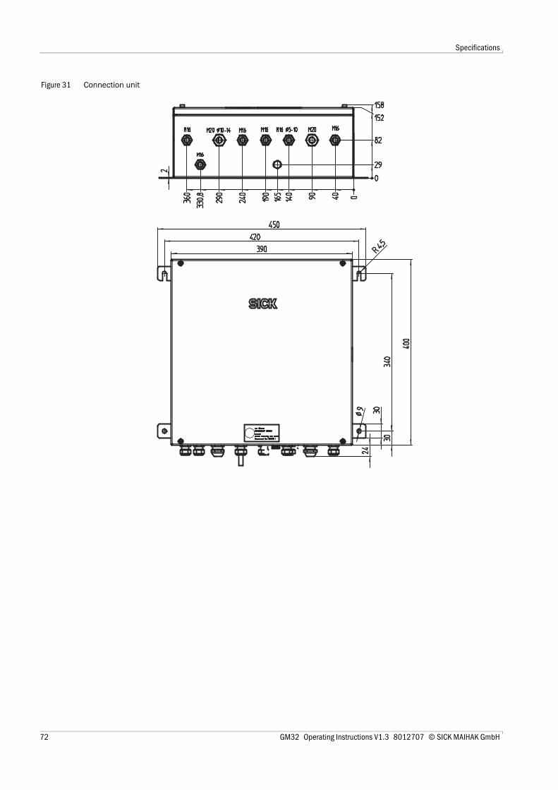
Specifications
Figure 31 Connection unit
72 GM32 Operating Instructions V1.3 8012707 © SICK MAIHAK GmbH

Index
Stichwörter
AAdditional documentation (information) . . . . . . . . . . 9Alignment- Automatic . . . . . . . . . . . . . . . . . . . . . . . . . . . . . . . . 41- Manual . . . . . . . . . . . . . . . . . . . . . . . . . . . . . . . . . . 42
BButtons, assignment . . . . . . . . . . . . . . . . . . . . . . . . 39
CCheck cycle . . . . . . . . . . . . . . . . . . . . . . 2, 12 - 13, 43Check point . . . . . . . . . . . . . . . . . . . . . . . . . . 2, 12 - 13Cleaning the window . . . . . . . . . . . . . . . . . . . . . . . . 52Compliance . . . . . . . . . . . . . . . . . . . . . . . . . . . . . . . . 66Connection diagram . . . . . . . . . . . . . . . . . . . . . 22 - 23Contrast . . . . . . . . . . . . . . . . . . . . . . . . . . . . . . . . . . . 39CUSUM . . . . . . . . . . . . . . . . . . . . . . . . . . . . . . . . . . 2, 12
DDesignated users . . . . . . . . . . . . . . . . . . . . . . . . . . . . 8Diagnosis (menu) . . . . . . . . . . . . . . . . . . . . . . . . . . . 40Disassembly . . . . . . . . . . . . . . . . . . . . . . . . . . . . . . . 46Disposal . . . . . . . . . . . . . . . . . . . . . . . . . . . . . . . . . . . 47Drying agent cartridges . . . . . . . . . . . . . . . . . . . . . . 54
EEarth . . . . . . . . . . . . . . . . . . . . . . . . . . . . . . . . . . . . . 32Earthing cable . . . . . . . . . . . . . . . . . . . . . . . . . . . . . . 32Error . . . . . . . . . . . . . . . . . . . . . . . . . . . . . . . . . . . . . . 59Error messages . . . . . . . . . . . . . . . . . . . . . . . . . . . . . 59Expendable parts . . . . . . . . . . . . . . . . . . . . . . . . . . . 50
FFailure (Status) . . . . . . . . . . . . . . . . . . . . . . . . . . . . . 41Flange attachment . . . . . . . . . . . . . . . . . . . . . . . . . . 15Fuses (probe) . . . . . . . . . . . . . . . . . . . . . . . . . . . . . . 31
GGlossary . . . . . . . . . . . . . . . . . . . . . . . . . . . . . . . . . . . . 2GMP probe . . . . . . . . . . . . . . . . . . . . . . . . . . . . . . . . 15GMP-Lanze . . . . . . . . . . . . . . . . . . . . . . . . . . . . . . . . 15GPP probe . . . . . . . . . . . . . . . . . . . . . . . . . . . . . . . . . 15- Electric connection . . . . . . . . . . . . . . . . . . . . . . . . 31
IImportant Information . . . . . . . . . . . . . . . . . . . . . . . . 8Information concerning the Manual . . . . . . . . . . . . . 8Information Symbols . . . . . . . . . . . . . . . . . . . . . . . . . 3
Intended use . . . . . . . . . . . . . . . . . . . . . . . . . . . . . . . . 8- Designated users . . . . . . . . . . . . . . . . . . . . . . . . . . 8- Users (target group) . . . . . . . . . . . . . . . . . . . . . . . . 8
IR module, replacing . . . . . . . . . . . . . . . . . . . . . . . . 53
LLamp, replacing . . . . . . . . . . . . . . . . . . . . . . . . . . . . 53Language . . . . . . . . . . . . . . . . . . . . . . . . . . . . . . . . . . 40LEDs . . . . . . . . . . . . . . . . . . . . . . . . . . . . . . . . . . . . . . 39Locking device lever . . . . . . . . . . . . . . . . . . . . . . . . . 35Logbook . . . . . . . . . . . . . . . . . . . . . . . . . . . . . . . . 12, 40
MMaintenance . . . . . . . . . . . . . . . . . . . . . . . . . . . . . . . 49Maintenance mode active (message) . . . . . . . . . . . 44Maintenance plan . . . . . . . . . . . . . . . . . . . . . . . . . . . 50Maintenance request (Status) . . . . . . . . . . . . . . . . . 41Malfunctions, clearing . . . . . . . . . . . . . . . . . . . . . . . 57Measuring method . . . . . . . . . . . . . . . . . . . . . . . . . . 15Measuring probe . . . . . . . . . . . . . . . . . . . . . . . . . . . . 15Measuring probe, aligning . . . . . . . . . . . . . . . . . . . . 30Menu tree . . . . . . . . . . . . . . . . . . . . . . . . . . . . . . . . . 40Mirror tracking . . . . . . . . . . . . . . . . . . . . . . . . . . . . . 12
NNational language . . . . . . . . . . . . . . . . . . . . . . . . . . 40
OOPC . . . . . . . . . . . . . . . . . . . . . . . . . . . . . . . . . . . . 2, 12Operation . . . . . . . . . . . . . . . . . . . . . . . . . . . . . . . . . . 37Operator panel . . . . . . . . . . . . . . . . . . . . . . . . . . . . . 39Optical alignment- Automatic . . . . . . . . . . . . . . . . . . . . . . . . . . . . . . . . 41- Manual . . . . . . . . . . . . . . . . . . . . . . . . . . . . . . . . . . 42- SR-unit . . . . . . . . . . . . . . . . . . . . . . . . . . . . . . . . . . 35
PProbe . . . . . . . . . . . . . . . . . . . . . . . . . . . . . . . . . . . . . 15- GMP . . . . . . . . . . . . . . . . . . . . . . . . . . . . . . . . . . . . 15- GPP . . . . . . . . . . . . . . . . . . . . . . . . . . . . . . . . . . . . . 15
Probe heater - electric connection . . . . . . . . . . . . . 31Probe, aligning . . . . . . . . . . . . . . . . . . . . . . . . . . . . . 30Product Description . . . . . . . . . . . . . . . . . . . . . . . . . 11Product identification . . . . . . . . . . . . . . . . . . . . . . . . 12Purge air fixture . . . . . . . . . . . . . . . . . . . . . . . . . . . . 15Purge air unit . . . . . . . . . . . . . . . . . . . . . . . . . . . 15, 55Putting out of operation . . . . . . . . . . . . . . . . . . 45 - 46
QQAL3 . . . . . . . . . . . . . . . . . . . . . . . . . . . . . . . 2, 12, 14
GM32 Operating Instructions V 1.3 8012707 © SICK MAIHAK GmbH 73

Index
RReference cycle . . . . . . . . . . . . . . . . . . . 2, 12 - 13, 43Removing the transport safety device . . . . . . . . . . . 27Responsibility of user . . . . . . . . . . . . . . . . . . . . . . . . . 8
SScope of delivery . . . . . . . . . . . . . . . . . . . . . . . . . . . . 18SCU . . . . . . . . . . . . . . . . . . . . . . . . . . . . . . . . . . . . 2, 12Sender lamp, replacing . . . . . . . . . . . . . . . . . . . . . . . 53Signal words . . . . . . . . . . . . . . . . . . . . . . . . . . . . . . . . . 3SOPAS-ET . . . . . . . . . . . . . . . . . . . . . . . . . . . . . . . 2, 13Specifications . . . . . . . . . . . . . . . . . . . . . . . . . . . . . . 65Start-up . . . . . . . . . . . . . . . . . . . . . . . . . . . . . . . . . . . . 25Status indicators . . . . . . . . . . . . . . . . . . . . . . . . 39, 41Status messages . . . . . . . . . . . . . . . . . . . . . . . . . . . . 41Switching on . . . . . . . . . . . . . . . . . . . . . . . . . . . . . . . . 32Symbols (Explanation) . . . . . . . . . . . . . . . . . . . . . . . . . 3
TTarget groups (users) . . . . . . . . . . . . . . . . . . . . . . . . . 8Type plate . . . . . . . . . . . . . . . . . . . . . . . . . . . . . . . . . . 12
UUncertain (Status) . . . . . . . . . . . . . . . . . . . . . . . . . . . 41User- Designated users . . . . . . . . . . . . . . . . . . . . . . . . . . . 8- Responsibility of user . . . . . . . . . . . . . . . . . . . . . . . . 8
VVisual inspection . . . . . . . . . . . . . . . . . . . . . . . . . . . . 52
WWarning symbols, warning levels . . . . . . . . . . . . . . . . 3Wearing parts . . . . . . . . . . . . . . . . . . . . . . . . . . . . . . . 50
ZZero point . . . . . . . . . . . . . . . . . . . . . . . . . . . . . . . . . . 13
74 GM32 Operating Instructions V 1.3 8012707 © SICK MAIHAK GmbH

Index
GM32 Operating Instructions V 1.3 8012707 © SICK MAIHAK GmbH 75

SICK MAIHAK GmbH | GermanyNimburger Str. 11 | 79276 Reute | www.sick.comPhone +49 7641 469-0 | Fax +49 7641 469-11 49 | [email protected]
8012
707/
2009
-03
(V1.
3) SICK worldwide
You will find our local subsidiary or agency at:www.sick.com
Your local sales and service partner
GM32