Embed Size (px)
Citation preview
GMEC 2015
Relaxation of Driven Pile Resistance in Granular Soils
Rodrigo Herrera, P.E.
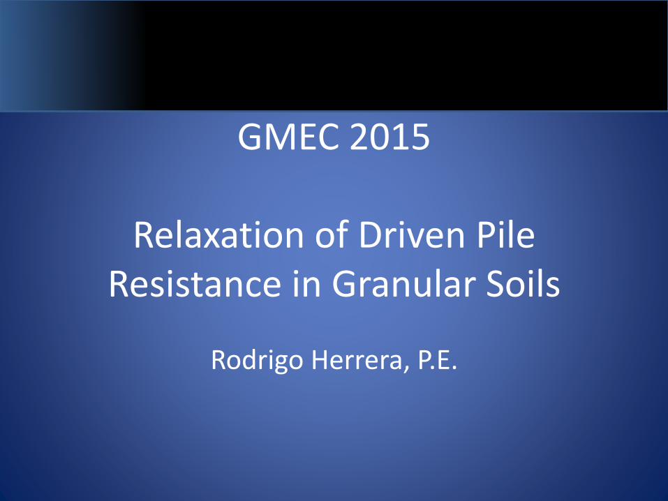
Relaxation of Driven Pile Resistance in Granular Soils
• Pile relaxation in granular soil– Pile driving may generate negative pore pressures in
dilatant material (e.g. dense sand)
– Negative pore pressure will produce a temporary increase in soil strength
– Pile resistance decreases with time, as pore pressures return to hydrostatic conditions
– In Florida, relaxation has been encountered typically in medium dense to very dense silty and shelly sands
OUTLINE
• Driven Pile Capacity (granular soils)
• Effective Stress
• Dilation & Relaxation
• Case Histories
• Design
• Construction
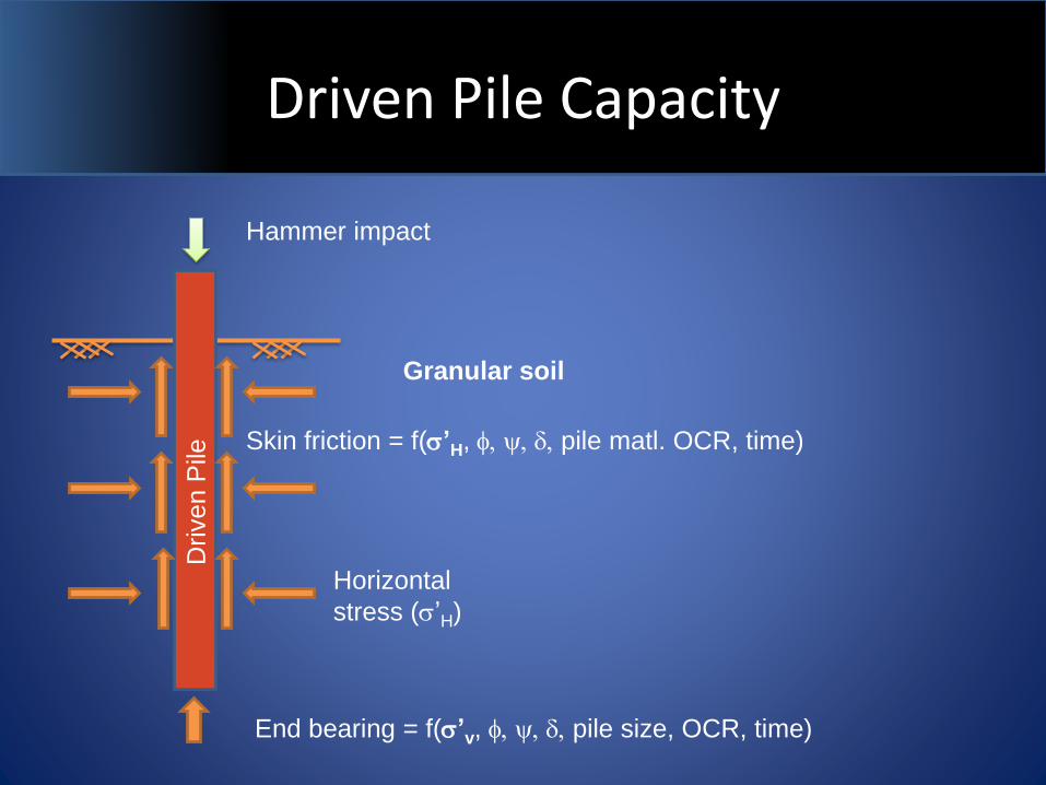
Driven Pile Capacity
Driven P
ile
Hammer impact
Horizontal
stress (s’H)
Skin friction = f(s’H, f, y, d, pile matl. OCR, time)
End bearing = f(s’v, f, y, d, pile size, OCR, time)
Granular soil
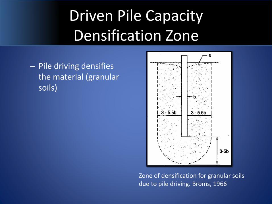
Driven Pile Capacity Densification Zone
– Pile driving densifies the material (granular soils)
Zone of densification for granular soils due to pile driving. Broms, 1966
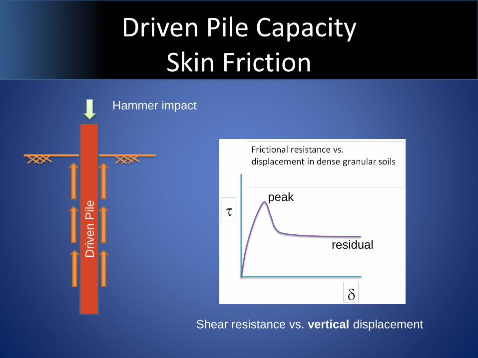
Driven Pile Capacity Skin Friction
Driven P
ile
Hammer impact
peak
residual
Shear resistance vs. vertical displacement
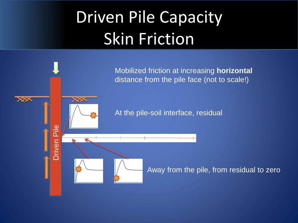
Driven Pile Capacity Skin Friction
Driven P
ile
Mobilized friction at increasing horizontal
distance from the pile face (not to scale!)
At the pile-soil interface, residual
Away from the pile, from residual to zero
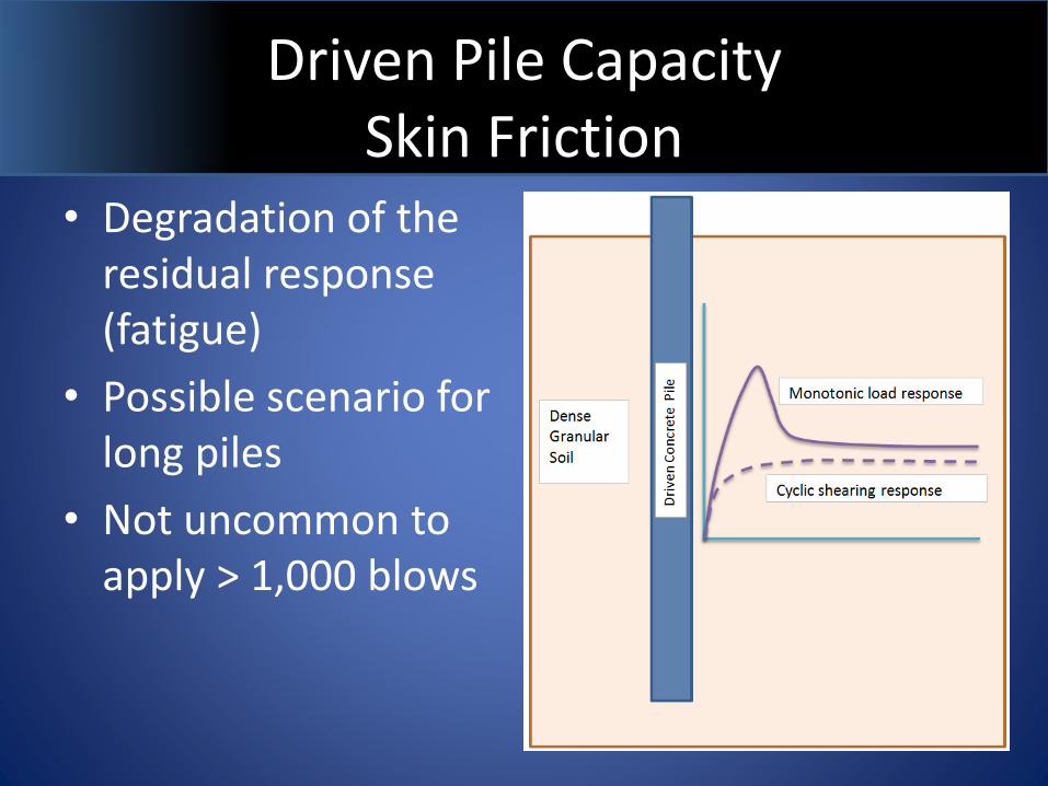
Driven Pile Capacity Skin Friction
• Degradation of the residual response (fatigue)
• Possible scenario for long piles
• Not uncommon to apply > 1,000 blows
Driven Pile Capacity End Bearing
III
IIIII
III
Pile
tip
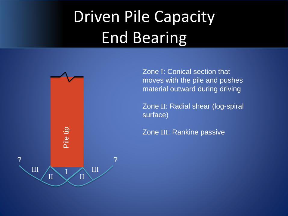
Zone I: Conical section that
moves with the pile and pushes
material outward during driving
Zone II: Radial shear (log-spiral
surface)
Zone III: Rankine passive
??
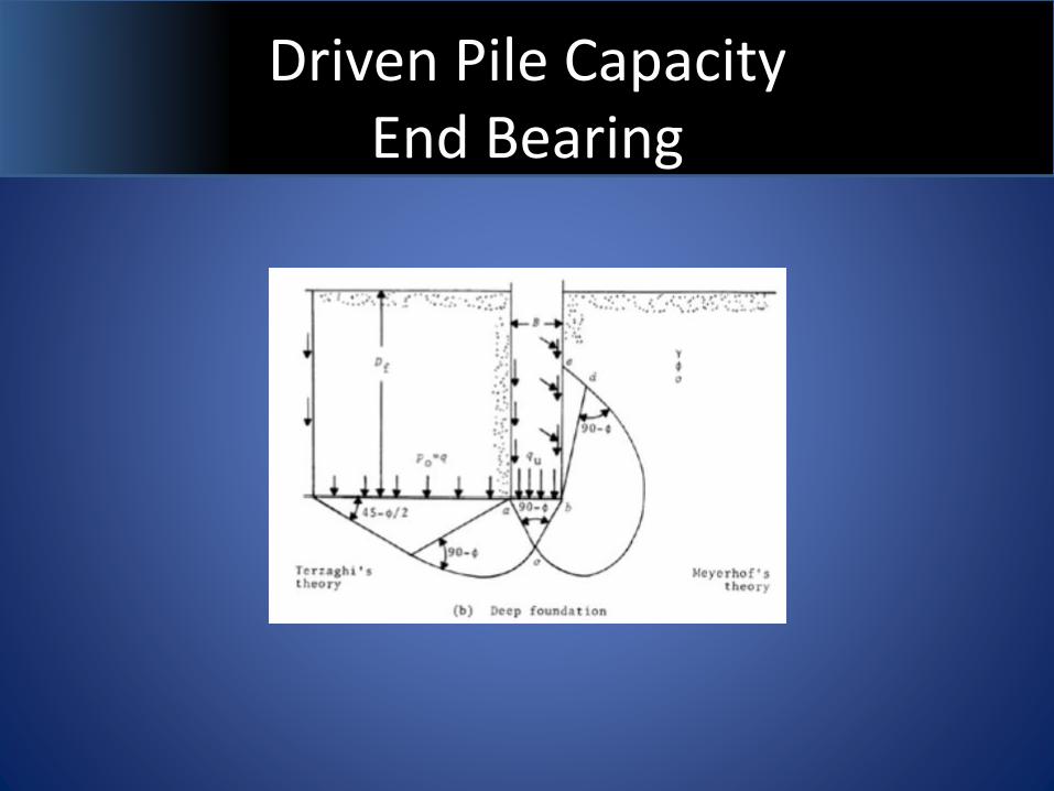
Driven Pile Capacity End Bearing
Driven Pile Capacity End Bearing
III
IIIII
III
Pile
tip
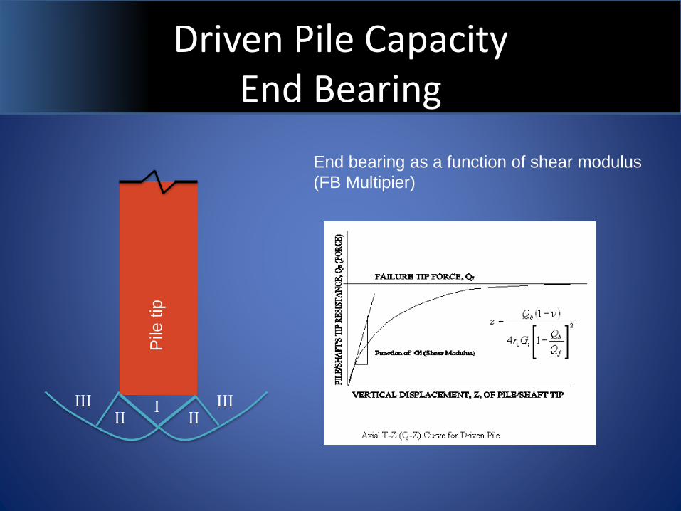
End bearing as a function of shear modulus
(FB Multipier)
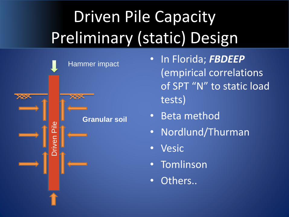
Driven Pile CapacityPreliminary (static) Design
• In Florida; FBDEEP(empirical correlations of SPT “N” to static load tests)
• Beta method
• Nordlund/Thurman
• Vesic
• Tomlinson
• Others..
Driven P
ile
Hammer impact
Granular soil
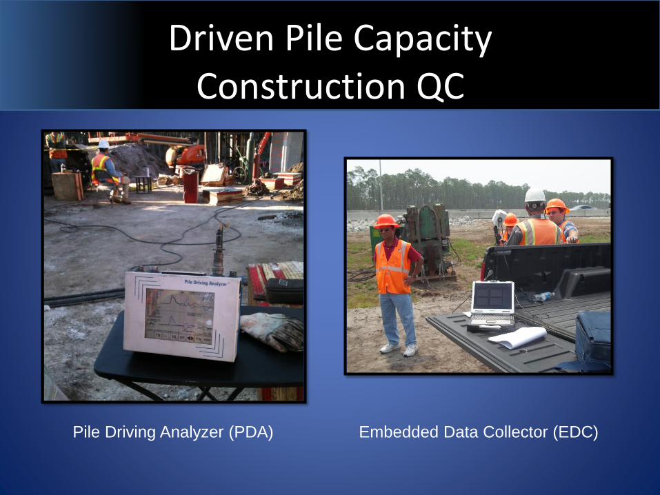
Driven Pile CapacityConstruction QC
Pile Driving Analyzer (PDA) Embedded Data Collector (EDC)
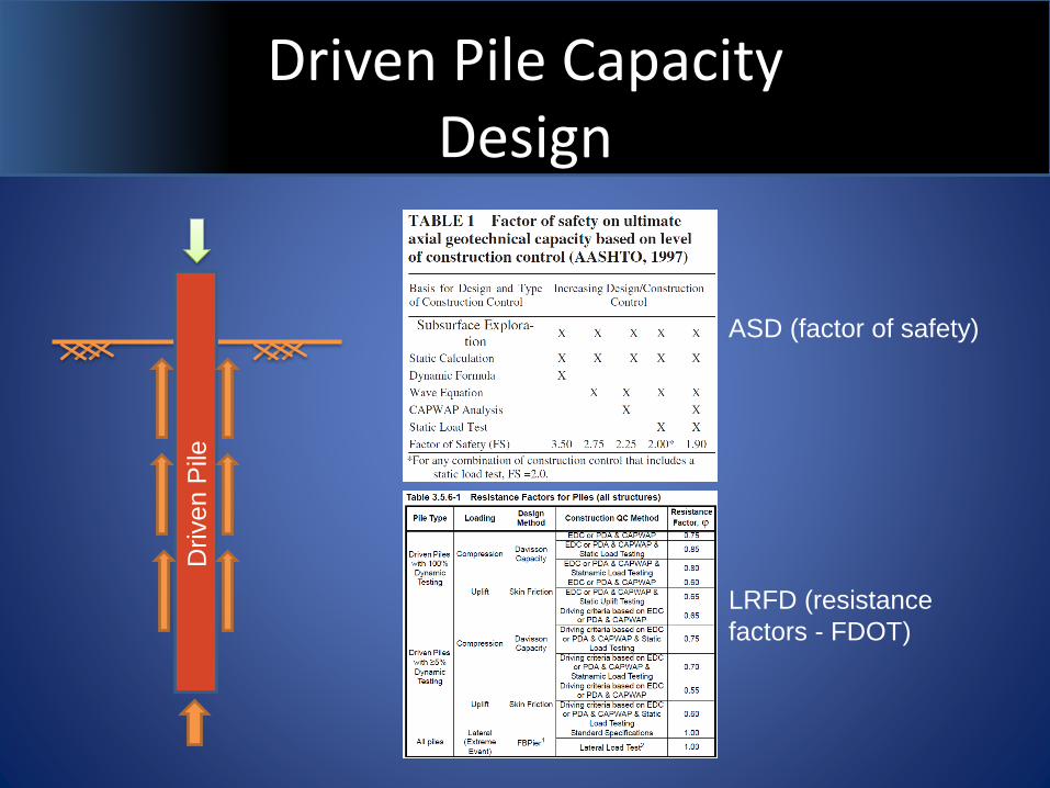
Driven Pile CapacityDesign
Driven P
ile
ASD (factor of safety)
LRFD (resistance
factors - FDOT)
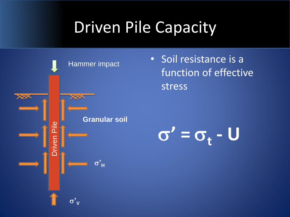
Driven Pile Capacity
• Soil resistance is a function of effective stress
Driven P
ile
Hammer impact
Granular soil
s’ = st - Us’H
s’V
Effective Stress
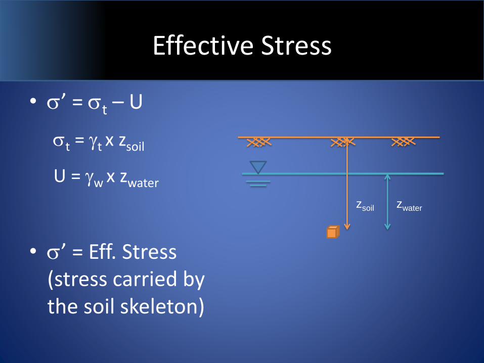
• s’ = st – U
st = gt x zsoil
U = gw x zwater
• s’ = Eff. Stress (stress carried by the soil skeleton)
zsoil zwater
Effective Stress
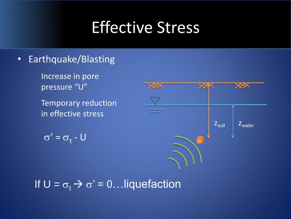
• Earthquake/Blasting
Increase in pore pressure “U”
Temporary reduction in effective stress
zsoil zwater
s’ = st - U
If U = st s’ = 0…liquefaction
Effective Stress
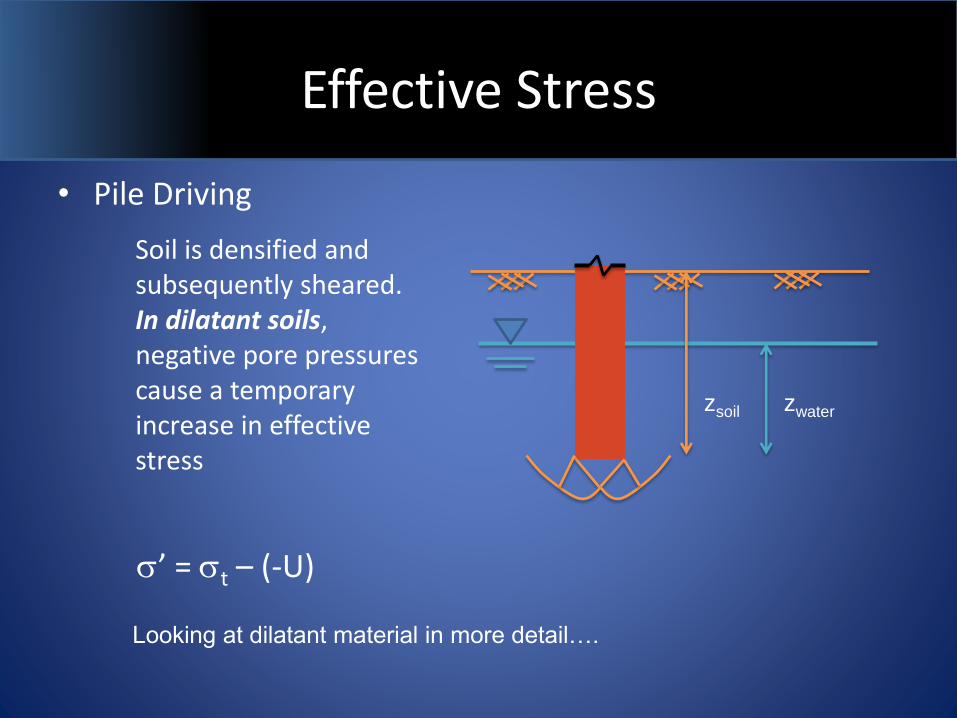
• Pile Driving
Soil is densified and subsequently sheared. In dilatant soils, negative pore pressures cause a temporary increase in effective stress
zsoil zwater
s’ = st – (-U)
Looking at dilatant material in more detail….
Dilation
– Dilation is the observed tendency of dense granular material to expand in volume as it is sheared.
– In densely packed arrangements interlocking prevents the grains from moving around each other and they are forced to either shear or “roll” over each other. It is the rolling action that can generate suction into the void spaces created during displacement.

Dilation
– “It is a remarkable fact that a dense sand, when compressed in one direction actually increases in volume.” (Lambe and Whitman 1969)
Dilation
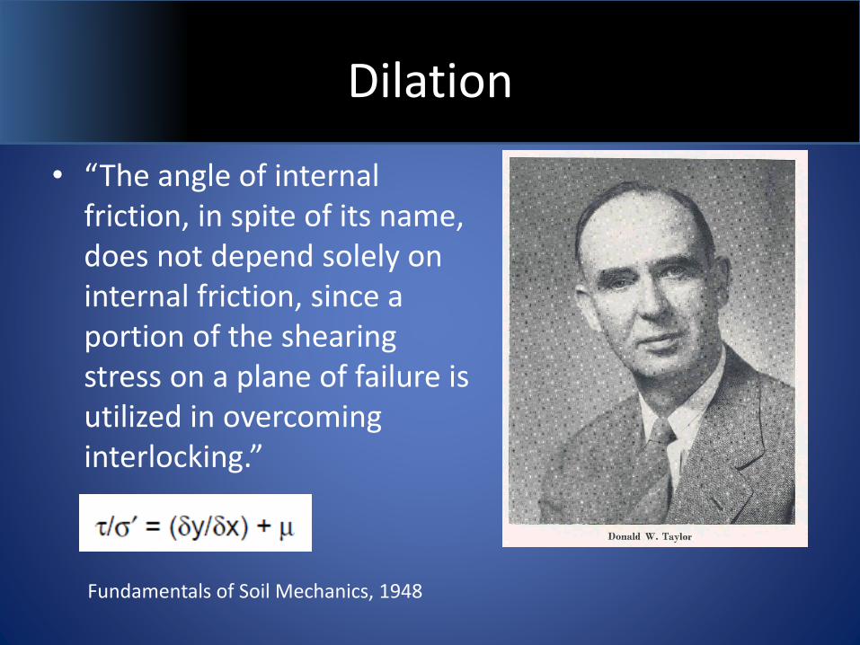
• “The angle of internal friction, in spite of its name, does not depend solely on internal friction, since a portion of the shearing stress on a plane of failure is utilized in overcoming interlocking.”
Fundamentals of Soil Mechanics, 1948
Dilation
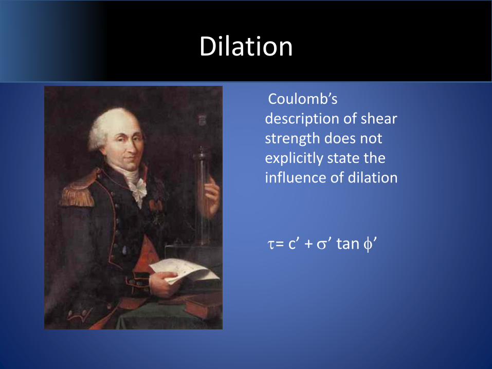
Coulomb’s description of shear strength does not explicitly state the influence of dilation
= c’ + s’ tan f’
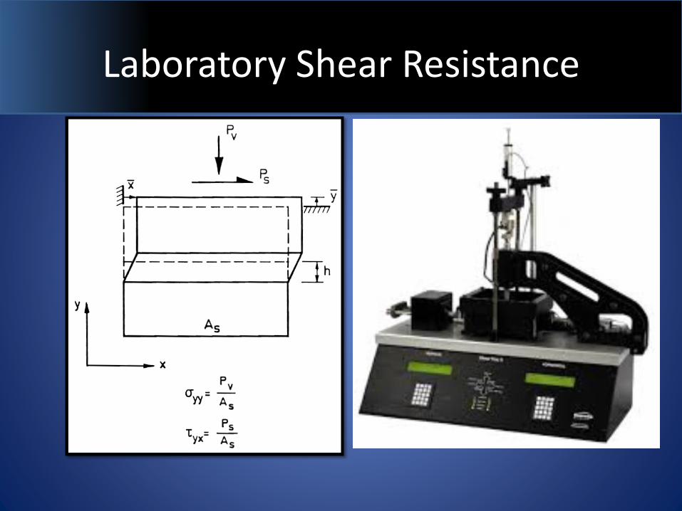
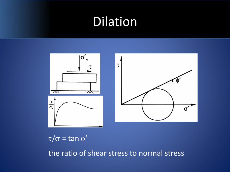
Laboratory Shear Resistance
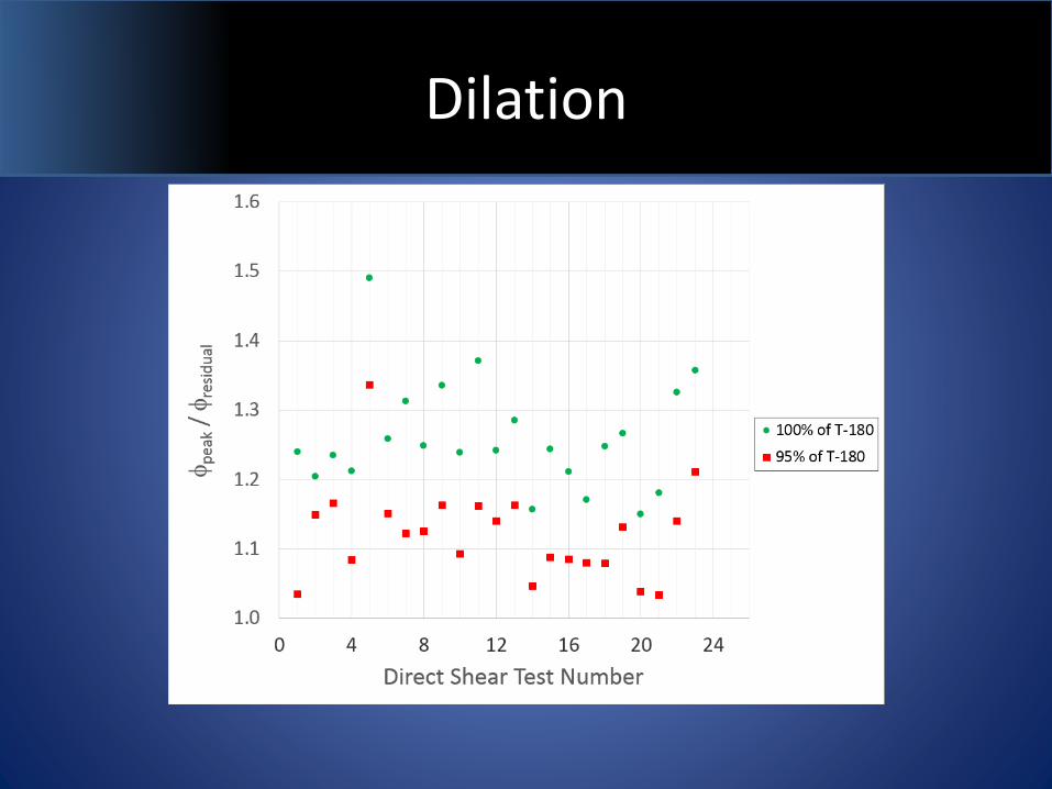
Dilation
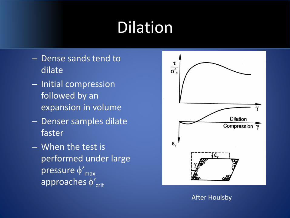
– Dense sands tend to dilate
– Initial compression followed by an expansion in volume
– Denser samples dilate faster
– When the test is performed under large pressure f’max
approaches f’crit
After Houlsby
peak
Residual
Dilation
/s = tan f’
the ratio of shear stress to normal stress
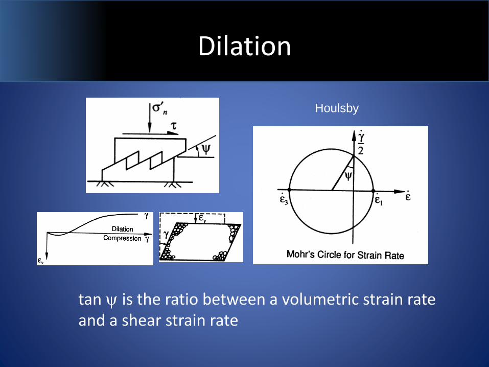
Dilation
tan y is the ratio between a volumetric strain rate and a shear strain rate
Houlsby
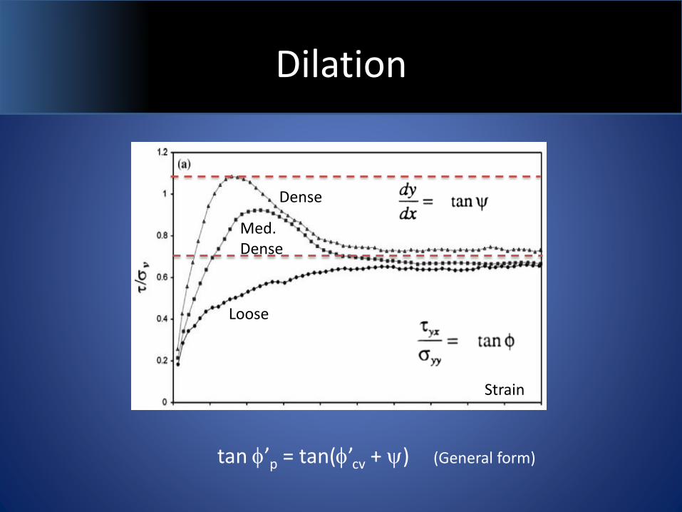
Dilation
tan f’p = tan(f’cv + y) (General form)
Strain
Loose
Med. Dense
Dense
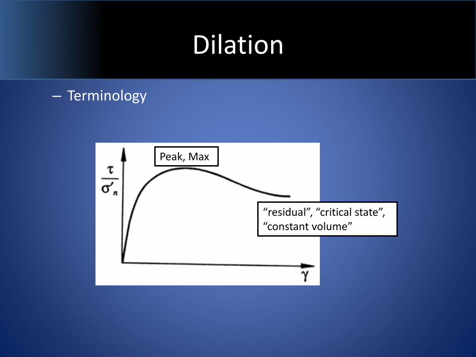
Dilation
– Terminology
Peak, Max
“residual”, “critical state”, “constant volume”
Dilation
Dilation
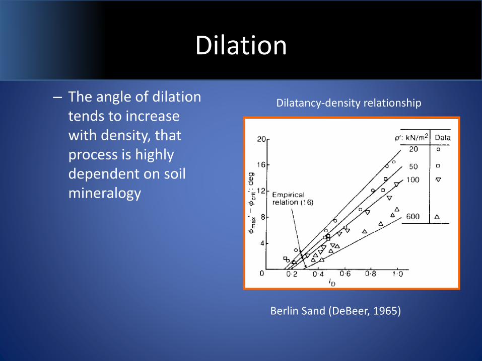
– The angle of dilation tends to increase with density, that process is highly dependent on soil mineralogy
Dilatancy-density relationship
Berlin Sand (DeBeer, 1965)
Dilation
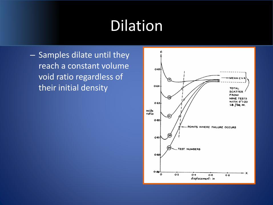
– Samples dilate until they reach a constant volume void ratio regardless of their initial density
Dilation
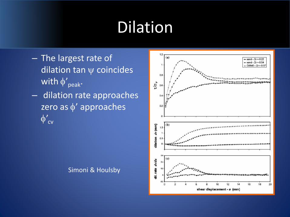
– The largest rate of dilation tan y coincides with f’peak.
– dilation rate approaches zero as f’ approaches f’cv
Simoni & Houlsby
Dilation
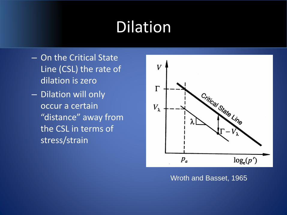
– On the Critical State Line (CSL) the rate of dilation is zero
– Dilation will only occur a certain “distance” away from the CSL in terms of stress/strain
Wroth and Basset, 1965
Dilation
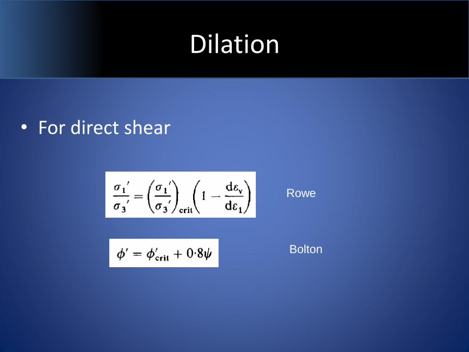
• For direct shear
Rowe
Bolton
Dilation
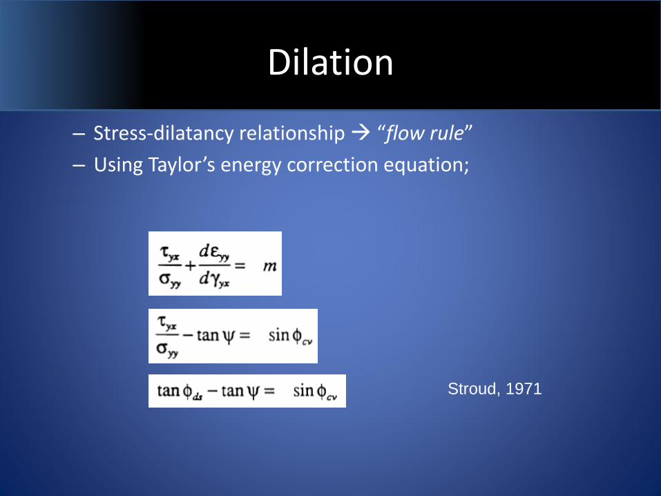
– Stress-dilatancy relationship “flow rule”
– Using Taylor’s energy correction equation;
Stroud, 1971
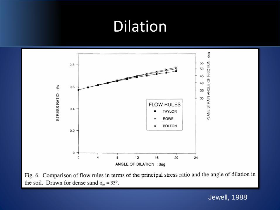
Dilation
Jewell, 1988
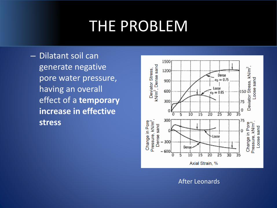
THE PROBLEM
– Dilatant soil can generate negative pore water pressure, having an overall effect of a temporary increase in effective stress
After Leonards
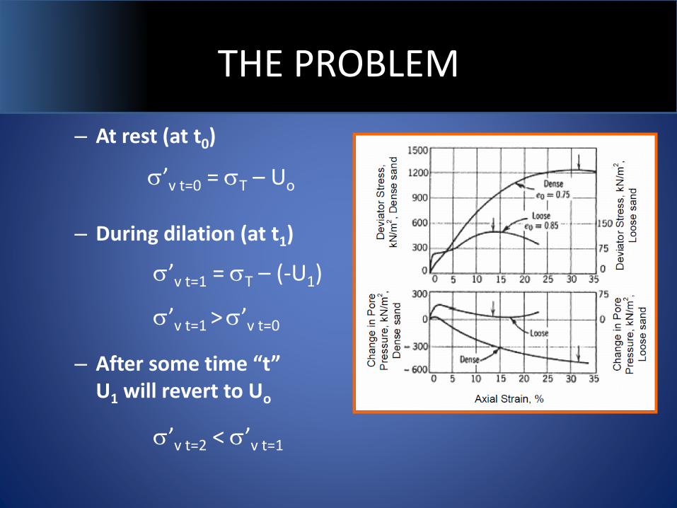
THE PROBLEM
– At rest (at t0)
– During dilation (at t1)
– After some time “t” U1 will revert to Uo
s’v t=0 = sT – Uo
s’v t=1 = sT – (-U1)
s’v t=1 > s’v t=0
s’v t=2 < s’v t=1
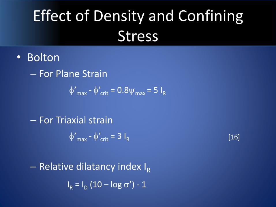
Effect of Density and Confining Stress
• Bolton
– For Plane Strain
– For Triaxial strain
– Relative dilatancy index IR
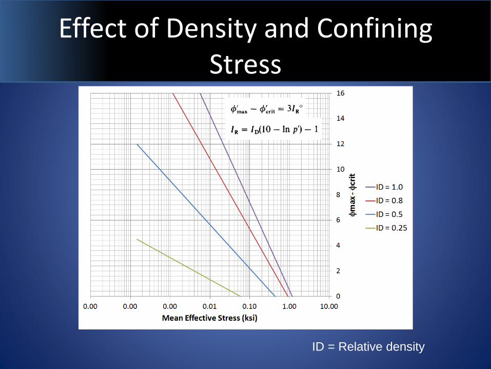
f’max - f’crit = 3 IR
IR = ID (10 – log s’) - 1
f’max - f’crit = 0.8ymax = 5 IR
[16]
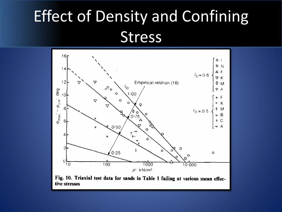
Effect of Density and Confining Stress
Effect of Density and Confining Stress
ID = Relative density
Effect of Density and Confining Stress
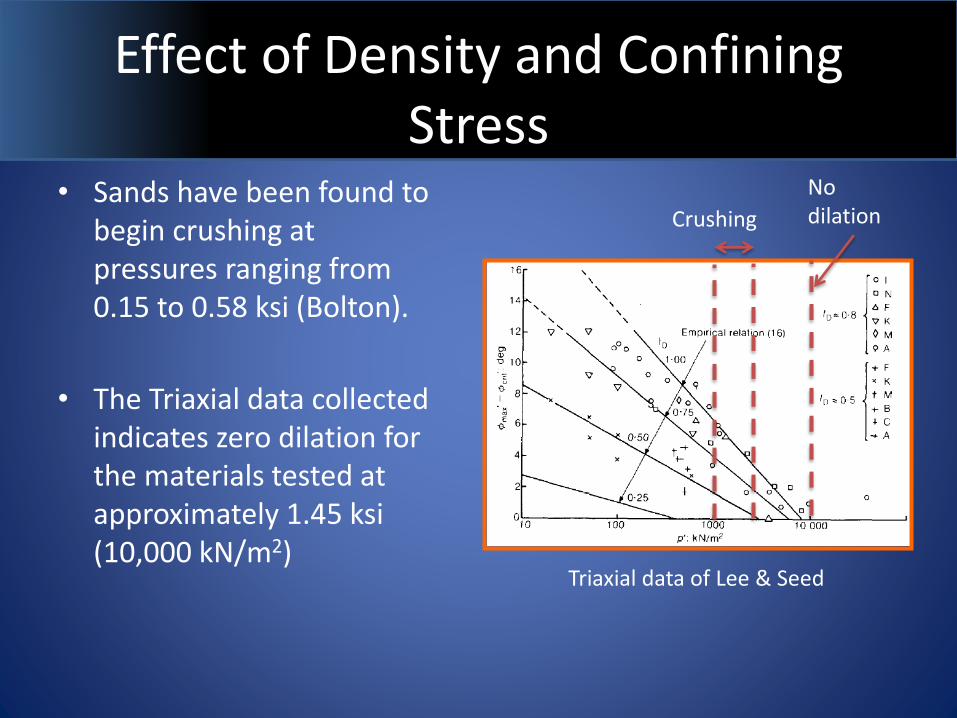
Triaxial data of Lee & Seed
Crushing
No dilation
• Sands have been found to begin crushing at pressures ranging from 0.15 to 0.58 ksi (Bolton).
• The Triaxial data collected indicates zero dilation for the materials tested at approximately 1.45 ksi (10,000 kN/m2)
Effect of Density and Confining Stress
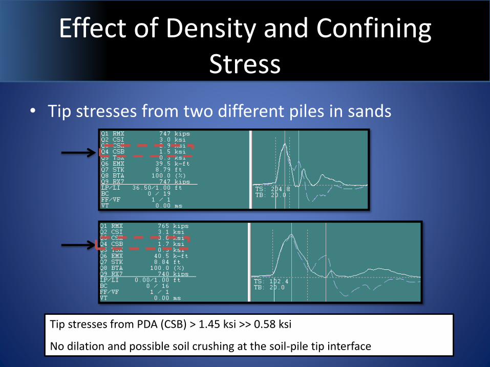
• Tip stresses from two different piles in sands
Tip stresses from PDA (CSB) > 1.45 ksi >> 0.58 ksi
No dilation and possible soil crushing at the soil-pile tip interface
Dilation at Pile Tip Shear Surfaces
Pile
tip
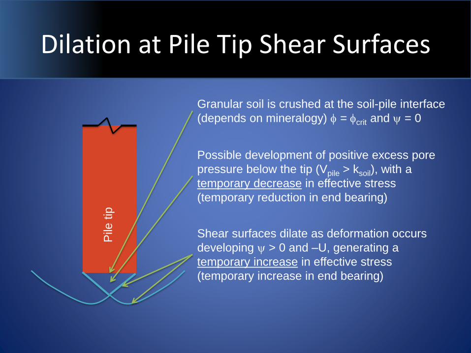
Granular soil is crushed at the soil-pile interface
(depends on mineralogy) f = fcrit and y = 0
Possible development of positive excess pore
pressure below the tip (Vpile > ksoil), with a
temporary decrease in effective stress
(temporary reduction in end bearing)
Shear surfaces dilate as deformation occurs
developing y > 0 and –U, generating a
temporary increase in effective stress
(temporary increase in end bearing)
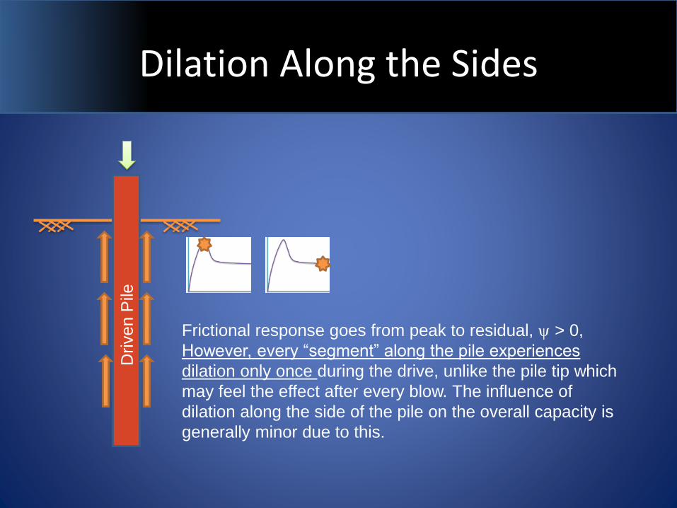
Dilation Along the Sides
Driven P
ile
Frictional response goes from peak to residual, y > 0,
However, every “segment” along the pile experiences
dilation only once during the drive, unlike the pile tip which
may feel the effect after every blow. The influence of
dilation along the side of the pile on the overall capacity is
generally minor due to this.
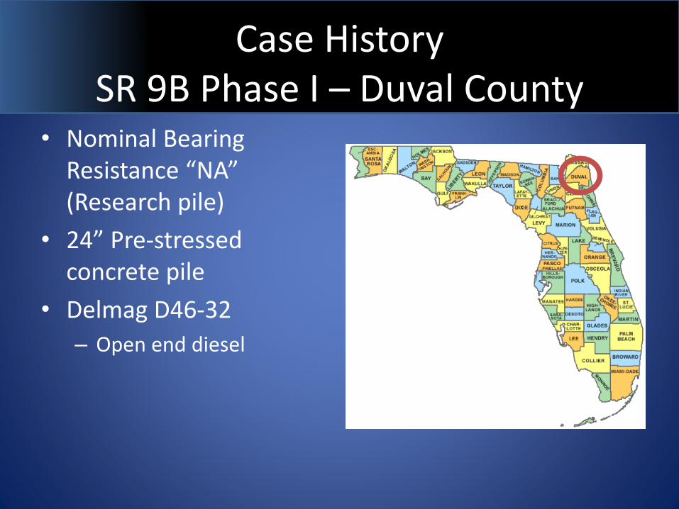
Case History SR 9B Phase I – Duval County
• Nominal Bearing Resistance “NA” (Research pile)
• 24” Pre-stressed concrete pile
• Delmag D46-32
– Open end diesel
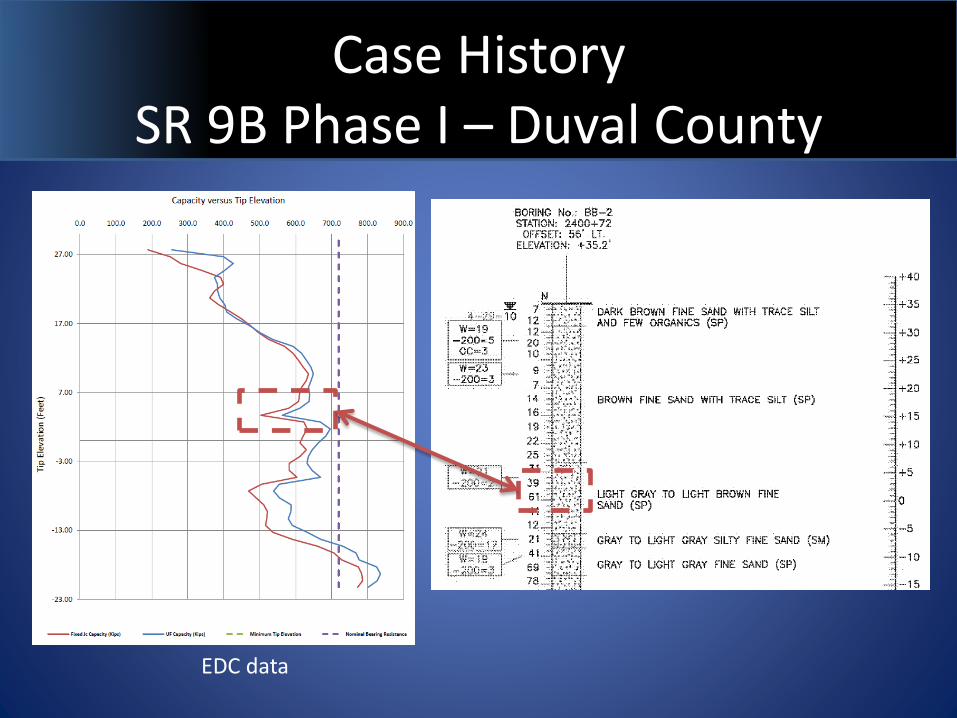
Case History SR 9B Phase I – Duval County
EDC data
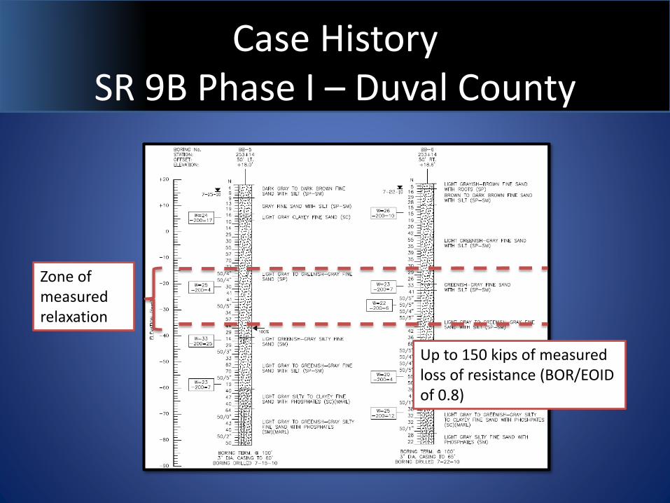
Case History SR 9B Phase I – Duval County
Zone of measured relaxation
Up to 150 kips of measured loss of resistance (BOR/EOID of 0.8)
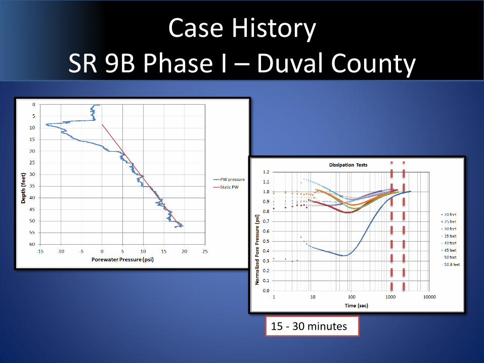
Case History SR 9B Phase I – Duval County
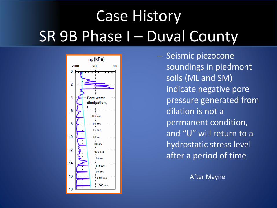
– Seismic piezocone soundings in piedmont soils (ML and SM) indicate negative pore pressure generated from dilation is not a permanent condition, and “U” will return to a hydrostatic stress level after a period of time
After Mayne
Case History SR 9B Phase I – Duval County
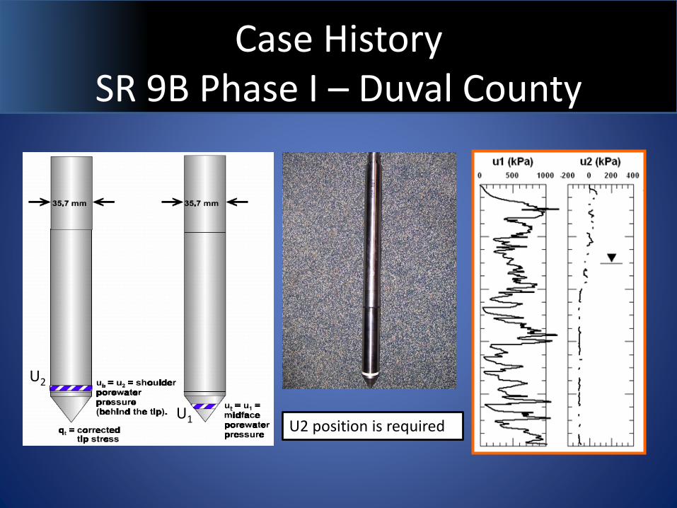
U2
U1U2 position is required
Case History SR 9B Phase I – Duval County
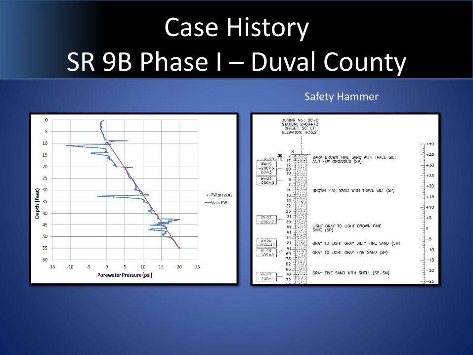
Safety Hammer
Case History SR 9B Phase I – Duval County
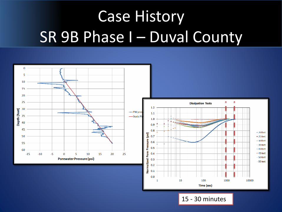
15 - 30 minutes
Case History SR 9B Phase I – Duval County
15 - 30 minutes
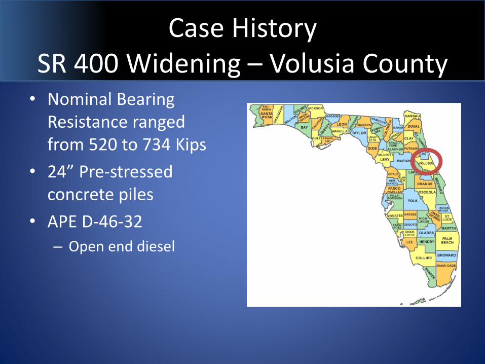
Case History SR 400 Widening – Volusia County
• Nominal Bearing Resistance ranged from 520 to 734 Kips
• 24” Pre-stressed concrete piles
• APE D-46-32
– Open end diesel
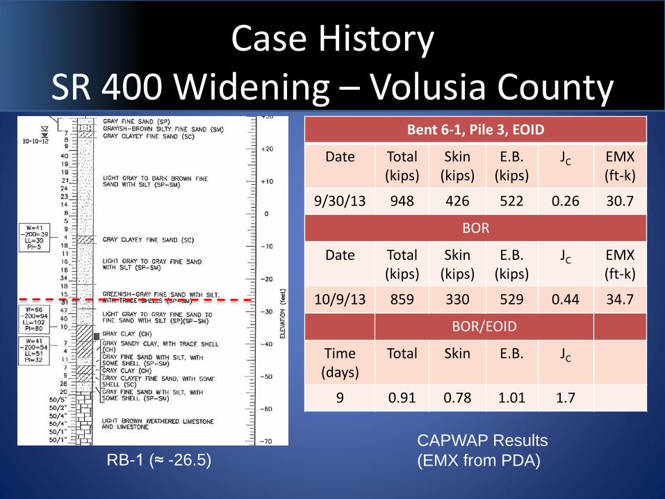
Case History SR 400 Widening – Volusia County
Bent 6-1, Pile 3, EOID
Date Total (kips)
Skin(kips)
E.B.(kips)
JC EMX (ft-k)
9/30/13 948 426 522 0.26 30.7
BOR
Date Total (kips)
Skin(kips)
E.B.(kips)
JC EMX (ft-k)
10/9/13 859 330 529 0.44 34.7
BOR/EOID
Time (days)
Total Skin E.B. JC
9 0.91 0.78 1.01 1.7
RB-1 (≈ -26.5)CAPWAP Results
(EMX from PDA)
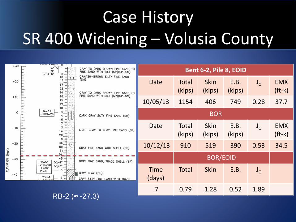
Case History SR 400 Widening – Volusia County
RB-2 (≈ -27.3)
Bent 6-2, Pile 8, EOID
Date Total (kips)
Skin(kips)
E.B.(kips)
JC EMX (ft-k)
10/05/13 1154 406 749 0.28 37.7
BOR
Date Total (kips)
Skin(kips)
E.B.(kips)
JC EMX (ft-k)
10/12/13 910 519 390 0.53 34.5
BOR/EOID
Time (days)
Total Skin E.B. JC
7 0.79 1.28 0.52 1.89
Case History SR 400 Widening – Volusia County
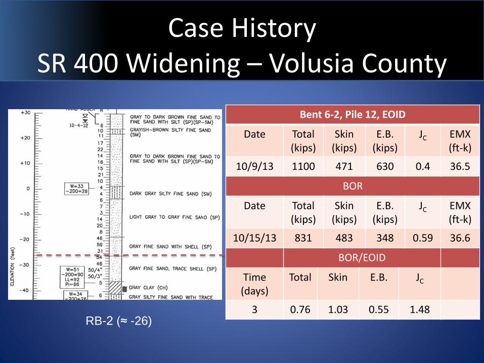
RB-2 (≈ -26)
Bent 6-2, Pile 12, EOID
Date Total (kips)
Skin(kips)
E.B.(kips)
JC EMX (ft-k)
10/9/13 1100 471 630 0.4 36.5
BOR
Date Total (kips)
Skin(kips)
E.B.(kips)
JC EMX (ft-k)
10/15/13 831 483 348 0.59 36.6
BOR/EOID
Time (days)
Total Skin E.B. JC
3 0.76 1.03 0.55 1.48
Case History SR 400 Widening – Volusia County
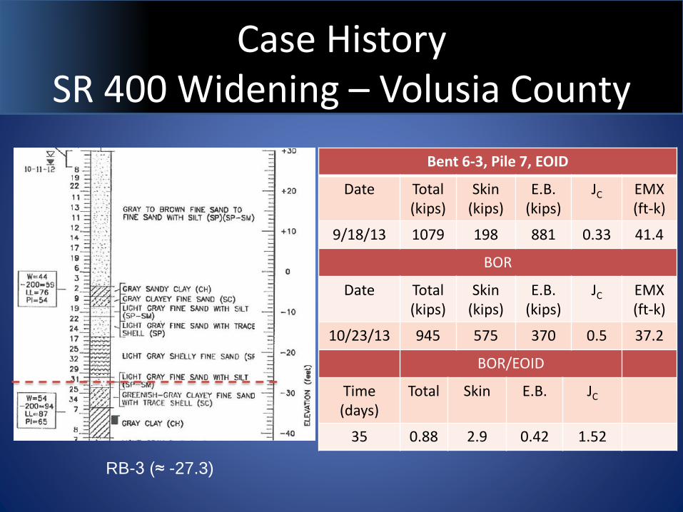
RB-3 (≈ -27.3)
Bent 6-3, Pile 7, EOID
Date Total (kips)
Skin(kips)
E.B.(kips)
JC EMX (ft-k)
9/18/13 1079 198 881 0.33 41.4
BOR
Date Total (kips)
Skin(kips)
E.B.(kips)
JC EMX (ft-k)
10/23/13 945 575 370 0.5 37.2
BOR/EOID
Time (days)
Total Skin E.B. JC
35 0.88 2.9 0.42 1.52
Relaxation - Design
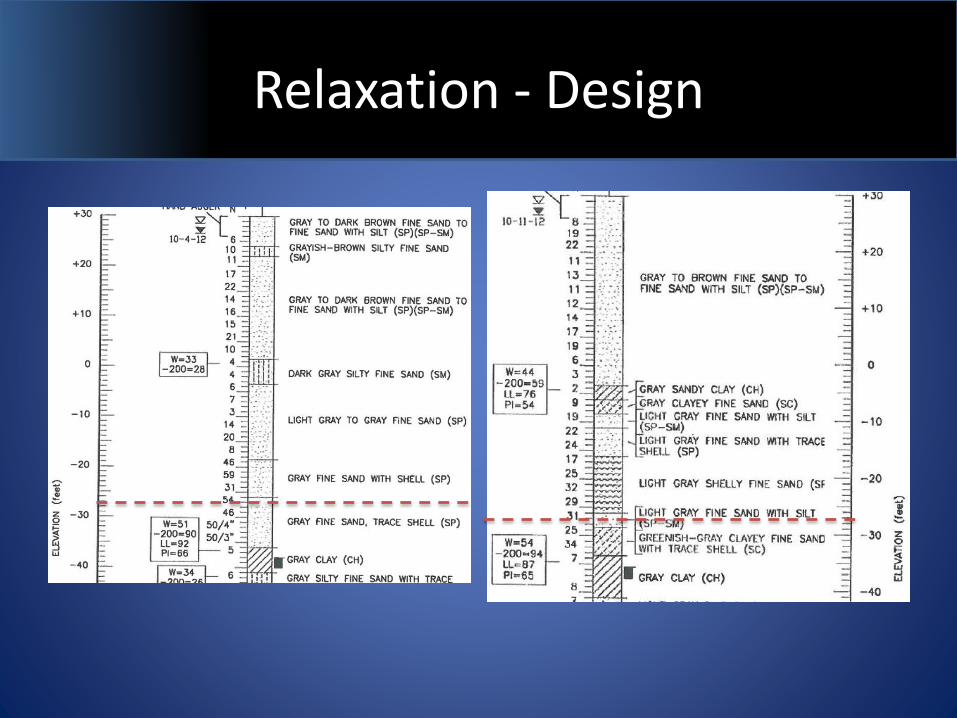
• Detection
– In order to address the issue in design it must be recognized during the field exploration
– SPT borings are the most common In-Situ testing method used in Florida for preliminary investigations
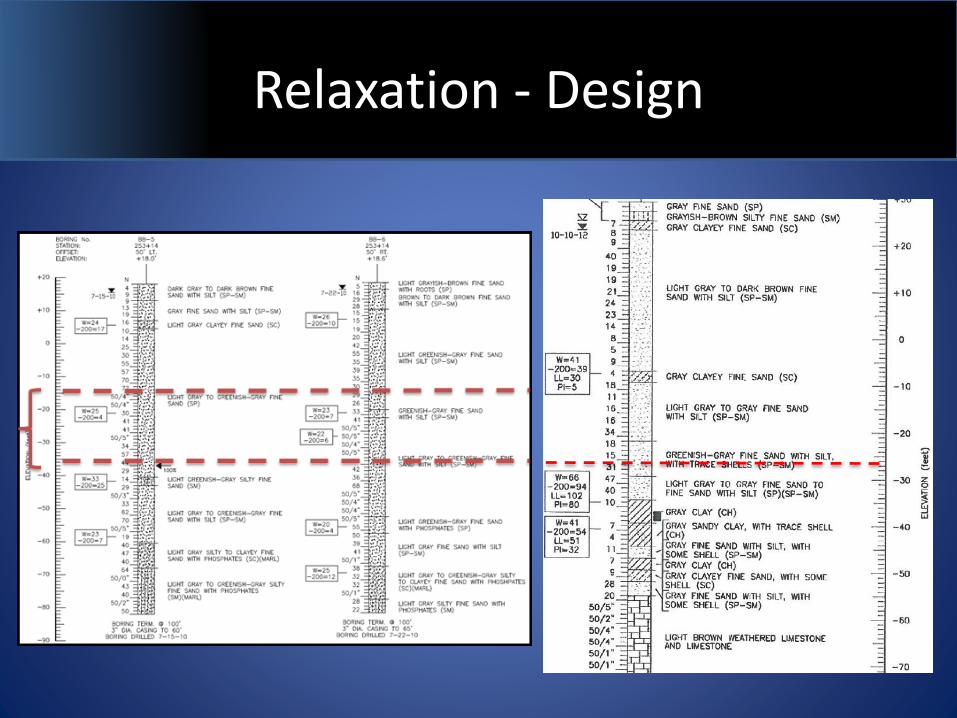
Relaxation - Design
Relaxation - Design
Relaxation - Design
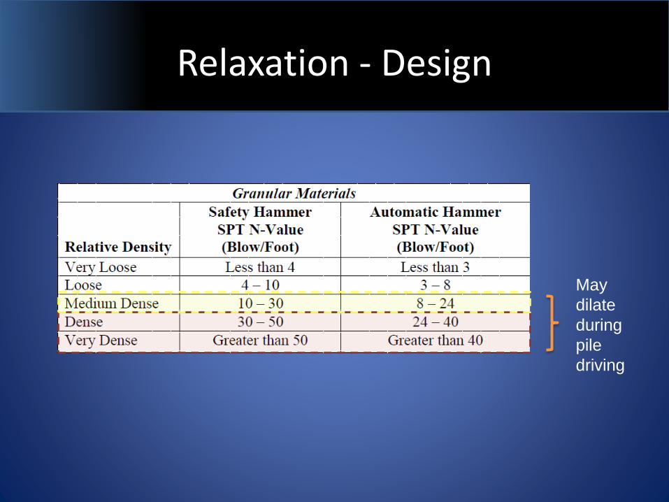
May
dilate
during
pile
driving
Relaxation - Design
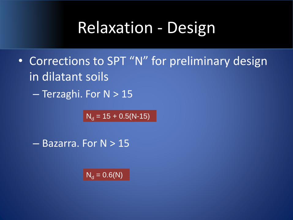
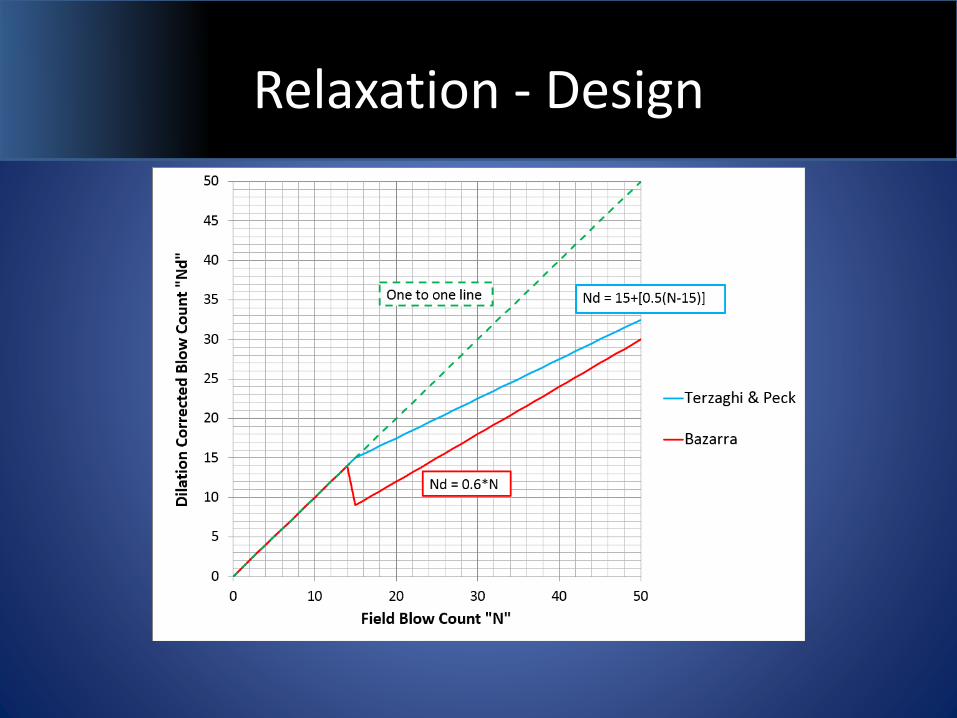
• Corrections to SPT “N” for preliminary design in dilatant soils
– Terzaghi. For N > 15
– Bazarra. For N > 15
Nd = 15 + 0.5(N-15)
Nd = 0.6(N)
Relaxation - Design
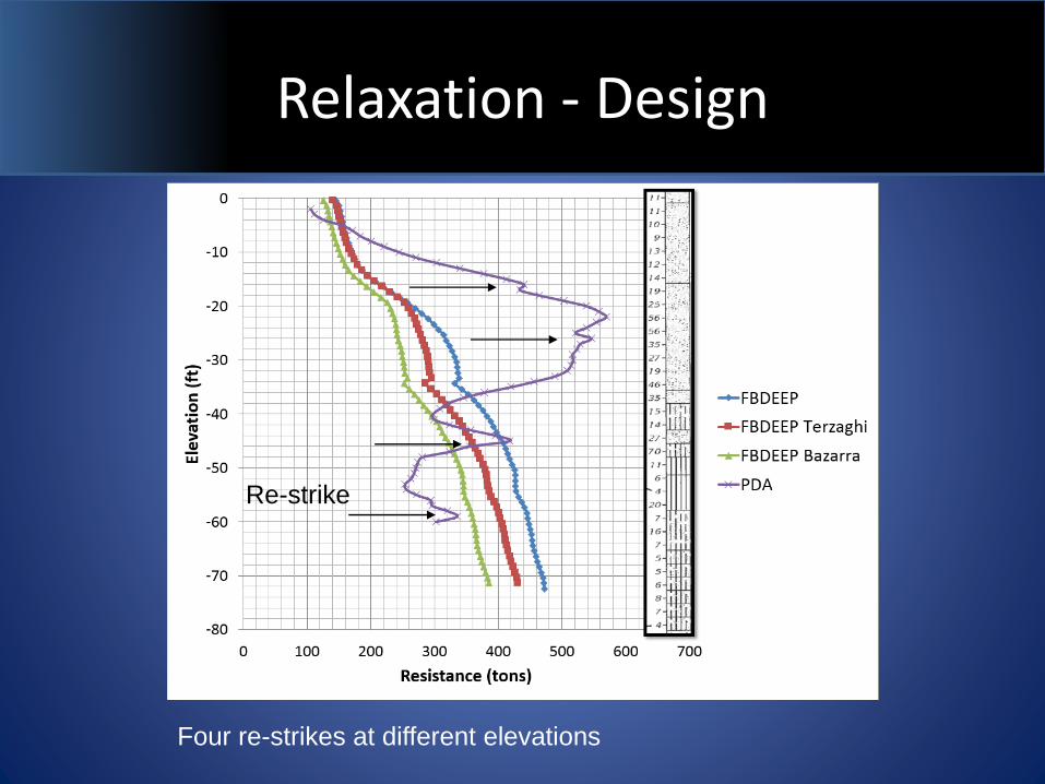
Relaxation - Design
Re-strike
Four re-strikes at different elevations
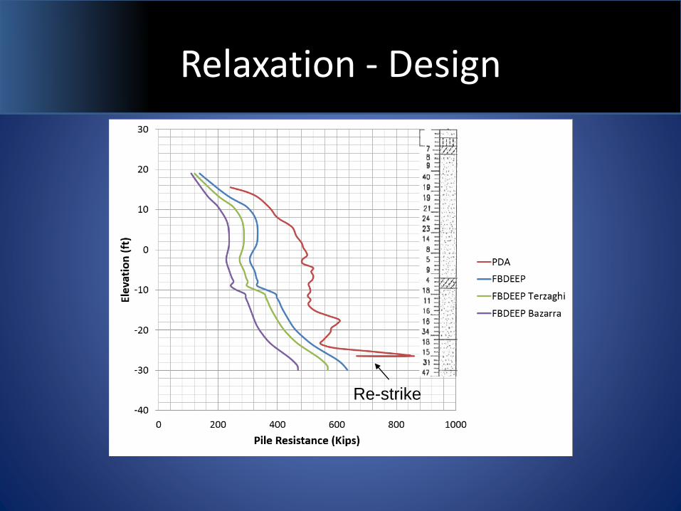
Relaxation - Design
Re-strike
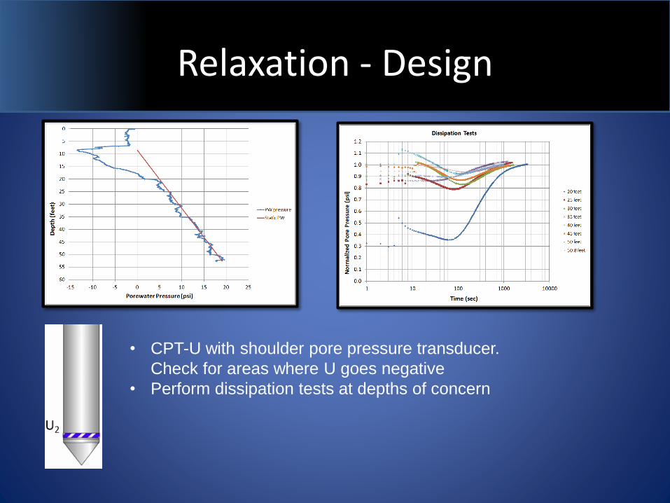
Relaxation - Design
• CPT-U with shoulder pore pressure transducer.
Check for areas where U goes negative
• Perform dissipation tests at depths of concern
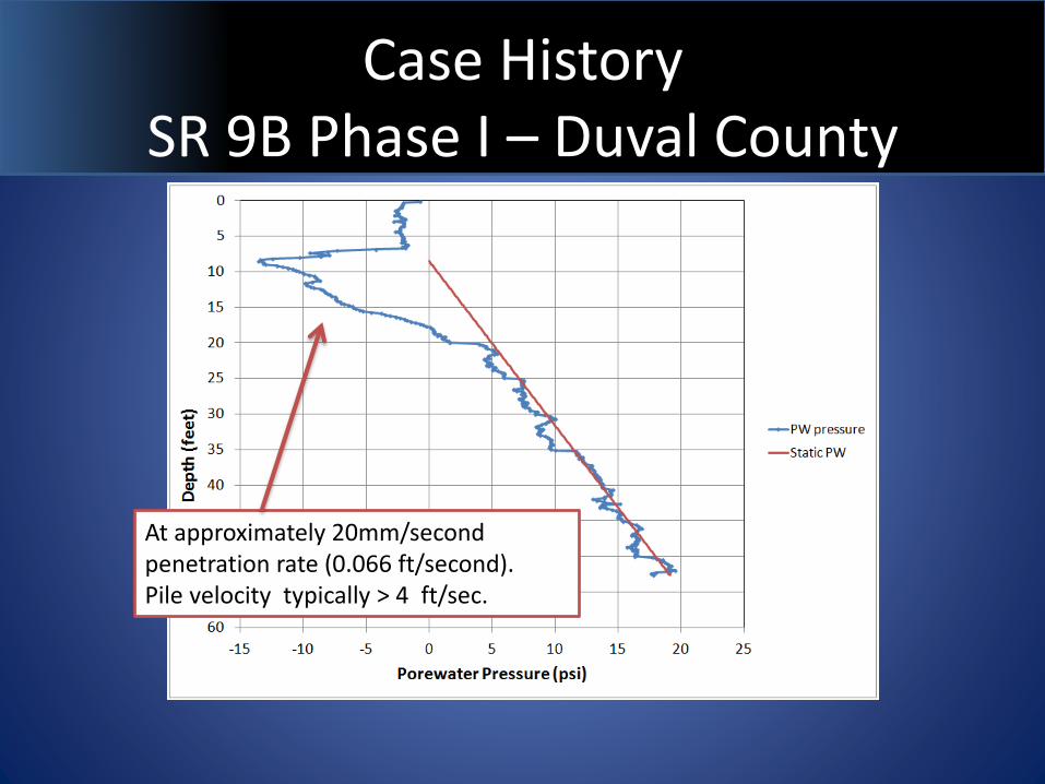
Case History SR 9B Phase I – Duval County
At approximately 20mm/second penetration rate (0.066 ft/second). Pile velocity typically > 4 ft/sec.
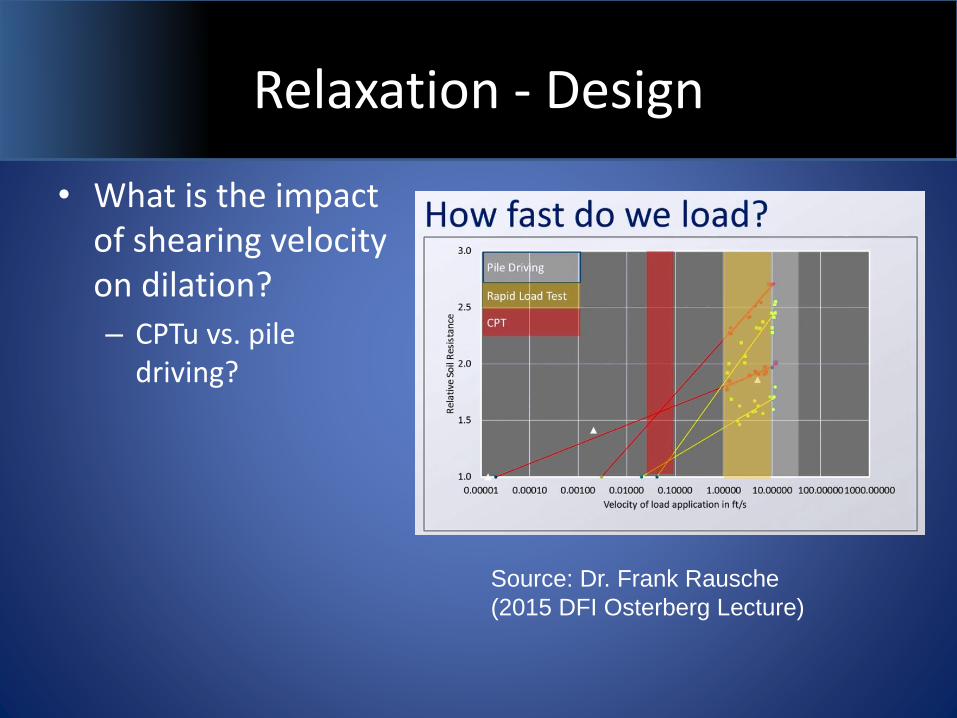
Relaxation - Design
• What is the impact of shearing velocity on dilation?
– CPTu vs. pile driving?
Source: Dr. Frank Rausche
(2015 DFI Osterberg Lecture)
Relaxation - Construction
• Set check (re-strike) during installation of Test Piles
– As soon as the nominal bearing resistance (NBR) is reached (below minimum tip)
– Use CPT-U results as a general guide on where to perform set-checks
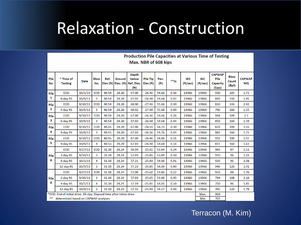
Relaxation - Construction
Terracon (M. Kim)
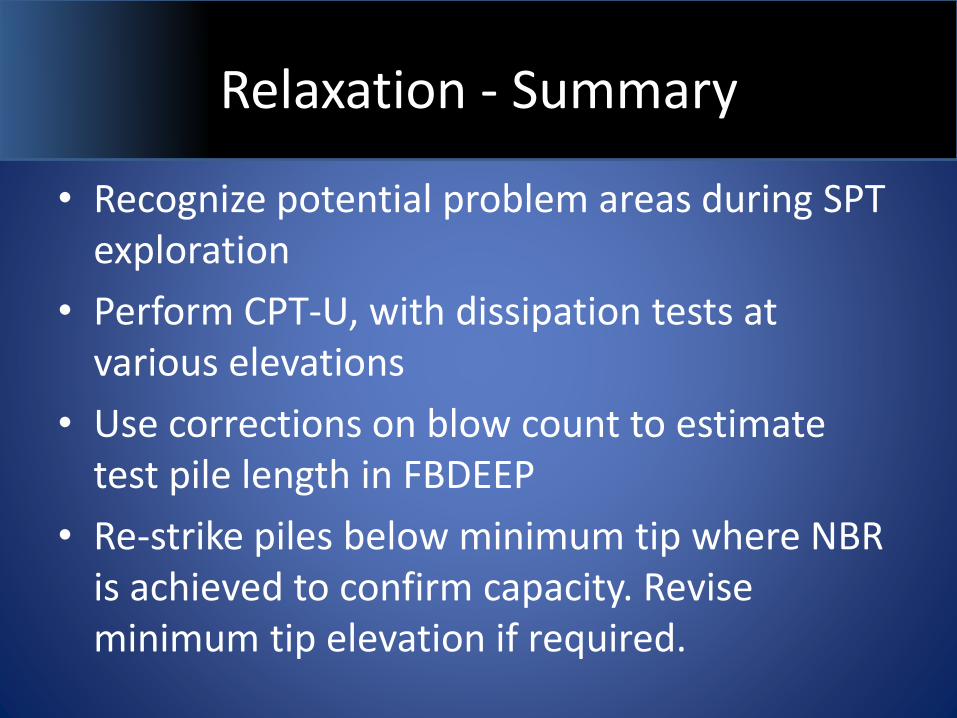
Relaxation - Summary
• Recognize potential problem areas during SPT exploration
• Perform CPT-U, with dissipation tests at various elevations
• Use corrections on blow count to estimate test pile length in FBDEEP
• Re-strike piles below minimum tip where NBR is achieved to confirm capacity. Revise minimum tip elevation if required.
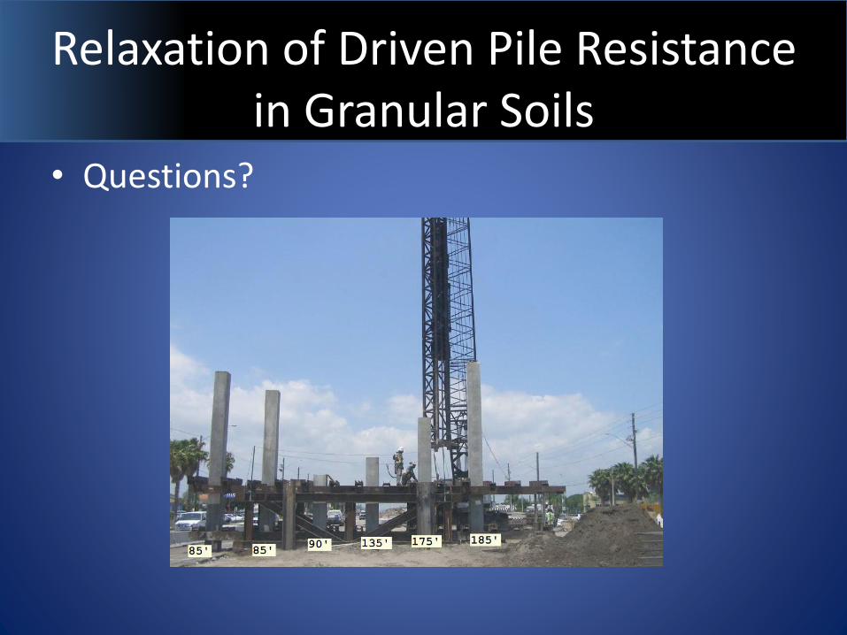
Relaxation of Driven Pile Resistance in Granular Soils
• Questions?