Embed Size (px)
Citation preview
1
gorenje
Heat Pump
WATER-TO-WATER
Instructions for Installation and Start-up
Water-to-water Heat Pump
2
1. INDEX
Water-to-water Heat Pump
3
1. Introduction
These Instructions explain the procedure for installation of the water-to-water heat pump. They
include a description of the start-up procedure that should be carried out by a competent expert
authorised by the manufacturer. Use the following Contents to find the relevant Chapters for the
correct mounting and installation of the pump.
Water-to-water Heat Pump
4
2. Safety Warnings
The heat pump is NOT firmly fixed to the wood transport palette.
Do not tilt the pump more than 45o during transport.
The sidewalls of the pump are not load-bearing, and must not be loaded during installation.
Before connection, flush the piping of the central heating system.
Install a filter on the heat source inlet in order to protect the evaporator from impurities deposit.
In the water-to-water heat pump, make sure the water quality from the well meets the
requirements for water pureness.
With power supply connection, observe the correct rotation field and the proper diameters of
the cable cords used.
The first start-up must be carried out by an authorised service provider in compliance with the
Installation and Start-up Instructions.
In order to prevent oxidation in the central heating system and heat pump condenser, add an
anti-corrosive agent to the water.
Any repairs and adjustments to the pump must be made by a Gorenje authorised servicing
technician only.
Before any repair, disconnect the pump from the power supply source.
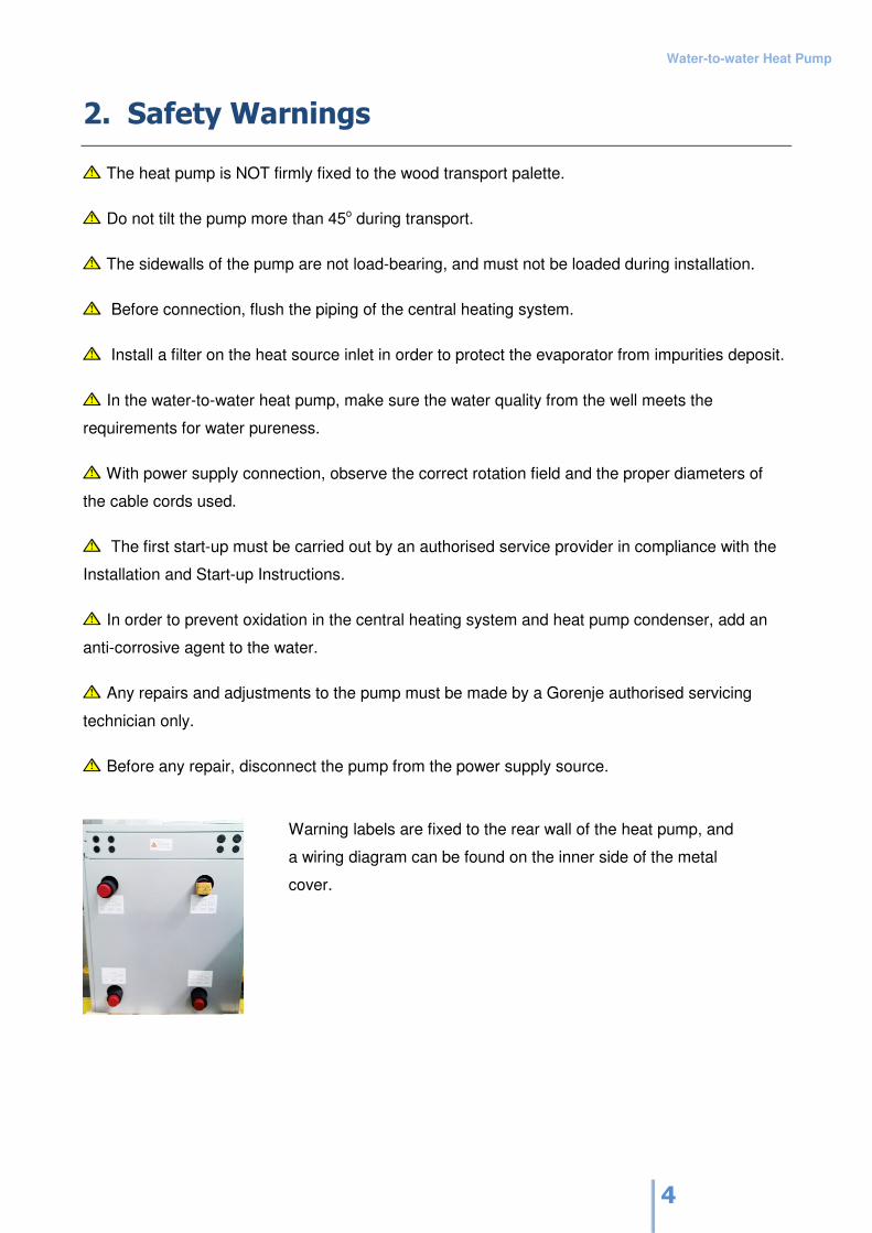
Warning labels are fixed to the rear wall of the heat pump, and
a wiring diagram can be found on the inner side of the metal
cover.
Water-to-water Heat Pump
5
Statutory Requirements
This heat pump was made in compliance with the applicable standards and complies with the
related requirements.
The heat pump may be connected to a heat source, heating system or electric power supply, in
compliance with applicable regulations.
Electric connection must be fixed, via a circuit breaker switch that cuts off supply to all conductors.
All conductors must have a diameter that corresponds with the power supply.
The pump must be connected to an adequate earthing connection.
Water-to-water Heat Pump
6
3. Use
Purpose of Use
The water-to-water heat pump is designed for installation in residential buildings (e.g., when
renovating the boiler room or as a heating source in newly constructed buildings). Underground
water of adequate quality and temperature is used as a heat source.
Operating Principles
Underground water of adequate quality and temperature (17 to 13°C) is claimed by means of
immersion pump from a well, at adequate depth. This water is transferred to the evaporator in the
heat pump. The heat accumulated in the evaporator in the heat pump is transferred to the
refrigerant, cooling down the underground water by 2 to 4°C; the cooled water is then returned to
underground some 15 m away from the point of collection, in the direction of the underground
water flow.
The refrigerant sucked by the electrically driven compressor in the heat pump is transferred to
higher pressure (higher temperature level). The power generated by the compressor is mostly
transferred to the refrigerant.
Refrigerant on the higher temperature level is transferred into condenser, transferring the heat to
heating water. The heating water may be heated up to 55 °).
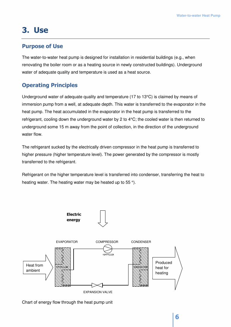
EVAPORATOR COMPRESSOR CONDENSER
Chart of energy flow through the heat pump unit
Heat from
ambient
Produced
heat for
heating
Electric
energy
EXPANSION VALVE
Water-to-water Heat Pump
7
4. Tehnical caracteristic
The construction of the heat pump unit allows installation indoors; the unit housing is made of
sheet metal, incorporating an operating panel used for adjustment of the required parameters by
the user. The control unit, located under the upper part of the unit, is used for connection to the
electricity supply and for connection of the circulating pump, temperature probes and mixing
valves.
The unit cooling circuit is filled with R407C refrigerant. This type of refrigerant is non-combustible
and does not contain ozone-depleting substances.
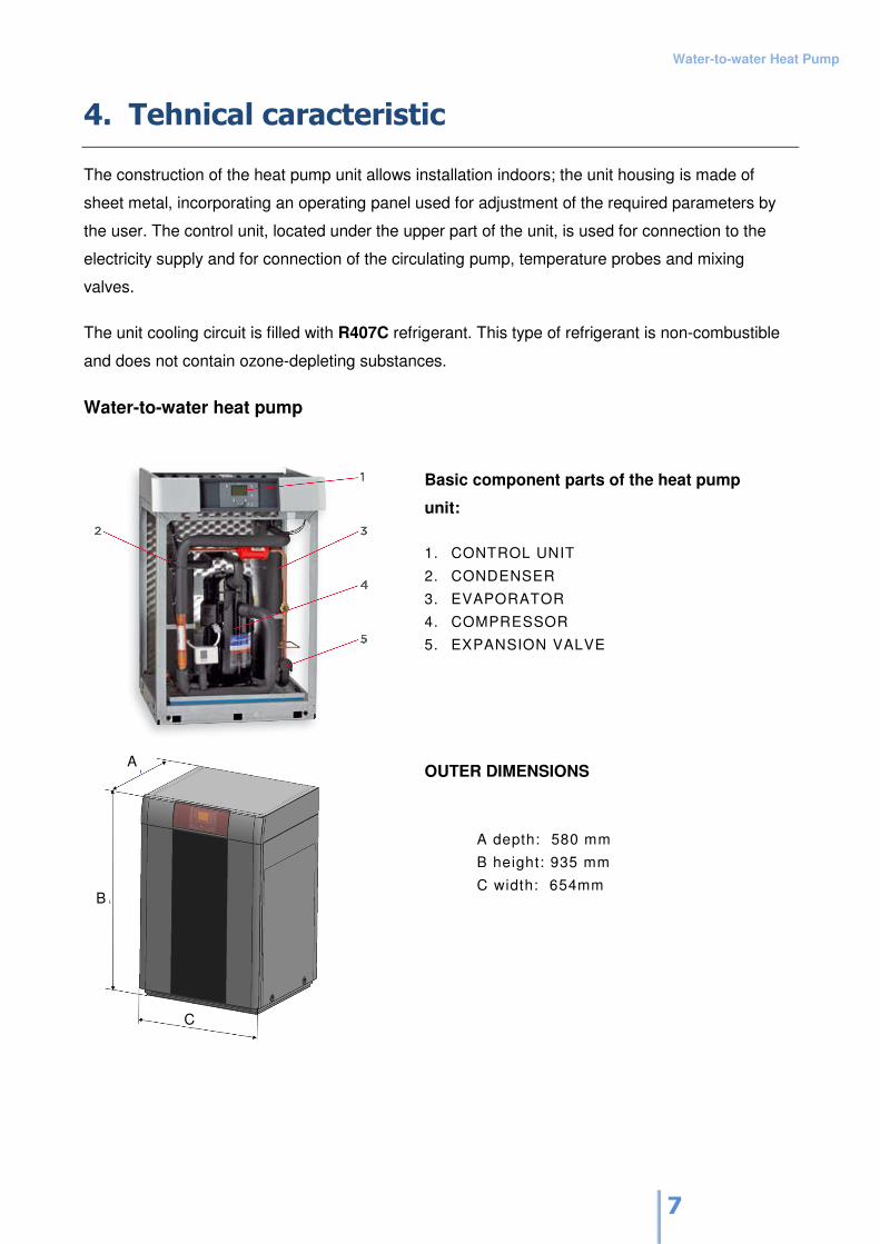
Water-to-water heat pump
Basic component parts of the heat pump
unit:
1. CONTROL UNIT
2. CONDENSER
3. EVAPORATOR
4. COMPRESSOR
5. EXPANSION VALVE
OUTER DIMENSIONS
A depth: 580 mm
B height: 935 mm
C width: 654mm
A
B
C
Water-to-water Heat Pump
8
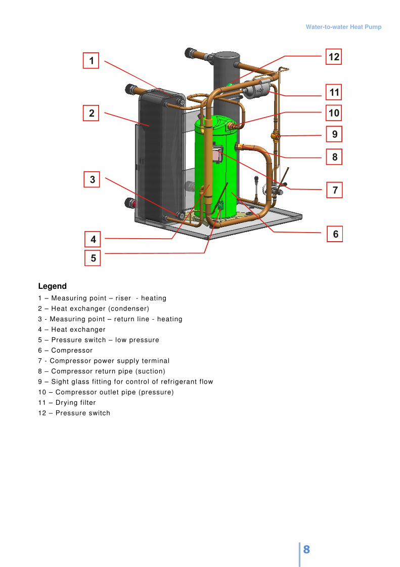
Legend
1 – Measuring point – r iser - heating
2 – Heat exchanger (condenser)
3 - Measuring point – return l ine - heating
4 – Heat exchanger
5 – Pressure switch – low pressure
6 – Compressor
7 - Compressor power supply terminal
8 – Compressor return pipe (suction)
9 – Sight glass f it t ing for control of refrigerant f low
10 – Compressor outlet pipe (pressure)
11 – Drying f il ter
12 – Pressure switch
Water-to-water Heat Pump
9
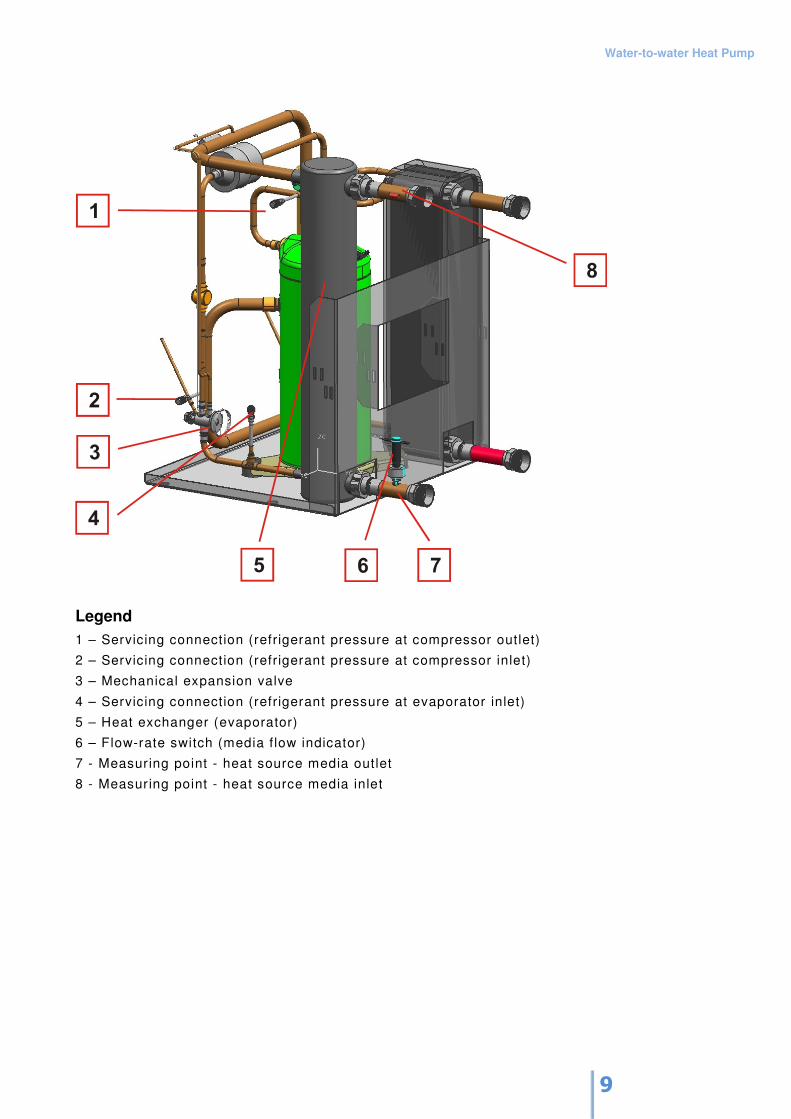
Legend
1 – Servicing connection (refrigerant pressure at compressor outlet)
2 – Servicing connection (refrigerant pressure at compressor inlet)
3 – Mechanical expansion valve
4 – Servicing connection (refrigerant pressure at evaporator inlet)
5 – Heat exchanger (evaporator)
6 – Flow-rate switch (media f low indicator)
7 - Measuring point - heat source media outlet
8 - Measuring point - heat source media inlet
Water-to-water Heat Pump
10
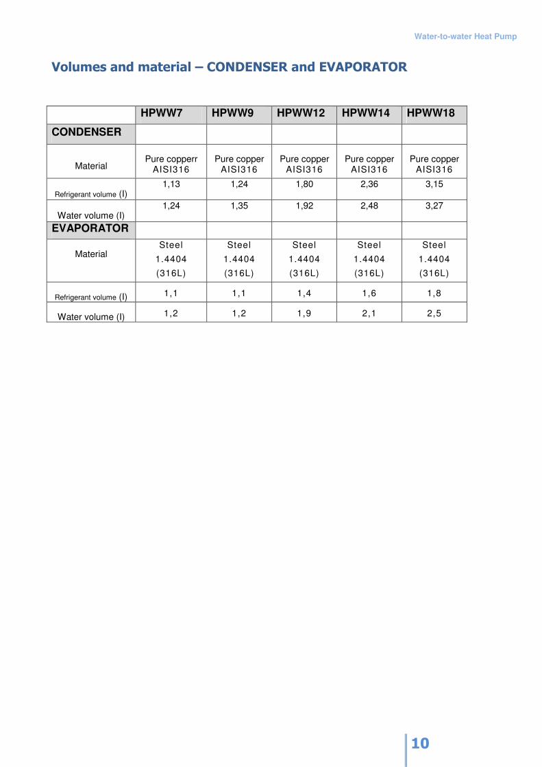
Volumes and material – CONDENSER and EVAPORATOR
HPWW7 HPWW9 HPWW12 HPWW14 HPWW18
CONDENSER
Material Pure copperr
AISI316 Pure copper
AISI316 Pure copper
AISI316 Pure copper
AISI316 Pure copper
AISI316
Refrigerant volume (I) 1,13 1,24 1,80 2,36 3,15
Water volume (I) 1,24 1,35 1,92 2,48 3,27
EVAPORATOR
Material Steel
1.4404
(316L)
Steel
1.4404
(316L)
Steel
1.4404
(316L)
Steel
1.4404
(316L)
Steel
1.4404
(316L)
Refrigerant volume (I) 1,1 1,1 1,4 1,6 1,8
Water volume (I) 1,2 1,2 1,9 2,1 2,5
Water-to-water Heat Pump
11
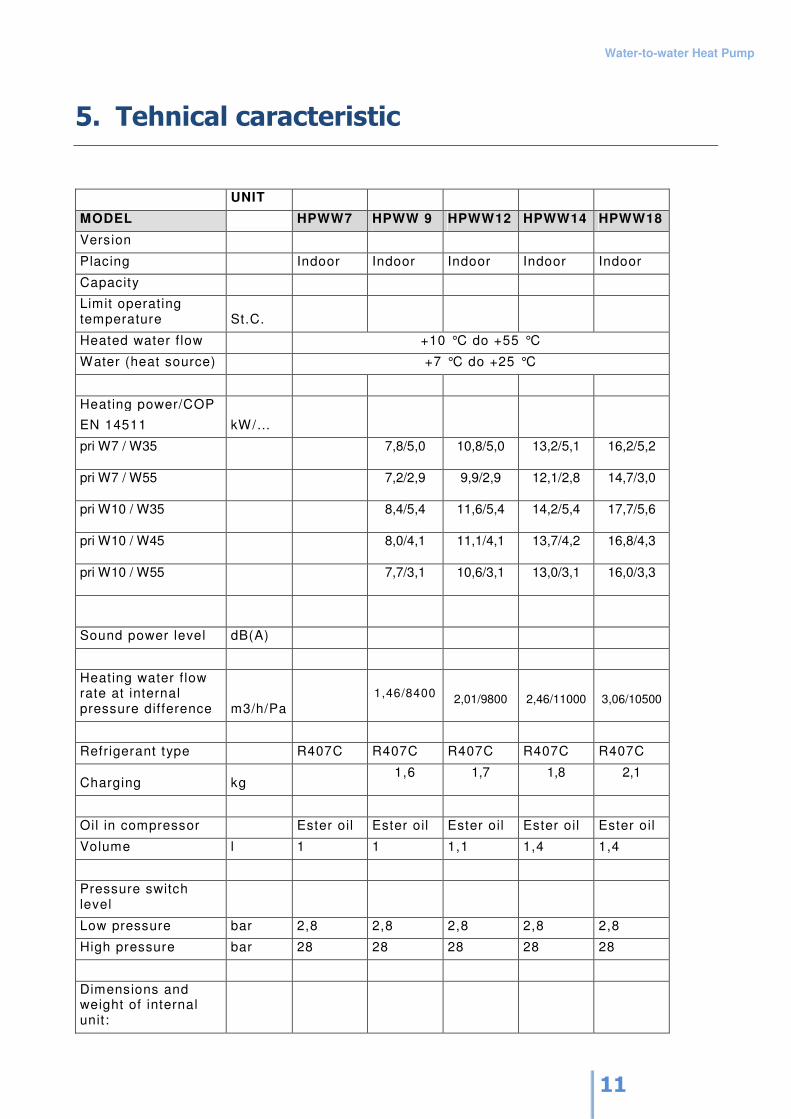
5. Tehnical caracteristic
UNIT
MODEL HPWW7 HPWW 9 HPWW12 HPWW14 HPWW18
Version
Placing Indoor Indoor Indoor Indoor Indoor
Capacity
Limit operating temperature St.C.
Heated water f low +10 °C do +55 °C
Water (heat source) +7 °C do +25 °C
Heating power/COP
EN 14511 kW/…
pri W7 / W35
7,8/5,0 10,8/5,0 13,2/5,1 16,2/5,2
pri W7 / W55
7,2/2,9 9,9/2,9 12,1/2,8 14,7/3,0
pri W10 / W35
8,4/5,4 11,6/5,4 14,2/5,4 17,7/5,6
pri W10 / W45
8,0/4,1 11,1/4,1 13,7/4,2 16,8/4,3
pri W10 / W55
7,7/3,1 10,6/3,1 13,0/3,1 16,0/3,3
Sound power level dB(A)
Heating water f low rate at internal pressure difference m3/h/Pa
1,46/8400 2,01/9800 2,46/11000 3,06/10500
Refrigerant type R407C R407C R407C R407C R407C
Charging kg 1,6 1,7 1,8 2,1
Oil in compressor Ester oil Ester oil Ester oil Ester oil Ester oil
Volume l 1 1 1,1 1,4 1,4
Pressure switch level
Low pressure bar 2,8 2,8 2,8 2,8 2,8
High pressure bar 28 28 28 28 28
Dimensions and weight of internal unit:
Water-to-water Heat Pump
12
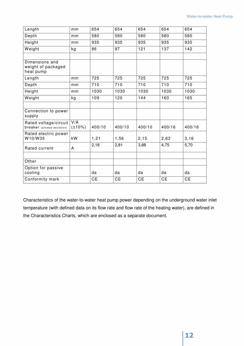
Length mm 654 654 654 654 654
Depth mm 580 580 580 580 580
Height mm 935 935 935 935 935
Weight kg 86 97 121 137 142
Dimensions and weight of packaged heat pump
Length mm 725 725 725 725 725
Depth mm 710 710 710 710 710
Height mm 1030 1030 1030 1030 1030
Weight kg 109 120 144 160 165
Connection to power supply
Rated voltage/circuit breaker (a l l owed dev ia t i on )
V/A (±10%) 400/10 400/10 400/10 400/16 400/16
Rated electr ic power W10/W35 kW 1,21 1,56 2,15 2,63 3,16
Rated current A 2,18 2,81 3,88 4,75 5,70
Other
Option for passive cooling da da da da da
Conformity mark CE CE CE CE CE
Characteristics of the water-to-water heat pump power depending on the underground water inlet
temperature (with defined data on its flow rate and flow rate of the heating water), are defined in
the Characteristics Charts, which are enclosed as a separate document.
Water-to-water Heat Pump
13
6. Delivery and Installation
Storage and Transport
Transport the heat pump in an upright position; when absolutely necessary, the pump may be tilted
to a maximum of 45o. Be careful during transport to avoid damage to the housing or to vital parts of
the unit.
The heat pump can also be moved without the use of the palette, by using the openings on the
bottom sidewalls. Push the metal rods through the opening (adequate load-bearing capacity and
max. diameter of 30 mm).
Store the heat pump in an upright position in a dry and clean place.
Placing and Installation
Place the heat pump in a well-ventilated room, avoid exposure to extreme dust and aggressive
substances. Make sure the temperature in the room is never below freezing and the air humidity is
not too high.
Place the heat pump horizontally on a firm floor with adequate load-bearing capacity. The lower
part of the frame should stand firmly on the floor in order to assure adequate sound protection.
Make sure the room has a floor drain.
Place the heat pump in a room where the noise will not disturb the environment, placing the rear
wall of the pump facing the wall. Do not place the heat pump in a room adjacent to a bedroom or
other rooms where the noise could disturb the residents.
Do not install the piping along bedroom walls or walls of other rooms where the noise might disturb
the residents. Let the installation technician mount special damping elements between the unit and
the piping in order to reduce vibration transfer from the unit into the environment. Next to the unit
dimensions, take into account additional space behind, above and to the left and right of the unit,
and especially in front of the unit.
Water-to-water Heat Pump
14
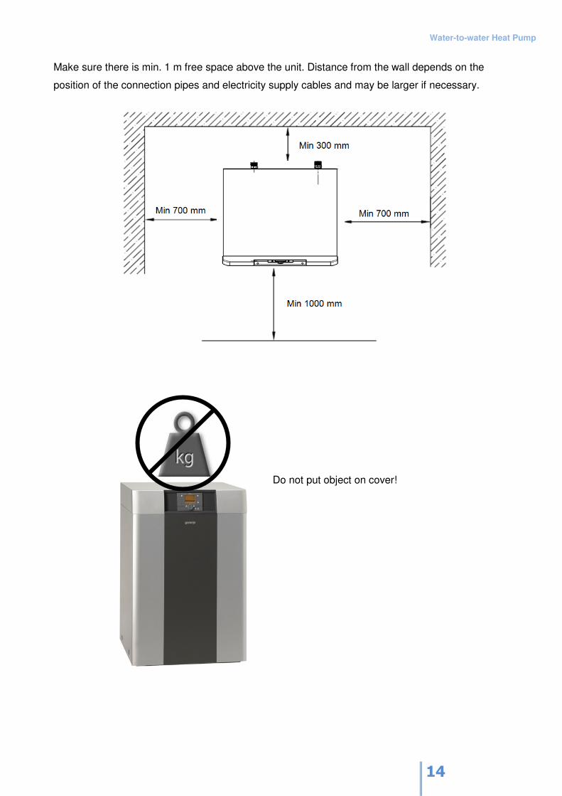
Make sure there is min. 1 m free space above the unit. Distance from the wall depends on the
position of the connection pipes and electricity supply cables and may be larger if necessary.
Do not put object on cover!
Water-to-water Heat Pump
15
7. Hydraulic Connection
Water-to-water heat pump connections
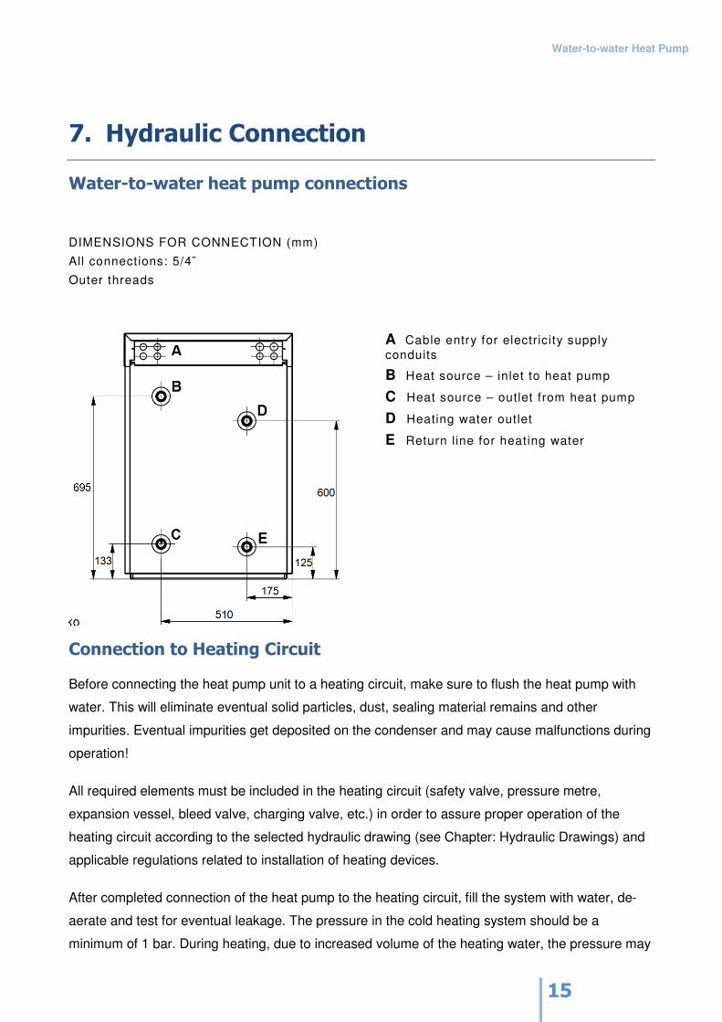
DIMENSIONS FOR CONNECTION (mm)
All connections: 5/4˘
Outer threads
A Cable entry for electricity supply
conduits
B Heat source – inlet to heat pump
C Heat source – outlet from heat pump
D Heating water outlet
E Return l ine for heating water
Connection to Heating Circuit
Before connecting the heat pump unit to a heating circuit, make sure to flush the heat pump with
water. This will eliminate eventual solid particles, dust, sealing material remains and other
impurities. Eventual impurities get deposited on the condenser and may cause malfunctions during
operation!
All required elements must be included in the heating circuit (safety valve, pressure metre,
expansion vessel, bleed valve, charging valve, etc.) in order to assure proper operation of the
heating circuit according to the selected hydraulic drawing (see Chapter: Hydraulic Drawings) and
applicable regulations related to installation of heating devices.
After completed connection of the heat pump to the heating circuit, fill the system with water, de-
aerate and test for eventual leakage. The pressure in the cold heating system should be a
minimum of 1 bar. During heating, due to increased volume of the heating water, the pressure may
Water-to-water Heat Pump
16
increase up to max. 2.5 bar. The increased volume will be absorbed by the expansion vessel,
whose dimensions must correlate with the capacity of the heating system (not all heating circuits
have a related expansion vessel). The safety valve should be triggered when the pressure reaches
3 bar.
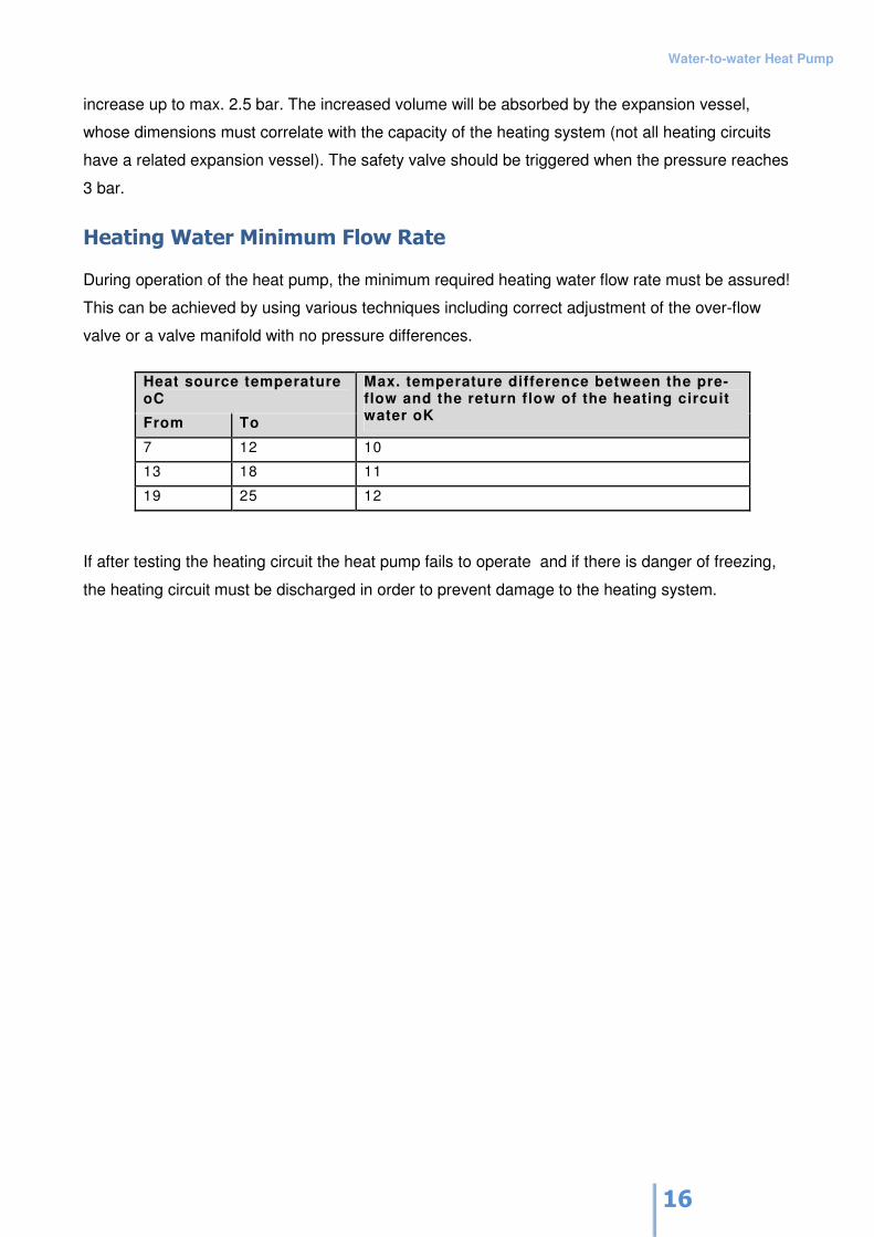
Heating Water Minimum Flow Rate
During operation of the heat pump, the minimum required heating water flow rate must be assured!
This can be achieved by using various techniques including correct adjustment of the over-flow
valve or a valve manifold with no pressure differences.
Heat source temperature oC
From To
Max. temperature difference between the pre-flow and the return flow of the heating circuit water oK
7 12 10
13 18 11
19 25 12
If after testing the heating circuit the heat pump fails to operate and if there is danger of freezing,
the heating circuit must be discharged in order to prevent damage to the heating system.
Water-to-water Heat Pump
17
Borehole fo Pumping the Water (Well)
Water from the underground that is needed for the operation of the water-to-water heat pump is
pumped from the well (borehole) The quantity of the groundwater must correspond to the heat
pump flow rate. The quantity of the ground water, reliability of the source and quality of water
largely depend on geological characteristics of the area; therefore make sure to verify all the
characteristics before making the borehole.
The depth of the borehole depend on the availability of the water source.
Required water pureness
Instal a filter at the heat inlet source on the heat pump to prevent impurities and protect the
evaporator against eventual damages. During the first months of use, the filter should be cleaned
more often. Once the amount of impurities is reduced, the cleaning intervals may be longer.
The underground water must not contain elements that could cause deposits in the heat
exchanger. To prevent depositing of iron in the heat pump system, the uppper limit value is for Iron
< 0,2mg/l and Manganese < 0,1mg/l. Before starting to use the water from the well, send a water
sample to the laboratory for an analyses to make sure the water quality corresponds to required
values. This will reduce the malfunctions to the heat pump system caused by impurities in water.
Use of surface water or salt water is not allowed.
Water-to-water Heat Pump
18
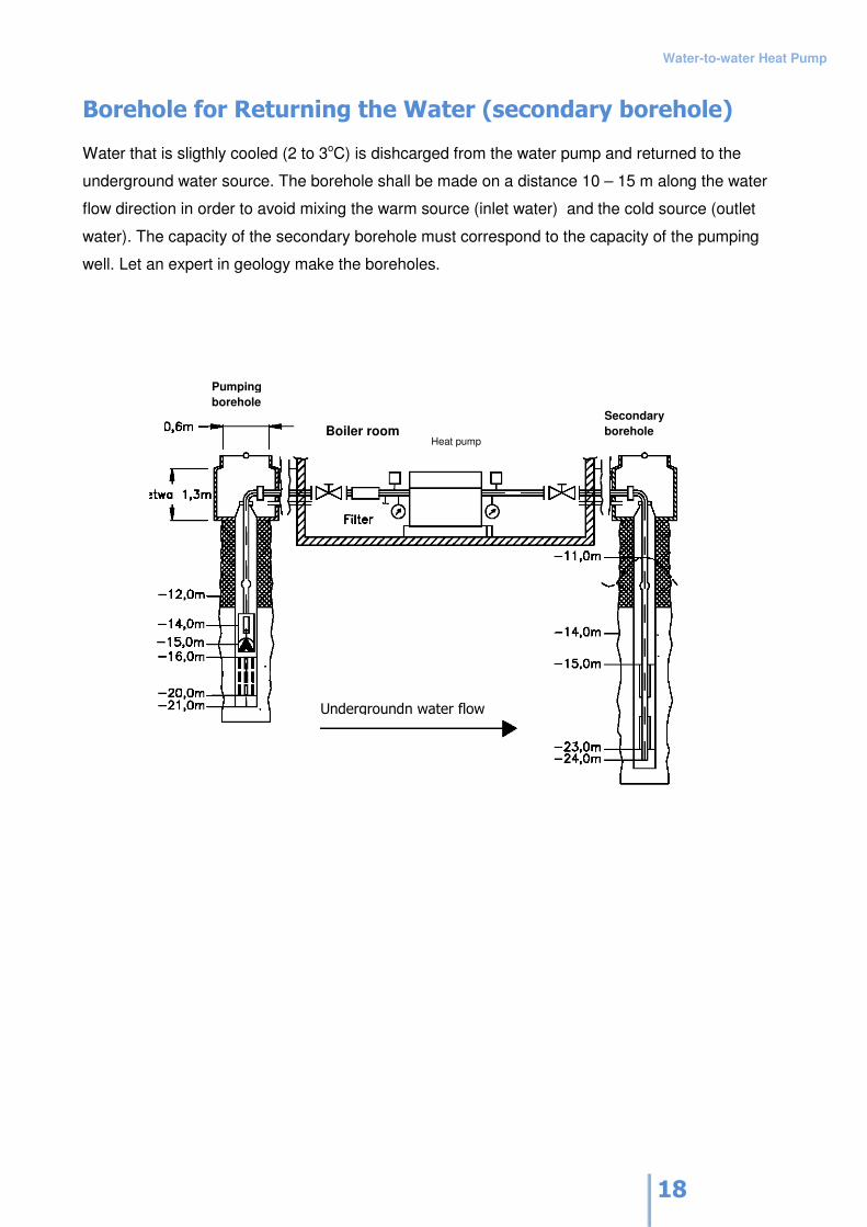
Borehole for Returning the Water (secondary borehole)
Water that is sligthly cooled (2 to 3oC) is dishcarged from the water pump and returned to the
underground water source. The borehole shall be made on a distance 10 – 15 m along the water
flow direction in order to avoid mixing the warm source (inlet water) and the cold source (outlet
water). The capacity of the secondary borehole must correspond to the capacity of the pumping
well. Let an expert in geology make the boreholes.
Heat pump
Secondary
borehole
Pumping
borehole
Boiler room
Undergroundn water flow
Water-to-water Heat Pump
19
8. Hydraulic Diagrams
Various applications (for various heat sources and extra features) are presented in the form of
basic hydraulic drawings.
The heat source for each hydraulic diagram can be selected with the adjustment of parameters.
In order to include extra features (solar cells, swimming pool, etc.) the parameters need to be
adjusted accordingly.
The wiring diagrams are basic diagrams and do not include safety elements (expansion vessels,
safety valves, bleed valves, etc.); these should be provided by the installation technician!
Detailed hydraulic drawings with complete elements are composed as separate documents.
Basic Diagrams
The following wiring diagrams can be selected by entering the number of the diagram in parameter
5700 (setting 'Adjustment’ before start, menu 'Configuration'). For operation of the basic diagram,
parameter 5700 must be adjusted and all the sensors connected.
All sensors included in the diagram must be connected. Component parts marked with dashed
lines are optional and are not indispensible for operation.
Water-to-water Heat Pump
20
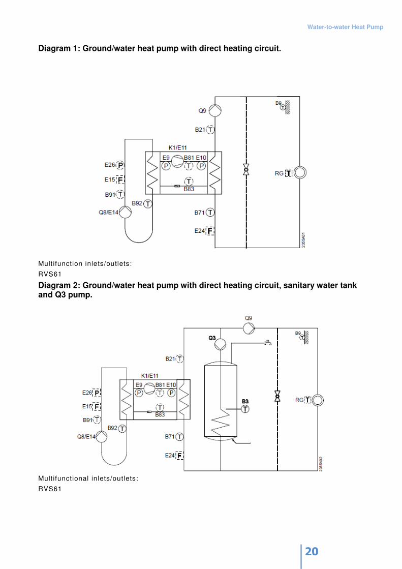
Diagram 1: Ground/water heat pump with direct heating circuit.
Multifunction inlets/outlets:
RVS61
Diagram 2: Ground/water heat pump with direct heating circuit, sanitary water tank and Q3 pump.
Multifunctional inlets/outlets:
RVS61
Water-to-water Heat Pump
21
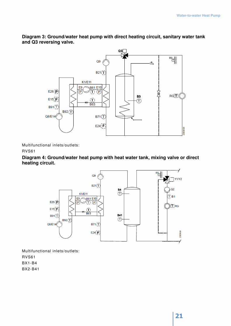
Diagram 3: Ground/water heat pump with direct heating circuit, sanitary water tank and Q3 reversing valve.
Multifunctional inlets/outlets:
RVS61
Diagram 4: Ground/water heat pump with heat water tank, mixing valve or direct heating circuit.
Multifunctional inlets/outlets:
RVS61
BX1-B4
BX2-B41
Water-to-water Heat Pump
22
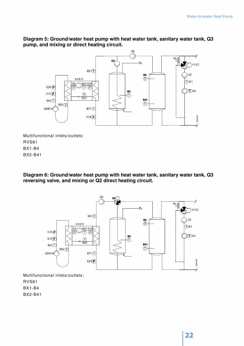
Diagram 5: Ground/water heat pump with heat water tank, sanitary water tank, Q3 pump, and mixing or direct heating circuit.
Multifunctional inlets/outlets:
RVS61
BX1-B4
BX2-B41
Diagram 6: Ground/water heat pump with heat water tank, sanitary water tank, Q3 reversing valve, and mixing or Q2 direct heating circuit.
Mult ifunctional inlets/outlets:
RVS61
BX1-B4
BX2-B41
Water-to-water Heat Pump
23
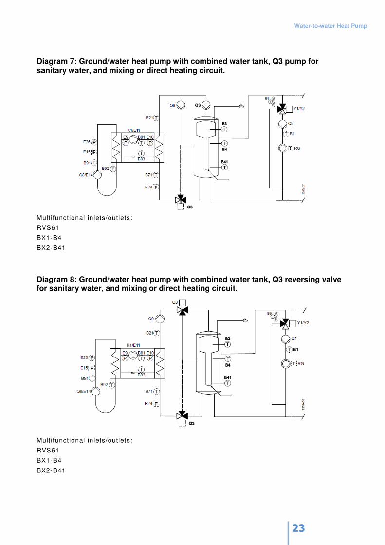
Diagram 7: Ground/water heat pump with combined water tank, Q3 pump for sanitary water, and mixing or direct heating circuit.
Multifunctional inlets/outlets:
RVS61
BX1-B4
BX2-B41
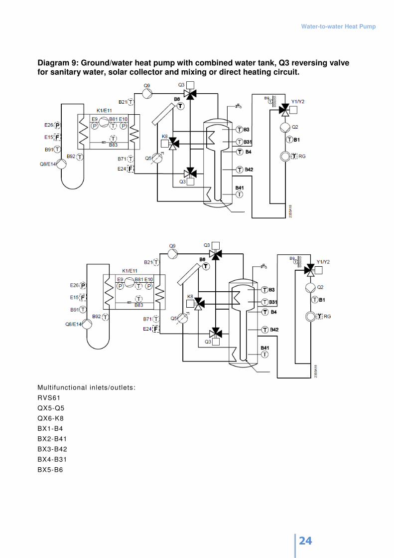
Diagram 8: Ground/water heat pump with combined water tank, Q3 reversing valve for sanitary water, and mixing or direct heating circuit.
Multifunctional inlets/outlets:
RVS61
BX1-B4
BX2-B41
Water-to-water Heat Pump
24
Diagram 9: Ground/water heat pump with combined water tank, Q3 reversing valve for sanitary water, solar collector and mixing or direct heating circuit.
Mult ifunctional inlets/outlets:
RVS61
QX5-Q5
QX6-K8
BX1-B4
BX2-B41
BX3-B42
BX4-B31
BX5-B6
Water-to-water Heat Pump
25
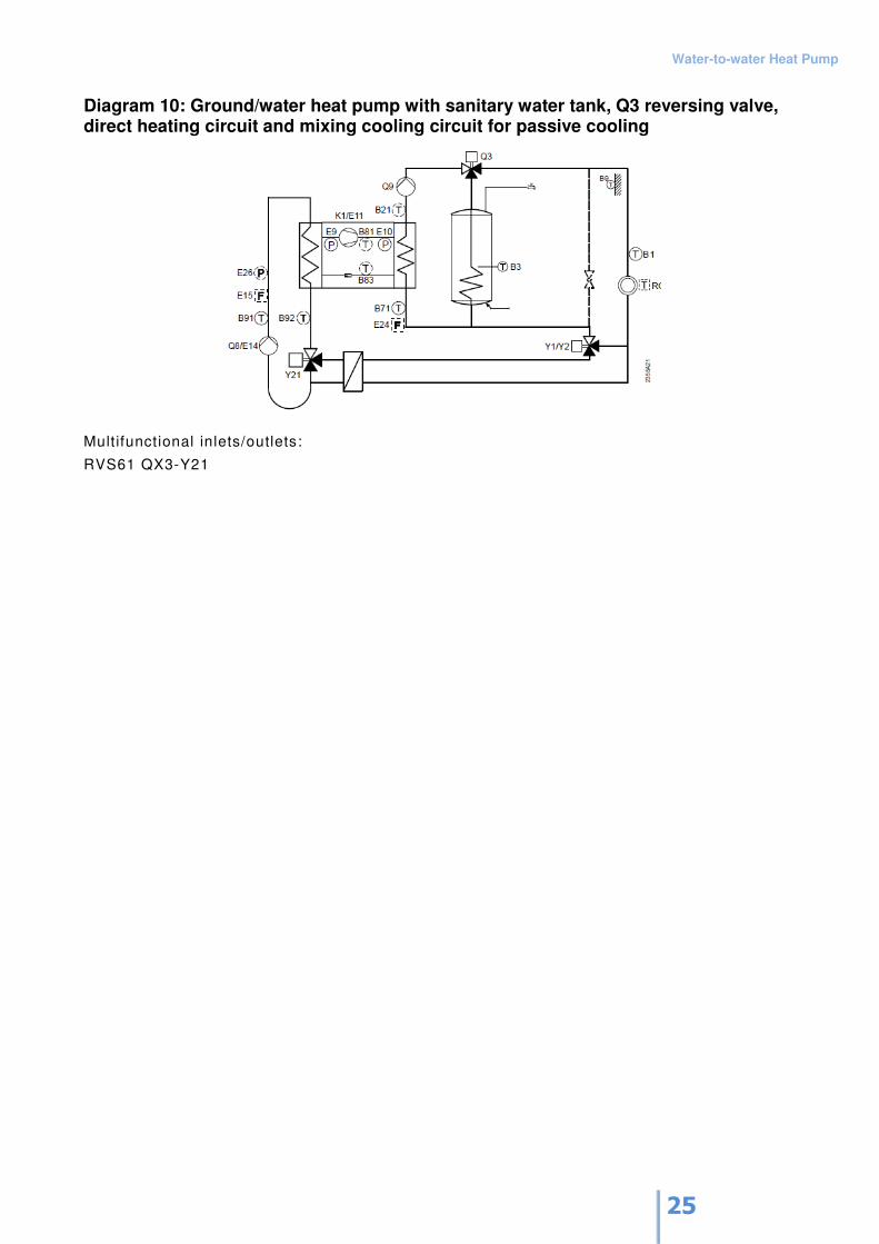
Diagram 10: Ground/water heat pump with sanitary water tank, Q3 reversing valve, direct heating circuit and mixing cooling circuit for passive cooling
Multifunctional inlets/outlets:
RVS61 QX3-Y21
Water-to-water Heat Pump
26
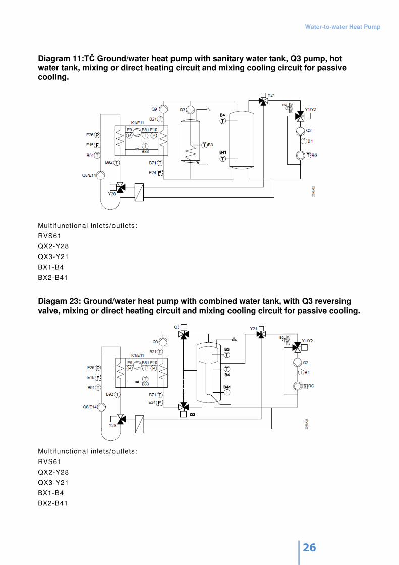
Diagram 11:TČ Ground/water heat pump with sanitary water tank, Q3 pump, hot water tank, mixing or direct heating circuit and mixing cooling circuit for passive cooling.
Multifunctional inlets/outlets:
RVS61
QX2-Y28
QX3-Y21
BX1-B4
BX2-B41
Diagam 23: Ground/water heat pump with combined water tank, with Q3 reversing valve, mixing or direct heating circuit and mixing cooling circuit for passive cooling.
Mult ifunctional inlets/outlets:
RVS61
QX2-Y28
QX3-Y21
BX1-B4
BX2-B41

Water-to-water Heat Pump
27
You can start by selecting a wiring diagram that does not comply with your heat pump and change
the heat source for this diagram (example: the ground/water heat pump that you want to include in
the heating system, as shown in diagram 5). Select diagram 5 (menu: Configuration, parameter
5700=5) and set heat source to 'Water' (menu: Configuration, parameter 5800=Water).
If you want to add a second heating circuit, you must add an expansion module. For adding the
second and third mixing heating circuits, you must add two 'zone' controllers and an expansion
module.
Water-to-water Heat Pump
28
9. Connection to Power Supply
The heat pump must be connected to the power supply grid. Connection to the grid must be made
by an expert in compliance with applicable legislation and local regulations. The heat pump has a
separate power supply line and controls supply line.
Power Supply Line
The installation technician must assure proper electric protection of the heat pump power supply
line. A 3p/16A/C circuit breaker should be used.
The three-phase power line must be made with a 5G2.5 cable cord. The cable cord should be
installed in the heat pump from the rear side via the M25x1.5 cable entry in order to prevent
moving and falling out of the cable cord from the terminal pins located on the electronics holder.
The cable cord should be connected to the DOVOD 3x400 VAC-1X1 terminal pins.
In case of an incorrect sequence of phases, the controller will report the error: 'Electric lock E6'.
Be careful – make sure the phase sequence is correct!
Do not forget to connect the PE earth conduit!
Controls Supply Line
The installation technician must assure proper electric protection of the control line of the pump. A
1p/6A/C circuit breaker should be used.
A single-phase power line must be made with a 3G1.5 cable cord. The cable cord should be
installed in the heat pump from the rear side via the M20x1.5 cable entry in order to prevent
moving and falling out of the cable cord from the terminal pins located on the electronics holder.
The cable cord should be connected to the DOVOD 230 VAC-1X3 terminal pins.
In case of an incorrect sequence of phases, the controller will report the error: 'Electric lock E6'.
Do not forget to connect the PE earth conduit!
Water-to-water Heat Pump
29
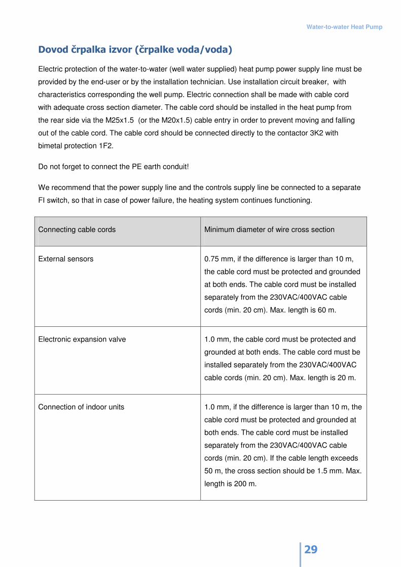
Dovod črpalka izvor (črpalke voda/voda)
Electric protection of the water-to-water (well water supplied) heat pump power supply line must be
provided by the end-user or by the installation technician. Use installation circuit breaker, with
characteristics corresponding the well pump. Electric connection shall be made with cable cord
with adequate cross section diameter. The cable cord should be installed in the heat pump from
the rear side via the M25x1.5 (or the M20x1.5) cable entry in order to prevent moving and falling
out of the cable cord. The cable cord should be connected directly to the contactor 3K2 with
bimetal protection 1F2.
Do not forget to connect the PE earth conduit!
We recommend that the power supply line and the controls supply line be connected to a separate
FI switch, so that in case of power failure, the heating system continues functioning.
Connecting cable cords Minimum diameter of wire cross section
External sensors 0.75 mm, if the difference is larger than 10 m,
the cable cord must be protected and grounded
at both ends. The cable cord must be installed
separately from the 230VAC/400VAC cable
cords (min. 20 cm). Max. length is 60 m.
Electronic expansion valve 1.0 mm, the cable cord must be protected and
grounded at both ends. The cable cord must be
installed separately from the 230VAC/400VAC
cable cords (min. 20 cm). Max. length is 20 m.
Connection of indoor units 1.0 mm, if the difference is larger than 10 m, the
cable cord must be protected and grounded at
both ends. The cable cord must be installed
separately from the 230VAC/400VAC cable
cords (min. 20 cm). If the cable length exceeds
50 m, the cross section should be 1.5 mm. Max.
length is 200 m.
Water-to-water Heat Pump
30
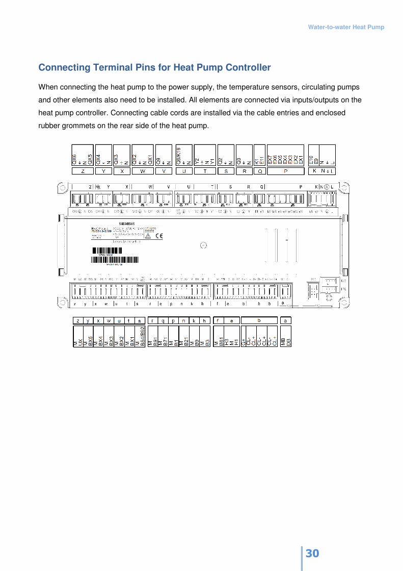
Connecting Terminal Pins for Heat Pump Controller
When connecting the heat pump to the power supply, the temperature sensors, circulating pumps
and other elements also need to be installed. All elements are connected via inputs/outputs on the
heat pump controller. Connecting cable cords are installed via the cable entries and enclosed
rubber grommets on the rear side of the heat pump.
Water-to-water Heat Pump
31
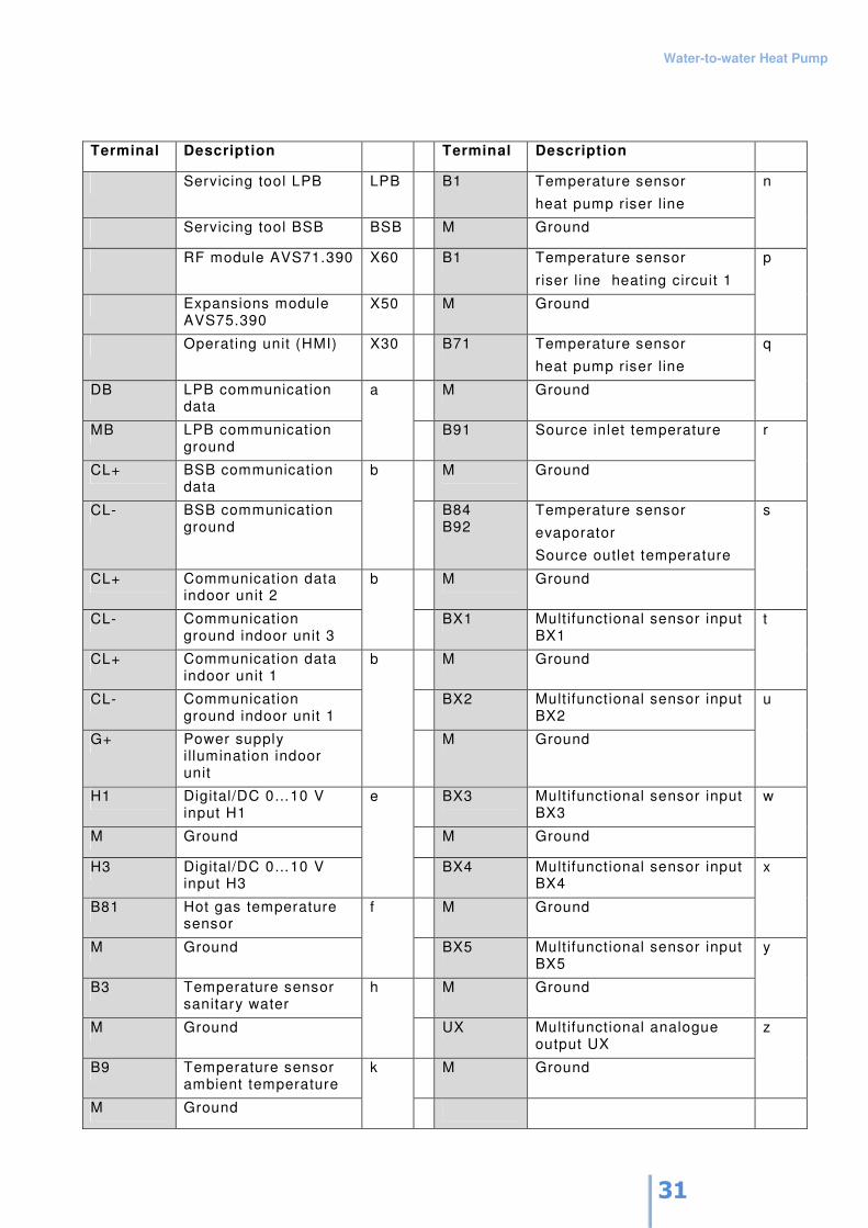
Terminal Description Terminal Description
Servicing tool LPB LPB B1 Temperature sensor
heat pump riser l ine
Servicing tool BSB BSB M Ground
n
RF module AVS71.390 X60 B1 Temperature sensor
riser l ine heating circuit 1
Expansions module AVS75.390
X50 M Ground
p
Operating unit (HMI) X30 B71 Temperature sensor
heat pump riser l ine
DB LPB communication data
M Ground
q
MB LPB communication ground
a
B91 Source inlet temperature
CL+ BSB communication data
M Ground
r
CL- BSB communication ground
b
B84 B92
Temperature sensor
evaporator
Source outlet temperature
CL+ Communication data indoor unit 2
M Ground
s
CL- Communication ground indoor unit 3
b
BX1 Multifunctional sensor input BX1
CL+ Communication data indoor unit 1
M Ground
t
CL- Communication ground indoor unit 1
BX2 Multifunctional sensor input BX2
G+ Power supply i llumination indoor unit
b
M Ground
u
H1 Digital/DC 0…10 V input H1
BX3 Multifunctional sensor input BX3
M Ground M Ground
w
H3 Digital/DC 0…10 V input H3
e
BX4 Multifunctional sensor input BX4
B81 Hot gas temperature sensor
M Ground
x
M Ground
f
BX5 Multifunctional sensor input BX5
B3 Temperature sensor sanitary water
M Ground
y
M Ground
h
UX Multifunctional analogue output UX
B9 Temperature sensor ambient temperature
M Ground
z
M Ground
k

Water-to-water Heat Pump
32
Water-to-water Heat Pump
33
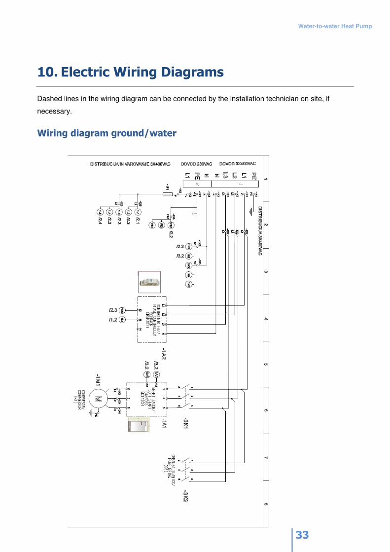
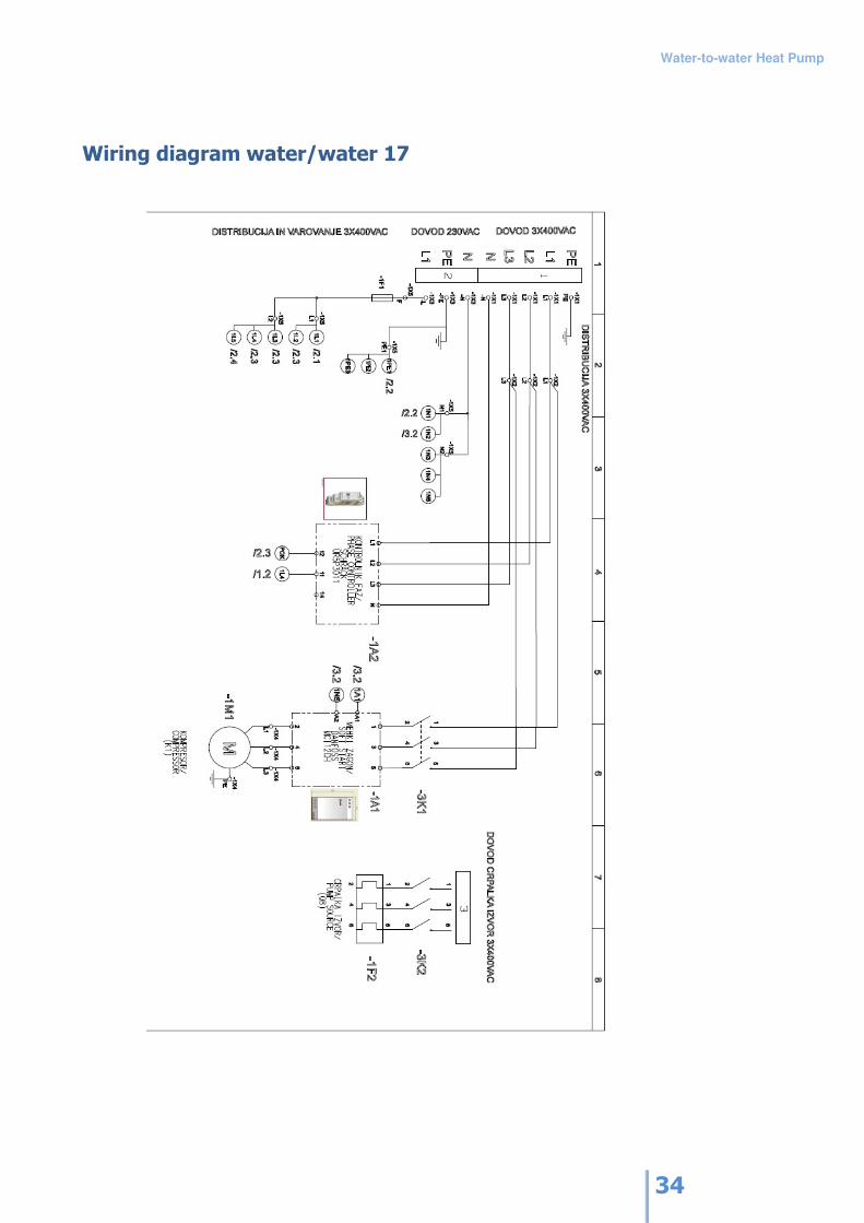
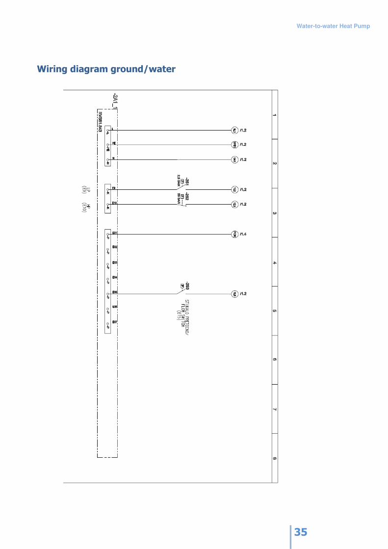
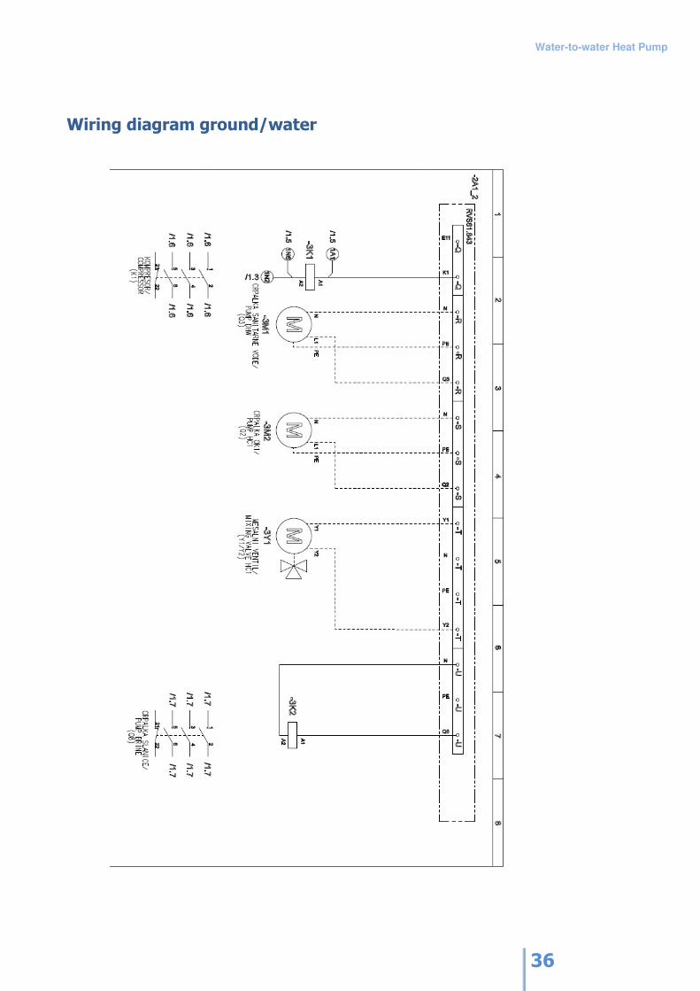
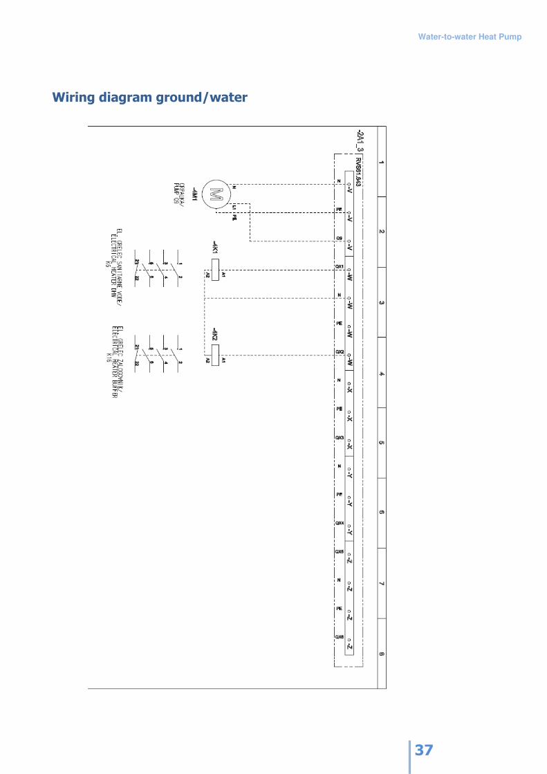
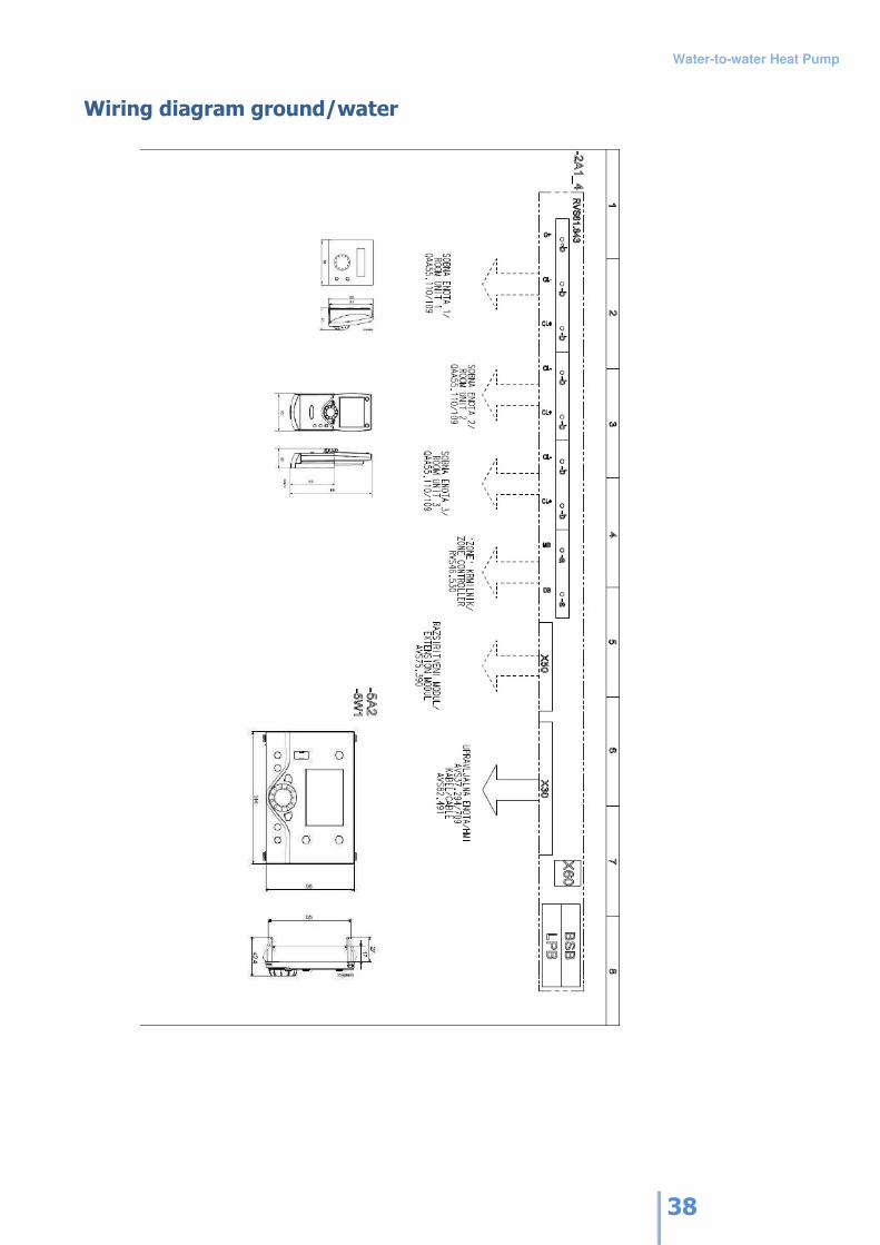
10. Electric Wiring Diagrams
Dashed lines in the wiring diagram can be connected by the installation technician on site, if
necessary.
Wiring diagram ground/water
Water-to-water Heat Pump
34
Wiring diagram water/water 17
Water-to-water Heat Pump
35
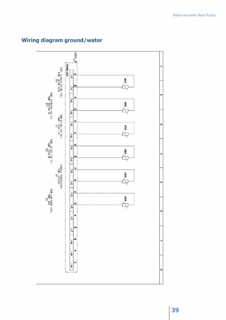
Wiring diagram ground/water
Water-to-water Heat Pump
36
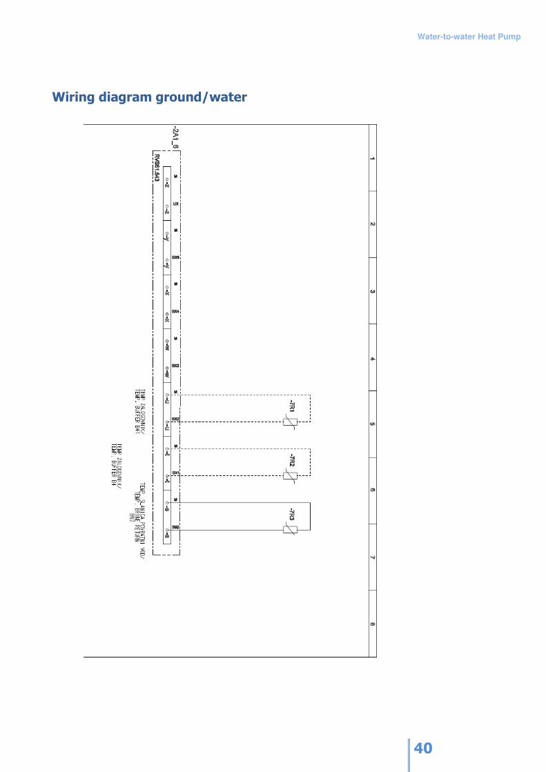
Wiring diagram ground/water
Water-to-water Heat Pump
37
Wiring diagram ground/water
Water-to-water Heat Pump
38
Wiring diagram ground/water
Water-to-water Heat Pump
39
Wiring diagram ground/water
Water-to-water Heat Pump
40
Wiring diagram ground/water
Water-to-water Heat Pump
41
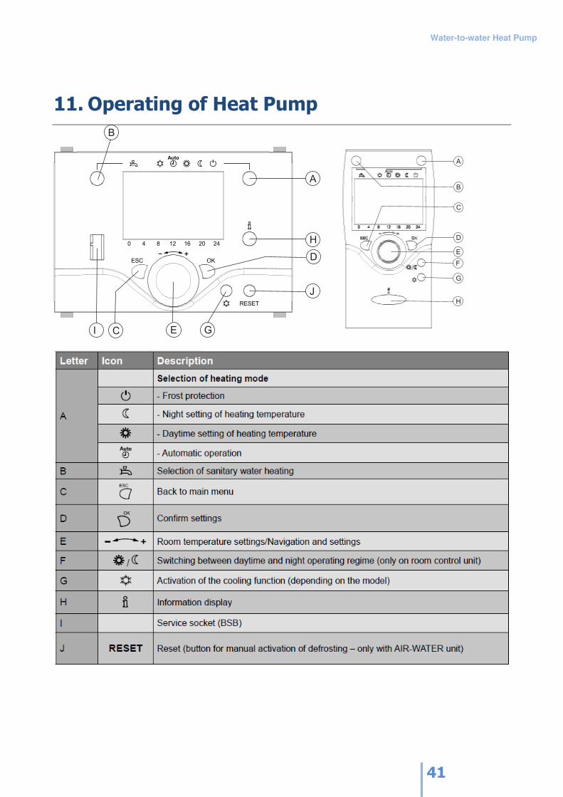
A
B
C
D
E
F
G
H
11. Operating of Heat Pump
B
A
H
D
J
GCI E
Water-to-water Heat Pump
42
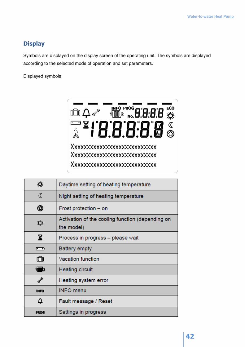
Display
Symbols are displayed on the display screen of the operating unit. The symbols are displayed
according to the selected mode of operation and set parameters.
Displayed symbols
Xxxxxxxxxxxxxxxxxxxxxxxxxxx
Xxxxxxxxxxxxxxxxxxxxxxxxxxx
Xxxxxxxxxxxxxxxxxxxxxxxxxxx
Water-to-water Heat Pump
43
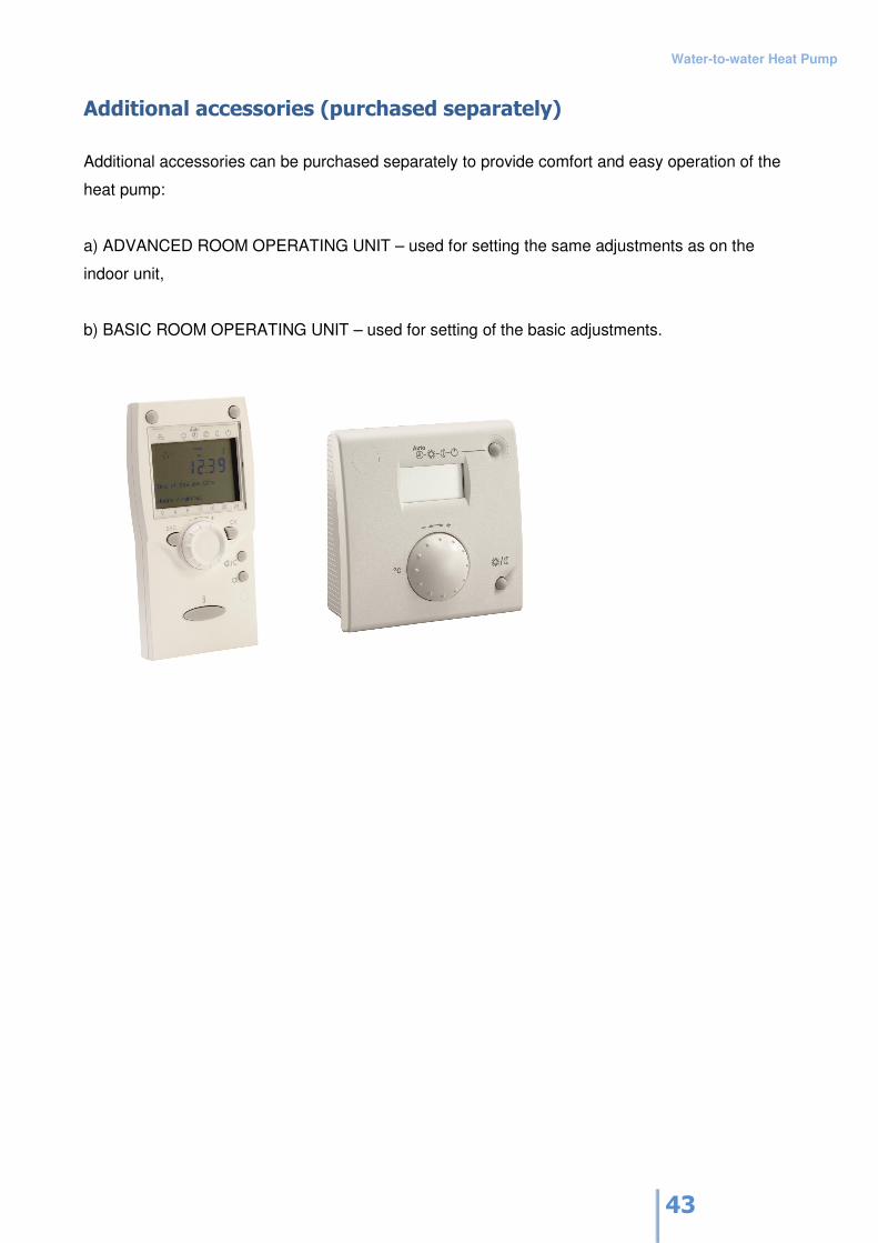
Additional accessories (purchased separately)
Additional accessories can be purchased separately to provide comfort and easy operation of the
heat pump:
a) ADVANCED ROOM OPERATING UNIT – used for setting the same adjustments as on the
indoor unit,
b) BASIC ROOM OPERATING UNIT – used for setting of the basic adjustments.
Water-to-water Heat Pump
44
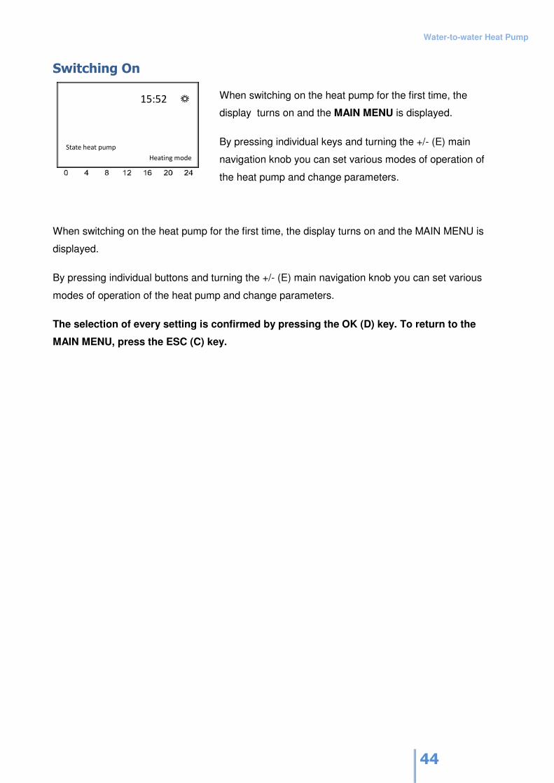
Switching On
When switching on the heat pump for the first time, the
display turns on and the MAIN MENU is displayed.
By pressing individual keys and turning the +/- (E) main
navigation knob you can set various modes of operation of
the heat pump and change parameters.
When switching on the heat pump for the first time, the display turns on and the MAIN MENU is
displayed.
By pressing individual buttons and turning the +/- (E) main navigation knob you can set various
modes of operation of the heat pump and change parameters.
The selection of every setting is confirmed by pressing the OK (D) key. To return to the
MAIN MENU, press the ESC (C) key.
Water-to-water Heat Pump
45
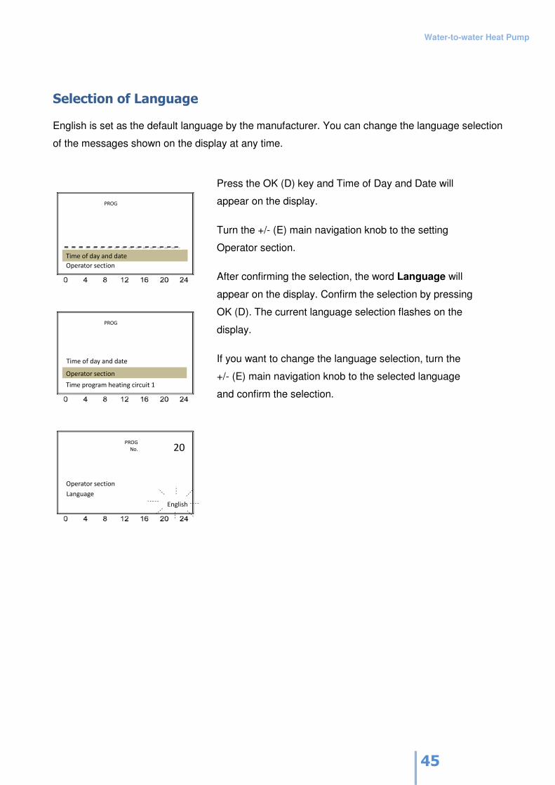
Selection of Language
English is set as the default language by the manufacturer. You can change the language selection
of the messages shown on the display at any time.
Press the OK (D) key and Time of Day and Date will
appear on the display.
Turn the +/- (E) main navigation knob to the setting
Operator section.
After confirming the selection, the word Language will
appear on the display. Confirm the selection by pressing
OK (D). The current language selection flashes on the
display.
If you want to change the language selection, turn the
+/- (E) main navigation knob to the selected language
and confirm the selection.
Water-to-water Heat Pump
46
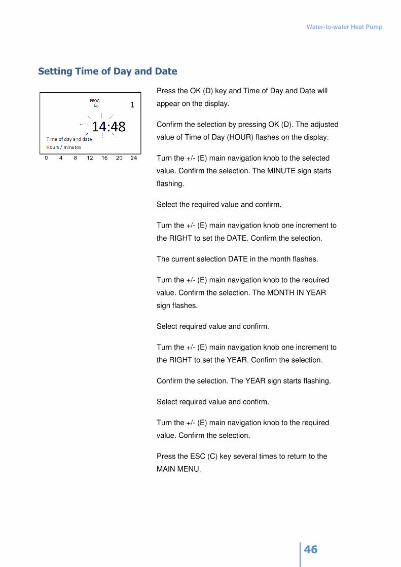
Setting Time of Day and Date
Press the OK (D) key and Time of Day and Date will
appear on the display.
Confirm the selection by pressing OK (D). The adjusted
value of Time of Day (HOUR) flashes on the display.
Turn the +/- (E) main navigation knob to the selected
value. Confirm the selection. The MINUTE sign starts
flashing.
Select the required value and confirm.
Turn the +/- (E) main navigation knob one increment to
the RIGHT to set the DATE. Confirm the selection.
The current selection DATE in the month flashes.
Turn the +/- (E) main navigation knob to the required
value. Confirm the selection. The MONTH IN YEAR
sign flashes.
Select required value and confirm.
Turn the +/- (E) main navigation knob one increment to
the RIGHT to set the YEAR. Confirm the selection.
Confirm the selection. The YEAR sign starts flashing.
Select required value and confirm.
Turn the +/- (E) main navigation knob to the required
value. Confirm the selection.
Press the ESC (C) key several times to return to the
MAIN MENU.
Water-to-water Heat Pump
47
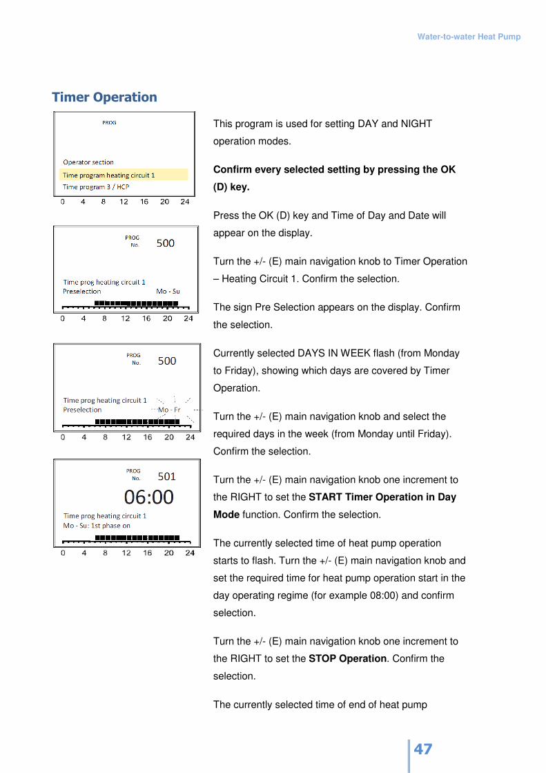
Timer Operation
This program is used for setting DAY and NIGHT
operation modes.
Confirm every selected setting by pressing the OK
(D) key.
Press the OK (D) key and Time of Day and Date will
appear on the display.
Turn the +/- (E) main navigation knob to Timer Operation
– Heating Circuit 1. Confirm the selection.
The sign Pre Selection appears on the display. Confirm
the selection.
Currently selected DAYS IN WEEK flash (from Monday
to Friday), showing which days are covered by Timer
Operation.
Turn the +/- (E) main navigation knob and select the
required days in the week (from Monday until Friday).
Confirm the selection.
Turn the +/- (E) main navigation knob one increment to
the RIGHT to set the START Timer Operation in Day
Mode function. Confirm the selection.
The currently selected time of heat pump operation
starts to flash. Turn the +/- (E) main navigation knob and
set the required time for heat pump operation start in the
day operating regime (for example 08:00) and confirm
selection.
Turn the +/- (E) main navigation knob one increment to
the RIGHT to set the STOP Operation. Confirm the
selection.
The currently selected time of end of heat pump
Water-to-water Heat Pump
48
operation flashes.
Turn the +/- (E) main navigation knob and set the
required time for end of operation (for example 22:00)
and confirm the selection. Press the ESC (C) key several
times to return to the MAIN MENU.
If the unit is connected to more than one heating circuit,
the Timer settings can be adjusted for each heating
circuit individually (Timer Operation for Heating Circuit 1,
Timer Operation for Heating Circuit 2, etc.).
Outside the time range of the Day Regime Operation,
the heat pump operates in the Night Regime (See
Section: Setting Room Temperature).
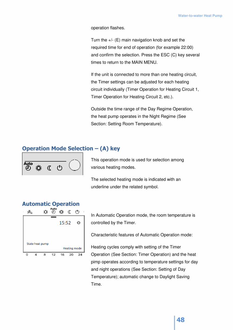
Operation Mode Selection – (A) key
This operation mode is used for selection among
various heating modes.
The selected heating mode is indicated with an
underline under the related symbol.
Automatic Operation
In Automatic Operation mode, the room temperature is
controlled by the Timer.
Characteristic features of Automatic Operation mode:
Heating cycles comply with setting of the Timer
Operation (See Section: Timer Operation) and the heat
pimp operates according to temperature settings for day
and night operations (See Section: Setting of Day
Temperature); automatic change to Daylight Saving
Time.
Water-to-water Heat Pump
49
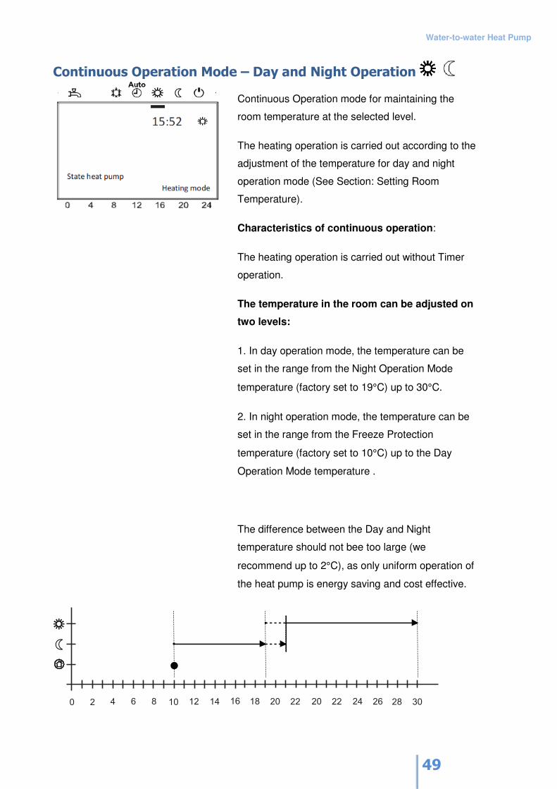
Continuous Operation Mode – Day and Night Operation
Continuous Operation mode for maintaining the
room temperature at the selected level.
The heating operation is carried out according to the
adjustment of the temperature for day and night
operation mode (See Section: Setting Room
Temperature).
Characteristics of continuous operation:
The heating operation is carried out without Timer
operation.
The temperature in the room can be adjusted on
two levels:
1. In day operation mode, the temperature can be
set in the range from the Night Operation Mode
temperature (factory set to 19°C) up to 30°C.
2. In night operation mode, the temperature can be
set in the range from the Freeze Protection
temperature (factory set to 10°C) up to the Day
Operation Mode temperature .
The difference between the Day and Night
temperature should not bee too large (we
recommend up to 2°C), as only uniform operation of
the heat pump is energy saving and cost effective.
Water-to-water Heat Pump
50
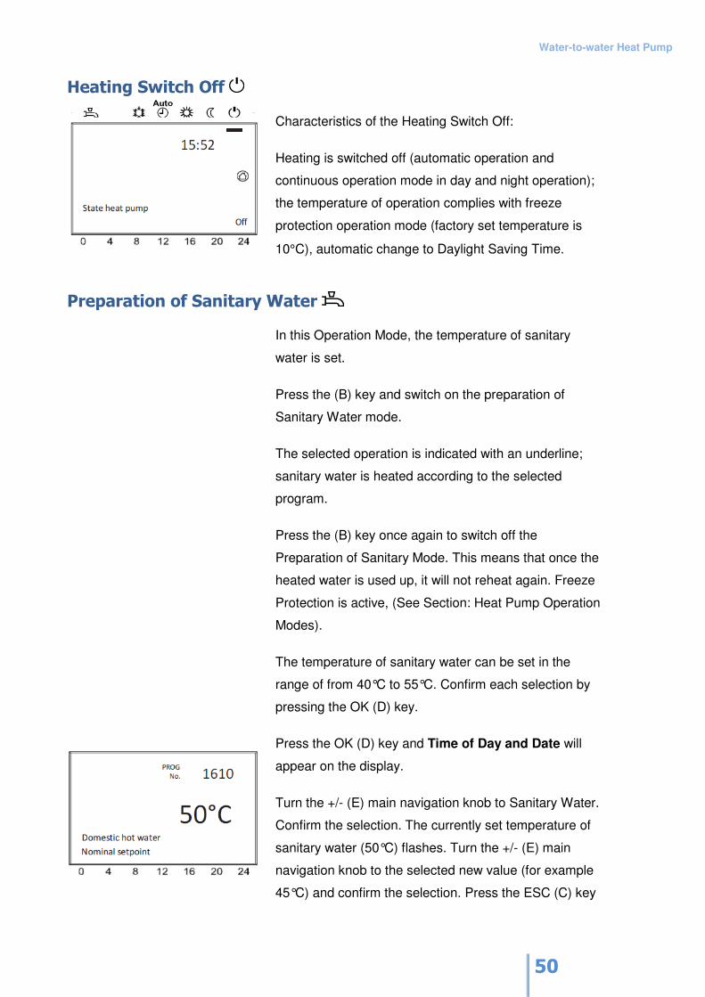
Heating Switch Off
Characteristics of the Heating Switch Off:
Heating is switched off (automatic operation and
continuous operation mode in day and night operation);
the temperature of operation complies with freeze
protection operation mode (factory set temperature is
10°C), automatic change to Daylight Saving Time. Preparation of Sanitary Water
In this Operation Mode, the temperature of sanitary
water is set.
Press the (B) key and switch on the preparation of
Sanitary Water mode.
The selected operation is indicated with an underline;
sanitary water is heated according to the selected
program.
Press the (B) key once again to switch off the
Preparation of Sanitary Mode. This means that once the
heated water is used up, it will not reheat again. Freeze
Protection is active, (See Section: Heat Pump Operation
Modes).
The temperature of sanitary water can be set in the
range of from 40°C to 55°C. Confirm each selection by
pressing the OK (D) key.
Press the OK (D) key and Time of Day and Date will
appear on the display.
Turn the +/- (E) main navigation knob to Sanitary Water.
Confirm the selection. The currently set temperature of
sanitary water (50°C) flashes. Turn the +/- (E) main
navigation knob to the selected new value (for example
45°C) and confirm the selection. Press the ESC (C) key
Water-to-water Heat Pump
51
several times to return to the MAIN MENU.
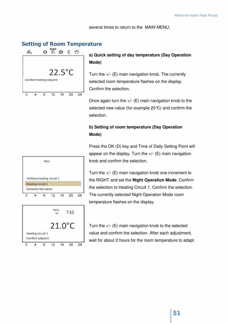
Setting of Room Temperature
a) Quick setting of day temperature (Day Operation
Mode)
Turn the +/- (E) main navigation knob. The currently
selected room temperature flashes on the display.
Confirm the selection.
Once again turn the +/- (E) main navigation knob to the
selected new value (for example 20°C) and confirm the
selection.
b) Setting of room temperature (Day Operation
Mode)
Press the OK (D) key and Time of Daily Setting Point will
appear on the display. Turn the +/- (E) main navigation
knob and confirm the selection.
Turn the +/- (E) main navigation knob one increment to
the RIGHT and set the Night Operation Mode. Confirm
the selection to Heating Circuit 1. Confirm the selection.
The currently selected Night Operation Mode room
temperature flashes on the display.
Turn the +/- (E) main navigation knob to the selected
value and confirm the selection. After each adjustment,
wait for about 2 hours for the room temperature to adapt.
Water-to-water Heat Pump
52
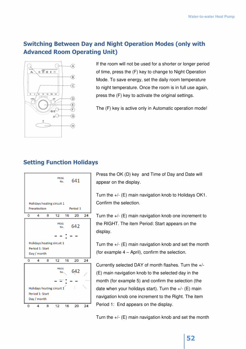
Switching Between Day and Night Operation Modes (only with
Advanced Room Operating Unit)
A
B
C
D
E
F
G
H
If the room will not be used for a shorter or longer period
of time, press the (F) key to change to Night Operation
Mode. To save energy, set the daily room temperature
to night temperature. Once the room is in full use again,
press the (F) key to activate the original settings.
The (F) key is active only in Automatic operation mode!
Setting Function Holidays
Press the OK (D) key and Time of Day and Date will
appear on the display.
Turn the +/- (E) main navigation knob to Holidays OK1.
Confirm the selection.
Turn the +/- (E) main navigation knob one increment to
the RIGHT. The item Period: Start appears on the
display.
Turn the +/- (E) main navigation knob and set the month
(for example 4 – April), confirm the selection.
Currently selected DAY of month flashes. Turn the +/-
(E) main navigation knob to the selected day in the
month (for example 5) and confirm the selection (the
date when your holidays start). Turn the +/- (E) main
navigation knob one increment to the Right. The item
Period 1: End appears on the display.
Turn the +/- (E) main navigation knob and set the month
Water-to-water Heat Pump
53
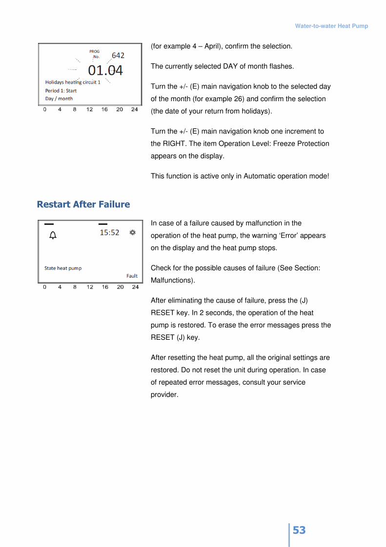
(for example 4 – April), confirm the selection.
The currently selected DAY of month flashes.
Turn the +/- (E) main navigation knob to the selected day
of the month (for example 26) and confirm the selection
(the date of your return from holidays).
Turn the +/- (E) main navigation knob one increment to
the RIGHT. The item Operation Level: Freeze Protection
appears on the display.
This function is active only in Automatic operation mode!
Restart After Failure
In case of a failure caused by malfunction in the
operation of the heat pump, the warning ‘Error’ appears
on the display and the heat pump stops.
Check for the possible causes of failure (See Section:
Malfunctions).
After eliminating the cause of failure, press the (J)
RESET key. In 2 seconds, the operation of the heat
pump is restored. To erase the error messages press the
RESET (J) key.
After resetting the heat pump, all the original settings are
restored. Do not reset the unit during operation. In case
of repeated error messages, consult your service
provider.
Water-to-water Heat Pump
54
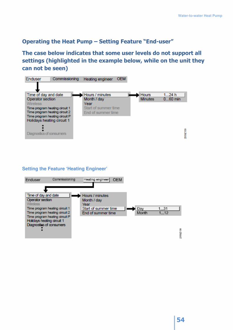
Operating the Heat Pump – Setting Feature “End-user”
The case below indicates that some user levels do not support all
settings (highlighted in the example below, while on the unit they
can not be seen)
Setting the Feature ‘Heating Engineer’

Water-to-water Heat Pump
55
Water-to-water Heat Pump
56
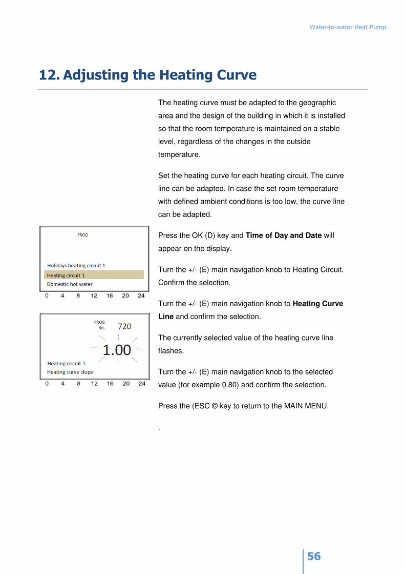
12. Adjusting the Heating Curve
The heating curve must be adapted to the geographic
area and the design of the building in which it is installed
so that the room temperature is maintained on a stable
level, regardless of the changes in the outside
temperature.
Set the heating curve for each heating circuit. The curve
line can be adapted. In case the set room temperature
with defined ambient conditions is too low, the curve line
can be adapted.
Press the OK (D) key and Time of Day and Date will
appear on the display.
Turn the +/- (E) main navigation knob to Heating Circuit.
Confirm the selection.
Turn the +/- (E) main navigation knob to Heating Curve
Line and confirm the selection.
The currently selected value of the heating curve line
flashes.
Turn the +/- (E) main navigation knob to the selected
value (for example 0.80) and confirm the selection.
Press the (ESC © key to return to the MAIN MENU.
.
Water-to-water Heat Pump
57
Temperatura ogrevalnega voda
Temperatura okolice
42
-8
0,80
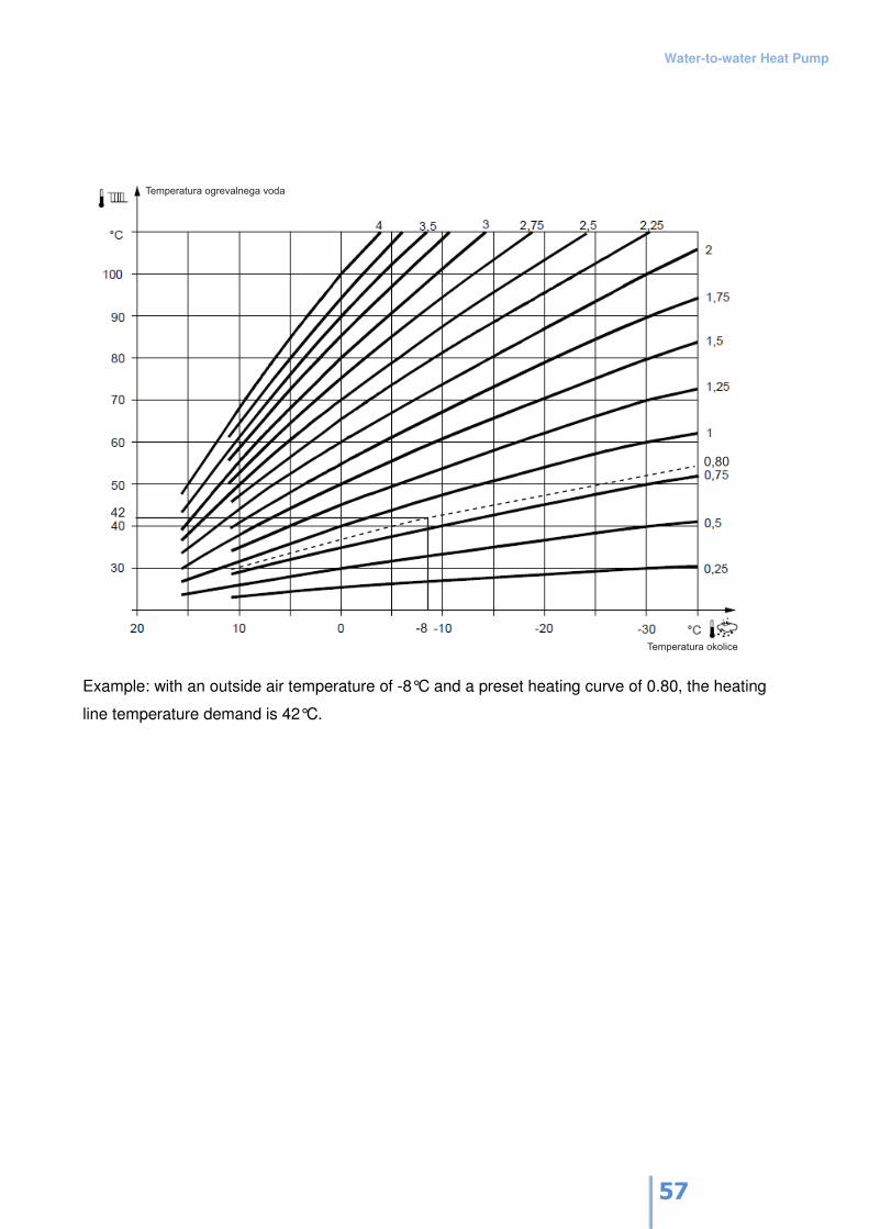
Example: with an outside air temperature of -8°C and a preset heating curve of 0.80, the heating
line temperature demand is 42°C.
Water-to-water Heat Pump
58
13. Switching on Additional Heat Sources
Switching on Additional Heat Source K27
Using the controller incorporated in the Gorenje heat pump, you can control the switching on (or
off) of the additional heat source (gas furnace, oil heater) depending on the outside temperature.
This will support the heat pump in the process of heating the sanitary water (extra setting) and
heating water, providing energy and cost saving of the heat pump (the decrease of COP reduces
cost efficiency of operation). Once there is no need for sanitary water or heating water, the K27
additional heat source can be disconnected.
Procedure:
Define the controller output as 'Heat demand K27' (user level: 'Setting’ before start-up, menu
'Configuration', parameters from 5890-5896).
Define the temperature range for the switching on and off of the extra heat source (user level OEM,
menu 'Configuration’, parameter 6128 (the unit switches on when the temperature is below the set
value (factory set at 0°C) and parameters 6129 (the unit switches off when the temperature is
below the set value (factory set at -30°C)).
If extra heating is used for the heating of sanitary water, the related 5736 should be set to 'off' (user
level: 'Setting’ before start-up, menu 'Configuration', parameter 5736 to 'off'.
Switching on of Electric Heater in the K6 Sanitary Water Tank
The electric heater in the hot water tank is switched on when sanitary water needs to be heated,
but due to malfunction of the heat pump, this is not possible. Also, the heater is switched on if the
temperature setting for sanitary water is too high and the capacity of the heat pump is insufficient.
In such a case, the heat pump will switch off (because of the high pressure reached) and the
heater will heat the sanitary water to the set temperature.
Procedure:
Define the controller output as 'Electric Heater for K6 Sanitary Water’ (user level: 'Setting’ before
start-up, menu 'Configuration', parameters from 5890-5896).
Water-to-water Heat Pump
59
Switching on the Electric Heater in the K16 Hot Water Tank
The electric heater in the K16 hot water tank switches on when water in the hot water tank needs
to be heated, but the heat pump failure (Limit Source Temp. Min. Brine (too low of a temperature of
the source)) prevents it. In this case, the heat pump switches off and the water is heated by the
electric heater.
Procedure:
Define the controller output as 'Electric Heater for K6 Hot Water Tank’ (user level: 'Setting’ before
start-up, menu 'Configuration', parameters from 5890-5896).
Water-to-water Heat Pump
60
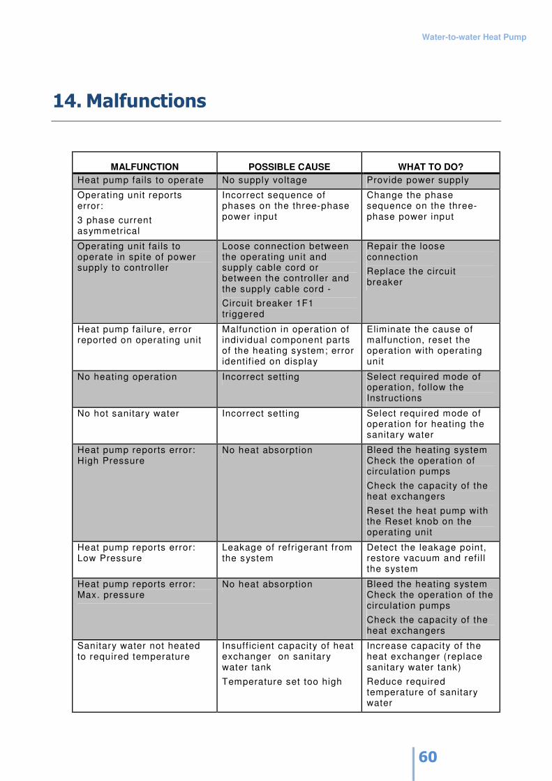
14. Malfunctions
MALFUNCTION POSSIBLE CAUSE WHAT TO DO?
Heat pump fails to operate No supply voltage Provide power supply
Operating unit reports error:
3 phase current asymmetrical
Incorrect sequence of phases on the three-phase power input
Change the phase sequence on the three-phase power input
Operating unit fails to operate in spite of power supply to controller
Loose connection between the operating unit and supply cable cord or between the controller and the supply cable cord -
Circuit breaker 1F1 triggered
Repair the loose connection
Replace the circuit breaker
Heat pump failure, error reported on operating unit
Malfunction in operation of individual component parts of the heating system; error identif ied on display
Eliminate the cause of malfunction, reset the operation with operating unit
No heating operation Incorrect sett ing Select required mode of operation, follow the Instructions
No hot sanitary water Incorrect sett ing Select required mode of operation for heating the sanitary water
Heat pump reports error: High Pressure
No heat absorption Bleed the heating system Check the operation of circulation pumps
Check the capacity of the heat exchangers
Reset the heat pump with the Reset knob on the operating unit
Heat pump reports error: Low Pressure
Leakage of refrigerant from the system
Detect the leakage point, restore vacuum and refi l l the system
Heat pump reports error: Max. pressure
No heat absorption Bleed the heating system Check the operation of the circulation pumps
Check the capacity of the heat exchangers
Sanitary water not heated to required temperature
Insufficient capacity of heat exchanger on sanitary water tank
Temperature set too high
Increase capacity of the heat exchanger (replace sanitary water tank)
Reduce required temperature of sanitary water

Water-to-water Heat Pump
61
15. Maintenance
In order to prevent damages to the heat pump, do not use the pump as a storage surface. Clean
the outer surface of the pump with a damp cloth.
To avoid causing damage to the surface, never use cleaning agents containing coarse particles,
sodium carbonate, acids or chlorines.
Layers of lime scale depositing inside the heat exchanger in the heat pump may cause
malfunctions and failure in operation. To avoid this, make sure the heat exchanger is free of
deposits or remove the deposits and clean the system as described below.
Cleaning of the Heating System
The combination of the steel structure and oxygen in the heating circuit may cause corrosion. Via
the valves, the circulation pump and the plastic pipes, the loose rust particles may enter the
heating system. With a floor heating system, use of impermeable material is mandatory.
We recommend using pipelines made of adequately corrosion resistant material in order to prevent
depositing of rust particles in the heat pump condenser.
Also, heating water may contain sealing material particles and lubricants. If the operation of the
heat pump is impaired, let an expert clean the system.
We recommend flushing the heat exchanger with counter flow.
We recommend using a 5% phosphorous acid solution. For more frequent cleaning, use 5% formic
acid.
To prevent leakage of acid into the heating system, connected the flushing device directly to the
heat pump.
Eventual residues of the cleaning agent may cause damages to the system. To prevent eventual
damages, make sure the system is thoroughly rinsed with neutral media.
Water-to-water Heat Pump
62
Use acid very carefully and take into account safety regulations and protection measures.
When in doubt about how to use the chemicals, consult the manufacturer or the vendor.
Heat Source System
The water-to-water heat pump must be protected against impurities. Instal a filter at the heat inlet
side on the heat pump. During the first months of use, the filter should be cleaned more often.
Once the amount of impurities is reduced, the cleaning intervals may be longer.
Required water pureness
The underground water must not contain elements that could cause deposits in the heat
exchanger. To prevent depositing of iron in the heat pump system, the uppper limit value is for Iron
< 0,2mg/l and Manganese < 0,1mg/l.
Use of surface water or salt water is not allowed. Consult your local water supplier on the
possibility of using the heat from underground water.
Water-to-water Heat Pump
63
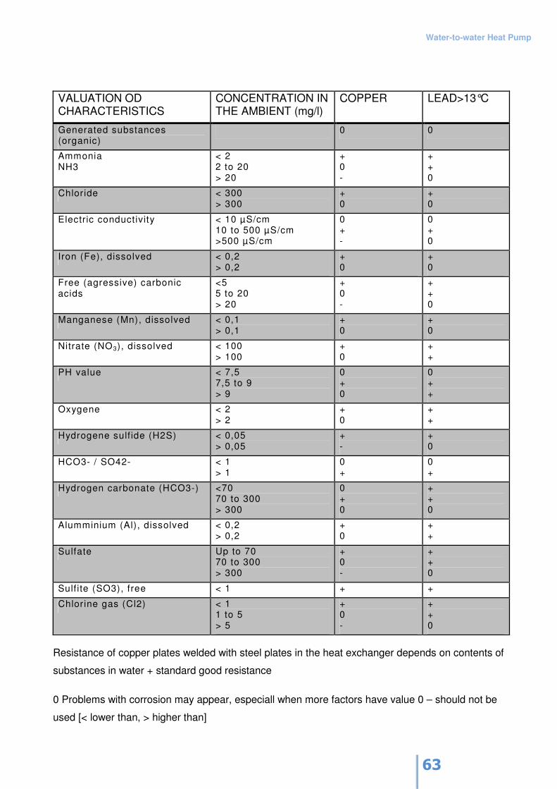
VALUATION OD CHARACTERISTICS
CONCENTRATION IN THE AMBIENT (mg/l)
COPPER LEAD>13°C
Generated substances (organic)
0 0
Ammonia NH3
< 2 2 to 20 > 20
+ 0 -
+ + 0
Chloride < 300 > 300
+ 0
+ 0
Electric conductivity < 10 µS/cm 10 to 500 µS/cm >500 µS/cm
0 + -
0 + 0
Iron (Fe), dissolved < 0,2 > 0,2
+ 0
+ 0
Free (agressive) carbonic acids
<5 5 to 20 > 20
+ 0 -
+ + 0
Manganese (Mn), dissolved < 0,1 > 0,1
+ 0
+ 0
Nitrate (NO3), dissolved < 100 > 100
+ 0
+ +
PH value < 7,5 7,5 to 9 > 9
0 + 0
0 + +
Oxygene < 2 > 2
+ 0
+ +
Hydrogene sulf ide (H2S) < 0,05 > 0,05
+ -
+ 0
HCO3- / SO42- < 1 > 1
0 +
0 +
Hydrogen carbonate (HCO3-) <70 70 to 300 > 300
0 + 0
+ + 0
Alumminium (Al), dissolved < 0,2 > 0,2
+ 0
+ +
Sulfate Up to 70 70 to 300 > 300
+ 0 -
+ + 0
Sulf ite (SO3), free < 1 + +
Chlorine gas (Cl2) < 1 1 to 5 > 5
+ 0 -
+ + 0
Resistance of copper plates welded with steel plates in the heat exchanger depends on contents of
substances in water + standard good resistance
0 Problems with corrosion may appear, especiall when more factors have value 0 – should not be
used [< lower than, > higher than]

Water-to-water Heat Pump
64