Embed Size (px)
Citation preview

Hkkjr ljdkj jsy eU=zky;
GOVERNMENT OF INDIA MINISTRY OF RAILWAYS
TECHNICAL SPECIFICATION
FOR
EQUALISER BEAMS, COMPENSATING BEAMS & LINKS
OF HIGH ADHESION & EQUALISER BEAMS (LONG & SHORT) OF TRIMOUNT
LOCOMOTIVE BOGIES
SPECIFICATION No. MP.0.4900.11 (Revision – 02)
April 2017
vuqla/kku vfHkdYi vkSj ekud laxBu y[kuÅ&226 011
RESEARCH DESIGNS & STANDARDS ORGANISATION LUCKNOW - 226 011
R.D.S.O
Technical Specification for Equaliser Beams, Compensating Beams & Links of High Adhesion and Equaliser Beams (Long & Short) of Trimount Locomotive Bogies
Motive Power Directorate (Vehicle Dynamics Group), RDSO, Lucknow Specification No.MP.0.4900.11 (Rev.02) April 2017
CONTENTS
Sl. No. Description Page No.
1. Scope 1
2. Definitions 1
3. Instructions for Purchaser 2
4. Specifications & Standards referred 2
5. Deviation(s) 3
6. Quality Assurance Plan 3
7. Manufacturing Procedure 3
8. Identification Marking 5
9. Stages of Inspection 6
10. Dimensions and Tolerances 6
11. Packing 6
12. Warranty 7
Annexure-I
1. Procedure For Hard Facing of New Equaliser Beams of Co-Co Trimount Bogies of Diesel & Electric Locomotives
i to iv
Technical Specification for Equaliser Beams, Compensating Beams & Links of High Adhesion and Equaliser Beams (Long & Short) of Trimount Locomotive Bogies
Motive Power Directorate (Vehicle Dynamics Group), RDSO Specification No.MP.0.4900.11 (Rev.02) April 2017 Page 1 of 7
TECHNICAL SPECIFICATION FOR
EQUALISER BEAMS, COMPENSATING BEAMS & LINKS OF HIGH ADHESION & EQUALISER BEAMS (LONG & SHORT) OF TRIMOUNT
LOCOMOTIVE BOGIES
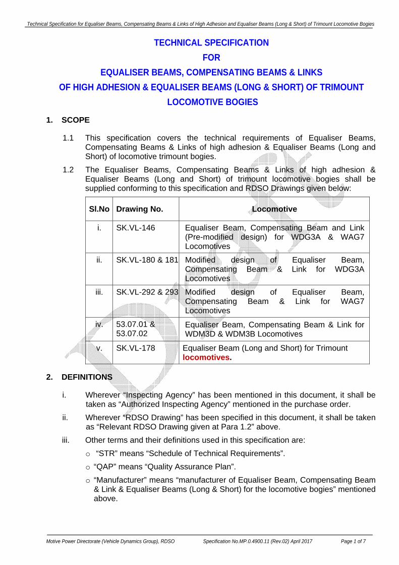
1. SCOPE
1.1 This specification covers the technical requirements of Equaliser Beams, Compensating Beams & Links of high adhesion & Equaliser Beams (Long and Short) of locomotive trimount bogies.
1.2 The Equaliser Beams, Compensating Beams & Links of high adhesion & Equaliser Beams (Long and Short) of trimount locomotive bogies shall be supplied conforming to this specification and RDSO Drawings given below:
Sl.No Drawing No. Locomotive
i. SK.VL-146 Equaliser Beam, Compensating Beam and Link (Pre-modified design) for WDG3A & WAG7 Locomotives
ii. SK.VL-180 & 181 Modified design of Equaliser Beam, Compensating Beam & Link for WDG3A Locomotives
iii. SK.VL-292 & 293 Modified design of Equaliser Beam, Compensating Beam & Link for WAG7 Locomotives
iv. 53.07.01 & 53.07.02
Equaliser Beam, Compensating Beam & Link for WDM3D & WDM3B Locomotives
v. SK.VL-178 Equaliser Beam (Long and Short) for Trimount locomotives.
2. DEFINITIONS
i. Wherever “Inspecting Agency” has been mentioned in this document, it shall be taken as “Authorized Inspecting Agency” mentioned in the purchase order.
ii. Wherever “RDSO Drawing” has been specified in this document, it shall be taken as “Relevant RDSO Drawing given at Para 1.2” above.
iii. Other terms and their definitions used in this specification are: o “STR” means “Schedule of Technical Requirements”. o “QAP” means “Quality Assurance Plan”. o “Manufacturer” means “manufacturer of Equaliser Beam, Compensating Beam
& Link & Equaliser Beams (Long & Short) for the locomotive bogies” mentioned above.

Technical Specification for Equaliser Beams, Compensating Beams & Links of High Adhesion and Equaliser Beams (Long & Short) of Trimount Locomotive Bogies
Motive Power Directorate (Vehicle Dynamics Group), RDSO Specification No.MP.0.4900.11 (Rev.02) April 2017 Page 2 of 7
o “Purchase Order” means “Purchase Order for Equaliser Beam, Compensating Beam & Link & Equaliser Beams (Long & Short) for the locomotive bogies” mentioned above.
3. INSTRUCTIONS FOR PURCHASER
3.1 Reference of this specification for Equaliser Beams, Compensating Beams & Links of high adhesion & Equaliser Beams (Long & Short) of trimount locomotive bogies should be clearly indicated in the purchase order.
3.2 The manufacturer shall be an RDSO Approved Vendor and the firm’s name shall be on the current list of RDSO Vendor Directory for supply of Equaliser Beams, Compensating Beams & Links of high adhesion & Equaliser Beams (Long & Short) of trimount locomotive bogies as per “Relevant RDSO Drawing given at Para 1.2”.
3.3 Inspection of Equaliser Beams, Compensating Beams & Links & Equaliser Beams (Long & Short) shall be carried out as per the instructions given in the RDSO Vendor Directory and prototype approval by Motive Power Directorate, RDSO. Purchaser shall clearly indicate this in the Purchase Order.
3.4 Purchaser is required to obtain clearance from RDSO for deviations from original design, material specifications, dimensions etc. desired by the manufacturer, if any.
4. SPECIFICATIONS & STANDARDS REFERRED
The firm shall have a copy of latest versions of following Specifications & Standards / Codes:
Sl. Spec. No. Description
1. IS: 2062 Steel for General Structural Purposes
2. IS: 2102 (Part I) General Tolerances
3. IS: 3703 Code of Practice for Magnetic Particle Flaw Detection
4. IS: 4225 Recommended Practice for Straight Beam Ultrasonic Testing of Steel Plates
5. IS: 5517 Steels for Hardening and Tempering
6. ASTM A: 435 Straight Beam Ultrasonic Examination of Steel Plates
7. RDSO Procedure No. MC-92
Procedure for Hard Facing of New Equaliser Beam of Co-Co Trimount Bogies of Diesel & Electric Locomotives
Technical Specification for Equaliser Beams, Compensating Beams & Links of High Adhesion and Equaliser Beams (Long & Short) of Trimount Locomotive Bogies
Motive Power Directorate (Vehicle Dynamics Group), RDSO Specification No.MP.0.4900.11 (Rev.02) April 2017 Page 3 of 7
4.1 The reference to the ASTM / IS Specifications quoted herein shall be taken as the reference to the latest version of these Specifications.
4.2 Specific provisions in this Specification will override those in the above ASTM / IS Specifications where these are not in conformity with one another.
4.3 Any special requirements given in the relevant drawings will override this specification.
5. DEVIATION(s)
If deviation(s) from original design, material specifications, dimensions etc. are desired by the manufacturer, specific proposals with reasons shall be submitted to the purchaser. The manufacturer shall not commence manufacture of Equaliser Beams, Compensating Beams & Links and Equaliser Beams (Long & Short) till clear authorization for acceptance of the deviation is granted by Motive Power Directorate, RDSO, Lucknow.
6. QUALITY ASSURANCE PLAN 6.1 The firm shall submit Quality Assurance Plan (QAP) in the standard format
as per ISO procedure to Motive Power Directorate, RDSO for approval. QAP shall cover all aspects of process / quality control requirement to ensure quality product.
6.2 The manufacturer shall proceed for manufacturing of Equaliser Beams, Compensating Beams & Links of high adhesion & Equaliser Beams (Long and Short) of locomotive trimount bogies only after approval of QAP. The firm shall strictly follow the stipulations of QAP.
6.3 Calibration of the Testing / Measuring Equipments should be done periodically.
7. MANUFACTURING PROCEDURE
7.1 During manufacture of prototype Equaliser Beams, Compensating Beams & Links of high adhesion & Equaliser Beams (Long and Short) of trimount locomotive bogies, the vendor is required to co-ordinate and maintain liaison with the Purchaser and with Motive Power Directorate, RDSO, Lucknow for any clarifications required in regard to drawings, specifications, manufacturing, inspection & testing etc.
7.2 During manufacture of these components, changes in the design considered necessary, if any, shall be identified by the Purchaser / RDSO. These changes shall be studied by RDSO and shall be incorporated in the components manufactured by the firm only after issue of to the relevant drawing alteration to this effect.
7.3 Raw Material .1 The chemical composition & mechanical properties of steel for manufacture
of Equaliser Beams, Compensating Beams & Links of high adhesion shall conform to IS: 2062:2011 Grade E250 Quality 'B0' (Normalised & killed Quality) or Grade E250 Quality ‘C' (Normalised & killed quality) & Equaliser Beams (Long and Short) of locomotive trimount bogies shall conform to IS: 2062:2011 Grade E250 Quality ‘C' (Normalised & killed
Technical Specification for Equaliser Beams, Compensating Beams & Links of High Adhesion and Equaliser Beams (Long & Short) of Trimount Locomotive Bogies
Motive Power Directorate (Vehicle Dynamics Group), RDSO Specification No.MP.0.4900.11 (Rev.02) April 2017 Page 4 of 7
Quality) unless some other material is specified in the relevant RDSO drawings.
.2 Steel plates shall be procured from SAIL / TISCO or other reputed manufacturers along with their test certificates. These test certificates shall be correlated with the stamping on plates to be taken up for manufacture prior to commencement of fabrication. However, the test certificate and the chemical properties & mechanical properties shall be verified by the firm and inspector, as per the specification.
.3 All test certificates shall be submitted to Inspecting Agency for scrutiny.
.4 Any deviation in material specification would lead to rejection of material.
7.4 Inspection of Steel Plates .1 All plates to be taken up for manufacture shall be cleaned for freedom from
rust and scales and shall then be examined visually for straightness and surface defects such as cracks, dents, pitting, bends etc.
.2 The firm shall check chemical composition and mechanical properties of at least one sample from each plate to be taken up for manufacture to ensure conformity of properties with the test certificates.
.3 Inspecting Agency can draw random samples for verification of chemical composition and mechanical properties from at least 20% of plates to be taken up for manufacture, if required. The manufacturer shall provide facilities at his premises to Inspecting Agency for evaluation of these properties. Any deviations in the chemical/ mechanical properties of these samples would warrant verification of these properties for all the plates of the lot.
.4 All plates shall be subjected to ultrasonic testing on the entire surface for detection of defects like lamination seams and internal flaws. The ultrasonic testing shall be carried out as per ASTM A: 435 / IS: 4225 using angular / normal probes. In case the ultrasonic testing reveals any flaw, the material should be rejected.
.5 Only those plates which have been tested and found acceptable being free from any defect stated above shall be used for manufacture.
7.5 Plate Cutting and Grinding .1 The Equaliser Beams, Compensating Beams & Links of high adhesion &
Equaliser Beams (Long and Short) of trimount locomotive bogies shall be cut from the plate by Automatic Flame / Laser / CNC Wire Cut / Water Jet Machine along the grains to required dimensions as per RDSO drawing. The end of Equaliser Beams (Long & Short) shall be cut shorter by approx. 4 mm to facilitate weld deposition at position where hard facing is required.
.3 All notches, gouges, flame and tool marks on the profile-cut surface shall be ground smooth and surface blended to achieve a surface finish as specified in the RDSO Drawing.
.4 Check straightness of Equaliser Beams, Compensating Beams & Links & Equaliser Beams (Long and Short) to ensure that no distortion has taken place during profile cutting. Distortion, if any, should be corrected using hydraulic press by cold method followed by ultrasonic inspection to ensure freedom from defects.
Technical Specification for Equaliser Beams, Compensating Beams & Links of High Adhesion and Equaliser Beams (Long & Short) of Trimount Locomotive Bogies
Motive Power Directorate (Vehicle Dynamics Group), RDSO Specification No.MP.0.4900.11 (Rev.02) April 2017 Page 5 of 7
7.6 Stress Relieving & Shot Blasting
A. Equaliser Beams & Compensating Beams .1 After plate cutting, the Equaliser Beams & Compensating Beams shall be
subjected to stress relieving. For this, raise the temperature slowly up to 640ºC and after 4 hrs. of slaking period. Allow cooling in furnace upto 200ºC. It shall then be allowed to cool in still air.
.2 Adequate measures shall be taken to avoid distortion in Equaliser Beams & Compensating Beams during stress relieving operation.
.3 Record of stress relieving cycle shall be submitted to the Inspecting Agency.
.4 After stress relieving, the Equaliser Beams & Compensating Beams shall be cleaned by shot blasting.
B. Equaliser Beams (Long & Short) This item does not require Stress Relieving & Shot Blasting.
7.7 Drilling and Reaming Holes are to be drilled and reamed in Equaliser Beams, Compensating Beams &
Links & Equaliser Beams (Long and Short) to the dimensions, tolerance and surface finish conforming to RDSO drawing.
7.8 Magnetic Particle Inspection After manufacture, the Equaliser Beams, Compensating Beams & Links & Equaliser Beams (Long and Short) shall be subjected to Magnetic Particle Test as per IS: 3703 at the locations marked ‘X’ in RDSO drawing for detection of cracks, if any. The components shall be free from any defect.
7.9 Hard Facing of Equaliser Beams (Long and Short)
Hard facing of both big and small ends of Equaliser Beam shall be carried out as per Procedure No. MC-92 issued by M&C Directorate, RDSO (copy reproduced at Annexure-I).
7.11 Fitment of Bushes
The Equaliser Beams, Compensating Beams & Links & Equaliser Beams (Long and Short) shall be fitted with bushes of material, grain size and hardness conforming to RDSO drawing.
8. IDENTIFICATION MARKING
Each Equaliser Beams, Compensating Beams & Links & Equaliser Beams (Long and Short) shall be provided with identification marking for traceability by stamping in 6 mm letters as given below: .1 Manufacturer’s initial .2 Month & Year of manufacture .3 Serial No. of Equaliser Equaliser Beams, Compensating Beams & Links &
Equaliser Beams (Long and Short) manufactured in particular month. .4 RDSO Drawing No. .5 ‘UT’ for indicating that the Beam has been tested ultrasonically
Technical Specification for Equaliser Beams, Compensating Beams & Links of High Adhesion and Equaliser Beams (Long & Short) of Trimount Locomotive Bogies
Motive Power Directorate (Vehicle Dynamics Group), RDSO Specification No.MP.0.4900.11 (Rev.02) April 2017 Page 6 of 7
For example: “ABC0106001.SKVL-181.UT”, “ABC0106001.SKVL-178.UT” for ultrasonically tested Beam No. 001 manufactured by ABC in January, 2006 as per RDSO Drawing No. SK.VL-181 and SK.VL-178. This serial number shall be reset in every month. Hence, “ABC0106001” will be a unique serial number for a beam/ link.
Record of above checks shall be maintained by the manufacturer as per the serial number for at least 06 years from the date of manufacture.
9. STAGES OF INSPECTION
9.1 The prototype inspection of Beams & Links shall be carried out by the Inspecting Agency in the following stages of manufacture:
.1 Inspection of raw material (as per the requirement of para 7.3), welding consumables (as per para 3 of Annexure-I), templates and fixtures (As per latest drawing of the component).
.2 Inspection after plate cutting to check dimensional accuracy (as per latest RDSO drawing of the component) and witnessing magnetic particle test (as per the locations marked at the drawing).
.3 Final inspection after hard facing (where ever applicable), fitment of bushes and making identification marking.
9.2 The manufacturer shall fabricate the Beams & Links in stages as detailed in Para 9.1. The manufacturer shall start each stage of manufacturing only after receipt of clearance of previous stage by the Inspecting Agency.
9.3 Regular inspection (Inspection after prototype) of the Beams & Links shall be carried out by the Inspecting Agency as per the inspection plan of the relevant component.
10. DIMENSIONS AND TOLERANCES
10.1 Dimensions and tolerances of Equaliser Beams, Compensating Beams & Links & Equaliser Beams (Long and Short) shall conform to RDSO drawings.
9.4 Detailed dimension Check Sheets shall be prepared for various stages during manufacturing of Equaliser Beams, Compensating Beams & Links & Equaliser Beams (Long and Short) in which measurements shall be recorded and kept for evaluation and verification by the Inspecting Agency.
9.5 All non-tolerance dimensions shall be maintained in accordance with IS: 2102 (Medium) or as indicated in the drawing.
9.6 Gauges, fixtures, templates and accurate measuring instruments shall be used to ensure correctness of the dimensions.
9.7 Periodic Calibration / Checking of Gauges, Templates and Fixtures shall be done for correctness and accuracy.
11. PACKING
11.1 Rust preventive coatings shall be applied on all machined surfaces before packing.
11.2 While packing, due care shall be taken to protect all machined surfaces against any damage.
Technical Specification for Equaliser Beams, Compensating Beams & Links of High Adhesion and Equaliser Beams (Long & Short) of Trimount Locomotive Bogies
Motive Power Directorate (Vehicle Dynamics Group), RDSO Specification No.MP.0.4900.11 (Rev.02) April 2017 Page 7 of 7
11.3 Equaliser Beams, Compensating Beams & Links & Equaliser Beams (Long and Short) shall be packed suitably to protect them against any damage during transit. Suitable non-metallic bushes shall be used to protect metal bushes fitted in Beams & Links.
11.4 Copy of all data packages including Dimension Check Sheets, Test certificate for chemical and mechanical properties of material, Ultrasonic Testing (UST), Magnetic Particle Test (MPT) etc. shall be supplied along-with Equaliser Beams, Compensating Beams & Links and the same shall be the property of Purchaser.
12. WARRANTY
The manufacturer shall undertake warranty for trouble-free and satisfactory service performance of Equaliser Beams, Compensating Beams & Links & Equaliser Beams (Long and Short) supplied by them for a period to be fixed by the purchaser from the date of commissioning into service. A period of 5 years from the date of commissioning into service is recommended. The firm shall arrange replacement of Equaliser Beams, Compensating Beams & Links & Equaliser Beams (Long and Short) if they are considered unserviceable due to defects observed during warranty period on account of metallurgical and/or manufacturing deficiency. The decision of purchaser in this regard shall be final.
13. AII the provisions contained in RDSO’s ISO procedures laid down in document no. QO-D-7.1-11, dated 19.07.2016 (Titled “ Vendor changes in approved status) and subsequent version/amendment thereof, shall be binding and applicable on the successful vendor/vendors in the contract floated by Railways to maintain quality of products supplied to Railways.
***
Technical Specification for Equaliser Beams, Compensating Beams & Links of High Adhesion and Equaliser Beams (Long & Short) of Trimount Locomotive Bogies
Motive Power Directorate (Vehicle Dynamics Group), RDSO Specification No.MP.0.4900.11 (Rev.02) April 2017 Page i of iv
ANNEXURE – I
Procedure for Hard Facing of New Equaliser Beams
of Co-Co Trimount Bogies of Diesel & Electric Locomotives
(M&C Directorate’s Procedure No. MC-92)
Introduction
Equaliser Beam is a very important component used in Trimount Bogies of Locomotives. The end portions of these Beams rest on axle boxes and get worn out during service. A procedure No. MC-43 (of August 2001) had been made for reclamation of worn out equalizing Beams. Fabrication of these Beams is carried out using steel to Gr. C of IS: 2062, which is mild steel and may wear out fast at the ends during service. It was decided to carryout hard facing of the ends of new equalizing Beams as well to increase their service life. This procedure outlines the procedure of hard facing of new Equaliser Beams.
1. Material
The material used in manufacturer of Equaliser Beams (both short & long type) is steel to IS: 2062 Gr. C (Normalized & killed quality).
2. Cutting of Equalizing Beam from plate
The equalizing Beam of required dimensions shall be cut from the plate as per existing procedure keeping the dimension of the end shorter by approx. 4 mm to facilitate weld deposition (as shown in the Fig.1).
3. Welding Consumables
MMAW electrodes as well as MIG / MAG filler wires can be employed.
3.1 MMAW electrodes approved under IRS Class H4B as per M-28-02 shall be used for above reclamation purpose. The diameter of electrodes used shall preferably be 4.0 mm. Higher diameter electrodes can be used in exceptional circumstances.
3.2 MIG/MAG welding filler wires approved under class V as per IRS: M-46-03 may also be used. The diameter of MIG/MAG wire used shall be 1.2 mm.
4. Preheating of Electrodes The electrodes shall be preheated to about 2500C for two hours or as recommended by the manufacturer. To avoid further absorption of moisture by the preheated electrodes, they should not be taken out from over at a time. They should be drawn from the oven so, as to be consumed within 30 minutes to one hour. Manufacturer’s recommendations regarding current conditions, preheating of electrodes and any other special characteristics shall be followed.
Technical Specification for Equaliser Beams, Compensating Beams & Links of High Adhesion and Equaliser Beams (Long & Short) of Trimount Locomotive Bogies
Motive Power Directorate (Vehicle Dynamics Group), RDSO Specification No.MP.0.4900.11 (Rev.02) April 2017 Page ii of iv
5. Hard facing Procedure
A. Preparation prior to welding i. Remove all dirt, dust, oil grease etc. properly from the area to be reclaimed. ii. Grind the faces properly to remove all oxidised layer formed during profile
cutting of Beam. iii. Check the face to be reclaimed by Dye Penetrant test to ensure absence of
any crack or other defect. iv. Ensure complete removal of dye from the hard faced zone. v. If any crack is noticed on the area to be hard faced the same may be
removed by grinding. Such removal however shall not reduce the thickness by more than 4 mm.
B. During Welding i. Preheat the ends of Beam to be hard faced to about 1500C by to & fro
motion of oxy-acetylene torch. Check correctness of temperature using thermal chalks.
ii. Set the Welding current & Voltage in the welding power source as per recommendations of electrode manufacturer depending upon the diameter of electrodes used.
iii. Interpass temperature of zone to be hard faced shall be maintained to about 1500C during welding.
iv. Connect the electrode with positive terminal of battery while welding using DC current.
v. Weld the area in down hand welding position. vi. The runs should be deposited only in longitudinal direction. vii. After each run, slag shall be removed. viii. Each run should immediately be peened when weld metal is in hot
condition i.e. dull red colour. Peening should be preferred utilising a ½” to ¾” diameter round nosed ½ Pound hammer. Repeated moderate blows should be used instead of few heavy blows. The effect of peening is to relieve internal stresses, minimise distortion and refine the micro-structure.
ix. Welding shall be commenced from mid thickness of Beam & progressed towards the edges or started from one edge & progressed upto other edge.
x. Put the stringent beads. Weaving shall not be more than two times of the diameter of electrodes.
xi. The crater end shall always be filled up by moving the electrode backwards for a distance of about 15 mm from finishing end and then electrode should be taken out from molten pool.
xii. Maintain appropriate welding speed to get smooth weld bead. xiii. Deposit 1-2 mm of extra metal so that after grinding & finishing the Beam
ends are of required dimensions. xiv. Keep arc length as short as possible.

Technical Specification for Equaliser Beams, Compensating Beams & Links of High Adhesion and Equaliser Beams (Long & Short) of Trimount Locomotive Bogies
Motive Power Directorate (Vehicle Dynamics Group), RDSO Specification No.MP.0.4900.11 (Rev.02) April 2017 Page iii of iv
xv. Highly skilled, trained & certified welder shall only be employed.
C. After Welding i. Inspect the weld area by magnifying glass for any welding defect especially
for any crack & short weld metal. ii. Grind the weld by using surface grinder to get required finish & dimensions. iii. The hard faced area finally shall have no any sharp edge, stress raiser, or
any potential source of fatigue. iv. To avoid localized overheating of weld & subsequent cracking the grinder
shall not locally grind at one place for longer duration. v. The finished weld shall then be checked visually & by Dye Penetrant test
for presence of surface defects. vi. Magnetic Particle test may be used in place of Dye Penetrant test to check
weld quality for surface & sub-surface defects. vii. Any crack or harmful defect if noticed, the same shall be gouged out and
re-welded by using the welding technique as stated above. viii. The hardness of weld shall be in the range of 300 to 350 BHN. ix. Stress relieving treatment shall not be required for new hard faced
Equaliser Beams.
Precautions i. Welding shall be carried out in flat / down – hand position only. ii. The surface to be hard faced shall be properly cleaned. iii. The welding electrodes shall be of good conditions. Any electrode with
damaged coating or rusted core wire shall not be used. iv. Adjust proper current & polarity in the machine during welding. v. Put the weld beads in longitudinal directions only.

Technical Specification for Equaliser Beams, Compensating Beams & Links of High Adhesion and Equaliser Beams (Long & Short) of Trimount Locomotive Bogies
Motive Power Directorate (Vehicle Dynamics Group), RDSO Specification No.MP.0.4900.11 (Rev.02) April 2017 Page iv of iv