Embed Size (px)
Citation preview
Page 1 of 56 File No. EL/ 7.1.108/SBC Spec. No RDSO/PE/SPEC/AC/0184 -2015 (Rev. 0)
Prepared by – SSE/TL&AC-III .
Checked by –
DSE (TL-AC & System design)
Hkkjr ljdkj
GOVERNMENT OF INDIA MINISTRY OF RAILWAYS
vuqla/kku vfHkdYi ,oa ekud laxBu
RESEARCH DESIGNS AND STANDARDS ORGANISATION MINISTRY OF RAILWAYS
,y-,p-ch- izdkj ds bZ-vks-th- okrkuqdwfyr ;kuks ds fy;s fLop cksMZ dSfcusV dh fof’kf"V
SPECIFICATION FOR SWITCH BOARD CABINET FOR LHB TYPE AC EOG COACHES
vkj-Mh-,l-vks-@ih-bZ-@,l ih bZ lh@ ,lh@0184 &2015 ¼ifj'kks/ku- 0½
Spec. No. RDSO/PE/SPEC/AC/0184 – 2015 (Rev. 0)
S. No. Date of amendment Revision Reason
vuqeksfnr
APPROVED
dk;Zdkjh funs'kd@ih ,l ,.M bZ ,e ;w
Executive Director/PS&EMU
Page 2 of 56 File No. EL/ 7.1.108/SBC Spec. No RDSO/PE/SPEC/AC/0184 -2015 (Rev. 0)
Prepared by – SSE/TL&AC-III .
Checked by –
DSE (TL-AC & System design)
INDEX
Clause No.
Description Page No.
1.0 Foreword 3
2.0 Scope of supply 3
3.0 Governing specifications 3
4.0 Operating and service conditions 4
5.0 Design and technical requirements 5
6.0 Constructional requirements 9
7.0 Tests 11
8.0 Schedule of tests 12
9.0 Description of tests 13
10.0 Technical data 15
11.0 Commissioning 16
12.0 Supplier’s responsibility 16
13.0 Marking and packing 16
14.0 Guarantee and Warranty 17
15.0 Training 17
16.0 Infringement of patent right 17
17.0 Service engineers 18
18.0 Cartel formation 18
19.0 Annexures 18
Annexure A :Undertaking against Cartel formation 19
Annexure B : Bill of material 20
Annexure C: Harness chart for LHB type EOG AC coaches 39
Annexure D: Codification chart 43
Annexure E: List of wiring diagram 51
Annexure F : List of drawings 52
Annexure G : List of connectors 54
Page 3 of 56 File No. EL/ 7.1.108/SBC Spec. No RDSO/PE/SPEC/AC/0184 -2015 (Rev. 0)
Prepared by – SSE/TL&AC-III .
Checked by –
DSE (TL-AC & System design)
SPECIFICATION FOR SWITCH BOARD CABINET (SBC) FOR LHB TYPE AC EOG COACHES
1.0 FOREWORD
1.1 This specification is for design, manufacture, testing and supply of Switch Board Cabinet
(SBC) consisting of all the power/control switchgear for coach lighting, air conditioning, pantry, pump control, sanitary system and public address system etc. of LHB type AC EOG Coach suitable for 3 phases, 750 volts, and 50 Hz train lighting system.
1.2 The quality aesthetics, design and overall workmanship of Switch Board Cabinet as a whole
shall be to international standards and the quality of the existing LHB equipment shall be considered prime basis.
1.3 Manufacturers of this system shall get RDSO approval for their product for which the
guidelines can be obtained from website www.rdso.indianrailways.gov.in. Such manufacturers shall have infrastructure for manufacture, testing and supply of Switch Board Cabinet and its accessories fittings as per requirements specified in RDSO schedule of technical requirements (STR) no. RDSO/PE/STR/AC/0027-2009 (Rev. 0).
2.0 SCOPE OF SUPPLY:
S.No Item description Qty/Coach(Nos.)
1 Switch Board Cabinet (SBC) consisting of all the power/control switchgear for coach lighting, air conditioning, pantry, pump control, sanitary system and public address system etc. for LHB type AC EOG Coach suitable for 3 phases, 750 volts, 50 Hz system.
1
3.0 GOVERNING SPECIFICATIONS
Manufacturers should have the following standards in compliance of the specification:
IS:13947(Pt.1)-1993 1 Low voltage switchgear and control gear Part-I General rules.
IS:13947(Pt.3)-1993 Part-3- Switches, disconnections and fuse combination units.
IS:8623-1993 Pt.-1 Low voltage switchgear and control gear assemblies: Part-I Requirements for the type tested and partially type tested assemblies.
IS:10118-1982 Code of practice for selection, installation and maintenance of the switchgear and the control gear.
IS:13703-1993 Low voltage fuses for voltages not exceeding 1000 volts or 1500 volts DC.
IS:1248 Pt.II-1983 Direct acting indicating analog electrical measuring instruments
Page 4 of 56 File No. EL/ 7.1.108/SBC Spec. No RDSO/PE/SPEC/AC/0184 -2015 (Rev. 0)
Prepared by – SSE/TL&AC-III .
Checked by –
DSE (TL-AC & System design)
and their accessories (ammeter and voltmeters).
IS:8828-1996 Electrical accessories, circuit breakers for over current protection for household and similar installations.
IS:1573-1986 Electroplated coatings of Zinc on Iron and Steel.
IS:1364-1992 Hexagon head bolts, screws and nuts of product grades A & B.
UIC 550 Power supply installation for Passenger stock.
Any deviation from this specification proposed by the manufacturer , aimed to improve upon the performance, utility and reliability/efficiency of the component/panel will be given due consideration, provided full particulars of the deviation with justification are furnished.
4.0 OPERATING & SERVICE CONDITIONS
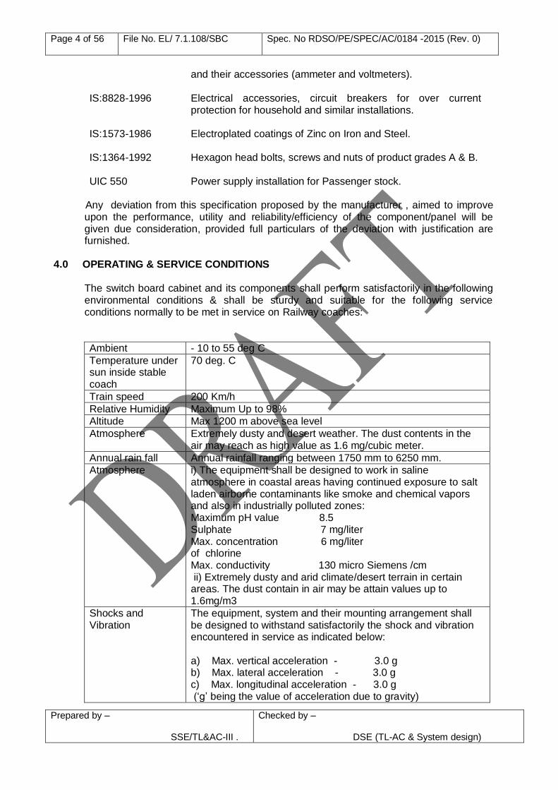
The switch board cabinet and its components shall perform satisfactorily in the following environmental conditions & shall be sturdy and suitable for the following service conditions normally to be met in service on Railway coaches:
Ambient - 10 to 55 deg C
Temperature under sun inside stable coach
70 deg. C
Train speed 200 Km/h
Relative Humidity Maximum Up to 98%
Altitude Max 1200 m above sea level
Atmosphere Extremely dusty and desert weather. The dust contents in the air may reach as high value as 1.6 mg/cubic meter.
Annual rain fall Annual rainfall ranging between 1750 mm to 6250 mm.
Atmosphere i) The equipment shall be designed to work in saline atmosphere in coastal areas having continued exposure to salt laden airborne contaminants like smoke and chemical vapors and also in industrially polluted zones: Maximum pH value 8.5 Sulphate 7 mg/liter Max. concentration 6 mg/liter of chlorine Max. conductivity 130 micro Siemens /cm ii) Extremely dusty and arid climate/desert terrain in certain areas. The dust contain in air may be attain values up to 1.6mg/m3
Shocks and Vibration
The equipment, system and their mounting arrangement shall be designed to withstand satisfactorily the shock and vibration encountered in service as indicated below: a) Max. vertical acceleration - 3.0 g b) Max. lateral acceleration - 3.0 g c) Max. longitudinal acceleration - 3.0 g (‘g’ being the value of acceleration due to gravity)
Page 5 of 56 File No. EL/ 7.1.108/SBC Spec. No RDSO/PE/SPEC/AC/0184 -2015 (Rev. 0)
Prepared by – SSE/TL&AC-III .
Checked by –
DSE (TL-AC & System design)
Operating Train/Electrical Environment
The equipment should function satisfactorily near 25 KV AC electric traction. It should not be susceptible to malfunction due to interference from overhead traction power supply lines or under abnormal conditions such as overloads and faults in the electrical circuits of the coach.
5.0 DESIGN & TECHNICAL REQUIREMENTS
5.1 The switch board cabinet comprises of the various cubicles consisting of power and control switchgear, measuring/Indicating instruments, protection devices, light fan & sanitary/pump control, controller of the air conditioning unit, switchgear for the pantry equipment, battery charger, disconnecting and earthing device, DC-DC converter insulation monitoring devices etc. as per enclosed Bill of material (BOM), Annexure ‘B’.
5.2 The Switch Board Cabinet shall be constructed as per RCF drawings LW70020 of latest alteration.
5.3 On the right side of the lower part of switch board cabinet a disconnecting and earthing
device shall be located as indicated in drawing. The main function of this device is to separate the coach equipment from the two feeders (input supply) and simultaneously earthing 750V AC network of the coach. The connection to this unit shall be made by supplier up to separate wago connectors. The connections to this unit shall be made/removed by removing the perforated metal sheet provided on the top right side of the disconnecting and earthing device. The size of the earthing & disconnecting device shall be reduced to bare minimum length, however the firm shall take prior approval from RDSO/PUs office and get the drawings approved
5.4 The left side of the lower part of Switch Board Cabinet is further divided vertically into
two parts for Battery charger and Main contactors along with main fuses. Mounting plate for main contactors along with main fuses shall be sliding for easy access and replacement/checking. The connection of this sliding plate shall be accessible by removing the polycarbonate sheet provided on the front left side of lower part of SBC. Battery charger is not in the scope of supply of the panel manufacturer.
5.5 The first layer (or back panel) contains contactors, relays, low voltage fuses, earth
leakage monitors and terminal blocks for the incoming and outgoing for 110V AC, 240V AC/415V AC, 1 KVA transformer, cable ducts and terminals for further layer. A transparent fire retardant polycarbonate sheet shall be provided to prevent accidental contact. The dimensions shall be strictly adhered to the drawing.
5.6 The second layer shall consist of three swivel frames as indicated in drawing. 5.7 On the upper left swivel frame, MCBs/MPCBs shall be arranged in two rows with a
voltage level of 240/415V AC.
5.8 On the second swivel frame on left side following items shall be mounted for feeding the AC load and part of the pantry load.
a) 110V/24V DC/DC converter and minimal voltage relay. b) *Wheel slide protection c) *Volume control & MCB for public address system d) *Public address system
Page 6 of 56 File No. EL/ 7.1.108/SBC Spec. No RDSO/PE/SPEC/AC/0184 -2015 (Rev. 0)
Prepared by – SSE/TL&AC-III .
Checked by –
DSE (TL-AC & System design)
* Note Item (b) , (c) and (d) are not in scope of supply of the power panel manufacturer, however, mounting holes shall be drilled as per the drawing and terminal connectors shall be provided in the Switch Board Cabinet.
5.9 The swivel frame on the right side shall be suitable for mounting. MCBs shall be
arranged in two rows with a voltage level of 110V ac/dc for lighting etc. 5.10 The third layer consists of the swivel doors of the Switch Board Cabinet. The upper
area of the doors shall be provided with a cut-out to operate the MCBs/MPCBs as per drawing without opening the door.
a) Underneath this cut out on the left door Voltmeter and Ammeter for supply network
with changeover switch shall be provided. The voltmeter shall be connected directly to 750V ac network. Therefore, backside of the voltmeter shall be covered with an earthed metal shell/sheet to prevent direct contact as indicated in drawing. A separate small door is to be provided for equipment of public address system so that it can be maintained through this door opened by a special key.
b) Below this cut-out for the right door the devices such as Ammeter for battery
charging current and discharging current along with various push buttons and indicators for faults of important devices (bus-bar network, local network, 415V network, battery charger) etc. with a voltage level under or equal to 110V shall be arranged. Underneath these devices, the operating and display unit for the air-conditioning unit shall be located.
5.11 Plug in type connections shall be provided for the following equipment:
a) RMPU b) CDTS & Lavatory wiring c) Battery charger d) Pump
5.12 The female connection shall be fixed on the SBC as per SKED-531 and the male connection shall be supplied to Production units(PUs) in advance so that harness with conduit can be made well in time. The connector designation and part nos. for connectors on Switch board cabinet side shall be as given in Annexure G .
5.13 All connections to the harting connector base shall be in series with the WAGO
connectors provided for equipment to ensure availability of alternate connection arrangement.
5.14 The general layout for providing these harting connections shall be as shown in SKED
No. 531. Firms shall get prior approval from RDSO for better alternative layout with the same connectors with alternative type of connectors suggested.
5.15 The following connectors are provided on front of Regulated Battery Charger : Main’s -MG02R24 -10P I Plug Battery -MG02R28 -10S I Socket Sensor -MG02R20 -27S I Socket
Page 7 of 56 File No. EL/ 7.1.108/SBC Spec. No RDSO/PE/SPEC/AC/0184 -2015 (Rev. 0)
Prepared by – SSE/TL&AC-III .
Checked by –
DSE (TL-AC & System design)
For making ready connections to the battery charger 3 harness shall be provided in series with the terminal slip S1x3 provided in SBC to ensure availability of alternate connection arrangement. To have compatibility with the battery charger the other ends of harness shall be provided with following connectors :
Main’s -MG08F24 -10S I Socket Battery -MG08F28 -10P I Plug Sensor -MG08F20 -27P I Plug The length of each harness shall be 1.5M to make ready connectors with the battery
charger.
5.16 All crimping of pins shall be done with suitable crimping tool prescribed by M/s Harting only to avoid any crimping failure. One set of tool shall also be supplied with panel for crimping in the harness.
5.17 All cables used for wiring of connector shall be e-beam as per RDSO specification no.
ELRS/SPEC/ELEC/0019 Rev.’2’ or latest.
5.18 All wiring shall be secured with cable ties and provided with cable protection sleeves made up of polyamide or ‘PMA jack’.
5.19 The firm shall carry out modification in readymade harness for provision of compatible
connector (which is in firm’s scope of supply) to match the connectors in SBC. 5.20 All comb bus bars to be replaced with cable looping as per RDSO drawing no.
RDSO/PE/SK/AC/0154-2011 (Rev. 0). 5.21 Controller for the AC unit shall be mounted on a small swivel frame as indicated in
drawing no. LW70020 alt. ‘e’ sheet 1/17 or latest for easy observation of LED indications by turning the frame. This unit is not in the scope of supply of panel manufacturer and shall be supplied loose for fitment/wiring.
5.22 MCBs shall be provided at the output of the RMPU micro-controller at suitable location
near the RMPU micro-controller as per the scheme advised by RDSO vide letter no. EL/7.1.108/SBC dated 04.07.2012. However, firm shall take prior approval of mounting arrangement before bulk supplies.
5.23 RDSO Modification sheet no. RDSO/PE/MS/AC/0054 (Rev.0)-2011 shall be followed for
providing MCBs for capacitor bank in LHB type coaches.
5.24 The internal wiring shall be done with Halogen free electron beam irradiated cables confirming to RDSO specification No. ELRS/SPEC/ELEC/0019 Rev. ‘2’ or latest. The sizes/type of cables shall be as indicated in harness chart to Annexure ‘C’. All cables/wiring shall be of black color with color coded sleeves according to phases shall be provided for identification. Control wiring and power cables shall be segregated according to the voltages and adequately secured with cable ties.
5.25 a) The outgoing/incoming terminal connections shall be brought out to a adequate
rated cage clamp type terminal block/MCB. b) The terminal blocks shall be located for easy access as indicated in the drawing.
Page 8 of 56 File No. EL/ 7.1.108/SBC Spec. No RDSO/PE/SPEC/AC/0184 -2015 (Rev. 0)
Prepared by – SSE/TL&AC-III .
Checked by –
DSE (TL-AC & System design)
c) Separators/intermediate plates shall be provided between adjacent terminal blocks, wherever required.
d) All cables leading to a terminal block shall be properly secured /clamped before termination.
e) It shall be ensured that not more than two wires are terminated at one point. f) The power panel shall be complete with all necessary crimping sockets and
ferrules for ready connections. Rings/tubular crimping sockets shall be used with suitable palm size to prevent loose connections during vibrations. Only copper crimping sockets of approved make shall be used. Crimping sockets of sizes smaller than 16 mm 2 shall be with metal reinforcement.
g) Marking ferrules shall be of computer generated type for easy identification of the cables with the help of shrinking sleeves (self-extinguishing) of suitable size horizontally printed or with the help of multi mark carrier/label of M/s. Tyco or equivalent approved make.
h) All cut-outs wherein cables enter/exit the switch board cabinet shall be provided with V-grooved rubber grommets/edge protection sleeves from protection against sharp edges.
5.26 Two earthing terminals shall be provided on top and bottom of the panel on diagonally
opposite ends. For earthing two braided copper cable of 70 sq mm and 300 mm in length each duly crimped shall be supplied with the panel. Earthing of the metal parts/sub- assemblies inside the panel shall also be done as indicated with suitable wire size as determined vide 7.4.3.1.7 (a) of IS: 8623 (Pt-I) – 1993.
5.27 Manufacturer shall provide a screen printed circuit diagram at backside of front door at
suitable place, which should be visible on opening of lower door
5.28 Suitable polyamide alleys/ducts with snap-in element of M/s. L&T/SALZAR/AKG shall be provided for cable trans versing as indicated in the drawings. Whenever the cables shall cross the door/passage area, the cables shall be covered by self-extinguishing and halogen free braiding/nylon jacket (material-polyamide 6.6)
5.29 All the devices fitted in the switch board cabinet shall allow access for easy
maintenance of all the equipments from the front of the panel.
5.30 Compact LED/fluorescent light fittings with a working voltage of 110V DC to drawing no. CC76415 along with a switch/ socket point shall be provided inside the switch board cabinet for ease of the maintenance staff. The fitting shall be clamped suitably to avoid damage due to vibrations.
5.31 A rotary switch for bypassing RMPU Micro controller shall be provided as per RDSO
Modification sheet no. RDSO/PE/MS/AC/0057 Rev.0-2011. 5.32 Interlocking of auxiliary contact of MPCB of ventilation motors of RMPU with heater
control circuit shall be ensured. The heater of the RMPU shall be switched off in case of tripping/inadvertent switching off of MPCB of ventilation motor of RMPU.
5.33 The Power/Control connections of the Switch Board Cabinet shall be as per wiring
diagram given in Annexure-E.
5.34 Care shall be taken to achieve a neat and symmetrical layout.
Page 9 of 56 File No. EL/ 7.1.108/SBC Spec. No RDSO/PE/SPEC/AC/0184 -2015 (Rev. 0)
Prepared by – SSE/TL&AC-III .
Checked by –
DSE (TL-AC & System design)
5.35 Only approved makes mentioned in the bill of material as per Annexure-B shall be used. For any deviation prior approval from RDSO shall be taken.
5.36 All rotary switches shall conform to IS:13947 (Pt. III) -93 and shall be suitable for
universal mounting. 5.37 General and safety requirements shall be governed by IS:13947 (Pt. I)-93 and
IS:8623-1993. 6.0 CONSTRUCTIONAL REQUIREMENTS 6.1 The switch board cabinet shall consist of welded steel tube construction, TIG
(Tungesten inert gas) welded to make complete frame with following dimensions. Making of structure with L-channel welded to form a tube is not permitted.
Height = 1850 mm Width = 1280 mm Depth = 920 +20 mm (including door)
a) No positive tolerances are allowed. However, negative tolerances shall be governed by MDG 0008.
b) The firm manufacturing revised /amended switch board cabinet shall submit the outer dimensional drawings for structure for approval from RDSO/PUs before starting bulk production.
6.2 The steel sheet used for the front door shall be 2 mm thick CRCA steel conforming to
IS:513-1994 & 1.6 mm 304 – stainless steel for bottom doors.
6.3 The dimensions/mounting/general layout of the switch board cabinet shall be conforming to RCF drawing no. LW70020 of latest alteration and other drawings enclosed as Annexure F. The drawings annexed are for general guidance only. For change in layout for manufacturing/improving the aesthetics from maintenance point of view, the manufacturer shall take prior approval of RDSO.
6.4 A top cover shall be provided on the top of switch board cabinet to prevent water
ingress inside of panel as shown in RCF drawing No. LW70020, sheet 1/17, alt ’e’ or latest.
6.5 The location and size of the hinges shall be as per RCF drawing No. LW70020, sheet
1/17, alt ’e’ or latest. 6.6 Panel shall be powder coated to thickness minimum 60 microns Grey shade No.
6102/08038 of M/s Nerolac paints or 877 of M/s Berger paints, after giving requisite surface treatment.
6.7 A suitable zinc plated saddle clamp shall be provided on the front side of the
Switchboard Cabinet door to prevent accidental damage to the indicating devices generally as per SKED 263.
6.8 All fasteners used shall be zinc plated and passivated according to IS:1573- 86 and conforming to IS:1364-92.
Page 10 of 56 File No. EL/ 7.1.108/SBC Spec. No RDSO/PE/SPEC/AC/0184 -2015 (Rev. 0)
Prepared by – SSE/TL&AC-III .
Checked by –
DSE (TL-AC & System design)
6.9 Switch Board Cabinet shall be covered from both sides (left & right side) with 1.6mm thick CRCA steel conforming to IS:513-1994.
6.10 The enclosure of equipment/component shall be given powder coating of thickness of minimum of 60 microns
6.11 The general construction of the switch board cabinet shall be such as to keep the
various voltage levels separated against each other as far as possible.
6.12 Suitable eye bolts shall be provided at the top four corners for lifting the Power Panel during mounting on the coach such that panel may not lift on one side during lifting.
6.13 The switch board cabinet shall be divided into two parts i.e. upper part and lower part.
6.14 The lower part of the switch board cabinet shall be further divided into two parts i.e.
Right side part and Left side part.
6.15 The upper part of the Switch Board Cabinet is divided depth wise into three different layers/levels.
6.16 Each SBC shall be provided with 5 nos. additional doors with polycarbonate sheet fixed
on the front top covers of SBC. Two nos. of such doors shall be provided on left leaf and 3 nos. on right leaf of the front cover. The general arrangement shall be as shown in RCF drawing no. LW70020 alt.”c” sheet 7/18 or latest for left door & LW70020 alt. “d” 8/18 or latest for right door.
6.17 Polycarbonate sheet used shall be fire retardant resin, 3 mm thick, scratch free and
shall be of M/s GE plastics. Each door leaf shall be provided with 1 no. Snap lock Part no. 264-9006 (lockable snap lock for flap cover of MPCBs/MCBs) and non lockable snap lock part no. 264-9009 for other flap covers of M/s DIRAK or approved make.
6.18 The doors shall be fixed to the main doors by means of two nos. industrial hinges Part
No. 218-9501 (Hinge) &218-0907.15-00000 (Nut plate) of M/s DIRAK or approved make.
6.19 The bottom doors of stainless steel make shall be of the SBC shown in drawing no.
LW70020 alt. ‘c’ sheet 16/17 or latest for left door & LW70020 alt. ‘c’ 17/17 or latest for right door to make it in line with the top doors.
6.20 Each SBC shall be provided with 4 nos. additional doors fixed on the front top covers of SBC. Two nos. of such doors each shall be provided on left leaf and right leaf of the front cover. The general arrangement shall be as shown in sketch no. SKED-406 Alt. “a” or latest.
6.21 The doors shall comprise of outer frame and transparent polycarbonate sheet provided
on the inside of doors for visibility of indication lamps provided on the front covers of the SBC.
6.22 Frame shall be fabricated with 1.6 mm thick CRCA sheet and shall be powder coated
to Siemens Grey shade after giving requisite surface treatment.
6.23 Polycorbonate sheet used shall be fire retardant resin, 4 mm thick, scratch free and shall be of M/s GE plastics. Each door leaf shall be provided with 2 nos. industrial locks
Page 11 of 56 File No. EL/ 7.1.108/SBC Spec. No RDSO/PE/SPEC/AC/0184 -2015 (Rev. 0)
Prepared by – SSE/TL&AC-III .
Checked by –
DSE (TL-AC & System design)
i.e. one of the top and one of the bottom of the door leaf as shown in SKED-406 alt. ‘a’ or latest.
6.24 The doors shall be fixed to the main doors by means of 3 nos. industrial hinges of M/s
Dirak or reputed make. The hinges shall be TIG welded to the door frames.
7.0 TESTS
7.1 Only after the drawings and the design have been approved and the clearance given to this effect, the manufacturer shall take up the manufacture of the prototype. It is to be clearly understood that any changes, required to be done in the prototype or any additional tests other than specified herein are required to be conducted on the prototype unit or its components, they shall be done expeditiously. The required testing facilities for inspection & testing shall be available at firm’s premises.
7.2 Firm’s internal testing shall be done by qualified person & submitted the test results to
RDSO. 7.3 The type tests shall be carried out by RDSO representative on prototype unit either
totally or in part under the following conditions without any additional cost:
a) A manufacturer undertakes to manufacture for the first time as per this specification.
b) An important change in design details of switch board cabinet has been introduced. c) Specification is modified necessitating the re- designing of equipment. d) Unsatisfactory performance reported from user Railways. e) Resumption of production after an interruption of more than two years.
7.4 RDSO may conduct surprise checks on the manufacturing process and quality control
along with any of the tests to ensure quality of product and its conformance to RDSO specification.
7.5 The firm shall maintain date-wise in-house quality control system and in-house quality
control records etc. for in stage process inspection and testing at the same along with QAP shall be made available to the inspecting official during type testing.
7.6 Inspecting Agency/Rites shall carry out the tests in manufacturer premises as per
acceptance & routine tests specified in tender specification. Check list consisting of testing details /measurements and acceptability shall be prepared and submitted along with inspection certificate to production units (PUs).
7.7 TYPE TESTS:
All the type tests mentioned in clause no. 8.0 shall be carried out on a prototype unit.
The firm manufacturing for the first time shall get the prototype approved from RDSO. The prototype test shall be undertaken either totally or in part on Switch Board Cabinet as per clause no. 8.0 under the following conditions without any additional cost :-
(i) A new variant of Switch Board Cabinet is introduced by existing manufacturer. (ii) A fundamental change in design is introduced and modification of Switch Board
Cabinet likely to affect its function. (iii) Failure or variations established during type test.
Page 12 of 56 File No. EL/ 7.1.108/SBC Spec. No RDSO/PE/SPEC/AC/0184 -2015 (Rev. 0)
Prepared by – SSE/TL&AC-III .
Checked by –
DSE (TL-AC & System design)
(iv) Resumptions of production after an interruption of more than two years. (v) Specification is amended or revised. (vi) During Quality audit if required. (vii) In any other condition, whenever RDSO/Purchaser feels necessity of the test.
7.8 ROUTINE TESTS:
Routine tests mentioned in clause no. 8.0 shall be carried out on each unit by the
manufacturer at his works to ensure compliance with the specification and the drawings.
7.9 ACCEPTANCE TESTS:
Acceptance test mentioned in clause no. 8.0 are to be carried out by an inspecting
authority nominated by the purchaser at the works of the manufacturer, on the sample picked up by the inspecting authority. All the acceptance tests shall be carried out at firm’s premises at the manufacturer’s cost. Inspecting officer will witness the tests. A copy of the internal tests conducted by the firm shall be supplied to inspecting/purchasing authority.
8.0 SCHEDULE OF TESTS :
Tests as mentioned in table below shall be carried out as per respective clause of IS:
8623 (Pt-I)-1993.
SN Clause of IS:8623
Tests Type Test
Routine Test
Accept- ance Test
1. 8.3.1 Visual inspection, including inspection of wiring and electrical operation test
Yes Yes Yes
2. 8.2.1 Temperature rise test Yes Yes* No
3. 8.2.6 Mechanical operation and sequence test Yes Yes Yes
4. 8.2.5 Test for verification of clearance and creep- age distances
Yes Yes Yes
5. 8.2.2 Test for verification of dielectric properties
Yes Yes Yes
6. 8.3.4 Test for verification of insulation resistance Yes Yes Yes
7. 8.3.3 Checking of electrical continuity Yes Yes Yes
8. 8.2.4 Verification for effectiveness of protective circuits
Yes Yes Yes
9. --- Check for satisfactory operation of rotary switches by rotating 10 times clockwise and 10 times anticlockwise. (WTC of rotary switches of OEM shall be checked by inspecting authority)
Yes Yes Yes
10. --- Check for BOM and proof of material as per spec. with proof of invoices.
Yes Yes Yes
* Shall be carried out in one no. SBC in every lot size of 20 nos.
Page 13 of 56 File No. EL/ 7.1.108/SBC Spec. No RDSO/PE/SPEC/AC/0184 -2015 (Rev. 0)
Prepared by – SSE/TL&AC-III .
Checked by –
DSE (TL-AC & System design)
8.1 The accuracy of measuring instruments used for both type and routine tests shall be of class 0.5.
8.2 For the commissioning of first panel, panel manufacturer shall depute his staff at
production unit (PUs) for interface with respect of items falling in RCF/ICF/PU scope of supply.
9.0 DESCRIPTION OF TESTS:
9.1 Visual inspection including inspection of wiring and electrical operation test: The test shall include visual inspection of control panel, overall dimensions, marking and
general layout of housing, earthing, colour coding as mentioned in the specification & drawings. Electrical operations shall also be checked as per concerned drawings and prepared test protocol.
General workmanship of Switch Board Cabinet and its accessories such as MPCB, MCB,
fuse, relay, contactor, connector, cable etc shall be checked. 9.2 Temperature rise test:
Temperature rise test of the Switch Board Cabinet shall be carried out as per clause no.
8.2.1 of IS 8623 Pt -1. During the temperature rise test, 125 A current shall be injected in 750 V circuits and 80 A shall be injected in 415 volt circuits. The reading at various points of switchgears conductors & insulators, HT fuses, bus bar, Panel body, Panel doors, handles etc. shall be measured at an interval of 30 minutes till the temperature will stabilized. The firm should submit the test protocol for temperature rise test in advance to RDSO.
9.3 Mechanical operation and sequence test:
This type test shall not be made on such devices of the assembly which have already
been type-tested according to their relevant specifications provided their mechanical operation is not impaired by their mounting.
For those parts which need a type test, satisfactory mechanical operation shall be verified
after installation in the assembly. The number of the operating cycles shall be 50. Note: In the case of withdrawable functional units, the cycle shall be from the connected
to the disconnected position and back to the connected position. At the same time, the operation of the mechanical interlocks associated with these
movements shall be checked. The test is considered to have been passed if the operating conditions of the apparatus, interlocks etc. have not been impaired and if the effort required for operation is practically the same as before the test.
9.4 Test for verification of clearance and creepage distances: Electrical/cable alley shall be mounted keeping in mind the RCF drawing no. LW70020 of
latest alteration for maintaining clearance and creepage distance. 9.5 Test for verification of di-electric properties:
Page 14 of 56 File No. EL/ 7.1.108/SBC Spec. No RDSO/PE/SPEC/AC/0184 -2015 (Rev. 0)
Prepared by – SSE/TL&AC-III .
Checked by –
DSE (TL-AC & System design)
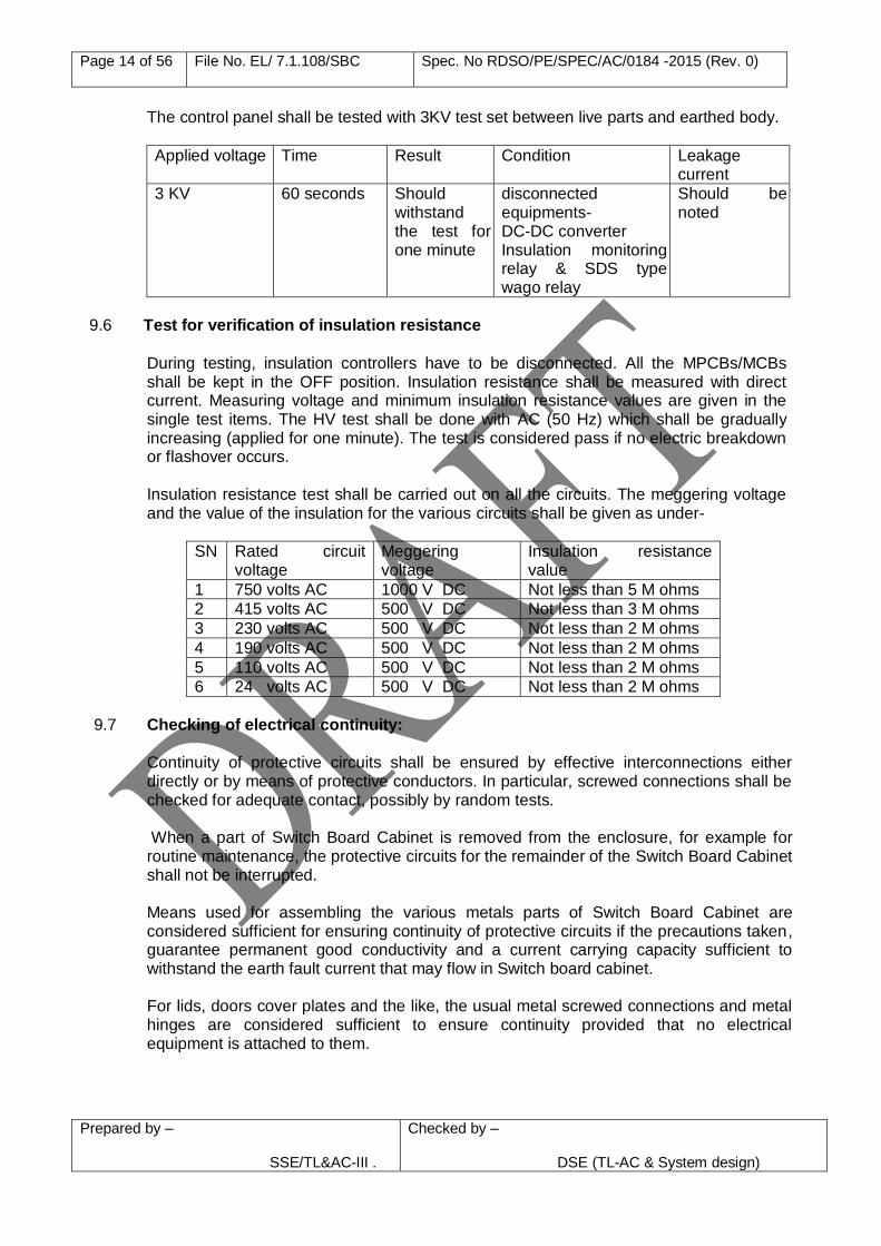
The control panel shall be tested with 3KV test set between live parts and earthed body.
Applied voltage Time Result Condition Leakage current
3 KV 60 seconds Should withstand the test for one minute
disconnected equipments- DC-DC converter Insulation monitoring relay & SDS type wago relay
Should be noted
9.6 Test for verification of insulation resistance
During testing, insulation controllers have to be disconnected. All the MPCBs/MCBs shall be kept in the OFF position. Insulation resistance shall be measured with direct current. Measuring voltage and minimum insulation resistance values are given in the single test items. The HV test shall be done with AC (50 Hz) which shall be gradually increasing (applied for one minute). The test is considered pass if no electric breakdown or flashover occurs.
Insulation resistance test shall be carried out on all the circuits. The meggering voltage
and the value of the insulation for the various circuits shall be given as under-
SN Rated circuit voltage
Meggering voltage
Insulation resistance value
1 750 volts AC 1000 V DC Not less than 5 M ohms
2 415 volts AC 500 V DC Not less than 3 M ohms
3 230 volts AC 500 V DC Not less than 2 M ohms
4 190 volts AC 500 V DC Not less than 2 M ohms
5 110 volts AC 500 V DC Not less than 2 M ohms
6 24 volts AC 500 V DC Not less than 2 M ohms
9.7 Checking of electrical continuity: Continuity of protective circuits shall be ensured by effective interconnections either
directly or by means of protective conductors. In particular, screwed connections shall be checked for adequate contact, possibly by random tests.
When a part of Switch Board Cabinet is removed from the enclosure, for example for
routine maintenance, the protective circuits for the remainder of the Switch Board Cabinet shall not be interrupted.
Means used for assembling the various metals parts of Switch Board Cabinet are considered sufficient for ensuring continuity of protective circuits if the precautions taken, guarantee permanent good conductivity and a current carrying capacity sufficient to withstand the earth fault current that may flow in Switch board cabinet.
For lids, doors cover plates and the like, the usual metal screwed connections and metal hinges are considered sufficient to ensure continuity provided that no electrical equipment is attached to them.
Page 15 of 56 File No. EL/ 7.1.108/SBC Spec. No RDSO/PE/SPEC/AC/0184 -2015 (Rev. 0)
Prepared by – SSE/TL&AC-III .
Checked by –
DSE (TL-AC & System design)
All parts of protective circuit within the Switch Board Cabinet shall be so designed that they are capable of withstanding the highest thermal and dynamic stresses that may occur at the place of installation of Switch Board Cabinet.
9.8 Verification for effectiveness of protective circuits:
It shall be verified that the different exposed conductive parts of the assembly are effectively connected to the protective circuit in accordance with some requirements. A protective circuit in an assembly consists of either a separate protective conductor or the conductive structural parts or both. It provides the following- (i) Protection against the consequences of faults within the assembly. (ii) Protections against the consequences of faults in external circuits supplied through
the assembly. 9.9 Check for satisfactory operation of rotary switch: Rotary switches shall be checked for satisfactory operation by rotating 10 times clockwise and
10 times anticlockwise. Work Test Certificate (WTC) of rotary switches of OEM shall be checked by inspecting authority.
9.10 Check for BOM:
(i) Bill of Material (BOM) used in Switch Board Cabinet as given in Annexure-B (description,
make, part no./ Catalog no. of each item) shall be checked. Work Test certificates(WTC) in respect of the following shall be submitted by the firm during prototype testing.
1. MCBs/MPCBs 2. Wide band contactors 3. Rotary switches 4. Overload relays 5. Control transformer 6. Earthing & disconnecting device 7. H.T fuses
(ii) In view of updating of the various catalogue/technical data sheets resulting in discontinuation/Non-availability of a particular make/part no; the firm shall take prior approval from RDSO for alternate part no. of a particular make before effecting bulk supplies.
(iii) Proforma in voice of all major items shall be supplied along with each supply of material.
10.0 TECHNICAL DATA 10.1 The manufacturer shall submit complete design details of SBC and its fittings, necessary
calculation, if any shall also be submitted. 10.2 The manufacturer shall also supply following:
a) Component drawings in CAD software in line with RCF drawings enclosed with
specification along with the material and specification. b) One set of the following will be supplied with every 10 units.
Page 16 of 56 File No. EL/ 7.1.108/SBC Spec. No RDSO/PE/SPEC/AC/0184 -2015 (Rev. 0)
Prepared by – SSE/TL&AC-III .
Checked by –
DSE (TL-AC & System design)
i) Operating and trouble-shooting manual. ii) Parts illustrated catalogue-indicating sources.
11.0 COMMISSIONING:
Firm shall be responsible for commissioning of prototype unit in one coach at RCF. The modification in Switch Board Cabinet shall be compatible with the coach harness provided for various circuits. Firm shall prove out the scheme in one coach for proper functioning of all related equipments.
12.0 Supplier’s responsibility
12.1 The Switch Board Cabinet shall be suitable for rugged service conditions normally to be
met within Railway rolling stocks, where coaches are expected to run up to a maximum speed of 200 kmph in varying climatic conditions existing throughout India.
12.2 The supplier shall be fully responsible for ensuring that all equipments forming part of
the supply is entirely fit for the purpose and no part of this specification shall in any way remove or reduce his obligation in this respect. In addition, it is the supplier’s responsibility to underwrite the complete switchgear system design and ensure that it is compatible with and will, in no way, compromise the design and performance of switch board cabinet of his supply.
The supplier shall provide “in the field” service support during the guarantee period.
12.3 The supplier shall supply any purpose built or special tools or equipment that may be
necessary for the correct operation, servicing, testing or installation of the equipment of the switch board cabinet.
12.4 The supplier will provide assistance, both in terms of material and technical, in
development of the system as a whole to ensure that when this switch board cabinet is installed as part of the integrated vehicle system, the performance of the system meets or exceeds the requirements specified.
12.5 If the Switch Board Cabinet fails to achieve these requirements, the Switch Board
Cabinet shall be modified at the supplier’s expense and within a time scale to be agreed with purchaser/consignee/RDSO.
13.0 MARKING AND PACKING
13.1 All the switch board cabinet and its main component/accessories shall be provided with a name/rating plate on the enclosure. The following information shall be available either by etching process or by engraving or screen- printed at the front door on each panel:
a) Name and Address of the manufacturer. b) Month of the manufacture.
c) Serial number of panel. d) Specification number. e) Hardware version f) Schematic/Connection diagram /fittings arrangement of the equipment on the side of the cover/body.
Page 17 of 56 File No. EL/ 7.1.108/SBC Spec. No RDSO/PE/SPEC/AC/0184 -2015 (Rev. 0)
Prepared by – SSE/TL&AC-III .
Checked by –
DSE (TL-AC & System design)
The first two digits shall indicate the year of manufacture and next two digits shall
indicate month. Further next four digits shall indicate manufacturing serial number.
13.2 The name/identification plates shall be of bright anodized aluminium with black letters embossed or etched on white background. These plates shall be fitted by riveting. The nameplate shall indicate the month and year of supply in addition to the usual information.
13.3 All components provided inside the panel shall be identified by screen/photo printed or
computer generated designation labels/legend marking plates. These should be mounted near the concerned component duly ensuring visibility. Circuits and components shall also be provided with the name plates indicating the operation/function of the switches/circuits. Contactors and circuit codification diagram (with glass fuse details ) shall be identified by aluminium anodized legend plates by adhesive of approved make on back side of left hand front doors. Balance indicating/measuring switchgear /devices installed on front door shall be identified by aluminium anodized legend plates by adhesive of approved make on the front doors itself. No riveting is allowed on front door.
13.4 Danger Notice plate shall be screen printed or sticker shall be provided on front of the
lower panel door conforming to IS:2551-82 for 750V. 13.5 The switch board cabinet and its sub assemblies shall be packed in thermacole boxes
and the empty spaces shall be filled with suitable filling material. Before keeping in the thermocole box, the SBC shall be wrapped with bubble sheet. The SBC shall be finally packed in a wooden case of sufficient strength, so that it can withstand bumps and jerks encountered in road/rail journey.
14.0 GUARANTEE/WARRANTY Guarantee/Warranty obligation of the equipment shall be as per IRS condition of
contract. 15.0 TRAINING
The contractor shall undertake to train, free of cost, the supervisors & staff of the Indian Railways for operation, maintenance, fault finding, trouble shooting, repair of the offered Switch Board Cabinet under the guidance of the skilled engineers as and when asked for by Railways.
16.0 INFRINGEMENT OF PATENT RIGHT
16.1 Indian Railway shall not be responsible for infringement of patent rights arising due to similarity in design, manufacturing process, use of similar components in design & development of this item and any other factor not mentioned herein which may cause such a dispute. The entire responsibility to settle any dispute/matters lies with the manufacturer/supplier.
16.2 Details/design/documents given by them are not infringing any IPR and they are
responsible in absolute and full measure instead of railways for any such violations. Data, specifications and other IP as generated out of interaction with railways shall not
Page 18 of 56 File No. EL/ 7.1.108/SBC Spec. No RDSO/PE/SPEC/AC/0184 -2015 (Rev. 0)
Prepared by – SSE/TL&AC-III .
Checked by –
DSE (TL-AC & System design)
be unilaterally used without the consent of RDSO and right of Railways/RDSO on such IP is acceptable to them.
17.0 SERVICE ENGINEERS
The manufacturer shall be required to make available the services of his engineer/engineers free of cost to which performance of the equipment in service periodically and also carry necessary repairs or replacement under warranty obligations. The necessary spares needed for replacement during service should be available with the service engineers at all the zonal Railways Head Quarter & Production Units to cover entire Indian Railways network. The service engineers shall be fully conversant with Switch Board Cabinet & electrical circuitry employed in Switch Board Cabinet.
18.0 CARTEL FORMATION
The firm will not engage cartel formation with other firms and will also submit a declaration in this regard as per attached Annexure –A.
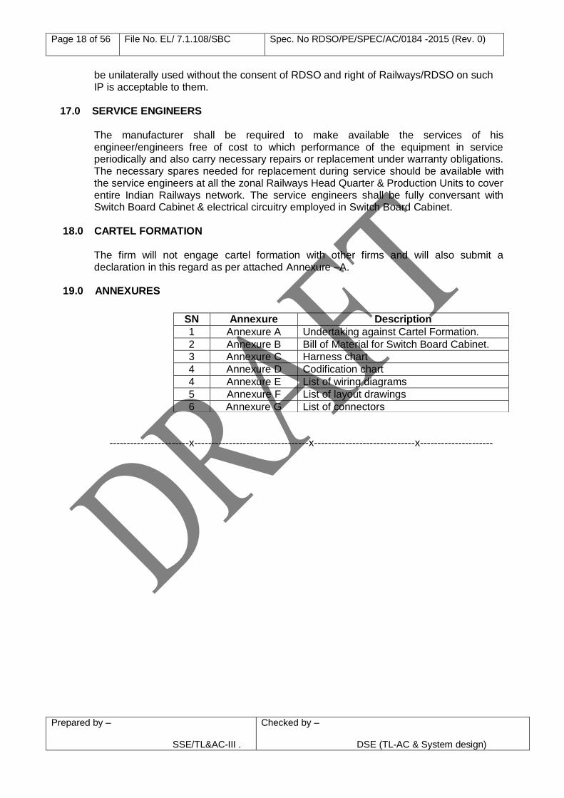
19.0 ANNEXURES
-----------------------x---------------------------------x-----------------------------x---------------------
SN Annexure Description
1 Annexure A Undertaking against Cartel Formation.
2 Annexure B Bill of Material for Switch Board Cabinet.
3 Annexure C Harness chart
4 Annexure D Codification chart
4 Annexure E List of wiring diagrams
5 Annexure F List of layout drawings
6 Annexure G List of connectors
Page 19 of 56 File No. EL/ 7.1.108/SBC Spec. No RDSO/PE/SPEC/AC/0184 -2015 (Rev. 0)
Prepared by – SSE/TL&AC-III .
Checked by –
DSE (TL-AC & System design)
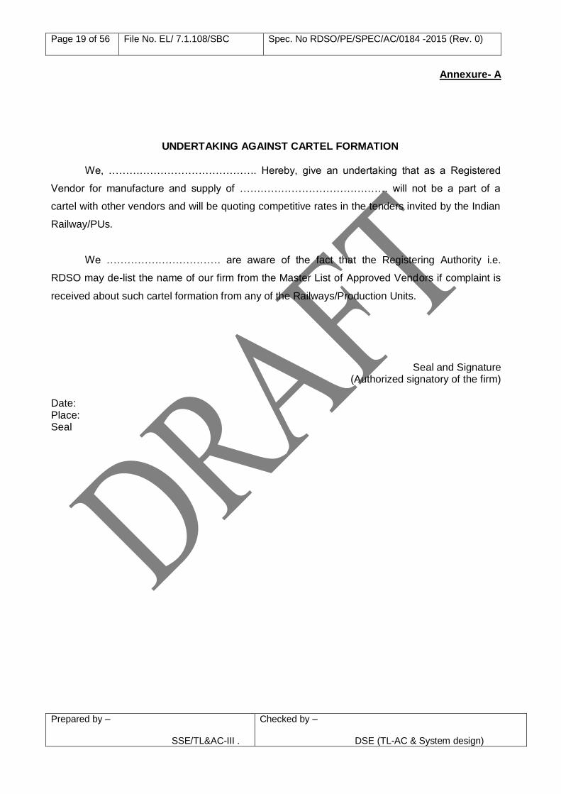
Annexure- A
UNDERTAKING AGAINST CARTEL FORMATION
We, ……………………………………. Hereby, give an undertaking that as a Registered
Vendor for manufacture and supply of ……………………………………. will not be a part of a
cartel with other vendors and will be quoting competitive rates in the tenders invited by the Indian
Railway/PUs.
We …………………………… are aware of the fact that the Registering Authority i.e.
RDSO may de-list the name of our firm from the Master List of Approved Vendors if complaint is
received about such cartel formation from any of the Railways/Production Units.
Seal and Signature (Authorized signatory of the firm)
Date: Place: Seal
Page 20 of 56 File No. EL/ 7.1.108/SBC Spec. No RDSO/PE/SPEC/AC/0184 -2015 (Rev. 0)
Prepared by – SSE/TL&AC-III .
Checked by –
DSE (TL-AC & System design)
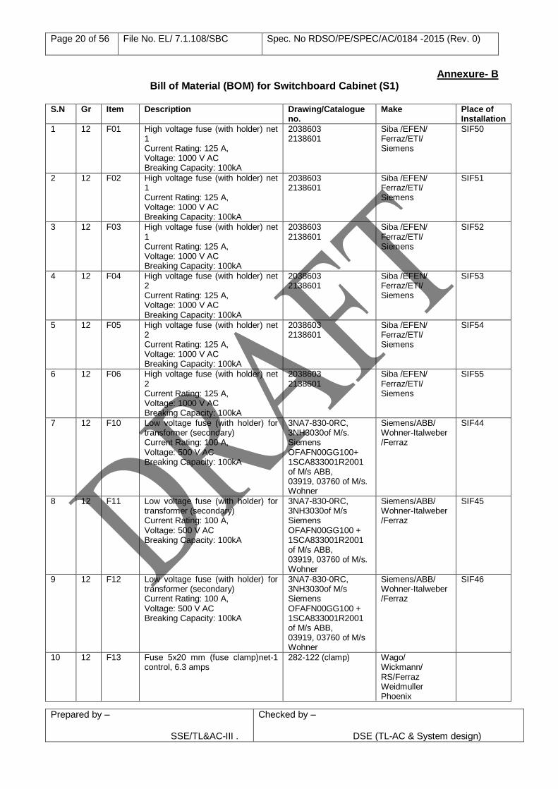
Annexure- B Bill of Material (BOM) for Switchboard Cabinet (S1)
S.N Gr Item Description Drawing/Catalogue
no. Make Place of
Installation
1 12 F01 High voltage fuse (with holder) net 1 Current Rating: 125 A, Voltage: 1000 V AC Breaking Capacity: 100kA
2038603 2138601
Siba /EFEN/ Ferraz/ETI/ Siemens
SIF50
2 12 F02 High voltage fuse (with holder) net 1 Current Rating: 125 A, Voltage: 1000 V AC Breaking Capacity: 100kA
2038603 2138601
Siba /EFEN/ Ferraz/ETI/ Siemens
SIF51
3 12 F03 High voltage fuse (with holder) net 1 Current Rating: 125 A, Voltage: 1000 V AC Breaking Capacity: 100kA
2038603 2138601
Siba /EFEN/ Ferraz/ETI/ Siemens
SIF52
4 12 F04 High voltage fuse (with holder) net 2 Current Rating: 125 A, Voltage: 1000 V AC Breaking Capacity: 100kA
2038603 2138601
Siba /EFEN/ Ferraz/ETI/ Siemens
SIF53
5 12 F05 High voltage fuse (with holder) net 2 Current Rating: 125 A, Voltage: 1000 V AC Breaking Capacity: 100kA
2038603 2138601
Siba /EFEN/ Ferraz/ETI/ Siemens
SIF54
6 12 F06 High voltage fuse (with holder) net 2 Current Rating: 125 A, Voltage: 1000 V AC Breaking Capacity: 100kA
2038603 2138601
Siba /EFEN/ Ferraz/ETI/ Siemens
SIF55
7 12 F10 Low voltage fuse (with holder) for transformer (secondary) Current Rating: 100 A, Voltage: 500 V AC Breaking Capacity: 100kA
3NA7-830-0RC, 3NH3030of M/s. Siemens OFAFN00GG100+ 1SCA833001R2001 of M/s ABB, 03919, 03760 of M/s. Wohner
Siemens/ABB/ Wohner-Italweber /Ferraz
SIF44
8 12 F11 Low voltage fuse (with holder) for transformer (secondary) Current Rating: 100 A, Voltage: 500 V AC Breaking Capacity: 100kA
3NA7-830-0RC, 3NH3030of M/s Siemens OFAFN00GG100 + 1SCA833001R2001 of M/s ABB, 03919, 03760 of M/s. Wohner
Siemens/ABB/ Wohner-Italweber /Ferraz
SIF45
9 12 F12 Low voltage fuse (with holder) for transformer (secondary) Current Rating: 100 A, Voltage: 500 V AC Breaking Capacity: 100kA
3NA7-830-0RC, 3NH3030of M/s Siemens OFAFN00GG100 + 1SCA833001R2001 of M/s ABB, 03919, 03760 of M/s Wohner
Siemens/ABB/ Wohner-Italweber /Ferraz
SIF46
10 12 F13 Fuse 5x20 mm (fuse clamp)net-1 control, 6.3 amps
282-122 (clamp) Wago/ Wickmann/ RS/Ferraz Weidmuller Phoenix
Page 21 of 56 File No. EL/ 7.1.108/SBC Spec. No RDSO/PE/SPEC/AC/0184 -2015 (Rev. 0)
Prepared by – SSE/TL&AC-III .
Checked by –
DSE (TL-AC & System design)
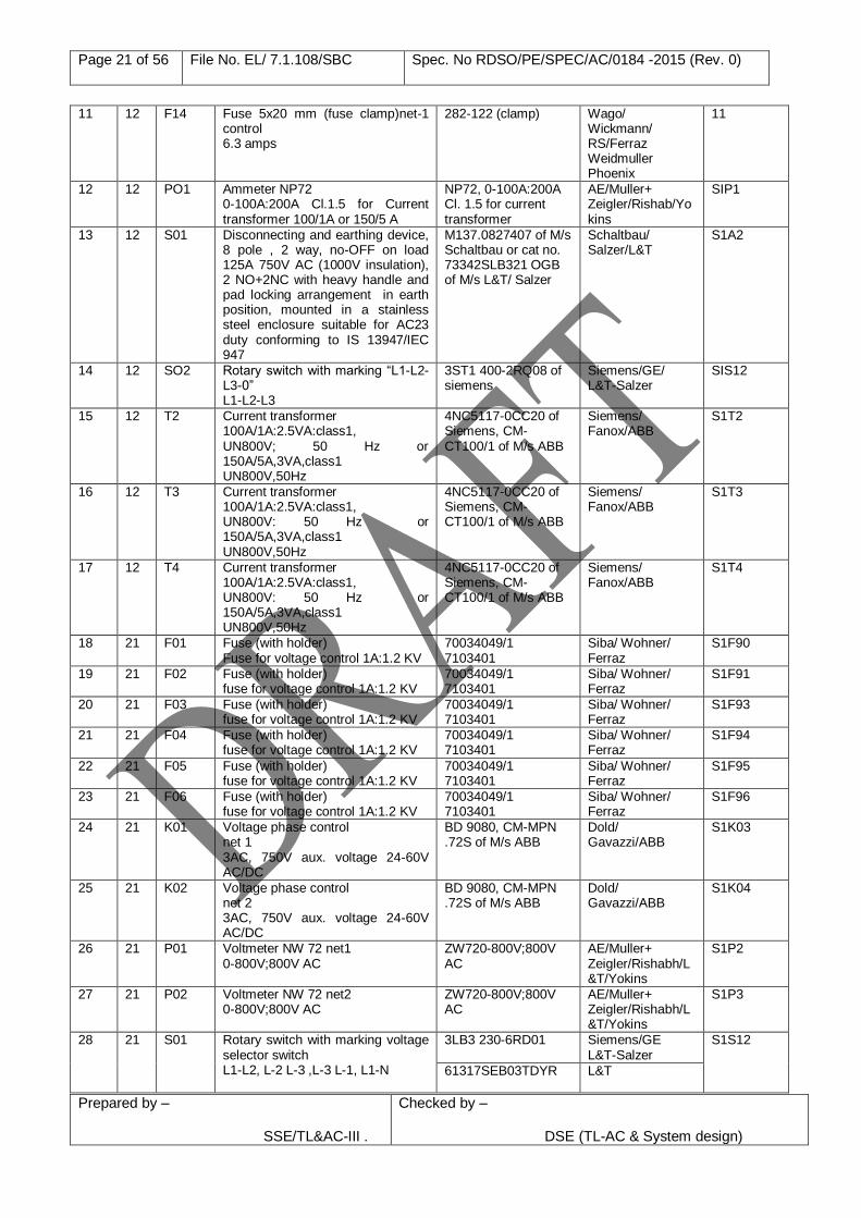
11 12 F14 Fuse 5x20 mm (fuse clamp)net-1 control 6.3 amps
282-122 (clamp) Wago/ Wickmann/ RS/Ferraz Weidmuller Phoenix
11
12 12 PO1 Ammeter NP72 0-100A:200A Cl.1.5 for Current transformer 100/1A or 150/5 A
NP72, 0-100A:200A Cl. 1.5 for current transformer
AE/Muller+ Zeigler/Rishab/Yokins
SIP1
13 12 S01 Disconnecting and earthing device, 8 pole , 2 way, no-OFF on load 125A 750V AC (1000V insulation), 2 NO+2NC with heavy handle and pad locking arrangement in earth position, mounted in a stainless steel enclosure suitable for AC23 duty conforming to IS 13947/IEC 947
M137.0827407 of M/s Schaltbau or cat no. 73342SLB321 OGB of M/s L&T/ Salzer
Schaltbau/ Salzer/L&T
S1A2
14 12 SO2 Rotary switch with marking “L1-L2-L3-0” L1-L2-L3
3ST1 400-2RQ08 of siemens
Siemens/GE/ L&T-Salzer
SIS12
15 12 T2 Current transformer 100A/1A:2.5VA:class1, UN800V; 50 Hz or 150A/5A,3VA,class1 UN800V,50Hz
4NC5117-0CC20 of Siemens, CM-CT100/1 of M/s ABB
Siemens/ Fanox/ABB
S1T2
16 12 T3 Current transformer 100A/1A:2.5VA:class1, UN800V: 50 Hz or 150A/5A,3VA,class1 UN800V,50Hz
4NC5117-0CC20 of Siemens, CM-CT100/1 of M/s ABB
Siemens/ Fanox/ABB
S1T3
17 12 T4 Current transformer 100A/1A:2.5VA:class1, UN800V: 50 Hz or 150A/5A,3VA,class1 UN800V,50Hz
4NC5117-0CC20 of Siemens, CM-CT100/1 of M/s ABB
Siemens/ Fanox/ABB
S1T4
18 21 F01 Fuse (with holder) Fuse for voltage control 1A:1.2 KV
70034049/1 7103401
Siba/ Wohner/ Ferraz
S1F90
19 21 F02 Fuse (with holder) fuse for voltage control 1A:1.2 KV
70034049/1 7103401
Siba/ Wohner/ Ferraz
S1F91
20 21 F03 Fuse (with holder) fuse for voltage control 1A:1.2 KV
70034049/1 7103401
Siba/ Wohner/ Ferraz
S1F93
21 21 F04 Fuse (with holder) fuse for voltage control 1A:1.2 KV
70034049/1 7103401
Siba/ Wohner/ Ferraz
S1F94
22 21 F05 Fuse (with holder) fuse for voltage control 1A:1.2 KV
70034049/1 7103401
Siba/ Wohner/ Ferraz
S1F95
23 21 F06 Fuse (with holder) fuse for voltage control 1A:1.2 KV
70034049/1 7103401
Siba/ Wohner/ Ferraz
S1F96
24 21 K01 Voltage phase control net 1 3AC, 750V aux. voltage 24-60V AC/DC
BD 9080, CM-MPN .72S of M/s ABB
Dold/ Gavazzi/ABB
S1K03
25 21 K02 Voltage phase control net 2 3AC, 750V aux. voltage 24-60V AC/DC
BD 9080, CM-MPN .72S of M/s ABB
Dold/ Gavazzi/ABB
S1K04
26 21 P01 Voltmeter NW 72 net1 0-800V;800V AC
ZW720-800V;800V AC
AE/Muller+ Zeigler/Rishabh/L&T/Yokins
S1P2
27 21 P02 Voltmeter NW 72 net2 0-800V;800V AC
ZW720-800V;800V AC
AE/Muller+ Zeigler/Rishabh/L&T/Yokins
S1P3
28 21 S01 Rotary switch with marking voltage selector switch L1-L2, L-2 L-3 ,L-3 L-1, L1-N
3LB3 230-6RD01 Siemens/GE L&T-Salzer
S1S12
61317SEB03TDYR L&T
Page 22 of 56 File No. EL/ 7.1.108/SBC Spec. No RDSO/PE/SPEC/AC/0184 -2015 (Rev. 0)
Prepared by – SSE/TL&AC-III .
Checked by –
DSE (TL-AC & System design)
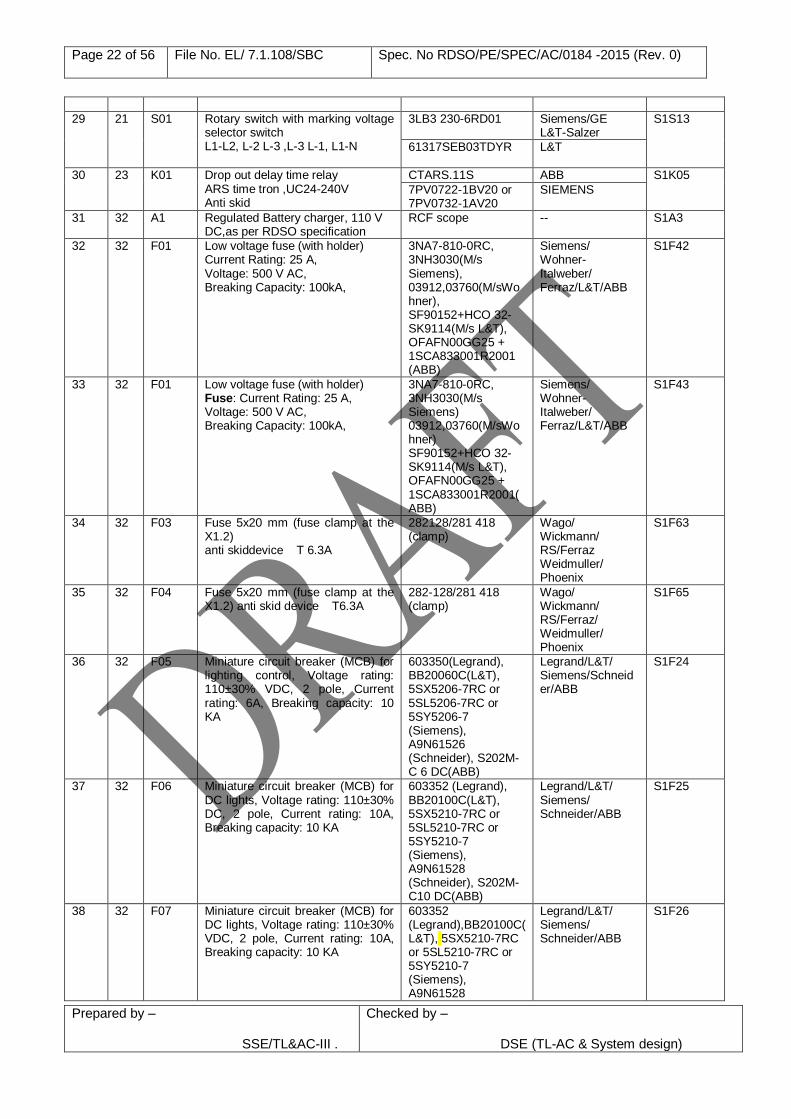
29 21 S01 Rotary switch with marking voltage selector switch L1-L2, L-2 L-3 ,L-3 L-1, L1-N
3LB3 230-6RD01 Siemens/GE L&T-Salzer
S1S13
61317SEB03TDYR L&T
30 23 K01 Drop out delay time relay ARS time tron ,UC24-240V Anti skid
CTARS.11S ABB S1K05
7PV0722-1BV20 or 7PV0732-1AV20
SIEMENS
31 32 A1 Regulated Battery charger, 110 V DC,as per RDSO specification
RCF scope -- S1A3
32 32 F01 Low voltage fuse (with holder) Current Rating: 25 A, Voltage: 500 V AC, Breaking Capacity: 100kA,
3NA7-810-0RC, 3NH3030(M/s Siemens), 03912,03760(M/sWohner), SF90152+HCO 32-SK9114(M/s L&T), OFAFN00GG25 + 1SCA833001R2001 (ABB)
Siemens/ Wohner- Italweber/ Ferraz/L&T/ABB
S1F42
33 32 F01 Low voltage fuse (with holder) Fuse: Current Rating: 25 A, Voltage: 500 V AC, Breaking Capacity: 100kA,
3NA7-810-0RC, 3NH3030(M/s Siemens) 03912,03760(M/sWohner) SF90152+HCO 32-SK9114(M/s L&T), OFAFN00GG25 + 1SCA833001R2001(ABB)
Siemens/ Wohner- Italweber/ Ferraz/L&T/ABB
S1F43
34 32 F03 Fuse 5x20 mm (fuse clamp at the X1.2) anti skiddevice T 6.3A
282128/281 418 (clamp)
Wago/ Wickmann/ RS/Ferraz Weidmuller/ Phoenix
S1F63
35 32 F04 Fuse 5x20 mm (fuse clamp at the X1.2) anti skid device T6.3A
282-128/281 418 (clamp)
Wago/ Wickmann/ RS/Ferraz/ Weidmuller/ Phoenix
S1F65
36 32 F05 Miniature circuit breaker (MCB) for lighting control, Voltage rating: 110±30% VDC, 2 pole, Current rating: 6A, Breaking capacity: 10 KA
603350(Legrand), BB20060C(L&T), 5SX5206-7RC or 5SL5206-7RC or 5SY5206-7 (Siemens), A9N61526 (Schneider), S202M-C 6 DC(ABB)
Legrand/L&T/ Siemens/Schneider/ABB
S1F24
37 32 F06 Miniature circuit breaker (MCB) for DC lights, Voltage rating: 110±30% DC, 2 pole, Current rating: 10A, Breaking capacity: 10 KA
603352 (Legrand), BB20100C(L&T), 5SX5210-7RC or 5SL5210-7RC or 5SY5210-7 (Siemens), A9N61528 (Schneider), S202M-C10 DC(ABB)
Legrand/L&T/ Siemens/ Schneider/ABB
S1F25
38 32 F07 Miniature circuit breaker (MCB) for DC lights, Voltage rating: 110±30% VDC, 2 pole, Current rating: 10A, Breaking capacity: 10 KA
603352 (Legrand),BB20100C(L&T), 5SX5210-7RC or 5SL5210-7RC or 5SY5210-7 (Siemens), A9N61528
Legrand/L&T/ Siemens/ Schneider/ABB
S1F26
Page 23 of 56 File No. EL/ 7.1.108/SBC Spec. No RDSO/PE/SPEC/AC/0184 -2015 (Rev. 0)
Prepared by – SSE/TL&AC-III .
Checked by –
DSE (TL-AC & System design)
(Schneider), S202M-C10 DC(ABB)
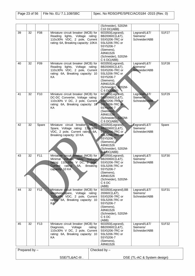
39 32 F08 Miniature circuit breaker (MCB) for Reading lights, Voltage rating: 110±30% VDC, 2 pole, Current rating: 6A, Breaking capacity: 10KA
603350(Legrand), BB20060C(L&T), 5SX5206-7RC or 5SL5206-7RC or 5SY5206-7 (Siemens), A9N61526 (Schneider), S202M-C 6 DC(ABB)
Legrand/L&T/ Siemens/ Schneider/ABB
S1F27
40 32 F09 Miniature circuit breaker (MCB) for Reading lights, Voltage rating: 110±30% VDC, 2 pole, Current rating: 6A, Breaking capacity: 10 KA
603350(Legrand), BB20060C(L&T), 5SX5206-7RC or 5SL5206-7RC or 5SY5206-7 (Siemens), A9N61526 (Schneider), S202M-C 6 DC(ABB)
Legrand/L&T/ Siemens/ Schneider/ABB
S1F28
41 32 F10 Miniature circuit breaker (MCB) for DC-DC Converter, Voltage rating: 110±30% V DC, 2 pole, Current rating: 6A, Breaking capacity: 10 KA
603350(Legrand), BB20060C(L&T), 5SX5206-7RC or 5SL5206-7RC or 5SY5206-7 (Siemens), A9N61526 (Schneider), S202M-C 6 DC(ABB)
Legrand/L&T/ Siemens/ Schneider/ABB
S1F29
42 32 Spare Miniature circuit breaker (MCB) Spare, Voltage rating: 110±30% VDC, 2 pole, Current rating: 6A, Breaking capacity: 10 KA
603350(Legrand), BB20060C(L&T), 5SX5206-7RC or 5SL5206-7RC or 5SY5206-7 (Siemens), A9N61526 (Schneider), S202M-C 6 DC(ABB)
Legrand/L&T/ Siemens/ Schneider/ABB
Spare
43 32 F11 Miniature circuit breaker (MCB) for Minimal Voltage relay, Voltage rating: 110±30% V DC, 2 pole, Current rating: 6A, Breaking capacity: 10 KA
603350(Legrand), BB20060C(L&T), 5SX5206-7RC or 5SL5206-7RC or 5SY5206-7 (Siemens), A9N61526 (Schneider), S202M-C 6 DC (ABB)
Legrand/L&T/ Siemens/ Schneider/ABB
S1F30
44 32 F12 Miniature circuit breaker (MCB) for telephone/spare, Voltage rating: 110±30% VDC, 2 pole, Current rating: 6A, Breaking capacity: 10 KA
603350(Legrand),BB20060C(L&T), 5SX5206-7RC or 5SL5206-7RC or 5SY5206-7 (Siemens), A9N61526 (Schneider), S202M-C 6 DC (ABB)
Legrand/L&T/ Siemens/ Schneider/ABB
S1F31
45 32 F13 Miniature circuit breaker (MCB) for Diagnosis, Voltage rating: 110±30% V DC, 2 pole, Current rating: 6A, Breaking capacity: 10 KA
603350(Legrand), BB20060C(L&T), 5SX5206-7RC or 5SL5206-7RC or 5SY5206-7 (Siemens), A9N61526
Legrand/L&T/ Siemens/ Schneider/ABB
S1F32
Page 24 of 56 File No. EL/ 7.1.108/SBC Spec. No RDSO/PE/SPEC/AC/0184 -2015 (Rev. 0)
Prepared by – SSE/TL&AC-III .
Checked by –
DSE (TL-AC & System design)
(Schneider), S202M-C 6 DC(ABB)
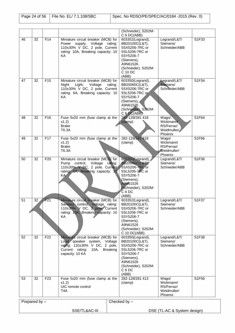
46 32 F14 Miniature circuit breaker (MCB) for Power supply, Voltage rating: 110±30% V DC, 2 pole, Current rating: 10A, Breaking capacity: 10 KA
603352(Legrand), BB20100C(L&T), 5SX5206-7RC or 5SL5206-7RC or 5SY5206-7 (Siemens), A9N61526 (Schneider), S202M-C 10 DC (ABB)
Legrand/L&T/ Siemens/ Schneider/ABB
S1F33
47 32 F15 Miniature circuit breaker (MCB) for Night Light, Voltage rating: 110±30% V DC, 2 pole, Current rating: 6A, Breaking capacity: 10 KA
603350(Legrand), BB20060C(L&T), 5SX5206-7RC or 5SL5206-7RC or 5SY5206-7 (Siemens), A9N61526 (Schneider), S202M-C 6 DC(ABB)
Legrand/L&T/ Siemens/ Schneider/ABB
S1F34
48 32 F16 Fuse 5x20 mm (fuse clamp at the x1.2) Brake T6.3A
282-128/281 418 (clamp)
Wago/ Wickmann/ RS/Ferraz/ Weidmuller/ Phoenix
S1F64
49 32 F17 Fuse 5x20 mm (fuse clamp at the x1.2) Brake T6.3A
282-128/281 418 (clamp)
Wago/ Wickmann/ RS/Ferraz/ Weidmuller/ Phoenix
S1F66
50 32 F20 Miniature circuit breaker (MCB) for Pump control, Voltage rating: 110±30% V DC, 2 pole, Current rating: 6A, Breaking capacity: 10 KA
603350(Legrand), BB20060C(L&T), 5SX5206-7RC or 5SL5206-7RC or 5SY5206-7 (Siemens), A9N61526 (Schneider), S202M-C 6 DC (ABB)
Legrand/L&T/ Siemens/ Schneider/ABB
S1F36
51 32 F21 Miniature circuit breaker (MCB) for Sanitary control, Voltage rating: 110±30% V DC, 2 pole, Current rating: 10A, Breaking capacity: 10 KA
603352(Legrand), BB20100C(L&T), 5SX5206-7RC or 5SL5206-7RC or 5SY5206-7 (Siemens), A9N61526 (Schneider), S202M-C 10 DC(ABB)
Legrand/L&T/ Siemens/ Schneider/ABB
S1F37
52 32 F22 Miniature circuit breaker (MCB) for Loud speaker system, Voltage rating: 110±30% V DC, 2 pole, Current rating: 10A, Breaking capacity: 10 KA
603350(Legrand), BB20100C(L&T), 5SX5206-7RC or 5SL5206-7RC or 5SY5206-7 (Siemens), A9N61526 (Schneider), S202M-C 6 DC (ABB)
Legrand/L&T/ Siemens/ Schneider/ABB
S1F38
53 32 F23 Fuse 5x20 mm (fuse clamp at the x1.2) UIC remote control T4A
282-128/281 413 (clamp)
Wago/ Wickmann/ RS/Ferraz/ Weidmuller/ Phoenix
S1F56
Page 25 of 56 File No. EL/ 7.1.108/SBC Spec. No RDSO/PE/SPEC/AC/0184 -2015 (Rev. 0)
Prepared by – SSE/TL&AC-III .
Checked by –
DSE (TL-AC & System design)
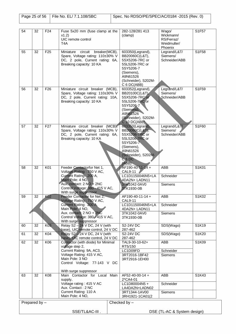
54 32 F24 Fuse 5x20 mm (fuse clamp at the x1.2) UIC remote control T4A
282-128/281 413 (clamp)
Wago/ Wickmann/ RS/Ferraz/ Weidmuller/ Phoenix
S1F57
55 32 F25 Miniature circuit breaker(MCB), Spare, Voltage rating: 110±30% V DC, 2 pole, Current rating: 6A, Breaking capacity: 10 KA
603350(Legrand), BB20060C(L&T), 5SX5206-7RC or 5SL5206-7RC or 5SY5206-7 (Siemens), A9N61526 (Schneider), S202M-C 6 DC(ABB)
Legrand/L&T/ Siemens/ Schneider/ABB
S1F58
56 32 F26 Miniature circuit breaker (MCB), Spare, Voltage rating: 110±30% V DC, 2 pole, Current rating: 10A, Breaking capacity: 10 KA
603352(Legrand), BB20100C(L&T), 5SX5206-7RC or 5SL5206-7RC or 5SY5206-7 (Siemens), A9N61526 (Schneider), S202M-C 10 DC(ABB)
Legrand/L&T/ Siemens/ Schneider/ABB
S1F59
57 32 F27 Miniature circuit breaker (MCB), Spare, Voltage rating: 110±30% V DC, 2 pole, Current rating: 6A, Breaking capacity: 10 KA
603350(Legrand), BB20060C(L&T), 5SX5206-7RC or 5SL5206-7RC or 5SY5206-7 (Siemens), A9N61526 (Schneider), S202M-C 6 DC (ABB)
Legrand/L&T/ Siemens/ Schneider/ABB
S1F60
58 32 K01 Feeder Contactorfor Net 1, Voltage Rating : 750 V AC, Current Rating: 200 A, Main Pole: 4 NO, Aux. contact: 2 NO + 2NC Control Voltage: 380 - 415 V AC, With surge suppressor
AF190-40-11-14 + CAL9-11
ABB S1K01
LC1D1150046N5+LA4DA2N+ LADN11
Schneider
3TK1042-0AV0 3TK1930-0B
Siemens
59 32 K02 Feeder Contactor for Net 2, Voltage Rating : 750 V AC, Current Rating: 200 A, Main Pole: 4 NO, Aux. contact: 2 NO + 2NC Control Voltage: 380 - 415 V AC, With surge suppressor
AF190-40-11-14 + CAL9-11
ABB S1K02
LC1D1150046N5+LA4DA2N+ LADN11
Schneider
3TK1042-0AV0 3TK1930-0B
Siemens
60 32 K03 Relay S2 – 24 V DC, 24 V (with base), UIC remote control, 24 V DC
S2-24V DC 287-462
SDS(Wago) S1K19
61 32 K04 Relay S2 – 24 V DC, 24 V (with base), UIC remote control, 24 V DC
S2-24V DC 287-462
SDS(Wago) S1K20
62 32 K06 Contactor (with diode) for Minimal voltage step 2, Current Rating: 9A, AC3, Voltage Rating: 415 V AC, Main Pole: 3 NO Control Voltage: 77-143 V DC With surge suppressor
TAL9-30-10-62+ RT5/150
ABB
S1K09
LC1D09FD Schneider
3RT2016-1BF42 3RT2916-1EH00
Siemens
63 32 K08 Main Contactor for Local Main supply, Voltage rating : 415 V AC Aux. Contact : 2 NC Current Rating: 110 A Main Pole: 4 NO,
AF52-40-00-14 + 2*CA4-01
ABB S1K43
LC1D80004N5 + LA4DA2N+LADN02
Schneider
3RT1344-1AV00 3RH1921-1CA01(2
Siemens
Page 26 of 56 File No. EL/ 7.1.108/SBC Spec. No RDSO/PE/SPEC/AC/0184 -2015 (Rev. 0)
Prepared by – SSE/TL&AC-III .
Checked by –
DSE (TL-AC & System design)
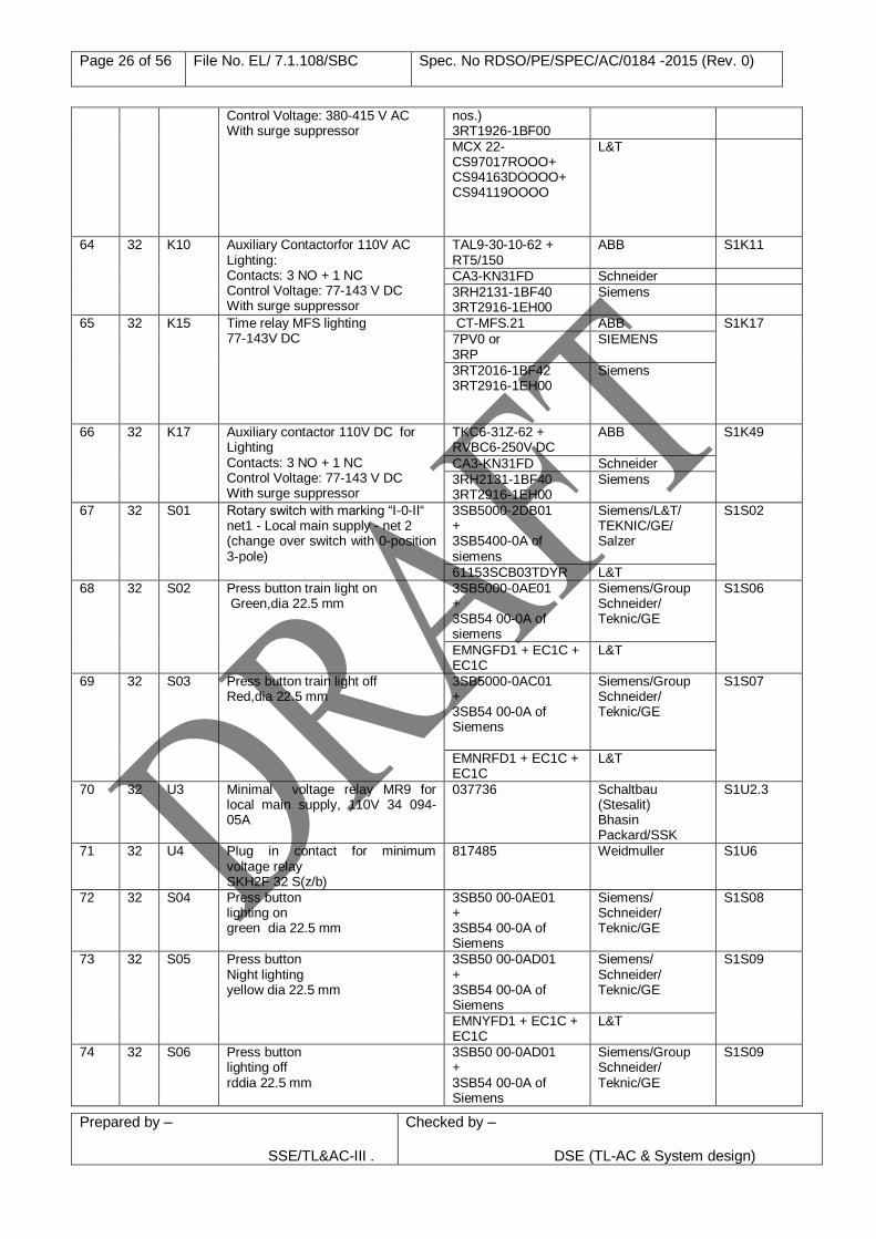
Control Voltage: 380-415 V AC With surge suppressor
nos.) 3RT1926-1BF00
MCX 22-CS97017ROOO+ CS94163DOOOO+ CS94119OOOO
L&T
64 32 K10 Auxiliary Contactorfor 110V AC Lighting: Contacts: 3 NO + 1 NC Control Voltage: 77-143 V DC With surge suppressor
TAL9-30-10-62 + RT5/150
ABB
S1K11
CA3-KN31FD Schneider
3RH2131-1BF40 3RT2916-1EH00
Siemens
65 32 K15 Time relay MFS lighting 77-143V DC
CT-MFS.21 ABB S1K17
7PV0 or 3RP
SIEMENS
3RT2016-1BF42 3RT2916-1EH00
Siemens
66 32 K17 Auxiliary contactor 110V DC for Lighting Contacts: 3 NO + 1 NC Control Voltage: 77-143 V DC With surge suppressor
TKC6-31Z-62 + RVBC6-250V DC
ABB S1K49
CA3-KN31FD Schneider
3RH2131-1BF40 3RT2916-1EH00
Siemens
67 32 S01 Rotary switch with marking “I-0-II“ net1 - Local main supply - net 2 (change over switch with 0-position 3-pole)
3SB5000-2DB01 + 3SB5400-0A of siemens
Siemens/L&T/ TEKNIC/GE/ Salzer
S1S02
61153SCB03TDYR L&T
68 32 S02 Press button train light on Green,dia 22.5 mm
3SB5000-0AE01 + 3SB54 00-0A of siemens
Siemens/Group Schneider/ Teknic/GE
S1S06
EMNGFD1 + EC1C + EC1C
L&T
69 32 S03 Press button train light off Red,dia 22.5 mm
3SB5000-0AC01 + 3SB54 00-0A of Siemens
Siemens/Group Schneider/ Teknic/GE
S1S07
EMNRFD1 + EC1C + EC1C
L&T
70 32 U3 Minimal voltage relay MR9 for local main supply, 110V 34 094-05A
037736 Schaltbau (Stesalit) Bhasin Packard/SSK
S1U2.3
71 32 U4 Plug in contact for minimum voltage relay SKH2F 32 S(z/b)
817485 Weidmuller
S1U6
72 32 S04 Press button lighting on green dia 22.5 mm
3SB50 00-0AE01 + 3SB54 00-0A of Siemens
Siemens/ Schneider/ Teknic/GE
S1S08
73 32 S05 Press button Night lighting yellow dia 22.5 mm
3SB50 00-0AD01 + 3SB54 00-0A of Siemens
Siemens/ Schneider/ Teknic/GE
S1S09
EMNYFD1 + EC1C + EC1C
L&T
74 32 S06 Press button lighting off rddia 22.5 mm
3SB50 00-0AD01 + 3SB54 00-0A of Siemens
Siemens/Group Schneider/ Teknic/GE
S1S09
Page 27 of 56 File No. EL/ 7.1.108/SBC Spec. No RDSO/PE/SPEC/AC/0184 -2015 (Rev. 0)
Prepared by – SSE/TL&AC-III .
Checked by –
DSE (TL-AC & System design)
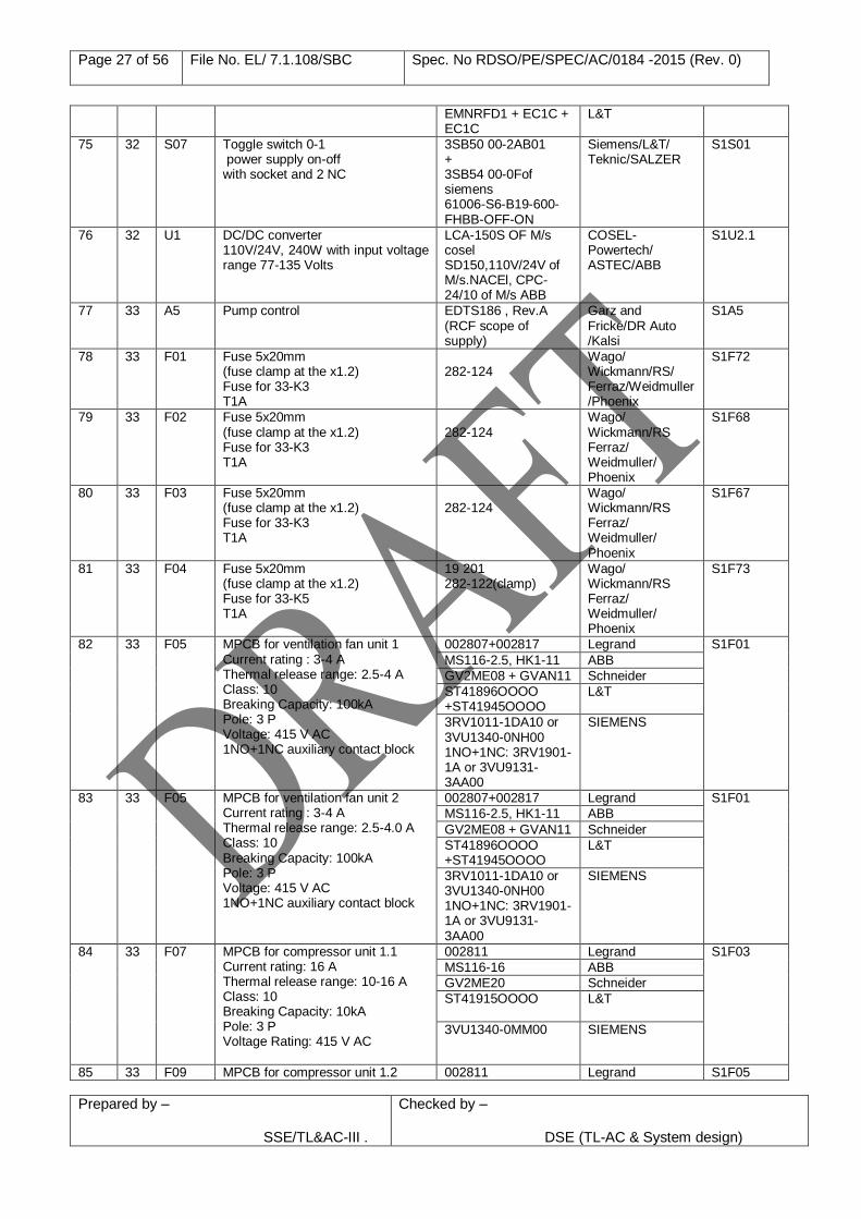
EMNRFD1 + EC1C + EC1C
L&T
75 32 S07 Toggle switch 0-1 power supply on-off with socket and 2 NC
3SB50 00-2AB01 + 3SB54 00-0Fof siemens 61006-S6-B19-600-FHBB-OFF-ON
Siemens/L&T/ Teknic/SALZER
S1S01
76 32 U1 DC/DC converter 110V/24V, 240W with input voltage range 77-135 Volts
LCA-150S OF M/s cosel SD150,110V/24V of M/s.NACEl, CPC-24/10 of M/s ABB
COSEL- Powertech/ ASTEC/ABB
S1U2.1
77 33 A5 Pump control EDTS186 , Rev.A (RCF scope of supply)
Garz and Fricke/DR Auto /Kalsi
S1A5
78 33 F01 Fuse 5x20mm (fuse clamp at the x1.2) Fuse for 33-K3 T1A
282-124
Wago/ Wickmann/RS/ Ferraz/Weidmuller/Phoenix
S1F72
79 33 F02 Fuse 5x20mm (fuse clamp at the x1.2) Fuse for 33-K3 T1A
282-124
Wago/ Wickmann/RS Ferraz/ Weidmuller/ Phoenix
S1F68
80 33 F03 Fuse 5x20mm (fuse clamp at the x1.2) Fuse for 33-K3 T1A
282-124
Wago/ Wickmann/RS Ferraz/ Weidmuller/ Phoenix
S1F67
81 33 F04 Fuse 5x20mm (fuse clamp at the x1.2) Fuse for 33-K5 T1A
19 201 282-122(clamp)
Wago/ Wickmann/RS Ferraz/ Weidmuller/ Phoenix
S1F73
82 33 F05 MPCB for ventilation fan unit 1 Current rating : 3-4 A Thermal release range: 2.5-4 A Class: 10 Breaking Capacity: 100kA Pole: 3 P Voltage: 415 V AC 1NO+1NC auxiliary contact block
002807+002817 Legrand S1F01
MS116-2.5, HK1-11 ABB
GV2ME08 + GVAN11 Schneider
ST41896OOOO +ST41945OOOO
L&T
3RV1011-1DA10 or 3VU1340-0NH00 1NO+1NC: 3RV1901-1A or 3VU9131-3AA00
SIEMENS
83 33 F05 MPCB for ventilation fan unit 2 Current rating : 3-4 A Thermal release range: 2.5-4.0 A Class: 10 Breaking Capacity: 100kA Pole: 3 P Voltage: 415 V AC 1NO+1NC auxiliary contact block
002807+002817 Legrand S1F01
MS116-2.5, HK1-11 ABB
GV2ME08 + GVAN11 Schneider
ST41896OOOO +ST41945OOOO
L&T
3RV1011-1DA10 or 3VU1340-0NH00 1NO+1NC: 3RV1901-1A or 3VU9131-3AA00
SIEMENS
84 33 F07 MPCB for compressor unit 1.1 Current rating: 16 A Thermal release range: 10-16 A Class: 10 Breaking Capacity: 10kA Pole: 3 P Voltage Rating: 415 V AC
002811 Legrand S1F03
MS116-16 ABB
GV2ME20 Schneider
ST41915OOOO L&T
3VU1340-0MM00
SIEMENS
85 33 F09 MPCB for compressor unit 1.2 002811 Legrand S1F05
Page 28 of 56 File No. EL/ 7.1.108/SBC Spec. No RDSO/PE/SPEC/AC/0184 -2015 (Rev. 0)
Prepared by – SSE/TL&AC-III .
Checked by –
DSE (TL-AC & System design)
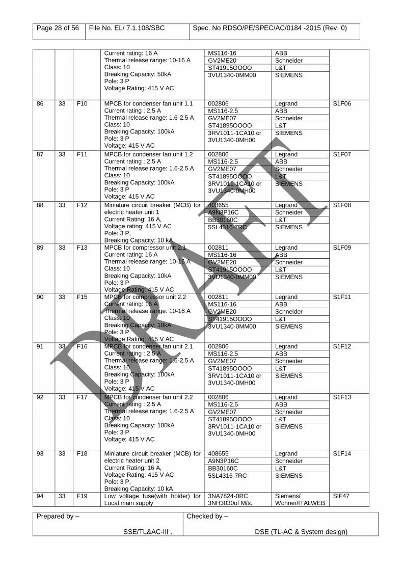
Current rating: 16 A Thermal release range: 10-16 A Class: 10 Breaking Capacity: 50kA Pole: 3 P Voltage Rating: 415 V AC
MS116-16 ABB
GV2ME20 Schneider
ST41915OOOO L&T
3VU1340-0MM00
SIEMENS
86 33 F10 MPCB for condenser fan unit 1.1 Current rating : 2.5 A Thermal release range: 1.6-2.5 A Class: 10 Breaking Capacity: 100kA Pole: 3 P Voltage: 415 V AC
002806 Legrand S1F06
MS116-2.5 ABB
GV2ME07 Schneider
ST41895OOOO L&T
3RV1011-1CA10 or 3VU1340-0MH00
SIEMENS
87 33 F11 MPCB for condenser fan unit 1.2 Current rating : 2.5 A Thermal release range: 1.6-2.5 A Class: 10 Breaking Capacity: 100kA Pole: 3 P Voltage: 415 V AC
002806 Legrand S1F07
MS116-2.5 ABB
GV2ME07 Schneider
ST41895OOOO L&T
3RV1011-1CA10 or 3VU1340-0MH00
SIEMENS
88 33 F12 Miniature circuit breaker (MCB) for electric heater unit 1 Current Rating: 16 A, Voltage rating: 415 V AC Pole: 3 P, Breaking Capacity: 10 kA
408655 Legrand S1F08
A9N3P16C Schneider
BB30160C L&T
5SL4316-7RC SIEMENS
89 33 F13 MPCB for compressor unit 2.1 Current rating: 16 A Thermal release range: 10-16 A Class: 10 Breaking Capacity: 10kA Pole: 3 P Voltage Rating: 415 V AC
002811 Legrand S1F09
MS116-16 ABB
GV2ME20 Schneider
ST41915OOOO L&T
3VU1340-0MM00
SIEMENS
90 33 F15 MPCB for compressor unit 2.2 Current rating: 16 A Thermal release range: 10-16 A Class: 10 Breaking Capacity: 10kA Pole: 3 P Voltage Rating: 415 V AC
002811 Legrand S1F11
MS116-16 ABB
GV2ME20 Schneider
ST41915OOOO L&T
3VU1340-0MM00
SIEMENS
91 33 F16 MPCB for condenser fan unit 2.1 Current rating : 2.5 A Thermal release range: 1.6-2.5 A Class: 10 Breaking Capacity: 100kA Pole: 3 P Voltage: 415 V AC
002806 Legrand S1F12
MS116-2.5 ABB
GV2ME07 Schneider
ST41895OOOO L&T
3RV1011-1CA10 or 3VU1340-0MH00
SIEMENS
92 33 F17 MPCB for condenser fan unit 2.2 Current rating : 2.5 A Thermal release range: 1.6-2.5 A Class: 10 Breaking Capacity: 100kA Pole: 3 P Voltage: 415 V AC
002806 Legrand S1F13
MS116-2.5 ABB
GV2ME07 Schneider
ST41895OOOO L&T
3RV1011-1CA10 or 3VU1340-0MH00
SIEMENS
93 33 F18 Miniature circuit breaker (MCB) for electric heater unit 2 Current Rating: 16 A, Voltage Rating: 415 V AC Pole: 3 P, Breaking Capacity: 10 kA
408655 Legrand S1F14
A9N3P16C Schneider
BB30160C L&T
5SL4316-7RC SIEMENS
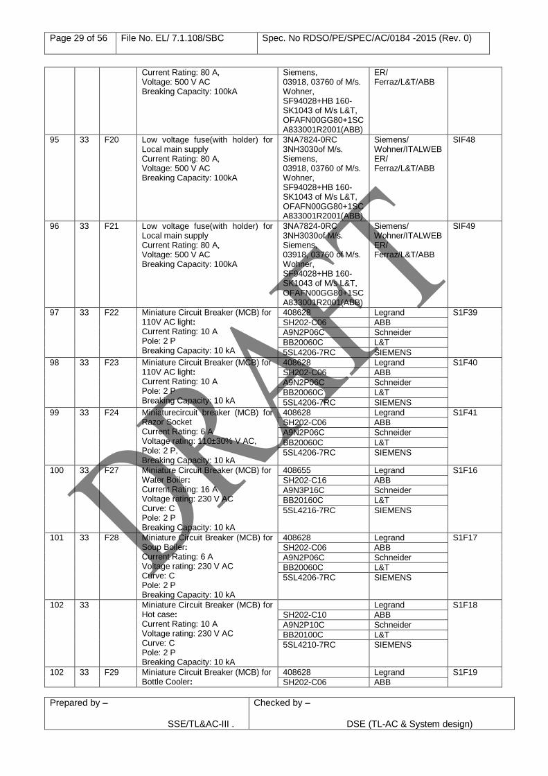
94 33 F19 Low voltage fuse(with holder) for Local main supply
3NA7824-0RC 3NH3030of M/s.
Siemens/ Wohner/ITALWEB
SIF47
Page 29 of 56 File No. EL/ 7.1.108/SBC Spec. No RDSO/PE/SPEC/AC/0184 -2015 (Rev. 0)
Prepared by – SSE/TL&AC-III .
Checked by –
DSE (TL-AC & System design)
Current Rating: 80 A, Voltage: 500 V AC Breaking Capacity: 100kA
Siemens, 03918, 03760 of M/s. Wohner, SF94028+HB 160-SK1043 of M/s L&T, OFAFN00GG80+1SCA833001R2001(ABB)
ER/ Ferraz/L&T/ABB
95 33 F20 Low voltage fuse(with holder) for Local main supply Current Rating: 80 A, Voltage: 500 V AC Breaking Capacity: 100kA
3NA7824-0RC 3NH3030of M/s. Siemens, 03918, 03760 of M/s. Wohner, SF94028+HB 160-SK1043 of M/s L&T, OFAFN00GG80+1SCA833001R2001(ABB)
Siemens/ Wohner/ITALWEBER/ Ferraz/L&T/ABB
SIF48
96 33 F21 Low voltage fuse(with holder) for Local main supply Current Rating: 80 A, Voltage: 500 V AC Breaking Capacity: 100kA
3NA7824-0RC 3NH3030of M/s. Siemens, 03918, 03760 of M/s. Wohner, SF94028+HB 160-SK1043 of M/s L&T, OFAFN00GG80+1SCA833001R2001(ABB)
Siemens/ Wohner/ITALWEBER/ Ferraz/L&T/ABB
SIF49
97 33 F22 Miniature Circuit Breaker (MCB) for 110V AC light: Current Rating: 10 A Pole: 2 P Breaking Capacity: 10 kA
408628 Legrand S1F39
SH202-C06 ABB
A9N2P06C Schneider
BB20060C L&T
5SL4206-7RC SIEMENS
98 33 F23 Miniature Circuit Breaker (MCB) for 110V AC light: Current Rating: 10 A Pole: 2 P Breaking Capacity: 10 kA
408628 Legrand S1F40
SH202-C06 ABB
A9N2P06C Schneider
BB20060C L&T
5SL4206-7RC SIEMENS
99 33 F24 Miniaturecircuit breaker (MCB) for Razor Socket Current Rating: 6 A Voltage rating: 110±30% V AC, Pole: 2 P, Breaking Capacity: 10 kA
408628 Legrand S1F41
SH202-C06 ABB
A9N2P06C Schneider
BB20060C L&T
5SL4206-7RC SIEMENS
100 33 F27 Miniature Circuit Breaker (MCB) for Water Boiler: Current Rating: 16 A Voltage rating: 230 V AC Curve: C Pole: 2 P Breaking Capacity: 10 kA
408655 Legrand S1F16
SH202-C16 ABB
A9N3P16C Schneider
BB20160C L&T
5SL4216-7RC SIEMENS
101 33 F28 Miniature Circuit Breaker (MCB) for Soup Boiler: Current Rating: 6 A Voltage rating: 230 V AC Curve: C Pole: 2 P Breaking Capacity: 10 kA
408628 Legrand S1F17
SH202-C06 ABB
A9N2P06C Schneider
BB20060C L&T
5SL4206-7RC SIEMENS
102 33 Miniature Circuit Breaker (MCB) for Hot case: Current Rating: 10 A Voltage rating: 230 V AC Curve: C Pole: 2 P Breaking Capacity: 10 kA
Legrand S1F18
SH202-C10 ABB
A9N2P10C Schneider
BB20100C L&T
5SL4210-7RC SIEMENS
102 33 F29 Miniature Circuit Breaker (MCB) for Bottle Cooler:
408628 Legrand S1F19
SH202-C06 ABB
Page 30 of 56 File No. EL/ 7.1.108/SBC Spec. No RDSO/PE/SPEC/AC/0184 -2015 (Rev. 0)
Prepared by – SSE/TL&AC-III .
Checked by –
DSE (TL-AC & System design)
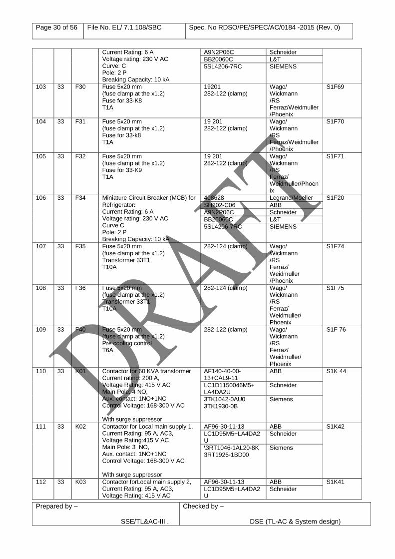
Current Rating: 6 A Voltage rating: 230 V AC Curve: C Pole: 2 P Breaking Capacity: 10 kA
A9N2P06C Schneider
BB20060C L&T
5SL4206-7RC SIEMENS
103 33 F30 Fuse 5x20 mm (fuse clamp at the x1.2) Fuse for 33-K8 T1A
19201 282-122 (clamp)
Wago/ Wickmann /RS Ferraz/Weidmuller/Phoenix
S1F69
104 33 F31 Fuse 5x20 mm (fuse clamp at the x1.2) Fuse for 33-k8 T1A
19 201 282-122 (clamp)
Wago/ Wickmann /RS Ferraz/Weidmuller/Phoenix
S1F70
105 33 F32 Fuse 5x20 mm (fuse clamp at the x1.2) Fuse for 33-K9 T1A
19 201 282-122 (clamp)
Wago/ Wickmann /RS Ferraz/ Weidmuller/Phoenix
S1F71
106 33 F34 Miniature Circuit Breaker (MCB) for Refrigerator: Current Rating: 6 A Voltage rating: 230 V AC Curve C Pole: 2 P Breaking Capacity: 10 kA
408628 Legrand/Moeller S1F20
SH202-C06 ABB
A9N2P06C Schneider
BB20060C L&T
5SL4206-7RC SIEMENS
107 33 F35 Fuse 5x20 mm (fuse clamp at the x1.2) Transformer 33T1 T10A
282-124 (clamp) Wago/ Wickmann /RS Ferraz/ Weidmuller /Phoenix
S1F74
108 33 F36 Fuse 5x20 mm (fuse clamp at the x1.2) Transformer 33T1 T10A
282-124 (clamp) Wago/ Wickmann /RS Ferraz/ Weidmuller/ Phoenix
S1F75
109 33 F40 Fuse 5x20 mm (fuse clamp at the x1.2) Pre cooling control T6A
282-122 (clamp) Wago/ Wickmann /RS Ferraz/ Weidmuller/ Phoenix
S1F 76
110
33 K01 Contactor for 60 KVA transformer Current rating: 200 A, Voltage Rating: 415 V AC Main Pole: 4 NO, Aux. contact: 1NO+1NC Control Voltage: 168-300 V AC With surge suppressor
AF140-40-00-13+CAL9-11
ABB
S1K 44
LC1D1150046M5+ LA4DA2U
Schneider
3TK1042-0AU0 3TK1930-0B
Siemens
111 33 K02 Contactor for Local main supply 1, Current Rating: 95 A, AC3, Voltage Rating:415 V AC Main Pole: 3 NO, Aux. contact: 1NO+1NC Control Voltage: 168-300 V AC With surge suppressor
AF96-30-11-13 ABB S1K42
LC1D95M5+LA4DA2U
Schneider
\3RT1046-1AL20-8K 3RT1926-1BD00
Siemens
112 33 K03 Contactor forLocal main supply 2, Current Rating: 95 A, AC3, Voltage Rating: 415 V AC
AF96-30-11-13 ABB S1K41
LC1D95M5+LA4DA2U
Schneider
Page 31 of 56 File No. EL/ 7.1.108/SBC Spec. No RDSO/PE/SPEC/AC/0184 -2015 (Rev. 0)
Prepared by – SSE/TL&AC-III .
Checked by –
DSE (TL-AC & System design)
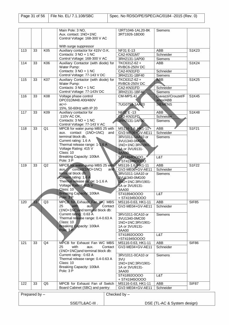
Main Pole: 3 NO, Aux. contact: 1NO+1NC Control Voltage: 168-300 V AC With surge suppressor
\3RT1046-1AL20-8K 3RT1926-1BD00
Siemens
113 33 K05 Auxiliary contactor for 415V O.K. Contacts: 3 NO + 1 NC Control Voltage: 168-300 V AC
NF31 E-13 ABB S1K23
CA2-KN31M7 Schneider
3RH2131-1AP00 Siemens
114 33 K06 Auxiliary Contactor (with diode) for Water Pump: Contacts: 3 NO + 1 NC Control Voltage: 77-143 V DC
TKC631Z-62 + RVBC6-250V DC
ABB S1K24
CA2-KN31FD Schneider
3RH2131-1BF40 Siemens
115 33 K07 Auxiliary Contactor (with diode) for Water Pump: Contacts: 3 NO + 1 NC Control Voltage: 77-143V DC
TKC631Z-62 + RVBC6-250V DC
ABB S1K25
CA2-KN31FD Schneider
3RH2131-1BF40 Siemens
116 33 K08 Voltage phase control DPC01DM48.400/480V ac+/- 15%, 50-60Hz with IP 20
CM-MPS.41 Gavazzi/Crouzet/Fanox/ABB
S1K45
7UG0753-1AA20 SIEMENS
117 33 K09 Auxiliary contactor for 110V AC OK, Contacts: 3 NO + 1 NC Control Voltage: 77-143 V AC
NF31 E -13 ABB S1K48
CA2-KN31FD Schneider
3RH2131-1AF00 Siemens
118 33 Q1 MPCB for water pump MBS 25 with aux. contact (1NO+1NC) and terminal block db, Current rating: 1.6 A Thermal release range: 1-1.6 A Voltage Rating: 415 V Class: 10 Breaking Capacity: 100kA Pole: 3 P
MS116-1.6, HK1-11 ABB S1F21
GV2-ME06+GV-AE11 Schneider
3RV1011-1AA10 or 3VU1340-0MG00 1NO+1NC:3RV1901-1A or 3VU9131-3AA00
Siemens
ST41894OOOO + ST41945OOOO
L&T
119 33 Q2 MPCB for water pump MBS 25 with aux. contact(1NO+1NC) and terminal block db Current rating: 1.6 A Thermal release range: 1-1.6 A Voltage Rating: 415 V Class: 10 Breaking Capacity: 100kA Pole: 3 P
MS116-1.6, HK1-11 ABB S1F22
GV2-ME06+GV-AE11 Schneider
3RV1011-1AA10 or 3VU1340-0MG00 1NO+1NC:3RV1901-1A or 3VU9131-3AA00
Siemens
ST41894OOOO + ST41945OOOO
L&T
120 33 Q3 MPCB for Exhaust Fan WC MBS 25 with aux. Contact (1NO+1NC)and terminal block db: Current rating : 0.63 A Thermal release range: 0.4-0.63 A Class: 10 Breaking Capacity: 100kA Pole: 3 P
MS116-0.63, HK1-11 ABB SIF85
GV2-ME04+GV-AE11 Schneider
3RV1011-0CA10 or 3VU1340-0MC00 1NO+1NC:3RV1901-1A or 3VU9131-3AA00
Siemens
ST41892OOOO +ST41945OOOO
L&T
121 33 Q4 MPCB for Exhaust Fan WC MBS 25 with aux. Contact (1NO+1NC)and terminal block db: Current rating : 0.63 A Thermal release range: 0.4-0.63 A Class: 10 Breaking Capacity: 100kA Pole: 3 P
MS116-0.63, HK1-11 ABB SIF86
GV2-ME04+GV-AE11 Schneider
3RV1011-0CA10 or 3VU 1NO+1NC:3RV1901-1A or 3VU9131-3AA00
Siemens
ST41892OOOO + ST41945OOOO
L&T
122 33 Q5 MPCB for Exhaust Fan of Switch Board Cabinet (SBC) and pantry:
MS116-0.63, HK1-11 ABB SIF87
GV2-ME04+GV-AE11 Schneider
Page 32 of 56 File No. EL/ 7.1.108/SBC Spec. No RDSO/PE/SPEC/AC/0184 -2015 (Rev. 0)
Prepared by – SSE/TL&AC-III .
Checked by –
DSE (TL-AC & System design)
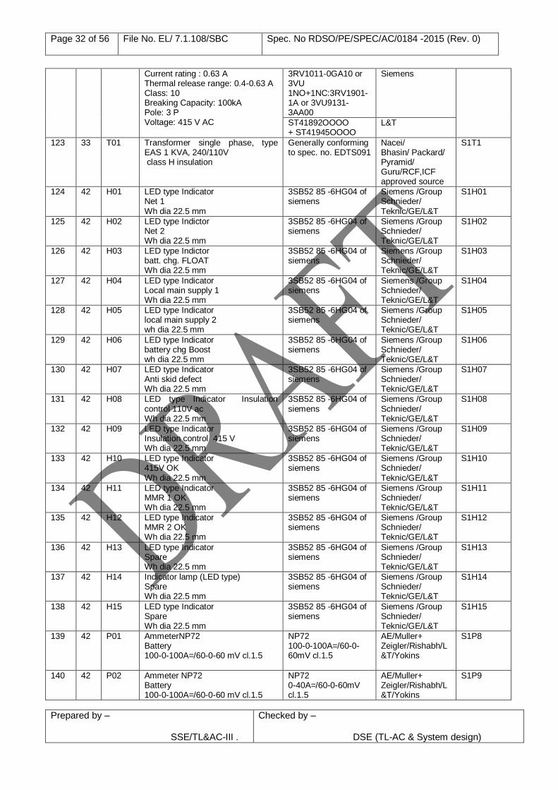
Current rating : 0.63 A Thermal release range: 0.4-0.63 A Class: 10 Breaking Capacity: 100kA Pole: 3 P Voltage: 415 V AC
3RV1011-0GA10 or 3VU 1NO+1NC:3RV1901-1A or 3VU9131-3AA00
Siemens
ST41892OOOO + ST41945OOOO
L&T
123 33 T01 Transformer single phase, type EAS 1 KVA, 240/110V class H insulation
Generally conforming to spec. no. EDTS091
Nacei/ Bhasin/ Packard/ Pyramid/ Guru/RCF,ICF approved source
S1T1
124 42 H01 LED type Indicator Net 1 Wh dia 22.5 mm
3SB52 85 -6HG04 of siemens
Siemens /Group Schnieder/ Teknic/GE/L&T
S1H01
125 42 H02 LED type Indictor Net 2 Wh dia 22.5 mm
3SB52 85 -6HG04 of siemens
Siemens /Group Schnieder/ Teknic/GE/L&T
S1H02
126 42 H03 LED type Indictor batt. chg. FLOAT Wh dia 22.5 mm
3SB52 85 -6HG04 of siemens
Siemens /Group Schnieder/ Teknic/GE/L&T
S1H03
127 42 H04 LED type Indicator Local main supply 1 Wh dia 22.5 mm
3SB52 85 -6HG04 of siemens
Siemens /Group Schnieder/ Teknic/GE/L&T
S1H04
128 42 H05 LED type Indicator local main supply 2 wh dia 22.5 mm
3SB52 85 -6HG04 of siemens
Siemens /Group Schnieder/ Teknic/GE/L&T
S1H05
129 42 H06 LED type Indicator battery chg Boost wh dia 22.5 mm
3SB52 85 -6HG04 of siemens
Siemens /Group Schnieder/ Teknic/GE/L&T
S1H06
130 42 H07 LED type Indicator Anti skid defect Wh dia 22.5 mm
3SB52 85 -6HG04 of siemens
Siemens /Group Schnieder/ Teknic/GE/L&T
S1H07
131 42 H08 LED type Indicator Insulation control 110V ac Wh dia 22.5 mm
3SB52 85 -6HG04 of siemens
Siemens /Group Schnieder/ Teknic/GE/L&T
S1H08
132 42 H09 LED type Indicator Insulation control 415 V Wh dia 22.5 mm
3SB52 85 -6HG04 of siemens
Siemens /Group Schnieder/ Teknic/GE/L&T
S1H09
133 42 H10 LED type Indicator 415V OK Wh dia 22.5 mm
3SB52 85 -6HG04 of siemens
Siemens /Group Schnieder/ Teknic/GE/L&T
S1H10
134 42 H11 LED type Indicator MMR 1 OK Wh dia 22.5 mm
3SB52 85 -6HG04 of siemens
Siemens /Group Schnieder/ Teknic/GE/L&T
S1H11
135 42 H12 LED type Indicator MMR 2 OK Wh dia 22.5 mm
3SB52 85 -6HG04 of siemens
Siemens /Group Schnieder/ Teknic/GE/L&T
S1H12
136 42 H13 LED type Indicator Spare Wh dia 22.5 mm
3SB52 85 -6HG04 of siemens
Siemens /Group Schnieder/ Teknic/GE/L&T
S1H13
137 42 H14 Indicator lamp (LED type) Spare Wh dia 22.5 mm
3SB52 85 -6HG04 of siemens
Siemens /Group Schnieder/ Teknic/GE/L&T
S1H14
138 42 H15 LED type Indicator Spare Wh dia 22.5 mm
3SB52 85 -6HG04 of siemens
Siemens /Group Schnieder/ Teknic/GE/L&T
S1H15
139 42 P01 AmmeterNP72 Battery 100-0-100A=/60-0-60 mV cl.1.5
NP72 100-0-100A=/60-0-60mV cl.1.5
AE/Muller+ Zeigler/Rishabh/L&T/Yokins
S1P8
140 42 P02 Ammeter NP72 Battery 100-0-100A=/60-0-60 mV cl.1.5
NP72 0-40A=/60-0-60mV cl.1.5
AE/Muller+ Zeigler/Rishabh/L&T/Yokins
S1P9
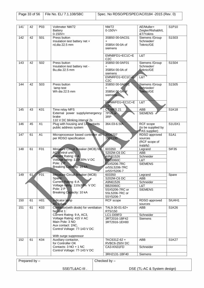
Page 33 of 56 File No. EL/ 7.1.108/SBC Spec. No RDSO/PE/SPEC/AC/0184 -2015 (Rev. 0)
Prepared by – SSE/TL&AC-III .
Checked by –
DSE (TL-AC & System design)
141` 42 P03 Voltmeter NW72 Battery 0-150V=
NW72 0-150V=
AE/Muller+ Zeigler/Rishabh/L&T/Yokins
S1P10
142 42 S01 Press button Insulation test battery net + rd,dia 22.5 mm
3SB50 00-0AC01 + 3SB54 00-0A of siemens
Siemens /Group Schnieder/ Teknic/GE
S1S03
EMNBFD1+EC1C+EC2C
L&T
143 42 S02 Press button Insulation test battery net - Bu,dia 22.5 mm
3SB50 00-0AF01 + 3SB54 00-0A of siemens
Siemens /Group Schnieder/ Teknic/GE
S1S04
EMNRFD1+EC1C+EC2C
L&T
144 42 S03 Press button lamp test Wh dia 22.5 mm
3SB50 00-0AG01 + 3SB54 00-0A of siemens
Siemens /Group Schnieder/ Teknic/GE
S1S05
EMNWFD1+EC1C+EC2C
L&T
145 43 K01 Time relay MFS External power supply/emergency brake 110 V DC blinking interval 2s
CT-MFS.21 ABB S1K18
7PV0 or 3RP
SIEMENS
146 45 X1 Plug with housing and 14 contacts public address system
364.03-6.StA RCF scope (to be supplied by PAS supplier)
S1U3X1
147 61 A1 Microprocessor based controller as per RDSO specification
3506707 3501130
RDSO approved sources (RCF scope of supply)
S1A1
148 61 F01 Miniature Circuit Breaker (MCB) for AC control unit: Current Rating: 6 A Voltage rating: 110±30% V DC Pole: 2 P Breaking Capacity: 10 kA
603350 Legrand SIF35
S202M-C6 DC ABB
A9N61526 Schneider
BB20060C L&T
5SX5206-7RC or5SL5206-7RC or5SY5206-7
SIEMENS
149 61 F01 Miniature Circuit Breaker (MCB) Spare: Current Rating: 6 A Voltage rating: 110±30% V DC Pole: 2 P Breaking Capacity: 10 kA
603350 Legrand Spare
S202M-C6 DC ABB
A9N61526 Schneider
BB20060C L&T
5SX5206-7RC or 5SL5206-7RC or 5SY5206-7
SIEMENS
150 61 H01 Indicator lamp AC failure
RCF scope RDSO approved sources
SIU4H1
151 61 K03 Contactor(with diode) for ventilation fan unit 1: Current Rating: 9 A, AC3, Voltage Rating: 415 V AC Main Pole: 3 NO Aux contact: 1NC, Control Voltage: 77-143 V DC With surge suppressor
TAL9-30-01-62+ RT5/150
ABB S1K26
LC1-D09FD Schneider
3RT2016-1BF42 3RT2916-1EH00
Siemens
152 61 K04 Auxiliary contactor, for Controller OK Contacts: 3 NO + 1 NC Control Voltage: 77-143 V DC
TKC631Z-62 + RVBC6-250V DC
ABB
S1K27
CA3-KN31FD
Schneider
3RH2131-1BF40 Siemens
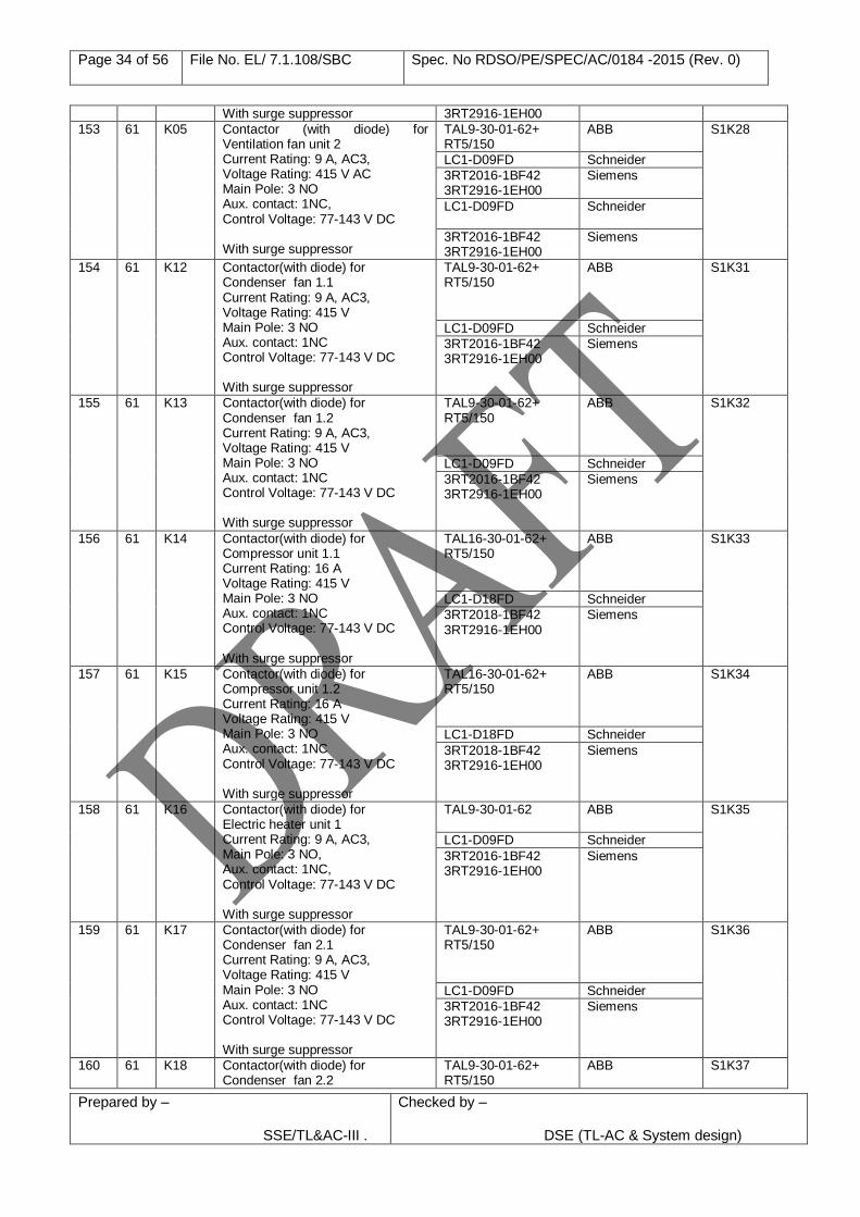
Page 34 of 56 File No. EL/ 7.1.108/SBC Spec. No RDSO/PE/SPEC/AC/0184 -2015 (Rev. 0)
Prepared by – SSE/TL&AC-III .
Checked by –
DSE (TL-AC & System design)
With surge suppressor 3RT2916-1EH00
153 61 K05 Contactor (with diode) for Ventilation fan unit 2 Current Rating: 9 A, AC3, Voltage Rating: 415 V AC Main Pole: 3 NO Aux. contact: 1NC, Control Voltage: 77-143 V DC With surge suppressor
TAL9-30-01-62+ RT5/150
ABB S1K28
LC1-D09FD Schneider
3RT2016-1BF42 3RT2916-1EH00
Siemens
LC1-D09FD
Schneider
3RT2016-1BF42 3RT2916-1EH00
Siemens
154 61 K12 Contactor(with diode) for Condenser fan 1.1 Current Rating: 9 A, AC3, Voltage Rating: 415 V Main Pole: 3 NO Aux. contact: 1NC Control Voltage: 77-143 V DC With surge suppressor
TAL9-30-01-62+ RT5/150
ABB
S1K31
LC1-D09FD Schneider
3RT2016-1BF42 3RT2916-1EH00
Siemens
155 61 K13 Contactor(with diode) for Condenser fan 1.2 Current Rating: 9 A, AC3, Voltage Rating: 415 V Main Pole: 3 NO Aux. contact: 1NC Control Voltage: 77-143 V DC With surge suppressor
TAL9-30-01-62+ RT5/150
ABB
S1K32
LC1-D09FD Schneider
3RT2016-1BF42 3RT2916-1EH00
Siemens
156 61 K14 Contactor(with diode) for Compressor unit 1.1 Current Rating: 16 A Voltage Rating: 415 V Main Pole: 3 NO Aux. contact: 1NC Control Voltage: 77-143 V DC With surge suppressor
TAL16-30-01-62+ RT5/150
ABB
S1K33
LC1-D18FD Schneider
3RT2018-1BF42 3RT2916-1EH00
Siemens
157 61 K15 Contactor(with diode) for Compressor unit 1.2 Current Rating: 16 A Voltage Rating: 415 V Main Pole: 3 NO Aux. contact: 1NC Control Voltage: 77-143 V DC With surge suppressor
TAL16-30-01-62+ RT5/150
ABB
S1K34
LC1-D18FD Schneider
3RT2018-1BF42 3RT2916-1EH00
Siemens
158 61 K16 Contactor(with diode) for Electric heater unit 1 Current Rating: 9 A, AC3, Main Pole: 3 NO, Aux. contact: 1NC, Control Voltage: 77-143 V DC With surge suppressor
TAL9-30-01-62 ABB
S1K35
LC1-D09FD Schneider
3RT2016-1BF42 3RT2916-1EH00
Siemens
159 61 K17 Contactor(with diode) for Condenser fan 2.1 Current Rating: 9 A, AC3, Voltage Rating: 415 V Main Pole: 3 NO Aux. contact: 1NC Control Voltage: 77-143 V DC With surge suppressor
TAL9-30-01-62+ RT5/150
ABB
S1K36
LC1-D09FD Schneider
3RT2016-1BF42 3RT2916-1EH00
Siemens
160 61 K18 Contactor(with diode) for Condenser fan 2.2
TAL9-30-01-62+ RT5/150
ABB
S1K37
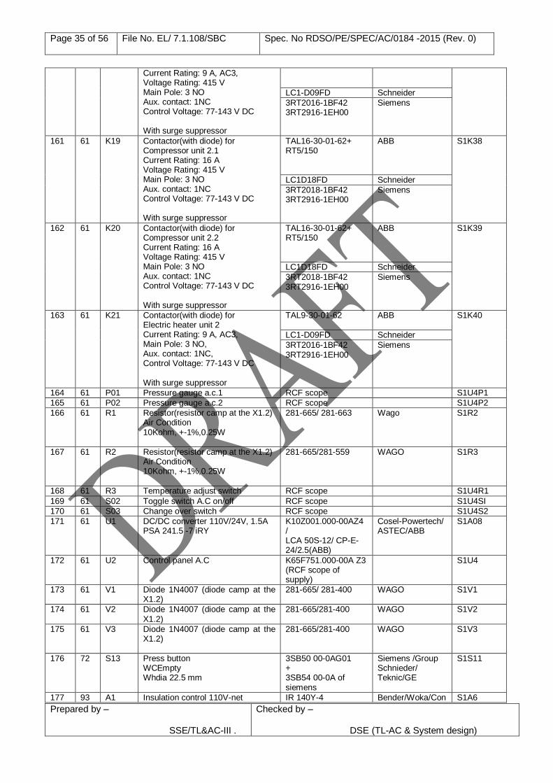
Page 35 of 56 File No. EL/ 7.1.108/SBC Spec. No RDSO/PE/SPEC/AC/0184 -2015 (Rev. 0)
Prepared by – SSE/TL&AC-III .
Checked by –
DSE (TL-AC & System design)
Current Rating: 9 A, AC3, Voltage Rating: 415 V Main Pole: 3 NO Aux. contact: 1NC Control Voltage: 77-143 V DC With surge suppressor
LC1-D09FD Schneider
3RT2016-1BF42 3RT2916-1EH00
Siemens
161 61 K19 Contactor(with diode) for Compressor unit 2.1 Current Rating: 16 A Voltage Rating: 415 V Main Pole: 3 NO Aux. contact: 1NC Control Voltage: 77-143 V DC With surge suppressor
TAL16-30-01-62+ RT5/150
ABB
S1K38
LC1D18FD Schneider
3RT2018-1BF42 3RT2916-1EH00
Siemens
162 61 K20 Contactor(with diode) for Compressor unit 2.2 Current Rating: 16 A Voltage Rating: 415 V Main Pole: 3 NO Aux. contact: 1NC Control Voltage: 77-143 V DC With surge suppressor
TAL16-30-01-62+ RT5/150
ABB
S1K39
LC1D18FD Schneider
3RT2018-1BF42 3RT2916-1EH00
Siemens
163 61 K21 Contactor(with diode) for Electric heater unit 2 Current Rating: 9 A, AC3, Main Pole: 3 NO, Aux. contact: 1NC, Control Voltage: 77-143 V DC With surge suppressor
TAL9-30-01-62 ABB
S1K40
LC1-D09FD Schneider
3RT2016-1BF42 3RT2916-1EH00
Siemens
164 61 P01 Pressure gauge a.c.1 RCF scope S1U4P1
165 61 P02 Pressure gauge a.c.2 RCF scope S1U4P2
166 61 R1 Resistor(resistor camp at the X1.2) Air Condition 10Kohm, +-1%,0.25W
281-665/ 281-663 Wago S1R2
167 61 R2 Resistor(resistor camp at the X1.2) Air Condition 10Kohm, +-1%,0.25W
281-665/281-559 WAGO S1R3
168 61 R3 Temperature adjust switch RCF scope S1U4R1
169 61 S02 Toggle switch A.C on/off RCF scope S1U4SI
170 61 S03 Change over switch RCF scope S1U4S2
171 61 U1 DC/DC converter 110V/24V, 1.5A PSA 241.5 -7 iRY
K10Z001.000-00AZ4 / LCA 50S-12/ CP-E-24/2.5(ABB)
Cosel-Powertech/ ASTEC/ABB
S1A08
172 61 U2 Control panel A.C K65F751.000-00A Z3 (RCF scope of supply)
S1U4
173 61 V1 Diode 1N4007 (diode camp at the X1.2)
281-665/ 281-400 WAGO S1V1
174 61 V2 Diode 1N4007 (diode camp at the X1.2)
281-665/281-400 WAGO S1V2
175 61 V3 Diode 1N4007 (diode camp at the X1.2)
281-665/281-400 WAGO S1V3
176 72 S13 Press button WCEmpty Whdia 22.5 mm
3SB50 00-0AG01 + 3SB54 00-0A of siemens
Siemens /Group Schnieder/ Teknic/GE
S1S11
177 93 A1 Insulation control 110V-net IR 140Y-4 Bender/Woka/Con S1A6
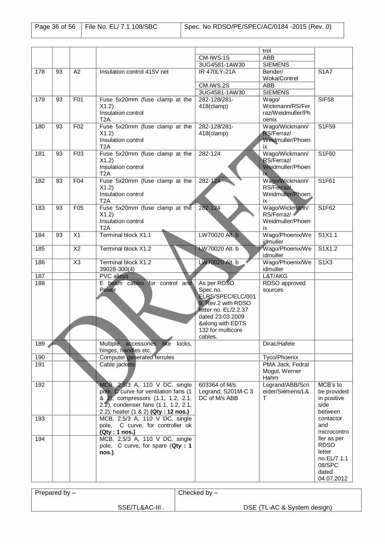
Page 36 of 56 File No. EL/ 7.1.108/SBC Spec. No RDSO/PE/SPEC/AC/0184 -2015 (Rev. 0)
Prepared by – SSE/TL&AC-III .
Checked by –
DSE (TL-AC & System design)
trel
CM-IWS.1S ABB
3UG4581-1AW30 SIEMENS
178 93 A2 Insulation control 415V net IR 470LY-21A Bender/ Woka/Contrel
S1A7
CM.IWS.2S ABB
3UG4581-1AW30 SIEMENS
179 93 F01 Fuse 5x20mm (fuse clamp at the X1.2) Insulation control T2A
282-128/281-418(clamp)
Wago/ Wickmann/RS/Ferraz/Weidmuller/Phoenix
SIF58
180 93 F02 Fuse 5x20mm (fuse clamp at the X1.2) Insulation control T2A
282-128/281-418(clamp)
Wago/Wickmann/RS/Ferraz/ Weidmuller/Phoenix
S1F59
181 93 F03 Fuse 5x20mm (fuse clamp at the X1.2) Insulation control T2A
282-124 Wago/Wickmann/RS/Ferraz/ Weidmuller/Phoenix
S1F60
182 93 F04 Fuse 5x20mm (fuse clamp at the X1.2) Insulation control T2A
282-124 Wago/Wickmann/RS/Ferraz/ Weidmuller/Phoenix
S1F61
183 93 F05 Fuse 5x20mm (fuse clamp at the X1.2) Insulation control T2A
282-124 Wago/Wickmann/RS/Ferraz/ Weidmuller/Phoenix
S1F62
184 93 X1 Terminal block X1.1
LW70020 Alt. b Wago/Phoenix/Weidmuller
S1X1.1
185 X2 Terminal block X1.2
LW70020 Alt. b Wago/Phoenix/Weidmuller
S1X1.2
186 X3 Terminal block X1.2 39028-300(4)
LW70020 Alt. b Wago/Phoenix/Weidmuller
S1X3
187 PVC alleys L&T/AKG
188 E beam cables for control and Power
As per RDSO Spec.no. ELRS/SPEC/ELC/0019, Rev.2 with RDSO letter no. EL/2.2.37 dated 23.03.2009 &along with EDTS 132 for multicore cables.
RDSO approved sources
189 Multiple accessories like locks, hinges, handles etc.
Dirac/Hafele
190 Computer generated ferrules Tyco/Phoenix
191 Cable jackets PMA Jack, Fedral Mogul, Werner Hahm
192 MCB, 2.5/3 A, 110 V DC, single pole, C curve for ventilation fans (1 & 2), compressors (1.1, 1.2, 2.1, 2.2), condenser fans (1.1, 1.2, 2.1, 2.2), heater (1 & 2) (Qty : 12 nos.)
603364 of M/s Legrand, S201M-C 3 DC of M/s ABB
Legrand/ABB/Scneider/Siemens/L&T
MCB’s to be provided in positive side between contactor and microcontroller as per RDSO letter no.EL/7.1.108/SPC dated 04.07.2012
193 MCB, 2.5/3 A, 110 V DC, single pole, C curve, for controller ok (Qty : 1 nos.)
194 MCB, 2.5/3 A, 110 V DC, single pole, C curve, for spare (Qty : 1 nos.)
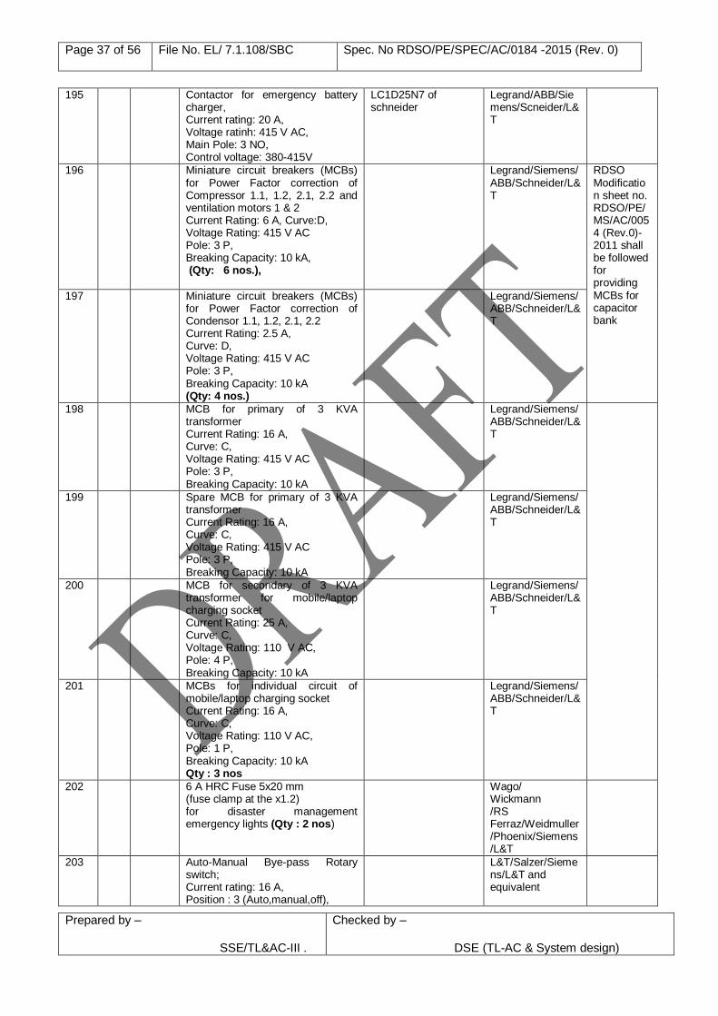
Page 37 of 56 File No. EL/ 7.1.108/SBC Spec. No RDSO/PE/SPEC/AC/0184 -2015 (Rev. 0)
Prepared by – SSE/TL&AC-III .
Checked by –
DSE (TL-AC & System design)
195 Contactor for emergency battery charger, Current rating: 20 A, Voltage ratinh: 415 V AC, Main Pole: 3 NO, Control voltage: 380-415V
LC1D25N7 of schneider
Legrand/ABB/Siemens/Scneider/L&T
196 Miniature circuit breakers (MCBs) for Power Factor correction of Compressor 1.1, 1.2, 2.1, 2.2 and ventilation motors 1 & 2 Current Rating: 6 A, Curve:D, Voltage Rating: 415 V AC Pole: 3 P, Breaking Capacity: 10 kA, (Qty: 6 nos.),
Legrand/Siemens/ABB/Schneider/L&T
RDSO Modification sheet no. RDSO/PE/MS/AC/0054 (Rev.0)-2011 shall be followed for providing MCBs for capacitor bank
197 Miniature circuit breakers (MCBs) for Power Factor correction of Condensor 1.1, 1.2, 2.1, 2.2 Current Rating: 2.5 A, Curve: D, Voltage Rating: 415 V AC Pole: 3 P, Breaking Capacity: 10 kA (Qty: 4 nos.)
Legrand/Siemens/ABB/Schneider/L&T
198 MCB for primary of 3 KVA transformer Current Rating: 16 A, Curve: C, Voltage Rating: 415 V AC Pole: 3 P, Breaking Capacity: 10 kA
Legrand/Siemens/ABB/Schneider/L&T
199 Spare MCB for primary of 3 KVA transformer Current Rating: 16 A, Curve: C, Voltage Rating: 415 V AC Pole: 3 P, Breaking Capacity: 10 kA
Legrand/Siemens/ABB/Schneider/L&T
200 MCB for secondary of 3 KVA transformer for mobile/laptop charging socket Current Rating: 25 A, Curve: C, Voltage Rating: 110 V AC, Pole: 4 P, Breaking Capacity: 10 kA
Legrand/Siemens/ABB/Schneider/L&T
201 MCBs for individual circuit of mobile/laptop charging socket Current Rating: 16 A, Curve: C, Voltage Rating: 110 V AC, Pole: 1 P, Breaking Capacity: 10 kA Qty : 3 nos
Legrand/Siemens/ABB/Schneider/L&T
202 6 A HRC Fuse 5x20 mm (fuse clamp at the x1.2) for disaster management emergency lights (Qty : 2 nos)
Wago/ Wickmann /RS Ferraz/Weidmuller/Phoenix/Siemens/L&T
203 Auto-Manual Bye-pass Rotary switch; Current rating: 16 A, Position : 3 (Auto,manual,off),
L&T/Salzer/Siemens/L&T and equivalent
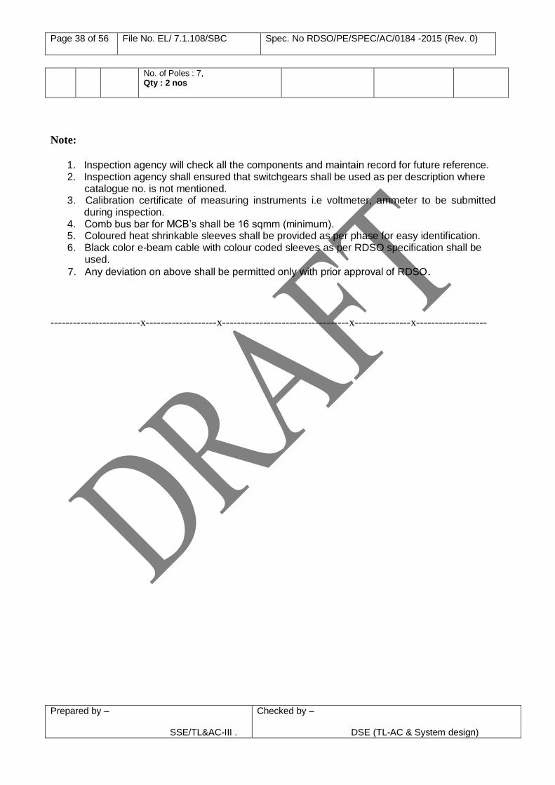
Page 38 of 56 File No. EL/ 7.1.108/SBC Spec. No RDSO/PE/SPEC/AC/0184 -2015 (Rev. 0)
Prepared by – SSE/TL&AC-III .
Checked by –
DSE (TL-AC & System design)
No. of Poles : 7, Qty : 2 nos
Note:
1. Inspection agency will check all the components and maintain record for future reference. 2. Inspection agency shall ensured that switchgears shall be used as per description where catalogue no. is not mentioned. 3. Calibration certificate of measuring instruments i.e voltmeter, ammeter to be submitted
during inspection. 4. Comb bus bar for MCB’s shall be 16 sqmm (minimum). 5. Coloured heat shrinkable sleeves shall be provided as per phase for easy identification. 6. Black color e-beam cable with colour coded sleeves as per RDSO specification shall be
used.
7. Any deviation on above shall be permitted only with prior approval of RDSO.
------------------------x-------------------x----------------------------------x---------------x-------------------
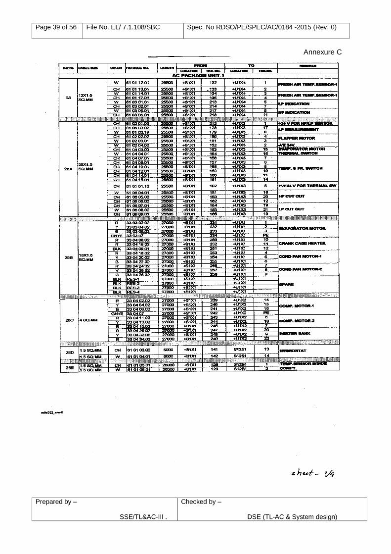
Page 39 of 56 File No. EL/ 7.1.108/SBC Spec. No RDSO/PE/SPEC/AC/0184 -2015 (Rev. 0)
Prepared by – SSE/TL&AC-III .
Checked by –
DSE (TL-AC & System design)
Annexure C
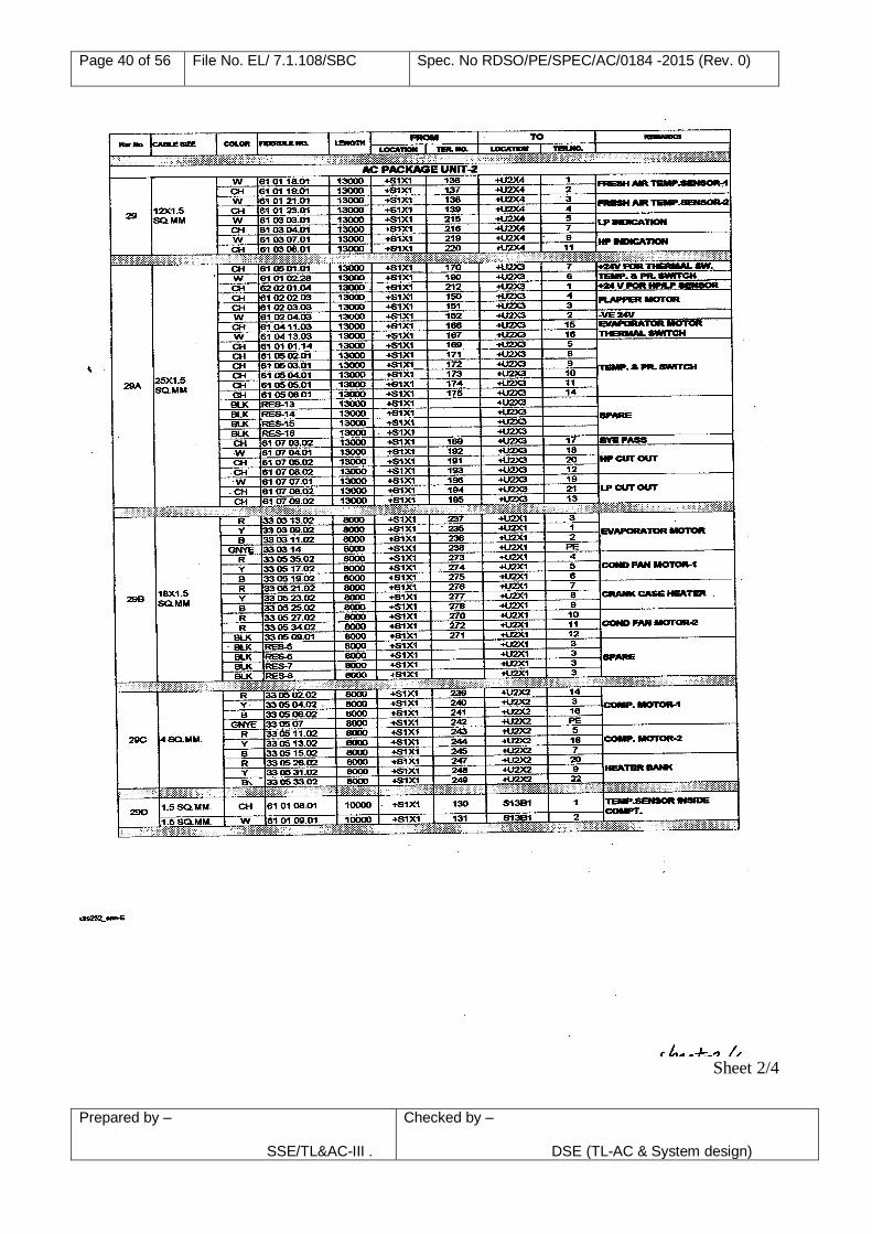
Page 40 of 56 File No. EL/ 7.1.108/SBC Spec. No RDSO/PE/SPEC/AC/0184 -2015 (Rev. 0)
Prepared by – SSE/TL&AC-III .
Checked by –
DSE (TL-AC & System design)
Sheet 2/4
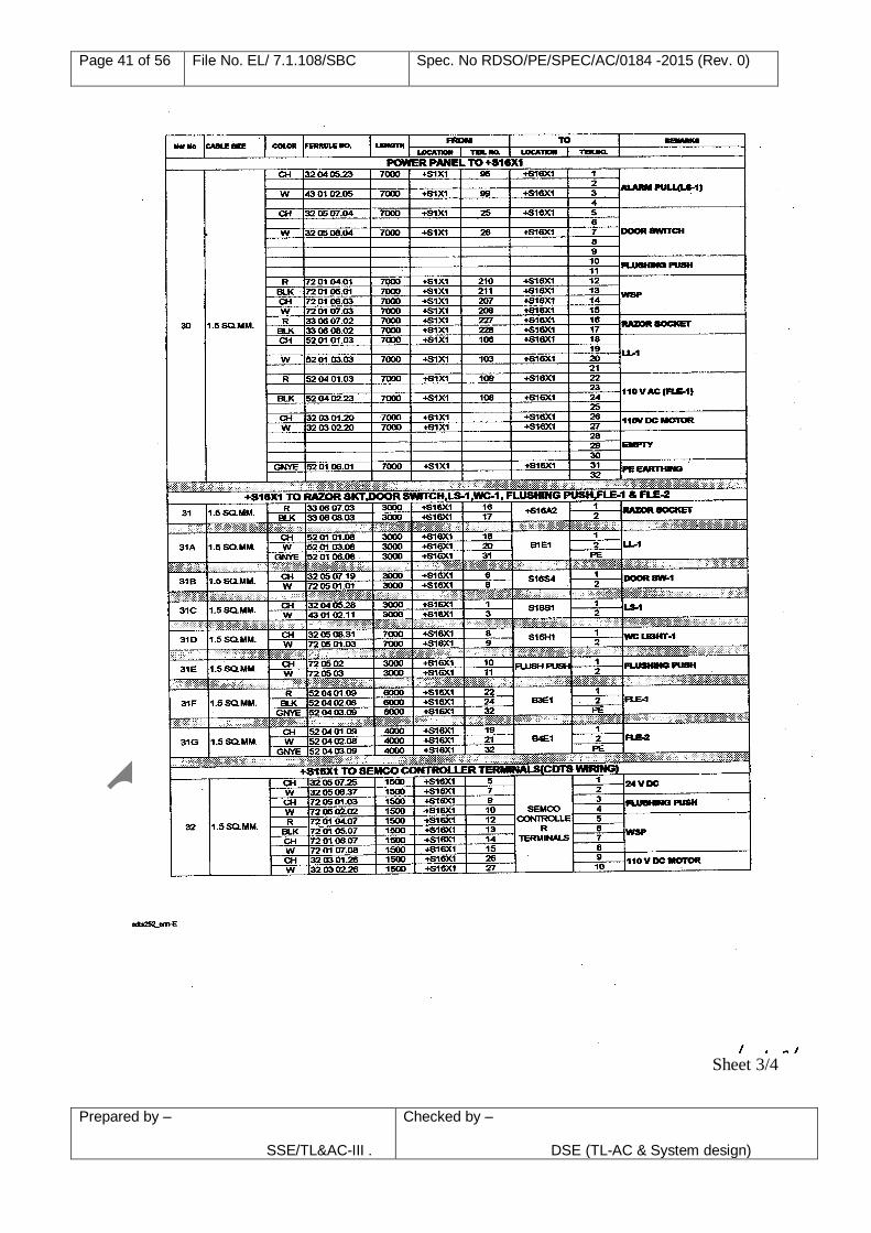
Page 41 of 56 File No. EL/ 7.1.108/SBC Spec. No RDSO/PE/SPEC/AC/0184 -2015 (Rev. 0)
Prepared by – SSE/TL&AC-III .
Checked by –
DSE (TL-AC & System design)
Sheet 3/4
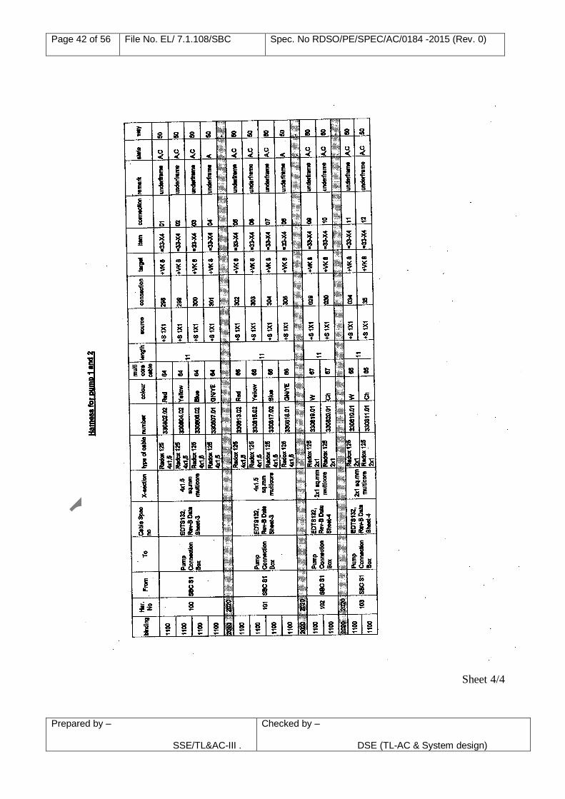
Page 42 of 56 File No. EL/ 7.1.108/SBC Spec. No RDSO/PE/SPEC/AC/0184 -2015 (Rev. 0)
Prepared by – SSE/TL&AC-III .
Checked by –
DSE (TL-AC & System design)
Sheet 4/4
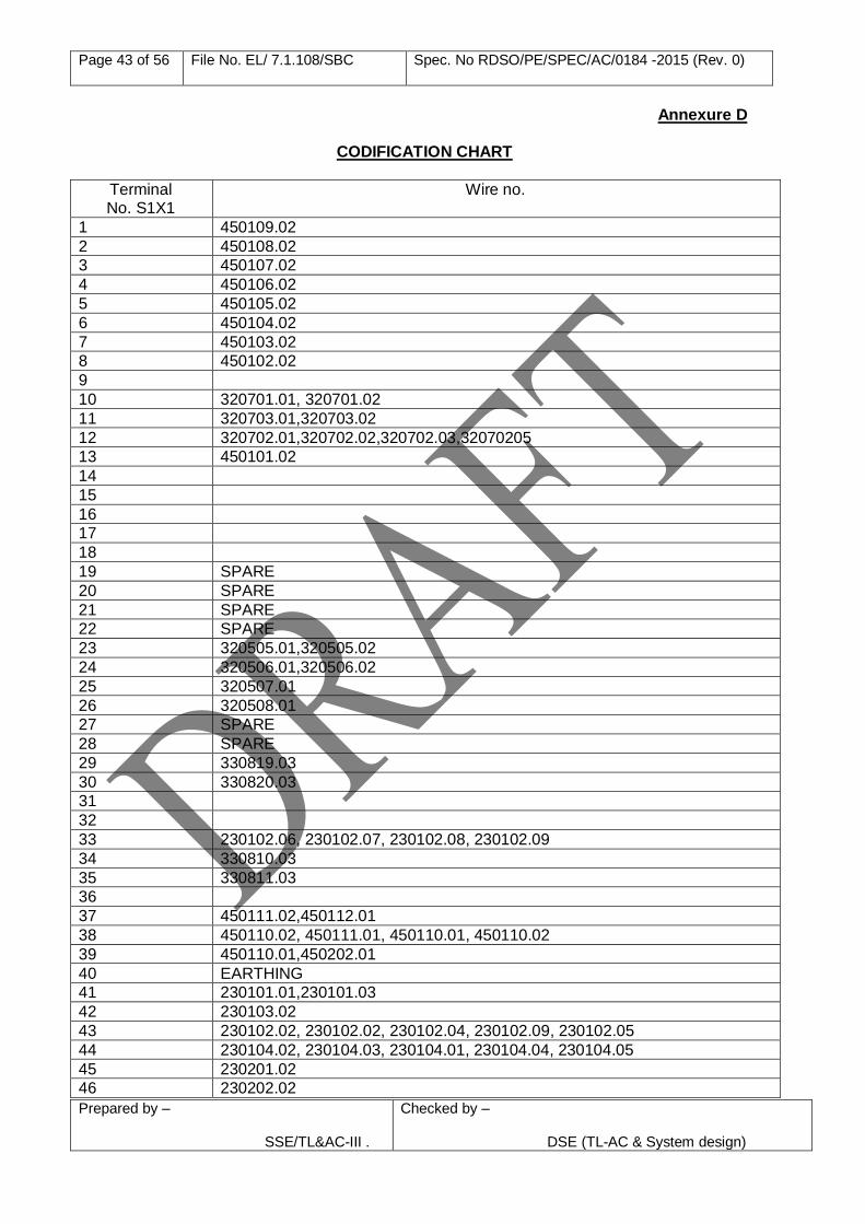
Page 43 of 56 File No. EL/ 7.1.108/SBC Spec. No RDSO/PE/SPEC/AC/0184 -2015 (Rev. 0)
Prepared by – SSE/TL&AC-III .
Checked by –
DSE (TL-AC & System design)
Annexure D
CODIFICATION CHART
Terminal No. S1X1
Wire no.
1 450109.02
2 450108.02
3 450107.02
4 450106.02
5 450105.02
6 450104.02
7 450103.02
8 450102.02
9
10 320701.01, 320701.02
11 320703.01,320703.02
12 320702.01,320702.02,320702.03,32070205
13 450101.02
14
15
16
17
18
19 SPARE
20 SPARE
21 SPARE
22 SPARE
23 320505.01,320505.02
24 320506.01,320506.02
25 320507.01
26 320508.01
27 SPARE
28 SPARE
29 330819.03
30 330820.03
31
32
33 230102.06, 230102.07, 230102.08, 230102.09
34 330810.03
35 330811.03
36
37 450111.02,450112.01
38 450110.02, 450111.01, 450110.01, 450110.02
39 450110.01,450202.01
40 EARTHING
41 230101.01,230101.03
42 230103.02
43 230102.02, 230102.02, 230102.04, 230102.09, 230102.05
44 230104.02, 230104.03, 230104.01, 230104.04, 230104.05
45 230201.02
46 230202.02
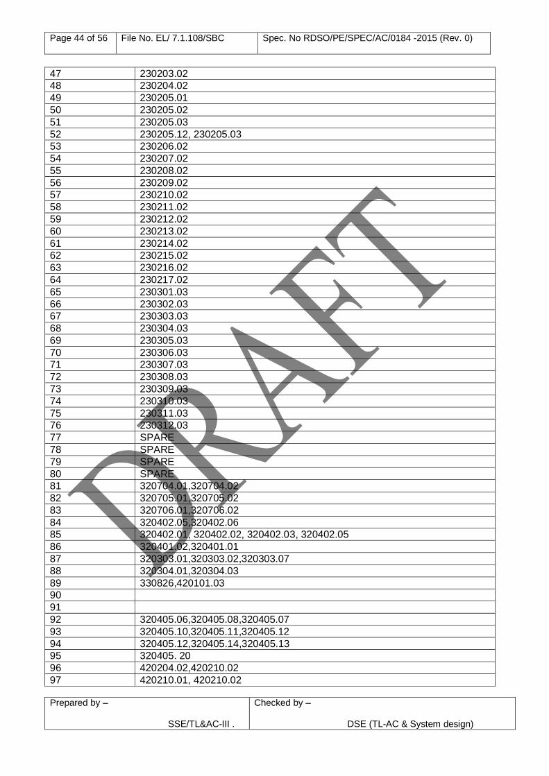
Page 44 of 56 File No. EL/ 7.1.108/SBC Spec. No RDSO/PE/SPEC/AC/0184 -2015 (Rev. 0)
Prepared by – SSE/TL&AC-III .
Checked by –
DSE (TL-AC & System design)
47 230203.02
48 230204.02
49 230205.01
50 230205.02
51 230205.03
52 230205.12, 230205.03
53 230206.02
54 230207.02
55 230208.02
56 230209.02
57 230210.02
58 230211.02
59 230212.02
60 230213.02
61 230214.02
62 230215.02
63 230216.02
64 230217.02
65 230301.03
66 230302.03
67 230303.03
68 230304.03
69 230305.03
70 230306.03
71 230307.03
72 230308.03
73 230309.03
74 230310.03
75 230311.03
76 230312.03
77 SPARE
78 SPARE
79 SPARE
80 SPARE
81 320704.01,320704.02
82 320705.01,320705.02
83 320706.01,320706.02
84 320402.05,320402.06
85 320402.01, 320402.02, 320402.03, 320402.05
86 320401.02,320401.01
87 320303.01,320303.02,320303.07
88 320304.01,320304.03
89 330826,420101.03
90
91
92 320405.06,320405.08,320405.07
93 320405.10,320405.11,320405.12
94 320405.12,320405.14,320405.13
95 320405. 20
96 420204.02,420210.02
97 420210.01, 420210.02
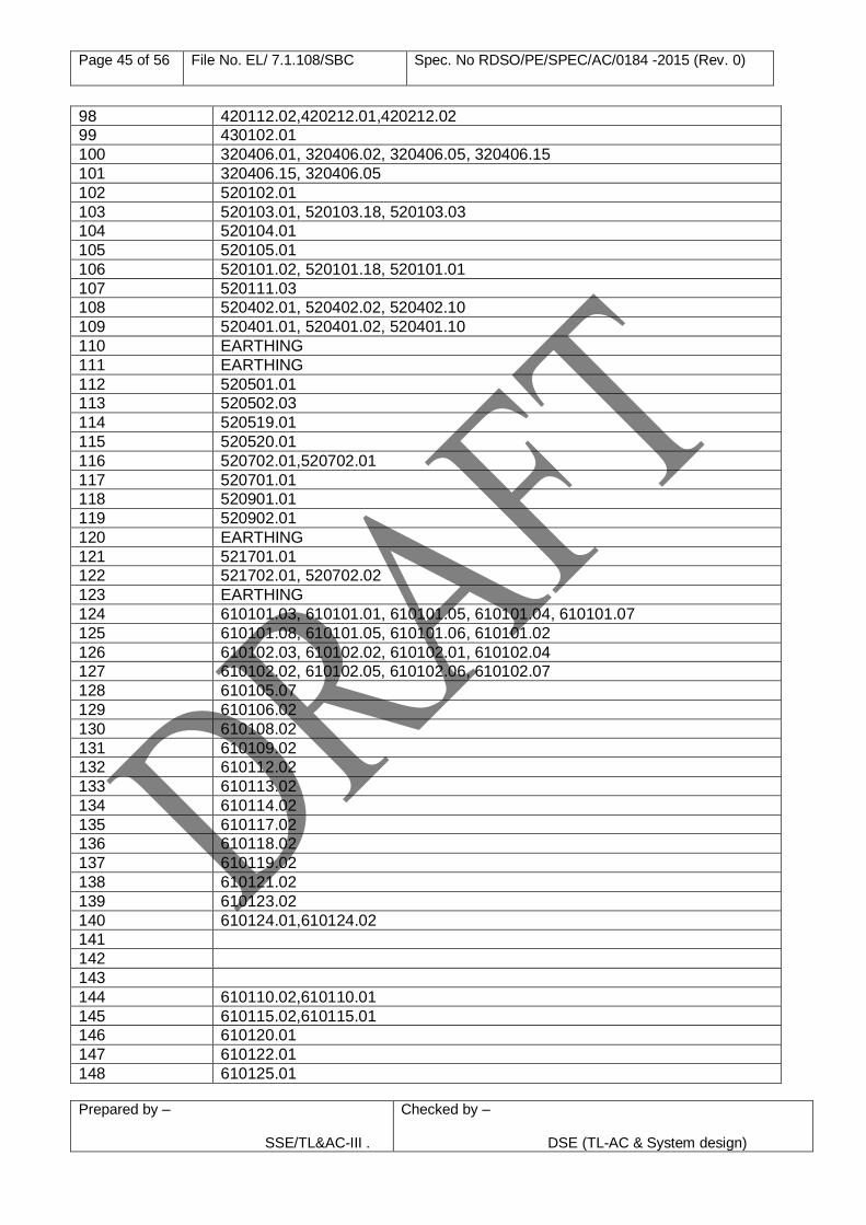
Page 45 of 56 File No. EL/ 7.1.108/SBC Spec. No RDSO/PE/SPEC/AC/0184 -2015 (Rev. 0)
Prepared by – SSE/TL&AC-III .
Checked by –
DSE (TL-AC & System design)
98 420112.02,420212.01,420212.02
99 430102.01
100 320406.01, 320406.02, 320406.05, 320406.15
101 320406.15, 320406.05
102 520102.01
103 520103.01, 520103.18, 520103.03
104 520104.01
105 520105.01
106 520101.02, 520101.18, 520101.01
107 520111.03
108 520402.01, 520402.02, 520402.10
109 520401.01, 520401.02, 520401.10
110 EARTHING
111 EARTHING
112 520501.01
113 520502.03
114 520519.01
115 520520.01
116 520702.01,520702.01
117 520701.01
118 520901.01
119 520902.01
120 EARTHING
121 521701.01
122 521702.01, 520702.02
123 EARTHING
124 610101.03, 610101.01, 610101.05, 610101.04, 610101.07
125 610101.08, 610101.05, 610101.06, 610101.02
126 610102.03, 610102.02, 610102.01, 610102.04
127 610102.02, 610102.05, 610102.06, 610102.07
128 610105.07
129 610106.02
130 610108.02
131 610109.02
132 610112.02
133 610113.02
134 610114.02
135 610117.02
136 610118.02
137 610119.02
138 610121.02
139 610123.02
140 610124.01,610124.02
141
142
143
144 610110.02,610110.01
145 610115.02,610115.01
146 610120.01
147 610122.01
148 610125.01
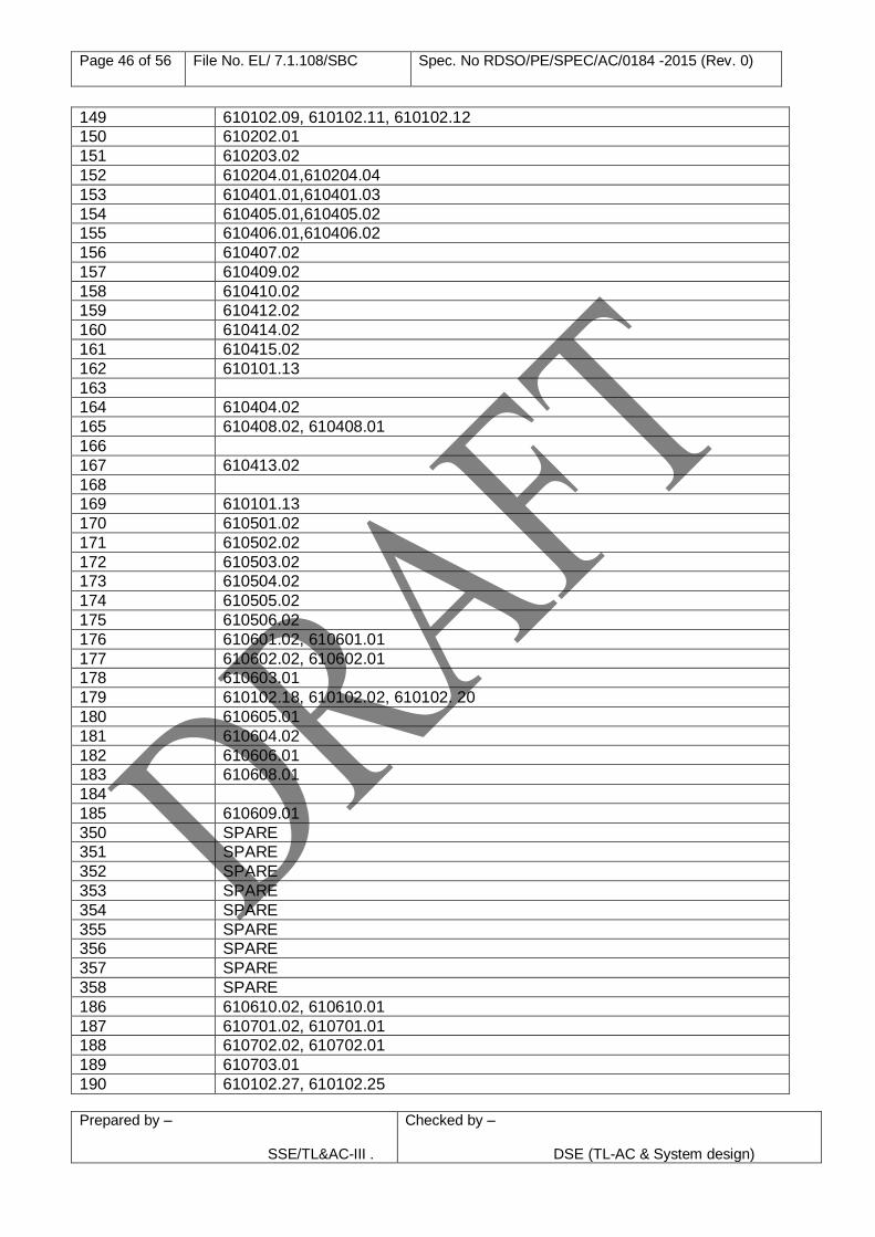
Page 46 of 56 File No. EL/ 7.1.108/SBC Spec. No RDSO/PE/SPEC/AC/0184 -2015 (Rev. 0)
Prepared by – SSE/TL&AC-III .
Checked by –
DSE (TL-AC & System design)
149 610102.09, 610102.11, 610102.12
150 610202.01
151 610203.02
152 610204.01,610204.04
153 610401.01,610401.03
154 610405.01,610405.02
155 610406.01,610406.02
156 610407.02
157 610409.02
158 610410.02
159 610412.02
160 610414.02
161 610415.02
162 610101.13
163
164 610404.02
165 610408.02, 610408.01
166
167 610413.02
168
169 610101.13
170 610501.02
171 610502.02
172 610503.02
173 610504.02
174 610505.02
175 610506.02
176 610601.02, 610601.01
177 610602.02, 610602.01
178 610603.01
179 610102.18, 610102.02, 610102. 20
180 610605.01
181 610604.02
182 610606.01
183 610608.01
184
185 610609.01
350 SPARE
351 SPARE
352 SPARE
353 SPARE
354 SPARE
355 SPARE
356 SPARE
357 SPARE
358 SPARE
186 610610.02, 610610.01
187 610701.02, 610701.01
188 610702.02, 610702.01
189 610703.01
190 610102.27, 610102.25
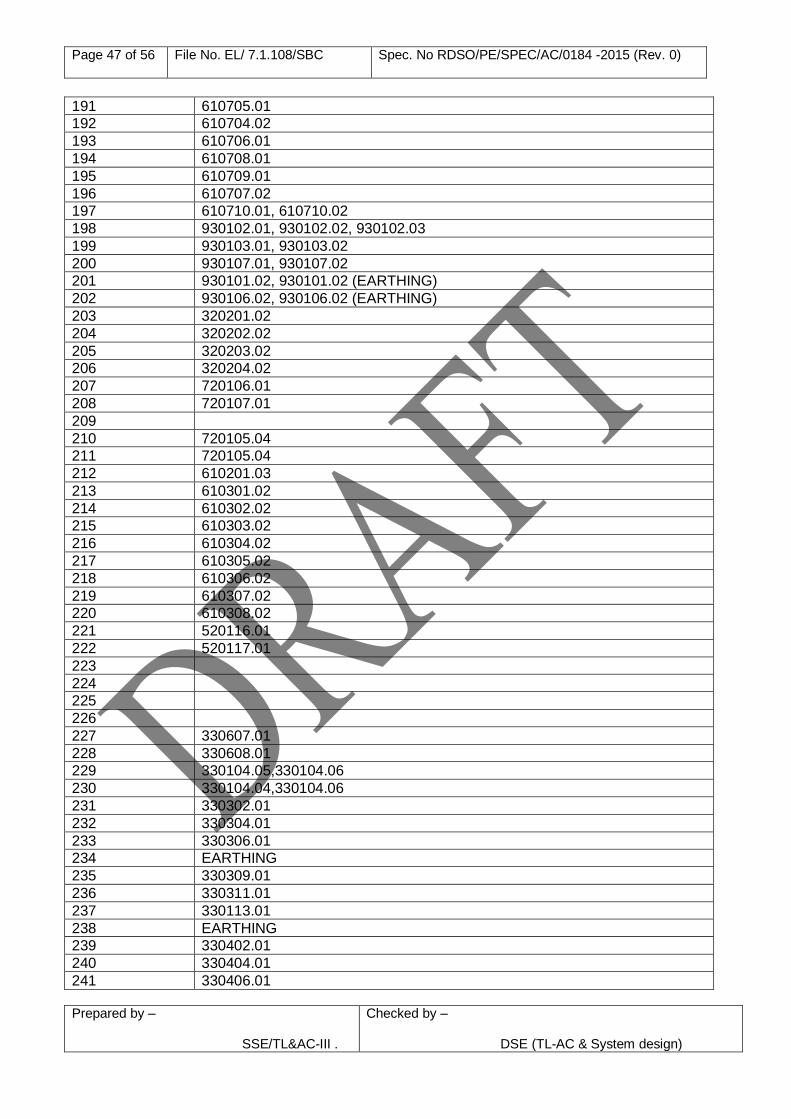
Page 47 of 56 File No. EL/ 7.1.108/SBC Spec. No RDSO/PE/SPEC/AC/0184 -2015 (Rev. 0)
Prepared by – SSE/TL&AC-III .
Checked by –
DSE (TL-AC & System design)
191 610705.01
192 610704.02
193 610706.01
194 610708.01
195 610709.01
196 610707.02
197 610710.01, 610710.02
198 930102.01, 930102.02, 930102.03
199 930103.01, 930103.02
200 930107.01, 930107.02
201 930101.02, 930101.02 (EARTHING)
202 930106.02, 930106.02 (EARTHING)
203 320201.02
204 320202.02
205 320203.02
206 320204.02
207 720106.01
208 720107.01
209
210 720105.04
211 720105.04
212 610201.03
213 610301.02
214 610302.02
215 610303.02
216 610304.02
217 610305.02
218 610306.02
219 610307.02
220 610308.02
221 520116.01
222 520117.01
223
224
225
226
227 330607.01
228 330608.01
229 330104.05,330104.06
230 330104.04,330104.06
231 330302.01
232 330304.01
233 330306.01
234 EARTHING
235 330309.01
236 330311.01
237 330113.01
238 EARTHING
239 330402.01
240 330404.01
241 330406.01
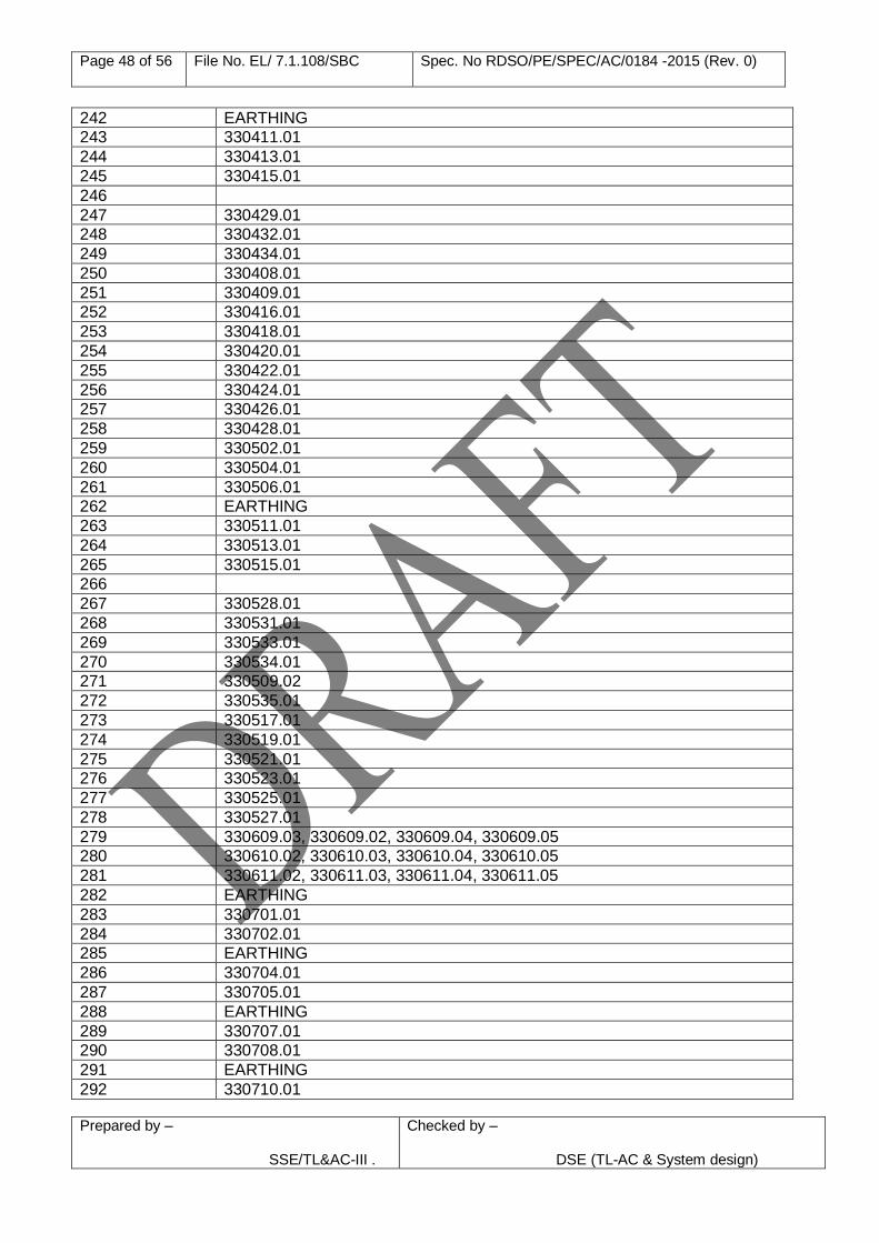
Page 48 of 56 File No. EL/ 7.1.108/SBC Spec. No RDSO/PE/SPEC/AC/0184 -2015 (Rev. 0)
Prepared by – SSE/TL&AC-III .
Checked by –
DSE (TL-AC & System design)
242 EARTHING
243 330411.01
244 330413.01
245 330415.01
246
247 330429.01
248 330432.01
249 330434.01
250 330408.01
251 330409.01
252 330416.01
253 330418.01
254 330420.01
255 330422.01
256 330424.01
257 330426.01
258 330428.01
259 330502.01
260 330504.01
261 330506.01
262 EARTHING
263 330511.01
264 330513.01
265 330515.01
266
267 330528.01
268 330531.01
269 330533.01
270 330534.01
271 330509.02
272 330535.01
273 330517.01
274 330519.01
275 330521.01
276 330523.01
277 330525.01
278 330527.01
279 330609.03, 330609.02, 330609.04, 330609.05
280 330610.02, 330610.03, 330610.04, 330610.05
281 330611.02, 330611.03, 330611.04, 330611.05
282 EARTHING
283 330701.01
284 330702.01
285 EARTHING
286 330704.01
287 330705.01
288 EARTHING
289 330707.01
290 330708.01
291 EARTHING
292 330710.01
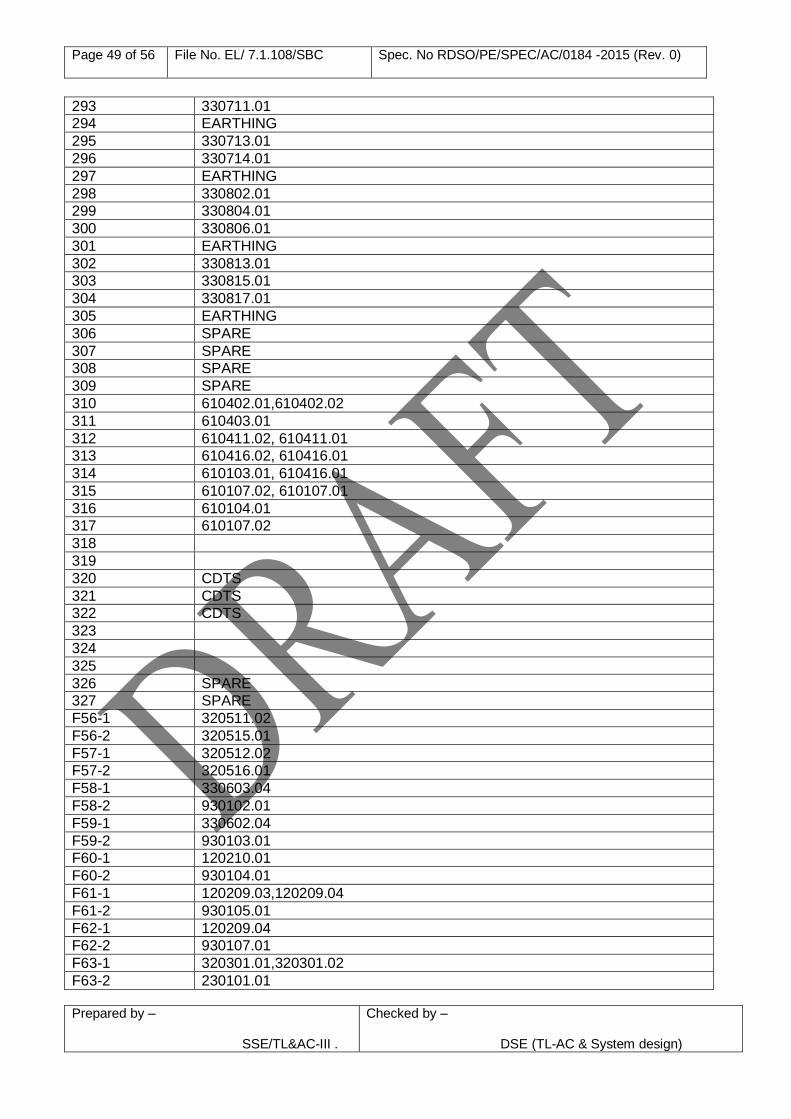
Page 49 of 56 File No. EL/ 7.1.108/SBC Spec. No RDSO/PE/SPEC/AC/0184 -2015 (Rev. 0)
Prepared by – SSE/TL&AC-III .
Checked by –
DSE (TL-AC & System design)
293 330711.01
294 EARTHING
295 330713.01
296 330714.01
297 EARTHING
298 330802.01
299 330804.01
300 330806.01
301 EARTHING
302 330813.01
303 330815.01
304 330817.01
305 EARTHING
306 SPARE
307 SPARE
308 SPARE
309 SPARE
310 610402.01,610402.02
311 610403.01
312 610411.02, 610411.01
313 610416.02, 610416.01
314 610103.01, 610416.01
315 610107.02, 610107.01
316 610104.01
317 610107.02
318
319
320 CDTS
321 CDTS
322 CDTS
323
324
325
326 SPARE
327 SPARE
F56-1 320511.02
F56-2 320515.01
F57-1 320512.02
F57-2 320516.01
F58-1 330603.04
F58-2 930102.01
F59-1 330602.04
F59-2 930103.01
F60-1 120210.01
F60-2 930104.01
F61-1 120209.03,120209.04
F61-2 930105.01
F62-1 120209.04
F62-2 930107.01
F63-1 320301.01,320301.02
F63-2 230101.01
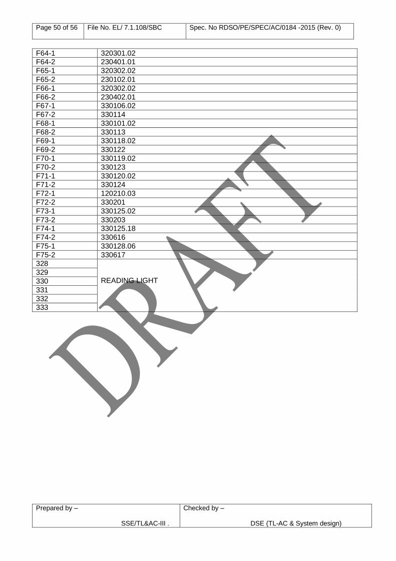
Page 50 of 56 File No. EL/ 7.1.108/SBC Spec. No RDSO/PE/SPEC/AC/0184 -2015 (Rev. 0)
Prepared by – SSE/TL&AC-III .
Checked by –
DSE (TL-AC & System design)
F64-1 320301.02
F64-2 230401.01
F65-1 320302.02
F65-2 230102.01
F66-1 320302.02
F66-2 230402.01
F67-1 330106.02
F67-2 330114
F68-1 330101.02
F68-2 330113
F69-1 330118.02
F69-2 330122
F70-1 330119.02
F70-2 330123
F71-1 330120.02
F71-2 330124
F72-1 120210.03
F72-2 330201
F73-1 330125.02
F73-2 330203
F74-1 330125.18
F74-2 330616
F75-1 330128.06
F75-2 330617
328 READING LIGHT
329
330
331
332
333
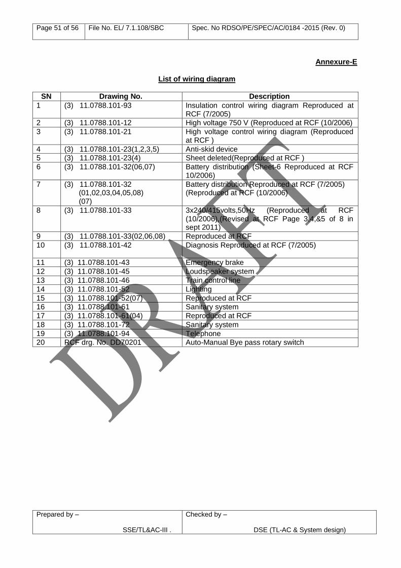
Page 51 of 56 File No. EL/ 7.1.108/SBC Spec. No RDSO/PE/SPEC/AC/0184 -2015 (Rev. 0)
Prepared by – SSE/TL&AC-III .
Checked by –
DSE (TL-AC & System design)
Annexure-E
List of wiring diagram
SN Drawing No. Description
1 (3) 11.0788.101-93 Insulation control wiring diagram Reproduced at RCF (7/2005)
2 (3) 11.0788.101-12 High voltage 750 V (Reproduced at RCF (10/2006)
3 (3) 11.0788.101-21 High voltage control wiring diagram (Reproduced at RCF )
4 (3) 11.0788.101-23(1,2,3,5) Anti-skid device
5 (3) 11.0788.101-23(4) Sheet deleted(Reproduced at RCF )
6 (3) 11.0788.101-32(06,07) Battery distribution (Sheet-6 Reproduced at RCF 10/2006)
7 (3) 11.0788.101-32 (01,02,03,04,05,08) (07)
Battery distribution Reproduced at RCF (7/2005) (Reproduced at RCF (10/2006)
8 (3) 11.0788.101-33 3x240/415volts,50Hz (Reproduced at RCF (10/2006),(Revised at RCF Page 3,4,&5 of 8 in sept 2011)
9 (3) 11.0788.101-33(02,06,08) Reproduced at RCF
10 (3) 11.0788.101-42 Diagnosis Reproduced at RCF (7/2005)
11 (3) 11.0788.101-43 Emergency brake
12 (3) 11.0788.101-45 Loudspeaker system
13 (3) 11.0788.101-46 Train control line
14 (3) 11.0788.101-52 Lighting
15 (3) 11.0788.101-52(07) Reproduced at RCF
16 (3) 11.0788.101-61 Sanitary system
17 (3) 11.0788.101-61(04) Reproduced at RCF
18 (3) 11.0788.101-72 Sanitary system
19 (3) 11.0788.101-94 Telephone
20 RCF drg. No. DD70201 Auto-Manual Bye pass rotary switch
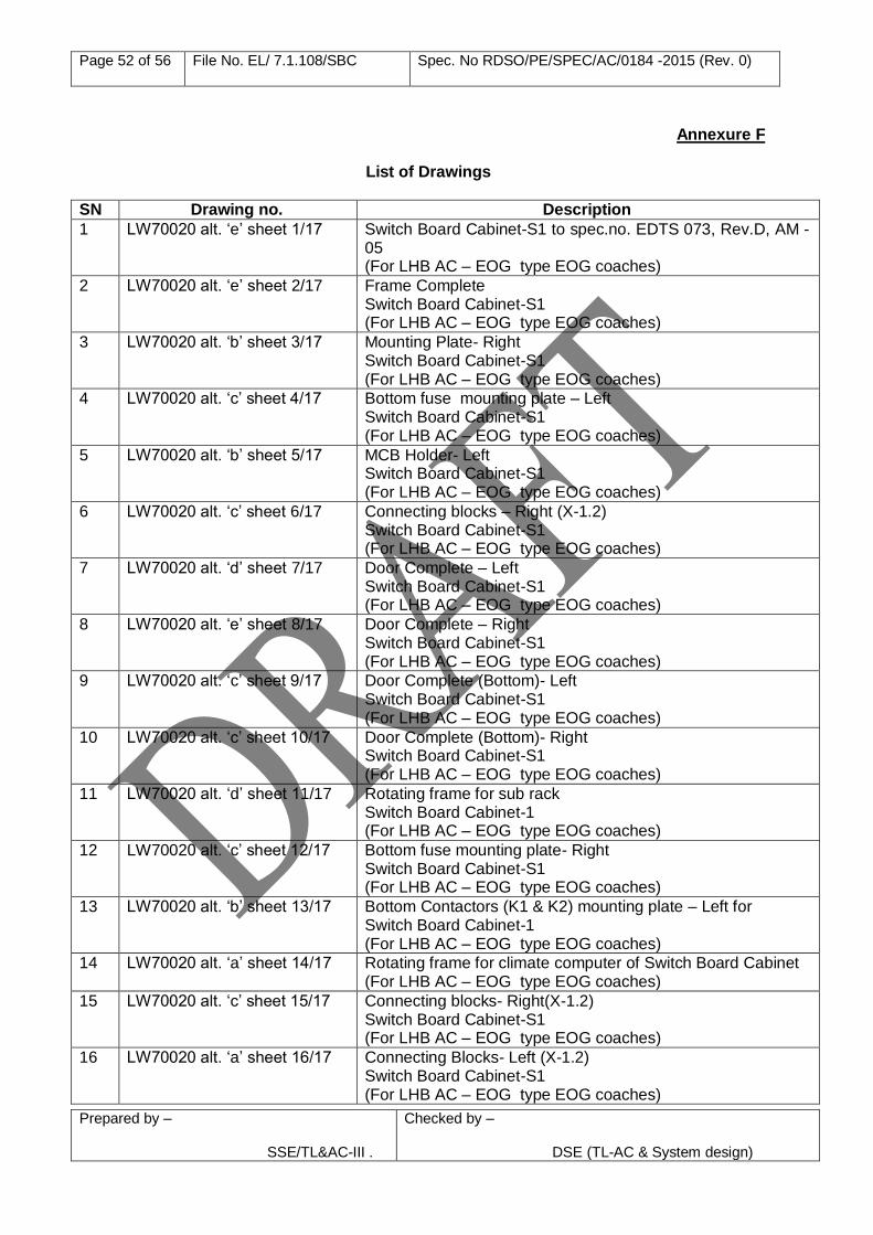
Page 52 of 56 File No. EL/ 7.1.108/SBC Spec. No RDSO/PE/SPEC/AC/0184 -2015 (Rev. 0)
Prepared by – SSE/TL&AC-III .
Checked by –
DSE (TL-AC & System design)
Annexure F
List of Drawings
SN Drawing no. Description
1 LW70020 alt. ‘e’ sheet 1/17 Switch Board Cabinet-S1 to spec.no. EDTS 073, Rev.D, AM -05 (For LHB AC – EOG type EOG coaches)
2 LW70020 alt. ‘e’ sheet 2/17 Frame Complete Switch Board Cabinet-S1 (For LHB AC – EOG type EOG coaches)
3 LW70020 alt. ‘b’ sheet 3/17 Mounting Plate- Right Switch Board Cabinet-S1 (For LHB AC – EOG type EOG coaches)
4 LW70020 alt. ‘c’ sheet 4/17 Bottom fuse mounting plate – Left Switch Board Cabinet-S1 (For LHB AC – EOG type EOG coaches)
5 LW70020 alt. ‘b’ sheet 5/17 MCB Holder- Left Switch Board Cabinet-S1 (For LHB AC – EOG type EOG coaches)
6 LW70020 alt. ‘c’ sheet 6/17 Connecting blocks – Right (X-1.2) Switch Board Cabinet-S1 (For LHB AC – EOG type EOG coaches)
7 LW70020 alt. ‘d’ sheet 7/17 Door Complete – Left Switch Board Cabinet-S1 (For LHB AC – EOG type EOG coaches)
8 LW70020 alt. ‘e’ sheet 8/17 Door Complete – Right Switch Board Cabinet-S1 (For LHB AC – EOG type EOG coaches)
9 LW70020 alt. ‘c’ sheet 9/17 Door Complete (Bottom)- Left Switch Board Cabinet-S1 (For LHB AC – EOG type EOG coaches)
10 LW70020 alt. ‘c’ sheet 10/17 Door Complete (Bottom)- Right Switch Board Cabinet-S1 (For LHB AC – EOG type EOG coaches)
11 LW70020 alt. ‘d’ sheet 11/17 Rotating frame for sub rack Switch Board Cabinet-1 (For LHB AC – EOG type EOG coaches)
12 LW70020 alt. ‘c’ sheet 12/17 Bottom fuse mounting plate- Right Switch Board Cabinet-S1 (For LHB AC – EOG type EOG coaches)
13 LW70020 alt. ‘b’ sheet 13/17 Bottom Contactors (K1 & K2) mounting plate – Left for Switch Board Cabinet-1 (For LHB AC – EOG type EOG coaches)
14 LW70020 alt. ‘a’ sheet 14/17 Rotating frame for climate computer of Switch Board Cabinet (For LHB AC – EOG type EOG coaches)
15 LW70020 alt. ‘c’ sheet 15/17 Connecting blocks- Right(X-1.2) Switch Board Cabinet-S1 (For LHB AC – EOG type EOG coaches)
16 LW70020 alt. ‘a’ sheet 16/17 Connecting Blocks- Left (X-1.2) Switch Board Cabinet-S1 (For LHB AC – EOG type EOG coaches)
Page 53 of 56 File No. EL/ 7.1.108/SBC Spec. No RDSO/PE/SPEC/AC/0184 -2015 (Rev. 0)
Prepared by – SSE/TL&AC-III .
Checked by –
DSE (TL-AC & System design)
17 LW70020 alt. ‘a’ sheet 17/17 Connecting Blocks- X3 Switch Board Cabinet-1 (For LHB AC – EOG type EOG coaches)
18 SKED 531 sheet 1/1 Arrangement of harting connectors in SBC-S1 (For LHB type EOG coaches)
19 SKED 263 sheet 1/1 Stopper bracket for right hand top door for S/W cabinet board –S1 (For LHB type coaches)
20 SKED406 sheet 1/1 Modified top & bottom doors for Switch Board Cabinet-S1 (For LHB type EOG coaches)
21 RDSO/PE/SK/AC/0154-2011(rev. 0)
Cable looping arrangement of bus bar in Switch Board Cabinet of LHB design
22 RDSO/PE/SK/AC/0186-2015 (rev. 0)
Connection of 2.5 A DC MCBs between microcontroller and contactors of RMPU
Note: 1. RDSO drawing at S.No. 21 shall be used in place of drawing at S.No. 5 2. Drawing of latest alteration to be used.
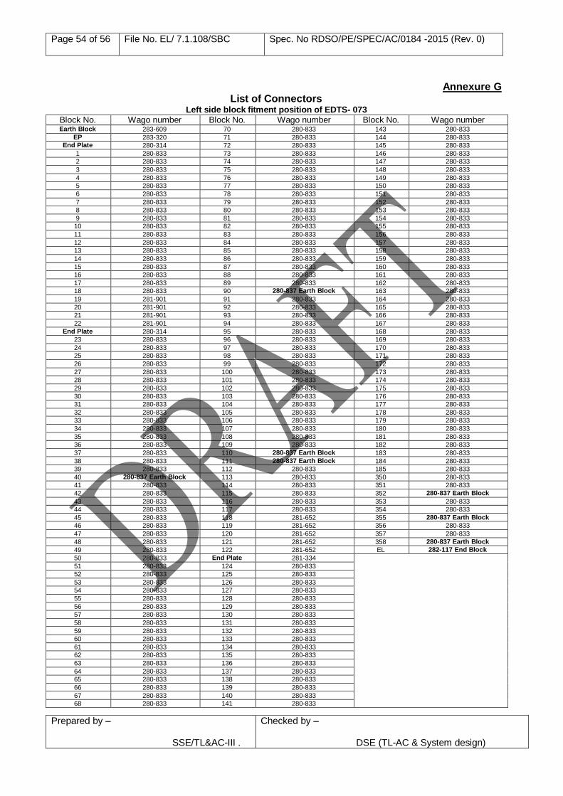
Page 54 of 56 File No. EL/ 7.1.108/SBC Spec. No RDSO/PE/SPEC/AC/0184 -2015 (Rev. 0)
Prepared by – SSE/TL&AC-III .
Checked by –
DSE (TL-AC & System design)
Annexure G
List of Connectors Left side block fitment position of EDTS- 073
Block No. Wago number Block No. Wago number Block No. Wago number Earth Block 283-609 70 280-833 143 280-833
EP 283-320 71 280-833 144 280-833 End Plate 280-314 72 280-833 145 280-833
1 280-833 73 280-833 146 280-833
2 280-833 74 280-833 147 280-833
3 280-833 75 280-833 148 280-833
4 280-833 76 280-833 149 280-833
5 280-833 77 280-833 150 280-833
6 280-833 78 280-833 151 280-833
7 280-833 79 280-833 152 280-833
8 280-833 80 280-833 153 280-833
9 280-833 81 280-833 154 280-833
10 280-833 82 280-833 155 280-833
11 280-833 83 280-833 156 280-833
12 280-833 84 280-833 157 280-833
13 280-833 85 280-833 158 280-833
14 280-833 86 280-833 159 280-833
15 280-833 87 280-833 160 280-833
16 280-833 88 280-833 161 280-833
17 280-833 89 280-833 162 280-833
18 280-833 90 280-837 Earth Block 163 280-833
19 281-901 91 280-833 164 280-833
20 281-901 92 280-833 165 280-833
21 281-901 93 280-833 166 280-833
22 281-901 94 280-833 167 280-833
End Plate 280-314 95 280-833 168 280-833
23 280-833 96 280-833 169 280-833
24 280-833 97 280-833 170 280-833
25 280-833 98 280-833 171 280-833
26 280-833 99 280-833 172 280-833
27 280-833 100 280-833 173 280-833
28 280-833 101 280-833 174 280-833
29 280-833 102 280-833 175 280-833
30 280-833 103 280-833 176 280-833
31 280-833 104 280-833 177 280-833
32 280-833 105 280-833 178 280-833
33 280-833 106 280-833 179 280-833
34 280-833 107 280-833 180 280-833
35 280-833 108 280-833 181 280-833
36 280-833 109 280-833 182 280-833
37 280-833 110 280-837 Earth Block 183 280-833
38 280-833 111 280-837 Earth Block 184 280-833
39 280-833 112 280-833 185 280-833
40 280-837 Earth Block 113 280-833 350 280-833
41 280-833 114 280-833 351 280-833
42 280-833 115 280-833 352 280-837 Earth Block
43 280-833 116 280-833 353 280-833
44 280-833 117 280-833 354 280-833
45 280-833 118 281-652 355 280-837 Earth Block
46 280-833 119 281-652 356 280-833
47 280-833 120 281-652 357 280-833
48 280-833 121 281-652 358 280-837 Earth Block
49 280-833 122 281-652 EL 282-117 End Block
50 280-833 End Plate 281-334
51 280-833 124 280-833
52 280-833 125 280-833
53 280-833 126 280-833
54 280-833 127 280-833
55 280-833 128 280-833
56 280-833 129 280-833
57 280-833 130 280-833
58 280-833 131 280-833
59 280-833 132 280-833
60 280-833 133 280-833
61 280-833 134 280-833
62 280-833 135 280-833
63 280-833 136 280-833
64 280-833 137 280-833
65 280-833 138 280-833
66 280-833 139 280-833
67 280-833 140 280-833
68 280-833 141 280-833
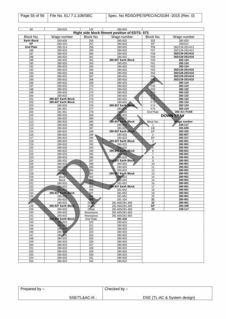
Page 55 of 56 File No. EL/ 7.1.108/SBC Spec. No RDSO/PE/SPEC/AC/0184 -2015 (Rev. 0)
Prepared by – SSE/TL&AC-III .
Checked by –
DSE (TL-AC & System design)
69 280-833 142 280-833
Right side block fitment position of EDTS- 073
Block No. Wago number Block No. Wago number Block No. Wago number Earth Block 283-609 256 280-833 333 280-833
EP 283-320 257 280-833 EP 280/314
End Plate 280-314 258 280-833 F56 282/128-281/413
186 280-833 259 280-833 F57 282/128-281/413
187 280-833 260 280-833 F58 282/128-281/418
188 280-833 261 280-833 F59 282/128-281/418
189 280-833 262 280-837 Earth Block F60 282-124
190 280-833 263 280-833 F61 282-124
191 280-833 264 280-833 F62 282-124
192 280-833 265 280-833 F63 282/128-281/418
193 280-833 266 280-833 F64 282/128-281/418
194 280-833 267 280-833 F65 282/128-281/418
195 280-833 268 280-833 F66 282/128-281/418
196 280-833 269 280-833 F67 282-124
197 280-833 270 280-833 F68 282-124
198 280-833 271 280-833 F69 282-122
199 280-833 272 280-833 F70 282-122
200 280-833 273 280-833 F71 282-122
201 280-837 Earth Block 274 280-833 F72 282-124
202 280-837 Earth Block 275 280-833 F73 282-124
203 280-833 276 280-837 Earth Block F74 282-124
204 281-901 277 280-833 F75 282-124
205 281-901 278 280-833 End Plate 282-311 FUSE
210 280-833 283 280-833 DOWN TRAY 211 280-833 284 280-833
212 280-833 285 280-837 Earth Block Block No. Wago number
213 280-833 286 280-833 1 249-117
214 280-833 287 280-833 EB 283-609
215 280-833 288 280-837 Earth Block EP 283-320
216 280-833 289 280-833 2 282-607
217 280-833 290 280-833 EP 282-317
218 280-833 291 280-837 Earth Block 3 282-901
219 280-833 292 280-833 4 282-901
220 280-833 293 280-833 5 282-901
221 280-833 294 280-837 Earth Block 6 285-601
222 280-833 295 280-833 7 285-601
223 280-833 296 280-833 8 285-601
224 280-833 297 280-837 Earth Block 9 280-901
225 280-833 298 280-833 10 280-901
226 280-833 299 280-833 11 280-901
227 280-833 300 280-833 12 280-901
228 280-833 301 280-837 Earth Block 13 280-901
229 Block 302 280-833 14 280-901
230 Block 303 280-833 15 280-901
231 280-833 304 281-652 16 280-901
232 280-833 305 280-837 Earth Block 17 280-901
233 280-833 306 281-652 18 280-901
234 280-837 Earth Block 307 281-652 19 280-901
235 280-833 308 281-652 20 280-901
236 280-833 309 281-334 21 280-901
237 280-833 Diode 281-665/281-400 22 280-901
238 280-837 Earth Block Diode 281-665/281-400 EP 280-309
239 280-833 Diode 281-665/281-400 23 249-117
240 280-833 Resistance 281-665/281-663
241 280-833 Resistance 281-665/281-663
242 280-837 Earth Block End Plate 281-334
243 280-833 320 280-833
244 280-833 321 280-833
245 280-833 322 280-833
246 280-833 323 280-833
247 280-833 324 280-833
248 280-833 325 280-833
249 280-833 326 280-833
250 280-833 327 280-833
251 280-833 328 280-833
252 280-833 329 280-833
253 280-833 330 280-833
254 280-833 331 280-833
255 280-833 332 280-833
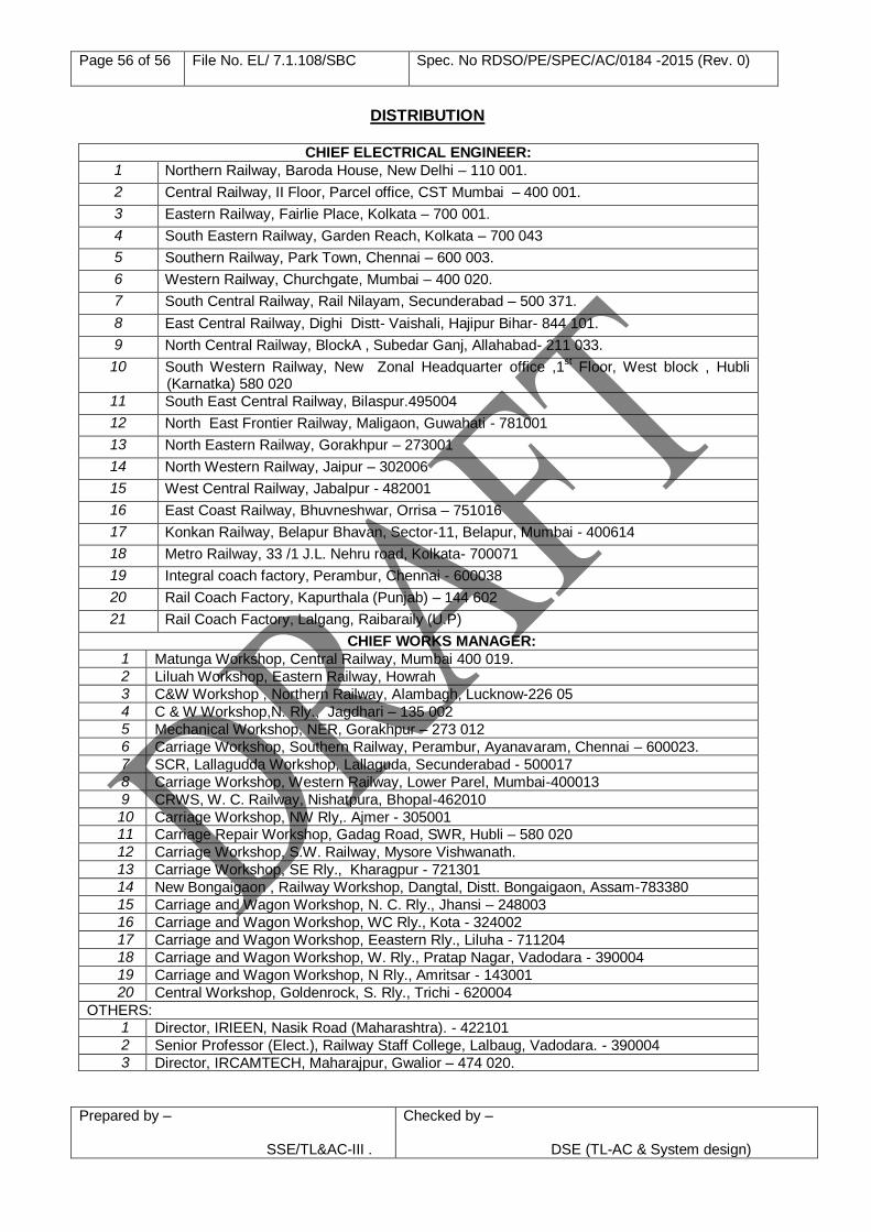
Page 56 of 56 File No. EL/ 7.1.108/SBC Spec. No RDSO/PE/SPEC/AC/0184 -2015 (Rev. 0)
Prepared by – SSE/TL&AC-III .
Checked by –
DSE (TL-AC & System design)
DISTRIBUTION
CHIEF ELECTRICAL ENGINEER:
1 Northern Railway, Baroda House, New Delhi – 110 001.
2 Central Railway, II Floor, Parcel office, CST Mumbai – 400 001.
3 Eastern Railway, Fairlie Place, Kolkata – 700 001.
4 South Eastern Railway, Garden Reach, Kolkata – 700 043
5 Southern Railway, Park Town, Chennai – 600 003.
6 Western Railway, Churchgate, Mumbai – 400 020.
7 South Central Railway, Rail Nilayam, Secunderabad – 500 371.
8 East Central Railway, Dighi Distt- Vaishali, Hajipur Bihar- 844 101.
9 North Central Railway, BlockA , Subedar Ganj, Allahabad- 211 033.
10 South Western Railway, New Zonal Headquarter office ,1st Floor, West block , Hubli
(Karnatka) 580 020 11 South East Central Railway, Bilaspur.495004
12 North East Frontier Railway, Maligaon, Guwahati - 781001
13 North Eastern Railway, Gorakhpur – 273001
14 North Western Railway, Jaipur – 302006
15 West Central Railway, Jabalpur - 482001
16 East Coast Railway, Bhuvneshwar, Orrisa – 751016
17 Konkan Railway, Belapur Bhavan, Sector-11, Belapur, Mumbai - 400614
18 Metro Railway, 33 /1 J.L. Nehru road, Kolkata- 700071
19 Integral coach factory, Perambur, Chennai - 600038
20 Rail Coach Factory, Kapurthala (Punjab) – 144 602
21 Rail Coach Factory, Lalgang, Raibaraily (U.P)
CHIEF WORKS MANAGER:
1 Matunga Workshop, Central Railway, Mumbai 400 019. 2 Liluah Workshop, Eastern Railway, Howrah 3 C&W Workshop , Northern Railway, Alambagh, Lucknow-226 05 4 C & W Workshop,N. Rly., Jagdhari – 135 002 5 Mechanical Workshop, NER, Gorakhpur – 273 012 6 Carriage Workshop, Southern Railway, Perambur, Ayanavaram, Chennai – 600023. 7 SCR, Lallagudda Workshop, Lallaguda, Secunderabad - 500017 8 Carriage Workshop, Western Railway, Lower Parel, Mumbai-400013 9 CRWS, W. C. Railway, Nishatpura, Bhopal-462010 10 Carriage Workshop, NW Rly,. Ajmer - 305001 11 Carriage Repair Workshop, Gadag Road, SWR, Hubli – 580 020 12 Carriage Workshop, S.W. Railway, Mysore Vishwanath. 13 Carriage Workshop, SE Rly., Kharagpur - 721301 14 New Bongaigaon , Railway Workshop, Dangtal, Distt. Bongaigaon, Assam-783380 15 Carriage and Wagon Workshop, N. C. Rly., Jhansi – 248003 16 Carriage and Wagon Workshop, WC Rly., Kota - 324002 17 Carriage and Wagon Workshop, Eeastern Rly., Liluha - 711204 18 Carriage and Wagon Workshop, W. Rly., Pratap Nagar, Vadodara - 390004 19 Carriage and Wagon Workshop, N Rly., Amritsar - 143001 20 Central Workshop, Goldenrock, S. Rly., Trichi - 620004
OTHERS: 1 Director, IRIEEN, Nasik Road (Maharashtra). - 422101 2 Senior Professor (Elect.), Railway Staff College, Lalbaug, Vadodara. - 390004 3 Director, IRCAMTECH, Maharajpur, Gwalior – 474 020.