Embed Size (px)
Citation preview

ACN. 000 317 251
EXTREMELY HIGH-GRADE MINERALISATION DISCOVERED JUST 0.4m FROM
SURFACE IN SOUTH-EAST EXTENSION OF STAGE 1 LAS MINERALE PIT (LM1)
Surface excavation immediately south-east of the LM1 Pit has exposed wide zones (~65m wide) of extremely high-grade surface copper mineralisation including copper minerals malachite, azurite, cuprite, chalcocite and chalcopyrite, immediately below shallow river-flat soils starting from just 0.4m depth
ADDITIONAL HIGH-GRADE COPPER MINERALISATION SENT TO STOCKPILES
Unit 34, Brickworks Annex,19 Brolga Avenue, SOUTHPORT 4215
Phone: +617 5503 1955 Facsimile: +617 5503 0288 Email: [email protected]
MARKET RELEASE 10th February 2014
ROCKLANDS COPPER PROJECT (CDU 100%)
Time lodged with ASX: 08:30am (Brisbane)
Figure 02: Surface preparations immediately south-east of LM1 Pit is exposing extremely high-grade copper mineralisation immediately below the soil cover. Left; dozer drag blade reveals high-grade copper oxides and right; surface mineralisation identified over 65m width.
Figure 01: Visually unexciting calcrete immediately below the soil cover reveals high-grade copper minerals when broken.
For
per
sona
l use
onl
y
Page 2
Figure 03: Surface excavation immediately south-east of the LM1 Pit exposed wide zones (~65m wide) of surface copper mineralisation including extremely high-grade copper minerals malachite, azurite, cuprite, chalcocite AND chalcopyrite, immediately below shallow river-flat soil cover. Visual estimates confirmed with XRF analysis conducted across the entire mineralised zone, including analysis of soil, calcrete, colluvium, float-rock and fresh-rock in outcrop.
For
per
sona
l use
onl
y
Page 3
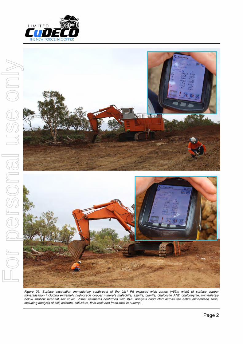
Figure 04: Example of solid piece of cuprite weighing ~250kg and inset, close-up of the distinctive port-grey coloured crystalline brittle matrix of cuprite (cuprite contains 88.8% copper). This was one of many samples exposed immediately below shallow river-flat soil cover (from 0.4m depth) during surface clearing excavations at the south-east extension to LM1.
For
per
sona
l use
onl
y

Page 4
Figure 05: Drill-and-blast drilling in LM1 Pit continues, whilst surface activity preparing for extensions to the south-east (along strike) commences.
For
per
sona
l use
onl
y

Page 5
Figure 06: High-grade oxide stockpile receiving additional loads of high-grade and extremely high-grade oxide copper mineralisation (top image) including large boulders of near solid chalcocite and cuprite. The below image shows an estimated ~2.5 tonne boulder of near solid chalcocite (chalcocite contains 79.8% copper, cuprite contains 88.8% copper).
For
per
sona
l use
onl
y

Page 6
Figure 07: High-grade oxide stockpile with example of large high-grade copper boulders...this boulders estimated to weigh ~3 tonnes is visually estimated to contain 60% cuprite (cuprite contains 88.8% copper).
For
per
sona
l use
onl
y
Page 7
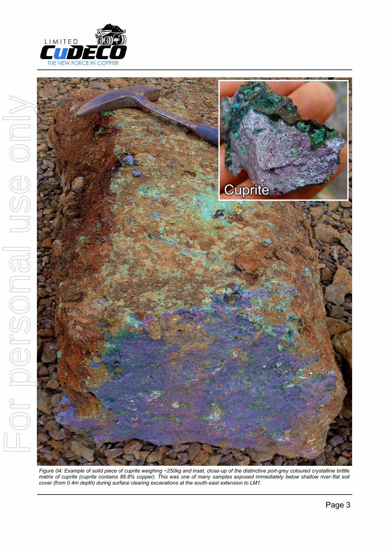
Figure 08: Example of high-grade near-solid chalcocite exposed at surface after the latest blast in LM1, with half-metre and metre wide chalcocite boulders weighing up to several tonnes each, strewn about by the blast. Inset shows close-ups of clean, freshly broken face (chalcocite contains 79.8% copper).
For
per
sona
l use
onl
y
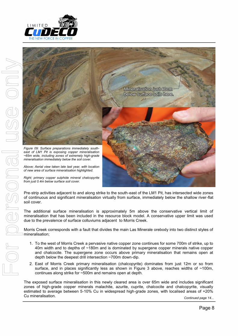
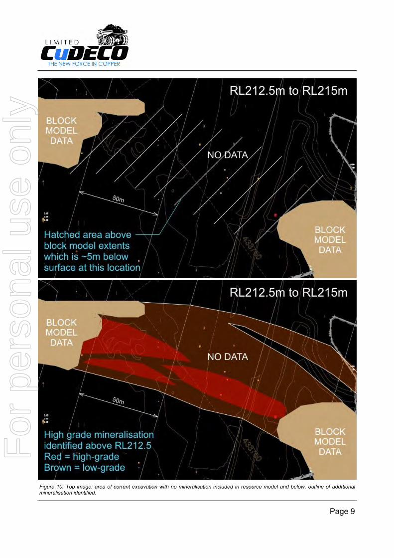
Pre-strip activities adjacent to and along strike to the south-east of the LM1 Pit, has intersected wide zones of continuous and significant mineralisation virtually from surface, immediately below the shallow river-flat soil cover. The additional surface mineralisation is approximately 5m above the conservative vertical limit of mineralisation that has been included in the resource block model. A conservative upper limit was used due to the prevalence of surface colluviums adjacent to Morris Creek. Morris Creek corresponds with a fault that divides the main Las Minerale orebody into two distinct styles of mineralisation;
1. To the west of Morris Creek a pervasive native copper zone continues for some 700m of strike, up to 40m width and to depths of ~180m and is dominated by supergene copper minerals native copper and chalcocite. The supergene zone occurs above primary mineralisation that remains open at depth below the deepest drill intersection ~700m down-dip.
2. East of Morris Creek primary mineralisation (chalcopyrite) dominates from just 12m or so from surface, and in places significantly less as shown in Figure 3 above, reaches widths of ~100m, continues along strike for ~500m and remains open at depth.
The exposed surface mineralisation in this newly cleared area is over 65m wide and includes significant zones of high-grade copper minerals malachite, azurite, cuprite, chalcocite and chalcopyrite, visually estimated to average between 5-10% Cu in widespread high-grade zones, with localised areas of +20% Cu mineralisation.
Page 8
Figure 09: Surface preparations immediately south-east of LM1 Pit is exposing copper mineralisation ~65m wide, including zones of extremely high-grade mineralisation immediately below the soil cover. Above; Aerial view taken late last year, with location of new area of surface mineralisation highlighted. Right; primary copper sulphide mineral chalcopyrite from just 0.4m below surface soil cover.
Continued page 14...
For
per
sona
l use
onl
y
Page 9
Figure 10: Top image; area of current excavation with no mineralisation included in resource model and below, outline of additional mineralisation identified.
For
per
sona
l use
onl
y
Page 10
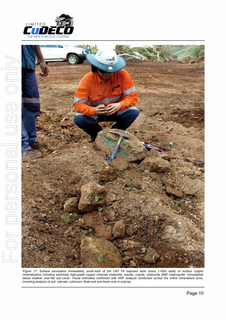
Figure 11: Surface excavation immediately south-east of the LM1 Pit exposed wide zones (~65m wide) of surface copper mineralisation including extremely high-grade copper minerals malachite, azurite, cuprite, chalcocite AND chalcopyrite, immediately below shallow river-flat soil cover. Visual estimates confirmed with XRF analysis conducted across the entire mineralised zone, including analysis of soil, calcrete, colluvium, float-rock and fresh-rock in outcrop.
For
per
sona
l use
onl
y
Page 11
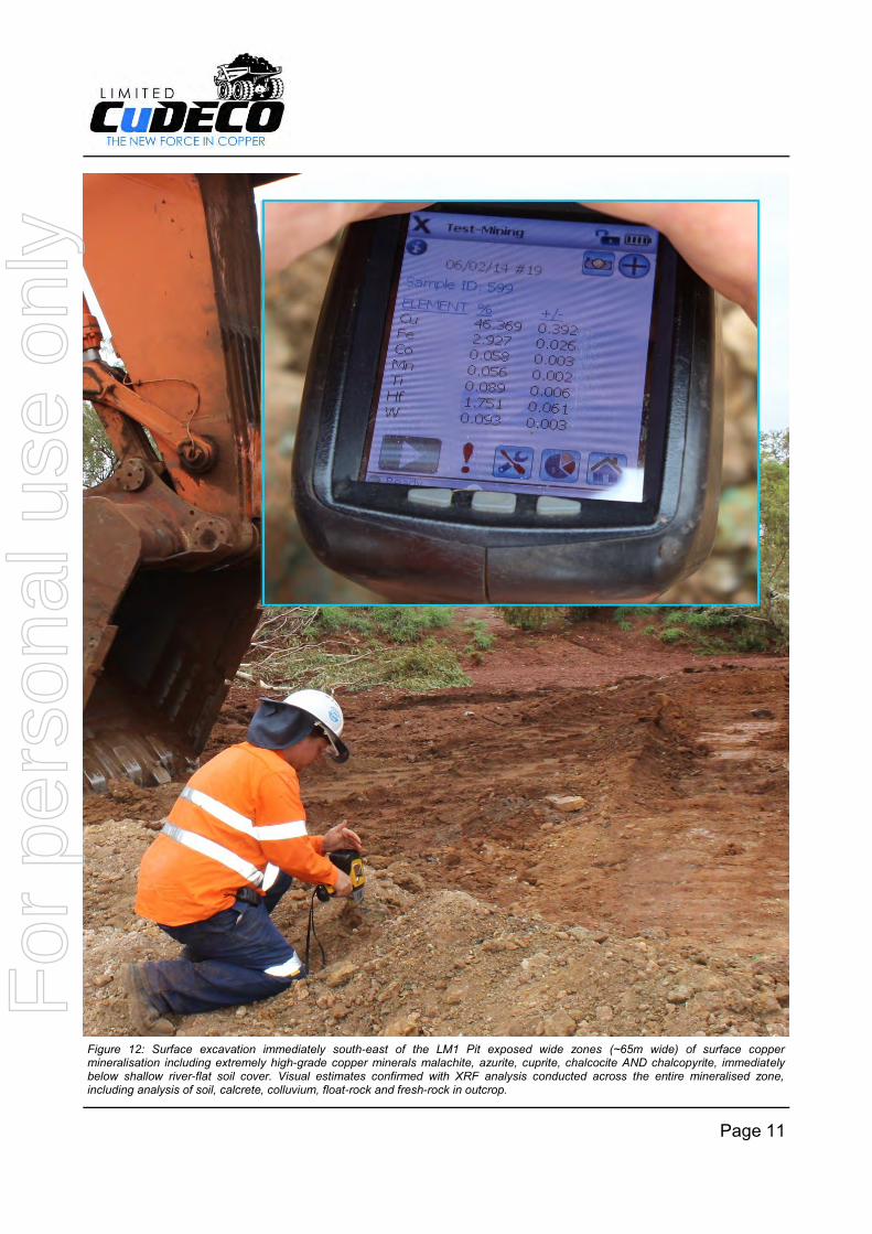
Figure 12: Surface excavation immediately south-east of the LM1 Pit exposed wide zones (~65m wide) of surface copper mineralisation including extremely high-grade copper minerals malachite, azurite, cuprite, chalcocite AND chalcopyrite, immediately below shallow river-flat soil cover. Visual estimates confirmed with XRF analysis conducted across the entire mineralised zone, including analysis of soil, calcrete, colluvium, float-rock and fresh-rock in outcrop.
For
per
sona
l use
onl
y
Page 12
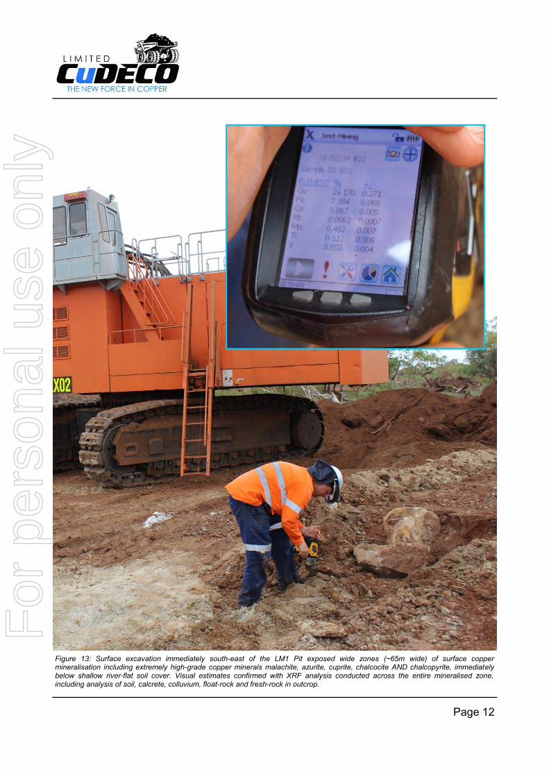
Figure 13: Surface excavation immediately south-east of the LM1 Pit exposed wide zones (~65m wide) of surface copper mineralisation including extremely high-grade copper minerals malachite, azurite, cuprite, chalcocite AND chalcopyrite, immediately below shallow river-flat soil cover. Visual estimates confirmed with XRF analysis conducted across the entire mineralised zone, including analysis of soil, calcrete, colluvium, float-rock and fresh-rock in outcrop.
For
per
sona
l use
onl
y
Page 13
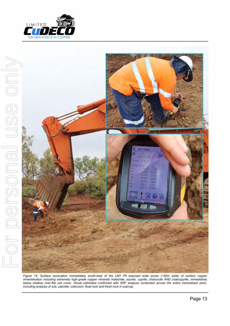
Figure 14: Surface excavation immediately south-east of the LM1 Pit exposed wide zones (~65m wide) of surface copper mineralisation including extremely high-grade copper minerals malachite, azurite, cuprite, chalcocite AND chalcopyrite, immediately below shallow river-flat soil cover. Visual estimates confirmed with XRF analysis conducted across the entire mineralised zone, including analysis of soil, calcrete, colluvium, float-rock and fresh-rock in outcrop.
For
per
sona
l use
onl
y
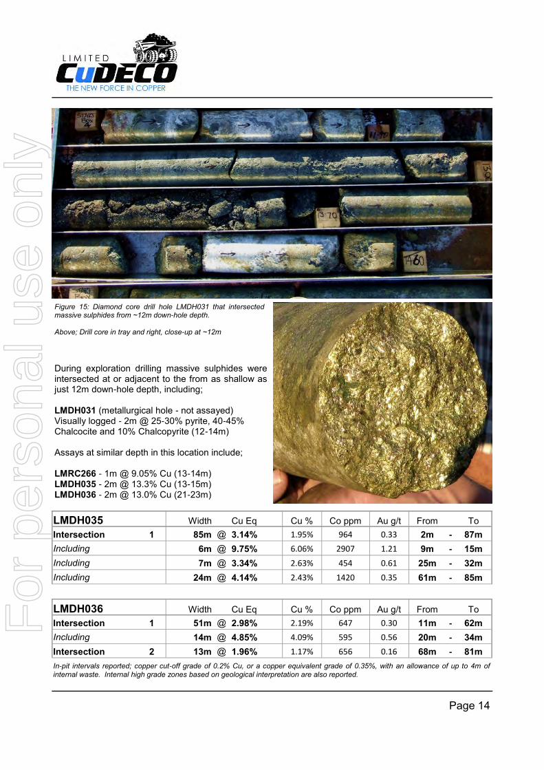
During exploration drilling massive sulphides were intersected at or adjacent to the from as shallow as just 12m down-hole depth, including; LMDH031 (metallurgical hole - not assayed) Visually logged - 2m @ 25-30% pyrite, 40-45% Chalcocite and 10% Chalcopyrite (12-14m) Assays at similar depth in this location include; LMRC266 - 1m @ 9.05% Cu (13-14m) LMDH035 - 2m @ 13.3% Cu (13-15m) LMDH036 - 2m @ 13.0% Cu (21-23m)
Page 14
Figure 15: Diamond core drill hole LMDH031 that intersected massive sulphides from ~12m down-hole depth. Above; Drill core in tray and right, close-up at ~12m
In-pit intervals reported; copper cut-off grade of 0.2% Cu, or a copper equivalent grade of 0.35%, with an allowance of up to 4m of internal waste. Internal high grade zones based on geological interpretation are also reported.
LMDH035 Width Cu Eq Cu % Co ppm Au g/t From To
Intersection 1 85m @ 3.14% 1.95% 964 0.33 2m - 87m
Including 6m @ 9.75% 6.06% 2907 1.21 9m - 15m
Including 7m @ 3.34% 2.63% 454 0.61 25m - 32m
Including 24m @ 4.14% 2.43% 1420 0.35 61m - 85m
LMDH036 Width Cu Eq Cu % Co ppm Au g/t From To
Intersection 1 51m @ 2.98% 2.19% 647 0.30 11m - 62m
Including 14m @ 4.85% 4.09% 595 0.56 20m - 34m
Intersection 2 13m @ 1.96% 1.17% 656 0.16 68m - 81m
For
per
sona
l use
onl
y
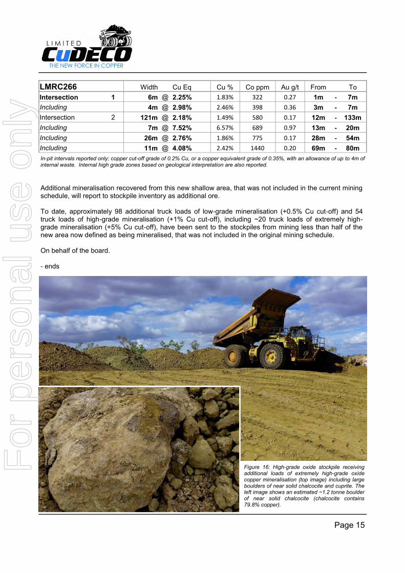
Additional mineralisation recovered from this new shallow area, that was not included in the current mining schedule, will report to stockpile inventory as additional ore. To date, approximately 98 additional truck loads of low-grade mineralisation (+0.5% Cu cut-off) and 54 truck loads of high-grade mineralisation (+1% Cu cut-off), including ~20 truck loads of extremely high-grade mineralisation (+5% Cu cut-off), have been sent to the stockpiles from mining less than half of the new area now defined as being mineralised, that was not included in the original mining schedule. On behalf of the board. - ends
Page 15
LMRC266 Width Cu Eq Cu % Co ppm Au g/t From To
Intersection 1 6m @ 2.25% 1.83% 322 0.27 1m - 7m
Including 4m @ 2.98% 2.46% 398 0.36 3m - 7m
Intersection 2 121m @ 2.18% 1.49% 580 0.17 12m - 133m
Including 7m @ 7.52% 6.57% 689 0.97 13m - 20m
Including 26m @ 2.76% 1.86% 775 0.17 28m - 54m
Including 11m @ 4.08% 2.42% 1440 0.20 69m - 80m
In-pit intervals reported only; copper cut-off grade of 0.2% Cu, or a copper equivalent grade of 0.35%, with an allowance of up to 4m of internal waste. Internal high grade zones based on geological interpretation are also reported.
Figure 16: High-grade oxide stockpile receiving additional loads of extremely high-grade oxide copper mineralisation (top image) including large boulders of near solid chalcocite and cuprite. The left image shows an estimated ~1.2 tonne boulder of near solid chalcocite (chalcocite contains 79.8% copper).
For
per
sona
l use
onl
y

Competent Person Statement Information in this report that relates to Exploration Targets and Exploration Results is based on information compiled by Mr Andrew Day. Mr Day is employed by Geoday Pty Ltd, an entity engaged by Cudeco to provide independent consulting services. Mr Day has a BAppSc (Hons) in geology and is a Member of the Australian Institute of Mining and Metallurgy (Member #303598). Mr Day has sufficient experience relevant to the style of mineralisation and type of deposit under consideration and to the activity being undertaken to qualify as a Competent Person as defined in the 2012 Edition of the “Australasian Code for Reporting of Exploration Results, Mineral Resources and Ore Reserves” (JORC Code). Mr Day consents to inclusion in the report of the matters based on his information in the form and context in which it appears. The information in this report insofar as it relates to Metallurgical Test Results and Recoveries, is based on information compiled by Mr Peter Hutchison, MRACI Ch Chem, MAusIMM, a full-time executive director of CuDeco Ltd. Mr Hutchison has sufficient experience in hydrometallurgical and metallurgical techniques which is relevant to the results under consideration and to the activity which he is undertaking to qualify as a competent person for the purposes of this report. Mr Hutchison consents to the inclusion in this report of the information, in the form and context in which it appears. Rocklands style mineralisation Dominated by dilational brecciated shear zones, throughout varying rock types, hosting coarse splashy to massive primary mineralisation, high-grade supergene chalcocite enrichment and bonanza-grade coarse native copper. Structures hosting mineralisation are sub-parallel, east-south-east striking, and dip steeply within metamorphosed volcano-sedimentary rocks of the eastern fold belt of the Mt Isa Inlier. The observed mineralisation, and alteration, exhibit affinities with Iron Oxide-Copper-Gold (IOCG) classification. Polymetallic copper-cobalt-gold mineralisation, and significant magnetite, persists from the surface, through the oxidation profile, and remains open at depth. Hand-held X-ray Fluorescence (XRF) Analysis
Hand-held XRF typically analyses a single point area of just 7-10mm in diameter, and is used to determine the composition of unidentified minerals during geological logging (particularly useful in identifying potential telluride minerals at Wilgar, which can be difficult to visually distinguish). It is important to note that selective point analysis is not suitable for determining average sample grade without first ensuring the area being tested is representative. This usually requires the sample to be crushed/pulverised, from which a homogenous and representative fraction can be selected for analysis. Analysis is completed with an Innovx Delta Premium hand-held XRF, which uses a Au/Ta anode x-ray tube and silicon drift detector. A measurement time of 30 seconds each for transition metals and heavy elements (beams 1 and 2, respectively) was used, in Soil Mode, for a total read time of 60 seconds for each sample. Disclaimer and Forward-looking Statements This report contains forward-looking statements that are subject to risk factors associated with resources businesses. It is believed that the expectations reflected in these statements are reasonable, but they may be affected by a variety of variables and changes in underlying assumptions which could cause actual results or trends to differ materially, including, but not limited to: price fluctuations, actual demand, currency fluctuations, drilling and production results, reserve estimates, loss of market, industry competition, environmental risks, physical risks, legislative, fiscal and regulatory developments, economic and financial market conditions in various countries and regions, political risks, project delays or advancements, approvals and cost estimates.
Page 16
For
per
sona
l use
onl
y
JORC Table 1 - Section 1 - Sampling Techniques and Data
Criteria JORC Code explanation Commentary
Sampling techniques
Nature and quality of sampling (eg cut channels, random chips, or specific specialised industry standard measurement tools appropriate to the minerals under investigation, such as down hole gamma sondes, or handheld XRF instruments, etc). These examples should not be taken as limiting the broad meaning of sampling.
Include reference to measures taken to ensure sample representivity and the appropriate calibration of any measurement tools or systems used.
Aspects of the determination of mineralisation that are Material to the Public Report.
In cases where ‘industry standard’ work has been done this would be relatively simple (eg ‘reverse circulation drilling was used to obtain 1 m samples from which 3 kg was pulverised to produce a 30 g charge for fire assay’). In other cases more explanation may be required, such as where there is coarse gold that has inherent sampling problems. Unusual commodities or mineralisation types (eg submarine nodules) may warrant disclosure of detailed information.
Representative 1 meter samples were taken from ¼ (NQ, HQ) or ½ (NQ, BQ) diamond core. Reverse Circulation (RC) drilling was sampled in 1m intervals, from which representative 3kg sub-samples were obtained for analysis.
Handheld XRF results were taken on numerous spot samples including soils and mineralised outcropping fresh-rock, across the interpreted mineralised zone uncovered with shallow excavation.
Drilling techniques
Drill type (eg core, reverse circulation, open-hole hammer, rotary air blast, auger, Bangka, sonic, etc) and details (eg core diameter, triple or standard tube, depth of diamond tails, face-sampling bit or other type, whether core is oriented and if so, by what method, etc).
LMDH035 Diamond drill hole (DD) was NQ, with standard recovery.
LMDH031 and LMDH036 diamond drill hole were PQ, with standard recovery.
LMRC266 Reverse circulation (RC)
Drill sample recovery
Method of recording and assessing core and chip sample recoveries and results assessed.
Measures taken to maximise sample recovery and ensure representative nature of the samples.
Whether a relationship exists between sample recovery and grade and whether sample bias may have occurred due to preferential loss/gain of fine/coarse material.
DD core recovery for drill holes were 100% in reported meters. RC recovery averaged 60% in reported meters.
Logging Whether core and chip samples have been
Drill samples were logged for lithology, mineralisation and alteration using
For
per
sona
l use
onl
y
Criteria JORC Code explanation Commentary
geologically and geotechnically logged to a level of detail to support appropriate Mineral Resource estimation, mining studies and metallurgical studies.
Whether logging is qualitative or quantitative in nature. Core (or costean, channel, etc) photography.
The total length and percentage of the relevant intersections logged.
a standardised logging system, including the recording of visually estimated volume percentages of major minerals.
Drill core was photographed after being logged by the geologist.
Drill core not used for bulk metallurgical testing and RC drill chips are stored at the Rocklands site.
Sub-sampling techniques and sample preparation
If core, whether cut or sawn and whether quarter, half or all core taken.
If non-core, whether riffled, tube sampled, rotary split, etc and whether sampled wet or dry.
For all sample types, the nature, quality and appropriateness of the sample preparation technique.
Quality control procedures adopted for all sub-sampling stages to maximise representivity of samples.
Measures taken to ensure that the sampling is representative of the in situ material collected, including for instance results for field duplicate/second-half sampling.
Whether sample sizes are appropriate to the grain size of the material being sampled.
All DD core was orientated along the bottom of hole, where possible. A cut line was drawn 1 cm to the right of the core orientation line.
Core was cut with a diamond saw, ½ core was used for NQ and ¼ core was used for PQ.
RC samples were split using a riffle splitter attached to the cyclone on the drill rig.
Sample intervals were 1 m down-hole in length unless the last portion of DD hole was part of a meter.
SGS Minerals Townsville Sample Preparation:
All samples were dried. Drill core was placed through jaw crusher and crushed to approx. 8mm. RC chips and core were split if necessary to a sample of less than approximately 3.5kg.
Native copper samples were prepared by 2 methods. Grain size of native copper determined which method was used.:
o Samples where native copper grain size was less than 2mm were disc ground to approximately 180µm. 500g was split and lightly pulverised for 30 seconds to approximately 100µm.
o Samples where native copper grain size was greater than 2mm were put through a roller crusher to approximately 3mm. Samples were sieved at 2mm with copper greater than 2mm hand picked out of sample. Material less than 2mm and residue above 2mm was disc ground to approximately 180µm. 500g was split from the sample and lightly pulverised for 30 seconds to approximately 100µm.
All other sampled material not containing native copper was pulverised to a nominal 90% passing 75µm.
Quality of assay data and laboratory tests
The nature, quality and appropriateness of the assaying and laboratory procedures used and whether the technique is considered partial or total.
For geophysical tools, spectrometers, handheld XRF instruments, etc, the parameters used in determining the analysis including instrument make and model, reading times, calibrations factors applied and their derivation, etc.
Nature of quality control procedures adopted (eg standards, blanks, duplicates, external laboratory checks) and whether acceptable levels of accuracy (ie lack of bias) and precision have been established.
Cu and Co grades were determined by 3 acid digest with either a ICP-AES (Inductively-Coupled Plasma Atomic Emission Spectrometer) or AAS (Atomic absorption Spectrometer) determination (SGS methods, ICP22D, ICP40Q, AAS22D AAS23Q, AAS40G).
Au grades were determined by 50g Fire Assay (at SGS Townsville method FAA505).
All analyses were carried out at internationally recognised, independent assay laboratorie SGS.
Quality assurance was provided by introduction of known certified standards, blanks and duplicate samples on a routine basis.
Assay results outside the optimal range for methods were re-analysed by appropriate methods. Copper assay results differ little between acid digest methods but cobalt assay results show a significant underestimation when analysed using the AAS.
Ore Research Pty Ltd certified copper and gold standards have been implemented as a part of QAQC procedures, as well as coarse and pulp blanks, and certified matrix matched copper-cobalt-gold standards. Performance for standards has been adequate.
QAQC monitoring is an active and ongoing process on batch by batch basis by which unacceptable results are re-assayed as soon as practicable.
Verification of sampling and
The verification of significant intersections by either independent or alternative
Results between twinned RC and diamond holes are in approximate agreement, when taken into consideration with the natural variation associated with breccia-hosted ore bodies, identified coarse
For
per
sona
l use
onl
y

Criteria JORC Code explanation Commentary
assaying company personnel.
The use of twinned holes.
Documentation of primary data, data entry procedures, data verification, data storage (physical and electronic) protocols.
Discuss any adjustment to assay data.
mineralisation, and subsequent weathering overprinting.
All assay data QAQC is checked prior to loading into the CuDECO Explorer 3 data base.
No adjustments have been made to assay data.
Location of data points
Accuracy and quality of surveys used to locate drill holes (collar and down-hole surveys), trenches, mine workings and other locations used in Mineral Resource estimation.
Specification of the grid system used.
Quality and adequacy of topographic control.
All drill holes at Rocklands have been surveyed with a differential global positioning system (DGPS) to within 10 cm accuracy and recorded in the CuDECO Explorer 3 database.
All drill holes, apart from vertical, have had down hole magnetic surveys at intervals not greater than 50 m and where magnetite will not affect the survey. Surveys where magnetite is suspected to have influenced results have been removed from the Database.
Where surveys are dubious the hole was resurveyed, where possible, via open hole in non-magnetic material.
Data spacing and distribution
Data spacing for reporting of Exploration Results.
Whether the data spacing and distribution is sufficient to establish the degree of geological and grade continuity appropriate for the Mineral Resource and Ore Reserve estimation procedure(s) and classifications applied.
Whether sample compositing has been applied.
Drilling has been completed on nominal local grid north-south sections, commencing at 100 m spacing and then closing to 50 m and 25 m for resource estimation. Local drilling in complex near-surface areas is further closed in to 12.5m
Vertical spacing of intercepts on the mineralised zones similarly commences at 100 m spacing and then closing to 50m and 25m for resource estimation, again some closer spacing is used in complex areas.
Drilling has predominantly occurred with angled holes approximately 55° to 60° inclination below the horizontal and either drilling to the local grid north or south, depending on the dip of the target mineralised zone.
Holes have been drilled to 600 m vertical depth
Drilling focusses on the known mineralised zones of Las Minerale and Las Minerale East; Rocklands South and South Extension; Rocklands Central and Le Meridian; Rainden, Solsbury Hill and Fairfield.
Data spacing and distribution is sufficient to establish geological and grade continuity appropriate for the Mineral Resource estimation procedure and has been taken into account in 3D space when determining the classifications to be applied.
Orientation of data in relation to geological structure
Whether the orientation of sampling achieves unbiased sampling of possible structures and the extent to which this is known, considering the deposit type.
If the relationship between the drilling orientation and the orientation of key mineralised structures is considered to have introduced a sampling bias, this should be assessed and reported if material.
Drilling was completed on local grid north-south section lines along the strike of the known mineralised zones and from either the north or the south depending on the dip
Vertical drilling at Las Minerale.
Vertical drilling has been used in key mineralised zones at Las Minerale and Rocklands South to achieve unbiased sampling of possible structures, mineralised zones and weathering horizons.
Horizontal layers of supergene enrichment occur at shallow depths in Las Minerale and Rocklands South and a vertical drill program was undertaken to address this layering and to provide bulk samples for metallurgical test work.
Sample security
The measures taken to ensure sample security.
Samples are either dispatched from site through a commercial courier or company employees to the Laboratories. Samples are signed for at the Laboratory with confirmation of receipt emailed through. Samples are then stored at the laboratory and returned to a locked storage shed on site.
Audits or reviews
The results of any audits or reviews of sampling techniques and data.
CuDECO conducts internal audits of sampling techniques and data management on a regular basis, to ensure industry best practice is employed at all times.
External reviews and audits of sampling have been conducted by the following groups;
2007 – In July 2007, Snowden were engaged to conduct a review of
For
per
sona
l use
onl
y

Criteria JORC Code explanation Commentary
drilling and sampling procedures at Rocklands, provide guidance on potential areas of improvement in data / sample management and geological logging procedures, and to ensure the Rocklands sampling and data record was appropriate for use in resource estimation. All recommendations were implemented.
2010 – In early 2010 Hellman & Schofield conducted a desktop review of the Rocklands database, as part of their due diligence for the resource estimate they completed in May 2010. Apart from limited logic and spot checks, the database was received on a “good faith” basis with responsibility for its accuracy taken by CuDECO. A number of issues were identified by H&S but these were largely addressed by CuDECO and H&S regarded unresolved issues at the time of resource estimation as unlikely to have a material impact on future estimates.
2010 - Mr Andrew Vigar of Mining Associates Limited visited the site in 12 to 15 October, 3 to 5 November and 8 to 10 December 2010 during the compilation of detailed review the drilling, sampling techniques, QAQC and previous resource estimates and 17 to 19 March 2011 to confirm the same for new drilling incorporated into this resource estimate. Methods were found to conform to international best practise, including that required by the JORC standard.
JORC Table 1 - Section 2 - Reporting of Exploration Results
Criteria JORC Code explanation Commentary
Mineral tenement and land tenure status
Type, reference name/number, location and ownership including agreements or material issues with third parties such as joint ventures, partnerships, overriding royalties, native title interests, historical sites, wilderness or national park and environmental settings.
The security of the tenure held at the time of reporting along with any known impediments to obtaining a licence to operate in the area.
The Rocklands Project is located within granted mining leases ML90177 and ML90188, and Infrastructure Lease ML90219. Landowner agreements formed part of the granting, and remain current for the duration of the mining leases.
Native Title Ancillary agreements have been signed with the Mitakoodi & Mayi peoples and the Kalkadoon peoples, the local custodians of the areas covered by the mining leases.
Mining Leases detailed above are granted for a period of 30 years; there is no known impediment to operating for this period of time. The Project operates under a Plan of Operations, the most recent of which was approved on 17
th October, 2013.
Exploration done by other parties
Acknowledgment and appraisal of exploration by other parties.
Previous reports on the Double Oxide mine by CRA and others between 1987 and 1994 describe a wide shear zone containing a number of sub parallel mineralised zones with a cumulative length of 6 km.
Geology Deposit type, geological setting and style of mineralisation.
Hosted within metamorphosed meso-Proterozoic age volcano-sedimentary rocks and intrusive dolerites of the Eastern Fold Belt of the Mt Isa Inlier. Dominated by dilational brecciated shear zones containing coarse patchy to massive primary mineralisation, with high-grade supergene chalcocite enrichment and bonanza-grade coarse native copper in oxide. Structures hosting mineralisation are sub-parallel, east-southeast striking and steeply dipping. The observed mineralisation, and alteration, exhibit affinities with Iron Oxide-Copper-Gold (IOCG) style deposits. Polymetallic copper-cobalt-gold mineralisation, and significant magnetite, persists from the surface, through the oxidation profile, and remains open at depth.
Drill hole Information
A summary of all information material to the understanding of the exploration results including a tabulation of the following information for all Material drill holes:
easting and northing of the drill hole collar
elevation or RL (Reduced Level – elevation above sea
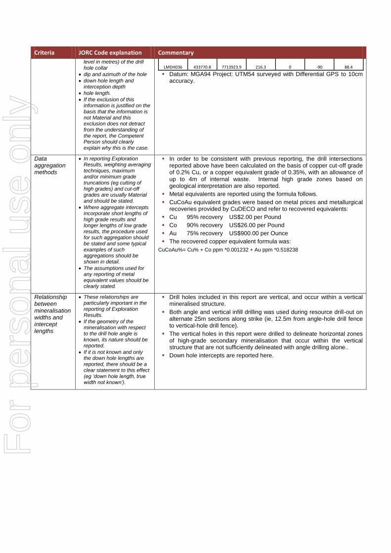
Hole ID Easting Northing RL Azi Dip Hole
(m) (°) (°) Depth (m)
LMRC266 433758.2 7713918.2 215.0 0 -90 226.0
LMDH031 433769.7 7713925.0 214.7 0 -90 87.4
LMDH035 433767.0 7713923.4 216.2 0 -90 90.0
For
per
sona
l use
onl
y
Criteria JORC Code explanation Commentary
level in metres) of the drill hole collar
dip and azimuth of the hole
down hole length and interception depth
hole length.
If the exclusion of this information is justified on the basis that the information is not Material and this exclusion does not detract from the understanding of the report, the Competent Person should clearly explain why this is the case.
LMDH036 433770.8 7713923.9 216.3 0 -90 88.4
Datum: MGA94 Project: UTM54 surveyed with Differential GPS to 10cm accuracy.
Data aggregation methods
In reporting Exploration Results, weighting averaging techniques, maximum and/or minimum grade truncations (eg cutting of high grades) and cut-off grades are usually Material and should be stated.
Where aggregate intercepts incorporate short lengths of high grade results and longer lengths of low grade results, the procedure used for such aggregation should be stated and some typical examples of such aggregations should be shown in detail.
The assumptions used for any reporting of metal equivalent values should be clearly stated.
In order to be consistent with previous reporting, the drill intersections reported above have been calculated on the basis of copper cut-off grade of 0.2% Cu, or a copper equivalent grade of 0.35%, with an allowance of up to 4m of internal waste. Internal high grade zones based on geological interpretation are also reported.
Metal equivalents are reported using the formula follows.
CuCoAu equivalent grades were based on metal prices and metallurgical recoveries provided by CuDECO and refer to recovered equivalents:
Cu 95% recovery US$2.00 per Pound
Co 90% recovery US$26.00 per Pound
Au 75% recovery US$900.00 per Ounce
The recovered copper equivalent formula was:
CuCoAu%= Cu% + Co ppm *0.001232 + Au ppm *0.518238
Relationship between mineralisation widths and intercept lengths
These relationships are particularly important in the reporting of Exploration Results.
If the geometry of the mineralisation with respect to the drill hole angle is known, its nature should be reported.
If it is not known and only the down hole lengths are reported, there should be a clear statement to this effect (eg ‘down hole length, true width not known’).
Drill holes included in this report are vertical, and occur within a vertical mineralised structure.
Both angle and vertical infill drilling was used during resource drill-out on alternate 25m sections along strike (ie, 12.5m from angle-hole drill fence to vertical-hole drill fence).
The vertical holes in this report were drilled to delineate horizontal zones of high-grade secondary mineralisation that occur within the vertical structure that are not sufficiently delineated with angle drilling alone..
Down hole intercepts are reported here.
For
per
sona
l use
onl
y
Criteria JORC Code explanation Commentary
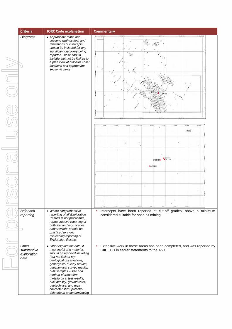
Diagrams Appropriate maps and sections (with scales) and tabulations of intercepts should be included for any significant discovery being reported These should include, but not be limited to a plan view of drill hole collar locations and appropriate sectional views.
Balanced reporting
Where comprehensive reporting of all Exploration Results is not practicable, representative reporting of both low and high grades and/or widths should be practiced to avoid misleading reporting of Exploration Results.
Intercepts have been reported at cut-off grades, above a minimum considered suitable for open pit mining.
Other substantive exploration data
Other exploration data, if meaningful and material, should be reported including (but not limited to): geological observations; geophysical survey results; geochemical survey results; bulk samples – size and method of treatment; metallurgical test results; bulk density, groundwater, geotechnical and rock characteristics; potential deleterious or contaminating
Extensive work in these areas has been completed, and was reported by CuDECO in earlier statements to the ASX.
For
per
sona
l use
onl
y

Criteria JORC Code explanation Commentary
substances.
Further work The nature and scale of planned further work (eg tests for lateral extensions or depth extensions or large-scale step-out drilling).
Diagrams clearly highlighting the areas of possible extensions, including the main geological interpretations and future drilling areas, provided this information is not commercially sensitive.
Mineralisation is open at depth. Current estimates are restricted to those expected to be reasonable for open pit mining. Limited drilling below this depth (-250m RL) shows widths and grades potentially suitable for underground extraction. CuDECO are currently considering target sizes and exploration programs to test this potential to 1,000m from surface.
For
per
sona
l use
onl
y