Embed Size (px)
Citation preview

Grand Bend Wind Farm Project Description Report
Prepared By:
Neegan Burnside Ltd. 292 Speedvale Avenue West Unit 20 Guelph ON N1H 1C4
Prepared for:
Grand Bend Wind Limited Partnership
February 13, 2012
File No: PIA 019991 The material in this report reflects best judgement in light of the information available at the time of preparation. Any use which a third party makes of this report, or any reliance on or decisions made based on it, are the responsibilities of such third parties. Neegan Burnside Ltd. accepts no responsibility for damages, if any, suffered by any third party as a result of decisions made or actions based on this report.
Grand Bend Wind Limited Partnership. i Draft Project Description Report February 2012
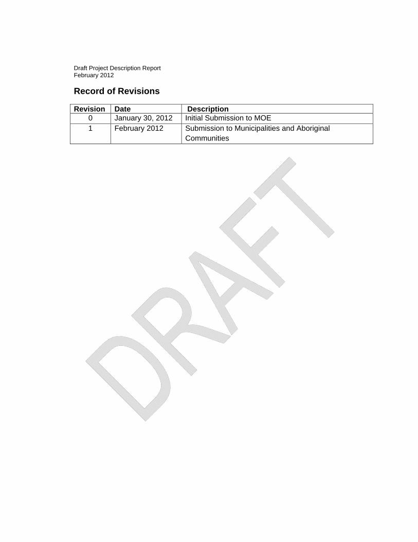
Record of Revisions
Revision Date Description 0 January 30, 2012 Initial Submission to MOE 1 February 2012 Submission to Municipalities and Aboriginal
Communities
Grand Bend Wind Limited Partnership. ii Draft Project Description Report February, 2012
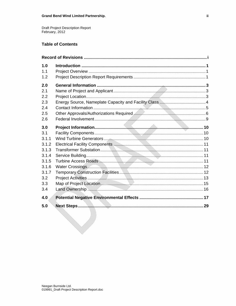
Table of Contents
Record of Revisions ........................................................................................................ i
1.0 Introduction ......................................................................................................... 1 1.1 Project Overview ...................................................................................................1 1.2 Project Description Report Requirements .............................................................1
2.0 General Information ............................................................................................ 3 2.1 Name of Project and Applicant ..............................................................................3 2.2 Project Location.....................................................................................................3 2.3 Energy Source, Nameplate Capacity and Facility Class .......................................4 2.4 Contact Information ...............................................................................................5 2.5 Other Approvals/Authorizations Required .............................................................6 2.6 Federal Involvement ..............................................................................................9
3.0 Project Information............................................................................................ 10 3.1 Facility Components............................................................................................10 3.1.1 Wind Turbine Generators .................................................................................... 10 3.1.2 Electrical Facility Components ............................................................................ 11 3.1.3 Transformer Substation....................................................................................... 11 3.1.4 Service Building................................................................................................... 11 3.1.5 Turbine Access Roads ........................................................................................ 11 3.1.6 Water Crossings.................................................................................................. 12 3.1.7 Temporary Construction Facilities ....................................................................... 12 3.2 Project Activities ..................................................................................................13 3.3 Map of Project Location.......................................................................................15 3.4 Land Ownership ..................................................................................................16
4.0 Potential Negative Environmental Effects ...................................................... 17
5.0 Next Steps.......................................................................................................... 29
Neegan Burnside Ltd. 019991_Draft Project Description Report.doc
Grand Bend Wind Limited Partnership. iii Draft Project Description Report February, 2012
Neegan Burnside Ltd. 019991_Draft Project Description Report.doc
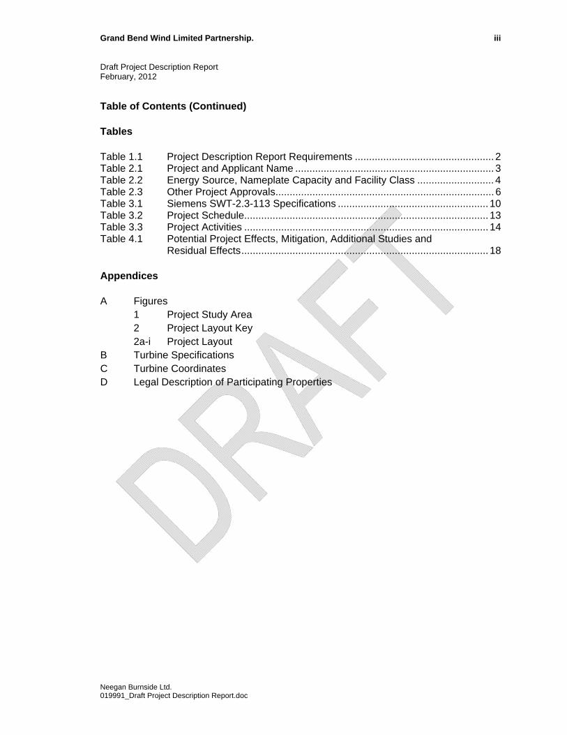
Table of Contents (Continued) Tables Table 1.1 Project Description Report Requirements ................................................. 2 Table 2.1 Project and Applicant Name ...................................................................... 3 Table 2.2 Energy Source, Nameplate Capacity and Facility Class ........................... 4 Table 2.3 Other Project Approvals............................................................................. 6 Table 3.1 Siemens SWT-2.3-113 Specifications ..................................................... 10 Table 3.2 Project Schedule...................................................................................... 13 Table 3.3 Project Activities ...................................................................................... 14 Table 4.1 Potential Project Effects, Mitigation, Additional Studies and
Residual Effects....................................................................................... 18 Appendices A Figures 1 Project Study Area 2 Project Layout Key
2a-i Project Layout B Turbine Specifications C Turbine Coordinates D Legal Description of Participating Properties
Grand Bend Wind Limited Partnership. 1 Draft Project Description Report February, 2012
1.0 Introduction
1.1 Project Overview
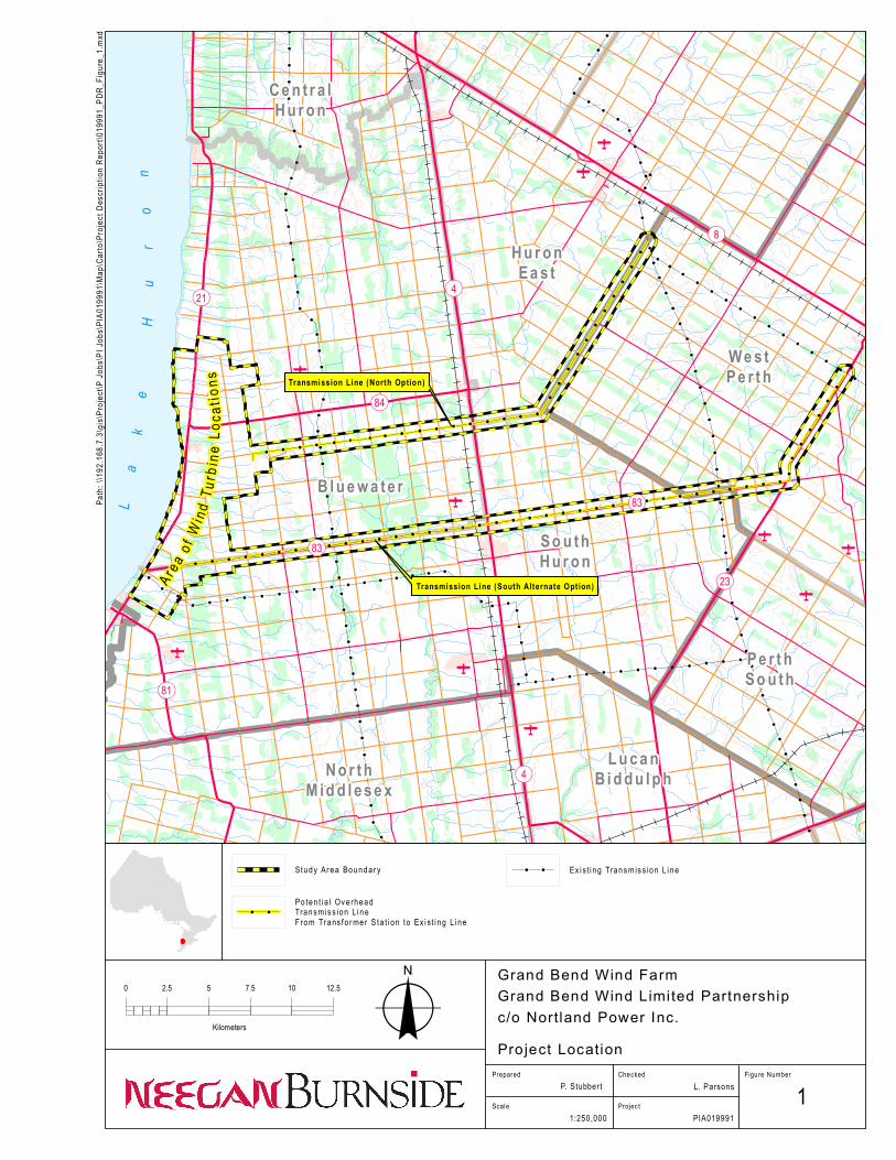
Grand Bend Wind Limited Partnership, c/o Northland Power Inc. (“Northland”) is proposing to develop, construct and operate a 100 MW wind facility located north of Grand Bend, Ontario. An application for approval is being prepared under Ontario Regulation 359/09 of the Environmental Protection Act. The project is classified as a Class 4 Wind facility under the Regulation. The Grand Bend Wind Farm (“the Project”) is located in Huron County, spanning the lower-tier municipalities of Bluewater and Huron South. Portions of the transmission line also traverse the municipality of Huron East and municipality of West Perth in Perth County. The project location and study area is provided in Appendix A, Figure 1. The basic project components will include approximately 48 turbines (Siemens SWT-2.3-113 direct drive wind turbine generators with a total name plate capacity of 100 MW), turbine access roads, a 36 kV electrical collection system, substation, a new transmission line within municipal road right-of ways (“ROWs”) along Rodgerville Road, Line 17 and Road 183 with connection to the provincial power grid at the 230 kV transmission line south of the Seaforth Transformer Station. An alternative transmission line connection to the grid is also under consideration west of Mitchell. During construction temporary components will include crane pads and work/storage areas at the turbine locations and construction of the transmission connections. Under O.Reg. 359/09, a Project Description Report (“PDR”) must be prepared as part of the application package. The PDR is intended to provide an overview of the project and act as the central document in the Renewable Energy Approval application. The Project Description Report is intended to be revised and updated throughout the Renewable Energy Approval process. Please refer to Record of Revisions table at the front of this document for revision references.
1.2 Project Description Report Requirements
This Project Description Report has been prepared in accordance with O.Reg. 359/09 and the guidance provided in Chapter 4 of the Technical Guide to Renewable Energy Approvals (MOE, 2011). Project Description Reports are required to include the information listed below in Table 1.1.
Neegan Burnside Ltd. 019991_Draft Project Description Report.doc

Grand Bend Wind Limited Partnership. 2 Draft Project Description Report February, 2012
Table 1.1 Project Description Report Requirements
Content Report Section
Reference 1. Any energy sources to be used to generate electricity at the
renewable energy generation facility 2.3
2. The facilities, equipment or technology that will be used to convert the renewable energy source or any other energy source to electricity.
3.1 and Appendix A
3. If applicable, the class of the renewable energy generation facility.
2.3
4. The activities that will be engaged in as part of the renewable energy project.
3.2
5. The nameplate capacity of the renewable energy generation facility.
2.3
6. The ownership of the land on which the project location is to be situated.
3.4 and Appendix C
7. If the person proposing to engage in the project does not own the land on which the project location is to be situated, a description of the permissions that are required to access the land and whether they have been obtained.
3.4
8. Any negative environmental effects that may result from engaging in the project.
4.0
9. An unbound, well marked, legible and reproducible map that is an appropriate size to fit on a 215 mm by 280 mm page, showing the project location and the land within 300 m of the project location.
Appendix A
Neegan Burnside Ltd. 019991_Draft Project Description Report.doc
Grand Bend Wind Limited Partnership. 3 Draft Project Description Report February, 2012
2.0 General Information
2.1 Name of Project and Applicant
The project and applicant name are provided in Table 2.1 Table 2.1 Project and Applicant Name Name of Project Grand Bend Wind Farm Name of Applicant Grand Bend Wind Limited Partnership c/o
Northland Power Inc. Northland Power Inc. (“Northland”) develops and operates clean and green power generation projects, mainly in the provinces of Ontario, Quebec and Saskatchewan. Since its inception in 1987, Northland has developed facilities generating a total of approximately 1,004 MW of electricity. Northland Power was founded on the belief that clean and green energy is vital to the future of our planet. Construction and operational practices are engineered to meet the highest environmental standards, even in jurisdictions where lower standards are legislated. In addition, Northland makes ongoing investments in its host communities to ensure they remain vibrant, healthy places to live. Additional information including a copy of this Project Description Report can be found on Northland’s website at: http://grandbend.northlandpower.ca/
2.2 Project Location
The proposed Project is located in Huron County, spanning the lower-tier municipalities of Bluewater and Huron South as well as a portion of Huron East and the municipality of West Perth in Perth County. The Project Study Area, shown in Appendix A, Figure 1, is bounded by:
The Bluewater Highway (Highway 21) to the west; Main Street East/Grand Bend Line to the south; Blackbush and Shipka Lines with a small section of the study area in the central
section of the project extending to Bronson Line and to the east; and, Staffa Road to the north; and Including two potential transmission line routes, as described below.
The preferred transmission line route is along Sararas/Rodgerville Road to Line 17, Road 183 and connecting to the 230 kV Hydro One transmission line just south of the Seaforth Transformer Station (“TS”). The second alternative route would follow
Neegan Burnside Ltd. 019991_Draft Project Description Report.doc
Grand Bend Wind Limited Partnership. 4 Draft Project Description Report February, 2012
Dashwood Road, Thames Road, Highway 23 and connect to the 230 kV Hydro One Transmission line east of Mitchell. Alternative potential transformer locations and storage building areas are indicated as well. O. Reg. 359/09 defines the Project Location as:
“a part of land and all or part of any building or structure in, on or over which a person is engaging in or proposes to engage in the project and any air space in which a person in engaging in or proposes to engage in the project”.
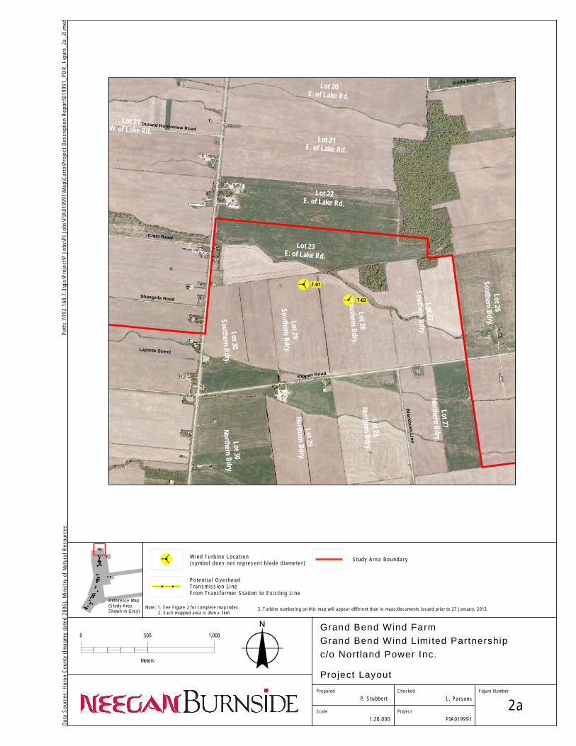
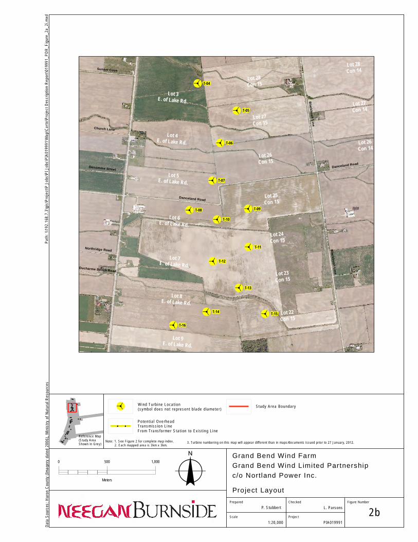
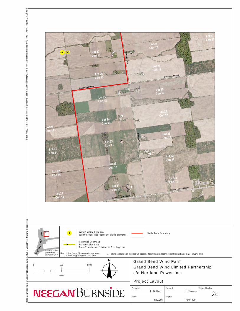
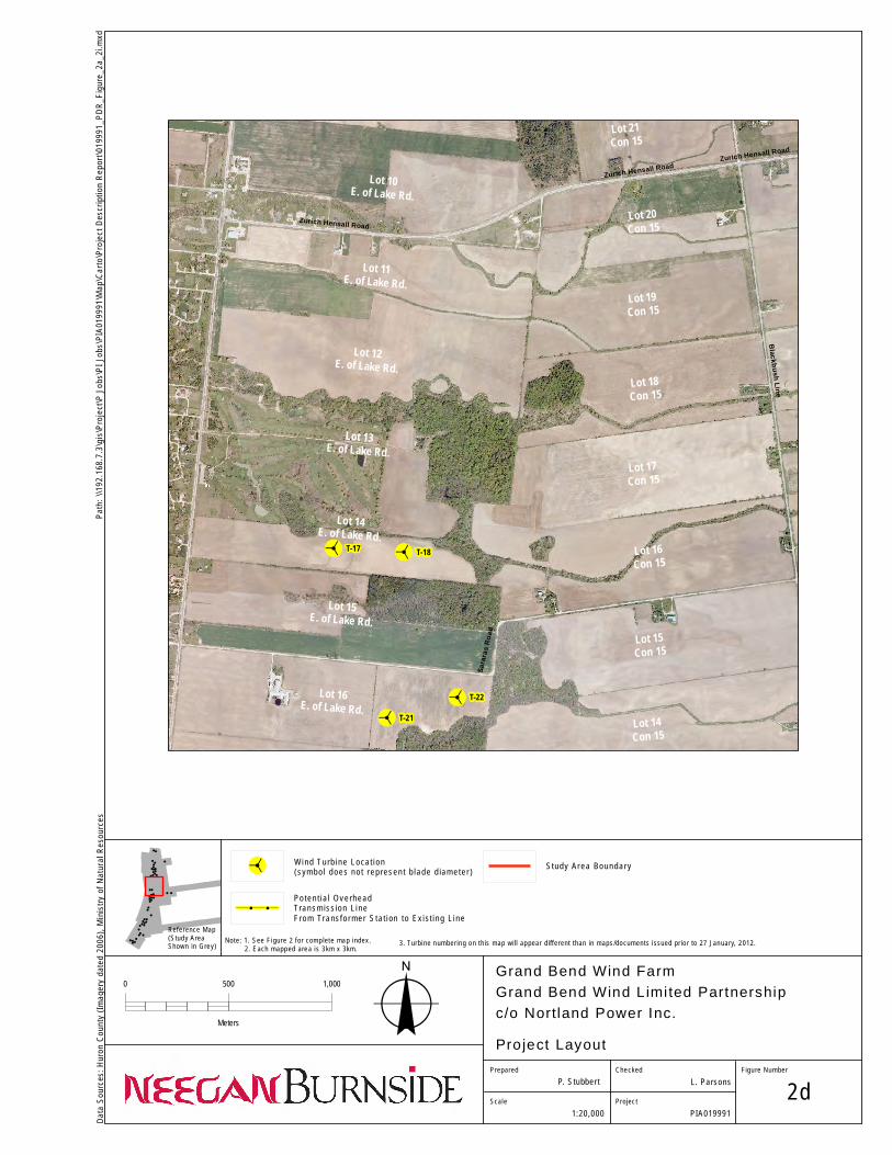
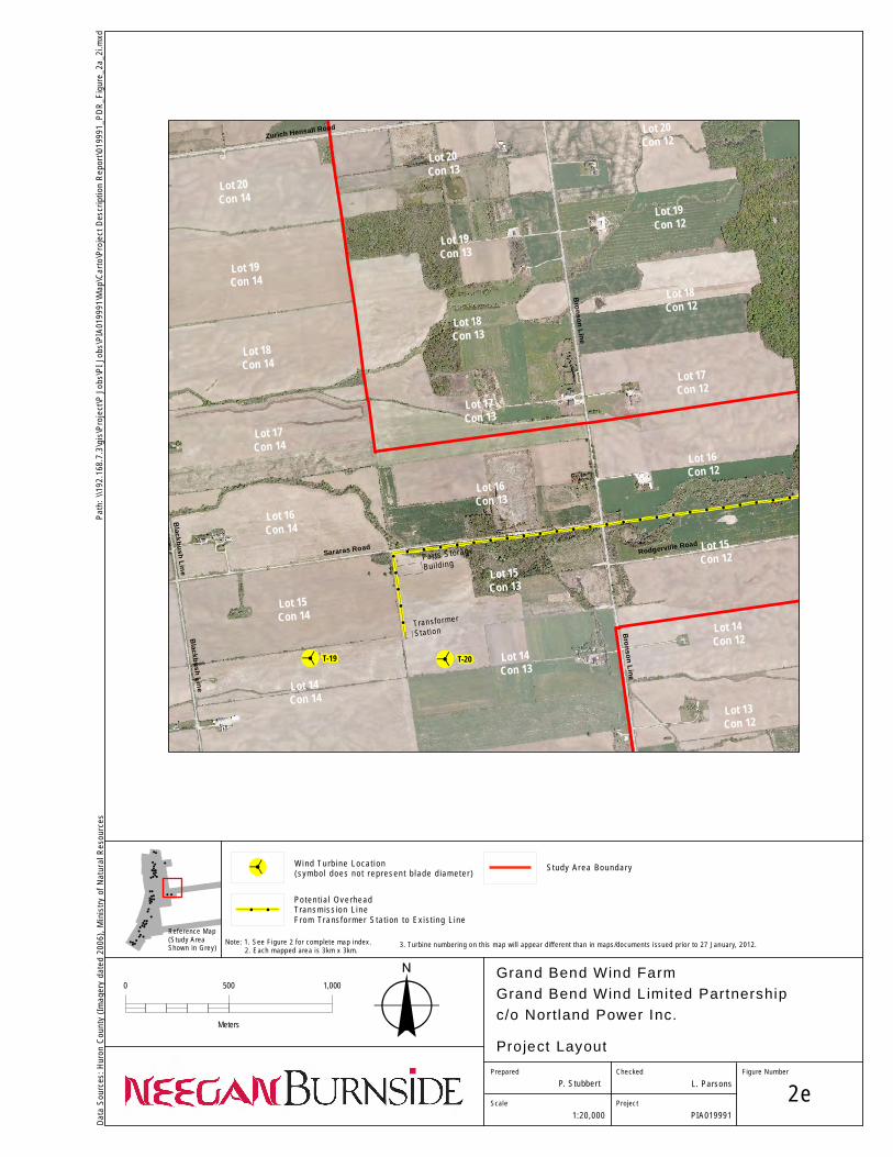
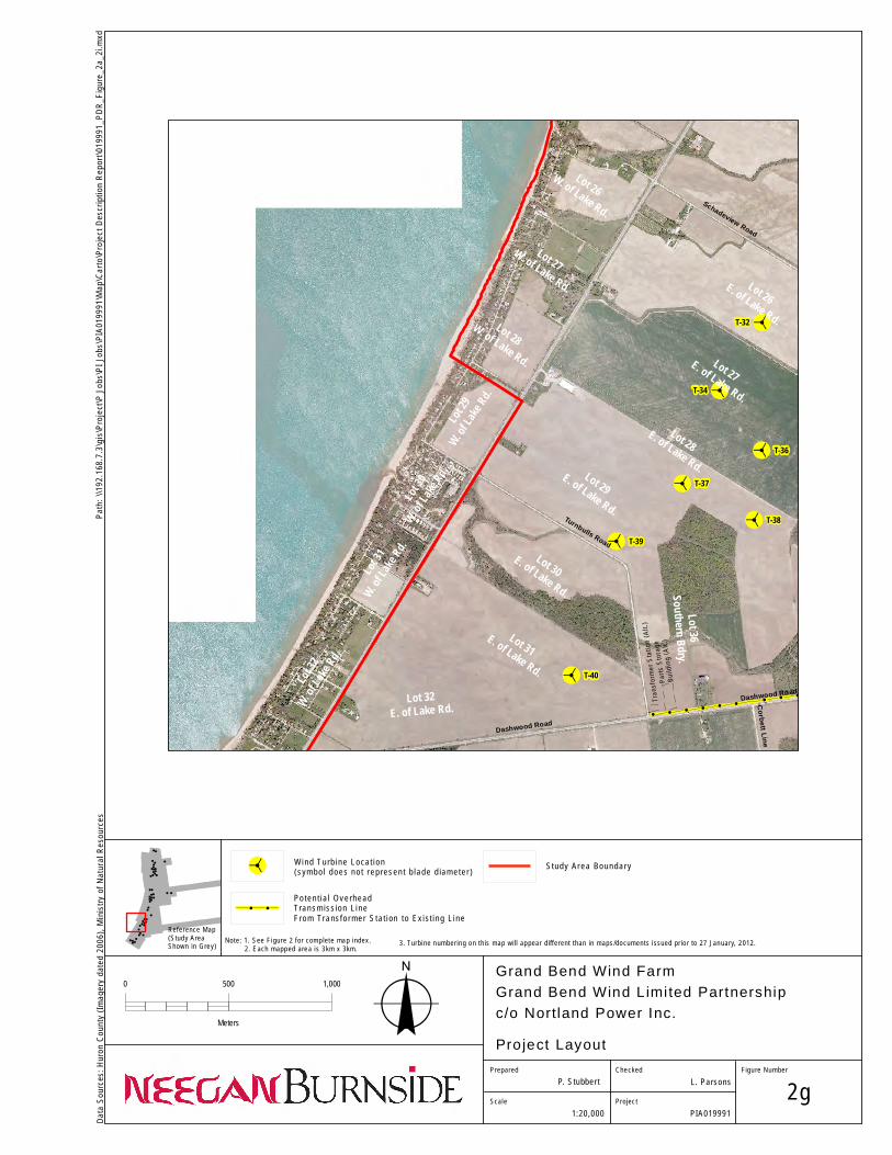
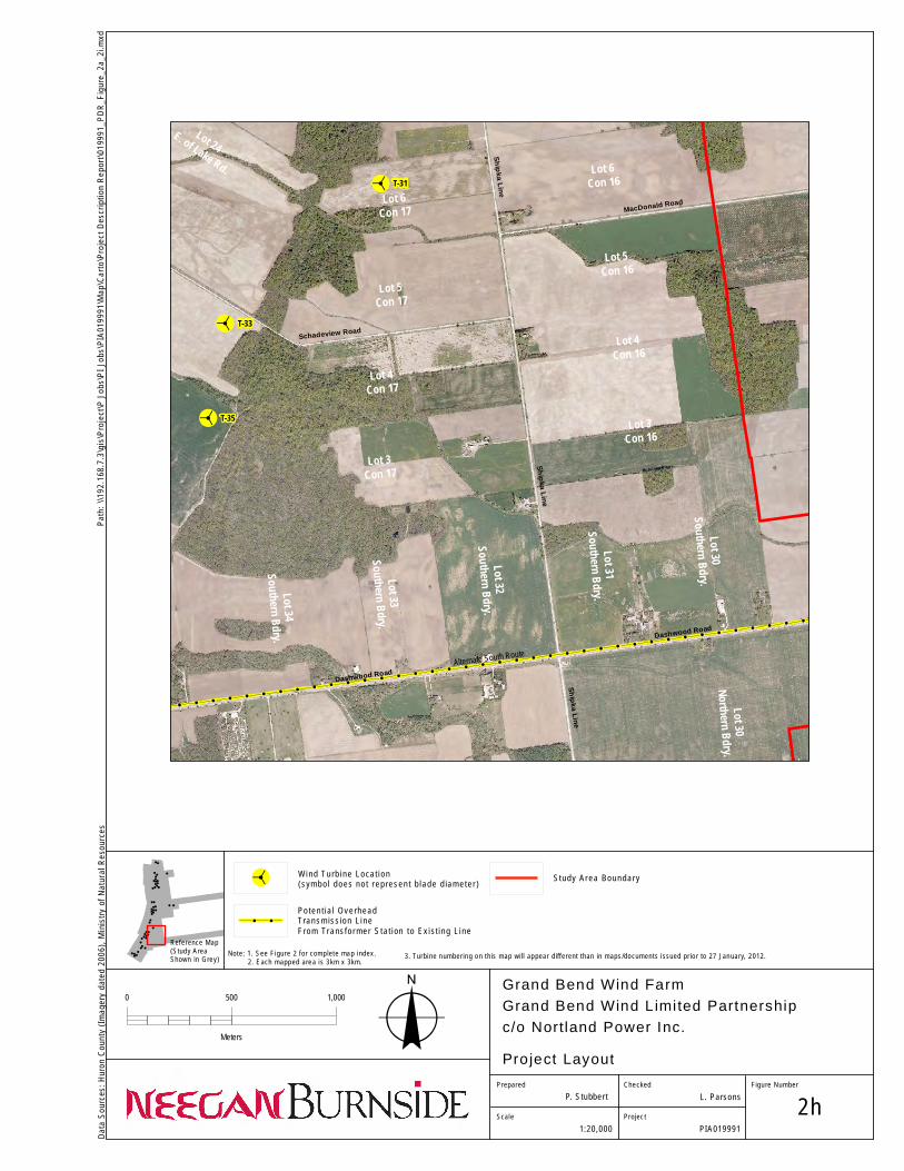
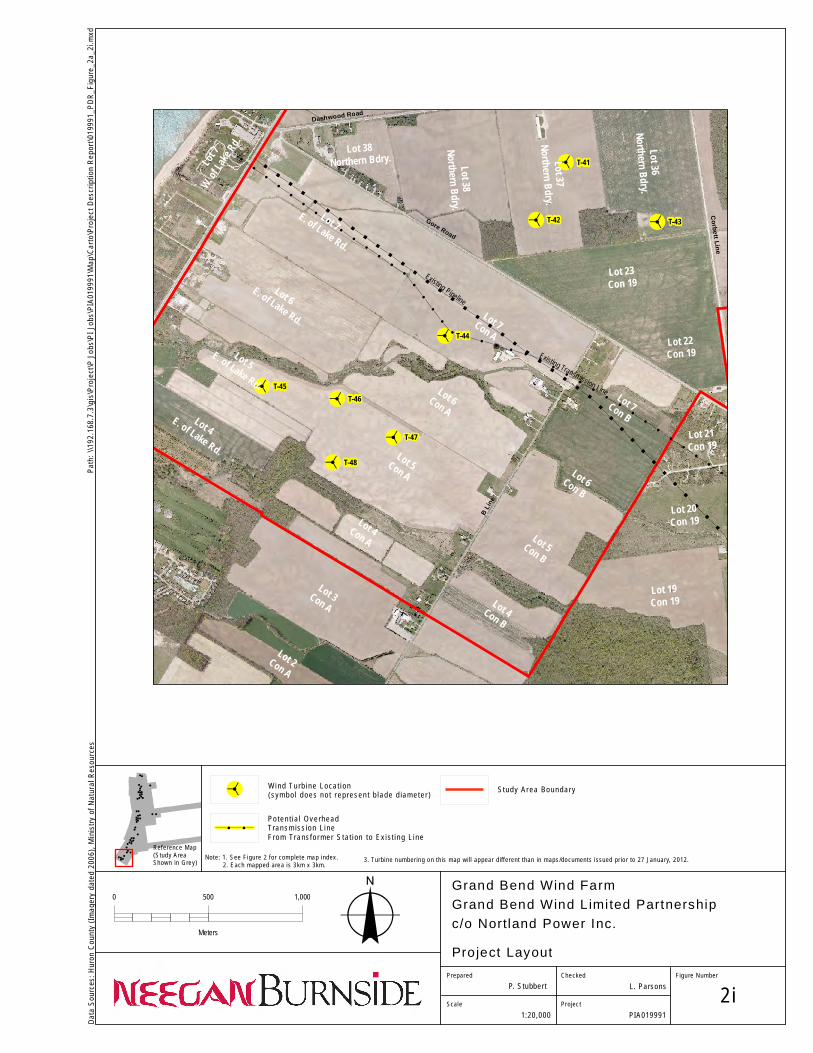
For the purposes of this Project, the Project Location includes the footprint of the facility components, plus any temporary work and storage locations. The boundary of the Project Location is used for defining setback and site investigation distances according to O.Reg. 359/09. The buildable area, which includes the footprint of the facility components, plus any temporary work and storage locations, will be staked on private lands. All construction and installation activities will be conducted within these designated areas; this includes construction vehicles and personnel. Similarly, all installation activities related to collector lines within the municipal road allowance will be contained within the boundaries of the road allowance. A detailed map of the Project Location and its vicinity is presented in Appendix A, Figures 2a-i.
2.3 Energy Source, Nameplate Capacity and Facility Class
Project information is presented in Table 2.2. Table 2.2 Energy Source, Nameplate Capacity and Facility Class Energy Source Wind Nameplate Capacity 100 MW Facility Class Class 4, Wind Facility Wind turbines capture kinetic energy in wind which is converted into electricity. Wind turbines are comprised of four basic parts:
foundation tower; blades; and nacelle.
Neegan Burnside Ltd. 019991_Draft Project Description Report.doc
Grand Bend Wind Limited Partnership. 5 Draft Project Description Report February, 2012
As wind moves over the turbine’s blades it causes “lift”. This lift force causes the blade assembly to rotate. The rotational energy resulting from the movement of the blades is converted in the nacelle to useable 60 Hz electricity. No supplementary fuel sources would be used to generate electricity for the Project. A Feed-in Tariff (“FIT”) Contract has been awarded for the project by the Ontario Power Authority (“OPA”) (FIT Contract # “F-002178-WIN-130-601).
2.4 Contact Information
Applicant The Applicant for the project is Grand Bend Wind Limited Partnership. c/o Northland Power Inc. (“Northland”). The principle contact is: Name: Carol-Ann Fletcher, P.Eng Company: Northland Power Inc. Address: 30 St. Clair Avenue West, 12th Floor Toronto, ON M4A 3A1 Email: [email protected] Telephone: (647) 288-1272 Consultant Neegan Burnside Ltd. (“Neegan Burnside”) was retained by Northland as the lead project consultant. Neegan Burnside is a majority owned Aboriginal firm providing engineering and environmental consulting services. The principle project consultant representing the applicant is: Name: Lyle Parsons, B.E.S. Company: Neegan Burnside Ltd. Address: 292 Speedvale Avenue West, Unit 20 Guelph, ON N1H 1C4 Email: [email protected] Telephone: (519) 925-1790 The project specific e-mail address and telephone hotline for this project is as follows: [email protected] 1-800-696-8093
Neegan Burnside Ltd. 019991_Draft Project Description Report.doc
Grand Bend Wind Limited Partnership. 6 Draft Project Description Report February, 2012
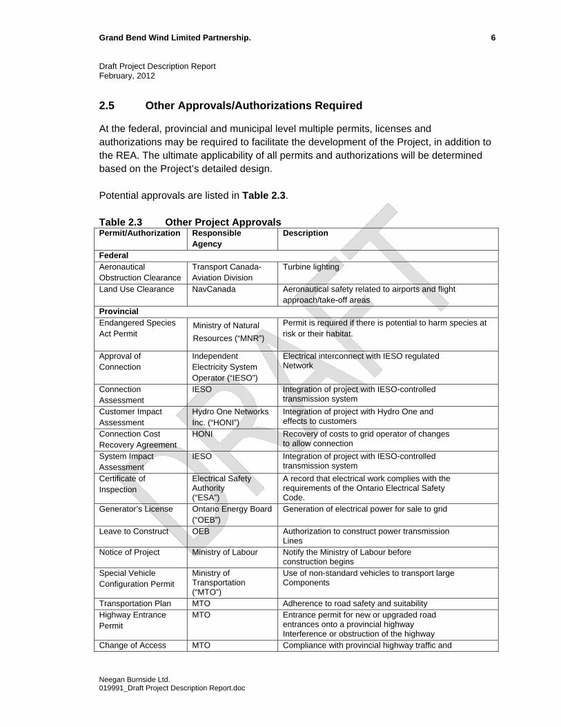
2.5 Other Approvals/Authorizations Required
At the federal, provincial and municipal level multiple permits, licenses and authorizations may be required to facilitate the development of the Project, in addition to the REA. The ultimate applicability of all permits and authorizations will be determined based on the Project’s detailed design. Potential approvals are listed in Table 2.3. Table 2.3 Other Project Approvals Permit/Authorization Responsible
Agency Description
Federal Aeronautical Obstruction Clearance
Transport Canada- Aviation Division
Turbine lighting
Land Use Clearance NavCanada Aeronautical safety related to airports and flight approach/take-off areas
Provincial Endangered Species Act Permit
Ministry of Natural
Resources (“MNR”)
Permit is required if there is potential to harm species at risk or their habitat.
Approval of Connection
Independent Electricity System Operator (“IESO”)
Electrical interconnect with IESO regulated Network
Connection Assessment
IESO Integration of project with IESO-controlled transmission system
Customer Impact Assessment
Hydro One Networks Inc. (“HONI”)
Integration of project with Hydro One and effects to customers
Connection Cost Recovery Agreement
HONI Recovery of costs to grid operator of changes to allow connection
System Impact Assessment
IESO Integration of project with IESO-controlled transmission system
Certificate of Inspection
Electrical Safety Authority (“ESA”)
A record that electrical work complies with the requirements of the Ontario Electrical Safety Code.
Generator’s License Ontario Energy Board (“OEB”)
Generation of electrical power for sale to grid
Leave to Construct OEB Authorization to construct power transmission Lines
Notice of Project Ministry of Labour Notify the Ministry of Labour before construction begins
Special Vehicle Configuration Permit
Ministry of Transportation (“MTO”)
Use of non-standard vehicles to transport large Components
Transportation Plan MTO Adherence to road safety and suitability Highway Entrance Permit
MTO Entrance permit for new or upgraded road entrances onto a provincial highway Interference or obstruction of the highway
Change of Access MTO Compliance with provincial highway traffic and
Neegan Burnside Ltd. 019991_Draft Project Description Report.doc
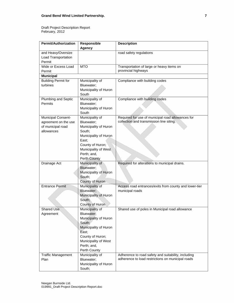
Grand Bend Wind Limited Partnership. 7 Draft Project Description Report February, 2012
Permit/Authorization Responsible Agency
Description
and Heavy/Oversize Load Transportation Permit
road safety regulations
Wide or Excess Load Permit
MTO Transportation of large or heavy items on provincial highways
Municipal Building Permit for turbines
Municipality of Bluewater; Municipality of Huron South
Compliance with building codes
Plumbing and Septic Permits
Municipality of Bluewater; Municipality of Huron South
Compliance with building codes
Municipal Consent- agreement on the use of municipal road allowances
Municipality of Bluewater; Municipality of Huron South; Municipality of Huron East; County of Huron; Municipality of West Perth; and, Perth County
Required for use of municipal road allowances for collection and transmission line siting.
Drainage Act Municipality of Bluewater; Municipality of Huron South; County of Huron
Required for alterations to municipal drains.
Entrance Permit Municipality of Bluewater; Municipality of Huron South; County of Huron
Access road entrances/exits from county and lower-tier municipal roads
Shared Use Agreement
Municipality of Bluewater; Municipality of Huron South; Municipality of Huron East; County of Huron; Municipality of West Perth; and, Perth County
Shared use of poles in Municipal road allowance
Traffic Management Plan
Municipality of Bluewater; Municipality of Huron South;
Adherence to road safety and suitability, including adherence to load restrictions on municipal roads
Neegan Burnside Ltd. 019991_Draft Project Description Report.doc
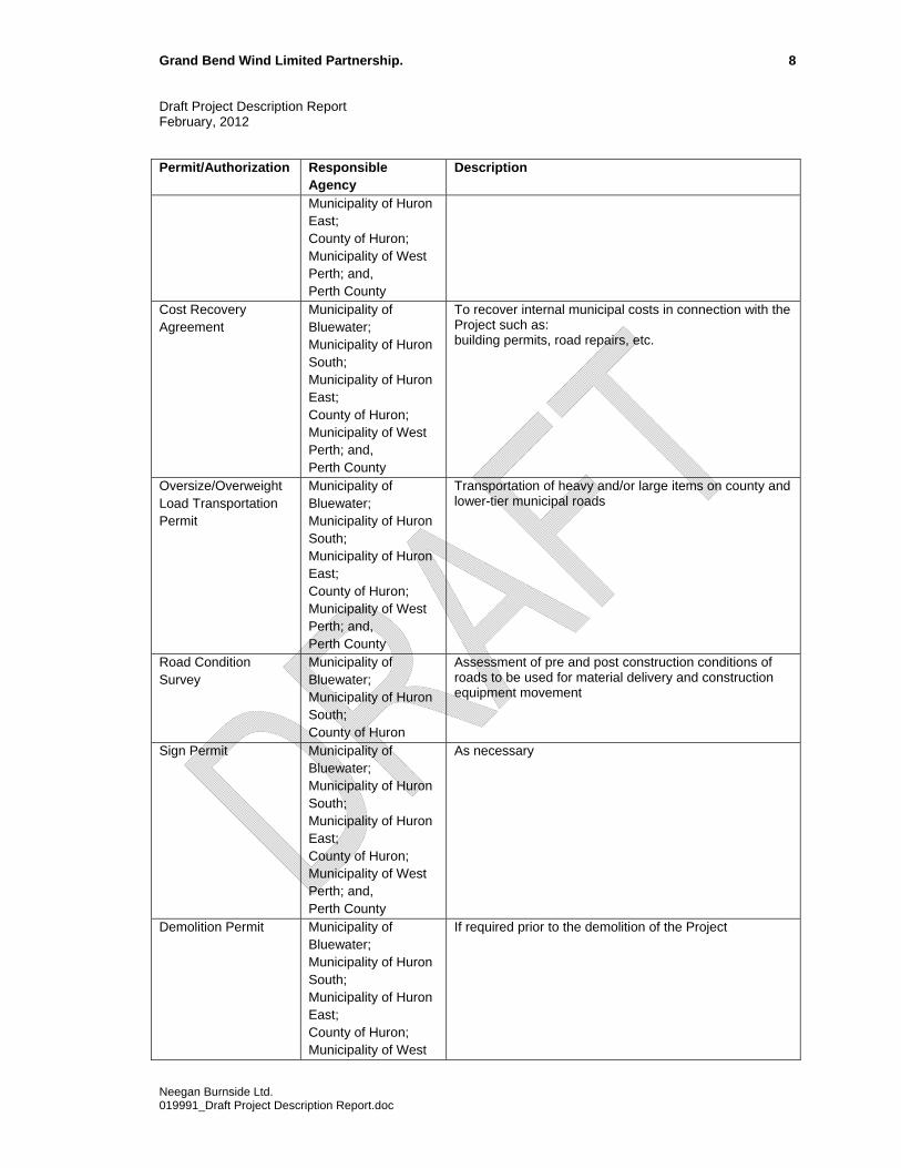
Grand Bend Wind Limited Partnership. 8 Draft Project Description Report February, 2012
Permit/Authorization Responsible Agency
Description
Municipality of Huron East; County of Huron; Municipality of West Perth; and, Perth County
Cost Recovery Agreement
Municipality of Bluewater; Municipality of Huron South; Municipality of Huron East; County of Huron; Municipality of West Perth; and, Perth County
To recover internal municipal costs in connection with the Project such as: building permits, road repairs, etc.
Oversize/Overweight Load Transportation Permit
Municipality of Bluewater; Municipality of Huron South; Municipality of Huron East; County of Huron; Municipality of West Perth; and, Perth County
Transportation of heavy and/or large items on county and lower-tier municipal roads
Road Condition Survey
Municipality of Bluewater; Municipality of Huron South; County of Huron
Assessment of pre and post construction conditions of roads to be used for material delivery and construction equipment movement
Sign Permit Municipality of Bluewater; Municipality of Huron South; Municipality of Huron East; County of Huron; Municipality of West Perth; and, Perth County
As necessary
Demolition Permit Municipality of Bluewater; Municipality of Huron South; Municipality of Huron East; County of Huron; Municipality of West
If required prior to the demolition of the Project
Neegan Burnside Ltd. 019991_Draft Project Description Report.doc
Grand Bend Wind Limited Partnership. 9 Draft Project Description Report February, 2012
Permit/Authorization Responsible Agency
Description
Perth; and, Perth County
Other Agencies Development, Interference with Wetlands, and Alterations to Shorelines and Watercourses Permit
Ausable Bayfield Conservation Authority/Upper Thames Conservation Authority
Work within floodplains, water crossings, river or stream valleys, hazardous lands and within or adjacent to wetlands.
2.6 Federal Involvement
Federal authorizations and clearances are noted in Table 2.3. This Project may trigger a federal Environmental Assessment (CEAA Screening) under the Canadian Environmental Assessment Act as federal funding may be provided. Federal agencies will be contacted during the consultation process to confirm federal involvement.
Neegan Burnside Ltd. 019991_Draft Project Description Report.doc
Grand Bend Wind Limited Partnership. 10 Draft Project Description Report February, 2012
3.0 Project Information
3.1 Facility Components
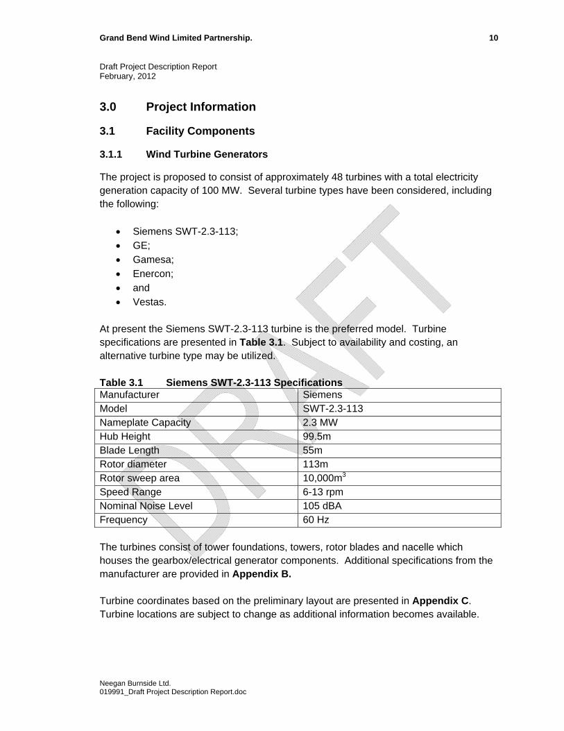
3.1.1 Wind Turbine Generators
The project is proposed to consist of approximately 48 turbines with a total electricity generation capacity of 100 MW. Several turbine types have been considered, including the following:
Siemens SWT-2.3-113; GE; Gamesa; Enercon; and Vestas.
At present the Siemens SWT-2.3-113 turbine is the preferred model. Turbine specifications are presented in Table 3.1. Subject to availability and costing, an alternative turbine type may be utilized. Table 3.1 Siemens SWT-2.3-113 Specifications Manufacturer Siemens Model SWT-2.3-113 Nameplate Capacity 2.3 MW Hub Height 99.5m Blade Length 55m Rotor diameter 113m Rotor sweep area 10,000m3 Speed Range 6-13 rpm Nominal Noise Level 105 dBA Frequency 60 Hz The turbines consist of tower foundations, towers, rotor blades and nacelle which houses the gearbox/electrical generator components. Additional specifications from the manufacturer are provided in Appendix B. Turbine coordinates based on the preliminary layout are presented in Appendix C. Turbine locations are subject to change as additional information becomes available.
Neegan Burnside Ltd. 019991_Draft Project Description Report.doc
Grand Bend Wind Limited Partnership. 11 Draft Project Description Report February, 2012
3.1.2 Electrical Facility Components
The project will also include the following components:
Step-up transformers adjacent to each turbine at the base of the tower; 36 kV underground electrical power lines from each turbine to the nearest
municipal road right-of-way (”ROW”); and, 36 kV electrical power lines to be located within municipal ROWs and connecting
to the transformer sub-station via one of the alternative routes; 115 or 230 KV transmission line from the sub-station to the existing 115 Kv or
230 kV Hydro One transmission system to the east of the Project Study Area; Connection to the115 or 230 KV Hydro One power grid at one of the following
two alternatives: – south of Seaforth TS location (preferred); or, – west of Mitchell.
3.1.3 Transformer Substation
A 30 m X 30 m (approx. size) substation will be constructed at one of the two alternative locations shown on Figure 2. 3.1.4 Service Building
A service and parts storage building will be located close to one of the transformer locations proposed. The building will be approximately 50’ x 120’ and include a parking area as shown on Figure 2. This building will be serviced with water/wastewater (well and septic). 3.1.5 Turbine Access Roads
Existing provincial and municipal roads will be used to transport project-related components, equipment and personnel to the Study Area during construction and as required during operation. The Project would be situated exclusively on privately owned land and municipal road allowances. Access to these lands will be required for installation and operation of the wind turbines and lease agreements have previously been signed with each of the landowners involved. Some agricultural laneways are present in the vicinity of the Project and will be utilized where possible. New laneways will be constructed as required and in consultation with landowners to provide access to the individual turbine sites. Construction access laneways will be approximately 10 m wide during construction. Permanent access laneways may be reduced in size to approximately 6 m wide with the exception of entrances off municipal roads and all turning areas which require wider turning radii.
Neegan Burnside Ltd. 019991_Draft Project Description Report.doc

Grand Bend Wind Limited Partnership. 12 Draft Project Description Report February, 2012
3.1.6 Water Crossings
Where underground collector lines cross watercourses or other sensitive natural areas, the buried gathered lines will be installed using directional drill techniques in suitably sized plastic conduits at a sufficient depth below the watercourse to prevent any possibility of accidental damage due to dredging or over excavation. Signs indicating the presence and location of the cables will also be placed on either side of the watercourse or other areas involved. All water crossings will require permit approval from the Ausable Bayfield Conservation Authority and/or the Upper Thames Conservation Authority. The final configuration and route for the collector lines will be determined as part of the REA process. All temporary crossings would comply with the DFO’s Ontario Operation Statement ‘Temporary Stream Crossings’ where possible. 3.1.7 Temporary Construction Facilities
Lands to be temporarily used during the construction of the Project include staging areas for access roads and underground cable construction, delivery truck turnaround areas, staging areas at each turbine location, and crane laydown areas. Any temporary structures used during construction will not be serviced with electrical or water hook-ups, and will be placed within delineated construction work areas. The existing land use at all Project areas is agricultural. Following construction activities, all locations will be restored to pre-impact conditions. Restoration work will start following installation of each wind turbine and removal of all construction materials and equipment from each turbine site. Turbine Staging Areas – At this time, plans are for turbine components to be delivered directly to the staging areas for each turbine. The components will be temporarily stored within these staging areas until assembled; there will be no central laydown area. Turbine staging areas will be initiated in conjunction with turbine assembly, and will be rehabilitated to pre-construction condition following the end of the construction phase. Turbine staging areas would be actively used to varying degrees during all construction activities at the specific turbine site areas. Access Road Staging Areas - A staging area will be required for construction of the access road. Delivery Truck Turnaround Areas - These turnaround areas will be the same width as access roads, with additional space as required for turning radii, and will be constructed in the same manner. There is a similar turnaround requirement for staging areas.
Neegan Burnside Ltd. 019991_Draft Project Description Report.doc
Grand Bend Wind Limited Partnership. 13 Draft Project Description Report February, 2012
Access Road Entrances - Access road entrances require a wider turning radius for construction/delivery vehicles. Crane Laydown Areas – An area will be identified within which crane components will be assembled. Crane Pads - Crane pads will consist of concrete pads on which the construction crane will sit. A crane pad would be located at each turbine location at the end of each access road to be used during turbine assembly. Pads will generally be constructed at the same time as the access roads. Concrete will be removed subsequent to construction and land beneath will be rehabilitated as required.
3.2 Project Activities
Project activities will generally include:
Project approvals; Construction; Operation and maintenance; and, Decommissioning (or re-powering).
A preliminary schedule of Project Activities is presented in Table 3.2. Table 3.2 Project Schedule Project Activity Anticipated Schedule Issue First Draft Project Description Report January 2012 REA Technical Studies Ongoing 2011 through
2012 Public Information Centre #1 Spring 2012 Issue Draft REA Reports to the Public Late summer 2012 Public Information Centre #2 Fall 2012 REA Submission/Approval Fall 2012/Spring 2013 Additional Permitting and Approvals Completed Ongoing 2012 through
2013 Start of Construction Fall 2013 Commercial Operation Date (“COD”) Fall 2014 Project Operation 2014- 2025 New Contract or Decommissioning Approximately 20 years
after COD
Neegan Burnside Ltd. 019991_Draft Project Description Report.doc
Grand Bend Wind Limited Partnership. 14 Draft Project Description Report February, 2012
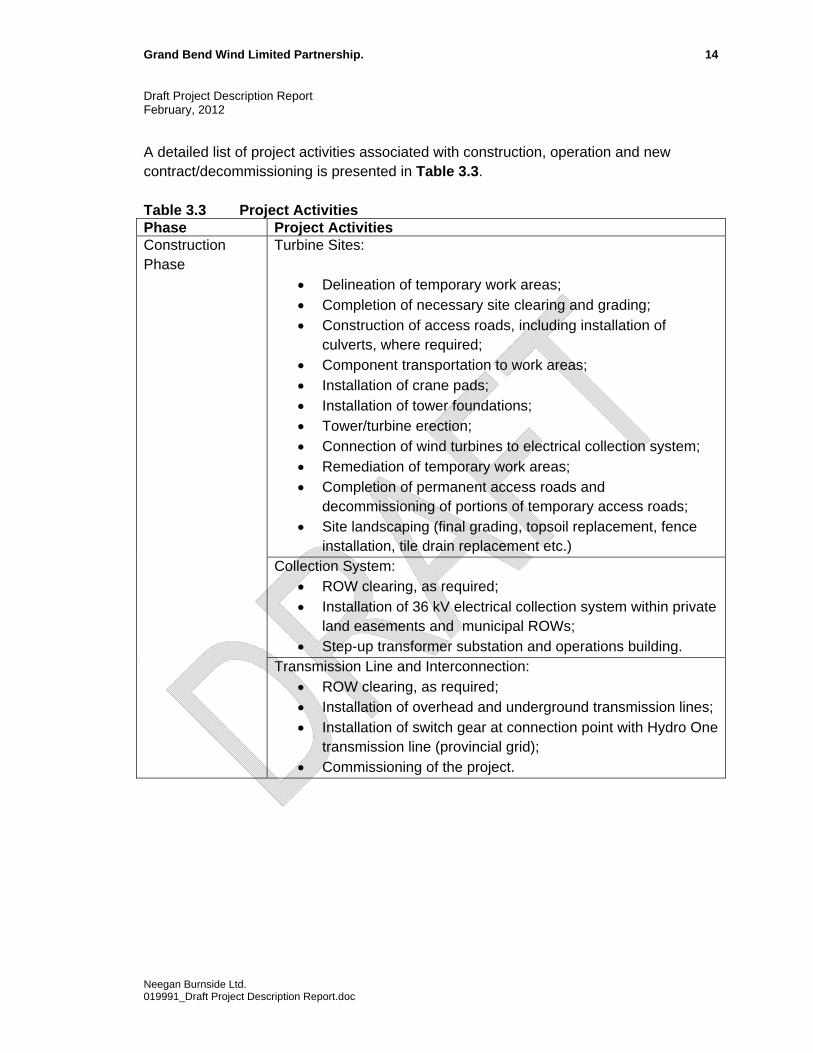
A detailed list of project activities associated with construction, operation and new contract/decommissioning is presented in Table 3.3. Table 3.3 Project Activities Phase Project Activities
Turbine Sites:
Delineation of temporary work areas; Completion of necessary site clearing and grading; Construction of access roads, including installation of
culverts, where required; Component transportation to work areas; Installation of crane pads; Installation of tower foundations; Tower/turbine erection; Connection of wind turbines to electrical collection system; Remediation of temporary work areas; Completion of permanent access roads and
decommissioning of portions of temporary access roads; Site landscaping (final grading, topsoil replacement, fence
installation, tile drain replacement etc.) Collection System:
ROW clearing, as required; Installation of 36 kV electrical collection system within private
land easements and municipal ROWs; Step-up transformer substation and operations building.
Construction Phase
Transmission Line and Interconnection: ROW clearing, as required; Installation of overhead and underground transmission lines; Installation of switch gear at connection point with Hydro One
transmission line (provincial grid); Commissioning of the project.
Neegan Burnside Ltd. 019991_Draft Project Description Report.doc
Grand Bend Wind Limited Partnership. 15 Draft Project Description Report February, 2012
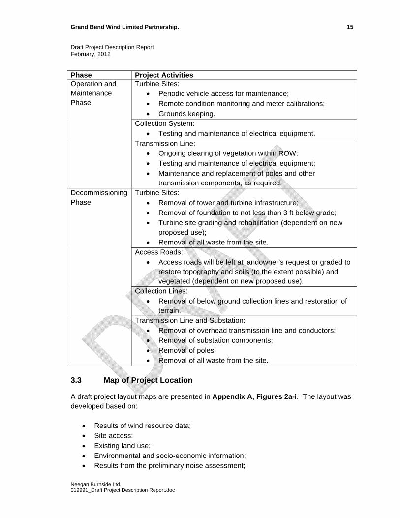
Phase Project Activities Turbine Sites:
Periodic vehicle access for maintenance; Remote condition monitoring and meter calibrations; Grounds keeping.
Collection System: Testing and maintenance of electrical equipment.
Operation and Maintenance Phase
Transmission Line: Ongoing clearing of vegetation within ROW; Testing and maintenance of electrical equipment; Maintenance and replacement of poles and other
transmission components, as required. Turbine Sites:
Removal of tower and turbine infrastructure; Removal of foundation to not less than 3 ft below grade; Turbine site grading and rehabilitation (dependent on new
proposed use); Removal of all waste from the site.
Access Roads: Access roads will be left at landowner’s request or graded to
restore topography and soils (to the extent possible) and vegetated (dependent on new proposed use).
Collection Lines: Removal of below ground collection lines and restoration of
terrain.
Decommissioning Phase
Transmission Line and Substation: Removal of overhead transmission line and conductors; Removal of substation components; Removal of poles; Removal of all waste from the site.
3.3 Map of Project Location
A draft project layout maps are presented in Appendix A, Figures 2a-i. The layout was developed based on:
Results of wind resource data; Site access; Existing land use; Environmental and socio-economic information; Results from the preliminary noise assessment;
Neegan Burnside Ltd. 019991_Draft Project Description Report.doc
Grand Bend Wind Limited Partnership. 16 Draft Project Description Report February, 2012
Interconnection feasibility; and, REA setback requirements.
The layout presented is considered to be draft and is subject to revisions based on input received from government agencies, aboriginal communities, the public and landowners through the REA consultation process as well as additional environmental data collected during field studies.
3.4 Land Ownership
The project will be located predominantly on private and municipal lands (private lands are predominantly in active agricultural use) as described below. Portions of the project located on private lands include:
Turbines; Temporary and permanent access roads; Turbine construction areas; Electrical collector system; Operation and maintenance building; Transformer sub-station; and, Connection station
Portions of the project located on municipal lands include:
Overhead and underground electrical collection and transmission lines within provincial and municipal ROWs; and,
Overhead and underground electrical collection and transmission line construction areas
The legal descriptions of land parcels on which the project will be located are presented in Appendix D. The permissions that are required to access the land have been obtained by the project proponent in the form of land lease agreements.
Neegan Burnside Ltd. 019991_Draft Project Description Report.doc
Grand Bend Wind Limited Partnership. 17 Draft Project Description Report February, 2012
Neegan Burnside Ltd. 019991_Draft Project Description Report.doc
4.0 Potential Negative Environmental Effects
Potential negative effects associated with the project are identified in the sections below. As the REA process progresses, each potential effect will be studied in greater detail to identify the significance, magnitude and duration of each effect. Mitigation will be developed to minimize effects to the extent possible. Finally, a post-construction monitoring program will be developed to identify and address any unexpected impacts that may result from the project. A key component of the REA process is the establishment of common setbacks for all renewable energy facilities in the Province. The Project was designed to meet the mandatory setbacks within O. Reg. 359/09 in all cases. Within the regulation there are some setbacks for which studies that identify potential negative environmental effects and mitigation measures can be conducted in lieu of meeting the setback requirements. In some instances in the proposed design, Project components are proposed within the defined setbacks. In these instances, additional assessments will be conducted. Potential negative effects, proposed mitigation measures and additional studies currently underway or proposed in the near future have been summarized in Table 4.1.

Northland Power Inc. 18 Draft Project Description Report February 2012
Table 4.1 Potential Project Effects, Mitigation, Additional Studies and Residual Effects Environmental Component
Potential Effects Proposed Mitigation/Additional Studies Anticipated Residual Effect
Heritage/Archaeology Disturbance to archaeological and cultural heritage resources during construction or decommissioning activities.
No anticipated effects during operation/maintenance
A Stage 1 Archaeological Assessment and consultation with agencies regarding Heritage Resources is currently underway.
Additional Archaeological and Cultural Assessments will be undertaken (by a licensed archaeologist) if it is determined that there is potential for resources to be present.
Consultation will be undertaken with relevant First Nations and Métis communities.
Should any unknown/unexpected artifacts or human remains be encountered during construction the construction contractor will stop work and the Ministry of Culture will be notified.
Appropriate clearance will be obtained by the Ministry of Tourism and Culture.
No residual effects anticipated
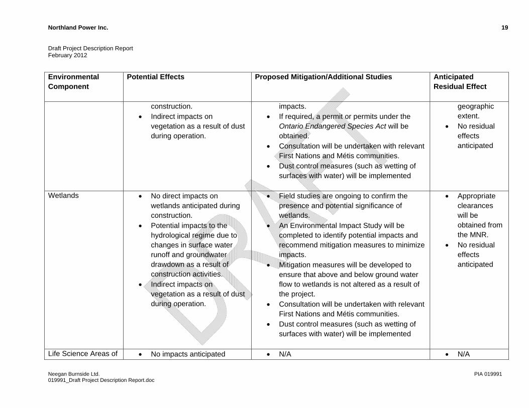
Woodlands and Natural Vegetation
Potential introduction of invasive species during construction.
Vegetation loss during construction, although project is primarily located in agricultural areas
No direct impact on Significant Woodlands anticipated during
Field studies are ongoing to confirm the presence, significance, sensitivity and abundance of woodlands and natural vegetation, including:
o Vegetation inventories; o Ecological Land Classification; and, o Species at Risk surveys.
An Environmental Impact Study will be completed to identify potential impacts and recommend mitigation measures to minimize
Appropriate clearances will be obtained from the MNR.
Impact anticipated to be short term in duration and of limited
Neegan Burnside Ltd. PIA 019991 019991_Draft Project Description Report.doc
Northland Power Inc. 19 Draft Project Description Report February 2012
Environmental Component
Potential Effects Proposed Mitigation/Additional Studies Anticipated
Residual Effect
construction. Indirect impacts on
vegetation as a result of dust during operation.
impacts. If required, a permit or permits under the
Ontario Endangered Species Act will be obtained.
Consultation will be undertaken with relevant First Nations and Métis communities.
Dust control measures (such as wetting of surfaces with water) will be implemented
geographic extent.
No residual effects anticipated
Wetlands No direct impacts on wetlands anticipated during construction.
Potential impacts to the hydrological regime due to changes in surface water runoff and groundwater drawdown as a result of construction activities.
Indirect impacts on vegetation as a result of dust during operation.
Field studies are ongoing to confirm the presence and potential significance of wetlands.
An Environmental Impact Study will be completed to identify potential impacts and recommend mitigation measures to minimize impacts.
Mitigation measures will be developed to ensure that above and below ground water flow to wetlands is not altered as a result of the project.
Consultation will be undertaken with relevant First Nations and Métis communities.
Dust control measures (such as wetting of surfaces with water) will be implemented
Appropriate clearances will be obtained from the MNR.
No residual effects anticipated
Life Science Areas of No impacts anticipated N/A N/A
Neegan Burnside Ltd. PIA 019991 019991_Draft Project Description Report.doc
Northland Power Inc. 20 Draft Project Description Report February 2012
Environmental Component
Potential Effects Proposed Mitigation/Additional Studies Anticipated Residual Effect
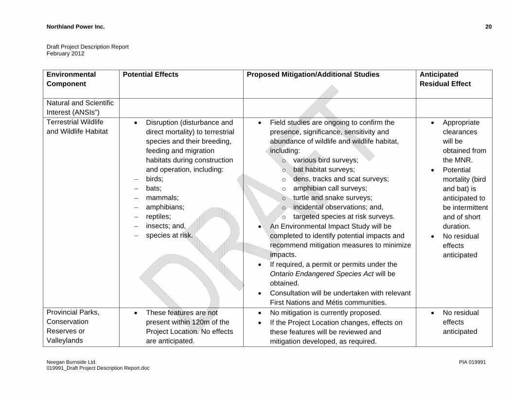
Natural and Scientific Interest (ANSIs”) Terrestrial Wildlife and Wildlife Habitat
Disruption (disturbance and direct mortality) to terrestrial species and their breeding, feeding and migration habitats during construction and operation, including:
– birds; – bats; – mammals; – amphibians; – reptiles; – insects; and, – species at risk.
Field studies are ongoing to confirm the presence, significance, sensitivity and abundance of wildlife and wildlife habitat, including:
o various bird surveys; o bat habitat surveys; o dens, tracks and scat surveys; o amphibian call surveys; o turtle and snake surveys; o incidental observations; and, o targeted species at risk surveys.
An Environmental Impact Study will be completed to identify potential impacts and recommend mitigation measures to minimize impacts.
If required, a permit or permits under the Ontario Endangered Species Act will be obtained.
Consultation will be undertaken with relevant First Nations and Métis communities.
Appropriate clearances will be obtained from the MNR.
Potential mortality (bird and bat) is anticipated to be intermittent and of short duration.
No residual effects anticipated
Provincial Parks, Conservation Reserves or Valleylands
These features are not present within 120m of the Project Location. No effects are anticipated.
No mitigation is currently proposed. If the Project Location changes, effects on
these features will be reviewed and mitigation developed, as required.
No residual effects anticipated
Neegan Burnside Ltd. PIA 019991 019991_Draft Project Description Report.doc
Northland Power Inc. 21 Draft Project Description Report February 2012
Environmental Component
Potential Effects Proposed Mitigation/Additional Studies Anticipated e
R sidual Effect
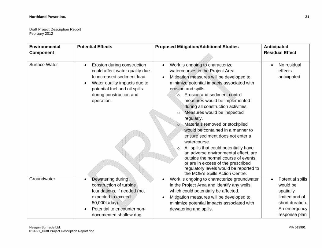
Surface Water Erosion during construction could affect water quality due to increased sediment load.
Water quality impacts due to potential fuel and oil spills during construction and operation.
Work is ongoing to characterize watercourses in the Project Area.
Mitigation measures will be developed to minimize potential impacts associated with erosion and spills.
o Erosion and sediment control measures would be implemented during all construction activities.
o Measures would be inspected regularly.
o Materials removed or stockpiled would be contained in a manner to ensure sediment does not enter a watercourse.
o All spills that could potentially have an adverse environmental effect, are outside the normal course of events, or are in excess of the prescribed regulatory levels would be reported to the MOE’s Spills Action Centre.
No residual effects anticipated
Groundwater Dewatering during construction of turbine foundations, if needed (not expected to exceed 50,000L/day).
Potential to encounter non-documented shallow dug
Work is ongoing to characterize groundwater in the Project Area and identify any wells which could potentially be affected.
Mitigation measures will be developed to minimize potential impacts associated with dewatering and spills.
Potential spills would be spatially limited and of short duration. An emergency response plan
Neegan Burnside Ltd. PIA 019991 019991_Draft Project Description Report.doc

Northland Power Inc. 22 Draft Project Description Report February 2012
Environmental Component
Potential Effects Proposed Mitigation/Additional Studies Anticipated
Residual Effect
wells during construction. Water quality impacts due to
potential fuel and oil spills during construction and operation.
will address spills.
No residual effects anticipated
Soils Soil compaction from
construction equipment. Loss of soils due to erosion
during construction. Soil quality impacts due to
potential fuel and oil spills during construction and operation.
Soils compacted in temporary construction areas will be rehabilitated as soon as possible after construction.
Soils compacted as a result of ongoing operations will be rehabilitated in accordance with an approved decommissioning plan.
Mitigation measures will be developed to minimize potential impacts associated with erosion and spills.
No residual effects anticipated
Aquatic Species and Aquatic Habitat
Potential impacts to fish habitat due to the installation of culverts along access roads during construction activities.
Potential sedimentation during construction.
Work is ongoing to characterize watercourses in the Project Area.
Detailed fish habitat assessments will be undertaken in areas where culverts are proposed.
Permits will be obtained from the Conservation Authority and/or Department of Fisheries and Oceans, as required for all culverts or other infrastructure within watercourse or within the Conservation Authority Regulation Limit. Appropriate DFO
No residual effects anticipated
Neegan Burnside Ltd. PIA 019991 019991_Draft Project Description Report.doc
Northland Power Inc. 23 Draft Project Description Report February 2012
Environmental Component
Potential Effects Proposed Mitigation/Additional Studies Anticipated Residual Effect
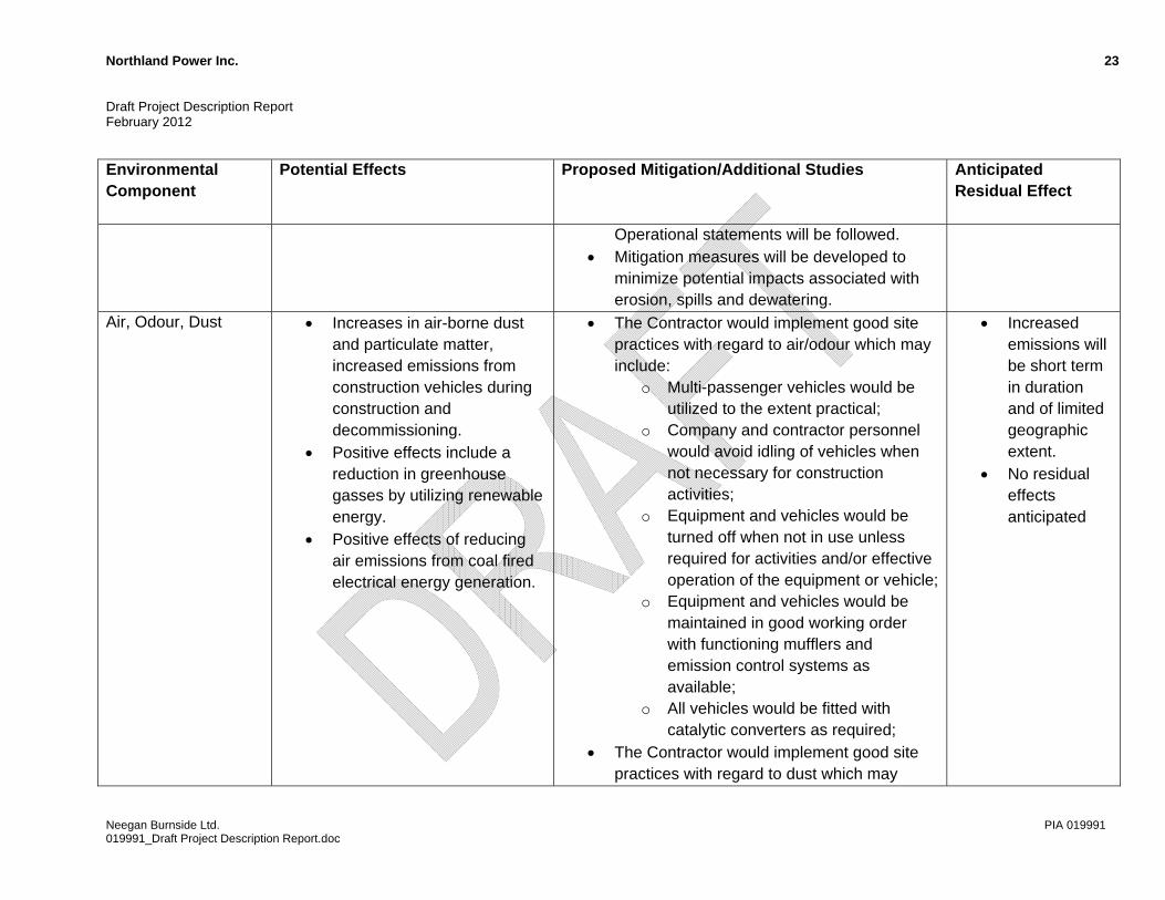
Operational statements will be followed. Mitigation measures will be developed to
minimize potential impacts associated with erosion, spills and dewatering.
Air, Odour, Dust Increases in air-borne dust and particulate matter, increased emissions from construction vehicles during construction and decommissioning.
Positive effects include a reduction in greenhouse gasses by utilizing renewable energy.
Positive effects of reducing air emissions from coal fired electrical energy generation.
The Contractor would implement good site practices with regard to air/odour which may include:
o Multi-passenger vehicles would be utilized to the extent practical;
o Company and contractor personnel would avoid idling of vehicles when not necessary for construction activities;
o Equipment and vehicles would be turned off when not in use unless required for activities and/or effective operation of the equipment or vehicle;
o Equipment and vehicles would be maintained in good working order with functioning mufflers and emission control systems as available;
o All vehicles would be fitted with catalytic converters as required;
The Contractor would implement good site practices with regard to dust which may
Increased emissions will be short term in duration and of limited geographic extent.
No residual effects anticipated
Neegan Burnside Ltd. PIA 019991 019991_Draft Project Description Report.doc
Northland Power Inc. 24 Draft Project Description Report February 2012
Environmental Component
Potential Effects Proposed Mitigation/Additional Studies Anticipated Residual Effect
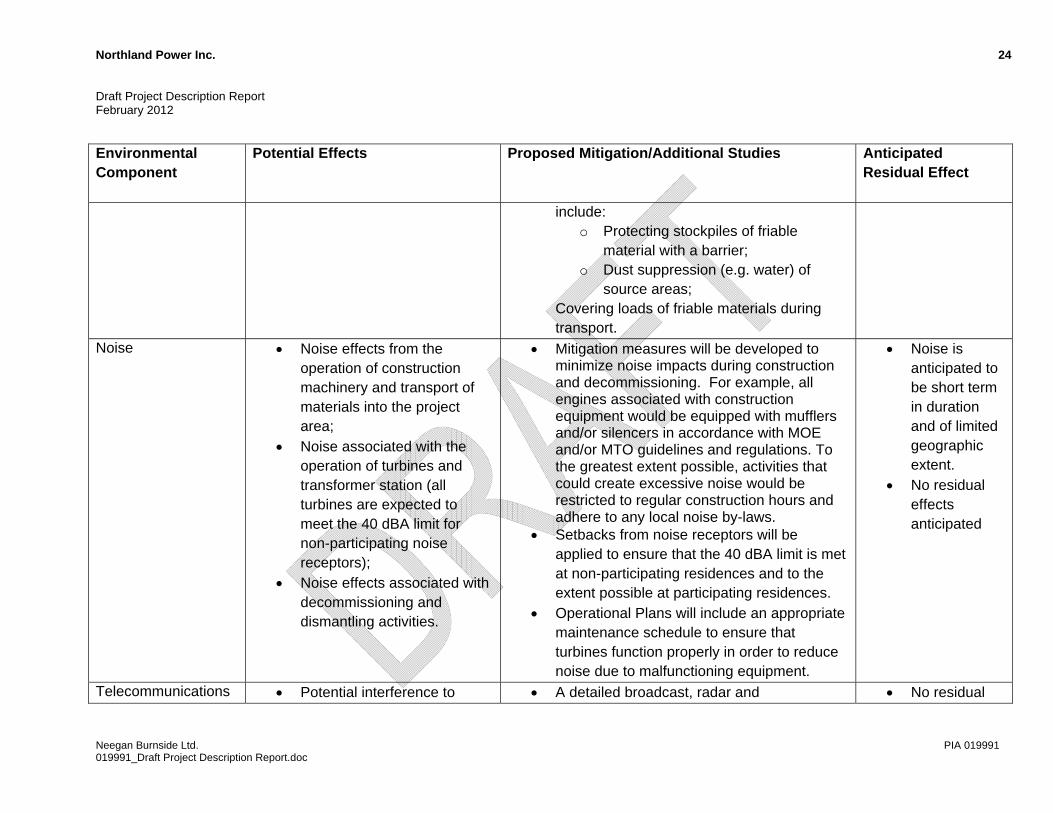
include: o Protecting stockpiles of friable
material with a barrier; o Dust suppression (e.g. water) of
source areas; Covering loads of friable materials during transport.
Noise Noise effects from the operation of construction machinery and transport of materials into the project area;
Noise associated with the operation of turbines and transformer station (all turbines are expected to meet the 40 dBA limit for non-participating noise receptors);
Noise effects associated with decommissioning and dismantling activities.
Mitigation measures will be developed to minimize noise impacts during construction and decommissioning. For example, all engines associated with construction equipment would be equipped with mufflers and/or silencers in accordance with MOE and/or MTO guidelines and regulations. To the greatest extent possible, activities that could create excessive noise would be restricted to regular construction hours and adhere to any local noise by-laws.
Setbacks from noise receptors will be applied to ensure that the 40 dBA limit is met at non-participating residences and to the extent possible at participating residences.
Operational Plans will include an appropriate maintenance schedule to ensure that turbines function properly in order to reduce noise due to malfunctioning equipment.
Noise is anticipated to be short term in duration and of limited geographic extent.
No residual effects anticipated
Telecommunications Potential interference to A detailed broadcast, radar and No residual
Neegan Burnside Ltd. PIA 019991 019991_Draft Project Description Report.doc
Northland Power Inc. 25 Draft Project Description Report February 2012
Environmental Component
Potential Effects Proposed Mitigation/Additional Studies Anticipated
Residual Effect
communication systems, including radar, cellular and broadcasting systems.
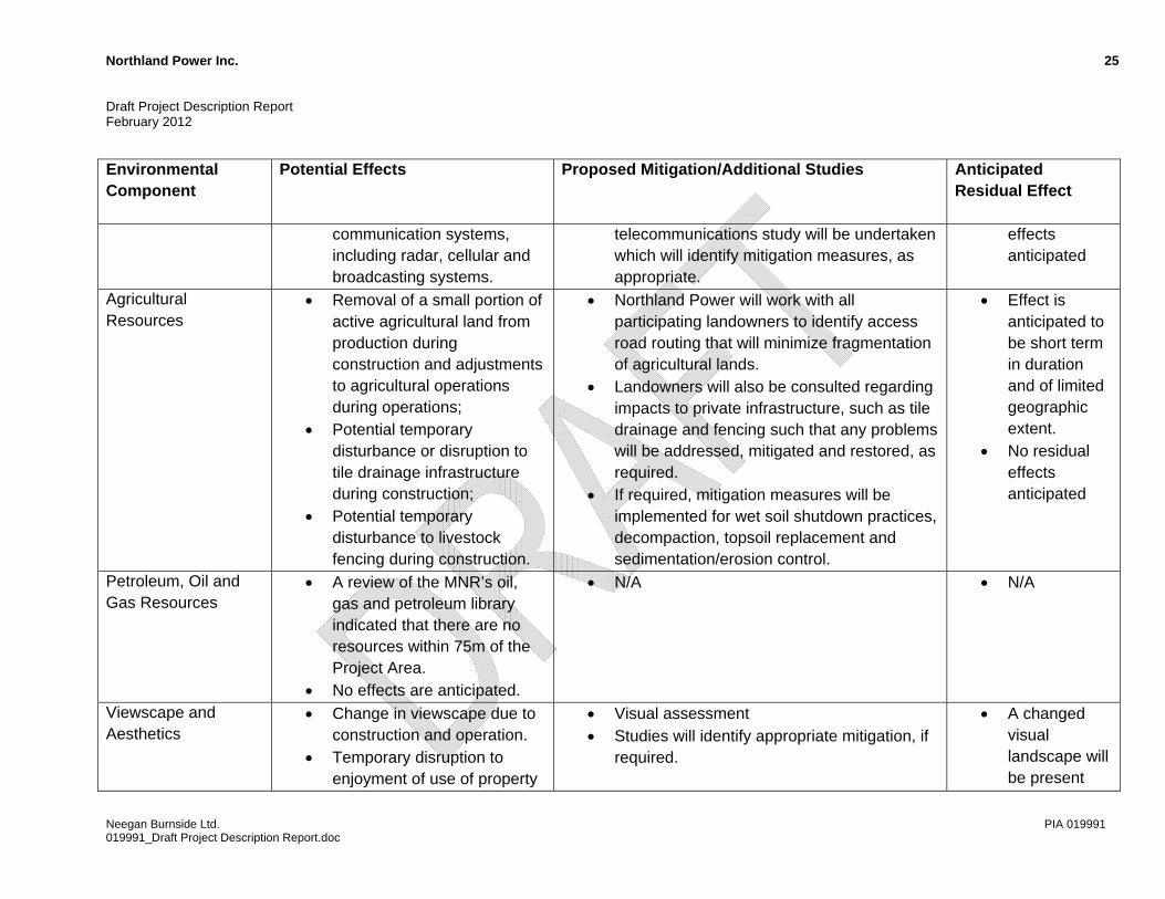
telecommunications study will be undertaken which will identify mitigation measures, as appropriate.
effects anticipated
Agricultural Resources
Removal of a small portion of active agricultural land from production during construction and adjustments to agricultural operations during operations;
Potential temporary disturbance or disruption to tile drainage infrastructure during construction;
Potential temporary disturbance to livestock fencing during construction.
Northland Power will work with all participating landowners to identify access road routing that will minimize fragmentation of agricultural lands.
Landowners will also be consulted regarding impacts to private infrastructure, such as tile drainage and fencing such that any problems will be addressed, mitigated and restored, as required.
If required, mitigation measures will be implemented for wet soil shutdown practices, decompaction, topsoil replacement and sedimentation/erosion control.
Effect is anticipated to be short term in duration and of limited geographic extent.
No residual effects anticipated
Petroleum, Oil and Gas Resources
A review of the MNR’s oil, gas and petroleum library indicated that there are no resources within 75m of the Project Area.
No effects are anticipated.
N/A N/A
Viewscape and Aesthetics
Change in viewscape due to construction and operation.
Temporary disruption to enjoyment of use of property
Visual assessment Studies will identify appropriate mitigation, if
required.
A changed visual landscape will be present
Neegan Burnside Ltd. PIA 019991 019991_Draft Project Description Report.doc

Northland Power Inc. 26 Draft Project Description Report February 2012
Environmental Component
Potential Effects Proposed Mitigation/Additional Studies Anticipated
Residual Effect
due to short term effects of dust, noise or traffic.
throughout the life of the project
Economy/Real Estate Values
Perceived effects on adjacent property values during construction and operation.
Positive impacts to local economy associated with local labour and equipment procurement during construction and operation.
Ongoing consultation will be maintained with the public and adjacent landowners to identify concerns and resolve significant issues.
Northland Power would make all reasonable efforts, to the extent possible, to source required services and materials from local suppliers where these items are available in sufficient quantity and quality and at competitive prices.
No residual effects anticipated
Provincial and Local Infrastructure
Temporary pressure on local services and inconvenience to local residents during construction.
Traffic delays on municipal and provincial roads due to construction activities within the ROWs and as a result of construction-related traffic (i.e. movement of heavy equipment and turbine components);
Damage to roads as a result of the movement of heavy
Traffic Management Plans will be developed to manage the delivery of equipment and large machinery to minimize local traffic disruptions to the extent possible.
A Road Condition Survey will be conducted. Any damage to local or provincial infrastructure as a result of construction or decommissioning activities will be repaired as quickly as possible.
Consultation will take place with the MTO and municipalities regarding the need to upgrade or widen any roads in order to allow for the delivery of equipment.
Any upgrades and/or subsequent
Effects are anticipated to be short term and of limited geographic extent.
No residual effects anticipated
Neegan Burnside Ltd. PIA 019991 019991_Draft Project Description Report.doc
Northland Power Inc. 27 Draft Project Description Report February 2012
Environmental Component
Potential Effects Proposed Mitigation/Additional Studies Anticipated Residual Effect
equipment and turbine components during construction.
rehabilitation and maintenance/repair will be negotiated with the appropriate authorities.
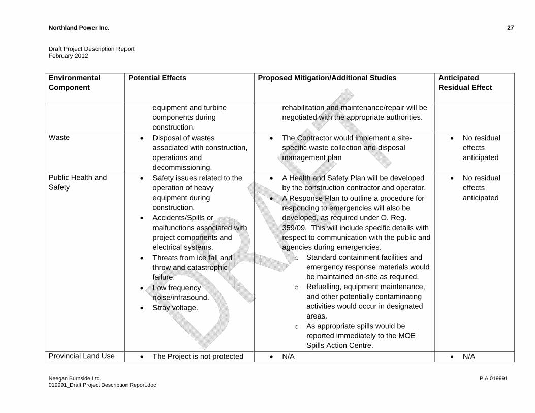
Waste Disposal of wastes associated with construction, operations and decommissioning.
The Contractor would implement a site-specific waste collection and disposal management plan
No residual effects anticipated
Public Health and Safety
Safety issues related to the operation of heavy equipment during construction.
Accidents/Spills or malfunctions associated with project components and electrical systems.
Threats from ice fall and throw and catastrophic failure.
Low frequency noise/infrasound.
Stray voltage.
A Health and Safety Plan will be developed by the construction contractor and operator.
A Response Plan to outline a procedure for responding to emergencies will also be developed, as required under O. Reg. 359/09. This will include specific details with respect to communication with the public and agencies during emergencies.
o Standard containment facilities and emergency response materials would be maintained on-site as required.
o Refuelling, equipment maintenance, and other potentially contaminating activities would occur in designated areas.
o As appropriate spills would be reported immediately to the MOE Spills Action Centre.
No residual effects anticipated
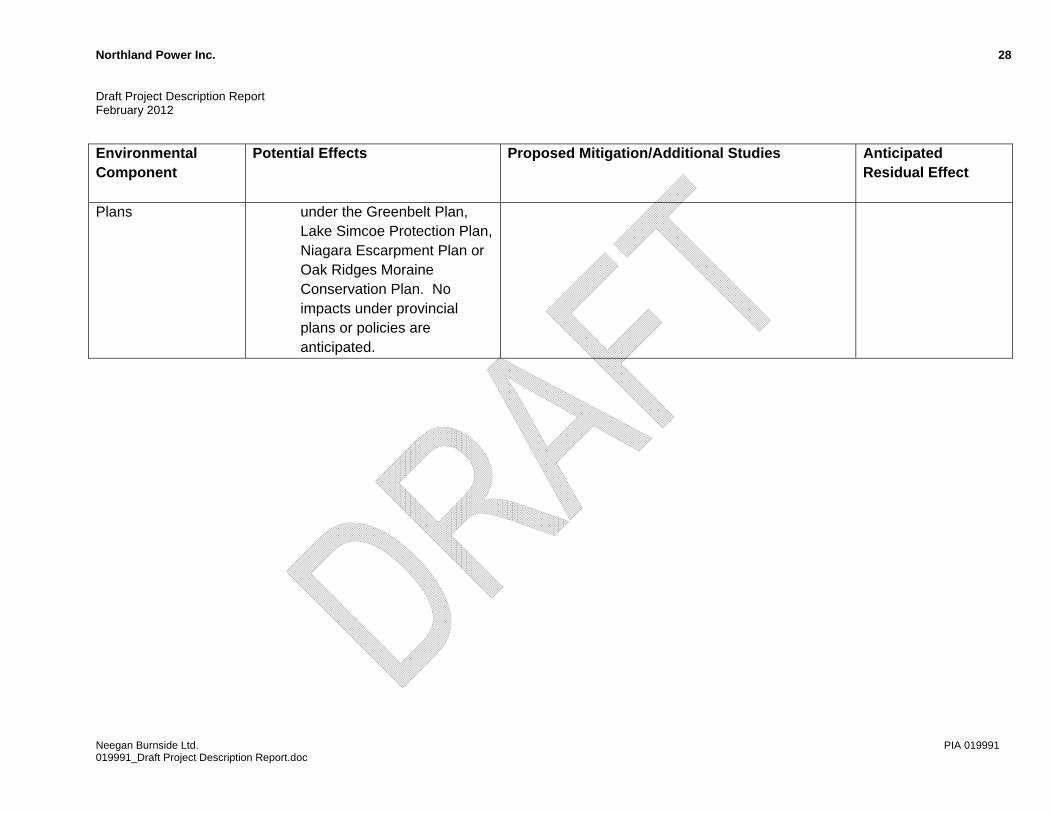
Provincial Land Use The Project is not protected N/A N/A
Neegan Burnside Ltd. PIA 019991 019991_Draft Project Description Report.doc
Northland Power Inc. 28 Draft Project Description Report February 2012
Neegan Burnside Ltd. PIA 019991 019991_Draft Project Description Report.doc
Environmental Component
Potential Effects Proposed Mitigation/Additional Studies Anticipated Residual Effect
Plans under the Greenbelt Plan, Lake Simcoe Protection Plan, Niagara Escarpment Plan or Oak Ridges Moraine Conservation Plan. No impacts under provincial plans or policies are anticipated.
Northland Power Inc. 29 Draft Project Description Report February 2012
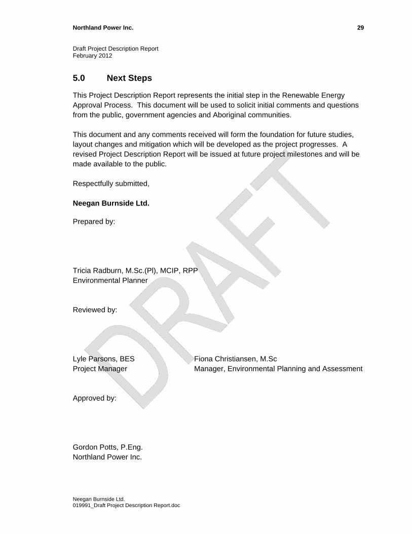
5.0 Next Steps
This Project Description Report represents the initial step in the Renewable Energy Approval Process. This document will be used to solicit initial comments and questions from the public, government agencies and Aboriginal communities. This document and any comments received will form the foundation for future studies, layout changes and mitigation which will be developed as the project progresses. A revised Project Description Report will be issued at future project milestones and will be made available to the public. Respectfully submitted, Neegan Burnside Ltd. Prepared by: Tricia Radburn, M.Sc.(Pl), MCIP, RPP Environmental Planner Reviewed by: Lyle Parsons, BES Fiona Christiansen, M.Sc Project Manager Manager, Environmental Planning and Assessment Approved by: Gordon Potts, P.Eng. Northland Power Inc.
Neegan Burnside Ltd. 019991_Draft Project Description Report.doc
Appendix A
Figures
Prepared Checked Figure Number
Scale Projec t
L. Parsons
PIA0199911
Path:
\\192
.168.7
.3\gis
\Proje
ct\P J
obs\P
I Job
s\PIA0
1999
1\Map
\Cart
o\Proj
ect D
escri
ption
Rep
ort\01
9991
_PDR
_Figu
re_1.m
xd
P. Stubber t
o1:250,000
Po ten t i a l Ov e rheadTrans m is s ion L i neFrom Tr ans fo r mer S ta t i on to Ex i s t i ng L i ne
! !
Study Ar ea Bounda r y Ex i s t i ng Trans m is s ion L i ne! !
0 2.5 5 7.5 10 12.5
Kilometers
q
q
q
q
q
q
q
!!
!!
!!
!!
!!
!!
!!
!!
!!
!!
!!
!!
!!
!!
!!
!!
!!
!!
!!
!
!
!
!
!
!!
!!
!!
!!
!!
!!
!!
!!
!
!
!
!
!
!
!
!
!
!
!
!
OP23
OP81
OP4OP21
OP84
OP83
OP83
OP4
OP8
N o r t hM id d l e s e x
C e n t r a lH u r o n
H u r o nE a s t
B l u e w a t e r
S o u t hH u r o n
L u c a nB i d d u l p h
We s tP e r t h
P e r t hS o u t h
C o u n t yo f H u r o n
Transmission Line (North Option)
Transmission Line (South Alternate Opt ion)Ar ea o f
Wi nd
T ur b
i ne Lo
catio
ns
La
ke
H
ur
on
Grand Bend Wind FarmGrand Bend Wind Limited Partnership
Project Locationc/o Nortland Power Inc.

Prepared Checked Figure Number
Scale Projec t
L. Parsons
PIA0199912
Path:
\\192
.168.7
.3\gis
\Proje
ct\P J
obs\P
I Job
s\PIA0
1999
1\Map
\Cart
o\Proj
ect D
escri
ption
Rep
ort\01
9991
_PDR
_Figu
re_2.m
xd
P. Stubber t
o1:100,000
Po ten t i a l Ov e rheadTrans m is s ion L i neFrom Tr ans fo r mer S ta t i on to Ex i s t i ng L i ne
! !
Study Ar ea Bounda r y
!!
!!
!!
!!
!!
!!
!!
!!
!!
!!
!!
!!
!!
!!
!!
!!
!!
!!
!!
!!
!!
!!
!!
!!
!!
!!
!!
!!
!!
!!
!!
!!
!!
!!
!!
!!
!!
!!
!!
!!
!!
!!
!!
!!
!!
!
!!
!
!
!
!
!
!
!
!
!
!
!
!
!
!
!
!
!!
!!
!!
!!
!!
!
!
!!
!!
!!
¬ÂǬÂÇ
¬ÂǬÂǬÂǬÂÇ
¬ÂǬÂÇ
¬ÂǬÂǬÂǬÂǬÂǬÂÇ
¬ÂÇ ¬ÂÇ
¬ÂÇ ¬ÂǬÂǬÂÇ
¬ÂÇ ¬ÂÇ ¬ÂǬÂÇ ¬ÂǬÂÇ
¬ÂÇ
¬ÂÇ
¬ÂÇ
¬ÂǬÂǬÂÇ ¬ÂǬÂǬÂǬÂÇ
¬ÂÇ
¬ÂǬÂÇ ¬ÂÇ
¬ÂÇ ¬ÂǬÂǬÂÇ
¬ÂÇ
¬ÂÇ
¬ÂÇ
¬ÂÇ
La
ke
H
ur
on
OP21
Blake
Zurich
Dashwood
Drysdale
Grand Bend
St. Jo seph
Dewey Po int
Mun. o f Bluewater
Mun. o f South Huron
Figure 2i
Figure 2f
Figure 2c
Figure 2g
Figure 2eFigure 2d
Figure 2h
Figure
2b
F igure 2a
0 1 2 3 4 5
Kilometers
Ex i s t i ng Trans m is s ion L i ne! !
Wi nd Tu rb i ne Loca t i on(Ye l l ow Das hed Li nerep res en ts 56m B l ade Rad i us)¬ÂÇ
Note : Re fe renc e F i gu res 2a to 2 i f o r mo r e de ta i l .
Data
Sour
ces:
Natur
al Re
sourc
es C
anad
a, Mi
nistry
of N
atural
Res
ource
s
Grand Bend Wind Farm
Grand Bend Wind Limited Partnership
Project Location Key Map
c/o Nortland Power Inc.
Prepared Checked Figure Number
Scale Projec t
L. Parsons
PIA0199912a
Grand Bend Wind Farm
Grand Bend Wind Limited Partnership
Project Layout
Path:
\\192
.168.7
.3\gis
\Proje
ct\P J
obs\P
I Job
s\PIA0
1999
1\Map
\Cart
o\Proj
ect D
escri
ption
Rep
ort\01
9991
_PDR
_Figu
re_2a
_2i.m
xd
P. Stubber t
¬ÂǬÂÇ
Lot 21E. of Lake Rd.
Lot 29Southern Bdry.
Lot 27Northern Bdry.
Lot 30Southern Bdry.
Lot 30Northern Bdry.
Lot 26Southern Bdry.
Lot 20E. of Lake Rd.
Lot 28Southern Bdry.
Lot 23E. of Lake Rd.
Lot 28Northern Bdry.
Lot 27Southern Bdry.
Lot 22E. of Lake Rd.
Lot 29Northern Bdry.
Lot 21W. of Lake Rd.
Kippen Road
Laporte Street
Shangrila Road
Staffa Road
Crest Road
Durand Huronview Road
Blackbush Line
T-02
T-01
o0 500 1,000
Meters
!!
!!!!
!!!!!!!!
!!! !!!
!!!!!!
!!
!
!!! !!!!
!
!! !
!!!!
!
!
!
!
Reference Map(Study AreaShown in Grey)
1:20,000
Wi nd Tu rb i ne Loca t i on(s ym bo l does no t r ep res en t b l ade d iam e te r )¬ÂÇ
Po ten t i a l Ov e rheadTrans m is s ion L i neFrom Tr ans fo r mer S ta t i on to Ex i s t i ng L i ne
! !
Study Ar ea Bounda r y
Note: 1. See Figure 2 for comp lete map index . 2. Each mapped area is 3km x 3km.
Data
Sourc
es: H
uron C
ounty
(Imag
ery da
ted 20
06), M
inistr
y of N
atural
Res
ource
s
c/o Nortland Power Inc.
3. Turbine number ing on this map will appear different than in maps /documents issued pr io r to 27 January, 2012.
Prepared Checked Figure Number
Scale Projec t
L. Parsons
PIA0199912b
Grand Bend Wind Farm
Grand Bend Wind Limited Partnership
Project Layout
Path:
\\192
.168.7
.3\gis
\Proje
ct\P J
obs\P
I Job
s\PIA0
1999
1\Map
\Cart
o\Proj
ect D
escri
ption
Rep
ort\01
9991
_PDR
_Figu
re_2a
_2i.m
xd
P. Stubber t
¬ÂÇ
¬ÂÇ
¬ÂÇ
¬ÂÇ
¬ÂÇ
¬ÂÇ
¬ÂÇ
¬ÂÇ
¬ÂÇ
¬ÂǬÂÇ
¬ÂÇ
¬ÂÇ
Lot 7E. of Lake Rd.
Lot 8E. of Lake Rd.
Lot 6E. of Lake Rd.Lot 24Con 15
Lot 5E. of Lake Rd.
Lot 26Con 15
Lot 3E. of Lake Rd.
Lot 26Con 14
Lot 22Con 15
Lot 28Con 14
Lot 4E. of Lake Rd.
Lot 27Con 14
Lot 9E. of Lake Rd.
Lot 27Con 15
Lot 28Con 15
Lot 25Con 15
Lot 23Con 15
Ducharme Beach Road
Northridge Road
Danceland Road
Denomme Street
Church Lane
Sunset Cove
Danceland Road
Blackbush Line
Blackbush LineT-04
T-05
T-06
T-09
T-07
T-10
T-11
T-12
T-13
T-15T-14
T-08
T-16
o0 500 1,000
Meters
!!
!!!!
!!!!!!!!
!!! !!!
!!!!!!
!!
!
!!! !!!!
!
!! !
!!!!
!
!
!
!
Reference Map(Study AreaShown in Grey)
1:20,000
Wi nd Tu rb i ne Loca t i on(s ym bo l does no t r ep res en t b l ade d iam e te r )¬ÂÇ
Po ten t i a l Ov e rheadTrans m is s ion L i neFrom Tr ans fo r mer S ta t i on to Ex i s t i ng L i ne
! !
Study Ar ea Bounda r y
Note: 1. See Figure 2 for comp lete map index . 2. Each mapped area is 3km x 3km.
Data
Sourc
es: H
uron C
ounty
(Imag
ery da
ted 20
06), M
inistr
y of N
atural
Res
ource
s
c/o Nortland Power Inc.
3. Turbine number ing on this map will appear different than in maps /documents issued pr io r to 27 January, 2012.
Prepared Checked Figure Number
Scale Projec t
L. Parsons
PIA0199912c
Grand Bend Wind Farm
Grand Bend Wind Limited Partnership
Project Layout
Path:
\\192
.168.7
.3\gis
\Proje
ct\P J
obs\P
I Job
s\PIA0
1999
1\Map
\Cart
o\Proj
ect D
escri
ption
Rep
ort\01
9991
_PDR
_Figu
re_2a
_2i.m
xd
P. Stubber t
¬ÂÇ
Lot 22Con 14
Lot 22Con 13
Lot 21Con 14
Lot 23Con 14
Lot 27Con 13
Lot 26Con 12
Lot 24Con 12
Lot 25Con 12
Lot 23Con 13
Lot 26Con 13
Lot 24Con 14
Lot 23Con 12
Lot 24Con 13
Lot 25Con 13
Lot 21Con 13
Lot 27Con 11
Lot 22Con 12
Lot 21Con 12
Lot 27Con 12
Zurich Hensall Road
Bronson Line
Zurich Hensall Road
Danceland Road
Danceland Road
Bronson Line
T-03
o0 500 1,000
Meters
!!
!!!!
!!!!!!!!
!!! !!!
!!!!!!
!!
!
!!! !!!!
!
!! !
!!!!
!
!
!
!
Reference Map(Study AreaShown in Grey)
1:20,000
Wi nd Tu rb i ne Loca t i on(s ym bo l does no t r ep res en t b l ade d iam e te r )¬ÂÇ
Po ten t i a l Ov e rheadTrans m is s ion L i neFrom Tr ans fo r mer S ta t i on to Ex i s t i ng L i ne
! !
Study Ar ea Bounda r y
Note: 1. See Figure 2 for comp lete map index . 2. Each mapped area is 3km x 3km.
Data
Sourc
es: H
uron C
ounty
(Imag
ery da
ted 20
06), M
inistr
y of N
atural
Res
ource
s
c/o Nortland Power Inc.
3. Turbine number ing on this map will appear different than in maps /documents issued pr io r to 27 January, 2012.
Prepared Checked Figure Number
Scale Projec t
L. Parsons
PIA0199912d
Grand Bend Wind Farm
Grand Bend Wind Limited Partnership
Project Layout
Path:
\\192
.168.7
.3\gis
\Proje
ct\P J
obs\P
I Job
s\PIA0
1999
1\Map
\Cart
o\Proj
ect D
escri
ption
Rep
ort\01
9991
_PDR
_Figu
re_2a
_2i.m
xd
P. Stubber t
¬ÂÇ ¬ÂÇ
¬ÂǬÂÇ Lot 14
Con 15
Lot 19Con 15
Lot 15Con 15
Lot 21Con 15
Lot 20Con 15
Lot 18Con 15
Lot 17Con 15
Lot 10E. of Lake Rd.
Lot 14E. of Lake Rd.Lot 16Con 15
Lot 11E. of Lake Rd.
Lot 15E. of Lake Rd.
Lot 12E. of Lake Rd.
Lot 16E. of Lake Rd.
Lot 13E. of Lake Rd.
Zurich Hensall Road
Zurich Hensall Road
Zurich Hensall Road
Blackbush Line
Sara
ras R
oad
T-17 T-18
T-22
T-21
o0 500 1,000
Meters
!!
!!!!
!!!!!!!!
!!! !!!
!!!!!!
!!
!
!!! !!!!
!
!! !
!!!!
!
!
!
!
Reference Map(Study AreaShown in Grey)
1:20,000
Wi nd Tu rb i ne Loca t i on(s ym bo l does no t r ep res en t b l ade d iam e te r )¬ÂÇ
Po ten t i a l Ov e rheadTrans m is s ion L i neFrom Tr ans fo r mer S ta t i on to Ex i s t i ng L i ne
! !
Study Ar ea Bounda r y
Note: 1. See Figure 2 for comp lete map index . 2. Each mapped area is 3km x 3km.
Data
Sourc
es: H
uron C
ounty
(Imag
ery da
ted 20
06), M
inistr
y of N
atural
Res
ource
s
c/o Nortland Power Inc.
3. Turbine number ing on this map will appear different than in maps /documents issued pr io r to 27 January, 2012.
Prepared Checked Figure Number
Scale Projec t
L. Parsons
PIA0199912e
Grand Bend Wind Farm
Grand Bend Wind Limited Partnership
Project Layout
Path:
\\192
.168.7
.3\gis
\Proje
ct\P J
obs\P
I Job
s\PIA0
1999
1\Map
\Cart
o\Proj
ect D
escri
ption
Rep
ort\01
9991
_PDR
_Figu
re_2a
_2i.m
xd
P. Stubber t
!!
!!
!!
!!
!!
!!
!!
!!
!!
!!
!!
!!
!!
!!
!!
!!
!!
!!
!!
!!
!!
!!
!!
!!
!!
!!
!!
!
¬ÂÇ ¬ÂÇ
TransformerSta t ion
Parts S torageBui ld ing
Lot 19Con 13
Lot 16Con 12
Lot 18Con 12
Lot 19Con 12
Lot 18Con 14
Lot 20Con 12
Lot 20Con 13
Lot 13Con 12
Lot 17Con 13
Lot 17Con 12
Lot 18Con 13
Lot 19Con 14
Lot 14Con 12
Lot 14Con 14
Lot 14Con 13
Lot 15Con 12
Lot 15Con 13
Lot 17Con 14
Lot 20Con 14
Lot 16Con 13
Lot 16Con 14
Lot 15Con 14
Blackbush LineBlackbush Line
Bronson Line
Rodgerville Road
Zurich Hensall Road
Sararas Road
Bronson Line
T-19 T-20
o0 500 1,000
Meters
!!
!!!!
!!!!!!!!
!!! !!!
!!!!!!
!!
!
!!! !!!!
!
!! !
!!!!
!
!
!
!
Reference Map(Study AreaShown in Grey)
1:20,000
Wi nd Tu rb i ne Loca t i on(s ym bo l does no t r ep res en t b l ade d iam e te r )¬ÂÇ
Po ten t i a l Ov e rheadTrans m is s ion L i neFrom Tr ans fo r mer S ta t i on to Ex i s t i ng L i ne
! !
Study Ar ea Bounda r y
Note: 1. See Figure 2 for comp lete map index . 2. Each mapped area is 3km x 3km.
Data
Sourc
es: H
uron C
ounty
(Imag
ery da
ted 20
06), M
inistr
y of N
atural
Res
ource
s
c/o Nortland Power Inc.
3. Turbine number ing on this map will appear different than in maps /documents issued pr io r to 27 January, 2012.

Prepared Checked Figure Number
Scale Projec t
L. Parsons
PIA0199912f
Grand Bend Wind Farm
Grand Bend Wind Limited Partnership
Project Layout
Path:
\\192
.168.7
.3\gis
\Proje
ct\P J
obs\P
I Job
s\PIA0
1999
1\Map
\Cart
o\Proj
ect D
escri
ption
Rep
ort\01
9991
_PDR
_Figu
re_2a
_2i.m
xd
P. Stubber t
!!
!!
!!
!!
!!
!!
!!
!!
!!
!!
!!
!!
¬ÂÇ
¬ÂÇ
¬ÂÇ ¬ÂÇ
¬ÂÇ
¬ÂÇ
¬ÂÇ
¬ÂÇ
¬ÂÇ
Lot 12Con 15
Lot 11Con 16
Lot 13Con 15
Lot 9Con 15
Lot 10Con 16
Lot 10Con 15
Lot 11Con 15
Lot 9Con 16
Lot 8Con 16
Lot 22E. of Lake Rd. Lot 8Con 15
Lot 8Con 17Lot 23E. of Lake Rd. Lot 7
Con 16
Lot 21E. of Lake Rd.
Lot 18E. of Lake Rd.
Lot 19E. of Lake Rd.
Lot 20E. of Lake Rd.
Lot 17E. of Lake Rd.
Hendrick Road
Shipka Line
Pepper Road
T-23T-24 T-25
T-26
T-27
T-28
T-29
T-30
o0 500 1,000
Meters
!!
!!!!
!!!!!!!!
!!! !!!
!!!!!!
!!
!
!!! !!!!
!
!! !
!!!!
!
!
!
!
Reference Map(Study AreaShown in Grey)
1:20,000
Wi nd Tu rb i ne Loca t i on(s ym bo l does no t r ep res en t b l ade d iam e te r )¬ÂÇ
Po ten t i a l Ov e rheadTrans m is s ion L i neFrom Tr ans fo r mer S ta t i on to Ex i s t i ng L i ne
! !
Study Ar ea Bounda r y
Note: 1. See Figure 2 for comp lete map index . 2. Each mapped area is 3km x 3km.
Data
Sourc
es: H
uron C
ounty
(Imag
ery da
ted 20
06), M
inistr
y of N
atural
Res
ource
s
c/o Nortland Power Inc.
3. Turbine number ing on this map will appear different than in maps /documents issued pr io r to 27 January, 2012.
Prepared Checked Figure Number
Scale Projec t
L. Parsons
PIA0199912g
Grand Bend Wind Farm
Grand Bend Wind Limited Partnership
Project Layout
Path:
\\192
.168.7
.3\gis
\Proje
ct\P J
obs\P
I Job
s\PIA0
1999
1\Map
\Cart
o\Proj
ect D
escri
ption
Rep
ort\01
9991
_PDR
_Figu
re_2a
_2i.m
xd
P. Stubber t
!!
!!
!!
!!
!!
!!
!!
!!
!!
!!
!!
!!
!!
!!
!!
!
!!
!!
!!
¬ÂÇ
¬ÂÇ
¬ÂÇ
¬ÂÇ
¬ÂǬÂÇ
¬ÂÇ
¬ÂÇ
Trans
forme
r Stat
ion (A
lt.)
Parts
Stor
age
Build
ing (A
lt.)
Lot 31
W. of La
ke Rd.
Lot 28W. of Lake Rd.
Lot 30
W. of La
ke Rd.
Lot 32E. of Lake Rd.
Lot 29
W. of La
ke Rd.
Lot 36Southern Bdry.
Lot 26E. of Lake Rd.
Lot 30E. of Lake Rd.
Lot 27W. of Lake Rd.
Lot 32
W. of La
ke Rd.
Lot 29E. of Lake Rd.
Lot 26W. of Lake Rd.
Lot 27E. of Lake Rd.
Lot 31E. of Lake Rd.
Lot 28E. of Lake Rd.
Dashwood Road
Corbett Line
Schadeview Road
Dashwood Road
Turnbulls Road
T-32
T-34
T-37
T-38
T-39
T-40
T-36
o0 500 1,000
Meters
!!
!!!!
!!!!!!!!
!!! !!!
!!!!!!
!!
!
!!! !!!!
!
!! !
!!!!
!
!
!
!
Reference Map(Study AreaShown in Grey)
1:20,000
Wi nd Tu rb i ne Loca t i on(s ym bo l does no t r ep res en t b l ade d iam e te r )¬ÂÇ
Po ten t i a l Ov e rheadTrans m is s ion L i neFrom Tr ans fo r mer S ta t i on to Ex i s t i ng L i ne
! !
Study Ar ea Bounda r y
Note: 1. See Figure 2 for comp lete map index . 2. Each mapped area is 3km x 3km.
Data
Sourc
es: H
uron C
ounty
(Imag
ery da
ted 20
06), M
inistr
y of N
atural
Res
ource
s
c/o Nortland Power Inc.
3. Turbine number ing on this map will appear different than in maps /documents issued pr io r to 27 January, 2012.
Prepared Checked Figure Number
Scale Projec t
L. Parsons
PIA0199912h
Grand Bend Wind Farm
Grand Bend Wind Limited Partnership
Project Layout
Path:
\\192
.168.7
.3\gis
\Proje
ct\P J
obs\P
I Job
s\PIA0
1999
1\Map
\Cart
o\Proj
ect D
escri
ption
Rep
ort\01
9991
_PDR
_Figu
re_2a
_2i.m
xd
P. Stubber t
!!
!!
!!
!!
!!
!!
!!
!!
!!
!!
!!
!!
!!
!!
!!
!!
!!
!!
!!
!!
!!
!!
!!
!!
!!
!!
!!
!!
!!
!!
!!
!!
!!
!!
¬ÂÇ
¬ÂǬÂÇ
¬ÂÇ
¬ÂÇ
Lot 34Southern Bdry.
Lot 3Con 16
Lot 30Northern Bdry.
Lot 5Con 17
Lot 6Con 16
Lot 5Con 16
Lot 4Con 17
Lot 33Southern Bdry.
Lot 3Con 17
Lot 24E. of Lake Rd.
Lot 4Con 16
Lot 6Con 17
Lot 32Southern Bdry.
Lot 31Southern Bdry.
Lot 30Southern Bdry.
Alternate South Route
Shipka Line
Shipka Line
Dashwood Road
MacDonald Road
Shipka Line
Schadeview Road
Dashwood Road
T-31
T-33
T-35
o0 500 1,000
Meters
!!
!!!!
!!!!!!!!
!!! !!!
!!!!!!
!!
!
!!! !!!!
!
!! !
!!!!
!
!
!
!
Reference Map(Study AreaShown in Grey)
1:20,000
Wi nd Tu rb i ne Loca t i on(s ym bo l does no t r ep res en t b l ade d iam e te r )¬ÂÇ
Po ten t i a l Ov e rheadTrans m is s ion L i neFrom Tr ans fo r mer S ta t i on to Ex i s t i ng L i ne
! !
Study Ar ea Bounda r y
Note: 1. See Figure 2 for comp lete map index . 2. Each mapped area is 3km x 3km.
Data
Sourc
es: H
uron C
ounty
(Imag
ery da
ted 20
06), M
inistr
y of N
atural
Res
ource
s
c/o Nortland Power Inc.
3. Turbine number ing on this map will appear different than in maps /documents issued pr io r to 27 January, 2012.
Prepared Checked Figure Number
Scale Projec t
L. Parsons
PIA0199912 i
Grand Bend Wind Farm
Grand Bend Wind Limited Partnership
Project Layout
Path:
\\192
.168.7
.3\gis
\Proje
ct\P J
obs\P
I Job
s\PIA0
1999
1\Map
\Cart
o\Proj
ect D
escri
ption
Rep
ort\01
9991
_PDR
_Figu
re_2a
_2i.m
xd
P. Stubber t
¬ÂÇ
¬ÂÇ ¬ÂÇ
¬ÂǬÂÇ
¬ÂÇ
¬ÂÇ
¬ÂÇ
"
"
"
"
"
"
"
"
"
"
"
"
"
"
"
"
"
"
"
"
"
"
"
"
"
"
"
"
"
"
"
"
"
"
"
"
"
"
"
"
"
"
"
"
"
"
"
"
"
"
"
"
"
"
"
"
"
"
"
"
"
"
"
"
"
"
"
"
"
"
"
"
"
"
"
"
"
"
"
"
"
"
"
"
"
"
"
"
"
"
"
"
"
"
"
"
"
"
"
"
"
"
"
"
"
"
"
"
"
"
"
"
"
"
"
"
"
"
"
"
"
"
"
"
"
"
"
"
"
"
"
"
"
"
"
"
"
"
"
"
"
"
"
"
"
"
"
"
"
"
"
"
"
"
"
"
"
"
"
"
"
"
"
"
"
"
"
Trans
forme
r Stat
ion (A
lt.)
Lot 36Northern Bdry.
Lot 4Con A
Lot 7Con ALot 5E. of Lake Rd. Lot 6Con A
Lot 7
W. of La
ke Rd.
Lot 20Con 19
Lot 22Con 19
Lot 5Con A
Lot 38Northern Bdry.
Lot 7Con B
Lot 5Con B
Lot 19Con 19
Lot 6Con B
Lot 37Northern Bdry.
Lot 23Con 19
Lot 38Northern Bdry.
Lot 6E. of Lake Rd.
Lot 21Con 19
Lot 2Con A
Lot 3Con A
Lot 7E. of Lake Rd.
Lot 4E. of Lake Rd.
Lot 4Con B
Existing Transmission Line
Existing Pipeline
Dashwood RoadCorbett Line
Gore Road
B Line
T-41
T-42 T-43
T-45T-46
T-47
T-48
T-44
o0 500 1,000
Meters
!!
!!!!
!!!!!!!!
!!! !!!
!!!!!!
!!
!
!!! !!!!
!
!! !
!!!!
!
!
!
!
Reference Map(Study AreaShown in Grey)
1:20,000
Wi nd Tu rb i ne Loca t i on(s ym bo l does no t r ep res en t b l ade d iam e te r )¬ÂÇ
Po ten t i a l Ov e rheadTrans m is s ion L i neFrom Tr ans fo r mer S ta t i on to Ex i s t i ng L i ne
! !
Study Ar ea Bounda r y
Note: 1. See Figure 2 for comp lete map index . 2. Each mapped area is 3km x 3km.
Data
Sourc
es: H
uron C
ounty
(Imag
ery da
ted 20
06), M
inistr
y of N
atural
Res
ource
s
c/o Nortland Power Inc.
3. Turbine number ing on this map will appear different than in maps /documents issued pr io r to 27 January, 2012.
Appendix B
Turbine Specifications
Turning moderate wind into maximum results
SWT - 2.3 - 113www.siemens.com/energy
Answers for energy.
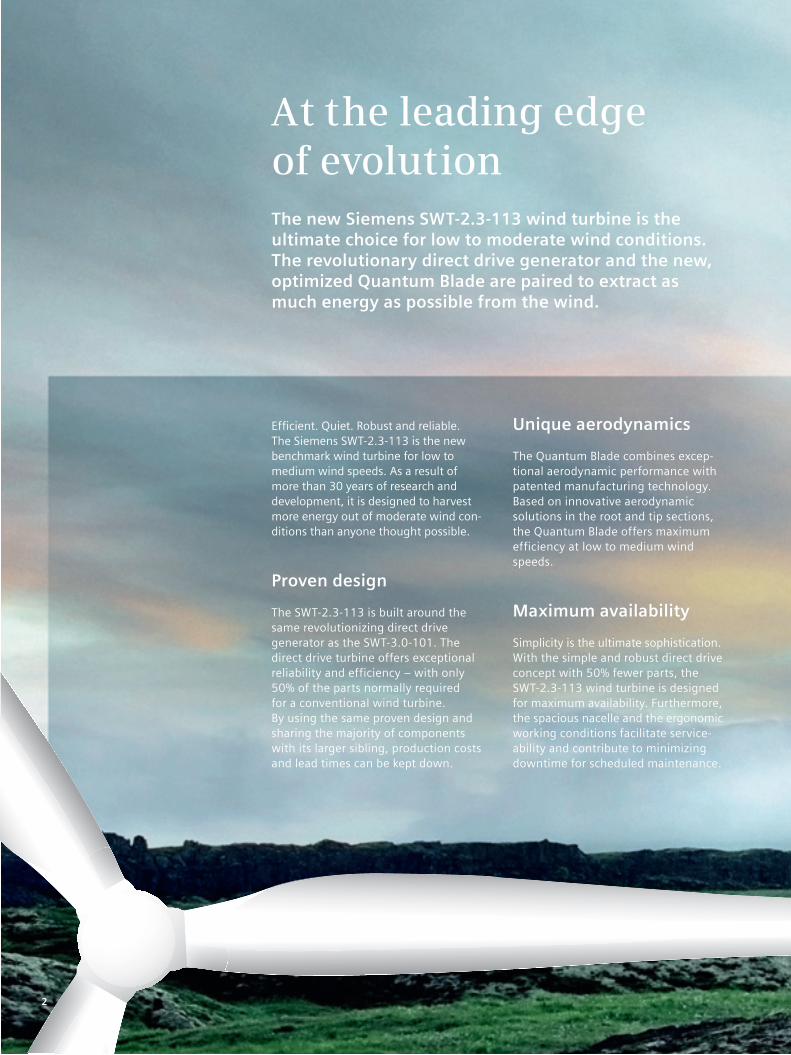
At the leading edgeof evolutionThe new Siemens SWT-2.3-113 wind turbine is the ultimate choice for low to moderate wind conditions. The revolutionary direct drive generator and the new, optimized Quantum Blade are paired to extract as much energy as possible from the wind.
Efficient. Quiet. Robust and reliable. The Siemens SWT-2.3-113 is the new benchmark wind turbine for low to medium wind speeds. As a result of more than 30 years of research and development, it is designed to harvest more energy out of moderate wind con-ditions than anyone thought possible.
Proven design
The SWT-2.3-113 is built around the same revolutionizing direct drive generator as the SWT-3.0-101. The direct drive turbine offers exceptional reliability and efficiency – with only 50% of the parts normally required for a conventional wind turbine. By using the same proven design and sharing the majority of components with its larger sibling, production costs and lead times can be kept down.
Unique aerodynamics
The Quantum Blade combines excep-tional aerodynamic performance with patented manufacturing technology. Based on innovative aerodynamic solutions in the root and tip sections, the Quantum Blade offers maximum efficiency at low to medium wind speeds.
Maximum availability
Simplicity is the ultimate sophistication.With the simple and robust direct drive concept with 50% fewer parts, the SWT-2.3-113 wind turbine is designed for maximum availability. Furthermore, the spacious nacelle and the ergonomic working conditions facilitate service-ability and contribute to minimizing downtime for scheduled maintenance.
2

You cannot change the wind. It may be strong, it may be light. This leaves it up to us to extract as much energy as we can from it.
Anne Schannong Vinther, Quality Engineer
3
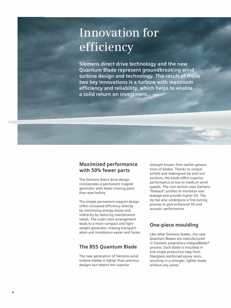
Innovation for efficiencySiemens direct drive technology and the new Quantum Blade represent groundbreaking wind turbine design and technology. The result of these two key innovations is a turbine with maximum efficiency and reliability, which helps to enable a solid return on investment.
Maximized performance with 50% fewer parts
The Siemens direct drive design incorporates a permanent magnet generator with fewer moving parts than ever before.
The simple permanent magnet design offers increased efficiency directly by minimizing energy losses and indirectly by reducing maintenance needs. The outer rotor arrangement leads to a more compact and light-weight generator, making transport-ation and installation easier and faster.
The B55 Quantum Blade
The new generation of Siemens wind turbine blades is lighter than previousdesigns but retains the superior
strength known from earlier genera-tions of blades. Thanks to unique airfoils and redesigned tip and root sections, the blade offers superior performance at low to medium wind speeds. The root section uses Siemens “flatback” profiles to minimize root leakage and provide higher lift. The tip has also undergone a fine-tuning process to give enhanced lift and acoustic performance.
One-piece moulding
Like other Siemens blades, the new Quantum Blades are manufactured in Siemens proprietary IntegralBlade® process. Each blade is moulded in one single production step from fiberglass-reinforced epoxy resin, resulting in a stronger, lighter blade without any joints.
4

Lower noise
With a low 105 dB noise level, the SWT-2.3-113 is one of the quietest wind turbines on the market. As a result, this turbine type has anextremely high ratio of energy out-put per noise affected area, resulting in fewer disturbances to people and wildlife.
Superior grid compliance
The Siemens NetConverter® is designed for maximum flexibility in the turbine’s response to voltage and frequency variations, fault ride-through capability and output adjustment. The advanced wind farm control system provides state-of-the-art fleet management.
5
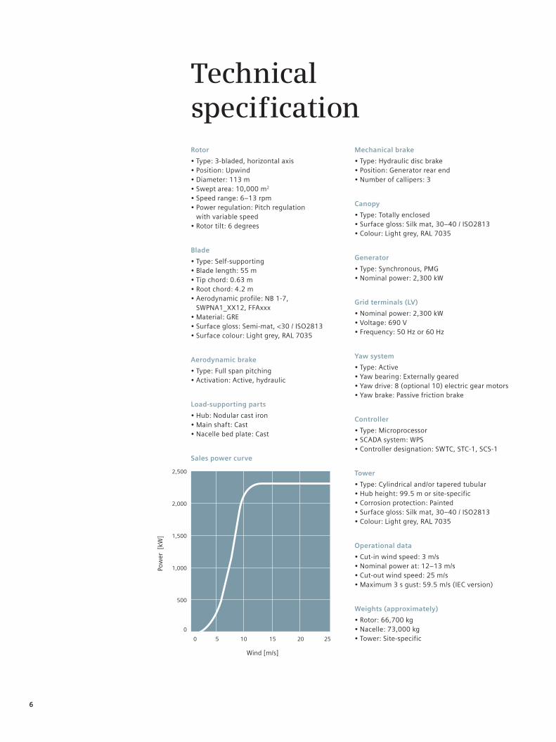
TechnicalspecificationRotor
• Type: 3-bladed, horizontal axis• Position: Upwind• Diameter: 113 m• Swept area: 10,000 m2
• Speed range: 6–13 rpm • Power regulation: Pitch regulation with variable speed• Rotor tilt: 6 degrees
Blade
• Type: Self-supporting• Blade length: 55 m• Tip chord: 0.63 m• Root chord: 4.2 m• Aerodynamic profile: NB 1-7,
SWPNA1_XX12, FFAxxx• Material: GRE• Surface gloss: Semi-mat, <30 / ISO2813• Surface colour: Light grey, RAL 7035
Aerodynamic brake
• Type: Full span pitching• Activation: Active, hydraulic
Load-supporting parts
• Hub: Nodular cast iron• Main shaft: Cast• Nacelle bed plate: Cast
Sales power curve
Mechanical brake
• Type: Hydraulic disc brake• Position: Generator rear end• Number of callipers: 3
Canopy
• Type: Totally enclosed• Surface gloss: Silk mat, 30–40 / ISO2813• Colour: Light grey, RAL 7035
Generator
• Type: Synchronous, PMG• Nominal power: 2,300 kW
Grid terminals (LV)
• Nominal power: 2,300 kW• Voltage: 690 V• Frequency: 50 Hz or 60 Hz
Yaw system
• Type: Active• Yaw bearing: Externally geared• Yaw drive: 8 (optional 10) electric gear motors• Yaw brake: Passive friction brake
Controller
• Type: Microprocessor• SCADA system: WPS• Controller designation: SWTC, STC-1, SCS-1
Tower
• Type: Cylindrical and/or tapered tubular• Hub height: 99.5 m or site-specific• Corrosion protection: Painted• Surface gloss: Silk mat, 30–40 / ISO2813• Colour: Light grey, RAL 7035
Operational data
• Cut-in wind speed: 3 m/s• Nominal power at: 12–13 m/s• Cut-out wind speed: 25 m/s• Maximum 3 s gust: 59.5 m/s (IEC version)
Weights (approximately)
• Rotor: 66,700 kg• Nacelle: 73,000 kg• Tower: Site-specific
6
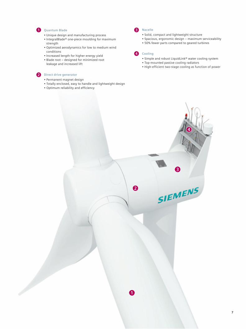
1
1
2
4
2
3
3
4
Quantum Blade
• Unique design and manufacturing process • IntegralBlade® one-piece moulding for maximum
strength • Optimized aerodynamics for low to medium wind
conditions • Increased length for higher energy yield • Blade root – designed for minimized root
leakage and increased lift
Direct drive generator
• Permanent magnet design• Totally enclosed, easy to handle and lightweight design• Optimum reliability and efficiency
Nacelle
• Solid, compact and lightweight structure• Spacious, ergonomic design – maximum serviceability• 50% fewer parts compared to geared turbines
Cooling
• Simple and robust LiquidLink® water cooling system• Top-mounted passive cooling radiators• High-efficient two-stage cooling as function of power
7
Published by and copyright © 2011:Siemens AGEnergy SectorFreyeslebenstrasse 191058 Erlangen, Germany
Siemens Wind Power A/SBorupvej 167330 Brande, Denmarkwww.siemens.com/wind
For more information, please contact our Customer Support Center.Phone: +49 180 524 70 00Fax: +49 180 524 24 71(Charges depending on provider)E-mail: [email protected]
Renewable Energy DivisionOrder No. E50001-W310-A174-V1-4A00Printed in GermanyDispo 34804, c4bs No. 7491fb 3867 WÜ WS 04113.0
Printed on elementary chlorine-free bleached paper.
All rights reserved. Trademarks mentioned in this document are the property of Siemens AG, its affiliates, or their respective owners.
Subject to change without prior notice. The information in this document contains general descriptions of the technical options available, which may not apply in all cases. The required technical options should therefore be specified in the contract.
Appendix C
Turbine Coordinates
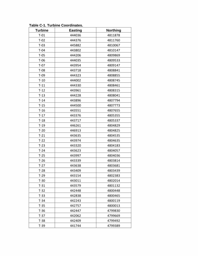
Table C-1. Turbine Coordinates. Turbine Easting Northing T‐01 444036 4811878
T‐02 444376 4811760
T‐03 445882 4810067
T‐04 443802 4810147
T‐05 444206 4809869
T‐06 444035 4809533
T‐07 443954 4809147
T‐08 443718 4808841
T‐09 444323 4808855
T‐10 444002 4808745
T‐11 444330 4808461
T‐12 443961 4808315
T‐13 444228 4808041
T‐14 443896 4807794
T‐15 444500 4807773
T‐16 443551 4807655
T‐17 443376 4805355
T‐18 443717 4805337
T‐19 446261 4804829
T‐20 446913 4804825
T‐21 443635 4804535
T‐22 443974 4804635
T‐23 443320 4804183
T‐24 443623 4804057
T‐25 443997 4804036
T‐26 443339 4803814
T‐27 443638 4803681
T‐28 443409 4803439
T‐29 443154 4802383
T‐30 443011 4802014
T‐31 443579 4801132
T‐32 442448 4800448
T‐33 442838 4800465
T‐34 442243 4800119
T‐35 442757 4800013
T‐36 442447 4799830
T‐37 442062 4799669
T‐38 442409 4799492
T‐39 441744 4799389

Turbine Easting Northing T‐40 441527 4798742
T‐41 441764 4798145
T‐42 441607 4797840
T‐43 442249 4797830
T‐44 441123 4797225
T‐45 440154 4796958
T‐46 440550 4796892
T‐47 440850 4796687
T‐48 440529 4796554

Appendix D
Legal Description of Participating
Properties
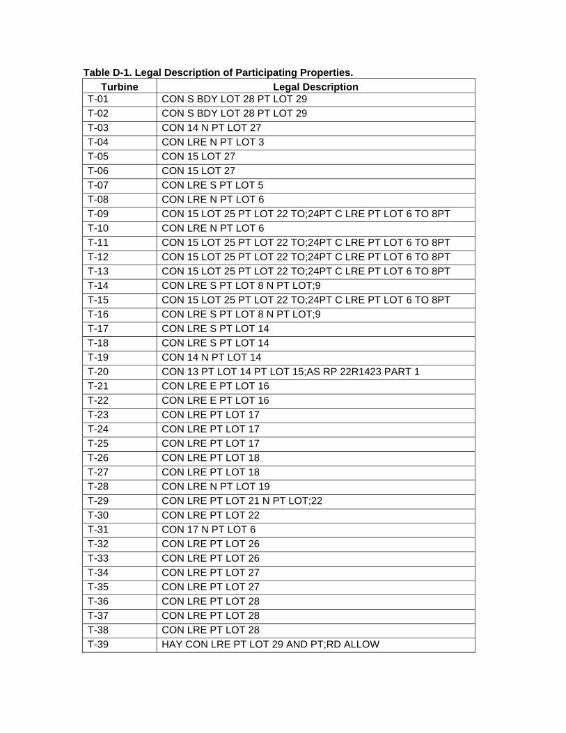
Table D-1. Legal Description of Participating Properties.
Turbine Legal Description T-01 CON S BDY LOT 28 PT LOT 29
T-02 CON S BDY LOT 28 PT LOT 29
T-03 CON 14 N PT LOT 27
T-04 CON LRE N PT LOT 3
T-05 CON 15 LOT 27
T-06 CON 15 LOT 27
T-07 CON LRE S PT LOT 5
T-08 CON LRE N PT LOT 6
T-09 CON 15 LOT 25 PT LOT 22 TO;24PT C LRE PT LOT 6 TO 8PT
T-10 CON LRE N PT LOT 6
T-11 CON 15 LOT 25 PT LOT 22 TO;24PT C LRE PT LOT 6 TO 8PT
T-12 CON 15 LOT 25 PT LOT 22 TO;24PT C LRE PT LOT 6 TO 8PT
T-13 CON 15 LOT 25 PT LOT 22 TO;24PT C LRE PT LOT 6 TO 8PT
T-14 CON LRE S PT LOT 8 N PT LOT;9
T-15 CON 15 LOT 25 PT LOT 22 TO;24PT C LRE PT LOT 6 TO 8PT
T-16 CON LRE S PT LOT 8 N PT LOT;9
T-17 CON LRE S PT LOT 14
T-18 CON LRE S PT LOT 14
T-19 CON 14 N PT LOT 14
T-20 CON 13 PT LOT 14 PT LOT 15;AS RP 22R1423 PART 1
T-21 CON LRE E PT LOT 16
T-22 CON LRE E PT LOT 16
T-23 CON LRE PT LOT 17
T-24 CON LRE PT LOT 17
T-25 CON LRE PT LOT 17
T-26 CON LRE PT LOT 18
T-27 CON LRE PT LOT 18
T-28 CON LRE N PT LOT 19
T-29 CON LRE PT LOT 21 N PT LOT;22
T-30 CON LRE PT LOT 22
T-31 CON 17 N PT LOT 6
T-32 CON LRE PT LOT 26
T-33 CON LRE PT LOT 26
T-34 CON LRE PT LOT 27
T-35 CON LRE PT LOT 27
T-36 CON LRE PT LOT 28
T-37 CON LRE PT LOT 28
T-38 CON LRE PT LOT 28
T-39 HAY CON LRE PT LOT 29 AND PT;RD ALLOW
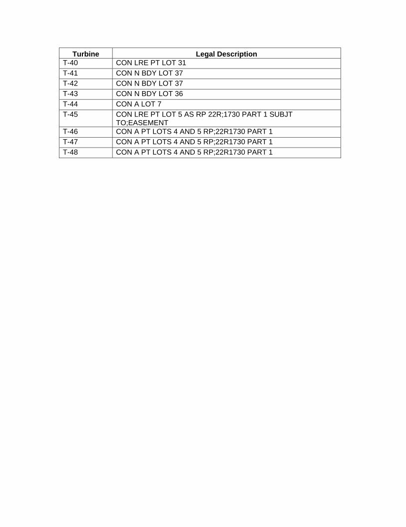
Turbine Legal Description T-40 CON LRE PT LOT 31
T-41 CON N BDY LOT 37
T-42 CON N BDY LOT 37
T-43 CON N BDY LOT 36
T-44 CON A LOT 7
T-45 CON LRE PT LOT 5 AS RP 22R;1730 PART 1 SUBJT TO;EASEMENT
T-46 CON A PT LOTS 4 AND 5 RP;22R1730 PART 1
T-47 CON A PT LOTS 4 AND 5 RP;22R1730 PART 1
T-48 CON A PT LOTS 4 AND 5 RP;22R1730 PART 1


![July 2012 Buchanan Creek Substation Transmission Project Creek... · Buchanan Creek Substation Transmission Project 1 ... new substation and approximately 150 metres of new ... (kV)],](https://img.pdfslide.net/doc/110x75/5ae59a7b7f8b9ae1578c809f/july-2012-buchanan-creek-substation-transmission-creekbuchanan-creek-substation.jpg)