Embed Size (px)
Citation preview

1
Granular Spreaders:Granular Spreaders:Granular Spreaders:Granular Spreaders:Granular Spreaders:
Selection,Selection,Selection,Selection,Selection,
Calibration,Calibration,Calibration,Calibration,Calibration,
TTTTTesting,esting,esting,esting,esting,
and Useand Useand Useand Useand Use
Richard L. Parish, PhD, PE
2
Table of Contents
Introduction ........................................................................................... 3Definitions ................................................................................... 4
Selection ................................................................................................. 6Spreaders vs. Sprayers ............................................................... 6Types of Spreaders ...................................................................... 7Spreader Operating Characteristics ......................................... 9Selection Criteria ....................................................................... 19
Calibration ........................................................................................... 20Basic Rate Calibration .............................................................. 20Adaptations for Different Spreader Types ............................ 21Factors That Affect Rate ........................................................... 22Initial Calibration ...................................................................... 25
Pattern Testing..................................................................................... 27Basic Procedure ......................................................................... 27Data Analysis ............................................................................. 29Data Interpretation ................................................................... 36Methods of Adjusting Spreader Patterns .............................. 37Factors That Affect Pattern ...................................................... 37Granule Segregation ................................................................. 45Alternate Pattern Test Procedures .......................................... 45Pattern Estimation .................................................................... 46
Use of Spreaders ................................................................................. 47Operating Modes ...................................................................... 47Header Strips ............................................................................. 56Speed........................................................................................... 57Level ............................................................................................ 58
Care and Maintenance of Spreaders ............................................... 58Cleaning ..................................................................................... 58Lubrication and Protection ...................................................... 59Storage ........................................................................................ 60Misuse......................................................................................... 60
For Additional Information............................................................... 61Standards ................................................................................... 61References .................................................................................. 61Contacting the Author ............................................................. 67
Acknowledgment ............................................................................... 68
3
IntroductionIntroductionIntroductionIntroductionIntroduction
Granular fertilizer spreaders are very popular for agricul-tural field use, commercial turf applications, and home lawn use.Several hundred thousand fertilizer spreaders are sold in theUnited States each year. Many of the people purchasing thosespreaders do not know how to select an appropriate spreader fortheir needs nor how to use the spreader properly to obtain opti-mum performance.
Proper use of spreaders is important economically andenvironmentally. Granular materials should be applied in auniform pattern and at the correct rate. If the rate is too low or ifthere are low spots in the pattern, the product will likely not beefficacious. If the rate is too high or there are high spots in thepattern, several problems are possible: the application will bemore costly than necessary due to the use of more product thannecessary; there is a risk of crop damage from overapplication;and excess product can be harmful to the environment. It isadvantageous to the applicator and to society to be sure productsare applied uniformly at the correct rate.
Much of the research reported in this bulletin has beendone on turf spreaders because they are smaller and easier towork with, but most of the principles discussed here are appli-cable to large agricultural spreaders as well. The informationshould make it easier for anyone using a fertilizer spreader toselect an appropriate type of spreader and to obtain optimumperformance from the selected spreader. This bulletin summarizes24 years of design, study, research, and teaching about fertilizerspreaders.
4
DefinitionsDefinitionsDefinitionsDefinitionsDefinitions
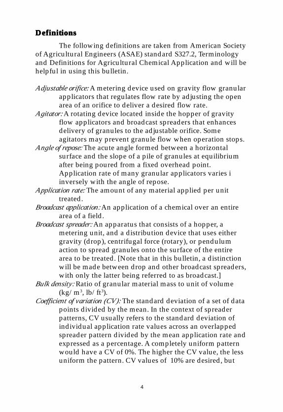
The following definitions are taken from American Societyof Agricultural Engineers (ASAE) standard S327.2, Terminologyand Definitions for Agricultural Chemical Application and will behelpful in using this bulletin.
Adjustable orifice: A metering device used on gravity flow granularapplicators that regulates flow rate by adjusting the openarea of an orifice to deliver a desired flow rate.
Agitator: A rotating device located inside the hopper of gravityflow applicators and broadcast spreaders that enhancesdelivery of granules to the adjustable orifice. Someagitators may prevent granule flow when operation stops.
Angle of repose: The acute angle formed between a horizontalsurface and the slope of a pile of granules at equilibriumafter being poured from a fixed overhead point.Application rate of many granular applicators varies iinversely with the angle of repose.
Application rate: The amount of any material applied per unittreated.
Broadcast application: An application of a chemical over an entirearea of a field.
Broadcast spreader: An apparatus that consists of a hopper, ametering unit, and a distribution device that uses eithergravity (drop), centrifugal force (rotary), or pendulumaction to spread granules onto the surface of the entirearea to be treated. [Note that in this bulletin, a distinctionwill be made between drop and other broadcast spreaders,with only the latter being referred to as broadcast.]
Bulk density: Ratio of granular material mass to unit of volume(kg/m3, lb/ft3).
Coefficient of variation (CV): The standard deviation of a set of datapoints divided by the mean. In the context of spreaderpatterns, CV usually refers to the standard deviation ofindividual application rate values across an overlappedspreader pattern divided by the mean application rate andexpressed as a percentage. A completely uniform patternwould have a CV of 0%. The higher the CV value, the lessuniform the pattern. CV values of 10% are desired, but
5
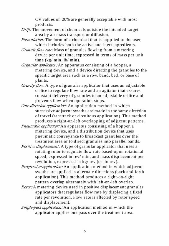
CV values of 20% are generally acceptable with mostproducts.
Drift: The movement of chemicals outside the intended targetarea by air mass transport or diffusion.
Formulation: The form of a chemical that is supplied to the user,which includes both the active and inert ingredients.
Granule flow rate: Mass of granules flowing from a meteringdevice per unit time, expressed in terms of mass per unittime (kg/min, lb/min).
Granular applicator: An apparatus consisting of a hopper, ametering device, and a device directing the granules to thespecific target area such as a row, band, bed, or base ofplants.
Gravity flow: A type of granular applicator that uses an adjustableorifice to regulate flow rate and an agitator that assuresconstant delivery of granules to an adjustable orifice andprevents flow when operation stops.
One-direction application: An application method in whichsuccessive adjacent swaths are made in the same directionof travel (racetrack or circuitous application). This methodproduces a right-on-left overlapping of adjacent patterns.
Pneumatic applicator: An apparatus consisting of a hopper, ametering device, and a distribution device that usespneumatic conveyance to broadcast granules over thetreatment area or to direct granules into parallel bands.
Positive displacement: A type of granular applicator that uses arotating rotor to regulate flow rate based upon rotationalspeed, expressed in rev/min, and mass displacement perrevolution, expressed in kg/rev (or lb/rev).
Progressive application: An application method in which adjacentswaths are applied in alternate directions (back and forthapplication). This method produces a right-on-rightpattern overlap alternately with left-on-left overlap.
Rotor: A metering device used in positive displacement granularapplicators that regulates flow rate by displacing a fixedrate per revolution. Flow rate is affected by rotor speedand displacement.
Single-pass application: An application method in which theapplicator applies one pass over the treatment area.
6
Size guide number, SGN: A number that defines the median particlesize of a granular fertilizer material for the purpose of sizematching of materials in fertilizer blending operations.The relationship is:
SGN = median particle diameter, mm X 10Median particle diameter is the diameter corresponding to50% retained by weight in a cumulative sieve analysis.
Swath, effective width: The center-to-center distance betweenoverlapping broadcast applications.
Uniformity index: A rating of the uniformity of size of particles of agranular material. It is a dimensionless ratio of the particlesize corresponding to 95% retained by weight to theparticle size corresponding to 10% retained by weight in acumulative sieve analysis of the material. A materialuniformly sized has a uniformity index equal to one. Lessuniformly sized materials have a smaller value.
SelectionSelectionSelectionSelectionSelectionSpreaders vs. SprayersSpreaders vs. SprayersSpreaders vs. SprayersSpreaders vs. SprayersSpreaders vs. Sprayers
Spreader application of granular fertilizer and pesticidesoffers several advantages over sprayer application of liquidformulations, especially for home gardeners and home lawnapplicators. Granular materials do not have to be diluted ormixed. It is much easier to apply granules evenly than it is toapply liquids evenly with the equipment available tohomeowners. Often, product manufacturers supply spreadersettings on the bag label so that no calibration is needed. Granularformulations of pesticides are generally safer both to the operatorand to the environment, since there is less risk of dermal absorp-tion, less drift, and no contaminated mixing area.
Although spreaders are easier to use than sprayers, thereare still many things an operator can do to help achieve a uniformdistribution pattern with the correct application rate. Even thoughgranular product manufacturers may provide recommendedsettings, professional applicators should always calibrate theirspreaders for each product.
7
TTTTTypes of Spreadersypes of Spreadersypes of Spreadersypes of Spreadersypes of Spreaders
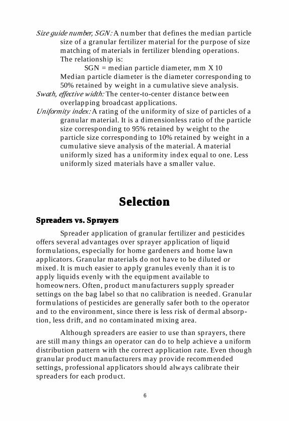
Most fertilizer spreaders can be divided into two maincategories, broadcast and drop. Drop spreaders have a full-widthhopper with a series of metering ports in the bottom or rear of thehopper. An example of a drop spreader is shown in Figure 1.Theoretically, an equal amount of product will be metered out ofeach hole, thus providing a uniform application across the entirewidth. If the holes are spaced too far apart, banding (and thuscrop striping) is possible. The pattern from a drop spreader stopsat the edges of the spreader with no taper; thus, adjacent patternsmust be abutted exactly with no space or overlap.
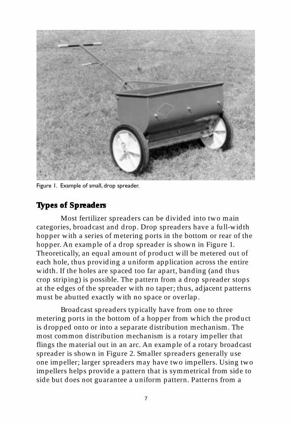
Broadcast spreaders typically have from one to threemetering ports in the bottom of a hopper from which the productis dropped onto or into a separate distribution mechanism. Themost common distribution mechanism is a rotary impeller thatflings the material out in an arc. An example of a rotary broadcastspreader is shown in Figure 2. Smaller spreaders generally useone impeller; larger spreaders may have two impellers. Using twoimpellers helps provide a pattern that is symmetrical from side toside but does not guarantee a uniform pattern. Patterns from a
Figure 1. Example of small, drop spreader.
8
single impeller can be skewed (i.e. heavier on one side of thecenterline than on the other) or can be nonuniform unless thespreader is properly designed and adjusted.
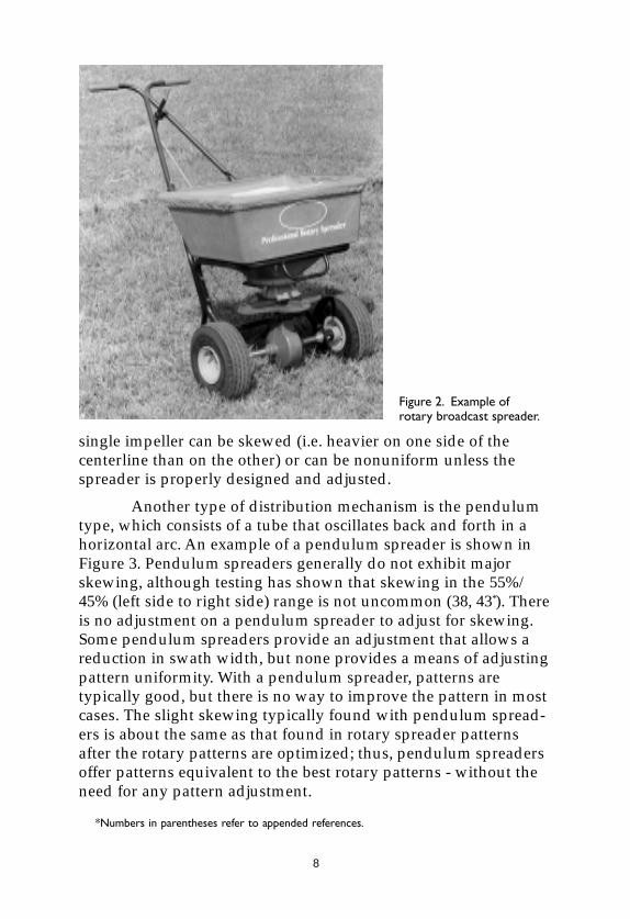
Another type of distribution mechanism is the pendulumtype, which consists of a tube that oscillates back and forth in ahorizontal arc. An example of a pendulum spreader is shown inFigure 3. Pendulum spreaders generally do not exhibit majorskewing, although testing has shown that skewing in the 55%/45% (left side to right side) range is not uncommon (38, 43*). Thereis no adjustment on a pendulum spreader to adjust for skewing.Some pendulum spreaders provide an adjustment that allows areduction in swath width, but none provides a means of adjustingpattern uniformity. With a pendulum spreader, patterns aretypically good, but there is no way to improve the pattern in mostcases. The slight skewing typically found with pendulum spread-ers is about the same as that found in rotary spreader patternsafter the rotary patterns are optimized; thus, pendulum spreadersoffer patterns equivalent to the best rotary patterns - without theneed for any pattern adjustment.
Figure 2. Example ofrotary broadcast spreader.
*Numbers in parentheses refer to appended references.
9
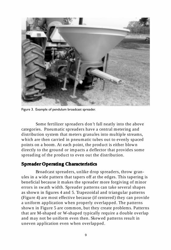
Some fertilizer spreaders don’t fall neatly into the abovecategories. Pneumatic spreaders have a central metering anddistribution system that meters granules into multiple streams,which are then carried in pneumatic tubes out to evenly spacedpoints on a boom. At each point, the product is either blowndirectly to the ground or impacts a deflector that provides somespreading of the product to even out the distribution.
Spreader Operating CharacteristicsSpreader Operating CharacteristicsSpreader Operating CharacteristicsSpreader Operating CharacteristicsSpreader Operating Characteristics
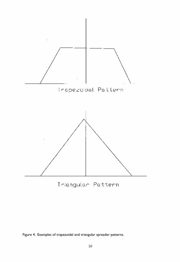
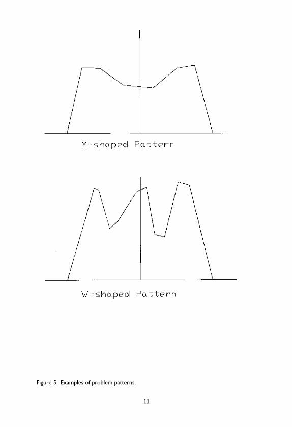
Broadcast spreaders, unlike drop spreaders, throw gran-ules in a wide pattern that tapers off at the edges. This tapering isbeneficial because it makes the spreader more forgiving of minorerrors in swath width. Spreader patterns can take several shapesas shown in figures 4 and 5. Trapezoidal and triangular patterns(Figure 4) are most effective because (if centered) they can providea uniform application when properly overlapped. The patternsshown in Figure 5 are common, but they create problems. Patternsthat are M-shaped or W-shaped typically require a double overlapand may not be uniform even then. Skewed patterns result inuneven application even when overlapped.
Figure 3. Example of pendulum broadcast spreader.
10
Figure 4. Examples of trapezoidal and triangular spreader patterns.
11
Figure 5. Examples of problem patterns.
12
Granule and Impeller DynamicsGranule and Impeller DynamicsGranule and Impeller DynamicsGranule and Impeller DynamicsGranule and Impeller Dynamics
The most common type of spreader for professional turfuse is the broadcast rotary spreader with a single impeller. A briefdiscussion of granule and impeller dynamics will provide a betterunderstanding of how the system works. First, granules seldomroll on the impeller, even when the granules are smooth andspherical. The granules generally slide out along the fins of theimpeller until they are discharged; thus, the coefficient of frictionof the granule on the impeller material has a major effect on howlong the granule takes to move from the drop point out to theedge of the impeller. For a given drop point, the longer the gran-ule stays on the impeller, the further the granule trajectory will beangled in the direction of rotation.
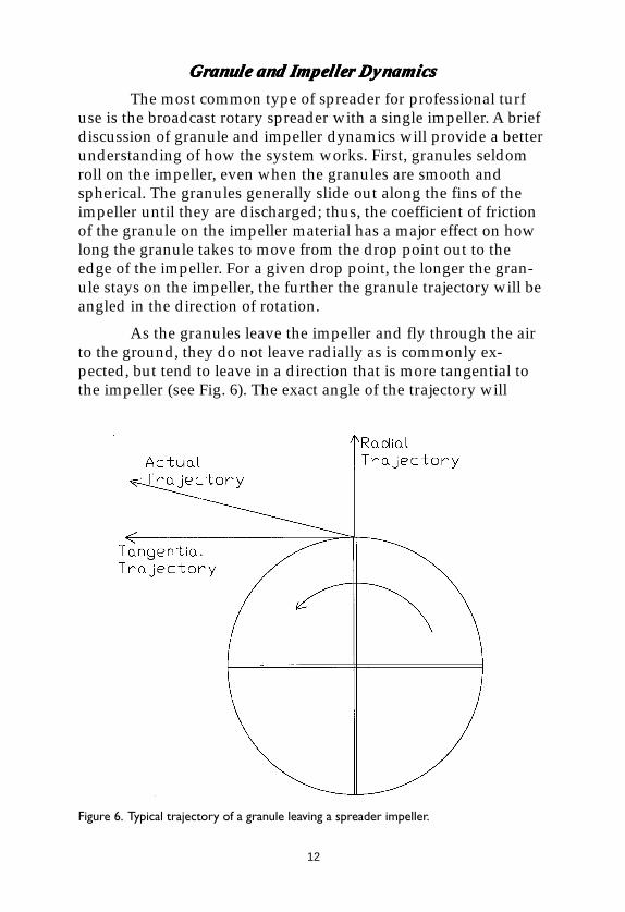
As the granules leave the impeller and fly through the airto the ground, they do not leave radially as is commonly ex-pected, but tend to leave in a direction that is more tangential tothe impeller (see Fig. 6). The exact angle of the trajectory will
Figure 6. Typical trajectory of a granule leaving a spreader impeller.
13
depend on impeller configuration, impeller speed, impellersurface, granule characteristics, and relative humidity, but ap-proximately 10° from tangential is typical.
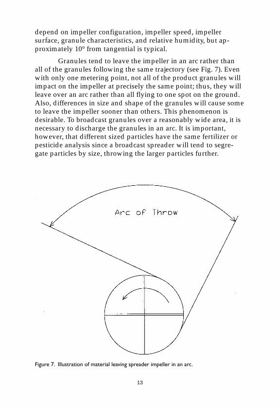
Granules tend to leave the impeller in an arc rather thanall of the granules following the same trajectory (see Fig. 7). Evenwith only one metering point, not all of the product granules willimpact on the impeller at precisely the same point; thus, they willleave over an arc rather than all flying to one spot on the ground.Also, differences in size and shape of the granules will cause someto leave the impeller sooner than others. This phenomenon isdesirable. To broadcast granules over a reasonably wide area, it isnecessary to discharge the granules in an arc. It is important,however, that different sized particles have the same fertilizer orpesticide analysis since a broadcast spreader will tend to segre-gate particles by size, throwing the larger particles further.
Figure 7. Illustration of material leaving spreader impeller in an arc.
14
Some spreaders use multiple ports (typically three) tofurther widen the discharge arc and thus contribute to a uniform,wide pattern. Using multiple ports can, however, contribute topeaks in the distribution pattern. It is common to have three peaksin the pattern from a spreader with three ports (45). Spreadermanufacturers have addressed this problem in several ways.Some manufacturers use one wide port (wide in terms of anglearound the impeller) to give a uniform flow of material in a widearc on the impeller (30). This method can work but can lead toinconsistencies in rate calibration compared with multiple ports.Since the effective line of metering is longer, the opening must besmaller in the other dimension to get the same rate, and calibra-tion is thus more sensitive to errors in opening. Another methodof smoothing out the peaks from multiple ports is to use a deflec-tor of some type under the metering opening on which the mul-tiple flows impinge and then blend together (45). A third methodis to mix more than one fin type on the impeller. If a 4-fin impellerhas two straight fins and two curved fins, the three peaks will bechanged into six smaller peaks, which will then more closelyapproach a uniform distribution (45).
Pattern AdjustmentPattern AdjustmentPattern AdjustmentPattern AdjustmentPattern Adjustment
Most professional rotary spreaders provide some means ofpattern adjustment to allow the operator to correct for productand environmental differences. Most small homeowner rotaryspreaders do not provide any means of pattern adjustment. Themost common means of pattern adjustment involves changing thepoint(s) at which the granules impinge on the impeller. This canbe done by moving the impeller itself, by moving the meteringport(s) radially or angularly (46), or by moving some type ofdeflector between the ports and the impeller (30).
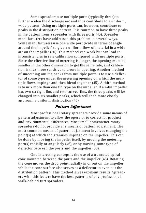
One interesting concept is the use of a truncated spiralcone mounted between the ports and the impeller (45). Rotatingthe cone moves the drop point radially in or out on the impellerwhile the cone surface also serves as a deflector to even out thedistribution pattern. This method gives excellent results. Spread-ers with this feature have the best patterns of any professionalwalk-behind turf spreaders.
15
Another approach is to rotate the ports in the hopperbottom to move the drop point angularly (46). Rotating the droppoint above the impeller may allow the pattern to be improved;however, with some spreaders this adjustment results merely inshifting the pattern side-to-side without any improvement inpattern shape. This method is effective mainly for compensatingfor material or operational variables in an otherwise optimalpattern.
A different approach is to open or close some of the portsto change the center of the drop zone on the impeller (45). Par-tially or completely closing one port can change the shape of thepattern but also changes delivery rate, so rate settings must bechanged accordingly. Another alternative is to move the fins onthe impeller to change the trajectory for a given drop point. This iscommon on large agricultural spreaders.
Not all pattern correction methods are adequate. Somespreaders have pattern adjustment systems that do not allowenough adjustment to compensate fully for all potential materials(30).
High-speed photography of granules on spreader impel-lers has shown that granules sometimes jump over the fins on theimpellers. This can disrupt the normal arc of release from theimpeller and result in a heavy spot in the pattern. Manufacturershave countered this problem by putting a lip on the top of theimpeller fins or by using curved channels for fins (45,46).
Alternate SprAlternate SprAlternate SprAlternate SprAlternate Spreader Designseader Designseader Designseader Designseader Designs
Most rotary broadcast spreaders throw material in alimited arc to the front or rear of the spreader. It is possible, withsmall homeowner rotary spreaders, to throw material in a full360° arc. This is generally not possible with larger spreadersbecause the thrown material would hit the operator, tractor, etc.Throwing material in a 360° arc eliminates one of the problemsinherent in most rotary spreaders - skewing (throwing morematerial on one side of the pattern than on the other). With a full360° arc there is no skewing and thus no need to correct thepattern when changing from one product to another. The size ofthe arc does, however, change with product. With larger granulesor higher density granules, the circular pattern will be larger than
16
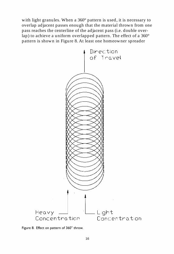
with light granules. When a 360° pattern is used, it is necessary tooverlap adjacent passes enough that the material thrown from onepass reaches the centerline of the adjacent pass (i.e. double over-lap) to achieve a uniform overlapped pattern. The effect of a 360°pattern is shown in Figure 8. At least one homeowner spreader
Figure 8. Effect on pattern of 360° throw.
17
using the 360° principle was marketed (6, 44). The small, low-speed impeller threw material with an effective swath width ofonly 30 inches. By limiting the recommended products, the manu-facturer could recommend a consistent 30-inch swath widthwithout having to correct for product variability.
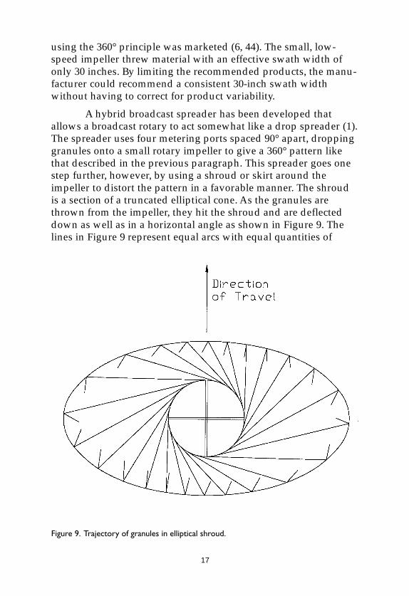
A hybrid broadcast spreader has been developed thatallows a broadcast rotary to act somewhat like a drop spreader (1).The spreader uses four metering ports spaced 90° apart, droppinggranules onto a small rotary impeller to give a 360° pattern likethat described in the previous paragraph. This spreader goes onestep further, however, by using a shroud or skirt around theimpeller to distort the pattern in a favorable manner. The shroudis a section of a truncated elliptical cone. As the granules arethrown from the impeller, they hit the shroud and are deflecteddown as well as in a horizontal angle as shown in Figure 9. Thelines in Figure 9 represent equal arcs with equal quantities of
Figure 9. Trajectory of granules in elliptical shroud.

18
granules. The ends of the lines are closer together at the center,but spread out at the edges because of the bounce off of theelliptical shroud. Note how this compacts the pattern near thecenter and spreads the pattern out at the edges. This eliminatesthe need for a double overlap as required for a normal 360° pat-tern and provides a very consistent trapezoidal pattern withtapered edges.
This design is unique among broadcast spreaders in that itgives the same width and shape of pattern for a wide range ofproducts and has no skewing. It can be used much like a dropspreader and provides almost the same uniformity, but it islighter, cheaper, and provides a wide pattern. The elliptical shroudspreader provides some tapering and is thus more forgiving ofswath width errors than a drop spreader. The first spreader usingthis design delivered a consistent 42-inch swath width with awide range of products. This design also dramatically reduces thewind distortion common to other broadcast spreaders. It providesbetter ground clearance than most drop spreaders.
DrDrDrDrDrop Sprop Sprop Sprop Sprop Spreader Meteringeader Meteringeader Meteringeader Meteringeader Metering
Drop spreaders have a row of ports across the bottom orrear of the hopper. A shut-off bar moves either front-to-rear orsideways to open and close the ports. Limiting the openingdetermines the rate setting. The shape of the holes as well as thetolerances in the linkage and shut-off bar determine the accuracyof metering. A drop spreader can be very accurate and consistentbut not all are. Some drop spreaders have a deflector under theports to even out the flow from the individual ports.
Not all spreaders have hoppers. One home lawn spreaderwas sold without a hopper. The products intended for applicationwith the spreader were packaged in standard-sized boxes. A boxof product was installed on the spreader and became the hopper,with product from the box metered down to an impeller. Since theactual metering and the distribution were done by metal compo-nents on the spreader and the box served only as the hopper, theperformance was equivalent to other small, low-cost homeownerrotary spreaders.

19
Selection CriteriaSelection CriteriaSelection CriteriaSelection CriteriaSelection Criteria
Factors in selecting a spreader include the size of the areato be covered, characteristics of the granular products to be ap-plied, availability of predetermined spreader settings, need foruniformity, and cost of the spreader (2). The following summa-rizes some of the considerations in choosing between drop-typeand broadcast spreaders:
Distribution uniformity:Distribution uniformity:Distribution uniformity:Distribution uniformity:Distribution uniformity: A drop spreader can be very precise anduniform across the swath width; in general, a broadcast patternwill be less uniform.
Distribution consistency:Distribution consistency:Distribution consistency:Distribution consistency:Distribution consistency: The pattern from a drop spreader staysessentially the same as long as it is used with compatible prod-ucts; broadcast patterns vary with product physical characteris-tics.
Feathering:Feathering:Feathering:Feathering:Feathering: A broadcast pattern feathers at the edges to accommo-date overlap and “forgive” minor errors in swath width; a dropspreader pattern is sharply defined and requires an exact swathwidth to avoid striping.
WWWWWind efind efind efind efind effect:fect:fect:fect:fect: Wind usually affects a drop pattern much less than abroadcast pattern since the drop point is closer to the ground andthe granules fall straight down.
Granule size:Granule size:Granule size:Granule size:Granule size: In general, broadcast spreaders can handle largergranules than drop spreaders because broadcast spreaders have asmaller number of larger ports.
Safety to surrSafety to surrSafety to surrSafety to surrSafety to surrounding arounding arounding arounding arounding areas:eas:eas:eas:eas: A drop spreader is considerably saferfor surrounding vegetation than a broadcast spreader since theproduct granules are not thrown out beyond the spreader. There isless drift with a drop spreader.
GrGrGrGrGround clearance:ound clearance:ound clearance:ound clearance:ound clearance: A drop spreader normally has the hoppercloser to the ground than a broadcast spreader and thus has lessground clearance and is more susceptible to damage from impact-ing rocks, roots, and other obstacles.
Drive torDrive torDrive torDrive torDrive torque:que:que:que:que: A drop spreader normally has a higher drive torquethan a broadcast spreader because of the full-width agitator, so adrop spreader will require more force to push or pull.
20
Speed efSpeed efSpeed efSpeed efSpeed effects:fects:fects:fects:fects: With a drop spreader, speed affects rate but notpattern. With a broadcast spreader, both rate and pattern can beaffected.
Plugging:Plugging:Plugging:Plugging:Plugging: Since a drop spreader has many small ports, it is moresusceptible to plugging than a broadcast spreader with one tothree larger ports. Also, the lower clearance of a drop spreadermakes it more likely to plug from wet foliage rubbing on thehopper bottom.
Construction material:Construction material:Construction material:Construction material:Construction material: Steel has traditionally been used for dropspreaders to achieve the required rigidity needed for precision,although some plastic drop spreaders are available. Broadcastspreaders can use plastic if desired to increase corrosion resistanceand reduce cost.
Swath width:Swath width:Swath width:Swath width:Swath width: Drop spreaders cover only the implement width;broadcast spreaders can deliver a much wider effective swath.
CalibrationCalibrationCalibrationCalibrationCalibrationBasic Rate CalibrationBasic Rate CalibrationBasic Rate CalibrationBasic Rate CalibrationBasic Rate Calibration
Rate calibration and determination of pattern and swathwidth should be entirely separate processes. Even though ratedata can be determined from pattern test data, the results areunreliable and can be dramatically incorrect. Before determining aspreader setting for the desired delivery rate, the effective swathwidth must be determined. For drop-type spreaders, the effectiveswath width can be measured directly. With broadcast spreaders,the effective swath width must be determined from pattern data.In some cases, this information will be available from the productmanufacturer as a part of the product label; if not, pattern testingwill be necessary. This will be described later.
Rate calibration is easy with most spreaders and involvesno complicated mathematics. Although there are as many calibra-tion methods as there are people recommending them, themethod recommended here is the easiest to use. In the mostgeneral format, all the operator has to do is find out how long ittakes (in seconds) for the spreader to cover a known area, collectthe material discharged for that length of time at a given setting,
21
and divide the amount by the area. This will give the rate (in kg/ha, lb/a, lb/1000 ft2, etc). The operator can then adjust the settingand try again until the desired delivery rate is achieved. Note thatthis method does notnotnotnotnot require any calculations of speed, flow rate,etc.
Adaptations for DifAdaptations for DifAdaptations for DifAdaptations for DifAdaptations for Different Spreader Tferent Spreader Tferent Spreader Tferent Spreader Tferent Spreader Typesypesypesypesypes
Perhaps the easiest to calibrate is a pendulum spreader (38,43). The spout can typically be removed by loosening two bolts.Once this is done, the output can be caught in a bucket or bag. Ifusing a bucket, it is easier to set the bucket on the ground underthe machine and hold a second bucket with a hole in the bottomover the oscillating spreader opening so that the flying granulesare caught by the second bucket and funneled down to the mainbucket. Some pendulum spreader manufacturers sell bags for thispurpose. It is essential that the PTO be engaged and the spreaderbe operating when the test is conducted; the delivery rate will bemuch less at a given setting if the spreader is not operating (43).
Most drop spreaders can be calibrated by hanging a pan ortray under the shut-off bar and then pushing the spreader for apredetermined distance while catching the output. Knowing thespreader width and the distance traveled allows easy calculationof the area. When using this method it is very important that thepan not hang on or even touch the shut-off bar because this cannot only affect the test results but can permanently change thecalibration of the spreader.
With most rotary spreaders, it is more difficult to catch theoutput. In some cases, the impeller can be removed, allowing thematerial to drop into a container. In other cases, it may be possibleto fasten a bag or tarp around the impeller(s) to catch the product.If these methods are not practical on a given spreader, it may benecessary to put a weighed amount of product in the spreader,drive the measured distance and spread while driving, thenweigh the amount remaining. The difference between the twoweights divided by the area covered will be the application rate.The spreader must be operating (i.e. PTO-engaged) during thetest.

22
Small spreaders, both drop and rotary broadcast, can becalibrated on a test stand. The typical test stand consists of a tablewith two vertical tires protruding. The tires are driven by a motorat a speed that will make the peripheral speed equal to the desiredground speed. A catch pan under a slot adjacent to the wheelscollects the product falling from the spreader while it is driven bythe wheels. It is convenient to have a counter on the drive wheelsto count revolutions. A conversion table is used to determine howmany revolutions are needed for a given area (e.g. 1,000 ft2) atvarious swath widths. If the impeller is removed, a rotaryspreader can be tested on a test stand. Generally accepted speedsare 2.75 mph for walk-behind homeowner spreaders and 3.0 mphfor walk-behind professional spreaders.
Pneumatic spreaders can be calibrated by catching theoutput from the individual discharge points in bags or othercontainers. Be sure to provide for the air stream to exit from thecontainer.
Factors That AfFactors That AfFactors That AfFactors That AfFactors That Affect Ratefect Ratefect Ratefect Ratefect Rate
Many factors can affect spreader delivery rate. It may benecessary to recalibrate a spreader when any of these factorschange.
HumidityHumidityHumidityHumidityHumidity
A common misconception is that fertilizer response tohumidity is a ramp function, i.e. hygroscopicity increases withhigher relative humidity. Fertilizer response to relative humidityis a step function. Every fertilizer product has what is known as a“critical relative humidity” (CRH). This is the relative humidity atwhich the fertilizer becomes hygroscopic and takes up water fromthe air. Below its CRH, a fertilizer will remain dry. Once the CRHis reached, the fertilizer will immediately begin to absorb water.The longer the fertilizer remains exposed to air above its CRH andthe higher the humidity above the CRH, the more moisture thefertilizer will absorb (33) - until it reaches saturation.
Humidity has two primary effects on delivery rate. First,as the fertilizer picks up moisture, it will become less flowableand its angle of repose will increase. The delivery rate through theport(s) will thus decrease. Also, if the fertilizer picks up enough
23
moisture, it will begin to build up on the spreader in areas such asunder the agitator. This buildup around the ports can furtherreduce the delivery rate, and it can also dramatically increase theforce needed to turn the agitator. With a walk-behind dropspreader, the increase in push force can be substantial.
SpeedSpeedSpeedSpeedSpeed
Speed can have a major effect on spreader delivery rate.Many small broadcast spreaders are gravimetric (meter on thebasis of gravity flow), and thus their delivery rate will be constantper unit time. If the ground speed changes, a given amount ofmaterial will be applied to more or less area. If, for example, aspreader meters 2 pounds per minute and covers 500 ft2 perminute, it will apply 4 lb/1,000 ft2. If the ground speed is in-creased 10% so that the spreader now covers 550 ft2 in a minute,the rate will decrease to 3.6 lb/1,000 ft2.
Volumetric metering means that the metering unit willdeliver a fixed amount of material per revolution and thus beunaffected by speed. A grain drill and a granular pesticide meteron a row-crop planter are examples of volumetric metering. Mostdrop-type spreaders are neither gravimetric nor fully volumetric.Some authorities have published statements that homeownerdrop-type spreaders are volumetric, thus speed is irrelevant (54).This is incorrect. Research has shown that common drop-typehomeowner spreaders are more nearly gravimetric than volumet-ric (17, 20, 47). Speed does have a major effect on their deliveryrate. Increasing ground speed will decrease application rate. Theexact relationship between speed and delivery rate will be differ-ent for each model of spreader and will be determined by thegeometry of that spreader.
PrPrPrPrProductoductoductoductoduct
Characteristics of the product granules can affect the ratecalibration (34, 36). Granule size is important, as is the size distri-bution. Unfortunately, some product manufacturers use only a topand bottom size specification for their granular products. Forinstance, they might specify only that 98% of the granules besmall enough to pass through a #14 sieve and large enough not topass through a #20 sieve. If one production run meets the spec butis skewed toward mostly 14-16 size granules and another produc-
24
tion run also meets the spec but is skewed toward mostly 18-20size granules, the two materials will perform very differently inspreaders.
Shape of the product is important, too. Shape can changethe angle of repose of a product and thus change how freely theproduct flows. This, in turn, can affect the delivery rate of gravi-metric metering systems.
Moisture content of the product can affect the angle ofrepose as well as the coefficient of friction of the granules. Eventu-ally, product moisture will stabilize at some level consistent withthe ambient relative humidity, but the initial product moisturewhen the bag is opened may be higher or lower, depending onhow it was packaged and stored. Changes in these properties canchange the delivery rate.
Manufacturers may make major changes in product andkeep the same product name. For instance, a manufacturer mighteven use different N-P-K sources for one batch because of rawmaterial availability. With pesticides, the manufacturer mightsubstitute a corn cob carrier for a clay carrier and not show anychanges on the label. Thus, even though the product name andfertilizer or pesticide analysis are the same, the physical productmay be completely different and perform differently in thespreader.
All of the above factors can affect the calibration anddelivery rate of a product through a spreader. Some of thesefactors are normally not checked or controlled by product manu-facturers; others (e.g. moisture) can change in shipping andstorage. It is important that an operator check the delivery rate foreach batch of product prior to application. The rate that wascorrect for the last batch may not be correct for this batch.
SprSprSprSprSpreader Angle/Handle Heighteader Angle/Handle Heighteader Angle/Handle Heighteader Angle/Handle Heighteader Angle/Handle Height
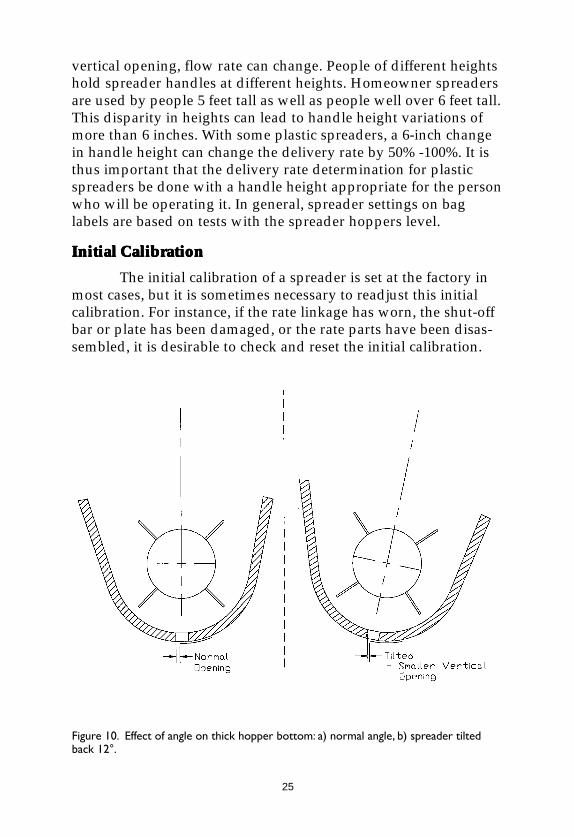
Unfortunately, something as simple as the height at whichthe handle is held can have a major effect on spreader deliveryrate. This is primarily a problem with plastic drop-type spreaders.With plastic spreaders, the hopper bottom is usually much thickerthan with steel spreaders. Since the hopper bottom is thick in thearea of the ports, the vertical opening can change as the hopper istilted (see Figure 10). Since granule flow rate is a function of
25
vertical opening, flow rate can change. People of different heightshold spreader handles at different heights. Homeowner spreadersare used by people 5 feet tall as well as people well over 6 feet tall.This disparity in heights can lead to handle height variations ofmore than 6 inches. With some plastic spreaders, a 6-inch changein handle height can change the delivery rate by 50% -100%. It isthus important that the delivery rate determination for plasticspreaders be done with a handle height appropriate for the personwho will be operating it. In general, spreader settings on baglabels are based on tests with the spreader hoppers level.
Initial CalibrationInitial CalibrationInitial CalibrationInitial CalibrationInitial Calibration
The initial calibration of a spreader is set at the factory inmost cases, but it is sometimes necessary to readjust this initialcalibration. For instance, if the rate linkage has worn, the shut-offbar or plate has been damaged, or the rate parts have been disas-sembled, it is desirable to check and reset the initial calibration.
Figure 10. Effect of angle on thick hopper bottom: a) normal angle, b) spreader tiltedback 12°.
26
This is possible with most larger spreaders and with some home-owner models. If recalibration is possible, the manufacturer willrecommend a procedure and, in some cases, provide a calibrationgage. One common method of recalibrating professional walk-behind rotary spreaders is to insert a gage rod (or the correct sizedrill bit) into the specified port opening, adjust the rate setting sothat the plate just closes on the gage, and then adjust the pointerto the specified mark on the scale. Another common method is toadjust the rate setting until a specified port just barely closes, andthen adjust the pointer to the specified mark on the scale. Somedrop spreaders are calibrated by using a gage that is held againstthe edge of the shut-off bar and the hopper bottom (with thespreader inverted). The shut-off bar is adjusted so that the tips ofthe ports show in a depressed portion of the gage but not at thesides of the gage. The rate plate is then locked down and thepointer moved to a specified mark on the scale. Other methodsmay be used by other manufacturers. The important point is to beaware of the need to periodically check the spreader’s initialcalibration using the manufacturer’s recommended procedureand then correct as needed.
In addition to the need to calibrate the rate setting itself,initial calibration can also involve other factors. The clearancebetween the shut-off bar or plate and the hopper bottom can havea major impact on delivery rate and should be held to closetolerances by the manufacturer. For example, one commonspreader has a tolerance of 0.003-0.015 inch between the shut-offbar and hopper. If this adjustment is changed in use, the ratecalibration can vary considerably. A common problem is granulesbuilding up between the shut-off bar or plate and the hopper,causing the bar or plate to be held out from the hopper. This candramatically increase the delivery rate, especially at lower set-tings.
Inexpensive homeowner spreaders that have the rate-setting mechanism on the upper handle and a cable down to theshut-off bar or plate are very subject to changes in initial calibra-tion. For example, any stretching or kinking of the control cable orany looseness in the handle bolts will change the initial calibra-tion.
27
Pattern TPattern TPattern TPattern TPattern TestingestingestingestingestingPattern testing is the critical first step to obtaining uniform
distribution with broadcast spreaders. A pattern test is necessaryto determine the effective swath width and the correct patternadjustment(s) for optimum uniformity (4, 5, 41). Some manufac-turers conduct pattern tests on each product in the spreaders theyrecommend and then put the recommended widths and patternsettings on the bag labels. With reputable companies, you cangenerally rely on the label pattern settings. In most cases, how-ever, you will need to conduct your own pattern test for eachspreader and product. With walk-behind spreaders, you shouldconduct a pattern test with each individual operator.
Basic ProcedureBasic ProcedureBasic ProcedureBasic ProcedureBasic Procedure
The basic procedure for conducting pattern tests is verystraightforward. Several collection trays are laid on the ground ina straight line perpendicular to the direction of spreader travel.The spreader is then operated over the line of trays. The materialcollected in the trays is measured and the resulting data used tocalculate the spreader pattern. The American Society of Agricul-tural Engineers has developed a standard for spreader patterntesting. The procedures outlined here are based on that standard(ASAE S341.2, Procedure for Measuring Distribution Uniformityand Calibrating Granular Broadcast Spreaders).
The size and configuration of the trays are important (9,48). The trays should be small enough that you can get at least 10trays in the effective swath width. More than 10 trays are better. Ifthe trays are too small, however, the test will be more difficult toconduct, and the results will be biased by the small tray size (9, 48,49). It is desirable to use as many trays as practical without resort-ing to reduced tray size. For large agronomic spreaders, the panscan be 12-24 inches wide by about 24 inches long and spacedevery 24-48 inches. For most professional turf spreaders, trays thatare 11-12 inches wide by 15 inches long work well. They should bespaced 12 inches apart for walk-behind spreaders and 24 inchesapart for tractor spreaders. For most small homeowner spreaders,trays 5-6 inches wide by about 15 inches long work well. Theseshould be spaced on 6-inch centers across the full pattern width.
28
With some very small homeowner spreaders, even narrower traysmay be needed to obtain adequate data points.
Trays for small spreaders should be about 2 inches high.Trays for large agronomic spreaders can be up to 4 inches high. Allshould have internal baffles to reduce the amount of material thatbounces out on impact. It is helpful to use baffles that do not reachall the way to the bottom of the trays so that pouring materialfrom the trays is easier.
Removing trays from the pattern to allow the spreader(and tractor) tires to pass through the line of pans is acceptable.The line of trays should extend at least far enough to each side tocatch the farthest granules thrown. Collecting material only in theeffective swath width is not adequate.
Making more than one pass over the trays for each test canbe helpful. This procedure helps average out small run-to-runvariations and also results in larger samples to measure. Testinghas shown that there are no statistically significant differences inthe patterns obtained from single or multiple passes.
Some spreader engineers have been concerned about theeffect of the air blast from the tractor exhaust and tractor coolingfan on material in the trays when making multiple passes over aline of trays. The concern is that the air blast from one pass mightblow material from a previous pass into or out of some of thetrays. Testing has shown that this effect is not significant, evenwith a very low density material and a tractor with an under-slung exhaust system.
The material from the trays can be measured either byweight or volume. Weighing the samples is more accurate, andelectronic scales with 0.1-gram accuracy are inexpensive andadequate for this job. An alternative is to measure the materialvolumetrically in a small graduated cylinder. Since you are inter-ested only in relative measurements, it really doesn’t matter whatunits of measurements you use (grams, ounces, cubic centimeters,milliliters).
29
Data AnalysisData AnalysisData AnalysisData AnalysisData Analysis
Once the material in the trays is measured, the data mustbe analyzed. One traditional way of analyzing the data is to plot agraph of the pattern on graph paper. This allows you to visualizethe pattern, and you can readily detect pattern problems such asskewing, peaks in the pattern, and light areas in the pattern.Given the information from a graph, you can then adjust thepattern settings on the spreader and make another pattern test,repeating this procedure until you obtain the best pattern possiblewith your spreader and product.
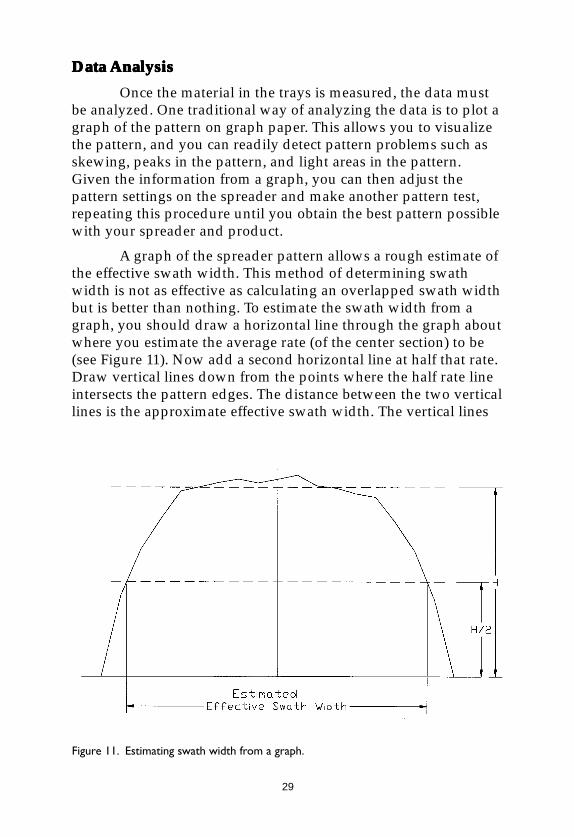
A graph of the spreader pattern allows a rough estimate ofthe effective swath width. This method of determining swathwidth is not as effective as calculating an overlapped swath widthbut is better than nothing. To estimate the swath width from agraph, you should draw a horizontal line through the graph aboutwhere you estimate the average rate (of the center section) to be(see Figure 11). Now add a second horizontal line at half that rate.Draw vertical lines down from the points where the half rate lineintersects the pattern edges. The distance between the two verticallines is the approximate effective swath width. The vertical lines
Figure 11. Estimating swath width from a graph.
30
represent the overlap points from adjacent patterns at the selectedswath width. If the pattern is skewed, one vertical line may befurther from the center than the other.
It is also possible to mathematically construct overlappedpatterns for various potential swath widths. This is done bylisting the data from the individual pans for the center swath andthen adding in the amounts at each point for assumed adjacent(identical) passes that overlap the center or primary pattern.Depending on the proposed operating mode, you will need to addleft-on-left, right-on-right or left-on-right, right-on-left. Threepatterns (center plus one on each side) may be adequate, but fortriangular patterns or narrow potential swath widths, it will benecessary to add in five or even seven patterns. Enough patternsmust be considered that all data points from overlapping passesfalling between the overlap points on the center pattern are takeninto account. All points beyond that will be a repeat of the pointsbetween the overlap points and thus are superfluous for thisexercise.
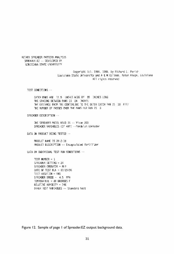
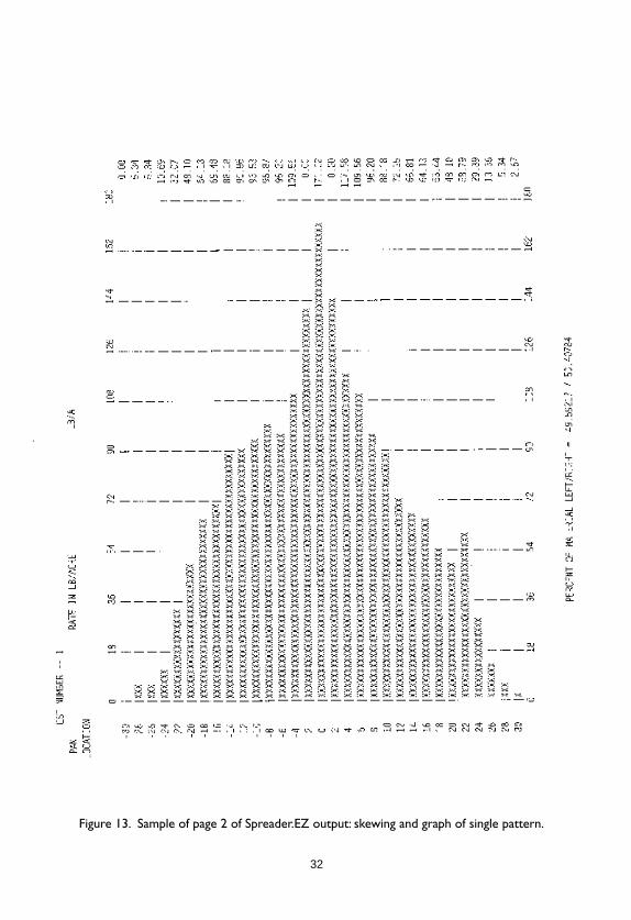
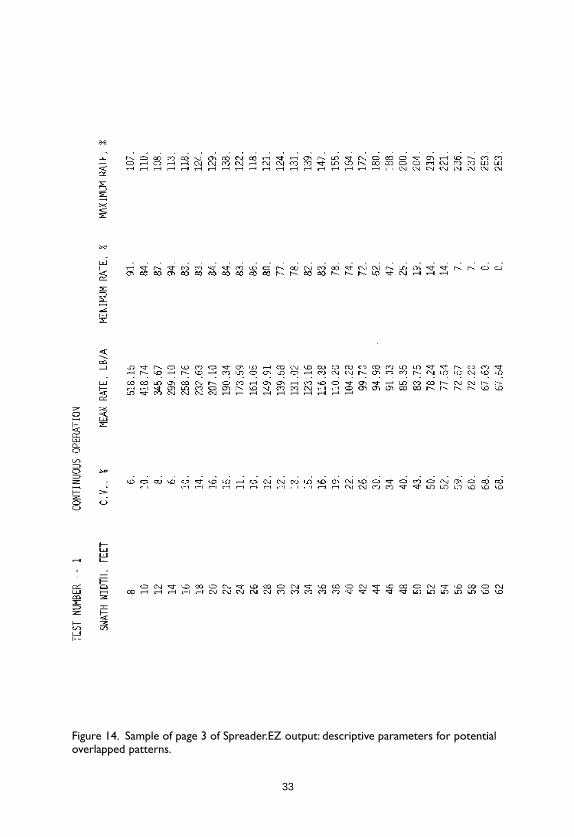
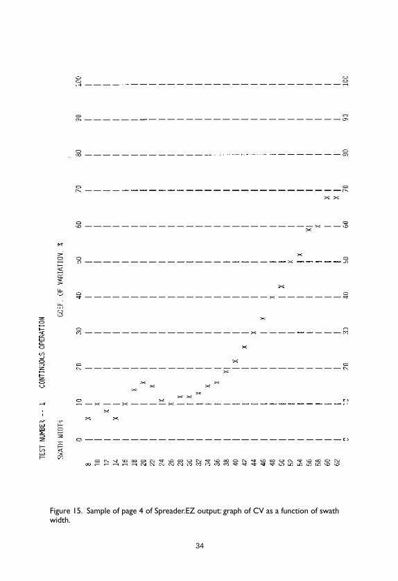
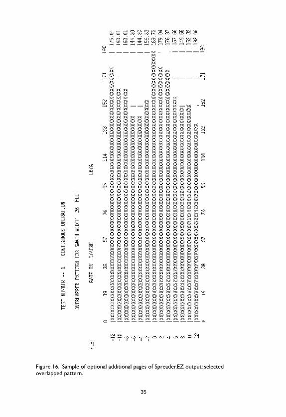
Although overlapped patterns can be analyzed manually,it is much easier to use a computer program. Several programs areavailable. A program called Spreader.EZ is available from theLouisiana Cooperative Extension Service (10, 14, 15, 19, 51). To usethis program, you first enter background information about thespreader, product, test conditions, etc. and the pattern data. Thecomputer will then print several pages of information for you.The first page will be a record of the background information(Figure 12). The second page will show a graph of a single pat-tern, a record of the apparent delivery rate at each point in thepattern, and a figure for skewing, expressed as % left, % right(Figure 13). The third page of the computer output shows a rangeof potential swath widths and several overlapped pattern param-eters for each. The parameters shown are coefficient of variation(CV), apparent mean delivery rate, and the minimum and maxi-mum points in the overlapped pattern, expressed as percentagesof the average delivery rate (Figure 14). The fourth page of theoutput shows a graph of CV as a function of overlapped swathwidth (Figure 15). Additional optional pages are possible. Eachoptional page will provide a graph of the overlapped pattern for aselected swath width (Figure 16).
31
Figure 12. Sample of page 1 of Spreader.EZ output: background data.
32
Figure 13. Sample of page 2 of Spreader.EZ output: skewing and graph of single pattern.
33
Figure 14. Sample of page 3 of Spreader.EZ output: descriptive parameters for potentialoverlapped patterns.
34
Figure 15. Sample of page 4 of Spreader.EZ output: graph of CV as a function of swathwidth.
35
Figure 16. Sample of optional additional pages of Spreader.EZ output: selectedoverlapped pattern.
36
Data InterpretationData InterpretationData InterpretationData InterpretationData Interpretation
CV is a measure of the overall uniformity of the pattern.The lower the CV, the more uniform the pattern. If the applicationrate were exactly the same all the way across the overlappedpattern, the CV would be 0%. A CV value of 10% or less is gener-ally considered acceptable for any spreading situation. With somecombinations of spreader and product, it will not be possible toobtain a CV 10% at a reasonable swath width. For most fertilizerspreading and some pesticides, a CV value 20% will be adequate.Obviously, you want the lowest CV possible with your equipmentand product, and you should make whatever adjustments areneeded to minimize CV.
Although CV gives a good “snapshot” of pattern unifor-mity, it doesn’t provide a full picture. The minimum and maxi-mum points in the overlapped pattern are critical because theydetermine whether the potential for striping is present. Ideally, theminimum and maximum points should both be as close to 100%as possible. In practice, with many broadcast spreaders a rangefrom a minimum of 80% and a maximum of 120% is about asgood as can be achieved. With most products this will be ad-equate, although some striping is still possible under certainconditions. Greening response of turfgrass (and other crops) tofertilization is somewhat of a step function rather than a continu-ous ramp function (48). For a given condition of crop, soil, andweather, there seems to be a fertilizer rate below which greeningdoes not occur and above which it does occur. If that critical ratefalls within the minimum/maximum range for an application,striping will likely occur. Striping cannot be predicted since thereis no way to predict the critical rate for any given condition.
What is acceptable in terms of CV, minimum, and maxi-mum will vary somewhat depending on expectations. If you aretop-dressing wheat, more variation across the pattern is accept-able than if you are preparing a golf green for a major tournament.Extraordinary measures may be justified for important or highlyvisible situations.
As noted earlier, the mean rate figure cited in the testresults should not be used to determine the rate setting. It willgenerally not be as accurate as a separate rate calibration.
37
Methods of Adjusting Spreader PatternsMethods of Adjusting Spreader PatternsMethods of Adjusting Spreader PatternsMethods of Adjusting Spreader PatternsMethods of Adjusting Spreader Patterns
If either the CV or the minimum or maximum rates are notacceptable for a given situation, it may be necessary to adjust thepattern and then rerun the pattern test. Several iterations of thismay be required to achieve an optimum pattern. General methodsof adjusting the pattern of a rotary broadcast spreader werediscussed in the section on Spreader Operating Characteristics.
On most walk-behind turf spreaders, the impeller turnscounterclockwise (as viewed from the top). With this configura-tion, moving the drop point on the impeller radially out will shiftthe pattern to the right since the granules will leave the impellersooner. Moving the drop point toward the center will shift thepattern left since the granules will stay on the impeller longer.Moving the drop point to the left will shift the pattern to the right,and moving the drop point to the right will shift the pattern to theleft. Partially or fully closing off the left port will reduce theamount of material thrown to the right (45). Tractor-powered andvehicle-mounted spreaders operate on similar principles, but thethrow will be toward the rear (46).
Some professional turf spreaders provide a way to restrictthe throw to one side to provide a one-sided pattern for use alongdriveways, buildings, etc. These systems typically consist of ashield or deflector that drops down on the right side and shouldalso include a convenient means of closing off the left port. If theleft port is not closed, the effect of the shield will be to pile up thematerial from the right side into a heavy band near the center.
Factors That AfFactors That AfFactors That AfFactors That AfFactors That Affect Patternfect Patternfect Patternfect Patternfect Pattern
Many spreader, product, and environmental factors canaffect the spreader pattern. When any of these factors change, anew pattern test will be needed to assure that a uniform pattern isbeing achieved.
WWWWWindindindindind
Wind will disturb a spreader pattern. Wind from the sideis more of a problem than wind in the direction of travel. A sidewind will cause the pattern to skew. Although any wind is apotential problem, the stronger the wind the worse the problemwill be. Also, lighter or smaller granules will be disturbed more
38
than larger, heavier granules for a given wind velocity. A goodgeneral rule is to avoid applications when the wind velocityexceeds 5 mph. If you can see tree leaves moving at all, it is windyenough to affect spreader patterns. Neither pattern tests nor actualapplications should be made when the wind is blowing.
Granule BounceGranule BounceGranule BounceGranule BounceGranule Bounce
Granules bounce when they impact a hard surface. Asnoted, collection trays used for pattern testing should beequipped with baffles to minimize granules bouncing out. Thisstill leaves the problem of material bouncing into the trays fromthe ground or floor. Pattern tests are most often conducted onpaved surfaces for two reasons: to allow the material to be sweptup after the test and to prevent damage to turf (or other crop)from the high rates often applied during testing because of mul-tiple passes. However, conducting pattern tests on hard surfaceswill lead to granules bouncing into trays and distorting the pat-tern. This problem has been documented in several researchstudies (27, 32, 40, 50).
The problem is most serious with larger, heavier granules(32, 50). The granules tend to bounce out from the center andaccumulate in the outer pans. This has the effect of making thepattern appear wider and heavier at the edges than it really is.Also, research studies have shown that much of the apparenttapering or feathering at the sides of broadcast spreader patternsis actually the result of granule bounce on the test surface, andthus the true pattern in the field will have much less tapering -and be less forgiving of swath width errors (32, 50). Bounce intothe pans also makes the apparent rate (based on pan data) muchhigher than the actual delivery rate. In one research study, morethan twice as much material was collected per pan in the outerpans using the standard test on concrete compared with testing anelevated spreader and deep pans that eliminated bounce (32). Theeffect is negligible with very light products such as vermiculite orsmall grades of ground corn cob. This problem of granule bounceinto the collection trays is the reason a separate rate calibration isrecommended rather than using pattern data for rate determina-tion. The effect of granule bounce in distorting the apparentpattern has been shown to be a factor of granule size and is notrelated to product bulk density.
39
Several alternative test methods have been suggested as away of correcting or compensating for the problem. The easiestway to avoid this problem is to conduct the test on turfgrass,pasture, or loosely tilled soil so that the granules will be trappedby the vegetation or soil and will not bounce. This approach cancause other problems as noted previously.
If an artificial test surface is desired, artificial turf or carpetworks well in some situations. The material can be placed underthe row of trays to reduce bounce, or sections of artificial turfwithin the overall carpeted area can actually serve as the collec-tors. This approach works well in theory but has practical limita-tions, particularly in a humid climate. Potential problems withthis approach include the problem of granules sticking in theartificial turf or carpet because of hygroscopic moisture underhigh humidity. Another problem is the tires of the spreader (andvehicle) grinding material into the carpet.
Granule TGranule TGranule TGranule TGranule Typeypeypeypeype
The effects of granule type on spreader performance havebeen discussed previously (34, 36). Movement of the granules onthe impeller is determined by the coefficient of friction betweenthe granule and the impeller. Trajectory of the granules is deter-mined by the angle and velocity of release from the impeller andthe aerodynamic characteristics of the granules. If one batch ofgranules differs from another in terms of granule size, granuleshape, granule density, or granule surface condition, the patternwill change. The granule characteristics of a particular productcan change dramatically from one batch to another, either becauseof deliberate formulation and manufacturing changes, or justoverly generous product quality specs.
In general, the larger the granule, the wider the pattern.Granule size is much more important than granule density. Sincethe mass of a granule is proportional to the cube of the radius,doubling the diameter of a granule will increase the mass by eighttimes. By comparison, the density of the most dense fertilizers isseldom more than 2-3 times the density of the lightest pesticidecarriers. Therefore, if granule size or the range of granule sizes, orthe distribution of granule sizes within a range, changes, a newpattern test is indicated.
40
Whenever possible, it is desirable to conduct pattern testsusing blank granules rather than granules containing a pesticide.This will usually not be possible for individual operators sinceblank granule versions of products are normally not available tothem. Whenever blank granules (e.g. ground corn cob, clay,peanut hulls, etc.) are available, they will be safer to handle andwill cause fewer environmental problems. Conducting tests withactive formulations can create cleanup problems. It is also expen-sive if the product is wasted. Research has shown that blankgranules often have the same pattern characteristics as granularpesticide formulations but generally do not have the same deliv-ery rate (36). Blank granules may also skew somewhat differentlybecause of differences in coefficient of friction on the impeller.Usually, blank granules can be used for pattern testing and thenformulated granules for rate testing. Some formulations mayaffect pattern if the formulation is sticky or wet and changes thecoefficient of friction of the granules on the impeller.
HumidityHumidityHumidityHumidityHumidity
Ambient relative humidity can have a major effect ondistribution pattern shape and uniformity (33). The concept ofcritical relative humidity has been discussed previously. Mostfertilizers and pesticides on fertilizer carriers are hygroscopic atsome critical relative humidity below 100%. In addition to chang-ing the flow rate of the material out of the spreader, humidity cancause other problems, particularly with rotary broadcast spreaders.
Humidity can cause fertilizer granules to soften and tobecome sticky. This can lead to buildup of fertilizer on the impel-ler surface and fins. The sticky granules can have a considerablydifferent coefficient of friction on a coating of fertilizer built up onthe impeller than dry granules have on a clean impeller. Researchhas shown that different types of fertilizer can cause somewhatdifferent problems. With some fertilizer materials such as ammo-nium nitrate that are cold water soluble, the granules become softand moist, but buildup on the impeller does not occur. In thiscase, the pattern changes with humidity level (above the CRH),but at a given humidity level there is no progressive change; thepattern remains constant at each humidity level. With an impellerturning counterclockwise on a walk-behind spreader, the effectwas to skew the pattern to the right.
41
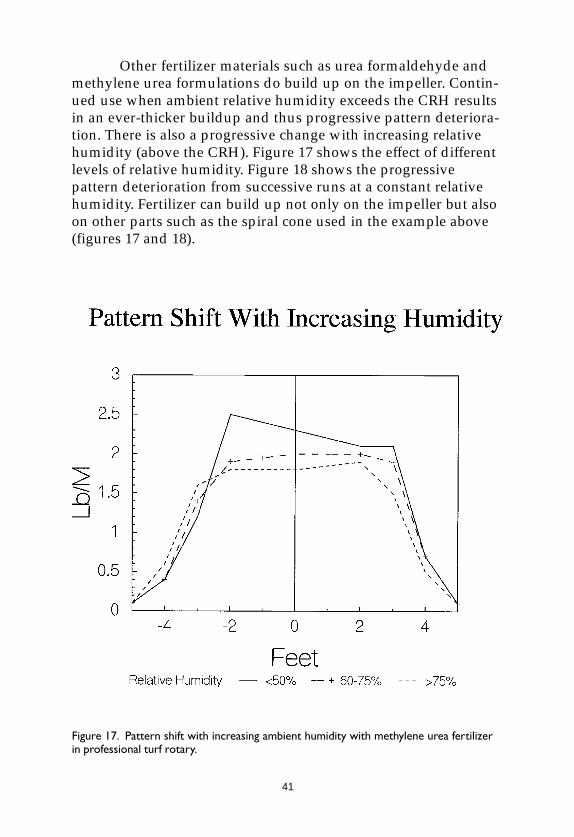
Other fertilizer materials such as urea formaldehyde andmethylene urea formulations do build up on the impeller. Contin-ued use when ambient relative humidity exceeds the CRH resultsin an ever-thicker buildup and thus progressive pattern deteriora-tion. There is also a progressive change with increasing relativehumidity (above the CRH). Figure 17 shows the effect of differentlevels of relative humidity. Figure 18 shows the progressivepattern deterioration from successive runs at a constant relativehumidity. Fertilizer can build up not only on the impeller but alsoon other parts such as the spiral cone used in the example above(figures 17 and 18).
Figure 17. Pattern shift with increasing ambient humidity with methylene urea fertilizerin professional turf rotary.
42
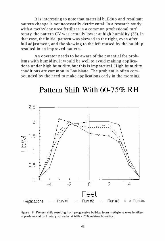
It is interesting to note that material buildup and resultantpattern change is not necessarily detrimental. In a research studywith a methylene urea fertilizer in a common professional turfrotary, the pattern CV was actually lower at high humidity (33). Inthat case, the initial pattern was skewed to the right, even afterfull adjustment, and the skewing to the left caused by the buildupresulted in an improved pattern.
An operator needs to be aware of the potential for prob-lems with humidity. It would be well to avoid making applica-tions under high humidity, but this is impractical. High humidityconditions are common in Louisiana. The problem is often com-pounded by the need to make applications early in the morning
Figure 18. Pattern shift resulting from progressive buildup from methylene urea fertilizerin professional turf rotary spreader at 60% - 75% relative humidity.
43
when humidity is highest (to avoid wind or, for turf, to avoidinterference with people). A spreader setting developed in anambient relative humidity below the CRH of the product willprobably not be correct if used at a humidity level above the CRH.If it is necessary to make applications of a fertilizer or fertilizer-based pesticide at a humidity level above its CRH, a pattern testshould be conducted at the higher humidity level. The operatorshould also be aware of progressive buildup and thus progressivepattern change with some products. This may necessitate frequentcleaning of the impeller or incremental changes in pattern settingas the application progresses.
SpeedSpeedSpeedSpeedSpeed
Speed of operation can affect pattern uniformity as well asdelivery rate (17, 20). On a few spreaders, the distributor(impeller[s] or spout) is driven independently of ground speed bya tractor PTO, a hydraulic motor, or an electric motor. When thedistributor is independently driven, ground speed should havelittle effect on pattern as long as the distributor speed is correct.On other spreaders, the distributor is ground driven. This is truefor most walk-behind spreaders and a few others. When thedistributor is ground driven, any change in ground speed willchange distributor speed. This will often cause a change in effec-tive swath width. In general, if the distributor speed is reduced,granules will not be thrown as far. Note that this is not alwaystrue. Because of air resistance, thrown granules tend to have a“terminal velocity.” Throwing them off the distributor faster doesnot necessarily make them fly any further since they are immedi-ately slowed by air resistance. On the other hand, the standardspeed may be fast enough that a reduction in speed has no effecton width of throw. In most cases, however, changing groundspeed will change the effective swath width of a ground-drivenspreader.
Rotary broadcast spreaders can also have changes inpattern shape as well as width if the impeller speed changes. Witheverything else equal, the faster the impeller turns, the earlier(angularly) the granules will be thrown off. Thus at faster speeds,the granules leave the impeller at a lower angle (relative to thedrop point) and at slower speeds, so the granules will ride theimpeller farther before being thrown off.
44
Research studies have shown that, in practice, patternchanges do not become statistically significant until the speedchange exceeds approximately 25% (17, 20). A decrease in speedhas more effect on pattern quality than an increase in speed(because of the “terminal velocity” factor). If the operating widthis held constant as speed changes, skewing will change signifi-cantly before either CV or minimum/maximum points changemuch (17, 20).
Roughness of SurfaceRoughness of SurfaceRoughness of SurfaceRoughness of SurfaceRoughness of Surface
The surface on which a broadcast spreader is operated canaffect the distribution pattern. This effect is completely differentfrom the problem of granule bounce on hard surfaces as discussedpreviously. Fertilizer spreader pattern tests are generally con-ducted on smooth surfaces, but in actual use, spreaders are fre-quently operated on rough surfaces. A turf spreader, for example,must occasionally operate over tree and shrub roots, rocks, etc. inthe turf.
Surprisingly, a rough operating surface had a significantdetrimental effect on spreader pattern in a research study (31).Under rough conditions, the patterns consistently skewed to theright (counterclockwise impeller rotation on a walk-behindspreader). Larger, spherical granules were less affected than weresmall irregular granules. Since the trend seems to be consistent, itwould be appropriate to consider surface roughness when deter-mining spreader pattern settings.
A spreader pattern setting is frequently a compromise.One setting might minimize skewing while another setting givesa wider optimum pattern, for instance. Since a single “best”pattern setting is frequently not obvious, it would be appropriateto select a pattern setting that would help correct the expectedpattern shift if a rough operating surface is expected.
Impeller/Spout AngleImpeller/Spout AngleImpeller/Spout AngleImpeller/Spout AngleImpeller/Spout Angle
Virtually all broadcast spreaders are designed to operatebest with the impeller or spout level. This may not be the same ashaving the hopper level. On some spreaders, the hopper is angleddown in the back to facilitate filling. It is the impeller or spout, notthe hopper, that must be level. If the impeller or spout is out oflevel side to side, the pattern will be skewed and the spreader will
45
probably throw farther to the high side. A more likely scenario isto have the spreader out of level front to rear. With a pendulumspreader, the primary effect of being out of level front to back willbe a change in swath width. With a rotary spreader, both widthand pattern skewing can be affected by the impeller being out oflevel front to rear.
It is important that the impeller or spout be level forpattern testing and also for field applications. Operators shouldbe warned to level tractor spreaders when hitching and to holdthe handle of walk-behind spreaders at the correct height to give alevel impeller.
Granule SegregationGranule SegregationGranule SegregationGranule SegregationGranule Segregation
When a product is a physical mix of two or more compo-nents, segregation in application is a potential problem. Larger,heavier granules throw farther than smaller, lighter granules. If,for instance, the nitrogen component of a mixed fertilizer iscomposed of small granules and the phosphorus and potashcomponents are composed of larger granules, the resulting patternwill have a higher percentage of nitrogen near the center of eachpass with a higher percentage of P and K near the overlap points.A similar situation can occur when pesticides are impregnated onone fraction of a mixed granule product. Even though the totalapplication rate may be fairly uniform, the distribution of pesti-cide across the pattern can be quite uneven.
Alternate Pattern TAlternate Pattern TAlternate Pattern TAlternate Pattern TAlternate Pattern Test Proceduresest Proceduresest Proceduresest Proceduresest Procedures
There are some alternate ways of conducting pattern teststhat are easier and faster, but they provide less reliable informa-tion. One common method consists of making a spreader passwithout collection trays and just throwing the material on theground. The operator then estimates pattern width by visuallyexamining the throw pattern on the ground. This approach hastwo major problems. First, the granules will bounce on a hardsurface and distort the pattern. Second, it is very difficult toestimate width from a pattern on the ground. The first concerncan be addressed by making the pass over turf or over a strip ofcarpet perpendicular to the direction of travel. While this willreduce bounce, it will also make visual evaluation of the pattern
46
even more difficult. A common error in using this method is tomeasure the total throw width and then use that as the effectivepattern width.
Tests can also be run using many different tray systems (9).One well-known test facility uses no pans; they place dividers onthe floor and then sweep up and measure the material betweenthe dividers. Other test facilities have used smaller or largercollection trays. Research studies have shown that using smaller(narrower) collection trays results in higher CV values for thesame pattern (9). Statistical theory has been used to verify andquantify this observation (49). The apparent effective swath widthcan also be very different with different collection trays.
A research study was conducted comparing greeningresponse of turfgrass to spreader patterns obtained from differenttypes and sizes of collection trays (48). The pattern test resultsfrom 11.5-inch wide trays best predicted the greening response ofthe turfgrass.
Pattern EstimationPattern EstimationPattern EstimationPattern EstimationPattern Estimation
Pattern shape and effective swath width can be estimatedwithout actually measuring the material in the collection trays.The material in the trays can be poured into a series of test tubesor small vials and then the containers lined up in order. Theheight of material in the containers becomes an approximategraph of the spreader pattern. For this method to be effective, it isnecessary to make several passes or use a higher rate setting (oruse larger pans) so that the amount collected is large enough toreadily differentiate visually. Once a pattern is established in thismanner, the operator can detect and correct any major patternproblems. Effective swath width can be estimated using themethod described previously for determining effective swathwidth from a graph. This method is less accurate than measuringthe material and analyzing the results, but much more accuratethan just throwing material on the ground.
Another method of pattern estimation has been suggestedfor use with pendulum spreaders, but research has proved that itdoes not work (39). The suggested method is to operate thependulum spreader briefly with the tractor stationary and mark
47
the outermost throw point on each side of the spreader. Theeffective swath width was claimed to be half the total throwdistance. This method does not work. Testing showed that thismethod resulted in a predicted width that was less than theeffective swath width. This error in swath width results in a highand unacceptable CV.
Use of SpreadersUse of SpreadersUse of SpreadersUse of SpreadersUse of SpreadersOperating ModesOperating ModesOperating ModesOperating ModesOperating Modes
Spreaders can be operated in different modes. Selecting thecorrect mode has a significant effect on the quality of the over-lapped pattern from broadcast spreaders. Operating mode is notgenerally a concern with drop spreaders, as long as the correctswath width is used.
Back-and-Forth vs. CirBack-and-Forth vs. CirBack-and-Forth vs. CirBack-and-Forth vs. CirBack-and-Forth vs. Circuitouscuitouscuitouscuitouscuitous
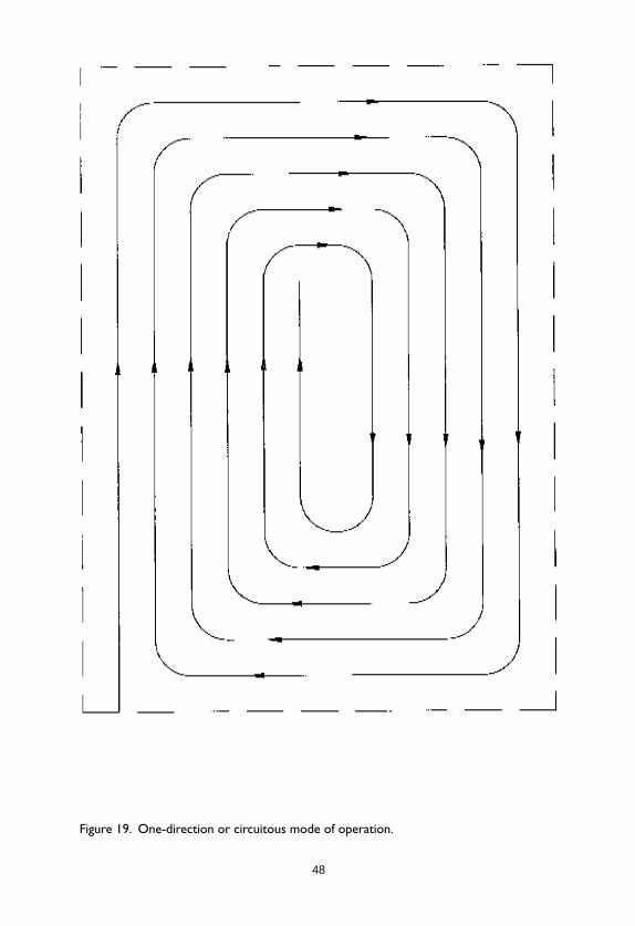
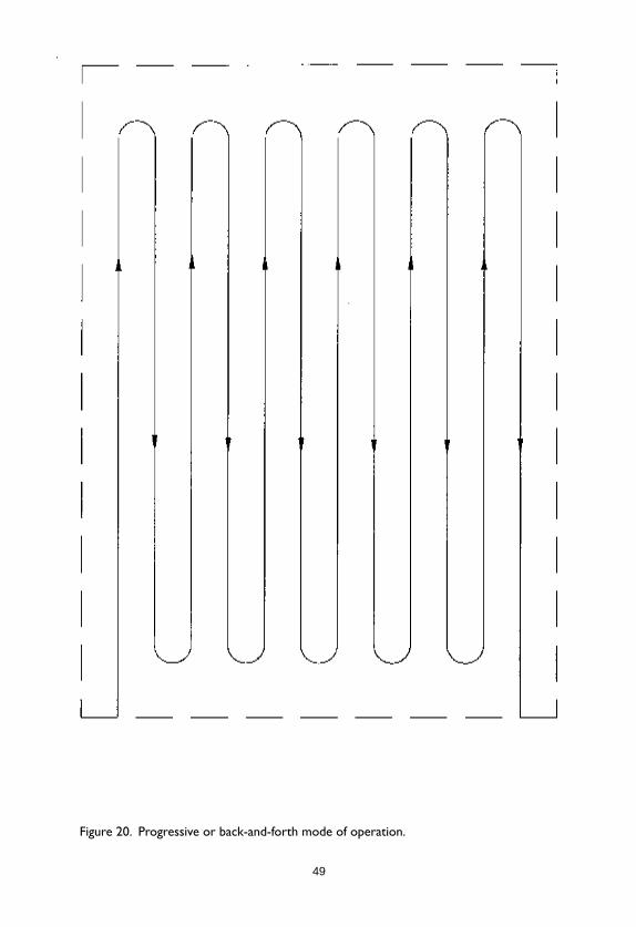
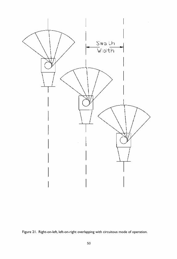
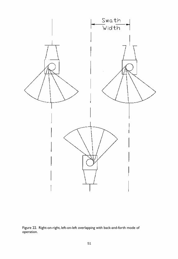
The two most common modes for spreader operation areone-direction or circuitous (Figure 19) and progressive or back-and-forth (Figure 20). The circuitous mode of operation results inthe right side of a pattern overlapping with the left side of theadjacent pattern (Figure 21). The back-and-forth mode results inthe right side of the pattern overlapping with the right side of theadjacent pattern (Figure 22). In theory, the back-and-forth modeshould exaggerate skewing problems and the circuitous modeshould partially compensate for skewing problems. In practice, itmakes very little difference if the pattern is decent to begin with.Research has shown that a circuitous mode of operation offers astatistically significant improvement in overlapped pattern unifor-mity when an overlapped pattern based on back-and-forth opera-tion is very poor (28). When the back-and-forth spreader patternis generally acceptable (CV 20%), there is statistically no advan-tage to using the more cumbersome circuitous mode of operation.
The circuitous mode can be used to help correct badspreader patterns, but it should be used for this purpose only afterall possible adjustments have been made. There is no problemwith using a circuitous pattern, but it is generally more cumber-some in the field.
48
Figure 19. One-direction or circuitous mode of operation.
49
Figure 20. Progressive or back-and-forth mode of operation.
50
Figure 21. Right-on-left, left-on-right overlapping with circuitous mode of operation.
51
Figure 22. Right-on-right, left-on-left overlapping with back-and-forth mode ofoperation.
52
Half-WHalf-WHalf-WHalf-WHalf-Width vs. Right-Angleidth vs. Right-Angleidth vs. Right-Angleidth vs. Right-Angleidth vs. Right-Angle
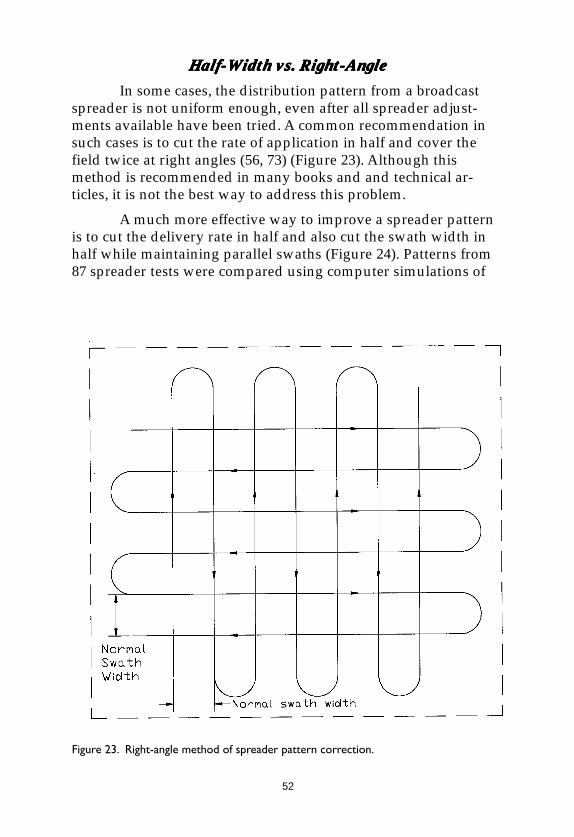
In some cases, the distribution pattern from a broadcastspreader is not uniform enough, even after all spreader adjust-ments available have been tried. A common recommendation insuch cases is to cut the rate of application in half and cover thefield twice at right angles (56, 73) (Figure 23). Although thismethod is recommended in many books and and technical ar-ticles, it is not the best way to address this problem.
A much more effective way to improve a spreader patternis to cut the delivery rate in half and also cut the swath width inhalf while maintaining parallel swaths (Figure 24). Patterns from87 spreader tests were compared using computer simulations of
Figure 23. Right-angle method of spreader pattern correction.
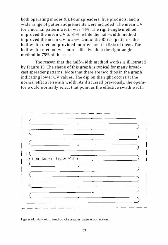
53
both operating modes (8). Four spreaders, five products, and awide range of pattern adjustments were included. The mean CVfor a normal pattern width was 44%. The right-angle methodimproved the mean CV to 31%, while the half-width methodimproved the mean CV to 25%. Out of the 87 test patterns, thehalf-width method provided improvement in 98% of them. Thehalf-width method was more effective than the right-anglemethod in 75% of the cases.
The reason that the half-width method works is illustratedby Figure 15. The shape of this graph is typical for many broad-cast spreader patterns. Note that there are two dips in the graphindicating lower CV values. The dip on the right occurs at thenormal effective swath width. As discussed previously, the opera-tor would normally select that point as the effective swath width
Figure 24. Half-width method of spreader pattern correction.
54
since it represents a lower CV than narrower or wider widths. Theother dip in CV occurs at a width approximately half the normalwidth, and the CV at this point is somewhat lower than the CV atthe normal width. Figure 14 shows another facet of this issue. Notonly is the CV reduced at the half-width, but the minimum andmaximum points are improved also. Since the difference betweenthe minimum and maximum points is what causes striping,reducing this variation will reduce striping.
The right-angle method will generally reduce the CV butwill not change the minimum and maximum points in the pat-tern. When the right-angle method is used, the extremes in thepattern (i.e. minimum and maximum) will remain exactly thesame, but less of the total pattern area will experience those ex-tremes. The effect of using the right-angle method is to changefrom striping to a diagonal checkerboard pattern, but there willstill be the same minimum and maximum points. Therefore,although the CV will be reduced somewhat, the potential forvariation in greening isisisisis notnotnotnotnot reduced. With the half-width method,the potential for variation in greening isisisisis reduced.
The half-width method is not routinely needed with goodspreaders. If the spreader can be adjusted to give an acceptablepattern with a normal swath width, then the normal swath widthshould be used since it will be much faster. If the overlappedpattern is not good enough even after all feasible adjustmentshave been made, then the half-width method can be used tofurther improve the pattern. The half-width method is also usefulwhen the operator wants extra “insurance” of good uniformity.An example would be fertilizing golf greens before a major tour-nament. In such a case, the need to avoid fertilizer striping at allcosts might justify the extra time involved to use the half-widthmethod.
With some low-quality homeowner and semi-professionalspreaders, the half-width method is needed routinely since thespreaders will not deliver adequate uniformity at a normal swathwidth with most materials. These spreaders tend to have a patternthat is triangular rather than trapezoidal and is heavily skewedwith most products (30). Figure 25 shows a typical pattern for thistype of spreader. Since these spreaders have no means of patternadjustment, it is necessary to use the half-width method to obtain
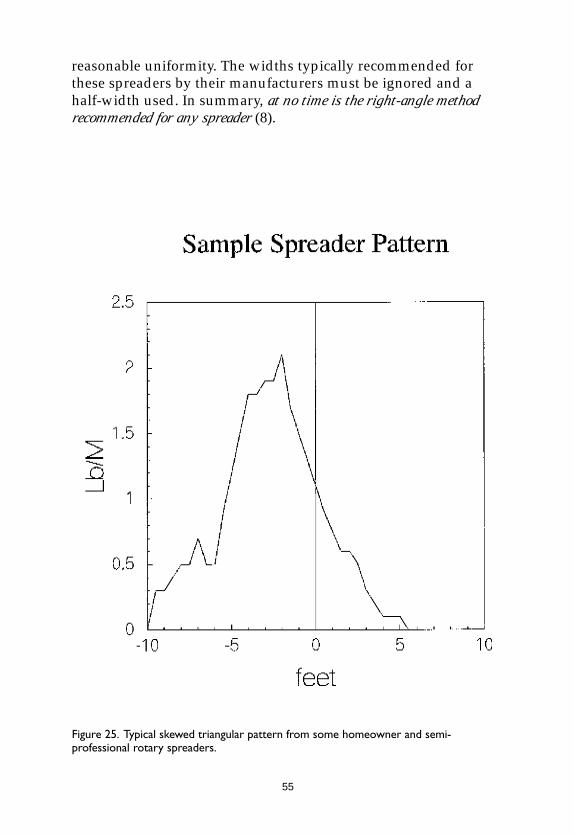
55
reasonable uniformity. The widths typically recommended forthese spreaders by their manufacturers must be ignored and ahalf-width used. In summary, at no time is the right-angle methodrecommended for any spreader (8).
Figure 25. Typical skewed triangular pattern from some homeowner and semi-professional rotary spreaders.
56
Header StripsHeader StripsHeader StripsHeader StripsHeader Strips
Standard broadcast spreader pattern tests evaluate thesteady-state patterns as the spreader is operated back-and-forthacross a field but do not consider the transient patterns at the endsof the field. When the typical back-and-forth pattern is used,header strips are needed along each end of the field. The headerstrips are usually single spreader passes along each end of thefield in a direction perpendicular to the main spreader operation.The header strips provide a place to turn off the spreader, turn itaround, and turn it back on. The spreader should not be turned onor off while standing still; it should be moving when turned on oroff to avoid excessive application.
The use of header strips can result in very uniform appli-cation with drop-type spreaders if the spreader is turned off andon at exactly the edge of the header strip. With broadcast spread-ers, the application rate in and near the header strips is seldomuniform. Since the header strip generally consists of a singlespreader pass, there is no overlap in the header strip itself, and thepattern tapers to both sides. When the regular passes enter andleave the header strip, they will be rounded. The beginning of apass will be concave, and the end of a pass will be convex asshown in Figure 26. When these rounded passes cross the taperedheader strip, unpredictable patterns of high and low rate result.This can be demonstrated for any given spreader pattern data,and examples have been studied, but no consistent general pat-tern prediction is possible. Suffice it to say that the pattern in theheader strips will be erratic. The operator can only do his best toturn the spreader off and on consistently and thus try to minimizethe inherent variability (42).
Some small homeowner spreaders do not have a means ofshutting off the flow while turning at the ends of the field (orlawn). Consumer research showed that many homeowners didnot use the on-off lever anyway; they just left the spreader onwhile making turns. Based on this research, a rotary spreader wasdesigned that had no remote on-off linkage (6, 44). It did, how-ever, have a small ring molded around the impeller that stoppedthe product flow after a small amount of product built up on theimpeller - if the impeller was not rotating. This prevented materialbeing discharged when the operator stopped, but allowed normal
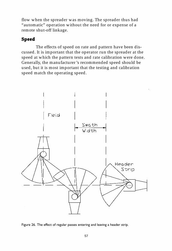
57
flow when the spreader was moving. The spreader thus had“automatic” operation without the need for or expense of aremote shut-off linkage.
SpeedSpeedSpeedSpeedSpeed
The effects of speed on rate and pattern have been dis-cussed. It is important that the operator run the spreader at thespeed at which the pattern tests and rate calibration were done.Generally, the manufacturer’s recommended speed should beused, but it is most important that the testing and calibrationspeed match the operating speed.
Figure 26. The effect of regular passes entering and leaving a header strip.

58
LevelLevelLevelLevelLevel
Most spreaders are designed to be level while operating.With broadcast spreaders, that means that the impeller or spoutshould be in a horizontal plane. For a drop spreader, it generallymeans that the hopper should be level. With tractor- or vehicle-mounted spreaders, the spreader should be leveled when hitched.With walk-behind spreaders, the operator must hold the spreaderlevel. There is a tendency for operators to change the handleheight and thus the angle of the spreader when pushing hard(uphill, full spreader, etc.). Operators need to be warned of theimplications of this and be cautioned to hold the spreader level.
Care and Maintenance of SpreadersCare and Maintenance of SpreadersCare and Maintenance of SpreadersCare and Maintenance of SpreadersCare and Maintenance of SpreadersCleaningCleaningCleaningCleaningCleaning
The single most important step in maintaining a fertilizerspreader is to clean it thoroughly after each use (2, 4, 5, 41). Thatdoesn’t mean after each season’s use or even every week; it meansevery day. The spreader should be emptied and thoroughly washedevery day it is used. Cold water is normally adequate unless thereis a buildup of cold-water-insoluble fertilizer. With some ureaformaldehyde and methylene urea fertilizers, it is difficult toremove deposits with cold water unless the buildup is scrubbed.Hot water will often loosen the buildup and allow it to be rinsedoff. If the buildup is in the hopper, it often helps to close thespreader and fill the hopper. By the time the water has all drainedout, the material will usually be loosened.
Some encapsulated slow-release fertilizers present aspecial problem since the sulfur, wax, or polymer coating maybuild up and be water-insoluble. Either abrasion or a solvent willbe needed to remove these materials. Either way, care must betaken to avoid damaging the spreader.
Once the spreader has been washed clean, it should beallowed to dry before storage. Parking the spreader in the sun-shine for a hour or so is an excellent way to promote drying. Ifwater is trapped in pockets anywhere in or on the spreader, thespreader may have to be tipped or inverted before it will dry.
59
Lubrication and ProtectionLubrication and ProtectionLubrication and ProtectionLubrication and ProtectionLubrication and Protection
Properly lubricating a spreader is important. Lubricatingthe wrong parts or using the wrong lubricant can do more dam-age than not lubricating at all. The best guide in determining howto lubricate a spreader is the operator’s manual furnished by themanufacturer. Because of different designs and the use of differentmaterials, lubrication recommendations will vary.
Damage FrDamage FrDamage FrDamage FrDamage From Solventsom Solventsom Solventsom Solventsom Solvents
Some common lubricants are solvents for some of thematerials commonly used in spreader construction. An example isWD-40® which dissolves ABS plastic, a material commonly usedfor knobs and other parts on homeowner spreaders. If somespreaders are lubricated indiscriminately with WD-40®, the ABSparts will begin to soften, weaken, or even dissolve.
Other solvents can damage the finish on spreaders. Manymetal spreaders now use a powder-coated finish (3). Commonpowder coatings such as epoxy, polyurethane, and polyester arethermoset plastics and tend to be unaffected by most solvents.Other coatings may be more easily damaged. Plastic hoppers andimpellers can also be damaged. Fiberglass-reinforced hoppers aregenerally made with thermoset materials such as polyester andmay be less damaged by solvents than parts made of thermoplas-tic materials such as polystyrene or ABS. Thermoplastic partsmade of polyolefins such as polyethylene and polypropylene arerelatively immune to many solvents.
The general rule for lubrication remains: follow themanufacturer’s instructions.
Damage FrDamage FrDamage FrDamage FrDamage From Tom Tom Tom Tom Too Much Groo Much Groo Much Groo Much Groo Much Greaseeaseeaseeaseease
More walk-behind rotary spreader gears have been dam-aged from over-lubrication than from under-lubrication. The gearson many spreaders should not be greased at all. Gears that aremade of nylon impregnated with molybdenum disulfide are self-lubricating. Greasing any gear set increases the risk of dirtbuildup and thus abrasion damage to the gears. Keeping thecover on the gear set will help prevent dirt buildup. If the manu-facturer recommends grease, then grease in moderation; if the
60
manufacturer does not recommend grease, don’t grease it. Ingeneral, open gears are better off without grease.
Excessive lubrication of other parts, too, can lead to dirtbuildup and abrasive wear. Lubricate in moderation, and onlywhen recommended.
StorageStorageStorageStorageStorage
Most important, fertilizer spreaders should be completelyclean with no remaining fertilizer residue when stored. Storespreaders inside away from sunlight, heat, and moisture. Nothingshould be piled on or in spreaders during storage; this coulddeform the hopper and/or wheels and could also acceleratecorrosion. Spreaders should be lubricated per the operatinginstructions before storage.
Spreaders should be stored with the mechanism open or“on.” This relieves the load on the operating spring and alsoprevents material or moisture being trapped in the hopper. Therate setting should be moved to the largest setting prior to open-ing the mechanism and storing the spreader.
MisuseMisuseMisuseMisuseMisuse
A fertilizer spreader is neither a lawn cart nor a wheelbar-row. It should not be used as such. A spreader contains delicatemetering components that can be damaged by rough handling. Itis particularly important to avoid impact or damage to the ratemetering components when handling or storing spreaders. Theshut-off bar on drop spreaders and the shut-off plate on broadcastspreaders are especially delicate and subject to damage fromrough handling.
61
For Additional InformationFor Additional InformationFor Additional InformationFor Additional InformationFor Additional InformationStandardsStandardsStandardsStandardsStandards
The following ASAE standards relate to fertilizer spreaders and may beof interest to readers.
ASAE S327.2. 1998. Terminology and Definitions for AgriculturalChemical Application. American Society of AgriculturalEngineers, Niles, MI.
ASAE S341.2. 1998. Procedure for Measuring DistributionUniformity and Calibrating Granular BroadcastSpreaders. American Society of Agricultural Engineers,Niles, MI.
ASAE EP371.1. 1998. Procedure for Calibrating GranularApplicators. American Society of Agricultural Engineers,Niles, MI.
ReferencesReferencesReferencesReferencesReferences
Additional information on this subject can be found in the followingarticles and papers by the author of this bulletin.
1. Amerine, J. D. and R. L. Parish. 1979. Development of a rotaryspreader with an elliptical shroud. ASAE paper number79-1511.
2. Parish, P. A. and R. L. Parish. 1988. How to choose a lawnspreader. Popular Mechanics 165(5):155-156.
3. Parish, R. L. 1978. Epoxy powder coating for lawn spreaders.AFP/SME Powder Coating Conference, Cincinnati, Ohio.
4. Parish, R. L. 1981. Selection, care and use of granularapplicators. American Lawn Applicator 2(3):20-24 and2(4):16-19.
5. Parish, R. L. 1981. Care and use of granular applicators. GolfCourse Management 49(4):35-38.
6. Parish, R. L. 1985. A spreader innovation. American LawnApplicator 6(7):52-54.
7. Parish, R. L. 1985. Spread it right. American Lawn Applicator6(7):56-58.

62
8. Parish, R. L. 1986. Evaluation of two methods of fertilizerspreader pattern correction. Transactions of the ASAE29(2):370-373.
9. Parish, R. L. 1986. Comparison of spreader pattern evaluationmethods. Applied Engineering in Agriculture 2(2):89-93.
10. Parish, R. L. 1986. Do-it-yourself pattern evaluation forgranular application. ASAE paper number AA86-007presented at the NAAA/ASAE Technical Session,Acapulco, Mexico, December 1-4.
11. Parish, R. L. 1986. Is spreader data reliable? American LawnApplicator 7(1):56-60.
12. Parish, R. L. 1986. Drop spreader complications. AmericanLawn Applicator 7(4):46-47.
13. Parish, R. L. 1986. Spreaders: theory vs. results. AmericanLawn Applicator 7(12):31-32, 34, 46.
14. Parish, R. L. 1986. Granular pattern analysis. Agrichemical Age30(8):18-19.
15. Parish, R. L. 1986. How accurate are your spreaders? FertilizerProgress 17(5):55-61.
16. Parish, R. L. 1987. Fundamentals of fertilizer spreaders.Southern Turfgrass 22(1):19-21.
17. Parish, R. L. 1987. Rotary spreader speed effects. AmericanLawn Applicator 8(6):35-36, 38.
18. Parish, R. L. 1987. Maintaining your spreader. American LawnApplicator 8(7):32-33.
19. Parish, R. L. 1987. A computer program for spreader patternanalysis. Applied Engineering in Agriculture 3(1):14-16.
20. Parish, R. L. 1987. The effect of speed on performance of arotary spreader. Applied Engineering in Agriculture 3(1):17-19.
21. Parish, R. L. 1987. Spread it right. The Louisiana TurfgrassBulletin 24(2):6-8.
22. Parish, R. L. 1987. Drop spreader complications. The LouisianaTurfgrass Bulletin 24(3):1-3.
24. Parish, R. L. 1988. Correcting spreader pattern data. AmericanLawn Applicator 9(10):28-29.
25. Parish, R. L. 1988. An improved spreader pattern starts withthe spreader. American Lawn Applicator 9(11):99-101.

63
26. Parish, R. L. 1989. Improving uniformity with broadcastgranular applicators. Paper number 118 presented at the1989 annual meeting, Weed Science Society of America,Dallas, TX.
27. Parish, R. L. 1989. Be careful how you conduct spreaderpattern tests. The Louisiana Turfgrass Bulletin 26(3):11-12.
28. Parish, R. L. 1990. Spreader pattern as influenced byoperating mode. Applied Engineering in Agriculture6(6):687-690.
29. Parish, R. L. 1990. Attaining uniform patterns: a constantchallenge. Lawn & Landscape Maintenance 11(9):46-48.
30. Parish, R. L. 1991. Effect of an adjustable drop point on turffertilizer spreader patterns. Applied Engineering inAgriculture 7(1):5-9.
31. Parish, R. L. 1991. Effect of rough operating surface on rotaryspreader distribution pattern. Applied Engineering inAgriculture 7(1):61-63.
32. Parish, R. L. 1991. Effect of material bouncing into and out ofcollection pans on observed spreader distribution pattern.Applied Engineering in Agriculture 7(3):311-315.
33. Parish, R. L. 1991. The effect of relative humidity on rotaryturf spreader patterns. Applied Engineering in Agriculture7(5):541-544.
34. Parish, R. L. 1992. Distribution of peanut hull granules withcommercial turf applicators. Applied Engineering inAgriculture 8(1):13-14.
35. Parish, R. L. 1992. An easy way to evaluate fertilizer spreaderpatterns. Louisiana Turfgrass Association Bulletin 29:9-10.
36. Parish, R. L. 1993. The effect of formulation on the applicationcharacteristics of pesticide granules. Applied Engineering inAgriculture 9(5):419-421.
37. Parish, R. L. 1994. Sensitivity of a hand-cranked nurseryspreader to operator variables. Journal of EnvironmentalHorticulture 12(4):187-190.
38. Parish, R. L. 1995. Pattern skewing with a pendulumspreader. Applied Engineering in Agriculture 11(4):511-512.
39. Parish, R. L. 1995. Estimating effective swath width with apendulum spreader. Applied Engineering in Agriculture11(4):507-509.
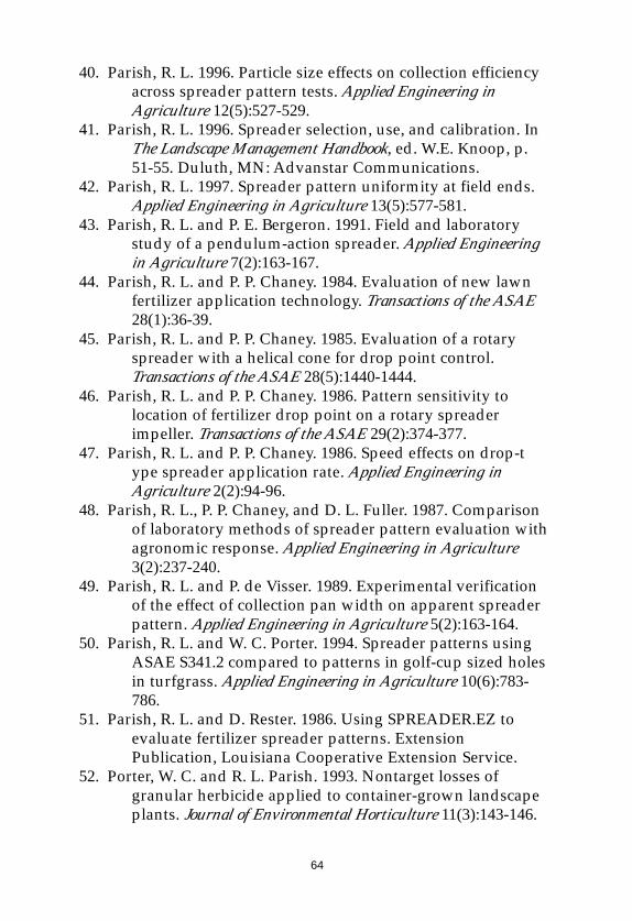
64
40. Parish, R. L. 1996. Particle size effects on collection efficiencyacross spreader pattern tests. Applied Engineering inAgriculture 12(5):527-529.
41. Parish, R. L. 1996. Spreader selection, use, and calibration. InThe Landscape Management Handbook, ed. W.E. Knoop, p.51-55. Duluth, MN: Advanstar Communications.
42. Parish, R. L. 1997. Spreader pattern uniformity at field ends.Applied Engineering in Agriculture 13(5):577-581.
43. Parish, R. L. and P. E. Bergeron. 1991. Field and laboratorystudy of a pendulum-action spreader. Applied Engineeringin Agriculture 7(2):163-167.
44. Parish, R. L. and P. P. Chaney. 1984. Evaluation of new lawnfertilizer application technology. Transactions of the ASAE28(1):36-39.
45. Parish, R. L. and P. P. Chaney. 1985. Evaluation of a rotaryspreader with a helical cone for drop point control.Transactions of the ASAE 28(5):1440-1444.
46. Parish, R. L. and P. P. Chaney. 1986. Pattern sensitivity tolocation of fertilizer drop point on a rotary spreaderimpeller. Transactions of the ASAE 29(2):374-377.
47. Parish, R. L. and P. P. Chaney. 1986. Speed effects on drop-type spreader application rate. Applied Engineering inAgriculture 2(2):94-96.
48. Parish, R. L., P. P. Chaney, and D. L. Fuller. 1987. Comparisonof laboratory methods of spreader pattern evaluation withagronomic response. Applied Engineering in Agriculture3(2):237-240.
49. Parish, R. L. and P. de Visser. 1989. Experimental verificationof the effect of collection pan width on apparent spreaderpattern. Applied Engineering in Agriculture 5(2):163-164.
50. Parish, R. L. and W. C. Porter. 1994. Spreader patterns usingASAE S341.2 compared to patterns in golf-cup sized holesin turfgrass. Applied Engineering in Agriculture 10(6):783-786.
51. Parish, R. L. and D. Rester. 1986. Using SPREADER.EZ toevaluate fertilizer spreader patterns. ExtensionPublication, Louisiana Cooperative Extension Service.
52. Porter, W. C. and R. L. Parish. 1993. Nontarget losses ofgranular herbicide applied to container-grown landscapeplants. Journal of Environmental Horticulture 11(3):143-146.
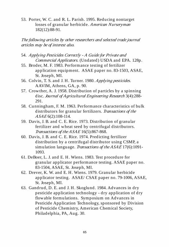
65
53. Porter, W. C. and R. L. Parish. 1995. Reducing nontargetlosses of granular herbicide. American Nurseryman182(12):88-91.
The following articles by other researchers and selected trade journalarticles may be of interest also.
54. Applying Pesticides Correctly - A Guide for Private andCommercial Applicators. (Undated) USDA and EPA. 128p.
55. Broder, M. F. 1983. Performance testing of fertilizerapplication equipment. ASAE paper no. 83-1503, ASAE,St. Joseph, MI.
56. Colvin, T. S. and J. H. Turner. 1980. Applying pesticides.AAVIM, Athens, GA, p. 90.
57. Crowther, A. J. 1958. Distribution of particles by a spinningdisc. Journal of Agricultural Engineering Research 3(4):288-291.
58. Cunningham, F. M. 1963. Performance characteristics of bulkdistributors for granular fertilizers. Transactions of theASAE 6(2):108-114.
59. Davis, J. B. and C. E. Rice. 1973. Distribution of granularfertilizer and wheat seed by centrifugal distributors.Transactions of the ASAE 16(5):867-868.
60. Davis, J. B. and C. E. Rice. 1974. Predicting fertilizerdistribution by a centrifugal distributor using CSMP, asimulation language. Transactions of the ASAE 17(6):1091-1093.
61. DeBoer, L. J. and E. H. Wiens. 1983. Test procedure forgranular applicator performance testing. ASAE paper no.83-1504, ASAE, St. Joseph, MI.
62. Drever, K. W. and E. H. Wiens. 1979. Granular herbicideapplicator testing. ASAE/CSAE paper no. 79-1006, ASAE,St. Joseph, MI.
63. Gandrud, D. E. and J. H. Skoglund. 1984. Advances in drypesticide application technology - dry application of dryflowable formulations. Symposium on Advances inPesticide Application Technology, sponsored by Divisionof Pesticide Chemistry, American Chemical Society,Philadelphia, PA, Aug. 30.
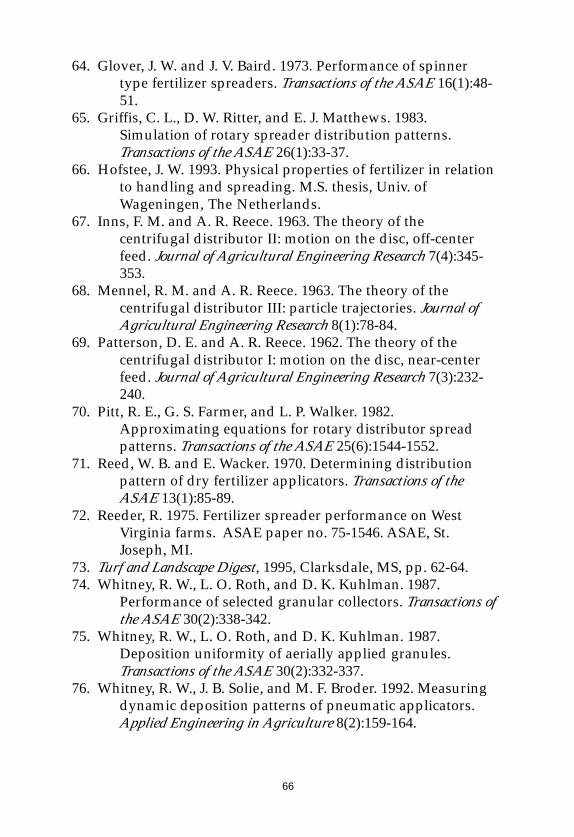
66
64. Glover, J. W. and J. V. Baird. 1973. Performance of spinnertype fertilizer spreaders. Transactions of the ASAE 16(1):48-51.
65. Griffis, C. L., D. W. Ritter, and E. J. Matthews. 1983.Simulation of rotary spreader distribution patterns.Transactions of the ASAE 26(1):33-37.
66. Hofstee, J. W. 1993. Physical properties of fertilizer in relationto handling and spreading. M.S. thesis, Univ. ofWageningen, The Netherlands.
67. Inns, F. M. and A. R. Reece. 1963. The theory of thecentrifugal distributor II: motion on the disc, off-centerfeed. Journal of Agricultural Engineering Research 7(4):345-353.
68. Mennel, R. M. and A. R. Reece. 1963. The theory of thecentrifugal distributor III: particle trajectories. Journal ofAgricultural Engineering Research 8(1):78-84.
69. Patterson, D. E. and A. R. Reece. 1962. The theory of thecentrifugal distributor I: motion on the disc, near-centerfeed. Journal of Agricultural Engineering Research 7(3):232-240.
70. Pitt, R. E., G. S. Farmer, and L. P. Walker. 1982.Approximating equations for rotary distributor spreadpatterns. Transactions of the ASAE 25(6):1544-1552.
71. Reed, W. B. and E. Wacker. 1970. Determining distributionpattern of dry fertilizer applicators. Transactions of theASAE 13(1):85-89.
72. Reeder, R. 1975. Fertilizer spreader performance on WestVirginia farms. ASAE paper no. 75-1546. ASAE, St.Joseph, MI.
73. Turf and Landscape Digest, 1995, Clarksdale, MS, pp. 62-64.74. Whitney, R. W., L. O. Roth, and D. K. Kuhlman. 1987.
Performance of selected granular collectors. Transactions ofthe ASAE 30(2):338-342.
75. Whitney, R. W., L. O. Roth, and D. K. Kuhlman. 1987.Deposition uniformity of aerially applied granules.Transactions of the ASAE 30(2):332-337.
76. Whitney, R. W., J. B. Solie, and M. F. Broder. 1992. Measuringdynamic deposition patterns of pneumatic applicators.Applied Engineering in Agriculture 8(2):159-164.

67
AcknowledgmentAcknowledgmentAcknowledgmentAcknowledgmentAcknowledgmentThe author is indebted to James D. Amerine,
retired spreader engineer, Marysville, OH, for invaluableinspiration, advice, and guidance throughout the courseof this work. Many of the studies and designs reported inthis bulletin were originally proposed by Mr. Amerine.
68
Contacting the AuthorContacting the AuthorContacting the AuthorContacting the AuthorContacting the Author
The author, Richard Parish, PhD, PE, has chaired theAmerican Society of Agricultural Engineers (ASAE) Pest Controland Fertilizer Application Committee and the Dry MaterialsApplication Subcommittee. He was formerly manager of Me-chanical Research and Development for The Scotts Company. Dr.Parish conducts tests on spreaders and granular materials formany companies and is a consultant on spreader design andtesting. He can be reached at:
Richard L. Parish
Hammond Research Station
21549 Old Covington Highway
Hammond, LA 70403
504-543-4125
504-543-4124 (fax)
[email protected] (e-mail)
http://gumbo.bae.lsu.edu/~rparish (web site)