Embed Size (px)
Citation preview

GRAPHENE COLLOIDAL DISPERSIONS:
PRODUCTION AND PROCESSING FOR NANOCOMPOSITES
AND THREE-DIMENSIONAL NETWORKS
A Dissertation
by
DORSA PARVIZ
Submitted to the Office of Graduate and Professional Studies of
Texas A&M University
in partial fulfillment of the requirements for the degree of
DOCTOR OF PHILOSOPHY
Chair of Committee, Micah J. Green
Committee Members, Mustafa Akbulut
Yossef Elabd
Jamie Grunlan
Head of Department, Nazmul Karim
August, 2016
Major Subject: Chemical Engineering
Copyright 2016, Dorsa Parviz

ii
ABSTRACT
Graphene, a two-dimensional layer of carbon atoms, is prized for its extraordinary
properties including high electrical and thermal conductivities, surface area and
exceptional mechanical strength. These supreme properties make it a promising material
for applications such as electronics, nanocomposites, and energy storage devices. The
scalable and repeatable production of high-quality graphene in large quantities is a
challenging task. Among all the various production methods, the liquid-phase exfoliation
from graphite is a promising technique due to its potential scalability, low cost, and
simplicity of processing. Yet, the reaggregation of graphene sheets in the liquid, caused
by the strong inter-sheets attractive forces, restricts the graphene yield of this method.
One of the main goals of this thesis is to increase the yield of liquid-phase
exfoliation method without compromising on the graphene quality. Non-covalent
functionalization of graphene with specific dispersant molecules prevents reaggregation
of the sheets and increases the graphene concentration in dispersions, while it preserves
the π-conjugated network of the nanosheets. Here, pyrene-derivatives are used as
dispersants to stabilize pristine graphene in aqueous dispersions through non-covalent
functionalization. We study the dependence of the graphene yield on the dispersant
concentration, functional groups, counterions, solvent choice, and pH of solution. The
graphene yield and graphene/dispersant ratio obtained by pyrene derivatives exceeds
those obtained by polymers and surfactants.
The pyrene-graphene interactions are then exploited for designing novel
copolymer dispersants which can improve the graphene dispersion in polymer

iii
nanocomposites. Normally, the incompatibility of pristine graphene surface energy with
polymers increases the interfacial tension within the nanocomposites and prevents
proper dispersion of the graphene nanosheets. The pyrene-polysiloxane copolymers,
synthesized through a hydrosilylation reaction, act both as graphene stabilizers in the
dispersions and the host matrix of the resulting nanocomposite. The
graphene/polysiloxane composite films are cast from the dispersion and their electrical
properties and morphological structure is characterized by various techniques. Similar
strategy is used to prepare pyrene-functional copolymers of polystyrene (PS) and
poly(methylmethacrylate) (PMMA) as graphene dispersants. The graphene dispersions
prepared by these dispersant are vacuum filtered to yield Janus graphene/PS and
graphene/PMMA composite films with one electrically-conductive side and another
electrically-insulating side.
In order to prepare aggregation-resistant graphene powder, we crumple graphene
nanosheets via rapid evaporation of the dispersions in an industrially scalable spray
dryer. Morphological transition of 2D nanosheets to 3D crumpled particles is directly
observed by sample collection within the spray dryer. The particle size and morphology
of the crumpled sheets is tuned by adjusting the Peclet number of spray drying process.
The unfolding of the crumpled particles upon rewetting depends on the sheet type and
the solvent choice. The crumpled GO nanosheets are then used to prepare porous 3D
networks of graphene using an aqueous sol-gel technique. The high surface area and
electrical conductivity of these networks can be exploited in applications such as energy
storage, chemical sensing, oil adsorption and catalysis.

iv
ACKNOWLEDGEMENTS
Dr. Green, thanks for the advice and encouragement you have given me over
these years. It is amazing to have an advisor who cares about your needs, helps you with
your choices and guides you through your research and career path. I have learned more
than just scientific concepts from you. You taught me how to approach a problem to find
practical answers and how to organize my thoughts in a systematic and presentable
manner. I have applied all these skills in other aspects of my life and I am so grateful for
that.
I would also like to thank Dr. Ronald Hedden, for all those brainstorming
sessions that we had and his advice over our common research projects. I am also
thankful to Dr. Grunlan, Dr.Elabd and Dr. Akbulut for their valuable input as my
committee members. I would also like to acknowledge all of my colleagues, past and
current members of the Green group. Special thanks to Sriya, Irin, Morgan, and Yueyi, it
would have been impossible to complete my work without you girls. You girls were
always inspirational and a great source of help. Ahmed, Tanvir, Rozana, Brandon, you
guys were always available during my time of need. The new graduate students in our
group: Touseef, Smit, and Martin, there was never a dull moment with you all.
Whenever my experiments were not cooperating, you always raised my spirits. To the
countless undergraduates who have worked in Green’s group, thank you for all those
joyful moments. Also, I thank the funding agencies: National Science Foundation (NSF),
Airforce Office of Scientific Research (AFOSR) and DuPont.

v
To my parents, you are my original source of inspiration; you are the ones to fuel
my thirst for knowledge and intellectual curiosity. There are not enough pages in this
thesis to convey how thankful I am for all of your constant support and encouragement
throughout the years. You have showered me with love, helped me to expand my
horizons, and always were present when I needed you the most. Even though you always
knew I would get my PhD, it still must be a surprise that it is in chemical engineering!
To my lovely, fun and wise younger brother, you are my best friend and no matter what
happen, I will always seek your advice, even if it is for photoshoping TEM images.

vi
TABLE OF CONTENTS
Page
ABSTRACT ...................................................................................................................... ii
ACKNOWLEDGEMENTS ..............................................................................................iv
TABLE OF CONTENTS ..................................................................................................vi
LIST OF FIGURES ............................................................................................................ x
LIST OF TABLES ....................................................................................................... xviii
CHAPTER I INTRODUCTION ........................................................................................ 1
1.1 Motivation .............................................................................................................. 1
1.2 Goals and outline of thesis ..................................................................................... 3
CHAPTER II GRAPHENE: STRUCTURE, PROPERTIES, PRODUCTION AND
APPLICATION .................................................................................................................. 8
2.1 History of graphene ............................................................................................... 8
2.2 Structure of graphene ............................................................................................. 9
2.2.1 Atomic structure ............................................................................................. 9
2.2.2 Electronic structure ....................................................................................... 11
2.2.3 Chemical structure ........................................................................................ 12
2.3 Graphene properties ............................................................................................. 14
2.3.1 Electrical properties ...................................................................................... 14
2.3.2 Mechanical properties ................................................................................... 15
2.3.3 Thermal properties ........................................................................................ 15
2.3.4 Optical properties .......................................................................................... 16
2.3.5 Other properties ............................................................................................ 17
2.4 Other graphene derivatives .................................................................................. 17
2.4.1 Graphene oxide (GO) .................................................................................... 17
2.4.2 Reduced graphene oxide (RGO) ................................................................... 21
2.5 Production and synthesis of graphene ................................................................. 22
2.5.1 Bottom-up approach ..................................................................................... 28
2.5.2 Top-down approach ...................................................................................... 31
2.5.2.1 Exfoliation in solid phase ....................................................................... 32
2.5.2.2 Exfoliation in liquid phase ..................................................................... 34
2.5.2.2.1 Oxidation-exfoliation-reduction of graphite .................................. 36
2.5.2.2.2 Intercalation-exfoliation of graphite .............................................. 38
2.5.2.2.3 Direct liquid-phase exfoliation ...................................................... 40
2.6 Conclusion ........................................................................................................... 49

vii
CHAPTER III GRAPHENE-BASED FUNCTIONAL MATERIALS ........................... 50
3.1 Graphene-polymer nanocomposites .................................................................... 50
3.1.1 Challenges and opportunities for graphene-polymer nanocomposites ......... 50
3.1.2 Incorporation of graphene into polymer matrices ......................................... 52
3.1.3 Modification of graphene-polymer interface ................................................ 54
3.1.4 Fabrication of graphene-polymer nanocomposites ....................................... 57
3.2 Graphene two-dimensional assemblies ............................................................... 59
3.2.1 Graphene-based thin films ............................................................................ 60
3.2.2 Freestanding graphene-based papers ............................................................ 65
3.3 Graphene three-dimensional networks ................................................................ 66
3.4 Conclusion ........................................................................................................... 73
CHAPTER IV GRAPHENE COLLOIDAL DISPERSIONS WITH PYRENE
DERIVATIVES AS STABILIZERS ............................................................................... 75
4.1 Introduction ......................................................................................................... 75
4.2 Experimental procedures ..................................................................................... 77
4.2.1 Materials ....................................................................................................... 77
4.2.2 Preparation of graphene dispersions ............................................................. 77
4.2.3 Preparation of graphene/epoxy composite .................................................... 78
4.2.4 Characterization of graphene dispersions ..................................................... 79
4.2.5 Dispersion stability tests ............................................................................... 80
4.2.6 Characterization of graphene/epoxy composites .......................................... 81
4.3 Results and discussion ......................................................................................... 82
4.3.1 Quality of graphene sheets ............................................................................ 82
4.3.2 Effectiveness of pyrene derivatives as graphene stabilizers ......................... 86
4.3.3 Graphene yield and processability ................................................................ 93
4.3.4 Stability of graphene dispersions .................................................................. 98
4.3.5 Graphene-polymer nanocomposites ........................................................... 101
4.4 Conclusion ......................................................................................................... 103
CHAPTER V DESIGNER PYRENE-FUCNTIONAL STABILIZER FOR
PRISTINE GRAPHENE/POLYSILOXANE CONDUCTIVE FILMS AND
NETWORKS .................................................................................................................. 105
5.1 Introduction ....................................................................................................... 105
5.2 Background of the graphene/silicone nanocomposites ..................................... 107
5.3 Experimental procedures ................................................................................... 110
5.3.1 Materials ..................................................................................................... 110
5.3.2 Synthesis of the pyrene-containing copolymers ......................................... 110
5.3.3 Preparation of graphene dispersions ........................................................... 112
5.3.4 Preparation of graphene/copolymer composite films and networks ........... 112
5.3.5 Characterization .......................................................................................... 113

viii
5.4 Results and discussion ....................................................................................... 115
5.4.1 Design of pyrene-containing copolymer ..................................................... 115
5.4.2 Analysis of linear copolymers (PMPyS) .................................................... 116
5.4.3 Graphene/copolymer (PMPyS-G) dispersions ............................................ 120
5.4.4 Graphene/copolymer (PMPyS-G) films ..................................................... 123
5.4.5 Networks of self-crosslinking copolymer (PMPyS-N) ............................... 126
5.4.6 Graphene/copolymer crosslinked networks (PMPyS-NG) ......................... 129
5.5 Conclusion ......................................................................................................... 131
CHAPTER VI JANUS FILMS OF PRISTINE GRAPHENE STABILIZED BY
PYRENE-FUCNTIONAL COPOLYMERS .................................................................. 133
6.1 Introduction ....................................................................................................... 133
6.2 Experimental procedures ................................................................................... 134
6.2.1 Materials ..................................................................................................... 134
6.2.2 Synthesis of pyrene-containing copolymers ............................................... 135
6.2.3 Preparation of graphene dispersions ........................................................... 136
6.2.4 Preparation of G/PMPMA and G/PSPMA Janus films .............................. 136
6.2.5 Characterization .......................................................................................... 137
6.3 Results and discussion ....................................................................................... 139
6.3.1 Analysis of pyrene-functional copolymers ................................................. 139
6.3.2 Graphene/copolymer dispersion and films ................................................. 143
6.4 Conclusions........................................................................................................ 151
CHAPTER VII CRUMPLING AND UNFOLDING OF SPRAY-DRIEDD
PRISTINE GRAPHENE AND GRAPHENE OXIDE NANOSHEETS ....................... 153
7.1 Introduction ....................................................................................................... 153
7.2 Experimental procedures ................................................................................... 156
7.2.1 Materials ..................................................................................................... 156
7.2.2 Preparation of graphene dispersions ........................................................... 156
7.2.3 Spray drying of the dispersions .................................................................. 157
7.2.4 Characterization .......................................................................................... 157
7.3 Results and discussion ....................................................................................... 159
7.3.1 Crumpling of the nanosheets ...................................................................... 159
7.3.2 Mechanism of nanosheets crumpling.......................................................... 163
7.3.3 Tuning crumpled particles morphology ...................................................... 168
7.3.4 Effect of dispersant and drying method ...................................................... 172
7.3.5 Unfolding of crumpled nanosheets ............................................................. 174
7.4 Conclusions........................................................................................................ 178
CHAPTER VIII MORPHOLOGY AND CROSSLINK CONTROL IN GRAPHENE
THREE-DIMENSIONAL NETWORKS ....................................................................... 180

ix
8.1 Introduction ....................................................................................................... 180
8.2 Experimental procedures ................................................................................... 183
8.2.1 Materials and methods ................................................................................ 183
8.2.2 Characterization .......................................................................................... 184
8.3 Results and discussion ....................................................................................... 186
8.3.1 GO-catalyst interactions and bridging structures ........................................ 186
8.3.2 GO morphology effects............................................................................... 190
8.4 Conclusion ......................................................................................................... 194
CHAPTER IX CONCLUSION AND FUTURE WORK .............................................. 196
9.1 Summary of thesis ............................................................................................. 196
9.1.1 Direct liquid-phase exfoliation of pristine graphene by pyrene derivatives . 196
9.1.2 Pyrene-based designer dispersant for graphene/polysiloxane composites . 197
9.1.3 Pyrene-functional PMMA & PS copolymers for Janus graphene films .... 198
9.1.4 Crumpling and unfolding of pristine graphene and graphene oxide sheets 198
9.1.5 Graphene conductive 3D networks with high surface area ........................ 199
9.2 Conclusions ....................................................................................................... 200
9.3 Future research directions .................................................................................. 202
REFERENCES ............................................................................................................... 204

x
LIST OF FIGURES
Page
Figure 2.1. (a) Atomic-resolution TEM image of a structurally perfect graphene
sheet (reproduced from Dato et al.14
), (b) Atomic model of a corrugated large-area
suspended graphene sheet (reproduced from Meyer et al.9) and (c) Graphene as the
building block of carbon buckyballs, carbon nanotubes and graphite (reproduced
from Geim et al.2). ........................................................................................................... 10
Figure 2.2. (a) Atomic model of various structural defects of a monolayer graphene
sheets, (b) HRTEM image of similar structural defects on a monolayer graphene sheet
(reproduced from Hashimoto et al. 23
), (c) The STEM image of the edge of a graphene
layer (reproduced from Suenaga et al. 41
), (d) schematic of different covalent
fictionalizations of pristine graphene, and (e) schematic of different non-covalent
functionalization of pristine graphene (reproduced from Rodriguez-Perez et al.21
). ....... 14
Figure 2.3. Most recent atomistic model of graphene oxide containing hydroxyl,
carboxyl and epoxide functional groups (reproduced from Szabo et al.70
)...................... 19
Figure 2.4. HRTEM images of (a) Pristine graphene, (b) GO, and (c) RGO. The
graphitic area are shown in yellow, the oxidized regions are shown in red and holes
are shown in blue (reproduced from Erickson et al. 72
). .................................................. 22
Figure 2.5. Various graphene synthesis method and respective product quality and
applications (reproduced from Sivudu et al.105
). .............................................................. 25
Figure 2.6. Categorization of main graphene production method based on their cost
and product quality (reproduced from Ren et al.106
). ....................................................... 28
Figure 2.7. Main bottom-up graphene synthesis techniques (reproduced from
Bonaccorso et al. 123
). ....................................................................................................... 31
Figure 2.8. Schematic of graphene production by (a) micromechanical cleavage
reproduced from Bonaccorso et al.123
), and (b) ball-milling (reproduced from Zhao
et al.131
). ............................................................................................................................ 33
Figure 2.9. Schematic of graphene production through oxidation-exfoliation-reduction
route (reproduced from Ren et al.106
). .............................................................................. 37
Figure 2.10. Schematic of graphene production through electrochemical intercalation-
exfoliation route (reproduced from Ren et al.106
) ............................................................ 39

xi
Figure 2.11. Direct liquid-phase exfoliation of graphite into graphene sheets (adapted
from Ren et al.106
) ............................................................................................................ 41
Figure 2.12. (a) Graphene concentration in various organic solvents vs. solvent
surface tension plot reveals the optimum surface tension (40-50 mJ/m2) for graphene
dispersion, and (b) TEM image of few-layer graphene sheets in NMP dispersion
(reproduced forom Hernandez et al. ). ............................................................................. 44
Figure 2.13. Production of stable aqueous graphene dispersions in presence of
dispersants. ....................................................................................................................... 45
Figure 3.1. Schematic of the covalent fictionalization of graphene with polystyrene
using “grafting from” approach (reproduced from Fang et al.219
). ................................. 56
Figure 3.2. Non-covalent functionalization of graphene by grafting pyrene-terminated
PANIPAam to its surface (reproduced from Liu et al. 222
). ............................................. 57
Figure 3.3. Fabrication of (a) graphene-polycarbonate nanocomposite through solution
mixing and melt blending (reproduced from Shen et al.227
) , and (b) graphene-natural
rubber nanocomposite through latex-mixing, melt mixing and hot-pressing
(reproduced from Zhan et al.210
). ..................................................................................... 58
Figure 3.4. (a) Typical graphene ink/solution used in the thin film fabrication, (b) a
transparent graphene conductive thin film, (c) graphene-PVA composite thin film,
(d) dip-coating of a substrate in graphene dispersion is another method for thin film
fabrication, (e) rod-coating of graphene solution on substrate, (f) spray-caoting of
graphen dispersion through air on the substrate, and (g) inkjet-printing using
graphene ink (reproduced from Bonaccorso et al. 123
). .................................................... 62
Figure 3.5. (a) Digital photo of flexible freestanding GO film, (b) SEM image of the
cross-section of GO freestanding film (reproduced from Dikin et al. 281
), (c) digital
photo of RGO freestanding films, and (d) SEM image of the cross-section of RGO
freestanding film (reproduced from Chen et al.285
). ......................................................... 67
Figure 3.6. Hydrothermal synthesis of 3D graphene network, (a) digital photo of GO
dispersions and GO hydrogel, (b) digital photo of the hydrothermally-reduced GO
aerogels, and (c) SEM image of the microporous structure of the hydrothermally-
reduced GO aerogel (reproduced form Xu et al. 233
). ...................................................... 70
Figure 3.7. SEM images of RGO aerogels porous structure prepared by (a) sol-gel
technique (reproduced from Worsley et al. 314
), and (b) freeze-casting technique
(reproduced from Qui et al. 319
) . ..................................................................................... 72
Figure 4.1. The molecular structure of various pyrene derivatives used in this study
as graphene stabilizers. ..................................................................................................... 83

xii
Figure 4.2. HRTEM images of the graphene sheets in Py-SASS-stabilized aqueous
dispersion. Counting the number of the layers on the edge of the sheets reveals the
few-layer nature of stabilized graphene. The sheet size varies between 2 to 3 µm. ........ 84
Figure 4.3. Raman spectra of expanded graphite and Py-SASS-stabilized graphene.
Downward shift of the 2D band at 2675 cm-1
confirms the few-layer nature of the
stabilized graphene. Presence of Py-SASS on the graphene surface appears in the
broad shoulder bound to the 2D band. ............................................................................. 85
Figure 4.4. Schematic of mechanism of pyrene derivatives adsorption on graphene
surface. ............................................................................................................................. 86
Figure 4.5. Final concentration of graphene stabilized by different pyrene derivatives
concentrations. The concentration of parent expanded graphite in all the dispersions
was 20 mg/ml. .................................................................................................................. 87
Figure 4.6. The number and position of functional groups affects the graphene
concentration in the dispersions. a) Py-SASS assisted dispersion with final graphene
concentration of 0.11 mg/ml and b) Py-(SO3)4 assisted dispersion with final graphene
concentration of 0.04 mg/ml. The same concentration of stabilizer (1 mg/ml) was
used in both samples. ....................................................................................................... 90
Figure 4.7. Zeta potential changes with stabilizer concentration in Py-SASS-stabilized
dispersions. The absolute value of the zeta potential decreased gradually with an
increase in the Py-SASS concentration. ........................................................................... 91
Figure 4.8. Thermogravimetric analysis of Py-SASS and freeze-dried Py-
SASS/graphene powder. ................................................................................................... 93
Figure 4.9. Graphene concentration increases with addition of initial expanded
graphite concentration. ..................................................................................................... 95
Figure 4.10. The post-centrifugation graphene concentration in mixtures of
ethanol/water. Ethanol was added to an aqueous dispersion of graphene to prepare
dispersions with 10-90 vol.% of ethanol. ......................................................................... 97
Figure 4.11. Redisperiosn of freeze-dried Py-SASS/graphene powder in water at
original dispersion concentration. .................................................................................... 98
Figure 4.12. zeta potential of graphene dispersion prepared with pyrene derivatives at
different pH values. The original pH of the dispersions before any change by acid or
base addition is mentioned in the parentheses in front of each pyrene derivative. .......... 99

xiii
Figure 4.13. Flocculation and redispersion of PCA-stabilized graphene dispersion
upon pH changes: a) The original dispersion at pH= 11, b) the destabilized dispersion
after addition of acid at pH= 3 and c) the recovered dispersion after increasing the
pH to 10.5 by addition of base. (Note that the concentration is lowered simply by
dilution effects of the acid and base.) ............................................................................. 100
Figure 4.14. Visible stability of graphene dispersions against temperature changes. .... 101
Figure 4.15. 0.5 wt % graphene/epoxy composites prepared by a) Doctor-blading
and b) casting in a Teflon mold. ..................................................................................... 102
Figure 4.16. SEM images of a) epoxy and b) Py-SASS stabilized graphene/epoxy
composite. ...................................................................................................................... 102
Figure 5.1. Designing pyrene-based polymeric stabilizer for pristine graphene............ 109
Figure 5.2. Synthesis of PMPyS copolymer via grafting 1-ethynylpyrene to PDMS-
PHMS copolymer backbone through a Pt-catalyzed hydrosilylation reaction. ............. 116
Figure 5.3. Elution profiles of different PMPyS fractions from GPC (performed by
Ziniu Yu). ....................................................................................................................... 117
Figure 5.4. FT-IR spectra of fraction 4 of the PMPyS sample (by Ziniu Yu) ............... 118
Figure 5.5. GPC analysis of a fraction 4 of the PMPyS sample confirms the
attachment of vinylpyrene groups to the polymer backbone (performed by Ziniu Yu) 119
Figure 5.6. UV-vis spectra of the copolymer precursors and all of the PMPyS
fractions. ......................................................................................................................... 120
Figure 5.7. Graphene concentration variation vs. PMPyS fractions concentration; the
pyrene content in the dispersions of all fractions was held constant at 1 mg/mL. ......... 122
Figure 5.8. HRTEM images of (a) graphene sheets stabilized by unfractionated
PMPyS copolymer, the inset shows the fraction 4 graphene dispersion and (b) a
graphene sheet in dispersion prepared by fraction 4 of the PMPyS copolymer, the
inset shows the edge of the same graphene sheets and verifies the few-layer nature
of stabilized graphene sheets. ......................................................................................... 123
Figure 5.9. SEM images of (a) the top surface of the graphene/PDMS film (fraction
4) cast on the membrane and (b) cross section of the film on the membrane (inset
shows digital image of the cast film). The average thickness of the sample is
~ 10 µm. This film has an electrical conductivity of 220 S/m. .................................... 124

xiv
Figure 5.10. DSC heating traces for fractions 2 and 6 of PMPyS and PMPyS-G
samples (performed by Ziniu Yu). ................................................................................. 126
Figure 5.11. (a) proposed mechanism of crosslinking of PMPyS-N copolymer,
and (b) digital image of the crosslinked film of PMPyS-N. ........................................... 127
Figure 5.12. FT-IR spectra of the crosslinking copolymer precursors and the
PMPyS-N productsat various reaction times. (a) SiH peak, these peaks were present
during the reaction and disappeared only after 7 days, (b) alkyne band peak, absence
of this peak at 3294 cm-1
in the PMPyS copolymers indicated a lack of free 1-
ethynylpyrene in the product, (c) a second band at 1508 cm-1
is indicative of a
C=C: Pt complex formed after grafting of pyrene groups to the polymer chains
and (d) -CΞC-H peak which disappeared after the reaction. ......................................... 128
Figure 5.13. SEM images of (a) top surface of the crosslinked graphene containing
PMPyS-NG film (digital image of the sample is shown in the inset), and (b) cross-
section of the graphene containing dispersion of the same sample cast on the PTFE
membrane (digital image of the sample is shown in the inset). ..................................... 129
Figure 5.14. (a) PDMS gel with (0.6 vol. %) and without graphene before swelling;
(b) PDMS gel with and without graphene after swelling in chloroform. Scale bars
are ~ 1 cm; (c) Soluble fraction of gel as measured from swelling study (performed
by Ziniu Yu). .................................................................................................................. 131
Figure 6.1. Proposed synthesis route of (a) PMPMA, and (b) PSPMA random
copolymers. n and m represent the mole fractions of MMA/Styrene and
pyrenemethyl methacrylate in the copolymer chain, respectively. ................................ 139
Figure 6.2. Absorbance spectra of pyrenemethyl methacrylate and the synthesized
copolymers. The pyrene characteristic peak appears for all three samples at 348 nm
(performed by Ziniu Yu). ............................................................................................... 140
Figure 6.3. Elution profiles of copolymers obtained from the GPC analysis
(performed by Ziniu Yu). ............................................................................................... 141
Figure 6.4. Comparison of the copolymers elution profiles traced by the UV-vis
and RI detectors (performed by Ziniu Yu) . ................................................................... 141
Figure 6.5. HRTEM images of graphene sheets cast from dispersions of (a)
graphene/PSPMA-15, and (b) graphene/PMPMA-15. ................................................... 144
Figure 6.6. Schematic of Janus graphene/copolymer film preparation by vacuum
filtration. ......................................................................................................................... 145

xv
Figure 6.7. SEM images of the cross-section of (a and d) Janus graphene/PSPMA-10
and graphene/PMPMA-10 films, respectively (the inset shows the digital photo of
the graphene/PSPMA-10 film), (b and f) polymer-rich sections of the Janus
graphene/PSPMA-10 and graphene/PMPMA-10 films, respectively, and (e and h)
graphene-rich sections of the Janus graphene/PSPMA-10 and graphene/PMPMA-10
films, respectively. ......................................................................................................... 147
Figure 6.8. Thermogravimetric analysis of PSPMA-15 and PMPMA-15 copolymers. 148
Figure 6.9. Thermogravimetric analysis of Janus and cast films of graphene
/PSPMA-10 and graphene/PSPMA-15. ......................................................................... 149
Figure 6.10. Thermogravimetric analysis of Janus and cast films of graphene
/PMPMA-10 and graphene/PMPMA-15. ....................................................................... 150
Figure 7.1. TEM images of nanosheets of (a) pristine graphene and (b) GO cast
from the aqueous dispersions. ........................................................................................ 159
Figure 7.2. (a) SEM and (b and c) HRTEM images of crumpled nanosheets of
pristine graphene. Dispersions of nanosheets were spray dried at atomizer pressure
of 60 Psi and drying temperature of 220 °C. The concentration of nanosheets
in dispersion was 0.1 mg/mL. ........................................................................................ 161
Figure 7.3. (a) SEM and (b and c) HRTEM images of crumpled nanosheets of GO.
Dispersions of nanosheets were spray dried at atomizer pressure of 60 Psi and drying
temperature of 220 °C. The concentration of nanosheets in dispersion is 0.1 mg/mL. . 162
Figure 7.4. TEM images of the evolution of nanosheets during drying within the
spray dryer, (a,b,c) pristine graphene and (d,e,f) GO nanosheets. Samples were
collected on TEM grids which were fixed at different stages within the spray dryer.
Stages were 10 cm apart from each other....................................................................... 164
Figure 7.5. HRTEM images of the edge folding phenomenon in pristine graphene
nanosheets. Samples were collected directly on TEM grids at the second stage
within the spray dryer. ................................................................................................... 164
Figure 7.6. Proposed mechanism of crumpling for pristine graphene and graphene
oxide nanosheets. ........................................................................................................... 167
Figure 7.7. Effect of initial droplet size (varied by changing the atomizer pressure)
on final morphology of the crumpled (a,b,c) pristine graphene and (d,e,f) GO
nanosheets. Samples were dried at 120 °C and concentration of nanosheets in the
dispersion was 0.1 mg/mL. ............................................................................................ 170

xvi
Figure 7.8. Effect of drying temperature on final morphology of crumpled (a,b,c)
pristine graphene and (d,e,f) GO nanosheets. All the samples were sprayed at
atomizer pressure of 40 psi and the concentration of the nanosheets in the dispersion
was 0.1 mg/ml. ............................................................................................................... 170
Figure 7.9. Effect of nanosheets concentration on the final morphology of (a,b)
pristine graphene and (c,d) GO nanosheets. All the samples were sprayed at an
atomizer pressure of 40 psi and dried at 170 °C. ........................................................... 171
Figure 7.10. Morphology of the freeze-dried (a) pristine graphene and (b) GO
nanosheets. ..................................................................................................................... 172
Figure 7.11. Effect of the dispersant on crumpling of pristine graphene nanosheets.
Pristine graphene nanosheets stabilized by (a) PVP, (b) PAM and (c) SDBS were
sprayed at atomizer pressure of 60 psi and dried at 220°C. ........................................... 173
Figure 7.12. TEM images of: a) Crumpled pristine graphene unfolding after
hydration on TEM grid; b) Crumpled pristine graphene unfolding after redispersion
in water; c) Crumpled GO remains crumpled after hydration on TEM grid;
d) Crumpled GO remains crumpled and does not redisperse in water. .......................... 175
Figure 7.13. TEM images of (a,b) annealed crumpled GO nanosheets and
(c,d) annealed crumpled GO nanosheets after rehydration on the TEM grid.
Annealing of the crumpled nanosheets was carried under nitrogen atmosphere and
at 600 °C. ........................................................................................................................ 176
Figure 7.14. We attempted to redisperse crumpled pristine graphene in (a) ethanol,
(b) acetone, and (c) chloroform. Aggregation was observed for ethanol and acetone
but redispersion (but not unfolding) occurred in chloroform. ........................................ 178
Figure 8.1. Images of (a) as-synthesized GO hydrogel, and (b) GO aerogel dried
using CPD. ..................................................................................................................... 187
Figure 8.2. SEM images of GO aerogels prepared with (a and b) 2 and 1 wt % of
GO content, respectively,(3.6 ml of ammonia was used), and (c and d) 1 wt% GO
content using 3.6 and 1.8 ml of ammonia, respectively. ................................................ 188
Figure 8.3. Proposed mechanism for gel crosslinking and bridge formation. (a) high
catalyst/GO ratio (0.024), (b) low catalyst/GO ratio (0.012), (scalebars ~ 1 μm in
SEM images). ................................................................................................................. 189
Figure 8.4. SEM images of CGO aerogels prepared using (a and b) CGO particles
sprayed at 150 °C, and (c and d) CGO particles sprayed at 120 °C ( the inset shows
the CGO particles morphology sprayed at 120 °C). ....................................................... 191

xvii
Figure 8.5. SEM images of aerogels prepared using CGO/GO ratios of (a and b) 0.3
(c and d) 1, and (e and f) 3. All the CGO particles were sprayed at 120 °C. ................. 192
Figure 8.6. Thermogravimetric characterization of GO and CGO aerogels. ................. 194

xviii
LIST OF TABLES
Page
Table 2.1. Property-application relationships for graphene sheets. Here, a thick
indicates importance, cross indicates unimportance and square means the property is
sometimes important (reproduced from Edwards et al. 86
). ............................................. 23
Table 4.1. Effect of functional groups on the graphene yield. The effectiveness of the
functional groups changes in the order of sulfonyl > carboxyl > amine. ......................... 88
Table 4.2. Effectiveness of surfactants, polymers and pyrene derivatives as graphene
stabilizers compared by their graphene yield and graphene/stabilizer ratio. ................... 94
Table 4.3. Average particle size in sulfonyl-containing graphene dispersions at
various pH values measured by DLS technique. .............................................................. 99
Table 4.4. Mechanical and electrical properties of 0.5 wt% PVP- and Py-SASS-
stabilized graphene/epoxy composites. .......................................................................... 103
Table 5.1. Molar masses of the PMPyS fractions obtained from GPC analysis
(performed by Ziniu Yu). ............................................................................................... 117
Table 5.2. Pyrene content of different PMPyS fractions (based on the area under
UV-vis spectra of each fraction). ................................................................................... 120
Table 6.1. Number average molecular weight (Mn) and polydispersity index (PDI)
of the copolymers obtained from the GPC results, using the UV-vis and RI detectors
(prepared by Ziniu Yu). .................................................................................................. 143
Table 6.2. Electrical conductivity and graphene content of the Janus and cast films of
graphene/PSPMA and graphene/PMPMA samples. ...................................................... 151
Table 8.1. The electrical conduct ivies and BET surface areas of the aerogels. All
these gels were prepared using 3.6 ml of ammonia as the catalyst. All the CGO
particles were sprayed at 120 °C. ................................................................................... 193

1
CHAPTER I
INTRODUCTION
1.1 Motivation
The scientific and technological developments over the last few decades have
globally touched our life styles; nowadays, we demand faster data processing and
storage systems, stronger and lighter structural materials, sustainable energy supply,
precision medicines, and targeted drug delivery. Hence, the urge to create new materials
with properties to satisfy the consumer demands has been the deepest motivation for
scientists all around the globe. With improvements in electron and atomic microscopy
techniques, it has become feasible to resolve and manipulate the materials structure at
nanoscale. The discovery of fullerenes and carbon nanotubes (CNT), two carbonaceous
materials with nanometer-size dimensions, is one of the main outcomes of the search for
novel materials in the “era of nanotechnology”. Like some other nanomaterials, CNTs
present an extraordinary combination of material properties including electrical, thermal,
mechanical and optical properties. Exploring the possible synthetic routes for
preparation of CNTs and developing methods to apply their properties in existing
technologies have led to discovery of a new carbon nanomaterial, called “graphene”.
Graphene, a single layer of carbon atoms arranged in a honeycomb lattice, is the
first two-dimensional atomic crystal that was identified in the lab in 2004 by Andre
Geim and Konstantin Novoselov. The achievement was a scientific breakthrough which
brought the 2010 Nobel Prize of physics to them. The theoretical studies have predicted

2
extremely high electrical and thermal conductivities, exceptional mechanical strength
and elasticity, and high surface area for graphene. The experimental measurements
performed on a single layer of graphene, exfoliated form HOPG (highly ordered
pyrolytic graphite), verified the theoretical predictions. Ever since, researchers from all
different scientific disciplines have explored its potential applications in preparation of
electronic devices, composite materials, sensors, energy conversion and storage, and
biomedical devices. Some researchers have claimed that graphene will replace the
traditional materials like silicon in the existing electronic products market.
Although graphene shows a lot of promise for future applications, there are many
challenges that need to be embraced and overcome before it can be adopted by the
modern technologies. The main obstacle is the repeatable production of high-quality
graphene in large quantities. Various methods have been developed to prepare graphene
with qualities that meet the requirements of specific applications. The products of these
methods are different in dimensions, defects density and electronic structure and offer a
broad range of quality and properties. Yet, a scalable approach that is capable of
producing graphene batches with similar properties is highly desirable. More
importantly, the transition from atomic-scale graphene sheet to the bulk graphene-based
products is associated with drastic changes in the properties. Thus, the lab-scale models
of such products have to be precisely investigated to pave the way for design and
manufacturing of graphene-based functional materials with industrial purposes.
Furthermore, the graphene production and incorporation into the final products must

3
remain economic to meet the end-user expectations. Otherwise, the graphene products
commercialization, like CNT products, will be hindered by economic considerations.
Among all the graphene production methods, the liquid-phase exfoliation of
graphene from graphite is a promising approach for scalable production of larger
amounts of graphene. However, this method is restrained by the strong attractive forces
between graphene sheets which cause reaggregation in the liquid phase. Thus, strategies
need to be developed to prevent reaggregation of the sheets and enhance their
processability in the liquid phase. Also, the strong inter-sheet attraction and surface
chemistry of graphene make is incompatible with many other materials such as
polymers. To process graphene sheets in presence of these materials, the graphene
surface has to be modified. However, the modification of graphene surface must
preserve the structure and quality of the original graphene sheets. Additionally,
alternative approaches that enable the production of aggregation-resistant graphene
sheets and their bulk macroscale structures are highly demanded.
1.2 Goals and outline of thesis
Facile and inexpensive production of graphene that suits composite material and
energy storage applications is the main theme of this thesis. Our goals can be categorized
as follows: (1) preparation of stable graphene colloidal dispersions, (2) modification of
graphene sheets into a more polymer-compatible surface, (3) morphological transition
of graphene to prepare aggregation-resistant sheets, and (4) assembly of the graphene
sheets in a three-dimensional network. To achieve these goals, a specific class of

4
dispersants was used to stabilize graphene in water. Also, graphene-philic copolymers
have been synthesized and used for preparation of graphene-polymer nanocomposites.
Moreover, graphene sheets have been crumpled into 3D morphology to produce
aggregation-resistant particles. Finally, the graphene planar 2D and crumpled 3D sheets
were used to prepare graphene hydrogels and aerogels.
Chapter II of the thesis is a review of the graphene structure, properties and
production methods. The graphene atomic, electronic and chemical structure is discussed
in this chapter. Electrical, mechanical, thermal and optical properties of graphene are
explained. Also, other graphene derivatives including graphene oxide (GO) and reduced
graphene oxide (RGO), their molecular structure and properties are introduced. Then,
the main approaches of graphene production are discussed with an emphasis on the
processing-structure-property relationships in their products and their suitability for
various applications. The bottoms-up and top-down methods with their advantages and
disadvantages are introduced. The liquid-phase exfoliation of graphene and its variation
based on the starting material, processing techniques and the product quality are
extensively discussed.
In Chapter III, the graphene-based materials for various applications along with
their fabrication methods are introduced to the reader. First, the graphene-polymer
nanocomposites and their current fabrication methods are reviewed. The challenges for
fabrication of nanocomposites and the possible strategies to overcome those challenges
are discussed. Next, the two-dimensional assemblies of graphene including graphene
thin films and freestanding papers are presented. The fabrication methods and the

5
potential application of these materials are also explained. Finally, the three-dimensional
graphene structures are introduced and their fabrication methods are reviewed in details.
In Chapter IV, our work on preparation of colloidal graphene dispersions using
pyrene-derivatives is presented. The quality of graphene sheets is investigated and the
mechanism of graphene stabilization by these dispersants is studied. The effects of
various parameters such as dispersant functional groups, counterions, concentration and
pH of dispersion on the graphene yield are evaluated. The yield of graphene in these
dispersions proves the higher efficiency of these dispersants as graphene stabilizers
compared to surfactants and polymers. Also, the stability and processability of these
dispersions at various pH and temperatures are assessed. The dispersions are then used
to prepare graphene-epoxy composites; the enhancement of composite mechanical and
electrical properties upon addition of graphene is evaluated.
Chapter V describes the design and synthesis of a graphene-philic copolymer
through grafting pyrene groups to the polymer backbone. The pyrene groups are grafted
to the polysiloxane backbone via hydrosilylation reaction. The pyrene-functional
polysiloxane copolymer acts as the graphene stabilizer in the dispersions, and as the host
matrix in the resulting nanocomposite. This designer dispersant improves the non-
covalent interactions at graphene-polymer interface to enhance the compatibility and the
dispersion of graphene within the polymer matrix. The graphene dispersions are
prepared in solvent and cast to form highly conductive graphene/polysiloxane films. The
variation of polymer synthesis chemistry leads to formation of conductive self-
crosslinking networks of graphene/polysiloxane.

6
In Chapter VI, we apply the designer stabilizer strategy to prepare pyrene-
functional polystyrene (PS) and poly(methylmethacrylate) (PMMA) copolymers. These
copolymers stabilize graphene through the non-covalent interactions of pyrene and
graphene. Vacuum filtration of the resulting graphene dispersions leads to formation of
Janus graphene composite films with an electrically-conductive side and another
electrically-insulating side. We demonstrate that formation of this specific structure is
feasible through leaching of the unbound polymer chains from the graphene film.
Chapter VII describes the crumpling of graphene sheets into three-dimensional
semi-spherical particles via spray drying the graphene dispersions. The π-π stacking of
the crumpled graphene sheets is less likely to occur and thus, these particles are prone to
aggregation. The mechanism of the morphological transition from 2D sheets to 3D
particles is observed by collecting samples within the spray dryer during the process.
Also, we demonstrate that the crumpling behavior of the sheets depends on their surface
chemistry and elasticity and differs for graphene oxide and pristine graphene. It is
possible to tune the product morphology and size by adjusting the Peclet number of the
drying process. Furthermore, the stability of the crumpled particles against rewetting
with various solvents is evaluated.
In Chapter VIII we study the formation of graphene 3D networks through a sol-
gel transition in graphene oxide aqueous dispersions. We indicate that the gelation
occurs due to the partial reduction and simultaneous crosslinking of the sheets and. The
reduction of the nanosheets triggers the π-π stacking between the reduced sections and
creates physical crosslinks, whereas the covalent bond formation between functional

7
groups of the GO nanosheets forms chemical crosslinks. We study the effect of GO
concentration and catalyst/GO ratio on corsslinking mechanism. We also assess the
effect of nanosheets morphology on the crosslinks density in the aerogels by using
crumpled graphene oxide particles as the GO source. To correlate the morphology of
aerogels with their bulk properties, we measure their electrical conductivity, surface area
and thermal stability.
Chapter IX summarizes the results of all the previous chapters. It also contains
concluding remarks about the importance of graphene dispersants, the design of novel
dispersants for nanocomposite applications, the mechanism of morphological transition
in nanosheets, and the application of crumpled graphene in 3D networks preparation.
Finally, the potential future research directions that can be followed based on the current
thesis is described.

8
CHAPTER II
GRAPHENE: STRUCTURE, PROPERTIES, PRODUCTION AND
APPLICATION
2.1 History of graphene
Graphene is the most recent addition to the carbon allotropes family consisting of
graphite, diamond, carbon nanotubes (CNT) and fullerenes. It is a freestanding atomic
layer of sp2 hybridized carbon atoms which was first isolated from HOPG (highly
ordered pyrolytic graphite) and indentified in the lab in 2004.1 This achievement brought
the 2010 Nobel Prize of physics to Professor Geim and Professor Novoselov at the
University of Manchester. The subsequent experiments revealed its exceptional
electrical, mechanical, optical, and thermal properties. Ever since, Scientists of all
research backgrounds have explored its potential applications in electronics, photonics,
spintronics, composites, and energy conversion and storage.
Despite the enormous recent excitement, graphene has been known since 1940s
in scientific communities.2 However, it was only depicted as a theoretical 2D crystal
such that its existence in real world was considered to be thermodynamically
unfavorable and thus, impossible. In fact, it was believed that such an atomic thin 2D
crystal cannot sustain the thermal fluctuations at room temperature and its structures
would collapse due to atomic dislocations and defects.2 If such a structure existed, it
should be embedded in a 3D structure as graphite.2-4
Many scientists tried to grow a
graphene layer on a substrate, particularly by adopting the chemical vapor deposition

9
(CVD) technique used for carbon nanotubes growth on SiC substrate.5,6
Unfortunately,
most of these attempts were not capable of producing a large, single layer and defect-
free “pristine graphene” sheet. It was not until 2004, the year that Geim and Novoselov
isolated graphene using the “scotch-tape” method (mechanical cleavage), that a single
layer of pristine graphene was introduced to the world.1,7
Since then, enormous effort has
been dedicated to devise various methods for graphene production such as epitaxial
growth, organic synthesis and solid- or liquid-phase exfoliation.8,9
2.2 Structure of graphene
2.2.1 Atomic structure
Graphene is a 2D monolayer of carbon atoms arranged into a honeycomb lattice.
Each carbon atom is connected to three other carbon atoms with covalent σ bonds of
0.142 nm length.10
The angel between the bonds is 120 ⁰. Also, each carbon atom shares
a delocalized double bound with adjacent atoms through its π orbital which is located
above and below the lattice plane. Such a sp2 hybridization of carbon atoms contributes
to the delocalized network of π electrons and forms a conjugated system along the
graphene layer. This 2D crystal may be a few microns in lateral size and is only
terminated at the edges by sp3 hybridized carbon atoms bonded to hydrogen atoms. Such
a thin layer of graphene may be pictures as a flat sheet; however, studies have shown
that some “rippling” occurs on the surface of freestanding graphene sheet.2,9
The rippling
intensifies with an increase in the sheet lateral size.11
Additionally, surface roughness of

10
a graphene sheet captured on a substrate is different than a freestanding one due to the
interactions with the substrate.12
Figure 2.1. (a) Atomic-resolution TEM image of a structurally perfect graphene sheet
(reproduced from Dato et al.14
), (b) Atomic model of a corrugated large-area suspended
graphene sheet (reproduced from Meyer et al.9) and (c) Graphene as the building block of carbon
buckyballs, carbon nanotubes and graphite (reproduced from Geim et al.2).
A graphene layer can be theoretically considered as the building block of other
carbon nanomaterials including fullerenes and carbon nanotubes (Figure 2.1). In reality,
graphene layers stack on top of each other to make graphite with interlayer spacing of
0.335 nm.2 Stacking of graphene layers occurs through sharing their π orbital electrons.
Attention must be paid to this stacking phenomenon, as it draws a distinction between

11
graphene and graphite.2 A single layer graphene sheet (SLG) poses specific atomic and
material properties which will be mentioned in the next section in this text. A bilayer
graphene represents almost similar properties, but further increase in the number of
layers changes the properties drastically and makes the sheets with more than 10 layers
of graphene to resemble graphite rather than a SLG sheet.13
Any graphene sheet with 2-
10 layers is called few-layer graphene (FLG).2
2.2.2 Electronic structure
A graphene layer has one type of electron and one type of hole as charge carriers.
These charge carriers behave as massless relativistic particles (known as Dirac
Fermions) when subjected to a magnetic field.7 The nature of these charge carriers
resembles electrons which have lost their rest mass and their behavior could be described
by a (2+1) dimensional Dirac equation.2,7,15
The carrier mobility in single layer graphene
is exceptionally high.1 The rapid carrier transport could be attributed to the low defect
density in pristine graphene, which allows the carriers to travel long interatomic
distances without being scattered, a phenomenon known as “ballistic transport”.16
Defects, impurities and surface roughness (wrinkles and ridges) may act as scattering
sites and reduce the carrier mean free path. Therefore, the carrier mobility measurement
highly depends on the graphene quality and also its interactions with the substrates and
surrounding environment.17
Carrier motilities up to 15,000 cm2/Vs have been measured
at ambient conditions.1,7,15
Impurity-induced scattering was minimized by measurements

12
under vacuum for a mechanically-exfoliated freestanding graphene layer and carrier
motilities as high as 200,000 cm2/Vs were obtained.
18
The other extraordinary electronic property of graphene is the fact that single
layer graphene is a zero band gap semiconductor.1,7
The valence and conduction bands
of graphene meet at the neutrality point (Dirac point). The carrier transport in such a
structure is ambipolar; meaning that the charge carrier can be tuned between holes and
electrons by applying a proper gate voltage. A positive gate bias promotes electrons as
carriers and a negative gate bias makes holes the dominant carriers.2,7,18
All the above-mentioned structural properties belong to single-layer graphene
and to some extent to bilayers. Addition of more layers to graphene, as in few-layer
graphene, potentially alters the electronic state, band structure and carrier transport due
to the interlayer interactions.13,19
2.2.3 Chemical structure
Pristine graphene sheet exhibits very low chemical reactivity due to its atomic-
thin flat structure.20
The lack of curvature in graphene 2D morphology hinders its
reactivity compared to CNTs and fullerenes.21
As expected, pristine graphene is a
hydrophobic material and prone to agglomeration in water. It is not soluble in most
organic solvents and remains inert in presence of air at temperatures up to ~ 250 ⁰C. On
the other hand, the atomic structure of a graphene layer is not always perfect; it contains
topological defects (pentagons and heptagons instead of hexagonal rings), vacancies
(missing atoms), adatoms (extra atoms) and impurities adsorbed on the surface (Figure

13
2.2a and b).22,23
The presence of these defective sites on the graphene increases its
reactivity.21,24
Also, the surface corrugation is expected to induce some defects and local
high-energy sites which may participate in chemical reactions.21
Because of the difference in carbon atom hybridization at the basal plane and the
edges, the chemical reactivity of these locations is not similar (Figure 2.2c). The sp3-
hybridized edges are more reactive and open to accept covalent fictionalization.25
In
contrary, the basal plane requires a sp2 to sp
3 transformation to become reactive. Such a
transformation is energy consuming and perturbs the π-conjugated system. Therefore,
highly energetic species are needed to attack the π network of the basal plane in order to
create covalent functionalization on the basal plane (Figure 2.2d). The edges of pristine
graphene have been decorated by hydrogen atoms and stronger bonds with fluorine.21,26-
29 Additionally, nitrogen-containing groups have been covalently attached to the basal
plane of graphene through the reaction of energetic free radicals such as aryl diazonium
salts and benzoyl peroxide and dienophiles such as azomethine ylide with the C=C bond
in the π system.30-32
Oxidation reactions that introduce oxygen-containing functional
groups to the pristine graphene surface will be discussed later in Section 2.4.1.
The non-covalent functionalization of graphene occurs through π-π interaction
with other chemical species (Figure 2.2e). Small organic molecules, polyaromatic
hydrocarbons such as pyrene,33
porphyrin34
and perylene,35
surfactants,36,37
polymers,38,39
and electron-donors and -acceptors such as aniline and nitrobenzene40
are
a few examples of the chemical species whose adsorption and vdW interactions with
graphene basal plane have been studied.21

14
Figure 2.2. (a) Atomic model of various structural defects of a monolayer graphene sheets, (b)
HRTEM image of similar structural defects on a monolayer graphene sheet (reproduced from
Hashimoto et al. 23
), (c) The STEM image of the edge of a graphene layer (reproduced from
Suenaga et al. 41
), (d) schematic of different covalent fictionalizations of pristine graphene, and
(e) schematic of different non-covalent functionalization of pristine graphene (reproduced from
Rodriguez-Perez et al.21
).
2.3 Graphene properties
2.3.1 Electrical properties
As was mentioned earlier, graphene has an extraordinary electronic structure.
The rapid charge transport along the basal plane is the origin of its high electrical
conductivity.2 The highest value of electrical conductivity that has been reported for a
freestanding SLG is 6000 S/cm. The corresponding resistivity was in the range of 10-6
Ω.m which is 100 times lower than that of silver.16
Obviously, these values change as the
number of the layers or the defects density increase in the graphene sheet.

15
2.3.2 Mechanical properties
Theoretical studies and simulations anticipated that a pristine single-layer
graphene exhibits spectacular mechanical properties because of its sp2-hybridized carbon
structure which provide the three-fold coordinated covalent C-C bonds along the
surface.42
An AFM nanoindentation technique (with a diamond AFM tip) was used to
measure the breaking strength and strain of a graphene monolayer suspended over a
silicon wafer substrate. A fracture strain of 25% was obtained for this sample and the
corresponding intrinsic tensile strength and the Young’s modulus were 130 GPa and ~1
TPa, respectively.43
This experiment and a couple of similar measurements confirmed
that graphene is the strongest material ever measured and could supersede strong
structural materials such as steel and Kevlar. Mechanical properties of few-layer
graphene were also investigated using the same AFM technique and Young’s modulus
of ~ 0.5 TPa was reported for these samples.44,45
2.3.3 Thermal properties
The in-plane thermal conduction in graphene is isotropic and mainly occurs by
phonon transport. The large phonon mean free path in the basal plane of pristine
graphene is responsible for the ballistic conduction at low temperatures.46
The presence
of impurities and defects in the structure contributes to phonon scattering and diminishes
the thermal conductivity. The in-plane thermal conductivity of graphene at room
temperature is among the highest values measured for a material, ~ 5000 W/mK for a
mechanically exfoliated SLG.47
Another measurement for a CVD grown sample showed

16
a thermal conductivity of 2500 W/mK.48
This value is in the same range as diamond
thermal conductivity (~ 2200 W/mK). The thermal conductivity of the SLG supported
by SiO2 was measured as 600 W/mK; the reduction of conductivity was attributed to
phonon transfer from graphene to the substrate.49
The cross-plane thermal conductivity
of graphene is pretty low and is in the same range of graphite thermal conductivity, ~
6W/mK.50
Interestingly, an increase in the number of layers of graphene sheets does not
alter the cross-plane thermal conductivity drastically.51
2.3.4 Optical properties
The optical transmittance of single-layer graphene has been experimentally
observed to be a constant value of ~ 97.7%.52,53
The independence of the transmittance
constant on material characteristics in graphene originates in its electronic properties and
the fact that carriers are massless Dirac fermions.52,54
The light absorption increases
linearly with the increase in number of layers of graphene and the absorption spectra is
flat at wavelengths of 300-2500 nm.53,54
The absorption of light generates electron/hole
pairs on graphene surface which tend to recombine very rapidly.55
The separation and
quick recombination of electron/hole along with electronic properties of graphene can be
promising in photodetectors.53
It is also possible to obtain photo luminescence in
graphene by perturbation of the π system through oxidation or doping. The interrupted π
system prevents the fast recombination of electron/hole pairs and allows for photo
luminescence. It is a reversible process, meaning that it is possible to quench the
luminescence by restoring the π conjugated network. 53

17
2.3.5 Other properties
In addition to its extraordinary mechanical, electrical and thermal properties,
graphene also has a theoretical surface area of 2630 m2/g.
56 Although this value is higher
than the surface area of CNTs, but the experimental values reported for the graphene
sheets produced in the lab is not even close to it.57
Also, graphene has been highlighted
as an efficient gas barrier material; the diffusion of small gas molecules through the
graphene layer is very difficult and selective.58,59
Graphene also has interesting magnetic
and spintronic properties.60
2.4 Other graphene derivatives
2.4.1 Graphene oxide (GO)
Graphene oxide is an important graphene derivative that has been widely used as
a precursor for graphene production through chemical or thermal reduction.8,61,62
Graphene oxide refers to a highly oxidized single layer of graphene in which the basal
plane and the edges are heavily functionalized with oxygen-containing groups. It is
produced by oxidization of graphite to form graphite oxide, followed by exfoliation of
GO from graphite oxide that can be accomplished via a variety of mechanical and
thermal techniques.63,64
Graphite flakes can be oxidized by chemical treatment in
presence of various oxidizing agents such as KClO3, HNO3, KMnO4 and H2SO4. Several
oxidation approaches have been developed to achieve higher degree of oxidation in the
resultant graphite oxide, with the modified Hummers’ method known as the most
efficient and common one.65
Like its graphite precursor, the graphite oxide obtained by
18
this method consists of stacks of many layers of GO that are held together by hydrogen
and other type of covalent bonds between the functional groups of the adjacent layers.
The interlayer spacing in graphite oxide is slightly larger than that of graphite due to the
presence of functional groups on its surface. It is very common to exfoliate GO from
graphite oxide in a solvent (usually water) by sonication.66,67
Upon exfoliation in liquid
phase, single-layer GO can be obtained in the dispersion.
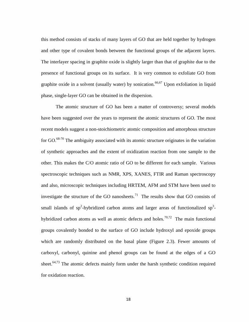
The atomic structure of GO has been a matter of controversy; several models
have been suggested over the years to represent the atomic structures of GO. The most
recent models suggest a non-stoichiometric atomic composition and amorphous structure
for GO.68-70
The ambiguity associated with its atomic structure originates in the variation
of synthetic approaches and the extent of oxidization reaction from one sample to the
other. This makes the C/O atomic ratio of GO to be different for each sample. Various
spectroscopic techniques such as NMR, XPS, XANES, FTIR and Raman spectroscopy
and also, microscopic techniques including HRTEM, AFM and STM have been used to
investigate the structure of the GO nanosheets.71
The results show that GO consists of
small islands of sp2-hybridized carbon atoms and larger areas of functionalized sp
3-
hybridized carbon atoms as well as atomic defects and holes.70,72
The main functional
groups covalently bonded to the surface of GO include hydroxyl and epoxide groups
which are randomly distributed on the basal plane (Figure 2.3). Fewer amounts of
carboxyl, carbonyl, quinine and phenol groups can be found at the edges of a GO
sheet.64,73
The atomic defects mainly form under the harsh synthetic condition required
for oxidation reaction.

19
Figure 2.3. Most recent atomistic model of graphene oxide containing hydroxyl, carboxyl and
epoxide functional groups (reproduced from Szabo et al.70
).
The presence of functional groups and defects induces higher surface roughness
in GO and give rise to a highly wrinkled structure compared to pristine graphene.70
The
surface roughness along with other parameters such as density and location of the
functional groups determine GO electronic structure which is quite different from that of
pristine graphene. The as-synthesized GO sheet is electrically insulator with a large band
gap; this is because of the high population of sp3 functionalized carbon atoms that
disrupts the π-conjugated system.66,74,75
Also, the carrier mobility in GO surface is very
low due to the lack of a proper percolation path between the sp2-hybridized islands.
64
However, it is possible to tune its electronic structure by reducing the density of
functional groups (particularly, epoxide and hydroxyl groups) on the basal plane through
chemical or thermal reduction.71
This allows for higher carrier motilities, introduces an
energy gap in the GO electron density of states and turns GO into a semiconductor.
Further removal of functional groups will lead to recovery of a large portion of the
network of sp2 carbon atoms and a highly conductive sample.
76,77

20
Although the functional groups of GO withhold achieving superior electrical
properties, but they can be advantageous to its chemical reactivity.64
Due to the high
polarity of the oxygen-containing groups, GO is easily dispersible in water and many
other solvents. It has recently been reported that GO on its own is not soluble in water;
instead, it is stabilized by anomalous oxidative debris.78
The solution-processability of
GO is important for preparation of bulk graphene products; processing of GO in liquid
phase via solution casting, spin coating, and vacuum filtration is very common. Also, the
functional groups are reactive sites that can be targeted in various chemical reactions for
modification of GO structure into a graphene derivative with tunable properties. For
example, the epoxide groups may be exposed to amine-containing groups to initiate a
ring-opening reaction and nitrogen-dope the GO surface.71,79
The carboxyl groups can be
activated by several chemical species and allow for attachment of small or large
molecules (i.e., surfactants and polymers) to the GO surface.80
Also, the hydroxyl groups
are always available for hydrogen bonding and spur the possibility of non-covalent
functionalization of GO.30,81
Most importantly, the chemical reactivity of GO stimulates
various chemical and thermal routes for its reduction which will be introduces in the
following section.
Like pristine graphene, the mechanical properties of GO change with addition of
more layers to the sheet. The Young’s modulus of single-layer GO is 156.5 GPa which is
almost five times lower than that of single layer pristine graphene. The Young’s
modulus of bi- and tri-layers of GO have been measured and reported to be 223.9 and

21
229.5 GPa, respectively.82
It is worthy to mention that these values are prone to change
with alteration of the type and density of the functional groups on the surface of GO.
2.4.2 Reduced graphene oxide (RGO)
Reduction of GO is very important for restoring the π-conjugated system in the
basal plane and thus, producing graphene. The product of the reduction process is
“reduced graphene oxide (RGO)” which has similarities with pristine graphene in atomic
and electronic structure, but never attains the same properties of pristine graphene.83
The
reduction process can reconstruct the sp2-bonding network only partially and leaves
some oxygenated species and lattice defects on the RGO surface (Figure 2.4). The
residual sp3-functionalized atoms and atomic defects act as scattering sites and prevent
the ballistic transport of charge carriers that has been observed in pristine graphene.84
In
fact, the carrier transport in RGO occurs through a percolation path which is created by
restored sp2-hybridized domains within the basal plane.
72,83 The mechanical properties of
RGO also suffer from the inhomogeneity of its atomic structure. The Young’s modulus
of an RGO sheets was measured as 185-250 GPa which is similar to modulus of 2-3
layer GO rather than that of pristine graphene.85
The degree of sp2 network restoration
fully depends on the initial oxidation level, reduction method and the extent of reduction.
The chemical reactivity of RGO is less than GO because of the loss of a large portion of
functional groups. Also, RGO renders less polarity and higher hydrophobicity compared
to GO and is not dispersible in water and the other solvents. The RGO sheets obtained
by chemical reduction in solution phase tends to aggregate due to the increased vdW

22
forces between the restores sp2 domains of their basal planes and thus, need to be
reduced in presence of some surfactant or polymers to prevent reaggregation.
Figure 2.4. HRTEM images of (a) Pristine graphene, (b) GO, and (c) RGO. The graphitic area
are shown in yellow, the oxidized regions are shown in red and holes are shown in blue
(reproduced from Erickson et al. 72
).
2.5 Production and synthesis of graphene
Since the first successful isolation of single-layer graphene in the lab in 20041,
scientists have investigated numerous strategies to achieve repeatable production of
high-quality graphene in large quantities. Though all these methods produce graphene,
the quality, purity, quantity, form and processability of their products are extremely
different. The products vary over a broad spectrum from pristine graphene to GO and
present a wide range of morphological (i.e., sheet size and thickness) and compositional
(i.e., sp2- and sp
3-hybridized carbon, defects, oxygen-containing groups and impurities)

23
structures; thus, offer a various range of material properties. On the other hand, a diverse
combination of material properties is required for different applications (Table 2.1). For
example, the graphene used in solar cells needs to be both electrically conductive and
extremely transparent, while the optical transparency is not as important as electrical
properties in supercapacitors and batteries. Therefore, it is expected that each
production method yields a graphene product which suits certain applications; the
competency of the product for a specific application can be estimated by accurate
inspection of its morphology and chemical composition.86
Table 2.1. Property-application relationships for graphene sheets. Here, a thick indicates
importance, cross indicates unimportance and square means the property is sometimes important
(reproduced from Edwards et al. 86
).
Depending on the preparation strategy, the graphene sheets indicate differences
in the morphological properties such as lateral size and thickness, the density of
structural and compositional defects on the surface, the residual impurity content,
surface chemistry and the chemical reactivity. These parameters can be used as metrics
for evaluation of graphene quality since they affect the graphene properties. In this

24
sense, high-quality graphene with superior material properties is a single- to few-layer
sheet with at least a few microns in length and minimal defects and impurities.
Characterization techniques used for assessment of these parameters have to be non-
destructive, have high resolution, provide both molecular and morphological
information, and be applicable for all product forms.53,87
Raman spectroscopy is an
invaluable tool that provides information about the sheet thickness 88
and structural
defects89
(i.e. sp3-hybridized carbon content and edge effects)
90. Microscopy techniques
including HRTEM and AFM have been extensively used to determine the sheets
thickness and lateral size.22,88,91
Also, the XPS spectroscopy has been used to assess the
compositional defects by measuring the C/O atomic ratio and distinguish pristine
graphene from RGO and GO.71
The necessity of using such high quality graphene
depends on the application type; electronic (e.g. transistors) and optical (e.g. light
emitting diodes OLED) devices, in which fast charge transportation over a micron-range
distance is required, demand single- and bilayer graphene sheets with the least defects
density.21,92,93
On the contrary, some of graphene properties like its chemical reactivity
and solubility in water do not improve with the quality and even enhance with higher
number of defects.21
Hence, graphene sheets of mediocre quality (i.e. smaller few-layer
sheets with more atomic defects) are appropriate for applications such as gas storage,
energy storage94
and sensors.95
Currently, the available techniques produce graphene in two major forms: (1)
large-area graphene sheets (usually adhered on a substrate) and (2) smaller free-standing
sheets (usually dispersed in a liquid). Large area graphene sheets are mainly produced

25
by bottom-up approaches such as chemical vapor deposition96-100
and epitaxial growth
on a substrate101,102
and can be few centimeters in size. These sheets are promising
candidates for preparation of thin films for flexible electronic devices and transparent
electrodes for photovoltaic devices. Top-down approaches have been explored to
exfoliate graphene from graphite in solid or liquid phase.74,103,104
These methods usually
produce a few micron-sized sheets which are suitable for preparation of electrodes in
batteries and supercapacitors, polymer composites and conductive inks and coatings
(Figure 2.5).
Figure 2.5. Various graphene synthesis method and respective product quality and applications
(reproduced from Sivudu et al.105
).

26
Aside from the general quality standards of the graphene sheets, each of these
product forms have to be processable in industrial procedures to make their way to the
final applications. The impurities associated with the products of these approaches are
from different origin; they can be metallic and catalyst particles or polymer and
surfactant chains in a solution and hence, require different removal processes. The large
area graphene sheets that can be transferred to other substrates, without being damaged
or contaminated, are of special interest to the device manufacturers. Likewise,
processing of smaller freestanding graphene sheets in liquid phase (e.g. solvent
evaporation and rewetting) and its exposure to various chemicals and flow fields (e.g.
during spin coating, solution casting, vacuum filtration, etc) is an inevitable step of
nanocomposites, batteries and coatings preparation. These smaller freestanding sheets
should be originally stable when dispersed in the liquid phase, be aggregation-resistant
after drying and rewetting in the liquid phase, remain stable over time and
centrifugation, have a high concentration in solution and carry the minimum dispersant
content.
Not all the methods produce the same amount of graphene and not all the
applications require comparable graphene quantities. Lower quantities of graphene are
demanded for production of transparent graphene electrodes and sensors or for the
fundamental studies of graphene properties. Lab-scale production methods are capable
of providing sufficient high quality graphene for these applications. Conversely,
graphene-based energy storage devices and polymer nanocomposites require bulk
quantities of graphene. So far, production of larger amounts of graphene has been

27
associated with a dissipation of quality which arises by an increase in the number of
layers and/or defects and/or reduction of the sheets lateral size. Hence, for such
applications, the quality of graphene has to be compromised to obtain larger quantities of
product.
It is also critical to produce these large quantities of graphene in a scalable, high-
yield fashion. The yield is defined by the ratio of graphene product / graphite feedstock,
and most prior studies report yields that are fairly low. One might think that yield is a
less important metric, given the relatively low cost of graphite, but the associated
handling and solvent usage dictates that pre-treatments and recycle streams should be
used to increase yields to useful levels. In the same context, the scalability of the
production methods becomes of great importance. Scalability may be understood
through the scaling law for production as a function of the system size. One may
undertake a scalability analysis for each separate unit operation within the graphene
production, with graphene synthesis distinct from graphene separation or handling units.
Some methods are more appropriate for scale up and some of them cannot be scaled up
due to difficult processing and demanding operational conditions such as high
temperature and pressure. Additionally, parameters such as cheap and easily accessible
precursor source and the efficiency of the process play a role in choosing the graphene
production method (Figure 2.6).
With all the above-mentioned points in mind, researchers have developed various
methods in the laboratories, with some of them being well-suited for certain

28
applications. These methods include a wide range of top-down and bottom-up
approaches which will be addressed in the following sections.
Figure 2.6. Categorization of main graphene production method based on their cost and product
quality (reproduced from Ren et al.106
).
2.5.1 Bottom-up approach
This approach refers to growth or synthesis of graphene at atomic level using
non-graphitic carbon sources. The main advantages of these methods include their
capability of producing large-area graphene films and tuning the graphene electronic
structure at the atomic level during the synthesis process. These features make the
product of bottom-up methods appropriate for applications that aim to harness the

29
superior charge carrier mobility in a graphene sheet including electronic devices such as
transistors and OLEDs.
The main bottom-up methods include epitaxial growth on silicon
carbide,101,102,107
chemical vapor deposition (CVD) on various substrates 96-100,108
and wet
chemical synthesis of graphene (Figure 2.7).109-111
In epitaxial growth, sublimation of
silicon atoms from SiC surface at high temperatures (>1000 ⁰C) is followed by
graphitization of remaining carbon atoms on the surface. The resultant graphene has
single to few layers, but suffers from non-uniformity in crystalline structure which
originates in the polycrystalline nature of the initial SiC wafer. Using CVD technique,
graphene layers can be deposited from solid, liquid or gaseous precursors on a substrate
through thermal, plasma enhanced, reactive and many more processes. Thermal CVD on
metals is the most common method in which pyrolysis of carbon containing gases such
as methane occurs at high temperature on metallic substrates. The type of metal,
pressure, temperature and gas feed rate are some of the parameters that define the final
structure of the product.99
The deposition on semiconductor and insulator substrates has
been recently investigated.112
The growth methods provide the opportunity to selectively dope graphene with
other molecules and functional groups to create a band-gap which is vital in applications
such as graphene-based field effect transistors (FETs), OLEDs, solar cells and battery
electrodes.113,114
However, the as-grown graphene contain some atomic defects and
impurities which are induced by the substrates and inhibit the charge transport along the
sheets surface. Also, in most cases the large graphene films have to be transferred to

30
another substrate (e.g. transfer from a conductive metallic substrate to an insulating
substrate in transistors); this can be challenging due to the strong interactions of the
graphene and the original substrate.115,116
Moreover, the lack of control on the number of
layers is another drawback of the CVD and epitaxial growth methods.117
Recently,
molecular beam epitaxy (MBE) has been applied to grow graphene on insulator
substrates with a considerable control over the number of layers.118
All these issues, as
well as the high cost of the substrate materials (which are usually etched away after the
synthesis), high operational temperature and pressure and the low yield of the continuous
growth process make the scalability of these methods problematic.
Researchers have recently attended to alternative bottom-up approaches, mainly
wet chemical methods, which let them avoid the challenges associated with using a
substrate and harsh growth conditions. These approaches have not been studied as vastly
as other methods and currently are in their early stages. Unzipping of carbon
nanotubes119-121
and organic synthesis of graphene-like polyacyclic hydrocarbons
(PAHs)109,122
are the two main routes of wet chemical synthesis. A controlled unzipping
of CNTs in various solutions (e.g. sulfuric acids, KOH, etc.) produces graphene
nanoribbons (GNR) of < 50 nm width which inherit the band-gap of the original CNT.121
The products of PAH-based organic synthesis are single layers of graphene with small
lateral size (< 200 nm).122
The main challenges in wet chemical synthesis methods are
increasing the flake size and inhibiting sheets aggregation after synthesis in liquid
phase.111
Despite all their limitation, the wet chemical approaches are promising because
of the high quality and purity of their resultant graphene.

31
Figure 2.7. Main bottom-up graphene synthesis techniques (reproduced from Bonaccorso et al. 123
).
2.5.2 Top-down approach
Graphite or its derivatives are the main carbon source in the top-down approach
that aims to “exfoliate” single- to few-layer graphene sheets from the “parent” graphitic
material. Since the interlayer vdW attractive forces in graphite are weak, they can be
dominated by an external force, resulting in separation of adjacent layers.1 Also, the
interlayer attractive forces can be diminished by intercalation of various atoms and
molecules into the graphite structure and increasing the interlayer spacing.124
It is
important to avoid disruption of the atomic structure and sp2 bonding network of
graphene layers during this process. Exfoliation may be carried out in solid or liquid

32
phase using various sources of external energy. Maintaining the exfoliated state of the
graphene sheets requires an energy barrier which prevents the reaggregation of the
sheets, especially in a medium which prompts the Brownian motion of the sheets, i.e.,
liquid phase. Here we briefly discuss the solid phase exfoliation and then we will review
the existing liquid phase exfoliation methods in depth, as it is the focus of this thesis.
2.5.2.1 Exfoliation in solid phase
Exfoliation of graphite into graphene sheets in solid phase may be accomplished
by applying mechanical forces (Figure 2.8). Micromechanical cleavage is the oldest
solid-phase exfoliation method that applies normal forces to separate graphene layers
from graphite source. Although this process produces very high-quality graphene sheets,
but it is extremely limited by its yield and efficiency and is impractical for large-scale
production of graphene.1
Ball milling is a well-established industrial technique that applies shear force to
exfoliate graphene sheets from graphite.125-129
This technique can produce large-area
graphene sheets in high quantities; however, intensive milling and grinding of the sheets
is necessary for production of few-layer graphene sheets. This damages the basal plane
of the graphene and increases the structural defects in the final product. The ball milling
has also been performed in presence of other components to modify the graphene surface
for specific applications.129,130
Thermal annealing or washing the product with solvents
is a required step for removal of the impurities (metals of the milling unit) in this
method.

33
Figure 2.8. Schematic of graphene production by (a) micromechanical cleavage reproduced
from Bonaccorso et al.123
), and (b) ball-milling (reproduced from Zhao et al.131
).
Thermal expansion of graphite oxide and graphite intercalation compounds
(GICs) via microwave radiation or rapid heating to high temperatures (>1000 ⁰C) is
another method to exfoliate graphene in solid-phase.132
First, the graphite oxide and
GICs have to be synthesized in liquid phase to introduce functional groups and
intercalants of various types to the graphite structure. The subsequent thermal shock
leads to flash evaporation and release of the functional groups and intercalants into the
interlayer spacing of graphite and ultimate exfoliation of graphene layers. The product of
this method has lower C/O ratio compared to pristine graphene.
In general, the solid-phase exfoliation methods are promising candidates for
large-scale production of graphene powder. Yet, the products of these methods suffer
from high density of structural and compositional defects. Additional exfoliation and/or
stabilization is needed to prepare the product of these methods for further liquid-phase
processing.

34
2.5.2.2 Exfoliation in liquid phase
Exfoliation of graphite in liquids allows for simple production of liquid
dispersions with high graphene content and facilitates processing of graphene in
industrial techniques. Parent graphite can be mechanically of electrochemically
exfoliated into graphene in a solvent; however, the high interfacial tension at the
graphene-solvent interface and strong inter-sheet attractive forces promote reaggregation
of exfoliated sheets, necessitating stabilization of the sheets prior or simultaneously to
the exfoliation. Stabilization can be achieved either by balancing the surface energy of
the sheets and the liquid phase to minimize the interfacial tension or by modifying the
sheets surface to eliminate the inter-sheet attraction and make them more solvent-
philic.133
The main stabilization routes include covalent functionalization through
oxidation prior to exfoliation, exfoliation in the solvents with surface energies similar to
graphene and non-covalent functionalization using surfactants, polymers and other types
of dispersant molecules.
The final products of these methods are colloidal dispersions of freestanding
graphene sheets. The choice of exfoliation technique and stabilization strategy
determines the graphene quality and quantity. Other than the morphological and
compositional properties of the sheets that can be assessed by characterization
techniques such as Raman spectroscopy,88-90
XPS spectroscopy,71
HRTEM, and
AFM,22,88,91
the concentration and stability of graphene in the dispersion are important
parameters which need to be determined precisely.134
UV-vis spectroscopy is the
common method of measuring graphene concentration; the absorption spectra of

35
graphene at wavelength of >500 nm is used to determine concentration according to the
Beer-Lambert law.103,135-137
Thermogravimetric analysis (TGA) of the graphene powder
cast from the dispersion may also be used for concentration measurements.138
The
colloidal stability of the dispersions has been analyzed by zeta potential
measurements.139,140
According to DLVO theory, a charge may develop at the interface
of colloidal particles and the solvent molecules. The value of this surface potential (zeta
potential) directly correlates to the colloidal stability of the dispersion. When the
absolute value of the zeta potential exceeds 30 mV, the dispersion is considered
stable.134,141
The long term stability is an important parameter in post-processing of the
dispersions. Proper separation of exfoliated/stabilized sheets from graphitic materials
and non-stabilized sheets through effective centrifugation improves the stability of
dispersion over time.134
Stable freestanding graphene sheets can be easily processed in presence of
solvents, polymers and other chemicals to produce polymer nanocomposites, printed
electronic devices,75,76
conductive inks and coatings, batteries and supercapacitors
electrodes and chemical sensors. Most of these applications require a proper electrical
conductivity, but ultrafast charge transportation is not essential for them. Thus, the
smaller flake size and higher number of layers of exfoliated graphene sheets is not an
impasse for such applications. Moreover, the yields of these methods, which could be
evaluated by measuring the graphene concentration in the dispersions, mostly exceed
those of bottom-up methods. Liquid-phase exfoliation require less demanding processing
conditions and has a lower cost of production due to the comparably cheap starting

36
material. All these characteristics make liquid-phase exfoliation methods a promising
candidate for large-scale production of graphene. Here, we outline the three main
graphene liquid exfoliation techniques that have been broadly investigated.
2.5.2.2.1 Oxidation-exfoliation-reduction of graphite
Chemical conversion of graphite to graphene oxide is the oldest exfoliation
technique for graphene production. It starts with oxidation of graphite into graphite
oxide, followed by exfoliation of graphite oxide into GO in a proper solvent via
sonication and ultimately, reduction of GO sheets to form RGO (Figure 2.9).66,67,71
The
oxidation is usually performed based on the modified Hummer’s method in presence of
oxidants including sulfuric acid, nitric acid and potassium permanganates.65,70
Oxidation
introduces covalent functional groups such as hydroxyl (-OH), carboxyl (-COOH),
epoxide (-O-) and carbonyl (C=O) to the layers of the resultant graphite oxide and makes
it hydrophilic. Graphite oxide can be easily exfoliated and dispersed in water to form
stable GO aqueous dispersions. The dispersed GO sheets are mostly single layer with
several hundreds of nanometer to a few micrometers length and are stable at
concentrations up to 10 mg/ml.71
As mentioned earlier in section 2.4.1, GO has a different composition and
structure than graphene and has to be reduced in order to restore the sp2-hybridized
network of carbon atoms and unique properties of graphene. Chemical reduction in
solution 77,142
or vapor phase143,144
, thermal annealing 61,145
and electrochemical
techniques 146
have been used to prepare RGO. The chemical reduction has been

37
performed using various reducing agents such as hydrazine77,142,147
, sodium borohydride
148 and hydroquinine
149 in the solution or vapor phase. Every reducing agent introduces a
different reduction reaction pathway; therefore, is capable of removing specific
functional groups and leaves the other oxygen-containing functionalities in the final
RGO product.53
It has been reported that the C/O atomic ratio of RGO can be increased
to 14.9:1 by choosing the proper reducing agent and reduction conditions.150
During the
chemical reduction in liquid phase, the brown aqueous dispersion of GO turns black and
the RGO sheets which are no longer hydrophilic aggregate and precipitate. To prevent
reaggregation, the reduction has to be performed in presence of proper dispersant
molecules in the solvent.74
Figure 2.9. Schematic of graphene production through oxidation-exfoliation-reduction route
(reproduced from Ren et al.106
).
In an alternative approach, the GO dispersions could be filtered and dried to
prepare GO powder for thermal reduction. Heating GO to temperatures as high as 1050
⁰C removes the hydroxyl and epoxide groups in form of carbon dioxide, but leaves some
stable carbonyl and ether functionalities on the basal plane.145,151
Electrical conductivity

38
of 1000-2300 S/m has been reported for thermally-reduced RGO. Electrochemical
reduction is an alternative method to avoid the hazardous chemicals (e.g. hydrazine) and
harsh reduction conditions (1100 ⁰C). In this technique, a voltage is applied to a GO
electrode in presence of a buffer solution.146
The high yield of the process, large quantities of the product and low cost of
production are the main advantages of this method. Moreover, the chemical reactivity
and hydrophilicity of the GO sheets allows using wet chemistry techniques to modify the
structure and properties of the sheets to prepare customized graphene for specific
applications. However, the demanding processing conditions and the mediocre quality of
RGO hinder the versatility of this route as a scalable graphene production method.
2.5.2.2.2 Intercalation-exfoliation of graphite
Graphene sheets can be produced quickly through electrochemical intercalation
and exfoliation of graphite. This method includes electrochemical oxidation/reduction of
graphite, intercalation of ions into the spacing of graphite layers and exfoliation under an
electrochemical bias, followed by a subsequent ultrasonication step to complete the
exfoliation (Figure 2.10). This whole electrochemical treatment of graphite can be
accomplished in less than an hour.152,153
A simple experimental set up for this method
includes a graphite working electrode, a reference electrode, electrolyte solution and a
DC power supply. The graphite host material could be a graphite rod, graphite flexible
foil or HOPG and common reference electrode materials are Pt, calomel and Ag/AgCl2.
The electrolyte which provides the intercalant ions can either be an aqueous solution of

39
acidic materials (sulfuric, perchloric, etc) and/or surfactants (SDBS, SBS, etc) or non-
aqueous solutions of ionic liquids and organic solvents.154-156
Applying a potential causes the oxidation (or reduction) of the graphite which
leads to intercalation of anions (or cations) from the electrolyte. The intercalation
increases the interlayer spacing and results in structural expansion of the electrode. Upon
completion of the intercalation, a reverse potential is applied to exfoliate the graphene
layers from the electrode. The graphene flakes precipitate in the solution and form
sludge at the bottom of the cell.152,153
In the anodic intercalation a positive potential is
applied to oxidize the graphite and intercalate anions.132,156-159
In this case, the potential
required for ion intercalation is usually higher than the potential needed for graphite
oxidation.2,152
Thus the product is partially oxidized graphene with sp3 carbon defects
and oxygen-containing functional groups. Non-oxidative intercalation and exfoliation
has been accomplished by cathodic reduction of graphite in presence of lithium ions to
avoid oxidation of graphite.160,161
Although the product offers a high C/O ratio and
minimal sp3 defects, but the quantity of the material produced by this method is very low
in the absence of acidic ions.153
Figure 2.10. Schematic of graphene production through electrochemical intercalation-exfoliation
route (reproduced from Ren et al.106
).

40
The graphene flakes produced by electrochemical exfoliation generally have
higher sheets size (up to 50 µm) than the other liquid-phase graphene products. The
number of layers of the sheets varies over a wide range from single to multiple layers
and hence, require further exfoliation though ultrasonication.152,153
Consequently, the
electrochemical intercalation and exfoliation of graphite is more perceived as a pre-
processing step rather than a main method of graphene production. The poor quality of
the anodic intercalation products, low yield of the cathodic intercalation products, and
the difficulty of removal of the residual electrolyte ions and solvents from the final
product are some issues that should be resolved before considering this method for large-
scale production of graphene.
2.5.2.2.3 Direct liquid-phase exfoliation
A more recent strategy is to directly exfoliate graphite in a solvent using
ultrasonication. This process involves three steps: (1) exfoliation of graphite, (2)
stabilization of graphene layers and (3) separation of graphene sheets from unexfoliated
and non-stabilized graphitic material (Figure 2.11). In exfoliation step, the ultrasonic
waves produce cavitation bubbles in the solvent; as these bubble collapses due to the
pressure increase, they generate high energy micro-jets and shock waves that act on the
bulk graphite and exert compressive stress on the sheets to induce exfoliation.130
In a
secondary mechanism, the unbalanced compressive forces on two adjacent layers cause
a shear-induced exfoliation. Additionally, the micro-jets may act as wedges that diffuse
to the interlayer spacing of graphite and enforce exfoliation.130
After exfoliation, the

41
sheet-liquid attractive forces have to exceed the graphene interlayer attractive forces in
order to prevent reaggregation. This could be accomplished by reducing the sheet-liquid
interfacial tension through various strategies such as usage of organic solvents, ionic
liquids or aqueous solutions of dispersants molecules. After sonication, unexfoliated
thick graphitic sheets are a large fraction of the solid content in the dispersion. These
heavier graphitic sheets can be separated from the exfoliated graphene by centrifugation
to obtain dispersions of high-quality graphene sheets with long term stability. The yield
of the process could be calculated by measuring the amount of starting graphite and the
concentration of graphene sheets in the centrifuged dispersions (using UV-vis
spectroscopy technique). The type of the solvent and the dispersant, as well as
processing parameters such as sonication time and power and centrifugation force and
time are the main factors that affect the graphene quality and process yield. Here, we
discuss various liquid systems and processing that have been used in direct liquid-phase
exfoliation of graphite and introduce the recent improvements of exfoliation techniques.
Figure 2.11. Direct liquid-phase exfoliation of graphite into graphene sheets (adapted from Ren
et al.106
).

42
(I) Dispersion in organic solvents
From a thermodynamic point of view, direct liquid-phase exfoliation can be
perceived as “dissolution” of graphene in the liquid phase for which the enthalpy of
mixing should be minimized. The following expression suggested by Coleman et al.103
shows the enthalpy of mixing of graphene in a pure solvent:
where is the enthalpy of mixing, is the volume of the mixture, is the
thickness of graphene sheet, and are the square root of the surface energies of
the solvent and graphene, respectively, and is the graphene volume fraction. The
surface energy of graphene is defined as the energy per area required for separation of
two adjacent layers. The term in parentheses represents the interfacial tension of
graphene sheets immersed in the solvent. Higher surface tension in the solution increases
the tendency of the sheets to adhere to each other; thus, complicates the exfoliation in
first place and later, induces reaggregation of exfoliated layers. When the surface
energies of solvent and graphene are equal or close, the enthalpy of mixing has its
minimal value and the exfoliation and dispersion occurs spontaneously or more easily.
Coleman et al. measured the graphene concentration after sonication and
centrifugation in a range of organic solvents to find the optimum surface tension for
graphene exfoliation and dispersion which was 40 mJ/m2
(Figure 2.12).103
Solvents
including N-methyl-2pyrrolidone (NMP), N,N-dimethylformamide (DMF) and ortho-
dichlorobenzene (o-DCB) have the surface energy within this desired range and have
been widely used to exfoliate single- and few-layer graphene sheets. Additionally,
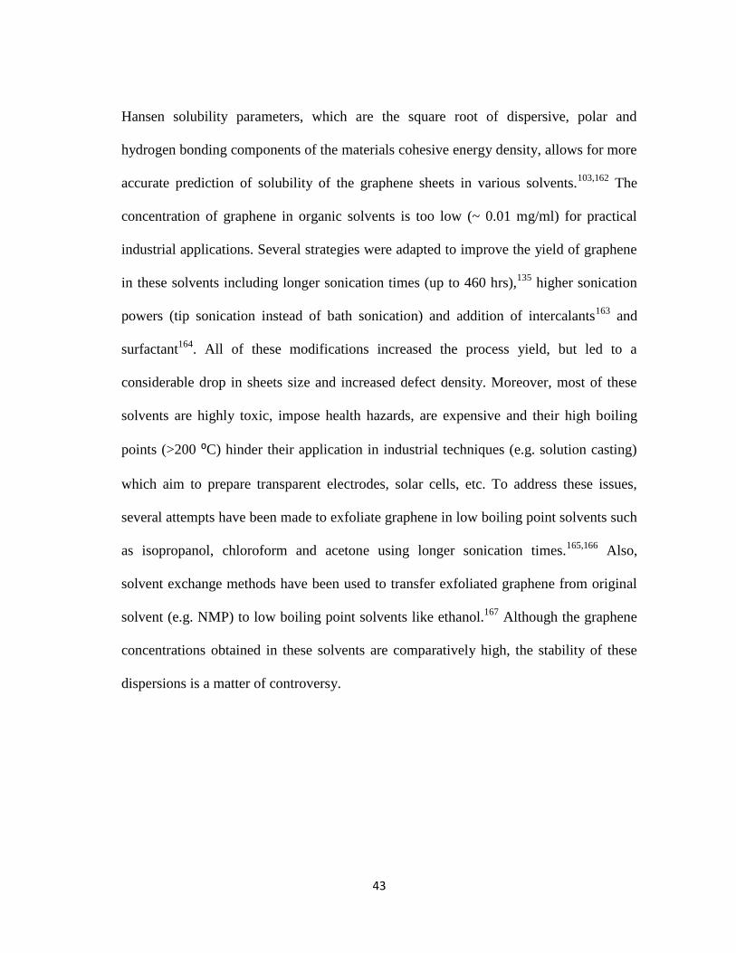
43
Hansen solubility parameters, which are the square root of dispersive, polar and
hydrogen bonding components of the materials cohesive energy density, allows for more
accurate prediction of solubility of the graphene sheets in various solvents.103,162
The
concentration of graphene in organic solvents is too low (~ 0.01 mg/ml) for practical
industrial applications. Several strategies were adapted to improve the yield of graphene
in these solvents including longer sonication times (up to 460 hrs),135
higher sonication
powers (tip sonication instead of bath sonication) and addition of intercalants163
and
surfactant164
. All of these modifications increased the process yield, but led to a
considerable drop in sheets size and increased defect density. Moreover, most of these
solvents are highly toxic, impose health hazards, are expensive and their high boiling
points (>200 ⁰C) hinder their application in industrial techniques (e.g. solution casting)
which aim to prepare transparent electrodes, solar cells, etc. To address these issues,
several attempts have been made to exfoliate graphene in low boiling point solvents such
as isopropanol, chloroform and acetone using longer sonication times.165,166
Also,
solvent exchange methods have been used to transfer exfoliated graphene from original
solvent (e.g. NMP) to low boiling point solvents like ethanol.167
Although the graphene
concentrations obtained in these solvents are comparatively high, the stability of these
dispersions is a matter of controversy.

44
Figure 2.12. (a) Graphene concentration in various organic solvents vs. solvent surface tension
plot reveals the optimum surface tension (40-50 mJ/m2) for graphene dispersion, and (b) TEM
image of few-layer graphene sheets in NMP dispersion (reproduced forom Hernandez et al. ).
Bourlinos et al. found that the charge transfer between the graphene and a solvent
with electron-withdrawing or –accepting components also leads to the exfoliation and
stabilization of the sheets.168
For example, the charge transfer between graphene and a
group of perfluorinated aromatic molecules (through π-interactions) facilitates the sheets
exfoliation and stabilization. The capability of other hydrocarbon solvents with
analogous electron-withdrawing or –accepting structure (e.g. toluene, benzene, pyridine)
to exfoliate and stabilize graphene has also been investigated.
Additionally, acids have been used for dissolving graphite. Chlorosulfonic acid can
dissolve graphene with concentration up to 2 mg/ml without sonication.169
The
protonation of the graphite layers is responsible for spontaneous exfoliation and
dispersion of graphene sheets, as it increase the interlayer spacing and induces repulsion
between the sheets. Addition of H2O2 to this acid resulted in immediate exfoliation of
large quantities of few-layer graphene sheets with minimum defect density.170
However,

45
the risks associated with working with the superacids and the need for many washes to
increase the pH before post-processing has restricted the practical application of the
product.
(II) Aqueous dispersions
Water is widely used in industrial applications due to its low boiling point, non-
toxicity, biocompatibility, and low cost. However, its surface tension of 72 mJ/m2 is
higher than that of an ideal exfoliation medium for graphene. Addition of surfactants,
polymers and small organic molecules reduces its surface tension and facilitates
exfoliation of graphite. Furthermore, adsorption of these dispersant molecules on the
graphene surface assists the stabilization of exfoliated sheets and prevents reaggregation
(Figure 2.13).
Figure 2.13. Production of stable aqueous graphene dispersions in presence of dispersants.
Surfactant molecules contain a hydrophobic tail and a hydrophilic head. The
hydrophobic tail of surfactants adsorbs on graphene surface via vdW, hydrophobic or π-
π interactions. In ionic surfactants, the hydrophilic head which is capable of dissociation

46
in presence of water molecules, positively or negatively charges the graphene surface.
This surface charge (reflected in the zeta potential value) induces an electrostatic
repulsion between the graphene sheets covered with surfactant molecules and stabilizes
these sheets. Surfactants like sodium dodecylbenzene sulfonate (SDBS)171
, sodium
cholate (SC)37,172
, sodium deoxycholate (SDC)173
have been used to disperse graphene
sheets of 2-4 layers with 1 micron lateral size at a concentration of 0.1 mg/ml. Longer
sonication time can improve the graphene concentration and yield. Non-ionic surfactants
stabilize graphene sheets through steric repulsion induced by their long hydrophilic
heads spread into the water. Guardia et al. and Smith et al. compared the graphene
concentration obtained from ionic and non-ionic surfactants and reported that non-ionic
surfactant can produce graphene dispersions with higher concentrations.174,175
Further, polymers have been widely used to stabilize graphene in water and in
organic solvents. Long polymer chains adsorbs on the graphene surface while some
segments of the chain extend into the solvent and provide a shield around the graphene
sheet through steric repulsion or depletion effects. Polyvinylpyrrolidone (PVP)38,39
and
polyacrylamide (PAM)176
are a few example of the polymers that assist exfoliation of
few-layer graphene sheets with average one micron lateral size. The yield of polymer-
assisted graphene dispersions is comparably higher than those obtained with ionic
surfactants. Furthermore, the polymer-assisted graphene dispersions can be directly
processed to fabricate polymer nanocomposites.
One of the main issues associated with surfactant- and polymer-assisted
dispersions is the high excessive dispersant content of the final graphene product.

47
Removal of the excessive dispersants is tedious task which requires further processing of
the dispersions and a 100 % removal of the dispersant is unachievable. Polycyclic
aromatic hydrocarbon (PAH) derivatives are a promising alternative to the polymers and
surfactants.33,177,178
These molecules have lower molecular weight than polymers and
surfactants and are capable of stabilizing high quantities of graphene in the aqueous
dispersions via π-π interactions with the sheets.
(III) Dispersions in Ionic liquids
Ionic liquids are semi-organic salts with hydrophobic and hydrophilic
components in their molecular structure.138,179,180
Certain ionic liquids have been used as
electrolyte in electrochemical exfoliation of graphite. Also, they have been used as
solvents for direct liquid-phase exfoliation of graphite via sonication. The graphene
sheets in dispersions of 1-butyl-3-methyl-imidazolium
bis(trifluoromethanesulfonyl)imide ([Bmim][Tf2N]) and 1-hexyl-3-methylimidazolium
hexafluorophosphate (HMIH) had less than 5 layers and were few microns in size.138,179
The graphene yield for one hour of sonication was quite high (~ 5 mg/ml) compared to
the organic and aqueous dispersions of graphene. However, the stability of graphene in
the dispersion, removal of the ionic liquids and high impurity content of the final product
remain as serious challenges.
(IV) Exfoliation via shear-mixing
All the above-mentioned graphene dispersions were prepared using
ultrasonication as the source of mechanical force. The average graphene concentration in
these dispersions is about 1-2 mg/ml which may yield high quantities of the sheets if and

48
only if large volumes of the dispersions are produced. However, the sonication
efficiency and graphene concentration in the dispersion decrease upon the increase of the
liquid volume. Hence, the improvement of the production rate by scaling up the
dispersion volume is impossible. Shear exfoliation is an alternative exfoliation technique
that has been recently used for graphene exfoliation.181
When higher shear rates are
applied in a liquid containing graphite and proper solvent and dispersant, the graphene
layers delaminate from graphite. Recent reports have demonstrated that high-shear
mixing can exfoliate nanosheets from the parent material with a power law relationship
written as:
where is the production rate, is the volume of the exfoliation vessel and depends
on the choice of nanosheet, solvent, and dispersant. If is greater than or equal to 1, then
scaling up to large volumes becomes feasible from a manufacturing standpoint. If is
less than 1, then scaling up results in diminishing returns, and this nanomanufacturing
approach will remain confined to the labscale. Coleman and co-workers have reported
that precise control of parameters such as initial graphite concentration, liquid volume,
mixing time, rotor diameter and speed can yield values of > 1 for several
dispersant/solvent combinations. 181
This shows excellent promise for scalable
exfoliation of pristine graphene from parent graphite materials. The graphene sheets
produced by this method are of high quality, have minimal defects and demonstrate
excellent material properties in various applications.

49
2.6 Conclusion
The unique 2D structure of graphene results in extraordinary properties that can
be exploited in applications such as electronics, composites, and energy conversion and
storage. GO and RGO are other graphene counterparts which share similar 2D planar
structure with pristine graphene. However, their properties are inferior relative to pristine
graphene due to their different chemical composition, atomic, and electronic structure.
Various bottom-up and top-down production techniques have been developed to produce
graphene sheets (i.e., pristine graphene, GO and RGO). Most of these production
techniques are restricted by a trade-off between the quality and quantity of their
products. Thus, scalable production of large quantities of high-quality graphene is a
challenging task. Bottom-up techniques produce high-quality pristine graphene sheets,
but they are not suitable for industrial production of graphene due to their low yield and
incapability for scale up. On the other hand, the liquid-phase exfoliation of graphene
from graphite is a promising method because of its high yield, ease of processing and
potential scalability. The tendency of graphene sheets for reaggregation in the solvent is
the main issue in this method. Functionalization of graphene sheets has been used as a
strategy to prevent reaggregation. GO and RGO can be produced by covalent
functionalization of graphene in liquid phase, while non-covalent functoinalization of
graphene yields pristine graphene dispersions. The liquid-phase exfoliated pristine
graphene, GO or RGO sheets can be processed further to prepare graphene-based
functional materials. In Chapter III, we discuss the fabrication of various graphene-based
materials using the liquid-phase exfoliated graphene sheets.

50
CHAPTER III
GRAPHENE-BASED FUNCTIONAL MATERIALS
3.1 Graphene-polymer nanocomposites
3.1.1 Challenges and opportunities for graphene-polymer nanocomposites
Reinforcement of polymers with filler materials enhances their bulk properties to
meet the requirements of the final application. Nanomaterials are often incorporated in
the polymer matrices to improve their electrical and thermal conductivity, mechanical
strength and stability, electrochemical reactivity, and many other physical properties.
The fillers morphology and content are the important factors that determine the
structure-property relationships in the nanocomposites. The higher surface area to
volume ratio, i.e. the aspect ratio, of the nanofiller enables effective filler-polymer
interactions in the nanocomposites and boosts the mechanical load transfer (e.g. normal
and shear forces) between the two phases. Most importantly, the high aspect ratio of the
nanofiller allows for enhancement of the bulk properties by addition of minimal filler
content to the polymer matrix. Therefore, the overall structure of the nanocomposite will
be dictated by the polymer phase, while its properties will be defined by those of the
polymer-filler interface.
Among various types of nanofillers, two-dimensional nanofillers are of great
importance due to their high aspect ratios. Graphite nanoplatelets have been traditionally
used as filler because their layered structures provide a larger interface and improve the
polymer-filler interactions.182-184
The graphene sheets obtained from top-down

51
approaches offer high aspect ratios that are two to three orders of magnitudes higher than
graphite. Also, these liquid-phase exfoliated single- to few-layer graphene sheets are
ideal fillers due to their high quality and their processability in presence of solvents; this
enables the usage of existing polymer processing techniques with no or minimum
modifications for fabrication of graphene-polymer nanocomposites. Graphene (including
pristine graphene, GO and RGO) has been added to polyolefins (e.g. PE, PP), acrylic
polymers (e.g. PMMA, PAM, PNIPAM, PAN), Vinyl polymers (e.g. PVA, PS, PVDF),
epoxy, polyurethane, conductive polymers (e.g. PANI, PPy, PEDOT), polycarbonate,
polyamide and polyimide.185,186
Addition of graphene to these polymers has enhanced
their mechanical strength, thermal conductivity, electrochemical activity and imparted
electrical conductivity and gas barrier properties.8,185-187
The improvement in polymer composites properties depends on the distribution
of the fillers in the polymer matrix and the filler-polymer interfacial interactions.188
Dispersion of pristine graphene in most of the polymer matrices is a challenging task due
the significant mismatch in their surface energies. This usually leads to aggregation of
the sheets in the polymer matrix. Moreover, incompatibility of the pristine graphene and
polymers surface energies induces a high interfacial tension that may weaken the
mechanical load transfer within the nanocomposite. Also, the low chemical reactivity of
pristine graphene reduces the chance for interfacial interactions through chemical bonds.
On the other hand, the hydrophilic nature of GO (and to some extent RGO) and the
presence of functional groups on its surface facilitates the interfacial interactions and
surface energy compatibility between the two phases. However, the insulating nature of

52
the GO and its inferior properties relative to pristine graphene necessitates further
restoration of the π-network though chemical or thermal reduction.
Additionally, the thermal and electrical conduction within an insulating polymer
matrix can only be accomplished through a percolation path, i.e. an interconnected
network of graphene sheets within the polymer matrix. Theoretically, such a percolation
path can form upon addition of very low amount of graphene to the composite. In
practice, the poor dispersion and agglomeration of graphene in polymer matrix hinder
the formation of an effective percolation path at such low graphene loadings.8
3.1.2 Incorporation of graphene into polymer matrices
Various techniques have been used to incorporate graphene sheets into polymer
matrices. Melt blending is a common technique in which the graphene in powder form is
added to the polymer while high temperatures and shear forces are applied to bring the
polymer into its melt phase.189-192
The mobility of the polymer chains in the melt phase
allows for proper mixing of the powder into the matrix and the strong shear forces assist
to distribute the graphene sheets in the matrix.191
The graphene powder used in this
method should be stabilized and aggregation-resistant in order to improve the dispersion
quality. This method is one of the least expensive, most versatile and, from
manufacturing point of view, scalable techniques for processing graphene in presence of
the polymers. However, the preparation of graphene in powder form requires drying of
the graphene dispersions obtained by liquid-phase exfoliation techniques. Moreover, the
high viscosity of the polymers, regardless of how strong the shear forces are, restricts the

53
proper mixing of graphene and polymer phases.193
Also, the incompatibility of the
graphene and polymer phases may result in a phase separation and subsequent
agglomeration of graphene sheets. In general, the final dispersion of the graphene in the
polymer matrix obtained by melt blending technique is not ideal.194
Solution blending is a simple method to prepare uniform graphene-polymer
nanocomposites.8,195-199
In this method the graphene is dispersed and the polymer is
dissolved separately in similar or two miscible solvents and then, these solutions are
mixed together by agitation, stirring or sonication to homogeneously disperse graphene
in the final solution. In the next step, the solvent is removed by various techniques such
as evaporation and filtration.200
This method facilitates the processing of graphene
dispersions in presence of polymers and presumably can yield higher dispersion quality
in the nanocomposite. However, it is restricted by the limited number of proper solvents
for garphene. Additionally, the solvent removal can be problematic as it may induce
phase separation and aggregation; complete removal of the solvent from the product is
also a matter of concern. Furthermore, the bulk quantities of the solvent used in this
method is an obstacle to its scalability.
In situ polymerization in presence of graphene sheets is another strategy that has
been explored extensively.201-205
In this method, the graphene sheets (pristine graphene,
GO or RGO) are added to polymer monomers in a common solvent and properly mixed
to yield a homogenous dispersion, followed by initiation and completion of the
polymerization. Various polymerization routes including radical 204,206,207
and emulsion
polymerization203
and polycondensation 208
have been practiced depending on the

54
chemistry of the host monomers and the properties demanded by the final
nanocomposites. This method improves the dispersion of graphene in the polymer
matrix considerably and yields highly uniform nanocomposites. However, the possibility
of graphene aggregation during the polymerization step in absence of external shear
force, difficulties associated with the removal of remaining solvent and residual reaction
initiators are the drawback of this approach.
Latex and emulsion mixing have also been used to incorporate graphene into
polymer matrices; this approach is especially useful when it is impossible to achieve a
uniform dispersion of graphene and polymer in the liquid phase.209-211
Using this
method, the graphene sheets and polymer particle are mixed into a solvent and graphene
sheets assemble at the graphene-polymer particles interface and form a segregated
network. Upon removal of the liquid, graphene-coated polymer particles are obtained
that can be processed by various techniques such as hot-pressing and vulcanization to
produce the final nanocomposites. This method has mainly been used to fabricate
electrically conductive composites with ultralow percolation threshold; the enhancement
of other properties of the nanocomposite is not the main focus of this approach.212,213
3.1.3 Modification of graphene-polymer interface
Some of the techniques mentioned in previous section improve the graphene
dispersion in polymer matrices, but they cannot resolve the incompatibility of graphene
and polymer surface energies. Thus, modification of graphene surface in order to
enhance the interfacial polymer-graphene interactions is inevitable.214,215
The

55
modification may be practiced through covalent 216-220
or non-covalent functionalization
221-224 of the graphene sheets. While the versatile surface chemistry of GO makes it a
promising candidate for covalent functionalization, the low chemical reactivity of
pristine graphene only allows for non-covalent functionalization. The covalent
functionalization of GO surface is possible through two different approaches called
“grafting to” and “grafting from” methods.
In “grafting to” methods, the polymer chain is grafted onto the GO surface via
chemical reaction with GO functional groups, mainly carboxyl and epoxide groups.216-218
Polymers containing amine groups can react with the carboxyl groups of GO, and the
epoxide groups of GO can engage in ring-opening reactions and be substituted by the
polymer chains. In “grafting from” method, the precursor or monomer of the final
polymer is first introduced to the GO surface and reacts with its functional groups and
then, through various polymerization methods, the polymer chains are directly grafted
from the GO surface.219,220
An example of “grafting from” modification route is
represented in Figure 3.1. This method combines the advantages of the graphene surface
modification and in situ polymerization to enhance the compatibility of graphene and
polymer matrix. Both of these grafting methods heavily rely on the density and
reactivity of the GO functional groups. While the “grafting from” method provides a
higher surface coverage with longer polymer chains, the “grafting to” method allows for
a wider range of polymer choices and is not restricted by the polymerization methods
available for specific GO surface chemistry.214,215

56
Figure 3.1. Schematic of the covalent fictionalization of graphene with polystyrene using
“grafting from” approach (reproduced from Fang et al.219
).
The non-covalent functionalization of graphene surface is feasible through π-π
stacking of aromatic units of the polymers and graphene, graphene-polymer hydrogen
bonding and electrostatic interactions of charged polymers and graphene surface.214,215
The π-π interactions can be used to modify pristine graphene, RGO and GO, but the
hydrogen bonding and electrostatic modifications are restricted to RGO and GO, as they
need hydroxyl groups and electrostatic charges on the graphene surface to interact with
the polymer. To non-covalently functionalize the RGO or pristine graphene sheets, π-π
stacking molecules such as pyrene and perylene have been grafted to various polymer
chains and the final polymers were used to homogeneously disperse graphene in a

57
solvent (Figure 3.2).222,225
Also, conjugated polymers such as PEDOT are capable of π-π
stacking with graphene and dispersing it in the solvent.223,224
Figure 3.2. Non-covalent functionalization of graphene by grafting pyrene-terminated
PANIPAam to its surface (reproduced from Liu et al. 222
).
3.1.4 Fabrication of graphene-polymer nanocomposites
The graphene-polymer mixture can be processed via various fabrication
techniques to produce the final nanocomposite (Figure 3.3). Conventional
nanocomposite fabrication techniques such as melt processing in extruders, internal
mixers and twin-roller mills, as well as masterbatching and molding approaches can be

58
applied on melt-blended graphene-polymer mixtures.191,226-229
The solvent in the solvent-
blended mixtures can be removed by simple casting and evaporation or filtration
techniques.8,197-199
The latex or emulsion-mixed samples usually require hot-pressing to
form an integrated nanocomposite structure.209-211
Figure 3.3. Fabrication of (a) graphene-polycarbonate nanocomposite through solution mixing
and melt blending (reproduced from Shen et al.227
) , and (b) graphene-natural rubber
nanocomposite through latex-mixing, melt mixing and hot-pressing (reproduced from Zhan et
al.210
).

59
Electrospinning of a graphene-polymer solution is another fabrication method
that produces nanocomposite fibers.230,231
This method produces mechanically strong
fibers; however, the stability and homogeneity of graphene dispersion in the polymer
solution and the lack of variety in the morphology of the final composites remains as the
main concerns in this method.
A different strategy has been applied to control the arrangement of the graphene
sheets within the polymer matrix. In contrast to graphene-filled nanocomposites, in
which the graphene sheets are randomly distributed within the polymer matrix, 3D
graphene-based aerogels have been filled with polymers to yield graphene-polymer
nanocomposites with a well-structured 3D percolating path.232
In this method, the in situ
polymerization and cross-linking of the polymer chains in presence of well-dispersed
graphene sheets results in graphene/polymer hydrogels.176
These hydrogels can then be
dried via freeze-drying and critical point drying techniques to yield a monolithic
graphene/polymer aerogels. Preparation of polymer-free 3D graphene-based aerogels is
also possible through hydrothermal and sol-gel techniques which will be discussed in
next section.233,234
Backfilling of the 3D graphene-based aerogels with other polymers
such as epoxy results in formation of electrically conductive graphene-polymer
nanocomposites with low filler content.232
3.2 Graphene two-dimensional assemblies
Graphene-based 2D materials have potential applications in transparent
conductive films,77,235-237
electronic devices and transistors,85,238-240
batteries and

60
supercapacitors,241,242
sensors 243-245
and membranes.246,247
Unlike in nanocomposites,
where low amounts of graphene are used to reinforce the polymer matrix, these
applications demand the availability of graphene properties along the surface of a large-
area graphene network. The properties of such a network are dictated by the individual
graphene sheets properties, as well as the connectivity of those sheets in the network.
These 2D networks can be produced by using CVD technique or by processing the
graphene-containing solutions. The liquid-phase processing allows for fabrication of
freestanding graphene papers and thin films of graphene sheets on a substrate.
3.2.1 Graphene-based thin films
Liquid-phase preparation of graphene thin film occurs through deposition of
graphene sheets from a solution on a substrate, followed by solvent removal. This
process can be performed using various fabrication methods including the conventional
processing techniques such as drop-casting, as well as more recent ones like layer-by-
layer (LBL) assembly (Figure 3.4). The graphene-containing solution can be chosen
from various types of graphene dispersions, solution mixtures of graphene and polymers
and mixtures of graphene and other nanomaterials. According to the existing literature,
GO and RGO are the main sources of graphene in liquid-phase thin film preparation.
Their higher solubility in the solvents simplifies their processing, while their chemical
reactivity facilitates the network formation through inert-sheet and sheet-substrate
interactions. However, simultaneous or subsequent reduction of these sheets is necessary
to enhance the electrical, thermal and optical properties of the film. There are fewer

61
reports of pristine graphene 2D network in the literature; in most of these reports
polymers are used as stabilizers. The choice of graphene solution, substrate and
fabrication technique determines the alignment of the sheets, graphene content, thickness
and uniformity of the film. Repeatability and scalability of the processing technique are
other key issues in graphene thin film preparation.
In drop casting, the dispersion or the solution mixture of graphene and polymer
are cast on a substrate, allowing for solvent evaporation with or without heating.248,249
The thickness of the film depends on the solid content of the solution. The film
formation is controlled by various parameters such as graphene (and polymer, if present)
concentration, temperature and the solvent evaporation from the air-liquid interface. The
uniformity of the final film is usually affected by drying effects (e.g. coffee ring
formation) and graphene sheets are aligned randomly within the film. Rod-coating is a
variation of drop casting in which a metal bar is used to control the deposition and
coating of the graphene solution on the substrate. Moreover, it is feasible to manipulate
the sheets arrangement through graphene-substrate interactions; to do so, the surface of
the substrate needs to be modified to attract the graphene sheets deposition. 250
Spin-coating is another popular technique that has been used to fabricate
graphene thin films. The graphene concentration (and polymer, if present), spinning
speed and duration, and solution viscosity affect the thickness of the final film. The fast
evaporation of the solvent, mostly resolves the drying issues associated with the drop
casting method. However, the alignment of the graphene sheets in the film is dictated by

62
the rotational motion of the solution and cannot be altered. Mostly GO and RGO-based
films have been prepared using this technique.75,251,252
Figure 3.4. (a) Typical graphene ink/solution used in the thin film fabrication, (b) a transparent
graphene conductive thin film, (c) graphene-PVA composite thin film, (d) dip-coating of a
substrate in graphene dispersion is another method for thin film fabrication, (e) rod-coating of
graphene solution on substrate, (f) spray-caoting of graphen dispersion through air on the
substrate, and (g) inkjet-printing using graphene ink (reproduced from Bonaccorso et al. 123
).

63
Spray-coating of the graphene dispersions allows for more uniform deposition of
graphene sheets on a substrate. The thickness of the film can be controlled by graphene
concentration and spraying duration. Developing patterned thin films is feasible in this
method by using a patterned substrate. Like with spin-coating, mostly GO and RGO-
based films have been prepared using this technique.62,253,254
Furthermore, electrophoretic deposition of graphene sheets from GO and RGO
dispersions has been reported.238,255-257
In this method the negatively charged graphene
sheets are deposited on a positively charged electrode. The graphene concentration in the
solvent, the working voltage, and the deposition time are the parameters affecting the
thickness and uniformity of the final film.
Layer-by-layer assembly of graphene sheets allows for a precise control over the
alignment of the graphene sheets and the film microstructure.258-265
In this technique,
alternating layers of materials are deposited from a graphene-containing solution and a
polymer solution. The adhesion of the alternative layers is accomplished by electrostatic
attraction between oppositely charged materials of each layer, hydrophobic attractions or
the covalent interactions of the materials within each layer. GO has been usually used as
the graphene source; GO sheets can participate in electrostatic and/or covalent
interactions with the polymers in the adjacent layers. The deposition of each individual
layer can be achieved via drop-casting, spin-coating, dip-coating 262
or spray-coating,266
or vacuum filtration; in this sense, the properties of each layer is controlled by the
parameters mentioned earlier in discussion of these methods. However, the inter-layer
interactions can be precisely controlled by adjusting the pH, temperature, deposition

64
time of each layer and the concentration of materials in the solutions.260,261
The
thickness, uniformity and properties of the resultant thin film depends on the both
individual layer properties and the inter-layer interactions. Recently, the LBL assembly
using polymer-stabilized pristine graphene dispersion has been reported.
Inkjet-printed graphene thin films are promising candidates as electrically
conductive constituents of transistors,267
solar cells,268
supercapacitors242
and chemical
sensors244,269
. Using this technique, droplets of graphene ink can be deposited on
different substrates. The graphene ink needs to satisfy some requirements to yield a
uniform, well-connected film of graphene flakes.270
First, large quantities of graphene
are needed to form a continuous film upon deposition and thus, graphene dispersions
with concentration much higher than those obtained by liquid-phase exfoliation methods
are required.271
Also, the graphene sheet size has to be smaller than the inkjet cartridge
nozzle diameter to avoid clogging the nozzle.268
Moreover, the inkjet printing process
requires a particular range of ink viscosity and surface tension that usually cannot be
obtained through the common liquid-phase exfoliation of graphene.271,272
GO dispersions
in water are good candidates as graphene inks since their high solubility in water assists
with obtaining high concentrations of graphene.273,274
However, the GO sheets are not
conductive, so further thermal annealing is necessary to restore electrical conductivity.242
The thermal annealing conditions (i.e. high temperatures) are not always compatible
with the thermally sensitive substrates. Pristine graphene inks have been developed by
adding ethyl cellulose and ethyl glycol during the exfoliation process to tune the
viscosity and surface tension of the ink.268,271,275-277
Presence of ethyl cellulose in the ink

65
prevents aggregation of the nanosheets caused by the drying effects. Recently, shear-
exfoliated graphene dispersions have been used as graphene inks.278
Moreover, an
alternative annealing method, intense pulsed light annealing, has been applied to remove
the remaining polymer content and improve the conductivity of the films.279
It is worth
mentioning that non-covalently functionalized graphene thin films have been prepared
by vacuum filtration of surfactant-stabilized graphene dispersions. 171
3.2.2 Freestanding graphene-based papers
Freestanding graphene films have been used to prepare battery and
supercapacitor electrodes, and membranes for water purification and gas sensors. These
films have been prepared by the flow-directed vacuum filtration of graphene dispersions
and graphene-polymer mixture solutions. During the filtration process, the graphene
sheets align and assemble on top of the filtration membrane.280
The tightly packed
graphene film can be peeled off from the membrane to yield a paper-like freestanding
film. These films were first prepared from GO dispersions; the mechanical properties of
the GO paper-like films surpassed those of CNT buckypapers (Figure 3.5a and b).281
It
was argued that the interlocking of the GO sheets through hydrogen bonding between
the film layers enhanced the inter-layer load transfer. The film thickness and
transparency could be controlled by the dispersion concentration and total mass of the
GO.77
However, the GO freestanding film are not electrically conductive, therefore,
attempts have been made to reduce them by filtering hydrazine over the film282
or by
flash photothermal reduction.283
The alternative was to vacuum filter the RGO

66
dispersion; the resultant RGO freestanding films were highly conductive and
mechanically strong (Figure 3.5c and d).284,285
Also, graphene-polymer composite films
have been produced using this method, including GO-PVA and GO-PMMA,286
pristine
graphene-cellulose,287
GO-cellulose,288
RGO-pyrenebutyrate. 289
3.3 Graphene three-dimensional networks
Three-dimensional networks of graphene have exceptional surface area and
porosity, mechanical stability and electrical conductivity.290,291
Combination of all these
unique properties in a bulk macroscale structure can be exploited in preparation batteries
and supercapacitors electrodes, adsorbents, sensors, and catalysts.292-294
Production
methods of these networks include: (1) using a pre-existing 3D network as template,
followed by removal of the templates, 295-297
and (2) assembly of the GO sheets in the
liquid phase, followed by removal of liquid phase, and reduction of GO.233,234,298
Products of these two approaches are very different in their properties and applications.

67
Figure 3.5. (a) Digital photo of flexible freestanding GO film, (b) SEM image of the the cross-
section of GO freestanding film (reproduced from Dikin et al. 281
), (c) digital photo of RGO
freestanding films, and (d) SEM image of the cross-section of RGO freestanding film
(reproduced from Chen et al.285
).
Pristine graphene 3D networks have been prepared by growing graphene via
CVD on metallic templates such as nickel foam295
and copper mesh299
, graphitization of
3D carbonaceous structures and coating or soaking of sponges of various materials in
pristine graphene dispersions.300
Due to the intact π-structure of pristine graphene, these
3D structures have high electrical conductivities. However, alteration of their porous
structure is difficult as it is patterned by the template structure. Moreover, removal of the
template is tedious and sometimes impossible. The etching techniques used for removal

68
of nickel foam from CVD-grown networks are costly and time consuming; also, the
graphitization of sponges and carbonaceous templates demands high temperature.
On the other hand, the versatile surface chemistry of GO enables assembly of
these sheets in the liquid phase to produce GO 3D networks with exceptional porous
structure.233,234
To obtain electrical conductivity and mechanical strength, those networks
need to be dried and reduced to form RGO aerogels. A homogeneous colloidal
dispersion of GO sheets in the solvent is the starting medium for the assembly process.
Specific combinations of the solvent polarity, GO surface chemistry (i.e. atomic
composition, density, type and ionic strength of its functional groups), GO
concentration, sheets size and pH of the dispersion are required to attain stable
dispersions.301
Alteration of any of those parameters may lead to destabilization of the
dispersion; the assembly process initiates when the dispersion is destabilized and the GO
sheets tend to aggregate. Various assembly techniques apply different stimuli such as
temperature, pressure or pH of the dispersion to change the GO interactions to prompt
aggregation. As the sheets approach each other, inter-sheet physical and/or chemical
bonds form; under proper condition (e.g. optimum GO concentration, dispersion pH,
etc), formation of these bonds leads to gelation. Subsequently, the well-integrated gel
can be dried via lyophilization (i.e. freeze drying) or critical drying point (CPD)
techniques in order to maintain the original porous structure and produce aerogels.
Further thermal reduction of the aerogels restores the graphene π network and removes
the residual functional groups from the sheets.
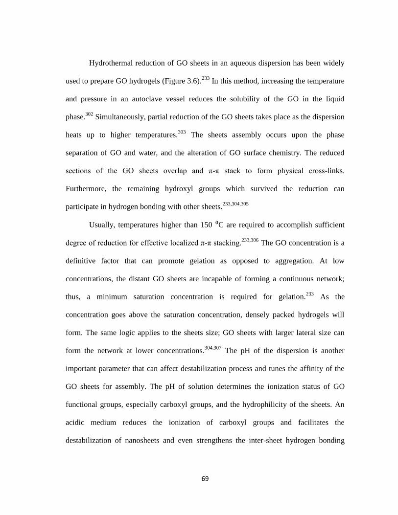
69
Hydrothermal reduction of GO sheets in an aqueous dispersion has been widely
used to prepare GO hydrogels (Figure 3.6).233
In this method, increasing the temperature
and pressure in an autoclave vessel reduces the solubility of the GO in the liquid
phase.302
Simultaneously, partial reduction of the GO sheets takes place as the dispersion
heats up to higher temperatures.303
The sheets assembly occurs upon the phase
separation of GO and water, and the alteration of GO surface chemistry. The reduced
sections of the GO sheets overlap and π-π stack to form physical cross-links.
Furthermore, the remaining hydroxyl groups which survived the reduction can
participate in hydrogen bonding with other sheets.233,304,305
Usually, temperatures higher than 150 ⁰C are required to accomplish sufficient
degree of reduction for effective localized π-π stacking.233,306
The GO concentration is a
definitive factor that can promote gelation as opposed to aggregation. At low
concentrations, the distant GO sheets are incapable of forming a continuous network;
thus, a minimum saturation concentration is required for gelation.233
As the
concentration goes above the saturation concentration, densely packed hydrogels will
form. The same logic applies to the sheets size; GO sheets with larger lateral size can
form the network at lower concentrations.304,307
The pH of the dispersion is another
important parameter that can affect destabilization process and tunes the affinity of the
GO sheets for assembly. The pH of solution determines the ionization status of GO
functional groups, especially carboxyl groups, and the hydrophilicity of the sheets. An
acidic medium reduces the ionization of carboxyl groups and facilitates the
destabilization of nanosheets and even strengthens the inter-sheet hydrogen bonding

70
during gelation.308,309
Furthermore, extensive attempts have been made to perform
hydrothermal-assisted co-assembly of GO sheets and various guest particles in order to
accomplish multifunctional 3D networks with unique properties.310
Figure 3.6. Hydrothermal synthesis of 3D graphene network, (a) digital photo of GO dispersions
and GO hydrogel, (b) digital photo of the hydrothermally-reduced GO aerogels, and (c) SEM
image of the microporous structure of the hydrothermally-reduced GO aerogel (reproduced form
Xu et al. 233
).
In addition to physical cross-linking (i.e., π-π stacking and hydrogen bonding),
GO sheets can be chemically cross-linked to form 3D networks. Formation of chemical
bonds between the sheets promotes the network formation. These chemical bonds can be
introduced to the gel structure through a second component which reacts with GO sheets
and connects them together. The second component could be a polymer, metal ion or
some organic molecule.298,304,308,311-313
The polymers mostly interact with GO sheets
through bonding with their functional groups, while the metal ions promote gelation
through electron donor-acceptor and ion-π interactions. The type and morphology of the
second component defines the porous structure of the gels. Although the presence of

71
second components improves the mechanical properties of the final aerogels, but it may
restricts the electrical conductivity of the product.
To address this issue, the sol-gel technique has been used to prepare highly
conductive graphene aerogels by avoiding the usage of non-conductive second
components. In this method, a catalyst is added to the GO dispersion to facilitate
chemical bond formation between GO sheets and other components234,314
or to trigger
direct chemical bonding of GO sheets through their epoxide and hydroxyl groups.315
According to Worsley et al., the other components used in this method (resorcinol and
formaldehyde) participate in a polymeric network formation that can later be pyrolyzed
at higher temperatures (Figure 3.7a).234
Direct cross-linking of GO sheets occurs through
ammonia-assisted deoxygenation of functional groups, covalent bonding, GO reduction
and π-π stacking of locally reduced sections of GO sheets .315
In this case, higher
temperatures (> 80 ⁰C) are needed to activate the chemical reaction path. Like
hydrothermal-assisted assembly, the temperature, GO concentration and the sheet size
are important factors that affect the gel formation. The pH of reaction medium is also
important; the basic condition improves ionization of the functional groups and improves
their chemical reactivity. Additionally, the catalyst concentration affects the extent of
chemical reactions and is definitive to the final structure of the hydrogels and dried
aerogels. Room temperature drying of directly cross-linked GO sheets results in high-
density aerogels and an improvement of mechanical and electrical properties by several
order of magnitudes. 316

72
In situ reduction of GO sheets in presence of a reducing agent is another method
to induce GO sheets assembly.306,317,318
The mechanism of gelation is similar to that of
hydrothermal method; however, in this case, the chemical reduction of GO sheets
induces aggregation and eliminates the need for higher temperatures. Since various
reducing agents are capable of reacting with different functional groups and restore the
π-conjugated network to different extents, the type and density of chemical bonds that
promote the sheets assembly are different in each case. Thus, the properties of the dried
aerogels vary based on the reducing agent used in the assembly process.317
Moreover,
addition of nanoparticles to the GO dispersion allows for simultaneous assembly of these
particles within the 3D network of the gels.312
Figure 3.7. SEM images of RGO aerogels porous structure prepared by (a) sol-gel technique
(reproduced from Worsley et al. 314
), and (b) freeze-casting technique (reproduced from Qui et
al. 319
) .

73
Freeze casting is another method to produce graphene-based porous structures
with superior mechanical properties.319
Freezing GO or partially reduced GO dispersions
forms a continuous network of GO which mimics the ice crystalline structure (Figure
3.7b). During this process, as the water molecules solidify and form ice crystals, the
sheets become entrapped within the ice-water crystal boundaries and form π- π stacks.
Subsequent removal of the ice by freeze-drying yields a 3D GO structure which is
connected by physical cross-links. Usage of partially reduced GO sheets as a starting
material can enhance the π- π stacking and improves the properties.319
3.4 Conclusion
The liquid-phase exfoliated graphene sheets are used for preparation of various
graphene-based materials including nanocomposites, thin films, freestanding papers, and
3D networks. Graphene-polymer nanocomposites can be prepared by conventional
polymer processing methods such as solution and melt blending. However, the
significant gap in the surface energies of graphene and most of the polymers prevents the
homogeneous dispersion of sheets in the matrix. Modification of graphene surface
through covalent and non-covalent functionalization improves the compatibility of the
sheets and the matrix and promotes the load transfer between the two phases.
Furthermore, the homogeneous dispersion of graphene sheets within the matrix allows
for polymer reinforcement at lower graphene loadings.
Two-dimensional assemblies of graphene are another category of graphene-based
materials that are suitable for electronic devices such as transistors, sensors, and solar

74
cells. The thin films of graphene are deposited on various substrates via drop casting,
spin coating, LBL assembly, or inkjet printing of graphene dispersions. The properties of
the films are dictated by the individual sheet properties, as well as the arrangement and
connectivity of the sheets within the 2D network.
Three-dimensional macrostructures of graphene are usually obtained by
assembly of GO sheets in aqueous dispersions. The physical and chemical cross-linking
of the GO sheets in the solvents forms a hydrogel that can be subsequently dried to yield
a porous 3D network. Hydrothermal, sol-gel, and freeze-casting techniques have been
used to prepare these networks. These networks have been used for preparation of
battery electrodes, oil adsorbents and catalysts.
In Chapter IV, we present our work on dispersant-assisted exfoliation of pristine
graphene in aqueous dispersions. In Chapter V and VI, we use the liquid-phase
exfoliated pristine graphene to prepare composite films with enhanced electrical
properties. In Chapter VII, we spray dry the pristine graphene dispersions to obtain
crumpled graphene sheets. These crumpled particles are then used to prepare graphene
3D networks in Chapter VIII.

75
CHAPTER IV
GRAPHENE COLLOIDAL DISPERSIONS WITH PYRENE
DERIVATIVES AS STABILIZERS*
4.1 Introduction
Production of large quantities of high-quality graphene sheets is essential for
practical application of this unique material in real life. Liquid-phase exfoliation of
graphene from graphite has been widely studied for its high graphene yield and quality,
scalability, inexpensive precursors, ease of processing and versatility for a broad range
of applications such as battery and supercapacitor electrodes,241,320
sensors,321
polymer
nanocomposites322
and soft electronics273,323
. Oxidation of graphite and subsequent
exfoliation of graphene oxide in water is one of the most common liquid-phase
exfoliation methods.66,324
However, graphene oxide, with structural defects and
functional groups on its surface, is electrically insulating and needs to be thermally or
chemically reduced to become conductive. 71,325
However, the complete restoration of
the π-conjugated network, as in the pristine graphene structure, is impossible and RGO
properties never reach those of pristine graphene. 77,326
Direct liquid-phase exfoliation of graphite yields pristine graphene sheets with
minimal structural defects,172
but the reaggregation of these sheets in the solvent due to
* Part of the data reported in this chapter was adapted by permission from (Parviz et al., “Dispersions of
non-covalently functionalized graphene with minimal stabilizer”, ACS Nano, 2012, 6, 8857-8867). Copyright 2012 American Chemical Society.

76
the strong inter-sheet attractive forces is a huge obstacle for obtaining stable graphene
dispersions.175
Using specific solvents with surface energies similar to that of graphene
is a method to reduce the graphene-solvent interfacial tension and keep the graphene
sheets dispersed in the solvent.103,133
However, many solvents including water do not
have such surface energies; thus an alternative approach should be adopted to minimize
the interfacial tension and/or increase the repulsive forces between graphene sheets such
that they overcome the attractive forces and prevent reaggregation. Certain
surfactants,37,137,171,174,237,327
polymers 38,39
and aromatic molecules 328
adsorb on the
graphene surface and provide a repulsive shield around the graphene sheet and stabilize
the exfoliated sheets in solvents with mismatching surface energies. However, presence
of high quantities of adsorbed and non-adsorbed polymer and surfactants in the final
dispersion affects the graphene quality by increasing the residual impurity content in the
product. Thus, the search for alternative molecules that can stabilize higher graphene
concentration with minimal stabilizer content is an ongoing process.
Several groups have reported the usage of different pyrene derivatives to stabilize
CNTs 329,330
and graphene 177,178
in dispersions.289,331,332
However, a systematic study of
the stabilization mechanism and its relationship to graphene yield and dispersion
stability is missing in the existing literature. In this chapter, we investigate the
effectiveness of various pyrene derivatives as graphene stabilizers, as well as the effect
of different constituents of their molecular structure such as functional groups and the
counterions on the graphene yield and quality. Also, we demonstrate that exceptionally

77
higher graphene/stabilizer ratios can be accomplished through pyrene derivatives as
compared to polymers and surfactants.
The work presented in this chapter was published in 2012 as a journal article in
ACS Nano.33
4.2 Experimental procedures
4.2.1 Materials
Expanded graphite was provided by Asbury Carbons (CAS# 7782-42-5, Grade
3805). The pyrene derivatives including pyrene, 1-pyrenesulfonic acid sodium salt (Py-
SASS), 1,3,6,8- pyrenetetrasulfonic acid tetra sodium salt (Py-(SO3)4), 1-pyrenesulfonic
acid hydrate (Py-SAH), 1-aminopyrene (Py-NH2), 1-pyrenemethylamine hydrochloride
(Py-M-NH2), 1-pyrenebutanol, 1-pyrenecarboxylic acid (PCA) and 1-pyrenebutyric acid
(PBA) were purchased from Sigma-Aldrich. Sodium dodecylbenzene sulfonate (SDBS)
was purchased from MP Biomedicals. Polyvinylpyrrolidone (PVP) (Mw ~10000) was
purchased from Sigma-Aldrich. Epoxy resin and hardener were purchased from
FibreGlast Developments Corporation. All the chemicals were used as received.
4.2.2 Preparation of graphene dispersions
In a typical preparation, a specific amount of stabilizer (pyrene derivatives, PVP
or SDBS) was dissolved in 20 ml of deionized water (DI). In case of PCA and PBA, the
pH of solution was increased to 10 by addition of ammonium hydroxide in order to
completely dissolve them in DI water. Expanded graphite (EG) was added to the

78
stabilizer solution and tip sonicated for one hour using a Misonix sonicator (XL 2000) at
output wattage of 7W at room temperature. During the sonication the temperature was
kept in at room temperature using a water bath as a heat sink. The dispersion was then
centrifuged (Centrific Centrifuge 225, Fischer Scientific) at 5000 rpm for 4 hours to
remove larger graphitic aggregates and the supernatant was collected as the final
dispersion. This stable dispersion was used for further characterizations and composite
production. The initial concentrations of stabilizers were varied over a range of 0.5-
7mg/ml. The ratio of the initial concentration of EG to initial concentration of stabilizer
was 10, 20 and 30 in order to study the effect of concentration of EG on the graphene
yield. The initial concentration of SDBS and PVP was 6 and 10 mg/ml, respectively.
4.2.3 Preparation of graphene/epoxy composite
Py-SASS-stabilized graphene dispersion with 3 mg/ml of Py-SASS and 0.8
mg/ml graphene was freeze-dried overnight. To prepare 0.5 wt% graphene/epoxy
composite 0.1 g of freeze-dried powder was added gradually to 3.15 g of epoxy resin and
vigorously stirred for half an hour. Then the mixture was sonicated for 30 min. 0.85 g of
hardener agent was added to the mixture and stirred. Resulting homogeneous mixture
was degassed in vacuum oven at 50 oC to get rid of bubbles. Finally the sample was
doctor-bladed on a dog-bone shaped substrate and cured in the oven at 77 oC for 6
hours. For comparison, 0.5 wt% graphene/epoxy composite was prepared by same
procedure using PVP-stabilized graphene. The final concentration value of graphene in
PVP-assisted dispersion was 1 mg/ml.

79
4.2.4 Characterization of graphene dispersions
To calculate the post-centrifugation concentration of graphene, the UV-vis
spectroscopy was performed on a Shimadzu UV-vis spectrophotometer 2550 at a
wavelength of 660 nm on the dispersions. A stabilizer solution with a concentration
similar to that of graphene dispersion was used as the blank to eliminate the effects of
the stabilizer on the absorbance. The graphene concentration was determined using
Beer’s law. According to Beer’s law, A= *C*l, in which A is the absorbance at the
given wavelength, is the molar extinction coefficient in the solution, l is the path
length of the light and C is the concentration. In order to calculate the extinction
coefficient, a regular vacuum filtration setup was utilized to measure the concentration
of graphene in the dispersion. Polytetrafluoroethylene (PTFE) membrane with a pore
size of 0.02 µm was used as the filter. The mass of the PTFE membrane, before and after
filtration was measured and used to determine the concentration of graphene. The
absorbance of the same dispersion (with now known concentration) was measured at 660
and used to calculate the extinction coefficient in the stabilizer solution. The same
filtered samples were used to measure Raman spectra on a Renishaw Raman microscope
using a 633 nm He_Ne laser.
High Resolution Transmission Electron Microscopy (HRTEM) samples were
prepared by deposition of a single drop of the dispersion on a 400-mesh carbon-coated
copper grid (Electron Microscopy Sciences, CF400-Cu), followed by air drying for a
few minutes. A voltage of 75 kV was used to image the samples on Hitachi H8100.

80
Thermogravimetric analysis (TGA) was carried out in TGA i 1000, Instrument
Specialist Inc. The temperature was raised from 0 oC to 1000 °C at the rate of 10
°C/min.
Zeta potential measurements were conducted on a Zetatrac analyzer from
Microtrac Inc. Two laser beams at 780 nm were irradiated to measure the electrophoretic
mobility of particles using the principles of dynamic light scattering. The Zetatrac
analyzer calculates the value of zeta potential from electrophoretic mobility using the
Smoluchowski equation: ξ=µɳ /ε, where ξ is the zeta potential, µ is the mobility, ɳ is the
viscosity of solution and ε is the dielectric constant of the solvent. Also, stability of the
dispersions against pH changes was examined by the zeta potential measurements at
various pH values of the dispersions. For these experiments, drop-wise addition of
hydrochloric acid (HCl) and sodium hydroxide (NaOH) to the dispersions in an
autotitrator from Microtrac Inc was used to alter the dispersion pH. All measurements
were carried at room temperature.
The average particle size was measured using Dynamic Light Scattering (DLS)
technique within the Zetatrac particle size analyzer unit from Microtrac Inc. Samples
concentration, if necessary, were diluted to at 0.05 -0.1 mg/ml for these measurements.
4.2.5 Dispersion stability tests
Graphene dispersions were frozen in a freezer at -15 ⁰C and then freeze-dried
(Vitris Benchtop Freeze Dryer) overnight to yield graphene powder samples. The freeze-
dried samples were redispersed in water and sonicated for 5 min. Redispersed samples

81
were centrifuged and the concentration of graphene in supernatant was measured to
evaluate the redispersibility of the graphene. Visible stability of the dispersion at higher
temperatures was tested by heating and centrifugation of the dispersions. Samples were
heated up gradually and after each 10 °C raise in the temperature they were centrifuged
for 30 min to check the possibility of visible sedimentation at higher temperatures.
Above 70 °C, samples were centrifuged after each 5 °C raise in the temperature.
Desorption of Py-SASS from graphene surface in presence of ethanol was
studied by adding ethanol to Py-SASS-assisted dispersions to get dispersions with 10 to
90 vol% of ethanol. All samples were centrifuged simultaneously for 1 hr and then the
concentration of graphene in supernatant was measured to study desorption of Py-SASS
from graphene in presence of ethanol. Samples containing graphene in the supernatant
were centrifuged for another 1 hr to test the time dependence of the desorption process.
4.2.6 Characterization of graphene/epoxy composites
Scanning Electron Microscopy (SEM): Samples were prepared by mounting the
samples on double-faced carbon tape and sputter coating with gold at 10 mA current for
1 min. An accelerating voltage of 5 kV was used to image the specimens on a Hitachi
S4300 SE/N.
Mechanical tests: Tensile tests were performed in a Test ResourcesTM
universal
testing machine (made in USA). Young’s modulus and tensile strength were averaged
from three tested specimens. Monotonic tensile testing was conducted on the specimens
by moving the linear actuator of the machine; the upper grip was moved up with the

82
actuator over a fixed displacement of 10 mm in 1000 sec and the lower grip was
fixed. The machine was operated on displacement feedback mode. The resulting load
data was plotted as a function of the displacement and the initial part of the curve was
fitted with a linear trend line. Based on a high fitting coefficient (i.e., R2> 95%), the
elastic modulus and the yield strength were determined from this linear regime.328
Electrical conductivity measurement: Electrical resistivity of the composites was
measured by standard four point probe method. The four point probe head (Signatone,
SP4-40045TBY) was mounted on a resistivity measurement stand (Signatone, Model
302). Two outer probes were connected to high impedance current source (Keithley
2400) to supply current through the sample and inner probes were coupled with a digital
voltmeter (Keithley 2000) to measure the voltage drop across the two probes.328
4.3 Results and discussion
4.3.1 Quality of graphene sheets
Various pyrene derivatives with various functional groups were used to stabilize
graphene in aqueous solutions. The molecular structure of these pyrene derivatives is
demonstrated in Figure 4.1. Among these derivatives, pyrene, P-NH2 and PB were
insoluble in water, but all other derivatives were dissolved in water either by pH change
or by heating the solution.

83
Figure 4.1. The molecular structure of various pyrene derivatives used in this study as graphene
stabilizers.
To evaluate the quality of graphene dispersed by pyrene derivatives, Py-SASS-
stabilized samples were characterized by HRTEM (Figure 4.2). Counting the number of
layers at the edge of the graphene sheet, which is a common technique for assessment of
the number of graphene layers,38,169,171
indicated that PY-SASS-stabilized graphene
sheets are consisted of 2-4 graphene layers. Also, the lateral dimensions of the sheets

84
varied between 2 to 3 µm. The lateral size and number of layers of the sheets are
consistent with the values reported in the literature for directly-exfoliated graphene
sheets in the liquid phase after centrifugation.38
Figure 4.2. HRTEM images of the graphene sheets in Py-SASS-stabilized aqueous dispersion.
Counting the number of the layers on the edge of the sheets reveals the few-layer nature of
stabilized graphene. The sheet size varies between 2 to 3 µm.
The degree of exfoliation and the structural defects of the PY-SASS-stabilized
graphene sheets were evaluated using RAMAN spectroscopy and comparison against
parent expanded graphite spectra (Figure 4.3). Raman spectra of both materials

85
demonstrate the three characteristic peaks of graphitic materials at 1330, 1580, and 2680
cm-1, corresponding to the D, G and 2D bands, respectively. The G band represents the
presence of sp2-hybridized carbon bonds in both graphene and expanded graphite
samples. The 2D band reflects the number of layers in the graphene and graphite
sheets.88
The downward shift of graphene 2D band compared to the parent graphite 2D
peak verifies the few-layer nature of the Py-SASS-stabilized graphene sheets. The D
band is representative of lattice defects and edge effects. Compared to parent graphite,
the D band of graphene sample demonstrated increased intensity; this could be attributed
to the increase in the number of graphene edges exposed in exfoliated sheets with lower
later size.88,169
Figure 4.3. Raman spectra of expanded graphite and Py-SASS-stabilized graphene. Downward
shift of the 2D band at 2675 cm-1
confirms the few-layer nature of the stabilized graphene.
Presence of Py-SASS on the graphene surface appears in the broad shoulder bound to the 2D
band.

86
4.3.2 Effectiveness of pyrene derivatives as graphene stabilizers
Pyrene is a prominent polycyclic aromatic hydrocarbon (PAH) with a molecular
structure similar to graphene. The existence of sp2-hybridized carbon network in pyrene
facilitates the electron sharing with graphene through π-π interactions.333,334
Pyrene
derivatives consist of a pyrene basal plane which is covalently functionalized by any of
the carboxyl, sulfonyl, hydroxyl and amine groups. In the water, these molecules adsorb
on graphene surface through π-π interactions to minimize the total surface energy of the
dispersion. Meanwhile, the polar functional groups provide stability in water, as well as
an electrostatic repulsive shield around the graphene sheets (Figure 4.4).
Figure 4.4. Schematic of mechanism of pyrene derivatives adsorption on graphene surface.
The effectiveness of pyrene derivatives as graphene stabilizers was evaluated by
measuring the post-centrifugation concentration of graphene sheets in the dispersions.
Figure 4.5 demonstrates the final graphene concentrations in the dispersions, stabilized
by various concentrations of different pyrene derivatives.

87
Figure 4.5. Final concentration of graphene stabilized by different pyrene derivatives
concentrations. The concentration of parent expanded graphite in all the dispersions was 20
mg/ml.
Since different graphene concentrations were obtained using different pyrene
derivatives, and based on the fact that pyrene derivatives are only different in their
functional groups, we argue that the effectiveness of these molecules as stabilizers is
determined by the type of the functional group attached to the pyrene basal plane. For a
range of initial stabilizer concentrations, Py-SASS and Py-SAH with one sulfonyl group
yielded higher graphene concentrations than the PCA and PBA which each have one
carboxyl group. Moreover, the Py-M-NH2 with amine functional group was the least
effective stabilizer among all the pyrene derivatives, yielded the lowest graphene
concentration (0.089 mg/ml). Therefore, a trend of functional groups effectiveness
exists, summarized as sulfonyl> carboxyl> amine (Table 4.1). This trend may be
explained by the mechanism behind the adsorption of pyrene derivatives on graphene
surface. The pyrene derivatives adsorb on graphene by sharing π electrons (i.e. π-π
interactions); the electron acceptance/donation between the two surfaces occurs due to

88
the variation in the electron density on their aromatic planes. The electron density on
pyrene changes due to the temporary polarization that occurs in presence of the polar
functional groups. The electron depletion/accumulation on pyrene surface is controlled
by the electronegativity of the functional groups. The sulfonyl group in Py-SASS and
Py-SAH has the highest electronegativity between the above-mentioned functional
groups. This electron-withdrawing group reduces the electron density on the pyrene
basal plane and facilitates the electron acceptance from the π-network of graphene
surface. Hence, Py-SASS and Py-SAH have higher affinity to adsorb on the graphene
surface and can stabilize higher number of exfoliated graphene sheets during the
sonication process. The electronegativity of carboxyl group is lower than sulfonyl, thus,
it has a lower tendency withdraw electrons from graphene and adsorb on its surface
compared to sulfonyl group. The amine group has the least electronegativity among all
the functional groups and is a weak electron-donor group. Hence, it has lower tendency
for adsorption on graphene surface compared the other functional groups and yield the
minimum stabilized graphene concentration.
Table 4.1. Effect of functional groups on the graphene yield. The effectiveness of the functional
groups changes in the order of sulfonyl > carboxyl > amine.

89
As the pyrene derivatives adsorb on graphene, their polar functional groups
dissociate in the water and form an outer layer of counterions around the stabilized
graphene sheets. According to DLVO theory, the total neutralization of the ions in the
solution occurs at a distance from the surface, leaving a layer of counterions with a total
opposite charge around the graphene.335
This layer acts as an electrostatic shield which
imposes repulsive forces between the stabilized graphene sheets and prevents
aggregation. A comparison between Py-SASS and Py-SAH-assisted dispersions allowed
evaluating the effect of this ionic shield on the effectiveness of pyrene derivatives for
graphene stabilization. These two pyrene derivatives are similar in structure with
exception of their counterions. The PY-SASS with sodium as the counterion yields
higher graphene concentrations (up to its solubility limit) than Py-SAH. This may be
attributed to the higher ionic strength and size of sodium compared to hydrogen ions (in
Py-SAH). An electrostatic shield of sodium ions may provide stronger repulsive forces
than a shield of hydrogen ions and thus, enables stabilization of higher number of
graphene sheets by preventing the reaggregation.
The number and position of functional groups attached to the pyrene is another
important factor that affects the adsorption behavior and effectiveness of pyrene
derivatives as graphene stabilizers. To our surprise, the Py-(SO3)4 with four sulfonyl
groups yielded lower graphene concentration in the dispersion relative to Py-SASS
(Figure 4.6). Also, this molecule could not disperse graphene at stabilizer concentration
higher than 1 mg/ml. It is possible that the symmetric arrangement of four sulfonyl
groups around pyrene reduces the probability of temporary polarization on aromatic

90
plane and reduces the electron-depletion on pyrene surface which is the adsorption
driving force. Also, the presence of four functional groups creates a steric hindrance that
prevents adsorption of this molecule on graphene surface. These effects intensify at
higher concentrations of stabilizer as the repulsion forces between the particles increase
the electron density on the pyrene plane.
Figure 4.6. The number and position of functional groups affects the graphene concentration in
the dispersions. a) Py-SASS assisted dispersion with final graphene concentration of 0.11 mg/ml
and b) Py-(SO3)4 assisted dispersion with final graphene concentration of 0.04 mg/ml. The same
concentration of stabilizer (1 mg/ml) was used in both samples.
The distance of functional groups from the pyrene is also an important parameter.
Comparison of PCA- and PBA-stabilized dispersions reveals that with an increase in the
stabilizer concentration PBA became more effective than PCA. At low stabilizer
concentrations, the shorter distance of electronegative group from the pyrene facilitates
the electron-withdrawal from the aromatic plane and improves the adsorption of PCA in

91
which the carboxyl group is closer to pyrene. However, as the stabilizer concentration
increases, the repulsive forces between the sheets become stronger and lead to an
increased electron density on the pyrene plane. In this situation, a larger distance from
the pyrene reduces the charge transfer to aromatic plane and maintains the affinity of
PBA for adsorption on graphene surface.
Figure 4.7. Zeta potential changes with stabilizer concentration in Py-SASS-stabilized
dispersions. The absolute value of the zeta potential decreased gradually with an increase in the
Py-SASS concentration.
For all the pyrene derivatives (except Py-SAH and Py-M-NH2) the graphene
concentration in the dispersions went through a maximum as the stabilizer concentration
increased. To study the reason of such behavior, we measured the zeta potential of a Py-
SASS-stabilized dispersion at various stabilizer concentrations (Figure 4.7). As the
pyrene derivatives adsorb on the graphene surface in water, the dissociated functional
groups impose a net charge on the graphene sheets. The average value of this surface

92
charge is represented by the zeta potential value of the graphene dispersions. For Py-
SASS-stabilized dispersions, the reduction of the zeta potential absolute value upon
addition of more stabilizers indicates a decrease in dissociation of the functional group at
higher stabilizer concentrations. Despite of the availability of more pyrene derivatives
for adsorption onto the graphene surface, the electrostatic repulsive forces provided by
them is not sufficient to prevent reaggregation of graphene sheets.336
Thus, the overall
graphene concentration decreases upon increase in stabilizer concentration. The
graphene concentration in Py-SAH and Py-M-NH2-assisted dispersion initially
increased and then remained constant. Reduced solubility of these two pyrene
derivatives in water at higher concentrations is the main reason for plateau in the
graphene concentration. Above the saturation concentration of these pyrene derivatives,
the excess stabilizer could not contribute to graphene stabilization and the graphene
concentration remained constant beyond the stabilizer solubility limit.
TGA was performed to estimate the surface coverage of graphene by Py-SASS.
Py-SASS carbonized completely at 750 ⁰C. The remaining mass of graphene at this
temperature after deduction of Py-SASS fraction was about 11.25 %. The surface
coverage of Py-SASS on graphene was calculated to be ~ 9.85* 10-10
mol/cm2, based on
the theoretical surface area of graphene (2630 m2/g) and remaining mass of Py-SAA
which was 88.75%. This is one order of magnitude higher than the previously reported
surface coverage by covalently-bonded polymers on the graphene surface.222

93
Figure 4.8. Thermogravimetric analysis of Py-SASS and freeze-dried Py-SASS/graphene
powder.
4.3.3 Graphene yield and processability
The most important characteristic of pyrene derivatives-assisted dispersions is
the high graphene to stabilizer ratio. The graphene concentration obtained using Py-
SASS at its optimal concentration was ~ 0.8 mg/ml; this concentration reached values as
high as 1.2 mg/ml depending on the sonicator efficiency. The higher graphene
concentrations reported in the literature were usually achieved by excessive sonication
time (up to 400 hrs) and lower centrifugation force (500-1500 rpm) and duration (2-90
min).337
Table 4.2 indicates the comparison of graphene ratio for dispersions prepared at
the same experimental condition using Py-SASS, PVP and SDBS.36,39
The higher
graphene/stabilizer ratio in Py-SASS-assisted dispersions enhances the graphene quality
by reducing the amount of excessive stabilizer and facilitates the application of this

94
product in nanocomposites and electrode where the presence of residual impurities is a
challenging issue.
Table 4.2. Effectiveness of surfactants, polymers and pyrene derivatives as graphene stabilizers
compared by their graphene yield and graphene/stabilizer ratio.
In an attempt to accomplish higher graphene yields, the initial graphite
concentration was altered. Figure 4.9 illustrated the graphene concentration obtained
using different expanded graphite concentration. For all the pyrene derivatives, the
increase in EG concentration led to an increase in the final graphene concentration.
However, large quantities of graphite may hinder an effective exfoliation during the
sonication process. Furthermore, the increase in graphene yield upon addition of more
EG depends on the stabilizer; Py-SASS- assisted sample showed the highest rate of
increase in graphene yield.

95
Figure 4.9. Graphene concentration increases with addition of initial expanded graphite
concentration.
Also, we attempted to disperse graphene into organic solvents including
methanol, ethanol and acetone using pyrene derivatives. However, an immediate
sedimentation of graphite after sonication indicated the incapability of pyrene
derivatives for stabilization of exfoliated graphene in pure organic solvent. This might be
attributed to the lack of a huge difference in polarities of pyrene derivatives and these
solvents; under these circumstances the minimization of total surface energy of the
dispersion does not occur through the adsorption path. Even if the pyrene derivatives
adsorb on graphene surface, the weak dissociation of the functional groups in organic
solvents cannot provide the strong repulsive shield around the graphene sheets. Thus, the
aggregation of exfoliated graphene sheets is inevitable.

96
In addition, we investigated the stability of graphene dispersion in mixtures of
water and ethanol. Graphene concentration after addition of different amounts of ethanol
to the dispersions and centrifugation is indicated in Figure 4.10. The graphene
concentration decreased upon addition of more ethanol to the dispersion. With more than
60 vol% of ethanol in the dispersion, complete aggregation of graphene sheets and
sedimentation occurred after one hour of centrifugation. Addition of ethanol to the
dispersion changes the polarity of the solution and affinity of Py-SASS to remain
adsorbed on the graphene surface. In presence of more ethanol molecules, desorption of
Py-SASS from graphene surface reduces the net charge of the surface and weakens the
repulsive shield around the sheets which leads to destabilization of graphene. Further
centrifugation of samples containing 50 and 60 vol% of ethanol for one more hour led to
aggregation and sedimentation of the graphene. This observation confirms the fact that
desorption of Py-SASS from graphene surface after addition of ethanol is a transition
between two equilibrium states that happens in a timely manner. The overnight
centrifugation of samples with 10-40 vol% of ethanol did not change the graphene
concentration; this means that desorption of Py-SASS in presence of up to 40 vol% of
ethanol is negligible.

97
Figure 4.10. The post-centrifugation graphene concentration in mixtures of ethanol/water.
Ethanol was added to an aqueous dispersion of graphene to prepare dispersions with 10-90 vol.%
of ethanol.
In order to obtain aggregation-resistant graphene powder, the aqueous
dispersions were freeze-dried after centrifugation. The stability of the resultant graphene
powders against aggregation was tested by redispersion into the water and subsequent
centrifugation. The Py-SASS/ and Py-SAH/graphene powders were easily redispersible
without any further sonication (Figure 4.11), but partial sedimentation occurred in all
other samples.
98
Figure 4.11. Redisperiosn of freeze-dried Py-SASS/graphene powder in water at original
dispersion concentration.
4.3.4 Stability of graphene dispersions
In terms of long-tem stability, all the dispersions were stable several months with
exception of Py-SAH-assisted sample which was slightly aggregated after 2 months. The
colloidal stability of all the dispersions was evaluated by zeta potential measurement
over a wide range of pH. The results are represented in Figure 4.12. The samples
stabilized with sulfonyl-containing pyrene derivatives were the highly stable over a wide
range of pH compared to the other dispersions. Both Py-SASS- and Py-(SO3)4-assited
samples had zeta potential values higher than ± 30 at their original pH which is
indicative of their colloidal stability. The Py-SAH-assisted sample had a low zeta
potential value at its original pH of 2 which explains its aggregation over time. However,
the increase in the pH of this sample made it stable at a pH range of 6-8.5. The
aggregation of the graphene sheets in these samples were traced with the increase in the
average particle size measured by the dynamic light scattering (Table 4.3).

99
Figure 4.12. zeta potential of graphene dispersion prepared with pyrene derivatives at different
pH values. The original pH of the dispersions before any change by acid or base addition is
mentioned in the parentheses in front of each pyrene derivative.
Table 4.3. Average particle size in sulfonyl-containing graphene dispersions at various pH
values measured by DLS technique.

100
Despite of the lower zeta potential values measured for the PCA, PBA and P-M-
NH2-assisted samples, these dispersions were stable over months. The stability of the
PCA and PBA-assisted dispersions was restricted to highly basic media due to the
presence of carboxyl groups and they destabilized with slight decrease in the pH.
However the destabilized PCA and PBA-samples were recovered to the original well-
dispersed state upon addition of a base (Figure 4.13). This observation confirms that the
destabilization of these samples is a reversible flocculation process that occurs solely
because of the lower solubility of PCA and PBA in water at lower pH values. PCA and
PBA remain adsorbed on graphene surface during the destabilization and prevent
reaggregation of graphene sheets; upon recovery of the original pH these sheets
redisperse back into the water.
Figure 4.13. Flocculation and redispersion of PCA-stabilized graphene dispersion upon pH
changes: a) The original dispersion at pH= 11, b) the destabilized dispersion after addition of
acid at pH= 3 and c) the recovered dispersion after increasing the pH to 10.5 by addition of base.
(Note that the concentration is lowered simply by dilution effects of the acid and base.)

101
The stability of dispersions at higher temperature is illustrated in Figure 4.14.
The dispersions with sulfonyl groups showed thermal stability at higher temperatures
compared to the other samples. In fact, the Py-SASS-assisted dispersion was stable up to
100 ⁰C; the stability at higher temperatures makes it a promising candidate for further
processing for nanocomposite applications.
Figure 4.14. Visible stability of graphene dispersions against temperature changes.
4.3.5 Graphene-polymer nanocomposites
For the first time, we investigated the application of graphene dispersion
stabilized with pyrene derivatives in polymer nanocomposites. To prepare
graphene/epoxy composite thin film, the Py-SASS-stabilized graphene dispersions were
freeze-dried and the resultant graphene powder was mixed into the epoxy matrix,
followed by degassing and doctor-blading of the mixture (Figure 4.15). The SEM
images the epoxy before and after graphene addition are depicted in Figure 4.16.

102
Figure 4.15. 0.5 wt % graphene/epoxy composites prepared by a) Doctor-blading and b) casting
in a Teflon mold.
Figure 4.16. SEM images of a) epoxy and b) Py-SASS stabilized graphene/epoxy composite.
The mechanical and electrical properties of doctor-bladed thin films of Py-SASS-
and PVP- stabilized graphene/epoxy are represented in Table 4.4. The electrical
conductivity of both samples is in the same range and both graphene samples enhanced
the electrical conductivity of the insulating epoxy matrix. The Py-SASS-stabilized
sample had a higher Young’s modulus than the PVP-stabilized sample; however, the
lower yield strength of the Py-SASS containing sample may be attributed to the poor

103
dispersion of the Py-SASS/graphene powder in the epoxy matrix. While the Py-
SASS/graphene powder slightly agglomerated in epoxy matrix even after 40 min of
sonication, the PVP/graphene sample homogeneously disperses into epoxy matrix.
Table 4.4. Mechanical and electrical properties of 0.5 wt% PVP- and Py-SASS-stabilized
graphene/epoxy composites.
4.4 Conclusion
In summary, we investigated the applicability of pyrene derivatives as graphene
stabilizer in aqueous dispersions. We showed that using Py-SASS, graphene
concentrations as high as 1 mg/ml were obtained. Also the graphene to stabilizer ratio
achieved by pyrene derivative sis much higher than those obtained using polymers and
surfactants as stabilizers. Also, the effect of the molecular structure of pyrene derivatives
on the graphene yield was studied. We demonstrated that the electronegativity of the
functional groups is an important factor that affects the adsorption of these species on
the graphene surface. The ionic strength and size of the counterions of the functional
groups determines the strength of the repulsive shield around the graphene sheets and

104
affects the final graphene concentration. The number and position of the functional
groups, as well as their distance from the pyrene basal plane are the other parameters
that control the adsorption of pyrene derivatives, graphene stabilization and final
concentration. The long-term colloidal stability of the solution were examined by
centrifugation and zeta potential measurements. We evaluated the processability of the
dispersions by studying the effects of solvent exchange and stability against
lyophilization. Also, the stability of dispersions against pH and temperature changes was
investigated. Finally, we prepared graphene/epoxy composite thin film using the Py-
SASS-stabilized graphene dispersions. The knowledge of stabilization mechanism and
the effect of controlling parameters allows for design of novel graphene stabilizers with
desirable molecular structures that match with various exfoliation and dispersion media.
In Chapter V, we use pyrene-graphene π-π interactions to design a novel polymeric
dispersant for pristine graphene.

105
CHAPTER V
DESIGNER PYRENE-FUCNTIONAL STABILIZER FOR PRISTINE
GRAPHENE/POLYSILOXANE CONDUCTIVE FILMS AND
NETWORKS*
5.1 Introduction
Incorporation of graphene sheets into polymer matrices allows the unique
properties of these sheets to be exploited not only in transparent thin films, but also in
bulk materials like polymers. In nanocomposites, graphene’s electrical and thermal
conductivity and mechanical rigidity are able to enhance the material properties of the
polymeric matrix.185,186,214,215
Liquid-phase exfoliated graphene sheets are promising
fillers for nanocomposites due to their high quality, processability and the large
quantities in which they can be produced. Solution mixing and melt blending are the
common methods used to disperse the graphene sheets into the polymer
matrix.186,189,190,194-196,214
However, the poor graphene dispersion obtained by these
methods prevents the enhancement of nanocomposite properties at low loadings of
graphene. The poor dispersion and aggregation of sheets is more pronounced when
pristine graphene is used instead of GO or RGO; the surface chemistry of GO and RGO
makes them more polymer-philic.
*Part of the data reported in this chapter was reproduced by permission of Royal Society of Chemistry from (Parviz et al., “Designer stabilizer for preparation of pristine graphene/polysiloxane films and networks”, Nanoscale, 2014, 6, 11722-11731).

106
As mentioned in Chapter III, alternative dispersing methods such as in situ
polymerization,201-203,205
modification of graphene surface through covalent, 216-218,220
and non-covalent functionalization.221,222,225,338
have been practiced to improve the
polymer-graphene interfacial interactions. Yet, these methods heavily rely on the surface
chemistry and reactivity of GO sheets. The few exceptions were those cases in which
conjugated copolymers and conductive polymers were attached to pristine graphene
surface via π-π interactions.223,224
The non-covalent functionalization of pristine
graphene with polymers has been rarely reported.339
The usage of GO in nanocomposites is problematic since it is electrically
insulating and needs further reduction to become conductive; however, the common
chemical or thermal reduction methods are not always applicable in presence of
polymers. Usage of RGO in nanocomposites has its own complications; RGO shows
poor dispersibility in most of the solvents relative to GO, while its properties cannot
reach those of pristine graphene. 326,340
In the last chapter, we demonstrated that exfoliation and stabilization of pristine
graphene in water is feasible using pyrene derivatives. The pyrene basal plane can
adsorb on graphene surface through π-π interactions and the functional groups provide
an electrostatic repulsive shield around the sheets to prevent reaggregation. However,
addition of those stabilized graphene sheets to the epoxy matrix was not sufficient to
enhance its electrical conductivity drastically. We argued that poor dispersion of
graphene sheets within the epoxy due to their incompatibility was responsible for the
lack of a considerable increase in electrical conductivity of the nanocomposite.

107
Furthermore, the presence of excessive pyrene derivatives in the matrix induces extra
interfacial tension which can prevent proper electron transfer within the nanocomposite.
In this chapter, we take advantage of the pyrene-graphene interactions to design a
polymer-based stabilizer for graphene. We tailor the polymer structure by grafting
pyrene groups to its backbone to induce π-π interactions between the polymer and
graphene. Such a designer polymer acts as both graphene stabilizer and polymer matrix
in the nanocomposite. Using this polymer, the exfoliation of graphene sheets in the
solvent and mixing them into the polymer matrix are performed in one single step in
presence of an appropriate solvent. The polymer-stabilized graphene dispersions are
simply cast to form graphene/polymer composite films and networks. In those
composites, the presence of excessive incompatible stabilizer molecules is not anymore
an issue.
This works was done in collaboration with Dr. Ronald Hedden at Texas Tech
University, Department of Chemical Engineering. The polymer synthesis and
characterizations were partially performed by his Ph.D. student, Ziniu Yu. This work
was published in 2014 as a journal article in Nanoscale.341
5.2 Background of the graphene/silicone nanocomposites
Polydimethylsiloxane (PDMS) is an organosiloxane polymer having a low glass
transition temperature and good thermal stability, which is used in a wide range of
applications such as elastomers, electronic materials, microfluidics, medical devices, and
piezoresistive devices.342
Due to the attractive possibilities of enhancing mechanical or
108
electrical properties of silicones by addition of carbon nanomaterials, numerous studies
have reported incorporation of graphite nanoplatelets, GO and RGO into PDMS.
Kujawski et al. mixed exfoliated graphite into the PDMS and observed a percolation
threshold at 3 wt. % loading of the filler, along with enhanced mechanical properties of
the composite.343
Chen et al. studied the piezoresistive behavior of PDMS composites
filled with graphite nanosheets by wet-mixing.344
Raza et al. blended PDMS with
graphite nanoplatelets through mechanical mixing and studied thermally conductive
behavior at interfaces.345
Ozbas et al. mixed exfoliated, oxidized graphite sheets into
PDMS, which led to a low percolation threshold at 0.8 wt. % loading of the filler and
also a tenfold decrease in gas permeability through the composite. 346
Xu et al. shear-
mixed RGO into PDMS to enhance the mechanical properties.347
However, the
aggregation of nanosheets made it difficult to obtain a homogenous dispersion of the
fillers in the polymer. To overcome this issue, several research groups tried methods
other than conventional mixing of the filler into the polymer matrix. Guimont et al.
grafted PDMS onto graphite oxide sheets via a hydrosilylation reaction and varied the
grafting density to enhance the filler dispersion quality in the PDMS.348
Gao et al.
covalently attached the GO to PDMS, and they observed enhancement in mechanical
properties.349
Hou et al. functionalized GO to make its surface energy more compatible
with PDMS.350
Also, some groups have infused pre-made graphene or CNT aerogels (or
other conductive monoliths) with PDMS, creating rigid composites.351
In all prior studies, expanded graphite, GO or RGO were used as conventional
nanofillers, with varying degrees of success in dispersion. One possibility which has not

109
been explored is to incorporate pristine graphene into linear PDMS or its copolymers in
order to produce a conductive, liquid-phase nanocomposite that is well above its glass
transition temperature at ambient temperature. In the absence of solvent, such a material
does not have any vapor pressure, which is potentially favorable for conductive fluid
applications. In order to disperse pristine graphene in a solvent-free polymer, graphene
sheets should interact strongly with the surrounding polymer matrix.
Here we introduce a new strategy for combining pristine graphene with a
siloxane-based matrix using a designer stabilizer that utilizes graphene-pyrene π-π
interactions (Figure 5.1). Pyrene side groups are grafted to a PDMS backbone through
hydrosilylation reaction. Pristine graphene-rich films with electrical conductivity up to
200 S/m were prepared by casting the copolymer-stabilized graphene dispersions and
leaching out the excess, unbound polymer on a porous substrate. The graphene-
containing PDMS-pyrene copolymers can also be crosslinked readily by simply
changing the stoichiometry of the hydrosilylation reaction, producing the first example
of a silicone elastomer containing pristine graphene. The final pristine graphene/polymer
composite is a two-component system which does not have functional groups covalently
bonded to the graphene, leaving the conjugation of the graphene rings intact.
Figure 5.1. Designing pyrene-based polymeric stabilizer for pristine graphene.

110
5.3 Experimental procedures
5.3.1 Materials
Poly(dimethylsiloxane)-co-(methylhydrosiloxane) copolymer (HMS-064, 5-7
mole % PMHS) was purchased from Gelest Inc (USA). Cis-dichlorobis(diethyl sulfide)
Pt (II) catalyst was purchased from Strem Chemicals (USA). 1-ethynylpyrene,
chloroform (HPLC grade), toluene (ACS grade) and methanol (ACS grade) were
purchased from Sigma-Aldrich (USA). Expanded graphite was provided by Asbury
Carbons (CAS# 7782-42-5, Grade 3806, USA).
5.3.2 Synthesis of the pyrene-containing copolymers
Synthesis of poly(dimethylsiloxane)-co-(methyl(vinylpyrenyl)siloxane) linear
copolymers (PMPyS): 5.0 g of HMS-064 copolymer was dissolved in 52.8 g of
chloroform. 30 mol % excess (1.2 g, 5.3 mmol) of 1-ethynylpyrene was added to the
solution, which was homogenized by stirring and heated to 44 C. 847 l of a toluene
solution of cis-dichlorobis(diethyl sulfide) Pt (II) (2.6610-3
g/g toluene) was added to
initiate the hydrosilylation reaction. This grafting reaction was allowed to proceed at 44
C for 3 d in solution. The reaction product was purified and separated into fractions of
comparatively narrow molar mass distribution by fractional precipitation from
chloroform (a good solvent) by incremental addition of methanol (a poor solvent).
Initial polymer concentration was approximately 10 g/L in chloroform. The residual
liquid phase was discarded.

111
Synthesis of poly(dimethylsiloxane)-co-(methyl(vinylpyrenyl)siloxane) networks
(PMPyS-N): A crosslinked network of PMPyS was obtained by reacting
poly(dimethylsiloxane)-co-(methylhydrosiloxane) with an amount of 1-ethynylpyrene
that was insufficient to convert all of the silane groups of the copolymer to vinylpyrene
groups. An initial mole ratio of silane:alkyne groups of 1.7:1 was chosen. 1.84 g of
HMS-064 copolymer was dissolved in 6.2 g of chloroform. 0.20 g (0.88 mmol) of 1-
ethynylpyrene was added to the solution, which was homogenized by stirring and
subsequently heated to 44 C. 110 l of a solution (2.6610-3
g/g toluene) of cis-
dichlorobis(diethyl sulfide) Pt (II) was added to initiate the hydrosilylation reaction
between the alkyne group of the 1-ethynylpyrene and the silane groups of the polymer
backbone. The grafting reaction was allowed to proceed at 44 C for 3 d without
stirring. The reaction product was poured into an open PTFE container and chloroform
was allowed to evaporate at 22 oC for 4 h until a viscous, bronze-colored film was
obtained. The temperature was increased to 110 C and the film was allowed to cure for
7 d in air. No precautions were taken to prevent ambient moisture from entering the
film, and the relative humidity was approximately 40-50 % at the ambient temperature
of 22 C. The resulting network was swelled to equilibrium in excess chloroform at 22
C for 3 d, during which time the chloroform was changed twice. The extractable mass
fraction of the network was determined after de-swelling the network by gradual
addition of methanol, vacuum-drying the material, and recording its mass.

112
5.3.3 Preparation of graphene dispersions
Preparation of Graphene Dispersions using PMPyS linear copolymers (PMPyS-
G): In a typical preparation, a specific amount of a fractionated PMPyS polymer was
dissolved in chloroform to obtain 1.0 mg/ml of pyrene in the final solution. Expanded
graphite (EG) was subsequently added to the solution (30 mg/ml) and was tip sonicated
(Misonix sonicator, XL 2000) for 1 h. During the sonication, an ice bath was used to
maintain the sample at room temperature to avoid any chloroform evaporation and to
maximize the efficiency of the exfoliation process. All dispersions were centrifuged
(Centrific Centrifuge 225, Fischer Scientific) at 5000 rpm for 4 h in order to remove
graphitic aggregates. The supernatant of the centrifuged samples was collected and used
for further processing and characterization. Also, the original unfractionated polymer
was used to disperse graphene through a similar procedure.
5.3.4 Preparation of graphene/copolymer composite films and networks
Synthesis of PMPyS network with Included Graphene (PMPyS-NG): A
crosslinked network containing pristine graphene flakes was prepared by a procedure
similar to PMPyS-N networks. After 3 d reaction between HMS-064 and 1-
ethynylpyrene in chloroform, the resulting polymer solution (with solids concentration
of 20 mg/ml) was sonicated in the presence of expanded graphite (30 mg/ml). The
resulting suspension was centrifuged to remove excess graphite, leaving a black solution
of polymer-stabilized graphene in the supernatant. The concentration of graphene was
measured using the absorbance of the dispersion at 660 nm. This solution was deposited

113
into the PTFE container and cured in air using the same temperature and humidity
profile used for PMPyS-N.
5.3.5 Characterization
FT-IR (Fourier Transform Infrared Spectroscopy): The expected product
structure of linear PMPyS was confirmed by FT-IR analysis of the purified fractions
using a Thermo Nicolet Nexus 470 spectrometer. In addition, the crosslinking reaction
was monitored by FT-IR spectroscopy. A thin film of the reaction mixture was
deposited onto a KBr disk and cured with the same temperature program used to prepare
bulk samples, while spectra were recorded periodically.
GPC (Gel Permeation Chromatography): The PMPyS fractions obtained were
characterized by GPC using tetrahydrofuran as mobile phase and four Phenomenex
-106 -10
5 -10
4 -10
3 Å) in series
covering a molar mass range of 1 kg mol-1
to 10,000 kg mol-1
, which were calibrated by
poly(methyl methacrylate) (PMMA) standards. All molar masses reported are relative to
PMMA. Elution of the polymer was detected by a Varian 380-LC mass-evaporative
detector, and elution of the pyrene groups was detected by a KNAUER V2.8 ultraviolet-
visible detector at a wavelength of 348 nm.
UV-Vis Spectroscopy: UV-Vis spectroscopy was performed on a Shimadzu 2550
spectrophotometer on fractionated PMPyS solutions in chloroform to measure the
pyrene content of each fraction. All fractions of PMPyS were dissolved in chloroform
with a polymer concentration of 1 mg/ml. Samples were scanned from wavelength 200

114
nm to 800 nm with pure chloroform as a reference. Also, the absorbance was measured
on all PMPyS-G samples at 660 nm to measure the concentration of graphene in
dispersions. The absorbance of the PMPyS copolymer was negligible at this wavelength.
The extinction coefficient for graphene in presence of the polymers in chloroform was
calculated through the vacuum filtration method.
HR-TEM (High Resolution Transmission Electron Microscopy): The dispersions
of PMPyS-G and the dispersion prepared with unfractionated polymer in chloroform
were deposited on lacey carbon TEM grids and dried in the air for 1 min. A voltage of
75 kV on a Hitachi H8100 was used to image the samples.
SEM (Scanning Electron Microscopy): An accelerating voltage of 2 kV was used
to image the samples on a Hitachi S4300 SE/N. The PMPyS-G sample was cast on a
filtration membrane (PTFE, 0.2 µm, Omnipore Membrane Filters) for imaging. Samples
were mounted on double face carbon tape.
Conductivity measurements: The electrical resistance of the samples was
measured using the four-point probe method. The four-point probe head (Signatone,
SP4-40045TBY) was mounted on a resistivity measurement stand (Signatone, Model
302). The current was supplied by a high impedance current source (Keithley 2400)
through the outer two probes. A voltmeter (Keithley 2000) was used to measure the
voltage across the inner two probes.
DSC (Differential Scanning Calorimetry): The thermal behavior of the polymers
before and after graphene loading was characterized by DSC (TA Instruments, Model Q-
20-1848). Approximately 5 mg of each sample was sealed in an aluminum pan and

115
heating traces were recorded under a nitrogen atmosphere. The heating rate for all the
samples was 10 °C min-1
and samples were heated from -80 °C to 90 °C.
5.4 Results and discussion
5.4.1 Design of pyrene-containing copolymer
To synthesize a pyrene-containing polysiloxane stabilizer, pyrene groups of
1-ethynylpyrene were grafted to the backbone of a silicon-based copolymer through
hydrosilylation reaction. Figure 5.2 shows the proposed mechanism of reaction between
the alkyne group of the 1-ethynylpyrene and the silane groups of the polymer backbone.
The Si-H groups of PHMS covalently bond to the ethynyl groups through
hydrosilylation, forming a substituted alkene. Further reaction of the alkene with an
additional Si-H is unlikely due to both steric hindrance and due to conjugation with the
adjacent pyrene ring. The percentage of Si-H groups bonding to pyrenes through this
reaction depends on the initial mole ratio of ethynyl and Si-H groups present in the
reaction medium. If the ratio of SiH:ethynyl is higher than 1.0, then excess Si-H groups
remain intact after the alkynes are exhausted. These remaining Si-H groups self-
crosslink later and form networks. However, if this ratio is lower than one, then most or
all of the Si-H groups undergo the hydrosilylation reaction and the product is a linear
copolymer. We studied 1.7:1.0 and 1.0:1.3 as SiH:alkyne ratios to illustrate the dramatic
differences in the product resulting from reaction stoichiometry.

116
Figure 5.2. Synthesis of PMPyS copolymer via grafting 1-ethynylpyrene to PDMS-PHMS
copolymer backbone through a Pt-catalyzed hydrosilylation reaction.
5.4.2 Analysis of linear copolymers (PMPyS)
The reaction with the SiH:ethynyl ratio of 1.0:1.3 produces a linear copolymer
having a broad chain length distribution. Therefore, we separated the sample into seven
fractions of narrower molar mass distribution, with Mw ranging from 49 kg mol-1
to 262
kg mol-1
, by fractional precipitation. The goal was to create well-defined polymeric
stabilizers that were free of low molar mass species, in order to evaluate their
effectiveness as graphene dispersants. The fractionation procedure not only narrows the
molar mass distribution, but also removes the majority of low molar mass by-products
and oligomers. GPC results (Figure 5.3) show the fractionated samples with
polydispersity index (PDI, Mw/Mn) much less than 2.0 and containing a minimum
amount of oligomeric impurities. Average molar mass characteristics of the fractions are
summarized in Table 5.1.
Si
CH3
CH3
O Si
H
CH3
O CH3
n m
n=0.93-0.95 m=0.05-0.07
CH3
PHMS-PDMS Copolymer 1-ethynylpyrene
Si
CH3
CH3
O Si
CH3
O CH3
n m
44 oC, PtII
Chloroform
CH3

117
Figure 5.3. Elution profiles of different PMPyS fractions from GPC (performed by Ziniu Yu).
Table 5.1. Molar masses of the PMPyS fractions obtained from GPC analysis (performed by
Ziniu Yu).
The expected structure of the PMPyS copolymer was confirmed by FT-IR
analysis of the purified fractions (Figure 5.4). Absence of the alkyne band at 3294 cm-1
in the PMPyS copolymers indicated a lack of free 1-ethynylpyrene, and appearance of
Fraction 1 Fraction 2 Fraction 3 Fraction 4 Fraction 5 Fraction 6 Fraction 7
Mw (kg/mol) 262 143 135 92 77 57 49 Mn (kg/mol) 170 82 124 78 66 56 43 Mw/Mn 1.55 1.74 1.09 1.18 1.17 1.02 1.13

118
both a C=C stretch band at 1596 cm-1
and a second band at 1508 cm-1
is indicative of a
C=C:Pt complex formed after grafting of pyrene groups to the polymer chains.352,353
Attachment of the pyrene groups to the polymer backbone was also confirmed by GPC
analysis with multiple detections. Simultaneous elution of pyrene groups and polymer
chains confirmed that grafting of pyrene groups to the backbone was successful (Figure
5.5). A minimal amount of free pyrene groups elutes with the residual impurity peak
around t = 80-95 min, indicating that a majority of the original pyrene groups were
successfully grafted to the polymer backbone.
Figure 5.4. FT-IR spectra of fraction 4 of the PMPyS sample (performed by Ziniu Yu).

119
Figure 5.5. GPC analysis of a fraction 4 of the PMPyS sample confirms the attachment of
vinylpyrene groups to the polymer backbone (performed by Ziniu Yu).
The pyrene content of each PMPyS fraction was estimated by comparing its UV
absorbance spectrum to that of 1-ethynylpyrene (Figure 5.6, Table 5.2). 1-ethynylpyrene
exhibits two absorbance bands near 350 and 330 nm, as do the PMPyS fractions; these
bands are absent in the PDMS-PMHS copolymer as obtained from the supplier. The
pyrene content in each PMPyS fraction was therefore estimated from these bands by
comparison to a 1-ethynylpyrene solution of known concentration. The results show that
the pyrene content of the PMPyS fractions is independent of the Mw within the limits of
uncertainty of the experiment. There is no discernable trend in the pyrene content of the
PMPyS chains with increasing molar mass.

120
Figure 5.6. UV-vis spectra of the copolymer precursors and all of the PMPyS fractions.
Table 5.2. Pyrene content of different PMPyS fractions (based on the area under UV-vis spectra
of each fraction).
5.4.3 Graphene/copolymer (PMPyS-G) dispersions
The basic procedure for preparing dispersions of stabilized pristine graphene
involves exfoliation of the graphene using tip sonication in a given solvent with the
stabilizer pre-dissolved in the solvent; this step is followed by centrifugation to remove
non-exfoliated graphitic material. The stable colloidal graphene remains in the
supernatant with a concentration measured by UV-vis absorbance at 660 nm. We first

121
checked whether 1-ethynylpyrene itself can act as a stabilizer in chloroform, but the
resulting concentration of dispersed graphene was zero. This observation is consistent
with our prior work;33
regardless of π-π interactions between the graphene and pyrene,
this particular functional group on the pyrene cannot provide enough electrostatic or
steric repulsion to prevent aggregation of graphene sheets. In contrast, we successfully
dispersed the graphene via the fractionated PMPyS samples in chloroform. Adsorption
of the PMPyS to the surface of the graphene sheets not only hinders aggregation of the
sheets, but provides a mechanism for the sheets to remain suspended in solution
indefinitely due to the favorable free energy of mixing between the macromolecular
stabilizers and the solvent.
The average extinction coefficient (at 660 nm) for graphene in presence of the
polymer in chloroform was 2200 L g-1
m-1
, which was measured by the typical procedure
of vacuum filtration. The graphene concentration after centrifugation was between 0.1-
0.7 mg/ml for various fractions (Figure 5.7). In prior work on pristine graphene
dispersions, the graphene concentration showed a clear trend with stabilizer
concentration. 33,39
The dependence of graphene concentration on stabilizer
concentration is somewhat complex in the current case since the fractions vary in both
molar mass and pyrene content. For simplicity, pyrene concentration was held constant
for each fraction in the graphene dispersion experiments. With pyrene concentration held
constant, the other quantities that vary from one fraction to another are the total polymer
concentration and the molar mass. No trend in graphene concentration is seen at constant
pyrene content. All PMPyS fractions are clearly capable of dispersing graphene in

122
chloroform solution, regardless of molar mass. Thus, it appears that the overall
concentration of the pyrene groups, rather than chain length, may be the key factor that
governs the maximum achievable concentration of dispersed graphene.
Figure 5.7. Graphene concentration variation vs. PMPyS fractions concentration; the pyrene
content in the dispersions of all fractions was held constant at 1 mg/mL.
HRTEM images (Figure 5.8) show representative graphene sheets deposited
from the dispersions onto a grid. The typical sheet sizes are 1 µm. The edge count for
several samples shows that sheets typically consist of 3-4 layers. This edge count is
typical for tip-sonicated pristine graphene dispersions enabled by a stabilizer.38,169

123
Figure 5.8. HRTEM images of (a) graphene sheets stabilized by unfractionated PMPyS
copolymer, the inset shows the fraction 4 graphene dispersion and (b) a graphene sheet in
dispersion prepared by fraction 4 of the PMPyS copolymer, the inset shows the edge of the same
graphene sheets and verifies the few-layer nature of stabilized graphene sheets.
5.4.4 Graphene/copolymer (PMPyS-G) films
To evaluate the properties of the graphene/copolymer system in the
absence of the solvent, a sample with an initial concentration of 1.7 vol. % graphene was
cast onto a non-porous polypropylene substrate to form a film. The sample was kept at
room temperature for a day to ensure that the chloroform was completely removed. The
electrical conductivity of this film was 2.6 * 10-5
S/m, and no increase in conductivity
was observed within a few weeks afterward. We hypothesized that removal of the
unbound polymer chains which are not adsorbed on the graphene may enhance the
electrical conductivity of the sample. In order to substantiate this hypothesis, a simple
technique was applied to remove the free polymer chains from the sample. The same

124
dispersion was cast onto the PTFE membrane with 0.2 µm pore size to yield a film with
initial 1.7 vol. % graphene content (Figure 5.9). This film was not crosslinked or glassy,
so the free PMPyS chains were absorbed into the pores of the membrane, leaving a
concentrated film of graphene and bound PMPyS on the surface. The lateral dimensions
of the graphene sheet are large enough to prevent sheets from entering the pores. SEM
images show no large graphene aggregates and the film morphology has a uniform
appearance (Fig. 5.9).
Figure 5.9. SEM images of (a) the top surface of the graphene/PDMS film (fraction 4) cast on
the membrane and (b) cross section of the film on the membrane (inset shows digital image of
the cast film). The average thickness of the sample is ~ 10 µm. This film has an electrical
conductivity of 220 S/m.
The electrical conductivity of the sample on the membrane was ~4 S/m after
being kept at ambient temperature for 2 d. The drastic increase in the electrical
conductivity of the sample verifies the removal of unbound polymer chains, increasing
the graphene concentration. Furthermore, the electrical conductivity of the same sample

125
was measured after 3 months, at which point the conductivity had increased to 220 S/m.
Such a considerable increase can be attributed to gradual leaching of unbound PMPyS
chains into the membrane, leaving a concentrated film of polymer-stabilized graphene
on the surface. As the PMPyS linear copolymers are well above their Tg at room
temperature and can be considered to be a melt, leaching of unbound chains from the
film into the pores is likely. The capillary effect induced by the porous structure of the
membrane drives the migration of the free polymer chains into the membrane, while the
graphene-bound chains remain on top of the membrane. The conductivity value of 220
S/m is significantly higher than what has been reported for polymeric films in the
pristine graphene nanocomposite literature. Furthermore, removal of unbound polymer
using a porous substrate can be considered as a useful post-processing technique to
increase graphene content and composite conductivity that may be useful in the broader
field of polymer nanocomposite processing.
The thermal behavior of the PMPyS and PMPyS-G was also investigated using
DSC (Figure 5.10). The Tg of the PMPyS is lower than -95 ⁰C and could not be observed
in our setup. As shown in the figure, an endotherm due to crystallization was observed at
about -50 ⁰C for the fraction of higher molar mass (fraction 2). The appearance of a
polymer crystallization peak likely indicates that the sequence distribution in the PMPyS
copolymers has some blocky character. The crystallization is probably dominated by a
population of chains having long, uninterrupted runs of PDMS repeat units. The bulky
pyrene groups are unlikely to participate in crystallization, especially if they are
adsorbed to the surface of graphene sheets. For fractions of higher Mw, the addition of

126
graphene does not change the crystallization temperature, further suggesting that pyrene
groups do not participate in crystallization. For PMPyS copolymers of lower Mw,
crystallization was weak or not observed at all, probably due to the influence of
numerous chain ends.
Figure 5.10. DSC heating traces for fractions 2 and 6 of PMPyS and PMPyS-G samples
(performed by Ziniu Yu).
5.4.5 Networks of self-crosslinking copolymer (PMPyS-N)
The fractionated PMPyS samples did not crosslink at high temperatures due to
replacement of nearly all SiH groups with pendant pyrene groups. In contrast, the
polymer with SiH:ethynyl ratio of 1.7:1.0 was able to undergo a slow self-crosslinking
reaction due to the presence of excess SiH groups. The proposed route of crosslinking

127
reaction is demonstrated in Figure 5.11a. This polymer was cured in chloroform solution
for 3 d as before, and a film of this polymer was then cast from chloroform solution and
heated to 110 C in air at 40-50 % relative humidity for an additional 4 d (Figure 5.11b).
Figure 5.11. (a) proposed mechanism of crosslinking of PMPyS-N copolymer, and (b) digital
image of the crosslinked film of PMPyS-N.
The reaction progress was observed by FT-IR (Figure 5.12). After 3 d in
chloroform, absence of bands characteristic of alkynes and the presence of C=C (1596
cm-1
) bands confirmed that the grafting of 1-ethylylpyrene to the polymer backbone
(Figure 5.11a, top row) was essentially complete. The band at approximately 2160 cm-1
is associated with Si-H groups, which are consumed during the grafting reaction, but are
still present in significant excess after 60 h. After 7 d at 110 C, the sample had become

128
a firm, rubber-like network. In the presence of the Pt catalyst, excess Si-H groups are
able to react with adventitious moisture (Figure 5.11a, bottom row). Disappearance of
the band at 2160 cm-1
and appearance of a weak, broad band at approximately 3200 to
3500 cm-1
confirms that silanol (SiOH) groups play a role in the crosslinking.
Condensation of silanol groups 110 C produces Si-O-Si linkages, which are not easily
detected spectroscopically due to the presence of a large number of such bonds in the
starting material. No new bands are detected except the C=C:Pt band at 1508 cm-1
. Pt
catalyst residues associate with a portion of the C=C bonds generated during the grafting
reaction. This association does not play a role in the crosslinking, as this band was also
present in the spectra of the linear PMPyS copolymers, which did not crosslink when
heated to 110 C.
Figure 5.12. FT-IR spectra of the crosslinking copolymer precursors and the PMPyS-N
productsat various reaction times. (a) SiH peak, these peaks were present during the reaction and
disappeared only after 7 days, (b) alkyne band peak, absence of this peak at 3294 cm-1
in the
PMPyS copolymers indicated a lack of free 1-ethynylpyrene in the product, (c) a second band at
1508 cm-1
is indicative of a C=C: Pt complex formed after grafting of pyrene groups to the
polymer chains and (d) -CΞC-H peak which disappeared after the reaction.

129
5.4.6 Graphene/copolymer crosslinked networks (PMPyS-NG)
The network-forming copolymer (PMPyS-N) was used as a stabilizer for
graphene as described previously. The polymer concentration was 20 mg/mL and the
resulting stable graphene concentration after centrifugation was 0.3 mg/mL as measured
by absorbance. The chloroform in these dispersions was evaporated at room temperature
to yield a film with 0.6 vol. % graphene. The neat copolymer was heated to 110 oC in
humid air, as with the PMPyS-N sample, and underwent a crosslinking reaction. After
14 d, the PMPyS-NG sample was removed from the heat and characterized. The
PMPyS-NG sample is shown in the inset of Figure 5.13a. The PMPyS-N sample
appeared to reach the gel point more quickly than the graphene-loaded sample, which
may be due to the ability of nanofillers to hinder the mobility of the reactive species (e.g.
water) during crosslinking. SEM images (Figure 5.13) show a smooth, uniform surface
with some areas of roughness on top and cross-section of PMPyS-NG crosslinked
network.
Figure 5.13. SEM images of (a) top surface of the crosslinked graphene containing PMPyS-NG
film (digital image of the sample is shown in the inset), and (b) cross-section of the graphene
containing dispersion of the same sample cast on the PTFE membrane (digital image of the
sample is shown in the inset).

130
The graphene-loaded sample (PMPyS-NG) had a conductivity of 4.28 *10-6
S/m.
We used the membrane deposition technique as before to remove some of the unbound
polymer chains via leaching to enhance the electrical conductivity of the crosslinked
composite. A 0.6 vol. % PMPyS-NG film was cast onto the PTFE membrane (as shown
in Figure 5.13b). The conductivity of this sample immediately after chloroform removal
was ~10-3
S/m. Improvement of the electrical conductivity in this case was not as drastic
as in the case of the linear PMPyS-G sample. The most likely explanation is that fewer
unbound polymer chains leached into the membrane due to the onset of crosslinking, so
the increase in the graphene concentration was not as pronounced in the crosslinked film
as in the melt. In addition, the precursor solution for PMPyS-NG contained fewer pyrene
units per chain, so the initial amount of graphene stabilized was lower. Also, the
conductivity of the crosslinked composite on the membrane did not change after several
months, which verifies that completion of crosslinking inhibits further leaching of the
unbound polymer chains.
To illustrate that the sample was fully crosslinked, the sample was swelled in
chloroform (Figure 5.14). The sample did not dissolve, and after deswelling in methanol
(a poor solvent for PDMS), the mass decreased from 0.60 g to 0.51 g. The removed mass
corresponds to uncrosslinked polymer and any other low molar mass species present.
The conductivity of the sample after swelling and deswelling was approximately the
same. The conductivity of this sample is typical for pristine graphene/polymer
composites reported in the literature, although some RGO/polymer composites have
reported substantially higher values. 8,354-356

131
Figure 5.14. (a) PDMS gel with (0.6 vol. %) and without graphene before swelling; (b) PDMS
gel with and without graphene after swelling in chloroform. Scale bars are ~ 1 cm; (c) Soluble
fraction of gel as measured from swelling study (performed by Ziniu Yu).
5.5 Conclusion
A conductive, silicone-stabilized graphene film was synthesized for the first time
using a copolymeric designer stabilizer as the polymer matrix. A pyrene group was
grafted to a PDMS backbone via hydrosilylation reaction with a SiH:ethynyl ratio of
1.0:1.3. The resulting polymer was able to stabilize pristine graphene in chloroform
through π-π interactions between the pyrene groups and graphene sheets. When cast onto
a filtration membrane, the graphene/polysiloxane film had an electrical conductivity as
high as 220 S/m. Such a drastic increase in the conductivity was attributed to the
removal of unbound polymer which led to higher graphene concentration. Changing the
SiH:ethynyl ratio in the hydrosilylation reaction to 1.7:1.0 leaves some unreacted SiH
groups in the polymer chain which self-crosslink at higher temperatures in the presence
of adventitious water. The crosslinked graphene/PDMS composite containing 0.6 vol. %

132
graphene had an electrical conductivity of 4.28 *10-6
S/m, which is typical for pristine
graphene/polymer composites reported in the literature. When the same sample was cast
onto the porous membrane, the conductivity increased to ~10-3
S/m due to the removal
of unbound polymer. This work holds promise for the synthesis of polymers with
graphene-binding pendant groups as a new framework for graphene/polymer
nanocomposite design. In Chapter VI, we use a similar approach to design pyrene-
functional PMMA and PS copolymers as novel dispersants for pristine graphene.

133
CHAPTER VI
JANUS FILMS OF PRISTINE GRAPHENE STABILIZED BY
PYRENE-FUCNTIONAL COPOLYMERS
6.1 Introduction
Polystyrene (PS) and poly(methylmethacrylate) (PMMA) are two of the most
common non-crystallizable, thermoplastic resins. Nanocomposites of GO, RGO or
pristine graphene with PS 8,357-408
, PMMA 205,381,383,409-454
, and their blends with each
other 356,455,456
or with other polymers 380,457-459
are among the most well-studied
graphene nanocomposite systems. The number of studies underscores the importance of
understanding and controlling the properties of PS and PMMA nanocomposites. In some
cases, the surface of GO or RGO were modified through covalent and non-covalent
functionalization to improve the dispersion and graphene interfaces in these polymer
matrices. However, the modification of pristine graphene surface through non-covalent
functionalization in presence of these polymers has been rarely reported. In the most
recent attempts, pyrene-functional PMMA-based block copolymers 438
and pyrene end-
functional telechelic PS polymers 396
have been employed as non-covalent stabilizers of
graphene oxide and pristine graphene, respectively.
Inspired by our work on pyrene-functional silicone stabilizers (discussed in the
previous chapter), we present a new approach for preparing novel thin films of PS or
PMMA with one graphene-enriched surface. Random copolymers of 1-
pyrenemethylmethacrylate with styrene or methyl methacrylate are prepared by simple,

134
bulk, free-radical polymerizations. After dispersing graphene nanosheets in solutions of
these polymeric stabilizers, cast films are prepared, and their electrical properties are
characterized for the first time. Applying a leaching approach in conjunction with
vacuum filtration increases the overall concentration of graphene in the films, while
promoting accumulation of graphene at the surface in contact with the filter. The
resulting asymmetric films are the first examples of graphene-containing thin films
having widely dissimilar electrical conductivities on the top and bottom surfaces. Here,
we describe the preparation, properties, and possible applications of these "Janus
graphene films," which have one electrically conductive surface and one electrically
insulating surface.
This works was done in collaboration with Dr. Ronald Hedden group at Texas
Tech University, Department of Chemical Engineering. The polymer synthesis and some
of the characterizations were performed by the Ph.D. student in this group, Ziniu Yu.460
6.2 Experimental procedures
6.2.1 Materials
Styrene (CAS# 100-42-5, 99 %) was purchased from Acros. Methyl methacrylate
(CAS# 80-62-6, 99 %) was purchased from Alfa Aesar. 1-pyrenemethyl methacrylate
(99 %), 2,2′-azobis(2-methylpropionitrile) (98 %), chloroform (HPLC grade),
tetrahydrofuran (ACS grade) and methanol (ACS grade) were purchased from Sigma-
Aldrich. Expanded graphite (Grade 3806) was provided by Asbury Carbons. All the
chemicals were used as received.

135
6.2.2 Synthesis of pyrene-containing copolymers
Polymer synthesis and characterization are adapted from the Ph.D. thesis of Ziniu
Yu.460
Synthesis of Poly(methyl methacrylate - co- 1-pyrenemethyl methacrylate)
Random Copolymers (PMPMA): Various mass fractions of 1-pyrenemethyl methacrylate
(0.01, 0.05, 0.10 and 0.15) were dissolved in methyl methacrylate (MMA) monomer to
yield a mixture of total mass 5.0 g. To initiate bulk free radical polymerization, 0.05 g of
2,2′-azobis(2-methylpropionitrile) (azobisisobutyronitrile, AIBN) was dissolved in the
monomer mixture, which was placed in a pre-heated dry-bath at 80 ⁰C for 12 h in a
sealed PTFE container. After cooling to room temperature, the reaction product was a
transparent, light yellow, glassy solid. Each polymer was purified by dissolving the
material in tetrahydrofuran (THF) at a concentration of 100 mg mL-1
, followed by
precipitation form THF by slow addition of excess methanol (typical methanol:THF
volume ratio of 2:1) with vigorous stirring. Copolymers synthesized with
1-pyrenemethyl methacrylate mass fractions of 0.01, 0.05, 0.10, and 0.15 were named
PMPMA-1, PMPMA-5, PMPMA-10 and PMPMA-15, respectively.
Synthesis of Poly(styrene - co- 1-pyrenemethyl methacrylate) Random
Copolymers (PSPMA): Procedures followed were similar to synthesis of PMPMA
copolymers, except styrene monomer was substituted for methyl methacrylate. PSPMA
copolymers with 1-pyrenemethyl methacrylate mass fractions of 0.01, 0.05, 0.10, and
0.15 were named PSPMA-1, PSPMA-5, PSPMA-10 and PSPMA-15, respectively.

136
6.2.3 Preparation of graphene dispersions
In order to prepare graphene dispersions, 200 mg mL-1
of coplymer-1, 40 mg/mL
of copolymer-5, 20 mg/mL of copolymer-10 and 13.33 mg mL-1
of copolymer-15 were
dissolved in chloroform. These specific concentrations of the copolymers were chosen to
yield ~ 1.3 mg mL-1
of pyrenemethylmethacrylate groups in the solution. Subsequently,
30 mg mL-1
of expanded graphite was added to the solution and the mixture was
tip-sonicated (Misonix sonicator, XL 2000) for 1 h. To avoid solvent evaporation, an ice
bath was used during the sonication. To separate the exfoliated nanosheets from the
graphitic aggregates, the resultant dispersions were centrifuged (Centrific Centrifuge
225, Fischer Scientific) for 4 h at 5000 rpm. The supernatant of the centrifuged
dispersions was collected and used for characterization experiments and nanocomposite
preparation.
6.2.4 Preparation of G/PMPMA and G/PSPMA Janus films
To prepare the Janus films, 10 mL of the graphene dispersions stabilized by
PMPMA-10, PSPMA-10, PMPMA-15, and PSPMA-15 were vacuum filtered through a
porous filtration membrane (PTFE, 0.2 µm, 47 mm in diameter, Omnipore Membrane
Filters). After the removal of the solvent, the resultant graphene/polymer films were
peeled off from the membrane and dried at room temperature for 24 hrs for complete
removal of the solvent. For electrical conductivity comparison, graphene/polymer films
were prepared by drop casting the same dispersions on kapton substrate.

137
6.2.5 Characterization
UV-Vis Spectroscopy: a Shimadzu 2550 spectrophotometer was used for UV-vis
spectrometry of 1-pyrenemethyl methacrylate, PMPMA-15 and PSPMA15 copolymers.
The samples were dissolved in chloroform (0.01 mg/mL) and pure chloroform was used
as the blank for the measurements. The pyrene peak at 348 nm was used to confirm the
presence of pyrene group in the backbone of copolymers.
GPC (Gel Permeation Chromatography): The copolymers were characterized by
GPC to calculate their molecular weight and PDI. Phenomenex Phenogel columns (5 µm
to 106 Å, 5 µm to 105 Å, 5 µm to 104 Å, 5 µm to 103 Å) in series were used for
polymer exclusion characterization. A molar mass range of 1 kg/mol to 10000 kg/mol
was covered by these columns and THF was used as the mobile phase. The calibration
curve for PSPMA and PMPMA copolymers were obtained using PS and PMMA
standards, respectively. Elution of PMPMA and PSPMA copolymers was recorded by a
KNAUER Smartline 2300 Refractive Index detector. In addition, elution of pyrene
groups was recorded by a Knauer V2.8 ultraviolet-visible detector at 348 nm which is
the wavelength of UV absorption peak of the pyrene group.
HRTEM (High Resolution Transmission Electron Microscopy): The graphene
dispersions were deposited on 200 mesh carbon-coated copper grids (Electron
Microscopy Sciences, CF200-Cu) and dried at room temperature for 1 min. A voltage of
200 kV and a Gatan camera on FEI Tecani G2 F20 HRTEM were used for imaging the
samples.

138
SEM (Scanning Electron Microscopy): graphene/copolymer nanocomposites
were cut to pieces and mounted on a double face carbon tape. An accelerating voltage of
2 kV was used to image the top surface and cross-section of the samples with a JEOL
JSM-7500F instrument.
TGA (Thermogravimetric Analysis): TGA was performed in a TA Instruments
Q50 TGA to determine the graphene content of the dispersions and nanocomposites.
Dispersions were drop casted on Kapton polyimide substrate and the solvent was
evaporated completely before the TGA experminets were conducted. 15 mg of each
sample was heated up from room temperature to 1000 ⁰C at a rate of 10 ⁰C /min in a
nitrogen atmosphere.
Conductivity measurements: The electrical resistance of the nanocomposites was
measured using the four-point probe method. The four-point probe head (Signatone,
SP4-40045TBY) was mounted on a resistivity measurement stand (Signatone, Model
302). The spacing between the probe tips was 1.5875 mm. The current was passed to the
sample through the outer probes using a Keithley 6221 AC and DC current source. A
Keithley 2000 multimeter was used to measure the voltage across the sample. The sheet
resistance and electrical conductivity of the samples were calculated using the measured
values of the voltage.

139
6.3 Results and discussion
6.3.1 Analysis of pyrene-functional copolymers
Our goal was to design pyrene-containing PMMA and PS polymer chains which
can stabilize graphene through π-π interactions. Figure 6.1 indicates the synthesis route
applied to prepare such polymers. Free radical polymerization of styrene and methyl
methacrylate (MMA) in presence of pyrene precursor yielded the random copolymers of
PSPMA and PMPMA, respectively. Varying the amount of pyrene precursor can change
the mole fraction of the pyrenemethyl methacrylate in the polymer chains. Copolymers
synthesized with 1-pyrenemethyl methacrylate mass fractions of 0.01, 0.05, 0.10, and
0.15 were named coplolymer-1, copolymer-5, copolymer-10 and coplolymer-15,
respectively. Observation of the pyrene characteristic peak at 348 nm in the absorbance
spectra of pyrenemethyl methacrylate and the copolymers verified the presence of
pyrene in the copolymers molecular structure (Figure 6.2). This specific peak does not
appear in the absorbance spectra of bulk PMMA and PS.461
Figure 6.1. Proposed synthesis route of (a) PMPMA, and (b) PSPMA random copolymers. n
and m represent the mole fractions of MMA/Styrene and pyrenemethyl methacrylate in the
copolymer chain, respectively.
Py
O
O
80 oC
12 h
* *n m
OO
Py
Py:
b)
a)
O
OPy
O
O
80 oC
12 h
* *n m
OO
Py
O O

140
Figure 6.2. Absorbance spectra of pyrenemethyl methacrylate and the synthesized copolymers.
The pyrene characteristic peak appears for all three samples at 348 nm (performed by Ziniu Yu).
To investigate the molecular structure of the copolymers, GPC analysis was
performed using a UV-Vis detector and a Refractive Index (RI) detector. Setting the
wavelength of the UV-Vis detector allowed for tracing the pyrene groups, while the RI
detector was used to detect the elution of the whole copolymer chains. The simultaneous
elution of the pyrene groups and the whole copolymer chains, shown in Figure 6.3 and
6.4, confirms the copolymerization of the 1- pyrenemethyl methacrylate with styrene and
MMA.

141
Figure 6.3. Elution profiles of copolymers obtained from the GPC analysis (performed by Ziniu
Yu).
Figure 6.4. Comparison of the copolymers elution profiles traced by the UV-vis and RI detectors
(performed by Ziniu Yu) .

142
The molecular weight and PDI of the copolymers were calculated from the GPC
results and are represented in Table 6.1. The PDI of PMPMA copolymers increased with
addition of more pyrene content, while the PDI of PSPMA copolymers showed an
opposite trend. This observation indicates that the presence of pyrene precursor affects
the polymerization of styrene and MMA differently. It may be explained by the fact that
large pyrene groups impose a significant steric hindrance during polymerization of
MMA monomers, leading to a broad distribution of polymer chains length. On the other
hand, the similarity of the pyrene structure and styrene may enhance the polymerization
of this monomer in presence of pyrene precursor. Additionally, the molar masses of
PMPMA copolymers obtained from UV-vis detector are higher than those obtained with
RI detector; this shows the preference of pyrene groups for attachment to the longer
PMPMA chains with higher molecular weight. On the other hand, the molar mass of
PSPMA copolymers calculated from RI detector data were higher than those obtained
from UV-vis detector. Therefore, the pyrene groups were attached to shorter PSPMA
chains with lower molecular weight.

143
Table 6.1. Number average molecular weight (Mn) and polydispersity index (PDI) of the
copolymers obtained from the GPC results, using the UV-vis and RI detectors (prepared by
Ziniu Yu).
6.3.2 Graphene/copolymer dispersion and films
The as-synthesized copolymers were used as dispersants to stabilize colloidal
pristine graphene. The concentrations of copolymers were chosen such that the pyrene
content remains constant (1.3 mg/ml) in all the dispersions. The exfoliation of graphene
sheets was carried by tip sonication in the chloroform solution of all the copolymers. The
residual graphitic materials were removed by a centrifugation step after exfoliation and
the supernatants were collected. Stable graphene dispersions were obtained through the
use of all the copolymers, except for PSPMA-1. Figure 6.5 depicts HRTEM images of
graphene nanosheets in graphene/PSPMA-15 (the inset of Figure 6.5) and graphene
PMPMA-15 dispersions. The lateral size of graphene nanosheets is ~1 µm. Because of

144
polymer coverage on the graphene surface, it was difficult to perform the normal edge
count of the graphene sheets. Folding of the graphene sheets may be due to the
entrapment of the sheets within high concentration of polymer chains during drying step
for TEM sample preparation.
Figure 6.5. HRTEM images of graphene sheets cast from dispersions of (a) graphene/PSPMA-
15, and (b) graphene/PMPMA-15.
Graphene/polymer films were prepared by vacuum filtration of the dispersion as
illustrated in Figure 6.6. In the dispersions, a certain fraction of the copolymer chains
adsorb on the surface due to π-π interactions between pyrenes and graphene; these chains
sterically prevent aggregation of the dispersed nanosheets. The other polymer chains
remain unbound in the dispersion. Upon vacuum filtration of the dispersion on a porous
membrane, the unbound polymers chains leach through the membrane pores. The
leaching of unbound polymer chains causes a graphene-rich layer to form adjacent to the

145
membrane. As this graphene-rich layer becomes thicker throughout the filtration
process, it prevents further diffusion of the polymer chains toward the membrane pores,
effectively limiting the leaching phenomenon. Consequently, the upper layers of the
final film (in which leaching does not occur) maintain a polymer concentration similar to
the original dispersion. This distinction between the upper and lower portion results in
the Janus-like structure.
Figure 6.6. Schematic of Janus graphene/copolymer film preparation by vacuum filtration.
Figure 6.7a shows the cross-section SEM image of Janus graphene/PSPMA-10
film. The dual character of the Janus film and the transition from the polymer-rich side
(on top of the film) to the graphene-rich side (at the bottom of the film) are depicted in
146
this image. In the polymer–rich side (Figure 6.7b), fewer graphene sheets with random
orientation are embedded in the polymer matrix. In contrast, the graphene sheets in the
graphene-rich side (Figure 6.7c) are highly aligned and are not covered with the polymer
layer; this confirms the polymer leaching in this section of the film. The alignment of the
graphene sheets may be attributed to the larger hydrostatic forces exerted at the bottom
of the film during the filtration. The same structure was observed in Janus
graphene/PMPMA-10 film cross-section (Figure 6.7d-f); however, the transition from
polymer-rich side to the graphene-rich area was not as sharp as in the graphene/PSPMA-
10 film. Additionally, the graphene sheets stacking in the graphene-rich area are less
compact compared to graphene/PSPMA-10 film.

147
Figure 6.7. SEM images of the cross-section of (a and d) Janus graphene/PSPMA-10 and
graphene/PMPMA-10 films, respectively (the inset shows the digital photo of the
graphene/PSPMA-10 film), (b and f) polymer-rich sections of the Janus graphene/PSPMA-10
and graphene/PMPMA-10 films, respectively, and (e and h) graphene-rich sections of the Janus
graphene/PSPMA-10 and graphene/PMPMA-10 films, respectively.
This leaching hypothesis suggests that there is an increase in the
graphene/polymer ratio from the original dispersion to the final Janus film. To assess the
original graphene content of the dispersions, the dispersions were cast on the Kapton
substrate to form films. TGA was then carried out on both the cast-films (representing

148
the dispersion) and the Janus films. The complete thermal degradation of the copolymers
themselves occurs by ~ 450 ⁰C, (Figure 6.8). Any remaining mass above this
temperature represents the graphene content of the samples.
Figure 6.8. Thermogravimetric analysis of PSPMA-15 and PMPMA-15 copolymers.
Figure 6.9 depicts the TGA results for the cast and Janus films prepared by
PSPMA copolymers. All the samples demonstrate similar degradation behavior to the
PSPMA copolymers, which confirms that graphene-copolymer interactions did not
affect the thermal degradation pattern of the PSPMA. Both cast films had the same
graphene content (~ 7.5 wt %). Since the same pyrene content was used in preparation of
all the dispersions, the similarity of graphene content in the cast films (and dispersions)
proves the fact that stabilization occurs through the π-π interactions of pyrene and

149
graphene. Both Janus films have higher graphene content (~ 20 wt %) which confirms
considerable leaching of the unbound polymer chains during the vacuum filtration.
Figure 6.9. Thermogravimetric analysis of Janus and cast films of graphene/PSPMA-10 and
graphene/PSPMA-15.
Similarly, Figure 6.10 shows the TGA results for the graphene films prepared
using the methacrylate-based copolymer, PMPMA. All the cast and Janus films featured
an extra degradation step compared to the PMPMA copolymer. Unlike the PSPMA case
above, the graphene-PMPMA interactions do affect the thermal degradation of the
polymer. Both cast films contained 5 wt % graphene which again confirms the π-π
stacking stabilization mechanism for graphene in presence of PMPMA copolymers.
However, their lower graphene content compared to the graphene/PSPMA cast films

150
means that PSPMA copolymers are better stabilizers. The slight increase in the graphene
content of Janus graphene/PMPMA-10 film (6.51 wt %) reveals the limited polymer
leaching in this sample. Though, the polymer leaching in the graphene/PMPMA-15 film
is less restricted and the graphene content rose to 11.15 wt % in this sample. However, a
comparison between the PSPMA and PMPMA samples indicates increased polymer
leaching in graphene/PSPMA films. This observation is consistent with the SEM images
which displayed a larger graphene-rich section in the Janus graphene/PSPMA film,
compared to the graphene/PMPMA film. It may be attributed to the fact that in PSPMA
copolymer, the pyrene groups and thus, the graphene sheets are mostly attached to the
shorter polymer chains; allowing the longer and heavier unbound polymer chains leach
through the membrane during vacuum filtration.
Figure 6.10. Thermogravimetric analysis of Janus and cast films of graphene/PMPMA-10 and
graphene/PMPMA-15.

151
The electrical conductivity of the cast and Janus films were also measured (Table
6.2). Despite the high graphene content in the cast films, their conductivity was below
the measureable threshold. The phase separation of unbound polymers and polymer-
stabilized graphene sheets may be a possible explanation for this observation. All the
Janus films were conductive on the graphene-rich side and non-conductive on the
polymer-rich side. This is the first report of the pristine graphene-polymer films with the
electrical properties changing from one side to other one. The conductivity values for all
the Janus film were in the same order of magnitude and among the highest values
reported for graphene/PMMA and graphene/PS nanocomposites in the literature.
356,379,423,462-465
Table 6.2. Electrical conductivity and graphene content of the Janus and cast films of
graphene/PSPMA and graphene/PMPMA samples.
6.4 Conclusions
In this work, pyrene-functional copolymers of PS and PMMA were synthesized
through a facile, one step radical polymerization route. The molecular structure of the

152
copolymers was characterized by UV-vis spectroscopy and GPC. The attachment of
pyrene to the polymer backbone was confirmed; different polymerization behavior of the
monomers in presence of pyrene precursor was revealed. The copolymers were used to
exfoliate and stabilize pristine graphene in chloroform. The Janus films of
graphene/copolymers were prepared by vacuum filtration of these dispersions. These
Janus graphene films have an electrically-conductive side with conductivities as high as
~ 140 S/m, and another polymer-rich electrically-insulating side. These Janus graphene
composite films may have potential application in sensors and specialized coatings.

153
CHAPTER VII
CRUMPLING AND UNFOLDING OF SPRAY-DRIEDD PRISTINE
GRAPHENE AND GRAPHENE OXIDE NANOSHEETS*
7.1 Introduction
The ability to controllably alter nanosheet morphology from a 2D planar
structure to a 3D “crumpled” structure is an exciting new avenue for engineering high-
surface area materials.466,467
Crumpled graphene sheets are less prone to reaggregation
since their morphology hinders the inter-sheet π-π stacking. Thus, crumpling can be used
as method for producing aggregation-resistant graphene powder that can be easily
redispersed in the liquids. Crumpling of 2D nanosheets into 3D particles occurs under
compressive forces. Recent work shows that aerosolization of nanosheets aqueous
dispersions can accomplish this goal due to droplet confinement forces; as aerosolized
droplets evaporate, compressive forces associated with evaporation alter dispersed
nanosheets into a “crumpled paper” morphology.
Thus far, such techniques have been limited to water-soluble, hydrophilic
graphene oxide. No studies have investigated crumpling of pristine, unfunctionalized
graphene. Huang et al. used an atomizer/furnace combination to process dispersed GO
into crumpled GO nanoparticles; they also investigated the response of such crumpled
particles to external compression and wetting and reported that the 3D morphology
*Part of the data reported in this chapter was reproduced with permission from (Parviz et al., “ Tailored crumpling and unfolding of spray-dried pristine graphene and graphene oxide sheets”, Small, 2015, 11, 2661-2668).

154
remained unchanged.468
Similarly, Zangmeister et al. used an aerosolization technique to
create crumpled graphene oxide; they investigated the change in fractal dimension of the
nanosheets and the appearance of defects in the structure of the nanosheets as a result of
crumpling.469,470
A more recent paper reported correlations between the confinement
force, rate of evaporation, and the final particle size.471
Such crumpled GO nanosheets
are useful in high surface area electrode material for batteries and ultracapacitor
applications.472,473
Separately, hollow nanospheres produced by assembly of the
nanosheets during the drying process were tested as oil absorbents in water.474
Additionally, metal nanoparticles such as Ni and Fe were encapsulated within the
crumpled nanosheets to produce graphene-based nanohybrids.475-479
However, despite the intense interest in this area, much remains unknown about
the nature of the morphology transition and the mechanism of crumpling in nanosheets.
Several theoretical studies have simulated folding and wrinkling of nanosheets under
compressive forces and tried to explain these phenomena in the context of nanosheet
elasticity and surface chemistry.480-484
Experiments that provide a clear picture of the
mechanism and dynamics of nanosheet deformation are critical.
It is also noteworthy that despite the novelty of 3D crumpled graphene, the
aerosolization and drying process used to make them is actually a mature engineering
field. In fact, in contrast to specialized atomizer/furnace setups,468,469
we found that this
process could be duplicated using a conventional industrial spray dryer. Spray dryers
have been used extensively for aerosolization and drying of colloidal dispersions to
produce a variety of powdered products, particularly in the pharmaceutical

155
industry.485,486
The processing parameters used in spray drying, such as temperature,
pressure and droplet size and their effect on the product morphology, has been
extensively investigated for a number of colloidal systems and can be used to tune
product structure. 487,488
In this chapter, we use this scalable industrial technique to crumple pristine
graphene nanosheets and study the differences in crumpling mechanisms as a function of
surface chemistry (graphene vs. GO) and spray drying parameters. We do so using an in-
situ sample collection technique to examine the crumpling process using electron
microscopy. This is the first time in the literature that evolution of 2D graphene
nanosheets under compressive forces has been directly observed. On this basis, we can
propose distinct mechanisms for the two nanosheet types as a function of surface
chemistry. We use dimensionless analysis of the spray drying process to show how
morphology differences may be tuned by spray drying process parameters (pressure,
temperature, droplet size). Additionally, we examine the reversibility of the crumpled
state of both GO and pristine graphene by observing redispersion and unfolding behavior
of the crumpled product. We believe that these insightful observations shed light on the
nature of nanosheet crumpling and bridge the theoretical predictions to real experimental
systems. Such information may allow control over folding and unfolding of the graphene
nanosheets and may extend to other nanosheet types for multifunctional materials
engineering. The work presented in this chapter was published in 2015 as a journal
article in Small.489

156
7.2 Experimental procedures
7.2.1 Materials
Expanded graphite was provided by Asbury Carbons (CAS# 7782-42-5, Grade
3806). 1-pyrenesulfonic acid sodium salt (Py-SASS), polyvinylpyrrolidone (PVP) with
Mw ~10000 and polyacrylamide (PAM) with nominal molar mass of 5 * 106 g/mol
(nonionic, water solubale) were purchased from Sigma-Aldrich. Sodium dodecyl
benzene sulfonate (SDBS) (157889) was purchased from MPBiochemicals. Single layer
graphene oxide (GO) was purchased from Cheap Tubes Inc. All the solvents including
chloroform, ethanol and acetone were purchased from Sigma Aldrich. All the chemicals
were used as received.
7.2.2 Preparation of graphene dispersions
In a typical preparation, specific amount of stabilizers including Py-SASS (2
mg/ml), PVP (10 mg/ml), PAM (10 mg/ml) or SDBS (6 mg/ml) was dissolved in the
deionized water (DI). EG (50 mg/ml) was added to the solution and tip sonicated for one
hour by a Misonix sonicator (XL 2000) at output wattage of 7W. A water bath was used
to maintain the room temperature during the sonication. The dispersion was then
centrifuged (Centrific Centrifuge 225, Fischer Scientific) at 5000 rpm for 4 hours to
remove larger aggregates and the supernatant was collected. This stable dispersion was
used for spray drying and further characterizations.

157
In order to prepare GO dispersions, GO powder was added to the DI water with
specific concentration and tip sonicated for 5-10 minutes. The dispersion was used for
spray drying and further characterizations.
7.2.3 Spray drying of the dispersions
Graphene and GO dispersions were processed in a spray dryer (Buchi 290 mini
spray dryer) to yield crumpled nanosheets. In this process, micron sized droplets of
dispersion were produced by the atomizer of spray dryer. The droplets were carried
away and dried by hot air to produce powder particles. The dry powders were settled by
a cyclone separator and the air was discharged from the separator along with small
particles. The atomizer pressure was 60 psi and the hot air temperature was 220 °C.
Temperature and pressure were changed in various experiments in order to assess the
effect of these parameters on the final morphology of the product. In all experiments,
10% of the dispersion flow rate and 100% of the aspirator rate was used for spraying the
dispersions.
7.2.4 Characterization
UV-vis spectroscopy was used to measure the concentration of graphene
nanosheets in the dispersions. The absorbance was measured using a Shimadzu UV-vis
spectrophotometer 2550 at a wavelength of 660 nm on the liquid samples against the
stabilizer solution to eliminate the effects of the stabilizer solution. The concentration

158
was determined using Beer’s law. Vacuum filtration was used to calculate the extinction
coefficient of stabilizer solution in water.
SEM (Scanning Electron Microscopy). Imaging of the powder samples was
carried on a Hitachi S4300 SE/N. All the samples were mounted on double face carbon
tape and an accelerating voltage of 2 kV was used to image.
High Resolution Transmission Electron Microscopy (HRTEM). A voltage of 75
kV was used to image the samples on Hitachi H8100. Samples were placed on 400 mesh
carbon-coated copper grids (Electron Microscopy Sciences, CF400-Cu).To observe the
change of morphology of the nanosheets during the drying process, grids were fixed
inside the spray dryer column and samples were directly collected on them. Collection of
the samples was done stages with 10 cm distance from each other. In order to image the
redispersed crumpled nanosheets in the solvent, liquid sample was deposited on the grid
and dried in the air for 1 min. Also, to assess the immediate response of the crumpled
nanosheets against hydration, samples were placed on the grids and micron sized droplet
of the solvent was deposited on top of them and was dried in the air for 1 min.
Freeze drying. Graphene and GO dispersions were frozen in a freezer at -15 oC
and further dried in a freeze dryer (Vitris Benchtop Freeze Dryer) overnight to yield dry
powdered samples. The final powder was used for imaging.

159
7.3 Results and discussion
7.3.1 Crumpling of the nanosheets
Aqueous dispersions of pristine graphene and GO were prepared with similar
nanosheet concentrations. TEM images in Figure 7.1a show pristine graphene
nanosheets which were deposited and dried on the TEM grid from the original Py-SASS-
assisted dispersion. Pristine graphene nanosheets typically consisted of 2-3 layers with a
typical lateral size of 1-1.5 µm; this is consistent with our work on pristine graphene
dispersions discussed in Chapter III.33,39,328
Images of GO nanosheets revealed single
layers with an average size of 3-4 µm as represented in Figure 7.1b. In contrast to
pristine graphene nanosheets, these sheets showed ripples and wrinkles on a small scale
rather than large-scale folds; again, these images are consistent with prior work.490,491
These ripples and wrinkles may be attributed to the capillary forces associated with the
evaporation of water on the surface of GO during sample preparation for TEM, which is
highly hydrophilic compared to pristine graphene.492
Figure 7.1. TEM images of nanosheets of (a) pristine graphene and (b) GO cast from the
aqueous dispersions.

160
Both dispersions were spray dried at an atomizer pressure of 60 psi and
temperature of 220°C. The initial droplet diameter varied in the range of 1-15 µm and
90% of the droplets were smaller than 10 µm at this operating condition of the spray
dryer (this data was provided by the manufacturer). The concentration of graphene and
GO nanosheets in the dispersions was 0.1 mg/ml. Figure 7.2 shows SEM and TEM
images of the spray-dried pristine graphene particles with sizes in the range of 0.5-1.5
µm. Particle size polydispersity is due to both the original nanosheet size polydispersity
and droplet size variation. The drying process turned the 2D pristine graphene
nanosheets to 3D compact multi-faced crumpled particles with dimples on the surface.
This is the first report of 3D crumpled pristine graphene nanosheets. In prior reports,
simultaneous aerosolization and in situ heating of GO yielded crumpled nanosheets of
reduced graphene oxide (rGO). In those cases, presence of functional groups and defects
on the GO surface during the crumpling process conduct the nanosheet deformation
through a different mechanism than defect-free pristine graphene deformation pattern
which we have studied in this work.

161
Figure 7.2. (a) SEM and (b and c) HRTEM images of crumpled nanosheets of pristine graphene.
Dispersions of nanosheets were spray dried at atomizer pressure of 60 Psi and drying
temperature of 220 °C. The concentration of nanosheets in dispersion was 0.1 mg/mL.
GO nanosheets in Figure 7.3 display a different morphology. These sheets were
also converted to 3D compact particles, but instead of dimples, their surface show ridges
and ripples. These particles have a more highly compacted appearance than the pristine
graphene particles and showed a size range of 0.5-1 µm. The difference in the
morphology of these two products may be attributed to differences in surface chemistry,
wettability, and elasticity of the nanosheets. Earlier reports of crumpled GO displayed a
wrinkled surface morphology similar to our results here; 468,469
however, our results

162
display a more compacted, sphere-like shape as opposed to the deflated, crumpled
morphology reported in the prior literature. This difference in the morphology may be
attributed to usage of an industrial spray dryer in our experiments which provides
different initial droplet size and drying rate compared to the atomizer/furnace setups.
Both of these parameters may affect the stacking state of nanosheets within the droplet
and deformation of nanosheets; hence, the final products of the crumpling process have
different morphologies.
Figure 7.3. (a) SEM and (b and c) HRTEM images of crumpled nanosheets of GO. Dispersions
of nanosheets were spray dried at atomizer pressure of 60 Psi and drying temperature of 220 °C.
The concentration of nanosheets in dispersion was 0.1 mg/mL.

163
7.3.2 Mechanism of nanosheets crumpling
To further investigate the crumpling process, we collected samples at various
points inside the spray drying setup using suspended TEM grids. This sample capture
technique is novel and allows the first-ever direct study of the gradual transition of the
morphology of nanosheets during the spray drying process. Samples were collected
directly on TEM grids fixed at stages 10 cm apart within the gas chamber as shown in
Figure 7.4. Figure 7.4a shows several pristine graphene nanosheets collected at 10 cm
away from the atomizer tip. At this stage, the nanosheets were still flat; specifically, they
were not folded or crumpled. Upon the evaporation of the water and shrinkage of the
droplet, pristine graphene nanosheets started to deform (Figure 7.4b). At this stage, the
deformation mainly occurred as folding and bending at the edges (Figure 7.5). As the
particles moved through the chamber, most of the water evaporated from the surface,
and a higher degree of deformation occurred due to higher capillary forces. Figure 7.4c
shows that the nanosheets were finally compacted into a 3D morphology with dimples
on the surface. We did not observe any particles that consisted of only dispersant (Py-
SASS) molecules. We also spray dried a batch of dispersant (Py-SASS) with the same
concentration and could not collect any product at the outlet of the spray dryer; this
verifies that the stabilizer molecules did not form crumpled aggregates during the
process and may be eliminated with the carrier gas. This also suggests that bulk
dispersant in droplets, unassociated with graphene, may be eliminated by this process.
We have investigated this topic in details somewhere else.493

164
Figure 7.4. TEM images of the evolution of nanosheets during drying within the spray dryer,
(a,b,c) pristine graphene and (d,e,f) GO nanosheets. Samples were collected on TEM grids which
were fixed at different stages within the spray dryer. Stages were 10 cm apart from each other.
Figure 7.5. HRTEM images of the edge folding phenomenon in pristine graphene nanosheets.
Samples were collected directly on TEM grids at the second stage within the spray dryer.

165
GO nanosheets showed a different trend during the drying process. At the first
stage (Figure 7.4d), GO nanosheets were wrinkled across their surface, and their
morphology was similar to the sample that was dried at room temperature in Figure 7.1.
As the water evaporated from the surface, the nanosheets began to buckle and deform
(Figure 7.4e). Deformation of GO nanosheets occurred through the formation and
compaction of more pronounced ripples and vertices on the surface, with low values for
the local radii of curvature. Figure 7.4f shows that the final GO particles are finally
compacted into a tight, highly wrinkled morphology.
Based on Figures 7.1-5, we may posit a mechanism for crumpling of pristine
graphene and GO nanosheets. Figure 7.6a-d schematically shows the proposed
mechanism of formation of 3D crumpled particles from dispersed pristine graphene
nanosheets. As the droplet emerges from the atomizer (Figure 7.6a) and begins to
evaporate, the hydrophilic Py-SASS molecules diffuse toward the center of the droplet
from the concentrated interface, while the hydrophobic graphene nanosheets with lower
mobility remain at the interface (Figure 7.6b). Evaporation of the water from the surface
of the droplet causes the surface tension to exert capillary forces on the nanosheets.
When the capillary forces dominate the electrostatic forces, the nanosheets will form a
continuous shell at the interface (Figure 7.6c). Finally, evaporation of water from inside
this shell induces further shell deformation and the deformation begins.
This process can be explained by elastic deformation theory.494
The mechanism
of buckling depends on the shell elastic modulus, thickness and wettability.495,496
An
elastic shell may bend or locally stretch under capillary pressure. For pristine graphene

166
nanosheets, which have a higher elastic modulus than GO, bending is the main
mechanism of deformation. The first step in deformation was folding of the nanosheets
at the edge of the pristine graphene shell (Figure 7.6d); folding at the edges requires less
energy than bending of the nanosheets in the middle. This observation of folding was
consistent with previous simulation results.497
In the next step, additional bending of the
nanosheets appeared in the form of dimples on the surface. If the shell is not uniform and
enclosed, capillary forces due to evaporation are not homogeneously distributed on the
shell such that localized dimples appeared (Figure 7.6e). Further evaporation of water
resulted in more dimples on the surface and enclosing of the shell (Figure 7.6f). Presence
of large amount of free dispersant molecules in the bulk dispersion may affect the shell
formation on the droplet surface; however, the exceptionally high graphene to Py-SASS
ratio in our dispersions (~ 0.34) and higher diffusivity of Py-SASS molecules compared
to graphene nanosheets impedes the formation of a separate dispersant shell on the
droplet surface.
For the crumpled GO particles, the mechanism differs substantially. GO
nanosheets also emerge from the atomizer within the droplet (Figure 7.6g), accumulate
at the surface of the droplet (Figure 7.6h) and are subjected to capillary forces on the
surface (Figure 7.6i). The presence of the hydrophilic functional groups on the surface of
GO enhances its wettability and causes increased capillary forces compared to pristine
graphene sheets. Also, GO nanosheets have a lower elastic modulus than pristine
graphene nanosheets which is caused by higher concentration of atomic-level defects
and single-layer nature of GO.325
Additionally, single-layer GO nanosheets form thinner

167
shell with lower bending stiffness compared to few-layer pristine graphene. Under the
enhanced capillary pressure they may undergo local deformation, and small wrinkles
appear on the surface (Figure 7.6j).483,484
Therefore, the initial step of the deformation
for GO shell is not folding; instead, the initial step is the formation of ripples and
vertices as observed in TEM images (Figure 7.1). Additional wrinkling and enclosure of
the shell occurs during evaporation of the water (Figure 7.6k). As the drying process
continues, more ripples appear on the surface, and the wrinkled surface is compressed
(Figure 7.6l). The difference in deformation behavior of pristine graphene and GO that
we observed is consistent with the results of a recent molecular simulation study which
predicted a highly wrinkled morphology for the GO and more smooth, folded, buckled
morphology for the pristine graphene nanosheets.497
Figure 7.6. Proposed mechanism of crumpling for pristine graphene and graphene oxide
nanosheets.

168
7.3.3 Tuning crumpled particles morphology
Various processing parameters in spray drying affect the deformation of the
shell. These parameters (temperature, pressure, droplet size) and their effect on product
morphology have been extensively reviewed for general spray drying elsewhere.485
It is
well established that the rate of drying relative to diffusion rate is the main parameter
which controls the deformation process; this ratio can be assessed by the Peclet number,
defined as R2/(D tdry). Here R is the radius of the droplets, D is the diffusivity coefficient
of the dispersed sheets, and tdry is the drying time. Pe >> 1 represents a fast drying
regime in which shell deformation occurs at large R and results in formation of a
crumpled shell with a hollow core. When Pe < 1, the drying is considered to be slow; in
this case the shell forms at lower R and shrinks to form highly crumpled and compact
particles. With these two regimes in mind, we examined how morphology varies with
these processing parameters. To calculate the Peclet number, the diffusion coefficient of
the pristine graphene nanosheets was calculated from Stokes-Einstein equation, D=
kBT/6πηRh, where kB is the Boltzmann constant, T is the temperature, η is the viscosity
of the solvent and Rh is the hydrodynamic radius of the nanosheets in this case.
Hydrodynamic radius of pristine graphene nanosheets (~ 150 nm) was measured by
dynamic light scattering technique. At 220 ⁰C, η = 0.282 * 10^ -3. The diffusion
coefficient of the pristine graphene nanosheets turned out to be 8.53 * 10^ -12
m2/s. For
all the experiments, the aspiration rate was kept at 35 m3/h. The diameter of the drying
chamber was 20 cm and its length was 60 cm. Therefore, the residence time of the
droplets inside the drying chamber (tdry) was calculated as ~ 1.5 s. Figure 7.7 shows the

169
variation of morphology and particle size with the increase in atomizer pressure. At P =
20 psi, the average droplet size was close to 50 µm and droplets formed at Pe = 48.8. At
this pressure, the shell formation occurred on larger droplets because of rapid water
evaporation; therefore, the final product contained crumpled, hollow particles with
relatively low density. Variation of the atomizer pressure to 60 psi changed the average
droplet size to less than 10 µm and Pe to 1.95; smaller droplets with narrower size
distribution were atomized at higher pressure. Thus, at lower Pe regime, a slower
evaporation rate led to formation of the shell on the surface of smaller droplets. Hence, a
compact crumpled morphology and a smaller, more homogeneous particle size
distribution were obtained for both pristine graphene and GO nanosheets.
The temperature of the carrier air was also changed to study its effect on the
crumpling of the nanosheets (Figure 7.8). The rise of temperature caused tdry to decrease
and D to increase simultaneously. However, within the range of 90-220 ⁰C drying was
rapid and the change in the drying rate was not drastic enough to change the morphology
of the particles. The increase in the temperature only decreased the size polydispersity of
the final product.

170
Figure 7.7. Effect of initial droplet size (varied by changing the atomizer pressure) on final
morphology of the crumpled (a,b,c) pristine graphene and (d,e,f) GO nanosheets. Samples were
dried at 120 °C and concentration of nanosheets in the dispersion was 0.1 mg/mL.
Figure 7.8. Effect of drying temperature on final morphology of crumpled (a,b,c) pristine
graphene and (d,e,f) GO nanosheets. All the samples were sprayed at atomizer pressure of 40
psi and the concentration of the nanosheets in the dispersion was 0.1 mg/ml.

171
We also investigated the effect of nanosheet concentration on the final
morphology and size of the particles. Figure 7.9 shows the final morphology of the
sample prepared with different concentrations. The increase in concentration results in
formation of larger particles which are less crumpled and are more similar to spherical
particles. The thickness of the shell is the parameter that defines the energy required for
the bending; if the number of the nanosheets increases within a single droplet, then a
thicker shell will form at the interface. Such a shell needs a larger capillary force for
deformation; it does not deform easily and will shrink to form a smooth semi-spherical
morphology, rather than highly crumpled particles.
Figure 7.9. Effect of nanosheets concentration on the final morphology of (a,b) pristine
graphene and (c,d) GO nanosheets. All the samples were sprayed at an atomizer pressure of 40
psi and dried at 170 °C.

172
7.3.4 Effect of dispersant and drying method
We also include a comparison of freeze drying and spray drying effects on dry,
crumpled graphene and GO powder morphology (Figure 7.10). In order to study the
effect of the drying method on the final morphology of the nanosheets, we freeze dried
pristine graphene and GO dispersions. Figure 7.10 shows the SEM images of the freeze
dried powder. Agglomerated nanosheets of pristine graphene did not bend or fold after
during freeze drying. Although the lateral size of the freeze-dried nanosheets is
comparable to those seen in the dispersion (Figure 7.1), the increased thickness shows
multiple layers stacked together. Similarly, large aggregates of the GO nanosheets
formed during the freeze drying process. All of these large aggregated nanosheets had a
wrinkled appearance with lots of ripples on the surface, but they were not bent or
buckled. These images demonstrate that it is the capillary forces unique to spray drying
that are responsible for the compression forces.
Figure 7.10. Morphology of the freeze-dried (a) pristine graphene and (b) GO nanosheets.

173
We also investigated the effect of the dispersant on the final morphology of
crumpled pristine graphene nanosheets. We dispersed pristine graphene nanosheets in
solutions of PVP, PAM and SDBS. The ratio of stabilizer to graphene in PVP, PAM and
SDBS- stabilized samples was 10, 100 and 30, respectively. The PVP-stabilized
crumpled particles had similar morphology to Py-SASS stabilized sample with less
dimples on the surface (Figure 7.11). This can be attributed to presence of long polymer
chains on the surface of graphene which may reduce the capillary forces exerted on the
surface. In the case of PAM and SDBS- stabilized sample, the concentration of free
stabilizer was so high in the dispersion that the stabilizer is the main component and
simply covered the nanosheets on the surface of the droplet; thus, we could not observe
the deformation of the nanosheets in these samples.
Figure 7.11. Effect of the dispersant on crumpling of pristine graphene nanosheets. Pristine
graphene nanosheets stabilized by (a) PVP, (b) PAM and (c) SDBS were sprayed at atomizer
pressure of 60 psi and dried at 220°C.

174
7.3.5 Unfolding of crumpled nanosheets
To investigate the stability of the crumpled morphology against hydration,
crumpled particles were placed on a TEM grid and a single droplet of water was cast on
top of the sample. Imaging of the sample was carried out immediately after evaporation.
Figure 7.12a shows that the crumpled pristine graphene nanosheets immediately unfold
after contacting the water droplet. Additionally, the crumpled pristine graphene
nanosheets were redispersed in water with the original concentration and centrifuged.
We also carried out TEM on these redispersed nanosheets (Figure 7.12b) and again we
observed that the pristine graphene nanosheets completely unfolded in the presence of
the water and became flat. However, the change in morphology did not affect the
stability of these particles within the dispersion since they were stable against
centrifugation (Figure 7.12b, inset). As demonstrated earlier, the presence of stabilizer
molecules on the surface of the sheets prevents the inter-sheet interactions; this indicates
that stabilizer molecules non-covalently bound to the pristine graphene surface remain
intact through the spray drying process. Thus, the crumpling morphology is reversible
and elastic. As soon as the water is added onto these particles, the crumpled particles
unfold to release the elastic energy which was stored in the dimples and minimize the
surface energy.

175
Figure 7.12. TEM images of: a) Crumpled pristine graphene unfolding after hydration on TEM
grid; b) Crumpled pristine graphene unfolding after redispersion in water; c) Crumpled GO
remains crumpled after hydration on TEM grid; d) Crumpled GO remains crumpled and does
not redisperse in water.
The same experiment was carried out with the GO crumpled particles. Figure
7.12c shows that the GO particles preserve the crumpled morphology after contacting
water on the TEM grid. Moreover, they remain crumpled even after redispersion in
water and centrifugation (Figure 7.12d). The origin of this preserved crumpled
morphology is unknown. It is possible that covalent ether bonds form between GO
nanosheets during the spray drying process (220 oC); prior work indicates that partial
reduction of GO in air can occur as low as 175 oC.
498 Additionally, we annealed

176
crumpled GO nanosheets at 600 °C; TEM images of this annealed powder can be seen in
Figures 7.13a and 7.13b. Interestingly, these particles preserved a less compact crumpled
morphology compared with those seen in Figure 7.3. Again, these annealed crumpled
GO nanosheets maintained the same morphology even after hydration on the TEM grid
(Figures 7.13c and 7.13d).
Figure 7.13. TEM images of (a,b) annealed crumpled GO nanosheets and (c,d) annealed
crumpled GO nanosheets after rehydration on the TEM grid. Annealing of the crumpled
nanosheets was carried under nitrogen atmosphere and at 600 °C.
Minimization of the surface energy is the main driving force for unfolding of the
pristine graphene nanosheets and strongly depends on the interactions between the

177
nanosheets, stabilizer molecules and the solvent. Therefore, the pristine graphene
crumpled particles were redispersed in other solvents in order to study the effect of
solvent on the unfolding behavior of these nanosheets. Figure 7.14 depicts TEM images
of the pristine graphene nanosheets after being redispersed and centrifuged in various
solvents. The nanosheets partially precipitated in presence of acetone and ethanol, and
some nanosheets remained in the supernatant. In presence of the chloroform all the
nanosheets remained in the supernatant. The supernatant was used for imaging of the
samples. The graphene nanosheets unfold easily in presence of ethanol and acetone. The
dispersant molecule (Py-SASS) is soluble in both ethanol and acetone; minimization of
surface energy requires the dissolution of the dispersant and rearrangement of the
graphene nanosheets which results in the unfolding of the crumpled particles. When
chloroform was used as the solvent, the crumpled pristine graphene sheets did not unfold
at all and remained crumpled. In this case, both stabilizer molecules and graphene sheets
have low affinity to dissolve and disperse in chloroform. Thus, the crumpled
morphology provides the lowest surface energy in this system and further minimization
of surface energy does not occur. This is the first demonstration that crumpled pristine
graphene nanosheets can preserve their morphology and yet be redispersed in presence
of a solvent. We conclude that it is possible to preserve the crumpled morphology of
pristine graphene nanosheets by controlling the relative surface energy of the solvent,
stabilizer and nanosheets. This concept brings up the possibility of further processing of
crumpled pristine graphene in liquid phase and use in films, composites, and electronics.

178
Figure 7.14. We attempted to redisperse crumpled pristine graphene in (a) ethanol, (b) acetone,
and (c) chloroform. Aggregation was observed for ethanol and acetone but redispersion (but not
unfolding) occurred in chloroform.
7.4 Conclusions
Pristine graphene nanosheets can be processed to 3D crumpled powders using a
spray drying technique. This drying technique is rapid and scalable, allowing nanosheets
to be altered to a 3D morphology at a faster rate than they can be exfoliated and
dispersed. Monitoring the deformation of nanosheets at consecutive stages within the
spray dryer provides the first experimental insight of the gradual dimensional transition
of pristine graphene nanosheets. Our observations verify the theoretical predictions that
the crumpling mechanism depends on the elasticity and surface chemistry of the
nanosheets; while the pristine graphene nanosheets crumple to form dimpled particles,
crumpled GO nanosheets feature a highly wrinkled morphology. The final particle size
and morphology can be easily tuned by changing the dimensionless ratio of evaporation
rate to diffusion rate, mediated by controllable spray drying parameters such as
temperature, pressure, and concentration of the original dispersion. Furthermore, we
investigated the reversibility of the crumpling by capturing the immediate morphology

179
changes of the nanosheets. We demonstrated that crumpling of pristine graphene
nanosheets is reversed upon rehydration. Surprisingly, this unfolding mechanism is
solvent-dependent; by choosing the appropriate solvent (chloroform vs. water) stable
dispersions of either the crumpled or unfolded nanosheets may be obtained. On the other
hand, GO nanosheets remain crumpled even after annealing and rehydration. These
findings may allow for tailored folding and unfolding of nanosheets. Since the GO
crumpled particles preserve their morphology upon rehydration, in Chapter VIII we use
them to prepare 3D graphene macrostructure with high surface area and electrical
conductivity.

180
CHAPTER VIII
MORPHOLOGY AND CROSSLINK CONTROL IN GRAPHENE
THREE-DIMENSIONAL NETWORKS
8.1 Introduction
Preparation of graphene 3D networks allows for individual nanosheets properties
to be utilized in bulk macroscopic materials while retaining high specific surface area.499
These 3D networks may be prepared by crosslinking of the 2D nanosheets. These
structures are prized for a range of interesting properties, including high specific surface
area, electrical conductivity, and potential for binder-free electrochemical energy storage
with mechanical integrity.500,501
In previous chapters, we focused on graphene nanosheets stabilization, surface
modification, and processing in order to improve their applicability in various
applications. However, for the scalable processing of nanosheets into 3D structures, a
host of additional issues become critical. For instance, the bulk electrical and mechanical
responses are dictated largely by the nature of the nanosheet crosslinks rather than the
individual nanosheet properties.502
Similarly, the bulk electrochemical or catalytic
properties of these materials are limited by issues such as pore size and available surface
area,503
which stem not only from precursor nanosheet dimensions but also from the
processing technique.

181
As discussed in Chapter III, various techniques have been employed to create
graphene-based gels and foams. Pristine graphene 3D networks have been prepared by
template-directed assembly of the nanosheets.295,299,300
Alternatively, simple freeze-
casting of GO (or RGO) dispersions may form crosslinked porous structures that mimic
the ice crystals morphology.319
In these cases, the pore distribution and surface area are
determined chiefly by the morphology of the template itself.504
Moreover, the removal of
the template may be costly and difficult, involving etching solutions or high temperature.
310,312
On the other hand, he versatile surface chemistry of GO enables its assembly into
3D networks with a range of porous structures.505
This is frequently accomplished
through simultaneous partial reduction of GO and crosslinking in aqueous solution to
produce a monolithic, robust hydrogel.233,234,304
As mentioned in Chapter III, two main
methods are commonly used to accomplish the gelation step. The first is the
hydrothermal reduction of GO nanosheets.233,302,303
Overlapping of the reduced sections
of the GO nanosheets and their consequent π-π stacking triggers the physical
crosslinking of the nanosheets. 233,304,305
Another approach to the GO network formation
is the creation of chemical crosslinks in addition to π-π stacking through the use of
additional reactive components.298,304,308,311-313
In contrast to these approaches, a one step sol-gel technique can be used to
synthesize GO gel with direct covalent bonds between the nanosheets. This process
avoids the usage of non-conductive additives. In this process, a catalyst (typically
ammonia) is added to a GO dispersion and held at high temperatures (90 oC).
234,506 The

182
high temperature facilitates the formation of inter-sheet covalent bonds through both
catalytic reactions of the functional groups and also induces partial chemical reduction
on the GO surface.507,508
This suggests that both physical (π-π stacking) and chemical
(covalent) bonding between GO nanosheets are occurring. Either freeze-drying or
critical point drying (CPD) is then used to convert the hydrogel into a porous,
interconnected aerogel structure.506,509
CPD is useful for removing water without a first
order phase transition; this allows the gel to avoid capillary-induced densification or loss
of mechanical integrity during drying. This is typically done after a solvent exchange to
CO2.232
Further thermal reduction can remove many of the remaining functional groups
to yield a conductive RGO 3D network.316
Little is known about graphene-graphene crosslinks created during the sol-gel
process and how they connect to the precursor graphene structure or catalyst content.
Our goal in this chapter is to establish synthesis-structure-properties relationships for
graphene gelation reactions. The structure of the gel is assessed by the degree of
crosslinking, the pore size distribution, and the arrangement of the nanosheets within the
network. The experimental parameters that affect the structure are the concentration of
GO and the ratio of GO to catalyst (ammonia). We aim to probe the effects of these
parameters in detail. We focus on the sol-gel method because other gelation methods are
less versatile and tend to yield materials that are either brittle or dense.510-512
Another factor that has not been examined is the possibility of using crumpled
graphene oxide (CGO).468
The use of spherical graphene structures such as CGO rather
than native GO would allow for an additional handle in the creation of GO-based gels
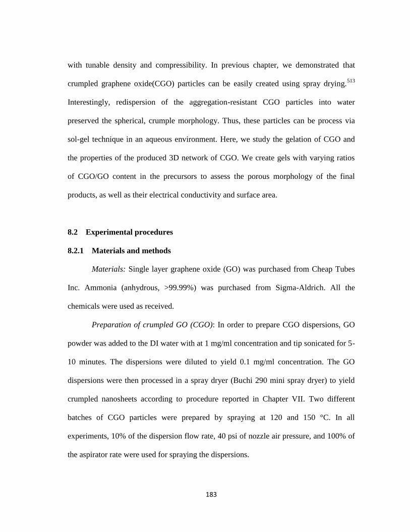
183
with tunable density and compressibility. In previous chapter, we demonstrated that
crumpled graphene oxide(CGO) particles can be easily created using spray drying.513
Interestingly, redispersion of the aggregation-resistant CGO particles into water
preserved the spherical, crumple morphology. Thus, these particles can be process via
sol-gel technique in an aqueous environment. Here, we study the gelation of CGO and
the properties of the produced 3D network of CGO. We create gels with varying ratios
of CGO/GO content in the precursors to assess the porous morphology of the final
products, as well as their electrical conductivity and surface area.
8.2 Experimental procedures
8.2.1 Materials and methods
Materials: Single layer graphene oxide (GO) was purchased from Cheap Tubes
Inc. Ammonia (anhydrous, >99.99%) was purchased from Sigma-Aldrich. All the
chemicals were used as received.
Preparation of crumpled GO (CGO): In order to prepare CGO dispersions, GO
powder was added to the DI water with at 1 mg/ml concentration and tip sonicated for 5-
10 minutes. The dispersions were diluted to yield 0.1 mg/ml concentration. The GO
dispersions were then processed in a spray dryer (Buchi 290 mini spray dryer) to yield
crumpled nanosheets according to procedure reported in Chapter VII. Two different
batches of CGO particles were prepared by spraying at 120 and 150 °C. In all
experiments, 10% of the dispersion flow rate, 40 psi of nozzle air pressure, and 100% of
the aspirator rate were used for spraying the dispersions.

184
Preparation of GO, CGO and CGO/GO hydrogels: To prepare 100% GO
hydrogels, GO nanosheets were dispersed in DI water (with concentrations of 10 and 20
mg/ml) by 2 hrs of bath sonication. Various amount of ammonia (1.8 and 3.6 ml) were
added to the dispersions, the mixtures were sealed in glass vials, and placed in an oven at
90 °C. The reaction was carried out for 72 hrs for the hydrogels to form.
To prepare 100% CGO hydrogels, CGO particles were added to DI water with 10
mg/ml concentration and bath sonicated for 1hr to obtain homogeneous CGO
dispersions. 3.6 ml of ammonia was added to the dispersions; the mixtures were sealed
in glass vials, and placed in an oven at 90 °C. The reaction was carried out for 72 hrs for
the hydrogels to form.
To prepare CGO/GO hydrogels, 10 mg/ml of GO and 10 mg/ml of were
dispersed in DI water separately using similar procedure of GO and CGO dispersions.
The two dispersions were then mixed to yield solutions with 25, 50 and 75% of CGO
total solid mass. The gelatoin process was similar to that used for 100% CGO gels.
Critical point drying (CPD) of hydrogels: Before drying, the hydrogels were
solvent-exchanged in ethanol bath for 3 days to remove the excess DI water and residual
ammonia. The CPD of the hydrogels was carried out in a Samdri-PVT-3D critical point
dryer after solvent exchange with the liquid CO2 in the dryer chamber.
8.2.2 Characterization
SEM (Scanning Electron Microscopy): graphene/copolymer nanocomposites
were cut to pieces and mounted on a double face carbon tape. An accelerating voltage of

185
2 kV was used to image the top surface and cross-section of the samples with a JEOL
JSM-7500F instrument.
TGA (Thermogravimetric Analysis): TGA was performed in a TA Instruments
Q50 TGA to determine the mass loss of the aerogels. 20-30 mg of each sample was
heated up from room temperature to 1000 ⁰C at a rate of 1 ⁰C /min in a nitrogen
atmosphere.
Conductivity measurements: The electrical resistance of the dried aerogels was
measured using the four-point probe method. The four-point probe head (Signatone,
SP4-40045TBY) was mounted on a resistivity measurement stand (Signatone, Model
302). The spacing between the probe tips was 1.5875 mm. The current was passed to the
sample through the outer probes using a Keithley 6221 AC and DC current source. A
Keithley 2000 multimeter was used to measure the voltage across the sample. The sheet
resistance and electrical conductivity of the samples were calculated using the measured
values of the voltage.
BET surface area measurements: the surface area of the dried aerogels was
calculated through BET method from the nitrogen adsorption/desorption isotherms. All
the samples were degassed for 24 hrs to remove the moisture from their surface. The
adsorption of nitrogen was performed at a relative pressure range of 0.05-0.3.

186
8.3 Results and discussion
8.3.1 GO-catalyst interactions and bridging structures
The GO hydrogels were synthesized by sol-gel technique using ammonia as the
catalyst. The hydrogels were subsequently dried using CPD technique to preserve their
porous structure (Figure 8.1). It has been suggested that both covalent crosslinking and
π-π stacking of the GO sheets are responsible for the gel formation in this synthesis
route.314
However, the interplay between the two crosslinking mechanisms is not well-
understood, with very little direct observation of covalent bonding in the prior literature.
We suggest that the synthesis parameters affect the extent of the two mechanisms; to
evaluate these effects we varied the GO concentration and catalyst/GO ratio during the
synthesis and observed the morphological changes in the porous structure of aerogels.
To understand the effect of GO concentration, we prepared samples with 1 and 2
wt% GO sheets, while keeping the amount of ammonia constant at 3.6 ml. The SEM
images of these samples (Figure 8.2a and b) suggest that lower GO concentration result
in a more densely packed structure, where the sheet-like morphology is not prominent
anymore. On the other hand, the higher concentration of GO yields a less compact
structure of highly wrinkled GO sheets. Additionally, more “bridging” structures were
observed at lower nanosheets concentration. These “bridges” are ubiquitous in our
preliminary images, but there has been little discussion on this front in the prior
literature.234,304,305,514

187
Figure 8.1. Images of (a) as-synthesized GO hydrogel, and (b) GO aerogel dried using CPD.
Furthermore, the catalyst/GO ratio was altered by decreasing the amount of
ammonia from 3.6 ml to 1.8 at constant 1 wt% GO content. The SEM images
demonstrate that a higher catalyst/GO ratio displays extensive bridging structures
(Figure 8.2c), whereas lower catalyst/GO ratio shows relatively little inter-sheet bridging
(Figure 8.2d). It is possible that the presence of more catalyst molecules facilitates the
reaction of GO functional groups and forms more inter-sheet covalent bonds. Thus, more
bridging structures can be observed at higher catalyst/GO ratio. It is unknown whether
the increase in these bridging structures would actually contribute to load-bearing
crosslinks.
188
Figure 8.2. SEM images of GO aerogels prepared with (a and b) 2 and 1 wt % of GO content,
respectively,(3.6 ml of ammonia was used), and (c and d) 1 wt% GO content using 3.6 and 1.8
ml of ammonia, respectively.
Based on these observations, we hypothesize that the gelation of GO sheets
occurs through two main routes (Figure 8.3). One involves the localized partial reduction
of graphene oxide to reduced graphene oxide (RGO) during gelation, resulting in
localized attractive π-π interactions between those reduced portions of the nanosheets
(depicted in gray).515
The second is the catalyst-assisted formation of covalent bonds,
including large “bridging” structures between nanosheets (depicted in red). With
addition of the catalyst/GO ratio, the density of catalyst-assisted covalent bonds in the
aerogels increases. It is feasible that these bridges are low-density carbonaceous
structures that initially form locally at the nanosheet surface; these structures may be the

189
product of the much-debated “oxidative debris” associated with the synthesis of the
parent GO nanosheets.78,516,517
(Oxidative debris is a by-product of common synthesis
GO methods, and it has been argued that oxidative debris acts in a surfactant-like
manner to allow for GO dispersion in water.78
)
Figure 8.3. Proposed mechanism for gel crosslinking and bridge formation. (a) high catalyst/GO
ratio (0.024), (b) low catalyst/GO ratio (0.012), (scalebars ~ 1 μm in SEM images).

190
8.3.2 GO morphology effects
Prior studies have indicated that the nanosheet size does affect the structure,
with larger nanosheets interacting at lower concentrations.518,519
We explored the
gelation process at an extreme aspect ratio of 1 in spherical, crumpled graphene.
Initially, the CGO particles sprayed at 150 °C were used to synthesize the CGO
hydrogels. These particles formed a very brittle hydrogel. The crumpled morphology of
the particles and the low density of the bridging structures can be observed in the SEM
images of its corresponding aerogel (Figure 8.4a and b). The crumpled particles are
prone to π-π stacking due to their highly wrinkled surface, thus, the physical crosslinking
through the π-π stacking is not the primary mechanism of gelation using these particles.
On the other hand the chemical crosslinking requires sufficient functional groups on the
sheets surface to participate in the covalent bond formation. The spray drying of the GO
sheets at 150 °C may partially remove the functional groups; hence, the chemical
crosslinking is also hindered in this sample. In order to promote the covalent bond
formation between the CGO particles, we reduced the spraying temperature to 120 °C.
These CGO particles formed a well-integrated hydrogel with high density of the
bridging structures (Figure 8.4c and d). Observation of more bridging structure confirms
that they indeed represent the chemical crosslinks. Additionally, the CGO aerogels
demonstrate a more homogenous porosity and higher packing density compared to the
GO aerogels. This may be because CGO particles tend to interact at shorter distances
such that higher (denser) packing is required for the same particle-particle interactions
and bond formation during gelation.

191
Figure 8.4. SEM images of CGO aerogels prepared using (a and b) CGO particles sprayed at
150 °C, and (c and d) CGO particles sprayed at 120 °C ( the inset shows the CGO particles
morphology sprayed at 120 °C).
To better understand the precursor morphology effect, we also synthesized
hydrogels with varying ratios of CGO/GO. At lower CGO/GO ratios, the porous
structure roughly resembles that of GO aerogels. As the CGO/GO ratio increases, the
structure becomes more like CGO aerogels. The gradual alteration of the aerogels
morphology is indicated in Figure 8.5. This trend of morphological changes with the
CGO/GO ratio confirms that the precursor morphology affects the crosslinking
mechanism and density.

192
Figure 8.5. SEM images of aerogels prepared using CGO/GO ratios of (a and b) 0.3 (c and d) 1,
and (e and f) 3. All the CGO particles were sprayed at 120 °C.
The electrical conductivities of GO, CGO and CGO/GO aerogels are indicated in
Table 8.1. All the aerogels are electrically conductive and their conductivity values are
in the same order of magnitude (~ 0.1 S/m). Interestingly, the electrical conductivity in

193
these GO-based aerogels is achieved without further chemical or thermal reduction that
normally is needed to restore the π- network of the graphene. This observation confirms
the partial reduction of GO and CGO sheets during the gelation process. Moreover,
assuming that electrical conduction happens through the interconnected network of
reduced sections of the GO sheets, we may infer that the extent of π-π stacking (i.e.,
physical crosslinking) is the same in all the equally conductive aerogels.
Table 8.1. The electrical conduct ivies and BET surface areas of the aerogels. All these gels
were prepared using 3.6 ml of ammonia as the catalyst. All the CGO particles were sprayed at
120 °C.
The BET surface areas of the aerogels are also represented in Table 8.1. Both GO
and CGO aerogels prepared with 1wt% of total nanosheets content displayed higher
surface areas than the combination CGO/GO aerogels. This might be attributed to the
anomalous morphology of GO and CGO nanosheets which leads to their non-uniform
arrangement within the 3D network and reduction of accessible surface area. Moreover,
both 1 wt% GO and CGO aerogels have higher surface area than the 2 wt% GO aerogel.
It implies that the presence of more bridging structures in aerogels prepared with higher
catalyst/GO ratio increases the available surface area of the samples.

194
The thermogravimetric analysis of the GO and CGO aerogels demonstrates a
rapid mass loss in all the samples up to 1000 °C (Figure 8.6). However, higher mass loss
was observed in 1 wt% GO and CGO gels compared to the 2 wt% GO gel. The extra
mass loss of 1 wt% GO and CGO aerogels may be attributes to the reduction of bridging
structures which are the major constituents of these samples.
Figure 8.6. Thermogravimetric characterization of GO and CGO aerogels.
8.4 Conclusion
Gelation of GO nanosheets is a simple method to prepare graphene 3D networks.
The sol-gel technique facilitates the chemical and physical crosslinking of the GO
nanosheets in presence of the catalyst molecules. The final morphology and properties of

195
the 3D network depends on the type and density of the crosslinks. We varied various
parameters such as GO concentration, catalyst/GO ratio and the nanosheets morphology
to gain a better understanding of the gelation and crosslinking mechanism in GO
hydrogels. Bridging structures were observed in samples prepared with higher
catalyst/GO ratio. These structures may be the product of inter-sheet covalent bonding
and thus, represents the chemical crosslinks in the GO aerogel. It is possible to alter the
nanosheets morphology to crumpled particle and prepared CGO aerogel. These aerogels
display extensive bridging between the nanosheets; it may be implied that the gelation of
CGO particles occur mainly through chemical crosslinking since these particles are
prone to π-π stacking. All the aerogels were electrically conductive without needing
further reduction. Moreover, exceptionally high surface area was observed in aerogels
with more bridging crosslinks. Further spectroscopic characterizations are required to
reveal the chemical composition of the bridging structure. We also expect a drastic
increase in the electrical conductivity of the aerogels after additional thermal annealing.

196
CHAPTER IX
CONCLUSION AND FUTURE WORK
9.1 Summary of thesis
In this thesis, the dispersant-assisted exfoliation of pristine graphene in the liquid
phase is studied. Also, graphene-philic copolymers are synthesized and used as
dispersants to enhance the graphene-polymer compatibility in the nanocomposites.
Additionally, the crumpling of graphene sheets is explored as a strategy for production
of aggregation-resistant graphene powder. The crumpled graphene sheets are used to
prepare highly porous and conductive graphene 3D networks. The experimental results
discussed in Chapters IV-VIII can be summarized as follows.
9.1.1 Direct liquid-phase exfoliation of pristine graphene by pyrene derivatives
We demonstrated that pyrene derivatives are promising dispersants for graphene
in aqueous dispersions. Single- to few-layer graphene sheets were stabilized by these
molecules, yielding exceptionally higher graphene/dispersant ratio compared to
polymers and surfactants. The effectiveness of pyrene derivatives is determined by the
type, number and electronegativity of functional groups and counterion. It also depends
on the distance between functional group and pyrene basal plane, and the pH of the
dispersion. The stability of dispersions against centrifugation lyophilization was
confirmed. The dispersions were also stable over a broad range of pH and temperature.

197
These dispersions show promise for applications such as nanocomposites, organic solar
cells, conductive films, and inkjet-printed electronic devices.
9.1.2 Pyrene-based designer dispersant for graphene/polysiloxane composites
A designer polysiloxane-based dispersant for graphene was synthesized and
applied to prepare a highly conductive polymer film. This stabilizer was simultaneously
used as the polymer matrix. To synthesize the stabilizer, 1-ethynylpyrene was grafted to
the backbone of a poly(dimethylsiloxane)-co-(methylhydrosiloxane) random copolymer
by Pt-catalyzed hydrosilylation reaction with a SiH: ethynyl ratio of 1.0:1.3. Dispersion
of graphene in chloroform was prepared through the π-π interactions between the
graphene sheets and the pyrene groups of the resulting copolymer. A graphene/polymer
film was cast from this dispersion. SEM and TEM images confirmed the homogeneous
distribution of the graphene sheets in the film. The conductivity of this film with 4 wt%
loading of graphene was measured to be 220 S/m. This is the first case of a melt-
processable, conductive graphene/polymer film reported in the literature. Later the ratio
of SiH:ethynyl was changed to 1.7:1.0, which led to self-crosslinking of the polymer at
110 ⁰C and resulted in a direct production of a conductive graphene/silicone elastomeric
composite. The crosslinking reaction was observed by FT-IR spectroscopy and the
network formation was confirmed by swelling and extraction of the product.

198
9.1.3 Pyrene-functional PMMA & PS copolymers for Janus graphene films
Similar strategy was applied to tailor the PS and PMMA polymer into a
graphene-philic copolymer. Pyrene-functional copolymers were synthesized by radical
polymerization in presence of 1-pyrenemethyl methacrylate. Graphene dispersions in
chloroform were obtained using these copolymers. The Janus graphene-based composite
films were prepared via vacuum filtration of the dispersions. These Janus films have an
electrically-conductive side with conductivities as high as ~ 140 S/m, and another
polymer-rich electrically-insulating side. The SEM images of the films cross-section
confirms that the leaching of unbound polymer chains into the porous filtration
membrane forms a graphene-rich section at the bottom of the film. The higher
concentration of graphene at this section of the film is responsible for its high electrical
conductivity.
9.1.4 Crumpling and unfolding of pristine graphene and graphene oxide sheets
A scalable spray drying technique was used to crumple pristine graphene sheets
for the first time. Aqueous graphene and graphene oxide dispersions were atomized and
dried in a spray dryer. During this process, 2D graphene sheets crumpled and
transformed into 3D particles. Transition of the sheets morphology during the drying
process was investigated by collecting samples at various heights of the spray dryer.
Pristine graphene sheets deformed as the droplet shrinkage induced capillary forces at
the interface and transformed into multi-faced crumpled particles with several dimples.
Graphene oxide sheets were spray dried using the same procedure; however, their highly

199
wrinkled final morphology was different than the crumpled pristine graphene sheets.
Differences in the elasticity and surface chemistry of pristine graphene and GO sheets
are the main reason for the difference in the final morphology. Spray drying parameters
such as atomizer pressure, drying temperature and concentration of sheets in the
dispersions were varied in order to observe their effect on the final morphology of
crumpled particles. Crumpled particles were redispersed into various solvents to assess
their unfolding behavior. GO particles remained crumpled in the water; however,
pristine graphene sheets immediately unfolded in the water due to the high affinity of
pyrene derivatives for water. However, the pristine graphene particles preserved their
crumpled morphology upon redispersion in chloroform. Thus, it was concluded that
unfolding of the pristine graphene sheets depends on the solvent choice.
9.1.5 Graphene conductive 3D networks with high surface area
Graphene oxide hydrogels were synthesized using a simple one step sol-gel
technique. Using this method, the gelation of graphene oxide nanosheets occurred in an
aqueous dispersion in presence of ammonia molecules as catalyst at 90 ⁰C. The
hydrogels were then dried in a critical point dryer to yield highly porous aerogels. The
structures of these aerogels were observed using SEM microscopy to evaluate the
physical and chemical crosslinking of the nanosheets. Stacking of the nanosheets and the
inter-sheets bridging were the dominant features of the aerogels structure. The stacking
of nanosheets was attributed to the overlapping and subsequent π-π stacking of the
reduced sections of the nanosheets. On the other hand, the bridging structures were

200
attributed to the covalent bond formation between the functional groups of the
nanosheets. We varied several parameters including nanosheets concentration,
catalyst/GO ratio and the nanosheets morphology to understand how they affect the
crosslinking mechanism. We observed that the higher catalyst/GO ratio intensifies the
covalent bond formation and increases the density of bridging structures in the final
aerogel. Crumpled graphene oxide particles were used in preparation of hydrogel to
assess the effect of nanosheets morphology on the aerogel crosslinks and properties.
These CGO hydrogels displayed extensive inter-sheet bridging which is due to their
aggregation- (and π-π stacking-) resistant morphology. All the aerogels were electrically
conductive (~ 0.1 S/m) without needing further reduction. This confirmed that partial
reduction of nanosheets occurs during the gelation. Samples with higher inter-sheet
bridging (including CGO aerogels) demonstrated an exceptionally high surface area
(1500-1600 m2/g).
9.2 Conclusions
The purpose of our research is to increase the graphene yield of liquid-phase
exfoliation method, as well as improving the pristine graphene compatibility and
dispersion within the polymer nanocomposites. Additionally, by crumpling and
assembling the graphene sheets into macrostructures, we attempt to harness the graphene
properties in bulk graphene-based materials. From the results of our experiments we can
conclude that:

201
(1) The proper choice of dispersant molecules can considerably improve the
graphene yield of direct liquid-phase exfoliation method. Moreover, the
presence of dispersant guarantees the redispersibility of pristine graphene
freeze-dried powder in the original solvent. However, the graphene yield of
this method remains restricted by other factors such as low efficiency of the
sonication technique and the need for separation of graphene from graphitic
materials in the final dispersions.
(2) It is important to come up with simple synthetic methods for preparation of
polymeric dispersants that are graphene-philic and can be directly used as
host matrix. This allows for better interactions at graphene-polymer interface
and achieving high electrical properties. The control over the molecular
structure of such dispersants (i.e., location and density of pyrene groups in
the polymer chain) can assist to exfoliate and stabilize more graphene sheets.
(3) Crumpling of graphene oxide is proved to be effective for production of
aggregation-resistant particles that can be processed later in the liquid phase;
but the crumpling of the pristine graphene is limited by the unfolding of these
sheets upon rewetting. Thus, it is easier to use crumpled graphene oxide
particle for preparation of high surface area materials. The gelation and
crosslinking of the crumpled graphene oxide particles is a facile method to
prepare pure graphene-based structures with superior electrical conductivity
and high surface area.

202
9.3 Future research directions
In Chapter IV we discussed that graphene yield can be increased through
stabilization of more nanosheets in the dispersion. However, the graphene yield is
constrained with the total volume of the dispersion that can be prepared by sonication
technique. It is possible to improve the graphene yield and scalability of liquid-phase
exfoliation method by substituting the sonication technique with shear mixing. Shear-
mixing in presence of proper solvent and dispersant can produce large volumes of
graphene dispersion. Moreover, exfoliation of nanosheets from parent materials
invariably results in a mixture of exfoliated and unexfoliated material that need to be
separated to yield stable dispersions. Common labscale techniques for separation
typically involve centrifugation and are not scalable. It is feasible to design a separation
unit that can handle large volumes of the exfoliated and unexfoliated sheets mixture
through multiple cycles of settling and washing of sediment.
The graphene/polysiloxane composites can be used in preparation of
piezoresistive coatings and microchips for biomedical devices. The graphene/PMMA
and PS composites may have potential application in conductive coatings. The ability to
customize the molecular structure of the synthesized copolymer allows for a better
control over the polymer-graphene interface. Alternative synthetic route may be
explored to prepare these customized polymeric graphene dispersant.
There are plenty of questions about crumpled graphene that have to be answered.
Currently, we are trying to obtain a deeper understanding of these particles at the
molecular level. The atomic and electronic structures of graphene in the crumpled state

203
are not well known and need to be studied. The mechanical properties of these particles
at the molecular level have to be investigated. Also, it is important to correlate the
molecular level changes with the bulk properties in the crumpled state.
The conductive 3D networks of graphene that we prepared using GO and CGO
may be used directly in Li-ion battery electrodes. The highly porous structure of these
materials provides a more accessible path for ion diffusion. The high surface area of
these structures facilitates the adsorption of these ions on the graphene sheets. Tailoring
of the structure for higher mechanical stability is possible through variation of crosslinks
density.
Finally, it is worth to mention that all the production and processing techniques
that we used for graphene can be (and in some cases have been) extended to many other
2D nanosheets including boron nitride, molybdenum sulfide, tungsten sulfide, and many
other transition metal dichalcogenide nanosheets.
204
REFERENCES
(1) Novoselov, K. S.; Geim, A. K.; Morozov, S. V.; Jiang, D.; Zhang, Y.;
Dubonos, S. V.; Grigorieva, I. V.; Firsov, A. A. Electric field effect in atomically thin
carbon films. Science 2004, 306, 666-669.
(2) Geim, A. K.; Novoselov, K. S. The rise of graphene. Nature Materials
2007, 6, 183-191.
(3) Venables, J. A.; Spiller, G. D. T.; Hanbucken, M. NUCLEATION AND
GROWTH OF THIN-FILMS. Reports on Progress in Physics 1984, 47, 399-459.
(4) Evans, J. W.; Thiel, P. A.; Bartelt, M. C. Morphological evolution during
epitaxial thin film growth: Formation of 2D islands and 3D mounds. Surface Science
Reports 2006, 61, 1-128.
(5) Krishnan, A.; Dujardin, E.; Treacy, M. M. J.; Hugdahl, J.; Lynum, S.;
Ebbesen, T. W. Graphitic cones and the nucleation of curved carbon surfaces. Nature
1997, 388, 451-454.
(6) Land, T. A.; Michely, T.; Behm, R. J.; Hemminger, J. C.; Comsa, G.
STM INVESTIGATION OF SINGLE LAYER GRAPHITE STRUCTURES
PRODUCED ON PT(111) BY HYDROCARBON DECOMPOSITION. Surface Science
1992, 264, 261-270.
(7) Novoselov, K. S.; Geim, A. K.; Morozov, S. V.; Jiang, D.; Katsnelson,
M. I.; Grigorieva, I. V.; Dubonos, S. V.; Firsov, A. A. Two-dimensional gas of massless
Dirac fermions in graphene. Nature 2005, 438, 197-200.
(8) Stankovich, S.; Dikin, D. A.; Dommett, G. H. B.; Kohlhaas, K. M.;
Zimney, E. J.; Stach, E. A.; Piner, R. D.; Nguyen, S. T.; Ruoff, R. S. Graphene-based
composite materials. Nature 2006, 442, 282-286.
(9) Meyer, J. C.; Geim, A. K.; Katsnelson, M. I.; Novoselov, K. S.; Booth, T.
J.; Roth, S. The structure of suspended graphene sheets. Nature 2007, 446, 60-63.
(10) Slonczewski, J. C.; Weiss, P. R. BAND STRUCTURE OF GRAPHITE.
Physical Review 1958, 109, 272-279.
(11) Fasolino, A.; Los, J. H.; Katsnelson, M. I. Intrinsic ripples in graphene.
Nature Materials 2007, 6, 858-861.
(12) Stolyarova, E.; Rim, K. T.; Ryu, S. M.; Maultzsch, J.; Kim, P.; Brus, L.
E.; Heinz, T. F.; Hybertsen, M. S.; Flynn, G. W. High-resolution scanning tunneling

205
microscopy imaging of mesoscopic graphene sheets on an insulating surface.
Proceedings of the National Academy of Sciences of the United States of America 2007,
104, 9209-9212.
(13) Partoens, B.; Peeters, F. M. From graphene to graphite: Electronic
structure around the K point. Physical Review B 2006, 74.
(14) Dato, A.; Lee, Z.; Jeon, K.-J.; Erni, R.; Radmilovic, V.; Richardson, T. J.;
Frenklach, M. Clean and highly ordered graphene synthesized in the gas phase.
Chemical Communications 2009, 6095-6097.
(15) Zhang, Y. B.; Tan, Y. W.; Stormer, H. L.; Kim, P. Experimental
observation of the quantum Hall effect and Berry's phase in graphene. Nature 2005, 438,
201-204.
(16) Du, X.; Skachko, I.; Barker, A.; Andrei, E. Y. Approaching ballistic
transport in suspended graphene. Nature Nanotechnology 2008, 3, 491-495.
(17) Hwang, E. H.; Adam, S.; Das Sarma, S. Carrier transport in two-
dimensional graphene layers. Physical Review Letters 2007, 98.
(18) Bolotin, K. I.; Sikes, K. J.; Jiang, Z.; Klima, M.; Fudenberg, G.; Hone, J.;
Kim, P.; Stormer, H. L. Ultrahigh electron mobility in suspended graphene. Solid State
Communications 2008, 146, 351-355.
(19) Morozov, S. V.; Novoselov, K. S.; Schedin, F.; Jiang, D.; Firsov, A. A.;
Geim, A. K. Two-dimensional electron and hole gases at the surface of graphite.
Physical Review B 2005, 72.
(20) Ryu, S.; Han, M. Y.; Maultzsch, J.; Heinz, T. F.; Kim, P.; Steigerwald,
M. L.; Brus, L. E. Reversible Basal Plane Hydrogenation of Graphene. Nano Letters
2008, 8, 4597-4602.
(21) Rodriguez-Perez, L.; Angeles Herranz, M.; Martin, N. The chemistry of
pristine graphene. Chemical Communications 2013, 49, 3721-3735.
(22) Meyer, J. C.; Kisielowski, C.; Erni, R.; Rossell, M. D.; Crommie, M. F.;
Zettl, A. Direct Imaging of Lattice Atoms and Topological Defects in Graphene
Membranes. Nano Letters 2008, 8, 3582-3586.
(23) Hashimoto, A.; Suenaga, K.; Gloter, A.; Urita, K.; Iijima, S. Direct
evidence for atomic defects in graphene layers. Nature 2004, 430, 870-873.

206
(24) Gao, X.; Wang, Y.; Liu, X.; Chan, T. L.; Irle, S.; Zhao, Y.; Zhang, S. B.
Regioselectivity control of graphene functionalization by ripples. Physical Chemistry
Chemical Physics 2011, 13, 19449-19453.
(25) Nakada, K.; Fujita, M.; Dresselhaus, G.; Dresselhaus, M. S. Edge state in
graphene ribbons: Nanometer size effect and edge shape dependence. Physical Review B
1996, 54, 17954-17961.
(26) Subrahmanyam, K. S.; Kumar, P.; Maitra, U.; Govindaraj, A.; Hembram,
K. P. S. S.; Waghmare, U. V.; Rao, C. N. R. Chemical storage of hydrogen in few-layer
graphene. Proceedings of the National Academy of Sciences of the United States of
America 2011, 108, 2674-2677.
(27) Schaefer, R. A.; Englert, J. M.; Wehrfritz, P.; Bauer, W.; Hauke, F.;
Seyller, T.; Hirsch, A. On the Way to GraphanePronounced Fluorescence of
Polyhydrogenated Graphene. Angewandte Chemie-International Edition 2013, 52, 754-
757.
(28) Zboril, R.; Karlicky, F.; Bourlinos, A. B.; Steriotis, T. A.; Stubos, A. K.;
Georgakilas, V.; Safarova, K.; Jancik, D.; Trapalis, C.; Otyepka, M. Graphene Fluoride:
A Stable Stoichiometric Graphene Derivative and its Chemical Conversion to Graphene.
Small 2010, 6, 2885-2891.
(29) Nair, R. R.; Ren, W.; Jalil, R.; Riaz, I.; Kravets, V. G.; Britnell, L.; Blake,
P.; Schedin, F.; Mayorov, A. S.; Yuan, S.; Katsnelson, M. I.; Cheng, H.-M.; Strupinski,
W.; Bulusheva, L. G.; Okotrub, A. V.; Grigorieva, I. V.; Grigorenko, A. N.; Novoselov,
K. S.; Geim, A. K. Fluorographene: A Two-Dimensional Counterpart of Teflon. Small
2010, 6, 2877-2884.
(30) Georgakilas, V.; Otyepka, M.; Bourlinos, A. B.; Chandra, V.; Kim, N.;
Kemp, K. C.; Hobza, P.; Zboril, R.; Kim, K. S. Functionalization of Graphene: Covalent
and Non-Covalent Approaches, Derivatives and Applications. Chemical Reviews 2012,
112, 6156-6214.
(31) Sinitskii, A.; Dimiev, A.; Corley, D. A.; Fursina, A. A.; Kosynkin, D. V.;
Tour, J. M. Kinetics of Diazonium Functionalization of Chemically Converted Graphene
Nanoribbons. Acs Nano 2010, 4, 1949-1954.
(32) Georgakilas, V.; Bourlinos, A. B.; Zboril, R.; Steriotis, T. A.; Dallas, P.;
Stubos, A. K.; Trapalis, C. Organic functionalisation of graphenes. Chemical
Communications 2010, 46, 1766-1768.
(33) Parviz, D.; Das, S.; Ahmed, H. S. T.; Irin, F.; Bhattacharia, S.; Green, M.
J. Dispersions of Non-Covalently Functionalized Graphene with Minimal Stabilizer. Acs
Nano 2012, 6, 8857-8867.

207
(34) Malig, J.; Stephenson, A. W. I.; Wagner, P.; Wallace, G. G.; Officer, D.
L.; Guldi, D. M. Direct exfoliation of graphite with a porphyrin - creating
functionalizable nanographene hybrids. Chemical Communications 2012, 48, 8745-
8747.
(35) Backes, C.; Hauke, F.; Hirsch, A. The Potential of Perylene Bisimide
Derivatives for the Solubilization of Carbon Nanotubes and Graphene. Advanced
Materials 2011, 23, 2588-2601.
(36) Das, S.; Wajid, A. S.; Shelburne, J. L.; Liao, Y.-C.; Green, M. J.
Localized In situ Polymerization on Graphene Surfaces for Stabilized Graphene
Dispersions. Acs Applied Materials & Interfaces 2011, 3.
(37) Green, A. A.; Hersam, M. C. Solution Phase Production of Graphene with
Controlled Thickness via Density Differentiation. Nano Letters 2009, 9, 4031-4036.
(38) Bourlinos, A. B.; Georgakilas, V.; Zboril, R.; Steriotis, T. A.; Stubos, A.
K.; Trapalis, C. Aqueous-phase exfoliation of graphite in the presence of
polyvinylpyrrolidone for the production of water-soluble graphenes. Solid State
Communications 2009, 149, 2172-2176.
(39) Wajid, A. S.; Das, S.; Irin, F.; Ahmed, H. S. T.; Shelburne, J. L.; Parviz,
D.; Fullerton, R. J.; Jankowski, A. F.; Hedden, R. C.; Green, M. J. Polymer-stabilized
graphene dispersions at high concentrations in organic solvents for composite
production. Carbon 2012, 50, 526-534.
(40) Voggu, R.; Das, B.; Rout, C. S.; Rao, C. N. R. Effects of charge transfer
interaction of graphene with electron donor and acceptor molecules examined using
Raman spectroscopy and cognate techniques. Journal of Physics-Condensed Matter
2008, 20.
(41) Suenaga, K.; Koshino, M. Atom-by-atom spectroscopy at graphene edge.
Nature 2010, 468, 1088-1090.
(42) Van Lier, G.; Van Alsenoy, C.; Van Doren, V.; Geerlings, P. Ab initio
study of the elastic properties of single-walled carbon nanotubes and graphene.
Chemical Physics Letters 2000, 326, 181-185.
(43) Lee, C.; Wei, X.; Kysar, J. W.; Hone, J. Measurement of the elastic
properties and intrinsic strength of monolayer graphene. Science 2008, 321, 385-388.
(44) Frank, I. W.; Tanenbaum, D. M.; Van der Zande, A. M.; McEuen, P. L.
Mechanical properties of suspended graphene sheets. Journal of Vacuum Science &
Technology B 2007, 25, 2558-2561.

208
(45) Poot, M.; van der Zant, H. S. J. Nanomechanical properties of few-layer
graphene membranes. Applied Physics Letters 2008, 92.
(46) Yu, C. H.; Shi, L.; Yao, Z.; Li, D. Y.; Majumdar, A. Thermal
conductance and thermopower of an individual single-wall carbon nanotube. Nano
Letters 2005, 5, 1842-1846.
(47) Balandin, A. A.; Ghosh, S.; Bao, W.; Calizo, I.; Teweldebrhan, D.; Miao,
F.; Lau, C. N. Superior thermal conductivity of single-layer graphene. Nano Letters
2008, 8, 902-907.
(48) Cai, W. W.; Moore, A. L.; Zhu, Y. W.; Li, X. S.; Chen, S. S.; Shi, L.;
Ruoff, R. S. Thermal Transport in Suspended and Supported Monolayer Graphene
Grown by Chemical Vapor Deposition. Nano Letters 2010, 10, 1645-1651.
(49) Seol, J. H.; Jo, I.; Moore, A. L.; Lindsay, L.; Aitken, Z. H.; Pettes, M. T.;
Li, X. S.; Yao, Z.; Huang, R.; Broido, D.; Mingo, N.; Ruoff, R. S.; Shi, L. Two-
Dimensional Phonon Transport in Supported Graphene. Science 2010, 328, 213-216.
(50) Nika, D. L.; Ghosh, S.; Pokatilov, E. P.; Balandin, A. A. Lattice thermal
conductivity of graphene flakes: Comparison with bulk graphite. Applied Physics Letters
2009, 94.
(51) Koh, Y. K.; Bae, M.-H.; Cahill, D. G.; Pop, E. Heat Conduction across
Monolayer and Few-Layer Graphenes. Nano Letters 2010, 10, 4363-4368.
(52) Nair, R. R.; Blake, P.; Grigorenko, A. N.; Novoselov, K. S.; Booth, T. J.;
Stauber, T.; Peres, N. M. R.; Geim, A. K. Fine structure constant defines visual
transparency of graphene. Science 2008, 320, 1308-1308.
(53) Singh, V.; Joung, D.; Zhai, L.; Das, S.; Khondaker, S. I.; Seal, S.
Graphene based materials: Past, present and future. Progress in Materials Science 2011,
56, 1178-1271.
(54) Kravets, V. G.; Grigorenko, A. N.; Nair, R. R.; Blake, P.; Anissimova, S.;
Novoselov, K. S.; Geim, A. K. Spectroscopic ellipsometry of graphene and an exciton-
shifted van Hove peak in absorption. Physical Review B 2010, 81, 155413.
(55) Rana, F.; George, P. A.; Strait, J. H.; Dawlaty, J.; Shivaraman, S.;
Chandrashekhar, M.; Spencer, M. G. Carrier recombination and generation rates for
intravalley and intervalley phonon scattering in graphene. Physical Review B 2009, 79,
115447.

209
(56) Peigney, A.; Laurent, C.; Flahaut, E.; Bacsa, R. R.; Rousset, A. Specific
surface area of carbon nanotubes and bundles of carbon nanotubes. Carbon 2001, 39,
507-514.
(57) Bonaccorso, F.; Colombo, L.; Yu, G.; Stoller, M.; Tozzini, V.; Ferrari, A.
C.; Ruoff, R. S.; Pellegrini, V. Graphene, related two-dimensional crystals, and hybrid
systems for energy conversion and storage. Science 2015, 347.
(58) Park, S.; Ruoff, R. S. Chemical methods for the production of graphenes.
Nature Nanotechnology 2009, 4, 217-224.
(59) Yoo, B. M.; Shin, H. J.; Yoon, H. W.; Park, H. B. Graphene and
Graphene Oxide and Their Uses in Barrier Polymers. Journal of Applied Polymer
Science 2014, 131.
(60) Han, W.; Kawakami, R. K.; Gmitra, M.; Fabian, J. Graphene spintronics.
Nature Nanotechnology 2014, 9, 794-807.
(61) Schniepp, H. C.; Li, J.-L.; McAllister, M. J.; Sai, H.; Herrera-Alonso, M.;
Adamson, D. H.; Prud'homme, R. K.; Car, R.; Saville, D. A.; Aksay, I. A.
Functionalized Single Graphene Sheets Derived from Splitting Graphite Oxide. The
Journal of Physical Chemistry B 2006, 110, 8535-8539.
(62) Gilje, S.; Han, S.; Wang, M.; Wang, K. L.; Kaner, R. B. A Chemical
Route to Graphene for Device Applications. Nano Letters 2007, 7, 3394-3398.
(63) Ruoff, R. Graphene: Calling all chemists. Nat Nano 2008, 3, 10-11.
(64) Dreyer, D. R.; Park, S.; Bielawski, C. W.; Ruoff, R. S. The chemistry of
graphene oxide. Chemical Society Reviews 2010, 39, 228-240.
(65) Hummers, W. S.; Offeman, R. E. PREPARATION OF GRAPHITIC
OXIDE. Journal of the American Chemical Society 1958, 80, 1339-1339.
(66) Stankovich, S.; Dikin, D. A.; Piner, R. D.; Kohlhaas, K. A.;
Kleinhammes, A.; Jia, Y.; Wu, Y.; Nguyen, S. T.; Ruoff, R. S. Synthesis of graphene-
based nanosheets via chemical reduction of exfoliated graphite oxide. Carbon 2007, 45,
1558-1565.
(67) Paredes, J. I.; Villar-Rodil, S.; Martinez-Alonso, A.; Tascon, J. M. D.
Graphene oxide dispersions in organic solvents. Langmuir 2008, 24, 10560-10564.
(68) He, H. Y.; Klinowski, J.; Forster, M.; Lerf, A. A new structural model for
graphite oxide. Chemical Physics Letters 1998, 287, 53-56.

210
(69) Buchsteiner, A.; Lerf, A.; Pieper, J. Water dynamics in graphite oxide
investigated with neutron scattering. Journal of Physical Chemistry B 2006, 110, 22328-
22338.
(70) Szabó, T.; Berkesi, O.; Forgó, P.; Josepovits, K.; Sanakis, Y.; Petridis, D.;
Dékány, I. Evolution of Surface Functional Groups in a Series of Progressively Oxidized
Graphite Oxides. Chemistry of Materials 2006, 18, 2740-2749.
(71) Dreyer, D. R.; Park, S.; Bielawski, C. W.; Ruoff, R. S. The chemistry of
graphene oxide. Chemical Society Reviews 2010, 39.
(72) Erickson, K.; Erni, R.; Lee, Z.; Alem, N.; Gannett, W.; Zettl, A.
Determination of the Local Chemical Structure of Graphene Oxide and Reduced
Graphene Oxide. Advanced Materials 2010, 22, 4467-4472.
(73) Kim, F.; Cote, L. J.; Huang, J. Graphene Oxide: Surface Activity and
Two-Dimensional Assembly. Advanced Materials 2010, 22, 1954-1958.
(74) Stankovich, S.; Piner, R. D.; Chen, X.; Wu, N.; Nguyen, S. T.; Ruoff, R.
S. Stable aqueous dispersions of graphitic nanoplatelets via the reduction of exfoliated
graphite oxide in the presence of poly(sodium 4-styrenesulfonate). Journal of Materials
Chemistry 2006, 16, 155-158.
(75) Becerril, H. A.; Mao, J.; Liu, Z.; Stoltenberg, R. M.; Bao, Z.; Chen, Y.
Evaluation of Solution-Processed Reduced Graphene Oxide Films as Transparent
Conductors. ACS Nano 2008, 2, 463-470.
(76) Eda, G.; Chhowalla, M. Chemically Derived Graphene Oxide: Towards
Large-Area Thin-Film Electronics and Optoelectronics. Advanced Materials 2010, 22,
2392-2415.
(77) Eda, G.; Fanchini, G.; Chhowalla, M. Large-area ultrathin films of
reduced graphene oxide as a transparent and flexible electronic material. Nature
Nanotechnology 2008, 3, 270-274.
(78) Rourke, J. P.; Pandey, P. A.; Moore, J. J.; Bates, M.; Kinloch, I. A.;
Young, R. J.; Wilson, N. R. The Real Graphene Oxide Revealed: Stripping the Oxidative
Debris from the Graphene-like Sheets. Angew. Chem.-Int. Edit. 2011, 50, 3173-3177.
(79) Yang, H.; Shan, C.; Li, F.; Han, D.; Zhang, Q.; Niu, L. Covalent
functionalization of polydisperse chemically-converted graphene sheets with amine-
terminated ionic liquid. Chemical Communications 2009, 3880-3882.

211
(80) Niyogi, S.; Bekyarova, E.; Itkis, M. E.; McWilliams, J. L.; Hamon, M.
A.; Haddon, R. C. Solution Properties of Graphite and Graphene. Journal of the
American Chemical Society 2006, 128, 7720-7721.
(81) Yang, X.; Zhang, X.; Liu, Z.; Ma, Y.; Huang, Y.; Chen, Y. High-
Efficiency Loading and Controlled Release of Doxorubicin Hydrochloride on Graphene
Oxide. Journal of Physical Chemistry C 2008, 112, 17554-17558.
(82) Suk, J. W.; Piner, R. D.; An, J.; Ruoff, R. S. Mechanical Properties of
Mono layer Graphene Oxide. Acs Nano 2010, 4, 6557-6564.
(83) Gómez-Navarro, C.; Meyer, J. C.; Sundaram, R. S.; Chuvilin, A.;
Kurasch, S.; Burghard, M.; Kern, K.; Kaiser, U. Atomic Structure of Reduced Graphene
Oxide. Nano Letters 2010, 10, 1144-1148.
(84) Chen, J.-H.; Cullen, W. G.; Jang, C.; Fuhrer, M. S.; Williams, E. D.
Defect Scattering in Graphene. Physical Review Letters 2009, 102, 236805.
(85) Robinson, J. T.; Zalalutdinov, M.; Baldwin, J. W.; Snow, E. S.; Wei, Z.;
Sheehan, P.; Houston, B. H. Wafer-scale Reduced Graphene Oxide Films for
Nanomechanical Devices. Nano Letters 2008, 8, 3441-3445.
(86) Edwards, R. S.; Coleman, K. S. Graphene synthesis: relationship to
applications. Nanoscale 2013, 5, 38-51.
(87) Huang, X.; Yin, Z.; Wu, S.; Qi, X.; He, Q.; Zhang, Q.; Yan, Q.; Boey, F.;
Zhang, H. Graphene-Based Materials: Synthesis, Characterization, Properties, and
Applications. Small 2011, 7, 1876-1902.
(88) Ferrari, A. C.; Meyer, J. C.; Scardaci, V.; Casiraghi, C.; Lazzeri, M.;
Mauri, F.; Piscanec, S.; Jiang, D.; Novoselov, K. S.; Roth, S.; Geim, A. K. Raman
spectrum of graphene and graphene layers. Physical Review Letters 2006, 97.
(89) Ferrari, A. C. Raman spectroscopy of graphene and graphite: Disorder,
electron-phonon coupling, doping and nonadiabatic effects. Solid State Communications
2007, 143, 47-57.
(90) Cancado, L. G.; Jorio, A.; Martins Ferreira, E. H.; Stavale, F.; Achete, C.
A.; Capaz, R. B.; Moutinho, M. V. O.; Lombardo, A.; Kulmala, T. S.; Ferrari, A. C.
Quantifying Defects in Graphene via Raman Spectroscopy at Different Excitation
Energies. Nano Letters 2011, 11, 3190-3196.
(91) Gass, M. H.; Bangert, U.; Bleloch, A. L.; Wang, P.; Nair, R. R.; Geim, A.
K. Free-standing graphene at atomic resolution. Nat Nano 2008, 3, 676-681.
212
(92) Bonaccorso, F.; Sun, Z.; Hasan, T.; Ferrari, A. C. Graphene photonics
and optoelectronics. Nat Photon 2010, 4, 611-622.
(93) Novoselov, K. S.; Falko, V. I.; Colombo, L.; Gellert, P. R.; Schwab, M.
G.; Kim, K. A roadmap for graphene. Nature 2012, 490, 192-200.
(94) Raccichini, R.; Varzi, A.; Passerini, S.; Scrosati, B. The role of graphene
for electrochemical energy storage. Nat Mater 2015, 14, 271-279.
(95) Lu, C.-H.; Yang, H.-H.; Zhu, C.-L.; Chen, X.; Chen, G.-N. A Graphene
Platform for Sensing Biomolecules. Angewandte Chemie-International Edition 2009, 48,
4785-4787.
(96) Kim, K. S.; Zhao, Y.; Jang, H.; Lee, S. Y.; Kim, J. M.; Kim, K. S.; Ahn,
J.-H.; Kim, P.; Choi, J.-Y.; Hong, B. H. Large-scale pattern growth of graphene films for
stretchable transparent electrodes. Nature 2009, 457, 706-710.
(97) Kobayashi, T.; Bando, M.; Kimura, N.; Shimizu, K.; Kadono, K.; Umezu,
N.; Miyahara, K.; Hayazaki, S.; Nagai, S.; Mizuguchi, Y.; Murakami, Y.; Hobara, D.
Production of a 100-m-long high-quality graphene transparent conductive film by roll-
to-roll chemical vapor deposition and transfer process. Applied Physics Letters 2013,
102.
(98) Bae, S.; Kim, H.; Lee, Y.; Xu, X.; Park, J.-S.; Zheng, Y.; Balakrishnan,
J.; Lei, T.; Ri Kim, H.; Song, Y. I.; Kim, Y.-J.; Kim, K. S.; Ozyilmaz, B.; Ahn, J.-H.;
Hong, B. H.; Iijima, S. Roll-to-roll production of 30-inch graphene films for transparent
electrodes. Nat Nano 2010, 5, 574-578.
(99) Wintterlin, J.; Bocquet, M. L. Graphene on metal surfaces. Surface
Science 2009, 603, 1841-1852.
(100) Liu, N.; Fu, L.; Dai, B.; Yan, K.; Liu, X.; Zhao, R.; Zhang, Y.; Liu, Z.
Universal Segregation Growth Approach to Wafer-Size Graphene from Non-Noble
Metals. Nano Letters 2011, 11, 297-303.
(101) Sutter, P. Epitaxial graphene: How silicon leaves the scene. Nat Mater
2009, 8, 171-172.
(102) Hannon, J. B.; Tromp, R. M. Pit formation during graphene synthesis on
SiC(0001): \textit{In situ} electron microscopy. Physical Review B 2008, 77, 241404.
(103) Hernandez, Y.; Nicolosi, V.; Lotya, M.; Blighe, F. M.; Sun, Z.; De, S.;
McGovern, I. T.; Holland, B.; Byrne, M.; Gun'ko, Y. K.; Boland, J. J.; Niraj, P.;
Duesberg, G.; Krishnamurthy, S.; Goodhue, R.; Hutchison, J.; Scardaci, V.; Ferrari, A.

213
C.; Coleman, J. N. High-yield production of graphene by liquid-phase exfoliation of
graphite. Nature Nanotechnology 2008, 3, 563-568.
(104) Coleman, J. N. Liquid Exfoliation of Defect-Free Graphene. Accounts of
Chemical Research 2013, 46, 14-22.
(105) Sivudu, K. S.; Mahajan, Y. R. Challenges and opportunities for the
mass production of high quality graphene: an analysis of worldwide patents.
Nanotech Insights 2012, 3, 6–19.
(106) Ren, W.; Cheng, H.-M. The global growth of graphene. Nat Nano 2014,
9, 726-730.
(107) Berger, C.; Song, Z.; Li, X.; Wu, X.; Brown, N.; Naud, C.; Mayou, D.;
Li, T.; Hass, J.; Marchenkov, A. N.; Conrad, E. H.; First, P. N.; de Heer, W. A.
Electronic confinement and coherence in patterned epitaxial graphene. Science 2006,
312, 1191-1196.
(108) Li, X.; Cai, W.; An, J.; Kim, S.; Nah, J.; Yang, D.; Piner, R.;
Velamakanni, A.; Jung, I.; Tutuc, E.; Banerjee, S. K.; Colombo, L.; Ruoff, R. S. Large-
Area Synthesis of High-Quality and Uniform Graphene Films on Copper Foils. Science
2009, 324, 1312-1314.
(109) Chen, L.; Hernandez, Y.; Feng, X.; Muellen, K. From Nanographene and
Graphene Nanoribbons to Graphene Sheets: Chemical Synthesis. Angewandte Chemie-
International Edition 2012, 51, 7640-7654.
(110) Choucair, M.; Thordarson, P.; Stride, J. A. Gram-scale production of
graphene based on solvothermal synthesis and sonication. Nat Nano 2009, 4, 30-33.
(111) Simpson, C. D.; Brand, J. D.; Berresheim, A. J.; Przybilla, L.; Rader, H.
J.; Mullen, K. Synthesis of a giant 222 carbon graphite sheet. Chemistry-a European
Journal 2002, 8, 1424-1429.
(112) Dato, A.; Radmilovic, V.; Lee, Z.; Phillips, J.; Frenklach, M. Substrate-
Free Gas-Phase Synthesis of Graphene Sheets. Nano Letters 2008, 8, 2012-2016.
(113) Wei, D.; Liu, Y.; Wang, Y.; Zhang, H.; Huang, L.; Yu, G. Synthesis of
N-Doped Graphene by Chemical Vapor Deposition and Its Electrical Properties. Nano
Letters 2009, 9, 1752-1758.
(114) Reddy, A. L. M.; Srivastava, A.; Gowda, S. R.; Gullapalli, H.; Dubey,
M.; Ajayan, P. M. Synthesis Of Nitrogen-Doped Graphene Films For Lithium Battery
Application. ACS Nano 2010, 4, 6337-6342.

214
(115) Caldwell, J. D.; Anderson, T. J.; Culbertson, J. C.; Jernigan, G. G.;
Hobart, K. D.; Kub, F. J.; Tadjer, M. J.; Tedesco, J. L.; Hite, J. K.; Mastro, M. A.;
Myers-Ward, R. L.; Eddy, C. R.; Campbell, P. M.; Gaskill, D. K. Technique for the Dry
Transfer of Epitaxial Graphene onto Arbitrary Substrates. ACS Nano 2010, 4, 1108-
1114.
(116) Unarunotai, S.; Murata, Y.; Chialvo, C. E.; Kim, H.-s.; MacLaren, S.;
Mason, N.; Petrov, I.; Rogers, J. A. Transfer of graphene layers grown on SiC wafers to
other substrates and their integration into field effect transistors. Applied Physics Letters
2009, 95.
(117) Lee, Y.; Bae, S.; Jang, H.; Jang, S.; Zhu, S.-E.; Sim, S. H.; Song, Y. I.;
Hong, B. H.; Ahn, J.-H. Wafer-Scale Synthesis and Transfer of Graphene Films. Nano
Letters 2010, 10, 490-493.
(118) Lippert, G.; Dabrowski, J.; Lemme, M.; Marcus, C.; Seifarth, O.; Lupina,
G. Direct graphene growth on insulator. Physica Status Solidi B-Basic Solid State
Physics 2011, 248, 2619-2622.
(119) Kosynkin, D. V.; Higginbotham, A. L.; Sinitskii, A.; Lomeda, J. R.;
Dimiev, A.; Price, B. K.; Tour, J. M. Longitudinal unzipping of carbon nanotubes to
form graphene nanoribbons. Nature 2009, 458, 872-876.
(120) Valentini, L. Formation of unzipped carbon nanotubes by CF4 plasma
treatment. Diamond and Related Materials 2011, 20, 445-448.
(121) Jiao, L.; Zhang, L.; Wang, X.; Diankov, G.; Dai, H. Narrow graphene
nanoribbons from carbon nanotubes. Nature 2009, 458, 877-880.
(122) Wu, J.; Pisula, W.; Müllen, K. Graphenes as Potential Material for
Electronics. Chemical Reviews 2007, 107, 718-747.
(123) Bonaccorso, F.; Lombardo, A.; Hasan, T.; Sun, Z.; Colombo, L.; Ferrari,
A. C. Production and processing of graphene and 2d crystals. Materials Today 2012, 15,
564-589.
(124) Fu, W.; Kiggans, J.; Overbury, S. H.; Schwartz, V.; Liang, C. Low-
temperature exfoliation of multilayer-graphene material from FeCl3 and CH3NO2 co-
intercalated graphite compound. Chemical Communications 2011, 47, 5265-5267.
(125) Liu, Z.; Liu, Q.; Huang, Y.; Ma, Y.; Yin, S.; Zhang, X.; Sun, W.; Chen,
Y. Organic Photovoltaic Devices Based on a Novel Acceptor Material: Graphene.
Advanced Materials 2008, 20, 3924-+.

215
(126) Posudievsky, O. Y.; Khazieieva, O. A.; Cherepanov, V. V.; Koshechko,
V. G.; Pokhodenko, V. D. High yield of graphene by dispersant-free liquid exfoliation of
mechanochemically delaminated graphite. Journal of Nanoparticle Research 2013, 15,
1-9.
(127) Lv, Y.; Yu, L.; Jiang, C.; Chen, S.; Nie, Z. Synthesis of graphene
nanosheet powder with layer number control via a soluble salt-assisted route. RSC
Advances 2014, 4, 13350-13354.
(128) Leon, V.; Quintana, M.; Herrero, M. A.; Fierro, J. L. G.; Hoz, A. d. l.;
Prato, M.; Vazquez, E. Few-layer graphenes from ball-milling of graphite with
melamine. Chemical Communications 2011, 47, 10936-10938.
(129) Jeon, I.-Y.; Choi, H.-J.; Jung, S.-M.; Seo, J.-M.; Kim, M.-J.; Dai, L.;
Baek, J.-B. Large-Scale Production of Edge-Selectively Functionalized Graphene
Nanoplatelets via Ball Milling and Their Use as Metal-Free Electrocatalysts for Oxygen
Reduction Reaction. Journal of the American Chemical Society 2013, 135, 1386-1393.
(130) Yi, M.; Shen, Z. A review on mechanical exfoliation for the scalable
production of graphene. Journal of Materials Chemistry A 2015, 3, 11700-11715.
(131) Zhao, W.; Wu, F.; Wu, H.; Chen, G. Preparation of Colloidal Dispersions
of Graphene Sheets in Organic Solvents by Using Ball Milling. Journal of
Nanomaterials 2010.
(132) Morales, G. M.; Schifani, P.; Ellis, G.; Ballesteros, C.; Martinez, G.;
Barbero, C.; Salavagione, H. J. High-quality few layer graphene produced by
electrochemical intercalation and microwave-assisted expansion of graphite. Carbon
2011, 49, 2809-2816.
(133) Israelachvili, J. N.: Intermolecular and surface forces. revised 3rd edition
ed.; Academic press.
(134) Johnson, D. W.; Dobson, B. P.; Coleman, K. S. A manufacturing
perspective on graphene dispersions. Current Opinion in Colloid & Interface Science
2015, 20, 367-382.
(135) Khan, U.; O'Neill, A.; Lotya, M.; De, S.; Coleman, J. N. High-
Concentration Solvent Exfoliation of Graphene. Small 2010, 6.
(136) Khan, U.; Porwal, H.; O’Neill, A.; Nawaz, K.; May, P.; Coleman, J. N.
Solvent-Exfoliated Graphene at Extremely High Concentration. Langmuir 2011, 27,
9077-9082.

216
(137) Lotya, M.; King, P. J.; Khan, U.; De, S.; Coleman, J. N. High-
Concentration, Surfactant-Stabilized Graphene Dispersions. Acs Nano 2010, 4.
(138) Nuvoli, D.; Valentini, L.; Alzari, V.; Scognamillo, S.; Bon, S. B.;
Piccinini, M.; Illescas, J.; Mariani, A. High concentration few-layer graphene sheets
obtained by liquid phase exfoliation of graphite in ionic liquid. Journal of Materials
Chemistry 2011, 21, 3428-3431.
(139) Liu, W. W.; Wang, J. N.; Wang, X. X. Charging of unfunctionalized
graphene in organic solvents. Nanoscale 2012, 4, 425-428.
(140) Konkena, B.; Vasudevan, S. Understanding Aqueous Dispersibility of
Graphene Oxide and Reduced Graphene Oxide through pKa Measurements. The Journal
of Physical Chemistry Letters 2012, 3, 867-872.
(141) Hunter, R.: Zeta potential in colloid science: principles and
applications. Academic Press, 1981.
(142) Bourlinos, A. B.; Gournis, D.; Petridis, D.; Szabo, T.; Szeri, A.; Dekany,
I. Graphite oxide: Chemical reduction to graphite and surface modification with primary
aliphatic amines and amino acids. Langmuir 2003, 19, 6050-6055.
(143) Park, S.; Hu, Y.; Hwang, J. O.; Lee, E.-S.; Casabianca, L. B.; Cai, W.;
Potts, J. R.; Ha, H.-W.; Chen, S.; Oh, J.; Kim, S. O.; Kim, Y.-H.; Ishii, Y.; Ruoff, R. S.
Chemical structures of hydrazine-treated graphene oxide and generation of aromatic
nitrogen doping. Nat Commun 2012, 3, 638.
(144) Youn, S. C.; Geng, J.; Son, B. S.; Yang, S. B.; Kim, D. W.; Cho, H. M.;
Jung, H.-T. Effect of the Exposure Time of Hydrazine Vapor on the Reduction of
Graphene Oxide Films. Journal of Nanoscience and Nanotechnology 2011, 11, 5959-
5964.
(145) McAllister, M. J.; Li, J.-L.; Adamson, D. H.; Schniepp, H. C.; Abdala, A.
A.; Liu, J.; Herrera-Alonso, M.; Milius, D. L.; Car, R.; Prud'homme, R. K.; Aksay, I. A.
Single Sheet Functionalized Graphene by Oxidation and Thermal Expansion of
Graphite. Chemistry of Materials 2007, 19, 4396-4404.
(146) Zhou, M.; Wang, Y.; Zhai, Y.; Zhai, J.; Ren, W.; Wang, F.; Dong, S.
Controlled Synthesis of Large-Area and Patterned Electrochemically Reduced Graphene
Oxide Films. Chemistry-a European Journal 2009, 15, 6116-6120.
(147) Lee, C.-G.; Park, S.; Ruoff, R. S.; Dodabalapur, A. Integration of reduced
graphene oxide into organic field-effect transistors as conducting electrodes and as a
metal modification layer. Applied Physics Letters 2009, 95.

217
(148) Shin, H.-J.; Kim, K. K.; Benayad, A.; Yoon, S.-M.; Park, H. K.; Jung, I.-
S.; Jin, M. H.; Jeong, H.-K.; Kim, J. M.; Choi, J.-Y.; Lee, Y. H. Efficient Reduction of
Graphite Oxide by Sodium Borohydride and Its Effect on Electrical Conductance.
Advanced Functional Materials 2009, 19, 1987-1992.
(149) Wang, S.; Chia, P.-J.; Chua, L.-L.; Zhao, L.-H.; Png, R.-Q.;
Sivaramakrishnan, S.; Zhou, M.; Goh, R. G. S.; Friend, R. H.; Wee, A. T. S.; Ho, P. K.
H. Band-like transport in surface-functionalized highly solution-processable graphene
nanosheets. Advanced Materials 2008, 20, 3440-+.
(150) Wu, Z.-S.; Ren, W.; Gao, L.; Liu, B.; Jiang, C.; Cheng, H.-M. Synthesis
of high-quality graphene with a pre-determined number of layers. Carbon 2009, 47, 493-
499.
(151) Schniepp, H. C.; Li, J. L.; McAllister, M. J.; Sai, H.; Herrera-Alonso, M.;
Adamson, D. H.; Prud'homme, R. K.; Car, R.; Saville, D. A.; Aksay, I. A.
Functionalized single graphene sheets derived from splitting graphite oxide. Journal of
Physical Chemistry B 2006, 110, 8535-8539.
(152) Abdelkader, A. M.; Cooper, A. J.; Dryfe, R. A. W.; Kinloch, I. A. How to
get between the sheets: a review of recent works on the electrochemical exfoliation of
graphene materials from bulk graphite. Nanoscale 2015, 7, 6944-6956.
(153) Low, C. T. J.; Walsh, F. C.; Chakrabarti, M. H.; Hashim, M. A.; Hussain,
M. A. Electrochemical approaches to the production of graphene flakes and their
potential applications. Carbon 2013, 54, 1-21.
(154) Alanyalioglu, M.; Jose Segura, J.; Oro-Sole, J.; Casan-Pastor, N. The
synthesis of graphene sheets with controlled thickness and order using surfactant-
assisted electrochemical processes. Carbon 2012, 50, 142-152.
(155) Wang, J.; Manga, K. K.; Bao, Q.; Loh, K. P. High-Yield Synthesis of
Few-Layer Graphene Flakes through Electrochemical Expansion of Graphite in
Propylene Carbonate Electrolyte. Journal of the American Chemical Society 2011, 133,
8888-8891.
(156) Parvez, K.; Wu, Z.-S.; Li, R.; Liu, X.; Graf, R.; Feng, X.; Muellen, K.
Exfoliation of Graphite into Graphene in Aqueous Solutions of Inorganic Salts. Journal
of the American Chemical Society 2014, 136, 6083-6091.
(157) Su, C.-Y.; Lu, A.-Y.; Xu, Y.; Chen, F.-R.; Khlobystov, A. N.; Li, L.-J.
High-Quality Thin Graphene Films from Fast Electrochemical Exfoliation. ACS Nano
2011, 5, 2332-2339.

218
(158) Parvez, K.; Li, R. J.; Puniredd, S. R.; Hernandez, Y.; Hinkel, F.; Wang, S.
H.; Feng, X. L.; Mullen, K. Electrochemically Exfoliated Graphene as Solution-
Processable, Highly Conductive Electrodes for Organic Electronics. Acs Nano 2013, 7,
3598-3606.
(159) Li, P.; Bae, S. H.; Zan, Q. Y.; Kim, N. H.; Lee, J. H. One-step process for
the exfoliation and surface modification of graphene by electrochemical method. Multi-
Functional Materials and Structures Iii, Pts 1 and 2 2010, 123-125, 743-746.
(160) Zhou, M.; Tang, J.; Cheng, Q.; Xu, G. J.; Cui, P.; Qin, L. C. Few-layer
graphene obtained by electrochemical exfoliation of graphite cathode. Chemical Physics
Letters 2013, 572, 61-65.
(161) Yang, Y. C.; Lu, F.; Zhou, Z.; Song, W. X.; Chen, Q. Y.; Ji, X. B.
Electrochemically cathodic exfoliation of graphene sheets in room temperature ionic
liquids N-butyl, methylpyrrolidinium bis(trifluoromethylsulfonyl)imide and their
electrochemical properties. Electrochimica Acta 2013, 113, 9-16.
(162) Hernandez, Y.; Lotya, M.; Rickard, D.; Bergin, S. D.; Coleman, J. N.
Measurement of Multicomponent Solubility Parameters for Graphene Facilitates Solvent
Discovery. Langmuir 2010, 26, 3208-3213.
(163) Geng, J.; Kong, B.-S.; Yang, S. B.; Jung, H.-T. Preparation of graphene
relying on porphyrin exfoliation of graphite. Chemical Communications 2010, 46, 5091-
5093.
(164) Du, W.; Jiang, X.; Zhu, L. From graphite to graphene: direct liquid-phase
exfoliation of graphite to produce single- and few-layered pristine graphene. Journal of
Materials Chemistry A 2013, 1, 10592-10606.
(165) O'Neill, A.; Khan, U.; Nirmalraj, P. N.; Boland, J.; Coleman, J. N.
Graphene Dispersion and Exfoliation in Low Boiling Point Solvents. Journal of Physical
Chemistry C 2011, 115, 5422-5428.
(166) Eun-Young Choi and Won San Choi and Young Boo Lee and Yong-
Young, N. Production of graphene by exfoliation of graphite in a volatile organic
solvent. Nanotechnology 2011, 22, 365601.
(167) Zhang, X.; Coleman, A. C.; Katsonis, N.; Browne, W. R.; van Wees, B.
J.; Feringa, B. L. Dispersion of graphene in ethanol using a simple solvent exchange
method. Chemical Communications 2010, 46, 7539-7541.
(168) Bourlinos, A. B.; Georgakilas, V.; Zboril, R.; Steriotis, T. A.; Stubos, A.
K. Liquid-Phase Exfoliation of Graphite Towards Solubilized Graphenes. Small 2009, 5,
1841-1845.

219
(169) Behabtu, N.; Lomeda, J. R.; Green, M. J.; Higginbotham, A. L.; Sinitskii,
A.; Kosynkin, D. V.; Tsentalovich, D.; Parra-Vasquez, A. N. G.; Schmidt, J.;
Kesselman, E.; Cohen, Y.; Talmon, Y.; Tour, J. M.; Pasquali, M. Spontaneous high-
concentration dispersions and liquid crystals of graphene. Nature Nanotechnology 2010,
5.
(170) Lu, W.; Liu, S.; Qin, X.; Wang, L.; Tian, J.; Luo, Y.; Asiri, A. M.; Al-
Youbi, A. O.; Sun, X. High-yield, large-scale production of few-layer graphene flakes
within seconds: using chlorosulfonic acid and H2O2 as exfoliating agents. Journal of
Materials Chemistry 2012, 22, 8775-8777.
(171) Lotya, M.; Hernandez, Y.; King, P. J.; Smith, R. J.; Nicolosi, V.;
Karlsson, L. S.; Blighe, F. M.; De, S.; Wang, Z.; McGovern, I. T.; Duesberg, G. S.;
Coleman, J. N. Liquid Phase Production of Graphene by Exfoliation of Graphite in
Surfactant/Water Solutions. Journal of the American Chemical Society 2009, 131, 3611-
3620.
(172) Lotya, M.; King, P. J.; Khan, U.; De, S.; Coleman, J. N. High-
Concentration, Surfactant-Stabilized Graphene Dispersions. Acs Nano 2010, 4, 3155-
3162.
(173) Hasan, T.; Torrisi, F.; Sun, Z.; Popa, D.; Nicolosi, V.; Privitera, G.;
Bonaccorso, F.; Ferrari, A. C. Solution-phase exfoliation of graphite for ultrafast
photonics. Physica Status Solidi B-Basic Solid State Physics 2010, 247, 2953-2957.
(174) Guardia, L.; Fernandez-Merino, M. J.; Paredes, J. I.; Solis-Fernandez, P.;
Villar-Rodil, S.; Martinez-Alonso, A.; Tascon, J. M. D. High-throughput production of
pristine graphene in an aqueous dispersion assisted by non-ionic surfactants. Carbon
2011, 49, 1653-1662.
(175) Smith, R. J.; Lotya, M.; Coleman, J. N. The importance of repulsive
potential barriers for the dispersion of graphene using surfactants. New Journal of
Physics 2010, 12.
(176) Das, S.; Irin, F.; Ma, L.; Bhattacharia, S. K.; Hedden, R. C.; Green, M. J.
Rheology and Morphology of Pristine Graphene/Polyacrylamide Gels. Acs Applied
Materials & Interfaces 2013, 5, 8633-8640.
(177) An, X.; Simmons, T. J.; Shah, R.; Wolfe, C.; Lewis, K. M.; Washington,
M.; Nayak, S. K.; Talapatra, S.; Kar, S. Stable Aqueous Dispersions of Noncovalently
Functionalized Graphene from Graphite and their Multifunctional High-Performance
Applications. Nano Letters 2010, 10, 4295-4301.
(178) Zhang, M.; Parajuli, R. R.; Mastrogiovanni, D.; Dai, B.; Lo, P.; Cheung,
W.; Brukh, R.; Chiu, P. L.; Zhou, T.; Liu, Z.; Garfunkel, E.; He, H. Production of

220
Graphene Sheets by Direct Dispersion with Aromatic Healing Agents. Small 2010, 6,
1100-1107.
(179) Wang, X. Q.; Fulvio, P. F.; Baker, G. A.; Veith, G. M.; Unocic, R. R.;
Mahurin, S. M.; Chi, M. F.; Dai, S. Direct exfoliation of natural graphite into
micrometre size few layers graphene sheets using ionic liquids. Chemical
Communications 2010, 46, 4487-4489.
(180) Bari, R.; Tamas, G.; Irin, F.; Aquino, A. J. A.; Green, M. J.; Quitevis, E.
L. Direct exfoliation of graphene in ionic liquids with aromatic groups. Colloids and
Surfaces a-Physicochemical and Engineering Aspects 2014, 463, 63-69.
(181) Paton, K. R.; Varrla, E.; Backes, C.; Smith, R. J.; Khan, U.; O'Neill, A.;
Boland, C.; Lotya, M.; Istrate, O. M.; King, P.; Higgins, T.; Barwich, S.; May, P.;
Puczkarski, P.; Ahmed, I.; Moebius, M.; Pettersson, H.; Long, E.; Coelho, J.; O'Brien, S.
E.; McGuire, E. K.; Sanchez, B. M.; Duesberg, G. S.; McEvoy, N.; Pennycook, T. J.;
Downing, C.; Crossley, A.; Nicolosi, V.; Coleman, J. N. Scalable production of large
quantities of defect-free few-layer graphene by shear exfoliation in liquids. Nature
Materials 2014, 13, 624-630.
(182) Zheng, W.; Lu, X. H.; Wong, S. C. Electrical and mechanical properties
of expanded graphite-reinforced high-density polyethylene. Journal of Applied Polymer
Science 2004, 91, 2781-2788.
(183) Zheng, W.; Wong, S.-C. Electrical conductivity and dielectric properties
of PMMA/expanded graphite composites. Composites Science and Technology 2003, 63,
225-235.
(184) Shen, J. W.; Huang, W. Y.; Zuo, S. W.; Hou, J. Polyethylene/grafted
polyethylene/graphite nanocomposites: Preparation, structure, and electrical properties.
Journal of Applied Polymer Science 2005, 97, 51-59.
(185) Kim, H.; Abdala, A. A.; Macosko, C. W. Graphene/Polymer
Nanocomposites. Macromolecules 2010, 43, 6515-6530.
(186) Chee, W. K.; Lim, H. N.; Huang, N. M.; Harrison, I. Nanocomposites of
graphene/polymers: a review. RSC Advances 2015, 5, 68014-68051.
(187) Xu, Q.; Xu, H.; Chen, J.; Lv, Y.; Dong, C.; Sreeprasad, T. S. Graphene
and graphene oxide: advanced membranes for gas separation and water purification.
Inorganic Chemistry Frontiers 2015, 2, 417-424.
(188) Thostenson, E. T.; Li, C.; Chou, T.-W. Nanocomposites in context.
Composites Science and Technology 2005, 65, 491-516.

221
(189) Mahmoud, W. E. Morphology and physical properties of poly(ethylene
oxide) loaded graphene nanocomposites prepared by two different techniques. European
Polymer Journal 2011, 47, 1534-1540.
(190) Bian, J.; Lin, H. L.; He, F. X.; Wei, X. W.; Chang, I. T.; Sancaktar, E.
Fabrication of microwave exfoliated graphite oxide reinforced thermoplastic
polyurethane nanocomposites: Effects of filler on morphology, mechanical, thermal and
conductive properties. Composites Part A: Applied Science and Manufacturing 2013, 47,
72-82.
(191) Shen, B.; Zhai, W.; Chen, C.; Lu, D.; Wang, J.; Zheng, W. Melt Blending
In situ Enhances the Interaction between Polystyrene and Graphene through pi-pi
Stacking. Acs Applied Materials & Interfaces 2011, 3, 3103-3109.
(192) Pang, H.; Chen, C.; Zhang, Y.-C.; Ren, P.-G.; Yan, D.-X.; Li, Z.-M. The
effect of electric field, annealing temperature and filler loading on the percolation
threshold of polystyrene containing carbon nanotubes and graphene nanosheets. Carbon
2011, 49, 1980-1988.
(193) Kalaitzidou, K.; Fukushima, H.; Drzal, L. T. A new compounding method
for exfoliated graphite-polypropylene nanocomposites with enhanced flexural properties
and lower percolation threshold. Composites Science and Technology 2007, 67, 2045-
2051.
(194) Sherif Araby and Izzuddin Zaman and Qingshi Meng and Nobuyuki
Kawashima and Andrew Michelmore and Hsu-Chiang Kuan and Peter Majewski and
Jun Ma and Liqun, Z. Melt compounding with graphene to develop functional, high-
performance elastomers. Nanotechnology 2013, 24, 165601.
(195) RamanathanT; Abdala, A. A.; StankovichS; Dikin, D. A.; Herrera
Alonso, M.; Piner, R. D.; Adamson, D. H.; Schniepp, H. C.; ChenX; Ruoff, R. S.;
Nguyen, S. T.; Aksay, I. A.; Prud'Homme, R. K.; Brinson, L. C. Functionalized
graphene sheets for polymer nanocomposites. Nat Nano 2008, 3, 327-331.
(196) Villar-Rodil, S.; Paredes, J. I.; Martinez-Alonso, A.; Tascon, J. M. D.
Preparation of graphene dispersions and graphene-polymer composites in organic media.
Journal of Materials Chemistry 2009, 19, 3591-3593.
(197) Li, X.; Xiao, Y.; Bergeret, A.; Longerey, M.; Che, J. Preparation of
Polylactide/Graphene Composites From Liquid-Phase Exfoliated Graphite Sheets.
Polymer Composites 2014, 35, 396-403.
(198) Wu, D.; Cheng, Y.; Feng, S.; Yao, Z.; Zhang, M. Crystallization Behavior
of Polylactide/Graphene Composites. Industrial & Engineering Chemistry Research
2013, 52, 6731-6739.

222
(199) Qi, X.-Y.; Yan, D.; Jiang, Z.; Cao, Y.-K.; Yu, Z.-Z.; Yavari, F.; Koratkar,
N. Enhanced Electrical Conductivity in Polystyrene Nanocomposites at Ultra-Low
Graphene Content. ACS Applied Materials & Interfaces 2011, 3, 3130-3133.
(200) Li, R.; Liu, C.; Ma, J. Studies on the properties of graphene oxide-
reinforced starch biocomposites. Carbohydrate Polymers 2011, 84, 631-637.
(201) Wang, X.; Hu, Y.; Song, L.; Yang, H.; Xing, W.; Lu, H. In situ
polymerization of graphene nanosheets and polyurethane with enhanced mechanical and
thermal properties. Journal of Materials Chemistry 2011, 21, 4222-4227.
(202) Kuila, T.; Bose, S.; Khanra, P.; Kim, N. H.; Rhee, K. Y.; Lee, J. H.
Characterization and properties of in situ emulsion polymerized poly(methyl
methacrylate)/graphene nanocomposites. Composites Part A: Applied Science and
Manufacturing 2011, 42, 1856-1861.
(203) Patole, A. S.; Patole, S. P.; Kang, H.; Yoo, J.-B.; Kim, T.-H.; Ahn, J.-H.
A facile approach to the fabrication of graphene/polystyrene nanocomposite by in situ
microemulsion polymerization. Journal of Colloid and Interface Science 2010, 350, 530-
537.
(204) Wu, F.; Lu, Y.; Shao, G.; Zeng, F.; Wu, Q. Preparation of
polyacrylonitrile/graphene oxide by in situ polymerization. Polymer International 2012,
61, 1394-1399.
(205) Potts, J. R.; Lee, S. H.; Alam, T. M.; An, J.; Stoller, M. D.; Piner, R. D.;
Ruoff, R. S. Thermomechanical properties of chemically modified graphene/poly(methyl
methacrylate) composites made by in situ polymerization. Carbon 2011, 49, 2615-2623.
(206) Bose, S.; Kuila, T.; Uddin, M. E.; Kim, N. H.; Lau, A. K. T.; Lee, J. H.
In-situ synthesis and characterization of electrically conductive polypyrrole/graphene
nanocomposites. Polymer 2010, 51, 5921-5928.
(207) Choi, K. S.; Liu, F.; Choi, J. S.; Seo, T. S. Fabrication of Free-Standing
Multilayered Graphene and Poly(3,4-ethylenedioxythiophene) Composite Films with
Enhanced Conductive and Mechanical Properties. Langmuir 2010, 26, 12902-12908.
(208) Paszkiewicz, S.; Szymczyk, A.; Špitalský, Z.; Mosnáček, J.;
Kwiatkowski, K.; Rosłaniec, Z. Structure and properties of nanocomposites based on
PTT-block-PTMO copolymer and graphene oxide prepared by in situ polymerization.
European Polymer Journal 2014, 50, 69-77.
(209) Tian, M.; Zhang, J.; Zhang, L.; Liu, S.; Zan, X.; Nishi, T.; Ning, N.
Graphene encapsulated rubber latex composites with high dielectric constant, low

223
dielectric loss and low percolation threshold. Journal of Colloid and Interface Science
2014, 430, 249-256.
(210) Zhan, Y.; Lavorgna, M.; Buonocore, G.; Xia, H. Enhancing electrical
conductivity of rubber composites by constructing interconnected network of self-
assembled graphene with latex mixing. Journal of Materials Chemistry 2012, 22, 10464-
10468.
(211) Li, M.; Gao, C.; Hu, H.; Zhao, Z. Electrical conductivity of thermally
reduced graphene oxide/polymer composites with a segregated structure. Carbon 2013,
65, 371-373.
(212) Du, J.; Zhao, L.; Zeng, Y.; Zhang, L.; Li, F.; Liu, P.; Liu, C. Comparison
of electrical properties between multi-walled carbon nanotube and graphene
nanosheet/high density polyethylene composites with a segregated network structure.
Carbon 2011, 49, 1094-1100.
(213) Pang, H.; Chen, T.; Zhang, G.; Zeng, B.; Li, Z.-M. An electrically
conducting polymer/graphene composite with a very low percolation threshold.
Materials Letters 2010, 64, 2226-2229.
(214) Zhang, M.; Li, Y.; Su, Z.; Wei, G. Recent advances in the synthesis and
applications of graphene-polymer nanocomposites. Polymer Chemistry 2015, 6, 6107-
6124.
(215) Layek, R. K.; Nandi, A. K. A review on synthesis and properties of
polymer functionalized graphene. Polymer 2013, 54, 5087-5103.
(216) Zhang, Y.; Mark, J. E.; Zhu, Y.; Ruoff, R. S.; Schaefer, D. W.
Mechanical properties of polybutadiene reinforced with octadecylamine modified
graphene oxide. Polymer 2014, 55, 5389-5395.
(217) Cano, M.; Khan, U.; Sainsbury, T.; O’Neill, A.; Wang, Z.; McGovern, I.
T.; Maser, W. K.; Benito, A. M.; Coleman, J. N. Improving the mechanical properties of
graphene oxide based materials by covalent attachment of polymer chains. Carbon 2013,
52, 363-371.
(218) Zarrin, H.; Fu, J.; Jiang, G.; Yoo, S.; Lenos, J.; Fowler, M.; Chen, Z.
Quaternized Graphene Oxide Nanocomposites as Fast Hydroxide Conductors. ACS
Nano 2015, 9, 2028-2037.
(219) Fang, M.; Wang, K.; Lu, H.; Yang, Y.; Nutt, S. Covalent polymer
functionalization of graphene nanosheets and mechanical properties of composites.
Journal of Materials Chemistry 2009, 19, 7098-7105.

224
(220) Beckert, F.; Friedrich, C.; Thomann, R.; Mülhaupt, R. Sulfur-
Functionalized Graphenes as Macro-Chain-Transfer and RAFT Agents for Producing
Graphene Polymer Brushes and Polystyrene Nanocomposites. Macromolecules 2012,
45, 7083-7090.
(221) Liang, J.; Huang, Y.; Zhang, L.; Wang, Y.; Ma, Y.; Guo, T.; Chen, Y.
Molecular-Level Dispersion of Graphene into Poly(vinyl alcohol) and Effective
Reinforcement of their Nanocomposites. Advanced Functional Materials 2009, 19,
2297-2302.
(222) Liu, J.; Yang, W.; Tao, L.; Li, D.; Boyer, C.; Davis, T. P.
Thermosensitive Graphene Nanocomposites Formed Using Pyrene-Terminal Polymers
Made by RAFT Polymerization. Journal of Polymer Science Part a-Polymer Chemistry
2010, 48, 425-433.
(223) Jo, K.; Lee, T.; Choi, H. J.; Park, J. H.; Lee, D. J.; Lee, D. W.; Kim, B.-S.
Stable Aqueous Dispersion of Reduced Graphene Nanosheets via Non-Covalent
Functionalization with Conducting Polymers and Application in Transparent Electrodes.
Langmuir 2011, 27, 2014-2018.
(224) Qi, X.; Pu, K.-Y.; Li, H.; Zhou, X.; Wu, S.; Fan, Q.-L.; Liu, B.; Boey, F.;
Huang, W.; Zhang, H. Amphiphilic Graphene Composites. Angewandte Chemie-
International Edition 2010, 49, 9426-9429.
(225) Xu, L. Q.; Wang, L.; Zhang, B.; Lim, C. H.; Chen, Y.; Neoh, K.-G.;
Kang, E.-T.; Fu, G. D. Functionalization of reduced graphene oxide nanosheets via
stacking interactions with the fluorescent and water-soluble perylene bisimide-
containing polymers. Polymer 2011, 52, 2376-2383.
(226) Yuan, B.; Bao, C.; Song, L.; Hong, N.; Liew, K. M.; Hu, Y. Preparation
of functionalized graphene oxide/polypropylene nanocomposite with significantly
improved thermal stability and studies on the crystallization behavior and mechanical
properties. Chemical Engineering Journal 2014, 237, 411-420.
(227) Shen, B.; Zhai, W.; Tao, M.; Lu, D.; Zheng, W. Enhanced interfacial
interaction between polycarbonate and thermally reduced graphene induced by melt
blending. Composites Science and Technology 2013, 86, 109-116.
(228) Istrate, O. M.; Paton, K. R.; Khan, U.; O’Neill, A.; Bell, A. P.; Coleman,
J. N. Reinforcement in melt-processed polymer–graphene composites at extremely low
graphene loading level. Carbon 2014, 78, 243-249.
(229) Bao, C.; Song, L.; Wilkie, C. A.; Yuan, B.; Guo, Y.; Hu, Y.; Gong, X.
Graphite oxide, graphene, and metal-loaded graphene for fire safety applications of
polystyrene. Journal of Materials Chemistry 2012, 22, 16399-16406.

225
(230) Das, S.; Wajid, A. S.; Bhattacharia, S. K.; Wilting, M. D.; Rivero, I. V.;
Green, M. J. Electrospinning of polymer nanofibers loaded with noncovalently
functionalized graphene. Journal of Applied Polymer Science 2013, 128, 4040-4046.
(231) Bao, Q. L.; Zhang, H.; Yang, J. X.; Wang, S.; Tong, D. Y.; Jose, R.;
Ramakrishna, S.; Lim, C. T.; Loh, K. P. Graphene-Polymer Nanofiber Membrane for
Ultrafast Photonics. Advanced Functional Materials 2010, 20, 782-791.
(232) Irin, F.; Das, S.; Atore, F. O.; Green, M. J. Ultralow Percolation
Threshold in Aerogel and Cryogel Templated Composites. Langmuir 2013, 29, 11449-
11456.
(233) Xu, Y.; Sheng, K.; Li, C.; Shi, G. Self-Assembled Graphene Hydrogel via
a One-Step Hydrothermal Process. Acs Nano 2010, 4, 4324-4330.
(234) Worsley, M. A.; Pauzauskie, P. J.; Olson, T. Y.; Biener, J.; Satcher, J. H.,
Jr.; Baumann, T. F. Synthesis of Graphene Aerogel with High Electrical Conductivity.
Journal of the American Chemical Society 2010, 132, 14067-14069.
(235) Wang, X.; Zhi, L.; Müllen, K. Transparent, Conductive Graphene
Electrodes for Dye-Sensitized Solar Cells. Nano Letters 2008, 8, 323-327.
(236) Zheng, Q.; Li, Z.; Yang, J.; Kim, J.-K. Graphene oxide-based transparent
conductive films. Progress in Materials Science 2014, 64, 200-247.
(237) De, S.; King, P. J.; Lotya, M.; O'Neill, A.; Doherty, E. M.; Hernandez,
Y.; Duesberg, G. S.; Coleman, J. N. Flexible, Transparent, Conducting Films of
Randomly Stacked Graphene from Surfactant-Stabilized, Oxide-Free Graphene
Dispersions. Small 2010, 6, 458-464.
(238) Wu, Z.-S.; Pei, S.; Ren, W.; Tang, D.; Gao, L.; Liu, B.; Li, F.; Liu, C.;
Cheng, H.-M. Field Emission of Single-Layer Graphene Films Prepared by
Electrophoretic Deposition. Advanced Materials 2009, 21, 1756-+.
(239) Hwang, H.; Joo, P.; Kang, M. S.; Ahn, G.; Han, J. T.; Kim, B.-S.; Cho, J.
H. Highly Tunable Charge Transport in Layer-by-Layer Assembled Graphene
Transistors. ACS Nano 2012, 6, 2432-2440.
(240) Chang, H.; Sun, Z.; Yuan, Q.; Ding, F.; Tao, X.; Yan, F.; Zheng, Z. Thin
Film Field-Effect Phototransistors from Bandgap-Tunable, Solution-Processed, Few-
Layer Reduced Graphene Oxide Films. Advanced Materials 2010, 22, 4872-+.
(241) Liang, M.; Zhi, L. Graphene-based electrode materials for rechargeable
lithium batteries. Journal of Materials Chemistry 2009, 19, 5871-5878.
226
(242) Le, L. T.; Ervin, M. H.; Qiu, H. W.; Fuchs, B. E.; Lee, W. Y. Graphene
supercapacitor electrodes fabricated by inkjet printing and thermal reduction of graphene
oxide. Electrochemistry Communications 2011, 13, 355-358.
(243) He, Q.; Sudibya, H. G.; Yin, Z.; Wu, S.; Li, H.; Boey, F.; Huang, W.;
Chen, P.; Zhang, H. Centimeter-Long and Large-Scale Micropatterns of Reduced
Graphene Oxide Films: Fabrication and Sensing Applications. ACS Nano 2010, 4, 3201-
3208.
(244) Dua, V.; Surwade, S. P.; Ammu, S.; Agnihotra, S. R.; Jain, S.; Roberts,
K. E.; Park, S.; Ruoff, R. S.; Manohar, S. K. All-Organic Vapor Sensor Using Inkjet-
Printed Reduced Graphene Oxide. Angewandte Chemie-International Edition 2010, 49,
2154-2157.
(245) Yin, Z.; He, Q.; Huang, X.; Zhang, J.; Wu, S.; Chen, P.; Lu, G.; Zhang,
Q.; Yan, Q.; Zhang, H. Real-time DNA detection using Pt nanoparticle-decorated
reduced graphene oxide field-effect transistors. Nanoscale 2012, 4, 293-297.
(246) Yang, X.; Qiu, L.; Cheng, C.; Wu, Y.; Ma, Z.-F.; Li, D. Ordered Gelation
of Chemically Converted Graphene for Next-Generation Electroconductive Hydrogel
Films. Angewandte Chemie-International Edition 2011, 50, 7325-7328.
(247) Qiu, L.; Zhang, X.; Yang, W.; Wang, Y.; Simon, G. P.; Li, D.
Controllable corrugation of chemically converted graphene sheets in water and potential
application for nanofiltration. Chemical Communications 2011, 47, 5810-5812.
(248) Bae, S.-Y.; Jeon, I.-Y.; Yang, J.; Park, N.; Shin, H. S.; Park, S.; Ruoff, R.
S.; Dai, L.; Baek, J.-B. Large-Area Graphene Films by Simple Solution Casting of Edge-
Selectively Functionalized Graphite. ACS Nano 2011, 5, 4974-4980.
(249) Zhang, X.; Wang, Y.; Watanabe, S.; Uddin, M. H.; Li, D. Evaporation-
induced flattening and self-assembly of chemically converted graphene on a solid
surface. Soft Matter 2011, 7, 8745-8748.
(250) Wu, C.; Cheng, Q.; Sun, S.; Han, B. Templated patterning of graphene
oxide using self-assembled monolayers. Carbon 2012, 50, 1083-1089.
(251) Chang, H.; Wang, G.; Yang, A.; Tao, X.; Liu, X.; Shen, Y.; Zheng, Z. A
Transparent, Flexible, Low-Temperature, and Solution-Processible Graphene Composite
Electrode. Advanced Functional Materials 2010, 20, 2893-2902.
(252) Li, S.-S.; Tu, K.-H.; Lin, C.-C.; Chen, C.-W.; Chhowalla, M. Solution-
Processable Graphene Oxide as an Efficient Hole Transport Layer in Polymer Solar
Cells. ACS Nano 2010, 4, 3169-3174.

227
(253) Layek, R. K.; Das, A. K.; Park, M. U.; Kim, N. H.; Lee, J. H. Layer-
structured graphene oxide/polyvinyl alcohol nanocomposites: dramatic enhancement of
hydrogen gas barrier properties. Journal of Materials Chemistry A 2014, 2, 12158-
12161.
(254) Min, K.; Han, T. H.; Kim, J.; Jung, J.; Jung, C.; Hong, S. M.; Koo, C. M.
A facile route to fabricate stable reduced graphene oxide dispersions in various media
and their transparent conductive thin films. Journal of Colloid and Interface Science
2012, 383, 36-42.
(255) Wang, M.; Oh, J.; Ghosh, T.; Hong, S.; Nam, G.; Hwang, T.; Nam, J.-D.
An interleaved porous laminate composed of reduced graphene oxide sheets and carbon
black spacers by in situ electrophoretic deposition. RSC Advances 2014, 4, 3284-3292.
(256) Singh, B. P.; Nayak, S.; Nanda, K. K.; Jena, B. K.; Bhattacharjee, S.;
Besra, L. The production of a corrosion resistant graphene reinforced composite coating
on copper by electrophoretic deposition. Carbon 2013, 61, 47-56.
(257) An, S. J.; Zhu, Y.; Lee, S. H.; Stoller, M. D.; Emilsson, T.; Park, S.;
Velamakanni, A.; An, J.; Ruoff, R. S. Thin Film Fabrication and Simultaneous Anodic
Reduction of Deposited Graphene Oxide Platelets by Electrophoretic Deposition. The
Journal of Physical Chemistry Letters 2010, 1, 1259-1263.
(258) Zhu, J.; Zhang, H.; Kotov, N. A. Thermodynamic and Structural Insights
into Nanocomposites Engineering by Comparing Two Materials Assembly Techniques
for Graphene. ACS Nano 2013, 7, 4818-4829.
(259) Alazemi, M.; Dutta, I.; Wang, F.; Blunk, R. H.; Angelopoulos, A. P.
Adsorption kinetics and nanostructure development during layer by layer assembly of
graphene nanoplatelets and amorphous carbon nanospheres. Carbon 2010, 48, 4063-
4073.
(260) Chen, J.-T.; Fu, Y.-J.; An, Q.-F.; Lo, S.-C.; Huang, S.-H.; Hung, W.-S.;
Hu, C.-C.; Lee, K.-R.; Lai, J.-Y. Tuning nanostructure of graphene oxide/polyelectrolyte
LbL assemblies by controlling pH of GO suspension to fabricate transparent and super
gas barrier films. Nanoscale 2013, 5, 9081-9088.
(261) Yu, L.; Lim, Y.-S.; Han, J. H.; Kim, K.; Kim, J. Y.; Choi, S.-Y.; Shin, K.
A graphene oxide oxygen barrier film deposited via a self-assembly coating method.
Synthetic Metals 2012, 162, 710-714.
(262) Yang, Y.-H.; Bolling, L.; Priolo, M. A.; Grunlan, J. C. Super Gas Barrier
and Selectivity of Graphene Oxide-Polymer Multilayer Thin Films. Advanced Materials
2013, 25, 503-508.

228
(263) Ji, Q.; Honma, I.; Paek, S.-M.; Akada, M.; Hill, J. P.; Vinu, A.; Ariga, K.
Layer-by-Layer Films of Graphene and Ionic Liquids for Highly Selective Gas Sensing.
Angewandte Chemie-International Edition 2010, 49, 9737-9739.
(264) Kulkarni, D. D.; Choi, I.; Singamaneni, S. S.; Tsukruk, V. V. Graphene
Oxide−Polyelectrolyte Nanomembranes. ACS Nano 2010, 4, 4667-4676.
(265) Zeng, G.; Xing, Y.; Gao, J.; Wang, Z.; Zhang, X. Unconventional Layer-
by-Layer Assembly of Graphene Multilayer Films for Enzyme-Based Glucose and
Maltose Biosensing. Langmuir 2010, 26, 15022-15026.
(266) Jeon, J.-W.; Kwon, S. R.; Lutkenhaus, J. L. Polyaniline
nanofiber/electrochemically reduced graphene oxide layer-by-layer electrodes for
electrochemical energy storage. Journal of Materials Chemistry A 2015, 3, 3757-3767.
(267) Akihiko, Tanioka, Y. Y. a. H. W. a. J.-i. I. a. S. I. a. Y. K. a. K. T. a. H.
M. a. M. A. a. T. M. a. M. M. a. Inkjet Printing of Graphene Nanoribbons for Organic
Field-Effect Transistors. Applied Physics Express 2011, 4, 115101.
(268) Torrisi, F.; Hasan, T.; Wu, W. P.; Sun, Z. P.; Lombardo, A.; Kulmala, T.
S.; Hsieh, G. W.; Jung, S. J.; Bonaccorso, F.; Paul, P. J.; Chu, D. P.; Ferrari, A. C.
Inkjet-Printed Graphene Electronics. Acs Nano 2012, 6, 2992-3006.
(269) Sriprachuabwong, C.; Karuwan, C.; Wisitsorrat, A.; Phokharatkul, D.;
Lomas, T.; Sritongkham, P.; Tuantranont, A. Inkjet-printed graphene-PEDOT:PSS
modified screen printed carbon electrode for biochemical sensing. Journal of Materials
Chemistry 2012, 22, 5478-5485.
(270) Jang, D.; Kim, D.; Moon, J. Influence of Fluid Physical Properties on
Ink-Jet Printability. Langmuir 2009, 25, 2629-2635.
(271) Li, J. T.; Ye, F.; Vaziri, S.; Muhammed, M.; Lemme, M. C.; Ostling, M.
Efficient Inkjet Printing of Graphene. Advanced Materials 2013, 25, 3985-3992.
(272) Capasso, A.; Castillo, A. E. D.; Sun, H.; Ansaldo, A.; Pellegrini, V.;
Bonaccorso, F. Ink-jet printing of graphene for flexible electronics: An environmentally-
friendly approach. Solid State Communications 2015, 224, 53-63.
(273) Huang, L.; Huang, Y.; Liang, J.; Wan, X.; Chen, Y. Graphene-based
conducting inks for direct inkjet printing of flexible conductive patterns and their
applications in electric circuits and chemical sensors. Nano Research 2011, 4, 675-684.
(274) Shin, K.-Y.; Hong, J.-Y.; Jang, J. Flexible and transparent graphene films
as acoustic actuator electrodes using inkjet printing. Chemical Communications 2011,
47, 8527-8529.

229
(275) Secor, E. B.; Hersam, M. C. Emerging Carbon and Post-Carbon
Nanomaterial Inks for Printed Electronics. The Journal of Physical Chemistry Letters
2015, 6, 620-626.
(276) Gao, Y.; Shi, W.; Wang, W.; Leng, Y.; Zhao, Y. Inkjet Printing Patterns
of Highly Conductive Pristine Graphene on Flexible Substrates. Industrial &
Engineering Chemistry Research 2014, 53, 16777-16784.
(277) Secor, E. B.; Prabhumirashi, P. L.; Puntambekar, K.; Geier, M. L.;
Hersam, M. C. Inkjet Printing of High Conductivity, Flexible Graphene Patterns. The
Journal of Physical Chemistry Letters 2013, 4, 1347-1351.
(278) Majee, S.; Song, M.; Zhang, S.-L.; Zhang, Z.-B. Scalable inkjet printing
of shear-exfoliated graphene transparent conductive films. Carbon 2016, 102, 51-57.
(279) Secor, E. B.; Ahn, B. Y.; Gao, T. Z.; Lewis, J. A.; Hersam, M. C. Rapid
and Versatile Photonic Annealing of Graphene Inks for Flexible Printed Electronics.
Advanced Materials 2015, 27, 6683-+.
(280) Putz, K. W.; Compton, O. C.; Segar, C.; An, Z.; Nguyen, S. T.; Brinson,
L. C. Evolution of Order During Vacuum-Assisted Self-Assembly of Graphene Oxide
Paper and Associated Polymer Nanocomposites. ACS Nano 2011, 5, 6601-6609.
(281) Dikin, D. A.; Stankovich, S.; Zimney, E. J.; Piner, R. D.; Dommett, G. H.
B.; Evmenenko, G.; Nguyen, S. T.; Ruoff, R. S. Preparation and characterization of
graphene oxide paper. Nature 2007, 448, 457-460.
(282) Compton, O. C.; Dikin, D. A.; Putz, K. W.; Brinson, L. C.; Nguyen, S. T.
Electrically Conductive "Alkylated" Graphene Paper via Chemical Reduction of Amine-
Functionalized Graphene Oxide Paper. Advanced Materials 2010, 22, 892-+.
(283) Cote, L. J.; Cruz-Silva, R.; Huang, J. Flash Reduction and Patterning of
Graphite Oxide and Its Polymer Composite. Journal of the American Chemical Society
2009, 131, 11027-11032.
(284) Li, D.; Mueller, M. B.; Gilje, S.; Kaner, R. B.; Wallace, G. G.
Processable aqueous dispersions of graphene nanosheets. Nature Nanotechnology 2008,
3, 101-105.
(285) Chen, H.; Mueller, M. B.; Gilmore, K. J.; Wallace, G. G.; Li, D.
Mechanically strong, electrically conductive, and biocompatible graphene paper.
Advanced Materials 2008, 20, 3557-+.

230
(286) Putz, K. W.; Compton, O. C.; Palmeri, M. J.; Nguyen, S. T.; Brinson, L.
C. High-Nanofiller-Content Graphene Oxide-Polymer Nanocomposites via Vacuum-
Assisted Self-Assembly. Advanced Functional Materials 2010, 20, 3322-3329.
(287) Malho, J.-M.; Laaksonen, P.; Walther, A.; Ikkala, O.; Linder, M. B.
Facile Method for Stiff, Tough, and Strong Nanocomposites by Direct Exfoliation of
Multilayered Graphene into Native Nanocellulose Matrix. Biomacromolecules 2012, 13,
1093-1099.
(288) Valentini, L.; Cardinali, M.; Fortunati, E.; Torre, L.; Kenny, J. M. A
novel method to prepare conductive nanocrystalline cellulose/graphene oxide composite
films. Materials Letters 2013, 105, 4-7.
(289) Xu, Y.; Bai, H.; Lu, G.; Li, C.; Shi, G. Flexible graphene films via the
filtration of water-soluble noncovalent functionalized graphene sheets. Journal of the
American Chemical Society 2008, 130, 5856-+.
(290) Zhou, G.; Ye, Z.; Shi, W.; Liu, J.; Xi, F. Applications of Three
Dimensional Graphene and Its Composite Materials. Progress in Chemistry 2014, 26,
950-960.
(291) Yin, S.; Niu, Z.; Chen, X. Assembly of Graphene Sheets into 3D
Macroscopic Structures. Small 2012, 8, 2458-2463.
(292) Yavari, F.; Chen, Z.; Thomas, A. V.; Ren, W.; Cheng, H.-M.; Koratkar,
N. High Sensitivity Gas Detection Using a Macroscopic Three-Dimensional Graphene
Foam Network. Scientific Reports 2011, 1.
(293) Peng, L.; Zheng, Y.; Li, J.; Jin, Y.; Gao, C. Monolithic Neat Graphene
Oxide Aerogel for Efficient Catalysis of S -> O Acetyl Migration. Acs Catalysis 2015, 5,
3387-3392.
(294) Wu, X.; Zhou, J.; Xing, W.; Wang, G.; Cui, H.; Zhuo, S.; Xue, Q.; Yan,
Z.; Qiao, S. Z. High-rate capacitive performance of graphene aerogel with a superhigh
C/O molar ratio. Journal of Materials Chemistry 2012, 22, 23186-23193.
(295) Chen, Z.; Ren, W.; Gao, L.; Liu, B.; Pei, S.; Cheng, H.-M. Three-
dimensional flexible and conductive interconnected graphene networks grown by
chemical vapour deposition. Nature Materials 2011, 10, 424-428.
(296) Zeng, Z.; Huang, X.; Yin, Z.; Li, H.; Chen, Y.; Li, H.; Zhang, Q.; Ma, J.;
Boey, F.; Zhang, H. Fabrication of Graphene Nanomesh by Using an Anodic Aluminum
Oxide Membrane as a Template. Advanced Materials 2012, 24, 4138-4142.

231
(297) Ji, H.; Zhang, L.; Pettes, M. T.; Li, H.; Chen, S.; Shi, L.; Piner, R.; Ruoff,
R. S. Ultrathin Graphite Foam: A Three-Dimensional Conductive Network for Battery
Electrodes. Nano Letters 2012, 12, 2446-2451.
(298) Wang, J.; Ellsworth, M. W. Graphene Aerogels. Graphene and Emerging
Materials for Post-Cmos Applications 2009, 19, 241-247.
(299) Ma, Y.; Chen, Y. Three-dimensional graphene networks: synthesis,
properties and applications. National Science Review 2015, 2, 40-53.
(300) Yang, Z.-Y.; Jin, L.-J.; Lu, G.-Q.; Xiao, Q.-Q.; Zhang, Y.-X.; Jing, L.;
Zhang, X.-X.; Yan, Y.-M.; Sun, K.-N. Sponge-Templated Preparation of High Surface
Area Graphene with Ultrahigh Capacitive Deionization Performance. Advanced
Functional Materials 2014, 24, 3917-3925.
(301) Cheng, C.; Li, D. Solvated Graphenes: An Emerging Class of Functional
Soft Materials. Advanced Materials 2013, 25, 13-30.
(302) Mungse, H. P.; Sharma, O. P.; Sugimura, H.; Khatri, O. P. Hydrothermal
deoxygenation of graphene oxide in sub- and supercritical water. Rsc Advances 2014, 4,
22589-22595.
(303) Choudhary, S.; Mungse, H. P.; Khatri, O. P. Hydrothermal
Deoxygenation of Graphene Oxide: Chemical and Structural Evolution. Chemistry-an
Asian Journal 2013, 8, 2070-2078.
(304) Bai, H.; Li, C.; Wang, X.; Shi, G. On the Gelation of Graphene Oxide.
Journal of Physical Chemistry C 2011, 115, 5545-5551.
(305) Goldstein, A. P.; Mickelson, W.; Machness, A.; Lee, G.; Worsley, M. A.;
Woo, L.; Zettl, A. Simultaneous Sheet Cross-Linking and Deoxygenation in the
Graphene Oxide Sol-Gel Transition. Journal of Physical Chemistry C 2014, 118, 28855-
28860.
(306) Lv, W.; Tao, Y.; Ni, W.; Zhou, Z.; Su, F.-Y.; Chen, X.-C.; Jin, F.-M.;
Yang, Q.-H. One-pot self-assembly of three-dimensional graphene macroassemblies
with porous core and layered shell. Journal of Materials Chemistry 2011, 21, 12352-
12357.
(307) Li, C.; Shi, G. Functional Gels Based on Chemically Modified
Graphenes. Advanced Materials 2014, 26, 3992-4012.
(308) Bai, H.; Li, C.; Wang, X.; Shi, G. A pH-sensitive graphene oxide
composite hydrogel. Chemical Communications 2010, 46, 2376-2378.

232
(309) Qin, S.-Y.; Liu, X.-J.; Zhuo, R.-X.; Zhang, X.-Z. Microstructure-
Controllable Graphene Oxide Hydrogel Film Based on a pH-Responsive Graphene
Oxide Hydrogel. Macromolecular Chemistry and Physics 2012, 213, 2044-2051.
(310) Niu, Z.; Liu, L.; Zhang, L.; Shao, Q.; Zhou, W.; Chen, X.; Xie, S. A
Universal Strategy to Prepare Functional Porous Graphene Hybrid Architectures.
Advanced Materials 2014, 26, 3681-3687.
(311) Wan, W.; Li, L.; Zhao, Z.; Hu, H.; Hao, X.; Winkler, D. A.; Xi, L.;
Hughes, T. C.; Qiu, J. Ultrafast Fabrication of Covalently Cross-linked Multifunctional
Graphene Oxide Monoliths. Advanced Functional Materials 2014, 24, 4915-4921.
(312) Cong, H.-P.; Ren, X.-C.; Wang, P.; Yu, S.-H. Macroscopic
Multifunctional Graphene-Based Hydrogels and Aerogels by a Metal Ion Induced Self-
Assembly Process. Acs Nano 2012, 6, 2693-2703.
(313) Srinivasan, S.; Je, S. H.; Back, S.; Barin, G.; Buyukcakir, O.; Guliyev, R.;
Jung, Y.; Coskun, A. Ordered Supramolecular Gels Based on Graphene Oxide and
Tetracationic Cyclophanes. Advanced Materials 2014, 26, 2725-2729.
(314) Worsley, M. A.; Olson, T. Y.; Lee, J. R. I.; Willey, T. M.; Nielsen, M. H.;
Roberts, S. K.; Pauzauskie, P. J.; Biener, J.; Satcher, J. H., Jr.; Baumann, T. F. High
Surface Area, sp(2)-Cross-Linked Three-Dimensional Graphene Monoliths. Journal of
Physical Chemistry Letters 2011, 2, 921-925.
(315) Worsley, M. A.; Kucheyev, S. O.; Mason, H. E.; Merrill, M. D.; Mayer,
B. P.; Lewicki, J.; Valdez, C. A.; Suss, M. E.; Stadermann, M.; Pauzauskie, P. J.;
Satcher, J. H., Jr.; Biener, J.; Baumann, T. F. Mechanically robust 3D graphene
macroassembly with high surface area. Chemical Communications 2012, 48, 8428-8430.
(316) Worsley, M. A.; Charnvanichborikarn, S.; Montalvo, E.; Shin, S. J.;
Tylski, E. D.; Lewicki, J. P.; Nelson, A. J.; Satcher, J. H., Jr.; Biener, J.; Baumann, T. F.;
Kucheyev, S. O. Toward Macroscale, Isotropic Carbons with Graphene-Sheet-Like
Electrical and Mechanical Properties. Advanced Functional Materials 2014, 24, 4259-
4264.
(317) Chen, W.; Yan, L. In situ self-assembly of mild chemical reduction
graphene for three-dimensional architectures. Nanoscale 2011, 3, 3132-3137.
(318) Chen, M.; Zhang, C.; Li, X.; Zhang, L.; Ma, Y.; Zhang, L.; Xu, X.; Xia,
F.; Wang, W.; Gao, J. A one-step method for reduction and self-assembling of graphene
oxide into reduced graphene oxide aerogels. Journal of Materials Chemistry A 2013, 1,
2869-2877.

233
(319) Qiu, L.; Liu, J. Z.; Chang, S. L. Y.; Wu, Y.; Li, D. Biomimetic
superelastic graphene-based cellular monoliths. Nature Communications 2012, 3.
(320) Huang, Y.; Liang, J.; Chen, Y. An Overview of the Applications of
Graphene-Based Materials in Supercapacitors. Small 2012, 8, 1805-1834.
(321) Liu, Y.; Dong, X.; Chen, P. Biological and chemical sensors based on
graphene materials. Chemical Society Reviews 2012, 41, 2283-2307.
(322) Huang, X.; Qi, X.; Boey, F.; Zhang, H. Graphene-based composites.
Chemical Society Reviews 2012, 41, 666-686.
(323) Schwierz, F. Graphene transistors. Nat Nano 2010, 5, 487-496.
(324) Park, S.; An, J.; Jung, I.; Piner, R. D.; An, S. J.; Li, X.; Velamakanni, A.;
Ruoff, R. S. Colloidal Suspensions of Highly Reduced Graphene Oxide in a Wide
Variety of Organic Solvents. Nano Letters 2009, 9, 1593-1597.
(325) Zhu, Y.; Murali, S.; Cai, W.; Li, X.; Suk, J. W.; Potts, J. R.; Ruoff, R. S.
Graphene and Graphene Oxide: Synthesis, Properties, and Applications. Advanced
Materials 2010, 22, 3906-3924.
(326) Tung, V. C.; Allen, M. J.; Yang, Y.; Kaner, R. B. High-throughput
solution processing of large-scale graphene. Nature Nanotechnology 2009, 4, 25-29.
(327) Vadukumpully, S.; Paul, J.; Valiyaveettil, S. Cationic surfactant mediated
exfoliation of graphite into graphene flakes. Carbon 2009, 47, 3288-3294.
(328) Das, S.; Kin, F.; Ahmed, H. S. T.; Cortinas, A. B.; Wajid, A. S.; Parviz,
D.; Jankowski, A. F.; Kato, M.; Green, M. J. Non-covalent functionalization of pristine
few-layer graphene using triphenylene derivatives for conductive poly (vinyl alcohol)
composites. Polymer 2012, 53, 2485-2494.
(329) Etika, K. C.; Jochum, F. D.; Cox, M. A.; Schattling, P.; Theato, P.;
Grunlan, J. C. Tailoring Properties of Carbon Nanotube Dispersions and
Nanocomposites Using Temperature-Responsive Copolymers of Pyrene-Modified
Poly(N-cyclopropylacrylamide). Macromolecules 2010, 43, 9447-9453.
(330) Fujigaya, T.; Nakashima, N. Methodology for homogeneous dispersion of
single-walled carbon nanotubes by physical modification. Polymer Journal 2008, 40,
577-589.
(331) Su, Q.; Pang, S.; Alijani, V.; Li, C.; Feng, X.; Muellen, K. Composites of
Graphene with Large Aromatic Molecules. Advanced Materials 2009, 21, 3191-+.
234
(332) Jang, J.-H.; Rangappa, D.; Kwon, Y.-U.; Honma, I. Direct preparation of
1-PSA modified graphene nanosheets by supercritical fluidic exfoliation and its
electrochemical properties. Journal of Materials Chemistry 2011, 21, 3462-3466.
(333) Bjoerk, J.; Hanke, F.; Palma, C.-A.; Samori, P.; Cecchini, M.; Persson,
M. Adsorption of Aromatic and Anti-Aromatic Systems on Graphene through pi-pi
Stacking. Journal of Physical Chemistry Letters 2010, 1, 3407-3412.
(334) Ershova, O. V.; Lillestolen, T. C.; Bichoutskaia, E. Study of polycyclic
aromatic hydrocarbons adsorbed on graphene using density functional theory with
empirical dispersion correction. Physical Chemistry Chemical Physics 2010, 12, 6483-
6491.
(335) Hunter, R. J.: Zeta potential in colloid science : principles and
applications; 2 ed.; Academic Press, 1981.
(336) Vigolo, B.; Penicaud, A.; Coulon, C.; Sauder, C.; Pailler, R.; Journet, C.;
Bernier, P.; Poulin, P. Macroscopic fibers and ribbons of oriented carbon nanotubes.
Science 2000, 290.
(337) Sun, Z.; Masa, J.; Liu, Z.; Schuhmann, W.; Muhler, M. Highly
Concentrated Aqueous Dispersions of Graphene Exfoliated by Sodium
Taurodeoxycholate: Dispersion Behavior and Potential Application as a Catalyst Support
for the Oxygen-Reduction Reaction. Chemistry-a European Journal 2012, 18.
(338) Teng, C.-C.; Ma, C.-C. M.; Lu, C.-H.; Yang, S.-Y.; Lee, S.-H.; Hsiao,
M.-C.; Yen, M.-Y.; Chiou, K.-C.; Lee, T.-M. Thermal conductivity and structure of non-
covalent functionalized graphene/epoxy composites. Carbon 2011, 49, 5107-5116.
(339) Wang, H.; Chen, Z.; Xin, L.; Cui, J.; Zhao, S.; Yan, Y. Synthesis of
pyrene-capped polystyrene by free radical polymerization and its application in direct
exfoliation of graphite into graphene nanosheets. Journal of Polymer Science Part a-
Polymer Chemistry 2015, 53, 2175-2185.
(340) Li, D.; Muller, M. B.; Gilje, S.; Kaner, R. B.; Wallace, G. G. Processable
aqueous dispersions of graphene nanosheets. Nat Nano 2008, 3, 101-105.
(341) Parviz, D.; Yu, Z.; Hedden, R. C.; Green, M. J. Designer stabilizer for
preparation of pristine graphene/polysiloxane films and networks. Nanoscale 2014, 6,
11722-11731.
(342) Luo, C.; Zuo, X.; Wang, L.; Wang, E.; Song, S.; Wang, J.; Wang, J.; Fan,
C.; Cao, Y. Flexible Carbon Nanotube-Polymer Composite Films with High
Conductivity and Superhydrophobicity Made by Solution Process. Nano Letters 2008, 8,
4454-4458.

235
(343) Kujawski, M.; Pearse, J. D.; Smela, E. Elastomers filled with exfoliated
graphite as compliant electrodes. Carbon 2010, 48, 2409-2417.
(344) Chen, L.; Chen, G.; Lu, L. Piezoresistive behavior study on finger-
sensing silicone rubber/graphite nanosheet nanocomposites. Advanced Functional
Materials 2007, 17, 898-904.
(345) Raza, M. A.; Westwood, A.; Brown, A.; Hondow, N.; Stirling, C.
Characterisation of graphite nanoplatelets and the physical properties of graphite
nanoplatelet/silicone composites for thermal interface applications. Carbon 2011, 49,
4269-4279.
(346) Ozbas, B.; O'Neill, C. D.; Register, R. A.; Aksay, I. A.; Prud'homme, R.
K.; Adamson, D. H. Multifunctional elastomer nanocomposites with functionalized
graphene single sheets. Journal of Polymer Science Part B-Polymer Physics 2012, 50,
910-916.
(347) Xu, P.; Loomis, J.; Bradshaw, R. D.; Panchapakesan, B. Load transfer
and mechanical properties of chemically reduced graphene reinforcements in polymer
composites. Nanotechnology 2012, 23.
(348) Guimont, A.; Beyou, E.; Alcouffe, P.; Martin, G.; Sonntag, P.;
Cassagnau, P. Synthesis and characterization of PDMS-grafted graphite oxide sheets.
Polymer 2013, 54, 4830-4837.
(349) Gao, J.; Shen, K.; Bao, F.; Yin, J.; Wang, D.; Ma, R.; Yan, C.; Chen, T.;
Wang, G.; Liu, X.; Zhang, X.; Zhang, D. Preparation and Characterization of a Graphene
Oxide Film Modified by the Covalent Attachment of Polysiloxane. Polymer-Plastics
Technology and Engineering 2013, 52, 553-557.
(350) Hou, Y.; Wang, D.; Zhang, X.-M.; Zhao, H.; Zha, J.-W.; Dang, Z.-M.
Positive piezoresistive behavior of electrically conductive alkyl-functionalized
graphene/polydimethylsilicone nanocomposites. Journal of Materials Chemistry C 2013,
1, 515-521.
(351) Chen, M.; Tao, T.; Zhang, L.; Gao, W.; Li, C. Highly conductive and
stretchable polymer composites based on graphene/MWCNT network. Chemical
Communications 2013, 49, 1612-1614.
(352) Powell, D. B.; Sheppard, N. Nuclear magnetic resonance and infrared
spectroscopic evidence for the structure of some metal–olefin complexes. Journal of the
Chemical Society 1960, 2519-2521.
(353) Wertz, D.W.Bouian, D. F.Hazouri, M. J. . Spectrochimica Acta 1973, 29
A, 1439-1449.
236
(354) Zaman, I.; Kuan, H.-C.; Meng, Q.; Michelmore, A.; Kawashima, N.; Pitt,
T.; Zhang, L.; Gouda, S.; Luong, L.; Ma, J. A Facile Approach to Chemically Modified
Graphene and its Polymer Nanocomposites. Advanced Functional Materials 2012, 22,
2735-2743.
(355) Martin-Gallego, M.; Hernandez, M.; Lorenzo, V.; Verdejo, R.; Lopez-
Manchado, M. A.; Sangermano, M. Cationic photocured epoxy nanocomposites filled
with different carbon fillers. Polymer 2012, 53, 1831-1838.
(356) Mao, C.; Zhu, Y.; Jiang, W. Design of Electrical Conductive Composites:
Tuning the Morphology to Improve the Electrical Properties of Graphene Filled
Immiscible Polymer Blends. Acs Applied Materials & Interfaces 2012, 4, 5281-5286.
(357) Alekseev, A.; Chen, D. L.; Tkalya, E. E.; Ghislandi, M. G.; Syurik, Y.;
Ageev, O.; Loos, J.; de With, G. Local Organization of Graphene Network Inside
Graphene/Polymer Composites. Advanced Functional Materials 2012, 22, 1311-1318.
(358) Alsharaeh, E. H.; Othman, A. A.; Aldosari, M. A. Microwave Irradiation
Effect on the Dispersion and Thermal Stability of RGO Nanosheets within a Polystyrene
Matrix. Materials 2014, 7, 5212-5224.
(359) Bao, C. L.; Song, L.; Wilkie, C. A.; Yuan, B. H.; Guo, Y. Q.; Hu, Y.;
Gong, X. L. Graphite oxide, graphene, and metal-loaded graphene for fire safety
applications of polystyrene. Journal of Materials Chemistry 2012, 22, 16399-16406.
(360) Basu, S.; Singhi, M.; Satapathy, B. K.; Fahim, M. Dielectric, Electrical,
and Rheological Characterization of Graphene-Filled Polystyrene Nanocomposites.
Polymer Composites 2013, 34, 2082-2093.
(361) Chen, X. Y.; Shi, Y. L.; Yang, D.; Hu, J. H.; Yang, P. Y. Preparation of
Polystyrene Functionalized Graphene by Atom Transfer Nitroxide Radical Coupling
Reaction. Acta Chimica Sinica 2012, 70, 817-821.
(362) Compton, O. C.; Kim, S.; Pierre, C.; Torkelson, J. M.; Nguyen, S. T.
Crumpled Graphene Nanosheets as Highly Effective Barrier Property Enhancers.
Advanced Materials 2010, 22, 4759-+.
(363) Fan, W.; Zhang, C.; Tjiu, W. W.; Liu, T. X. Fabrication of electrically
conductive graphene/polystyrene composites via a combination of latex and layer-by-
layer assembly approaches. Journal of Materials Research 2013, 28, 611-619.
(364) Fang, M.; Wang, K. G.; Lu, H. B.; Yang, Y. L.; Nutt, S. Single-layer
graphene nanosheets with controlled grafting of polymer chains. Journal of Materials
Chemistry 2010, 20, 1982-1992.

237
(365) Gu, R. P.; Xu, W. Z.; Charpentier, P. A. Synthesis of graphene-
polystyrene nanocomposites via RAFT polymerization. Polymer 2014, 55, 5322-5331.
(366) Han, Y. Q.; Wu, Y.; Shen, M. X.; Huang, X. L.; Zhu, J. J.; Zhang, X. G.
Preparation and properties of polystyrene nanocomposites with graphite oxide and
graphene as flame retardants. Journal of Materials Science 2013, 48, 4214-4222.
(367) Heeder, N.; Yussuf, A.; Guo, F.; Chakraborty, I.; Godfrin, M. P.; Hurt,
R.; Tripathi, A.; Bose, A.; Shukla, A. Highly conductive graphene-based segregated
composites prepared by particle templating. Journal of Materials Science 2014, 49,
2567-2570.
(368) Hu, H. T.; Wang, X. B.; Wang, J. C.; Wan, L.; Liu, F. M.; Zheng, H.;
Chen, R.; Xu, C. H. Preparation and properties of graphene nanosheets-polystyrene
nanocomposites via in situ emulsion polymerization. Chemical Physics Letters 2010,
484, 247-253.
(369) Kattimuttathu, S. I.; Krishnappan, C.; Vellorathekkaepadil, V.; Nutenki,
R.; Mandapati, V. R.; Cernik, M. Synthesis, characterization and optical properties of
graphene oxide-polystyrene nanocomposites. Polymers for Advanced Technologies
2015, 26, 214-222.
(370) Kim, S. D.; Zhang, W. L.; Choi, H. J. Pickering emulsion-fabricated
polystyrene-graphene oxide microspheres and their electrorheology. Journal of
Materials Chemistry C 2014, 2, 7541-7546.
(371) Lee, J.; Yun, Y. S.; Kim, D. H.; Park, H. H.; Jin, H. J. Nanocomposites of
Polystyrene/Polystyrene-Grafted Graphene Oxides Synthesized by In-Situ Bulk
Polymerization. Journal of Nanoscience and Nanotechnology 2013, 13, 1769-1772.
(372) Li, B. P.; Hou, W. P.; Sun, J. H.; Jiang, S. D.; Xu, L. L.; Li, G. X.;
Memon, M. A.; Cao, J. H.; Huang, Y.; Bielawski, C. W.; Geng, J. X. Tunable
Functionalization of Graphene Oxide Sheets through Surface-Initiated Cationic
Polymerization. Macromolecules 2015, 48, 994-1001.
(373) Li, Y.; Wang, Z. Q.; Yang, L.; Gu, H.; Xue, G. Efficient coating of
polystyrene microspheres with graphene nanosheets. Chemical Communications 2011,
47, 10722-10724.
(374) Li, Y. H.; Zhou, L. K.; Li, C. Q.: The preparation, morphology and
electrical properties of polystyrene/graphene nanocomposite foams using supercritical
carbon dioxide. In Materials in Industry and Nanotechnology; Xu, B., Li, H. Y., Eds.;
Advanced Materials Research, 2013; Vol. 771; pp 51-54.

238
(375) Liu, Y. T.; Yang, J. M.; Xie, X. M.; Ye, X. Y. Polystyrene-grafted
graphene with improved solubility in organic solvents and its compatibility with
polymers. Materials Chemistry and Physics 2011, 130, 794-799.
(376) Nasirpouri, F.; Pourmahmoudi, H.; Abbasi, F.; Littlejohn, S.; Chauhan,
A. S.; Nogaret, A. Modification of Chemically Exfoliated Graphene to Produce Efficient
Piezoresistive Polystyrene-Graphene Composites. Journal of Electronic Materials 2015,
44, 3512-3522.
(377) Oxfall, H.; Rondin, J.; Bouquey, M.; Muller, R.; Rigdahl, M.;
Rychwalski, R. W. Elongational flow mixing for manufacturing of graphite
nanoplatelet/polystyrene composites. Journal of Applied Polymer Science 2013, 128,
2679-2686.
(378) Park, W.; Hu, J. N.; Jauregui, L. A.; Ruan, X. L.; Chen, Y. P. Electrical
and thermal conductivities of reduced graphene oxide/polystyrene composites. Applied
Physics Letters 2014, 104.
(379) Pham, V. H.; Cuong, T. V.; Dang, T. T.; Hur, S. H.; Kong, B. S.; Kim, E.
J.; Shin, E. W.; Chung, J. S. Superior conductive polystyrene - chemically converted
graphene nanocomposite. Journal of Materials Chemistry 2011, 21, 11312-11316.
(380) Qi, X. Y.; Yan, D.; Jiang, Z. G.; Cao, Y. K.; Yu, Z. Z.; Yavari, F.;
Koratkar, N. Enhanced Electrical Conductivity in Polystyrene Nanocomposites at Ultra-
Low Graphene Content. Acs Applied Materials & Interfaces 2011, 3, 3130-3133.
(381) Ren, L. L.; Wang, X. Y.; Guo, S. Z.; Liu, T. X. Functionalization of
thermally reduced graphene by in situ atom transfer radical polymerization. Journal of
Nanoparticle Research 2011, 13, 6389-6396.
(382) Ren, P. G.; Yan, D. X.; Chen, T.; Zeng, B. Q.; Li, Z. M. Improved
Properties of Highly Oriented Graphene/Polymer Nanocomposites. Journal of Applied
Polymer Science 2011, 121, 3167-3174.
(383) Rissanou, A. N.; Harmandaris, V. Dynamics of various polymer-graphene
interfacial systems through atomistic molecular dynamics simulations. Soft Matter 2014,
10, 2876-2888.
(384) Rissanou, A. N.; Harmandaris, V. Structural and Dynamical Properties of
Polystyrene Thin Films Supported by Multiple Graphene Layers. Macromolecules 2015,
48, 2761-2772.
(385) Roghani-Mamaqani, H. Surface-initiated ATRP of styrene from epoxy
groups of graphene nanolayers: twofold polystyrene chains and various graft densities.
Rsc Advances 2015, 5, 53357-53368.

239
(386) Shen, B.; Zhai, W. T.; Chen, C.; Lu, D. D.; Wang, J.; Zheng, W. G. Melt
Blending In situ Enhances the Interaction between Polystyrene and Graphene through pi-
pi Stacking. Acs Applied Materials & Interfaces 2011, 3, 3103-3109.
(387) Steenackers, M.; Gigler, A. M.; Zhang, N.; Deubel, F.; Seifert, M.; Hess,
L. H.; Lim, C.; Loh, K. P.; Garrido, J. A.; Jordan, R.; Stutzmann, M.; Sharp, I. D.
Polymer Brushes on Graphene. Journal of the American Chemical Society 2011, 133,
10490-10498.
(388) Sun, S. T.; Cao, Y. W.; Feng, J. C.; Wu, P. Y. Click chemistry as a route
for the immobilization of well-defined polystyrene onto graphene sheets. Journal of
Materials Chemistry 2010, 20, 5605-5607.
(389) Syurik, J.; Ageev, O. A.; Cherednichenko, D. I.; Konoplev, B. G.;
Alexeev, A. Non-linear conductivity dependence on temperature in graphene-based
polymer nanocomposite. Carbon 2013, 63, 317-323.
(390) Syurik, Y. V.; Ghislandi, M. G.; Tkalya, E. E.; Paterson, G.; McGrouther,
D.; Ageev, O. A.; Loos, J. Graphene Network Organisation in Conductive Polymer
Composites. Macromolecular Chemistry and Physics 2012, 213, 1251-1258.
(391) Tang, L. C.; Wang, X.; Gong, L. X.; Peng, K.; Zhao, L.; Chen, Q.; Wu, L.
B.; Jiang, J. X.; Lai, G. Q. Creep and recovery of polystyrene composites filled with
graphene additives. Composites Science and Technology 2014, 91, 63-70.
(392) Tkalya, E.; Ghislandi, M.; Alekseev, A.; Koning, C.; Loos, J. Latex-based
concept for the preparation of graphene-based polymer nanocomposites. Journal of
Materials Chemistry 2010, 20, 3035-3039.
(393) Tkalya, E.; Ghislandi, M.; Otten, R.; Lotya, M.; Alekseev, A.; van der
Schoot, P.; Coleman, J.; de With, G.; Koning, C. Experimental and Theoretical Study of
the Influence of the State of Dispersion of Graphene on the Percolation Threshold of
Conductive Graphene/Polystyrene Nanocomposites. Acs Applied Materials & Interfaces
2014, 6, 15113-15121.
(394) Wang, C.; Chiu, Y. C. Isothermal crystallization of syndiotactic
polystyrene induced by graphene nanosheets and carbon nanotubes: a comparative study.
Journal of Polymer Research 2015, 22.
(395) Wang, C.; Chiu, Y. C.; Huang, C. L. Electrical percolation and
crystallization kinetics of semi-crystalline polystyrene composites filled with graphene
nanosheets. Materials Chemistry and Physics 2015, 164, 206-213.
(396) Wang, H. N.; Chen, Z.; Xin, L. X.; Cui, J.; Zhao, S.; Yan, Y. H. Synthesis
of pyrene-capped polystyrene by free radical polymerization and its application in direct

240
exfoliation of graphite into graphene nanosheets. Journal of Polymer Science Part a-
Polymer Chemistry 2015, 53, 2175-2185.
(397) Wu, N.; She, X. L.; Yang, D. J.; Wu, X. F.; Su, F. B.; Chen, Y. F.
Synthesis of network reduced graphene oxide in polystyrene matrix by a two-step
reduction method for superior conductivity of the composite. Journal of Materials
Chemistry 2012, 22, 17254-17261.
(398) Wu, X. L.; Liu, P. Facile preparation and characterization of graphene
nanosheets/polystyrene composites. Macromolecular Research 2010, 18, 1008-1012.
(399) Xie, P. F.; Ge, X. P.; Fang, B.; Li, Z.; Liang, Y.; Yang, C. Z. Pickering
emulsion polymerization of graphene oxide-stabilized styrene. Colloid and Polymer
Science 2013, 291, 1631-1639.
(400) Yan, D. X.; Pang, H.; Li, B.; Vajtai, R.; Xu, L.; Ren, P. G.; Wang, J. H.;
Li, Z. M. Structured Reduced Graphene Oxide/Polymer Composites for Ultra-Efficient
Electromagnetic Interference Shielding. Advanced Functional Materials 2015, 25, 559-
566.
(401) Yan, D. X.; Ren, P. G.; Pang, H.; Fu, Q.; Yang, M. B.; Li, Z. M. Efficient
electromagnetic interference shielding of lightweight graphene/polystyrene composite.
Journal of Materials Chemistry 2012, 22, 18772-18774.
(402) Yang, J. T.; Huang, L. Q.; Li, L. L.; Zhang, Y. F.; Chen, F.; Zhong, M. Q.
Preparation of polystyrene/graphene oxide composites and their supercritical carbon
dioxide foaming. Journal of Polymer Research 2013, 20.
(403) Yeole, N.; Kutcherlapati, S. N. R.; Jana, T. Polystyrene-graphene oxide
(GO) nanocomposite synthesized by interfacial interactions between RAFT modified
GO and core-shell polymeric nanoparticles. Journal of Colloid and Interface Science
2015, 443, 137-142.
(404) Yeom, H. Y.; Na, H. Y.; Lee, S. J. Influence of Graphene Oxide and
Graphite Nanoplatelets on Rheological and Electrical Properties of Polystyrene
Nanocomposites. Polymer-Korea 2014, 38, 502-509.
(405) Yin, G. N.; Zheng, Z.; Wang, H. T.; Du, Q. G.; Zhang, H. D. Preparation
of graphene oxide coated polystyrene microspheres by Pickering emulsion
polymerization. Journal of Colloid and Interface Science 2013, 394, 192-198.
(406) Yu, Y. H.; Lin, Y. Y.; Lin, C. H.; Chan, C. C.; Huang, Y. C. High-
performance polystyrene/graphene-based nanocomposites with excellent anti-corrosion
properties. Polymer Chemistry 2014, 5, 535-550.

241
(407) Zhang, L. Y.; Shi, T. J.; Wu, S. L.; Zhou, H. O. Graphene/polystyrene
nanocomposites synthesized via Pickering emulsion polymerization. High Performance
Polymers 2014, 26, 156-165.
(408) Zhao, P. F.; Luo, Y. Y.; Yang, J. L.; He, D. N.; Kong, L. X.; Zheng, P.;
Yang, Q. Electrically conductive graphene-filled polymer composites with well
organized three-dimensional microstructure. Materials Letters 2014, 121, 74-77.
(409) Aldosari, M. A.; Othman, A. A.; Alsharaeh, E. H. Synthesis and
Characterization of the in Situ Bulk Polymerization of PMMA Containing Graphene
Sheets Using Microwave Irradiation. Molecules 2013, 18, 3152-3167.
(410) Chang, K. C.; Ji, W. F.; Lai, M. C.; Hsiao, Y. R.; Hsu, C. H.; Chuang, T.
L.; Wei, Y.; Yeh, J. M.; Liu, W. R. Synergistic effects of hydrophobicity and gas barrier
properties on the anticorrosion property of PMMA nanocomposite coatings embedded
with graphene nanosheets. Polymer Chemistry 2014, 5, 1049-1056.
(411) Dai, J.; Lang, M. D. Preparation and Mechanical Properties of Graphene
Oxide/PMMA and Surface-functionalized Graphene/PMMA Composites. Acta Chimica
Sinica 2012, 70, 1237-1244.
(412) Das, B.; Prasad, K. E.; Ramamurty, U.; Rao, C. N. R. Nano-indentation
studies on polymer matrix composites reinforced by few-layer graphene.
Nanotechnology 2009, 20.
(413) Fan, Z.; Gong, F.; Nguyen, S. T.; Duong, H. M. Advanced
multifunctional graphene aerogel - Poly (methyl methacrylate) composites: Experiments
and modeling. Carbon 2015, 81, 396-404.
(414) Feng, L.; Guan, G. H.; Li, C. C.; Zhang, D.; Xiao, Y. N.; Zheng, L. C.;
Zhu, W. X. In situ Synthesis of Poly(methyl methacrylate)/Graphene Oxide
Nanocomposites Using Thermal-initiated and Graphene Oxide-initiated Polymerization.
Journal of Macromolecular Science Part a-Pure and Applied Chemistry 2013, 50, 720-
727.
(415) Goncalves, G.; Marques, P. A. A. P.; Barros-Timmons, A.; Bdkin, I.;
Singh, M. K.; Emami, N.; Gracio, J. Graphene oxide modified with PMMA via ATRP as
a reinforcement filler. Journal of Materials Chemistry 2010, 20, 9927-9934.
(416) Heo, S.; Cho, S. Y.; Kim, D. H.; Choi, Y.; Park, H. H.; Jin, H. J.
Improved Thermal Properties of Graphene Oxide-Incorporated Poly(methyl
methacrylate) Microspheres. Journal of Nanoscience and Nanotechnology 2012, 12,
5990-5994.

242
(417) Hu, X. J.; Su, E. Q.; Zhu, B. C.; Jia, J. J.; Yao, P. H.; Bai, Y. X.
Preparation of silanized graphene/poly(methyl methacrylate) nanocomposites in situ
copolymerization and its mechanical properties. Composites Science and Technology
2014, 97, 6-11.
(418) Jang, J. Y.; Jeong, H. M.; Kim, B. K. Compatibilizing Effect of Graphite
Oxide in Graphene/PMMA Nanocomposites. Macromolecular Research 2009, 17, 626-
628.
(419) Ji, W. F.; Chang, K. C.; Lai, M. C.; Li, C. W.; Hsu, S. C.; Chuang, T. L.;
Yeh, J. M.; Liu, W. R. Preparation and comparison of the physical properties of
PMMA/thermally reduced graphene oxides composites with different carboxylic group
content of thermally reduced graphene oxides. Composites Part a-Applied Science and
Manufacturing 2014, 65, 108-114.
(420) Jiang, S. H.; Gui, Z.; Bao, C. L.; Dai, K.; Wang, X.; Zhou, K. Q.; Shi, Y.
Q.; Lo, S. M.; Hu, Y. Preparation of functionalized graphene by simultaneous reduction
and surface modification and its polymethyl methacrylate composites through latex
technology and melt blending. Chemical Engineering Journal 2013, 226, 326-335.
(421) Ju, S. P.; Wang, Y. C.; Huang, G. J.; Chang, J. W. Miscibility of
graphene and poly(methyl methacrylate) (PMMA): molecular dynamics and dissipative
particle dynamics simulations. Rsc Advances 2013, 3, 8298-8307.
(422) Khezerlou, H.; Tahmasebipour, M. Molecular Dynamic Simulation of
Graphene-Poly Methyl Methacrylate Nano-Composite. Journal of Nanoelectronics and
Optoelectronics 2014, 9, 580-583.
(423) Kuila, T.; Bose, S.; Khanra, P.; Kim, N. H.; Rhee, K. Y.; Lee, J. H.
Characterization and properties of in situ emulsion polymerized poly(methyl
methacrylate)/graphene nanocomposites. Composites Part a-Applied Science and
Manufacturing 2011, 42, 1856-1861.
(424) Kumar, M.; Chung, J. S.; Hur, S. H. Controlled atom transfer radical
polymerization of MMA onto the surface of high-density functionalized graphene oxide.
Nanoscale Research Letters 2014, 9.
(425) Li, X. G.; McKenna, G. B. Considering Viscoelastic Micromechanics for
the Reinforcement of Graphene Polymer Nanocomposites. Acs Macro Letters 2012, 1,
388-391.
(426) Li, Y. L.; Kuan, C. F.; Chen, C. H.; Kuan, H. C.; Yip, M. C.; Chiu, S. L.;
Chiang, C. L. Preparation, thermal stability and electrical properties of
PMMA/functionalized graphene oxide nanosheets composites. Materials Chemistry and
Physics 2012, 134, 677-685.

243
(427) Liao, K. H.; Aoyama, S.; Abdala, A. A.; Macosko, C. Does Graphene
Change T-g of Nanocomposites? Macromolecules 2014, 47, 8311-8319.
(428) Liao, K. H.; Kobayashi, S.; Kim, H.; Abdala, A. A.; Macosko, C. W.
Influence of Functionalized Graphene Sheets on Modulus and Glass Transition of
PMMA. Macromolecules 2014, 47, 7674-7676.
(429) Liu, F.; Hu, N.; Ning, H. M.; Liu, Y. L.; Li, Y.; Wu, L. K. Molecular
dynamics simulation on interfacial mechanical properties of polymer nanocomposites
with wrinkled graphene. Computational Materials Science 2015, 108, 160-167.
(430) Meng, Q. S.; Kuan, H. C.; Araby, S.; Kawashima, N.; Saber, N.; Wang,
C. H.; Ma, J. Effect of interface modification on PMMA/graphene nanocomposites.
Journal of Materials Science 2014, 49, 5838-5849.
(431) Mohamadi, S.; Sharifi-Sanjani, N.; Mahdavi, H. Functionalization of
Graphene Sheets via Chemically Grafting of PMMA Chains Through in-situ
Polymerization. Journal of Macromolecular Science Part a-Pure and Applied Chemistry
2011, 48, 577-582.
(432) Pramoda, K. P.; Hussain, H.; Koh, H. M.; Tan, H. R.; He, C. B. Covalent
Bonded Polymer-Graphene Nanocomposites. Journal of Polymer Science Part a-
Polymer Chemistry 2010, 48, 4262-4267.
(433) Rissanou, A. N.; Harmandaris, V. Structure and dynamics of
poly(methylmethacrylate)/graphene systems through atomistic molecular dynamics
simulations. Journal of Nanoparticle Research 2013, 15.
(434) Roghani-Mamaqani, H.; Haddadi-Asl, V.; Sobhkhiz, Z.; Ghaderi-
Ghahfarrokhi, M. Grafting poly (methyl methacrylate) from azo-functionalized graphene
nanolayers via reverse atom transfer radical polymerization. Colloid and Polymer
Science 2015, 293, 735-750.
(435) Sheng, X. X.; Xie, D. L.; Cai, W. X.; Zhang, X. Y.; Zhong, L.; Zhang, H.
P. In Situ Thermal Reduction of Graphene Nanosheets Based Poly(methyl methacrylate)
Nanocomposites with Effective Reinforcements. Industrial & Engineering Chemistry
Research 2015, 54, 649-658.
(436) Skountzos, E. N.; Anastassiou, A.; Mavrantzas, V. G.; Theodorou, D. N.
Determination of the Mechanical Properties of a Poly(methyl methacrylate)
Nanocomposite with Functionalized Graphene Sheets through Detailed Atomistic
Simulations. Macromolecules 2014, 47, 8072-8088.

244
(437) Song, J. L.; Zhang, J. X.; Lin, C. L. Influence of Graphene Oxide on the
Tribological and Electrical Properties of PMMA Composites. Journal of Nanomaterials
2013.
(438) Song, S. Q.; Wan, C. Y.; Zhang, Y. Non-covalent functionalization of
graphene oxide by pyrene-block copolymers for enhancing physical properties of
poly(methyl methacrylate). Rsc Advances 2015, 5, 79947-79955.
(439) Thomassin, J. M.; Trifkovic, M.; Alkarmo, W.; Detrembleur, C.; Jerome,
C.; Macosko, C. Poly(methyl methacrylate)/Graphene Oxide Nanocomposites by a
Precipitation Polymerization Process and Their Dielectric and Rheological
Characterization. Macromolecules 2014, 47, 2149-2155.
(440) Tripathi, S. N.; Saini, P.; Gupta, D.; Choudhary, V. Electrical and
mechanical properties of PMMA/reduced graphene oxide nanocomposites prepared via
in situ polymerization. Journal of Materials Science 2013, 48, 6223-6232.
(441) Valles, C.; Kinloch, I. A.; Young, R. J.; Wilson, N. R.; Rourke, J. P.
Graphene oxide and base-washed graphene oxide as reinforcements in PMMA
nanocomposites. Composites Science and Technology 2013, 88, 158-164.
(442) Vo, N. H.; Dao, T. D.; Jeong, H. M. Electrically Conductive
Graphene/Poly(methyl methacrylate) Composites with Ultra-Low Percolation Threshold
by Electrostatic Self-Assembly in Aqueous Medium. Macromolecular Chemistry and
Physics 2015, 216, 770-782.
(443) Vuluga, D.; Thomassin, J. M.; Molenberg, I.; Huynen, I.; Gilbert, B.;
Jerome, C.; Alexandre, M.; Detrembleur, C. Straightforward synthesis of conductive
graphene/polymer nanocomposites from graphite oxide. Chemical Communications
2011, 47, 2544-2546.
(444) Wang, G. R.; Liu, L. Q.; Dai, Z. H.; Liu, Q.; Miao, H.; Zhang, Z. Biaxial
compressive behavior of embedded monolayer graphene inside flexible poly (methyl
methacrylate) matrix. Carbon 2015, 86, 69-77.
(445) Wang, J. C.; Hu, H. T.; Wang, X. B.; Xu, C. H.; Zhang, M.; Shang, X. P.
Preparation and Mechanical and Electrical Properties of Graphene Nanosheets-
Poly(methyl methacrylate) Nanocomposites via In Situ Suspension Polymerization.
Journal of Applied Polymer Science 2011, 122, 1866-1871.
(446) Wang, J. L.; Shi, Z. X.; Ge, Y.; Wang, Y.; Fan, J. C.; Yin, J. Solvent
exfoliated graphene for reinforcement of PMMA composites prepared by in situ
polymerization. Materials Chemistry and Physics 2012, 136, 43-50.

245
(447) Wang, W.; Jayatissa, A. H. Comparison study of graphene based
conductive nanocomposites using poly(methyl methacrylate) and polypyrrole as matrix
materials. Journal of Materials Science-Materials in Electronics 2015, 26, 7780-7783.
(448) Wang, W. L.; Jayatissa, A. H. Computational and experimental study of
electrical conductivity of graphene/poly(methyl methacrylate) nanocomposite using
Monte Carlo method and percolation theory. Synthetic Metals 2015, 204, 141-147.
(449) Yan, J. L.; Qi, G. Q.; Cao, J.; Luo, Y.; Yang, W.; Xie, B. H.; Yang, M. B.
Study on Amino-functionalized Graphene Oxide/Poly(methyl methacrylate)
Nanocomposites. Chemistry Letters 2012, 41, 683-685.
(450) Yang, J. T.; Yan, X. H.; Wu, M. J.; Chen, F.; Fei, Z. D.; Zhong, M. Q.
Self-assembly between graphene sheets and cationic poly(methyl methacrylate)
(PMMA) particles: preparation and characterization of PMMA/graphene composites.
Journal of Nanoparticle Research 2012, 14.
(451) Yuan, X. Y.; Zou, L. L.; Liao, C. C.; Dai, J. W. Improved properties of
chemically modified graphene/poly(methyl methacrylate) nanocomposites via a facile
in-situ bulk polymerization. Express Polymer Letters 2012, 6, 847-858.
(452) Zeng, X. P.; Yang, J. J.; Yuan, W. X. Preparation of a poly(methyl
methacrylate)-reduced graphene oxide composite with enhanced properties by a solution
blending method. European Polymer Journal 2012, 48, 1674-1682.
(453) Zhang, H. B.; Zheng, W. G.; Yan, Q.; Jiang, Z. G.; Yu, Z. Z. The effect
of surface chemistry of graphene on rheological and electrical properties of
polymethylmethacrylate composites. Carbon 2012, 50, 5117-5125.
(454) Zhang, K.; Zhang, W. L.; Choi, H. J. Facile fabrication of self-assembled
PMMA/graphene oxide composite particles and their electroresponsive properties.
Colloid and Polymer Science 2013, 291, 955-962.
(455) Lin, C. Y.; Liu, T.; Zuo, M.; Li, H. H.; Chen, Q.; Zheng, Q. Effect of
chemically reduced graphene oxide on the isothermal and non-isothermal phase
separation behavior of poly(methyl methacrylate)/poly(styrene-co-acrylonitrile) binary
polymer blends. Rsc Advances 2015, 5, 82259-82270.
(456) Ye, S. B.; Cao, Y. W.; Feng, J. C.; Wu, P. Y. Temperature-dependent
compatibilizing effect of graphene oxide as a compatibilizer for immiscible polymer
blends. Rsc Advances 2013, 3, 7987-7995.
(457) Mohamadi, S.; Sharifi-Sanjani, N.; Foyouhi, A. Evaluation of graphene
nanosheets influence on the physical properties of PVDF/PMMA blend. Journal of
Polymer Research 2013, 20.

246
(458) Xing, Y.; Zhang, Y.; Zhang, H. M. Compatibilizing Effect of Graphene
Oxide on Polyamide 6/Polystyrene Blends. Acta Polymerica Sinica 2015, 706-712.
(459) You, F.; Wang, D. R.; Li, X. X.; Liu, M. J.; Dang, Z. M.; Hu, G. H.
Synthesis of Polypropylene- Grafted Graphene and Its Compatibilization Effect on
Polypropylene/ Polystyrene Blends. Journal of Applied Polymer Science 2014, 131.
(460) Yu, Z. N. Thermal and Mechanical Properties of Smectic Main Chain
Liquid Crystalline Networks. . Dissertation, Texas Tech University, 2015.
(461) Li, T.; Zhou, C. L.; Jiang, M. UV ABSORPTION-SPECTRA OF
POLYSTYRENE. Polymer Bulletin 1991, 25, 211-216.
(462) Zhang, H.-B.; Zheng, W.-G.; Yan, Q.; Jiang, Z.-G.; Yu, Z.-Z. The effect
of surface chemistry of graphene on rheological and electrical properties of
polymethylmethacrylate composites. Carbon 2012, 50, 5117-5125.
(463) Yang, Y.-K.; He, C.-E.; Peng, R.-G.; Baji, A.; Du, X.-S.; Huang, Y.-L.;
Xie, X.-L.; Mai, Y.-W. Non-covalently modified graphene sheets by imidazolium ionic
liquids for multifunctional polymer nanocomposites. Journal of Materials Chemistry
2012, 22, 5666-5675.
(464) Liu, N.; Luo, F.; Wu, H. X.; Liu, Y. H.; Zhang, C.; Chen, J. One-step
ionic-liquid-assisted electrochemical synthesis of ionic-liquid-functionalized graphene
sheets directly from graphite. Advanced Functional Materials 2008, 18, 1518-1525.
(465) Li, W.; Tang, X.-Z.; Zhang, H.-B.; Jiang, Z.-G.; Yu, Z.-Z.; Du, X.-S.;
Mai, Y.-W. Simultaneous surface functionalization and reduction of graphene oxide with
octadecylamine for electrically conductive polystyrene composites. Carbon 2011, 49,
4724-4730.
(466) Agnoli, S.; Granozzi, G. Second generation graphene: Opportunities and
challenges for surface science. Surface Science 2013, 609, 1-5.
(467) Zhu, W.; Low, T.; Perebeinos, V.; Bol, A. A.; Zhu, Y.; Yan, H.; Tersoff,
J.; Avouris, P. Structure and Electronic Transport in Graphene Wrinkles. Nano Letters
2012, 12, 3431-3436.
(468) Luo, J.; Jang, H. D.; Sun, T.; Xiao, L.; He, Z.; Katsoulidis, A. P.;
Kanatzidis, M. G.; Gibson, J. M.; Huang, J. Compression and Aggregation-Resistant
Particles of Crumpled Soft Sheets. Acs Nano 2011, 5, 8943-8949.
(469) Ma, X.; Zachariah, M. R.; Zangmeister, C. D. Crumpled Nanopaper from
Graphene Oxide. Nano Letters 2012, 12, 486-489.

247
(470) Zangmeister, C. D.; Ma, X.; Zachariah, M. R. Restructuring of Graphene
Oxide Sheets into Monodisperse Nanospheres. Chemistry of Materials 2012, 24, 2554-
2557.
(471) Wang, W.-N.; Jiang, Y.; Biswas, P. Evaporation-Induced Crumpling of
Graphene Oxide Nanosheets in Aerosolized Droplets: Confinement Force Relationship.
Journal of Physical Chemistry Letters 2012, 3, 3228-3233.
(472) Luo, J.; Jang, H. D.; Huang, J. Effect of Sheet Morphology on the
Scalability of Graphene-Based Ultracapacitors. Acs Nano 2013, 7, 1464-1471.
(473) Mao, B. S.; Wen, Z.; Bo, Z.; Chang, J.; Huang, X.; Chen, J. Hierarchical
Nanohybrids with Porous CNT-Networks Decorated Crumpled Graphene Balls for
Supercapacitors. Acs Applied Materials & Interfaces 2014, 6, 9881-9889.
(474) Sohn, K.; Na, Y. J.; Chang, H.; Roh, K.-M.; Jang, H. D.; Huang, J. Oil
absorbing graphene capsules by capillary molding. Chemical Communications 2012, 48,
5968-5970.
(475) Luo, J.; Zhao, X.; Wu, J.; Jang, H. D.; Kung, H. H.; Huang, J. Crumpled
Graphene-Encapsulated Si Nanoparticles for Lithium Ion Battery Anodes. Journal of
Physical Chemistry Letters 2012, 3, 1824-1829.
(476) Mao, S.; Wen, Z.; Kim, H.; Lu, G.; Hurley, P.; Chen, J. A General
Approach to One-Pot Fabrication of Crumpled Graphene-Based Nanohybrids for Energy
Applications. Acs Nano 2012, 6, 7505-7513.
(477) Chen, Y.; Guo, F.; Jachak, A.; Kim, S.-P.; Datta, D.; Liu, J.; Kulaots, I.;
Vaslet, C.; Jang, H. D.; Huang, J.; Kane, A.; Shenoy, V. B.; Hurt, R. H. Aerosol
Synthesis of Cargo-Filled Graphene Nanosacks. Nano Letters 2012, 12, 1996-2002.
(478) Chen, Y.; Guo, F.; Qiu, Y.; Hu, H.; Kulaots, I.; Walsh, E.; Hurt, R. H.
Encapsulation of Particle Ensembles in Graphene Nanosacks as a New Route to
Multifunctional Materials. Acs Nano 2013, 7, 3744-3753.
(479) Mao, S.; Wen, Z.; Huang, T.; Hou, Y.; Chen, J. High-performance bi-
functional electrocatalysts of 3D crumpled graphene-cobalt oxide nanohybrids for
oxygen reduction and evolution reactions. Energy & Environmental Science 2014, 7,
609-616.
(480) Guo, F.; Kim, F.; Han, T. H.; Shenoy, V. B.; Huang, J.; Hurt, R. H.
Hydration-Responsive Folding and Unfolding in Graphene Oxide Liquid Crystal Phases.
Acs Nano 2011, 5, 8019-8025.

248
(481) Sen, D.; Bahadur, J.; Mazumder, S.; Verma, G.; Hassan, P. A.;
Bhattacharya, S.; Vijai, K.; Doshi, P. Nanocomposite silica surfactant microcapsules by
evaporation induced self assembly: tuning the morphological buckling by modifying
viscosity and surface charge. Soft Matter 2012, 8, 1955-1963.
(482) Cranford, S. W.; Buehler, M. J. Packing efficiency and accessible surface
area of crumpled graphene. Physical Review B 2011, 84.
(483) Tallinen, T.; Astrom, J. A.; Timonen, J. The effect of plasticity in
crumpling of thin sheets. Nature Materials 2009, 8, 25-29.
(484) Pereira, V. M.; Castro Neto, A. H.; Liang, H. Y.; Mahadevan, L.
Geometry, Mechanics, and Electronics of Singular Structures and Wrinkles in Graphene.
Physical Review Letters 2010, 105.
(485) Vehring, R. Pharmaceutical particle engineering via spray drying.
Pharmaceutical Research 2008, 25, 999-1022.
(486) Nandiyanto, A. B. D.; Okuyama, K. Progress in developing spray-drying
methods for the production of controlled morphology particles: From the nanometer to
submicrometer size ranges. Advanced Powder Technology 2011, 22, 1-19.
(487) Kho, K.; Hadinoto, K. Aqueous re-dispersibility characterization of
spray-dried hollow spherical silica nano-aggregates. Powder Technology 2010, 198,
354-363.
(488) Cheow, W. S.; Li, S.; Hadinoto, K. Spray drying formulation of hollow
spherical aggregates of silica nanoparticles by experimental design. Chemical
Engineering Research & Design 2010, 88, 673-685.
(489) Parviz, D.; Metzler, S. D.; Das, S.; Irin, F.; Green, M. J. Tailored
Crumpling and Unfolding of Spray‐Dried Pristine Graphene and Graphene Oxide
Sheets. Small 2015.
(490) Hu, H.; Xin, J. J.; Hu, H.; Wang, X.; Lu, X. Organic Liquids-Responsive
β-Cyclodextrin-Functionalized Graphene-Based Fluorescence Probe: Label-Free
Selective Detection of Tetrahydrofuran. Molecules 2014, 19, 7459-7479.
(491) Huang, P.; Xu, C.; Lin, J.; Wang, C.; Wang, X. S.; Zhang, C. L.; Zhou, X.
J.; Guo, S. W.; Cui, D. X. Folic Acid-conjugated Graphene Oxide loaded with
Photosensitizers for Targeting Photodynamic Therapy. Theranostics 2011, 1, 240-250.
(492) Wei, N.; Lv, C.; Xu, Z. Wetting of Graphene Oxide: A Molecular
Dynamics Study. Langmuir 2014, 30, 3572-3578.

249
(493) Irin, F.; Hansen, M. J.; Bari, R.; Parviz, D.; Metzler, S. D.; Bhattacharia,
S. K.; Green, M. J. Adsorption and removal of graphene dispersants. Journal of Colloid
and Interface Science 2015, 446, 282-289.
(494) Tsapis, N.; Dufresne, E. R.; Sinha, S. S.; Riera, C. S.; Hutchinson, J. W.;
Mahadevan, L.; Weitz, D. A. Onset of buckling in drying droplets of colloidal
suspensions. Physical Review Letters 2005, 94.
(495) Bahadur, J.; Sen, D.; Mazumder, S.; Bhattacharya, S.; Frieinghaus, H.;
Goerigk, G. Origin of Buckling Phenomenon during Drying of Micrometer-Sized
Colloidal Droplets. Langmuir 2011, 27, 8404-8414.
(496) Bahadur, J.; Sen, D.; Mazumder, S.; Paul, B.; Bhatt, H.; Singh, S. G.
Control of Buckling in Colloidal Droplets during Evaporation-Induced Assembly of
Nanoparticles. Langmuir 2012, 28, 1914-1923.
(497) Chang, C.; Song, Z.; Lin, J.; Xu, Z. How graphene crumples are
stabilized? Rsc Advances 2013, 3, 2720-2726.
(498) Stevens, B.; Dessiatova, E.; Hagen, D. A.; Todd, A. D.; Bielawski, C. W.;
Grunlan, J. C. Low-Temperature Thermal Reduction of Graphene Oxide Nanobrick
Walls: Unique Combination of High Gas Barrier and Low Resistivity in Fully Organic
Polyelectrolyte Multilayer Thin Films. ACS Applied Materials & Interfaces 2014, 6,
9942-9945.
(499) Jiang, D.-e.; Cooper, V. R.; Dai, S. Porous graphene as the ultimate
membrane for gas separation. Nano letters 2009, 9, 4019-4024.
(500) Biener, J.; Stadermann, M.; Suss, M.; Worsley, M. A.; Biener, M. M.;
Rose, K. A.; Baumann, T. F. Advanced carbon aerogels for energy applications. Energy
& Environmental Science 2011, 4, 656-667.
(501) Lei, Z.; Lu, L.; Zhao, X. S. The electrocapacitive properties of graphene
oxide reduced by urea. Energy & Environmental Science 2012, 5, 6391-6399.
(502) Liu, Y.; Xie, B.; Zhang, Z.; Zheng, Q.; Xu, Z. Mechanical properties of
graphene papers. Journal of the Mechanics and Physics of Solids 2012, 60, 591-605.
(503) Wu, Z. S.; Winter, A.; Chen, L.; Sun, Y.; Turchanin, A.; Feng, X.;
Müllen, K. Three‐Dimensional Nitrogen and Boron Co‐doped Graphene for
High‐Performance All‐Solid‐State Supercapacitors. Advanced Materials 2012, 24, 5130-
5135.

250
(504) Cao, X.; Shi, Y.; Shi, W.; Lu, G.; Huang, X.; Yan, Q.; Zhang, Q.; Zhang,
H. Preparation of novel 3D graphene networks for supercapacitor applications. Small
2011, 7, 3163-3168.
(505) Bai, H.; Li, C.; Wang, X.; Shi, G. On the gelation of graphene oxide. The
Journal of Physical Chemistry C 2011, 115, 5545-5551.
(506) Worsley, M. A.; Kucheyev, S. O.; Mason, H. E.; Merrill, M. D.; Mayer,
B. P.; Lewicki, J.; Valdez, C. A.; Suss, M. E.; Stadermann, M.; Pauzauskie, P. J.
Mechanically robust 3D graphene macroassembly with high surface area. Chemical
Communications 2012, 48, 8428-8430.
(507) Worsley, M. A.; Olson, T. Y.; Lee, J. R.; Willey, T. M.; Nielsen, M. H.;
Roberts, S. K.; Pauzauskie, P. J.; Biener, J.; Satcher Jr, J. H.; Baumann, T. F. High
surface area, sp2-cross-linked three-dimensional graphene monoliths. The journal of
physical chemistry letters 2011, 2, 921-925.
(508) Worsley, M. A.; Pauzauskie, P. J.; Olson, T. Y.; Biener, J.; Satcher Jr, J.
H.; Baumann, T. F. Synthesis of graphene aerogel with high electrical conductivity.
Journal of the American Chemical Society 2010, 132, 14067-14069.
(509) Wang, J.; Ellsworth, M. Graphene aerogels. Ecs Transactions 2009, 19,
241-247.
(510) Wu, Y.; Yi, N.; Huang, L.; Zhang, T.; Fang, S.; Chang, H.; Li, N.; Oh, J.;
Lee, J. A.; Kozlov, M.; Chipara, A. C.; Terrones, H.; Xiao, P.; Long, G.; Huang, Y.;
Zhang, F.; Zhang, L.; Lepro, X.; Haines, C.; Lima, M. D.; Lopez, N. P.; Rajukumar, L.
P.; Elias, A. L.; Feng, S.; Kim, S. J.; Narayanan, N. T.; Ajayan, P. M.; Terrones, M.;
Aliev, A.; Chu, P.; Zhang, Z.; Baughman, R. H.; Chen, Y. Three-dimensionally bonded
spongy graphene material with super compressive elasticity and near-zero Poisson's
ratio. Nature Communications 2015, 6.
(511) Sudeep, P. M.; Narayanan, T. N.; Ganesan, A.; Shaijumon, M. M.; Yang,
H.; Ozden, S.; Patra, P. K.; Pasquali, M.; Vajtai, R.; Ganguli, S.; Roy, A. K.;
Anantharaman, M. R.; Ajayan, P. M. Covalently Interconnected Three-Dimensional
Graphene Oxide Solids. Acs Nano 2013, 7, 7034-7040.
(512) Li, C.; Shi, G. Three-dimensional graphene architectures. Nanoscale
2012, 4, 5549-5563.
(513) Parviz, D.; Metzler, S. D.; Das, S.; Irin, F.; Green, M. J. Tailored
Crumpling and Unfolding of Spray-Dried Pristine Graphene and Graphene Oxide
Sheets. Small 2015, 11, 2661-2668.

251
(514) Lv, W.; Zhang, C.; Li, Z.; Yang, Q.-H. Self-Assembled 3D Graphene
Monolith from Solution. Journal of Physical Chemistry Letters 2015, 6, 658-668.
(515) Yao, B.; Chen, J.; Huang, L.; Zhou, Q.; Shi, G. Base-Induced Liquid
Crystals of Graphene Oxide for Preparing Elastic Graphene Foams with Long-Range
Ordered Microstructures. Advanced Materials 2015, n/a-n/a.
(516) Coluci, V. R.; Martinez, D. S. f. T.; Hon rio, J. G.; de Faria, A. i. F.;
Morales, D. A.; Skaf, M. S.; Alves, O. L.; Umbuzeiro, G. A. Noncovalent interaction
with graphene oxide: the crucial role of oxidative debris. The Journal of Physical
Chemistry C 2014, 118, 2187-2193.
(517) Faria, A. F.; Martinez, D. S. T.; Moraes, A. C.; Maia da Costa, M. E.;
Barros, E. B.; Souza Filho, A. G.; Paula, A. J.; Alves, O. L. Unveiling the role of
oxidation debris on the surface chemistry of graphene through the anchoring of Ag
nanoparticles. Chemistry of Materials 2012, 24, 4080-4087.
(518) Ruzicka, B.; Zaccarelli, E. A fresh look at the Laponite phase diagram.
Soft Matter 2011, 7, 1268-1286.
(519) Wu, Q.; Meng, Y.; Wang, S.; Li, Y.; Fu, S.; Ma, L.; Harper, D.
Rheological Behavior of Cellulose Nanocrystal Suspension: Influence of Concentration
and Aspect Ratio. Journal of Applied Polymer Science 2014, 131.