Embed Size (px)
Citation preview
YDG2030
GRAPHIC EQUALIZER
OPERATING MANUALMANUEL D’UTILISATIONBEDIENUNGSHANDBUCH
INPUT LEVEL
0
+10-∞L R
L RCLIP
-6-12-18-24-30-36-42 MEMORY
F G Q
GRAPHICEQUALIZER
NOTCH 1 2 3 4 HPF LPF
STORE RECALL
MEMORY
DISPLAY FLAT UTILITY
L R BYPASS
POWER
ON OFF
FCC INFORMATION (U.S.A.)1. IMPORTANT NOTICE: DO NOT MODIFY THIS UNIT!
This product, when installed as indicated in the instructions contained in this manual, meets FCC requirements. Modifications not expressly approved by Yamaha may void your authority, granted by the FCC, to use the product.
2. IMPORTANT: When connecting this product to accessories and/or another product use only high quality shielded cables. Cable/s supplied with this product MUST be used. Follow all installation instructions. Failure to follow instructions could void your FCC authorization to use this product in the USA.
3. NOTE: This product has been tested and found to comply with the requirements listed in FCC Regulations, Part 15 for Class “B” digital devices. Compliance with these requirements provides a reasonable level of assurance that your use of this product in a residential environment will not result in harmful interference with other electronic devices. This equipment generates/uses radio frequencies and, if not installed and used according to the instructions found in the users manual, may cause interference harmful to the operation of other electronic devices. Compliance with FCC regulations does not guarantee that interference will not occur in all installations. If this product is found to be the source of interference, which can be determined by turning the unit “OFF” and “ON”, please try to eliminate the problem by using one of the following measures:
Relocate either this product or the device that is being affected by the interference.
Utilize power outlets that are on different branch (circuit breaker or fuse) circuits or install AC line filter/s.
In the case of radio or TV interference, relocate/reorient the antenna. If the antenna lead-in is 300 ohm ribbon lead, change the lead-in to co-axial type cable.
If these corrective measures do not produce satisfactory results, please contact the local retailer authorized to distribute this type of product. If you can not locate the appropriate retailer, please contact Yamaha Corporation of America, Electronic Service Division, 6600 Orangethorpe Ave, Buena Park, CA 90620
*This applies only to products distributed by YAMAHA CORPORATION OF AMERICA
CANADA
This digital apparatus does not exceed the “Class B” limits for radio noise emissions from digital apparatus set out in the Radio Interference Regulation of the Canadian Department of Communications.
Le présent appareil numérique n’émet pas de bruits radio-électriques dépassant les limites applicables aux appareils numériques de la “Classe B” prescrites dans le Règlement sur le brouillage radioélectrique édicté par le Ministère Des Communications du Canada.
*This applies only to products distributed by YAMAHA CANADA MUSIC LTD.
IMPORTANT NOTICE FOR THE UNITED KINGDOM
Connecting the Plug and CordWARNING: THIS APPARATUS MUST BE EARTHED
IMPORTANT: The wires in this mains lead are coloured in accord-ance with the following code:
GREEN-AND-YELLOW : EARTHBLUE : NEUTRALBROWN : LIVE
As the colours of the wires in the mains lead of this apparatus may not correspond with the coloured markings identifying the terminals in your plug, proceed as follows:
The wire which is coloured GREEN-AND-YELLOW must be connected to the terminal in the plug which is marked by the letter E or by the safety earth symbol or coloured GREEN or GREEN-AND-YELLOW.
The wire which is coloured BLUE must be connected to the terminal which is marked with the letter N or coloured BLACK.
The wire which is coloured BROWN must be connected to the terminal which is marked with the letter L or coloured RED.
ADVARSEL!Lithiumbatteri-Eksplosionsfare ved fejlagtig handtering. Udskift-ning ma kun ske med batteri af samme fabrikat og type. Lever detbrugte batteri tilbage til leverandoren.
VARNINGExplosionsfara vid felaktigt batteribyte. Anvand samma batteritypeller en ekvivalent typ som rekommenderas av apparattillverkaren.Kassera anvant batteri enligt fabrikantes instruktion.
VAROITUSParisto voi rajahtaa, jos se on virheellisesti asennettu. Vaihdaparisto ainoastaan laitevalmistajan suosittelemaan tyyppiin. Havitakaytetty paristo valmistajan ohjeiden mukaisesti.
YDG2030
1 – Contents –
En
glis
h
ContentsCongratulations ..........................................................................................................................2Precautions .................................................................................................................................3The front panel ...........................................................................................................................4The rear panel ............................................................................................................................5Memory areas .............................................................................................................................6How the memories are arranged in the YDG2030 ...................................................................6Recalling an equalization setting ..............................................................................................6Storing an equalization setting .................................................................................................6A note on software protection .................................................................................................6
Using the display ........................................................................................................................7The [DISPLAY] key ......................................................................................................................7The [L/<] and [R/>] keys .............................................................................................................7Linking channels ......................................................................................................................7The notch filter, and HPF and LPF indicators ...........................................................................8
Utilities ........................................................................................................................................9SYSTEM SETUP ........................................................................................................................9TITLE EDIT ...............................................................................................................................9BULK DUMP ..........................................................................................................................10Y-485 NETWORK ...................................................................................................................10Y-485 COMM. I/O .................................................................................................................11PARAMETER COPY ................................................................................................................11SOFTWARE PROTECT ............................................................................................................11MIDI CONTROL ....................................................................................................................12DELAY DISPLAY ....................................................................................................................12
TUTORIAL ................................................................................................................................13Finding a suitable memory area in which to store the setting ................................................13Initializing the memory area ..................................................................................................13Choosing 6 or 12dB boost/cut ...............................................................................................13Linking the L and R channels ..................................................................................................14Making graphic equalizer settings ..........................................................................................14Using the sweep function .......................................................................................................15
Example I: Eliminating feedback ............................................................................................15Example II: “Tuning” a room .................................................................................................16
Using the notch filters, and the HPF and LPF .........................................................................16I. Turning the filters on and off individually ............................................................................16II. Editing the filters graphically .............................................................................................17III. Editing the filters numerically ...........................................................................................17
Setting up the input level, attenuation and delay ...................................................................18I. Input level and input attenuation ........................................................................................18II. Delay ..............................................................................................................................18
Specifications ...........................................................................................................................19MIDI Implementation Chart ...................................................................................................65User programs ..........................................................................................................................66Program change table...............................................................................................................67Block diagram ...........................................................................................................................68Dimensions ...............................................................................................................................69
YDG2030

2 – Congratulations –
CongratulationsYour new YDG2030 Digital Graphic Equalizer uses the most advanced Yamaha digital sig-nal processing to provide extremely precise, stable equalization.As well as a stereo 30 band graphic equalizer, YDG2030 Digital Graphic Equalizer has a highand low pass filter, and 4 notch filters which can be used to selectively “knock out” specificfrequencies.Furthermore, the unit can operate at either 6 or 12dB cut/boost.If you are used to using conventional analog graphic equalizers with sliders, you will findthe YDG2030 very easy to use. Selecting “sliders” and “moving” them are simple operationsperformed with rotary encoders on the front panel. With a multi-function LCD screen, youcan see at a glance exactly which “slider”, or notch filter you are moving. Or if you prefer,you can change to a purely numeric display for the notch filter parameters.One of the biggest advantages of Yamaha digital equalizers (apart from their stunning 20 bitsound) is the ability to store the equalizer settings you create for instant recall. The YDG2030has the ability to store 40 different settings in this way, avoiding the need to completelyreconfigure the sliders every time the unit has to be used for a different purpose, or inanother environment.In order to satisfy the most demanding needs of music professionals, the YDG2030 is able tobe controlled not only by MIDI, but also by the new standard Y-485 interface. This allows forthe fastest possible system configuration, without having to use up an extra MIDI channel tosend program changes.We urge you to read this manual carefully before using this unit, in order to fully appreciate,and be able to take advantage of, the many advanced features it offers.
NEDERLAND
Dit apparaat bevat een lithium batterij voor geheugen back-up.
Raadpleeg uw leverancier over de verwijdering van de batterij op het moment dat u het apparaat ann het einde van de levensduur afdankt of de volgende Yamaha Service Afdeiing:
Yamaha Music Nederland Service AfdeiingKanaalweg 18-G, 3526 KL UTRECHTTel. 030-2828425
Gooi de batterij niet weg, maar lever hem in als KCA.
THE NETHERLANDS
This apparatus contains a lithium battery for memory back-up.
For the removal of the battery at the moment of the disposal at the end of the service life please consult your retailer or Yamaha Service Center as follows:
Yamaha Music Nederland Service CenterAddress: Kanaalweg 18-G, 3526 KL UTRECHTTel: 030-2828425
Do not throw away the battery. Instead, hand it in as small chemical waste.
YDG2030
3 – Precautions
Precautions
Warnings1. Connect this unit’s power cord only to an AC
outlet of the type stated in this Owner’s Man-ual or as marked on the unit. Failure to do so isa fire and electrical shock hazard.
2. Do not allow water to enter this unit or allowthe unit to become wet. Fire or electrical shockmay result.
3. Do not place heavy objects, including this unit,on top of the power cord. A damaged powercord is a fire and electrical shock hazard. Inparticular, be careful not to place heavy objectson a power cord covered by a carpet.
4. Do not place a container with liquid or smallmetal objects on top of this unit. Liquid ormetal objects inside this unit are a fire and elec-trical shock hazard.
5. Do not remove the unit’s cover. You couldreceive an electrical shock. If you think internalinspection, maintenance, or repair is necessary,contact your dealer.
6. Do not modify the unit. Doing so is a fire andelectrical shock hazard.
7. If lightning begins to occur, turn off the powerswitch of the unit as soon as possible, andunplug the power cable plug from the electricaloutlet.If there is a possibility of lightning, do nottouch the power cable plug if it is still con-nected. Doing so may be an electrical shockhazard.
8. If the power cord is damaged (i.e., cut or a barewire is exposed), ask your dealer for a replace-ment. Using the unit with a damaged powercord is a fire and electrical shock hazard.
9. If you notice any abnormality, such as smoke,odor, or noise, or if a foreign object or liquidgets inside the unit, turn it off immediately.Remove the power cord from the AC outlet.Consult your dealer for repair. Using the unitin this condition is a fire and electrical shockhazard.
10. Should this unit be dropped or the cabinet bedamaged, turn the power switch off, removethe power plug from the AC outlet, and contactyour dealer. If you continue using the unitwithout heeding this instruction, fire or electri-cal shock may result.
Cautions1. Keep this unit away from the following loca-
tions: Locations exposed to oil splashes or steam,such as near cooking stoves, humidifiers, etc. Unstable surfaces, such as a wobbly table orslope. Locations exposed to excessive heat, such asinside a car with all the windows closed, orplaces that receive direct sunlight. Locations subject to excessive humidity ordust accumulation.
2. Do not place the power cord close to a heater. Itmay melt, causing fire or electrical shock.
3. Hold the power cord plug when disconnectingit from an AC outlet. Never pull the cord. Adamaged power cord is a potential fire andelectrical shock hazard.Do not touch the power plug with wet hands.Doing so is a potential electrical shock hazard.
4. Use extreme caution when using a speakerstand and speaker bracket.
5. To relocate the unit, turn the power switch off,remove the power plug from the AC outlet,and remove all connecting cables. Damagedcables may cause fire or electrical shock.
6. Turn off all musical instruments, audio equip-ment, and speakers when connecting to thisunit. Use the correct connecting cables and con-nect as specified. Always lower the volume control to minimumbefore turning on the power to this unit. A sud-den blast of sound may damage your hearing.
7. Do not output distorted sounds for long peri-ods of time, as this will cause the speaker toheat up, leading to a fire hazard.
8. If you know you will not use this unit for along period of time, such as when going onvacation, remove the power plug from the ACoutlet. Leaving it connected is a potential firehazard.
9. To prevent electrical shock when cleaning theunit, remove the power plug from the AC out-let.
10. The inside of the unit should be cleaned peri-odically. Dust accumulation inside the unitmay cause malfunction and is a potential firehazard. Consult your dealer for informationabout cleaning.
Backup batteryThe unit contains a long-life lithium battery which maintains the contents of the buffer and usermemory locations even when the unit is off. With normal use, the battery should last approximately 5years. If the battery voltage falls below a certain level, a “***WARNING*** LOW BATTERY” messagewill appear on the screen when the power is turned on. If this occurs, have the battery replaced by ata qualified Yamaha service center. Do not attempt to replace the battery yourself!
YDG2030
4 – The front panel
The front panel
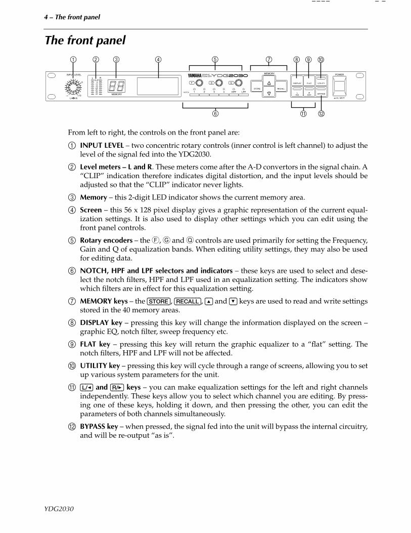
From left to right, the controls on the front panel are:
1 INPUT LEVEL – two concentric rotary controls (inner control is left channel) to adjust thelevel of the signal fed into the YDG2030.
2 Level meters – L and R. These meters come after the A-D convertors in the signal chain. A“CLIP” indication therefore indicates digital distortion, and the input levels should beadjusted so that the “CLIP” indicator never lights.
3 Memory – this 2-digit LED indicator shows the current memory area.
4 Screen – this 56 x 128 pixel display gives a graphic representation of the current equal-ization settings. It is also used to display other settings which you can edit using thefront panel controls.
5 Rotary encoders – the F, G and Q controls are used primarily for setting the Frequency,Gain and Q of equalization bands. When editing utility settings, they may also be usedfor editing data.
6 NOTCH, HPF and LPF selectors and indicators – these keys are used to select and dese-lect the notch filters, HPF and LPF used in an equalization setting. The indicators showwhich filters are in effect for this equalization setting.
7 MEMORY keys – the [STORE], [RECALL], [^] and [%] keys are used to read and write settingsstored in the 40 memory areas.
8 DISPLAY key – pressing this key will change the information displayed on the screen –graphic EQ, notch filter, sweep frequency etc.
9 FLAT key – pressing this key will return the graphic equalizer to a “flat” setting. Thenotch filters, HPF and LPF will not be affected.
0 UTILITY key – pressing this key will cycle through a range of screens, allowing you to setup various system parameters for the unit.
A [L/<] and [R/>] keys – you can make equalization settings for the left and right channelsindependently. These keys allow you to select which channel you are editing. By press-ing one of these keys, holding it down, and then pressing the other, you can edit theparameters of both channels simultaneously.
B BYPASS key – when pressed, the signal fed into the unit will bypass the internal circuitry,and will be re-output “as is”.
INPUT LEVEL
0
+10-∞L R
L RCLIP
-6-12-18-24-30-36-42 MEMORY
F G Q
GRAPHICEQUALIZER
NOTCH 1 2 3 4 HPF LPF
STORE RECALL
MEMORY
DISPLAY FLAT UTILITY
L R BYPASS
POWER
ON OFF
3 4 51
A6 B
72 8 9 :
YDG2030
5 – The rear panel
The rear panel
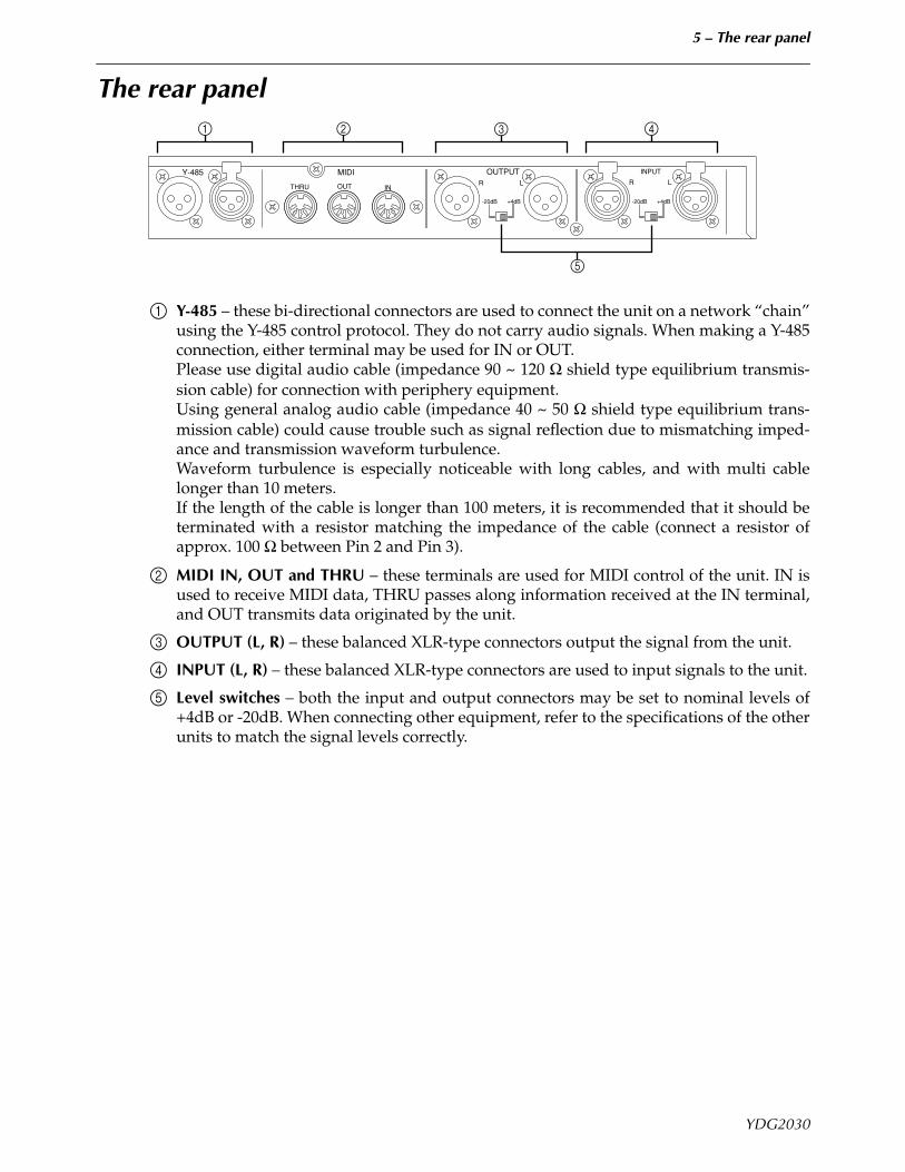
1 Y-485 – these bi-directional connectors are used to connect the unit on a network “chain”using the Y-485 control protocol. They do not carry audio signals. When making a Y-485connection, either terminal may be used for IN or OUT. Please use digital audio cable (impedance 90 ~ 120 Ω shield type equilibrium transmis-sion cable) for connection with periphery equipment. Using general analog audio cable (impedance 40 ~ 50 Ω shield type equilibrium trans-mission cable) could cause trouble such as signal reflection due to mismatching imped-ance and transmission waveform turbulence. Waveform turbulence is especially noticeable with long cables, and with multi cablelonger than 10 meters. If the length of the cable is longer than 100 meters, it is recommended that it should beterminated with a resistor matching the impedance of the cable (connect a resistor ofapprox. 100 Ω between Pin 2 and Pin 3).
2 MIDI IN, OUT and THRU – these terminals are used for MIDI control of the unit. IN isused to receive MIDI data, THRU passes along information received at the IN terminal,and OUT transmits data originated by the unit.
3 OUTPUT (L, R) – these balanced XLR-type connectors output the signal from the unit.
4 INPUT (L, R) – these balanced XLR-type connectors are used to input signals to the unit.
5 Level switches – both the input and output connectors may be set to nominal levels of+4dB or -20dB. When connecting other equipment, refer to the specifications of the otherunits to match the signal levels correctly.
Y-485 MIDI
THRU OUT IN
OUTPUTR L
+4dB
INPUT
R L
-20dB +4dB-20dB
1 32 4
5
YDG2030
6 – Memory areas
Memory areas
How the memories are arranged in the YDG2030The unit contains 40 memory areas which contain equalization settings, all of which areuser-programmable. This allows you to set up and store frequently-used equalization set-tings which you can recall at any time. These settings can be stored to a mass-storage device(MIDI data file system or personal computer system) either through the MIDI interface, orthe Y-485 connectors (see the section on “Utilities” for full details of this).
Recalling an equalization settingUse the MEMORY [^] and [%] keys to display the name of the setting you want to recall. Thename (set in UTILITY mode) is shown in the middle of the display, and the memory numberflashes on the LED display.Press the [RECALL] key.If you had not made any changes to the previous setting, the new setting will be displayedimmediately.If you had made changes to the previous setting without storing them, the unit will flash“RECALL OK?” in the center of the screen. If you really want to recall this setting, press the[RECALL] key again (while this message is flashing, you can use the MEMORY [^] and [%]keys to select another setting to be recalled). If you press the [RECALL] key, the number in theLED will stop flashing, and the screen will show the equalization curve for this setting. Ifyou have made a mistake in selecting the setting or pressing the [RECALL] key in the firstplace, and do not want to recall the setting, press any key except the [RECALL] key.Remember that the equalization curve shown will be for either the left or the right channel,depending on whether the [L/<] or [R/>] key is lit.
Storing an equalization settingWhen you have edited a setting, you use the MEMORY [^] and [%] keys to select a memoryarea where you want to store the setting (if the memory area you are editing is the areawhere you want to store the setting, you do not need to press the [^] and [%] keys). As youstep through the memory areas, the name of each one will be displayed in the center of thescreen.When you have selected the area, press the [STORE] key to write these settings into memory.The unit will flash “STORE OK?” in the center of the screen. Press the [STORE] key again toconfirm the store, or any other key to cancel the store.
A note on software protectionYou can protect the settings against accidental key-presses, etc., by using the UTILITY soft-ware protection (see “SOFTWARE PROTECT” on page 11). If protection is set to ON, thenany attempt to store or recall settings using the methods described above will result in themessage “ERR ** NOW PROTECT” being shown on the screen. The 2-digit LED will start toflash if you attempt to recall, store or modify a setting with protection on, as an additionalwarning. If you get the “ERR ** NOW PROTECT” message when trying to perform anyoperations with protection on, press any key to stop the LED flashing. “ERR ** NOW PRO-TECT” will disappear from the screen.
YDG2030
7 – Using the display
Using the display
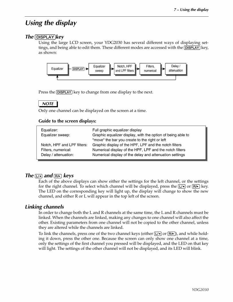
The [DISPLAY]keyUsing the large LCD screen, your YDG2030 has several different ways of displaying set-tings, and being able to edit them. These different modes are accessed with the [DISPLAY] key,as shown:
Press the [DISPLAY] key to change from one display to the next.
NOTE
Only one channel can be displayed on the screen at a time.
Guide to the screen displays:
The [L/<] and [R/>] keysEach of the above displays can show either the settings for the left channel, or the settingsfor the right channel. To select which channel will be displayed, press the [L/<] or [R/>] key.The LED on the corresponding key will light up, the display will change to show the newchannel, and either R or L will appear in the top left of the screen.
Linking channelsIn order to change both the L and R channels at the same time, the L and R channels must belinked. When the channels are linked, making any changes to one channel will also affect theother. Existing parameters from one channel will not be copied to the other channel, unlessthey are altered while the channels are linked.To link the channels, press one of the two channel keys (either [L/<] or [R/>]), and while hold-ing it down, press the other one. Because the screen can only show one channel at a time,only the settings of the first channel you pressed will be displayed, and the LED on that keywill light. The settings of the other channel will not be displayed, and its LED will blink.
YDG2030
8 – Using the display – The notch filter, and HPF and LPF indicators
The notch filter, and HPF and LPF indicators
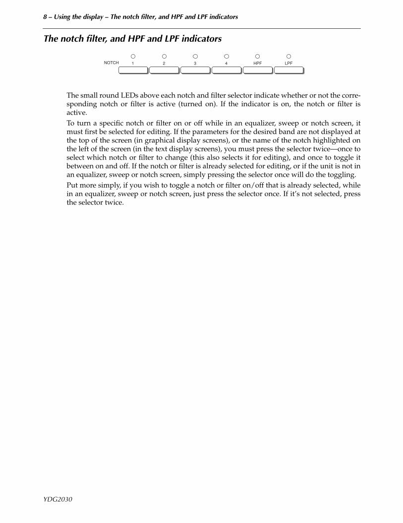
The small round LEDs above each notch and filter selector indicate whether or not the corre-sponding notch or filter is active (turned on). If the indicator is on, the notch or filter isactive.To turn a specific notch or filter on or off while in an equalizer, sweep or notch screen, itmust first be selected for editing. If the parameters for the desired band are not displayed atthe top of the screen (in graphical display screens), or the name of the notch highlighted onthe left of the screen (in the text display screens), you must press the selector twice—once toselect which notch or filter to change (this also selects it for editing), and once to toggle itbetween on and off. If the notch or filter is already selected for editing, or if the unit is not inan equalizer, sweep or notch screen, simply pressing the selector once will do the toggling.Put more simply, if you wish to toggle a notch or filter on/off that is already selected, whilein an equalizer, sweep or notch screen, just press the selector once. If it’s not selected, pressthe selector twice.
21 3 4 HPF LPFNOTCH
YDG2030
9 – Utilities
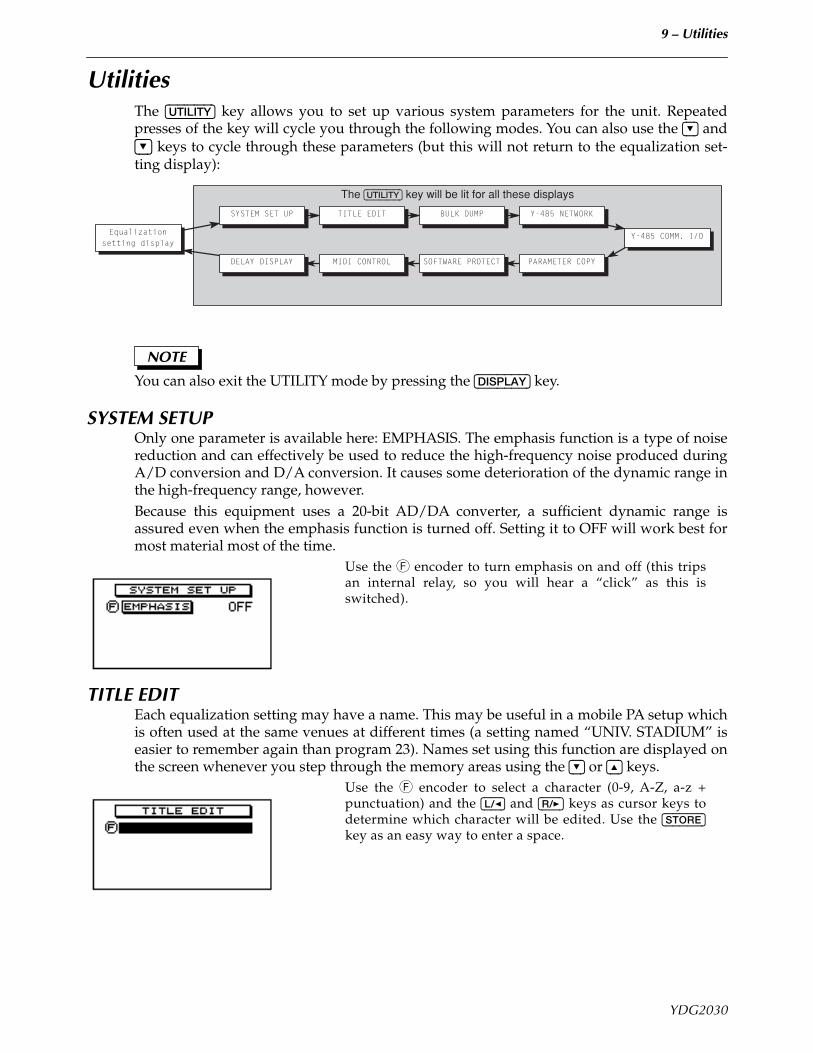
UtilitiesThe [UTILITY] key allows you to set up various system parameters for the unit. Repeatedpresses of the key will cycle you through the following modes. You can also use the [%] and[%] keys to cycle through these parameters (but this will not return to the equalization set-ting display):
NOTE
You can also exit the UTILITY mode by pressing the [DISPLAY] key.
SYSTEM SETUPOnly one parameter is available here: EMPHASIS. The emphasis function is a type of noisereduction and can effectively be used to reduce the high-frequency noise produced duringA/D conversion and D/A conversion. It causes some deterioration of the dynamic range inthe high-frequency range, however.Because this equipment uses a 20-bit AD/DA converter, a sufficient dynamic range isassured even when the emphasis function is turned off. Setting it to OFF will work best formost material most of the time.
Use the F encoder to turn emphasis on and off (this tripsan internal relay, so you will hear a “click” as this isswitched).
TITLE EDITEach equalization setting may have a name. This may be useful in a mobile PA setup whichis often used at the same venues at different times (a setting named “UNIV. STADIUM” iseasier to remember again than program 23). Names set using this function are displayed onthe screen whenever you step through the memory areas using the [%] or [^] keys.
Use the F encoder to select a character (0-9, A-Z, a-z +punctuation) and the [L/<] and [R/>] keys as cursor keys todetermine which character will be edited. Use the [STORE]key as an easy way to enter a space.
The [UTILITY] key will be lit for all these displays
Y-485 COMM. I/OEqualizationsetting display
SOFTWARE PROTECTDELAY DISPLAY PARAMETER COPYMIDI CONTROL
SYSTEM SET UP BULK DUMPTITLE EDIT Y-485 NETWORK
YDG2030
10 – Utilities – BULK DUMP
BULK DUMPThree parameters are available here:Use the F encoder to select whether bulk dump operationswill take place through the MIDI or Y-485 connections.Use the G encoder to select what kind of data will bedumped. You can choose between: ALL DATA (all memoryareas will be dumped), SYSTEM (the parameters you setup in the UTILITY menus will be dumped), MEMORY (asingle memory area, or all memory areas will be dumped),and BANK (the Program Change tables).If you have selected MEMORY with the G encoder, use theQ encoder to select the memory area that you want todump (1 through 40 or ALL).If you have selected BANK with the G encoder, use the Qencoder to select the Program Change bank you want todump (A through D or ALL).
NOTE
You can dump this data over MIDI to a MIDI data filer device (including a personal com-puter), or over the Y-485 network to a computer connected through the YAMAHA IFU485interface.There is no need to set the unit into any special receive mode to receive bulk dump datafrom an external device.
Y-485 NETWORKThe Y-485 network is more complex (in terms of software addressing) than the MIDI system.Each device on a network belongs to a group and has a device number within that group.
Use the [L/<] and [R/>] keys to decide whether you are edit-ing the REMOTE or LOCAL settings. The LOCAL settings,of course, refer to this unit, and the REMOTE settings referto a unit to which you will be sending data.The F encoder allows you to set up a group numberbetween 1 and 7. The Y-485 protocol allows messages to besent to groups of units. If you are editing the REMOTE set-tings, you can also set this to a “*”. This is a “don’t care”value – the remote device address is irrelevant, and mes-sages will be sent to all groups.The G encoder allows you to set a device number insidethe group between 1 and 31. If you are editing REMOTEsettings, you can also set this to a “*”. This is a “don’t care”value – the remote device address is irrelevant, and mes-sages will be sent to all devices.The Q encoder allows you to set the data transfer rate forthe LOCAL settings only. This should usually be set to9600 (even though a value of 38400 may be set).
To control this unit and other Y-485 units from a computer, you will require an IFU485 hard-ware interface, and computer software (QS-1) to control it. QS-1 software is available forboth Macintosh and IBM-compatible computers. Contact Yamaha or your local Yamaha dis-tributor for further details.
YDG2030
11 – Utilities – Y-485 COMM. I/O
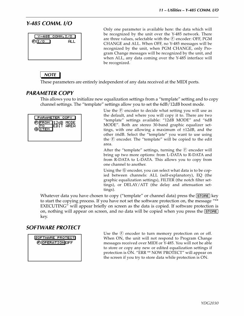
Y-485 COMM. I/OOnly one parameter is available here: the data which willbe recognized by the unit over the Y-485 network. Thereare three values, selectable with the F encoder: OFF, PGMCHANGE and ALL. When OFF, no Y-485 messages will berecognized by the unit, when PGM CHANGE, only Pro-gram Change messages will be recognized by the unit, andwhen ALL, any data coming over the Y-485 interface willbe recognized.
NOTE
These parameters are entirely independent of any data received at the MIDI ports.
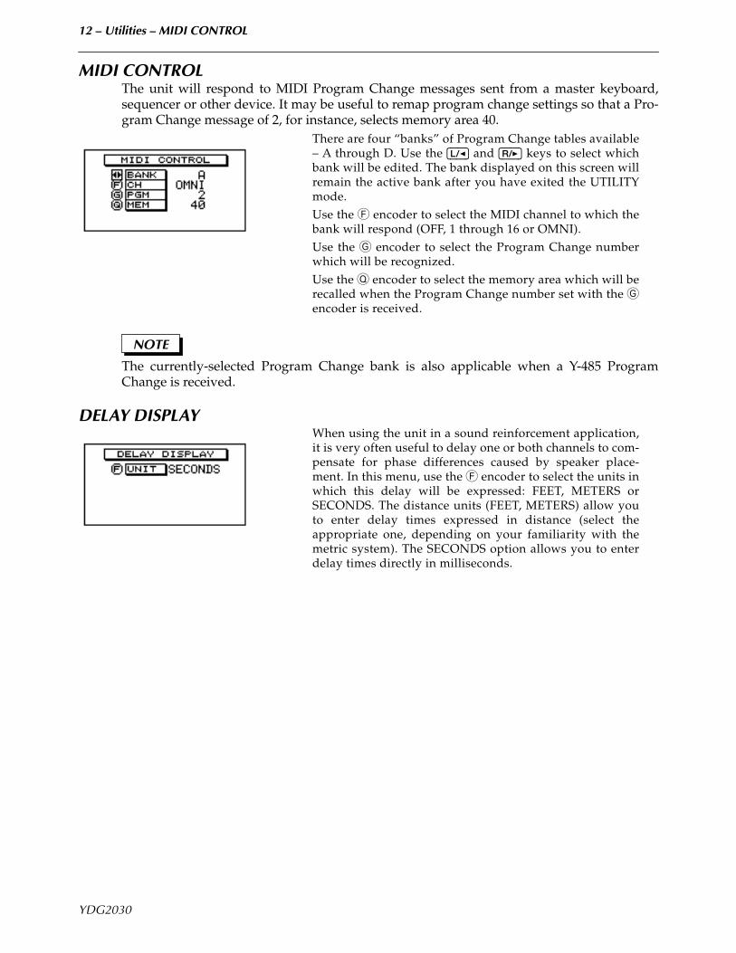
PARAMETER COPYThis allows you to initialize new equalization settings from a “template” setting and to copychannel settings. The “template” settings allow you to set the 6dB/12dB boost mode.
Use the F encoder to decide what setting you will use asthe default, and where you will copy it to. There are two“template” settings available: “12dB MODE” and “6dBMODE”. Both are stereo 30-band graphic equalizer set-tings, with one allowing a maximum of ±12dB, and theother ±6dB. Select the “template” you want to use usingthe F encoder. The “template” will be copied to the editarea.After the “template” settings, turning the F encoder willbring up two more options: from L-DATA to R-DATA andfrom R-DATA to L-DATA. This allows you to copy fromone channel to another.Using the G encoder, you can select what data is to be cop-ied between channels: ALL (self-explanatory), EQ (thegraphic equalization settings), FILTER (the notch filter set-tings), or DELAY/ATT (the delay and attenuation set-tings).
Whatever data you have chosen to copy (“template” or channel data) press the [STORE] keyto start the copying process. If you have not set the software protection on, the message “**EXECUTING” will appear briefly on screen as the data is copied. If software protection ison, nothing will appear on screen, and no data will be copied when you press the [STORE]key.
SOFTWARE PROTECTUse the F encoder to turn memory protection on or off.When ON, the unit will not respond to Program Changemessages received over MIDI or Y-485. You will not be ableto store or copy any new or edited equalization settings ifprotection is ON. “ERR ** NOW PROTECT” will appear onthe screen if you try to store data while protection is ON.
YDG2030
12 – Utilities – MIDI CONTROL
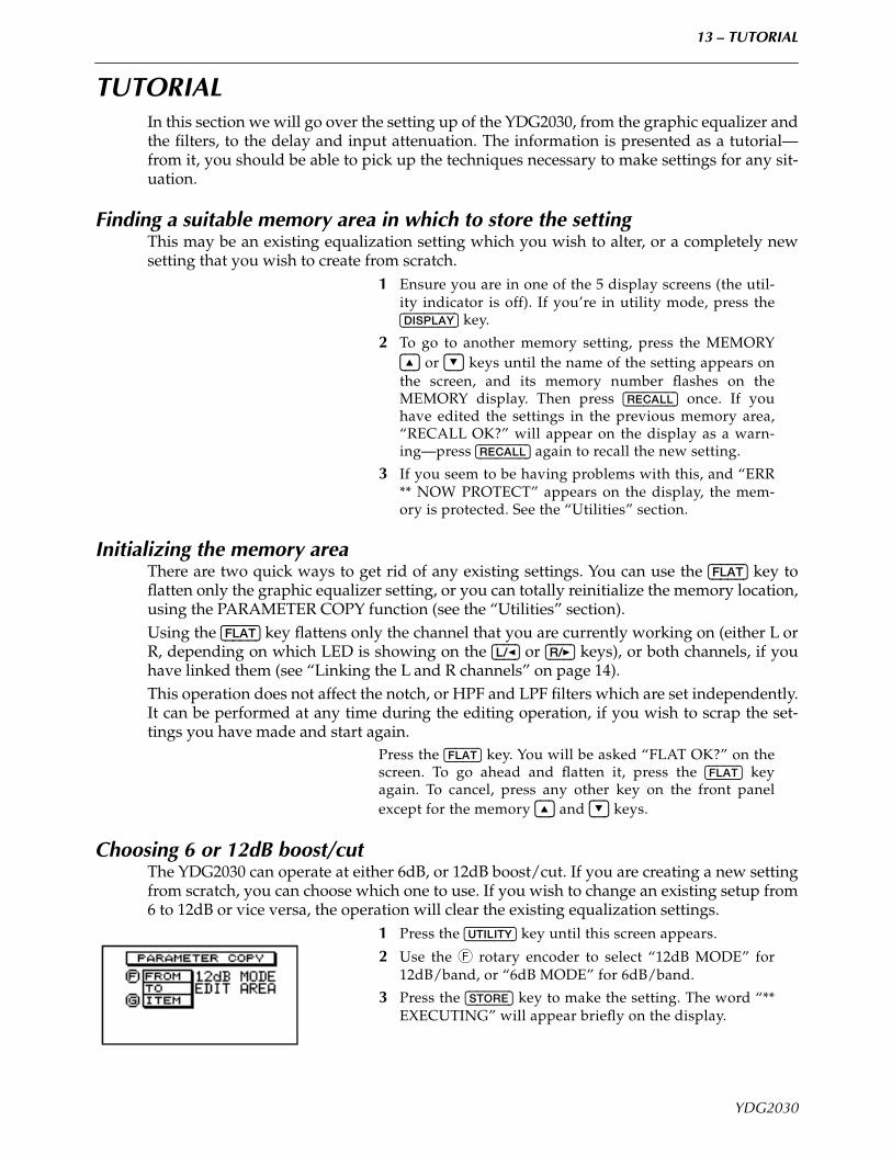
MIDI CONTROLThe unit will respond to MIDI Program Change messages sent from a master keyboard,sequencer or other device. It may be useful to remap program change settings so that a Pro-gram Change message of 2, for instance, selects memory area 40.
There are four “banks” of Program Change tables available– A through D. Use the [L/<] and [R/>] keys to select whichbank will be edited. The bank displayed on this screen willremain the active bank after you have exited the UTILITYmode.Use the F encoder to select the MIDI channel to which thebank will respond (OFF, 1 through 16 or OMNI).Use the G encoder to select the Program Change numberwhich will be recognized.Use the Q encoder to select the memory area which will berecalled when the Program Change number set with the Gencoder is received.
NOTE
The currently-selected Program Change bank is also applicable when a Y-485 ProgramChange is received.
DELAY DISPLAYWhen using the unit in a sound reinforcement application,it is very often useful to delay one or both channels to com-pensate for phase differences caused by speaker place-ment. In this menu, use the F encoder to select the units inwhich this delay will be expressed: FEET, METERS orSECONDS. The distance units (FEET, METERS) allow youto enter delay times expressed in distance (select theappropriate one, depending on your familiarity with themetric system). The SECONDS option allows you to enterdelay times directly in milliseconds.
YDG2030
13 – TUTORIAL
TUTORIALIn this section we will go over the setting up of the YDG2030, from the graphic equalizer andthe filters, to the delay and input attenuation. The information is presented as a tutorial—from it, you should be able to pick up the techniques necessary to make settings for any sit-uation.
Finding a suitable memory area in which to store the settingThis may be an existing equalization setting which you wish to alter, or a completely newsetting that you wish to create from scratch.
1 Ensure you are in one of the 5 display screens (the util-ity indicator is off). If you’re in utility mode, press the[DISPLAY] key.
2 To go to another memory setting, press the MEMORY[^] or [%] keys until the name of the setting appears onthe screen, and its memory number flashes on theMEMORY display. Then press [RECALL] once. If youhave edited the settings in the previous memory area,“RECALL OK?” will appear on the display as a warn-ing—press [RECALL] again to recall the new setting.
3 If you seem to be having problems with this, and “ERR** NOW PROTECT” appears on the display, the mem-ory is protected. See the “Utilities” section.
Initializing the memory areaThere are two quick ways to get rid of any existing settings. You can use the [FLAT] key toflatten only the graphic equalizer setting, or you can totally reinitialize the memory location,using the PARAMETER COPY function (see the “Utilities” section).Using the [FLAT] key flattens only the channel that you are currently working on (either L orR, depending on which LED is showing on the [L/<] or [R/>] keys), or both channels, if youhave linked them (see “Linking the L and R channels” on page 14).This operation does not affect the notch, or HPF and LPF filters which are set independently.It can be performed at any time during the editing operation, if you wish to scrap the set-tings you have made and start again.
Press the [FLAT] key. You will be asked “FLAT OK?” on thescreen. To go ahead and flatten it, press the [FLAT] keyagain. To cancel, press any other key on the front panelexcept for the memory [^] and [%] keys.
Choosing 6 or 12dB boost/cutThe YDG2030 can operate at either 6dB, or 12dB boost/cut. If you are creating a new settingfrom scratch, you can choose which one to use. If you wish to change an existing setup from6 to 12dB or vice versa, the operation will clear the existing equalization settings.
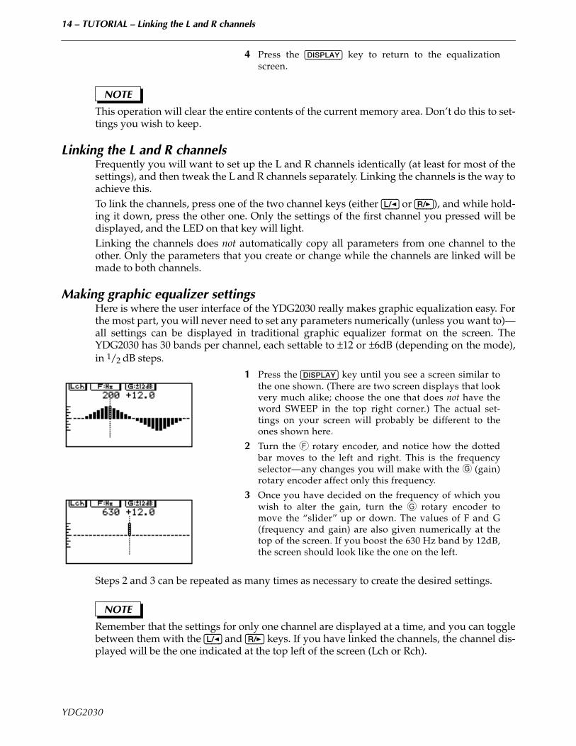
1 Press the [UTILITY] key until this screen appears.
2 Use the F rotary encoder to select “12dB MODE” for12dB/band, or “6dB MODE” for 6dB/band.
3 Press the [STORE] key to make the setting. The word “**EXECUTING” will appear briefly on the display.
YDG2030
14 – TUTORIAL – Linking the L and R channels
4 Press the [DISPLAY] key to return to the equalizationscreen.
NOTE
This operation will clear the entire contents of the current memory area. Don’t do this to set-tings you wish to keep.
Linking the L and R channelsFrequently you will want to set up the L and R channels identically (at least for most of thesettings), and then tweak the L and R channels separately. Linking the channels is the way toachieve this.To link the channels, press one of the two channel keys (either [L/<] or [R/>]), and while hold-ing it down, press the other one. Only the settings of the first channel you pressed will bedisplayed, and the LED on that key will light.Linking the channels does not automatically copy all parameters from one channel to theother. Only the parameters that you create or change while the channels are linked will bemade to both channels.
Making graphic equalizer settingsHere is where the user interface of the YDG2030 really makes graphic equalization easy. Forthe most part, you will never need to set any parameters numerically (unless you want to)—all settings can be displayed in traditional graphic equalizer format on the screen. TheYDG2030 has 30 bands per channel, each settable to ±12 or ±6dB (depending on the mode),in 1/2 dB steps.
1 Press the [DISPLAY] key until you see a screen similar tothe one shown. (There are two screen displays that lookvery much alike; choose the one that does not have theword SWEEP in the top right corner.) The actual set-tings on your screen will probably be different to theones shown here.
2 Turn the F rotary encoder, and notice how the dottedbar moves to the left and right. This is the frequencyselector—any changes you will make with the G (gain)rotary encoder affect only this frequency.
3 Once you have decided on the frequency of which youwish to alter the gain, turn the G rotary encoder tomove the “slider” up or down. The values of F and G(frequency and gain) are also given numerically at thetop of the screen. If you boost the 630 Hz band by 12dB,the screen should look like the one on the left.
Steps 2 and 3 can be repeated as many times as necessary to create the desired settings.
NOTE
Remember that the settings for only one channel are displayed at a time, and you can togglebetween them with the [L/<] and [R/>] keys. If you have linked the channels, the channel dis-played will be the one indicated at the top left of the screen (Lch or Rch).
YDG2030
15 – TUTORIAL – Using the sweep function
4 Once you have created the desired settings, don’t forgetto store them inside one of the memory areas, so youcan use them again at a later time.
Using the sweep functionThe sweep function allows you to move a given gain cut or boost through a number of dif-ferent frequencies quickly and easily. This is a relative function—if you boost a certain fre-quency up to +2 dB from -4dB, then alter the frequency, the setting of the new frequency willnot become +2 dB, but will rise by 6 dB, the actual amount of the original boost. This opera-tion is clearly shown on the screen display, with both the resultant gain and the amount ofgain/cut being listed.This has several uses, e.g. searching for feedback frequencies or dead frequencies in a room.For example, if feedback suddenly occurs, and you can guess the approximate frequency,the quickest method of eliminating the feedback is to enter the sweep screen, then sweep a6dB cut (more or less) through the approximate area until you find the point where the feed-back disappears. The 6dB will be subtracted from the previous settings as you sweepthrough the frequency bands. When the sweep screen is exited, the last setting you made isremembered.The two examples given are suggestions of how the YDG2030 can be used. You may, ofcourse, adapt your own methods of using graphic equalizers to working with the YDG2030.
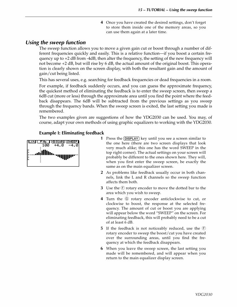
Example I: Eliminating feedback1 Press the [DISPLAY] key until you see a screen similar to
the one here (there are two screen displays that lookvery much alike; this one has the word SWEEP in thetop right corner). The actual settings on your screen willprobably be different to the ones shown here. They will,when you first enter the sweep screen, be exactly thesame as on the main equalizer screen.
2 As problems like feedback usually occur in both chan-nels, link the L and R channels so the sweep functionaffects them both.
3 Use the F rotary encoder to move the dotted bar to thearea which you wish to sweep.
4 Turn the G rotary encoder anticlockwise to cut, orclockwise to boost, the response at the selected fre-quency. The amount of cut or boost you are applyingwill appear below the word “SWEEP” on the screen. Foreliminating feedback, this will probably need to be a cutof at least 6 dB.
5 If the feedback is not noticeably reduced, use the Frotary encoder to sweep the boost/cut you have createdover the surrounding areas, until you find the fre-quency at which the feedback disappears.
6 When you leave the sweep screen, the last setting youmade will be remembered, and will appear when youreturn to the main equalizer display screen.
YDG2030
16 – TUTORIAL – Using the notch filters, and the HPF and LPF
Example II: “Tuning” a roomOne method of “tuning” a room (compensating for dead and live frequencies) with a con-ventional graphic equalizer is to move the faders up and down one at a time while puttingwhite noise through the sound system. Then, if “ringing” is heard at any particular fre-quency, you can reduce the gain of that frequency. Likewise, if a particular frequency seemsto get lost, you can increase its gain. This process is simplified greatly with the YDG2030, asa preset gain or cut can be swept through the entire frequency range using the F rotaryencoder.
1 Enter the sweep screen (see step 1 in the exampleabove).
2 If you wish to alter both channels simultaneously, linkthe channels (see step 2 in the example above).
3 To search for particularly “live” spots, turn the G rotaryencoder to increase the gain by a few dB (experiment tofind the best amount). When this gain is swept, it willbe added to the existing gains at each frequency.
4 While feeding an appropriate signal through the soundsystem (pink or white noise is best, if possible), use theF rotary encoder to sweep the frequency gain you cre-ated through the entire frequency band, listening forpoints that start to ring/feed back. If no ringing occurs,try increasing the gain setting until it does.
5 Once you know the feedback frequencies, press the[DISPLAY] key four times to return to the main graphicequalizer screen, and reduce the gains of those frequen-cies.
Steps 3, 4 and 5 can be repeated as many times as necessary.
Using the notch filters, and the HPF and LPFBesides the HPF and LPF, which are shelving high-pass and low-pass filters, respectively,the notch filters provide very selective gain cuts, with adjustable Q. One of their main uses isto filter out sounds that occur at specific frequencies, such as 50/60 Hz AC hum, or the highfrequency noise induced by some fluorescent lighting, or lighting dimmers. Of course, toavoid affecting the original material any more than necessary, try to use the narrowest notchpossible that will remove the offending signals.Q is a measure of the resonance of the filter. Basically, the higher the Q, the narrower thenotch. Except for setting the Q, the process for setting the notch filters and the HPF and LPFis exactly the same (the shelving HPF and LPF don’t have Q).
I. Turning the filters on and off individually1 If you are in any screen other than the two filter screens,
simply press the notch or filter indicator correspondingto the notch or filter you wish to toggle on/off.
2 If you are in one of the two filter screens, first ensure thenotch or filter is selected for editing (you may need topress the corresponding selector once to do this), thenpress the appropriate selector to toggle it on/off.
YDG2030
17 – TUTORIAL – Using the notch filters, and the HPF and LPF
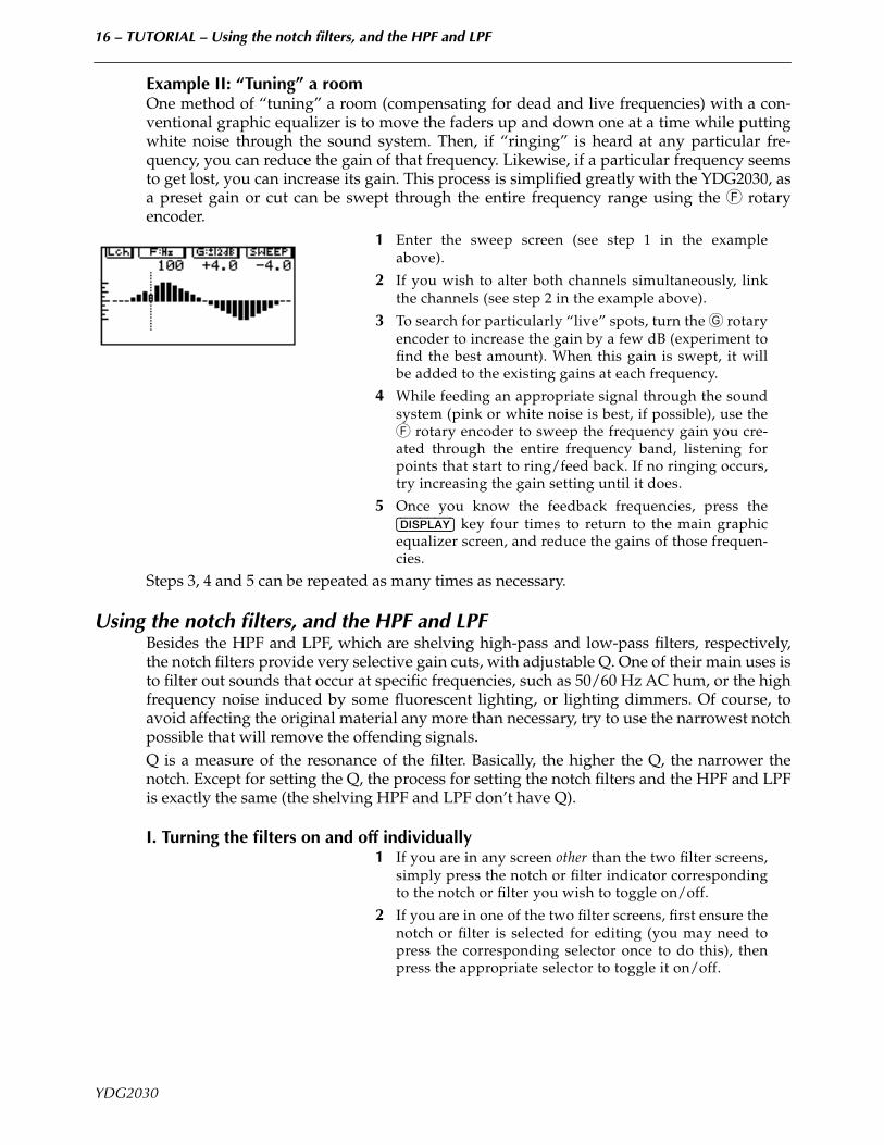
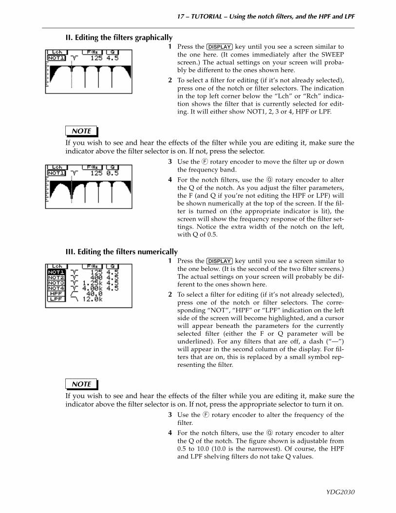
II. Editing the filters graphically1 Press the [DISPLAY] key until you see a screen similar to
the one here. (It comes immediately after the SWEEPscreen.) The actual settings on your screen will proba-bly be different to the ones shown here.
2 To select a filter for editing (if it’s not already selected),press one of the notch or filter selectors. The indicationin the top left corner below the “Lch” or “Rch” indica-tion shows the filter that is currently selected for edit-ing. It will either show NOT1, 2, 3 or 4, HPF or LPF.
NOTE
If you wish to see and hear the effects of the filter while you are editing it, make sure theindicator above the filter selector is on. If not, press the selector.
3 Use the F rotary encoder to move the filter up or downthe frequency band.
4 For the notch filters, use the Q rotary encoder to alterthe Q of the notch. As you adjust the filter parameters,the F (and Q if you’re not editing the HPF or LPF) willbe shown numerically at the top of the screen. If the fil-ter is turned on (the appropriate indicator is lit), thescreen will show the frequency response of the filter set-tings. Notice the extra width of the notch on the left,with Q of 0.5.
III. Editing the filters numerically1 Press the [DISPLAY] key until you see a screen similar to
the one below. (It is the second of the two filter screens.)The actual settings on your screen will probably be dif-ferent to the ones shown here.
2 To select a filter for editing (if it’s not already selected),press one of the notch or filter selectors. The corre-sponding “NOT”, “HPF” or “LPF” indication on the leftside of the screen will become highlighted, and a cursorwill appear beneath the parameters for the currentlyselected filter (either the F or Q parameter will beunderlined). For any filters that are off, a dash (“—”)will appear in the second column of the display. For fil-ters that are on, this is replaced by a small symbol rep-resenting the filter.
NOTE
If you wish to see and hear the effects of the filter while you are editing it, make sure theindicator above the filter selector is on. If not, press the appropriate selector to turn it on.
3 Use the F rotary encoder to alter the frequency of thefilter.
4 For the notch filters, use the Q rotary encoder to alterthe Q of the notch. The figure shown is adjustable from0.5 to 10.0 (10.0 is the narrowest). Of course, the HPFand LPF shelving filters do not take Q values.
YDG2030
18 – TUTORIAL – Setting up the input level, attenuation and delay
Setting up the input level, attenuation and delay
I. Input level and input attenuationThere are two operations on the YDG2030 that affect the input level—the input level controlin the analog domain (pre A/D converters), and the attenuation parameter (INP.ATT) in thedigital domain (post A/D converters).The input level control (on the front panel) should be set so that the level meters register thehighest possible level without the CLIP indicator lighting.The input attenuation parameter is provided to compensate for equalizer settings that alterthe overall gain of the sound e.g. if the equalizer settings result in an overall gain increase of4dB (for example), internal clipping may occur even if the level meters do not indicate clip-ping.As a guide to input attenuation level, adjust it so that the output volume is the same aswhen the bypass function is used. The attenuation can be set from 0dB to infinity (∞), withthe highest numerical value being shown as 50 (see instructions below).
II. DelayIn sound reinforcement situations, it is often desirable for the sound from various loud-speakers to be delayed, to compensate for phase delay caused by speaker placement. Due toits position in the signal chain, the equalization stage is a good place to add this delay.The YDG2030 can delay signals by up to 714 milliseconds (242m, about 800ft). You can inputthis information either directly as milliseconds, or as a distance in feet or meters (set yourpreference in the “Utilities”). You can make individual settings for both channels, or for bothchannels at the same time by linking L and R. These settings are stored in the memory areaalong with the equalization settings.
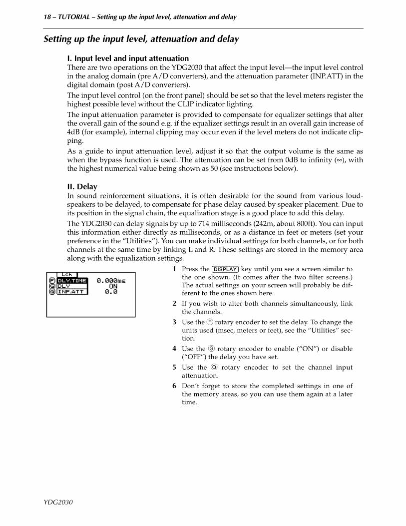
1 Press the [DISPLAY] key until you see a screen similar tothe one shown. (It comes after the two filter screens.)The actual settings on your screen will probably be dif-ferent to the ones shown here.
2 If you wish to alter both channels simultaneously, linkthe channels.
3 Use the F rotary encoder to set the delay. To change theunits used (msec, meters or feet), see the “Utilities” sec-tion.
4 Use the G rotary encoder to enable (“ON”) or disable(“OFF”) the delay you have set.
5 Use the Q rotary encoder to set the channel inputattenuation.
6 Don’t forget to store the completed settings in one ofthe memory areas, so you can use them again at a latertime.
YDG2030
19 – Specifications
YDG2030
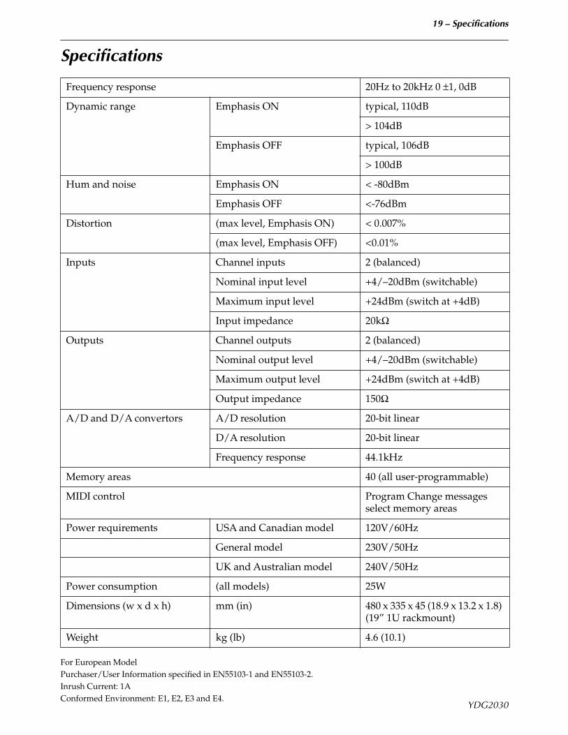
Specifications
For European ModelPurchaser/User Information specified in EN55103-1 and EN55103-2.Inrush Current: 1AConformed Environment: E1, E2, E3 and E4.
Frequency response 20Hz to 20kHz 0 ±1, 0dB
Dynamic range Emphasis ON typical, 110dB
> 104dB
Emphasis OFF typical, 106dB
> 100dB
Hum and noise Emphasis ON < -80dBm
Emphasis OFF <-76dBm
Distortion (max level, Emphasis ON) < 0.007%
(max level, Emphasis OFF) <0.01%
Inputs Channel inputs 2 (balanced)
Nominal input level +4/–20dBm (switchable)
Maximum input level +24dBm (switch at +4dB)
Input impedance 20kΩ
Outputs Channel outputs 2 (balanced)
Nominal output level +4/–20dBm (switchable)
Maximum output level +24dBm (switch at +4dB)
Output impedance 150Ω
A/D and D/A convertors A/D resolution 20-bit linear
D/A resolution 20-bit linear
Frequency response 44.1kHz
Memory areas 40 (all user-programmable)
MIDI control Program Change messages select memory areas
Power requirements USA and Canadian model 120V/60Hz
General model 230V/50Hz
UK and Australian model 240V/50Hz
Power consumption (all models) 25W
Dimensions (w x d x h) mm (in) 480 x 335 x 45 (18.9 x 13.2 x 1.8) (19” 1U rackmount)
Weight kg (lb) 4.6 (10.1)
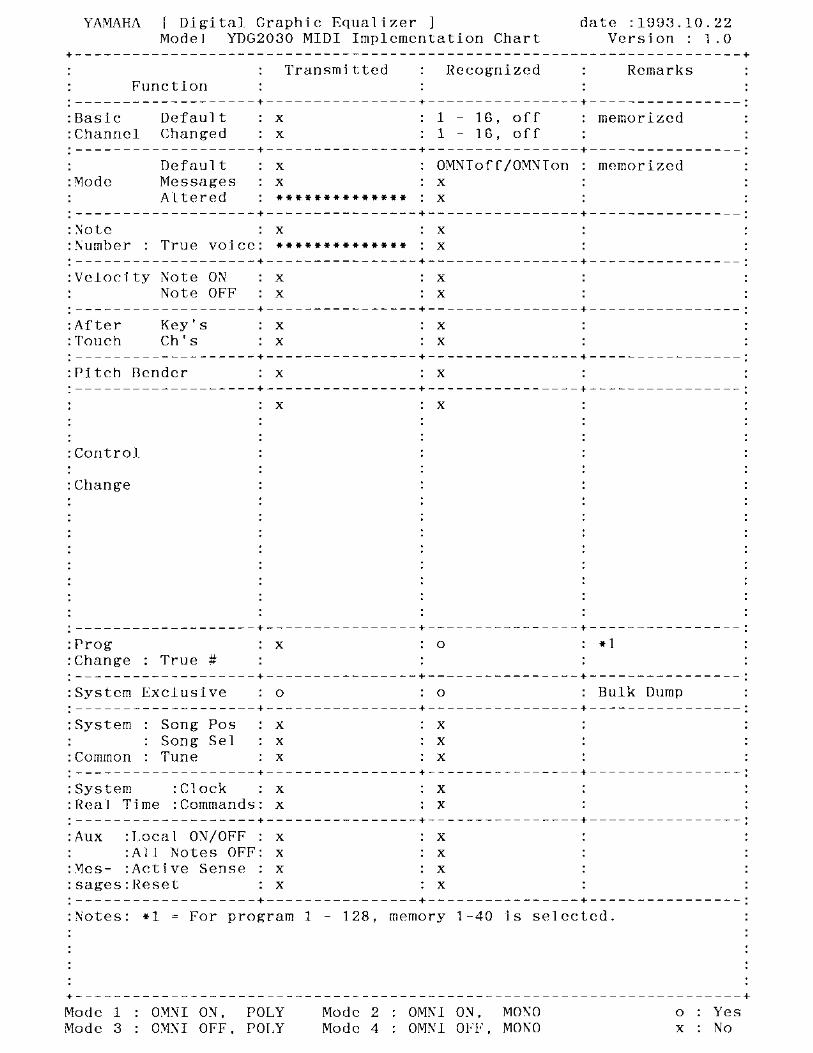
MIDI Implementation Chart MIDI Implementation Chart / Tableau d'implantation MIDI / MIDI-Implementation-Chart
66 – User programs / Programmes utilisateur / User-Programme –
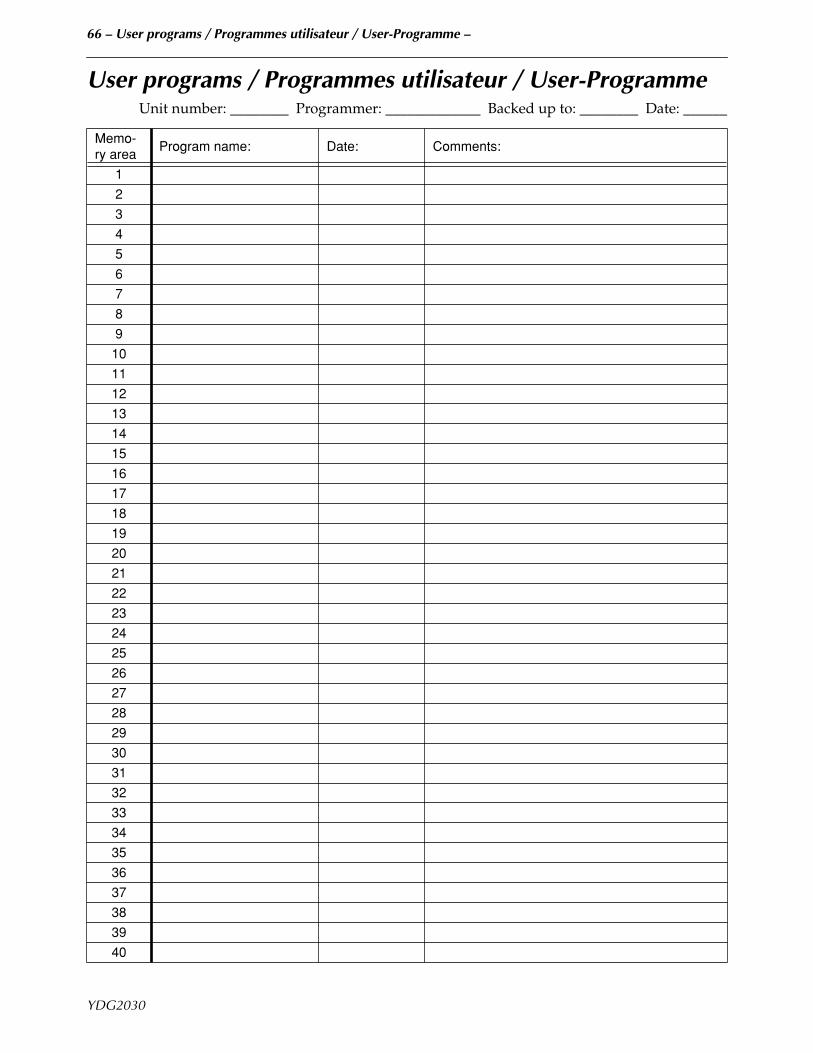
User programs / Programmes utilisateur / User-ProgrammeUnit number: ________ Programmer: _____________ Backed up to: ________ Date: ______
Memo-ry area
Program name: Date: Comments:
1
2
3
4
5
6
7
8
9
10
11
12
13
14
15
16
17
18
19
20
21
22
23
24
25
26
27
28
29
30
31
32
33
34
35
36
37
38
39
40
YDG2030
67 – Program change table / Tableau de changement de programme / Program-Change-Tabelle –
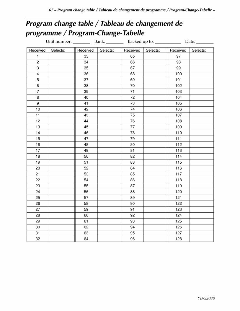
Program change table / Tableau de changement de programme / Program-Change-Tabelle
Unit number: ________ Bank: ________ Backed up to: ____________ Date: ________
Received Selects: Received Selects: Received Selects: Received Selects:
1 33 65 97
2 34 66 98
3 35 67 99
4 36 68 100
5 37 69 101
6 38 70 102
7 39 71 103
8 40 72 104
9 41 73 105
10 42 74 106
11 43 75 107
12 44 76 108
13 45 77 109
14 46 78 110
15 47 79 111
16 48 80 112
17 49 81 113
18 50 82 114
19 51 83 115
20 52 84 116
21 53 85 117
22 54 86 118
23 55 87 119
24 56 88 120
25 57 89 121
26 58 90 122
27 59 91 123
28 60 92 124
29 61 93 125
30 62 94 126
31 63 95 127
32 64 96 128
YDG2030
68 – Block diagram / Schéma de principe / Blockdiagramm –
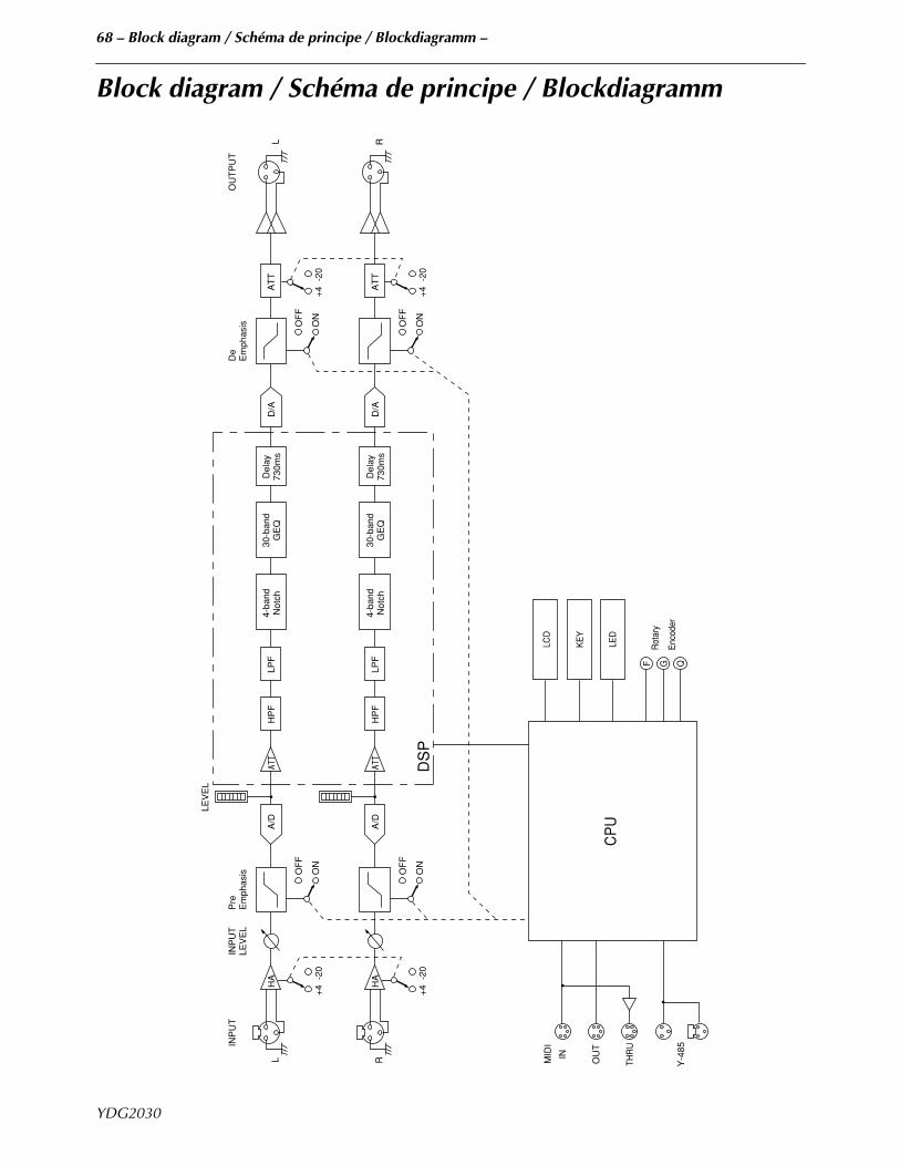
Block diagram / Schéma de principe / Blockdiagramm
L
INP
UT
INP
UT
LEV
EL
Pre
Em
phas
is
LEV
EL
De
Em
phas
isO
UT
PU
T
OF
F
ON
+4
-20
OF
F
ON
+4
-20
A/D
HA
ATT
HP
FLP
F4-
band
Not
ch30
-ban
dG
EQ
Del
ay73
0ms
D/A
AT
TL
R
OF
F
ON
+4
-20
OF
F
ON
+4
-20
A/D
HA
HP
FLP
F4-
band
Not
ch30
-ban
dG
EQ
Del
ay73
0ms
D/A
AT
TR
DS
P
MID
I
IN OU
T
THR
U
Y-4
85
CP
U
LCD
KE
Y
LED
F G Q
Rot
ary
Enc
oder
ATT
YDG2030
69 – Dimensions / Abmessungen –
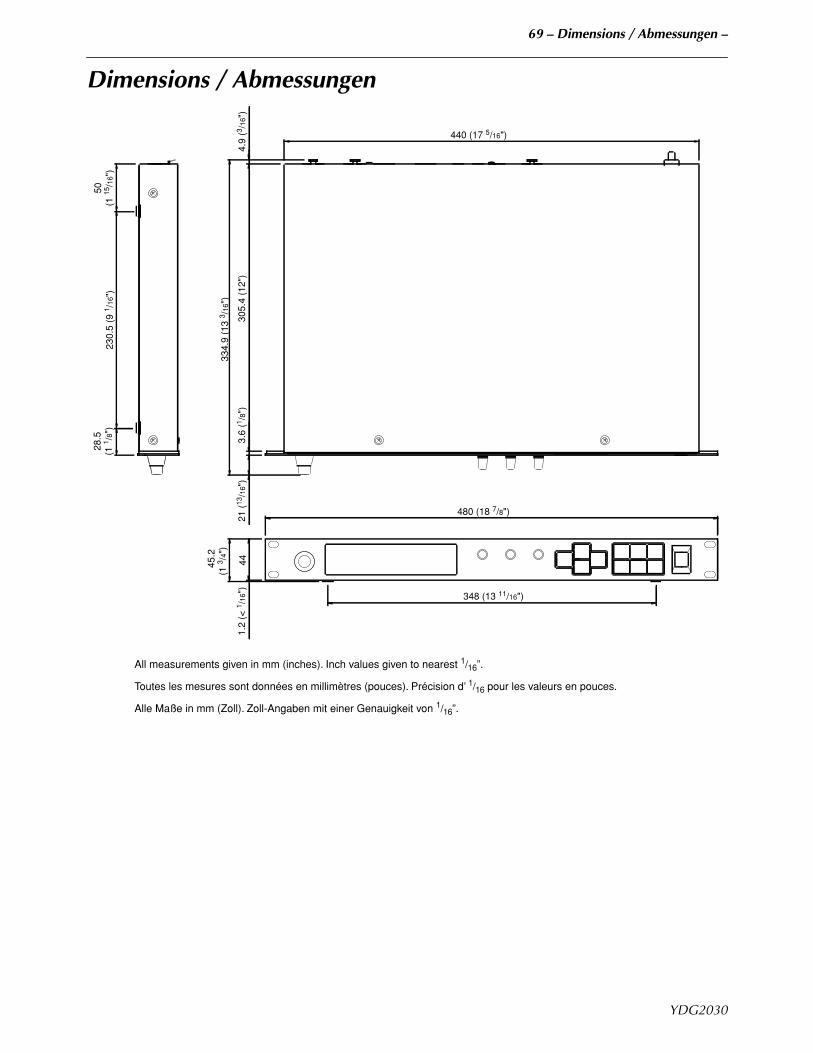
Dimensions / Abmessungen
All measurements given in mm (inches). Inch values given to nearest 1/16”.
Toutes les mesures sont données en millimètres (pouces). Précision d’ 1/16 pour les valeurs en pouces.
Alle Maße in mm (Zoll). Zoll-Angaben mit einer Genauigkeit von 1/16”.
21 (
13/1
6")
44
45.
2(1
3 /4"
)
348 (13 11/16")
480 (18 7/8")
1.2
(< 1 /
16")
3.6
(1 /8"
)
334
.9 (
13 3 /
16")
305.
4 (1
2")
28.5
(1 1 /
8")
230.
5 (9
1 /16
")50
(1 15
/16"
)
4.9
(3 /16
")
440 (17 5/16")
YDG2030

R4 1 CR 72
00 01 500 CR Printed in Japan
VQ95490
Pro Audio & Digital Musical Instrument DivisionP.O. Box 3, Hamamatsu, 430-8651, Japan


![Constant-Q Graphic Equalizers* - Rane · · 2016-08-24band octave equalizer. ... a detailed discussion of a typical gyrator graphic equalizer, see [8]; for a circuit critique of](https://img.pdfslide.net/doc/110x75/5ae4f0f37f8b9a90138fb0fa/constant-q-graphic-equalizers-octave-equalizer-a-detailed-discussion-of.jpg)