Embed Size (px)
Citation preview
© Faculty of Mechanical Engineering, Belgrade. All rights reserved FME Transactions (2018) 46, 10-16 10
Received: January 2017, Accepted: September 2017 Correspondence to: Dr Alberto Martini Alma Mater Studiorum University of Bologna Via Fontanelle 40, 47121 Forlì (FC), Italy E-mail: [email protected] doi:10.5937/fmet1801010M
Alberto Martini Assistant Professor
Alma Mater Studiorum University of Bologna Department of Industrial Engineering
Italy
Gravity Compensation of a 6-UPS Parallel Kinematics Machine Tool Through Elastically Balanced Constant-Force Generators Gravity compensation is a viable strategy to improve the performance of manipulators, particularly in terms of power consumption. This work studies the static balancing of a prototypal 5-axis parallel kinematics machine tool with UPS-legs. Exact gravity compensation is achieved by turning the legs into constant-force generators, through tension springs. A numerical multibody model is implemented and simulated within a commercial software environment (MSC Adams™) to assess the effectiveness of the proposed balancing strategy. Keywords: static balancing, gravity compensation, elastic compensation, constant-force generator, Parallel Kinematics Machine, 5-axis machine tool.
1. INTRODUCTION
A mechanism is said to be statically balanced (or gravity compensated) if its total potential energy is invariant for any admissible pose. In such an instance, no motor actions are required to sustain the weight of its moving parts. Gravity compensation through passive (i.e. not actuated) devices is a common practice for heavy-duty serial manipulators [1-4], since it brings essential benefits, namely lower motor loads, enhanced energy efficiency, reduced vibrational levels [5], quality precision in manufacturing [6, 7], improved safety and productivity [8]. It is proven convenient for closed-loop mechanisms as well, provided that gravity loads are comparable with inertial actions [9-11]. Hence, static balancing is suitable for applications featuring parallel robots with a heavy moving platform, long working periods in rest position and operations at low/moderate dynamics, e.g. robotically assisted surgery and machining tasks [9, 10]. In particular, the implemen–tation of a gravity compensation strategy is expected to significantly enhance the operation of parallel kinema–tics machine tools (PKMs), which typically meet all the mentioned specifications [12-16].
Numerous approaches have been developed for the gravity compensation of both serial and parallel robots [17-26]. The study deals with static balancing of parallel robots, achieved by making the legs operate as constant-force generators (CFGs), a concept developed in [9, 22, 27]. By following this strategy, a set of leg-exerted constant forces that realizes the neutral equilibrium of the moving platform is firstly determined. Then, each leg is made to generate the required force by installing balancing components whose parameters are determined
by imposing a condition of constant potential energy. In particular, this work presents the gravity
compensation of a 5-axis machine tool with six UPS-legs (i.e. featuring a universal-prismatic-spherical joint sequence, underline denoting the actuated one). A solution for turning UPS-legs into CFGs through pure elastic compensation has been recently proposed [28]. This new method is expected to provide better working performance with respect to known solutions requiring sliding counterweights [9], which are difficult to be implemented in practice and may worsen the robot dynamic operation. Indeed, balancing counterweights considerably increase the robot mass, hence possibly inducing higher motor loads [24, 29]. Moreover they may trigger vibration phenomena [30-33], thus being potentially detrimental for PKMs in terms of machining tolerances and cutting tool life [34- 36].
A feasible solution for achieving exact gravity com–pensation (i.e. without residual unbalanced loads) is analytically derived. Its effectiveness is assessed through numerical simulations in a multibody environ–ment.
The paper is organized as follows. Section 2 describes the studied PKM. Section 3 presents the balancing procedure and the simulation results. Section 4 draws some conclusions.
2. DESCRIPTION OF THE PARALLEL KINEMATICS
MACHINE TOOL
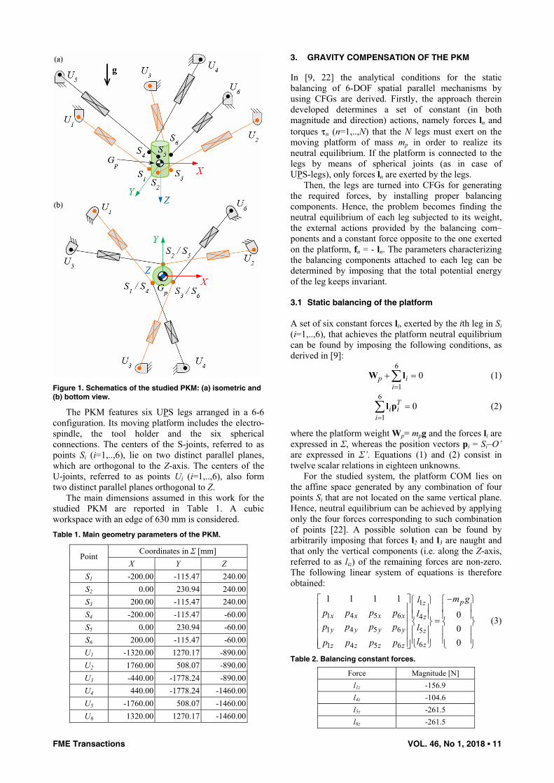
The machine tool architecture considered in this work characterizes a prototypal 5-axis PKM, namely the Mikromat 6X [35]. Schematics of the PKM are represented in Figure 1. A fixed coordinate system, Σ = XYZ, is defined as shown in Figure 1. Its origin, O, coincides with the center of mass (COM) of the moving platform, Gp (lying along the spindle rotational axis), at the PKM reference position. The Z-axis is vertical and directed like the gravity vector, g. A coordinate system attached to the platform, Σ’ = X’Y’Z’, centered in O’ and coincident with Σ at the PKM reference position is also set.
FME Transactions VOL. 46, No 1, 2018 ▪ 11
Figure 1. Schematics of the studied PKM: (a) isometric and (b) bottom view.
The PKM features six UPS legs arranged in a 6-6 configuration. Its moving platform includes the electro-spindle, the tool holder and the six spherical connections. The centers of the S-joints, referred to as points Si (i=1,..,6), lie on two distinct parallel planes, which are orthogonal to the Z-axis. The centers of the U-joints, referred to as points Ui (i=1,..,6), also form two distinct parallel planes orthogonal to Z.
The main dimensions assumed in this work for the studied PKM are reported in Table 1. A cubic workspace with an edge of 630 mm is considered. Table 1. Main geometry parameters of the PKM.
Coordinates in Σ [mm] Point X Y Z
S1 -200.00 -115.47 240.00S2 0.00 230.94 240.00S3 200.00 -115.47 240.00S4 -200.00 -115.47 -60.00S5 0.00 230.94 -60.00S6 200.00 -115.47 -60.00U1 -1320.00 1270.17 -890.00U2 1760.00 508.07 -890.00U3 -440.00 -1778.24 -890.00U4 440.00 -1778.24 -1460.00U5 -1760.00 508.07 -1460.00U6 1320.00 1270.17 -1460.00
3. GRAVITY COMPENSATION OF THE PKM
In [9, 22] the analytical conditions for the static balancing of 6-DOF spatial parallel mechanisms by using CFGs are derived. Firstly, the approach therein developed determines a set of constant (in both magnitude and direction) actions, namely forces ln and torques τn (n=1,..,N) that the N legs must exert on the moving platform of mass mp in order to realize its neutral equilibrium. If the platform is connected to the legs by means of spherical joints (as in case of UPS-legs), only forces ln are exerted by the legs.
Then, the legs are turned into CFGs for generating the required forces, by installing proper balancing components. Hence, the problem becomes finding the neutral equilibrium of each leg subjected to its weight, the external actions provided by the balancing com–ponents and a constant force opposite to the one exerted on the platform, fn = - ln. The parameters characterizing the balancing components attached to each leg can be determined by imposing that the total potential energy of the leg keeps invariant.
3.1 Static balancing of the platform
A set of six constant forces li, exerted by the ith leg in Si (i=1,..,6), that achieves the platform neutral equilibrium can be found by imposing the following conditions, as derived in [9]:
6
10p i
i=+ =∑W l (1)
6
10T
i ii=
=∑ l p (2)
where the platform weight Wp= mpg and the forces li are expressed in Σ, whereas the position vectors pi = Si–O’ are expressed in Σ’. Equations (1) and (2) consist in twelve scalar relations in eighteen unknowns.
For the studied system, the platform COM lies on the affine space generated by any combination of four points Si that are not located on the same vertical plane. Hence, neutral equilibrium can be achieved by applying only the four forces corresponding to such combination of points [22]. A possible solution can be found by arbitrarily imposing that forces l2 and l3 are naught and that only the vertical components (i.e. along the Z-axis, referred to as liz) of the remaining forces are non-zero. The following linear system of equations is therefore obtained:
1
1 4 5 6 4
1 4 5 6 5
61 4 5 6
1 1 1 1
000
pz
x x x x z
y y y y z
zz z z z
m glp p p p lp p p p l
lp p p p
−⎡ ⎤ ⎧ ⎫⎧ ⎫⎢ ⎥ ⎪ ⎪⎪ ⎪
⎪ ⎪ ⎪ ⎪⎢ ⎥ =⎨ ⎬ ⎨ ⎬⎢ ⎥ ⎪ ⎪ ⎪ ⎪⎢ ⎥ ⎪ ⎪ ⎪ ⎪⎢ ⎥ ⎩ ⎭ ⎩ ⎭⎣ ⎦
(3)
Table 2. Balancing constant forces.
Force Magnitude [N] l1z -156.9 l4z -104.6 l5z -261.5 l6z -261.5
12 ▪ VOL. 46, No 1, 2018 FME Transactions
For the mechanism of interest the square matrix in (3) can be always inverted to find a unique solution. By assuming a platform mass mp = 80 [kg], the force values reported in Table 2 are obtained. 3.2 Static balancing of the legs
An effective solution to make a generic UPS-leg exert the required constant force (thus turning the leg into a CFG) has been presented in [28]. The method is here briefly recalled.
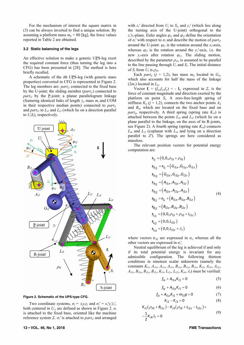
A schematic of the ith UPS-leg (with generic mass properties) converted in CFG is represented in Figure 2. The leg members are: parti2 connected to the fixed base by the U-joint; the sliding member (parti1) connected to parti2 by the P-joint; a planar parallelogram linkage (featuring identical links of length γi, mass mγ and COM in their respective median points) connected to parti1 and parti2 in Li1 and Li2 (which lie on a direction parallel to UiSi), respectively.
Figure 2. Schematic of the UPS-type CFG.
Two coordinate systems, σi = xiyizi and σi' = xi'yi'zi', both centered in Ui, are defined as shown in Figure 2. σi is attached to the fixed base, oriented like the machine reference system Σ. σi' is attached to parti2 and arranged
with zi' directed from Ui to Si, and yi' (which lies along the turning axis of the U-joint) orthogonal to the zi'xi-plane. Euler angles ϕi1 and ϕi2 define the orientation of σi' with respect to σi and describe the motion of parti2 around the U-joint: ϕi1 is the rotation around the xi-axis, whereas ϕi2 is the rotation around the yi'-axis, i.e. the new yi-axis after rotation ϕi1. The sliding motion, described by the parameter ρi3, is assumed to be parallel to the line passing through Ui and Si. The initial distance of Si from Ui is ρi0.
Each partij (j = 1,2), has mass mij located in Gij, which also accounts for half the mass of the linkage (2mγ) located in Lij.
Vector fi = (fix,fiy,fiz) = - li, expressed in Σ, is the force of constant magnitude and direction exerted by the platform on point Si. A zero-free-length spring of stiffness Kij (j = 1,2), connects the two anchor points Aij and Bij, which are located on the fixed base and on partij, respectively. A third spring (spring rate Ki3) is attached between the points Li4 and Li5 (which lie on a plane parallel to the linkage, on the axes of its R-joints, see Figure 2). A fourth spring (spring rate Ki4) connects Li4 and Li3 (coplanar with Li4 and lying on a direction parallel to Z'). The springs are here considered as massless.
The relevant position vectors for potential energy computation are:
( )( )
( )( )( )
( )( )( )( )( )
ρ ρ
ρ ρ
λ
= +
= +
=
=
=
= +
=
= + +
=
= +
3 0
1 1 11
2 2 22
1 1 11
2 2 22
1 1 11
2 2 22
3 0 11
22
23
0,0,
, ,
, ,
, ,
, ,
, ,
, ,
0,0,
0,0,
0,0,
S i ii
G S i x i y i zi i
G i x i y i zi
A i x i y i zi
A i x i y i zi
B S i x i y i zi i
B i x i y i zi
L i i i zi
L i zi
L i z ii
G G G
G G G
A A A
A A A
B B B
B B B
L
L
L
r
r r
r
r
r
r r
r
r
r
r
(4)
where vectors rAij are expressed in σi, whereas all the other vectors are expressed in σi'.
Neutral equilibrium of the leg is achieved if and only if its total potential energy is invariant for any admissible configuration. The following thirteen conditions in nineteen scalar unknowns (namely the constants Ki1, Ai1x, Ai1y, Ai1z, Bi1x, Bi1y, Bi1z, Ki2, Ai2x, Ai2y, Ai2z, Bi2x, Bi2y, Bi2z, Ki3, Li1z, Li2z, Ki4, λi) must be verified:
+ =1 1 0ix i x if A K (5)
+ =1 1 0iy i y if A K (6)
+ + =1 1 1 0iz i z i if A K m g (7) − =1 3 0i iK K (8)
( ) ( )ρ ρ
λ
+ − + − +
− =
1 0 1 3 0 1 2
41
02
i i i z i i i z i z
i i
K B K L L
K (9)
FME Transactions VOL. 46, No 1, 2018 ▪ 13
+ =1 1 1 2 2 2 0i x i x i i x i x iA B K A B K (10)
( )ρρ
+ + +
+ =1 0 1 1 2 2 2
0 0i x i i z i i x i z i
ix i
A B K A B K
f (11)
+ =1 1 1 2 2 2 0i y i x i i y i x iA B K A B K (12)
+ =1 1 1 2 2 2 0i y i y i i y i y iA B K A B K (13)
( )ρ
ρ
+ + +
+ =1 0 1 1 2 2 2
0 0i y i i z i i y i z i
iy i
A B K A B K
f (14)
( )
+ +
+ + =1 1 1 2 2 2
1 1 2 2 0i z i x i i z i x i
i i x i i x
A B K A B K
g m G m G (15)
( )+ +
+ + =
1 1 1 2 2 2
1 1 2 2 0
i z i y i i z i y i
i i y i i y
A B K A B K
g m G m G (16)
( )
( )ρ ρ
ρ
+ + + +
⎡ ⎤+ + + =⎣ ⎦
1 0 1 1 2 2 2 0
1 0 1 2 2 0
i z i i z i i z i z i iz i
i i i z i i z
A B K A B K f
g m G m G (17)
For the PKM under investigation, some simpli–fications can be made. In particular, points Gi1 can be considered to lie on the lines passing through Ui and Si; points Gi2 can be considered to be coincident with points Ui. Moreover, only the force components fiz are present, as computed in Section 3.1. Consequently, the conditions (5-17) change as follows:
=1 1 0i x iA K (18) =1 1 0i y iA K (19)
+ + =1 1 1 0iz i z i if A K m g (20) − =1 3 0i iK K (21)
( ) ( )ρ ρ
λ
+ − + − +
− =
1 0 1 3 0 1 2
41
02
i i i z i i i z i z
i i
K B K L L
K (22)
+ =1 1 1 2 2 2 0i x i x i i x i x iA B K A B K (23)
( )ρ + + =1 0 1 1 2 2 2 0i x i i z i i x i z iA B K A B K (24)
+ =1 1 1 2 2 2 0i y i x i i y i x iA B K A B K (25)
+ =1 1 1 2 2 2 0i y i y i i y i y iA B K A B K (26)
( )ρ + + =1 0 1 1 2 2 2 0i y i i z i i y i z iA B K A B K (27)
+ =1 1 1 2 2 2 0i z i x i i z i x iA B K A B K (28) + =1 1 1 2 2 2 0i z i y i i z i y iA B K A B K (29)
( )
( )ρ
ρ ρ
+ + +
+ + + =1 0 1 1 2 2 2
0 1 0 1 0i z i i z i i z i z i
iz i i i i z
A B K A B K
f m g G (30)
A solution that satisfies (18-30) can be found by arbitrarily choosing some parameters and by imposing some algebraic constraints. In particular, by imposing the value of Ki1 the following parameters can be determined from (18-21):
= =1 1 0i x i yA A ;+
= − 11
1
iz ii z
i
f m gA
K; =3 1i iK K (31)
Then, by imposing Ki2, Ai2x, Ai2y and Ai2z, the following linear system of equations is obtained from (23-30):
⎡ ⎤ ⎧ ⎫⎢ ⎥ ⎪ ⎪⎧ ⎫⎢ ⎥ ⎪ ⎪⎪ ⎪⎢ ⎥ ⎪ ⎪⎪ ⎪⎢ ⎥ ⎪ ⎪⎪ ⎪⎪ ⎪ ⎪ ⎪⎢ ⎥ =⎨ ⎬ ⎨ ⎬⎢ ⎥⎪ ⎪ ⎪ ⎪⎢ ⎥⎪ ⎪ ⎪ ⎪⎢ ⎥⎪ ⎪ ⎪ ⎪⎢ ⎥⎪ ⎪ ⎪ ⎪⎩ ⎭⎢ ⎥ ⎪ ⎪⎢ ⎥⎣ ⎦ ⎩ ⎭
1
2
1
2
1
2
0 0 0 0 0 0
0 0 0 0 0 0
0 0 0 0 0 0
0 0 0 0 0 0
0 0 0 0 0 0
0 0 0 0 0
0 0 0 0 0
0 0 0 0
ix
ix i x
iy i x
iy i y
iy i y
iz iz i z
iz iz i z
iz iz iz
E
E B
E B
E B
E B
C E B
C E B
C E Q
(32)
where
= = =
= = −1 1 2 2 2 2
2 2 1 1
; ; ;
;iz i z i ix i x i iy i y i
iz i z i iz i i z
C A K E A K E A K
E A K Q m gG (33)
A solution can be found provided that the following condition is satisfied:
=2 2i x i yA A (34)
In particular, in case the following condition is imposed:
= =2 2 0i x i yA A (35)
Also, the parameters Bi2x, Bi2y and Bi2z can be set arbitrarily, and the remaining unknowns are given by:
−= − = − = 2
1 2 1 2 1; ;iz iz iz iz i zi x i x i y i y i z
iz iz iz
E E Q E BB B B B B
C C C (36)
Otherwise, if the following condition holds
= ≠2 2 0i x i yA A (37)
it must be necessarily
= = =2 2 2 0i x i y i zB B B (38)
i.e. the spring with stiffness Ki2 cannot be installed, and the following solution is found:
= = =1 1 10; izi x i y i z
iz
QB B B
C (39)
This implies that the spring with stiffness Ki2 is not necessarily required. However, without such spring, it may be difficult to implement in practice the spring with stiffness Ki1, since its anchor point on parti1 would be univocally determined by the values of fiz, mi1 and Gi1z.
Finally, by choosing Ki4, Li1z and Li2z, the last parameter can be obtained from (22)
λ− +
= 1 1 21
42 i z i z i z
i ii
B L LK
K (40)
It is worth noting that the fourth spring would not be required in case (Bi1z–Li1z+Li2z) = 0. Nonetheless, adding a spring permits a larger flexibility in the design of the leg while not significantly increasing its complexity.
Table 3 shows the main numerical values adopted for the simulations reported in Section 3.3, computed by considering mi1 = 25 [kg] and Gi1z = - 850 [mm].
14 ▪ VOL. 46, No 1, 2018 FME Transactions
Table 3. Parameters adopted for the numerical model.
leg # (i)
Parameter 1 2, 3 4 5, 6 Ki1 [kN/m] 2.000 2.000 2.000 2.000 Ki2 [kN/m] 2.000 2.000 2.000 2.000 Ki3 [kN/m] 2.000 2.000 2.000 2.000 Ki4 [kN/m] 8.000 8.000 8.000 8.000
Ai1z [m] -0.201 -0.123 -0.175 -0.253 Ai2z [m] -0.200 -0.200 -0.200 -0.200 Bi1x [m] -0.099 -0.082 -0.114 -0.079 Bi1y [m] -0.099 -0.082 -0.114 -0.079 Bi1x [m] -1.314 -1.339 -1.511 -1.043 Bi2x [m] 0.100 0.050 0.100 0.100 Bi2y [m] 0.100 0.050 0.100 0.100 Bi2z [m] 0.800 0.300 0.800 0.800 Li1z [m] -1.500 -1.500 -1.500 -1.500 Li2z [m] 0.200 0.200 0.200 0.200 λi [m] 0.425 0.425 0.425 0.425
3.3 Numerical model and simulations
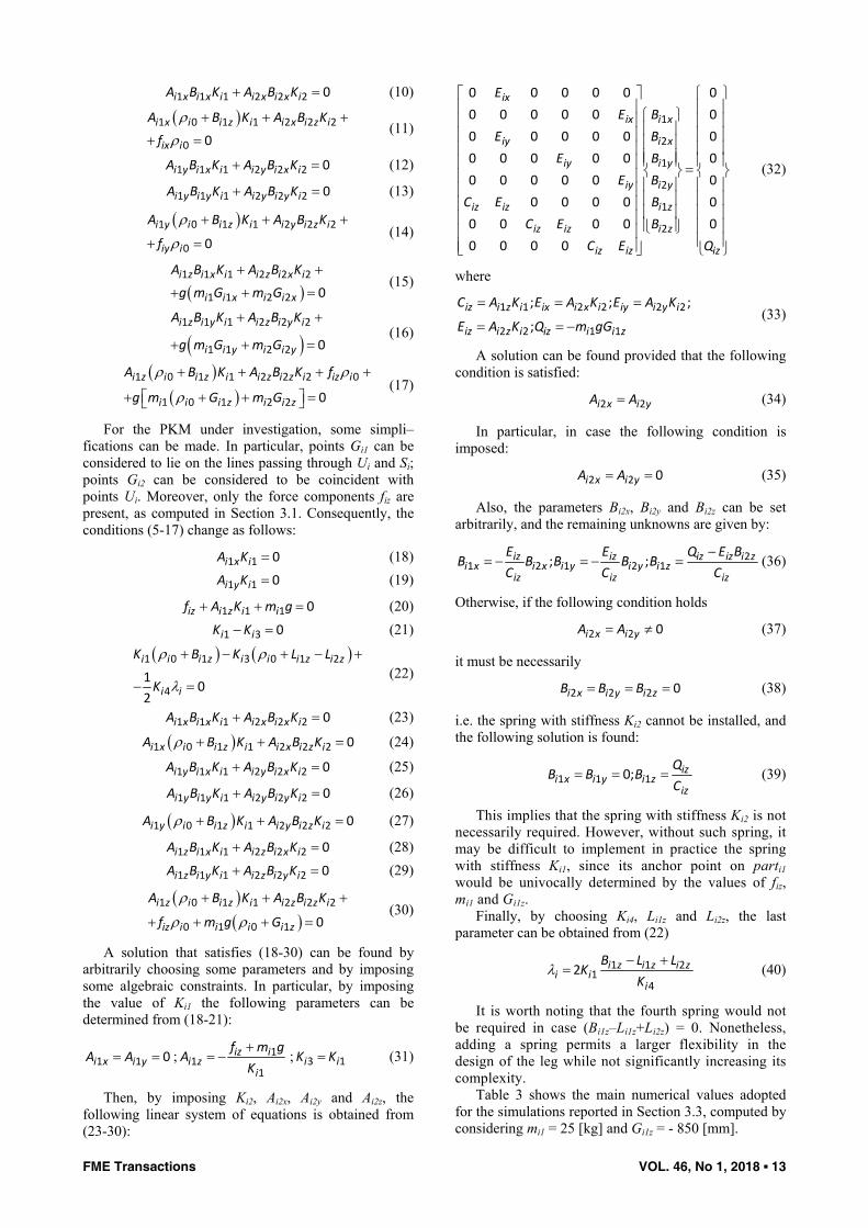
Two multibody models are implemented, one for the unbalanced PKM, one for its statically balanced variant. The motor forces required for a quasi-static trajectory through the workspace are evaluated. In particular, a total amount of 27 points of the cubic workspace are taken into account, namely its center, its vertices, and the median points of its edges (Figure 3).
Figure 3. Simulated quasi-static trajectory.
Figure 4. Motor forces of the unbalanced PKM.
Figure 4 shows the required motor forces of the unbalanced PKM for the tested trajectory, with an imposed rotation of the moving platform of +15° around the Y-axis. Figure 5 reports the motor forces of the compensated machine tool under the same conditions.
FME Transactions VOL. 46, No 1, 2018 ▪ 15
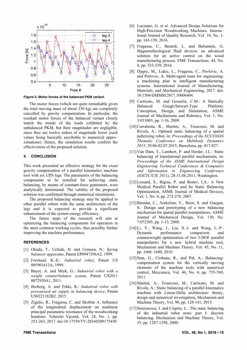
Figure 5. Motor forces of the balanced PKM variant.
The motor forces (which are quite remarkable given the total moving mass of about 230 kg) are completely cancelled by gravity compensation. In particular, the residual motor forces of the balanced variant closely match the trends of the loads exhibited by the unbalanced PKM, but their magnitudes are negligible, since they are twelve orders of magnitude lower (such values being basically ascribable to numerical appro–ximations). Hence, the simulation results confirm the effectiveness of the proposed solution.
4. CONCLUSION
This work presented an effective strategy for the exact gravity compensation of a parallel kinematics machine tool with six UPS legs. The parameters of the balancing components to be installed for achieving static balancing, by means of constant-force generators, were analytically determined. The validity of the proposed solution was confirmed through numerical simulations.
The proposed balancing strategy may be applied to other parallel robots with the same architecture of the legs and it is expected to provide a significant enhancement of the system energy efficiency.
The future steps of the research will aim at optimizing the balancing components for operation in the most common working cycles, thus possibly further improving the machine performance.
REFERENCES
[1] Okada, T., Uchida, H. and Uemura, N.: Spring balancer apparatus, Patent EP0947296A2, 1999.
[2] Forslund, K.-E.: Industrial robot, Patent US 005901613A, 1999.
[3] Bayer, A. and Merk, G.: Industrial robot with a weight counterbalance system, Patent US2011 0072930A1, 2011.
[4] Broberg, A. and Erkki, R.: Industrial robot with pressurized air supply in balancing device, Patent US9221182B2, 2015.
[5] Zigulic, R., Fragassa, C. and Skoblar A. Influence of the longitudinal displacement on nonlinear principal parametric resonance of the woodworking bandsaw. Tehnicki Vjesnik. Vol. 24, No. 1, pp. 253-263, 2017. doi:10.17559/TV-20160209175450
[6] Lucisano, G. et al. Advanced Design Solutions for High-Precision Woodworking Machines. Interna–tional Journal of Quality Research, Vol. 10, No. 1: pp. 143-158, 2016.
[7] Fragassa, C., Berardi, L. and Balsamini, G. Magnetorheological fluid devices: an advanced solution for an active control on the wood manufacturing process. FME Transactions. 44, No. 4, pp. 333-339, 2016.
[8] Djapic, M., Lukic, L., Fragassa, C., Pavlovic, A. and Petrovic, A. Multi-agent team for engineering: a machining plan in intelligent manufacturing systems. International Journal of Manufacturing, Materials, and Mechanical Engineering, 2017. doi: 10.1504/IJMMM.2017.10006404.
[9] Carricato, M. and Gosselin, C.M.: A Statically Balanced Gough/Stewart-Type Platform: Conception, Design, and Simulation, ASME Journal of Mechanisms and Robotics, Vol. 1, No. 3:031005, pp. 1-16, 2009.
[10] Carrabotta, R., Martini, A., Troncossi, M. and Rivola, A.: Optimal static balancing of a spatial palletizing robot, in: Proceedings of the ECCOMAS Thematic Conference on Multibody Dynamics 2015, 29.06-02.07.2015, Barcelona, pp. 817-827.
[11] Van Dam, T., Lambert, P. and Herder, J.L.: Static balancing of translational parallel mechanisms, in: Proceedings of the ASME International Design Engineering Technical Conferences & Computers and Information in Engineering Conference (IDETC/CIE 2011), 28-31.08.2011, Washington.
[12] Lessard, S., Bigras, P. and Bonev, I.A.: A New Medical Parallel Robot and Its Static Balancing Optimization, ASME Journal of Medical Devices, Vol. 1, No. 4, pp. 272-278, 2007.
[13] Baradat, C., Arakelian, V., Briot, S. and Guegan, S.: Design and prototyping of a new balancing mechanism for spatial parallel manipulators, ASME Journal of Mechanical Design, Vol. 130, No. 7:072305, pp. 1-13, 2008.
[14] Li, Y., Wang, J., Liu, X.-J. and Wang, L.-P.: Dynamic performance comparison and counterweight optimization of two 3-DOF parallel manipulators for a new hybrid machine tool, Mechanism and Machine Theory, Vol. 45, No. 11, pp. 1668–1680, 2010.
[15] Stan, G., Ciobanu, R., and Pal, A.: Balancing-compensation system for the vertically moving elements of the machine tools with numerical control, Meccanica, Vol. 46, No. 4, pp. 755-769, 2011.
[16] Martini, A., Troncossi, M., Carricato, M. and Rivola, A.: Static balancing of a parallel kinematics machine with Linear-Delta architecture: theory, design and numerical investigation, Mechanism and Machine Theory, Vol. 90, pp. 128-141, 2015.
[17] Simionescu, I. and Ciupitu, L.: The static balancing of the industrial robot arms: part I: discrete balancing, Mechanism and Machine Theory, Vol. 35, pp. 1287-1298, 2000.
16 ▪ VOL. 46, No 1, 2018 FME Transactions
[18] Simionescu, I. and Ciupitu, L.: The static balancing of the industrial robot arms: part II: Continuous balancing, Mechanism and Machine Theory, Vol. 35, pp. 1299-1311, 2000.
[19] Agrawal, S.K. and Fattah, A.: Gravity-balancing of spatial robotic manipulators, Mechanism and Machine Theory, Vol. 39, No. 12, pp. 1331-1344, 2004.
[20] Lee, Y.-Y. and Chen, D.-Z.: Determination of spring installation configuration on statically balan–ced planar articulated manipulators, Mechanism and Machine Theory, Vol. 74, pp. 319-336, 2014.
[21] Gosselin, C.M. and Wang, J.: Static balancing of spatial six degree-of-freedom parallel mechanisms with revolute actuators: Journal of Robotic Systems, Vol. 17, No. 3, pp. 159-170, 2000.
[22] Ebert-Uphoff, I., Gosselin, C.M. and Laliberté, T.: Static balancing of spatial parallel platform mechanisms–revisited, ASME Journal of Mechanical Design, Vol. 122, No. 1, pp. 43-51, 2000.
[23] Russo, A., Sinatra, R. and Xi, F.: Static balancing of parallel robots, Mechanism and Machine Theory, Vol. 40, No. 2, pp. 191-202, 2005.
[24] Martini, A., Troncossi, M., Carricato, M. and Rivola, A.: Elastodynamic behaviour of balanced closed-loop mechanisms: numerical analysis of a four-bar linkage, Meccanica, Vol. 49, No. 3, pp. 601-614, 2014.
[25] Simionescu, I. et al.: Static balancing with elastic systems of DELTA parallel robots, Mechanism and Machine Theory, Vol. 87, pp. 150-162, 2015.
[26] Stevanović, I., Rašuo, B.: Development of a Miniature Robot Based on Experience Inspired by Nature, FME Transactions, Volume 45 No 1, 2017, pp. 189-197.
[27] Nathan, R.H.: A constant force generation mecha–nism, ASME Journal of Mechanisms, Transmis–sions, and Automation in Design, Vol. 107, No. 4, pp. 508-512, 1985.
[28] Martini, A.: Development of an elastically compensated UPS-type constant-force generator for the static balancing of spatial parallel mechanisms, in: Proceedings of the XXIII AIMETA Conference, 04-07.09.2017, Salerno.
[29] Lowen, G.G., Tepper, F.R. and Berkof, R.S.: The quantitative influence of complete force balancing on the forces and moments of certain families of four-bar linkages, Mechanism and Machine Theory, Vol. 9, No. 3-4, pp. 299-323, 1974.
[30] Raghu, E. and Balasubramonian, A.: Experimental study on the elastodynamic behavior of the
unbalanced and the counterweighted four bar mechanisms, ASME Journal of Mechanical Design, Vol. 112, No. 3, pp. 271-277, 1990.
[31] Walker, M.J. and Haines, R.S.: An experimental study of the effects of counterweights on a six-bar chain, Mechanism and Machine Theory, Vol. 17, No. 6, pp. 355-360, 1982.
[32] Martini, A., Troncossi, M. and Rivola, A.: Elastodynamic effects of mass-balancing: experimental investigation of a four-bar linkage, Advances in Mechanical Engineering, pp. 1-10, 2013.
[33] Radovanović, NV., Zorić, ND., Trišović, NR., Tomović AM.: Free Planar Vibration of Structures Composed of Rigid Bodies and Elastic Beam Segments, FME Transactions, Vol. 45, No 1, pp. 97-102, 2017
[34] Pavlovic, A., Fragassa, C., Ubertini, F. and Martini, A.: Modal analysis and stiffness optimization: the case of a tool machine for ceramic tile surface finishing, Journal of the Serbian Society for Computational Mechanics, Vol. 10, No. 2, pp. 30-44, 2016.
[35] Martini, A., Troncossi, M., Vincenzi N.: Structural and elastodynamic analysis of rotary transfer machines by means of a Finite Element model, Journal of the Serbian Society for Computational Mechanics, Vol. 11, 2017.
[36] Wieland, F.: Hexapodal Machining Center, Patent US6241437B1, 2001.
ГРАВИТАЦИЈСКА КОМПЕНЗАЦИЈА 6-УПС МАШИНЕ АЛАТЕ СА ПАРАЛЕЛНОМ
КИНЕМАТИКОМ ПОМОЋУ ЕЛАСТИЧНО УРАВНОТЕЖЕНИХ КОНСТАНТНИХ СИЛА
ГЕНЕРАТОРА
А. Мартини Компензација гравитације је одржива стратегија за побољшање перформанси манипулатора, нарочито у погледу потрошње енергије. Овај рад проучава статичко балансирање прототипне 5-осовинске машине алатке са паралелном кинематиком УПС ослонцима. Прецизна компензација гравитације се постиже пребацивањем ослонаца у генераторе са константном снагом, путем еластиних опруга. Нумерички вишетелесни модел се имплементира и симулира у комерцијалном софтверском окружењу (MSC Adams™) како би се проценила ефикасност предложене стратегије балансирања.
![KINEMATICS - new.excellencia.co.innew.excellencia.co.in/college/web/pdf/Kinematics-merged.pdf · KINEMATICS KINEMATICS WORKSHEET 1 1) Displacement is a _____ [ ] 1) Vector quantity](https://img.pdfslide.net/doc/110x75/5f356d4687229051801abace/kinematics-new-kinematics-kinematics-worksheet-1-1-displacement-is-a-.jpg)