Embed Size (px)
Citation preview

1 I
ALP 4.0 - MOTARD M4
Grazie per la fi ducia accordata e buon divertimento. Con questo libretto abbiamo voluto darLe le informazioni necessarie per un corretto uso e una buona manutenzione della Sua moto.
I dati e le caratteristiche indicate sul presente manuale non impegnano la BETAMOTOR S.p.A che si riserva il diritto di apportare modifi che e miglio-ramenti ai propri modelli in qualsiasi momento e senza preavviso.
2I
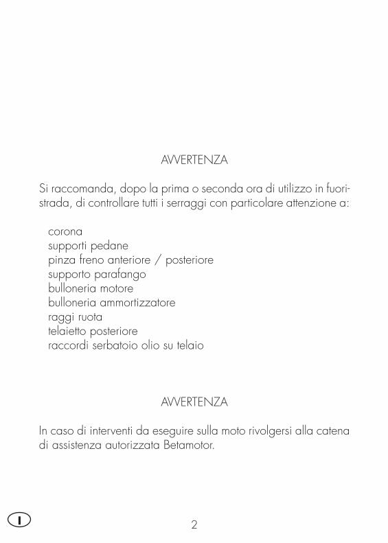
AVVERTENZA
Si raccomanda, dopo la prima o seconda ora di utilizzo in fuori-strada, di controllare tutti i serraggi con particolare attenzione a:
• corona• supporti pedane• pinza freno anteriore / posteriore• supporto parafango• bulloneria motore• bulloneria ammortizzatore• raggi ruota• telaietto posteriore• raccordi serbatoio olio su telaio
AVVERTENZA
In caso di interventi da eseguire sulla moto rivolgersi alla catena di assistenza autorizzata Betamotor.
IND
ICE
3 I
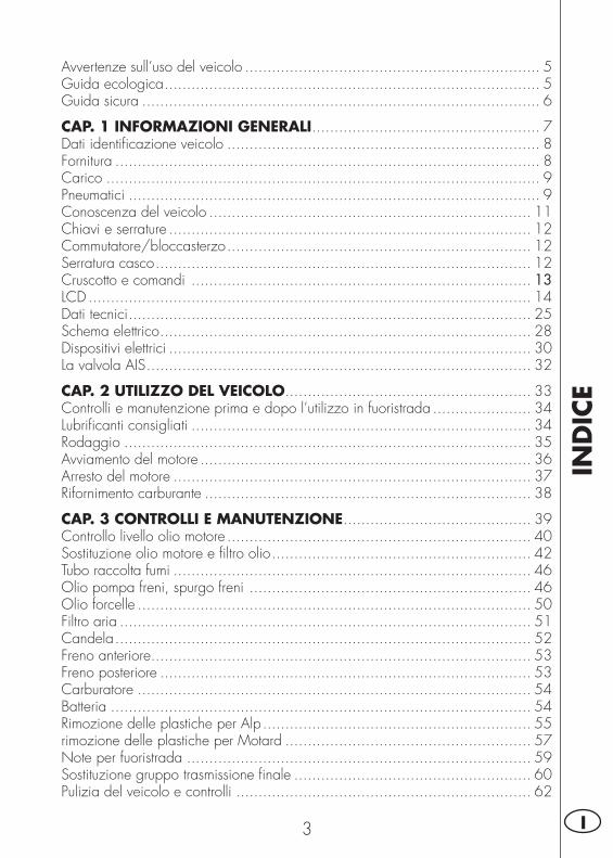
Avvertenze sull’uso del veicolo .................................................................. 5Guida ecologica .................................................................................... 5Guida sicura ......................................................................................... 6
CAP. 1 INFORMAZIONI GENERALI ................................................... 7Dati identifi cazione veicolo ...................................................................... 8Fornitura ............................................................................................... 8Carico ................................................................................................. 9Pneumatici ............................................................................................ 9Conoscenza del veicolo ........................................................................ 11Chiavi e serrature ................................................................................. 12Commutatore/bloccasterzo .................................................................... 12Serratura casco .................................................................................... 12Cruscotto e comandi ............................................................................ 13LCD ................................................................................................... 14Dati tecnici .......................................................................................... 25Schema elettrico ................................................................................... 28Dispositivi elettrici ................................................................................. 30La valvola AIS ...................................................................................... 32
CAP. 2 UTILIZZO DEL VEICOLO ....................................................... 33Controlli e manutenzione prima e dopo l’utilizzo in fuoristrada ...................... 34Lubrifi canti consigliati ............................................................................ 34Rodaggio ........................................................................................... 35Avviamento del motore .......................................................................... 36Arresto del motore ................................................................................ 37Rifornimento carburante ......................................................................... 38
CAP. 3 CONTROLLI E MANUTENZIONE .......................................... 39Controllo livello olio motore .................................................................... 40Sostituzione olio motore e fi ltro olio .......................................................... 42Tubo raccolta fumi ................................................................................ 46Olio pompa freni, spurgo freni ............................................................... 46Olio forcelle ........................................................................................ 50Filtro aria ............................................................................................ 51Candela ............................................................................................. 52Freno anteriore ..................................................................................... 53Freno posteriore ................................................................................... 53Carburatore ........................................................................................ 54Batteria .............................................................................................. 54Rimozione delle plastiche per Alp ............................................................ 55rimozione delle plastiche per Motard ....................................................... 57Note per fuoristrada ............................................................................. 59Sostituzione gruppo trasmissione fi nale ..................................................... 60Pulizia del veicolo e controlli .................................................................. 62
IND
ICE
4I
Controlli dopo la pulizia ........................................................................ 62Manutenzione programmata ................................................................... 63Lunga inattività del veicolo ..................................................................... 64Dopo un lungo periodo di inattività .......................................................... 64
CAP. 4 REGOLAZIONI ..................................................................... 65Regolazione freni ................................................................................. 66Regolazione frizione ............................................................................. 66Regolazione ammortizzatore posteriore .................................................... 67Regolazione minimo ............................................................................ 67Regolazione gioco gas ......................................................................... 67Controllo e regolazione gioco sterzo........................................................ 68Tensionamento catena ........................................................................... 69Fascio luminoso ................................................................................... 70
CAP. 5 SOSTITUZIONI ..................................................................... 71Sostituzione pastiglie freno anteriore ....................................................... 72Sostituzione pastiglie freno posteriore ....................................................... 74Sostituzione lampada faro ALP ............................................................... 75Sostituzione lampada faro MOTARD M4 .................................................. 76Sostituzione indicatori di direzione e fanalino posteriore .............................. 77Sostituzione luce targa........................................................................... 78Caratteristiche lampade ......................................................................... 78
CAP. 6 COSA FARE IN CASO DI EMERGENZA ................................ 79
INDICE ALFABETICO ........................................................................ 81
5 I
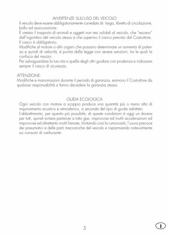
AVVERTENZE SULL’USO DEL VEICOLO• Il veicolo deve essere obbligatoriamente corredato di: targa, libretto di circolazione, bollo ed assicurazione.
• È vietato il trasporto di animali e oggetti non resi solidali al veicolo, che “escano” dall’ingombro del veicolo stesso e che superino il carico previsto dal Costruttore.
• Il casco è obbligatorio.• Modifi che al motore o altri organi che possano determinare un aumento di poten-za e quindi di velocità, è punita dalla legge con severe sanzioni, tra le quali la confi sca del mezzo.
• Per salvaguardare la tua vita e quella degli altri guidare con prudenza e indossare sempre il casco di sicurezza.
ATTENZIONE:Modifi che e manomissioni durante il periodo di garanzia, esimono il Costruttore da qualsiasi responsabilità e fanno decadere la garanzia stessa.
GUIDA ECOLOGICA• Ogni veicolo con motore a scoppio produce una quantità più o meno alta di inquinamento acustico e atmosferico, a seconda del tipo di guida adottato.
• L’abbattimento, per quanto più possibile, di queste condizioni è oggi un dovere per tutti, quindi evitare partenze a tutto gas, improvvise ed inutili accelerazioni ed improvvise ed altrettanto inutili frenate, limitando così la rumorosità, l’usura precoce dei pneumatici e delle parti meccaniche del veicolo e risparmiando notevolmente sui consumi di carburante.
6I
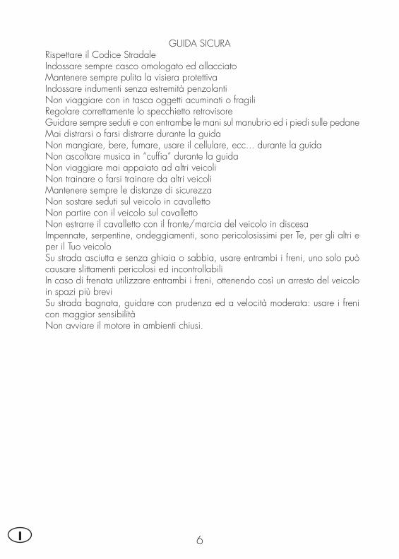
GUIDA SICURA• Rispettare il Codice Stradale• Indossare sempre casco omologato ed allacciato• Mantenere sempre pulita la visiera protettiva• Indossare indumenti senza estremità penzolanti• Non viaggiare con in tasca oggetti acuminati o fragili• Regolare correttamente lo specchietto retrovisore• Guidare sempre seduti e con entrambe le mani sul manubrio ed i piedi sulle pedane• Mai distrarsi o farsi distrarre durante la guida• Non mangiare, bere, fumare, usare il cellulare, ecc... durante la guida• Non ascoltare musica in “cuffi a” durante la guida• Non viaggiare mai appaiato ad altri veicoli• Non trainare o farsi trainare da altri veicoli• Mantenere sempre le distanze di sicurezza• Non sostare seduti sul veicolo in cavalletto• Non partire con il veicolo sul cavalletto• Non estrarre il cavalletto con il fronte/marcia del veicolo in discesa• Impennate, serpentine, ondeggiamenti, sono pericolosissimi per Te, per gli altri e per il Tuo veicolo
• Su strada asciutta e senza ghiaia o sabbia, usare entrambi i freni, uno solo può causare slittamenti pericolosi ed incontrollabili
• In caso di frenata utilizzare entrambi i freni, ottenendo così un arresto del veicolo in spazi più brevi
• Su strada bagnata, guidare con prudenza ed a velocità moderata: usare i freni con maggior sensibilità
• Non avviare il motore in ambienti chiusi.
1
INFO
RM
AZ
ION
I G
ENER
ALI
7 I
INDICE ARGOMENTI
CAP. 1 INFORMAZIONI GENERALI
Dati identifi cazione veicolo
Fornitura
Carico
Pneumatici
Conoscenza del veicolo
Chiavi e serrature
Commutatore/bloccasterzo
Serratura casco
Cruscotto e comandi
LCD
Dati tecnici
Schema elettrico
Dispositivi elettrici
La valvola AIS
1IN
FORM
AZ
ION
I G
ENER
ALI
8I
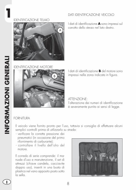
DATI IDENTIFICAZIONE VEICOLO
I dati di identifi cazione A sono impressi sul canotto dello sterzo nel lato destro.
IDENTIFICAZIONE TELAIO
I dati di identifi cazione B del motore sono impressi nella zona indicata in fi gura.
ATTENZIONE:l’alterazione dei numeri di identifi cazione è severamente punita ai sensi di legge.
IDENTIFICAZIONE MOTORE
FORNITURA
• Il veicolo viene fornito pronto per l’uso, tuttavia si consiglia di effettuare alcuni semplici controlli prima di utilizzarlo su strada:- verifi care la corretta pressione dei pneumatici (in occasione del primo rifornimento di carburante);
- controllare il livello dell’olio del motore.
• Il corredo di serie comprende: il ma-nuale d’uso e manutenzione, il set di attrezzi (chiave candela, cacciavite doppio uso), inseriti in una busta di plastica nel vano apposito posto sotto la sella.
A
B
1
INFO
RM
AZ
ION
I G
ENER
ALI
9 I
CARICO
• Carico massimo (conducente + passeggero + carico): 340 Kg.• Non trasportare assolutamente oggetti voluminosi o troppo pesanti, che potrebbero pregiudicare la stabilità del veicolo.
• Non trasportare oggetti che sporgano dal veicolo o che coprano i dispositivi d’illuminazione e di segnalazione.
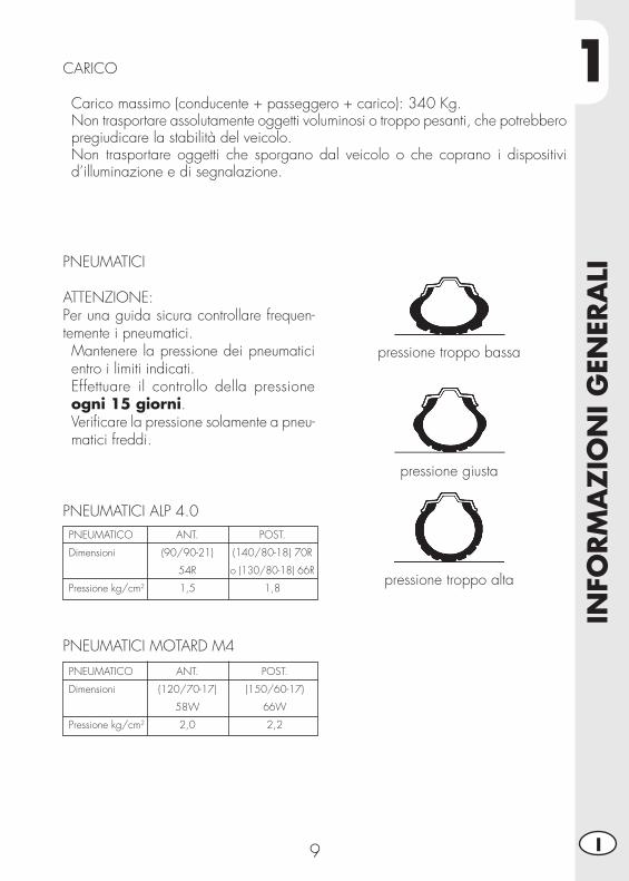
PNEUMATICI
ATTENZIONE: Per una guida sicura controllare frequen-temente i pneumatici.• Mantenere la pressione dei pneumatici entro i limiti indicati.
• Effettuare il controllo della pressione ogni 15 giorni.
• Verifi care la pressione solamente a pneu-matici freddi.
pressione troppo bassa
pressione giusta
pressione troppo alta
PNEUMATICI ALP 4.0PNEUMATICO
Dimensioni
Pressione kg/cm2
POST.
(140/80-18) 70R
o (130/80-18) 66R
1,8
ANT.
(90/90-21)
54R
1,5
PNEUMATICI MOTARD M4
PNEUMATICO
Dimensioni
Pressione kg/cm2
POST.
(150/60-17)
66W
2,2
ANT.
(120/70-17)
58W
2,0
1IN
FORM
AZ
ION
I G
ENER
ALI
10I
Nota: Lo spessore minimo del battistrada dei pneumatici (TUBE TYPE) non deve mai essere inferiore ai 2 mm. La mancata adempienza a questa norma è punita ai sensi di legge.
• Controllare prima di ogni viaggio che i pneumatici non presentino tagli, screpola-ture, abrasioni, rigonfi amenti, ecc... In questi casi far esaminare il pneumatico da un esperto in quanto potrebbero verifi carsi condizioni estremamente pericolose.
• In caso di foratura arrestare subito il veicolo; proseguire la marcia, oltre ad essere rischioso, può provocare irrimediabili danni al pneumatico ed al cerchio ruota.
1
INFO
RM
AZ
ION
I G
ENER
ALI
11 I
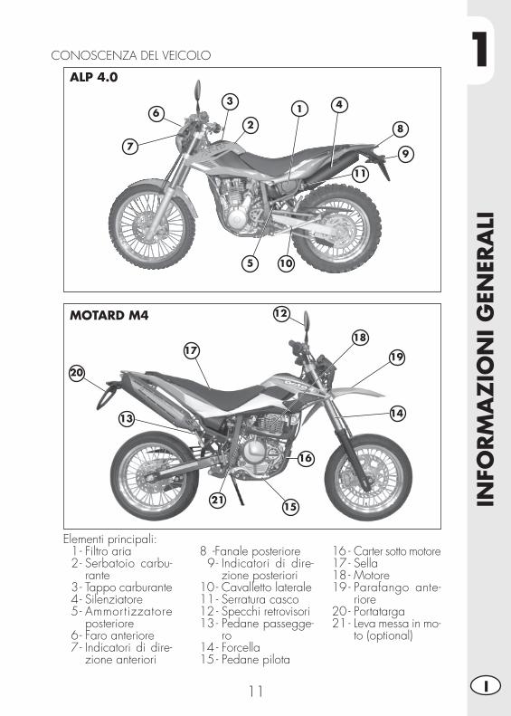
CONOSCENZA DEL VEICOLO
Elementi principali: 1 - Filtro aria 2 - Serbatoio carbu-
rante 3 - Tappo carburante 4 - Silenziatore 5 - Ammortizzatore
po ste riore 6 - Faro anteriore 7 - Indicatori di dire-
zione anteriori
8 - Fanale posteriore 9 - Indicatori di dire-
zione posteriori10 - Cavalletto laterale11 - Serratura casco12 - Specchi retrovisori13 - Pedane passegge-
ro14 - Forcella15 - Pedane pilota
16 - Carter sotto motore17 - Sella18 - Motore19 - Parafango ante-
riore20 - Portatarga21 - Leva messa in mo-
to (optional)
20
17
12
18
19
14
16
21
13
15
7
10
6
5
3
2
1
8
9
4
11
ALP 4.0
MOTARD M4
1IN
FORM
AZ
ION
I G
ENER
ALI
12I
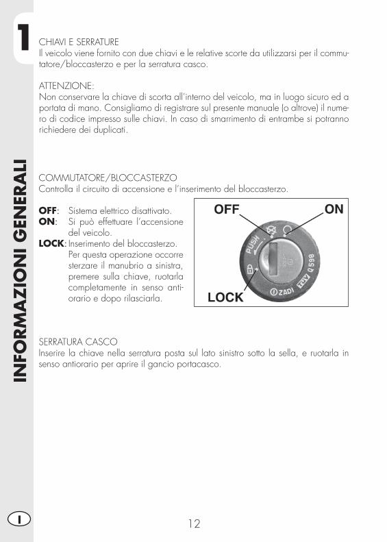
CHIAVI E SERRATUREIl veicolo viene fornito con due chiavi e le relative scorte da utilizzarsi per il commu-tatore/bloccasterzo e per la serratura casco.
ATTENZIONE:Non conservare la chiave di scorta all’interno del veicolo, ma in luogo sicuro ed a portata di mano. Consigliamo di registrare sul presente manuale (o altrove) il nume-ro di codice impresso sulle chiavi. In caso di smarrimento di entrambe si potranno richiedere dei duplicati.
COMMUTATORE/BLOCCASTERZOControlla il circuito di accensione e l’inserimento del bloccasterzo.
OFF: Sistema elettrico disattivato.ON: Si può effettuare l’accensione
del veicolo.LOCK: Inserimento del bloccasterzo. Per questa operazione occorre
sterzare il manubrio a sinistra, premere sulla chiave, ruotarla completamente in senso anti-orario e dopo rilasciarla.
SERRATURA CASCOInserire la chiave nella serratura posta sul lato sinistro sotto la sella, e ruotarla in senso antiorario per aprire il gancio portacasco.

1
INFO
RM
AZ
ION
I G
ENER
ALI
13 I
1 - LCD 2 - Commutatore a chiave 3 - Spia folle 4 - Spia indicatori di direzione 5 - Spia abbaglianti 6 - Spia cavalletto 7 - Leva frizione 8 - Leva freno anteriore 9 - Manopola accelleratore
10 - Pulsante accensione11 - Pulsante stop motore12 - Pulsante indicatori di direzione13 - Pulsante clacson14 - Deviatore luci15 - Passing 16 - Scroll17- Tasto MODE
CRUSCOTTO E COMANDI
1
2
7 8
9
10
111213
14 15 16
3
5
17
4 6
1IN
FORM
AZ
ION
I G
ENER
ALI
14I
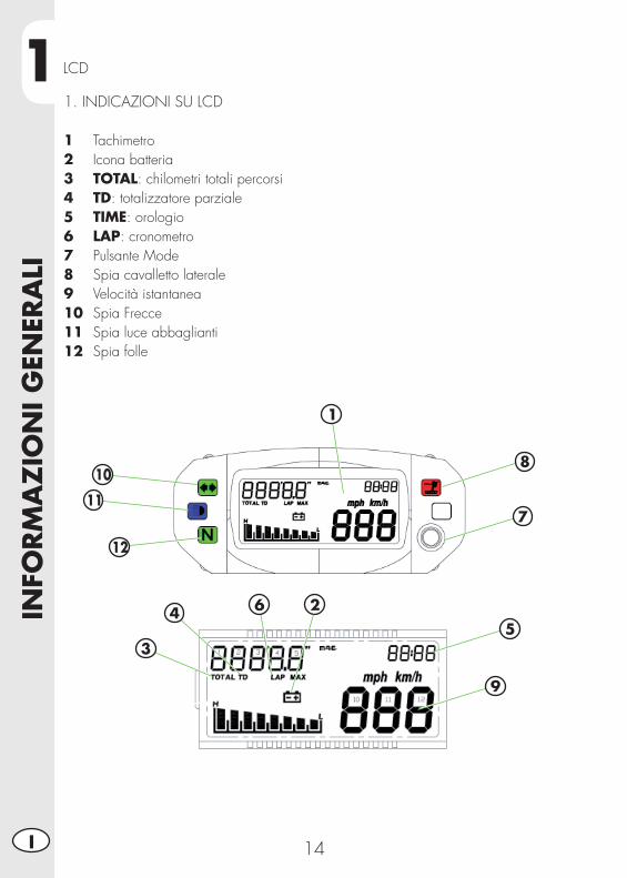
LCD
1. INDICAZIONI SU LCD
1 Tachimetro2 Icona batteria3 TOTAL: chilometri totali percorsi4 TD: totalizzatore parziale5 TIME: orologio6 LAP: cronometro7 Pulsante Mode8 Spia cavalletto laterale9 Velocità istantanea 10 Spia Frecce11 Spia luce abbaglianti12 Spia folle
2
3
45
7
6
9
1
10
11
12
8
1
INFO
RM
AZ
ION
I G
ENER
ALI
15 I
2. FUNZIONI STRUMENTAZIONE
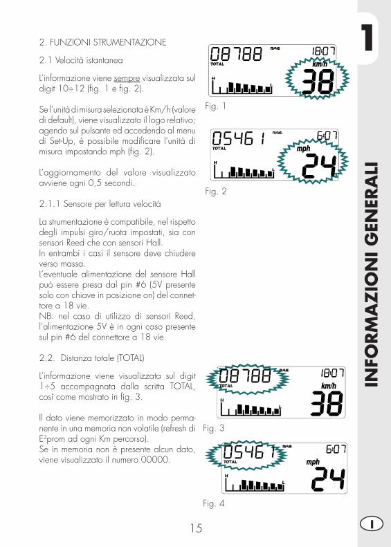
2.1 Velocità istantanea
L’informazione viene sempre visualizzata sul digit 10÷12 (fi g. 1 e fi g. 2).
Se l’unità di misura selezionata è Km/h (valore di default), viene visualizzato il logo relativo; agendo sul pulsante ed accedendo al menu di Set-Up, è possibile modifi care l’unità di misura impostando mph (fi g. 2).
L’aggiornamento del valore visualizzato avviene ogni 0,5 secondi.
2.1.1 Sensore per lettura velocità
La strumentazione è compatibile, nel rispetto degli impulsi giro/ruota impostati, sia con sensori Reed che con sensori Hall.In entrambi i casi il sensore deve chiudere verso massa.L’eventuale alimentazione del sensore Hall può essere presa dal pin #6 (5V presente solo con chiave in posizione on) del connet-tore a 18 vie.NB: nel caso di utilizzo di sensori Reed, l’alimentazione 5V è in ogni caso presente sul pin #6 del connettore a 18 vie.
2.2. Distanza totale (TOTAL)
L’informazione viene visualizzata sul digit 1÷5 accompagnata dalla scritta TOTAL, così come mostrato in fi g. 3.
Il dato viene memorizzato in modo perma-nente in una memoria non volatile (refresh di E2prom ad ogni Km percorso).Se in memoria non è presente alcun dato, viene visualizzato il numero 00000.
Fig. 1
Fig. 2
Fig. 3
Fig. 4
1IN
FORM
AZ
ION
I G
ENER
ALI
16I
Fig. 5
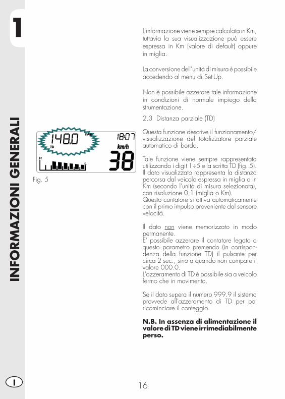
2.3 Distanza parziale (TD)
Questa funzione descrive il funzionamento/visualizzazione del totalizzatore parziale automatico di bordo.
Tale funzione viene sempre rappresentata utilizzando i digit 1÷5 e la scritta TD (fi g. 5).Il dato visualizzato rappresenta la distanza percorsa dal veicolo espressa in miglia o in Km (secondo l'unità di misura selezionata), con risoluzione 0,1 (miglia o Km).Questo contatore si attiva automaticamente con il primo impulso proveniente dal sensore velocità.
Il dato non viene memorizzato in modo permanente.E' possibile azzerare il contatore legato a questo parametro premendo (in corrispon-denza della funzione TD) il pulsante per circa 2 sec., sino a quando non compare il valore 000.0.L'azzeramento di TD è possibile sia a veicolo fermo che in movimento.
Se il dato supera il numero 999.9 il sistema provvede all'azzeramento di TD per poi ricominciare il conteggio.
N.B. In assenza di alimentazione il valore di TD viene irrimediabilmente perso.
L’informazione viene sempre calcolata in Km, tuttavia la sua visualizzazione può essere espressa in Km (valore di default) oppure in miglia.
La conversione dell’unità di misura è possibile accedendo al menu di Set-Up.
Non è possibile azzerare tale informazione in condizioni di normale impiego della strumentazione.

1
INFO
RM
AZ
ION
I G
ENER
ALI
17 I
Fig. 6
Fig. 7
Fig. 8
2.4 Cronometro (LAP)
Questa funzione descrive il funzionamento/visualizzazione del cronometro.L'informazione viene visualizzata utilizzando i digit 1÷5 e la scritta LAP.
Per accedere al menu del cronometro, bisogna tenere premuto il pulsante in corri-spondenza della schermata come mostrato in fi gura 6 fi no alla comparsa del cronometro (fi gure 7-8).
Il dato è visualizzato nel formato mm:ss se ore=0 e nel formato hh:mm se ore >0.
Se ore>0, quando LAP è operativo il simbo-lo - che separa le ore dai minuti è mostrato lampeggiante, mentre viene visualizzato fi sso quando LAP non è operativo.Se ore=0, quando LAP è operativo i simboli ' e " che separano i minuti dai secondi, sono mostrati lampeggianti, mentre sono visualiz-zati fi ssi quando LAP non è operativo.
Attivazione: è possibile attivare il cronometro in due modi:1) manualmente, tramite una pressione breve (<2 sec.) del pulsante;2) in automatico, se la velocità diventa >0
Disattivazione: è possibile fermare il crono-metro nel seguente modo:1) in automatico se la velocità = 02) con il pulsante se la velocità = 0Se la velocità diventa = 0, il cronometro si ferma, anche se l’attivazione è stata data da pulsante.
Azzeramento: è possibile azzerare il crono-metro tramite una pressione lunga (>5 sec.) del pulsante.
Uscita: per uscire dalla modalità cronometro, tenere premuto il pulsante per un tempo com-preso tra 2 e 5 secondi con vel=0.Se al momento dell’uscita il cronometro è attivo, la scritta LAP verrà mostrata lampeg-giante indipendentemente dalla funzione visualizzata.
1IN
FORM
AZ
ION
I G
ENER
ALI
18I
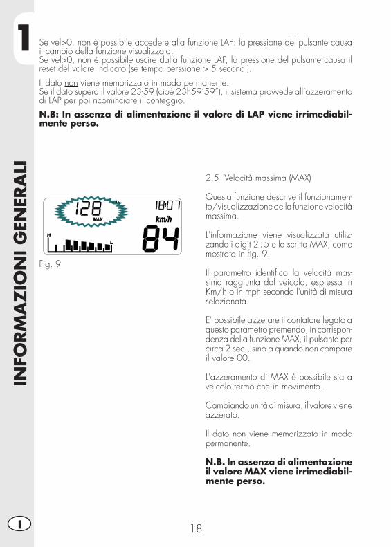
2.5 Velocità massima (MAX)
Questa funzione descrive il funzionamen-to/visualizzazione della funzione velocità massima.
L'informazione viene visualizzata utiliz-zando i digit 2÷5 e la scritta MAX, come mostrato in fi g. 9.
Il parametro identifi ca la velocità mas-sima raggiunta dal veicolo, espressa in Km/h o in mph secondo l'unità di misura selezionata.
E' possibile azzerare il contatore legato a questo parametro premendo, in corrispon-denza della funzione MAX, il pulsante per circa 2 sec., sino a quando non compare il valore 00.
L'azzeramento di MAX è possibile sia a veicolo fermo che in movimento.
Cambiando unità di misura, il valore viene azzerato.
Il dato non viene memorizzato in modo permanente.
N.B. In assenza di alimentazione il valore MAX viene irrimediabil-mente perso.
Fig. 9
Se vel>0, non è possibile accedere alla funzione LAP: la pressione del pulsante causa il cambio della funzione visualizzata.Se vel>0, non è possibile uscire dalla funzione LAP, la pressione del pulsante causa il reset del valore indicato (se tempo perssione > 5 secondi).
Il dato non viene memorizzato in modo permanente.Se il dato supera il valore 23-59 (cioè 23h59’59”), il sistema provvede all’azzeramento di LAP per poi ricominciare il conteggio.
N.B: In assenza di alimentazione il valore di LAP viene irrimediabil-mente perso.
1
INFO
RM
AZ
ION
I G
ENER
ALI
19 I
2.6 Standby
La funzione di standby è utilizzata per la re-golazione dell'orologio (vedi par. 2.8.1).
L'informazione viene mostrata come in fi gura 10.
Fig. 10
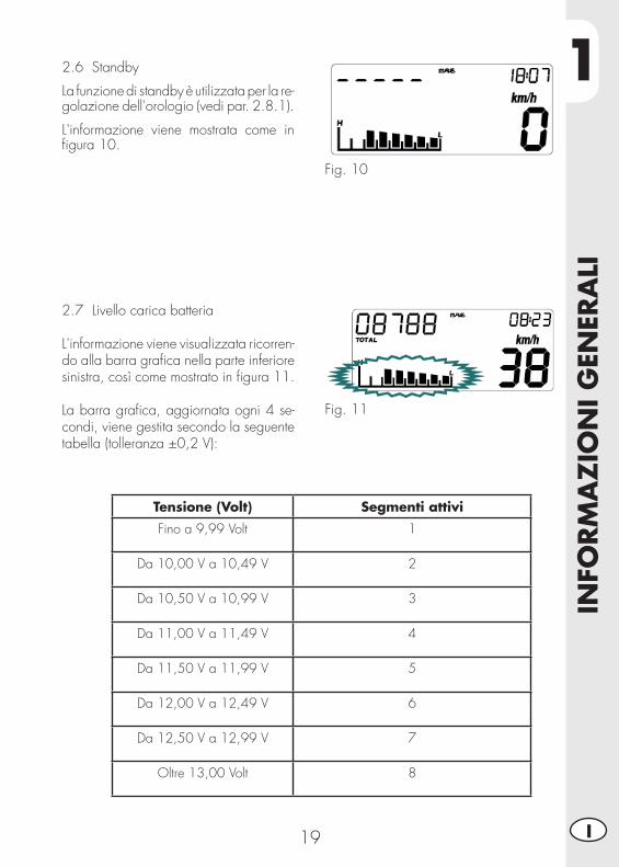
2.7 Livello carica batteria
L'informazione viene visualizzata ricorren-do alla barra grafi ca nella parte inferiore sinistra, così come mostrato in fi gura 11.
La barra grafi ca, aggiornata ogni 4 se-condi, viene gestita secondo la seguente tabella (tolleranza ±0,2 V):
Fig. 11
Tensione (Volt) Segmenti attivi
Fino a 9,99 Volt 1
Da 10,00 V a 10,49 V 2
Da 10,50 V a 10,99 V 3
Da 11,00 V a 11,49 V 4
Da 11,50 V a 11,99 V 5
Da 12,00 V a 12,49 V 6
Da 12,50 V a 12,99 V 7
Oltre 13,00 Volt 8
1IN
FORM
AZ
ION
I G
ENER
ALI
20I
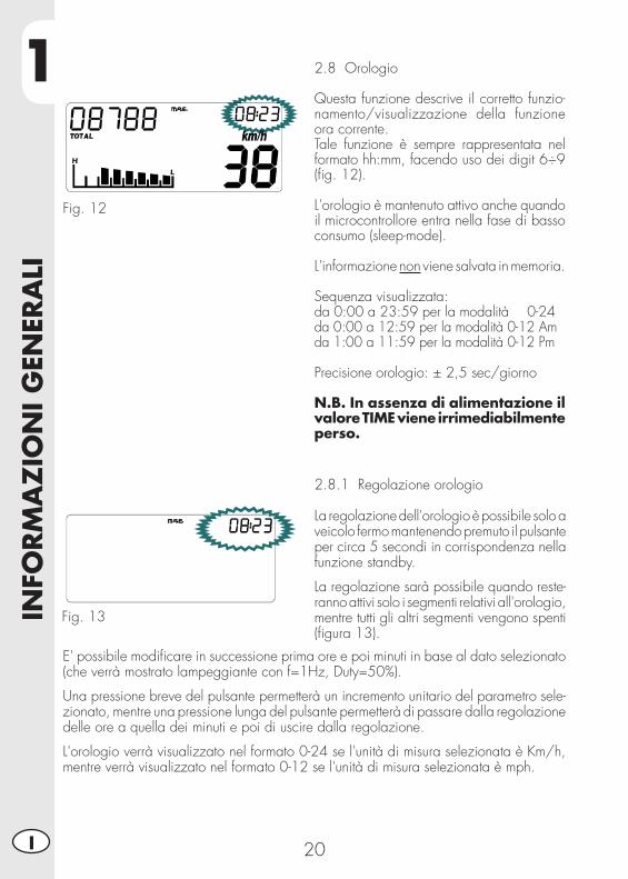
2.8 Orologio
Questa funzione descrive il corretto funzio-namento/visualizzazione della funzione ora corrente.Tale funzione è sempre rappresentata nel formato hh:mm, facendo uso dei digit 6÷9 (fi g. 12).
L'orologio è mantenuto attivo anche quando il microcontrollore entra nella fase di basso consumo (sleep-mode).
L'informazione non viene salvata in memoria.
Sequenza visualizzata: da 0:00 a 23:59 per la modalità 0-24 da 0:00 a 12:59 per la modalità 0-12 Am da 1:00 a 11:59 per la modalità 0-12 Pm
Precisione orologio: ± 2,5 sec/giorno
N.B. In assenza di alimentazione il valore TIME viene irrimediabilmente perso.
Fig. 12
2.8.1 Regolazione orologio
La regolazione dell'orologio è possibile solo a veicolo fermo mantenendo premuto il pulsante per circa 5 secondi in corrispondenza nella funzione standby.
La regolazione sarà possibile quando reste-ranno attivi solo i segmenti relativi all'orologio, mentre tutti gli altri segmenti vengono spenti (fi gura 13).
Fig. 13
E' possibile modifi care in successione prima ore e poi minuti in base al dato selezionato (che verrà mostrato lampeggiante con f=1Hz, Duty=50%).
Una pressione breve del pulsante permetterà un incremento unitario del parametro sele-zionato, mentre una pressione lunga del pulsante permetterà di passare dalla regolazione delle ore a quella dei minuti e poi di uscire dalla regolazione.
L'orologio verrà visualizzato nel formato 0-24 se l'unità di misura selezionata è Km/h, mentre verrà visualizzato nel formato 0-12 se l'unità di misura selezionata è mph.
1
INFO
RM
AZ
ION
I G
ENER
ALI
21 I
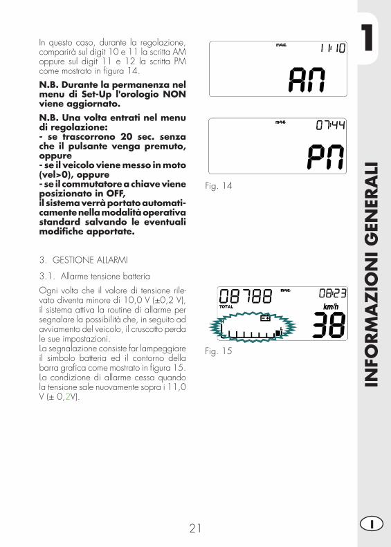
In questo caso, durante la regolazione, comparirà sul digit 10 e 11 la scritta AM oppure sul digit 11 e 12 la scritta PM come mostrato in fi gura 14.
N.B. Durante la permanenza nel menu di Set-Up l'orologio NON viene aggiornato.N.B. Una volta entrati nel menu di regolazione:- se trascorrono 20 sec. senza che il pulsante venga premuto, oppure- se il veicolo viene messo in moto (vel>0), oppure- se il commutatore a chiave viene posizionato in OFF,il sistema verrà portato automati-camente nella modalità operativa standard salvando le eventuali modifi che apportate.
3. GESTIONE ALLARMI
3.1. Allarme tensione batteria
Ogni volta che il valore di tensione rile-vato diventa minore di 10,0 V (±0,2 V), il sistema attiva la routine di allarme per segnalare la possibilità che, in seguito ad avviamento del veicolo, il cruscotto perda le sue impostazioni.La segnalazione consiste far lampeggiare il simbolo batteria ed il contorno della barra grafi ca come mostrato in fi gura 15.La condizione di allarme cessa quando la tensione sale nuovamente sopra i 11,0 V (± 0,2V).
Fig. 14
Fig. 15
1IN
FORM
AZ
ION
I G
ENER
ALI
22I
4. SPIE DI SEGNALAZIONE E RETROILLUMINAZIONE
4.1 Spia Indicatori di direzione
Il sistema attiva la spia con l'attivazione degli indicatori di direzione.
N.B. Il segnale deve arrivare alla strumentazione già alternato.
4.2 Spia Abbaglianti
Il sistema attiva la spia in sincronia con l'attivazione dei proiettori abbaglianti.
4.3 Spia Neutral
Il sistema attiva la spia in sincronia con il posizionamento della leva del cambio in posizione neutral.
4.4 Retroilluminazione LCD e quadrante
La retroilluminazione del cristallo è di colore orange. La retroilluminazione sempre accesa se il blocco chiave è in posizione ON.
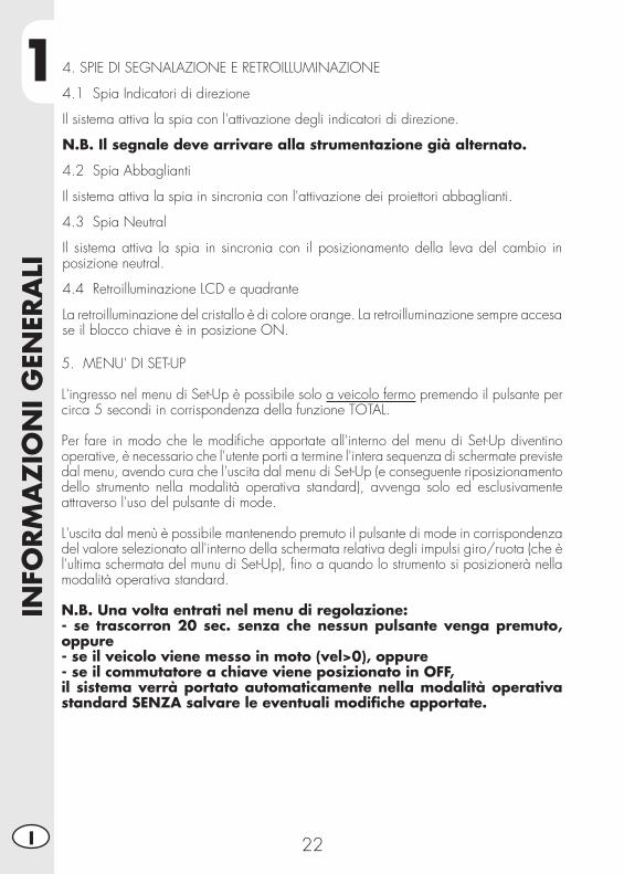
5. MENU' DI SET-UP
L'ingresso nel menu di Set-Up è possibile solo a veicolo fermo premendo il pulsante per circa 5 secondi in corrispondenza della funzione TOTAL.
Per fare in modo che le modifi che apportate all'interno del menu di Set-Up diventino operative, è necessario che l'utente porti a termine l'intera sequenza di schermate previste dal menu, avendo cura che l'uscita dal menu di Set-Up (e conseguente riposizionamento dello strumento nella modalità operativa standard), avvenga solo ed esclusivamente attraverso l'uso del pulsante di mode.
L'uscita dal menù è possibile mantenendo premuto il pulsante di mode in corrispondenza del valore selezionato all'interno della schermata relativa degli impulsi giro/ruota (che è l'ultima schermata del munu di Set-Up), fi no a quando lo strumento si posizionerà nella modalità operativa standard.
N.B. Una volta entrati nel menu di regolazione:- se trascorron 20 sec. senza che nessun pulsante venga premuto, oppure- se il veicolo viene messo in moto (vel>0), oppure- se il commutatore a chiave viene posizionato in OFF,il sistema verrà portato automaticamente nella modalità operativa standard SENZA salvare le eventuali modifi che apportate.
1
INFO
RM
AZ
ION
I G
ENER
ALI
23 I
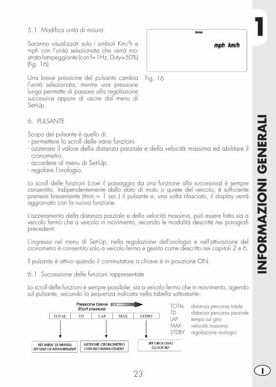
5.1 Modifi ca unità di misura
Saranno visualizzati solo i simboli Km/h e mph con l'unità selezionata che verrà mo-strata lampeggiante (con f=1Hz, Duty=50%) (fi g. 16).
Una breve pressione del pulsante cambia l'unità selezionata, mentre una pressione lunga permette di passare alla regolazione successiva oppure di uscire dal menu di Set-Up.
Fig. 16
6. PULSANTE
Scopo del pulsante è quello di:- permettere lo scroll delle varie funzioni.- azzerare il valore della distanza parziale e della velocità massima ed abilitare il cronometro.
- accedere al menu di Set-Up.- regolare l'orologio.
Lo scroll delle funzioni (cioè il passaggio da una funzione alla successiva) è sempre consentito, indipendentemente dallo stato di moto o quiete del veicolo; è suffi ciente premere brevemente (tmin = 1 sec.) il pulsante e, una volta rilasciato, il display verrà aggiornato con la nuova funzione.
L'azzeramento della distanza parziale e della velocità massima, può essere fatta sia a veicolo fermo che a veicolo in movimento, secondo le modalità descritte nei paragrafi precedenti.
L'ingresso nel menu di Set-Up, nella regolazione dell'orologio e nell'attivazione del cronometro è consentito solo a veicolo fermo e gestito come descritto nei capitoli 2 e 6.
Il pulsante è attivo quando il commutatore a chiave è in posizione ON.
6.1 Successione delle funzioni rappresentate
Lo scroll delle funzioni è sempre possibile, sia a veicolo fermo che in movimento, agendo sul pulsante, secondo la sequenza indicata nella tabella sottostante:
TOTAL distanza percorsa totaleTD distanza percorsa parzialeLAP tempo sul giroMAX velocità massimaSTDBY regolazione orologio
1IN
FORM
AZ
ION
I G
ENER
ALI
24I
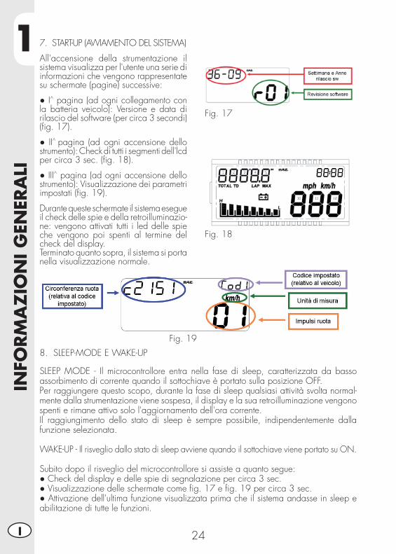
7. START-UP (AVVIAMENTO DEL SISTEMA)
All'accensione della strumentazione il sistema visualizza per l'utente una serie di informazioni che vengono rappresentate su schermate (pagine) successive:
● I^ pagina (ad ogni collegamento con la batteria veicolo): Versione e data di rilascio del software (per circa 3 secondi) (fi g. 17).
● II^ pagina (ad ogni accensione dello strumento): Check di tutti i segmenti dell'lcd per circa 3 sec. (fi g. 18).
● III^ pagina (ad ogni accensione dello strumento): Visualizzazione dei parametri impostati (fi g. 19).
Durante queste schermate il sistema esegue il check delle spie e della retroilluminazio-ne: vengono attivati tutti i led delle spie che vengono poi spenti al termine del check del display.Terminato quanto sopra, il sistema si porta nella visualizzazione normale.
Fig. 17
Fig. 18
Fig. 19
8. SLEEP-MODE E WAKE-UP
SLEEP MODE - Il microcontrollore entra nella fase di sleep, caratterizzata da basso assorbimento di corrente quando il sottochiave è portato sulla posizione OFF.Per raggiungere questo scopo, durante la fase di sleep qualsiasi attività svolta normal-mente dalla strumentazione viene sospesa, il display e la sua retroilluminazione vengono spenti e rimane attivo solo l'aggiornamento dell'ora corrente.Il raggiungimento dello stato di sleep è sempre possibile, indipendentemente dalla funzione selezionata.
WAKE-UP - Il risveglio dallo stato di sleep avviene quando il sottochiave viene portato su ON.
Subito dopo il risveglio del microcontrollore si assiste a quanto segue:● Check del display e delle spie di segnalazione per circa 3 sec.● Visualizzazione delle schermate come fi g. 17 e fi g. 19 per circa 3 sec.● Attivazione dell'ultima funzione visualizzata prima che il sistema andasse in sleep e abilitazione di tutte le funzioni.
1
INFO
RM
AZ
ION
I G
ENER
ALI
25 I
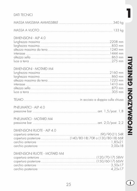
DATI TECNICI
MASSA MASSIMA AMMISSIBILE ...................................................... 340 kg
MASSA A VUOTO ......................................................................... 133 kg
DIMENSIONI - ALP 4.0lunghezza massima .....................................................................2208 mmlarghezza massima ........................................................................850 mmaltezza massima da terra ..............................................................1240 mminterasse ....................................................................................1444 mmaltezza sella .................................................................................863 mmluce a terra ..................................................................................275 mm
DIMENSIONI - MOTARD M4lunghezza massima .....................................................................2160 mmlarghezza massima ........................................................................860 mmaltezza massima da terra ..............................................................1220 mminterasse ....................................................................................1410 mmaltezza sella .................................................................................870 mmluce a terra ..................................................................................305 mm
TELAIO ........................................................ in acciaio a doppia culla chiusa
PNEUMATICI - ALP 4.0pressione bar .................................................................ant. 1,5/post. 1,8
PNEUMATICI - MOTARD M4pressione bar .................................................................ant. 2,0/post. 2,2
DIMENSIONI RUOTE - ALP 4.0copertura anteriore ............................................................ (90/90-21) 54Rcopertura posteriore ............................. (140/80-18) 70R o (130/80-18) 66Rcerchio anteriore ............................................................................................................................... 1,85x21cerchio posteriore ............................................................................................................................. 3,00x18
DIMENSIONI RUOTE - MOTARD M4copertura anteriore ........................................................ (120/70-17) 58Wcopertura posteriore ....................................................... (150/60-17) 66Wcerchio anteriore ............................................................................................................................... 3,50x17cerchio posteriore ............................................................................................................................. 4,25x17
1IN
FORM
AZ
ION
I G
ENER
ALI
26I
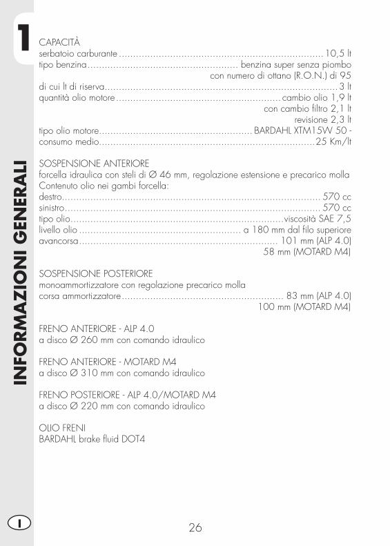
CAPACITÀserbatoio carburante ........................................................................10,5 lttipo benzina ..................................................... benzina super senza piombo
con numero di ottano (R.O.N.) di 95 di cui lt di riserva ..................................................................................3 ltquantità olio motore .......................................................... cambio olio 1,9 lt
con cambio fi ltro 2,1 ltrevisione 2,3 lt
tipo olio motore...................................................... BARDAHL XTM15W 50 -consumo medio............................................................................25 Km/lt
SOSPENSIONE ANTERIOREforcella idraulica con steli di Ø 46 mm, regolazione estensione e precarico mollaContenuto olio nei gambi forcella:destro ........................................................................................... 570 cc sinistro .......................................................................................... 570 cctipo olio ...........................................................................viscosità SAE 7,5livello olio ......................................................... a 180 mm dal fi lo superioreavancorsa ...................................................................... 101 mm (ALP 4.0)
58 mm (MOTARD M4)
SOSPENSIONE POSTERIOREmonoammortizzatore con regolazione precarico mollacorsa ammortizzatore ......................................................... 83 mm (ALP 4.0)
100 mm (MOTARD M4)
FRENO ANTERIORE - ALP 4.0a disco Ø 260 mm con comando idraulico
FRENO ANTERIORE - MOTARD M4a disco Ø 310 mm con comando idraulico
FRENO POSTERIORE - ALP 4.0/MOTARD M4a disco Ø 220 mm con comando idraulico
OLIO FRENIBARDAHL brake fl uid DOT4
1
INFO
RM
AZ
ION
I G
ENER
ALI
27 I
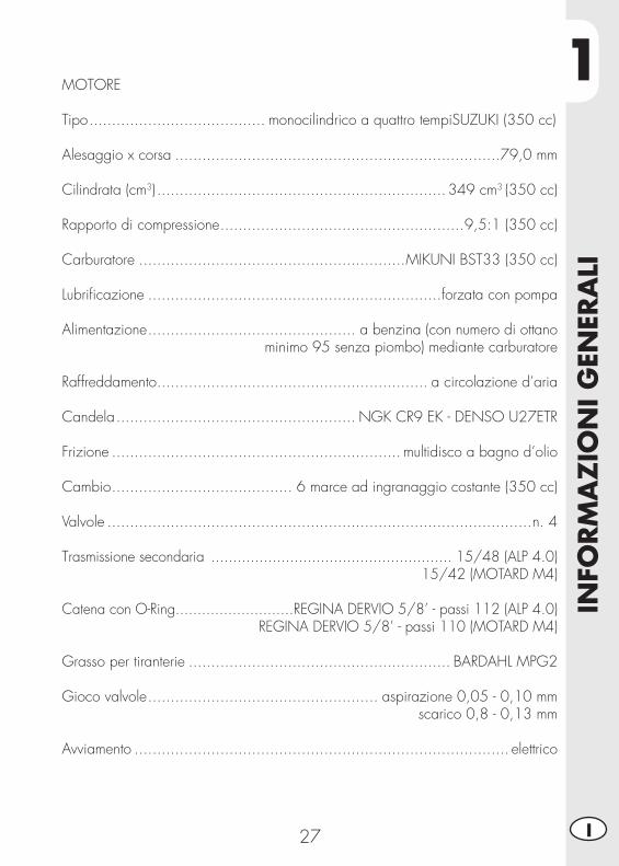
MOTORE
Tipo ....................................... monocilindrico a quattro tempiSUZUKI (350 cc)
Alesaggio x corsa ........................................................................79,0 mm
Cilindrata (cm3) ................................................................ 349 cm3 (350 cc)
Rapporto di compressione ......................................................9,5:1 (350 cc)
Carburatore ...........................................................MIKUNI BST33 (350 cc)
Lubrifi cazione .................................................................forzata con pompa
Alimentazione .............................................. a benzina (con numero di ottano minimo 95 senza piombo) mediante carburatore
Raffreddamento ............................................................ a circolazione d’aria
Candela ..................................................... NGK CR9 EK - DENSO U27ETR
Frizione ................................................................ multidisco a bagno d’olio
Cambio ........................................ 6 marce ad ingranaggio costante (350 cc)
Valvole ..............................................................................................n. 4
Trasmissione secondaria ....................................................... 15/48 (ALP 4.0)15/42 (MOTARD M4)
Catena con O-Ring...........................REGINA DERVIO 5/8’ - passi 112 (ALP 4.0)REGINA DERVIO 5/8’ - passi 110 (MOTARD M4)
Grasso per tiranterie .......................................................... BARDAHL MPG2
Gioco valvole ................................................... aspirazione 0,05 - 0,10 mm scarico 0,8 - 0,13 mm
Avviamento ................................................................................... elettrico
1IN
FORM
AZ
ION
I G
ENER
ALI
28I
Ne
Ve
Az
Ro
Rs-
Gi
Ve
Vi
Ve
Vi
Ro
ViNe
Ve
-Bl
Bi-
Ne
Bl-N
e
Ve
-Bl
Gi-
Rs
Az
Bi-
Gi
Bi-
Ma
2181716158M
a-N
e
Ne
(ant
.)
NeNe
Gr-
Ve
NeRs
Ro
Rs
Rs
Rs
Bl
(pos
t.)
Ne
NeNe
Bi-
Bl
Ne
Ne
Bi-
Bl
Ne
Bi-
Bl
Ne
Bi-
Bl
Gi
Bi-
Bl
Gi
Ne
Ro
Ne
Az
Bi
Bl
Ro
Az
Ne
Bl
Bl
Bl
Ma-
Gi
Ne
RsBi
Ne
RsBl
Bi
Ne
Bi
Gi
Ne
Ne
Ne
Bi
Bi
Ro
NeBl
Ne
Ro
Ar
Bi
Bi-
Ne
Bl
Bl
-+N
e
Bl
Bl
Bl
Ne
Ve
Rs
Gi
Gi
Gi
Bl-N
e
Bl
Gr-
Ve
Ne
Bl
Ve
Ne
Rs
Bi-
Ne
Ma-
Bi
Gi-
Rs
Bl-N
e
Gi
Bi-
Bl
Ne
Rs
Ne
Ro-
Vi
Ne
B L
Bl-N
e
Ro-
Gi
Ne
Ro Bi
Ne
Ne
Ve
-Bl
Ve
-Bl
Ne
Ma
Ne
Rs
Rs
Rs
Rs
M
+_
Ne
NeVi
Ar
Ne
Bi
Gi
Ro Ne
Ve
Ne
Ne
Vi
Gi
Ne
Ne
Rs
Ve
Rs
Bl
Gr
Ve
-Bl
Vi
Ro
Ro Gi
Ne
Ve
Ma
Ne
Gi
Bl
Ve
Ma
Bi
Bi Bl
Ne
Gr
Ne
Rs
Bi
Ne
Ve
-Ne
Rs-
Ne
Vi-
Ne
BiM
a
Gr
Gi
Bl
Ve
Bl-N
e
Gi
Bi-
Gi
Bi-
Ar
Bi-
Ar
Ma-
Ne
Gr
Gr
Gi
Bl-N
e
Ma-
Ne
Bi-
Rs
3 7M
a-G
i
Vi
Ve
Bl-N
e
Ar-
Ne
14 13
4 10
Gr-
Ne
Gr-
Ne
6
1
2
6
5
4
3
7
8 11
10 9
12
13
1415
16
17
18
20
21
22
23
25
24
2830
29
31323334
36
3738
3940
4344
45
46
4749
48
2627
25
35
41
4250
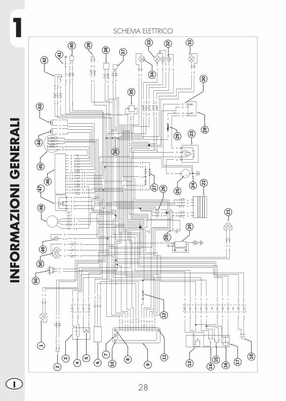
50SCHEMA ELETTRICO
1
INFO
RM
AZ
ION
I G
ENER
ALI
29 I
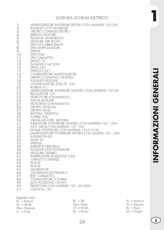
LEGENDA SCHEMA ELETTRICO
1) LAMPEGGIATORE ANTERIORE DESTRO CON LAMPADA 12V-10W2) PULSANTE STOP ANTERIORE3) GRUPPO COMANDI DESTRO4) ARRESTO MOTORE5) PULSANTE AVVIAMENTO6) SENSORE GIRI RUOTA7) SPIA LUCE ABBAGLIANTI8) SPIA LAMPEGGIATORI9) DISPLAY10) SPIA FOLLE11) SPIA CAVALLETTO12) DIODO 1A.13) PULSANTE CLACSON14) DEVIO LUCI15) SPRAZZO LUCI16) COMMUTATORE LAMPEGGIATORI17) GRUPPO COMANDO SINISTRO18) PULSANTE FRIZIONE19) CONDENSATORE 4700 ?F - 25V 20) BOBINA A.T.21) LAMPEGGIATORE ANTERIORE SINISTRO CON LAMPADA 12V-10V22) REGOLATORE 12V23) TELERUTTORE D’AVVIAMENTO24) MASSA MOTORE25) MOTORINO D’AVVIAMENTO26) GRUPPO DIODI 6A27) GRUPPO DIODI28) BATTERIA - ERMETICA29) FUSIBILE 20A30) MASSA MOTORE - BATTERIA31) INDICATORE POSTERIORE SINISTRO CON LAMPADA 12V - 10W 32) LUCE TARGA CON LAMPADA 12V - 5W33) FANALE POSTERIORE CON LAMPADA 12V-5/21W34) LAMPEGGIATORE POSTERIORE DESTRO CON LAMPDA 12V - 10W35) INTERMITTENZA36) DIODI 3A. 37) FARFALLA38) RUBINETTO BENZINA39) PULSANTE STOP POSTERIORE40) SENSORE CAMBIO41) INTERRUTTORE POSIZIONE FOLLE42) CAVALLETTO LATERALE43) PICK-UP44) PICK-UP45) GENERATORE46) CENTRALINA ELETTRONICA47) RELÈ’ CAVALLETTO48) COMMUTATORE A CHIAVE49) LUCE POSIZIONE 12V-3W50) PROIETTORE CON LAMPADA 12V - 55/60W51) CLACSON 12V
Legenda coloriBi = BiancoVe = VerdeMa = MarroneVi = Viola
Bl = BluNe = NeroGi = GialloRs = Rosso
Ar = ArancioAz = AzzurroRo = RosaGr = Grigio
1IN
FORM
AZ
ION
I G
ENER
ALI
30I
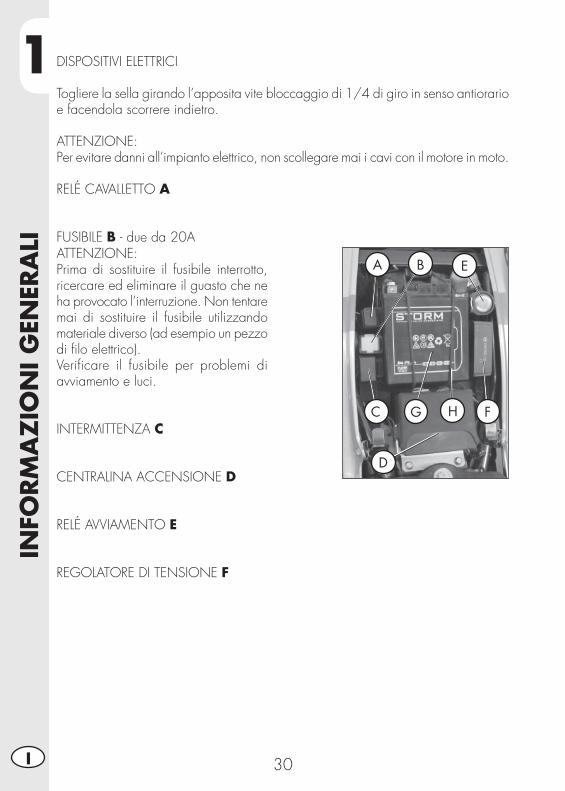
ATTENZIONE:Prima di sostituire il fusibile interrotto, ricercare ed eliminare il guasto che ne ha provocato l’interruzione. Non tentare mai di sostituire il fusibile utilizzando materiale diverso (ad esempio un pezzo di fi lo elettrico).Verifi care il fusibile per problemi di avviamento e luci.
INTERMITTENZA C
CENTRALINA ACCENSIONE D
RELÉ AVVIAMENTO E
REGOLATORE DI TENSIONE F
A B E
C G H F
D
DISPOSITIVI ELETTRICI
Togliere la sella girando l’apposita vite bloccaggio di 1/4 di giro in senso antiorario e facendola scorrere indietro.
ATTENZIONE:Per evitare danni all’impianto elettrico, non scollegare mai i cavi con il motore in moto.
RELÉ CAVALLETTO A
FUSIBILE B - due da 20A

1
INFO
RM
AZ
ION
I G
ENER
ALI
31 I
NOTE RELATIVE ALLA BATTERIA GInserire la batteria nell’apposita sede sottosella (posizione come da foto) fi ssandola con l’elastico di corredo H. Collegare il terminale del cavo di colore nero al negativo (-) e il cavo di colore rosso al positivo (+) inserendo il cappuccio rosso di protezione. Rimontare la sella.
BOBINA A.T. - MOTORINO AVVIAMENTO IPer accedere a questi componenti è necessario rimuovere la sella, le fi ancate anteriori e il serbatoio (vedi pag. 55, 56 per ALP e 57, 58 per MOTARD).
I

1IN
FORM
AZ
ION
I G
ENER
ALI
32I
A
DISPOSITIVI PER VERSIONE E3
Gli ultimi modelli sono omologati E3 e si differiscono dall’omologazioni precedenti per l’inserimento della valvola AIS
LA VALVOLA AISSi chiama AIS A ed è un sistema d’im-missione d’aria che consente di comple-tare la combustione di quella parte di idrocarburi incombusti,residuo del ciclo termodinamico.
2
UTI
LIZ
ZO
DEL
VEI
CO
LO
33 I
INDICE ARGOMENTI
CAP. 2 UTILIZZO DEL VEICOLO
Controlli e manutenzione prima e dopo l’utilizzo in fuoristrada
Lubrifi canti consigliati
Rodaggio
Avviamento del motore
Arresto del motore
Rifornimento carburante
2U
TILI
ZZ
O D
EL V
EICO
LO
34I
CONTROLLI E MANUTENZIONE PRIMA E DOPO L’UTILIZZO IN FUORISTRADA
Onde evitare spiacevoli inconvenienti durante il funzionamento del veicolo è con-sigliabile effettuare, sia prima che dopo l’utilizzo, alcune operazioni di controllo e manutenzione. Infatti pochi minuti dedicati a queste operazioni, oltre a rendere la guida più sicura, possono farvi risparmiare tempo e denaro. Quindi procedere come segue:
PNEUMATICI verifi care la pressione, lo stato generale e lo spessore del batti-strada
RAGGI verifi care la corretta tensioneBULLONERIA verifi care completamente tutta la bulloneriaCATENA verifi care la tensione (gioco 20 mm) e se necessario lubrifi careFILTRO ARIA pulire il fi ltro e bagnarlo con apposito olio (vedi pag. 51)
Nota:Controllare la presenza dei documenti di identifi cazione del veicolo.Nei giorni freddi è consigliabile prima della partenza, fare scaldare il motore facen-dolo funzionare al minimo per alcuni istanti. Ogni volta che il veicolo viene utilizzato in fuoristrada occorre lavarlo accuratamente, asciugarlo e quindi lubrifi carlo.
LUBRIFICANTI CONSIGLIATI
Per un migliore funzionamento ed una più lunga durata del mezzo si raccomanda di utilizzare preferibilmente i prodotti elencati in tabella:
TIPO DI PRODOTTO SPECIFICHE TECNICHE
OLIO MOTORE (2,1 lt) BARDAHL XTM15W 50
OLIO FRENI BARDAHL brake fl uid DOT 4 OLIO PER FORCELLE (570 cc DX e SX) LIQUI MOLY RACING SUSPENSION
OIL SAE 7,5
GRASSO PER TIRANTERIE BARDAHL MPG2
Nota:Per gli interventi di sostituzione si raccomanda di attenersi scrupolosamente alla tabella indicata.
2
UTI
LIZ
ZO
DEL
VEI
CO
LO
35 I
RODAGGIO
Il rodaggio ha una durata di circa 10 ore di attività, durante questo periodo si consiglia di:• Utilizzare il veicolo dopo aver fatto scal-dare bene il motore
• Evitare di viaggiare a velocità costante (variando la velocità i vari componenti si assesteranno uniformemente ed in minor tempo).
• Evitare di ruotare la manopola dell’acce-leratore per più di 3/4.
ATTENZIONE:Dopo i primi 1000 Km di percorrenza sostituire l’olio del motore
AVVERTENZA:È necessario accertarsi dopo 1000 Km di percorrenza che il fi ltro metallico, posto sulla parte fi nale del serbatoio dell’olio, sia pulito (vedi pag. 42). Se così non fosse, utilizzare un getto di aria compressa.
• Utilizzare sempre benzina super senza piombo.
• Dopo la prima uscita fuoristrada provvede-re a controllare tutta la bulloneria.
2U
TILI
ZZ
O D
EL V
EICO
LO
36I
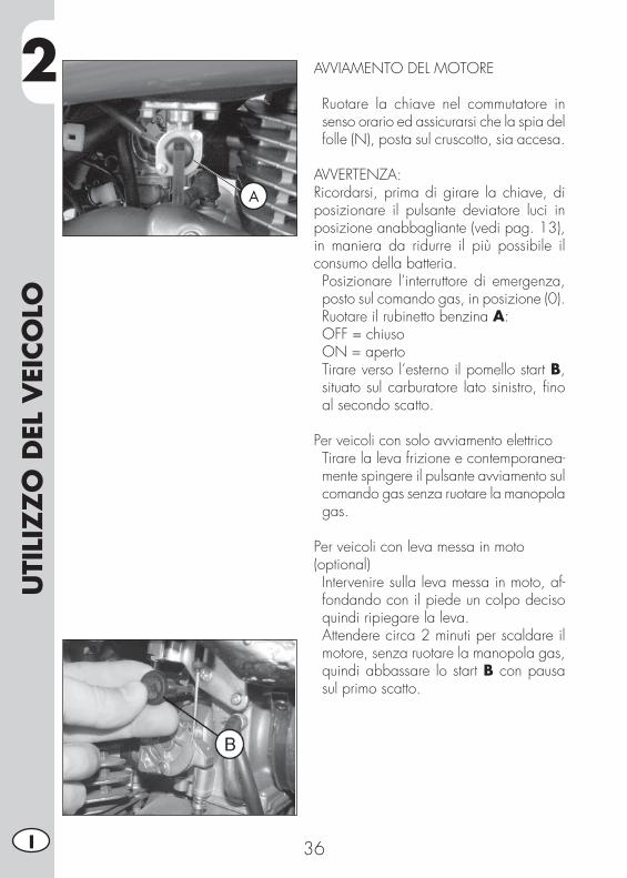
AVVIAMENTO DEL MOTORE
• Ruotare la chiave nel commutatore in senso orario ed assicurarsi che la spia del folle (N), posta sul cruscotto, sia accesa.
AVVERTENZA:Ricordarsi, prima di girare la chiave, di posizionare il pulsante deviatore luci in posizione anabbagliante (vedi pag. 13), in maniera da ridurre il più possibile il consumo della batteria. • Posizionare l’interruttore di emergenza, posto sul comando gas, in posizione (0).
• Ruotare il rubinetto benzina A: OFF = chiuso ON = aperto• Tirare verso l’esterno il pomello start B, situato sul carburatore lato sinistro, fi no al secondo scatto.
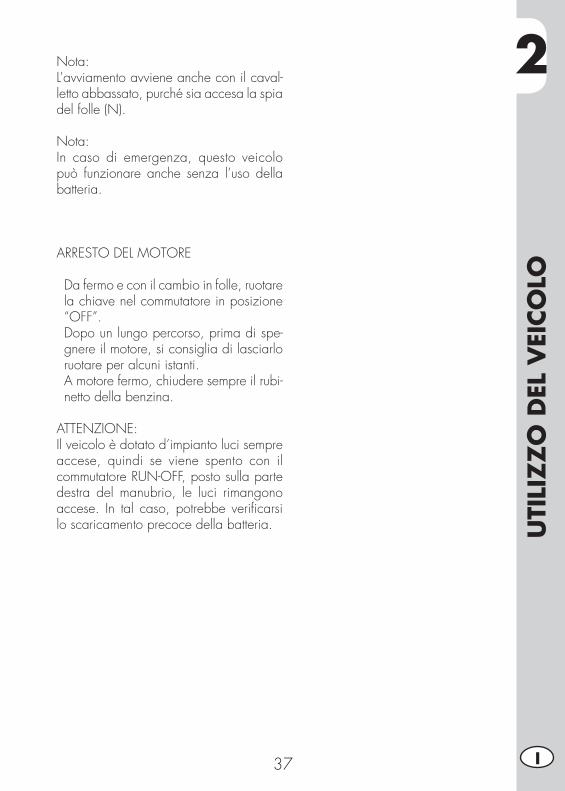
Per veicoli con solo avviamento elettrico• Tirare la leva frizione e contemporanea-mente spingere il pulsante avviamento sul comando gas senza ruotare la manopola gas.
Per veicoli con leva messa in moto (optional)• Intervenire sulla leva messa in moto, af-fondando con il piede un colpo deciso quindi ripiegare la leva.
• Attendere circa 2 minuti per scaldare il motore, senza ruotare la manopola gas, quindi abbassare lo start B con pausa sul primo scatto.
A
2
UTI
LIZ
ZO
DEL
VEI
CO
LO
37 I
Nota:L’avviamento avviene anche con il caval-letto abbassato, purché sia accesa la spia del folle (N).
Nota:In caso di emergenza, questo veicolo può funzionare anche senza l’uso della batteria.
ARRESTO DEL MOTORE
• Da fermo e con il cambio in folle, ruotare la chiave nel commutatore in posizione “OFF”.
• Dopo un lungo percorso, prima di spe-gnere il motore, si consiglia di lasciarlo ruotare per alcuni istanti.
• A motore fermo, chiudere sempre il rubi-netto della benzina.
ATTENZIONE:Il veicolo è dotato d’impianto luci sempre accese, quindi se viene spento con il commutatore RUN-OFF, posto sulla parte destra del manubrio, le luci rimangono accese. In tal caso, potrebbe verifi carsi lo scaricamento precoce della batteria.
2U
TILI
ZZ
O D
EL V
EICO
LO
38I
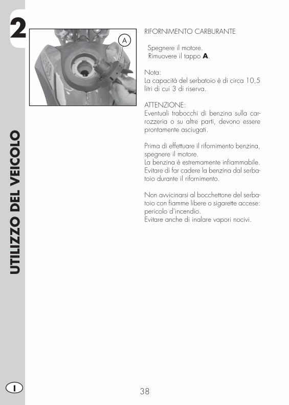
RIFORNIMENTO CARBURANTE
•Spegnere il motore.• Rimuovere il tappo A.
Nota:La capacità del serbatoio è di circa 10,5 litri di cui 3 di riserva.
ATTENZIONE:Eventuali trabocchi di benzina sulla car-rozzeria o su altre parti, devono essere prontamente asciugati.
Prima di effettuare il rifornimento benzina, spegnere il motore.La benzina è estremamente infi ammabile.Evitare di far cadere la benzina dal serba-toio durante il rifornimento.
Non avvicinarsi al bocchettone del serba-toio con fi amme libere o sigarette accese: pericolo d’incendio.Evitare anche di inalare vapori nocivi.
A
3
CO
NTR
OLL
I E
MA
NU
TEN
ZIO
NE
39 I
INDICE ARGOMENTI
CAP. 3 CONTROLLI E MANUTENZIONE
Controllo livello olio motore
Sostituzione olio motore e fi ltro olio
Tubo raccolta fumi
Olio pompa freni, spurgo freni
Olio forcelle
Filtro aria
Candela
Freno anteriore
Freno posteriore
Carburatore
Batteria
Rimozione delle plastiche per ALP
Rimozione delle plastiche per MOTARD M4
Note per fuoristrada
Sostituzione gruppo trasmissione fi nale
Pulizia del veicolo e controlli
Controlli dopo la pulizia
Manutenzione programmata
Lunga inattività del veicolo
Dopo un lungo periodo di inattività
3CO
NTR
OLL
I E
MA
NU
TEN
ZIO
NE
40I
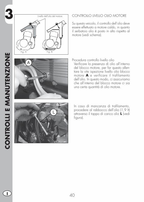
CONTROLLO LIVELLO OLIO MOTORE
Su questo veicolo, il controllo dell’olio deve essere effettuato a motore caldo, in quanto il serbatoio olio è posto in alto rispetto al motore (vedi schema).
Fig. A
Livello dell’olio del motore
Fig. B
Procedura controllo livello olio• Verifi care la presenza di olio all’interno del blocco motore, per far questo allen-tare la vite ispezione livello olio blocco motore A e verificare il trafilamento dell’olio. In questo modo, ci assicuriamo che all’interno del blocco motore ci sia una certa quantità di olio motore.
• In caso di mancanza di trafi lamento, procedere al rabbocco dell’olio (1,9 lt) attraverso il tappo di carico olio L (vedi fi gura).
3
CO
NTR
OLL
I E
MA
NU
TEN
ZIO
NE
41 I
M N
Controllo livello olioDa effettuare solo dopo aver verifi cato la presenza dell’olio nel motore (vedi pag. 40).• Avviare il motore e farlo girare al minimo per tre minuti.
• Spegnere il motore ed aspettare un mi-nuto.
• Togliere il tappo del bocchettone di riempimento dell’olio.
• Con uno straccio pulito togliere le tracce di olio dall’asta di livello.
• Tenendo la motocicletta verticalmente, reinserire l’asta di livello fi no a far toccare la fi lettatura del collo del bocchettone di riempimento dell’olio, senza però avvita-re il tappo.
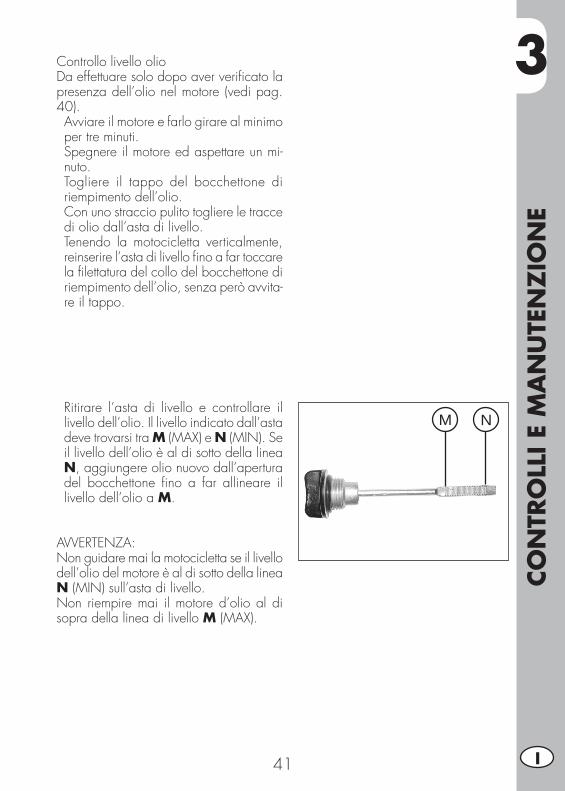
• Ritirare l’asta di livello e controllare il livello dell’olio. Il livello indicato dall’asta deve trovarsi tra M (MAX) e N (MIN). Se il livello dell’olio è al di sotto della linea N, aggiungere olio nuovo dall’apertura del bocchettone fi no a far allineare il livello dell’olio a M.
AVVERTENZA:Non guidare mai la motocicletta se il livello dell’olio del motore è al di sotto della linea N (MIN) sull’asta di livello.Non riempire mai il motore d’olio al di sopra della linea di livello M (MAX).

3CO
NTR
OLL
I E
MA
NU
TEN
ZIO
NE
42I
SOSTITUZIONE OLIO MOTORE E FILTRO OLIO
Eseguire sempre la sostituzione dell’olio a motore caldo, facendo attenzione a non toccare il motore e l’olio stesso onde evitare scottature.
• La sostituzione del fi ltro olio dovrebbe essere fatta insieme alla sostituzione dell’olio.
• Appoggiare la moto sul cavalletto.• Posizionare un contenitore sotto al motore.• Svitare il tappo di carico L e quello di scarico F.
• Vuotare completamente il carter.
Sostituzione fi ltro olio• Togliere il coperchio del fi ltro olio svitan-do i 3 dadi di fi ssaggio G.
• Togliere il fi ltro olio.

3
CO
NTR
OLL
I E
MA
NU
TEN
ZIO
NE
43 I
Svuotamento olio dal serbatoio• Togliere le 4 viti di fi ssaggio carter po-steriore motore.
• Svitare la vite Q e far defl uire tutto l’olio dal serbatoio.
• Si consiglia, al primo cambio d’olio (vedi pag. 35), di effettuare anche la pulizia del fi ltro metallico, posto sulla parte fi nale del serbatoio olio.
La procedura di smontaggio è la seguente:• Svitare la fascetta del tubo di raccordo serbatoio carter motore.
• Mediante chiave inglese, svitare in senso orario il raccordo, dotato di reticella metallica.
• Pulire mediante getto di aria.
ATTENZIONE:Utilizzare sempre protezioni per gli occhi durante questa operazione.
3CO
NTR
OLL
I E
MA
NU
TEN
ZIO
NE
44I
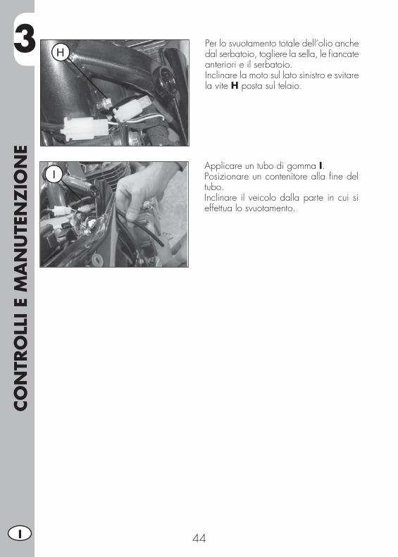
• Per lo svuotamento totale dell’olio anche dal serbatoio, togliere la sella, le fi ancate anteriori e il serbatoio.
• Inclinare la moto sul lato sinistro e svitare la vite H posta sul telaio.
• Applicare un tubo di gomma I.• Posizionare un contenitore alla fi ne del tubo.
• Inclinare il veicolo dalla parte in cui si effettua lo svuotamento.
3
CO
NTR
OLL
I E
MA
NU
TEN
ZIO
NE
45 I
Montaggio• Procedere in senso inverso alle operazioni di smontaggio del fi ltro a rete metallica del serbatoio olio.
• Inserire un nuovo fi ltro olio.• Applicare leggermente olio motore all’O-Ring del coperchio fi ltro prima dell’inseri-mento.
• Inserire il coperchio fi ltro olio, dopo aver montato molla ed O-Ring e serrare le tre viti di fi ssaggio.
• Rimontare il tappo di scarico olio, posto sul carter motore, con le due viti di scarico olio del serbatoio (se necessario, utilizza-re guarnizioni nuove).
• Introdurre la giusta quantità di olio. Quantità olio motore: cambio olio ............................. 1,9 lt con cambio fi ltro ...................... 2,1 lt revisione ................................. 2,3 lt
• Riavvitare il tappo di carico.• Avviare il motore lasciandolo girare per qualche minuto prima di spegnerlo.
• Spegnere il motore ed attendere circa un minuto, quindi controllare il livello ed eventualmente rabboccare, senza mai superare il livello max.
Nota: superati i primi 1000 km di percorrenza sostituire l’olio motore. Le successive sosti-tuzioni devono essere effettuate ogni 4000 km (15 mesi), utilizzando i lubrifi canti consigliati a pag. 34.Per il fi ltro olio, invece, la prima sostituzione deve essere effettuata insieme all’olio moto-re; le successive ogni 8000 km (45 mesi).
AVVERTENZA:Smaltire l’olio usato nel rispetto delle norma-tive vigenti.
3CO
NTR
OLL
I E
MA
NU
TEN
ZIO
NE
46I
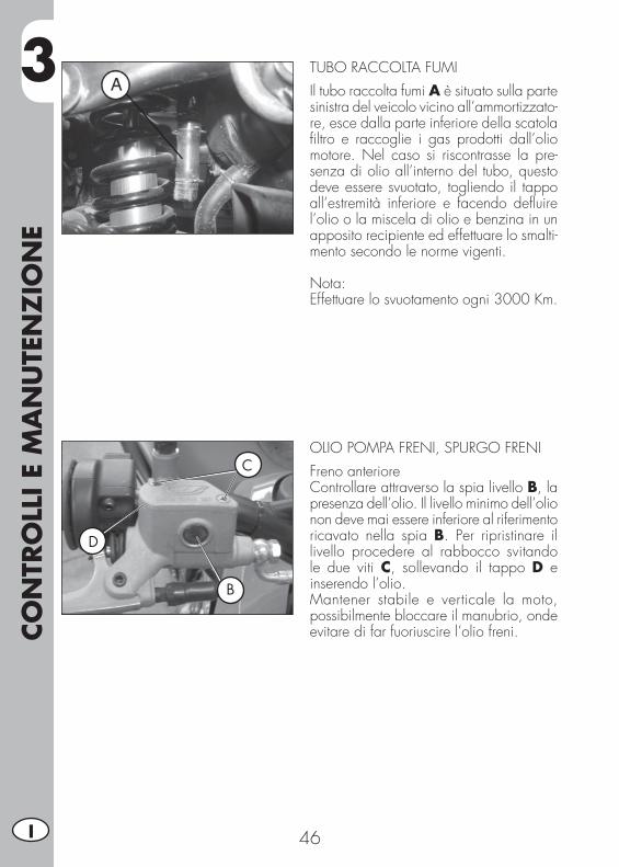
TUBO RACCOLTA FUMI
Il tubo raccolta fumi A è situato sulla parte sinistra del veicolo vicino all’ammortizzato-re, esce dalla parte inferiore della scatola fi ltro e raccoglie i gas prodotti dall’olio motore. Nel caso si riscontrasse la pre-senza di olio all’interno del tubo, questo deve essere svuotato, togliendo il tappo all’estremità inferiore e facendo defl uire l’olio o la miscela di olio e benzina in un apposito recipiente ed effettuare lo smalti-mento secondo le norme vigenti.
Nota:Effettuare lo svuotamento ogni 3000 Km.
OLIO POMPA FRENI, SPURGO FRENI Freno anterioreControllare attraverso la spia livello B, la presenza dell’olio. Il livello minimo dell’olio non deve mai essere inferiore al riferimento ricavato nella spia B. Per ripristinare il livello procedere al rabbocco svitando le due viti C, sollevando il tappo D e inserendo l’olio.Mantener stabile e verticale la moto, possibilmente bloccare il manubrio, onde evitare di far fuoriuscire l’olio freni.
B
C
D

3
CO
NTR
OLL
I E
MA
NU
TEN
ZIO
NE
47 I
Freno posteriore
Controllare attraverso il contenitore olio E, la presenza dell’olio. Il livello dell’olio non deve mai essere inferiore alla tacca F di livello minimo in rilievo sul contenitore. Per ripristinare il livello procedere come descritto:
• Rimuovere la vite di fi ssaggio del conte-nitore olio G.
• Sfi lare il contenitore olio dalla sua sede.
• Aprire il tappo facendo attenzione a man-tenere in posizione verticale il contenitore dell’olio freni.
• Avvolgerlo, come in fi gura, con carta assorbente.
• Procedere con il rabbocco.
ATTENZIONE:Il liquido freni è altamente corrosivo, quindi attenzione a non far cadere alcuna goccia sulle parti verniciate del veicolo.
ATTENZIONE:Nel caso in cui si rilevi una scarsa resisten-za azionando la leva del freno, l’anomalia potrebbe essere causata da una bolla d’aria nell’impianto frenante, in tal caso è necessario effettuare lo spurgo freni (pag. 48/49) oppure rivolgersi al più presto ad un’offi cina autorizzata.
Nota:Per le sostituzioni attenersi alla tabella a pag. 63, utilizzando i lubrifi canti consi-gliati a pag. 34.
E
F
G
3CO
NTR
OLL
I E
MA
NU
TEN
ZIO
NE
48I
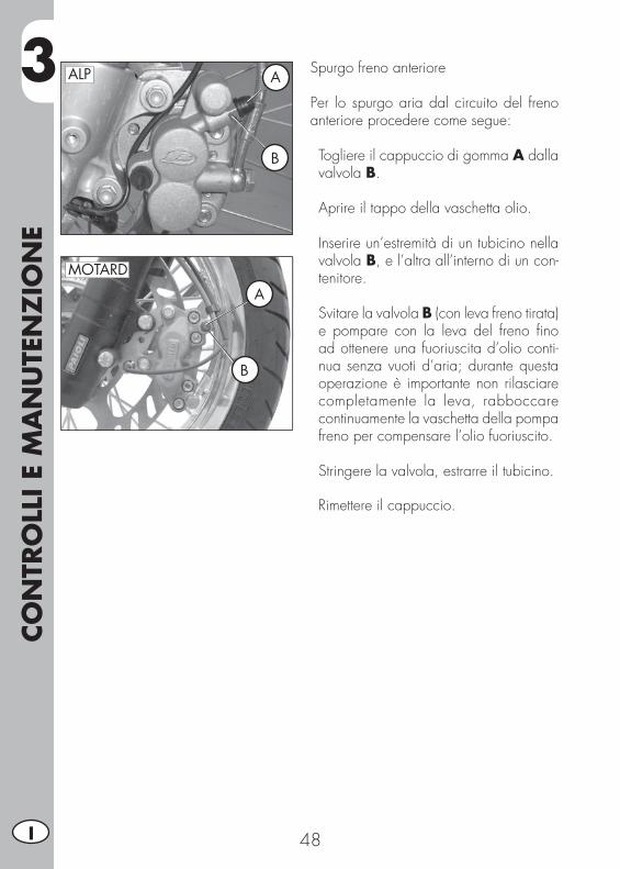
Spurgo freno anteriore
Per lo spurgo aria dal circuito del freno anteriore procedere come segue:
• Togliere il cappuccio di gomma A dalla valvola B.
• Aprire il tappo della vaschetta olio.
• Inserire un’estremità di un tubicino nella valvola B, e l’altra all’interno di un con-tenitore.
• Svitare la valvola B (con leva freno tirata) e pompare con la leva del freno fi no ad ottenere una fuoriuscita d’olio conti-nua senza vuoti d’aria; durante questa operazione è importante non rilasciare completamente la leva, rabboccare continuamente la vaschetta della pompa freno per compensare l’olio fuoriuscito.
• Stringere la valvola, estrarre il tubicino.
• Rimettere il cappuccio.
ALP
MOTARD
A
B
A
B

3
CO
NTR
OLL
I E
MA
NU
TEN
ZIO
NE
49 I
Spurgo freno posteriore
Per lo spurgo aria dal circuito del freno posteriore procedere come segue:
• Togliere il cappuccio di gomma C.
• Aprire il tappo della vaschetta olio.
• Inserire un’estremità di un tubicino nella valvola, e l’altra all’interno di un conte-nitore D.
• Svitare la valvola D (con leva freno tirata) e pompare con la leva del freno fi no ad ottenere una fuoriuscita d’olio conti-nua senza vuoti d’aria; durante questa operazione è importante non rilasciare completamente la leva, rabboccare continuamente la vaschetta della pompa freno per compensare l’olio fuoriuscito.
• Stringere la valvola, estrarre il tubicino.
• Rimettere il cappuccio.
D
C

3CO
NTR
OLL
I E
MA
NU
TEN
ZIO
NE
50I
OLIO FORCELLEStelo destro/sinistroLa descrizione relativa alla sostituzione dell’olio delle forcelle riveste un carattere puramente informativo. Infatti è consi-gliabile rivolgersi ad un’offi cina autoriz-zata BETAMOTOR per effettuare questa operazione. Per la sostituzione procedere nel modo seguente:1) Togliere il manubrio, svitando le quattro
viti C di fi ssaggio dei due cavallotti D.
2) Allentare le viti B e C di serraggio dello stelo.
3) Togliere il tappo inferiore (vite brugola nel fodero della forcella) ed il tappo superiore A.
4) Attendere il completo svuotamento dell’olio dallo stelo.
5) Riavvitare il tappo inferiore del fodero della forcella.
6) Immettere olio indicato nella tabella a pag. 34.
7) Riavvitare il tappo superiore A.8) Stringere in sequenza, prima la vite B,
poi la vite C e di nuovo la vite B.
3
CO
NTR
OLL
I E
MA
NU
TEN
ZIO
NE
51 I
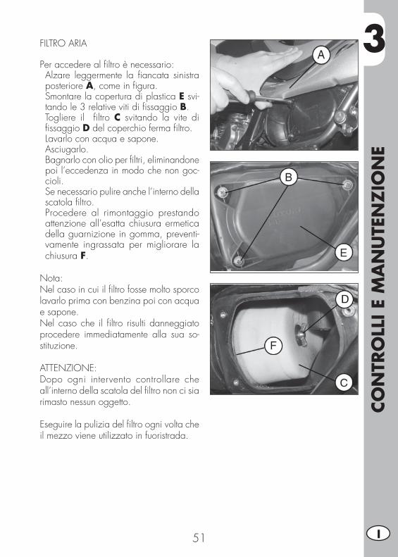
FILTRO ARIA
Per accedere al fi ltro è necessario:• Alzare leggermente la fi ancata sinistra posteriore A, come in fi gura.
• Smontare la copertura di plastica E svi-tando le 3 relative viti di fi ssaggio B.
• Togliere il fi ltro C svitando la vite di fi ssaggio D del coperchio ferma fi ltro.
• Lavarlo con acqua e sapone.• Asciugarlo.• Bagnarlo con olio per fi ltri, eliminandone poi l’eccedenza in modo che non goc-cioli.
• Se necessario pulire anche l’interno della scatola fi ltro.
• Procedere al rimontaggio prestando attenzione all’esatta chiusura ermetica della guarnizione in gomma, preventi-vamente ingrassata per migliorare la chiusura F.
Nota:Nel caso in cui il fi ltro fosse molto sporco lavarlo prima con benzina poi con acqua e sapone. Nel caso che il fi ltro risulti danneggiato procedere immediatamente alla sua so-stituzione.
ATTENZIONE:Dopo ogni intervento controllare che all’interno della scatola del fi ltro non ci sia rimasto nessun oggetto.
Eseguire la pulizia del fi ltro ogni volta che il mezzo viene utilizzato in fuoristrada.
3CO
NTR
OLL
I E
MA
NU
TEN
ZIO
NE
52I
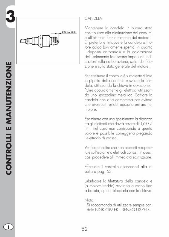
CANDELA
Mantenere la candela in buono stato contribuisce alla diminuzione dei consumi e all’ottimale funzionamento del motore.E’ preferibile rimuovere la candela a mo-tore caldo (ovviamente spento) in quanto i depositi carboniosi e la colorazione dell’isolamento forniscono importanti indi-cazioni sulla carburazione, sulla lubrifi ca-zione e sullo stato generale del motore.
Per effettuare il controllo è suffi ciente sfi lare la pipetta della corrente e svitare la can-dela, utilizzando la chiave in dotazione.Pulire accuratamente gli elettrodi utilizzan-do uno spazzolino metallico. Soffi are la candela con aria compressa per evitare che eventuali residui possano entrare nel motore.
Esaminare con uno spessimetro la distanza fra gli elettrodi che dovrà essere di 0,6-0,7 mm, nel caso non corrisponda a questo valore è possibile correggerla piegando l’elettrodo di massa.
Verifi care inoltre che non presenti screpola-ture sull’isolante o elettrodi corrosi, in questi casi procedere all’immediata sostituzione.
Effettuare il controllo attenendosi alla ta-bella a pag. 63. Lubrifi care la fi lettatura della candela e (a motore freddo) avvitarla a mano fi no a battuta, quindi bloccarla con la chiave.
Nota:• Si raccomanda di utilizzare sempre can-dele NGK CR9 EK - DENSO U27ETR.
3
CO
NTR
OLL
I E
MA
NU
TEN
ZIO
NE
53 I
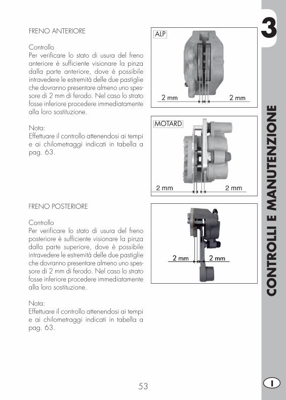
FRENO ANTERIORE
ControlloPer verifi care lo stato di usura del freno anteriore è suffi ciente visionare la pinza dalla parte anteriore, dove è possibile intravedere le estremità delle due pastiglie che dovranno presentare almeno uno spes-sore di 2 mm di ferodo. Nel caso lo strato fosse inferiore procedere immediatamente alla loro sostituzione.
Nota:Effettuare il controllo attenendosi ai tempi e ai chilometraggi indicati in tabella a pag. 63.
FRENO POSTERIORE
ControlloPer verifi care lo stato di usura del freno posteriore è suffi ciente visionare la pinza dalla parte superiore, dove è possibile intravedere le estremità delle due pastiglie che dovranno presentare almeno uno spes-sore di 2 mm di ferodo. Nel caso lo strato fosse inferiore procedere immediatamente alla loro sostituzione.
Nota:Effettuare il controllo attenendosi ai tempi e ai chilometraggi indicati in tabella a pag. 63.
ALP
MOTARD
3CO
NTR
OLL
I E
MA
NU
TEN
ZIO
NE
54I
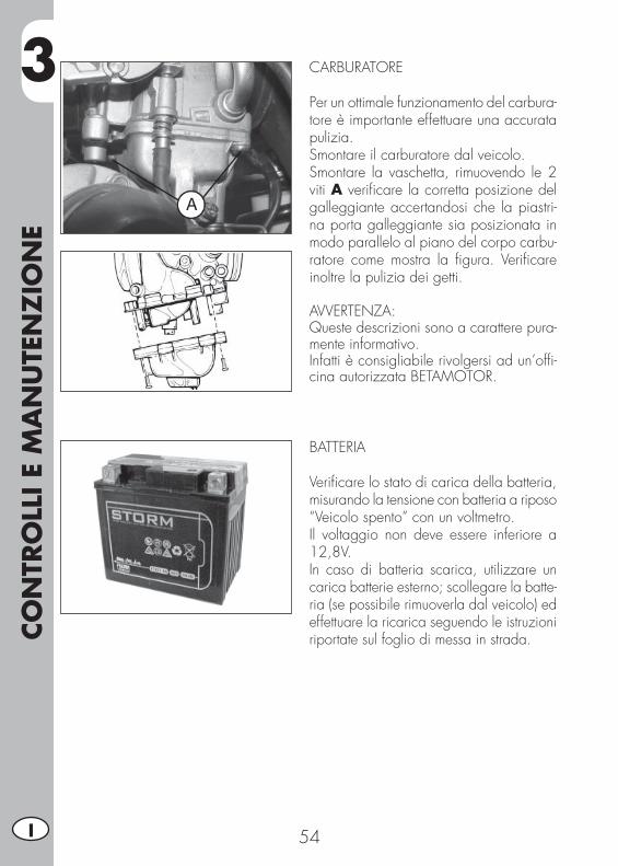
CARBURATORE
Per un ottimale funzionamento del carbura-tore è importante effettuare una accurata pulizia.Smontare il carburatore dal veicolo.Smontare la vaschetta, rimuovendo le 2 viti A verifi care la corretta posizione del galleggiante accertandosi che la piastri-na porta galleggiante sia posizionata in modo parallelo al piano del corpo carbu-ratore come mostra la fi gura. Verifi care inoltre la pulizia dei getti.
AVVERTENZA:Queste descrizioni sono a carattere pura-mente informativo.Infatti è consigliabile rivolgersi ad un’offi -cina autorizzata BETAMOTOR.
BATTERIA
Verifi care lo stato di carica della batteria, misurando la tensione con batteria a riposo “Veicolo spento” con un voltmetro.Il voltaggio non deve essere inferiore a 12,8V.In caso di batteria scarica, utilizzare un carica batterie esterno; scollegare la batte-ria (se possibile rimuoverla dal veicolo) ed effettuare la ricarica seguendo le istruzioni riportate sul foglio di messa in strada.
3
CO
NTR
OLL
I E
MA
NU
TEN
ZIO
NE
55 I
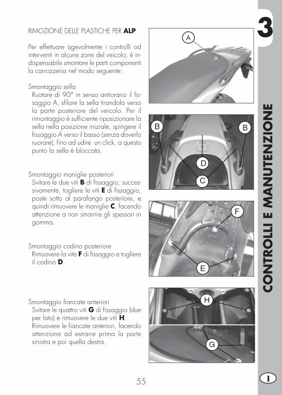
RIMOZIONE DELLE PLASTICHE PER ALP
Per effettuare agevolmente i controlli od interventi in alcune zone del veicolo, è in-dispensabile smontare le parti componenti la carrozzeria nel modo seguente:
Smontaggio sella• Ruotare di 90° in senso antiorario il fi s-saggio A, sfi lare la sella tirandola verso la parte posteriore del veicolo. Per il rimontaggio è suffi ciente riposizionare la sella nella posizione iniziale, spingere il fi ssaggio A verso il basso (senza doverlo ruorare), fi no ad udire un click. a questo punto la sella è bloccata.
Smontaggio maniglie posteriori• Svitare le due viti B di fi ssaggio, succes-sivamente, togliere le viti E di fi ssaggio, poste sotto al parafango posteriore, e quindi rimuovere le maniglie C, facendo attenzione a non smarrire gli spessori in gomma.
Smontaggio codino posteriore• Rimuovere la vite F di fi ssaggio e togliere il codino D.
Smontaggio fi ancate anteriori• Svitare le quattro viti G di fi ssaggio (due per lato) e rimuovere le due viti H.
• Rimuovere le fi ancate anteriori, facendo attenzione ad estrarre prima la parte sinistra e poi quella destra.
A
3CO
NTR
OLL
I E
MA
NU
TEN
ZIO
NE
56I
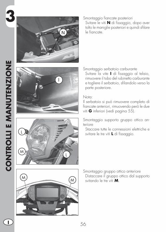
Smontaggio fi ancate posteriori• Svitare le viti N di fi ssaggio, dopo aver tolto le maniglie posteriori e quindi sfi lare le fi ancate.
Smontaggio serbatoio carburante• Svitare la vite I di fi ssaggio al telaio, rimuovere il tubo del rubinetto carburante e togliere il serbatoio, sfi landolo verso la parte posteriore.
Nota:Il serbatoio si può rimuovere completo di fi ancate anteriori, rimuovendo però le due viti G inferiori (vedi pagina 55).
Smontaggio supporto gruppo ottico an-teriore• Staccare tutte le connessioni elettriche e svitare le tre viti L di fi ssaggio.
Smontaggio gruppo ottico anteriore• Distaccare il gruppo ottico dal supporto svitando le tre viti M.
L
L
M
MM
3
CO
NTR
OLL
I E
MA
NU
TEN
ZIO
NE
57 I
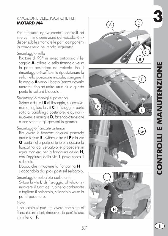
RIMOZIONE DELLE PLASTICHE PER MOTARD M4
Per effettuare agevolmente i controlli od interventi in alcune zone del veicolo, è in-dispensabile smontare le parti componenti la carrozzeria nel modo seguente:
Smontaggio sella• Ruotare di 90° in senso antiorario il fi s-saggio A, sfi lare la sella tirandola verso la parte posteriore del veicolo. Per il rimontaggio è suffi ciente riposizionare la sella nella posizione iniziale, spingere il fi ssaggio A verso il basso (senza doverlo ruorare), fi no ad udire un click. a questo punto la sella è bloccata.
Smontaggio maniglie posteriori• Svitare le due viti B di fi ssaggio, successiva-mente, togliere le viti C di fi ssaggio, poste sotto al parafango posteriore, e quindi ri-muovere le maniglie D, facendo attenzione a non smarrire gli spessori in gomma.
Smontaggio fi ancate anteriori• Rimuovere le fi ancate anteriori partendo quella sinistra E. Svitare le tre viti F e la vite G posta nella parte anteriore, staccare la fi ancatina dal serbatoio e procedere in ugual maniera per la fi ancatina destra H, con l’aggiunta della vite I posta sopra il serbatoio.
Dopodiche rimuovere la fi ancatina H staccandola dai pioli posti sul serbatoio.
Smontaggio serbatoio carburante• Svitare la vite L di fi ssaggio al telaio, ri-muovere il tubo del rubinetto carburante e togliere il serbatoio, sfi landolo verso la parte posteriore.
Nota:Il serbatoio si può rimuovere completo di fi ancate anteriori, rimuovendo però le due viti inferiori F.
B
A
C
D
F
G
E
I
H
L
3CO
NTR
OLL
I E
MA
NU
TEN
ZIO
NE
58I
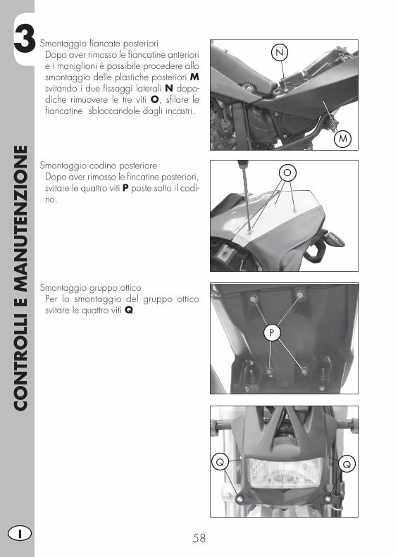
Smontaggio fi ancate posteriori• Dopo aver rimosso le fi ancatine anteriori e i maniglioni è possibile procedere allo smontaggio delle plastiche posteriori M svitando i due fi ssaggi laterali N dopo-diche rimuovere le tre viti O, sfi lare le fi ancatine sbloccandole dagli incastri.
M
N
OSmontaggio codino posteriore• Dopo aver rimosso le fi ncatine posteriori, svitare le quattro viti P poste sotto il codi-no.
P
Smontaggio gruppo ottico• Per lo smontaggio del gruppo ottico svitare le quattro viti Q.
Q Q

3
CO
NTR
OLL
I E
MA
NU
TEN
ZIO
NE
59 I
NOTE PER FUORISTRADA
Per un utilizzo del veicolo in fuoristrada è possibile smontare le parti ritenute ingom-branti come: il portatarga, il cavalletto, l’indicatore di direzione e le pedane passeggero.
Smontaggio cavalletto• Rimuovere l’interruttore cavalletto svitando l’unica vite di fi ssaggio C.
• Togliere facendo attenzione, la molla D di ritorno del cavalletto e il cavalletto stesso.
• Il veicolo è dotato di interruttore di recu-pero sul cavalletto, sarà quindi necessa-rio “ponticellare” le connessioni elettriche dell’interruttore.
Smontaggio pedane passeggero• Svitare le due viti E indicate in fi gura e rimuovere la pedana passeggero com-pleta di supporto attacco al telaio.
3CO
NTR
OLL
I E
MA
NU
TEN
ZIO
NE
60I
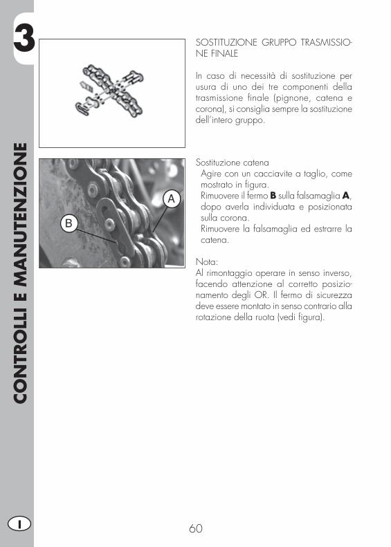
Sostituzione catena• Agire con un cacciavite a taglio, come mostrato in fi gura.
• Rimuovere il fermo B sulla falsamaglia A, dopo averla individuata e posizionata sulla corona.
• Rimuovere la falsamaglia ed estrarre la catena.
Nota:Al rimontaggio operare in senso inverso, facendo attenzione al corretto posizio-namento degli OR. Il fermo di sicurezza deve essere montato in senso contrario alla rotazione della ruota (vedi fi gura).
SOSTITUZIONE GRUPPO TRASMISSIO-NE FINALE
In caso di necessità di sostituzione per usura di uno dei tre componenti della trasmissione fi nale (pignone, catena e corona), si consiglia sempre la sostituzione dell’intero gruppo.

3
CO
NTR
OLL
I E
MA
NU
TEN
ZIO
NE
61 I
Sostituzione pignone catena• Allentare la ruota posteriore.• Allentare i registri catena.• Far avanzare la ruota fi no a fi ne corsa, in modo da poter allentare la catena.
• Svitare le 2 viti F di fi ssaggio del coper-chietto.
Sostituzione corona• Per la sostituzione della corona, rimuove-re la ruota posteriore, allentando prima i registri destri e sinistri A e B, e successi-vamente svitando il dado dell’asse ruota C.
• È necessario spostare le ruote verso la parte anteriore del veicolo, per allentare la tensione della catena.
• Svitare le sei viti D di fi ssaggio della corona.
• Per il rimontaggio, operare in senso in-verso, utilizzando frenafi letti sulle sei viti di fi ssaggio.
• Inserire la prima marcia e togliere il see-ger G di fi ssaggio pignone.
• È necessario spostare le ruote verso la parte anteriore del veicolo, per allentare la tensione della catena.
• Procedere con la sostituzione del pignone catena.
• Per il rimontaggio procedere in senso inverso allo smontaggio.
3CO
NTR
OLL
I E
MA
NU
TEN
ZIO
NE
62I
PULIZIA DEL VEICOLO E CONTROLLI
Per ammorbidire lo sporco e il fango depositato sulle superfi ci verniciate usare un getto di acqua. Una volta ammorbiditi, fango e sporcizia sono asportabili con una spugna soffi ce per carrozzeria imbevuta di molta acqua e “shampoo” (2-4% di shampoo in acqua). Successivamente sciacquare abbondantemente con acqua, ed asciugare con soffi o di aria e panno o pelle scamosciata. Per l’esterno del motore servirsi di petrolio, pennello e stracci puliti. Il petrolio è dannoso per la vernice. Si ricorda che l’eventuale lucidatura con cere siliconiche deve essere sempre preceduta dal lavaggio.
I detersivi inquinano le acque. Pertanto il lavaggio del veicolo va effettuato in zone attrezzate per la raccolta e la depurazione dei liquidi impiegati per il lavaggio stesso.
Il lavaggio non deve mai essere eseguito al sole specialmente d’estate quando la carrozzeria è ancora calda in quanto lo shampoo, asciugandosi prima del risciacquo, può causare danni alla vernice. Non usare mai stracci imbevuti
di benzina o nafta per il lavaggio delle superfi ci verniciate o in materia plastica, per evitare la perdita della loro brillantezza e delle caratteristiche meccaniche dei materiali.
CONTROLLI DOPO LA PULIZIA
Dopo la pulizia del motociclo è buona norma:
• Pulire il fi ltro dell’aria (procedere come descritto a pag. 51).• Svuotare la vaschetta del carburatore allentando la vite scarico benzina (procedere come descritto a pag. 54) per controllare l’eventuale presenza di acqua.
• Lubrifi care la catena.
3
CO
NTR
OLL
I E
MA
NU
TEN
ZIO
NE
63 I
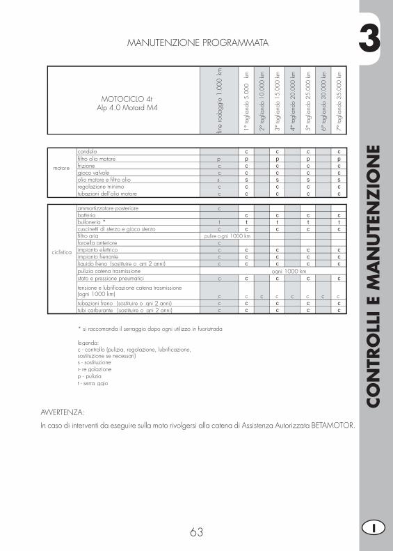
MANUTENZIONE PROGRAMMATA
AVVERTENZA:
In caso di interventi da eseguire sulla moto rivolgersi alla catena di Assistenza Autorizzata BETAMOTOR.
c s c s c s cp p p s p s pc c c s c c cc c c c c c cs s s s s s sc c c c c c cc c c c c c c
c c cc c c s c c ct t t t t t tc c c c c c c
s s sc c c
c c c c c c cc c c c c c cc c c c c c c
c c c c c c c
c c c c c c cc c c c c c c
MOTOCICLO 4t Alp 4.0 Motard M4
fine
roda
ggio
1.0
00 k
m
1° ta
glia
ndo
5.00
0 k
m
2° ta
glia
ndo
10.0
00 k
m
3° ta
glia
ndo
15.0
00 k
m
4° ta
glia
ndo
20.0
00 k
m
5° ta
glia
ndo
25.0
00 k
m
6° ta
glia
ndo
30.0
00 k
m
7° ta
glia
ndo
35.0
00 k
m
motore
candelafiltro olio motore p frizione cgioco valvole colio motore e filtro olio s regolazione minimotubazioni dell'olio motore c
ciclistica
ammortizzatore posteriore cbatteriabulloneria * tcuscinetti di sterzo e gioco sterzo cfiltro ariaforcella anteriore cimpianto elettrico cimpianto frenante cliquido freno (sostituire o gni 2 anni) cpulizia catena trasmissionestato e pressione pneumatici c
tensione e lubrificazione catena trasmissione (ogni 1000 km) c c c c c c c ctubazioni freno (sostituire o gni 2 anni) ctubi carburante (sostituire o gni 2 anni) c
* si raccomanda il serraggio dopo ogni utilizzo in fuoristrada
legenda:c - controllo (pulizia, regolazione, lubrificazione, sostituzione se necessari)s - sostituzioner- re golazionep - puliziat - serra ggio
pulire o gni 1000 km
ogni 1000 km
c

3CO
NTR
OLL
I E
MA
NU
TEN
ZIO
NE
64I
LUNGA INATTIVITÀ DEL VEICOLO
In previsione di un lungo periodo di inattività del veicolo, ad esempio durante la stagione invernale, è necessario adottare alcuni semplici accorgimenti a garanzia di un buon mantenimento:• Eseguire un’accurata pulizia del veicolo in tutte le sue parti.• Ridurre la pressione dei pneumatici di circa il 30%, mantenendoli possibilmente sollevati da terra.
• Rimuovere la candela ed immettere dal foro qualche goccia di olio motore. Far compiere qualche giro al motore, azionando la leva di avviamento a pedale (dove previsto). Riavvitare la candela.
• Coprire con un velo d’olio o silicone spray le parti non verniciate, tranne le parti in gomma ed i freni.
• Rimuovere la batteria e conservarla in luogo asciutto, ricaricandola una volta al mese.
• Coprire il veicolo con un telo a protezione della polvere.
• Scaricare la vaschetta del carburatore agendo sull’apposita vite A. Il carburante espulso dalla vaschetta tramite un’ap-posita tubazione deve essere raccolto all’interno di un recipiente e immesso nel serbatoio carburante senza disperderlo nell’ambiente.
• Serrare nuovamente la vite.
DOPO UN LUNGO PERIODO DI INAT-TIVITÀ
• Rimontare la batteria.• Ripristinare la pressione dei pneumatici.• Controllare il serraggio di tutte le viti di una certa importanza meccanica.
Nota: Il controllo del serraggio delle viti deve es-sere ripetuto con una frequenza periodica.
• Effettuare il primo avviamento con il sistema a pedale: “kick-starter” (dove previsto).
4
REG
OLA
ZIO
NI
65 I
INDICE ARGOMENTI
CAP. 4 REGOLAZIONI
Regolazione freni
Regolazione frizione
Regolazione ammortizzatore posteriore
Regolazione minimo
Regolazione gioco gas
Controllo e regolazione gioco sterzo
Tensionamento catena
Fascio luminoso
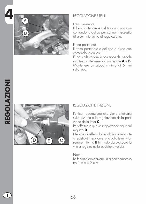
4REG
OLA
ZIO
NI
66I
REGOLAZIONE FRENI
Freno anterioreIl freno anteriore è del tipo a disco con comando idraulico per cui non necessita di alcun intervento di regolazione.
Freno posterioreIl freno posteriore è del tipo a disco con comando idraulico.E’ possibile variare la posizione del pedale in altezza intervenendo sui registri A e B.Mantenere un gioco minimo di 5 mm sulla leva.
REGOLAZIONE FRIZIONE
L’unica operazione che viene effettuata sulla frizione è la regolazione della posi-zione della leva C.Per effettuare questa regolazione agire sul registro D.Nel caso si effettui la regolazione sulla vite a registro è importante, una volta terminata, serrare il fermo E in modo da bloccare la vite a registro nella posizione voluta.
Nota:La frizione deve avere un gioco compreso tra 1 mm e 2 mm.

4
REG
OLA
ZIO
NI
67 I
REGOLAZIONE AMMORTIZZATORE POSTERIOREPer effettuare la regolazione del precarico molla, agire con una chiave a settore, prima sulla controghiera A per sbloccare la ghiera B di regolazione.Una volta trovata la regolazione ottimale, serrare la ghiera B e la controghiera A.
ATTENZIONE:Per la regolazione dell’ammortizzatore posteriore ALP 4.0, considerare che la lunghezza della molla con precarico stan-dard è di 194 mm, mentre la lunghezza della molla dell’ammortizzatore posteriore del MOTARD M4 con precarico standard è di 235 mm.
REGOLAZIONE MINIMO
Per eseguire correttamente questa opera-zione, si consiglia di effettuarla a motore caldo, collegando un contagiri elettronico al cavo candela. Intervenire poi sulla vite di registro A tarando il minimo (n° giri motore 1500 ± 100).
REGOLAZIONE GIOCO GAS
Qualora sul comando dell’acceleratore sia presente una corsa a vuoto superiore ai 3 mm misurati sul bordo della manopola stessa, occorre effettuarne la regolazione agendo sul registro B della manopola.

4REG
OLA
ZIO
NI
68I
CONTROLLO E REGOLAZIONE GIOCO STERZOVerifi care periodicamente il gioco del can-notto di sterzo muovendo avanti e indietro le forcelle come illustrato in fi gura. Qua-lora si avverta del gioco, procedere alla regolazione operando nel modo seguente:
• Svitare le 4 viti C.• Estrarre il manubrio D, porgendo parti-colare attenzione ai cavallotti E.
• Allentare il dado F.• Recuperare il gioco intervenendo sulla ghiera G.
Per il ribloccaggio procedere nel modo inverso.
Nota:Una corretta regolazione, oltre a non lasciare del gioco, non deve causare indurimenti o irregolarità durante la rota-zione del manubrio; verifi care il senso di montaggio dei cavallotti che può variare l’assetto del manubrio.
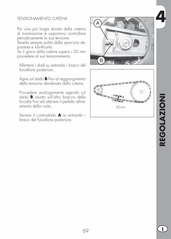
4
REG
OLA
ZIO
NI
69 I
TENSIONAMENTO CATENA
Per una più lunga durata della catena di trasmissione è opportuno controllare periodicamente la sua tensione.Tenerla sempre pulita dalla sporcizia de-positata e lubrifi carla.Se il gioco della catena supera i 20 mm procedere al suo tensionamento.
• Allentare i dadi su entrambi i bracci del forcellone posteriore.
• Agire sul dado B fi no al raggiungimento della tensione desiderata della catena.
• Procedere analogamente agendo sul dado B situato sull’altro braccio della forcella fi no ad ottenere il perfetto alline-amento della ruota.
• Serrare il controdado A su entrambi i bracci del forcellone posteriore.
20 mm
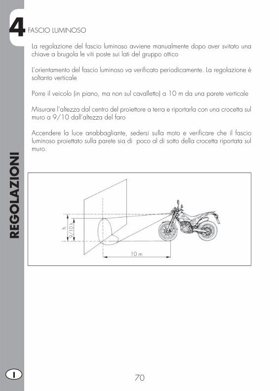
4REG
OLA
ZIO
NI
70I
FASCIO LUMINOSO
• La regolazione del fascio luminoso avviene manualmente dopo aver svitato una chiave a brugola le viti poste sui lati del gruppo ottico
• L’orientamento del fascio luminoso va verifi cato periodicamente. La regolazione è soltanto verticale
• Porre il veicolo (in piano, ma non sul cavalletto) a 10 m da una parete verticale
• Misurare l’altezza dal centro del proiettore a terra e riportarla con una crocetta sul muro a 9/10 dall’altezza del faro
• Accendere la luce anabbagliante, sedersi sulla moto e verifi care che il fascio luminoso proiettato sulla parete sia di poco al di sotto della crocetta riportata sul muro.
9/10
h
10 m
h
5
SOST
ITU
ZIO
NI
71 I
INDICE ARGOMENTI
CAP. 5 SOSTITUZIONI
Sostituzione pastiglie freno anteriore
Sostituzione pastiglie freno posteriore
Sostituzione lampada faro ALP
Sostituzione lampada faro MOTARD M4
Sostituzione indicatori di direzione e fanalino posteriore
Sostituzione luce targa
Caratteristiche lampade

5SO
STIT
UZ
ION
I
72I
SOSTITUZIONE PASTIGLIE FRENO AN-TERIORE
La descrizione relativa alla sostituzione del-le pastiglie, riveste un carattere puramente informativo; infatti è consigliabile rivolgersi ad un’offi cina autorizzata BETAMOTOR per effettuare questa operazione.
FRENO ANTERIORE PER ALP 4.0
Per la sostituzione occorre procedere nel seguente modo:
• Smontare la pinza svitando le due viti A
• Svitare le due viti B
• Estrarre le pastiglie
• Per il rimontaggio procedere in senso inverso, utilizzando frenafi letti sulle viti A.
ATTENZIONE: Durante lo smontaggio della pinza freno anteriore fare attenzione a non danneg-giare il sensore C.
Prestare particolare attenzione ad effettua-re correttamente il rimontaggio delle viti per evitare problemi di frenata.
Nel caso di rimozione del disco freno, nel rimontaggio applicare del frenafi letti alle viti.
A
B
C
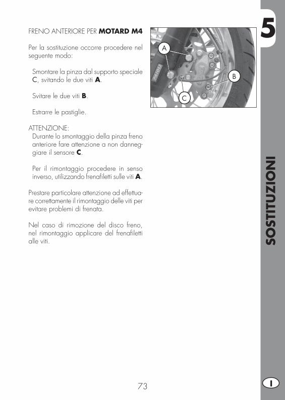
5
SOST
ITU
ZIO
NI
73 I
FRENO ANTERIORE PER MOTARD M4
Per la sostituzione occorre procedere nel seguente modo:
• Smontare la pinza dal supporto speciale C, svitando le due viti A.
• Svitare le due viti B.
• Estrarre le pastiglie.
ATTENZIONE: Durante lo smontaggio della pinza freno anteriore fare attenzione a non danneg-giare il sensore C.
• Per il rimontaggio procedere in senso inverso, utilizzando frenafi letti sulle viti A.
Prestare particolare attenzione ad effettua-re correttamente il rimontaggio delle viti per evitare problemi di frenata.
Nel caso di rimozione del disco freno, nel rimontaggio applicare del frenafi letti alle viti.
A
B
C

5SO
STIT
UZ
ION
I
74I
Per la sostituzione occorre procedere nel seguente modo:
• Posizionare la moto su un cavalletto cen-trale, con la ruota posteriore sollevata da terra.
• Allentare il registro ruota A destro e sinistro e rimuovere l’asse ruota B.
SOSTITUZIONE PASTIGLIE FRENO PO-STERIORELa descrizione relativa alla sostituzione del-le pastiglie, riveste un carattere puramente informativo; infatti è consigliabile rivolgersi ad un’offi cina autorizzata BETAMOTOR per effettuare questa operazione.
• Estrarre la pinza freno completa di pia-stra.
• Togliere i ferodi consumati e sostituirli con nuovi della stessa tipologia.
• Per il rimontaggio procedere in senso in-verso a quello descritto precedentemente.
• È necessario assicurarsi di aver posizio-nato le pastiglie nel modo corretto, dopo aver montato pinza e supporto ruota, utilizzando la leva freno per chiudere il pistone della pinza, in modo da verifi ca-re subito l’esatto montaggio.
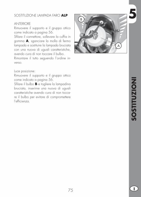
5
SOST
ITU
ZIO
NI
75 I
SOSTITUZIONE LAMPADA FARO ALP
ANTERIORE Rimuovere il supporto e il gruppo ottico come indicato a pagina 56.Sfi lare il connettore, sollevare la cuffi a in gomma A, sganciare la molla di fermo lampada e sostituire la lampada bruciata con una nuova di uguali caratteristiche, avendo cura di non toccare il bulbo.Rimontare il tutto seguendo l’ordine in-verso.
Luce posizione:Rimuovere il supporto e il gruppo ottico come indicato a pagina 56.Sfi lare il bulbo B e togliere la lampadina bruciata, inserirne una nuova di uguali caratteristiche avendo cura di non tocca-re il bulbo per evitare di compromettere l’effi cienza.
A
B
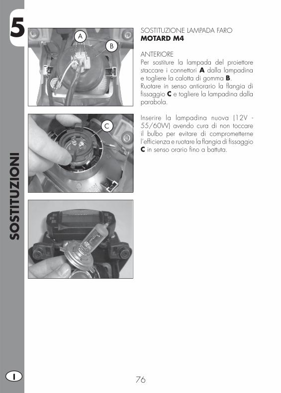
5SO
STIT
UZ
ION
I
76I
SOSTITUZIONE LAMPADA FARO MOTARD M4
ANTERIOREPer sostiture la lampada del proiettore staccare i connettori A dalla lampadina e togliere la calotta di gomma B.Ruotare in senso antiorario la fl angia di fi ssaggio C e togliere la lampadina dalla parabola.
Inserire la lampadina nuova (12V - 55/60W) avendo cura di non toccare il bulbo per evitare di comprometterne l’effi cienza e ruotare la fl angia di fi ssaggio C in senso orario fi no a battuta.
AB
C
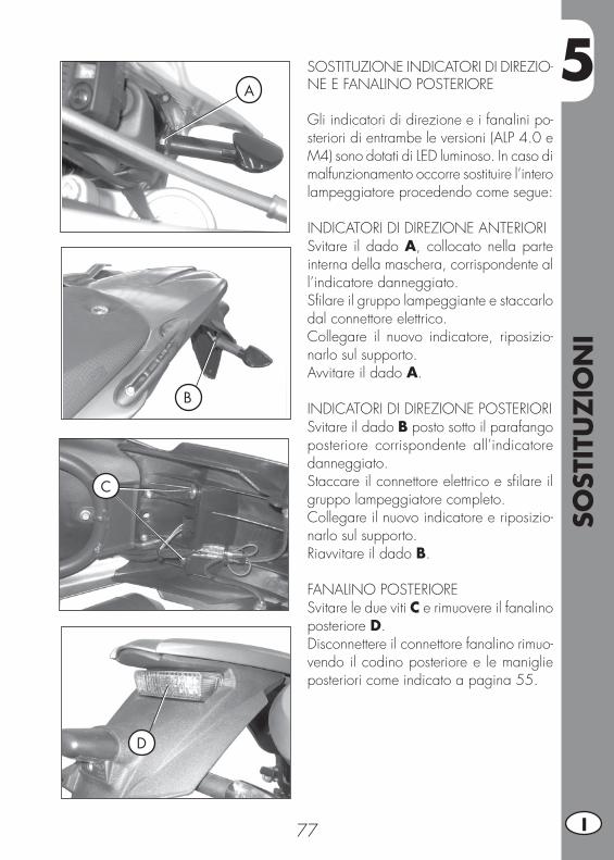
5
SOST
ITU
ZIO
NI
77 I
SOSTITUZIONE INDICATORI DI DIREZIO-NE E FANALINO POSTERIORE
Gli indicatori di direzione e i fanalini po-steriori di entrambe le versioni (ALP 4.0 e M4) sono dotati di LED luminoso. In caso di malfunzionamento occorre sostituire l’intero lampeggiatore procedendo come segue:
INDICATORI DI DIREZIONE ANTERIORISvitare il dado A, collocato nella parte interna della maschera, corrispondente al l’indicatore danneggiato.Sfi lare il gruppo lampeggiante e staccarlo dal connettore elettrico.Collegare il nuovo indicatore, riposizio-narlo sul supporto.Avvitare il dado A.
INDICATORI DI DIREZIONE POSTERIORISvitare il dado B posto sotto il parafango posteriore corrispondente all’indicatore danneggiato.Staccare il connettore elettrico e sfi lare il gruppo lampeggiatore completo.Collegare il nuovo indicatore e riposizio-narlo sul supporto.Riavvitare il dado B.
FANALINO POSTERIORESvitare le due viti C e rimuovere il fanalino posteriore D.Disconnettere il connettore fanalino rimuo-vendo il codino posteriore e le maniglie posteriori come indicato a pagina 55.
A
B
D
C
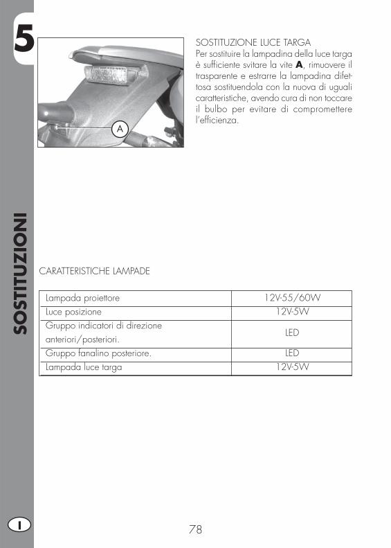
5SO
STIT
UZ
ION
I
78I
Lampada proiettore 12V-55/60W Luce posizione 12V-5W Gruppo indicatori di direzione anteriori/posteriori.
LED
Gruppo fanalino posteriore. LED Lampada luce targa 12V-5W
CARATTERISTICHE LAMPADE
A
SOSTITUZIONE LUCE TARGAPer sostituire la lampadina della luce targa è suffi ciente svitare la vite A, rimuovere il trasparente e estrarre la lampadina difet-tosa sostituendola con la nuova di uguali caratteristiche, avendo cura di non toccare il bulbo per evitare di compromettere l’effi cienza.
6
CO
SA F
ARE
IN C
ASO
DI EM
ERG
ENZ
A
79 I
INDICE ARGOMENTI
CAP. 6 COSA FARE IN CASO DI EMERGENZA
INDICE ALFABETICO
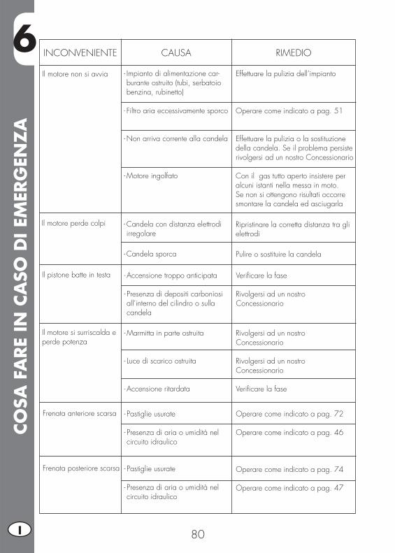
6CO
SA F
ARE
IN C
ASO
DI EM
ERG
ENZ
A
80I
INCONVENIENTE CAUSA
Il motore non si avvia
RIMEDIO
- Impianto di alimentazione car-burante ostruito (tubi, serbatoio benzina, rubinetto)
- Filtro aria eccessivamente sporco
- Non arriva corrente alla candela
- Motore ingolfato
Effettuare la pulizia dell’impianto
Operare come indicato a pag. 51
Effettuare la pulizia o la sostituzione della candela. Se il problema persiste rivolgersi ad un nostro Concessionario
Con il gas tutto aperto insistere per alcuni istanti nella messa in moto. Se non si ottengono risultati occorre smontare la candela ed asciugarla
Il motore perde colpi - Candela con distanza elettrodi irregolare
- Candela sporca
Ripristinare la corretta distanza tra gli elettrodi
Pulire o sostituire la candela
Il pistone batte in testa - Accensione troppo anticipata
- Presenza di depositi carboniosi all’interno del cilindro o sulla candela
Verifi care la fase
Rivolgersi ad un nostro Concessionario
Il motore si surriscalda e perde potenza
- Marmitta in parte ostruita
- Luce di scarico ostruita
- Accensione ritardata
Rivolgersi ad un nostro Concessionario
Rivolgersi ad un nostro Concessionario
Verifi care la fase
Frenata anteriore scarsa - Pastiglie usurate
- Presenza di aria o umidità nel circuito idraulico
Operare come indicato a pag. 72
Operare come indicato a pag. 46
Frenata posteriore scarsa - Pastiglie usurate
- Presenza di aria o umidità nel circuito idraulico
Operare come indicato a pag. 74
Operare come indicato a pag. 47
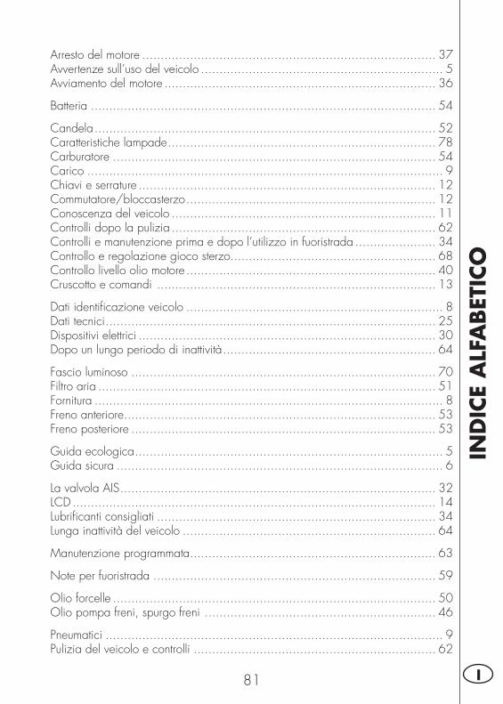
IND
ICE
ALF
ABET
ICO
81 I
Arresto del motore ................................................................................ 37Avvertenze sull’uso del veicolo .................................................................. 5Avviamento del motore .......................................................................... 36
Batteria .............................................................................................. 54
Candela ............................................................................................. 52Caratteristiche lampade ......................................................................... 78Carburatore ........................................................................................ 54Carico ................................................................................................. 9Chiavi e serrature ................................................................................. 12Commutatore/bloccasterzo .................................................................... 12Conoscenza del veicolo ........................................................................ 11Controlli dopo la pulizia ........................................................................ 62Controlli e manutenzione prima e dopo l’utilizzo in fuoristrada ...................... 34Controllo e regolazione gioco sterzo........................................................ 68Controllo livello olio motore .................................................................... 40Cruscotto e comandi ............................................................................ 13
Dati identifi cazione veicolo ...................................................................... 8Dati tecnici .......................................................................................... 25Dispositivi elettrici ................................................................................. 30Dopo un lungo periodo di inattività .......................................................... 64
Fascio luminoso ................................................................................... 70Filtro aria ............................................................................................ 51Fornitura ............................................................................................... 8Freno anteriore ..................................................................................... 53Freno posteriore ................................................................................... 53
Guida ecologica .................................................................................... 5Guida sicura ......................................................................................... 6
La valvola AIS ...................................................................................... 32LCD ................................................................................................... 14Lubrifi canti consigliati ............................................................................ 34Lunga inattività del veicolo ..................................................................... 64
Manutenzione programmata ................................................................... 63
Note per fuoristrada ............................................................................. 59
Olio forcelle ........................................................................................ 50Olio pompa freni, spurgo freni ............................................................... 46
Pneumatici ............................................................................................ 9Pulizia del veicolo e controlli .................................................................. 62
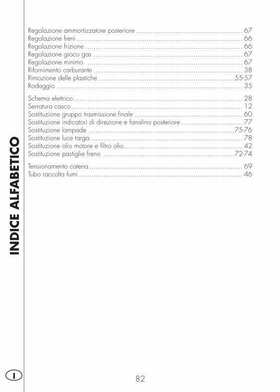
IND
ICE
ALF
ABET
ICO
82I
Regolazione ammortizzatore posteriore .................................................... 67Regolazione freni ................................................................................. 66Regolazione frizione ............................................................................. 66Regolazione gioco gas ......................................................................... 67Regolazione minimo ............................................................................ 67Rifornimento carburante ......................................................................... 38Rimozione delle plastiche ...................................................................55-57Rodaggio ........................................................................................... 35
Schema elettrico ................................................................................... 28Serratura casco .................................................................................... 12Sostituzione gruppo trasmissione fi nale ..................................................... 60Sostituzione indicatori di direzione e fanalino posteriore .............................. 77Sostituzione lampade .......................................................................75-76Sostituzione luce targa........................................................................... 78Sostituzione olio motore e fi ltro olio .......................................................... 42Sostituzione pastiglie freno ................................................................72-74
Tensionamento catena ........................................................................... 69Tubo raccolta fumi ................................................................................ 46

83 GB
ALP 4.0 - MOTARD M4
Thanks for you preference, and have a good time! This hand-book contains the information you need to properly operate and maintain your motorcycle.
The data and specifi cations provided in this manual does not constitute an engagement on the part of BETAMOTOR S.p.A. BETAMOTOR reserves the right to make any changes and improvements to its models at any moment and without notice.
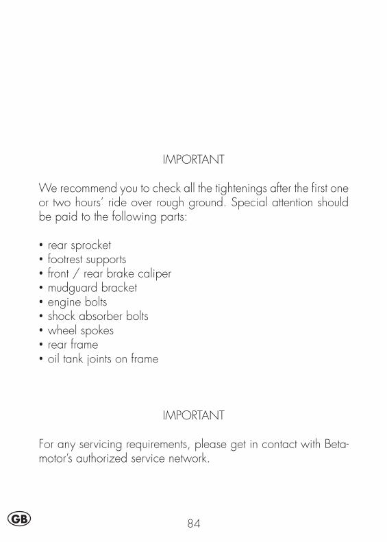
84GB
IMPORTANT
We recommend you to check all the tightenings after the fi rst one or two hours’ ride over rough ground. Special attention should be paid to the following parts:
• rear sprocket• footrest supports• front / rear brake caliper• mudguard bracket• engine bolts• shock absorber bolts• wheel spokes• rear frame• oil tank joints on frame
IMPORTANT
For any servicing requirements, please get in contact with Beta-motor’s authorized service network.
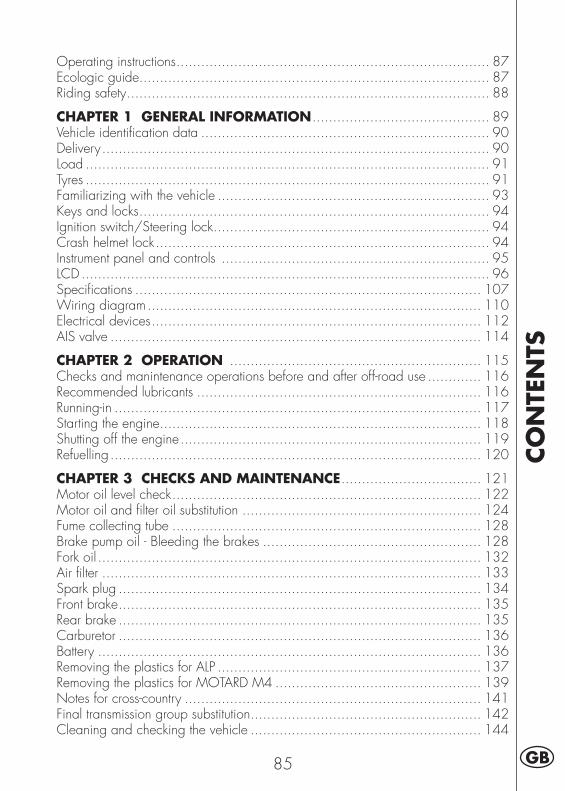
CO
NTE
NTS
85 GB
Operating instructions ............................................................................ 87Ecologic guide..................................................................................... 87Riding safety ........................................................................................ 88
CHAPTER 1 GENERAL INFORMATION ........................................... 89Vehicle identifi cation data ...................................................................... 90Delivery .............................................................................................. 90Load .................................................................................................. 91Tyres .................................................................................................. 91Familiarizing with the vehicle .................................................................. 93Keys and locks ..................................................................................... 94Ignition switch/Steering lock ................................................................... 94Crash helmet lock ................................................................................. 94Instrument panel and controls ................................................................. 95LCD ................................................................................................... 96Specifi cations .................................................................................... 107Wiring diagram ................................................................................. 110Electrical devices ................................................................................ 112AIS valve .......................................................................................... 114
CHAPTER 2 OPERATION ............................................................. 115Checks and manintenance operations before and after off-road use ............. 116Recommended lubricants ..................................................................... 116Running-in ......................................................................................... 117Starting the engine .............................................................................. 118Shutting off the engine ......................................................................... 119Refuelling .......................................................................................... 120
CHAPTER 3 CHECKS AND MAINTENANCE .................................. 121Motor oil level check ........................................................................... 122Motor oil and fi lter oil substitution .......................................................... 124Fume collecting tube ........................................................................... 128Brake pump oil - Bleeding the brakes ..................................................... 128Fork oil ............................................................................................. 132Air fi lter ............................................................................................ 133Spark plug ........................................................................................ 134Front brake ........................................................................................ 135Rear brake ........................................................................................ 135Carburetor ........................................................................................ 136Battery ............................................................................................. 136Removing the plastics for ALP ................................................................ 137Removing the plastics for MOTARD M4 .................................................. 139Notes for cross-country ........................................................................ 141Final transmission group substitution ........................................................ 142Cleaning and checking the vehicle ........................................................ 144
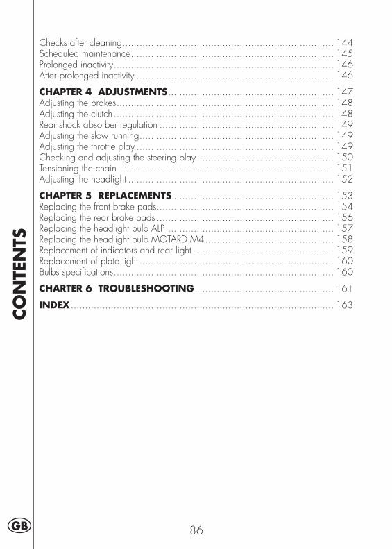
CO
NTE
NTS
86GB
Checks after cleaning .......................................................................... 144Scheduled maintenance ....................................................................... 145Prolonged inactivity ............................................................................. 146After prolonged inactivity ..................................................................... 146
CHAPTER 4 ADJUSTMENTS .......................................................... 147Adjusting the brakes ............................................................................ 148Adjusting the clutch ............................................................................. 148Rear shock absorber regulation ............................................................. 149Adjusting the slow running .................................................................... 149Adjusting the throttle play ..................................................................... 149Checking and adjusting the steering play ................................................ 150Tensioning the chain ............................................................................ 151Adjusting the headlight ........................................................................ 152
CHAPTER 5 REPLACEMENTS ........................................................ 153Replacing the front brake pads .............................................................. 154Replacing the rear brake pads .............................................................. 156Replacing the headlight bulb ALP .......................................................... 157Replacing the headlight bulb MOTARD M4 ............................................. 158Replacement of indicators and rear light ................................................ 159Replacement of plate light .................................................................... 160Bulbs specifi cations ............................................................................. 160
CHARTER 6 TROUBLESHOOTING ................................................ 161
INDEX ............................................................................................ 163
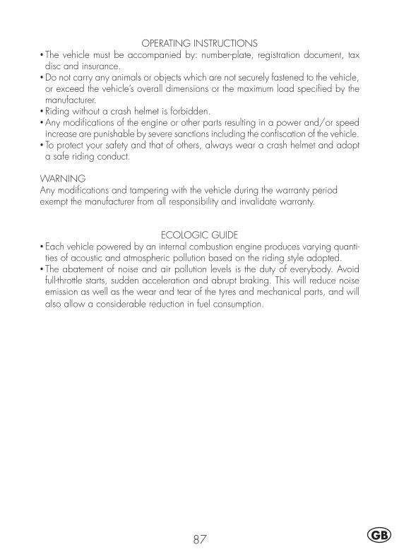
87 GB
OPERATING INSTRUCTIONS• The vehicle must be accompanied by: number-plate, registration document, tax disc and insurance.
• Do not carry any animals or objects which are not securely fastened to the vehicle, or exceed the vehicle’s overall dimensions or the maximum load specifi ed by the manufacturer.
• Riding without a crash helmet is forbidden.• Any modifi cations of the engine or other parts resulting in a power and/or speed increase are punishable by severe sanctions including the confi scation of the vehicle.
• To protect your safety and that of others, always wear a crash helmet and adopt a safe riding conduct.
WARNINGAny modifi cations and tampering with the vehicle during the warranty period exempt the manufacturer from all responsibility and invalidate warranty.
ECOLOGIC GUIDE• Each vehicle powered by an internal combustion engine produces varying quanti-ties of acoustic and atmospheric pollution based on the riding style adopted.
• The abatement of noise and air pollution levels is the duty of everybody. Avoid full-throttle starts, sudden acceleration and abrupt braking. This will reduce noise emission as well as the wear and tear of the tyres and mechanical parts, and will also allow a considerable reduction in fuel consumption.
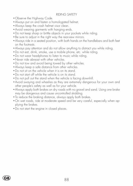
88GB
RIDING SAFETY• Observe the Highway Code.• Always put on and fasten a homologated helmet.• Always keep the crash helmet visor clean.• Avoid wearing garments with hanging ends.• Do not keep sharp or brittle objects in your pockets while riding.• Be sure to adjust in the right way the rearview mirrors.• Always ride in a seated position, with both hands on the handlebars and both feet on the footrests.
• Always pay attention and do not allow anything to distract you while riding.• Do not eat, drink, smoke, use a mobile phone, etc. while riding.• Do not wear headphones to listen to music while riding.• Never ride abreast with other vehicles.• Do not tow and avoid being towed by other vehicles.• Always keep a safe distance from other vehicles.• Do not sit on the vehicle when it is on its stand.• Do not start off while the vehicle is on its stand.• Do not pull out the stand when the vehicle is facing downhill.• Avoid swaying and wheelies as they are extremely dangerous for your own and other people’s safety as well as for your vehicle.
• Always apply both brakes on dry roads with no gravel and sand. Using one brake may be dangerous and cause uncontrolled skidding.
• To reduce the braking distance, always apply both brakes.• On wet roads, ride at moderate speed and be very careful, especially when ap-plying the brakes.
• Do not start the engine in closed places.
1
GEN
ERA
L IN
FORM
ATI
ON
89 GB
CONTENTS
CHAPTER 1 GENERAL INFORMATION
Vehicle identifi cation data
Delivery
Load
Tyres
Familiarizing with the vehicle
Keys and locks
Ignition switch/Steering lock
Crash helmet lock
Instrument panel and controls
LCD
Specifi cations
Wiring diagram
Electrical devices
AIS valve
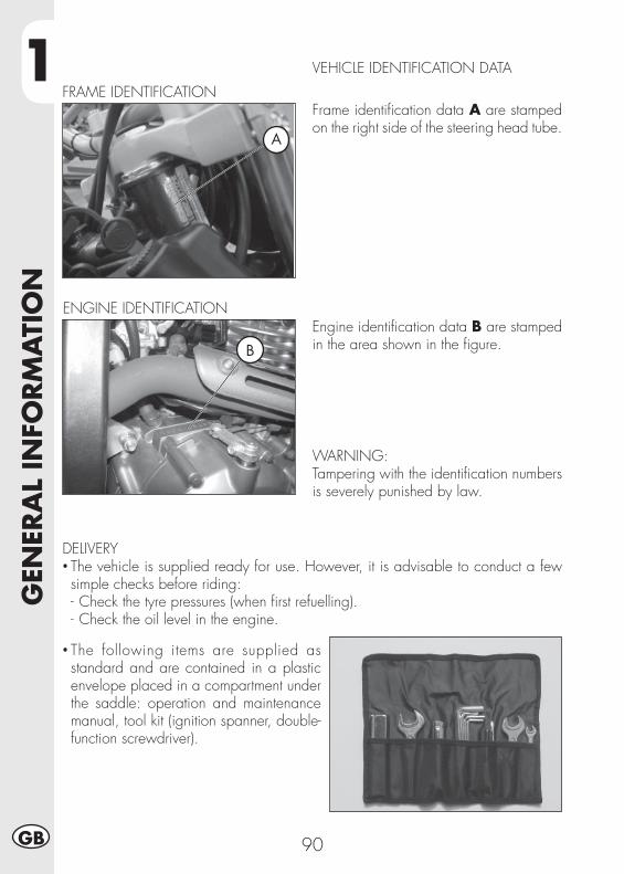
1G
ENER
AL
INFO
RM
ATI
ON
90GB
DELIVERY• The vehicle is supplied ready for use. However, it is advisable to conduct a few simple checks before riding:- Check the tyre pressures (when fi rst refuelling).- Check the oil level in the engine.
• The following items are supplied as standard and are contained in a plastic envelope placed in a compartment under the saddle: operation and maintenance manual, tool kit (ignition spanner, double-function screwdriver).
VEHICLE IDENTIFICATION DATA
Frame identifi cation data A are stamped on the right side of the steering head tube.
Engine identifi cation data B are stamped in the area shown in the fi gure.
WARNING:Tampering with the identifi cation numbers is severely punished by law.
ENGINE IDENTIFICATION
A
B
FRAME IDENTIFICATION
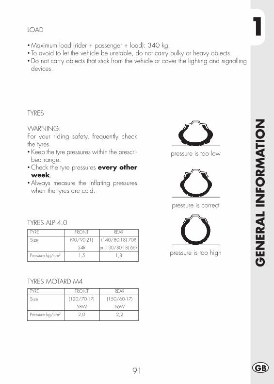
1
GEN
ERA
L IN
FORM
ATI
ON
91 GB
LOAD
• Maximum load (rider + passenger + load): 340 kg.• To avoid to let the vehicle be unstable, do not carry bulky or heavy objects.• Do not carry objects that stick from the vehicle or cover the lighting and signalling devices.
TYRES
WARNING:For your riding safety, frequently check the tyres.• Keep the tyre pressures within the prescri-bed range.
• Check the tyre pressures every other week.
• Always measure the infl ating pressures when the tyres are cold.
pressure is too low
pressure is correct
pressure is too high
TYRES ALP 4.0TYRE
Size
Pressure kg/cm2
REAR
(140/80-18) 70R
or (130/80-18) 66R
1,8
FRONT
(90/90-21)
54R
1,5
TYRES MOTARD M4TYRE
Size
Pressure kg/cm2
REAR
(150/60-17)
66W
2,2
FRONT
(120/70-17)
58W
2,0
1G
ENER
AL
INFO
RM
ATI
ON
92GB
Note:The tyre (TUBE TYPE) tread depth must never be less than 2 mm.Failure to comply with this rule is punished under the regulations in force.
• Before riding, check the tyres for cuts, cracks, abrasions, bulges, etc. If any defects are found, have the tyres checked by an expert as riding with a damaged tyre can be extremely dangerous.
• If a tyre gets punctured, stop the vehicle immediately. Riding with a fl at tyre is dangerous and may seriously damage the tyre itself and the wheel rim.
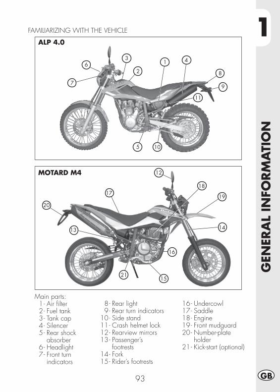
1
GEN
ERA
L IN
FORM
ATI
ON
93 GB
FAMILIARIZING WITH THE VEHICLE
Main parts: 1 - Air fi lter 2 - Fuel tank 3 - Tank cap 4 - Silencer 5 - Rear shock absorber 6 - Headlight 7 - Front turn indicators
8 - Rear light 9 - Rear turn indicators 10 - Side stand 11 - Crash helmet lock 12 - Rearview mirrors 13 - Passenger’s footrests 14 - Fork 15 - Rider’s footrests
16 - Undercowl 17 - Saddle 18 - Engine 19 - Front mudguard 20 - Number-plate holder 21 - Kick-start (optional)
ALP 4.0
MOTARD M4
7
10
6
5
3
2
1
8
9
4
11
20
17
12
18
19
14
16
21
13
15
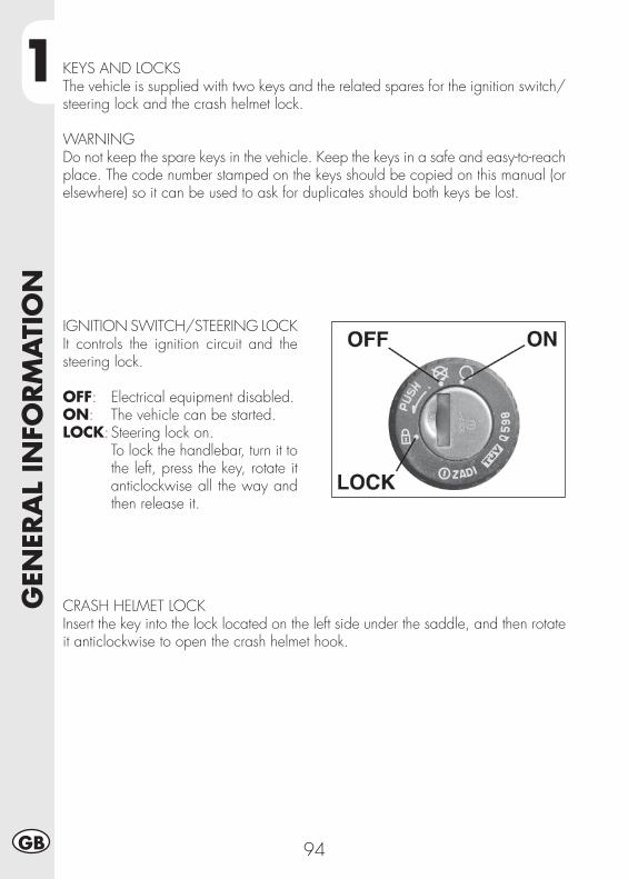
1G
ENER
AL
INFO
RM
ATI
ON
94GB
KEYS AND LOCKSThe vehicle is supplied with two keys and the related spares for the ignition switch/steering lock and the crash helmet lock.
WARNINGDo not keep the spare keys in the vehicle. Keep the keys in a safe and easy-to-reach place. The code number stamped on the keys should be copied on this manual (or elsewhere) so it can be used to ask for duplicates should both keys be lost.
IGNITION SWITCH/STEERING LOCKIt controls the ignition circuit and the steering lock.
OFF: Electrical equipment disabled.ON: The vehicle can be started.LOCK: Steering lock on. To lock the handlebar, turn it to
the left, press the key, rotate it anticlockwise all the way and then release it.
CRASH HELMET LOCKInsert the key into the lock located on the left side under the saddle, and then rotate it anticlockwise to open the crash helmet hook.
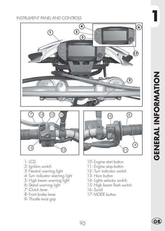
1
GEN
ERA
L IN
FORM
ATI
ON
95 GB
1 - LCD 2 - Ignition switch 3 - Neutral warning light 4 - Turn indicator warning light 5 - High beam warning light 6 - Stand warning light 7 - Clutch lever 8 - Front brake lever 9 - Throttle twist grip
10 - Engine start button11 - Engine stop button12 - Turn indicator switch13 - Horn button14 - Lights selector switch15 - High beam fl ash switch 16 - Scroll17- MODE button
INSTRUMENT PANEL AND CONTROLS
7 8
9
10
111213
14 15 16
1
2
3
5
17
4 6
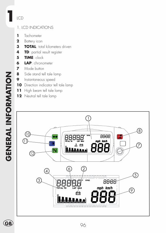
1G
ENER
AL
INFO
RM
ATI
ON
96GB
LCD
1. LCD INDICATIONS
1 Tachometer2 Battery icon3 TOTAL: total kilometers driven4 TD: partial result register5 TIME: clock6 LAP: chronometer 7 Mode button8 Side stand tell tale lamp9 Instantaneous speed 10 Direction indicator tell tale lamp11 High beam tell tale lamp12 Neutral tell tale lamp
2
3
45
7
6
9
1
10
11
12
8
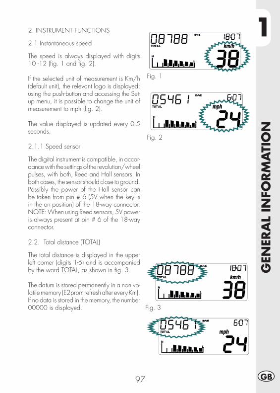
1
GEN
ERA
L IN
FORM
ATI
ON
97 GB
2. INSTRUMENT FUNCTIONS
2.1 Instantaneous speed
The speed is always displayed with digits 10 -12 (fi g. 1 and fi g. 2).
If the selected unit of measurement is Km/h (default unit), the relevant logo is displayed; using the push-button and accessing the Set-up menu, it is possible to change the unit of measurement to mph (fi g. 2).
The value displayed is updated every 0.5 seconds.
2.1.1 Speed sensor
The digital instrument is compatible, in accor-dance with the settings of the revolution/wheel pulses, with both, Reed and Hall sensors. In both cases, the sensor should close to ground.Possibly the power of the Hall sensor can be taken from pin # 6 (5V when the key is in the on position) of the 18-way connector.NOTE: When using Reed sensors, 5V power is always present at pin # 6 of the 18-way connector.
2.2. Total distance (TOTAL)
The total distance is displayed in the upper left corner (digits 1-5) and is accompanied by the word TOTAL, as shown in fi g. 3.
The datum is stored permanently in a non vo-latile memory (E2prom refresh after every Km).If no data is stored in the memory, the number 00000 is displayed.
Fig. 1
Fig. 2
Fig. 3
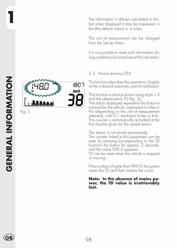
1G
ENER
AL
INFO
RM
ATI
ON
98GB
Fig. 5
2.3 Partial distance (TD)
This function describes the operation/display of the onboard automatic partial totalizator.
This function is always shown using digits 1-5 and the abbreviation TD (fi g. 5).The datum displayed represents the distance covered by the vehicle, expressed in miles or Km (depending on the unit of measurement selected), with 0.1 resolution (miles or Km).This counter is automatically activated at the fi rst impulse given by the speed sensor.
The datum is not stored permanently.The counter linked to this parameter can be reset by pressing (corresponding to the TD function) the button for approx. 2 seconds, until the value 000.0 appears. TD can be reset when the vehicle is stopped or moving.
If the number is higher than 999.9, the system resets the TD and then restarts the count.
Note: In the absence of mains po-wer, the TD value is irretrievably lost.
The information is always calculated in Km, but when displayed it may be expressed in Km (the default value) or in miles.
The unit of measurement can be changed from the Set-Up Menu.
It is not possible to reset such information du-ring conditions of normal use of the instrument.
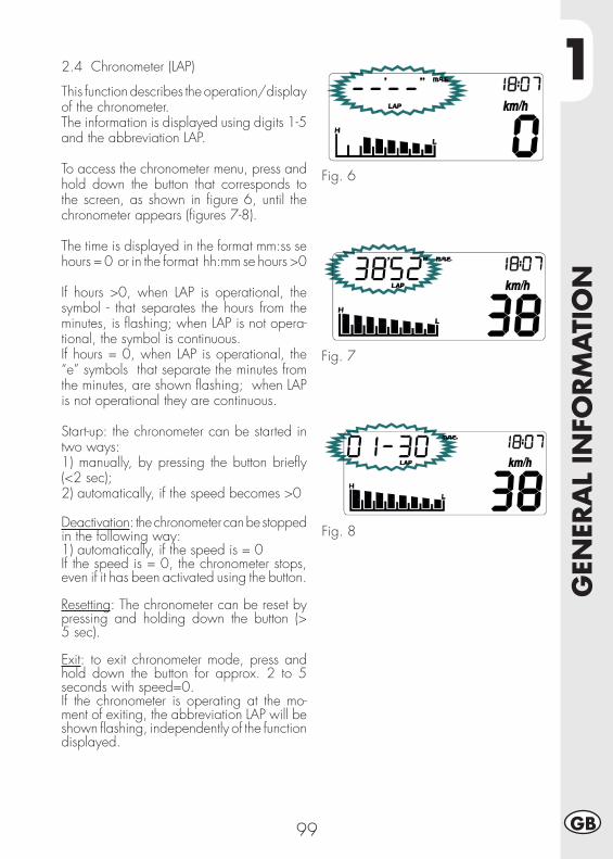
1
GEN
ERA
L IN
FORM
ATI
ON
99 GB
Fig. 6
Fig. 7
Fig. 8
2.4 Chronometer (LAP)
This function describes the operation/display of the chronometer.The information is displayed using digits 1-5 and the abbreviation LAP.
To access the chronometer menu, press and hold down the button that corresponds to the screen, as shown in fi gure 6, until the chronometer appears (fi gures 7-8).
The time is displayed in the format mm:ss se hours = 0 or in the format hh:mm se hours >0
If hours >0, when LAP is operational, the symbol - that separates the hours from the minutes, is fl ashing; when LAP is not opera-tional, the symbol is continuous.If hours = 0, when LAP is operational, the “e” symbols that separate the minutes from the minutes, are shown fl ashing; when LAP is not operational they are continuous.
Start-up: the chronometer can be started in two ways:1) manually, by pressing the button briefl y (<2 sec);2) automatically, if the speed becomes >0
Deactivation: the chronometer can be stopped in the following way:1) automatically, if the speed is = 0If the speed is = 0, the chronometer stops, even if it has been activated using the button.
Resetting: The chronometer can be reset by pressing and holding down the button (> 5 sec).
Exit: to exit chronometer mode, press and hold down the button for approx. 2 to 5 seconds with speed=0.If the chronometer is operating at the mo-ment of exiting, the abbreviation LAP will be shown fl ashing, independently of the function displayed.
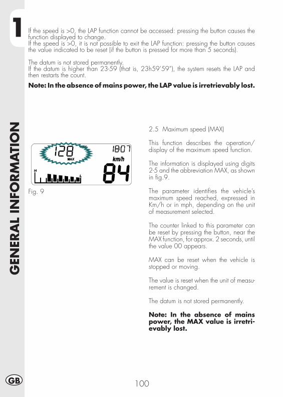
1G
ENER
AL
INFO
RM
ATI
ON
100GB
2.5 Maximum speed (MAX)
This function describes the operation/display of the maximum speed function.
The information is displayed using digits 2-5 and the abbreviation MAX, as shown in fi g.9.
The parameter identifi es the vehicle’s maximum speed reached, expressed in Km/h or in mph, depending on the unit of measurement selected.
The counter linked to this parameter can be reset by pressing the button, near the MAX function, for approx. 2 seconds, until the value 00 appears.
MAX can be reset when the vehicle is stopped or moving.
The value is reset when the unit of measu-rement is changed.
The datum is not stored permanently.
Note: In the absence of mains power, the MAX value is irretri-evably lost.
Fig. 9
If the speed is >0, the LAP function cannot be accessed: pressing the button causes the function displayed to change.If the speed is >0, it is not possible to exit the LAP function: pressing the button causes the value indicated to be reset (if the button is pressed for more than 5 seconds).
The datum is not stored permanently.If the datum is higher than 23-59 (that is, 23h59’59”), the system resets the LAP and then restarts the count.
Note: In the absence of mains power, the LAP value is irretrievably lost.
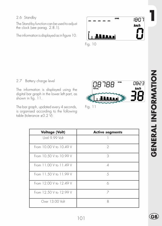
1
GEN
ERA
L IN
FORM
ATI
ON
101 GB
2.6 Standby
The Stand-by function can be used to adjust the clock (see parag. 2.8.1).
The information is displayed as in fi gure 10.
Fig. 10
2.7 Battery charge level
The information is displayed using the digital bar graph in the lower left part, as shown in fi g. 11.
The bar graph, updated every 4 seconds, is organised according to the following table (tolerance ±0.2 V):
Fig. 11
Voltage (Volt) Active segments
Until 9.99 Volt 1
From 10.00 V to 10.49 V 2
From 10.50 V to 10.99 V 3
From 11.00 V to 11.49 V 4
From 11.50 V to 11.99 V 5
From 12.00 V to 12.49 V 6
From 12.50 V to 12.99 V 7
Over 13.00 Volt 8
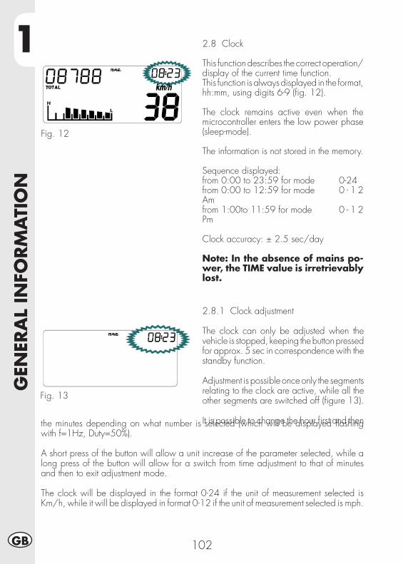
1G
ENER
AL
INFO
RM
ATI
ON
102GB
2.8 Clock
This function describes the correct operation/display of the current time function.This function is always displayed in the format, hh:mm, using digits 6-9 (fi g. 12).
The clock remains active even when the microcontroller enters the low power phase (sleep-mode).
The information is not stored in the memory.
Sequence displayed: from 0:00 to 23:59 for mode 0-24 from 0:00 to 12:59 for mode 0 - 1 2 Am from 1:00to 11:59 for mode 0 - 1 2 Pm
Clock accuracy: ± 2.5 sec/day
Note: In the absence of mains po-wer, the TIME value is irretrievably lost.
Fig. 12
2.8.1 Clock adjustment
The clock can only be adjusted when the vehicle is stopped, keeping the button pressed for approx. 5 sec in correspondence with the standby function.
Adjustment is possible once only the segments relating to the clock are active, while all the other segments are switched off (fi gure 13).
It is possible to change the hour fi rst and then
Fig. 13
the minutes depending on what number is selected (which will be displayed fl ashing with f=1Hz, Duty=50%).
A short press of the button will allow a unit increase of the parameter selected, while a long press of the button will allow for a switch from time adjustment to that of minutes and then to exit adjustment mode.
The clock will be displayed in the format 0-24 if the unit of measurement selected is Km/h, while it will be displayed in format 0-12 if the unit of measurement selected is mph.
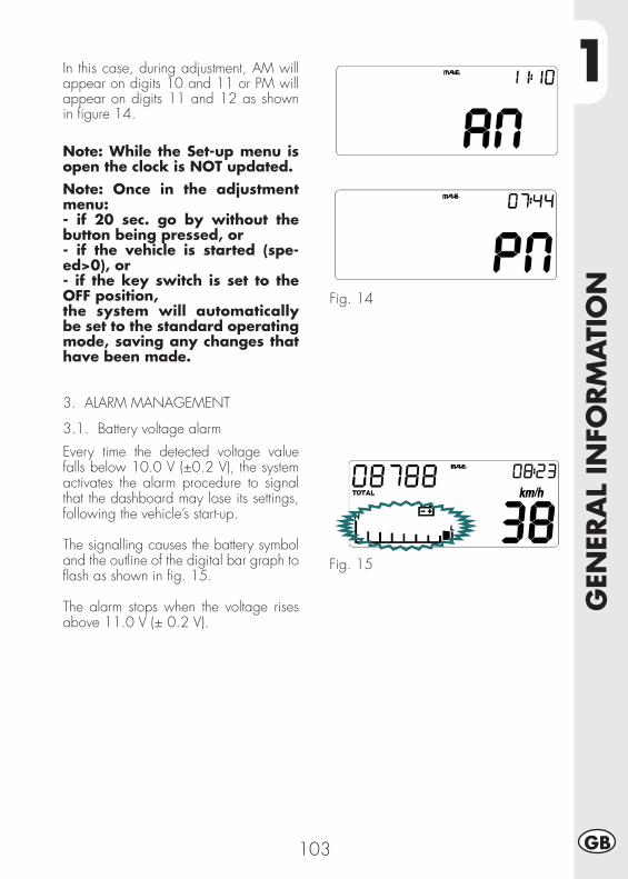
1
GEN
ERA
L IN
FORM
ATI
ON
103 GB
In this case, during adjustment, AM will appear on digits 10 and 11 or PM will appear on digits 11 and 12 as shown in fi gure 14.
Note: While the Set-up menu is open the clock is NOT updated.Note: Once in the adjustment menu:- if 20 sec. go by without the button being pressed, or- if the vehicle is started (spe-ed>0), or- if the key switch is set to the OFF position,the system will automatically be set to the standard operating mode, saving any changes that have been made.
3. ALARM MANAGEMENT
3.1. Battery voltage alarm
Every time the detected voltage value falls below 10.0 V (±0.2 V), the system activates the alarm procedure to signal that the dashboard may lose its settings, following the vehicle’s start-up.
The signalling causes the battery symbol and the outline of the digital bar graph to fl ash as shown in fi g. 15.
The alarm stops when the voltage rises above 11.0 V (± 0.2 V).
Fig. 14
Fig. 15
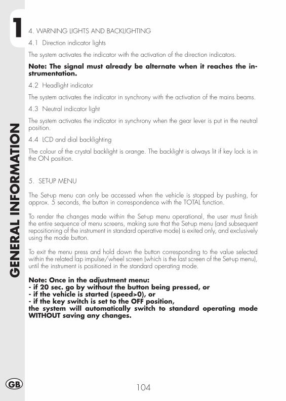
1G
ENER
AL
INFO
RM
ATI
ON
104GB
4. WARNING LIGHTS AND BACKLIGHTING
4.1 Direction indicator lights
The system activates the indicator with the activation of the direction indicators.
Note: The signal must already be alternate when it reaches the in-strumentation.
4.2 Headlight indicator
The system activates the indicator in synchrony with the activation of the mains beams.
4.3 Neutral indicator light
The system activates the indicator in synchrony when the gear lever is put in the neutral position.
4.4 LCD and dial backlighting
The colour of the crystal backlight is orange. The backlight is always lit if key lock is in the ON position.
5. SET-UP MENU
The Set-up menu can only be accessed when the vehicle is stopped by pushing, for approx. 5 seconds, the button in correspondence with the TOTAL function.
To render the changes made within the Set-up menu operational, the user must fi nish the entire sequence of menu screens, making sure that the Set-up menu (and subsequent repositioning of the instrument in standard operative mode) is exited only, and exclusively using the mode button.
To exit the menu press and hold down the button corresponding to the value selected within the related lap impulse/wheel screen (which is the last screen of the Set-up menu), until the instrument is positioned in the standard operating mode.
Note: Once in the adjustment menu:- if 20 sec. go by without the button being pressed, or- if the vehicle is started (speed>0), or- if the key switch is set to the OFF position,the system will automatically switch to standard operating mode WITHOUT saving any changes.
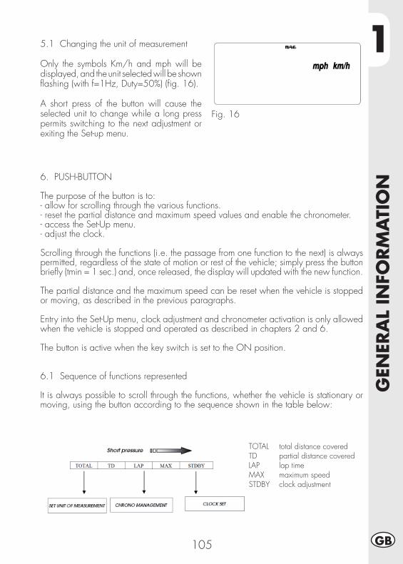
1
GEN
ERA
L IN
FORM
ATI
ON
105 GB
5.1 Changing the unit of measurement
Only the symbols Km/h and mph will be displayed, and the unit selected will be shown fl ashing (with f=1Hz, Duty=50%) (fi g. 16).
A short press of the button will cause the selected unit to change while a long press permits switching to the next adjustment or exiting the Set-up menu.
Fig. 16
6. PUSH-BUTTON
The purpose of the button is to:- allow for scrolling through the various functions.- reset the partial distance and maximum speed values and enable the chronometer.- access the Set-Up menu.- adjust the clock.
Scrolling through the functions (i.e. the passage from one function to the next) is always permitted, regardless of the state of motion or rest of the vehicle; simply press the button briefl y (tmin = 1 sec.) and, once released, the display will updated with the new function.
The partial distance and the maximum speed can be reset when the vehicle is stopped or moving, as described in the previous paragraphs.
Entry into the Set-Up menu, clock adjustment and chronometer activation is only allowed when the vehicle is stopped and operated as described in chapters 2 and 6.
The button is active when the key switch is set to the ON position.
6.1 Sequence of functions represented
It is always possible to scroll through the functions, whether the vehicle is stationary or moving, using the button according to the sequence shown in the table below:
TOTAL total distance coveredTD partial distance coveredLAP lap timeMAX maximum speedSTDBY clock adjustment
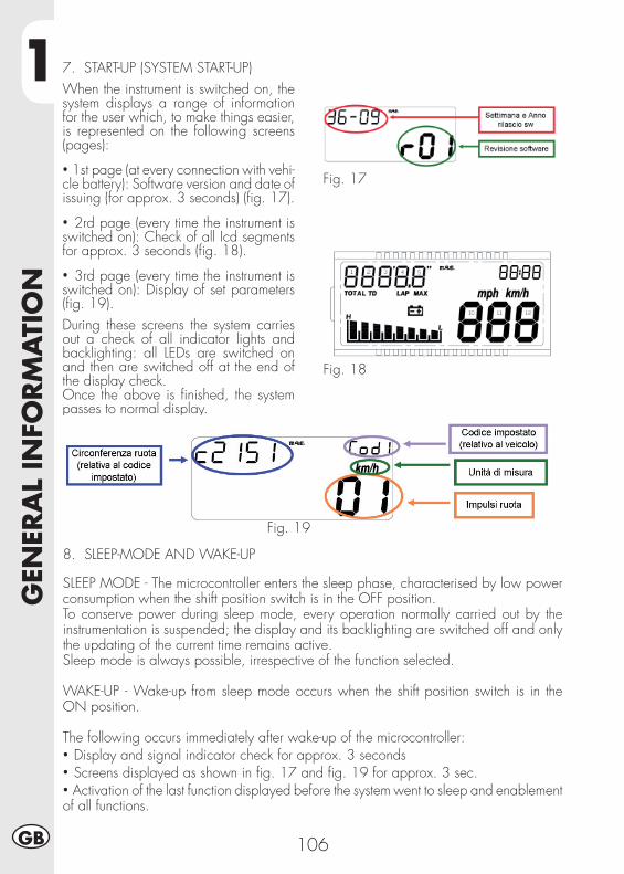
1G
ENER
AL
INFO
RM
ATI
ON
106GB
7. START-UP (SYSTEM START-UP)When the instrument is switched on, the system displays a range of information for the user which, to make things easier, is represented on the following screens (pages):
• 1st page (at every connection with vehi-cle battery): Software version and date of issuing (for approx. 3 seconds) (fi g. 17).
• 2rd page (every time the instrument is switched on): Check of all Icd segments for approx. 3 seconds (fi g. 18).
• 3rd page (every time the instrument is switched on): Display of set parameters (fi g. 19).During these screens the system carries out a check of all indicator lights and backlighting: all LEDs are switched on and then are switched off at the end of the display check.Once the above is fi nished, the system passes to normal display.
Fig. 17
Fig. 18
Fig. 19
8. SLEEP-MODE AND WAKE-UP
SLEEP MODE - The microcontroller enters the sleep phase, characterised by low power consumption when the shift position switch is in the OFF position.To conserve power during sleep mode, every operation normally carried out by the instrumentation is suspended; the display and its backlighting are switched off and only the updating of the current time remains active.Sleep mode is always possible, irrespective of the function selected. WAKE-UP - Wake-up from sleep mode occurs when the shift position switch is in the ON position.
The following occurs immediately after wake-up of the microcontroller:• Display and signal indicator check for approx. 3 seconds• Screens displayed as shown in fi g. 17 and fi g. 19 for approx. 3 sec.• Activation of the last function displayed before the system went to sleep and enablement of all functions.
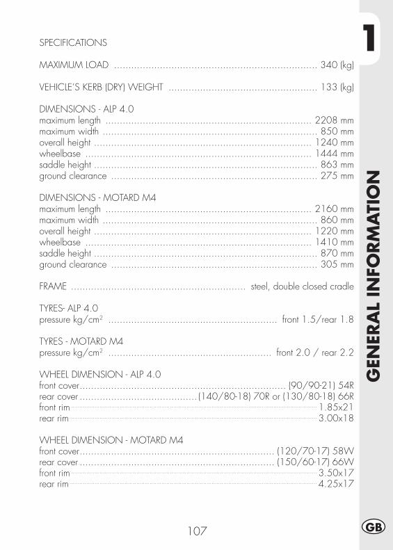
1
GEN
ERA
L IN
FORM
ATI
ON
107 GB
SPECIFICATIONS
MAXIMUM LOAD ....................................................................... 340 (kg)
VEHICLE’S KERB (DRY) WEIGHT .................................................... 133 (kg)
DIMENSIONS - ALP 4.0maximum length ........................................................................ 2208 mmmaximum width ........................................................................... 850 mmoverall height ............................................................................ 1240 mmwheelbase ............................................................................... 1444 mmsaddle height .............................................................................. 863 mmground clearance ........................................................................ 275 mm
DIMENSIONS - MOTARD M4maximum length ........................................................................ 2160 mmmaximum width ........................................................................... 860 mmoverall height ............................................................................ 1220 mmwheelbase ............................................................................... 1410 mmsaddle height .............................................................................. 870 mmground clearance ........................................................................ 305 mm
FRAME ............................................................. steel, double closed cradle
TYRES- ALP 4.0pressure kg/cm2 ........................................................... front 1.5/rear 1.8
TYRES - MOTARD M4pressure kg/cm2 ......................................................... front 2.0 / rear 2.2
WHEEL DIMENSION - ALP 4.0front cover ........................................................................ (90/90-21) 54Rrear cover ......................................... (140/80-18) 70R or (130/80-18) 66Rfront rim ................................................................................................................................................... 1.85x21rear rim .................................................................................................................................................... 3.00x18
WHEEL DIMENSION - MOTARD M4front cover .................................................................... (120/70-17) 58Wrear cover .................................................................... (150/60-17) 66Wfront rim ................................................................................................................................................... 3.50x17rear rim .................................................................................................................................................... 4.25x17
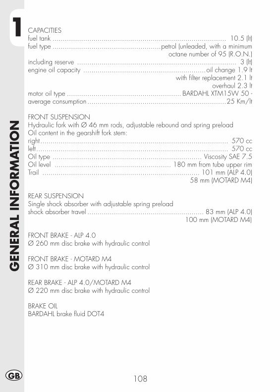
1G
ENER
AL
INFO
RM
ATI
ON
108GB
CAPACITIESfuel tank ..................................................................................... 10.5 (lt)fuel type .....................................................petrol (unleaded, with a minimum octane number of 95 (R.O.N.)including reserve .............................................................................. 3 (lt)engine oil capacity ............................................................oil change 1.9 lt
with fi lter replacement 2.1 ltoverhaul 2.3 lt
motor oil type ........................................................ BARDAHL XTM15W 50 -average consumption ....................................................................25 Km/lt
FRONT SUSPENSIONHydraulic fork with Ø 46 mm rods, adjustable rebound and spring preloadOil content in the gearshift fork stem:right ............................................................................................ 570 ccleft .............................................................................................. 570 ccOil type ......................................................................... Viscosity SAE 7.5Oil level ......................................................... 180 mm from tube upper rimTrail ............................................................................. 101 mm (ALP 4.0)
58 mm (MOTARD M4)
REAR SUSPENSIONSingle shock absorber with adjustable spring preloadshock absorber travel ......................................................... 83 mm (ALP 4.0)
100 mm (MOTARD M4)
FRONT BRAKE - ALP 4.0Ø 260 mm disc brake with hydraulic control
FRONT BRAKE - MOTARD M4Ø 310 mm disc brake with hydraulic control
REAR BRAKE - ALP 4.0/MOTARD M4Ø 220 mm disc brake with hydraulic control
BRAKE OILBARDAHL brake fl uid DOT4
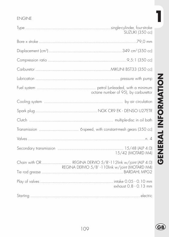
1
GEN
ERA
L IN
FORM
ATI
ON
109 GB
ENGINE
Type .....................................................................single-cylinder, four-strokeSUZUKI (350 cc)
Bore x stroke ...............................................................................79,0 mm
Displacement (cm3) ........................................................... 349 cm3 (350 cc)
Compression ratio ................................................................9,5:1 (350 cc)
Carburetor .............................................................MIKUNI BST33 (350 cc)
Lubrication .....................................................................pressure with pump
Fuel system ................................................ petrol (unleaded, with a minimum octane number of 95), by carburettor
Cooling system ................................................................ by air circulation
Spark plug .................................................. NGK CR9 EK - DENSO U27ETR
Clutch .................................................................... multiple-disc in oil bath
Transmission ................................ 6-speed, with constant-mesh gears (350 cc)
Valves ...............................................................................................n. 4
Secondary transmission ....................................................... 15/48 (ALP 4.0)15/42 (MOTARD M4)
Chain with OR ........................ REGINA DERVIO 5/8’-112link w/joint (ALP 4.0)REGINA DERVIO 5/8’ -110link w/joint (MOTARD M4)
Tie rod grease .................................................................. BARDAHL MPG2
Play of valves ........................................................... intake 0.05 - 0.10 mm exhaust 0.8 - 0.13 mm
Starting .........................................................................................electric
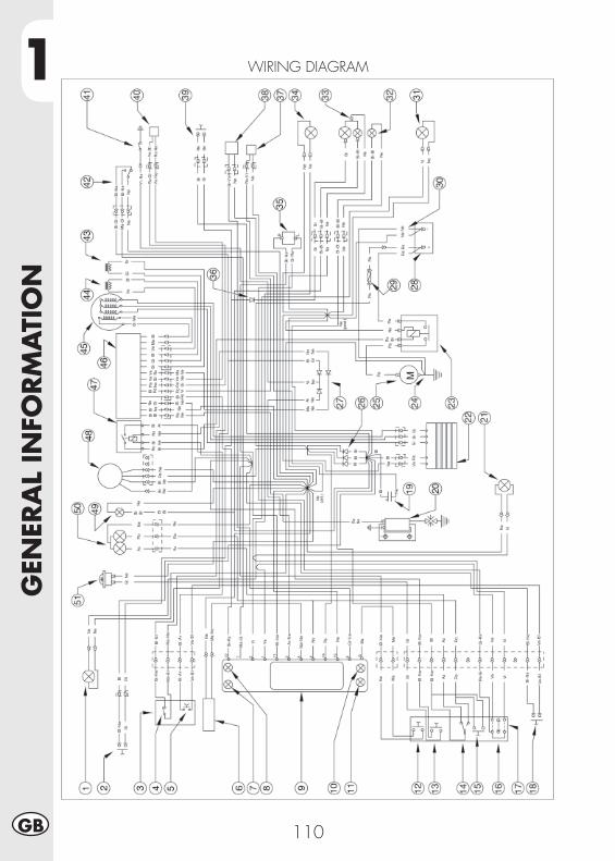
1G
ENER
AL
INFO
RM
ATI
ON
110GB
WIRING DIAGRAM
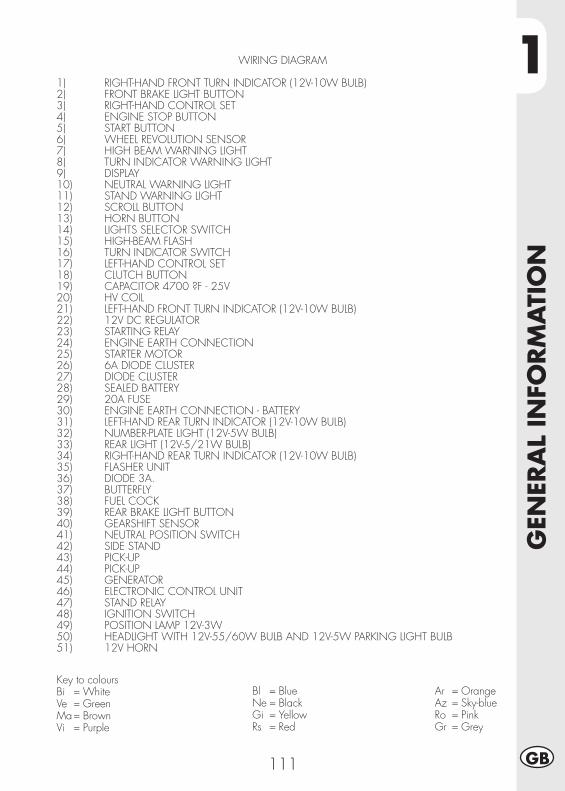
1
GEN
ERA
L IN
FORM
ATI
ON
111 GB
WIRING DIAGRAM
1) RIGHT-HAND FRONT TURN INDICATOR (12V-10W BULB)2) FRONT BRAKE LIGHT BUTTON3) RIGHT-HAND CONTROL SET4) ENGINE STOP BUTTON5) START BUTTON6) WHEEL REVOLUTION SENSOR7) HIGH BEAM WARNING LIGHT8) TURN INDICATOR WARNING LIGHT9) DISPLAY10) NEUTRAL WARNING LIGHT11) STAND WARNING LIGHT12) SCROLL BUTTON13) HORN BUTTON14) LIGHTS SELECTOR SWITCH15) HIGH-BEAM FLASH16) TURN INDICATOR SWITCH17) LEFT-HAND CONTROL SET18) CLUTCH BUTTON19) CAPACITOR 4700 ?F - 25V 20) HV COIL21) LEFT-HAND FRONT TURN INDICATOR (12V-10W BULB)22) 12V DC REGULATOR23) STARTING RELAY24) ENGINE EARTH CONNECTION25) STARTER MOTOR26) 6A DIODE CLUSTER27) DIODE CLUSTER28) SEALED BATTERY29) 20A FUSE30) ENGINE EARTH CONNECTION - BATTERY31) LEFT-HAND REAR TURN INDICATOR (12V-10W BULB) 32) NUMBER-PLATE LIGHT (12V-5W BULB)33) REAR LIGHT (12V-5/21W BULB)34) RIGHT-HAND REAR TURN INDICATOR (12V-10W BULB)35) FLASHER UNIT 36) DIODE 3A.37) BUTTERFLY38) FUEL COCK39) REAR BRAKE LIGHT BUTTON40) GEARSHIFT SENSOR41) NEUTRAL POSITION SWITCH42) SIDE STAND43) PICK-UP44) PICK-UP45) GENERATOR46) ELECTRONIC CONTROL UNIT47) STAND RELAY48) IGNITION SWITCH49) POSITION LAMP 12V-3W50) HEADLIGHT WITH 12V-55/60W BULB AND 12V-5W PARKING LIGHT BULB51) 12V HORN
Key to coloursBi = WhiteVe = GreenMa = BrownVi = Purple
Bl = BlueNe = BlackGi = YellowRs = Red
Ar = OrangeAz = Sky-blueRo = PinkGr = Grey
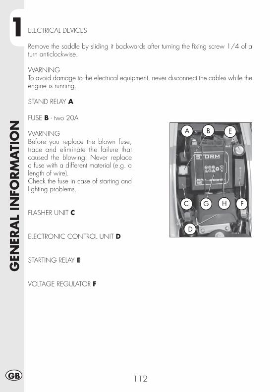
1G
ENER
AL
INFO
RM
ATI
ON
112GB
ELECTRICAL DEVICES
Remove the saddle by sliding it backwards after turning the fi xing screw 1/4 of a turn anticlockwise.
WARNINGTo avoid damage to the electrical equipment, never disconnect the cables while the engine is running.
STAND RELAY A
FUSE B - two 20A
WARNINGBefore you replace the blown fuse, trace and eliminate the failure that caused the blowing. Never replace a fuse with a different material (e.g. a length of wire).Check the fuse in case of starting and lighting problems.
FLASHER UNIT C
ELECTRONIC CONTROL UNIT D
STARTING RELAY E
VOLTAGE REGULATOR F
A B E
C G H F
D

1
GEN
ERA
L IN
FORM
ATI
ON
113 GB
NOTES ON THE BATTERY GInsert the new battery in the specially designed compartment under the saddle (see photo) tightening it with the equipment elastic H. Connect the black cable terminal to the negative (-) and the red cable to the positive (+) inserting the red cap protection.Reassemble the saddle.
HV COIL - STARTING DEVICE IIn order to have access to these components, it is necessary to remove the saddle, the front sides and the tank (see pages 137, 138 for ALP and pages 139, 140 for MOTARD).
I

1G
ENER
AL
INFO
RM
ATI
ON
114GB
A
DEVICES FOR E3 VERSION
The latest models are E3 type-approved and they differ from prior approvals in that have been introduced:
AIS VALVEIt is called AIS A and it is an air intake system which allows to complete the com-bustion of some unburned fuels remaining from the thermodynamic cycle.
2
OPER
ATI
ON
115 GB
CONTENTS
CHAPTER 2 OPERATION
Checks and manintenance operations before and after off-road use
Recommended lubricants
Running-in
Starting the engine
Shutting off the engine
Refuelling
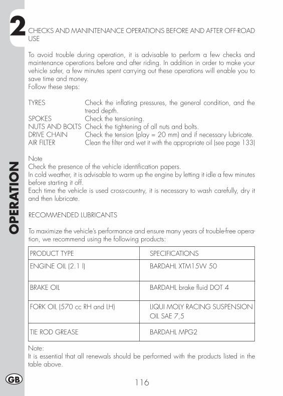
2O
PER
ATI
ON
116GB
CHECKS AND MANINTENANCE OPERATIONS BEFORE AND AFTER OFF-ROAD USE
To avoid trouble during operation, it is advisable to perform a few checks and maintenance operations before and after riding. In addition in order to make your vehicle safer, a few minutes spent carrying out these operations will enable you to save time and money.Follow these steps:
TYRES Check the infl ating pressures, the general condition, and the tread depth.
SPOKES Check the tensioning.NUTS AND BOLTS Check the tightening of all nuts and bolts.DRIVE CHAIN Check the tension (play = 20 mm) and if necessary lubricate.AIR FILTER Clean the fi lter and wet it with the appropriate oil (see page 133)
NoteCheck the presence of the vehicle identifi cation papers.In cold weather, it is advisable to warm up the engine by letting it idle a few minutes before starting it off.Each time the vehicle is used cross-country, it is necessary to wash carefully, dry it and then lubricate.
RECOMMENDED LUBRICANTS
To maximize the vehicle’s performance and ensure many years of trouble-free opera-tion, we recommend using the following products:
PRODUCT TYPE SPECIFICATIONS
ENGINE OIL (2.1 l) BARDAHL XTM15W 50
BRAKE OIL BARDAHL brake fl uid DOT 4 FORK OIL (570 cc RH and LH) LIQUI MOLY RACING SUSPENSION OIL SAE 7,5
TIE ROD GREASE BARDAHL MPG2
Note:It is essential that all renewals should be performed with the products listed in the table above.
2
OPER
ATI
ON
117 GB
RUNNING-IN
The running-in period lasts approximately 10 hours, during which it is advisable to:• Warm up the engine well before starting off.
• Avoid riding at constant speed (changing the speed allows the different components to bed in uniformly and in a shorter time).
• Avoid turning the throttle twist grip more than 3/4 of its travel.
WARNING:After the fi rst 1000 km renew the engine oil.
IMPORTANT:It is necessary to make sure that after running for 1000 Km., the metallic fi lter, positioned on the fi nal part of the oil tank, is clean (see page 124). If it should not be clean, use compressed air to clean it.
• Always use high-octane unleaded petrol.• After using the vehicle on rough ground for the fi rst time, carefully check the tightening of all nuts and bolts.
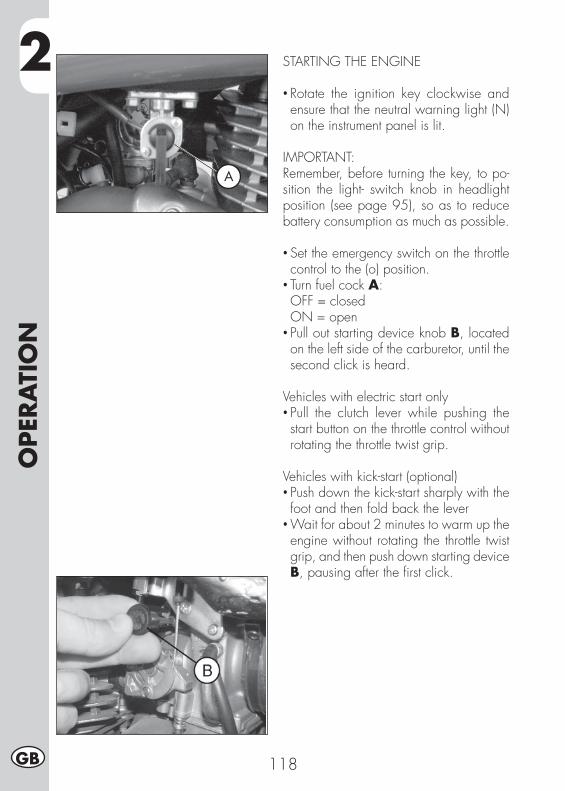
2O
PER
ATI
ON
118GB
STARTING THE ENGINE
• Rotate the ignition key clockwise and ensure that the neutral warning light (N) on the instrument panel is lit.
IMPORTANT:Remember, before turning the key, to po-sition the light- switch knob in headlight position (see page 95), so as to reduce battery consumption as much as possible.
• Set the emergency switch on the throttle control to the (o) position.
• Turn fuel cock A: OFF = closed ON = open• Pull out starting device knob B, located on the left side of the carburetor, until the second click is heard.
Vehicles with electric start only• Pull the clutch lever while pushing the start button on the throttle control without rotating the throttle twist grip.
Vehicles with kick-start (optional)• Push down the kick-start sharply with the foot and then fold back the lever
• Wait for about 2 minutes to warm up the engine without rotating the throttle twist grip, and then push down starting device B, pausing after the fi rst click.
A
2
OPER
ATI
ON
119 GB
Note:The vehicle can be started while the stand is down providing the neutral warning light (N) is lit.
Note:In an emergency, the vehicle can also be operated without a battery.
SHUTTING OFF THE ENGINE
• While the vehicle is stationary and in neutral gear, rotate the ignition key to the “OFF” position.
• Before stopping the engine after a long ride, it is advisable to let it idle for a few moments.
• Always close the fuel cock after stopping the engine.
ATTENTION:The vehicle is equipped with a light system which is always lit, so, if it is turned off with the RUN-OFF switch, positioned on the right side of the handle-bar, the lights stay on. In such case, the battery could run down prematurely.
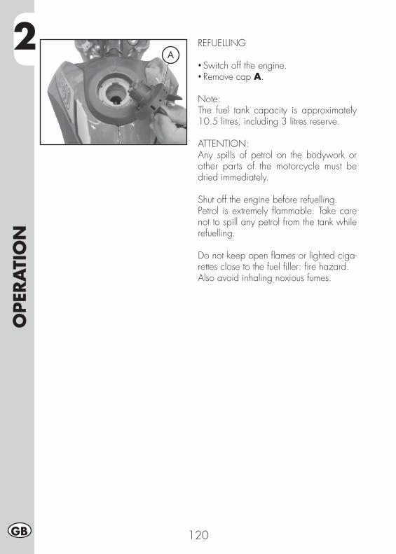
2O
PER
ATI
ON
120GB
REFUELLING
• Switch off the engine.• Remove cap A.
Note:The fuel tank capacity is approximately 10.5 litres, including 3 litres reserve.
ATTENTION:Any spills of petrol on the bodywork or other parts of the motorcycle must be dried immediately.
Shut off the engine before refuelling.Petrol is extremely fl ammable. Take care not to spill any petrol from the tank while refuelling.
Do not keep open fl ames or lighted ciga-rettes close to the fuel fi ller: fi re hazard.Also avoid inhaling noxious fumes.
A
3
CH
ECK
S A
ND
MA
INTE
NA
NCE
121 GB
CONTENTS
CHAPTER 3 CHECKS AND MAINTENANCE
Motor oil level check
Motor oil and fi lter oil substitution
Fume collecting tube
Brake pump oil - Bleeding the brakes
Fork oil
Air fi lter
Spark plug
Front brake
Rear brake
Carburetor
Battery
Removing the plastics for ALP
Removing the plastics for MOTARD M4
Notes for cross-country
Final transmission group substitution
Cleaning and checking the vehicle
Checks after cleaning
Scheduled maintenance
Prolonged inactivity
After prolonged inactivity
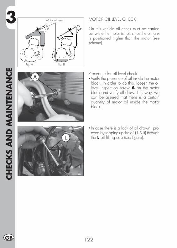
3CH
ECK
S A
ND
MA
INTE
NA
NCE
122GB
MOTOR OIL LEVEL CHECK
On this vehicle oil check must be carried out while the motor is hot, since the oil tank is positioned higher than the motor (see scheme).
Fig. A
Motor oil level
Fig. B
Procedure for oil level check• Verify the presence of oil inside the motor block. In order to do this, loosen the oil level inspection screw A on the motor block and verify oil draw. This way, we can be assured that there is a certain quantity of motor oil inside the motor block.
• In case there is a lack of oil drawn, pro-ceed by topping-up the oil (1.9 lt) through the L oil fi lling cap (see fi gure).
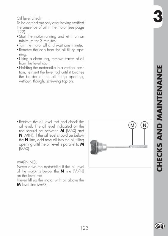
3
CH
ECK
S A
ND
MA
INTE
NA
NCE
123 GB
Oil level checkTo be carried out only after having verifi ed the presence of oil in the motor (see page 122).• Start the motor running and let it run on minimum for 3 minutes.
• Turn the motor off and wait one minute.• Remove the cap from the oil fi lling ope-ning.
• Using a clean rag, remove traces of oil from the level rod.
• Holding the motor-bike in a vertical posi-tion, reinsert the level rod until it touches the border of the oil fi lling opening, without, though, screwing top on.
• Retrieve the oil level rod and check the oil level. The oil level indicated on the rod should be between M (MAX) and N (MIN). If the oil level should be below the N line, add new oil into the oil fi lling opening until the oil level is parallel to M (MAX).
WARNING:Never drive the motor-bike if the oil level of the motor is below the N line (M/N) on the level rod.Never fi ll up the motor with oil above the M level line (MAX).
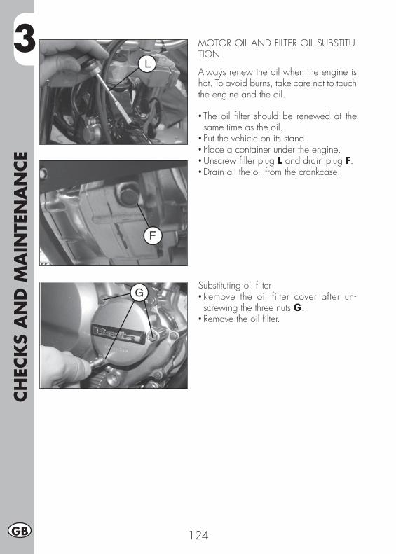
3CH
ECK
S A
ND
MA
INTE
NA
NCE
124GB
MOTOR OIL AND FILTER OIL SUBSTITU-TION
Always renew the oil when the engine is hot. To avoid burns, take care not to touch the engine and the oil.
• The oil fi lter should be renewed at the same time as the oil.
• Put the vehicle on its stand.• Place a container under the engine.• Unscrew fi ller plug L and drain plug F.• Drain all the oil from the crankcase.
Substituting oil fi lter• Remove the oil filter cover after un-screwing the three nuts G.
• Remove the oil fi lter.

3
CH
ECK
S A
ND
MA
INTE
NA
NCE
125 GB
Emptying oil from the tank• Remove the four carter clamping screws at the back of the motor.
• Unloosen the Q screw and let all of the oil fl ow out of the tank.
• The fi rst time you change the oil (see page 117), we suggest that you also clean the metal fi lter which is positioned on the fi nal end of the oil tank.
The disassembling procedure is the fol-lowing:• Unloosen the tank connecting carter motor tube.
• Using a monkey wrench, unscrew the joint having a metal net in clockwise direction.
• Clean it with a jet of air
ATTENTION:Always use eye protection during this procedure.
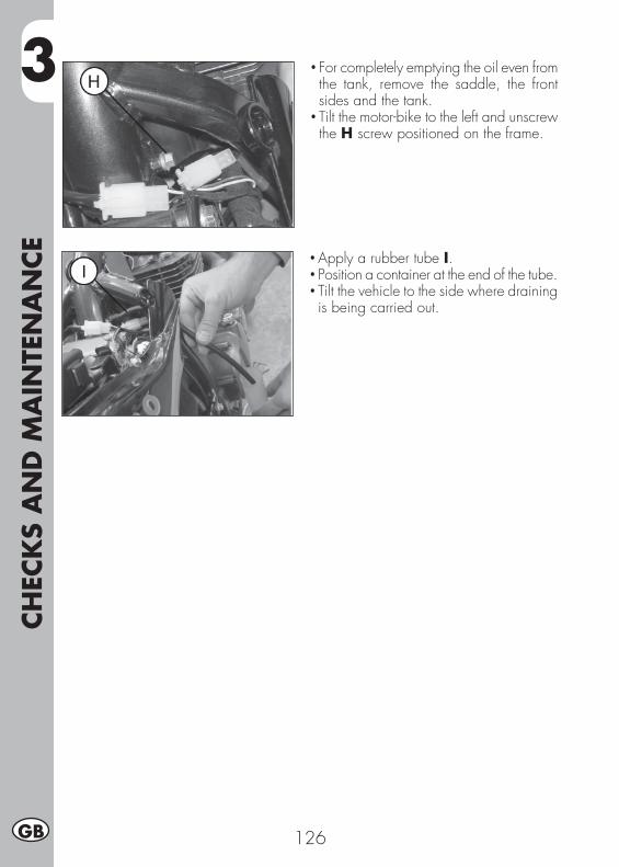
3CH
ECK
S A
ND
MA
INTE
NA
NCE
126GB
• For completely emptying the oil even from the tank, remove the saddle, the front sides and the tank.
• Tilt the motor-bike to the left and unscrew the H screw positioned on the frame.
• Apply a rubber tube I.• Position a container at the end of the tube.• Tilt the vehicle to the side where draining is being carried out.
3
CH
ECK
S A
ND
MA
INTE
NA
NCE
127 GB
Assembly• Proceed by carrying out the inverse pro-cedure to that of disassembling the metal fi lter and net of the oil tank
• Insert a new oil fi lter.• Apply a thin fi lm of engine oil to the fi lter cover O-ring before insertion.
• Fit the oil fi lter cover after fi tting the spring and the O-ring, and then tighten the three fastening screws.
• Reassemble the oil drainage cap, posi-tioned on the motor carter, with the two oil drainage screws of the tank (if necessary, use new gaskets).
• Pour in the necessary quantity of oil. Engine oil capacity: oil change ............................... 1.9 lt with fi lter replacement ............... 2.1 lt overhaul ................................ 2.3 lt
• Retighten the loading cap.• Start the engine and allow it to idle for a few minutes.
• Switch off the engine, wait for about a minute, and then check the level. If necessary top up without exceeding the max level.
NoteRenew the oil after the fi rst 1,000 km.Subsequent renewals should be every 4,000 km (15 months). Always use the lubricants shown on page 112.The oil fi lter should be replaced for the fi rst time when the oil is fi rst renewed, and subsequently every 8,000 km (45 months).
WARNING:Dispose of used oil in compliance with the regulations in force.

3CH
ECK
S A
ND
MA
INTE
NA
NCE
128GB
FUME COLLECTING TUBE
Fume collecting tube A is located on the left side of the vehicle, next to the shock absorber, and comes out of the lower part of the fi lter box. It is designed to collect the fumes produced by the engine oil. Should you fi nd some oil in the tube, remove the cap at the lower end of the tube and drain the oil, or the mixture of oil and petrol, into a suitable container. Disposal is to be made according to the regulations in force.
NoteEmpty the fume collecting tube every 3,000 km.
BRAKE PUMP OIL - BLEEDING THE BRA-KES
Front brakeCheck that oil is present by looking through oil level sight B. The minimum oil level should never be lower than the mark on sight B. To restore the oil level, loosen the two screws C, lift cover D and pour in fresh oil.Keep the motor in a stable vertical position, possibly blocking the handle-bar, so as to avoid the brake oil from spilling out.
B
C
D
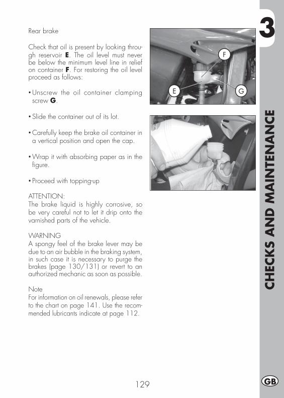
3
CH
ECK
S A
ND
MA
INTE
NA
NCE
129 GB
Rear brake
Check that oil is present by looking throu-gh reservoir E. The oil level must never be below the minimum level line in relief on container F. For restoring the oil level proceed as follows:
• Unscrew the oil container clamping screw G.
• Slide the container out of its lot.
• Carefully keep the brake oil container in a vertical position and open the cap.
• Wrap it with absorbing paper as in the fi gure.
• Proceed with topping-up
ATTENTION:The brake liquid is highly corrosive, so be very careful not to let it drip onto the varnished parts of the vehicle.
WARNINGA spongy feel of the brake lever may be due to an air bubble in the braking system, in such case it is necessary to purge the brakes (page 130/131) or revert to an authorized mechanic as soon as possible.
NoteFor information on oil renewals, please refer to the chart on page 141. Use the recom-mended lubricants indicate at page 112.
E
F
G
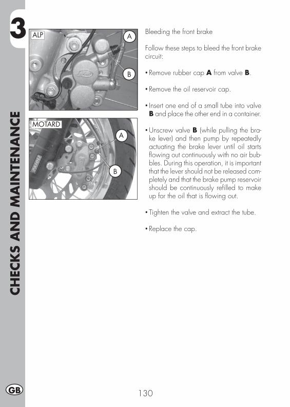
3CH
ECK
S A
ND
MA
INTE
NA
NCE
130GB
Bleeding the front brake
Follow these steps to bleed the front brake circuit:
• Remove rubber cap A from valve B.
• Remove the oil reservoir cap.
• Insert one end of a small tube into valve B and place the other end in a container.
• Unscrew valve B (while pulling the bra-ke lever) and then pump by repeatedly actuating the brake lever until oil starts fl owing out continuously with no air bub-bles. During this operation, it is important that the lever should not be released com-pletely and that the brake pump reservoir should be continuously refi lled to make up for the oil that is fl owing out.
• Tighten the valve and extract the tube.
• Replace the cap.
MOTARD
B
A
ALP A
B
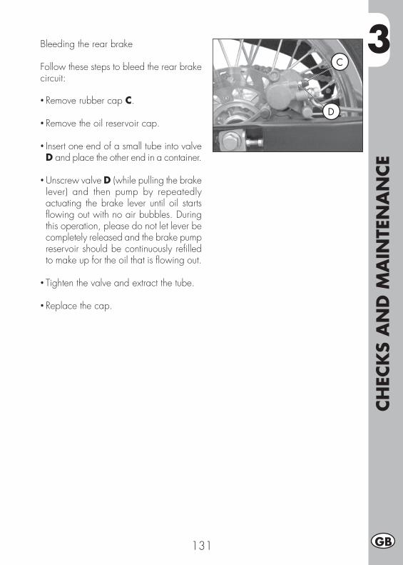
3
CH
ECK
S A
ND
MA
INTE
NA
NCE
131 GB
Bleeding the rear brake
Follow these steps to bleed the rear brake circuit:
• Remove rubber cap C.
• Remove the oil reservoir cap.
• Insert one end of a small tube into valve D and place the other end in a container.
• Unscrew valve D (while pulling the brake lever) and then pump by repeatedly actuating the brake lever until oil starts fl owing out with no air bubbles. During this operation, please do not let lever be completely released and the brake pump reservoir should be continuously refi lled to make up for the oil that is fl owing out.
• Tighten the valve and extract the tube.
• Replace the cap.
D
C
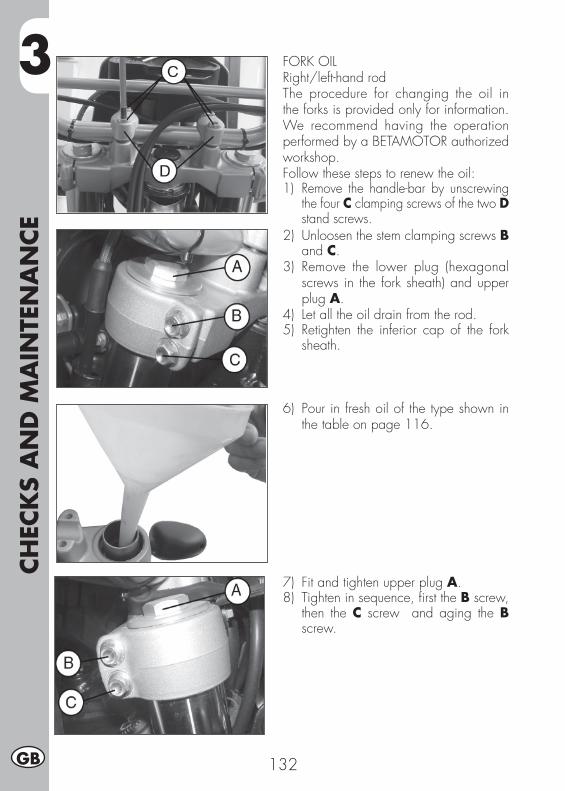
3CH
ECK
S A
ND
MA
INTE
NA
NCE
132GB
FORK OILRight/left-hand rodThe procedure for changing the oil in the forks is provided only for information. We recommend having the operation performed by a BETAMOTOR authorized workshop.Follow these steps to renew the oil:1) Remove the handle-bar by unscrewing
the four C clamping screws of the two D stand screws.
2) Unloosen the stem clamping screws B and C.
3) Remove the lower plug (hexagonal screws in the fork sheath) and upper plug A.
4) Let all the oil drain from the rod.5) Retighten the inferior cap of the fork
sheath.
6) Pour in fresh oil of the type shown in the table on page 116.
7) Fit and tighten upper plug A.8) Tighten in sequence, fi rst the B screw,
then the C screw and aging the B screw.
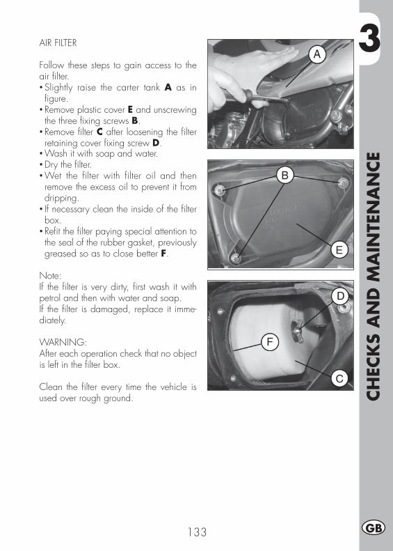
3
CH
ECK
S A
ND
MA
INTE
NA
NCE
133 GB
AIR FILTER
Follow these steps to gain access to the air fi lter.• Slightly raise the carter tank A as in fi gure.
• Remove plastic cover E and unscrewing the three fi xing screws B.
• Remove fi lter C after loosening the fi lter retaining cover fi xing screw D.
• Wash it with soap and water.• Dry the fi lter.• Wet the filter with filter oil and then remove the excess oil to prevent it from dripping.
• If necessary clean the inside of the fi lter box.
• Refi t the fi lter paying special attention to the seal of the rubber gasket, previously greased so as to close better F.
Note:If the fi lter is very dirty, fi rst wash it with petrol and then with water and soap.If the fi lter is damaged, replace it imme-diately.
WARNING:After each operation check that no object is left in the fi lter box.
Clean the fi lter every time the vehicle is used over rough ground.
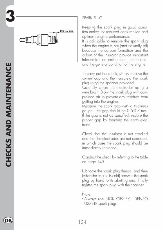
3CH
ECK
S A
ND
MA
INTE
NA
NCE
134GB
SPARK PLUG
Keeping the spark plug in good condi-tion makes for reduced consumption and optimum engine performance.It is advisable to remove the spark plug when the engine is hot (and naturally off) because the carbon formation and the colour of the insulator provide important information on carburetion, lubrication, and the general condition of the engine.
To carry out the check, simply remove the current cap and then unscrew the spark plug using the spanner provided.Carefully clean the electrodes using a wire brush. Blow the spark plug with com-pressed air to prevent any residues from getting into the engine.Measure the spark gap with a thickness gauge. The gap should be 0.6-0.7 mm. If the gap is not as specifi ed, restore the proper gap by bending the earth elec-trode.
Check that the insulator is not cracked and that the electrodes are not corroded, in which case the spark plug should be immediately replaced.
Conduct the check by referring to the table on page 145.
Lubricate the spark plug thread, and then (when the engine is cold) screw in the spark plug by hand to its abutting end. Finally tighten the spark plug with the spanner.
Note:• Always use NGK CR9 EK - DENSO U27ETR spark plugs.
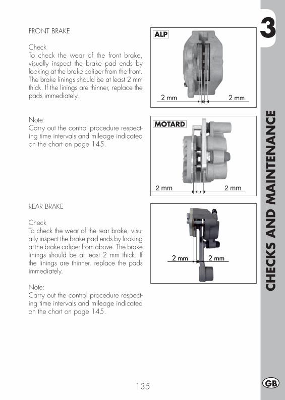
3
CH
ECK
S A
ND
MA
INTE
NA
NCE
135 GB
FRONT BRAKE
CheckTo check the wear of the front brake, visually inspect the brake pad ends by looking at the brake caliper from the front. The brake linings should be at least 2 mm thick. If the linings are thinner, replace the pads immediately.
Note:Carry out the control procedure respect-ing time intervals and mileage indicated on the chart on page 145.
REAR BRAKE
CheckTo check the wear of the rear brake, visu-ally inspect the brake pad ends by looking at the brake caliper from above. The brake linings should be at least 2 mm thick. If the linings are thinner, replace the pads immediately.
Note:Carry out the control procedure respect-ing time intervals and mileage indicated on the chart on page 145.
ALP
MOTARD
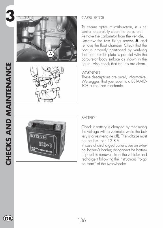
3CH
ECK
S A
ND
MA
INTE
NA
NCE
136GB
CARBURETOR
To ensure optimum carburetion, it is es-sential to carefully clean the carburetor.Remove the carburetor from the vehicle.Unscrew the two fi xing screws A and remove the fl oat chamber. Check that the fl oat is properly positioned by verifying that fl oat holder plate is parallel with the carburetor body surface as shown in the fi gure. Also check that the jets are clean.
WARNING:These descriptions are purely informative.We suggest that you revert to a BETAMO-TOR authorized mechanic.
BATTERY
Check if battery is charged by measuring the voltage with a voltmeter while the bat-tery is at rest (engine off). The voltage must not be less than 12.8 V.In case of discharged battery, use an exter-nal battery’s loader; disconnect the battery (if possible remove it from the vehicle) and recharge it following the instructions ”to go on road“ of the two-wheeler.

3
CH
ECK
S A
ND
MA
INTE
NA
NCE
137 GB
REMOVING THE PLASTICS FOR ALP
To facilitate checks and operations in certain areas of the vehicle, it is essential to remove the bodywork sections as de-scribed below.
Saddle removal•Turn the fi xing A by 90° anticlockwise, take out the saddle by pulling it to the back of the vehicle. To fi t it back in, just put the saddle back in its place, push the fi xing A down (without turning it) until it clicks. Now the saddle is in place.
Disassembling rear handles• Unscrew the two clamping screws B then remove the other clamping screw E, positioned under the rear mudguard and thus remove the handles C, taking care not to mislay the rubber shims.
Disassembling rear tail• Remove the clamping screw F and remo-ve the tail D.
Disassembling front sides• Unscrew the four clamping screws G (two on each side) and remove the two screws H.
• Remove the front sides, being careful to remove the left side fi rst and then the right side.
A
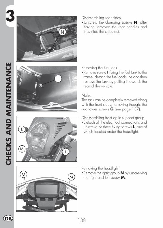
3CH
ECK
S A
ND
MA
INTE
NA
NCE
138GB
Disassembling rear sides• Unscrew the clamping screws N, after having removed the rear handles and thus slide the sides out.
Removing the fuel tank• Remove screw I fi xing the fuel tank to the frame, detach the fuel cock line and then remove the tank by pulling it towards the rear of the vehicle.
Note:The tank can be completely removed along with the front sides, removing though, the two lower screws G (see page 137).
Disassembling front optic support group• Detach all the electrical connections and unscrew the three fi xing screws L, one of which located under the headlight.
Removing the headlight• Remove the optic group N by unscrewing the right and left screw M.
L
L
M
MM
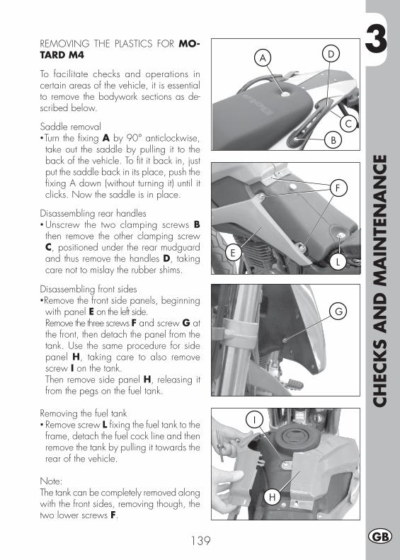
3
CH
ECK
S A
ND
MA
INTE
NA
NCE
139 GB
REMOVING THE PLASTICS FOR MO-TARD M4
To facilitate checks and operations in certain areas of the vehicle, it is essential to remove the bodywork sections as de-scribed below.
Saddle removal•Turn the fi xing A by 90° anticlockwise, take out the saddle by pulling it to the back of the vehicle. To fi t it back in, just put the saddle back in its place, push the fi xing A down (without turning it) until it clicks. Now the saddle is in place.
Disassembling rear handles• Unscrew the two clamping screws B then remove the other clamping screw C, positioned under the rear mudguard and thus remove the handles D, taking care not to mislay the rubber shims.
Disassembling front sides•Remove the front side panels, beginning with panel E on the left side.
Remove the three screws F and screw G at the front, then detach the panel from the tank. Use the same procedure for side panel H, taking care to also remove screw I on the tank.
Then remove side panel H, releasing it from the pegs on the fuel tank.
Removing the fuel tank• Remove screw L fi xing the fuel tank to the frame, detach the fuel cock line and then remove the tank by pulling it towards the rear of the vehicle.
Note:The tank can be completely removed along with the front sides, removing though, the two lower screws F.
F
G
E
I
H
L
B
A
C
D

3CH
ECK
S A
ND
MA
INTE
NA
NCE
140GB
Disassembling rear sides• After removing the front side panels and the grab handles, unscrew the two side fasteners N and remove rear fairings M. Subsequently remove the three screws O and take off the side panels, disengaging them from their catches.
M
N
ODisassembling rear tail• After removing the rear side panels, unscrew the four screws P under the tail fairing.
P
Removing the headlight• Loosen the four screws Q and remove the headlight assembly.
Q Q
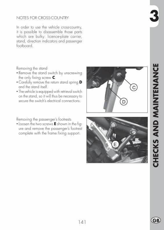
3
CH
ECK
S A
ND
MA
INTE
NA
NCE
141 GB
NOTES FOR CROSS-COUNTRY
In order to use the vehicle cross-country, it is possible to disassemble those parts which are bulky: licence-plate carrier, stand, direction indicators and passenger footboard.
Removing the stand• Remove the stand switch by unscrewing the only fi xing screw C.
• Carefully remove the return stand spring D and the stand itself.
• The vehicle is equipped with retrieval switch on the stand, so it will thus be necessary to secure the switch’s electrical connections.
Removing the passenger’s footrests• Loosen the two screws E shown in the fi g-ure and remove the passenger’s footrest complete with the frame fi xing support.
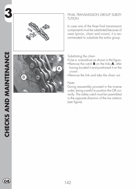
3CH
ECK
S A
ND
MA
INTE
NA
NCE
142GB
Substituting the chain• Use a screwdriver as shown in the fi gure.• Remove the catch B on the links A, after having located it and positioned it on the crown.
• Remove the link and take the chain out
Note:During reassembly proceed in the inverse order, being careful to position the OR cor-rectly. The safety catch must be assembled in the opposite direction of the tire rotation (see fi gure).
FINAL TRANSMISSION GROUP SUBSTI-TUTION
In case one of the three fi nal transmission components must be substituted because of wear (pinion, chain and crown), it is rec-ommended to substitute the entire group.

3
CH
ECK
S A
ND
MA
INTE
NA
NCE
143 GB
Replacing the front sprocket• Loosen the rear wheel.• Loosen the chain adjusters.• Move the wheel forward to the end of its travel to allow the slackening of the chain.
• Remove the two chain guard fi xing screws F.
Substituting the crown• For crown substitution, remove the rear tire, by fi rst loosening the right and left regulators A and B, and subsequently unscrewing the tire axis nut C.
• It is necessary to move the tires towards the rear end of the vehicle, so as to loosen tension on the chain.
• Unscrew the six crown clamping screws D.• For reassembling, proceed in the inverse manner, using blockage-threads on the six clamping screws.
• Insert the fi rst gear and remove the seeger G of the pinion clamping.
• It is necessary to move the tires towards the front of the vehicle, so as to loosen tension on the chain.
• Replace the sprocket.• To reassemble, follow the same procedu-re in reverse order.
3CH
ECK
S A
ND
MA
INTE
NA
NCE
144GB
CLEANING AND CHECKING THE VEHICLE
Use water jet to soften the dirt and mud accumulated on the paintwork, then remove them with a soft bodywork sponge soaked in water and shampoo (2-4 percent shampoo in water). Subsequently rinse well with water, and dry with air and cloth or suede leather. For the outside of the engine use a brush soaked in petroleum and clean rags. Petroleum damages the paintwork. Always wash the vehicle before waxing it with silicon waxes.
Detergents pollute water. Always wash the vehicle in areas equipped for col-lection and purifi cation of the washing liquids.
Never wash the vehicle in the sun, particularly during the summer when the bodywork is hot. The shampoo would dry before being rinsed off and cause damage to the paintwork. Do not clean the plastic surfaces with cloths soaked
in petrol or naphtha as they would lose their shine and mechanical properties.
CHECKS AFTER CLEANING
After cleaning the motorcycle, it is advisable to:
• Clean the air fi lter (refer to the procedure described on page 133).• Empty the fuel container by loosening the fuel emptying screw in order (as described on page 136) to check for the presence of water.
• Add grease to the chain.
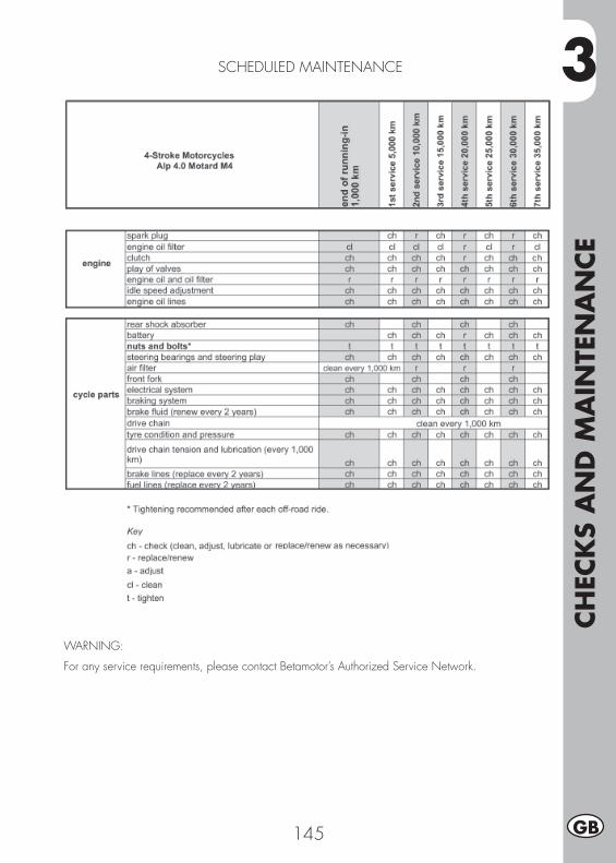
3
CH
ECK
S A
ND
MA
INTE
NA
NCE
145 GB
SCHEDULED MAINTENANCE
WARNING:
For any service requirements, please contact Betamotor’s Authorized Service Network.
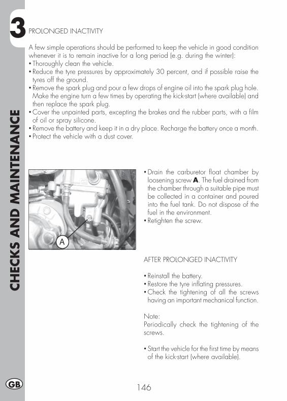
3CH
ECK
S A
ND
MA
INTE
NA
NCE
146GB
PROLONGED INACTIVITY
A few simple operations should be performed to keep the vehicle in good condition whenever it is to remain inactive for a long period (e.g. during the winter):• Thoroughly clean the vehicle.• Reduce the tyre pressures by approximately 30 percent, and if possible raise the tyres off the ground.
• Remove the spark plug and pour a few drops of engine oil into the spark plug hole. Make the engine turn a few times by operating the kick-start (where available) and then replace the spark plug.
• Cover the unpainted parts, excepting the brakes and the rubber parts, with a fi lm of oil or spray silicone.
• Remove the battery and keep it in a dry place. Recharge the battery once a month.• Protect the vehicle with a dust cover.
• Drain the carburetor fl oat chamber by loosening screw A. The fuel drained from the chamber through a suitable pipe must be collected in a container and poured into the fuel tank. Do not dispose of the fuel in the environment.
• Retighten the screw.
AFTER PROLONGED INACTIVITY
• Reinstall the battery.• Restore the tyre infl ating pressures.• Check the tightening of all the screws having an important mechanical function.
Note:Periodically check the tightening of the screws.
• Start the vehicle for the fi rst time by means of the kick-start (where available).
4
AD
JUST
MEN
TS
147 GB
CONTENTS
CHAPTER 4 ADJUSTMENTS
Adjusting the brakes
Adjusting the clutch
Rear shock absorber regulation
Adjusting the slow running
Adjusting the throttle play
Checking and adjusting the steering play
Tensioning the chain
Adjusting the headlight
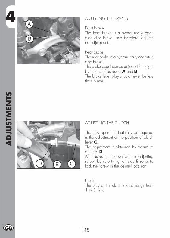
4A
DJU
STM
ENTS
148GB
ADJUSTING THE BRAKES
Front brakeThe front brake is a hydraulically oper-ated disc brake, and therefore requires no adjustment.
Rear brakeThe rear brake is a hydraulically operated disc brake.The brake pedal can be adjusted for height by means of adjusters A and B.The brake lever play should never be less than 5 mm.
ADJUSTING THE CLUTCH
The only operation that may be required is the adjustment of the position of clutch lever C.The adjustment is obtained by means of adjuster D.After adjusting the lever with the adjusting screw, be sure to tighten stop E so as to lock the screw in the desired position.
Note:The play of the clutch should range from 1 to 2 mm.
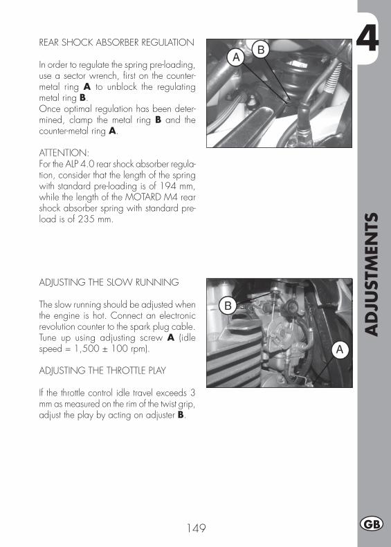
4
AD
JUST
MEN
TS
149 GB
REAR SHOCK ABSORBER REGULATION
In order to regulate the spring pre-loading, use a sector wrench, fi rst on the counter-metal ring A to unblock the regulating metal ring B.Once optimal regulation has been deter-mined, clamp the metal ring B and the counter-metal ring A.
ATTENTION:For the ALP 4.0 rear shock absorber regula-tion, consider that the length of the spring with standard pre-loading is of 194 mm, while the length of the MOTARD M4 rear shock absorber spring with standard pre-load is of 235 mm.
ADJUSTING THE SLOW RUNNING
The slow running should be adjusted when the engine is hot. Connect an electronic revolution counter to the spark plug cable. Tune up using adjusting screw A (idle speed = 1,500 ± 100 rpm).
ADJUSTING THE THROTTLE PLAY
If the throttle control idle travel exceeds 3 mm as measured on the rim of the twist grip, adjust the play by acting on adjuster B.
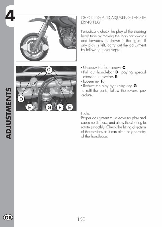
4A
DJU
STM
ENTS
150GB
CHECKING AND ADJUSTING THE STE-ERING PLAY
Periodically check the play of the steering head tube by moving the forks backwards and forwards as shown in the fi gure. If any play is felt, carry out the adjustment by following these steps:
• Unscrew the four screws C.• Pull out handlebar D, paying special attention to clevises E.
• Loosen nut F.• Reduce the play by turning ring G.To refi t the parts, follow the reverse pro-cedure.
Note:Proper adjustment must leave no play and cause no stiffness, and allow the steering to rotate smoothly. Check the fi tting direction of the clevises as it can alter the geometry of the handlebar.
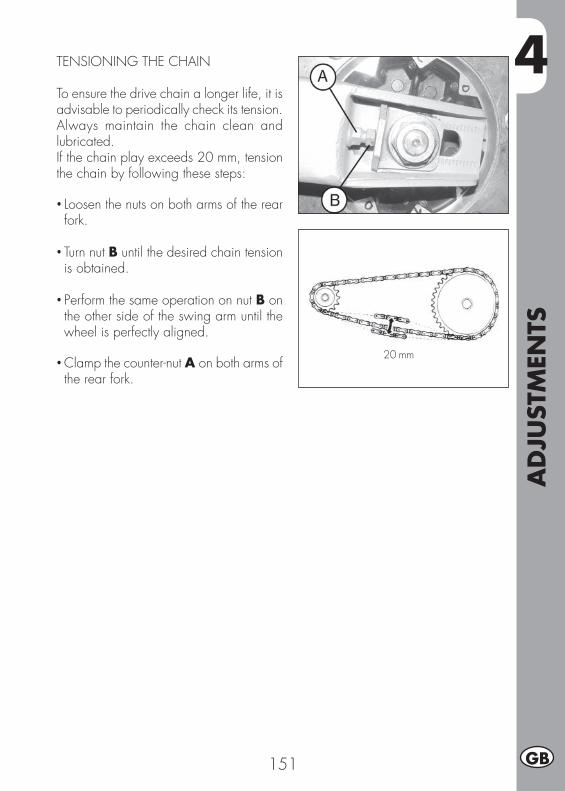
4
AD
JUST
MEN
TS
151 GB
TENSIONING THE CHAIN
To ensure the drive chain a longer life, it is advisable to periodically check its tension.Always maintain the chain clean and lubricated.If the chain play exceeds 20 mm, tension the chain by following these steps:
• Loosen the nuts on both arms of the rear fork.
• Turn nut B until the desired chain tension is obtained.
• Perform the same operation on nut B on the other side of the swing arm until the wheel is perfectly aligned.
• Clamp the counter-nut A on both arms of the rear fork.
20 mm
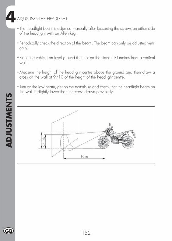
4A
DJU
STM
ENTS
152GB
ADJUSTING THE HEADLIGHT
• The headlight beam is adjusted manually after loosening the screws on either side of the headlight with an Allen key.
• Periodically check the direction of the beam. The beam can only be adjusted verti-cally.
• Place the vehicle on level ground (but not on the stand) 10 metres from a vertical wall.
• Measure the height of the headlight centre above the ground and then draw a cross on the wall at 9/10 of the height of the headlight centre.
• Turn on the low beam, get on the motorbike and check that the headlight beam on the wall is slightly lower than the cross drawn previously.
9/10
h
10 m
h
5
REP
LACEM
ENTS
153 GB
CONTENTS
CHAPTER 5 REPLACEMENTS
Replacing the front brake pads
Replacing the rear brake pads
Replacing the headlight bulb ALP
Replacing the headlight bulb MOTARD M4
Replacement of indicators and rear light
Replacement of plate light
Bulbs specifi cations
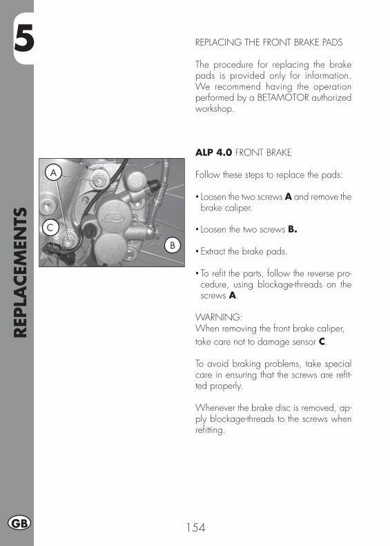
5REP
LACEM
ENTS
154GB
REPLACING THE FRONT BRAKE PADS
The procedure for replacing the brake pads is provided only for information. We recommend having the operation performed by a BETAMOTOR authorized workshop.
ALP 4.0 FRONT BRAKE
Follow these steps to replace the pads:
• Loosen the two screws A and remove the brake caliper.
• Loosen the two screws B.
• Extract the brake pads.
• To refi t the parts, follow the reverse pro-cedure, using blockage-threads on the screws A.
WARNING:When removing the front brake caliper, take care not to damage sensor C. To avoid braking problems, take special care in ensuring that the screws are refi t-ted properly.
Whenever the brake disc is removed, ap-ply blockage-threads to the screws when refi tting.
A
B
C
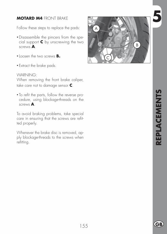
5
REP
LACEM
ENTS
155 GB
MOTARD M4 FRONT BRAKE
Follow these steps to replace the pads:
• Disassemble the pincers from the spe-cial support C by unscrewing the two screws A.
• Loosen the two screws B.
• Extract the brake pads.
WARNING:When removing the front brake caliper, take care not to damage sensor C.
• To refi t the parts, follow the reverse pro-cedure, using blockage-threads on the screws A.
To avoid braking problems, take special care in ensuring that the screws are refi t-ted properly.
Whenever the brake disc is removed, ap-ply blockage-threads to the screws when refi tting.
A
B
C
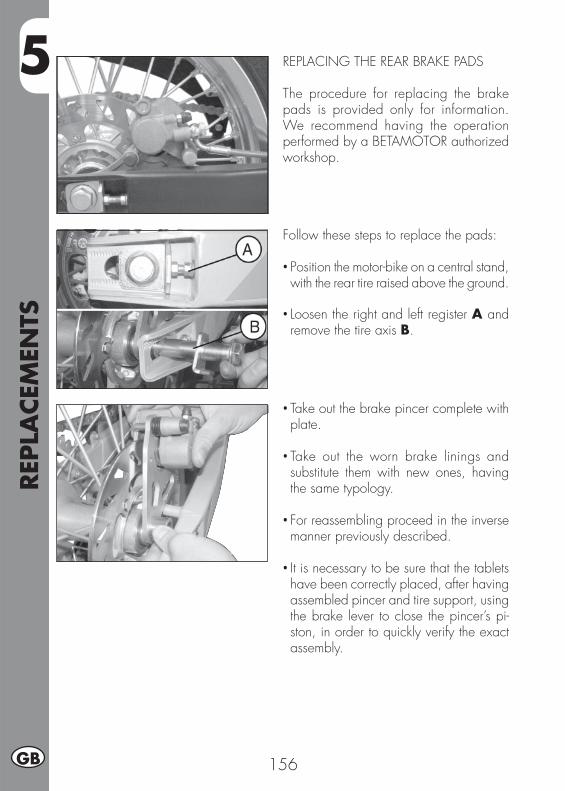
5REP
LACEM
ENTS
156GB
Follow these steps to replace the pads:
• Position the motor-bike on a central stand, with the rear tire raised above the ground.
• Loosen the right and left register A and remove the tire axis B.
REPLACING THE REAR BRAKE PADS
The procedure for replacing the brake pads is provided only for information. We recommend having the operation performed by a BETAMOTOR authorized workshop.
• Take out the brake pincer complete with plate.
• Take out the worn brake linings and substitute them with new ones, having the same typology.
• For reassembling proceed in the inverse manner previously described.
• It is necessary to be sure that the tablets have been correctly placed, after having assembled pincer and tire support, using the brake lever to close the pincer’s pi-ston, in order to quickly verify the exact assembly.

5
REP
LACEM
ENTS
157 GB
REPLACING THE HEADLIGHT BULB ALP
FRONT Remove the rest and the light unit as de-scribed on page 138.Pull out the wire, lift the rubber cap A, re-lease the lamp-locking spring and replace the burnt lamp with a new one having the same specifi cations, taking care not to touch the bulb.Fit it all back in, in reverse order.
Parking light:Remove the rest and the light unit as de-scribed on page 138.Take out the bulb B and remove the burnt lamp, replace it with a new one having the same specifi cations, taking care not to touch the bulb in order not to damage it.
A
B

5REP
LACEM
ENTS
158GB
REPLACING THE HEADLIGHT BULB MO-TARD M4
FRONTTo replace the headlight bulb, disconnect connectors A from the bulb and then re-move rubber cap B.Turn fastening fl ange C anticlockwise and remove the bulb from the refl ector.
Fit a new bulb (12V - 55/60W) taking care not to touch the bulb to avoid impairing its function. Rotate the bulb holder clockwise to the stop.
AB
C

5
REP
LACEM
ENTS
159 GB
A
B
D
C
REPLACEMENT OF INDICATORS AND REAR LIGHT
In both models (ALP 4.0 and M4), the indicators and rear lights have a light LED. In the event of a breakdown, replace the whole indicator as follows:
FRONT INDICATORSUnscrew the nut A inside the cover, which matches the damaged indicator.Pull out the light unit and disconnect it from the electric wire.Connect the new indicator, fi t it back onto its rest.Screw the nut A.
REAR INDICATORSUnscrew the nut B under the rear fender, which matches the damaged indicator.Pull out the light unit and disconnect it from the electric wire.Connect the new indicator, fi t it back onto its rest.Screw the nut B.
Rear lightUnscrew the two screws C and remove the rear light D.Disconnect the light wire by removing the back tail and back handles as described on page 137.
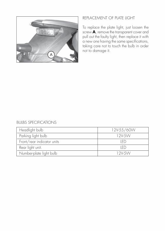
A
REPLACEMENT OF PLATE LIGHT
To replace the plate light, just loosen the screw A, remove the transparent cover and pull out the faulty light, then replace it with a new one having the same specifi cations, taking care not to touch the bulb in order not to damage it.
Headlight bulb 12V-55/60W Parking light bulb 12V-5W Front/rear indicator units LED Rear light unit. LED Number-plate light bulb 12V-5W
BULBS SPECIFICATIONS
6
TRO
UBLE
SHO
OTI
NG
161 GB
CONTENTS
CHARTER 6 TROUBLESHOOTING
INDEX
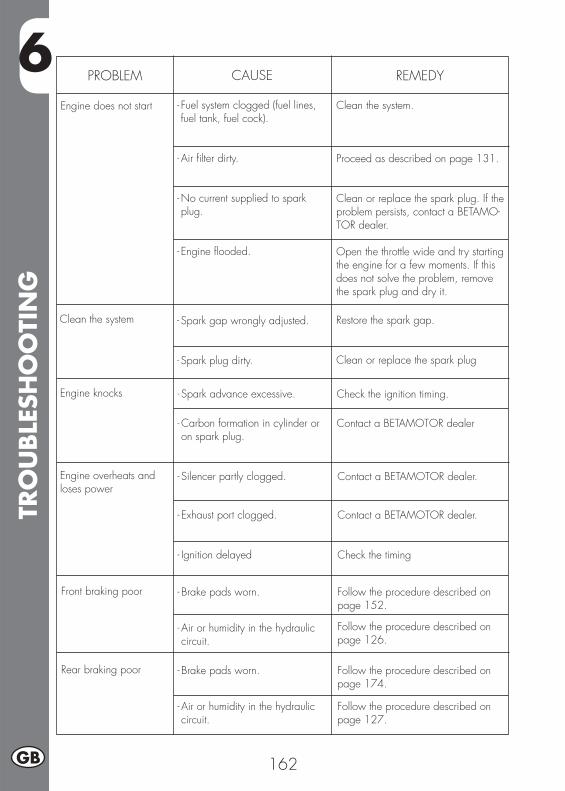
6TR
OU
BLE
SHO
OTI
NG
162GB
PROBLEM CAUSE
Engine does not start
REMEDY
- Fuel system clogged (fuel lines, fuel tank, fuel cock).
- Air fi lter dirty.
- No current supplied to spark plug.
- Engine fl ooded.
Clean the system.
Proceed as described on page 131.
Clean or replace the spark plug. If the problem persists, contact a BETAMO-TOR dealer. Open the throttle wide and try starting the engine for a few moments. If this does not solve the problem, remove the spark plug and dry it.
Clean the system - Spark gap wrongly adjusted.
- Spark plug dirty.
Restore the spark gap.
Clean or replace the spark plug
Engine knocks - Spark advance excessive.
- Carbon formation in cylinder or on spark plug.
Check the ignition timing.
Contact a BETAMOTOR dealer
Engine overheats and loses power
- Silencer partly clogged.
- Exhaust port clogged.
- Ignition delayed
Contact a BETAMOTOR dealer.
Contact a BETAMOTOR dealer.
Check the timing
Front braking poor - Brake pads worn.
- Air or humidity in the hydraulic circuit.
Follow the procedure described on page 152.
Follow the procedure described on page 126.
Rear braking poor - Brake pads worn.
- Air or humidity in the hydraulic circuit.
Follow the procedure described on page 174.
Follow the procedure described on page 127.
IND
EX
163 GB
Adjusting the brakes ............................................................................ 148Adjusting the clutch ............................................................................. 148Adjusting the headlight ........................................................................ 152Adjusting the slow running .................................................................... 149Adjusting the throttle play ..................................................................... 149After prolonged inactivity ..................................................................... 146Air fi lter ............................................................................................ 133AIS valve .......................................................................................... 114
Battery ............................................................................................. 136Brake pump oil - Bleeding the brakes ..................................................... 128Bulbs specifi cations ............................................................................. 160
Carburetor ........................................................................................ 136Checking and adjusting the steering play ................................................ 150Checks after cleaning .......................................................................... 144Checks and manintenance operations before and after off-road use ............. 116Cleaning and checking the vehicle ........................................................ 144Crash helmet lock ................................................................................. 94
Delivery .............................................................................................. 90
Ecologic guide..................................................................................... 87Electrical devices ................................................................................ 112
Familiarizing with the vehicle .................................................................. 93Final transmission group substitution ........................................................ 142Fork oil ............................................................................................. 132Front brake ........................................................................................ 135Fume collecting tube ........................................................................... 128
Ignition switch/Steering lock ................................................................... 94Instrument panel and controls ................................................................. 95
Keys and locks ..................................................................................... 94
LCD ................................................................................................... 96Load .................................................................................................. 91
Motor oil and fi lter oil substitution .......................................................... 124Motor oil level check ........................................................................... 122
Notes for cross-country ........................................................................ 141
IND
EX
164GB
Operating instructions ............................................................................ 87
Prolonged inactivity ............................................................................. 146
Rear brake ........................................................................................ 135Rear shock absorber regulation ............................................................. 149Recommended lubricants ..................................................................... 116Refuelling .......................................................................................... 120Removing the plastics for ALP ................................................................ 137Removing the plastics for MOTARD M4 .................................................. 139Replacement of indicators and rear light ................................................ 159Replacement of plate light .................................................................... 160Replacing the front brake pads .............................................................. 154Replacing the headlight bulb ALP .......................................................... 157Replacing the headlight bulb MOTARD M4 ............................................. 158Replacing the rear brake pads .............................................................. 156Riding safety ........................................................................................ 88Running-in ......................................................................................... 117
Scheduled maintenance ....................................................................... 145Shutting off the engine ......................................................................... 119Spark plug ........................................................................................ 134Specifi cations .................................................................................... 107Starting the engine .............................................................................. 118
Tensioning the chain ............................................................................ 151Tyres .................................................................................................. 91
Vehicle identifi cation data ...................................................................... 90
Wiring diagram ................................................................................. 110

165 F
ALP 4.0 - MOTARD M4
Merci de votre confi ance et bon divertissement. Ce livret vous donnera les informations nécessaires pour une utilisation correcte et un bon entretien de votre moto.
Les informations et les caractéristiques indiquées dans ce manuel n’engagent pas BETAMOTOR S.p.A. qui se réserve le droit d’apporter des modifi cations et des améliorations à ses modèles à tout moment et sans préavis.
166F
AVERTISSEMENT
Il est recommandé, au bout de la première ou de la seconde heure d’utilisation en tout-terrain, de contrôler tous les serrages avec une attention particulière pour:
• Couronne• Supports de cale-pieds• Étrier de frein avant / arrière• Support de garde-boue• Boulonnerie moteur• Boulonnerie amortisseur.• Rayons roue• Cadre arrière• Supports réservoir huile sur cadre
AVERTISSEMENT
En cas d’intervention à effectuer sur la moto, s’adresser au réseau d’assistance agréé Betamotor.
TABLE
DES
MA
TIÈR
ES
167 F
Conseils pour l’utilisation du véhicule ...................................................... 169Conduite écologique .......................................................................... 169Conduire en sécurité ........................................................................... 170
CHAP. 1 GÉNÉRALITÉS .................................................................. 171Données d’identifi cation du véhicule ...................................................... 172Equipement ....................................................................................... 172Charge ............................................................................................ 173Pneumatiques..................................................................................... 173Connaissance du véhicule .................................................................... 175Clés et serrures .................................................................................. 176Contacteur principal/Verrouillage de direction ......................................... 176Serrure pour casque ............................................................................ 176Tableau de bord et commandes ........................................................... 177LCD ................................................................................................. 178Caractéristiques techniques .................................................................. 189Schéma électrique .............................................................................. 192Équipement électrique ......................................................................... 194La soupape AIS .................................................................................. 196
CHAP. 2 UTILISATION DU VÉHICULE ............................................ 197Contrôles et entretien avant et après l’utilisation en tout-terrain ..................... 198Lubrifi ants conseillés ............................................................................ 198Rodage ............................................................................................ 199Dèmarrage du moteur ......................................................................... 200Arrêt du moteur .................................................................................. 201Approvisionnement en carburant............................................................ 202
CHAP. 3 CONTRÔLES ET ENTRETIEN ............................................. 203Contrôle niveau huile moteur ................................................................ 204Vidange huile moteur et fi ltre à huile ....................................................... 206Tuyau de récupératin des fumées ........................................................... 210Liquide de frein, purge du circuit ........................................................... 210Huile de fourche ................................................................................ 214Filtre à air ......................................................................................... 215Bougie ............................................................................................. 216Frein avant ........................................................................................ 217Frein arrière ....................................................................................... 217Carburateur ....................................................................................... 218Batterie ............................................................................................. 218Desmontage des plastiques pour ALP ...................................................... 219Desmontage des plastiques pour MOTARD M4 ........................................ 221Note pour usage tout-terrain ................................................................. 223Substitution groupe transmission fi nal ...................................................... 224Nettoyage du véhicule et contrôles ........................................................ 226
TABLE
DES
MA
TIÈR
ES
168F
Contrôles après le nettoyage ................................................................ 226Entretien programmé ........................................................................... 227Longue inactivité du véhicule................................................................. 228Après une longue période d’inactivité ..................................................... 228
CHAP. 4 RÉGLAGES ....................................................................... 229Réglage des freins .............................................................................. 230Réglage de l’embrayage ..................................................................... 230Réglage amortisseur arrière .................................................................. 231Réglage du ralenti .............................................................................. 231Réglage du jeu à la poignée des gaz .................................................... 231Contrôle et réglage du jeu à la direction ................................................. 232Tension de la chaîne ........................................................................... 233Faisceau lumineux .............................................................................. 234
CHAP. 5 REMPLACEMENTS ........................................................... 235Remplacement des plaquettes de frein avant ............................................ 236Remplacement des plaquettes de frein arrière ........................................... 238Remplacement des ampoules ALP ..........................................................239Remplacement des ampoules MOTARD M4 ............................................ 240Substitution des clignotants et du feu arrière ............................................ 241Substitution lumière plaque d’immatriculation ............................................ 242Caractéristiques lampes ....................................................................... 242
CHAP. 6 QUE FAIRE EN CAS D’URGENCE ?.................................. 243
INDEX ALPHABÉTIQUE .................................................................. 245
169 F
CONSEILS POUR L’UTILISATION DU VÉHICULE• Le véhicule doit être obligatoirement pourvu de: plaque d’immatriculation, carter grise, vignette et assurance.
• Il est interdit de transporter des animaux ou objets qui ne soient pas rendus solidaires du véhicule, qui dépassent l’encombrement du véhicule et la charge utile prévue par le constructeur;
• Le casque est obligatoire.• Toute modifi cation apportée au moteur ou aux autres organes, destinée à augmenter la puissance et par conséquent la vitesse, est sévèrement sanctionnée par la loi et entraîne la saisie du véhicule.
• Pour ne pas risquer sa vie ni celle des autres, conduire prudemment et toujours porter le casque de sécurité.
ATTENTIONLes modifi cations ou transformations au cours de la période de garantie dégagent le Constructeur de toute responsabilité et annulent la garantie.
CONDUITE ÉCOLOGIQUE• Chaque véhicule à moteur à explosion produit une quantité plus ou moins importante de pollution sonore et atmosphérique, selon le type de conduite adopté.
• L’abaissement, autant que possible, de ces conditions constitue de nos jours un devoir pour tous, éviter donc les départs plein gaz, les accélérations brutales et inutiles ainsi que les freinages impromptus et tout aussi inutiles, afi n de limiter le bruit, l’usure précoce des pneus et des parties mécaniques du véhicule ainsi que, de manière non négligeable, la consommation de carburant.
170F
CONDUIRE EN SÉCURITÉ• Respecter le code de la route• Toujours porter un casque homologué et attaché• Toujours garder propre la visière de protection• Porter des vêtements sans pans fl ottants• Ne pas rouler avec des objets pointus ou fragiles dans les poches• Régler le rétroviseur correctement• Toujours conduire assis avec le deux mains sur le guidon et les pieds sur les cale-pieds
• Ne jamais se distraire ou se laisser distraire en conduisant• Ne pas manger, boire, fumer, téléphoner etc... en conduisant• Ne pas écouter de musique avec un baladeur en conduisant• Ne pas rouler de front avec d’autres véhicules• Ne pas remorquer ou se faire remorquer par d’autres véhicules• Toujours maintenir les distances de sécurité• Ne pas rester assis sur le véhicule sur béquille• Ne pas partir avec le véhicule sur béquille• Ne pas sortir la béquille avec l’avant du véhicule en descente• Cabrages, lacets et zigzags sont très dangereux pour le pilote, les autres et le véhicule
• Sur route sèche et sans gravillon ni sable, utiliser les deux freins. L’utilisation d’un seul frein peut provoquer des glissades dangereuses et incontrôlables.
• En cas de freinage, utiliser les deux freins pour avoir un arrêt du véhicule sur une distance plus réduite
• Sur route mouillée, conduire avec prudence et à vitesse modéré: utiliser les freins avec plus de sensibilité
• Ne pas mettre le moteur en marche dans une pièce close.
1
GÉN
ÉRA
LITÉ
S
171 F
TABLE DES MATIÈRES
CHAP. 1 GÉNÉRALITÉS
Données d’identifi cation du véhicule
Equipement
Charge
Pneumatiques
Connaissance du véhicule
Clés et serrures
Contacteur principal/Verrouillage de direction
Serrure pour casque
Tableau de bord et commandes
Indications sue ecran LCD
Caractéristiques techniques
Schéma électrique
Équipement électrique
La soupape AIS
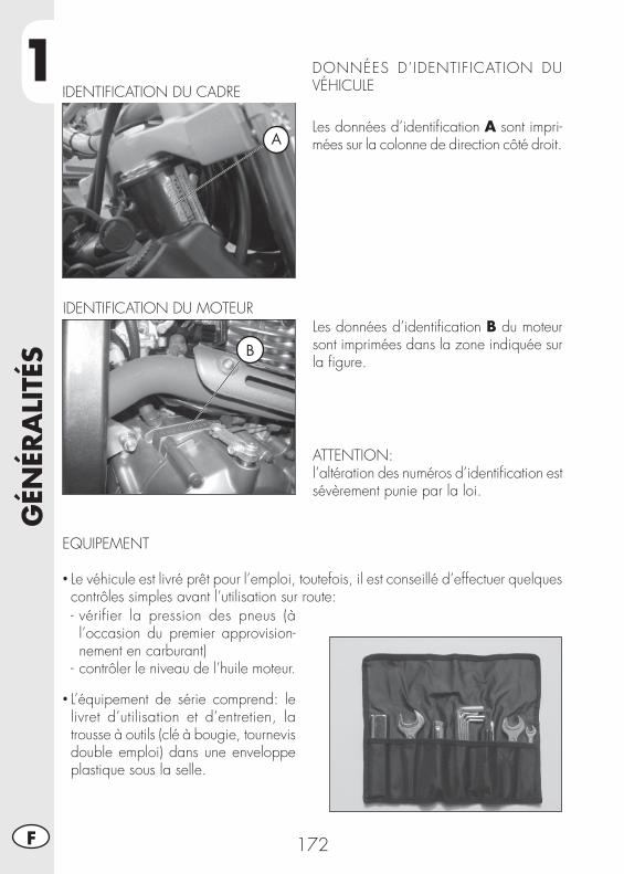
1G
ÉNÉR
ALI
TÉS
172F
DONNÉES D’IDENTIFICATION DU VÉHICULE
Les données d’identifi cation A sont impri-mées sur la colonne de direction côté droit.
IDENTIFICATION DU CADRE
Les données d’identifi cation B du moteur sont imprimées dans la zone indiquée sur la fi gure.
ATTENTION:l’altération des numéros d’identifi cation est sévèrement punie par la loi.
IDENTIFICATION DU MOTEUR
EQUIPEMENT
• Le véhicule est livré prêt pour l’emploi, toutefois, il est conseillé d’effectuer quelques contrôles simples avant l’utilisation sur route:- vérifier la pression des pneus (à l’occasion du premier approvision-nement en carburant)
- contrôler le niveau de l’huile moteur.
• L’équipement de série comprend: le livret d’utilisation et d’entretien, la trousse à outils (clé à bougie, tournevis double emploi) dans une enveloppe plastique sous la selle.
A
B
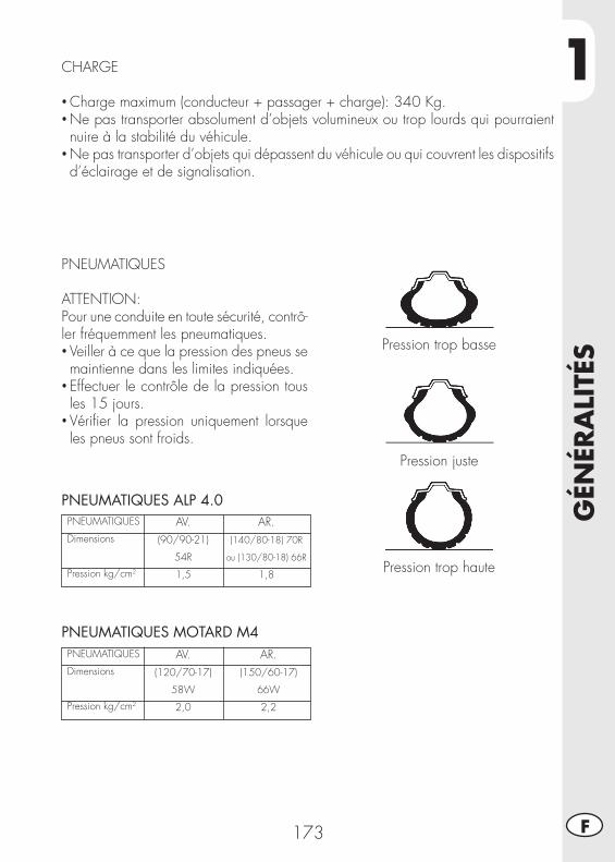
1
GÉN
ÉRA
LITÉ
S
173 F
CHARGE
• Charge maximum (conducteur + passager + charge): 340 Kg.• Ne pas transporter absolument d’objets volumineux ou trop lourds qui pourraient nuire à la stabilité du véhicule.
• Ne pas transporter d’objets qui dépassent du véhicule ou qui couvrent les dispositifs d’éclairage et de signalisation.
PNEUMATIQUES
ATTENTION:Pour une conduite en toute sécurité, contrô-ler fréquemment les pneumatiques.• Veiller à ce que la pression des pneus se maintienne dans les limites indiquées.
• Effectuer le contrôle de la pression tous les 15 jours.
• Vérifi er la pression uniquement lorsque les pneus sont froids.
Pression trop basse
Pression juste
Pression trop haute
PNEUMATIQUES ALP 4.0PNEUMATIQUES
Dimensions
Pression kg/cm2
AR.(140/80-18) 70R
ou (130/80-18) 66R
1,8
AV.(90/90-21)
54R
1,5
PNEUMATIQUES MOTARD M4PNEUMATIQUES
Dimensions
Pression kg/cm2
AR.(150/60-17)
66W
2,2
AV.(120/70-17)
58W
2,0
1G
ÉNÉR
ALI
TÉS
174F
Note:L’épaisseur minimum de la bande de roulement des pneumatiques (TUBE TYPE) ne doit jamais être inférieure à 2 mm.Toute infraction à cette norme est punie par la loi.
• Avant chaque trajet, contrôler que les pneus ne présentent pas de coupures, fi ssures, usure, renfl ements, etc... Dans tous ces cas, faire vérifi er le pneu par un expert car il pourrait s’agir de conditions extrêmement dangereuses.
• En cas de crevaison, arrêter immédiatement le véhicule. Poursuivre sa route, en plus d’être risqué, peut causer des dommages irréparables au pneumatique et à la jante.
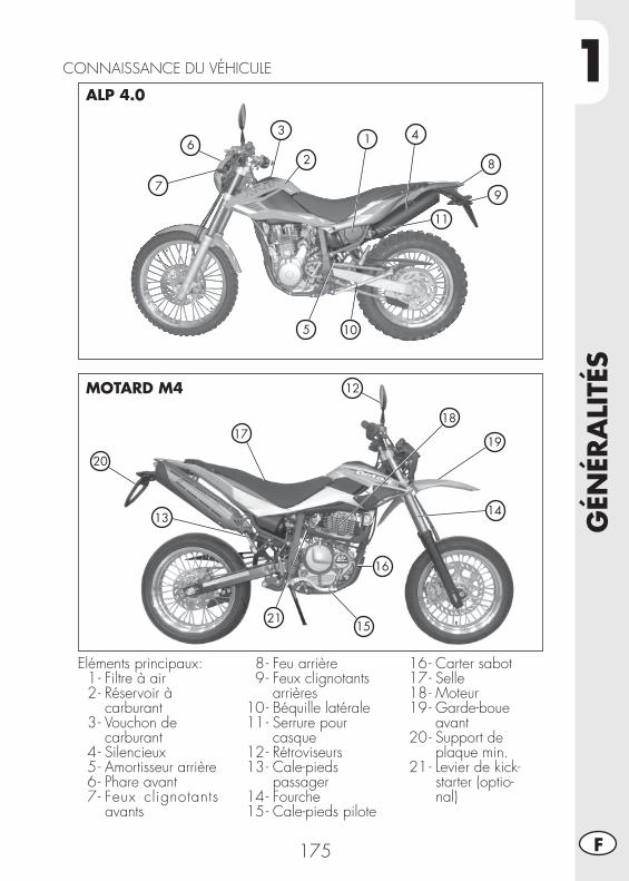
1
GÉN
ÉRA
LITÉ
S
175 F
CONNAISSANCE DU VÉHICULE
Eléments principaux: 1 - Filtre à air 2 - Réservoir à carburant 3 - Vouchon de carburant 4 - Silencieux 5 - Amortisseur arrière 6 - Phare avant 7 - Feux clignotants
avants
8 - Feu arrière 9 - Feux clignotants arrières 10 - Béquille latérale 11 - Serrure pour casque 12 - Rétroviseurs 13 - Cale-pieds passager 14 - Fourche 15 - Cale-pieds pilote
16 - Carter sabot 17 - Selle 18 - Moteur 19 - Garde-boue avant 20 - Support de plaque min. 21 - Levier de kick-
starter (optio-nal)
ALP 4.0
MOTARD M4
7
10
6
5
3
2
1
8
9
4
11
20
17
12
18
19
14
16
21
13
15
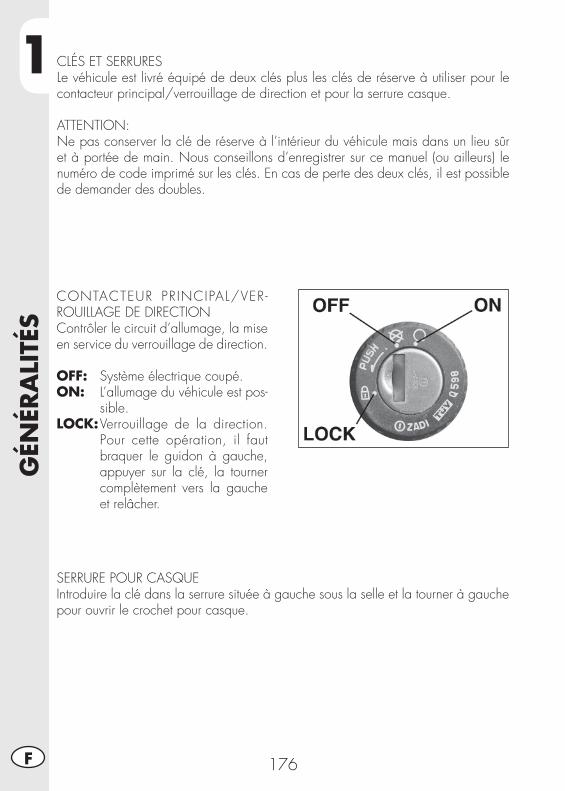
1G
ÉNÉR
ALI
TÉS
176F
CLÉS ET SERRURESLe véhicule est livré équipé de deux clés plus les clés de réserve à utiliser pour le contacteur principal/verrouillage de direction et pour la serrure casque.
ATTENTION:Ne pas conserver la clé de réserve à l’intérieur du véhicule mais dans un lieu sûr et à portée de main. Nous conseillons d’enregistrer sur ce manuel (ou ailleurs) le numéro de code imprimé sur les clés. En cas de perte des deux clés, il est possible de demander des doubles.
CONTACTEUR PRINCIPAL/VER-ROUILLAGE DE DIRECTIONContrôler le circuit d’allumage, la mise en service du verrouillage de direction.
OFF: Système électrique coupé.ON: L’allumage du véhicule est pos-
sible.LOCK: Verrouillage de la direction.
Pour cette opération, il faut braquer le guidon à gauche, appuyer sur la clé, la tourner complètement vers la gauche et relâcher.
SERRURE POUR CASQUEIntroduire la clé dans la serrure située à gauche sous la selle et la tourner à gauche pour ouvrir le crochet pour casque.
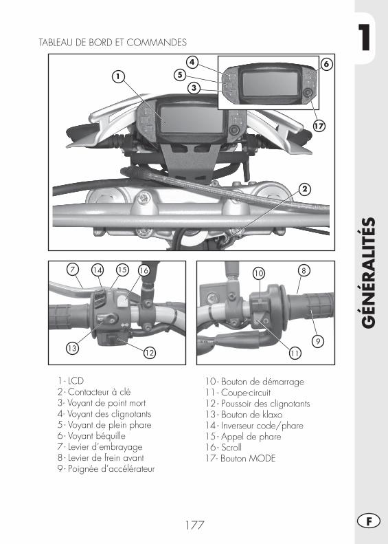
1
GÉN
ÉRA
LITÉ
S
177 F
1 - LCD 2 - Contacteur à clé 3 - Voyant de point mort 4 - Voyant des clignotants 5 - Voyant de plein phare 6 - Voyant béquille 7 - Levier d’embrayage 8 - Levier de frein avant 9 - Poignée d’accélérateur
10 - Bouton de démarrage11 - Coupe-circuit12 - Poussoir des clignotants13 - Bouton de klaxo14 - Inverseur code/phare15 - Appel de phare 16 - Scroll17- Bouton MODE
TABLEAU DE BORD ET COMMANDES
7 8
9
10
111213
14 15 16
1
2
3
5
17
4 6
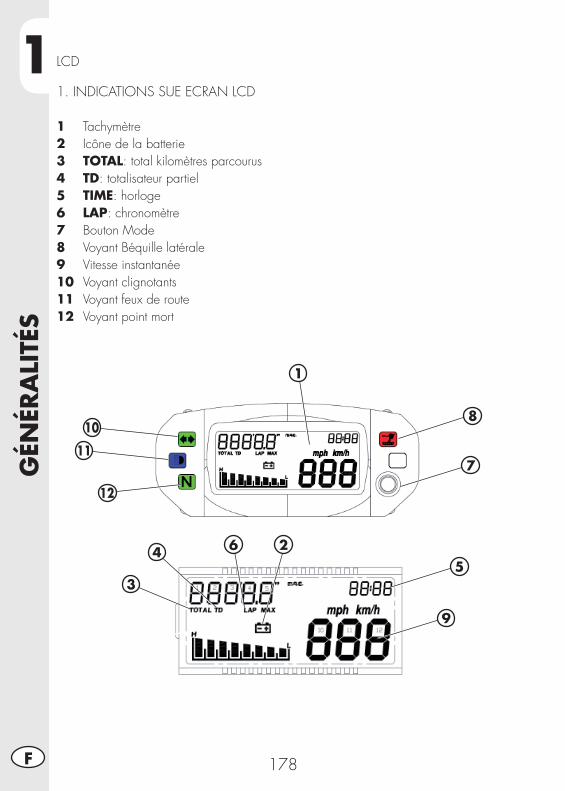
1G
ÉNÉR
ALI
TÉS
178F
LCD
1. INDICATIONS SUE ECRAN LCD
1 Tachymètre2 Icône de la batterie3 TOTAL: total kilomètres parcourus4 TD: totalisateur partiel5 TIME: horloge6 LAP: chronomètre 7 Bouton Mode8 Voyant Béquille latérale9 Vitesse instantanée 10 Voyant clignotants11 Voyant feux de route12 Voyant point mort
2
3
45
7
6
9
1
10
11
12
8
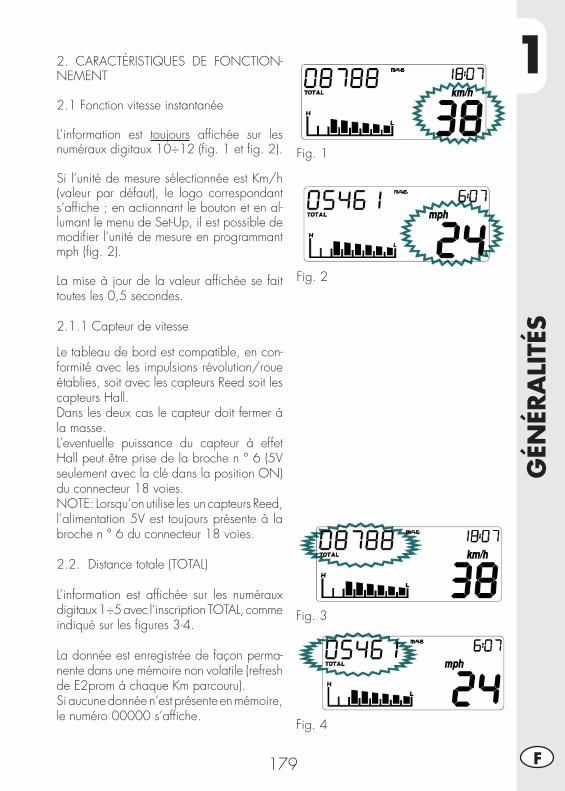
1
GÉN
ÉRA
LITÉ
S
179 F
2. CARACTÉRISTIQUES DE FONCTION-NEMENT
2.1 Fonction vitesse instantanée
L’information est toujours affi chée sur les numéraux digitaux 10÷12 (fi g. 1 et fi g. 2).
Si l’unité de mesure sélectionnée est Km/h (valeur par défaut), le logo correspondant s’affi che ; en actionnant le bouton et en al-lumant le menu de Set-Up, il est possible de modifi er l’unité de mesure en programmant mph (fi g. 2).
La mise à jour de la valeur affi chée se fait toutes les 0,5 secondes.
2.1.1 Capteur de vitesse
Le tableau de bord est compatible, en con-formité avec les impulsions révolution/roue établies, soit avec les capteurs Reed soit les capteurs Hall.Dans les deux cas le capteur doit fermer à la masse.L’eventuelle puissance du capteur à effet Hall peut être prise de la broche n ° 6 (5V seulement avec la clé dans la position ON) du connecteur 18 voies.NOTE: Lorsqu’on utilise les un capteurs Reed, l’alimentation 5V est toujours présente à la broche n ° 6 du connecteur 18 voies.
2.2. Distance totale (TOTAL)
L’information est affi chée sur les numéraux digitaux 1÷5 avec l’inscription TOTAL, comme indiqué sur les fi gures 3-4.
La donnée est enregistrée de façon perma-nente dans une mémoire non volatile (refresh de E2prom à chaque Km parcouru).Si aucune donnée n’est présente en mémoire, le numéro 00000 s’affi che.
Fig. 1
Fig. 2
Fig. 3
Fig. 4
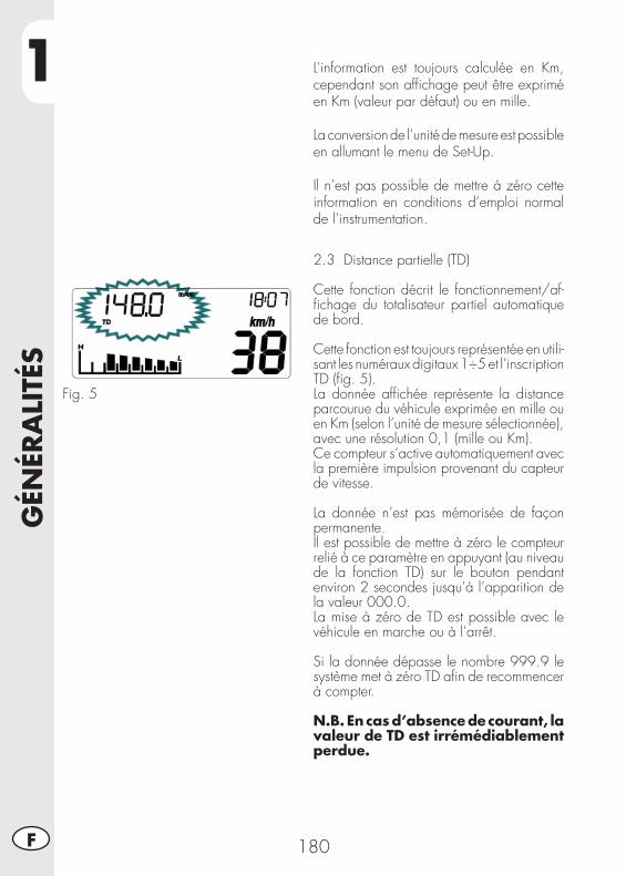
1G
ÉNÉR
ALI
TÉS
180F
Fig. 5
2.3 Distance partielle (TD)
Cette fonction décrit le fonctionnement/af-fi chage du totalisateur partiel automatique de bord.
Cette fonction est toujours représentée en utili-sant les numéraux digitaux 1÷5 et l’inscription TD (fi g. 5).La donnée affi chée représente la distance parcourue du véhicule exprimée en mille ou en Km (selon l’unité de mesure sélectionnée), avec une résolution 0,1 (mille ou Km).Ce compteur s’active automatiquement avec la première impulsion provenant du capteur de vitesse.
La donnée n’est pas mémorisée de façon permanente.Il est possible de mettre à zéro le compteur relié à ce paramètre en appuyant (au niveau de la fonction TD) sur le bouton pendant environ 2 secondes jusqu’à l’apparition de la valeur 000.0.La mise à zéro de TD est possible avec le véhicule en marche ou à l’arrêt.
Si la donnée dépasse le nombre 999.9 le système met à zéro TD afi n de recommencer à compter.
N.B. En cas d’absence de courant, la valeur de TD est irrémédiablement perdue.
L’information est toujours calculée en Km, cependant son affi chage peut être exprimé en Km (valeur par défaut) ou en mille.
La conversion de l’unité de mesure est possible en allumant le menu de Set-Up.
Il n’est pas possible de mettre à zéro cette information en conditions d’emploi normal de l’instrumentation.
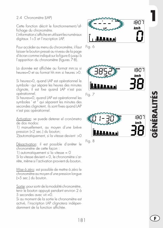
1
GÉN
ÉRA
LITÉ
S
181 F
Fig. 6
Fig. 7
Fig. 8
2.4 Chronomètre (LAP)
Cette fonction décrit le fonctionnement/af-fi chage du chronomètre.L’information s’affi che en utilisant les numéraux digitaux 1÷5 et l’inscription LAP.
Pour accéder au menu du chronomètre, il faut laisser le bouton pressé au niveau de la page d’écran comme indiqué sur la fi gure 6 jusqu’à l’apparition du chronomètre (fi gures 7-8).
La donnée est affi chée au format mm:ss si heures=0 et au format hh:mm si heures >0.
Si heures>0, quand LAP est opérationnel le symbole - qui sépare les heures des minutes clignote, il est fi xe quand LAP n’est pas opérationnel. Si heures=0, quand LAP est opérationnel les symboles ‘ et “ qui séparent les minutes des secondes clignotent, ils sont fi xes quand LAP n’est pas opérationnel.
Activation: se puede detener el cronómetro de dos modos:1) manuellement, au moyen d’une brève pression (<2 sec.) du bouton;2) automatiquement, si la vitesse devient >0
Désactivation: il est possible d’arrêter le chronomètre de cette façon : 1) automatiquement si la vitesse = 0Si la vitesse devient = 0, le chronomètre s’ar-rête, même si l’activation provient du bouton.
Mise à zéro: est possible de mettre à zéro le chronomètre au moyen d’une pression longue (>5 sec.) du bouton.
Sortie: pour sortir de la modalité chronomètre, tenir le bouton appuyé pendant environ 2 à 5 secondes avec vit.=0.Si au moment de la sortie le chronomètre est activé, l’inscription LAP clignotera indépen-damment de la fonction affi chée.
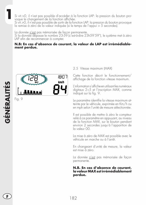
1G
ÉNÉR
ALI
TÉS
182F
2.5 Vitesse maximum (MAX)
Cette fonction décrit le fonctionnement/affi chage de la fonction vitesse maximum.
L’information s’affi che en utilisant les numéraux digitaux 2÷5 et l’inscription MAX, comme indiqué sur la fi g. 9.
Le paramètre identifi e la vitesse maximum at-teinte par le véhicule, exprimée en Km/h ou en mph selon l’unité de mesure sélectionnée.
Il est possible de mettre à zéro le compteur relié à ce paramètre en appuyant, au niveau de la fonction MAX, sur le bouton pendant environ 2 secondes jusqu’à l’apparition de la valeur 00.
La mise à zéro de MAX est possible avec le véhicule en marche ou à l’arrêt.
En changeant d’unité de mesure, la valeur est mise à zéro.
La donnée n’est pas mémorisée de façon permanente.
N.B. En cas d’absence de courant, la valeur MAX est irrémédiablement perdue.
Fig. 9
Si vit.>0, il n’est pas possible d’accéder à la fonction LAP: la pression du bouton pro-voque le changement de la fonction affi chée.Si vit.>0, il n’est pas possible de sortir de la fonction LAP: la pression du bouton provoque la remise à zéro de la valeur indiquée (si le temps de l’appui > 5 secondes).
La donnée n’est pas mémorisée de façon permanente.Si la donnée dépasse le nombre 23-59 (c’est-à-dire 23h59’59”), le système met à zéro LAP afi n de recommencer à compter.
N.B: En cas d’absence de courant, la valeur de LAP est irrémédiable-ment perdue.
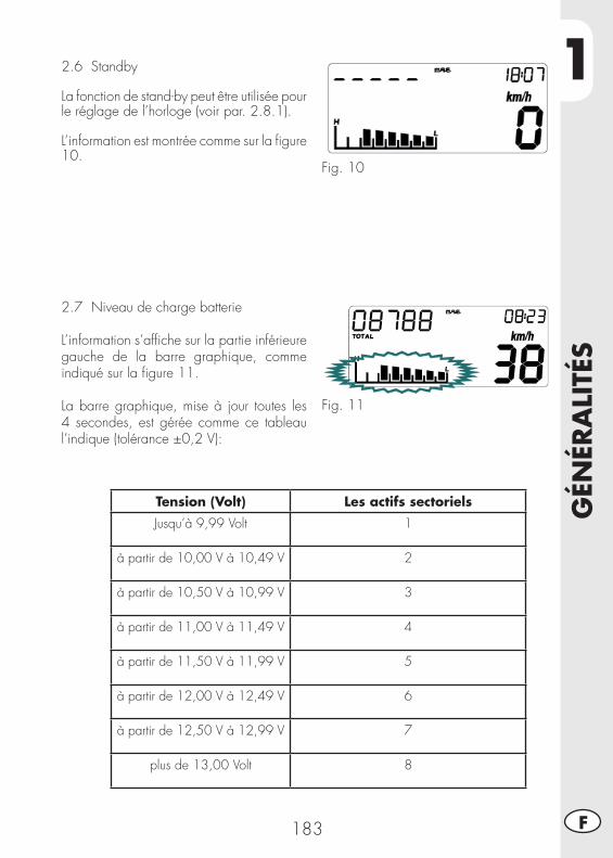
1
GÉN
ÉRA
LITÉ
S
183 F
2.6 Standby
La fonction de stand-by peut être utilisée pour le réglage de l’horloge (voir par. 2.8.1).
L’information est montrée comme sur la fi gure 10.
Fig. 10
2.7 Niveau de charge batterie
L’information s’affi che sur la partie inférieure gauche de la barre graphique, comme indiqué sur la fi gure 11.
La barre graphique, mise à jour toutes les 4 secondes, est gérée comme ce tableau l’indique (tolérance ±0,2 V):
Fig. 11
Tension (Volt) Les actifs sectoriels
Jusqu’à 9,99 Volt 1
à partir de 10,00 V à 10,49 V 2
à partir de 10,50 V à 10,99 V 3
à partir de 11,00 V à 11,49 V 4
à partir de 11,50 V à 11,99 V 5
à partir de 12,00 V à 12,49 V 6
à partir de 12,50 V à 12,99 V 7
plus de 13,00 Volt 8
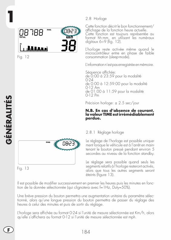
1G
ÉNÉR
ALI
TÉS
184F
2.8 Horloge
Cette fonction décrit le bon fonctionnement/affi chage de la fonction heure actuelle.Cette fonction est toujours représentée au format hh:mm, en utilisant les numéraux digitaux 6÷9 (fi g. 12).
L’horloge reste activée même quand le microcontrôleur entre en phase de faible consommation (sleep-mode).
L’information n’est pas enregistrée en mémoire.
Séquence affi chée: de 0:00 à 23:59 pour la modalité0-24 de 0:00 à 12:59:00 pour la modalité0-12 Am de 01:00 à 11:59 pour la modalité0-12 Pm
Précision horloge: ± 2.5 sec/jour
N.B. En cas d’absence de courant, la valeur TIME est irrémédiablement perdue.
Fig. 12
2.8.1 Réglage horloge
Le réglage de l’horloge est possible unique-ment lorsque le véhicule est à l’arrêt en main-tenant le bouton pressé pendant environ 5 secondes au niveau de la fonction standby.
Le réglage sera possible quand seuls les segments relatifs à l’horloge resteront activés, alors que tous les autres segments seront éteints (fi gure 13).
Fig. 13
Il est possible de modifi er successivement en premier les heures puis les minutes en fonc-tion de la donnée sélectionnée (qui clignotera avec f=1Hz, Duty=50%).
Une brève pression du bouton permettra une augmentation unitaire du paramètre sélec-tionné, alors qu’une longue pression du bouton permettra de passer du réglage des heures à celui des minutes et puis de sortir du réglage.
L’horloge sera affi chée au format 0-24 si l’unité de mesure sélectionnée est Km/h, alors qu’elle s’affi chera au format 0-12 si l’unité de mesure sélectionnée est mph.
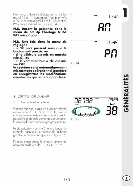
1
GÉN
ÉRA
LITÉ
S
185 F
Dans ce cas, durant le réglage, sur le numéro digital 10 et 11 apparaîtra l’inscription AM ou sur le numéro digital 11 et 12 l’inscription PM comme indiqué sur la fi gure 14.
N.B. Durant la présence dans le menu de Set-Up l’horloge N’EST PAS mise à jour.
N.B. Une fois dans le menu de réglage :- si 20 secs passent sans que le bouton soit pressé, ou - si le véhicule est mis en marche (vit>0), ou- si le commutateur à clé est mis sur OFF, le système sera automatiquement mis en mode opérationnel standard en enregistrant les modifi cations éventuelles qui ont été apportées.
3. GESTION DES ALARMES
3.1. Alarme tension batterie
Chaque fois que la valeur de tension relevée est inférieure à 10,0 V (±0,2 V), le système active une alarme de routine pour signaler la possibilité qu’après le démarrage du véhicule, le tableau de bord perde ses programmations.
La signalisation consiste à faire clignoter le symbole batterie et le contour de la barre graphique comme indiqué sur la fi gure 15.
L’alarme cesse quand la tension remonte de nouveau au-dessus de 11,0 V (± 0,2 V).
Fig. 14
Fig. 15
1G
ÉNÉR
ALI
TÉS
186F
4. VOYANTS DE SIGNALISATION ET RÉTRO-ÉCLAIRAGE
4.1 Voyant clignotants
Le système active le voyant avec l’activation des clignotants.
N.B. Le signal doit arriver à l’instrument comme signal alternatif.
4.2 Voyant feux de route
Le système active le voyant simultanément avec l’activation des feux de route.
4.3 Voyant Neutre
Le système active le voyant simultanément avec le positionnement du levier de vitesse en position neutre.
4.4 Rétro-éclairage LCD et cadran
Le rétro-éclairage du cristal est de couleur orange. Le rétro-éclairage est toujours allumé si le commutateur à clé est sur la position ON.
5. MENU DE SET-UP
L’entrée dans le menu de Set-Up est possible uniquement avec le véhicule à l’arrêt (vit=0 Km/h) en appuyant pendant environ 5 secondes sur le bouton au niveau de la fonction TOTAL.
Pour que les modifi cations apportées à l’intérieur du menu de Set-Up soient opérationnelles, il faut que l’utilisateur fi nisse toute la séquence de la page d’écran prévue par le menu, en faisant attention que la sortie du menu de Set-Up (et le repositionnement successif de l’instrument en mode opérationnel standard), se fasse exclusivement à travers l’usage du bouton de mode.
Il est possible de sortir du menu en maintenant le bouton mode pressé au niveau de la valeur sélectionnée à l’intérieur de la page d’écran des impulsions tour/roue (la dernière page d’écran du menu de Set-Up), jusqu’à ce que l’instrument se positionne sur le mode opérationnel standard.
N.B. Une fois dans le menu de réglage :- si 20 sec. passent sans que le bouton soit pressé, ou- si le véhicule est mis en marche (vit.>0), ou- si le commutateur à clé est mis sur OFF, le système sera automatiquement porté en modalité de travail stand-ard, SANS enregistrer les éventuelles modifi cations apportées.
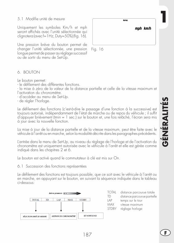
1
GÉN
ÉRA
LITÉ
S
187 F
5.1 Modifi e unité de mesure
Uniquement les symboles Km/h et mph seront affi chés avec l’unité sélectionnée qui clignotera (avec f=1Hz, Duty=50%) (fi g. 16).
Une pression brève du bouton permet de changer l’unité sélectionnée, une pression longue permet de passer au réglage successif ou de sortir du menu de Set-Up.
Fig. 16
6. BOUTON
Le bouton permet:- le défi lement des différentes fonctions.- la mise à zéro de la valeur de la distance partielle et celle de la vitesse maximum et l’activation du chronomètre.- d’accéder au menu de Set-Up.- de régler l’horloge.
Le défi lement des fonctions (c’est-à-dire le passage d’une fonction à la successive) est toujours autorisé, indépendamment de l’état de marche ou de repos du véhicule ; il suffi t d’appuyer brièvement (tmin = 1 sec.) sur le bouton et, une fois relâché, l’écran sera mis à jour avec la nouvelle fonction.
La mise à jour de la distance partielle et de la vitesse maximum, peut être faite avec le véhicule à l’arrêt ou en marche, selon la modalité décrite dans les paragraphes précédents.
L’entrée dans le menu de Set-Up, au niveau du réglage de l’horloge et de l’activation du chronomètre est uniquement autorisée avec le véhicule à l’arrêt et elle est gérée comme indiqué dans les chapitres 2 et 6.
Le bouton est activé quand le commutateur à clé est mis sur On.
6.1 Succession des fonctions représentées
Le défi lement des fonctions est toujours possible, que ce soit avec le véhicule à l’arrêt ou en marche, en appuyant sur le bouton, en suivant la séquence indiquée dans le tableau ci-dessous:
TOTAL distance parcourue totaleTD distance parcourue partielleLAP temps sur le tourMAX vitesse maximumSTDBY réglage horloge
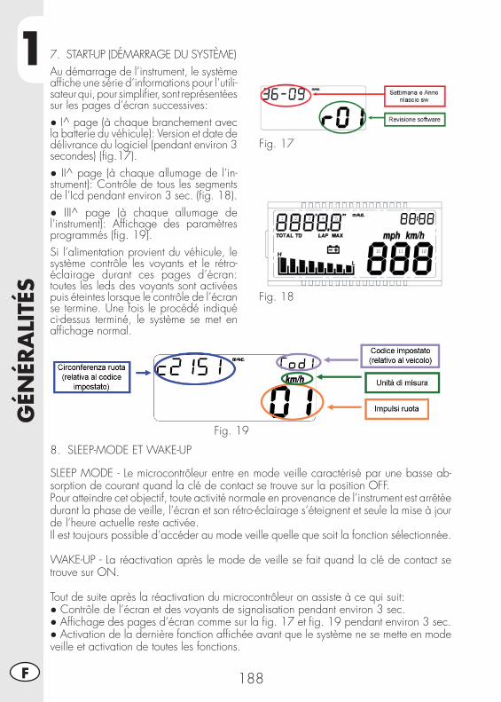
1G
ÉNÉR
ALI
TÉS
188F
7. START-UP (DÉMARRAGE DU SYSTÈME)Au démarrage de l’instrument, le système affi che une série d’informations pour l’utili-sateur qui, pour simplifi er, sont représentées sur les pages d’écran successives:● I^ page (à chaque branchement avec la batterie du véhicule): Version et date de délivrance du logiciel (pendant environ 3 secondes) (fi g.17).● II^ page (à chaque allumage de l’in-strument): Contrôle de tous les segments de l’Icd pendant environ 3 sec. (fi g. 18).● III^ page (à chaque allumage de l’instrument): Affi chage des paramètres programmés (fi g. 19).Si l’alimentation provient du véhicule, le système contrôle les voyants et le rétro-éclairage durant ces pages d’écran: toutes les leds des voyants sont activées puis éteintes lorsque le contrôle de l’écran se termine. Une fois le procédé indiqué ci-dessus terminé, le système se met en affi chage normal.
Fig. 17
Fig. 18
Fig. 19
8. SLEEP-MODE ET WAKE-UP
SLEEP MODE - Le microcontrôleur entre en mode veille caractérisé par une basse ab-sorption de courant quand la clé de contact se trouve sur la position OFF.Pour atteindre cet objectif, toute activité normale en provenance de l’instrument est arrêtée durant la phase de veille, l’écran et son rétro-éclairage s’éteignent et seule la mise à jour de l’heure actuelle reste activée.Il est toujours possible d’accéder au mode veille quelle que soit la fonction sélectionnée. WAKE-UP - La réactivation après le mode de veille se fait quand la clé de contact se trouve sur ON.
Tout de suite après la réactivation du microcontrôleur on assiste à ce qui suit:● Contrôle de l’écran et des voyants de signalisation pendant environ 3 sec.● Affi chage des pages d’écran comme sur la fi g. 17 et fi g. 19 pendant environ 3 sec.● Activation de la dernière fonction affi chée avant que le système ne se mette en mode veille et activation de toutes les fonctions.
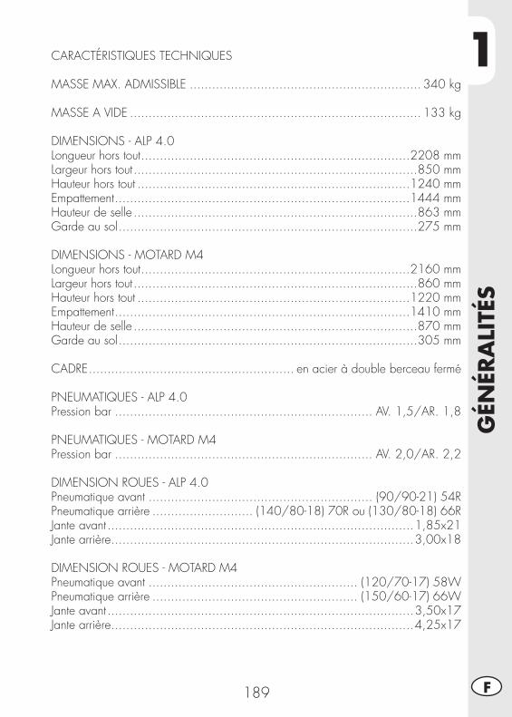
1
GÉN
ÉRA
LITÉ
S
189 F
CARACTÉRISTIQUES TECHNIQUES
MASSE MAX. ADMISSIBLE .............................................................. 340 kg
MASSE A VIDE .............................................................................. 133 kg
DIMENSIONS - ALP 4.0Longueur hors tout ........................................................................2208 mmLargeur hors tout ............................................................................850 mmHauteur hors tout .........................................................................1240 mmEmpattement ...............................................................................1444 mmHauteur de selle ............................................................................863 mmGarde au sol ................................................................................275 mm
DIMENSIONS - MOTARD M4Longueur hors tout ........................................................................2160 mmLargeur hors tout ............................................................................860 mmHauteur hors tout .........................................................................1220 mmEmpattement ...............................................................................1410 mmHauteur de selle ............................................................................870 mmGarde au sol ................................................................................305 mm
CADRE ....................................................... en acier à double berceau fermé
PNEUMATIQUES - ALP 4.0Pression bar ..................................................................... AV. 1,5/AR. 1,8
PNEUMATIQUES - MOTARD M4Pression bar ..................................................................... AV. 2,0/AR. 2,2
DIMENSION ROUES - ALP 4.0Pneumatique avant ............................................................ (90/90-21) 54RPneumatique arrière ........................... (140/80-18) 70R ou (130/80-18) 66RJante avant ..................................................................................1,85x21Jante arrière .................................................................................3,00x18
DIMENSION ROUES - MOTARD M4Pneumatique avant ........................................................ (120/70-17) 58WPneumatique arrière ....................................................... (150/60-17) 66WJante avant ..................................................................................3,50x17Jante arrière .................................................................................4,25x17
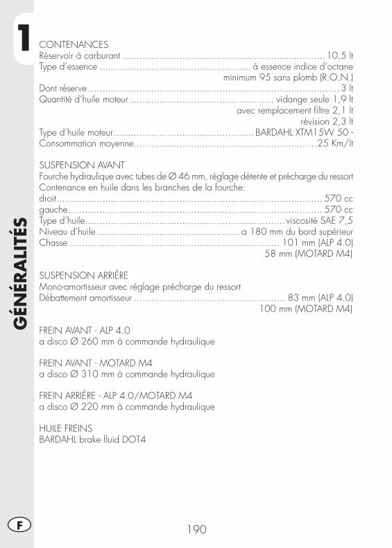
1G
ÉNÉR
ALI
TÉS
190F
CONTENANCESRéservoir à carburant .......................................................................10,5 ltType d’essence ..................................................... à essence indice d’octane
minimum 95 sans plomb (R.O.N.) Dont réserve ........................................................................................3 ltQuantité d’huile moteur .................................................. vidange seule 1,9 lt
avec remplacement fi ltre 2,1 ltrévision 2,3 lt
Type d’huile moteur ................................................. BARDAHL XTM15W 50 -Consommation moyenne ................................................................25 Km/lt
SUSPENSION AVANTFourche hydraulique avec tubes de Ø 46 mm, réglage détente et précharge du ressortContenance en huile dans les branches de la fourche:droit ............................................................................................. 570 cc gauche ......................................................................................... 570 ccType d’huile ......................................................................viscosité SAE 7,5Niveau d’huile .................................................. a 180 mm du bord supérieurChasse .......................................................................... 101 mm (ALP 4.0)
58 mm (MOTARD M4)
SUSPENSION ARRIÈREMono-amortisseur avec réglage précharge du ressortDébattement amortisseur ..................................................... 83 mm (ALP 4.0)
100 mm (MOTARD M4)
FREIN AVANT - ALP 4.0a disco Ø 260 mm à commande hydraulique
FREIN AVANT - MOTARD M4a disco Ø 310 mm à commande hydraulique
FREIN ARRIÈRE - ALP 4.0/MOTARD M4a disco Ø 220 mm à commande hydraulique
HUILE FREINSBARDAHL brake fl uid DOT4
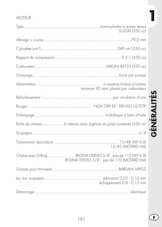
1
GÉN
ÉRA
LITÉ
S
191 F
MOTEUR
Type ................................................................monocylindre à quatre tempsSUZUKI (350 cc)
Alésage x course ..........................................................................79,0 mm
Cylindrée (cm3) ................................................................ 349 cm3 (350 cc)
Rapport de compression ........................................................9,5:1 (350 cc)
Carburateur ............................................................MIKUNI BST33 (350 cc)
Graissage .........................................................................forcé par pompe
Alimentation ........................................................ à essence (indice d’octaneminimum 95 sans plomb) par carburateur
Refroidissement ............................................................par circulation d’aire
Bougie ....................................................... NGK CR9 EK - DENSO U27ETR
Embrayage ........................................................... multidisque à bain d’huile
Boîte de vitesses ..................6 vitesses avec pignons en prise constante (350 cc)
Soupapes ..........................................................................................n. 4
Transmission secondaire ....................................................... 15/48 (ALP 4.0)15/42 (MOTARD M4)
Chaîne avec O-Ring.........................REGINA DERVIO 5/8’ - pas de 112 (ALP 4.0)REGINA DERVIO 5/8’ - pas de 110 (MOTARD M4)
Graisse pour timonerie ....................................................... BARDAHL MPG2
Jeu aux soupapes .................................................admission 0,05 - 0,10 mm échappement 0,8 - 0,13 mm
Démarrage ................................................................................. électrique
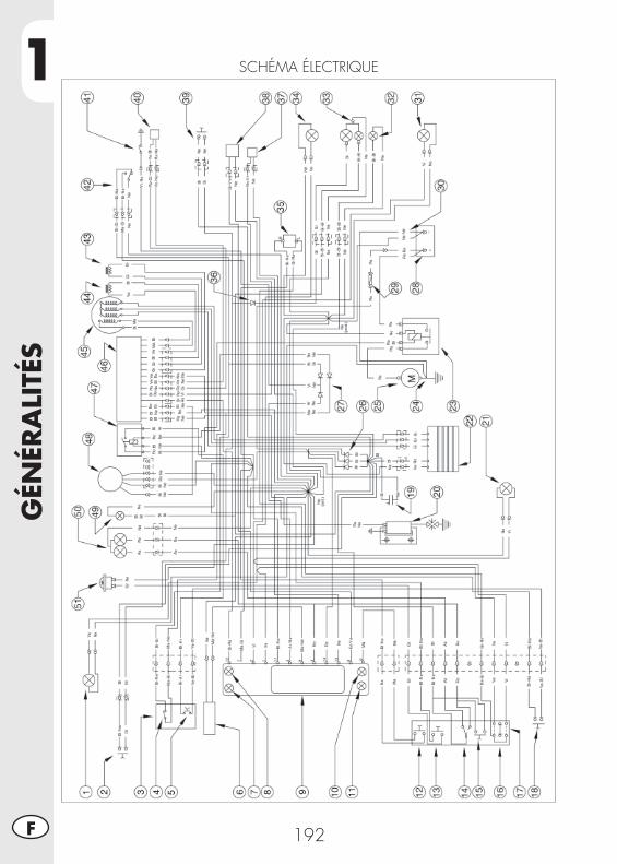
1G
ÉNÉR
ALI
TÉS
192F
SCHÉMA ÉLECTRIQUE
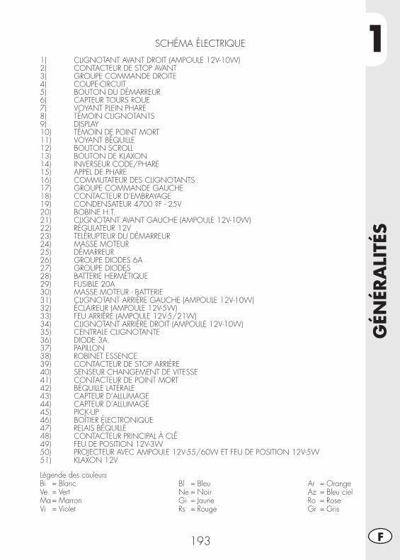
1
GÉN
ÉRA
LITÉ
S
193 F
SCHÉMA ÉLECTRIQUE
1) CLIGNOTANT AVANT DROIT (AMPOULE 12V-10W)2) CONTACTEUR DE STOP AVANT3) GROUPE COMMANDE DROITE4) COUPE-CIRCUIT5) BOUTON DU DÉMARREUR6) CAPTEUR TOURS ROUE7) VOYANT PLEIN PHARE8) TÉMOIN CLIGNOTANTS9) DISPLAY10) TÉMOIN DE POINT MORT11) VOYANT BÉQUILLE12) BOUTON SCROLL13) BOUTON DE KLAXON14) INVERSEUR CODE/PHARE15) APPEL DE PHARE16) COMMUTATEUR DES CLIGNOTANTS17) GROUPE COMMANDE GAUCHE18) CONTACTEUR D’EMBRAYAGE19) CONDENSATEUR 4700 ?F - 25V 20) BOBINE H.T.21) CLIGNOTANT AVANT GAUCHE (AMPOULE 12V-10W)22) RÉGULATEUR 12V23) TELÉRUPTEUR DU DÉMARREUR24) MASSE MOTEUR25) DÉMARREUR26) GROUPE DIODES 6A27) GROUPE DIODES28) BATTERIE HERMÉTIQUE29) FUSIBLE 20A30) MASSE MOTEUR - BATTERIE31) CLIGNOTANT ARRIÈRE GAUCHE (AMPOULE 12V-10W) 32) ÉCLAIREUR (AMPOULE 12V-5W)33) FEU ARRIÈRE (AMPOULE 12V-5/21W)34) CLIGNOTANT ARRIÈRE DROIT (AMPOULE 12V-10W)35) CENTRALE CLIGNOTANTE36) DIODE 3A.37) PAPILLON38) ROBINET ESSENCE39) CONTACTEUR DE STOP ARRIÈRE40) SENSEUR CHANGEMENT DE VITESSE41) CONTACTEUR DE POINT MORT42) BÉQUILLE LATÉRALE43) CAPTEUR D’ALLUMAGE44) CAPTEUR D’ALLUMAGE45) PICK-UP46) BOÎTIER ÉLECTRONIQUE47) RELAIS BÉQUILLE48) CONTACTEUR PRINCIPAL À CLÉ49) FEU DE POSITION 12V-3W50) PROJECTEUR AVEC AMPOULE 12V-55/60W ET FEU DE POSITION 12V-5W51) KLAXON 12V
Légende des couleursBi = BlancVe = VertMa = MarronVi = Violet
Bl = BleuNe = NoirGi = JauneRs = Rouge
Ar = OrangeAz = Bleu cielRo = RoseGr = Gris
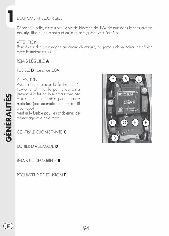
1G
ÉNÉR
ALI
TÉS
194F
ÉQUIPEMENT ÉLECTRIQUE
Déposer la selle, en tournant la vis de blocage de 1/4 de tour dans le sens inverse des aiguilles d’une montre et en la faisant glisser vers l’arrière.
ATTENTION:Pour éviter des dommages au circuit électrique, ne jamais débrancher les câbles avec le moteur en route.
RELAIS BÉQUILLE A
FUSIBLE B - deux de 20A
ATTENTION:Avant de remplacer le fusible grillé, trouver et éliminer la panne qui en a provoqué la fusion. Ne jamais chercher à remplacer un fusible par un autre matériau (par exemple un bout de fi l électrique).Vérifi er le fusible pour les problèmes de démarrage et d’éclairage.
CENTRALE CLIGNOTANTE C
BOÎTIER D’ALLUMAGE D
RELAIS DU DÉMARREUR E
RÉGULATEUR DE TENSION F
A B E
C G H F
D
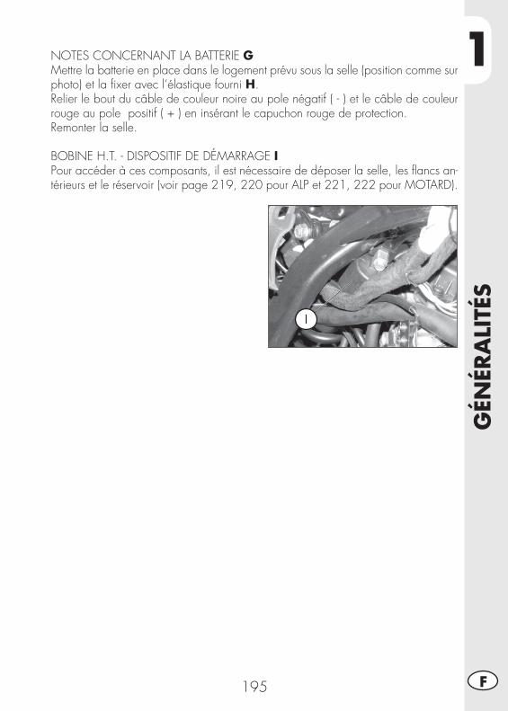
1
GÉN
ÉRA
LITÉ
S
195 F
NOTES CONCERNANT LA BATTERIE GMettre la batterie en place dans le logement prévu sous la selle (position comme sur photo) et la fi xer avec l’élastique fourni H. Relier le bout du câble de couleur noire au pole négatif ( - ) et le câble de couleur rouge au pole positif ( + ) en insérant le capuchon rouge de protection.Remonter la selle.
BOBINE H.T. - DISPOSITIF DE DÉMARRAGE IPour accéder à ces composants, il est nécessaire de déposer la selle, les fl ancs an-térieurs et le réservoir (voir page 219, 220 pour ALP et 221, 222 pour MOTARD).
I
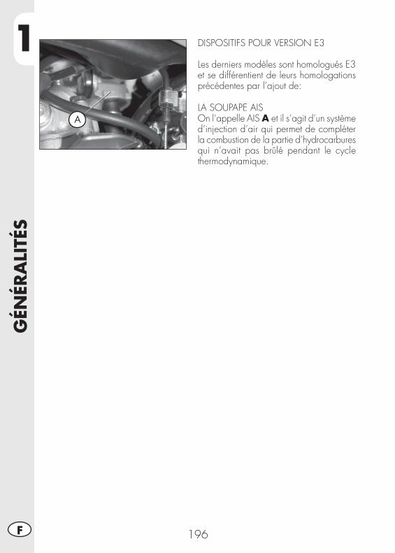
1G
ÉNÉR
ALI
TÉS
196F
A
DISPOSITIFS POUR VERSION E3
Les derniers modèles sont homologués E3 et se différentient de leurs homologations précédentes par l’ajout de:
LA SOUPAPE AISOn l’appelle AIS A et il s’agit d’un système d’injection d’air qui permet de compléter la combustion de la partie d’hydrocarbures qui n’avait pas brûlé pendant le cycle thermodynamique.
2
UTI
LISA
TIO
N D
U V
ÉHIC
ULE
197 F
TABLE DES MATIÈRES
CHAP. 2 UTILISATION DU VÉHICULE
Contrôles et entretien avant et après l’utilisation en tout-terrain
Lubrifi ants conseillés
Rodage
Dèmarrage du moteur
Arrêt du moteur
Approvisionnement en carburant
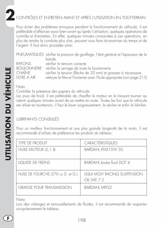
2U
TILI
SATI
ON
DU
VÉH
ICU
LE
198F
CONTRÔLES ET ENTRETIEN AVANT ET APRÈS L’UTILISATION EN TOUT-TERRAIN
Pour éviter des problèmes ennuyeux pendant le fonctionnement du véhicule, il est préférable d’effectuer aussi bien avant qu’après l’utilisation, quelques opérations de contrôle et d’entretien. En effet, quelques minutes consacrées à ces opérations, en plus de rendre la conduite plus sûre, peuvent vous faire économiser du temps et de l’argent. Il faut donc procéder ainsi:
PNEUMATIQUES vérifi er la pression de gonfl age, l’état général et l’épaisseur de la bande
RAYONS vérifi er la tension correcteBOULONNERIE vérifi er le serrage de toute la boulonnerieCHAÎNE vérifi er la tension (fl èche de 20 mm) et graisser si nécessaireFILTRE A AIR nettoyer le fi ltre et l’humecter avec l’huile appropriée (voir page 215)
Nota:Contrôler la présence des papiers du véhicule.Les jours de froid, il est préférable de chauffer le moteur en le laissant tourner au ralenti quelques minutes avant de se mettre en route. Toutes les fois que le véhicule est utilisé en tout-terrain, il faut le laver soigneusement, le sécher et enfi n le lubrifi er.
LUBRIFIANTS CONSEILLÉS
Pour un meilleur fonctionnement et une plus grande longévité de la moto, il est recommandé d’utiliser de préférence les produits du tableau:
TYPE DE PRODUIT CARACTÉRISTIQUES
HUILE MOTEUR (2,1 lt) BARDAHL XTM15W 50
LIQUIDE DE FREINS BARDAHL brake fl uid DOT 4
HUILE DE FOURCHE (570 cc D. et G.) LIQUI MOLY RACING SUSPENSION OIL SAE 7,5
GRAISSE POUR TRANSMISSION BARDAHL MPG2
Nota:Lors des vidanges et renouvellements de fl uides, il est recommandé de respecter scrupuleusement le tableau.
2
UTI
LISA
TIO
N D
U V
ÉHIC
ULE
199 F
RODAGE
Le rodage correspond à une dizaine d’heures d’activité, pendant cette période il est conseillé de:• Utiliser le véhicule après avoir bien chauffé le moteur
• Eviter de rouler à vitesse constante (en va-riant la vitesse, les différents composants se tasseront de manière plus uniforme en un temps plus réduit)
• Eviter de tourner la poignée de l’accélé-rateur plus de 3/4
ATTENTION:Au bout de 1000 premiers kilomètres de trajet, vidanger l’huile du moteur.
AVERTISSEMENT:Il est nécessaire de s’assurer après 1000 km de route que le fi ltre métallique, situé sur la partie fi nale du réservoir d’huile, soit propre (voir page 206). Si ce n’est pas le cas utiliser un jet d’air comprimé.
• Toujours utiliser de l’essence super sans plomb.
• Après la première sortie en tout-terrain, contrôler toute la boulonnerie.
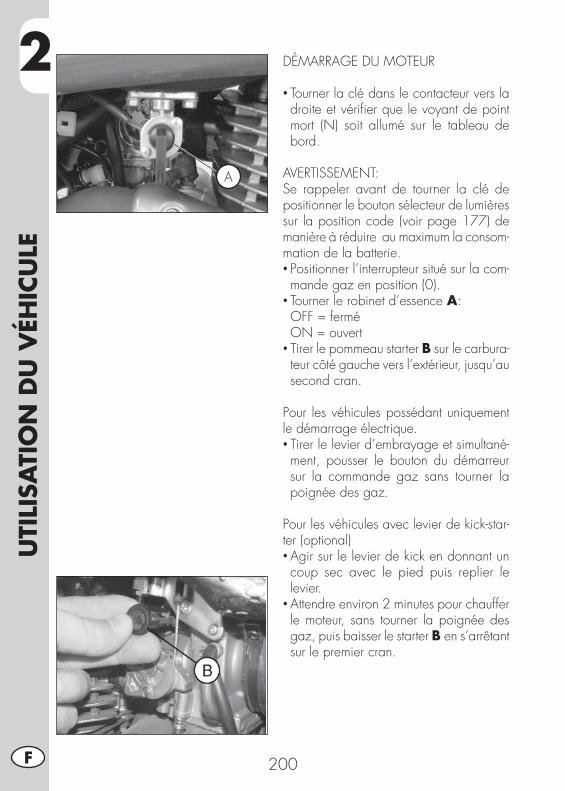
2U
TILI
SATI
ON
DU
VÉH
ICU
LE
200F
DÈMARRAGE DU MOTEUR
• Tourner la clé dans le contacteur vers la droite et vérifi er que le voyant de point mort (N) soit allumé sur le tableau de bord.
AVERTISSEMENT:Se rappeler avant de tourner la clé de positionner le bouton sélecteur de lumières sur la position code (voir page 177) de manière à réduire au maximum la consom-mation de la batterie.• Positionner l’interrupteur situé sur la com-mande gaz en position (0).
• Tourner le robinet d’essence A: OFF = fermé ON = ouvert• Tirer le pommeau starter B sur le carbura-teur côté gauche vers l’extérieur, jusqu’au second cran.
Pour les véhicules possédant uniquement le démarrage électrique.• Tirer le levier d’embrayage et simultané-ment, pousser le bouton du démarreur sur la commande gaz sans tourner la poignée des gaz.
Pour les véhicules avec levier de kick-star-ter (optional)• Agir sur le levier de kick en donnant un coup sec avec le pied puis replier le levier.
• Attendre environ 2 minutes pour chauffer le moteur, sans tourner la poignée des gaz, puis baisser le starter B en s’arrêtant sur le premier cran.
A
2
UTI
LISA
TIO
N D
U V
ÉHIC
ULE
201 F
Note:Le démarrage a lieu également avec la béquille baissée, du moment que le voyant de point mort (N) est allumé.
Note:En cas d’urgence, ce véhicule peut fonc-tionner également sans batterie.
ARRÊT DU MOTEUR
• A l’arrêt et avec les vitesses au point mort, tourner la clé de contact en position “OFF“.
• Après un long parcours, avant de couper le moteur, il est conseillé de le laisser tourner quelques instants.
• Lorsque le moteur est coupé, toujours fermer le robinet d’essence.
ATTENTION:Le véhicule est doté d’une installation lumières toujours allumées, ainsi si l’on éteint le commutateur RUN-OFF, situé sur la partie droite du guidon les lumières restent allumée.Dans ce cas, il pourrait se vérifi er un dé-chargement précoce de la batterie.
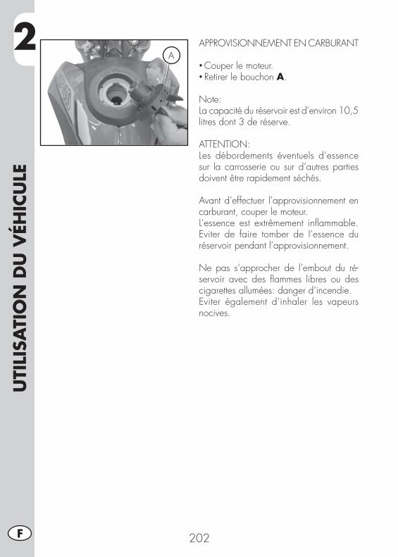
2U
TILI
SATI
ON
DU
VÉH
ICU
LE
202F
APPROVISIONNEMENT EN CARBURANT
• Couper le moteur.• Retirer le bouchon A.
Note:La capacité du réservoir est d’environ 10,5 litres dont 3 de réserve.
ATTENTION:Les débordements éventuels d’essence sur la carrosserie ou sur d’autres parties doivent être rapidement séchés.
Avant d’effectuer l’approvisionnement en carburant, couper le moteur.L’essence est extrêmement infl ammable. Eviter de faire tomber de l’essence du réservoir pendant l’approvisionnement.
Ne pas s’approcher de l’embout du ré-servoir avec des fl ammes libres ou des cigarettes allumées: danger d’incendie.Eviter également d’inhaler les vapeurs nocives.
A
3
CO
NTR
ÔLE
S ET
EN
TRET
IEN
203 F
TABLE DES MATIÈRES
CHAP. 3 CONTRÔLES ET ENTRETIEN
Contrôle niveau huile moteur
Vidange huile moteur et fi ltre à huile
Tuyau de récupératin des fumées
Liquide de frein, purge du circuit
Huile de fourche
Filtre à air
Bougie
Frein avant
Frein arrière
Carburateur
Batterie
Desmontage des plastiques pour ALP
Desmontage des plastiques pour MOTARD M4
Note pour usage tout-terrain
Substitution groupe transmission fi nal
Nettoyage du véhicule et contrôles
Contrôles après le nettoyage
Entretien programmé
Longue inactivité du véhicule
Après une longue période d’inactivité
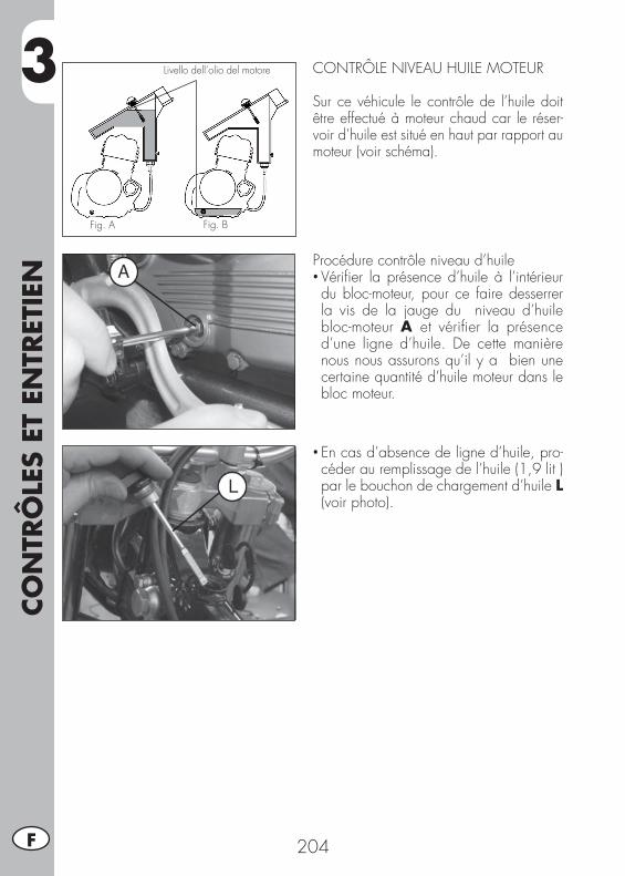
3CO
NTR
ÔLE
S ET
EN
TRET
IEN
204F
CONTRÔLE NIVEAU HUILE MOTEUR
Sur ce véhicule le contrôle de l’huile doit être effectué à moteur chaud car le réser-voir d’huile est situé en haut par rapport au moteur (voir schéma).
Fig. A
Livello dell’olio del motore
Fig. B
Procédure contrôle niveau d’huile• Vérifi er la présence d’huile à l’intérieur du bloc-moteur, pour ce faire desserrer la vis de la jauge du niveau d’huile bloc-moteur A et vérifi er la présence d’une ligne d’huile. De cette manière nous nous assurons qu’il y a bien une certaine quantité d’huile moteur dans le bloc moteur.
• En cas d’absence de ligne d’huile, pro-céder au remplissage de l’huile (1,9 lit ) par le bouchon de chargement d’huile L (voir photo).
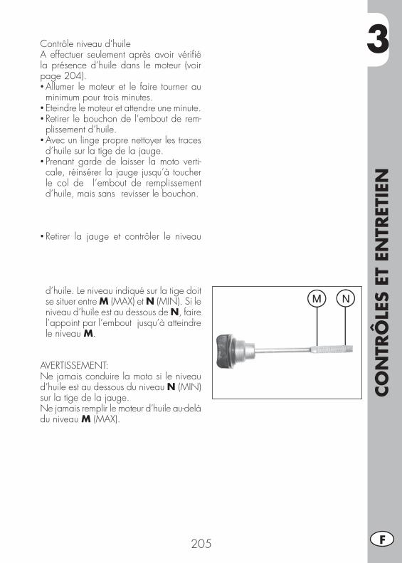
3
CO
NTR
ÔLE
S ET
EN
TRET
IEN
205 F
Contrôle niveau d’huileA effectuer seulement après avoir vérifi é la présence d’huile dans le moteur (voir page 204).• Allumer le moteur et le faire tourner au minimum pour trois minutes.
• Eteindre le moteur et attendre une minute.• Retirer le bouchon de l’embout de rem-plissement d’huile.
• Avec un linge propre nettoyer les traces d’huile sur la tige de la jauge.
• Prenant garde de laisser la moto verti-cale, réinsérer la jauge jusqu’à toucher le col de l’embout de remplissement d’huile, mais sans revisser le bouchon.
• Retirer la jauge et contrôler le niveau
d’huile. Le niveau indiqué sur la tige doit se situer entre M (MAX) et N (MIN). Si le niveau d’huile est au dessous de N, faire l’appoint par l’embout jusqu’à atteindre le niveau M.
AVERTISSEMENT:Ne jamais conduire la moto si le niveau d’huile est au dessous du niveau N (MIN) sur la tige de la jauge.Ne jamais remplir le moteur d’huile au-delà du niveau M (MAX).

3CO
NTR
ÔLE
S ET
EN
TRET
IEN
206F
VIDANGE HUILE MOTEUR ET FILTRE À HUILE
Toujours faire la vidange à moteur chaud en veillant à ne pas toucher le moteur ni l’huile sous peine de brûlures.
• Le remplacement du fi ltre à huile doit avoir lieu en même temps que la vidange.
• Mettre la moto sur béquille.• Placer un récipient sous le moteur.• Dévisser le bouchon de remplissage L et le bouchon de vidange F.
• Vidanger complètement le carter.
Substitution fi ltre à huile• Retirer le couvercle du fi ltre à huile en dévissant les trois écrous G.
• Retirer le fi ltre à huile.

3
CO
NTR
ÔLE
S ET
EN
TRET
IEN
207 F
Vidange huile du réservoir• Enlever les 4 vis de fi xation carter pos-térieur moteur.
• Dévisser la vis Q et faire s’écouler toute l’huile du réservoir.
• Il est conseillé – au premier changement d’huile (voir page 199) – d’effectuer aussi le nettoyage du fi ltre métallique situé sur la partie fi nale du réservoir d’huile.
La procédure de démontage est la suivante:• Dévisser la gaine du tube de raccord réservoir carter moteur
• Utilisant une clé anglaise, dévisser dans le sens horaire le raccord, doté d’une résille métallique.
• Nettoyer avec jet d’air.
ATTENTION:Utiliser toujours une protection pour les yeux durant cette opération.
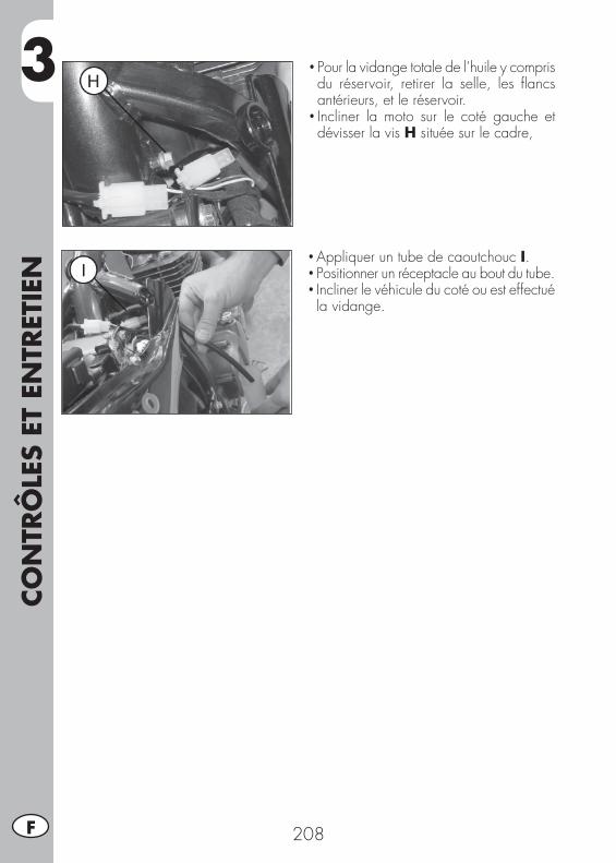
3CO
NTR
ÔLE
S ET
EN
TRET
IEN
208F
• Pour la vidange totale de l’huile y compris du réservoir, retirer la selle, les fl ancs antérieurs, et le réservoir.
• Incliner la moto sur le coté gauche et dévisser la vis H située sur le cadre,
• Appliquer un tube de caoutchouc I.• Positionner un réceptacle au bout du tube.• Incliner le véhicule du coté ou est effectué la vidange.
3
CO
NTR
ÔLE
S ET
EN
TRET
IEN
209 F
Montage• Procéder en sens inverse du démontage du fi ltre à résille métallique du réservoir d’huile.
• Insérer un nouveau fi ltre à huile.• Appliquer une légère couche d’huile mo-teur sur le joint torique avant l’introduction.
• Remettre le couvercle du fi ltre à huile après montage du ressort et du joint torique et serrer les 3 vis de fi xation.
• Remonter le bouchon de déchargement d’huile, situé sur le carter moteur, avec les deux vis de déchargement d’huile du ré-servoir (si nécessaire utiliser de nouveaux joints).
• Introduire la juste quantité d’huile. Quantité d’huile moteur: vidange seule .......................... 1,9 lt avec changement de fi ltre .......... 2,1 lt révision ................................... 2,3 lt
• Revisser le bouchon de rechargement.• Démarrer le moteur en laissant tourner quelques minutes avant de le couper.
• Couper le moteur et attendre quelques minutes, puis contrôler le niveau et éven-tuellement faire l’appoint sans jamais dépasser le niveau maximum.
Note:lorsque les 1000 premiers kilomètre de parcours ont été effectués, vidanger l’huile moteur. Les vidanges suivantes s’effectuent tous les 4000 km (15 mois), en utilisant les lubrifi ants conseillés à page 198.Pour le fi ltre à huile en revanche, le premier changement a lieu en même temps que la vidange. Les remplacements suivants tous les 8000 km (45 mois).
AVERTISSEMENT:Evacuer l’huile usée dans le respect des normes en vigueur.

3CO
NTR
ÔLE
S ET
EN
TRET
IEN
210F
TUYAU DE RÉCUPÉRATIN DES FUMÉES
Le tuyau de récupération des fumées A est situé sur la partie gauche du véhicule près de l’amortisseur, il sort de la partie inférieure du boîtier de fi ltre et récupère les gaz produits par l’huile moteur. En pré-sence d’huile à l’intérieur du tuyau, celui-ci doit être vidé, en retirant le bouchon sur l’extrémité inférieure et en faisant couler l’huile ou le mélange huile-essence dans un récipient. Evacuer l’huile dans le respect des normes en vigueur.
Note:Vider ce tuyau tous les 3000 km.
LIQUIDE DE FREIN, PURGE DU CIRCUIT
Frein avantContrôler par le voyant de niveau B, la présence de liquide. Le niveau minimum de liquide ne doit jamais être en dessous du repère sur le témoin B. Pour rétablir le niveau, faire l’appoint après avoir dévissé les deux vis C et soulevé le bouchon D.Maintenir stable et verticale la moto, si possible bloquer le guidon, afi n d’éviter de faire déborder l’huile des freins.
B
C
D
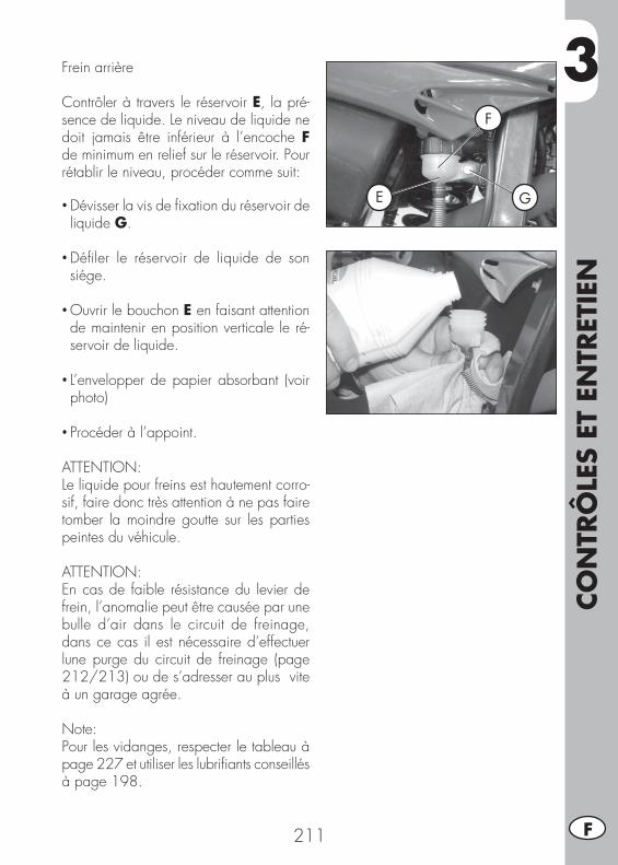
3
CO
NTR
ÔLE
S ET
EN
TRET
IEN
211 F
Frein arrière
Contrôler à travers le réservoir E, la pré-sence de liquide. Le niveau de liquide ne doit jamais être inférieur à l’encoche F de minimum en relief sur le réservoir. Pour rétablir le niveau, procéder comme suit:
• Dévisser la vis de fi xation du réservoir de liquide G.
• Défi ler le réservoir de liquide de son siége.
• Ouvrir le bouchon E en faisant attention de maintenir en position verticale le ré-servoir de liquide.
• L’envelopper de papier absorbant (voir photo)
• Procéder à l’appoint.
ATTENTION:Le liquide pour freins est hautement corro-sif, faire donc très attention à ne pas faire tomber la moindre goutte sur les parties peintes du véhicule.
ATTENTION:En cas de faible résistance du levier de frein, l’anomalie peut être causée par une bulle d’air dans le circuit de freinage, dans ce cas il est nécessaire d’effectuer lune purge du circuit de freinage (page 212/213) ou de s’adresser au plus vite à un garage agrée.
Note:Pour les vidanges, respecter le tableau à page 227 et utiliser les lubrifi ants conseillés à page 198.
E
F
G
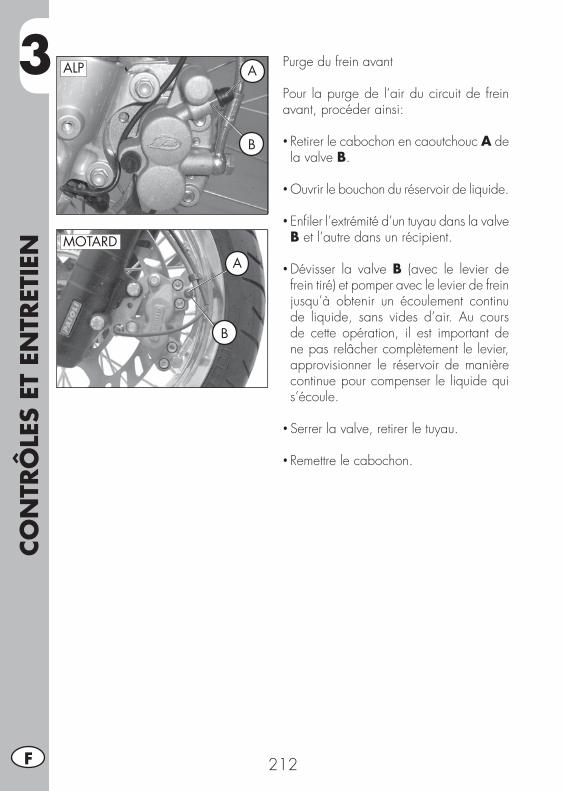
3CO
NTR
ÔLE
S ET
EN
TRET
IEN
212F
Purge du frein avant
Pour la purge de l’air du circuit de frein avant, procéder ainsi:
• Retirer le cabochon en caoutchouc A de la valve B.
• Ouvrir le bouchon du réservoir de liquide.
• Enfi ler l’extrémité d’un tuyau dans la valve B et l’autre dans un récipient.
• Dévisser la valve B (avec le levier de frein tiré) et pomper avec le levier de frein jusqu’à obtenir un écoulement continu de liquide, sans vides d’air. Au cours de cette opération, il est important de ne pas relâcher complètement le levier, approvisionner le réservoir de manière continue pour compenser le liquide qui s’écoule.
• Serrer la valve, retirer le tuyau.
• Remettre le cabochon.
MOTARD
B
A
ALP A
B
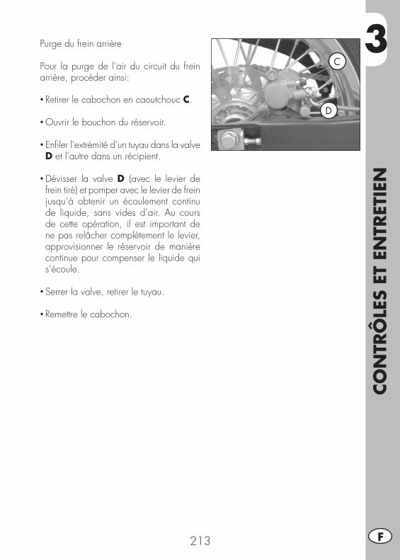
3
CO
NTR
ÔLE
S ET
EN
TRET
IEN
213 F
Purge du frein arrière
Pour la purge de l’air du circuit du frein arrière, procéder ainsi:
• Retirer le cabochon en caoutchouc C.
• Ouvrir le bouchon du réservoir.
• Enfi ler l’extrémité d’un tuyau dans la valve D et l’autre dans un récipient.
• Dévisser la valve D (avec le levier de frein tiré) et pomper avec le levier de frein jusqu’à obtenir un écoulement continu de liquide, sans vides d’air. Au cours de cette opération, il est important de ne pas relâcher complètement le levier, approvisionner le réservoir de manière continue pour compenser le liquide qui s’écoule.
• Serrer la valve, retirer le tuyau.
• Remettre le cabochon.
D
C
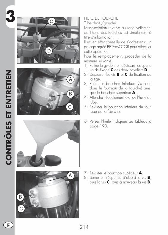
3CO
NTR
ÔLE
S ET
EN
TRET
IEN
214F
HUILE DE FOURCHETube droit /gaucheLa description relative au renouvellement de l’huile des fourches est simplement à titre d’information.Il est en effet conseillé de s’adresser à un garage agréé BETAMOTOR pour effectuer cette opération.Pour le remplacement, procéder de la manière suivante:1) Retirer le guidon, en dévissant les quatre
vis de fi xage C des deux cavaliers D.2) Desserrer les vis B et C de fi xation de
la tige.3) Retirer le bouchon inférieur (vis allen
dans le fourreau de la fourche) ainsi que le bouchon supérieur A.
4) Attendre l’écoulement total de l’huile du tube.
5) Revisser le bouchon inférieur du four-reau de la fourche.
6) Verser l’huile indiquée au tableau à page 198.
7) Revisser le bouchon supérieur A.8) Serrer en séquence d’abord la vis B,
puis la vis C, puis à nouveau la vis B.

3
CO
NTR
ÔLE
S ET
EN
TRET
IEN
215 F
FILTRE À AIR
Pour accéder au fi ltre, il faut:• Relever légèrement le fl anc postérieur gauche A, comme sur la photo.
• Déposer le couvercle en plastique E en dévissant les 3 vis de fi xation B.
• Retirer le fi ltre C après avoir desserré la vis de fi xation D du couvercle de maintien.
• Le laver avec eau et savon.• Le sécher.• L’humecter d’huile pour fi ltre, en éliminant l’excédent de manière à ce qu’il ne goutte pas.
• Si nécessaire, nettoyer également l’inté-rieur du boîtier.
• Remonter l’ensemble en veillant à la fermeture hermétique du joint en caout-chouc, précédemment graissé pour améliorer la fermeture F.
Note:Dans le cas où le fi ltre serait trop sale, le laver d’abord à l’essence puis à l’eau et savon.Si le fi ltre est endommagé, procéder immé-diatement à son remplacement.
ATTENTION:Après chaque intervention, contrôler qu’au-cun objet n’est resté à l’intérieur du boîtier.
Nettoyer le fi ltre toutes les fois que le véhi-cule est utilisé en tout-terrain.
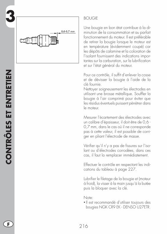
3CO
NTR
ÔLE
S ET
EN
TRET
IEN
216F
BOUGIE
Une bougie en bon état contribue à la di-minution de la consommation et au parfait fonctionnement du moteur. Il est préférable de retirer la bougie lorsque le moteur est en température (évidemment coupé) car les dépôts de calamine et la coloration de l’isolant fournissent des indications impor-tantes sur la carburation, sur la lubrifi cation et sur l’état général du moteur.
Pour ce contrôle, il suffi t d’enlever la cosse et de dévisser la bougie à l’aide de la clé fournie.Nettoyer soigneusement les électrodes en utilisant une brosse métallique. Souffl er la bougie à l’air comprimé pour éviter que les résidus éventuels puissent pénétrer dans le moteur.
Mesurer l’écartement des électrodes avec un calibre d’épaisseur, il doit être de 0,6 - 0,7 mm, dans le cas où il ne corresponde pas à cette valeur, il est possible de corri-ger en pliant l’électrode de masse.
Vérifi er qu’il n’y a pas de fi ssures sur l’iso-lant ou d’électrodes corrodées, dans ces cas, il faut la remplacer immédiatement.
Effectuer le contrôle en respectant les indi-cations du tableau à page 227.
Lubrifi er le fi letage de la bougie et (moteur à froid), la visser à la main jusqu’à la butée puis la bloquer avec la clé.
Note:• Il est recommandé d’utiliser toujours des bougies NGK CR9 EK - DENSO U27ETR.
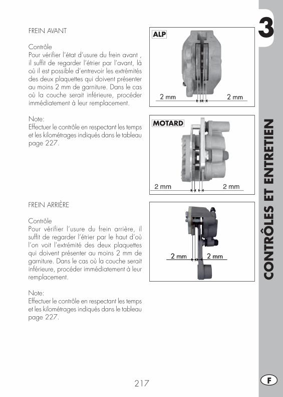
3
CO
NTR
ÔLE
S ET
EN
TRET
IEN
217 F
FREIN AVANT
ContrôlePour vérifi er l’état d’usure du frein avant , il suffi t de regarder l’étrier par l’avant, là où il est possible d’entrevoir les extrémités des deux plaquettes qui doivent présenter au moins 2 mm de garniture. Dans le cas où la couche serait inférieure, procéder immédiatement à leur remplacement.
Note:Effectuer le contrôle en respectant les temps et les kilométrages indiqués dans le tableau page 227.
FREIN ARRIÈRE
ContrôlePour vérifier l’usure du frein arrière, il suffi t de regarder l’étrier par le haut d’où l’on voit l’extrémité des deux plaquettes qui doivent présenter au moins 2 mm de garniture. Dans le cas où la couche serait inférieure, procéder immédiatement à leur remplacement.
Note:Effectuer le contrôle en respectant les temps et les kilométrages indiqués dans le tableau page 227.
ALP
MOTARD
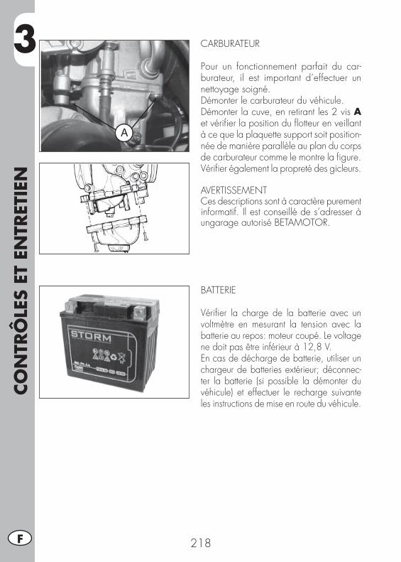
3CO
NTR
ÔLE
S ET
EN
TRET
IEN
218F
CARBURATEUR
Pour un fonctionnement parfait du car-burateur, il est important d’effectuer un nettoyage soigné.Démonter le carburateur du véhicule.Démonter la cuve, en retirant les 2 vis A et vérifi er la position du fl otteur en veillant à ce que la plaquette support soit position-née de manière parallèle au plan du corps de carburateur comme le montre la fi gure. Vérifi er également la propreté des gicleurs.
AVERTISSEMENTCes descriptions sont à caractère purement informatif. Il est conseillé de s’adresser à ungarage autorisé BETAMOTOR.
BATTERIE
Vérifi er la charge de la batterie avec un voltmètre en mesurant la tension avec la batterie au repos: moteur coupé. Le voltage ne doit pas être inférieur à 12,8 V.En cas de décharge de batterie, utiliser un chargeur de batteries extérieur; déconnec-ter la batterie (si possible la démonter du véhicule) et effectuer le recharge suivante les instructions de mise en route du véhicule.
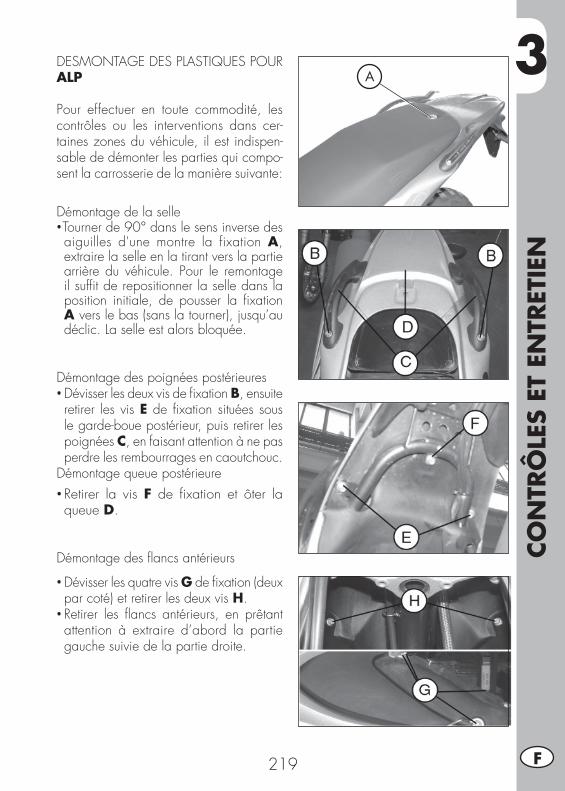
3
CO
NTR
ÔLE
S ET
EN
TRET
IEN
219 F
DESMONTAGE DES PLASTIQUES POUR ALP
Pour effectuer en toute commodité, les contrôles ou les interventions dans cer-taines zones du véhicule, il est indispen-sable de démonter les parties qui compo-sent la carrosserie de la manière suivante:
Démontage de la selle•Tourner de 90° dans le sens inverse des aiguilles d'une montre la fixation A, extraire la selle en la tirant vers la partie arrière du véhicule. Pour le remontage il suffi t de repositionner la selle dans la position initiale, de pousser la fi xation A vers le bas (sans la tourner), jusqu’au déclic. La selle est alors bloquée.
Démontage des poignées postérieures• Dévisser les deux vis de fi xation B, ensuite retirer les vis E de fi xation situées sous le garde-boue postérieur, puis retirer les poignées C, en faisant attention à ne pas perdre les rembourrages en caoutchouc.
Démontage queue postérieure• Retirer la vis F de fi xation et ôter la queue D.
Démontage des fl ancs antérieurs
• Dévisser les quatre vis G de fi xation (deux par coté) et retirer les deux vis H.
• Retirer les fl ancs antérieurs, en prêtant attention à extraire d’abord la partie gauche suivie de la partie droite.
A
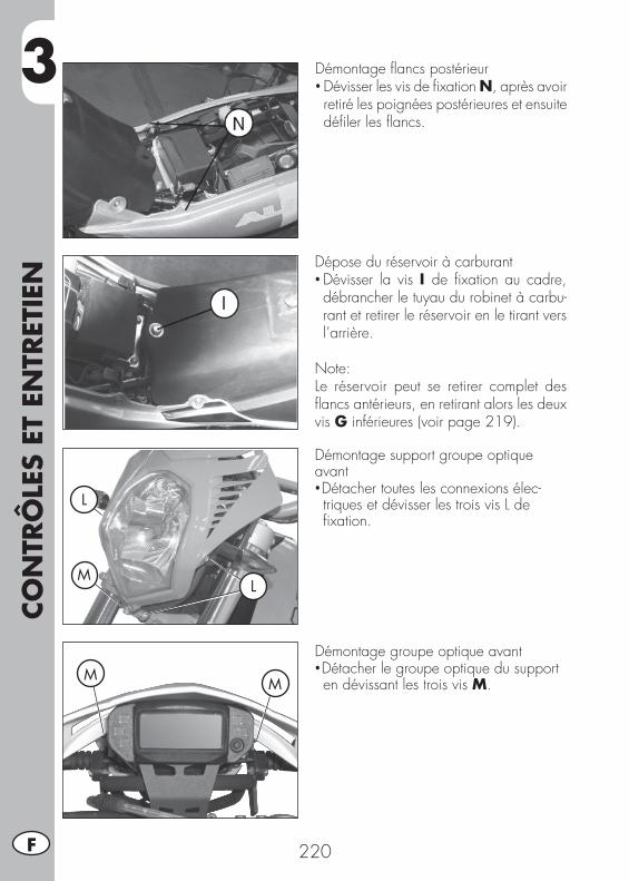
3CO
NTR
ÔLE
S ET
EN
TRET
IEN
220F
Démontage fl ancs postérieur• Dévisser les vis de fi xation N, après avoir retiré les poignées postérieures et ensuite défi ler les fl ancs.
Dépose du réservoir à carburant• Dévisser la vis I de fi xation au cadre, débrancher le tuyau du robinet à carbu-rant et retirer le réservoir en le tirant vers l’arrière.
Note:Le réservoir peut se retirer complet des fl ancs antérieurs, en retirant alors les deux vis G inférieures (voir page 219).
Démontage support groupe optique avant•Détacher toutes les connexions élec-triques et dévisser les trois vis L de fi xation.
Démontage groupe optique avant•Détacher le groupe optique du support en dévissant les trois vis M.
L
L
M
MM
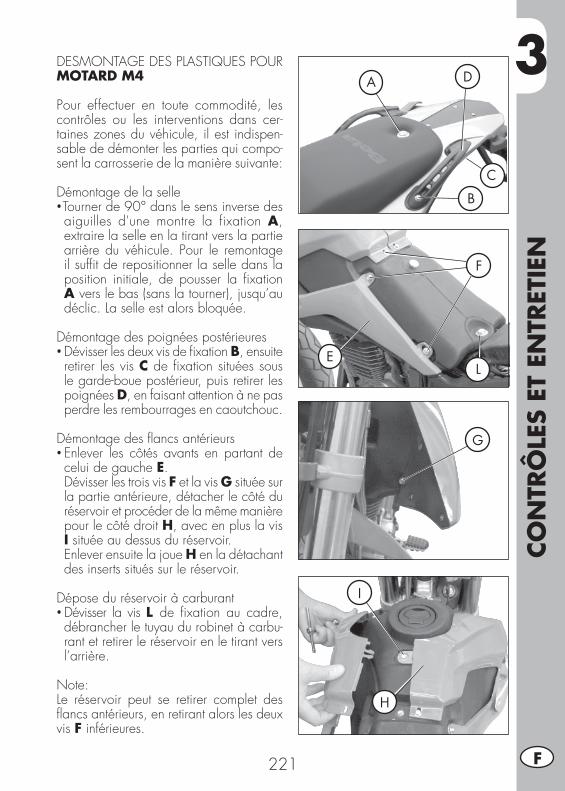
3
CO
NTR
ÔLE
S ET
EN
TRET
IEN
221 F
DESMONTAGE DES PLASTIQUES POUR MOTARD M4
Pour effectuer en toute commodité, les contrôles ou les interventions dans cer-taines zones du véhicule, il est indispen-sable de démonter les parties qui compo-sent la carrosserie de la manière suivante:
Démontage de la selle•Tourner de 90° dans le sens inverse des aiguilles d'une montre la fixation A, extraire la selle en la tirant vers la partie arrière du véhicule. Pour le remontage il suffi t de repositionner la selle dans la position initiale, de pousser la fi xation A vers le bas (sans la tourner), jusqu’au déclic. La selle est alors bloquée.
Démontage des poignées postérieures• Dévisser les deux vis de fi xation B, ensuite retirer les vis C de fi xation situées sous le garde-boue postérieur, puis retirer les poignées D, en faisant attention à ne pas perdre les rembourrages en caoutchouc.
Démontage des fl ancs antérieurs• Enlever les côtés avants en partant de celui de gauche E.
Dévisser les trois vis F et la vis G située sur la partie antérieure, détacher le côté du réservoir et procéder de la même manière pour le côté droit H, avec en plus la vis I située au dessus du réservoir.
Enlever ensuite la joue H en la détachant des inserts situés sur le réservoir.
Dépose du réservoir à carburant• Dévisser la vis L de fi xation au cadre, débrancher le tuyau du robinet à carbu-rant et retirer le réservoir en le tirant vers l’arrière.
Note:Le réservoir peut se retirer complet des fl ancs antérieurs, en retirant alors les deux vis F inférieures.
F
G
E
I
H
L
B
A
C
D
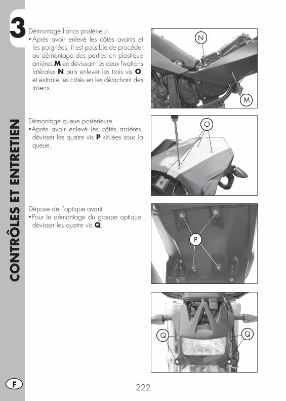
3CO
NTR
ÔLE
S ET
EN
TRET
IEN
222F
Démontage fl ancs postérieur• Après avoir enlevé les côtés avants et les poignées, il est possible de procéder au démontage des parties en plastique arrières M en dévissant les deux fi xations latérales N puis enlever les trois vis O, et extraire les côtés en les détachant des inserts.
M
N
ODémontage queue postérieure•Après avoir enlevé les côtés arrières, dévisser les quatre vis P situées sous la queue.
P
Dépose de l’optique avant•Pour le démontage du groupe optique, dévisser les quatre vis Q.
Q Q
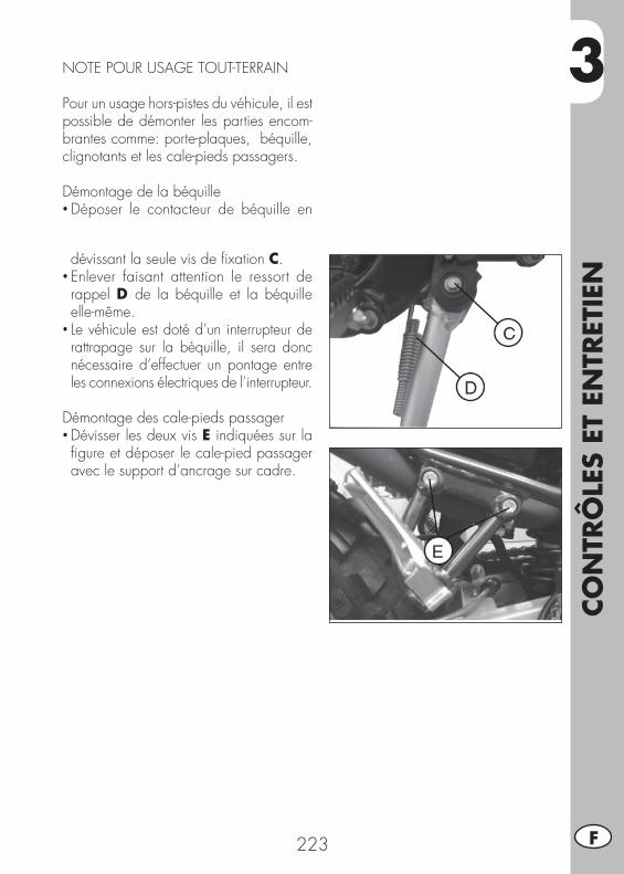
3
CO
NTR
ÔLE
S ET
EN
TRET
IEN
223 F
NOTE POUR USAGE TOUT-TERRAIN
Pour un usage hors-pistes du véhicule, il est possible de démonter les parties encom-brantes comme: porte-plaques, béquille, clignotants et les cale-pieds passagers.
Démontage de la béquille• Déposer le contacteur de béquille en
dévissant la seule vis de fi xation C.• Enlever faisant attention le ressort de rappel D de la béquille et la béquille elle-même.
• Le véhicule est doté d’un interrupteur de rattrapage sur la béquille, il sera donc nécessaire d’effectuer un pontage entre les connexions électriques de l’interrupteur.
Démontage des cale-pieds passager• Dévisser les deux vis E indiquées sur la fi gure et déposer le cale-pied passager avec le support d’ancrage sur cadre.
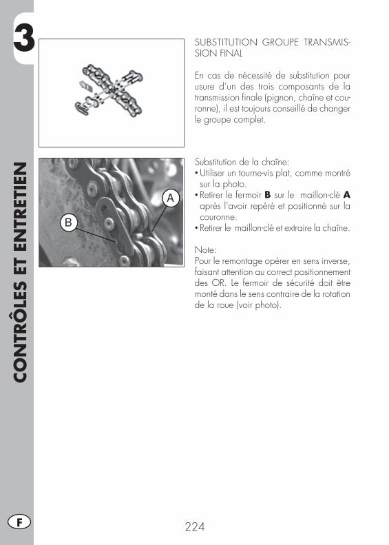
3CO
NTR
ÔLE
S ET
EN
TRET
IEN
224F
Substitution de la chaîne:• Utiliser un tourne-vis plat, comme montré sur la photo.
• Retirer le fermoir B sur le maillon-clé A après l’avoir repéré et positionné sur la couronne.
• Retirer le maillon-clé et extraire la chaîne.
Note:Pour le remontage opérer en sens inverse, faisant attention au correct positionnement des OR. Le fermoir de sécurité doit être monté dans le sens contraire de la rotation de la roue (voir photo).
SUBSTITUTION GROUPE TRANSMIS-SION FINAL
En cas de nécessité de substitution pour usure d’un des trois composants de la transmission fi nale (pignon, chaîne et cou-ronne), il est toujours conseillé de changer le groupe complet.
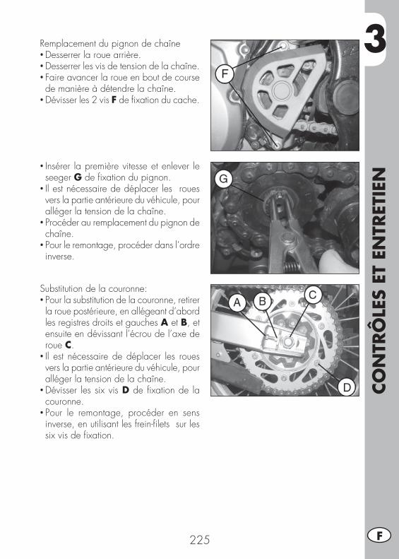
3
CO
NTR
ÔLE
S ET
EN
TRET
IEN
225 F
Remplacement du pignon de chaîne• Desserrer la roue arrière.• Desserrer les vis de tension de la chaîne.• Faire avancer la roue en bout de course de manière à détendre la chaîne.
• Dévisser les 2 vis F de fi xation du cache.
Substitution de la couronne:• Pour la substitution de la couronne, retirer la roue postérieure, en allégeant d’abord les registres droits et gauches A et B, et ensuite en dévissant l’écrou de l’axe de roue C.
• Il est nécessaire de déplacer les roues vers la partie antérieure du véhicule, pour alléger la tension de la chaîne.
• Dévisser les six vis D de fi xation de la couronne.
• Pour le remontage, procéder en sens inverse, en utilisant les frein-fi lets sur les six vis de fi xation.
• Insérer la première vitesse et enlever le seeger G de fi xation du pignon.
• Il est nécessaire de déplacer les roues vers la partie antérieure du véhicule, pour alléger la tension de la chaîne.
• Procéder au remplacement du pignon de chaîne.
• Pour le remontage, procéder dans l’ordre inverse.
3CO
NTR
ÔLE
S ET
EN
TRET
IEN
226F
NETTOYAGE DU VÉHICULE ET CONTRÔLES
Pour ramollir la saleté et la boue accumulées sur les peintures, utiliser un jet d’eau.Une fois ramollis, la boue et la saleté doivent être enlevées avec une éponge douce pour carrosserie imprégnée de beaucoup d’eau et shampooing (2-4% de sham-pooing dans l’eau). Rincer ensuite abondamment à l’eau et essuyer avec un jet d’air comprimée et un linge ou une peau de chamois. Pour l’extérieur du moteur, utiliser du pétrole avec pinceaux et chiffons propres. Le pétrole est nocif pour les peintures. Il est rappelé que le lustrage éventuel avec des cires au silicone doit toujours être précédé d’un lavage.
Les détergents polluent les eaux. Aussi, le lavage du véhicule doit s’effectuer dans un endroit équipé pour la récupération et l’épuration des liquides de lavage.
Le lavage ne doit jamais avoir lieu au soleil, en particulier l’été lorsque la carrosserie est encore chaude et que le shampooing sèche avant le rinçage pouvant provoquer des dommages à la peinture. Ne jamais utiliser de chiffon
imprégnés d’essence ou de mazout pour le lavage des peintures ou des plastiques car il perdent leur brillant et les caractéristiques mécaniques des matériaux se détériorent.
CONTRÔLES APRÈS LE NETTOYAGE
Après le nettoyage de la moto, il est préférable de:
• Nettoyer le fi ltre à air (procéder comme décrit à page 215)• Démonter la cuve du carburateur desserrant la vis de déchargement du carburant (procéder comme décrit à page 218) pour contrôler la présence d’eau éventuelle
• Graisser la chaîne.
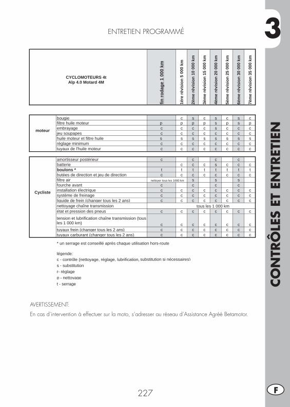
3
CO
NTR
ÔLE
S ET
EN
TRET
IEN
227 F
ENTRETIEN PROGRAMMÉ
AVERTISSEMENT:
En cas d’intervention à effectuer sur la moto, s’adresser au réseau d’Assistance Agréé Betamotor.
CYCLOMOTEURS 4t Alp 4.0 Motard 4M
fin ro
dage
1 0
00 k
m
1ère
révi
sion
5 0
00 k
m
2èm
e ré
visi
on 1
0 00
0 km
3èm
e ré
visi
on 1
5 00
0 km
4èm
e ré
visi
on 2
0 00
0 km
5èm
e ré
visi
on 2
5 00
0 km
6èm
e ré
visi
on 3
0 00
0 km
7èm
e ré
visi
on 3
5 00
0 km
moteur
bougie c s c s c s cfiltre huile moteur p p p p s p s pembrayage c c c c s c c cjeu soupapes c c c c c c c chuile moteur et filtre huile s s s s s s s sréglage minimum c c c c c c c ctuyaux de l'huile moteur c c c c c c c c
Cycliste
amortisseur postérieur c c c cbatterie c c c s c c cboulons * t t t t t t t tbutées de direction et jeu de direction c c c c c c c cfiltre air s s sfourche avant c c c cinstallation électrique c c c c c c c csystème de freinage c c c c c c c cliquide de frein (changer tous les 2 ans) c c c c c c c cnettoyage chaîne transmissionétat et pression des pneus c c c c c c c c
tension et lubrification chaîne transmission (tous les 1 000 km) c c c c c c c ctuyaux frein (changer tous les 2 ans) c c c c c c c ctuyaux carburant (changer tous les 2 ans) c c c c c c c c
* un serrage est conseillé après chaque utilisation hors-route
légende :c - contrôle (nettoyage, réglage, lubrification, substitution si nécessaires)s - substitutionr- réglagep - nettoyaget - serrage
nettoyer tous les 1000 km
tous les 1 000 km
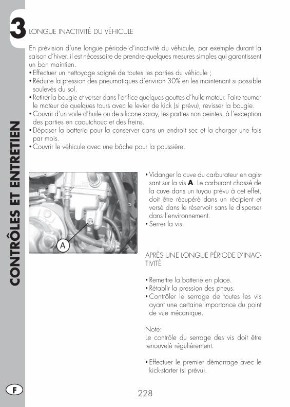
3CO
NTR
ÔLE
S ET
EN
TRET
IEN
228F
LONGUE INACTIVITÉ DU VÉHICULE
En prévision d’une longue période d’inactivité du véhicule, par exemple durant la saison d’hiver, il est nécessaire de prendre quelques mesures simples qui garantissent un bon maintien.• Effectuer un nettoyage soigné de toutes les parties du véhicule ;• Réduire la pression des pneumatiques d’environ 30% en les maintenant si possible soulevés du sol.
• Retirer la bougie et verser dans l’orifi ce quelques gouttes d’huile moteur. Faire tourner le moteur de quelques tours avec le levier de kick (si prévu), revisser la bougie.
• Couvrir d’un voile d’huile ou de silicone spray, les parties non peintes, à l’exception des parties en caoutchouc et des freins.
• Déposer la batterie pour la conserver dans un endroit sec et la charger une fois par mois.
• Couvrir le véhicule avec une bâche pour la poussière.
• Vidanger la cuve du carburateur en agis-sant sur la vis A. Le carburant chassé de la cuve dans un tuyau prévu à cet effet, doit être récupéré dans un récipient et versé dans le réservoir sans le disperser dans l’environnement.
• Serrer la vis.
APRÈS UNE LONGUE PÉRIODE D’INAC-TIVITÉ
• Remettre la batterie en place.• Rétablir la pression des pneus.• Contrôler le serrage de toutes les vis ayant une certaine importance du point de vue mécanique.
Note:Le contrôle du serrage des vis doit être renouvelé régulièrement.
• Effectuer le premier démarrage avec le kick-starter (si prévu).

4
RÉG
LAG
ES
229 F
TABLE DES MATIÈRES
CHAP. 4 RÉGLAGES
Réglage des freins
Réglage de l’embrayage
Réglage amortisseur arrière
Réglage du ralenti
Réglage du jeu à la poignée des gaz
Contrôle et réglage du jeu à la direction
Tension de la chaîne
Faisceau lumineux
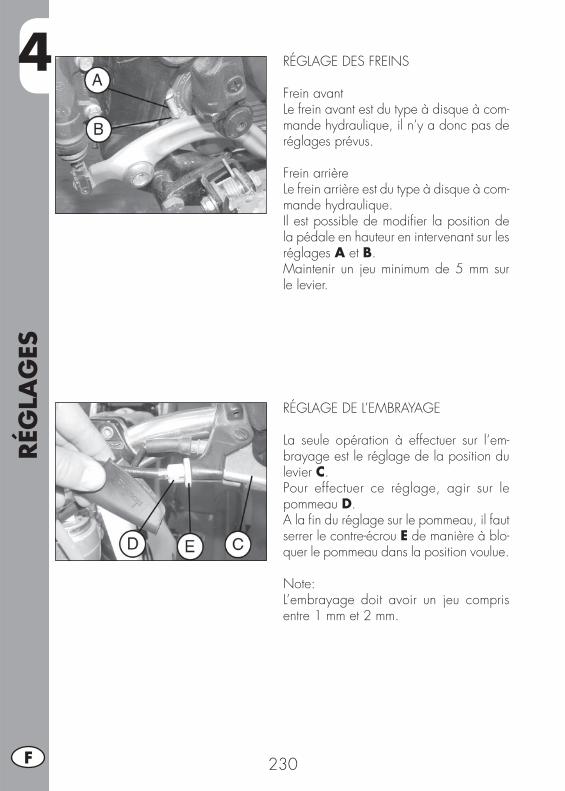
4RÉG
LAG
ES
230F
RÉGLAGE DES FREINS
Frein avantLe frein avant est du type à disque à com-mande hydraulique, il n’y a donc pas de réglages prévus.
Frein arrièreLe frein arrière est du type à disque à com-mande hydraulique. Il est possible de modifi er la position de la pédale en hauteur en intervenant sur les réglages A et B.Maintenir un jeu minimum de 5 mm sur le levier.
RÉGLAGE DE L’EMBRAYAGE
La seule opération à effectuer sur l’em-brayage est le réglage de la position du levier C.Pour effectuer ce réglage, agir sur le pommeau D.A la fi n du réglage sur le pommeau, il faut serrer le contre-écrou E de manière à blo-quer le pommeau dans la position voulue.
Note:L’embrayage doit avoir un jeu compris entre 1 mm et 2 mm.
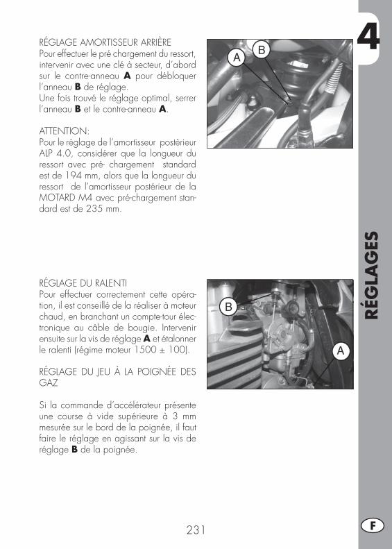
4
RÉG
LAG
ES
231 F
RÉGLAGE AMORTISSEUR ARRIÈREPour effectuer le pré chargement du ressort, intervenir avec une clé à secteur, d’abord sur le contre-anneau A pour débloquer l’anneau B de réglage.Une fois trouvé le réglage optimal, serrer l’anneau B et le contre-anneau A.
ATTENTION:Pour le réglage de l’amortisseur postérieur ALP 4.0, considérer que la longueur du ressort avec pré- chargement standard est de 194 mm, alors que la longueur du ressort de l’amortisseur postérieur de la MOTARD M4 avec pré-chargement stan-dard est de 235 mm.
RÉGLAGE DU RALENTIPour effectuer correctement cette opéra-tion, il est conseillé de la réaliser à moteur chaud, en branchant un compte-tour élec-tronique au câble de bougie. Intervenir ensuite sur la vis de réglage A et étalonner le ralenti (régime moteur 1500 ± 100).
RÉGLAGE DU JEU À LA POIGNÉE DES GAZ
Si la commande d’accélérateur présente une course à vide supérieure à 3 mm mesurée sur le bord de la poignée, il faut faire le réglage en agissant sur la vis de réglage B de la poignée.
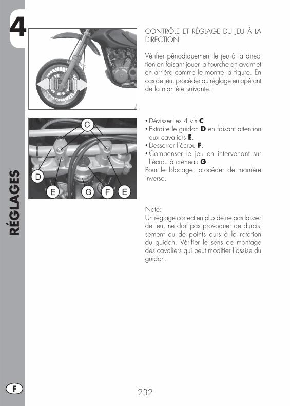
4RÉG
LAG
ES
232F
CONTRÔLE ET RÉGLAGE DU JEU À LA DIRECTION
Vérifi er périodiquement le jeu à la direc-tion en faisant jouer la fourche en avant et en arrière comme le montre la fi gure. En cas de jeu, procéder au réglage en opérant de la manière suivante:
• Dévisser les 4 vis C.• Extraire le guidon D en faisant attention aux cavaliers E.
• Desserrer l’écrou F.• Compenser le jeu en intervenant sur l’écrou à créneau G.
Pour le blocage, procéder de manière inverse.
Note:Un réglage correct en plus de ne pas laisser de jeu, ne doit pas provoquer de durcis-sement ou de points durs à la rotation du guidon. Vérifi er le sens de montage des cavaliers qui peut modifi er l’assise du guidon.
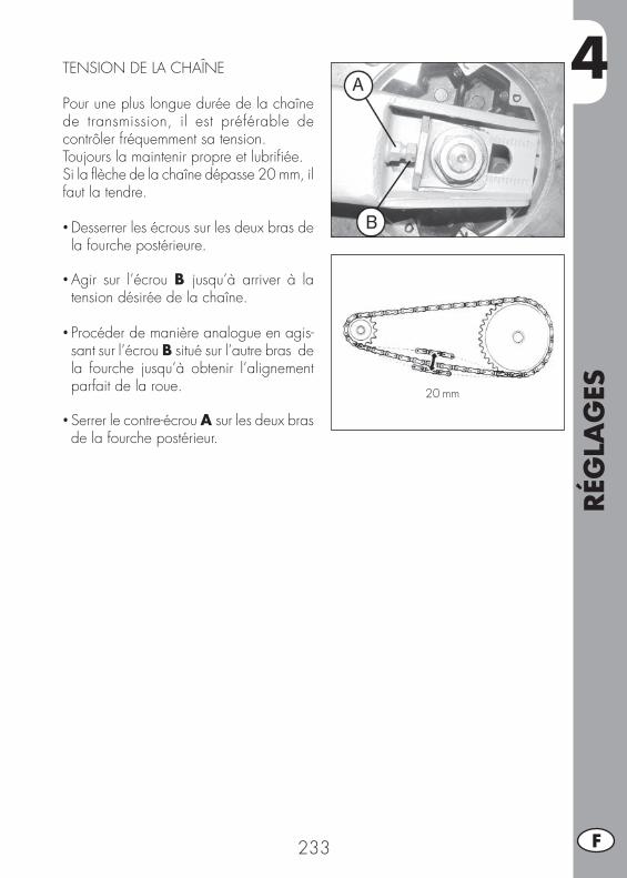
4
RÉG
LAG
ES
233 F
TENSION DE LA CHAÎNE
Pour une plus longue durée de la chaîne de transmission, il est préférable de contrôler fréquemment sa tension.Toujours la maintenir propre et lubrifi ée.Si la fl èche de la chaîne dépasse 20 mm, il faut la tendre.
• Desserrer les écrous sur les deux bras de la fourche postérieure.
• Agir sur l’écrou B jusqu’à arriver à la tension désirée de la chaîne.
• Procéder de manière analogue en agis-sant sur l’écrou B situé sur l’autre bras de la fourche jusqu’à obtenir l’alignement parfait de la roue.
• Serrer le contre-écrou A sur les deux bras de la fourche postérieur.
20 mm
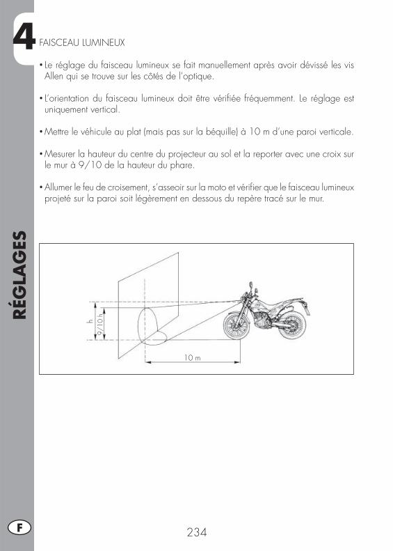
4RÉG
LAG
ES
234F
FAISCEAU LUMINEUX
• Le réglage du faisceau lumineux se fait manuellement après avoir dévissé les vis Allen qui se trouve sur les côtés de l’optique.
• L’orientation du faisceau lumineux doit être vérifi ée fréquemment. Le réglage est uniquement vertical.
• Mettre le véhicule au plat (mais pas sur la béquille) à 10 m d’une paroi verticale.
• Mesurer la hauteur du centre du projecteur au sol et la reporter avec une croix sur le mur à 9/10 de la hauteur du phare.
• Allumer le feu de croisement, s’asseoir sur la moto et vérifi er que le faisceau lumineux projeté sur la paroi soit légèrement en dessous du repère tracé sur le mur.
9/10
h
10 m
h
5
REM
PLA
CEM
ENTS
235 F
TABLE DES MATIÈRES
CHAP. 5 REMPLACEMENTS
Remplacement des plaquettes de frein avant
Remplacement des plaquettes de frein arrière
Remplacement des ampoules ALP
Remplacement des ampoules MOTARD
Substitution des clignotants et du feu arrière
Substitution lumière plaque d’immatriculation
Caractéristiques lampes
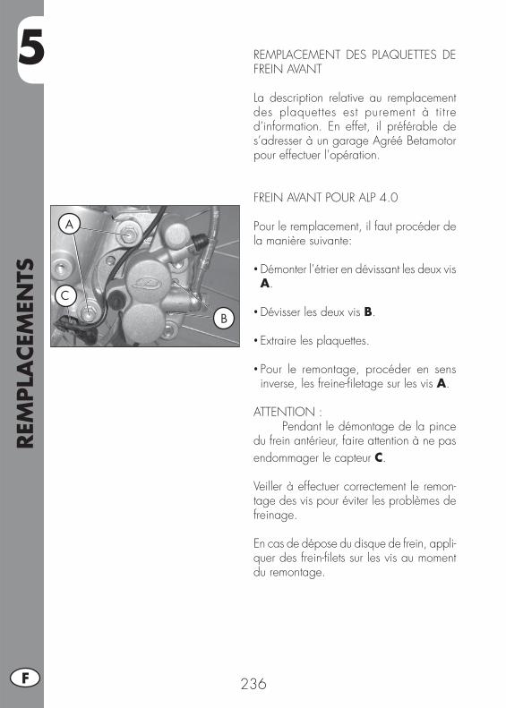
5REM
PLA
CEM
ENTS
236F
REMPLACEMENT DES PLAQUETTES DE FREIN AVANT
La description relative au remplacement des plaquettes est purement à titre d’information. En effet, il préférable de s’adresser à un garage Agréé Betamotor pour effectuer l’opération.
FREIN AVANT POUR ALP 4.0
Pour le remplacement, il faut procéder de la manière suivante:
• Démonter l’étrier en dévissant les deux vis A.
• Dévisser les deux vis B.
• Extraire les plaquettes.
• Pour le remontage, procéder en sens inverse, les freine-fi letage sur les vis A.
ATTENTION :Pendant le démontage de la pince
du frein antérieur, faire attention à ne pas endommager le capteur C. Veiller à effectuer correctement le remon-tage des vis pour éviter les problèmes de freinage.
En cas de dépose du disque de frein, appli-quer des frein-fi lets sur les vis au moment du remontage.
A
B
C

5
REM
PLA
CEM
ENTS
237 F
FREIN AVANT POUR MOTARD M4
Retirer les trois vis de fi xation et le rebord du phare.
• Démonter la pince du support spécial C, dévissant les deux vis A.
• Dévisser les deux vis B.
• Extraire les plaquettes.
ATTENTION :Pendant le démontage de la pince
du frein antérieur, faire attention à ne pas endommager le capteur C.
• Pour le remontage, procéder en sens inverse, en utilisant des freine-fi letage sur les vis A.
Veiller à effectuer correctement le remon-tage des vis pour éviter les problèmes de freinage.
En cas de dépose du disque de frein, appli-quer des frein-fi lets sur les vis au moment du remontage.
A
B
C
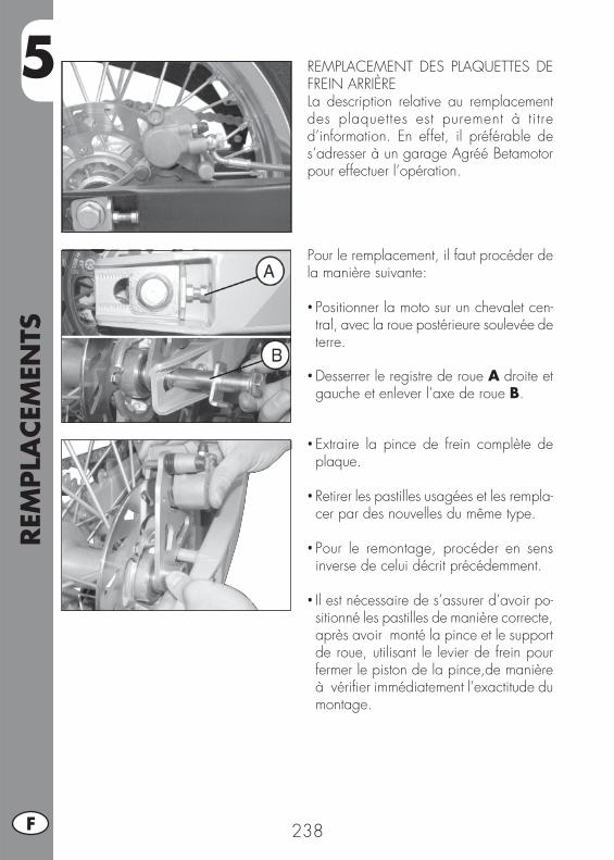
5REM
PLA
CEM
ENTS
238F
Pour le remplacement, il faut procéder de la manière suivante:
• Positionner la moto sur un chevalet cen-tral, avec la roue postérieure soulevée de terre.
• Desserrer le registre de roue A droite et gauche et enlever l’axe de roue B.
REMPLACEMENT DES PLAQUETTES DE FREIN ARRIÈRELa description relative au remplacement des plaquettes est purement à titre d’information. En effet, il préférable de s’adresser à un garage Agréé Betamotor pour effectuer l’opération.
• Extraire la pince de frein complète de plaque.
• Retirer les pastilles usagées et les rempla-cer par des nouvelles du même type.
• Pour le remontage, procéder en sens inverse de celui décrit précédemment.
• Il est nécessaire de s’assurer d’avoir po-sitionné les pastilles de manière correcte, après avoir monté la pince et le support de roue, utilisant le levier de frein pour fermer le piston de la pince,de manière à vérifi er immédiatement l’exactitude du montage.

5
REM
PLA
CEM
ENTS
239 F
REMPLACEMENT DES AMPOULES ALP
AVANT Enlever le support et le groupe optique comme illustré à la page 220.Extraire le connecteur, soulever la protec-tion en caoutchouc A, décrocher le ressort d’arrêt de la lampe et substituer l’ampoule grillée par une neuve aux mêmes caracté-ristiques, en ayant soin de ne pas toucher le bulbe.Remonter le tout en suivant l’ordre inverse.
Feu de position :Enlever le support et le groupe optique comme illustré à la page 220.Extraire le bulbe B et enlever l’ampoule grillée, en insérer une neuve aux mêmes caractéristiques en ayant soin de ne pas toucher le bulbe afi n d’éviter d’en compro-mettre l’effi cacité.
A
B

5REM
PLA
CEM
ENTS
240F
REMPLACEMENT DES AMPOULES MO-TARD M4
AVANTPour changer l’ampoule du projecteur, détacher les connecteurs A de l’ampoule et enlever la calotte en caoutchouc B.Tourner dans le sens inverse des aiguilles d’une montre la bride de fi xation C et enlever l’ampoule de la parabole.
Insérer l’ampoule neuve (12V - 55/60W) en ayant soin de ne pas touche le bulbe afi n d’éviter de compromettre son effi cacité et tourner la bride de fi xation C dans le sens des aiguilles d’une montre jusqu’au maximum.
AB
C
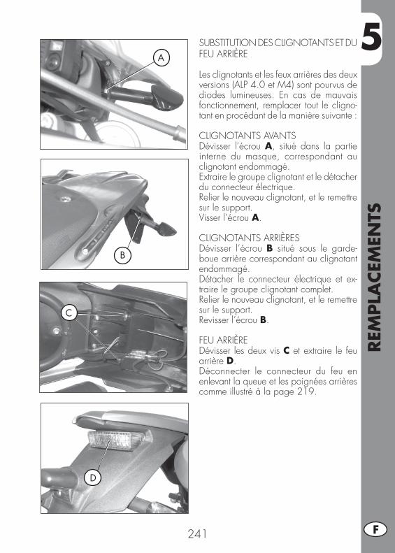
5
REM
PLA
CEM
ENTS
241 F
SUBSTITUTION DES CLIGNOTANTS ET DU FEU ARRIÈRE
Les clignotants et les feux arrières des deux versions (ALP 4.0 et M4) sont pourvus de diodes lumineuses. En cas de mauvais fonctionnement, remplacer tout le cligno-tant en procédant de la manière suivante :
CLIGNOTANTS AVANTSDévisser l’écrou A, situé dans la partie interne du masque, correspondant au clignotant endommagé.Extraire le groupe clignotant et le détacher du connecteur électrique.Relier le nouveau clignotant, et le remettre sur le support.Visser l’écrou A.
CLIGNOTANTS ARRIÈRESDévisser l’écrou B situé sous le garde-boue arrière correspondant au clignotant endommagé.Détacher le connecteur électrique et ex-traire le groupe clignotant complet.Relier le nouveau clignotant, et le remettre sur le support.Revisser l’écrou B.
FEU ARRIÈREDévisser les deux vis C et extraire le feu arrière D.Déconnecter le connecteur du feu en enlevant la queue et les poignées arrières comme illustré à la page 219.
A
B
D
C
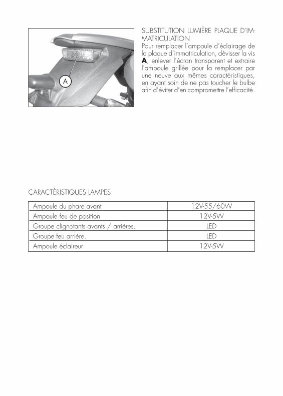
Ampoule du phare avant 12V-55/60W Ampoule feu de position 12V-5W Groupe clignotants avants / arrières. LED Groupe feu arrière. LED Ampoule éclaireur 12V-5W
A
SUBSTITUTION LUMIÈRE PLAQUE D’IM-MATRICULATIONPour remplacer l’ampoule d’éclairage de la plaque d’immatriculation, dévisser la vis A, enlever l’écran transparent et extraire l’ampoule grillée pour la remplacer par une neuve aux mêmes caractéristiques, en ayant soin de ne pas toucher le bulbe afi n d’éviter d’en compromettre l’effi cacité.
CARACTÉRISTIQUES LAMPES

6
QU
E FA
IRE
EN C
AS
D’U
RG
ENCE
?
243 F
TABLE DES MATIÈRES
CHAP. 6 QUE FAIRE EN CAS D’URGENCE ?
INDEX ALPHABÉTIQUE
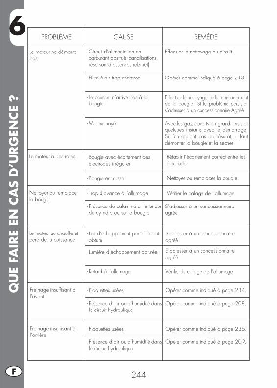
6Q
UE
FAIR
E EN
CA
S D
’URG
ENCE
?
244F
PROBLÈME CAUSE
Le moteur ne démarre pas
REMÈDE
- Circuit d’alimentation en carburant obstrué (canalisations, réservoir d’essence, robinet)
- Filtre à air trop encrassé
- Le courant n’arrive pas à la bougie
- Moteur noyé
Effectuer le nettoyage du circuit
Opérer comme indiqué à page 213.
Effectuer le nettoyage ou le remplacement de la bougie. Si le problème persiste, s’adresser à un concessionnaire Agréé
Avec les gaz ouverts en grand, insister quelques instants avec le démarrage. Si l’on obtient pas de résultat, il faut démonter la bougie et la sécher
Le moteur à des ratés - Bougie avec écartement des électrodes irrégulier
- Bougie encrassé
Rétablir l’écartement correct entre les électrodes
Nettoyer ou remplacer la bougie
Nettoyer ou remplacer la bougie
- Trop d’avance à l’allumage
- Présence de calamine à l’intérieur du cylindre ou sur la bougie
Vérifi er le calage de l’allumage
S’adresser à un concessionnaire agréé
Le moteur surchauffe et perd de la puissance
- Pot d’échappement partiellement obturé
- Lumière d’échappement obturée
- Retard à l’allumage
S’adresser à un concessionnaire agréé
S’adresser à un concessionnaire agréé
Vérifi er le calage de l’allumage
Freinage insuffi sant à l’avant
- Plaquettes usées
- Présence d’air ou d’humidité dans le circuit hydraulique
Opérer comme indiqué à page 234.
Opérer comme indiqué à page 208.
Freinage insuffi sant à l’arrière
- Plaquettes usées
- Présence d’air ou d’humidité dans le circuit hydraulique
Opérer comme indiqué à page 236.
Opérer comme indiqué à page 209.
IND
EX A
LPH
ABÉT
IQU
E
245 F
Approvisionnement en carburant............................................................ 202Après une longue période d’inactivité ..................................................... 228Arrêt du moteur .................................................................................. 201
Batterie ............................................................................................. 218Bougie ............................................................................................. 216
Caractéristiques lampes ....................................................................... 242Caractéristiques techniques .................................................................. 189Carburateur ....................................................................................... 218Charge ............................................................................................ 173Clés et serrures .................................................................................. 176Conduire en sécurité ........................................................................... 170Conduite écologique .......................................................................... 169Connaissance du véhicule .................................................................... 175Conseils pour l’utilisation du véhicule ...................................................... 169Contacteur principal/Verrouillage de direction ......................................... 176Contrôle et réglage du jeu à la direction ................................................. 232Contrôle niveau huile moteur ................................................................ 204Contrôles après le nettoyage ................................................................ 226Contrôles et entretien avant et après l’utilisation en tout-terrain ..................... 198
Dèmarrage du moteur ......................................................................... 200Desmontage des plastiques pour ALP ...................................................... 219Desmontage des plastiques pour MOTARD M4 ....................................... 221Données d’identifi cation du véhicule ...................................................... 172
Entretien programmé ........................................................................... 227Equipement ....................................................................................... 172Équipement électrique ......................................................................... 194
Faisceau lumineux .............................................................................. 234Filtre à air ......................................................................................... 215Frein arrière ....................................................................................... 217Frein avant ........................................................................................ 217
Huile de fourche ................................................................................ 214
La soupape AIS .................................................................................. 196LCD ................................................................................................. 178Liquide de frein, purge du circuit ........................................................... 210Longue inactivité du véhicule................................................................. 228Lubrifi ants conseillés ............................................................................ 198
IND
EX A
LPH
ABÉT
IQU
E
246F 246
Nettoyage du véhicule et contrôles ........................................................ 226Note pour usage tout-terrain ................................................................. 223
Pneumatiques..................................................................................... 173
Réglage amortisseur arrière .................................................................. 231Réglage de l’embrayage ..................................................................... 230Réglage des freins .............................................................................. 230Réglage du jeu à la poignée des gaz .................................................... 231Réglage du ralenti .............................................................................. 231Remplacement des ampoules ALP ..........................................................239Remplacement des ampoules MOTARD M4 ............................................ 240Remplacement des plaquettes de frein arrière ........................................... 238Remplacement des plaquettes de frein avant ............................................ 236Rodage ............................................................................................ 199
Schéma électrique .............................................................................. 192Serrure pour casque ............................................................................ 176Substitution des clignotants et du feu arrière ............................................ 241Substitution groupe transmission fi nal ...................................................... 224Substitution lumière plaque d’immatriculation ............................................ 242
Tableau de bord et commandes ........................................................... 177Tension de la chaîne ........................................................................... 233Tuyau de récupératin des fumées ........................................................... 210
Vidange huile moteur et fi ltre à huile ....................................................... 206

247 D
ALP 4.0 - MOTARD M4
Vielen Dank für Ihr Vertrauen und viel Spaß.Mit dieser Bedienungsanleitung möchten wir Ihnen die notwen-digen Informationen für einen richtigen Gebrauch und eine gute Wartung Ihres Motorrads geben.
Alle Angaben zu Technik und Ausstattung sind unverbindlich. Die BETAMO-TOR S.p.A. behält sich das Recht vor an ihren Fahrzeugmodellen jederzeit und ohne Vorankündigung Änderungen und Verbesserungen vorzunehmen.
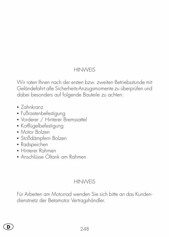
248D
HINWEIS
Wir raten Ihnen nach der ersten bzw. zweiten Betriebsstunde mit Geländefahrt alle Sicherheits-Anzugsmomente zu überprüfen und dabei besonders auf folgende Bauteile zu achten:
• Zahnkranz• Fußrastenbefestigung• Vorderer / Hinterer Bremssattel• Kotfl ügelbefestigung• Motor Bolzen • Stoßdämpfern Bolzen • Radspeichen• Hinterer Rahmen• Anschlüsse Öltank am Rahmen
HINWEIS
Für Arbeiten am Motorrad wenden Sie sich bitte an das Kunden-dienstnetz der Betamotor Vertragshändler.
INH
ALT
SVER
ZEI
CH
NIS
249 D
Hinweise zum Gebrauch des Fahrzeugs ................................................. 251Umweltfreundliches Fahren ................................................................... 251Sicheres Fahren .................................................................................. 252
KAPITEL 1 ALLGEMEINE ANGABEN .............................................. 253Rahmen- und motornummer ................................................................... 254Auslieferung ...................................................................................... 254Zuladung .......................................................................................... 255Reifen ............................................................................................... 255Wichtigste Fahrzeugteile ...................................................................... 257Schlüssel und Schlösser ........................................................................ 258Zünd-/ Lenkerschloß ........................................................................... 258Helmschloß ....................................................................................... 258Armaturenbrett und Bedienungselemente ................................................ 259Anzeigen am LCD .............................................................................. 260Technische Angaben ........................................................................... 271Elektrischer Schaltplan ......................................................................... 274Elektrische Anlage .............................................................................. 276Das AIS-Ventil .................................................................................... 278
KAPITEL 2 BEDIENUNGSVORSCHRIFTEN ..................................... 279Kontrollen und Wartung vor und nach Einsatz im Gelände ......................... 280Empfohlene Schmiermittel .................................................................... 280Einfahren .......................................................................................... 281Starten des Motors .............................................................................. 282Abstellen des Motors ........................................................................... 283Tanken ............................................................................................. 284
KAPITEL 3 WARTUNG UND KONTROLLEN .................................. 285Kontrolle motorölstand ......................................................................... 286Wechsel von motoröl und Ölfi lter ........................................................... 288Leitung Öldampfsammlung ................................................................... 292Bremsfl üssigkeit, entlüften der bremsen .................................................... 292Gabelöl ............................................................................................ 296Luftfi lter ............................................................................................. 297Zündkerze ......................................................................................... 298Vorderradbremse ................................................................................ 299Hinterradbremse ................................................................................. 299Vergaser ........................................................................................... 300Batterie ............................................................................................. 300Ausbau der plastikteile für ALP ............................................................... 301Ausbau der plastikteile für motard M4 .................................................... 303Hinweise für Geländefahrten ................................................................ 305Wechseln der endantriebseinheit ........................................................... 306Fahrzeugpfl ege und Kontrollen .............................................................. 308
INH
ALT
SVER
ZEI
CH
NIS
250D
Kontrollen nach der Fahrzeugpfl ege ....................................................... 308Wartungsprogramm ............................................................................ 309Längeres Stilllegen des Fahrzeugs .......................................................... 310Nach längerem Stillegen des Fahrzeugs ................................................. 310
KAPITEL 4 EINSTELLUNGEN .......................................................... 311Einstellung der bremsen ....................................................................... 312Einstellung der Kupplung ...................................................................... 312Einstellung des hinteren Stoßdämpfers ..................................................... 313Leerlaufeinstellung ............................................................................... 313Einstellung des Gaszuges ..................................................................... 313Kontrolle und Einstellung Lenkerspiel ....................................................... 314Spannen der Kette .............................................................................. 315Einstellung des Scheinwerfers ................................................................ 316
KAPITEL 5 AUSTAUSCHEN/ AUSWECHSELN VON TEILEN ........... 317Auswechseln der Bremsbeläge an der Vorderradbremse ............................ 318Auswechseln der Bremsbeläge an der Hinterradbremse ............................. 320Auswechseln lampen ALP .................................................................... 321Auswechseln Lampen MOTARD M4 ....................................................... 322Auswechseln von blinkern und Rücklicht .................................................. 323Auswechseln der Nummernschildbeleuchtung........................................... 324Eigenschaften Lampe ........................................................................... 324
KAPITEL 6 WAS IST IM NOTFALL ZU TUN .................................... 325
ALPHABETISCHES INHALTSVERZEICHNIS ..................................... 327
251 D
HINWEISE ZUM GEBRAUCH DES FAHRZEUGS• Das Fahrzeug muß vorschriftsmäßig mit folgendem ausgestattet sein: Nummernschild, Fahrzeugschein, Fahrzeugsteuer- und Versicherungsmarke.
• Das Fahren und der Transport mit Tieren und nicht fest am Fahrzeug befestigten oder am Fahrzeug überstehenden Gegenständen ist verboten. Die vom Hersteller angegebene Nutzlast darf nicht überschritten werden.
• Es besteht Helmpfl icht.• Veränderungen am Motor oder anderen Fahrzeugteilen, die die Fahrzeugleistung und damit die Geschwindigkeit erhöhen, ist gesetzlich verboten und wird, u. a. mit Beschlagnahmung des Fahrzeugs, bestraft.
• Zum Schutz des eigenen Lebens und des Lebens anderer Personen stets vorsichtig fahren und immer einen Sturzhelm tragen.
ACHTUNG:Bei Änderungen am Fahrzeug während der Garantiezeit haftet der Hersteller nicht und es verfallen sämtliche Garantieansprüche.
UMWELTFREUNDLICHES FAHREN•Je nach Fahrstil verursacht jedes Fahrzeug mit Verbrennungsmotor eine mehr oder weniger starke akustische und atmosphärische Verschmutzung.
• Die Verringerung dieser Umweltbelastungen ist heute für alle zur Pfl icht gewor-den. Vermeiden Sie daher ein Anfahren mit Vollgas sowie unnötiges plötzliches Beschleunigen und Abbremsen des Fahrzeugs. Die Geräuschbelastung ist dann geringer, die Reifen und die mechanischen Fahrzeugteile verschleißen langsamer, der Benzinverbrauch kann deutlich gesenkt werden.
252D
SICHERES FAHREN• Die Straßenverkehrsordnung beachten.• Stets einen zugelassenen Sturzhelm tragen und diesen festschnallen.• Das Schutzvisier am Helm immer sauber halten.• Enganliegende Kleidung tragen.• Niemals mit spitzen oder zerbrechlichen Gegenständen in den Taschen fahren.• Die Rückspiegel richtig einstellen.• Nur im Sitzen fahren, beide Hände am Lenker halten und die Füße auf das Trittbrett/ die Fußrasten stellen.
• Stets aufmerksam fahren und sich nie ablenken lassen.• Beim Fahren nie essen, trinken, rauchen, telefonieren usw…• Beim Fahren niemals über Kopfhörer Musik hören.• Nie neben anderen Fahrzeugen fahren.• Nie andere Fahrzeuge abschleppen oder sich abschleppen lassen.• Immer den Sicherheitsabstand einhalten.• Nicht auf das Fahrzeug setzen, solange dieses auf dem Ständer steht.• Nicht mit dem Motorroller anfahren, wenn dieses auf dem Ständer steht.• Den Ständer nicht benutzen, wenn das Fahrzeug in Fahrtrichtung auf abschüssiger Straße steht.
• Fahren mit angehobenem Vorderrad, Schlangenfahren, Wippen ist gefährlich für Dich, für die anderen und für den Motorroller.
• Auf trockener, sand- und kiesfreier Straße stets mit beiden Bremsen gleichzeitig bremsen, um ein gefährliches und nicht kontrollierbares Rutschen oder Ausbrechen des Fahrzeugs zu vermeiden.
• Stets mit beiden Bremsen gleichzeitig bremsen, der Bremsweg wird kürzer.• Auf nassen Straßen vorsichtig und langsam fahren, weniger stark bremsen.• Den Motor niemals in geschlossenen Räumen laufen lassen.
1
ALL
GEM
EIN
E A
NG
ABEN
253 D
INHALTSVERZEICHNIS
KAPITEL 1 ALLGEMEINE ANGABEN
Rahmen- und motornummer
Auslieferung
Zuladung
Reifen
Wichtigste Fahrzeugteile
Schlüssel und Schlösser
Zünd-/ Lenkerschloß
Helmschloß
Armaturenbrett und Bedienungselemente
Anzeigen am LCD
Technische Angaben
Elektrischer Schaltplan
Elektrische Anlage
Das AIS-Ventil
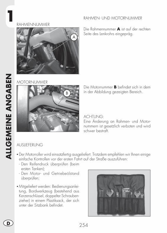
1A
LLG
EMEI
NE
AN
GA
BEN
254D
RAHMEN- UND MOTORNUMMER
Die Rahmennummer A ist auf der rechten Seite des Lenkrohrs eingepräg.
RAHMENNUMMER
Die Motornummer B befi ndet sich in dem in der Abbildung gezeigten Bereich.
ACHTUNG:Eine Änderung an Rahmen- und Motor-nummern ist gesetzlich verboten und wird schwer bestraft.
MOTORNUMMER
AUSLIEFERUNG
• Der Motorroller wird einsatzfertig ausgeliefert. Trotzdem empfehlen wir Ihnen einige einfache Kontrollen vor der ersten Fahrt auf der Straße auszuführen:- Den Reifendruck überprüfen (beim ersten Tanken);
- Den Motor- und Getriebeölstand überprüfen;
• Mitgeliefert werden: Bedienungsanlei-tung, Bordwerkzeug (bestehend aus Kerzenschlüssel, doppelter Schrauben-zieher) in einem Plastiksack, der sich unter der Sitzbank befi ndet.
A
B
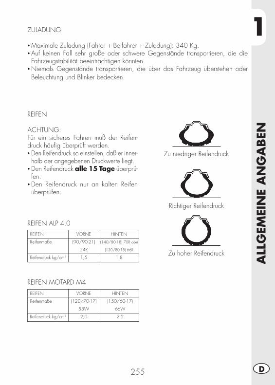
1
ALL
GEM
EIN
E A
NG
ABEN
255 D
ZULADUNG
• Maximale Zuladung (Fahrer + Beifahrer + Zuladung): 340 Kg.• Auf keinen Fall sehr große oder schwere Gegenstände transportieren, die die Fahrzeugstabilität beeinträchtigen könnten.
• Niemals Gegenstände transportieren, die über das Fahrzeug überstehen oder Beleuchtung und Blinker bedecken.
REIFEN
ACHTUNG:Für ein sicheres Fahren muß der Reifen-druck häufi g überprüft werden.• Den Reifendruck so einstellen, daß er inner-halb der angegebenen Druckwerte liegt.
• Den Reifendruck alle 15 Tage überprü-fen.
• Den Reifendruck nur an kalten Reifen überprüfen.
Zu niedriger Reifendruck
Richtiger Reifendruck
Zu hoher Reifendruck
REIFEN ALP 4.0REIFEN
Reifenmaße
Reifendruck kg/cm2
HINTEN
(140/80-18) 70R oder
(130/80-18) 66R
1,8
VORNE
(90/90-21)
54R
1,5
REIFEN MOTARD M4
REIFEN
Reifenmaße
Reifendruck kg/cm2
HINTEN
(150/60-17)
66W
2,2
VORNE
(120/70-17)
58W
2,0

1A
LLG
EMEI
NE
AN
GA
BEN
256D
Anmerkung:Das Reifenprofi l (Schlauchreifen - TUBE TYPE) muß mindestens 2 mm betragen.Fahren mit geringerem Reifenprofi l wird gesetzlich bestraft.
• Vor jedem Fahrtantritt die Reifen auf Schnittstellen, Abschürfungen, Aufblähen usw. überprüfen. Werden Beschädigungen am Reifen festgestellt, muß der Reifen von einem Fachmann überprüft werden. Das Fahren mit beschädigten Reifen ist sehr gefährlich.
• Bei einem Loch im Reifen das Fahrzeug sofort anhalten. Weiterfahren ist sehr ge-fährlich und kann den Reifen und die Radfelgen schwer beschädigen.
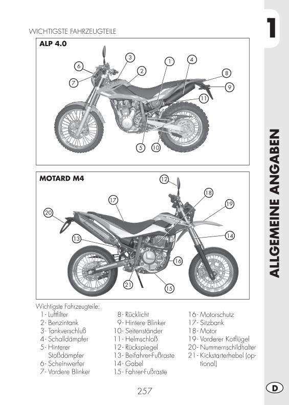
1
ALL
GEM
EIN
E A
NG
ABEN
257 D
WICHTIGSTE FAHRZEUGTEILE
Wichtigste Fahrzeugteile: 1 - Luftfi lter 2 - Benzintank 3 - Tankverschluß 4 - Schalldämpfer 5 - Hinterer Stoßdämpfer 6 - Scheinwerfer 7 - Vordere Blinker
8 - Rücklicht 9 - Hintere Blinker 10 - Seitenständer 11 - Helmschloß 12 - Rückspiegel 13 - Beifahrer-Fußraste 14 - Gabel 15 - Fahrer-Fußraste
16 - Motorschutz 17 - Sitzbank 18 - Motor 19 - Vorderer Kotfl ügel 20 - Nummernschildhalter 21 - Kickstarterhebel (op-
tional)
7
6
5
3
2
1
8
9
4
11
ALP 4.0
MOTARD M4
10
20
17
12
18
19
14
16
21
13
15
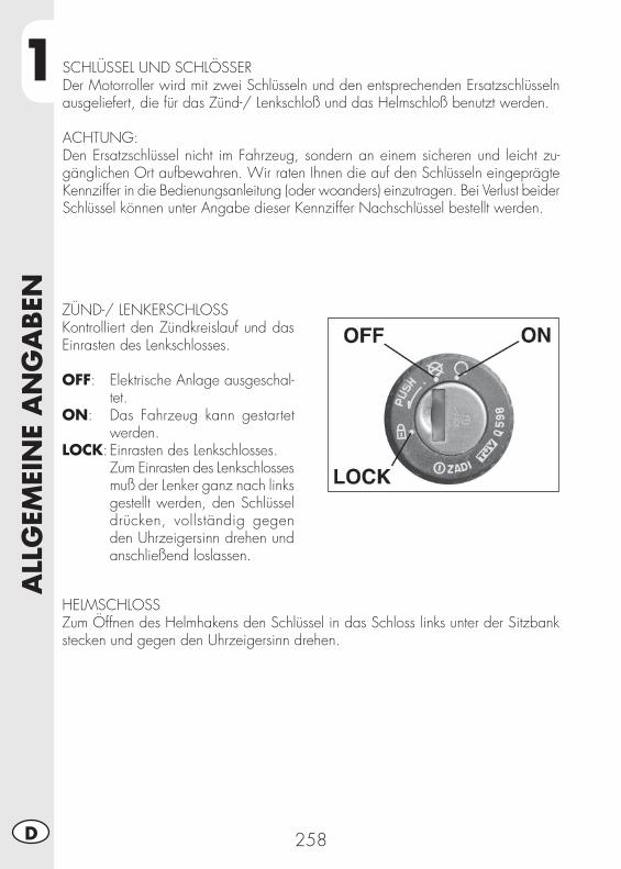
1A
LLG
EMEI
NE
AN
GA
BEN
258D
SCHLÜSSEL UND SCHLÖSSERDer Motorroller wird mit zwei Schlüsseln und den entsprechenden Ersatzschlüsseln ausgeliefert, die für das Zünd-/ Lenkschloß und das Helmschloß benutzt werden.
ACHTUNG:Den Ersatzschlüssel nicht im Fahrzeug, sondern an einem sicheren und leicht zu-gänglichen Ort aufbewahren. Wir raten Ihnen die auf den Schlüsseln eingeprägte Kennziffer in die Bedienungsanleitung (oder woanders) einzutragen. Bei Verlust beider Schlüssel können unter Angabe dieser Kennziffer Nachschlüssel bestellt werden.
ZÜND-/ LENKERSCHLOSSKontrolliert den Zündkreislauf und das Einrasten des Lenkschlosses.
OFF: Elektrische Anlage ausgeschal-tet.
ON: Das Fahrzeug kann gestartet werden.
LOCK: Einrasten des Lenkschlosses. Zum Einrasten des Lenkschlosses
muß der Lenker ganz nach links gestellt werden, den Schlüssel drücken, vollständig gegen den Uhrzeigersinn drehen und anschließend loslassen.
HELMSCHLOSSZum Öffnen des Helmhakens den Schlüssel in das Schloss links unter der Sitzbank stecken und gegen den Uhrzeigersinn drehen.
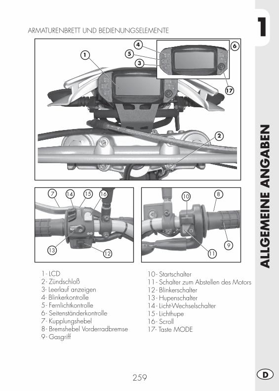
1
ALL
GEM
EIN
E A
NG
ABEN
259 D
1 - LCD 2 - Zündschloß 3 - Leerlauf anzeigen 4 - Blinkerkontrolle 5 - Fernlichtkontrolle 6 - Seitenständerkontrolle 7 - Kupplungshebel 8 - Bremshebel Vorderradbremse 9 - Gasgriff
10 - Startschalter11 - Schalter zum Abstellen des Motors12 - Blinkerschalter13 - Hupenschalter14 - Licht-Wechselschalter15 - Lichthupe 16 - Scroll17- Taste MODE
ARMATURENBRETT UND BEDIENUNGSELEMENTE
7 8
9
10
111213
14 15 16
1
2
3
5
17
4 6
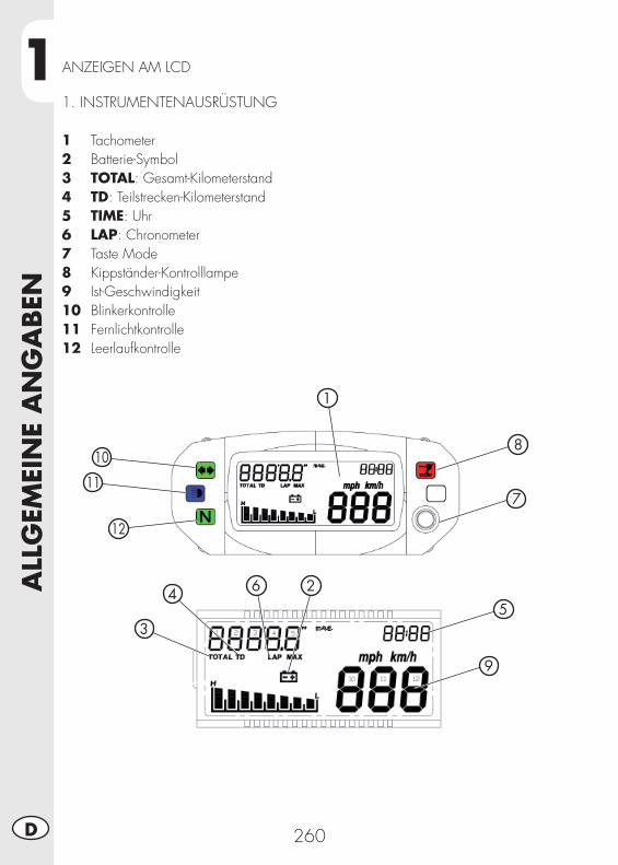
1A
LLG
EMEI
NE
AN
GA
BEN
260D
ANZEIGEN AM LCD
2
3
45
7
6
9
1
10
11
12
8
1. INSTRUMENTENAUSRÜSTUNG
1 Tachometer2 Batterie-Symbol3 TOTAL: Gesamt-Kilometerstand4 TD: Teilstrecken-Kilometerstand5 TIME: Uhr6 LAP: Chronometer7 Taste Mode8 Kippständer-Kontrolllampe9 Ist-Geschwindigkeit 10 Blinkerkontrolle11 Fernlichtkontrolle12 Leerlaufkontrolle
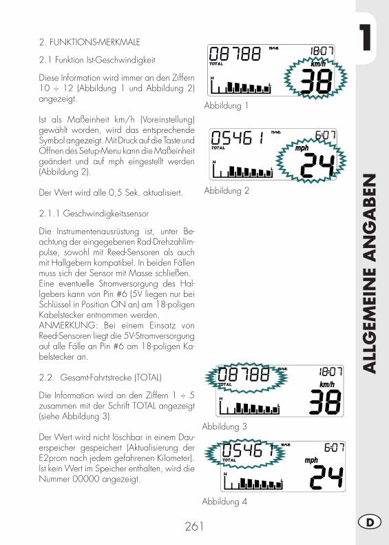
1
ALL
GEM
EIN
E A
NG
ABEN
261 D
2. FUNKTIONS-MERKMALE
2.1 Funktion Ist-Geschwindigkeit
Diese Information wird immer an den Ziffern 10 ÷ 12 (Abbildung 1 und Abbildung 2) angezeigt.
Ist als Maßeinheit km/h (Voreinstellung) gewählt worden, wird das entsprechende Symbol angezeigt. Mit Druck auf die Taste und Öffnen des Setup-Menu kann die Maßeinheit geändert und auf mph eingestellt werden (Abbildung 2).
Der Wert wird alle 0,5 Sek. aktualisiert.
2.1.1 Geschwindigkeitssensor
Die Instrumentenausrüstung ist, unter Be-achtung der eingegebenen Rad-Drehzahlim-pulse, sowohl mit Reed-Sensoren als auch mit Hallgebern kompatibel. In beiden Fällen muss sich der Sensor mit Masse schließen.Eine eventuelle Stromversorgung des Hal-lgebers kann von Pin #6 (5V liegen nur bei Schlüssel in Position ON an) am 18-poligen Kabelstecker entnommen werden.ANMERKUNG: Bei einem Einsatz von Reed-Sensoren liegt die 5V-Stromversorgung auf alle Fälle an Pin #6 am 18-poligen Ka-belstecker an.
2.2. Gesamt-Fahrtstrecke (TOTAL)
Die Information wird an den Ziffern 1 ÷ 5 zusammen mit der Schrift TOTAL angezeigt (siehe Abbildung 3).
Der Wert wird nicht löschbar in einem Dau-erspeicher gespeichert (Aktualisierung der E2prom nach jedem gefahrenen Kilometer).Ist kein Wert im Speicher enthalten, wird die Nummer 00000 angezeigt.
Abbildung 1
Abbildung 2
Abbildung 3
Abbildung 4
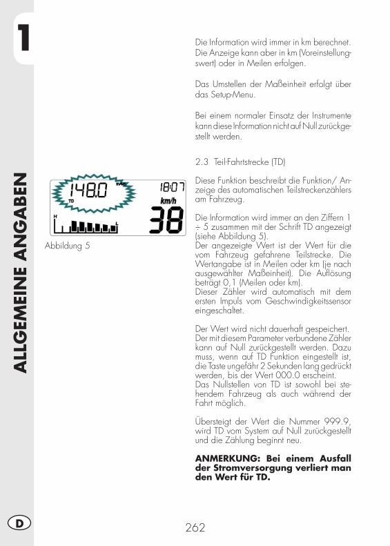
1A
LLG
EMEI
NE
AN
GA
BEN
262D
Abbildung 5
2.3 Teil-Fahrtstrecke (TD)
Diese Funktion beschreibt die Funktion/ An-zeige des automatischen Teilstreckenzählers am Fahrzeug.
Die Information wird immer an den Ziffern 1 ÷ 5 zusammen mit der Schrift TD angezeigt (siehe Abbildung 5).Der angezeigte Wert ist der Wert für die vom Fahrzeug gefahrene Teilstrecke. Die Wertangabe ist in Meilen oder km (je nach ausgewählter Maßeinheit). Die Aufl ösung beträgt 0,1 (Meilen oder km).Dieser Zähler wird automatisch mit dem ersten Impuls vom Geschwindigkeitssensor eingeschaltet.
Der Wert wird nicht dauerhaft gespeichert.Der mit diesem Parameter verbundene Zähler kann auf Null zurückgestellt werden. Dazu muss, wenn auf TD Funktion eingestellt ist, die Taste ungefähr 2 Sekunden lang gedrückt werden, bis der Wert 000.0 erscheint.Das Nullstellen von TD ist sowohl bei ste-hendem Fahrzeug als auch während der Fahrt möglich.
Übersteigt der Wert die Nummer 999.9, wird TD vom System auf Null zurückgestellt und die Zählung beginnt neu.
ANMERKUNG: Bei einem Ausfall der Stromversorgung verliert man den Wert für TD.
Die Information wird immer in km berechnet. Die Anzeige kann aber in km (Voreinstellung-swert) oder in Meilen erfolgen.
Das Umstellen der Maßeinheit erfolgt über das Setup-Menu.
Bei einem normaler Einsatz der Instrumente kann diese Information nicht auf Null zurückge-stellt werden.
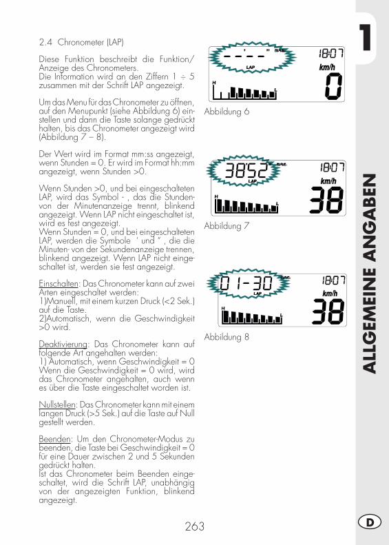
1
ALL
GEM
EIN
E A
NG
ABEN
263 D
Abbildung 6
Abbildung 7
Abbildung 8
2.4 Chronometer (LAP)
Diese Funktion beschreibt die Funktion/ Anzeige des Chronometers.Die Information wird an den Ziffern 1 ÷ 5 zusammen mit der Schrift LAP angezeigt.
Um das Menu für das Chronometer zu öffnen, auf den Menupunkt (siehe Abbildung 6) ein-stellen und dann die Taste solange gedrückt halten, bis das Chronometer angezeigt wird (Abbildung 7 – 8).
Der Wert wird im Format mm:ss angezeigt, wenn Stunden = 0. Er wird im Format hh:mm angezeigt, wenn Stunden >0.
Wenn Stunden >0, und bei eingeschalteten LAP, wird das Symbol - , das die Stunden- von der Minutenanzeige trennt, blinkend angezeigt. Wenn LAP nicht eingeschaltet ist, wird es fest angezeigt.Wenn Stunden = 0, und bei eingeschalteten LAP, werden die Symbole ‘ und “ , die die Minuten- von der Sekundenanzeige trennen, blinkend angezeigt. Wenn LAP nicht einge-schaltet ist, werden sie fest angezeigt.
Einschalten: Das Chronometer kann auf zwei Arten eingeschaltet werden:1) Manuell, mit einem kurzen Druck (<2 Sek.) auf die Taste.2) Automatisch, wenn die Geschwindigkeit >0 wird.
Deaktivierung: Das Chronometer kann auf folgende Art angehalten werden:1) Automatisch, wenn Geschwindigkeit = 0Wenn die Geschwindigkeit = 0 wird, wird das Chronometer angehalten, auch wenn es über die Taste eingeschaltet worden ist.
Nullstellen: Das Chronometer kann mit einem langen Druck (>5 Sek.) auf die Taste auf Null gestellt werden.
Beenden: Um den Chronometer-Modus zu beenden, die Taste bei Geschwindigkeit = 0 für eine Dauer zwischen 2 und 5 Sekunden gedrückt halten.Ist das Chronometer beim Beenden einge-schaltet, wird die Schrift LAP, unabhängig von der angezeigten Funktion, blinkend angezeigt.
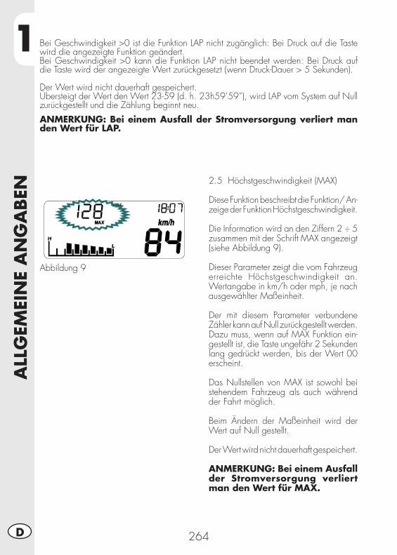
1A
LLG
EMEI
NE
AN
GA
BEN
264D
2.5 Höchstgeschwindigkeit (MAX)
Diese Funktion beschreibt die Funktion/ An-zeige der Funktion Höchstgeschwindigkeit.
Die Information wird an den Ziffern 2 ÷ 5 zusammen mit der Schrift MAX angezeigt (siehe Abbildung 9).
Dieser Parameter zeigt die vom Fahrzeug erreichte Höchstgeschwindigkeit an. Wertangabe in km/h oder mph, je nach ausgewählter Maßeinheit.
Der mit diesem Parameter verbundene Zähler kann auf Null zurückgestellt werden. Dazu muss, wenn auf MAX Funktion ein-gestellt ist, die Taste ungefähr 2 Sekunden lang gedrückt werden, bis der Wert 00 erscheint.
Das Nullstellen von MAX ist sowohl bei stehendem Fahrzeug als auch während der Fahrt möglich.
Beim Ändern der Maßeinheit wird der Wert auf Null gestellt.
Der Wert wird nicht dauerhaft gespeichert.
ANMERKUNG: Bei einem Ausfall der Stromversorgung verliert man den Wert für MAX.
Abbildung 9
Bei Geschwindigkeit >0 ist die Funktion LAP nicht zugänglich: Bei Druck auf die Taste wird die angezeigte Funktion geändert.Bei Geschwindigkeit >0 kann die Funktion LAP nicht beendet werden: Bei Druck auf die Taste wird der angezeigte Wert zurückgesetzt (wenn Druck-Dauer > 5 Sekunden).
Der Wert wird nicht dauerhaft gespeichert.Übersteigt der Wert den Wert 23-59 (d. h. 23h59’59”), wird LAP vom System auf Null zurückgestellt und die Zählung beginnt neu.
ANMERKUNG: Bei einem Ausfall der Stromversorgung verliert man den Wert für LAP.
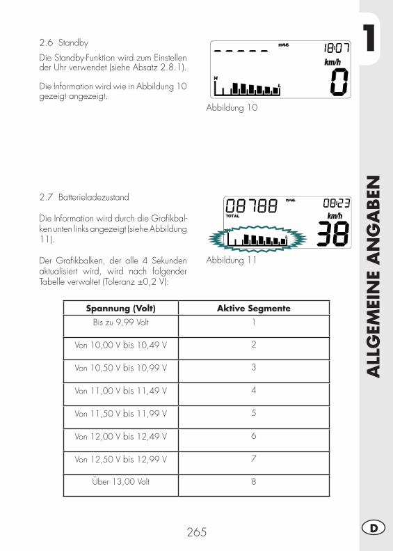
1
ALL
GEM
EIN
E A
NG
ABEN
265 D
2.6 Standby
Die Standby-Funktion wird zum Einstellen der Uhr verwendet (siehe Absatz 2.8.1).
Die Information wird wie in Abbildung 10 gezeigt angezeigt.
Abbildung 10
2.7 Batterieladezustand
Die Information wird durch die Grafi kbal-ken unten links angezeigt (siehe Abbildung 11).
Der Grafi kbalken, der alle 4 Sekunden aktualisiert wird, wird nach folgender Tabelle verwaltet (Toleranz ±0,2 V):
Abbildung 11
Spannung (Volt) Aktive Segmente
Bis zu 9,99 Volt 1
Von 10,00 V bis 10,49 V 2
Von 10,50 V bis 10,99 V 3
Von 11,00 V bis 11,49 V 4
Von 11,50 V bis 11,99 V 5
Von 12,00 V bis 12,49 V 6
Von 12,50 V bis 12,99 V 7
Über 13,00 Volt 8
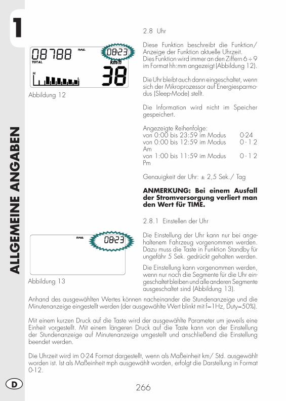
1A
LLG
EMEI
NE
AN
GA
BEN
266D
2.8 Uhr
Diese Funktion beschreibt die Funktion/ Anzeige der Funktion aktuelle Uhrzeit.Dies Funktion wird immer an den Ziffern 6 ÷ 9 im Format hh:mm angezeigt (Abbildung 12).
Die Uhr bleibt auch dann eingeschaltet, wenn sich der Mikroprozessor auf Energiesparmo-dus (Sleep-Mode) stellt.
Die Information wird nicht im Speicher gespeichert.
Angezeigte Reihenfolge: von 0:00 bis 23:59 im Modus 0-24 von 0:00 bis 12:59 im Modus 0 - 1 2 Am von 1:00 bis 11:59 im Modus 0 - 1 2 Pm
Genauigkeit der Uhr: ± 2,5 Sek./ Tag
ANMERKUNG: Bei einem Ausfall der Stromversorgung verliert man den Wert für TIME.
Abbildung 12
2.8.1 Einstellen der Uhr
Die Einstellung der Uhr kann nur bei ange-haltenem Fahrzeug vorgenommen werden. Dazu muss die Taste in Funktion Standby für ungefähr 5 Sek. gedrückt gehalten werden.
Die Einstellung kann vorgenommen werden, wenn nur noch die Segmente für die Uhr ein-geschaltet bleiben und alle anderen Segmente ausgeschaltet sind (Abbildung 13).
Abbildung 13
Anhand des ausgewählten Wertes können nacheinander die Stundenanzeige und die Minutenanzeige eingestellt werden (der ausgewählte Wert blinkt mit f=1Hz, Duty=50%).
Mit einem kurzen Druck auf die Taste wird der ausgewählte Parameter um jeweils eine Einheit vorgestellt. Mit einem längeren Druck auf die Taste kann von der Einstellung der Stundenanzeige auf Minutenanzeige umgestellt und anschließend die Einstellung beendet werden.
Die Uhrzeit wird im 0-24 Format dargestellt, wenn als Maßeinheit km/ Std. ausgewählt worden ist. Ist als Maßeinheit mph ausgewählt worden, erfolgt die Darstellung in Format 0-12.
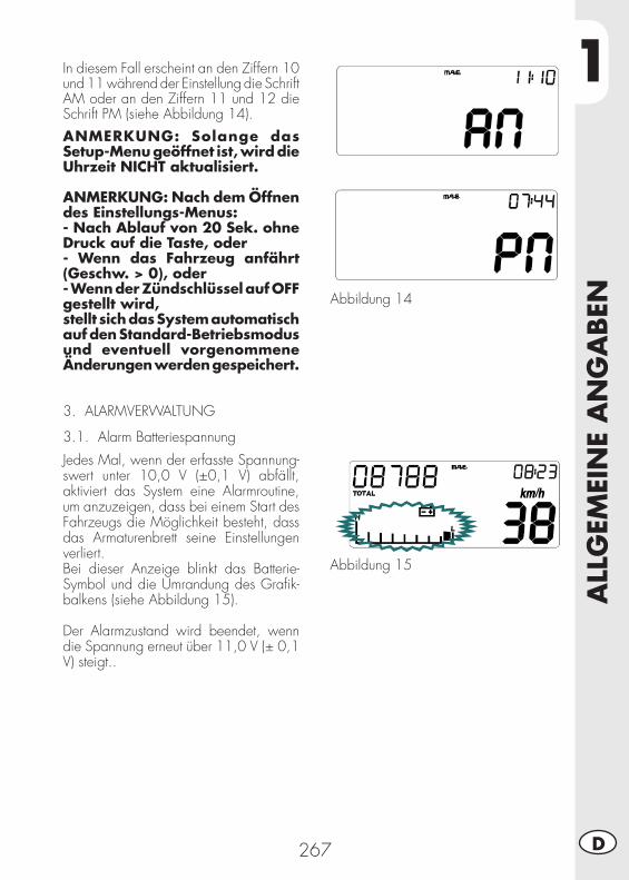
1
ALL
GEM
EIN
E A
NG
ABEN
267 D
In diesem Fall erscheint an den Ziffern 10 und 11 während der Einstellung die Schrift AM oder an den Ziffern 11 und 12 die Schrift PM (siehe Abbildung 14).
ANMERKUNG: Solange das Setup-Menu geöffnet ist, wird die Uhrzeit NICHT aktualisiert.
ANMERKUNG: Nach dem Öffnen des Einstellungs-Menus:- Nach Ablauf von 20 Sek. ohne Druck auf die Taste, oder- Wenn das Fahrzeug anfährt (Geschw. > 0), oder- Wenn der Zündschlüssel auf OFF gestellt wird,stellt sich das System automatisch auf den Standard-Betriebsmodus und eventuell vorgenommene Änderungen werden gespeichert.
3. ALARMVERWALTUNG
3.1. Alarm Batteriespannung
Jedes Mal, wenn der erfasste Spannung-swert unter 10,0 V (±0,1 V) abfällt, aktiviert das System eine Alarmroutine, um anzuzeigen, dass bei einem Start des Fahrzeugs die Möglichkeit besteht, dass das Armaturenbrett seine Einstellungen verliert.Bei dieser Anzeige blinkt das Batterie-Symbol und die Umrandung des Grafi k-balkens (siehe Abbildung 15).
Der Alarmzustand wird beendet, wenn die Spannung erneut über 11,0 V (± 0,1 V) steigt..
Abbildung 14
Abbildung 15
1A
LLG
EMEI
NE
AN
GA
BEN
268D
4. KONTROLLLAMPEN UND HINTERGRUNDBELEUCHTUNG
4.1 Blinkerkontrolle
Das System schaltet diese Kontrolllampe ein, sobald die Blinker eingeschaltet werden.
ANMERKUNG: Das Signal muss bereits alternierend zur Instrumen-tenausrüstung gelangen.
4.2 Fernlichtkontrolle
Das System schaltet diese Kontrolllampe ein, sobald das Fernlicht eingeschaltet wird.
4.3 Leerlaufkontrolle
Das System schaltet diese Kontrolllampe ein, sobald der Schalthebel auf Leerlauf gestellt wird.
4.4 Hintergrundbeleuchtung LCD und Skalenscheibe
Das LCD hat eine orangene Hintergrundbeleuchtung. Solange der Zündschlüssel auf ON gestellt ist, ist die Hintergrundbeleuchtung immer eingeschaltet.
5. SETUP-MENU
Das Setup-Menu kann nur bei angehaltenem Fahrzeug (Geschw. = 0 Km/h) geöffnet werden. Das muss die Taste bei geöffneter Funktion TOTAL für ungefähr 5 Sekunden gedrückt werden.
Damit die im Setup-Menu vorgenommenen Änderungen übernommen werden, muss der Anwender die gesamte Abfolge der vorgesehenen Menupunkte zu Ende bringen. Es muss darauf geachtet werden, dass das Beenden des Setup-Menus (und damit das Rückstellen des Instruments auf den Standard-Betriebsmodus) nur und ausschließlich über die Mode-Taste erfolgt.
Zum Beenden des Menus die Taste beim ausgewählten Wert im Menupunkt Impulsanzahl pro Raddrehung (letzter Menupunkt des Setup-Menus) solange gedrückt halten, bis sich das Instrument auf Standard-Betriebsmodus zurückgestellt hat.
ANMERKUNG: Nach dem Öffnen des Einstellungs-Menus:- Nach Ablauf von 20 Sek. ohne Druck auf die Taste, oder- Wenn das Fahrzeug anfährt (Geschw. > 0), oder- Wenn der Zündschlüssel auf OFF gestellt wird,stellt sich das System automatisch auf den Standard-Betriebsmodus, OHNE eventuell vorgenommene Änderungen zu speichern.
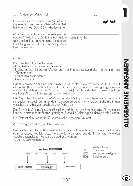
1
ALL
GEM
EIN
E A
NG
ABEN
269 D
5.1 Ändern der Maßeinheit
Es werden nur die Symbole km/h und mph angezeigt. Die ausgewählte Maßeinheit blinkt (mit f=1Hz, Duty=50%) (Abbildung 16).
Mit einem kurzen Druck auf die Taste wird die ausgewählte Einheit geändert, mit einem lan-gen Druck auf die Taste kann auf die nächste Einstellung umgestellt oder das Setup-Menu beendet werden.
Abbildung 16
6. TASTE
Die Taste hat folgende Aufgaben:- Durchblättern der einzelnen Funktionen.- Nullstellen des Teilstrecken-Wertes und der Höchstgeschwindigkeit, Einschalten des Chronometers.
- Öffnen des Setup-Menus.- Einstellen der Uhr.
Das Durchblättern der einzelnen Funktionen (d. h. das Umstellen von einer Funktion auf die nächste) kann sowohl bei stehendem als auch bei fahrendem Fahrzeug vorgenommen werden. Es reicht ein kurzer Druck (tmin = 1 Sek.) auf die Taste. Bei Loslassen der Taste wird das Display mit der neuen Funktion aktualisiert.
Das Nullstellen des Teilstrecken-Wertes und der Höchstgeschwindigkeit kann sowohl bei stehendem als auch bei fahrendem Fahrzeug vorgenommen werden. Siehe die in den vorstehenden Absätzen beschriebenen Verfahren.
Das Öffnen des Setup-Menus zum Einstellen der Uhr und zum Einschalten des Chronometers kann nur bei stehendem Fahrzeug erfolgen. Siehe die Anleitungen in den Kapiteln 2 und 6.
Die Taste ist aktiv, wenn der Zündschlüssel auf Position On steht.
6.1 Abfolge der dargestellten Funktionen
Das Durchlaufen der Funktionen ist jederzeit, sowohl bei stehendem als auch bei fahren-dem Fahrzeug, möglich. Dazu muss die Taste entsprechend der in der nachstehenden Tabelle angegebenen Reihenfolge gedrückt werden:TOTAL Gesamt-Fahrtstrecke
TD Teil-FahrtstreckeLAP RundenzeitMAX HöchstgeschwindigkeitSTDBY Einstellen der Uhr
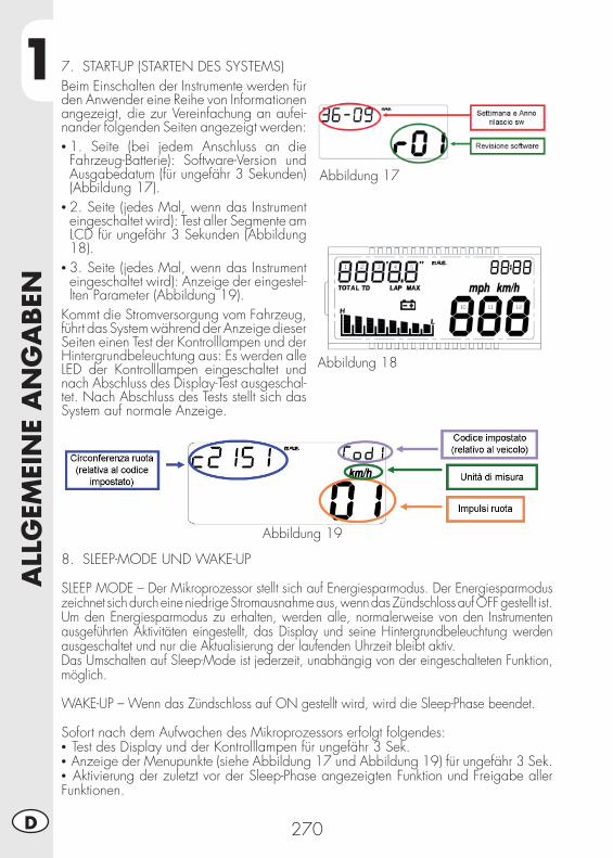
1A
LLG
EMEI
NE
AN
GA
BEN
270D
7. START-UP (STARTEN DES SYSTEMS)Beim Einschalten der Instrumente werden für den Anwender eine Reihe von Informationen angezeigt, die zur Vereinfachung an aufei-nander folgenden Seiten angezeigt werden:• 1. Seite (bei jedem Anschluss an die Fahrzeug-Batterie): Software-Version und Ausgabedatum (für ungefähr 3 Sekunden) (Abbildung 17).
• 2. Seite (jedes Mal, wenn das Instrument eingeschaltet wird): Test aller Segmente am LCD für ungefähr 3 Sekunden (Abbildung 18).
• 3. Seite (jedes Mal, wenn das Instrument eingeschaltet wird): Anzeige der eingestel-lten Parameter (Abbildung 19).
Kommt die Stromversorgung vom Fahrzeug, führt das System während der Anzeige dieser Seiten einen Test der Kontrolllampen und der Hintergrundbeleuchtung aus: Es werden alle LED der Kontrolllampen eingeschaltet und nach Abschluss des Display-Test ausgeschal-tet. Nach Abschluss des Tests stellt sich das System auf normale Anzeige.
Abbildung 17
Abbildung 18
Abbildung 19
8. SLEEP-MODE UND WAKE-UP
SLEEP MODE – Der Mikroprozessor stellt sich auf Energiesparmodus. Der Energiesparmodus zeichnet sich durch eine niedrige Stromausnahme aus, wenn das Zündschloss auf OFF gestellt ist.Um den Energiesparmodus zu erhalten, werden alle, normalerweise von den Instrumenten ausgeführten Aktivitäten eingestellt, das Display und seine Hintergrundbeleuchtung werden ausgeschaltet und nur die Aktualisierung der laufenden Uhrzeit bleibt aktiv.Das Umschalten auf Sleep-Mode ist jederzeit, unabhängig von der eingeschalteten Funktion, möglich.
WAKE-UP – Wenn das Zündschloss auf ON gestellt wird, wird die Sleep-Phase beendet.
Sofort nach dem Aufwachen des Mikroprozessors erfolgt folgendes:• Test des Display und der Kontrolllampen für ungefähr 3 Sek.• Anzeige der Menupunkte (siehe Abbildung 17 und Abbildung 19) für ungefähr 3 Sek.• Aktivierung der zuletzt vor der Sleep-Phase angezeigten Funktion und Freigabe aller Funktionen.
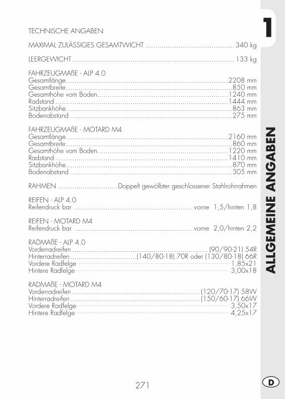
1
ALL
GEM
EIN
E A
NG
ABEN
271 D
TECHNISCHE ANGABEN
MAXIMAL ZULÄSSIGES GESAMTWICHT ........................................... 340 kg
LEERGEWICHT .............................................................................. 133 kg
FAHRZEUGMAßE - ALP 4.0Gesamtlänge ..............................................................................2208 mmGesamtbreite ................................................................................850 mmGesamthöhe vom Boden...............................................................1240 mmRadstand ...................................................................................1444 mmSitzbankhöhe ................................................................................863 mmBodenabstand ..............................................................................275 mm
FAHRZEUGMAßE - MOTARD M4Gesamtlänge ..............................................................................2160 mmGesamtbreite ................................................................................860 mmGesamthöhe vom Boden...............................................................1220 mmRadstand ...................................................................................1410 mmSitzbankhöhe ................................................................................870 mmBodenabstand ..............................................................................305 mm
RAHMEN .............................Doppelt gewölbter geschlossener Stahlrohrrahmen
REIFEN - ALP 4.0Reifendruck bar ......................................................... vorne 1,5/hinten 1,8
REIFEN - MOTARD M4Reifendruck bar ......................................................... vorne 2,0/hinten 2,2
RADMAßE - ALP 4.0Vorderradreifen ................................................................. (90/90-21) 54RHinterradreifen ................................(140/80-18) 70R oder (130/80-18) 66RVordere Radfelge .............................................................................................................................. 1,85x21Hintere Radfelge ............................................................................................................................... 3,00x18
RADMAßE - MOTARD M4Vorderradreifen ............................................................. (120/70-17) 58WHinterradreifen .............................................................. (150/60-17) 66WVordere Radfelge .............................................................................................................................. 3,50x17Hintere Radfelge ............................................................................................................................... 4,25x17
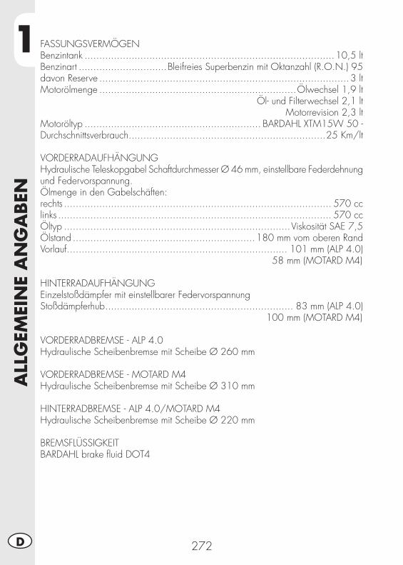
1A
LLG
EMEI
NE
AN
GA
BEN
272D
FASSUNGSVERMÖGENBenzintank .....................................................................................10,5 ltBenzinart ..............................Bleifreies Superbenzin mit Oktanzahl (R.O.N.) 95 davon Reserve .....................................................................................3 ltMotorölmenge ...................................................................Ölwechsel 1,9 lt
Öl- und Filterwechsel 2,1 ltMotorrevision 2,3 lt
Motoröltyp ............................................................ BARDAHL XTM15W 50 -Durchschnittsverbrauch ...................................................................25 Km/lt
VORDERRADAUFHÄNGUNGHydraulische Teleskopgabel Schaftdurchmesser Ø 46 mm, einstellbare Federdehnung und Federvorspannung.Ölmenge in den Gabelschäften:rechts ........................................................................................... 570 cc links ............................................................................................. 570 ccÖltyp .............................................................................Viskosität SAE 7,5Ölstand ..............................................................180 mm vom oberen RandVorlauf ........................................................................... 101 mm (ALP 4.0)
58 mm (MOTARD M4)
HINTERRADAUFHÄNGUNGEinzelstoßdämpfer mit einstellbarer FedervorspannungStoßdämpferhub ................................................................ 83 mm (ALP 4.0)
100 mm (MOTARD M4)
VORDERRADBREMSE - ALP 4.0Hydraulische Scheibenbremse mit Scheibe Ø 260 mm
VORDERRADBREMSE - MOTARD M4Hydraulische Scheibenbremse mit Scheibe Ø 310 mm
HINTERRADBREMSE - ALP 4.0/MOTARD M4Hydraulische Scheibenbremse mit Scheibe Ø 220 mm
BREMSFLÜSSIGKEITBARDAHL brake fl uid DOT4
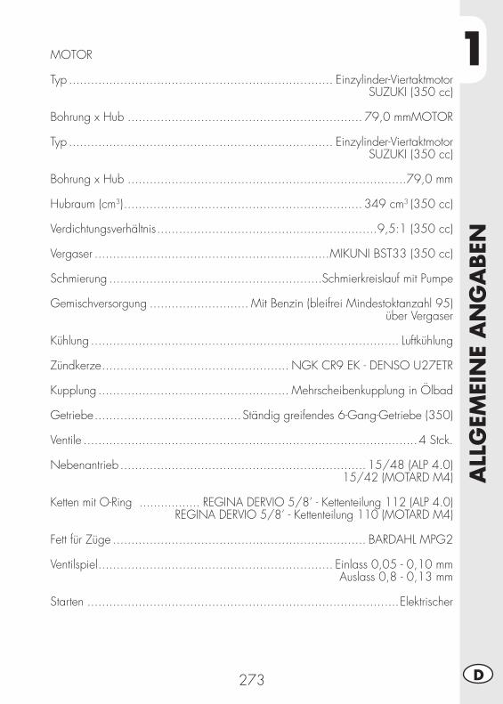
1
ALL
GEM
EIN
E A
NG
ABEN
273 D
MOTOR
Typ ........................................................................ Einzylinder-ViertaktmotorSUZUKI (350 cc)
Bohrung x Hub ................................................................ 79,0 mmMOTOR
Typ ........................................................................ Einzylinder-ViertaktmotorSUZUKI (350 cc)
Bohrung x Hub ............................................................................79,0 mm
Hubraum (cm3) ................................................................. 349 cm3 (350 cc)
Verdichtungsverhältnis ............................................................9,5:1 (350 cc)
Vergaser ................................................................MIKUNI BST33 (350 cc)
Schmierung ..........................................................Schmierkreislauf mit Pumpe
Gemischversorgung ........................... Mit Benzin (bleifrei Mindestoktanzahl 95) über Vergaser
Kühlung .................................................................................... Luftkühlung
Zündkerze ................................................... NGK CR9 EK - DENSO U27ETR
Kupplung .................................................... Mehrscheibenkupplung in Ölbad
Getriebe ........................................Ständig greifendes 6-Gang-Getriebe (350)
Ventile ...........................................................................................4 Stck.
Nebenantrieb ................................................................... 15/48 (ALP 4.0)15/42 (MOTARD M4)
Ketten mit O-Ring ................. REGINA DERVIO 5/8’ - Kettenteilung 112 (ALP 4.0)REGINA DERVIO 5/8’ - Kettenteilung 110 (MOTARD M4)
Fett für Züge ..................................................................... BARDAHL MPG2
Ventilspiel ................................................................ Einlass 0,05 - 0,10 mm Auslass 0,8 - 0,13 mm
Starten .....................................................................................Elektrischer
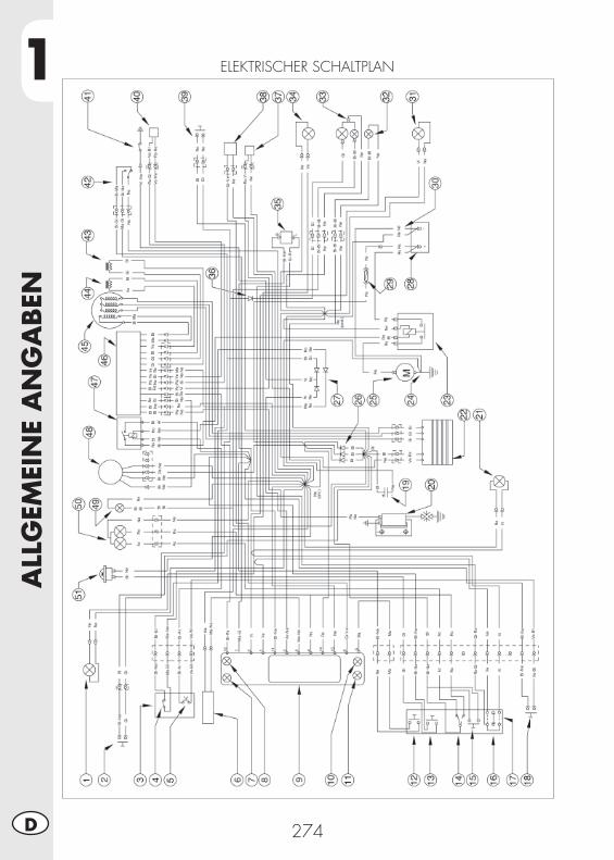
1A
LLG
EMEI
NE
AN
GA
BEN
274D
ELEKTRISCHER SCHALTPLAN
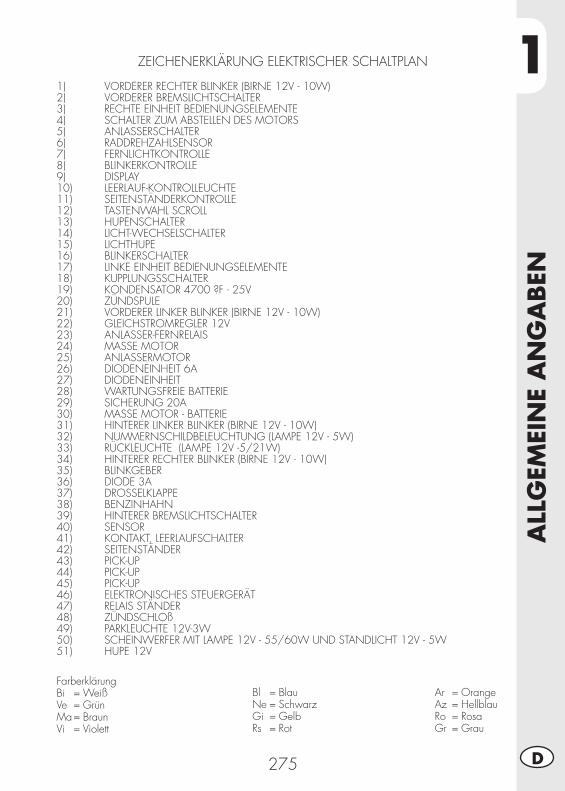
1
ALL
GEM
EIN
E A
NG
ABEN
275 D
ZEICHENERKLÄRUNG ELEKTRISCHER SCHALTPLAN
1) VORDERER RECHTER BLINKER (BIRNE 12V - 10W)2) VORDERER BREMSLICHTSCHALTER3) RECHTE EINHEIT BEDIENUNGSELEMENTE4) SCHALTER ZUM ABSTELLEN DES MOTORS5) ANLASSERSCHALTER6) RADDREHZAHLSENSOR7) FERNLICHTKONTROLLE8) BLINKERKONTROLLE9) DISPLAY10) LEERLAUF-KONTROLLEUCHTE11) SEITENSTÄNDERKONTROLLE12) TASTENWAHL SCROLL13) HUPENSCHALTER14) LICHT-WECHSELSCHALTER15) LICHTHUPE16) BLINKERSCHALTER17) LINKE EINHEIT BEDIENUNGSELEMENTE18) KUPPLUNGSSCHALTER19) KONDENSATOR 4700 ?F - 25V 20) ZÜNDSPULE21) VORDERER LINKER BLINKER (BIRNE 12V - 10W)22) GLEICHSTROMREGLER 12V23) ANLASSER-FERNRELAIS24) MASSE MOTOR25) ANLASSERMOTOR26) DIODENEINHEIT 6A27) DIODENEINHEIT28) WARTUNGSFREIE BATTERIE29) SICHERUNG 20A30) MASSE MOTOR - BATTERIE31) HINTERER LINKER BLINKER (BIRNE 12V - 10W) 32) NUMMERNSCHILDBELEUCHTUNG (LAMPE 12V - 5W)33) RÜCKLEUCHTE (LAMPE 12V -5/21W)34) HINTERER RECHTER BLINKER (BIRNE 12V - 10W)35) BLINKGEBER36) DIODE 3A 37) DROSSELKLAPPE38) BENZINHAHN39) HINTERER BREMSLICHTSCHALTER40) SENSOR41) KONTAKT, LEERLAUFSCHALTER42) SEITENSTÄNDER43) PICK-UP44) PICK-UP45) PICK-UP46) ELEKTRONISCHES STEUERGERÄT47) RELAIS STÄNDER48) ZÜNDSCHLOß49) PARKLEUCHTE 12V-3W50) SCHEINWERFER MIT LAMPE 12V - 55/60W UND STANDLICHT 12V - 5W51) HUPE 12V
FarberklärungBi = WeißVe = GrünMa = BraunVi = Violett
Bl = BlauNe = SchwarzGi = GelbRs = Rot
Ar = OrangeAz = HellblauRo = RosaGr = Grau
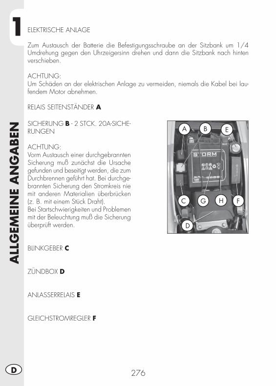
1A
LLG
EMEI
NE
AN
GA
BEN
276D
ELEKTRISCHE ANLAGE
Zum Austausch der Batterie die Befestigungsschraube an der Sitzbank um 1/4 Umdrehung gegen den Uhrzeigersinn drehen und dann die Sitzbank nach hinten verschieben.
ACHTUNG:Um Schäden an der elektrischen Anlage zu vermeiden, niemals die Kabel bei lau-fendem Motor abnehmen.
RELAIS SEITENSTÄNDER A
SICHERUNG B - 2 STCK. 20A-SICHE-RUNGEN
ACHTUNG:Vorm Austausch einer durchgebrannten Sicherung muß zunächst die Ursache gefunden und beseitigt werden, die zum Durchbrennen geführt hat. Bei durchge-brannten Sicherung den Stromkreis nie mit anderen Materialien überbrücken (z. B. mit einem Stück Draht).Bei Startschwierigkeiten und Problemen mit der Beleuchtung muß die Sicherung überprüft werden.
BLINKGEBER C
ZÜNDBOX D
ANLASSERRELAIS E
GLEICHSTROMREGLER F
A B E
C G H F
D
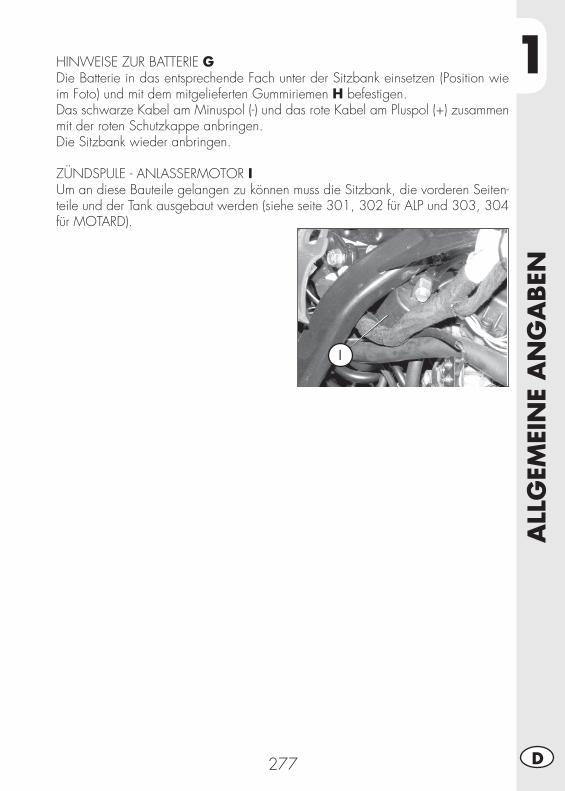
1
ALL
GEM
EIN
E A
NG
ABEN
277 D
HINWEISE ZUR BATTERIE GDie Batterie in das entsprechende Fach unter der Sitzbank einsetzen (Position wie im Foto) und mit dem mitgelieferten Gummiriemen H befestigen.Das schwarze Kabel am Minuspol (-) und das rote Kabel am Pluspol (+) zusammen mit der roten Schutzkappe anbringen.Die Sitzbank wieder anbringen.
ZÜNDSPULE - ANLASSERMOTOR IUm an diese Bauteile gelangen zu können muss die Sitzbank, die vorderen Seiten-teile und der Tank ausgebaut werden (siehe seite 301, 302 für ALP und 303, 304 für MOTARD).
I
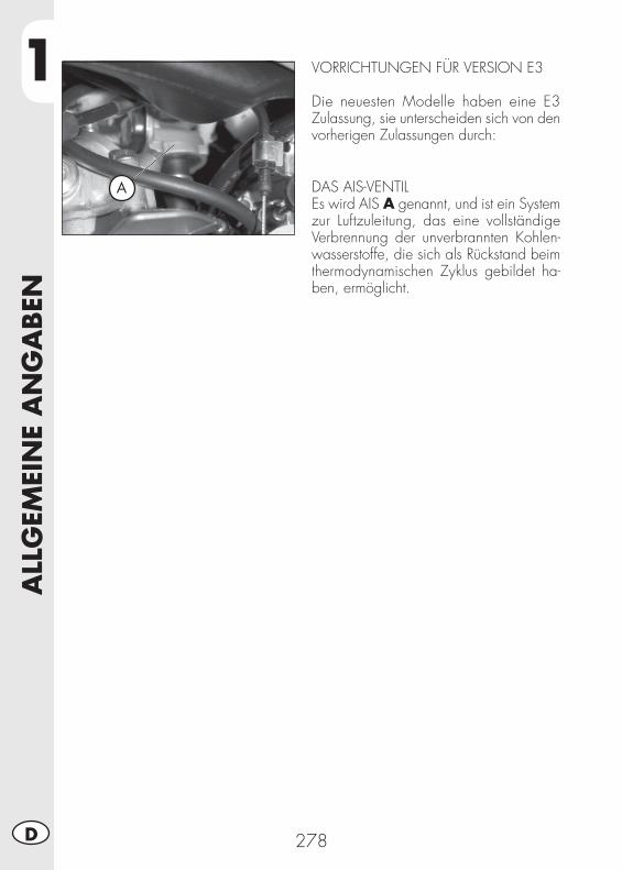
1A
LLG
EMEI
NE
AN
GA
BEN
278D
A
VORRICHTUNGEN FÜR VERSION E3
Die neuesten Modelle haben eine E3 Zulassung, sie unterscheiden sich von den vorherigen Zulassungen durch:
DAS AIS-VENTILEs wird AIS A genannt, und ist ein System zur Luftzuleitung, das eine vollständige Verbrennung der unverbrannten Kohlen-wasserstoffe, die sich als Rückstand beim thermodynamischen Zyklus gebildet ha-ben, ermöglicht.
2
BED
IEN
UN
GSV
ORSC
HRIF
TEN
279 D
INHALTSVERZEICHNIS
KAPITEL 2 BEDIENUNGSVORSCHRIFTEN
Kontrollen und Wartung vor und nach Einsatz im Gelände
Empfohlene Schmiermittel
Einfahren
Starten des Motors
Abstellen des Motors
Tanken
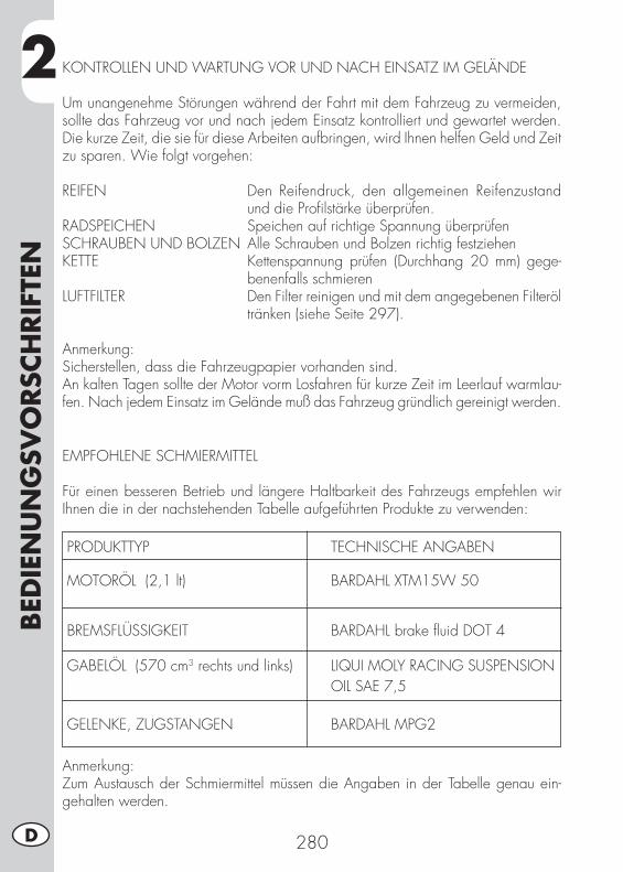
2BED
IEN
UN
GSV
ORSC
HRIF
TEN
280D
KONTROLLEN UND WARTUNG VOR UND NACH EINSATZ IM GELÄNDE
Um unangenehme Störungen während der Fahrt mit dem Fahrzeug zu vermeiden, sollte das Fahrzeug vor und nach jedem Einsatz kontrolliert und gewartet werden. Die kurze Zeit, die sie für diese Arbeiten aufbringen, wird Ihnen helfen Geld und Zeit zu sparen. Wie folgt vorgehen:
REIFEN Den Reifendruck, den allgemeinen Reifenzustand und die Profi lstärke überprüfen.
RADSPEICHEN Speichen auf richtige Spannung überprüfenSCHRAUBEN UND BOLZEN Alle Schrauben und Bolzen richtig festziehenKETTE Kettenspannung prüfen (Durchhang 20 mm) gege-
benenfalls schmierenLUFTFILTER Den Filter reinigen und mit dem angegebenen Filteröl
tränken (siehe Seite 297).
Anmerkung:Sicherstellen, dass die Fahrzeugpapier vorhanden sind.An kalten Tagen sollte der Motor vorm Losfahren für kurze Zeit im Leerlauf warmlau-fen. Nach jedem Einsatz im Gelände muß das Fahrzeug gründlich gereinigt werden.
EMPFOHLENE SCHMIERMITTEL
Für einen besseren Betrieb und längere Haltbarkeit des Fahrzeugs empfehlen wir Ihnen die in der nachstehenden Tabelle aufgeführten Produkte zu verwenden:
PRODUKTTYP TECHNISCHE ANGABEN
MOTORÖL (2,1 lt) BARDAHL XTM15W 50
BREMSFLÜSSIGKEIT BARDAHL brake fl uid DOT 4 GABELÖL (570 cm3 rechts und links) LIQUI MOLY RACING SUSPENSION OIL SAE 7,5
GELENKE, ZUGSTANGEN BARDAHL MPG2
Anmerkung:Zum Austausch der Schmiermittel müssen die Angaben in der Tabelle genau ein-gehalten werden.
2
BED
IEN
UN
GSV
ORSC
HRIF
TEN
281 D
EINFAHREN
Die Einfahrzeit dauert ungefähr 10 Be-triebsstunden, während dieser Zeit müs-sen folgenden Vorschriften eingehalten werden:• Den Motor vorm Losfahren warmlaufen lassen;
• Fahrten mit gleichbleibender Geschwin-digkeit vermeiden. Bei Geschwindigkeits-änderungen spielen sich die mechani-schen Bauteile schneller und gleichmäßi-ger ein.
• Den Gasgriff nicht mehr als 3/4 Umdre-hung öffnen;
ACHTUNG:Nach den ersten 1000 Km muß das Getrie-beöl gewechselt werden.
HINWEIS:Nach 1000 km Fahrtstrecke prüfen, ob der Metallfi lter am Endteil des Öltanks sauber ist (siehe Seite 288). Andernfalls mit einem Pressluftstrahl reinigen.
• Ausschließlich bleifreies Superbenzin tanken.
• Nach dem ersten Einsatz im Gelände alle Schrauben und Bolzen über-prüfen.
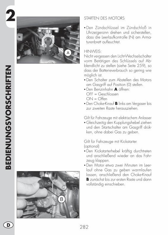
2BED
IEN
UN
GSV
ORSC
HRIF
TEN
282D
STARTEN DES MOTORS
• Den Zündschlüssel im Zündschloß in Uhrzeigersinn drehen und sicherstellen, dass die Leerlaufkontrolle (N) am Arma-turenbrett aufl euchtet.
HINWEIS:Nicht vergessen den Licht-Wechselschalter vorm Betätigen des Schlüssels auf Ab-blendlicht zu stellen (siehe Seite 259), so dass der Batterieverbrauch so gering wie möglich ist. • Den Schalter zum Abstellen des Motors am Gasgriff auf Position (0) stellen.
• Den Benzinhahn A öffnen: OFF = Geschlossen ON = Offen• Den Choke-Knauf B links am Vergaser bis zur zweiten Raste herausziehen.
Gilt für Fahrzeuge mit elektrischem Anlasser• Gleichzeitig den Kupplungshebel ziehen und den Startschalter am Gasgriff drük-ken, ohne dabei Gas zu geben.
Gilt für Fahrzeuge mit Kickstarter(optional)• Den Kickstarterhebel kräftig durchtreten und anschließend wieder an das Fahr-zeug klappen.
• Den Motor etwa zwei Minuten im Leer-lauf ohne Gas zu geben warmlaufen lassen, anschließend den Choke-Knauf B zunächst bis zur ersten Raste und dann vollständig einschieben.
A
2
BED
IEN
UN
GSV
ORSC
HRIF
TEN
283 D
Anmerkung:Der Motor kann auch mit abgeklapptem Seitenständer gestartet werden, allerdings muß dabei der Leerlauf (N) eingelegt sein.
Anmerkung:Im Notfall funktioniert dieses Fahrzeug auch ohne Batterie.
ABSTELLEN DES MOTORS
• Im Stand und im Leerlauf den Zündschlüs-sel auf “OFF” drehen.
• Nach längerer Fahrt raten wir Ihnen den Motor vorm Abstellen einen kurzen Moment im Leerlauf laufen zu lassen.
• Nach Abstellen des Motors stets den Benzinhahn schließen.
ACHTUNG:Das Fahrzeug ist mit einer Beleuchtungs-anlage ausgestattet, die immer ange-schaltet ist. D. h. wird das Fahrzeug mit dem RUN-OFF Schalter rechts am Lenker ausgeschaltet, bleibt die Beleuchtung eingeschaltet. In diesem Fall kann sich die Batterie vorzeitig entladen.
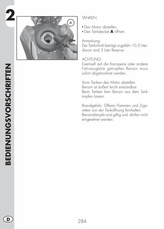
2BED
IEN
UN
GSV
ORSC
HRIF
TEN
284D
TANKEN
• Den Motor abstellen.• Den Tankdeckel A öffnen.
Anmerkung:Der Tankinhalt beträgt ungefähr 10,5 Liter, davon sind 3 Liter Reserve.
ACHTUNG:Eventuell auf die Karosserie oder andere Fahrzeugteile getropftes Benzin muss sofort abgetrocknet werden.
Vorm Tanken den Motor abstellen.Benzin ist äußert leicht entzündbar.Beim Tanken kein Benzin aus dem Tank tropfen lassen.
Brandgefahr. Offene Flammen und Ziga-retten von der Tanköffnung fernhalten.Benzindämpfe sind giftig und dürfen nicht eingeatmet werden.
A
3
WA
RTU
NG
UN
D K
ON
TRO
LLEN
285 D
INHALTSVERZEICHNIS
KAPITEL 3 WARTUNG UND KONTROLLEN
Kontrolle motorölstand
Wechsel von motoröl und Ölfi lter
Leitung Öldampfsammlung
Bremsfl üssigkeit, entlüften der bremsen
Gabelöl
Luftfi lter
Zündkerze
Vorderradbremse
Hinterradbremse
Vergaser
Batterie
Ausbau der plastikteile für ALP
Ausbau der plastikteile für MOTARD M4
Hinweise für Geländefahrten
Wechseln der endantriebseinheit
Fahrzeugpfl ege und Kontrollen
Kontrollen nach der Fahrzeugpfl ege
Wartungsprogramm
Längeres Stilllegen des Fahrzeugs
Nach längerem Stillegen des Fahrzeugs
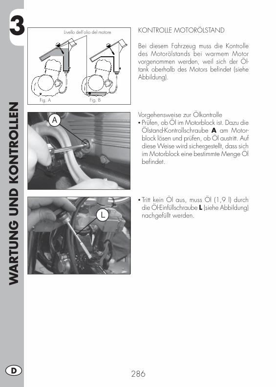
3W
ARTU
NG
UN
D K
ON
TRO
LLEN
286D
KONTROLLE MOTORÖLSTAND
Bei diesem Fahrzeug muss die Kontrolle des Motorölstands bei warmem Motor vorgenommen werden, weil sich der Öl-tank oberhalb des Motors befi ndet (siehe Abbildung).
Fig. A
Livello dell’olio del motore
Fig. B
Vorgehensweise zur Ölkontrolle• Prüfen, ob Öl im Motorblock ist. Dazu die Ölstand-Kontrollschraube A am Motor-block lösen und prüfen, ob Öl austritt. Auf diese Weise wird sichergestellt, dass sich im Motorblock eine bestimmte Menge Öl befi ndet.
• Tritt kein Öl aus, muss Öl (1,9 l) durch die Öl-Einfüllschraube L (siehe Abbildung) nachgefüllt werden.
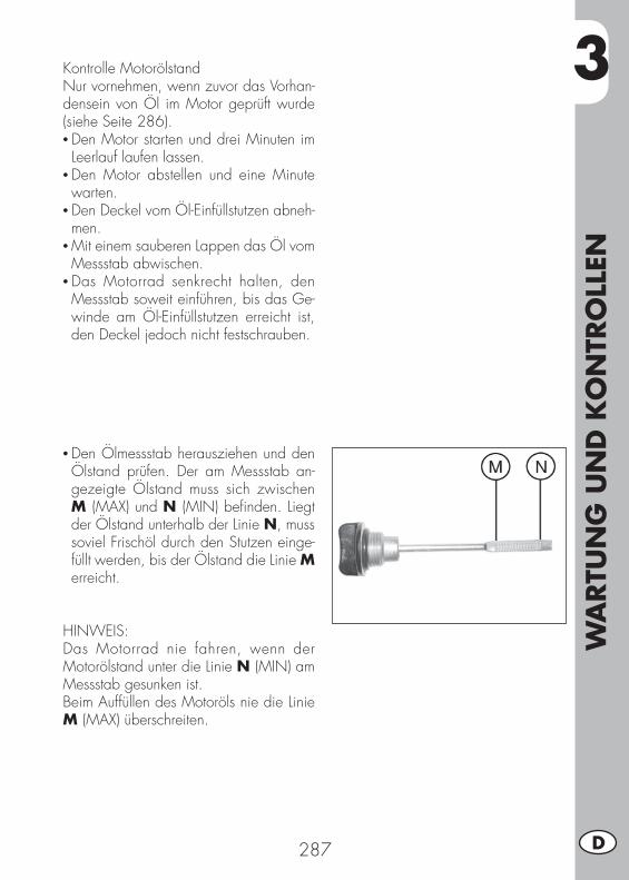
3
WA
RTU
NG
UN
D K
ON
TRO
LLEN
287 D
Kontrolle MotorölstandNur vornehmen, wenn zuvor das Vorhan-densein von Öl im Motor geprüft wurde (siehe Seite 286).• Den Motor starten und drei Minuten im Leerlauf laufen lassen.
• Den Motor abstellen und eine Minute warten.
• Den Deckel vom Öl-Einfüllstutzen abneh-men.
• Mit einem sauberen Lappen das Öl vom Messstab abwischen.
• Das Motorrad senkrecht halten, den Messstab soweit einführen, bis das Ge-winde am Öl-Einfüllstutzen erreicht ist, den Deckel jedoch nicht festschrauben.
• Den Ölmessstab herausziehen und den Ölstand prüfen. Der am Messstab an-gezeigte Ölstand muss sich zwischen M (MAX) und N (MIN) befi nden. Liegt der Ölstand unterhalb der Linie N, muss soviel Frischöl durch den Stutzen einge-füllt werden, bis der Ölstand die Linie M erreicht.
HINWEIS:Das Motorrad nie fahren, wenn der Motorölstand unter die Linie N (MIN) am Messstab gesunken ist.Beim Auffüllen des Motoröls nie die Linie M (MAX) überschreiten.

3W
ARTU
NG
UN
D K
ON
TRO
LLEN
288D
WECHSEL VON MOTORÖL UND ÖLFILTER
Das Motoröl muß bei warmem Motor gewechselt werden. Beim Ölwechsel den Motor nicht berühren, Verbrennungsge-fahr.
• Der Ölfi lter muß beim Ölwechsel eben-falls ausgetauscht werden.
• Das Motorrad auf den Ständer stellen.• Einen Behälter zum Auffangen des Altöls unter dem Motor aufstellen.
• Die Einfüllschraube L und die Ablaß-schraube F abschrauben.
• Das Öl vollständig aus dem Gehäuse abfl ießen lassen.
Wechseln des Ölfi lters• Die drei Befestigungsmuttern G am Fil-terdeckel lösen und den Ölfi lterdeckel entfernen.
• Den Ölfi lter ausbauen.
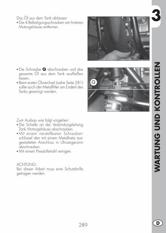
3
WA
RTU
NG
UN
D K
ON
TRO
LLEN
289 D
Das Öl aus dem Tank ablassen• Die 4 Befestigungsschrauben am hinteren Motorgehäuse entfernen.
• Die Schraube Q abschrauben und das gesamte Öl aus dem Tank ausfl ießen lassen.
• Beim ersten Ölwechsel (siehe Seite 281) sollte auch der Metallfi lter am Endteil des Tanks gereinigt werden.
Zum Ausbau wie folgt vorgehen:• Die Schelle an der Verbindungsleitung Tank Motorgehäuse abschrauben.
• Mit einem verstellbaren Schrauben-schlüssel den mit einem Metallnetz aus-gestatteten Anschluss in Uhrzeigersinn abschrauben.
• Mit einem Pressluftstrahl reinigen.
ACHTUNG:Bei dieser Arbeit muss eine Schutzbrille getragen werden.
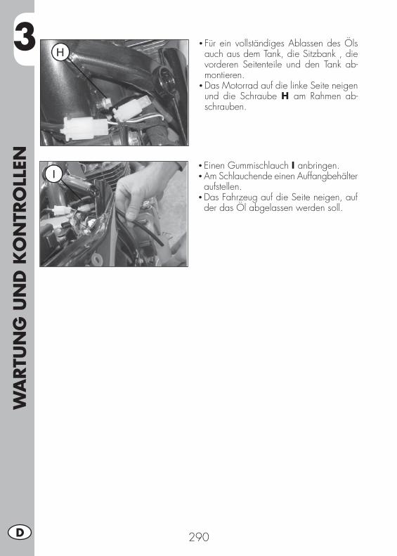
3W
ARTU
NG
UN
D K
ON
TRO
LLEN
290D
• Für ein vollständiges Ablassen des Öls auch aus dem Tank, die Sitzbank , die vorderen Seitenteile und den Tank ab-montieren.
• Das Motorrad auf die linke Seite neigen und die Schraube H am Rahmen ab-schrauben.
• Einen Gummischlauch I anbringen.• Am Schlauchende einen Auffangbehälter aufstellen.
• Das Fahrzeug auf die Seite neigen, auf der das Öl abgelassen werden soll.
3
WA
RTU
NG
UN
D K
ON
TRO
LLEN
291 D
Einbau• Beim Einbau in umgekehrter Reihenfolge wie beim Ausbau des Metall-Netzfi lters am Öltank vorgehen.
• Einen neuen Ölfi lter einsetzen.• Die Feder und den O-Ring anbringen und den Filterdeckel mit den drei Muttern befestigen.
• Die Feder und den O-Ring anbringen, den Ölfi lterdeckel einsetzen und die drei Befestigungsschrauben festziehen.
• Die Öl-Ablassschraube, zusammen mit den beiden Ablassschrauben am Tank, wieder am Motorgehäuse anbringen (gegebenenfalls neue Dichtungen verwen-den).
• Die richtige Ölmenge einfüllen. Benötigte Ölmenge: Ölwechsel ............................... 1,9 lt Öl- und Filterwechsel ................. 2,1 lt Motorrevision ........................... 2,3 lt
• Die Öl-Einfüllschraube festschrauben..• Den Motor starten und einige Minuten laufen lassen.
• Den Motor wieder abstellen und ungefähr eine Minute warten, anschließend den Ölstand überprüfen und gegebenenfalls etwas Motoröl nachfüllen, die Markierung MAX darf nie überschritten werden.
Anmerkung:Nach den ersten 1.000 gefahrenen Kilome-tern muss das Motoröl gewechselt werden. Anschließend muss das Motoröl alle 4.000 km (15 Monate), dabei ausschließlich die auf Seite 280 angegebenen Schmiermittel verwenden.Der Ölfi lter muss beim ersten Ölwechsel und anschließend alle 8000 km (45 Monate) gewechselt werden.
HINWEIS:Das Altöl muß entsprechend der gesetzli-chen Umweltvorschriften entsorgt werden.

3W
ARTU
NG
UN
D K
ON
TRO
LLEN
292D
LEITUNG ÖLDAMPFSAMMLUNG
Die Leitung der Öldampfsammlung A befi ndet sich auf der linken Fahrzeugseite in der Nähe des Stoßdämpfers, kommt Unterseite des Filtergehäuses und sammelt die Motoröldämpfe. Sobald sich Öl in dieser Leitung befi ndet, muß diese geleert werden. Dazu den Verschluß am unteren Ende der Leitung abnehmen und das aus-fl ießende Öl bzw. Benzin- Ölgemisch in einem geeigneten Behälter auffangen. Das Altöl muß entsprechend der gesetzlichen Umweltvorschriften entsorgt werden.
Anmerkung:Die Leitung muß alle 3.000 km entleert werden.
BREMSFLÜSSIGKEIT, ENTLÜFTEN DER BREMSEN
VorderradbremseDen Bremsfl üssigkeit am Kontrollfenster B überprüfen. Der Bremsfl üssigkeitsstand darf nie unter die entsprechende Mar-kierung am Kontrollfenster B abfallen. Zum Nachfüllen der Bremsfl üssigkeit die beiden Schrauben C lösen, den Deckel D anheben und die Bremsfl üssigkeit einfüllen.Das Fahrzeug fest und senkrecht halten, möglichst den Lenker blockieren, um zu vermeiden, dass Bremsfl üssigkeit austritt.
B
C
D

3
WA
RTU
NG
UN
D K
ON
TRO
LLEN
293 D
Hinterradbremse
Den Bremsflüssigkeitsstand am Brems-flüssigkeitsbehälter E überprüfen. Der Bremsfl üssigkeitsstand darf nie unter die Markierung des Mindeststands am Brems-fl üssigkeitsbehälter F abfallen. Gegebe-nenfalls den Bremsfl üssigkeitsstand wie folgt auffüllen:
• Mit einem geeigneten Schlussel die Befestigungsschraube des Bremsfl ussig-keitsbehalters abschrauben G.
• Den Bremsfl üssigkeitsbehälter aus seinem Sitz herausziehen.
• Den Deckel öffnen. Dabei darauf ach-ten, dass der Bremsfl üssigkeitsbehälter senkrecht gehalten wird.
• Wie in der Abbildung gezeigt in saugfä-higes Papier wickeln.
• Die Bremsfl üssigkeit nachfüllen.
ACHTUNG:Die Bremsfl üssigkeit ist stark ätzend. Unbe-dingt darauf achten, dass keine Bremsfl üs-sigkeit auf lackierte Fahrzeugteile tropft.
ACHTUNG:Gibt der Bremshebel bei Betätigung nach, können sich Luftblasen im Bremskreislauf befi nden. In diesem Fall müssen die Brem-sen entlüftet werden (Seite 294/295), oder wenden Sie sich so bald wie möglich an eine Vertragswerkstatt.
Anmerkung:Zum Wechseln der Bremsfl üssigkeit bitte die Angaben in der Tabelle aus Seite 309 einhalten. Die in der Tabelle auf Seite 280 angegebenen Schmiermittel und Flüssigkei-ten verwenden.
E
F
G

3W
ARTU
NG
UN
D K
ON
TRO
LLEN
294D
Entlüften der Vorderradbremse
Zum Entlüften der Vorderradbremse wie folgt vorgehen:
• Die Gummikappe A vom Entlüftungsventil B abnehmen.
• Den Deckel vom Bremsfl üssigkeitsbehälter abnehmen.
• Einen Schlauch auf das Entlüftungsventil B aufsetzen, das andere Schlauchende in einen Behälter leiten.
• Das Ventil B (bei gezogenem Bremshebel) losschrauben und mit dem Bremshebel solange pumpen, bis nur noch Bremsfl üs-sigkeit ohne Luftblasen austritt. Wichtig, bei dieser Arbeit den Bremshebel niemals vollständig loslassen und ständig Brems-fl üssigkeit nachfüllen, um die austretende Bremsfl üssigkeit zu ersetzen.
• Das Entlüftungsventil wieder festschrau-ben und den Schlauch abnehmen.
• Die Gummikappe wieder aufsetzen.
MOTARD
B
A
ALP A
B
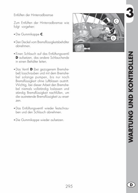
3
WA
RTU
NG
UN
D K
ON
TRO
LLEN
295 D
Entlüften der Hinterradbremse
Zum Entlüften der Hinterradbremse wie folgt vorgehen:
• Die Gummikappe C.
• Den Deckel vom Bremsfl üssigkeitsbehälter abnehmen.
• Einen Schlauch auf das Entlüftungsventil D aufsetzen, das andere Schlauchende in einen Behälter leiten.
• Das Ventil D (bei gezogenem Bremshe-bel) losschrauben und mit dem Bremshe-bel solange pumpen, bis nur noch Bremsfl üssigkeit ohne Luftblasen austritt. Wichtig, bei dieser Arbeit den Bremshe-bel niemals vollständig loslassen und ständig Bremsfl üssigkeit nachfüllen, um die austretende Bremsfl üssigkeit zu erset-zen.
• Das Entlüftungsventil wieder festschrau-ben und den Schlauch abnehmen.
• Die Gummikappe wieder aufsetzen.
D
C

3W
ARTU
NG
UN
D K
ON
TRO
LLEN
296D
GABELÖLRechter/Linker GabelschaftDie Beschreibung zum Wechseln des Gabelöl hat rein informativen Charakter. Wir empfehlen Ihnen sich zum Austausch des Gabelöl an den BETAMOTOR-Kunden-dienst zu wenden.Zum Austausch des Gabelöls wie folgt vorgehen:1) Die vier Befestigungsschrauben C der
beiden Bügelschrauben D abschrau-ben und den Lenker entfernen.
2) Die Befestigungsschrauben des Gabel-schafts B und C lösen.
3) Die untere Verschlussschraube (Inbus-schraube in der Gabelhülse) und die obere Verschlussschraube A abschrau-ben.
4) Das Gabelöl vollständig ausfließen lassen.
5) Die untere Verschlussschraube in der Gabelhülse wieder festschrauben.
6) Das in der Tabelle auf Seite 280 an-gegebenen Gabelöl einfüllen.
7) Den oberen Verschluß A wieder schließen.
8) In der angegebenen Reihenfolge fest-ziehen: zuerst die Schraube B, dann die Schraube C und die neue Schraube B.
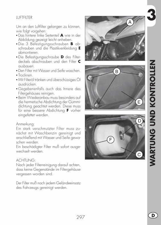
3
WA
RTU
NG
UN
D K
ON
TRO
LLEN
297 D
LUFTFILTER
Um an den Luftfi lter gelangen zu können, wie folgt vorgehen:• Das hintere linke Seitenteil A wie in der Abbildung gezeigt leicht anheben.
• Die 3 Befestigungsschrauben B ab-schrauben und die Plastikverkleidung E abmontieren.
• Die Befestigungsschraube D des Filter-deckels abschrauben und den Filter C ausbauen.
• Den Filter mit Wasser und Seife waschen.• Trocknen.• Mit Filteröl tränken und überschüssiges Öl ausdrücken.
• Gegebenenfalls auch das Innere des Filtergehäuses reinigen.
• Beim Wiederanbau muss besonders auf die hermetische Abdichtung der Gummi-dichtung geachtet werden. Diese muss für eine bessere Abdichtung F vorher eingefettet werden.
Anmerkung:Ein stark verschmutzter Filter muss zu-nächst mit Waschbenzin gereinigt und anschließend mit Wasser und Seife gewa-schen werden.Ein beschädigter Filter muß sofort ausge-wechselt werden.
ACHTUNG:Nach jeder Filterreinigung darauf achten, dass keine Gegenstände im Filtergehäuse vergessen worden sind.
Der Filter muß nach jedem Geländeeinsatz des Fahrzeugs gereinigt werden.
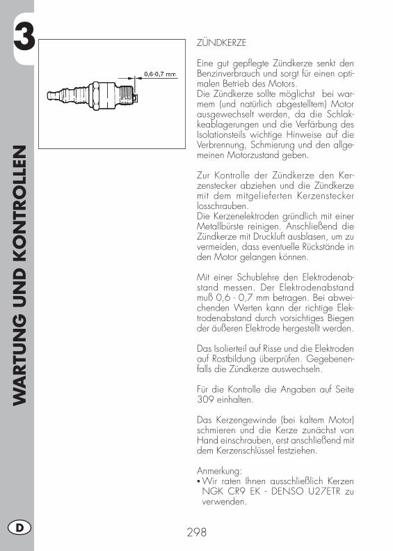
3W
ARTU
NG
UN
D K
ON
TRO
LLEN
298D
ZÜNDKERZE
Eine gut gepfl egte Zündkerze senkt den Benzinverbrauch und sorgt für einen opti-malen Betrieb des Motors.Die Zündkerze sollte möglichst bei war-mem (und natürlich abgestelltem) Motor ausgewechselt werden, da die Schlak-keablagerungen und die Verfärbung des Isolationsteils wichtige Hinweise auf die Verbrennung, Schmierung und den allge-meinen Motorzustand geben.
Zur Kontrolle der Zündkerze den Ker-zenstecker abziehen und die Zündkerze mit dem mitgelieferten Kerzenstecker losschrauben.Die Kerzenelektroden gründlich mit einer Metallbürste reinigen. Anschließend die Zündkerze mit Druckluft ausblasen, um zu vermeiden, dass eventuelle Rückstände in den Motor gelangen können.
Mit einer Schublehre den Elektrodenab-stand messen. Der Elektrodenabstand muß 0,6 - 0,7 mm betragen. Bei abwei-chenden Werten kann der richtige Elek-trodenabstand durch vorsichtiges Biegen der äußeren Elektrode hergestellt werden.
Das Isolierteil auf Risse und die Elektroden auf Rostbildung überprüfen. Gegebenen-falls die Zündkerze auswechseln.
Für die Kontrolle die Angaben auf Seite 309 einhalten.
Das Kerzengewinde (bei kaltem Motor) schmieren und die Kerze zunächst von Hand einschrauben, erst anschließend mit dem Kerzenschlüssel festziehen.
Anmerkung:• Wir raten Ihnen ausschließlich Kerzen NGK CR9 EK - DENSO U27ETR zu verwenden.

3
WA
RTU
NG
UN
D K
ON
TRO
LLEN
299 D
VORDERRADBREMSE
KontrolleUm den Verschleißzustand der Vorderrad-bremse zu überprüfen, reicht es aus den Bremssattel von der Vorderseite her zu betrachten. Von dort aus sieht man die beiden Bremsbeläge, die eine Belagstärke von mindestens 2 mm haben müssen. Bei geringerer Belagstärke müssen die Brem-sbeläge sofort ausgewechselt werden.
Anmerkung:Für die Kontrolle müssen die auf Seite 309 angegebenen Zeitabstände und Kilometerleistungen beachtet werden.
HINTERRADBREMSE
KontrolleUm den Verschleißzustand der Hinter-radbremse zu überprüfen, reicht es aus den Bremssattel von der oben her zu betrachten. Von dort aus sieht man die beiden Bremsbeläge, die eine Belagstärke von mindestens 2 mm haben müssen. Bei geringerer Belagstärke müssen die Brem-sbeläge sofort ausgewechselt werden.
Anmerkung:Für die Kontrolle müssen die auf Seite 309 angegebenen Zeitabstände und Kilometerleistungen beachtet werden.
ALP
MOTARD

3W
ARTU
NG
UN
D K
ON
TRO
LLEN
300D
VERGASER
Damit der Vergaser jederzeit bestens funktioniert, muß er gründlich gereinigt werden.Den Vergaser aus dem Fahrzeug ausbau-en.Die zwei Schrauben A entfernen und die Vergaserwanne ausbauen. Die rich-tige Schwimmerposition überprüfen. Das Schwimmerblech muß, wie in der Abbil-dung gezeigt, parallel zum Vergaserge-häuse stehen. Überprüfen, ob die Düsen sauber sind.
HINWEIS:Diese Beschreibungen haben rein infor-mativen Charakter. Für diese Arbeiten sollten Sie sich an einen BETAMOTOR-Kundendienst wenden.
BATTERIE
Den Ladezustand der Batterie überprüfen. Dazu die Batteriespannung bei abgestel-ltem Fahrzeug und nicht laufendem Motor mit einem Spannungsmeter messen. Die Batteriespannung darf nicht weniger als 12,8V betragen.Falls die Batterie erschöpft ist, verwenden Sie ein Ladegerät; schalten Sie die Batterie aus (wenn es möglich wäre, bitte nehmen Sie die Batterie aus dem Fahrzeug weg!) und laden Sie nach unseren Bedienung-sanleitungen nach.
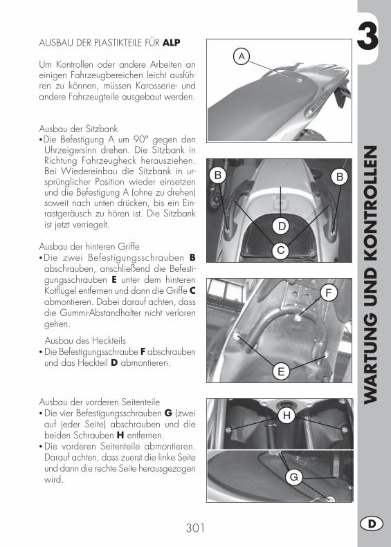
3
WA
RTU
NG
UN
D K
ON
TRO
LLEN
301 D
AUSBAU DER PLASTIKTEILE FÜR ALP
Um Kontrollen oder andere Arbeiten an einigen Fahrzeugbereichen leicht ausfüh-ren zu können, müssen Karosserie- und andere Fahrzeugteile ausgebaut werden.
Ausbau der Sitzbank•Die Befestigung A um 90° gegen den Uhrzeigersinn drehen. Die Sitzbank in Richtung Fahrzeugheck herausziehen. Bei Wiedereinbau die Sitzbank in ur-sprünglicher Position wieder einsetzen und die Befestigung A (ohne zu drehen) soweit nach unten drücken, bis ein Ein-rastgeräusch zu hören ist. Die Sitzbank ist jetzt verriegelt.
Ausbau der hinteren Griffe•Die zwei Befestigungsschrauben B abschrauben, anschließend die Befesti-gungsschrauben E unter dem hinteren Kotfl ügel entfernen und dann die Griffe C abmontieren. Dabei darauf achten, dass die Gummi-Abstandhalter nicht verloren gehen.
Ausbau des Heckteils• Die Befestigungsschraube F abschrauben und das Heckteil D abmontieren.
Ausbau der vorderen Seitenteile• Die vier Befestigungsschrauben G (zwei auf jeder Seite) abschrauben und die beiden Schrauben H entfernen.
• Die vorderen Seitenteile abmontieren. Darauf achten, dass zuerst die linke Seite und dann die rechte Seite herausgezogen wird.
A
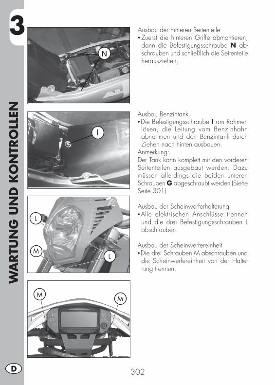
3W
ARTU
NG
UN
D K
ON
TRO
LLEN
302D
Ausbau der hinteren Seitenteile• Zuerst die hinteren Griffe abmontieren, dann die Befestigungsschraube N ab-schrauben und schließlich die Seitenteile herausziehen.
Ausbau Benzintank•Die Befestigungsschraube I am Rahmen lösen, die Leitung vom Benzinhahn abnehmen und den Benzintank durch Ziehen nach hinten ausbauen.
Anmerkung:Der Tank kann komplett mit den vorderen Seitenteilen ausgebaut werden. Dazu müssen allerdings die beiden unteren Schrauben G abgeschraubt werden (Siehe Seite 301).
Ausbau der Scheinwerferhalterung•Alle elektrischen Anschlüsse trennen und die drei Befestigungsschrauben L abschrauben.
Ausbau der Scheinwerfereinheit•Die drei Schrauben M abschrauben und die Scheinwerfereinheit von der Halte-rung trennen.
L
L
M
MM
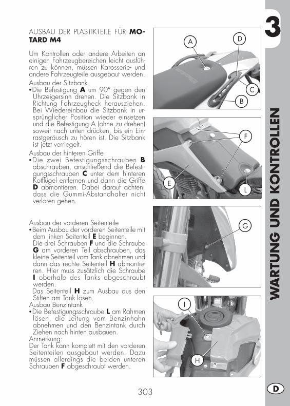
3
WA
RTU
NG
UN
D K
ON
TRO
LLEN
303 D
AUSBAU DER PLASTIKTEILE FÜR MO-TARD M4
Um Kontrollen oder andere Arbeiten an einigen Fahrzeugbereichen leicht ausfüh-ren zu können, müssen Karosserie- und andere Fahrzeugteile ausgebaut werden.Ausbau der Sitzbank•Die Befestigung A um 90° gegen den Uhrzeigersinn drehen. Die Sitzbank in Richtung Fahrzeugheck herausziehen. Bei Wiedereinbau die Sitzbank in ur-sprünglicher Position wieder einsetzen und die Befestigung A (ohne zu drehen) soweit nach unten drücken, bis ein Ein-rastgeräusch zu hören ist. Die Sitzbank ist jetzt verriegelt.
Ausbau der hinteren Griffe•Die zwei Befestigungsschrauben B abschrauben, anschließend die Befesti-gungsschrauben C unter dem hinteren Kotfl ügel entfernen und dann die Griffe D abmontieren. Dabei darauf achten, dass die Gummi-Abstandhalter nicht verloren gehen.
Ausbau der vorderen Seitenteile•Beim Ausbau der vorderen Seitenteile mit dem linken Seitenteil E beginnen.
Die drei Schrauben F und die Schraube G am vorderen Teil abschrauben, das kleine Seitenteil vom Tank abnehmen und dann das rechte Seitenteil H abmontie-ren. Hier muss zusätzlich die Schraube I oberhalb des Tanks abgeschraubt werden.
Das Seitenteil H zum Ausbau aus den Stiften am Tank lösen.
Ausbau Benzintank•Die Befestigungsschraube L am Rahmen lösen, die Leitung vom Benzinhahn abnehmen und den Benzintank durch Ziehen nach hinten ausbauen.
Anmerkung:Der Tank kann komplett mit den vorderen Seitenteilen ausgebaut werden. Dazu müssen allerdings die beiden unteren Schrauben F abgeschraubt werden.
F
G
E
I
H
L
B
A
C
D
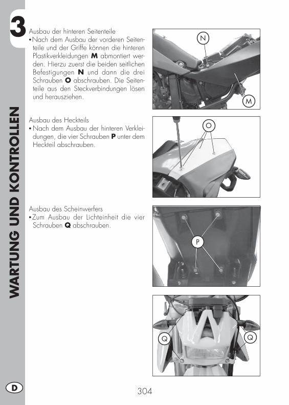
3W
ARTU
NG
UN
D K
ON
TRO
LLEN
304D
Ausbau der hinteren Seitenteile•Nach dem Ausbau der vorderen Seiten-teile und der Griffe können die hinteren Plastikverkleidungen M abmontiert wer-den. Hierzu zuerst die beiden seitlichen Befestigungen N und dann die drei Schrauben O abschrauben. Die Seiten-teile aus den Steckverbindungen lösen und herausziehen.
M
N
OAusbau des Heckteils• Nach dem Ausbau der hinteren Verklei-dungen, die vier Schrauben P unter dem Heckteil abschrauben.
P
Ausbau des Scheinwerfers•Zum Ausbau der Lichteinheit die vier Schrauben Q abschrauben.
Q Q
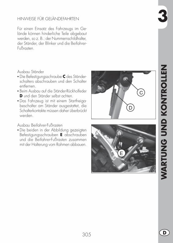
3
WA
RTU
NG
UN
D K
ON
TRO
LLEN
305 D
HINWEISE FÜR GELÄNDEFAHRTEN
Für einen Einsatz des Fahrzeugs im Ge-lände können hinderliche Teile abgebaut werden, so z. B.: der Nummernschildhalter, der Ständer, der Blinker und die Beifahrer-Fußrasten.
Ausbau Ständer• Die Befestigungsschraube C des Ständer-schalters abschrauben und den Schalter entfernen.
• Beim Ausbau auf die Ständer-Rückholfeder D und den Ständer selbst achten.
• Das Fahrzeug ist mit einem Startfreiga-beschalter am Ständer ausgestattet, die Schalterkontakte müssen daher überbrückt werden.
Ausbau Beifahrer-Fußrasten• Die beiden in der Abbildung gezeigten Befestigungsschrauben E abschrauben und die Beifahrer-Fußrasten zusammen mit der Halterung vom Rahmen abbauen.

3W
ARTU
NG
UN
D K
ON
TRO
LLEN
306D
Wechseln der Kette• Mit einem Flachkopfschraubenzieher wie in der Abbildung gezeigt vorgehen.
• Das Kettenschloss such und auf den Zahnkranz einstellen, anschließend die Sperre B am Kettenschloss A entfernen.
• Das Kettenschloss entfernen und die Kette herausziehen.
Anmerkung:Beim Wiedereinbau in umgekehrter Reihenfolge vorgehen, auf das richtige Anbringen der O-Ringe achten. Die Sperre am Kettenschloss muss gegen die Rad-drehrichtung angebracht werden (siehe Abbildung).
WECHSELN DER ENDANTRIEBSEINHEIT
Muss eines der drei Elemente der Endan-triebseinheit (Ritzel, Kette und Zahnkranz) wegen Verschleiß gewechselt werden, sollte stets die gesamte Einheit gewechselt werden.

3
WA
RTU
NG
UN
D K
ON
TRO
LLEN
307 D
Austausch des Kettenritzels• Das Hinterrad lockern.• Die Einstellvorrichtungen der Kette lok-kern.
• Das Hinterrad bis zum Anschlag nach vorne verschieben, so dass sich die Kette lockert.
• Die zwei Befestigungsschrauben F der Abdeckung abschrauben.
Auswechseln des Zahnkranzes• Für das Auswechseln des Zahnkranzes das Hinterrad ausbauen, dazu zuerst die linke und rechte Stellvorrichtungen A und B lösen und anschließend die Radachsmutter C abschrauben.
• Um die Kettenspannung zu lockern, müssen die Räder in Richtung Fahrzeug-Frontseite verschoben werden.
• Die sechs Befestigungsschrauben D des Zahnkranzes abschrauben.
• Beim Wiedereinbau in umgekehrter Reihenfolge wie beim Ausbau vorgehen und Gewindestoppmittel an den sechs Befestigungsschrauben anbringen.
• Den ersten Gang einlegen und den Seegerring G zur Befestigung des Ritzels entfernen.
• Um die Kettenspannung zu lockern, müssen die Räder in Richtung Fahrzeug-Frontseite verschoben werden.
• Das Kettenritzel austauschen.• Beim Wiedereinbau in umgekehrter Rei-henfolge wie beim Ausbau vorgehen.
3W
ARTU
NG
UN
D K
ON
TRO
LLEN
308D
FAHRZEUGPFLEGE UND KONTROLLEN
Zum Aufweichen von Schmutz und Schlamm auf den lackierten Oberfl ächen einen Wasserstrahl benutzen. Ist der Schmutz aufgeweicht, muss er mit einem weichen Schwamm mit viel Wasser und Autoshampoo (2 - 4% Shampoo im Wasser) entfernt werden. Anschließend mit viel Wasser abspülen und mit einem Luftstrahl und einem Lappen oder Wildledertuch trocknen. Den Motor außen mit Petroleum, Pinsel und reinen Lappen säubern. Petroleum schädigt den Lack. Eine Glanzbehandlung darf erst nach erfolgtem Waschen durchgeführt werden.
Die Reinigungsmittel verschmutzen das Wasser. Daher muß die Fahrzeugreini-gung an Orten stattfi nden, die mit einer Anlage zur Waschwasserrückführung und Aufbereitung ausgestattet sind.
Das Fahrzeug nie in praller Sonne waschen. Dies gilt besonders im Sommer, wenn die Karosserie noch warm ist und das Shampoo noch vor dem abspülen antrocknen kann. Dies kann Schäden an der Karosserie verursachen. Benutzen
Sie nie in Benzin oder Öl getränkte Lappen zur Reinigung lackierter Fahrzeugteile, um Glanzverluste und den Verlust mechanischer Eigenschaften zu vermeiden.
KONTROLLEN NACH DER FAHRZEUGPFLEGE
Nach der Fahrzeugpfl ege sollten folgende Kontrollen durchgeführt werden:
• Den Luftfi lter reinigen (siehe Anleitung aus Seite 2297).• Den Vergaser durch Öffnen der Benzin-Ablassschraube entleeren (wie auf Seite 300 angegeben vorgehen), um zu prüfen, ob Wasser enthalten ist.
• Die Kette schmieren.
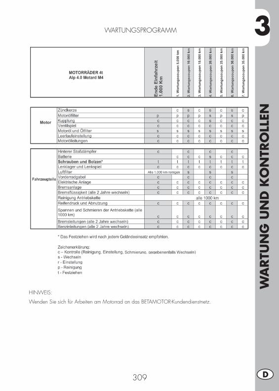
3
WA
RTU
NG
UN
D K
ON
TRO
LLEN
309 D
WARTUNGSPROGRAMM
HINWEIS:
Wenden Sie sich für Arbeiten am Motorrad an das BETAMOTOR-Kundendienstnetz.
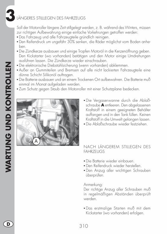
3W
ARTU
NG
UN
D K
ON
TRO
LLEN
310D
LÄNGERES STILLLEGEN DES FAHRZEUGS
Soll der Motorroller längere Zeit stillgelegt werden, z. B. während des Winters, müssen zur richtigen Aufbewahrung einige einfache Vorkehrungen getroffen werden:• Das Fahrzeug und alle Fahrzeugteile gründlich reinigen.• Den Reifendruck um ungefähr 30% senken, die Räder möglichst vom Boden anhe-ben.
• Die Zündkerze ausbauen und einige Tropfen Motoröl in die Kerzenöffnung geben. Den Kickstarter (wo vorhanden) betätigen und den Motor einige Umdrehungen ausführen lassen. Die Zündkerze wieder einschrauben.
• Die elektronische Diebstahlsicherung (wenn vorhanden) abklemmen.• Außer an Gummiteilen und Bremsen auf alle nicht lackierten Fahrzeugteile eine dünne Schicht Silikonöl auftragen.
• Die Batterie ausbauen und an einem Trockenen Ort aufbewahren. Die Batterie muß einmal im Monat aufgeladen werden.
• Zum Schutz gegen Staub den Motorroller mit einer Schutzplane bedecken.
• Die Vergaserwanne durch die Ablaß-schraube A entleeren. Den abgelassenen Kraftstoff in einem geeigneten Behälter auffangen und in den Tank füllen. Keinen Kraftstoff in die Umwelt gelangen lassen.
• Die Ablaßschraube wieder festziehen.
NACH LÄNGEREM STILLEGEN DES FAHRZEUGS
• Die Batterie wieder einbauen.• Den Reifendruck wieder herstellen.• Den Anzug aller wichtigen Schrauben überprüfen.
Anmerkung:Der richtige Anzug aller Schrauben muß in regelmäßigen Abständen überprüft werden.
• Das erstmalige Starten muß mit dem Kickstarter (wo vorhanden) erfolgen.
4
EIN
STEL
LUN
GEN
311 D
INHALTSVERZEICHNIS
KAPITEL 4 EINSTELLUNGEN
Einstellung der bremsen
Einstellung der Kupplung
Einstellung des hinteren Stoßdämpfers
Leerlaufeinstellung
Einstellung des Gaszuges
Kontrolle und Einstellung Lenkerspiel
Spannen der Kette
Einstellung des Scheinwerfers
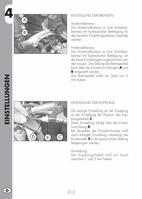
4EI
NST
ELLU
NG
EN
312D
EINSTELLUNG DER BREMSEN
VorderradbremseDie Vorderradbremse ist eine Scheiben-bremse mit hydraulischer Betätigung für die keinerlei Einstellungsarbeiten benötigt werden.
HinterradbremseDie Hinterradbremse ist eine Scheiben-bremse mit hydraulischer Betätigung, an der keine Einstellungen vorgenommen wer-den müssen. Die Stellung des Bremspedals kann über die Einstellvorrichtungen A und B eingestellt werden.Das Bremspedal sollte ein Spiel von 5 mm haben.
EINSTELLUNG DER KUPPLUNG
Die einzige Einstellung an der Kupplung ist die Einstellung der Position des Kup-plungshebels C.Diese Einstellung erfolgt über die Einstel-lvorrichtung D.Bei Verstellen der Einstellschraube muß nach erfolgter Einstellung unbedingt die Kontermutter E in der gewünschten Stellung festgezogen werden.
Anmerkung:Der Kupplungshebel muß ein Spiel zwischen 1 und 2 mm haben.

4
EIN
STEL
LUN
GEN
313 D
EINSTELLUNG DES HINTEREN STOSSDÄM-PFERSFür die Einstellung der Federvorspannung zuerst den Konter-Gewindering A verstel-len, so dass der Gewinde-Einstellungsring B gelöst wird.Nachdem die optimale Einstellung gefun-den wurde, den Gewindering B und den Konter-Gewindering A festziehen.
ACHTUNG:Für die Einstellung des hinteren Stoßdäm-pfers ALP 4.0 beachten, dass die Federlän-ge bei Standard-Vorspannung 194 mm be-trägt. Beim Fahrzeug MOTARD M4 beträgt die Federlänge am hinteren Stoßdämpfer bei Standard-Vorspannung 235 mm.
LEERLAUFEINSTELLUNG
Um den Leerlauf richtig einzustellen, muß diese Arbeit bei warmem Motor ausgeführt werden. Einen elektronischen Drehzahl-messer an das Zündkabel anschließen. Die Leerlaufdrehzahl über die Leerlauf-Einstellschraube A auf einen Wert von 1.500 ± 100 U/min einstellen.
EINSTELLUNG DES GASZUGES
Hat der Gasgriff ein Spiel von mehr als 3 mm (gemessen am oberen Rand des Ga-sgriffs), muß das Spiel über die Einstellvor-richtung B am Gasgriff eingestellt werden.
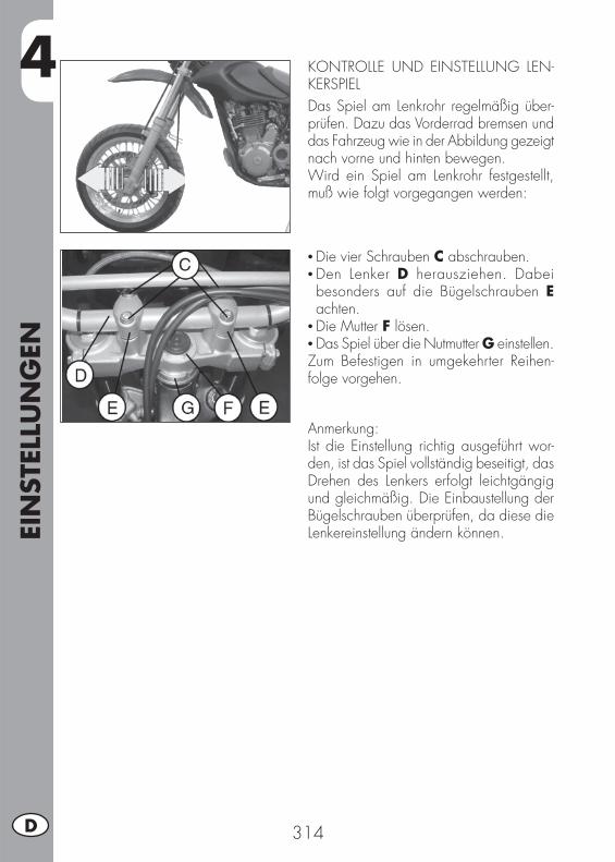
4EI
NST
ELLU
NG
EN
314D
KONTROLLE UND EINSTELLUNG LEN-KERSPIELDas Spiel am Lenkrohr regelmäßig über-prüfen. Dazu das Vorderrad bremsen und das Fahrzeug wie in der Abbildung gezeigt nach vorne und hinten bewegen.Wird ein Spiel am Lenkrohr festgestellt, muß wie folgt vorgegangen werden:
• Die vier Schrauben C abschrauben.• Den Lenker D herausziehen. Dabei besonders auf die Bügelschrauben E achten.
• Die Mutter F lösen.• Das Spiel über die Nutmutter G einstellen.Zum Befestigen in umgekehrter Reihen-folge vorgehen.
Anmerkung:Ist die Einstellung richtig ausgeführt wor-den, ist das Spiel vollständig beseitigt, das Drehen des Lenkers erfolgt leichtgängig und gleichmäßig. Die Einbaustellung der Bügelschrauben überprüfen, da diese die Lenkereinstellung ändern können.
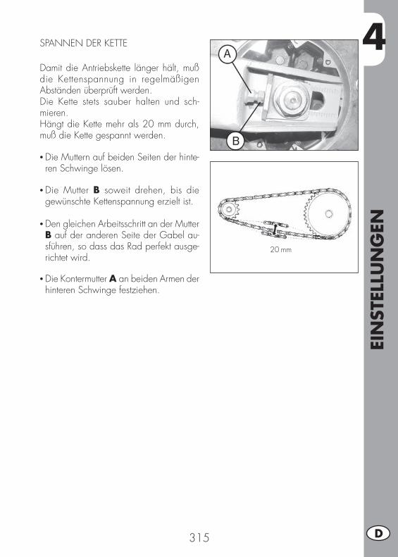
4
EIN
STEL
LUN
GEN
315 D
SPANNEN DER KETTE
Damit die Antriebskette länger hält, muß die Kettenspannung in regelmäßigen Abständen überprüft werden.Die Kette stets sauber halten und sch-mieren.Hängt die Kette mehr als 20 mm durch, muß die Kette gespannt werden.
• Die Muttern auf beiden Seiten der hinte-ren Schwinge lösen.
• Die Mutter B soweit drehen, bis die gewünschte Kettenspannung erzielt ist.
• Den gleichen Arbeitsschritt an der Mutter B auf der anderen Seite der Gabel au-sführen, so dass das Rad perfekt ausge-richtet wird.
• Die Kontermutter A an beiden Armen der hinteren Schwinge festziehen.
20 mm
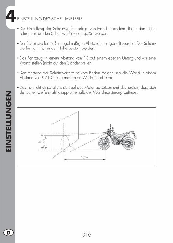
4EI
NST
ELLU
NG
EN
316D
EINSTELLUNG DES SCHEINWERFERS
• Die Einstellung des Scheinwerfers erfolgt von Hand, nachdem die beiden Inbus-schrauben an den Scheinwerferseiten gelöst wurden.
• Der Scheinwerfer muß in regelmäßigen Abständen eingestellt werden. Der Schein-werfer kann nur in der Höhe verstellt werden.
• Das Fahrzeug in einem Abstand von 10 auf einem ebenen Untergrund vor eine Wand stellen (nicht auf den Ständer stellen).
• Den Abstand der Scheinwerfermitte vom Boden messen und die Wand in einem Abstand von 9/10 des gemessenen Wertes markieren.
• Das Fahrlicht einschalten, sich auf das Motorrad setzen und überprüfen, dass sich der Scheinwerferstrahl knapp unterhalb der Wandmarkierung befi ndet.
9/10
h
10 m
h
5
AU
STA
USC
HEN
/ A
USW
ECH
SELN
VO
N T
EILE
N
317 D
INHALTSVERZEICHNIS
KAPITEL 5 AUSTAUSCHEN/ AUSWECHSELN VON TEILEN
Auswechseln der Bremsbeläge an der Vorderradbremse
Auswechseln der Bremsbeläge an der Hinterradbremse
Auswechseln lampen ALP
Auswechseln Lampen MOTARD M4
Auswechseln von blinkern und Rücklicht
Auswechseln der Nummernschildbeleuchtung
Eigenschaften Lampe
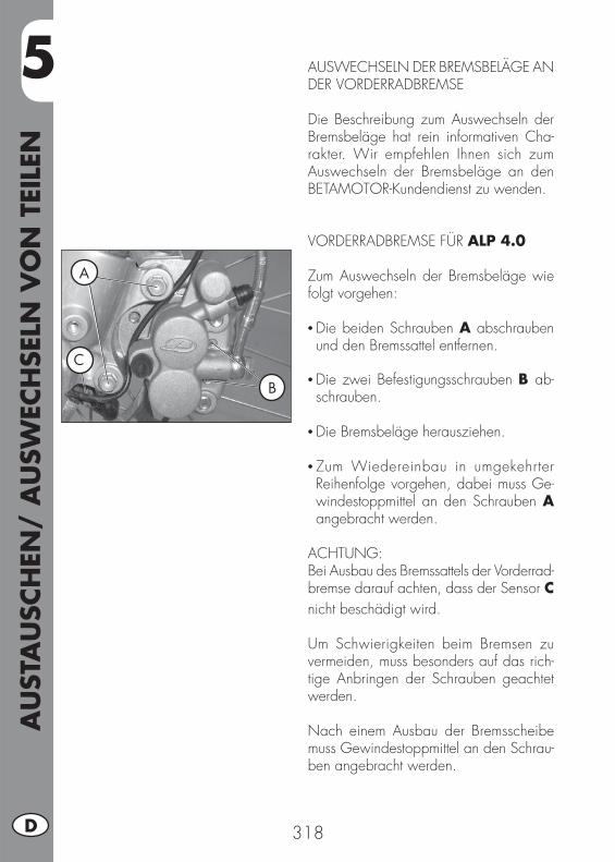
5A
UST
AU
SCH
EN/
AU
SWEC
HSE
LN V
ON
TEI
LEN
318D
AUSWECHSELN DER BREMSBELÄGE AN DER VORDERRADBREMSE
Die Beschreibung zum Auswechseln der Bremsbeläge hat rein informativen Cha-rakter. Wir empfehlen Ihnen sich zum Auswechseln der Bremsbeläge an den BETAMOTOR-Kundendienst zu wenden.
VORDERRADBREMSE FÜR ALP 4.0
Zum Auswechseln der Bremsbeläge wie folgt vorgehen:
• Die beiden Schrauben A abschrauben und den Bremssattel entfernen.
• Die zwei Befestigungsschrauben B ab-schrauben.
• Die Bremsbeläge herausziehen.
• Zum Wiedereinbau in umgekehrter Reihenfolge vorgehen, dabei muss Ge-windestoppmittel an den Schrauben A angebracht werden.
ACHTUNG:Bei Ausbau des Bremssattels der Vorderrad-bremse darauf achten, dass der Sensor C nicht beschädigt wird. Um Schwierigkeiten beim Bremsen zu vermeiden, muss besonders auf das rich-tige Anbringen der Schrauben geachtet werden.
Nach einem Ausbau der Bremsscheibe muss Gewindestoppmittel an den Schrau-ben angebracht werden.
A
B
C
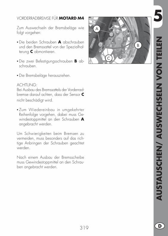
5
AU
STA
USC
HEN
/ A
USW
ECH
SELN
VO
N T
EILE
N
319 D
VORDERRADBREMSE FÜR MOTARD M4
Zum Auswechseln der Bremsbeläge wie folgt vorgehen:
• Die beiden Schrauben A abschrauben und den Bremssattel von der Spezialhal-terung C abmontieren.
• Die zwei Befestigungsschrauben B ab-schrauben.
• Die Bremsbeläge herausziehen.
ACHTUNG:Bei Ausbau des Bremssattels der Vorderrad-bremse darauf achten, dass der Sensor C nicht beschädigt wird.
• Zum Wiedereinbau in umgekehrter Reihenfolge vorgehen, dabei muss Ge-windestoppmittel an den Schrauben A angebracht werden.
Um Schwierigkeiten beim Bremsen zu vermeiden, muss besonders auf das rich-tige Anbringen der Schrauben geachtet werden.
Nach einem Ausbau der Bremsscheibe muss Gewindestoppmittel an den Schrau-ben angebracht werden.
A
B
C
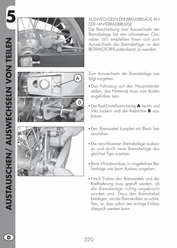
5A
UST
AU
SCH
EN/
AU
SWEC
HSE
LN V
ON
TEI
LEN
320D
Zum Auswechseln der Bremsbeläge wie folgt vorgehen:
• Das Fahrzeug auf den Hauptständer stellen, das Hinterrad muss vom Boden angehoben sein.
• Die Rad-Einstellvorrichtung A rechts und links lockern und die Radachse B aus-bauen.
AUSWECHSELN DER BREMSBELÄGE AN DER HINTERRADBREMSEDie Beschreibung zum Auswechseln der Bremsbeläge hat rein informativen Cha-rakter. Wir empfehlen Ihnen sich zum Auswechseln der Bremsbeläge an den BETAMOTOR-Kundendienst zu wenden.
• Den Bremssattel komplett mit Blech her-ausziehen.
• Die verschlissenen Bremsbeläge ausbau-en und durch neue Bremsbeläge des gleichen Typs ersetzen.
• Beim Wiedereinbau in umgekehrter Rei-henfolge wie beim Ausbau vorgehen.
• Nach Einbau des Bremssattels und der Radhalterung muss geprüft werden, ob die Bremsbeläge richtig angebracht worden sind. Dazu den Bremshebel betätigen, um die Bremskolben zu schlie-ßen, so dass sofort der richtige Einbau überprüft werden kann.
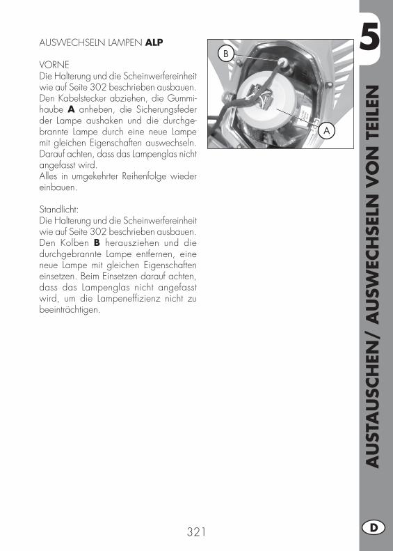
5
AU
STA
USC
HEN
/ A
USW
ECH
SELN
VO
N T
EILE
N
321 D
AUSWECHSELN LAMPEN ALP
VORNE Die Halterung und die Scheinwerfereinheit wie auf Seite 302 beschrieben ausbauen.Den Kabelstecker abziehen, die Gummi-haube A anheben, die Sicherungsfeder der Lampe aushaken und die durchge-brannte Lampe durch eine neue Lampe mit gleichen Eigenschaften auswechseln. Darauf achten, dass das Lampenglas nicht angefasst wird.Alles in umgekehrter Reihenfolge wieder einbauen.
Standlicht:Die Halterung und die Scheinwerfereinheit wie auf Seite 302 beschrieben ausbauen.Den Kolben B herausziehen und die durchgebrannte Lampe entfernen, eine neue Lampe mit gleichen Eigenschaften einsetzen. Beim Einsetzen darauf achten, dass das Lampenglas nicht angefasst wird, um die Lampeneffi zienz nicht zu beeinträchtigen.
B
A
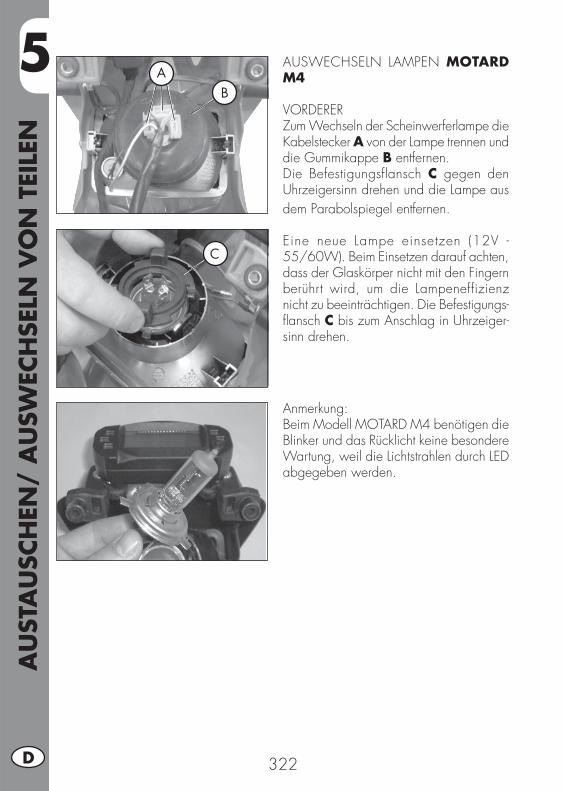
5A
UST
AU
SCH
EN/
AU
SWEC
HSE
LN V
ON
TEI
LEN
322D
AUSWECHSELN LAMPEN MOTARD M4
VORDERERZum Wechseln der Scheinwerferlampe die Kabelstecker A von der Lampe trennen und die Gummikappe B entfernen.Die Befestigungsflansch C gegen den Uhrzeigersinn drehen und die Lampe aus dem Parabolspiegel entfernen.
Eine neue Lampe einsetzen (12V - 55/60W). Beim Einsetzen darauf achten, dass der Glaskörper nicht mit den Fingern berührt wird, um die Lampeneffizienz nicht zu beeinträchtigen. Die Befestigungs-fl ansch C bis zum Anschlag in Uhrzeiger-sinn drehen.
Anmerkung:Beim Modell MOTARD M4 benötigen die Blinker und das Rücklicht keine besondere Wartung, weil die Lichtstrahlen durch LED abgegeben werden.
AB
C
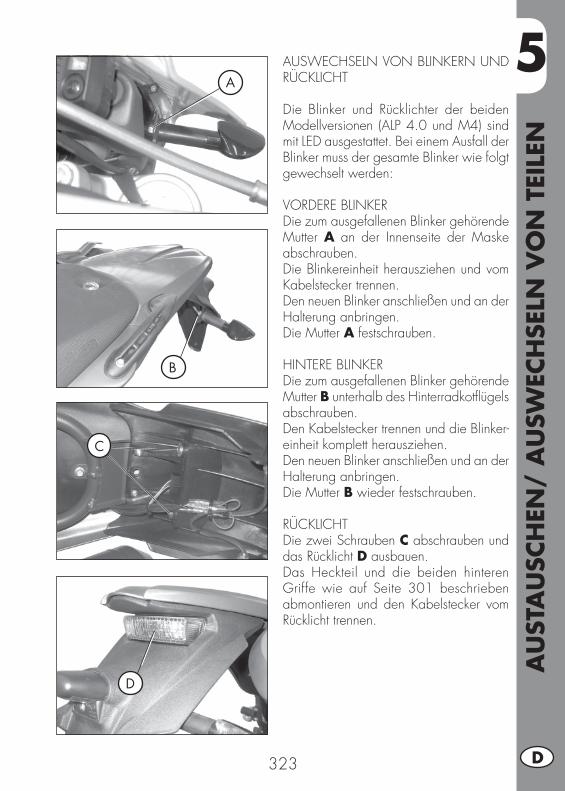
5
AU
STA
USC
HEN
/ A
USW
ECH
SELN
VO
N T
EILE
N
323 D
AUSWECHSELN VON BLINKERN UND RÜCKLICHT
Die Blinker und Rücklichter der beiden Modellversionen (ALP 4.0 und M4) sind mit LED ausgestattet. Bei einem Ausfall der Blinker muss der gesamte Blinker wie folgt gewechselt werden:
VORDERE BLINKERDie zum ausgefallenen Blinker gehörende Mutter A an der Innenseite der Maske abschrauben.Die Blinkereinheit herausziehen und vom Kabelstecker trennen.Den neuen Blinker anschließen und an der Halterung anbringen.Die Mutter A festschrauben.
HINTERE BLINKERDie zum ausgefallenen Blinker gehörende Mutter B unterhalb des Hinterradkotfl ügels abschrauben.Den Kabelstecker trennen und die Blinker-einheit komplett herausziehen.Den neuen Blinker anschließen und an der Halterung anbringen.Die Mutter B wieder festschrauben.
RÜCKLICHTDie zwei Schrauben C abschrauben und das Rücklicht D ausbauen.Das Heckteil und die beiden hinteren Griffe wie auf Seite 301 beschrieben abmontieren und den Kabelstecker vom Rücklicht trennen.
A
B
D
C
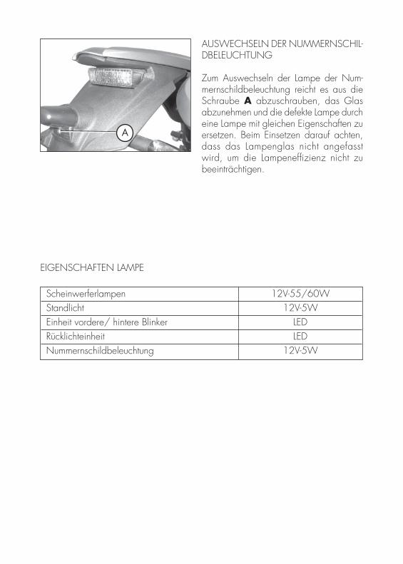
Scheinwerferlampen 12V-55/60W Standlicht 12V-5W Einheit vordere/ hintere Blinker LED Rücklichteinheit LED Nummernschildbeleuchtung 12V-5W
A
AUSWECHSELN DER NUMMERNSCHIL-DBELEUCHTUNG
Zum Auswechseln der Lampe der Num-mernschildbeleuchtung reicht es aus die Schraube A abzuschrauben, das Glas abzunehmen und die defekte Lampe durch eine Lampe mit gleichen Eigenschaften zu ersetzen. Beim Einsetzen darauf achten, dass das Lampenglas nicht angefasst wird, um die Lampeneffi zienz nicht zu beeinträchtigen.
EIGENSCHAFTEN LAMPE

6
WA
S IS
T IM
NO
TFA
LL Z
U T
UN
325 D
INHALTSVERZEICHNIS
KAPITEL 6 WAS IST IM NOTFALL ZU TUN
ALPHABETISCHES INHALTSVERZEICHNIS
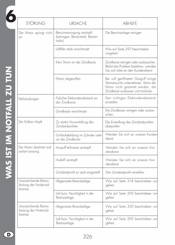
6W
AS
IST
IM N
OTF
ALL
ZU
TU
N
326D
STÖRUNG URSACHE
Der Motor springt nicht an
ABHILFE
- Benzinversorgung verstopft (Leitungen, Benzintank, Benzin-hahn)
- Luftfi lter stark verschmutzt
- Kein Strom an der Zündkerze
- Motor abgesoffen
Die Benzinanlage reinigen
Wie auf Seite 297 beschrieben vorgehen
Zündkerze reinigen oder austauschen. Bleibt das Problem bestehen, wenden Sie sich bitte an den Kundendienst Bei voll geöffnetem Gasgriff einige Startversuche unternehmen. Kann der Motor nicht gestartet werden, die Zündkerze ausbauen und trocknen
Fehlzündungen - Falscher Elektrodenabstand an der Zündkerze
- Zündkerze verschmutzt
Den richtigen Elektrodenabstand einstellen
Die Zündkerze reinigen oder austau-schen.
Der Kolben klopft - Zu starke Vorverstellung des Zündzeitpunktes
- Schlackebildung im Zylinder oder an der Zündkerze
Die Einstellung des Zündzeitpunktes überprüfen
Wenden Sie sich an unseren Kunden-dienst
Der Motor überhitzt und verliert Leistung
- Auspuff teilweise verstopft
- Auslaß verstopft
- Zündzeitpunkt zu spät eingestellt
Wenden Sie sich an unseren Kun-dendienst
Wenden Sie sich an unseren Kun-dendienst
Den Zündzeitpunkt einstellen
Unzureichende Brems-leistung der Vorderrad-bremse
- Abgenutzte Bremsbeläge
- Luft bzw. Feuchtigkeit in der Bremsanlage
Wie auf Seite 318 beschrieben vor-gehen
Wie auf Seite 292 beschrieben vor-gehen
Unzureichende Brems-leistung der Hinterrad-bremse
- Abgenutzte Bremsbeläge
- Luft bzw. Feuchtigkeit in der Bremsanlage
Wie auf Seite 320 beschrieben vor-gehen
Wie auf Seite 293 beschrieben vor-gehen
ALP
HA
BET
ISCH
ES IN
HA
LTSV
ERZ
EICH
NIS
327 D
Abstellen des Motors ........................................................................... 283Anzeigen am LCD .............................................................................. 260Armaturenbrett und Bedienungselemente ................................................ 259Ausbau der plastikteile für ALP ............................................................... 301Ausbau der plastikteile für MOTARD M4 ................................................. 303Auslieferung ...................................................................................... 254Auswechseln der Bremsbeläge an der Hinterradbremse ............................. 320Auswechseln der Bremsbeläge an der Vorderradbremse ............................ 318Auswechseln der Nummernschildbeleuchtung........................................... 324Auswechseln lampen ALP .................................................................... 321Auswechseln Lampen MOTARD M4 ....................................................... 322Auswechseln von blinkern und Rücklicht .................................................. 323
Batterie ............................................................................................. 300Bremsfl üssigkeit, entlüften der bremsen .................................................... 292
Das AIS-Ventil .................................................................................... 278
Eigenschaften Lampe ........................................................................... 324Einfahren .......................................................................................... 281Einstellung der bremsen ....................................................................... 312Einstellung der Kupplung ...................................................................... 312Einstellung des Gaszuges ..................................................................... 313Einstellung des hinteren Stoßdämpfers ..................................................... 313Einstellung des Scheinwerfers ................................................................ 316Elektrische Anlage .............................................................................. 276Elektrischer Schaltplan ......................................................................... 274Empfohlene Schmiermittel .................................................................... 280
Fahrzeugpfl ege und Kontrollen .............................................................. 308
Gabelöl ............................................................................................ 296
Helmschloß ....................................................................................... 258Hinterradbremse ................................................................................. 299Hinweise für Geländefahrten ................................................................ 305Hinweise zum Gebrauch des Fahrzeugs ................................................. 251
Kontrolle motorölstand ......................................................................... 286Kontrollen nach der Fahrzeugpfl ege ....................................................... 308Kontrollen und Wartung vor und nach Einsatz im Gelände ......................... 280Kontrolle und Einstellung Lenkerspiel ....................................................... 314
ALP
HA
BET
ISCH
ES IN
HA
LTSV
ERZ
EICH
NIS
328D
Längeres Stilllegen des Fahrzeugs .......................................................... 310Leerlaufeinstellung ............................................................................... 313Leitung Öldampfsammlung ................................................................... 292Luftfi lter ............................................................................................. 297
Nach längerem Stillegen des Fahrzeugs ................................................. 310
Rahmen- und motornummer ................................................................... 254Reifen ............................................................................................... 255
Schlüssel und Schlösser ........................................................................ 258Sicheres Fahren .................................................................................. 252Spannen der Kette .............................................................................. 315Starten des Motors .............................................................................. 282
Tanken ............................................................................................. 284Technische Angaben ........................................................................... 271
Umweltfreundliches Fahren ................................................................... 251
Vergaser ........................................................................................... 300Vorderradbremse ................................................................................ 299
Wartungsprogramm ............................................................................ 309Wechseln der endantriebseinheit ........................................................... 306Wechsel von motoröl und Ölfi lter ........................................................... 288Wichtigste Fahrzeugteile ...................................................................... 257
Zuladung .......................................................................................... 255Zündkerze ......................................................................................... 298Zünd-/ Lenkerschloß ........................................................................... 258

329 E
ALP 4.0 - MOTARD M4
Gracias por la confi anza que nos han concedido y buena di-versión. Con este libro hemos querido darle las informaciones necesarias para un uso correcto y un buen mantenimiento de Su moto.
Los datos y las características indicadas en éste manual no comprometen BETAMOTOR S.p.A que se reserva los derechos a realizar modifi caciones y mejoras a sus propios modelos en cualquier momento sin previo aviso.
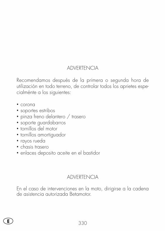
330E
ADVERTENCIA
Recomendamos después de la primera o segunda hora de utilización en todo terreno, de controlar todos los aprietes espe-cialménte a los siguientes:
• corona• soportes estribos• pinza freno delantero / trasero• soporte guardabarros• tornillos del motor• tornillos amortiguador• rayos rueda• chasis trasero• enlaces deposito aceite en el bastidor
ADVERTENCIA
En el caso de intervenciones en la moto, dirigirse a la cadena de asistencia autorizada Betamotor.
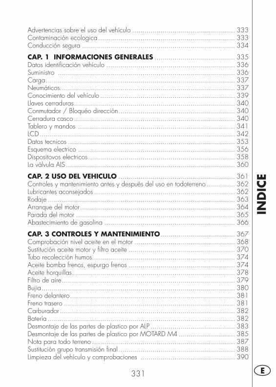
IND
ICE
331 E
Advertencias sobre el uso del vehículo ................................................... 333Contaminación ecologica .................................................................... 333Conducción segura ............................................................................ 334
CAP. 1 INFORMACIONES GENERALES ........................................ 335Datos identifi cación vehículo ................................................................ 336Suministro ........................................................................................ 336Carga .............................................................................................. 337Neumáticos ....................................................................................... 337Conocimiento del vehículo ................................................................... 339Llaves cerraduras ................................................................................ 340Conmutador / Bloquéo dirección .......................................................... 340Cerradura casco ................................................................................ 340Tablero y mandos .............................................................................. 341LCD ................................................................................................. 342Datos tecnicos ................................................................................... 353Esquema electrico .............................................................................. 356Dispositovos electricos ......................................................................... 358La válvula AIS .................................................................................... 360
CAP. 2 USO DEL VEHICULO .......................................................... 361Controles y mantenimiento antes y después del uso en todoterreno .............. 362Lubricantes aconsejados ...................................................................... 362Rodaje ............................................................................................. 363Arranque del motor ............................................................................. 364Parada del motor ............................................................................... 365Abastecimiento de gasolina ................................................................. 366
CAP. 3 CONTROLES Y MANTENIMIENTO ..................................... 367Comprobación nivel aceite en el motor .................................................. 368Sustitución aceite motor y fi ltro aceite ..................................................... 370Tubo recolección humos ....................................................................... 374Aceite bomba frenos, espurgo frenos ..................................................... 374Aceite horquillas ................................................................................. 378Filtro de aire ...................................................................................... 379Bujia ................................................................................................ 380Freno delantero .................................................................................. 381Freno trasero ..................................................................................... 381Carburador ....................................................................................... 382Batería ............................................................................................. 382Desmontaje de las partes de plastico por ALP .......................................... 383Desmontaje de las partes de plastico por MOTARD M4 ............................ 385Nota para todo terreno ....................................................................... 387Sustitución grupo transmisión fi nal .......................................................... 388Limpieza del vehículo y comprobaciones ............................................... 390
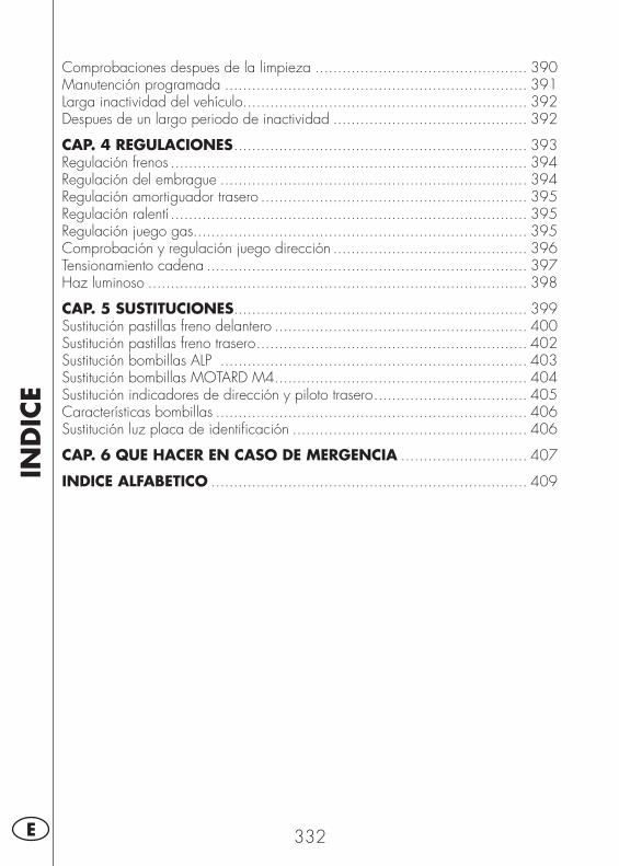
IND
ICE
332E
Comprobaciones despues de la limpieza ............................................... 390Manutención programada ................................................................... 391Larga inactividad del vehículo............................................................... 392Despues de un largo periodo de inactividad ........................................... 392
CAP. 4 REGULACIONES ................................................................. 393Regulación frenos ............................................................................... 394Regulación del embrague .................................................................... 394Regulación amortiguador trasero ........................................................... 395Regulación ralentí ............................................................................... 395Regulación juego gas.......................................................................... 395Comprobación y regulación juego dirección ........................................... 396Tensionamiento cadena ....................................................................... 397Haz luminoso .................................................................................... 398
CAP. 5 SUSTITUCIONES................................................................. 399Sustitución pastillas freno delantero ........................................................ 400Sustitución pastillas freno trasero ............................................................ 402Sustitución bombillas ALP .................................................................... 403Sustitución bombillas MOTARD M4........................................................ 404Sustitución indicadores de dirección y piloto trasero .................................. 405Características bombillas ..................................................................... 406Sustitución luz placa de identifi cación .................................................... 406
CAP. 6 QUE HACER EN CASO DE MERGENCIA ............................ 407
INDICE ALFABETICO ...................................................................... 409
333 E
ADVERTENCIAS SOBRE EL USO DEL VEHÍCULO• El vehículo debe ser obligatoriaménte provisto de: placa, libreto de identifi cación, impuesto y seguro.
• Está prohibido transportar animales y otros objetos no integrado al vehículo, que “salgan” de las dimenciones máximas ocupadas por el vehículo y que superen la carga prevista pr el constructor.
• Es obligatorio el uso del casco.• Modifi caciones al motor o a otros organos que puedan determinar un aumento de potencia y por consiguiente aumento de velocidad, es castigado por la ley con severas sanciones, entre las cuales el secuestro del vehículo.
• Para salvaguardar su vida y la de los demás, conducir con prudencia y ponerse siempre el casco.
ATENCION:Modifi caciones o intervenciones durante la garantía, liberan al Constructor de cualquier responsabilidad y hacen decaer la misma garantía.
CONTAMINACIÓN ECOLOGICA• Todos los vehículos con motor de explosión producen una cantidad mas o menos elevada de contaminación acústica y atmosférica, según el tipo de conducción.
• La mayor reducción posible de estas condiciones es hoy un deber para todos, por lo tanto evitar salidas a todo gas, improvisas e inutiles aceleraciones e improvisas igualmente inutiles frenadas, limitando asì la rumorosidad, el desgaste precoz de los neumáticos y de las partes mecanicas del vehículo y ahorrando en el gasto de gasolina.
334E
CONDUCCIÓN SEGURA• Respetar el código de la circulación• Ponerse siempre el casco homologado y enganchado•Tener siempre limpia la visera protectiva• Ponerse siempre ropa sin extremos colgando• No viajar teniendo en el bolsillo objetos con punta o fragiles• Regular correctaménte los espejos retrovisores• Conducir siempre sentados, con las dos manos en el manillar y los pies sobre los estribos
• No distraerse nunca durante la conducción • No comer, beber, fumar, usar el celular, etc…. mientras conduce• No escuchar musica con auriculares mientras conduce• No viajar nunca en pareja con otros vehículos • No remolcar o dejarse remolcar por otros vehículos• Tener siempre una distancia de seguridad• No estar sentados cuando el vehículo se encuentra sobre el caballete• No salir con el vehículo sobre el caballete• No extraer el caballete cuando el vehículo se encuentra con su parte anterior en bajada
• Empinadas, serpentinas, oscilaciones, son peligrosas para Ti, para los demás y para tu vehículo
• En calle seca y sin grava o arena, usar ambos frenos, un solo freno puede provocar deslizamientos peligrosos e incontrolables.
• En caso de frenada utilizar ambos frenos, se obtendrá una parada del vehículo en un espacio mas corto
• En calle mojada, conducir con prudencia y a velocidad moderada : utilizar los frenos con mas sensibilidad
• No arrancar el motor en locales cerrados
1
INFO
RM
ACIO
NES
GEN
ERA
LES
335 E
INDICE DE LOS ARGUMENTOS
CAP. 1 INFORMACIONES GENERALES
Datos identifi cación vehículo
Suministro
Carga
Neumáticos
Conocimiento del vehículo
Llaves cerraduras
Conmutador / Bloquéo dirección
Cerradura casco
Tablero y mandos
LCD
Datos tecnicos
Esquema electrico
Dispositovos electricos
La válvula AIS
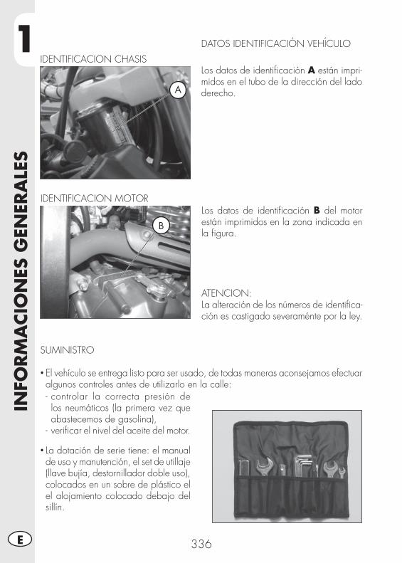
1IN
FORM
ACIO
NES
GEN
ERA
LES
336E
DATOS IDENTIFICACIÓN VEHÍCULO
Los datos de identifi cación A están impri-midos en el tubo de la dirección del lado derecho.
IDENTIFICACION CHASIS
Los datos de identifi cación B del motor están imprimidos en la zona indicada en la fi gura.
ATENCION:La alteración de los números de identifi ca-ción es castigado severaménte por la ley.
IDENTIFICACION MOTOR
SUMINISTRO • El vehículo se entrega listo para ser usado, de todas maneras aconsejamos efectuar algunos controles antes de utilizarlo en la calle:- controlar la correcta presión de los neumáticos (la primera vez que abastecemos de gasolina),
- verifi car el nivel del aceite del motor.
• La dotación de serie tiene: el manual de uso y manutención, el set de utillaje (llave bujía, destornillador doble uso), colocados en un sobre de plástico el el alojamiento colocado debajo del sillín.
A
B
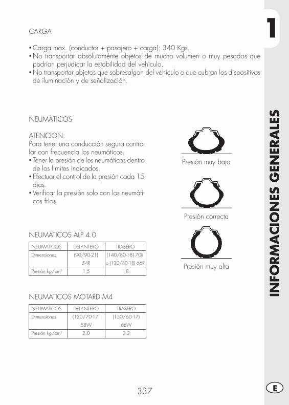
1
INFO
RM
ACIO
NES
GEN
ERA
LES
337 E
CARGA
• Carga max. (conductor + pasajero + carga): 340 Kgs.• No transportar absolutaménte objetos de mucho volumen o muy pesados que podrían perjudicar la estabilidad del vehículo.
• No transportar objetos que sobresalgan del vehículo o que cubran los dispositivos de iluminación y de señalización.
NEUMÁTICOS
ATENCION:Para tener una conducción segura contro-lar con frecuencia los neumáticos.• Tener la presión de los neumáticos dentro de los limites indicados.
• Efectuar el control de la presión cada 15 dias.
• Verifi car la presión solo con los neumáti-cos fríos.
Presión muy baja
Presión correcta
Presión muy alta
NEUMATICOS ALP 4.0
NEUMATICOS
Dimensiones
Presión kg/cm2
TRASERO
(140/80-18) 70R
o (130/80-18) 66R
1,8
DELANTERO
(90/90-21)
54R
1,5
NEUMATICOS MOTARD M4
NEUMATICOS
Dimensiones
Presión kg/cm2
TRASERO
(150/60-17)
66W
2,2
DELANTERO
(120/70-17)
58W
2,0
1IN
FORM
ACIO
NES
GEN
ERA
LES
338E
Nota:El espesor mínimo de la banda de rodadura de los neumáticos (TUBE TYPE) no debe ser nunca inferior a los 2 mm.La falta de respeto de esta norma es castigada por la ley.
• Controlar antes de cada viaje que los neumáticos no tengan cortes, rajaduras, abrasiones, hinchazones, etc…. En tal caso hecer examinar el neumático por un experto puesto que se podrían verifi car condiciones extremamente peligrosas.
• En el caso de pinchazo parar inmediatamente el vehículo; seguir viajando, además de ser arriesgado, puede provocar irremediables daños al neumático y a la llanta.
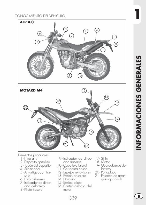
1
INFO
RM
ACIO
NES
GEN
ERA
LES
339 E
CONOCIMIENTO DEL VEHÍCULO
Elementos principales 1 - Filtro aire 2 - Depósito gasolina 3 - Tapón del depósito 4 - Silenciador 5 - Amortiguador tra-
sero 6 - Faro delantero 7 - Indicador de direc-
ción delantero 8 - Piloto trasero
9 - Indicador de direc-ción traseros
10 - Caballete lateral 11- Cerradura casco 12 - Espejos retrovisores 13 - Estribo pasajero 14 - Horquilla 15 - Estribo piloto 16 - Carter debajo del
motor
17 - Sillín 18 - Motor 19 - Guardabarros de-
lantero 20 - Portaplaca21 - Palanca de arran-
que (opcional)
7
10
6
5
3
2
1
8
9
4
11
ALP 4.0
MOTARD M4
20
17
12
18
19
14
16
21
13
15
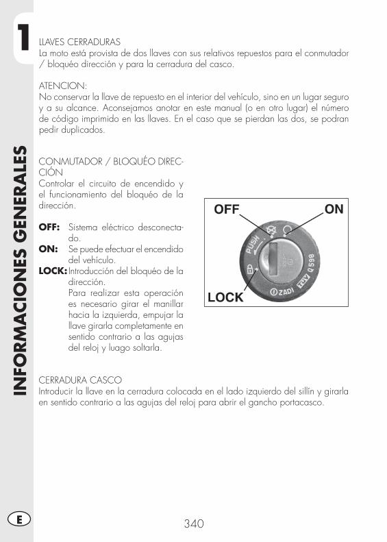
1IN
FORM
ACIO
NES
GEN
ERA
LES
340E
LLAVES CERRADURASLa moto está provista de dos llaves con sus relativos repuestos para el conmutador / bloquéo dirección y para la cerradura del casco.
ATENCION:No conservar la llave de repuesto en el interior del vehículo, sino en un lugar seguro y a su alcance. Aconsejamos anotar en este manual (o en otro lugar) el número de código imprimido en las llaves. En el caso que se pierdan las dos, se podran pedir duplicados.
CONMUTADOR / BLOQUÉO DIREC-CIÓNControlar el circuito de encendido y el funcionamiento del bloquéo de la dirección.
OFF: Sistema eléctrico desconecta-do.
ON: Se puede efectuar el encendido del vehículo.
LOCK: Introducción del bloquéo de la dirección.
Para realizar esta operación es necesario girar el manillar hacia la izquierda, empujar la llave girarla completamente en sentido contrario a las agujas del reloj y luago soltarla.
CERRADURA CASCOIntroducir la llave en la cerradura colocada en el lado izquierdo del sillín y girarla en sentido contrario a las agujas del reloj para abrir el gancho portacasco.
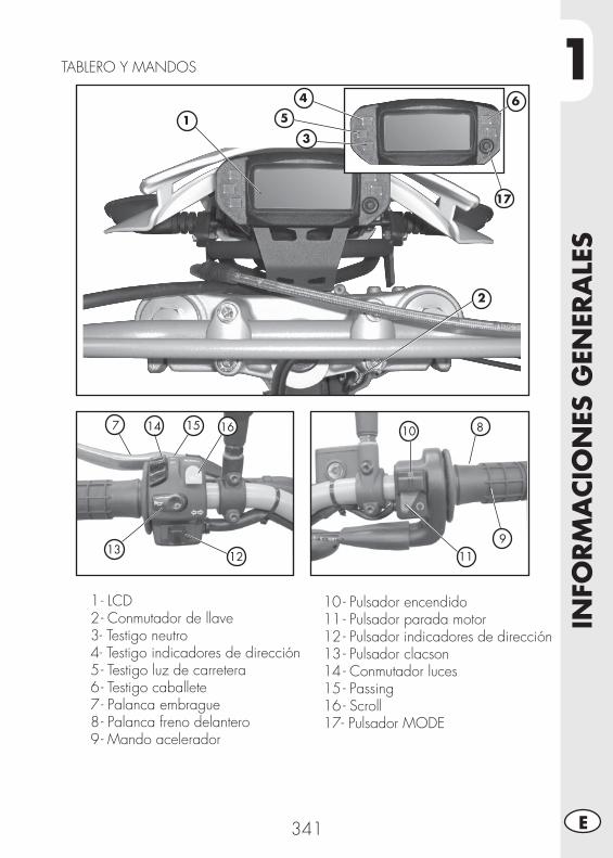
1
INFO
RM
ACIO
NES
GEN
ERA
LES
341 E
1 - LCD 2 - Conmutador de llave 3 - Testigo neutro 4 - Testigo indicadores de dirección 5 - Testigo luz de carretera 6 - Testigo caballete 7 - Palanca embrague 8 - Palanca freno delantero 9 - Mando acelerador
10 - Pulsador encendido11 - Pulsador parada motor12 - Pulsador indicadores de dirección13 - Pulsador clacson14 - Conmutador luces15 - Passing 16 - Scroll17- Pulsador MODE
TABLERO Y MANDOS
7 8
9
10
111213
14 15 16
1
2
3
5
17
4 6
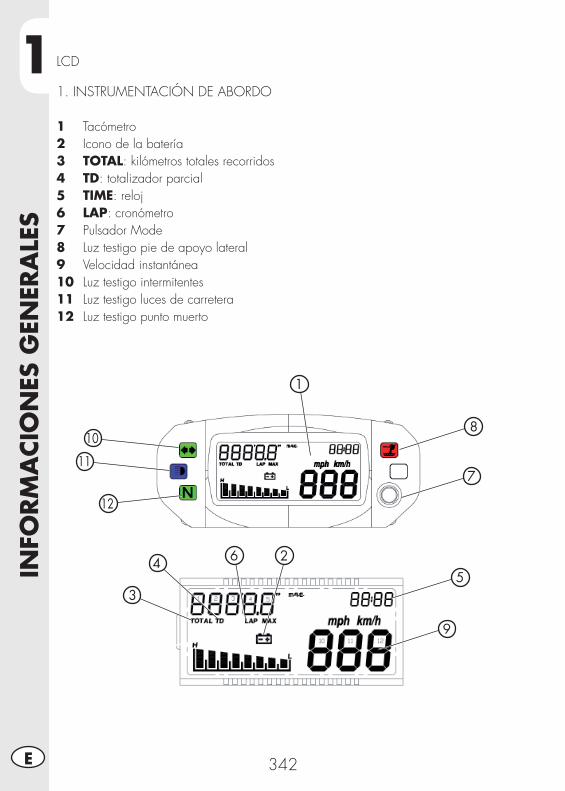
1IN
FORM
ACIO
NES
GEN
ERA
LES
342E
2
3
45
7
6
9
1
10
11
12
8
LCD
1. INSTRUMENTACIÓN DE ABORDO
1 Tacómetro2 Icono de la batería3 TOTAL: kilómetros totales recorridos4 TD: totalizador parcial5 TIME: reloj6 LAP: cronómetro7 Pulsador Mode8 Luz testigo pie de apoyo lateral9 Velocidad instantánea 10 Luz testigo intermitentes11 Luz testigo luces de carretera12 Luz testigo punto muerto
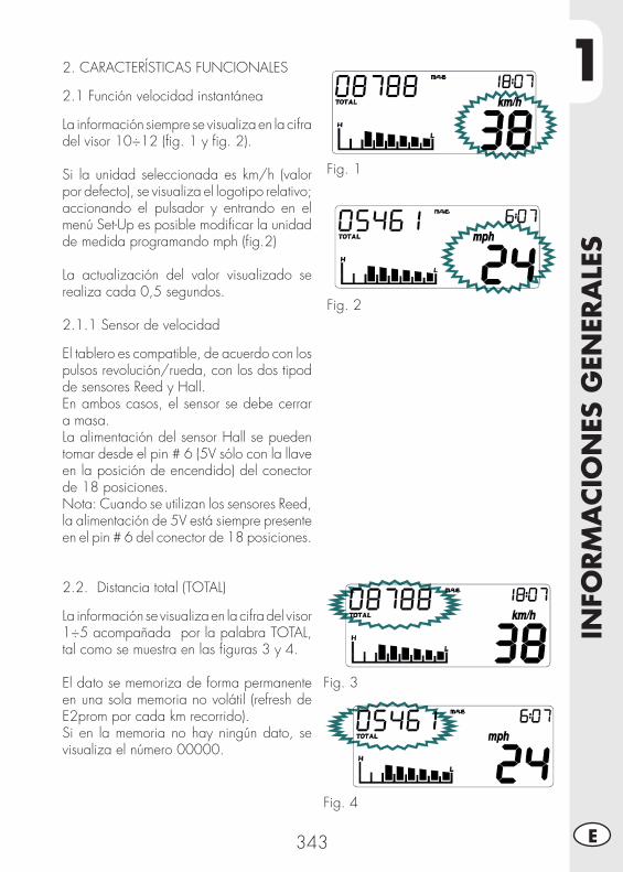
1
INFO
RM
ACIO
NES
GEN
ERA
LES
343 E
2. CARACTERÍSTICAS FUNCIONALES
2.1 Función velocidad instantánea
La información siempre se visualiza en la cifra del visor 10÷12 (fi g. 1 y fi g. 2).
Si la unidad seleccionada es km/h (valor por defecto), se visualiza el logotipo relativo; accionando el pulsador y entrando en el menú Set-Up es posible modifi car la unidad de medida programando mph (fi g.2)
La actualización del valor visualizado se realiza cada 0,5 segundos.
2.1.1 Sensor de velocidad
El tablero es compatible, de acuerdo con los pulsos revolución/rueda, con los dos tipod de sensores Reed y Hall.En ambos casos, el sensor se debe cerrar a masa.La alimentación del sensor Hall se pueden tomar desde el pin # 6 (5V sólo con la llave en la posición de encendido) del conector de 18 posiciones.Nota: Cuando se utilizan los sensores Reed, la alimentación de 5V está siempre presente en el pin # 6 del conector de 18 posiciones.
2.2. Distancia total (TOTAL)
La información se visualiza en la cifra del visor 1÷5 acompañada por la palabra TOTAL, tal como se muestra en las fi guras 3 y 4.
El dato se memoriza de forma permanente en una sola memoria no volátil (refresh de E2prom por cada km recorrido).Si en la memoria no hay ningún dato, se visualiza el número 00000.
Fig. 1
Fig. 2
Fig. 3
Fig. 4
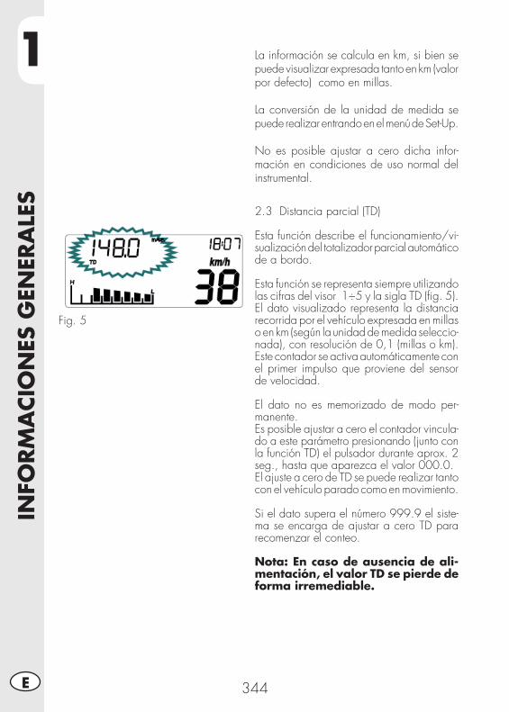
1IN
FORM
ACIO
NES
GEN
ERA
LES
344E
Fig. 5
2.3 Distancia parcial (TD)
Esta función describe el funcionamiento/vi-sualización del totalizador parcial automático de a bordo.
Esta función se representa siempre utilizando las cifras del visor 1÷5 y la sigla TD (fi g. 5).El dato visualizado representa la distancia recorrida por el vehículo expresada en millas o en km (según la unidad de medida seleccio-nada), con resolución de 0,1 (millas o km).Este contador se activa automáticamente con el primer impulso que proviene del sensor de velocidad.
El dato no es memorizado de modo per-manente.Es posible ajustar a cero el contador vincula-do a este parámetro presionando (junto con la función TD) el pulsador durante aprox. 2 seg., hasta que aparezca el valor 000.0.El ajuste a cero de TD se puede realizar tanto con el vehículo parado como en movimiento.
Si el dato supera el número 999.9 el siste-ma se encarga de ajustar a cero TD para recomenzar el conteo.
Nota: En caso de ausencia de ali-mentación, el valor TD se pierde de forma irremediable.
La información se calcula en km, si bien se puede visualizar expresada tanto en km (valor por defecto) como en millas.
La conversión de la unidad de medida se puede realizar entrando en el menú de Set-Up.
No es posible ajustar a cero dicha infor-mación en condiciones de uso normal del instrumental.
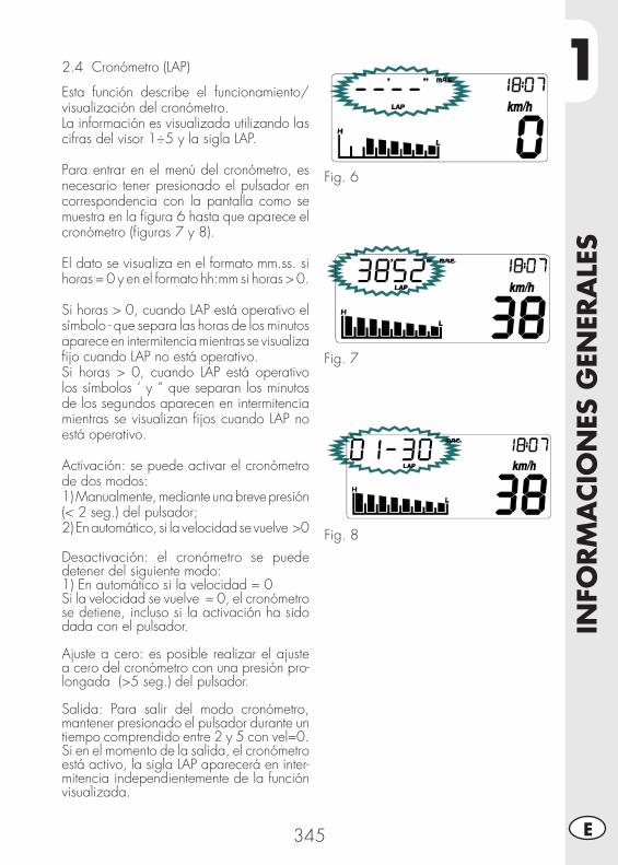
1
INFO
RM
ACIO
NES
GEN
ERA
LES
345 E
Fig. 6
Fig. 7
Fig. 8
2.4 Cronómetro (LAP)
Esta función describe el funcionamiento/visualización del cronómetro.La información es visualizada utilizando las cifras del visor 1÷5 y la sigla LAP.
Para entrar en el menú del cronómetro, es necesario tener presionado el pulsador en correspondencia con la pantalla como se muestra en la fi gura 6 hasta que aparece el cronómetro (fi guras 7 y 8).
El dato se visualiza en el formato mm.ss. si horas = 0 y en el formato hh:mm si horas > 0.
Si horas > 0, cuando LAP está operativo el símbolo - que separa las horas de los minutos aparece en intermitencia mientras se visualiza fi jo cuando LAP no está operativo.Si horas > 0, cuando LAP está operativo los símbolos ‘ y “ que separan los minutos de los segundos aparecen en intermitencia mientras se visualizan fi jos cuando LAP no está operativo.
Activación: se puede activar el cronómetro de dos modos:1) Manualmente, mediante una breve presión (< 2 seg.) del pulsador;2) En automático, si la velocidad se vuelve >0
Desactivación: el cronómetro se puede detener del siguiente modo:1) En automático si la velocidad = 0Si la velocidad se vuelve = 0, el cronómetro se detiene, incluso si la activación ha sido dada con el pulsador.
Ajuste a cero: es posible realizar el ajuste a cero del cronómetro con una presión pro-longada (>5 seg.) del pulsador.
Salida: Para salir del modo cronómetro, mantener presionado el pulsador durante un tiempo comprendido entre 2 y 5 con vel=0.Si en el momento de la salida, el cronómetro está activo, la sigla LAP aparecerá en inter-mitencia independientemente de la función visualizada.
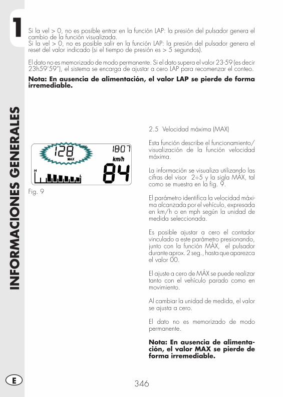
1IN
FORM
ACIO
NES
GEN
ERA
LES
346E
2.5 Velocidad máxima (MAX)
Esta función describe el funcionamiento/visualización de la función velocidad máxima.
La información se visualiza utilizando las cifras del visor 2÷5 y la sigla MÁX, tal como se muestra en la fi g. 9.
El parámetro identifi ca la velocidad máxi-ma alcanzada por el vehículo, expresada en km/h o en mph según la unidad de medida seleccionada.
Es posible ajustar a cero el contador vinculado a este parámetro presionando, junto con la función MÁX, el pulsador durante aprox. 2 seg., hasta que aparezca el valor 00.
El ajuste a cero de MÁX se puede realizar tanto con el vehículo parado como en movimiento.
Al cambiar la unidad de medida, el valor se ajusta a cero.
El dato no es memorizado de modo permanente.
Nota: En ausencia de alimenta-ción, el valor MAX se pierde de forma irremediable.
Fig. 9
Si la vel > 0, no es posible entrar en la función LAP: la presión del pulsador genera el cambio de la función visualizada.Si la vel > 0, no es posible salir en la función LAP: la presión del pulsador genera el reset del valor indicado (si el tiempo de presión es > 5 segundos).
El dato no es memorizado de modo permanente. Si el dato supera el valor 23-59 (es decir 23h59’59”), el sistema se encarga de ajustar a cero LAP para recomenzar el conteo.
Nota: En ausencia de alimentación, el valor LAP se pierde de forma irremediable.
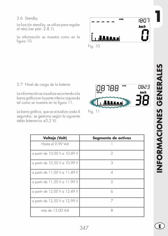
1
INFO
RM
ACIO
NES
GEN
ERA
LES
347 E
2.6 Standby
La función stand by se utiliza para regular el reloj (ver párr. 2.8.1).
La información se muestra como en la fi gura 10.
Fig. 10
2.7 Nivel de carga de la batería
La información se visualiza recurriendo a la barra gráfi ca en la parte inferior izquierda tal como se muestra en la fi gura 11.
La barra gráfi ca, que se actualiza cada 4 segundos, se gestiona según la siguiente tabla (tolerancia ±0,2 V):
Fig. 11
Voltaje (Volt) Segmento de activos
Hasta el 9,99 Volt 1
a partir de 10,00 V a 10,49 V 2
a partir de 10,50 V a 10,99 V 3
a partir de 11,00 V a 11,49 V 4
a partir de 11,50 V a 11,99 V 5
a partir de 12,00 V a 12,49 V 6
a partir de 12,50 V a 12,99 V 7
más de 13,00 Volt 8
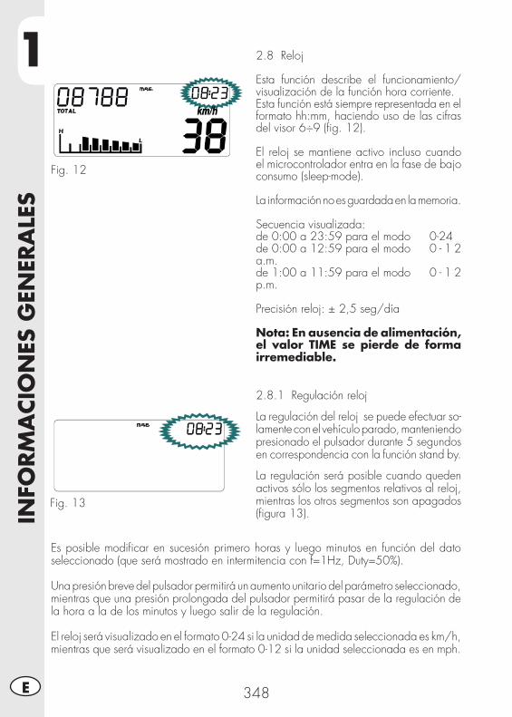
1IN
FORM
ACIO
NES
GEN
ERA
LES
348E
2.8 Reloj
Esta función describe el funcionamiento/visualización de la función hora corriente.Esta función está siempre representada en el formato hh:mm, haciendo uso de las cifras del visor 6÷9 (fi g. 12).
El reloj se mantiene activo incluso cuando el microcontrolador entra en la fase de bajo consumo (sleep-mode).
La información no es guardada en la memoria.
Secuencia visualizada: de 0:00 a 23:59 para el modo 0-24 de 0:00 a 12:59 para el modo 0 - 1 2 a.m. de 1:00 a 11:59 para el modo 0 - 1 2 p.m.
Precisión reloj: ± 2,5 seg/día
Nota: En ausencia de alimentación, el valor TIME se pierde de forma irremediable.
Fig. 12
2.8.1 Regulación reloj
La regulación del reloj se puede efectuar so-lamente con el vehículo parado, manteniendo presionado el pulsador durante 5 segundos en correspondencia con la función stand by.
La regulación será posible cuando queden activos sólo los segmentos relativos al reloj, mientras los otros segmentos son apagados (fi gura 13).
Fig. 13
Es posible modifi car en sucesión primero horas y luego minutos en función del dato seleccionado (que será mostrado en intermitencia con f=1Hz, Duty=50%).
Una presión breve del pulsador permitirá un aumento unitario del parámetro seleccionado, mientras que una presión prolongada del pulsador permitirá pasar de la regulación de la hora a la de los minutos y luego salir de la regulación.
El reloj será visualizado en el formato 0-24 si la unidad de medida seleccionada es km/h, mientras que será visualizado en el formato 0-12 si la unidad seleccionada es en mph.
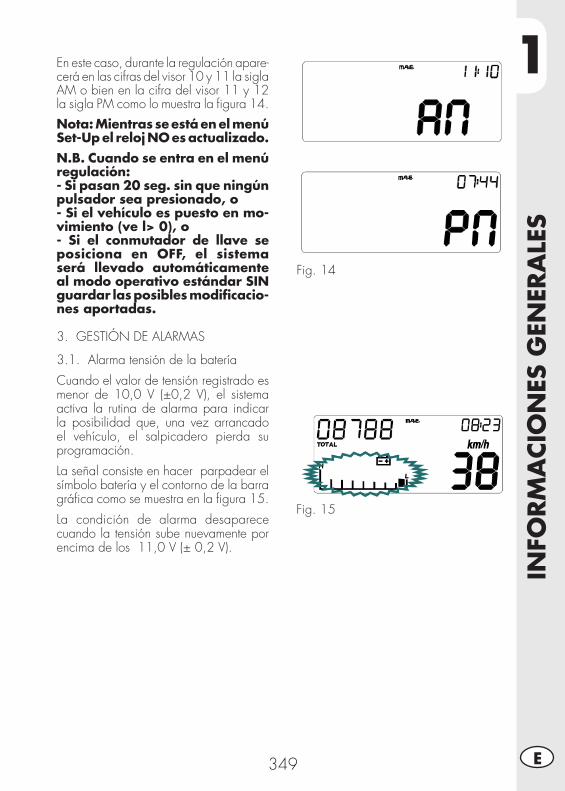
1
INFO
RM
ACIO
NES
GEN
ERA
LES
349 E
En este caso, durante la regulación apare-cerá en las cifras del visor 10 y 11 la sigla AM o bien en la cifra del visor 11 y 12 la sigla PM como lo muestra la fi gura 14.
Nota: Mientras se está en el menú Set-Up el reloj NO es actualizado.N.B. Cuando se entra en el menú regulación:- Si pasan 20 seg. sin que ningún pulsador sea presionado, o- Si el vehículo es puesto en mo-vimiento (ve l> 0), o- Si el conmutador de llave se posiciona en OFF, el sistema será llevado automáticamente al modo operativo estándar SIN guardar las posibles modifi cacio-nes aportadas.
3. GESTIÓN DE ALARMAS
3.1. Alarma tensión de la batería
Cuando el valor de tensión registrado es menor de 10,0 V (±0,2 V), el sistema activa la rutina de alarma para indicar la posibilidad que, una vez arrancado el vehículo, el salpicadero pierda su programación.
La señal consiste en hacer parpadear el símbolo batería y el contorno de la barra gráfi ca como se muestra en la fi gura 15.
La condición de alarma desaparece cuando la tensión sube nuevamente por encima de los 11,0 V (± 0,2 V).
Fig. 14
Fig. 15
1IN
FORM
ACIO
NES
GEN
ERA
LES
350E
4. LUCES PILOTO DE SEÑALIZACIÓN Y RETROILUMINACIÓN
4.1 Luz piloto de los indicadores de dirección
El sistema activa el piloto al activarse los indicadores de dirección.
Nota: La señal debe llegar desde la instrumentación ya alternada.
4.2 Luz piloto de luces de carretera
El sistema activa el piloto en sincronía con la activación de los proyectores de las luces de carretera.
4.3 Luz piloto neutral
El sistema activa el piloto en sincronía con la posición de la palanca de cambio en posición neutral.
4.4 Retroiluminación LCD y cuadrante
La iluminación posterior del cristal es de color naranja. La iluminación trasera permanece siempre encendida si el bloque de la llave está en la posición ON.
5. MENÚ SET-UP
Entrar en el menú Set-Up es posible solamente si el vehículo está parado (vel=0 Km/h) presionando el pulsador durante aprox. 5 segundos en correspondencia con la función TOTAL.
Para que las modifi caciones aportadas dentro del menú Set-Up se conviertan en operativas, es necesario que el usuario fi nalice toda la secuencia de pantallas previstas en el menú, teniendo cuidado que la salida del menú Set-Up (y el consiguiente reposicionamiento del instrumento en el modo operativo estándar) se produzca sólo y exclusivamente mediante el uso del pulsador mode.
Se puede salir del menú manteniendo presionado el pulsador mode en correspondencia con el valor seleccionado en la pantalla relativa a los impulsos revolución/rueda (que es la última pantalla del menú Set-Up), hasta que el instrumento se sitúe en el modo operativo estándar.
Nota: Cuando se entra en el menú regulación:- Si pasan 20 seg. sin que ningún pulsador sea presionado, o - Si el vehículo es puesto en movimiento (ve l> 0), o- Si el conmutador de llave se posiciona en OFF,el sistema será llevado automáticamente al modo operativo estándar SIN guardar las posibles modifi caciones aportadas.
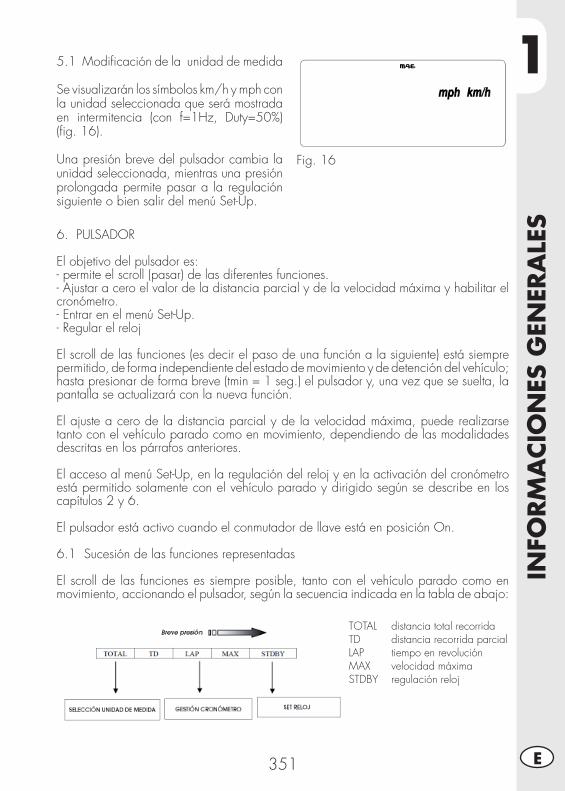
1
INFO
RM
ACIO
NES
GEN
ERA
LES
351 E
5.1 Modifi cación de la unidad de medida
Se visualizarán los símbolos km/h y mph con la unidad seleccionada que será mostrada en intermitencia (con f=1Hz, Duty=50%) (fi g. 16).
Una presión breve del pulsador cambia la unidad seleccionada, mientras una presión prolongada permite pasar a la regulación siguiente o bien salir del menú Set-Up.
Fig. 16
6. PULSADOR
El objetivo del pulsador es:- permite el scroll (pasar) de las diferentes funciones.- Ajustar a cero el valor de la distancia parcial y de la velocidad máxima y habilitar el cronómetro.- Entrar en el menú Set-Up.- Regular el reloj
El scroll de las funciones (es decir el paso de una función a la siguiente) está siempre permitido, de forma independiente del estado de movimiento y de detención del vehículo; hasta presionar de forma breve (tmin = 1 seg.) el pulsador y, una vez que se suelta, la pantalla se actualizará con la nueva función.
El ajuste a cero de la distancia parcial y de la velocidad máxima, puede realizarse tanto con el vehículo parado como en movimiento, dependiendo de las modalidades descritas en los párrafos anteriores.
El acceso al menú Set-Up, en la regulación del reloj y en la activación del cronómetro está permitido solamente con el vehículo parado y dirigido según se describe en los capítulos 2 y 6.
El pulsador está activo cuando el conmutador de llave está en posición On.
6.1 Sucesión de las funciones representadas
El scroll de las funciones es siempre posible, tanto con el vehículo parado como en movimiento, accionando el pulsador, según la secuencia indicada en la tabla de abajo:
TOTAL distancia total recorridaTD distancia recorrida parcialLAP tiempo en revoluciónMAX velocidad máximaSTDBY regulación reloj
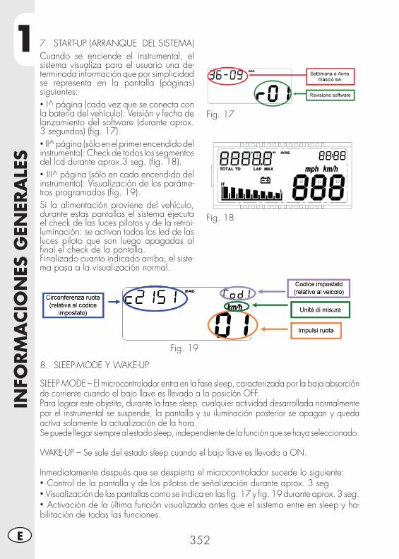
1IN
FORM
ACIO
NES
GEN
ERA
LES
352E
7. START-UP (ARRANQUE DEL SISTEMA)Cuando se enciende el instrumental, el sistema visualiza para el usuario una de-terminada información que por simplicidad se representa en la pantalla (páginas) siguientes:• I^ página (cada vez que se conecta con la batería del vehículo): Versión y fecha de lanzamiento del software (durante aprox. 3 segundos) (fi g. 17).• II^ página (sólo en el primer encendido del instrumento): Check de todos los segmentos del lcd durante aprox.3 seg. (fi g. 18).• III^ página (sólo en cada encendido del instrumento): Visualización de los paráme-tros programados (fi g. 19).Si la alimentación proviene del vehículo, durante estas pantallas el sistema ejecuta el check de las luces pilotos y de la retroi-luminación: se activan todos los led de las luces piloto que son luego apagadas al fi nal el check de la pantalla.Finalizado cuanto indicado arriba, el siste-ma pasa a la visualización normal.
Fig. 17
Fig. 18
Fig. 19
8. SLEEP-MODE Y WAKE-UP
SLEEP MODE – El microcontrolador entra en la fase sleep, caracterizada por la baja absorción de corriente cuando el bajo llave es llevado a la posición OFF.Para lograr este objetito, durante la fase sleep, cualquier actividad desarrollada normalmente por el instrumental se suspende, la pantalla y su iluminación posterior se apagan y queda activa solamente la actualización de la hora.Se puede llegar siempre al estado sleep, independiente de la función que se haya seleccionado.
WAKE-UP – Se sale del estado sleep cuando el bajo llave es llevado a ON.
Inmediatamente después que se despierta el microcontrolador sucede lo siguiente:• Control de la pantalla y de los pilotos de señalización durante aprox. 3 seg.• Visualización de las pantallas como se indica en las fi g. 17 y fi g. 19 durante aprox. 3 seg.• Activación de la última función visualizada antes que el sistema entre en sleep y ha-bilitación de todas las funciones.
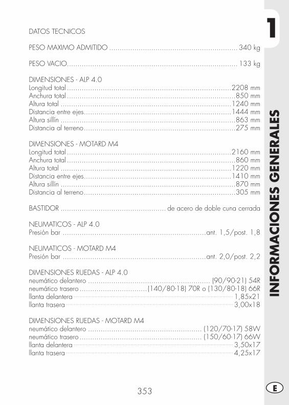
1
INFO
RM
ACIO
NES
GEN
ERA
LES
353 E
DATOS TECNICOS
PESO MAXIMO ADMITIDO ............................................................. 340 kg
PESO VACIO................................................................................. 133 kg
DIMENSIONES - ALP 4.0Longitud total ..............................................................................2208 mmAnchura total ................................................................................850 mmAltura total .................................................................................1240 mmDistancia entre ejes ......................................................................1444 mmAltura sillín ...................................................................................863 mmDistancia al terreno ........................................................................275 mm
DIMENSIONES - MOTARD M4Longitud total ..............................................................................2160 mmAnchura total ................................................................................860 mmAltura total .................................................................................1220 mmDistancia entre ejes ......................................................................1410 mmAltura sillín ...................................................................................870 mmDistancia al terreno ........................................................................305 mm
BASTIDOR .................................................. de acero de doble cuna cerrada
NEUMATICOS - ALP 4.0Presión bar ....................................................................ant. 1,5/post. 1,8
NEUMATICOS - MOTARD M4Presión bar ....................................................................ant. 2,0/post. 2,2
DIMENSIONES RUEDAS - ALP 4.0neumático delantero .......................................................... (90/90-21) 54Rneumático trasero ................................ (140/80-18) 70R o (130/80-18) 66Rllanta delantera .................................................................................................................................. 1,85x21llanta trasera ........................................................................................................................................ 3,00x18
DIMENSIONES RUEDAS - MOTARD M4neumático delantero ...................................................... (120/70-17) 58Wneumático trasero .......................................................... (150/60-17) 66Wllanta delantera .................................................................................................................................. 3,50x17llanta trasera ........................................................................................................................................ 4,25x17
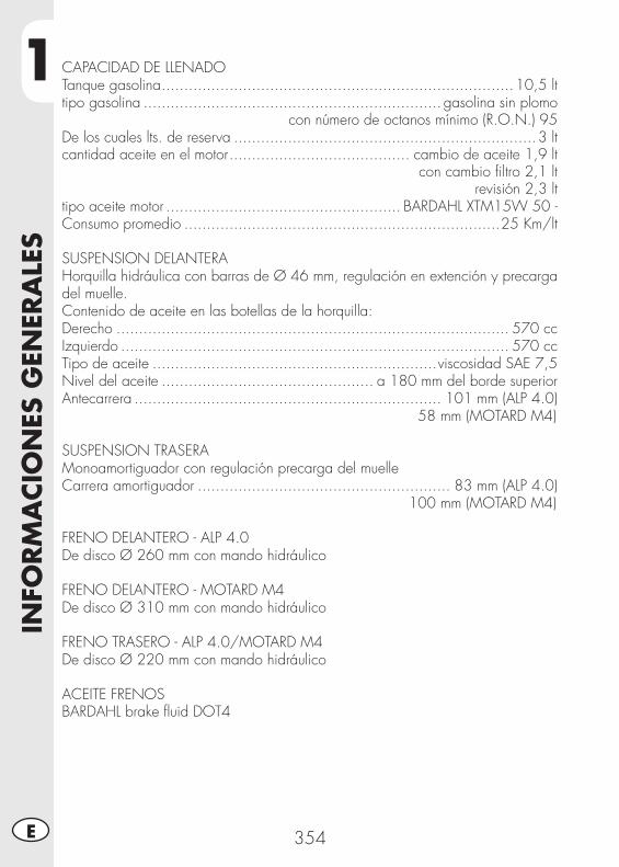
1IN
FORM
ACIO
NES
GEN
ERA
LES
354E
CAPACIDAD DE LLENADOTanque gasolina ..............................................................................10,5 lttipo gasolina .................................................................. gasolina sin plomo
con número de octanos mínimo (R.O.N.) 95 De los cuales lts. de reserva ...................................................................3 ltcantidad aceite en el motor ........................................ cambio de aceite 1,9 lt
con cambio fi ltro 2,1 ltrevisión 2,3 lt
tipo aceite motor .................................................... BARDAHL XTM15W 50 -Consumo promedio ......................................................................25 Km/lt
SUSPENSION DELANTERAHorquilla hidráulica con barras de Ø 46 mm, regulación en extención y precarga del muelle.Contenido de aceite en las botellas de la horquilla:Derecho ....................................................................................... 570 cc Izquierdo ...................................................................................... 570 ccTipo de aceite ...............................................................viscosidad SAE 7,5Nivel del aceite ............................................... a 180 mm del borde superiorAntecarrera .................................................................... 101 mm (ALP 4.0)
58 mm (MOTARD M4)
SUSPENSION TRASERAMonoamortiguador con regulación precarga del muelleCarrera amortiguador ........................................................ 83 mm (ALP 4.0)
100 mm (MOTARD M4)
FRENO DELANTERO - ALP 4.0De disco Ø 260 mm con mando hidráulico
FRENO DELANTERO - MOTARD M4De disco Ø 310 mm con mando hidráulico
FRENO TRASERO - ALP 4.0/MOTARD M4De disco Ø 220 mm con mando hidráulico
ACEITE FRENOSBARDAHL brake fl uid DOT4
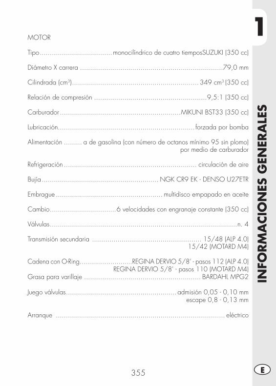
1
INFO
RM
ACIO
NES
GEN
ERA
LES
355 E
MOTOR
Tipo ....................................monocilíndrico de cuatro tiemposSUZUKI (350 cc)
Diámetro X carrera .......................................................................79,0 mm
Cilindrada (cm3) ............................................................... 349 cm3 (350 cc)
Relación de compresión ........................................................9,5:1 (350 cc)
Carburador ............................................................MIKUNI BST33 (350 cc)
Lubricación.................................................................... forzada por bomba
Alimentación ......... a de gasolina (con número de octanos mínimo 95 sin plomo)por medio de carburador
Refrigeración .................................................................. circulación de aire
Bujía .......................................................... NGK CR9 EK - DENSO U27ETR
Embrague ..................................................... multidisco empapado en aceite
Cambio .................................6 velocidades con engranaje constante (350 cc)
Válvulas .............................................................................................n. 4
Transmisión secundaria ........................................................ 15/48 (ALP 4.0)15/42 (MOTARD M4)
Cadena con O-Ring...........................REGINA DERVIO 5/8’ - pasos 112 (ALP 4.0)REGINA DERVIO 5/8’ - pasos 110 (MOTARD M4)
Grasa para varillaje .......................................................... BARDAHL MPG2
Juego válvulas .......................................................admisión 0,05 - 0,10 mm escape 0,8 - 0,13 mm
Arranque .................................................................................... eléctrico
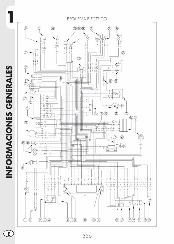
1IN
FORM
ACIO
NES
GEN
ERA
LES
356E
ESQUEMA ELECTRICO
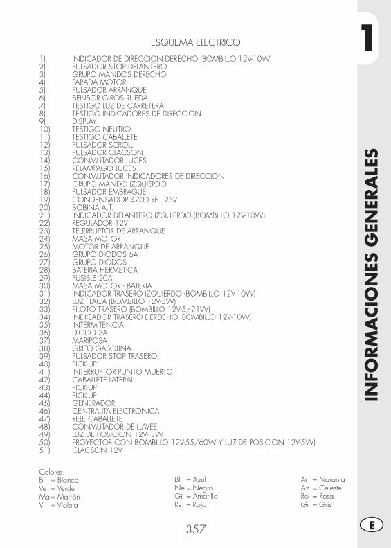
1
INFO
RM
ACIO
NES
GEN
ERA
LES
357 E
ESQUEMA ELECTRICO
1) INDICADOR DE DIRECCION DERECHO (BOMBILLO 12V-10W)2) PULSADOR STOP DELANTERO3) GRUPO MANDOS DERECHO4) PARADA MOTOR5) PULSADOR ARRANQUE6) SENSOR GIROS RUEDA7) TESTIGO LUZ DE CARRETERA8) TESTIGO INDICADORES DE DIRECCION9) DISPLAY10) TESTIGO NEUTRO11) TESTIGO CABALLETE12) PULSADOR SCROLL13) PULSADOR CLACSON14) CONMUTADOR LUCES15) RELAMPAGO LUCES16) CONMUTADOR INDICADORES DE DIRECCION17) GRUPO MANDO IZQUIERDO18) PULSADOR EMBRAGUE19) CONDENSADOR 4700 ?F - 25V 20) BOBINA A.T.21) INDICADOR DELANTERO IZQUIERDO (BOMBILLO 12V-10W)22) REGULADOR 12V23) TELERRUPTOR DE ARRANQUE24) MASA MOTOR25) MOTOR DE ARRANQUE26) GRUPO DIODOS 6A27) GRUPO DIODOS28) BATERIA HERMETICA29) FUSIBLE 20A30) MASA MOTOR - BATERIA31) INDICADOR TRASERO IZQUIERDO (BOMBILLO 12V-10W) 32) LUZ PLACA (BOMBILLO 12V-5W)33) PILOTO TRASERO (BOMBILLO 12V-5/21W)34) INDICADOR TRASERO DERECHO (BOMBILLO 12V-10W)35) INTERMITENCIA36) DIODO 3A.37) MARIPOSA38) GRIFO GASOLINA39) PULSADOR STOP TRASERO40) PICK-UP41) INTERRUPTOR PUNTO MUERTO42) CABALLETE LATERAL43) PICK-UP44) PICK-UP45) GENERADOR46) CENTRALITA ELECTRONICA47) RELE CABALLETE48) CONMUTADOR DE LLAVEE49) LUZ DE POSICION 12V- 3W50) PROYECTOR CON BOMBILLO 12V-55/60W Y LUZ DE POSICION 12V-5W)51) CLACSON 12V
Colores:Bi = BlancoVe = VerdeMa = MarrónVi = Violeta
Bl = AzulNe = NegroGi = AmarilloRs = Rojo
Ar = NaranjaAz = CelesteRo = RosaGr = Gris
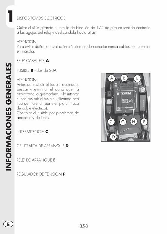
1IN
FORM
ACIO
NES
GEN
ERA
LES
358E
DISPOSITOVOS ELECTRICOS
Quitar el sillín girando el tornillo de bloquéo de 1/4 de giro en sentido contrario a las agujas del reloj y deslizandola hacia atras.
ATENCION:Para evitar dañar la instalación eléctrica no desconectar nunca cables con el motor en marcha.
RELE’ CABALLETE A
FUSIBLE B - dos de 20A
ATENCION:Antes de sustituir el fusible quemado, buscar y eliminar el daño que ha provocado la quemadura. No intentar nunca sustituir el fusible utilizando otro tipo de material (por ejemplo un trozo de cable eléctrico).Controlar el fusible por problemas de arranque y de luces.
INTERMITENCIA C
CENTRALITA DE ARRANQUE D
RELE’ DE ARRANQUE E
REGULADOR DE TENSION F
A B E
C G H F
D

1
INFO
RM
ACIO
NES
GEN
ERA
LES
359 E
NOTA RELATIVA A LA BATERIA GIntroducir la batería en su alojamiento (posición como en la foto) fi jandola con el elástico de equipamiento H. Conectar al terminal del cable de color negro al negativo (-) y el cable de color rojo al positivo (+) y colocar el capuchón rojo de protección.Montar nuevamente el sillín.
BOBINA A.T. – MOTOR DE ARRANQUE IPara acceder a estos componentes es necesario desmontar el sillín, los paneles laterales anteriores y el deposito (ver página 383, 384 por ALP y 385, 386 por MOTARD).
I
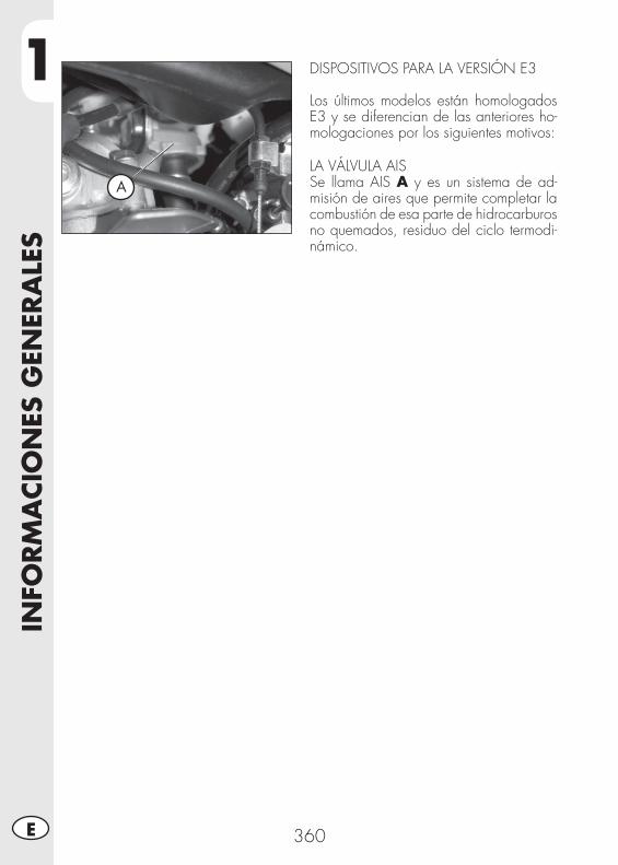
1IN
FORM
ACIO
NES
GEN
ERA
LES
360E
A
DISPOSITIVOS PARA LA VERSIÓN E3
Los últimos modelos están homologados E3 y se diferencian de las anteriores ho-mologaciones por los siguientes motivos:
LA VÁLVULA AISSe llama AIS A y es un sistema de ad-misión de aires que permite completar la combustión de esa parte de hidrocarburos no quemados, residuo del ciclo termodi-námico.
2
USO
DEL
VEH
ICU
LO
361 E
INDICE ARGUMENTOS
CAP. 2 USO DEL VEHICULO
Controles y mantenimiento antes y después del uso en todoterreno
Lubricantes aconsejados
Rodaje
Arranque del motor
Parada del motor
Abastecimiento de gasolina
2U
SO D
EL V
EHIC
ULO
362E
CONTROLES Y MANTENIMIENTO ANTES Y DESPUÉS DEL USO EN TODOTERRENO
Para evitar desagradables inconvenientes durante el funcionamiento del vehículo se aconseja efectuar, sea antes que después del uso, algunas operaciones de control y manutención. En efecto, pocos minutos dedicados a ésta operación, además de obtener una conducción mas segura, pueden hacerle ahorrar tiempo y dinero. Por lo tanto proceder de la siguiente manera:
NEUMATICOS verifi car la presión, las condiciones generales y el espesor de la banda de rodadura.
RAYOS verifi car el correcto tensionamiento.CONJUNTO DE PERNOS verifi car el apriete de todos los pernos.CADENA verifi car el tensionamiento (juego 20 mm) y si es nece-
sario engrasar.FILTRO DEL AIRE limpiar el fi ltro y mojarlo con el aceite especial (ver pág. 379).
Nota:Verifi car la presencia de los documentos de identifi cación del vehículo.En los dias frios se aconseja antes de la salida, calentar el motor dejandolo en función en ralentí por algunos instantes. Cada vez que utilizamos el vehículo en todo terreno es necesario lavarlo con muy bien, secarlo y luego lubricarlo.
LUBRICANTES ACONSEJADOS
Para conseguir un funcionamiento mejor y alargar la vida del vehículo recomendamos utilizar preferiblemente los productos indicados en la tabla:
TIPO DE PRODUCTO ESPECIFICACIONES TECNICAS
ACEITE MOTOR (2,1 lt) BARDAHL XTM15W 50
ACEITE FRENOS BARDAHL brake fl uid DOT 4 ACEITE PARA HORQUILLA LIQUI MOLY RACING SUSPENSION(570 cc DER. e IZQ.) OIL SAE 7,5
GRASA PARA VARILLAJE BARDAHL MPG2
Nota:Para las intervenciones de sustitución recomendamos seguir escrupolosaménte la tabla.
2
USO
DEL
VEH
ICU
LO
363 E
RODAJE
El rodaje dura alrededor de 10 horas de actividad, durante éste periodo aconse-jamos:• Usar el vehículo después de haber ca-lentado bien el motor.
• Evitar viajar a velocidad constante (va-riando la velocidad cada componente se asienta uniformemente en menor tiempo.
• Evitar girar el mando del acelerador por mas de 3/4.
ATENCION:Después de los primeros 1000 kms de recorrido sustituir el aceite del motor.
ADVERTENCIAEs necesario cerciorarse después de los 1000 km. de recorrido, que el fi ltro de metal, ubicado en la parte fi nal del depo-sito de aceite, esté limpio (ver pág. 370). Si así no fuese, utilizar un chorro de aire comprimido.
• Utilizar siempre gasolina super sin plomo.• Después de la primera salida en todo terreno, proceder a la verifi cación de todos los pernos y tornillos.
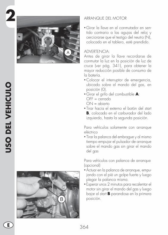
2U
SO D
EL V
EHIC
ULO
364E
ARRANQUE DEL MOTOR
• Girar la llave en el conmutador en sen-tido contrario a las agujas del reloj y cerciorarse que el testigo del neutro (N), colocado en el tablero, esté prendido.
ADVERTENCIA:Antes de girar la llave recordarse de conmutar la luz en la posición de luz de cruce (ver pág. 341), para obtener la mayor reducción posible de consumo de la batería.• Colocar el interruptor de emergencia, ubicado sobre el mando del gas, en posición (0).
• Girar el grifo del combustible A: OFF = cerrado ON = abierto• Tirar hacia el externo el botón del start B, colocado en el carburador del lado izquierdo, hasta la segunda posición.
Para vehículos solamente con arranque eléctrico• Tirar la palanca del embrague y al mismo tiempo empujar el pulsador de arranque sobre el mando gas sin girar el mando del gas
Para vehículos con palanca de arranque (opcional)• Actuar en la palanca de arranque, empu-jando con el pié un golpe fuerte y luego plegar la palanca misma.
• Esperar unos 2 minutos para recalentar el motor sin girar el mando del gas y luego bajar el start B parandose en la primera posición.
A
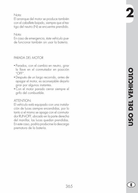
2
USO
DEL
VEH
ICU
LO
365 E
Nota:El arranque del motor se produce también con el caballete bajado, siempre que el tes-tigo del neutro (N) se encuentre prendido.
Nota:En caso de emergencia, éste vehículo pue-de funcionar también sin usar la batería.
PARADA DEL MOTOR
• Parados, con el cambio en neutro, girar la llave en el conmutador en posición “OFF”.
• Después de un largo recorrido, antes de apagar el motor, es aconsejable dejarlo girar por algunos instantes.
• Con el motor parado cerrar siempre el grifo del combustible.
ATTENTION:El vehículo está equipado con una instala-ción de luces siempre encendidas, por lo tanto si el mismo se apaga con el conmuta-dor RUN-OFF, ubicado en la parte derecha del manillar, las luces quedan prendidas. En este caso, podría producirse la descarga prematura de la batería.
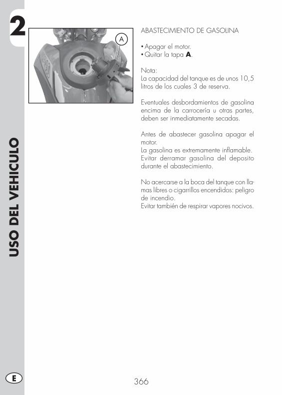
2U
SO D
EL V
EHIC
ULO
366E
ABASTECIMIENTO DE GASOLINA
• Apagar el motor.• Quitar la tapa A.
Nota:La capacidad del tanque es de unos 10,5 litros de los cuales 3 de reserva.
Eventuales desbordamientos de gasolina encima de la carrocería u otras partes, deben ser inmediatamente secadas.
Antes de abastecer gasolina apagar el motor.La gasolina es extremamente infl amable.Evitar derramar gasolina del deposito durante el abastecimiento.
No acercarse a la boca del tanque con lla-mas libres o cigarrillos encendidos: peligro de incendio.Evitar también de respirar vapores nocivos.
A
3
CO
NTR
OLE
S Y
MA
NTE
NIM
IEN
TO
367 E
INDICE DE LOS ARGUMENTOS
CAP. 3 CONTROLES Y MANTENIMIENTO
Comprobación nivel aceite en el motor
Sustitución aceite motor y fi ltro aceite
Tubo recolección humos
Aceite bomba frenos, espurgo frenos
Aceite horquillas
Filtro de aire
Bujia
Freno delantero
Freno trasero
Carburador
Batería
Desmontaje de las partes de plastico por ALP
Desmontaje de las partes de plastico por MOTARD M4
Nota para todo terreno
Sustitución grupo transmisión fi nal
Limpieza del vehículo y comprobaciones
Comprobaciones despues de la limpieza
Manutención programada
Larga inactividad del vehículo
Despues de un largo periodo de inactividad
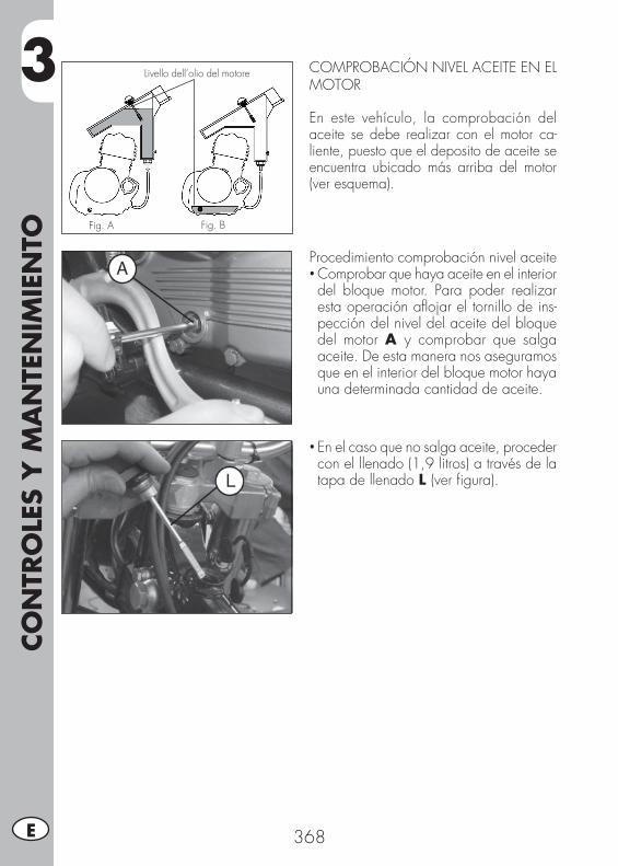
3CO
NTR
OLE
S Y
MA
NTE
NIM
IEN
TO
368E
COMPROBACIÓN NIVEL ACEITE EN EL MOTOR
En este vehículo, la comprobación del aceite se debe realizar con el motor ca-liente, puesto que el deposito de aceite se encuentra ubicado más arriba del motor (ver esquema).
Fig. A
Livello dell’olio del motore
Fig. B
Procedimiento comprobación nivel aceite• Comprobar que haya aceite en el interior del bloque motor. Para poder realizar esta operación afl ojar el tornillo de ins-pección del nivel del aceite del bloque del motor A y comprobar que salga aceite. De esta manera nos aseguramos que en el interior del bloque motor haya una determinada cantidad de aceite.
• En el caso que no salga aceite, proceder con el llenado (1,9 litros) a través de la tapa de llenado L (ver fi gura).
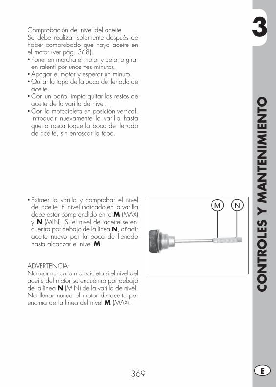
3
CO
NTR
OLE
S Y
MA
NTE
NIM
IEN
TO
369 E
Comprobación del nivel del aceiteSe debe realizar solamente después de haber comprobado que haya aceite en el motor (ver pág. 368).• Poner en marcha el motor y dejarlo girar en ralentí por unos tres minutos.
• Apagar el motor y esperar un minuto.• Quitar la tapa de la boca de llenado de aceite.
• Con un paño limpio quitar los restos de aceite de la varilla de nivel.
• Con la motocicleta en posición vertical, introducir nuevamente la varilla hasta que la rosca toque la boca de llenado de aceite, sin enroscar la tapa.
• Extraer la varilla y comprobar el nivel del aceite. El nivel indicado en la varilla debe estar comprendido entre M (MAX) y N (MIN). Si el nivel del aceite se en-cuentra por debajo de la línea N, añadir aceite nuevo por la boca de llenado hasta alcanzar el nivel M.
ADVERTENCIA:No usar nunca la motocicleta si el nivel del aceite del motor se encuentra por debajo de la línea N (MIN) de la varilla de nivel.No llenar nunca el motor de aceite por encima de la línea del nivel M (MAX).

3CO
NTR
OLE
S Y
MA
NTE
NIM
IEN
TO
370E
SUSTITUCIÓN ACEITE MOTOR Y FILTRO ACEITE
Efectuar siempre la sustitución del aceite con el motor caliente, prestando atención en no tocar el motor y el mismo aceite para evitar quemaduras.
• La sustitución del fi ltro del aceite debería realizarse junto con la sustitución del aceite.
• Colocar la moto sobre el caballete.• Colocar un contenedor debajo del motor.• Destornillar el tapón de llenado L y de vaciado F.
• Vaciar completamente el carter.
Cambio del fi ltro de aceite• Quitar la tapa del fi ltro aceite destornil-lando las 3 tuercas de fi jación G.
• Quitar el fi ltro aceite.
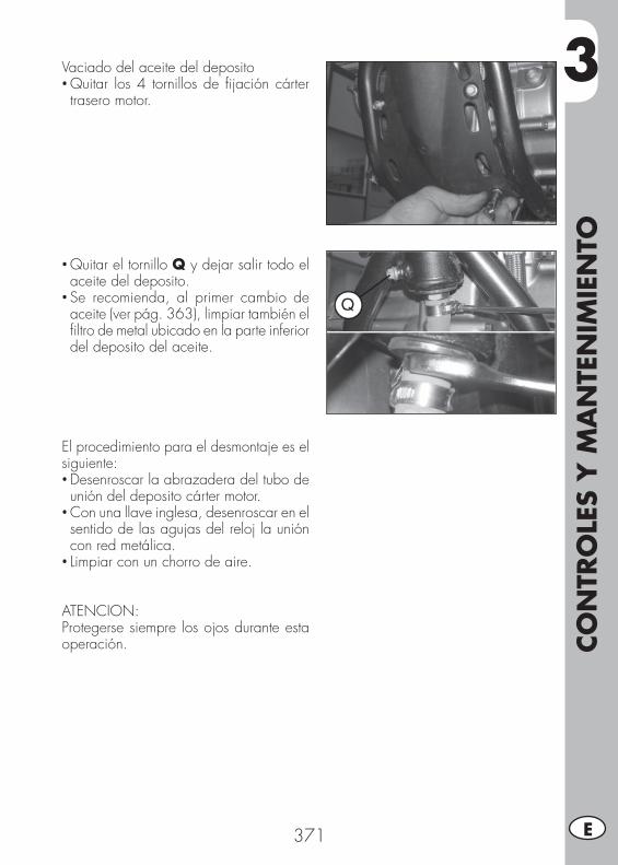
3
CO
NTR
OLE
S Y
MA
NTE
NIM
IEN
TO
371 E
Vaciado del aceite del deposito• Quitar los 4 tornillos de fi jación cárter trasero motor.
• Quitar el tornillo Q y dejar salir todo el aceite del deposito.
• Se recomienda, al primer cambio de aceite (ver pág. 363), limpiar también el fi ltro de metal ubicado en la parte inferior del deposito del aceite.
El procedimiento para el desmontaje es el siguiente:• Desenroscar la abrazadera del tubo de unión del deposito cárter motor.
• Con una llave inglesa, desenroscar en el sentido de las agujas del reloj la unión con red metálica.
• Limpiar con un chorro de aire.
ATENCION:Protegerse siempre los ojos durante esta operación.

3CO
NTR
OLE
S Y
MA
NTE
NIM
IEN
TO
372E
• Para el vaciado total del deposito de aceite, quitar el sillín, los paneles latera-les delanteros y el deposito.
• Inclinar la moto hacia el lado izquierdo y desenroscar el tornillo H ubicada en el bastidor.
• Colocar el tubo de goma I.• Colocar un recipiente en la extremidad del tubo.
• Inclinar el vehículo del lado de la salida del aceite.
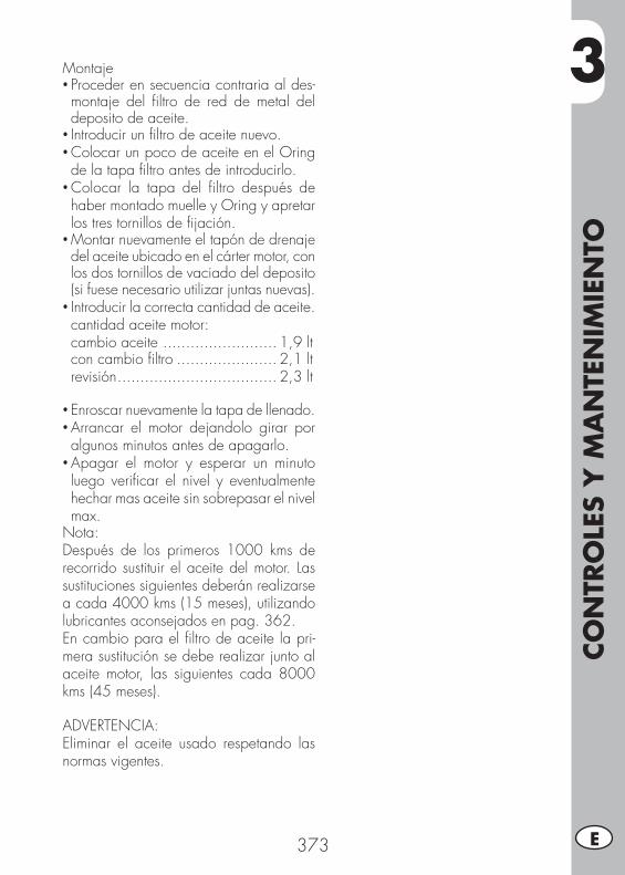
3
CO
NTR
OLE
S Y
MA
NTE
NIM
IEN
TO
373 E
Montaje• Proceder en secuencia contraria al des-montaje del fi ltro de red de metal del deposito de aceite.
• Introducir un fi ltro de aceite nuevo.• Colocar un poco de aceite en el Oring de la tapa fi ltro antes de introducirlo.
• Colocar la tapa del fi ltro después de haber montado muelle y Oring y apretar los tres tornillos de fi jación.
• Montar nuevamente el tapón de drenaje del aceite ubicado en el cárter motor, con los dos tornillos de vaciado del deposito (si fuese necesario utilizar juntas nuevas).
• Introducir la correcta cantidad de aceite. cantidad aceite motor: cambio aceite ......................... 1,9 lt con cambio fi ltro ...................... 2,1 lt revisión ................................... 2,3 lt
• Enroscar nuevamente la tapa de llenado.• Arrancar el motor dejandolo girar por algunos minutos antes de apagarlo.
• Apagar el motor y esperar un minuto luego verifi car el nivel y eventualmente hechar mas aceite sin sobrepasar el nivel max.
Nota: Después de los primeros 1000 kms de recorrido sustituir el aceite del motor. Las sustituciones siguientes deberán realizarse a cada 4000 kms (15 meses), utilizando lubricantes aconsejados en pag. 362.En cambio para el fi ltro de aceite la pri-mera sustitución se debe realizar junto al aceite motor, las siguientes cada 8000 kms (45 meses).
ADVERTENCIA:Eliminar el aceite usado respetando las normas vigentes.
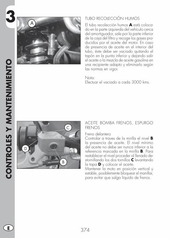
3CO
NTR
OLE
S Y
MA
NTE
NIM
IEN
TO
374E
TUBO RECOLECCIÓN HUMOS
El tubo recolección humos A está coloca-do en la parte izquierda del vehículo cerca del amortiguador, sale por la parte inferior de la caja del fi ltro y recoge los gases pro-ducidos por el aceite del motor. En caso de presencia de aceite en el interior del tubo, éste debe ser vaciado quitando el tapón en la punta inferior y dejando salir el aceite o la mezcla de aceite gasolina en una recipiente adapto y eliminarlo según las normas en vigor.
Nota:Efectuar el vaciado a cada 3000 kms.
ACEITE BOMBA FRENOS, ESPURGO FRENOSFreno delanteroControlar a traves de la mirilla el nivel B la presencia de aceite. El nivel mínimo del aceite no debe ser nunca inferior a la referencia marcada en la mirilla B. Para restablecer el nivel proceder al llenado de-stornillando los dos tornillos C levantando la tapa D y colocar el aceite.Mantener la moto en posición vertical y estable, posiblemente bloquear el manillar, para evitar que salga líquido de frenos.
B
C
D

3
CO
NTR
OLE
S Y
MA
NTE
NIM
IEN
TO
375 E
Freno trasero
Verifi car la existencia de aceite en el contenedor E. El nivel del aceite no debe ser nunca inferior a la marca F del nivel mínimo en relieve en el contenedor. Para restablecer el nivel proceder como descrito:
•Desenroscar el tornillo de fi jacion del contenedor del aceite G.
• Extraer el contenedor de aceite de su alojamiento.
• Abrir la tapa prestando atención en man-tener en posición vertical el contenedor del líquido de frenos.
• Envolver con papel absorbente como muestra la fi gura.
• Proceder con el llenado.
ATENCION:El líquido para frenos es muy corrosivo, por lo tanto tener cuidado en no dejar caer gotas sobre las partes pintadas del vehículo.
ATENCION:En el caso que se notara una escasa resistencia accionando la palanca del freno, el defecto podría ser provocado por una burbuja de aire en el circuito, en ese caso es necesario realizar la purga de los frenos (pág. 376/377) o dirigirse lo antes posible a un taller autorizado.
Nota:Para la sustitución seguir la tabla a pag. 391 utilizando los lubricantes aconsejados en pag. 362.
E
F
G

3CO
NTR
OLE
S Y
MA
NTE
NIM
IEN
TO
376E
Espurgo freno delantero
Para quitar aire del circuito del freno de-lantero proceder de la siguiente manera:
• Quitar el capuchón de goma A de la válvula B.
• Abrir el tapón del recipiente de aceite.
• Introducir una extremidad de un tubo en la válvula B y la otra en el interior de un contenedor.
• Destornillar la válvula B (con palanca del freno tirada) y bombear con la palanca del freno hasta que salga aceite sin burbujas de aire; durante ésta operación es importante no soltar completamente la palanca, rellenar continuamente el recipiente del aceite de la bomba del freno para compensar el aceite salido.
• Apretar la válvula y extraer el tubo.
• Volver a colocar el capuchón.
MOTARD
B
A
ALP A
B

3
CO
NTR
OLE
S Y
MA
NTE
NIM
IEN
TO
377 E
Espurgo freno trasero
Para quitar aire del circuito del freno trasero proceder de la siguiente manera:
• Quitar el capuchón de goma C.
• Abrir la tapa del recipiente de aceite.
• Introducir una extremidad de un tubo en la válvula D y la otra en el interior de un contenedor.
• Destornillar la válvula D (con palanca del freno tirada) y bombear con la palanca del freno hasta que salga aceite sin burbujas de aire; durante ésta operación es importante no soltar completamente la palanca, rellenar continuamente el recipiente del aceite de la bomba del freno para compensar el aceite salido.
• Apretar la válvula y extraer el tubo.
• Volver a colocar el capuchón.
D
C
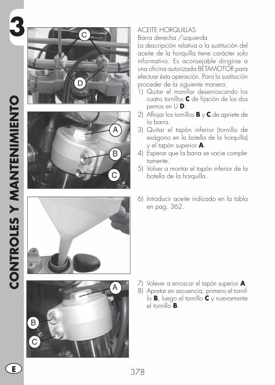
3CO
NTR
OLE
S Y
MA
NTE
NIM
IEN
TO
378E
ACEITE HORQUILLASBarra derecha /izquierdaLa descripción relativa a la sustitución del aceite de la horquilla tiene carácter solo informativo. Es aconsejable dirigirse a una ofi cina autorizada BETAMOTOR para efectuar ésta operación. Para la sustitución proceder de la siguiente manera:1) Quitar el manillar desenroscando los
cuatro tornillos C de fi jación de los dos pernos en U D.
2) Afl ojar los tornillos B y C de apriete de la barra.
3) Quitar el tapón inferior (tornillo de exágono en la botella de la horquilla) y el tapón superior A.
4) Esperar que la barra se vacie comple-tamente.
5) Volver a montar el tapón inferior de la botella de la horquilla.
6) Introducir aceite indicado en la tabla en pag. 362.
7) Volever a enroscar el tapón superior A.8) Apretar en secuencia, primero el tornil-
lo B, luego el tornillo C y nuevamente el tornillo B.

3
CO
NTR
OLE
S Y
MA
NTE
NIM
IEN
TO
379 E
FILTRO DE AIRE
Para acceder al fi ltro es necesario:•Levantar apenas el panel lateral izquierdo trasero A, como en la fi gura.
• Quitar la cobertura de plastico E destor-nillando los 3 tornillos de fi jación B.
• Quitar el fi ltro C destornillando el tornillo de fi jación D de la tapa sujeción fi ltro.
• Lavarlo con agua y jabón.• Secarlo.• Empaparlo en aceite para fi ltros y elimi-nar el aceite en exceso de manera que no gotee.
• Si fuera necesario limpiar también la parte interior de la caja del fi ltro.
• Proceder al montaje prestando atención al perfecto cerrado hermético del empa-que de goma, engrasado antes para mejorar el cierre F.
Nota:En el caso que el fi ltro se encuentre muy sucio lavarlo antes con gasolina y después con agua y jabón. En el caso que el fi ltro esté dañado sus-tituirlo.
ATENCION:Después de cada intervención verifi car que no haya quedado ningún objeto en el interior de la caja.
Efectuar la limpieza del fi ltro cada vez que el vehículo se utilice en todo terreno.
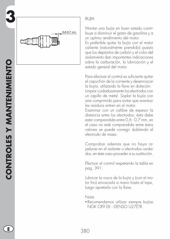
3CO
NTR
OLE
S Y
MA
NTE
NIM
IEN
TO
380E
BUJIA
Montar una bujía en buen estado contri-buye a disminuir el gasto de gasolina y a un optimo rendimiento del motor.Es preferible quitar la bujía con el motor caliente (naturalménte prendido) puesto que los depósitos de carbón y el color del aislamiento dan importantes indicaciones sobre la carburación, la lubricación y el estado general del motor.
Para efectuar el control es sufi ciente quitar el capuchón de la corriente y desenroscar la bujía, utilizando la llave en dotación.Limpiar cuidadosamente los electrodos con un cepillo de metal. Soplar la bujía con aire comprimido para evitar que eventua-les residuos entren en el motor.Examinar con un calibre de espesor la distancia entre los electrodos, ésta debe estar comprendida entre 0,6 - 0,7 mm, en el caso no esté comprendida entre éstos valores se puede corregir doblando el electrodo de masa.
Comprobar además que no haya ra-jaduras en el aislante o electrodos oxida-dos, en éste caso proceder a su sustitución.
Efectuar el control respetando la tabla en pag. 391.
Lubricar la rosca de la bujía y (con el mo-tor frio) enroscarla a mano hasta el tope, luego apretarla con la llave.
Nota:• Recomendamos utilizar siempre bujías NGK CR9 EK - DENSO U27ETR.
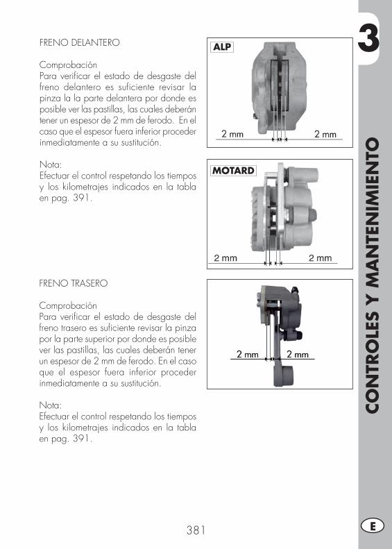
3
CO
NTR
OLE
S Y
MA
NTE
NIM
IEN
TO
381 E
FRENO DELANTERO
ComprobaciónPara verifi car el estado de desgaste del freno delantero es sufi ciente revisar la pinza la la parte delantera por donde es posible ver las pastillas, las cuales deberán tener un espesor de 2 mm de ferodo. En el caso que el espesor fuera inferior proceder inmediatamente a su sustitución.
Nota:Efectuar el control respetando los tiempos y los kilometrajes indicados en la tabla en pag. 391.
FRENO TRASERO
ComprobaciónPara verifi car el estado de desgaste del freno trasero es sufi ciente revisar la pinza por la parte superior por donde es posible ver las pastillas, las cuales deberán tener un espesor de 2 mm de ferodo. En el caso que el espesor fuera inferior proceder inmediatamente a su sustitución.
Nota:Efectuar el control respetando los tiempos y los kilometrajes indicados en la tabla en pag. 391.
ALP
MOTARD
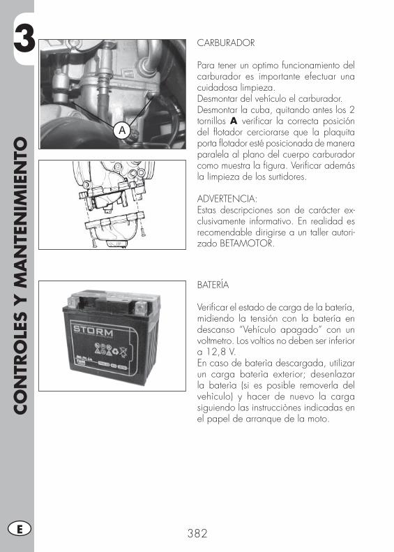
3CO
NTR
OLE
S Y
MA
NTE
NIM
IEN
TO
382E
CARBURADOR
Para tener un optimo funcionamiento del carburador es importante efectuar una cuidadosa limpieza.Desmontar del vehículo el carburador.Desmontar la cuba, quitando antes los 2 tornillos A verifi car la correcta posición del fl otador cerciorarse que la plaquita porta fl otador esté posicionada de manera paralela al plano del cuerpo carburador como muestra la fi gura. Verifi car además la limpieza de los surtidores.
ADVERTENCIA:Estas descripciones son de carácter ex-clusivamente informativo. En realidad es recomendable dirigirse a un taller autori-zado BETAMOTOR.
BATERÍA
Verifi car el estado de carga de la batería, midiendo la tensión con la batería en descanso “Vehículo apagado” con un voltmetro. Los voltios no deben ser inferior a 12,8 V.En caso de baterìa descargada, utilizar un carga baterìa exterior; desenlazar la baterìa (si es posible removerla del vehìculo) y hacer de nuevo la carga siguiendo las instrucciònes indicadas en el papel de arranque de la moto.

3
CO
NTR
OLE
S Y
MA
NTE
NIM
IEN
TO
383 E
DESMONTAJE DE LAS PARTES DE PLASTI-CO POR ALP
Para realizar mas facilmente comproba-ciones o intervenciones en algunas zonas del vehículo, es indispensable desmontar las partes que componen la carrocería de la siguiente manera:
Desmontaje del asiento• Girar de 90° en sentido contrario a las agujas del reloj la fi jación A, extraer el asiento tirándolo hacia la parte posterior del vehículo. Para el montaje es sufi ciente colocar nuevamente el asiento en su posición inicial, empujar la fi jación A hacia abajo (sin tener que girarla), hasta oír un clic, a este punto el asiento está bloqueado.
Desmontaje manijas posteriores• Desenroscar los dos tornillos B de fi ja-ción, luego, quitar los tornillos E de fi ja-ción ubicados debajo del guardabarros trasero, y luego quitar las manijas C, teniendo cuidado para no perder los espesores de goma.
Desmontaje cola trasera• Montar nuevamente el tornillo F de fi ja-ción y quitar la cola D.
Desmontar los paneles laterales delanteros• Desenroscar los cuatro tornillos G de fi jación (dos por cada lado) y quitar los dos tornillos H.
• Desmontar los paneles laterales delante-ros teniendo cuidado en quitar antes la parte izquierda y luego la derecha.
A
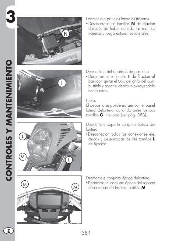
3CO
NTR
OLE
S Y
MA
NTE
NIM
IEN
TO
384E
L
L
M
Desmontaje paneles laterales traseros• Desenroscar los tornillos N de fi jación después de haber quitado las manijas traseras y luego extraer los laterales.
Desmontaje del depósito de gasolina• Desenroscar el tornillo I de fi jación al bastidor, quitar el tubo del grifo del com-bustible y sacar el depósito extrayendolo hacia atras.
Nota:El deposito se puede extraer con el panel lateral delantero, quitando antes los dos tornillos G inferiores (ver pág. 383).
Desmontaje soporte conjunto óptico de-lantero•Desconectar todas las conexiones elé-ctricas y desenroscar los tres tornillos L de fi jación.
Desmontaje conjunto óptico delantero•Desmontar el conjunto óptico del soporte desenroscando los tres tornillos M.M
M

3
CO
NTR
OLE
S Y
MA
NTE
NIM
IEN
TO
385 E
DESMONTAJE DE LAS PARTES DE PLASTI-CO POR MOTARD M4
Para realizar mas facilmente comprobaciones o intervenciones en algunas zonas del vehículo, es indispensable desmontar las partes que compo-nen la carrocería de la siguiente manera:
Desmontaje del asiento• Girar de 90° en sentido contrario a las agujas del reloj la fi jación A, extraer el asiento tirándolo hacia la parte posterior del vehículo. Para el montaje es sufi ciente co-locar nuevamente el asiento en su posición inicial, empujar la fi jación A hacia abajo (sin tener que girarla), hasta oír un clic, a este punto el asiento está bloqueado.
Desmontaje manijas posteriores• Desenroscar los dos tornillos B de fi jación, luego, quitar los tornillos C de fi jación ubicados debajo del guardabarros trase-ro, y luego quitar las manijas D, teniendo cuidado para no perder los espesores de goma.
Desmontar los paneles laterales delanteros•Desmontar los paneles laterales delante-ros iniciando desde la izquierda E.
Desenroscar los tres tornillos F y el tornillo G ubicada en la parte delantera, des-enganchar el panel lateral del deposito y proceder de la misma manera con el panel lateral derecho H, añadiendo el tornillo I ubicado sobre el deposito.
Y luego desmoontar el panel lateral H desenganchandolo de las estacas ubica-das en el deposito.
Desmontaje del depósito de gasolina• Desenroscar el tornillo L de fi jación al bastidor, quitar el tubo del grifo del com-bustible y sacar el depósito extrayendolo hacia atras.
Nota:El deposito se puede extraer con el panel lateral delantero, quitando antes los dos tornillos F inferiores.
F
G
E
I
H
L
B
A
C
D
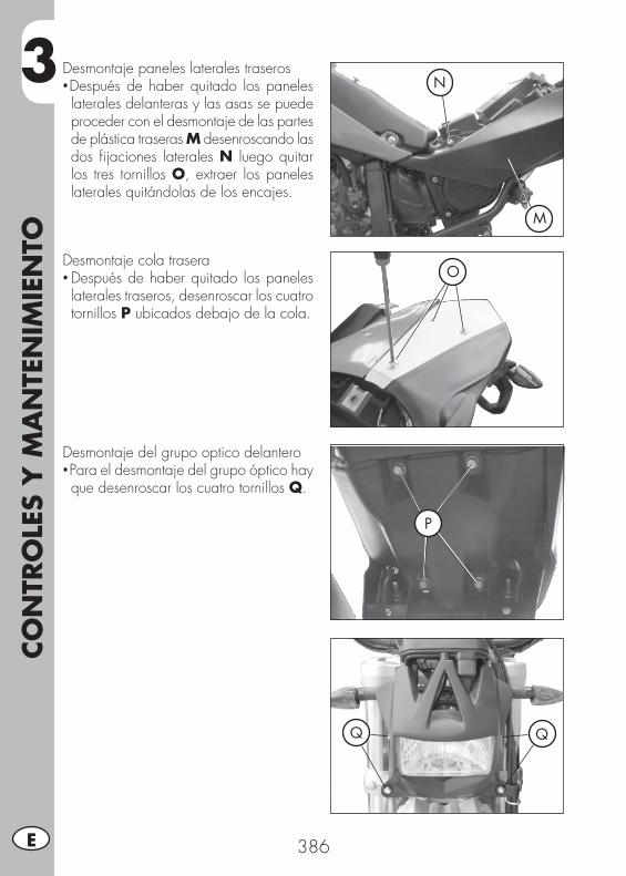
3CO
NTR
OLE
S Y
MA
NTE
NIM
IEN
TO
386E
Desmontaje paneles laterales traseros•Después de haber quitado los paneles laterales delanteras y las asas se puede proceder con el desmontaje de las partes de plástica traseras M desenroscando las dos fi jaciones laterales N luego quitar los tres tornillos O, extraer los paneles laterales quitándolas de los encajes.
M
N
ODesmontaje cola trasera• Después de haber quitado los paneles laterales traseros, desenroscar los cuatro tornillos P ubicados debajo de la cola.
P
Desmontaje del grupo optico delantero•Para el desmontaje del grupo óptico hay que desenroscar los cuatro tornillos Q.
Q Q
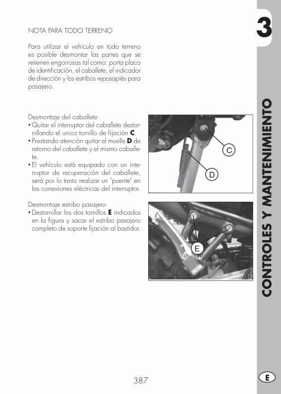
3
CO
NTR
OLE
S Y
MA
NTE
NIM
IEN
TO
387 E
NOTA PARA TODO TERRENO
Para utilizar el vehículo en todo terreno es posible desmontar las partes que se retienen engorrosas tal como: porta placa de identifi cación, el caballete, el indicador de dirección y los estribos reposapiés para pasajero.
Desmontaje del caballete• Quitar el interruptor del caballete destor-nillando el unico tornillo de fi jación C.
• Prestando atención quitar el muelle D de retorno del caballete y el mismo caballe-te.
• El vehículo está equipado con un inte-rruptor de recuperación del caballete, será por lo tanto realizar un "puente" en las conexiones eléctricas del interruptor.
Desmontaje estribo pasajero• Destornillar los dos tornillos E indicados en la fi gura y sacar el estribo pasajero completo de soporte fi jación al bastidor.
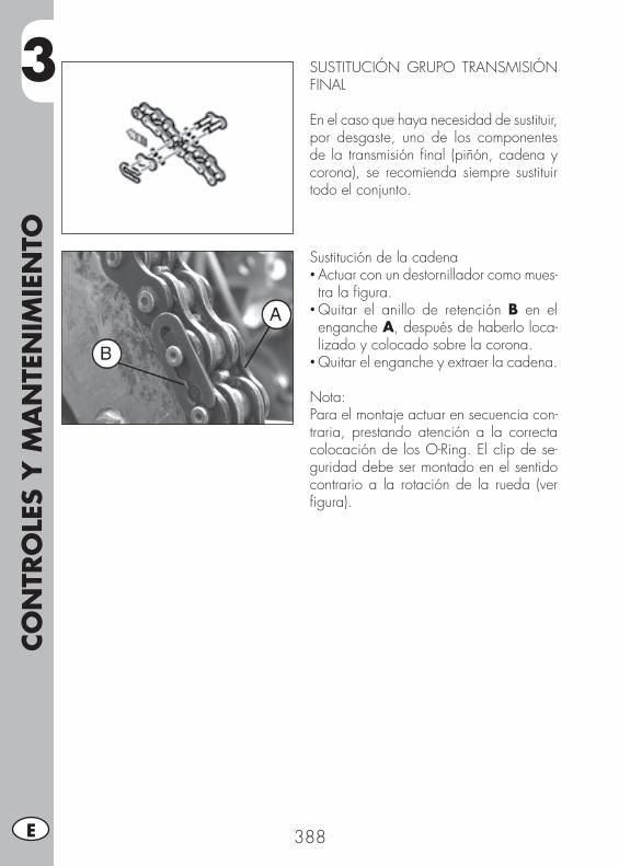
3CO
NTR
OLE
S Y
MA
NTE
NIM
IEN
TO
388E
Sustitución de la cadena• Actuar con un destornillador como mues-tra la fi gura.
• Quitar el anillo de retención B en el enganche A, después de haberlo loca-lizado y colocado sobre la corona.
• Quitar el enganche y extraer la cadena.
Nota:Para el montaje actuar en secuencia con-traria, prestando atención a la correcta colocación de los O-Ring. El clip de se-guridad debe ser montado en el sentido contrario a la rotación de la rueda (ver fi gura).
SUSTITUCIÓN GRUPO TRANSMISIÓN FINAL
En el caso que haya necesidad de sustituir, por desgaste, uno de los componentes de la transmisión fi nal (piñón, cadena y corona), se recomienda siempre sustituir todo el conjunto.
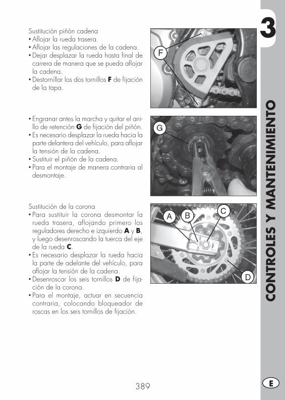
3
CO
NTR
OLE
S Y
MA
NTE
NIM
IEN
TO
389 E
Sustitución piñón cadena• Afl ojar la rueda trasera.• Afl ojar las regulaciones de la cadena.• Dejar desplazar la rueda hasta fi nal de carrera de manera que se pueda afl ojar la cadena.
• Destornillar los dos tornillos F de fi jación de la tapa.
Sustitución de la corona• Para sustituir la corona desmontar la rueda trasera, aflojando primero los reguladores derecho e izquierdo A y B, y luego desenroscando la tuerca del eje de la rueda C.
• Es necesario desplazar la rueda hacia la parte de adelante del vehículo, para afl ojar la tensión de la cadena.
• Desenroscar los seis tornillos D de fi ja-ción de la corona.
• Para el montaje, actuar en secuencia contraria, colocando bloqueador de roscas en los seis tornillos de fi jación.
• Engranar antes la marcha y quitar el ani-llo de retención G de fi jación del piñón.
• Es necesario desplazar la rueda hacia la parte delantera del vehículo, para afl ojar la tensión de la cadena.
• Sustituir el piñón de la cadena.• Para el montaje de manera contraria al desmontaje.
3CO
NTR
OLE
S Y
MA
NTE
NIM
IEN
TO
390E
LIMPIEZA DEL VEHÍCULO Y COMPROBACIONES
Para ablandar la suciedad y el barro depositado en la superfi cie pintada usar un chorro de agua. Una vez ablandado el barro y suciedad se deben quitar con una esponja blanda para carrocería empapada con mucha agua y “ champú “ (2-4 % de champú en agua) . Luego enjuagar abundantemente con agua y secar con un chorro de aire y un paño o con piel. Para la parte externa del motor usar petrolio, pincel y trapos limpios. El petrolio daña la pintura. Recordamos que para eventual lustrado con ceras siliconicas hay que proceder antes a un lavado.
Los detergentes contaminan las aguas. Por lo tanto el lavado del vehículo hay que realizarlo en zona equipada para la recolección y la depuración de líquidos empleados para el mismo lavado.
El lavado no debe ser nunca realizado bajo el sol especialmente de verano cuando la carrocería está aún caliente puesto que el champú que se seca antes que el agua puede provocar daños a la pintura. No utilizar nunca
trapos mojado con gasolina o gasoil para lavar superfi cies pintadas o de material plástico, para evitar que pierdan su brillantez y las características mecánicas de los materiales.
COMPROBACIONES DESPUES DE LA LIMPIEZA
Después de limpiar la moto es buena norma:
• Limpiar el fi ltro de aire (proceder como descrito en pag. 379)• Desmontar la cuba del carburador afl ojando el tornillo de drenaje de la gasolina (proceder como descrito en pag. 382) para verifi car eventual existencia de agua.
• Engrasar la cadena.
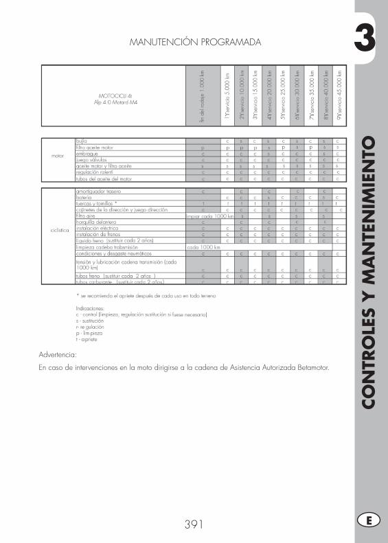
3
CO
NTR
OLE
S Y
MA
NTE
NIM
IEN
TO
391 E
MANUTENCIÓN PROGRAMADA
Advertencia:
En caso de intervenciones en la moto dirigirse a la cadena de Asistencia Autorizada Betamotor.

3CO
NTR
OLE
S Y
MA
NTE
NIM
IEN
TO
392E
LARGA INACTIVIDAD DEL VEHÍCULO
En previsión de una larga inactividad del vehículo, por ejemplo durante el invier-no, es necesario adoptar algunas simples precauciones para garantizar un buen mantenimiento:• Efectuar una completa limpieza del vehículo en todas sus partes.• Reducir la presión de los neumáticos de un 30 % teniendolos posiblemente no apoyados a la tierra.
• Quitar la bujía e introducir por el agujero algunas gotas de aceite para motor. Hacer gira el motor por algunas vueltas, accionando la palanca arranque a pedal (donde prevista) . Volver a eroscar la bujía .
• Cubrir con un pelicula de aceite o silicona en aerosol las partes sin pintar, menos las partes de goma y los frenos.
• Quitar la batería y guardarla en lugar seco, cargandola una vez por mes.• Tapar el vehículo con un telón para protegerlo del polvo.
• Descargar la cuba del carburador ac-tuando en el tornillo A. El combustible extraido de la cuba con un tubo debe ser recogido en el interior de un recipiente y colocado en el depósito del combustible sin desperdiciarlo en el medio ambiente.
• Apretar nuevamente el tornillo.
DESPUES DE UN LARGO PERIODO DE INACTIVIDAD
• Colocar la batería• Restablecer la presión de los neumáticos.• Verifi car el apriete de todos los tornillos de levada importancia mecanica.
Nota:La verifi cación del apriete de los tornillos se debe realizar con una frecuencia periódica.
• Efectuar el primer arranque con el sistema de pedal: “kick starter“ (donde previsto).
4
REG
ULA
CIO
NES
393 E
INDICE ARGUMENTOS
CAP. 4 REGULACIONES
Regulación frenos
Regulación del embrague
Regulación amortiguador trasero
Regulación ralentí
Regulación juego gas
Comprobación y regulación juego dirección
Tensionamiento cadena
Haz luminoso

4REG
ULA
CIO
NES
394E
REGULACIÓN FRENOS
Freno delanteroEl freno delantero es de disco con mando hidráulico por lo tanto no necesita regu-laciones.
Freno traseroEl freno trasero es de disco con mando hidráulico.Es posible variar la posición del pedal en altura interviniendo en los reguladores A y B.Mantener un juego mínimo de 5 mm en la palanca.
REGULACIÓN DEL EMBRAGUE
La única operación que se efectúa en el embrague es es la regulación de la palanca C.Para efectuar ésta regulación actuar en el regulador D.En el caso se efectúe la regulación en el tornillo de regulación es importante una vez terminada la operación apretar la tuerca E de manera que el tornillo de regu-lación se quede en la posición deseada.
Nota:El embrague debe tener un juego com-prendido entre 1 mm y 2 mm.
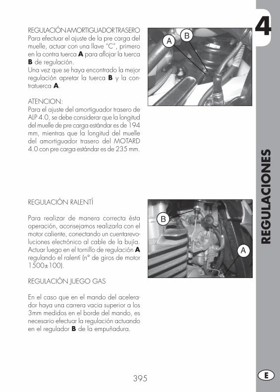
4
REG
ULA
CIO
NES
395 E
REGULACIÓN AMORTIGUADOR TRASEROPara efectuar el ajuste de la pre carga del muelle, actuar con una llave “C”, primero en la contra tuerca A para afl ojar la tuerca B de regulación.Una vez que se haya encontrado la mejor regulación apretar la tuerca B y la con-tratuerca A.
ATENCION:Para el ajuste del amortiguador trasero de ALP 4.0, se debe considerar que la longitud del muelle de pre carga estándar es de 194 mm, mientras que la longitud del muelle del amortiguador trasero del MOTARD 4.0 con pre carga estándar es de 235 mm.
REGULACIÓN RALENTÍ
Para realizar de manera correcta ésta operación, aconsejamos realizarla con el motor caliente, conectando un cuentarevo-luciones electrónico al cable de la bujía. Actuar luego en el tornillo de regulación A regulando el ralentí (n° de giros de motor 1500±100).
REGULACIÓN JUEGO GAS
En el caso que en el mando del acelera-dor haya una carrera vacia superior a los 3mm medidos en el borde del mando, es necesario efectuar la regulación actuando en el regulador B de la empuñadura.
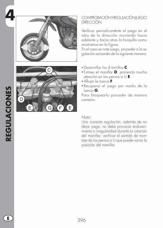
4REG
ULA
CIO
NES
396E
COMPROBACIÓN Y REGULACIÓN JUEGO DIRECCIÓN
Verifi car periodicaménte el juego en el tubo de la dirección moviendo hacia adelante y hacia atras la horquilla como mostramos en la fi gura.En el caso se note juego, proceder a la re-gulación actuando de la siguiente manera:
• Destornillar los 4 tornillos C.• Extraer el manillar D, poniendo mucha atención en los pernos a U E.
• Afl ojar la tuerca F.• Recuperar el juego por medio de la tuerca G.
Para bloquearlo proceder de manera contaria.
Nota:Una correcta regulación, además de no dejar juego, no debe provocar endureci-miento o irregularidad durante la rotación del manillar; verifi car el sentido de mon-taje de los pernos a U que puede variar la posición del manillar.
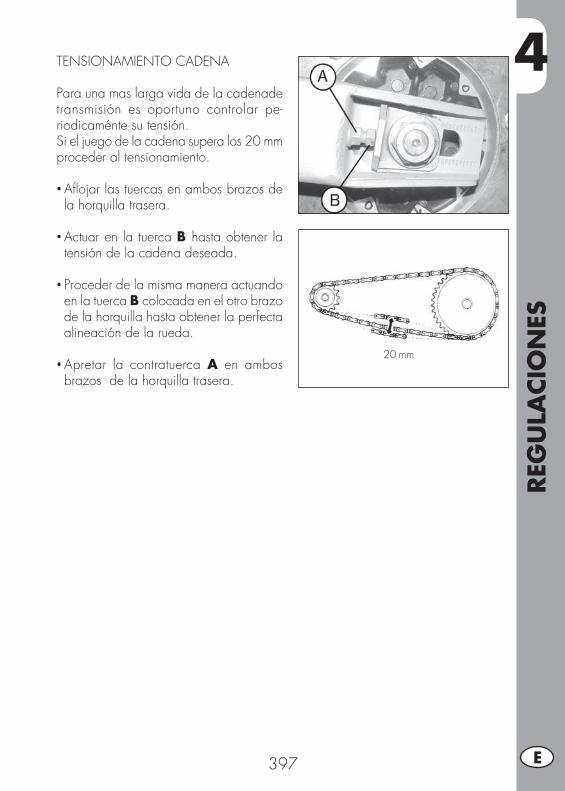
4
REG
ULA
CIO
NES
397 E
TENSIONAMIENTO CADENA
Para una mas larga vida de la cadenade transmisión es oportuno controlar pe-riodicaménte su tensión.Si el juego de la cadena supera los 20 mm proceder al tensionamiento.
• Afl ojar las tuercas en ambos brazos de la horquilla trasera.
• Actuar en la tuerca B hasta obtener la tensión de la cadena deseada.
• Proceder de la misma manera actuando en la tuerca B colocada en el otro brazo de la horquilla hasta obtener la perfecta alineación de la rueda.
• Apretar la contratuerca A en ambos brazos de la horquilla trasera.
20 mm
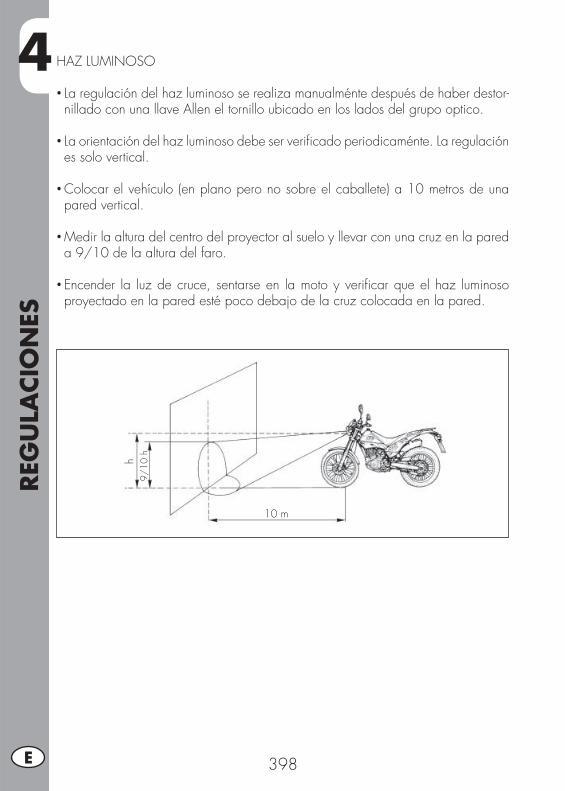
4REG
ULA
CIO
NES
398E
HAZ LUMINOSO
• La regulación del haz luminoso se realiza manualménte después de haber destor-nillado con una llave Allen el tornillo ubicado en los lados del grupo optico.
• La orientación del haz luminoso debe ser verifi cado periodicaménte. La regulación es solo vertical.
• Colocar el vehículo (en plano pero no sobre el caballete) a 10 metros de una pared vertical.
• Medir la altura del centro del proyector al suelo y llevar con una cruz en la pared a 9/10 de la altura del faro.
• Encender la luz de cruce, sentarse en la moto y verifi car que el haz luminoso proyectado en la pared esté poco debajo de la cruz colocada en la pared.
9/10
h
10 m
h
5
SUST
ITU
CIO
NES
399 E
INDICE DE ARGUMENTOS
CAP. 5 SUSTITUCIONES
Sustitución pastillas freno delantero
Sustitución pastillas freno trasero
Sustitución bombillas ALP
Sustitución bombillas MOTARD M4
Sustitución indicadores de dirección y piloto trasero
Sustitución luz placa de identifi cación
Características bombillas

5SU
STIT
UCIO
NES
400E
SUSTITUCIÓN PASTILLAS FRENO DE-LANTERO
La descripción relativa a la sustitución de las pastillas es de caracter informativo puesto que es aconsejable dirigirse a un taller autorizado Betamotor para efectuar ésta operación.
FRENO DELANTERO POR ALP 4.0
Para la sustitución es necesario proceder de la siguiente manera:
• Desmontar la pinza destornillando los dos tornillos A
• Desenroscar los dos tornillos B.
• Extraer las pastillas.
• Para el montaje proceder de manera contraria, colocando bloqueador de roscas en los tornillos A.
ATENCIÓN:Durante el desmontaje de la pinza de frenos delantera prestar atención para no dañar el sensor C. Prestar mucha atención al correcto mon-taje de los tornillos para evitar problemas de frenada.
En el caso se tenga que desmontar el disco freno, en el montaje aplicar bloqueador de roscas a los tornillos.
A
B
C

5
SUST
ITU
CIO
NES
401 E
FRENO DELANTERO POR MOTARD M4
Para la sustitución es necesario proceder de la siguiente manera:
• Desmontar la pinza del soporte especial C, desenroscando los dos tornillos A.
• Desenroscar los dos tornillos B.
• Extraer las pastillas.
ATENCIÓN:Durante el desmontaje de la pinza de frenos delantera prestar atención para no dañar el sensor C.
• Para el montaje proceder de manera contraria, colocando bloqueador de roscas en los tornillos A.
Prestar mucha atención al correcto mon-taje de los tornillos para evitar problemas de frenada.
En el caso se tenga que desmontar el disco freno, en el montaje aplicar bloqueador de roscas a los tornillos.
A
B
C
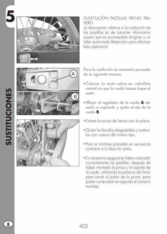
5SU
STIT
UCIO
NES
402E
Para la sustitución es necesario proceder de la siguiente manera:
• Colocar la moto sobre en caballete central sin que la rueda trasera toque el suelo.
• Afl ojar el regulador de la rueda A de-recho e izquierdo y quitar el eje de la rueda B.
SUSTITUCIÓN PASTILLAS FRENO TRA-SEROLa descripción relativa a la sustitución de las pastillas es de caracter informativo puesto que es aconsejable dirigirse a un taller autorizado Betamotor para efectuar ésta operación.
• Extraer la pinza de frenos con la placa.
• Quitar los ferodos desgastados y sustituir-los con nuevos del mismo tipo.
• Para el montaje proceder en secuencia contraria a lo descrito antes.
• Es necesario asegurarse haber colocado correctamente las pastillas, después de haber montado la pinza y el soporte de la rueda, utilizando la palanca del freno para cerrar el pistón de la pinza, para poder comprobar en seguida el correcto montaje.

5
SUST
ITU
CIO
NES
403 E
SUSTITUCIÓN BOMBILLAS ALP
DELANTERO Desmontar el soporte y el conjunto óptico como indicado en la página 384.Extraer el conector, levantar la protección de goma A, desenganchar el resorte de sujeción de la bombilla y sustituir la bombil-la quemada con otra nueva con idénticas características, prestando atención en no tocar la ampolla.Montar todo nuevamente siguiendo la secuencia contraria.
Luz de posición:Desmontar el soporte y el conjunto óptico como indicado en la página 384.Extraer el portalámparas B y quitar la bombilla quemada, colocar otra nueva con idénticas características prestando atención en no tocar la ampolla para no perjudicar la efi ciencia de la misma.
B
A
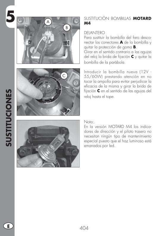
5SU
STIT
UCIO
NES
404E
SUSTITUCIÓN BOMBILLAS MOTARD M4
DELANTEROPara sustituir la bombilla del faro desco-nectar los conectores A de la bombilla y quitar la protección de goma B.Girar en el sentido contrario a las agujas del reloj la brida de fi jación C y quitar la bombilla de la parábola.
Introducir la bombilla nueva (12V - 55/60W) prestando atención en no tocar la ampolla para evitar perjudicar la efi cacia de la misma y girar la brida de fi jación C en el sentido de las agujas del reloj hasta el tope.
Nota:En la versión MOTARD M4 los indica-dores de dirección y el piloto trasero no necesitan ningún tipo de mantenimiento especial puesto que el haz luminoso está emanados por led.
AB
C
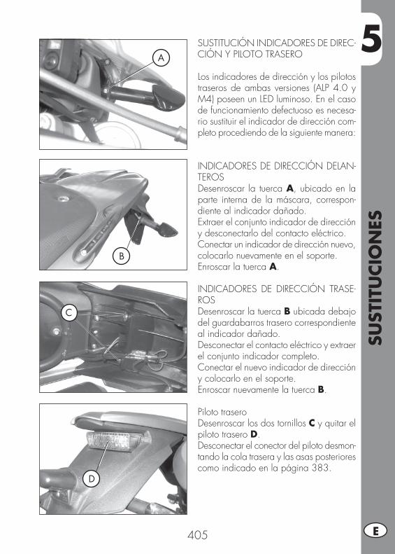
5
SUST
ITU
CIO
NES
405 E
D
C
B
ASUSTITUCIÓN INDICADORES DE DIREC-CIÓN Y PILOTO TRASERO
Los indicadores de dirección y los pilotos traseros de ambas versiones (ALP 4.0 y M4) poseen un LED luminoso. En el caso de funcionamiento defectuoso es necesa-rio sustituir el indicador de dirección com-pleto procediendo de la siguiente manera:
INDICADORES DE DIRECCIÓN DELAN-TEROSDesenroscar la tuerca A, ubicado en la parte interna de la máscara, correspon-diente al indicador dañado.Extraer el conjunto indicador de dirección y desconectarlo del contacto eléctrico.Conectar un indicador de dirección nuevo, colocarlo nuevamente en el soporte.Enroscar la tuerca A.
INDICADORES DE DIRECCIÓN TRASE-ROSDesenroscar la tuerca B ubicada debajo del guardabarros trasero correspondiente al indicador dañado.Desconectar el contacto eléctrico y extraer el conjunto indicador completo.Conectar el nuevo indicador de dirección y colocarlo en el soporte.Enroscar nuevamente la tuerca B.
Piloto traseroDesenroscar los dos tornillos C y quitar el piloto trasero D.Desconectar el conector del piloto desmon-tando la cola trasera y las asas posteriores como indicado en la página 383.
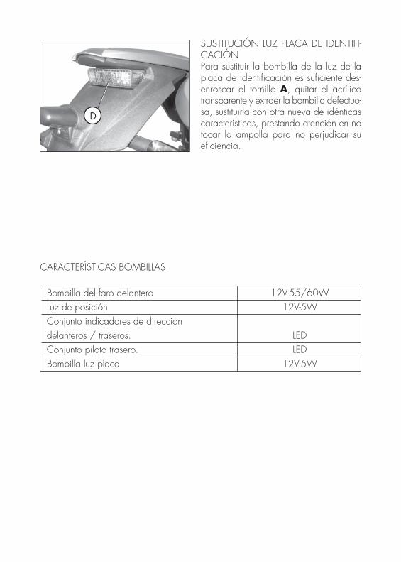
Bombilla del faro delantero 12V-55/60W Luz de posición 12V-5W Conjunto indicadores de dirección delanteros / traseros. LED Conjunto piloto trasero. LED Bombilla luz placa 12V-5W
D
SUSTITUCIÓN LUZ PLACA DE IDENTIFI-CACIÓNPara sustituir la bombilla de la luz de la placa de identifi cación es sufi ciente des-enroscar el tornillo A, quitar el acrílico transparente y extraer la bombilla defectuo-sa, sustituirla con otra nueva de idénticas características, prestando atención en no tocar la ampolla para no perjudicar su efi ciencia.
CARACTERÍSTICAS BOMBILLAS
6
QU
E H
ACER
EN
CA
SO D
E EM
ERG
ENCIA
407 E
INDICE DE LOS ARGUMENTOS
CAP. 6 QUE HACER EN CASO DE MERGENCIA
INDICE ALFABETICO
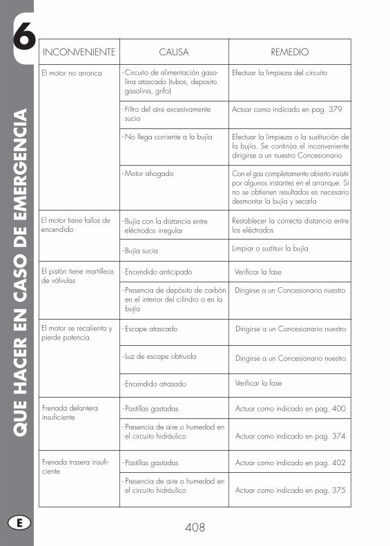
6Q
UE
HA
CER
EN
CA
SO D
E EM
ERG
ENCIA
408E
INCONVENIENTE CAUSA
El motor no arranca
REMEDIO
- Circuito de alimentación gaso-lina atascado (tubos, deposito gasolina, grifo)
- Filtro del aire excesivamente sucio
- No llega corriente a la bujía
- Motor ahogado
Efectuar la limpieza del circuito
Actuar como indicado en pag. 379
Efectuar la limpieza o la sustitución de la bujía. Se continúa el inconveniente dirigirse a un nuestro Concesionario
Con el gas completamente abierto insistir por algunos instantes en el arranque. Si no se obtienen resultados es necesario desmontar la bujía y secarla
El motor tiene fallos de encendido
- Bujía con la distancia entre eléctrodos irregular
- Bujía sucia
Restablecer la correcta distancia entre los eléctrodos
Limpiar o sustituir la bujía
El pistón tiene martilleos de válvulas
- Encendido anticipado
- Presencia de depósito de carbón en el interior del cilindro o en la bujía
Verifi car la fase
Dirigirse a un Concesionario nuestro
El motor se recalienta y pierde potencia
- Escape atascado
- Luz de escape obtruida
- Encendido atrasado
Dirigirse a un Concesionario nuestro
Dirigirse a un Concesionario nuestro
Frenada delantera insufi ciente
- Pastillas gastadas
- Presencia de aire o humedad en el circuito hidráulico
Actuar como indicado en pag. 400
Actuar como indicado en pag. 374
Frenada trasera insufi -ciente
- Pastillas gastadas
- Presencia de aire o humedad en el circuito hidráulico
Actuar como indicado en pag. 402
Actuar como indicado en pag. 375
Verifi car la fase
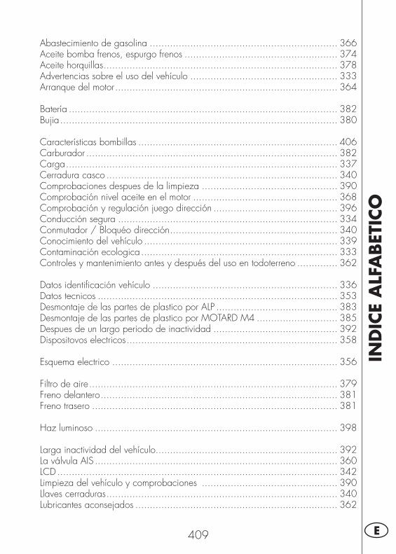
IND
ICE
ALF
ABET
ICO
409 E
Abastecimiento de gasolina ................................................................. 366Aceite bomba frenos, espurgo frenos ..................................................... 374Aceite horquillas ................................................................................. 378Advertencias sobre el uso del vehículo ................................................... 333Arranque del motor ............................................................................. 364
Batería ............................................................................................. 382Bujia ................................................................................................ 380
Características bombillas ..................................................................... 406Carburador ....................................................................................... 382Carga .............................................................................................. 337Cerradura casco ................................................................................ 340Comprobaciones despues de la limpieza ............................................... 390Comprobación nivel aceite en el motor .................................................. 368Comprobación y regulación juego dirección ........................................... 396Conducción segura ............................................................................ 334Conmutador / Bloquéo dirección .......................................................... 340Conocimiento del vehículo ................................................................... 339Contaminación ecologica .................................................................... 333Controles y mantenimiento antes y después del uso en todoterreno .............. 362
Datos identifi cación vehículo ................................................................ 336Datos tecnicos ................................................................................... 353Desmontaje de las partes de plastico por ALP .......................................... 383Desmontaje de las partes de plastico por MOTARD M4 ............................ 385Despues de un largo periodo de inactividad ........................................... 392Dispositovos electricos ......................................................................... 358
Esquema electrico .............................................................................. 356
Filtro de aire ...................................................................................... 379Freno delantero .................................................................................. 381Freno trasero ..................................................................................... 381
Haz luminoso .................................................................................... 398
Larga inactividad del vehículo............................................................... 392La válvula AIS .................................................................................... 360LCD ................................................................................................. 342Limpieza del vehículo y comprobaciones ............................................... 390Llaves cerraduras ................................................................................ 340Lubricantes aconsejados ...................................................................... 362
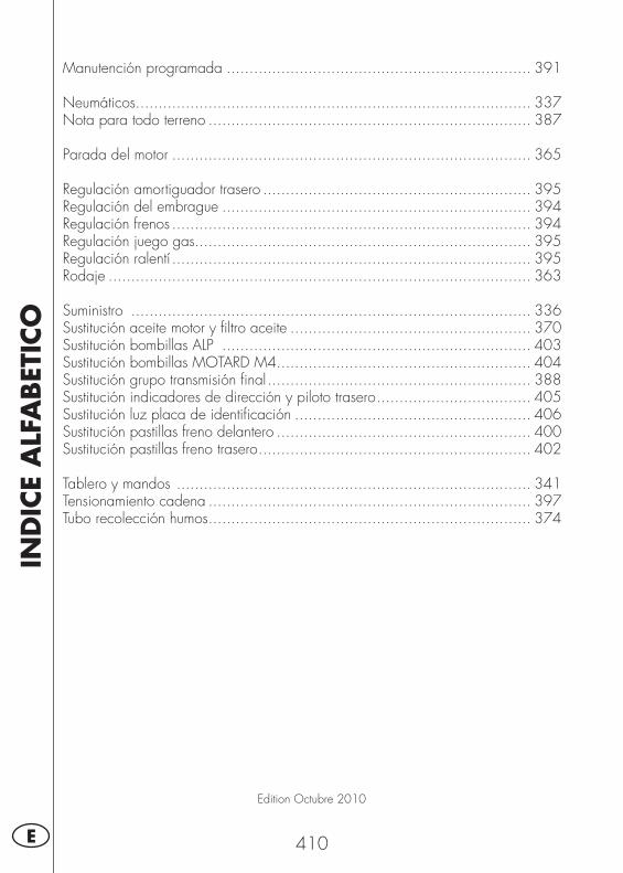
IND
ICE
ALF
ABET
ICO
410E
Edition Octubre 2010
Manutención programada ................................................................... 391
Neumáticos ....................................................................................... 337Nota para todo terreno ....................................................................... 387
Parada del motor ............................................................................... 365
Regulación amortiguador trasero ........................................................... 395Regulación del embrague .................................................................... 394Regulación frenos ............................................................................... 394Regulación juego gas.......................................................................... 395Regulación ralentí ............................................................................... 395Rodaje ............................................................................................. 363
Suministro ........................................................................................ 336Sustitución aceite motor y fi ltro aceite ..................................................... 370Sustitución bombillas ALP .................................................................... 403Sustitución bombillas MOTARD M4........................................................ 404Sustitución grupo transmisión fi nal .......................................................... 388Sustitución indicadores de dirección y piloto trasero .................................. 405Sustitución luz placa de identifi cación .................................................... 406Sustitución pastillas freno delantero ........................................................ 400Sustitución pastillas freno trasero ............................................................ 402
Tablero y mandos .............................................................................. 341Tensionamiento cadena ....................................................................... 397Tubo recolección humos ....................................................................... 374