Embed Size (px)
Citation preview
IMAGE HERE
Submitted by: John C. Zeman, PE, SE Katherine Mulvey, PE p 217.352.7408 / [email protected] June 19, 2020
Greenways Multi-Use Trail: Lake Charleston to Warbler Ridge Conservation Area Connection Feasibility Study
Grand Prairie Friends / Greenways Multi-Use Trail: Feasibility Study Lake Charleston to Warbler Ridge Conservation Area Connection
FARNSWORTH GROUP / 1
TABLE OF CONTENTS Table of Contents ............................................................................................................................................. 1
List of Exhibits ................................................................................................................................................... 1
1.0 Introduction ..................................................................................................................................... 2
2.0 Conceptual Bridge Design ................................................................................................................ 2
3.0 Conceptual Trail Design .................................................................................................................... 3
4.0 Budgetary Project Cost Estimate ..................................................................................................... 4
5.0 Conclusion ........................................................................................................................................ 4
LIST OF EXHIBITS
A. Base Map
B. Structure Concept Plan
C. Budgetary Project Cost Estimate
D. Site Photographs
E. FEMA Flood Data
F. Abbreviated Existing Bridge Plans: IL Route 130 over Embarras River
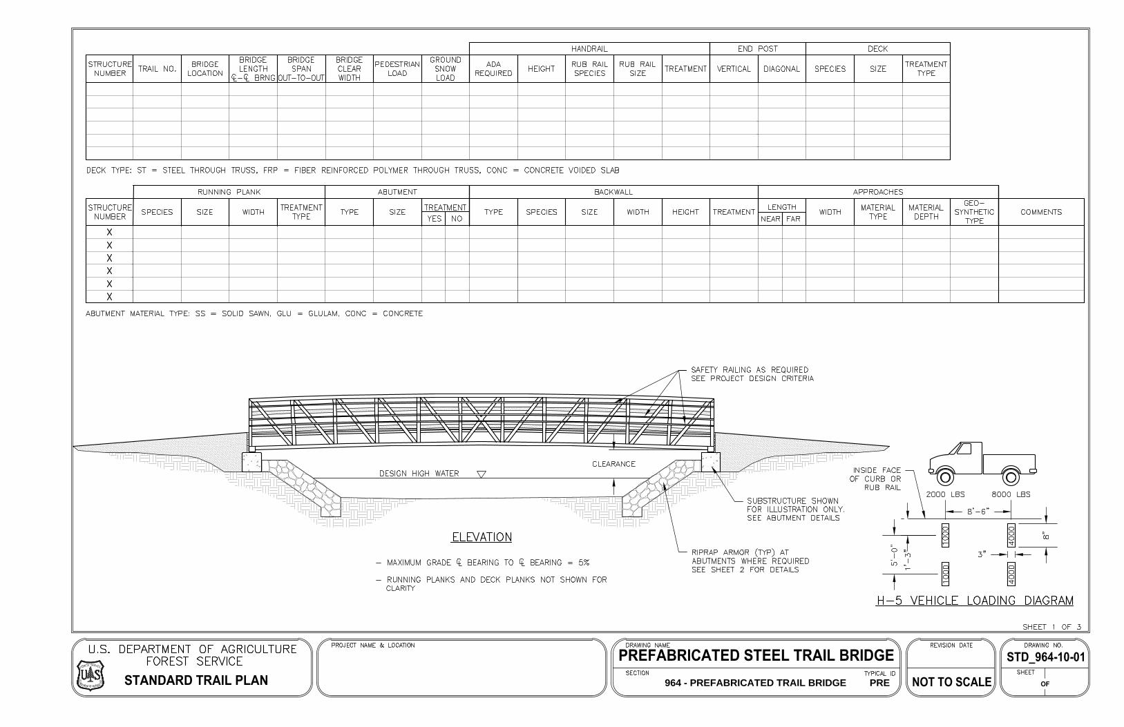
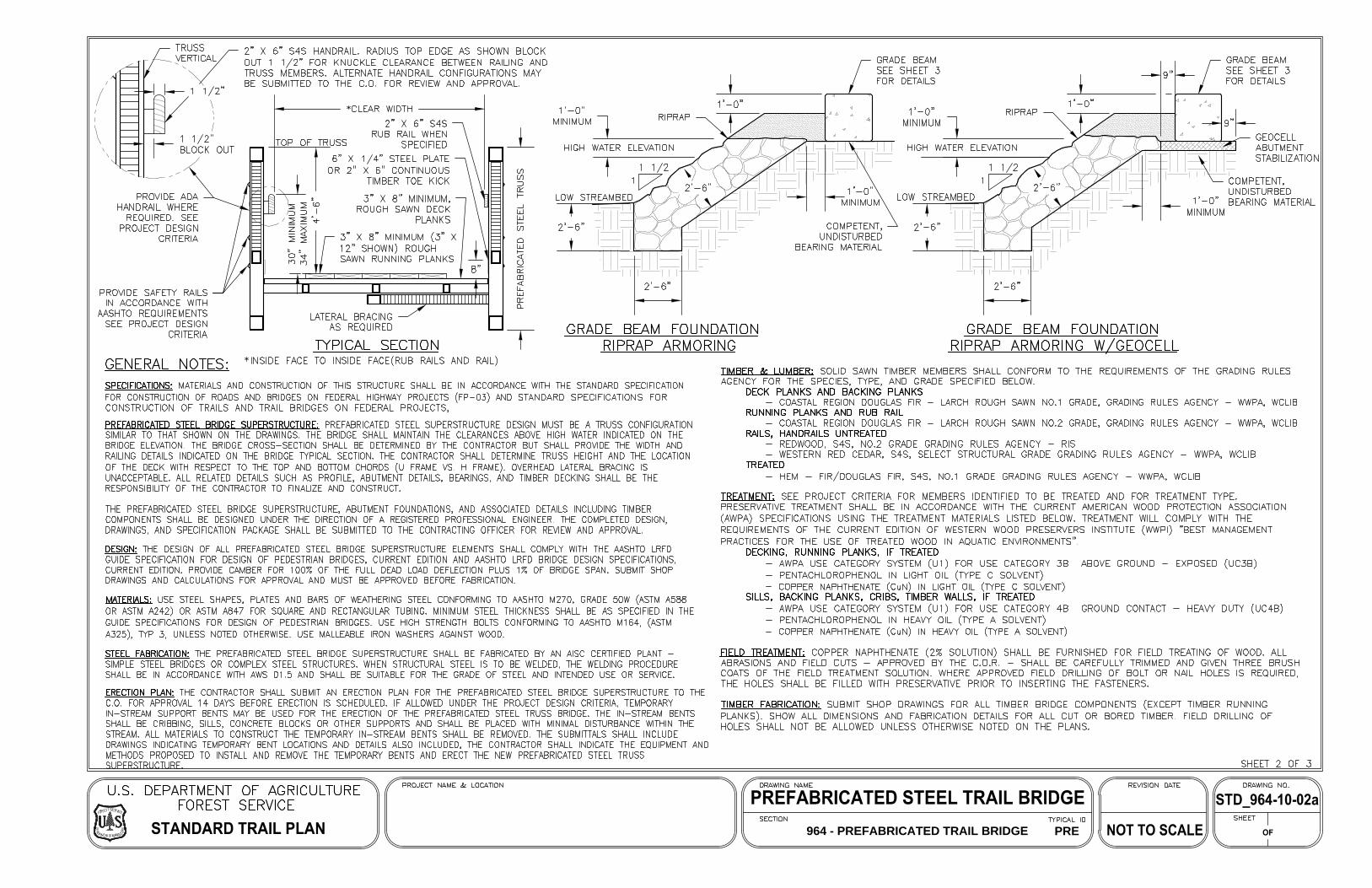
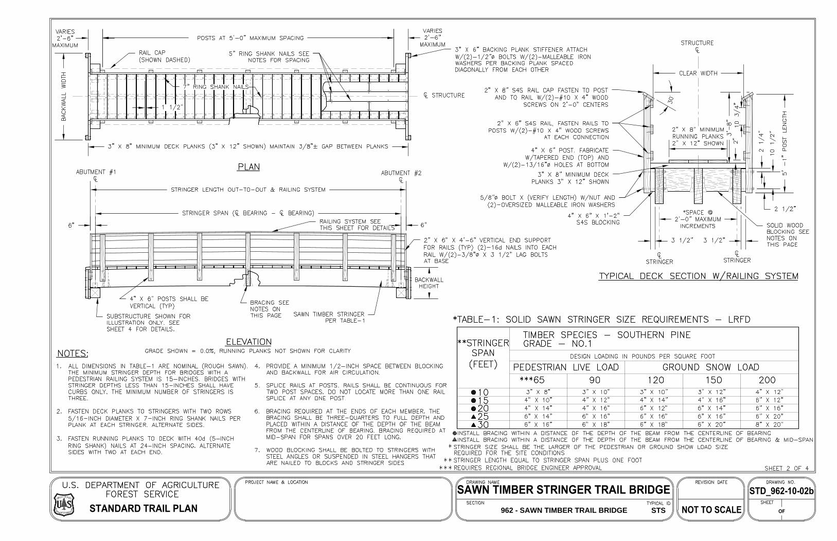
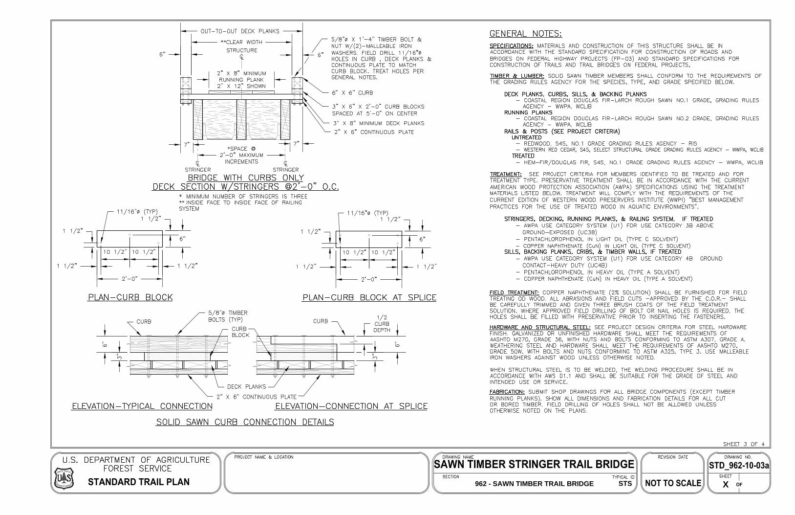
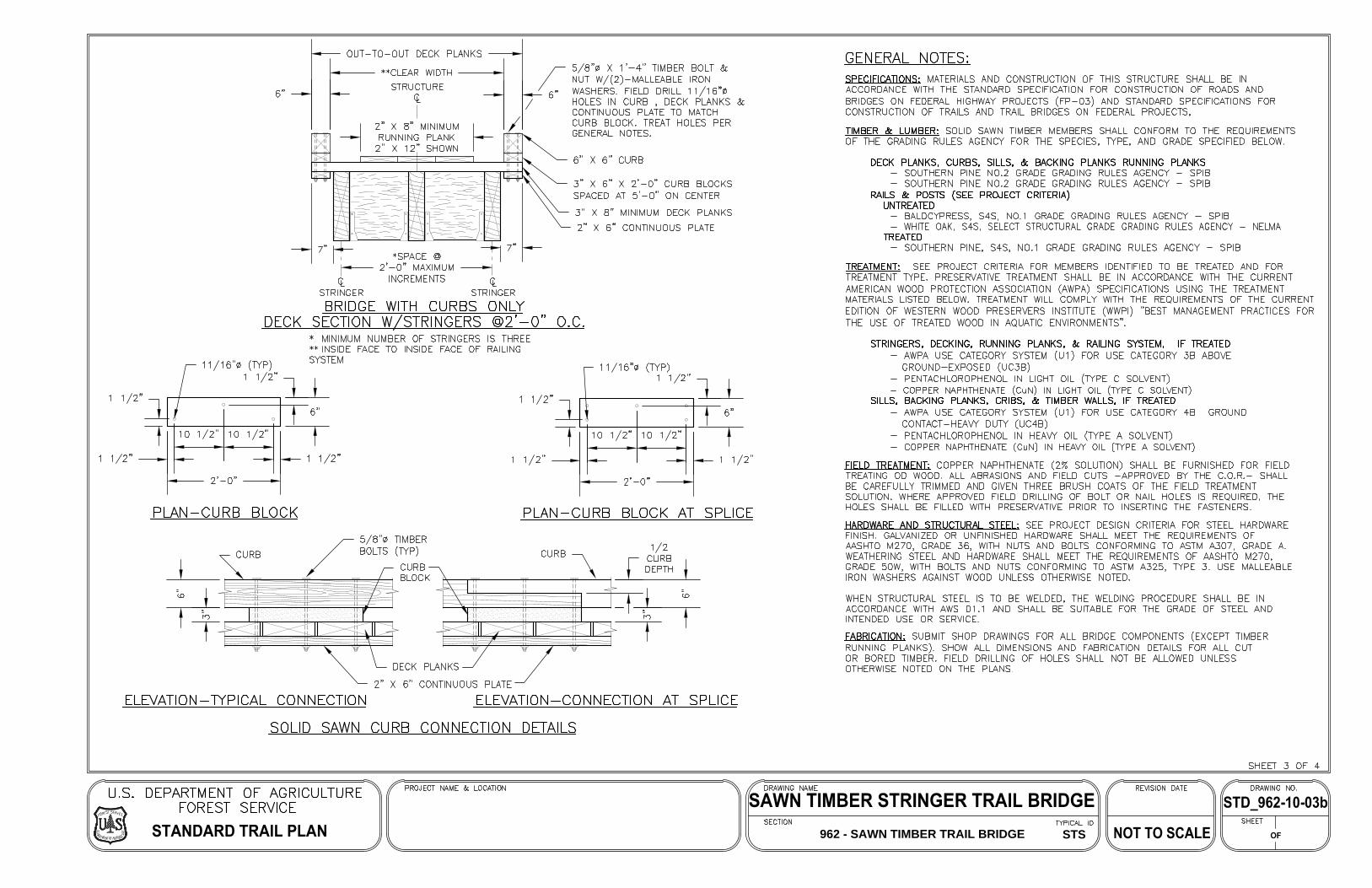
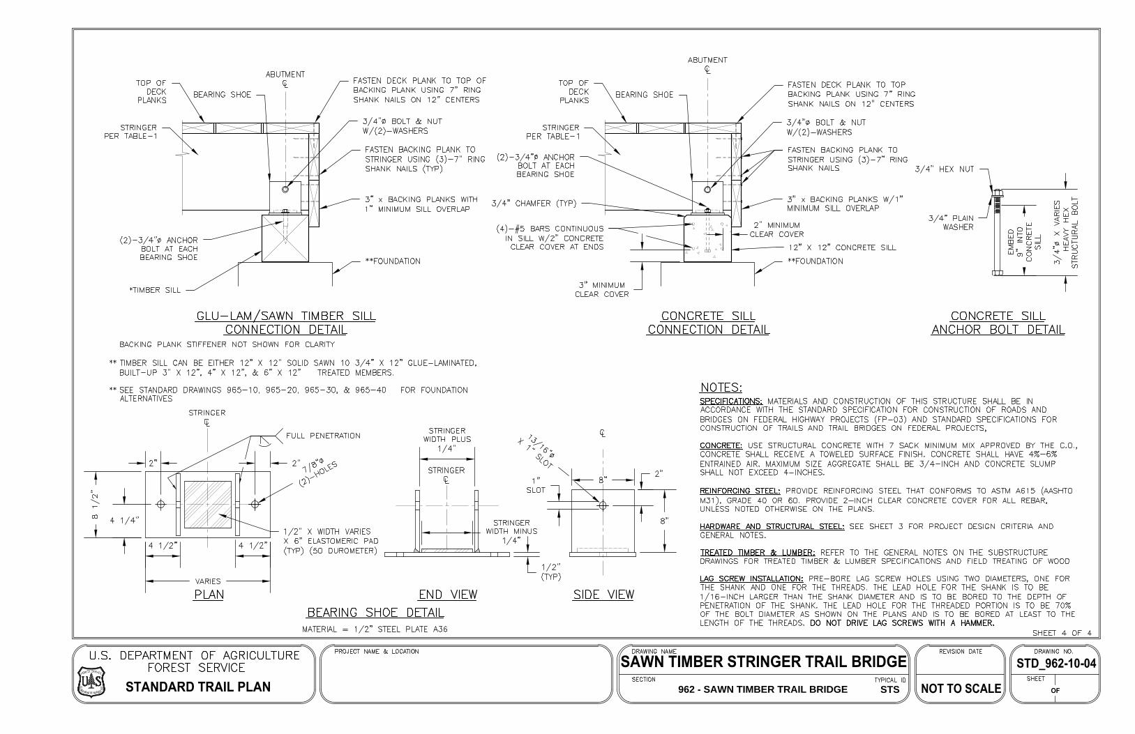
G. U.S. Forest Service Standard Trail Plans: Prefabricated Steel Trail Bridge
H. U.S. Forest Service Standard Trail Plans: Boardwalks
I. U.S. Forest Service Standard Trail Plans: Sawn Timber Trail Bridge
J. Trail Design Guidelines – Excerpts from Appendix C of Wake County Consolidated Open Space Plan (Wake County, North Carolina)
Contact Information: John C. Zeman, PE, SE Katherine Mulvey, PE
p 217.352.7408 / [email protected] June 19, 2020
Grand Prairie Friends / Greenways Multi-Use Trail: Feasibility Study Lake Charleston to Warbler Ridge Conservation Area Connection
FARNSWORTH GROUP / 2
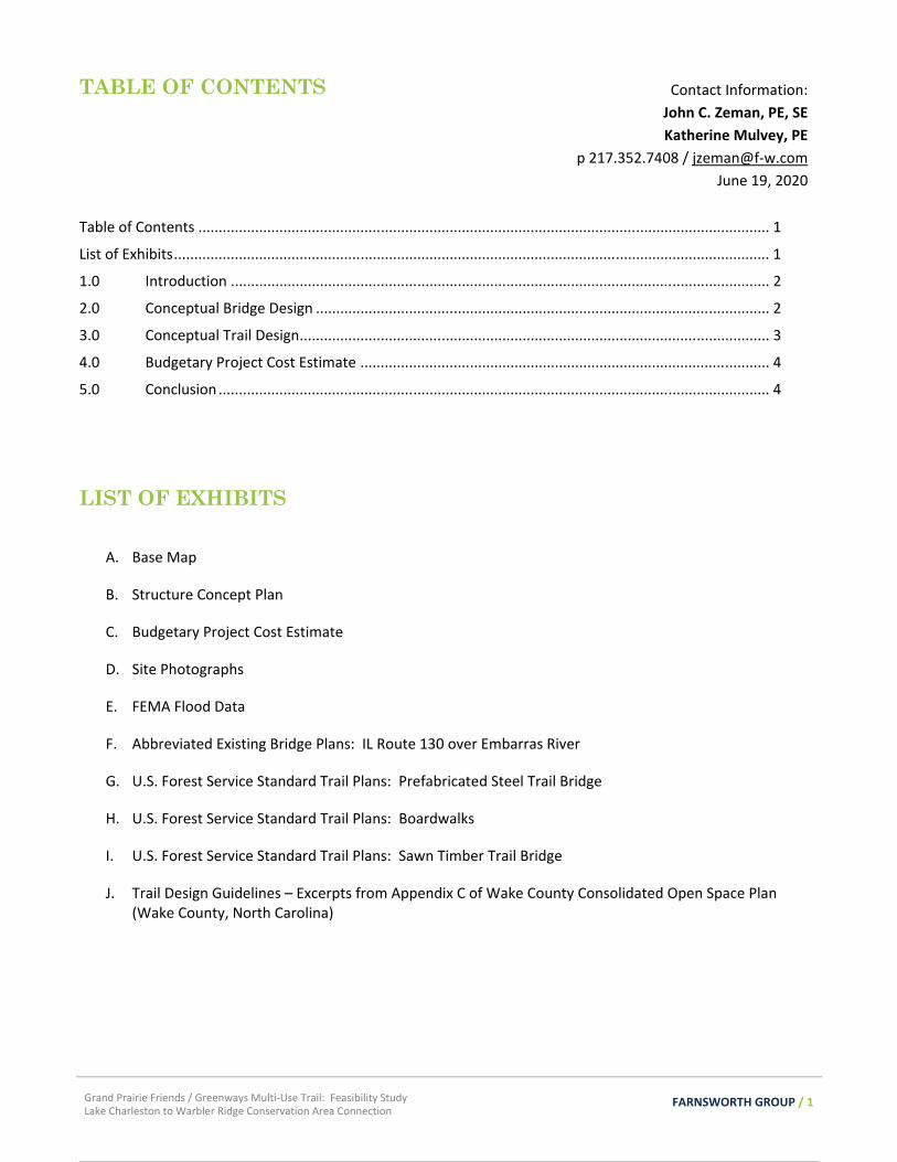
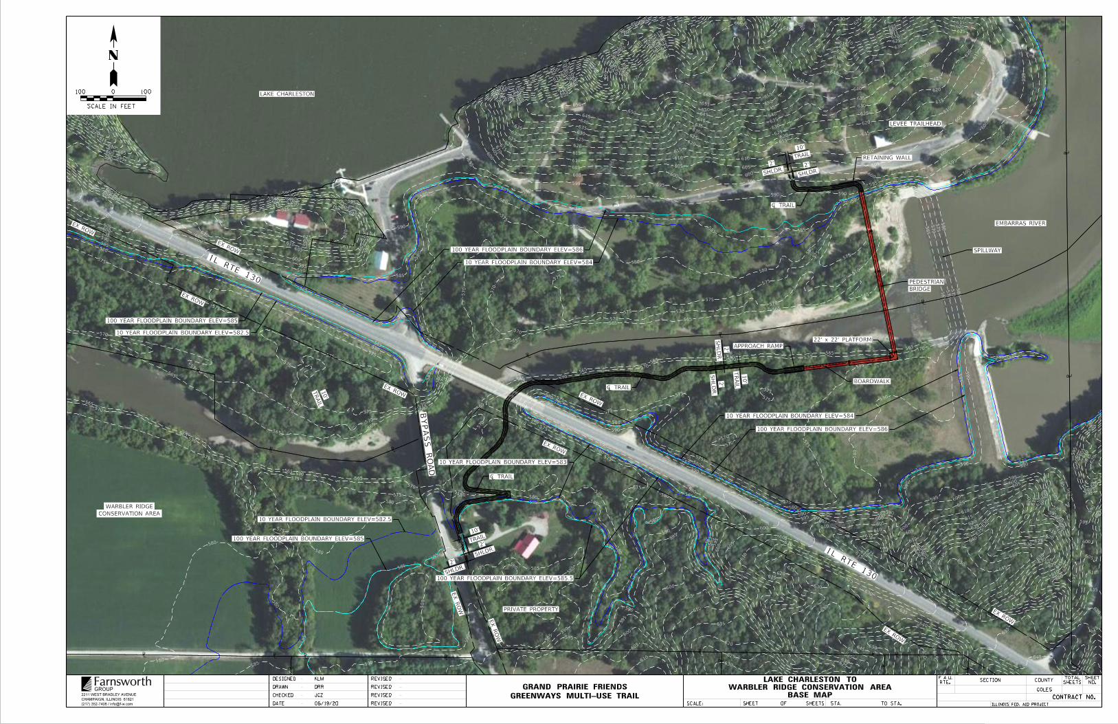
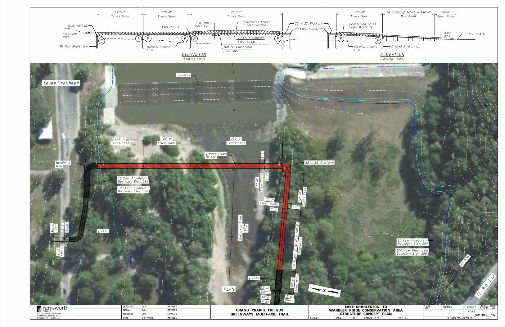
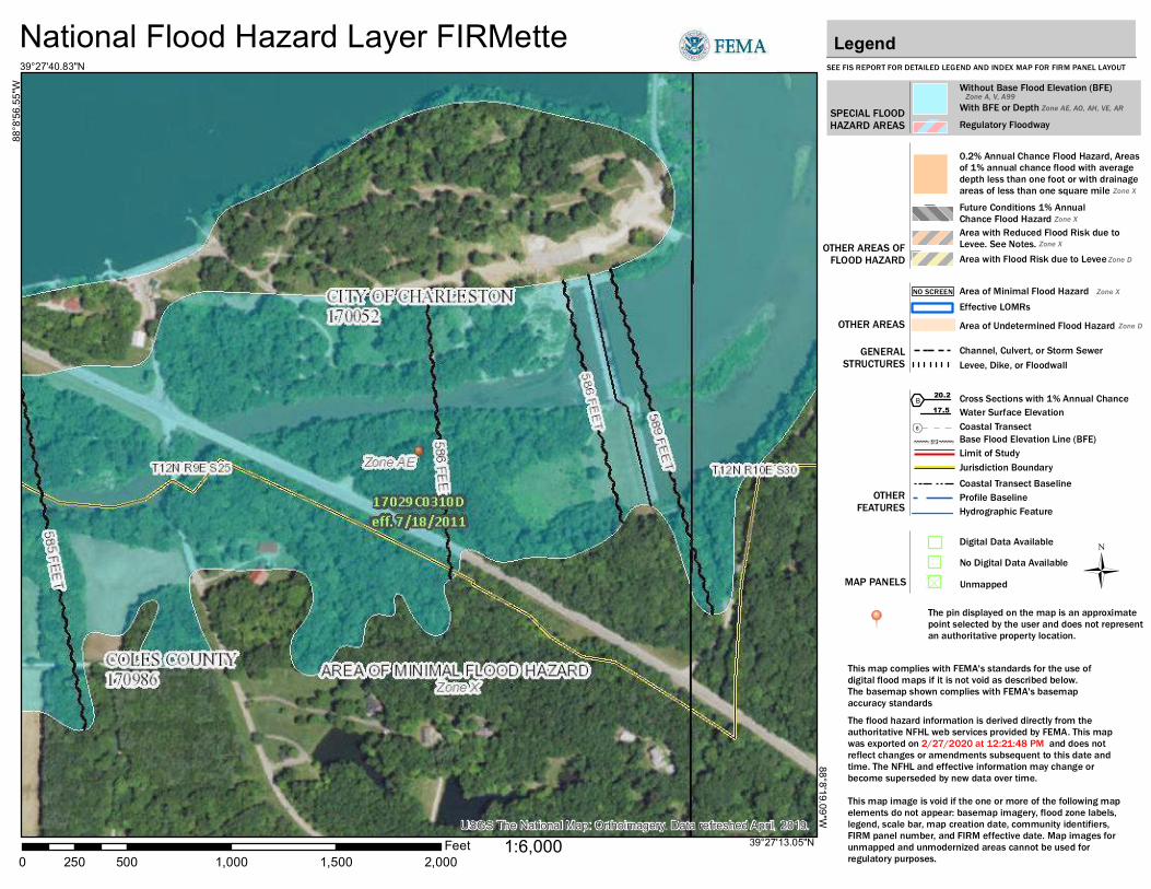
1.0 INTRODUCTION The objective of this report is to evaluate the feasibility and cost to design and construct a segment of the proposed Greenways Multi-Use Trail to connect Lake Charleston to the Warbler Ridge Conservation Area via a 10-foot wide trailway and a pedestrian bridge over the Embarras River. The pedestrian bridge would be an independent structure located just west of the Lake Charleston spillway and on property owned by the City of Charleston. This report includes a brief description and sketch of the conceptual design of the trailway segment and bridge, along with a budgetary estimate of the engineering services and construction costs required. The conceptual trailway and bridge designs are preliminary and subject to refinement in subsequent phases of design. The proposed segment of trail is located south of Charleston, Illinois, where the Embarras River passes over the Lake Charleston spillway, continues under IL Route 130, and then under Bypass Road. Exhibit A is a Base Map which overlays aerial imagery, one-foot contours (only displaying five-foot contours for clarity), and property boundaries obtained from Coles County GIS. It is our understanding that the property along each side of the Embarras River located upstream (east) of IL Route 130 is owned by the City of Charleston. The IL Route 130 right-of-way (ROW) is owned by the State of Illinois and is managed by the Illinois Department of Transportation (IDOT). The property located southeast of the intersection of IL Route 130 and Bypass Road is currently private property. Bypass Road is a township road managed by Charleston Township and Coles County Highway Department. Exhibit D contains photographs of the site along the proposed trail route, taken during a May 6, 2020 site visit. The high-water information for the Embarras River was taken from the current FEMA Flood Insurance Study. Floodplain boundaries are shown in the attached exhibits for the 10-year and 100-year high water elevations. Note that the terms “10-year” and “100-year” indicate an annual probability of 10% and 1%, respectively. These high-water elevations are based on a 1976 hydrologic study and a 1985 hydraulic study, each by the U.S. Army Corps of Engineers. As noted in the Flood Insurance Study, all elevations reference the North American Vertical Datum from 1988 (NAVD 88). FEMA Flood Data is included as Exhibit E. The adjacent IL Route 130 bridge over the Embarras River was constructed in 1981. Plans for this bridge were obtained from the Illinois Department of Transportation (IDOT), and the structural, roadway, and geotechnical information in these plans was used as a basis for the conceptual design work summarized here. Abbreviated Existing Bridge Plans are included as Exhibit F. 2.0 CONCEPTUAL BRIDGE DESIGN Our team identified several alternate bridge locations and analyzed each location based on its construction cost, potential impacts to the Embarras River floodplain, connection with the existing terrain, proximity to area amenities, and traveling experience for the trail user. The proposed bridge location has a northern terminus located close to the Lake Charleston pavilion and parking lot, which provides direct access for trail users. With the spillway nearby, the trail user is immersed in the sights and sounds of the rushing water. The main span over the Embarras River is at an elevation above the 100-year flood elevation. When crossing a floodplain perpendicular to the direction of flow, new structures are to be built above the 100-year high water elevation to minimize impacts to the river’s flow. Building a structure parallel to the direction of flow and below the 100-year high water elevation in a floodplain is generally accepted by permitting agencies, such as the Illinois Department of Natural Resources (IDNR) Office of Water Resources, because the structure has less of an impact on the river’s flow. Once the bridge crosses to the south bank of the Embarras River, the structure turns westward to run parallel to the direction of river flow. This turning point creates an opportunity for a viewing platform where trail users can rest, meet, and enjoy the view. The remaining spans of the bridge are designed to ramp down at a maximum slope of 5% to existing ground level along the south bank of the Embarras River. A Structure Concept Plan is included as Exhibit B.
Grand Prairie Friends / Greenways Multi-Use Trail: Feasibility Study Lake Charleston to Warbler Ridge Conservation Area Connection
FARNSWORTH GROUP / 3
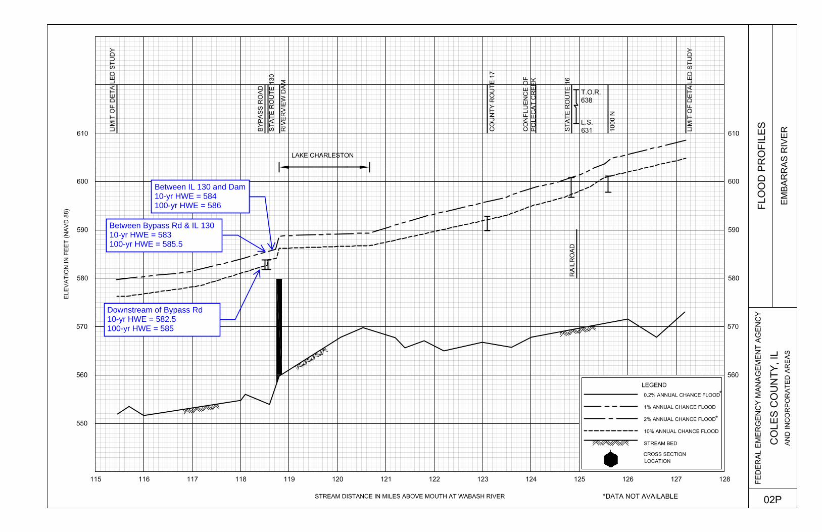
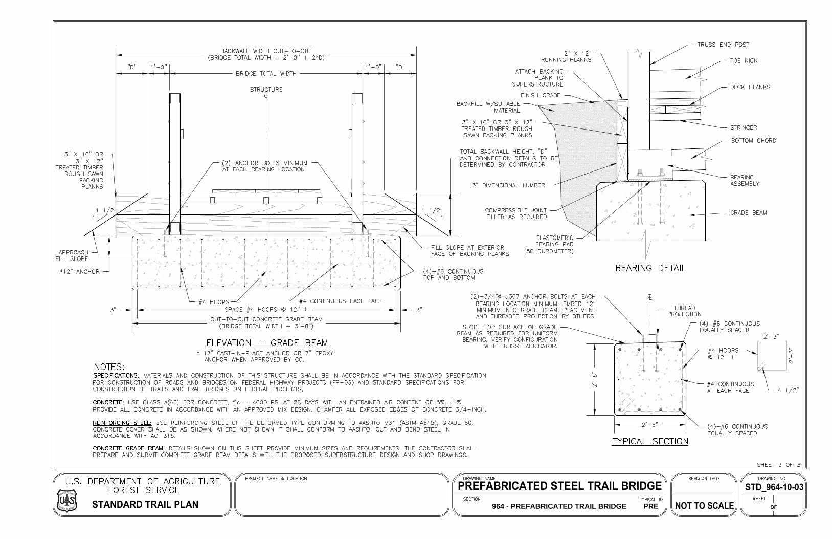
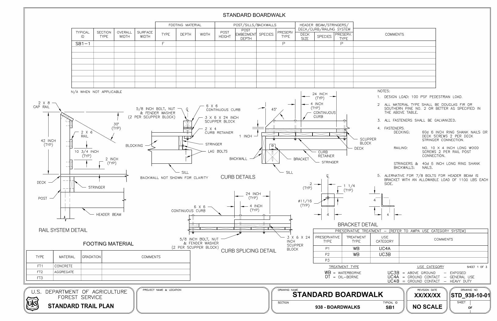
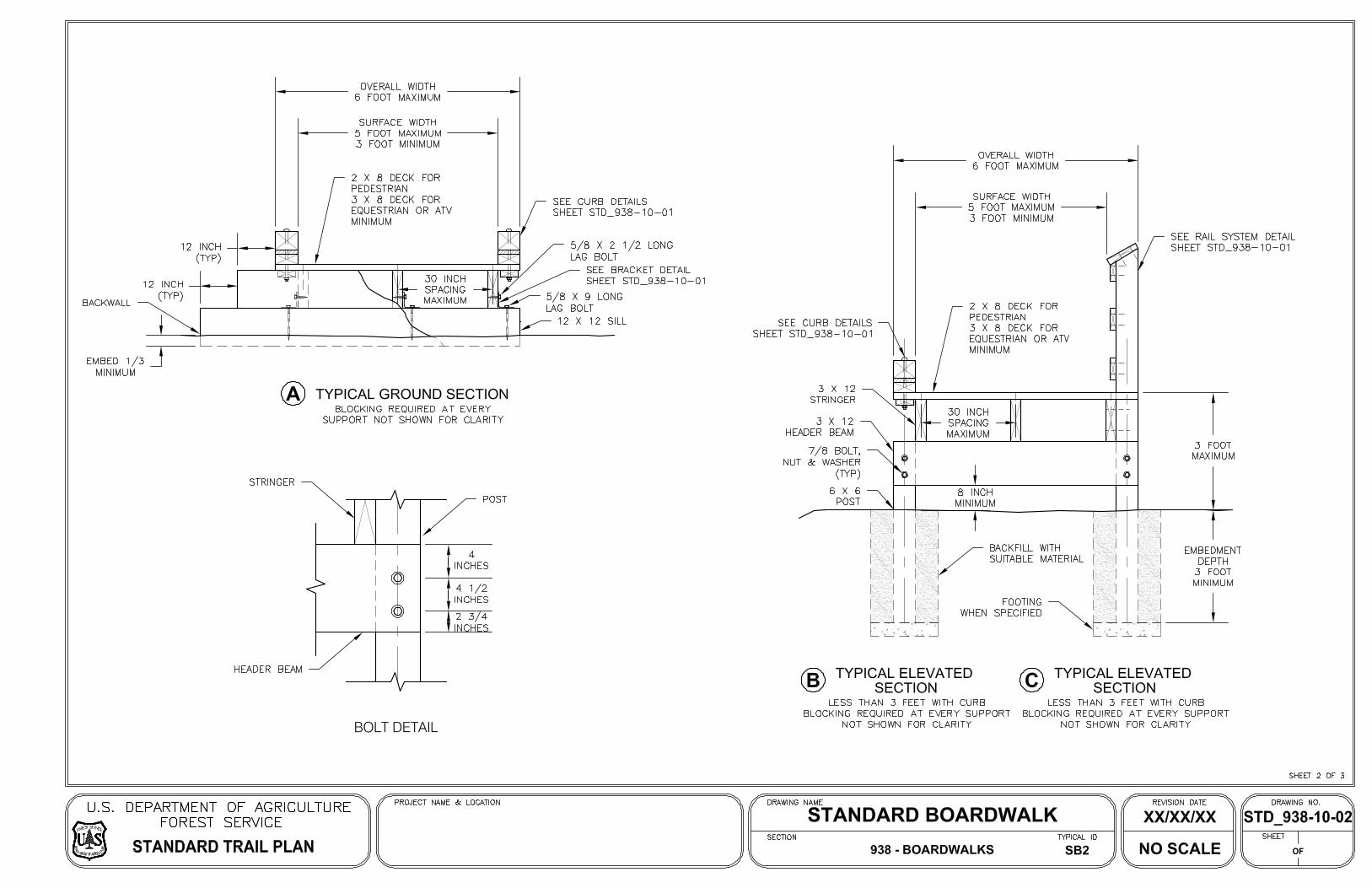
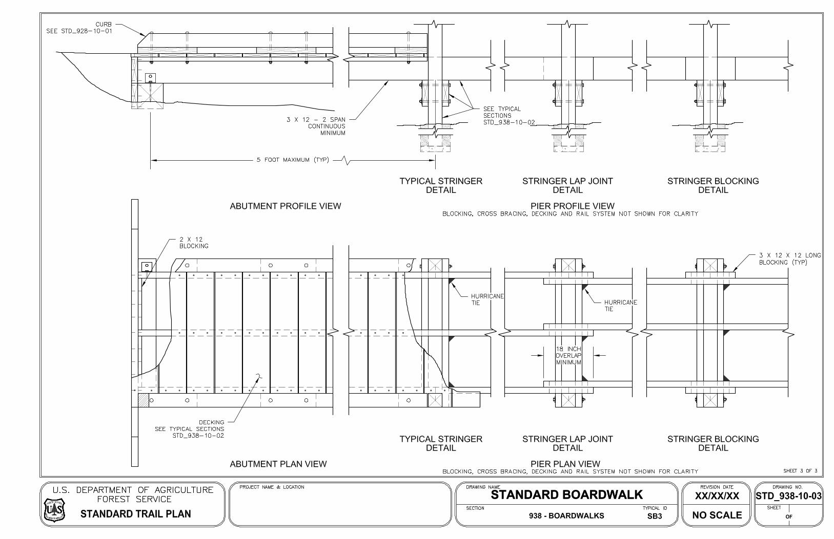
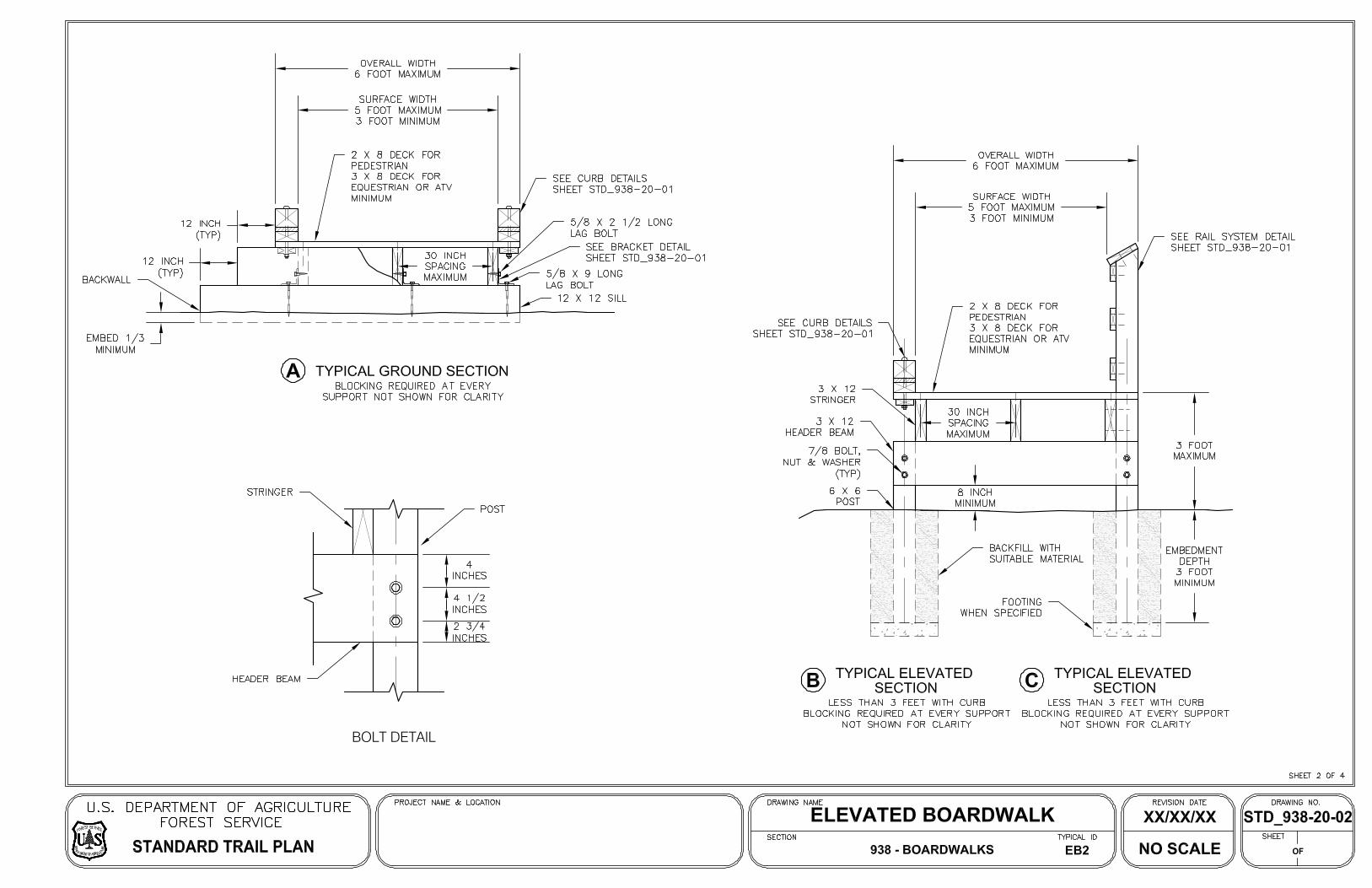
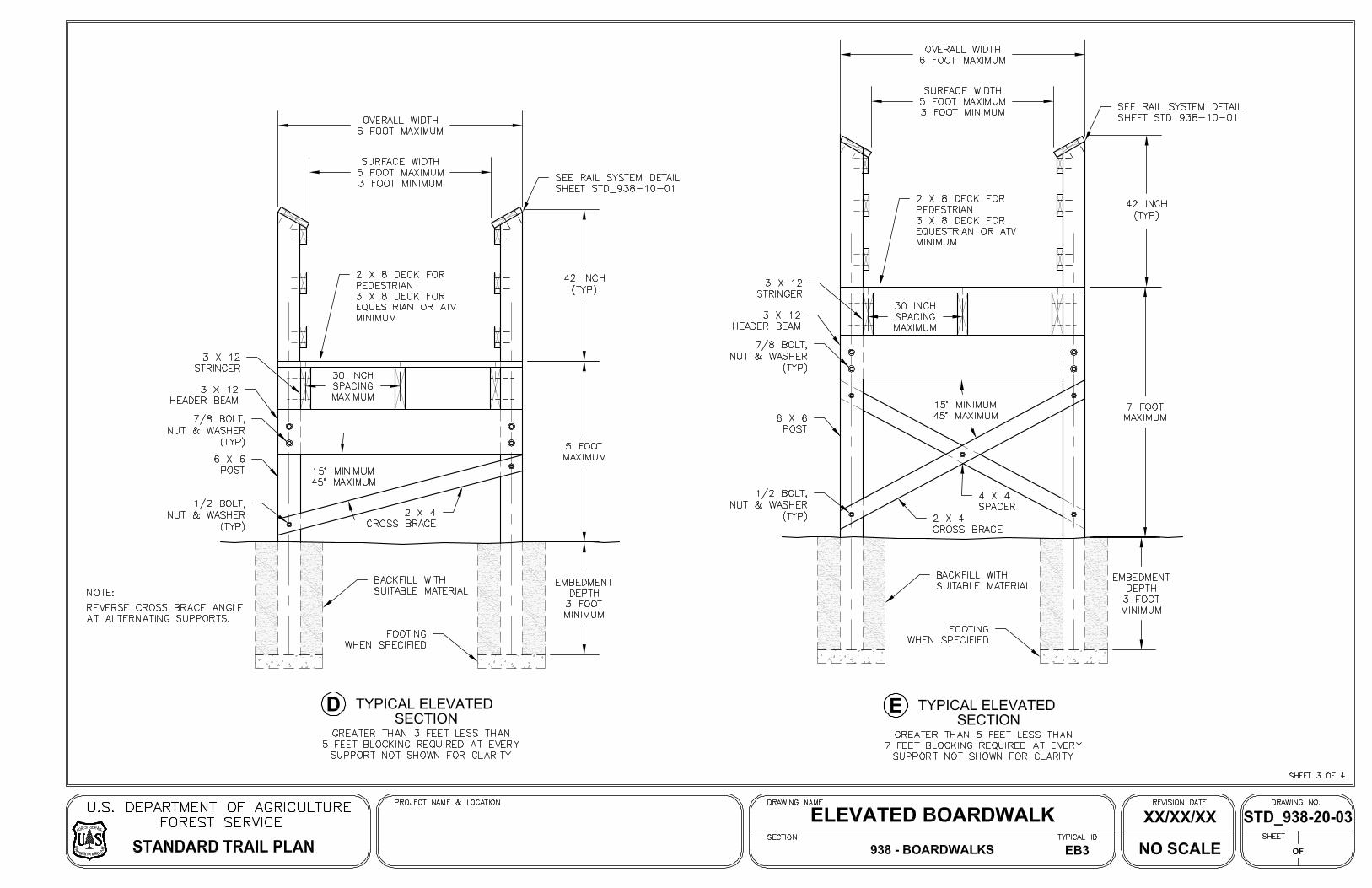
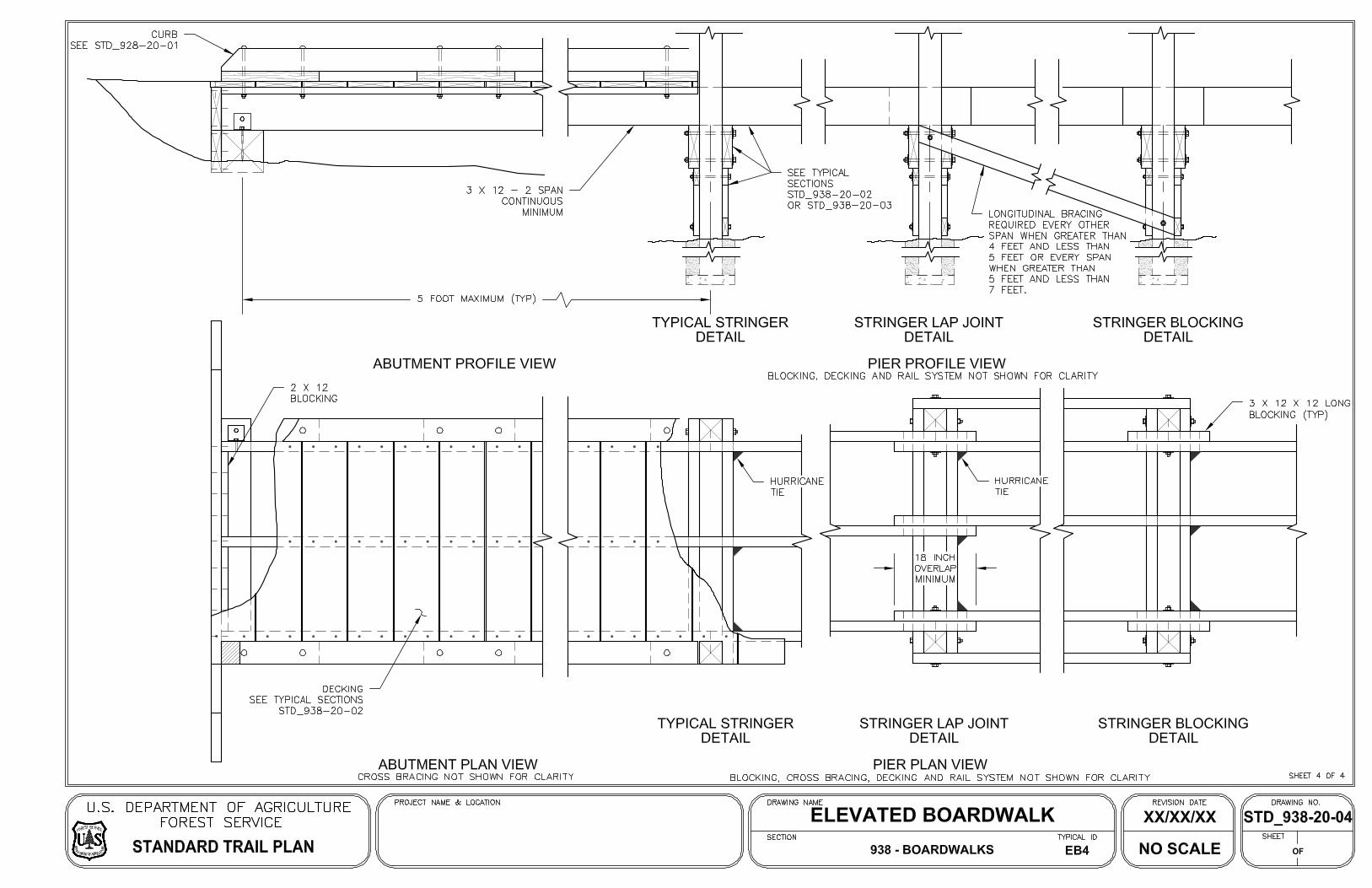
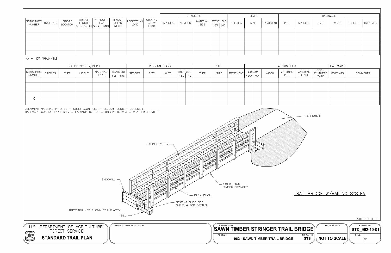
When crossing a floodplain perpendicular to the direction of flow, it is best to minimize the number of supports which would obstruct river flow. Combining this desire for longer spans over the floodplain with setting the bridge above the 100-year high water elevation led us to recommend using prefabricated steel truss spans supported by single-column, drilled concrete shaft foundations. Once the structure turns to run parallel to the direction of flow and ramps down, the height of each support decreases. Once the support height gets below 7 to 8 feet above ground level, it becomes feasible to construct timber boardwalk spans. Boardwalk spans are much shorter than steel truss spans, but they cost less to construct per square foot of bridge deck. In order to bring the trail down to existing ground level at the southwest terminus of the bridge, we propose constructing a ramp using concrete retaining walls filled with embankment and topped with trail pavement. The U.S. Forest Service has a variety of Standard Trail Plan sheets available online, and we have included some in the exhibits to illustrate the structure types proposed here. Exhibit G illustrates details for the prefabricated steel truss spans. Exhibits H and I illustrate details which we could combine and modify for the boardwalk spans. Typically, the prefabricated steel truss spans are designed and fabricated by specialty contractors, then delivered to site in large segments. A general contractor would erect and assemble the truss segments in place. IDOT maintains a list of prequalified pedestrian truss contractors. After contacting one of these prequalified contractors to obtain budgetary construction cost data, we learned that the 250-foot-long truss span over the main channel of the Embarras River would be more structurally efficient with a deck clear width of 12 feet. A narrower deck clear width for such a long span would have less lateral stability, requiring heavier structural steel members and a higher cost per square foot of deck. Therefore, we recommend a 12-foot clear width for the trail on the bridge. In their Bureau of Design and Environment Manual, IDOT requires a minimum clear width of 10 feet on pedestrian bridges with two-way traffic but recommends providing up to 14 feet of clear width as desirable for a better experience for trail users. For the prefabricated steel truss spans, we recommend using weathering steel with an Ipe wood deck. Weathering steel is a special material that forms a sacrificial, protective coating of rust on the outside surface. This rusty coating is generally stable for the service life of the bridge, requiring no maintenance, as long it is not exposed to deicing salts. Furthermore, weathering steel is often used for its rustic appearance, which is typically preferred for natural areas. For the deck, Ipe wood is a hard and strong walnut that is naturally resistant to rot, abrasion, weather, and insects. The material costs for Ipe is notably more than other wood species, but the advantage is found in its durability. The wood material is also perceived as a more friendly material choice for natural recreational activities. For the boardwalk spans, we recommend using Ipe wood deck for durability and consistency with the rest of the bridge, but we recommend using conventional treated lumber, such as pine or fir, for the structural members. The shorter boardwalk spans will be easier to maintain when the lumber requires repairs or replacement. 3.0 CONCEPTUAL TRAIL DESIGN The trailway at the north terminus of the pedestrian bridge is located above the 100-year floodplain and is sloped up to connect with the existing roadway. The trailway connection at the southwest terminus of the pedestrian bridge is mostly located within the 100-year floodplain. It meanders along the south bank of the river to a crossing under the IL Route 130 bridge at its southeastern-most span. From there, the proposed trailway crosses the floodplain on private property and then rises out of the floodplain via a switchback. Then the trailway crosses Bypass Road at grade to connect to the Warbler Ridge Conservation Area. Based on the FEMA flood maps, the proposed trailway would flood frequently. As an example, along the bank of the Embarras River from the southwest terminus of the pedestrian bridge to IL Route 130, the ground is approximately at elevation 574. The FEMA flood maps indicate the 10-year and 100-year high water elevations at this location are 584 and 586, respectively. Therefore, it is recommended that the trail surface be built with
Grand Prairie Friends / Greenways Multi-Use Trail: Feasibility Study Lake Charleston to Warbler Ridge Conservation Area Connection
FARNSWORTH GROUP / 4
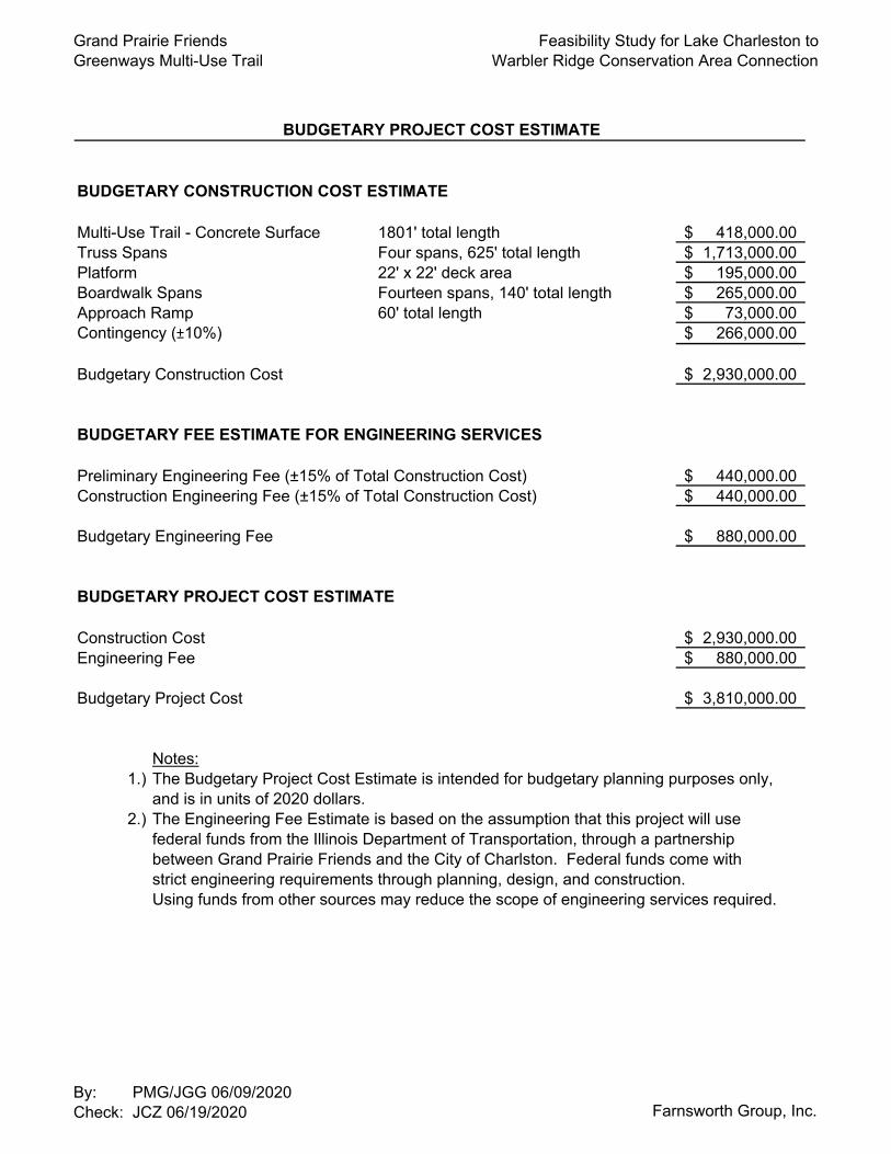
concrete pavement and concrete cutoff walls to protect it from high water velocities. Concrete surfaces are capable of withstanding the most powerful environmental forces. They hold up well again the erosive action of water, root intrusion, and subgrade deficiencies such as soft soils. Not only is it a strong material type, it has the lowest maintenance requirement when property installed. Exhibit J contains Trail Design Guidelines which illustrate conventional concepts related to selecting trail materials for different cases of flood exposure and flow velocities. The width of the trail is presented as 10-foot pavement with 2-foot shoulders, following IDOT design policy in the Bureau of Design and Environmental Manual, to accommodate two-way traffic for trail users. 4.0 BUDGETARY PROJECT COST ESTIMATE Exhibit C contains a budgetary project cost estimate for the proposed trail and pedestrian bridge. The budgetary project cost estimate is $3.81 million, consisting of $2.93 million for construction and $0.88 million for preliminary and construction engineering. The budgetary project cost estimate presented here was based on the conceptual design and is therefore subject to refinement in subsequent phases of design. To estimate the cost of construction and engineering services for this project, we assumed that federal funds would be obtained from IDOT, through a partnership with the City of Charleston. Federal funds come with strict engineering requirements through planning, design, and construction. Using funds from other sources may reduce the scope of engineering services required. While preparing the construction cost estimate, we compiled unit price data from IDOT bidding records for similar trail and bridge types and quotes received from suppliers. The estimated fee for engineering services includes planning, design, and construction. During the planning phase for the trail and bridge over a waterway, we prepare a conceptual design of the trailway and bridge (included with this report); we survey property boundaries, topography, and floodplain; we conduct a hydrologic and hydraulic analysis of the floodway; we submit the preliminary trail and bridge design and hydraulic data to IDOT for their approval; and we apply for floodway permits from the US Army Corps of Engineering, IDNR Office of Water Resources, and the Illinois EPA. During the design phase, we prepare construction plans, specifications, and estimates. The plans and specifications would be reviewed by IDOT. During the construction phase, observations and documentation of the work by an engineer according to IDOT policy is required for approval of progress payments to the contractor and final acceptance of the project by IDOT. 5.0 CONCLUSION Within this feasibility study, we presented a conceptual design for a multi-use trail connection from Lake Charleston to the Warbler Ridge Conservation Area at a budgetary project cost of $3.81 million. The feasibility of this trail connection will depend on a partnership between Grand Prairie Friends and the City of Charleston, since the proposed pedestrian bridge and most of the proposed trailway would be on City property. The proposed trailway will also require acquisition of some or all of the private property located southeast of the intersection of IL Route 130 and Bypass Road, along with permanent easements to cross IDOT ROW and Charleston Township ROW, respectively. We recommend early coordination with these stakeholders, along with permitting agencies, especially the U.S. Army Corps of Engineers and IDNR Office of Water Resources. The master plan for the Greenways Multi-Use Trail is to connect Charleston to Fox Ridge State Park by following the Embarras River. Accurate flood modeling of the Embarras River will be critical for making decisions about the location of and the materials to use for the trailway. Considering that the current flood model is over 35 years old, we recommend conducting a hydrologic and hydraulic study along the length of the proposed trail to update the FEMA flood maps before proceeding with design of the trailway.
565
565
565565
565
565
565
565
565
565
565
565
565
565565
565
565
565
565
565
565
570
570
575
575
580
580
565
570
570
570
570
570
570
570
570
570
570
570
570
570
570
570
570
570
570
570
570
570
570570
570
575 575
580
585
590
595
600
605
610
605 600
600 595
565
570
565
570
565570
570
575
580
580
580
585 590
575
575
575
575
575
575
575
575
575
575
575 575
575575
575
575
575
575
575
575
575
575
575
575
575
575
575
575575
575
575
575
575
575
580
580
580
580
580
580
580
580
580
580
580
580
580
580
580
580
580
580
580
580
580
580
580580
580
580
580
580
595
585
590
600
605
595
610
585
585
585
585
585
585
585585
585
585
585
585
585
585
585
585
585
585 585
585
585
585
585
585
585
585
585
585
585
585585
585
585
585585
585
585
585
585
590
590
590
590
590590590
590
590
590
590
590
590
590
590
590
590
590
590
590
590
590
590
590
590
590
590
590
590
590
590
585
595
595
595
595
595
595
595
595
595 595
595
595
595
595
595
595
595
595
595
595
595
595
595595
595595
595600
600
600
600600600
600
600
600
600
600
600
600
600
600
600
600
600
600
600600
600
600
600
600
600
600
600
600
600600
600
605
610
600
600 605
610
605
605
605
605
605
605 605 605
605
605
605
605
605
605605
605
605
605
605
605
605
605
605
605
605
605
605
605
605
605
615620
610
610
610
610
610
610
610610
610
610
610
610
610
610
610
610
610
610
610
610
610
610
610
610
610
610
610
610
610
620
615
610
615
610
620
615
615
615
615
615
615 615
615
615
615
615
615
615
615
615
615
615
615
615
615
615
615
615 615
615615
620
620
620
620
620
620
620
620
620620
620
620
620
620
620
620
620 62
0
620
620
620
620
620
620
620
625
630
635
640645
650
625
620
615
610
605
600
630
625
625
625
625
625
625
625625625625
625
625
625
625
625
625
625
625
625
625
625
625
625
630
635630
625
630
630
630
630
630
630630
63063
0
630
630
630
630
630
630
630
630
630
630
630625
620
615
635
635
635
635 635635
635
635
635
635
635
635
635
635
635
640
640
640
640
640640
640
640
640
640
640
640
640
640
645
640
635
645
645
645
645
645
645
645
645
645
645
650
670
665
660
655
650
650
650
650
650
650
650
650650
650
655
655
655
655
655
66066
0
660
660
665
665
SECTION COUNTY
ILLINOIS
TOTAL
SHEETS
SHEET
NO.RTE.
DATE
DESIGNED
CHECKED
DRAWN
REVISED
REVISED
REVISED
REVISED SHEET OF SHEETS STA. TO STA.
-
-
-
-
-
-
-
-
KLM
DRR
JCZ
06/19/20
COLES
F.A.U.
CONTRACT NO.
FED. AID PROJECT(217) 352-7408 / [email protected]
GROUP
SCALE:
2211 WEST BRADLEY AVENUE
CHAMPAIGN, ILLINOIS 61821GREENWAYS MULTI-USE TRAIL
GRAND PRAIRIE FRIENDS
BASE MAPWARBLER RIDGE CONSERVATION AREA
LAKE CHARLESTON TO
TRAIL
10'
SHLDR.2'
SHLDR.2'
TRAIL10'
SH
LD
R.
2'
SH
LD
R.
2'
TR
AIL
10'
SHLDR.2'
SHLDR.2'
¢¢ ¢
¢
¢
¢ ¢
¢
¢¢
¢
¢
¢
¢
¢
¢
¢
¢
¢
¢¢ ¢
¢
¢
10 YEAR FLOODPLAIN BOUNDARY ELEV=582.5
10 YEAR FLOODPLAIN BOUNDARY ELEV=582.5
10 YEAR FLOODPLAIN BOUNDARY ELEV=584
10 YEAR FLOODPLAIN BOUNDARY ELEV=584
LAKE CHARLESTON
SCALE IN FEET
0100 100
100 YEAR FLOODPLAIN BOUNDARY ELEV=586
100 YEAR FLOODPLAIN BOUNDARY ELEV=585
100 YEAR FLOODPLAIN BOUNDARY ELEV=586
100 YEAR FLOODPLAIN BOUNDARY ELEV=585.5
100 YEAR FLOODPLAIN BOUNDARY ELEV=585
EMBARRAS RIVER
EX ROW
EX ROW
EX ROW
EX ROW
EX ROW
SPILLWAY
BRIDGE
PEDESTRIAN
IL RTE 130
IL RTE 130
BY
PA
SS
RO
AD
BOARDWALK
APPROACH RAMP
RETAINING WALL
10'
TRAIL
SHLDR.SHLDR.
2'2'
10'
TRAIL
22' x 22' PLATFORM
10 YEAR FLOODPLAIN BOUNDARY ELEV=583
EX ROW
EX ROW
EX R
OW
EX R
OW
EX ROW
¡ TRAIL
¡ TRAIL
¡ TRAIL
LEVEE TRAILHEAD
PRIVATE PROPERTY
CONSERVATION AREA
WARBLER RIDGE
SH
LD
R.
SH
LD
R.
10'
TR
AIL
2'
2'
TR
AIL
10'
SHLDR.2'
SHLDR.2'
SECTION COUNTY
ILLINOIS
TOTAL
SHEETS
SHEET
NO.RTE.
DATE
DESIGNED
CHECKED
DRAWN
REVISED
REVISED
REVISED
REVISED SHEET OF SHEETS STA. TO STA.
-
-
-
-
-
-
-
-
JCZ
06/19/20
COLES
F.A.U.
CONTRACT NO.
FED. AID PROJECT(217) 352-7408 / [email protected]
GROUP
SCALE:
2211 WEST BRADLEY AVENUE
CHAMPAIGN, ILLINOIS 61821GREENWAYS MULTI-USE TRAIL
GRAND PRAIRIE FRIENDS
BASE MAPWARBLER RIDGE CONSERVATION AREA
LAKE CHARLESTON TO
565
565
565
565
565565
570570
575575
580580
565
570
570
570
570
575
575
575
575
575
580
580
580
580
580
585
585
585
585
585
585
585
590
590
590
590
590
590
590
590
590
595
595
595
595
595
595
600
600
600
600
600
600
600
605
605
605
605
605
605
610
610
610
610
610
610
615
615
615
615
615
620
620
620
625
625
630
635
Cle
ar
Width
12'-
0"
6'-
0"
6'-
0"
Clear Width
12'-0"
6'-0"6'-0"
JCZ
DJM
Trail
10'-0"
Truss Span
125'-0"
Truss Span
125'-0"
Truss Span
250'-0"
Appr. Ramp
60'-0"
Boardwalk
14 Spans @ 10'-0" = 140'-0"
Truss Span
125'-0"
Trail
10'-
0"
Shldr.
2'-
0"
Shldr.
2'-
0"
Appr.
Ra
mp
60'-
0"
Board
walk
14 S
pans
@ 10'-
0"
= 140'-
0"
Truss S
pan
125'-
0"
Truss Span
250'-0"
Truss Span
125'-0"
Truss Span
125'-0"
Shldr.
2'-0"
Shldr.
2'-0"
STRUCTURE CONCEPT PLANWARBLER RIDGE CONSERVATION AREA
LAKE CHARLESTON TO
¢
ELEVATION
FEEE
(Looking East)
ELEVATION
(Looking South)
Em
barras Riv
er
N
125'-0" 125'-0"
12'-
0"
Cle
ar
Width
6'-
0"
6'-
0"
¢
PLAN
250'-0"
Truss Span Truss Span Truss Span
125'-
0"
Truss S
pan
14 S
pans
@ 10'-
0"
= 140'-
0"
Board
walk
60'-
0"
12'-0"
Clear Width
6'-0"6'-0"
FE
10'-0"
Trail
max.
5.0%
FFElev. 584.0
10 Yr. Floodplain
Elev. 586.0
100 Yr. Floodplain
Appr.
Ra
mp
Flo
w
Spillway
Boundary Elev. 586
100 Year Floodplain
Boundary Elev. 584
10 Year Floodplain
Boundary Elev. 584
10 Year Floodplain
Boundary Elev. 586
100 Year Floodplain
Bridge
¡ Pedestrian
22' x 22' Platform
IL.
Rte. 130
EX R
OW
10'-
0"
Trail
Wall
Retaining
2'-
0"
Shldr.
2'-
0"
Shldr.
Elev. 589.48 Elev. 590.31
Wall
Retaining Elev. 574.31
¡ Trail
¡ Trail
Superstructure
Pedestrian Truss22' x 22' Platform
Elev. 590.31Superstructure
Pedestrian Truss
Drilled Shaft, typ.Drilled Shaft, typ.
Vert. Cl.
1'-0" min.
Line
Natural Ground
Line
Natural Ground
Levee Trailhead
2'-0"
Shldr.
2'-0"
Shldr.
Grand Prairie FriendsGreenways Multi-Use Trail
Feasibility Study for Lake Charleston toWarbler Ridge Conservation Area Connection
BUDGETARY CONSTRUCTION COST ESTIMATE
Multi-Use Trail - Concrete Surface 1801' total length 418,000.00$ Truss Spans Four spans, 625' total length 1,713,000.00$ Platform 22' x 22' deck area 195,000.00$ Boardwalk Spans Fourteen spans, 140' total length 265,000.00$ Approach Ramp 60' total length 73,000.00$ Contingency (±10%) 266,000.00$
Budgetary Construction Cost 2,930,000.00$
BUDGETARY FEE ESTIMATE FOR ENGINEERING SERVICES
Preliminary Engineering Fee (±15% of Total Construction Cost) 440,000.00$ Construction Engineering Fee (±15% of Total Construction Cost) 440,000.00$
Budgetary Engineering Fee 880,000.00$
BUDGETARY PROJECT COST ESTIMATE
Construction Cost 2,930,000.00$ Engineering Fee 880,000.00$
Budgetary Project Cost 3,810,000.00$
Notes:1.) The Budgetary Project Cost Estimate is intended for budgetary planning purposes only,
and is in units of 2020 dollars.2.) The Engineering Fee Estimate is based on the assumption that this project will use
federal funds from the Illinois Department of Transportation, through a partnershipbetween Grand Prairie Friends and the City of Charlston. Federal funds come withstrict engineering requirements through planning, design, and construction.Using funds from other sources may reduce the scope of engineering services required.
BUDGETARY PROJECT COST ESTIMATE
By: PMG/JGG 06/09/2020Check: JCZ 06/19/2020 Farnsworth Group, Inc.
Greenways Multi-Use Trail – Feasibility Study Photo Log
1
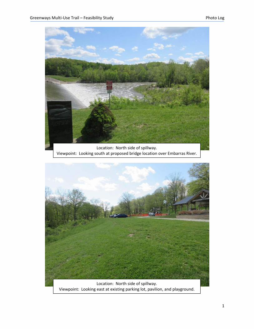
Location: North side of spillway. Viewpoint: Looking east at existing parking lot, pavilion, and playground.
Location: North side of spillway. Viewpoint: Looking south at proposed bridge location over Embarras River.
Greenways Multi-Use Trail – Feasibility Study Photo Log
2
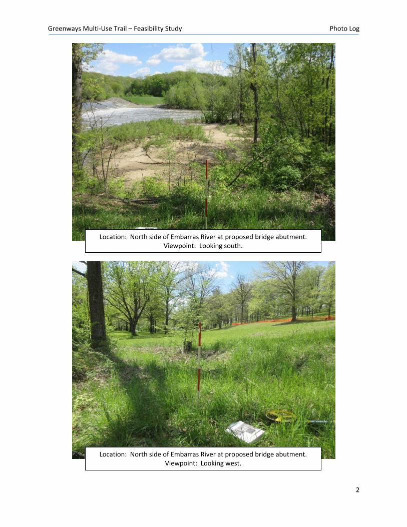
Location: North side of Embarras River at proposed bridge abutment. Viewpoint: Looking west.
Location: North side of Embarras River at proposed bridge abutment. Viewpoint: Looking south.
Greenways Multi-Use Trail – Feasibility Study Photo Log
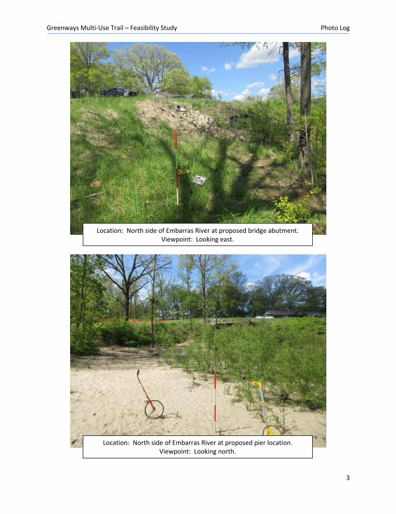
3
Location: North side of Embarras River at proposed pier location. Viewpoint: Looking north.
Location: North side of Embarras River at proposed bridge abutment. Viewpoint: Looking east.
Greenways Multi-Use Trail – Feasibility Study Photo Log
4
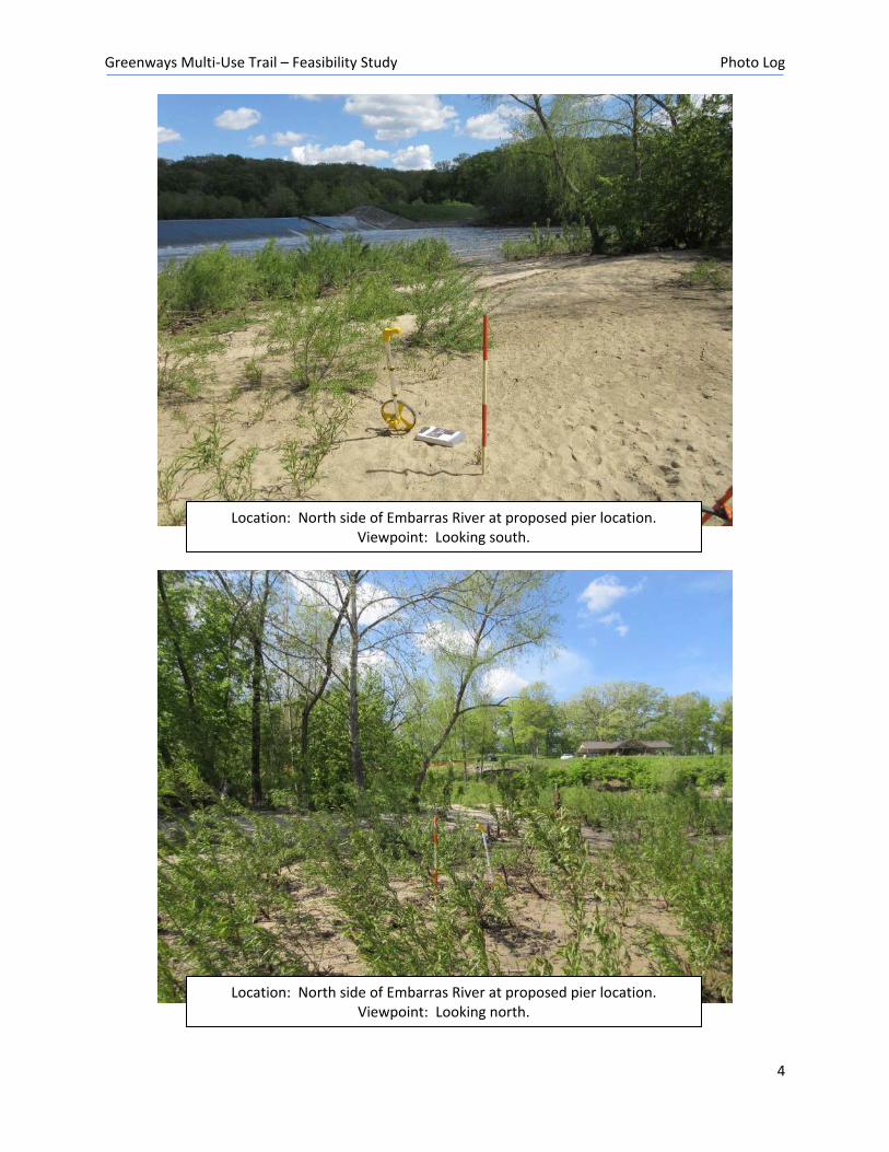
Location: North side of Embarras River at proposed pier location. Viewpoint: Looking south.
Location: North side of Embarras River at proposed pier location. Viewpoint: Looking north.
Greenways Multi-Use Trail – Feasibility Study Photo Log
5
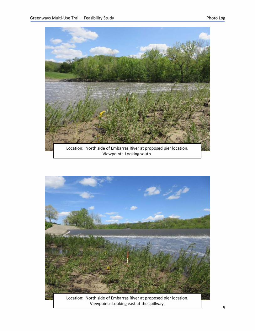
Location: North side of Embarras River at proposed pier location. Viewpoint: Looking east at the spillway.
Location: North side of Embarras River at proposed pier location. Viewpoint: Looking south.
Greenways Multi-Use Trail – Feasibility Study Photo Log
6
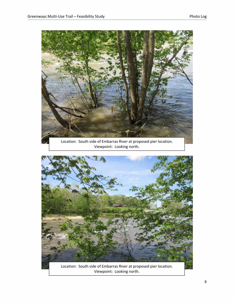
Location: South side of Embarras River at proposed pier location. Viewpoint: Looking north.
Location: South side of Embarras River at proposed pier location. Viewpoint: Looking north.
Greenways Multi-Use Trail – Feasibility Study Photo Log
7
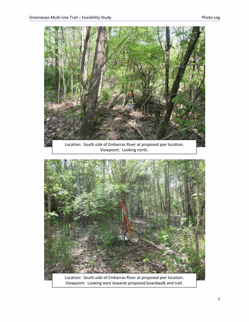
Location: South side of Embarras River at proposed pier location. Viewpoint: Looking west towards proposed boardwalk and trail.
Location: South side of Embarras River at proposed pier location. Viewpoint: Looking north.
Greenways Multi-Use Trail – Feasibility Study Photo Log
8
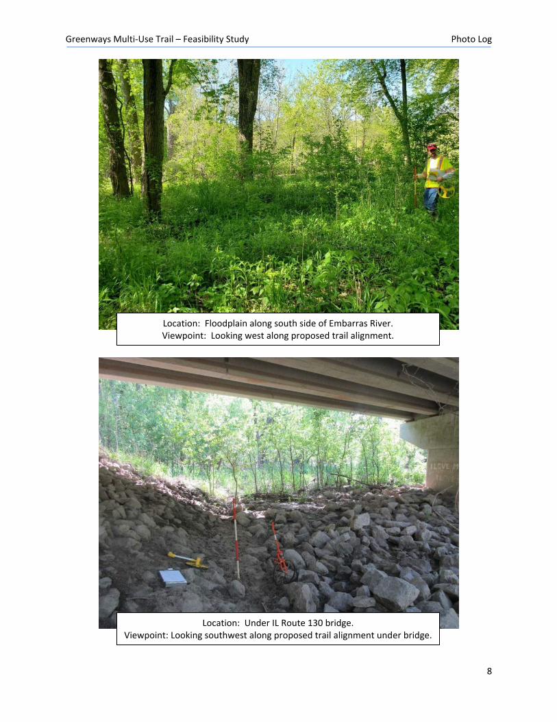
Location: Under IL Route 130 bridge. Viewpoint: Looking southwest along proposed trail alignment under bridge.
Location: Floodplain along south side of Embarras River. Viewpoint: Looking west along proposed trail alignment.
Greenways Multi-Use Trail – Feasibility Study Photo Log
9
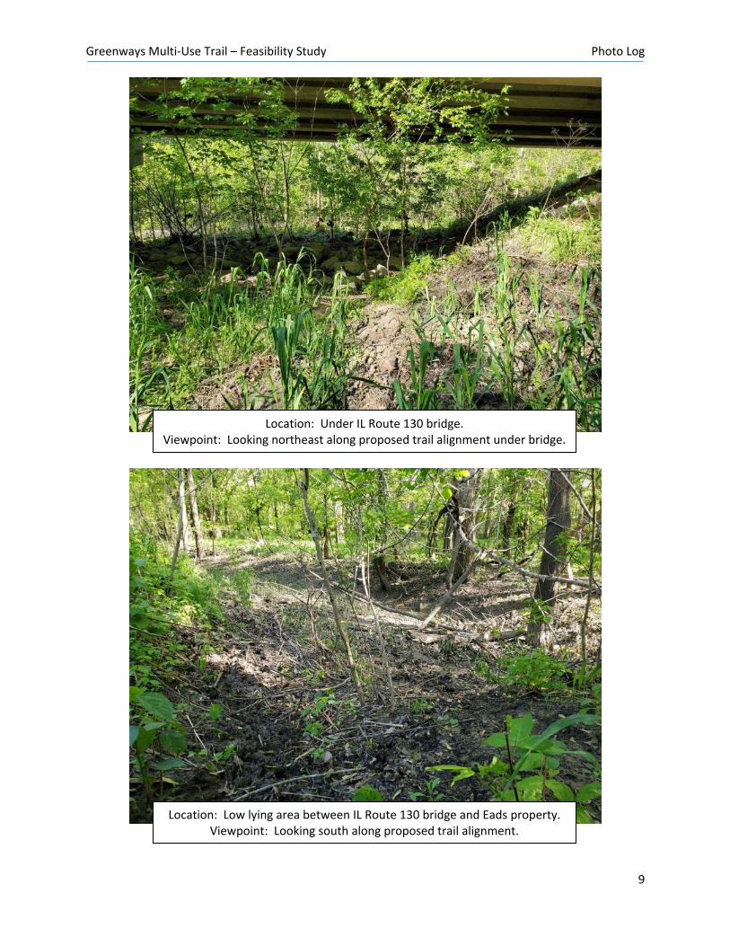
Location: Low lying area between IL Route 130 bridge and Eads property. Viewpoint: Looking south along proposed trail alignment.
Location: Under IL Route 130 bridge. Viewpoint: Looking northeast along proposed trail alignment under bridge.
Greenways Multi-Use Trail – Feasibility Study Photo Log
10
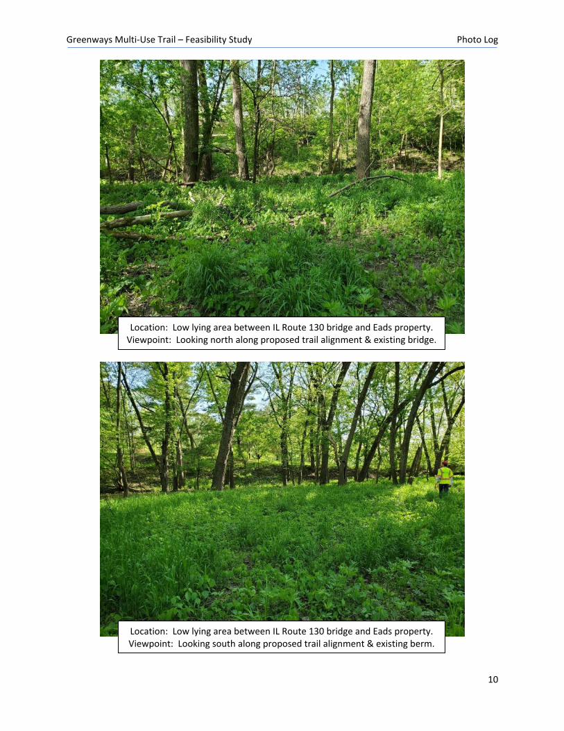
Location: Low lying area between IL Route 130 bridge and Eads property. Viewpoint: Looking south along proposed trail alignment & existing berm.
Location: Low lying area between IL Route 130 bridge and Eads property. Viewpoint: Looking north along proposed trail alignment & existing bridge.
Greenways Multi-Use Trail – Feasibility Study Photo Log
11
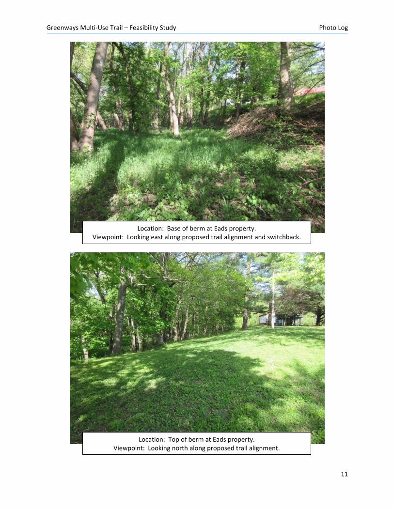
Location: Base of berm at Eads property. Viewpoint: Looking east along proposed trail alignment and switchback.
Location: Top of berm at Eads property. Viewpoint: Looking north along proposed trail alignment.
Greenways Multi-Use Trail – Feasibility Study Photo Log
12
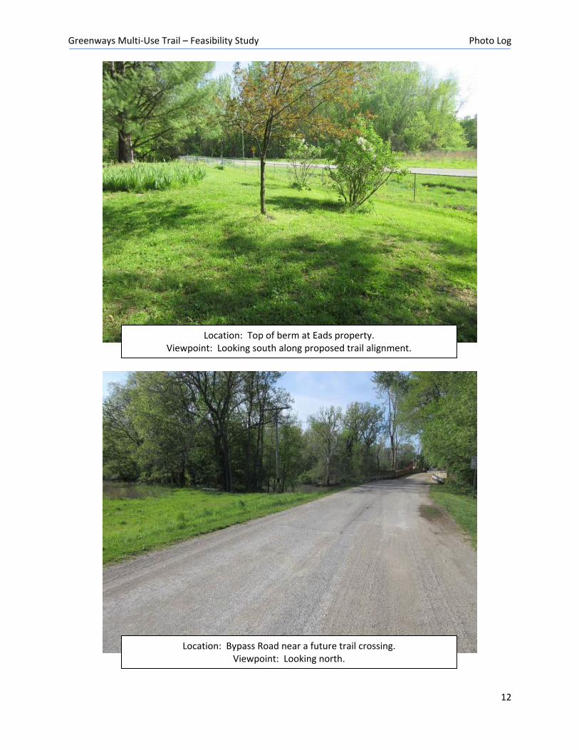
Location: Top of berm at Eads property. Viewpoint: Looking south along proposed trail alignment.
Location: Bypass Road near a future trail crossing. Viewpoint: Looking north.
USGS The National Map: Orthoimagery. Data refreshed April, 2019.
National Flood Hazard Layer FIRMette
0 500 1,000 1,500 2,000250Feet
Ü
88°8
'56.55
"W
39°27'40.83"N
88°8'19.09"W
39°27'13.05"N
SEE FIS REPORT FOR DETAILED LEGEND AND INDEX MAP FOR FIRM PANEL LAYOUT
SPECIAL FLOODHAZARD AREAS
Without Base Flood Elevation (BFE)Zone A, V, A99
With BFE or Depth Zone AE, AO, AH, VE, ARRegulatory Floodway
0.2% Annual Chance Flood Hazard, Areasof 1% annual chance flood with averagedepth less than one foot or with drainageareas of less than one square mile Zone XFuture Conditions 1% AnnualChance Flood Hazard Zone XArea with Reduced Flood Risk due toLevee. See Notes. Zone XArea with Flood Risk due to Levee Zone D
NO SCREEN Area of Minimal Flood Hazard Zone X
Area of Undetermined Flood Hazard Zone D
Channel, Culvert, or Storm SewerLevee, Dike, or Floodwall
Cross Sections with 1% Annual Chance17.5 Water Surface Elevation
Coastal Transect
Coastal Transect BaselineProfile BaselineHydrographic Feature
Base Flood Elevation Line (BFE)
Effective LOMRs
Limit of StudyJurisdiction Boundary
Digital Data AvailableNo Digital Data AvailableUnmapped
This map complies with FEMA's standards for the use of digital flood maps if it is not void as described below. The basemap shown complies with FEMA's basemap accuracy standardsThe flood hazard information is derived directly from theauthoritative NFHL web services provided by FEMA. This mapwas exported on 2/27/2020 at 12:21:48 PM and does notreflect changes or amendments subsequent to this date andtime. The NFHL and effective information may change orbecome superseded by new data over time.This map image is void if the one or more of the following mapelements do not appear: basemap imagery, flood zone labels,legend, scale bar, map creation date, community identifiers,FIRM panel number, and FIRM effective date. Map images forunmapped and unmodernized areas cannot be used forregulatory purposes.
Legend
OTHER AREAS OFFLOOD HAZARD
OTHER AREAS
GENERALSTRUCTURES
OTHERFEATURES
MAP PANELS
8
1:6,000
B 20.2
The pin displayed on the map is an approximate point selected by the user and does not represent an authoritative property location.
Between IL 130 and Dam10-yr HWE = 584100-yr HWE = 586
Between Bypass Rd & IL 13010-yr HWE = 583100-yr HWE = 585.5
Downstream of Bypass Rd10-yr HWE = 582.5100-yr HWE = 585
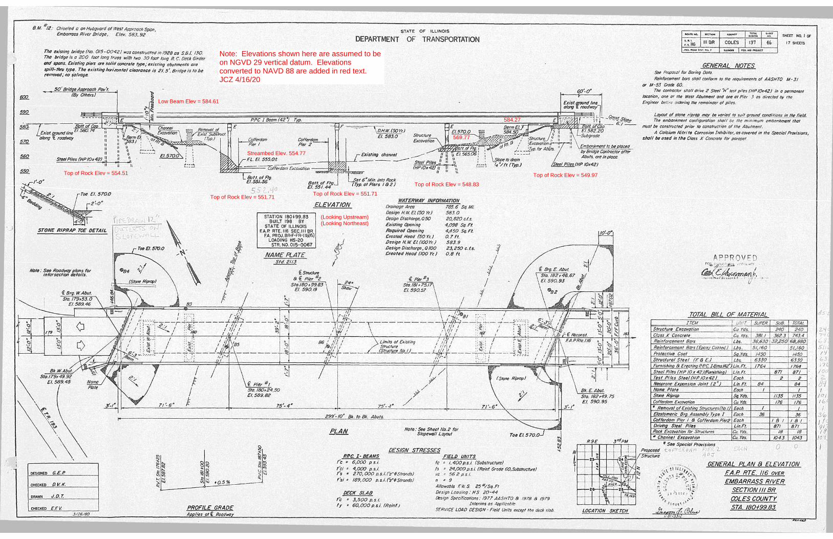
Note: Elevations shown here are assumed to beon NGVD 29 vertical datum. Elevationsconverted to NAVD 88 are added in red text.JCZ 4/16/20
Low Beam Elev = 584.61
Top of Rock Elev = 551.71Top of Rock Elev = 551.71
Top of Rock Elev = 554.51
Top of Rock Elev = 548.83
Top of Rock Elev = 549.97
Streambed Elev. 554.77
(Looking Upstream)(Looking Northeast)
569.77
584.27
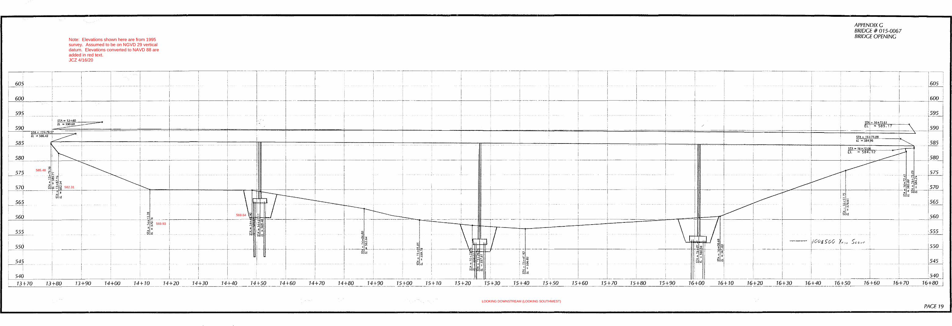
Note: Elevations shown here are from 1995survey. Assumed to be on NGVD 29 verticaldatum. Elevations converted to NAVD 88 areadded in red text.JCZ 4/16/20
569.93
582.31
585.48
569.64
LOOKING DOWNSTREAM (LOOKING SOUTHWEST)
964 - PREFABRICATED TRAIL BRIDGE PRE
964 - PREFABRICATED TRAIL BRIDGE PRE

964 - PREFABRICATED TRAIL BRIDGE PRE
964 - PREFABRICATED TRAIL BRIDGE PRE

962 - SAWN TIMBER TRAIL BRIDGESTS

962 - SAWN TIMBER TRAIL BRIDGE STS
962 - SAWN TIMBER TRAIL BRIDGE STS
962 - SAWN TIMBER TRAIL BRIDGE
X
STS
962 - SAWN TIMBER TRAIL BRIDGE STS
962 - SAWN TIMBER TRAIL BRIDGE STS

Desi
gn G
uide
lines
- Re
vise
d Se
ptem
ber
2006
C-�
Design Guidelines
C
DescriptionThe design development guidelines featured in this Appendix have been tailored to meet the specific facility development needs of the Wake County Consolidated Open Space System. The purpose of these guide-lines is to assist the County and its municipalities and partnering organiz-ations in developing open space and greenway facilities.
These guidelines provide a variety of trail facility and ecological system restoration concepts and ideas. These guidelines are not a substitute for a more thorough examination and detailed landscape architectural and engineering evaluation of each project segment. These guidelines serve as minimum standards for greenway facility development. Wake County disclaims any liability for the use, appropriateness and accuracy of these guidelines as they apply to a specific project. They are not to be used for construction.
The following resource materials have been used in the preparation of these guidelines:
• Adherence to national design standards for off-road trails and green- way facilities, as defined by the American Association of State Highway Transportation Officials (AASHTO), the Americans with Disabilities Act (ADA), Designing Sidewalks and Trails for Access: Part 2 and the Man-ual on Uniform Traffic Control Devices.
For more in-depth information and design development standards, the fol-lowing publications should be consulted:
Greenways: A Guide to Planning, Design and Development Published by Island Press, 1993 Authors: Charles A. Flink and Robert Searns For more information visit www.greenways.com
Trails for the Twenty-First Century Published by Island Press, 2001 Authors: Charles A. Flink, Robert Searns and Kristine Olka For more information visit www.greenways.com
Resources
Wak
e Co
unty
Ope
n Sp
ace
Plan
- Re
vise
d Se
ptem
ber
2006
C-2
Additional Resources
Guide to the Development of Bicycle Facilities Updated in 2000 by the American Association of State Highway Transportation Officials (AASHTO). Available from FHWA or AASHTO. www.aashto.org/bookstore/abs.html
Manual on Uniform Traffic Control Devices (MUTCD) Published by the U. S. Department of Transportation, Washington, DC Universal Access to Outdoor Recreation: A Design Guide Published by PLAE, Inc., Berkeley, CA, 1993
Designing Sidewalks and Trails for Access: Part Two - Best Practices Design Guide Published by U.S. Department of Transportation, Washington, DC, 2001
In all cases, the recommended guidelines in this report meet or exceed national standards. Should these national standards be revised in the future and result in discrepancies with this chapter, the national standards should prevail for all design decisions.
Other useful web sites for information include: Rails-to-Trails Conservancy - www.railtrails.org National Park Service - www.nps.org U.S. Department of Transportation - www.walkinginfo.org and www.bicyclinginfo.org Trails and Greenways Clearinghouse - www.trailsandgreenways.org National Bicycle and Pedestrian Clearinghouse - www.bikefed.org/clear.htm Greenways Incorporated - www.greenways.com
Desi
gn G
uide
lines
- Re
vise
d Se
ptem
ber
2006
C-�
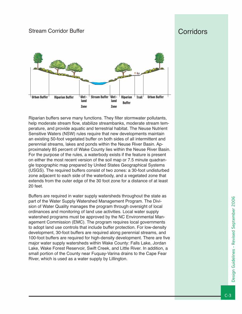
CorridorsStream Corridor Buffer
Riparian buffers serve many functions. They filter stormwater pollutants, help moderate stream flow, stabilize streambanks, moderate stream tem-perature, and provide aquatic and terrestrial habitat. The Neuse Nutrient Sensitive Waters (NSW) rules require that new developments maintain an existing 50-foot vegetated buffer on both sides of all intermittent and perennial streams, lakes and ponds within the Neuse River Basin. Ap-proximately 85 percent of Wake County lies within the Neuse River Basin. For the purpose of the rules, a waterbody exists if the feature is present on either the most recent version of the soil map or 7.5 minute quadran-gle topographic map prepared by United States Geographical Systems (USGS). The required buffers consist of two zones: a 30-foot undisturbed zone adjacent to each side of the waterbody, and a vegetated zone that extends from the outer edge of the 30 foot zone for a distance of at least 20 feet.
Buffers are required in water supply watersheds throughout the state as part of the Water Supply Watershed Management Program. The Divi-sion of Water Quality manages the program through oversight of local ordinances and monitoring of land use activities. Local water supply watershed programs must be approved by the NC Environmental Man-agement Commission (EMC). The program requires local governments to adopt land use controls that include buffer protection. For low-density development, 30-foot buffers are required along perennial streams, and 100-foot buffers are required for high-density development. There are five major water supply watersheds within Wake County: Falls Lake, Jordan Lake, Wake Forest Reservoir, Swift Creek, and Little River. In addition, a small portion of the County near Fuquay-Varina drains to the Cape Fear River, which is used as a water supply by Lillington.
Riparian Buffer Stream Buffer Riparian Buffer
Urban BufferTrailWet-landZone
Wet-landZone
Urban Buffer
Wak
e Co
unty
Ope
n Sp
ace
Plan
- Re
vise
d Se
ptem
ber
2006
C-�
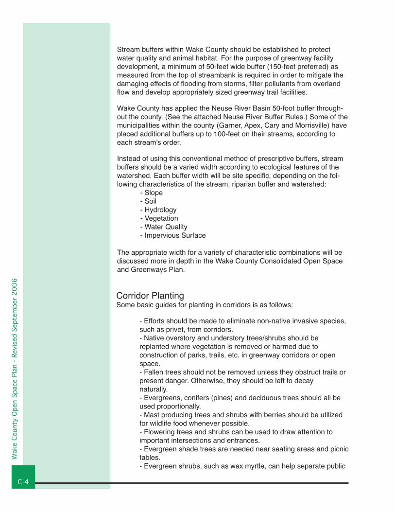
Corridor PlantingSome basic guides for planting in corridors is as follows:
- Efforts should be made to eliminate non-native invasive species, such as privet, from corridors. - Native overstory and understory trees/shrubs should be replanted where vegetation is removed or harmed due to construction of parks, trails, etc. in greenway corridors or open space. - Fallen trees should not be removed unless they obstruct trails or present danger. Otherwise, they should be left to decay naturally. - Evergreens, conifers (pines) and deciduous trees should all be used proportionally. - Mast producing trees and shrubs with berries should be utilized for wildlife food whenever possible. - Flowering trees and shrubs can be used to draw attention to important intersections and entrances. - Evergreen shade trees are needed near seating areas and picnic tables. - Evergreen shrubs, such as wax myrtle, can help separate public
Stream buffers within Wake County should be established to protect water quality and animal habitat. For the purpose of greenway facility development, a minimum of 50-feet wide buffer (150-feet preferred) as measured from the top of streambank is required in order to mitigate the damaging effects of flooding from storms, filter pollutants from overland flow and develop appropriately sized greenway trail facilities.
Wake County has applied the Neuse River Basin 50-foot buffer through-out the county. (See the attached Neuse River Buffer Rules.) Some of the municipalities within the county (Garner, Apex, Cary and Morrisville) have placed additional buffers up to 100-feet on their streams, according to each stream's order.
Instead of using this conventional method of prescriptive buffers, stream buffers should be a varied width according to ecological features of the watershed. Each buffer width will be site specific, depending on the fol-lowing characteristics of the stream, riparian buffer and watershed: - Slope - Soil - Hydrology - Vegetation - Water Quality - Impervious Surface
The appropriate width for a variety of characteristic combinations will be discussed more in depth in the Wake County Consolidated Open Space and Greenways Plan.
Desi
gn G
uide
lines
- Re
vise
d Se
ptem
ber
2006
C-�
Types of Trail Treads
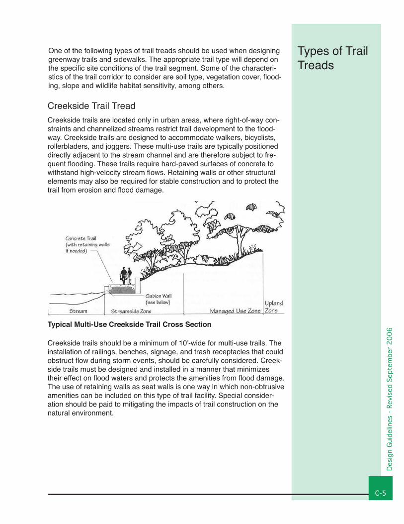
Creekside Trail TreadCreekside trails are located only in urban areas, where right-of-way con-straints and channelized streams restrict trail development to the flood-way. Creekside trails are designed to accommodate walkers, bicyclists, rollerbladers, and joggers. These multi-use trails are typically positioned directly adjacent to the stream channel and are therefore subject to fre-quent flooding. These trails require hard-paved surfaces of concrete to withstand high-velocity stream flows. Retaining walls or other structural elements may also be required for stable construction and to protect the trail from erosion and flood damage.
Creekside trails should be a minimum of 10'-wide for multi-use trails. The installation of railings, benches, signage, and trash receptacles that could obstruct flow during storm events, should be carefully considered. Creek-side trails must be designed and installed in a manner that minimizes their effect on flood waters and protects the amenities from flood damage. The use of retaining walls as seat walls is one way in which non-obtrusive amenities can be included on this type of trail facility. Special consider-ation should be paid to mitigating the impacts of trail construction on the natural environment.
Typical Multi-Use Creekside Trail Cross Section
One of the following types of trail treads should be used when designing greenway trails and sidewalks. The appropriate trail type will depend on the specific site conditions of the trail segment. Some of the characteri-stics of the trail corridor to consider are soil type, vegetation cover, flood-ing, slope and wildlife habitat sensitivity, among others.
Wak
e Co
unty
Ope
n Sp
ace
Plan
- Re
vise
d Se
ptem
ber
2006
C-6
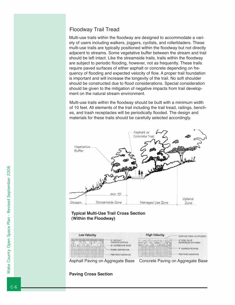
Floodway Trail TreadMulti-use trails within the floodway are designed to accommodate a vari-ety of users including walkers, joggers, cyclists, and rollerbladers. These multi-use trails are typically positioned within the floodway but not directly adjacent to streams. Some vegetative buffer between the stream and trail should be left intact. Like the streamside trails, trails within the floodway are subject to periodic flooding, however, not as frequently. These trails require paved surfaces of either asphalt or concrete depending on fre-quency of flooding and expected velocity of flow. A proper trail foundation is important and will increase the longevity of the trail. No soft shoulder should be constructed due to flood considerations. Special consideration should be given to the mitigation of negative impacts from trail develop-ment on the natural stream environment.
Multi-use trails within the floodway should be built with a minimum width of 10 feet. All elements of the trail including the trail tread, railings, bench-es, and trash receptacles will be periodically flooded. The design and materials for these trails should be carefully selected accordingly.
Typical Multi-Use Trail Cross Section(Within the Floodway)
Paving Cross Section
Asphalt Paving on Aggregate Base Concrete Paving on Aggregate Base
Desi
gn G
uide
lines
- Re
vise
d Se
ptem
ber
2006
C-�
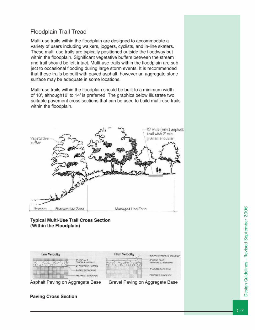
Floodplain Trail TreadMulti-use trails within the floodplain are designed to accommodate a variety of users including walkers, joggers, cyclists, and in-line skaters. These multi-use trails are typically positioned outside the floodway but within the floodplain. Significant vegetative buffers between the stream and trail should be left intact. Multi-use trails within the floodplain are sub-ject to occasional flooding during large storm events. It is recommended that these trails be built with paved asphalt, however an aggregate stone surface may be adequate in some locations.
Multi-use trails within the floodplain should be built to a minimum width of 10’, although12’ to 14’ is preferred. The graphics below illustrate two suitable pavement cross sections that can be used to build multi-use trails within the floodplain.
Typical Multi-Use Trail Cross Section(Within the Floodplain)
Paving Cross Section
Asphalt Paving on Aggregate Base Gravel Paving on Aggregate Base
Wak
e Co
unty
Ope
n Sp
ace
Plan
- Re
vise
d Se
ptem
ber
2006
C-�
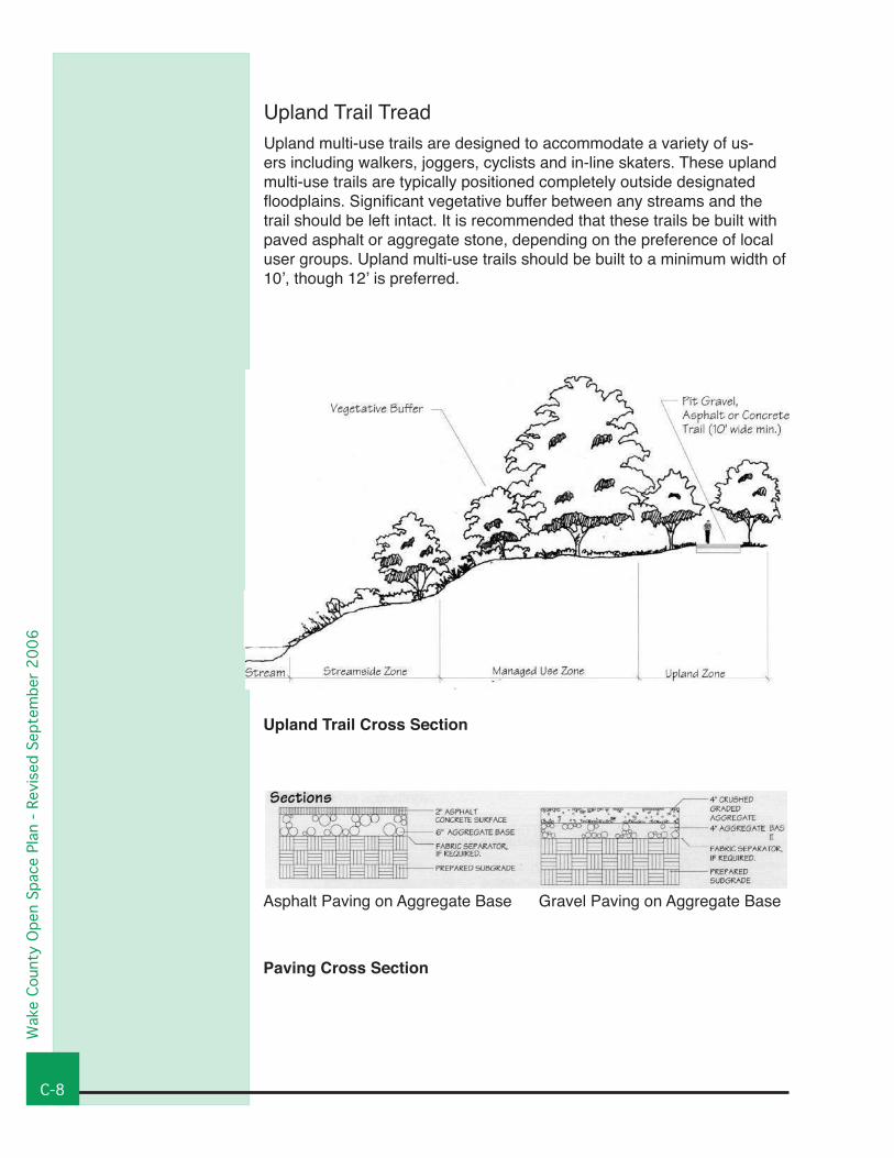
Upland Trail TreadUpland multi-use trails are designed to accommodate a variety of us-ers including walkers, joggers, cyclists and in-line skaters. These upland multi-use trails are typically positioned completely outside designated floodplains. Significant vegetative buffer between any streams and the trail should be left intact. It is recommended that these trails be built with paved asphalt or aggregate stone, depending on the preference of local user groups. Upland multi-use trails should be built to a minimum width of 10’, though 12’ is preferred.
Upland Trail Cross Section
Paving Cross Section
Asphalt Paving on Aggregate Base Gravel Paving on Aggregate Base
Desi
gn G
uide
lines
- Re
vise
d Se
ptem
ber
2006
C-�
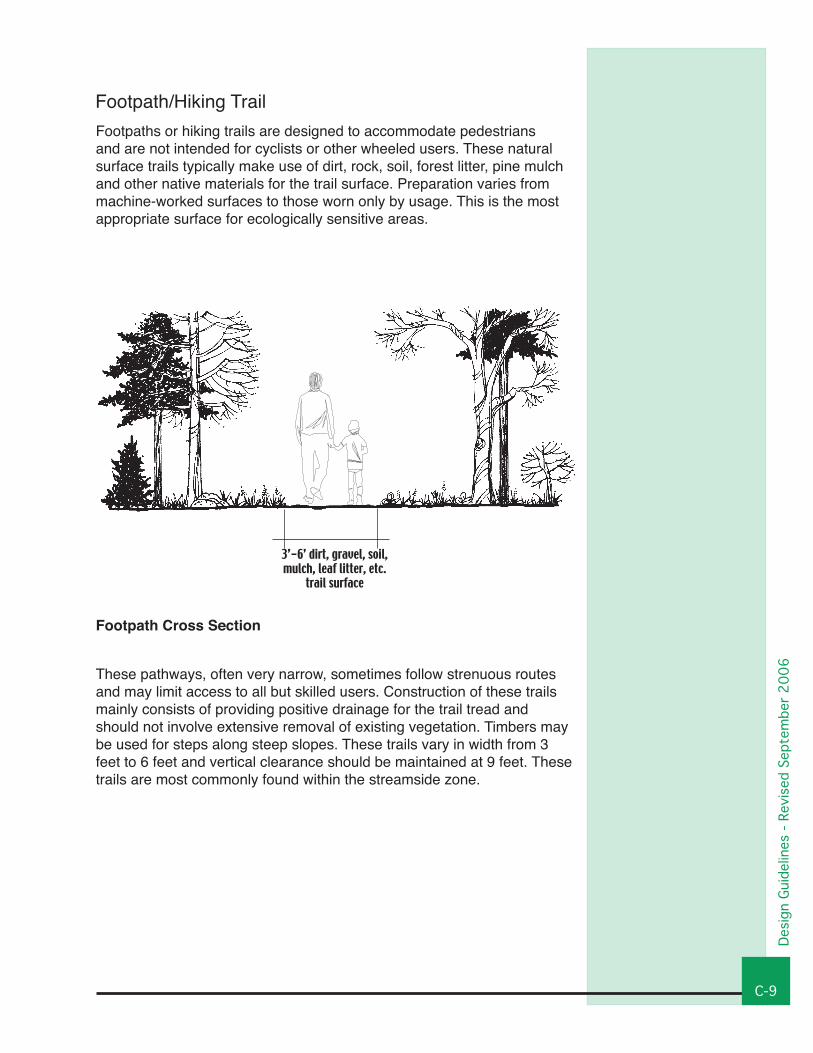
Footpath/Hiking Trail Footpaths or hiking trails are designed to accommodate pedestrians and are not intended for cyclists or other wheeled users. These natural surface trails typically make use of dirt, rock, soil, forest litter, pine mulch and other native materials for the trail surface. Preparation varies from machine-worked surfaces to those worn only by usage. This is the most appropriate surface for ecologically sensitive areas.
These pathways, often very narrow, sometimes follow strenuous routes and may limit access to all but skilled users. Construction of these trails mainly consists of providing positive drainage for the trail tread and should not involve extensive removal of existing vegetation. Timbers may be used for steps along steep slopes. These trails vary in width from 3 feet to 6 feet and vertical clearance should be maintained at 9 feet. These trails are most commonly found within the streamside zone.
3’-6’ dirt, gravel, soil, mulch, leaf litter, etc.
trail surface
Footpath Cross Section
Wak
e Co
unty
Ope
n Sp
ace
Plan
- Re
vise
d Se
ptem
ber
2006
C-�0
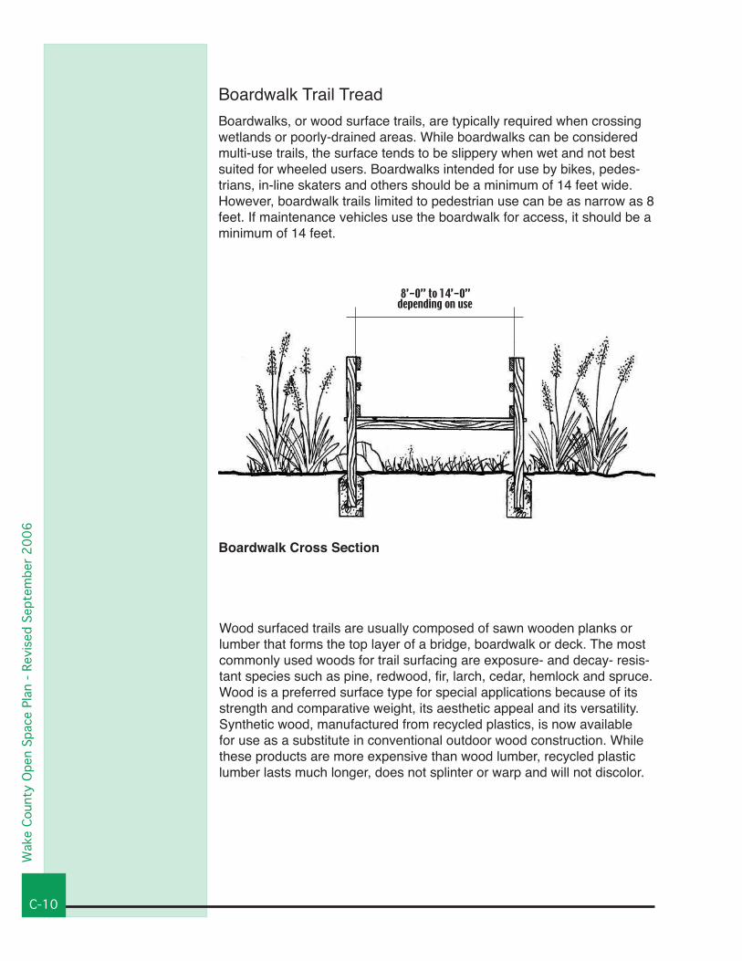
Wood surfaced trails are usually composed of sawn wooden planks or lumber that forms the top layer of a bridge, boardwalk or deck. The most commonly used woods for trail surfacing are exposure- and decay- resis-tant species such as pine, redwood, fir, larch, cedar, hemlock and spruce. Wood is a preferred surface type for special applications because of its strength and comparative weight, its aesthetic appeal and its versatility. Synthetic wood, manufactured from recycled plastics, is now available for use as a substitute in conventional outdoor wood construction. While these products are more expensive than wood lumber, recycled plastic lumber lasts much longer, does not splinter or warp and will not discolor.
Boardwalk Trail TreadBoardwalks, or wood surface trails, are typically required when crossing wetlands or poorly-drained areas. While boardwalks can be considered multi-use trails, the surface tends to be slippery when wet and not best suited for wheeled users. Boardwalks intended for use by bikes, pedes-trians, in-line skaters and others should be a minimum of 14 feet wide. However, boardwalk trails limited to pedestrian use can be as narrow as 8 feet. If maintenance vehicles use the boardwalk for access, it should be a minimum of 14 feet.
8’-0” to 14’-0”depending on use
Boardwalk Cross Section
Desi
gn G
uide
lines
- Re
vise
d Se
ptem
ber
2006
C-��
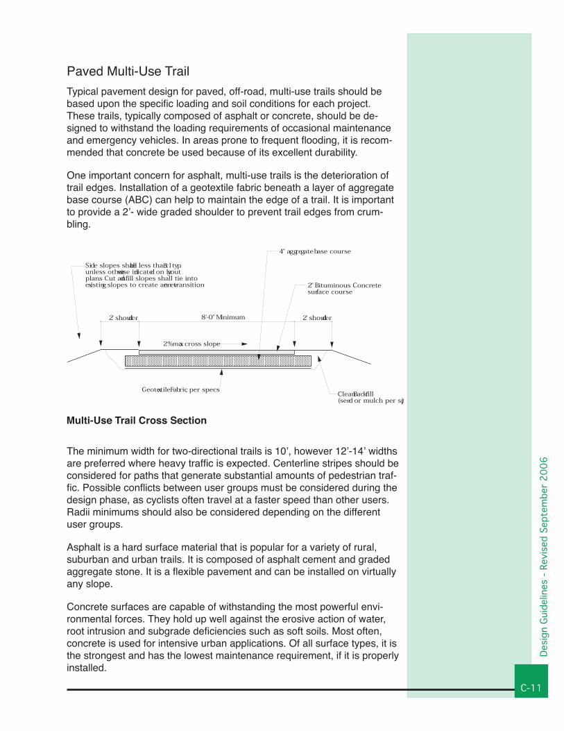
Paved Multi-Use TrailTypical pavement design for paved, off-road, multi-use trails should be based upon the specific loading and soil conditions for each project. These trails, typically composed of asphalt or concrete, should be de-signed to withstand the loading requirements of occasional maintenance and emergency vehicles. In areas prone to frequent flooding, it is recom-mended that concrete be used because of its excellent durability.
One important concern for asphalt, multi-use trails is the deterioration of trail edges. Installation of a geotextile fabric beneath a layer of aggregate base course (ABC) can help to maintain the edge of a trail. It is important to provide a 2’- wide graded shoulder to prevent trail edges from crum-bling.
The minimum width for two-directional trails is 10’, however 12’-14’ widths are preferred where heavy traffic is expected. Centerline stripes should be considered for paths that generate substantial amounts of pedestrian traf-fic. Possible conflicts between user groups must be considered during the design phase, as cyclists often travel at a faster speed than other users. Radii minimums should also be considered depending on the different user groups.
Asphalt is a hard surface material that is popular for a variety of rural, suburban and urban trails. It is composed of asphalt cement and graded aggregate stone. It is a flexible pavement and can be installed on virtually any slope.
Concrete surfaces are capable of withstanding the most powerful envi-ronmental forces. They hold up well against the erosive action of water, root intrusion and subgrade deficiencies such as soft soils. Most often, concrete is used for intensive urban applications. Of all surface types, it is the strongest and has the lowest maintenance requirement, if it is properly installed.
Multi-Use Trail Cross Section
Asphalt Pavement Construction Detail
Not to Scale
Notes:1. Cross slope direction varies. See layout plans fro direction of slope2. Amount of cross slope varies between 0% and 2%. See layout plans3. Contractor is responsible for re-establishing all slopes disturbed by construction.
2% max cross slope
Geotextile Fabric, per specs
Side slopes shall be less than 3:1 typ.unless otherwise indicated on layoutplans. Cut and fill slopes shall tie intoexisting slopes to create an even transition.
2' shoulder 2' shoulder8'-0" Minimum
Clean Backfill(seed or mulch per sp)
2" Bituminous Concretesurface course
4" aggregate base course
8
5