Embed Size (px)
Citation preview
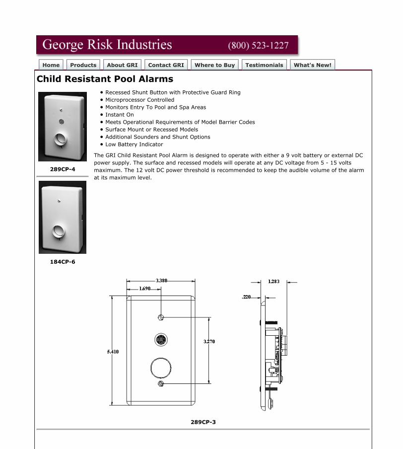
Home Products About GRI Contact GRI Where to Buy Testimonials What's New!
Child Resistant Pool Alarms
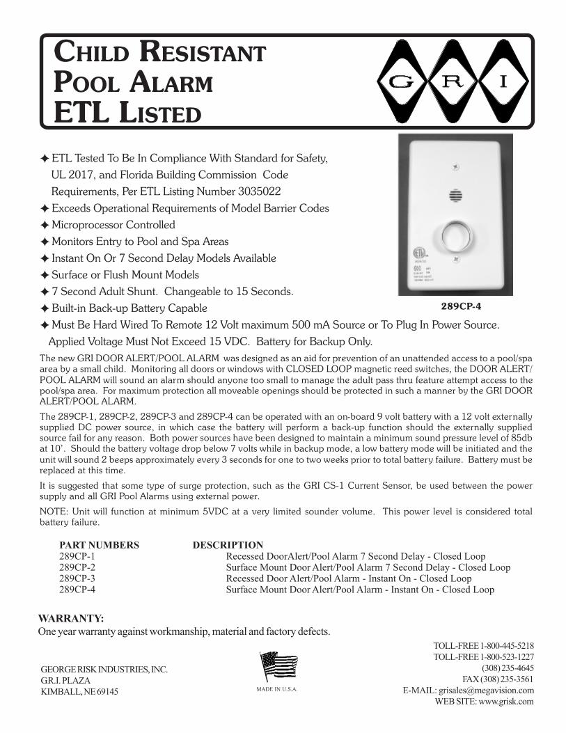
289CP-4
184CP-6
Recessed Shunt Button with Protective Guard RingMicroprocessor ControlledMonitors Entry To Pool and Spa AreasInstant OnMeets Operational Requirements of Model Barrier CodesSurface Mount or Recessed ModelsAdditional Sounders and Shunt OptionsLow Battery Indicator
The GRI Child Resistant Pool Alarm is designed to operate with either a 9 volt battery or external DCpower supply. The surface and recessed models will operate at any DC voltage from 5 - 15 voltsmaximum. The 12 volt DC power threshold is recommended to keep the audible volume of the alarmat its maximum level.
289CP-3
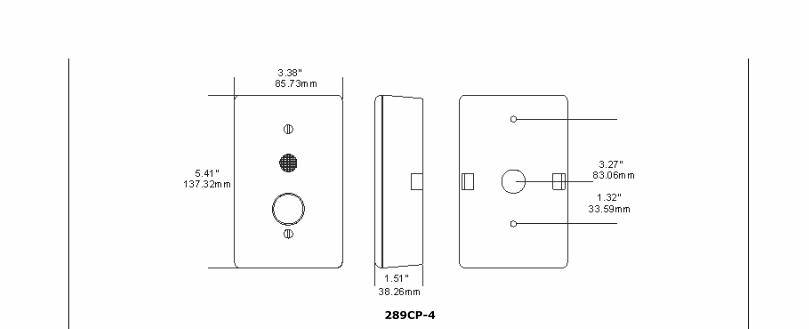
289CP-4
Product Specification PDF's About PDF
GRI Child Resistant Pool Alarms Product Specification PDF
GRI Child Resistant Pool Alarms Instructions PDF
New 2008 Jumper Settings Green Terminal PDF
[Home] [Products] [What's New!] [Security Products] [Data Entry Peripherals] [Pushbutton Switches][Custom Engraved Keycaps] [Proximity Sensors] [Contact GRI] [About GRI]
Can't find what you are looking for?
Revised: Friday, September 13, 2013Web design by The Computer Guy Copyright © 1997-2013
G.R.I. - Your Choice when Reliability Matters!
GEORGE RISK INDUSTRIES, INC.G.R.I. PLAZAKIMBALL, NE 69145 MADE IN U.S.A.
TOLL-FREE 1-800-445-5218TOLL-FREE 1-800-523-1227
(308) 235-4645FAX (308) 235-3561
E-MAIL: [email protected] SITE: www.grisk.com
CHILD RESISTANTPOOL ALARMETL LISTED
289CP-4
WARRANTY:One year warranty against workmanship, material and factory defects.
��ETL Tested To Be In Compliance With Standard for Safety,UL 2017, and Florida Building Commission CodeRequirements, Per ETL Listing Number 3035022
��Exceeds Operational Requirements of Model Barrier Codes��Microprocessor Controlled��Monitors Entry to Pool and Spa Areas��Instant On Or 7 Second Delay Models Available��Surface or Flush Mount Models��7 Second Adult Shunt. Changeable to 15 Seconds. ��Built-in Back-up Battery Capable��Must Be Hard Wired To Remote 12 Volt maximum 500 mA Source or To Plug In Power Source.
Applied Voltage Must Not Exceed 15 VDC. Battery for Backup Only.The new GRI DOOR ALERT/POOL ALARM was designed as an aid for prevention of an unattended access to a pool/spaarea by a small child. Monitoring all doors or windows with CLOSED LOOP magnetic reed switches, the DOOR ALERT/POOL ALARM will sound an alarm should anyone too small to manage the adult pass thru feature attempt access to thepool/spa area. For maximum protection all moveable openings should be protected in such a manner by the GRI DOORALERT/POOL ALARM.
The 289CP-1, 289CP-2, 289CP-3 and 289CP-4 can be operated with an on-board 9 volt battery with a 12 volt externallysupplied DC power source, in which case the battery will perform a back-up function should the externally suppliedsource fail for any reason. Both power sources have been designed to maintain a minimum sound pressure level of 85dbat 10’. Should the battery voltage drop below 7 volts while in backup mode, a low battery mode will be initiated and theunit will sound 2 beeps approximately every 3 seconds for one to two weeks prior to total battery failure. Battery must bereplaced at this time.
It is suggested that some type of surge protection, such as the GRI CS-1 Current Sensor, be used between the powersupply and all GRI Pool Alarms using external power.
NOTE: Unit will function at minimum 5VDC at a very limited sounder volume. This power level is considered totalbattery failure.
PART NUMBERS DESCRIPTION289CP-1 Recessed DoorAlert/Pool Alarm 7 Second Delay - Closed Loop289CP-2 Surface Mount Door Alert/Pool Alarm 7 Second Delay - Closed Loop289CP-3 Recessed Door Alert/Pool Alarm - Instant On - Closed Loop289CP-4 Surface Mount Door Alert/Pool Alarm - Instant On - Closed Loop
GEORGE RISK INDUSTRIES, INC.G.R.I. PLAZAKIMBALL, NE 69145
MADE IN U.S.A.
TOLL-FREE 1-800-445-5218 • 1-800-523-1227(308) 235-4645 • FAX (308) 235-3561
E-MAIL: [email protected] SITE: www.grisk.com
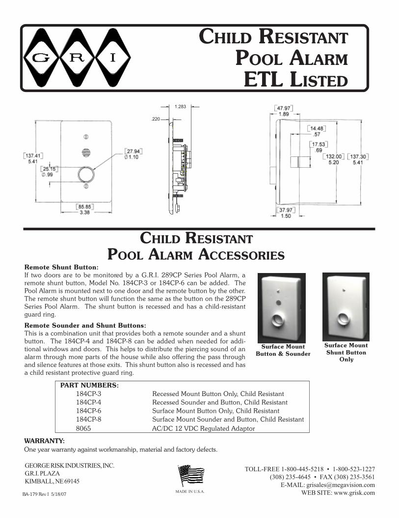
Remote Shunt Button:If two doors are to be monitored by a G.R.I. 289CP Series Pool Alarm, aremote shunt button, Model No. 184CP-3 or 184CP-6 can be added. ThePool Alarm is mounted next to one door and the remote button by the other.The remote shunt button will function the same as the button on the 289CPSeries Pool Alarm. The shunt button is recessed and has a child-resistantguard ring.
Remote Sounder and Shunt Buttons:This is a combination unit that provides both a remote sounder and a shuntbutton. The 184CP-4 and 184CP-8 can be added when needed for addi-tional windows and doors. This helps to distribute the piercing sound of analarm through more parts of the house while also offering the pass throughand silence features at those exits. This shunt button also is recessed and hasa child resistant protective guard ring.
Surface MountButton & Sounder
Surface MountShunt Button
Only
PART NUMBERS:184CP-3 Recessed Mount Button Only, Child Resistant184CP-4 Recessed Sounder and Button, Child Resistant184CP-6 Surface Mount Button Only, Child Resistant184CP-8 Surface Mount Sounder and Button, Child Resistant8065 AC/DC 12 VDC Regulated Adaptor
BA-179 Rev I 5/18/07
WARRANTY:One year warranty against workmanship, material and factory defects.
CHILD RESISTANTPOOL ALARMETL LISTED
.220
1.283
CHILD RESISTANTPOOL ALARM ACCESSORIES
PR
OD
UC
T D
ES
CR
IPT
ION
FOR
TH
ED
OO
R A
LER
T/P
OO
L ALA
RM
Models 289C
P-1, 289C
P-2, 289C
P-3 and 289C
P-4
Type SM
Signaling D
eviceE
TL Tested To Be In C
ompliance W
ith Standard For Safety,
UL 2017, and Florida B
uilding Com
mission C
ode Requirem
ents,P
er ETL Listing N
umber 3035022
APPLIC
ATIO
N:
The GR
I DO
OR
/ALE
RT P
OO
L ALA
RM
is designed as an aid to detectunsupervised access to a pool/spa area by a sm
all child. Monitoring all
doors and window
s with m
agnetic reed switches the D
OO
R A
LER
T/PO
OL
ALA
RM
will sound an alarm
should anyone too small to m
anage the adultpass through feature attem
pt access to the pool/spa area. For maxim
umprotection all m
oveable openings should be protected in such a manner
by the GR
I DO
OR
ALE
RT/PO
OL A
LAR
M.
DESC
RIPTIO
N:
The GR
I DO
OR
ALE
RT/P
OO
L ALA
RM
uses a microprocessor to m
onitorthe C
LOS
ED
LOO
P m
agnetic reed switches, shunt/cancel button, battery
and power supply voltages, and to provide the tim
ing options. The re-cessed versions are designed to fit inside a single gang utility box, w
hilethe surface m
ount versions may easily be m
ounted to the wall of any
structure.
The 289CP
-1 and 289CP
-2 versions offer a seven second delay in which
an adult may open the protected door, shut it, and then press the shunt/
cancel button without the alarm
sounding.
The 289CP
-3 and 289CP
-4 versions alarm instantly if the protected door
is open before the shunt/cancel button is pressed.
All versions m
ust be operated with a 12 volt externally supplied D
C pow
ersource. A
n optional onboard 9 volt battery can be used, in which case the
battery will perform
a backup function should the externally supplied sourcefail for any reason. The G
RI D
OO
R A
LER
T/PO
OL A
LAR
M is designed to
maintain a m
inimum
sound pressure level.
MO
DEL N
UM
BER
AN
D VER
SION
289CP
-1R
ecessed Door A
lert/Pool A
larm 7 S
econd Delay
289CP
-2S
urface Mount D
oor Alert/P
ool Alarm
7 Second D
elay289C
P-3
Recessed D
oor Alert/P
ool Alarm
Instant On
289CP
-4S
urface Mount D
oor Alert/P
ool Alarm
Instant On
It is suggested that some type of surge protection, such as the G
RI C
S-1
Current S
ensor, be used between the pow
er supply and all GR
I Pool A
larms
using external power.
NO
TE: U
nit will function at m
inimum
5VD
C at a very lim
ited sounder vol-um
e. This power level is considered total battery failure.
SPECIFIC
ATION
S:B
attery TypeStandard 9 Volt
Battery Life
Approxim
ately 2 Weeks
External P
ower S
upply12V
DC
500 mA
Output
Applied Voltage m
ust not exceed15 Volts D
CLow
Bat M
ode7V
DC
Mounting H
eightR
ef. Local Code
Sw
itchC
losed Loop
WA
RR
AN
TY: One year against w
orkmanship, m
aterial and factory defects.
DISC
LAIM
ER
Recom
mended
alkaline battery B
atteryC
lip
5/23/2007
Figu
re 2.
Terminal
Connections
& Jumpers
TER
MIN
AL TM
1TE
RM
INA
L TM1
TER
MIN
AL TM
1TE
RM
INA
L TM1
TER
MIN
AL TM
1P
INP
INP
INP
INP
INE
xternal Pow
er (+)1
Ground
2R
emote S
ounder Controller
3R
emote R
eset/Delay S
witch
4D
oor Contact
5R
emote S
ounder Pow
er (+)6
Alarm
Signal
7
The jum
pers on JP1 are factory
preselected. Alteration can effect tim
-ing and/or delay function.
JP1TM
11234567
JP1XXX
Door
Contact
Connections
The G.R.I. D
oor Alert/P
ool Alarm
is not a life saving device. Its’ intentis to serve strictly as a m
onitoring device on doors and window
s tohelp prevent unattended access to pool and spa areas.

INS
TALLAT
ION
INS
TR
UC
TIO
NS
A) Installing the D
oor SensorN
OTE: C
losed Loop Switch R
equired.
The GR
I DO
OR
ALE
RT/PO
OL A
LAR
M uses C
LOS
ED
LOO
P (nor-m
ally open) magnetic reed sw
itches. Install the magnetic reed
switch on the door according to the m
anufacturer’s installationinstructions. If there is a screen door, a sw
itch should be in-stalled on it as w
ell. The switches should be connected in paral-
lel as in Figure 1. In this configuration the DO
OR
ALE
RT/PO
OL
ALA
RM
will only activate if both doors are open. N
ext run thew
ires from the sw
itch(es) to where the D
OO
R A
LER
T/PO
OL
ALA
RM
will be located on the w
all.
B) Installing the D
OO
R A
LERT/PO
OL A
LAR
MN
OTE: The D
OO
R A
LER
T/PO
OL A
LAR
M m
ust be mounted as per local
code or regulations.
SUR
FAC
E MO
UN
T VERSIO
N:
Rem
ove the DO
OR
ALE
RT/P
OO
L ALA
RM
from the surface m
ount case.K
nockouts are provided on this case for wire access. A
ttach the surfacem
ount case directly to the wall or existing fixture, or it m
ay be mounted to
cover a single gang electrical box. Attach the w
ires from door sw
itch toterm
inal TM1 pins 2 and 5. It does not m
atter which w
ire goes in which
location. Using an external 12 volt D
C supply, run the w
ires from the
power source to the alarm
unit and attach the positive voltage to pin 1 andground to pin 2 of term
inal TM1.
If battery backup is desired, connect a standard 9 volt battery. The alarmw
ill beep twice during pow
er up indicating a successful diagnostics test.Lay the battery in the bottom
of the case and reassemble the D
OO
RA
LER
T/PO
OL A
LAR
M w
ith the button on the bottom and the sounder on
N /O
DO
OR
Figu
re 1. W
iring Diagram
Shunt/C
ancel
Sounder
SC
RE
EN
N /O
INSTA
LLATIO
NW
IRIN
G D
IAG
RA
MS
ingle Door w
ithS
creen
top. Secure w
ith the two screw
s provided.
REC
ESSED VER
SION
:The recessed version of the D
OO
R A
LER
T/PO
OL A
LAR
M is designed to
fit in a single gang utility box. Run the w
ires from the door sensor sw
itch(es)into the utility box. A
ttach the wires to term
inal TM1 pins 2 and 5. It does
not matter w
hich wire goes in w
hich location. Using an external 12 volt
DC
supply, run the wires from
the power source to the alarm
unit andattach the positive voltage to pin 1 and ground to pin 2 of term
inal TM1. If
battery back up is desired, install a standard 9 volt battery on the back ofthe D
OO
R A
LER
T/PO
OL A
LAR
M. The alarm
will beep tw
ice during power
up later indicating a successful diagnostics test. Finally, insert the DO
OR
ALE
RT/P
OO
L ALA
RM
into the utility box with the button on the bottom
and the sounder on top. Secure w
ith the two screw
s provided.
PERTA
INS TO
SUR
FAC
E MO
UN
T AN
D R
ECESSED
:To m
aintain maxim
um sounder volum
e, a low battery m
ode will be initi-
ated. Should the voltage drop below
7 volts the low battery m
ode will be
triggered and the unit will beep approxim
ately every 5 seconds for one totw
o weeks prior to total battery failure. The battery m
ust be replaced atthis tim
e and the cause of power failure determ
ined and restored.
When the alarm
is sounding, it can only be turned off by pressing theshunt/cancel button. If the door is still open 7 seconds after the button ispressed, the alarm
will sound again and continue until the door is closed
and the button is pressed.
WIR
ING
SPECIFIC
ATIO
N:
For connection of optional remote equipm
ent and door contact switches a
Belden CAT5 C
L2 or equivalent cable is recomm
ended. For the connectionof the 12 volt pow
er supply to the alarm unit a Belden 18-2 C
L2-CM
R 300v
60ºC or equivalent w
ire is recomm
ended. In all cases installer should refer-ence current local N
.E.C. code, and/or code requirem
ents set forth by localhousing authority or code enforcem
ent jurisdiction.
REC
OM
MEN
DED
SYSTEMS TESTIN
G:
Periodic system testing shall be perform
ed on a weekly basis, and should
incorporate operation of each door and window
covered by the system, to
confirm an alarm
sounding at each opening. Installation of on-board batteryas redundant pow
er source shall necessitate this testing is performed w
ithprim
ary power source disconnected. In all cases battery should be replaced
on a regular basis of every 80 to 90 days.

G.R.I. POOL ALARMSOFTWARE JUMPER OPTIONS
(New 2008 Jumper Settings with Green Terminal G.R.I. 289 Series Pool Alarms)
JP1 Jumper Positions
Note that position 1 is closest to Sounder.
Position 1 No Jumper, Instant On. With Jumper, 7 Second Delay.
Position 2 No Jumper, 15 Second Shunt. With Jumper, 7 Second Shunt.
Position 3 No Jumper, Aux/Relay Follows Alarm. With Jumper, Aux/RelayFollows Door.
Aux Output TM1-7 Is Grounded When On. 400 mA Maximum Current.
Select Desired Setting And Restore Power To Save
PLEASE NOTE: Always reference local codes and / or regulations concerninginstallation of the G.R.I. Pool Alarms. Some state and area building codes do notaccept seven second delay units.