Embed Size (px)
Citation preview
Gridless optical networking field trial: flexible spectrum switching, defragmentation and transport of 10G/40G/100G/555G over
620-km field fiber
N. Amaya,1,*
M. Irfan,1 G. Zervas,
1 K. Banias,
1 M. Garrich,
1,4 I. Henning,
1
D. Simeonidou,1 Y. R. Zhou,
2 A. Lord,
2 K. Smith,
2 V. J. F. Rancano,
3 S. Liu,
3
P. Petropoulos,3 and D. J. Richardson
3
1School of Computer Science and Electronic Engineering, University of Essex, Colchester CO4 3SQ, UK 2BT Innovate & Design, pp. B29/OP8, Polaris House, BT Adastral Park, Ipswich IP5 3RE, UK
3Optoelectronics Research Centre, University of Southampton, Southampton, SO17 1BJ, UK 4Dipartimento di Elettronica, Politecnico di Torino, Torino 10129, Italy
Abstract: We present results from the first gridless networking field trial with flexible spectrum switching nodes and 620 km of installed fibre links. Signals at 10G, 12.25G, 42.7G, DP-QPSK 40G, DP-QPSK 100G and 555G are generated, successfully transported and switched using flexible, custom spectrum allocation per channel. Spectrum defragmentation is demonstrated using integrated SOA-MZI wavelength converters. Results show error-free end-to-end performance (BER<1e-9) for the OOK channels and good pre-FEC BER performance with sufficient margin to FEC limit for the 40G and 100G coherent channels as well as for the 555G super-channel.
©2011 Optical Society of America
OCIS codes: (060.4250) Networks; (060.4510) Optical communications.
References and links
1. P. J. Winzer, A. H. Gnauck, S. Chandrasekhar, S. Draving, J. Evangelista, and B. Zhu, “Generation and 1,200-km transmission of 448-Gb/s ETDM 56-Gbaud PDM 16-QAM using a single I/Q modulator,” 36th European Conference and Exhibition on Optical Communication (ECOC), 19–23 Sept. 2010.
2. S. Chandrasekhar, X. Liu, B. Zhu, and D. W. Peckham, “Transmission of a 1.2-Tb/s 24-carrier no-guard-interval coherent OFDM superchannel over 7200-km of ultra-large-area fiber,” 35th European Conference on Optical Communication, ECOC '09, 20–24 Sept. 2009.
3. D. Hillerkuss, T. Schellinger, R. Schmogrow, M. Winter, T. Vallaitis, R. Bonk, A. Marculescu, J. Li, M. Dreschmann, J. Meyer, S. Ben Ezra, N. Narkiss, B. Nebendahl, F. Parmigiani, P. Petropoulos, B. Resan, K. Weingarten, T. Ellermeyer, J. Lutz, M. Moller, M. Huebner, J. Becker, C. Koos, W. Freude, and J. Leuthold, “Single source optical OFDM transmitter and optical FFT receiver demonstrated at line rates of 5.4 and 10.8 Tbit/s,” Optical Fiber Communication (OFC2010), 21–25 March 2010.
4. J. Yu, Z. Dong, X. Xiao, Y. Xia, S. Shi, C. Ge, W. Zhou, N. Chi, and Y. Shao, “Generation, transmission and coherent detection of 11.2 Tb/s (112×100Gb/s) single source optical OFDM superchannel,” OFC/NFOEC, 6–10 March 2011.
5. T. Xia, G. Wellbrock, Y. K. Huang, E. Ip, M. F. Huang, Y. Shao, T. Wang, Y. Aono, T. Tajima, S. Murakami, and M. Cvijetic, “Field experiment with mixed line-rate transmission (112-Gb/s, 450-Gb/s, and 1.15-Tb/s) over 3,560 km of installed fiber using filterless coherent receiver and EDFAs only,” Optical Fiber Communication Conference and Exposition (OFC/NFOEC), 6–10 March 2011.
6. D. Geisler, Y. Yin, K. Wen, N. Fontaine, R. Scott, S. Chang, and S. Yoo, “Demonstration of spectral defragmentation in flexible bandwidth optical networking by FWM,” IEEE Photon. Technol. Lett. (to be published).
7. N. Amaya, G. S. Zervas, B. Rahimzadeh Rofoee, M. Irfan, Y. Qin, and D. Simeonidou, “Field trial of a 1.5 Tb/s adaptive and gridless OXC supporting elastic 1000-fold bandwidth granularity,” in 37th European Conference and Exposition on Optical Communications, paper We.9.K.2, ECOC 2011.
8. K. Roberts, D. Beckett, D. Boertjes, J. Berthold, and C. Laperle, “100G and beyond with digital coherent signal processing,” IEEE Commun. Mag. 48(7), 62–69 (2010).
9. WaveShaper, http://www.finisar.com/optical_instrumentation. 10. D. Apostolopoulos, K. Vyrsokinos, P. Zakynthinos, N. Pleros, and H. Avramopoulos, “An SOA-MZI NRZ
wavelength conversion scheme with enhanced 2R regeneration characteristics,” IEEE Photon. Technol. Lett. 21(19), 1363–1365 (2009).
(C) 2011 OSA 12 December 2011 / Vol. 19, No. 26 / OPTICS EXPRESS B277#157557 - $15.00 USD Received 2 Nov 2011; accepted 8 Nov 2011; published 18 Nov 2011

11. M. Spyropoulou, N. Pleros, K. Vyrsokinos, D. Apostolopoulos, M. Bougioukos, D. Petrantonakis, A. Miliou, and H. Avramopoulos, “40 Gb/s NRZ wavelength conversion using a differentially-biased SOA-MZI: theory and experiment,” J. Lightwave Technol. 29(10), 1489–1499 (2011).
12. Y. Miyamoto, “4O-Gbit/s transport system: its WDM upgrade,” Optical Fiber Communication (2000), Vol. 3, pp. 323–325.
13. S. Tibuleac and M. Filer, “Transmission impairments in DWDM networks with reconfigurable optical add-drop multiplexers,” J. Lightwave Technol. 28(4), 557–598 (2010).
14. H. Suzuki, M. Fujiwara, N. Takachio, K. Iwatsuki, T. Kitoh, and T. Shibata, “12.5 GHz spaced 1.28 Tb/s (512-channel×2.5 Gb/s) super-dense WDM transmission over 320 km SMF using multiwavelength generation technique,” IEEE Photon. Technol. Lett. 14(3), 405–407 (2002).
1. Introduction
Future transport networks will need to deal with a mix of providers’ traffic representing services (i.e. 10Gb/s legacy channels), core traffic (i.e. at 100G, 400 Gb/s and beyond), as well as alien traffic, which could be variable bit rate and format channels. Hence, optical nodes will need to allocate resources in a flexible and efficient manner to support a mix of super-channels and lower speed channels. The nodes’ complexity will largely depend on the network segment (i.e. inner core, metro), and should also facilitate transparent interoperability between segments. In addition, metro segments might carry legacy 10 Gb/s requiring dispersion compensated (DC) links whereas inner core segments might just use coherent compensation techniques (e.g. DSP) to support high speed and super-channels. To address increasing traffic growth, advances in modulation formats enable a 100G channel to fit in a standard 50-GHz WDM slot. However, this may not be the case for higher bit-rate channels. For instance, super-channels at 400 Gb/s [1], 1Tb/s [2] and beyond [3,4] will occupy broader spectrum, which neither fits within the existing ITU grid nor is supported by conventional optical network infrastructures. Moreover, simultaneously supporting a combination of high-capacity super-channels and lower bit rate channels is critical [5].
Flexible and gridless optical networking is proposed to address such diverse requirements so as to switch and transport mix line rate technologies ranging from 10 Gb/s (25GHz spectrum) for better spectral efficiency to 555 Gb/s (650GHz spectrum). However, transporting mixed signal bit rates and modulation formats in such a flexible manner could lead to spectral fragmentation and increased blocking [6]. To overcome this, a super-channel or multiple lower bit rate channels need to be moved to a different spectral region. Wavelength conversion could provide a vital network function for such spectrum defragmentation optimizing spectral efficiency. To represent this evolving network scenario, we report results from the first, to the best of our knowledge, gridless optical networking field trial with adaptive and flexible spectrum inner-core node as well as flexible spectrum switching nodes placed in different geographical locations, connected by several field fibre links totaling 620 km. We have successfully demonstrated flexible switching and transport of mixed traffic including a high-speed super-channel at 555 Gb/s (650 GHz bandwidth), coherent 100G and 40G (50 GHz), 40G OOK NRZ (100 GHz), 40G OOK RZ (150 GHz), 12.25 and 10 Gb/s NRZ (25 GHz) signals. Also, the flexible-architecture inner-core node demonstrates adaptive architecture reconfiguration as in [7], mixed channels’ switching and spectral defragmentation using wavelength converters based on cross-gain modulation (XGM) in a semiconductor-optical-amplifier Mach-Zehnder Interferometer (SOA-MZI).
(C) 2011 OSA 12 December 2011 / Vol. 19, No. 26 / OPTICS EXPRESS B278#157557 - $15.00 USD Received 2 Nov 2011; accepted 8 Nov 2011; published 18 Nov 2011
2. Gridless network scenario
BT Tower, London
40G, 100G
Coherent
10G /
40G, 100G
Coherent
Flex‐grid
OXC
Flex‐grid
OXC
10G /
40G, 100G
Coherent
42.7G,
555G
DCM
Op cal Back Plane
SSS Split SD2 DEM
Flexible‐Architecture
12.25G
42.7G,
555G
BT Labs, Ipswich
JANET Aurora Dark Fibre Link PoP, Chelmsford
University of Essex, Colchester
205 km
50 km
55 km
SD1
Node‐1 Node‐3 Rx‐1 Tx‐1 Tx‐2
Tx‐3 RX‐2 Node‐2
Link‐1
410 km
Link‐2
110 km
Link‐3
50 km
Link‐4
50 km
SSS: Spectrum Selec ve Switching
DEM: Op cal Demul plexing
SD1: Spectrum defragmenta on 1
SD2: Spectrum defragmenta on 2
12.25G
Tx‐4
UEssex Labs
(Colchester)
BT Labs (Ipswich)
BT Tower London
13.1 km
36.1 km
87.3 km
53.6 km 14.7 km
PoP
Lab
Chelmsford
50 km
55 km
Link 3 Link 4
Link 1 Ipswich-London- Ipswich
= 410 km
Link 2 = 110 km
Loopback
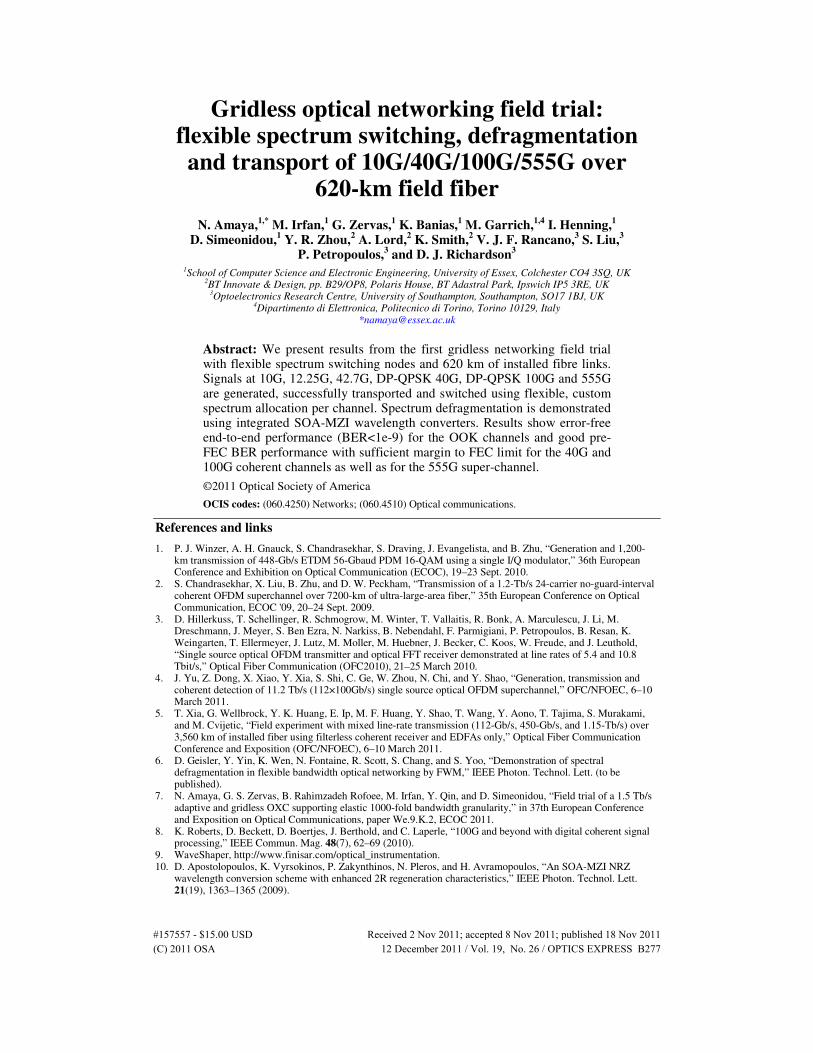
Fig. 1. Gridless networking scenario and field trial map.
As shown in Fig. 1, the field trial gridless network is comprised of 3 optical nodes placed in different geographical locations and connected by 4 field fibre links with total 620-km of installed standard single mode fibre (SSMF). Links 2 – 4 are links of conventional design with in-line DCMs, whereas link 1 is a new DCM–less link of total 410km, which has 5 in-line amplifiers located in BT exchanges from Ipswich to London BT Tower, and looping back to Ipswich. The 3 optical nodes implement flexible spectrum switching whereby signals are switched all-optically with a custom bandwidth allocation per channel. Node-2 is a flexible-architecture node [7] that supports on-demand architecture reconfiguration to provide multiple functions including spectrum switching and wavelength conversion for defragmentation. Hence, the field trial optical network represents a potential future flexible network, with different types of optical nodes with varying level of network functionality, e.g. in Core and Metro, with both conventional in-line DCM design and new DCM-less design.
At Tx-1 and Tx-2, coherent 40G (DP-QPSK) and coherent 100G (dual carrier, DP-QPSK) are generated by commercial WDM transponders [8]. The coherent 100G and 40G signals from Tx-1 are transmitted over Link-1 (410-km DCM-less) to Node-1. Also, a coherent 100G, 40G and a standard 10G NRZ channels from Tx-2 are input to Node-1 but without prior transmission. At Node-1 channels are combined using flexible spectrum switching, with a custom bandwidth allocation per channel, and transmitted over Link-3 (50-km dispersion compensated) to Node-2. Meanwhile, in Tx-3 channels 1x555 Gb/s, 3x42.7 Gb/s OOK RZ, 1x42.7 Gb/s OOK NRZ are generated and transmitted over Link-2 (110-km dispersion compensated) to Node-2. Also, Tx-4 generates channels 3x10Gb/s OOK NRZ. Node-2 provides a flexible-architecture platform whereby modules (subsystems) are interconnected through a backplane (3D-MEMS) to form optical nodes with on-demand functionality and able to reconfigure on the fly (20ms per 3D-MEMS cross-connection) according to traffic requirements, e.g. spectrum defragmentation when and where required. All input signals to Node-2 have to be transported over Link-4 to Node-3. However, there is contention between
(C) 2011 OSA 12 December 2011 / Vol. 19, No. 26 / OPTICS EXPRESS B279#157557 - $15.00 USD Received 2 Nov 2011; accepted 8 Nov 2011; published 18 Nov 2011
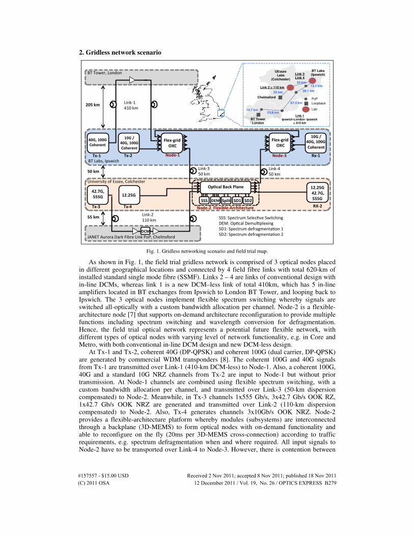
wavelengths, as shown in Fig. 2(b). Thus, Node-2 implements spectrum defragmentation and the signals are successfully switched, using flexible spectrum switching, to Node-3. In Node 3, the signals originally generated by Tx-1 and Tx-2 are dropped and input to the receiver Rx-1 for performance evaluation. Signals originally generated by Tx-3 and Tx-4 are spectrum-switched at Nodes 2, 3 and 1 and sent back to Node-2. At Node-2 they are dropped and input to the receiver (Rx-2) for performance evaluation.
3. Experimental setup and results
As shown in Fig. 2(a), the 555 Gb/s signal is generated from a 10.675-GHz 2-ps MLL pulse train followed by super-continuum generation in a HNLF, band-pass filtering and frequency-time transformation in dispersive medium (274.23-ps/nm to achieve a 23.4-ps delay between adjacent sub-carriers). Then, the signal is intensity modulated in a LiNbO3 MZM with a 42.7-Gb/s signal, which is composed of four electrically multiplexed pseudo-random bit sequences (PRBS) of length 2
7-1, 2
9-1, 2
10-1 and 2
11-1, at 10.675 Gb/s each. Thus, adjacent sub-carriers
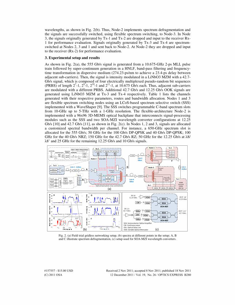
are modulated with a different PRBS. Additional 42.7 Gb/s and 12.25 Gb/s OOK signals are generated using LiNbO3 MZM at Tx-3 and Tx-4 respectively. Table 1 lists the channels generated with their respective parameters, routes and bandwidth allocation. Nodes 1 and 3 are flexible spectrum switching nodes using an LCoS-based spectrum selective switch (SSS) implemented with a WaveShaper [9]. The SSS switches programmable C-band spectrum slots from 10-GHz up to 5-THz with a 1-GHz resolution. The flexible-architecture Node-2 is implemented with a 96x96 3D-MEMS optical backplane that interconnects signal-processing modules such as the SSS and two SOA-MZI wavelength converter configurations at 12.25 Gb/s [10] and 42.7 Gb/s [11], as shown in Fig. 2(c). In Nodes 1, 2 and 3, signals are allocated a customized spectral bandwidth per channel. For instance, a 650-GHz spectrum slot is allocated for the 555 Gb/s; 50 GHz for the 100 Gb/s DP-QPSK and 40 Gb/s DP-QPSK; 100 GHz for the 40 Gb/s NRZ; 150 GHz for the 42.7 Gb/s RZ; 50 GHz for the 12.25 Gb/s at λ8/ λ8’ and 25 GHz for the remaining 12.25 Gb/s and 10 Gb/s signals.
WDM
terminal
(100G,
40G Tx)
Tx‐1
forward
traffic
Link 1
410km Node‐3
Link 3
50km
WAVESH
APER 10G Tx
40G Tx
Node‐1
Link 2 ‐ 110km
DCM
Link 4
50km
Node‐2
SOA‐MZI WC
SOA‐MZI
WC
λ8 λ'8
λ11 λ'11
forward
traffic
12.2
5G
Tx
Rx‐2
WAVESH
APER
Tx 2
100G Rx 10G Rx 40G Rx
Rx 1
Drop traffic
to 100G/40G/
10G Rx
555G Tx
Tx‐3
42.7G Tx
DE
MU
X
DE
MU
X
A
B
C
D E
100G Tx DCM
DCM
42.7G Rx 12.25G Rx 555G Rx
WAVESHAPER
drop traffic
CW MZM
PRBS 27‐1
EDFA CW
CW Couple
r
Tx‐4
F
Op cal back plane cross‐connec ons
D
E
A
B λ8
λ11
C λ8’
λ11’ F
SOA
SOA
SOA-MZI
VOA
VOA
VOA
ODL
ODL
SOA
SOA
SOA-MZI
VOA
VOA IN λ8
12.25 Gb/s
IN λ11
42.7 Gb/s
OUT λ8’
12.25 Gb/s
OUT λ11’
42.7 Gb/s
(a)
(b) (c)
CW
CW
SOA: Semiconductor Op cal Amplifier
CW: Con nuous wave
ODL: Op cal Delay Line
VOA: Variable Op cal A enuator
Fig. 2. (a) Field trial gridless networking setup, (b) spectra at different points in the setup; A, B and C illustrate spectrum defragmentation, (c) setup used for SOA-MZI wavelength converters.
(C) 2011 OSA 12 December 2011 / Vol. 19, No. 26 / OPTICS EXPRESS B280#157557 - $15.00 USD Received 2 Nov 2011; accepted 8 Nov 2011; published 18 Nov 2011
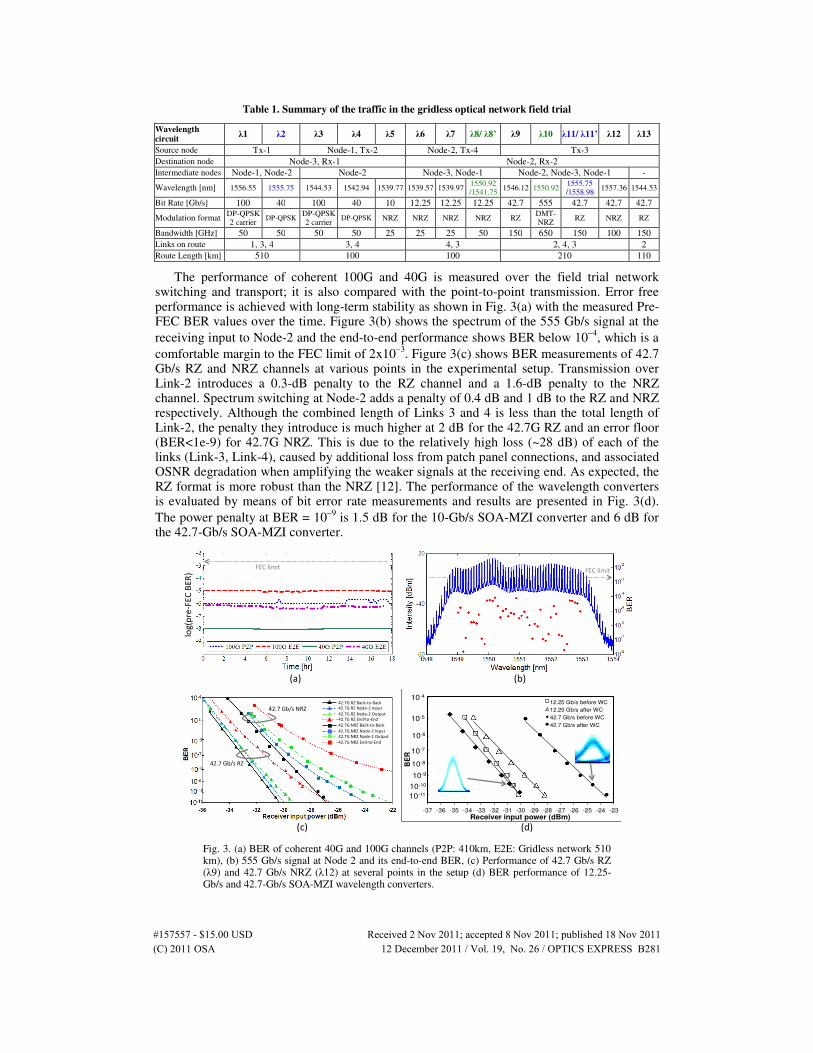
Table 1. Summary of the traffic in the gridless optical network field trial
Wavelength circuit
λ1 λ2 λ3 λ4 λ5 λ6 λ7 λ8/ λ8’ λ9 λ10 λ11/ λ11’ λ12 λ13
Source node Tx-1 Node-1, Tx-2 Node-2, Tx-4 Tx-3
Destination node Node-3, Rx-1 Node-2, Rx-2
Intermediate nodes Node-1, Node-2 Node-2 Node-3, Node-1 Node-2, Node-3, Node-1 -
Wavelength [nm] 1556.55 1555.75 1544.53 1542.94 1539.77 1539.57 1539.97 1550.92 /1541.75
1546.12 1550.92 1555.75 /1558.98
1557.36 1544.53
Bit Rate [Gb/s] 100 40 100 40 10 12.25 12.25 12.25 42.7 555 42.7 42.7 42.7
Modulation format DP-QPSK 2 carrier
DP-QPSK DP-QPSK 2 carrier
DP-QPSK NRZ NRZ NRZ NRZ RZ DMT-NRZ
RZ NRZ RZ
Bandwidth [GHz] 50 50 50 50 25 25 25 50 150 650 150 100 150
Links on route 1, 3, 4 3, 4 4, 3 2, 4, 3 2
Route Length [km] 510 100 100 210 110
The performance of coherent 100G and 40G is measured over the field trial network switching and transport; it is also compared with the point-to-point transmission. Error free performance is achieved with long-term stability as shown in Fig. 3(a) with the measured Pre-FEC BER values over the time. Figure 3(b) shows the spectrum of the 555 Gb/s signal at the
receiving input to Node-2 and the end-to-end performance shows BER below 10−4
, which is a
comfortable margin to the FEC limit of 2x10⁻³
. Figure 3(c) shows BER measurements of 42.7 Gb/s RZ and NRZ channels at various points in the experimental setup. Transmission over Link-2 introduces a 0.3-dB penalty to the RZ channel and a 1.6-dB penalty to the NRZ channel. Spectrum switching at Node-2 adds a penalty of 0.4 dB and 1 dB to the RZ and NRZ respectively. Although the combined length of Links 3 and 4 is less than the total length of Link-2, the penalty they introduce is much higher at 2 dB for the 42.7G RZ and an error floor (BER<1e-9) for 42.7G NRZ. This is due to the relatively high loss (~28 dB) of each of the links (Link-3, Link-4), caused by additional loss from patch panel connections, and associated OSNR degradation when amplifying the weaker signals at the receiving end. As expected, the RZ format is more robust than the NRZ [12]. The performance of the wavelength converters is evaluated by means of bit error rate measurements and results are presented in Fig. 3(d).
The power penalty at BER = 10−9
is 1.5 dB for the 10-Gb/s SOA-MZI converter and 6 dB for the 42.7-Gb/s SOA-MZI converter.
10-4
10-5
10-6
10-7
10-8
10-9
10-10
10-11
-37 -36 -35 -34 -33 -32 -31 -30 -29 -28 -27 -26 -25 -24 -23
BE
R
Receiver input power (dBm)
12.25 Gb/s before WC
12.25 Gb/s after WC
42.7 Gb/s before WC
42.7 Gb/s after WC
42.7 Gb/s NRZ
42.7 Gb/s RZ
42.7G RZ Back‐to‐Back
42.7G RZ Node‐2 Input
42.7G RZ Node‐2 Output
42.7G RZ End‐to‐End
42.7G NRZ Back‐to‐Back
42.7G NRZ Node‐2 Input
42.7G NRZ Node‐2 Output
42.7G NRZ End‐to‐End
(a) (b)
(c) (d)
log(p
re‐F
EC B
ER)
FEC limit FEC limit
Fig. 3. (a) BER of coherent 40G and 100G channels (P2P: 410km, E2E: Gridless network 510 km), (b) 555 Gb/s signal at Node 2 and its end-to-end BER, (c) Performance of 42.7 Gb/s RZ (λ9) and 42.7 Gb/s NRZ (λ12) at several points in the setup (d) BER performance of 12.25-Gb/s and 42.7-Gb/s SOA-MZI wavelength converters.
(C) 2011 OSA 12 December 2011 / Vol. 19, No. 26 / OPTICS EXPRESS B281#157557 - $15.00 USD Received 2 Nov 2011; accepted 8 Nov 2011; published 18 Nov 2011
4. Channel filtering and spacing
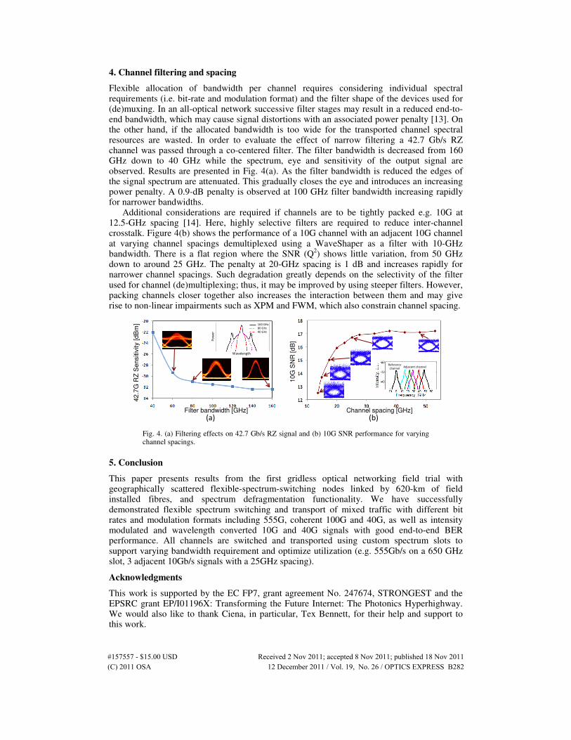
Flexible allocation of bandwidth per channel requires considering individual spectral requirements (i.e. bit-rate and modulation format) and the filter shape of the devices used for (de)muxing. In an all-optical network successive filter stages may result in a reduced end-to-end bandwidth, which may cause signal distortions with an associated power penalty [13]. On the other hand, if the allocated bandwidth is too wide for the transported channel spectral resources are wasted. In order to evaluate the effect of narrow filtering a 42.7 Gb/s RZ channel was passed through a co-centered filter. The filter bandwidth is decreased from 160 GHz down to 40 GHz while the spectrum, eye and sensitivity of the output signal are observed. Results are presented in Fig. 4(a). As the filter bandwidth is reduced the edges of the signal spectrum are attenuated. This gradually closes the eye and introduces an increasing power penalty. A 0.9-dB penalty is observed at 100 GHz filter bandwidth increasing rapidly for narrower bandwidths.
Additional considerations are required if channels are to be tightly packed e.g. 10G at 12.5-GHz spacing [14]. Here, highly selective filters are required to reduce inter-channel crosstalk. Figure 4(b) shows the performance of a 10G channel with an adjacent 10G channel at varying channel spacings demultiplexed using a WaveShaper as a filter with 10-GHz bandwidth. There is a flat region where the SNR (Q
2) shows little variation, from 50 GHz
down to around 25 GHz. The penalty at 20-GHz spacing is 1 dB and increases rapidly for narrower channel spacings. Such degradation greatly depends on the selectivity of the filter used for channel (de)multiplexing; thus, it may be improved by using steeper filters. However, packing channels closer together also increases the interaction between them and may give rise to non-linear impairments such as XPM and FWM, which also constrain channel spacing.
Filter bandwidth [GHz]
42
.7G
RZ
Sensitiv
ity [
dB
m]
Channel spacing [GHz]
10G
SN
R [d
B]
Reference
channel Adjacent channel
Wavelength
Pow
er
160 GHz
80 GHz
40 GHz
(a) (b)
Fig. 4. (a) Filtering effects on 42.7 Gb/s RZ signal and (b) 10G SNR performance for varying channel spacings.
5. Conclusion
This paper presents results from the first gridless optical networking field trial with geographically scattered flexible-spectrum-switching nodes linked by 620-km of field installed fibres, and spectrum defragmentation functionality. We have successfully demonstrated flexible spectrum switching and transport of mixed traffic with different bit rates and modulation formats including 555G, coherent 100G and 40G, as well as intensity modulated and wavelength converted 10G and 40G signals with good end-to-end BER performance. All channels are switched and transported using custom spectrum slots to support varying bandwidth requirement and optimize utilization (e.g. 555Gb/s on a 650 GHz slot, 3 adjacent 10Gb/s signals with a 25GHz spacing).
Acknowledgments
This work is supported by the EC FP7, grant agreement No. 247674, STRONGEST and the EPSRC grant EP/I01196X: Transforming the Future Internet: The Photonics Hyperhighway. We would also like to thank Ciena, in particular, Tex Bennett, for their help and support to this work.
(C) 2011 OSA 12 December 2011 / Vol. 19, No. 26 / OPTICS EXPRESS B282#157557 - $15.00 USD Received 2 Nov 2011; accepted 8 Nov 2011; published 18 Nov 2011