Embed Size (px)
Citation preview

8/13/2019 Groth Catalogue
http://slidepdf.com/reader/full/groth-catalogue 1/175
INDEX
Table of Contents •
Warranty •
ISO 9001 Certificate •
Product Selection Guide •

8/13/2019 Groth Catalogue
http://slidepdf.com/reader/full/groth-catalogue 2/175
Model Number Model Description . . . . . . . . . . . . . . . . . . . . . . . . . . . . . . . . . . . . . . . . . . .Page Number
INDEX TABLE OF CONTENTS . . . . . . . . . . . . . . . . . . . . . . . . . . . . . . . . . . . . . . . . . . . . iPRODUCT LIMITED WARRANTY . . . . . . . . . . . . . . . . . . . . . . . . . . . . . . . . . . . . iiISO 9001 CERTIFICATE . . . . . . . . . . . . . . . . . . . . . . . . . . . . . . . . . . . . . . . . . . . iiiPRODUCT SELECTION GUIDE . . . . . . . . . . . . . . . . . . . . . . . . . . . . . . . . . . . . . . 1
SECTION 1 PRESSURE / VACUUM RELIEF VALVES1200A Pressure / Vacuum Relief Valves, (vta) vent to atmosphere . . . . . . . . . . . . . . . . 1001200A/7618 Pressure/Vacuum Relief Valve with Flame Arrester, (vta) . . . . . . . . . . . . . . . . . . 1101220A Pressure / Vacuum Relief Valves with Pipe-Away Feature . . . . . . . . . . . . . . . . . 1201220A/7618 Pressure/Vacuum Relief Valve with Flame Arrester, Pipe-Away . . . . . . . . . . . . . 130
Fiberglass Valves . . . . . . . . . . . . . . . . . . . . . . . . . . . . . . . . . . . . . . . . . . . . . . . . 160Steam Jacketed Valves . . . . . . . . . . . . . . . . . . . . . . . . . . . . . . . . . . . . . . . . . . . . 170
SECTION 2 FLAME ARRESTER / DETONATION ARRESTER7618, 7628 Flame Arrester . . . . . . . . . . . . . . . . . . . . . . . . . . . . . . . . . . . . . . . . . . . . . . . . . . . 2007622 Flame Check . . . . . . . . . . . . . . . . . . . . . . . . . . . . . . . . . . . . . . . . . . . . . . . . . . . . 210
Flame Arrester, Steam Jacketed . . . . . . . . . . . . . . . . . . . . . . . . . . . . . . . . . . . . . 220
7658A Detonation Arrester . . . . . . . . . . . . . . . . . . . . . . . . . . . . . . . . . . . . . . . . . . . . . . . 2308400A Pressure Relief and Flame Trap Assembly . . . . . . . . . . . . . . . . . . . . . . . . . . . . . 2408500A Flame Trap Assembly . . . . . . . . . . . . . . . . . . . . . . . . . . . . . . . . . . . . . . . . . . . . . 2508110 Back Pressure Check Valve . . . . . . . . . . . . . . . . . . . . . . . . . . . . . . . . . . . . . . . . 260
SECTION 3 PRESSURE / VACUUM RELIEF VALVES1260A Pressure Relief Valves w/Pipe-Away feature . . . . . . . . . . . . . . . . . . . . . . . . . . . 3002300A Pressure Relief Valves, (vta) vent to atmosphere . . . . . . . . . . . . . . . . . . . . . . . . 3101300A Vacuum Relief Valves, Top Mount . . . . . . . . . . . . . . . . . . . . . . . . . . . . . . . . . . . 3201360A Vacuum Relief Valves, Side Mount . . . . . . . . . . . . . . . . . . . . . . . . . . . . . . . . . . . 3305000, 5100 Free Vent, Top Mount . . . . . . . . . . . . . . . . . . . . . . . . . . . . . . . . . . . . . . . . . . . . . 3506000, 6100 Gauge Hatch . . . . . . . . . . . . . . . . . . . . . . . . . . . . . . . . . . . . . . . . . . . . . . . . . . . . 3606200 Gauge Hatch . . . . . . . . . . . . . . . . . . . . . . . . . . . . . . . . . . . . . . . . . . . . . . . . . . . . 370
SECTION 4 EMERGENCY PRESSURE RELIEF VALVES2000A, 2050A Emergency Pressure Relief Valves, Weight Loaded . . . . . . . . . . . . . . . . . . . . . . 4002100 Emergency Pressure Relief Valves, Spring Loaded . . . . . . . . . . . . . . . . . . . . . . 4102400A, 2450A Emergency Pressure Relief Valves, Weight Loaded; Hinged . . . . . . . . . . . . . . . 4202500A Pilot-Operated Emergency Relief Valves . . . . . . . . . . . . . . . . . . . . . . . . . . . . . . 430
SECTION 5 MISCELLANEOUSTest Stands . . . . . . . . . . . . . . . . . . . . . . . . . . . . . . . . . . . . . . . . . . . . . . . . . . . . . 500
SECTION 6 PILOT OPERATED VALVES1660A Series Pilot Operated Valves . . . . . . . . . . . . . . . . . . . . . . . . . . . . . . . . . . . . . . . . . . . . . 6001400 Series Pilot Operated Valves . . . . . . . . . . . . . . . . . . . . . . . . . . . . . . . . . . . . . . . . . . . . . 6501500 Series Air Operated Valves . . . . . . . . . . . . . . . . . . . . . . . . . . . . . . . . . . . . . . . . . . . . . . . 670
SECTION 7 BLANKET GAS REGULATORS3011 Series Blanket Gas Regulators . . . . . . . . . . . . . . . . . . . . . . . . . . . . . . . . . . . . . . . . . . . . 700
SECTION 8 TECHNICAL SECTION . . . . . . . . . . . . . . . . . . . . . . . . . . . . . . . . . . . . . . . . . . . .800
TABLE OF CONTENTS
Groth Corporation, a Continental Disc company, Stafford, TX, USAIndex 02.qxd, June, 2002, 2.5m

8/13/2019 Groth Catalogue
http://slidepdf.com/reader/full/groth-catalogue 3/175
Groth’s Product Limited Warranty terms applies only to purchase orders accepted by Groth Corporation.
A. Seller warrants that products which are manufactured by Seller, are manufactured in accordance with publishedspecifications and free from defects in materials and/or workmanship for a period of (12) twelve months. Seller, atits option, will repair or replace any products returned intact to the factory, transportation charges prepaid, whichSeller, upon inspection, shall determine to be defective in material and/or workmanship. The foregoing shallconstitute the sole remedy for any breach of Seller’s warranty.
B. THERE ARE NO UNDERSTANDINGS, AGREEMENTS, REPRESENTATIONS, OR WARRANTIES, EXPRESSOR IMPLIED, (INCLUDING MERCHANTABILITY OR FITNESS FOR A PARTICULAR PURPOSE REGARDINGPRODUCTS) UNLESS SPECIFIED IN THE SALES CONTRACT. THIS CONTRACT STATES THE ENTIREOBLIGATION OF SELLER.
Seller makes no warranties, either express or implied, except as provided herein, including without limitationthereof, warranties as to marketability, merchantability, for a particular purpose or use, or against infringement ofany patent of products. In no event shall Seller be liable for any direct, incidental or consequential damages ofany nature, or losses or expenses resulting from any defective new product or the use of any such product,including any damages for loss of time, inconvenience, or loss of use of any such product.
C. The original Manufacturer shall be solely responsible for the design, development, supply, production, andperformance of its products hereunder, and the protection of its trade name or names, if any. It assumes noresponsibility, for products modified or changed in any way by its agent or customer. Any such modifications orchanges to products sold by Seller hereunder shall make the product limited warranty null and void.
D. The Manufacturer shall be under no obligation to manufacture, sell, or supply or to continue to manufacture, sellor supply any of the Products.
Groth Corporation, a Continental Disc company, Stafford, TX, USA
PRODUCT LIMITED WARRANTY
GROTH is committed to the total quality improvement process
Groth Corporation13650 N. Promenade Blvd.
Stafford, TX 77477
800-354-7684
www.grothcorp.com
a Continental Disc Company
ii

8/13/2019 Groth Catalogue
http://slidepdf.com/reader/full/groth-catalogue 4/175
CERTIFICATE
Groth Corporation, a Continental Disc company, Stafford, TX, USA ii

8/13/2019 Groth Catalogue
http://slidepdf.com/reader/full/groth-catalogue 5/175
SECTION 1PRESSURE / VACUUM RELIEF VALVES
1200A Presure / Vacuum Relief Valves •
1200A/7618 Pressure / Vacuum Relief Valves w/ Flame Arrester •
1220A Pressure / Vacuum Relief Valves w/Pipe-Away Feature •
1220A/7618 Pressure / Vacuum Relief Valve w/Flame Arrester w/Pipe-Away Feature •
Fiberglass Relief Valves •
Steam Jacketed Valves •

8/13/2019 Groth Catalogue
http://slidepdf.com/reader/full/groth-catalogue 6/175
PRESSURE / VACUUM RELIEF VALVE
Model 1200A
Groth Corporation, a Continental Disc company, Stafford, TX, USA
MODEL 1200A
MODEL 1201B
■ Sizes 2”through 12”■
Pressure settings 0.5 oz/in2
to 15 PSIG■ Vacuum settings 0.5 oz/in 2 to 12 PSIG■ Available in aluminum (type 356),
carbon steel, stainless steel, fiber-glass, and other materials
■ Modular construction
PRESSURE / VACUUMRELIEF VALVEModel 1200A is designed to protect your tank fromdamage created by over-pressure or excessivevacuum. Costly product evaporation losses due tonormal tank “breathing” are greatly reduced.Because the Model 1200A retains toxic vapors,atmospheric contamination is minimized. This helpsto provide increased fire protection and safety.
SPECIAL FEATURESModel 1200A offers Groth’s special “cushioned air”seating. Superior performing Teflon ® 1 seatingdiaphragms are standard to minimize stickingcaused by resinous vapors and atmospheric mois-ture. The Model 1200A has a self draining housingbody and drip rings to protect seating surfaces fromcondensate and freezing. This design also avoidsdangerous pressure or vacuum buildup due tobinding or clogging of the valve. Buna-N, Viton ® ,and other seating diaphragms can be providedwhen required. To insure the proper alignment ofseating surfaces, there is peripheral guiding and acenter stabilizing system.
GROTH,THE CAPABILITYCOMPANYAs with all Groth products, every model 1200A isfactory inspected and tested to meet your criticalrequirements and special needs. Inventory ismaintained to insure rapid delivery.
1 Teflon is a registered trademark of DuPont Corporation.
MODEL 1200A
100Section 1:100-171.qxd, June, 2002, 2.5m

8/13/2019 Groth Catalogue
http://slidepdf.com/reader/full/groth-catalogue 7/175

8/13/2019 Groth Catalogue
http://slidepdf.com/reader/full/groth-catalogue 8/175Groth Corporation, a Continental Disc company, Stafford, TX, USA
Flow capacity is certifiedby GrothCorporation, basedonactual tests conductedincompliance withAPI Std. 2000.Flow measurement accuracy has beenverifiedby anindependent testinglaboratory.
Pressure Relief Capacity
Flow capacity values listed above are based on full open valves at 100% over-pressure.
For an equivalent size fiberglass valve, reduce tabulated capacities by 32%.
Read the flow capacity at 100% over-pressure directly from the table above. Use linearinterpolation if the set pressure is not listed. (Ref: Page TPD1)
If the allowable over-pressure is less than 100%, modify the flow capacity using theappropriate “ C” factor from the table. If allowable over-pressure is more than 10 0%,consult page TPD1 or your Groth Representative.
Calculate the percentage over-pressure by the follow ing formul a. Note that allpressures are gage pressure expressed in the same units of measure.
Pf = Flowing pressurePs = Set pressure% OP= [ (Pf - Ps) / Ps] x 100
Calculate flow capacity at less than 100% over-pressure according to the followingexample.
Example—Flow Capacity Calculation 1. Read flow capacity atset pressure from table Flow= 131,000 SCFH
6” Model 1200A 2. Calculate over-pressure % OP= [ (7- 4 )/ 4 ]x 100= 75%4 In WC set pressure [Ps] 3 . Read “ C” factor from table “ C”= 0.877 In WC flowing pressure [ Pf] 4 . Calculate flow capacity Flow = 0 .87 x 1 3 1 , 0 0 0 = 113,970 SCFH
Example—To find“C” factor fromtable:Read “ C” factor for75% Over-pressure at intersection of row70 and column5“ C” factor at 75% OP= 0.87
Model 1200A
102
PRESSURE / VACUUM RELIEF VALVE
Set Pressure Air Flow Capacity at 100% Over-pressure (Double Set Pressure)(Ps) 1000 Standard Cubic Feet per Hour at 60° F
In WC Oz/ Sq In 2” 3” 4” 6” 8” 10” 12”0.87 0.50 7.65 16.2 28.9 61.9 108 174 2171.00 0.58 8.22 17.4 31.1 66.5 116 187 2331.73 1.00 10.8 22.8 40.8 87.2 152 246 3052.00 1.16 11.6 24.5 43.8 93.7 164 264 3282.60 1.50 13.2 27.8 49.8 106 186 300 3733.00 1.73 14.1 29.9 53.4 114 200 322 4003.46 2.00 15.2 32.0 57.3 123 214 345 429
4.00 2.31 16.3 34.4 61.5 131 230 371 4606.00 3.47 19.8 41.8 74.7 160 279 450 5608.00 4.62 22.7 47.9 85.7 183 320 516 64110.0 5.78 25.1 53.1 95.1 203 355 573 71212.0 6.93 27.3 57.8 103 221 386 623 77415.0 8.66 30.2 63.9 114 244 427 689 85620.0 11.6 34.3 72.5 130 277 485 781 97125.0 14.4 37.7 79.6 142 305 532 859 106730.0 17.3 40.6 85.7 153 328 573 925 1149
“C” Factor Table%OP 0 1 2 3 4 5 6 7 8 9
10 0.42 0.43 0.44 0.45 0.46 0.46 0.47 0.48 0.49 0.5020 0.51 0.52 0.52 0.53 0.54 0.55 0.56 0.56 0.57 0.5830 0.59 0.59 0.60 0.61 0.61 0.62 0.63 0.64 0.64 0.6540 0.66 0.66 0.67 0.68 0.68 0.69 0.70 0.70 0.71 0.7250 0.72 0.73 0.73 0.74 0.75 0.75 0.76 0.77 0.77 0.7860 0.78 0.79 0.80 0.80 0.81 0.81 0.82 0.82 0.83 0.8470 0.84 0.85 0.85 0.86 0.86 0.87 0.88 0.88 0.89 0.8980 0.90 0.90 0.91 0.91 0.92 0.92 0.93 0.93 0.94 0.9490 0.95 0.95 0.96 0.96 0.97 0.97 0.98 0.99 0.99 1.00

8/13/2019 Groth Catalogue
http://slidepdf.com/reader/full/groth-catalogue 9/175Groth Corporation, a Continental Disc company, Stafford, TX, USA103
Flow capacity is certifiedby GrothCorporation, basedonactual tests conductedincompliance withAPI Std. 2000.Flow measurement accuracy has beenverifiedby anindependent testinglaboratory.
Flow capacity values listed above are based on full open valves at 100% over-pressure.
For an equivalent size fiberglass valve, reduce tabulated capacities by 32%.
Read the flow capacity at 100% over-pressure directly from the table above. Use linearinterpolation if the set pressure is not listed. (Ref: Page TPD1)
If the allowable over-pressure is less than 100%, modify the flow capacity using theappropriate “ C” factor from the table. If allowable over-pressure is more than 10 0%,consult page TPD1 or your Groth Representative.
Calculate the percentage over-pressure by the follow ing formula . Note that allpressures are gage pressure expressed in the same units of measure.
Pf = Flowing pressurePs = Set pressure% OP= [ (Pf - Ps) / Ps] x 100
Calculate flow capacity at less than 100% over-pressure according to the followingexample.
Example—Flow Capacity Calculation 1. Read flow capacity atset pressure from table Flow= 3,670 NCMH
6” Model 1200A 2. Calculate over-pressure % OP= [ (1 75- 1 0 0) / 1 0 0]x 100= 75%100 mm WC Set Pressure [Ps] 3 . Read “ C” factor from table “ C”= 0.87175 mm WC Flowing Pressure [Pf] 4 . Calculate flow capacity Flow = 0 .87 x 3 , 6 7 0 = 3 ,19 3 NCM H
“C” Factor Table%OP 0 1 2 3 4 5 6 7 8 9
10 0.42 0.43 0.44 0.45 0.46 0.46 0.47 0.48 0.49 0.5020 0.51 0.52 0.52 0.53 0.54 0.55 0.56 0.56 0.57 0.5830 0.59 0.59 0.60 0.61 0.61 0.62 0.63 0.64 0.64 0.6540 0.66 0.66 0.67 0.68 0.68 0.69 0.70 0.70 0.71 0.7250 0.72 0.73 0.73 0.74 0.75 0.75 0.76 0.77 0.77 0.7860 0.78 0.79 0.80 0.80 0.81 0.81 0.82 0.82 0.83 0.8470 0.84 0.85 0.85 0.86 0.86 0.87 0.88 0.88 0.89 0.8980 0.90 0.90 0.91 0.91 0.92 0.92 0.93 0.93 0.94 0.9490 0.95 0.95 0.96 0.96 0.97 0.97 0.98 0.99 0.99 1.00
Example—To find“C” factor fromtable:Read “ C” factor for75% Over-pressure at intersection of row70 and column5“ C” factor at 75% OP= 0.87
Set Pressure Air Flow Capacity at 100% Over-pressure (Double Set Pressure)(Ps) 1000 Normal Cubic Meters per Hour at 0° C
mmWC mb 2” 3” 4” 6” 8” 10” 12”22 2.16 0.22 0.46 0.82 1.74 3.05 4.91 6.1150 4.90 0.32 0.68 1.22 2.62 4.58 7.38 9.1775 7.35 0.40 0.83 1.49 3.19 5.58 9.00 11.2100 9.80 0.45 0.96 1.72 3.67 6.42 10.4 12.9125 12.3 0.51 1.07 1.91 4.09 7.15 11.5 14.3150 14.7 0.55 1.17 2.09 4.47 7.81 12.6 15.6175 17.2 0.59 1.26 2.25 4.81 8.40 13.5 16.8
200 19.6 0.63 1.34 2.39 5.12 8.95 14.4 17.9225 22.1 0.67 1.41 2.53 5.41 9.46 15.3 18.9250 24.5 0.70 1.49 2.66 5.68 9.93 16.0 19.9275 27.0 0.73 1.55 2.78 5.94 10.4 16.7 20.8300 29.4 0.76 1.62 2.89 6.18 10.8 17.4 21.6375 36.8 0.85 1.79 3.20 6.84 12.0 19.3 23.9500 49.0 0.96 2.03 3.63 7.76 13.6 21.9 27.2625 61.3 1.05 2.23 3.99 8.52 14.9 24.0 29.9750 73.5 1.14 2.40 4.29 9.18 16.1 25.9 32.2
Pressure Relief CapacityModel 1200A
PRESSURE / VACUUM RELIEF VALVE

8/13/2019 Groth Catalogue
http://slidepdf.com/reader/full/groth-catalogue 10/175
Flow capacity is certifiedby GrothCorporation, basedonactual tests conductedincompliance withAPI Std. 2000.Flow measurement accuracy has beenverifiedby anindependent testinglaboratory.
Flow capacity values listed above are based on full open valves at 100% over-vacuum.
For an equivalent size fiberglass valve, reduce tabulated capacities by 32%.
Read the flow capacity at 10 0% over-vacuum directly from th e table above. Use linearinterpolation if the set vacuum is not listed. (Ref: Page TPD1)
If the allowable over-vacuum is less than 10 0%, modify t he flow capacity using theappropriate “ C” factor from the table. If allowable over-vacuum is more than 10 0%,consult page TPD1 or your Groth Representative.
Calculate the percentage over-vacuum by the following form ula. Note that allpressures are gage pressure expressed in the same units of measure.
Pf = Flowing pressurePs = Set pressure% OV= [ (Pf - Ps) / Ps] x 100
Calculate flow capacity at less than 100% over-vacuum according to the followingexample.
Example—Flow Capacity Calculation 1. Read flow capacity atset vacuum from table Flow= 74,0 00 SCFH
6” Model 1200A 2. Calculate over-vacuum % OV= [ (7- 4 )/ 4 ]x 100= 75%4 In WC set vacuum [Ps] 3 . Read “ C” factor from table “ C”= 0.877 In WC flowing vacuum [Pf] 4 . Calculate flow capacity Flow = 0 .87 x 7 4 , 0 0 0 = 64 ,38 0 SCFH
Example—To find“C” factor fromtable:Read “ C” factor for75% Over-vacuum at intersection of row70 and column5“ C” factor at 75% OV= 0.87
104Groth Corporation, a Continental Disc company, Stafford, TX, USA
“C” Factor Table%OV 0 1 2 3 4 5 6 7 8 9
10 0.42 0.43 0.44 0.45 0.46 0.46 0.47 0.48 0.49 0.5020 0.51 0.52 0.52 0.53 0.54 0.55 0.56 0.56 0.57 0.5830 0.59 0.59 0.60 0.61 0.61 0.62 0.63 0.64 0.64 0.6540 0.66 0.66 0.67 0.68 0.68 0.69 0.70 0.70 0.71 0.7250 0.72 0.73 0.73 0.74 0.75 0.75 0.76 0.77 0.77 0.7860 0.78 0.79 0.80 0.80 0.81 0.81 0.82 0.82 0.83 0.8470 0.84 0.85 0.85 0.86 0.86 0.87 0.88 0.88 0.89 0.8980 0.90 0.90 0.91 0.91 0.92 0.92 0.93 0.93 0.94 0.9490 0.95 0.95 0.96 0.96 0.97 0.97 0.98 0.99 0.99 1.00
Set Vacuum Air Flow Capacity at 100% Over-vacuum(Double Set Vacuum)(Ps) 1000 Standard Cubic Feet per Hour at 60° F
In WC Oz/ Sq In 2” 3” 4” 6” 8” 10” 12”0.87 0.50 4.70 10.3 16.0 34.7 60.5 91.1 1291.00 0.58 5.05 11.0 17.2 37.3 65.0 97.9 1381.73 1.00 6.63 14.5 22.6 49.0 85.3 129 1822.00 1.16 7.12 15.6 24.2 52.6 91.6 138 1952.60 1.50 8.10 17.7 27.6 59.8 104 157 2223.00 1.73 8.70 19.0 29.6 64.2 112 169 2383.46 2.00 9.33 20.4 31.8 68.9 120 181 256
4.00 2.31 10.0 21.9 34.1 74.0 129 194 2746.00 3.47 12.2 26.7 41.5 90.1 157 237 3348.00 4.62 14.0 30.6 47.7 103 180 272 38410.0 5.78 15.6 34.0 53.0 115 200 302 42712.0 6.93 17.0 37.1 57.8 125 218 329 46515.0 8.66 18.8 41.1 64.0 139 242 365 51620.0 11.6 21.4 46.8 72.9 158 276 415 58725.0 14.4 23.6 51.5 80.3 174 304 457 64630.0 17.3 25.4 55.6 86.6 188 327 493 697
Vacuum Relief CapacityModel 1200A
PRESSURE / VACUUM RELIEF VALVE

8/13/2019 Groth Catalogue
http://slidepdf.com/reader/full/groth-catalogue 11/175Groth Corporation, a Continental Disc company, Stafford, TX, USA105
Flow capacity is certifiedby GrothCorporation, basedonactual tests conductedincompliance withAPI Std. 2000.Flow measurement accuracy has beenverifiedby anindependent testinglaboratory.
Flow capacity values listed above are based on full open valves at 100% over-vacuum.
For an equivalent size fiberglass valve, reduce tabulated capacities by 32%.
Read the flow capacity at 10 0% over-vacuum directly from the table above. Use linearinterpolation if the set vacuum is not listed. (Ref: Page TPD1)
If the allowable over-vacuum is less than 10 0%, modify the flow capacity using theappropriate “ C” factor from the table. If allowable over-vacuum is more than 10 0%,consult page TPD1 or your Groth Representative.
Calculate the percentage over-vacuum by the following form ula. Note that allpressures are gage pressure expressed in the same units of measure.
Pf = Flowing pressurePs = Set pressure% OV= [ (Pf - Ps) / Ps] x 100
Calculate flow capacity at less than 100% over-vacuum according to the followingexample.
Example—Flow Capacity Calculation 1. Read flow capacity atset vacuum from table Flow= 2,080 NCMH
6” Model 1200A 2. Calculate over-vacuum % OV= [(1 75- 1 0 0) / 1 0 0]x 100= 75%100 mm WC Set Vacuum [ Ps] 3 . Read “ C” factor from table “ C”= 0.87175 mm WC Flowing Vacuum [ Pf] 4 . Calculate flow capacity Flow = 0 .87 x 2 , 0 8 0 = 1,81 0 NCM H
“C” Factor Table%OV 0 1 2 3 4 5 6 7 8 9
10 0.42 0.43 0.44 0.45 0.46 0.46 0.47 0.48 0.49 0.5020 0.51 0.52 0.52 0.53 0.54 0.55 0.56 0.56 0.57 0.5830 0.59 0.59 0.60 0.61 0.61 0.62 0.63 0.64 0.64 0.6540 0.66 0.66 0.67 0.68 0.68 0.69 0.70 0.70 0.71 0.7250 0.72 0.73 0.73 0.74 0.75 0.75 0.76 0.77 0.77 0.7860 0.78 0.79 0.80 0.80 0.81 0.81 0.82 0.82 0.83 0.8470 0.84 0.85 0.85 0.86 0.86 0.87 0.88 0.88 0.89 0.8980 0.90 0.90 0.91 0.91 0.92 0.92 0.93 0.93 0.94 0.9490 0.95 0.95 0.96 0.96 0.97 0.97 0.98 0.99 0.99 1.00
Example—To find“C” factor fromtable:Read “ C” factor for75% Over-vacuum at intersection of row70 and column5“ C” factor at 75% OV= 0.87
Set Vacuum Air Flow Capacity at 100% Over-vacuum(Double Set Vacuum)(Ps) 1000 Normal Cubic Meters per Hour at 0° C
mmWC mb 2” 3” 4” 6” 8” 10” 12”22 2.16 0.13 0.29 0.45 0.98 1.71 2.58 3.6550 4.90 0.20 0.44 0.68 1.48 2.58 3.88 5.4875 7.35 0.24 0.53 0.83 1.81 3.15 4.74 6.70100 9.80 0.28 0.62 0.96 2.08 3.62 5.46 7.72125 12.3 0.31 0.69 1.07 2.32 4.04 6.09 8.60150 14.7 0.34 0.75 1.17 2.53 4.41 6.65 9.40175 17.2 0.37 0.81 1.26 2.73 4.75 7.16 10.1
200 19.6 0.39 0.86 1.34 2.91 5.07 7.64 10.8225 22.1 0.42 0.91 1.42 3.08 5.36 8.08 11.4250 24.5 0.44 0.96 1.49 3.23 5.64 8.49 12.0275 27.0 0.46 1.00 1.56 3.38 5.90 8.88 12.6300 29.4 0.48 1.04 1.62 3.52 6.14 9.25 13.1375 36.8 0.53 1.16 1.80 3.91 6.81 10.3 14.5500 49.0 0.60 1.32 2.05 4.45 7.75 11.7 16.5625 61.3 0.66 1.45 2.26 4.90 8.54 12.9 18.2750 73.5 0.72 1.57 2.44 5.29 9.22 13.9 19.6
Vacuum Relief CapacityModel 1200A
PRESSURE / VACUUM RELIEF VALVE

8/13/2019 Groth Catalogue
http://slidepdf.com/reader/full/groth-catalogue 12/175106Groth Corporation, a Continental Disc company, Stafford, TX, USA
Flow capacity is certifiedby GrothCorporation, basedonactual tests conductedincompliance withAPI Std. 2000.Flow measurement accuracy has beenverifiedby anindependent testinglaboratory.
Flow capacity values listed above are based on full open valves at 100% over-pressure.
For an equivalent size fiberglass valve, reduce tabulated capacities by 32%.
Read the flow capacity at 100% over-pressure directly from the table above. Use linearinterpolation if the set pressure is not listed. (Ref: Page TPD1)
If the allowable over-pressure is less than 100%, modify the flow capacity using theappropriate “ C” factor from the table. If allowable over-pressure is more than 10 0%,consult page TPD1 or your Groth Representative.
Calculate the percentage over-pressure by the follow ing formul a. Note that allpressures are gage pressure expressed in the same units of measure.
Pf = Flowing pressurePs = Set pressure% OP= [ (Pf - Ps) / Ps] x 100
Calculate flow capacity at less than 100% over-pressure according to the followingexample.
Example—Flow Capacity Calculation 1. Read flow capacity atset pressure from table Flow= 448,000 SCFH
6” Model 1201B 2. Calculate over-pressure % OP= [ (7- 4 )/ 4 ]x 100= 75%4 PSIG set pressure [Ps] 3 . Read “ C” factor from table “ C”= 0.837 PSIG flowing pressure [Pf] 4 . Calculate flow capacity Flow = 0 .83 x 4 4 8 , 0 0 0 = 371,840 SCFH
Example—To find“C” factor fromtable:Read “ C” factor for75% Over-pressure at intersection of row70 and column5“ C” factor at 75% OP= 0.83
“C” Factor Table%OP 0 1 2 3 4 5 6 7 8 9
10 •••Consult Factory•••20 0.27 0.29 0.30 0.32 0.33 0.35 0.36 0.38 0.39 0.4030 0.42 0.43 0.44 0.45 0.47 0.48 0.49 0.50 0.51 0.5240 0.53 0.54 0.55 0.56 0.57 0.58 0.59 0.60 0.61 0.6250 0.63 0.64 0.65 0.66 0.67 0.67 0.68 0.69 0.70 0.7160 0.72 0.72 0.73 0.74 0.75 0.76 0.76 0.77 0.78 0.7970 0.80 0.80 0.81 0.82 0.82 0.83 0.84 0.85 0.85 0.8680 0.87 0.87 0.88 0.89 0.90 0.90 0.91 0.92 0.92 0.9390 0.94 0.94 0.95 0.96 0.96 0.97 0.97 0.98 0.99 1.00
Set Pressure Air Flow Capacity at 100% Over-pressure (Double Set Pressure)(Ps) 1000 Standard Cubic Feet per Hour at 60° FPSIG 2” 3” 4” 6” 8” 10” 12”1.00 28.0 53.4 92.5 210 345 529 7392.00 40.3 77.4 134 304 500 767 10703.00 50.2 96.9 168 381 625 960 13404.00 58.8 114 198 448 736 1130 15775.00 66.5 130 225 510 838 1286 17946.00 73.7 144 250 568 932 1431 19977.00 80.4 158 274 622 1022 1568 21888.00 86.7 171 297 674 1107 1699 23719.00 92.8 184 319 724 1189 1825 254610.0 98.6 196 340 772 1267 1945 271411.0 104 208 360 818 1343 2062 287712.0 110 219 380 863 1417 2176 303613.0 115 231 400 907 1489 2286 318914.0 120 241 418 949 1559 2393 333915.0 125 252 437 991 1627 2498 3486
Pressure Relief CapacityModel 1201B
PRESSURE / VACUUM RELIEF VALVE

8/13/2019 Groth Catalogue
http://slidepdf.com/reader/full/groth-catalogue 13/175Groth Corporation, a Continental Disc company, Stafford, TX, USA107
Flow capacity is certifiedby GrothCorporation, basedonactual tests conductedincompliance withAPI Std. 2000.Flow measurement accuracy has beenverifiedby anindependent testinglaboratory.
Flow capacity values listed above are based on full open valves at 100% over-pressure.
For an equivalent size fiberglass valve, reduce tabulated capacities by 32%.
Read the flow capacity at 100% over-pressure directly from the table above. Use linearinterpolation if the set pressure is not listed. (Ref: Page TPD1)
If the allowable over-pressure is less than 100%, modify the flow capacity using theappropriate “ C” factor from the table. If allowable over-pressure is more than 10 0%,consult page TPD1 or your Groth Representative.
Calculate the percentage over-pressure by the follow ing formula . Note that allpressures are gage pressure expressed in the same units of measure.
Pf = Flowing pressurePs = Set pressure% OP= [ (Pf - Ps) / Ps] x 100
Calculate flow capacity at less than 100% over-pressure according to the followingexample.
Example—Flow Capacity Calculation 1. Read flow capacity atset pressure from table Flow= 16,200 NCMH
6” Model 1201B 2. Calculate over-pressure % OP= [(0 .7- 0 .4 ) / 0 . 4]x 100= 75%0.4 BarG Set Pressure [Ps] 3 . Read “ C” factor from table “ C”= 0.830.7 BarG Flowing Pressure [Pf] 4 . Calculate flow capacity Flow = 0 .83 x 1 6 , 2 0 0 = 13 ,4 46 NCM H
Example—To find“C” factor fromtable:Read “ C” factor for75% Over-pressure at intersection of row70 and column5“ C” factor at 75% OP= 0.83
“C” Factor Table%OP 0 1 2 3 4 5 6 7 8 9
10 •••Consult Factory•••20 0.27 0.29 0.30 0.32 0.33 0.35 0.36 0.38 0.39 0.4030 0.42 0.43 0.44 0.45 0.47 0.48 0.49 0.50 0.51 0.5240 0.53 0.54 0.55 0.56 0.57 0.58 0.59 0.60 0.61 0.6250 0.63 0.64 0.65 0.66 0.67 0.67 0.68 0.69 0.70 0.7160 0.72 0.72 0.73 0.74 0.75 0.76 0.76 0.77 0.78 0.7970 0.80 0.80 0.81 0.82 0.82 0.83 0.84 0.85 0.85 0.8680 0.87 0.87 0.88 0.89 0.90 0.90 0.91 0.92 0.92 0.9390 0.94 0.94 0.95 0.96 0.96 0.97 0.97 0.98 0.99 1.00
Set Pressure Air Flow Capacity at 100% Over-pressure (Double Set Pressure)(Ps) 1000 Normal Cubic Meters per Hour at 0° CBarG 2” 3” 4” 6” 8” 10” 12”0.07 0.82 1.57 2.72 6.16 10.1 15.5 21.70.10 0.99 1.89 3.28 7.45 12.2 18.8 26.20.15 1.23 2.36 4.09 9.28 15.2 23.4 32.60.20 1.43 2.76 4.80 10.9 17.9 27.4 38.30.25 1.62 3.14 5.44 12.3 20.3 31.1 43.40.30 1.79 3.48 6.04 13.7 22.5 34.5 48.20.35 1.95 3.81 6.61 15.0 24.6 37.8 52.7
0.40 2.10 4.12 7.14 16.2 26.6 40.9 57.00.45 2.25 4.41 7.66 17.4 28.5 43.8 61.10.50 2.39 4.70 8.16 18.5 30.4 46.6 65.10.55 2.52 4.98 8.64 19.6 32.2 49.4 68.90.60 2.65 5.25 9.10 20.6 33.9 52.1 72.60.70 2.89 5.76 10.0 22.7 37.2 57.2 79.70.80 3.13 6.25 10.8 24.6 40.4 62.1 86.50.90 3.35 6.72 11.7 26.5 43.5 66.7 93.11.00 3.56 7.18 12.5 28.3 46.4 71.2 99.4
Pressure Relief CapacityModel 1201B
PRESSURE / VACUUM RELIEF VALVE

8/13/2019 Groth Catalogue
http://slidepdf.com/reader/full/groth-catalogue 14/175108Groth Corporation, a Continental Disc company, Stafford, TX, USA
Flow capacity is certifiedby GrothCorporation, basedonactual tests conductedincompliance withAPI Std2000.Flow measurement accuracy has beenverifiedby anindependent testinglaboratory.
Flow capacity values listed above are based on full open valves at 100% over-vacuum.
For an equivalent size fiberglass valve, reduce tabulated capacities by 32%.
Read the flow capacity at 10 0% over-vacuum directly from th e table above. Use linearinterpolation if the set vacuum is not listed. (Ref: Page TPD1)
If the allowable over-vacuum is less than 10 0%, modify t he flow capacity using theappropriate “ C” factor from the table. If allowable over-vacuum is more than 10 0%,consult page TPD1 or your Groth Representative.
Calculate the percentage over-vacuum by the following form ula. Note that allpressures are gage pressure expressed in the same units of measure.
Pf = Flowing pressurePs = Set pressure% OV= [ (Pf - Ps) / Ps] x 100
Calculate flow capacity at less than 100% over-vacuum according to the followingexample.
Example—Flow Capacity Calculation 1. Read flow capacity atset vacuum from table Flow= 166,000 SCFH
6” Model 1202B 2. Calculate over-vacuum % OV= [(3 .50- 2 .0) / 2 .0 ]x 100= 75%2 PSIG set vacuum [Ps] 3 . Read “ C” factor from table “ C”= 0.833.5 PSIG flowing vacuum [Pf] 4 . Calculate flow capacity Flow = 0 .83 x 1 6 6 , 0 0 0 = 137,780 SCFH
Example—To find“C” factor fromtable:Read “ C” factor for75% Over-vacuum at intersection of row70 and column5“ C” factor at 75% OV= 0.83
Vacuum Relief CapacityModel 1202B
PRESSURE / VACUUM RELIEF VALVE
Set Vacuum Air Flow Capacity at 100% Over-vacuum(Double Set Vacuum)(Ps) 1000 Standard Cubic Feet per Hour at 60° FPSIG 2” 3” 4” 6” 8” 10” 12”1.00 13.8 30.5 52.9 120 197 302 4221.10 14.5 31.9 55.4 126 206 316 4421.20 15.1 33.2 57.7 131 215 330 4601.30 15.7 34.5 59.9 136 223 342 4781.40 16.2 35.7 62.0 141 231 355 4951.50 16.8 36.9 64.0 145 239 366 5111.75 18.0 39.6 68.7 156 256 393 548
2.00 19.1 42.0 73.0 166 272 417 5822.25 20.1 44.3 76.9 174 286 439 6132.50 21.0 46.3 80.4 183 300 460 6412.75 21.9 48.2 83.7 190 312 478 6673.00 22.7 49.9 86.6 197 323 495 6913.25 23.4 51.4 89.3 203 333 511 7133.50 24.0 52.8 91.8 208 342 525 732
>3.50 CONSULT FACTORY FOR VACUUM SETTINGS GREATER THAN 3.5 PSI
“C” Factor Table%OV 0 1 2 3 4 5 6 7 8 9
10 •••Consult Factory•••20 0.27 0.29 0.30 0.32 0.33 0.35 0.36 0.38 0.39 0.4030 0.42 0.43 0.44 0.45 0.47 0.48 0.49 0.50 0.51 0.5240 0.53 0.54 0.55 0.56 0.57 0.58 0.59 0.60 0.61 0.62
50 0.63 0.64 0.65 0.66 0.67 0.67 0.68 0.69 0.70 0.7160 0.72 0.72 0.73 0.74 0.75 0.76 0.76 0.77 0.78 0.7970 0.80 0.80 0.81 0.82 0.82 0.83 0.84 0.85 0.85 0.8680 0.87 0.87 0.88 0.89 0.90 0.90 0.91 0.92 0.92 0.9390 0.94 0.94 0.95 0.96 0.96 0.97 0.97 0.98 0.99 1.00

8/13/2019 Groth Catalogue
http://slidepdf.com/reader/full/groth-catalogue 15/175Groth Corporation, a Continental Disc company, Stafford, TX, USA109
Flow capacity is certifiedby GrothCorporation, basedonactual tests conductedincompliance withAPI Std. 2000.Flow measurement accuracy has beenverifiedby anindependent testinglaboratory.
Flow capacity values listed above are based on full open valves at 100% over-vacuum.
For an equivalent size fiberglass valve, reduce tabulated capacities by 32%.
Read the flow capacity at 10 0% over-vacuum directly from the table above. Use linearinterpolation if the set vacuum is not listed. (Ref: Page TPD1)
If the allowable over-vacuum is less than 10 0%, modify the flow capacity using theappropriate “ C” factor from the table. If allowable over-vacuum is more than 10 0%,consult page TPD1 or your Groth Representative.
Calculate the percentage over-vacuum by the following form ula. Note that allpressures are gage pressure expressed in the same units of measure.
Pf = Flowing pressurePs = Set pressure% OV= [ (Pf - Ps) / Ps] x 100
Calculate flow capacity at less than 100% over-vacuum according to the followingexample.
Example—Flow Capacity Calculation 1. Read flow capacity atset vacuum from table Flow= 4,530 NCMH
6” Model 1202B 2. Calculate over-vacuum % OV= [(0 .17- 0 . 12 ) / 0 .12 ]x 100= 42%0.12 BarG Set Vacuum [Ps] 3 . Read “ C” factor from table “ C”= 0.550.17 BarG Flowing Vacuum [Pf] 4 . Calculate flow capacity Flow = 0 .55 x 4 , 5 3 0 = 2 ,49 2 NCM H
Example—To find“C” factor fromtable:Read “ C” factor for42% Over-vacuum at intersection of row40 and column2“ C” factor at 42% OV= 0.55
Vacuum Relief CapacityModel 1202B
PRESSURE / VACUUM RELIEF VALVE
“C” Factor Table%OV 0 1 2 3 4 5 6 7 8 9
10 •••Consult Factory•••20 0.27 0.29 0.30 0.32 0.33 0.35 0.36 0.38 0.39 0.4030 0.42 0.43 0.44 0.45 0.47 0.48 0.49 0.50 0.51 0.5240 0.53 0.54 0.55 0.56 0.57 0.58 0.59 0.60 0.61 0.62
50 0.63 0.64 0.65 0.66 0.67 0.67 0.68 0.69 0.70 0.7160 0.72 0.72 0.73 0.74 0.75 0.76 0.76 0.77 0.78 0.7970 0.80 0.80 0.81 0.82 0.82 0.83 0.84 0.85 0.85 0.8680 0.87 0.87 0.88 0.89 0.90 0.90 0.91 0.92 0.92 0.9390 0.94 0.94 0.95 0.96 0.96 0.97 0.97 0.98 0.99 1.00
Set Vacuum Air Flow Capacity at 100% Over-vacuum(Double Set Vacuum)(Ps) 1000 Normal Cubic Meters per Hour at 0° CBarG 2” 3” 4” 6” 8” 10” 12”0.07 0.41 0.90 1.55 3.52 5.77 8.87 12.40.10 0.48 1.06 1.83 4.16 6.83 10.5 14.60.11 0.51 1.11 1.92 4.35 7.14 11.0 15.30.12 0.53 1.15 1.99 4.53 7.43 11.4 15.90.13 0.55 1.20 2.07 4.69 7.70 11.8 16.50.14 0.56 1.24 2.14 4.85 7.96 12.2 17.10.15 0.58 1.27 2.20 5.00 8.21 12.6 17.6
0.16 0.60 1.31 2.27 5.14 8.44 13.0 18.10.17 0.61 1.35 2.33 5.28 8.66 13.3 18.60.18 0.63 1.38 2.38 5.41 8.88 13.6 19.00.19 0.64 1.41 2.44 5.53 9.08 13.9 19.40.20 0.66 1.44 2.49 5.65 9.27 14.2 19.80.22 0.68 1.49 2.58 5.86 9.62 14.8 20.60.24 0.70 1.54 2.67 6.05 9.93 15.2 21.3
>0.24 CONSULT FACTORY FOR VACUUM SETTINGS GREATER THAN 0.24 BARG

8/13/2019 Groth Catalogue
http://slidepdf.com/reader/full/groth-catalogue 16/175
PRESSURE / VACUUM RELIEF VALVE
Model 1200A/7618with Flame Arrester
MODEL 1200A/7618
110Groth Corporation, a Continental Disc company, Stafford, TX, USA
■ Sizes 2” through 12”■ Pressure settings 0.5 oz/in 2 to 15 PSIG■ Vacuum settings 0.5 oz/in 2 to 12 PSIG■ Available in aluminum (type 356),
carbon steel, stainless steel andother materials
■ Factory Mutual approvedflame arresters
■ Proven spiral wound, crimpedribbon, flame element
■ Modular Construction
PRESSURE / VACUUM RELIEF VALVEWITH FLAME ARRESTERThe Model 1200A/7618 Pressure/Vacuum Valve &Flame arrester combination units are designed toprotect your tank from damage created by over-pressure or excessive vacuum, at the same timethat they provide protection from externally causedsources of heat and ignition. The result is increasedfire protection and safety.
SPECIAL FEATURESThe Model 1200A Pressure/Vacuum relief valveoffers Groth’s special “cushioned air” seating.Superior performing Teflon ® 1 seating diaphragmsare standard to minimize sticking caused byresinous vapors and atmospheric moisture. Selfdraining housings and drip rings protect seatingsurfaces from condensate and freezing.
The wafer construction of the Model 7618 flamearrester affords easy accessibility to the flame bankfor maintenance. All Groth flame arresters utilizespiral wound, crimped ribbon constructed flameelements. These proven, Factory Mutual approvedelements, have been reported by NTIS of the
Dept. of Commerce, to provide the best flamequenching performance for the least pressure drop.Groth flame arresters are pneumatic tested to 15PSIG as standard.
GROTH,THE CAPABILITYCOMPANYAs with all Groth products, every model1200A/7618 is factory inspected and tested tomeet your critical requirements and special needs.Inventory is maintained to insure rapid delivery.
1 Teflon is a registered trademark of DuPont Corporation.
MODEL 1200A/7618

8/13/2019 Groth Catalogue
http://slidepdf.com/reader/full/groth-catalogue 17/175111 Groth Corporation, a Continental Disc company, Stafford, TX, USA
† W.P. =Working Pressure. ‡ On spring loaded valves, change model number. 150#A.N.S.I. drilling compatibility, F.F. on aluminumand R.F. on carbon steel and stainless steel alloys.16 oz/ in 2 set with spacer. S.S. set weights-Consult Factory. *Some sizes require non-ferrous components to achieve 0.5 oz./sq.in. setting.
MODEL # SIZE MATERIAL OPTIONS
1200A/7618 Weight Loaded1201B/7618 Pressure Spring1202B/7618 Vacuum Spring1203A/7618 Pressure & Vacuum Springs
02"Thru12"
Flame Element MaterialPallet MaterialSeat Material
* Body Material
O = No OptionsZ = Special Options
O = No Jacket J = Steam JacketS = SpacerH = Steam Jacket and SpacerDiaphragm Material (Seat):
B = Buna-N T = Teflon ® 1
V = Viton ®
Z = Special
1 = Aluminum3 = Carbon Steel5 = 316 SSZ = Special
EXAMPLEIndicates a 2" Model 1200A/7618 with Aluminum Body and Seat, 316 SS Pallet, Teflon ® 1 Seat Diaphragm, Aluminum Flame Element andno other options.
Include model number and setting when ordering.For special options, consult factory.When ordering steam jacket, include steam pressure / temperature.
* Stainless steel guides, stems are standard with aluminum and carbon steelbodies. Stainless steel seats standard wit h carbon steel bodies. N
O T E S
1 0 0 20 12 1 5 00T
Specifications subject to change without notice. Certified dimensions available upon request.
1 5 P S I G S P R I N G L O A D E D P R E S S U R E
( 1 . 0 5 k g . / c m 2 )
1 2 P S I G S P R I N G L O A D E D V A C U U M
( 0 . 8 4 k g . / c m 2 )
A
* 0 . 5 o z / i n 2
W E I G H T L O A D E D
( 2 . 2 0 g m . / c m 2 )
1 6 o z / i n 2
( 7 0 . 3 g m . / c m 2 )
1
B
C
A
BB
167 8
See TPD2 forVacuumSettings
and MAWP
Max. Set Max. Set Max. Min. Max. W.P. † Min. Vac.Pressure Vacuum. Setting Setting for Min. Setting A B BB C Approx. Ship
Inlet Weight Weight Spring Weight Vacuum for Length Height Height Width Wt. Lbs.Flg Loaded Loaded Loaded Loaded Setting Max. W.P. † (mm) (mm) (mm) (mm) (Aluminum)
2” 12 oz/ in 2 13 ” 27” 33 ” 9 ” 35(50 mm) (52.7 gm/cm
2
) (346) (685) (860) (241) (16 kg)
3” 11 oz/ in 2 18” 29 ” 38 ” 11 ” 45(80 mm) (48.3 gm/cm 2) (457) (752) (984) (292) (20 kg)
4” 11 oz/ in 2 19 ” 34 ” 46 ” 13” 70(100 mm) (48.3 gm/cm 2) (502) (879) (1175) (330) (32 kg)
6” 16 oz/ in 2 28 ” 43 ” 58 ” 19” 125(150 mm) (70.3 gm/cm 2) (730) (1099) (1492) (483) (57 kg)
8” 16 oz/ in 2 36” 51 ” 69 ” 23 ” 210(200 mm) (70.3 gm/cm 2) (914) (1305) (1765) (600) (95 kg)
10” 16 oz/ in 2 42” 58 ” 83 30 ” 350(250 mm) (70.3 gm/cm 2) (1067) (1495) (2108) (781) (160 kg)
12” 16 oz/ in2
48 ” 65 ” 88 ” 35 ” 500(300 mm) (70.3 gm/cm 2) (1232) (1661) (2238) (908) (227 kg)
3/41/83/81/2
3/47/8
5/81/23/8
3/41/43/4
1/45/83/4
1/23/45/8
1/27/85/8
SPECIFICATIONS
HOW TO ORDERFor easy ordering, select proper model numbers
1 Teflon is a registered trademark of DuPont Corporation.

8/13/2019 Groth Catalogue
http://slidepdf.com/reader/full/groth-catalogue 18/175

8/13/2019 Groth Catalogue
http://slidepdf.com/reader/full/groth-catalogue 19/175Groth Corporation, a Continental Disc company, Stafford, TX, USA113
Flow capacity is certifiedby GrothCorporation, basedonactual tests conductedincompliance withAPI Std. 2000.Flow measurement accuracy has beenverifiedby anindependent testinglaboratory.
Flow capacity values listed above are based on full open valves at 100% over-pressure.
Consult Factory for flow capacity with fiberglass valve.
Read the flow capacity at 100% over-pressure directly from the table above. Use linearinterpolation if the set pressure is not listed. (Ref: Page TPD1)
If the allowable over-pressure is less than 100%, modify the flow capacity using theappropriate “ C” factor from the table. If allowable over-pressure is more than 10 0%,consult page TPD1 or your Groth Representative.
Calculate the percentage over-pressure by the follow ing formula . Note that allpressures are gage pressure expressed in the same units of measure.
Pf = Flowing pressure
Ps = Set pressure% OP= [ (Pf - Ps) / Ps] x 100
Calculate flow capacity at less than 100% over-pressure according to the followingexample.
Example—Flow Capacity Calculation 1. Read flow capacity atset pressure from table Flow= 2,210 NCMH
6” Model 1200A/ 7 618 2. Calculate over-pressure % OP= [ (2 50- 1 5 0) / 1 5 0]x 100= 67%150 mm WC Set Pressure [Ps] 3 . Read “ C” factor from table “ C”= 0.82250 mm WC Flowing Pressure [Pf] 4 . Calculate flow capacity Flow = 0 .82 x 2 , 2 1 0 = 1,81 2 NCM H
Example—To find“C” factor fromtable:Read “ C” factor for67% Over-pressure at intersection of row60 and column7“ C” factor at 67% OP= 0.82
Pressure Relief CapacityModel 1200A/7618
PRESSURE / VACUUM RELIEF VALVE
“C” Factor Table%OP 0 1 2 3 4 5 6 7 8 9
1020 Consult30 Factory4050 0.72 0.73 0.73 0.74 0.75 0.75 0.76 0.77 0.77 0.7860 0.78 0.79 0.80 0.80 0.81 0.81 0.82 0.82 0.83 0.84
70 0.84 0.85 0.85 0.86 0.86 0.87 0.88 0.88 0.89 0.8980 0.90 0.90 0.91 0.91 0.92 0.92 0.93 0.93 0.94 0.9490 0.95 0.95 0.96 0.96 0.97 0.97 0.98 0.99 0.99 1.00
Set Pressure Air Flow Capacity at 100% Over-pressure (Double Set Pressure)(Ps) 1000 Normal Cubic Meters per Hour at 0° C
mmWC 2” 3” 4” 6” 8” 10” 12”22.0 0.09 0.18 0.32 0.64 1.04 1.65 1.9150.0 0.14 0.30 0.55 1.13 1.82 2.87 3.5375.0 0.18 0.39 0.70 1.46 2.35 3.70 4.62100 0.21 0.46 0.83 1.74 2.80 4.40 5.53150 0.26 0.58 1.06 2.21 3.55 5.59 7.05200 0.31 0.69 1.25 2.61 4.19 6.59 8.35250 0.35 0.78 1.42 2.97 4.76 7.48 9.50
300 0.39 0.87 1.57 3.29 5.27 8.30 10.5375 0.44 0.98 1.78 3.73 5.98 9.41 12.0500 0.51 1.15 2.09 4.39 7.02 11.0 14.1625 0.58 1.30 2.36 4.97 7.96 12.5 15.9750 0.64 1.44 2.62 5.50 8.80 13.8 17.6

8/13/2019 Groth Catalogue
http://slidepdf.com/reader/full/groth-catalogue 20/175114Groth Corporation, a Continental Disc company, Stafford, TX, USA
Flow capacity is certifiedby GrothCorporation, basedonactual tests conductedincompliance withAPI Std. 2000.Flow measurement accuracy has beenverifiedby anindependent testinglaboratory.
Flow capacity values listed above are based on full open valves at 100% over-vacuum.
Consult Factory for flow capacity with fiberglass valve.
Read the flow capacity at 10 0% over-vacuum directly from th e table above. Use linearinterpolation if the set vacuum is not listed. (Ref: Page TPD1)
If the allowable over-vacuum is less than 10 0%, modify t he flow capacity using theappropriate “ C” factor from the table. If allowable over-vacuum is more than 10 0%,consult page TPD1 or your Groth Representative.
Calculate the percentage over-vacuum by the following form ula. Note that allpressures are gage pressure expressed in the same units of measure.
Pf = Flowing pressurePs = Set pressure% OV= [ (Pf - Ps) / Ps] x 100
Calculate flow capacity at less than 100% over-vacuum according to the followingexample.
Example—Flow Capacity Calculation 1. Read flow capacity atset vacuum from table Flow= 46,7 00 SCFH
6” Model 1200A/ 7618 2. Calculate over-vacuum % OV= [ (7- 4 )/ 4 ]x 100= 75%4 In WC set vacuum [Ps] 3 . Read “ C” factor from table “ C”= 0.877 In WC flowing vacuum [Pf] 4 . Calculate flow capacity Flow = 0 .87 x 4 6 , 7 0 0 = 40 ,62 9 SCFH
Set Vacuum Air Flow Capacity at 100% Over-vacuum(Double Set Vacuum)(Ps) 1000 Standard Cubic Feet per Hour at 60° F
In WC Oz/ Sq In 2” 3” 4” 6” 8” 10” 12”0.87 0.50 2.55 5.19 8.80 17.9 28.6 44.3 53.61.00 0.58 2.77 5.73 9.70 19.8 31.6 48.9 60.41.73 1.00 3.78 8.15 13.6 28.3 45.1 69.4 89.82.00 1.16 4.10 8.90 14.9 31.0 49.3 75.8 99.02.60 1.50 4.74 10.4 17.4 36.2 57.7 88.6 1173.00 1.73 5.14 11.3 18.9 39.5 62.9 96 1283.46 2.00 5.56 12.3 20.5 42.9 68.4 105 139
4.00 2.31 6.03 13.4 22.3 46.7 74.4 114 1526.00 3.47 7.54 16.9 28.1 58.9 93.8 144 1938.00 4.62 8.84 19.9 33.0 69.4 110 169 22710.0 5.78 10.0 22.5 37.4 78.6 125 192 25812.0 6.93 11.1 24.9 41.5 87.1 139 212 28615.0 8.66 12.5 28.2 46.9 98.6 157 240 32420.0 11.6 14.7 33.1 55.1 116 184 282 38125.0 14.4 16.6 37.5 62.3 131 209 319 43230.0 17.3 18.3 41.5 68.9 145 231 353 478
Example—To find“C” factor fromtable:Read “ C” factor for75% Over-vacuum at intersection of row70 and column5“ C” factor at 75% OV= 0.87
Vacuum Relief CapacityModel 1200A/7618
PRESSURE / VACUUM RELIEF VALVE
“C” Factor Table%OV 0 1 2 3 4 5 6 7 8 9
1020 Consult30 Factory40
50 0.72 0.73 0.73 0.74 0.75 0.75 0.76 0.77 0.77 0.7860 0.78 0.79 0.80 0.80 0.81 0.81 0.82 0.82 0.83 0.8470 0.84 0.85 0.85 0.86 0.86 0.87 0.88 0.88 0.89 0.8980 0.90 0.90 0.91 0.91 0.92 0.92 0.93 0.93 0.94 0.9490 0.95 0.95 0.96 0.96 0.97 0.97 0.98 0.99 0.99 1.00

8/13/2019 Groth Catalogue
http://slidepdf.com/reader/full/groth-catalogue 21/175Groth Corporation, a Continental Disc company, Stafford, TX, USA115
Flow capacity is certifiedby GrothCorporation, basedonactual tests conductedincompliance withAPI Std. 2000.Flow measurement accuracy has beenverifiedby anindependent testinglaboratory.
Flow capacity values listed above are based on full open valves at 100% over-vacuum.
Consult Factory for flow capacity with fiberglass valve.
Read the flow capacity at 10 0% over-vacuum directly from the table above. Use linearinterpolation if the set vacuum is not listed. (Ref: Page TPD1)
If the allowable over-vacuum is less than 10 0%, modify the flow capacity using theappropriate “ C” factor from the table. If allowable over-vacuum is more than 10 0%,consult page TPD1 or your Groth Representative.
Calculate the percentage over-vacuum by the following form ula. Note that allpressures are gage pressure expressed in the same units of measure.
Pf = Flowing pressurePs = Set pressure% OV= [ (Pf - Ps) / Ps] x 100
Calculate flow capacity at less than 100% over-vacuum according to the followingexample.
Example—Flow Capacity Calculation 1. Read flow capacity atset vacuum from table Flow= 1,660 NCMH
6” Model 1200A/ 7618 2. Calculate over-vacuum % OV= [(2 50- 1 5 0) / 1 5 0]x 100= 67%150 mm WC Set Vacuum [ Ps] 3 . Read “ C” factor from table “ C”= 0.82250 mm WC Flowing Vacuum [ Pf] 4 . Calculate flow capacity Flow = 0 .82 x 1 , 6 6 0 = 1 ,36 1 NCM H
Example—To find“C” factor fromtable:Read “ C” factor for67% Over-vacuum at intersection of row60 and column7“ C” factor at 67% OV= 0.82
“C” Factor Table%OV 0 1 2 3 4 5 6 7 8 9
1020 Consult30 Factory4050 0.72 0.73 0.73 0.74 0.75 0.75 0.76 0.77 0.77 0.7860 0.78 0.79 0.80 0.80 0.81 0.81 0.82 0.82 0.83 0.8470 0.84 0.85 0.85 0.86 0.86 0.87 0.88 0.88 0.89 0.8980 0.90 0.90 0.91 0.91 0.92 0.92 0.93 0.93 0.94 0.9490 0.95 0.95 0.96 0.96 0.97 0.97 0.98 0.99 0.99 1.00
Set Vacuum Air Flow Capacity at 100% Over-vacuum(Double Set Vacuum)(Ps) 1000 Normal Cubic Meters per Hour at 0° C
mmWC 2” 3” 4” 6” 8” 10” 12”22.0 0.07 0.15 0.26 0.52 0.84 1.29 1.6050.0 0.12 0.25 0.42 0.87 1.39 2.13 2.7875.0 0.14 0.32 0.53 1.11 1.77 2.72 3.59100 0.17 0.38 0.63 1.32 2.09 3.21 4.27150 0.21 0.48 0.79 1.66 2.64 4.05 5.42200 0.25 0.56 0.93 1.95 3.11 4.76 6.40250 0.28 0.63 1.05 2.21 3.53 5.40 7.27
300 0.31 0.70 1.17 2.45 3.90 5.97 8.06375 0.35 0.80 1.32 2.78 4.42 6.77 9.10500 0.41 0.93 1.55 3.26 5.19 7.94 10.7625 0.47 1.06 1.76 3.69 5.87 8.98 12.2750 0.52 1.17 1.94 4.08 6.50 9.90 13.5
Vacuum Relief CapacityModel 1200A/7618
PRESSURE / VACUUM RELIEF VALVE

8/13/2019 Groth Catalogue
http://slidepdf.com/reader/full/groth-catalogue 22/175
PRESSURE / VACUUM RELIEF VALVE
Model 1220Awith Pipe-Away Feature
MODEL 1221B
MODEL 1220A
120Groth Corporation, a Continental Disc company, Stafford, TX, USA
■ Sizes 2” through 12”■
Pressure settings 0.5 oz/in2
to 15 PSIG■ Vacuum settings 0.5 oz/in 2 to 12 PSIG■ Available in aluminum (type 356),
carbon steel, stainless steel andother materials.
■ Modular construction
PRESSURE / VACUUM RELIEFVALVE WITH PIPE-AWAY FEATUREModel 1220A is used for pressure and vacuumrelief where vapors must be piped away. Specialpallets in the Model 1220A housing virtually elimi-nate the intake of air and the escape of vaporsexcept during normal tank breathing, thus reduc-ing the loss of product. These special pallets areengineered to allow only the intake or outlet reliefnecessary to maintain the proper working pres-sure, thereby protecting the tank from possibledamage. Escaping vapors are piped awaythrough a flanged outlet connection. This helps toprovide increased fire protection and safety.
SPECIAL FEATURESModel 1220A offers Groth’s special “cushionedair” seating. Superior performing Teflon ® 1 seatingdiaphragms are standard to minimize stickingcaused by resinous vapors and atmosphericmoisture. The Model 1220A has a self draininghousing body and drip rings to protect seatingsurfaces from condensate and freezing. Thisdesign also avoids pressure or vacuum buildupdue to binding or clogging of the valve. Buna-N,Viton ® and other seating diaphragms can be pro-vided when required. Model 1221B may bespring loaded when required for use on blanket-
ed tanks or other type installation requiringhigher settings. To insure the proper alignment ofseating surfaces there is peripheral guiding and acenter stabilizing stem.
GROTH,THE CAPABILITYCOMPANYAs with all Groth products, every Model 1220A isfactory inspected and tested to meet your criticalrequirements and special needs. Inventory ismaintained to insure rapid delivery.
1 Teflon is a registered trademark of DuPont Corporation.
120
MODEL 1220A

8/13/2019 Groth Catalogue
http://slidepdf.com/reader/full/groth-catalogue 23/175121 Groth Corporation, a Continental Disc company, Stafford, TX, USA
† W.P. =Working Pressure. ‡ On spring loaded valves, change model number. 150#R.F. drilling compatibility F.F. on aluminumand R.F. on carbon steel and stainless steel alloys.Fiberglass dimensions on request. 16 oz/in 2 set with spacer. S.S. set weights-Consult Factory. *Some sizes require non-ferrous components to achieve 0.5 oz./sq. in. setting.
Specifications subject to change without notice. Certified dimensions available upon request.
1 5 P S I G S P R I N G L O A D E D P R E S S U R E
( 1 . 0 5 k g . / c m 2 )
1 2 P S I G S P R I N G L O A D E D V A C U U M
( 0 . 8 4 k g . / c m 2 )
MODEL # SIZE MATERIAL OPTIONS
1220A Weight Loaded1221B Pressure Spring1222B Vacuum Spring1223A Pressure & Vacuum Springs
02"Thru12"
Pallet MaterialSeat Material
* Body Material
O = No OptionsZ = Special OptionsO = No Jacket
J = Steam JacketS = SpacerH = Steam Jacket and SpacerDiaphragm Material (Seat):
B = Buna-N T = Teflon ® 1
V = Viton ®
Z = Special
1 = Aluminum3 = Carbon Steel5 = 316 SS6 = Vinyl Ester Resin7 = FuranZ = Special
EXAMPLE
Indicates a 2" Model 1220A with Aluminum Body and Seat, 316 SS Pallet, Teflon ® 1 Seat Diaphragm and no other options.
Include model number and setting when ordering.For special options, consult factory.When ordering steam jacket, include steam pressure / temperature.
* Stainless steel guides, stems are standard with aluminum and carbon steelbodies. Stainless steel seats standard wit h carbon steel bodies. N
O T E S
1 0 0 22 12 1 5 00T
* 0 . 5 o z / i n 2
W E I G H T L O A D E D
( 2 . 2 0 g m . / c m 2
)
A
See TPD2 forVacuumSettings
and MAWP
Max. Set Max. Set Max. Min. Max. W.P. † Min. Vac.Pressure Vacuum Setting Setting for Min. Setting A B C D E BB Approx. Ship
Inlet Outlet Weight Weight Spring Weight Vacuum for Length Height Width Wt. Lbs.Flg. Flg. Loaded Loaded Loaded Loaded Setting Max. W.P. † (mm) (mm) (mm) (mm) (mm) (mm) (Aluminum)
2” 3” 11 oz/in 2 12 oz/in 2 14 ” 12 ” 7 ” 7” 5 ” 19 ” 26(50 mm) (80 mm) (48.2 gm/cm 2) (52.7 gm/cm 2) (361) (320) (191) (178) (140) (499) (12 kg)
3” 4” 13 oz/in 2 11 oz/in 2 18” 15 ” 9” 8 ” 6” 23 ” 34(80 mm) (100 mm) (57.0 gm/cm 2) (48.3 gm/cm 2) (457) (384) (229) (206) (152) (594) (16 kg)
4” 6” 16 oz/in 2 11 oz/in 2 19 ” 18 ” 11” 9 ” 6 ” 28 ” 49(100 mm) (150 mm) (70.3 gm/cm 2) (48.3 gm/cm 2) (489) (463) (279) (241) (165) (727) (22 kg)
6” 8” 16 oz/in 2 16 oz/in 2 26 ” 23 ” 13 ” 12 ” 8 ” 38 ” 93(150 mm) (200 mm) (70.3 gm/cm 2) (70.3 gm/cm 2) (673) (603) (343) (324) (216) (984) (42 kg)
8” 10” 16 oz/ in 2 16 oz/in 2 32 ” 28 ” 16” 15 ” 10 ” 45 ” 137(200 mm) (250 mm) (70.3 gm/cm 2) (70.3 gm/cm 2) (826) (723) (406) (387) (273) (1149) (62 kg)
10” 12” 16 oz/ in 2 16 oz/in 2 37 ” 34 ” 19” 18” 12 ” 54 ” 186(250 mm) (300 mm) (70.3 gm/cm 2) (70.3 gm/cm 2) (959) (876) (483) (457) (318) (1375) (85 kg)
12” 14” 16 oz/ in 2 16 oz/in 2 42 ” 39 ” 21” 20 ” 15” 58 ” 260(300 mm) (350 mm) (70.3 gm/cm 2) (70.3 gm/cm 2) (1086) (993) (533) (524) (381) (1496) (118 kg)
7/85/81/83/4
1/81/21/23/4
1/43/41/41/21/2
3/81/23/41/23/41/2
5/81/21/21/41/4
3/81/81/8
5/81/21/25/81/4
HOW TO ORDERFor easy ordering, select proper model numbers
1 Teflon is a registered trademark of DuPont Corporation.
B
D
E
SPECIFICATIONS

8/13/2019 Groth Catalogue
http://slidepdf.com/reader/full/groth-catalogue 24/175
Flow capacity is certifiedby GrothCorporation, basedonactual tests conductedincompliance withAPI Std. 2000.Flow measurement accuracy has beenverifiedby anindependent testinglaboratory.
Flow capacity values listed above are based on full open valves at 100% over-pressure.
For an equivalent size fiberglass valve, reduce tabulated capacities by 32%.
Read the flow capacity at 100% over-pressure directly from the table above. Use linearinterpolation if the set pressure is not listed. (Ref: Page TPD1)
If the allowable over-pressure is less than 100%, modify the flow capacity using theappropriate “ C” factor from the table. If allowable over-pressure is more than 10 0%,consult page TPD1 or your Groth Representative.
Calculate the percentage over-pressure by the follow ing formul a. Note that allpressures are gage pressure expressed in the same units of measure.
Pf = Flowing pressurePs = Set pressure% OP= [ (Pf - Ps) / Ps] x 100
Calculate flow capacity at less than 100% over-pressure according to the followingexample.
Example—Flow Capacity Calculation 1. Read flow capacity atset pressure from table Flow= 112,000 SCFH
6” Model 1220A 2. Calculate over-pressure % OP= [ (7- 4 )/ 4 ]x 100= 75%4 In WC set pressure [Ps] 3 . Read “ C” factor from table “ C”= 0.877 In WC flowing pressure [ Pf] 4 . Calculate flow capacity Flow = 0 .87 x 11 2 , 0 0 0 = 97,440 SCFH
Example—To find“C” factor fromtable:Read “ C” factor for75% Over-pressure at intersection of row70 and column5“ C” factor at 75% OP= 0.87
Groth Corporation, a Continental Disc company, Stafford, TX, USA 122
Pressure Relief CapacityModel 1220A
PRESSURE / VACUUM RELIEF VALVE
Set Pressure Air Flow Capacity at 100% Over-pressure (Double Set Pressure)(Ps) 1000 Standard Cubic Feet per Hour at 60° F
In WC Oz/ Sq In 2” 3” 4” 6” 8” 10” 12”0.87 0.50 6.87 13.3 25.2 52.7 82.6 135 1751.00 0.58 7.39 14.3 27.1 56.6 88.8 145 1881.73 1.00 9.71 18.8 35.6 74.3 117 190 2472.00 1.16 10.4 20.2 38.2 79.8 125 205 2652.60 1.50 11.9 23.0 43.5 90.8 143 233 3023.00 1.73 12.8 24.7 46.8 97.5 153 250 3243.46 2.00 13.7 26.6 50.2 105 164 268 348
4.00 2.31 14.7 28.6 53.9 112 177 288 3746.00 3.47 18.0 35.0 65.9 137 215 351 4568.00 4.62 20.7 40.4 75.8 157 248 404 52510.0 5.78 23.1 45.1 84.6 175 276 450 58412.0 6.93 25.2 49.4 92.4 191 301 491 63815.0 8.66 28.1 55.2 103 211 335 546 70920.0 11.6 32.2 63.7 118 241 383 625 81125.0 14.4 35.8 71.2 131 267 424 692 89830.0 17.3 39.0 77.9 143 289 460 751 975
“C” Factor Table%OP 0 1 2 3 4 5 6 7 8 9
10 0.42 0.43 0.44 0.45 0.46 0.46 0.47 0.48 0.49 0.5020 0.51 0.52 0.52 0.53 0.54 0.55 0.56 0.56 0.57 0.5830 0.59 0.59 0.60 0.61 0.61 0.62 0.63 0.64 0.64 0.6540 0.66 0.66 0.67 0.68 0.68 0.69 0.70 0.70 0.71 0.7250 0.72 0.73 0.73 0.74 0.75 0.75 0.76 0.77 0.77 0.7860 0.78 0.79 0.80 0.80 0.81 0.81 0.82 0.82 0.83 0.8470 0.84 0.85 0.85 0.86 0.86 0.87 0.88 0.88 0.89 0.8980 0.90 0.90 0.91 0.91 0.92 0.92 0.93 0.93 0.94 0.9490 0.95 0.95 0.96 0.96 0.97 0.97 0.98 0.99 0.99 1.00

8/13/2019 Groth Catalogue
http://slidepdf.com/reader/full/groth-catalogue 25/175Groth Corporation, a Continental Disc company, Stafford, TX, USA123
Pressure Relief CapacityModel 1220A
PRESSURE / VACUUM RELIEF VALVE
Flow capacity is certifiedby GrothCorporation, basedonactual tests conductedincompliance withAPI Std. 2000.Flow measurement accuracy has beenverifiedby anindependent testinglaboratory.
Flow capacity values listed above are based on full open valves at 100% over-pressure.
For an equivalent size fiberglass valve, reduce tabulated capacities by 32%.
Read the flow capacity at 100% over-pressure directly from the table above. Use linearinterpolation if the set pressure is not listed. (Ref: Page TPD1)
If the allowable over-pressure is less than 100%, modify the flow capacity using theappropriate “ C” factor from the table. If allowable over-pressure is more than 10 0%,consult page TPD1 or your Groth Representative.
Calculate the percentage over-pressure by the follow ing formula . Note that allpressures are gage pressure expressed in the same units of measure.
Pf = Flowing pressurePs = Set pressure% OP= [ (Pf - Ps) / Ps] x 100
Calculate flow capacity at less than 100% over-pressure according to the followingexample.
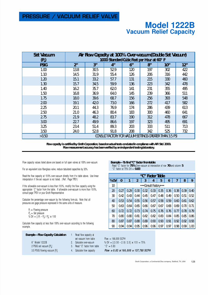
Example—Flow Capacity Calculation 1. Read flow capacity atset pressure from table Flow= 3,140 NCMH
6” Model 1220A 2. Calculate over-pressure % OP= [ (1 75- 1 0 0) / 1 0 0]x 100= 75%100 mm WC Set Pressure [Ps] 3 . Read “ C” factor from table “ C”= 0.87175 mm WC Flowing Pressure [Pf] 4 . Calculate flow capacity Flow = 0 .87 x 3 , 1 4 0 = 2 ,73 2 NCM H
“C” Factor Table%OP 0 1 2 3 4 5 6 7 8 9
10 0.42 0.43 0.44 0.45 0.46 0.46 0.47 0.48 0.49 0.5020 0.51 0.52 0.52 0.53 0.54 0.55 0.56 0.56 0.57 0.5830 0.59 0.59 0.60 0.61 0.61 0.62 0.63 0.64 0.64 0.6540 0.66 0.66 0.67 0.68 0.68 0.69 0.70 0.70 0.71 0.7250 0.72 0.73 0.73 0.74 0.75 0.75 0.76 0.77 0.77 0.7860 0.78 0.79 0.80 0.80 0.81 0.81 0.82 0.82 0.83 0.8470 0.84 0.85 0.85 0.86 0.86 0.87 0.88 0.88 0.89 0.8980 0.90 0.90 0.91 0.91 0.92 0.92 0.93 0.93 0.94 0.9490 0.95 0.95 0.96 0.96 0.97 0.97 0.98 0.99 0.99 1.00
Example—To find“C” factor fromtable:Read “ C” factor for75% Over-pressure at intersection of row70 and column5“C” factor at 75% OP= 0.87
Set Pressure Air Flow Capacity at 100% Over-pressure (Double Set Pressure)(Ps) 1000 Normal Cubic Meters per Hour at 0° C
mmWC mb 2” 3” 4” 6” 8” 10” 12”22 2.16 0.19 0.37 0.71 1.48 2.33 3.80 4.9350 4.90 0.29 0.56 1.07 2.23 3.50 5.72 7.4275 7.35 0.36 0.69 1.31 2.72 4.28 6.99 9.10100 9.80 0.41 0.80 1.51 3.14 4.93 8.05 10.4125 12.3 0.46 0.89 1.68 3.50 5.51 8.99 11.7150 14.7 0.50 0.98 1.84 3.82 6.02 9.80 12.7175 17.2 0.54 1.06 1.99 4.12 6.49 10.6 13.7
200 19.6 0.58 1.13 2.12 4.39 6.92 11.3 14.7225 22.1 0.61 1.20 2.25 4.65 7.33 12.0 15.5250 24.5 0.65 1.26 2.36 4.89 7.71 12.6 16.3275 27.0 0.68 1.32 2.48 5.11 8.07 13.2 17.1300 29.4 0.70 1.38 2.58 5.33 8.42 13.7 17.8375 36.8 0.78 1.54 2.88 5.91 9.40 15.3 19.8500 49.0 0.90 1.78 3.30 6.75 10.7 17.5 22.7625 61.3 1.00 1.99 3.67 7.46 11.9 19.4 25.1750 73.5 1.09 2.18 3.99 8.07 12.9 21.0 27.3

8/13/2019 Groth Catalogue
http://slidepdf.com/reader/full/groth-catalogue 26/175
Flow capacity is certifiedby GrothCorporation, basedonactual tests conductedincompliance withAPI Std. 2000.Flow measurement accuracy has beenverifiedby anindependent testinglaboratory.
Flow capacity values listed above are based on full open valves at 100% over-vacuum.
For an equivalent size fiberglass valve, reduce tabulated capacities by 32%.
Read the flow capacity at 10 0% over-vacuum directly from th e table above. Use linearinterpolation if the set vacuum is not listed. (Ref: Page TPD1)
If the allowable over-vacuum is less than 10 0%, modify t he flow capacity using theappropriate “ C” factor from the table. If allowable over-vacuum is more than 10 0%,consult page TPD1 or your Groth Representative.
Calculate the percentage over-vacuum by the following form ula. Note that allpressures are gage pressure expressed in the same units of measure.
Pf = Flowing pressurePs = Set pressure% OV= [ (Pf - Ps) / Ps] x 100
Calculate flow capacity at less than 100% over-vacuum according to the followingexample.
Example—Flow Capacity Calculation 1. Read flow capacity atset vacuum from table Flow= 74,0 00 SCFH
6” Model 1220A 2. Calculate over-vacuum % OV= [ (7- 4 )/ 4 ]x 100= 75%4 In WC set vacuum [Ps] 3 . Read “ C” factor from table “ C”= 0.877 In WC flowing vacuum [Pf] 4 . Calculate flow capacity Flow = 0 .87 x 7 4 , 0 0 0 = 64,3 80 SCFH
Example—To find“C” factor fromtable:Read “ C” factor for75% Over-vacuum at intersection of row70 and column5“ C” factor at 75% OV= 0.87
Groth Corporation, a Continental Disc company, Stafford, TX, USA 124
Vacuum Relief CapacityModel 1220A
PRESSURE / VACUUM RELIEF VALVE
Set Vacuum Air Flow Capacity at 100% Over-vacuum(Double Set Vacuum)(Ps) 1000 Standard Cubic Feet per Hour at 60° F
In WC Oz/ Sq In 2” 3” 4” 6” 8” 10” 12”0.87 0.50 4.70 10.3 16.0 34.7 60.5 91.1 1291.00 0.58 5.05 11.0 17.2 37.3 65.0 97.9 1381.73 1.00 6.63 14.5 22.6 49.0 85.3 129 1822.00 1.16 7.12 15.6 24.2 52.6 91.6 138 1952.60 1.50 8.10 17.7 27.6 59.8 104 157 2223.00 1.73 8.70 19.0 29.6 64.2 112 169 2383.46 2.00 9.33 20.4 31.8 68.9 120 181 256
4.00 2.31 10.0 21.9 34.1 74.0 129 194 2746.00 3.47 12.2 26.7 41.5 90.1 157 237 3348.00 4.62 14.0 30.6 47.7 103 180 272 38410.0 5.78 15.6 34.0 53.0 115 200 302 42712.0 6.93 17.0 37.1 57.8 125 218 329 46515.0 8.66 18.8 41.1 64.0 139 242 365 51620.0 11.6 21.4 46.8 72.9 158 276 415 58725.0 14.4 23.6 51.5 80.3 174 304 457 64630.0 17.3 25.4 55.6 86.6 188 327 493 697
“C” Factor Table%OV 0 1 2 3 4 5 6 7 8 9
10 0.42 0.43 0.44 0.45 0.46 0.46 0.47 0.48 0.49 0.5020 0.51 0.52 0.52 0.53 0.54 0.55 0.56 0.56 0.57 0.5830 0.59 0.59 0.60 0.61 0.61 0.62 0.63 0.64 0.64 0.6540 0.66 0.66 0.67 0.68 0.68 0.69 0.70 0.70 0.71 0.7250 0.72 0.73 0.73 0.74 0.75 0.75 0.76 0.77 0.77 0.7860 0.78 0.79 0.80 0.80 0.81 0.81 0.82 0.82 0.83 0.8470 0.84 0.85 0.85 0.86 0.86 0.87 0.88 0.88 0.89 0.8980 0.90 0.90 0.91 0.91 0.92 0.92 0.93 0.93 0.94 0.9490 0.95 0.95 0.96 0.96 0.97 0.97 0.98 0.99 0.99 1.00

8/13/2019 Groth Catalogue
http://slidepdf.com/reader/full/groth-catalogue 27/175Groth Corporation, a Continental Disc company, Stafford, TX, USA125
Vacuum Relief CapacityModel 1220A
PRESSURE / VACUUM RELIEF VALVE
Flow capacity is certifiedby GrothCorporation, basedonactual tests conductedincompliance withAPI Std. 2000.Flow measurement accuracy has beenverifiedby anindependent testinglaboratory.
Flow capacity values listed above are based on full open valves at 100% over-vacuum.
For an equivalent size fiberglass valve, reduce tabulated capacities by 32%.
Read the flow capacity at 10 0% over-vacuum directly from the table above. Use linearinterpolation if the set vacuum is not listed. (Ref: Page TPD1)
If the allowable over-vacuum is less than 10 0%, modify the flow capacity using theappropriate “ C” factor from the table. If allowable over-vacuum is more than 10 0%,consult page TPD1 or your Groth Representative.
Calculate the percentage over-vacuum by the following form ula. Note that allpressures are gage pressure expressed in the same units of measure.
Pf = Flowing pressurePs = Set pressure% OV= [ (Pf - Ps) / Ps] x 100
Calculate flow capacity at less than 100% over-vacuum according to the followingexample.
Example—Flow Capacity Calculation 1. Read flow capacity atset vacuum from table Flow= 2,080 NCMH
6” Model 1220A 2. Calculate over-vacuum % OV= [(1 75- 1 0 0) / 1 0 0]x 100= 75%100 mm WC Set Vacuum [ Ps] 3 . Read “ C” factor from table “ C”= 0.87175 mm WC Flowing Vacuum [ Pf] 4 . Calculate flow capacity Flow = 0 .87 x 2 , 0 8 0 = 1 ,81 0 NCM H
“C” Factor Table%OV 0 1 2 3 4 5 6 7 8 9
10 0.42 0.43 0.44 0.45 0.46 0.46 0.47 0.48 0.49 0.5020 0.51 0.52 0.52 0.53 0.54 0.55 0.56 0.56 0.57 0.5830 0.59 0.59 0.60 0.61 0.61 0.62 0.63 0.64 0.64 0.6540 0.66 0.66 0.67 0.68 0.68 0.69 0.70 0.70 0.71 0.7250 0.72 0.73 0.73 0.74 0.75 0.75 0.76 0.77 0.77 0.7860 0.78 0.79 0.80 0.80 0.81 0.81 0.82 0.82 0.83 0.8470 0.84 0.85 0.85 0.86 0.86 0.87 0.88 0.88 0.89 0.8980 0.90 0.90 0.91 0.91 0.92 0.92 0.93 0.93 0.94 0.9490 0.95 0.95 0.96 0.96 0.97 0.97 0.98 0.99 0.99 1.00
Example—To find“C” factor fromtable:Read “ C” factor for75% Over-vacuum at intersection of row70 and column5“ C” factor at 75% OV= 0.87
Set Vacuum Air Flow Capacity at 100% Over-vacuum(Double Set Vacuum)(Ps) 1000 Normal Cubic Meters per Hour at 0° C
mmWC mb 2” 3” 4” 6” 8” 10” 12”22 2.16 0.13 0.29 0.45 0.98 1.71 2.58 3.6550 4.90 0.20 0.44 0.68 1.48 2.58 3.88 5.4875 7.35 0.24 0.53 0.83 1.81 3.15 4.74 6.70100 9.80 0.28 0.62 0.96 2.08 3.62 5.46 7.72125 12.3 0.31 0.69 1.07 2.32 4.04 6.09 8.60150 14.7 0.34 0.75 1.17 2.53 4.41 6.65 9.40175 17.2 0.37 0.81 1.26 2.73 4.75 7.16 10.1
200 19.6 0.39 0.86 1.34 2.91 5.07 7.64 10.8225 22.1 0.42 0.91 1.42 3.08 5.36 8.08 11.4250 24.5 0.44 0.96 1.49 3.23 5.64 8.49 12.0275 27.0 0.46 1.00 1.56 3.38 5.90 8.88 12.6300 29.4 0.48 1.04 1.62 3.52 6.14 9.25 13.1375 36.8 0.53 1.16 1.80 3.91 6.81 10.3 14.5500 49.0 0.60 1.32 2.05 4.45 7.75 11.7 16.5625 61.3 0.66 1.45 2.26 4.90 8.54 12.9 18.2750 73.5 0.72 1.57 2.44 5.29 9.22 13.9 19.6

8/13/2019 Groth Catalogue
http://slidepdf.com/reader/full/groth-catalogue 28/175Groth Corporation, a Continental Disc company, Stafford, TX, USA 126
Pressure Relief CapacityModel 1221B
PRESSURE / VACUUM RELIEF VALVE
Flow capacity is certifiedby GrothCorporation, basedonactual tests conductedincompliance withAPI Std. 2000.Flow measurement accuracy has beenverifiedby anindependent testinglaboratory.
Flow capacity values listed above are based on full open valves at 100% over-pressure.
For an equivalent size fiberglass valve, reduce tabulated capacities by 32%.
Read the flow capacity at 100% over-pressure directly from the table above. Use linearinterpolation if the set pressure is not listed. (Ref: Page TPD1)
If the allowable over-pressure is less than 100%, modify the flow capacity using theappropriate “ C” factor from the table. If allowable over-pressure is more than 10 0%,consult page TPD1 or your Groth Representative.
Calculate the percentage over-pressure by the following formula. Note that allpressures are gage pressure expressed in the same units of measure.
Pf = Flowing pressurePs = Set pressure% OP= [ (Pf - Ps) / Ps] x 100
Calculate flow capacity at less than 100% over-pressure according to the followingexample.
Example—Flow Capacity Calculation 1. Read flow capacity atset pressure from table Flow= 448,000 SCFH
6” Model 1221B 2. Calculate over-pressure % OP= [ (7- 4 )/ 4 ]x 100= 75%4 PSIG set pressure [Ps] 3 . Read “ C” factor from table “ C”= 0.837 PSIG flowing pressure [Pf] 4 . Calculate flow capacity Flow = 0 .83 x 4 4 8 , 0 0 0 = 371,840 SCFH
Example—To find“C” factor fromtable:Read “ C” factor for75% Over-pressure at intersection of row70 and column5“ C” factor at 75% OP= 0.83
“C” Factor Table%OP 0 1 2 3 4 5 6 7 8 9
10 •••Consult Factory•••20 0.27 0.29 0.30 0.32 0.33 0.35 0.36 0.38 0.39 0.4030 0.42 0.43 0.44 0.45 0.47 0.48 0.49 0.50 0.51 0.5240 0.53 0.54 0.55 0.56 0.57 0.58 0.59 0.60 0.61 0.6250 0.63 0.64 0.65 0.66 0.67 0.67 0.68 0.69 0.70 0.7160 0.72 0.72 0.73 0.74 0.75 0.76 0.76 0.77 0.78 0.7970 0.80 0.80 0.81 0.82 0.82 0.83 0.84 0.85 0.85 0.8680 0.87 0.87 0.88 0.89 0.90 0.90 0.91 0.92 0.92 0.9390 0.94 0.94 0.95 0.96 0.96 0.97 0.97 0.98 0.99 1.00
Set Pressure Air Flow Capacity at 100% Over-pressure (Double Set Pressure)(Ps) 1000 Standard Cubic Feet per Hour at 60° FPSIG 2” 3” 4” 6” 8” 10” 12”1.00 28.0 53.4 92.5 210 345 529 7392.00 40.3 77.4 134 304 500 767 10703.00 50.2 96.9 168 381 625 960 13404.00 58.8 114 198 448 736 1130 15775.00 66.5 130 225 510 838 1286 17946.00 73.7 144 250 568 932 1431 19977.00 80.4 158 274 622 1022 1568 2188
8.00 86.7 171 297 674 1107 1699 23719.00 92.8 184 319 724 1189 1825 254610.0 98.6 196 340 772 1267 1945 271411.0 104 208 360 818 1343 2062 287712.0 110 219 380 863 1417 2176 303613.0 115 231 400 907 1489 2286 318914.0 120 241 418 949 1559 2393 333915.0 125 252 437 991 1627 2498 3486

8/13/2019 Groth Catalogue
http://slidepdf.com/reader/full/groth-catalogue 29/175Groth Corporation, a Continental Disc company, Stafford, TX, USA127
Pressure Relief CapacityModel 1221B
PRESSURE / VACUUM RELIEF VALVE
Flow capacity is certifiedby GrothCorporation, basedonactual tests conductedincompliance withAPI Std. 2000.Flow measurement accuracy has beenverifiedby anindependent testinglaboratory.
Flow capacity values listed above are based on full open valves at 100% over-pressure.
For an equivalent size fiberglass valve, reduce tabulated capacities by 32%.
Read the flow capacity at 100% over-pressure directly from the table above. Use linearinterpolation if the set pressure is not listed. (Ref: Page TPD1)
If the allowable over-pressure is less than 100%, modify the flow capacity using theappropriate “ C” factor from the table. If allowable over-pressure is more than 10 0%,consult page TPD1 or your Groth Representative.
Calculate the percentage over-pressure by the follow ing formula . Note that allpressures are gage pressure expressed in the same units of measure.
Pf = Flowing pressurePs = Set pressure% OP= [ (Pf - Ps) / Ps] x 100
Calculate flow capacity at less than 100% over-pressure according to the followingexample.
Example—Flow Capacity Calculation 1. Read flow capacity atset pressure from table Flow= 16,200 NCMH
6” Model 1221B 2. Calculate over-pressure % OP= [(0 .7- 0 .4 ) / 0 . 4]x 100= 75%0.4 BarG Set Pressure [Ps] 3 . Read “ C” factor from table “ C”= 0.830.7 BarG Flowing Pressure [Pf] 4 . Calculate flow capacity Flow = 0 .83 x 1 6 , 2 0 0 = 13 ,4 46 NCM H
Example—To find“C” factor fromtable:Read “ C” factor for75% Over-pressure at intersection of row70 and column5“ C” factor at 75% OP= 0.83
Set Pressure Air Flow Capacity at 100% Over-pressure (Double Set Pressure)(Ps) 1000 Normal Cubic Meters per Hour at 0° CBarG 2” 3” 4” 6” 8” 10” 12”0.07 0.82 1.57 2.72 6.16 10.1 15.5 21.70.10 0.99 1.89 3.28 7.45 12.2 18.8 26.20.15 1.23 2.36 4.09 9.28 15.2 23.4 32.60.20 1.43 2.76 4.80 10.9 17.9 27.4 38.30.25 1.62 3.14 5.44 12.3 20.3 31.1 43.40.30 1.79 3.48 6.04 13.7 22.5 34.5 48.20.35 1.95 3.81 6.61 15.0 24.6 37.8 52.7
0.40 2.10 4.12 7.14 16.2 26.6 40.9 57.00.45 2.25 4.41 7.66 17.4 28.5 43.8 61.10.50 2.39 4.70 8.16 18.5 30.4 46.6 65.10.55 2.52 4.98 8.64 19.6 32.2 49.4 68.90.60 2.65 5.25 9.10 20.6 33.9 52.1 72.60.70 2.89 5.76 10.0 22.7 37.2 57.2 79.70.80 3.13 6.25 10.8 24.6 40.4 62.1 86.50.90 3.35 6.72 11.7 26.5 43.5 66.7 93.11.00 3.56 7.18 12.5 28.3 46.4 71.2 99.4
“C” Factor Table%OP 0 1 2 3 4 5 6 7 8 9
10 •••Consult Factory•••20 0.27 0.29 0.30 0.32 0.33 0.35 0.36 0.38 0.39 0.4030 0.42 0.43 0.44 0.45 0.47 0.48 0.49 0.50 0.51 0.5240 0.53 0.54 0.55 0.56 0.57 0.58 0.59 0.60 0.61 0.62
50 0.63 0.64 0.65 0.66 0.67 0.67 0.68 0.69 0.70 0.7160 0.72 0.72 0.73 0.74 0.75 0.76 0.76 0.77 0.78 0.7970 0.80 0.80 0.81 0.82 0.82 0.83 0.84 0.85 0.85 0.8680 0.87 0.87 0.88 0.89 0.90 0.90 0.91 0.92 0.92 0.9390 0.94 0.94 0.95 0.96 0.96 0.97 0.97 0.98 0.99 1.00
8/13/2019 Groth Catalogue
http://slidepdf.com/reader/full/groth-catalogue 30/175

8/13/2019 Groth Catalogue
http://slidepdf.com/reader/full/groth-catalogue 31/175

8/13/2019 Groth Catalogue
http://slidepdf.com/reader/full/groth-catalogue 32/175
PRESSURE / VACUUM RELIEF VALVE
Model 1220A/7618and Flame Arrester w/pipe-away feature
MODEL 1220A/7618
130Groth Corporation, a Continental Disc company, Stafford, TX, USA
■ Sizes 2” through 12”
■ Pressure settings 0.5 oz/in 2 to 15 PSIG■ Vacuum settings 0.5 oz/in 2 to 12 PSIG■ Available in aluminum (type 356),
carbon steel, stainless steel andother materials.
■ Factory Mutual approved flame arresters■ Proven spiral wound,crimped ribbon,
flame element■ Modular construction
PRESSURE / VACUUM RELIEFVALVE WITH FLAME ARRESTER(PIPE-AWAY)The Model 1220A/7618 combination units are usedfor pressure and vacuum relief where vapors must bepiped away. They are designed to protect your tankfrom damage created by over-pressure or excessivevacuum, at the same time that they provide protec-tion from externally caused sources of heat andignition. The result is reduced emissions level andincreased fire protection and safety.
SPECIAL FEATURESThe Model 1220A Pressure/Vacuum relief valve withflanged pipe-away outlet offers Groth’s special “cush-ioned air” seating. Superior performing Teflon ® 1
seating diaphragms are standard to minimize stickingcaused by resinous vapors and atmospheric mois-ture. Self draining housings and drip rings protectseating surfaces from condensate and freezing.
The wafer construction of the Model 7618 flamearrester affords easy accessibility to the flame bankfor maintenance. All Groth flame arresters utilizespiral wound, crimped ribbon constructed flameelements. These proven, Factory Mutual approvedelements, have been reported by NTIS of theDept. of Commerce, to provide the best flamequenching performance for the least pressure drop.Groth flame arresters are pneumatic tested to 15PSIG as standard.
1 Teflon is a registered trademark of DuPont Corporation.
MODEL 1220A/7618
GROTH,THE CAPABILITYCOMPANYAs with all Groth products, every Model1220A/7618 is factory inspected and testedto meet your critical requirements and specialneeds. Inventory is maintained to insurerapid delivery.

8/13/2019 Groth Catalogue
http://slidepdf.com/reader/full/groth-catalogue 33/175131 Groth Corporation, a Continental Disc company, Stafford, TX, USA
Specifications subject to change without notice. Certified dimensions available upon request.
1 5 P S I G S P R I N G L O A D E D P R E S S U R E
( 1 . 0 5 k g . / c m 2 )
1 2 P S I G S P R I N G L O A D E D V A C U U M
( 0 . 8 4 k g . / c m 2 )
MODEL # SIZE MATERIAL OPTIONS
1220A/7618 Weight Loaded1221B/7618 Pressure Spring1222B/7618 Vacuum Spring1223A/7618 Pressure & Vacuum Springs
02"Thru12"
Flame Element Material
Pallet MaterialSeat Material* Body Material
O = No OptionsZ = Special Options
O = No Jacket J = Steam JacketS = SpacerH = Steam Jacket and SpacerDiaphragm Material (Seat):
B = Buna-N T = Teflon ® 1
V = Viton ®
Z = Special
1 = Aluminum3 = Carbon Steel5 = 316 SSZ = Special
EXAMPLEIndicates a 2" Model 1220A/7618 with Aluminum Body and Seat, 316 SS Pallet, Teflon ® 1 Seat Diaphragm Aluminum Flame Element and
no other options.
Include model number and setting when ordering.For special options, consult factory.When ordering steam jacket, include steam pressure / temperature.
* Stainless steel guides, stems are standard with aluminum and carbon steelbodies. Stainless steel seats standard w ith carbon steel bodies. N
O T E S
1 0 0 22 12 1 5 00T
* 0 . 5 o z / i n 2
W E I G H T L O A D E D
( 2 . 2 0 g m . / c m 2
)
A 1
B
D
C
A
E
BB
D
C
167 8
See TPD2 forVacuumSettings
and MAWP
† W.P. =Working Pressure. ‡ On spring loaded valves, change model number. 150#R.F. drilling compatibility F.F. on aluminumand R.F. on carbon steel and stainless steel alloys.16 oz/ in 2 set with spacer. S.S. set weights-Consult Factory. *Some sizes require non-ferrous components to achieve 0.5 oz./sq.in. setting.
Max. Set Max. Set Max. Min. Max. W.P. † Min. Vac.Pressure Vacuum Setting Setting for Min. Setting A B BB C D E Approx. Ship
Inlet Outlet Weight Weight Spring Weight Vacuum for Length Height Height Width Wt. Lbs.Flg. Flg. Loaded Loaded Loaded Loaded Setting Max. W.P. † (mm) (mm) (mm) (mm) (mm) (mm) (Aluminum)
2” 3” 11 oz/in 2 12 oz/in 2 141/4” 26 5/8” 33 5/8” 83/4” 20 1/4” 51/2” 45(50 mm) (80 mm) (48.2 gm/cm 2) (52.7 gm/cm 2) (361) (676) (854) (221) (514) (140) (20 kg)
3” 4” 13 oz/in 2 11 oz/in 2 18” 31 1/8” 39 3/8” 91/2” 23 1/8” 6” 60(80 mm) (100 mm) (57.0 gm/cm 2) (48.3 gm/cm 2) (457) (790) (1000) (241) (588) (152) (27 kg)
4” 6” 16 oz/in 2 11 oz/in 2 191/4” 37” 47 3/8” 11 1/2” 26 3/4” 61/2” 90(100 mm) (150 mm) (70.3 gm/cm 2) (48.3 gm/cm 2) (489) (940) (1203) (292) (679) (165) (41 kg)
6” 8” 16 oz/in 2 16 oz/in 2 261/2” 44 3/4” 59 3/4” 16 1/2” 31 1/2” 81/2” 160(150 mm) (200 mm) (70.3 gm/cm 2) (70.3 gm/cm 2) (673) (1136) (1518) (419) (800) (216) (73 kg)
8” 10” 16 oz/ in 2 16 oz/in 2 321/2” 53 1/2” 70 1/4” 21” 37 3/8” 10 3/4” 270(200 mm) (250 mm) (70.3 gm/cm 2) (70.3 gm/cm 2) (826) (1358) (1784) (533) (949) (273) (123 kg)
10” 12” 16 oz/ in 2 16 oz/in 2 371/4” 64 1/2” 84 1/8” 24 3/4” 45 1/4” 12 1/2” 420(250 mm) (300 mm) (70.3 gm/cm 2) (70.3 gm/cm 2) (959) (1638) (2137) (629) (1149) (318) (190 kg)
12” 14” 16 oz/ in 2 16 oz/in 2 423/4” 71 5/8” 91 3/8” 28 5/8” 50 1/8” 15” 600(300 mm) (350 mm) (70.3 gm/cm
2
) (70.3 gm/cm2
) (1086) (1819) (2321) (727) (1273) (381) (273 kg)
SPECIFICATIONS
HOW TO ORDERFor easy ordering, select proper model numbers
1Telfon is a registered trademark of DuPont Corporation.

8/13/2019 Groth Catalogue
http://slidepdf.com/reader/full/groth-catalogue 34/175Groth Corporation, a Continental Disc company, Stafford, TX, USA 132
Pressure Relief CapacityModel 1220A/7618
PRESSURE / VACUUM RELIEF VALVE
Flow capacity is certifiedby GrothCorporation, basedonactual tests conductedincompliance withAPI Std. 2000.Flow measurement accuracy has beenverifiedby anindependent testinglaboratory.
Flow capacity values listed above are based on full open valves at 100% over-pressure.
Consult Factory for flow capacity with fiberglass valve.
Read the flow capacity at 100% over-pressure directly from the table above. Use linearinterpolation if the set pressure is not listed. (Ref: Page TPD1)
If the allowable over-pressure is less than 100%, modify the flow capacity using theappropriate “ C” factor from the table. If allowable over-pressure is more than 10 0%,consult page TPD1 or your Groth Representative.
Calculate the percentage over-pressure by the follow ing formul a. Note that allpressures are gage pressure expressed in the same units of measure.
Pf = Flowing pressurePs = Set pressure% OP= [ (Pf - Ps) / Ps] x 100
Calculate flow capacity at less than 100% over-pressure according to the followingexample.
Example—Flow Capacity Calculation 1. Read flow capacity atset pressure from table Flow= 58,0 00 SCFH
6” Model 1220A/ 7 618 2. Calculate over-pressure % OP= [ (7- 4 )/ 4 ]x 100= 75%4 In WC set pressure [Ps] 3 . Read “ C” factor from table “ C”= 0.877 In WC flowing pressure [ Pf] 4 . Calculate flow capacity Flow = 0 .87 x 5 8 , 0 0 0 = 50,4 60 SCFH
Set Pressure Air Flow Capacity at 100% Over-pressure (Double Set Pressure)(Ps) 1000 Standard Cubic Feet per Hour at 60° F
In WC Oz/ Sq In 2” 3” 4” 6” 8” 10” 12”0.87 0.50 2.92 5.68 10.3 20.7 32.3 51.5 59.11.00 0.58 3.19 6.34 11.5 23.3 36.2 57.6 67.81.73 1.00 4.45 9.23 16.8 34.4 53.0 84.4 1052.00 1.16 4.84 10.1 18.5 37.8 58.2 92.6 1162.60 1.50 5.64 11.9 21.7 44.6 68.5 109 1383.00 1.73 6.12 13.0 23.7 48.8 74.8 119 1513.46 2.00 6.65 14.1 25.9 53.2 81.6 130 165
4.00 2.31 7.21 15.4 28.2 58.0 88.9 141 1806.00 3.47 9.07 19.5 35.7 73.6 113 179 2308.00 4.62 10.7 23.0 42.1 86.8 133 211 27210.0 5.78 12.1 26.1 47.7 98.6 151 240 30912.0 6.93 13.3 28.9 52.9 109 167 266 34315.0 8.66 15.1 32.7 60.0 124 189 301 38920.0 11.6 17.7 38.4 70.4 146 222 354 45725.0 14.4 20.0 43.5 79.7 165 252 400 51830.0 17.3 22.2 48.1 88.2 182 278 443 574
Example—To find“C” factor fromtable:Read “ C” factor for75% Over-pressure at intersection of row70 and column5“ C” factor at 75% OP= 0.87
“C” Factor Table%OP 0 1 2 3 4 5 6 7 8 9
1020 Consult30 Factory40
50 0.72 0.73 0.73 0.74 0.75 0.75 0.76 0.77 0.77 0.7860 0.78 0.79 0.80 0.80 0.81 0.81 0.82 0.82 0.83 0.8470 0.84 0.85 0.85 0.86 0.86 0.87 0.88 0.88 0.89 0.8980 0.90 0.90 0.91 0.91 0.91 0.92 0.93 0.93 0.94 0.9490 0.95 0.95 0.96 0.96 0.97 0.97 0.98 0.99 0.99 1.00

8/13/2019 Groth Catalogue
http://slidepdf.com/reader/full/groth-catalogue 35/175

8/13/2019 Groth Catalogue
http://slidepdf.com/reader/full/groth-catalogue 36/175Groth Corporation, a Continental Disc c ompany, Stafford, TX, USA 134
Vacuum Relief CapacityModel 1220A/7618
PRESSURE / VACUUM RELIEF VALVE
Flow capacity is certifiedby GrothCorporation, basedonactual tests conductedincompliance withAPI Std. 2000.Flow measurement accuracy has beenverifiedby anindependent testinglaboratory.
Flow capacity values listed above are based on full open valves at 100% over-vacuum.
Consult Factory for flow capacity with fiberglass valve.
Read the flow capacity at 10 0% over-vacuum directly from th e table above. Use linearinterpolation if the set vacuum is not listed. (Ref: Page TPD1)
If the allowable over-vacuum is less than 10 0%, modify t he flow capacity using theappropriate “ C” factor from the table. If allowable over-vacuum is more than 10 0%,consult page TPD1 or your Groth Representative.
Calculate the percentage over-vacuum by the following form ula. Note that allpressures are gage pressure expressed in the same units of measure.
Pf = Flowing pressurePs = Set pressure% OV= [ (Pf - Ps) / Ps] x 100
Calculate flow capacity at less than 100% over-vacuum according to the followingexample.
Example—Flow Capacity Calculation 1. Read flow capacity atset vacuum from table Flow= 46,7 00 SCFH
6” Model 1220A/ 7618 2. Calculate over-vacuum % OV= [ (7- 4 )/ 4 ]x 100= 75%4 In WC set vacuum [Ps] 3 . Read “ C” factor from table “ C”= 0.877 In WC flowing vacuum [Pf] 4 . Calculate flow capacity Flow = 0 .87 x 4 6 , 7 0 0 = 40,6 29 SCFH
Example—To find“C” factor fromtable:Read “ C” factor for75% Over-vacuum at intersection of row70 and column5“ C” factor at 75% OV= 0.87
Set Vacuum Air Flow Capacity at 100% Over-vacuum(Double Set Vacuum)(Ps) 1000 Standard Cubic Feet per Hour at 60° F
In WC Oz/ Sq In 2” 3” 4” 6” 8” 10” 12”0.87 0.50 2.55 5.19 8.80 17.9 28.6 44.3 53.61.00 0.58 2.77 5.73 9.70 19.8 31.6 48.9 60.41.73 1.00 3.78 8.15 13.6 28.3 45.1 69.4 89.82.00 1.16 4.10 8.90 14.9 31.0 49.3 75.8 99.02.60 1.50 4.74 10.4 17.4 36.2 57.7 88.6 1173.00 1.73 5.14 11.3 18.9 39.5 62.9 96.0 1283.46 2.00 5.56 12.3 20.5 42.9 68.4 105 139
4.00 2.31 6.03 13.4 22.3 46.7 74.4 114 1526.00 3.47 7.54 16.9 28.1 58.9 93.8 144 1938.00 4.62 8.84 19.9 33.0 69.4 110 169 22710.0 5.78 10.0 22.5 37.4 78.6 125 192 25812.0 6.93 11.1 24.9 41.5 87.1 139 212 28615.0 8.66 12.5 28.2 46.9 98.6 157 240 32420.0 11.6 14.7 33.1 55.1 116 184 282 38125.0 14.4 16.6 37.5 62.3 131 209 319 43230.0 17.3 18.3 41.5 68.9 145 231 353 478
“C” Factor Table%OV 0 1 2 3 4 5 6 7 8 9
1020 Consult30 Factory40
50 0.72 0.73 0.73 0.74 0.75 0.75 0.76 0.77 0.77 0.7860 0.78 0.79 0.80 0.80 0.81 0.81 0.82 0.82 0.83 0.8470 0.84 0.85 0.85 0.86 0.86 0.87 0.88 0.88 0.89 0.8980 0.90 0.90 0.91 0.91 0.91 0.92 0.93 0.93 0.94 0.9490 0.95 0.95 0.96 0.96 0.97 0.97 0.98 0.99 0.99 1.00

8/13/2019 Groth Catalogue
http://slidepdf.com/reader/full/groth-catalogue 37/175Groth Corporation, a Continental Disc company, Stafford, TX, USA135
Vacuum Relief CapacityModel 1220A/7618
PRESSURE / VACUUM RELIEF VALVE
Flow capacity is certifiedby GrothCorporation, basedonactual tests conductedincompliance withAPI Std. 2000.Flow measurement accuracy has beenverifiedby anindependent testinglaboratory.
Flow capacity values listed above are based on full open valves at 100% over-vacuum.
Consult Factory for flow capacity with fiberglass valve.
Read the flow capacity at 10 0% over-vacuum directly from the table above. Use linearinterpolation if the set vacuum is not listed. (Ref: Page TPD1)
If the allowable over-vacuum is less than 10 0%, modify the flow capacity using theappropriate “ C” factor from the table. If allowable over-vacuum is more than 10 0%,consult page TPD1 or your Groth Representative.
Calculate the percentage over-vacuum by the following form ula. Note that allpressures are gage pressure expressed in the same units of measure.
Pf= Flowing pressure
Ps = Set pressure% OV= [ (Pf - Ps) / Ps] x 100
Calculate flow capacity at less than 100% over-vacuum according to the followingexample.
Example—Flow Capacity Calculation 1. Read flow capacity atset vacuum from table Flow= 1,660 NCMH
6” Model 1220A/ 7618 2. Calculate over-vacuum % OV= [(2 50- 1 5 0) / 1 5 0]x 100= 67%150 mm WC Set Vacuum [ Ps] 3 . Read “ C” factor from table “ C”= 0.82250 mm WC Flowing Vacuum [Pf] 4 . Calculate flow capacity Flow = 0 .82 x 1 , 6 6 0 = 1 ,36 1 NCM H
Example—To find“C” factor fromtable:Read “ C” factor for67% Over-vacuum at intersection of row60 and column7“ C” factor at 67% OV= 0.82
Set Vacuum Air Flow Capacity at 100% Over-vacuum(Double Set Vacuum)(Ps) 1000 Normal Cubic Meters per Hour at 0° C
mmWC 2” 3” 4” 6” 8” 10” 12”22.0 0.07 0.15 0.26 0.52 0.84 1.29 1.6050.0 0.12 0.25 0.42 0.87 1.39 2.13 2.7875.0 0.14 0.32 0.53 1.11 1.77 2.72 3.59100 0.17 0.38 0.63 1.32 2.09 3.21 4.27150 0.21 0.48 0.79 1.66 2.64 4.05 5.42200 0.25 0.56 0.93 1.95 3.11 4.76 6.40
250 0.28 0.63 1.05 2.21 3.53 5.40 7.27300 0.31 0.70 1.17 2.45 3.90 5.97 8.06375 0.35 0.80 1.32 2.78 4.42 6.77 9.10500 0.41 0.93 1.55 3.26 5.19 7.94 10.7625 0.47 1.06 1.76 3.69 5.87 8.98 12.2750 0.52 1.17 1.94 4.08 6.50 9.90 13.5
“C” Factor Table%OV 0 1 2 3 4 5 6 7 8 9
1020 Consult30 Factory4050 0.72 0.73 0.73 0.74 0.75 0.75 0.76 0.77 0.77 0.78
60 0.78 0.79 0.80 0.80 0.81 0.81 0.82 0.82 0.83 0.8470 0.84 0.85 0.85 0.86 0.86 0.87 0.88 0.88 0.89 0.8980 0.90 0.90 0.91 0.91 0.91 0.92 0.93 0.93 0.94 0.9490 0.95 0.95 0.96 0.96 0.97 0.97 0.98 0.99 0.99 1.00

8/13/2019 Groth Catalogue
http://slidepdf.com/reader/full/groth-catalogue 38/175160Groth Corporation, a Continental Disc company, Stafford, TX, USA
■Groth provides fiberglassproducts for corrosive service
■ Available in Series 1200A, 1300A,2000A and others
FIBERGLASS SERIES 1200A,1300A, 2000A, AND OTHERSFiberglass valves are used the same as theircounter parts manufactured in metal, primarily onabove ground storage tank installations.Fiberglass construction can be used where high-ly corrosive and toxic liquids are being stored.The Fiberglass series design will protect the tankfrom damage created by overpressuring orexcessive vacuum. Costly product evaporationlosses due to normal tank “breathing” are greatlyreduced. Retention of product vapors, reducesthe possibility of atmospheric contamination.
SPECIAL FEATURESFiberglass valves offer Groth’s special “cush-ioned air” seating. Superior performing Teflon ® 1
seating diaphragms are standard to minimizesticking caused by resinous vapors and atmos-pheric moisture. These valves have a selfdraining housing body and drip rings to protectseating surfaces from condensate and freezing.This design also avoids pressure or vacuumbuildup due to binding or clogging of the valves.These Fiberglass valves may be spring loadedwhen required for use on blanketed tank or othertype installations requiring higher settings. Toinsure the proper alignment of seating surfaces
there is peripheral guiding and a center stabiliz-ing stem.
GROTH, THE CAPABILITYCOMPANYAs with all Groth products, every valve is factoryinspected and tested to meet your criticalrequirements and special needs.
1Telfon is a registered trademark of DuPont Corporation.
MODEL 2050
MODEL 1220A
PRESSURE / VACUUM RELIEF VALVE
FiberglassRelief Valves

8/13/2019 Groth Catalogue
http://slidepdf.com/reader/full/groth-catalogue 39/175
ACIDS:Acetic Nitric (5%)Acrylic PhosphoricChlorophenol SulfonicHydrochloric Sulfuric (25%, 50%)
BASES:Aniline Sodium CarbonateDiethylamine Sodium Hydroxide (5%,50%)Potassium Carbonate
SALTS:Alum Ferric ChlorideAmmonium Bromide Magnesium SulfateCalcium Chloride Sodium Chromate
WATER:Demineralized Distilled
SOLVENTS:Acetone MethanolBenzene Methyl Ethyl KetoneCarbon Disulfide Methyl Isobutyl KetoneCarbon Tetrachloride PerchloroethyleneChlorobenzene TolueneEthanol TrichloroethyleneEthyl Acetate XyleneEthylene Dichloride
OTHERS:Acrylonitrile Pulp Mill LiquorsBenzyl Chloride StyreneCyclohexanone Toluene DiisocyanateFormalin
NON RESISTANT
Solvents PhenolOleum Bromine
Furfural
* Synthetic Veil should be used in inner layer.
NON RESISTANT
Bleaching Agents PeroxidesFree Halogens
FIBERGLASS WITHVINYL ESTER RESIN #411
FIBERGLASSWITH FURAN RESIN
CORROSION RESISTANCE
161 Groth Corporation, a Continental Disc company, Stafford, TX, USA
ACIDS:AceticAcrylicBoricChromic (20%)FormicHydrochloricHydrofluoric *Nitric (All Conc.)PerchloricPhosphoricSulfuric (75%)
SALTS:AlumAmmonium ChlorideCalcium ChlorideFerric ChlorideMagnesium SulfateSodium ChlorideSodium Chromate
BLEACHING AGENTS:Calcium ChlorateCalcium HypochloriteChlorine DioxideChlorine WaterHydrogen PeroxidePotassiumPermanganateSodium ChlorateSodium Hypochlorite
BASES:Potassium HydroxideSodium Hydroxide *Ammonium Hydroxide *Ammonium CarbonatePotassium Carbonate *Sodium Carbonate *
WATER:DemineralizedDistilled
OTHERS:AlcoholsAlum ChlorohydroxideGlycerinSulfonated DetergentsUrea-Ammonium NitrateFertilizers
Dimensional drawings on request.Chemical resistance information provided by Dow Chemical (Vinyl Ester Resin) and Qua Corr (Furan).For Flow Data see corresponding Model Brochure.Consult a chemical resistance guide or handbook for additional material compatability information.
RESISTANT RESISTANT

8/13/2019 Groth Catalogue
http://slidepdf.com/reader/full/groth-catalogue 40/175170Groth Corporation, a Continental Disc company, Stafford, TX, USA
■Prevents freezing and productbuildup
■ Designed for easy maintenance■ Available for most models
(consult factory)
STEAM JACKETED VALVESSteam Jacketed Valves are designed for use ontanks containing liquids whose vapors may crys-tallize at normal temperature. They affordprotection against valve clogging. Uniform heat-ing of the housing and valves assures the valvewill remain in operating condition. Available onmodel numbers 1200A, 1220A, 1260A, 1300A,1360A, 2000A, 2300A, and 2400A.
SPECIAL FEATURESSteam Jacketed Valves are built of corrosionresistant materials throughout. Valve covers canbe easily removed for convenient inspection andmaintenance. Steam heated valves are suitablefor steam circulation up to 100 PSIG saturated.
GROTH,THE CAPABILITYCOMPANYAs with all Groth products, every SteamJacketed Valve is factory inspected and tested tomeet your critical requirements and specialneeds.
PRESSURE / VACUUM RELIEF VALVE
Steam Jacketed Valves

8/13/2019 Groth Catalogue
http://slidepdf.com/reader/full/groth-catalogue 41/175
EXAMPLE
Indicates a 2" Model 1200 with 316 SS Body, Seat and Pallet, Teflon ® 1
Seat Diaphragm, Steam Jacketed and no other options.
171 Groth Corporation, a Continental Disc company, Stafford, TX, USA
MODEL # SIZE MATERIAL OPTIONS
02"Thru12"
Pallet MaterialSeat Material
* Body Material
O = No OptionsZ = Special OptionsO = No Jacket
J = Steam JacketDiaphragm Material (Seat):
B = Buna-N T = Teflon ® 1
V = VitonM = Metal-to-MetalZ = Special
3 = Carbon Steel5 = 316 SSZ = SpecialInclude model number, setting and steam pressure when ordering.
For special options, consult factory.When ordering steam jacket, include steam pressure / temperature.
* Stainless steel guides, and stems are standard with carbon steel bodies. N O T E S
1 0 0 20 52 5 5 0 JT
For Model Number, seecorresponding brochure…
A
HOW TO ORDERFor easy ordering, select proper model numbers
1Telfon is a registered trademark of DuPont Corporation.

8/13/2019 Groth Catalogue
http://slidepdf.com/reader/full/groth-catalogue 42/175
SECTION 2FLAME ARRESTERS
7618, 7628 Flame Arrester •
7622 Flame Check •
Steam Jacketed Flame Arresters •
7658A Detonation Arrester •
8400A Pressure Relief and Flame Trap Assembly •
Flame Trap Assembly •
Back Pressure Check Valve •

8/13/2019 Groth Catalogue
http://slidepdf.com/reader/full/groth-catalogue 43/175
MODEL 7618 (VERTICAL)
MODEL 7618
MODEL 7628
200Groth Corporation, a Continental Disc company, Stafford, TX, USA
Note:All Groth Flame Arresters are Bi-directional. FactoryMutual regulates that Flame arresters be installed lessthan 10 pipe diameters from the source of ignition.
■ Sizes 2” through 60”
■ Available in, carbon steel, stainlesssteel aluminum (type 356) and othermaterials
■ Wafer design for quick andeasy maintenance
■ Unique recessed seating forsuperior protection
■ Factory Mutual approval for mostsizes and materials
■ Proven spiral wound, crimpedribbon, flame element
FLAME ARRESTERBoth models are designed to inhibit flame propa-gation in gas piping systems and to protect lowpressure tanks containing flammable liquids.Arresters protect low flash point liquids from exter-nally caused sources of heat and ignition. Thisprovides increased fire protection and safety.
SPECIAL FEATURESBoth models are built of corrosion resistant materi-als throughout. Wafer design construction affordseasy accessibility to the flame bank. Additionally,
jack screws aid in the removal from the shellassembly. All Groth flame arrester flame banksutilize spiral wound, crimped ribbon constructedflame elements. These proven, Factory Mutualapproved elements have been reported, by NTISof the Dept. of Commerce, to provide the bestflame quenching performance for the least pres-sure drop. Groth’s special recessed flame bankseating construction uniquely provides an extrameasure of protection against leakage and possi-ble flame propagation.
GROTH, THE CAPABILITYCOMPANYAs with all Groth products, every Flame Arrester isfactory inspected and tested to meet all criticalrequirements and special needs. Inventory ismaintained to insure rapid delivery.
MODEL 7628 (HORIZONTAL)
Section 2:200-263.qxd, June, 2002, 2.5m
FLAME ARRESTERS
Models 7618 / 7628

8/13/2019 Groth Catalogue
http://slidepdf.com/reader/full/groth-catalogue 44/175
Specifications subject to change without notice. Certified dimensions available upon request.
Groth Corporation, a Continental Disc company, Stafford, TX, USA201
* Larger sizes available on special application. †150#A.N.S.I. drilling compatibility, F.F. on aluminumand R.F. on carbon steel and stainless steel alloys. Pneumatictested to 15 PSI as standard.
A
MODEL # SIZE MATERIAL OPTIONS
7618 Vertical7628 Horizontal 02"Thru60"
Flame element winding
Body Material
O = No OptionsZ = Special OptionsO = No Jacket
J = Steam JacketF = Flanged outlet (in-line design)W = Weatherhood (replaces
flanged outlet)
1 = Aluminum3 = Carbon Steel5 = 316 SSZ = Special
EXAMPLE
Indicates a 2" Model 7628 with Aluminum Body, 316 SS Flame Element Winding, Flanged Outlet and no other options.
Include model number when ordering.For special options, consult factory.When ordering steam jacket, include steam pressure/ temperature. N
O T E S
2 8 0 26 17 5 00F
AA
BBB
MAWP 7618 MAWP 7628 Approx.A B AA BB MAWP 7618 Carbon MAWP 7628 Carbon Ship.
Size*† Width Height Length Height Aluminum or SS Aluminum or SS Wt. Lbs.(mm) (mm) (mm) (mm) (mm) (mm) (mm) (mm) (Aluminum)
2” 8 ” 14” 13 ” 9 ” 50 PSIG 100 PSIG 150 PSIG 350 PSIG 18(51 mm) (221) (356) (349) (241) (345 kPa) (690 kPa) (1035 kPa) (2415 kPa) (8kg)
3” 9 ” 16” 15 ” 11” 50 PSIG 100 PSIG 140 PSIG 325 PSIG 25(76 mm) (241) (406) (400) (279) (345 kPa) (690 kPa) (966 kPa) (2242 kPa) (11 kg)
4” 11 ” 18 ” 18” 12 ” 50 PSIG 100 PSIG 140 PSIG 325 PSIG 40(102 mm) (292) (464) (457) (318) (345 kPa) (690 kPa) (966 kPa) (2242 kPa) (18 kg)
6” 16 ” 21” 21” 16 ” 50 PSIG 100 PSIG 140 PSIG 325 PSIG 70(152 mm) (419) (533) (533) (419) (345 kPa) (690 kPa) (966 kPa) (2242 kPa) (32 kg)
8” 21” 25” 25” 20 ” 50 PSIG 100 PSIG 90 PSIG 200 PSIG 135(203 mm) (533) (635) (635) (521) (345 kPa) (690 kPa) (621 kPa) (1380 kPa) (61 kg)
10” 24 ” 30” 30” 24 ” 50 PSIG 100 PSIG 75 PSIG 150 PSIG 235(254 mm) (629) (762) (762) (622) (345 kPa) (690 kPa) (517 kPa) (1035 kPa) (107 kg)
12” 28 ” 32 ” 32 ” 28 ” 50 PSIG 100 PSIG 75 PSIG 150 PSIG 345(305 mm) (727) (826) (826) (724) (345 kPa) (690 kPa) (517 kPa) (1035 kPa) (156 kg)
1/21/21/25/8
1/23/4
1/2
1/21/2
1/21/41/2
3/41/2
1/23/43/4
SPECIFICATIONS
HOW TO ORDERFor easy ordering, select proper model numbers

8/13/2019 Groth Catalogue
http://slidepdf.com/reader/full/groth-catalogue 45/175
Model 7618 / 7628
202Groth Corporation, a Continental Disc company, Stafford, TX, USA
FLAME ARRESTERS
A i r F l o w
1 0 0 0 S T D c u b
i c f e e t p e r h o u r a t 0 ° C
Tank Pressure - inches W.C.
1. Flow facility and equipment comply with API 2000.
2. Flow measurement accuracy verified by an independant research organization.3. Flow capacity is based on actual tests and certified by Groth Corporation.
4. Flow data are for tank mounting or end of line and includes f
loss, exit loss, and internal losses.
12 ”10 ”
8”
6”
4”
2”
3”
End of LineFlow Capacity
Tank Pressure Air Flow - 1000 Standard Cubic feet per HourIn W.C. oz/ sq in 2” 3” 4” 6” 8” 10” 12”
1 0.6 2.89 5.05 8.98 20.2 34.7 54.7 79.12 1.2 4.40 8.03 14.3 32.1 55.9 87.8 1273 1.7 5.58 10.4 18.5 41.5 72.7 114 1644 2.3 6.57 12.4 22.0 49.5 87.0 136 1976 3.5 8.25 15.8 28.0 63.1 111 174 2518 4.6 9.66 18.6 33.1 74.5 132 206 29710 5.8 10.9 21.2 37.6 84.7 150 235 338
12 6.9 12.0 23.5 41.7 93.8 166 260 37514 8.1 13.1 25.6 45.5 102 182 284 40916 9.2 14.0 27.5 49.0 110 196 306 44118 10.4 14.9 29.4 52.2 118 209 327 47020 11.6 15.8 31.1 55.4 125 222 346 49922 12.7 16.6 32.8 58.3 131 234 365 52524 13.9 17.4 34.4 61.1 138 245 383 55126 15.0 18.1 35.9 63.9 144 256 400 57628 16.2 18.9 37.4 66.5 150 267 416 59930 17.3 19.6 38.8 69.0 155 277 432 622

8/13/2019 Groth Catalogue
http://slidepdf.com/reader/full/groth-catalogue 46/175Groth Corporation, a Continental Disc company, Stafford, TX, USA203
FLAME ARRESTERS
A i r F l o w
1 0 0 0 c u b i c m e t e r s p e r h o u r a t 0 ° C
Tank Pressure - millimeters H 2O
1. Flow facility and equipment comply with API 2000.
2. Flow measurement accuracy verified by an independant research organization.3. Flow capacity is based on actual tests and certified by Groth Corporation.
4. Flow data are for tank mounting or end of line and includes flame
loss, exit loss, and internal losses.
1 2”1 0”8 ”
6 ”
4 ”
2 ”
3 ”
Model 7618 / 7628End of Line
Flow Capacity
Tank Pressure Air Flow - 1000 Cubic Meters per Hour at 0°CmmH 2O mb 2” 3” 4” 6” 8” 10” 12”
25 2.45 0.08 0.14 0.25 0.57 0.98 1.55 2.2450 4.90 0.12 0.23 0.40 0.91 1.58 2.49 3.5975 7.35 0.16 0.29 0.52 1.18 2.06 3.23 4.66100 9.80 0.19 0.35 0.62 1.40 2.46 3.86 5.57150 14.7 0.23 0.45 0.79 1.79 3.15 4.93 7.11200 19.6 0.27 0.53 0.94 2.11 3.73 5.84 8.42250 24.5 0.31 0.60 1.07 2.40 4.25 6.64 9.57
300 29.4 0.34 0.66 1.18 2.66 4.72 7.37 10.6350 34.3 0.37 0.72 1.29 2.90 5.15 8.04 11.6400 39.2 0.40 0.78 1.39 3.12 5.55 8.67 12.5450 44.1 0.42 0.83 1.48 3.33 5.92 9.25 13.3500 49.0 0.45 0.88 1.57 3.53 6.28 9.81 14.1550 53.9 0.47 0.93 1.65 3.72 6.62 10.3 14.9600 59 0.49 0.97 1.73 3.90 6.94 10.8 15.6650 64 0.51 1.02 1.81 4.07 7.25 11.3 16.3700 69 0.53 1.06 1.88 4.24 7.55 11.8 17.0750 74 0.55 1.10 1.95 4.40 7.84 12.2 17.6

8/13/2019 Groth Catalogue
http://slidepdf.com/reader/full/groth-catalogue 47/175204Groth Corporation, a Continental Disc company, Stafford, TX, USA
FLAME ARRESTERS
A i r F l o w
1 0 0 0 S T D c u b i c f e e t p e r h o u r
Pressure Drop - inches W.C.
1. Flow facility and equipment comply with API 20 00.
2. Flow m easurement accuracy verified by an independant research organization.
3. Flow capacity is based on actual tests and certified by Groth
4. Flow data are for in-line mounting and does not include entra
12 ”10 ”
8”
6”
4”
2”
3”
Model 7628 / 7618In-Line
Flow Capacity
Pressure Drop Air Flow - 1000 Standard Cubic feet per HourIn W.C. oz/ sq in 2” 3” 4” 6” 8” 10” 12”
1 0.6 3.32 5.58 9.92 23.6 40.2 63.4 91.82 1.2 5.27 9.44 16.8 40.0 69.1 109 1573 1.7 6.79 12.6 22.4 53.3 93.0 146 2114 2.3 8.08 15.3 27.2 64.8 113.8 178 2576 3.5 10.3 20.0 35.5 84.5 150 234 3378 4.6 12.1 23.9 42.5 101 180 282 405
10 5.8 13.8 27.5 48.8 116 207 324 466
12 6.9 15.3 30.7 54.5 130 232 363 52214 8.1 16.6 33.6 59.8 142 255 398 57316 9.2 17.9 36.4 64.7 154 277 431 62018 10.4 19.1 39.0 69.3 165 297 463 66520 11.6 20.2 41.5 73.7 176 306 480 70122 12.7 21.3 43.8 77.9 186 320 502 72324 13.9 22.3 44.8 79.7 190 335 524 75626 15.0 23.3 46.6 82.9 198 348 545 78628 16.2 24.3 48.4 86.0 205 362 566 81630 17.3 25.2 50.1 89.1 212 374 586 845

8/13/2019 Groth Catalogue
http://slidepdf.com/reader/full/groth-catalogue 48/175Groth Corporation, a Continental Disc company, Stafford, TX, USA205
FLAME ARRESTERS
A i r F l o w
1 0 0 0 c u b i c m e t e r s p e r h o u r a t 0 ° C
Pressure Drop - millimeters H 2O
1. Flow facility and equipment comply with API 20 00 .
2. Flow m easurement accuracy verified by an independant research organization.
3. Flow capacity is based on actual tests and certified by Groth Corp
4. Flow data are for in-line mounting and does not include entrance l
1 2”1 0”8 ”
6 ”
4 ”
2 ”
3 ”
Model 7628 / 7618In-Line
Flow Capacity
Pressure Drop Air Flow - 1000 Cubic Meters per Hour at 0°CmmH 2O mb 2” 3” 4” 6” 8” 10” 12”
25 2.45 0.09 0.16 0.28 0.67 1.14 1.80 2.6050 4.90 0.15 0.27 0.48 1.13 1.96 3.08 4.4575 7.35 0.19 0.36 0.63 1.51 2.63 4.13 5.97100 9.80 0.23 0.43 0.77 1.84 3.22 5.05 7.29150 14.7 0.29 0.57 1.00 2.39 4.24 6.63 9.55200 19.6 0.34 0.68 1.21 2.87 5.10 7.98 11.5250 24.5 0.39 0.78 1.38 3.29 5.88 9.18 13.2
300 29.4 0.43 0.87 1.54 3.68 6.58 10.3 14.8350 34.3 0.47 0.95 1.69 4.04 7.23 11.3 16.2400 39.2 0.51 1.03 1.83 4.37 7.84 12.2 17.6450 44.1 0.54 1.10 1.96 4.68 8.41 13.1 18.8500 49.0 0.57 1.17 2.09 4.97 8.66 13.6 19.9550 53.9 0.60 1.24 2.21 5.26 9.08 14.2 20.5600 59 0.63 1.27 2.26 5.38 9.48 14.8 21.4650 64 0.66 1.32 2.35 5.60 9.87 15.5 22.3700 69 0.69 1.37 2.44 5.81 10.2 16.0 23.1750 74 0.71 1.42 2.52 6.01 10.6 16.6 23.9

8/13/2019 Groth Catalogue
http://slidepdf.com/reader/full/groth-catalogue 49/175210Groth Corporation, a Continental Disc company, Stafford, TX, USA
■
Sizes 1/2” through 1-1/2”■ Available with carbon andstainless steel housing andstainless steel element(perforated plate construction
■ Designed for easy maintenance
FLAME CHECKSModel 7622 is designed to prevent flashback insmall lines carrying flammable gases. They areoften used in small pilot lines and are intendedfor use where the gas flow can be shut off. TheFlame Checks are union type fittings with FNPTconnections.
SPECIAL FEATURESThe Model 7622 flame element consists of perfo-rated plates with sufficient openings to provide aminimum pressure drop and still prevent flashback in the line. The construction permits easyaccess for inspection and maintenance.
GROTH, THE CAPABILITYCOMPANYAs with all Groth products every Model 7622 isfactory inspected and tested to meet your criticalrequirements and special needs. Inventory ismaintained to insure rapid delivery.
MODEL 7622
FLAME CHECKS
Model 7622

8/13/2019 Groth Catalogue
http://slidepdf.com/reader/full/groth-catalogue 50/175

8/13/2019 Groth Catalogue
http://slidepdf.com/reader/full/groth-catalogue 51/175
Model 7622Flow Capacity
212Groth Corporation, a Continental Disc company, Stafford, TX, USA
FLAME ARRESTERS
A i r F l o w
S T D c u b i c f e e t p e r h o u r
Tank Pressure - inches W.C.
1. Flow facility and equipment comply with API 2000.2. Flowmeasurement accuracy verified by an independant rese arch organization.
3. Flow capacity is based on actual tests and certified by Groth
1 ”1/2
” 3/1/2
1 ”
Pressure Drop Air Flow - Standard Cubic feet per HourIn W.C. oz/ sq in 1/2 &3/4 ” 1” 1 1/2”
1 0.6 145 236 5552 1.2 206 334 7853 1.7 252 409 9624 2.3 291 472 11106 3.5 356 578 13608 4.6 411 668 157010 5.8 460 746 1755
12 6.9 503 817 192214 8.1 544 883 207516 9.2 581 944 221818 10.4 616 1001 235320 11.6 649 1055 247922 12.7 681 1106 260024 13.9 711 1155 271526 15.0 740 1202 282528 16.2 768 1247 293230 17.3 795 1290 3034

8/13/2019 Groth Catalogue
http://slidepdf.com/reader/full/groth-catalogue 52/175Groth Corporation, a Continental Disc company, Stafford, TX, USA213
Flow CapacityModel 7622
FLAME ARRESTERS
A i r F l o w
C u b i c m e t e r s p e r h o u r a t 0 ° C
Tank Pressure - millimeters H 20
1. Flow facility and equipment comply with API 2000.
2. Flow measurement accuracy verified by an independant research organization.
3. Flow capacity is based on actual tests and certified by Groth Corp
Pressure Drop Air Flow-Cubic meters per Hour at 0°CmmH 20 mb 1/2 &3/4 ” 1” 1 1/2”
25 2.45 4.09 6.64 15.650 4.90 5.78 9.39 22.175 7.35 7.08 11.5 27.0100 9.80 8.17 13.3 31.2150 14.7 10.0 16.3 38.2200 19.6 11.6 18.8 44.1250 24.5 12.9 21.0 49.3
300 29.4 14.1 23.0 54.0350 34.3 15.3 24.8 58.3400 39.2 16.3 26.5 62.3450 44.1 17.3 28.1 66.1500 49.0 18.3 29.6 69.7550 53.9 19.1 31.1 73.1600 59 20.0 32.5 76.3650 64 20.8 33.8 79.4700 69 21.6 35.0 82.4750 74 22.3 36.3 85.3
1 ”1/2
” ”3/41/2
1”

8/13/2019 Groth Catalogue
http://slidepdf.com/reader/full/groth-catalogue 53/175220Groth Corporation, a Continental Disc company, Stafford, TX, USA
■ Prevents freezing and productbuildup
STEAM JACKETED FLAMEARRESTERSSteam Jacketed Flame Arresters are designed foruse on tanks containing liquids whose vapors maycrystallize at normal temperatures. SteamJacketing protects the flame arrester bank elementfrom clogging.
SPECIAL FEATURESSteam Jacketed Flame Arresters are built of cor-rosion resistant materials throughout. Jacketedflame arresters are suitable for saturated steamup to 100 PSIG.
GROTH, THE CAPABILITYCOMPANYAs with all Groth products, every Steam JacketedFlame Arrester is factory inspected and tested tomeet your critical requirements and specialneeds. Inventory is maintained to insure rapiddelivery.
MODEL 7618
FLAME ARRESTERS
Steam Jacketed

8/13/2019 Groth Catalogue
http://slidepdf.com/reader/full/groth-catalogue 54/175Groth Corporation, a Continental Disc company, Stafford, TX, USA221
* Larger sizes available on special application. †150#A.N.S.I. drilled compatibility, F.F. on aluminumand R.F. on carbon steel and stainless steel alloys.
MODEL # SIZE MATERIAL OPTIONS
761802"Thru60"
Flame element winding
Body Material
O = No OptionsZ = Special OptionsO = No Jacket
J = Steam JacketF = Flanged outlet (in-line design)W = Weatherhood (replaces
flanged outlet)
3 = Carbon Steel5 = 316 SSZ = Special
EXAMPLE
Indicates a 2" Model 7618 with Carbon Steel Body, 316 SS Flame Element Winding, Flanged Outlet, Steam Jacket and no other options.
Include model number when ordering.For special options, consult factory.When ordering steam jacket, include steam pressure/ temperature. N
O T E S
1 8 0 26 37 5 0 JF
Specifications subject to change without notice. Certified dimensions available upon request.
B
A
A BSize*† Width Height Approx. Ship.Flange (Metric) (Metric) Wt. Lbs.
2” 12 ” 13 ” 22(51 mm) (321) (349) (10 kg)
3” 12 ” 15 ” 31(76 mm) (321) (400) (14 kg)
4” 14 ” 18” 50(102 mm) (372) (457) (23 kg)
6” 17 ” 21” 88(152 mm) (454) (533) (40 kg)
8” 25 ” 25” 170(203 mm) (657) (635) (77 kg)
10” 29 ” 30” 290(254 mm) (759) (762) (132 kg)
12” 31 ” 32 ” 430(305 mm) (810) (826) (195 kg)
1/27/8
7/8
7/8
7/8
5/8
3/45/8
3/45/8
SPECIFICATIONS
HOW TO ORDERFor easy ordering, select proper model numbers

8/13/2019 Groth Catalogue
http://slidepdf.com/reader/full/groth-catalogue 55/175
■ USCG Approved
■ Successfully Tested to Procedures
Approved by USCG, IMO & CSA
■ Multiple Flow Selections per pipe size
■ In-line Maintenance Available
Pre-ignition
a Continental Disc Company
DETONATION FLAME ARRESTER
Model 7658A
Ignition
Confined Deflagration
Detonation Arrested Pressure Wave
Video Sequence of Detonation

8/13/2019 Groth Catalogue
http://slidepdf.com/reader/full/groth-catalogue 56/175
G ROTH C ORPORATION HAS PROVIDED
THE MOST R ELIABLE F IRE P REVENTION
E QUIPMENT SINCE 1971.
As the industry leader in supplyingfire protection equipment for liquidstorage and the handling offlammable vapors, GrothCorporation has developed a com-plete line of deflagration anddetonation flame arresters.
To verify the function and reliabilityof these arresters, Groth hasinstalled a state of the art facility,capable of performing testsunder any condition of vapormedium, system pressure and
temperature, ignition and flamepropagation characteristics andtest specifications.
The Groth Model 7658A has beensuccessfully tested to USCG andIMO standards for detonation flamearresters. Groth can provide addi-tional testing under your specificoperating conditions.By utilizingmultiple flame element diametersfor each pipe size, an arrester canbe sized to provide your requiredflow capacity at minimum cost.
New and innovative solutions areconstantly being developed atGroth Corporation. Groth will
continue to provide the best avail-able pressure/vacuum reliefand fire prevention equipmentfor your liquid storage and vaporhandling facilities .
• Sizes 2” through 24” (2” through 12” USCG approved).• Low pressure drop with multiple element sizes available for each flange size.• Easy cleaning.• Bi-directional flame arresting.• Vertical or horizontal installation.• Standard materials of construction are
carbon steel or stainless steel.• 316 SS element is standard
Options • In-line cleaning• Large inspection and cleaning ports.• Swing bolts for fast element removal.• Special and exotic materials available.• Testing to customer specifications available.
Burn Test
INTRODUCTION
FEATURES
SPECIFICATIONSSpecifications subject to change without notice. Certified dimensions available upon request.
* Larger sizes available on special application. All units with ANSI 150 RF flanges standard. (other flange drillings available)
SIZE* 2”x5” 3”x6” 4”x8” 6”x12” 8”x16” 10”x20” 12”x24”(50 mm) (80 mm) (100 mm) (150 mm) (200 mm) (250 mm) (300 mm)
“A” Length 17.19 20.31 22.43 25.75 29.63 32.43 38.19(metric) (437) (516) (570) (654) (753) (824) (970)
“B” Diameter 9.00 11.00 13.50 19.00 23.50 27.50 32.00(metric) (229) (279) (343) (483) (597) (699) (813)
Estimated Weight 100 225 350 625 1200 1500 1800(metric) (45 kg) (102 kg) (159 kg) (284 kg) (545 kg) (682 kg) (818 kg)
Groth Corporation, a Continental Disc company, Stafford, TX, USA231

8/13/2019 Groth Catalogue
http://slidepdf.com/reader/full/groth-catalogue 57/175
Note: Contact factory for flowon other sizes.
N O M I N A L E L E M E N T D I A M E T E R
N O M I N A L P I P E S I Z E
FLOW CAPACITY
“A”Section A-A
“A”
“B” Diamete
Groth Corporation, a Continental Disc company, Stafford, TX, USA 232
hsng a b wtsize in mm in mm lbs kg
5” 17.19 437 9.00 229 75 34
6” 20.31 516 11.00 279 100 45
8” 22.43 570 1 3.50 343 175 79
12” 25.94 659 19.00 483 350 159
16” 29.63 753 23.50 597 550 249
20” 32.43 824 27.50 699 850 386
24” 38.75 984 32.00 813 1200 544
28” 35.75 908 36.50 927 1600 726
30” 42.88 1086 38.75 984 1900 862
32” 39.25 997 41.75 1060 2200 998
36” 42.00 1067 46.00 1219 2900 1315
42” 50.00 1270 53.00 1346 4100 1860
48” 56.00 1422 59.50 1511 5300 2404
Air Flow Capacity1000 Standard Cubic Feet per Hour at 60° F
Pressure Drop [OSI] 0.58 1 1.16 1.73 2 2.31 3.47 4.62 5.78 6.93 9.24 11.6 13.9 16.0Pressure Drop [InWC] 1 1.73 2 3 3.46 4 6 8 10 12 16 20 24 27.7
2 5 0.63 1.08 1.24 1.82 2.08 2.39 3.46 4.48 5.45 6.37 8.11 9.72 11.2 12.62 6 0.89 1.50 1.72 2.50 2.84 3.23 4.60 5.85 7.02 8.12 10.1 12.0 13.7 15.22 8 1.48 2.40 2.72 3.81 4.27 4.79 6.54 8.07 9.46 10.7 13.0 15.1 17.0 18.63 6 0.92 1.58 1.82 2.70 3.11 3.57 5.27 6.90 8.49 10.0 13.0 15.8 18.5 20.93 8 1.61 2.73 3.14 4.60 5.25 6.00 8.66 11.1 13.5 15.7 19.9 23.7 27.3 30.43 10 2.43 4.05 4.63 6.64 7.52 8.52 11.9 15.0 17.9 20.5 25.4 29.7 33.7 37.23 12 3.32 5.40 6.11 8.57 9.61 10.8 14.7 18.2 21.3 24.1 29.3 33.9 38.2 41.84 8 1.63 2.81 3.23 4.81 5.52 6.35 9.36 12.3 15.1 17.8 23.1 28.1 32.9 37.24 10 2.52 4.30 4.95 7.29 8.34 9.55 13.9 17.9 21.8 25.5 32.4 38.9 44.9 50.24 12 3.57 6.01 6.88 9.99 11.4 12.9 18.4 23.4 28.1 32.5 40.5 47.9 54.7 60.74 16 5.91 9.60 10.9 15.2 17.1 19.2 26.1 32.3 37.8 42.9 52.1 60.3 67.8 74.36 12 3.67 6.31 7.3 10.8 12.4 14.3 21.1 27.6 34.0 40.2 52.0 63.3 74.1 83.76 16 6.43 10.9 12.5 18.4 21.0 24.0 34.6 44.6 53.9 62.8 79.4 94.8 109 1226 20 9.72 16.2 18.5 26.6 30.1 34.1 47.8 60.1 71.5 82.1 101 119 135 1496 24 13.3 21.6 24.5 34.3 38.4 43.1 58.8 72.6 85.1 96.6 117 136 153 1678 16 6.53 11.2 12.9 19.2 22.1 25.4 37.4 49.1 60.4 71.4 92.5 113 132 1498 20 10.1 17.2 19.8 29.1 33.3 38.2 55.4 71.7 87.2 102 130 156 180 2018 24 14.3 24.0 27.5 40.0 45.4 51.7 73.6 93.6 112 130 162 192 219 2438 30 21.2 34.9 39.6 56.0 63.0 70.9 97.7 121 143 163 199 231 261 28610 20 10.2 17.5 20.2 30.0 34.5 39.7 58.5 76.7 94.4 112 145 176 206 23310 24 14.6 24.9 28.7 42.3 48.4 55.5 80.9 105 128 150 191 230 267 29910 30 22.3 37.5 43.0 62.4 71.0 80.8 115 146 175 203 253 299 342 37910 42 39.9 64.3 72.7 101 113 126 171 210 246 278 336 388 435 47612 24 14.7 25.2 29.1 43.3 49.7 57.2 84.2 110 136 161 208 253 297 33512 36 32.1 54.1 61.9 89.9 102 116 166 211 253 292 365 431 493 546
12 42 42.4 70.3 80.1 114 129 146 203 254 301 345 424 495 560 61612 48 53.2 86.4 97.8 137 154 172 235 291 340 386 469 543 610 668

8/13/2019 Groth Catalogue
http://slidepdf.com/reader/full/groth-catalogue 58/175
Note: Contact factory for flowon other sizes.
N O M I N A L E L E M E N T D I A M E T E R
N O M I N A L P I P E S I Z E
Air Flow CapacityCubic Meters per Hour at 0° C
Pressure Drop [mmWC] 20.4 40.7 61.1 81.5 102 153 204 255 306 356 407 509 611 713Pressure Drop [mbar] 2 4 6 8 10 15 20 25 30 35 40 50 60 70
2 5 14.8 29.2 43.1 56.6 69.8 101 131 159 186 212 237 284 328 3702 6 21.0 40.8 59.5 77.4 94.5 134 171 205 237 267 296 350 400 4462 8 35.2 65.6 92.6 117 140 191 236 276 313 348 380 440 495 5463 6 21.5 42.7 63.6 84.2 104 154 202 248 293 337 380 463 542 6173 8 37.8 74.1 109 143 175 253 326 394 459 521 580 692 797 8953 10 57.5 110 159 205 249 349 439 522 599 672 740 868 985 10943 12 79.3 148 208 264 315 430 530 621 705 783 856 991 1114 12284 8 38.3 76.0 113 150 186 274 359 441 522 600 676 822 963 10974 10 59.3 117 172 226 279 405 524 637 745 848 947 1136 1313 14804 12 84.0 163 238 310 378 537 684 820 948 1069 1184 1400 1599 17854 16 141 262 370 469 560 764 943 1105 1254 1392 1522 1762 1980 21836 12 86.1 171 254 337 418 616 807 993 1174 1349 1520 1851 2166 24696 16 151 296 436 571 702 1012 1302 1576 1836 2083 2321 2768 3186 3579
6 20 230 441 637 821 996 1396 1757 2089 2398 2688 2962 3472 3940 43776 24 317 590 833 1055 1260 1718 2121 2486 2820 3132 3424 3964 4456 49118 16 153 304 452 599 743 1095 1435 1766 2086 2399 2703 3290 3851 43908 20 237 467 689 906 1116 1620 2096 2548 2979 3392 3790 4544 5251 59208 24 336 653 953 1238 1512 2150 2736 3282 3794 4278 4738 5599 6395 71408 30 505 950 1354 1726 2072 2854 3548 4178 4760 5302 5813 6756 7619 841910 20 239 475 707 935 1161 1710 2243 2759 3260 3748 4223 5141 6017 685910 24 342 675 999 1314 1623 2363 3067 3738 4381 4999 5594 6728 7795 880710 30 525 1020 1488 1935 2362 3359 4276 5128 5928 6684 7403 8748 9993 1115710 42 955 1759 2467 3107 3695 5003 6146 7176 8119 8996 9817 11331 12710 1398412 24 344 684 1018 1347 1671 2463 3229 3972 4695 5397 6082 7402 8665 987712 36 756 1468 2143 2786 3401 4837 6157 7384 8536 9625 10660 12597 14390 1606612 42 1005 1914 2751 3530 4262 5931 7428 8796 10064 11252 12372 14450 16355 1812512 48 1268 2360 3333 4220 5039 6873 8486 9943 11282 12528 13697 15855 17824 19646
FLOW CAPACITY METRIC
MODEL # MATERIAL OPTIONS
7658A Flange Sizes02 = 2”
THRU
24 = 24”
Element Sizes05 = 5”
THRU
48 = 48”Body Material3 = Carbon Steel5 = 316 SSZ = Special
Include model number when ordering.For special options, consult f actory.When ordering steam jacket, include steam pressure/ temperature.See flow table for available sizes. N
O T E S
O = No Special OptionsS = Swing BoltsI = Instrument Connections*
J = Steam JacketP = Inspection Ports*R = In-line CleaningZ = Special Options
F = 15 0# R.F. ANSI FlangeD = DIN PN16 FlangeZ = Special Flange Drilling
EXAMPLEIndicates a 3” Model 7658A with Carbon Steel body, 316 SS Flame Element, ANSI Flanged Outlet and no other options.
A 0 3 F8 35 06 5 0
Flame elementwinding5 = 316 SSZ = Special
6
x
7 x
* Custom er specified size
Groth Corporation, a Continental Disc company, Stafford, TX, USA233
HOW TO ORDER
For easy ordering, select proper model numbers
Section 2:7658 Brch.qxd, June, 2002, 2.5m

8/13/2019 Groth Catalogue
http://slidepdf.com/reader/full/groth-catalogue 59/175
■ Sizes 2" through 12"
■ Unit designed for quick and easymaintenance
■ Single port regulator for tightshut-off
■ Aluminum (type 356), carbonsteel and stainless steel.
■ Factory Mutual approved flame
arrester
GROTH REGULATORThe regulator part of the assembly is a backpressure regulator to maintain upstream pres-sure over a range of 2" W.C. to 24" W.C. Itprovides a tight shut-off and maintains pressureat approximately 20% over the predeterminedset pressure. This assembly is usually placed
just upstream from a flare or burner.
GROTH FLAME ARRESTERModel 7628 flame arrester is attached to Model8860 Back Pressure Regulator with the thermalshut-off control valve. See Model 7628 informa-tion in this catalog.
SPECIAL FEATURESThis unit accomplishes two purposes. It willmaintain a predetermined back pressure in orderthat only surplus gas is flared and inhibits a pos-sible flame flashback of the flare into thecombustible fuel control system. A fusible ele-ment that is rated at 260°F precludes valve
shut-off unless contacted by flame. The visualindicator provides operator with easy adjust-ments. The proven spiral wound, crimpedribbon, flame element was reported by NTIS ofthe Dept. of Commerce to provide the best flamequenching performance for the least pressuredrop. The unit is corrosion resistant throughoutand quick and easy to open and maintain.Standard operating range is 2" to 12" of waterand special springs are available when higherpressures are required.
MODEL 8400A
GROTH, THE CAPABILITYCOMPANY
As with all Groth products, every Model 8400Ais factory inspected and tested to meet yourcritical requirements and special needs. Grothis ISO 9001 Certified to insure reliable quality.
240Groth Corporation, a Continental Disc company, Stafford, TX, USA
PRESSURE RELIEF AND FLAME TRAP ASSEMBLY
Model 8400A

8/13/2019 Groth Catalogue
http://slidepdf.com/reader/full/groth-catalogue 60/175
EXAMPLE
Indicates a 4" Model 8400A with aluminum body, 316SS pallet and flame element, Buna-N diaphragm.
MODEL # SIZE MATERIAL OPTIONS
8400A 02" THRU
12"
Z = Special OptionsO = No Specials
DiaphragmMaterialB = Buna-NZ = SpecialFor special options, consult f actory.
N O T E S
4 A 00 40 O1
Specifications subject to change without notice. Certified dimensions available upon request.
* 150#A.N.S.I. compatibility. F.F. on aluminumand R.F. on carbon steel and stainless steel alloys.
Flame ElementPallet Material
Body Material1 = Aluminum3 = Carbon Steel5 = 316 SSZ = Special
B558
A
B
D
241 Groth Corporation, a Continental Disc company, Stafford, TX, USA
A B C D Approx. Ship.Model Size* Length Height Width Face to Face Wt. Lbs.No. (Metric) (Metric) (Metric) (Metric) (Aluminum)
8400A 2” 28.69” 25” 20.50” 22.81” 80(50.8 mm) (729) (635) (521) (579) (36 KG)
8400A 3” 31.31” 26” 20.50” 26.06” 100(76.2 mm) (795) (660) (521) (662) (45 KG)
8400A 4” 34.25” 27” 20.50” 29.69” 150(101.6 mm) (870) (686) (521) (754) (68 KG)
8400A 6” 41.81” 32.25” 26.50” 36.06” 200(152.4 mm) (1062) (819) (673) (916) (91 KG)
8400A 8” 50.06” 33.50” 26.50” 47.94” 300(203.2 mm) (1272) (851) (673) (1218) (136 KG)
8400A 10” 55.63” 48.50” 25.50” 55.63” 645(254 mm) (1413) (1232) (648) (1413) (293 KG)
8400A 12” 67.38” 50.75” 25.50” 67.38” 795(305 mm) (1711) (1289) (648) (1711) (362 KG)
SPECIFICATIONS
HOW TO ORDERFor easy ordering, select proper model numbers

8/13/2019 Groth Catalogue
http://slidepdf.com/reader/full/groth-catalogue 61/175242Groth Corporation, a Continental Disc company, Stafford, TX, USA
FLAME TRAP ASSEMBLY
Model 8400A
Pressure Air Flow Capacity1000 Standard Cubic Feet per Hour at 60° F
In WC 2” 3” 4” 6” 8” 10” 12”0.25 0.62 1.40 2.48 5.58 9.92 15.5 22.30.50 0.99 2.24 3.97 8.94 15.9 24.8 35.80.75 1.29 2.90 5.15 11.6 20.6 32.2 46.41.00 1.54 3.46 6.15 13.8 24.6 38.5 55.41.50 1.96 4.42 7.85 17.7 31.4 49.1 70.72.00 2.32 5.23 9.29 20.9 37.2 58.1 83.63.00 2.93 6.59 11.7 26.4 46.9 73.2 1054.00 3.44 7.75 13.8 31.0 55.1 86.1 1245.00 3.90 8.76 15.6 35.1 62.3 97.4 1406.00 4.30 9.69 17.2 38.7 68.9 108 155
8.0 5.03 11.3 20.1 45.3 80.5 126 18110.0 5.67 12.8 22.7 51.1 90.8 142 20412.0 6.26 14.1 25.0 56.3 100 156 22514.0 6.79 15.3 27.2 61.1 109 170 24416.0 7.29 16.4 29.1 65.6 117 182 26218.0 7.75 17.4 31.0 69.8 124 194 27920.0 8.20 18.4 32.8 73.8 131 205 29525.0 9.21 20.7 36.9 82.9 147 230 33230.0 10.1 22.8 40.5 91.2 162 253 365
Pressure Flow Capacity of 0.7 SG Digester Gas1000 Standard Cubic Feet per Hour at 60° F
In WC 2” 3” 4” 6” 8” 10” 12”0.25 0.74 1.67 2.97 6.67 11.9 18.5 26.70.50 1.19 2.67 4.75 10.7 19.0 29.7 42.70.75 1.54 3.46 6.16 13.9 24.6 38.5 55.41.00 1.84 4.14 7.36 16.6 29.4 46.0 66.21.50 2.35 5.28 9.39 21.1 37.5 58.7 84.52.00 2.78 6.25 11.1 25.0 44.4 69.4 1003.00 3.50 7.88 14.0 31.5 56.0 87.5 1264.00 4.11 9.26 16.5 37.0 65.8 103 1485.00 4.66 10.5 18.6 41.9 74.5 116 1686.00 5.15 11.6 20.6 46.3 82.3 129 1858.0 6.02 13.5 24.1 54.1 96.2 150 21710.0 6.78 15.3 27.1 61.0 109 170 24412.0 7.48 16.8 29.9 67.3 120 187 26914.0 8.12 18.3 32.5 73.0 130 203 29216.0 8.71 19.6 34.8 78.4 139 218 31418.0 9.27 20.9 37.1 83.4 148 232 33420.0 9.80 22.0 39.2 88.2 157 245 35325.0 11.0 24.8 44.0 99.1 176 275 39630.0 12.1 27.2 48.4 109 194 303 436

8/13/2019 Groth Catalogue
http://slidepdf.com/reader/full/groth-catalogue 62/175243 Groth Corporation, a Continental Disc company, Stafford, TX, USA
FLAME TRAP ASSEMBLY
Model 8400A
Pressure Air Flow CapacityNormal Cubic Meters per Hour at 0° C
mmWC 2” 3” 4” 6” 8” 10” 12”5 15.2 34.2 60.9 137 243 380 54810 24.7 55.6 98.8 222 395 617 88915 32.2 72.5 129 290 516 806 116020 38.7 87.0 155 348 619 967 139240 58.8 132 235 530 941 1471 211860 74.5 168 298 670 1192 1862 268180 87.7 197 351 789 1403 2193 3157100 99.4 224 398 894 1590 2485 3578150 124 280 497 1119 1989 3107 4475200 145 327 581 1308 2325 3633 5232250 164 369 656 1475 2622 4097 5900300 181 406 723 1626 2890 4516 6504350 196 441 784 1765 3137 4902 7059400 210 474 842 1894 3367 5261 7576450 224 504 896 2016 3583 5599 8062500 237 533 947 2131 3788 5918 8522600 260 586 1042 2344 4168 6512 9377700 282 635 1129 2541 4517 7058 10164800 303 681 1211 2724 4843 7567 10896
Pressure Flow Capacity of 0.7 SG Digester GasNormal Cubic Meters per Hour at 0° C
mmWC 2” 3” 4” 6” 8” 10” 12”5 18.2 40.9 72.8 164 291 455 65510 29.5 66.4 118 266 472 738 106315 38.5 86.7 154 347 616 963 138720 46.2 104 185 416 739 1155 166340 70.3 158 281 633 1125 1758 253260 89.0 200 356 801 1424 2225 320480 105 236 419 943 1677 2621 3774100 119 267 475 1069 1901 2970 4276150 149 334 594 1337 2377 3714 5348200 174 391 695 1563 2779 4342 6253250 196 441 783 1763 3134 4897 7051300 216 486 864 1943 3455 5398 7773350 234 527 937 2109 3750 5859 8437400 252 566 1006 2264 4025 6289 9056450 268 602 1071 2409 4283 6692 9636500 283 637 1132 2546 4527 7074 10186600 311 701 1245 2802 4981 7783 11208700 337 759 1350 3037 5399 8436 12148800 362 814 1447 3256 5788 9044 13023

8/13/2019 Groth Catalogue
http://slidepdf.com/reader/full/groth-catalogue 63/175
■ Sizes 2" through 12"■ Aluminum (type 356), carbon
steel and stainless steel.■ Designed for quick and easy
maintenance■ Factory Mutual approved flame
arrester
FLAME TRAP ASSEMBLYThis unit includes a Groth Model 7628 horizontalflame arrester and a Groth Model 8530 thermaloperated shut-off valve. This unit is generallyinstalled in combustible vapor lines. They arealso installed in a line to gas utilization equip-ment, as close as possible to the source ofcombustion.
SPECIAL FEATURESThe unit may be installed in horizontal or verticallines. The valve includes a fusible elementwhich melts at 260°F and provides shut-downwithin 15 seconds. A pyrex sight glass is usedto provide a view of the indicator rod showingvalve position. Easy maintenance features areprovided which enable the quick removal andcleaning of the Groth wafer type flame bankassembly. Additionally, the fusible element isreplaceable without disassembly of valve.
GROTH, THE CAPABILITYCOMPANYAs with all Groth products, every Model 8500A isfactory inspected and tested to meet your criticalrequirements and special needs. Groth is ISO9001 Certified to insure reliable quality.
MODEL 8500A
250Groth Corporation, a Continental Disc company, Stafford, TX, USA
FLAME TRAP ASSEMBLY
Model 8500A

8/13/2019 Groth Catalogue
http://slidepdf.com/reader/full/groth-catalogue 64/175

8/13/2019 Groth Catalogue
http://slidepdf.com/reader/full/groth-catalogue 65/175

8/13/2019 Groth Catalogue
http://slidepdf.com/reader/full/groth-catalogue 66/175253 Groth Corporation, a Continental Disc company, Stafford, TX, USA
FLAME TRAP ASSEMBLY
Model 8500A
Pressure Air Flow CapacityNormal Cubic Meters per Hour at 0° C
mmWC 2” 3” 4” 6” 8” 10” 12”5 15.2 34.2 60.9 137 243 380 54810 24.7 55.6 98.8 222 395 617 88915 32.2 72.5 129 290 516 806 116020 38.7 87.0 155 348 619 967 139240 58.8 132 235 530 941 1471 211860 74.5 168 298 670 1192 1862 268180 87.7 197 351 789 1403 2193 3157100 99.4 224 398 894 1590 2485 3578150 124 280 497 1119 1989 3107 4475200 145 327 581 1308 2325 3633 5232250 164 369 656 1475 2622 4097 5900300 181 406 723 1626 2890 4516 6504350 196 441 784 1765 3137 4902 7059400 210 474 842 1894 3367 5261 7576450 224 504 896 2016 3583 5599 8062500 237 533 947 2131 3788 5918 8522600 260 586 1042 2344 4168 6512 9377700 282 635 1129 2541 4517 7058 10164800 303 681 1211 2724 4843 7567 10896
Pressure Flow Capacity of 0.7 SG Digester GasNormal Cubic Meters per Hour at 0° C
mmWC 2” 3” 4” 6” 8” 10” 12”5 18.2 40.9 72.8 164 291 455 65510 29.5 66.4 118 266 472 738 106315 38.5 86.7 154 347 616 963 138720 46.2 104 185 416 739 1155 166340 70.3 158 281 633 1125 1758 253260 89.0 200 356 801 1424 2225 320480 105 236 419 943 1677 2621 3774100 119 267 475 1069 1901 2970 4276
150 149 334 594 1337 2377 3714 5348200 174 391 695 1563 2779 4342 6253250 196 441 783 1763 3134 4897 7051300 216 486 864 1943 3455 5398 7773350 234 527 937 2109 3750 5859 8437400 252 566 1006 2264 4025 6289 9056450 268 602 1071 2409 4283 6692 9636500 283 637 1132 2546 4527 7074 10186600 311 701 1245 2802 4981 7783 11208700 337 759 1350 3037 5399 8436 12148800 362 814 1447 3256 5788 9044 13023

8/13/2019 Groth Catalogue
http://slidepdf.com/reader/full/groth-catalogue 67/175
MODEL 8110
■ Sizes 2" through 12"■ Full Flow with low pressure drop■ Standard aluminum (type 356),
carbon steel and stainless steelconstruction
BACK PRESSURE CHECK VALVEModel 8110 is used specifically in low pressuregas control lines where minimum pressure dropsand maximum flow capacity are required.
SPECIAL FEATURESModel 8110 valves are built of corrosion resis-tant trim. Furnished standard in aluminum withfree swinging aluminum pendulum type pallet.By removing the cover, easy access is providedfor quick inspection and maintenance. Model8110 check valves should be installed in yourlow pressure line downstream of meters, regula-tors and other gas control devices that may beotherwise damaged by an accidental reversal ofthe pressure in the system due to pressurewaves from a flashback or similar disturbance.
GROTH, THE CAPABILITYCOMPANYAs with all Groth products, every Model 8110 isfactory inspected and tested to meet your criticalrequirements and special needs. Groth is ISO9001 Certified to insure reliable quality.
260Groth Corporation, a Continental Disc company, Stafford, TX, USA
BACK PRESSURE CHECK VALVE
Model 8110

8/13/2019 Groth Catalogue
http://slidepdf.com/reader/full/groth-catalogue 68/175
EXAMPLE
Indicates a 4" Model 8110 with an aluminum body, flanged and no specials.
MODEL # SIZE MATERIAL OPTIONS
8110 02" THRU
12"
Z = Special OptionsO = No Specials
F = FlangedFor special options, consult factory.
N O T E S
8 0 01 41 O1
Specifications subject to change without notice. Certified dimensions available upon request.
* 150#A.N.S.I. compatibility. F.F. on aluminumand R.F. on carbon steel and stainless steel alloys.
Body Material
1 = Aluminum3 = Carbon Steel5 = 316 SSZ = Special
F
A
B
261 Groth Corporation, a Continental Disc company, Stafford, TX, USA
SPECIFICATIONS
HOW TO ORDERFor easy ordering, select proper model numbers
Length Height Approx.Flange Flange Shipping Lbs.
Model Size* A B (max) (Aluminum)No. (Metric) (Metric) Flanged
8110 2” 8” 8.12” 9(50.8 mm) (203) (206) (4 KG)
8110 3” 9.50” 10.50” 15(76.2 mm) (241) (267) (7 KG)
8110 4” 11.50” 11.50” 28(101.6 mm) (292) (292) (13 KG)
8110 6” 14” 13.50” 50(152.4 mm) (356) (343) (23 KG)
8110 8” 19.50” 16.50” 90(203.2 mm) (495) (419) (41 KG)
8110 10” 22” 24.75” 140(254 mm) (559) (629) (64)
8110 12” 24.25 28.62 210(305 mm) (616) (727) (95)

8/13/2019 Groth Catalogue
http://slidepdf.com/reader/full/groth-catalogue 69/175262Groth Corporation, a Continental Disc company, Stafford, TX, USA
BACK PRESSURE CHECK VALVE
Model 8110
Pressure Flow Capacity of 0.7 SG Digester Gas1000 Standard Cubic Feet per Hour at 60° F
In WC 2” 3” 4” 6” 8” 10” 12”0.25 1.33 2.99 5.31 12.0 21.2 33.2 47.80.50 2.66 5.98 10.6 23.9 42.5 66.4 95.60.75 3.98 8.96 15.9 35.9 63.7 100 1431.00 5.31 12.0 21.2 47.8 85.0 133 1911.50 7.97 17.9 31.9 71.7 127 199 2872.00 9.20 20.7 36.8 82.8 147 230 3313.00 11.3 25.4 45.1 101 180 282 4064.00 13.0 29.3 52.0 117 208 325 4685.00 14.5 32.7 58.2 131 233 364 5246.00 15.9 35.9 63.7 143 255 398 5748.0 18.4 41.4 73.6 166 294 460 66210.0 20.6 46.3 82.3 185 329 514 74112.0 22.5 50.7 90.1 203 361 563 81114.0 24.3 54.8 97.4 219 389 609 87616.0 26.0 58.6 104 234 416 651 93718.0 27.6 62.1 110 248 442 690 99420.0 29.1 65.5 116 262 466 727 104725.0 32.5 73.2 130 293 520 813 117130.0 35.6 80.2 143 321 570 891 1283
Pressure Air Flow Capacity1000 Standard Cubic Feet per Hour at 60° F
In WC 2” 3” 4” 6” 8” 10” 12”0.25 1.11 2.50 4.44 10.0 17.8 27.8 40.00.50 2.22 5.00 8.89 20.0 35.6 55.6 80.00.75 3.33 7.50 13.3 30.0 53.3 83.3 1201.00 4.44 10.0 17.8 40.0 71.1 111 1601.50 6.67 15.0 26.7 60.0 107 167 2402.00 7.70 17.3 30.8 69.3 123 192 2773.00 9.43 21.2 37.7 84.9 151 236 3394.00 10.9 24.5 43.5 98.0 174 272 3925.00 12.2 27.4 48.7 110 195 304 4386.00 13.3 30.0 53.3 120 213 333 480
8.0 15.4 34.6 61.6 139 246 385 55410.0 17.2 38.7 68.9 155 275 430 62012.0 18.9 42.4 75.4 170 302 471 67914.0 20.4 45.8 81.5 183 326 509 73316.0 21.8 49.0 87.1 196 348 544 78418.0 23.1 52.0 92.4 208 370 577 83120.0 24.3 54.8 97.4 219 389 609 87625.0 27.2 61.2 109 245 435 680 98030.0 29.8 67.1 119 268 477 745 1073

8/13/2019 Groth Catalogue
http://slidepdf.com/reader/full/groth-catalogue 70/175263 Groth Corporation, a Continental Disc company, Stafford, TX, USA
BACK PRESSURE CHECK VALVE
Model 8110
Pressure Air Flow CapacityNormal Cubic Meters per Hour at 0° C
mmWC 2” 3” 4” 6” 8” 10” 12”5 24.8 55.8 99.1 223 397 620 89210 49.6 112 198 446 793 1239 178415 74.4 167 297 669 1190 1859 267720 99.1 223 397 892 1586 2478 356940 194 435 774 1742 3096 4838 696660 237 533 948 2133 3792 5925 853280 274 616 1095 2463 4379 6842 9852100 306 688 1224 2754 7895 7649 11015150 375 843 1499 3373 5996 9368 13490200 433 974 1731 3894 6923 10817 15577
250 484 1088 1935 4354 7740 12094 17416300 530 1192 2120 4770 8479 13249 19078350 572 1288 2290 5152 9159 14310 20607400 612 1377 2448 5507 9791 15298 22029450 649 1460 2596 5841 10385 16226 23366500 684 1539 2737 6157 10947 17104 24630600 749 1686 2998 6745 11991 18736 26980700 810 1821 3238 7286 12952 20238 29142800 865 1947 3462 7789 13846 21635 31154
Pressure Flow Capacity of 0.7 SG Digester GasNormal Cubic Meters per Hour at 0° C
mmWC 2” 3” 4” 6” 8” 10” 12”5 30.4 68.5 122 274 487 761 109510 60.8 137 243 548 974 1521 219015 91.3 205 365 821 1460 2282 328620 122 274 487 1095 1947 3042 438140 238 534 950 2138 3801 5938 855160 291 655 1164 2618 4655 7273 1047380 336 756 1344 3023 5375 8398 12093100 376 845 1502 3380 6009 9389 13521150 460 1035 1840 4140 7360 11500 16560
200 531 1195 2125 4780 8498 13279 19121250 594 1336 2375 5345 9501 14846 21378300 651 1464 2602 5855 10408 16263 23419350 703 1581 2811 6324 11242 17566 25295400 751 1690 3005 6760 12019 18779 27042450 797 1793 3187 7171 12748 19918 28682500 840 1890 3359 7558 13437 20995 30233600 920 2070 3680 8280 14720 22999 33119700 994 2236 3975 8943 15899 24842 35773800 1062 2390 4249 9561 16997 26557 38243

8/13/2019 Groth Catalogue
http://slidepdf.com/reader/full/groth-catalogue 71/175
SECTION 3PRESSURE / VACUUM RELIEF VALVES
1260A Pressure Relief Valves w/Pipe-Away Feature •
2300A Pressure Relief Valves •
1300A Vacuum Relief Valves •
1360A Vacuum Relief Valves •
5000, 5100 Free Vents •
6000, 6100 Gauge Hatch •
6200 Gauge Hatch •

8/13/2019 Groth Catalogue
http://slidepdf.com/reader/full/groth-catalogue 72/175300Groth Corporation, a Continental Disc company, Stafford, TX, USA
MODEL 1260A
MODEL 1261A
■ Sizes 2” through 12”
■ Pressure settings 0.5 oz/in2
to 15 PSIG■ Available in aluminum (type 356),
carbon steel, stainless steel,fiberglass, and other materials
■ Modular construction
PRESSURERELIEF VALVEPressure Relief Valve Model 1260A is for usewhere pressure relief is required and all relievingvapors must be piped away. Tank relief, to avoidtank damage, is controlled by a spring or weightloaded pallet in the valve housing. Pressure reliefvalves help provide increased fire protection andsafety. The Model 1260A can also be used for in-line vacuum relief where flanged inlet connectionis required. Back pressure in the system must beconsidered when using flow curves.
SPECIAL FEATURESModel 1260A offers Groth’s special “cushionedair” seating. Superior performing Teflon ® 1 seatingdiaphragms are standard to minimize stickingcaused by resinous vapors and atmosphericmoisture. The Model 1260A has a self-draininghousing body and drip rings to protect seatingsurfaces from condensate and freezing. Thisdesign also avoids pressure or vacuum buildupdue to binding or clogging of the valve. Buna-N,Viton ® and other seating diaphragms can be pro-vided when required.
GROTH,THE CAPABILITYCOMPANYAs with all Groth products, every Model 1260A isfactory inspected and tested to meet your criticalrequirements and special needs. Inventory ismaintained to insure rapid delivery.
1 Teflon is a registered trademark of DuPont Corporation.
MODEL 1260A
Section 3:300-371.qxd, June, 2002, 2.5m
PRESSURE RELIEF VALVE
Model 1260A

8/13/2019 Groth Catalogue
http://slidepdf.com/reader/full/groth-catalogue 73/175
MODEL # SIZE MATERIAL OPTIONS
1260A Weight Loaded1261A Pressure Spring 02"
Thru12"
Pallet MaterialSeat Material
* Body Material
O = No OptionsZ = Special OptionsO = No Jacket
J = Steam JacketS = SpacerH = Steam Jacket and SpacerDiaphragm Material (Seat):
B = Buna-N T = Teflon ® 1
V = Viton ®
Z = Special
1 = Aluminum3 = Carbon Steel5 = 316 SS6 = Vinyl Ester Resin7 = FuranZ = Special
EXAMPLE
Indicates a 2" Model 1260A with Aluminum Body and Seat, 316 SS Pallet, Teflon ® 1 Seat Diaphragm and no other options.
Include model number and setting when ordering.For special options, consult factory.When ordering steam jacket, include steam pressure / temperature.
* Stainless steel guides and stems are standard with aluminum and carbonsteel bodies. Stainless steel seats standard w ith carbon steel bodies. N
O T E S
1 0 0 26 12 1 5 00TA
Specifications subject to change without notice. Certified dimensions available upon request.
1 5 P S I G S P R I N G L O A D E D P R E S S U R E
( 1 . 0 5 k g . / c m 2 )
* 0 . 5 o z / i n 2
W E I G H T L O A D E D
( 2 . 2 0 g m . / c m 2 )
BB
D
E
C
A
B
D
E
‡ On spring loaded valves, change model number. 150#R.F. drilling compatibility F.F. on aluminumand R.F. on carbon steel and stainless steel alloys.Fiberglass dimensions on request. 16 oz/in 2 set with spacer. S.S. set weights-Consult Factory. *Some sizes require non-ferrous components to achieve 0.5 oz/ sq. in. setting.
Groth Corporation, a Continental Disc company, Stafford, TX, USA301
Max. Set Max. Set Min.Pressure Pressure Setting A B C D E BB Approx. Ship.
Inlet Outlet Weight Spring Weight Length Height Width Wt. Lbs.Flg. Flg. Loaded Loaded Loaded (mm) (mm) (mm) (mm) (mm) (mm) (Aluminum)
2” 3” 11 oz/ in 2 8 ” 9 ” 7 ” 4 ” 5 ” 16 ” 16(50 mm) (80 mm) (48.3 gm/cm 2) (219) (238) (191) (105) (140) (422) (7 kg)
3” 4” 13 oz/ in 2 10” 11 ” 9” 5” 6” 20 ” 22(80 mm) (100 mm) (57.1 gm/cm 2) (254) (282) (229) (127) (152) (514) (10 kg)
4” 6” 16 oz/ in 2 11” 13 ” 11” 6 ” 6 ” 25 ” 29(100 mm) (150 mm) (70.3 gm/cm 2) (279) (352) (279) (165) (165) (651) (13 kg)
6” 8” 16 oz/ in 2 14 ” 17 ” 13 ” 8 ” 8 ” 34 ” 55(150 mm) (200 mm) (70.3 gm/cm 2) (368) (441) (343) (216) (216) (876) (25 kg)
8” 10” 16 oz/in 2 18” 21 ” 16” 9 ” 10 ” 39 ” 92(200 mm) (250 mm) (70.3 gm/cm 2) (457) (539) (406) (248) (273) (1010) (42 kg)
10” 12” 16 oz/in 2 20 ” 23 ” 19” 10 ” 12 ” 46 ” 105(250 mm) (300 mm) (70.3 gm/cm 2) (527) (600) (483) (260) (318) (1178) (48 kg)
12” 14” 16 oz/in 2 24 ” 26 ” 21” 11” 15” 49 ” 149(300 mm) (350 mm) (70.3 gm/cm 2) (629) (676) (533) (279) (381) (1251) (68 kg)
1/45/83/4
3/81/21/45/83/4
3/43/43/41/4
1/21/21/21/23/81/2
5/81/21/27/8
1/41/8
5/81/21/81/23/85/8
SPECIFICATIONS
HOW TO ORDERFor easy ordering, select proper model numbers
1 Teflon is a registered trademark of DuPont Corporation.

8/13/2019 Groth Catalogue
http://slidepdf.com/reader/full/groth-catalogue 74/175
Flow capacity is certifiedby GrothCorporation, basedonactual tests conductedincompliance withAPI Std. 2000.Flow measurement accuracy has beenverifiedby anindependent testinglaboratory.
Flow capacity values listed above are based on full open valves at 100% over-pressure.
For an equivalent size fiberglass valve, reduce tabulated capacities by 32%.
Read the flow capacity at 100% over-pressure directly from the table above. Use linearinterpolation if the set pressure is not listed. (Ref: Page TPD1)
If the allowable over-pressure is less than 100%, modify the flow capacity using theappropriate “ C” factor from the table. If allowable over-pressure is more than 10 0%,consult page TPD1 or your Groth Representative.
Calculate the percentage over-pressure by the follow ing formul a. Note that allpressures are gage pressure expressed in the same units of measure.
Pf = Flowing pressurePs =Set pressure% OP= [ (Pf - Ps) / Ps] x 100
Calculate flow capacity at less than 100% over-pressure according to the followingexample.
Example—Flow Capacity Calculation 1. Read flow capacity atset pressure from table Flow= 112,000 SCFH
6” Model 1260A 2. Calculate over-pressure % OP= [ (7- 4 )/ 4 ]x 100= 75%4 In WC set pressure [Ps] 3 . Read “ C” factor from table “ C”= 0.877 In WC flowing pressure [ Pf] 4 . Calculate flow capacity Flow = 0 .87 x 11 2 , 0 0 0 = 97,440 SCFH
Example—To find“C” factor fromtable:Read “ C” factor for75% Over-pressure at intersection of row70 and column5“ C” factor at 75% OP= 0.87
302Groth Corporation, a Continental Disc c ompany, Stafford, TX, USA
Pressure Relief CapacityModel 1260A
PRESSURE RELIEF VALVE
“C” Factor Table%OP 0 1 2 3 4 5 6 7 8 9
10 0.42 0.43 0.44 0.45 0.46 0.46 0.47 0.48 0.49 0.5020 0.51 0.52 0.52 0.53 0.54 0.55 0.56 0.56 0.57 0.5830 0.59 0.59 0.60 0.61 0.61 0.62 0.63 0.64 0.64 0.6540 0.66 0.66 0.67 0.68 0.68 0.69 0.70 0.70 0.71 0.7250 0.72 0.73 0.73 0.74 0.75 0.75 0.76 0.77 0.77 0.7860 0.78 0.79 0.80 0.80 0.81 0.81 0.82 0.82 0.83 0.8470 0.84 0.85 0.85 0.86 0.86 0.87 0.88 0.88 0.89 0.8980 0.90 0.90 0.91 0.91 0.92 0.92 0.93 0.93 0.94 0.9490 0.95 0.95 0.96 0.96 0.97 0.97 0.98 0.99 0.99 1.00
Set Pressure Air Flow Capacity at 100% Over-pressure (Double Set Pressure)(Ps) 1000 Standard Cubic Feet per Hour at 60° F
In WC Oz/ Sq In 2” 3” 4” 6” 8” 10” 12”0.87 0.50 6.87 13.3 25.2 52.7 82.6 135 1751.00 0.58 7.39 14.3 27.1 56.6 88.8 145 1881.73 1.00 9.71 18.8 35.6 74.3 117 190 2472.00 1.16 10.4 20.2 38.2 79.8 125 205 2652.60 1.50 11.9 23.0 43.5 90.8 143 233 3023.00 1.73 12.8 24.7 46.8 97.5 153 250 3243.46 2.00 13.7 26.6 50.2 105 164 268 348
4.00 2.31 14.7 28.6 53.9 112 177 288 3746.00 3.47 18.0 35.0 65.9 137 215 351 4568.00 4.62 20.7 40.4 75.8 157 248 404 52510.0 5.78 23.1 45.1 84.6 175 276 450 58412.0 6.93 25.2 49.4 92.4 191 301 491 63815.0 8.66 28.1 55.2 103 211 335 546 70920.0 11.6 32.2 63.7 118 241 383 625 81125.0 14.4 35.8 71.2 131 267 424 692 89830.0 17.3 39.0 77.9 143 289 460 751 975
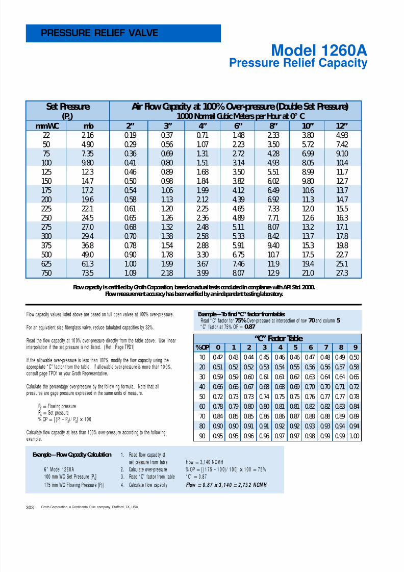
8/13/2019 Groth Catalogue
http://slidepdf.com/reader/full/groth-catalogue 75/175Groth Corporation, a Continental Disc company, Stafford, TX, USA303
Pressure Relief CapacityModel 1260A
PRESSURE RELIEF VALVE
Flow capacity is certifiedby GrothCorporation, basedonactual tests conductedincompliance withAPI Std. 2000.Flow measurement accuracy has beenverifiedby anindependent testinglaboratory.
Flow capacity values listed above are based on full open valves at 100% over-pressure.
For an equivalent size fiberglass valve, reduce tabulated capacities by 32%.
Read the flow capacity at 100% over-pressure directly from the table above. Use linearinterpolation if the set pressure is not listed. (Ref: Page TPD1)
If the allowable over-pressure is less than 100%, modify the flow capacity using theappropriate “ C” factor from the table. If allowable over-pressure is more than 10 0%,consult page TPD1 or your Groth Representative.
Calculate the percentage over-pressure by the follow ing formula . Note that allpressures are gage pressure expressed in the same units of measure.
Pf = Flowing pressurePs = Set pressure% OP= [ (Pf - Ps) / Ps] x 100
Calculate flow capacity at less than 100% over-pressure according to the followingexample.
Example—Flow Capacity Calculation 1. Read flow capacity atset pressure from table Flow= 3,140 NCMH
6” Model 1260A 2. Calculate over-pressure % OP= [ (1 75- 1 0 0) / 1 0 0]x 100= 75%100 mm WC Set Pressure [Ps] 3 . Read “ C” factor from table “ C”= 0.87175 mm WC Flowing Pressure [Pf] 4 . Calculate flow capacity Flow = 0 .87 x 3 , 1 4 0 = 2 ,73 2 NCM H
Example—To find“C” factor fromtable:Read “ C” factor for75% Over-pressure at intersection of row70 and column5“ C” factor at 75% OP= 0.87
“C” Factor Table%OP 0 1 2 3 4 5 6 7 8 9
10 0.42 0.43 0.44 0.45 0.46 0.46 0.47 0.48 0.49 0.5020 0.51 0.52 0.52 0.53 0.54 0.55 0.56 0.56 0.57 0.5830 0.59 0.59 0.60 0.61 0.61 0.62 0.63 0.64 0.64 0.6540 0.66 0.66 0.67 0.68 0.68 0.69 0.70 0.70 0.71 0.7250 0.72 0.73 0.73 0.74 0.75 0.75 0.76 0.77 0.77 0.7860 0.78 0.79 0.80 0.80 0.81 0.81 0.82 0.82 0.83 0.8470 0.84 0.85 0.85 0.86 0.86 0.87 0.88 0.88 0.89 0.8980 0.90 0.90 0.91 0.91 0.92 0.92 0.93 0.93 0.94 0.9490 0.95 0.95 0.96 0.96 0.97 0.97 0.98 0.99 0.99 1.00
Set Pressure Air Flow Capacity at 100% Over-pressure (Double Set Pressure)(Ps) 1000 Normal Cubic Meters per Hour at 0° C
mmWC mb 2” 3” 4” 6” 8” 10” 12”22 2.16 0.19 0.37 0.71 1.48 2.33 3.80 4.9350 4.90 0.29 0.56 1.07 2.23 3.50 5.72 7.4275 7.35 0.36 0.69 1.31 2.72 4.28 6.99 9.10100 9.80 0.41 0.80 1.51 3.14 4.93 8.05 10.4125 12.3 0.46 0.89 1.68 3.50 5.51 8.99 11.7150 14.7 0.50 0.98 1.84 3.82 6.02 9.80 12.7175 17.2 0.54 1.06 1.99 4.12 6.49 10.6 13.7
200 19.6 0.58 1.13 2.12 4.39 6.92 11.3 14.7225 22.1 0.61 1.20 2.25 4.65 7.33 12.0 15.5250 24.5 0.65 1.26 2.36 4.89 7.71 12.6 16.3275 27.0 0.68 1.32 2.48 5.11 8.07 13.2 17.1300 29.4 0.70 1.38 2.58 5.33 8.42 13.7 17.8375 36.8 0.78 1.54 2.88 5.91 9.40 15.3 19.8500 49.0 0.90 1.78 3.30 6.75 10.7 17.5 22.7625 61.3 1.00 1.99 3.67 7.46 11.9 19.4 25.1750 73.5 1.09 2.18 3.99 8.07 12.9 21.0 27.3

8/13/2019 Groth Catalogue
http://slidepdf.com/reader/full/groth-catalogue 76/175

8/13/2019 Groth Catalogue
http://slidepdf.com/reader/full/groth-catalogue 77/175
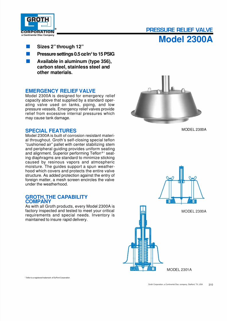
8/13/2019 Groth Catalogue
http://slidepdf.com/reader/full/groth-catalogue 78/175310Groth Corporation, a Continental Disc company, Stafford, TX, USA
MODEL 2300A
MODEL 2301A
■ Sizes 2” through 12”■
Pressure settings 0.5 oz/in2
to 15 PSIG■ Available in aluminum (type 356),carbon steel, stainless steel andother materials.
EMERGENCY RELIEF VALVEModel 2300A is designed for emergency reliefcapacity above that supplied by a standard oper-ating valve used on tanks, piping, and lowpressure vessels. Emergency relief valves providerelief from excessive internal pressures whichmay cause tank damage.
SPECIAL FEATURESModel 2300A is built of corrosion resistant materi-al throughout. Groth’s self-closing special teflon“cushioned air” pallet with center stabilizing stemand peripheral guiding provides uniform seatingand alignment. Superior performing Teflon ® 1 seat-ing diaphragms are standard to minimize stickingcaused by resinous vapors and atmosphericmoisture. The guides support a spun weather-hood which covers and protects the entire valvestructure. As added protection against the entry offoreign matter, a mesh screen encircles the valveunder the weatherhood.
GROTH,THE CAPABILITYCOMPANYAs with all Groth products, every Model 2300A isfactory inspected and tested to meet your criticalrequirements and special needs. Inventory ismaintained to insure rapid delivery.
1 Teflon is a registered trademark of DuPont Corporation.
MODEL 2300A
PRESSURE RELIEF VALVE
Model 2300A

8/13/2019 Groth Catalogue
http://slidepdf.com/reader/full/groth-catalogue 79/175
Specifications subject to change without notice. Certified dimensions available upon request.
* * 0 . 5 o z / i n 2
( 2 . 2 g m
/ c m 2 )
W E I G H T L O A D E D
MODEL # SIZE MATERIAL OPTIONS
2300A Weight Loaded2301A Spring Loaded
02"Thru12"
Pallet MaterialSeat Material
* Body Material
O = No OptionsZ = Special OptionsO = No Jacket
J = Steam JacketS = SpacerH = Steam Jacket and SpacerDiaphragm Material (Seat):
B = Buna-N T = Teflon ® 1
V = Viton ®
Z = Special
1 = Aluminum#
3 = Carbon Steel5 = 316 SS6 = Vinyl Ester Resin7 = FuranZ = Special
EXAMPLE
Indicates a 2" Model 2300A with Aluminum Body and Seat, 316 SS Pallet, Teflon ® 1 Seat Diaphragm and no other options.
Include model number and setting when ordering.For special options, consult factory.When ordering steam jacket, include steam pressure / temperature.
* Stainless steel guides and stems are standard with aluminum and carbonsteel bodies. Stainless steel seats standard with carbon steel bodies.
# Aluminum body not available on 230 1A. N O T E S
2 0 0 20 13 1 5 00T
1 6 o z / i n 2
W E I G H T L O A D E D
( 7 0 . 3 g m
/ c m 2 )
1 5 P S I G S P R I N G L O A D E D
( 1 . 0 5 k g . / c m 2 )
‡ On spring-loaded valves, change to model 2301A. † Larger sizes available - consult factory. * 150#A.N.S.I. drilling compatibility, F.F. on aluminumand R.F. on carbon steel and stainless steel alloys.Fiberglass dimensions on request. **Some sizes require non-ferrous components to achieve 0.5 oz/ sq. in. setting.
A
BB
AA
B
A
Maximum Minimum A AA B BB Approx. ShipSize*† Set Set Diameter Diameter Height Height Wt. Lbs.Flange Pressure Pressure (mm) (mm) (mm) (mm) (Aluminum)
2” 9 ” 9 ” 6 ” 16 ” 12(50 mm) (241) (241) (168) (419) (5 kg)
3” 11 ” 13” 8 ” 18 ” 15(80 mm) (292) (330) (219) (467) (7 kg)
4” 13” 13” 10 ” 22 ” 20(100 mm) (330) (330) (268) (572) (9 kg)
6” 19” 19 ” 15” 30 ” 30(150 mm) (482) (495) (381) (784) (14 kg)
8” 23 ” 23 ” 16 ” 35 ” 45(200 mm) (600) (597) (422) (899) (20 kg)
10” 30 ” 25 ” 17” 41 ” 65(250 mm) (781) (648) (431) (1051) (30 kg)
12” 36” 25 ” 18” 42 ” 100(300 mm) (914) (648) (457) (1076) (45 kg
3/81/2
3/81/23/4
3/85/81/25/8
1/21/2
1/29/16
5/85/81/2
1/25/81/21/2
Groth Corporation, a Continental Disc company, Stafford, TX, USA311
SPECIFICATIONS
HOW TO ORDERFor easy ordering, select proper model numbers
1 Teflon is a registered trademark of DuPont Corporation.

8/13/2019 Groth Catalogue
http://slidepdf.com/reader/full/groth-catalogue 80/175
Flow capacity is certifiedby GrothCorporation, basedonactual tests conductedincompliance withAPI Std. 2000.Flow measurement accuracy has beenverifiedby anindependent testinglaboratory.
Flow capacity values listed above are based on full open valves at 100% over-pressure.
For an equivalent size fiberglass valve, reduce tabulated capacities by 32%.
Read the flow capacity at 100% over-pressure directly from the table above. Use linearinterpolation if the set pressure is not listed. (Ref: Page TPD1)
If the allowable over-pressure is less than 100%, modify the flow capacity using theappropriate “ C” factor from the table. If allowable over-pressure is more than 10 0%,consult page TPD1 or your Groth Representative.
Calculate the percentage over-pressure by the follow ing formul a. Note that allpressures are gage pressure expressed in the same units of measure.
Pf = Flowing pressurePs = Set pressure% OP= [ (Pf - Ps) / Ps] x 100
Calculate flow capacity at less than 100% over-pressure according to the followingexample.
Example—Flow Capacity Calculation 1. Read flow capacity atset pressure from table Flow= 125,000 SCFH
6” Model 2300A 2. Calculate over-pressure % OP= [ (7- 4 )/ 4 ]x 100= 75%4 In WC set pressure [Ps] 3 . Read “ C” factor from table “ C”= 0.877 In WC flowing pressure [ Pf] 4 . Calculate flow capacity Flow = 0 .87 x 1 2 5 , 0 0 0 = 108,750 SCFH
Example—To find“C” factor fromtable:Read “ C” factor for75% Over-pressure at intersection of row70 and column5“ C” factor at 75% OP= 0.87
312Groth Corporation, a Continental Disc c ompany, Stafford, TX, USA
Pressure Relief CapacityModel 2300A
PRESSURE RELIEF VALVE
“C” Factor Table%OP 0 1 2 3 4 5 6 7 8 9
10 0.42 0.43 0.44 0.45 0.46 0.46 0.47 0.48 0.49 0.5020 0.51 0.52 0.52 0.53 0.54 0.55 0.56 0.56 0.57 0.5830 0.59 0.59 0.60 0.61 0.61 0.62 0.63 0.64 0.64 0.6540 0.66 0.66 0.67 0.68 0.68 0.69 0.70 0.70 0.71 0.7250 0.72 0.73 0.73 0.74 0.75 0.75 0.76 0.77 0.77 0.7860 0.78 0.79 0.80 0.80 0.81 0.81 0.82 0.82 0.83 0.8470 0.84 0.85 0.85 0.86 0.86 0.87 0.88 0.88 0.89 0.8980 0.90 0.90 0.91 0.91 0.92 0.92 0.93 0.93 0.94 0.9490 0.95 0.95 0.96 0.96 0.97 0.97 0.98 0.99 0.99 1.00
Set Pressure Air Flow Capacity at 100% Over-pressure (Double Set Pressure)(Ps) 1000 Standard Cubic Feet per Hour at 60° F
In WC Oz/ Sq In 2” 3” 4” 6” 8” 10” 12”0.87 0.50 6.98 15.4 26.1 58.5 88.4 143 2111.00 0.58 7.50 16.5 28.0 62.8 95.0 154 2271.73 1.00 9.85 21.7 36.8 82.5 125 203 2982.00 1.16 10.6 23.3 39.6 88.6 134 218 3202.60 1.50 12.1 26.6 45.1 101 153 248 3653.00 1.73 12.9 28.6 48.4 108 164 266 3923.46 2.00 13.9 30.7 52.0 116 176 285 420
4.00 2.31 14.9 33.0 55.8 125 189 307 4516.00 3.47 18.2 40.4 68.2 152 230 374 5508.00 4.62 21.0 46.6 78.5 175 265 430 63310.0 5.78 23.4 52.1 87.6 194 295 479 70512.0 6.93 25.6 57.1 95.7 212 322 523 76915.0 8.66 28.5 63.8 107 235 358 581 85520.0 11.6 32.7 73.6 122 268 409 665 97925.0 14.4 36.3 82.2 136 296 454 736 108430.0 17.3 39.5 89.9 148 321 492 799 1177

8/13/2019 Groth Catalogue
http://slidepdf.com/reader/full/groth-catalogue 81/175
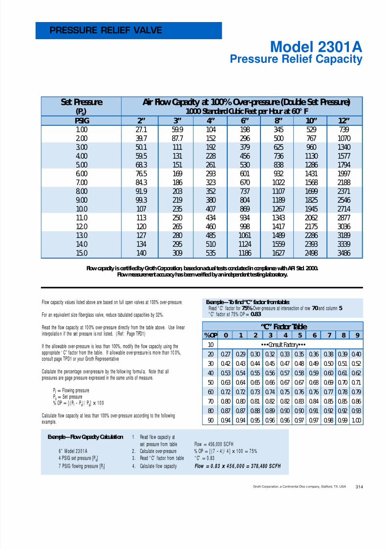
8/13/2019 Groth Catalogue
http://slidepdf.com/reader/full/groth-catalogue 82/175314Groth Corporation, a Continental Disc c ompany, Stafford, TX, USA
Pressure Relief CapacityModel 2301A
PRESSURE RELIEF VALVE
Flow capacity is certifiedby GrothCorporation, basedonactual tests conductedincompliance withAPI Std. 2000.Flow measurement accuracy has beenverifiedby anindependent testinglaboratory.
Flow capacity values listed above are based on full open valves at 100% over-pressure.
For an equivalent size fiberglass valve, reduce tabulated capacities by 32%.
Read the flow capacity at 100% over-pressure directly from the table above. Use linearinterpolation if the set pressure is not listed. (Ref: Page TPD1)
If the allowable over-pressure is less than 100%, modify the flow capacity using theappropriate “ C” factor from the table. If allowable over-pressure is more than 10 0%,consult page TPD1 or your Groth Representative.
Calculate the percentage over-pressure by the follow ing formul a. Note that allpressures are gage pressure expressed in the same units of measure.
Pf = Flowing pressurePs = Set pressure% OP= [ (Pf - Ps) / Ps] x 100
Calculate flow capacity at less than 100% over-pressure according to the followingexample.
Example—Flow Capacity Calculation 1. Read flow capacity atset pressure from table Flow= 456,000 SCFH
6” Model 2301A 2. Calculate over-pressure % OP= [ (7- 4 )/ 4 ]x 100= 75%4 PSIG set pressure [Ps] 3 . Read “ C” factor from table “ C”= 0.837 PSIG flowing pressure [Pf] 4 . Calculate flow capacity Flow = 0 .83 x 4 5 6 , 0 0 0 = 378,480 SCFH
Example—To find“C” factor fromtable:Read “ C” factor for75% Over-pressure at intersection of row70 and column5“ C” factor at 75% OP= 0.83
Set Pressure Air Flow Capacity at 100% Over-pressure (Double Set Pressure)(Ps) 1000 Standard Cubic Feet per Hour at 60° FPSIG 2” 3” 4” 6” 8” 10” 12”1.00 27.1 59.9 104 198 345 529 7392.00 39.7 87.7 152 296 500 767 10703.00 50.1 111 192 379 625 960 13404.00 59.5 131 228 456 736 1130 15775.00 68.3 151 261 530 838 1286 17946.00 76.5 169 293 601 932 1431 19977.00 84.3 186 323 670 1022 1568 2188
8.00 91.9 203 352 737 1107 1699 23719.00 99.3 219 380 804 1189 1825 254610.0 107 235 407 869 1267 1945 271411.0 113 250 434 934 1343 2062 287712.0 120 265 460 998 1417 2175 303613.0 127 280 485 1061 1489 2286 318914.0 134 295 510 1124 1559 2393 333915.0 140 309 535 1186 1627 2498 3486
“C” Factor Table%OP 0 1 2 3 4 5 6 7 8 9
10 •••Consult Factory•••20 0.27 0.29 0.30 0.32 0.33 0.35 0.36 0.38 0.39 0.4030 0.42 0.43 0.44 0.45 0.47 0.48 0.49 0.50 0.51 0.5240 0.53 0.54 0.55 0.56 0.57 0.58 0.59 0.60 0.61 0.62
50 0.63 0.64 0.65 0.66 0.67 0.67 0.68 0.69 0.70 0.7160 0.72 0.72 0.73 0.74 0.75 0.76 0.76 0.77 0.78 0.7970 0.80 0.80 0.81 0.82 0.82 0.83 0.84 0.85 0.85 0.8680 0.87 0.87 0.88 0.89 0.90 0.90 0.91 0.92 0.92 0.9390 0.94 0.94 0.95 0.96 0.96 0.97 0.97 0.98 0.99 1.00

8/13/2019 Groth Catalogue
http://slidepdf.com/reader/full/groth-catalogue 83/175Groth Corporation, a Continental Disc company, Stafford, TX, USA315
Pressure Relief CapacityModel 2301A
PRESSURE RELIEF VALVE
Flow capacity is certifiedby GrothCorporation, basedonactual tests conductedincompliance withAPI Std. 2000.Flow measurement accuracy has beenverifiedby anindependent testinglaboratory.
Flow capacity values listed above are based on full open valves at 100% over-pressure.
For an equivalent size fiberglass valve, reduce tabulated capacities by 32%.
Read the flow capacity at 100% over-pressure directly from the table above. Use linearinterpolation if the set pressure is not listed. (Ref: Page TPD1)
If the allowable over-pressure is less than 100%, modify the flow capacity using theappropriate “ C” factor from the table. If allowable over-pressure is more than 10 0%,consult page TPD1 or your Groth Representative.
Calculate the percentage over-pressure by the follow ing formula . Note that allpressures are gage pressure expressed in the same units of measure.
Pf = Flowing pressurePs = Set pressure% OP= [ (Pf - Ps) / Ps] x 100
Calculate flow capacity at less than 100% over-pressure according to the followingexample.
Example—Flow Capacity Calculation 1. Read flow capacity atset pressure from table Flow= 17,100 NCMH
6” Model 2301A 2. Calculate over-pressure % OP= [ (0 .7- 0 .4 ) / 0 . 4]x 100= 75%0.4 BarG Set Pressure [Ps] 3 . Read “ C” factor from table “ C”= 0.830.7 BarG Flowing Pressure [Pf] 4 . Calculate flow capacity Flow = 0 .83 x 1 7 , 1 0 0 = 14 ,1 93 NCM H
Example—To find“C” factor fromtable:Read “ C” factor for75% Over-pressure at intersection of row70 and column5“ C” factor at 75% OP= 0.83
Set Pressure Air Flow Capacity at 100% Over-pressure (Double Set Pressure)(Ps) 1000 Normal Cubic Meters per Hour at 0° CBarG 2” 3” 4” 6” 8” 10” 12”0.07 0.80 1.76 3.05 5.83 10.1 15.5 21.70.10 0.97 2.13 3.70 7.13 12.2 18.8 26.20.15 1.21 2.67 4.64 9.05 15.2 23.4 32.70.20 1.43 3.16 5.48 10.8 17.9 27.4 38.30.25 1.63 3.60 6.25 12.5 20.3 31.1 43.40.30 1.82 4.02 6.98 14.0 22.5 34.5 48.20.35 2.00 4.42 7.68 15.6 24.6 37.8 52.7
0.40 2.18 4.81 8.34 17.1 26.6 40.8 57.00.45 2.35 5.18 8.99 18.6 28.5 43.8 61.10.50 2.51 5.54 9.62 20.0 30.4 46.6 65.10.55 2.67 5.89 10.2 21.4 32.2 49.4 68.90.60 2.83 6.24 10.8 22.8 33.9 52.0 72.70.70 3.13 6.90 12.0 25.6 37.3 57.1 79.80.80 3.42 7.55 13.1 28.3 40.4 62.0 86.60.90 3.70 8.17 14.2 31.0 43.5 66.7 93.21.00 3.98 8.78 15.2 33.6 46.4 71.2 99.4
“C” Factor Table%OP 0 1 2 3 4 5 6 7 8 9
10 •••Consult Factory•••20 0.27 0.29 0.30 0.32 0.33 0.35 0.36 0.38 0.39 0.4030 0.42 0.43 0.44 0.45 0.47 0.48 0.49 0.50 0.51 0.5240 0.53 0.54 0.55 0.56 0.57 0.58 0.59 0.60 0.61 0.62
50 0.63 0.64 0.65 0.66 0.67 0.67 0.68 0.69 0.70 0.7160 0.72 0.72 0.73 0.74 0.75 0.76 0.76 0.77 0.78 0.7970 0.80 0.80 0.81 0.82 0.82 0.83 0.84 0.85 0.85 0.8680 0.87 0.87 0.88 0.89 0.90 0.90 0.91 0.92 0.92 0.9390 0.94 0.94 0.95 0.96 0.96 0.97 0.97 0.98 0.99 1.00

8/13/2019 Groth Catalogue
http://slidepdf.com/reader/full/groth-catalogue 84/175320Groth Corporation, a Continental Disc company, Stafford, TX, USA
■ Sizes 2” through 12”■ Vacuum settings 0.5 oz/in 2 to 12 PSIG■ Available in aluminum (type 356),
carbon steel, stainless steel andother materials .
■ Modular construction
VACUUM RELIEF VALVEModel 1300A is used when vacuum relief is theonly requirement. Intake relief necessary underworking conditions is achieved by a spring orweight loaded pallet. This feature of the Model1300A reduces the possibility of tank damage.The Model 1300A helps to provide increased fireprotection and safety. Valve size must be select-ed to perform required vacuum relief underoperating and thermal conditions. Flow curves forvacuum relief are provided.
SPECIAL FEATURESModel 1300A offers Groth’s special “cushionedair” seating. Superior performing Teflon ® 1 seatingdiaphragms are standard to minimize stickingcaused by resinous vapors and atmosphericmoisture. The Model 1300A has a self draininghousing body and drip rings to protect seatingsurfaces from condensate and freezing. Thisdesign also avoids vacuum buildup due to bind-ing or clogging of the vent. Metal-to-metal,Buna-N, Viton ® and other seating diaphragmscan be provided when required.
GROTH,THE CAPABILITYCOMPANYAs with all Groth products, every Model 1300A isfactory inspected and tested to meet your criticalrequirements and special needs. Inventory ismaintained to insure rapid delivery.
1 Teflon is a registered trademark of DuPont Corporation.
MODEL 1300A
MODEL 1300A
MODEL 1301A
VACUUM RELIEF VALVE
Model 1300A

8/13/2019 Groth Catalogue
http://slidepdf.com/reader/full/groth-catalogue 85/175321 Groth Corporation, a Continental Disc company, Stafford, TX, USA
†
W.P. =Working Pressure.‡
On spring loaded valves, change model number. 150#A.N.S.I. drilling compatibility, F.F. on aluminumand R.F. on carbon steel and stainless steel alloys.Fiberglass dimensions on request. 16 oz/ in 2 set with spacer. S.S. set weights-Consult Factory. *Some sizes require non-ferrous components to achieve 0.5 oz./ sq. in. setting.
Specifications subject to change without notice. Certified dimensions available upon request.
MODEL # SIZE MATERIAL OPTIONS
1300A Weight Loaded1301A Spring Loaded 02"Thru12"
Pallet MaterialSeat Material* Body Material
O = No OptionsZ = Special OptionsO = No Jacket
J = Steam JacketS = SpacerH = Steam Jacket and SpacerDiaphragm Material (Seat):
B = Buna-N T = Teflon ® 1
V = Viton ®
M = Metal-to-MetalZ = Special
1 = Aluminum3 = Carbon Steel5 = 316 SS6 = Vinyl Ester Resin7 = FuranZ = Special
EXAMPLE
Indicates a 2" Model 1300A with Aluminum Body and Seat, 316 SS Pallet, Teflon ® 1 Seat Diaphragm and no other options.
Include model number and setting when ordering.For special options, consult factory.When ordering steam jacket, include steam pressure / temperature.
* Stainless steel guides and stems are standard with aluminum and carbonsteel bodies. N
O T E S
1 0 0 20 13 1 5 00TA
1 2 P S I G S P R I N G L O A D E D
( 0 . 8 4 k g . / c m 2 )
A
C
BB
* 0 . 5 o z / i n 2
W E I G H T L O A D E D
( 2 . 2 0 g m . / c m 2
)
B
See TPD2 forVacuumSettings
and MAWP
Max. Set Max. Set Min. SetVacuum Vacuum Vacuum Max. W.P. † Min. Vac. A B BB C Approx. Ship.
Size Weight Spring Weight for Min. Vac. Setting vs. Length Height Height Width Wt. Lbs.Loaded Loaded Loaded Setting Max. W.P. † (mm) (mm) (mm) (mm) (Aluminum)
2” 12 oz/ in 2 115/8” 67/8” 14” 6” 15(50 mm) (52.7 gm/cm 2) (295) (174) (356) (152) (7 kg)
3” 11 oz/ in 2 153/4” 73/4” 16 1/4” 73/4” 21(80 mm) (48.3 gm/cm 2) (400) (196) (413) (197) (10 kg)
4” 11 oz/ in 2 171/4” 95/8” 19 7/8” 9” 32(100 mm) (48.3 gm/cm 2) (438) (244) (505) (229) (14 kg)
6” 16 oz/ in 2 231/2” 11 7/8” 27” 12” 61(150 mm) (70.3 gm/cm 2) (597) (301) (686) (305) (28 kg)
8” 16 oz/ in 2 281/2” 15 1/2” 31 7/8” 14 1/2” 81(200 mm) (70.3 gm/cm 2) (724) (393) (810) (368) (37 kg)
10” 16 oz/ in 2 331/4” 18 5/8” 37 7/8” 16 1/2” 121(250 mm) (70.3 gm/cm 2) (845) (473) (962) (419) (55 kg)
12” 16 oz/ in 2 371/4” 21 5/8” 42” 19” 165(300 mm) (70.3 gm/cm 2) (946) (549) (1067) (483) (75 kg)
SPECIFICATIONS
HOW TO ORDERFor easy ordering, select proper model numbers
1 Teflon is a registered trademark of DuPont Corporation.

8/13/2019 Groth Catalogue
http://slidepdf.com/reader/full/groth-catalogue 86/175
Flow capacity is certifiedby GrothCorporation, basedonactual tests conductedincompliance withAPI Std. 2000.Flow measurement accuracy has beenverifiedby anindependent testinglaboratory.
Flow capacity values listed above are based on full open valves at 100% over-vacuum.
For an equivalent size fiberglass valve, reduce tabulated capacities by 32%.
Read the flow capacity at 10 0% over-vacuum directly from th e table above. Use linearinterpolation if the set vacuum is not listed. (Ref: Page TPD1)
If the allowable over-vacuum is less than 10 0%, modify t he flow capacity using theappropriate “ C” factor from the table. If allowable over-vacuum is more than 10 0%,consult page TPD1 or your Groth Representative.
Calculate the percentage over-vacuum by the following form ula. Note that allpressures are gage pressure expressed in the same units of measure.
Pf = Flowing pressurePs = Set pressure% OV= [ (Pf - Ps) / Ps] x 100
Calculate flow capacity at less than 100% over-vacuum according to the followingexample.
Example—Flow Capacity Calculation 1. Read flow capacity atset vacuum from table Flow= 74,0 00 SCFH
6” Model 1300A 2. Calculate over-vacuum % OV= [ (7- 4 )/ 4 ]x 100= 75%4 In WC set vacuum [Ps] 3 . Read “ C” factor from table “ C”= 0.877 In WC flowing vacuum [Pf] 4 . Calculate flow capacity Flow = 0 .87 x 7 4 , 0 0 0 = 64 ,38 0 SCFH
Example—To find“C” factor fromtable:Read “ C” factor for75% Over-vacuum at intersection of row70 and column5“ C” factor at 75% OV= 0.87
322Groth Corporation, a Continental Disc c ompany, Stafford, TX, USA
Vacuum Relief CapacityModel 1300A
VACUUM RELIEF VALVE
“C” Factor Table%OV 0 1 2 3 4 5 6 7 8 9
10 0.42 0.43 0.44 0.45 0.46 0.46 0.47 0.48 0.49 0.5020 0.51 0.52 0.52 0.53 0.54 0.55 0.56 0.56 0.57 0.5830 0.59 0.59 0.60 0.61 0.61 0.62 0.63 0.64 0.64 0.6540 0.66 0.66 0.67 0.68 0.68 0.69 0.70 0.70 0.71 0.7250 0.72 0.73 0.73 0.74 0.75 0.75 0.76 0.77 0.77 0.7860 0.78 0.79 0.80 0.80 0.81 0.81 0.82 0.82 0.83 0.8470 0.84 0.85 0.85 0.86 0.86 0.87 0.88 0.88 0.89 0.8980 0.90 0.90 0.91 0.91 0.92 0.92 0.93 0.93 0.94 0.9490 0.95 0.95 0.96 0.96 0.97 0.97 0.98 0.99 0.99 1.00
Set Vacuum Air Flow Capacity at 100% Over-vacuum(Double Set Vacuum)(Ps) 1000 Standard Cubic Feet per Hour at 60° F
In WC Oz/ Sq In 2” 3” 4” 6” 8” 10” 12”0.87 0.50 4.70 10.3 16.0 34.7 60.5 91.1 1291.00 0.58 5.05 11.0 17.2 37.3 65.0 97.9 1381.73 1.00 6.63 14.5 22.6 49.0 85.3 129 1822.00 1.16 7.12 15.6 24.2 52.6 91.6 138 1952.60 1.50 8.10 17.7 27.6 59.8 104 157 2223.00 1.73 8.70 19.0 29.6 64.2 112 169 2383.46 2.00 9.33 20.4 31.8 68.9 120 181 256
4.00 2.31 10.0 21.9 34.1 74.0 129 194 2746.00 3.47 12.2 26.7 41.5 90.1 157 237 3348.00 4.62 14.0 30.6 47.7 103 180 272 38410.0 5.78 15.6 34.0 53.0 115 200 302 42712.0 6.93 17.0 37.1 57.8 125 218 329 46515.0 8.66 18.8 41.1 64.0 139 242 365 51620.0 11.6 21.4 46.8 72.9 158 276 415 58725.0 14.4 23.6 51.5 80.3 174 304 457 64630.0 17.3 25.4 55.6 86.6 188 327 493 697

8/13/2019 Groth Catalogue
http://slidepdf.com/reader/full/groth-catalogue 87/175

8/13/2019 Groth Catalogue
http://slidepdf.com/reader/full/groth-catalogue 88/175324Groth Corporation, a Continental Disc company, Stafford, TX, USA
Vacuum Relief CapacityModel 1301A
VACUUM RELIEF VALVE
Flow capacity is certifiedby GrothCorporation, basedonactual tests conductedincompliance withAPI Std. 2000.Flow measurement accuracy has beenverifiedby anindependent testinglaboratory.
Flow capacity values listed above are based on full open valves at 100% over-vacuum.
For an equivalent size fiberglass valve, reduce tabulated capacities by 32%.
Read the flow capacity at 10 0% over-vacuum directly from th e table above. Use linearinterpolation if the set vacuum is not listed. (Ref: Page TPD1)
If the allowable over-vacuum is less than 10 0%, modify t he flow capacity using theappropriate “ C” factor from the table. If allowable over-vacuum is more than 10 0%,consult page TPD1 or your Groth Representative.
Calculate the percentage over-vacuum by the following form ula. Note that allpressures are gage pressure expressed in the same units of measure.
Pf = Flowing pressurePs = Set pressure% OV= [ (Pf - Ps) / Ps] x 100
Calculate flow capacity at less than 100% over-vacuum according to the followingexample.
Example—Flow Capacity Calculation 1. Read flow capacity atset vacuum from table Flow= 166,000 SCFH
6” Model 1301A 2. Calculate over-vacuum % OV= [ (3 .50- 2 .0) / 2 .0 ]x 100= 75%2 PSIG set vacuum [Ps] 3 . Read “ C” factor from table “ C”= 0.833.5 PSIG flowing vacuum [Pf] 4 . Calculate flow capacity Flow = 0 .83 x 1 6 6 , 0 0 0 = 137,780 SCFH
Example—To find“C” factor fromtable:Read “ C” factor for75% Over-vacuum at intersection of row70 and column5“ C” factor at 75% OV= 0.83
Set Vacuum Air Flow Capacity at 100% Over-vacuum(Double Set Vacuum)(Ps) 1000 Standard Cubic Feet per Hour at 60° FPSIG 2” 3” 4” 6” 8” 10” 12”1.00 13.8 30.5 52.9 120 197 302 4221.10 14.5 31.9 55.4 126 206 316 4421.20 15.1 33.2 57.7 131 215 330 4601.30 15.7 34.5 59.9 136 223 342 4781.40 16.2 35.7 62.0 141 231 355 4951.50 16.8 36.9 64.0 145 239 366 5111.75 18.0 39.6 68.7 156 256 393 548
2.00 19.1 42.0 73.0 166 272 417 5822.25 20.1 44.3 76.9 174 286 439 6132.50 21.0 46.3 80.4 183 300 460 6412.75 21.9 48.2 83.7 190 312 478 6673.00 22.7 49.9 86.6 197 323 495 6913.25 23.4 51.4 89.3 203 333 511 7133.50 24.0 52.8 91.8 208 342 525 732
>3.50 CONSULT FACTORY FOR VACUUM SETTINGS GREATER THAN 3.5 PSI
“C” Factor Table%OV 0 1 2 3 4 5 6 7 8 9
10 •••Consult Factory•••20 0.27 0.29 0.30 0.32 0.33 0.35 0.36 0.38 0.39 0.4030 0.42 0.43 0.44 0.45 0.47 0.48 0.49 0.50 0.51 0.5240 0.53 0.54 0.55 0.56 0.57 0.58 0.59 0.60 0.61 0.62
50 0.63 0.64 0.65 0.66 0.67 0.67 0.68 0.69 0.70 0.7160 0.72 0.72 0.73 0.74 0.75 0.76 0.76 0.77 0.78 0.7970 0.80 0.80 0.81 0.82 0.82 0.83 0.84 0.85 0.85 0.8680 0.87 0.87 0.88 0.89 0.90 0.90 0.91 0.92 0.92 0.9390 0.94 0.94 0.95 0.96 0.96 0.97 0.97 0.98 0.99 1.00

8/13/2019 Groth Catalogue
http://slidepdf.com/reader/full/groth-catalogue 89/175Groth Corporation, a Continental Disc company, Stafford, TX, USA325
Vacuum Relief CapacityModel 1301A
PRESSURE RELIEF VALVE
Flow capacity is certifiedby GrothCorporation, basedonactual tests conductedincompliance withAPI Std. 2000.Flow measurement accuracy has beenverifiedby anindependent testinglaboratory.
Flow capacity values listed above are based on full open valves at 100% over-vacuum.
For an equivalent size fiberglass valve, reduce tabulated capacities by 32%.
Read the flow capacity at 10 0% over-vacuum directly from the table above. Use linearinterpolation if the set vacuum is not listed. (Ref: Page TPD1)
If the allowable over-vacuum is less than 10 0%, modify the flow capacity using theappropriate “ C” factor from the table. If allowable over-vacuum is more than 10 0%,consult page TPD1 or your Groth Representative.
Calculate the percentage over-vacuum by the following form ula. Note that allpressures are gage pressure expressed in the same units of measure.
Pf = Flowing pressurePs = Set pressure% OV= [ (Pf - Ps) / Ps] x 100
Calculate flow capacity at less than 100% over-vacuum according to the followingexample.
Example—Flow Capacity Calculation 1. Read flow capacity atset vacuum from table Flow= 4,530 NCMH
6” Model 1301A 2. Calculate over-vacuum % OV= [ (0 .17- 0 . 12 ) / 0 .12 ]x 100= 42%0.12 BarG Set Vacuum [Ps] 3 . Read “ C” factor from table “ C”= 0.550.17 BarG Flowing Vacuum [Pf] 4 . Calculate flow capacity Flow = 0 .55 x 4 , 5 3 0 = 2,492 NCM H
Example—To find“C” factor fromtable:Read “ C” factor for42% Over-vacuum at intersection of row40 and column2“ C” factor at 42% OV= 0.55
Set Vacuum Air Flow Capacity at 100% Over-vacuum(Double Set Vacuum)(Ps) 1000 Normal Cubic Meters per Hour at 0° CBarG 2” 3” 4” 6” 8” 10” 12”0.07 0.41 0.90 1.55 3.52 5.77 8.87 12.40.10 0.48 1.06 1.83 4.16 6.83 10.5 14.60.11 0.51 1.11 1.92 4.35 7.14 11.0 15.30.12 0.53 1.15 1.99 4.53 7.43 11.4 15.90.13 0.55 1.20 2.07 4.69 7.70 11.8 16.50.14 0.56 1.24 2.14 4.85 7.96 12.2 17.10.15 0.58 1.27 2.20 5.00 8.21 12.6 17.6
0.16 0.60 1.31 2.27 5.14 8.44 13.0 18.10.17 0.61 1.35 2.33 5.28 8.66 13.3 18.60.18 0.63 1.38 2.38 5.41 8.88 13.6 19.00.19 0.64 1.41 2.44 5.53 9.08 13.9 19.40.20 0.66 1.44 2.49 5.65 9.27 14.2 19.80.22 0.68 1.49 2.58 5.86 9.62 14.8 20.60.24 0.70 1.54 2.67 6.05 9.93 15.2 21.3
>0.24 CONSULT FACTORY FOR VACUUM SETTINGS GREATER THAN 0.24 BARG
“C” Factor Table%OV 0 1 2 3 4 5 6 7 8 9
10 •••Consult Factory•••20 0.27 0.29 0.30 0.32 0.33 0.35 0.36 0.38 0.39 0.4030 0.42 0.43 0.44 0.45 0.47 0.48 0.49 0.50 0.51 0.5240 0.53 0.54 0.55 0.56 0.57 0.58 0.59 0.60 0.61 0.62
50 0.63 0.64 0.65 0.66 0.67 0.67 0.68 0.69 0.70 0.7160 0.72 0.72 0.73 0.74 0.75 0.76 0.76 0.77 0.78 0.7970 0.80 0.80 0.81 0.82 0.82 0.83 0.84 0.85 0.85 0.8680 0.87 0.87 0.88 0.89 0.90 0.90 0.91 0.92 0.92 0.9390 0.94 0.94 0.95 0.96 0.96 0.97 0.97 0.98 0.99 1.00
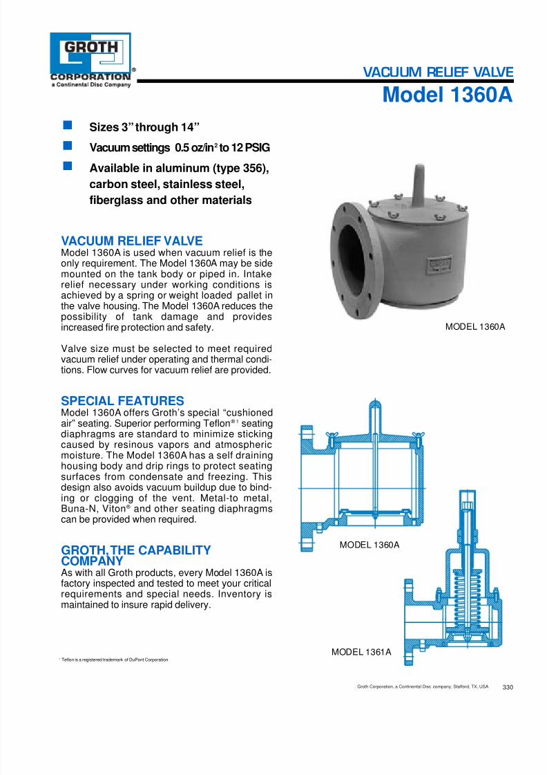
8/13/2019 Groth Catalogue
http://slidepdf.com/reader/full/groth-catalogue 90/175330Groth Corporation, a Continental Disc company, Stafford, TX, USA
MODEL 1361A
MODEL 1360A
■ Sizes 3” through 14”■ Vacuum settings 0.5 oz/in 2 to 12 PSIG■ Available in aluminum (type 356),
carbon steel, stainless steel,fiberglass and other materials
VACUUM RELIEF VALVEModel 1360A is used when vacuum relief is theonly requirement. The Model 1360A may be sidemounted on the tank body or piped in. Intakerelief necessary under working conditions isachieved by a spring or weight loaded pallet inthe valve housing. The Model 1360A reduces thepossibility of tank damage and providesincreased fire protection and safety.
Valve size must be selected to meet requiredvacuum relief under operating and thermal condi-tions. Flow curves for vacuum relief are provided.
SPECIAL FEATURESModel 1360A offers Groth’s special “cushionedair” seating. Superior performing Teflon ® 1 seatingdiaphragms are standard to minimize stickingcaused by resinous vapors and atmosphericmoisture. The Model 1360A has a self draininghousing body and drip rings to protect seatingsurfaces from condensate and freezing. Thisdesign also avoids vacuum buildup due to bind-ing or clogging of the vent. Metal-to metal,Buna-N, Viton ® and other seating diaphragmscan be provided when required.
GROTH,THE CAPABILITYCOMPANYAs with all Groth products, every Model 1360A isfactory inspected and tested to meet your criticalrequirements and special needs. Inventory ismaintained to insure rapid delivery.
1 Teflon is a registered trademark of DuPont Corporation.
MODEL 1360A
VACUUM RELIEF VALVE
Model 1360A

8/13/2019 Groth Catalogue
http://slidepdf.com/reader/full/groth-catalogue 91/175331 Groth Corporation, a Continental Disc c ompany, Stafford, TX, USA
MODEL # SIZE MATERIAL OPTIONS
1360A Weight loaded1361A Spring loaded 03"
Thru14"
Pallet MaterialSeat Material
* Body Material
O = No Options
Z = Special OptionsO = No Jacket
J = Steam JacketS = SpacerH = Steam Jacket and SpacerDiaphragm Material (Seat):
B = Buna-N T = Teflon ® 1
V = Viton ®
Z = Special
1 = Aluminum3 = Carbon Steel5 = 316 SS6 = Vinyl Ester Resin7 = FuranZ = Special
EXAMPLE
Indicates a 3" Model 1360A with Aluminum Body and Seat, 316 SS Pallet, Teflon ® 1 Seat Diaphragm , and no other options.
Include maximum working pressure.Include model number and setting when ordering.For special options, consult factory.When ordering steam jacket, include steam pressure / temperature.
* Stainless steel quides and stems are standard with alum inum and carbonsteel bodies. Stainless steel seats standard with carbon steel bodies.
N O T E S
3 A 0 30 16 1 5 00T
Specifications subject to change without notice. Certified dimensions available upon request.
1
1 2 P S I G S P R I N G L O A D E D V A C U U M
( 0 . 8 4 k g . / c m 2 )
* 0 . 5 o z / i n 2
W E I G H T L O A D E D
( 2 . 2 0 g m . / c m 2
)
B
E
C
A
BB
See TPD2 forVacuumSettings
and MAWP
† W.P. =Working Pressure. ‡ On spring loaded valves, change model number. 150#R.F. drilling compatibility F.F. on aluminumand R.F. on carbon steel and stainless steel alloys.Fiberglass dimensions on request. 16 oz/in 2 set with spacer. S.S. set weights-Consult Factory. *Some sizes require non-ferrous components to achieve 0.5 oz./sq. in. setting.
Max. Set Max. Set Min. Set Max. W.P. † Min. Vac.Vacuum Vacuum Vacuum for Min. Setting A B C E BB Approx. Ship.
Size Weight Spring Weight Vac. vs. Length Height Width Height Wt. Lbs.Flange Loaded Loaded Loaded Setting Max. W.P. † (mm) (mm) (mm) (mm) (mm) (Aluminum)
3” 11 oz/in 2 8 ” 9 ” 7 ” 5 ” 16 ” 12(80 mm) (48.2 gm/cm 2) (219) (235) (191) (140) (413) (6 kg)
4” 13 oz/in 2 10” 11 ” 9” 6” 19 ” 17(100 mm) (57.0 gm/cm 2) (254) (292) (229) (152) (502) (8 kg)
6” 16 oz/in 2 11” 14 ” 11” 6 ” 24 ” 23(150 mm) (70.3 gm/cm 2) (279) (362) (279) (165) (626) (10 kg)
8” 16 oz/in 2 14 ” 17 ” 13 ” 8 ” 32 ” 42(200 mm) (70.3 gm/cm 2) (368) (451) (343) (216) (832) (19 kg)
10” 16 oz/ in 2 18” 21 ” 16” 10 ” 38” 71(250 mm) (70.3 gm/cm 2) (457) (539) (406) (273) (965) (32 kg)
12” 16 oz/ in 2 20 ” 25 ” 19” 12 ” 45 ” 83(300 mm) (70.3 gm/cm 2) (527) (654) (483) (318) (1153) (38 kg)
14” 16 oz/ in2
24 ” 29 ” 21” 15” 48 ” 118(350 mm) (70.3 gm/cm 2) (629) (742) (533) (381) (1238) (54 kg)
3/41/43/4
3/81/23/43/4
3/41/4
3/41/21/23/41/2
5/81/21}4
3/41/2
1/41/21/21/45/8
SPECIFICATIONS
HOW TO ORDERFor easy ordering, select proper model numbers
1 Teflon is a registered trademark of DuPont Corporation.

8/13/2019 Groth Catalogue
http://slidepdf.com/reader/full/groth-catalogue 92/175
Flow capacity is certifiedby GrothCorporation, basedonactual tests conductedincompliance withAPI Std. 2000.Flow measurement accuracy has beenverifiedby anindependent testinglaboratory.
Flow capacity values listed above are based on full open valves at 100% over-vacuum.
For an equivalent size fiberglass valve, reduce tabulated capacities by 32%.
Read the flow capacity at 10 0% over-vacuum directly from th e table above. Use linearinterpolation if the set vacuum is not listed. (Ref: Page TPD1)
If the allowable over-vacuum is less than 10 0%, modify t he flow capacity using theappropriate “ C” factor from the table. If allowable over-vacuum is more than 10 0%,consult page TPD1 or your Groth Representative.
Calculate the percentage over-vacuum by the following form ula. Note that allpressures are gage pressure expressed in the same units of measure.
Pf = Flowing pressurePs = Set pressure% OV= [ (Pf - Ps) / Ps] x 100
Calculate flow capacity at less than 100% over-vacuum according to the followingexample.
Example—Flow Capacity Calculation 1. Read flow capacity atset vacuum from table Flow= 59,3 00 SCFH
6” Model 1360A 2. Calculate over-vacuum % OV= [ (7- 4 )/ 4 ]x 100= 75%4 In WC set vacuum [Ps] 3 . Read “ C” factor from table “ C”= 0.877 In WC flowing vacuum [Pf] 4 . Calculate flow capacity Flow = 0 .87 x 5 9 , 3 0 0 = 1,5 91 SCFH
Example—To find“C” factor fromtable:Read “ C” factor for75% Over-vacuum at intersection of row70 and column5“ C” factor at 75% OV= 0.87
332Groth Corporation, a Continental Disc c ompany, Stafford, TX, USA
Vacuum Relief CapacityModel 1360A
VACUUM RELIEF VALVE
“C” Factor Table%OV 0 1 2 3 4 5 6 7 8 9
10 0.42 0.43 0.44 0.45 0.46 0.46 0.47 0.48 0.49 0.5020 0.51 0.52 0.52 0.53 0.54 0.55 0.56 0.56 0.57 0.5830 0.59 0.59 0.60 0.61 0.61 0.62 0.63 0.64 0.64 0.6540 0.66 0.66 0.67 0.68 0.68 0.69 0.70 0.70 0.71 0.7250 0.72 0.73 0.73 0.74 0.75 0.75 0.76 0.77 0.77 0.7860 0.78 0.79 0.80 0.80 0.81 0.81 0.82 0.82 0.83 0.8470 0.84 0.85 0.85 0.86 0.86 0.87 0.88 0.88 0.89 0.8980 0.90 0.90 0.91 0.91 0.92 0.92 0.93 0.93 0.94 0.9490 0.95 0.95 0.96 0.96 0.97 0.97 0.98 0.99 0.99 1.00
Set Vacuum Air Flow Capacity at 100% Over-vacuum(Double Set Vacuum)(Ps) 1000 Standard Cubic Feet per Hour at 60° F
In WC Oz/ Sq In 3” 4” 6” 8” 10” 12” 14”0.87 0.50 8.01 14.8 27.8 57.4 99.4 136 1821.00 0.58 8.61 15.9 29.9 61.6 107 146 1951.73 1.00 11.3 20.8 39.3 80.9 140 192 2572.00 1.16 12.1 22.4 42.2 86.9 151 207 2762.60 1.50 13.8 25.5 48.0 98.9 171 235 3143.00 1.73 14.8 27.3 51.5 106 184 252 3373.46 2.00 15.9 29.3 55.3 114 197 271 361
4.00 2.31 17.1 31.5 59.3 122 212 291 3886.00 3.47 20.8 38.4 72.3 149 258 354 4728.00 4.62 23.9 44.0 83.0 171 297 407 54210.0 5.78 26.6 49.0 92.3 190 330 452 60312.0 6.93 28.9 53.4 101 207 359 492 65715.0 8.66 32.1 59.1 111 230 398 546 72820.0 11.6 36.5 67.3 127 261 453 621 82925.0 14.4 40.2 74.1 140 288 499 684 91330.0 17.3 43.4 80.0 151 311 538 738 985

8/13/2019 Groth Catalogue
http://slidepdf.com/reader/full/groth-catalogue 93/175Groth Corporation, a Continental Disc company, Stafford, TX, USA333
Vacuum Relief CapacityModel 1360A
VACUUM RELIEF VALVE
Flow capacity is certifiedby GrothCorporation, basedonactual tests conductedincompliance withAPI Std. 2000.Flow measurement accuracy has beenverifiedby anindependent testinglaboratory.
Flow capacity values listed above are based on full open valves at 100% over-vacuum.
For an equivalent size fiberglass valve, reduce tabulated capacities by 32%.
Read the flow capacity at 10 0% over-vacuum directly from the table above. Use linearinterpolation if the set vacuum is not listed. (Ref: Page TPD1)
If the allowable over-vacuum is less than 10 0%, modify the flow capacity using theappropriate “ C” factor from the table. If allowable over-vacuum is more than 10 0%,consult page TPD1 or your Groth Representative.
Calculate the percentage over-vacuum by the following form ula. Note that allpressures are gage pressure expressed in the same units of measure.
Pf = Flowing pressurePs = Set pressure% OV= [ (Pf - Ps) / Ps] x 100
Calculate flow capacity at less than 100% over-vacuum according to the followingexample.
Example—Flow Capacity Calculation 1. Read flow capacity atset vacuum from table Flow= 1,660 NCMH
6” Model 1360A 2. Calculate over-vacuum % OV= [ (1 75- 1 0 0) / 1 0 0]x 100= 75%100 mm WC Set Vacuum [ Ps] 3 . Read “ C” factor from table “ C”= 0.87175 mm WC Flowing Vacuum [ Pf] 4 . Calculate flow capacity Flow = 0 .87 x 1 , 6 6 0 = 1 ,44 4 NCM H
“C” Factor Table%OV 0 1 2 3 4 5 6 7 8 9
10 0.42 0.43 0.44 0.45 0.46 0.46 0.47 0.48 0.49 0.5020 0.51 0.52 0.52 0.53 0.54 0.55 0.56 0.56 0.57 0.5830 0.59 0.59 0.60 0.61 0.61 0.62 0.63 0.64 0.64 0.6540 0.66 0.66 0.67 0.68 0.68 0.69 0.70 0.70 0.71 0.7250 0.72 0.73 0.73 0.74 0.75 0.75 0.76 0.77 0.77 0.7860 0.78 0.79 0.80 0.80 0.81 0.81 0.82 0.82 0.83 0.8470 0.84 0.85 0.85 0.86 0.86 0.87 0.88 0.88 0.89 0.8980 0.90 0.90 0.91 0.91 0.92 0.92 0.93 0.93 0.94 0.9490 0.95 0.95 0.96 0.96 0.97 0.97 0.98 0.99 0.99 1.00
Example—To find“C” factor fromtable:Read “ C” factor for75% Over-vacuum at intersection of row70 and column5“ C” factor at 75% OV= 0.87
Set Vacuum Air Flow Capacity at 100% Over-vacuum(Double Set Vacuum)(Ps) 1000 Normal Cubic Meters per Hour at 0° C
mmWC mb 3” 4” 6” 8” 10” 12” 14”22 2.16 0.23 0.42 0.78 1.62 2.80 3.84 5.1250 4.90 0.34 0.63 1.18 2.43 4.21 5.77 7.7075 7.35 0.41 0.76 1.44 2.97 5.14 7.05 9.41100 9.80 0.48 0.88 1.66 3.42 5.92 8.12 10.8125 12.3 0.53 0.98 1.85 3.81 6.61 9.06 12.1150 14.7 0.58 1.07 2.02 4.16 7.22 9.89 13.2175 17.2 0.63 1.16 2.18 4.49 7.78 10.7 14.2
200 19.6 0.67 1.23 2.32 4.78 8.29 11.4 15.2225 22.1 0.71 1.30 2.45 5.06 8.77 12.0 16.0250 24.5 0.74 1.37 2.58 5.32 9.22 12.6 16.9275 27.0 0.78 1.43 2.70 5.56 9.64 13.2 17.6300 29.4 0.81 1.49 2.81 5.79 10.0 13.8 18.4375 36.8 0.90 1.65 3.12 6.42 11.1 15.3 20.4500 49.0 1.02 1.88 3.55 7.31 12.7 17.4 23.2625 61.3 1.13 2.08 3.91 8.06 14.0 19.1 25.5750 73.5 1.21 2.24 4.22 8.70 15.1 20.7 27.6

8/13/2019 Groth Catalogue
http://slidepdf.com/reader/full/groth-catalogue 94/175334Groth Corporation, a Continental Disc c ompany, Stafford, TX, USA
Vacuum Relief CapacityModel 1361A
VACUUM RELIEF VALVE
Flow capacity is certifiedby GrothCorporation, basedonactual tests conductedincompliance withAPI Std. 2000.Flow measurement accuracy has beenverifiedby anindependent testinglaboratory.
Flow capacity values listed above are based on full open valves at 100% over-vacuum.
For an equivalent size fiberglass valve, reduce tabulated capacities by 32%.
Read the flow capacity at 10 0% over-vacuum directly from th e table above. Use linearinterpolation if the set vacuum is not listed. (Ref: Page TPD1)
If the allowable over-vacuum is less than 10 0%, modify t he flow capacity using theappropriate “ C” factor from the table. If allowable over-vacuum is more than 10 0%,consult page TPD1 or your Groth Representative.
Calculate the percentage over-vacuum by the following form ula. Note that allpressures are gage pressure expressed in the same units of measure.
Pf = Flowing pressurePs = Set pressure% OV= [ (Pf - Ps) / Ps] x 100
Calculate flow capacity at less than 100% over-vacuum according to the followingexample.
Example—Flow Capacity Calculation 1. Read flow capacity atset vacuum from table Flow= 116,000 SCFH
6” Model 1361A 2. Calculate over-vacuum % OV= [ (3 .50- 2 .0) / 2 .0 ]x 100= 75%2 PSIG set vacuum [Ps] 3 . Read “ C” factor from table “ C”= 0.833.5 PSIG flowing vacuum [Pf] 4 . Calculate flow capacity Flow = 0 .83 x 11 6 , 0 0 0 = 96,280 SCFH
Example—To find“C” factor fromtable:Read “ C” factor for75% Over-vacuum at intersection of row70 and column5“ C” factor at 75% OV= 0.83
“C” Factor Table%OV 0 1 2 3 4 5 6 7 8 9
10 •••Consult Factory•••20 0.27 0.29 0.30 0.32 0.33 0.35 0.36 0.38 0.39 0.4030 0.42 0.43 0.44 0.45 0.47 0.48 0.49 0.50 0.51 0.5240 0.53 0.54 0.55 0.56 0.57 0.58 0.59 0.60 0.61 0.62
50 0.63 0.64 0.65 0.66 0.67 0.67 0.68 0.69 0.70 0.7160 0.72 0.72 0.73 0.74 0.75 0.76 0.76 0.77 0.78 0.7970 0.80 0.80 0.81 0.82 0.82 0.83 0.84 0.85 0.85 0.8680 0.87 0.87 0.88 0.89 0.90 0.90 0.91 0.92 0.92 0.9390 0.94 0.94 0.95 0.96 0.96 0.97 0.97 0.98 0.99 1.00
Set Vacuum Air Flow Capacity at 100% Over-vacuum(Double Set Vacuum)(Ps) 1000 Standard Cubic Feet per Hour at 60° FPSIG 3” 4” 6” 8” 10” 12” 14”1.00 22.6 49.8 86.4 196 322 494 6891.10 23.6 52.0 90.2 204 336 516 7201.20 24.5 54.0 93.8 213 349 536 7481.30 25.4 56.0 97.2 220 362 556 7751.40 26.2 57.8 100 227 374 574 8011.50 27.0 59.6 103 234 385 591 8251.75 28.8 63.5 110 250 411 631 880
2.00 30.4 67.0 116 264 433 665 9282.25 31.8 70.1 122 276 453 696 9712.50 33.1 72.8 126 287 471 723 10092.75 34.1 75.2 131 296 486 747 10423.00 35.1 77.3 134 304 500 767 10703.25 35.9 79.0 137 311 511 785 10953.50 36.5 80.5 140 317 520 799 1115
>3.50 CONSULT FACTORY FOR VACUUM SETTINGS GREATER THAN 3.5 PSI

8/13/2019 Groth Catalogue
http://slidepdf.com/reader/full/groth-catalogue 95/175Groth Corporation, a Continental Disc company, Stafford, TX, USA335
Vacuum Relief CapacityModel 1361A
VACUUM RELIEF VALVE
Flow capacity is certifiedby GrothCorporation, basedonactual tests conductedincompliance withAPI Std. 2000.Flow measurement accuracy has beenverifiedby anindependent testinglaboratory.
Flow capacity values listed above are based on full open valves at 100% over-vacuum.
For an equivalent size fiberglass valve, reduce tabulated capacities by 32%.
Read the flow capacity at 10 0% over-vacuum directly from the table above. Use linearinterpolation if the set vacuum is not listed. (Ref: Page TPD1)
If the allowable over-vacuum is less than 10 0%, modify the flow capacity using theappropriate “ C” factor from the table. If allowable over-vacuum is more than 10 0%,consult page TPD1 or your Groth Representative.
Calculate the percentage over-vacuum by the following form ula. Note that allpressures are gage pressure expressed in the same units of measure.
Pf = Flowing pressurePs = Set pressure% OV= [ (Pf - Ps) / Ps] x 100
Calculate flow capacity at less than 100% over-vacuum according to the followingexample.
Example—Flow Capacity Calculation 1. Read flow capacity atset vacuum from table Flow= 3,200 NCMH
6” Model 1361A 2. Calculate over-vacuum % OV= [ (0 .17- 0 . 12 ) / 0 .12 ]x 100= 42%0.12 BarG Set Vacuum [Ps] 3 . Read “ C” factor from table “ C”= 0.550.17 BarG Flowing Vacuum [Pf] 4 . Calculate flow capacity Flow = 0 .55 x 3 , 2 0 0 = 1,76 0 NCM H
Example—To find“C” factor fromtable:Read “ C” factor for42% Over-vacuum at intersection of row40 and column2“ C” factor at 42% OV= 0.55
Set Vacuum Air Flow Capacity at 100% Over-vacuum(Double Set Vacuum)(Ps) 1000 Normal Cubic Meters per Hour at 0° C
BarG 3” 4” 6” 8” 10” 12” 14”0.07 0.66 1.46 2.53 5.74 9.39 14.4 20.20.10 0.77 1.71 2.96 6.72 11.0 16.9 23.70.11 0.81 1.78 3.09 7.00 11.5 17.6 24.70.12 0.84 1.85 3.20 7.26 11.9 18.3 25.60.13 0.86 1.91 3.31 7.50 12.3 18.9 26.40.14 0.89 1.96 3.41 7.72 12.6 19.4 27.20.15 0.91 2.02 3.50 7.93 13.0 19.9 27.9
0.16 0.94 2.07 3.58 8.12 13.3 20.4 28.60.17 0.96 2.11 3.66 8.30 13.6 20.9 29.30.18 0.98 2.15 3.73 8.47 13.9 21.3 29.80.19 0.99 2.19 3.80 8.62 14.1 21.7 30.40.20 1.01 2.23 3.86 8.76 14.3 22.0 30.90.22 1.04 2.29 3.97 9.01 14.7 22.7 31.70.24 1.06 2.34 4.06 9.21 15.1 23.2 32.4
>0.24 CONSULT FACTORY FOR VACUUM SETTINGS GREATER THAN 0.24 BARG
“C” Factor Table%OV 0 1 2 3 4 5 6 7 8 9
10 •••Consult Factory•••20 0.27 0.29 0.30 0.32 0.33 0.35 0.36 0.38 0.39 0.4030 0.42 0.43 0.44 0.45 0.47 0.48 0.49 0.50 0.51 0.5240 0.53 0.54 0.55 0.56 0.57 0.58 0.59 0.60 0.61 0.62
50 0.63 0.64 0.65 0.66 0.67 0.67 0.68 0.69 0.70 0.7160 0.72 0.72 0.73 0.74 0.75 0.76 0.76 0.77 0.78 0.7970 0.80 0.80 0.81 0.82 0.82 0.83 0.84 0.85 0.85 0.8680 0.87 0.87 0.88 0.89 0.90 0.90 0.91 0.92 0.92 0.9390 0.94 0.94 0.95 0.96 0.96 0.97 0.97 0.98 0.99 1.00

8/13/2019 Groth Catalogue
http://slidepdf.com/reader/full/groth-catalogue 96/175
MODEL 5100
■ Sizes 2” through 12”■ Available in carbon steel, stain-
less steel and other materials■ High flow capacity
FREE VENTSModel 5000 Series are designed to be used ontanks containing non-volatile liquids and on ventpipe extremities. Groth Free Vents offer efficientflow capacity for the protection of the tank.
SPECIAL FEATURESModel 5000 Series are built of corrosion resistantmaterials throughout. A wire mesh screen pre-vents foreign matter from entering the tank orpipe opening. Weather hoods are easily remov-able for inspection of vent and wire mesh screen.
GROTH,THE CAPABILITY
COMPANYAs with all Groth products, every Model 5000Series is factory inspected to meet all criticalrequirements and special needs. Inventory ismaintained to insure rapid delivery.
MODEL 5000
MODEL 5100
350Groth Corporation, a Continental Disc company, Stafford, TX, USA
MODEL 5000
FREE VENTS
Model 5000

8/13/2019 Groth Catalogue
http://slidepdf.com/reader/full/groth-catalogue 97/175
MODEL # SIZE MATERIAL OPTIONS
50005100 02"Thru12"
Body Material
O = No OptionsZ = Special Options
3 = Carbon Steel5 = 316 SSZ = Special
EXAMPLE
Indicates a 2" Model 5000 with Carbon Steel and no options.
Include model number when ordering.For special options, consult factory.
N O T E S
5 0 0 20 30 O
Specifications subject to change without notice. Certified dimensions available upon request.
* Larger sizes available on special application.
A
B
BB
AA
MODEL 5000 MODEL 5100AA BB Approx. Ship.
Size* Width Height Wt. Lbs.Flange (Metric) (Metric) (CS / SS)
2” 9 1/2” 53/8” 11(51 mm) (241) (137) (5 kg)
3” 11 1/2” 513/16” 14(76 mm) (292) (148) (6 kg)
4” 13” 6 5/16” 18(102 mm) (330) (160) (8 kg)
6” 17” 7 3/8” 28(152 mm) (432) (187) (13 kg)
8” 19 1/2” 91/4” 42(203 mm) (495) (235) (19 kg)
10” 23 1/2” 10 5/8” 60(254 mm) (597) (270) (27 kg)
12” 25 1/2” 11 1/8” 95(305 mm) (648) (283) (43 kg)
A BSize* Width Height Approx. Ship.Flange (Metric) (Metric) Wt. Lbs.
2” 10 1/4” 67/8” 8(51 mm) (260) (175) (4 kg)
3” 14 1/2” 91/4” 20(76 mm) (368) (235) (9 kg)
4” 18 3/4” 11 3/8” 35(102 mm) (476) (289) (16 kg)
6” 26 7/8” 15 11/16 ” 70(152 mm) (683) (398) (32 kg)
8” 35 1/8” 20 1/8” 135(203 mm) (892) (511) (61 kg)
10” 43 3/8” 24” 235(254 mm) (1102) (610) (107 kg)
12” 51 7/8” 28 7/16” 350(305 mm) (1318) (722) (159 kg)
Groth Corporation, a Continental Disc company, Stafford, TX, USA351
SPECIFICATIONS
HOW TO ORDERFor easy ordering, select proper model numbers

8/13/2019 Groth Catalogue
http://slidepdf.com/reader/full/groth-catalogue 98/175
A i r F l o w
1 0 0 0 S T D c u b i c f e e t p e r h o u r
Tank Pressure - inches W.C.
1. Flow facility and equipment comply with API 2000.2. Flow measurement accuracy verified by an independent research organization.
3. Flow capacity is based on actual tests and certified by Groth
1 2”1 0”8 ”
6 ”
4 ”
2 ”
3 ”
Flow CapacityModel 5000
FREE VENTS
Tank Pressure Air Flow - 1000 Standard Cubic feet per HourInW.C. Oz/ Sq In 2” 3” 4” 6” 8” 10” 12”
1 0.58 3.34 7.34 12.7 28.6 49.6 78.2 1122 1.16 4.72 10.4 17.9 40.5 70.2 111 1593 1.73 5.78 12.7 21.9 49.5 85.9 135 1944 2.31 6.67 14.7 25.3 57.2 99.2 156 2246 3.47 8.17 18.0 31.0 70.0 121 192 2758 4.62 9.44 20.8 35.8 80.9 140 221 31710 5.78 10.5 23.2 40.0 90.4 157 247 354
15 8.66 12.9 28.4 48.9 111 192 303 43420 11.6 14.9 32.8 56.5 128 221 349 50125 14.4 16.7 36.6 63.1 143 248 390 56030 17.3 18.2 40.1 69.1 156 271 427 61335 20.2 19.7 43.3 74.6 169 293 461 66240 23.1 21.0 46.3 79.7 180 313 493 70745 26.0 22.3 49.1 84.5 191 332 523 75050 28.9 23.5 51.7 89.1 201 349 551 79055 31.8 24.6 54.2 93.4 211 366 577 82860 34.7 25.7 56.6 97.5 220 382 603 864
352Groth Corporation, a Continental Disc company, Stafford, TX, USA

8/13/2019 Groth Catalogue
http://slidepdf.com/reader/full/groth-catalogue 99/175
A i r F l o w
1 0 0 0 c u b i c m e t e r s p e r h o u r a t 0 ° C
Tank Pressure - millimeters H 2O
1. Flow facility and equipment comply with API 2000.2. Flow measurement accuracy verified by an independent research organization.
3. Flow capacity is based on actual tests and certified by Groth Corp
12 ”10 ”8”
6”
4”
2”
3”
Flow CapacityModel 5000
FREE VENTS
353 Groth Corporation, a Continental Disc company, Stafford, TX, USA
Tank Pressure Air Flow - 1000 Cubic Meters per Hour at 0°CmmH 2O mb 2” 3” 4” 6” 8” 10” 12”
25 2.45 0.09 0.21 0.36 0.80 1.39 2.20 3.1550 4.90 0.13 0.29 0.50 1.14 1.97 3.11 4.4675 7.35 0.16 0.36 0.62 1.39 2.41 3.81 5.46100 9.80 0.19 0.41 0.71 1.61 2.79 4.40 6.30150 14.7 0.23 0.51 0.87 1.97 3.41 5.38 7.72200 19.6 0.27 0.58 1.01 2.27 3.94 6.21 8.91250 24.5 0.30 0.65 1.12 2.54 4.41 6.95 9.96
375 36.8 0.36 0.80 1.38 3.11 5.39 8.50 12.2500 49.0 0.42 0.92 1.59 3.59 6.23 9.81 14.1625 61.3 0.47 1.03 1.77 4.01 6.96 11.0 15.7750 73.5 0.51 1.13 1.94 4.39 7.62 12.0 17.2875 85.8 0.55 1.22 2.10 4.74 8.22 13.0 18.61000 98.0 0.59 1.30 2.24 5.07 8.79 13.9 19.91125 110 0.63 1.38 2.38 5.37 9.32 14.7 21.11250 123 0.66 1.45 2.50 5.66 9.82 15.5 22.21375 135 0.69 1.52 2.62 5.94 10.3 16.2 23.31500 147 0.72 1.59 2.74 6.20 10.7 16.9 24.3

8/13/2019 Groth Catalogue
http://slidepdf.com/reader/full/groth-catalogue 100/175
A i r F l o w
1 0 0 0 S T D c u b i c f e e t p e r h o u r
Tank Vacuum- inches W.C.
1. Flow facility and equipment comply with API 2000.2. Flow measurement accuracy verified by an independent research organization.
3. Flow capacity is based on actual tests and certified by Groth
12 ”10 ”
8”
6”
4”
2”
3”
Tank Vacuum Air Flow - 1000 Standard Cubic feet per HourIn W.C. Oz/ Sq In 2” 3” 4” 6” 8” 10” 12”
1 0.58 2.78 6.11 10.5 23.8 41.3 65.1 93.42 1.16 3.92 8.63 14.9 33.6 58.3 91.9 1323 1.73 4.80 10.6 18.2 41.1 71.3 112 1614 2.31 5.53 12.2 21.0 47.4 82.3 130 1866 3.47 6.76 14.9 25.6 57.9 100 158 2278 4.62 7.79 17.1 29.5 66.7 116 182 26210 5.78 8.68 19.1 32.9 74.4 129 203 292
15 8.66 10.6 23.2 40.0 90.5 157 247 35520 11.6 12.1 26.6 45.9 104 180 284 40725 14.4 13.4 29.6 51.0 115 200 315 45230 17.3 14.6 32.2 55.4 125 217 343 49135 20.2 15.7 34.5 59.4 134 233 367 52740 23.1 16.6 36.6 63.1 143 247 390 55945 26.0 17.5 38.5 66.4 150 260 411 58950 28.9 18.3 40.3 69.5 157 272 430 61655 31.8 19.1 42.0 72.3 164 284 447 64160 34.7 19.8 43.5 75.0 169 294 463 665
354Groth Corporation, a Continental Disc company, Stafford, TX, USA
Flow CapacityModel 5000
FREE VENTS

8/13/2019 Groth Catalogue
http://slidepdf.com/reader/full/groth-catalogue 101/175
A i r F l o w
1 0 0 0 c u b i c m e t e r s p e r h o u r a t 0 ° C
Tank Vacuum- millimeters H 2O
1. Flow facility and equipment comply with API 2000.2. Flow measurement accuracy verified by an independent research organization.
3. Flow capacity is based on actual tests and certified by Groth Corp
12 ”10 ”8”6”
4”
2”
3”
Groth Corporation, a Continental Disc company, Stafford, TX, USA355
Vacuum Relief CapacityModel 5000
FREE VENTS
Tank Vacuum Air Flow - 1000 Cubic Meters per Hour at 0°CmmH 2O mb 2” 3” 4” 6” 8” 10” 12”
25 2.5 0.08 0.17 0.30 0.67 1.2 1.8 2.650 4.9 0.11 0.24 0.42 0.95 1.6 2.6 3.775 7.4 0.13 0.30 0.51 1.16 2.0 3.2 4.5100 9.8 0.16 0.34 0.59 1.33 2.3 3.6 5.2150 14.7 0.19 0.42 0.72 1.63 2.8 4.5 6.4200 19.6 0.22 0.48 0.83 1.88 3.3 5.1 7.4250 24.5 0.24 0.54 0.92 2.09 3.6 5.7 8.2
375 36.8 0.30 0.65 1.13 2.54 4.4 7.0 10.0500 49.0 0.34 0.75 1.29 2.92 5.1 8.0 11.4625 61.3 0.38 0.83 1.43 3.24 5.6 8.9 12.7750 73.5 0.41 0.90 1.56 3.52 6.1 9.6 13.8875 85.8 0.44 0.97 1.67 3.78 6.6 10.3 14.81000 98.0 0.47 1.03 1.77 4.01 7.0 11.0 15.71125 110 0.49 1.08 1.87 4.23 7.3 11.6 16.61250 123 0.52 1.13 1.96 4.42 7.7 12.1 17.31375 135 0.54 1.18 2.04 4.60 8.0 12.6 18.01500 147 0.56 1.22 2.11 4.77 8.3 13.0 18.7

8/13/2019 Groth Catalogue
http://slidepdf.com/reader/full/groth-catalogue 102/175

8/13/2019 Groth Catalogue
http://slidepdf.com/reader/full/groth-catalogue 103/175
A i r F l o w
1 0 0 0 c u b i c m e t e r s p e r h o u r a t 0 ° C
Tank Pressure -millimeters H 2O
1. Flow facility and equipment comply with API 2000.2. Flow measurement accuracy verified by an independent research organization.
3. Flow capacity is based on actual tests and certified by Groth Corp
1 2”1 0”
8 ”
6 ”
4 ”
2 ”
3 ”
Flow CapacityModel 5100
FREE VENTS
357 Groth Corporation, a Continental Disc company, Stafford, TX, USA
Tank Pressure Air Flow - 1000 Cubic Meters per Hour at 0°CmmH 2O mb 2” 3” 4” 6” 8” 10” 12”
25 2.45 0.11 0.23 0.40 0.91 1.58 2.49 3.5750 4.90 0.15 0.33 0.57 1.29 2.23 3.52 5.0575 7.35 0.18 0.41 0.70 1.58 2.74 4.31 6.19100 9.80 0.21 0.47 0.81 1.82 3.16 4.98 7.14150 14.7 0.26 0.57 0.99 2.23 3.87 6.10 8.75200 19.6 0.30 0.66 1.14 2.58 4.47 7.04 10.1250 24.5 0.34 0.74 1.27 2.88 4.99 7.87 11.3
375 36.8 0.41 0.90 1.56 3.53 6.11 9.64 13.8500 49.0 0.47 1.04 1.80 4.07 7.06 11.1 16.0625 61.3 0.53 1.17 2.01 4.55 7.88 12.4 17.8750 73.5 0.58 1.28 2.20 4.98 8.63 13.6 19.5875 85.8 0.63 1.38 2.38 5.38 9.32 14.7 21.11000 98.0 0.67 1.47 2.54 5.74 10.0 15.7 22.51125 110 0.71 1.56 2.69 6.09 10.6 16.6 23.91250 123 0.75 1.65 2.84 6.42 11.1 17.5 25.21375 135 0.78 1.73 2.97 6.73 11.7 18.4 26.41500 147 0.82 1.80 3.11 7.02 12.2 19.2 27.5

8/13/2019 Groth Catalogue
http://slidepdf.com/reader/full/groth-catalogue 104/175
A i r F l o w
1 0 0 0 S T D c u b i c f e e t p e r h o u r
Tank Vacuum- inches W.C.
1. Flow facility and equipment comply with API 2000.2. Flow measurement accuracy verified by an independent research organization.
3. Flow capacity is based on actual tests and certified by Groth
12 ”10 ”8”
6”
4”
2”
3”
Flow CapacityModel 5100
FREE VENTS
358Groth Corporation, a Continental Disc company, Stafford, TX, USA
Tank Vacuum Air Flow - 1000 Standard Cubic feet per HourIn W.C. Oz/ Sq In 2” 3” 4” 6” 8” 10” 12”
1 0.58 3.06 6.72 11.6 26.2 45.4 71.6 1032 1.16 4.32 9.49 16.4 37.0 64.1 101 1453 1.73 5.28 11.6 20.0 45.2 78.5 124 1774 2.31 6.09 13.4 23.1 52.2 90.5 143 2056 3.47 7.44 16.4 28.2 63.7 111 174 2508 4.62 8.56 18.8 32.5 73.4 127 201 28810 5.78 9.55 21.0 36.2 81.8 142 224 321
15 8.66 11.6 25.5 44.0 99.6 173 272 39020 11.6 13.3 29.3 50.5 114 198 312 44825 14.4 14.8 32.5 56.1 127 220 347 49730 17.3 16.1 35.4 61.0 138 239 377 54135 20.2 17.3 37.9 65.4 148 256 404 58040 23.1 18.3 40.3 69.4 157 272 429 61545 26.0 19.3 42.4 73.1 165 286 452 64850 28.9 20.2 44.4 76.4 173 300 473 67855 31.8 21.0 46.2 79.6 180 312 492 70560 34.7 21.8 47.8 82.5 186 323 510 731

8/13/2019 Groth Catalogue
http://slidepdf.com/reader/full/groth-catalogue 105/175

8/13/2019 Groth Catalogue
http://slidepdf.com/reader/full/groth-catalogue 106/175
MODEL 6000
MODEL 6100
■ Sizes 4” through 10”■ Constructed in aluminum, carbon
steel, stainless steel, andadditional materials.
■ Available in free lift or lock down-cover
■ Designed to assure uniform seating
GAUGE HATCHModel 6000 Series provide access for gauging orobtaining product samples from storage tanks.The Model 6000 also provides pressure relief asemergency venting. The Model 6100 incorpo-rates a positive cover hold down which assures apremium tight seal on tanks with internal pres-sures up to 3 PSIG. Gasketed covers arerecommended on tanks with high pressure set-tings. Model 6100 offers lock down capability.
SPECIAL FEATURESModel 6000 Series is designed with a serratedfoot treadle surface to avoid foot slippage whenopening. This model permits the use of bothhands during gauging or sampling. Gravity willclose the cover upon removal of pressure on thefoot treadle. Groth’s special “cushioned-air” seat-ing or metal-to-metal seatings available.
GROTH,THE CAPABILITYCOMPANYAs with all Groth products, every Model 6000Series is factory inspected and tested to meet
your critical requirements and special needs.Inventory is maintained to insure rapid delivery.
MODEL 6100
360Groth Corporation, a Continental Disc company, Stafford, TX, USA
GAUGE HATCH
Model 6000

8/13/2019 Groth Catalogue
http://slidepdf.com/reader/full/groth-catalogue 107/175
MODEL # SIZE MATERIAL OPTIONS
60006100 04"
Thru10"
Material
O = No OptionsZ = Special OptionsD = Drilled 150 # A.N.S.I.U = Undrilled
Diaphragm Material (Seat):B = Buna-N T = Teflon ® 1
V = Viton ®
M = Metal-to-MetalZ = Special
1 = Aluminum3 = Carbon Steel5 = 316 SSZ = Special
EXAMPLE
Indicates a 4" Model 6000 with Aluminum material, Teflon ® 1 Diaphragm, Drilled Flange and no other options.
Include model number when ordering.For special options, consult factory.
N O T E S
6 0 0 400 1 0DT
Specifications subject to change without notice. Certified dimensions available upon request.
‡ When gauge hatch includes the lock down feature, change model number to 6100. † 150 #A.N.S.I. drilling compatibility, F.F. on aluminum, carbon steel and stainless steel alloys.
A
B
A
B
361 Groth Corporation, a Continental Disc company, Stafford, TX, USA
A B Approx. ShipSize Width Height Wt. Lbs.
(Metric) (Metric) (Aluminum)4” 10” 6” 7
(102 mm) (254) (152) (3 Kg)6” 12 1/2” 8” 10
(152 mm) (318) (203) (5 Kg.)
8” 15” 8” 13(203 mm) (381) (203) (6 Kg)
10” 17 3/4” 9” 17(254 mm) (451) (229) (8 Kg)
SPECIFICATIONS
HOW TO ORDERFor easy ordering, select proper model numbers
1 Teflon is a registered trademark of DuPont Corporation.

8/13/2019 Groth Catalogue
http://slidepdf.com/reader/full/groth-catalogue 108/175
■ Low Cost Design
■ Size 8”■ Constructed in aluminum (type
356) with Buna-N seat insert.■ Available in free lift cover■ Set 2 oz/in 2 in free lift design■ 150# ANSI Flat Face drilled flange
GAUGE HATCHModel 6200 provides access for gauging orobtaining product samples from storage tanks.The Model 6200 also provides pressure relief asemergency venting.
SPECIAL FEATURESModels 6200 will stay in the full open positionwhich will permit the use of both hands duringgauging or sampling. Units are mass produced intype 356 aluminum cover and base with a Buna-N seat insert. Optional seals are available.
GROTH,THE CAPABILITYCOMPANYAs with all Groth products, every Model 6200 isfactory inspected and tested to meet your criticalrequirements and special needs. Inventory ismaintained to insure rapid delivery.
MODEL 6200
MODEL 6200
370Groth Corporation, a Continental Disc c ompany, Stafford, TX, USA
GAUGE HATCH
Model 6200

8/13/2019 Groth Catalogue
http://slidepdf.com/reader/full/groth-catalogue 109/175
A B Approx.Size Width Height Ship.
(mm) (mm) Wt. Lbs. (kg)
8” 13 1/2” 31/2” 10(200) (343) (89) (5)
MODEL # SIZE MATERIAL OPTIONS
620008" Material
O = No OptionsZ = Special Options
Diaphragm Material (Seat):B = Buna-N* (Insert)V = Viton ®
* Buna-N is Standard;Teflon seal not available
1 = Aluminum
EXAMPLE
Indicates a 8" Model 6200 with Aluminum material, Buna-N insert.
Include model number when ordering.For special options, consult factory.
N O T E S
6 0 0 802 1 0B
Specifications subject to change without notice. Certified dimensions available upon request.
‡ When gauge hatch includes the lock down feature, change model number to 6300. †150 #flat face A.N.S.I. drilling compatibility.
A
B
371 Groth Corporation, a Continental Disc company, Stafford, TX, USA
SPECIFICATIONS
HOW TO ORDERFor easy ordering, select proper model numbers

8/13/2019 Groth Catalogue
http://slidepdf.com/reader/full/groth-catalogue 110/175

8/13/2019 Groth Catalogue
http://slidepdf.com/reader/full/groth-catalogue 111/175400Groth Corporation, a Continental Disc company, Stafford, TX, USA
MODEL 2050A
MODEL 2050A (PRESSURE & VACUUM
MODEL 2000A (PRESSURE)
■ Sizes 16,” 20” and 24”■
Pressure settings 1.5 - 16 oz/in2
■ Vacuum settings 0.5 - 4 oz/in 2
■ Available in carbon steel,stainless steel, fiberglass andother materials
■ Easy access manway combinedwith emergency relief.
EMERGENCY PRESSURERELIEF VALVEModel 2000A is designed to provide emergencyrelief capacity beyond that furnished by the nor-mal operating pressure relief valve on the tank.The valve protects the tank against rupture orexplosion that could result from excessive inter-nal pressures caused by fire, etc. As excessivepressure builds up, Model 2000A relieves, thenreseats when over pressure has been dissipated.Removable stops can be provided which restrictthe lift of the cover.
SPECIAL FEATURESModel 2000A is built of corrosion resistant mate-rials throughout. A restraining cable connects thehead and flange and also serves as a groundingcable. Groth’s special Teflon ® 1 “cushioned air”pallet and peripheral guiding insures properalignment and integrity of seating. Model 2050Aincorporates a vacuum breaker.
GROTH, THE CAPABILITYCOMPANYAs with all Groth products, every Model 2000A isfactory inspected and tested to meet your criticalrequirements and special needs. Inventory ismaintained to insure rapid delivery.
1 Teflon is a registered trademark of DuPont Corporation.
MODEL 2000A
Section 4:400-423.qxd, June, 2002, 2.5m
EMERGENCY PRESSURE RELIEF VALVE
Model 2000A
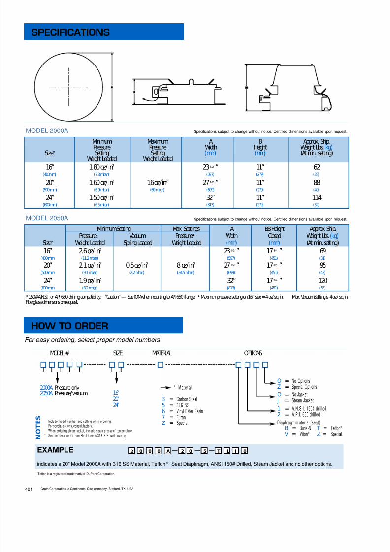
8/13/2019 Groth Catalogue
http://slidepdf.com/reader/full/groth-catalogue 112/175
Minimum Maximum A B Approx. Ship.Pressure Pressure Width Height † Weight Lbs. (kg)
Size* Setting Setting (mm) (mm) (At min. setting)Weight Loaded Weight Loaded
16” 1.80 oz/ in 2 23 ” 11” 62(400mm) (7.8 mbar) (597) (279) (28)
20” 1.60 oz/ in 2 16 oz/in 2 27 ” 11” 88(500 mm) (6.9 mbar) (69 mbar) (699) (279) (40)
24” 1.50 oz/ in 2 32” 11” 114(600 mm) (6.5 mbar) (813) (279) (52)
1/2
1/2
MinimumSetting Max. Settings A BB Height Approx. Ship.Pressure Vacuum Pressure ▲ Width Closed Weight Lbs. (kg)
Size* Weight Loaded Spring Loaded Weight Loaded (mm) (mm) (At min. setting)16” 2.6 oz/in 2 23 ” 17 ” 69
(400 mm) (11.2 mbar) (597) (451) (31)
20” 2.1 oz/in 2 0.5 oz/in 2 8 oz/in 2 27 ” 17 ” 95(500 mm) (9.1 mbar) (2.2 mbar) (34.5 mbar) (699) (451) (43)
24” 1.9 oz/in 2 32” 17 ” 120(600 mm) (8.2 mbar) (813) (451) (55)
3/4
3/41/2
3/41/2
401 Groth Corporation, a Continental Disc company, Stafford, TX, USA
* 150#A.N.S.I. or API 650 drilling compatibility. “Caution” — See IOMwhen mounting to API 650 flange. ▲ Maximumpressure setting on 16” size =4 oz/sq. in. Max. VacuumSetting is 4 oz./ sq. in.Fiberglass dimensions on request.
MODEL # SIZE MATERIAL OPTIONS
2000A Pressure only2050A Pressure/vacuum 16"
20"24"
* Mater ia lO = No OptionsZ = Special OptionsO = No Jacket
J = Steam Jacket1 = A.N.S.I. 150# drilled2 = A.P.I. 650 drilledDiaphragm m aterial (seat)
B = Buna-N T = Teflon ® 1
V = Viton ® Z = Special
3 = Carbon Steel5 = 316 SS6 = Vinyl Ester Resin7 = FuranZ = Special
EXAMPLE
indicates a 20" Model 2000A with 316 SS Material, Teflon ® 1 Seat Diaphragm, ANSI 150# Drilled, Steam Jacket and no other options.
Include model number and setting when ordering.For special options, consult factory.When ordering steam jacket, include steam pressure/ temperature.
* Seat material on Carbon Steel base is 316 S.S. weld overlay N O T E S
0 0 2 00 52 T 0 J1
MODEL 2000A Specifications subject to change without notice. Certified dimensions available upon request.
MODEL 2050A Specifications subject to change without notice. Certified dimensions available upon request.
A
SPECIFICATIONS
HOW TO ORDERFor easy ordering, select proper model numbers
1 Teflon is a registered trademark of DuPont Corporation.

8/13/2019 Groth Catalogue
http://slidepdf.com/reader/full/groth-catalogue 113/175402Groth Corporation, a Continental Disc company, Stafford, TX, USA
EMERGENCY PRESSURE RELIEF VALVE
Emergency Pressure Relief CapacityModel 2000A
Flow capacity values listed above are based on full open valves at 100% over-pressure.
Vacuum flow rating applies only to Model 2050A.
Read the flow capacity at 10 0% over-pressure directly from the table above. Use linearinterpolation if the set pressure is not listed. (Ref: Page TPD1)
If the allowable over-pressure is less than 100%, modify the flow capacity using theappropriate “ C” factor from the table. If allowable over-pressure is more than 10 0%, consultpage TPD1 or your Groth Representative. Note: Vacuum capacity is modified using the “C”factor on page 412.
Calculate the percentage over-pressure by the followin g formula. Note that all pressures are
gage pressure expressed in the same units of measure.
Pf = Flowing pressurePs = Set pressure% OP= [ (Pf - Ps) / Ps] x 100
Calculate flow capacity at less than 100% over-pressure according to the following example.
Example—Flow Capacity Calculation 1. Read flow capacity atset pressure from table Flow= 829,000 SCFH
20” Model 2000A 2. Calculate over-pressure % OP= [ (7- 4 )/ 4 ]x 100= 75%4 In WC set pressure [Ps] 3. Read “ C” factor from table “ C”= 0.957 In WC flowing pressure [ Pf] 4. Calculate flow capacity Flow = 0 .95 x 8 2 9 , 0 0 0 = 787,550 SCFH
Example—To find“C” factor fromtable:Read “ C” factor for75% Over-pressure at intersection of row70 and column5“ C” factor at 75% OP= 0.95
2050Only
Use“C”
FactorCharton
Page412for
VacuumFlow
Type 2000A2050A
Pressure
Vacuum
“C” Factor Table - Pressure Only%OP 0 1 2 3 4 5 6 7 8 9
10 0.70 0.71 0.71 0.72 0.72 0.73 0.73 0.74 0.74 0.7520 0.75 0.76 0.76 0.77 0.77 0.78 0.78 0.79 0.79 0.8030 0.80 0.81 0.81 0.82 0.82 0.83 0.83 0.84 0.84 0.8540 0.85 0.86 0.86 0.87 0.87 0.88 0.88 0.89 0.89 0.9050 0.90 0.90 0.90 0.91 0.91 0.91 0.91 0.91 0.92 0.9260 0.92 0.92 0.92 0.93 0.93 0.93 0.93 0.93 0.94 0.9470 0.94 0.94 0.94 0.95 0.95 0.95 0.95 0.95 0.96 0.9680 0.96 0.96 0.96 0.97 0.97 0.97 0.97 0.97 0.98 0.9890 0.98 0.98 0.98 0.99 0.99 0.99 0.99 0.99 1.00 1.00
Set Pressure/ Vacuum Air Flow Capacity at 100% Over-pressure (Double Set Pressure/ Vacuum)(Ps) 1000 Standard Cubic Feet per Hour at 60° F
In WC Oz/ Sq In 16” Pressure 20” Pressure 24” Pressure All Vacuum0.87 0.50 * 651.73 1.00 * 912.60 1.50 422 668 9703.00 1.73 454 718 10433.46 2.00 * 487 771 1120 1294.00 2.31 524 829 12044.33 2.50 545 862 12525.00 2.89 585 926 13455.19 3.00 * 597 944 1371 1576.93 4.00 * 689 1090 1583 18010.4 6.00 843 1334 193713.9 8.00 973 1539 223617.3 10.0 1087 1720 249820.8 12.0 1190 1883 273524.2 14.0 1284 2033 295227.7 16.0 1372 2172 3154
* Standardvacuumsettings, consult factory for other settings.Flow capacity is certifiedby GrothCorporation, basedonactual tests conductedincompliance withAPI Std. 2000.
Flow measurement accuracy has beenverifiedby anindependent testinglaboratory.

8/13/2019 Groth Catalogue
http://slidepdf.com/reader/full/groth-catalogue 114/175403 Groth Corporation, a Continental Disc company, Stafford, TX, USA
Example—Flow Capacity Calculation 1. Read flow capacity atset pressure from table Flow= 23,300 NCMH
20” Model 2000A 2. Calculate over-pressure % OP= [ (175- 1 0 0) / 1 0 0]x 100= 75%100 mm WC Set Pressure [Ps] 3 . Read “ C” factor from table “ C”= 0.95175 mm WC Flowing Pressure [Pf] 4 . Calculate flow capacity Flow = 0 .95 x 2 3 , 3 0 0 = 22,1 35 NCM H
Example—To find“C” factor fromtable:Read “ C” factor for75% Over-pressure at intersection of row70 and column5“ C” factor at 75% OP= 0.95
2050Only
Flow capacity values listed above are based on full open valves at 100% over-pressure.
Vacuum flow rating applies only to Model 2050A.
Read the flow capacity at 1 00 % over-pressure directly from t he table above. Use linearinterpolation if the set pressure is not listed. (Ref: Page TPD1)
If the allowable over-pressure is less than 100%, modify the flow capacity using theappropriate “ C” factor from the table. If allowable over-pressure is more than 10 0%, consultpage TPD1 or your Groth Representative. Note: Vacuum capacity is modified using the “C”factor on page 413.
Calculate the percentage over-pressure by the following formula. Note that all pressures are
gage pressure expressed in the same units of measure.
Pf = Flowing pressurePs = Set pressure% OP= [ (Pf - Ps) / Ps] x 100
Calculate flow capacity at less than 100% over-pressure according to the following example.
Use“C”
FactorCharton
Page413for
VacuumFlow
EMERGENCY PRESSURE RELIEF VALVE
Emergency Pressure Relief CapacityModel 2000A
Set Pressure/ Vacuum Air Flow Capacity at 100% Over-pressure (Double Set Pressure/ Vacuum)(Ps) 1000 Standard Cubic Meters per Hour at 0° C
mmWC mb 16” Pressure 20” Pressure 24” Pressure All Vacuum22 2.16 * 1.8344 4.31 * 2.5888 8.63 * 13.8 21.9 31.7 3.63100 9.80 14.7 23.3 33.8132 12.9 * 16.9 26.8 38.9 4.42176 17.3 * 19.5 30.9 44.9 5.08200 19.6 20.8 32.9 47.8250 24.5 23.2 36.8 53.4300 29.4 25.5 40.3 58.5350 34.3 27.5 43.5 63.2400 39.2 29.4 46.5 67.5500 49.0 32.8 51.9 75.4600 58.8 35.9 56.9 82.6700 68.6 38.8 61.4 89.1
“C” Factor Table - Pressure Only%OP 0 1 2 3 4 5 6 7 8 9
10 0.70 0.71 0.71 0.72 0.72 0.73 0.73 0.74 0.74 0.7520 0.75 0.76 0.76 0.77 0.77 0.78 0.78 0.79 0.79 0.8030 0.80 0.81 0.81 0.82 0.82 0.83 0.83 0.84 0.84 0.8540 0.85 0.86 0.86 0.87 0.87 0.88 0.88 0.89 0.89 0.9050 0.90 0.90 0.90 0.91 0.91 0.91 0.91 0.91 0.92 0.9260 0.92 0.92 0.92 0.93 0.93 0.93 0.93 0.93 0.94 0.9470 0.94 0.94 0.94 0.95 0.95 0.95 0.95 0.95 0.96 0.9680 0.96 0.96 0.96 0.97 0.97 0.97 0.97 0.97 0.98 0.9890 0.98 0.98 0.98 0.99 0.99 0.99 0.99 0.99 1.00 1.00
Type 2000A2050A
Pressure
Vacuum
* Standardvacuumsettings, consult factory for other settings.
Flow capacity is certifiedby GrothCorporation, basedonactual tests conductedincompliance withAPI Std. 2000.Flow measurement accuracy has beenverifiedby anindependent testinglaboratory.

8/13/2019 Groth Catalogue
http://slidepdf.com/reader/full/groth-catalogue 115/175410Groth Corporation, a Continental Disc company, Stafford, TX, USA
■ Sizes 16,” 20” and 24”
■ Pressure settings 1 - 15 PSIG■ Available in carbon steel, stain-
less steel and other materials■ Unique design – spring loaded
cover
EMERGENCY PRESSURERELIEF VALVEModel 2100 is designed to provide emergencyrelief capacity beyond that furnished by the nor-mal operating pressure relief valve on the tank.The Valve protects the tank against rupture orexplosion that could result from excessive inter-nal pressures caused by fire, etc. Model 2100 isdesigned to be self-closing. As excessive pres-sure builds up, Model 2100 relieves, then reseatswhen the overpressure has been dissipated.
SPECIAL FEATURESModel 2100 is built of corrosion resistant materi-als throughout. It is designed with independentlyadjustable springs which load the cover and keepthe valve tightly sealed until emergency relief isrequired. Model 2100 features Viton ® seating toinsure a tight seal.
GROTH, THE CAPABILITYCOMPANYAs with all Groth products, every Model 2100 isfactory inspected and tested to meet your criticalrequirements and special needs. Inventory ismaintained to insure rapid delivery.
MODEL 2100
EMERGENCY PRESSURE RELIEF VALVE
Model 2100

8/13/2019 Groth Catalogue
http://slidepdf.com/reader/full/groth-catalogue 116/175411 Groth Corporation, a Continental Disc company, Stafford, TX, USA
Specifications subject to change without notice. Certified dimensions available upon request.
* 150#A.N.S.I. drilling compatibility, or API 650 drilled Flange option
MODEL # SIZE MATERIAL OPTIONS
210016"20"24"
* Mater ia l O = No Options
Z = Special OptionsO = No Jacket
J = Steam Jacket1 = A.N.S.I. 150# drilled2 = A.P.I. 650 drilledO-Ring Material (Seat)#
B = Buna-NV = Viton ®
Z = Special
3 = Carbon Steel5 = 316 SS8 = HastelloyZ = Special
EXAMPLEindicates a 20" Model 2100 with 316 SS Material, Viton ® Seat O-Ring, ANSI 150# Drilled, Steam Jacket and no other options.
Include model number and setting when ordering.For special options, consult factory.When ordering steam jacket, include steam pressure/ temperature.
* Seat material on Carbon Steel base is 31 6 Stainless Steel weld overlay.# Teflon O-ring not available. N
O T E S
0 0 2 01 52 V 0 J1
Size* Minimum Maximum A B Approx. ShippingFlange Setting Setting Width Height Weight Lbs. (kg)(Metric) Pressure Pressure
Spring Loaded Spring Loaded (mm) (mm) (At min. set.) (At max. set.)
16” 36 ” 23” 310 490(400 mm) (933) (584) (141) (223)
20” 1 PSIG 15 PSIG 36 ” 23” 335 500(500 mm) (69 mbar) (1.03 bar) (933) (584) (152) (227)
24” 40 ” 27” 420 670(600 mm) (1035) (686) (190) (304)
3/4
3/4
3/4
SPECIFICATIONS
HOW TO ORDERFor easy ordering, select proper model numbers

8/13/2019 Groth Catalogue
http://slidepdf.com/reader/full/groth-catalogue 117/175
Flow capacity values listed above are based on full open valves at 100% over-pressure.
Read the flow capacity at 10 0% over-pressure directly from the table above. Use linearinterpolation if the set pressure is not listed. (Ref: Page TPD1)
If the allowable over-pressure is less than 100%, modify the flow capacity using theappropriate “ C” factor from the table. If allowable over-pressure is more than 100 %,consult page TPD1 or your Groth Representative.
Calculate the percentage over-pressure by the follow ing formula. Note that allpressures are gage pressure expressed in the same units of measure.
Pf = Flowing pressurePs = Set pressure% OP= [ (Pf - Ps) / Ps] x 100
Calculate flow capacity at less than 100% over-pressure according to the followingexample.
Example—Flow Capacity Calculation 1. Read flow capacity atset pressure from table Flow= 1,877,000 SCFH
20” Model 2100 2. Calculate over-pressure % OP= [ (7- 4 )/ 4 ]x 100= 75%4 PSIG set pressure [Ps] 3 . Read “ C” factor from table “ C”= 0.837 PSIG flowing pressure [Pf] 4 . Calculate flow capacity Flow = 0 .83 x 1 , 8 7 7 , 0 0 0 = 1 ,55 7,91 0 SCFH
Example—To find“C” factor fromtable:Read “C” factor for75% Over-pressure at intersection of row70 and column5“ C” factor at 75% OP= 0.83
412Groth Corporation, a Continental Disc company, Stafford, TX, USA
EMERGENCY PRESSURE RELIEF VALVE
Emergency Pressure Relief CapacityModel 2100
“C” Factor Table%OP 0 1 2 3 4 5 6 7 8 9
10 •••Consult Factory•••20 0.27 0.29 0.30 0.32 0.33 0.35 0.36 0.38 0.39 0.4030 0.42 0.43 0.44 0.45 0.47 0.48 0.49 0.50 0.51 0.5240 0.53 0.54 0.55 0.56 0.57 0.58 0.59 0.60 0.61 0.6250 0.63 0.64 0.65 0.66 0.67 0.67 0.68 0.69 0.70 0.7160 0.72 0.72 0.73 0.74 0.75 0.76 0.76 0.77 0.78 0.7970 0.80 0.80 0.81 0.82 0.82 0.83 0.84 0.85 0.85 0.86
80 0.87 0.87 0.88 0.89 0.90 0.90 0.91 0.92 0.92 0.9390 0.94 0.94 0.95 0.96 0.96 0.97 0.97 0.98 0.99 1.00
Set Pressure Air Flow Capacity at 100% Over-pressure (Double Set Pressure)(Ps) 1000 Standard Cubic Feet per Hour at 60° FPSIG 16” 20” 24”1.00 609 952 13712.00 857 1340 19303.00 1045 1633 23524.00 1201 1877 27045.00 1337 2089 30096.00 1458 2278 32827.00 1568 2450 3529
8.00 1669 2608 37579.00 1763 2755 396910.0 1851 2893 416711.0 1934 3022 435312.0 2012 3145 453013.0 2087 3261 469714.0 2158 3372 485715.0 2226 3478 5010

8/13/2019 Groth Catalogue
http://slidepdf.com/reader/full/groth-catalogue 118/175
Flow capacity values listed above are based on full open valves at 100% over-pressure.
Read the flow capacity at 10 0% over-pressure directly from the table above. Use linearinterpolation if the set pressure is not listed. (Ref: Page TPD1)
If the allowable over-pressure is less than 100%, modify the flow capacity using theappropriate “ C” factor from the table. If allowable over-pressure is more than 100 %,consult page TPD1 or your Groth Representative.
Calculate the percentage over-pressure by the following form ula. Note that allpressures are gage pressure expressed in the same units of measure.
Pf = Flowing pressurePs = Set pressure% OP= [ (Pf - Ps) / Ps] x 100
Calculate flow capacity at less than 100% over-pressure according to the followingexample.
Example—Flow Capacity Calculation 1. Read flow capacity atset pressure from table Flow= 64,900 NCMH
20” Model 2100 2. Calculate over-pressure % OP= [ (0 .7- 0 . 4) / 0 .4 ]x 100= 75%0.4 BarG Set Pressure [Ps] 3 . Read “ C” factor from table “ C”= 0.830.7 BarG Flowing Pressure [Pf] 4 . Calculate flow capacity Flow = 0 .83 x 6 4 , 9 0 0 = 53 ,867 NCM H
Example—To find“C” factor fromtable:Read “ C” factor for75% Over-pressure at intersection of row70 and column5“ C” factor at 75% OP= 0.83
413 Groth Corporation, a Continental Disc company, Stafford, TX, USA
EMERGENCY PRESSURE RELIEF VALVE
Emergency Pressure Relief CapacityModel 2100
Set Pressure Air Flow Capacity at 100% Over-pressure (Double Set Pressure)(Ps) 1000 Standard Cubic Meters per Hour at 0°CBarG 16” 20” 24”0.07 17.8 27.8 39.90.10 21.2 33.1 47.60.15 25.8 40.4 58.10.20 29.7 46.5 66.80.25 33.1 51.8 74.50.30 36.2 56.6 81.30.35 38.9 60.9 87.50.40 41.5 64.9 93.30.45 43.9 68.6 98.60.50 46.1 72.1 1040.55 48.2 75.4 1080.60 50.2 78.5 1130.70 53.9 84.3 1210.80 57.3 89.6 1290.90 60.5 94.6 1361.00 63.4 99.2 143
“C” Factor Table%OP 0 1 2 3 4 5 6 7 8 9
10 •••Consult Factory•••20 0.27 0.29 0.30 0.32 0.33 0.35 0.36 0.38 0.39 0.4030 0.42 0.43 0.44 0.45 0.47 0.48 0.49 0.50 0.51 0.5240 0.53 0.54 0.55 0.56 0.57 0.58 0.59 0.60 0.61 0.6250 0.63 0.64 0.65 0.66 0.67 0.67 0.68 0.69 0.70 0.7160 0.72 0.72 0.73 0.74 0.75 0.76 0.76 0.77 0.78 0.79
70 0.80 0.80 0.81 0.82 0.82 0.83 0.84 0.85 0.85 0.8680 0.87 0.87 0.88 0.89 0.90 0.90 0.91 0.92 0.92 0.9390 0.94 0.94 0.95 0.96 0.96 0.97 0.97 0.98 0.99 1.00

8/13/2019 Groth Catalogue
http://slidepdf.com/reader/full/groth-catalogue 119/175
MODEL 2400A
MODEL 2400A (PRESSURE)
MODEL 2450A PRESSURE/VACUUM
420Groth Corporation, a Continental Disc company, Stafford, TX, USA
■ Sizes 16”, 20” and 24”
■ Pressure settings 1.5 - 8 oz/in2
■ Vacuum settings 0.5 - 4 oz/in 2
■ Hinged with lift stop for positivereseating
■ Available in carbon steel, stain-less steel and other materials
■ Easy access manway combinedwith emergency relief
EMERGENCY PRESSURERELIEF VALVESeries 2400A is designed to provide emergencyrelief capacity beyond that furnished by the nor-mal operating pressure/vacuum relief of valve onthe tank. The valve protects the tank against rup-ture or internal pressures caused by fireexposure, etc. Series 2400A is designed to beself-closing. As excessive pressure builds up,Series 2400A relieves, then reseats when overpressure has been dissipated. Counter weightsare available for lower settings.
SPECIAL FEATURESSeries 2400A is built of corrosion resistant mater-ial throughout. Groth’s special Teflon ® 1 “cushionedair” pallet provides integrity of seating. Model2450A incorporates a vacuum breaker.
GROTH, THE CAPABILITYCOMPANYAs with all Groth products, every Series 2400A isfactory inspected and tested to meet your criticalrequirements and special needs. Inventory ismaintained to insure rapid delivery.
1 Teflon is a registered trademark of DuPont Corporation.
MODEL 2450A
EMERGENCY PRESSURE RELIEF VALVE
Model 2400A

8/13/2019 Groth Catalogue
http://slidepdf.com/reader/full/groth-catalogue 120/175

8/13/2019 Groth Catalogue
http://slidepdf.com/reader/full/groth-catalogue 121/175
Type 2400A2450A
Pressure
Vacuum
Flow capacity is certifiedby GrothCorporation, basedonactual tests conductedincompliance withAPI Std. 2000.Flow measurement accuracy has beenverifiedby anindependent testinglaboratory.
# Other vacuumsettings available onspecial order.
Example—Flow Capacity Calculation 1. Read flow capacity atset pressure from table Flow= 829,000 SCFH
20” Model 2400A 2. Calculate over-pressure % OP= [ (7- 4 )/ 4 ]x 100= 75%4 In WC Set pressure [Ps] 3 . Read “ C” factor from table “ C”= 0.957 In WC Flowing pressure [Pf] 4 . Calculate flow capacity Flow = 0 .95 x 8 2 9 , 0 0 0 = 787,550 SCFH
Example—To find“C” factor fromtable:Read “ C” factor for75% Over-pressure at intersection of row70 and column5“ C” factor at 75% OP= 0.95
Flow capacity values listed above are based on full open valves at 100% over-pressure.
Vacuum flow rating applies only to Model 2450A.
Read the flow capacity at 1 00 % over-pressure directly from t he table above. Use linearinterpolation if the set pressure is not listed. (Ref: Page TPD1)
If the allowable over-pressure is less than 100%, modify the flow capacity using theappropriate “ C” factor from the table. If allowable over-pressure is more than 10 0%, consultpage TPD1 or your Groth Representative. Note: Vacuum capacity is modified using the “C”factor on page 412.
Calculate the percentage over-pressure by the follow ing formula . Note that all pressures are
gage pressure expressed in the same units of measure.
Pf = Flowing pressurePs = Set pressure% OP= [ (Pf - Ps) / Ps] x 100
Calculate flow capacity at less than 100% over-pressure according to the following example.
2450Only
Use“C”
FactorCharton
Page412for
VacuumFlow
Set Pressure/ Vacuum Air Flow Capacity at 100% Over-pressure (Double Set Pressure/ Vacuum)(Ps) 1000 Standard Cubic Feet per Hour at 60° F
In WC Oz/ Sq In 16” Pressure 20” Pressure 24” Pressure All Vacuum #
0.87 0.50 651.73 1.00 912.60 1.50 422 668 9703.00 1.73 454 718 10433.46 2.00 487 771 1120 1294.00 2.31 524 829 12044.33 2.50 545 862 12525.00 2.89 585 926 13455.19 3.00 597 944 1371 1576.93 4.00 689 1090 1583 18010.4 6.00 843 1334 193713.9 8.00 973 1539 2236
“C” Factor Table%OP 0 1 2 3 4 5 6 7 8 9
10 0.70 0.71 0.71 0.72 0.72 0.73 0.73 0.74 0.74 0.7520 0.75 0.76 0.76 0.77 0.77 0.78 0.78 0.79 0.79 0.8030 0.80 0.81 0.81 0.82 0.82 0.83 0.83 0.84 0.84 0.8540 0.85 0.86 0.86 0.87 0.87 0.88 0.88 0.89 0.89 0.90
50 0.90 0.90 0.90 0.91 0.91 0.91 0.91 0.91 0.92 0.9260 0.92 0.92 0.92 0.93 0.93 0.93 0.93 0.93 0.94 0.9470 0.94 0.94 0.94 0.95 0.95 0.95 0.95 0.95 0.96 0.9680 0.96 0.96 0.96 0.97 0.97 0.97 0.97 0.97 0.98 0.9890 0.98 0.98 0.98 0.99 0.99 0.99 0.99 0.99 1.00 1.00
422Groth Corporation, a Continental Disc company, Stafford, TX, USA
EMERGENCY PRESSURE RELIEF VALVE
Emergency Pressure Relief CapacityModel 2400A

8/13/2019 Groth Catalogue
http://slidepdf.com/reader/full/groth-catalogue 122/175
Flow capacity is certifiedby GrothCorporation, basedonactual tests conductedincompliance withAPI Std. 2000.Flow measurement accuracy has beenverifiedby anindependent testinglaboratory.
# Other vacuumsettings available onspecial order.
Example—Flow Capacity Calculation 1. Read flow capacity atset pressure from table Flow= 23,300 NCMH
20” Model 2400A 2. Calculate over-pressure % OP= [ (175- 1 0 0) / 1 0 0]x 100= 75%100 mm WC Set pressure [Ps] 3 . Read “ C” factor from table “ C”= 0.95175 mm WC Flowing pressure [Pf] 4 . Calculate flow capacity Flow = 0 .95 x 2 3 , 3 0 0 = 22,1 35 NCM H
Example—To find“C” factor fromtable:Read “ C” factor for75% Over-pressure at intersection of row70 and column5“ C” factor at 75% OP= 0.95
Flow capacity values listed above are based on full open valves at 100% over-pressure.
Vacuum flow rating applies only to Model 2450A.
Read the flow capacity at 1 00 % over-pressure directly from t he table above. Use linearinterpolation if the set pressure is not listed. (Ref: Page TPD1)
If the allowable over-pressure is less than 100%, modify the flow capacity using theappropriate “ C” factor from the table. If allowable over-pressure is more than 10 0%, consultpage TPD1 or your Groth Representative. Note: Vacuum capacity is modified using the “C”factor on page 413.
Calculate the percentage over-pressure by the following formula. Note that all pressures aregage pressure expressed in the same units of measure.
Pf = Flowing pressurePs = Set pressure% OP= [ (Pf - Ps) / Ps] x 100
Calculate flow capacity at less than 100% over-pressure according to the following example.
2450Only
Use“C”
FactorCharton
Page413for
VacuumFlow
Set Pressure/ Vacuum Air Flow Capacity at 100% Over-pressure (Double Set Pressure/ Vacuum)(Ps) 1000 Standard Cubic Meters per Hour at 0° C
mmWC mb 16” Pressure 20” Pressure 24” Pressure All Vacuum #
22 2.16 1.8344 4.31 2.5888 8.63 13.8 21.9 31.7 3.63100 9.80 14.7 23.3 33.8132 12.9 16.9 26.8 38.9 4.42176 17.3 19.5 30.9 44.9 5.08200 19.6 20.8 32.9 47.8250 24.5 23.2 36.8 53.4300 29.4 25.5 40.3 58.5351 34.3 27.5 43.5 63.2
“C” Factor Table%OP 0 1 2 3 4 5 6 7 8 9
10 0.70 0.71 0.71 0.72 0.72 0.73 0.73 0.74 0.74 0.7520 0.75 0.76 0.76 0.77 0.77 0.78 0.78 0.79 0.79 0.8030 0.80 0.81 0.81 0.82 0.82 0.83 0.83 0.84 0.84 0.8540 0.85 0.86 0.86 0.87 0.87 0.88 0.88 0.89 0.89 0.90
50 0.90 0.90 0.90 0.91 0.91 0.91 0.91 0.91 0.92 0.9260 0.92 0.92 0.92 0.93 0.93 0.93 0.93 0.93 0.94 0.9470 0.94 0.94 0.94 0.95 0.95 0.95 0.95 0.95 0.96 0.9680 0.96 0.96 0.96 0.97 0.97 0.97 0.97 0.97 0.98 0.9890 0.98 0.98 0.98 0.99 0.99 0.99 0.99 0.99 1.00 1.00
Type 2400A2450A
Pressure
Vacuum
423 Groth Corporation, a Continental Disc company, Stafford, TX, USA
EMERGENCY PRESSURE RELIEF VALVE
Emergency Pressure Relief CapacityModel 2400A

8/13/2019 Groth Catalogue
http://slidepdf.com/reader/full/groth-catalogue 123/175
MODEL 2500A
■ Documented compliance to EPA’s
Method 21 testing (<500 ppm)■ Derakane, Furan, Carbon Steel,
316 SS and other body materialsavailable
■ Available in Flange sizes 18” - 24”(Consult factory for other sizes)
■ ANSI 150# and API 650 drilling■ Full lift by 20% overpressure■ Trim available in 316 SS or
Hastelloy C■ Standard FEP Diaphragm■ Pressure settings 5” W.C. to 6 PSIG
PILOT OPERATED EMERGENCYPRESSURE RELIEF VALVEModel 2500A is designed to provide emergencyrelief capacity beyond that furnished by the normaloperating pressure relief valve on the tank. TheValve protects the tank against rupture or explo-sion that could result from excessive internalpressures caused by an external fire, etc. Model2500A is designed to be self-closing. As excessivepressure builds up, Model 2500A relieves, thenreseats when overpressure has been dissipated.
SPECIAL FEATURESModel 2500A is designed to assist in meeting therequirements of the 1990 Clean Air ActAmendments as best available control technology.Unit provides the capability to meet the leakagerate requirement of 500 ppm or less. This pilot-
operated valve with large actuator is the onlyproven way to insure the necessary sealing forceto meet the requirement. The Model 2500A is builtof corrosion resistant materials throughout whichallows it to be used in severe service environ-ments, i.e. ethylene dichloride, methylene chloride.
GROTH, THE CAPABILITYCOMPANYAs with all Groth products, every Model 2500A isfactory inspected and tested to meet your criticalrequirements and special needs.
MODEL 2500A
430Groth Corporation, a Continental Disc company, Stafford, TX, USA
EMERGENCY PRESSURE RELIEF VALVE
Model 2500APilot Operated

8/13/2019 Groth Catalogue
http://slidepdf.com/reader/full/groth-catalogue 124/175
Min. Max. A C Approx.Size* Setting Setting Width Height Center Line Ship.
Pressure Pressure (Metric) (Metric) (Metric) Wt. Lbs.18” 36” 40” 21” 280
(457 mm) (914) (1016) (533) (127 kg)
20” 39” 42” 23” 350(508 mm) (991) (1067) (584) (159 kg)
24” 42” 44 1/2” 24” 450(610 mm) (1067) (1130) (610) (204 kg)
MODEL # SIZE MATERIAL SOFTGOODS OPTIONS
2500A 16”18”20”24”
Body Material3 = Carbon Steel5 = Stainless Steel6 = Derakane7 = FuranZ = Special
L = Low Pressure Pilot0 = No Special OptionsZ = Special Options
EXAMPLE
Indicates a 20" Model 2500A with Derakane body, 316 S.S. Trim and Pilot, Viton ® soft goods, no other options.
Include model number when ordering.For special options, consult factory.
N O T E S
5 A 2 000 6
Specifications subject to change without notice. Certified dimensions available upon request.
* 150 #A.N.S.I. or API 650 drilling available. Consult factory for special settings.** See Techincal Section (page TS4) “PILOTOPERATEDVALVES- Modes of Failure”.
Pilot5 = 316 S.S.8 = Hastelloy C-276
Trim5 = 316 S.S.H = Hastelloy C-276
Z = Special
Soft Goods (“ O” rings)*B = Buna-NE = EPRV = Viton ®
K = KalrezZ = Special
* Teflon diaphragms
5 5 V 0
1 2 ” W . C . ( s t a n d a r d )
( 2 9 . 9 m
b a r )
5 ” W . C . ( 1 4 0 2 P i l o t )
( 1 2 . 5 m b a r )
6 P S I G
( 0 . 4 1 b a r )
Actuator (W eatherhood)3 = Carbon Steel5 = 316 S.S.Z = Special
2
431 Groth Corporation, a Continental Disc company, Stafford, TX, USA
SPECIFICATIONS
HOW TO ORDERFor easy ordering, select proper model numbers

8/13/2019 Groth Catalogue
http://slidepdf.com/reader/full/groth-catalogue 125/175
SECTION 5TEST STANDS

8/13/2019 Groth Catalogue
http://slidepdf.com/reader/full/groth-catalogue 126/175
■
Pressure/Vacuum Relief ValveTest Stand
■ Pilot Valve Test Stand
■ Pneumatic/Hydraulic Pressure ReliefValve Test Stand - Manual orAutomatic Clamping
■ Compressor and Air Receiver
a Continental Disc Company
VALVE TEST STANDS

8/13/2019 Groth Catalogue
http://slidepdf.com/reader/full/groth-catalogue 127/175

8/13/2019 Groth Catalogue
http://slidepdf.com/reader/full/groth-catalogue 128/175
Since 1960, the Groth name has been synonymous with the repair, manufacture or testing of valves. thisvast experience lead us into the venture of manufacturing valve test equipment. Simple in design; easy touse; inexpensive to maintain, included with these principals, the standard modesl discussed in thisbrochure offer the user many years of trouble-free operation.
Groth can also provide the following:• Optional digital interface, critical valve data can be captured with appropriate software• Optional digital pressure gauges feature data logging capability and a serial interface for data
downloading• Units designed to meet your specific requirement• Start-up assistance
The final inspection of any new or repaired valve is an actual test in accordance with approved standardsand codes. To do this, you need the best available test equipment.
We welcome you to visit our Stafford, Texas facility, where will be pleased to demonstrate various modelsof test stands under actual conditions.
STANDARD■ Pressure/Vacuum testing■ Dial gages■ Flowmeters■ Manometers■ Pressure vessel directly under test flange
for smooth regulated pressure or vacuum■ Heavy steel construction■ SS tubing■ Mounting adapters and gaskets included
OPTIONS■ Digital Gages■ Skid Mounted
SERIES 200 TEST STANDSThe Groth Series 200 test stand contains all valves andgages necessary to accurately verify settings for bothpressure and vacuum conditions. Seat leakage is moni-tored using flow meters rangng from 0.1 - 100 SCFH.
The Series 200 is designed to assist in meeting therequirements of the 1990 Clean Air Act Amendments.
MODEL 220
INTRODUCTION
Groth Corporation, a Continental Disc company, Stafford, TX, USA 502
SERIES 200 TEST STANDS
Pressure / Vacuum Relief Valve
MODEL 210

8/13/2019 Groth Catalogue
http://slidepdf.com/reader/full/groth-catalogue 129/175Groth Corporation, a Continental Disc company, Stafford, TX, USA503
For easy ordering, select proper model number
2000 = No Special OptionsZ = Special Options
EXAMPLEIndicates a Model 210, hydraulic clamps, digital and dial gages, and no other options.
1 30 3
1 = Flange bolting 1 = Dial2 = Digital3 = Both
0
Specifications subject to change without notice.
2
TEST SYSTEM SPECIFICATIONValve size range = 2" - 24"MAWP = 30 psigTest Pressure = 12 PSI Vacuum to
15 PSI Pressure
UTILITY REQUIREMENTS
Compressed Air = 80 - 150 psig1/2" nominalline size
Electric Power = 100/115/230 VACSingle Phase50/60 Hz10 Amp
Depth 43"Weight 1,600 LB
Depth 32"Weight 1,200 LB
66"
36"
58"
SPECIFICATIONS
Model 200-3
Model 200-1
HOW TO ORDER
MODEL # CLAMPING GAGES OTHER

8/13/2019 Groth Catalogue
http://slidepdf.com/reader/full/groth-catalogue 130/175
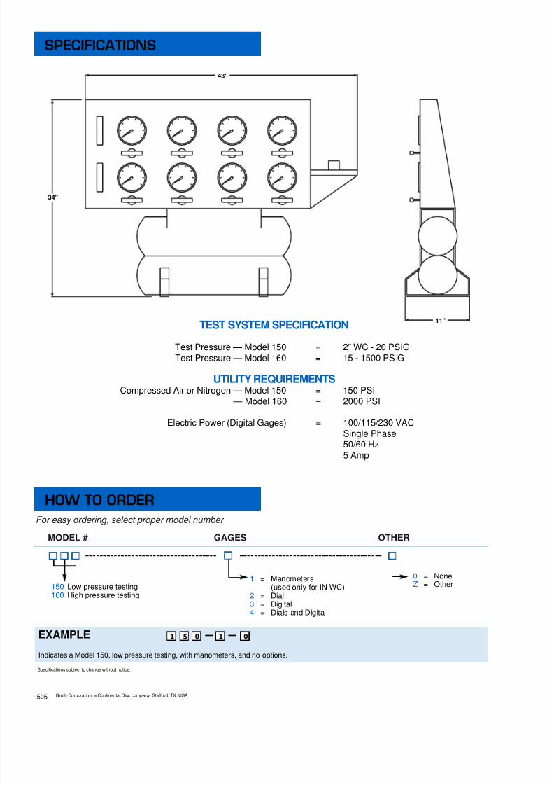
8/13/2019 Groth Catalogue
http://slidepdf.com/reader/full/groth-catalogue 131/175
For easy ordering, select proper model number
MODEL # GAGES OTHER
150 Low pressure testing160 High pressure testing
0 = NoneZ = Other
EXAMPLE
Indicates a Model 150, low pressure testing, with manometers, and no options.
5 10 0
1 = Manometers(used only for IN WC)
2 = Dial3 = Digital4 = Dials and Digital
Specifications subject to change without notice.
1
TEST SYSTEM SPECIFICATION
Test Pressure — Model 150 = 2” WC - 20 PSIGTest Pressure — Model 160 = 15 - 1500 PSIG
UTILITY REQUIREMENTSCompressed Air or Nitrogen — Model 150 = 150 PSI
— Model 160 = 2000 PSI
Electric Power (Digital Gages) = 100/115/230 VACSingle Phase50/60 Hz5 Amp
43"
34"
11"
Groth Corporation, a Continental Disc company, Stafford, TX, USA
SPECIFICATIONS
HOW TO ORDER
505

8/13/2019 Groth Catalogue
http://slidepdf.com/reader/full/groth-catalogue 132/175
STANDARD■ Easy setup and installation■ 6" dial test gages■
1/2" thru 10" valve mountings■ Up to 2000 psi test pressure■ SS tubing & valves■ 360 degree accessibility
OPTIONS■ Manual or hydraulic clamping with
safety interlock■ Digital gages with precision of 0.07%■ High pressure compressor and
air receiver■ Skid mounted
SERIES 100 — PRESSURERELIEF VALVE TEST STAND
All Groth pressure relief valve test stands com-bine extremely high accuracy with maximumproductivity in testing and determining set pres-sure.
Groth provides various options to meet yourtesting needs. Mounting of valves is quick andsafe with either flange bolting, manual or auto-matic clamping. The test stands have easy toread dial or digital pressure gauges.
Test stand construction is robust and is basedon almost forty years of relief valve assemblyand testing.
Manual or Automatic Clamping
Groth Corporation, a Continental Disc company, Stafford, TX, USA 506
SERIES 100 TEST STANDS
Pressure Relief Valve - Pneumatic / Hydraulic
Bolt on Unit
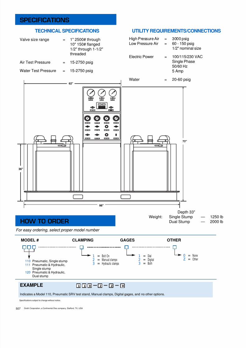
8/13/2019 Groth Catalogue
http://slidepdf.com/reader/full/groth-catalogue 133/175
For easy ordering, select proper model number
MODEL # CLAMPING GAGES OTHER
110 Pneumatic, Single stump111 Pneumatic & Hydraulic,
Single stump120 Pneumatic & Hydraulic,
Dual stump
0 = NoneZ = Other
EXAMPLE
Indicates a Model 110, Pneumatic SRV test stand, Manual clamps, Digital gages, and no other options.
1 20 2
1 = Bolt On2 = Manual clamps3 = Hydraulic clamps
1 = Dial2 = Digital3 = Both
0
Specifications subject to change without notice.
1
TECHNICAL SPECIFICATIONS
Valve size range = 1" 2500# through10" 150# flanged1/2" through 1-1/2"threaded
Air Test Pressure = 15-2750 psig
Water Test Pressure = 15-2750 psig
UTILITY REQUIREMENTS/CONNECTIONSHigh Pressure Air = 3000 psigLow Pressure Air = 60 - 150 psig
1/2" nominal size
Electric Power = 100/115/230 VACSingle Phase50/60 Hz5 Amp
Water = 20-60 psig
Depth 33"Weight: Single Stump — 1250 lb
Dual Stump — 2000 lb
62"
36"
72"
98"
Groth Corporation, a Continental Disc company, Stafford, TX, USA507
SPECIFICATIONS
HOW TO ORDER

8/13/2019 Groth Catalogue
http://slidepdf.com/reader/full/groth-catalogue 134/175

8/13/2019 Groth Catalogue
http://slidepdf.com/reader/full/groth-catalogue 135/175
MODEL # NO. OF BOTTLES MAX PRESSURE OPTIONS
3000 PSI6000 PSI
EXAMPLE
Indicates a compressor with 12 bottles and a maximum pressure of 3000 psi. (as shown in picture on front)
2 03 0
03060912
Specifications subject to change without notice.
1
SPECIFICATIONSCompressor = 5.6 CFM @ 3000 - 5 H.P.
7.0 CFM @ 6000 - 7.5 H.P.
Receiver 9.0 cu. ft.(6 Bottles) = 1850 SCF @ 3000 psi
UTILITY REQUIREMENTS
Electrical Power = 208/230/460 VACSingle Phase/3 Phase50/60 Hz
140
04 01
0 = No Options1 = Air DryerZ = Special
0
Weight 1,900 LB
38"
6"
60"
70"15"(TYP)
For easy ordering, select proper model number
Groth Corporation, a Continental Disc company, Stafford, TX, USA509
SPECIFICATIONS
HOW TO ORDER

8/13/2019 Groth Catalogue
http://slidepdf.com/reader/full/groth-catalogue 136/175

8/13/2019 Groth Catalogue
http://slidepdf.com/reader/full/groth-catalogue 137/175
Groth Corporation, a Continental Disc company, Stafford, TX, USA511
a Continental Disc Company
13650 N. Promenade Blvd.Stafford, Texas 77477
tel (281) 295-6800 fax (281) 295-6999
www.grothcorp.com
Section 5:TestStndBrc.qxd, June, 2002, 2.5m

8/13/2019 Groth Catalogue
http://slidepdf.com/reader/full/groth-catalogue 138/175
SECTION 6
PILOT OPERATED RELIEF VALVES
Series 1660A Pilot Operated Valves •
Series 1400 Pilot Operated Valves •
Series 1500 Pilot Operated Valves •

8/13/2019 Groth Catalogue
http://slidepdf.com/reader/full/groth-catalogue 139/175
Model 1660AU.S. Patent No. 5,499,648
Model 1401EU.S. Patent No. 5,163,471
Model 1402U.S. Patent No. 5,992,449
■ Premium seat tightness to set pressure
■ Snap or modulating valve action
■ Provides ability to meet “Clean Air Act”requirements
a Continental Disc Compan yPILOT OPERATED RELIEF VALVE
SERIES 1660A

8/13/2019 Groth Catalogue
http://slidepdf.com/reader/full/groth-catalogue 140/175
Pressure and/or vacuum reliefvalves are used on liquidstorage tanks and otherprocess vessels or systemsto prevent structural damagedue to excess internal pressureor vacuum.
Storage tanks are pressurizedwhen liquid is pumped inand compresses the existingvapor or when increasingtemperature causes increasedevaporation or expansion ofexisting vapor. Conversely, vac-uum may be created whenpumping out or decreasing tem-perature. To prevent damage,vapor must be allowed toescape or enter the tank at aspecified pressure or vacuum.The volume rate of ventingdepends upon the tank size,volatility of the contents, thepumping rate and the tempera-ture. See API Standard 2000for the procedures to determineventing requirements.
The pilot operated relief valvehas two principal advantagesover other types of relief valves:
1) It is bubble tight to setpressure.
2) It is fully open at less than10% above set pressure.
These characteristics permit anoperating pressure nearer tothe maximum allowable work-ing pressure of the tank. Highoperating pressures reduceevaporation and total ventingvolume, thereby reducing prod-uct loss and cost of processingemissions.
A tank may also have provi-sions for emergency pressurerelief due to fire exposureand/or an inert gas blanket inthe vapor space.
A typical tank installation isshown in Figure 1 whichincludes a pilot operated pres-sure/vacuum relief valve, a gasblanketing regulator and a pilotoperated emergency pressurerelief valve.
The Groth Series 1660A PilotOperated Valve is available inthe following configurations:
See pages 603, 604 and 611.
RELIEF SERVICE
PRESSURE VACUUM
1660A1661A
1662A
1663A
Typical Tank Installation
Figure 1
DIRECTACTUATED
PILOTOPERATED
PILOTOPERATED
INTRODUCTION
Groth Corporation, a Continental Disc company, Stafford, TX, USA601

8/13/2019 Groth Catalogue
http://slidepdf.com/reader/full/groth-catalogue 141/175
• Sizes 2” through 12”• Full Pipe Bore Seat Nozzle• Standard Pressure Settings from 2.0" W.C.
to 15 PSIG
• Temperature Range from -323°Fto 300°F
• Designed for Easy Maintenance• Minimal Spare Parts Requirements
• Inherent Backflow Prevention• ISO 9001 Certified Manufacturing Process• Easily Adjustable Blowdown• Snap Action or Modulating Pilot• Premium Seat Tightness to Set Pressure.• Standard Body Materials are Aluminum,
Carbon Steel, or 316 S.S.• Film seat design meets EPA Method 21
LOW PRESSURE STORAGE TANKSThe Groth Model 1660A Pilot OperatedValves can meet seat tightness requirementsof environmental regulations, even when theoperating pressure is close to the setpressure, such as when gas blanketing isused.
CRYOGENIC STORAGE TANKSLeaking pressure relief valves on lowtemperature tanks cause unsafe freeze-ups. Tight pilot operated valves with snapaction are the safest devices known.Modulating valves must not be used oncryogenic service.
NATURAL GASSome natural gas production facilities requirelarge volume relief capacities at lowpressures and pilot operated valves are idealfor these applications. When the relief valveis installed downstream of a pressurereducing valve, the modulating mode canprevent destructive interaction between thetwo valves.
AIR SEPARATION PLANTSPilot operated valves prevent the accidentalloss of gases when used in both low pressureprocess and storage applications.
AIR BLOWERSAir blowers for conveyor systems andwaste water treatment plants, as well asother uses, often require accurate relief forboth pressure and vacuum. Pilot operatedrelief valves—both pressure valves and vacu-um valves—are extremely well suited forsuch services.
FEATURES
APPLICATIONS
Groth Corporation, a Continental Disc company, Stafford, TX, USA 602

8/13/2019 Groth Catalogue
http://slidepdf.com/reader/full/groth-catalogue 142/175
Model 1660A - Pressure Relief -Pilot ActuatedThe function of the pilot valve (A) is to controlpressure in the main valve actuator (B) or upperdome of the main valve. The effective area ofthe actuator diaphragm (1) is significantly largerthan the pallet seat area (2). Tank pressure isapplied both on top of the actuator diaphragmand below the main valve seat area. Becauseof the area ratio, the downward force isgreater than the opening force and results ina tight main valve seat.
When tank pressure reaches set pressure, theforce acting upward on the pilot valve sensediaphragm overcomes the downward springforce. The pilot valve begins to flow through the
seat (6) to the breather port (3). This flowresults in a pressure drop in the upper dome(B). As a result, pressure acting under themain valve pallet will open the valve andrelieve the over-pressure condition.
Adjustment of the blowdown needle (4) can pro-vide either “snap action” or “modulating”pilot valve operation. For snap-action opera-tion, the main valve pallet lifts quickly to fullopen. In modulating service, the pallet will liftsufficiently to maintain set pressure regardlessof the flow rate up to the rated capacity of thevalve at the specified set pressure.
The main valve remains open (and flowing)as long as the tank pressure is higher thanthe pilot valve set pressure.
As tank pressure decreases to the pilot valvereseat pressure, the pilot valve closes allowingtank vapors to flow back into the upper dome(B). As the upper dome pressure rises, the pal-let assembly is tightly closed against the seat.
The adjustable orifice or blowdown needle (4)affects the closing of the pilot valve. Blowdowncan vary from zero for modulating operation to10% for snap-action operation.
NOTE: The actuator diaphragm (1) is notattached to the support plate (5) unless vacuumrelief or Low set 1402 pilot is specified. Thisdesign provides “inherent back-flow preven-tion” when the discharge header pressureexceeds tank pressure. No additional hardwareis required for this protection.
DESIGN AND FUNCTION
Closed Condition
Open Condition
Groth Corporation, a Continental Disc company, Stafford, TX, USA603

8/13/2019 Groth Catalogue
http://slidepdf.com/reader/full/groth-catalogue 143/175
Model 1661A -Pressure Relief - Pilot ActuatedVacuum Relief - Direct ActuatedVacuum relief is provided by attachment of the actuatordiaphragm to the pallet/support plate assembly. Thisprovides pressure and vacuum protection with a single mainvalve and a single pilot valve.
The valve opens when the tank vacuum acting on the actu-ator diaphragm overcomes the weight of the palletassembly. The vacuum applied to the area differentialbetween the actuator diaphragm (1) and the pallet seat area(2) provides the lifting force. The vacuum cracking pressureis approximately 1.0 - 2.0” WC, and is determined by theweight of the pallet assembly and related components. Fullopen flow is achieved in the 1.7" to 3.5" WC range, depend-ing on valve size, pressure setting and materials ofconstruction. The diaphragm is attached by the upper sup-port plate (8), so backflow prevention is not provided bythis valve.
Model 1662A - Vacuum Relief -Pilot Valve ActuatedOperation of a Pilot Actuated Vacuum Relief Valve is similarto pressure relief except for the physical connectionsbetween the pilot and main valve. The vacuum sense lines(9 & 10) connect the spring chamber breather port and thepilot valve exhaust port to the main valve total pressure pick-up as shown.
Atmospheric pressure is applied under the boost andsense diaphragms and in the upper dome (B) through thebreather port (3). Below set vacuum the spring force isgreater than the lift created by tank vacuum above the sensediaphragm (7) so both the pilot valve and the main valve willremain closed.
At set vacuum the pilot valve opens and the upper dome isreduced to tank vacuum. The diaphragm is attached by asecond actuator support plate (8) for vacuum operatedvalves. Main valve internal pressure under the actuatordiaphragm (1) opens the main valve. The valve remainsopen and flowing until the system reaches the pilot valvereseat pressure.
NOTE: Backflow pressure relief prevention is provided forpilot operated vacuum relief valves in case positive systempressure can occur. A bypass line with a check valve isused to apply pressure to the upper dome. Another checkvalve prevents pressure discharge from the pilot vent.
CAUTION:
See Technical Section TPD3 for Modes of Failure.
1
8
3
7
9
10
A
B
Open Condition—Direct Actuated
Open Condition
DESIGN AND FUNCTION
Closed Condition
Groth Corporation, a Continental Disc company, Stafford, TX, USA 604

8/13/2019 Groth Catalogue
http://slidepdf.com/reader/full/groth-catalogue 144/175

8/13/2019 Groth Catalogue
http://slidepdf.com/reader/full/groth-catalogue 145/175
1. Elastomer material options are specified by the soft goods option in the part number; refer to the “How to Order Section” on page 615 of this catalog.2. Consult factory for material options not listed above.3. 316 SS Seat Insert Optional.4. Teflon is a registered trademark of DuPont Corporation.
ASSEMBLY
Groth Corporation, a Continental Disc company, Stafford, TX, USA 606
Model 1660 Pilot OperatedRelief Valve
` Materials of ConstructionItem Description Aluminum Carbon Stainless
Steel Steel1 Pilot SS SS SS2 Nipple, Pipe 316 SS 316 SS 316 SS3 Housing, Upper Actuator AL CS 316 SS4 Rivet SS SS SS5 Plate, Diaphragm AL 316 SS 316 SS6 Bolt, Hex 316 SS 316 SS 316 SS7 Washer, Lock 316 SS 316 SS 316 SS8 Plug, Pipe 316 SS 316 SS 316 SS9 Guide, Spindle AL 316 SS 316 SS
10 Rod, Spindle 316 SS 316 SS 316 SS11 Spindle 316 SS 316 SS 316 SS12 Bearing, Spindle PTFE PTFE PTFE13 Stud/Nut (not shown) 316 SS 316 SS 316 SS14 Insert, Locking 316 SS 316 SS 316 SS15 Seat, Body See Note 3 316 SS See Note 316 Gasket, Actuator Teflon ® FEP 4 Teflon ® FEP 4 Teflon ® FEP 4
17 Cap Spindle, Lower AL 316 SS 316 SS18 Pickup, Pressure 316 SS 316 SS 316 SS19 Tube Connector 316 SS 316 SS 316 SS20 Body AL CS CF8M (316 SS)21 Diaphragm, Actuator Teflon ® FEP 4 Teflon ® FEP 4 Teflon ® FEP 4
22 Housing, Lower Actuator AL CS 316 SS23 Tubing 316 SS 316 SS 316 SS24 Nut, Hex Jam 316 SS 316 SS 316 SS25 Cap, Spindle-Upper AL 316 SS 316 SS26 Connector, Tube 316 SS 316 SS 316 SS27 Nut, Hex Jam 316 SS 316 SS 316 SS28 Retainer Plate, O-Ring AL 316 SS 316SS29 Pallet, O-Ring AL 316 SS 316 SS30 O-Ring See Note 1 See Note 1 See Note 131 Retainer, Snap Ring SS SS SS
FILM SEAT COMPONENTS (ITEMS 1-27 ARE SAME AS ABOVE)32 Ring, Film Seat AL 316 SS 316 SS33 Plate, Film Seat AL 316 SS 316 SS34 Screw, Hex Skt Flt Hd SS SS SS35 Nut, Hex SS SS SS36 Washer, Lock SS SS SS37 Seat, Film Teflon ® FEP 4 Teflon ® FEP 4 Teflon ® FEP 4
38 Jackscrew 316 SS 316 SS 316 SS39 Bushing, Jackscrew 316 SS 316 SS 316 SS40 Retainer, Film Seat AL 316 SS 316 SS41 Nut, Hex Jam 316 SS 316 SS 316 SS42 Washer, Flat 316 SS 316 SS 316 SS

8/13/2019 Groth Catalogue
http://slidepdf.com/reader/full/groth-catalogue 146/175
U.S. PATENT NO. 5,163,471
ASSEMBLY
Groth Corporation, a Continental Disc company, Stafford, TX, USA607
Model 1401E Pilot Valve

8/13/2019 Groth Catalogue
http://slidepdf.com/reader/full/groth-catalogue 147/175Groth Corporation, a Continental Disc company, Stafford, TX, USA 608
1. Elastomer material options for the pilot valve(s) are specified by the soft goods designation in the “Howto Order Section” section on page 615 of this catalog.2. 17-7 PHSSor Chrome Vanadiumfor Set Pressure greater than 8 PSI.3. Consult factory for material options not listed above.4. Teflon is a registered trademark of DuPont Corporation
ASSEMBLY
Model 1401E Pilot Valve
Materials of Construction
Item Description Qty.All
316 SS
1 Cap, Adjustment Screw 1 316 SS2 Screw, Adjustment 1 316 SS3 Nut, Hex 1 316 SS4 Bonnet, Spring 1 316 SS5 Button, Spring 1 316 SS6 Spring 1 316 SS (Note 2)7 Vent, Breather 2 Plastic8 Bolt, Hex 4 316 SS9 Case, Diaphragm-Upper 1 316 SS
10 Gasket, Actuator 1 Teflon ® FEP 4
11 Spacer, Actuator Housing 1 316 SS12 Bolt Hex 12 316 SS13 Nut, Hex 12 316 SS14 Washer, Lock 12 316 SS15 Diaphragm, Actuator 1 Teflon ® FEP 4
16 Bolt, Hex 8 316 SS17 Screen, Filter 1 316 SS18 Bushing, Blowdown 1 316 SS19 O-Ring 1 PTFE20 Needle, Blowdown 1 316 SS21 Nut, Hex Jam 1 316 SS
22 Stem 1 316 SS23 Nut, Hex 1 316 SS24 Washer, Lock 1 316 SS25 Washer 1 Teflon ® FEP 4
26 Screw, Stem 1 316 SS27 O-Ring 1 Note 128 O-Ring 1 Note 129 Guide, Spring 1 316 SS30 Spacer, Central 1 316 SS31 Spacer, Lower 1 316 SS32 O-Ring 1 Note 133 Disc, Stem 1 316 SS
34 Bushing, Seat 1 316 SS35 Gasket, Spring Bonnet 1 Note 136 Nut, Swage 4 304 SS37 Plate, Support-Upper 1 316 SS38 Plate, Support-Lower 1 316 SS39 Case, Diaphragm-Lower 1 316 SS40 Diaphragm, Body 1 Teflon ® FEP 4
41 Gasket, Body 1 Teflon ® FEP 4
42 Body 1 316 SS

8/13/2019 Groth Catalogue
http://slidepdf.com/reader/full/groth-catalogue 148/175
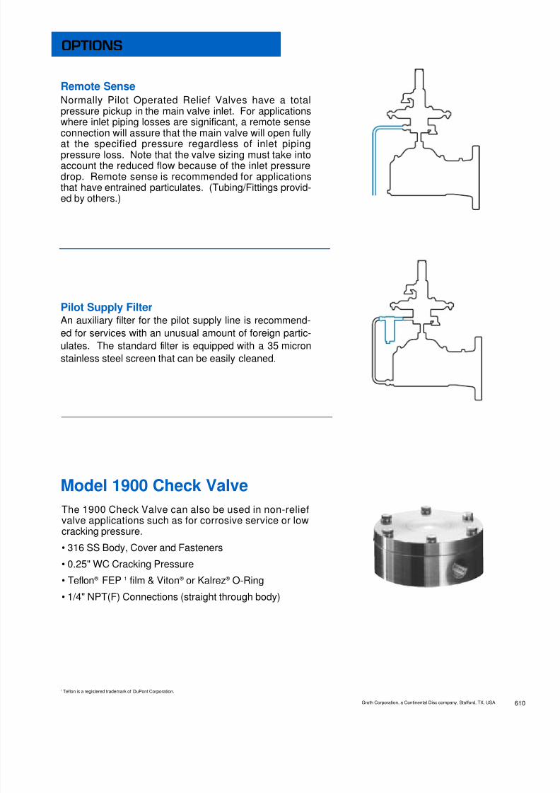
8/13/2019 Groth Catalogue
http://slidepdf.com/reader/full/groth-catalogue 149/175
Remote SenseNormally Pilot Operated Relief Valves have a totalpressure pickup in the main valve inlet. For applicationswhere inlet piping losses are significant, a remote senseconnection will assure that the main valve will open fullyat the specified pressure regardless of inlet pipingpressure loss. Note that the valve sizing must take intoaccount the reduced flow because of the inlet pressuredrop. Remote sense is recommended for applicationsthat have entrained particulates. (Tubing/Fittings provid-ed by others.)
Pilot Supply FilterAn auxiliary filter for the pilot supply line is recommend-ed for services with an unusual amount of foreign partic-ulates. The standard filter is equipped with a 35 micronstainless steel screen that can be easily cleaned.
Model 1900 Check ValveThe 1900 Check Valve can also be used in non-reliefvalve applications such as for corrosive service or lowcracking pressure.
• 316 SS Body, Cover and Fasteners
• 0.25" WC Cracking Pressure
• Teflon ® FEP 1 film & Viton ® or Kalrez ® O-Ring
• 1/4" NPT(F) Connections (straight through body)
1 Teflon is a registered trademark of DuPont Corporation.
OPTIONS
Groth Corporation, a Continental Disc company, Stafford, TX, USA 610

8/13/2019 Groth Catalogue
http://slidepdf.com/reader/full/groth-catalogue 150/175
The Model 1663A will be required for pilot operated pressure and vacuum relief when the vacuum set-ting is greater than the direct actuated vacuum setting of the Model 1661. Minimum vacuum setting forModel 1663A is 3" W.C. and rated capacity is achieved at 10% over-pressure.
Dual pilot valves allow a single relief valve to provide independent settings for pressure and vacuum.Two Groth Model 1900 Check Valves provide isolation of the pressure and vacuum functions. The valveis closed within the set pressure range specified and opens above the positive pressure setting andbelow the vacuum setting. Backflow prevention protection is not available if the discharge header pres-sure exceeds tank pressure.
Model 1660A SeriesCryogenic Services• Tested and proven reliable below minus 300°F.• Snap action at lowest temperatures.• Tight shut-off with patented conical film seat• No freeze-up for safe operation.• All Teflon ® 1 diaphragms
The Groth Series 1660A pilot operated valves aredesigned to provide the safest and most reliable operationfor Cryogenic service. With the incorporation of a Teflon ®
FEP 1 diaphragm and aluminum or 316 SS seatmaterials, the low temperature does not effect valveoperation or valve seat tightness. Tight shut-off anddependable service is assured.
1 Teflon is a registered trademark of DuPont Corporation.
OPTIONS
Model 1663A Dual Pilot OperatedPressure and Vacuum Relief Valve
Groth Corporation, a Continental Disc company, Stafford, TX, USA611

8/13/2019 Groth Catalogue
http://slidepdf.com/reader/full/groth-catalogue 151/175
The Model 1402 Pilot Valve lowers theeffective pressure range of all Groth PilotOperated Valves to 2.0" WC (dependingon valve model, size and materials ofconstruction).
The Model 1402 pilot valve functions as a4-way valve and the main valve is suppliedwith a double acting actuator. Below setpressure, the pilot uses tank pressure topressurize the upper chamber of the actua-tor and vents the lower chamber. At setpressure, the pilot exhausts the upperchamber and pressurizes the lower cham-ber, applying sufficient upward force toovercome the weight of the valve stemassembly.
The action is modulating and non-flowing(the pilot only emits vapors while the mainvalve actuator is being exhausted).
The pilot valve pressure setting isadjustable throughout the range of 2.0" to8.0" WC. It is used for pressure relief onlyand is available with all applicable materialsand options shown on pages 608-610.
* Patent Protected
* Model 1402 pilot required for settings less than 3" WC [7.5 mb].** Model 1402 pilot required for settings less than 7" WC [17.2 mb].*** Direct acting vacuum [Model 1661A] achieves rated capacity at 3.5” WC (8.6 mb)
MATERIAL OPTION ALUMINUM CARBON STEEL STAINLESS STEEL
Sizes 2" - 12" 2" - 12" 2" - 12"
Pressure Settings *2" WC to 15 PSIG **2" WC to 15 PSIG **2" WC to 15 PSIG
5.0 mb to 1.0 BarG 5.0 mb to 1.0 BarG 5.0 mb to 1.0 BarG
Vacuum Settings ***3" WC to 12 PSIG ***3" WC to 12 PSIG ***3" WC to 12 PSIG
7.5 mb to 0.83 BarG 7.5 mb to 0.83 BarG 7.5 mb to 0.83 BarG
Temperature Limits - 323°F to 300°F - 20°F to 300°F - 323°F to 300°F
- 197°C to 150°C - 29°C to 150°C - 197°C to 150°C
OPTIONS
Model 1402 Low SetPilot Operated Relief Valve
TECHNICAL DATA
Groth Corporation, a Continental Disc company, Stafford, TX, USA 612

8/13/2019 Groth Catalogue
http://slidepdf.com/reader/full/groth-catalogue 152/175
Air Flow Capacity at 3.5” WC (2 oz/in2) vacuum
1000 Standard Cubic Feet per Hour at 60°F2” 3” 4” 6” 8” 10” 12”
6.82 15.1 26.1 58.5 102 161 232
Model 1661A Direct Actuated ValveVacuum Relief Capacity
Model 1660A, 1661A, 1663A Pilot Operated ValvePressure Relief Capacity
CAPACITY
Groth Corporation, a Continental Disc company, Stafford, TX, USA613
Set Pressure Air Flow Capacity at 10% Over-pressure(P
s) 1000 Standard Cubic Feet per Hour at 60°F
In WC Oz/Sq In 2” 3” 4” 6” 8” 10” 12”2.00 1.16 5.46 12.0 20.9 46.8 81.9 129 1854.00 2.31 7.73 17.1 29.5 66.3 116 182 2626.00 3.47 9.48 20.9 36.2 81.3 142 223 3228.00 4.62 11.0 24.2 41.9 94.0 165 258 372
10.00 5.78 12.3 27.1 46.9 105 184 289 41715.00 8.66 15.1 33.3 57.7 129 227 356 51220.00 11.6 17.5 38.6 66.8 150 262 412 59425.00 14.4 19.6 43.3 75.0 168 294 462 666
PSIG1 20.7 45.7 79.0 177 311 488 7022 29.8 65.8 114 255 447 702 10113 37.1 81.9 142 318 557 875 12604 43.6 96.1 166 373 654 1027 14785 49.4 109 189 424 742 1165 1677
6 54.9 121 210 471 824 1294 18638 65.1 144 248 557 976 1533 220710 74.4 164 284 638 1117 1754 252512 83.2 184 318 713 1249 1961 282514 91.6 202 350 785 1375 2159 310915 95.7 211 366 820 1436 2255 3247
Model 1662A, 1663A Pilot Operated ValveVacuum Relief Capacity
Set Vacuum Air Flow Capacity at 10% Over-vacuum(P s ) 1000 Standard Cubic Feet per Hour at 60°F
In WC Oz/Sq In 2” 3” 4” 6” 8” 10” 12”3.00 1.73 6.66 14.7 25.5 57.1 100 157 2264.00 2.31 7.69 17.0 29.4 65.9 115 181 2616.00 3.47 9.41 20.8 35.9 80.6 141 222 3198.00 4.62 10.8 23.9 41.4 93.0 163 256 368
10.00 5.78 12.1 26.7 46.3 104 182 285 41112.00 6.93 13.3 29.2 50.6 114 199 312 45016.00 9.27 15.3 33.7 58.3 131 229 360 51820.00 11.6 17.0 37.6 65.0 146 255 401 57825.00 14.4 19.0 41.9 72.5 163 285 447 644
PSIG1 19.9 44.0 76.1 171 299 470 6762 27.7 61.0 106 237 415 652 9383 33.2 73.2 127 284 498 781 11254 37.4 82.5 143 320 561 881 12685 40.7 89.8 155 349 610 959 13806 43.2 95.3 165 370 648 1018 14667 45.0 99.3 172 386 675 1060 1527
Actual setting depends on size, material and pallet type and varies from 1.0 - 2.0” WC
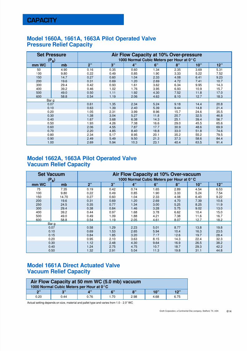
8/13/2019 Groth Catalogue
http://slidepdf.com/reader/full/groth-catalogue 153/175

8/13/2019 Groth Catalogue
http://slidepdf.com/reader/full/groth-catalogue 154/175
MODEL # SIZE MATERIAL SOFT GOODS TYPE OPTIONS(seenotes1-4)
1660A1661A1662A1663A
02 = 2”03 = 3”04 = 4”06 = 6”08 = 8”10 = 10”12 = 12”
Main Valve1 = Alum3 = C. Steel5 = S.S.
B = Buna-NE = EPRV = Viton ®
K = Kalrez ®
Z = Special
1. Refer to BOM on pages 606 and 608.2. Diaphragm material for main valve (actuator and film seat) and
Pilot Valve are only available in Teflon ® FEP 1.3. 300 Series Pilot is standard (see page 608).4. O-ring material is specified by soft goods selection; PTFE is not available.5. FEP Film only; Kalrez O-rings in Pilot Valve (see page 605-8). N
O T E S
O = No Special OptionsZ = Special Options
O = No Blowdown or Remote SenseB = Manual BlowdownR = Remote Sense2 = Both Blowdown and Remote Sense
O = No Pilot to Hdr or Test ConnectionH = Pilot Exhaust Piped to Dischg HeaderT = Field Test Connection2 = Both Pilot to Hdr & Test Connection
O = No Filter or Low Set 1402 PilotF = Pilot Supply FilterL = Low Set 1402 Pilot2 = Both Filter and Low Set 1402 Pilot
EXAMPLEIndicates a 6” Model 1660A (pressure relief only) with carbon steel body and “O-Ring” seat using Viton ® soft goods with snap action pilotwith remote pilot sense connection and no specials.
0 0 R O6 66 31 S O R O
M = ModulatingS = SnapAction
SeatR = “O” Ring
(see note 4)F = Film Seat
(see note 5)
V
Specifications subject to change without notice. Certified dimensions available upon request.
A
B
E
D
C DIA
SPECIFICATIONS
Groth Corporation, a Continental Disc company, Stafford, TX, USA615
APPROX. SHIP WT.SIZE A B C D E (Aluminum)
INLET OUTLET (mm) (mm) (mm) (mm) (mm) Lbs (kg)2” 3” 11.75" 19.75" 7.50" 2.75" 6.00" 30
(50 mm) (80 mm) (298) (502) (190) (70) (152) (14)
3” 4” 14.75" 21.50" 9.00" 2.53" 8.00" 45(80 mm) (100 mm) (375) (546) (229) (64) (203) (20)
4” 6” 18.00" 21.75" 11.00" 4.00" 10.00" 56(100 mm) (150 mm) (457) (552) (279) (102) (254) (25)
6” 8” 21.25" 26.00" 13.50" 4.32" 12.00" 80(150 mm) (200 mm) (540) (660) (343) (110) (305) (36)
8” 10” 25.50" 28.00" 16.00" 5.31" 14.00" 130(200 mm) (250 mm) (648) (711) (406) (135) (356) (59)
10” 12” 31.75" 31.50" 19.00" 6.65" 18.00" 170(250 mm) (300 mm) (806) (800) (483) (169) (457) (77)
12” 16” 36.50" 35.00" 23.50" 8.00" 20.10" 230(300 mm) (400 mm) (927) (889) (597) (203) (510) (104)
HOW TO ORDER
For easy ordering, select proper model numbers
A
Section 6:1660 Brch.qxd, June, 2002, 2.5m
1 Teflon is a registered trademark of DuPont Corporation.

8/13/2019 Groth Catalogue
http://slidepdf.com/reader/full/groth-catalogue 155/175
Pilot operated valves are used toreplace weight loaded or springloaded valves in many applica-tions to increase efficiency andreduce evaporation losses.Several advantages are obtainedover the traditional type. Forexample, the process pressuresmay be closer to the set pressurethan would be considered pru-dent and safe with the traditional
valve. Additionally, greater con-servation is obtained due to mini-mum product loss which in turnprovides increased profits.
The Groth 1400 Series valvesprovide safe, dependable andaccurate low pressure and/orvacuum protection. Full flow isattained at no more than 10%over-pressure. This reduces theneed for a large over-pressureand saves product, which trans-lates into profit. Blowdown maybe adjusted to requirementsbetween 0 and 10% of set pres-sure. The Models 1400 and 1420incorporate a vacuum breaker.
GROTH, THE CAPABILITY COMPANY Groth manufactures a completeline of tank protection equipmentand is the number one companyin this field. As with all Grothproducts, every 1400 Seriesvalve is factory inspected andtested to meet your criticalrequirements and special needs.Inventory is maintained to insurerapid delivery.
Model 1400
Model 1430 Model 1460
Model 1420
Patent Protected
a Continental Disc Compan yPILOT OPERATED VALVES
SERIES 1400
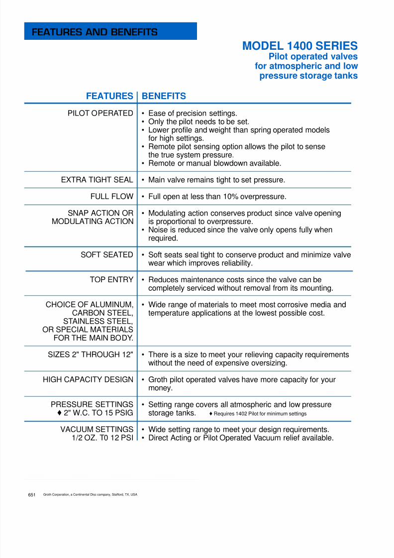
8/13/2019 Groth Catalogue
http://slidepdf.com/reader/full/groth-catalogue 156/175
FEATURESPILOT OPERATED
EXTRA TIGHT SEAL
FULL FLOW
SNAP ACTION ORMODULATING ACTION
SOFT SEATED
TOP ENTRY
CHOICE OF ALUMINUM,CARBON STEEL,
STAINLESS STEEL,OR SPECIAL MATERIALS
FOR THE MAIN BODY.
SIZES 2" THROUGH 12"
HIGH CAPACITY DESIGN
PRESSURE SETTINGS♦ 2" W.C. TO 15 PSIG
VACUUM SETTINGS1/2 OZ. T0 12 PSI
BENEFITS• Ease of precision settings.• Only the pilot needs to be set.• Lower profile and weight than spring operated models
for high settings.• Remote pilot sensing option allows the pilot to sense
the true system pressure.• Remote or manual blowdown available.
• Main valve remains tight to set pressure.
• Full open at less than 10% overpressure.
• Modulating action conserves product since valve openingis proportional to overpressure.
• Noise is reduced since the valve only opens fully whenrequired.
• Soft seats seal tight to conserve product and minimize valvewear which improves reliability.
• Reduces maintenance costs since the valve can becompletely serviced without removal from its mounting.
• Wide range of materials to meet most corrosive media andtemperature applications at the lowest possible cost.
• There is a size to meet your relieving capacity requirementswithout the need of expensive oversizing.
• Groth pilot operated valves have more capacity for your
money.• Setting range covers all atmospheric and low pressure
storage tanks. ♦ Requires 1402 Pilot for minimum settings
• Wide setting range to meet your design requirements.• Direct Acting or Pilot Operated Vacuum relief available.
FEATURES AND BENEFITS
Groth Corporation, a Continental Disc company, Stafford, TX, USA651
MODEL 1400 SERIESPilot operated valves
for atmospheric and lowpressure storage tanks

8/13/2019 Groth Catalogue
http://slidepdf.com/reader/full/groth-catalogue 157/175
The pilot operated valve is aself-contained system whichdoes not require any externalpower or pressure source. Thepilot valve, using system medi-um and pressure, automaticallycontrols the actuator pressure toeither open or close the mainvalve depending on the pres-sure setting of the pilot vs. theactual system pressures.
System medium and pressure issensed at the pickup fitting justabove the inlet flange. In the caseof remote sensing, the pickuppoint is directly on the vessel andusually close to the valve inlet.The medium and pressure is then
channeled to the pilot inlet and isredistributed to the sense cham-ber and to the actuator.
Under normal system operatingconditions, the same pressure isacting downward against theactuator and upwards against
the seat pallet. Since the actua-tor has a larger area than theseat pallet, the net force isdownward which will press thepallet against the seat and thuskeep the main valve closed.While the pilot and main valveare closed, there is no bleed tothe atmosphere.
When the system pressure risesto the pilot set point due to anover-pressure condition, theupward force in the pilot sensechamber will overcome thedownward spring force to lift thepilot stem. As the stem lifts, itopens the pilot seat to allow flowthrough the pilot and out to the
atmosphere. (In applicationswhere nothing is permitted todischarge directly into theatmosphere, the pilot dischargemay be plumbed to the mainvalve outlet for channeling to acollection header. Notify thevendor if this is the situation in
case compensating adjustmentsneed to be made.) The flowthrough the pilot and adjustableorifice will cause a pressuredrop downstream of the orificewhich in turn causes the pres-sure in the actuator to drop.When the actuator pressuredecreases to a point wherethe upward force on theseat pallet is greater than thedownward force of the actuator,the main valve will open. Theamount the main valve opensdepends on the system over-pressure. The greater the over-pressure, the wider the mainvalve opens, until full open isobtained at approximately 10%
over-pressure.After the excess pressure hasbeen relieved and the systempressure is again below the setpoint of the pilot, the valve willreturn to its normal closed posi-tion as described in Figure 1.
Groth Corporation, a Continental Disc company, Stafford, TX, USA 652
OPERATION

8/13/2019 Groth Catalogue
http://slidepdf.com/reader/full/groth-catalogue 158/175
FIELD TEST CONNECTION
(Backflow Prevention Included)
MANUAL OR REMOTE BLOWDOWN
PILOT DISCHARGE TUBED TO MAIN VALVE OUTLET
Remote Pickup for Pilot
MODEL 1900 CHECK VALVEThe 1900 Check Valve can also be used in non-reliefvalve applications such as for corrosive service or lowcracking pressure.
• 316 SS Body, Cover and Fasteners
• 0.25" WC Cracking Pressure
• Teflon ® 1 film & Viton ® or Kalrez ® O-Ring
• 1/4" NPT(F) Connections (straight through body)
1 Teflon is a registered trademark of DuPont Corporation.
CONFIGURATIONS
Groth Corporation, a Continental Disc company, Stafford, TX, USA653

8/13/2019 Groth Catalogue
http://slidepdf.com/reader/full/groth-catalogue 159/175
PressureSetting
psig
0.070.20.40.60.81.01.21.41.6
1.82.03.04.05.06.07.08.09.0
10.011.012.013.014.015.0
2"(2.976 in 2)
76.9128184228265299329357384
409433540633717795869939
1006107111341195125413081351
3"(7.013 in 2)
181302434537625704775842904
96410201272149116901874204722122371252326722816295630823183
4"(12.35 in 2)
320532764946
11011239136614831593
169717962240262629763300360538964175444447054958517753605535
6"(28.51 in 2)
73712271764218325422861315234233677
391741465171606268697618832389949638
102591086011363117991221612616
8"(49.65 in 2)
126821113035375643734922543258896325
673971338896
104291181813106143191547416581176491868419535202842100121689
10"(78.47 in 2)
198032964738586468267683846691939875
105201113613887162811844920460223542415625885275522916830473316423276133834
12"(112.7 in 2)
28094675672083189682
10898120081303914006
149221579519697230922616829021317073426336715390804137243189448474643347953
VALVE SIZE (ORIFICE SIZE)
VacuumSettingIn. WC
0.871.001.732.003.004.006.008.00
10.00
2"
7884
111119145167203233260
3"
172183242260317365445510567
4"
267287377403493568692795883
6"
578622817877
10701233150217171917
8"
100810831422152718672150261730003333
10"
151816322150230028173233395045335033
12"
215023003033325039674567556764007117
VALVE SIZE
Tables are provided toallow you to select theproper size valve for yourapplication. It is suggestedthat API Standard 2000 be
utilized to obtain therequired flow capacity.
TABLE IModel 1400/1430SCFM Air Capacity
@10% Over-pressure
and 60°F
TABLE IIModel 1420/1460SCFM Air Capacity
@10% Over-pressureand 60°F
TABLE IIIVacuum Flow Capacity
Model 1400/1420SCFM Air Capacity
@100% Over-pressureand 60°F
For an equivalent size fiberglass valve, reduce tabulated capacities by 32%.
2"(2.976 in 2)
84.7141207259303343379413444473501625731825901971
10361096115212051256130413501395
3"(7.013 in 2)
200333488610715808893972
1046111511821474172319432124228924402582271528412960307431823286
4"(12.35 in 2)
353587860
107512591423157317121842196420812595303434223741403042984547478150025212541356045787
6"(28.51 in 2)
8141355198524812907328636323952425245354803599270047900863693049921
10497110371154812033124951293713360
8"(49.65 in 2)
14182360345743215062572263246882740478978365
10434121971375915039162031727818280192222011120955217602252923266
10"(78.47 in 2)
2241373054646830800090409995
1087711702124811322116491192772174523769256082730728891303793178533119343903560636772
VALVE SIZE (ORIFICE SIZE)PressureSetting
psig
0.070.20.40.60.81.01.21.41.61.82.03.04.05.06.07.08.09.0
10.011.012.013.014.015.0
SIZING TABLES
12"(112.7 in 2)
3218535678479809
1149012989143551562116807179251898823685276853123134137367783921841494436314565047566493925113852812
Groth Corporation, a Continental Disc company, Stafford, TX, USA 654

8/13/2019 Groth Catalogue
http://slidepdf.com/reader/full/groth-catalogue 160/175
PressureSettingmbarg
51020304050
100
150200250300350400450500550600650700750800850900
1000
2"(2.976 in 2)
2.243.174.565.656.577.4110.5
13.015.116.918.620.522.223.925.527.028.530.031.432.834.235.636.838.7
3"(7.013 in 2)
5.307.4910.813.315.517.524.8
30.635.439.843.848.252.356.260.063.667.270.774.077.480.683.886.791.1
4"(12.35 in 2)
9.3313.218.923.527.330.743.7
53.862.570.177.184.892.199.0106112118124130136142147151158
6"(28.51 in 2)
21.530.443.754.163.070.9101
124144162178196213229244259273287301314325335343361
8"(49.65 in 2)
37.052.375.393.1108122174
214248279306337366393420445470494518541559575591621
10"(78.47 in 2)
57.881.7117145169191271
334387435478526571614655695734771808845873897921969
12"(112.7 in 2)
82.0116167206240270384
473549617678746810871929986
10411094114711981237127213061373
VALVE SIZE (ORIFICE SIZE)
VacuumSettingmbarg
23457
10152025
2"
2.202.693.103.464.094.875.936.817.58
3"
4.805.886.777.578.9310.613.014.916.6
4"
7.489.1510.511.813.916.620.223.225.8
6"
16.219.922.925.630.236.043.850.355.9
8"
28.334.639.944.652.662.776.487.797.5
10"
42.652.160.167.179.294.4115132147
12"
60.273.784.994.9112133163187208
VALVE SIZE
Tables are provided toallow you to select theproper size valve for yourapplication. It is suggest-
ed that API Standard2000 be utilized to obtainthe required flow capacity.
TABLE IModel 1400/1430NCMM Air Capacity
@100% Over-pressureand 0°C
TABLE IIModel 1420/1460NCMM Air Capacity
@100% Over-pressureand 0°C
TABLE IIIVacuum Flow
CapacityModel 1400/1420NCMM Air Capacity
@100% Over-pressureand 0°C
For an equivalent size fiberglass valve, reduce tabulated capacities by 32%.
2"(2.976 in 2)
2.47
3.505.136.427.518.5112.115.017.419.521.523.725.627.428.830.231.532.733.834.936.037.038.039.9
3"(7.013 in 2)
5.84
8.2612.115.117.720.028.635.341.046.150.855.860.464.668.071.274.177.079.782.384.887.289.594.1
4"(12.35 in 2)
10.3
14.621.326.731.235.350.462.172.281.289.498.3106114120125131136140145149153158166
6"(28.51 in 2)
23.8
33.649.261.572.181.5116143167187206227246263276289301313324334345354364383
8"(49.65 in 2)
41.4
58.585.7107126142202250290326359395428458481504525545564582600617633666
10"(78.47 in 2)
65.4
92.5135169198224320395459516568625676723761796829861891920948975
10011053
12"(112.7 in 2)
93.9
133195243285322460567659741816897971
10391093114311911237128013221362140114381512
VALVE SIZE (ORIFICE SIZE)PressureSettingmbarg
5
1020304050
100150200250300350400450500550600650700750800850900
1000
SIZING TABLES
Groth Corporation, a Continental Disc company, Stafford, TX, USA655

8/13/2019 Groth Catalogue
http://slidepdf.com/reader/full/groth-catalogue 161/175

8/13/2019 Groth Catalogue
http://slidepdf.com/reader/full/groth-catalogue 162/175
HOW TO ORDER
Groth Corporation, a Continental Disc company, Stafford, TX, USA657
MODEL # SIZE MATERIAL SOFT GOODS TYPE OPTIONS(see note 3)
1400142014301460
02 = 2"03 = 3"04 = 4"06 = 6"08 = 8"10 = 10"12 = 12"
(see note 2)
Main Valve Trim1 = Aluminum5 = 316 S.S.Z = Special
Body Matl.1 = Aluminum3 = C. Steel5 = 316 S.S.Z = Special
B = Buna-NE = EPRK = Kalrez ®
(see note 5)T = Teflon
® FEP
1
(see note 6)
V = Viton ®
Z = Special
1. See 1660 Brochure for details on 1401E or 1402 Pilot Valves.2. Carbon and Stainless Steel Valves include 316 SS Trim.3. Diaphragm material for main actuator and pilot valve are only available in Teflon
® FEP
1.
4. 300 Series Pilot is standard; see 1660 Brochure for pilot valve details.5. Kalrez O-rings; Teflon
® FEP
1Diaphragms and Gaskets.
6. Teflon ® FEP 1 Diaphragms and Gaskets with Viton ® O-rings.7. 1402 pilot valve available for modulating service only.8. Pilot Exhaust Piped to Discharge Header is not available w/1402 pilot valve. Pilot will only exhaust
vapors in the dome.
N O T E S
EXAMPLE
Indicates a 6" Model 1430 with carbon steel body and 316 SS trim using viton soft goods, snap action with remote pilot pickup andno options.
0 0 V O3 64 31 5 S O R O
O = No OptionsZ = Special Options
O = No Blowdown or Remote SenseB = Manual BlowdownR = Remote Sense2 = Both Blowdown and Remote Sense
O = No Pilot to Header or Test ConnectionH = Pilot Exhaust Piped to Discharge Header (see note 8)T = Field Test Connection2 = Both Pilot to Header and Test Connection
O = No Filter or Low Set 1402 PilotF = Pilot Supply FilterL = Low Set 1402 Pilot2 = Both Filter and Low Set 1402 Pilot (see note 7 & 8)
M = ModulatingS = Snap Action
(see note 7)
O
For easy ordering, select proper model numbers
Section 6:1400 Brch.qxd, June, 2002, 2.5m
1 Teflon is a registered trademark of DuPont Corporation.

8/13/2019 Groth Catalogue
http://slidepdf.com/reader/full/groth-catalogue 163/175
Model 1500Air OperatedPressure / Vacuum Relief ValvesRelief to atmosphere design Model 1530
Air Operated Pressure Relief ValveRelief to atmosphere design
a Continental Disc Compan y
PILOT OPERATED VALVES
Series 1500
■ Severe service application
■ Premium tight seal
■ Snap Acting
■ Instrument air operated
Model 1520Air OperatedPressure / Vacuum Relief ValvesPipe-away design
Model 1560Air OperatedPressure Relief ValvesPipe-away design

8/13/2019 Groth Catalogue
http://slidepdf.com/reader/full/groth-catalogue 164/175

8/13/2019 Groth Catalogue
http://slidepdf.com/reader/full/groth-catalogue 165/175
BENEFITS
• Use instrument air or N 2
• Non-corrosive and non-pluggng• Lower profile and weight than spring operated models
for high settings.• Remote pilot sensing from pressure switch.• Remote or manual blowdown available.
• Main valve remains tight to set pressure.
• Full open at set point
• Snap acting for immediate efficiency
• Soft seats seal tight to conserve product and minimize valvewear which improves reliability.
• Reduces maintenance costs since the valve can becompletely serviced without removal from its mounting.
• Wide range of materials to meet most corrosive media andtemperature applications at the lowest possible cost.
• There is a size to meet your relieving capacity requirementswithout the need of expensive oversizing.
• Groth air pilot operated valves have higher capacity, size forsize, than most other relief valves. You get more capacity foryour money.
• Setting range covers all atmospheric and low pressurestorage tanks.
• Wide setting range to meet your design requirements.• Weight or spring loaded valve.
FEATURES
AIR OPERATED
EXTRA TIGHT SEAL
FULL FLOW
SNAP ACTION
SOFT SEATED
TOP ENTRY
CHOICE OFAluminum, Carbon Steel, Fiberglass
(FRP), or special materials forthe main body.
SIZES 2" THROUGH 12"
HIGH CAPACITY DESIGN
PRESSURE SETTINGS5" W.C. TO 15 PSIG
VACUUM SETTINGS1/2 OZ. T0 12 PSI
(Model 1500 and 1520 ONLY)
FEATURES AND BENEFITS
Groth Corporation, a Continental Disc company, Stafford, TX, USA 672
SERIES 1500Air operated valves for atmospheric
and low pressure storage tanks
Air operated valves are used to replace weightloaded, spring loaded and pilot operated valves insevere application where polymerization andcrystallization may take place and plug as well as cor-rode the control orifices. The air operated valveincreases valve efficiency and reduces evaporationlosses. the pressure switch coupled with a solenoidvalve and using plant instrument air instead of corro-sive product vapor provides a bubble tight seal in thevalve. additionally, the use of clean air greatly reducesmaintenance time when compared with the pilot oper-ated valve. By using the air operated valve, remotesensing is provided by the pressure switch. This valve
provides greater conservation due to minimum productloss which in turn add to the profits at the bottom line.
The Groth 1500 Series group provides safe, depend-able and accurate low pressure and/or vacuum on yourstorage tank. a range of pressure and vacuumrequirements may be easily set. full flow is obtainableat set point and the snap acting feature providesimmediate efficiency. This reduces the requirement forlarge overpressure and saves product, translating intoprofit. the standard valve may incorporate a vacuumbreaker when desired.

8/13/2019 Groth Catalogue
http://slidepdf.com/reader/full/groth-catalogue 166/175
The 1500 Series air operatedvalve is available in five basicmodels: the 1500, 1520, 1530,1560 and 1580. the 1500 and1520 are combination pres-sure/vacuum valves. The 1500discharges to the atmosphereand 1520 has an outlet flangefor pipe-away applications. The1530 is a pressure only valvethat discharges to atmosphere.The 1560 may be used for pres-sure or vacuum for pipe-awayapplications. All valves are heldin the closed position by lowpressure plant air. When the airpressure is removed the valve isforced open by the processpressure or vacuum. Full open
position is achieved as low as 5”WC pressure or vacuum insome cases.
The system is composed of theair operated valve, a pressureswitch and a three-way solenoidvalve. The pressure switch isattached to the tank or vesseland connected to the solenoidvalve which controls the instru-ment air or N 2 line. This is thenormal configuration but ifdesired or necessary more thanone switch or solenoid valvemay be used. Placement on thetank for the pressure switch andplacement of the solenoid valvemay be located to meet yourrequirements.
The pressure switch is adjustedto the desired valve set point.
when the pressure in the tankreaches the set point a signal issent to the solenoid valve which
is de-energized and the plant airis cut off and exhausted. Thisreleases the pressure on thevalve actuator allowing the mainvalve seat pallet to move upthereby venting the tank.
In a similar manner the reversetakes place when the set pointpressure is reached when thevalve is open. the pressureswitch energizes the solenoidvalve which is then energized toopen. This opening permits theline to open and plant instru-ment air enters the actuatorforcing the main valve seat pal-let to move down closing thevalve which eliminates the tank
vapor flow.
Groth Corporation, a Continental Disc company, Stafford, TX, USA673
OPERATION

8/13/2019 Groth Catalogue
http://slidepdf.com/reader/full/groth-catalogue 167/175
PressureSetting
psig
0.20.40.60.81.01.21.41.61.8
2.03.04.05.06.07.08.09.0
10.011.012.013.014.015.0
2"(2.976 in 2)
128184228265299329357384409
433540633717795869939
1006107111341195125413081351
3"(7.013 in 2)
302434537625704775842904964
10201272149116901874204722122371252326722816295630823183
4"(12.35 in 2)
532764946
110112391366148315931697
17962240262629763300360538964175444447054958517753605535
6"(28.51 in 2)
122717642183254228613152342336773917
41465171606268697618832389949638
102591086011363117991221612616
8"(49.65 in 2)
211130353756437349225432588963256739
71338896104291181813106143191547416581176491868419535202842100121689
10"(78.47 in 2)
32964738586468267683846691939875
10520
1113613887162811844920460223542415625885275522916830473316423276133834
12"(112.7 in 2)
4675672083189682
1089812008130391400614922
1579519697230922616829021317073426336715390804137243189448474643347953
VALVE SIZE (ORIFICE SIZE)
VacuumSettingIn. WC
0.871.001.732.003.004.006.008.00
10.00
2"
7884
111119145167203233260
3"
172183242260317365445510567
4"
267287377403493568692795883
6"
578622817877
10701233150217171917
8"
100810831422152718672150261730003333
10"
151816322150230028173233395045335033
12"
215023003033325039674567556764007117
VALVE SIZE
Tables are provided toallow you to select theproper size valve for yourapplication. It is suggestedthat API Standard 2000 be
utilized to obtain therequired flow capacity.
TABLE IModel 1500/1530SCFM Air Capacity
@10% Over-pressure
and 60°F
TABLE IIModel 1520/1560SCFM Air Capacity
@10% Over-pressureand 60°F
TABLE IIIVacuum Flow Capacity
Model 1500/1520SCFM Air Capacity
@100% Over-pressureand 60°F
For an equivalent size fiberglass valve, reduce tabulated capacities by 32%.
2"(2.976 in 2)
141207259303343379413444473501625731825901971
10361096115212051256130413501395
3"(7.013 in 2)
333488610715808893972
1046111511821474172319432124228924402582271528412960307431823286
4"(12.35 in 2)
587860
107512591423157317121842196420812595303434223741403042984547478150025212541356045787
6"(28.51 in 2)
1355198524812907328636323952425245354803599270047900863693049921
10497110371154812033124951293713360
8"(49.65 in 2)
2360345743215062572263246882740478978365
10434121971375915039162031727818280192222011120955217602252923266
10"(78.47 in 2)
373054646830800090409995
1087711702124811322116491192772174523769256082730728891303793178533119343903560636772
VALVE SIZE (ORIFICE SIZE)PressureSetting
psig
0.20.40.60.81.01.21.41.61.82.03.04.05.06.07.08.09.0
10.011.012.013.014.015.0
SIZING TABLES
12"(112.7 in 2)
535678479809
1149012989143551562116807179251898823685276853123134137367783921841494436314565047566493925113852812
Groth Corporation, a Continental Disc company, Stafford, TX, USA 674

8/13/2019 Groth Catalogue
http://slidepdf.com/reader/full/groth-catalogue 168/175

8/13/2019 Groth Catalogue
http://slidepdf.com/reader/full/groth-catalogue 169/175Groth Corporation, a Continental Disc company, Stafford, TX, USA 676
EXAMPLEIndicates a 6" Model 1530 with carbon steel body and 316 SS trim using Viton ® soft goods with factory supplied pressure switch and solenoid.
1. Aluminum body will include stainless steel and/or aluminum trim.2. Carbon steel and stainless steel body wil include stainless steel trim.3. Aluminum and carbon steel will include carbon steel actuator housing, all other are stainless steel.
MODEL # SIZE MATERIAL SOFT GOODS OPTIONS
1500152015301560
02”thru12“
Trim B = Buna-NE = EPRV = Viton ®
T = Teflon ® FEP 1
Z = Special
N O T E S
0 0 V O3 65 31 5 O
O = No OptionsZ = Special Options
1 = Factory supplied pressure switch2 = Factory supplied solenoid valve3 = Both 1 and 2 above
HOW TO ORDERFor easy ordering, select proper model numbers
Body Material1 = Aluminum3 = Carbon Steel5 = 316 S.S.6 = Vinyl Ester
Resin7 = FuranZ = Special
1 Teflon is a registered trademark of DuPont Corporation.

8/13/2019 Groth Catalogue
http://slidepdf.com/reader/full/groth-catalogue 170/175

8/13/2019 Groth Catalogue
http://slidepdf.com/reader/full/groth-catalogue 171/175
SECTION 7
BLANKET GAS REGULATORS
Series 3011 Blanket Gas Regulators •

8/13/2019 Groth Catalogue
http://slidepdf.com/reader/full/groth-catalogue 172/175
Patented US 5,238,021 and 5,931,188
3011H cutaway shown
FEATURESBalanced chambers for accurate performance
Single stage regulation - 200 PSI to 0.5”WC
Bubble tight shut-offSetting range from 0.5”WC to 8.0”WC
All stainless steel construction
Compact design
BLANKET GAS REGULATORS
Series 3011

8/13/2019 Groth Catalogue
http://slidepdf.com/reader/full/groth-catalogue 173/175
MODEL SELECTIONSPECIFICATIONSPlease note when spring ranges overlap, select the lighter spring
MODEL # SPRING MAX SUPPLY MIN SETTING MAX SETTINGRANGE PSI BAR IN WC MBAR IN WC MBAR
3 200 13.8 0.5 1.2 0.7 1.7
4 200 13.8 0.7 1.7 1.0 2.55 200 13.8 1.0 2.5 2.0 5.0
1 50 3.4 0.5 1.2 1.0 2.5
2 100 6.9 1.0 2.5 1.5 3.7
3 150 10.3 1.5 3.7 2.0 5.0
4 200 13.8 2.0 5.0 3.5 8.7
5 200 13.8 3.5 8.7 6.5 16.2
6 200 13.8 6.5 16.2 8.0 20.0
3011 SERIES
Both the 3011L and 3011H gas blanketregulators provide a controlled gasenvironment in storage tanks for thefollowing applications.• Refineries• Chemical & Petrochemical Plants• Liquid Bulk Storage Terminals• Pulp & Paper Plants
The blanket gas is controlled at a definedpressue (or vacuum) level and is used toexclude air from the tank. This is done forthe following reasons.• Elimination of a potentially flammable
mixture by maintaining either an inert orfuel rich environment.
• Minimize tank corrosion.• Prevent product contamination.• Reduce hydrocarbon emissions during
normal breathing.• Prevent product evaporation.
Groth gas blanket regulators have thefollowing features:
• Direct acting, modulating valves with apatented force multiplying linkage.• Balanced forces acting on piston (setting
is not affected by supply pressure.)• Compact size and weight.• Setting range is from 0.5” WC - 8.0” WC
(Consult factory for other settings)• NPT (F) or ANSI flange connections.• Wide selection of elastomer seal materials.• Adjustable flow capacity (5-100%)• Available for vacuum service
(consult factory)
Benefits of storage tank blanketing arerecognized by the following governmentregulations and industrial standards.• API Standard 2000• EPA Publication AP-42• NFPA 69 - Standard on Explosion
Prevention Systems• OSHA Part 1910.106
3011Lpressure service
weight33lb / 15kg
MAWP2 PSI / .14 BAR
3011Hpressure service
weight21lb / 10kg
MAWP8 PSI / 0.5 BAR
4330 1529225 21
36
4
27 26
23 243433
32
18
17
2019
3
11
28
26
35
10
9
2
1
13 42
25
Figure 1: Cross-section of 3011H
SUPPLY PRESSURE (BAR)3.5-6.9
7.0-10.3
10.4-13.8
3011L
3011H
SETPRESSURE
MBAR0.3-3.4
1.2 - 2.52.5 - 3.73.7 - 5.05.0 - 20
SUPPLY PRESSURE (PSI)51-100
101-150
151-200
3011L
3011H
SETPRESSURE
IN WC5-50
0.5 - 1.01.0 - 1.5
1.5 - 2.02.0 - 8.0
Use 3011H when set pressure range overlaps.
Groth Corporation, a Continental Disc company, Stafford, TX, USA702
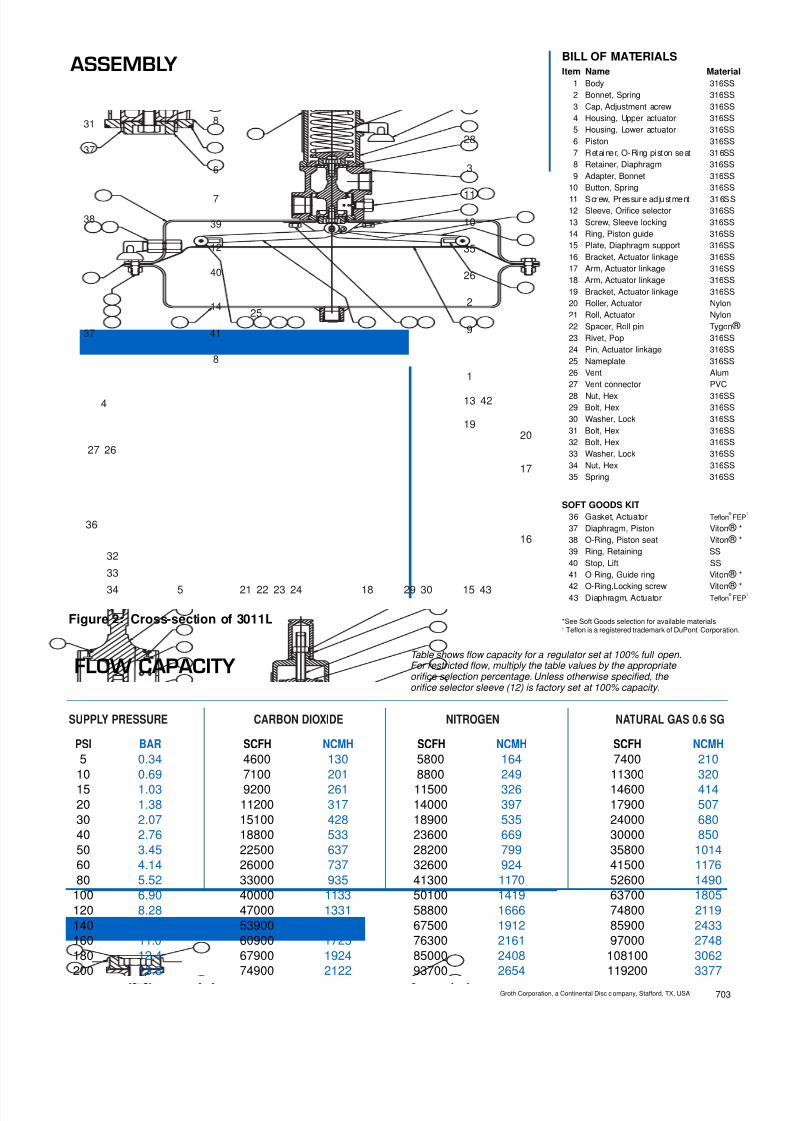
8/13/2019 Groth Catalogue
http://slidepdf.com/reader/full/groth-catalogue 174/175
SUPPLY PRESSURE CARBON DIOXIDE NITROGEN NATURAL GAS 0.6 SG
PSI BAR SCFH NCMH SCFH NCMH SCFH NCMH
5 0.34 4600 130 5800 164 7400 21010 0.69 7100 201 8800 249 11300 32015 1.03 9200 261 11500 326 14600 41420 1.38 11200 317 14000 397 17900 50730 2.07 15100 428 18900 535 24000 68040 2.76 18800 533 23600 669 30000 85050 3.45 22500 637 28200 799 35800 101460 4.14 26000 737 32600 924 41500 117680 5.52 33000 935 41300 1170 52600 1490
100 6.90 40000 1133 50100 1419 63700 1805120 8.28 47000 1331 58800 1666 74800 2119140 9.66 53900 1527 67500 1912 85900 2433160 11.0 60900 1725 76300 2161 97000 2748180 12.4 67900 1924 85000 2408 108100 3062200 13.8 74900 2122 93700 2654 119200 3377
BILL OF MATERIALSItem Name Material
1 Body 316SS2 Bonnet, Spring 316SS3 Cap, Adjustment acrew 316SS4 Housing, Upper actuator 316SS5 Housing, Lower actuator 316SS6 Piston 316SS7 Retainer, O-Ring piston seat 316SS8 Retainer, Diaphragm 316SS9 Adapter, Bonnet 316SS
10 Button, Spring 316SS11 Screw, Pressure ad justment 316SS12 Sleeve, Orifice selector 316SS13 Screw, Sleeve locking 316SS14 Ring, Piston guide 316SS15 Plate, Diaphragm support 316SS16 Bracket, Actuator linkage 316SS17 Arm, Actuator linkage 316SS18 Arm, Actuator linkage 316SS19 Bracket, Actuator linkage 316SS20 Roller, Actuator Nylon21 Roll, Actuator Nylon22 Spacer, Roll pin Tygon ® 23 Rivet, Pop 316SS24 Pin, Actuator linkage 316SS25 Nameplate 316SS26 Vent Alum27 Vent connector PVC28 Nut, Hex 316SS29 Bolt, Hex 316SS30 Washer, Lock 316SS31 Bolt, Hex 316SS32 Bolt, Hex 316SS33 Washer, Lock 316SS34 Nut, Hex 316SS35 Spring 316SS
SOFT GOODS KIT36 Gasket, Actuator Teflon
® FE
37 Diaphragm, Piston Viton ® *38 O-Ring, Piston seat Viton ® *39 Ring, Retaining SS40 Stop, Lift SS41 O-Ring, Guide ring Viton ® *
42 O-Ring,Locking screw Viton ® *43 Diaphragm, Actuator Teflon ®
FE
*See Soft Goods selection for available materials1 Teflon is a registered trademark of DuPont Corporation.
16
43
4
5
27
259
36
15
28
34
33
32
30
26
29
26
35
24232221
2019
18
17
4213
11
10
3
2
1
ASSEMBLY
41
40
3938
37
37
31
14
12
7
8
8
6
Figure 2: Cross-section of 3011L
FLOW CAPACITYTable shows flow capacity for a regulator set at 100% full open.For restricted flow, multiply the table values by the appropriateorifice selection percentage. Unless otherwise specified, theorifice selector sleeve (12) is factory set at 100% capacity.
Groth Corporation, a Continental Disc c ompany, Stafford, TX, USA 703

8/13/2019 Groth Catalogue
http://slidepdf.com/reader/full/groth-catalogue 175/175
HOW TO ORDER
Figure 3: 3011H
20.0
11.0
8.0
1.631.63
11.0
6.88
3.75
INLET
OUTLETOUTLET
INLET
1/2" NPT(F)SENSE PORT
1" NPT(F)(TYP)
1" 150#FLANGE
(TYP)
1" NPT(F)(TYP)
1" 150#FLANGE
(TYP)
1/2" NPT(F)SENSE PORT
Ø19.5
13.0
Ø14.0
3.75
Figure 4: 3011L