Embed Size (px)
Citation preview
Gl
Ra
b
a
ARRA
KSFTP
1
lmdtfnatdintfc
ascTsoa
0d
Materials Chemistry and Physics 116 (2009) 638–644
Contents lists available at ScienceDirect
Materials Chemistry and Physics
journa l homepage: www.e lsev ier .com/ locate /matchemphys
rowth and characterization of iron oxide nanocrystalline thin films viaow-cost ultrasonic spray pyrolysis
ajendra N. Goyala,∗, Davinder Kaurb, Ashish K. Pandeya
Department of Chemistry, Indian Institute of Technology Roorkee, Roorkee 247667, IndiaDepartment of Physics & Center of Nanotechnology, Indian Institute of Technology Roorkee, Roorkee 247667, India
r t i c l e i n f o
rticle history:eceived 31 January 2009eceived in revised form 18 April 2009
a b s t r a c t
The preparation and characterization of iron oxide nanocrystalline thin films by ultrasonic spray pyrolysistechnique is reported. Iron oxide films were grown on quartz substrate at different deposition tempera-
◦ ◦
ccepted 3 May 2009eywords:pray pyrolysise2O3 nanopowderhin films
tures varying from 400 C to 700 C. Both orientation and the size of the crystallites were found to dependon the substrate temperature. The XRD results of nanocrystalline thin films revealed the magnetite tohematite phase transformation with increase in substrate temperature. The morphological characteriza-tion of these films by Field emission scanning electron microscopy and Atomic force microscopy showeda grain growth from needle to plate like shape and size distribution in the range of 50–100 nm. Thedeposited thin films exhibited the estimated direct band gap (Eg) in the range 2–2.2 eV. A comparison of
thin fi
hase transformation the various properties of. Introduction
Thin films of iron oxide have attracted considerable attention inast few years due to their interesting magnetic properties. The half-
etallic magnetite Fe3O4 is highly spin polarized in nature and isesirable for tunneling magneto-resistance based device applica-ions [1]. Materials in nanometer range are found to exhibit newunctional properties for a wide range of applications. Magneticanoparticles of iron oxide due to its biocompatibility, catalyticctivity and low toxicity have dragged significant attention forheir applications in various fields of medical care such as drugelivery system, cancer therapy, and magnetic resonance imag-
ng [2–4]. Apart from the biomedical applications, these iron oxideanoparticles are of technological importance due to their applica-ion in many fields including high density magnetic storage devices,erro-fluids, magnetic refrigeration systems, catalysis and chemi-al/biological sensors [5,6].
Several type of crystal structures and compositions are found tossociated with Iron oxides, like wustite (FeO), which has a rockalt phase, magnetite (Fe3O4) and maghemite (�-Fe2O3), havingubic spinel structure [7]. Hematite is isostructural with corundum.
he unit cell is hexagonal with a = 0.5034 nm and c = 1.375 nm. Thetructure of hematite can be described as consisting of hcp arrays ofxygen ions stacked along the [0 0 1] direction, i.e. planes of anionsre parallel to the (0 0 1) plane. Two third of the sites are filled with∗ Corresponding author. Tel.: +91 1332 285794; fax: +91 1332 273560.E-mail addresses: [email protected], [email protected] (R.N. Goyal).
254-0584/$ – see front matter © 2009 Elsevier B.V. All rights reserved.oi:10.1016/j.matchemphys.2009.05.002
lm and nanopowder of iron oxide are also presented.© 2009 Elsevier B.V. All rights reserved.
FeIII ions which are arranged regularly with two filled sites beingfollowed by one vacant site in the (0 0 1) plane thereby forming six-fold rings. The oxygen and Fe arrangement forming Fe–O3–Fe tripletstructure influences the magnetic properties of the oxide. Struc-tural relationships exist between certain planes in the hematitestructure and those in other iron oxides, namely magnetite andgoethite. There is, for example, a relationship between the (1 1 1)plane of magnetite and (0 0 1) plane of hematite, hence nucleationand growth of the magnetite on the (0 0 1) plane of hematite issometimes observed. Stoichiometric hematite is a n-type semi-conductor and the bandgap is commonly considered to be 2.2 eV.Certain properties of hematite—its ability against dissolution at pH>4 and the fact that a reasonable amount (29%) of visible light hasenergies greater than the hematite band gap (2.2 eV) have promptedinvestigation into use of this oxide as an anode for photo assistedelectrolysis of water for hydrogen production [8].
Out of these Magnetite (Fe3O4) is known for having highestCurie temperature (∼860 K). In the cubic inverse spinel structureof Fe3O4, iron cations occupy interstices of a face-centered-cubicclosed packed array of oxygen ions (lattice parameter ∼8.396 Å)[9]. The eight tetrahedral sites of the cube are occupied by Fe3+ ionswhereas the sixteen octahedral sites are equally shared by Fe3+ andFe2+ ions. The rapid hopping of electrons between Fe2+ and Fe3+
ions in the octahedral sites results in good room temperature con-
ductivity to Fe3O4 [10], specifically � ∼35,000 �� cm (�: resistivity,polycrystalline film) [11].A variety of techniques have been used to fabricate iron oxidethin films such as pulsed laser deposition (PLD) [12], sol–gel [13],sputtering [14,15], and molecular beam epitaxy (MBE) [16]. Com-
istry and Physics 116 (2009) 638–644 639
ptinsrnioictZ
stan
2
(cttvCtpuhtradfttfishtptcu
podaAmM5fi
Table 1Optimized spray parameters used for the preparation of Iron oxide thin films.
Spray mode Ultrasonic nebulizerAir blast AtomizerUltrasonic frequency (MHz) 1.67Droplet size (�m) 2.89Solution flow rate (ml h−1) 10Distance from heater to substrate (cm) 5Solvent Distilled water and methanolPrecursor Ferric chloride hexa hydrate
−1
R.N. Goyal et al. / Materials Chem
ared to other vacuum deposition techniques, spray pyrolysis offershe possibility of preparing small as well as large area coating ofron oxide thin films and nanopowder at low cost for various tech-ological applications. Unlike physical vapour deposition methods,pray pyrolysis does not require high quality target and nor does itequire vacuum at any stage, which is a great advantage if the tech-ique is to be scaled up for the industrial applications. Moreover,
n spray pyrolysis technique, the deposition rate and the thicknessf the films can be easily controlled over a wide range by chang-ng the spray parameters, thus eliminating the major drawbacks ofhemical methods such as sol–gel, which produces films of limitedhickness [17]. Earlier the successful preparation of nanocrystallinenO thin films by the same technique have been reported [18].
In the present study, we have used the simple and low cost ultra-onic spray pyrolysis technique to grow iron oxide nanocrystallinehin films. Further, we have also tried to correlate the structuralnd optical properties of iron oxide nanocrystalline thin films withanopowder.
. Experimental details
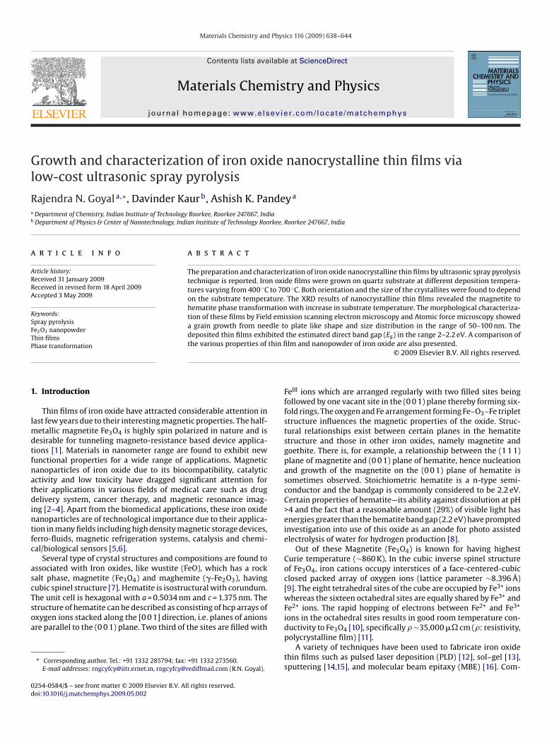
Iron oxide thin films were prepared from aqueous solution of Ferric ChlorideFeCl3·6H2O) (purity 99%, Sigma–Aldrich, USA) by dissolving it in distilled water to aoncentration of 0.1 M. The substrates were first ultrasonically degreased with ace-one, ethanol and deionised water. The designed setup for ultrasonic spray pyrolysisechnique is shown in Fig. 1. Ferric Chloride precursor solution was poured in to theessel from inlet side. The ultrasonic nebulizer (Model NE-U17, Omron Matsusakao. Ltd., Japan), which contains 1.67 MHz transducer, atomizes the chemical solu-ion into the stream of fine droplets. The vibration of the transducer converts therecursor solution into the aerosol. The nebulized spray, which goes up in the col-mn, was deposited on a hot substrate, which was further heat treated to get theigh quality films. Specially designed digital substrate heater with temperature con-roller from Excel instruments, Mumbai, India was used to heat the substrate. Theate of deposition was controlled by the carrier gas flow rate, substrate temperatures well as precursor concentration. To make precursor solution, ferric chloride wasissolved in double distilled water. The choice of solution concentration is crucialor the successful deposition of iron oxide thin films. Methanol was added to adjusthe concentration of the final solution and to enhance the rate of evaporation. Solu-ions of various concentrations were tried to optimize the right stoichiometry of thelms. It is observed that when spray solution is of high concentration, the crackstart appearing over the films and surface of the films becomes rough. On the otherand, with very dilute spray solution, the films are porous and have voids. Finally,he solution of concentration 0.10 M was found to give good quality films. For thereparation of good quality films, various parameters such as nozzle to substrate dis-ance, deposition rate and flow rate of air (carrier gas), deposition temperature andoncentration were optimized to get good quality films. The optimized parameterssed are presented in Table 1.
The substrate temperature was calibrated by placing a thermocouple tem-orarily at the substrate position and simultaneously measuring the temperaturef the control thermocouple inside the heater plate. After the spraying proce-ure, the hotplate was switched off and the samples were subsequently cooled in
ir. The orientation and crystallinity of the thin films were studied using BrukerXS C-8 advanced diffractrometer in �–2� geometry. The surface topography andicrostructure were studied using scanning probe microscope (NT-MDT: NTEGRAodel) and field emission scanning electron microscopy (FE-SEM). Varian Cary-000 UV–vis–NIR spectrometer was used to study the optical properties of thinlms.
Fig. 1. Schematic diagram of ultra
Concentration (mol l ) 0.1Deposition temperature (◦C) 400, 500, 600, and 700 ◦CSubstrate Quartz
To check the conductivity of the prepared thin films for voltammetric purposes,the electrode of the thin films deposited on quartz at different temperatures weremade by making a contact of the film with a copper strip and then the whole assem-bly was wrapped with a good quality scotch tape keeping a hole of 3 mm dia inthe tape just above the film to expose that particular area of the film to be in con-tact with the electrolyte solution. The electrochemical experiments were carriedout using computerized BAS (Bioanalytical Systems, West Lafayette, USA) CV-50 Wvoltammetric analyzer. Electrochemical studies were performed using a conven-tional three electrode glass cell with a platinum wire as an auxillary electrode andAg/AgCl electrode as reference (model MF- 2052 RB-5B). The thin film electrode wasused as the working electrode. Phosphate buffer of pH 7.2 (� = 0.1 M) was used forrecording voltammograms. All potentials were measured at room temperature withreference to Ag/AgCl electrode.
3. Results and discussion
3.1. Fe2O3 nanocrystalline thin films
Fe2O3 thin films were deposited using ultrasonic spray pyrolysison quartz substrate at various deposition temperature in the range400–700 ◦C. The chemical solution was atomized into the streamof the fine droplets via ultrasonic nebulizer operated to an atomiz-ing frequency of 1.67 MHz. Chloride precursor solution was pouredinto the vessel from inlet side. The aerosol was generated from thevibration of the transducer. The nebulized spray, which goes up inthe column, was deposited on a hot substrate. The average diame-ter of the misted droplet can be approximately calculated from anexpression given by Lang [19]:
Dd = 0.34
(8��
�f 2
)
Where Dd is the droplet diameter, � is the solution surface tension(72.9 × 10⁻³ N m−1; surface tension of pure water), � is the solu-
tion density (1027 kg m−3), and f is the applied ultrasonic frequency(1.7 MHz). The diameter of the misted droplets was calculated usingthe above parameters and was about 2.89 �m. The mean diameterof the particles (Dp) formed from the misted droplet was theoreti-sonic spray pyrolysis setup.
6 istry a
c
D
wc(ilota
bstfisdmtTt
Fa
40 R.N. Goyal et al. / Materials Chem
ally calculated using the following equation [20]:
p = Dd
(CprMcomp
�compMpr
)
here Dp is the mean diameter of the particles (Fe-oxide) fabri-ated through pyrolysis reaction, Cpr is the precursor concentration0.1 mol l−1), Mcomp is the molecular mass of the compound, �comp
s the theoretical density of the compound and Mpr is the molecu-ar mass of the precursor. Substituting the Dd value (the diameterf the misted droplet) and the constants into above equation theheoretical mean diameter of Fe-oxide powder was found to bepproximately 403 nm.
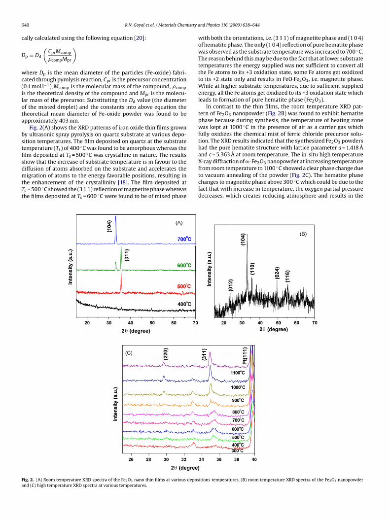
Fig. 2(A) shows the XRD patterns of iron oxide thin films growny ultrasonic spray pyrolysis on quartz substrate at various depo-ition temperatures. The film deposited on quartz at the substrateemperature (Ts) of 400 ◦C was found to be amorphous whereas thelm deposited at Ts = 500 ◦C was crystalline in nature. The resultshow that the increase of substrate temperature is in favour to the
iffusion of atoms absorbed on the substrate and accelerates theigration of atoms to the energy favorable positions, resulting inhe enhancement of the crystallinity [18]. The film deposited ats = 500 ◦C showed the (3 1 1) reflection of magnetite phase whereashe films deposited at Ts = 600 ◦C were found to be of mixed phase
ig. 2. (A) Room temperature XRD spectra of the Fe2O3 nano thin films at various deposnd (C) high temperature XRD spectra at various temperatures.
nd Physics 116 (2009) 638–644
with both the orientations, i.e. (3 1 1) of magnetite phase and (1 0 4)of hematite phase. The only (1 0 4) reflection of pure hematite phasewas observed as the substrate temperature was increased to 700 ◦C.The reason behind this may be due to the fact that at lower substratetemperatures the energy supplied was not sufficient to convert allthe Fe atoms to its +3 oxidation state, some Fe atoms get oxidizedto its +2 state only and results in FeO·Fe2O3, i.e. magnetite phase.While at higher substrate temperatures, due to sufficient suppliedenergy, all the Fe atoms get oxidized to its +3 oxidation state whichleads to formation of pure hematite phase (Fe2O3).
In contrast to the thin films, the room temperature XRD pat-tern of Fe2O3 nanopowder (Fig. 2B) was found to exhibit hematitephase because during synthesis, the temperature of heating zonewas kept at 1000 ◦C in the presence of air as a carrier gas whichfully oxidizes the chemical mist of ferric chloride precursor solu-tion. The XRD results indicated that the synthesized Fe2O3 powdershad the pure hematite structure with lattice parameter a = 1.418 Åand c = 5.363 Å at room temperature. The in-situ high temperatureX-ray diffraction of �-Fe2O3 nanopowder at increasing temperature
from room temperature to 1100 ◦C showed a clear phase change dueto vacuum annealing of the powder (Fig. 2C). The hematite phasechanges to magnetite phase above 300 ◦C which could be due to thefact that with increase in temperature, the oxygen partial pressuredecreases, which creates reducing atmosphere and results in theitions temperatures, (B) room temperature XRD spectra of the Fe2O3 nanopowder
R.N. Goyal et al. / Materials Chemistry and Physics 116 (2009) 638–644 641
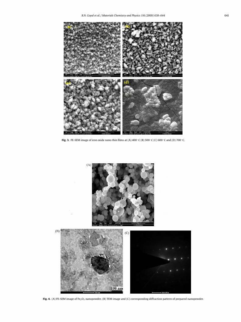
Fig. 3. FE-SEM image of iron oxide nano thin films at (A) 400 ◦C (B) 500 ◦C (C) 600 ◦C and (D) 700 ◦C.
Fig. 4. (A) FE-SEM image of Fe2O3 nanopowder, (B) TEM image and (C) corresponding diffraction pattern of prepared nanopowder.
642 R.N. Goyal et al. / Materials Chemistry and Physics 116 (2009) 638–644
s at (A
rw
ggnbtppttsclf
(TTtscpoitt
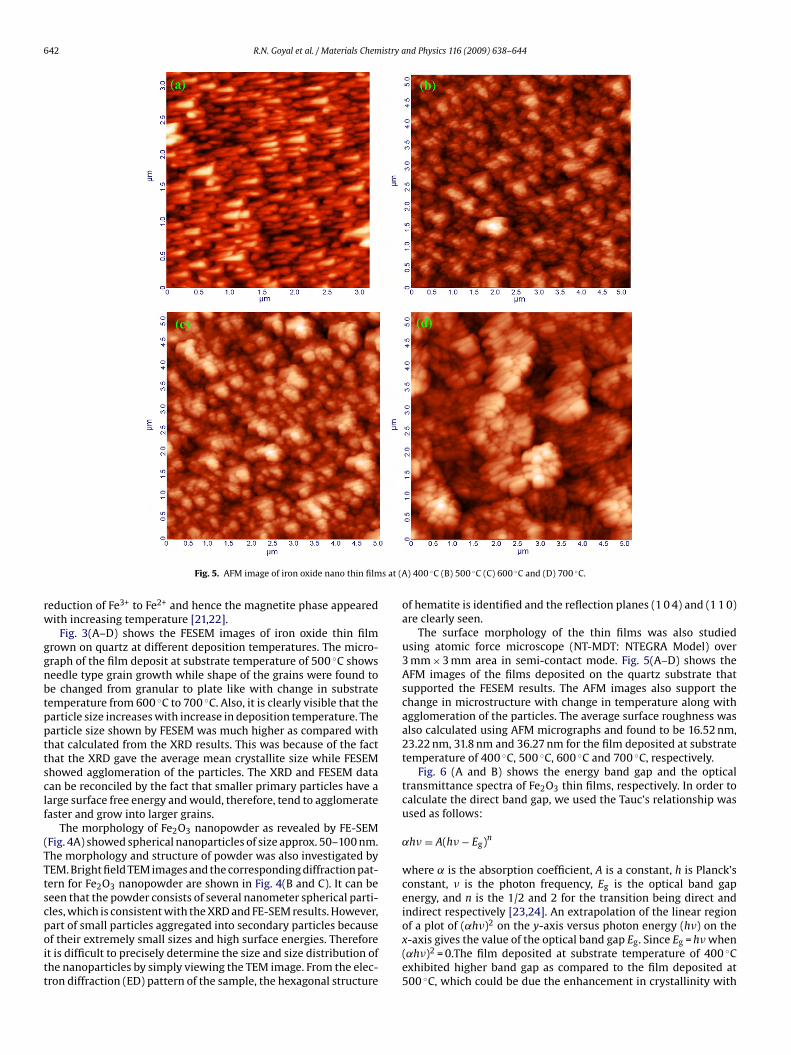
Fig. 5. AFM image of iron oxide nano thin film
eduction of Fe3+ to Fe2+ and hence the magnetite phase appearedith increasing temperature [21,22].
Fig. 3(A–D) shows the FESEM images of iron oxide thin filmrown on quartz at different deposition temperatures. The micro-raph of the film deposit at substrate temperature of 500 ◦C showseedle type grain growth while shape of the grains were found toe changed from granular to plate like with change in substrateemperature from 600 ◦C to 700 ◦C. Also, it is clearly visible that thearticle size increases with increase in deposition temperature. Thearticle size shown by FESEM was much higher as compared withhat calculated from the XRD results. This was because of the facthat the XRD gave the average mean crystallite size while FESEMhowed agglomeration of the particles. The XRD and FESEM dataan be reconciled by the fact that smaller primary particles have aarge surface free energy and would, therefore, tend to agglomerateaster and grow into larger grains.
The morphology of Fe2O3 nanopowder as revealed by FE-SEMFig. 4A) showed spherical nanoparticles of size approx. 50–100 nm.he morphology and structure of powder was also investigated byEM. Bright field TEM images and the corresponding diffraction pat-ern for Fe2O3 nanopowder are shown in Fig. 4(B and C). It can beeen that the powder consists of several nanometer spherical parti-les, which is consistent with the XRD and FE-SEM results. However,
art of small particles aggregated into secondary particles becausef their extremely small sizes and high surface energies. Thereforet is difficult to precisely determine the size and size distribution ofhe nanoparticles by simply viewing the TEM image. From the elec-ron diffraction (ED) pattern of the sample, the hexagonal structure) 400 ◦C (B) 500 ◦C (C) 600 ◦C and (D) 700 ◦C.
of hematite is identified and the reflection planes (1 0 4) and (1 1 0)are clearly seen.
The surface morphology of the thin films was also studiedusing atomic force microscope (NT-MDT: NTEGRA Model) over3 mm × 3 mm area in semi-contact mode. Fig. 5(A–D) shows theAFM images of the films deposited on the quartz substrate thatsupported the FESEM results. The AFM images also support thechange in microstructure with change in temperature along withagglomeration of the particles. The average surface roughness wasalso calculated using AFM micrographs and found to be 16.52 nm,23.22 nm, 31.8 nm and 36.27 nm for the film deposited at substratetemperature of 400 ◦C, 500 ◦C, 600 ◦C and 700 ◦C, respectively.
Fig. 6 (A and B) shows the energy band gap and the opticaltransmittance spectra of Fe2O3 thin films, respectively. In order tocalculate the direct band gap, we used the Tauc’s relationship wasused as follows:
˛h� = A(h� − Eg)n
where ˛ is the absorption coefficient, A is a constant, h is Planck’sconstant, � is the photon frequency, Eg is the optical band gapenergy, and n is the 1/2 and 2 for the transition being direct andindirect respectively [23,24]. An extrapolation of the linear region
of a plot of (˛h�)2 on the y-axis versus photon energy (h�) on thex-axis gives the value of the optical band gap Eg. Since Eg = h� when(˛h�)2 = 0.The film deposited at substrate temperature of 400 ◦Cexhibited higher band gap as compared to the film deposited at500 ◦C, which could be due the enhancement in crystallinity with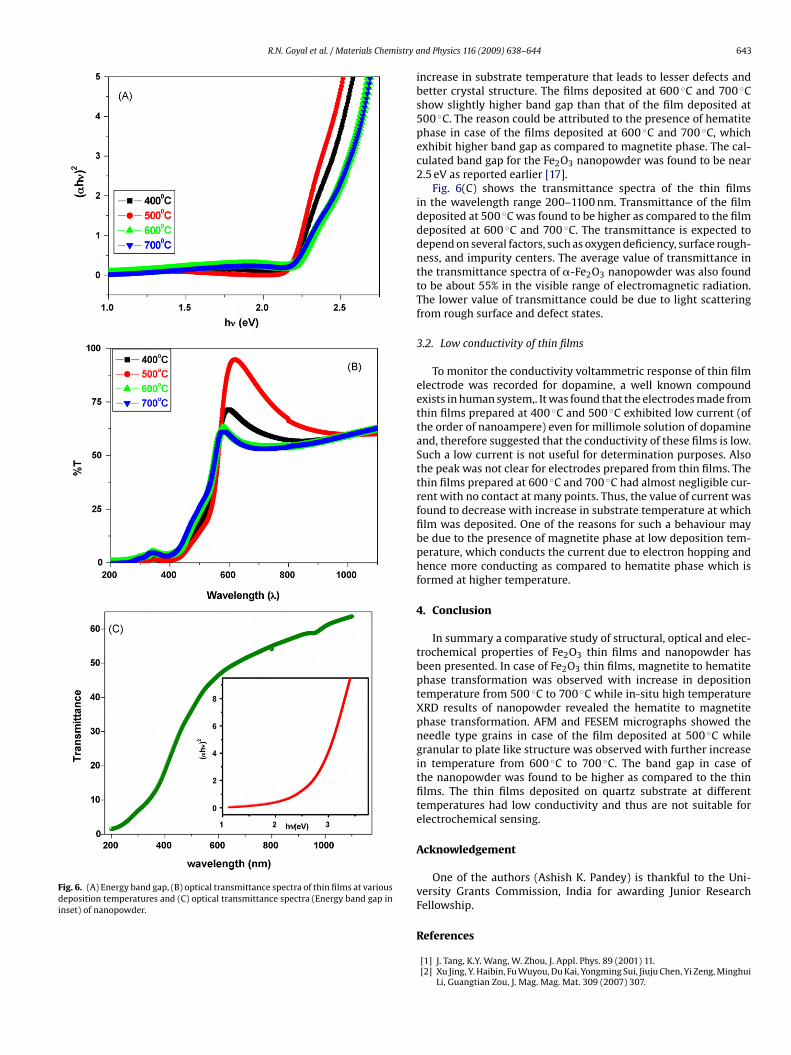
R.N. Goyal et al. / Materials Chemistry a
Fig. 6. (A) Energy band gap, (B) optical transmittance spectra of thin films at variousdeposition temperatures and (C) optical transmittance spectra (Energy band gap ininset) of nanopowder.
nd Physics 116 (2009) 638–644 643
increase in substrate temperature that leads to lesser defects andbetter crystal structure. The films deposited at 600 ◦C and 700 ◦Cshow slightly higher band gap than that of the film deposited at500 ◦C. The reason could be attributed to the presence of hematitephase in case of the films deposited at 600 ◦C and 700 ◦C, whichexhibit higher band gap as compared to magnetite phase. The cal-culated band gap for the Fe2O3 nanopowder was found to be near2.5 eV as reported earlier [17].
Fig. 6(C) shows the transmittance spectra of the thin filmsin the wavelength range 200–1100 nm. Transmittance of the filmdeposited at 500 ◦C was found to be higher as compared to the filmdeposited at 600 ◦C and 700 ◦C. The transmittance is expected todepend on several factors, such as oxygen deficiency, surface rough-ness, and impurity centers. The average value of transmittance inthe transmittance spectra of �-Fe2O3 nanopowder was also foundto be about 55% in the visible range of electromagnetic radiation.The lower value of transmittance could be due to light scatteringfrom rough surface and defect states.
3.2. Low conductivity of thin films
To monitor the conductivity voltammetric response of thin filmelectrode was recorded for dopamine, a well known compoundexists in human system,. It was found that the electrodes made fromthin films prepared at 400 ◦C and 500 ◦C exhibited low current (ofthe order of nanoampere) even for millimole solution of dopamineand, therefore suggested that the conductivity of these films is low.Such a low current is not useful for determination purposes. Alsothe peak was not clear for electrodes prepared from thin films. Thethin films prepared at 600 ◦C and 700 ◦C had almost negligible cur-rent with no contact at many points. Thus, the value of current wasfound to decrease with increase in substrate temperature at whichfilm was deposited. One of the reasons for such a behaviour maybe due to the presence of magnetite phase at low deposition tem-perature, which conducts the current due to electron hopping andhence more conducting as compared to hematite phase which isformed at higher temperature.
4. Conclusion
In summary a comparative study of structural, optical and elec-trochemical properties of Fe2O3 thin films and nanopowder hasbeen presented. In case of Fe2O3 thin films, magnetite to hematitephase transformation was observed with increase in depositiontemperature from 500 ◦C to 700 ◦C while in-situ high temperatureXRD results of nanopowder revealed the hematite to magnetitephase transformation. AFM and FESEM micrographs showed theneedle type grains in case of the film deposited at 500 ◦C whilegranular to plate like structure was observed with further increasein temperature from 600 ◦C to 700 ◦C. The band gap in case ofthe nanopowder was found to be higher as compared to the thinfilms. The thin films deposited on quartz substrate at differenttemperatures had low conductivity and thus are not suitable forelectrochemical sensing.
Acknowledgement
One of the authors (Ashish K. Pandey) is thankful to the Uni-versity Grants Commission, India for awarding Junior ResearchFellowship.
References
[1] J. Tang, K.Y. Wang, W. Zhou, J. Appl. Phys. 89 (2001) 11.[2] Xu Jing, Y. Haibin, Fu Wuyou, Du Kai, Yongming Sui, Jiuju Chen, Yi Zeng, Minghui
Li, Guangtian Zou, J. Mag. Mag. Mat. 309 (2007) 307.

6 istry a
[[
[
[
[
[
[
[[
truct. Mater. 9 (1997) 125.
44 R.N. Goyal et al. / Materials Chem
[3] B. Fang, G. Wang, M. Li, X. Kan, Electroanalysis 17 (2005) 744.[4] A.K. Gupta, M. Gupta, Biomaterials 26 (2005) 3995.[5] V. Sreeja, P.A. Joy, Mater. Res. Bull. 42 (2007) 1570.[6] J. Du, H. Liu, J. Magn. Magn. Mater. 302 (2006) 263.[7] T. Tepper, C.A. Ross, J. Appl. Phys. 91 (2002) 7.[8] S.S. Kulkarni, C.D. Lokhande, Mater. Chem. Phys. 82 (2003) 151.[9] N. Tsuda, K. Nasu, A. Fujimori, K. Shiratori, Elec. Cond. Oxid. (Shokabo, Japan)
(1993) 307.10] E.J.W. Verwey, Nature (London) 144 (1939) 327.11] J.M.D. Coey, A.E. Berkowitz, L.I. Balcells, F.F. Putris, F.T. Parker, Appl. Phys. Lett.
72 (1998) 734.12] M.K. Krause, P. Esquinazi, M. Ziese, R. Hohne, A. Pan, A. Galkin, E. Zeldov, J. Magn.
Magn. Mater. 245 (2002) 1097.13] N.J. Tang, W. Zhong, H.Y. Jiang, X.L. Wu, W. Liu, Y.W. Du, J. Magn. Magn. Mater.
282 (2004) 92.14] S. Ohta, A. Tterada, Thin Solid films 143 (1986) 73.
[[[
[
nd Physics 116 (2009) 638–644
15] G. Zhang, C. Fan, L. Pan, F. Wang, P. Wu, H. Giu, Y. Gub, Y. Zhang, J. Magn. Magn.Mater. 293 (2005) 737.
16] W. Eerenstein, L. Kalev, L. Niesen, T.T.M. Palstra, T. Hibma, J. Magn. Magn. Mater.258–259 (2003) 73.
[17] R.N. Goyal, A.K. Pandey, D. Kaur, A. Kumar, J. Nanosci. Nanotechnol. 9 (2009)4692.
[18] P. Singh, A. Kumar, Deepak, D. Kaur, J. Crys. Growth 306 (2007) 303.19] R.J. Lang, J Acoust. Soc. Am. 43 (1962) 6.20] J.M. Nedeljkovie, Z.V. Saponjic, Z. Rakocevic, V. Jakanovic, D.P. Uskokovic, Nanos-
21] I.A. Serbinov, G.A. Niklasson, C.G. Granqvist, J. Mater. Sci. 23 (1988) 3876.22] A. Petras, K. Preisinger, Mereiter, Mater. Sci. Forum 278 (1998) 396.23] L. Dghoughi, B. Elidrissi, C. Bernede, M. Addou, M.A. Lamrani, M. Regragui, H.
Erguig, Appl. Surf. Sci. 253 (2006) 1823.24] A.A. Akl, Appl. Surf. Sci. 233 (2004) 307.


![[Battezzati_L.,_Pozzovivo_S.,_Rizzi_P.] Nanocrystalline Aluminum Alloys.pdf](https://img.pdfslide.net/doc/110x75/577cc2111a28aba711941b5e/battezzatilpozzovivosrizzip-nanocrystalline-aluminum-alloyspdf.jpg)