Embed Size (px)
Citation preview
Exploration & Production
This document is the property of Total. It must not be stored, reproduced or disclosed to others without written authorisation from the Company.
GENERAL SPECIFICATION
SAFETY
GS EP SAF 262
Pressure protection relief and hydrocarbon disposal systems
03 01/2011 General review
02 10/2005 Addition of EP root to document identification and included pressure protection from former GS SAF 261
01 10/2003 Change of Group name and logo
00 04/2001 Old TotalFina SP SEC 262
Rev. Date Notes
Owner: EP/HSE Managing entity: EP/SCR/ED/ECP
Exploration & Production
General Specification Date : 01/2011
GS EP SAF 262 Rev : 03
This document is the property of Total. It must not be stored, reproduced or disclosed to others without written authorisation from the Company.
Page 2/42
Contents
1. Scope ....................................................................................................................... 4 1.1 Purpose of the specification ............................................................................................... 4
1.2 Applicability ........................................................................................................................ 4
2. Reference documents ............................................................................................. 5
3. Terminology and definitions .................................................................................. 6
4. Pressure protection and relief ............................................................................... 8 4.1 Requirements for pressure protection and relief ................................................................ 8
4.2 Relief device setting ......................................................................................................... 11
4.3 Relief system sizing ......................................................................................................... 11
4.4 Relief system configuration .............................................................................................. 12
4.5 Relief devices .................................................................................................................. 13
5. Disposal system description ................................................................................ 14 5.1 Collecting systems ........................................................................................................... 14
5.2 Independence of collecting systems ................................................................................ 15
5.3 Release systems ............................................................................................................. 16
5.4 Release systems applicability .......................................................................................... 18
6. Safety design requirements ................................................................................. 22 6.1 Disposal network ............................................................................................................. 22
6.2 Mist or liquid recovery ...................................................................................................... 24
6.3 Structure of elevated flares .............................................................................................. 24
6.4 Burn pits ........................................................................................................................... 24
6.5 Ignition systems ............................................................................................................... 25
6.6 Flare tips and pilots .......................................................................................................... 25
6.7 Flashback and internal deflagration ................................................................................. 25
6.8 Radiation hazards ............................................................................................................ 28
6.9 Smoke and pollution ........................................................................................................ 28
6.10 Elevated flare tip replacement. ........................................................................................ 29
7. Disposal system lay-out ....................................................................................... 30 7.1 General ............................................................................................................................ 30
Exploration & Production
General Specification Date : 01/2011
GS EP SAF 262 Rev : 03
This document is the property of Total. It must not be stored, reproduced or disclosed to others without written authorisation from the Company.
Page 3/42
7.2 Radiation .......................................................................................................................... 32
7.3 Flammable gas ................................................................................................................ 38
7.4 Toxic gas ......................................................................................................................... 38
7.5 Noise ................................................................................................................................ 38
7.6 Minimum distances .......................................................................................................... 38
7.7 Maximum distances ......................................................................................................... 38
8. Closed flare systems ............................................................................................ 39 8.1 Application and objective ................................................................................................. 39
8.2 System description .......................................................................................................... 39
8.3 Closed flare systems specific safety requirements .......................................................... 40
8.4 Flare stack purge gas and pelletised ignition systems .................................................... 41
8.5 Closed flare and pelletised ignition systems validation .................................................... 41
Bibliography ................................................................................................................. 42
Exploration & Production
General Specification Date : 01/2011
GS EP SAF 262 Rev : 03
This document is the property of Total. It must not be stored, reproduced or disclosed to others without written authorisation from the Company.
Page 4/42
1. Scope
1.1 Purpose of the specification The purpose of this general specification is to define safety requirements for the design of the pressure protection and relief and the hydrocarbon disposal systems suitable for production, processing, transportation and storage installations in the oil and gas industry.
Hydrocarbon disposal systems are here defined as the systems to dispose of vapours or liquid hydrocarbon by burning or venting to the atmosphere during normal operation (fatal flow) including maintenance or inspection, abnormal operation such as process upsets (excess flow, off-specification products) and emergencies (pressure relief and emergency depressurisation).
The usual hydrocarbon disposal methods are to discharge vapours to atmosphere, non-volatile liquids to a catch pit and volatile liquids to other equipment operating at a lower pressure. However Company's policy is to reduce its overall emissions and waste generation wherever technically and/or economically feasible. Therefore alternate solutions to disposal e.g. vapour recovery system, gas re-injection, fully rated mechanical design; instrumented protection systems should be assessed.
The following basic principles should be applied (refer to GS EP ENV 001):
• Minimising flaring operations, with a “no flaring” target, by implementing all practical alternatives to burning associated gas,
• Avoiding, as far as reasonably practically, the continuous process cold venting practice.
These principles do not apply to emergency situations and special operations (blow-down, shutdown, trips and start-up, etc.).
Other factors that may impact the design of hydrocarbon disposal system should be considered, in particular:
• Applicable local or international regulations governing air and water quality control,
• Meteorological conditions,
• Properties of hydrocarbon released (toxicity, volatility, flammability, etc.),
• Other specifics, as applicable.
1.2 Applicability This specification is not retroactive. It shall apply to new installations and to major modifications or extensions of existing installations. This specification applies to on-shore and offshore installations including FPSO and their cargo blanketing systems, refrigerated LPG/NGL storages and cryogenic LNG storages (see GS EP SAF 341 section 5.1.1). Specific requirements for FPSO vent systems are also covered in GS EP STR 651 section 5.8.
This specification is limited to highlight HSE related matters (refer to GS EP ENV 001 & GS EP SAF 221) and does not cover, in particular:
• Shutdown and emergency depressurisation systems (refer to GS EP SAF 261),
• Detailed design of disposal systems, such as flares, vents, pits, etc. (refer to GS EP ECP 103).
Exploration & Production
General Specification Date : 01/2011
GS EP SAF 262 Rev : 03
This document is the property of Total. It must not be stored, reproduced or disclosed to others without written authorisation from the Company.
Page 5/42
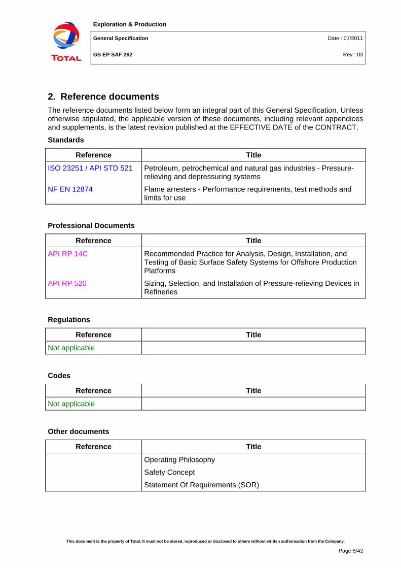
2. Reference documents The reference documents listed below form an integral part of this General Specification. Unless otherwise stipulated, the applicable version of these documents, including relevant appendices and supplements, is the latest revision published at the EFFECTIVE DATE of the CONTRACT.
Standards
Reference Title
ISO 23251 / API STD 521 Petroleum, petrochemical and natural gas industries - Pressure-relieving and depressuring systems
NF EN 12874 Flame arresters - Performance requirements, test methods and limits for use
Professional Documents
Reference Title
API RP 14C Recommended Practice for Analysis, Design, Installation, and Testing of Basic Surface Safety Systems for Offshore Production Platforms
API RP 520 Sizing, Selection, and Installation of Pressure-relieving Devices in Refineries
Regulations
Reference Title
Not applicable
Codes
Reference Title
Not applicable
Other documents
Reference Title
Operating Philosophy
Safety Concept
Statement Of Requirements (SOR)
Exploration & Production
General Specification Date : 01/2011
GS EP SAF 262 Rev : 03
This document is the property of Total. It must not be stored, reproduced or disclosed to others without written authorisation from the Company.
Page 6/42
Total General Specifications
Reference Title
GS EP ECP 103 Process sizing criteria
GS EP ENV 001 Environmental requirements for projects design and E&P activities
GS EP SAF 021 Layout
GS EP SAF 216 Area classification
GS EP SAF 221 Safety rules for buildings
GS EP SAF 228 Liquid drainage
GS EP SAF 253 Impacted area, restricted area and fire zones
GS EP SAF 260 Design of High Integrity Protection Systems (HIPS)
GS EP SAF 261 Emergency Shut-Down and Emergency De-Pressurisation (ESD & EDP)
GS EP SAF 337 Passive fire protection: Basis of design
GS EP SAF 341 Location and protection of onshore hydrocarbon storage
GS EP SAF 380 Safety Engineering Requirements for an F(P)SO
GS EP STR 651 General principles for a F(P)SO Design
3. Terminology and definitions There are five types of statements in this specification, the “shall”, “should”, “may”, “can” and “must” statements. They are to be understood as follows: Shall Is to be understood as mandatory. Deviating from a “shall”
statement requires derogation approved by Company. Should Is to be understood as strongly recommended to comply with the
requirements of the specification. Alternatives shall provide a similar level of protection and this shall be documented.
May Is to be understood as permission.
Can Is to be understood as a physical possibility.
Must Expresses a regulatory obligation
Note that “will” is not to be understood as a statement. Its use is to be avoided, unless it is necessary to describe a sequence of events.
Exploration & Production
General Specification Date : 01/2011
GS EP SAF 262 Rev : 03
This document is the property of Total. It must not be stored, reproduced or disclosed to others without written authorisation from the Company.
Page 7/42
Abnormal (operating condition)
Condition which occurs in a process component when an operating variable ranges outside of its normal operating limits (API).
Blow-Down (of a plant or equipment)
Depressurisation of a plant or part of a plant, or equipment.
Blow-Down (PSV device)
Difference between the set pressure and the closing pressure of a pressure relieving device (API + Company).
Bursting Disc “burst pressure”
The burst pressure of a rupture disc at the specified temperature is the value of the upstream static pressure minus the value of the downstream static pressure just prior to when the disc bursts. When the downstream pressure is atmospheric, the burst pressure is the upstream static gauge pressure. (API RP 520).
Bursting Disc “rated or marked burst pressure”
The marked burst pressure, or rated burst pressure of a rupture disc, is the burst pressure established by tests for the specified temperature and marked on the disc tag by the manufacturer. The marked burst pressure may be any pressure within the manufacturing range unless otherwise specified by the customer. The marked burst pressure is applied to all of the rupture discs of the same lot. (API RP 520)
Flaring, emergency Flaring a peak flow of combustible gas in emergency conditions for periods of time generally less than 15 minutes (Company).
Flaring, maximum continuous
Flaring the largest allowable steady flow of combustible gas in abnormal or upset operating conditions, for periods of time that may exceed 15 minutes (Company).
Fuel source Same as ISO definition of "source of release" (API).
Ignition source Source of temperature and energy sufficient to initiate combustion (API).
Impacted area Area that extends beyond the boundaries of the installation but which is nevertheless affected either permanently by normal operation of the facility (noise, radiation, etc.) or exceptionally by the consequences of an emergency situation caused by a major failure (Company).
Latent failure Latent failures should normally be considered as an existing condition and not as a cause of overpressure when assessing whether a scenario is single or double jeopardy (ISO 23251 / API STD 521).
Major failure A conceivable incident that can possibly occur on the facility. Used for the definition of the facility restricted area and impacted +area (Company).
Pressure Protection and Relief device (PRV or PSV)
Device, generally Pressure Safety Valve (PSV) or bursting disk, releasing hydrocarbon contained inside process equipment in order to ensure that the prevailing pressure shall not exceed the design pressure (Company).
Pressure Relief device Back Pressure is the pressure that exists at the outlet of a relief
Exploration & Production
General Specification Date : 01/2011
GS EP SAF 262 Rev : 03
This document is the property of Total. It must not be stored, reproduced or disclosed to others without written authorisation from the Company.
Page 8/42
“back pressure” device as the result of the pressure of the discharge system. It is the sum of the superimposed and built-up back pressure (API RP 520).
Pressure Relief device “set pressure”
The set pressure is the inlet gauge pressure at which the pressure relief device is set to open under service conditions. (API RP 520).
Public Human beings, fauna, flora, installations or organisations who are outside the installation restricted area and who are not commissioned by Company to conduct a work approved by them (Company).
Restricted area Area within the boundaries of the installation and hence under the control of Company, affected permanently by normal operation of the facility or exceptionally by the consequences of an emergency situation caused by a major failure (Company).
Source of release Point from which flammable gas, liquid or a combination of both can be released into the atmosphere (ISO).
Thermal Expansion Relief Valve (TERV or TSV)
Device releasing hydrocarbon trapped inside a capacity (usually a pipeline section) submitted to heat input in order to maintain pressure below design pressure. The acronym "TSV" is used in the present specification.
4. Pressure protection and relief
4.1 Requirements for pressure protection and relief
4.1.1 Causes of over-pressurisation The abnormal events listed below can lead to an over-pressurisation; they shall therefore be taken into account for the design of Pressure Protection and Relief systems:
• Blocked outlet,
• Inadvertent inlet valve opening,
• Check-valve failure,
• Utilities failure (Electricity, Cooling, Instrument Air, Steam, Fuel, Inert Gas...),
• Mechanical failure,
• Heat exchanger tube failure,
• Transient pressure surge (water hammer …, slugging regime),
• Plant fires,
• Process changes, chemical reactions.
Process facilities shall be designed to minimise the occurrence of these causes. The rules and principles contained in this document are focused on the mitigation devices to minimise the effects of an over-pressurisation.
4.1.2 Pressure protection systems selection Three main approaches are possible for pressure protection systems:
Exploration & Production
General Specification Date : 01/2011
GS EP SAF 262 Rev : 03
This document is the property of Total. It must not be stored, reproduced or disclosed to others without written authorisation from the Company.
Page 9/42
4.1.2.1 Full pressure-rated mechanical design The system design pressure exceeds any possible pressure, including in the case(s) of process upset, and with due allowance for corrosion being made.
Fully rated pressure mechanical design is the preferred option from a safety point of view.
This type of design is highly recommended downstream of wellheads up to the production manifold, advisable for the first stage production separator when technically realistic to do so and mandatory for closed drain gathering networks up to the closed drain drum inlet nozzle.
Any part of a compression unit shall be able to withstand the equalising pressure ("settle out" pressure) after a shutdown.
Note: A pressure system requiring TSV's cannot be considered as fully-pressure rated. Refer to section 4.1.3.
4.1.2.2 Relief systems The system design pressure includes a safety margin above the system maximum operating pressure (refer to GS EP ECP 103 for "maximum operating pressure" definition) but, in case of a process upset, the pressure prevailing in the system can nevertheless exceed the design pressure. The system is therefore fitted with relief devices, designed to open at design pressure in case of upset conditions. Refer also to GS EP ECP 103.
Offshore and in accordance with API RP 14C, a primary protection against over-pressurisation shall be provided by a PSHH (actuating a SDV or an ESDV) and a secondary protection by relief valves.
Although not specifically meant for onshore environment, API RP 14C approach shall also be applied to onshore facilities for over-pressure protection. Possible derogations may be granted based on SAFE chart analysis e.g. low hazard facilities and/or low sensitivity environment.
4.1.2.3 High Integrity Pressure Protection Systems (HIPPS) They are instrument-based systems of sufficient integrity (involving high reliability redundant and/or diversified instruments) so as to make the risk of exceeding the design pressure acceptable (refer to GS EP SAF 260).
HIPPS are not an option given preference by Company. HIPPS shall be selected only when full pressure rated designs and relief systems prove impractical, generally because of environmental considerations (to avoid relief to atmosphere through relief valve) and/or lay-out constraints (size of relief headers and associated downstream systems: vents, flares, etc.).
In all cases, an exception dossier including a reliability study based on detailed design including equipment brand, type and model shall be submitted to Company for approval.
Note: Thermal expansion relief valves (TSVs) may be necessary on HIPPS protected equipment. Refer to section 4.1.3.
4.1.3 Criteria for installation of relief devices Pressure relief devices shall be limited to hardware devices with no possibility of common mode of failure e.g. common upstream isolation valves. Pressure relief devices may consist in one, or a combination, of the following: Pressure Safety Valve PSV, PSV fire case, Thermal Safety Valve TSV, bursting discs or other specifics.
Exploration & Production
General Specification Date : 01/2011
GS EP SAF 262 Rev : 03
This document is the property of Total. It must not be stored, reproduced or disclosed to others without written authorisation from the Company.
Page 10/42
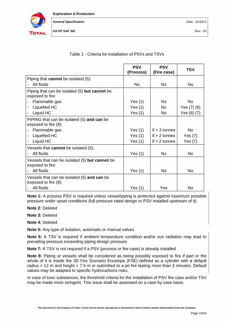
Table 1 - Criteria for installation of PSVs and TSVs
PSV (Process)
PSV (Fire case) TSV
Piping that cannot be isolated (5): - All fluids No No No Piping that can be isolated (5) but cannot be exposed to fire: - Flammable gas - Liquefied HC - Liquid HC
Yes (1) Yes (1) Yes (1)
No No No
No Yes (7) (6) Yes (6) (7)
PIPING that can be isolated (5) and can be exposed to fire (8): - Flammable gas - Liquefied HC - Liquid HC
Yes (1) Yes (1) Yes (1)
if > 3 tonnes if > 2 tonnes if > 2 tonnes
No Yes (7) Yes (7)
Vessels that cannot be isolated (5): - All fluids Yes (1) No No Vessels that can be isolated (5) but cannot be exposed to fire: - All fluids Yes (1) No No Vessels that can be isolated (5) and can be exposed to fire (8): - All fluids Yes (1) Yes No
Note 1: A process PSV is required unless vessel/piping is protected against maximum possible pressure under upset conditions (full pressure rated design or PSV installed upstream of it).
Note 2: Deleted
Note 3: Deleted
Note 4: Deleted
Note 5: Any type of isolation, automatic or manual valves
Note 6: A TSV is required if ambient temperature condition and/or sun radiation may lead to prevailing pressure exceeding piping design pressure
Note 7: A TSV is not required if a PSV (process or fire case) is already installed
Note 8: Piping or vessels shall be considered as being possibly exposed to fire if part or the whole of it is inside the 3D Fire Scenario Envelope (FSE) defined as a cylinder with a default radius = 12 m and height = 7.5 m or submitted to a jet fire lasting more than 3 minutes. Default values may be adapted to specific hydrocarbons risks.
In case of toxic substances, the threshold criteria for the installation of PSV fire case and/or TSV may be made more stringent. This issue shall be assessed on a case by case basis.
Exploration & Production
General Specification Date : 01/2011
GS EP SAF 262 Rev : 03
This document is the property of Total. It must not be stored, reproduced or disclosed to others without written authorisation from the Company.
Page 11/42
4.2 Relief device setting The setting points and other characteristics of the relief devices shall be as per GS EP ECP 103 for process equipment, utilities and pressure vessels for storage of liquefied hydrocarbon. GS EP SAF 341 recommendations shall apply for liquid petroleum product tanks.
4.3 Relief system sizing
4.3.1 Failure cases Individual relief valves shall be sized to relief the overpressure resulting from the combination of any existing steady state condition and any cause of overpressure. The simultaneous occurrence of two or more unrelated causes of overpressure (also known as double or multiple jeopardy) is not a basis for design.
The causes of overpressure are considered unrelated if no process or mechanical or electrical linkages exist among them, or if the length of time that elapses between possible successive occurrences of these causes is sufficient to make their classification unrelated.
Latent failures (e.g. instrumentation, check valves, fire pumps …) should normally be considered as an existing condition and not as a cause of overpressure when assessing whether a scenario is single or double jeopardy.
One example of latent failure is a fire pump not starting upon demand. The scenario of having a single fire event and the pump failing to start is the combination of a single jeopardy and a latent failure, and is not considered as a double jeopardy. The fire heat input to calculate the flare load cannot be reduced by the possible cooling effect of the firewater system.
Operator error is considered as a potential source of overpressure.
Fire is a cause of overpressure. To define the combined relieving loads under fire exposure, the probable maximum extent of a fire should be estimated, as noted in section 4.1.3. A more detailed analysis can show a smaller fire-impact area.
For examples of single and double jeopardy scenarios, refer to ISO 23251 / API STD 521, section 4.2.
This International Standard describes single-jeopardy scenarios that should be considered as a basis for design. The user may choose to go beyond these practices and assess multiple jeopardy scenarios.
4.3.2 Multiple wells system relief The relief system shall be sized to handle the most demanding overpressure situations likely to occur.
In the absence of general common mode of failure (e.g. logic solver, wellhead control panel, air instrument, power supply …) the default scenario shall be full flow production from all the sources involved (wells, trunklines in the case of a riser platform receiving remote wellhead effluent, etc, …) during 90 seconds, followed by 15 minutes of production of the source producing the largest flow rate.
Where relevant, a transient analysis shall be conducted to check that incoming master valve and/or wing valve closing time does not lead to an overpressure situation in the flow-line, manifold or even trunk-line. If this were the case, then the pressure relieving devices would be
Exploration & Production
General Specification Date : 01/2011
GS EP SAF 262 Rev : 03
This document is the property of Total. It must not be stored, reproduced or disclosed to others without written authorisation from the Company.
Page 12/42
sized to avoid this occurrence, unless the piping section likely to become over pressured could be designed to withstand the well shut-in pressure.
4.3.3 Control valves Sizing of PSVs for protection against overpressure in case of failure of control valves fitted with a by-pass shall be covered by guidance provided within GS EP ECP 103.
4.4 Relief system configuration
4.4.1 Number of relief valves The number of relief valves fitted onto an equipment is not driven only by safety related concerns. However the following rules shall apply on top of other (e.g. process) considerations:
• For process pressure safety valves, if n is the number of PSV (or set of PSV) necessary to ensure 100% relief capacity, then n + 1 PSV (or set of) shall be installed (generally 2 x 100%, possibly 3 x 50%).
• A spare relief valve is always installed except if the protected equipment can be isolated and de-pressurised/drained without production loss (e.g. test separator, pig trap, etc.).
• Where, for capacity reasons, several pressure relief valves must be provided in parallel, the set pressures should be staggered to avoid chattering during relief. The difference between set points shall be less than 6% of the design pressure.
• A single TSV shall be provided for pipework thermal relief.
4.4.2 Isolation valves The following rules shall apply:
• n + 1 sets of pressure relief valves shall be associated with car seal procedures for both upstream and downstream isolation valves (refer to GS EP ECP 103):
• Interlock devices are acceptable but the use of keys shall be avoided.
• The PSV’s installation with two upstream isolation valves is required on all fluids having one of the following conditions:
- Operating pressure above 70 barg,
- Operating pressure above 35 barg, only for LNG,
- H2S partial pressure > 1 bar,
- Fluid very corrosive and abrasive.
• “Double block and bleed” is an acceptable alternative to positive isolation provided that the workplace is not left unattended during change-out of PSVs.
• In all cases, means shall be provided to allow controlled venting of trapped gas between the upstream isolation valve(s) and the PSV in preparation for a maintenance intervention.
• For single 100% capacity pressure relief valves, the fitting of upstream isolation valve(s) shall be assessed, depending on the Operating Philosophy.
• If feasible, and assuming this does not create interference with other process systems, the relief discharge lines from a process unit should be routed to a common sub-header.
Exploration & Production
General Specification Date : 01/2011
GS EP SAF 262 Rev : 03
This document is the property of Total. It must not be stored, reproduced or disclosed to others without written authorisation from the Company.
Page 13/42
• Upstream and downstream isolation valves should be minimised by careful consideration of operating and maintenance philosophies of the concerned relief device, equipment, or unit.
• Where downstream isolation valves cannot be avoided, they shall be locked or car sealed open in normal operating conditions. A single valve without positive isolation is generally considered as acceptable, but for toxic services (H2S partial pressure exceeding 1 bar or an equivalent harmful effect to human life) an auditable risk analysis shall be performed in order to define the downstream isolation.
• Isolation valves shall be gate valve or full bore ball valve.
4.4.3 Relief system piping Adequate supports shall be provided upstream and downstream the relief devices.
Relief lines shall slope downwards to the relief header, without any low point. The relief headers shall slope continuously towards the vent or flare stack.
Adequate systems shall be installed to separate liquids before the vent or flare tip. Where liquid is expected, a K.O. drum shall be provided. Where practicable, flare KO drum liquids should be re-injected in the main process; however as per GS EP SAF 228 section 5.1.2 automatic transfer of liquids from a KO flare drum to the closed drain drum may be accepted.
The design of the network and, in particular, of the drain points, shall be such that the ingress of air under vacuum conditions is avoided. The relief piping shall be selected from material suitable for the lowest expected discharge temperatures. If water may be present, the risk of ice or hydrate formation shall be assessed, and methanol or glycol injection or any other suitable mitigation measure such as separate headers to the flare K.O. drum, should be envisaged to avoid blockage.
4.5 Relief devices
4.5.1 Spring loaded relief valves
4.5.1.1 Conventional spring-loaded relief valves They shall be installed where back-pressure does not exceed 10% of the set pressure. They are the recommended type for TSVs.
4.5.1.2 Balanced pressure relief valves They are suitable for back-pressures ranging from 10% to 50% of the set pressure. They can be of two main types: balanced piston and balanced bellows. Balanced bellows shall be given preference where the fluid is corrosive or fouling.
4.5.2 Pilot-operated relief valves Pilot-operated relief valves shall be selected rather than conventional spring-loaded relief valves when any of the requirement listed here-after is paramount: low accumulation rates, more accurate settings and thus higher suitability for high pressure service, calibration without removing the valve, handling of large flows, etc.
Exploration & Production
General Specification Date : 01/2011
GS EP SAF 262 Rev : 03
This document is the property of Total. It must not be stored, reproduced or disclosed to others without written authorisation from the Company.
Page 14/42
4.5.3 Bursting discs The use of bursting discs shall be limited to the cases listed below and avoided in all other cases:
• Fast response is required, e.g. protection of the water side of a gas cooler in case of tube rupture, protection against surge effects of loading/unloading buoys, in parallel of fast opening valve in closed flare design (see section 8).
• Downstream relief system must be protected from a corrosive fluid (in this case, particular attention should be paid to prevent any debris from damaging or plugging a downstream relief valve).
As bursting discs present unobstructed reverse flow paths once burst, special attention shall be addressed to the hazards from backflow from the discharge system to the process. If necessary segregated discharge systems should be considered for bursting discs.
Bursting discs can be of various types:
• Conventional bursting discs: Suitable when operating conditions are stable and do not exceed 70% of the rated burst pressure.
• Scored tension-loaded bursting discs: They shall be given preference over conventional bursting discs when the system operating pressure reaches 85% of the rated burst pressure and/or when debris resulting from disk burst should be avoided.
• Reverse-acting bursting discs: Recommended when operating pressure reaches up to 90% of the rated burst pressure.
• Composite bursting discs: they shall be selected when resistance to corrosion is a paramount requirement.
- Domed type are suitable for operating pressure reaching 80% of the rated burst pressure.
- Flat type are the particularly suitable for low rated bursting pressures and shall typically be used as corrosion barriers in which case they may typically operate at 50% of the rated burst pressure.
5. Disposal system description The selection and definition of disposal systems result from a combination of process studies, safety and environmental requirements, and operation and maintenance considerations. The following development is intended to list-out the various schemes for disposal of hydrocarbon, to provide definitions for the different devices constituting the systems and to focus on the main safety issues considered. It also provides guidelines for the selection of the appropriate disposal systems at the pre-project stage.
5.1 Collecting systems
5.1.1 Low Pressure (LP) disposal system A LP disposal system is a system where the back-pressure must be maintained low, even at maximum relief flowrate. Therefore the flowrate sent to such a system is relatively small with regards to the pipework diameter to ensure a low back-pressure at any time, including emergency situations. This system generally collects:
Exploration & Production
General Specification Date : 01/2011
GS EP SAF 262 Rev : 03
This document is the property of Total. It must not be stored, reproduced or disclosed to others without written authorisation from the Company.
Page 15/42
• Excess or fatal gas from low pressure processing units for which a low back pressure is required (e.g. last separation stage of a crude stabilisation plant).
• PSVs (1) and BDVs relief streams from low pressure equipment requiring a low back pressure for a proper operation of the pressure relief device, and for a proper depressurisation of the equipment.
• Possibly blanketing gases or venting from atmospheric storage tanks,
• Exhausts of gas expansion motors.
Note 1: As a general rule all PSV's and TSV’s from equipment/piping handling hydrocarbon and/or toxic substances should be collected unless it is demonstrated it is safe and non-detrimental to environment to do otherwise. If possible, recycling TSV discharge to process vessels, closed drains drum, tanks is preferred to discharging to flare.
5.1.2 High Pressure (HP) disposal system A HP disposal system is a system where the back pressure can be higher than what is admissible in the LP relief system. The HP disposal system collects the high flowrate sources which cannot be routed to the LP disposal system because they would create excessive back pressure. This generally includes:
• Excess gas which must be released for pressure control of high pressure processing units,
• The release of PSVs and BDVs from high pressure equipment.
5.1.3 Low Temperature (LT) disposal system It is a disposal system collecting cold gas from cryo-technic units, or gas made cold due to Joule-Thomson effect in the relief device. Piping metallurgy shall be adequate for cold service and cold disposal streams shall be segregated from wet gas disposal system to avoid formation of hydrates.
5.1.4 Acid/toxic disposal system Such a disposal system collects acid and/or toxic gases, and therefore requires specific materials and/or specific disposal means for safety or environmental reasons.
5.1.5 Liquid disposal system A liquid disposal system gathers off-specification liquids or liquids that must be disposed of in case of process upset or emergency.
5.2 Independence of collecting systems
5.2.1 General For simplicity and safety of operation, it is recommended to have an equipment dedicated to a single relief system. Generally a vessel connected to the HP flare system via a PCV, shall have its PSV/BDV connected to the same HP flare system.
This rule may however be deviated from where the temperature resulting from an emergency depressurisation is not compatible with the design of the HP (or LP) collecting system. In this
Exploration & Production
General Specification Date : 01/2011
GS EP SAF 262 Rev : 03
This document is the property of Total. It must not be stored, reproduced or disclosed to others without written authorisation from the Company.
Page 16/42
case the discharge of the BDVs can be connected to a different system such as the LT disposal system.
5.2.2 Segregation Permanent connections between LP and HP flare headers are prohibited.
The necessity to collect acid/toxic gas in a dedicated network (limit the use of stringent material specification, adequate protection to personnel and environment) shall be addressed on a case by case basis (see also section 5.4.7).
5.3 Release systems
5.3.1 Flare A flare is device or system used to safely dispose of relief gases in an environmentally compliant manner through the use of combustion. Its geometry is either (refer to ISO 23251 / API STD 521):
5.3.1.1 Elevated flare Flare where the burner is raised high above ground level to reduce radiation intensity and to aid in dispersion.
Suitable calculations shall be carried out to determine adequate elevation to ensure maximum dispersion and compliance with allowable radiation level.
Onshore the flare stack should be vertical. Where vertical design is not feasible offshore, the wording "flare boom" may be used.
5.3.1.2 Ground flare Ground flares are non-elevated flares.
A ground flare is normally an enclosed flare but can also be a ground multi-burner flare.
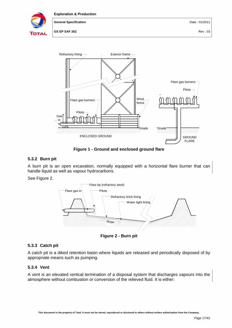
5.3.1.3 Enclosed ground flare (see Figure 1) Enclosure with one or more burners arranged in such a manner that the flame is not directly visible.
Exploration & Production
General Specification Date : 01/2011
GS EP SAF 262 Rev : 03
This document is the property of Total. It must not be stored, reproduced or disclosed to others without written authorisation from the Company.
Page 17/42
Pilots
Flare gas burners
Grade
Refractory lining Exterior frame
Wind fence
Pilots
Flare gas burners
Gas in
Grade
ENCLOSED GROUND GROUND FLARE
Figure 1 - Ground and enclosed ground flare
5.3.2 Burn pit A burn pit is an open excavation, normally equipped with a horizontal flare burner that can handle liquid as well as vapour hydrocarbons.
See Figure 2.
Flare gas in
Flare tip (refractory steel)
Pilots
Refractory brick lining
Water tight lining
Slope
Figure 2 - Burn pit
5.3.3 Catch pit A catch pit is a diked retention basin where liquids are released and periodically disposed of by appropriate means such as pumping.
5.3.4 Vent A vent is an elevated vertical termination of a disposal system that discharges vapours into the atmosphere without combustion or conversion of the relieved fluid. It is either:
Exploration & Production
General Specification Date : 01/2011
GS EP SAF 262 Rev : 03
This document is the property of Total. It must not be stored, reproduced or disclosed to others without written authorisation from the Company.
Page 18/42
5.3.4.1 Cold vent Vent handling significant flowrates generally from pressurised equipment (the wording "cold" means here: without flame). As a basic rule and in order to ensure proper gas dispersion, cold vents shall be elevated (15 m minimum above grade).
PSV's releasing hydrocarbons or toxic products directly to atmosphere shall do so via a collection system and a cold vent elevated at least 15 m above grade; their individual release at lower elevation (say 3m) is not permitted.
In all cases, and more specifically in case of toxic gas, dispersion and radiation calculations shall be carried out (refer to section 5.4.1).
PSV's releasing non-hydrocarbons, non toxic products can be released individually at elevations of 3m minimum above grade.
Because venting is not visible to traffic, special precautions shall be taken to avoid the possible ignition of a gas cloud by boat, helicopter, or any land vehicle approaching the installation (refer to section 7.3, Flammable gas).
5.3.4.2 Degassing vent Vent handling low flow-rates, generally from atmospheric equipment (lube and seal oil degassing tanks, sump tank, etc.).
5.3.4.3 Liquid burners These systems are portable devices used during well testing, stimulation operation or possibly pipeline depressurisation. They are used temporarily and shall not be elaborated upon any further in the present specification.
5.4 Release systems applicability
5.4.1 Cold vent (Processing facilities) Cold vents present several major inconveniences impacting safety and environment:
• The dispersion of large quantities of gas may, under unfavourable atmospheric conditions, lead to a flammable gas cloud reaching an ignition point,
• The use of cold vents on a continuous or semi-continous basis lead to discharge into the atmosphere of substantial amount of hydrocarbon vapours,
• Heavier than air flammable and toxic gases will reach grade,
• Increased risk of internal deflagration/detonation,
• Risk not visible by traffic.
As a consequence of what precedes the use of cold vents shall be strictly limited and the restrictions listed below shall apply:
• Only gases or vapour with a Molecular Weight (MW) < 40 kg/kmole and with H2S content < 0.5% (see note 1) shall be routed to cold vents. Liquid or two-phase streams are prohibited.
• Liquid or two-phase streams with equivalent MW greater than 60 are prohibited.
Exploration & Production
General Specification Date : 01/2011
GS EP SAF 262 Rev : 03
This document is the property of Total. It must not be stored, reproduced or disclosed to others without written authorisation from the Company.
Page 19/42
• Gases or vapours, regardless of their MW, shall be discharged with a velocity (at the tip of the vent) larger than 150 m/s to ensure proper dispersion at design rate. In case the discharge velocity is less than 150 m/s the vent shall be considered as a degassing vent (see section 5.4.2).
• The release of gases at actual temperature above their auto-ignition temperature is prohibited.
• Cold vents shall not be used when the estimated environmental impact over the life time of the installations, including start-up and upsets, exceeds that of an equivalent flare with purge and pilots.
• The restricted area created by cold vents shall be calculated by an approved method. Three criteria shall be taken into consideration: LFL limit, radiation in case of ignition, toxic TLV (refer to GS EP SAF 253).
- Flammable gas concentration shall not exceed 100% LFL (instantaneous) under the worst possible combination of flowrate, molecular weight and weather conditions, and no source of ignition or presence of personnel shall exist within this area.
- Radiation level outside the restricted area in case the vent ignites shall not exceed 4.7 kW/m2 for periods not longer than 15 minutes.
- Threshold Limit Value - Short Term Exposure Limit (TLV - STEL, refer to section 7.4.2) shall not exceed 10 ppm for H2S and 5 ppm for SO2.
Possible exceptions to this set of rules are PSV fire case or TSV on pipelines that may be routed to atmosphere if found advisable to do so (specific study).
Note 1: 0.5% H2S content is given as an order of magnitude only. In all cases it shall be verified that the discharge of acid (or toxic) waste gas does not create additional hazards.
In spite of these limitations, cold vents may however prove a good alternative where are used on a very infrequent basis on satellite installations for emergency disposal purposes. This is specially true for wellheads platforms with numerous sources of release but few sources of ignition, and where it is preferable to add another source of release (a cold vent) rather than a new source of ignition (a flare).
5.4.2 Degassing vents
5.4.2.1 Degassing vents for Processing facilities A degassing vent differs from a cold vent mainly by the flowrate it handles, the gas discharge velocity and the fact that a degassing vent always generates a permanent hazardous area. The following rules shall apply for the design of degassing vents:
• Vents having a peak flowrate not exceeding 200 Sm3/h and a gas velocity at vent tip below 150 m/s are considered as degassing vents.
• Degassing vents generate Zone 1 hazardous areas, which shall be defined in accordance with requirements of GS EP SAF 216.
• For degassing vents having a peak flow rate larger than 100 Sm3/h, a dispersion calculation shall be carried out to verify that the distances specified by GS EP SAF 216 are adequate.
Exploration & Production
General Specification Date : 01/2011
GS EP SAF 262 Rev : 03
This document is the property of Total. It must not be stored, reproduced or disclosed to others without written authorisation from the Company.
Page 20/42
• If the gas is toxic a dispersion calculation shall be carried out in all cases to verify that the maximum allowable concentration of contaminant and the maximum allowable radiation in case of ignition are within allowable limits (see section 7.4, and refer to GS EP SAF 253).
• Degassing vents shall be reduced to a minimum such that they can be collected to a common discharge system and discharged away from possible sources of ignition in accordance with the requirements of GS EP SAF 216 and GS EP SAF 253.
• If the degassing vent is located in the vicinity of a flare, the possibility of ignition by hot soot particles from the flare shall be taken into consideration.
5.4.2.2 Degassing vents for large storage tanks For large petroleum atmospheric storage tanks and for cargo vents on FPSO the degassing vent flowrate can exceed 200 m3/h. A dispersion calculation should be carried out for peak flow larger than 100 m3/h and is mandatory for flowrate larger than 200 m3/h (refer to GS EP SAF 341 and GS EP STR 651).
5.4.3 Flares
5.4.3.1 Non-elevated flares From a safety stand point, non-elevated flares present only slim advantages over elevated flares (better tolerance to the presence of liquids, reduced air ingress due to chimney effect and no vacuum in the flare collecting system) but have the major inconvenience that gas dispersion does not benefit of the jet effect in case of flame-out.
For these reasons Company's policy is to avoid installation of non-elevated flares.
5.4.3.2 Elevated flares Elevated flares are suitable both for onshore and offshore environments. They shall be given preference over other types of flare wherever imposed by constraints of radiation or gas dispersion. Presence of surrounding inhabited areas, transportation means or industrial installations, for instance, shall lead to the installation of an elevated flare. If the effluent sent to flare is acid or toxic, an elevated flare shall also be retained, to ensure dispersion of toxic gas cloud, should the flare flame out.
The only safety related inconveniences linked to elevated flares are:
• The fact that partial vacuum, due to chimney effect, may prevail at the bottom of the stack and possibly in the whole collecting system (if purge gas MW is lower than 29 and if flare stack is high enough, say 30 m).
• The necessity to provide the flare supporting structure with passive fire protection if it can be exposed to radiation flux in case of an incident in other process or storage units (refer to GS EP SAF 337).
• The operational risks associated with their inspection, repair or tip replacement. (see section 6.10).
5.4.4 Ground flares Ground flares can be used when specific environmental constraints of radiation, noise, and light prevail. The major shortcomings of ground flares are their difficulty in controlling large variations
Exploration & Production
General Specification Date : 01/2011
GS EP SAF 262 Rev : 03
This document is the property of Total. It must not be stored, reproduced or disclosed to others without written authorisation from the Company.
Page 21/42
of waste gas flowrate, the poor flammable/toxic gas dispersion they provide in case of flame out and, only for enclosed ground flares, the enhanced effect of an explosion due to confinement.
5.4.4.1 Open ground flare For reasons of reliability (thermal radiation flux on each individual burner) and difficulty in achieving a satisfactory flowrate distribution, non enclosed ground flares are not the preferred option.
5.4.4.2 Enclosed ground flare They are suitable where local regulations require non-luminous burning and/or where criteria of maximum radiation/noise that can be imposed onto environment are a limiting factor. It shall not be overlooked that enclosed ground flares have a practical flowrate limitation of around 100,000 kg/h.
A set of staggered enclosed ground flares can be considered where smokeless flaring is desired without steam use. They should be installed together with an elevated flare to combine advantages of both systems i.e. large disposal capacity with lower back-pressure requirement and reduced environmental impact during normal operation. In such a case the ground flare(s) should be designed to handle typically 10% to 20% of the elevated flare maximum flow.
This design alternative is not the preferred one and should be selected only if proven unavoidable and a special attention shall be paid to the design of the staggering system. The control valves manifold shall be fitted with a safety by-pass (e.g. rupture disc) capable of handling the maximum flowrate under emergency relief conditions; this by-pass shall never be equipped with a flame arrester.
5.4.5 Burn pits Permanent burn pits (onshore) constitute an inferior alternative for continuous flaring. Their gas dispersion capabilities are even less favourable than non-elevated flares. The level of radiation they generate at ground level is high and, as a consequence, the land encroachment is increased. The geotechnical maintenance of the burn pit itself is very demanding and the life duration of the flare tip is shorten.
Burn pits shall not be regarded as suitable disposal systems when permanent flaring is required and elevated or enclosed ground flares shall be given preference instead. Burn pits are strictly prohibited to flare acid or toxic waste gases.
5.4.6 Catch pit Catch pits are prohibited where “Toxic” streams are concerned.
5.4.7 H2S management As a general rule toxic gas containing more than 0.5% mole H2S shall be flared for the protection of personnel (see also sections 5.4.1 and 5.4.2).
In case one or several waste streams (e.g. amine treatment, etc.) contain more H2S than other process streams likely to discharge to the flare, then it shall be assessed on an ad hoc basis whether they shall be routed to a specific flare system designed to cope with this additional hazard: increased safety distances, higher stack, forced draught, improved metallurgy, etc. (see also section 5.1.4).
Exploration & Production
General Specification Date : 01/2011
GS EP SAF 262 Rev : 03
This document is the property of Total. It must not be stored, reproduced or disclosed to others without written authorisation from the Company.
Page 22/42
5.4.8 Back-up and spare systems Back-up or spare disposal systems may be justifiable in certain situations (e.g. NGL inventories). However, they introduce specific safety concerns, and their design shall be carefully studied with regards to necessary connections and isolations between the normal and back-up systems and it shall be verified that a back-up system will not create unsafe situations, in particular air ingress, during normal operation or during the change-over sequence. Fixed inert gas injection facilities shall be provided at the bottom of the back-up/spare flare stack.
A back-up or spare system shall adhere to the same rules as the normal system.
5.4.9 Flares in parallel As a basic rule and in order to avoid overloading one flare tip or that unequal flowrate distribution creates a partial vacuum in one flare stack, flares operating in parallel shall in no case be connected to a common collecting network. As a consequence each individual flare shall be dedicated to one, and only one, collecting system, itself attached to one unit or group of units. Jumpers between different flares or collecting systems, if any, shall be provided with positive isolation (see also section 5.4.8).
6. Safety design requirements
6.1 Disposal network
6.1.1 Fire and explosion protection The protection of the disposal network against the effects of fire and explosion shall be carefully studied, because the likelihood of occurrence of a major damage on the disposal network cannot be discarded, and consequences can prove catastrophic. This shall apply in particular to the HP flare network which collects and routes to the disposal system most of the hydrocarbon inventory in case of an emergency depressurisation.
Consequently the following points shall be addressed during the design phase of a new installation:
• The routing of the headers shall be optimised in order to minimise the risks of damage in case of fire or explosion.
• The necessity to provide headers and sub-headers with blast protection designed for blast peak overpressure and blast wave duration in critical areas shall be assessed.
• The integrity of the structure supporting the elevated flares shall withstand the conditions created by the worst fire and explosion scenario considered in the Safety Concept and as per GS EP SAF 253.
6.1.2 Flowrates and sizing The network shall be designed to accommodate the maximum predicted flow. Common modes of failure such as loss of control power shall be taken into account. Dynamic effects which may reduce flare or vent capacities shall also be contemplated. Flow metering systems shall be installed on flares networks for compliance with environmental requirements and local regulations. Only non-intrusive flow metering devices (e.g. ultrasonic) are permitted.
Exploration & Production
General Specification Date : 01/2011
GS EP SAF 262 Rev : 03
This document is the property of Total. It must not be stored, reproduced or disclosed to others without written authorisation from the Company.
Page 23/42
The effect of carry-over that may result in the formation of liquid slugs in the collecting system shall be considered. Its consequence on piping (routing, slope, supporting, etc.) shall be adequately addressed.
The disposal system shall be sized to fulfil the more demanding of the requirements exposed in GS EP SAF 261.
6.1.3 Peak flow to flare The relief system and flare shall be designed at least for the maximum flow to the flare, considering:
• The blocked outlet case.
• The depressurisation case taking where a BDV timer shall be installed, as per GS EP SAF 261, to allow closure of upstream and downstream safety valves and avoid flare overload.
• Other cases such as utility failure and interaction of several utilities if relevant.
In addition it shall be assessed if one or several incoming streams will continue to flow even after normal inlet ESDV closing time. The study shall consider such elements as existence of common mode of failure, number of automatic shut-off devices mounted in series, etc. Default figures for duration of continuing flows shall be those given by GS EP ECP 103.
The ESD system response time should normally not exceed 45 seconds and in the absence of calculation, simulation or experience, this value shall be considered for design. In the case of long pipes carrying liquids where surge effects may be generated by a fast closure, the response time may be adjusted with consideration to maximum acceptable overpressure in the pipe. In this case, the longer response time shall be considered for the calculation of the flow to flare.
It shall be verified that the flare system can sustain the BDV common failure case, (simultaneous opening for all fire zones) unless it can be established that this occurrence cannot happen (refer to GS EP SAF 261).
An auditable document shall be prepared which defines the design cases for each element of the disposal system.
6.1.4 Isolation The fitting of isolation valves onto the collecting and disposal network shall be limited to that necessary for tie-ins or overhaul purposes.
Check valves downstream of relief devices are prohibited.
6.1.5 Noise and vibrations The design shall take into account the causes and effects of noise and resonance in the disposal network and associated supporting structures (refer to GS EP SAF 221).
The kinetic pressure ρv2 (single phase and/or two phases) shall not exceed the threshold values set in GS EP ECP 103.
Company preference from a safety viewpoint is that connections on relief headers and sub-heaters greater than 4" diameter are made at 45° for minimisation of noise, vibration and stress
Exploration & Production
General Specification Date : 01/2011
GS EP SAF 262 Rev : 03
This document is the property of Total. It must not be stored, reproduced or disclosed to others without written authorisation from the Company.
Page 24/42
on piping supports. 90° connections are acceptable with suitable demonstration of adequate piping and support design.
6.1.6 Material selection Thermodynamic simulations shall be carried out to determine the lowest possible transient temperature in the different parts of the network and materials suitable for resulting temperature shall be selected accordingly. The software approved by Company is defined in GS EP ECP 103.
In addition the possibility that a depressurisation occurs while the collecting/disposal network is already cold (e.g. two consecutive ESD-1 with depressurisation of a same fire zone in a short period, or depressurisation of several fire zones in series with the same flare network) shall be envisaged. Material selection and design conditions of flare system and upstream equipment shall be made accordingly or reliable preventive measures and auditable documents shall be implemented to avoid this scenario.
6.2 Mist or liquid recovery The collecting system and its associated components shall be designed to optimise mist or liquid recovery in order to achieve the following objectives:
• Prevention of "golden rain" from elevated flares, ground flares or from vents,
• Minimisation of smoke and pollution.
Position of relief and blow-down valves as well as slopes of the relief headers/sub-headers should be optimised to minimise presence of low points and hence of liquids in the collecting system.
Burn pits do not require mist or liquid recovery components.
The K.O. drum shall be equipped with a LSHH that shall initiate the shutdown without depressurisation (SD-2, refer to GS EP SAF 261 for more details) of all units attached to the disposal system. The possibility of a subsequent depressurisation (either manually or automatically) still exists at LSHH. The LSHH shall therefore be low enough (and consequently the K.O. drum large enough) to allow the full depressurisation to take place without liquid carry-over to the disposal system.
The K.O. drum gas/liquid separation design criteria are set in GS EP ECP 103.
6.3 Structure of elevated flares The structure of elevated flares shall be designed to withstand the worst credible wind gusts and seismic risks it can face in its lifetime.
The integrity of the structure supporting the elevated flares shall be demonstrated for the considered fire and explosion scenario, and over the period of time necessary to achieve the complete depressurisation of the installation. If necessary passive fire protection shall be applied to fulfil this requirement.
6.4 Burn pits The tips of burn pits shall be provided with facilities to allow periodic replacement as per requirements set forth in the Operating Philosophy.
Exploration & Production
General Specification Date : 01/2011
GS EP SAF 262 Rev : 03
This document is the property of Total. It must not be stored, reproduced or disclosed to others without written authorisation from the Company.
Page 25/42
The diked area shall be designed to address satisfactorily the problems caused by intense thermal radiation in the vicinity of the tip (lining with refractory bricks), possible flammable liquids carry-over (slope), geotechnical stability (wind and rain water) and rain water (water tightness is strongly recommended).
Two different burn pits shall be separated by a minimum distance so as they can be considered as independent (see section 7.6). Conversely, the distance between two burners operating in parallel in a common burn pit shall not exceed a maximum distance (see section 7.7).
Disposal of production water by evaporation (natural by sun/wind, or enhanced by radiation) shall be subject to a particular study and requires Company's approval.
A fence shall be installed around any burn pit.
6.5 Ignition systems A fixed ignition system shall be provided for permanently used flares or burn pits. The system shall be testable to ensure its required reliability upon demand. High-voltage ignition sparks (close to the pilots) should be given preference over other devices.
The provision of suitable portable back-up equipment such as a special shot-gun or equivalent is mandatory. In any case the back-up equipment shall allow the ignition of the disposal system from a safe distance for the operator.
6.6 Flare tips and pilots Continuous pilots are mandatory for flares and burn pits, with a minimum number of three oriented 120° each other.
The fuel flow to each pilot shall be sufficient to prevent pilot flame-out for the maximum wind gust velocity during the lifetime of the installations. A reliable back-up fuel source (e.g. other part of the installation or set of propane cylinders) shall be provided for black-start. Wet gas should not be used as pilot gas.
The flare tip design should minimise the risk of flame lift-off in the cases of high velocity release or combination of wind gusts with low velocity release. Flare tip design based on the use of Coanda effect or involving moving parts is prohibited. Where possible the use of sonic tips should be given preference.
Flame detectors should be provided on pilots with alarm in main control room.
Each group of flare tips should be continuously monitored by a dedicated Closed Circuit Television (CCTV) and Visual Display Unit (VDU) located in main control room.
Elevated flare tips shall be vertical, and last pair of flanges horizontal, even when the stack is tilted, in order to avoid stress at the tip connection and facilitate tip replacement.
6.7 Flashback and internal deflagration
6.7.1 Flashback or internal ignition prevention Flashback or internal ignition prevention shall be ensured as per ISO 23251 / API STD 521.
Non-sonic flares can be protected from flashback or internal ignition effects by any or combination of: 1) gas seals associated with gas purge, 2) design withstanding internal explosion, 3) liquid seal.
Exploration & Production
General Specification Date : 01/2011
GS EP SAF 262 Rev : 03
This document is the property of Total. It must not be stored, reproduced or disclosed to others without written authorisation from the Company.
Page 26/42
Liquid seal is prohibited where low discharge temperature may freeze the liquid contained in the seal.
Sonic flares can be protected by any or combination of: 1) kinetic seals associated with gas purge 2) design withstanding internal explosion.
6.7.2 Cold vents internal deflagration design It is Company’s policy to design cold vents and associated piping to withstand internal deflagration. A default design pressure of 15 barg shall be considered at preliminary stage of the project. This design pressure can be challenged during the next steps of the project, using a CFD deflagration study.
Therefore and unless imposed by local applicable regulation, cold vents shall not be fitted with a permanent purge gas system.
6.7.3 Flares internal deflagration design The design pressure required to withstand internal deflagration shall be calculated using a CFD deflagration study. There are two options for purge gas requirements depending on whether the flare system can withstand or not internal deflagration.
6.7.3.1 Systems not withstanding internal deflagration A permanent purge gas system is mandatory for all systems not withstanding internal deflagration. In case of lack of purge gas (PSLL or FSLL) an ESD1 shutdown shall be triggered on all units connected to the concerned system.
6.7.3.2 Systems withstanding internal deflagration In that case gas purge is not strictly required. Should gas purge be installed, units connected to the concerned system should not be shutdown in case of lack of purge gas.
6.7.4 Gas purge and gas seal The primary protection method against flashback is the use of continuous purge gas flow withdrawn from the process, but inert gas may be used if available. The minimum purge flowrate is function of the gas molecular weight, stack diameter and tip design (refer to GS EP ECP 103 to calculate the minimum gas purge flowrate).
The heaviest available gas should be preferably used as the normal source of purge gas in order to avoid ingress of air.
The minimum flow is reduced by the application of a static seal (also called molecular seal) or of a kinetic seal (also called fluidic-type seal).
• Molecular seals can be used for LP flares and only where pressure drop is deemed acceptable. They are strictly prohibited for sonic flares. Gravel box used as some form of molecular seal are also strictly prohibited.
• Kinetic seals have none of these limitations and are the preferred solution but they become immediately inefficient in case of loss of purge gas. Where a kinetic seal is used, and where practical, two independent sources of purge gas should be used to ensure plant availability and the loss of purge gas shall trigger an ESD-1 of all units connected to the concerned flare.
Exploration & Production
General Specification Date : 01/2011
GS EP SAF 262 Rev : 03
This document is the property of Total. It must not be stored, reproduced or disclosed to others without written authorisation from the Company.
Page 27/42
Unless inert gas is used as purge gas, purge fuel-gas and pilot gas shall be taken from the same source in order to avoid loss of purging while pilots remain in service. Inert gas is acceptable as normal source of purge gas if produced by the installation itself, or as back-up if sourced externally.
Monitoring of air ingress in the flare stack (Oxygen analyser) should be envisaged on a case by case analysis. This monitoring is however mandatory for closed flare systems.
6.7.5 Headers and sub-headers All main flare headers shall be purged but individual lines connecting relief equipment to a header are not required to be purged.
It may happen however that a collecting network is not constituted only of headers and individual spur lines but comprises several sub-headers. The decision to purge sub-headers shall be made on a case per case basis considering that it is desirable to avoid too many purge points while ensuring nevertheless purging of long pipe runs that would be left stagnant otherwise. The purge gas flowrate for sub-headers shall be calculated using the formula mentioned in GS EP ECP 103 and shall be accounted for in the total purge gas flowrate demand.
6.7.6 Liquid seals This option constitutes an alternative to gas purge for non-sonic flares and where weather conditions are adequate (no risk of freezing). For further details, refer to ISO 23251 / API STD 521 which provides liquid seals typicals.
6.7.7 Flame arresters Flame arresters shall be designed in accordance with the standard NF EN 12874.
Normal and emergency venting for pressure or vacuum on refrigerated atmospheric storage tanks shall be accomplished by PV valves or open vents (refer to ISO 23251 / API STD 521).
It is not necessary to consider a flame arrester for use with a PV valve venting to atmosphere.
Open vents shall be fitted with flame arresters on atmospheric tanks in which petroleum products with a flash point below 37.8 °C are stored and where the fluid temperature may exceed the flash point.
Open vents without flame arresters may be used on atmospheric tanks for:
• Stored products with a flash point of 37.8 °C or above and provided the contents are not heated and the temperature remains below the flash point.
• Heated tanks in which the storage temperature is below the flash point.
• Tanks with a capacity of less than 9.5 m3.
• Crude oil tanks with a capacity of less than 477 m3.
• Storage tanks for viscous products such as cutbacks and penetration asphalts, where the danger of tank collapse resulting from plugging the flame arrester is greater than the possibility of flame transmission.
Flame arresters shall be fitted between equipment containing hydrocarbon and their degassing vent tip. Flame arresters are prohibited on flare and cold vent system.
Exploration & Production
General Specification Date : 01/2011
GS EP SAF 262 Rev : 03
This document is the property of Total. It must not be stored, reproduced or disclosed to others without written authorisation from the Company.
Page 28/42
Flame arresters shall be located at the vent tip or less than 3 metres away from the tip and only if there is no bend or piping obstruction between the tip and the flame arrester. If these rules cannot be adhered to, then a special study shall be carried out to determine if detonation might occur and whether it will be stable or unstable, the result of which shall be used to specify the proper type of flame arrester.
Flame arresters shall be accessible for maintenance without scaffolding and shall be fitted with bug screens. For critical equipment that cannot be put off-line for maintenance, Company preferred solution is to install two separate vent lines, each with its flame arrester and its upstream LO block valve. In order to facilitate the set-up of a maintenance program, flame arresters shall be itemised on the P&IDs.
In the presence of H2S the risks of spontaneous ignition caused by pyrophoric iron shall be contemplated and incorporated into design and material selection.
6.7.8 Static electricity Ignition of vents can occur due to static electricity or lightning. Vent tips shall be designed to minimise this risk and should be either torus or oil droplet-shaped.
6.7.9 Disposed gas monitoring Gas flow metering is required on all flares and main cold vents. The flowmeter instrument should be non intrusive and selected in order to measure the whole flowrate range with good accuracy.
Requirement for on-line analysis should be evaluated. As a minimum a sampling point at the outlet of the flare KO drums shall be provided.
6.8 Radiation hazards
6.8.1 Cold vents Cold vents frequently ignite because of static electricity and therefore shall be designed for both radiation and dispersion (see section 7.2).
6.8.2 Snuffing systems Unless imposed by local regulation, Company's policy is to avoid flare and cold vents snuffing systems.
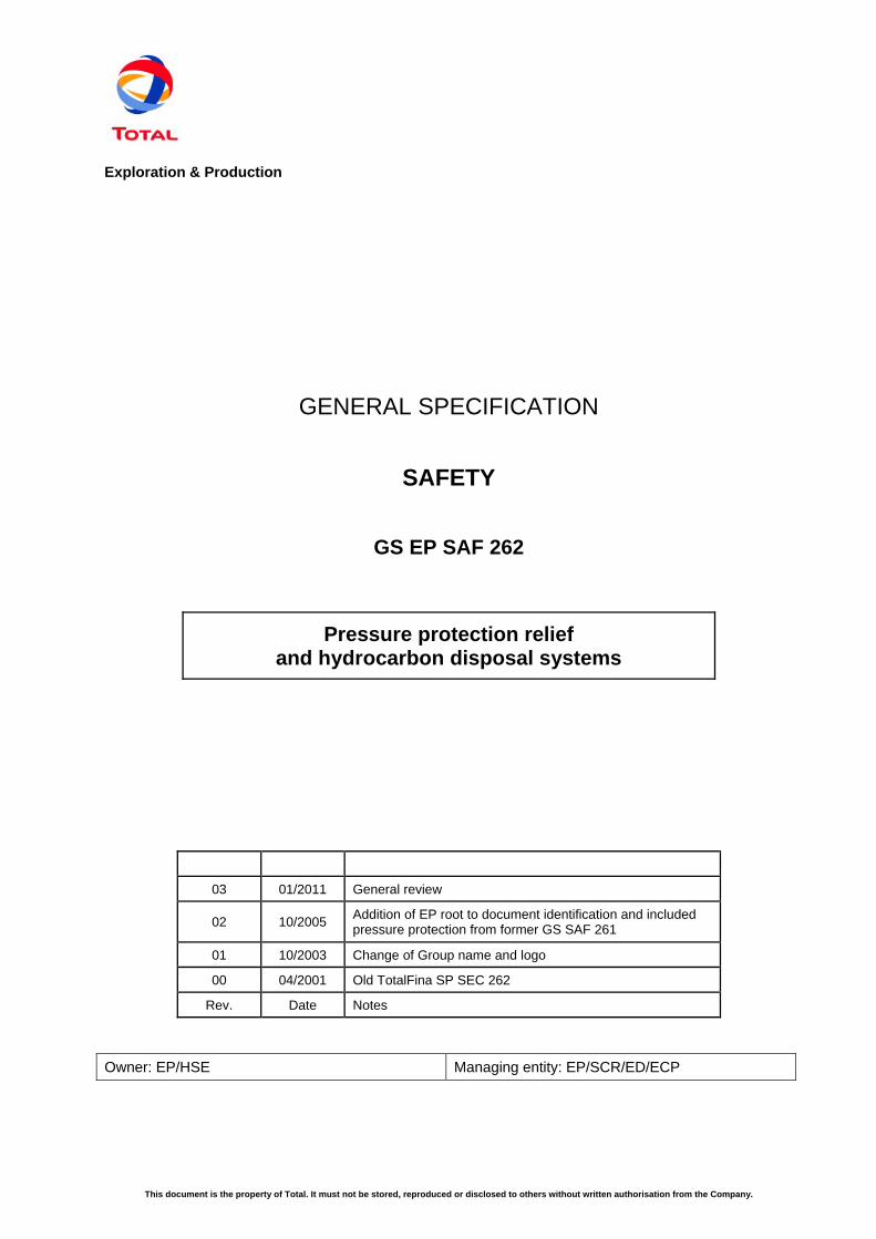
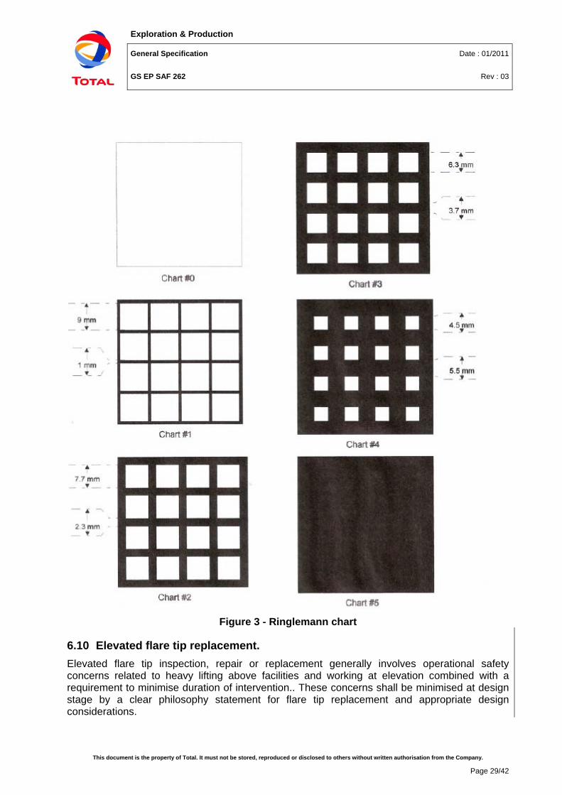
6.9 Smoke and pollution It is Company's policy to install smokeless flares where feasible, for maximum continuous flaring. Flare combustion is considered smokeless if it not is darker than Ringlemann Chart No 1 (refer to Figure 3).
Flares shall be designed and operated with flare smoke opacity at least less than 40% (Ringelmann chart 2) for emergency flaring.
Exploration & Production
General Specification Date : 01/2011
GS EP SAF 262 Rev : 03
This document is the property of Total. It must not be stored, reproduced or disclosed to others without written authorisation from the Company.
Page 29/42
Figure 3 - Ringlemann chart
6.10 Elevated flare tip replacement. Elevated flare tip inspection, repair or replacement generally involves operational safety concerns related to heavy lifting above facilities and working at elevation combined with a requirement to minimise duration of intervention.. These concerns shall be minimised at design stage by a clear philosophy statement for flare tip replacement and appropriate design considerations.
Exploration & Production
General Specification Date : 01/2011
GS EP SAF 262 Rev : 03
This document is the property of Total. It must not be stored, reproduced or disclosed to others without written authorisation from the Company.
Page 30/42
The method for onshore elevated flare tip removal shall be by mobile crane wherever technically possible, and this shall be taken into account in the specification of flare stack height and location.
For offshore situations and onshore where the crane method is not feasible, the mandatory method is via the use of temporary manual lifting devices (base frame, lifting arch/davit and jibs) installed on the flare tip platform and winches if necessary installed at grade level. A dedicated laydown zone shall be defined at the base of the flare stack for tip removal. For inclined flare stacks, a trolley system may be preferred to guide the lowering of the tip down the stack.
Dismountable risers can be accepted only for installations where all flare stacks including spare stack are located on a common structure and plant shutdowns should be avoided, e.g. NGL plants.
Flare tip replacement by helicopter shall never be specified as the base case method, but can be proposed as an alternate when specialised resources are available and proven, and shall be subject to an approved derogation following dedicated hazard identification and risk assessment studies.
When the manual lifting method is specified, no permanently installed lifting provisions (padeyes etc) shall be provided on the flare tip platform due to problems associated with their integrity, testing and certification at the time of replacement. Any lifting devices and ancillaries shall only be installed for the duration of the tip replacement.
The flare tip platform shall have removable handrails, grating and heat shielding to allow easier installation of the lifting devices. Where flare tip platforms support more than one flare tip, the heaviest tip should be located immediately in front of the planned drop zone, with lighter flare tips offset. A minimum of 0.7m free space shall be available on all sides of the flare tip platform.
All temporary lifting material shall be stored at site or base warehouse and be available at short notice for emergency tip replacements by the site personnel. The use of specialised lifting contractors is however recommended for programmed tip replacements. In all cases a tip replacement method statement shall be prepared and approved.
7. Disposal system lay-out
7.1 General
7.1.1 General requirements The location of cold vent and flare outlets within the installation is governed by four different concepts:
• Their impact onto adjacent areas, facilities or units,
• The requirement for disposal systems to remain operational throughout emergency response (in particular emergency depressurisation) in case of major incident affecting the facilities,
• The hazard they present, as a potential ignition source that cannot be controlled, in case of incident elsewhere on the installation.
• The hazard they present for third parties around the installation, in case of flare flame out.
Exploration & Production
General Specification Date : 01/2011
GS EP SAF 262 Rev : 03
This document is the property of Total. It must not be stored, reproduced or disclosed to others without written authorisation from the Company.
Page 31/42
In practice these requirements shall be addressed as follows:
• Hazards generated by disposal system normal operation (radiation, dispersion of flammable and toxic gas, noise, etc.) shall be taken into account for the outlining of the impacted and restricted areas and the positioning of other unit and ancillary facilities in comparison with flares, cold vents and burn pits.
• Flares and cold vents shall always be located in their own fire zone so that they shall not be exposed to consequences they could not withstand. This issue is not developed any further in the present document; refer to GS EP SAF 253.
• Flares and cold vents shall be located in such a way that they do not risk to ignite a flammable gas cloud caused by a major failure on other process or storage units. Onshore, flares and cold vents shall be outside the flammable restricted area generated by other units. If not feasible (e.g. offshore and brown fields) a dispersion calculation shall be carried out to determine the maximum elevation of a flammable gas cloud and then the flare or cold vent outlet elevation to avoid ignition. On the other hand, in all cases, the other units shall be outside the restricted area generated by flares and cold vents.
7.1.2 Hazards and effects Hazards/effects listed below shall be considered for the definition of the impacted and restricted areas and also the positioning of other units (refer to GS EP SAF 253):
• Radiation: Limit radiation, either continuous and peak, on off-site properties and persons, equipment, buildings and personnel on the installation. Applicable to impacted area, restricted area and equipment lay-out.
• Flammable gas: Avoid ignition of a flammable gas cloud released from a cold vent or in case of flare flame out.
• Toxic hazards: (Mainly for H2S and SO2, but not limited to) limit the risk of a toxic gas cloud to reach off-site population, provide means of alarm and adequate protection to personnel present in the restricted area.
• Noise: Limit both continuous and peak noise levels acceptable for personnel present in the restricted area and for off-site populations (see section 7.5).
It may happen that light emitted by a flare could become an effect that must be taken into consideration, specially in environmentally sensitive areas. Considering that local regulation shall always govern prevailing requirements, the issue is not elaborated upon any further in the present document.
7.1.3 Flaring cases to be envisaged Distances to impacted area, restricted area and units shall be delimited around flares, burn pits and cold vents considering the effects they can generate under two circumstances:
• Maximum continuous flaring: Maximum continuous flaring includes all accepted modes of sustained flaring, as defined in the Operating Philosophy, including degraded, partial and reduced operating modes.
• Emergency flaring: Emergency flaring is here defined as the modes of flaring occurring in case of process upset, blocked outlet, emergency depressurisation, or failure of equipment (including power or control failure). The expected emergency flaring rates and their associated maximum duration shall be clearly identified in the Operating Philosophy.
Exploration & Production
General Specification Date : 01/2011
GS EP SAF 262 Rev : 03
This document is the property of Total. It must not be stored, reproduced or disclosed to others without written authorisation from the Company.
Page 32/42
All the criteria defined in this document consider that the equilibrium temperature is attained.
In all instances ‘Emergency Flaring’ assumes an exposure time of 15 minutes or less. For exposure time longer than 15 minutes the radiation limits for ‘Maximum Continuous Flaring’ shall be considered.
Cold vent ignition shall be considered as ‘Emergency Flaring’.
7.1.4 Meteorological conditions considered The meteorological conditions taken into account for the design of the impacted and restricted areas are:
• If site wind velocities data are available up to one hundred-years return the worst wind direction(s) shall be used. By default the wind velocity shall be: 20 m/s.
• All atmospheric classes.
• For transmissivity (depending on Relative Humidity and ambient temperature), refer to GS EP ECP 103.
7.2 Radiation
7.2.1 Calculation of a radiation level The method and input data to calculate the radiations emitted by a flare or an accidentally ignited cold vent shall be approved by Company. The methodology to define the radiation level shall comply with the following principles:
• All the criteria defined in this document are inclusive of sun radiation. No credit shall be given to possible vectorial combination of sun and hydrocarbon disposal system radiation flux (refer to GS EP SAF 253 for default sun radiation).
• In practice, forced convection (wind) and natural convection (in particular on vertical surfaces) tend to decrease the surface temperature but these phenomena shall not be considered.
• Radiation calculation shall be done using the minimum Relative Humidity in a consistent manner with GS EP ECP 103.
• The radiation flux resulting from several flares operating in parallel shall be considered. Unless it can be demonstrated otherwise, the flux shall be added up algebraically, without credit to possible vectorial combination.
Throughout next sections 7.2.2 to 7.2.6 radiation levels are inclusive of sun radiation and shall be noted kW* for confirmation.
7.2.2 Public
7.2.2.1 Requirement for public For maximum continuous flaring, public shall be able to perform normally their activities.
During emergency situation, the same shall apply except that the maximum allowed radiation level can be slightly increased owing to shorter exposure duration.
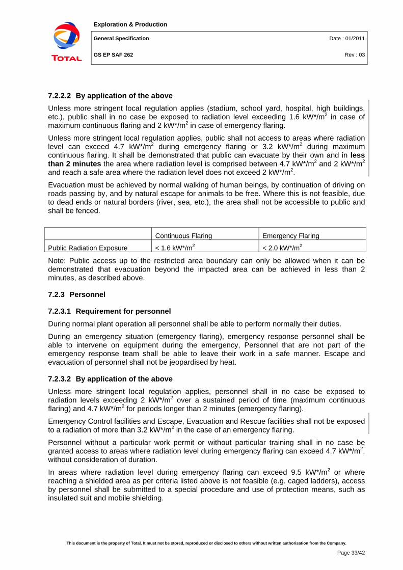
Exploration & Production
General Specification Date : 01/2011
GS EP SAF 262 Rev : 03
This document is the property of Total. It must not be stored, reproduced or disclosed to others without written authorisation from the Company.
Page 33/42
7.2.2.2 By application of the above Unless more stringent local regulation applies (stadium, school yard, hospital, high buildings, etc.), public shall in no case be exposed to radiation level exceeding 1.6 kW*/m2 in case of maximum continuous flaring and 2 kW*/m2 in case of emergency flaring.
Unless more stringent local regulation applies, public shall not access to areas where radiation level can exceed 4.7 kW*/m2 during emergency flaring or 3.2 kW*/m2 during maximum continuous flaring. It shall be demonstrated that public can evacuate by their own and in less than 2 minutes the area where radiation level is comprised between 4.7 kW*/m2 and 2 kW*/m2 and reach a safe area where the radiation level does not exceed 2 kW*/m2.
Evacuation must be achieved by normal walking of human beings, by continuation of driving on roads passing by, and by natural escape for animals to be free. Where this is not feasible, due to dead ends or natural borders (river, sea, etc.), the area shall not be accessible to public and shall be fenced.
Continuous Flaring Emergency Flaring
Public Radiation Exposure < 1.6 kW*/m2 < 2.0 kW*/m2
Note: Public access up to the restricted area boundary can only be allowed when it can be demonstrated that evacuation beyond the impacted area can be achieved in less than 2 minutes, as described above.
7.2.3 Personnel
7.2.3.1 Requirement for personnel During normal plant operation all personnel shall be able to perform normally their duties.
During an emergency situation (emergency flaring), emergency response personnel shall be able to intervene on equipment during the emergency, Personnel that are not part of the emergency response team shall be able to leave their work in a safe manner. Escape and evacuation of personnel shall not be jeopardised by heat.
7.2.3.2 By application of the above Unless more stringent local regulation applies, personnel shall in no case be exposed to radiation levels exceeding 2 kW*/m2 over a sustained period of time (maximum continuous flaring) and 4.7 kW*/m2 for periods longer than 2 minutes (emergency flaring).
Emergency Control facilities and Escape, Evacuation and Rescue facilities shall not be exposed to a radiation of more than 3.2 kW*/m2 in the case of an emergency flaring.
Personnel without a particular work permit or without particular training shall in no case be granted access to areas where radiation level during emergency flaring can exceed 4.7 kW*/m2, without consideration of duration.
In areas where radiation level during emergency flaring can exceed 9.5 kW*/m2 or where reaching a shielded area as per criteria listed above is not feasible (e.g. caged ladders), access by personnel shall be submitted to a special procedure and use of protection means, such as insulated suit and mobile shielding.
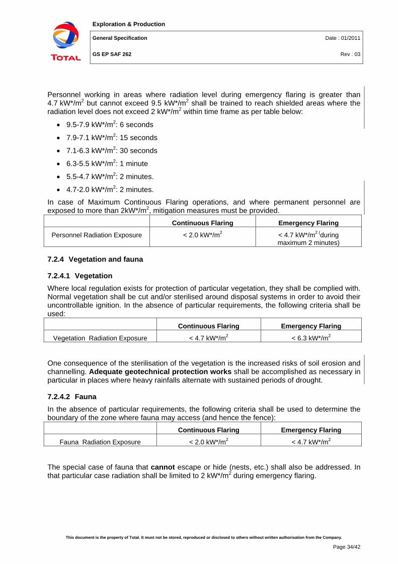
Exploration & Production
General Specification Date : 01/2011
GS EP SAF 262 Rev : 03
This document is the property of Total. It must not be stored, reproduced or disclosed to others without written authorisation from the Company.
Page 34/42
Personnel working in areas where radiation level during emergency flaring is greater than 4.7 kW*/m2 but cannot exceed 9.5 kW*/m2 shall be trained to reach shielded areas where the radiation level does not exceed 2 kW*/m2 within time frame as per table below:
• 9.5-7.9 kW*/m2: 6 seconds
• 7.9-7.1 kW*/m2: 15 seconds
• 7.1-6.3 kW*/m2: 30 seconds
• 6.3-5.5 kW*/m2: 1 minute
• 5.5-4.7 kW*/m2: 2 minutes.
• 4.7-2.0 kW*/m2: 2 minutes.
In case of Maximum Continuous Flaring operations, and where permanent personnel are exposed to more than 2kW*/m2, mitigation measures must be provided.
Continuous Flaring Emergency Flaring
Personnel Radiation Exposure < 2.0 kW*/m2 < 4.7 kW*/m2 (during maximum 2 minutes)
7.2.4 Vegetation and fauna
7.2.4.1 Vegetation Where local regulation exists for protection of particular vegetation, they shall be complied with. Normal vegetation shall be cut and/or sterilised around disposal systems in order to avoid their uncontrollable ignition. In the absence of particular requirements, the following criteria shall be used:
Continuous Flaring Emergency Flaring
Vegetation Radiation Exposure < 4.7 kW*/m2 < 6.3 kW*/m2
One consequence of the sterilisation of the vegetation is the increased risks of soil erosion and channelling. Adequate geotechnical protection works shall be accomplished as necessary in particular in places where heavy rainfalls alternate with sustained periods of drought.
7.2.4.2 Fauna In the absence of particular requirements, the following criteria shall be used to determine the boundary of the zone where fauna may access (and hence the fence):
Continuous Flaring Emergency Flaring
Fauna Radiation Exposure < 2.0 kW*/m2 < 4.7 kW*/m2
The special case of fauna that cannot escape or hide (nests, etc.) shall also be addressed. In that particular case radiation shall be limited to 2 kW*/m2 during emergency flaring.
Exploration & Production
General Specification Date : 01/2011
GS EP SAF 262 Rev : 03
This document is the property of Total. It must not be stored, reproduced or disclosed to others without written authorisation from the Company.
Page 35/42
7.2.5 Equipment
7.2.5.1 Principles The maximum temperatures that can be attained by material and equipment shall meet the following requirements:
• The surface temperatures shall be, during continuous and emergency flaring, below the auto-ignition temperature of hydrocarbons that can leak around.
• During maximum continuous flaring, the temperature of the material shall be below the limit ensuring their integrity over their specified lifetime. Furthermore material surface temperature shall be below what is required for the integrity of the painting or the protective coating, over their specified lifetime.
• During emergency flaring, and unless it is accepted to replace an equipment after an emergency flaring, material temperature shall be below what is required for the integrity of material or equipment, for the specified number of emergency situations they can face in their lifetime.
7.2.5.2 Criteria See section 7.2.6 below.
7.2.5.3 Additional considerations The maximum allowable radiation level exercised onto an equipment is not in itself a criteria; what really matters is the material skin and internal temperature once thermal equilibrium has been reached after a few minute exposure. This general consideration imparts three important consequences:
• Radiation criteria enclosed in attached table shall be used but shall remain valid only as long as concerned equipment are directly exposed to flare radiation. If this were not the case (view factor) then the criteria could be made less stringent.
• Whenever an equipment cannot be sited far enough from a flare (or a cold vent) to contain radiation flux within allowable limits, for instance offshore where lay-out constraints may become paramount or onshore for some equipment attached to the flare system itself, then as last option shielding can be used. This solution shall be approved by Company. Shielding shall be regarded as a suitable alternative only if its efficiency and life duration is demonstrated by the Vendor.
• Water curtains shall not be considered as a shielding device.
• Default values provided below are based on average emissivity and assume no view factor credit. In many cases surface temperatures can be significantly reduced by an appropriate siting and orientation in comparison with the radiation sources and/or painting in light grey "aluminium" colour.
7.2.6 Allowable radiation summary table All radiation levels in next table are inclusive of sun radiation.
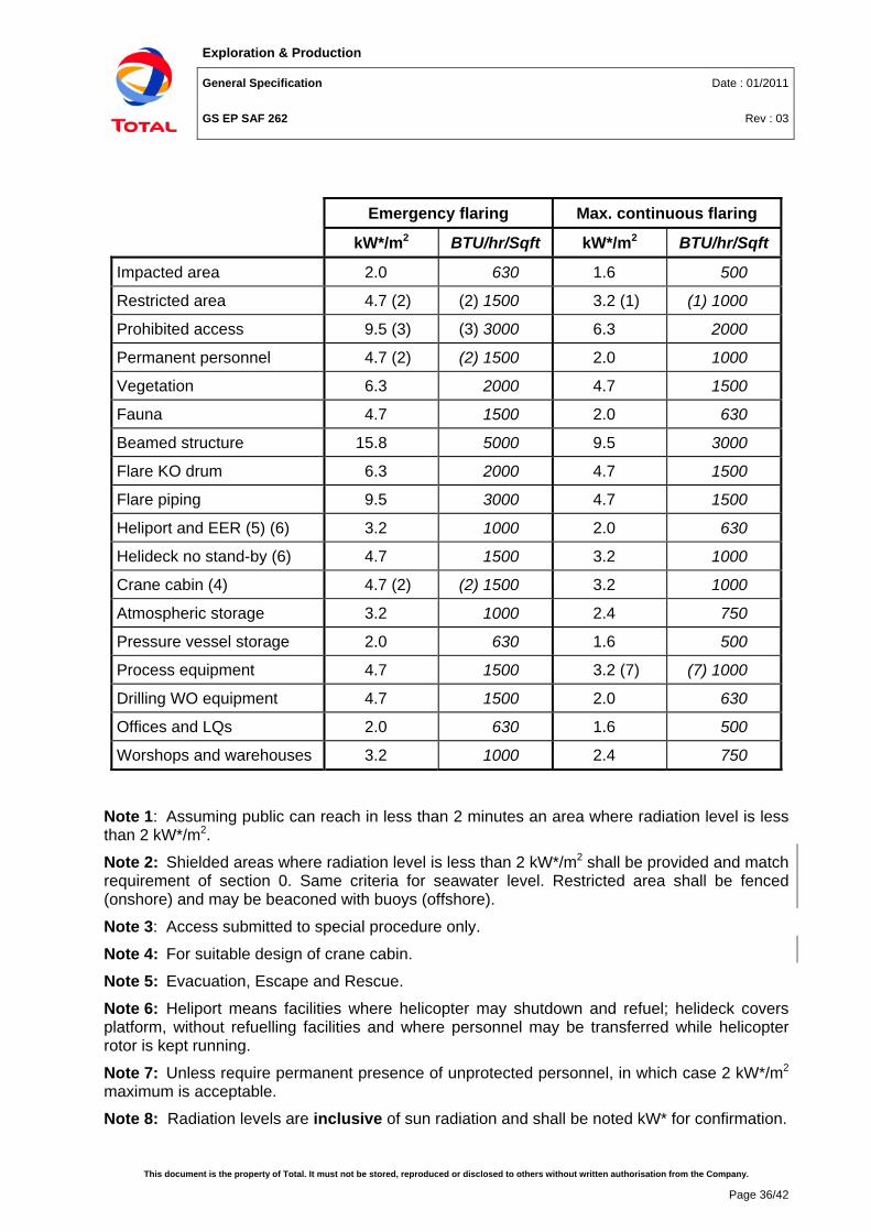
Exploration & Production
General Specification Date : 01/2011
GS EP SAF 262 Rev : 03
This document is the property of Total. It must not be stored, reproduced or disclosed to others without written authorisation from the Company.
Page 36/42
Emergency flaring Max. continuous flaring
kW*/m2 BTU/hr/Sqft kW*/m2 BTU/hr/Sqft
Impacted area 2.0 630 1.6 500
Restricted area 4.7 (2) (2) 1500 3.2 (1) (1) 1000
Prohibited access 9.5 (3) (3) 3000 6.3 2000
Permanent personnel 4.7 (2) (2) 1500 2.0 1000
Vegetation 6.3 2000 4.7 1500
Fauna 4.7 1500 2.0 630
Beamed structure 15.8 5000 9.5 3000
Flare KO drum 6.3 2000 4.7 1500
Flare piping 9.5 3000 4.7 1500
Heliport and EER (5) (6) 3.2 1000 2.0 630
Helideck no stand-by (6) 4.7 1500 3.2 1000
Crane cabin (4) 4.7 (2) (2) 1500 3.2 1000
Atmospheric storage 3.2 1000 2.4 750
Pressure vessel storage 2.0 630 1.6 500
Process equipment 4.7 1500 3.2 (7) (7) 1000
Drilling WO equipment 4.7 1500 2.0 630
Offices and LQs 2.0 630 1.6 500
Worshops and warehouses 3.2 1000 2.4 750
Note 1: Assuming public can reach in less than 2 minutes an area where radiation level is less than 2 kW*/m2.
Note 2: Shielded areas where radiation level is less than 2 kW*/m2 shall be provided and match requirement of section 0. Same criteria for seawater level. Restricted area shall be fenced (onshore) and may be beaconed with buoys (offshore).
Note 3: Access submitted to special procedure only.
Note 4: For suitable design of crane cabin.
Note 5: Evacuation, Escape and Rescue.
Note 6: Heliport means facilities where helicopter may shutdown and refuel; helideck covers platform, without refuelling facilities and where personnel may be transferred while helicopter rotor is kept running.
Note 7: Unless require permanent presence of unprotected personnel, in which case 2 kW*/m2 maximum is acceptable.
Note 8: Radiation levels are inclusive of sun radiation and shall be noted kW* for confirmation.
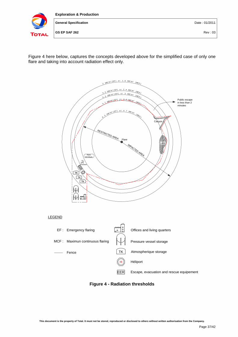
Exploration & Production
General Specification Date : 01/2011
GS EP SAF 262 Rev : 03
This document is the property of Total. It must not be stored, reproduced or disclosed to others without written authorisation from the Company.
Page 37/42
Figure 4 here below, captures the concepts developed above for the simplified case of only one flare and taking into account radiation effect only.
Figure 4 - Radiation thresholds
LEGEND
EF :
MCF :
Emergency flaring
Maximun continuous flaring
TK
H
EER
Offices and living quarters
Pressure vessel storage
Atmospherique storage
Héliport
Escape, evacuation and rescue equipement
Lake
Canyon
Flare
2 kW/ m² ( EF ) o r 1 . 6 kW / m ² ( MCF )
3 . 2 kW/ m² ( EF ) o r 2 . 4 kW/ m² ( MCF )
3 . 2 kW / m² ( EF ) o r 2 kW / m ² ( MCF )
4 . 7 kW/ m² ( EF ) o r 3 . 2 kW/ m² ( MCF )
6 . 3 kW / m² ( EF ) o r 4 . 7 kW/ m² ( MCF )
Process
FlareKO Drum
RESTRICTED AREA
IMPACTED AREA
Public escapein less than 2minutes
Fence
Exploration & Production
General Specification Date : 01/2011
GS EP SAF 262 Rev : 03
This document is the property of Total. It must not be stored, reproduced or disclosed to others without written authorisation from the Company.
Page 38/42
7.3 Flammable gas
7.3.1 Gas dispersion Safety distances related to gas dispersion shall be calculated in line with the requirement set forth in GS EP SAF 253.
Gas dispersion calculations shall be carried out for all types of disposal systems, as they are similarly considered as sources of release and ignition.
7.3.2 Criteria The layout of disposal systems in regards of flammable gas effects, and the flammable gas restricted area around disposal systems shall be determined as per GS EP SAF 253.
7.4 Toxic gas
7.4.1 Toxic gas dispersion Safety distances related to toxic gas dispersion shall be calculated in line with the requirement set forth in GS EP SAF 253.
7.4.2 Criteria The layout of disposal systems in regards of toxic gas effects, and the toxic gas restricted and impacted areas around disposal systems shall be determined as per GS EP SAF 253.
7.5 Noise Noise calculations shall be conducted as per method mentioned in GS EP SAF 221. The same scenarios as these envisaged for flammable gas dispersion shall be used (refer to section 7.3.1. In the absence of more stringent local regulation the following criteria shall prevail:
Impacted area Restricted area
Maximum continuous 60 dB(A) 85 dB (A)
Emergency 95 dB(A) 115 dB (A) (1)
Note 1: or General Alarm hearing level, whichever the lowest.
7.6 Minimum distances Minimum default safety distances between disposal systems and other equipment or facilities are provided in GS EP SAF 021. These default distances may be used only for conceptual studies prior to the completion of specific consequence Analysis - HAZAN.
7.7 Maximum distances If several elevated flares or burn pits do not need to be independent, then precautions shall be taken to minimise the extent of a flammable gas cloud (in case of flame-out of one of flare/burn pit) that could result in a flash fire.
This shall be achieved by a maximum distance of 10 metres between two flare tips or two burners in the same burn-pit. It shall be verified that proximity does not induce additional
Exploration & Production
General Specification Date : 01/2011
GS EP SAF 262 Rev : 03
This document is the property of Total. It must not be stored, reproduced or disclosed to others without written authorisation from the Company.
Page 39/42
hazards (e.g. increased radiation flux) and that material specification is selected accordingly. Flare tips shall be at the same elevation.
Company does not impose maximum distance between cold vents or degassing vents but strongly recommends all outlets should be grouped together in the same area. Cold vent outlets shall be at the same elevation.
8. Closed flare systems
8.1 Application and objective This section 8 is applicable to FPSO installations only.
The closed flare systems requirements are also specified in GS EP SAF 380.
The objective of closed flare systems is to permanently recover continuous relatively small streams of process/utility gas such as, blanket gas from wash tanks or storage tanks, stripping gas from tri-ethylene glycol regenerators... etc.
These streams are otherwise vented to atmosphere or flared with impact to the environment.
Emergency flaring and continuous flaring during process start-up/upset conditions involving large amounts of gas are not concerned by this Flare Gas Recovery Unit (FGRU).
All Closed Flare systems shall be approved by Company by derogation. A dedicated HAZOP of the Closed Flare system shall be carried out with particular emphasis on HP/LP flare interconnection (if any).
The Closed Flare system shall be capable of operation as a “conventional” flare system, for example during periods of start-up / early production phase.
8.2 System description The FGRU shall be designed as a side stream from the flare header to capture and compress the gas for re-use or re-injection into the main process (refer to ISO 23251 / API STD 521 section 7.4).
The system consists of:
• a flare system as per above sections 4, 5, 6 and 7,
• a Fast Opening Valve (FOV) feeding the flare system,
• a blower or compressor package(s) and auxiliary equipment (filter, scrubber …),
• a header pressure and compressor load instrument control system,
• a device to ensure a positive pressure on the FGRU during normal operation, and open when header pressure is too high.
• and if required a recovered gas process treatment package.
Two types of positive pressure devices can be used (see ISO 23251 / API STD 521 fig. 20):
- a set of pilot-operated relief valve and fast opening valve (FOV) in parallel,
- a set of rupture disc and fast opening valve (FOV) in parallel.
Company preferred option is the set of rupture discs and FOV in parallel.
Exploration & Production
General Specification Date : 01/2011
GS EP SAF 262 Rev : 03
This document is the property of Total. It must not be stored, reproduced or disclosed to others without written authorisation from the Company.
Page 40/42
Based on local requirements the availability of the FGRU shall be assessed and the sparing philosophy decided accordingly (SOR shall provide the desired sparing philosophy).
Continuous running of the gas recovery compressor is recommended to minimise system failure upon demand.
The flare header pressure is controlled within a narrow pressure band by the load of the compressor.
Should the flare header pressure increase due to gas flow rate in excess of the compressor maximum capacity the FGRU positive pressure device will immediately open the gas flow path towards to flare stack. The Fast Opening Valve to flare shall be opened immediately by separate and direct signals from the ESD1 logic (because Company policy is based on automatic EDP), immediately by the PSHH on the flare system and immediately after a trip of any unit (e.g. MP/HP compressor package) that will ultimately lead to PSHH in the flare KO drum).
The FOV safety instrumented function shall be SIL3. Therefore the FOV shall of a sufficient integrity to be suitable for SIL3 safety instrumented functions.
Opening time of the FOV shall not be greater than one third of the time to reach the bursting pressure of the rupture disc.
For maintenance and availability purpose two parallel sets of full flow rupture disc shall be used. Burst discs shall be fitted with a device/system to alarm when it has been broken.
The isolation valves, upstream and downstream of the on-line bursting disc shall be locked open. The off-line bursting disc isolation valves shall be locked closed.
Bursting discs shall be checked at each planned shutdown, or annually, and replaced with new ones as necessary.
In case of too low pressure in the flare header the FGRU shall be shutdown and isolated.
The system operates at very low positive pressure and the risk of vacuum pressure and possible air ingress shall be minimised. Oxygen content at the suction header of compressor(s) shall be monitored and the FGRU shall be shutdown on high oxygen level.
8.3 Closed flare systems specific safety requirements The following safety considerations shall be assessed and a risk analysis shall be made on the whole system at each project step (FEED, and Detail Engineering).
• Emergency streams shall always have flow paths to the flare available at all times.
• Oxygen content of the gas shall be monitored continuously. For FGRU improved availability the oxygen analyser should be spared.
• Segregation concept of the HP and LP flares should be carefully considered. When possible all permanent low pressure gas streams should be connected to the LP flare where the FGRU should be installed.
• Careful attention shall be paid to the various gas compositions. Acid gas and Inert gas recovery should be avoided.
• Facilities shall be provided for inspection, testing and replacement of vital equipment such as, instruments, analysers, bursting disc and pilot operated relief valve of the FGRU positive pressure device.
Exploration & Production
General Specification Date : 01/2011
GS EP SAF 262 Rev : 03
This document is the property of Total. It must not be stored, reproduced or disclosed to others without written authorisation from the Company.
Page 41/42
• Due to the possibility of significant liquids in the flare system liquid knock-out vessels should be provided for the compressors.
8.4 Flare stack purge gas and pelletised ignition systems It is Company policy to purge the flare stack of closed flare systems downstream the FOV.
Where possible, nitrogen should be used to prevent air ingress in the flare stack. If nitrogen is not available, an heavier-than-air gas should be used to purge the flare stack.
In order to minimise gas flaring and CO2 release in the environment, flare tip pilots could be replaced by a redundant pelletised ignition system. Therefore the flare would not be normally lit and upon release of gas the pelletised ignition system will automatically light the HC stream.
The pelletised ignition shall launch a minimum of two pellets with a time interval. The time interval shall take account for the gas travel time difference between low gas flowrate and maximum gas flowrate (emergency depressurisation).
In case the system does not automatically ignite the flare, the operator will monitor the absence of flame via a CCTV, and manually launch an additional pellet.
In order to maintain a good reliability (probability of failure on demand) air supply for the pellet launch should be provided with a back-up supply which automatically activates in case of loss of the primary air supply. The two systems shall be tested periodically. The test frequency shall be determined by a detailed reliability study.
8.5 Closed flare and pelletised ignition systems validation A detailed risk assessment study shall be carried out at all project stages for both the FGRU and the Pelletised Ignition system, and submitted to Company for approval.
Exploration & Production
General Specification Date : 01/2011
GS EP SAF 262 Rev : 03
This document is the property of Total. It must not be stored, reproduced or disclosed to others without written authorisation from the Company.
Page 42/42
Bibliography
Reference Title
BS 2742 Use of the Ringelmann and miniature smoke charts
ISO 28300 / API STD 2000 Petroleum, petrochemical and natural gas industries - Venting of atmospheric and low-pressure storage tanks
Reference Title
API RP 14J Recommended Practice for Design and Hazards Analysis for Offshore Production Facilities
Reference Title
IP Code, Part 15 Area classification code for petroleum for installations, part 15 of the Institute of Petroleum Model Code of Safe practice (March 1990)