Embed Size (px)
Citation preview


GUIDANCE TO THE STANDARD SPECIFICATION FOR THERMAL IMAGING OF LV ELECTRICAL INSTALLATIONS November 1998 DETR Ref No. 38/6/120
No. of pages: 52 of text
Compiled by: N Barnard, Oscar Faber Applied Research C C Pearson, BSRIA
Carried out for: DETR

ACKNOWLEDGEMENTS
©BSRIA FMS 5/99 Guidance to the standard specification for thermal imaging of LV electrical installations
ACKNOWLEDGEMENTS
This work was part-funded by the Department of the Environment, Transport and the Regions (DETR), under the Partners in Innovation scheme. BSRIA and Oscar Faber Applied Research (OFAR) acknowledges the financial support of the DETR which has led to the production of this specification.
Department of the Environment, Transport and the Regions (Ref. 38/6/120 Initial research was undertaken by OFAR and this document was produced by BSRIA in collaboration with the following contributing industrial organisations: AGEMA Infrared Systems AM Electrical Barclay Property Holdings Building & Property Deritend Infra-Red Inspection Services (IRIS) Johnson Controls MBE Consultants Nat West Group Property Norwich Union TCS This publication is issued with the agreement of the DETR and every opportunity has been taken to incorporate the views of the industrial collaborators, but final editorial control of this document rests with BSRIA.

PREFACE
©BSRIA FMS 5/99 Guidance to the standard specification for thermal imaging of LV electrical installations
PREFACE
Failures of electrical systems in buildings are becoming increasingly costly in terms of downtime and disruption with ever more reliance being placed on connected computers. Thermal imaging has demonstrated its ability to detect potential electrical faults, so enabling remedial work to be carried out and failure prevented. However, safety considerations and other constraints which can reduce its effectiveness can limit implementation. This guidance has been produced to aid the specification of thermal imaging so that it can be implemented safely and effectively on electrical systems up to 1000 V a.c. (≤ 1000 V a.c.). The work has been undertaken by Oscar Faber Applied Research (OFAR) in collaboration with BSRIA, manufacturers, practitioners and specifiers. The DETR has provided 50% funding. The documentation is based on a combination of good practice, theory, and standards. Part 1 (this document) includes relevant information, procedures and guidance. Part 2 published separately is the standard specification. The document is aimed primarily at specifiers such as consulting engineers and building operators. It also contains information which may be useful to electrical plant manufacturers and thermal imaging practitioners.

EXECUTIVE SUMMARY
©BSRIA FMS 5/99 Guidance to the standard specification for thermal imaging of LV electrical installations
EXECUTIVE SUMMARY
Many potential electrical faults generate excessive heat, eg faulty components and loose, oxidised or corroded connections. Thermal imaging can be used to detect these as hot spots. The technique is particularly valuable where plant breakdown would critically affect business eg a computer centre. At a more general level, many office power distribution systems are becoming more critical with greater reliance being placed on computers. This should increase the benefits (and use) of the technique in the future. Effective use of the technique often relies on imaging of live installations. Particular attention must therefore be given to safety and the requirements of the Electricity at Work Regulations. Competency of the personnel undertaking the work is of paramount importance. A risk assessment and method statement must be produced prior to the site work. Thermal imaging cameras are generally preferred to simpler single point measurement devices (radiometers) as they generally offer better detection and reporting capabilities. The work will normally be undertaken by two personnel: one competent in thermal imaging (thermographer), the other a site operative competent to make adjustments to the plant and take any direct electrical measurements. Successful fault detection is significantly dependent on the expertise of the thermographer, although some comparative and maximum temperature criteria are available which can be used as a benchmark. Reporting may be limited to details of identified faults although full reports and record documentation may sometimes be specified.
CONTENTS
©BSRIA FMS 5/99 Guidance to the standard specification for thermal imaging of LV electrical installations
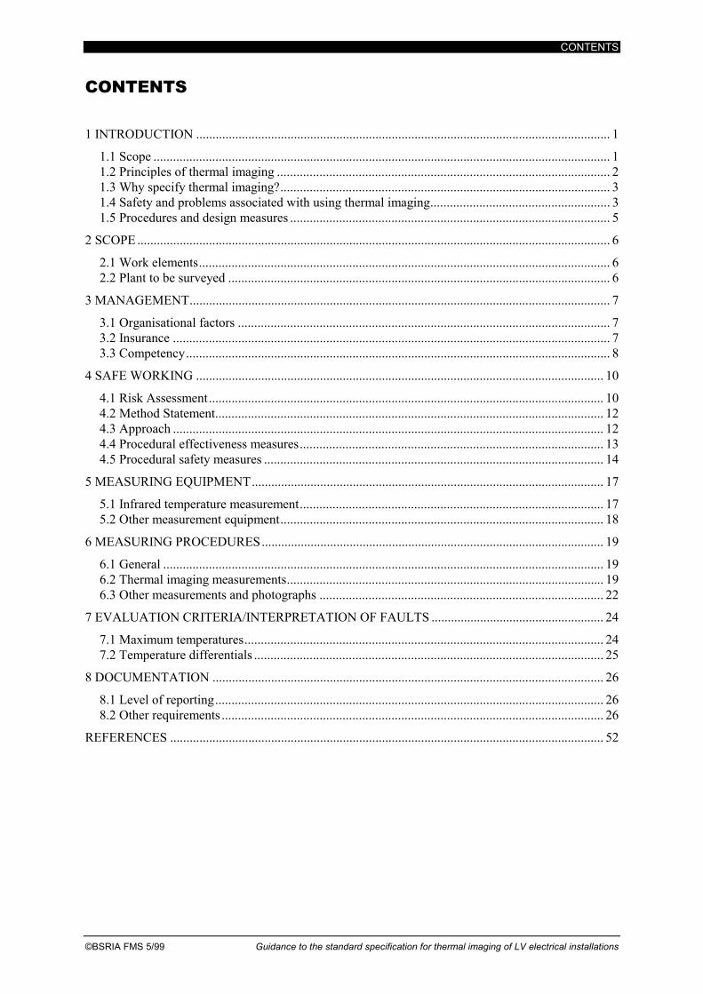
CONTENTS
1 INTRODUCTION ............................................................................................................................... 1
1.1 Scope ............................................................................................................................................ 1 1.2 Principles of thermal imaging ...................................................................................................... 2 1.3 Why specify thermal imaging?..................................................................................................... 3 1.4 Safety and problems associated with using thermal imaging....................................................... 3 1.5 Procedures and design measures .................................................................................................. 5
2 SCOPE ................................................................................................................................................. 6
2.1 Work elements.............................................................................................................................. 6 2.2 Plant to be surveyed ..................................................................................................................... 6
3 MANAGEMENT................................................................................................................................. 7
3.1 Organisational factors .................................................................................................................. 7 3.2 Insurance ...................................................................................................................................... 7 3.3 Competency.................................................................................................................................. 8
4 SAFE WORKING ............................................................................................................................. 10
4.1 Risk Assessment......................................................................................................................... 10 4.2 Method Statement....................................................................................................................... 12 4.3 Approach .................................................................................................................................... 12 4.4 Procedural effectiveness measures............................................................................................. 13 4.5 Procedural safety measures ........................................................................................................ 14
5 MEASURING EQUIPMENT............................................................................................................ 17
5.1 Infrared temperature measurement............................................................................................. 17 5.2 Other measurement equipment................................................................................................... 18
6 MEASURING PROCEDURES......................................................................................................... 19
6.1 General ....................................................................................................................................... 19 6.2 Thermal imaging measurements................................................................................................. 19 6.3 Other measurements and photographs ....................................................................................... 22
7 EVALUATION CRITERIA/INTERPRETATION OF FAULTS ..................................................... 24
7.1 Maximum temperatures.............................................................................................................. 24 7.2 Temperature differentials ........................................................................................................... 25
8 DOCUMENTATION ........................................................................................................................ 26
8.1 Level of reporting....................................................................................................................... 26 8.2 Other requirements ..................................................................................................................... 26
REFERENCES ..................................................................................................................................... 52

CONTENTS
Guidance to the standard specification for thermal imaging of LV electrical installations ©BSRIA FMS 5/99
APPENDICES
Appendix A: Safety legislation............................................................................................................. 28 Appendix B: Design effectiveness measures........................................................................................ 30 Appendix C: Design safety measures ................................................................................................... 38 Appendix D: Cost benefit analyses....................................................................................................... 41 Appendix E: Typical emissivity values ................................................................................................ 42 Appendix F: Typical conductivity values............................................................................................. 43 Appendix G: Absolute temperature criteria based on the ANSI, IEEE and NEMA standards ............ 44 Appendix H: Absolute temperature criteria based on British and European standards ....................... 47 TABLES
Table 4.1 General hazards .................................................................................................................... 11 FIGURES
Figure 1.1 Thermal image of an isolator................................................................................................. 1 Figure 1.2 Thermal image of a busbar connection ................................................................................ 2 Figure 1.3 Thermal image of a cable connection................................................................................... 2 Figure 1.4 Radiation components ........................................................................................................... 5 Figure 4.1 Thermal image comparing panel surface temperatures....................................................... 13 Figure 6.1 Estimation of internal temperature from external surface reading (high conductance
and emissivity) .................................................................................................................... 21 Figure 6.2 Heat dissipation/conduction for hidden components .......................................................... 22 Figure 6.3 Calculation of product m*l for various values of m............................................................ 23 Figure 6.4 Initial estimate of component temperature for Te = ta and various values of m*l ............. 23 Figure 6.5 Correction of component temperature for Te > Ta and various values of m*l.................. 23 EQUATIONS
Equation 1.1 Stefan-Boltzmann Relationship........................................................................................ 2 Equation 6.1 Estimation of internal temperature from external surface reading............................... 20 Equation 7.1 Corrected maximum for cooling by natural convection and radiation........................... 25 Equation 7.2 Corrected maximum for cooling by forced convection and radiation............................. 25
INTRODUCTION SECTION 1
©BSRIA FMS 5/99 Guidance to the standard specification for thermal imaging of LV electrical installations 1
1 INTRODUCTION
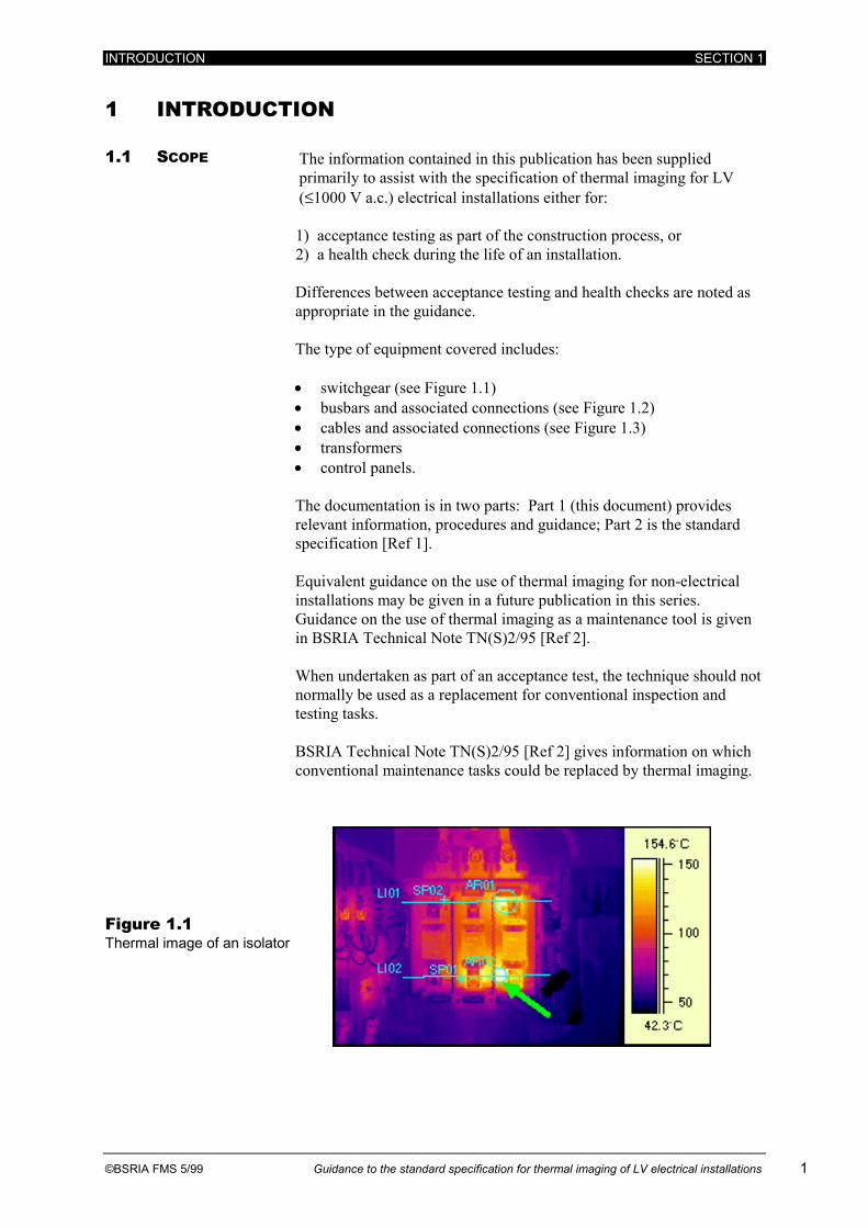
1.1 SCOPE The information contained in this publication has been supplied primarily to assist with the specification of thermal imaging for LV (≤1000 V a.c.) electrical installations either for: 1) acceptance testing as part of the construction process, or 2) a health check during the life of an installation.
Differences between acceptance testing and health checks are noted as appropriate in the guidance. The type of equipment covered includes: • switchgear (see Figure 1.1) • busbars and associated connections (see Figure 1.2) • cables and associated connections (see Figure 1.3) • transformers • control panels. The documentation is in two parts: Part 1 (this document) provides relevant information, procedures and guidance; Part 2 is the standard specification [Ref 1]. Equivalent guidance on the use of thermal imaging for non-electrical installations may be given in a future publication in this series. Guidance on the use of thermal imaging as a maintenance tool is given in BSRIA Technical Note TN(S)2/95 [Ref 2]. When undertaken as part of an acceptance test, the technique should not normally be used as a replacement for conventional inspection and testing tasks. BSRIA Technical Note TN(S)2/95 [Ref 2] gives information on which conventional maintenance tasks could be replaced by thermal imaging.
Figure 1.1 Thermal image of an isolator

SECTION 1 INTRODUCTION
2 Guidance to the standard specification for thermal imaging of LV electrical installations ©BSRIA FMS 5/99
Figure 1.2 Thermal image of a busbar connection
Figure 1.3 Thermal image of a cable connection
1.2 PRINCIPLES OF
THERMAL IMAGING
The radiation emitted from the surface of an object is a function of the object temperature as described by the Stefan-Boltzmann relationship (Equation 1.1). The infrared element of the radiation is measured and converted into an equivalent temperature. The thermal image is constructed from a multitude of point measurements taken in sequence whilst scanning the field of view by representing the point temperature values on a grey or colour scale (see Figures 1.1, 1.2 and 1.3). Single point infrared measurement devices (radiometers) are also available which give an average temperature value for a target measurement area. These are cheaper but unlike the imaging cameras are not practical for inspecting large areas quickly and are generally less effective at detecting faults (refer to Section 5).
Equation 1.1 Stefan-Boltzmann Relationship
W = σ.ε.T4
where W is the radiant power emitted (W/m2) σ is the Stefan-Boltzmann constant (5.69 W/m2K4) ε is the object emissivity T is the absolute temperature of the object (K)

INTRODUCTION SECTION 1
©BSRIA FMS 5/99 Guidance to the standard specification for thermal imaging of LV electrical installations 3
1.3 WHY SPECIFY THERMAL IMAGING?
The temperatures of electrical components and connections are indicative of their health. Excessive heat due to increased electrical resistance will be generated by faulty components and by loose, oxidised or corroded connections. Equipment running hot can also be related to poor assembly, overloading, failure of cooling etc Conventional techniques such as impedance testing and torque checking have a relatively low effectiveness in detecting and preventing failure due to these causes. Thermal imaging is a non-contact on-line technique which can be employed to detect these temperature rises as “hot spots”. Identification of hot spots can be used to trigger remedial work, reducing the number of defects and improving reliability. The two key benefits available from the reduction in defects are: 1. Increased plant availability - this can result in very large
benefit : cost ratio for key installations supporting business-critical functions, eg computer centres. It should also be noted that thermal imaging can be (and is best) done with the plant on-line, reducing the need to take critical plant off-line for testing which in itself would reduce availability.
2. Avoidance of consequential damage - this can be damage to the installation itself, connected plant, or other damage due to fire or explosion for example.
Feedback from thermal imaging of electrical installations shows a significant rate of potential fault detection for an initial survey, typically in the region of one to two faults for every 10 panels inspected.
1.4 SAFETY AND
PROBLEMS ASSOCIATED WITH USING THERMAL IMAGING
Thermal imaging work needs to be effective in detecting faults but it must also be carried out in compliance with the requirements for safe working laid down in the relevant regulations. The Health & Safety at Work etc Act 1974 [Ref 3] is the primary general legislation. There are also a number of more specific associated Acts and Regulations which should be complied with when undertaking this work. Of particular note are the following: • Electricity at Work Regulations 1989 [Ref 4] • Management of Health & Safety at Work Regulations 1992 (MHSW)
[Ref 5] • Construction (Design and Management) Regulations 1994 (CDM)
[Ref 6] • Provision and Use of Work Equipment Regulations 1992 (PUWER)
[Ref 7]. Discussion of these and other relevant legislation is provided in Appendix A. Safe working is discussed in detail in Section 4. Safety requirements will often conflict with the requirements for effective thermal imaging but must remain of the highest priority irrespective of the needs for better thermal imaging. The greater the temperature rise or gradient which is observable for a fault, the more effective will be the fault detection. Panel covers, screens etc which provide protection against contact with live equipment will obscure or

SECTION 1 INTRODUCTION
4 Guidance to the standard specification for thermal imaging of LV electrical installations ©BSRIA FMS 5/99
at best attenuate the observable temperature rise. The best results will invariably be obtained by removing the panel covers, screens etc and inspecting live exposed components. However, safety requirements will often either preclude this approach or require special procedures or precautions to be observed. This may compromise the effectiveness of the imaging and/or increase the cost of its implementation. Other problems which can limit the effectiveness of thermal imaging are outlined below.
Access
The ability to effectively thermal image may be limited by a number of factors including: • safety interlocks preventing access without isolation • the location of equipment in inaccessible places • restricted access preventing imaging on safety or physical grounds.
Panel/component layout and construction
Certain types of layouts and constructions can hide components from view.
Lightly loaded circuits
Temperature rises will be small for lightly loaded circuits hence reducing the probability of fault detection.
Absolute measurement accuracy
The key parameter used to calculate the temperature from the radiation collected is emissivity (a measure of the efficiency of a surface in absorbing and radiating infrared radiation - refer to CIBSE C3 [Ref 8]). This is used together with a value for the ambient background radiant temperature to calculate the portion of the measured radiation emitted from the object - see Figure 1.4. An appropriate value for the emissivity must therefore be used to give an accurate temperature measurement. Most non-metallic surfaces in building services have emissivity values in the region of 0.9 to 0.95 and so these values are commonly used as defaults for surveys. However, some materials (eg copper and aluminium) may have emissivity values considerably less than this and adjustments will need to be made to ensure reasonable accuracy. Typical emissivity values are given in Appendix E Table E.1. The accuracy of the measurement itself (rather than the assumed parameters) should also be borne in mind – refer to Section 5. It should be emphasised that the comments made above relate to absolute temperature measurement. Both sources of inaccuracy will be of less concern when undertaking comparative measurements for which thermal imaging is most suited.

INTRODUCTION SECTION 1
©BSRIA FMS 5/99 Guidance to the standard specification for thermal imaging of LV electrical installations 5
Figure 1.4 Radiation components
Reflections
Materials which have a low emissivity will reflect a large proportion of the radiant energy which impinges on them. Reflections from heat sources (eg lights, sun) can cause great difficulty in interpreting images and in achieving reasonably accurate temperature measurements.
Interpretation
The level of temperature rise which causes concern will vary for different plant and with the installation characteristics. Absolute failure criteria are therefore difficult to define, complicating the interpretation of the results. Identification of potential faults is primarily the responsibility of the thermographer, and therefore is very dependent on his or her competency.
Panel/compartment operating temperature
Panel/compartment operating temperatures can be significantly above ambient. Opening doors/covers will introduce a cooling effect. An adjustment will need to be made for this to obtain representative temperature values in cases where components are allowed to adjust to ambient conditions with the panel doors/covers open.
1.5 PROCEDURES AND DESIGN MEASURES
Guidance on procedures which can be used to address/reduce the problems noted above is provided in Section 4. Design measures to improve the effectiveness and safety of thermal imaging are given in Appendices B and C. These are mainly appropriate to acceptance testing. Although similar modifications could be made to an existing installation for a health check, these would inevitably be limited and at a higher cost. Because of this flexibility, there will be more onus on the design measures being incorporated for acceptance testing than for health checks.
It should be noted that glass and perspex are opaque to infrared radiation and that it is not possible to thermal image through these or other common construction materials.
M e a s u r e m e n td e v ic e
O b je c t :S u r f a c e t e m p e r a tu r e tsE m i s s iv i ty εT r a n s m i s s iv i t y τR e f l e c t iv i ty ρε + τ + ρ = 1
F o r o p a q u e o b je c t s :T r a n s m i s s iv i t y τ = 0R e f l e c t iv i ty ρ = 1 - ε
B a c k g r o u n d r a d ia n t t e m p e r a tu r e tb
E m i s s io n ε .σ . t s 4
T r a n s m i s s io n τ .σ . t s 4
R e f l e c t io n ρ .σ .t s 4