Embed Size (px)
Citation preview

t
GUIDE TO FOUNDATION AND SUPPORT SYSTEMS FOR MANUFACTURED HOMES
Excellence in Design
Manufacturing and Installation Series
Factors to Consider in Design
Proprietary Foundation and Support Systems
Non-proprietary Foundation and SupportSystems
DRAFT ndash Not for Distribution March 27 2002
US Department of Housing and Urban Development
Office of Policy Developmen and Research
PATH (Partnership for Advancing Technology in Housing) is a privatepublic effort to develop demonstrate and gain widespread market acceptance for the next generation of American housing Through the use of new or innovative technologies the goal of PATH is to improve the quality durability environmental efficiency and affordability of tomorrowrsquos homes
PATH is managed and supported by the US Department of Housing and Urban Development (HUD) In addishytion all Federal Agencies that engage in housing research and technology development are PATH partners including the Departments of Energy and Commerce as well as the Environmental Protection Agency (EPA) and the Federal Emergency Management Agency (FEMA) State and local governments and other participants from the public sector are also partners in PATH Product manufacturers home builders insurance compashynies and lenders represent private industry in the PATH partnership
To learn more about PATH please contact
451 Seventh Street SW Washington DC 20410 202-708-4250 (phone) 202-708-5873 (fax) e-mail pathnetpathnetorg
Visit PDampRrsquos Web Site wwwhuduserorg to find this report and others sponsored by HUDrsquos Office of Policy Development and Research (PDampR) Other services of HUD USER PDampRrsquos Research Information Service include listservs special interest bimonthly publications (best practices significant studies from other sources) access to public use databases hotline 1-800-245-2691 for help accessing the information you need
GUIDE TO FOUNDATION AND SUPPORT SYSTEMS FOR MANUFACTURED HOMES
Excellence in Design
Manufacturing and Installation Series
Prepared for US Department of Housing and Urban Development
Office of Policy Development and Research
Prepared by Manufactured Housing Research Alliance
New York NY
DRAFT ndash Not for Distribution March 27 2002
A C K N O W L E D G E M E N T S
The Manufactured Housing Research Alliance wishes to acknowledge the assistance advice and guidance of a number of people without whose help this publication would not have been possible
The effort was lead by a project steering committee Bill Farish Fleetwood Enterprises Project Chair Ed Bryant Champion Enterprises Charles Fanaro Hi-Tech Housing Bill Freeborne US Department of Housing and Urban Development James Reitzner Asset Development Group Andrea Vrankar US Department of Housing and Urban Development Roger Walker Ventana Development LLC Frank Walter Manufactured Housing Institute
Other industry representatives whose advice and guidance helped shape the guide Gary Austin Mobile Corral Homes Inc JR Bader Mausten Home Sales David Conover National Evaluation Service Pamela B Danner Danner and Associates Brian Fannon Sun Communities Siavash Farvardin National Evaluation Service Doug Gorman Home Mart John Ingargiola Federal Emergency Management Agency Therese P McAllister Greenhorne amp OMara Barry McCabe Hometown America Communities Gary McDaniel Chateau Communities Rick Mendlen US Department of Housing and Urban Development George Porter Manufactured Housing Resources Roger Wendt Sunrise Home Service
Companies that submitted designs or product information The Anchor Post Company LLC Asset Development Group Chateau Communities Cherry Hill Homes CWS Communities Fast Track Foundation Systems Fleetwood Homes Goffs Fleetwood Home Center Jensens Inc JM Products Inc Oliver Technologies Inc Roger Huddleston Manufactured Homes Tie Down Engineering Ventana Development LLC
Design production and editorial subcontractors Hoi L Chu HLC Group Dorothy Foster Jennifer Goode Robert LaPointe
MHRA staff responsible for coordinating and facilitating development of the guide Emanuel Levy Executive Director Ed Salsbury Project Coordinator Sandra Ho Editorial Director Ian Klose Staff Kathleen Boodoo Staff
D I S C L A I M E R O F WA R R A N T I E S A N D L I M I TAT I O N O F L I A B I L I T I E S
Neither the authors nor reviewers nor the US Department of Housing and Urban Development nor the Manufactured Housing Institute nor the Manufactured Housing Research Alliance nor any of their employees or representatives makes any warranty guarantee or representation expressed or implied with respect to the accushyracy effectiveness or usefulness of any information method or material in this document nor assumes any liashybility for the use of any information methods or materials disclosed herein or for damages arising from such use This publication is intended for the use of professional personnel who are competent to evaluate the significance and limitations of the reported information and who should accept responsibility for the application of the material it contains All responsibility as to the appropriate use of information in this document is the responsibility of the reader or user
The contents of this report are the view of the contractor and do not necessarily reflect the views or policies of the US Department of Housing and Urban Development or the US government
Neither the US government nor MHRA endorse products or manufacturers Trade or manufacturers names that appear herein are used solely because they are considered essential to the objective of the report Companies that appear in Chapter 4 paid a fee to include their material in the guide Other foundation suppliers that MHRA was aware of are listed at the end of Chapter 4 All manufacturers are welcome to participate in future versions of the guide Any claims made by a company were not independently verified by MHRA and makes no representation or warranties of any kind either express or implied including but not limited to warranties of title noninfringement or implied warranties of merchantability or fitness for a particular purpose and expressly disclaims any liability with respect to the content or accuracy of this information This is not a consumer report There is no relative ranking of systems
MHRA does not endorse certify or control the foundation systems presented as case studies in Chapter Three or the company proprietary foundation systems presented in Chapter Four The views and opinions of the companies expressed in Chapter Four do not necessarily state or reflect those of MHRA and shall not be used for advertising or product endorsement purposes MHRA does not guarantee the accuracy completeness currency or reliability of the information submitted by the companies concerning their proprietary foundation systems The information obtained from this guide is provided without warranties of any kind either express or implied including but not limited to warranties of title noninfringement or implied warranties of merchantability or fitness for a particular purpose The use of any information contained in these materials is voluntary and reliance on it by the user should be undershytaken after an independent review of its accuracy completeness currency and reliability
The systems included in this guide are representative of the systems MHRA was aware of at the time of publication MHRA does not imply that these are all of the systems that exist
C O P Y R I G H T N O T I C E S
Table 21 Figures 26 and 28 are Copyright 2000 International Code Council Inc Falls Church Virginia 2000 International Residential Code and copyright 1995 One- and Two-Family Dwelling Code Reprinted with permission of the author All rights reserved
Figure 23 is Copyright 1996 BOCA International Country Club Hills Illinois BOCA National Building Code1999 Commentary Reproduced with permission All rights reserved
P H O T O C R E D I T S
Courtesy of Anchor Post Company Figures 428-431
Courtesy of Asset Development Group Figure 344
Courtesy of Cherry Hill Homes Figures 325 327 328
Courtesy of Goffrsquos Fleetwood Homes Figure 332
Courtesy of Fast Track Foundations Systems Figures 47-420
Courtesy of Roger Huddleston Manufactured Homes Figures 363 369
Courtesy of Steve Hullibarger Figures 13 14 24 210 39-319 321 322 348 361 362 364 365-367
Courtesy of Jensenrsquos Inc Figures 12 347 349 357
Courtesy of JM Products Figures 422-427
Courtesy of Manufactured Housing Institute Figures I1 I2 11 336 346
Courtesy of Oliver Technologies Figures 41-46
Courtesy of Tie Down Engineering Figures 432-441
Courtesy of Ventana Development Figures 330 331 368
F O R E W O R D
For several decades manufactured homes built to the preemptive Federal Manufactured Home Construction and Safety Standards have been the nations foremost source of unsubsidized affordable housing Until relatively recently the majority of manufactured homes were economical single section designs financed with asset-backed loans sold most often to first-time home buyers and seniors and located in suburban and rural settings Manufactured homes were also distinguished from their site-built counterparts in the way they were secured to the groundmdashthe majority are held in place by pier and anchor systems
Within the last five years the manufactured housing industry has experienced an evolution and the rate of change appears to be accelerating Sales of multisection homes have well-outpaced single-section designs the popularity of landhome financing continues to grow the buyer demographics are diversifying and new markets are opening to manufactured homes particularly in urban infill and higher density areas
Homes built in compliance with the HUD standards are entering the portfolio of developers that have historically used site-building methods exclusively The economics of building homes in a factory under a single national code has long been attractive But only in the last few years has the vision of manufactured homes as a technology for supplying a wider range of affordable housing needs begun to be realized
The changes in the manufactured housing market the evolution of the industry itself and the diversification of the potential customers for manufactured homes are ushering in a host of innovations and changes to the industrys core product No area is more affected by these changes than the methods for supporting and fastening the home to the ground
This guide serves several functions First it helps decision makers in formulating a strategy for sorting among founshydation and support system alternatives and describes factors that impact the design and construction process Second it exposes the manufactured housing industry buyers of manufactured homes and others interested in HUD-code housing to some of the more popular and practical ways of designing and installing manufactured home foundation or support systems These designs are springboards for exploring alternative design approaches and solutions Lastly through the use of case studies the guide examines how some practitioners are already pursing new foundation and support system methods hinting at the wealth and diversity of foundation solutions yet to come
Lawrence L Thompson
General Deputy Assistant Secretary for Policy Development and Research
CONTENTS
11
11
12
13
14
21 210 211
32
36
312
314
316
318
320
322
324
326
328
330
336
338
340
342
348
350
42
46
410
414
418
422
426
A1
B2
C3
Chapter 1 Executive Summary 11
Chapter 3 Individual Foundation Evaluations Non-Proprietary Systems 31
Chapter 4 Individual Foundation Evaluations Proprietary Systems 41
Chapter 2 Factors to Consider in Foundation Selection and Design 21
Appendices
Using the Guide ix
Why a Foundation and Support Systems Guide
Purpose of the Guide
How the Guide is Organized
What the Words ldquoReal Property Foundationrdquo Mean
What the Words ldquoFHA Permanent Foundationrdquo Mean
Site Conditions Major Design Factors Best Design Practices
Pier and Ground Anchor Support Systems
Crawl Space Systems
Case Study 1 Mt Clemens MI
Case Study 2 Williamston KY
Case Study 3 Longmont CO
Case Study 4 Campbellsville KY
Case Study 5 Mahomet IL
Case Study 6 Mahomet IL
Case Study 7 Fond du Lac WI
Case Study 8 Kansas City MO
Case Study 9 Germantown WI
Slabs-on-Grade
Case Study 10 Milwaukee WI
Case Study 11 Eau Claire WI
Case Study 12 Hyde Park MD
Basements
Case Study 13 Mahomet IL
Case Study 14 Elizabethtown PA
All Steel Foundation System Oliver Technologies Inc
The Anchorpanel Foundation Fast Track Foundation Systems
Rigid Foundation Anchoring System JM Products Inc
The Storm Anchor System The Anchor Post Company LLC
Vector Dynamics Foundation System Tie Down Engineering
Xi Foundation System Tie Down Engineering
Other Proprietary Foundation System Suppliers
A Glossary
B References
C Additional Resources
USING THE GUIDE
The Guide to Foundation and Support Systems for Manufactured Homes contains information for many audiences but it is written with one goal in mind to help those in the industry responsible for selecting designing and installing foundations recognize the available options and make well-informed decisions
Chapters 1 and 2 cover factors that influence the selection of a foundation system These secshytions will help readers form a checklist of the many factors that enter into decisions about foundations For the expert they are a refresher and may suggest new ideas and approaches to foundation design and construction
Chapters 3 and 4 describe foundation systems Chapter 3 describes the non-proprietary foundashytions systems Chapter 4 describes proprietary foundation systems Non-proprietary systems are made of components such as concrete blocks for which there are many suppliers The non-proprietary design shows one way to build a system such as a basement There are many design approaches as suggested by the case studies that accompany each non-proprietary system description The case studies were culled from examples subshymitted by designers and installers operating in an array of manufactured housing markets In contrast proprietary systems are those in which part or all of the major components that comprise the foundation system are owned and usually patented by a single company
Table I1 is a quick reference to information about the foundation solutions presented in the guide and the page on which detailed explanation is given The table helps differentiate among foundation systems and summarizes the attributes of each option The factors described in the table are initial cost real property classification installashytion time use in flood prone areas use in seismic areas and use in areas subject to frost heave These and other factors that enter into the design of all foundation systems such as high wind areas expansive soils and termite damage are described in Chapter 2
Figure I1
Figure I2
ix
Table I1
Foundation System Type Initial Cost1
Real Property
Foundation2
Installation Time3
Use in Seismic Areas
Use in Flood Hazard Areas4
Use in Areas Subject to
Frost Heave
Page No See Page 210 See Page 13 See Page 210 See Page 27 See Page 25 See Page 24
NON-PROPRIETARY FOUNDATION SYSTEMS
Pier and Ground Anchors
32 $ N yen Y Y Y
Crawl Spaces 36 $$ ndash $$$ Y yenyen Y Y Y
Slabs 330 $$ ndash $$$ Y yenyen Y Y Y
Basements 342 $$$$ Y yenyenyen Y N Y
PROPRIETARY FOUNDATION SYSTEMS5
The All Steel Foundation System Oliver Technologies
42 $ ndash $$ Y yenndash yenyen Y Y Y
The Anchorpanel Foundation Fast Track Foundation 46 $ ndash $$ Y yenndash yenyen Y Y Y
Rigid Foundation Anchoring System JM Products 410 $ ndash $$ Y yenndash yenyen Y Y Y
The Storm Anchor System The Anchor Post Company
414 $ ndash $$ Y yenndash yenyen Y Y Y
Vector Dynamics Tie Down Engineering
418 $ ndash $$ Y yenndash yenyen Y Y Y
Xi Foundation Tie Down Engineering
422 $ ndash $$ Y yenndash yenyen Y Y Y
1 The symbols in this column are intended to suggest the relative magnitude of initial system costs not absolute dollar figures Initial costs are ranked from least ($) to most ($$$$) costly As with any rating method individual designs may be exceptions to these relative placements
2 The designation shown for non-proprietary real foundation systems is a general guideline Such designation is subject to the manufacturers verification and not all designs may qualify as a real property foundation Real property foundation designations for proprietary foundation sysshytems were determined by the companies that supply those products and have not been independently verified Whether a manufactured home may be classified as real property is determined by state or local laws
3 The symbols in this column are intended to suggest the relative time required to install the foundation or support system not absolute instalshylation times Installation costs are ranked from requiring the least amount of time ( yen ) to the most amount of time ( yenyenyen ) to install As with any rating method individual designs may be exceptions to these relative placements
4 For use in flood hazard area the lowest floor of a manufactured home shall be elevated to or above the base flood elevation (BFE) and be securely anchored to an adequately anchored foundation system to resist flotation collapse and lateral movement (44 CFR 603 (c)(6) with a 36-inch pier height exception rule for existing communities at 603 (c)(12)(ii)mdashFEMAmdashNational Flood Insurance Program)
5 Entries for the proprietary foundation systems are provided by the companies themselves and are not independently verified
x
1 C H A P T E R
EXECUTIVE SUMMARY
The term foundation means all components of the support and anchoring system (that might include such features as piers footings slabs walls ties anchoring equipment ground anchors or any other material or equipment) that supports a home and secures it to the ground6
W H Y A F O U N D AT I O N A N D S U P P O RT S Y S T E M S G U I D E
For as many types and varieties of manufactured homes as are now producedmdashwith more to comemdashthere are equally as many varieties of installation and support systems This is the first guide to consider and compare the major foundation alternatives in use across the country This guide was developed to fill this void with two goals in mind to present a compilation of foundation ideas and inventions culled from experts and practitioners across the nation and to offer a range of practical and cost-competitive foundation solutions
There is no single best foundation system There is however a way to organize the process of deciding among alternative foundashytion designs that are appropriate for a given site and budget The process starts with recogshynizing and prioritizing the major factors that influence the selection of the foundation system Whether the main considerations are initial cost frost heave resistance or a host of other issues this information will help the reader focus on an appropriate foundation design Understanding the foundation alternashytives and proven design and installation pracshytices is the next step By presenting both sets of information this guide helps narrow the field among many options and establish a methodical process for decision making
P U R P O S E O F T H E G U I D E
Users of this guide should find practical and helpful solutions to their individual situations Whether the reader is a retailer trying to find better and more economical ways to deliver a finished home a contractor faced with an unusual soil condition or anyone wanting to better understand the alternatives suggestions can be found in this guide There are summaries and tables for quickly identifying appropriate foundation systems for a particular site and homebuyer as well as technical details for direct application to the project at hand
A source of first resort for foundation systems information
The guide is intended to be instrumental in fostering the wider dissemination of good ideas and out of the box thinking that characterizes the manufactured housing industry in general
Foundation alternatives rather than a single best solution
Each system included in this compilation suggest advantages in at least some settings Comments about the pros and cons as well as the special limitations of each system are included
When deciding among alternatives several key conditions and objectives should be considered such as What is the budget What kind of financing will be sought What type of soil is found at the site Is the area subject to frost
6 Depending on the context and application the means for anchoring supporting and otherwise securing a manufactured home to the ground is referred to as either the support system or foundation system For simplicity the term foundation system is used throughout this guide and should be interpreted broadly as including support and foundation systems
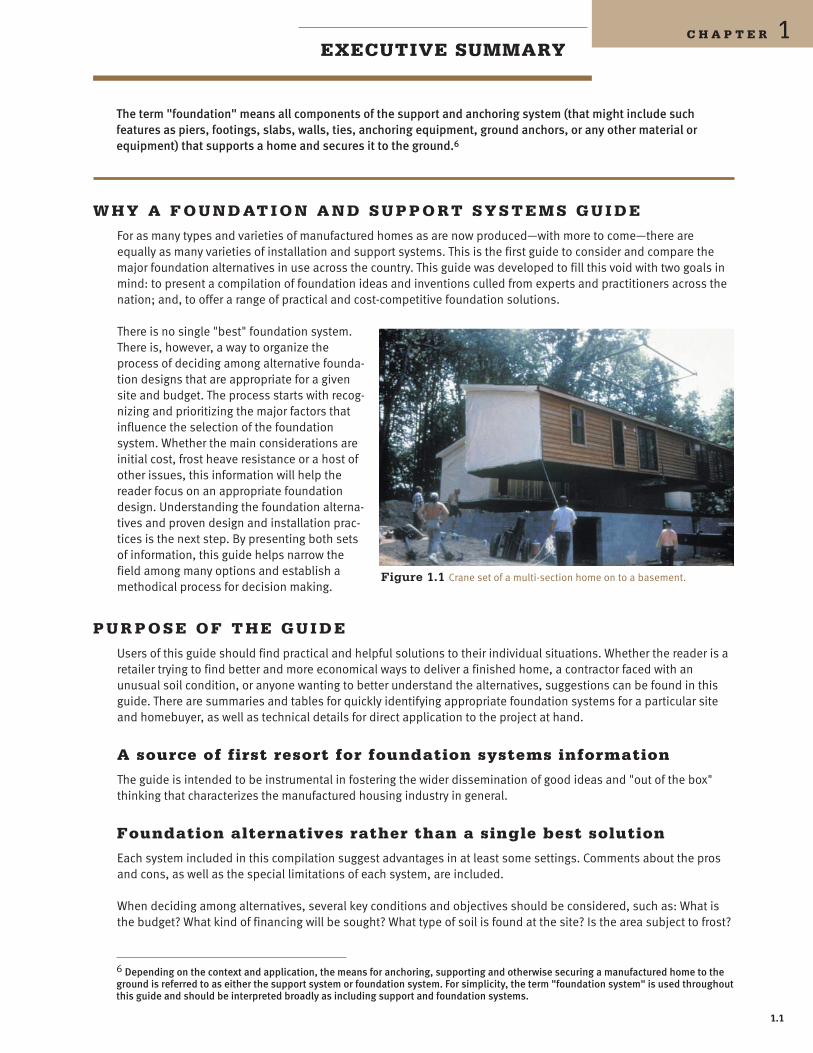
Figure 11 Crane set of a multi-section home on to a basement
11
Is the home being placed in a land-lease community or on private land Is the area subject to high winds floods or deep frost penetration This guide explains how these factors influence the selection and design of a foundation and makes suggestions and recommendations
Information on all types of systems
The intent of this document is to be inclusive offering guidance on an array of foundation systems However since there are many design variations the guide only begins to sort through the options The guide also suggests a way of organizing foundation systems into categories that are helpful in understanding almost any foundation design Often the home manufacturers installation instructions provide guidance on design and construction of foundation and support systems While this document is intended to complement the manufacturers guidelines where there are discrepancies between the two documents the manufacturers instructions should be followed
A wide range of designs
Ideas and examples of foundation designs were solicited from all parts of the manufacshytured housing industry As a result practishytioners willing to share their ideas suggested many very practical and proven concepts Experts including licensed professional engineers and contractors reviewed each system that was submitted Some designs were eliminated because they were too speshycialized in their applicability The designs that are included are worthy of consideration for many types of applications sites and design objectives
H O W T H E G U I D E I S O R G A N I Z E D
The guide is organized into three sections as follows
Chapter 2mdashFactors to consider in foundation selection anddesign
This section discusses the major factors that drive the choice of a foundation system and the issues that influence the specific design of a foundation The factors listed below and discussed in detail in Chapter 2 are used to rate the relative merits of foundation designs
1 Site conditions
2 Major design factors
3 Best design practices
Chapter 3mdashNon-proprietary systems built of readily availablematerials
This section covers four foundation classifications
bull Pier and ground anchor support systems (the most popular method of securing manufactured homes to the ground)
bull Crawl space systems
bull Slabs-on-grade foundation systems
bull Basements
Figure 12 Slabs are an increasingly popular foundation system for manufacshytured homes especially in the Northeast
12
Introduction
A non-proprietary system is considered to be in the public domainmdashusable by anyone without paying a royalty fee or other consideration for its use It is not a product of manufacturing or individual company output Non-proprietary systems can be conshystructed by any qualified contractor using materials available from most building suppliers
Included in each foundation class are a series of case studies drawn from actual installations and contributed by practitioners from across the nation The case studies suggest how a basic concept can be modified to meet the specific needs of a site home design or buyer preference
Chapter 4mdashProprietary systems wholly-owned by a single company
This section contains information about several proprietary foundation products marketed to the manufactured housing industry A proprietary system is a product manufactured by a company that owns some protectable interest in the design Some are patented There is spirited competition among manushyfacturers of these proprietary systems resulting in rich choices for the retailer builder contractor and homebuyer
The information contained in this section was prepared by the companies themselves The following products and companies are represented
bull All Steel Foundation Oliver Technologies Inc
bull The Anchorpanel Fast Track Foundation Systems
bull Rigid Foundation Anchoring System JM Products Inc
bull The Storm Anchor System The Anchor Post Company LLC
bull Vector Dynamics Foundation System Tie Down Engineering
bull Xi Foundation System Tie Down Engineering
W H AT T H E W O R D S R E A L P R O P E RT Y F O U N D AT I O N rdquo M E A N
Because of the rapid pace of advances in the manufactured housing industry many customary and industry and phrases have changed or taken on new meanings This is especially true when the subject is foundation systems
For example the manufactured home is the only type of residential dwelling intended to be used as either personal or real property Manufacturers often establish a special set of conditions for foundation systems intended for use with homes financed as real property with a mortgage or deed of trust The techniques for supporting homes financed as either real or personal property are intended to result in properly engineered and reliable foundation systems Whether used with real property or personal property all foundation systems including those in this guide are meant to be safe durable and long lasting
Nothing in this guide is intended to suggest that a home on any particular foundation system is or is not real propshyerty rather than personal property In all cases real or personal property status is determined by state or local laws that may or may not reference foundation type Similarly eligibility for conventional long-term financing is detershymined by underwriting standards that may or may not reference the foundation type or real versus personal property status
Figure 13 Some foundations use a combination of interior piers and perimeter walls to support the home
Figure 14 Some foundations are recessed to create a site-built look
13
W H AT T H E W O R D S P E R M A N E N T F O U N D AT I O N rdquo M E A N
The US Department of Housing and Urban Development (HUD) Federal Housing Administration (FHA) defines pershymanent foundation systems as follows
Permanent foundations must be constructed of durable materials ie concrete mortared masonry or treated wood-and be site-built It shall have attachment points to anchor and stabilize the manufactured home to transfer all loads herein defined to the underlying soil or rock The permanent foundations shall be structurally developed in accordance with this document or be structurally designed by a licensed professional engineer for the following
1 Vertical stability
a Rated anchorage capacity to prevent uplift and overturning due to wind or seismic forces whichever controls Screw-in soil anchors are not considered a permanent anchorage
b Footing size to prevent overloading the soil-bearing capacity and avoid soil settlement Footing shall be reinforced concrete to be considered permanent
c Base of footing below maximum frost-penetration depth
d Encloses a basement of crawl space with a continuous wall (whether bearing or non-bearing) that separates the basement of crawl space from the backfill and keeps out vermin or water
2 Lateral stability Rated anchorage capacity to prevent sliding due to wind or seismic forces whichever controls in the transverse and longitudinal directions7
It is beyond the scope and purpose of this guide to assess whether a particular foundation system meets this definishytion of performance and would likely qualify for FHA Title II insurance This is the responsibility of the FHA and its representatives However this guide contains useful information that the professional and consumer may want to consider in determining the appropriate foundation system to be used for a given installation
Nearly 30 years ago when HUD adopted the nationally preemptive manufactured home standards the stage was set for the explosive growth of the nations primary source of unsubsidized affordable housing The information conshytained in this guide is intended to complement and affirm this preemptive mandate and help the industry to conshytinue to meet the nations ever diversifying housing needs
7 US Department of Housing and Urban Development 1996 Permanent Foundations Guide for Manufactured Housing HUD-007487 September 1996 Questions regarding whether or not a system qualifies under this definition can be referred to the US Department of Housing and Urban Development Office of Consumer and Regulatory Affairs 451 7th St SW Room 9156 Washington DC 20410 phone (202) 708-6409
14
2 C H A P T E RFACTORS TO CONSIDER IN FOUNDATION SELECTION AND DESIGN
This section discusses the major factors that drive the choice of a foundation system and the issues that influence the specific design of a foundation The factors listed below and discussed in detail in Chapter 2 are used to rate the relative merits of foundation designs
1 Site conditions
2 Major design factors
3 Best design practices
Decisions about foundation systems are based on many factors This chapter presents the major considerations in selecting and designing foundation systems although not all factors relate to every installation Issues such as frost depth seismic activity and presence of flood plains have regional importance Wherever possible graphic informashytion such as maps has been included to help correlate influential factors with regional occurrence
To help organize the issues and navigate through the myriad factors that impact foundation design and selection this chapter is divided into three parts
bull Part 1 site conditions describes features and issues that are characteristic of the building site These are factors that shape decisions about the foundation and over which the installer designer builder or developer have little or no say Each site comes with its own set of such conditions and these features vary from site to site and region to region These givens begin to suggest the better foundation systems for a specific site
bull Part 2 major design factors covers conditions that are placed on to the building process usually by the buyer retailer manufacturer andor lender The decisions related to these factors are discretionary and are often the primary considerations in choosing the type of foundation
bull Part 3 basic design practices is a summary of best design and construction practices that can be applied in nearly all installations although their relative importance can vary by type of foundation A review of these facshytors during the design process will help avoid costly mistakes
1 S I T E C O N D I T I O N S
Characteristics of major soil types
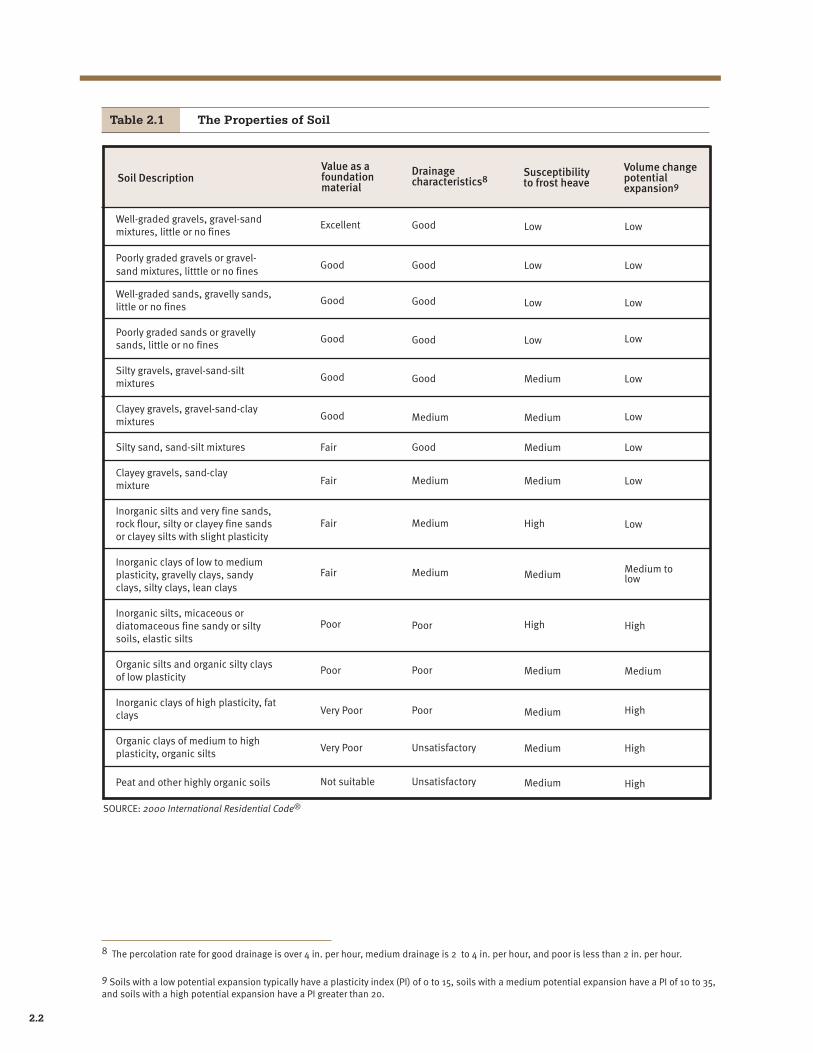
The United States has a wide variety of soils Since it is the soil that supports the home understanding the properties of different soil types is fundamental to sound foundation selection and design (see Table 21) Certain soils have relatively little ability to support weight Some become more or less supshyportive when wet or dry Others may expand or shrink when moisture is present Some soils will compact well and others wont Whatever the soil condition knowledge of foundation system alternashytives can help save money and possibly contribute to the long-term durability of the home
Knowledge of these general soil types and how soil properties impact foundation design is important for a contractor and others involved in the home instalshylation including retailers and installers In most cases it isnt necessary to make a detailed analysis of the soil types However it is advisable to pay careful attention to the impact that unusual or troublesome soils can have on a home
Figure 21 Soil test torque probe measures soil bearing capacity for soil classification
21
Table 21 The Properties of Soil
Soil Description Value as a foundation material
Drainage characteristics8
Susceptibility to frost heave
Volume change potential expansion9
Well-graded gravels gravel-sand mixtures little or no fines
Excellent Good Low Low
Poorly graded gravels or gravel-sand mixtures litttle or no fines
Good Good Low Low
Well-graded sands gravelly sands little or no fines
Good Good Low Low
Poorly graded sands or gravelly sands little or no fines
Good Good Low Low
Silty gravels gravel-sand-silt mixtures
Good Good Medium Low
Clayey gravels gravel-sand-clay mixtures Good Medium Medium Low
Silty sand sand-silt mixtures Fair Good Medium Low
Clayey gravels sand-clay mixture Fair Medium Medium Low
Inorganic silts and very fine sands rock flour silty or clayey fine sands or clayey silts with slight plasticity
Fair Medium High Low
Inorganic clays of low to medium plasticity gravelly clays sandy clays silty clays lean clays
Fair Medium Medium Medium to low
Inorganic silts micaceous or diatomaceous fine sandy or silty soils elastic silts
Poor Poor High High
Organic silts and organic silty clays of low plasticity
Poor Poor Medium Medium
Inorganic clays of high plasticity fat clays Very Poor Poor Medium High
Organic clays of medium to high plasticity organic silts Very Poor Unsatisfactory Medium High
Peat and other highly organic soils Not suitable Unsatisfactory Medium High
SOURCE 2000 International Residential Codereg
8 The percolation rate for good drainage is over 4 in per hour medium drainage is 2 to 4 in per hour and poor is less than 2 in per hour
9 Soils with a low potential expansion typically have a plasticity index (PI) of 0 to 15 soils with a medium potential expansion have a PI of 10 to 35 and soils with a high potential expansion have a PI greater than 20
22
Factors to Consider
One important measure of the ability of soil to support the weight of the home is its bearing capacity a value represhysenting the weight that one sq ft of earth surface is capable of supporting without risk of subsiding This information may already be available from the local building department or from a local engineer Values range from less than 1000 lbs per square foot (psf) to more than 4000 psf
Other problems can arise when foundation systems are placed on soils that contain a high percentage of organic matter or on fill soil Excessive organic matter should be removed and fill properly compacted
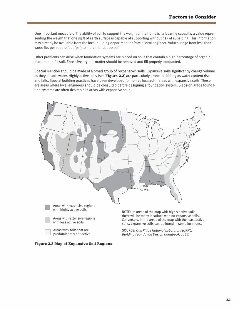
Special mention should be made of a broad group of expansive soils Expansive soils significantly change volume as they absorb water Highly active soils (see Figure 22) are particularly prone to shifting as water content rises and falls Special building practices have been developed for homes located in areas with expansive soils These are areas where local engineers should be consulted before designing a foundation system Slabs-on-grade foundashytion systems are often desirable in areas with expansive soils
Areas with extensive regions with highly active soils
Areas with extensive regions with less active soils
Areas with soils that are predominantly not active
Figure 22 Map of Expansive Soil Regions
NOTE In areas of the map with highly active soils there will be many locations with no expansive soils Conversely in the areas of the map with the least active soils expansive soils can be found in some locations
SOURCE Oak Ridge National Laboratory (ORNL) Building Foundation Design Handbook 1988
23
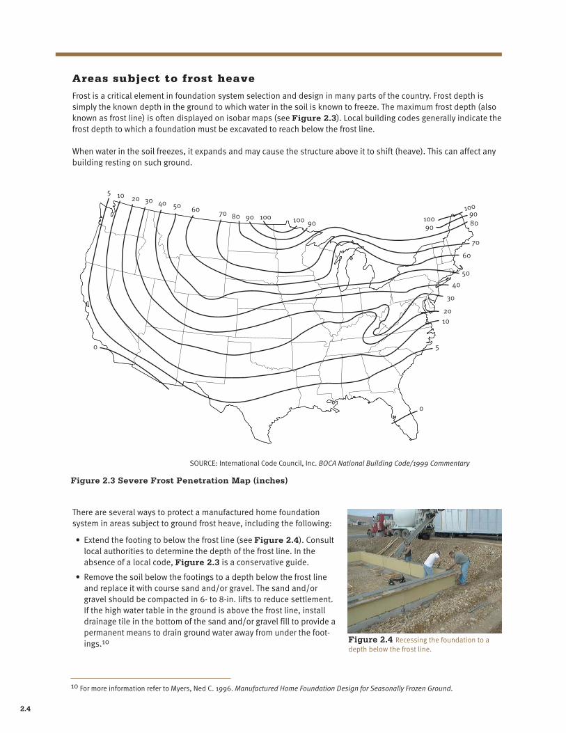
Areas subject to frost heave
Frost is a critical element in foundation system selection and design in many parts of the country Frost depth is simply the known depth in the ground to which water in the soil is known to freeze The maximum frost depth (also known as frost line) is often displayed on isobar maps (see Figure 23) Local building codes generally indicate the frost depth to which a foundation must be excavated to reach below the frost line
When water in the soil freezes it expands and may cause the structure above it to shift (heave) This can affect any building resting on such ground
10
10
20
20
30
30
40
40
60 70 80
50
50
70
60
80 90
9090 100 100
10010090
5
5
0
0
SOURCE International Code Council Inc BOCA National Building Code1999 Commentary
Figure 23 Severe Frost Penetration Map (inches)
There are several ways to protect a manufactured home foundation system in areas subject to ground frost heave including the following
bull Extend the footing to below the frost line (see Figure 24) Consult local authorities to determine the depth of the frost line In the absence of a local code Figure 23 is a conservative guide
bull Remove the soil below the footings to a depth below the frost line and replace it with course sand andor gravel The sand andor gravel should be compacted in 6- to 8-in lifts to reduce settlement If the high water table in the ground is above the frost line install drainage tile in the bottom of the sand andor gravel fill to provide a permanent means to drain ground water away from under the footshyings10 Figure 24 Recessing the foundation to a
depth below the frost line
10 For more information refer to Myers Ned C 1996 Manufactured Home Foundation Design for Seasonally Frozen Ground
24
Factors to Consider
bull Use an uninsulated slab designed to move with the soil as and if it shifts when the soil freezes This type of slab is often referred to as floating
bull Use an insulated slab or crawl space that does not extend below the frost line but is intended to remain stashytionary even as the surrounding ground freezes The insulation wraps around the outside of the foundation and prevents the soil directly under the home from freezing These designs require the use of thermostatically conshytrolled vents that close during freezing periods to keep the air space under the home at a temperature warmer than the outside11
Flood hazard areas
Unless proper precautions are taken homes located in low-lying sites near waterways or along the coasts are at risk of flood damage Riverine flooding takes place when excessive runoff causes a stream or river to overflow its normal channel Coastal flooding normally is the result of ocean storms which can be severe
Flood hazard areas are referred to as flood plains Flood plains outside the floodway may become inundated with rising water that has little or no movement It is possible to minimize or eliminate the risk of damage to homes located in the flood plain A flood plain may however contain floodways an identified area where the risk of damage from moving water and the debris that it may carry is so great that it prohibits residential construction
The first step when dealing with a building site within a flood plain is to verify that it is outside of the floodway The Federal Emergency Management Agency (FEMA) and its local flood plain administrator are the best sources of inforshymation regarding the history of local floods and potential for flood damage12
In addition to identifying areas subject to varying degrees of flood severity FEMAs flood maps are used to detershymine zones for National Flood Insurance Program (NFIP) premium rates In a flood plain the lowest floor is located at or above the Base Flood Elevation (BFE) The BFE also referred to as 100-year flood level is indicated on the Flood Insurance Rate Map (FIRM) available from the local FEMA administrator FEMAs flood maps indicate the areas where the land is below the BFE New homes installed with the first floor (including a basement floor) below the BFE are ineligible for the NFIP rates (certain exceptions apply consult 44 CFR 603 local flood plain ordinance) In most cases homes below the BFE ineligible for any form of federally supported financing and other types of disaster assistance
If properly designed crawl space foundation systems can be used in flood plains Other suitable foundation sysshytems include reinforced piers and pile foundation systems Basements by definition involve substantial excavation and the creation of below-grade living areas This automatically disqualifies them from participating in the NFIP Finally slabs may be acceptable assuming the home itself is sufficiently elevated above the ground13
11 For more information refer to Myers Ned C 1996 Manufactured Home Foundation Design for Seasonally Frozen Ground
12 Maps denoting flood areas are available from the FEMA flood map repository The maps can be ordered by calling (800) 358-9616 or by visiting the map order web site at wwwmscfemagovMSCproducthtm
13 For more information about building in the flood plain consult 44 CFR 603 local flood plain ordinance and FEMA guidelines including Manufactured Home Installation In Flood Hazard Areas FEMA 85 (September 1985) As this guide goes to press FEMA is in process of revising and updating the FEMA 85 document
25
Wind Loads
The southeast coast of the United States is prone to tropical storms and hurricanes Foundation design and selecshytion in these areas is often subject to local code wind speed minimums (see Figure 25) Where hurricanes are common the selection of a foundation system must take into consideration its ability to hold a home down in hurrishycane winds
80
Basic wind speed 70 mph (fastest mile)
Special wind region
80 70 70 80
80
70
70 80
90
9090
90
9070
70
110
110
110
110
100 90
90
80
100
100
110
110
110
110
70
70
90
NOTES 1 Values are fastest-mile speeds at 33 ft (10m) above ground
for exposure category C and are associated with an annual probability of 002
2 Linear interpolation between wind speed contours is acceptable
3 Caution in the use of wind speed contours in mountainous regions of Alaska is advised
SOURCE ASCE 7-88 1990 American Society of Civil 4 The ASCE 7-98 2000 at Figure 6-1 shows wind speed values as Engineers - Minimum Design Loads for Buildings and
3-second gusts with a revised map Other Structures Fig1 Basic Wind Speed (mph)
Figure 25 Basic Wind Speed Map (fastest wind speed mph)
26
Factors to Consider
Seismic areas
Parts of the West Coast and certain other mid-continent locations are subject to earthquakes that can move a home off its foundation (see Figure 26) Since HUD-code homes are engineered to resist the severe forces and stresses that occur during transportation at highway speeds they are particularly well suited to survive earthquakes with little damage
Hawaii
Zone 0 Puerto Rico
Zone 1
Zone 2
Zone 3
Zone 4 SOURCE International Code Council Inc 1995 One-and Two-Family Dwelling Code reg
Figure 26 Seismic Zone Map
27
Snow loads
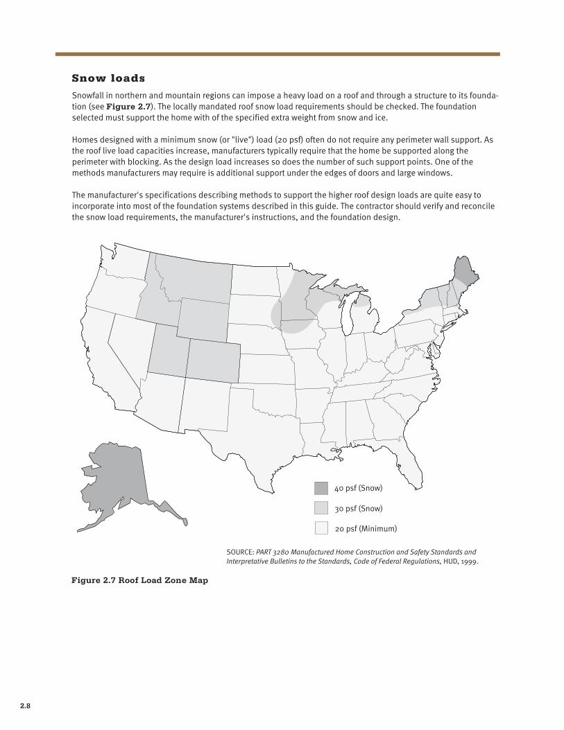
Snowfall in northern and mountain regions can impose a heavy load on a roof and through a structure to its foundashytion (see Figure 27) The locally mandated roof snow load requirements should be checked The foundation selected must support the home with of the specified extra weight from snow and ice
Homes designed with a minimum snow (or live) load (20 psf) often do not require any perimeter wall support As the roof live load capacities increase manufacturers typically require that the home be supported along the perimeter with blocking As the design load increases so does the number of such support points One of the methods manufacturers may require is additional support under the edges of doors and large windows
The manufacturers specifications describing methods to support the higher roof design loads are quite easy to incorporate into most of the foundation systems described in this guide The contractor should verify and reconcile the snow load requirements the manufacturers instructions and the foundation design
40 psf (Snow)
30 psf (Snow)
20 psf (Minimum)
SOURCE PART 3280 Manufactured Home Construction and Safety Standards and Interpretative Bulletins to the Standards Code of Federal Regulations HUD 1999
Figure 27 Roof Load Zone Map
28
Factors to Consider
Areas prone to termites
Termites represent a threat to wood buildings almost everywhere although the problem is particularly acute in some areas of the southeastern states and Hawaii (see Figure 28) The use of steel concrete and pressure-treated lumber can minimize the damage caused by these pests There are good termite shield designs that can be incorporated into most foundation systems in areas of especially high infestations of termites Most shields are conshystructed from lengths of galvanized steel inserted between the concrete and wood portions of the foundation The steel protrudes outward and downward creating a barrier to termite mud tubes
In termite-prone areas the design and construction of the foundation system should assure that there is no contact between untreated wood components of the foundation and the ground Good workmanship would also entail cleaning up all wood scraps from the job site
Very Heavy
Moderate To Heavy NOTE Lines defining areas are approximate only Local conditions may be more or less severe than
Slight To Moderate indicated by the region classification
None To Slight regSOURCE 2000 International Residential Code
Figure 28 Termite Infestation Probability
29
Local state national requirements
As opposed to the HUD code which is preemptive of local codes and creates uniformity of manufactured home conshystruction across state lines foundation systems are typically subject to state or local building codes So while the homes themselves may enjoy consistency of design and construction foundation plans are subject to review by the local code enforcement authorities
All of the non-proprietary systems described in this guide must be tailored to the site conditions If local building department approval is required the use of a local engineer to prepare plans for submission is prudent and may be required for HUDFHA-insured financing Proprietary systems almost always carry engineering approvals but some building departments may not approve their design concepts Consult with the proprietary foundation system manshyufacturer before planning to use a system in a particular jurisdiction
2 M A J O R D E S I G N FA C T O R S
Initial cost
Among the many factors that shape the selection of the foundation system cost is one ofmdashif not the mostmdashimporshytant especially for the sellers and buyers of modestly priced housing Generally discussions of cost focus on the initial home price While the purchase price is only part of the total cost equationmdashmaintenance and upkeep being the other major considerationsmdashit is the part that can be quantified pre-purchase Price is in many cases the detershymining factor in choosing a foundation system and this guide compares foundation systems in terms of the relative first cost
Among the foundation systems reviewed in this guide there is considerable variation in cost with pier and anchor systems among the least costly and basements the most expensive Price is conditioned on local site conditions and design parameters such as the case in seismic and flood hazard areas where design constraints generally increase the cost of all foundation systems Other factors such as amenity aesthetics and desire to qualify for real property financing are variables that may compete with or override the desire to select a low-cost foundation
Real property foundation classification
Be sure that the foundation system selected is one that is familiar and acceptable to construction and mortgage lenders In advance of settling on a system that is intended to have a real property classification it is always prushydent to confer with area lenders as to the locally acceptable foundation systems (for more discussion of this topic see page 13)
Installation time
To speed up construction time for foundation systems its smart to be aware of local design and construction pracshytices Using prefabricated components such as precast concrete grade beams manufactured structural panels preshyfabricated steel stanchions pony walls framed for the non-proprietary systems or one of the proprietary systems described in Chapter 4 can significantly reduce installation time
Simple installations can be done in one day but the time required for more complex jobs can extend to a week or more When planning the time needed for an installation it may help to set up a schedule of tasks that are to take place both before and after the homes arrival from the factory
Compared with site building where construction schedules are often subject to lengthy delays the manufactured home delivery dates are usually accurate to within a day or so Use this to work backwards and schedule prelimishynary site work and foundation construction If possible try to have all pre-delivery work done a day or so before the home arrives Doing pre-delivery work any earlier could affect the cost of borrowed construction funds any later could mean the house is in the way while the work is being finished It is prudent to budget extra time for site work the first few times a new system is specified
210
Factors to Consider
The home manufacturer can be a valuable resource in the foundation planning process Developers and retailers who consistently get homes done on time do so because they plan their projects much like the home manufacturer plans for factory production Each person working on a foundation or home installation should know the role they are expected to perform the time in which they are to do it and the standard to which they are to perform
In general the proprietary systems will require less time because the components are prefabricatedpreassembled in advance and generally require less work at the site In budgeting foundation construction time it is generally true that pier and anchor systems are the speediest followed by crawl space systems slab-on-grade and basements Foundation systems that require a crane for moving the home on to the foundation such as a basement typically take longer and usually cost more to install
Matching up to the manufacturers floorchassis system
Some of the foundation alternatives described in this guide require modifications to the floor and chassis system While many manufacturers offer these variations in their regular option lists some do not Its wise to contact the manufacturer to make sure their floor and chassis can be adapted for use with the selected foundation
For example some basement designs work best with floors that are capable of clear spanning from the outside wall to the centerline (mating wall) To allow for basements uncluttered by a forest of posts that may be required to supshyport the traditional chassis rails many manufacturers offer (usushyally at a cost premium) one of several types of integrated floorchassis systems These systems place the chassis in line with the floor system and move the structural support to the exterior wall where it bears directly on the foundation wall
Other designs make use of direct fastening connections between the perimeter stemwall and the rim joists of the homes floor (see Figure 29) This system calls for recessing the steel chassis parts away from the edge of the floor joists Additionally all utility dropouts need to be clear of this contact zone between the foundation Figure 29 Recessing the outrigger to avoid interfering with the foundation wall
sill and the floor joists
For all of the foundation systems presented in this guide there are numerous ways the homes are actually attached to their foundations and ultimately to the ground Direct bolting and nailing are very common If a steel-to-steel connection is involved welding is optimal Coordinate the design of the connection with the manufacturer
3 B E S T D E S I G N P R A C T I C E S
Ventilating crawl spaces
Most manufactured homes except for those placed over basements have an area under the home and above the ground that in most cases should be ventilated The primary purpose of crawl space ventilation is to minimize the accumulation of moisture under the home Excessive moisture accumulation under any home can create an ideal
Perimeter joist
Floor decking
Lateral floor joists Short outrigger
Chassis I-beam
Long outrigger
Steel crossmember
211
environment for moisture seepage into the home itself The manushyfacturers installation instructions spell out the amount of open vent area that must be provided per square foot of home (see Figure 210) Further most instructions require even distribution of the vents and allowance for cross ventilation
A notable exception is insulated crawl spaces under homes of the type described on page 24 Such crawl spaces should have thermoshystatically controlled vents containing temperature-actuated devices that close during freezing periods
Moisture barrier
A complimentary technique for minimizing moisture accumulation under the home is to place a continuous polyethylene sheet of at least 6-mil thickness on the ground below the home The barrier blocks moisture in the ground from entering the crawl space (see Figure 211)
Site drainage
Proper site drainage is also essential to prevent water from accumulating in the foundation area
Grading is the most effective tool for keeping water away from a home This can be achieved in two ways First if new lots are being created the grading plan should elevate each home to promote water flow away from the home This may not be an option if the home is placed on an existing lot Second once the home is in place final grading normally in the form of backfilling against the foundation wall should slope away from the home for a distance of 3ndash5 ft (check local code requireshyments) To supplement proper grading many builders add gutters and downspouts to remove rainwater from the roof and divert it a good distance from the foundation
Figure 210 Foundation wall detail showing an air vent
Figure 211 Polyethylene sheet for helping to keep moisture out of the crawl space
3 C H A P T E RINDIVIDUAL FOUNDATION EVALUATIONS NON-PROPRIETARY SYSTEMS
This section covers four foundation classifications
bull Pier and ground anchor support systems (the most popular method of securing manufactured homes to the ground)
bull Crawl space systems
bull Slabs-on-grade foundation systems
bull Basements
A non-proprietary system is considered to be in the public domainmdashusable by anyone without paying a royalty fee or other consideration for its use It is not a product of manufacturing or individual company output Non-proshyprietary systems can be constructed by any qualified contractor using materials available from most building supshypliers
Included in each foundation class are a series of case studies drawn from actual installations and contributed by practitioners from across the nation The case studies suggest how a basic concept can be modified to meet the specific needs of a site home design or buyer preference
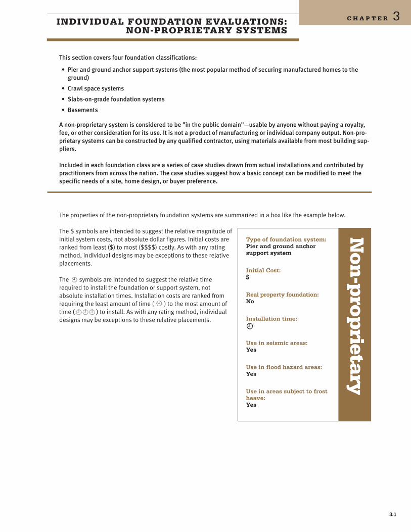
The properties of the non-proprietary foundation systems are summarized in a box like the example below
The $ symbols are intended to suggest the relative magnitude of initial system costs not absolute dollar figures Initial costs are ranked from least ($) to most ($$$$) costly As with any rating method individual designs may be exceptions to these relative placements
The yen symbols are intended to suggest the relative time required to install the foundation or support system not absolute installation times Installation costs are ranked from requiring the least amount of time ( yen ) to the most amount of time ( yenyenyen ) to install As with any rating method individual designs may be exceptions to these relative placements
Type of foundation system Pier and ground anchor support system
Initial Cost $
Real property foundation No
Installation time yen
Use in seismic areas Yes
Use in flood hazard areas Yes
Use in areas subject to frost heave Yes
Non
-prop
rietary
31
Pier and Ground Anchor Support Systems
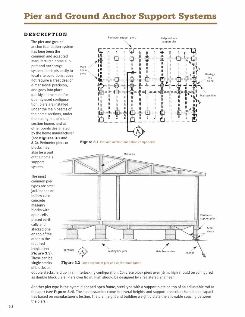
D E S C R I P T I O N
The pier and ground anchor foundation system has long been the common and accepted manufactured home supshyport and anchorage system It adapts easily to local site conditions does not require a great deal of dimensional precision and goes into place quickly In the most freshyquently used configurashytion piers are installed under the main beams of the home sections under the mating line of multi-section homes and at other points designated by the home manufacturer (see Figures 31 and 32) Perimeter piers or blocks may also be a part of the homes support system
The most common pier types are steel jack stands or hollow core concrete masonry blocks with open cells placed vertishycally and stacked one on top of the other to the required height (see Figure 33) These can be single stacks of blocks or
Perimeter support piers Ridge column support pier
Main beam piers Marriage
line piers
Figure 31 Pier and anchor foundation components
Marriage line
Mating line
Mating line pier Main beam piers Anchor
Steel straps
Perimeter support pier
Figure 32 Cross section of pier and anchor foundation
SECTION
double stacks laid up in an interlocking configuration Concrete block piers over 36 in high should be configured as double block piers Piers over 80 in high should be designed by a registered engineer
Another pier type is the pyramid-shaped open frame steel type with a support plate on top of an adjustable rod at the apex (see Figure 34) The steel pyramids come in several heights and support prescribedrated load capacishyties based on manufacturers testing The pier height and building weight dictate the allowable spacing between the piers
32
Non-Proprietary Systems
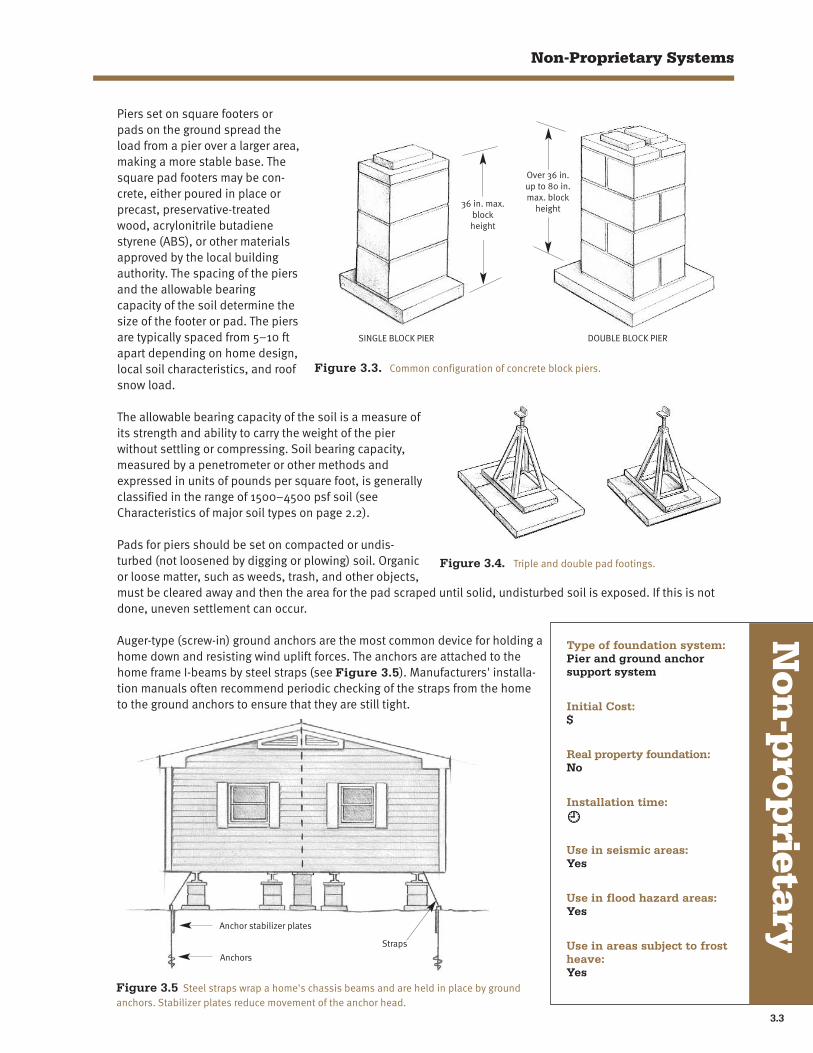
Piers set on square footers or pads on the ground spread the load from a pier over a larger area making a more stable base The square pad footers may be conshycrete either poured in place or precast preservative-treated wood acrylonitrile butadiene styrene (ABS) or other materials approved by the local building authority The spacing of the piers and the allowable bearing capacity of the soil determine the size of the footer or pad The piers are typically spaced from 5ndash10 ft apart depending on home design local soil characteristics and roof snow load
Over 36 in up to 80 in max block
height
DOUBLE BLOCK PIER
36 in max block height
SINGLE BLOCK PIER
Figure 33 Common configuration of concrete block piers
The allowable bearing capacity of the soil is a measure of its strength and ability to carry the weight of the pier without settling or compressing Soil bearing capacity measured by a penetrometer or other methods and expressed in units of pounds per square foot is generally classified in the range of 1500ndash4500 psf soil (see Characteristics of major soil types on page 22)
Pads for piers should be set on compacted or undisshyturbed (not loosened by digging or plowing) soil Organic or loose matter such as weeds trash and other objects must be cleared away and then the area for the pad scraped until solid undisturbed soil is exposed If this is not
Figure 34 Triple and double pad footings
done uneven settlement can occur
Auger-type (screw-in) ground anchors are the most common device for holding a home down and resisting wind uplift forces The anchors are attached to the home frame I-beams by steel straps (see Figure 35) Manufacturers installashytion manuals often recommend periodic checking of the straps from the home to the ground anchors to ensure that they are still tight
Anchor stabilizer plates
Anchors
Straps
Figure 35 Steel straps wrap a homes chassis beams and are held in place by ground anchors Stabilizer plates reduce movement of the anchor head
Type of foundation system Pier and ground anchor support system
Initial Cost $
Real property foundation No
Installation time yen
Use in seismic areas Yes
Use in flood hazard areas Yes
Use in areas subject to frost heave Yes
Non
-prop
rietary
33
Zone III
Zone
II Zo
ne I
Zone I
Zone
II
Zone
III
Zone I
Zone I
Zone II
Zone III
Zone I
NOTE See Section 3280305(c)(2) for areas included in each Wind Zone
SOURCE PART 3280 Manufactured Home Construction and Safety Standards April 1999
Figure 36 HUD Wind Zone Map
The spacing of the anchors and the strap is usually specified by the home manufacturer based on the size of the home and the wind zone In all wind zones (see Figure 36) home manufacturers require tie down straps between I-beams and anchors In HUD wind zones II and III vertical straps from the sidewall of the home to ground anchors are required in conjunction with the straps from the I-beam to the ground anchor In the absence of manufacturer recommendations or an engineering analysis based on soil capacity measurements the MHRA Maximum Anchor Spacing Selector chart (see Figure 37) is a handy tool for selecting and designing a system
Stabilizer plates when used in conjunction with ground anchors reduce the movement of the anchor head and therefore improve the overall structural performance of a system (see Figure 35) Figure 37 Anchor spacing chart developed by MHRA
34
Non-Proprietary Systems
C O S T O F C O N S T R U C T I O N
The pier and anchor support system is the least initial cost for providing a support system for manufactured homes
R E A L P R O P E RT Y C L A S S I F I C AT I O N
In most instances lenders and state and federal agencies do not consider pier and ground anchor support sysshytems as shown in Figures 33 34 and 35 a real property foundation The exceptions are cases where the anchors are held in place by means other than the soil alone such as encasing the anchors in a concrete slab These types of approaches are explored later in this chapter as part of the discussions of crawl spaces baseshyments and slabs
I N S TA L L AT I O N
The installation of a pier and ground anchor foundation system is frequently accomplished in one working day
W I N D L O A D R E S I S TA N C E
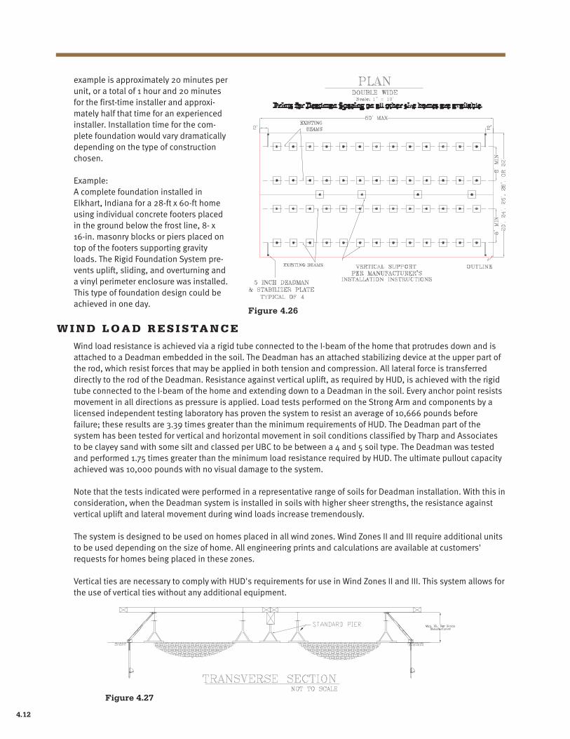
Of the non-proprietary systems the pier and anchor system is the one most often specified by manufacturers installation instructions as an effective means to resist wind forces
G R AV I T Y L O A D R E S I S TA N C E
A pier and anchor foundation supports gravity loads (live and dead) adequately if it is designed to take into account the bearing strength of the soil the piers are properly spaced and there are appropriate perimeter piers installed as required by the home manufacturer and the authority having jurisdiction
S E I S M I C L O A D R E S I S TA N C E
Since the HUD standards have no provisions for seismic resistance design almost all manufactured housing (and therefore most pier and anchor installations) is not designed specifically to withstand seismic loads Calculations show however that a manufactured home capable of resisting the HUD code wind forces will slightly exceed the requirements meeting for the highest seismic forces in the model building codes
F L O O D R E S I S TA N C E
The foundation type is suitable for use in flood plain areas when FEMA-recommended14 designs or designs meeting FEMAs performance criteria are used FEMA suggests taking the following precautions when a home is located in a flood plain the anchor system should be designed to resist uplift floatation collapse and lateral movement under saturated soil conditions and the floor level should be set above the 100-year base flood eleshyvation Under no circumstances should the home be located in a floodway
F R O S T P R O T E C T I O N
In areas where frost is a design issue individual anchors and footers under the piers are extended to below the frost line and bear on earth below that depth As an alternative to running the footers below the frost line holes for the footers may be dug to the frost depth and then back filled to the surface with gravel or other material that will not retain moisture Another option is to insulate the area around the crawl space This would eliminate the need to run the anchors and footings below the frost depth
14 Federal Emergency Management Agency September 1985 Manufactured Home Installation in Flood Hazard Areas FEMA 85
35
Crawl Space Systems
D E S C R I P T I O N
The crawl space foundation system described here has two main distinguishing characteristics it incorporates full perimeter wall support together with internal independent support points and the space itself is not habitable15
Within that very broad definition there are many styles designs and ways to build crawl space foundation sysshytems This section describes one design that has worked effectively with manufactured homes Crawl space foundashytion systems are intended for use where a traditional site-built foundation system is preferred and to qualify for as real property This foundation is less well suited for instances where economy speed or installation flexibility is paramount
In the design shown in Figure 38 the perimeter foundation wall rests on an excavated footer The wall itself may be constructed of one or more conventional building materials (such as poured concrete concrete block or treated wood) The entire perimeter of the manufactured home floor bears directly upon this wall The chassis is also fully supported but with relatively economical piers The manufacturer-designated ridge beam support points are carried by economical piers or posts The homes resistance to horizontal or uplift forces is achieved through attachment of the floor joists to the exterior foundation wall No additional anchoring devices are used (see Figure 38)
Figure 38 Crawl space foundation with full perimeter support in low-profile configuration
This foundation can be used on sloping lots (see Figure 39) and for recessed low profile installations (see Figure 310) In the latter case the structural walls form a barrier to the entry of water underneath the home and act as a short retaining wall The low profile design providing a site built look is much more difficult to achieve with a traditional anchor set or slab foundation (see Figure 311)
Access to the crawl space for utility hookups and repairs must be considered This is potentially problematic in a low-profile installation One solution is for the manufacturer to install an access panel in an appropriate location such as a closet floor Figure 39 Stepped foundation
15 Some crawl space designs use only the interior piers for supporting the homes (see crawl space case studies)
36
Non-Proprietary Systems
Figure 310 A crawl space foundation system with full perimeter support ready for home installation
C O N S T R U C T I O N
Crawl space foundation systems require more care and precision than conventional anchor systems The exteshyrior wall of the foundation should not exceed the dimenshysions of the manufactured homes perimeter floor joists (not including the thickness of any exterior siding or sheathing) After staking the site excavation to the depth of the footing is done with a backhoe (see Figure 312) Interior footings may be individually dug with a power soil auger (see Figure 313) or poured as a grade beam Some variations of this system allow placing interior piers on crushed rock
Figure 313 Digging chassis support footers with a power auger
Figure 311 The low profile crawl space foundation system provides more of a site built appearance
Figure 312 Excavating for perimeter footings with a backhoe
As forms are constructed they are double checked to make sure they are level dimensionally accurate and square (see Figure 314) Reinforcing steel is set as required Concrete is poured tamped and dressed (eg anchor bolts are carefully placed for the sill) Forms are stripped and the structure is again measured The walls may also be constructed of mortared and grouted hollow core blocks again with bolted sills A third option is a
concrete or block stemwall in combination with a wood-framed ponywall
Pony walls are especially useful when a low-profile installation is either not posshysible or not desirable They also afford the installer with a bit more dimensional tolerance when placing the home directly on the stem wall (see Figure 315)
A well thought out plan for setting anchor bolts will prevent trouble later when installing the home Bolts should be carefully placed so that they will not coinshycide with the floor joists (see Figure 316) This is a matter of good planning and careful workmanship Cutting off bolts or coring out the sill to allow for the bolts washer and hex nut is not recommended Interior support footers both along the chassis and at the ridge beam columns may be poured concrete or crushed rock (if locally approved)
Type of foundation system Crawl space
Initial Cost $$ ndash $$$
Real property foundation Yes
Installation time
yenyen
Use in seismic areas Yes
Use in flood hazard areas Yes
Use in areas subject to frost heave Yes
Non
-prop
rietary
37
Figure 314 Forms ready for concrete pour
V E N T I L AT I O N
Crawl space ventilation is provided through perimeter wall vent openings Planning for vents varies depending primarily on whether or not the home is being installed in a low-profile configuration
I N S TA L L AT I O N
Normally the foundation especially the low-profile vershysion is completed before the home arrives The axles tires and hitches are removed and the home is installed on the foundation by craning or rolling (see Figures 317 and 318) Once placed on the foundashytion sill or pony wall the floor is brought to a level posishytion Interior piers are placed along the chassis beams and positioned at the designated ridge beam columns
Figure 315 Ponywall construction method
Figure 316 Carefully placed anchor bolts will not interfere with any portion of the manufactured homes floor joists
Where an open endwall permits the truck to back the home inside the foundation a home can be moved into posishytion by the toter Building the missing endwall then finishes the foundation
Figure 317 Installing a home with a crane Figure 318 Installing a home with a roller system
38
Non-Proprietary Systems
There are a number of options for constructing the inteshyrior piers that carry the chassis and ridge beam loads to the ground The most economical is approved dimensional lumber such as redwood or treated fir (see Figure 319) Also popular are non-grouted hollow core concrete blocks and manufactured steel piers Since these structural components only provide vertical support they may be selected for economy and ease of installation
M E T H O D S O F AT TA C H M E N T
The crawl space design allows attachment of the entire perimeter of the floor joist system to the foundation sill the preferred and most economical approach The connection is secured with engineer-approved nailing strips (or approved steel nailing plates) fastened according to an engineers nailing schedule (see Figures 320 to 322) The strips may then be painted and left as
Figure 319 Economical support posts for chassis and ridge beam columns Only used in conjunction with a structural perimeter wall
Figure 320 The manufactured home floor is secured to the foundation sill by a nailing strip The material and the nail schedule must be desigshynated by an engineer
a finished surface If vinyl siding is to be applied over the sheathing it is installed last
Chassis piers may be placed and tightened to the chassis beam through compression wedges nailed in place spot welds or a number of proprietary attachment devices
Figure 321 The dark horizontal area is the manufactured home floor joist covered with the bottom board The light wood is the foundation sill A factory installed flashing is visible at the bottom edge of the exterior siding
Figure 322 Nailing strip complete ready for painting When matching vershytical siding is used the joint is almost invisible from the street
C O N S T R U C T I O N C H A L L E N G E S
Typically a crawl space foundation is fully constructed before a home is installed This presents a few challenges to the foundation contractor and home installer
bull The foundation must be precisely measured and constructed Installersbuilders are advised to consult with the home manufacturer to obtain the exact floor dimensions There is less tolerance for error than if the foundation were intended for a site-built home
bull The manufacturer must provide a foundation ready floor-chassis system This involves recessing all steel chassis components 8ndash10 in from the edge of the floor joists
39
bull The home is normally moved onto the foundation with rollers (see Figure 318) If the site is not accessible from the street a crane is used (see Figure 317) The use of a crane is often the method of choice for multiple installations
bull Often the working conditions under the home are cramped and dark due to the enclosed perimeter
bull When placing a home in a low-profile installation planning for adequate slope in the homes drain line is important If the home site and proximity is high enough above the street sewer the drain line can be routed under the perimeter foundation footer otherwise a sleeve must be placed in the foundation wall to allow the drain to exit Depending on the floor plan the drain may need to be routed a substantial distance before it exits the foundation creating potential problems with inadequate slope Some manufacturers can supply drops through the floor and ship sufficient loose material to hang the drain line with proper slope
C O S T
Crawl space foundation systems generally are more expensive than slabs and anchors but less than basement founshydation systems If carefully planned savings gained in some parts of the system will pay for costs generated in other areas For example the cost of tie-downs (ground anchors) is eliminated in crawl space foundations and piers used for the support of the chassis may be scaled back significantly These savings partly offset the additional costs associated with building a perimeter wall that both supports and finishes the home
R E A L P R O P E RT Y C L A S S I F I C AT I O N
A crawl space foundation system utilizing the perimeter load-bearing enclosure walls could be expected to meet the conditions for real property financing With the structural perimeter wall the home can be securely attached to the foundation to resist wind gravity and seismic forces
I N S TA L L AT I O N T I M E
Installing a manufactured home on a perimeter wall crawl space foundation system is typically a two-step process similar to an installation over a basement First the home is delivered alongside or near the foundation and uncoushypled from the transporting truck Next the house is raised the axles wheels and hitches are removed and then it is rolled or craned onto the foundation This is inherently slower than driving the home into its final setup position as would be the case with an anchor and pier or slab system A crew of three typically can construct the crawl space foundation system in three days before delivery and install and finish the home in five days after delivery (not including a garage or other ancillary structures)
W I N D L O A D R E S I S TA N C E
Although the areas where this system has been popular are not prone to hurricanes crawl space systems offer effective resistance to the buffeting forces of high winds The continuous fastening of the homes floor joists to a sill ( ie anchored to a structural concrete wall and footing)provides good resistance to horizontal forces Further homes set in low profile offer less wall exposure to high winds thus reducing the loads required to be resisted by the connections
G R AV I T Y L O A D R E S I S TA N C E
The perimeter load-bearing enclosure wall support system provides excellent gravity load resistance The perimeter wall carries much of the roof load directly to the earth The chassis main beams and piers carry only the interior floor loads The perimeter enclosure wall supports the full perimeter of the home
310
Non-Proprietary Systems
S E I S M I C L O A D R E S I S TA N C E
The perimeter load-bearing enclosure wall support system combined with a deep stemwall provides adequate seismic load resistance The structural connection of the home to the perimeter foundation wall can be designed to effectively transfer the forces to the earth around the foundation This system has been used effectively in the San Francisco Bay Area one of the highest seismic risk zones in the nation
F L O O D R E S I S TA N C E
The low-profile version of the crawl space foundation system described here is not intended for use in floodplain areas However when FEMA-recommended designs are specified crawl space system foundation systems are suitshyable for use in floodplains Among the FEMA requirements are the following the foundation system resists flotation the floor level is set above the base flood elevation and the home site is not in the floodway
F R O S T H E AV E
As long as the footers reach to below the maximum frost depth crawl space foundation systems can be and have been used in any climate
311
Case Study 1 M t C l e m e n s M I
Chateau Communities 6160 S Syracuse Englewood CO 80111 (303) 874-3361 Tel (303) 874-7098 Fax
This Chateau Communities foundation resembles what many people visualize when they think of a traditional crawl space It has been fine-tuned over the years by Chateau and is in widespread use in land-lease communities develshyoped and owned by the company
In 1984 when Chateau acquired the community at Mt Clemens Michigan they took a hard look at the foundation used in the existing homes in the development From those observations they made innovations and developed the system shown in this case study For example as new homes were added to the community the foundations were modified to incorporate a non-load-bearing concrete barrier wall designed to keep animals from burrowing under the homes
The crawl space foundation is formed using conventional foundation materials but forming of the 6ndash8 in concrete perimeter wall requires a skilled crew The area for the foundation is then excavated to slope from front to back allowing for drainage to the existing storm sewer The use of sump pumps has been discontinued because of high maintenance experienced by the developer Chateau also installs gutters and downspouts on every home to provide positive drainage away from the home
Masonry block skirting
Floor joist
Steel chassis beams
16- x 16-in Masonry block pier columns
10 in Concrete footing wall
Figure 323 Cross section showing masonry pier supports and deep concrete perimeter wall
312
Non-Proprietary Systems
The Chateau design allows for the low profile final appearance that is popular with buyers many of whom are seniors preferring as few steps up into the home as possible
Piers for chassis support were originally poured into augured ground holes bored 42 in below grade Subsequently Chateau opted to set concrete blocks on grade instead of the deep augured piers The use of fairly small piers and high dimensional tolerances require close construcshytion supervision The 6ft-8in I-beam pier spacing is set at and the centerline piers are sized and located according to the home manufacturers instructions
Access in setting the home is unobstructed one of the benefits of the low front wall The driver backs the home over this wall and maneuvers it into position There are no pre-constructed foundation components to get in the way After the truck leaves the installers go about their normal activities of lifting mating setting and finishing each home
The home is secured with ground anchors or as recommended by the manufacturer and skirting is installed over the exterior concrete wall The home is set at-grade with provision made for installing ventilation openings
The exterior walls of the homes do not bear on the foundation wall Skirting can be one of a number of basic building materialsmdashconcrete aluminum fiberglass or vinylmdashor it can be a proprietary manufactured skirting The skirting is used to close the gap between the bottom of the home and the top of the barrier wall
Use of reinforcement in the concrete perimeter walls may allow them to become load-bearing with the use of anchor bolts to attach the home to the foundation thus eliminating the need for ground anchors
To reduce costs estimated at $4000 to $4500 the reviewers recommended using 8 x 16 in concrete blocks for the piers as well as for the wall with appropriate steel reinforcing
Either increasing the size of the footings or decreasing the space between the piers would allow for higher roof loads and varying soil conditions The foundation is frost resistant due to the deep concrete wall at its perimeter extending below local frost line Although this case study does not meet the FHAs real property permanent foundashytion definition because it utilizes soil driven ground anchors this is of no concern to Chateau which does not conshyvert their homes to real property However if costs permit it can be easily modified to meet the FHA definition
This Chateau system is economical as it does not require costly custom home modifications such as a foundation-ready chassis that in most cases would be a special order
Figure 324 View of the Chateau foundation system from inside the crawl space
Case Study11
CCrraa
wwll SS
ppaa
ccee
313
Case Study 2 W i l l i a m s t o n K Y
Cherry Hill Homes 1300 North Main Street Williamstown KY 41097-9437 (800) 844-0543 Tel (859) 823-2801 Fax
Cherry Hills foundation system is designed as a shallow crawl space foundation with a perimeter footing extending below the frost line Since the frost depth in Cherry Hills market area is normally around 24 in protection against heaving from frost is achieved with a moderate amount of backfill
The system uses 16-in wide conshycrete footers with 16-in transverse runners that are 8 in deep and reinshyforced with rebar The continuous footers are poured onto compacted soil and the anchors are set into the concrete Crushed rock is then placed into the open cells of the concrete (see Figure 325) Finally the entire area is covered with a sheet of 6-mil polyethylene sheeting that serves as a ground moisture barrier
Excellent drainage is created with the use of 4 in perforated pipe that is placed adjacent to the perimeter of the foundation and then covered with crushed rock (see Figure 326) Ventilation for the crawl space is provided via thermostatically controlled vents placed in the foundation walls The amount of vent area required is dictated by local building codes
Figure 325 Open cells filled with crushed rock
Delivery of a home is fairly easy because the flat concrete pad and crushed rock form a level surface over which the home can be maneuvered The even surface and lack of obstructions facilitate making the small adjustments typically needed when mating the sections after the truck has left the site Concrete is a superior support surface for the safe use of manual jacks and other tools necshyessary for spotting a home Figure 326
Crushed gravel
4 in Drain pipe
Rebar
Block piers
Concrete block perimeter wall
314
Non-Proprietary Systems
Once the home is in place Cherry Hill installs ground anchors per the home manufacturers instructions The anchors are sunk into the concrete footers (see Figure 327) Chassis beams and the ridge beam column supports are rested upon dry stacked hollow core concrete blocks each sitting on the concrete footer
To enclose the perimeter addishytional hollow core concrete blocks are mortared into place However this wall is not designed to bear loads except at specific points required by the manufacturer such as at key window and door locashytions Finally soil is backfilled against the exterior block wall to a depth that will not only prevent freezing of water in the soil below the footers but will also add aesshythetically to the home by giving it a low-profile appearance (see Figure 328)
The backfill is graded away from the home to further prevent water from collecting under the home Coupled with the perimeter drainshypipe this helps to ensure the crawl space remains dry
The Cherry Hill foundation is expected to meet FHAs definition for a permanent foundation It is easily adapted for difficult site conditions can be readily modified for sites with higher wind and roof loads and by extending the footing depth can be used in areas that have deeper frost conditions It is well anchored and provides for uniform continuous support for the home The design may also be cost competitive with a full pour uniform slab due to the reduced amount of concrete used
By using a series of cells that can be easily adjusted when forming and pouring the concrete the design can be modified for larger and smaller homes The interior concrete footers can be poured parallel with the long axis (and the chassis) of the home rather than perpendicular to it Depending upon the geometry of the home this change may result in some cost savings Aligning the footers with the chassis beams would also allow a slight amount of additional flexibility in pier placements
Figure 327 Concrete block piers support the chassis I-beams Anchors are encased in the concrete runners
Figure 328 Nearly finished foundation system showing access door and crawl space ventilation openings
By using a monolithic slab tying the foundation together the Cherry Hill foundation can easily be classified as a floating slab This would eliminate the need for backfilling and extending footers down below the frost line However such changes might keep the home from qualifying for FHA and other types of permanent financing
Case Study22
CCrraa
wwll SS
ppaa
ccee
315
Case Study 3 L o n g m o n t C O
Ventana Development 10401 Oxford Rd Longmont CO 80504 (303) 684-9157 Tel (303) 684-9146 Fax
This Ventana wood-enclosed foundation sits on an 8- x 16-in footer and is designed as a grade beam The wooden perimeter wall is made up of two-by-four studs spaced 16 in apart (doubled at the sides of doors and windows) covered on the outside with frac34 pressure treated plywood sheathing and a waterproof membrane The I-beams of the home are supported on jack stands set on 16- x 16-in concrete pads (see Figure 329)
Foundation grade
plywood 34 in thick 2- x 4-in Frame wall
6 Mil plastic sheeting extends 2 ft past footing
1 in Diameter gravel
8- x 16-in Footing
4 in Void
Jack stand
16- x 16-in Pad
Figure 329 Cross section view of Ventanas crawl space design showing voids used in areas of expansive soils
Because this system is designed for expansive soil the engineer specified the voids at the bottom of the grade beam walls to concentrate the beams weight on smaller portions of the expansive soils This is needed because the lightweight construction characteristic of manufactured homes may otherwise be incapable of resisting heave forces that can reach 1500 psf in expanding moist soil
This foundation uses no forms the concrete is placed directly into a trench dug with a backhoe Due to the many variations including irregular finished surfaces in the finished concrete the wood exterior walls are built after the home is in place (see Figure 330)
316
Non-Proprietary Systems
The Ventana foundation could be expected to meet FHAs definition of a permanent foundation and allows a house to be driven straight on to the foundation-a primary objective of the systems creator The design of the footers and stem walls allows for resistance to higher roof loads and local wind loads As shown it is suitable for frost depths of approximately 30 in Deeper excashyvation and concrete placement would allow the system to accommodate more chalshylenging roof and wind loads or deeper frost lines (see Figure 331)
The foundation uses a ground-to-siding clearance of 12 in instead of the minimum 6 to 8 in thereby providing sufficient space to use operable vents in the foundation walls The vents must be opened and closed at the appropriate times of the year The use of a plastic sheeting moisture barrier on the ground could reduce the required ventilation from 1150 of the floor area to 11500 cutting the number of vents needed A French drain is used in this system to discharge any water that might accumulate under the home
It is possible to create shear walls from the perimeter wall framing and sheathing With a suitable fastening method such as steel nailing plates that connect the framing and sheathing to the homes floor system it is possible to eliminate the anchors into the footers
The foundation walls are attached to the manufactured home floor assembly with nails They can be connected to a rim joist or an interior joist The primary purpose of this attachment is to give the walls added lateral resistance to caving in or colshylapsing from backfilled earth
This design uses pressure-treated plywoodmdashtreated for ground-contact applications in accordance with the Uniform Building Codemdashis used to resist deterioration when buried in the earth A cementatious panel board is specified for use on the on the above grade portion of the perimeter walls to enhance the appearance of the home
The crawl space is accessed through an opening in the exterior wall of the foundation protected by a large window well The position of the steel chassis must be kept in mind when choosing the location of the crawl space access
In this development the garages are all 4-wall structures abutting the home and built on thickened-edge slabs The grade differential between the home and the garage is exactly 15-12 in This permits two steps up into the house and adequate headroom at the doorway separating the garage and home
Figure 330 Excavation of the ground prior to setting the foundation
Figure 331 Framed stemwall sitting on concrete footer ready for siding
Case Study33
CCrraa
wwll SS
ppaa
ccee
317
Case Study 4 C a m p b e l l s v i l l e K Y
Goffrsquos Fleetwood Homes 2093 New Columbia Road Campbellsville KY 42718 (270) 789-4092 Tel (270) 465-3453 Fax
Goffs foundation design is a monolithic grade-beam footer combining in a single-concrete base support for the chassis beams the ridge beam columns and the exteshyrior wall This foundashytion is a grid-like that omits portions of the concrete (see Figure 332) to cut costs without sacrificing structural integrity The design offers a reliably solid structure that is flexible in the sense that it can be used with a variety of different sizes and brands of manufactured homes without making small adjustments for floor widths or lengths Further it is a good example of a design improvement over individual pier footers and ground anchors at relatively little increase in cost
Great care is taken to crown each site to encourage water to flow away from the home In addition a positive drain point is installed at the lowest portion of the foundation channeling water away from the foundation Goff will do a low-profile installation only where there is sufficient slope to the property to expose an opening in the foundation at the lowest corner for drainage Any concrete blocks in contact with earth backfill are protected with a coat of basement-proofing asphalt
Excavation is done without the need for forms as the straight lines and relatively shallow depth (24 in to the frost line) can be quickly dug with a backhoe (see Figure 333) The concrete footers extend below the frost line giving the structure the ability to resist frost heave The spacing between the lateral grade beams varies between 8 to 12 ft depending upon the size of I-beams in the homes chassis Goff installs anchor bolts along the outside edges of the foundation and at the centerline Centerline anchors are not frequently used in the industry but Goff includes them for the extra security and resistance to movement they can provide Later Goff attaches ground anchor heads to these bolts to hold the straps securing the home chassis
This Goff design is expected to meet FHAs definition of a permanent foundation as long as the anchors are secured in the structural concrete rather than driven into the soil
When a home is installed it is rolled over the open foundation and mated together quickly A relatively speedy installation is possible because working on a level concrete base allows faster and higher quality output than doing the same in a muddy rolling field Hollow-core concrete blocks support the chassis I-beams and the concentrated ridge beam loads that are located at the marriage line Depending on the customer or installers preference steel jack stands with adjustable heads could be substituted for the concrete blocks
Figure 332 This grid-like slab can be used to support homes in a range of sizes
318
Non-Proprietary Systems
The perimeter foundation wall also built from blocks extends to within frac14 in of the floor assembly If the exterior walls of the home sag the perimeter foundation walls begin to carry some of the load The final height of the home is adjusted without cutting any brick or block to match the height of the perimeter wall
Typically this foundation can be constructed in five to six hours It requires 12 to 18 yards of concrete Labor and material costs range from $1500 for a 1150 sq ft home to about $2300 for a 1680 sq ft design This cost is justishyfied according to Goff because this foundation reduces home servicing costs by 60
An advantage of this design is its simplicity and ability to be adapted to other site conditions For example if addishytional capacity for resisting wind or snow loads is needed the amount and depth of concrete could be increased without adding complexity to the site preparation foundation construction or home installation The amount of concrete can be decreased by adding earth backfill at the perimeter wall Backfill against the perimeter wall estabshylishes a drainage pattern required by most lenders and allows a reduction in concrete depth The footer depth for frost line is measured from the top of the backfill to the bottom of grade beam
Figure 333 The Goff system combines a concrete slab with traditional anchors
Access panel
4- x 8- x 16-in Concrete block
non- load bearing wall
Tensioning head 45o - 50o
Main I-beam
Wood shim
8- x 8- x 16-in Concrete block
pier
Concrete transverse grade beam
Case Study44
CCrraa
wwll SS
ppaa
ccee
319
Case Study 5 M a h o m e t I L
Roger Huddleston Homes Inc 106 South Prairie Road PO Box 739 Mahomet IL 61853-0739 (217) 586-4444 Tel (217) 586-2230 Fax
Huddlestons moderately expensive crawl space foundation design incorporates ribbon footers a crawl space ground anchors with tie-down straps and concrete block walls instead of isolated piers The system uses a considershyable number of concrete block walls for both interior and exterior support These cross walls are laid out to support the chassis and marriage wall (see Figure 334)
For moisture control the design calls for a polyethylene vapor retarder and pea gravel covering the ground lining the crawl space Crawl space ventilation is controlled by thermostatically activated vents that open fully when interior or exterior temperatures exceed 700 F and close when temperatures drop below 400 F
The 28-in clearance between the bottom of the chassis and the grade below provides adequate space for the crossover ducts and easy access for servicing of any utilities Entry to the crawl space is through a metal door in a sidewall of the foundation created in a space formed by a large window well
The ground anchors and galvanized diagonal strapping give the home its horizontal stability because they widen the base of the home While this design likely does not qualify under FHAs definition of a permanent foundation it could conform if the anchors were set into the slab instead of the ground With this change the weight of the conshycrete adequately resists the wind load
8- x 8- x 16-in Concrete block
pier
8 in Masonry
walls
Figure 334 Plan view of Huddlestons foundation system showing both interior and exterior supports
320
Non-Proprietary Systems
This design is well suited for excavated (low-profile) home installations where a full basement is not desired The concrete block walls are mortared for strength and stability The soil is then backfilled against the walls to create the impression that the home is only slightly elevated above the finish grade (see Figure 335)
8 in Concrete block
Steel I-beams
masonry wall
4 in Solid concrete block
12 in Rebar
30-in long - 1116-in Diameter double disk
18- x 8-in Concrete footer steel ground anchor rod SECTION
Figure 335 Cross section of foundation system showing earth berming and connection to ground anchors
A crane or roll-on beam equipment is required to move the home over the deep crawl space and the pre-constructed internal concrete block walls that support the chassis beams and the ridge beam columns While the use of a crane or roll-on beam does increase cost constructing the foundation walls after the home has been placed would create difficult working conditions and make it harder to achieve quality workmanship
The exterior footings in this system are load bearing Huddleston notes that the home manufacturer designs the structure such that the exterior wall loads are transferred to the chassis and from there through the piers to the ground Lacking structural function the perimeter walls are capped with steel termite shields instead of a sill and terminate an inch or two below the manufactured home floor Insulation is placed into this gap and the surface is finished with matching siding extended down from the home
In contrast to foundations where only the area for the footer is excavated this design calls excavation of the entire foundation area Excavation costs can be substantial in areas where the frost line is quite deep
The use of a generous amount of material that is well in excess of a structurally minimal design is deliberate on Huddlestons part From experience and intuition Huddleston feels the design yields an extra measure of support and durability To this end the design attends to the smallest details for example all-mortared joints in the block walls are finished by striking them with a steel-grooving tool It may be possible to cost-optimize the design without degrading its performance by reducing some of the structure (using double-stack piers)
Case Study55
CCrraa
wwll SS
ppaa
ccee
321
Case Study 6 M a h o m e t I L
Roger Huddleston Homes Inc 106 South Prairie Road PO Box 739 Mahomet IL 61853-0739 (217) 586-4444 Tel (217) 586-2230 Fax
Figure 336 This foundation system similar to the one used by Huddleston is designed to carry the weight of the home at the perimeter and mating walls
This unreinforced concrete stemwall foundation relatively expensive for a crawl space is designed to support a home with a perimeter support-type chassis or an integrated floor system that requires support at the exterior walls and the mating line only The installation of a home requires a crane or roll-on beam equipment
This crawl space foundation was originally designed for use with modular homes but its advantages can be applishycable to HUD-code homes In places where integrated floor systems are popular including the Midwest and northshyeastern states this foundation should be considered It is also appropriate for HUD-code homes built on a chassis that requires support at the perimeter Such chassis have large cross members that can span 14 ft or more and steel sections that must rest on perimeter walls and centerline columns
When Huddleston installs a modular home on this foundation 2-in rigid foam sheeting insulates the inside of each foundation wall Since HUD-code homes have fully insulated floors this step is not necessary
In plan view this system shows a row of regularly spaced block piers resting on a continuous 18-in-wide by 8-inshydeep footer This is the normal method of supporting a modular home at the mating wall but it needs some adjustshyments for a HUD-code home Additional piers would be required at specific points along the mating wall for the ridge beam columns
Huddlestons system provides excellent support where the building loads are concentrated it features good under-floor ventilation and it offers good clearance under a home for utility installation and service Huddlestons plans
322
Non-Proprietary Systems
indicate a foundation wall comprised of five courses of 8-in concrete blocks for a height of a little over 40 in This height could be reduced if allowable clearances were maintained under the home This would take into account the combined floorchassis thickness the method of hanging and connecting the heat duct crossover and other utilitymechanical considerations If no part of the manufactured home was suspended below the level of the sill plate two or possibly three courses of concrete block could be eliminated The number of required courses is likely to be controlled by the frost depth
Access to the underside of any home with a raised floor is always desirable The plans do not indicate a crawl space entry however an access door could easily be created in the foundations sidewall protected by a large window well Alternatively the home manufacturer could build-in access via an approved opening in the floor normally in a closet or other out-of-the way location
For moisture control the design calls for a polyethylene vapor retarder and pea gravel covering the ground lining the crawl space Crawl space ventilation is controlled by thermostatically activated vents that open fully when interior or exterior temperatures exceed 700 F and close when temperatures drop below 400 F
The tops of the foundation walls are capped with a metal termite shield sandwiched between the concrete block wall and the 2- x 8-in treated wood sill The sills are secured to the foundation with frac12- x 12 in anchor bolts (see Figure 337) Anchor bolt spacing is not indicated but should follow local building codes (typically 4 to 6 ft on center)
12- x 12-in
Anchor bolt
2 in Perimeter rigid insulation
8- x 8- x 16-in Double
block piers
Pea gravel
2 - 4 Rebar
8- x 18-in Concrete footer
PIER SECTION PERIMETER WALL SECTION
Figure 337 Cross section view showing perimeter and mating line supports for this recessed foundation system
This foundation system could be adapted to support higher roof loads or wind loads by adjusting the footing size and including more reinforcement This foundation system will likely meet FHArsquos definition of a permanent foundashytion The frost depth is 4 ft per local building code For deeper frost lines extending the trench for the perimeter footings to the required frost depth would be all that is needed Steel reinforcing rods are specified in Huddlestons footers but not in the foundations walls Additional reinforcing could be added in the wall if local soil or seismic conditions warrant
Case Study66
CCrraa
wwll SS
ppaa
ccee
323
Case Study 7 F o n d d u L a c W I
Asset Development Group (Steenberg) 8050 North Port Washington Rd PO Box 170872 Milwaukee WI 53217 (414) 352-9310 Tel (414) 352-6944 Fax
This design is a variation on the increasingly popular frost-protected shallow foundation system The frost protecshytion is achieved by placing a closed-cell expanded-bead polystyrene rigid insulation board between the structure and the ground This thermal barrier is intended to retain a sufficient amount of heat within the footprint of the foundation to prevent the soil underneath the footings from freezing The concept has been used successfully in areas with deep frost depths where reductions in excavation and concrete can create significant cost savings
2 in Polystyrene insulation
8- x 8- x 16-in Concrete block
6- x 12-in Footing
Sand
8 in Gravel base
Figure 338 Insulation extends down the foundation wall and away from the home creating a ldquoheat sinkrdquo under the home
324
Non-Proprietary Systems
The foundation rests on mortared block walls set on 6- x 12-in footings and an 8-in deep gravel road base that extends 20 in beyond the perimeter walls to allow for moisture to drain away from the structure The bottom of the footing is only 22 in below exterior grade The bottom of the crushed rock base is 30 in below exterior grade Without the gravel and polystyrene insulation the footings would have to extend 26 in deeper to meet the local frost depth (see Figure 338)
In most cases the blocks are mortared and filled with grout Anchor-bolts are used to attach the foundation wall to the sill
Spaced vent blocks in the exterior wall provide ventilation One sq ft of vent area per 150 sq-ft of floor area should be adequate unless a different ratio is spelled out in local regulations Placing a standard door in the exterior wall is an easy way to provide access
It may not be necessary for the home to overhang the outside wall by the minimum 2 in shown in this design In fact if the floor were flush to the block wall a number of more recognized attachment methods become feasible such as a plywood oriented strand board (OSB) or steel nailing plates techniques of attachment that effectively transfer the loads from the home to the foundation
This foundation lends itself to the use of standard methods for chassis and centerline support Concrete block wood posts or prefabricated steel piers could all be used With any of these support materials the installer sets anchoring devices in the poured concrete ideally ensuring that each such anchor is positively tied to a steel reinshyforcing rod or wire mesh
This system does not place any unusual demands on the home installers and no special or expensive equipment is needed Inasmuch as a fair amount of work is done at grade level in the construction of the foundation such as placing the polystyrene and extending the gravel base 20 in beyond the outside of the footer the site will be relashytively flat this allows the trucker to roll the home into position for the installers
Although subject to verification the design most likely meets FHAs definition of a permanent foundation As with other crawl space foundations it could be strengthened to support higher roof loads by increasing the size of the footings
Although Asset Development Group has only placed two or three homes on this type of foundation it is a clever concept to use a thermal barrier to trap latent heat below the home and thereby reducing the depth to which the surrounding soil will freeze With further investigation and analysis it might be possible to develop optimal design solutions based on this approach particularly for areas subject to deep frost penetration
Case Study77
CCrraa
wwll SS
ppaa
ccee
325
Case Study 8 K a n s a s C i t y M O
North Creek CWS Communities Trust Kansas City MO
The crawl space foundation used at North Creek a 234-site land-lease community in Kansas City developed by CWS Communities (now a subsidiary of Chateau Communities) is typical of many fee-simple developments The design calls for a back-filled perimeter wall providing structural support to the home and satisfying the 36-in frost depth requirement
This foundation uses a steel-reinforced poured concrete platform consisting of 12-in thick footers along the perimeter and down the center of the home and 412-in thick runners for I-beam chassis support piers The widths of the three longitudinal concrete runners are determined by the location of the chassis I-beams An additional 8 in is added to this width to assure that there is bearing for the pier even in cases where the chassis is not perfectly straight (see Figure 339) Thus if the I-beam is located 30 in from the perimeter each outside runner will be 38 in wide Similarly the center runner will be 76 in wide
Jack stands
Home I-beams
Embedded foundation anchors
Attached garage
Figure 339 Plan view of the foundation system showing points of support for the chassis
The primary vertical support for the home is provided with standard steel piers or dry-stacked concrete blocks No special attachment method is used between the piers and the concrete or between the piers and the bottom of the I-beam Foundation anchors are embedded in the perimeter footer and the steel straps generate resistance to horishyzontal movement (see Figure 340)
The perimeter wall for this system is primarily designed to resist lateral earth pressure The perimeter wall also satshyisfies the manufacturers requirement for perimeter support at certain locations It is fastened to the perimeter joists of the home This attachment method also creates a firmly braced structure against which earth may be backfilled With 24 in of backfill the footer extends to a depth of 36 in thereby ensuring against frost heave
The base of the exterior wall is connected to the footer through the use of concrete anchor bolts set at 5-ft intervals The entire wood perimeter wall including 2- x 4-in studs and frac34-in plywood sheathing is pressure-treated to the levels required for ground contact The 8 in of exposed perimeter wall is protected by adding a surface of cementishytious paneling running from the bottom of the home rim joist and extending several inches into the ground
326
Non-Proprietary Systems
SECTION
2- x 4-in Frame wall
Steel or block pier
4 Rebar 2 x 6 Pressure
treated sill plate
34 in Plywood
Anchor at panel ends
Figure 340 The weight of the home is transferred to the ground by jack stands and stablilized by anchors
Because the depth to which the home is recessed soil removed from the excavation is more than sufficient to backfill against the foundation wall and create the steep grade (5 for 10 ft) required for proper water drainage
Installation of homes on North Creeks foundations is simple and straightforward Because the foundation is recessed in the ground the home is backed right onto the footers by the delivery truck The flat concrete surface is a good base for manual jacks and other installation and stabishylizing tools The walls can be constructed and placed last so the working environment under the home is open and unrestricted
The foundation vents at North Creek are sized and spaced according to the Uniform Building Code which governs residential construction in Missouri Because 8 in of foundation wall is exposed above the top of the soil there is plenty of room to cut the vents into this wall Crawl space access is through a 2- x 3-ft chute located along the rear yard wall
Garages are optional in this development When ordered the garage foundation (slab and footer) is located adjashycent to the manufactured home but not attached to it The garage foundashytion floats on top of the soil If the garage shifts due to frost heave it will not impact the home (see Figure 341)
This system likely meets FHAs definition of a real property permanent foundation It can easily be altered to meet a variety of more difficult site conditions such as deeper frost levels high winds heavy snow loads and earthquakes By increasing the height of the piers and exterior walls the home can be elevated to a height suitshyable for placement within Figure 341a flood plain
SECTION
4 ft Slab with thickened edge
4 Rebar
6 Mil plastic
sheeting
Jack stand
Case Study88
CCrraa
wwll SS
ppaa
ccee
327
Case Study 9 G e r m a n t o w n W I
Asset Development Group (Wick Continuous Crossbeam Frame) 8050 North Port Washington Rd PO Box 170872 Milwaukee WI 53217 (414) 352-9310 Tel (414) 352-6944 Fax
The crawl space foundation system used by Asset Development Group in its Brookside Meadows land-lease comshymunity takes maximum advantage of Wick Building Systems continuous crossbeam frame This is a load-bearing perimeter wall foundation with footers excavated to below the frost line The home rests on only the perimeter walls and on a row of columns down the mating wall
Home manufacturer Wick Building Systems devised a unique manufactured home chassis that has the outward appearance of a standard steel frame but is designed to transfer all of a homes loads to the exterior foundation walls and to a row of supports evenly spaced along the mating wall The frame incorporates a 4- x 8-in steel-bearing block welded to the end of each of the full outriggers that are spaced 8 ft apart along the outside of each of the chassis I-beams Flat steel-bearing plates are welded to the bottom of each of the bearing blocks and rest on wood blocks set within pockets in the foundation wall (see Figure 342)
3-Point set chassis
Fiberglass foundation wrap
8- x 16-in Crawl space vents
Center pier supports
Crawl space well
2- x 6-in Pressure treated
pocket plate
2- x 6-in Pressure treated
sill plate
6 Mil polyethelene
Poured concrete or block
foundation wall
Continuous concrete footer
Figure 342 Isometric diagram showing cutouts in the exterior foundation wall to accommodate the loadcarrying outriggers
328
Non-Proprietary Systems
The two main steel I-beams are joined by heavy steel cross members welded 4 ft intervals Welded on at the front and rear ends of the main beams are shorter beams of slightly less vertical depth as extensions These extensions rest on wood blocks set in the front and rear end walls of the foundation
The poured concrete foundation is supported by spread footers placed below the frost line At 8-ft centers along each of the sidewalls an 8-in deep by 14-in long pocket is formed into the concrete This pocket serves two purposes to support the steel bearing blocks at the end of each chassis outrigger and to provide venshytilation for the crawl space Access to the crawl space is gained through a 24- x 24-in opening formed into one of the exterior sidewalls A corshyrugated 36-in steel corrugated well protects the opening when the home foundation is recessed
Pressure-treated 2- x 6-inlumber is carefully cut and secured to the bottom of all the pockets with anchor bolts Additionally treated 2- x 6-in sills are secured to the top of all stemwalls with anchor bolts (see Figure 343)
The interior of the foundation may be backfilled but must be finished with a 6-mil poly vapor retarder laid over a bed of pea gravel The manufacturer specifies at least 24 in of clearance to the bottom of the chassis
Homes are normally installed on this system with a crane however roller systems may also be used With either method homes are delivered by truck to a spot adjacent to the foundation before installation begins (see Figure 344)
Each home has an attached site-built 2-car garage At the wall locations inside the garage the foundation chassis pockets are sealed and finished with fire-stop protection Garages are located either on the sidewall or the end wall of the homes
The Brookside Meadows development was one of the first to make mortgage loans to homeshyowners in a land-lease community purchased in the secondary market by the Federal Home Loan Mortgage Corporation (Freddie Mac) The foundation system is expected to meet the defshyinition of an FHA permanent foundation
Chassis I-beam
16 in Fiberglass foundation wrap
8- x 16-in Vent
2- x 6- Pressure treated sill plate
6 Mil plastic vapor barrier
Concrete footer
Figure 343 The reinforced I-beams transfer the loads to the perimeter foundation wall
SECTION
Pea gravel
Figure 344
Case Study99
CCrraa
wwll SS
ppaa
ccee
329
Slabs-on-Grade
D E S C R I P T I O N
A slab is a foundation that is designed to provide all necessary structural support to a manufactured home in an economical manner The home is typically elevated above the slab creating what appears to be a conventional crawl space under the home However to distinguish this group of foundations that even in the coldest climates sit above the frost line and are monolithic (ie the home sits on a single integrated structural element) they are separately classified within this guide
Thermostatically operated vents
Uninsulated Insulated slab
Figure 345 A slab supports the home on top of the earth The slab is uninsulated or insulated depending on the local conditions and goals of the designer
In this regard the term slab when applied to manufactured housing has a slightly different meaning than it does when used with stick-built homes A slab used for a stick-built home is considered to be at once a structural supshyport for the rest of the building (as it is for a manufactured home) and a semi-finished floor over which linoleum tile wood or carpeting is installed as the finished surface All manufactured homes are delivered with full raised floors that include insulation and finished surfaces as well as electrical and plumbing systems and in most areas heatingcooling ducts The slab under a manufactured home therefore does not act as the homes floor but rather as a platform for the home
Slabs are not unique to manufactured homes They are recognized and accepted for many other types of buildings including site-built single-family homes and commercial structures They are commonly found in areas with freezing and expansive soils
Part of the reason slabs are economical is that they are relatively thin extending only as deep as required to carry the structural loads In northern climates with deep frost depths the slab generally does not run to below the frost line In such cases the slab (often referred to as a floating slab) can shift as the soil underneath expands and contracts due to forces such as frost heave This movement can be minimized or eliminated if the ground under the
330
Non-Proprietary Systems
home is kept dry through the use of effective drainage techniques such as drain tile and sump pumps In conshytrast properly designed crawl space and basement foundations remain fixed even if the adjacent soil moves The propensity of uninsulated slabs to shift with soil movement may keep them from meeting state or local requirements for a real property founshydation and therefore from qualifying for real property financing
An insulated slab is insulated around its perimeter which keeps the ground under the slab warmer than the surshyrounding soil For this design (comshymonly referred to as a shallow frost-protected foundation) to work during the coldest months the crawl area ventilation must be closed to prevent cold outside air from cooling the space under the home and freezing the soil beneath the slab The modest heat loss through the floor of the home keeps the crawl area warm and the insulation traps the heat in the soil thus providing a heat sink that minimizes the chance of the ground freezing under the home Although subject to review by the local authority this design variation may qualify as a real property foundation16
A D VA N TA G E S
The primary attraction of a slab is its relatively low cost Due to the normal rectangular shape of the slab the time and materials required for forming are minimal compared to other concrete designs Because there are no footings or piers extending down into the earth below the slab itself in areas that have deep frost lines or expansive soils the savings can be significant when compared to deep piers
D I S A D VA N TA G E S Type of foundation system
As noted earlier uninsulated slabs are not typically used for homes intended to Slab-on-grade meet real property requirements However in areas where there is no frost or a relatively shallow frost line the cost to qualify the foundation may be modest Initial Cost (see Real property classification on page 334) $$ ndash $$$
If the manufactured home will have an attached garage it may not be possible to economically pour a single slab for both structures due to the vertical height
Real property foundation Yes
difference between the garage slab and the floor of the house The two foundashytions can be separated by an expansion joint as any variation in movement between the home and the garage could be structurally damaging to either or Installation time
both Possible differential movement between adjacent slabs should be considshy yenyenered
Use in seismic areas A slab is less suitable than other designs for sloping lots In most such Yes instances it is necessary to excavate to a level site (cutting a level pad)
Use in flood hazard areas Yes
Use in areas subject to frost heave
16 See Chapter 1 page 13 Also refer to NAHBs Design Guide for Frost Protected Shallow Yes Foundations (June 1994) in Appendix C Additional Resources
Figure 346 The simple design of slabs minimizes the time required for fork work and provides a level base for the home
Non
-prop
rietary
331
C O N S T R U C T I O N
A slab must be capable of handling points of concentrated loads such as centerline (ridge beam) piers or distribshyuted loads such as along exterior walls The slab must be able to resist upheaval pressure from the ground below and not fail to act as a structural unit or monolith (see Figure 347)
A number of techniques and mateshyrials are used to reinforce a slab The variables that impact rigidity and durability include the overall thickshyness of the concrete and the incorposhyration of various types of reinforcing that are encased in concrete
The use of post-tensioning while not common for relatively lightweight construction applications like manushyfactured homes is nevertheless a way to dramatically increase the strength and load-carrying capacity of concrete slabs
S L A B V E N T I L AT I O N
With rare exceptions there is no difference between slab anchor and pier and crawl space foundations with respect to ventilation requirements Adequate ventilation is needed to dissipate moisture migrating into the area under the home from other sources Vents are normally provided in the exterior wall or the skirting surrounding the home As with other foundashytions provision for cross ventishylation is essential The area beneath a manufactured home installed on a slab is accessed through an opening in the exterior containment wall or skirting (see Figure 348)
I N S TA L L AT I O N
Generally slabs offer a ready subsurface for the installation of a manufactured home The home is merely driven over the slab for assembly The hard and level slab provides an ideal working surface for the installers to complete the connection between foundation and home Once rough-spotted the close-off plastic can be stripped and the two (or more) sections leveled and mated together
The materials used for crawl space foundations can also be used for a slab The most popular piering material is the hollow core concrete block These blocks can be used at the manufacturer-specified points along the chassis I-beams and the mating wall the latter for support of the ridge beam Alternatively a fabricated steel stanchion with screw thread cap can be used
M E T H O D S O F AT TA C H M E N T
To act in unison with its slab foundation a home must be permanently anchored to the foundation This is comshymonly accomplished through the use of anchors embedded in the concrete Homes can also be permanently affixed
Figure 347 Slabs provide a monolithic structural base that if uninsulated can move with shifting soil pressures
Figure 348 The access opening for this system is just behind the rear steps Crawl space vents are evenly spaced in the foundation walls
332
Non-Proprietary Systems
through welded or bolted connections between the chassis and the piers if the piers are themselves permanent Examples of permanent piers are mortared and grouted concrete blocks and steel stanshychions bolted to the slab The permanent attachment may also be through a structural load-bearing exterior wall (see Figure 349)
C O N S T R U C T I O N C H A L L E N G E S
Relative to basements and crawl space founshydations the slab offers fewer construction and installation challenges Slabs are comshymonly poured somewhat wider and longer than the homes for which they are intended Thus less precision is required in their layout and preparation
The uppermost challenge is the need to pour a high quality well-reinforced singular mass of concrete as it will litershyally become the ship upon which the house will sail in heaving soil conditions There cannot be any chance of failure or breaking into disconnected sections the consequences of which could be severe for the home
A garage with a slab floor adjacent to the homes floor would need a carefully designed offset pour and expansion joints between home and garage (see Figures 350 and 351) Otherwise any weak points in the concrete between the house and garage could grow to a large structural problem if the monolith separates under pressure and were to move independently of each other This could create structural damage at the point where the house and garage connect
Figure 349 This view under a home shows block chassis supports embedded anchors and masonry exterior wall
Finish floor
Home slab Expansion joint
Garage slab
Figure 350 The slab presents challenges when adding a garage
333
C O S T
The overall cost of a typical slab and the attendant material and labor to install a manufactured home upon it falls in the low to mid-range of all foundations covshyered by this guide More concrete is conshysumed than in simpler ribbon footing crawl space foundations However less form construction and less restrictive dimensional tolerances create savings But the dramatic savings results from not having to excavate or pour concrete to any significant depth in the ground Consequently the relative cost savings increases in areas with deep frost lines
R E A L P R O P E RT Y C L A S S I F I C AT I O N
Except in the case of uninsulated slabs in areas with deep frost penetration slab designs may be made to meet requirements for real property financing In particular insulated slabs and slabs used in areas with no frost penetrashytion may meet the FHA real property criteria
I N S TA L L AT I O N T I M E
A slab creates an ideal environment for the house installation process The homes footprint is over a firm clean and often dry platform Level concrete is perfect for the safe and rapid lifting of a home with manual jacks to remove the wheels axles and hitches and to rest the home upon its supports These advantages usually speed up the installation process
W I N D L O A D R E S I S TA N C E
A slab is an excellent base to which a house can be permanently secured with ground anchors embedded in conshycrete When properly engineered and installed these anchors can give a home the horizontal resistance necessary for wind load resistance Due to varying wind load potential and standards across the country the installer should verify anchoring requirements before pouring the slab
G R AV I T Y L O A D R E S I S TA N C E
Weight loads from the manufactured home and its future contents are transferred to the ground and spread over a considerable area by the slab This assures that the foundation can support the home even in the lower ranges of soil-bearing capacity
S E I S M I C L O A D R E S I S TA N C E
In higher seismic zones slabs are required to meet more stringent design and engineering requirements A foundashytion system that is designed to move under pressure from the earth below is less suitable for use in the higher seismic risk zones Seismic load engineering may involve detailing connections for large withdrawal loads and the possibly designing the slab as a reinforced structural mat foundation
Figure 351 Side-by-side slabs for a house and garage The elevated garage foundation will keep the house and garage floors near each other vertically
334
Non-Proprietary Systems
F L O O D R E S I S TA N C E
Although no home should ever be installed in a floodway slabs can be used successfully to support homes located in the flood plain provided the floor of the home is above the 100-year base flood elevation Knowledge of the soil upon which the slab is to be poured with respect to its behavior when saturated will help decide whether a slab is the best foundation selection in a flood plain Standing water may act to scour the area under a shallow foundation impairing its performance once floodwaters recede
F R O S T H E AV E
If properly designed and installed slabs can resist the forces of frost heave The two major strategies insulating the slab and taking steps to keep the ground under the slab dry (eg use of drain tiles) are proven and successful measures Uninsulated slabs in frost-prone areas may be subject to shifting when exposed to frost conditions
335
Case Study 10 M i l w a u k e e W I
Asset Development Group 8050 North Port Washington Rd PO Box 170872 Milwaukee WI 53217 (414) 352-9310 Tel (414) 352-6944 Fax
This case study presents two similar slab designs developed for Asset Development Group over a span of 17 years Asset utilized the slab design after years of trying to work with various forms of deep piers to meet Wisconsins frost depth requirements
Figure 352 The slab design calls for anchors embedded in the concrete and saw-cut joints for expansion
Saw cut joints
24- x 24-in Concrete
pad under each pier (typical)
Anchors 4- x 4-in Wire mesh continuous
5 Rebar at 12 in on center
Design option 1 is a one-type-fits-all slab design that is sufficiently flexible to support and anchor just about any home subject to the most extreme snow or wind load provided the anchoring devices are properly installed a home can be
2 12 in Deep clean stably anchored to the slab in all four directions The slab thickness and considshyerable use of reinshyforcing preshyvent the slab from cracking when the
5 Rebar
Gravel bed 24- x 24- x 8-in Concrete pad
saw cut and filled with elastomeric
Minimum 10 in 3000 concrete
slab
Figure 353 The generously proportioned slab is thicker at loading points
SECTION
336
Non-Proprietary Systems
soil moves The slab provides an effective radon and vapor retarder and permits addition of a perimeter foundation wall or skirting Installation requires the equipment typically found on the construction site
The biggest drawback to the design is its cost Depending on location this design could cost upwards of $6000 For a 38-ft home the design requires more than 30 cubic yards (cu yd) of concrete a rather generous amount and calls for reinforcing bars spaced every 12 in underlain with 4-by-4 wire and mesh
Foundation cost reductions are possible by taking the following steps thinning the slab in the center limiting the use of reinforcing bar to the edges for anchor reinforcement and eliminating the 24- x 24-in concrete pads under the piers (the slab is thick enough to support them) Thinning of the pad in the central area to about 6 in would save about 8 yd of concrete Fiberglass-entrained concrete with reinforcing bar at the edges for anchor reinforceshyment would cut cost without compromising structural performance
This uninsulated slab is not sufficiently deep to meet the FHAs definition of a permanent foundation unless the site has a very shallow frost depth
Design option 2 is a variation in which a 4-in thick slab is used to provide a base for perimeter enclosure walls and interior piers The design calls for rebar-reinforced concrete ribbons under the perimeter and chassis rails and conshycrete reinforced with 6-by-6 wire mesh between the runners (see Figure 354)
4- x 6-in Block perimeter wall
Concrete slab with 6- x 6-in
welded wire mesh
Pier
4 Rebar
Figure 354 Asset Development also uses a thinner slab providing a more economical use of poured concrete
This foundation works best on level ground it requires heavy construction equipment that can be difficult to get to the building site but installation can be handled by semi-skilled crews To accommodate for higher roof loads the design would require additional reinforcing steel and concrete to increase the slab strength
The uplift restraint system of this design uses slab anchors and strapping attached to the main rails instead of ground anchors but it does not meet FHAs definition of a permanent foundation The foundation is not heave resistant but its monolithic construction protects the home atop it from damage if the ground is subject to moveshyment due to frost heave
Case Study1100
SSllaa
bb--oo
nn--GG
rraadd
ee
337
Case Study 11 E a u C l a i r e W I
Asset Development Group 8050 North Port Washington Rd PO Box 170872 Milwaukee WI 53217 (414) 352-9310 Tel (414) 352-6944 Fax
This Asset slab design falls into a group of foundations referred to as shallow frost protected Instead of running the footer down below the frost line the slab edge is insulated to create a thermal barrier By preventing the earth below it from freezing the insulation serves to prevent frost heave
The slab is poured to the exact exterior dimensions of the homes floor joist assembly It has thicker layer of conshycrete around its perimeter and down the long axis of the home under the mating line Sheets of rigid insulation are placed vertically and away from the slab between the slab edge and surrounding earth
Figure 355 This simple slab shape is insulated along the perimeter to avoid running the slab down below the frost line
4 in Slab 8 in Perimeter beam
When successfully employed this slab makes a stable platform onto which a manufactured home can be quickly and efficiently placed The poured concrete can permanently secure any anchoring devices and most types of enclosing or skirting options
Like most slabs this design is most economically used on a level site The system calls for a bed of sand as the subshysurface for the concrete approximately 12 in of sand appears to be adequate A 6-mil polyethylene vapor retarder is placed over the sand before the concrete is poured
The design engineer specified a soil bearing capacity of 3000 lbs per sq ft a relatively high bearing strength Three reinforcing steel rods are used along the perimeter of the slab and down the center If this system were to be used on soils with less than 3000 lbs soil bearing capacity additional steel reinforcing would be appropriate
338
Non-Proprietary Systems
The design engineer also specified fiber-reinforced concrete which incorporates a mix of fibersmdashmost commonly synthetic fiberglassmdashinto the concrete This product in use since the 1940s is an alternative to the use of welded wire mesh to reinforce the concrete While fiber-reinforced concrete costs an estimated $7 to $10 more per cubic yard this may represent a savings when the labor and material needed to install wire mesh is considered
The basic thickness of this slab is 4 inches A 12-in wide strip of the perimeter however is 8-in thick as is a 12-in beam that runs the length of the home at the center (mating) line The specifications indicate that three 4 (frac12-in diameter) lengths of reinforcing bar are to be located along the long edges of the slab and in the thickened center beam Anchors used to stabilize the manufactured home are embedded in the concrete
Before finalizing the concrete thickness specifications the installer must verify that the concrete bearing strength is sufficient for the concentrated loads that will be supported at designated points along the mating line When the home is installed any of several pier and blocking systems can be used To qualify for real property financing including possibly FHA insured loans (an option with this type of slab foundation) the home must be deemed to be permanently affixed to the slab
The most unique aspect of this foundation is the foam thermal insulation barriers placed along the outside edge of the concrete The plans require a 24-in vertical section of two layers of 1frac12-in rigid foam Another two layers are placed at the bottom of these and angle away from the slab at 45-degrees (see Figure 356)
The purpose of the insulation boards is to prevent the soil underneath the home from freezing The insulation will slow the movement of heat in the ground to the outside sufficiently to keep the winter temperature of the ground under the home higher than the ambient soil temperature The depth to which the rigid foam is placed depends on local data for the depth to which soil freezes
Ventilation of this system requires standard openings in the exterior walls erected over the slab perimeter Since this system is not suitable for recessed installations a simple access way is located along either of the sidewalls
8- x 8- x 16-in Concrete
block wall
4 Rebar 6 Mil polyethelene vapor barrier
Sand base
1 12 in Rigid insulation
SECTION
Figure 356 The slab edge is insulated with 3 in of foam sheathing extending down and away from the home
Case Study1111
SSllaa
bb--oo
nn--GG
rraadd
ee
339
Case Study 12 H y d e P a r k M D
Jensenrsquos Inc 246 Redstone St Southington CT 06489 (860) 793-0281 Tel (860) 793-6909 Fax
This Jensens concrete slab foundation is relatively easy to construct economical design and permits a home fairly quick home setup It can be finished with conventional tools and small power equipment and the home can be easily rolled into place Using a slab is particularly economical in deep frost areas such as New England where many of Jensens communities are located
Jensens had three objectives when it began adapting the slab-on-grade founshydation design in the mid-1980s elimishynate home re-levshyeling problems create a solid base for foundation skirting and develop a better platform to grade soil away from a home to create better drainage
Jensens slab designs achieve all three goals and are now used in most of their communities The company has concluded that the simplest of its designs works as well as its most sophisticated ones It finds that a slab without deep piers can satshyisfy all of a homes needs if properly drained
Jensens is able to keep the concrete profile relatively shallow (24 in) in the northern states of Connecticut and New Hampshire but ironically is required to go deeper (36 in) in the more southerly states of Maryland and New Jersey (24 in to 36 in respectively) This has nothing to do with frost depth levels since these slabs float but rather is the result of locally mandated code requirements These local requirements also affect the concrete mix and result in strength variations from 3000 pounds per square inch (psi) to 4000 pounds per square inch (psi)
The center of the slab is 6-in and the perimeter is 24 in it is reinforced with fiber mesh The slabs exterior dimenshysions will typically exceed the homes footprint by 3 to 8 in in either direction The home is attached with steel straps secured by anchors embedded into the concrete Jensens currently uses j-bolts to secure the anchor head in the concrete slab in some applications and special steel plates located under the pour in others When homes are placed in HUD Wind Zone II areas Jensens anticipates the need for manufacturer-installed supplemental frame ties
In New Jersey Jensens pours a slab with open cells through which it runs some of the utilities such as sewer lines The open cells also save on the cost of concrete
Figure 357 Jensens finds that their simple designs function as effectively as some of the more complex versions they have developed
340
Non-Proprietary Systems
Jensens notes that planning for drainage is crucial to the successful use of a slab in frost-prone areas All unsuitshyable and organic material is removed prior to pouring the slab The pad is poured on compactable soil or a comshypacted gravel base For proper drainage Jensens tries to maintain a grade of at least 3 away from the slab for a distance of 10ndash15 ft
To satisfy local requirements in New Hampshire Jensens uses vinyl skirting with ventilation in every other panel in the other states each panel is ventilated Before adopting the every panel approach Jensens encountered quite a bit of frame rusting and bottomboard deterioration
When a garage is built next to a Jensens home in Maryland it is placed on a similarly constructed slab adjacent to the homes slab The intention is that the garage will float along with the house in case of frost heave
Inasmuch as only the Maryland and New Jersey slabs are on footings that extend below the frost line they are alone among the various Jensens designs that would likely meet FHAs real property permanent foundation definition This is not an issue for Jensens as all their homes are placed in their land-lease communities
Jensens slab designs can be adapted to difficult site conditions and roof and wind loads Extremely high roof loads may require a thicker slab at the load points On a steep slope the slab could be poured in stepped sections (in
SSllaa
bb--oo
nn--GG
rraadd
ee C
ase Study1122
multiples of 4 in) to allow for easy alignshyment of the tops of the piers Alternatively one or more edges can be dug in the high side of site and a block retaining wall conshystructed This elimishynates steps to the home
Since Jensens owns its communities it can monitor the pershyformance of the slabs over the long term The company reports that the need for re-leveling one of their early issues before adopting the slab-onshygrade design has all but disappeared It has also encountered no problems with frost heave a natural concern with slabs Drainage around homes eliminates ponding under homes
Concrete block perimeter
wall
5 in Thick slab
Edge thickened all around
Figure 358
341
Basements
D E S C R I P T I O N
A basement is both a structural support system for a manufacshytured home and a substantial addition to the livable space of the home This makes the baseshyment unique among the classes of founshydations described in this guide
Basements are an integral part of home designs including site-built homes parshyticularly in the northern half of the country from the Intermountain West to the Northeast Their popularity in this region stems from the basements ability to give a home excellent support even in deep frost locations and to generate relatively inexpensive living space (see Figure 359) This
living area is particularly important to families whose outdoor activities are curtailed in the winter
The popularity of baseshyments in colder climates is readily apparent from the census data Basements account for upward of 4 out of every 5 site-built home foundashytions in the 33 states that comprise Zone 3 of the HUD thermal standards (see Figure 360) In the Northeast and north central states the prefershy
1 ence for basements
2 climbs to 9 of every 10 homes
3
Basements are well SOURCE PART 3280 Manufactured Home Construction and Safety Standards April 1999
suited for sloping lots Figure 360 Thermal Zone Map for Manufactured Housing especially lots that slope
Figure 359 Cross section of a typical basement The depth of the foundation walls lends this system to use in areas with deep frost
Zones
342
Non-Proprietary Systems
down to the back of the home This allows the conshystruction of the walk-out basement featuring doors to a rear yard Indeed many developers create special grades to accommodate a walkout basement If the development site is relatively level the grading plan will call for substantially elevated pads upon which to perch the homes (see Figure 361)
Basements are natural for low profile installashytions Basements support the full perimeter wall of the home Typically supports for the interior of the home are provided at the marriage line Posts are designed to carry the loads transferred by the floor joists and cross beams that support the chassis
Basements can be built partially or entirely above ground creating in essence a two-story or a split-level manufactured home This application suggests even more varieties for home placements Upslope lots can be developed with basements that incorposhyrate a garage that is directly accessible from the street (see Figure 362)
C O N S T R U C T I O N
Basements demand extreme care in their construcshytion The outside wall cannot be longer or wider than the floor of the manufactured home If such a conshystruction error is made the remedy can be very expensive or can result in a very awkward correcshytion The basement walls should never protrude horizontally beyond the edge of the perimeter floor joists
Obviously the excavation of a large quantity of soil presents a disposal problem A certain amount of earth can be used to backfill against the baseshyment wall to create drainage slope away from the house But the exporting of soil becomes a budget item not usually encountered when using slabs or crawl space foundations (see Figure 363)
Balancing the soil helps to minimize this by excavating less of the basement than would normally be anticipated With this plan the basement walls extend 3 or 4 ft above the natural site grade Earth removed from the excavation is used as backfill to create a substantial grade away from the house and bring the grade to within 8-10 in from the bottom of the floor
Because of the size of the structure basements require far more material (typishycally concrete andor concrete blocks if specified) than other foundations Up to 90 cu yds or more can be for a basement for a larger two-section home
Depending on the type of basement and the method used to install home secshytions the basement may or may not be fully completed before the home arrives Homes that are to be rolled onto cross-beam girders need to have the top 6-8 in of wall (or the top course of concrete blocks) left out to permit the home to be rolled across the basement walls and into final position
Figure 361 A home in Denver Colorado with a walkout basement
Figure 362 Garagebasement on upslope lot in Oakland California
Type of foundation system Basements
Initial Cost $$$$
Real property foundation Yes
Installation time
yenyenyen
Use in seismic areas Yes
Use in flood hazard areas No
Use in areas subject to frost heave Yes
Non
-prop
rietary
343
A well thought-out plan for securing the home to the foundation will prevent trouble later when installing the home Since bolts can intershyfere with the floor joists foundation straps may be preferable Cutting off bolts or coring out the sill to allow for the bolts washer and hex nut is not recommended (see Figure 364)
Most basements incorporate usable space and are accessed through stairwells from the upper (main) level Walk-out basements have stanshydard exit doors to the outside yard In any case a code-complying access must be incorporated into the structures design
V E N T I L AT I O N
A basement is usually intended to become part of the habitable space of a home and direct ventilation to the outside is not recommended (see Figure 365) Therefore only ventilation that can be controlled by the homeowner is used Doors if it is a walkout basement and opershyable windows if they are part of the design allow natural ventilation
Basements are often conditioned (heated and cooled) with ducted supply and return assuring adequate air changes When the basement is part of the conditioned space the equipment size will need to be adjusted accordingly In such cases the home manufacturer must be consulted for requirements covering adequate air flow ducting protection against heat loss etc A basement that will be heated by the manufactured homes system adds greatly to the burden of the mechanical plant and must be accounted for by the manufacturer when sizing the heating system ducts system and electrical system
Figure 363 Basement showing backfill to create drainage slope
Figure 364 It is not recommended to core out the sill for an anchor bolt
I N S TA L L AT I O N
It is more challenging to install a manufactured home on a basement than on slab or crawl space foundations Inevitably the homes sections will be maneuvered over substantial vertical heights Many contractors who set up homes on slabs or crawl spaces are not well equipped to handle a basement
The two primary methods of installing homes on basements are the crane (see Figure 366) and the roller (see Figure 367) systems as described below
Crane set Perhaps the more common of the two processes a crane picks up and places each home
Figure 365 Basements are usually considered part of the living space and do not require vents for bringing in outside air
section directly on the basement walls (and cross girders if used) This permits the basement to be more fully comshyplete before the home arrives Provisions must be made however to withdraw the cranes straps before they are trapped between the basement and the home
344
Non-Proprietary Systems
Figure 366 Above-ground basement with garage
Figure 367 A typical roller system for conveying a home onto its foundation
A basement may also pose structural issues for the manufacturer For example manufactured homes in most cases are required to have a number of shearwalls that carry the loads from the wall and roof diaphragms to the foundashytion These shearwalls are supported by multiple joists under each wall Since this is a unique feature of these homes special provisions must be made for connectinganchoring of the multiple shearwall joists and shearwall end columns to the foundation system to ensure adequate transfer of the loads
For a crane installation to go quickly the setup crew and the crane operator must be experienced with this process an appropriate strap spreader device must be used the homes must be at the site and in position for pickup and the crane must be able to set up fairly near the basement
Strap (or cable) withdrawal can be accomplished by measuring and cutting portions of the sill (make sure that the foundation approvals permit this) then replacing them after the straps are pulled out A good way to avoid trapping the straps between the sections of the home is to set the second module onto jack posts at the center line that are set at a slightly high position The home will come down and rest in a canted posture that allows removal of the straps The jacks can then lower the home into a level position
The cost of using a crane varies by location Rates are highly variable some crane operators charge high minimums others charge steep rates for travel time so it is wise to shop around In normal conditions a two-section home can be set and made weather-tight in 4 hours
Roller system Popular for all types of manufactured home installations the use of rollers is an effective way of moving homes forward sideways and up or down mild slopes Rollers are best suited to place a home over an enclosed foundation system especially a basement
Contractors can set up the temporary columns rails channels and roller devices rapidly Special column supports are used for basement sets Typically 2 or 3 such rails are used The home is simply pushed sideways over the baseshyment walls and rolled into final position Using hydraulic jacks the home is then lowered onto the sills and cross beams if used In either case the axles tires and hitches are removed before the home is lifted onto or rolled over the basement
I N T E R I O R S U P P O RT S
The supporting structure of a basement depends on whether the home has a standard or integrated floor system
Standard floor system The majority of manufactured homes are built with floor joists running either parallel or perpendicular to the length of the home and framed by perimeter joists The floor assembly of each section of the home rests on the steel chassis consisting of two steel I-beams The design of most manufactured homes requires
345
support for the chassis I-beams at several points as well as at designated points along the marriage wall Under HUD regulations the chassis may not be removed from the manufactured home
Foundations including basements must accomshymodate a homes support requirements Thus basements for manufactured homes commonly feature heavy steel cross beams for transferring the load to the basement walls and columns in the center of the basement for marriage line supshyport (see Figure 368)
Integrated floor system An alternative design to the conventional chassis system is the inteshygrated floor system An integrated floor consolishydates the floor joists and the chassis into a single structure The home then has lower transportation and installation profiles and is supported at the perimeter and centerline wall This has obvious advantages for basement applications as it eliminates the need for steel crossshybeams and provides more flexibility in locating a stairwell to the basement
M E T H O D S O F AT TA C H M E N T
The basement design allows the entire perimeter length of the floor joist system to be attached to the top of the sill the preferred and most economical approach The connection is secured with engineer-approved nailing strips (or approved steel nailing plates) fastened according to an engineers nailing schedule The strips may then be painted and left as a finished surface
Some states such as Minnesota have specific requirements for connections between the basement sill and a homes floor to allow the soil pressures applied against the basement wall to be resisted by the floor diaphragm If vinyl siding is to be applied over the sheathing it is installed last
C O N S T R U C T I O N C H A L L E N G E S
The basement is fully constructed before the home is installed This presents a few challenges to the foundation contractor and home installer
bull The basement must be precisely measured and constructed Installersbuilders are advised to consult with the home manufacturer to obtain the exact floor dimensions There is less tolerance for error than if the foundation were intended for a site-built home because such errors cannot be corrected by the floor framing carpenters as they can when site building a home
bull The location and design of all under-floor utilities and structures (for example drain lines heat duct crossovers steel chassis components and axle hangers) must be considered in advance
bull The manufacturer must provide a foundation ready floorchassis system with steel chassis components suffishyciently recessed to allow an 8-10 in clearance from the edge of the floor joists Alternatively the manufacturer must construct the home on a floorchassis system designed to allow a clear span between the basement wall and the marriage wall
bull Unless special precautions are taken including coating the exterior of the walls with a water- tight sealant baseshyments are particularly susceptible to water penetration
bull The home manufacturer must provide a stairwell design that permits entry to the basement
Figure 368 The structure of the basement includes supports for carrying the home at the perimeter and centerline
346
Non-Proprietary Systems
C O S T
Basements are expensive compared to other types of foundation systems However basements can add significant amounts of usable space to a home
R E A L P R O P E RT Y C L A S S I F I C AT I O N
Properly designed basements would be expected to meet the conditions set for real property financing When the walls and connections are properly engineered basements effectively resist wind gravity and seismic forces
I N S TA L L AT I O N T I M E
Constructing a basement requires more time than other foundation systems and as indicated is more complicated and requires a greater degree of precision However most of the site work is completed prior to the arrival of the home Once the transporter delivers the home the installation contractor positions the home over the basement either using the crane or roll-on methods described earlier In either case basement installations require more time than other systems
W I N D L O A D R E S I S TA N C E
With proper fastening of home to foundation basements effectively resist wind loads Due to the firm attachment techniques used with most basements the homes are well protected and secured to the ground
G R AV I T Y L O A D R E S I S TA N C E
In general the basement design offers the potential for good gravity load resistance The weight of the home can be transferred through the load-bearing walls or columns to the footers In most cases connections even at the perimeter wall are economically made
S E I S M I C L O A D R E S I S TA N C E
Although earthquake risks are relatively low in most areas where basements are popular the mass and depth of a basement coupled with the attachment methods offers good resistance against the effects of shaking from ground motion
F L O O D R E S I S TA N C E
Due to the fact that a basement can easily fill with water during a flood this system is not recommended when building in a flood plain In fact the basement floor is considered the first floor of a residence under the FEMA National Flood Insurance Program As such it would fall below the base flood elevation level for such a home and the home would not qualify for flood insurshyance
F R O S T H E AV E
Full basements will have footings and concrete floors below any known frost line in the United States Walkshyout basements on the other hand may need extra deep footings because the exit door threshold will be at grade level Overall basements are relatively impershyvious to frost-induced movement (see Figure 369)
Figure 369 Basements are typically mostly or entirely below grade satisfying the most stringent frost depth requirements
347
Case Study 13
Roger Huddleston Homes Inc 106 South Prairie Road PO Box 739 Mahomet IL 61853-0739 (217) 586-4444 Tel (217) 586-2230 Fax
This Huddleston basement foundation plan is designed for use under a home manufactured with an integrated floor system An integrated floor replaces the traditional inset chassis with a perimeter beam that is in the same plane as the floor joists This type of floor design available from a small but growing number of home manufacturers requires placement of vertical supports along only the outside walls and the center mating line
Huddlestons basement employs a continuous 2-ft wide by 1-ft deep perimeter footer In poor soil conditions the footer size increases
Huddleston installs a centerline beam resting on jack posts located at load-bearing points (see Figure 370) Without this beam additional posts would be required Four-inch pockets are formed into the basement end walls that receive the ends of this beam If additional bearing is preferred the pockets are deeper or pilasters are formed into the walls Huddleston is considering eliminating the individual footers for the posts and pouring a continuous 2-ft x 1-ft integrated ribbon instead The basement floor is a 4 in slab reinforced with 6 in welded wire fabric over 4 in of gravel fill
Heavy duty basement jack posts
2- x 2- x 1-ft Column footers
8- x 8- x 4-in Beam pocket
Figure 370 Huddlestonrsquos design uses a centerline beam resting on jack posts to carry the weight of the mating wall
The perimeter walls are 10 in thick and 9 ft tall reinforced with horizontal and vertical rebar By setting the home on a 9 ft wall Huddleston has plenty of headroom allowing for the structural and mechanical services that run below the floor joists and insulation Some buyers conceal these elements by finishing off their basements with drop-down ceilings When these service components can be located elsewhere the basement can be made shalshylower which offers the opportunity to reduce costs
348
Non-Proprietary Systems
Huddlestons basements are carefully constructed to be exactly 1 in shorter and one inch narrower than the manushyfacturers stated floor dimensions This practice evolved over many years of placing homes on basements allows small dimensional adjustments to be made and facilitates the finishing operations
The homes floor is attached to the top of the basement with foundation anchors (USP Lumber Connectors FA foundation anchors) set in the concrete of the perimeter walls The anchors are run up over the sheathing of the home but under the vinyl siding then nailed into place Metal termite shields cap the tops of the basement walls since the home is in heavy termite areas
6 Mil plastic
vapor barrier 10 in Concrete wall
9 ft high
6- x 6- x 16-in Wire mesh
4 in Drain tile
3 12 in Rebar
4 in Perimeter
Figure 371 Cross section of basement showing structural reinforcing and techniques to keep the basement dry
SECTION
Careful planning is required when ordering the factorys plumbing drops and duct crossovers to ensure that the pipes and ducts wont intersect with centerline supports The manufacturer can ship the drain line assembly loose for planning laying out gluing together and hanging on-site after the home is placed
The design requires 87 cu yd of concrete for a 26 ft-4 in x 66 ft home a relatively expensive amount of material when compared with a structurally optimized design Huddleston deliberately uses extra-thick walls and a heavy centerline beam noting the company has never had a problem or callback with one of these homes
Basements in general typically run down below the frost line in any of the contiguous 48 states except if used on a sloped site where part or the entire wall is exposed to ambient conditions The latter design would require running the footing down below the frost line This design could also be easily adapted for high roof loads
This Huddleston basement design requires a contractor with experience in installing homes over excavated sitesmdash deep or shallow Homes installed on this system require either a crane or a heavy-duty roller apparatus The foundashytion would likely meet FHAs definition of a permanent foundation
Case Study1133
BBaa
sseemmeenn
ttss
349
Case Study 14 E l i z a b e t h t o w n PA
Fleetwood Enterprises Inc 3125 Myers St Riverside CA 92513 (909) 351-3958 Tel (909) 351-3724 Fax
Fleetwood Homes is a home manufacturer and offers this basement option as a prototype that can be adapted to site-specific conditions It is designed for a HUD code home with a traditional chassis It incorporates steel crossshybeams that are supported by pockets or pilasters in outside walls and columns along the mating line These crossshybeams support the homes chassis main beams This design may be less expensive than the integrated floor design profiled in Case Study 13 It is also easier to adapt to typical manufactured home construction since only a few manshyufacturers currently offer integrated floors
Placing steel crossbeams across the top of the basement to receive the homes chassis requires a substantial 30 in of space between the basement ceiling and the finished floor of the manufactured home Additionally there are numerous potential conflicts and interference possibilities that may require more than 30 in of vertical space (see Figures 372 and 373)
2- x 6-in Pressure
treated plate
Chassis main I-beam
Transverse beam 2 12 in
Anchor bolts
8- x 8- x 16-in Concrete block
Plastic vapor barrier
4 in Slab
12 in Rebar
SECTION
Figure 372 Cross section of the Fleetwood basement showing the consideration depth required for the structural components
Figure 373 Detail of basement wall showing pocket for I-beams
Utilities or services that hang beneath the homes I-beams such as axle hangers drain lines and gas lines must be carefully laid out to avoid interfershyence with the additional transverse beams or example a drain line running the length of the home may be difficult to place within the 10ndash12 in transverse space and might have to fall below those beams to attain the required slope If dropped below the transverse beams more headroom will be needed
The Fleetwood design is a good option for a sloped lot as it can be constructed in almost any configushyration as long as the top of the basement is in a
350
Non-Proprietary Systems
level plane to accept the home Walkout basements are certainly possible with this system as are windows in wells or on exposed walls
This basement requires a roller system or a crane for installation Steel cutting and fabricashytion equipment and welding equipment for bonding the chassis I-beams to the basement cross beams may also be required
When the home is rolled over the baseshyment using the cross beams as rails the top row of concrete blocks must be added after the home is installed However if a crane is used to set the home this row of blocks can be in place before the home is installed
Incorporating stairs with this design is a challenge Fleetwood prohibits any cutting of the chassis mem-
Interior ridge beam support posts
Floor joist
4- x 4-in Posts
Web stiffeners
Transverse beam
Support column
Concrete footing
Figure 374 Cross section of a home and basement at the centerline showing the column support of the mating wall
SECTION
bers including outrigshygers and crossmembers to accommodate a stairwell It also requires that the stair structure is built in a way that does not impose any loads upon the homes floor As a result the stair runs will be long due to the depth of the structure and must be straight to avoid the chassis main beams An alternative would be to use external stairs but this is less desirable due to exposure to the elements
Fleetwoods design and instructions call for welded connections at all chassiscrossbeam intersects as well as a continuous perimeter wall connection This makes for a very solid structure
Few opportunities for cost saving exist when using this type of basement It might be possible to reduce welding costs and avoid subcontracting by contractors who are not qualified for welding by using non steel non welded components such as heavy timbers or Glue lam beams
The system as shown is designed for a house with 40 psf roof loads and an 80 mph wind load It is expected to meet the FHAs definition of a permanent foundation and its deep footings protect it from frost heave Like all baseshyments it is not for use in any area where the basement floor would be located below the base flood elevation as this will disqualify the house from FEMAs National Flood Insurance Program Because of its full perimeter wall attachment this design is suitable for use in areas with high seismic risk
Case Study1144
BBaa
sseemmeenn
ttss
351
4 C H A P T E RINDIVIDUAL FOUNDATION EVALUATIONS PROPRIETARY SYSTEMS
This section contains information about several proprietary foundation products marketed to the manufactured housing industry A proprietary system is a product manufactured by a company that owns some protectable interest in the design Some proprietary systems are patented There is spirited competition among manufacturers of these proprietary systems resulting in rich choices for the retailer builder contractor and homebuyer
The information contained in this section was prepared by the companies themselves The following products and companies are represented
bull All Steel Foundation Oliver Technologies Inc
bull The Anchorpanel Foundation Fast Track Foundation Systems
bull Rigid Foundation Anchoring System JM Products Inc
bull The Storm Anchor System The Anchor Post Company LLC
bull Vector Dynamics Foundation System Tie Down Engineering
bull Xi Foundation System Tie Down Engineering
The properties of the proprietary foundation systems are summarized in a box like the example below
The $ symbols are intended to suggest the relative magnitude of initial system costs not absolute dollar figures Initial costs are ranked from least ($) to most ($$$$) costly As with any rating method individual designs may be exceptions to these relative placements
The yen symbols are intended to suggest the relative time required to install the foundation or support system not absolute installation times Installation costs are ranked from requiring the least amount of time ( yen ) to the most amount of time ( yenyenyen ) to install As with any rating method individual designs may be exceptions to these relative placements
CCoommppaannyy NNaammee Contact Information
Initial Cost $ ndash $$
Real property foundation Yes
Installation time yen ndash yenyen
Use in seismic areas Yes
Use in flood hazard areas Yes
Use in areas subject to frost heave Yes
Prop
rietary
D I S C L A I M E R
The views and opinions of the companies expressed in Chapter 4 do not necessarily state or reflect those of MHRA and shall not be used for advertising or product endorsement purposes MHRA does not guarantee the accuracy completeness currency or reliability of the information submitted by the companies concerning their proprietary foundation systems The information obtained from this guide is provided without warranties of any kind either express or implied including but not limited to warranties of title noninfringement or implied warranties of merchantability or fitness for a particular purpose The use of any information contained in these materials is volunshytary and reliance on it by the user should be undertaken after an independent review of its accuracy completeness currency and reliashybility
41
All Steel Foundation System
C O M PA N Y N A M E
Oliver Technologies Inc
B A S I C D E S I G N F E AT U R E S
In most cases the All Steel Foundation System eliminates lateral anchors straps and stabilizer plates in HUD Wind Zone I The concept design of the ASFS Model 1100 series is to resist ultimate design loads of Wind Zone III forces ie ultimate uplift and horizontal loads plus 150 safety factor
The Model 1100 ASFS is comprised of a 3-sq ft galvanized steel pan which serves as footer for a steel pier The steel pier takes the place of a conventional masonry pier at the location in which it is placed U brackets are attached to the pan for attaching square steel support tubes These tubes serve as the pier and the protection for longitudinal winds The pans are placed under the main rail steel I-beams of the house The tubes are installed in an X configuration oriented in the longitudinal direction to create a pier and longitudinal brace The tubes are made adjustable by nesting 1 frac14-in tubes inside 1 frac12-in tube and locking them to appropriate lengths with 4 Tek screws per arm The tubes are then attached to the I-beams and the pan with steel brackets and frac12-in diameter grade 2 Bolts The transverse arm is attached to the pan by placing tubing in a U bracket and a 2 frac12-in grade 2 bolt The other end of the tube is then attached to the opposing I-beam by use of an I-beam clamp connector and a 2 frac12-in grade 2 bolt The transverse arms can be made adjustable by using a 5-ft 1 frac12-in outer tube and a 5-ft 1 frac14-in inner tube that are also locked together with 4 tek screws
Figure 41 All Steel Foundation Model 1100
The Model 1100 V Brace ASFS is also comprised of a 3-sq ft galvanized steel pan but it has a V pattern that uses a 3-bolt connection instead of telescoping arms (select 1 of the 4 correct lengths of tube or cut and drill the tube to achieve the 40ndash60 degree angle) Attach two 1 frac12-in tubes to the U bracket located in the center of the pan with the
42
Proprietary Systems
carriage bolt Then attach the beam clamps to the frame and using the carriage bolts connect the tubes to the beam clamps This results in a V configuration The transverse arm is attached to the pan by placing tubing in a U bracket and a 2 frac12-in grade 2 bolt The other end of the tube is then attached to the opposing I-beam by use of an I-beam clamp connector and a 2 frac12-in grade 2 bolt The transverse arms are also adjustable by using a 5 ft 1 frac12-in outer tube and a 5-ft 1 frac14-in inner tube that are also locked together with 4 Tek screws
The Model 1100 ASFS and Model 1100 ldquoVrdquo Brace ASFS come in varieties that conform to all wind zone and speshycific state requirements
Figure 42 All Steel Foundation Model 1100 ldquoVrdquo
Both the Model 1100 and Model 1100 ldquoVrdquo series can be used in concrete applications
Figure 43 Concrete application of Model 1100
OOlliivveerr TTeecchhnnoollooggiieess IInncc PO Box 9 Hohenwald TN 38462 (800) 284-7437 Toll free (931) 796-4555 Tel (931) 796-8811 Fax wwwolivertechnologiescom
Initial Cost $ ndash $$
Real property foundation Yes
Installation time yen ndash yenyen
Use in seismic areas Yes
Use in flood hazard areas Yes
Use in areas subject to frost heave Yes
Prop
rietary
43
Figure 44 Location diagram for Wind Zone I All Steel Foundation System
R E A L P R O P E RT Y C L A S S I F I C AT I O N
The All Steel Foundation System is tested to Federal Manufactured Home Construction and Safety Standards Part 3280 section 3280305 and section 3280306 The All Steel Foundation Systemrsquos lateral and longitudinal composhynents for poured concrete are being used across the United States for financing as a real property foundation
I N S TA L L AT I O N T I M E
Installation on a 60-ft house requires only 2 systems Estimated installation time for both systems is 40 minutes total (20 minutes per system)
W I N D L O A D R E S I S TA N C E
The All Steel Foundation System resists longitudinal and lateral wind loads
The All Steel Foundation Systems were tested to comply with the Federal Manufactured Home Construction amp Safety Standards section 3280305 and section 3280306
The HUD code defines 3 wind zones each with loads that must be resisted by the home In each wind zone an uplift load is defined The design loads are expressed in pounds per square foot (psf)
In Zone I the maximum sustained wind speed to be resisted is 65 miles per hour (mph) resulting in a lateral wind load of 15 psf and a uplift wind load of 9
Figure 45 Model 1100 IT diagram psf
44
Proprietary Systems
In Zone II (coastal areas) the wind speed to be resisted is 100 mph with a lateral wind load of 39 psf and uplift wind load of 27 psf
In Zone III (southern Florida New Orleans area and area around Cape Hateras plus entire Alaska coastline) the wind speed to be resisted is 110 mph with a lateral wind load of 47 psf and uplift wind load of 32 psf
Tests were also conducted on the home for longitudinal and lateral wind loads
G R AV I T Y L O A D R E S I S TA N C E
A test was conducted in class 4B 1000 psf soil with 150 overload factor and found to be adequate In a wind event the upward pitch of the roof is what gives the home uplift as the wind passes over it With maximum code uplift Oliver Technologies achieves its design and ultimate load (150) with no rollover effect (moment of rollover) to the test home
S E I S M I C L O A D R E S I S TA N C E
When using the lateral and longitudinal system together a home would be protected for seismic loads This is accomplished by the clamps connecting directly to the I-beam of the home
F L O O D R E S I S TA N C E
The systemrsquos effectiveness for flood resistance would be based on several factors eg whether the pan or concrete system is used and the length of anchors used at the shear walls
F R O S T H E AV E
When installing the All Steel Foundation System in frost susceptible soil the ground can be excavated to a depth of 6 in and filled with course sand or fine gravel that will allow water to drain This method can be done in soil condishytions that donrsquot have a high content of clay-based soil that will hold water and not allow water to drain
I N D E P E N D E N T T E S T I N G
Testing was conducted by Edward M Salsbury PE consulting engineer Testing was witnessed by a RADCO staff engineer RF Tucker PE
Figure 46 Lateral and longitudinal (rear system) protection shown under home
45
The Anchorpanelreg Foundation
C O M PA N Y N A M E
Fast Trackreg Foundation Systems
Figure 47 1 Prep Site 2 Set Units 3 Hang Panels 4 Place Concrete
B A S I C D E S I G N F E AT U R E S
The Anchorpanelreg foundation is comprised of structural panels that are attached about the perimeter of a home and then cast into a continuous concrete footing The result is a perimeter foundation that sustains two-story load and wind seismic or flood forces Anchorpanel is in effect a convenshytional perimeter foundation
A perimeter enclosure which is required anyway is efficiently utilized for all manushyfactured housing bracing and perimeter support requirements saving cost in labor and materials
C O N S T R U C T I O N I N S TA L L AT I O N A N D AT TA C H M E N T
The Anchorpanel foundation is attached to a home already set upon any interior supports (meeting the manufacshyturers gravity load requirements) thereby satisfying all anchoring and perimeter-support requirements and creshyating a permanent crawl space that can be backfilled against
The heavily galvanized corrugated-steel panels are fabricated in heights to match each home installation Panels wrap the home perimeter according to a simple CAD routine Panels wrap the perimeter according to that CAD printout
The panels have a deformation pattern of tabs and openings built into them continuously along the bottom edge which is cast into a continuous perimeter concrete footing The tops lag-screw into the rim of the floor framing along the exterior wall line The panels are caulked together at adjacent interlocking edges sealing metal edges from the exterior Ventilation is built into the panel system as needed often as screened venting along the panel tops
For longevity the panel finish is typically G235 galvashynizing with a cement or tar or polymer exterior coating applied after installation or a polymer coating applied prior to panel manufacture Alternatively any architecshytural finish stone veneer siding or insulation board can be applied to the in-place panels with adhesives screws or gun-nails
Top view Bottom view Figure 48
Figure 49 The Anchorpanel foundation simply ldquowrapsrdquo around difficult footprints
Trained contractors typically install Anchorpanel foundations Please check for availability andor opportunity
46
yenyen
Proprietary Systems
Figure 410 A ldquokitrdquo of panel lengths matches each installation
R E A L P R O P E RT Y C L A S S I F I C AT I O N
Permanent Perimeter Foundation System
The perimeter is concrete-grade beam footing The interior supports can be prefabshyricated pads set coincident with the unit setup or in-situ concrete footings The site preparation and interior support method must meet manufacturer and HUD foundashytion design requirements for a given locashytion
I N S TA L L AT I O N T I M E
With a crew of two a typical Figure 411 foundation takes 2 to 3 days to complete including site prep and interior supports The Anchorpanel perimeter can be completed in a single day depending upon scheduling of any required inspections and the concrete delivery Installation time can be slightly affected by architectural features or site slopes It can be affected more by weather site conditions
Figure 412 Concrete added and unusual foundation design requirementsto the trench
W I N D L O A D R E S I S TA N C E
This foundation creates a solid connection to earth that resists lateral and uplift forces from wind A continuous line of lag screw attachment stoutly anchors the manufactured home perimeter to the foundation directly along the exterior wall lines and also lowers the uplift forces by securely sealing off the homes crawl space perimeter For a typical multi-wide installation of a lightweight home (18 psf) a standard Anchorpanel installation (12- x 10-in footing 14-in diameter lags at 6-in on center) meets wind anchorage requirements for all HUD wind zones noting that Wind Zone III requires about one-third more footing concrete Single-wide installations in Wind Zones II and III or two-story units anywhere will typically require additional fasteners and concrete These traverse walls (only) usually have lag screws at 3 in or 4 in off center with footings at 15 in +shysquare
FFAASSTT TTRRAACCKKreg FFoouunnddaattiioonn SSyysstteemmss 31078 Turner Road Fort Bragg CA 95437 (800) 789-9694 Toll free (707) 961-1891 Tel wwwFastTrackFoundationscom
Initial Cost $ ndash $$
Real property foundation Yes
Installation time yen ndash
Use in seismic areas Yes
Use in flood hazard areas Yes
Use in areas subject to frost heave Yes
Prop
rietary
47
G R AV I T Y L O A D R E S I S TA N C E
The Anchorpanel foundation safely accepts gravity loads well in excess of the soils bearing value at the base of the footing ICBO-ER tests prove typical unvented panel axial failure values of about 20000 per lineal foot (plf) of founshydation for panels up to 6-ft tall Eight-foot tall panels sustained over 12500 plf The top-vented panels safely carry 1500 plf as limited by the bearing strength of the manufactured home rim member in contact
In combination with the concrete footing and the home above Anchorpanel serves as a deep I-beam at grade spreading concentrated loads minimizing uneven settlement and mitishygating weaker soil conditions By sealing off the perimeter with a permanent trenchedconshycrete footing it also reduces the seasonal changes in soil moisture content that lead to differential expansion It can then be backfilled against to create surface runoff away from the foundation For expansive soil conditions the swelling is forced to move the perimeter footing as a unit If conditions warrant the adjacent interior (concrete) footing pads can dowel into the perimeter footing to avoid differshyential movement For highly expansive soils the interior supports can be built as transverse-spanning grade beams tying into the perimeter beams forming a cost-effective two-way grid with a minimal exposure to expanding forces
S E I S M I C L O A D R E S I S TA N C E
The Anchorpanel perimeter is specifically designed to resist seismic forces and provide safe support during earthshyquakes The panels exceed the strength of conventionally framed shear walls by a factor of 4 The worst-case group of ICBO-ER unvented panel tests (lowest results) withstood over 3000 plf indicating a safe allowable shear value of at least 1000 plf for 6-ft tall panels These tests also showed the panels to have a deep range of ductility and energy absorption prior to ultimate failure
The system provides strength exceeding all building code requirements for the foundation of a manufactured home or a conventional site-built dwelling It is routinely used for low-cost foundation retrofits of two-story buildings in seismic zone 4 The number of lag screws installed generally determines the shear strength of the system whether vented or unvented
F L O O D R E S I S TA N C E
The Anchorpanel foundation resists the effects of flooding eroshysion (scour) by virtue of its trenched-perimeter concrete footing This footing excavation can be made deeper if necessary where more erosion is anticipated The trench does not have to be filled with concrete less expensive panel material can simply extend down further
Since this system utilizes a solid galvanized-steel wall that sinks in water it exhibits only negative buoyancy for panels of any height With the required openings it meets FEMA flood-resistant design requirements safely supporting homes located
Figure 415in 100-year flood plains
Figure 413
Figure 414 The coated panels can safely be backfilled
The Anchorpanel foundation offers durable flood protection by providing a continuous trenched-perimeter footing resisting uplift by mass and grade-beam action It continues to provide wind anchorage and lateral stability even when soils are fully saturated and significant erosion has occurred
48
Proprietary Systems
F R O S T H E AV E
The Anchorpanel foundation can be set below local frost lines whether frost depths are achieved by deeper trenching or by backfill methods When the footings must be set low the majority of the depth can be made by the panels themselves without requiring more concrete
For unusual frost conditions that cause a given perimeter-footing depth to exhibit frost heave at any location the deep I-beam strength of Anchorpanel minimizes the effects of heave forces The crawl space perimeter then provides frost stability for interior supports
The Anchorpanel system economically complements energy-efficient conshytrolled ventilation crawl space designs being a durable substrate for insulation and cladding Rigid insulashytion can extend down into the footing
trench according to typical frost-protection design allowing a much shallower footing
I N D E P E N D E N T T E S T I N G
The Anchorpanel system has completed a rigorous simultashyneous-combined-loads full-scale testing protocol at an ICBOshyER listed lab facility for use as a perimeter-foundation with unvented panels up to one-story tall This testing demonshystrated the system can be used for bearing walls (including two-story homes) in any seismic zone for panels up to 6-ft tall and without involving a consulting engineer These tests meet ASTM E-72 (as modified for foundation walls)
Code Listings in place at this writing are
bull California Foundation Standard Plan Approvals 92-1F and 92-2F
bull California Tiedown Standard Plan Approval ETS-128
bull California Earthquake Resisting Bracing System Approval ERBS-88721
ICBO-ER Anchorpanel Foundation Wall Submittal File No 01-05-15
US Patent No 6076320 and 6205725
Figure 416
Figure 417 A durable base for stone cladding
Figure 418 Low set vented along the top
Figure 419 View site foundations (with decks) cost less Figure 420
49
Rigid Foundation Anchoring System
C O M PA N Y N A M E PRODUCTS INC JM Products Inc
B A S I C D E S I G N F E AT U R E S
The Rigid Foundation Anchoring System is made up of several components including one design of the Deadman It is engineered to be used throughout a wide range of soil classes The classes range from class 4B 270 in-pound soils which includes soft clay and silts through
Class 2 550 in-pound soils and higher which includes very dense sands coarse gravel preloaded silts hard clays and coral The MinuteMan Anchors Soil Classification Chart describes these soil classes The system may be used in soil classes 1 2 4and 5 excluding SW SP within class 4 as described by UBC This foundation system can be used on most soils except for soils containing well-graded sands or gravelly-sands with little or no fines and poorly graded sands or gravelly-sands with little or no fines
The Deadman part of the system is a heavy 78-in round steel pointed rod The sharpened steel cutting blades welded to the base of the rod form an Figure 422
Pivoting Deadman arrow-shaped design with a hinged pivoting foot that opens into the soil Foot (Driving
creating a ldquodeadmanrdquo effect The steel cutting blades cut or slice through Position) Pat Pend the soil with the hinged foot following the path of the cutting blades with virtually no disturbance to the soil as it is installed
The multidirectional stabilizer and cap assembly is an interlocking two-part system that is used to resist horizontal movement of the Deadman rod at grade level The stabilizer plate has a 1516-in internal diameter tube welded to the center of the plate which slips over the 78-in rod of the Deadman This keeps the plate in contact with the rod of the Deadman at all times The cap is a 6-in square channel with a hole in the center that slips over the Deadman rod and
Figure 423 Stabilizer locks into the top of the stabilizer plate via interlocking notches The Plate withCap (Side View) cap and multidirectional stabilizer once in place provide resistance Pat Pend
against lateral movement of the rod at grade level
The connection from the home to the Deadman is referred to as the ldquoStrong Armrdquo It consists of a locking frame clamp which is connected to the I-beam of the home and a telescoping steel
Figure 421 tube with pre-drilled holes at both ends
This is attached to the locking frame clamp and the tension head of the Deadman Once pinned and locked into position the Strong Arm transfers all loads in both compression and tension directly to the Deadman For homes placed on floating concrete slabs concrete slabs with frost-free perimeter footshyings or concrete runners the Deadman part of the system may not be required The Strong Arm is designed to be used as the anchoring system where the tension head would be attached to the concrete using concrete anchor bolts and attached to the Strong Arm as described
FIgure 424
410
Proprietary Systems
C O N S T R U C T I O N I N S TA L L AT I O N A N D AT TA C H M E N T
The Deadman is driven into the soil pneumatically by threading a jack hammer bit onto the 78-in acme-threaded rod of the Deadman It can be installed in a range from vertical to a 15 degree angle The Deadman is driven into the soil to the point the installation bit comes in contact with the soil The proper depth is approximately 40 in Unscrewing the bit exposes approximately 1-in of threads The multi-directional stabilizer and cap is placed over the threaded rod and driven into the soil to the point the cap comes in contact with the soil The tension head is then threaded onto the exposed threads and tightened This draws the rod upward at approximately 4 in of drawshy
back The Deadmans pivoting foot opens into the undisshyturbed soil outside of the original cut path that was made during installation The pivoting foot now creates a deadman effect within the soil As the head continues to be tightened the soil directly about the foot is compressed to form the bottom of the cone of soil shear This provides resistance against vertical uplift In addition the soil directly beneath the cap is compacted around the stabilizer which allows for greater resistance against horizontal movement at grade level Once installed the Deadman becomes fixed and cannot be manually removed
The tension head provides the connection for the teleshyscoping Strong Arm to the Deadman The Strong Arm is secured to the manufactured home frame with a locking frame clamp The telescoping Strong Arm tube is bolted to the frame connection and telescoped down to the tension head of the Deadman and bolted in place There is a predrilled at 516 in hole in the side of the outer tube using a drill bit drill through the inner tube and install the bolt and nut provided at 516 in x 2-14 in thus locking the teleshyscoping tube in place making a rigid connection between the Deadman and the I-beam of the home No special
Figure 425 training is required for the installation of this system
When longitudinal bracing is required the telescoping Strong Arm is connected to a tension head which is attached to concrete using a concrete bolt or a tenshysion head attached to a Deadman installed directly under the I-beam of the home The Strong Arm is telescoped up to a U-bracket (spring hanger) and thru bolted The U-bracket is welded and pre-installed by the frame manufacturer for the purpose of attaching the under carriage that is used to transport the home By unbolting the under carriage the U-bracket welded to the bottom of the frame makes for an extremely strong connection for longitude bracing
R E A L P R O P E RT Y C L A S S I F I C AT I O N
The Rigid Foundation Anchoring System likely qualifies as a real property founshydation It has been designed and tested by three independent licensed professhysional engineers This system is designed to be used in conjunction with many non-proprietary foundation designs as the means of anchoring to prevent uplift overturning and sliding due to wind and seismic forces It is considered permashynent when used with foundation designs that meet HUDs guidelines
I N S TA L L AT I O N T I M E
This system can be used to anchor many non-proprietary foundation designs The installation time for 4 units on a 28-ft x 60-ft home in Elkhart Indiana for
Typical I-Beam of Manufactured Home Frame Connection
Telescoping Strong Arm Tension Head
Grade Level Compression Cap
Stabilizer Plate
Compacted Soil
Compressed Soil Creating Bottom Cone of Soil Shear
Spade Anchor Foot Creating a ldquo Deadmanrdquo
JJMM PPrroodduuccttss 680 County Rd 1025 East Toledo IL 62468 (217) 849-3172 Tel (217) 843-2326 Tel (217) 849-3225 Fax Contacts Mike Howard Joe Daily E-mail jmproductsrr1net
Initial Cost $ ndash $$
Real property foundation Yes
Installation time yen ndash yenyenUse in seismic areas Yes
Use in flood hazard areas Yes
Use in areas subject to frost heave Yes
Prop
rietary
411
example is approximately 20 minutes per unit or a total of 1 hour and 20 minutes for the first-time installer and approxishymately half that time for an experienced installer Installation time for the comshyplete foundation would vary dramatically depending on the type of construction chosen
Example A complete foundation installed in Elkhart Indiana for a 28-ft x 60-ft home using individual concrete footers placed in the ground below the frost line 8- x 16-in masonry blocks or piers placed on top of the footers supporting gravity loads The Rigid Foundation System preshyvents uplift sliding and overturning and a vinyl perimeter enclosure was installed This type of foundation design could be achieved in one day
Figure 426
W I N D L O A D R E S I S TA N C E
Wind load resistance is achieved via a rigid tube connected to the I-beam of the home that protrudes down and is attached to a Deadman embedded in the soil The Deadman has an attached stabilizing device at the upper part of the rod which resist forces that may be applied in both tension and compression All lateral force is transferred directly to the rod of the Deadman Resistance against vertical uplift as required by HUD is achieved with the rigid tube connected to the I-beam of the home and extending down to a Deadman in the soil Every anchor point resists movement in all directions as pressure is applied Load tests performed on the Strong Arm and components by a licensed independent testing laboratory has proven the system to resist an average of 10666 pounds before failure these results are 339 times greater than the minimum requirements of HUD The Deadman part of the system has been tested for vertical and horizontal movement in soil conditions classified by Tharp and Associates to be clayey sand with some silt and classed per UBC to be between a 4 and 5 soil type The Deadman was tested and performed 175 times greater than the minimum load resistance required by HUD The ultimate pullout capacity achieved was 10000 pounds with no visual damage to the system
Note that the tests indicated were performed in a representative range of soils for Deadman installation With this in consideration when the Deadman system is installed in soils with higher sheer strengths the resistance against vertical uplift and lateral movement during wind loads increase tremendously
The system is designed to be used on homes placed in all wind zones Wind Zones II and III require additional units to be used depending on the size of home All engineering prints and calculations are available at customers requests for homes being placed in these zones
Vertical ties are necessary to comply with HUDs requirements for use in Wind Zones II and III This system allows for the use of vertical ties without any additional equipment
Figure 427
412
Proprietary Systems
G R AV I T Y L O A D R E S I S TA N C E
The Rigid Foundation Anchoring System is designed to prevent uplift overturning and sliding due to wind or seismic forces Although the system is capable of supporting some vertical load it has not been designed to comshypletely support the home Gravity loads should be supported by footings and piers required by the home manufacshyturer and state agency having jurisdiction
S E I S M I C L O A D R E S I S TA N C E
The calculations of the seismic design load for the Rigid Foundation System were based on the 1997 Uniform Building Code (UBC) Chapter 6 The seismic load was calculated using the Simplified Design Base Shear method (Section 163023) for Seismic Zone 4 for a Near Source Factor of Na=13 This corresponds to the worst case sceshynario for the United States
F L O O D R E S I S TA N C E
The Rigid Foundation Anchor System is suitable for use in flood plain areas when FEMA-recommended designs are utilized and whereby the anchoring system resists flotation the floor level is set above the base flood elevation and the home is not set in a flood way
F R O S T H E AV E
In areas where frost heave is an issue individual concrete footers could be used The footers should extend below the maximum frost penetration and piers should be placed on top of the footers to support the gravity loads of the home Footer and pier locations should be placed per home manufacturer specifications The Deadman part of the Rigid Foundation Anchoring System is a type of a ground anchoring device HUD requirements state that ground anchors should be embedded below the frost line The length of the Deadman should be considered when installing in frost-prone areas
In areas where the frost line extends below the installation depth of the Deadman a properly insulated perimeter enclosure should reduce the frost heave exposure under the home
I N D E P E N D E N T T E S T I N G
Independent testing has been performed by
bull Professional Design Group Inc Mike Alexander PE
bull Donald Tharp and Associates PE
bull CTC Certified Testing Consultants PE
bull Pacific Consulting Services PE
bull Geotechnology Inc Mat Testing Div Licensed Materials Eng
bull Bowers Professional Engineer Services registered PE
Third-party engineering analysis has been performed by
bull Professional Design Group Inc Mike Alexander PE
bull Pacific Consulting and Engineering Service Registered PE
bull Donald Tharp and Associates PE
State Approvals Missouri Illinois Kentucky Arkansas Texas California Nevada Arizona Colorado Washington Oregon Utah and Idaho Many states do not have approvals for anchoring systems but require a system to be approved by the home manufacturer Many home manufacturers have approved the use of this system and additional approvals are anticishypated
413
The Storm Anchorreg System
C O M PA N Y N A M E
The Anchor Post Company LLC
The mission of the Anchor Post Company LLC is to mitigate disasters as they relate to life and property through the manufacturing and marketing of affordable foundation anchoring systems
B A S I C D E S I G N F E AT U R E S
The Storm Anchorreg (US Patent 6347489B1) is a permanent support column that replaces blocking and anchoring devices for manufactured homes (Figure 428) As shown in Figure 429 the Storm Anchor is designed to fasten to standard I-beam flanges that vary in width from 2-frac34 to 3-frac12 in For beam flange widths outside of this range the Anchor Post Company fabricates a comparable cap plate to make the connection The Anchor Post Company also manufactures the Anchor Postreg which has an adjustable cap plate system to be used on marriage walls The Storm Anchor has an adjustable cap plate that can be positioned to within 116 of an inch of the desired elevation Once the installation is complete rotation of the cap plate is restricted eliminating the possibility of unintentional changes in the height
Figure 428 The Storm Anchor system Figure 429 Storm Anchor details
The forces resisted by the Storm Anchor system are transferred to properly designed concrete footings The choice of a particular concrete foundation is discretionary based on many factors as outlined in chapters 2 and 3 of this guide As such the factored loads that the Storm Anchor can resist are symbiotic and interdependent with the footing design
Typically isolated square concrete footings are used in lower wind regions that have a significant frost depth Figure 430 shows a typical footing section for a manufactured home in northern Indiana Larger continuous footshyings are used in coastal areas and are sized to resist overturning forces Figure 431 shows a typical footing secshytion for a manufactured home in central South Carolina It should be noted that the footing thickness amount of reinforcing steel and typical details are based on minimum requirements outlined in Building Code Requirements
414
Proprietary Systems
Figure 430 Typical isolated footer in Figure 431 Typical continuous footer in central South Carolina northern Indiana
for Structural Concrete with Commentary ACI 318-99 These provisions are not necessarily required for all manufacshytured home foundations but they do represent good practice Individual footings for a given manufactured home are designed on a case-by-case basis
The maximum allowable loads that can be resisted by the Storm Anchor system depend on the number of posts and braces used for the particular unit Only certain units need to be cross-braced per HUD requirements Limiting values were obtained by testing using a factor of safety of 40 and are expressed as allowable loads in Table 41 Each independent unit (anchor) can resist the following allowable loads
Table 41 The Storm Anchor Allowable loads as provided by SBCCI Report No 2149
Height Vertical Lateral Uplift
lt 45rdquo 127 k 31 k 47 k
45ndash51375rdquo 107 k 31 k 47 k
C O N S T R U C T I O N I N S TA L L AT I O N A N D AT TA C H M E N T
The design digging and pouring of the chosen concrete footing should all be completed by the time the manufactured home is delivered As an example the footings would have been prepared as shown in Figure 430 for a manufactured home in Northern Indiana At a minimum it is important to install the Storm Anchor system in accordance with the spacing guidelines provided in each manufactured homes installation manual However the Storm Anchor system has been optimized to most efficiently resist loading when the posts are spaced at 8 ft center or closer The actual spacing depends on the manufactured home dimensions soil conditions and design lateral loading
To install the manufactured home is placed on the footing by a toter or other means Any final corrections of the homes position may be accomplished by a rolling and jacking set
TThhee AAnncchhoorr PPoosstt CCoommppaannyy LLLLCC 1150 Hungryneck Blvd Suite C-346 Mt Pleasant SC 29464 (843) 200-3573 Tel Contact Tim Hushion wwwanchorpostcom
Initial Cost $ ndash $$
Real property foundation Yes
Installation time yenndash yenyen
Use in seismic areas Yes
Use in flood hazard areas Yes
Use in areas subject to frost heave Yes
Prop
rietary
415
After being moved into final position the floor must be temporarily supported while the running gear is removed This can be accomplished in many acceptable ways but the most common way is to use jacks and shoring next to every support point The attachment is made by using the accompanying friction clamps and torque to 175 ft-lbs Since the structural floor beam is jacked at only a few locations slight deflection may occur at various points where the Storm Anchor is being placed This deflection can be corrected by using jacks near the Storm Anchor placement until completion
The base of the Storm Anchor is attached to the concrete utilizing frac12-in wedge anchor bolts drilled into the footer The adjustable head of the Storm Anchor aids in making final adjustments in 116 in increments
The temporary jacks and shoring are removed additional posts are placed under the door and window openings as required by the manufacturer and exterior skirting is applied to the homeowners desire
This should take two people no longer than 1 day excluding the concrete footing which can be estimated to take about 2 days
R E A L P R O P E RT Y C L A S S I F I C AT I O N
The Storm Anchor system is a real-property foundation system Lindbergh and Associates has determined that the Storm Anchor system can resist loading requirements beyond the minimum established loads The structural comshyponents making up the Storm Anchor system have been designed as a combination of braced frames and pin-pin columns to resist the design gravity uplift overturning and lateral loading conditions described in ASCE 7-98 and the AISC Manual of Steel Construction where applicable This meets all known requirements for a permanent founshydation and has been recognized as such by mortgage lenders in South Carolina
I N S TA L L AT I O N T I M E
In almost all cases the installation time is faster than that of the conventional anchoring systems currently utilized Under normal conditions installation should take no longer than 1 day for two people in regard to setting of the anchors themselves
W I N D L O A D R E S I S TA N C E
The configuration of braced posts and pin-pin posts is determined on a case-by-case basis For high wind regions more posts are required to resist overturning forces and more braces are required to resist lateral forces put on the system Likewise the higher the wind loads are in a given region the thicker the concrete footers or more steel reinshyforcement must be The Storm Anchor system has been optimized to resist wind loads between 90 and 160 mph (3 second gust wind speeds) Nevertheless the continuous concrete footers are required to resist the overturning loads put on the system
G R AV I T Y L O A D R E S I S TA N C E
As with wind loading conditions the Storm Anchor system posts can be spaced to adequately resist extremely high loading conditions For practical purposes a maximum spacing of 8 ft on center has been recommended to prevent premature buckling of a post when overturning compression is combined with gravity loads For dead and live loads only the system can resist an allowable load of 220 psf
Although the Storm Anchor system can satisfactorily perform in soils that shrink and swell appreciably because of changes in soil moisture content the system is not recommended for use with expansive soils unless an engineer has determined that the manufactured home itself can tolerate the significant relative displacements along the length of the I-beams
416
Proprietary Systems
S E I S M I C L O A D R E S I S TA N C E
Lindbergh amp Associates performed the calculations to show that the Storm Anchor system could resist the highest level seismic loading given in the International Building Code 2000 As with wind design the spacing of the bracing depends on the level of seismic loading Although the Storm Anchor can be used for all site classes identified in the International Building Code 2000 special foundation ties may be required for structures classified as Seismic Design Category D or higher
F L O O D R E S I S TA N C E
As a minimum The Anchor Post Company recommends that the homeowner elevate his or her home above the base flood elevation defined for the 100-year flood This can be easily accomplished in most cases by using the Storm Anchor system For flood waters that exceed this level Lindbergh amp Associates has determined that the Storm Anchor system can resist a buoyancy force of 175 kips per post or 63 kips total vertical load This load is limited by the weight of the concrete footings Although impractical to build utilizing enough concrete to match post strengths will allow for a total vertical load of 252 kips It is important to note that the posts are not specifically detailed to resist significant lateral loads placed on the posts by debris and floating structures that may impact the system during a significant flood event The Storm Anchor system can be used to elevate manufactured homes 36-frac12 to 51shy38 in above grade The Storm Anchor system uses a special bottom post section to accommodate lower elevashytions when desired The maximum height for the Storm Anchor is 51 38 in above grade The system has been designed for floodwater velocities of 10 fts
F R O S T H E AV E
It is recommended that the bottom of the concrete footings be set at or below the frost depth This is the primary means of compliance with the International Building Code 2000
I N D E P E N D E N T T E S T I N G
SBCCI Public Safety Testing and Evaluation Services Inc Report 2149 According to this report the Storm Anchor meets the requirements of the following codes Standard Building Code Florida Building Code-Building International One and Two Family Dwelling Code and International Residential Code or Supplements
Anchor Post and Storm Anchor Design and Detailing Report Charles Lindbergh amp Associates Project No LampA 20019 May 7 2001 Timothy Wayne Mays PhD EIT and Charles Lindbergh PhD PE
Report of Mechanical Testing prepared by Professional Services Industries Inc Report No 138-18025-1 April 11 2001 Chris Lopez PE
417
B A S I C D E S I G N F E A
One as am which prevents forcing the l the tension from the str a rec-tangle th
on the ends of the home
R E A L P R O P E R
The Vector Dy
I N S TA L L A
The inst
W I N D L O A D R E S I S T
The Vector sy ans-ferred from the w ind loads incre
o prevent
T U R E S
pect of the Vectorrsquos performance relates to the tension that is created from the base pad to the beblocks from sliding and toppling Vector is installed on the inside beams of multi-section homes rein-
agging between the sections of a multi-section home via the diagonal crossties The combination ofapping the center compression member the floor system and the vertical supports forms
at keeps the home and system in square under wind loads By adding the hardware and longitudinalfrom the base pad to the beam increased protection is quickly added to protect against winds
Vector Dynamics can be used to retrofit existing homes
T Y C L A S S I F I C AT I O N
namics lateral and longitudinal components for poured concrete are being used across the United for meeting the conditions for real property financing
T I O N T I M E
allers using Vector estimate approximately 20 minutes per system for a total of 1 hour for the 28- x 70-ft
A N C E
stem uses the building structure to transfer pier loads into foundation pads The wind loads are trind side of the home through diagonal crossties to the opposite lee side foundation pads As w
ase lee-side pier forces also increase which increases the Vector pads (lee-side) resistance to hori-movement One performance aspect includes tension from the base pad to the beam which helps t
Vector Dynamics Foundation System
C O M PA N Y N A M E
Tie Down Engineering
struts
States
home
zontal
Figure 432 May 2001mdashTexas Tech University US Department of Energy and US Department of Housing and Urban Development ldquooverstressedrdquo a single section manufactured home and its Vector Dynamics foundashytion with 110 mph windgusts from the propwash of a C130 aircraft in Lubbock Texas
418
Proprietary Systems
Longitudinal Strut
Figure 433 Vector Dynamicrsquos lateral and longitudinal components for poured concrete
blocks from sliding and toppling Vector is installed on the inside beams of multi-section homes reinforcing the lagshyging between the sections of a multi-section home via the diagonal crossties
Vector is designed for use in all HUD-designated Wind Zones
No special method or equipment is necessary to install Vector properly
G R AV I T Y L O A D R E S I S TA N C E
Each galvanized Vector pad provides either 2 or 3 sq ft of bearing surface thus providing an appropriate amount of gravity load resistance for the applicable soil conditions at the Vector piers which are used to support the home
Because Vector has been tested in extremely soft soils and the installation instructions are based accordingly there is no adjustment required for soil conshyditions with the exception of Class V soil The Vector instructions for Class V soil are slightly more demanding than those for other soil conditions in that vertical ties are added
Assuming that proper support for the soil bearing capacity has been provided Vector Dynamics can be used in both expansive and non-expansive soils
S E I S M I C L O A D R E S I S TA N C E
When the lateral and longitudinal components of Vector are used together the home is protected against seismic loads By reinforcing the lagging between sections and by creating tension from the base pad to the beam Vector preshyvents the home from rotating off of the piers
TTIIEE DDOOWWNN EENNGGIINNEEEERRIINNGG 5901 Wheaton Drive Atlanta GA 30336 (800) 241-1806 Toll free (404) 344-0000 Tel (404) 349-0401 Fax wwwtiedowncom
Initial Cost $ ndash $$
Real property foundation Yes
Installation time yen ndash yenyen
Use in seismic areas Yes
Use in flood hazard areas Yes
Use in areas subject to frost heave Yes
Prop
rietary
419
Longitudinal Strut
Figure 434 Ground set vector dynamics with lateral and longitudinal components
F L O O D R E S I S TA N C E
The ability of the concrete Vector system to resist loads associated with flooding depends upon the volume of conshycrete used in the foundationVector piers For the ground-set Vector the depth of anchors used and the method of installation would determine the effectiveness of that system in resisting flood loads
F R O S T H E AV E
Regardless of whether the concrete or ground-set version of Vector is used a properly insulated perimeter encloshysure would eliminate the frost heave issue in all but the most severe freezing areas The concrete version of Vector when the footers are at proper depth for the areas requirements will be unaffected by frost heave whether skirted or not
I N D E P E N D E N T T E S T I N G
State approvals Alabama California Florida Idaho Illinois Michigan Minnesota Missouri Nevada New Mexico North Carolina Tennessee Texas Utah
Design Listing 101 RADCO Design Listing 102 RADCO Test Reports See Table 42
Figure 435 The dynamics of the Vector system
420
Proprietary Systems
Figure 436 28- x 70-ft home with lateral and longitudinal components
Table 42 Vector Dynamics Test Reports
Test Identification Wind Zone Soil Class Ground Concrete Lateral Longitudinal
Wiss Janney Elstner WJE No 971061
1 2 3 3 4 5 X X
RADCO Inc RAD-2134
1 2 3 3 X X X
Professional Design Groupmdash61098
1 2 5 X X
K2 Engineering Inc 99-MH03-TDE
2 3 4B 5 X X
K2 Engineering Inc 99-MH04-TDE
1 2 3 4B X X
K2 Engineering Inc 99-MH13-TDE
1 2 3 4B X X
K2 Engineering Inc 00-MH02-TDE
NA 1000 psf
3000 psf X
K2 Engineering Inc 00-MH03-TDE
1 4A X X
K2 Engineering Inc 00-MH04-TDE
1 4A X X
K2 Engineering Inc 00-MH17-TDE
NA 4A X
K2 Engineering Inc 00-MH20-TDE
1 2 3 4B X X
K2 Engineering Inc 00-MH21-TDE
NA NA X
K2 Engineering Inc 01-MH04-TDE
1 4A X X
K2 Engineering Inc 00-MH22-TDE
1 2 3 asphalt X
K2 Engineering Inc 01-MH15-TDE 1 2 3 4B X X
K2 Engineering Inc 01-MH18-TDE 1 2 3 NA X X
421
Xi Foundation System
C O M PA N Y N A M E
Tie Down Engineering
B A S I C D E S I G N F E AT U R E S
The performance of the Xi system relates to the tension and compression loads that are transferred from the base pad at one pier to the opposite beam By adding the hardware and longitudinal struts from the base pad (under a concrete block pier) to the beam increased protection is quickly added to protect against winds on the ends of the home In higher wind zones the concrete block pier can be substituted with the Xi galavanized adjustable pier system that also provides longitudinal resistance The Xi system can also be used to retrofit
R E A L P R O P E RT Y C L A S S I F I C AT I O N
Tie Downrsquos Xi base modification can be used on poured concrete for financing as a real property foundation
I N S TA L L AT I O N T I M E
Installers who have been routinely using the system estimate approximately 20 minutes per system for a total of 40 minutes for the 28- x 60-ft home
W I N D L O A D R E S I S TA N C E
The Xi system uses the rigidity of the strut to transfer wind loads into foundation pads The wind loads are transshyferred from the wind side of the home via the strut to the opposite lee-side beam or base pad As wind loads increase lee-side pier forces also increase which increases the Xi padsrsquo (lee-side) resistance to horizontal moveshyment
The Xi system is designed for use in all wind zones
No special method or equipment is necessary to install Xi properly
Figure 437 Wind Zone 1 with concrete pier lateral system
422
Proprietary Systems
Figure 438 Xi Wind Zone 1 with concrete pier lateral and longitudinal systems
G R AV I T Y L O A D R E S I S TA N C E
Each galvanized VectorXi pad provides 3 sq ft of bearing surface Gravity load resistance at the Xi piers which are used to support the home is 3000 lbs of support in 1000 psf soil and 6000 lbs of support in 2000 psf soil etc
Because Xi has been tested in extremely soft soils and the installation instructions are based accordingly the 3-sq ft VectorXi pads work in all soil classifications (including I II III IV and V)
The Xi system performs equally well in both expansive and non-expansive soils when proper support for the soil-bearing capacity has been provided
S E I S M I C L O A D R E S I S TA N C E
When the lateral and longitudinal strut components of the galvanized steel Xi pier system are used together the home is protected against seismic loads
F L O O D R E S I S TA N C E
The capacity of the concrete Xi system to resist loads associated with flooding depends upon the volume of concrete used in the foundationVector piers For the ground-set system the depth of anchors used and the method of installashytion would determine the effectiveness of that system in resisting flood loads
NOTE Vertical ties are preferable over diagonal ties in flood-prone areas
F R O S T H E AV E
Regardless of whether the concrete or ground-set version of Xi is used a propshyerly insulated perimeter enclosure would eliminate the frost heave issue in all but the most severe freezing areas The concrete version of Xi when the footers are at proper depth for the areas requirements will be unaffected by frost heave whether skirted or not
TTIIEE DDOOWWNN EENNGGIINNEEEERRIINNGG 5901 Wheaton Drive Atlanta GA 30336 (800) 241-1806 Toll free (404) 344-0000 Tel (404) 349-0401 Fax wwwtiedowncom
Initial Cost $ ndash $$
Real property foundation Yes
Installation time yen ndash yenyen
Use in seismic areas Yes
Use in flood hazard areas Yes
Use in areas subject to frost heave Yes
Prop
rietary
423
Figure 439 Xi Wind Zone 1 2 or 3 with steel Xi pier lateral and longitudinal
I N D E P E N D E N T T E S T I N G
State approvals Alabama Florida Missouri North Carolina Tennesee Nevada (more pending as of 3102)
Test Reports K2 Engineering 01-MH02-TDE K2 Engineering 01-MH03-TDE K2 Engineering 01-MH13-TDE K2 Engineering 01-MH15-TDE
Figure 440
424
Proprietary Systems
Figure 441 All components hot galvanized coated
425
O T H E R P R O P R I E TA RY F O U N D AT I O N S Y S T E M S U P P L I E R S
ABESCO DistributingGus Foundation Systems Perma-Brace Construction Guard Products Inc 6 Monterey Circle 15177 Westlynn Dr 5851 Florin-Perkins Rd Woodland CA 95695 Lake Elsinore CA 92530 Sacramento CA 95828-1097 530-666-2013 Tel 909-678-4011 Tel 800-322-2479 Tel 916-383-5207 Fax Ground Level Construction Inc Power Wall
400 E Selah Rd Douglas Vierra (inventor) Aerosmith Fastening Systems Yakima WA 98901 354 Lone Tree Rd 5530 W Raymond St 509-575-1668 Tel Oroville CA 95965-9669 Indianapolis IN 46241 509-575-1560 Fax 800-568-9888 Tel 800-538-8183 Tel 530-534-7289 Fax 317-243-5959 Tel Hoffman Precast 317-390-6980 Fax Brad Hoffman Replacon
PO Box 316 5875 Camp Far West Rd Builder Solutions Ankeny IA 50021 Sheridan CA 95681 Pre-cast Foundations 515-276-7701 Tel 530-633-2050 Tel John Shilling President 515-270-8974 Fax 530-633-2028 Fax 21950 Meadow Hill Drive 4 Spring TX 77388 HubbleAB Chance Safety Support Systems 281-353-9098 Tel Construction 2212 Ella Ct 281-288-5640 Fax 210 N Allen St Grand Junction CO 81505
Centralia MO 65240 888-388-4400 Tel Central Piers Inc 573-682-8414 Tel 970-254-1367 Tel Matt Cusimano 573-682-8660 Fax 970-245-7843 Fax PO Box 11333 Fresno CA 93706 Magnum Foundation Systems Stabilizer Systems Inc 800-653-0387 Tel 77328 Mosby Creek Rd 3463 Holly Circle Dr 559-268-1439 Fax Cottage Grove OR 97424 Highland CA 92346
541-942-3465 Tel 800-558-1222 Tel D-Mac LLC 541-767-0279 Fax David Wade Owner Style Crest Products Inc 1105 E Discovery Ln Manufactured Housing 600 Hagerty Dr Drawer A Anaheim CA 92801 Specialists Fremont OH 43420 714-808-3918 Tel 354 Lone Tree Rd 419-332-7369 Tel 714-808-3922 Fax Oroville CA 95965-9669 419-332-8763 Fax
800-568-9888 Tel Earthbound Incorporated 530-534-7289 Fax Sure Safe Industries Inc 3601 SW 29th St Suite 215 1257 Simpson Way Topeka KS 66614-2015 Minute Man Anchors Inc Escondido CA 92029 785-273-1345 Tel 305 W King St 800-322-1999 Tel 785-273-6058 Fax East Flat Rock NC 28726 760-740-0341 Fax
828-692-0256 Tel F amp S Manufacturing Inc 828-692-0258 Fax Woodmaster Foundations Inc RR2 Mahone Bay 845 Dexter St Nova Scotia CANADA B0J 2E0 Modular Products Inc Prescott WI 54021 902-627-1600 Tel 315 SW 14th Street 715-262-3655 Tel 902-627-1700 Fax Des Moines IA 50309 715-262-5079 Fax
515-246-9900 Tel 515-246-9770 Fax
426
A P P E N D I X A GLOSSARY
ABS Acrylonitrile butadiene styrene Plastic material used in the fabrication of footers under manufactured home and stab lizer plates for auguring ground anchors
Base flood level Defined by FEMA in 44 CFR Chapter 1 as the flood level that has a one percent 1 probability of being equaled or exceeded in any given year
Basement That portion of a building that is partly or completely below grade (see story above grade)
Chassis The steel trailer that carries the weight of the manufactured home The entire transportation system includes the folshylowing subsystems drawbar and coupling mechanism frame running gear assembly and lights
Crawl space A crawl space incorporates full perimeter wall support together with internal independent support points the space itself is not habitable
Dead loads The weight of all materials of construction incorporated into the building including but not limited to walls floors roofs ceilings stairways built-in partitions finishes cladding and other similarly incorporated architectural and structural items and fixed service equipment
Expansive soils Soils that change volume significantly as their moisture content changes
FEMA Federal Emergency Management Agency
FHA Federal Housing Administration within the US Department of Housing and Urban Development
Flashing Sheet metal or other material used to seal around penetrations to resist moisture intrusion
Floating slab A type of foundation that generally does not run to below the frost line and is designed to move as a unit without differential settlement or cracking as the soil underneath expands and contracts due to forces such as frost heave
Flood plain or flood-prone area Any land area susceptible to being inundated by water from any source
Floodway See regulatory floodway
Footers The parts of a foundation system that actually transmit the weight of the building to the ground
Grade The finished ground level adjoining the building at all exterior walls
HUD US Department of Housing and Urban Development
HUD-code home A home meeting the US Department of Housing and Urban Developments standards for new manufactured homes known as the Manufactured Home Construction and Safety Standards
A1
I-beam One of two steel beams shaped like an I that provide the main support for a manufactured home and constitute the main structural element of the chassis or trailer
Live loads Those loads produced by the use and occupancy of the building or other structure and do not include construction loads or environmental loads such as wind load snow load rain load earthquake load flood load or dead load
Manufactured home As defined in Code of Federal Regulations Part 3280 a manufactured home is a structure transportable in one or more sections which in the traveling mode is 8 body feet (2438 body mm) or more in width or 40 body feet (12 192 body mm) or more in length or when erected on site is 320 square feet (30 m2) or more and which is built on a permanent chassis and designed to be used as a dwelling with or without a permanent foundation when connected to the required utilities and includes the plumbing heating air-conditioning and electrical systems contained therein except that such term shall include any structure that meets all the requirements of this paragraph except the size requirements and with respect to which the manufacturer voluntarily files a certification required by the secretary (HUD) and complies with the standards established under this title and except that such term shall not include any self propelled recreational vehicle For mobile homes built prior to June 15 1976 a label certifying comshypliance to the Standard for Mobile Homes NFPA 501 in effect at the time of manufacture is required For the purshypose of these provisions a mobile home shall be considered a manufactured home
Marriage or mating wall The joint between two sections of a double-section or triple-section home
Penetrometer An instrument for measuring firmness or consistency (as of soil)
Permanent foundation The US Department of Housing and Urban Development Federal Housing Administration defines permanent founshydation systems as follows
Permanent foundations must be constructed of durable materials ie concrete mortared masonry or treated wood -and be site-built It shall have attachment points to anchor and stabilize the manufactured home to transfer all loads herein defined to the underlying soil or rock The permanent foundations shall be structurally developed in accordance with this document [Permanent Foundations Guide for Manufactured Housing] or be structurally designed by a licensed professional engineer for the following
1 Vertical stability
a Rated anchorage capacity to prevent uplift and overturning due to wind or seismic forces whichever controls Screw-in soil anchors are not considered a permanent anchorage
b Footing size to prevent overloading the soil-bearing capacity and avoids soil settlement Footing shall be reinshyforced concrete to be considered permanent
c Base of footing below maximum frost-penetration depth
d Encloses a basement of crawl space with a continuous wall (whether bearing or non-bearing) that separates the basement of crawl space from the backfill and keeps out vermin or water
2 Lateral stability Rated anchorage capacity to prevent sliding due to wind or seismic forces whichever controls in the transverse and longitudinal directions
A2
Glossary
Piers Short columns of masonry or steel that provide support between the footing and the main beam
Psf Pounds per square foot
Psi Pounds per square inch
Regulatory floodway The channel of a river or other watercourse and the adjacent land areas that must be reserved in order to discharge the base flood without cumulatively increasing the water surface elevation more than a designated height
Rim joist The outermost joist around the perimeter of the floor framing
Riverine Relating to formed by or resembling a river (including tributaries) stream brook etc
Shear wall A general term for walls that are designed and constructed to resist racking from seismic and wind by use of masonry concrete cold-formed steel or wood framing
Skirting Weather-resistant framing and sheeting used to enclose the crawl space of a manufactured home
Slope The fall (pitch) of a line of pipe in reference to a horizontal plane In drainage the slope is expressed as the fall in units vertical per units horizontal (percent) for a length of pipe
Soil test torque probe Device for drilling into the ground for measuring the resistance of the soil to anchor pull out
Stabilizer plates Metal or plastic device typically 8- to 12-in wide and 12- to 18-in deep used with ground anchor to resist lateral movement of the head of the anchor
Story above grade The International Residential Code defines story above grade as any story having its finished floor surface entirely above grade except that a basement is considered a story above grade when the finished surface of the floor above the basement is
1 More than 6 ft (1829 mm) above grade plane
2 More than 6 ft (1829 mm) above the finished ground level for more than 50 of the total building perimeter
3 More than 12 ft (3658 mm) above the finished ground level at any point
Tie downs Straps or cables attaching the home to ground anchors
Vapor retarder A material having a permeance rating of 10 or less when tested in accordance with ASTM E 96
Vent A passageway for conveying flue gases from fuel-fired appliances or their vent connectors to the outside atmosshyphere
A3
A P P E N D I X B REFERENCES
1 The American Institute of Architects 1981 RamseySleeper Architectural Graphic Standards Seventh Edition New York John Wiley and Sons Inc
2 American Society of Civil Engineers ASCE 7-88 1990 Minimum Design Loads for Buildings and Other Structures Figure 1 Basic Wind Speed (mph)
3 Building Officials and Code Administrators International Inc BOCA National Building Code 1999 Commentary Illinois
4 Dillon RM ed 1956 Protection Against Decay and Termites in Residential Construction Building Research Institute Publication 448 National Academy of SciencesNational Research Council
5 International Code Council 2000 International Residential Code For One- and Two-Family Dwellings Falls Church VA
6 International Conference of Building Officials 1982 Uniform Building Code Whittier CA
7 Krigger John 1998 Your Mobile Home Energy and Repair Guide for Manufactured Housing Fourth Edition Helena MT Saturn Resource Management
8 Lewis Walter H Harold B Olin John L Schmidt 1972 Construction Principles Materials and Methods Chicago American Savings and Loan Institute Press
9 Manufactured Housing Research Alliance 2000 Moisture Problems In Manufactured Homes Understanding Their Causes and Finding Solutions Excellence in Design Manufacturing and Installation Series New York NY
10 Myers Ned C 1996 Manufactured Home Foundation Design for Seasonally Frozen Ground Progressive Engineering Inc
11 National Conference of States on Building Codes and Standards Manufactured Home Installations NCSBCSANSI A2251 - 1994 Approved by ANSI on January 4 1994 Herndon VA
12 US Department of Energy Oak Ridge National Laboratory 1988 Building Foundation Design Handbook Prepared by Underground Space Center - University of Minnesota Springfield VA National Technical Information Service US Department of Commerce
13 US Department of Housing and Urban Development 1999 Code of Federal Regulations PART 3280 Manufactured Home Construction and Safety Standards and Interpretive Bulletins to the Standards Herndon VA Housing and Building Technology Division National Conference of States on Building Codes and Standards
14 US Department of Housing and Urban Development 1994 Design Guide for Frost-Protected Shallow Foundations Prepared by NAHB Research Center Upper Marlboro MD Instrument No DU100K000005B97
15 US Department of Housing and Urban Development 1999 Manufactured Home Installation Training Manual Prepared by Steven Winter Associates Inc Rockville MD HUD Users Document Reproduction Service
16 US Department of Housing and Urban Development 1996 Permanent Foundations Guide for Manufactured Housing HUD-007487 Prepared by School of ArchitectureBuilding Research Council University of Illinois at Urbana-Champaign Rockville MD HUD Users Document Reproduction Service
17 US Federal Emergency Management Agency 1985 Manufactured Home Installation in Flood Hazard Areas FEMA 85 Washington DC US Government Printing Office
18 US Federal Emergency Management Agency 1986 Protecting Manufactured Homes From High Winds Washington DC US Government Printing Office
B1
C A P P E N D I X
ADDITIONAL RESOURCES
P U B L I C AT I O N S
1 American National Standard 1994 Manufactured Home Installations National Conference of States on Building Codes and Standards NCS BCSANSI A2251mdash1994
2 COSAA Manufactured Housing Reference Guide for State Installation Programs 1998 Council of State Administrative Agencies -Installation Committee
3 Manufactured Housing Research Alliance 2000 Guidelines for Anchor System Design Technical Support Document New York NY
4 Marshall and Yokel 1995 Recommended Performance-Based Criteria for the Design of Manufactured Home Foundation Systems to Resist Wind and Seismic Loads NISTIR 5664 Gaithersburg MD National Institute for Standards and Technology
5 NAHB Research Center 1993 Stemwall Foundations for Residential Construction Upper Marlboro MD
6 Porter George 1996 Manufactured Housing Installation and Repair Nassau DE Manufactured Housing Resources
7 Porter George 1999 The Past Present and Future of Installations Manufactured Housing Resources Manufactured Home Merchandiser
8 Pearson John Anatol Longinow Donald Meinheit 1996 Wind Protection Tie-Downs for Manufactured Homes ASCE JournalmdashPractice Periodical on Structural Design and Construction
9 Rosenberg Cecelia June 13 1996 Examples of Types of Floodplain Foundation Correspondence to Supplement National Flood Insurance Program (NFIP) Washington DC FEMA
10 Rosenberg Cecelia August 22 1995 Pre-Engineered Standard Designs for Manufactured Home Foundations Correspondence to Developing Standard Foundation Systems Washington DC FEMA
11 US Department of Commerce National Bureau of Standards 1981 A Study of Reaction Forces on Mobile Home Foundations Caused by Wind and Flood Loads NBS Building Science Series
12 US Department of Housing and Urban Development 1995 Laboratory Testing of Soil Anchors HUD-0006546 Prepared by Wiss Janney Eistner Associates Inc Northbrook IL
13 US Department of Housing and Urban Development 1989 Permanent Foundations Guide for Manufactured Housing HUD Handbook 49303 Prepared by Small Homes Council Building Research Council University of Illinois Champaign IL
14 US Department of Housing and Urban Development 1996 Permanent Foundations Guide for Manufactured HousingmdashSoftware Users Guide HUD-7585 Prepared by School of ArchitectureBuilding Research Council University of Illinois Champaign IL
15 US Department of Housing and Urban Development 1991 Testing of Soil Anchors and Strapping WJE No 901798 Prepared by Wiss Janney Eistner Associates Inc Northbrook IL
16 US Department of Housing and Urban Development 1995 The Effect of Earthquakes on Manufactured Home Installations Prepared by National Conference of States on Building Codes and Standards Inc Herndon VA
17 US Department of Housing and Urban Development 1983 Transportation Research Volume I Permanent Perimeter Foundations for Manufactured Housing HUD-H-5467 Prepared by Southwest Research Institute San Antonio TX
C1
S TAT E R E G U L AT I O N S F O R I N S TA L L AT I O N P R O G R A M S
Alabama Alabama Manufactured Housing Commission Statutory Law 1993
Arizona Department of Building and Fire SafetymdashArizona Revised Statutes (Title 41) 1989 Suggested Methods of Complying with MobileManufactured Home Installation Standards 4th Edition Article 2mdashInstallation Standards and Codes and 41-2175mdashQualifications and Requirements for License
Arkansas Rules and Regulations for Manufactured Homes 1989 and 1993 editions
California Mobile Home Installation Guide May 1984 CA Code of Regulations Title 25 Division 1 Chapter 2mdashMobile Home Parks April 11991 and January 1992 and CA Health and Safety Division 13 Part 21mdashMobile Parks Act February 28 1991
Colorado Installation and Set-Up Standards for Manufactured HousingmdashResolution 20 August 21 1991
Florida Motor Vehicle Laws 1989 and 1993 editions Rules 15C-10101 to 10110 Florida Administrative Code January 10 1994 New Frame and Tie Requirements March 29 1999 Section 32808249mdashFL Mobile Home Installer Statutes and Installation Standards Revisions March 29 1999
Georgia HB 1039mdashTitle 8 Article 2 Chapter 2 1991 and March 18 1992 Rules and Regulations for Manufactured Housing Chapter 120-3-7 April 29 1994 and The Manufactured Housing Act April 291994
Idaho Title 44 Chapter 21mdashSenate Bill 1240 by Transportation Committee 1988 Chapter 21mdashManufactured Home Dealer and Broker License April 28 1994 ID Manufactured Home Installation Guide 1994 and Idaho Manufactured Home Installation Standard July 1 2000
Illinois IL Manufactured Home Installation Act Draft January 12 1995 and Amendment to Senate Bill 429 May 2 1995
Indiana Appendix CmdashCABO One- and Two-Family Dwelling Code 1989 and IN Standard for the Permanent Installation of Manufactured Homes October 19 1982
Iowa IAC Division VImdashPart 2 Section 661 - 16620 November 16 1988 and Senate File 2190 Code Supplement 1993 Section 33530 May 10 1994
Kentucky Title 815 Chapter 25mdashManufactured Homes and Recreational Vehicles February 1 1994
Maine Chapter 900 Manufactured Home Installation Standard March 1 1993
Maryland Title 05mdashDepartment of Housing and Community Development Subtitle 02 Chapter 04mdashIndustrialized Buildings and Mobile Homes July 9 1990 and MD Building Performance Standards Article 83B Section 6 1993
Massachusetts 780 CMR Article 18mdashManufactured Buildings Home Components and Mobile Homes September 1 1980
Michigan Mobile Home Commission Rules March 1987 February 2 1990 Draft January 16 1991 Draft June 19 1991 Draft September 10 1991 Draft October 22 1991 and February 21 1995 Mobile Home Commission Act and Other Related Statutes December 1992 Mobile Home Commission Rules Handbook and Installer and Servicer Licensing October 16 1995
Minnesota Manufactured Home Rules Chapter 1350 April 3 1989 Manufactured Home Building Code Minnesota Statutes 1988 Chapter 1350 Minnesota State Building CodemdashManufactured Homes and Administrative Law Judge Report on Chapter 1350 Proposed Amendments to Rule Governing Manufactured Homes March 10 2000 Manufactured Home Information Bulletin No 31 June 27 2000 and Minnesota RulesmdashChapter 1350 -Rules Governing Manufactured Homes June 26 2000
C2
Additional Resources
Mississippi Rules and Regulations of the Mobile Home Division for Factory Manufactured Movable Homes MH-4 1991 State Statutes Sections 75-49-1 to 75-49-19 Factory Manufactured Movable Homes MH-5 1991 Rules and Regulations for the Uniform Standards Code for the Factory-Built Homes Law Section 25-41-1 MS Codemdash1972 Annotated August 17 1992 and State Fire Marshals Office Manufactured Housing Division Blocking Anchoring and Tie Downs Bulletin 93-4 1993
Missouri Title XLI Codes and Standards Chapter 700 Manufactured Homes (Mobile Homes) June 2 1994 and Final DraftmdashMO Anchor Installation Standards October 29 1997
Nevada NAC 489 Sections 400 405 410 415 420 425 430 435 440 445 450 and 455 November 22 1985
New Jersey Bureau of Construction Code Enforcement Bulletin 80-6 September 15 1980 Uniform Construction Code Sections 523-215 to 523-216 November 19 1990 Title 5 Chapter 21 Residential Site Improvement Standards January 6 1997 and Title 5 Chapter 23 Subchapter 6 Uniform Construction Code Rehabilitation Subcode January 5 1998
New Mexico Manufactured Housing Act and Regulations January 1 1990 and Manufactured Housing Division Regulations Amendments November 12 1990
New York Title 9 Parts 1222 and 1223 June 6 1984 and An Installation Guide for the Code Enforcement Officialmdash MobileManufactured Homes January 1997
North Carolina Regulations for ManufacturedMobile Homes 1989 Edition Standard Pier and Anchor Placement Tables July 9 1993 and Regulations for ManufacturedMobile Homes 1995 edition
Ohio Ohio Basic Building Code Section 6210 January 1 1989 and Ohio Regulation 3701-27-082 Tie Downs Supports Blocking May 4 1994
Oklahoma Generic Installation Code for Manufactured Homes January 7 1997
Oregon Manufactured Dwelling Administrative Rules Chapter 918 Divisions 500 505 510 515 and 520 January 1990 Oregon Manufactured Dwelling Standard 1997 edition and Manufactured Home Installation Survey May 39 1995
Pennsylvania General Assembly of PA House Bill 97 Referred to Committee on Consumer Affairs January 19 1995
South Carolina South Carolina Manufactured Housing Board Regulations May 25 1990
South Dakota Public Health and Safety Code SL 1990 Chapter 278 Section 2 Part 34-34A July 1 1991
Tennessee ANCB Regulations Chapter 0780-2-5 Stabilizing Manufactured Homes 1993
Texas Texas Department of Licensing and Regulation Manufactured Housing Chapter 69 September 1991 Architectural Barriers Act September 1 1997 Proposed Rewrite of Manufactured Housing Division Administrative Rules 10 Texas Administrative Code Chapter 80 Draft January 22 1998 and TX MHA Proposed Rules by TDHCA March 9 1998
Vermont Vermont Fire Prevention and Building Code 1989 edition
Virginia VA Industrialized Building and Manufactured Home Safety Regulations March 1 1991
Washington Washington Administrative Code WAC 296-150B Sections 185 200 205 210 215 220 225 230 235 240 245 250 255 and 300 1991 edition
West Virginia Adopted ANSI A2251mdash1994 edition
Wisconsin Wisconsin Administrative Code Comm 2718mdashPier Foundation December 1997
C3
I N T E R N AT I O N A L C O D E C O U N C I L
1 Guidelines for Manufactured Housing Installations Appendix C 1985
2 One- and Two-Family Dwelling Code Appendix C 1986
3 One- and Two-Family Dwelling Code Appendix C 1989
4 One- and Two-Family Dwelling Code Appendix C 1992
5 One- and Two-Family Dwelling Code Appendix A Manufactured Housing Used as Dwellings 1995
6 International One- and Two-Family Dwelling Code Appendix A Manufactured Housing Used as Dwellings 1998
7 International Residential Code Appendix E Manufactured Housing Used as Dwellings 2000
I N T E R N AT I O N A L C O N F E R E N C E O F B U I L D I N G O F F I C I A L S
Guidelines for Manufactured Housing Installations 1991
D E PA RT M E N T O F H I G H WAY S A F E T Y A N D M O T O R V E H I C L E S mdash F L O R I D A
Anchor and Tie-Down Installation Standards for MobileManufactured Homes and Park Trailers Part ImdashInstallation and Inspection January 1996
E D U C AT I O N T R A I N I N G A N D A C C R E D I TAT I O N P R O G R A M S F O R I N S TA L L E R S A N D I N S P E C T O R S
1 PA Manufactured Housing Association PMHA Installation Course for Manufactured Housing Manufactured
2 Model Manufactured Home Installation Manual Manufactured Housing Institute Arlington VA April 1992
3 Manufactured Housing in Washington StatemdashMonitoring Compliance with Map Set-Up Specifications WA State Energy Office Olympia WA August 1994
4 Manufactured Home Installation Training Manual Steven Winter Associates Norwalk CN April 1999 HUD-PDR April 1999
S A M P L I N G O F I N S TA L L AT I O N C O S T S
1 White Craig Industry Needs Change in Sitting and Distribution Manufactured Home Merchandiser Chicago IL May 1987
2 Manufactured Home Installations Costs Survey Manufactured Housing Institute Arlington VA December 19 1997
F R O S T- P R O T E C T E D F O U N D AT I O N R E S E A R C H
1 Progressive Engineering Incorporated (PE) Drafts and Reports
1 Update on Frost Penetration Project March 10 1995
2 Frost Penetration Investigation Report December 1995 ndash February 1996 94-1780 (B)
3 Frost Penetration Investigation Report (with Appendix A) December 1995 ndash February 1996 94-1780(C)
4 Frost Penetration Investigation Correspondence and Details
C4
Additional Resources
5 Frost Penetration Investigation Draft Test Report March 24 1995 94-1780
6 Frost Penetration Investigation Report March 24 1995 94-1780
7 Manufactured Housing Foundation Design for Seasonally Frozen GroundmdashDraft Reports April 17 1995 and May 15 1995
8 Manufactured Housing Foundation Design for Seasonally Frozen GroundmdashFinal Report June 14 1996
2 NAHB Research Center
1 Frost Protected Shallow Foundations in Residential ConstructionmdashPhase I NAHB Research Center Upper Marlboro MD April 1993
2 Frost Protected Shallow Foundations -Phase II Final Report NAHB Research Center Upper Marlboro MD June 1994
3 Design Guide for Frost Protected Shallow Foundations NAHB Research Center Upper Marlboro MD June 1994
4 Energy-Efficient Frost Protected Shallow Foundations NAHB Washington DC 1999
3 Building Research Establishment (Glasgow UK)
1 CENTC 89 Building FoundationsmdashProtection Against Frost Heave November 2 1993
C5

PATH (Partnership for Advancing Technology in Housing) is a privatepublic effort to develop demonstrate and gain widespread market acceptance for the next generation of American housing Through the use of new or innovative technologies the goal of PATH is to improve the quality durability environmental efficiency and affordability of tomorrowrsquos homes
PATH is managed and supported by the US Department of Housing and Urban Development (HUD) In addishytion all Federal Agencies that engage in housing research and technology development are PATH partners including the Departments of Energy and Commerce as well as the Environmental Protection Agency (EPA) and the Federal Emergency Management Agency (FEMA) State and local governments and other participants from the public sector are also partners in PATH Product manufacturers home builders insurance compashynies and lenders represent private industry in the PATH partnership
To learn more about PATH please contact
451 Seventh Street SW Washington DC 20410 202-708-4250 (phone) 202-708-5873 (fax) e-mail pathnetpathnetorg
Visit PDampRrsquos Web Site wwwhuduserorg to find this report and others sponsored by HUDrsquos Office of Policy Development and Research (PDampR) Other services of HUD USER PDampRrsquos Research Information Service include listservs special interest bimonthly publications (best practices significant studies from other sources) access to public use databases hotline 1-800-245-2691 for help accessing the information you need
GUIDE TO FOUNDATION AND SUPPORT SYSTEMS FOR MANUFACTURED HOMES
Excellence in Design
Manufacturing and Installation Series
Prepared for US Department of Housing and Urban Development
Office of Policy Development and Research
Prepared by Manufactured Housing Research Alliance
New York NY
DRAFT ndash Not for Distribution March 27 2002
A C K N O W L E D G E M E N T S
The Manufactured Housing Research Alliance wishes to acknowledge the assistance advice and guidance of a number of people without whose help this publication would not have been possible
The effort was lead by a project steering committee Bill Farish Fleetwood Enterprises Project Chair Ed Bryant Champion Enterprises Charles Fanaro Hi-Tech Housing Bill Freeborne US Department of Housing and Urban Development James Reitzner Asset Development Group Andrea Vrankar US Department of Housing and Urban Development Roger Walker Ventana Development LLC Frank Walter Manufactured Housing Institute
Other industry representatives whose advice and guidance helped shape the guide Gary Austin Mobile Corral Homes Inc JR Bader Mausten Home Sales David Conover National Evaluation Service Pamela B Danner Danner and Associates Brian Fannon Sun Communities Siavash Farvardin National Evaluation Service Doug Gorman Home Mart John Ingargiola Federal Emergency Management Agency Therese P McAllister Greenhorne amp OMara Barry McCabe Hometown America Communities Gary McDaniel Chateau Communities Rick Mendlen US Department of Housing and Urban Development George Porter Manufactured Housing Resources Roger Wendt Sunrise Home Service
Companies that submitted designs or product information The Anchor Post Company LLC Asset Development Group Chateau Communities Cherry Hill Homes CWS Communities Fast Track Foundation Systems Fleetwood Homes Goffs Fleetwood Home Center Jensens Inc JM Products Inc Oliver Technologies Inc Roger Huddleston Manufactured Homes Tie Down Engineering Ventana Development LLC
Design production and editorial subcontractors Hoi L Chu HLC Group Dorothy Foster Jennifer Goode Robert LaPointe
MHRA staff responsible for coordinating and facilitating development of the guide Emanuel Levy Executive Director Ed Salsbury Project Coordinator Sandra Ho Editorial Director Ian Klose Staff Kathleen Boodoo Staff
D I S C L A I M E R O F WA R R A N T I E S A N D L I M I TAT I O N O F L I A B I L I T I E S
Neither the authors nor reviewers nor the US Department of Housing and Urban Development nor the Manufactured Housing Institute nor the Manufactured Housing Research Alliance nor any of their employees or representatives makes any warranty guarantee or representation expressed or implied with respect to the accushyracy effectiveness or usefulness of any information method or material in this document nor assumes any liashybility for the use of any information methods or materials disclosed herein or for damages arising from such use This publication is intended for the use of professional personnel who are competent to evaluate the significance and limitations of the reported information and who should accept responsibility for the application of the material it contains All responsibility as to the appropriate use of information in this document is the responsibility of the reader or user
The contents of this report are the view of the contractor and do not necessarily reflect the views or policies of the US Department of Housing and Urban Development or the US government
Neither the US government nor MHRA endorse products or manufacturers Trade or manufacturers names that appear herein are used solely because they are considered essential to the objective of the report Companies that appear in Chapter 4 paid a fee to include their material in the guide Other foundation suppliers that MHRA was aware of are listed at the end of Chapter 4 All manufacturers are welcome to participate in future versions of the guide Any claims made by a company were not independently verified by MHRA and makes no representation or warranties of any kind either express or implied including but not limited to warranties of title noninfringement or implied warranties of merchantability or fitness for a particular purpose and expressly disclaims any liability with respect to the content or accuracy of this information This is not a consumer report There is no relative ranking of systems
MHRA does not endorse certify or control the foundation systems presented as case studies in Chapter Three or the company proprietary foundation systems presented in Chapter Four The views and opinions of the companies expressed in Chapter Four do not necessarily state or reflect those of MHRA and shall not be used for advertising or product endorsement purposes MHRA does not guarantee the accuracy completeness currency or reliability of the information submitted by the companies concerning their proprietary foundation systems The information obtained from this guide is provided without warranties of any kind either express or implied including but not limited to warranties of title noninfringement or implied warranties of merchantability or fitness for a particular purpose The use of any information contained in these materials is voluntary and reliance on it by the user should be undershytaken after an independent review of its accuracy completeness currency and reliability
The systems included in this guide are representative of the systems MHRA was aware of at the time of publication MHRA does not imply that these are all of the systems that exist
C O P Y R I G H T N O T I C E S
Table 21 Figures 26 and 28 are Copyright 2000 International Code Council Inc Falls Church Virginia 2000 International Residential Code and copyright 1995 One- and Two-Family Dwelling Code Reprinted with permission of the author All rights reserved
Figure 23 is Copyright 1996 BOCA International Country Club Hills Illinois BOCA National Building Code1999 Commentary Reproduced with permission All rights reserved
P H O T O C R E D I T S
Courtesy of Anchor Post Company Figures 428-431
Courtesy of Asset Development Group Figure 344
Courtesy of Cherry Hill Homes Figures 325 327 328
Courtesy of Goffrsquos Fleetwood Homes Figure 332
Courtesy of Fast Track Foundations Systems Figures 47-420
Courtesy of Roger Huddleston Manufactured Homes Figures 363 369
Courtesy of Steve Hullibarger Figures 13 14 24 210 39-319 321 322 348 361 362 364 365-367
Courtesy of Jensenrsquos Inc Figures 12 347 349 357
Courtesy of JM Products Figures 422-427
Courtesy of Manufactured Housing Institute Figures I1 I2 11 336 346
Courtesy of Oliver Technologies Figures 41-46
Courtesy of Tie Down Engineering Figures 432-441
Courtesy of Ventana Development Figures 330 331 368
F O R E W O R D
For several decades manufactured homes built to the preemptive Federal Manufactured Home Construction and Safety Standards have been the nations foremost source of unsubsidized affordable housing Until relatively recently the majority of manufactured homes were economical single section designs financed with asset-backed loans sold most often to first-time home buyers and seniors and located in suburban and rural settings Manufactured homes were also distinguished from their site-built counterparts in the way they were secured to the groundmdashthe majority are held in place by pier and anchor systems
Within the last five years the manufactured housing industry has experienced an evolution and the rate of change appears to be accelerating Sales of multisection homes have well-outpaced single-section designs the popularity of landhome financing continues to grow the buyer demographics are diversifying and new markets are opening to manufactured homes particularly in urban infill and higher density areas
Homes built in compliance with the HUD standards are entering the portfolio of developers that have historically used site-building methods exclusively The economics of building homes in a factory under a single national code has long been attractive But only in the last few years has the vision of manufactured homes as a technology for supplying a wider range of affordable housing needs begun to be realized
The changes in the manufactured housing market the evolution of the industry itself and the diversification of the potential customers for manufactured homes are ushering in a host of innovations and changes to the industrys core product No area is more affected by these changes than the methods for supporting and fastening the home to the ground
This guide serves several functions First it helps decision makers in formulating a strategy for sorting among founshydation and support system alternatives and describes factors that impact the design and construction process Second it exposes the manufactured housing industry buyers of manufactured homes and others interested in HUD-code housing to some of the more popular and practical ways of designing and installing manufactured home foundation or support systems These designs are springboards for exploring alternative design approaches and solutions Lastly through the use of case studies the guide examines how some practitioners are already pursing new foundation and support system methods hinting at the wealth and diversity of foundation solutions yet to come
Lawrence L Thompson
General Deputy Assistant Secretary for Policy Development and Research
CONTENTS
11
11
12
13
14
21 210 211
32
36
312
314
316
318
320
322
324
326
328
330
336
338
340
342
348
350
42
46
410
414
418
422
426
A1
B2
C3
Chapter 1 Executive Summary 11
Chapter 3 Individual Foundation Evaluations Non-Proprietary Systems 31
Chapter 4 Individual Foundation Evaluations Proprietary Systems 41
Chapter 2 Factors to Consider in Foundation Selection and Design 21
Appendices
Using the Guide ix
Why a Foundation and Support Systems Guide
Purpose of the Guide
How the Guide is Organized
What the Words ldquoReal Property Foundationrdquo Mean
What the Words ldquoFHA Permanent Foundationrdquo Mean
Site Conditions Major Design Factors Best Design Practices
Pier and Ground Anchor Support Systems
Crawl Space Systems
Case Study 1 Mt Clemens MI
Case Study 2 Williamston KY
Case Study 3 Longmont CO
Case Study 4 Campbellsville KY
Case Study 5 Mahomet IL
Case Study 6 Mahomet IL
Case Study 7 Fond du Lac WI
Case Study 8 Kansas City MO
Case Study 9 Germantown WI
Slabs-on-Grade
Case Study 10 Milwaukee WI
Case Study 11 Eau Claire WI
Case Study 12 Hyde Park MD
Basements
Case Study 13 Mahomet IL
Case Study 14 Elizabethtown PA
All Steel Foundation System Oliver Technologies Inc
The Anchorpanel Foundation Fast Track Foundation Systems
Rigid Foundation Anchoring System JM Products Inc
The Storm Anchor System The Anchor Post Company LLC
Vector Dynamics Foundation System Tie Down Engineering
Xi Foundation System Tie Down Engineering
Other Proprietary Foundation System Suppliers
A Glossary
B References
C Additional Resources
USING THE GUIDE
The Guide to Foundation and Support Systems for Manufactured Homes contains information for many audiences but it is written with one goal in mind to help those in the industry responsible for selecting designing and installing foundations recognize the available options and make well-informed decisions
Chapters 1 and 2 cover factors that influence the selection of a foundation system These secshytions will help readers form a checklist of the many factors that enter into decisions about foundations For the expert they are a refresher and may suggest new ideas and approaches to foundation design and construction
Chapters 3 and 4 describe foundation systems Chapter 3 describes the non-proprietary foundashytions systems Chapter 4 describes proprietary foundation systems Non-proprietary systems are made of components such as concrete blocks for which there are many suppliers The non-proprietary design shows one way to build a system such as a basement There are many design approaches as suggested by the case studies that accompany each non-proprietary system description The case studies were culled from examples subshymitted by designers and installers operating in an array of manufactured housing markets In contrast proprietary systems are those in which part or all of the major components that comprise the foundation system are owned and usually patented by a single company
Table I1 is a quick reference to information about the foundation solutions presented in the guide and the page on which detailed explanation is given The table helps differentiate among foundation systems and summarizes the attributes of each option The factors described in the table are initial cost real property classification installashytion time use in flood prone areas use in seismic areas and use in areas subject to frost heave These and other factors that enter into the design of all foundation systems such as high wind areas expansive soils and termite damage are described in Chapter 2
Figure I1
Figure I2
ix
Table I1
Foundation System Type Initial Cost1
Real Property
Foundation2
Installation Time3
Use in Seismic Areas
Use in Flood Hazard Areas4
Use in Areas Subject to
Frost Heave
Page No See Page 210 See Page 13 See Page 210 See Page 27 See Page 25 See Page 24
NON-PROPRIETARY FOUNDATION SYSTEMS
Pier and Ground Anchors
32 $ N yen Y Y Y
Crawl Spaces 36 $$ ndash $$$ Y yenyen Y Y Y
Slabs 330 $$ ndash $$$ Y yenyen Y Y Y
Basements 342 $$$$ Y yenyenyen Y N Y
PROPRIETARY FOUNDATION SYSTEMS5
The All Steel Foundation System Oliver Technologies
42 $ ndash $$ Y yenndash yenyen Y Y Y
The Anchorpanel Foundation Fast Track Foundation 46 $ ndash $$ Y yenndash yenyen Y Y Y
Rigid Foundation Anchoring System JM Products 410 $ ndash $$ Y yenndash yenyen Y Y Y
The Storm Anchor System The Anchor Post Company
414 $ ndash $$ Y yenndash yenyen Y Y Y
Vector Dynamics Tie Down Engineering
418 $ ndash $$ Y yenndash yenyen Y Y Y
Xi Foundation Tie Down Engineering
422 $ ndash $$ Y yenndash yenyen Y Y Y
1 The symbols in this column are intended to suggest the relative magnitude of initial system costs not absolute dollar figures Initial costs are ranked from least ($) to most ($$$$) costly As with any rating method individual designs may be exceptions to these relative placements
2 The designation shown for non-proprietary real foundation systems is a general guideline Such designation is subject to the manufacturers verification and not all designs may qualify as a real property foundation Real property foundation designations for proprietary foundation sysshytems were determined by the companies that supply those products and have not been independently verified Whether a manufactured home may be classified as real property is determined by state or local laws
3 The symbols in this column are intended to suggest the relative time required to install the foundation or support system not absolute instalshylation times Installation costs are ranked from requiring the least amount of time ( yen ) to the most amount of time ( yenyenyen ) to install As with any rating method individual designs may be exceptions to these relative placements
4 For use in flood hazard area the lowest floor of a manufactured home shall be elevated to or above the base flood elevation (BFE) and be securely anchored to an adequately anchored foundation system to resist flotation collapse and lateral movement (44 CFR 603 (c)(6) with a 36-inch pier height exception rule for existing communities at 603 (c)(12)(ii)mdashFEMAmdashNational Flood Insurance Program)
5 Entries for the proprietary foundation systems are provided by the companies themselves and are not independently verified
x
1 C H A P T E R
EXECUTIVE SUMMARY
The term foundation means all components of the support and anchoring system (that might include such features as piers footings slabs walls ties anchoring equipment ground anchors or any other material or equipment) that supports a home and secures it to the ground6
W H Y A F O U N D AT I O N A N D S U P P O RT S Y S T E M S G U I D E
For as many types and varieties of manufactured homes as are now producedmdashwith more to comemdashthere are equally as many varieties of installation and support systems This is the first guide to consider and compare the major foundation alternatives in use across the country This guide was developed to fill this void with two goals in mind to present a compilation of foundation ideas and inventions culled from experts and practitioners across the nation and to offer a range of practical and cost-competitive foundation solutions
There is no single best foundation system There is however a way to organize the process of deciding among alternative foundashytion designs that are appropriate for a given site and budget The process starts with recogshynizing and prioritizing the major factors that influence the selection of the foundation system Whether the main considerations are initial cost frost heave resistance or a host of other issues this information will help the reader focus on an appropriate foundation design Understanding the foundation alternashytives and proven design and installation pracshytices is the next step By presenting both sets of information this guide helps narrow the field among many options and establish a methodical process for decision making
P U R P O S E O F T H E G U I D E
Users of this guide should find practical and helpful solutions to their individual situations Whether the reader is a retailer trying to find better and more economical ways to deliver a finished home a contractor faced with an unusual soil condition or anyone wanting to better understand the alternatives suggestions can be found in this guide There are summaries and tables for quickly identifying appropriate foundation systems for a particular site and homebuyer as well as technical details for direct application to the project at hand
A source of first resort for foundation systems information
The guide is intended to be instrumental in fostering the wider dissemination of good ideas and out of the box thinking that characterizes the manufactured housing industry in general
Foundation alternatives rather than a single best solution
Each system included in this compilation suggest advantages in at least some settings Comments about the pros and cons as well as the special limitations of each system are included
When deciding among alternatives several key conditions and objectives should be considered such as What is the budget What kind of financing will be sought What type of soil is found at the site Is the area subject to frost
6 Depending on the context and application the means for anchoring supporting and otherwise securing a manufactured home to the ground is referred to as either the support system or foundation system For simplicity the term foundation system is used throughout this guide and should be interpreted broadly as including support and foundation systems
Figure 11 Crane set of a multi-section home on to a basement
11
Is the home being placed in a land-lease community or on private land Is the area subject to high winds floods or deep frost penetration This guide explains how these factors influence the selection and design of a foundation and makes suggestions and recommendations
Information on all types of systems
The intent of this document is to be inclusive offering guidance on an array of foundation systems However since there are many design variations the guide only begins to sort through the options The guide also suggests a way of organizing foundation systems into categories that are helpful in understanding almost any foundation design Often the home manufacturers installation instructions provide guidance on design and construction of foundation and support systems While this document is intended to complement the manufacturers guidelines where there are discrepancies between the two documents the manufacturers instructions should be followed
A wide range of designs
Ideas and examples of foundation designs were solicited from all parts of the manufacshytured housing industry As a result practishytioners willing to share their ideas suggested many very practical and proven concepts Experts including licensed professional engineers and contractors reviewed each system that was submitted Some designs were eliminated because they were too speshycialized in their applicability The designs that are included are worthy of consideration for many types of applications sites and design objectives
H O W T H E G U I D E I S O R G A N I Z E D
The guide is organized into three sections as follows
Chapter 2mdashFactors to consider in foundation selection anddesign
This section discusses the major factors that drive the choice of a foundation system and the issues that influence the specific design of a foundation The factors listed below and discussed in detail in Chapter 2 are used to rate the relative merits of foundation designs
1 Site conditions
2 Major design factors
3 Best design practices
Chapter 3mdashNon-proprietary systems built of readily availablematerials
This section covers four foundation classifications
bull Pier and ground anchor support systems (the most popular method of securing manufactured homes to the ground)
bull Crawl space systems
bull Slabs-on-grade foundation systems
bull Basements
Figure 12 Slabs are an increasingly popular foundation system for manufacshytured homes especially in the Northeast
12
Introduction
A non-proprietary system is considered to be in the public domainmdashusable by anyone without paying a royalty fee or other consideration for its use It is not a product of manufacturing or individual company output Non-proprietary systems can be conshystructed by any qualified contractor using materials available from most building suppliers
Included in each foundation class are a series of case studies drawn from actual installations and contributed by practitioners from across the nation The case studies suggest how a basic concept can be modified to meet the specific needs of a site home design or buyer preference
Chapter 4mdashProprietary systems wholly-owned by a single company
This section contains information about several proprietary foundation products marketed to the manufactured housing industry A proprietary system is a product manufactured by a company that owns some protectable interest in the design Some are patented There is spirited competition among manushyfacturers of these proprietary systems resulting in rich choices for the retailer builder contractor and homebuyer
The information contained in this section was prepared by the companies themselves The following products and companies are represented
bull All Steel Foundation Oliver Technologies Inc
bull The Anchorpanel Fast Track Foundation Systems
bull Rigid Foundation Anchoring System JM Products Inc
bull The Storm Anchor System The Anchor Post Company LLC
bull Vector Dynamics Foundation System Tie Down Engineering
bull Xi Foundation System Tie Down Engineering
W H AT T H E W O R D S R E A L P R O P E RT Y F O U N D AT I O N rdquo M E A N
Because of the rapid pace of advances in the manufactured housing industry many customary and industry and phrases have changed or taken on new meanings This is especially true when the subject is foundation systems
For example the manufactured home is the only type of residential dwelling intended to be used as either personal or real property Manufacturers often establish a special set of conditions for foundation systems intended for use with homes financed as real property with a mortgage or deed of trust The techniques for supporting homes financed as either real or personal property are intended to result in properly engineered and reliable foundation systems Whether used with real property or personal property all foundation systems including those in this guide are meant to be safe durable and long lasting
Nothing in this guide is intended to suggest that a home on any particular foundation system is or is not real propshyerty rather than personal property In all cases real or personal property status is determined by state or local laws that may or may not reference foundation type Similarly eligibility for conventional long-term financing is detershymined by underwriting standards that may or may not reference the foundation type or real versus personal property status
Figure 13 Some foundations use a combination of interior piers and perimeter walls to support the home
Figure 14 Some foundations are recessed to create a site-built look
13
W H AT T H E W O R D S P E R M A N E N T F O U N D AT I O N rdquo M E A N
The US Department of Housing and Urban Development (HUD) Federal Housing Administration (FHA) defines pershymanent foundation systems as follows
Permanent foundations must be constructed of durable materials ie concrete mortared masonry or treated wood-and be site-built It shall have attachment points to anchor and stabilize the manufactured home to transfer all loads herein defined to the underlying soil or rock The permanent foundations shall be structurally developed in accordance with this document or be structurally designed by a licensed professional engineer for the following
1 Vertical stability
a Rated anchorage capacity to prevent uplift and overturning due to wind or seismic forces whichever controls Screw-in soil anchors are not considered a permanent anchorage
b Footing size to prevent overloading the soil-bearing capacity and avoid soil settlement Footing shall be reinforced concrete to be considered permanent
c Base of footing below maximum frost-penetration depth
d Encloses a basement of crawl space with a continuous wall (whether bearing or non-bearing) that separates the basement of crawl space from the backfill and keeps out vermin or water
2 Lateral stability Rated anchorage capacity to prevent sliding due to wind or seismic forces whichever controls in the transverse and longitudinal directions7
It is beyond the scope and purpose of this guide to assess whether a particular foundation system meets this definishytion of performance and would likely qualify for FHA Title II insurance This is the responsibility of the FHA and its representatives However this guide contains useful information that the professional and consumer may want to consider in determining the appropriate foundation system to be used for a given installation
Nearly 30 years ago when HUD adopted the nationally preemptive manufactured home standards the stage was set for the explosive growth of the nations primary source of unsubsidized affordable housing The information conshytained in this guide is intended to complement and affirm this preemptive mandate and help the industry to conshytinue to meet the nations ever diversifying housing needs
7 US Department of Housing and Urban Development 1996 Permanent Foundations Guide for Manufactured Housing HUD-007487 September 1996 Questions regarding whether or not a system qualifies under this definition can be referred to the US Department of Housing and Urban Development Office of Consumer and Regulatory Affairs 451 7th St SW Room 9156 Washington DC 20410 phone (202) 708-6409
14
2 C H A P T E RFACTORS TO CONSIDER IN FOUNDATION SELECTION AND DESIGN
This section discusses the major factors that drive the choice of a foundation system and the issues that influence the specific design of a foundation The factors listed below and discussed in detail in Chapter 2 are used to rate the relative merits of foundation designs
1 Site conditions
2 Major design factors
3 Best design practices
Decisions about foundation systems are based on many factors This chapter presents the major considerations in selecting and designing foundation systems although not all factors relate to every installation Issues such as frost depth seismic activity and presence of flood plains have regional importance Wherever possible graphic informashytion such as maps has been included to help correlate influential factors with regional occurrence
To help organize the issues and navigate through the myriad factors that impact foundation design and selection this chapter is divided into three parts
bull Part 1 site conditions describes features and issues that are characteristic of the building site These are factors that shape decisions about the foundation and over which the installer designer builder or developer have little or no say Each site comes with its own set of such conditions and these features vary from site to site and region to region These givens begin to suggest the better foundation systems for a specific site
bull Part 2 major design factors covers conditions that are placed on to the building process usually by the buyer retailer manufacturer andor lender The decisions related to these factors are discretionary and are often the primary considerations in choosing the type of foundation
bull Part 3 basic design practices is a summary of best design and construction practices that can be applied in nearly all installations although their relative importance can vary by type of foundation A review of these facshytors during the design process will help avoid costly mistakes
1 S I T E C O N D I T I O N S
Characteristics of major soil types
The United States has a wide variety of soils Since it is the soil that supports the home understanding the properties of different soil types is fundamental to sound foundation selection and design (see Table 21) Certain soils have relatively little ability to support weight Some become more or less supshyportive when wet or dry Others may expand or shrink when moisture is present Some soils will compact well and others wont Whatever the soil condition knowledge of foundation system alternashytives can help save money and possibly contribute to the long-term durability of the home
Knowledge of these general soil types and how soil properties impact foundation design is important for a contractor and others involved in the home instalshylation including retailers and installers In most cases it isnt necessary to make a detailed analysis of the soil types However it is advisable to pay careful attention to the impact that unusual or troublesome soils can have on a home
Figure 21 Soil test torque probe measures soil bearing capacity for soil classification
21
Table 21 The Properties of Soil
Soil Description Value as a foundation material
Drainage characteristics8
Susceptibility to frost heave
Volume change potential expansion9
Well-graded gravels gravel-sand mixtures little or no fines
Excellent Good Low Low
Poorly graded gravels or gravel-sand mixtures litttle or no fines
Good Good Low Low
Well-graded sands gravelly sands little or no fines
Good Good Low Low
Poorly graded sands or gravelly sands little or no fines
Good Good Low Low
Silty gravels gravel-sand-silt mixtures
Good Good Medium Low
Clayey gravels gravel-sand-clay mixtures Good Medium Medium Low
Silty sand sand-silt mixtures Fair Good Medium Low
Clayey gravels sand-clay mixture Fair Medium Medium Low
Inorganic silts and very fine sands rock flour silty or clayey fine sands or clayey silts with slight plasticity
Fair Medium High Low
Inorganic clays of low to medium plasticity gravelly clays sandy clays silty clays lean clays
Fair Medium Medium Medium to low
Inorganic silts micaceous or diatomaceous fine sandy or silty soils elastic silts
Poor Poor High High
Organic silts and organic silty clays of low plasticity
Poor Poor Medium Medium
Inorganic clays of high plasticity fat clays Very Poor Poor Medium High
Organic clays of medium to high plasticity organic silts Very Poor Unsatisfactory Medium High
Peat and other highly organic soils Not suitable Unsatisfactory Medium High
SOURCE 2000 International Residential Codereg
8 The percolation rate for good drainage is over 4 in per hour medium drainage is 2 to 4 in per hour and poor is less than 2 in per hour
9 Soils with a low potential expansion typically have a plasticity index (PI) of 0 to 15 soils with a medium potential expansion have a PI of 10 to 35 and soils with a high potential expansion have a PI greater than 20
22
Factors to Consider
One important measure of the ability of soil to support the weight of the home is its bearing capacity a value represhysenting the weight that one sq ft of earth surface is capable of supporting without risk of subsiding This information may already be available from the local building department or from a local engineer Values range from less than 1000 lbs per square foot (psf) to more than 4000 psf
Other problems can arise when foundation systems are placed on soils that contain a high percentage of organic matter or on fill soil Excessive organic matter should be removed and fill properly compacted
Special mention should be made of a broad group of expansive soils Expansive soils significantly change volume as they absorb water Highly active soils (see Figure 22) are particularly prone to shifting as water content rises and falls Special building practices have been developed for homes located in areas with expansive soils These are areas where local engineers should be consulted before designing a foundation system Slabs-on-grade foundashytion systems are often desirable in areas with expansive soils
Areas with extensive regions with highly active soils
Areas with extensive regions with less active soils
Areas with soils that are predominantly not active
Figure 22 Map of Expansive Soil Regions
NOTE In areas of the map with highly active soils there will be many locations with no expansive soils Conversely in the areas of the map with the least active soils expansive soils can be found in some locations
SOURCE Oak Ridge National Laboratory (ORNL) Building Foundation Design Handbook 1988
23
Areas subject to frost heave
Frost is a critical element in foundation system selection and design in many parts of the country Frost depth is simply the known depth in the ground to which water in the soil is known to freeze The maximum frost depth (also known as frost line) is often displayed on isobar maps (see Figure 23) Local building codes generally indicate the frost depth to which a foundation must be excavated to reach below the frost line
When water in the soil freezes it expands and may cause the structure above it to shift (heave) This can affect any building resting on such ground
10
10
20
20
30
30
40
40
60 70 80
50
50
70
60
80 90
9090 100 100
10010090
5
5
0
0
SOURCE International Code Council Inc BOCA National Building Code1999 Commentary
Figure 23 Severe Frost Penetration Map (inches)
There are several ways to protect a manufactured home foundation system in areas subject to ground frost heave including the following
bull Extend the footing to below the frost line (see Figure 24) Consult local authorities to determine the depth of the frost line In the absence of a local code Figure 23 is a conservative guide
bull Remove the soil below the footings to a depth below the frost line and replace it with course sand andor gravel The sand andor gravel should be compacted in 6- to 8-in lifts to reduce settlement If the high water table in the ground is above the frost line install drainage tile in the bottom of the sand andor gravel fill to provide a permanent means to drain ground water away from under the footshyings10 Figure 24 Recessing the foundation to a
depth below the frost line
10 For more information refer to Myers Ned C 1996 Manufactured Home Foundation Design for Seasonally Frozen Ground
24
Factors to Consider
bull Use an uninsulated slab designed to move with the soil as and if it shifts when the soil freezes This type of slab is often referred to as floating
bull Use an insulated slab or crawl space that does not extend below the frost line but is intended to remain stashytionary even as the surrounding ground freezes The insulation wraps around the outside of the foundation and prevents the soil directly under the home from freezing These designs require the use of thermostatically conshytrolled vents that close during freezing periods to keep the air space under the home at a temperature warmer than the outside11
Flood hazard areas
Unless proper precautions are taken homes located in low-lying sites near waterways or along the coasts are at risk of flood damage Riverine flooding takes place when excessive runoff causes a stream or river to overflow its normal channel Coastal flooding normally is the result of ocean storms which can be severe
Flood hazard areas are referred to as flood plains Flood plains outside the floodway may become inundated with rising water that has little or no movement It is possible to minimize or eliminate the risk of damage to homes located in the flood plain A flood plain may however contain floodways an identified area where the risk of damage from moving water and the debris that it may carry is so great that it prohibits residential construction
The first step when dealing with a building site within a flood plain is to verify that it is outside of the floodway The Federal Emergency Management Agency (FEMA) and its local flood plain administrator are the best sources of inforshymation regarding the history of local floods and potential for flood damage12
In addition to identifying areas subject to varying degrees of flood severity FEMAs flood maps are used to detershymine zones for National Flood Insurance Program (NFIP) premium rates In a flood plain the lowest floor is located at or above the Base Flood Elevation (BFE) The BFE also referred to as 100-year flood level is indicated on the Flood Insurance Rate Map (FIRM) available from the local FEMA administrator FEMAs flood maps indicate the areas where the land is below the BFE New homes installed with the first floor (including a basement floor) below the BFE are ineligible for the NFIP rates (certain exceptions apply consult 44 CFR 603 local flood plain ordinance) In most cases homes below the BFE ineligible for any form of federally supported financing and other types of disaster assistance
If properly designed crawl space foundation systems can be used in flood plains Other suitable foundation sysshytems include reinforced piers and pile foundation systems Basements by definition involve substantial excavation and the creation of below-grade living areas This automatically disqualifies them from participating in the NFIP Finally slabs may be acceptable assuming the home itself is sufficiently elevated above the ground13
11 For more information refer to Myers Ned C 1996 Manufactured Home Foundation Design for Seasonally Frozen Ground
12 Maps denoting flood areas are available from the FEMA flood map repository The maps can be ordered by calling (800) 358-9616 or by visiting the map order web site at wwwmscfemagovMSCproducthtm
13 For more information about building in the flood plain consult 44 CFR 603 local flood plain ordinance and FEMA guidelines including Manufactured Home Installation In Flood Hazard Areas FEMA 85 (September 1985) As this guide goes to press FEMA is in process of revising and updating the FEMA 85 document
25
Wind Loads
The southeast coast of the United States is prone to tropical storms and hurricanes Foundation design and selecshytion in these areas is often subject to local code wind speed minimums (see Figure 25) Where hurricanes are common the selection of a foundation system must take into consideration its ability to hold a home down in hurrishycane winds
80
Basic wind speed 70 mph (fastest mile)
Special wind region
80 70 70 80
80
70
70 80
90
9090
90
9070
70
110
110
110
110
100 90
90
80
100
100
110
110
110
110
70
70
90
NOTES 1 Values are fastest-mile speeds at 33 ft (10m) above ground
for exposure category C and are associated with an annual probability of 002
2 Linear interpolation between wind speed contours is acceptable
3 Caution in the use of wind speed contours in mountainous regions of Alaska is advised
SOURCE ASCE 7-88 1990 American Society of Civil 4 The ASCE 7-98 2000 at Figure 6-1 shows wind speed values as Engineers - Minimum Design Loads for Buildings and
3-second gusts with a revised map Other Structures Fig1 Basic Wind Speed (mph)
Figure 25 Basic Wind Speed Map (fastest wind speed mph)
26
Factors to Consider
Seismic areas
Parts of the West Coast and certain other mid-continent locations are subject to earthquakes that can move a home off its foundation (see Figure 26) Since HUD-code homes are engineered to resist the severe forces and stresses that occur during transportation at highway speeds they are particularly well suited to survive earthquakes with little damage
Hawaii
Zone 0 Puerto Rico
Zone 1
Zone 2
Zone 3
Zone 4 SOURCE International Code Council Inc 1995 One-and Two-Family Dwelling Code reg
Figure 26 Seismic Zone Map
27
Snow loads
Snowfall in northern and mountain regions can impose a heavy load on a roof and through a structure to its foundashytion (see Figure 27) The locally mandated roof snow load requirements should be checked The foundation selected must support the home with of the specified extra weight from snow and ice
Homes designed with a minimum snow (or live) load (20 psf) often do not require any perimeter wall support As the roof live load capacities increase manufacturers typically require that the home be supported along the perimeter with blocking As the design load increases so does the number of such support points One of the methods manufacturers may require is additional support under the edges of doors and large windows
The manufacturers specifications describing methods to support the higher roof design loads are quite easy to incorporate into most of the foundation systems described in this guide The contractor should verify and reconcile the snow load requirements the manufacturers instructions and the foundation design
40 psf (Snow)
30 psf (Snow)
20 psf (Minimum)
SOURCE PART 3280 Manufactured Home Construction and Safety Standards and Interpretative Bulletins to the Standards Code of Federal Regulations HUD 1999
Figure 27 Roof Load Zone Map
28
Factors to Consider
Areas prone to termites
Termites represent a threat to wood buildings almost everywhere although the problem is particularly acute in some areas of the southeastern states and Hawaii (see Figure 28) The use of steel concrete and pressure-treated lumber can minimize the damage caused by these pests There are good termite shield designs that can be incorporated into most foundation systems in areas of especially high infestations of termites Most shields are conshystructed from lengths of galvanized steel inserted between the concrete and wood portions of the foundation The steel protrudes outward and downward creating a barrier to termite mud tubes
In termite-prone areas the design and construction of the foundation system should assure that there is no contact between untreated wood components of the foundation and the ground Good workmanship would also entail cleaning up all wood scraps from the job site
Very Heavy
Moderate To Heavy NOTE Lines defining areas are approximate only Local conditions may be more or less severe than
Slight To Moderate indicated by the region classification
None To Slight regSOURCE 2000 International Residential Code
Figure 28 Termite Infestation Probability
29
Local state national requirements
As opposed to the HUD code which is preemptive of local codes and creates uniformity of manufactured home conshystruction across state lines foundation systems are typically subject to state or local building codes So while the homes themselves may enjoy consistency of design and construction foundation plans are subject to review by the local code enforcement authorities
All of the non-proprietary systems described in this guide must be tailored to the site conditions If local building department approval is required the use of a local engineer to prepare plans for submission is prudent and may be required for HUDFHA-insured financing Proprietary systems almost always carry engineering approvals but some building departments may not approve their design concepts Consult with the proprietary foundation system manshyufacturer before planning to use a system in a particular jurisdiction
2 M A J O R D E S I G N FA C T O R S
Initial cost
Among the many factors that shape the selection of the foundation system cost is one ofmdashif not the mostmdashimporshytant especially for the sellers and buyers of modestly priced housing Generally discussions of cost focus on the initial home price While the purchase price is only part of the total cost equationmdashmaintenance and upkeep being the other major considerationsmdashit is the part that can be quantified pre-purchase Price is in many cases the detershymining factor in choosing a foundation system and this guide compares foundation systems in terms of the relative first cost
Among the foundation systems reviewed in this guide there is considerable variation in cost with pier and anchor systems among the least costly and basements the most expensive Price is conditioned on local site conditions and design parameters such as the case in seismic and flood hazard areas where design constraints generally increase the cost of all foundation systems Other factors such as amenity aesthetics and desire to qualify for real property financing are variables that may compete with or override the desire to select a low-cost foundation
Real property foundation classification
Be sure that the foundation system selected is one that is familiar and acceptable to construction and mortgage lenders In advance of settling on a system that is intended to have a real property classification it is always prushydent to confer with area lenders as to the locally acceptable foundation systems (for more discussion of this topic see page 13)
Installation time
To speed up construction time for foundation systems its smart to be aware of local design and construction pracshytices Using prefabricated components such as precast concrete grade beams manufactured structural panels preshyfabricated steel stanchions pony walls framed for the non-proprietary systems or one of the proprietary systems described in Chapter 4 can significantly reduce installation time
Simple installations can be done in one day but the time required for more complex jobs can extend to a week or more When planning the time needed for an installation it may help to set up a schedule of tasks that are to take place both before and after the homes arrival from the factory
Compared with site building where construction schedules are often subject to lengthy delays the manufactured home delivery dates are usually accurate to within a day or so Use this to work backwards and schedule prelimishynary site work and foundation construction If possible try to have all pre-delivery work done a day or so before the home arrives Doing pre-delivery work any earlier could affect the cost of borrowed construction funds any later could mean the house is in the way while the work is being finished It is prudent to budget extra time for site work the first few times a new system is specified
210
Factors to Consider
The home manufacturer can be a valuable resource in the foundation planning process Developers and retailers who consistently get homes done on time do so because they plan their projects much like the home manufacturer plans for factory production Each person working on a foundation or home installation should know the role they are expected to perform the time in which they are to do it and the standard to which they are to perform
In general the proprietary systems will require less time because the components are prefabricatedpreassembled in advance and generally require less work at the site In budgeting foundation construction time it is generally true that pier and anchor systems are the speediest followed by crawl space systems slab-on-grade and basements Foundation systems that require a crane for moving the home on to the foundation such as a basement typically take longer and usually cost more to install
Matching up to the manufacturers floorchassis system
Some of the foundation alternatives described in this guide require modifications to the floor and chassis system While many manufacturers offer these variations in their regular option lists some do not Its wise to contact the manufacturer to make sure their floor and chassis can be adapted for use with the selected foundation
For example some basement designs work best with floors that are capable of clear spanning from the outside wall to the centerline (mating wall) To allow for basements uncluttered by a forest of posts that may be required to supshyport the traditional chassis rails many manufacturers offer (usushyally at a cost premium) one of several types of integrated floorchassis systems These systems place the chassis in line with the floor system and move the structural support to the exterior wall where it bears directly on the foundation wall
Other designs make use of direct fastening connections between the perimeter stemwall and the rim joists of the homes floor (see Figure 29) This system calls for recessing the steel chassis parts away from the edge of the floor joists Additionally all utility dropouts need to be clear of this contact zone between the foundation Figure 29 Recessing the outrigger to avoid interfering with the foundation wall
sill and the floor joists
For all of the foundation systems presented in this guide there are numerous ways the homes are actually attached to their foundations and ultimately to the ground Direct bolting and nailing are very common If a steel-to-steel connection is involved welding is optimal Coordinate the design of the connection with the manufacturer
3 B E S T D E S I G N P R A C T I C E S
Ventilating crawl spaces
Most manufactured homes except for those placed over basements have an area under the home and above the ground that in most cases should be ventilated The primary purpose of crawl space ventilation is to minimize the accumulation of moisture under the home Excessive moisture accumulation under any home can create an ideal
Perimeter joist
Floor decking
Lateral floor joists Short outrigger
Chassis I-beam
Long outrigger
Steel crossmember
211
environment for moisture seepage into the home itself The manushyfacturers installation instructions spell out the amount of open vent area that must be provided per square foot of home (see Figure 210) Further most instructions require even distribution of the vents and allowance for cross ventilation
A notable exception is insulated crawl spaces under homes of the type described on page 24 Such crawl spaces should have thermoshystatically controlled vents containing temperature-actuated devices that close during freezing periods
Moisture barrier
A complimentary technique for minimizing moisture accumulation under the home is to place a continuous polyethylene sheet of at least 6-mil thickness on the ground below the home The barrier blocks moisture in the ground from entering the crawl space (see Figure 211)
Site drainage
Proper site drainage is also essential to prevent water from accumulating in the foundation area
Grading is the most effective tool for keeping water away from a home This can be achieved in two ways First if new lots are being created the grading plan should elevate each home to promote water flow away from the home This may not be an option if the home is placed on an existing lot Second once the home is in place final grading normally in the form of backfilling against the foundation wall should slope away from the home for a distance of 3ndash5 ft (check local code requireshyments) To supplement proper grading many builders add gutters and downspouts to remove rainwater from the roof and divert it a good distance from the foundation
Figure 210 Foundation wall detail showing an air vent
Figure 211 Polyethylene sheet for helping to keep moisture out of the crawl space
3 C H A P T E RINDIVIDUAL FOUNDATION EVALUATIONS NON-PROPRIETARY SYSTEMS
This section covers four foundation classifications
bull Pier and ground anchor support systems (the most popular method of securing manufactured homes to the ground)
bull Crawl space systems
bull Slabs-on-grade foundation systems
bull Basements
A non-proprietary system is considered to be in the public domainmdashusable by anyone without paying a royalty fee or other consideration for its use It is not a product of manufacturing or individual company output Non-proshyprietary systems can be constructed by any qualified contractor using materials available from most building supshypliers
Included in each foundation class are a series of case studies drawn from actual installations and contributed by practitioners from across the nation The case studies suggest how a basic concept can be modified to meet the specific needs of a site home design or buyer preference
The properties of the non-proprietary foundation systems are summarized in a box like the example below
The $ symbols are intended to suggest the relative magnitude of initial system costs not absolute dollar figures Initial costs are ranked from least ($) to most ($$$$) costly As with any rating method individual designs may be exceptions to these relative placements
The yen symbols are intended to suggest the relative time required to install the foundation or support system not absolute installation times Installation costs are ranked from requiring the least amount of time ( yen ) to the most amount of time ( yenyenyen ) to install As with any rating method individual designs may be exceptions to these relative placements
Type of foundation system Pier and ground anchor support system
Initial Cost $
Real property foundation No
Installation time yen
Use in seismic areas Yes
Use in flood hazard areas Yes
Use in areas subject to frost heave Yes
Non
-prop
rietary
31
Pier and Ground Anchor Support Systems
D E S C R I P T I O N
The pier and ground anchor foundation system has long been the common and accepted manufactured home supshyport and anchorage system It adapts easily to local site conditions does not require a great deal of dimensional precision and goes into place quickly In the most freshyquently used configurashytion piers are installed under the main beams of the home sections under the mating line of multi-section homes and at other points designated by the home manufacturer (see Figures 31 and 32) Perimeter piers or blocks may also be a part of the homes support system
The most common pier types are steel jack stands or hollow core concrete masonry blocks with open cells placed vertishycally and stacked one on top of the other to the required height (see Figure 33) These can be single stacks of blocks or
Perimeter support piers Ridge column support pier
Main beam piers Marriage
line piers
Figure 31 Pier and anchor foundation components
Marriage line
Mating line
Mating line pier Main beam piers Anchor
Steel straps
Perimeter support pier
Figure 32 Cross section of pier and anchor foundation
SECTION
double stacks laid up in an interlocking configuration Concrete block piers over 36 in high should be configured as double block piers Piers over 80 in high should be designed by a registered engineer
Another pier type is the pyramid-shaped open frame steel type with a support plate on top of an adjustable rod at the apex (see Figure 34) The steel pyramids come in several heights and support prescribedrated load capacishyties based on manufacturers testing The pier height and building weight dictate the allowable spacing between the piers
32
Non-Proprietary Systems
Piers set on square footers or pads on the ground spread the load from a pier over a larger area making a more stable base The square pad footers may be conshycrete either poured in place or precast preservative-treated wood acrylonitrile butadiene styrene (ABS) or other materials approved by the local building authority The spacing of the piers and the allowable bearing capacity of the soil determine the size of the footer or pad The piers are typically spaced from 5ndash10 ft apart depending on home design local soil characteristics and roof snow load
Over 36 in up to 80 in max block
height
DOUBLE BLOCK PIER
36 in max block height
SINGLE BLOCK PIER
Figure 33 Common configuration of concrete block piers
The allowable bearing capacity of the soil is a measure of its strength and ability to carry the weight of the pier without settling or compressing Soil bearing capacity measured by a penetrometer or other methods and expressed in units of pounds per square foot is generally classified in the range of 1500ndash4500 psf soil (see Characteristics of major soil types on page 22)
Pads for piers should be set on compacted or undisshyturbed (not loosened by digging or plowing) soil Organic or loose matter such as weeds trash and other objects must be cleared away and then the area for the pad scraped until solid undisturbed soil is exposed If this is not
Figure 34 Triple and double pad footings
done uneven settlement can occur
Auger-type (screw-in) ground anchors are the most common device for holding a home down and resisting wind uplift forces The anchors are attached to the home frame I-beams by steel straps (see Figure 35) Manufacturers installashytion manuals often recommend periodic checking of the straps from the home to the ground anchors to ensure that they are still tight
Anchor stabilizer plates
Anchors
Straps
Figure 35 Steel straps wrap a homes chassis beams and are held in place by ground anchors Stabilizer plates reduce movement of the anchor head
Type of foundation system Pier and ground anchor support system
Initial Cost $
Real property foundation No
Installation time yen
Use in seismic areas Yes
Use in flood hazard areas Yes
Use in areas subject to frost heave Yes
Non
-prop
rietary
33
Zone III
Zone
II Zo
ne I
Zone I
Zone
II
Zone
III
Zone I
Zone I
Zone II
Zone III
Zone I
NOTE See Section 3280305(c)(2) for areas included in each Wind Zone
SOURCE PART 3280 Manufactured Home Construction and Safety Standards April 1999
Figure 36 HUD Wind Zone Map
The spacing of the anchors and the strap is usually specified by the home manufacturer based on the size of the home and the wind zone In all wind zones (see Figure 36) home manufacturers require tie down straps between I-beams and anchors In HUD wind zones II and III vertical straps from the sidewall of the home to ground anchors are required in conjunction with the straps from the I-beam to the ground anchor In the absence of manufacturer recommendations or an engineering analysis based on soil capacity measurements the MHRA Maximum Anchor Spacing Selector chart (see Figure 37) is a handy tool for selecting and designing a system
Stabilizer plates when used in conjunction with ground anchors reduce the movement of the anchor head and therefore improve the overall structural performance of a system (see Figure 35) Figure 37 Anchor spacing chart developed by MHRA
34
Non-Proprietary Systems
C O S T O F C O N S T R U C T I O N
The pier and anchor support system is the least initial cost for providing a support system for manufactured homes
R E A L P R O P E RT Y C L A S S I F I C AT I O N
In most instances lenders and state and federal agencies do not consider pier and ground anchor support sysshytems as shown in Figures 33 34 and 35 a real property foundation The exceptions are cases where the anchors are held in place by means other than the soil alone such as encasing the anchors in a concrete slab These types of approaches are explored later in this chapter as part of the discussions of crawl spaces baseshyments and slabs
I N S TA L L AT I O N
The installation of a pier and ground anchor foundation system is frequently accomplished in one working day
W I N D L O A D R E S I S TA N C E
Of the non-proprietary systems the pier and anchor system is the one most often specified by manufacturers installation instructions as an effective means to resist wind forces
G R AV I T Y L O A D R E S I S TA N C E
A pier and anchor foundation supports gravity loads (live and dead) adequately if it is designed to take into account the bearing strength of the soil the piers are properly spaced and there are appropriate perimeter piers installed as required by the home manufacturer and the authority having jurisdiction
S E I S M I C L O A D R E S I S TA N C E
Since the HUD standards have no provisions for seismic resistance design almost all manufactured housing (and therefore most pier and anchor installations) is not designed specifically to withstand seismic loads Calculations show however that a manufactured home capable of resisting the HUD code wind forces will slightly exceed the requirements meeting for the highest seismic forces in the model building codes
F L O O D R E S I S TA N C E
The foundation type is suitable for use in flood plain areas when FEMA-recommended14 designs or designs meeting FEMAs performance criteria are used FEMA suggests taking the following precautions when a home is located in a flood plain the anchor system should be designed to resist uplift floatation collapse and lateral movement under saturated soil conditions and the floor level should be set above the 100-year base flood eleshyvation Under no circumstances should the home be located in a floodway
F R O S T P R O T E C T I O N
In areas where frost is a design issue individual anchors and footers under the piers are extended to below the frost line and bear on earth below that depth As an alternative to running the footers below the frost line holes for the footers may be dug to the frost depth and then back filled to the surface with gravel or other material that will not retain moisture Another option is to insulate the area around the crawl space This would eliminate the need to run the anchors and footings below the frost depth
14 Federal Emergency Management Agency September 1985 Manufactured Home Installation in Flood Hazard Areas FEMA 85
35
Crawl Space Systems
D E S C R I P T I O N
The crawl space foundation system described here has two main distinguishing characteristics it incorporates full perimeter wall support together with internal independent support points and the space itself is not habitable15
Within that very broad definition there are many styles designs and ways to build crawl space foundation sysshytems This section describes one design that has worked effectively with manufactured homes Crawl space foundashytion systems are intended for use where a traditional site-built foundation system is preferred and to qualify for as real property This foundation is less well suited for instances where economy speed or installation flexibility is paramount
In the design shown in Figure 38 the perimeter foundation wall rests on an excavated footer The wall itself may be constructed of one or more conventional building materials (such as poured concrete concrete block or treated wood) The entire perimeter of the manufactured home floor bears directly upon this wall The chassis is also fully supported but with relatively economical piers The manufacturer-designated ridge beam support points are carried by economical piers or posts The homes resistance to horizontal or uplift forces is achieved through attachment of the floor joists to the exterior foundation wall No additional anchoring devices are used (see Figure 38)
Figure 38 Crawl space foundation with full perimeter support in low-profile configuration
This foundation can be used on sloping lots (see Figure 39) and for recessed low profile installations (see Figure 310) In the latter case the structural walls form a barrier to the entry of water underneath the home and act as a short retaining wall The low profile design providing a site built look is much more difficult to achieve with a traditional anchor set or slab foundation (see Figure 311)
Access to the crawl space for utility hookups and repairs must be considered This is potentially problematic in a low-profile installation One solution is for the manufacturer to install an access panel in an appropriate location such as a closet floor Figure 39 Stepped foundation
15 Some crawl space designs use only the interior piers for supporting the homes (see crawl space case studies)
36
Non-Proprietary Systems
Figure 310 A crawl space foundation system with full perimeter support ready for home installation
C O N S T R U C T I O N
Crawl space foundation systems require more care and precision than conventional anchor systems The exteshyrior wall of the foundation should not exceed the dimenshysions of the manufactured homes perimeter floor joists (not including the thickness of any exterior siding or sheathing) After staking the site excavation to the depth of the footing is done with a backhoe (see Figure 312) Interior footings may be individually dug with a power soil auger (see Figure 313) or poured as a grade beam Some variations of this system allow placing interior piers on crushed rock
Figure 313 Digging chassis support footers with a power auger
Figure 311 The low profile crawl space foundation system provides more of a site built appearance
Figure 312 Excavating for perimeter footings with a backhoe
As forms are constructed they are double checked to make sure they are level dimensionally accurate and square (see Figure 314) Reinforcing steel is set as required Concrete is poured tamped and dressed (eg anchor bolts are carefully placed for the sill) Forms are stripped and the structure is again measured The walls may also be constructed of mortared and grouted hollow core blocks again with bolted sills A third option is a
concrete or block stemwall in combination with a wood-framed ponywall
Pony walls are especially useful when a low-profile installation is either not posshysible or not desirable They also afford the installer with a bit more dimensional tolerance when placing the home directly on the stem wall (see Figure 315)
A well thought out plan for setting anchor bolts will prevent trouble later when installing the home Bolts should be carefully placed so that they will not coinshycide with the floor joists (see Figure 316) This is a matter of good planning and careful workmanship Cutting off bolts or coring out the sill to allow for the bolts washer and hex nut is not recommended Interior support footers both along the chassis and at the ridge beam columns may be poured concrete or crushed rock (if locally approved)
Type of foundation system Crawl space
Initial Cost $$ ndash $$$
Real property foundation Yes
Installation time
yenyen
Use in seismic areas Yes
Use in flood hazard areas Yes
Use in areas subject to frost heave Yes
Non
-prop
rietary
37
Figure 314 Forms ready for concrete pour
V E N T I L AT I O N
Crawl space ventilation is provided through perimeter wall vent openings Planning for vents varies depending primarily on whether or not the home is being installed in a low-profile configuration
I N S TA L L AT I O N
Normally the foundation especially the low-profile vershysion is completed before the home arrives The axles tires and hitches are removed and the home is installed on the foundation by craning or rolling (see Figures 317 and 318) Once placed on the foundashytion sill or pony wall the floor is brought to a level posishytion Interior piers are placed along the chassis beams and positioned at the designated ridge beam columns
Figure 315 Ponywall construction method
Figure 316 Carefully placed anchor bolts will not interfere with any portion of the manufactured homes floor joists
Where an open endwall permits the truck to back the home inside the foundation a home can be moved into posishytion by the toter Building the missing endwall then finishes the foundation
Figure 317 Installing a home with a crane Figure 318 Installing a home with a roller system
38
Non-Proprietary Systems
There are a number of options for constructing the inteshyrior piers that carry the chassis and ridge beam loads to the ground The most economical is approved dimensional lumber such as redwood or treated fir (see Figure 319) Also popular are non-grouted hollow core concrete blocks and manufactured steel piers Since these structural components only provide vertical support they may be selected for economy and ease of installation
M E T H O D S O F AT TA C H M E N T
The crawl space design allows attachment of the entire perimeter of the floor joist system to the foundation sill the preferred and most economical approach The connection is secured with engineer-approved nailing strips (or approved steel nailing plates) fastened according to an engineers nailing schedule (see Figures 320 to 322) The strips may then be painted and left as
Figure 319 Economical support posts for chassis and ridge beam columns Only used in conjunction with a structural perimeter wall
Figure 320 The manufactured home floor is secured to the foundation sill by a nailing strip The material and the nail schedule must be desigshynated by an engineer
a finished surface If vinyl siding is to be applied over the sheathing it is installed last
Chassis piers may be placed and tightened to the chassis beam through compression wedges nailed in place spot welds or a number of proprietary attachment devices
Figure 321 The dark horizontal area is the manufactured home floor joist covered with the bottom board The light wood is the foundation sill A factory installed flashing is visible at the bottom edge of the exterior siding
Figure 322 Nailing strip complete ready for painting When matching vershytical siding is used the joint is almost invisible from the street
C O N S T R U C T I O N C H A L L E N G E S
Typically a crawl space foundation is fully constructed before a home is installed This presents a few challenges to the foundation contractor and home installer
bull The foundation must be precisely measured and constructed Installersbuilders are advised to consult with the home manufacturer to obtain the exact floor dimensions There is less tolerance for error than if the foundation were intended for a site-built home
bull The manufacturer must provide a foundation ready floor-chassis system This involves recessing all steel chassis components 8ndash10 in from the edge of the floor joists
39
bull The home is normally moved onto the foundation with rollers (see Figure 318) If the site is not accessible from the street a crane is used (see Figure 317) The use of a crane is often the method of choice for multiple installations
bull Often the working conditions under the home are cramped and dark due to the enclosed perimeter
bull When placing a home in a low-profile installation planning for adequate slope in the homes drain line is important If the home site and proximity is high enough above the street sewer the drain line can be routed under the perimeter foundation footer otherwise a sleeve must be placed in the foundation wall to allow the drain to exit Depending on the floor plan the drain may need to be routed a substantial distance before it exits the foundation creating potential problems with inadequate slope Some manufacturers can supply drops through the floor and ship sufficient loose material to hang the drain line with proper slope
C O S T
Crawl space foundation systems generally are more expensive than slabs and anchors but less than basement founshydation systems If carefully planned savings gained in some parts of the system will pay for costs generated in other areas For example the cost of tie-downs (ground anchors) is eliminated in crawl space foundations and piers used for the support of the chassis may be scaled back significantly These savings partly offset the additional costs associated with building a perimeter wall that both supports and finishes the home
R E A L P R O P E RT Y C L A S S I F I C AT I O N
A crawl space foundation system utilizing the perimeter load-bearing enclosure walls could be expected to meet the conditions for real property financing With the structural perimeter wall the home can be securely attached to the foundation to resist wind gravity and seismic forces
I N S TA L L AT I O N T I M E
Installing a manufactured home on a perimeter wall crawl space foundation system is typically a two-step process similar to an installation over a basement First the home is delivered alongside or near the foundation and uncoushypled from the transporting truck Next the house is raised the axles wheels and hitches are removed and then it is rolled or craned onto the foundation This is inherently slower than driving the home into its final setup position as would be the case with an anchor and pier or slab system A crew of three typically can construct the crawl space foundation system in three days before delivery and install and finish the home in five days after delivery (not including a garage or other ancillary structures)
W I N D L O A D R E S I S TA N C E
Although the areas where this system has been popular are not prone to hurricanes crawl space systems offer effective resistance to the buffeting forces of high winds The continuous fastening of the homes floor joists to a sill ( ie anchored to a structural concrete wall and footing)provides good resistance to horizontal forces Further homes set in low profile offer less wall exposure to high winds thus reducing the loads required to be resisted by the connections
G R AV I T Y L O A D R E S I S TA N C E
The perimeter load-bearing enclosure wall support system provides excellent gravity load resistance The perimeter wall carries much of the roof load directly to the earth The chassis main beams and piers carry only the interior floor loads The perimeter enclosure wall supports the full perimeter of the home
310
Non-Proprietary Systems
S E I S M I C L O A D R E S I S TA N C E
The perimeter load-bearing enclosure wall support system combined with a deep stemwall provides adequate seismic load resistance The structural connection of the home to the perimeter foundation wall can be designed to effectively transfer the forces to the earth around the foundation This system has been used effectively in the San Francisco Bay Area one of the highest seismic risk zones in the nation
F L O O D R E S I S TA N C E
The low-profile version of the crawl space foundation system described here is not intended for use in floodplain areas However when FEMA-recommended designs are specified crawl space system foundation systems are suitshyable for use in floodplains Among the FEMA requirements are the following the foundation system resists flotation the floor level is set above the base flood elevation and the home site is not in the floodway
F R O S T H E AV E
As long as the footers reach to below the maximum frost depth crawl space foundation systems can be and have been used in any climate
311
Case Study 1 M t C l e m e n s M I
Chateau Communities 6160 S Syracuse Englewood CO 80111 (303) 874-3361 Tel (303) 874-7098 Fax
This Chateau Communities foundation resembles what many people visualize when they think of a traditional crawl space It has been fine-tuned over the years by Chateau and is in widespread use in land-lease communities develshyoped and owned by the company
In 1984 when Chateau acquired the community at Mt Clemens Michigan they took a hard look at the foundation used in the existing homes in the development From those observations they made innovations and developed the system shown in this case study For example as new homes were added to the community the foundations were modified to incorporate a non-load-bearing concrete barrier wall designed to keep animals from burrowing under the homes
The crawl space foundation is formed using conventional foundation materials but forming of the 6ndash8 in concrete perimeter wall requires a skilled crew The area for the foundation is then excavated to slope from front to back allowing for drainage to the existing storm sewer The use of sump pumps has been discontinued because of high maintenance experienced by the developer Chateau also installs gutters and downspouts on every home to provide positive drainage away from the home
Masonry block skirting
Floor joist
Steel chassis beams
16- x 16-in Masonry block pier columns
10 in Concrete footing wall
Figure 323 Cross section showing masonry pier supports and deep concrete perimeter wall
312
Non-Proprietary Systems
The Chateau design allows for the low profile final appearance that is popular with buyers many of whom are seniors preferring as few steps up into the home as possible
Piers for chassis support were originally poured into augured ground holes bored 42 in below grade Subsequently Chateau opted to set concrete blocks on grade instead of the deep augured piers The use of fairly small piers and high dimensional tolerances require close construcshytion supervision The 6ft-8in I-beam pier spacing is set at and the centerline piers are sized and located according to the home manufacturers instructions
Access in setting the home is unobstructed one of the benefits of the low front wall The driver backs the home over this wall and maneuvers it into position There are no pre-constructed foundation components to get in the way After the truck leaves the installers go about their normal activities of lifting mating setting and finishing each home
The home is secured with ground anchors or as recommended by the manufacturer and skirting is installed over the exterior concrete wall The home is set at-grade with provision made for installing ventilation openings
The exterior walls of the homes do not bear on the foundation wall Skirting can be one of a number of basic building materialsmdashconcrete aluminum fiberglass or vinylmdashor it can be a proprietary manufactured skirting The skirting is used to close the gap between the bottom of the home and the top of the barrier wall
Use of reinforcement in the concrete perimeter walls may allow them to become load-bearing with the use of anchor bolts to attach the home to the foundation thus eliminating the need for ground anchors
To reduce costs estimated at $4000 to $4500 the reviewers recommended using 8 x 16 in concrete blocks for the piers as well as for the wall with appropriate steel reinforcing
Either increasing the size of the footings or decreasing the space between the piers would allow for higher roof loads and varying soil conditions The foundation is frost resistant due to the deep concrete wall at its perimeter extending below local frost line Although this case study does not meet the FHAs real property permanent foundashytion definition because it utilizes soil driven ground anchors this is of no concern to Chateau which does not conshyvert their homes to real property However if costs permit it can be easily modified to meet the FHA definition
This Chateau system is economical as it does not require costly custom home modifications such as a foundation-ready chassis that in most cases would be a special order
Figure 324 View of the Chateau foundation system from inside the crawl space
Case Study11
CCrraa
wwll SS
ppaa
ccee
313
Case Study 2 W i l l i a m s t o n K Y
Cherry Hill Homes 1300 North Main Street Williamstown KY 41097-9437 (800) 844-0543 Tel (859) 823-2801 Fax
Cherry Hills foundation system is designed as a shallow crawl space foundation with a perimeter footing extending below the frost line Since the frost depth in Cherry Hills market area is normally around 24 in protection against heaving from frost is achieved with a moderate amount of backfill
The system uses 16-in wide conshycrete footers with 16-in transverse runners that are 8 in deep and reinshyforced with rebar The continuous footers are poured onto compacted soil and the anchors are set into the concrete Crushed rock is then placed into the open cells of the concrete (see Figure 325) Finally the entire area is covered with a sheet of 6-mil polyethylene sheeting that serves as a ground moisture barrier
Excellent drainage is created with the use of 4 in perforated pipe that is placed adjacent to the perimeter of the foundation and then covered with crushed rock (see Figure 326) Ventilation for the crawl space is provided via thermostatically controlled vents placed in the foundation walls The amount of vent area required is dictated by local building codes
Figure 325 Open cells filled with crushed rock
Delivery of a home is fairly easy because the flat concrete pad and crushed rock form a level surface over which the home can be maneuvered The even surface and lack of obstructions facilitate making the small adjustments typically needed when mating the sections after the truck has left the site Concrete is a superior support surface for the safe use of manual jacks and other tools necshyessary for spotting a home Figure 326
Crushed gravel
4 in Drain pipe
Rebar
Block piers
Concrete block perimeter wall
314
Non-Proprietary Systems
Once the home is in place Cherry Hill installs ground anchors per the home manufacturers instructions The anchors are sunk into the concrete footers (see Figure 327) Chassis beams and the ridge beam column supports are rested upon dry stacked hollow core concrete blocks each sitting on the concrete footer
To enclose the perimeter addishytional hollow core concrete blocks are mortared into place However this wall is not designed to bear loads except at specific points required by the manufacturer such as at key window and door locashytions Finally soil is backfilled against the exterior block wall to a depth that will not only prevent freezing of water in the soil below the footers but will also add aesshythetically to the home by giving it a low-profile appearance (see Figure 328)
The backfill is graded away from the home to further prevent water from collecting under the home Coupled with the perimeter drainshypipe this helps to ensure the crawl space remains dry
The Cherry Hill foundation is expected to meet FHAs definition for a permanent foundation It is easily adapted for difficult site conditions can be readily modified for sites with higher wind and roof loads and by extending the footing depth can be used in areas that have deeper frost conditions It is well anchored and provides for uniform continuous support for the home The design may also be cost competitive with a full pour uniform slab due to the reduced amount of concrete used
By using a series of cells that can be easily adjusted when forming and pouring the concrete the design can be modified for larger and smaller homes The interior concrete footers can be poured parallel with the long axis (and the chassis) of the home rather than perpendicular to it Depending upon the geometry of the home this change may result in some cost savings Aligning the footers with the chassis beams would also allow a slight amount of additional flexibility in pier placements
Figure 327 Concrete block piers support the chassis I-beams Anchors are encased in the concrete runners
Figure 328 Nearly finished foundation system showing access door and crawl space ventilation openings
By using a monolithic slab tying the foundation together the Cherry Hill foundation can easily be classified as a floating slab This would eliminate the need for backfilling and extending footers down below the frost line However such changes might keep the home from qualifying for FHA and other types of permanent financing
Case Study22
CCrraa
wwll SS
ppaa
ccee
315
Case Study 3 L o n g m o n t C O
Ventana Development 10401 Oxford Rd Longmont CO 80504 (303) 684-9157 Tel (303) 684-9146 Fax
This Ventana wood-enclosed foundation sits on an 8- x 16-in footer and is designed as a grade beam The wooden perimeter wall is made up of two-by-four studs spaced 16 in apart (doubled at the sides of doors and windows) covered on the outside with frac34 pressure treated plywood sheathing and a waterproof membrane The I-beams of the home are supported on jack stands set on 16- x 16-in concrete pads (see Figure 329)
Foundation grade
plywood 34 in thick 2- x 4-in Frame wall
6 Mil plastic sheeting extends 2 ft past footing
1 in Diameter gravel
8- x 16-in Footing
4 in Void
Jack stand
16- x 16-in Pad
Figure 329 Cross section view of Ventanas crawl space design showing voids used in areas of expansive soils
Because this system is designed for expansive soil the engineer specified the voids at the bottom of the grade beam walls to concentrate the beams weight on smaller portions of the expansive soils This is needed because the lightweight construction characteristic of manufactured homes may otherwise be incapable of resisting heave forces that can reach 1500 psf in expanding moist soil
This foundation uses no forms the concrete is placed directly into a trench dug with a backhoe Due to the many variations including irregular finished surfaces in the finished concrete the wood exterior walls are built after the home is in place (see Figure 330)
316
Non-Proprietary Systems
The Ventana foundation could be expected to meet FHAs definition of a permanent foundation and allows a house to be driven straight on to the foundation-a primary objective of the systems creator The design of the footers and stem walls allows for resistance to higher roof loads and local wind loads As shown it is suitable for frost depths of approximately 30 in Deeper excashyvation and concrete placement would allow the system to accommodate more chalshylenging roof and wind loads or deeper frost lines (see Figure 331)
The foundation uses a ground-to-siding clearance of 12 in instead of the minimum 6 to 8 in thereby providing sufficient space to use operable vents in the foundation walls The vents must be opened and closed at the appropriate times of the year The use of a plastic sheeting moisture barrier on the ground could reduce the required ventilation from 1150 of the floor area to 11500 cutting the number of vents needed A French drain is used in this system to discharge any water that might accumulate under the home
It is possible to create shear walls from the perimeter wall framing and sheathing With a suitable fastening method such as steel nailing plates that connect the framing and sheathing to the homes floor system it is possible to eliminate the anchors into the footers
The foundation walls are attached to the manufactured home floor assembly with nails They can be connected to a rim joist or an interior joist The primary purpose of this attachment is to give the walls added lateral resistance to caving in or colshylapsing from backfilled earth
This design uses pressure-treated plywoodmdashtreated for ground-contact applications in accordance with the Uniform Building Codemdashis used to resist deterioration when buried in the earth A cementatious panel board is specified for use on the on the above grade portion of the perimeter walls to enhance the appearance of the home
The crawl space is accessed through an opening in the exterior wall of the foundation protected by a large window well The position of the steel chassis must be kept in mind when choosing the location of the crawl space access
In this development the garages are all 4-wall structures abutting the home and built on thickened-edge slabs The grade differential between the home and the garage is exactly 15-12 in This permits two steps up into the house and adequate headroom at the doorway separating the garage and home
Figure 330 Excavation of the ground prior to setting the foundation
Figure 331 Framed stemwall sitting on concrete footer ready for siding
Case Study33
CCrraa
wwll SS
ppaa
ccee
317
Case Study 4 C a m p b e l l s v i l l e K Y
Goffrsquos Fleetwood Homes 2093 New Columbia Road Campbellsville KY 42718 (270) 789-4092 Tel (270) 465-3453 Fax
Goffs foundation design is a monolithic grade-beam footer combining in a single-concrete base support for the chassis beams the ridge beam columns and the exteshyrior wall This foundashytion is a grid-like that omits portions of the concrete (see Figure 332) to cut costs without sacrificing structural integrity The design offers a reliably solid structure that is flexible in the sense that it can be used with a variety of different sizes and brands of manufactured homes without making small adjustments for floor widths or lengths Further it is a good example of a design improvement over individual pier footers and ground anchors at relatively little increase in cost
Great care is taken to crown each site to encourage water to flow away from the home In addition a positive drain point is installed at the lowest portion of the foundation channeling water away from the foundation Goff will do a low-profile installation only where there is sufficient slope to the property to expose an opening in the foundation at the lowest corner for drainage Any concrete blocks in contact with earth backfill are protected with a coat of basement-proofing asphalt
Excavation is done without the need for forms as the straight lines and relatively shallow depth (24 in to the frost line) can be quickly dug with a backhoe (see Figure 333) The concrete footers extend below the frost line giving the structure the ability to resist frost heave The spacing between the lateral grade beams varies between 8 to 12 ft depending upon the size of I-beams in the homes chassis Goff installs anchor bolts along the outside edges of the foundation and at the centerline Centerline anchors are not frequently used in the industry but Goff includes them for the extra security and resistance to movement they can provide Later Goff attaches ground anchor heads to these bolts to hold the straps securing the home chassis
This Goff design is expected to meet FHAs definition of a permanent foundation as long as the anchors are secured in the structural concrete rather than driven into the soil
When a home is installed it is rolled over the open foundation and mated together quickly A relatively speedy installation is possible because working on a level concrete base allows faster and higher quality output than doing the same in a muddy rolling field Hollow-core concrete blocks support the chassis I-beams and the concentrated ridge beam loads that are located at the marriage line Depending on the customer or installers preference steel jack stands with adjustable heads could be substituted for the concrete blocks
Figure 332 This grid-like slab can be used to support homes in a range of sizes
318
Non-Proprietary Systems
The perimeter foundation wall also built from blocks extends to within frac14 in of the floor assembly If the exterior walls of the home sag the perimeter foundation walls begin to carry some of the load The final height of the home is adjusted without cutting any brick or block to match the height of the perimeter wall
Typically this foundation can be constructed in five to six hours It requires 12 to 18 yards of concrete Labor and material costs range from $1500 for a 1150 sq ft home to about $2300 for a 1680 sq ft design This cost is justishyfied according to Goff because this foundation reduces home servicing costs by 60
An advantage of this design is its simplicity and ability to be adapted to other site conditions For example if addishytional capacity for resisting wind or snow loads is needed the amount and depth of concrete could be increased without adding complexity to the site preparation foundation construction or home installation The amount of concrete can be decreased by adding earth backfill at the perimeter wall Backfill against the perimeter wall estabshylishes a drainage pattern required by most lenders and allows a reduction in concrete depth The footer depth for frost line is measured from the top of the backfill to the bottom of grade beam
Figure 333 The Goff system combines a concrete slab with traditional anchors
Access panel
4- x 8- x 16-in Concrete block
non- load bearing wall
Tensioning head 45o - 50o
Main I-beam
Wood shim
8- x 8- x 16-in Concrete block
pier
Concrete transverse grade beam
Case Study44
CCrraa
wwll SS
ppaa
ccee
319
Case Study 5 M a h o m e t I L
Roger Huddleston Homes Inc 106 South Prairie Road PO Box 739 Mahomet IL 61853-0739 (217) 586-4444 Tel (217) 586-2230 Fax
Huddlestons moderately expensive crawl space foundation design incorporates ribbon footers a crawl space ground anchors with tie-down straps and concrete block walls instead of isolated piers The system uses a considershyable number of concrete block walls for both interior and exterior support These cross walls are laid out to support the chassis and marriage wall (see Figure 334)
For moisture control the design calls for a polyethylene vapor retarder and pea gravel covering the ground lining the crawl space Crawl space ventilation is controlled by thermostatically activated vents that open fully when interior or exterior temperatures exceed 700 F and close when temperatures drop below 400 F
The 28-in clearance between the bottom of the chassis and the grade below provides adequate space for the crossover ducts and easy access for servicing of any utilities Entry to the crawl space is through a metal door in a sidewall of the foundation created in a space formed by a large window well
The ground anchors and galvanized diagonal strapping give the home its horizontal stability because they widen the base of the home While this design likely does not qualify under FHAs definition of a permanent foundation it could conform if the anchors were set into the slab instead of the ground With this change the weight of the conshycrete adequately resists the wind load
8- x 8- x 16-in Concrete block
pier
8 in Masonry
walls
Figure 334 Plan view of Huddlestons foundation system showing both interior and exterior supports
320
Non-Proprietary Systems
This design is well suited for excavated (low-profile) home installations where a full basement is not desired The concrete block walls are mortared for strength and stability The soil is then backfilled against the walls to create the impression that the home is only slightly elevated above the finish grade (see Figure 335)
8 in Concrete block
Steel I-beams
masonry wall
4 in Solid concrete block
12 in Rebar
30-in long - 1116-in Diameter double disk
18- x 8-in Concrete footer steel ground anchor rod SECTION
Figure 335 Cross section of foundation system showing earth berming and connection to ground anchors
A crane or roll-on beam equipment is required to move the home over the deep crawl space and the pre-constructed internal concrete block walls that support the chassis beams and the ridge beam columns While the use of a crane or roll-on beam does increase cost constructing the foundation walls after the home has been placed would create difficult working conditions and make it harder to achieve quality workmanship
The exterior footings in this system are load bearing Huddleston notes that the home manufacturer designs the structure such that the exterior wall loads are transferred to the chassis and from there through the piers to the ground Lacking structural function the perimeter walls are capped with steel termite shields instead of a sill and terminate an inch or two below the manufactured home floor Insulation is placed into this gap and the surface is finished with matching siding extended down from the home
In contrast to foundations where only the area for the footer is excavated this design calls excavation of the entire foundation area Excavation costs can be substantial in areas where the frost line is quite deep
The use of a generous amount of material that is well in excess of a structurally minimal design is deliberate on Huddlestons part From experience and intuition Huddleston feels the design yields an extra measure of support and durability To this end the design attends to the smallest details for example all-mortared joints in the block walls are finished by striking them with a steel-grooving tool It may be possible to cost-optimize the design without degrading its performance by reducing some of the structure (using double-stack piers)
Case Study55
CCrraa
wwll SS
ppaa
ccee
321
Case Study 6 M a h o m e t I L
Roger Huddleston Homes Inc 106 South Prairie Road PO Box 739 Mahomet IL 61853-0739 (217) 586-4444 Tel (217) 586-2230 Fax
Figure 336 This foundation system similar to the one used by Huddleston is designed to carry the weight of the home at the perimeter and mating walls
This unreinforced concrete stemwall foundation relatively expensive for a crawl space is designed to support a home with a perimeter support-type chassis or an integrated floor system that requires support at the exterior walls and the mating line only The installation of a home requires a crane or roll-on beam equipment
This crawl space foundation was originally designed for use with modular homes but its advantages can be applishycable to HUD-code homes In places where integrated floor systems are popular including the Midwest and northshyeastern states this foundation should be considered It is also appropriate for HUD-code homes built on a chassis that requires support at the perimeter Such chassis have large cross members that can span 14 ft or more and steel sections that must rest on perimeter walls and centerline columns
When Huddleston installs a modular home on this foundation 2-in rigid foam sheeting insulates the inside of each foundation wall Since HUD-code homes have fully insulated floors this step is not necessary
In plan view this system shows a row of regularly spaced block piers resting on a continuous 18-in-wide by 8-inshydeep footer This is the normal method of supporting a modular home at the mating wall but it needs some adjustshyments for a HUD-code home Additional piers would be required at specific points along the mating wall for the ridge beam columns
Huddlestons system provides excellent support where the building loads are concentrated it features good under-floor ventilation and it offers good clearance under a home for utility installation and service Huddlestons plans
322
Non-Proprietary Systems
indicate a foundation wall comprised of five courses of 8-in concrete blocks for a height of a little over 40 in This height could be reduced if allowable clearances were maintained under the home This would take into account the combined floorchassis thickness the method of hanging and connecting the heat duct crossover and other utilitymechanical considerations If no part of the manufactured home was suspended below the level of the sill plate two or possibly three courses of concrete block could be eliminated The number of required courses is likely to be controlled by the frost depth
Access to the underside of any home with a raised floor is always desirable The plans do not indicate a crawl space entry however an access door could easily be created in the foundations sidewall protected by a large window well Alternatively the home manufacturer could build-in access via an approved opening in the floor normally in a closet or other out-of-the way location
For moisture control the design calls for a polyethylene vapor retarder and pea gravel covering the ground lining the crawl space Crawl space ventilation is controlled by thermostatically activated vents that open fully when interior or exterior temperatures exceed 700 F and close when temperatures drop below 400 F
The tops of the foundation walls are capped with a metal termite shield sandwiched between the concrete block wall and the 2- x 8-in treated wood sill The sills are secured to the foundation with frac12- x 12 in anchor bolts (see Figure 337) Anchor bolt spacing is not indicated but should follow local building codes (typically 4 to 6 ft on center)
12- x 12-in
Anchor bolt
2 in Perimeter rigid insulation
8- x 8- x 16-in Double
block piers
Pea gravel
2 - 4 Rebar
8- x 18-in Concrete footer
PIER SECTION PERIMETER WALL SECTION
Figure 337 Cross section view showing perimeter and mating line supports for this recessed foundation system
This foundation system could be adapted to support higher roof loads or wind loads by adjusting the footing size and including more reinforcement This foundation system will likely meet FHArsquos definition of a permanent foundashytion The frost depth is 4 ft per local building code For deeper frost lines extending the trench for the perimeter footings to the required frost depth would be all that is needed Steel reinforcing rods are specified in Huddlestons footers but not in the foundations walls Additional reinforcing could be added in the wall if local soil or seismic conditions warrant
Case Study66
CCrraa
wwll SS
ppaa
ccee
323
Case Study 7 F o n d d u L a c W I
Asset Development Group (Steenberg) 8050 North Port Washington Rd PO Box 170872 Milwaukee WI 53217 (414) 352-9310 Tel (414) 352-6944 Fax
This design is a variation on the increasingly popular frost-protected shallow foundation system The frost protecshytion is achieved by placing a closed-cell expanded-bead polystyrene rigid insulation board between the structure and the ground This thermal barrier is intended to retain a sufficient amount of heat within the footprint of the foundation to prevent the soil underneath the footings from freezing The concept has been used successfully in areas with deep frost depths where reductions in excavation and concrete can create significant cost savings
2 in Polystyrene insulation
8- x 8- x 16-in Concrete block
6- x 12-in Footing
Sand
8 in Gravel base
Figure 338 Insulation extends down the foundation wall and away from the home creating a ldquoheat sinkrdquo under the home
324
Non-Proprietary Systems
The foundation rests on mortared block walls set on 6- x 12-in footings and an 8-in deep gravel road base that extends 20 in beyond the perimeter walls to allow for moisture to drain away from the structure The bottom of the footing is only 22 in below exterior grade The bottom of the crushed rock base is 30 in below exterior grade Without the gravel and polystyrene insulation the footings would have to extend 26 in deeper to meet the local frost depth (see Figure 338)
In most cases the blocks are mortared and filled with grout Anchor-bolts are used to attach the foundation wall to the sill
Spaced vent blocks in the exterior wall provide ventilation One sq ft of vent area per 150 sq-ft of floor area should be adequate unless a different ratio is spelled out in local regulations Placing a standard door in the exterior wall is an easy way to provide access
It may not be necessary for the home to overhang the outside wall by the minimum 2 in shown in this design In fact if the floor were flush to the block wall a number of more recognized attachment methods become feasible such as a plywood oriented strand board (OSB) or steel nailing plates techniques of attachment that effectively transfer the loads from the home to the foundation
This foundation lends itself to the use of standard methods for chassis and centerline support Concrete block wood posts or prefabricated steel piers could all be used With any of these support materials the installer sets anchoring devices in the poured concrete ideally ensuring that each such anchor is positively tied to a steel reinshyforcing rod or wire mesh
This system does not place any unusual demands on the home installers and no special or expensive equipment is needed Inasmuch as a fair amount of work is done at grade level in the construction of the foundation such as placing the polystyrene and extending the gravel base 20 in beyond the outside of the footer the site will be relashytively flat this allows the trucker to roll the home into position for the installers
Although subject to verification the design most likely meets FHAs definition of a permanent foundation As with other crawl space foundations it could be strengthened to support higher roof loads by increasing the size of the footings
Although Asset Development Group has only placed two or three homes on this type of foundation it is a clever concept to use a thermal barrier to trap latent heat below the home and thereby reducing the depth to which the surrounding soil will freeze With further investigation and analysis it might be possible to develop optimal design solutions based on this approach particularly for areas subject to deep frost penetration
Case Study77
CCrraa
wwll SS
ppaa
ccee
325
Case Study 8 K a n s a s C i t y M O
North Creek CWS Communities Trust Kansas City MO
The crawl space foundation used at North Creek a 234-site land-lease community in Kansas City developed by CWS Communities (now a subsidiary of Chateau Communities) is typical of many fee-simple developments The design calls for a back-filled perimeter wall providing structural support to the home and satisfying the 36-in frost depth requirement
This foundation uses a steel-reinforced poured concrete platform consisting of 12-in thick footers along the perimeter and down the center of the home and 412-in thick runners for I-beam chassis support piers The widths of the three longitudinal concrete runners are determined by the location of the chassis I-beams An additional 8 in is added to this width to assure that there is bearing for the pier even in cases where the chassis is not perfectly straight (see Figure 339) Thus if the I-beam is located 30 in from the perimeter each outside runner will be 38 in wide Similarly the center runner will be 76 in wide
Jack stands
Home I-beams
Embedded foundation anchors
Attached garage
Figure 339 Plan view of the foundation system showing points of support for the chassis
The primary vertical support for the home is provided with standard steel piers or dry-stacked concrete blocks No special attachment method is used between the piers and the concrete or between the piers and the bottom of the I-beam Foundation anchors are embedded in the perimeter footer and the steel straps generate resistance to horishyzontal movement (see Figure 340)
The perimeter wall for this system is primarily designed to resist lateral earth pressure The perimeter wall also satshyisfies the manufacturers requirement for perimeter support at certain locations It is fastened to the perimeter joists of the home This attachment method also creates a firmly braced structure against which earth may be backfilled With 24 in of backfill the footer extends to a depth of 36 in thereby ensuring against frost heave
The base of the exterior wall is connected to the footer through the use of concrete anchor bolts set at 5-ft intervals The entire wood perimeter wall including 2- x 4-in studs and frac34-in plywood sheathing is pressure-treated to the levels required for ground contact The 8 in of exposed perimeter wall is protected by adding a surface of cementishytious paneling running from the bottom of the home rim joist and extending several inches into the ground
326
Non-Proprietary Systems
SECTION
2- x 4-in Frame wall
Steel or block pier
4 Rebar 2 x 6 Pressure
treated sill plate
34 in Plywood
Anchor at panel ends
Figure 340 The weight of the home is transferred to the ground by jack stands and stablilized by anchors
Because the depth to which the home is recessed soil removed from the excavation is more than sufficient to backfill against the foundation wall and create the steep grade (5 for 10 ft) required for proper water drainage
Installation of homes on North Creeks foundations is simple and straightforward Because the foundation is recessed in the ground the home is backed right onto the footers by the delivery truck The flat concrete surface is a good base for manual jacks and other installation and stabishylizing tools The walls can be constructed and placed last so the working environment under the home is open and unrestricted
The foundation vents at North Creek are sized and spaced according to the Uniform Building Code which governs residential construction in Missouri Because 8 in of foundation wall is exposed above the top of the soil there is plenty of room to cut the vents into this wall Crawl space access is through a 2- x 3-ft chute located along the rear yard wall
Garages are optional in this development When ordered the garage foundation (slab and footer) is located adjashycent to the manufactured home but not attached to it The garage foundashytion floats on top of the soil If the garage shifts due to frost heave it will not impact the home (see Figure 341)
This system likely meets FHAs definition of a real property permanent foundation It can easily be altered to meet a variety of more difficult site conditions such as deeper frost levels high winds heavy snow loads and earthquakes By increasing the height of the piers and exterior walls the home can be elevated to a height suitshyable for placement within Figure 341a flood plain
SECTION
4 ft Slab with thickened edge
4 Rebar
6 Mil plastic
sheeting
Jack stand
Case Study88
CCrraa
wwll SS
ppaa
ccee
327
Case Study 9 G e r m a n t o w n W I
Asset Development Group (Wick Continuous Crossbeam Frame) 8050 North Port Washington Rd PO Box 170872 Milwaukee WI 53217 (414) 352-9310 Tel (414) 352-6944 Fax
The crawl space foundation system used by Asset Development Group in its Brookside Meadows land-lease comshymunity takes maximum advantage of Wick Building Systems continuous crossbeam frame This is a load-bearing perimeter wall foundation with footers excavated to below the frost line The home rests on only the perimeter walls and on a row of columns down the mating wall
Home manufacturer Wick Building Systems devised a unique manufactured home chassis that has the outward appearance of a standard steel frame but is designed to transfer all of a homes loads to the exterior foundation walls and to a row of supports evenly spaced along the mating wall The frame incorporates a 4- x 8-in steel-bearing block welded to the end of each of the full outriggers that are spaced 8 ft apart along the outside of each of the chassis I-beams Flat steel-bearing plates are welded to the bottom of each of the bearing blocks and rest on wood blocks set within pockets in the foundation wall (see Figure 342)
3-Point set chassis
Fiberglass foundation wrap
8- x 16-in Crawl space vents
Center pier supports
Crawl space well
2- x 6-in Pressure treated
pocket plate
2- x 6-in Pressure treated
sill plate
6 Mil polyethelene
Poured concrete or block
foundation wall
Continuous concrete footer
Figure 342 Isometric diagram showing cutouts in the exterior foundation wall to accommodate the loadcarrying outriggers
328
Non-Proprietary Systems
The two main steel I-beams are joined by heavy steel cross members welded 4 ft intervals Welded on at the front and rear ends of the main beams are shorter beams of slightly less vertical depth as extensions These extensions rest on wood blocks set in the front and rear end walls of the foundation
The poured concrete foundation is supported by spread footers placed below the frost line At 8-ft centers along each of the sidewalls an 8-in deep by 14-in long pocket is formed into the concrete This pocket serves two purposes to support the steel bearing blocks at the end of each chassis outrigger and to provide venshytilation for the crawl space Access to the crawl space is gained through a 24- x 24-in opening formed into one of the exterior sidewalls A corshyrugated 36-in steel corrugated well protects the opening when the home foundation is recessed
Pressure-treated 2- x 6-inlumber is carefully cut and secured to the bottom of all the pockets with anchor bolts Additionally treated 2- x 6-in sills are secured to the top of all stemwalls with anchor bolts (see Figure 343)
The interior of the foundation may be backfilled but must be finished with a 6-mil poly vapor retarder laid over a bed of pea gravel The manufacturer specifies at least 24 in of clearance to the bottom of the chassis
Homes are normally installed on this system with a crane however roller systems may also be used With either method homes are delivered by truck to a spot adjacent to the foundation before installation begins (see Figure 344)
Each home has an attached site-built 2-car garage At the wall locations inside the garage the foundation chassis pockets are sealed and finished with fire-stop protection Garages are located either on the sidewall or the end wall of the homes
The Brookside Meadows development was one of the first to make mortgage loans to homeshyowners in a land-lease community purchased in the secondary market by the Federal Home Loan Mortgage Corporation (Freddie Mac) The foundation system is expected to meet the defshyinition of an FHA permanent foundation
Chassis I-beam
16 in Fiberglass foundation wrap
8- x 16-in Vent
2- x 6- Pressure treated sill plate
6 Mil plastic vapor barrier
Concrete footer
Figure 343 The reinforced I-beams transfer the loads to the perimeter foundation wall
SECTION
Pea gravel
Figure 344
Case Study99
CCrraa
wwll SS
ppaa
ccee
329
Slabs-on-Grade
D E S C R I P T I O N
A slab is a foundation that is designed to provide all necessary structural support to a manufactured home in an economical manner The home is typically elevated above the slab creating what appears to be a conventional crawl space under the home However to distinguish this group of foundations that even in the coldest climates sit above the frost line and are monolithic (ie the home sits on a single integrated structural element) they are separately classified within this guide
Thermostatically operated vents
Uninsulated Insulated slab
Figure 345 A slab supports the home on top of the earth The slab is uninsulated or insulated depending on the local conditions and goals of the designer
In this regard the term slab when applied to manufactured housing has a slightly different meaning than it does when used with stick-built homes A slab used for a stick-built home is considered to be at once a structural supshyport for the rest of the building (as it is for a manufactured home) and a semi-finished floor over which linoleum tile wood or carpeting is installed as the finished surface All manufactured homes are delivered with full raised floors that include insulation and finished surfaces as well as electrical and plumbing systems and in most areas heatingcooling ducts The slab under a manufactured home therefore does not act as the homes floor but rather as a platform for the home
Slabs are not unique to manufactured homes They are recognized and accepted for many other types of buildings including site-built single-family homes and commercial structures They are commonly found in areas with freezing and expansive soils
Part of the reason slabs are economical is that they are relatively thin extending only as deep as required to carry the structural loads In northern climates with deep frost depths the slab generally does not run to below the frost line In such cases the slab (often referred to as a floating slab) can shift as the soil underneath expands and contracts due to forces such as frost heave This movement can be minimized or eliminated if the ground under the
330
Non-Proprietary Systems
home is kept dry through the use of effective drainage techniques such as drain tile and sump pumps In conshytrast properly designed crawl space and basement foundations remain fixed even if the adjacent soil moves The propensity of uninsulated slabs to shift with soil movement may keep them from meeting state or local requirements for a real property founshydation and therefore from qualifying for real property financing
An insulated slab is insulated around its perimeter which keeps the ground under the slab warmer than the surshyrounding soil For this design (comshymonly referred to as a shallow frost-protected foundation) to work during the coldest months the crawl area ventilation must be closed to prevent cold outside air from cooling the space under the home and freezing the soil beneath the slab The modest heat loss through the floor of the home keeps the crawl area warm and the insulation traps the heat in the soil thus providing a heat sink that minimizes the chance of the ground freezing under the home Although subject to review by the local authority this design variation may qualify as a real property foundation16
A D VA N TA G E S
The primary attraction of a slab is its relatively low cost Due to the normal rectangular shape of the slab the time and materials required for forming are minimal compared to other concrete designs Because there are no footings or piers extending down into the earth below the slab itself in areas that have deep frost lines or expansive soils the savings can be significant when compared to deep piers
D I S A D VA N TA G E S Type of foundation system
As noted earlier uninsulated slabs are not typically used for homes intended to Slab-on-grade meet real property requirements However in areas where there is no frost or a relatively shallow frost line the cost to qualify the foundation may be modest Initial Cost (see Real property classification on page 334) $$ ndash $$$
If the manufactured home will have an attached garage it may not be possible to economically pour a single slab for both structures due to the vertical height
Real property foundation Yes
difference between the garage slab and the floor of the house The two foundashytions can be separated by an expansion joint as any variation in movement between the home and the garage could be structurally damaging to either or Installation time
both Possible differential movement between adjacent slabs should be considshy yenyenered
Use in seismic areas A slab is less suitable than other designs for sloping lots In most such Yes instances it is necessary to excavate to a level site (cutting a level pad)
Use in flood hazard areas Yes
Use in areas subject to frost heave
16 See Chapter 1 page 13 Also refer to NAHBs Design Guide for Frost Protected Shallow Yes Foundations (June 1994) in Appendix C Additional Resources
Figure 346 The simple design of slabs minimizes the time required for fork work and provides a level base for the home
Non
-prop
rietary
331
C O N S T R U C T I O N
A slab must be capable of handling points of concentrated loads such as centerline (ridge beam) piers or distribshyuted loads such as along exterior walls The slab must be able to resist upheaval pressure from the ground below and not fail to act as a structural unit or monolith (see Figure 347)
A number of techniques and mateshyrials are used to reinforce a slab The variables that impact rigidity and durability include the overall thickshyness of the concrete and the incorposhyration of various types of reinforcing that are encased in concrete
The use of post-tensioning while not common for relatively lightweight construction applications like manushyfactured homes is nevertheless a way to dramatically increase the strength and load-carrying capacity of concrete slabs
S L A B V E N T I L AT I O N
With rare exceptions there is no difference between slab anchor and pier and crawl space foundations with respect to ventilation requirements Adequate ventilation is needed to dissipate moisture migrating into the area under the home from other sources Vents are normally provided in the exterior wall or the skirting surrounding the home As with other foundashytions provision for cross ventishylation is essential The area beneath a manufactured home installed on a slab is accessed through an opening in the exterior containment wall or skirting (see Figure 348)
I N S TA L L AT I O N
Generally slabs offer a ready subsurface for the installation of a manufactured home The home is merely driven over the slab for assembly The hard and level slab provides an ideal working surface for the installers to complete the connection between foundation and home Once rough-spotted the close-off plastic can be stripped and the two (or more) sections leveled and mated together
The materials used for crawl space foundations can also be used for a slab The most popular piering material is the hollow core concrete block These blocks can be used at the manufacturer-specified points along the chassis I-beams and the mating wall the latter for support of the ridge beam Alternatively a fabricated steel stanchion with screw thread cap can be used
M E T H O D S O F AT TA C H M E N T
To act in unison with its slab foundation a home must be permanently anchored to the foundation This is comshymonly accomplished through the use of anchors embedded in the concrete Homes can also be permanently affixed
Figure 347 Slabs provide a monolithic structural base that if uninsulated can move with shifting soil pressures
Figure 348 The access opening for this system is just behind the rear steps Crawl space vents are evenly spaced in the foundation walls
332
Non-Proprietary Systems
through welded or bolted connections between the chassis and the piers if the piers are themselves permanent Examples of permanent piers are mortared and grouted concrete blocks and steel stanshychions bolted to the slab The permanent attachment may also be through a structural load-bearing exterior wall (see Figure 349)
C O N S T R U C T I O N C H A L L E N G E S
Relative to basements and crawl space founshydations the slab offers fewer construction and installation challenges Slabs are comshymonly poured somewhat wider and longer than the homes for which they are intended Thus less precision is required in their layout and preparation
The uppermost challenge is the need to pour a high quality well-reinforced singular mass of concrete as it will litershyally become the ship upon which the house will sail in heaving soil conditions There cannot be any chance of failure or breaking into disconnected sections the consequences of which could be severe for the home
A garage with a slab floor adjacent to the homes floor would need a carefully designed offset pour and expansion joints between home and garage (see Figures 350 and 351) Otherwise any weak points in the concrete between the house and garage could grow to a large structural problem if the monolith separates under pressure and were to move independently of each other This could create structural damage at the point where the house and garage connect
Figure 349 This view under a home shows block chassis supports embedded anchors and masonry exterior wall
Finish floor
Home slab Expansion joint
Garage slab
Figure 350 The slab presents challenges when adding a garage
333
C O S T
The overall cost of a typical slab and the attendant material and labor to install a manufactured home upon it falls in the low to mid-range of all foundations covshyered by this guide More concrete is conshysumed than in simpler ribbon footing crawl space foundations However less form construction and less restrictive dimensional tolerances create savings But the dramatic savings results from not having to excavate or pour concrete to any significant depth in the ground Consequently the relative cost savings increases in areas with deep frost lines
R E A L P R O P E RT Y C L A S S I F I C AT I O N
Except in the case of uninsulated slabs in areas with deep frost penetration slab designs may be made to meet requirements for real property financing In particular insulated slabs and slabs used in areas with no frost penetrashytion may meet the FHA real property criteria
I N S TA L L AT I O N T I M E
A slab creates an ideal environment for the house installation process The homes footprint is over a firm clean and often dry platform Level concrete is perfect for the safe and rapid lifting of a home with manual jacks to remove the wheels axles and hitches and to rest the home upon its supports These advantages usually speed up the installation process
W I N D L O A D R E S I S TA N C E
A slab is an excellent base to which a house can be permanently secured with ground anchors embedded in conshycrete When properly engineered and installed these anchors can give a home the horizontal resistance necessary for wind load resistance Due to varying wind load potential and standards across the country the installer should verify anchoring requirements before pouring the slab
G R AV I T Y L O A D R E S I S TA N C E
Weight loads from the manufactured home and its future contents are transferred to the ground and spread over a considerable area by the slab This assures that the foundation can support the home even in the lower ranges of soil-bearing capacity
S E I S M I C L O A D R E S I S TA N C E
In higher seismic zones slabs are required to meet more stringent design and engineering requirements A foundashytion system that is designed to move under pressure from the earth below is less suitable for use in the higher seismic risk zones Seismic load engineering may involve detailing connections for large withdrawal loads and the possibly designing the slab as a reinforced structural mat foundation
Figure 351 Side-by-side slabs for a house and garage The elevated garage foundation will keep the house and garage floors near each other vertically
334
Non-Proprietary Systems
F L O O D R E S I S TA N C E
Although no home should ever be installed in a floodway slabs can be used successfully to support homes located in the flood plain provided the floor of the home is above the 100-year base flood elevation Knowledge of the soil upon which the slab is to be poured with respect to its behavior when saturated will help decide whether a slab is the best foundation selection in a flood plain Standing water may act to scour the area under a shallow foundation impairing its performance once floodwaters recede
F R O S T H E AV E
If properly designed and installed slabs can resist the forces of frost heave The two major strategies insulating the slab and taking steps to keep the ground under the slab dry (eg use of drain tiles) are proven and successful measures Uninsulated slabs in frost-prone areas may be subject to shifting when exposed to frost conditions
335
Case Study 10 M i l w a u k e e W I
Asset Development Group 8050 North Port Washington Rd PO Box 170872 Milwaukee WI 53217 (414) 352-9310 Tel (414) 352-6944 Fax
This case study presents two similar slab designs developed for Asset Development Group over a span of 17 years Asset utilized the slab design after years of trying to work with various forms of deep piers to meet Wisconsins frost depth requirements
Figure 352 The slab design calls for anchors embedded in the concrete and saw-cut joints for expansion
Saw cut joints
24- x 24-in Concrete
pad under each pier (typical)
Anchors 4- x 4-in Wire mesh continuous
5 Rebar at 12 in on center
Design option 1 is a one-type-fits-all slab design that is sufficiently flexible to support and anchor just about any home subject to the most extreme snow or wind load provided the anchoring devices are properly installed a home can be
2 12 in Deep clean stably anchored to the slab in all four directions The slab thickness and considshyerable use of reinshyforcing preshyvent the slab from cracking when the
5 Rebar
Gravel bed 24- x 24- x 8-in Concrete pad
saw cut and filled with elastomeric
Minimum 10 in 3000 concrete
slab
Figure 353 The generously proportioned slab is thicker at loading points
SECTION
336
Non-Proprietary Systems
soil moves The slab provides an effective radon and vapor retarder and permits addition of a perimeter foundation wall or skirting Installation requires the equipment typically found on the construction site
The biggest drawback to the design is its cost Depending on location this design could cost upwards of $6000 For a 38-ft home the design requires more than 30 cubic yards (cu yd) of concrete a rather generous amount and calls for reinforcing bars spaced every 12 in underlain with 4-by-4 wire and mesh
Foundation cost reductions are possible by taking the following steps thinning the slab in the center limiting the use of reinforcing bar to the edges for anchor reinforcement and eliminating the 24- x 24-in concrete pads under the piers (the slab is thick enough to support them) Thinning of the pad in the central area to about 6 in would save about 8 yd of concrete Fiberglass-entrained concrete with reinforcing bar at the edges for anchor reinforceshyment would cut cost without compromising structural performance
This uninsulated slab is not sufficiently deep to meet the FHAs definition of a permanent foundation unless the site has a very shallow frost depth
Design option 2 is a variation in which a 4-in thick slab is used to provide a base for perimeter enclosure walls and interior piers The design calls for rebar-reinforced concrete ribbons under the perimeter and chassis rails and conshycrete reinforced with 6-by-6 wire mesh between the runners (see Figure 354)
4- x 6-in Block perimeter wall
Concrete slab with 6- x 6-in
welded wire mesh
Pier
4 Rebar
Figure 354 Asset Development also uses a thinner slab providing a more economical use of poured concrete
This foundation works best on level ground it requires heavy construction equipment that can be difficult to get to the building site but installation can be handled by semi-skilled crews To accommodate for higher roof loads the design would require additional reinforcing steel and concrete to increase the slab strength
The uplift restraint system of this design uses slab anchors and strapping attached to the main rails instead of ground anchors but it does not meet FHAs definition of a permanent foundation The foundation is not heave resistant but its monolithic construction protects the home atop it from damage if the ground is subject to moveshyment due to frost heave
Case Study1100
SSllaa
bb--oo
nn--GG
rraadd
ee
337
Case Study 11 E a u C l a i r e W I
Asset Development Group 8050 North Port Washington Rd PO Box 170872 Milwaukee WI 53217 (414) 352-9310 Tel (414) 352-6944 Fax
This Asset slab design falls into a group of foundations referred to as shallow frost protected Instead of running the footer down below the frost line the slab edge is insulated to create a thermal barrier By preventing the earth below it from freezing the insulation serves to prevent frost heave
The slab is poured to the exact exterior dimensions of the homes floor joist assembly It has thicker layer of conshycrete around its perimeter and down the long axis of the home under the mating line Sheets of rigid insulation are placed vertically and away from the slab between the slab edge and surrounding earth
Figure 355 This simple slab shape is insulated along the perimeter to avoid running the slab down below the frost line
4 in Slab 8 in Perimeter beam
When successfully employed this slab makes a stable platform onto which a manufactured home can be quickly and efficiently placed The poured concrete can permanently secure any anchoring devices and most types of enclosing or skirting options
Like most slabs this design is most economically used on a level site The system calls for a bed of sand as the subshysurface for the concrete approximately 12 in of sand appears to be adequate A 6-mil polyethylene vapor retarder is placed over the sand before the concrete is poured
The design engineer specified a soil bearing capacity of 3000 lbs per sq ft a relatively high bearing strength Three reinforcing steel rods are used along the perimeter of the slab and down the center If this system were to be used on soils with less than 3000 lbs soil bearing capacity additional steel reinforcing would be appropriate
338
Non-Proprietary Systems
The design engineer also specified fiber-reinforced concrete which incorporates a mix of fibersmdashmost commonly synthetic fiberglassmdashinto the concrete This product in use since the 1940s is an alternative to the use of welded wire mesh to reinforce the concrete While fiber-reinforced concrete costs an estimated $7 to $10 more per cubic yard this may represent a savings when the labor and material needed to install wire mesh is considered
The basic thickness of this slab is 4 inches A 12-in wide strip of the perimeter however is 8-in thick as is a 12-in beam that runs the length of the home at the center (mating) line The specifications indicate that three 4 (frac12-in diameter) lengths of reinforcing bar are to be located along the long edges of the slab and in the thickened center beam Anchors used to stabilize the manufactured home are embedded in the concrete
Before finalizing the concrete thickness specifications the installer must verify that the concrete bearing strength is sufficient for the concentrated loads that will be supported at designated points along the mating line When the home is installed any of several pier and blocking systems can be used To qualify for real property financing including possibly FHA insured loans (an option with this type of slab foundation) the home must be deemed to be permanently affixed to the slab
The most unique aspect of this foundation is the foam thermal insulation barriers placed along the outside edge of the concrete The plans require a 24-in vertical section of two layers of 1frac12-in rigid foam Another two layers are placed at the bottom of these and angle away from the slab at 45-degrees (see Figure 356)
The purpose of the insulation boards is to prevent the soil underneath the home from freezing The insulation will slow the movement of heat in the ground to the outside sufficiently to keep the winter temperature of the ground under the home higher than the ambient soil temperature The depth to which the rigid foam is placed depends on local data for the depth to which soil freezes
Ventilation of this system requires standard openings in the exterior walls erected over the slab perimeter Since this system is not suitable for recessed installations a simple access way is located along either of the sidewalls
8- x 8- x 16-in Concrete
block wall
4 Rebar 6 Mil polyethelene vapor barrier
Sand base
1 12 in Rigid insulation
SECTION
Figure 356 The slab edge is insulated with 3 in of foam sheathing extending down and away from the home
Case Study1111
SSllaa
bb--oo
nn--GG
rraadd
ee
339
Case Study 12 H y d e P a r k M D
Jensenrsquos Inc 246 Redstone St Southington CT 06489 (860) 793-0281 Tel (860) 793-6909 Fax
This Jensens concrete slab foundation is relatively easy to construct economical design and permits a home fairly quick home setup It can be finished with conventional tools and small power equipment and the home can be easily rolled into place Using a slab is particularly economical in deep frost areas such as New England where many of Jensens communities are located
Jensens had three objectives when it began adapting the slab-on-grade founshydation design in the mid-1980s elimishynate home re-levshyeling problems create a solid base for foundation skirting and develop a better platform to grade soil away from a home to create better drainage
Jensens slab designs achieve all three goals and are now used in most of their communities The company has concluded that the simplest of its designs works as well as its most sophisticated ones It finds that a slab without deep piers can satshyisfy all of a homes needs if properly drained
Jensens is able to keep the concrete profile relatively shallow (24 in) in the northern states of Connecticut and New Hampshire but ironically is required to go deeper (36 in) in the more southerly states of Maryland and New Jersey (24 in to 36 in respectively) This has nothing to do with frost depth levels since these slabs float but rather is the result of locally mandated code requirements These local requirements also affect the concrete mix and result in strength variations from 3000 pounds per square inch (psi) to 4000 pounds per square inch (psi)
The center of the slab is 6-in and the perimeter is 24 in it is reinforced with fiber mesh The slabs exterior dimenshysions will typically exceed the homes footprint by 3 to 8 in in either direction The home is attached with steel straps secured by anchors embedded into the concrete Jensens currently uses j-bolts to secure the anchor head in the concrete slab in some applications and special steel plates located under the pour in others When homes are placed in HUD Wind Zone II areas Jensens anticipates the need for manufacturer-installed supplemental frame ties
In New Jersey Jensens pours a slab with open cells through which it runs some of the utilities such as sewer lines The open cells also save on the cost of concrete
Figure 357 Jensens finds that their simple designs function as effectively as some of the more complex versions they have developed
340
Non-Proprietary Systems
Jensens notes that planning for drainage is crucial to the successful use of a slab in frost-prone areas All unsuitshyable and organic material is removed prior to pouring the slab The pad is poured on compactable soil or a comshypacted gravel base For proper drainage Jensens tries to maintain a grade of at least 3 away from the slab for a distance of 10ndash15 ft
To satisfy local requirements in New Hampshire Jensens uses vinyl skirting with ventilation in every other panel in the other states each panel is ventilated Before adopting the every panel approach Jensens encountered quite a bit of frame rusting and bottomboard deterioration
When a garage is built next to a Jensens home in Maryland it is placed on a similarly constructed slab adjacent to the homes slab The intention is that the garage will float along with the house in case of frost heave
Inasmuch as only the Maryland and New Jersey slabs are on footings that extend below the frost line they are alone among the various Jensens designs that would likely meet FHAs real property permanent foundation definition This is not an issue for Jensens as all their homes are placed in their land-lease communities
Jensens slab designs can be adapted to difficult site conditions and roof and wind loads Extremely high roof loads may require a thicker slab at the load points On a steep slope the slab could be poured in stepped sections (in
SSllaa
bb--oo
nn--GG
rraadd
ee C
ase Study1122
multiples of 4 in) to allow for easy alignshyment of the tops of the piers Alternatively one or more edges can be dug in the high side of site and a block retaining wall conshystructed This elimishynates steps to the home
Since Jensens owns its communities it can monitor the pershyformance of the slabs over the long term The company reports that the need for re-leveling one of their early issues before adopting the slab-onshygrade design has all but disappeared It has also encountered no problems with frost heave a natural concern with slabs Drainage around homes eliminates ponding under homes
Concrete block perimeter
wall
5 in Thick slab
Edge thickened all around
Figure 358
341
Basements
D E S C R I P T I O N
A basement is both a structural support system for a manufacshytured home and a substantial addition to the livable space of the home This makes the baseshyment unique among the classes of founshydations described in this guide
Basements are an integral part of home designs including site-built homes parshyticularly in the northern half of the country from the Intermountain West to the Northeast Their popularity in this region stems from the basements ability to give a home excellent support even in deep frost locations and to generate relatively inexpensive living space (see Figure 359) This
living area is particularly important to families whose outdoor activities are curtailed in the winter
The popularity of baseshyments in colder climates is readily apparent from the census data Basements account for upward of 4 out of every 5 site-built home foundashytions in the 33 states that comprise Zone 3 of the HUD thermal standards (see Figure 360) In the Northeast and north central states the prefershy
1 ence for basements
2 climbs to 9 of every 10 homes
3
Basements are well SOURCE PART 3280 Manufactured Home Construction and Safety Standards April 1999
suited for sloping lots Figure 360 Thermal Zone Map for Manufactured Housing especially lots that slope
Figure 359 Cross section of a typical basement The depth of the foundation walls lends this system to use in areas with deep frost
Zones
342
Non-Proprietary Systems
down to the back of the home This allows the conshystruction of the walk-out basement featuring doors to a rear yard Indeed many developers create special grades to accommodate a walkout basement If the development site is relatively level the grading plan will call for substantially elevated pads upon which to perch the homes (see Figure 361)
Basements are natural for low profile installashytions Basements support the full perimeter wall of the home Typically supports for the interior of the home are provided at the marriage line Posts are designed to carry the loads transferred by the floor joists and cross beams that support the chassis
Basements can be built partially or entirely above ground creating in essence a two-story or a split-level manufactured home This application suggests even more varieties for home placements Upslope lots can be developed with basements that incorposhyrate a garage that is directly accessible from the street (see Figure 362)
C O N S T R U C T I O N
Basements demand extreme care in their construcshytion The outside wall cannot be longer or wider than the floor of the manufactured home If such a conshystruction error is made the remedy can be very expensive or can result in a very awkward correcshytion The basement walls should never protrude horizontally beyond the edge of the perimeter floor joists
Obviously the excavation of a large quantity of soil presents a disposal problem A certain amount of earth can be used to backfill against the baseshyment wall to create drainage slope away from the house But the exporting of soil becomes a budget item not usually encountered when using slabs or crawl space foundations (see Figure 363)
Balancing the soil helps to minimize this by excavating less of the basement than would normally be anticipated With this plan the basement walls extend 3 or 4 ft above the natural site grade Earth removed from the excavation is used as backfill to create a substantial grade away from the house and bring the grade to within 8-10 in from the bottom of the floor
Because of the size of the structure basements require far more material (typishycally concrete andor concrete blocks if specified) than other foundations Up to 90 cu yds or more can be for a basement for a larger two-section home
Depending on the type of basement and the method used to install home secshytions the basement may or may not be fully completed before the home arrives Homes that are to be rolled onto cross-beam girders need to have the top 6-8 in of wall (or the top course of concrete blocks) left out to permit the home to be rolled across the basement walls and into final position
Figure 361 A home in Denver Colorado with a walkout basement
Figure 362 Garagebasement on upslope lot in Oakland California
Type of foundation system Basements
Initial Cost $$$$
Real property foundation Yes
Installation time
yenyenyen
Use in seismic areas Yes
Use in flood hazard areas No
Use in areas subject to frost heave Yes
Non
-prop
rietary
343
A well thought-out plan for securing the home to the foundation will prevent trouble later when installing the home Since bolts can intershyfere with the floor joists foundation straps may be preferable Cutting off bolts or coring out the sill to allow for the bolts washer and hex nut is not recommended (see Figure 364)
Most basements incorporate usable space and are accessed through stairwells from the upper (main) level Walk-out basements have stanshydard exit doors to the outside yard In any case a code-complying access must be incorporated into the structures design
V E N T I L AT I O N
A basement is usually intended to become part of the habitable space of a home and direct ventilation to the outside is not recommended (see Figure 365) Therefore only ventilation that can be controlled by the homeowner is used Doors if it is a walkout basement and opershyable windows if they are part of the design allow natural ventilation
Basements are often conditioned (heated and cooled) with ducted supply and return assuring adequate air changes When the basement is part of the conditioned space the equipment size will need to be adjusted accordingly In such cases the home manufacturer must be consulted for requirements covering adequate air flow ducting protection against heat loss etc A basement that will be heated by the manufactured homes system adds greatly to the burden of the mechanical plant and must be accounted for by the manufacturer when sizing the heating system ducts system and electrical system
Figure 363 Basement showing backfill to create drainage slope
Figure 364 It is not recommended to core out the sill for an anchor bolt
I N S TA L L AT I O N
It is more challenging to install a manufactured home on a basement than on slab or crawl space foundations Inevitably the homes sections will be maneuvered over substantial vertical heights Many contractors who set up homes on slabs or crawl spaces are not well equipped to handle a basement
The two primary methods of installing homes on basements are the crane (see Figure 366) and the roller (see Figure 367) systems as described below
Crane set Perhaps the more common of the two processes a crane picks up and places each home
Figure 365 Basements are usually considered part of the living space and do not require vents for bringing in outside air
section directly on the basement walls (and cross girders if used) This permits the basement to be more fully comshyplete before the home arrives Provisions must be made however to withdraw the cranes straps before they are trapped between the basement and the home
344
Non-Proprietary Systems
Figure 366 Above-ground basement with garage
Figure 367 A typical roller system for conveying a home onto its foundation
A basement may also pose structural issues for the manufacturer For example manufactured homes in most cases are required to have a number of shearwalls that carry the loads from the wall and roof diaphragms to the foundashytion These shearwalls are supported by multiple joists under each wall Since this is a unique feature of these homes special provisions must be made for connectinganchoring of the multiple shearwall joists and shearwall end columns to the foundation system to ensure adequate transfer of the loads
For a crane installation to go quickly the setup crew and the crane operator must be experienced with this process an appropriate strap spreader device must be used the homes must be at the site and in position for pickup and the crane must be able to set up fairly near the basement
Strap (or cable) withdrawal can be accomplished by measuring and cutting portions of the sill (make sure that the foundation approvals permit this) then replacing them after the straps are pulled out A good way to avoid trapping the straps between the sections of the home is to set the second module onto jack posts at the center line that are set at a slightly high position The home will come down and rest in a canted posture that allows removal of the straps The jacks can then lower the home into a level position
The cost of using a crane varies by location Rates are highly variable some crane operators charge high minimums others charge steep rates for travel time so it is wise to shop around In normal conditions a two-section home can be set and made weather-tight in 4 hours
Roller system Popular for all types of manufactured home installations the use of rollers is an effective way of moving homes forward sideways and up or down mild slopes Rollers are best suited to place a home over an enclosed foundation system especially a basement
Contractors can set up the temporary columns rails channels and roller devices rapidly Special column supports are used for basement sets Typically 2 or 3 such rails are used The home is simply pushed sideways over the baseshyment walls and rolled into final position Using hydraulic jacks the home is then lowered onto the sills and cross beams if used In either case the axles tires and hitches are removed before the home is lifted onto or rolled over the basement
I N T E R I O R S U P P O RT S
The supporting structure of a basement depends on whether the home has a standard or integrated floor system
Standard floor system The majority of manufactured homes are built with floor joists running either parallel or perpendicular to the length of the home and framed by perimeter joists The floor assembly of each section of the home rests on the steel chassis consisting of two steel I-beams The design of most manufactured homes requires
345
support for the chassis I-beams at several points as well as at designated points along the marriage wall Under HUD regulations the chassis may not be removed from the manufactured home
Foundations including basements must accomshymodate a homes support requirements Thus basements for manufactured homes commonly feature heavy steel cross beams for transferring the load to the basement walls and columns in the center of the basement for marriage line supshyport (see Figure 368)
Integrated floor system An alternative design to the conventional chassis system is the inteshygrated floor system An integrated floor consolishydates the floor joists and the chassis into a single structure The home then has lower transportation and installation profiles and is supported at the perimeter and centerline wall This has obvious advantages for basement applications as it eliminates the need for steel crossshybeams and provides more flexibility in locating a stairwell to the basement
M E T H O D S O F AT TA C H M E N T
The basement design allows the entire perimeter length of the floor joist system to be attached to the top of the sill the preferred and most economical approach The connection is secured with engineer-approved nailing strips (or approved steel nailing plates) fastened according to an engineers nailing schedule The strips may then be painted and left as a finished surface
Some states such as Minnesota have specific requirements for connections between the basement sill and a homes floor to allow the soil pressures applied against the basement wall to be resisted by the floor diaphragm If vinyl siding is to be applied over the sheathing it is installed last
C O N S T R U C T I O N C H A L L E N G E S
The basement is fully constructed before the home is installed This presents a few challenges to the foundation contractor and home installer
bull The basement must be precisely measured and constructed Installersbuilders are advised to consult with the home manufacturer to obtain the exact floor dimensions There is less tolerance for error than if the foundation were intended for a site-built home because such errors cannot be corrected by the floor framing carpenters as they can when site building a home
bull The location and design of all under-floor utilities and structures (for example drain lines heat duct crossovers steel chassis components and axle hangers) must be considered in advance
bull The manufacturer must provide a foundation ready floorchassis system with steel chassis components suffishyciently recessed to allow an 8-10 in clearance from the edge of the floor joists Alternatively the manufacturer must construct the home on a floorchassis system designed to allow a clear span between the basement wall and the marriage wall
bull Unless special precautions are taken including coating the exterior of the walls with a water- tight sealant baseshyments are particularly susceptible to water penetration
bull The home manufacturer must provide a stairwell design that permits entry to the basement
Figure 368 The structure of the basement includes supports for carrying the home at the perimeter and centerline
346
Non-Proprietary Systems
C O S T
Basements are expensive compared to other types of foundation systems However basements can add significant amounts of usable space to a home
R E A L P R O P E RT Y C L A S S I F I C AT I O N
Properly designed basements would be expected to meet the conditions set for real property financing When the walls and connections are properly engineered basements effectively resist wind gravity and seismic forces
I N S TA L L AT I O N T I M E
Constructing a basement requires more time than other foundation systems and as indicated is more complicated and requires a greater degree of precision However most of the site work is completed prior to the arrival of the home Once the transporter delivers the home the installation contractor positions the home over the basement either using the crane or roll-on methods described earlier In either case basement installations require more time than other systems
W I N D L O A D R E S I S TA N C E
With proper fastening of home to foundation basements effectively resist wind loads Due to the firm attachment techniques used with most basements the homes are well protected and secured to the ground
G R AV I T Y L O A D R E S I S TA N C E
In general the basement design offers the potential for good gravity load resistance The weight of the home can be transferred through the load-bearing walls or columns to the footers In most cases connections even at the perimeter wall are economically made
S E I S M I C L O A D R E S I S TA N C E
Although earthquake risks are relatively low in most areas where basements are popular the mass and depth of a basement coupled with the attachment methods offers good resistance against the effects of shaking from ground motion
F L O O D R E S I S TA N C E
Due to the fact that a basement can easily fill with water during a flood this system is not recommended when building in a flood plain In fact the basement floor is considered the first floor of a residence under the FEMA National Flood Insurance Program As such it would fall below the base flood elevation level for such a home and the home would not qualify for flood insurshyance
F R O S T H E AV E
Full basements will have footings and concrete floors below any known frost line in the United States Walkshyout basements on the other hand may need extra deep footings because the exit door threshold will be at grade level Overall basements are relatively impershyvious to frost-induced movement (see Figure 369)
Figure 369 Basements are typically mostly or entirely below grade satisfying the most stringent frost depth requirements
347
Case Study 13
Roger Huddleston Homes Inc 106 South Prairie Road PO Box 739 Mahomet IL 61853-0739 (217) 586-4444 Tel (217) 586-2230 Fax
This Huddleston basement foundation plan is designed for use under a home manufactured with an integrated floor system An integrated floor replaces the traditional inset chassis with a perimeter beam that is in the same plane as the floor joists This type of floor design available from a small but growing number of home manufacturers requires placement of vertical supports along only the outside walls and the center mating line
Huddlestons basement employs a continuous 2-ft wide by 1-ft deep perimeter footer In poor soil conditions the footer size increases
Huddleston installs a centerline beam resting on jack posts located at load-bearing points (see Figure 370) Without this beam additional posts would be required Four-inch pockets are formed into the basement end walls that receive the ends of this beam If additional bearing is preferred the pockets are deeper or pilasters are formed into the walls Huddleston is considering eliminating the individual footers for the posts and pouring a continuous 2-ft x 1-ft integrated ribbon instead The basement floor is a 4 in slab reinforced with 6 in welded wire fabric over 4 in of gravel fill
Heavy duty basement jack posts
2- x 2- x 1-ft Column footers
8- x 8- x 4-in Beam pocket
Figure 370 Huddlestonrsquos design uses a centerline beam resting on jack posts to carry the weight of the mating wall
The perimeter walls are 10 in thick and 9 ft tall reinforced with horizontal and vertical rebar By setting the home on a 9 ft wall Huddleston has plenty of headroom allowing for the structural and mechanical services that run below the floor joists and insulation Some buyers conceal these elements by finishing off their basements with drop-down ceilings When these service components can be located elsewhere the basement can be made shalshylower which offers the opportunity to reduce costs
348
Non-Proprietary Systems
Huddlestons basements are carefully constructed to be exactly 1 in shorter and one inch narrower than the manushyfacturers stated floor dimensions This practice evolved over many years of placing homes on basements allows small dimensional adjustments to be made and facilitates the finishing operations
The homes floor is attached to the top of the basement with foundation anchors (USP Lumber Connectors FA foundation anchors) set in the concrete of the perimeter walls The anchors are run up over the sheathing of the home but under the vinyl siding then nailed into place Metal termite shields cap the tops of the basement walls since the home is in heavy termite areas
6 Mil plastic
vapor barrier 10 in Concrete wall
9 ft high
6- x 6- x 16-in Wire mesh
4 in Drain tile
3 12 in Rebar
4 in Perimeter
Figure 371 Cross section of basement showing structural reinforcing and techniques to keep the basement dry
SECTION
Careful planning is required when ordering the factorys plumbing drops and duct crossovers to ensure that the pipes and ducts wont intersect with centerline supports The manufacturer can ship the drain line assembly loose for planning laying out gluing together and hanging on-site after the home is placed
The design requires 87 cu yd of concrete for a 26 ft-4 in x 66 ft home a relatively expensive amount of material when compared with a structurally optimized design Huddleston deliberately uses extra-thick walls and a heavy centerline beam noting the company has never had a problem or callback with one of these homes
Basements in general typically run down below the frost line in any of the contiguous 48 states except if used on a sloped site where part or the entire wall is exposed to ambient conditions The latter design would require running the footing down below the frost line This design could also be easily adapted for high roof loads
This Huddleston basement design requires a contractor with experience in installing homes over excavated sitesmdash deep or shallow Homes installed on this system require either a crane or a heavy-duty roller apparatus The foundashytion would likely meet FHAs definition of a permanent foundation
Case Study1133
BBaa
sseemmeenn
ttss
349
Case Study 14 E l i z a b e t h t o w n PA
Fleetwood Enterprises Inc 3125 Myers St Riverside CA 92513 (909) 351-3958 Tel (909) 351-3724 Fax
Fleetwood Homes is a home manufacturer and offers this basement option as a prototype that can be adapted to site-specific conditions It is designed for a HUD code home with a traditional chassis It incorporates steel crossshybeams that are supported by pockets or pilasters in outside walls and columns along the mating line These crossshybeams support the homes chassis main beams This design may be less expensive than the integrated floor design profiled in Case Study 13 It is also easier to adapt to typical manufactured home construction since only a few manshyufacturers currently offer integrated floors
Placing steel crossbeams across the top of the basement to receive the homes chassis requires a substantial 30 in of space between the basement ceiling and the finished floor of the manufactured home Additionally there are numerous potential conflicts and interference possibilities that may require more than 30 in of vertical space (see Figures 372 and 373)
2- x 6-in Pressure
treated plate
Chassis main I-beam
Transverse beam 2 12 in
Anchor bolts
8- x 8- x 16-in Concrete block
Plastic vapor barrier
4 in Slab
12 in Rebar
SECTION
Figure 372 Cross section of the Fleetwood basement showing the consideration depth required for the structural components
Figure 373 Detail of basement wall showing pocket for I-beams
Utilities or services that hang beneath the homes I-beams such as axle hangers drain lines and gas lines must be carefully laid out to avoid interfershyence with the additional transverse beams or example a drain line running the length of the home may be difficult to place within the 10ndash12 in transverse space and might have to fall below those beams to attain the required slope If dropped below the transverse beams more headroom will be needed
The Fleetwood design is a good option for a sloped lot as it can be constructed in almost any configushyration as long as the top of the basement is in a
350
Non-Proprietary Systems
level plane to accept the home Walkout basements are certainly possible with this system as are windows in wells or on exposed walls
This basement requires a roller system or a crane for installation Steel cutting and fabricashytion equipment and welding equipment for bonding the chassis I-beams to the basement cross beams may also be required
When the home is rolled over the baseshyment using the cross beams as rails the top row of concrete blocks must be added after the home is installed However if a crane is used to set the home this row of blocks can be in place before the home is installed
Incorporating stairs with this design is a challenge Fleetwood prohibits any cutting of the chassis mem-
Interior ridge beam support posts
Floor joist
4- x 4-in Posts
Web stiffeners
Transverse beam
Support column
Concrete footing
Figure 374 Cross section of a home and basement at the centerline showing the column support of the mating wall
SECTION
bers including outrigshygers and crossmembers to accommodate a stairwell It also requires that the stair structure is built in a way that does not impose any loads upon the homes floor As a result the stair runs will be long due to the depth of the structure and must be straight to avoid the chassis main beams An alternative would be to use external stairs but this is less desirable due to exposure to the elements
Fleetwoods design and instructions call for welded connections at all chassiscrossbeam intersects as well as a continuous perimeter wall connection This makes for a very solid structure
Few opportunities for cost saving exist when using this type of basement It might be possible to reduce welding costs and avoid subcontracting by contractors who are not qualified for welding by using non steel non welded components such as heavy timbers or Glue lam beams
The system as shown is designed for a house with 40 psf roof loads and an 80 mph wind load It is expected to meet the FHAs definition of a permanent foundation and its deep footings protect it from frost heave Like all baseshyments it is not for use in any area where the basement floor would be located below the base flood elevation as this will disqualify the house from FEMAs National Flood Insurance Program Because of its full perimeter wall attachment this design is suitable for use in areas with high seismic risk
Case Study1144
BBaa
sseemmeenn
ttss
351
4 C H A P T E RINDIVIDUAL FOUNDATION EVALUATIONS PROPRIETARY SYSTEMS
This section contains information about several proprietary foundation products marketed to the manufactured housing industry A proprietary system is a product manufactured by a company that owns some protectable interest in the design Some proprietary systems are patented There is spirited competition among manufacturers of these proprietary systems resulting in rich choices for the retailer builder contractor and homebuyer
The information contained in this section was prepared by the companies themselves The following products and companies are represented
bull All Steel Foundation Oliver Technologies Inc
bull The Anchorpanel Foundation Fast Track Foundation Systems
bull Rigid Foundation Anchoring System JM Products Inc
bull The Storm Anchor System The Anchor Post Company LLC
bull Vector Dynamics Foundation System Tie Down Engineering
bull Xi Foundation System Tie Down Engineering
The properties of the proprietary foundation systems are summarized in a box like the example below
The $ symbols are intended to suggest the relative magnitude of initial system costs not absolute dollar figures Initial costs are ranked from least ($) to most ($$$$) costly As with any rating method individual designs may be exceptions to these relative placements
The yen symbols are intended to suggest the relative time required to install the foundation or support system not absolute installation times Installation costs are ranked from requiring the least amount of time ( yen ) to the most amount of time ( yenyenyen ) to install As with any rating method individual designs may be exceptions to these relative placements
CCoommppaannyy NNaammee Contact Information
Initial Cost $ ndash $$
Real property foundation Yes
Installation time yen ndash yenyen
Use in seismic areas Yes
Use in flood hazard areas Yes
Use in areas subject to frost heave Yes
Prop
rietary
D I S C L A I M E R
The views and opinions of the companies expressed in Chapter 4 do not necessarily state or reflect those of MHRA and shall not be used for advertising or product endorsement purposes MHRA does not guarantee the accuracy completeness currency or reliability of the information submitted by the companies concerning their proprietary foundation systems The information obtained from this guide is provided without warranties of any kind either express or implied including but not limited to warranties of title noninfringement or implied warranties of merchantability or fitness for a particular purpose The use of any information contained in these materials is volunshytary and reliance on it by the user should be undertaken after an independent review of its accuracy completeness currency and reliashybility
41
All Steel Foundation System
C O M PA N Y N A M E
Oliver Technologies Inc
B A S I C D E S I G N F E AT U R E S
In most cases the All Steel Foundation System eliminates lateral anchors straps and stabilizer plates in HUD Wind Zone I The concept design of the ASFS Model 1100 series is to resist ultimate design loads of Wind Zone III forces ie ultimate uplift and horizontal loads plus 150 safety factor
The Model 1100 ASFS is comprised of a 3-sq ft galvanized steel pan which serves as footer for a steel pier The steel pier takes the place of a conventional masonry pier at the location in which it is placed U brackets are attached to the pan for attaching square steel support tubes These tubes serve as the pier and the protection for longitudinal winds The pans are placed under the main rail steel I-beams of the house The tubes are installed in an X configuration oriented in the longitudinal direction to create a pier and longitudinal brace The tubes are made adjustable by nesting 1 frac14-in tubes inside 1 frac12-in tube and locking them to appropriate lengths with 4 Tek screws per arm The tubes are then attached to the I-beams and the pan with steel brackets and frac12-in diameter grade 2 Bolts The transverse arm is attached to the pan by placing tubing in a U bracket and a 2 frac12-in grade 2 bolt The other end of the tube is then attached to the opposing I-beam by use of an I-beam clamp connector and a 2 frac12-in grade 2 bolt The transverse arms can be made adjustable by using a 5-ft 1 frac12-in outer tube and a 5-ft 1 frac14-in inner tube that are also locked together with 4 tek screws
Figure 41 All Steel Foundation Model 1100
The Model 1100 V Brace ASFS is also comprised of a 3-sq ft galvanized steel pan but it has a V pattern that uses a 3-bolt connection instead of telescoping arms (select 1 of the 4 correct lengths of tube or cut and drill the tube to achieve the 40ndash60 degree angle) Attach two 1 frac12-in tubes to the U bracket located in the center of the pan with the
42
Proprietary Systems
carriage bolt Then attach the beam clamps to the frame and using the carriage bolts connect the tubes to the beam clamps This results in a V configuration The transverse arm is attached to the pan by placing tubing in a U bracket and a 2 frac12-in grade 2 bolt The other end of the tube is then attached to the opposing I-beam by use of an I-beam clamp connector and a 2 frac12-in grade 2 bolt The transverse arms are also adjustable by using a 5 ft 1 frac12-in outer tube and a 5-ft 1 frac14-in inner tube that are also locked together with 4 Tek screws
The Model 1100 ASFS and Model 1100 ldquoVrdquo Brace ASFS come in varieties that conform to all wind zone and speshycific state requirements
Figure 42 All Steel Foundation Model 1100 ldquoVrdquo
Both the Model 1100 and Model 1100 ldquoVrdquo series can be used in concrete applications
Figure 43 Concrete application of Model 1100
OOlliivveerr TTeecchhnnoollooggiieess IInncc PO Box 9 Hohenwald TN 38462 (800) 284-7437 Toll free (931) 796-4555 Tel (931) 796-8811 Fax wwwolivertechnologiescom
Initial Cost $ ndash $$
Real property foundation Yes
Installation time yen ndash yenyen
Use in seismic areas Yes
Use in flood hazard areas Yes
Use in areas subject to frost heave Yes
Prop
rietary
43
Figure 44 Location diagram for Wind Zone I All Steel Foundation System
R E A L P R O P E RT Y C L A S S I F I C AT I O N
The All Steel Foundation System is tested to Federal Manufactured Home Construction and Safety Standards Part 3280 section 3280305 and section 3280306 The All Steel Foundation Systemrsquos lateral and longitudinal composhynents for poured concrete are being used across the United States for financing as a real property foundation
I N S TA L L AT I O N T I M E
Installation on a 60-ft house requires only 2 systems Estimated installation time for both systems is 40 minutes total (20 minutes per system)
W I N D L O A D R E S I S TA N C E
The All Steel Foundation System resists longitudinal and lateral wind loads
The All Steel Foundation Systems were tested to comply with the Federal Manufactured Home Construction amp Safety Standards section 3280305 and section 3280306
The HUD code defines 3 wind zones each with loads that must be resisted by the home In each wind zone an uplift load is defined The design loads are expressed in pounds per square foot (psf)
In Zone I the maximum sustained wind speed to be resisted is 65 miles per hour (mph) resulting in a lateral wind load of 15 psf and a uplift wind load of 9
Figure 45 Model 1100 IT diagram psf
44
Proprietary Systems
In Zone II (coastal areas) the wind speed to be resisted is 100 mph with a lateral wind load of 39 psf and uplift wind load of 27 psf
In Zone III (southern Florida New Orleans area and area around Cape Hateras plus entire Alaska coastline) the wind speed to be resisted is 110 mph with a lateral wind load of 47 psf and uplift wind load of 32 psf
Tests were also conducted on the home for longitudinal and lateral wind loads
G R AV I T Y L O A D R E S I S TA N C E
A test was conducted in class 4B 1000 psf soil with 150 overload factor and found to be adequate In a wind event the upward pitch of the roof is what gives the home uplift as the wind passes over it With maximum code uplift Oliver Technologies achieves its design and ultimate load (150) with no rollover effect (moment of rollover) to the test home
S E I S M I C L O A D R E S I S TA N C E
When using the lateral and longitudinal system together a home would be protected for seismic loads This is accomplished by the clamps connecting directly to the I-beam of the home
F L O O D R E S I S TA N C E
The systemrsquos effectiveness for flood resistance would be based on several factors eg whether the pan or concrete system is used and the length of anchors used at the shear walls
F R O S T H E AV E
When installing the All Steel Foundation System in frost susceptible soil the ground can be excavated to a depth of 6 in and filled with course sand or fine gravel that will allow water to drain This method can be done in soil condishytions that donrsquot have a high content of clay-based soil that will hold water and not allow water to drain
I N D E P E N D E N T T E S T I N G
Testing was conducted by Edward M Salsbury PE consulting engineer Testing was witnessed by a RADCO staff engineer RF Tucker PE
Figure 46 Lateral and longitudinal (rear system) protection shown under home
45
The Anchorpanelreg Foundation
C O M PA N Y N A M E
Fast Trackreg Foundation Systems
Figure 47 1 Prep Site 2 Set Units 3 Hang Panels 4 Place Concrete
B A S I C D E S I G N F E AT U R E S
The Anchorpanelreg foundation is comprised of structural panels that are attached about the perimeter of a home and then cast into a continuous concrete footing The result is a perimeter foundation that sustains two-story load and wind seismic or flood forces Anchorpanel is in effect a convenshytional perimeter foundation
A perimeter enclosure which is required anyway is efficiently utilized for all manushyfactured housing bracing and perimeter support requirements saving cost in labor and materials
C O N S T R U C T I O N I N S TA L L AT I O N A N D AT TA C H M E N T
The Anchorpanel foundation is attached to a home already set upon any interior supports (meeting the manufacshyturers gravity load requirements) thereby satisfying all anchoring and perimeter-support requirements and creshyating a permanent crawl space that can be backfilled against
The heavily galvanized corrugated-steel panels are fabricated in heights to match each home installation Panels wrap the home perimeter according to a simple CAD routine Panels wrap the perimeter according to that CAD printout
The panels have a deformation pattern of tabs and openings built into them continuously along the bottom edge which is cast into a continuous perimeter concrete footing The tops lag-screw into the rim of the floor framing along the exterior wall line The panels are caulked together at adjacent interlocking edges sealing metal edges from the exterior Ventilation is built into the panel system as needed often as screened venting along the panel tops
For longevity the panel finish is typically G235 galvashynizing with a cement or tar or polymer exterior coating applied after installation or a polymer coating applied prior to panel manufacture Alternatively any architecshytural finish stone veneer siding or insulation board can be applied to the in-place panels with adhesives screws or gun-nails
Top view Bottom view Figure 48
Figure 49 The Anchorpanel foundation simply ldquowrapsrdquo around difficult footprints
Trained contractors typically install Anchorpanel foundations Please check for availability andor opportunity
46
yenyen
Proprietary Systems
Figure 410 A ldquokitrdquo of panel lengths matches each installation
R E A L P R O P E RT Y C L A S S I F I C AT I O N
Permanent Perimeter Foundation System
The perimeter is concrete-grade beam footing The interior supports can be prefabshyricated pads set coincident with the unit setup or in-situ concrete footings The site preparation and interior support method must meet manufacturer and HUD foundashytion design requirements for a given locashytion
I N S TA L L AT I O N T I M E
With a crew of two a typical Figure 411 foundation takes 2 to 3 days to complete including site prep and interior supports The Anchorpanel perimeter can be completed in a single day depending upon scheduling of any required inspections and the concrete delivery Installation time can be slightly affected by architectural features or site slopes It can be affected more by weather site conditions
Figure 412 Concrete added and unusual foundation design requirementsto the trench
W I N D L O A D R E S I S TA N C E
This foundation creates a solid connection to earth that resists lateral and uplift forces from wind A continuous line of lag screw attachment stoutly anchors the manufactured home perimeter to the foundation directly along the exterior wall lines and also lowers the uplift forces by securely sealing off the homes crawl space perimeter For a typical multi-wide installation of a lightweight home (18 psf) a standard Anchorpanel installation (12- x 10-in footing 14-in diameter lags at 6-in on center) meets wind anchorage requirements for all HUD wind zones noting that Wind Zone III requires about one-third more footing concrete Single-wide installations in Wind Zones II and III or two-story units anywhere will typically require additional fasteners and concrete These traverse walls (only) usually have lag screws at 3 in or 4 in off center with footings at 15 in +shysquare
FFAASSTT TTRRAACCKKreg FFoouunnddaattiioonn SSyysstteemmss 31078 Turner Road Fort Bragg CA 95437 (800) 789-9694 Toll free (707) 961-1891 Tel wwwFastTrackFoundationscom
Initial Cost $ ndash $$
Real property foundation Yes
Installation time yen ndash
Use in seismic areas Yes
Use in flood hazard areas Yes
Use in areas subject to frost heave Yes
Prop
rietary
47
G R AV I T Y L O A D R E S I S TA N C E
The Anchorpanel foundation safely accepts gravity loads well in excess of the soils bearing value at the base of the footing ICBO-ER tests prove typical unvented panel axial failure values of about 20000 per lineal foot (plf) of founshydation for panels up to 6-ft tall Eight-foot tall panels sustained over 12500 plf The top-vented panels safely carry 1500 plf as limited by the bearing strength of the manufactured home rim member in contact
In combination with the concrete footing and the home above Anchorpanel serves as a deep I-beam at grade spreading concentrated loads minimizing uneven settlement and mitishygating weaker soil conditions By sealing off the perimeter with a permanent trenchedconshycrete footing it also reduces the seasonal changes in soil moisture content that lead to differential expansion It can then be backfilled against to create surface runoff away from the foundation For expansive soil conditions the swelling is forced to move the perimeter footing as a unit If conditions warrant the adjacent interior (concrete) footing pads can dowel into the perimeter footing to avoid differshyential movement For highly expansive soils the interior supports can be built as transverse-spanning grade beams tying into the perimeter beams forming a cost-effective two-way grid with a minimal exposure to expanding forces
S E I S M I C L O A D R E S I S TA N C E
The Anchorpanel perimeter is specifically designed to resist seismic forces and provide safe support during earthshyquakes The panels exceed the strength of conventionally framed shear walls by a factor of 4 The worst-case group of ICBO-ER unvented panel tests (lowest results) withstood over 3000 plf indicating a safe allowable shear value of at least 1000 plf for 6-ft tall panels These tests also showed the panels to have a deep range of ductility and energy absorption prior to ultimate failure
The system provides strength exceeding all building code requirements for the foundation of a manufactured home or a conventional site-built dwelling It is routinely used for low-cost foundation retrofits of two-story buildings in seismic zone 4 The number of lag screws installed generally determines the shear strength of the system whether vented or unvented
F L O O D R E S I S TA N C E
The Anchorpanel foundation resists the effects of flooding eroshysion (scour) by virtue of its trenched-perimeter concrete footing This footing excavation can be made deeper if necessary where more erosion is anticipated The trench does not have to be filled with concrete less expensive panel material can simply extend down further
Since this system utilizes a solid galvanized-steel wall that sinks in water it exhibits only negative buoyancy for panels of any height With the required openings it meets FEMA flood-resistant design requirements safely supporting homes located
Figure 415in 100-year flood plains
Figure 413
Figure 414 The coated panels can safely be backfilled
The Anchorpanel foundation offers durable flood protection by providing a continuous trenched-perimeter footing resisting uplift by mass and grade-beam action It continues to provide wind anchorage and lateral stability even when soils are fully saturated and significant erosion has occurred
48
Proprietary Systems
F R O S T H E AV E
The Anchorpanel foundation can be set below local frost lines whether frost depths are achieved by deeper trenching or by backfill methods When the footings must be set low the majority of the depth can be made by the panels themselves without requiring more concrete
For unusual frost conditions that cause a given perimeter-footing depth to exhibit frost heave at any location the deep I-beam strength of Anchorpanel minimizes the effects of heave forces The crawl space perimeter then provides frost stability for interior supports
The Anchorpanel system economically complements energy-efficient conshytrolled ventilation crawl space designs being a durable substrate for insulation and cladding Rigid insulashytion can extend down into the footing
trench according to typical frost-protection design allowing a much shallower footing
I N D E P E N D E N T T E S T I N G
The Anchorpanel system has completed a rigorous simultashyneous-combined-loads full-scale testing protocol at an ICBOshyER listed lab facility for use as a perimeter-foundation with unvented panels up to one-story tall This testing demonshystrated the system can be used for bearing walls (including two-story homes) in any seismic zone for panels up to 6-ft tall and without involving a consulting engineer These tests meet ASTM E-72 (as modified for foundation walls)
Code Listings in place at this writing are
bull California Foundation Standard Plan Approvals 92-1F and 92-2F
bull California Tiedown Standard Plan Approval ETS-128
bull California Earthquake Resisting Bracing System Approval ERBS-88721
ICBO-ER Anchorpanel Foundation Wall Submittal File No 01-05-15
US Patent No 6076320 and 6205725
Figure 416
Figure 417 A durable base for stone cladding
Figure 418 Low set vented along the top
Figure 419 View site foundations (with decks) cost less Figure 420
49
Rigid Foundation Anchoring System
C O M PA N Y N A M E PRODUCTS INC JM Products Inc
B A S I C D E S I G N F E AT U R E S
The Rigid Foundation Anchoring System is made up of several components including one design of the Deadman It is engineered to be used throughout a wide range of soil classes The classes range from class 4B 270 in-pound soils which includes soft clay and silts through
Class 2 550 in-pound soils and higher which includes very dense sands coarse gravel preloaded silts hard clays and coral The MinuteMan Anchors Soil Classification Chart describes these soil classes The system may be used in soil classes 1 2 4and 5 excluding SW SP within class 4 as described by UBC This foundation system can be used on most soils except for soils containing well-graded sands or gravelly-sands with little or no fines and poorly graded sands or gravelly-sands with little or no fines
The Deadman part of the system is a heavy 78-in round steel pointed rod The sharpened steel cutting blades welded to the base of the rod form an Figure 422
Pivoting Deadman arrow-shaped design with a hinged pivoting foot that opens into the soil Foot (Driving
creating a ldquodeadmanrdquo effect The steel cutting blades cut or slice through Position) Pat Pend the soil with the hinged foot following the path of the cutting blades with virtually no disturbance to the soil as it is installed
The multidirectional stabilizer and cap assembly is an interlocking two-part system that is used to resist horizontal movement of the Deadman rod at grade level The stabilizer plate has a 1516-in internal diameter tube welded to the center of the plate which slips over the 78-in rod of the Deadman This keeps the plate in contact with the rod of the Deadman at all times The cap is a 6-in square channel with a hole in the center that slips over the Deadman rod and
Figure 423 Stabilizer locks into the top of the stabilizer plate via interlocking notches The Plate withCap (Side View) cap and multidirectional stabilizer once in place provide resistance Pat Pend
against lateral movement of the rod at grade level
The connection from the home to the Deadman is referred to as the ldquoStrong Armrdquo It consists of a locking frame clamp which is connected to the I-beam of the home and a telescoping steel
Figure 421 tube with pre-drilled holes at both ends
This is attached to the locking frame clamp and the tension head of the Deadman Once pinned and locked into position the Strong Arm transfers all loads in both compression and tension directly to the Deadman For homes placed on floating concrete slabs concrete slabs with frost-free perimeter footshyings or concrete runners the Deadman part of the system may not be required The Strong Arm is designed to be used as the anchoring system where the tension head would be attached to the concrete using concrete anchor bolts and attached to the Strong Arm as described
FIgure 424
410
Proprietary Systems
C O N S T R U C T I O N I N S TA L L AT I O N A N D AT TA C H M E N T
The Deadman is driven into the soil pneumatically by threading a jack hammer bit onto the 78-in acme-threaded rod of the Deadman It can be installed in a range from vertical to a 15 degree angle The Deadman is driven into the soil to the point the installation bit comes in contact with the soil The proper depth is approximately 40 in Unscrewing the bit exposes approximately 1-in of threads The multi-directional stabilizer and cap is placed over the threaded rod and driven into the soil to the point the cap comes in contact with the soil The tension head is then threaded onto the exposed threads and tightened This draws the rod upward at approximately 4 in of drawshy
back The Deadmans pivoting foot opens into the undisshyturbed soil outside of the original cut path that was made during installation The pivoting foot now creates a deadman effect within the soil As the head continues to be tightened the soil directly about the foot is compressed to form the bottom of the cone of soil shear This provides resistance against vertical uplift In addition the soil directly beneath the cap is compacted around the stabilizer which allows for greater resistance against horizontal movement at grade level Once installed the Deadman becomes fixed and cannot be manually removed
The tension head provides the connection for the teleshyscoping Strong Arm to the Deadman The Strong Arm is secured to the manufactured home frame with a locking frame clamp The telescoping Strong Arm tube is bolted to the frame connection and telescoped down to the tension head of the Deadman and bolted in place There is a predrilled at 516 in hole in the side of the outer tube using a drill bit drill through the inner tube and install the bolt and nut provided at 516 in x 2-14 in thus locking the teleshyscoping tube in place making a rigid connection between the Deadman and the I-beam of the home No special
Figure 425 training is required for the installation of this system
When longitudinal bracing is required the telescoping Strong Arm is connected to a tension head which is attached to concrete using a concrete bolt or a tenshysion head attached to a Deadman installed directly under the I-beam of the home The Strong Arm is telescoped up to a U-bracket (spring hanger) and thru bolted The U-bracket is welded and pre-installed by the frame manufacturer for the purpose of attaching the under carriage that is used to transport the home By unbolting the under carriage the U-bracket welded to the bottom of the frame makes for an extremely strong connection for longitude bracing
R E A L P R O P E RT Y C L A S S I F I C AT I O N
The Rigid Foundation Anchoring System likely qualifies as a real property founshydation It has been designed and tested by three independent licensed professhysional engineers This system is designed to be used in conjunction with many non-proprietary foundation designs as the means of anchoring to prevent uplift overturning and sliding due to wind and seismic forces It is considered permashynent when used with foundation designs that meet HUDs guidelines
I N S TA L L AT I O N T I M E
This system can be used to anchor many non-proprietary foundation designs The installation time for 4 units on a 28-ft x 60-ft home in Elkhart Indiana for
Typical I-Beam of Manufactured Home Frame Connection
Telescoping Strong Arm Tension Head
Grade Level Compression Cap
Stabilizer Plate
Compacted Soil
Compressed Soil Creating Bottom Cone of Soil Shear
Spade Anchor Foot Creating a ldquo Deadmanrdquo
JJMM PPrroodduuccttss 680 County Rd 1025 East Toledo IL 62468 (217) 849-3172 Tel (217) 843-2326 Tel (217) 849-3225 Fax Contacts Mike Howard Joe Daily E-mail jmproductsrr1net
Initial Cost $ ndash $$
Real property foundation Yes
Installation time yen ndash yenyenUse in seismic areas Yes
Use in flood hazard areas Yes
Use in areas subject to frost heave Yes
Prop
rietary
411
example is approximately 20 minutes per unit or a total of 1 hour and 20 minutes for the first-time installer and approxishymately half that time for an experienced installer Installation time for the comshyplete foundation would vary dramatically depending on the type of construction chosen
Example A complete foundation installed in Elkhart Indiana for a 28-ft x 60-ft home using individual concrete footers placed in the ground below the frost line 8- x 16-in masonry blocks or piers placed on top of the footers supporting gravity loads The Rigid Foundation System preshyvents uplift sliding and overturning and a vinyl perimeter enclosure was installed This type of foundation design could be achieved in one day
Figure 426
W I N D L O A D R E S I S TA N C E
Wind load resistance is achieved via a rigid tube connected to the I-beam of the home that protrudes down and is attached to a Deadman embedded in the soil The Deadman has an attached stabilizing device at the upper part of the rod which resist forces that may be applied in both tension and compression All lateral force is transferred directly to the rod of the Deadman Resistance against vertical uplift as required by HUD is achieved with the rigid tube connected to the I-beam of the home and extending down to a Deadman in the soil Every anchor point resists movement in all directions as pressure is applied Load tests performed on the Strong Arm and components by a licensed independent testing laboratory has proven the system to resist an average of 10666 pounds before failure these results are 339 times greater than the minimum requirements of HUD The Deadman part of the system has been tested for vertical and horizontal movement in soil conditions classified by Tharp and Associates to be clayey sand with some silt and classed per UBC to be between a 4 and 5 soil type The Deadman was tested and performed 175 times greater than the minimum load resistance required by HUD The ultimate pullout capacity achieved was 10000 pounds with no visual damage to the system
Note that the tests indicated were performed in a representative range of soils for Deadman installation With this in consideration when the Deadman system is installed in soils with higher sheer strengths the resistance against vertical uplift and lateral movement during wind loads increase tremendously
The system is designed to be used on homes placed in all wind zones Wind Zones II and III require additional units to be used depending on the size of home All engineering prints and calculations are available at customers requests for homes being placed in these zones
Vertical ties are necessary to comply with HUDs requirements for use in Wind Zones II and III This system allows for the use of vertical ties without any additional equipment
Figure 427
412
Proprietary Systems
G R AV I T Y L O A D R E S I S TA N C E
The Rigid Foundation Anchoring System is designed to prevent uplift overturning and sliding due to wind or seismic forces Although the system is capable of supporting some vertical load it has not been designed to comshypletely support the home Gravity loads should be supported by footings and piers required by the home manufacshyturer and state agency having jurisdiction
S E I S M I C L O A D R E S I S TA N C E
The calculations of the seismic design load for the Rigid Foundation System were based on the 1997 Uniform Building Code (UBC) Chapter 6 The seismic load was calculated using the Simplified Design Base Shear method (Section 163023) for Seismic Zone 4 for a Near Source Factor of Na=13 This corresponds to the worst case sceshynario for the United States
F L O O D R E S I S TA N C E
The Rigid Foundation Anchor System is suitable for use in flood plain areas when FEMA-recommended designs are utilized and whereby the anchoring system resists flotation the floor level is set above the base flood elevation and the home is not set in a flood way
F R O S T H E AV E
In areas where frost heave is an issue individual concrete footers could be used The footers should extend below the maximum frost penetration and piers should be placed on top of the footers to support the gravity loads of the home Footer and pier locations should be placed per home manufacturer specifications The Deadman part of the Rigid Foundation Anchoring System is a type of a ground anchoring device HUD requirements state that ground anchors should be embedded below the frost line The length of the Deadman should be considered when installing in frost-prone areas
In areas where the frost line extends below the installation depth of the Deadman a properly insulated perimeter enclosure should reduce the frost heave exposure under the home
I N D E P E N D E N T T E S T I N G
Independent testing has been performed by
bull Professional Design Group Inc Mike Alexander PE
bull Donald Tharp and Associates PE
bull CTC Certified Testing Consultants PE
bull Pacific Consulting Services PE
bull Geotechnology Inc Mat Testing Div Licensed Materials Eng
bull Bowers Professional Engineer Services registered PE
Third-party engineering analysis has been performed by
bull Professional Design Group Inc Mike Alexander PE
bull Pacific Consulting and Engineering Service Registered PE
bull Donald Tharp and Associates PE
State Approvals Missouri Illinois Kentucky Arkansas Texas California Nevada Arizona Colorado Washington Oregon Utah and Idaho Many states do not have approvals for anchoring systems but require a system to be approved by the home manufacturer Many home manufacturers have approved the use of this system and additional approvals are anticishypated
413
The Storm Anchorreg System
C O M PA N Y N A M E
The Anchor Post Company LLC
The mission of the Anchor Post Company LLC is to mitigate disasters as they relate to life and property through the manufacturing and marketing of affordable foundation anchoring systems
B A S I C D E S I G N F E AT U R E S
The Storm Anchorreg (US Patent 6347489B1) is a permanent support column that replaces blocking and anchoring devices for manufactured homes (Figure 428) As shown in Figure 429 the Storm Anchor is designed to fasten to standard I-beam flanges that vary in width from 2-frac34 to 3-frac12 in For beam flange widths outside of this range the Anchor Post Company fabricates a comparable cap plate to make the connection The Anchor Post Company also manufactures the Anchor Postreg which has an adjustable cap plate system to be used on marriage walls The Storm Anchor has an adjustable cap plate that can be positioned to within 116 of an inch of the desired elevation Once the installation is complete rotation of the cap plate is restricted eliminating the possibility of unintentional changes in the height
Figure 428 The Storm Anchor system Figure 429 Storm Anchor details
The forces resisted by the Storm Anchor system are transferred to properly designed concrete footings The choice of a particular concrete foundation is discretionary based on many factors as outlined in chapters 2 and 3 of this guide As such the factored loads that the Storm Anchor can resist are symbiotic and interdependent with the footing design
Typically isolated square concrete footings are used in lower wind regions that have a significant frost depth Figure 430 shows a typical footing section for a manufactured home in northern Indiana Larger continuous footshyings are used in coastal areas and are sized to resist overturning forces Figure 431 shows a typical footing secshytion for a manufactured home in central South Carolina It should be noted that the footing thickness amount of reinforcing steel and typical details are based on minimum requirements outlined in Building Code Requirements
414
Proprietary Systems
Figure 430 Typical isolated footer in Figure 431 Typical continuous footer in central South Carolina northern Indiana
for Structural Concrete with Commentary ACI 318-99 These provisions are not necessarily required for all manufacshytured home foundations but they do represent good practice Individual footings for a given manufactured home are designed on a case-by-case basis
The maximum allowable loads that can be resisted by the Storm Anchor system depend on the number of posts and braces used for the particular unit Only certain units need to be cross-braced per HUD requirements Limiting values were obtained by testing using a factor of safety of 40 and are expressed as allowable loads in Table 41 Each independent unit (anchor) can resist the following allowable loads
Table 41 The Storm Anchor Allowable loads as provided by SBCCI Report No 2149
Height Vertical Lateral Uplift
lt 45rdquo 127 k 31 k 47 k
45ndash51375rdquo 107 k 31 k 47 k
C O N S T R U C T I O N I N S TA L L AT I O N A N D AT TA C H M E N T
The design digging and pouring of the chosen concrete footing should all be completed by the time the manufactured home is delivered As an example the footings would have been prepared as shown in Figure 430 for a manufactured home in Northern Indiana At a minimum it is important to install the Storm Anchor system in accordance with the spacing guidelines provided in each manufactured homes installation manual However the Storm Anchor system has been optimized to most efficiently resist loading when the posts are spaced at 8 ft center or closer The actual spacing depends on the manufactured home dimensions soil conditions and design lateral loading
To install the manufactured home is placed on the footing by a toter or other means Any final corrections of the homes position may be accomplished by a rolling and jacking set
TThhee AAnncchhoorr PPoosstt CCoommppaannyy LLLLCC 1150 Hungryneck Blvd Suite C-346 Mt Pleasant SC 29464 (843) 200-3573 Tel Contact Tim Hushion wwwanchorpostcom
Initial Cost $ ndash $$
Real property foundation Yes
Installation time yenndash yenyen
Use in seismic areas Yes
Use in flood hazard areas Yes
Use in areas subject to frost heave Yes
Prop
rietary
415
After being moved into final position the floor must be temporarily supported while the running gear is removed This can be accomplished in many acceptable ways but the most common way is to use jacks and shoring next to every support point The attachment is made by using the accompanying friction clamps and torque to 175 ft-lbs Since the structural floor beam is jacked at only a few locations slight deflection may occur at various points where the Storm Anchor is being placed This deflection can be corrected by using jacks near the Storm Anchor placement until completion
The base of the Storm Anchor is attached to the concrete utilizing frac12-in wedge anchor bolts drilled into the footer The adjustable head of the Storm Anchor aids in making final adjustments in 116 in increments
The temporary jacks and shoring are removed additional posts are placed under the door and window openings as required by the manufacturer and exterior skirting is applied to the homeowners desire
This should take two people no longer than 1 day excluding the concrete footing which can be estimated to take about 2 days
R E A L P R O P E RT Y C L A S S I F I C AT I O N
The Storm Anchor system is a real-property foundation system Lindbergh and Associates has determined that the Storm Anchor system can resist loading requirements beyond the minimum established loads The structural comshyponents making up the Storm Anchor system have been designed as a combination of braced frames and pin-pin columns to resist the design gravity uplift overturning and lateral loading conditions described in ASCE 7-98 and the AISC Manual of Steel Construction where applicable This meets all known requirements for a permanent founshydation and has been recognized as such by mortgage lenders in South Carolina
I N S TA L L AT I O N T I M E
In almost all cases the installation time is faster than that of the conventional anchoring systems currently utilized Under normal conditions installation should take no longer than 1 day for two people in regard to setting of the anchors themselves
W I N D L O A D R E S I S TA N C E
The configuration of braced posts and pin-pin posts is determined on a case-by-case basis For high wind regions more posts are required to resist overturning forces and more braces are required to resist lateral forces put on the system Likewise the higher the wind loads are in a given region the thicker the concrete footers or more steel reinshyforcement must be The Storm Anchor system has been optimized to resist wind loads between 90 and 160 mph (3 second gust wind speeds) Nevertheless the continuous concrete footers are required to resist the overturning loads put on the system
G R AV I T Y L O A D R E S I S TA N C E
As with wind loading conditions the Storm Anchor system posts can be spaced to adequately resist extremely high loading conditions For practical purposes a maximum spacing of 8 ft on center has been recommended to prevent premature buckling of a post when overturning compression is combined with gravity loads For dead and live loads only the system can resist an allowable load of 220 psf
Although the Storm Anchor system can satisfactorily perform in soils that shrink and swell appreciably because of changes in soil moisture content the system is not recommended for use with expansive soils unless an engineer has determined that the manufactured home itself can tolerate the significant relative displacements along the length of the I-beams
416
Proprietary Systems
S E I S M I C L O A D R E S I S TA N C E
Lindbergh amp Associates performed the calculations to show that the Storm Anchor system could resist the highest level seismic loading given in the International Building Code 2000 As with wind design the spacing of the bracing depends on the level of seismic loading Although the Storm Anchor can be used for all site classes identified in the International Building Code 2000 special foundation ties may be required for structures classified as Seismic Design Category D or higher
F L O O D R E S I S TA N C E
As a minimum The Anchor Post Company recommends that the homeowner elevate his or her home above the base flood elevation defined for the 100-year flood This can be easily accomplished in most cases by using the Storm Anchor system For flood waters that exceed this level Lindbergh amp Associates has determined that the Storm Anchor system can resist a buoyancy force of 175 kips per post or 63 kips total vertical load This load is limited by the weight of the concrete footings Although impractical to build utilizing enough concrete to match post strengths will allow for a total vertical load of 252 kips It is important to note that the posts are not specifically detailed to resist significant lateral loads placed on the posts by debris and floating structures that may impact the system during a significant flood event The Storm Anchor system can be used to elevate manufactured homes 36-frac12 to 51shy38 in above grade The Storm Anchor system uses a special bottom post section to accommodate lower elevashytions when desired The maximum height for the Storm Anchor is 51 38 in above grade The system has been designed for floodwater velocities of 10 fts
F R O S T H E AV E
It is recommended that the bottom of the concrete footings be set at or below the frost depth This is the primary means of compliance with the International Building Code 2000
I N D E P E N D E N T T E S T I N G
SBCCI Public Safety Testing and Evaluation Services Inc Report 2149 According to this report the Storm Anchor meets the requirements of the following codes Standard Building Code Florida Building Code-Building International One and Two Family Dwelling Code and International Residential Code or Supplements
Anchor Post and Storm Anchor Design and Detailing Report Charles Lindbergh amp Associates Project No LampA 20019 May 7 2001 Timothy Wayne Mays PhD EIT and Charles Lindbergh PhD PE
Report of Mechanical Testing prepared by Professional Services Industries Inc Report No 138-18025-1 April 11 2001 Chris Lopez PE
417
B A S I C D E S I G N F E A
One as am which prevents forcing the l the tension from the str a rec-tangle th
on the ends of the home
R E A L P R O P E R
The Vector Dy
I N S TA L L A
The inst
W I N D L O A D R E S I S T
The Vector sy ans-ferred from the w ind loads incre
o prevent
T U R E S
pect of the Vectorrsquos performance relates to the tension that is created from the base pad to the beblocks from sliding and toppling Vector is installed on the inside beams of multi-section homes rein-
agging between the sections of a multi-section home via the diagonal crossties The combination ofapping the center compression member the floor system and the vertical supports forms
at keeps the home and system in square under wind loads By adding the hardware and longitudinalfrom the base pad to the beam increased protection is quickly added to protect against winds
Vector Dynamics can be used to retrofit existing homes
T Y C L A S S I F I C AT I O N
namics lateral and longitudinal components for poured concrete are being used across the United for meeting the conditions for real property financing
T I O N T I M E
allers using Vector estimate approximately 20 minutes per system for a total of 1 hour for the 28- x 70-ft
A N C E
stem uses the building structure to transfer pier loads into foundation pads The wind loads are trind side of the home through diagonal crossties to the opposite lee side foundation pads As w
ase lee-side pier forces also increase which increases the Vector pads (lee-side) resistance to hori-movement One performance aspect includes tension from the base pad to the beam which helps t
Vector Dynamics Foundation System
C O M PA N Y N A M E
Tie Down Engineering
struts
States
home
zontal
Figure 432 May 2001mdashTexas Tech University US Department of Energy and US Department of Housing and Urban Development ldquooverstressedrdquo a single section manufactured home and its Vector Dynamics foundashytion with 110 mph windgusts from the propwash of a C130 aircraft in Lubbock Texas
418
Proprietary Systems
Longitudinal Strut
Figure 433 Vector Dynamicrsquos lateral and longitudinal components for poured concrete
blocks from sliding and toppling Vector is installed on the inside beams of multi-section homes reinforcing the lagshyging between the sections of a multi-section home via the diagonal crossties
Vector is designed for use in all HUD-designated Wind Zones
No special method or equipment is necessary to install Vector properly
G R AV I T Y L O A D R E S I S TA N C E
Each galvanized Vector pad provides either 2 or 3 sq ft of bearing surface thus providing an appropriate amount of gravity load resistance for the applicable soil conditions at the Vector piers which are used to support the home
Because Vector has been tested in extremely soft soils and the installation instructions are based accordingly there is no adjustment required for soil conshyditions with the exception of Class V soil The Vector instructions for Class V soil are slightly more demanding than those for other soil conditions in that vertical ties are added
Assuming that proper support for the soil bearing capacity has been provided Vector Dynamics can be used in both expansive and non-expansive soils
S E I S M I C L O A D R E S I S TA N C E
When the lateral and longitudinal components of Vector are used together the home is protected against seismic loads By reinforcing the lagging between sections and by creating tension from the base pad to the beam Vector preshyvents the home from rotating off of the piers
TTIIEE DDOOWWNN EENNGGIINNEEEERRIINNGG 5901 Wheaton Drive Atlanta GA 30336 (800) 241-1806 Toll free (404) 344-0000 Tel (404) 349-0401 Fax wwwtiedowncom
Initial Cost $ ndash $$
Real property foundation Yes
Installation time yen ndash yenyen
Use in seismic areas Yes
Use in flood hazard areas Yes
Use in areas subject to frost heave Yes
Prop
rietary
419
Longitudinal Strut
Figure 434 Ground set vector dynamics with lateral and longitudinal components
F L O O D R E S I S TA N C E
The ability of the concrete Vector system to resist loads associated with flooding depends upon the volume of conshycrete used in the foundationVector piers For the ground-set Vector the depth of anchors used and the method of installation would determine the effectiveness of that system in resisting flood loads
F R O S T H E AV E
Regardless of whether the concrete or ground-set version of Vector is used a properly insulated perimeter encloshysure would eliminate the frost heave issue in all but the most severe freezing areas The concrete version of Vector when the footers are at proper depth for the areas requirements will be unaffected by frost heave whether skirted or not
I N D E P E N D E N T T E S T I N G
State approvals Alabama California Florida Idaho Illinois Michigan Minnesota Missouri Nevada New Mexico North Carolina Tennessee Texas Utah
Design Listing 101 RADCO Design Listing 102 RADCO Test Reports See Table 42
Figure 435 The dynamics of the Vector system
420
Proprietary Systems
Figure 436 28- x 70-ft home with lateral and longitudinal components
Table 42 Vector Dynamics Test Reports
Test Identification Wind Zone Soil Class Ground Concrete Lateral Longitudinal
Wiss Janney Elstner WJE No 971061
1 2 3 3 4 5 X X
RADCO Inc RAD-2134
1 2 3 3 X X X
Professional Design Groupmdash61098
1 2 5 X X
K2 Engineering Inc 99-MH03-TDE
2 3 4B 5 X X
K2 Engineering Inc 99-MH04-TDE
1 2 3 4B X X
K2 Engineering Inc 99-MH13-TDE
1 2 3 4B X X
K2 Engineering Inc 00-MH02-TDE
NA 1000 psf
3000 psf X
K2 Engineering Inc 00-MH03-TDE
1 4A X X
K2 Engineering Inc 00-MH04-TDE
1 4A X X
K2 Engineering Inc 00-MH17-TDE
NA 4A X
K2 Engineering Inc 00-MH20-TDE
1 2 3 4B X X
K2 Engineering Inc 00-MH21-TDE
NA NA X
K2 Engineering Inc 01-MH04-TDE
1 4A X X
K2 Engineering Inc 00-MH22-TDE
1 2 3 asphalt X
K2 Engineering Inc 01-MH15-TDE 1 2 3 4B X X
K2 Engineering Inc 01-MH18-TDE 1 2 3 NA X X
421
Xi Foundation System
C O M PA N Y N A M E
Tie Down Engineering
B A S I C D E S I G N F E AT U R E S
The performance of the Xi system relates to the tension and compression loads that are transferred from the base pad at one pier to the opposite beam By adding the hardware and longitudinal struts from the base pad (under a concrete block pier) to the beam increased protection is quickly added to protect against winds on the ends of the home In higher wind zones the concrete block pier can be substituted with the Xi galavanized adjustable pier system that also provides longitudinal resistance The Xi system can also be used to retrofit
R E A L P R O P E RT Y C L A S S I F I C AT I O N
Tie Downrsquos Xi base modification can be used on poured concrete for financing as a real property foundation
I N S TA L L AT I O N T I M E
Installers who have been routinely using the system estimate approximately 20 minutes per system for a total of 40 minutes for the 28- x 60-ft home
W I N D L O A D R E S I S TA N C E
The Xi system uses the rigidity of the strut to transfer wind loads into foundation pads The wind loads are transshyferred from the wind side of the home via the strut to the opposite lee-side beam or base pad As wind loads increase lee-side pier forces also increase which increases the Xi padsrsquo (lee-side) resistance to horizontal moveshyment
The Xi system is designed for use in all wind zones
No special method or equipment is necessary to install Xi properly
Figure 437 Wind Zone 1 with concrete pier lateral system
422
Proprietary Systems
Figure 438 Xi Wind Zone 1 with concrete pier lateral and longitudinal systems
G R AV I T Y L O A D R E S I S TA N C E
Each galvanized VectorXi pad provides 3 sq ft of bearing surface Gravity load resistance at the Xi piers which are used to support the home is 3000 lbs of support in 1000 psf soil and 6000 lbs of support in 2000 psf soil etc
Because Xi has been tested in extremely soft soils and the installation instructions are based accordingly the 3-sq ft VectorXi pads work in all soil classifications (including I II III IV and V)
The Xi system performs equally well in both expansive and non-expansive soils when proper support for the soil-bearing capacity has been provided
S E I S M I C L O A D R E S I S TA N C E
When the lateral and longitudinal strut components of the galvanized steel Xi pier system are used together the home is protected against seismic loads
F L O O D R E S I S TA N C E
The capacity of the concrete Xi system to resist loads associated with flooding depends upon the volume of concrete used in the foundationVector piers For the ground-set system the depth of anchors used and the method of installashytion would determine the effectiveness of that system in resisting flood loads
NOTE Vertical ties are preferable over diagonal ties in flood-prone areas
F R O S T H E AV E
Regardless of whether the concrete or ground-set version of Xi is used a propshyerly insulated perimeter enclosure would eliminate the frost heave issue in all but the most severe freezing areas The concrete version of Xi when the footers are at proper depth for the areas requirements will be unaffected by frost heave whether skirted or not
TTIIEE DDOOWWNN EENNGGIINNEEEERRIINNGG 5901 Wheaton Drive Atlanta GA 30336 (800) 241-1806 Toll free (404) 344-0000 Tel (404) 349-0401 Fax wwwtiedowncom
Initial Cost $ ndash $$
Real property foundation Yes
Installation time yen ndash yenyen
Use in seismic areas Yes
Use in flood hazard areas Yes
Use in areas subject to frost heave Yes
Prop
rietary
423
Figure 439 Xi Wind Zone 1 2 or 3 with steel Xi pier lateral and longitudinal
I N D E P E N D E N T T E S T I N G
State approvals Alabama Florida Missouri North Carolina Tennesee Nevada (more pending as of 3102)
Test Reports K2 Engineering 01-MH02-TDE K2 Engineering 01-MH03-TDE K2 Engineering 01-MH13-TDE K2 Engineering 01-MH15-TDE
Figure 440
424
Proprietary Systems
Figure 441 All components hot galvanized coated
425
O T H E R P R O P R I E TA RY F O U N D AT I O N S Y S T E M S U P P L I E R S
ABESCO DistributingGus Foundation Systems Perma-Brace Construction Guard Products Inc 6 Monterey Circle 15177 Westlynn Dr 5851 Florin-Perkins Rd Woodland CA 95695 Lake Elsinore CA 92530 Sacramento CA 95828-1097 530-666-2013 Tel 909-678-4011 Tel 800-322-2479 Tel 916-383-5207 Fax Ground Level Construction Inc Power Wall
400 E Selah Rd Douglas Vierra (inventor) Aerosmith Fastening Systems Yakima WA 98901 354 Lone Tree Rd 5530 W Raymond St 509-575-1668 Tel Oroville CA 95965-9669 Indianapolis IN 46241 509-575-1560 Fax 800-568-9888 Tel 800-538-8183 Tel 530-534-7289 Fax 317-243-5959 Tel Hoffman Precast 317-390-6980 Fax Brad Hoffman Replacon
PO Box 316 5875 Camp Far West Rd Builder Solutions Ankeny IA 50021 Sheridan CA 95681 Pre-cast Foundations 515-276-7701 Tel 530-633-2050 Tel John Shilling President 515-270-8974 Fax 530-633-2028 Fax 21950 Meadow Hill Drive 4 Spring TX 77388 HubbleAB Chance Safety Support Systems 281-353-9098 Tel Construction 2212 Ella Ct 281-288-5640 Fax 210 N Allen St Grand Junction CO 81505
Centralia MO 65240 888-388-4400 Tel Central Piers Inc 573-682-8414 Tel 970-254-1367 Tel Matt Cusimano 573-682-8660 Fax 970-245-7843 Fax PO Box 11333 Fresno CA 93706 Magnum Foundation Systems Stabilizer Systems Inc 800-653-0387 Tel 77328 Mosby Creek Rd 3463 Holly Circle Dr 559-268-1439 Fax Cottage Grove OR 97424 Highland CA 92346
541-942-3465 Tel 800-558-1222 Tel D-Mac LLC 541-767-0279 Fax David Wade Owner Style Crest Products Inc 1105 E Discovery Ln Manufactured Housing 600 Hagerty Dr Drawer A Anaheim CA 92801 Specialists Fremont OH 43420 714-808-3918 Tel 354 Lone Tree Rd 419-332-7369 Tel 714-808-3922 Fax Oroville CA 95965-9669 419-332-8763 Fax
800-568-9888 Tel Earthbound Incorporated 530-534-7289 Fax Sure Safe Industries Inc 3601 SW 29th St Suite 215 1257 Simpson Way Topeka KS 66614-2015 Minute Man Anchors Inc Escondido CA 92029 785-273-1345 Tel 305 W King St 800-322-1999 Tel 785-273-6058 Fax East Flat Rock NC 28726 760-740-0341 Fax
828-692-0256 Tel F amp S Manufacturing Inc 828-692-0258 Fax Woodmaster Foundations Inc RR2 Mahone Bay 845 Dexter St Nova Scotia CANADA B0J 2E0 Modular Products Inc Prescott WI 54021 902-627-1600 Tel 315 SW 14th Street 715-262-3655 Tel 902-627-1700 Fax Des Moines IA 50309 715-262-5079 Fax
515-246-9900 Tel 515-246-9770 Fax
426
A P P E N D I X A GLOSSARY
ABS Acrylonitrile butadiene styrene Plastic material used in the fabrication of footers under manufactured home and stab lizer plates for auguring ground anchors
Base flood level Defined by FEMA in 44 CFR Chapter 1 as the flood level that has a one percent 1 probability of being equaled or exceeded in any given year
Basement That portion of a building that is partly or completely below grade (see story above grade)
Chassis The steel trailer that carries the weight of the manufactured home The entire transportation system includes the folshylowing subsystems drawbar and coupling mechanism frame running gear assembly and lights
Crawl space A crawl space incorporates full perimeter wall support together with internal independent support points the space itself is not habitable
Dead loads The weight of all materials of construction incorporated into the building including but not limited to walls floors roofs ceilings stairways built-in partitions finishes cladding and other similarly incorporated architectural and structural items and fixed service equipment
Expansive soils Soils that change volume significantly as their moisture content changes
FEMA Federal Emergency Management Agency
FHA Federal Housing Administration within the US Department of Housing and Urban Development
Flashing Sheet metal or other material used to seal around penetrations to resist moisture intrusion
Floating slab A type of foundation that generally does not run to below the frost line and is designed to move as a unit without differential settlement or cracking as the soil underneath expands and contracts due to forces such as frost heave
Flood plain or flood-prone area Any land area susceptible to being inundated by water from any source
Floodway See regulatory floodway
Footers The parts of a foundation system that actually transmit the weight of the building to the ground
Grade The finished ground level adjoining the building at all exterior walls
HUD US Department of Housing and Urban Development
HUD-code home A home meeting the US Department of Housing and Urban Developments standards for new manufactured homes known as the Manufactured Home Construction and Safety Standards
A1
I-beam One of two steel beams shaped like an I that provide the main support for a manufactured home and constitute the main structural element of the chassis or trailer
Live loads Those loads produced by the use and occupancy of the building or other structure and do not include construction loads or environmental loads such as wind load snow load rain load earthquake load flood load or dead load
Manufactured home As defined in Code of Federal Regulations Part 3280 a manufactured home is a structure transportable in one or more sections which in the traveling mode is 8 body feet (2438 body mm) or more in width or 40 body feet (12 192 body mm) or more in length or when erected on site is 320 square feet (30 m2) or more and which is built on a permanent chassis and designed to be used as a dwelling with or without a permanent foundation when connected to the required utilities and includes the plumbing heating air-conditioning and electrical systems contained therein except that such term shall include any structure that meets all the requirements of this paragraph except the size requirements and with respect to which the manufacturer voluntarily files a certification required by the secretary (HUD) and complies with the standards established under this title and except that such term shall not include any self propelled recreational vehicle For mobile homes built prior to June 15 1976 a label certifying comshypliance to the Standard for Mobile Homes NFPA 501 in effect at the time of manufacture is required For the purshypose of these provisions a mobile home shall be considered a manufactured home
Marriage or mating wall The joint between two sections of a double-section or triple-section home
Penetrometer An instrument for measuring firmness or consistency (as of soil)
Permanent foundation The US Department of Housing and Urban Development Federal Housing Administration defines permanent founshydation systems as follows
Permanent foundations must be constructed of durable materials ie concrete mortared masonry or treated wood -and be site-built It shall have attachment points to anchor and stabilize the manufactured home to transfer all loads herein defined to the underlying soil or rock The permanent foundations shall be structurally developed in accordance with this document [Permanent Foundations Guide for Manufactured Housing] or be structurally designed by a licensed professional engineer for the following
1 Vertical stability
a Rated anchorage capacity to prevent uplift and overturning due to wind or seismic forces whichever controls Screw-in soil anchors are not considered a permanent anchorage
b Footing size to prevent overloading the soil-bearing capacity and avoids soil settlement Footing shall be reinshyforced concrete to be considered permanent
c Base of footing below maximum frost-penetration depth
d Encloses a basement of crawl space with a continuous wall (whether bearing or non-bearing) that separates the basement of crawl space from the backfill and keeps out vermin or water
2 Lateral stability Rated anchorage capacity to prevent sliding due to wind or seismic forces whichever controls in the transverse and longitudinal directions
A2
Glossary
Piers Short columns of masonry or steel that provide support between the footing and the main beam
Psf Pounds per square foot
Psi Pounds per square inch
Regulatory floodway The channel of a river or other watercourse and the adjacent land areas that must be reserved in order to discharge the base flood without cumulatively increasing the water surface elevation more than a designated height
Rim joist The outermost joist around the perimeter of the floor framing
Riverine Relating to formed by or resembling a river (including tributaries) stream brook etc
Shear wall A general term for walls that are designed and constructed to resist racking from seismic and wind by use of masonry concrete cold-formed steel or wood framing
Skirting Weather-resistant framing and sheeting used to enclose the crawl space of a manufactured home
Slope The fall (pitch) of a line of pipe in reference to a horizontal plane In drainage the slope is expressed as the fall in units vertical per units horizontal (percent) for a length of pipe
Soil test torque probe Device for drilling into the ground for measuring the resistance of the soil to anchor pull out
Stabilizer plates Metal or plastic device typically 8- to 12-in wide and 12- to 18-in deep used with ground anchor to resist lateral movement of the head of the anchor
Story above grade The International Residential Code defines story above grade as any story having its finished floor surface entirely above grade except that a basement is considered a story above grade when the finished surface of the floor above the basement is
1 More than 6 ft (1829 mm) above grade plane
2 More than 6 ft (1829 mm) above the finished ground level for more than 50 of the total building perimeter
3 More than 12 ft (3658 mm) above the finished ground level at any point
Tie downs Straps or cables attaching the home to ground anchors
Vapor retarder A material having a permeance rating of 10 or less when tested in accordance with ASTM E 96
Vent A passageway for conveying flue gases from fuel-fired appliances or their vent connectors to the outside atmosshyphere
A3
A P P E N D I X B REFERENCES
1 The American Institute of Architects 1981 RamseySleeper Architectural Graphic Standards Seventh Edition New York John Wiley and Sons Inc
2 American Society of Civil Engineers ASCE 7-88 1990 Minimum Design Loads for Buildings and Other Structures Figure 1 Basic Wind Speed (mph)
3 Building Officials and Code Administrators International Inc BOCA National Building Code 1999 Commentary Illinois
4 Dillon RM ed 1956 Protection Against Decay and Termites in Residential Construction Building Research Institute Publication 448 National Academy of SciencesNational Research Council
5 International Code Council 2000 International Residential Code For One- and Two-Family Dwellings Falls Church VA
6 International Conference of Building Officials 1982 Uniform Building Code Whittier CA
7 Krigger John 1998 Your Mobile Home Energy and Repair Guide for Manufactured Housing Fourth Edition Helena MT Saturn Resource Management
8 Lewis Walter H Harold B Olin John L Schmidt 1972 Construction Principles Materials and Methods Chicago American Savings and Loan Institute Press
9 Manufactured Housing Research Alliance 2000 Moisture Problems In Manufactured Homes Understanding Their Causes and Finding Solutions Excellence in Design Manufacturing and Installation Series New York NY
10 Myers Ned C 1996 Manufactured Home Foundation Design for Seasonally Frozen Ground Progressive Engineering Inc
11 National Conference of States on Building Codes and Standards Manufactured Home Installations NCSBCSANSI A2251 - 1994 Approved by ANSI on January 4 1994 Herndon VA
12 US Department of Energy Oak Ridge National Laboratory 1988 Building Foundation Design Handbook Prepared by Underground Space Center - University of Minnesota Springfield VA National Technical Information Service US Department of Commerce
13 US Department of Housing and Urban Development 1999 Code of Federal Regulations PART 3280 Manufactured Home Construction and Safety Standards and Interpretive Bulletins to the Standards Herndon VA Housing and Building Technology Division National Conference of States on Building Codes and Standards
14 US Department of Housing and Urban Development 1994 Design Guide for Frost-Protected Shallow Foundations Prepared by NAHB Research Center Upper Marlboro MD Instrument No DU100K000005B97
15 US Department of Housing and Urban Development 1999 Manufactured Home Installation Training Manual Prepared by Steven Winter Associates Inc Rockville MD HUD Users Document Reproduction Service
16 US Department of Housing and Urban Development 1996 Permanent Foundations Guide for Manufactured Housing HUD-007487 Prepared by School of ArchitectureBuilding Research Council University of Illinois at Urbana-Champaign Rockville MD HUD Users Document Reproduction Service
17 US Federal Emergency Management Agency 1985 Manufactured Home Installation in Flood Hazard Areas FEMA 85 Washington DC US Government Printing Office
18 US Federal Emergency Management Agency 1986 Protecting Manufactured Homes From High Winds Washington DC US Government Printing Office
B1
C A P P E N D I X
ADDITIONAL RESOURCES
P U B L I C AT I O N S
1 American National Standard 1994 Manufactured Home Installations National Conference of States on Building Codes and Standards NCS BCSANSI A2251mdash1994
2 COSAA Manufactured Housing Reference Guide for State Installation Programs 1998 Council of State Administrative Agencies -Installation Committee
3 Manufactured Housing Research Alliance 2000 Guidelines for Anchor System Design Technical Support Document New York NY
4 Marshall and Yokel 1995 Recommended Performance-Based Criteria for the Design of Manufactured Home Foundation Systems to Resist Wind and Seismic Loads NISTIR 5664 Gaithersburg MD National Institute for Standards and Technology
5 NAHB Research Center 1993 Stemwall Foundations for Residential Construction Upper Marlboro MD
6 Porter George 1996 Manufactured Housing Installation and Repair Nassau DE Manufactured Housing Resources
7 Porter George 1999 The Past Present and Future of Installations Manufactured Housing Resources Manufactured Home Merchandiser
8 Pearson John Anatol Longinow Donald Meinheit 1996 Wind Protection Tie-Downs for Manufactured Homes ASCE JournalmdashPractice Periodical on Structural Design and Construction
9 Rosenberg Cecelia June 13 1996 Examples of Types of Floodplain Foundation Correspondence to Supplement National Flood Insurance Program (NFIP) Washington DC FEMA
10 Rosenberg Cecelia August 22 1995 Pre-Engineered Standard Designs for Manufactured Home Foundations Correspondence to Developing Standard Foundation Systems Washington DC FEMA
11 US Department of Commerce National Bureau of Standards 1981 A Study of Reaction Forces on Mobile Home Foundations Caused by Wind and Flood Loads NBS Building Science Series
12 US Department of Housing and Urban Development 1995 Laboratory Testing of Soil Anchors HUD-0006546 Prepared by Wiss Janney Eistner Associates Inc Northbrook IL
13 US Department of Housing and Urban Development 1989 Permanent Foundations Guide for Manufactured Housing HUD Handbook 49303 Prepared by Small Homes Council Building Research Council University of Illinois Champaign IL
14 US Department of Housing and Urban Development 1996 Permanent Foundations Guide for Manufactured HousingmdashSoftware Users Guide HUD-7585 Prepared by School of ArchitectureBuilding Research Council University of Illinois Champaign IL
15 US Department of Housing and Urban Development 1991 Testing of Soil Anchors and Strapping WJE No 901798 Prepared by Wiss Janney Eistner Associates Inc Northbrook IL
16 US Department of Housing and Urban Development 1995 The Effect of Earthquakes on Manufactured Home Installations Prepared by National Conference of States on Building Codes and Standards Inc Herndon VA
17 US Department of Housing and Urban Development 1983 Transportation Research Volume I Permanent Perimeter Foundations for Manufactured Housing HUD-H-5467 Prepared by Southwest Research Institute San Antonio TX
C1
S TAT E R E G U L AT I O N S F O R I N S TA L L AT I O N P R O G R A M S
Alabama Alabama Manufactured Housing Commission Statutory Law 1993
Arizona Department of Building and Fire SafetymdashArizona Revised Statutes (Title 41) 1989 Suggested Methods of Complying with MobileManufactured Home Installation Standards 4th Edition Article 2mdashInstallation Standards and Codes and 41-2175mdashQualifications and Requirements for License
Arkansas Rules and Regulations for Manufactured Homes 1989 and 1993 editions
California Mobile Home Installation Guide May 1984 CA Code of Regulations Title 25 Division 1 Chapter 2mdashMobile Home Parks April 11991 and January 1992 and CA Health and Safety Division 13 Part 21mdashMobile Parks Act February 28 1991
Colorado Installation and Set-Up Standards for Manufactured HousingmdashResolution 20 August 21 1991
Florida Motor Vehicle Laws 1989 and 1993 editions Rules 15C-10101 to 10110 Florida Administrative Code January 10 1994 New Frame and Tie Requirements March 29 1999 Section 32808249mdashFL Mobile Home Installer Statutes and Installation Standards Revisions March 29 1999
Georgia HB 1039mdashTitle 8 Article 2 Chapter 2 1991 and March 18 1992 Rules and Regulations for Manufactured Housing Chapter 120-3-7 April 29 1994 and The Manufactured Housing Act April 291994
Idaho Title 44 Chapter 21mdashSenate Bill 1240 by Transportation Committee 1988 Chapter 21mdashManufactured Home Dealer and Broker License April 28 1994 ID Manufactured Home Installation Guide 1994 and Idaho Manufactured Home Installation Standard July 1 2000
Illinois IL Manufactured Home Installation Act Draft January 12 1995 and Amendment to Senate Bill 429 May 2 1995
Indiana Appendix CmdashCABO One- and Two-Family Dwelling Code 1989 and IN Standard for the Permanent Installation of Manufactured Homes October 19 1982
Iowa IAC Division VImdashPart 2 Section 661 - 16620 November 16 1988 and Senate File 2190 Code Supplement 1993 Section 33530 May 10 1994
Kentucky Title 815 Chapter 25mdashManufactured Homes and Recreational Vehicles February 1 1994
Maine Chapter 900 Manufactured Home Installation Standard March 1 1993
Maryland Title 05mdashDepartment of Housing and Community Development Subtitle 02 Chapter 04mdashIndustrialized Buildings and Mobile Homes July 9 1990 and MD Building Performance Standards Article 83B Section 6 1993
Massachusetts 780 CMR Article 18mdashManufactured Buildings Home Components and Mobile Homes September 1 1980
Michigan Mobile Home Commission Rules March 1987 February 2 1990 Draft January 16 1991 Draft June 19 1991 Draft September 10 1991 Draft October 22 1991 and February 21 1995 Mobile Home Commission Act and Other Related Statutes December 1992 Mobile Home Commission Rules Handbook and Installer and Servicer Licensing October 16 1995
Minnesota Manufactured Home Rules Chapter 1350 April 3 1989 Manufactured Home Building Code Minnesota Statutes 1988 Chapter 1350 Minnesota State Building CodemdashManufactured Homes and Administrative Law Judge Report on Chapter 1350 Proposed Amendments to Rule Governing Manufactured Homes March 10 2000 Manufactured Home Information Bulletin No 31 June 27 2000 and Minnesota RulesmdashChapter 1350 -Rules Governing Manufactured Homes June 26 2000
C2
Additional Resources
Mississippi Rules and Regulations of the Mobile Home Division for Factory Manufactured Movable Homes MH-4 1991 State Statutes Sections 75-49-1 to 75-49-19 Factory Manufactured Movable Homes MH-5 1991 Rules and Regulations for the Uniform Standards Code for the Factory-Built Homes Law Section 25-41-1 MS Codemdash1972 Annotated August 17 1992 and State Fire Marshals Office Manufactured Housing Division Blocking Anchoring and Tie Downs Bulletin 93-4 1993
Missouri Title XLI Codes and Standards Chapter 700 Manufactured Homes (Mobile Homes) June 2 1994 and Final DraftmdashMO Anchor Installation Standards October 29 1997
Nevada NAC 489 Sections 400 405 410 415 420 425 430 435 440 445 450 and 455 November 22 1985
New Jersey Bureau of Construction Code Enforcement Bulletin 80-6 September 15 1980 Uniform Construction Code Sections 523-215 to 523-216 November 19 1990 Title 5 Chapter 21 Residential Site Improvement Standards January 6 1997 and Title 5 Chapter 23 Subchapter 6 Uniform Construction Code Rehabilitation Subcode January 5 1998
New Mexico Manufactured Housing Act and Regulations January 1 1990 and Manufactured Housing Division Regulations Amendments November 12 1990
New York Title 9 Parts 1222 and 1223 June 6 1984 and An Installation Guide for the Code Enforcement Officialmdash MobileManufactured Homes January 1997
North Carolina Regulations for ManufacturedMobile Homes 1989 Edition Standard Pier and Anchor Placement Tables July 9 1993 and Regulations for ManufacturedMobile Homes 1995 edition
Ohio Ohio Basic Building Code Section 6210 January 1 1989 and Ohio Regulation 3701-27-082 Tie Downs Supports Blocking May 4 1994
Oklahoma Generic Installation Code for Manufactured Homes January 7 1997
Oregon Manufactured Dwelling Administrative Rules Chapter 918 Divisions 500 505 510 515 and 520 January 1990 Oregon Manufactured Dwelling Standard 1997 edition and Manufactured Home Installation Survey May 39 1995
Pennsylvania General Assembly of PA House Bill 97 Referred to Committee on Consumer Affairs January 19 1995
South Carolina South Carolina Manufactured Housing Board Regulations May 25 1990
South Dakota Public Health and Safety Code SL 1990 Chapter 278 Section 2 Part 34-34A July 1 1991
Tennessee ANCB Regulations Chapter 0780-2-5 Stabilizing Manufactured Homes 1993
Texas Texas Department of Licensing and Regulation Manufactured Housing Chapter 69 September 1991 Architectural Barriers Act September 1 1997 Proposed Rewrite of Manufactured Housing Division Administrative Rules 10 Texas Administrative Code Chapter 80 Draft January 22 1998 and TX MHA Proposed Rules by TDHCA March 9 1998
Vermont Vermont Fire Prevention and Building Code 1989 edition
Virginia VA Industrialized Building and Manufactured Home Safety Regulations March 1 1991
Washington Washington Administrative Code WAC 296-150B Sections 185 200 205 210 215 220 225 230 235 240 245 250 255 and 300 1991 edition
West Virginia Adopted ANSI A2251mdash1994 edition
Wisconsin Wisconsin Administrative Code Comm 2718mdashPier Foundation December 1997
C3
I N T E R N AT I O N A L C O D E C O U N C I L
1 Guidelines for Manufactured Housing Installations Appendix C 1985
2 One- and Two-Family Dwelling Code Appendix C 1986
3 One- and Two-Family Dwelling Code Appendix C 1989
4 One- and Two-Family Dwelling Code Appendix C 1992
5 One- and Two-Family Dwelling Code Appendix A Manufactured Housing Used as Dwellings 1995
6 International One- and Two-Family Dwelling Code Appendix A Manufactured Housing Used as Dwellings 1998
7 International Residential Code Appendix E Manufactured Housing Used as Dwellings 2000
I N T E R N AT I O N A L C O N F E R E N C E O F B U I L D I N G O F F I C I A L S
Guidelines for Manufactured Housing Installations 1991
D E PA RT M E N T O F H I G H WAY S A F E T Y A N D M O T O R V E H I C L E S mdash F L O R I D A
Anchor and Tie-Down Installation Standards for MobileManufactured Homes and Park Trailers Part ImdashInstallation and Inspection January 1996
E D U C AT I O N T R A I N I N G A N D A C C R E D I TAT I O N P R O G R A M S F O R I N S TA L L E R S A N D I N S P E C T O R S
1 PA Manufactured Housing Association PMHA Installation Course for Manufactured Housing Manufactured
2 Model Manufactured Home Installation Manual Manufactured Housing Institute Arlington VA April 1992
3 Manufactured Housing in Washington StatemdashMonitoring Compliance with Map Set-Up Specifications WA State Energy Office Olympia WA August 1994
4 Manufactured Home Installation Training Manual Steven Winter Associates Norwalk CN April 1999 HUD-PDR April 1999
S A M P L I N G O F I N S TA L L AT I O N C O S T S
1 White Craig Industry Needs Change in Sitting and Distribution Manufactured Home Merchandiser Chicago IL May 1987
2 Manufactured Home Installations Costs Survey Manufactured Housing Institute Arlington VA December 19 1997
F R O S T- P R O T E C T E D F O U N D AT I O N R E S E A R C H
1 Progressive Engineering Incorporated (PE) Drafts and Reports
1 Update on Frost Penetration Project March 10 1995
2 Frost Penetration Investigation Report December 1995 ndash February 1996 94-1780 (B)
3 Frost Penetration Investigation Report (with Appendix A) December 1995 ndash February 1996 94-1780(C)
4 Frost Penetration Investigation Correspondence and Details
C4
Additional Resources
5 Frost Penetration Investigation Draft Test Report March 24 1995 94-1780
6 Frost Penetration Investigation Report March 24 1995 94-1780
7 Manufactured Housing Foundation Design for Seasonally Frozen GroundmdashDraft Reports April 17 1995 and May 15 1995
8 Manufactured Housing Foundation Design for Seasonally Frozen GroundmdashFinal Report June 14 1996
2 NAHB Research Center
1 Frost Protected Shallow Foundations in Residential ConstructionmdashPhase I NAHB Research Center Upper Marlboro MD April 1993
2 Frost Protected Shallow Foundations -Phase II Final Report NAHB Research Center Upper Marlboro MD June 1994
3 Design Guide for Frost Protected Shallow Foundations NAHB Research Center Upper Marlboro MD June 1994
4 Energy-Efficient Frost Protected Shallow Foundations NAHB Washington DC 1999
3 Building Research Establishment (Glasgow UK)
1 CENTC 89 Building FoundationsmdashProtection Against Frost Heave November 2 1993
C5
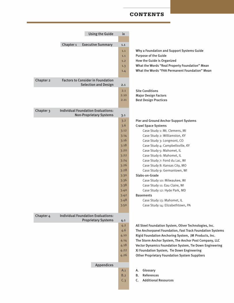