Embed Size (px)
Citation preview

Arizona Geological Survey www.azgs.az.gov
repository.azgs.az.gov
XXXX
Precambrian granite overlain by coarse-grained conglomerate
Contributed rePort Cr-07-b
Geology of the Bloody Basin: Central Arizona’s Transition Zone
Gwyn Rhys-Evans

Arizona Geological Survey Contributed Report Series The Contributed Report Series provides non-AZGS authors with a forum for publishing docu-ments concerning Arizona geology. While review comments may have been incorporated, this document does not necessarily conform to AZGS technical, editorial, or policy standards.
The Arizona Geological Survey issues no warranty, expressed or implied, regarding the suitability of this product for a particular use. Moreover, the Arizona Geological Survey shall not be liable under any circumstances for any direct, indirect, special, incidental, or consequential damages with respect to claims by users of this product.
The author(s) is solely responsible for the data and ideas expressed herein.

GEOLOGY OF THE BLOODY BASIN:
CENTRAL ARIZONA’S TRANSITION ZONE
by
Gwyn Rhys-Evans
A Thesis Presented in Partial Fulfillment Of the Requirements for the Degree
Master of Science
ARIZONA STATE UNIVERSITY
DECEMBER 2006


ABSTRACT
New geologic mapping in the Bloody Basin of central Arizona’s Transition Zone
reveals two distinct sets of normal faults that have a nearly 90° orientation with respect to
one another. Miocene Hickey basalt unconformably overlies the Verde River granite that
together makes a sequence of rocks that has been dissected into a series of tilted fault
blocks. Regionally anomalous, northeast-striking normal faulting resulted in a synthetic
array of half-grabens that are locally filled with a volcaniclastic conglomerate grading
into a granite-rich conglomerate. These northeast-striking faults are thought to be
influenced by a preexisting Precambrian structure that has been defined by aeromagnetic
studies as the Holbrook lineament. This lineament projects directly through the Bloody
Basin and would explain, at least in part, the origin of these anomalously oriented faults.
Following this northwest-southeast directed extension, a dominant northeast-southwest
extension direction resulted in a more regionally pervasive pattern of northwest-striking
normal faults, including the Verde fault that cross-cuts the previously formed set. The
least principal stress direction required for development of these extensional features is
that which currently exists within the Colorado Plateau, northeast-southwest directed.
The resultant thinned upper crust due to this extension gave way to the emplacement of a
suite of mafic dikes that intruded basin-filling material shed during the first tectonic
event.
Timing of the first event is constrained to between 13.5 and 8 Ma, the age of tilted
Hickey basalt and Miocene movement along the cross-cutting Verde fault, respectively.
This timing is coeval with the Basin and Range Disturbance; however, characteristics that
help to define this event do not wholly agree with what is observed in the Bloody Basin.
iii

A pulse of local northwest-southeast directed extension may have swept through the area
giving rise to the infant Bloody Basin, which was then cut short by extension created
possibly by crustal buoyancy forces related to the Colorado Plateau.
Because the Bloody Basin lacks detailed geologic mapping, a nexus is provided
that connects previous studies in the region. A synthesis of these studies has led to a
better understanding of extensional tectonic events and how they are manifested in the
Transition Zone of central Arizona. Continued efforts into filling voids through detailed
geologic mapping such as this, will provide a better understanding as to the fundamental
framework of such a unique region.
iv

ACKNOWLEDGMENTS
I would like to thank my advisor Dr. Edmund Stump for suggesting what
amounted to be a rewarding and challenging project, shrouded by the ominous name:
The Bloody Basin. I had many unique and branding experiences in the Bloody Basin and
I have Ed to thank for these. I would also like to express my gratitude towards him for
partially funding this project. I would also like to thank my supervisory committee, Dr.
Stephen J. Reynolds and Dr. Stan Williams for their time and efforts. Special thanks to
Dr. Williams for his determination and willingness to see me through last minute issues.
Special thanks also goes to Doug Greene for putting together and leading an adventurous
trip down the ‘wild’ stretch of the Verde River. Without his generosity, some parts of
this country would have never been seen by myself. Additionally, I would like to thank
Patty Fetter of the US Forest Service for the many insights during the river trip and also
for playing a major role in use of equipment. I would also like to thank Marivel Linares
of the US Forest Service for her patience and helpfulness in allowing me to use and
acquire the air-photos of the Bloody Basin, this saved many long hours of hiking. I
would also like to thank the Department of Geology (now the School of Earth and Space
Exploration) at ASU for partial funding of this project. Special thanks to my friends and
family for all of their support. Finally, I would like to thank my wife for allowing me to
pursue this goal in my life and for supporting me throughout thick and thin, and with an
extraordinary amount of support.

TABLE OF CONTENTS
Page
LIST OF FIGURES……………………………………………………………………...vii
LIST OF PLATES………………………………………………………………………...x
INTRODUCTION .............................................................................................................. 1
METHOD OF STUDY....................................................................................................... 6
GEOLOGIC SETTING ...................................................................................................... 8
Regional........................................................................................................................... 8
Local .............................................................................................................................. 10
PREVIOUS STUDIES...................................................................................................... 12
MAP UNIT DESCRIPTIONS .......................................................................................... 16
Stratigraphy ................................................................................................................... 17
Precambrian Units ......................................................................................................... 18
Tertiary Units................................................................................................................. 22
Quaternary Units............................................................................................................ 45
PETROGRAPHY ............................................................................................................. 48
Sample Locations .......................................................................................................... 49
Precambrian Units ......................................................................................................... 50
Tertiary Units................................................................................................................. 54
Summary Table.............................................................................................................. 64
STRUCTURE ................................................................................................................... 65
Precambrian ................................................................................................................... 65
Tertiary .......................................................................................................................... 67
v

Northeast Trending Faults.......................................................................................... 68
Amount of Extension .............................................................................................. 77
Timing..................................................................................................................... 77
Northwest Trending Faults......................................................................................... 78
Verde Fault.............................................................................................................. 83
Amount of Extension .............................................................................................. 88
Timing..................................................................................................................... 88
Reverse and Strike-slip Faulting ................................................................................ 89
Timing..................................................................................................................... 91
Dikes........................................................................................................................... 91
Timing..................................................................................................................... 93
Tertiary Dome ............................................................................................................ 93
DISCUSSION................................................................................................................... 95
Least Principal Stress Direction .................................................................................... 95
Fault Orientation and Regional Considerations............................................................. 99
Fault-Block Widths...................................................................................................... 106
Relations to Basin and Range Disturbance.................................................................. 108
Conclusions ................................................................................................................. 109
TERTIARY HISTORY .................................................................................................. 112
REFERENCES ............................................................................................................... 116
vi

LIST OF FIGURES
Figure Page
1. Physiographic provinces of Arizona.............................................................................. 2
2. Location of study area.................................................................................................... 4
3. 2004 ASTER satellite image of the Bloody Basin and vicinity..................................... 7
4. Map showing locations of previous studies conducted in the vicinity of the Bloody
Basin ................................................................................................................................. 13
5. Representative stratigraphy from four locations in the Bloody Basin......................... 17
6. Field photographs of Precambrian chlorite-mica schist............................................... 19
7. Field photograph of Precambrian Verde granite.......................................................... 21
8. Field photograph of Tertiary volcanics overlying older conglomerate (Toc).............. 24
9. Field photograph of confined Tertiary older conglomerate (Toc) ............................... 25
10. Field photograph of regionally tilted Tertiary volcanics ........................................... 28
11. Field photograph of Tertiary mudstone ..................................................................... 30
12. Field photograph of Tertiary tuff overlying Tertiary conglomerate .......................... 32
13. Field photograph of Tertiary conglomerate (Tc1)...................................................... 34
14. Field photograph of Tertiary conglomerate (Tc2)...................................................... 36
15. Field photograph of Tertiary younger sediments....................................................... 38
16. Field photograph of Tertiary granite conglomerate ................................................... 40
17. Field photograph of angular unconformity showing horizontal basin fill overlying
gently dipping Tertiary volcanics ..................................................................................... 41
18. Field photographs of Tertiary dome; including brecciated margins and flow banding
........................................................................................................................................... 43
vii

19. Field photograph of steeply dipping Tertiary dike .................................................... 46
20. Map showing locations of sample collections for petrographic analysis .................. 49
21. Photomicrograph of Precambrian chlorite-mica schist.............................................. 51
22. Photomicrograph of Precambrian Verde River granite ............................................. 53
23. Photomicrographs of interlocking aggregate and trachytic textures observed in
Tertiary volcanics.............................................................................................................. 56
24. Photomicrograph of Tertiary tuff............................................................................... 58
25. Photomicrograph of Tertiary mudstone ..................................................................... 60
26. Photomicrograph of representative Tertiary dike ...................................................... 62
27. Photomicrograph of Tertiary dome............................................................................ 63
28. Map showing locations of structures observed in the Bloody Basin ......................... 66
29. Field photographs showing vertical trace of Pine Mountain fault and a segment
displaying the steeply dipping nature ............................................................................... 70
30. Field photograph of northeast-striking fault intersected by a northwest-striking fault
........................................................................................................................................... 71
31. Field photograph of volcanic breccia at the Marble Mine......................................... 71
32. Field photographs of North Red Creek fault with striations along the plane ............ 73
33. Stereogram of data for northeast-striking faults ........................................................ 76
34. Field photograph of offset northwest striking fault along Forest Service Road 24 ... 79
35. Simplified cross-section from B to B’ ....................................................................... 81
36. Field photograph of mineral lineations on granite footwall of Red Creek fault ........ 82
37. Field photographs of Verde fault ............................................................................... 84
38. Field photograph of steeply dipping Precambrian bedding ....................................... 86
viii

39. Stereogram of data for northwest-striking faults ....................................................... 87
40. Field photographs of strike-slip faulting in the Bloody Basin; including lineations . 90
41. Stereogram of data for dike orientations.................................................................... 92
42. Map showing synthesis of faults in the area from past studies................................ 101
43. Stereogram showing the combination of data for northwest and northeast-striking
faults................................................................................................................................ 103
44. Map showing general locations of magnetic anomalies on the Colorado Plateau... 105
45. Map showing locations of basins in the Transition Zone ........................................ 107
46. Diagrammatic summary of the Tertiary history of the Bloody Basin ..................... 115
ix

LIST OF PLATES
Plate
1. Geologic map of the Bloody Basin
x

INTRODUCTION
Central Arizona is a topographically and geologically diverse region within a
transition zone that crosses the State of Arizona between two other physiographically
distinct provinces: the northern Colorado Plateau and the southern and western Basin and
Range (Figure 1). The Colorado Plateau occupies portions of four southwestern states;
Arizona, Utah, Colorado, and New Mexico. In Arizona, the Colorado Plateau is broadly
characterized by relatively flat-lying, Paleozoic and Mesozoic sedimentary strata with
relatively little structural deformation (Reynolds, 1988). The Basin and Range, spanning
much of the western United States and vast portions of southern and western Arizona, is
characterized regionally by block-faulted mountains (Eberly and Stanley, 1978) that are
discontinuous and generally trend northwest- to northeast. The ranges developed due to
this block faulting have been subsequently isolated by sediment filled basins (Menges
and Pearthree, 1989). The Transition Zone, that separates the two, is generally
characterized by horst-block mountain ranges, volcanic mountains, grabens, half-graben
basins (Hendricks and Plescia, 1991), and plateau remnants (Menges and Pearthree,
1989). It is a zone that qualifies as a legitimate transition, because it contains features
that characterize the other two provinces.
Detailed geologic mapping and petrographic analysis of areas in the Transition
Zone are greatly limited and subsequently hinder our ability to fully understand this
region. Although geophysical surveys have been conducted across this northwest-
trending swath (e.g., West et al., 2004; Parsons et al., 1996; Warren, 1969) for
understanding crustal thicknesses and isostatic equilibrium of the plateau, these studies
need to be supplemented by detailed bedrock mapping and structural analysis to broaden

2
Figure 1. General map of the State of Arizona showing the approximate extent of the three main physiographic provinces that are recognized.

3
our understanding as to the evolution of the region. With these types of studies, such
questions as how this region has responded to tectonic stress interaction between the
relatively coherent Colorado Plateau and the highly extended Basin and Range can be
answered. Additionally, detailed studies may offer insight as to the extent of
deformational events such as the Basin and Range disturbance or even the Mid-Tertiary
orogeny. Because of these needs, new geologic mapping has been completed in the
Bloody Basin and vicinity of the central Transition Zone (Figure 1).
The Bloody Basin study area is located within the Tonto National Forest and is
approximately100 km north of Phoenix, Arizona in Yavapai County (Figure 2). This area
referred to as the central Transition Zone by Leighty (1997), lies on the southwest margin
of the Colorado Plateau and is locally bounded to the north by the Pine Mountain
Wilderness area and to the east by the Mazatzal Wilderness area (Figure 2). The focus of
the geologic mapping and accompanying research was concentrated on Tertiary evolution
of the basin proper and surrounding area; however, Precambrian rocks are well exposed
in the area and undoubtedly aided in the breadth of understanding. In addition to a new
geologic map, a link has been provided to other geologic maps (see Previous Work
Section) that have been previously constructed in the surrounding areas, such as Pine
Mountain Wilderness (Canney et al. 1967), Mazatzal Wilderness (Wrucke and Conway,
1987) and the Rover Peak quadrangle (Brand, 2005). Brand’s (2005) study linked
geologic maps in the New River Mesa, Humboldt Mountain, and Horseshoe Dam
quadrangle’s (see Ferguson et al., 1998; Gilbert et al., 1998; and Ferguson et al., 1999;
respectively). This new study, in concert with those just mentioned provides the

4
Figure 2. Location map of the Bloody Basin study area. Note the study area is within the central Transition Zone.

5
foundation for a broader tectonic understanding of the central Transition Zone that
should lead to more insight into the evolution of this diverse region.

METHOD OF STUDY
The following is a brief description of the methods used during the course of research
conducted in the Bloody Basin:
1. The primary research effort was to construct an approximately 200 km2 geologic
map of the Bloody Basin area at a scale of 1:24,000. Some complicated areas
required mapping at 1:10,000 for better understanding. Base topographic maps
used were 1:24,000 USGS, 7.5’ quadrangles: Bloody Basin, Brooklyn Peak, Tule
Mesa, and Wet Bottom Mesa. The completed field maps were compiled using
ArcMap 9.1.
2. Field mapping was supported with satellite image interpretation (Figure 3).
1:24,000 color aerial photographs which were provided by the United States
Forest Service provided stereoscopic coverage of the area.
3. A six day kayak trip on the Verde River through the Mazatzal Wilderness was
required to access portions of the Roadless area in the wilderness, that otherwise
were inaccessible.
4. Thirty thin-sections from representative geologic units were used for petrographic
identification.

7
Figure 3. 2004 ASTER image used for coarse interpretation then supported by field reconnaissance. Yellow bands are granite bodies that subsequently helped delineate faulting in the area. Verde fault is well-recognized as the linear expression cutting across the northeast corner of the image. Dashed line is the approximate boundary of the study area. Source: www.geoinformaticsnetwork.org/swgeonet/

GEOLOGIC SETTING
Regional Overview
As previously noted, Arizona contains portions of three physiographic provinces
that make up the landscape of the American southwest (see Figure 1); Basin and Range,
Colorado Plateau and Transition Zone. The Basin and Range and Colorado Plateau
contain unique characteristic that distinguish each as a separate province. The Transition
Zone contains characteristics of both the Basin and Range and Colorado Plateau and
therefore offers a unique insight in regards to the interaction of the bounding provinces.
The Arizona Basin and Range physiography is due partly to the Basin and Range
Disturbance (Menges and Pearthree, 1989), an event that resulted in extensional block
faulting between 14 – 5 Ma ( Shafiqullah et al., 1980) and possibly beginning as young as
13 – 12 Ma (Eberly and Stanley, 1978). This event is now manifested by northwest
trending pediment ranges, bounded by moderate to high angle normal faults and
separated by deep valley alluvium (Eberly and Stanley, 1978). Range blocks that make
up these pediments may be tilted as documented in Nevada (Stewart, 1981) although this
characteristic is largely undocumented in Arizona (Menges and Pearthrees, 1989).
Additionally, the fault zones that comprise these alluvial basins are generally structural
boundaries of grabens or tilted half-grabens and fault block ranges (Stewart, 1998).
Basin dimensions range from 10 km to locally up to 50 km wide with the amount of
extension between 10 – 20% of original (Stewart, 1998).

9
The Colorado Plateau is described as a coherent block surrounded on three sides
by the extensional block faulted regimes of the Basin and Range province and the Rio
Grande Rift (Thompson and Zoback, 1979). This “coherent block” has elevations that
range from 1200 m in its eroded center to 2600 m along several of its margins, with an
average elevation of 2000 m (Chase et. al., 2002). Additionally, this elevation equates to
approximately 1.2 km of uplift relative to the surrounding provinces (e.g. Chase et al.,
2002). Geologically, the plateau consists of thick sequences of Paleozoic and Mesozoic
strata that are generally flat-lying or sub-horizontal (Reynolds, 1988). The interior of the
Arizona portion of the plateau is, for the most part, surficially structureless with some
noted monoclines. Scarce northwest trending faults exist adjacent to the Colorado
Plateau and Transition Zone boundary (Reynolds, 1988).
The Transition Zone, regionally speaking, is a zone of transitional structures as
wide as 150 km between the Colorado Plateau and the Basin and Range province
(Stewart, 1998). As seen on the state geologic map (Reynolds,1988) the Transition Zone
is roughly 70 to 80 km wide in central Arizona and trends northwest-southeast. The
Transition Zone contains structures that are characteristic of both the Colorado Plateau
and Basin and Range provinces (Stewart, 1998). The Bloody Basin lies within this
Transition Zone.

10
Local Overview
The Bloody Basin study area is just beyond the southern margin of the Pine
Mountain Wilderness area, which is the south end of the Black Hills, a north- to
northwest-trending footwall block of the Verde fault. The geology of the Black Hills has
been studied extensively by Canney et al. (1968), Anderson and Creasy (1958) and from
studies in the adjoining Verde Valley by Twenter and Metzger (1963). The geology of
the southern Black Hills consist of Precambrian granites, gneisses, and metamorphic
mafic rocks unconformably overlain by either Paleozoic sediments of Tapeats Sandstone,
Martin Limestone, and remnant patches of Mississippian Redwall Limestone or directly
overlain by Cenozoic volcanic rocks, whereby the Paleozoic have been stripped through
erosion (Canney et al., 1968). The Black Hills are extensively faulted throughout and
bounded to the east by the Verde fault zone and to the west by the Coyote/Shylock fault
zones (Twenter and Metzger, 1963).
To the east of the study area lie the Mazatzal Mountains within the Mazatzal
Wilderness area. The Mazatzal Wilderness is occupied by four stratified sequences of
Proterozoic metasedimentary or metasedimentary and metavolcanic rocks, including the
East Verde River Formation and the Tonto Basin Supergroup and, as Wrucke and
Conway (1987) state, few areas in Arizona expose so many well preserved sections of
layered Proterozoic rocks. These rocks are commonly intruded by the Gibson Creek
Batholith and the Diamond Rim Intrusive Suite of various granite, aplite and intrusive
rhyolite (Wrucke and Conway, 1987). These Proterozoic rocks record the folding and

11
thrusting from the Mazatzal orogeny originally mapped by Wilson (1939). The
Mazatzal Wilderness also contains Paleozoic Tapeats Sandstone, Martin Formation,
Mississippian Redwall Limestone and Naco Formation that overlie the Proterozoic
basement described above. Tertiary sedimentary and volcanic rocks are exposed here in
the Verde River valley and north of the East Verde River (Wrucke and Conway, 1987).
Additionally, Wrucke and Conway (1987) note conspicuous north- and northwest-
trending faults as well as the north-trending Verde River graben that overlaps into the
current study.
To the south of the Bloody Basin, in the Rover Peak quadrangle, Precambrian
basement granite and metamorphic rocks are overlain by Tertiary sediment and volcanic
rocks (Brand, 2005) with no preserved Paleozoic rocks. Brand (2005) identified major
north-northwest trending faults with east-side-down motion that were active later than
13.5 Ma, the 40Ar/39Ar dates obtained from tilted basalts in the area. Additionally, Brand
(2005) noted a younger flat-lying volcanic unit that caps these tilted basalts. Ages
obtained from these rocks by 40Ar/39Ar yielded ages around 6.4 Ma.
Finally, to the west of the study area is the Aqua Fria National Monument which
can broadly be characterized as containing Precambrian granites and metamorphic rocks
that are generally overlain by Tertiary sediment and volcanic rocks. It is worth noting
that the western rim of the Bloody Basin is generally flat-lying to sub-horizontal and
appears to be largely unextended.
PREVIOUS STUDIES
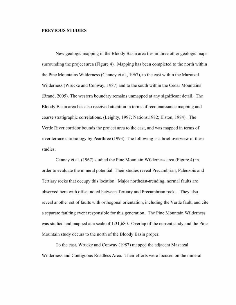
New geologic mapping in the Bloody Basin area ties in three other geologic maps
surrounding the project area (Figure 4). Mapping has been completed to the north within
the Pine Mountains Wilderness (Canney et al., 1967), to the east within the Mazatzal
Wilderness (Wrucke and Conway, 1987) and to the south within the Cedar Mountains
(Brand, 2005). The western boundary remains unmapped at any significant detail. The
Bloody Basin area has also received attention in terms of reconnaissance mapping and
coarse stratigraphic correlations. (Leighty, 1997; Nations,1982; Elston, 1984). The
Verde River corridor bounds the project area to the east, and was mapped in terms of
river terrace chronology by Pearthree (1993). The following is a brief overview of these
studies.
Canney et al. (1967) studied the Pine Mountain Wilderness area (Figure 4) in
order to evaluate the mineral potential. Their studies reveal Precambrian, Paleozoic and
Tertiary rocks that occupy this location. Major northeast-trending, normal faults are
observed here with offset noted between Tertiary and Precambrian rocks. They also
reveal another set of faults with orthogonal orientation, including the Verde fault, and cite
a separate faulting event responsible for this generation. The Pine Mountain Wilderness
was studied and mapped at a scale of 1:31,680. Overlap of the current study and the Pine
Mountain study occurs to the north of the Bloody Basin proper.
To the east, Wrucke and Conway (1987) mapped the adjacent Mazatzal
Wilderness and Contiguous Roadless Area. Their efforts were focused on the mineral

13
Figure 4. Generalized map showing geographic locations of previously conducted studies around the Bloody Basin.

14
resource potential in the wilderness area, which resulted in a geologic study that included
detailed description and history of rocks from Precambrian through Tertiary. The
Mazatzal Wilderness was studied and mapped at a scale of 1:48,000. The Mazatzal
Wilderness and Bloody Basin study areas overlap slightly along the Verde River corridor
(Figure 4).
Brand (2005) mapped the Cedar Mountains area to the south of the present study.
His efforts included geologic mapping, history, tectonic interpretation, and 40Ar/39Ar
dating to constrain timing of faulting in the area. Precambrian and Tertiary volcanics
found in the Cedar Mountains are similar and correlative with units in the Bloody Basin;
however, the Tertiary Chalk Canyon Formation (Gomez, 1979) that Brand (2005)
observed does not appear to continue from the Cedar Mountains area further on to the
north. Brand (2005) completed geologic mapping at a scale of 1:24,000.
Leighty (1997) conducted an extraordinary study with the focus of Neogene
tectonism and magmatism across the Basin and Range, specifically in central Arizona,
that included, but was not limited to, reconnaissance-style geologic mapping,
petrographic analysis, and tectonic stress field orientation. Leighty’s (1997) work
contains information regarding faulting and petrographic analysis of the Bloody Basin
and surrounding areas.
Nations et al. (1982) conducted a review of the locations and chronology of
Tertiary sedimentary deposits in Arizona. Although mention of the Bloody Basin is
included in this study with respect to correlating stratigraphy, any in-depth details
regarding the general history of the area are lacking.

15
Elston (1984) conducted a broad overview of central Arizona landscape
development with regional correlation of rocks and timing of events responsible for
present day landscapes of central Arizona. Specifically, Elston (1984) correlates a
conglomerate found in the Bloody Basin (Bloody Basin conglomerate) with that found
near Cave Creek. Elston (1984) also lists a detailed summary and time table of how
tectonic and depositional events in central Arizona transpired over the last 38 m.y.
Pearthree (1993) conducted a study along the Verde River from Sullivan Lake to
Horseshoe Reservoir with a focus primarily of the ages and correlations of terrace
deposits along the Verde River corridor. This study, although detailed in terms of project
objective, lacks any information regarding faulting that occurred along this corridor.

MAP UNIT DESCRIPTIONS
For this study, the rocks in the Bloody Basin were divided into 19 different units
based on lithology, composition, and relative age. Of these 19 units, 3 are defined as
Precambrian, 11 are defined as Tertiary (Miocene), and the remaining 4 are Quaternary.
The Miocene designation is based on dates yielded from similar volcanics to the south in
the Cedar Mountains where an age of 13.5 Ma was obtained (Brand, 2005). These
volcanics, as well as the volcanics in the study area have subsequently been correlated
with the widespread Hickey Basalt Formation of central Arizona. This correlation is
based on ages of nearby deposits, composition, and stratigraphic position. The
Precambrian designation is from the past work of Anderson (1989). The granite observed
in the Bloody Basin is correlated with the Verde River Granite Batholith, which has
similar composition and is dated at approximately 1700 Ma, based on relative age
relations to isotopically dated rocks (Anderson, 1989). Quaternary units are mapped
primarily from active fluvial systems in the Bloody Basin and the Verde River drainage.
Figure 5 illustrates the generalized stratigraphy as represented by four localities in
the study area that will help in understanding the extent and thickness of the volcanic and
sedimentary units present. As Figure 5 shows, some of the sedimentary units in the area
are discontinuous. Other units, such as the volcanics, are widespread and relatively
uniform in thickness. Each unit description consists of observations followed by
interpretation.

17
Southern Basin
Western rim Central Basin Red Creek
Tgc
Tsy
Toc
Xg
Tv
Tt
Tc1
Tc2
0 m
100 mRed Creek
Western Rim
Central Basin
Southern Basin
Map showing stratigraphic locations
0 2 4 6 81Kilometers
Bloody BasinRoad
FS 24
StudyArea Boundary
Verd
eR
iver
Figure 5. Generalized stratigraphy representing four localities in the Bloody Basin study area. Note the discontinuous nature of Tc1 to the west and Toc to the east. See text for details on symbols used and unit descriptions.

18
PRECAMBRIAN UNITS
Precambrian chlorite-mica schist (Xcms)
Precambrian chlorite-mica schist (Xcms) is observed as a north-south trending
body in the southwest portion of the study area (Plate 1). This unit is orange to tan on
weathered surfaces, and locally black to dark brown. On fresh surfaces this unit displays
a pinkish-orange and greenish hue. It generally has a corroded appearance displaying
moderately eroded slopes, with local more resistant, cliff-forming outcrops. In hand
sample, this unit is composed of muscovite (40%), chlorite (40%), and quartz (20%).
Xcms has an intrusive contact with a feldspathic granite, Xg (Figure 6a) and locally is
overlain by a coarse-grained conglomerate, Toc. Contacts with other units are faults
(Plate 1). Muscovite + chlorite and quartz define a weak to moderate foliation as seen in
thin-section, but this characteristic is hard to recognize in hand-sample. A weak lineation
defined by the alignment of quartz is locally seen in hand sample. This unit also displays
local mesoscopic folds and contains abundant west- southwest to east- southeast, ~1 m
wide quartz veins. Figure 6b is a typical outcrop of Xcms.
Based on the presence of chlorite + muscovite + quartz, this unit is interpreted as
having derived from an argillaceous sandstone, that has undergone moderate deformation
manifested as the weak foliation and mesoscopic folding. The age of this unit is
constrained by the intrusive contact with Xg, suggesting Xcms is the oldest unit in the
study area.

19
Figure 6. Precambrian chlorite-mica schist (Xcms) found in the Bloody Basin. A) a picture showing an intrusive contact between feldspathic granite (Xg) and Xcms. Picture looking 210°. Qa contact is a local unconformity. Hammer is 29 cm long, and B) photograph of Xcms showing mesoscopic folding in a typical outcrop. Fold axis is oriented 70 → 190. Photograph looking 175°. Shell casing is 4 cm long.

20
Precambrian granite (Xg) (Verde River Granite)
Precambrian granite (Xg) is the most widespread Precambrian unit in the study
area and is observed mainly in three northeast trending swaths, with a local outcrop in the
south-central portion of the field area. This unit is orange to burnt orange on weathered
and fresh surfaces and typically weathers to subdued slopes. It is primarily composed of
60 - 70%, 5-10 mm, euhedral K-feldspar, 20 – 25%, 2-5 mm euhedral quartz, and 5 –
20% biotite flakes. Xg is uncomformably overlain by the coarse-grained conglomerate,
Toc (Figure 7), in the west and the northwest and also unconformably overlain by
Tertiary volcanics (Tv), in the western portion of the study area. Additionally, this unit
intrudes Xcms as noted above (see Figure 6a). Xg is typically massive but locally
contains irregular joints and fractures as well as local dikes and sills of similar
composition. Figure 7 is a field photograph of a typical outcrop.
The Xg unit in the Bloody Basin is correlated to the Verde River Granite
Batholith (Anderson, 1989) on the basis of location and composition. This batholith
occupies 1200 km2 of the lower Verde River and extends from the New River-Cave
Creek volcanic belt to the Mazatzal Mountains (see Figure 8, Anderson, 1989). Relative
timing of this unit is thought to be post-deformation of Xcms, as Xg is not observed to
have undergone a penetrative deformation, lacking foliation and any linear structures.
However, because of the magnitude of this batholith, this interpretation should be
considered local and preliminary.

21
Figure 7. Field photograph of Precambrian granite (Xg) outcrop unconformably overlain by a coarse-grained conglomerate, Toc (see text for details). Photograph is looking 310°. Staff is 1.3 m.

22
Precambrian granite undifferentiated (Xgu)
This unit was mapped in a reconnaissance fashion in the far northeast portion of
the study area (Plate 1). Within this undifferentiated unit, there is a red to burgundy
conglomerate that contains sub-angular to sub-rounded clast with < 10% well-rounded
softball size lithophysae. Wrucke and Conway (1987) interpreted this as a rhyolite ash
flow tuff. Also within this undifferentiated unit is a granodiorite that contains 60 – 70%
euhedral biotite, approximately 20% quartz and < 10% feldspar. Additionally, and
adjacent to the Verde River is a hematite bearing unit that contains possibly epidote
veining 2 – 4 mm wide. For a more comprehensive description of this area the reader in
referred to Wrucke and Conway (1987).
TERTIARY UNITS
Tertiary older conglomerate (Toc)
Tertiary older conglomerate (Toc) is primarily located in a northeast trending
swath on the northwest side of the study area and is mainly absent to the west (Plate 1).
This unit is red to orange on fresh and weathered surfaces. It tends to form subtle slopes
in the southern exposures and more moderate to steep slopes in the northern part of the
study area. Toc is primarily composed of angular, 1 to 8 cm, granitic clasts, but may also
locally contain metamorphic clasts (Leighty, 1997). Locally it displays crude horizontal

23
to sub-horizontal bedding 0.5 to 1.5 m thick. This unit is in sharp contact with the
underlying Xg unit (Figure 7) and in sharp contact with the overlying Tv (Figure 8). It
ranges in thickness from 50 to 250 m (see Figure 5).
Brand (2005) observed a similar unit to the south, describing a granite rich pre-
volcanic conglomerate overlying Precambrian rocks. Leighty (1997) also describes a unit
with similar characteristics which he interpreted to be a fanglomerate found in local
troughs or depressions in the Bloody Basin and Cave Creek areas. Wrucke and Conway
(1987) describe an older conglomerate similar to Toc in the central and northeastern parts
of the Mazatzal Wilderness Area. Elston (1984) describes a “red fanglomerate” near
Cave Creek that underlies a tuff containing an early Oligocene fossil that he correlates
with this Bloody Basin unit, which he uses the name “Bloody Basin fanglomerate”. He
also suggests these deposits were the result of strong regional uplift. The discontinuous,
but widespread nature of this unit is suggestive of local basins receiving locally derived
material prior to volcanism. Figure 9 shows what is interpreted to represent one of these
local basins prior to volcanism in the region. The picture is taken looking to the south
and shows a confining ridge of Xcms/Tv surrounding the margins of this unit. Timing of
this unit is constrained to be no younger than early Oligocene based on Elston’s (1984)
correlation.

24
Figure 8. Photograph of Tertiary volcanic unit (Tv) overlying older conglomerate (Toc). Picture looking 240°. Staff is 1.3 m.

25
Figure 9. Photograph of interpreted closed basin prior to regional volcanism. Note the highlands surrounding the margins of the Toc. Xcms is chlorite-mica schist. Photo is looking south from the western rim of the study area on Forest Service Road 269.

26
Tertiary volcanics (Tv) (Hickey Formation Basalt)
Tertiary volcanics (Tv) is the most widespread unit of Tertiary rock in the study
area (Plate 1). It was mapped as one unit, although it is noted that there are probably
many individual flows in the region that could be distinguished and mapped separately if
a detailed study were undertaken. Broadly, the volcanics consist of basaltic flows and
agglomerate. The basalts are black to brown on weathered surfaces and grey to black
when fresh. The agglomerates are typically burgundy on weathered surfaces and reddish
brown to burgundy when fresh. These volcanics erode primarily to bench-slope
topography, with more resistant benches possibly indicating individual flows. In hand
sample, primary phenocrysts are commonly olivine and plagioclase with olivine
phenocrysts typically altered to a brownish - yellow iddingsite (see Petrography section
for further detail). Additionally, the basalts are commonly vesicular and secondary
mineralization of calcite is widespread.
Unit Tv locally displays a mesoscopic, trachytic texture, defined as the parallel
alignment of plagioclase laths with local olivine phenocrysts. In thin-section, this type of
texture is very apparent and quite common. Outcrops displaying this characteristic can
be found on top of Hardscramble Tank and North Pass Tank No. 1. Tv overlies Xg in the
eastern portion of the field area and Toc in the west. As stated above, Tv is overlain in
the central portion of the study area by units Tsy, Tc, and Tgc. Tv also contains
interbedded red beds that are generally volcaniclastic sandstone that can be up to 2 m
thick, as well as local interbedded, volcaniclastic conglomerate (Tc1) and tuffs. Tv has

27
been tilted 10° – 30° mainly westward, throughout the study area (Figure 10). The flat-
lying volcanics (4 – 6 Ma) that aided in constraining timing of tilted fault blocks in the
Rover Peak quadrangle to the south (Brand, 2005) are not observed in the Bloody Basin.
Tv ranges in thickness from 450 to 600 m (Plate 1). This is consistent with
observations by others in the region: Brand (2005) ~600m; Leighty (1997) > 450 m;
Wrucke and Conway (1987) > 700 m; and Anderson and Creasy (1958), 0 – 400 m in the
nearby Black Hills.
As indicated earlier, the volcanics in this region have been correlated with the
Hickey Formation on the basis of geographic location and composition. The Hickey
Formation ranges in age from 14.6 Ma to 10.1 Ma (McKee and Anderson, 1971). Brand
(2005) obtained a confident age of 13.5 Ma from the top of the volcanic sequence at
Cook’s Mesa just to the south of the Bloody Basin in the Rover Peak quadrangle.
Additionally, a younger sequence of Tertiary volcanics has been documented in central
Arizona, including the Verde Valley (McKee and Anderson, 1971), Mazatzal Wilderness
Area (Wrucke and Conway, 1987) and the Cedar Mountains (Brand, 2005), consisting of
7 to 4 Ma basalt flows (McKee and Anderson, 1971). At least in the Mazatzal
Wilderness area and Cedar Mountains, these volcanics are flat-lying and cap a gently to
moderately-tilted older sequence of the Hickey Formation. However, flat-lying volcanics
were not observed in the Bloody Basin.

28
Figure 10. Photograph of moderate, west-dipping Tertiary volcanics (Tv). Picture looking north from atop Dugan Peak (Plate 1).

29
Tertiary basalt undifferentiated (Tbu)
Undifferentiated Tertiary basalt was mapped in reconnaissance fashion in the
northeastern portion of the field area. This area contains basalts similar to those
described above, as well as some thin, interbedded tuffaceous and sedimentary units.
Tertiary mudstone (Tm)
Tertiary mudstone (Tm) is observed only in the southern portion of the study area
and is limited in aerial exposure (Plate 1). It is bluish to aqua on weathered surfaces and
light green when fresh. Tm erodes as slopes and benches, with benches up to 25 cm
thick. Tm is composed of fine-grain mud and more resistant layers of interbedded silt in
hand sample. In thin-section however, this unit contains well-defined microcrystalline
pods with curvilinear boundaries adjacent to regions that contain abundant, angular
heterolithic fragments. The unit is overlain by Qc and Tv and is presumed to be
interbedded within the Tv unit, although its base is not exposed. Tm contains local ripple
marks and discoid shaped concretions that react vigorously with HCl. Also, this unit dips
gently to the southwest at 10° and is at least 25 m thick. Figure 11 is a typical exposure
of Tm.
Unit Tm may represent a local depression during volcanism in the region that was
subsequently overlain by additional volcanics. The unique color and composition of this
unit are not well understood, but the presence of ripple marks and strong calcification

30
Figure 11. Photograph of typical exposure of Tertiary mudstone (Tm). Note more resistant silty layer outlined with white dashes, dipping gently to the southwest at 10° suggesting pre-tectonic deposition. Also note unique blue/green color. Outlined layer is ~ 25 cm wide. Picture looking 130°.

31
may be indicative of a low energy aqueous environment. Timing of this unit is not well
constrained, but the fact that it is gently dipping suggests pre-tectonic deposition.
Tertiary tuff (Tt)
Tertiary tuff (Tt) is observed as a thin layer adjacent to the Verde River in the
eastern portion of the study area (Plate 1). This unit is white to light tan on weathered and
fresh surfaces and erodes as a cliff former. Tt is 70% composed of mm to 2 cm sized
pumice fragments with additional and less abundant angular fragments composed of
plagioclase, olivine, quartz, hornblende, and euhedral biotite less than 1 mm. This unit is
in sharp contact with underlying Tv and Tc1 and the overlying Tc1. It is typically
massive; however, some joints and fractures are present locally. This unit is <75 m in
thickness. Figure 12 is a typical exposure.
Timing of this unit can only be constrained to pre-tectonic as indicated by the
moderate dip of the contact with the underlying unit, Tc1 (Figure 12). Although local
significance of this tuff is enigmatic, an interbedded tuff within a rather thick sequence of
regionally abundant Hickey Formation is not unreasonable.
Tertiary conglomerate (Tc1)
Tertiary conglomerate (Tc1) is observed locally interbedded within the Tv unit
(Plate 1) (Figure 5). Tc1 is tan to light grey and erodes as a slope former unless incised

32
Figure 12. Photograph of Tertiary tuff (Tt) overlying volcaniclastic conglomerate (Tc1) near the Verde River. Note massive appearance of Tt with some regular jointing. Contact is dipping to the west 30°. Picture looking due north. Staff is 1.3 m.

33
by modern stream channels. Tc1 contains up to 30%, 5 – 8 cm, subangular to angular,
reddish and black, volcanic clasts that are supported by a fine-grained volcaniclastic
matrix. This unit is in sharp contact with underlying Tv and displays a 0.5 m wide
alteration zone where Tv overlies this unit. Tc1 displays moderately defined bedding 0.5 –
1 m wide. This unit ranges in thickness from 25 to 180 m and appears to pinch out to the
west, as it is not observed west of the Hutch Gulch. The thickest portion of this unit is
along the Verde River where it contains an interbedded layer of Tv, whereas to the west
Tv is interbedded with Tc1 (see Figure 5). Figure 13 is a typical exposure of Tc1 in the
Bloody Basin.
Based on the lithology of angular volcanic clasts, suggesting local derivation, and
the interbedded nature within Tv, Tc1 is thought to represent a period of deposition
associated with the onset of faulting in the region, subsequently concealed by continued
volcanism. The fact that this unit is wedge shaped with the eastern exposures being the
thickest indicates a source region somewhere other than the west, although paleotransport
indicators were not observed. Timing of this unit can only be constrained to the age of the
Hickey Formation, 14.6 to 10.1 Ma, and before movement occurred on the major
northeast trending faults.
Tertiary conglomerate (Tc2)
Tertiary conglomerate (Tc2) is mainly observed in the south-central portion of the
study area and is typically absent in the north-northeast (Plate 1). This unit is generally a

34
Figure 13. Typical outcrop of Tertiary conglomerate (Tc1) in the study area. Note layering within this unit. Picture looking due north. Staff is 1.3 m.

35
defining grey on fresh and weathered surfaces, and typically erodes to subtle slopes
unless observed adjacent to modern streams or drainages, in which case this unit is stable
in cliff form. This unit is poorly sorted and contains clasts mm to 10’s of cm’s in size.
Clasts are primarily black to grey, angular to sub-angular, volcanic rock, usually
aphanitic but locally containing visible olivine and plagioclase. Clasts may also be
highly vesicular with local infills of secondary calcite. Additionally, this unit locally
contains clasts of reddish, agglomeritic volcanics and sub-angular marble clasts. Tc2
depositionally overlies Tv and is gradationally overlain locally by Tsy or Tgc. This unit
may also be locally overlain by Quaternary colluvium (Qc). Tc2 is crudely to moderately
stratified with bedding planes 1-2 m apart and typically sub-horizontal. Fanning dips are
observed in the west-central portion of the study area; however, this type of feature is an
exception and not common in the Bloody Basin. Tc2 is 1 -180 m thick. Figure 14 is a
typical exposure.
Based on angularity and composition of clasts that compose Tc2, this unit is
interpreted to be a locally derived basin fill that is a result of faulting in the Bloody Basin.
The description by Brand (2005) of field relations and lithology of a similar unit in the
Cedar Mountains area, suggests deposits resulting from similar mechanisms extend
beyond this local basin.
Relative timing of this unit is constrained to syn to post-tectonic, based on the
slight fanning dips and horizontal to subhorizontal nature of the unit. However, a fault
gouge between Tc2 and Xcms is observed along the Bloody Basin Road, suggesting
movement

36
Figure 14. Photograph showing typical outcrop of Tertiary conglomerate (Tc2). Note the difference in clast size from Tc2 (Figure 13) and Tc1. Also note absence of granite (see Tgc unit description for details). Photo looking 050°. Staff is 1.3 m.

37
subsequent to deposition (see Fault section for further details). Tc2 maintains sub-
horizontal orientation in this locality.
Tertiary younger sediments (Tsy)
Tertiary younger sediment (Tsy), observed in the south-central portion of the
study area (Plate 1), is light tan to brown on fresh and weathered surfaces. This unit is
generally horizontal and topographically subdued with local incision by modern
drainages. Tsy is primarily composed of a well sorted, silty-clay with interbedded
gypsiferous layers that range in thickness from 2 – 20 cm. This unit depositionally
overlies Tv or gradationally overlies Tc2. Stratigraphically, it is overlain by a granite
conglomerate, Tgc (see Figure 5). This unit also displays sub-horizontal to horizontal,
thin laminae, 2-5 cm wide. Tsy is approximately 40 m thick. Figure 15 is a typical
outcrop of Tsy.
Tsy could represent a lull or quiescent period without major faulting in the area
based on the gradational nature from the underlying Tc2 unit, which is considerably
coarser and thought to represent active deposition due to faulting in the region. The
reduced grain size may represent the lack of a major source for detritus, such as easily
eroded, uplifting and fractured rock. It is clear then, that timing of this unit is constrained
by its horizontal nature which suggests post-tectonic deposition. However, that this unit
is stratigraphically overlain by Tgc (see Figure 5), suggests increased tectonism following

38
Figure 15. Photograph showing sub-horizontal Tertiary younger sediment unit (Tsy). Picture looking 340° from the intersection of Bloody Basin Road and Forest Service Road 24.

39
the deposition of this fine grain unit. Whether Tsy is interbedded between Tc2 and Tgc or
is post-Tgc is not clear. Contact between Tgc and Tsy was not observed.
Tertiary granite conglomerate (Tgc)
Tertiary granite conglomerate (Tgc) is aerially exposed as an oblong body
primarily in the central portion of the basin, but observed locally in the south (Plate 1).
This unit is typically grey to tan on fresh and weathered surfaces and generally erodes as
steep to moderate slopes. It is clast supported by 35-45%, 2-10 cm (locally up to 25 cm)
angular to sub-angular granite clasts and 35-45%, 2-10 cm highly vesicular to massive
volcanic clasts that may be composed of abundant olivine and plagioclase. Tgc has a
gradational contact with the underlying Tc2 unit and where Tc2 is absent, it directly
overlies Tv. Tgc is generally massive in appearance but locally displays sub-horizontal
planar structures up to 2 m wide. This unit is 1 to 120 m thick. Figure 16 is a typical
outcrop of this unit.
This granite conglomerate is interpreted to be a locally derived, basin fill (Figure
17) resulting from the unroofing and deposition of the granite footwall of major faults in
the study area. This interpretation is based on upward grading from a granite-poor
section (Tc2) into a conformable sequence of granite-rich material (Tgc). The
conformable sequence from the Tc2 into Tgc (Figure 17) basin fill demonstrates the
erosion exclusively of volcanics until granite is exposed and subsequently shed into the
basin. Timing of this unit is then thought to be post-tectonic based on its relatively flat-

40
Figure 16. Field photograph of Tertiary granite conglomerate (Tgc). Photo taken approximately mid-section of unit. Note greater percentage of volcanic clasts in photo and the less abundant sub-rounded granite clasts. Hammer handle is 29 cm long and is pointing to the north. Note: Locality of photograph is the floor of an ephemeral stream, giving rise to the sub-rounded appearance of some of the clasts.

41

42
lying nature. It should be noted that this unit was distinguished strictly on the presence of
granite clasts. Brand (2005) discusses a similar sequence of evolving basin fill material;
however, he lumped both volcanic-rich and granite-rich material into one unit.
Tertiary plug and dome (Tp, Td)
One volcanic plug (Tp) and one volcanic dome (Td) are observed in the study
area. Tp is located in far northeast corner of the field area, adjacent to the Verde River
and is known as Squaw Butte (Plate 1). Reconnaissance mapping in this area confirmed
the interpretation by Wrucke and Conway (1987) and description is deferred to their
work, although it is worth noting they yielded a K-Ar of 8.9±6 Ma.
Td is located in the west-central portion of the study area, adjacent to the Mustang
Hills. This unit is grey to black on weathered surfaces and a light tan on fresh. It erodes
as a cliff or as steep slopes. Td is in sharp contact with Tv to the east and Xg to the west.
The margins of this body consist of an up to 15 m wide zone of angular fragments and
brecciated rock of the same composition. Away from this breccia zone and towards the
interior of the body, Td becomes a vertically to sub-vertically flow banded unit with
typical band widths of 2 to 4 cm. Bands are locally highly deformed illustrating a
complex eruptive history. The overall composition of this unit, as seen in thin-section, is
dominantly sanadine (85%) with sparse phenocrysts of hornblende all aligned and
displaying a trachytic texture. Overall diameter of this body is approximately 1 km. It is
dissected nearly 150 m by the ephemeral Brushy Creek. Figure 18 shows flow-banding

43
Figure 18. Photographs of Tertiary dome (Td) showing contrasting differences between the flow-banded interior and brecciated margin, A) detail of crackle breccia. Hammer is 29 cm. Photograph looking 080°, and B) vertical flow bands near the center of the dome. Compass arm is pointing due north.

44
as observed in the interior of this body and the brecciated rock as observed on the
margins.
Based on the brecciated margins, that can be considered tensional crackle breccia
(Laznicka, 1988) and the massive core with well developed flow banding, in addition to
the abundant potassium feldspar and the localized extent, which is probably due to the
viscosity of the magma (Sheridan, 1984), Td is interpreted as a hornblende- bearing
rhyolite dome that post-dates the basaltic volcanics in the area. The fact that this body
straddles the major northeast trending fault suggests the fault acted as a conduit for
magma migration. To further constrain the relative timing, Td is subsequently offset by
strike-slip faulting probably related to a second generation of faulting in the area (see
Fault section).
Tertiary Dikes
Eight mafic dikes have been identified in the study area. A swarm of five dikes is
observed in the south-central portion of the study area (Plate 1) and three more near the
Mustang Hills (Plate 1). Dikes range in thickness from 25 cm to 4 m, have linear
exposure of 0.5 to 1 km, and generally strike northwest-southeast. Dikes are generally
black to grey on weathered surfaces and black on fresh. These tabular bodies are
typically more resistant to erosion than the surrounding rocks resulting in fin-like
exposures. Composition in hand samples is difficult to discern as they are primarily
aphanitic in texture; however, in thin-section phenocrysts of olivine + plagioclase +
45
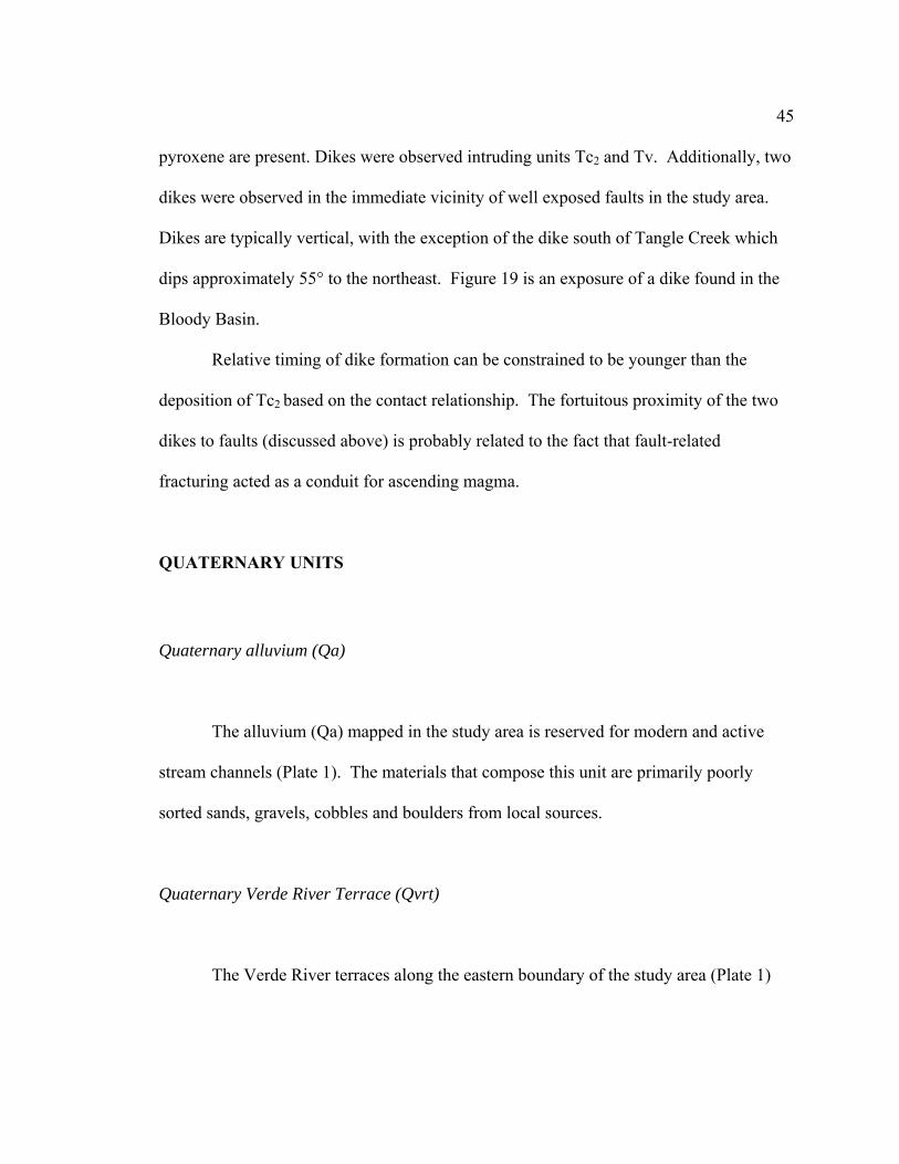
pyroxene are present. Dikes were observed intruding units Tc2 and Tv. Additionally, two
dikes were observed in the immediate vicinity of well exposed faults in the study area.
Dikes are typically vertical, with the exception of the dike south of Tangle Creek which
dips approximately 55° to the northeast. Figure 19 is an exposure of a dike found in the
Bloody Basin.
Relative timing of dike formation can be constrained to be younger than the
deposition of Tc2 based on the contact relationship. The fortuitous proximity of the two
dikes to faults (discussed above) is probably related to the fact that fault-related
fracturing acted as a conduit for ascending magma.
QUATERNARY UNITS
Quaternary alluvium (Qa)
The alluvium (Qa) mapped in the study area is reserved for modern and active
stream channels (Plate 1). The materials that compose this unit are primarily poorly
sorted sands, gravels, cobbles and boulders from local sources.
Quaternary Verde River Terrace (Qvrt)
The Verde River terraces along the eastern boundary of the study area (Plate 1)

46
Figure 19. Photograph of northwestern exposure of dike south of Tangle Creek. Dike is approximately 4 m wide and dipping approximately 55° to the northeast. Picture looking 330°.

47
were mapped in a reconnaissance fashion. Terrace deposits have a range in clast size
from silt and sand to gravel and cobble. Although terraces along the Verde River
corridor can be mapped based on relative age, there was no attempt to do so for this
study. Pearthree (1993) has reported an extensive study on the Verde River corridor
from Sullivan Lake to Horseshoe Reservoir.
Quaternary colluvium (Qc)
Quaternary colluvium (Qc) was mapped in the south-central and west-central
portions of the study area (Plate 1). Colluvium depositionally overlies older basin fill
deposits (Tc) and volcanics (Tv) and is found at the toe of steep gradients. This unit is
composed of poorly sorted detritus ranging from fine-grained sands to large, 25 cm,
angular boulders. Materials composing this unit are locally derived volcanic, granitic,
and metamorphic detritus.
Quaternary terrace (Qt)
A Quaternary terrace (Qt) was mapped in one location along Red Creek, an active
stream channel draining into the Verde River (Plate 1). This unit sits approximately 10 m
above the modern stream and is composed of sub-rounded to sub-angular sands, gravels,
and cobbles of primarily volcanic composition.

PETROGRAPHY OF MAP UNITS
Thirty-two samples were collected for petrographic analysis and prepared for
thin-sections by Quality Thin-Sections of Tucson. The main purpose of this method was
to bolster mineral identification in hand samples as well as to aid in identifying
compositions of aphanitic rocks, which precludes not only accurate mineral identification
but can lead to erroneous interpretation.
Below are a selective group of detailed petrographic descriptions for the
metamorphic and igneous units as well as one sedimentary unit (Tm). Table 1(located at
the end of the section) is a summary of 20 samples, including geologic unit, composition,
and textures present. Table 1 also shows composition in primarily alkaline basalts, with
primary phenocryst composition ranging from olivine-rich to plagioclase-rich in either an
interlocking granular texture or more commonly a trachytic texture. Compositions for
the basalts are all very similar with varying percentages of phenocrysts. Figure 20 is a
map showing sample locations.
The name of the unit is first and the sample number follows. Interpretation
follows description where appropriate.

49
Figure 20. Generalized map showing locations of samples collected for petrographic analysis in the study area.

50
PRECAMBRIAN UNITS
Precambrian chlorite-mica schist (Xcms) (BB22)
The chlorite-mica schist consists of chlorite + muscovite + plagioclase + quartz.
Chlorite makes up 30% of this unit and generally displays a corroded appearance, with
irregular grain boundaries. Chlorite is observed with a distinctive green to pale green
color in plain light and displays an undulatory extinction in polarized light. Oxide
alteration on rims of phenocrysts and occasionally chlorite cores are replaced by the fine-
grain mica, sericite. Muscovite composes up to 30% and generally has a corroded
appearance, with local grains being subhedral to anhedral. Alteration to secondary
sericite is not uncommon. Plagioclase is observed as less than 10% of composition and is
generally corroded and fractured, with fractures filled with fine-grain sericite.
Plagioclase, where present, can be identified by distinctive albite twinning. Quartz
comprises roughly 30% of this unit and is observed as subhedral to corroded grains.
Quartz grains display an undulatory extinction and locally contain opaque inclusions.
Grain boundaries are generally curvy linear, and a weak suturing may be observed. The
foliation of this unit is defined by the compositional layering of chlorite + muscovite +
sericite and quartz. Local chlorite porphyroblasts have formed oblique to the main
foliation. Figure 21 is a photomicrograph of this unit.
Based on the presence of chlorite + muscovite + plagioclase + quartz, this unit is
interpreted to have been derived from argillaceous sandstone that underwent moderate

51
Figure 21. Photomicrograph of Precambrian chlorite-muscovite schist (Xcms) showing moderate foliation development. Note chlorite (chl) + mica and quartz (Qtz) defines this foliation. Also note, oblique growth of chlorite porphyroblast (ob. chl). Crossed-polars, long dimension of photomicrograph is 5.5 mm. Sample BB22.

52
greenschist facies metamorphism (Yardley, 1998). The presence of the oblique mineral
growth of chlorite is probably the result of alteration of another mineral, such as biotite,
having recrystallized subsequent to primary metamorphism.
Precambrian granite (Xg) (BB28)
The Precambrian granite is coarse grained and composed of potassium feldspar
(microcline), quartz, plagioclase and a trace of biotite. Microcline composes 60% of this
rock, is generally euhedral to subhedral and can be readily identified by a characteristic
perthitic texture. Microcline grains commonly have a sieved appearance and may show
some alteration to sericite. Grain boundaries are generally linear and display an
interlocking texture. Plagioclase is readily identified by albite twinning and phenocrysts
are generally euhedral or show a weak corrosion along grain boundaries. Quartz is
generally corroded to subhedral, but interlocking, and typically possesses an undulatory
extinction and sutured grain boundaries. In general, this unit is highly fractured with
fractures typically filled with opaques. Figure 22 is a photomicrograph of granite from
the study area.

53
Figure 22. Photomicrograph of Precambrian granite (Xg). K-spar (microcline) showing perthitic texture, plagioclase (Plag) identified by albite twinning, and quartz (Qtz). Crossed-polars, long dimension of photomicrograph is 5.5 mm. Sample BB28.

54
TERTIARY UNITS
Tertiary volcanics (Tv) (BB:12,14,18,21,26,30,35,38,40)
The volcanic rocks sampled from the Bloody Basin have an overall porphyritic
texture with percentage of phenocrysts ranging from 5 to 60%. Samples are massive to
highly vesicular, with vesicles locally filled with calcite. Phenocrysts are primarily
olivine + plagioclase + clinopyroxene, with minor amounts of orthopyroxene. In general,
composition of these rooks falls into an alkali basalt category.
Olivine is the most abundant mineral and can be up to 100% phenocryst content.
Olivine is little to highly altered from rim alteration to fracture fill, to complete
replacement of primary olivine by iddingsite. These phenocrysts are generally euhedral
to subhedral. Plagioclase is also abundant and where olivine is in trace amounts
plagioclase is the dominant species. Plagioclase phenocrysts are generally unaltered, and
euhedral to subhedral, although local sericite replacement is observed in sieved
phenocrysts. Plagioclase phenocrysts generally show twinning under Albite or Carlsbad
twin laws. Plagioclase may also display local oscillatory zoning. Plagioclase content
was determined to be between An30-40 using the Michel-Levy Method for plagioclase
content (e.g. p. 272, Nesse, 1991). This plagioclase composition is consistent with
McKee and Anderson (1971) were samples of Hickey basalt where determined to be
composed primarily of labradorite by means of refractive indices. Pyroxene is generally
euhedral to subhedral and is typically not as abundant as olivine and plagioclase, except

55
for BB12 and BB26, where pyroxene is between 60 and 90% of the phenocryst content
(Table 1). Phenocrysts are locally concentrically zoned and may have a poikolitic
appearance with inclusions of plagioclase or opaque minerals. Locally phenocrysts may
also display exsolution lamellae.
Groundmass in these basalts typically includes plagioclase, olivine, pyroxene, and
opaque minerals. At least one sample (BB21) has a microcrystalline groundmass. The
texture of most samples is either an interlocking aggregate or highly to moderately
trachytic (Figure 23), displaying primarily subparallel plagioclase laths, deflecting around
and wrapping phenocrysts.
In general, composition of volcanics from the Bloody Basin is relatively similar
and can be defined as alkaline to sub-alkaline (see Table 1). The dominant composition
of phenocrysts from sample to sample varies somewhat, but is not enough to suggest
individual and unique eruptive events. Groundmass textures do vary from trachytic to
interlocking aggregate, but further sampling would be needed to show any consistency.
Additionally, Leighty (1997) defined a middle-Miocene biotite-bearing alkaline basalt in
the lower Red Creek area. BB12 was taken from the lower Red Creek and biotite is not
observed in this sample. Sampling may be from different flows in the same area or
because of the limited amount of biotite, it may just be that biotite was not in BB12.
Also, McKee and Anderson (1971) conducted chemical analyses on samples taken from
the Hickey basalt and found composition of volcanics to range from tholeiitic to alkalic
basalt, as well as basanite. These basalt fields are consistent with compositions observed
in the Bloody Basin.

56
Figure 23. Photomicrographs of two representative samples of Tertiary volcanics (Tv) in the Bloody Basin. A) interlocking aggregate of pyroxene (opx) showing Carlsbad twinning, plagioclase (plag) with distinctive albite twinning, olivine (ol) partially altered to iddingsite. Black holes are vesicles. Crossed polars, Sample BB18 and B) common trachytic texture in the Bloody Basin volcanics with subparallel microlites deflecting around olivine (ol) highly altered to iddingsite. Crossed polars, Sample BB35. Both photomicrographs have a long dimension of 2.8 mm.

57
Tertiary tuff (Tt) (BB34)
BB34 is composed of approximately 40% fragmental phenocrysts in a dense, dark
brown to black microcrystalline groundmass. Microscopically visible minerals are
plagioclase, hornblende, and biotite. All plagioclase observed is either broken or
fragmented and varies in size from 0.5 to 1 mm. Fragments display characteristic albite
twinning and oscillatory zoning. Hornblende is observed as euhedral to fragmented and
locally displays oxidized rims. Biotite is euhedral to fragmented and may contain opaque
or plagioclase inclusions. Figure 24 is a photomicrograph of this unit.
The presence of primarily fragmented phenocrysts in a matrix of dense glass,
accompanied by euhedral hornblende and biotite, is consistent with a volcanic tuff that
underwent post-deposition mineral growth of euhedral hornblende and biotite.
Tertiary mudrock (Tm) (BBMR)
In hand sample this unit appears to be a fine-grained mudstone/siltstone; however
in thin-section Tm is composed of poorly to moderately sorted regions composed of 60-
70% sub-angular to sub-rounded silty detritus sharply separated from regions consisting
of considerably less abundant silts (20-25%) but with similar angularity. Silt in both

58
Figure 24. Photomicrograph of Tertiary tuff (Tt) illustrating highly fractured and fragmented nature of this rock. Euhedral to subhedral hornblende (hb) is not uncommon, plagioclase (plag) and quartz (qtz), however, are commonly fractured. Crossed polars, long dimension of photomicrograph is 5.5 mm. Sample BB34.

59
cases is roughly equal amounts of quartz, plagioclase, and clinopyroxene, with minor
amounts of calcite. Also, in both cases, silt is in a black to dark brown volcanic glass.
Figure 25 is a photomicrograph of Tm.
Confident interpretation as to the origin of this unit still remains ambiguous.
However, one hypothesis that may explain the observation in terms of two separate and
starkly contrasting silt percentages is reworked tuffaceous material. Rock fragments
within this tuff may have been composed of high and low volumes of phenocrysts,
allowing for the fortuitous deposition as now seen in thin-section.
Tertiary dikes (BB:2,3,4)
Three of the seven dikes observed in the Bloody Basin were sampled for thin-
sections. These dikes all have a similar composition to each other as well as being
consistent with overall composition of the volcanics in the study area. Dikes typically
have an overall porphyritic texture with 15-20% phenocryst content in a trachytic
groundmass. Phenocryst composition generally consists of olivine ± plagioclase +
clinopyroxene. Olivine is euhedral to subhedral and locally altered to iddingsite.
Plagioclase is euhedral to subhedral and commonly displays oscillatory zoning.
Plagioclase may be fractured and altered to sericite and also may contain opaque
inclusions. Clinopyroxene is less abundant, is typically euhedral to subhedral, and
locally displays twinning. The groundmass typically includes plagioclase, olivine,

60
Figure 25. Photomicrograph of Tertiary mudrock (Tm) illustrating zones of dominantly clastic fragments sharply separated by anastamosing boundaries from fine-grained microcrystalline areas. Bright ubiquitous objects are quartz fragments. Crossed polars, long dimension of photomicrograph is 5.5 mm. Sample BBMR.

61
clinopyroxene, and opaques. The groundmass minerals are typically subparallel and
deflect around the larger phenocrysts. Figure 26 is a photomicrograph of a dike south of
Tangle Creek.
Leighty (1997) discusses dikes of similar composition and texture that he sampled
in the Bloody Basin. Although locations of Leighty’s (1997) samples are unknown,
descriptions are consistent with the present study.
Tertiary dome (Td) (BB24)
The composition of Td consists of clinopyroxene, hornblende, and opaques, with
a trace of quartz, in a dense and strongly aligned trachytic groundmass consisting of
dense sanidine laths. Grains that comprise this rock are chiefly equigranular. Cpx is
subhedral and lathlike. Hornblende is euhedral to subhedral. Opaque minerals are
generally euhedral. Quartz phenocrysts are not common but when observed are
subhedral to anhedral. Figure 27 is a photomicrograph of a sample from the dome.
The composition and strong trachytic texture are consistent with a hornblende-
bearing rhyolite. Aside from the tuff discussed above, this is the only unit that contains
hornblende.

62
Figure 26. Photomicrograph of representative dike in the Bloody Basin. Olivine (ol) is primarily fresh with rimmed alteration. Pyroxene (cpx) is partially corroded and shows concentric zoning. Note moderate trachytic texture shown by orientation of subparallel microlites. Crossed polars, long dimension of photomicrograph is 5.5 mm. Sample BBD4.

63
Figure 27. Photomicrograph of Tertiary dome (Td) from the Bloody Basin. Microcrystalline sanidine displays trachytic texture. Hornblende (hb) and pyroxene (cpx) are commonly euhedral. Cross polars, long dimension of photomicrograph is 2.8 mm. Sample BB24.

64
Sample Unit Phenocryst %
Phenocryst composition w/ relative abundance
(%)
Groundmass Texture Rock Name
BB12 Tv 60 cpx (60) + ol (40) + plag (10)
Feld + cpx + ol + op
interlocking Olivine Basalt
BB14 Tv 35 ol (100) Feld (70) + ol (15) + op (15)
interlocking Basanite
BB17 Qd n/a n/a n/a n/a Quartz dike
BB18 Tv 30 Plag (60) +ol (15) + cpx (15)
cpx (60) + plag (30) + op (10)
interlocking Andesite
BB21 Tv 5 Plag (80) + ol (20)
glass none Andesite
BB22 Xcms Chl + musc + plag + qtz
foliation Chlorite Schist
BB24 Tp2 < 1 n/a k-spar (85) + hb (15)
trachytic Alkali Trachyte
BB26 Tv 10 Cpx (90) + qtz (10)
Feld (60) + glass (30) + op (10)
trachytic Quartz Tholeitte
BB28 Xg n/a k-spar (60) + qtz (40) + bio (<1)
n/a coarse Granite
BB30 Tv 50 Plag (90) + ol(10)
Plag (80)+ ol (10) + op (10)
trachytic Andesite
BB34 Tt 35 Plag (70)+hb(20) + bio(10)
glass fragmented Crystal Tuff
BB35 Tv 15 Ol (70) + opx(20) + plag(10) +
Plag (80) + op (20)
trachytic Olivine Basalt
BB36 Tv n/a n/a n/a welded Tuff BB38 Tv 30 Ol(60) + plag(40) Plag(60) +
ol(30) + op(10) trachytic Olivine
basalt BB39 Tv 25 Ol(80) + plag(20) Plag(60) +
op(30) + ol(10) interlocking Olivine
Basalt BB40 Tv 10 Ol(95) + qtz(<5) Plag(60) +
ol(20) + op(20) Quartz
Tholeiite BB41 Tp1 50 Plag(70) + hb(30) dense Weak
trachytic Andesite
Plug BBD2/3 Dike 20 Ol(90) + cpx(10) Plag (90)+
ol(10) trachytic Olivine
Basalt BBD4 Dike 15 Ol(70) + plag(20)
+ cpx(10) Plag(50) + op(30) + ol(20)
trachytic Olivine Basalt
BBMR Tm n/a Qtz+plag+cpx+ca glass Poorly sorted
Mudstone
Table 1. Summary table of petrographic analysis for rock units in the Bloody Basin. Igneous rock name is based on modal mineralogy after the classification scheme of the IUGS Subcommission on the Systematics of Igneous Rocks.

STRUCTURE
Precambrian foliation development along with mesoscopic folding and major
Tertiary fault block rotation with accompanying dike and dome emplacement
characterize the major structural features of the Bloody Basin study area. Two Tertiary
fault sets are identified in the study area with orthogonal orientation to one another. One
set is related to northwest-southeast directed extension and the other is thought related to
northeast-southwest directed extension with subsequent dike emplacement. In addition to
the dominant Tertiary normal fault sets and dikes, minor strike slip-faulting with
genetically related reverse movement has occurred in the Bloody Basin. This section
provides details regarding these structures based on field observations and discusses
timing where appropriate. Figure 28 is a general map of the structures and most locations
discussed herein.
PRECAMBRIAN STRUCTURES
The chlorite-muscovite schist (Xcms) has a highly corroded and weathered
appearance and because of this characteristic, structures are difficult to decipher. A
foliation, when present, is moderately to steeply dipping, and varies in strike from
northwest to northeast, which are attitudes similar to other Precambrian terranes in
Arizona (Rehrig et el., 1980). Mesoscopic folding is observed in well exposed road cuts

66
Figure 28. Generalized map showing locations and structures discussed in this section. Normal faults are indicated by ball and stick on down-thrown side. Dashed and dotted line indicates inferred fault (see text for details). RF = Reverse fault (teeth on up-thrown side); SSS = Strike-slip segment; FS = Frog Springs. For further map details see Plate 1.

67
along the Bloody Basin Road. Also observed are abundant northeast-striking, less than
1 m wide, weakly foliated quartz veins that are reduced mainly to piles of rubble.
The Precambrian granite (Xg) that has been correlated with the Verde River
batholith (1700 Ma) contains randomly oriented dikes and sills of similar composition
along with irregular fracture patterns. In addition to these features, in the extreme
northeast corner of the study area, a previously mapped (Canney et al., 1967 and Wrucke
and Conway, 1987) quartz vein described as a saddle reef deposit by Canney et al. (1967)
was confirmed by field reconnaissance. This linear feature is approximately 2-3 m wide
northeast-southwest-striking and exposed for nearly 5 km. It is noted that this body is not
found beyond the cross-cutting Verde fault. In general, this coarse-grained granite does
not display any structural grain such as the previously mentioned foliation, indicating a
deformational event older than the intrusion.
TERTIARY STRUCTURES
Evolution of Tertiary structures identified in the Bloody Basin area involved
faulting, emplacement of basaltic dikes, and the emplacement of a hornblende-bearing
rhyolite dome. As previously discussed, two distinct fault set orientations are recognized
and are possibly unrelated, resulting from extensional events directed roughly orthogonal
to each other. Northeast-striking faults are characterized by a series of tilted and
moderately dissected fault blocks that display a synthetic normal fault block array
indicating northwest-southeast directed extension. Block rotation related to this faulting

68
is responsible for moderately (10°-30°) northwest dipping strata that dominate the
study area.
The second set of faults is oriented northwest-southeast, and is characterized by a
series of moderate- to high-angle normal faults that show both northeast-and southwest-
side-down motions indicating northeast-southwest extension. Local block rotation is
responsible for gentle to moderate (10°-30°) southwesterly dipping strata. A
southeasterly segment of the roughly 95 km trace of the northwest-striking Verde fault is
associated with this second event and is within the extreme northeastern portion of the
study area. In addition to the northwest-striking faults, a suite of dilatational dikes is
associated with this second deformation event.
Northeast-Trending Faults
The northeast-trending faults occur southeast of the southeast escarpment of the
Pine Mountains Wilderness area (Plate 1; Figure 28). Strata are displaced down to the
southeast along nearly parallel southeast dipping faults. Dip parallel separation along
these faults, as measured in cross-section, varies from 730 to 1,200 m.
From northwest to southeast, the primary “breakaway” fault (Pine Mountain fault)
(Figure 28) is traced along the southeast escarpment of the Pine Mountain Wilderness
area (Plate 1). This fault has a roughly linear trace from the Mustang Hills, northeast to
Skeleton Ridge (Plate 1), where it is intersected and truncated by the through going
Verde fault. Because a large portion of this fault is concealed by Tertiary sediment (Tgc)

69
direct measurement of the attitude along this segment is difficult. However, the linear
trace suggests a vertical to very steep dip (Figure 29A). South of the Mustang Hills, the
trace of this fault abruptly changes to a nearly north-south strike (Plate 1). Dip along this
section also appears nearly vertical based on the linear trace. Near Mud Springs Creek
(Plate 1) the fault jogs to the southeast for a short distance before abruptly turning back to
the south- southwest direction. The dip along this section changes from vertical to a
moderate 055° to the southeast (Figure 29B). The fault appears to follow the attitude of
the foliation of the metamorphic unit (Xcms) along this segment. This segment continues
southwest to Cottonwood Springs where it is truncated by another northwest-striking
fault (Figure 30). The trace of this fault is not observed southwest of the cross-cutting
structure; however Brand (2005) mapped a similar striking fault in the Rover Peak
quadrangle that would project to the north, suggesting a relationship between the two.
The primary faulting places younger Tertiary volcanics (Tv) against Precambrian
granite (Xg). Block rotation responsible for dipping strata is evident in some locals (see
Unit Description; Figure 13) which may indicate the fault flattens at depth.
Other details revealed by well exposed outcrops demonstrate dilatational and non-
dilatational components of this fault. Figure 31 is an outcrop of the fault at the Marble
Mine (Plate 1). A strong chaotic breccia, composed of angular volcanic clasts is within a
tear drop shaped body (in map view) of primarily calcite/marble that is approximately
100 m wide and tapers southwest to thin (< 1 m) veins in approximately 2 km. This
segment of the fault is interpreted to have a large dilatational component resulting in the
formation of this marbleized body. Figure 29B, demonstrates a largely non-dilatational

70
Figure 29. Field photographs showing dip variability along the Pine Mountain fault. A) vertical trace of Pine Mountain fault looking northeast from Marble Mine (white rock in foreground) and B) trace of Pine Mountain fault dipping 055° to the east. Foliation within Xcms dips roughly 060° to the east. Picture looking north. See Unit Description section for details on symbols used.

71
Figure 30. Photograph showing the intersection of northeast-trending fault by a northwest-striking fault. The northeast-striking is demonstrated by the dashed white line and the northwest fault is coming out of the picture. Picture looking 270°.
Figure 31. Photograph of volcanic breccia within a marblized body along the Pine Mountain fault at Marble Mine. Pen for scale. Picture looking 180°.

72
component, resulting in roughly 20 m of hanging wall brecciation. This sharp contact
between the two units suggests lack of dilation at least in this setting. Additionally, a 5 m
wide swath of gouge is present where the Tc2 and Xcms are in fault contact (Plate 1).
The difference in these characteristics shows the heterogeneity and probably differential
movement along the fault as well as response to faulting of different lithologic bodies.
Studies on this fault have been documented by past workers. Canney et al. (1967)
suggest that vertical displacement along this portion of the fault occurred along one large
break. They go on to suggest that displacement along this fault to be at least 300 m based
on topographic position of the Tertiary volcanics. If the same approach is taken in the
Bloody Basin, similar displacement amounts, however actual displacement along this
fault is probably much more than 300 m (Canney et al., 1967).
Elston (1984) and Canney et al. (1967) show the Pine Mountain fault as a zone
and discuss a pair of faults along the Pine Mountain Wilderness margin. Elston (1984)
shows a fault north of this study with strike-slip motion in undivided Precambrian rocks
seemingly interpreted from a Skylab photograph of central Arizona. Canney et al. (1967)
describe a similar fault with unknown sense of slip. Field reconnaissance southeast of
Rugged Mesa (Plate 1) reveals a quite different interpretation from the Canney et al.
(1967) map, which shows a fault separating two bodies of granite. The contact here is an
unconformity with the unit Toc (see Unit Descriptions section) depositionally overlying
Precambrian granite, and not fault related as they suggest.
Continuing to the east, toward the Verde River, a relatively short, but well
exposed trace of a northeast-striking fault (Figure 32A) is observed in the North Red

73
Figure 32. Well exposed North Red Creek fault in the east-central portion of the study area. A) excellent exposure of North Red Creek fault showing roughly 15 m tall fault scarp. Picture looking 025°, approximately along strike, and B) oblique striations along same fault further to the south near Dugan Rock Tank. Striations are oriented 45°→80°. Picture looking 290°
74
Creek area (Plate 1). Measurements along this fault show a consistent northeast strike
and dip to the southeast between 55°-60°. Lineations observed on the southern segment
of this fault (Figure 32B), near Dugan Rock Tank, record left-lateral, oblique-slip motion.
This fault appears to die out in the northeast and is truncated to the southwest by a
northwest-striking fault near Frog Springs (Plate 1).
Previous work by Wrucke and Conway (1987) show the trace of this fault is
inferred to continue beyond the intersection at Frog Springs. Detailed mapping of the
area shows Quaternary cover south of Frog Springs to beyond the map area, which would
conceal any trace likely to be found. Although likely that this fault continues to the
southwest, it may also end at this location. The fault shown in Plate 1and Figure 28 is
therefore not traced beyond Frog Springs.
Continuing to the east, the third fault in this array roughly parallels the Verde
River corridor (Plate 1) and is the western margin of a graben situated along the Verde
River (see Wrucke and Conway, 1987). Available measurements along this fault show a
consistent 45° dip to the southeast. Tertiary volcanics (Tv) and sediments (Tc1) dip
moderately (15°-30°) west-northwest into Precambrian granite (Xg). The dipping strata
along this fault appear to become less steep to the northeast. Near the Landing Strip
(Plate 1), dipping strata measure 25°-30° to the west-southwest and west-northwest, and
on the western margin of Pete’s Cabin Mesa to the northeast, dipping strata measure
approximately 15°. This may reflect a change in fault geometry at depth. To the south,
this fault is likely intersected by a northwest-striking fault concealed by Quaternary cover
and to the northeast it probably intersects with the northwest-striking Verde fault as

75
suggested by Wrucke and Conway (1987) although the trace of the fault is difficult to
decipher in this area.
A brief note on the inference of a fourth normal fault within this set (Figure 28).
Under the Tertiary sedimentary cover in the central portion of the basin, there is believed
to exist a fault that is similar in nature to those described above. The basis for this
inference is shown well in cross-section (A-A’; Plate 1). The projection to the subsurface
of the contact between Tv and Xg at the North Red Creek location, results in an
unreasonable thickness of the Tertiary volcanics. With the inferred fault, a more
reasonable approximation of the subsurface geometries is achieved. It is realized that
only geometrical constraints in cross-section support this inference and that surface data
for this fault is absent. However, it is not uncommon to have basin bounding faults
covered by erosional processes as is a characteristic of the Basin and Range physiography
(Shafiqullah et al., 1980).
Finally, Figure 33 is a stereogram of all measurements obtained along well
exposed fault traces. The stereogram shows a cluster of poles to fault planes in the
northwest, demonstrating the overall northeast-striking and steeply dipping attitude of
this fault set. Also shown is the average strike and dip of the faults measured: 033° and
57° SE.

76
Figure 33. Lower Hemisphere, equal area projection of fault data related to northeast-striking faults. Data shows a cluster of poles to planes in the northwest, indicating northeast-striking faults. Great circle represents average orientation of all northeast data: 033°; 57° SE.

77
Amount of Northwest-Southeast Extension
Extension in the northwest-southeast direction was calculated to be 15% after the
methods of Twiss and Moores (1992). This is in contrast to amount of extension by
Brand (2005) which he estimated to be 8.5 - 10% of the for the Rover Peak area.
However, this amount is within the estimates of extension for the Basin and Range
province of 5 – 15% (see Thompson and Burke, 1974). Zoback et al., (1981) also suggest
up to 23% extension in parts of the Basin and Range in north-central Nevada. The
amount of extension calculated above may be an overestimate because of unknown
geometries of faults at depth. If the faults at depth are made of multiple minor faults,
than the estimate would be too high. Conversely, because the amount of total erosion is
not known, and the Tc1 marker horizon in one of the tilted blocks was removed, the
estimate would be a minimum (Morley, 1996). This estimate is also based on the
assumption of dip parallel movement along planar faults. The presence of lineations on a
portion of the North Red Creek fault suggests some oblique movement has occurred.
Timing of Northwest-Southeast Extension
Brand (2005) obtained an 40Ar-39Ar date from tilted Hickey basalt in the Rover
Peak area of 13.5 Ma and a younger age of flat-lying basalts at 6.4 Ma. With correlation
of the volcanics to the north in the Bloody Basing, this loosely constrains the timing of

78
faulting in this area to between 13.5 and 6.4 Ma (see timing of northeast-southwest
extension for additional constraints).
Northwest-Trending Faults
The northwest-trending faults in the study area are a series of normal faults with
down to the northeast and down to the southwest movement. Displacement along these
faults is variable, and may be as little as 10’s of meters (see B – B’; Plate 1) to as much as
and probably more than 600 m on the Verde fault (Wrucke and Conway, 1987).
Beginning in the south of the study area, a high angle normal fault exists with
down to the northeast motion. From the furthest southeastern position along the fault,
heading northwest to Forest Service Road 24 (Plate 1) this fault has a consistent strike to
the northwest and maintains a northeasterly dip of 55°-65°. A jog to the west in the fault
trace occurs northwest of Forest Service Road 24, for a short distance before continuing
strike to the northwest. This jog may be the result of a minor cross-cutting fault that
displaces the trace of this fault to the southwest (Figure 34) along Forest Service Road
24. Tertiary volcanics and sediment northeast of this fault dip moderately (20°-30°) into
the fault and appear to level off with closer proximity (Plate 1). The northwestern trace
of this fault appears to terminate in the Hummingbird Spring area where it cuts across the
main Pine Mountain fault (Plate 1). To the southeast this fault connects with a previously
mapped fault by Brand (2005) where it maintains consistent strike before turning south
near the Verde River.

79
Figure 34. Photograph of northwest-striking fault being displaced by a minor northeast-striking fault along Forest Service Road 24. Displacement is less than 20 m as measured along strike of the cross-cutting fault. Lineations on cross-cutting fault of 35°→250° are consistent with relative motion shown here. Photograph is looking 320°.

80
Continuing to the north, another well exposed fault exists northeast of Tangle
Creek (Plate 1; Figure 28) and appears to form the conjugate pair of the previously
mentioned fault. Measurements along this fault reveal a northwest-southeast strike and
dip to the southwest of 65°. Tertiary strata dip moderately away from the fault up to 30°,
to the southwest. The trace of this fault becomes concealed to the northwest and southeast
under Tertiary and Quaternary sediments (Plate 1). Figure 35 is a cross-section through
the two previously discussed faults to demonstrate the geometry of the area.
Further to the northeast, a well exposed fault along Red Creek (Plate 1; Figure 28)
also displays southwest-side-down motion. Direct measurement on this structure show a
northwest-southeast strike, with a steep dip to the southwest at 68°. Striations observed
on the polished Precambrian granite footwall (Figure 36) record nearly pure dip-slip
motion. The trace of this fault probably continues northwest, beyond where it is currently
mapped, based on the outcrop expression of the Precambrian granite to the northwest
(Plate 1). However, fault recognition in these volcanics is often difficult precluding the
ability to trace the faults extensively.
Wrucke and Conway (1987) show a trace of this fault continuing southeast across
the Verde River with opposite side down motion. The reason for this is unclear, although
it may have to do with some type of transfer boundary concealed under Quaternary
sediment along the Verde River corridor.

81

82
Figure 36. Mineral lineations on the Red Creek fault recording nearly dip-slip movement. Lineations are oriented 68→220°. Photograph looking 042°. Pencil for scale.

83
Verde Fault
In the far northeastern corner of the study area is a well exposed trace of the
Verde fault readily identified (Figure 37) by a 10-15 m wide zone of gouge or the
obvious juxtaposition of Tertiary volcanics on Precambrian granite . The well-known
(Canney et al., 1967) Verde fault is a northwest-trending normal fault that is the eastern
boundary of the uplifted Black Hills (Ransome, 1925; Anderson and Creasy, 1958) (Pine
Mountain is the southern margin of the Black Hills). The Verde Valley to the east is the
topographic expression of the down dropped block, which as Ransome (1925) and Elston
(1984) describe is a Basin and Range structure that is located well within the Transition
Zone. The Verde fault has been traced from near Bakers Pass north of Jerome (Anderson
and Creasy, 1958) to the Mazatzal Wilderness area where it intersects the Deadman fault
(Wrucke and Conway, 1987), a length of approximately 95 km. The Verde fault zone
consist of up to 13 strands near the town of Jerome with primarily normal sense motion
that have been down dropped progressively to the east. This zone eventually turns to a
single strand 6.5 km south of 34° 15’ in the Black Hills (Anderson and Creasy, 1958).
Movement along the Verde fault has a protracted history, with vertical separation of up to
300 m during the Precambrian and 450 m of displacement occurring following the
deposition of the Hickey basalt (Anderson and Creasy, 1958). In the Mazatzal
Wilderness, Wrucke and Conway (1987) estimate about 600 m of displacement had
occurred.

84
Figure 37. Photographs showing exposures of Verde fault along the northeastern boundary of the study area. A) down to the northwest volcanics (Tv) against granite (Xg) footwall. Photo looking 330° (approximately along strike). Note cows for scale., and B) detail of Verde fault south of Squaw Butte (Plate 1). Gouge zone approximately 10 m wide in this area. Fault orientation is N 290° W; 55° NE. Pen for scale. Photo looking 290°.

85
Dip along the Verde fault varies from 50°-70° to the northeast near Jerome to
less than 45° northeast near Black Canyon. In the study area, the structure was measured
as 45°-55° dipping to the northeast, with measurable strata dipping gently away from the
fault approximately 15° to the northeast. Southeast of Squaw Butte, along the Verde
River in the extreme northeast portion of the study area, the Verde fault cuts moderately
tilted (55° N-NE) Precambrian bedding (Wrucke and Conway, 1987) (Figure 38).
The intersection of the Pine Mountain fault and the Verde fault (Plate 1) lacks
strong evidence to trace the Pine Mountain fault beyond the Verde fault; however, a
planar structural fabric exists within the volcanics on the north side of the Verde fault
oriented roughly orthogonal to it. This fabric is sub-vertical, consistent with the
northeast-trending fault. This feature could represent a trace of the northeast-striking
Pine Mountain fault. However, the lack of abundant evidence to trace the Pine Mountain
fault to the northeast across the Verde fault demonstrates the cross-cutting relationship of
the Verde fault on the Pine Mountain fault.
Finally, Figure 39 is a stereogram of all measurements obtained along well
exposed fault traces of northwest-trending structures. The stereogram shows a cluster of
poles to fault planes in the southwest, demonstrating the overall northwest-striking and
steeply dipping attitude of this fault set. Also shown is the average strike and dip of the
faults measured: 302° and 60° NE.

86
Figure 38. Steeply dipping Precambrian strata oriented 290°, 55° NE. Trace of Verde fault in to the left of photograph where Tertiary volcanics are observed. Author for scale. Photo looking 090°.

87
Figure 39. Lower Hemisphere, equal area projection of fault data related to northwest-striking faults. Data shows a cluster of poles to planes in the southwest, indicating northwest-striking faults. Great circle represents average orientation of all northwest data: 302°; 60° NW.

88
Amount of Northeast-Southwest Extension
The amount of extension for this direction was not calculated because the estimate
would have required the assumption of largely unknown variables. There is a very
lengthy span across the Tertiary volcanics in the central portion of the study (Plate 1) area
where it would have to be assumed that this is a coherent block. The reality is that the
volcanics had been rotated by previous extension making it improbable that this block
remained coherent.
Timing of Northeast-Southwest Extension
Timing of extension in this direction can be inferred based on the age of the
Verde Formation which followed a major increment of block-faulting along the Verde
fault in the Verde Valley (Bressler and Butler, 1978; Elston, 1984). It must also be
assumed that by virtue of orientation all northwest-striking structures are related. So, if
initial deposition of the Verde Formation occurred around 8 Ma (Bressler and Butler,
1977) a structural basin is suggested to already be in place to receive incoming detritus,
constraining the initial movement on the fault; however deposition and faulting may have
occurred simultaneously (Anderson and Creasy, 1958). This indicates that movement
along the Verde fault may have started prior to 8 Ma in the Verde Valley, with
continuation through to the Quaternary (Menges and Pearthree, 1983). It is not known
whether movement along this fault in the Verde Valley was occurring at the same time as

89
the southern reaches, i.e., Pine Mountain area, however the amount of displacement
that has occurred in this area and the fact that displacement along the Verde fault
increases to the south from Jerome (p.81 Anderson and Creasy, 1958) suggests that the
timing of initial movement can be extrapolated to the south. Elston (1984) also suggested
initial movement along the Verde fault began around 8 Ma.
Reverse and Strike-Slip Faulting
Two northeast-striking reverse faults are well exposed west of the Mustang Hills
(Plate 1; Figure 28). These faults are parallel to one another, but largely different in
angle of dip. The southern fault is a high angle structure that dips approximately 70° to
the southeast. The northern fault dips moderately (45°) to the southeast. Vertical
displacement on these faults is largely unknown, however based on the faulted units and
outcrop exposure of Tertiary volcanics and Tertiary sedimentary rocks, displacement is
thought to be minor compared to the adjacent high angle normal fault, (See cross-sections
in Plate 1) i.e., if reverse faults had significant vertical movement, they would have likely
exposed underlying basement rock.
A well exposed strike-slip fault (Figure 40A) is located west of the Mustang Hills.
A sub-vertical, left-lateral strike-slip structure is observed displacing Tertiary strata.
Movement along this fault was recorded by moderately (45°) north-dipping lineations on
the plane of the exposed fault (Figure 40B), demonstrating a strike-slip sense of motion

90
Figure 40. Photographs of strike-slip faulting in the Bloody Basin. A) on-strike exposure of the fault showing Tertiary dome (Td) on the left and Tertiary volcanics (Tv) on the right. Staff is 1.3 m. Photograph looking 140° and B) striations oriented 45°→345° on Td side of fault record oblique slip motion. Photo looking 145°.

91
with a dip-slip component. Total displacement in both the vertical and horizontal
directions on this structure is also largely unknown, however based on outcrop exposure
of the faulted rocks, net displacement could be from 1-2 hundred meters.
The development of the reverse faulting is thought to be the result of movement
along the left-lateral strike slip fault. The bend in the fault would act as a restraining
zone, providing appropriate conditions for the generation of reverse type faulting.
Timing of Reverse and Strike-Slip Faulting
Based on cross-cutting relationships, the timing of these structures succeeds
evolution of the main Pine Mountain fault in the Bloody Basin, < 13.5 Ma. Additional
constraints come from the inferred age of the rhyolite dome (discussed below) which
could be as young as 8 Ma.
Dikes
Eight basaltic dikes were mapped in the study area. Dikes are generally vertical
and range in thickness from 0.25 cm to 4 m and have linear exposure of 0.5 to 1 km.
Dikes intrude Tertiary volcanics and sediments and in at least two instances are
coincident with faults, near Tear Springs and north of Tangle Creek. Figure 41 is a
stereogram of orientations measured for dikes in the study area. The average trend of

92
Figure 41. Lower Hemisphere, equal area projection of dike orientation data. Data shows planes striking northwest-southeast, indicating northwest directed extension. Average orientation of all data: 315°.

93
these dikes is 315°. These dikes are interpreted as Mode І structures, i.e. wholly
dilatational (see Davis and Reynolds, 1996) and assuming they have not been rotated
from original emplacement, the extensions direction required would be in the northeast-
southwest direction. The average strike of the dikes mentioned above, coincides within
15° of the average northwest-striking faults.
Timing of Dike Emplacement
Dike emplacement is constrained by the fact they intrude Tertiary sediments and
by the inference they are related to northeast –southwest extension, coeval with
movement along the Verde fault, at least 8 Ma.
Dome
The Tertiary dome has a core with well developed flow banding, in some portions
highly deformed by folding, grading outward to angular blocks and fragments of the
same composition. Flow bands vary in orientation and can be nearly vertical to
moderately dipping (30°). The steeper bands are generally toward the interior of the
dome. This dome is centered on the through going northeast-striking Pine Mountain
fault. Approximately 6.5 km to the northeast, in the Pine Mountain Wilderness, Canney
et al. (1967), document at least three other such structures describing them as pluglike
masses with similar weathering and composition as the dome observed in the Bloody

94
Basin. Their age assignment for the structures found in the Pine Mountain area, was
Quaternary based on fresh appearance and similar structures found in the Verde Valley
that penetrate the Verde Formation of 8 to 2.5 Ma (Bressler and Butler, 1977). If
correlative, this age would suggest strike-slip faulting in the Bloody Basin would have to
be younger than 8 Ma as this dome is offset by strike-slip faulting.

DISCUSSION
Least Principal Stress Direction
In the southwestern United States observations have been made concerning more
than one orientation of Tertiary aged extensional features such as dikes and normal faults.
These observations have led to studies conducted throughout the Basin and Range
province to try and demonstrate that for example, suites of dikes oriented orthogonal to
one another could be products of a reoriented least principal stress direction (see Rehrig
and Heidrick, 1976). Determination of the least principal stress direction is applicable to
features such as normal faults based on Anderson’s theory of faulting (Anderson, 1951),
where the least principal stress direction is orthogonal to the strike of the fault. This
determination is equally applicable to extensional dikes known as Mode I (Twiss and
Moores, 1992) features that require a local direction of least principal stress
perpendicular to the strike of the planar body (Davis and Reynolds, 1996). Because the
Bloody Basin contains more than one orientation of normal faults and Mode I features, it
follows that there could be a manifestation here of a reoriented least principal stress
direction displayed in late-Tertiary aged structures.
The orientation of the least principal stress direction from mid-Tertiary to present
has been documented based on work conducted in Arizona and the southwest. Rehrig
and Heidrick (1976) conducted a structural analysis of mid-Tertiary dikes, veins and
stocks of Arizona and concluded a late Oligocene to Miocene regional σ3 stress
orientation of ENE ± 20°. Zoback et al. (1981) also concluded this orientation for the

96
southern Basin and Range during mid- Miocene (20-10 Ma), citing trends of dike
swarms, fault slip vectors, stratal tilts. Leighty (1997) discusses multiple least principal
stress orientations for central Arizona: early Miocene (mid-Tertiary orogeny) → NE-SW
directed extension; late-middle Miocene to late Miocene (Basin and Range Disturbance)
→ E-W directed extension; and late Miocene and younger (crustal buoyancy extension)
→ NE-SW directed extension. Currently, and broadly speaking, the least principal stress
direction along the southwestern margin of the Colorado Plateau, i.e., the central
Transition Zone, is directed northwest-southeast (Zoback and Zoback, 1989).
Perpendicular to this direction and within the Colorado Plateau province is a northeast-
southwest directed least principal stress field (Zoback and Zoback, 1989).
Studies that have focused on documenting manifestations of a varying least
principal stress direction, such as the above fault and dike scenarios, have been ascribed
to be the result of: 1) a reorientation of the least principal stress direction (Angelier et al.,
1985) or 2) an interaction between more than one least principal stress direction, such as
that between the Colorado Plateau and the Basin and Range provinces (Arabasz and
Julander, 1986). Angelier et al. (1985) document multiple fault orientations in a study
conducted near Hoover Dam and conclude the observed faults are the result of a
reorientation of the least principal stress direction that occurred during the late Cenozoic.
Conversely, studies conducted in the southeastern Transition Zone (see Aldrich and
Laughlin, 1984) and in the seismically active western Transition Zone (see Arabasz and
Julander, 1986) have concluded that varying orientation of extensional features are the

97
result of an interaction between least principal states of stress between the Colorado
Plateau and the Basin and Range provinces.
In the Bloody Basin, the development of the northeast-trending structures (i.e.
Pine Mountain fault) as well as the north-northeast-trending Verde River graben (Figure
42) (Wrucke and Conway, 1987), suggests extension occurred in a northwest-southeast
direction. If timing of these northeast-trending structures is also considered (< 13.5 Ma),
one would expect that a similar orientation of structures would have developed due the
bulk extension direction in place at this time in the southwest United States, which was
E-W to ESE-WSW directed during the Basin and Range Disturbance (see Spencer and
Reynolds, 1986, 1989). Based on the age of the tilted rocks in the Bloody Basin, timing
of the northeast-trending structures is coeval with the Basin and Range Disturbance, but
the extension direction required to produce these features is not entirely consistent with
the Basin and Range directed extension. To account for this extension direction
discrepancy, influences by preexisting structures (see Fault Orientations with Regional
Considerations Section) may have played a role in the development of these normal faults
precluding a required extension direction orthogonal to the strike of the fault.
If one considers the northwest-trending normal faults (i.e., Verde fault) and dikes
in the Bloody Basin, the extension direction required to produce these features would
presumably be northeast-southwest, nearly perpendicular to that described above. The
northeast-southwest extension direction does not coincide with that of the bulk extension
related to the Basin and Range Disturbance (discussed above). Additionally, because
these features are thought to be distinctly younger (see next section) than the northeast-

98
trending structures, a timing discrepancy precludes their formation during the Basin
and Range Disturbance. If the current direction of least principal stress is considered for
the Colorado Plateau, then it could be asserted that the extension direction responsible for
the Verde fault and other northwest-trending structures (i.e. dikes) in the Bloody Basin
may have been influenced by the least principal stress that currently exists within the
Colorado Plateau. This assertion is supported by the coincidence of the extension
direction required for the development of the northwest-trending normal faults and the
northwest-trending extensional dikes versus that of the current least principal stress of the
Colorado Plateau, i.e., northeast-southwest directed. This is further supported by the fact
that the Verde fault has had Quaternary movement along it (Menges and Pearthree, 1983)
suggesting this least principal stress direction may still be in place.
Unlike studies showing the interaction of the states of stress between the Colorado
Plateau and Basin and Range provinces (Aldrich and Laughlin, 1984) where it is shown
that a zone of transition between the stress fields of both provinces reflects intermediate
directions in terms of structural orientations, the Bloody Basin region may display a very
discrete differentiation between past and present least principal stress directions in the
Transition Zone.

99
Fault orientation with Regional Considerations
Studies conducted adjacent to the Bloody Basin (e.g. Brand, 2005; Wrucke and Conway,
1987; Canney et al., 1967) have resulted in differences of interpretation regarding the
structural features observed, notably the orientation of faults. Wrucke and Conway
(1987) suggest that fault geometries observed in the Mazatzal Wilderness are a result of
contemporaneous formation, citing the fact that cross-cutting relationships are observed
by all fault orientations. Also, the curving of faults from a northerly trend to a more
northwesterly trend is observed, suggesting a continuum rather than a clear truncation or
cross-cutting relationship. They go on to say, however, that north-trending structures are
more commonly offset by the northwest-trending structures. Brand (2005) agreed with
this interpretation using the Lime Creek fault and Horseshoe Dam fault as an example of
a north-trending fault curving to the northwest, which intersects and cross-cuts a
northeast-striking fault, and has resulted in the formation of rhomb-shaped fault blocks.
Brand (2005) agrees with Leighty’s (1997) interpretation that the north and northwest-
trending structures are a result of an extensional continuum, rather than separate tectonic
events. Work in the Bloody Basin shows an obvious trend of a set of faults to the
northeast and a mutually orthogonal northwest -trending set (Plate 1). This relationship is
consistent with the work by Canney et al. (1967) in the Pine Mountain Wilderness area,
where their mapping also shows clear perpendicular sets of faults. They attribute these
geometries to be the result of separate faulting events; however they do not clearly
suggest a chronology of these events. Additionally to the south, Ferguson et al. (1998)

100
describe north-striking faults in the New River Mesa area that they interpret as the
result of late-Miocene east-west extension (Basin and Range Disturbance) (see Leighty,
1997). They also describe a set of northwest-striking faults resulting from northeast-
southwest oriented extension in the New River Mesa area that they suggest may have
resulted from waning movements on the metamorphic core complex system to the south,
block faulting of the Basin and Range Disturbance, or an even younger extensional event.
Figure 42 is a simplified tectonic map of the region, including Pine Mountain Wilderness,
Mazatzal Wilderness, Rover Peak quadrangle, New River Mesa quadrangle, Humboldt
Mountain, and this study. The map demonstrates two orthogonal orientations of faulting
throughout the region.
In the study area, four main criteria to evaluate the chronology of faulting and
ultimately to support evidence for suggesting a reorientation of σ3 or an interaction of
stress fields with a dominant direction prevailing are: 1) cross-cutting relationships at
fault intersections, e.g., the Verde fault and Pine Mountain fault. Not only is the Pine
Mountain fault truncated by the Verde fault, but also the southerly trace of this fault
appears to be truncated by another northwest-striking fault (Plate 1). Additionally, based
on field relations, other northeast-trending faults are truncated by these northwest-
trending structures. The general northeast-southwest-trending Verde River graben
(Wrucke and Conway, 1987) would require extension perpendicular to this overall
direction, i.e., northwest-southeast directed. This structure is truncated by the through-
going Verde fault (Figure 42); 2) orientation of Mode І fractures (dikes) are coincident
with northwest-striking faults and they intrude basin fill thought related to the first

101
Figure 42. Simplified tectonic map showing fault distributions in: Pine Mountain Wilderness, Mazatzal Wilderness, Rover Peak, New River Mesa, Humboldt Mountain, and the present study. A northwest-trending set of faults cross-cuts a northeast-trending set. Note the absence of northeast-trending faults beyond Pine Mountain Wilderness.

102
extensional event. Assuming these dikes are Mode І fractures, a perpendicular
orientation to the local direction of least principal stress is implied (Davis and Reynolds,
1996), i.e. northeast-southwest. Dike orientation and average strike of northwest-
trending faults is within 15° (see Figures 41 and 39; respectively), by virtue of this
similarity they are considered related and both types of structures are a result of
northeast-southwest directed extension; 3) fault orientation data indicate a nearly 90°
difference in dip direction of fault plane sets in the study area. Figure 43 shows
combined fault plane data from the study area, and 4) the presence of the Verde River
graben (Wrucke and Conway, 1987) supports a distinct extension direction from that
responsible for the northwest-striking faults and dikes.
One question that remains unclear is the origin of the northeast-striking faults.
Although evidence for these structures indicates formation in a northwest-southeast
directed extensional regime, this fault orientation is anomalous in a more regional
context. Review of the Arizona State geologic map (Reynolds, 1988) reveals a northeast-
trending swath through this part of the Transition Zone that contains other northeast-
trending faults southwest of the Bloody Basin. Northwest and southeast of this swath,
faults are generally northwest-trending. One explanation for this anomalous fault
orientation could be preexisting Precambrian structures that underlie the piles of
volcanics in this area of the Transition Zone. Elston and Young (1991) report that many
faults in Arizona have experienced episodes of reactivation and that the origin of these
structures derives from Precambrian tectonic episodes. They go on to further say that
these structures may have been reactivated during Neogene faulting. The dominant

103
Figure 43. Stereogram showing orthogonal orientation of fault plane data from the Bloody Basin. Solid circles are poles to planes of northeast-trending structures and open circles are poles to planes of northwest-trending structures. Average fault plane orientation for closed circles is: 033°; 57° SE. Average fault plane orientation for open circles is: 302°; 60° NW. The difference between strike of these two averages is: 91°.

104
structural trends of Proterozoic rocks, as reported by Karlstrom et al. (1987), are north
to northeast. Hendricks and Plescia (1991) report a series of northeast-trending positive
magnetic anomalies across the Colorado Plateau that have been shown to originate in the
Precambrian basement (Hedricks, 1974; Shoemaker et al., 1978; and Sumner, 1985).
These anomalous ridges have also been related to major structural features (Shoemaker et
al., 1978) with origination occurring during Precambrian tectonic episodes and later
reactivated by Laramide and Basin and Range faulting events. Figure 44 is a simplified
map of these northeast-trending lineaments across the Colorado Plateau. Hendricks and
Plescia (1991) project the Holbrook lineament (Figure 44) southwestward across the
Transition Zone, citing coincidence of the lineament with the vertical offset of the Moho
described by Warren (1969). This projection centers on the Bloody Basin (Figure 44)
and its boundaries are coincident with the absence of northeast-striking faults, northwest
of the southeastern margin of Pine Mountain (Canney et al., 1967; Anderson and Creasy,
1958). This northeast orientation also wanes southeast of this projected lineament. It is
reasonable to assert, based on its location and orientation, that the Holbrook lineament
may be responsible for the observed orientations of the northeast-trending structures.
These structures may be the result of reactivated preexisting Precambrian structures and
because an existing weakness does not exist beyond this anomaly, northeast-trending
structures are not observed. Pine Mountain may mark the northern boundary zone of this
lineament.
Lastly, if the geographic position of the Bloody Basin is considered with other
well developed structural basins in the Transition Zone, an elongate northwest-trend of

105
Figure 44. Map showing major northeast-trending positive magnetic anomalies that may be related to major Precambrian features (see text for details). The projection of the Holbrook lineament cuts across the southeast margin of the Pine Mountain Wilderness area, north of which, northeast-trending faults are not observed. Note this orientation of the Holbrook lineament coincides with normal faults in the Bloody Basin and vicinity. PM = Pine Mountain; MWA = Mazatzal Wilderness Area (modified from Hedrick and Plescia, 1991).

106
structures is apparent (Figure 45). In terms of aerial extent however, the Bloody
Basin is comparatively smaller than these other Transition Zone basins. Timing of the
depositional environments from the Payson-Tonto Basins to the Verde Basin reveals a
northwest younging (see Figure 2 in Nations et al., 1982). Based on this trend, and the
fact that the Bloody Basin is located between the Payson-Tonto and Verde Basins, there
is a suggested link between all of these structures. Whether it is chronologic or genetic is
unclear.
Fault-block widths
Two models have been proposed in the literature to explain Basin and Range
structural development. One model is related to curved, downward flattening listric
faults. The other model is related to horst and graben development (see p. 33 of Effimoff
and Pinezich, 1986) above either plastically extending substrate or the result of
fragmentation and segmentation into buoyant tectonic blocks. In the Bloody Basin study
area, the western rim of the basin is a relatively flat-lying, thick sequence of Hickey
basalt. Initial faulting occurs approximately 5 km east of the presumably retreated rim
margin. Widths of fault blocks within the Bloody Basin are between 2 and 5.5 km.
South of the Bloody Basin, in the Rover Peak area, major fault blocks are roughly 5 km
wide (see Brand, 2005, Plate 2). The widths of the blocks in both areas are considerably
less than the average crest to crest width of 30 km that is typical of Basin and Range
structures (Stewart, 1998) that may sole into listric type faults.

107
Figure 45. Generalized map showing locations of major basins in the Transition Zone of Arizona. Note the northwest trend sub-parallel to the boundaries of the Transition Zone. GW = Grand Wash; H = Hualapai; CV = Chino Valley; V = Verde; P = Payson; T = Tonto; SC = San Carlos (modified from Nations et al., 1981).

108
In terms of block rotation, rotating a relatively narrow (2-5 km) fault block to
a depth of 10-15 km (brittle-ductile boundary) where a high-angle fault could sole out
into a master listric fault seems unreasonable. In order to accommodate such movement,
major dislocations of the block, either vertical or otherwise, would be required. These
major dislocations would probably be manifested in surface expressions such as faulting,
but such are not observed in the Bloody Basin. It is more likely that block faulting is of
horst and graben type, which is observed in the Verde River corridor (see Verde River
graben, Figure 42). To what depths faults continue is unclear, but it is suggested that a
weak zone within basement material, possibly preexisting (see above), may be
responsible for the narrow, moderately rotated blocks.
Relations to Basin and Range Disturbance
The timing of northwest-southeast directed extension is coeval with the Basin and
Range Disturbance as indicated by the ages yielded from tilted Hickey basalts in the
Cedar Mountains area (Brand, 2005). Timing of the northwest-trending structures are
presumably younger than the Basin and Range Disturbance, especially considering the
northwest-trending Verde fault has been active in the Quaternary Period (Menges and
Pearthree, 1983). The uplifted Black Hills are a response to movement along the Verde
fault, which has created a basin and range physiography and, as Ransome (1925; among
others) puts it, this is a Basin and Range type structure that is impressed into the
Transition Zone, but as indicated above the timing is not consistent with the Basin and

109
Range Disturbance. The style of faulting present in the Bloody Basin, i.e., high-angle
normal faults with stratal rotations of up to 30°, is in contrast with the very little stratal
rotation that is typically associated with Basin-Range tectonism (Stewart, 1998).
Additionally, if dip-slip displacement is considered a characteristic accompanying these
high-angle faults, as Loring (1976) suggests, then the northeast-trending faults that are
observed recording oblique movement (Figure 32) would not fit this dip-slip description.
However, the younger northwest-trending faults that record dip-slip displacement (Figure
36) are consistent with this dip-slip quality. The magnitude of extension of the area does
not quite compare to typical Basin-Range physiography in that high-angle normal faults
are not concealed by deep alluvial basins, with up to 50 km separating ranges. The
Bloody Basin contains basin-filled detritus, in some cases only locally, and fault bounded
blocks are a maximum of 5 km apart.
Conclusions
In terms of extensional faulting in the Bloody Basin, there exist manifestations of
two separate deformational events. The first event, with northwest-southeast directed
extension, resulted in a series of northeast-striking, high-angle normal faults with down-
to-the-southeast motion. The orientation of these faults may be the result of the
combination of extended crust and influence by pre-existing structures in Precambrian
basement material. If these northeast-trending faults were influenced by preexisting
structures such as the Holbrook lineament, then the resultant normal fault orientations

110
may not need a perpendicularly oriented least principal stress direction. This may be
supported by the fact that lineations observed on these northeast-striking structures record
oblique movement. Based on the timing of this first event (< 13.5 Ma), extension was
occurring in this portion of the Transition Zone during the Basin and Range Disturbance.
This extension is manifested by: 1) northeast-trending, high-angle normal faults with
moderate stratal rotation and 2) the presence of the north-northeast-trending Verde River
graben.
The second event, with relative northeast-southwest directed extension, resulted
in a series of northwest-striking normal faults and extensional dikes that cross-cut the
preexisting northeast-striking structures. The orientation of these northwest-striking
structures is not consistent with the bulk extension that occurred during the Basin and
Range Disturbance and the timing of the Basin and Range Disturbance is presumably
much older. Because the Verde fault has Quaternary movement along it and because of
its proximity to the Colorado Plateau, the modern day least principal stress direction of
the Colorado Plateau may be applied, which is northeast-southwest directed in this
region. This least principal stress direction of the Colorado Plateau is consistent with that
required for the development of the northwest-striking extensional features in the Bloody
Basin. These northwest-striking extensional features may be a product of the coherent
plateau extending away from its interior, in a fashion suggesting the margins of this
massive block are being pulled away by an extending terrain. This type of mechanism
and timing is also consistent with the crustal buoyancy deformation that Leighty (1997)

111
suggests for late-Miocene and younger that involved northeast-southwest directed
extension.
Because of inconsistent styles and orientations of structures in the Bloody Basin
area, a clear cut relationship to the Basin and Range Disturbance is difficult, albeit the
timing of some fault orientations are coeval with that of the Basin and Range
Disturbance. The relative least principal stress direction required to form the northeast-
trending normal faults is not entirely consistent with that of the Basin and Range,
however, the timing of these extensional events is consistent. It is suggested that a pulse
of Basin and Range tectonism affected the area, but may have been influenced by
preexisting basement structures. Because of the short duration of this extensional
episode, highly extended terrain with deep alluvial valleys did not develop. Following
this pulse of extension, the more dominant least principal stress direction of the Colorado
Plateau region resulted in extension perpendicular to the previous northwest-southeast
direction. Movement along the Verde fault ensued along with other subordinate and
similarly oriented extensional features.

TERTIARY HISTORY
Tertiary events of the Bloody Basin area can be dated from about 33-38 Ma based
on the correlation by Elston (1984) of the Bloody Basin fanglomerate to a similar red
fanglomerate in Cave Creek that underlies a tuff containing a fossil of early Oligocene
age. By that time, Paleozoic sections of the area had been eroded away and the oldest
Tertiary unit in the area, Bloody Basin fanglomerate, was filling fault related troughs
(Elston, 1984) and/or irregular topography (Figure 46A and B). The deposition of this
fanglomerate was probably in response to strong regional uplift (Elston, 1984) that may
have resulted in an eastward thinning (see Figure 5) of this unit to unconformably overlie
the widespread Precambrian Verde River batholith.
Following the formation of the Bloody Basin fanglomerate, up to 600 m of
olivine-rich and alkaline basalt began to occupy the area around 15 Ma and continued
through to at least 13 Ma (Figure 46C). During this interval, west-thinning
accumulations of angular, coarse volcanic clastic material marked a period of locally
derived deposition that may have been the result of local faulting in the area masked by
subsequent lava flows. Also occurring during this period of active volcanism is the
deposition of interbedded volcaniclastic sandstone layers and intermittent layers of
pyroclastic tuffs. Additionally, local aqueous environments along the now southern edge
of the current basin resulted in a relatively thin accumulation of fine-grained mudstone
and siltstone.
Following the cessation of volcanism in the area (< 13 Ma), northwest-southeast
directed extension produced a synthetic array of half grabens (Figure 46D), with

113
accompanying block rotation. Movement along these faults probably occurred until
at least 8 Ma, but possibly later to allow for local accumulation of volcaniclastic basin fill
to be shed into fault related half-grabens. Local accumulations of up to 100 m of chiefly
volcanic–rich basin fill material were then capped by granite-rich detritus that records the
footwall exposure of the Precambrian granite. Based on orientation, formation of the
Verde River graben is coeval with this time frame.
Following the development of the northeast-striking faults and possibly
subsequent to the primary basin filling event, emplacement of a viscous, rhyolite magma
occurred along the Pine Mountain fault, and developed into a local dome-like mass west
of the present day Mustang Hills.
Following the emplacement of the rhyolite dome, a reorientation of the least
principal stress direction occurred. A northeast-southwest oriented, least principal stress
direction began crustal rifting around ~ 8 Ma (Figure 46E), prior to the initial
accumulation of the Verde Formation (Bressler and Bulter, 1977). Extension in this
direction resulted in the formation of the Verde fault and other major northwest-striking
faults that truncated and offset previously developed faults. Also occurring during this
interval is the formation of minor strike-slip faulting along a reactivated, vertical Pine
Mountain normal fault which was accompanied by reverse faulting, resulting in the offset
of the rhyolite dome. This extensional interval is thought responsible for the current
physiography between the topographically subdued Bloody Basin and the well exposed
and elevated Cedar Mountain fault blocks to the south, in the Rover Peak quadrangle.

114
Northeast-southwest extension resulted in a thinned crust and allowed for
magma migration along some already developed conduits, such as the fault north of
Tangle Creek (Plate 1) and weak zones, and emplaced basaltic dikes into basin fill and
volcanic flows (Figure 46F). Figure 46 is a diagrammatic summary of these events.

115
Figure 46. Simplified, diagrammatic representation of the Tertiary history of the Bloody Basin. A) local basins and depressions developing during regional uplift, B) basins and depressions filled in with locally derived material, C) voluminous deposition of the Hickey basalt blankets the region and preserves older Tertiary conglomerate, D) northwest-southeast directed extension ensues, extending the terrain up to 15% with high-angle normal faults and results in the filling of half-grabens with fault related fill, E) northeast-southwest directed extension follows after a reorientation of the least principal stress field, F) dike emplacement results from over-thinned crust, and G) present day Bloody Basin configuration. Some details have been left out for clarity. See text for details on symbols used. Not to scale.

REFERENCES Anderson, E.M., 1951, The dynamics of faulting and dyke formation with application to
Britain: Oliver and Boyd, Edinburgh, 206 p.
Anderson, C,A., and Creasy, S.C., 1958, Geology and ore deposits of the Jerome area, Yavapai County, Arizona: U.S. Geological Survey Professional Paper 308, 185 p.
Anderson, Phillip., 1989, Stratigraphic Framework, Volcanic-Plutonic Evolution, and
Vertical Deformation of the Proterozoic Volcanic Belts of Arizona in Jenney, J.P. and Reynolds, S.J., Geologic Evolution of Arizona: Tucson, Arizona Geological Society Digest 17, p. 57-147
Aldrich, M.J., and Laughlin, A.W., 1984, A Model for the Tectonic Development of the
Southeastern Colorado Plateau Boundary, Journal of Geophysical Research, v. 89, no. B12, p. 10,207-10,218.
Angelier, J., Colleta, B., and Anderson, R.E., 1985, Neogene paleostress changes in the
Basin and Range: A case study at Hoover Dam, Nevada-Arizona, Geological Society of America Bulletin, v. 96, p. 347-361.
Arabasz, W.J., and Julander, D.R., 1986, Geometry of seismically active faults and
crustal deformation within the Basin and Range-Colorado Plateau transition in Utah, Geological Society of America Special Paper 208, p. 43-74.
Brand, P., 2005, Tertiary Extension and Fault-Block Rotation in the Transition
Zone, Cedar Mountains Area, Arizona, Masters Thesis, Arizona State University, 111 p.
Bressler, S.L., and Fuller, R.F., 1977, Magnetostratigraphy of the Late Tertiary Verde
Formation, central Arizona, Earth and Planetary Science Letters, no. 38, p. 319- 330.
Canney, F.C., Lehmbeck, W.L., Williams, F.E., 1967, Mineral Resources of the Pine
Mountain Primitive Area, Arizona, Geological Survey Bulletin 1230-J, 45 p. Chase, C.G., J.A. Libarkin., and A.J. Sussman., 2002, Colorado Plateau: Geoid and
Means of Isostatic Support, International Geology Review, v. 44, p. 575-587. Davis, G.H. and Reynolds, S.J., 1994, Structural Geology of Rocks and Regions
(Textbook), 2nd ed., John Wiley and Sons, Inc., U.S.A., 776 p.
Eberly, L.D. and Stanley, T.B., 1978, Cenozoic Stratigraphy and geologic history of southwestern Arizona, Geological Society of American Bulletin, v. 89, p. 921-940.

117
Effimoff, E.B., and Pinezich, A.R., 1986, Tertiary structural development of selected basins: Basin and Range province, northeastern Nevada, in Mayer, L., eds., Extensional tectonics of the southwestern United States: Geological Society of America Special Paper 206, 59 p..
Elston, D.P., 1984, Rocks, Landforms, and Landscape Development in central Arizona,
in Smiley, T.L., Nations, J.D., Pewe, T.L., Schafer, J.P., eds., Landscapes of Arizona: The Geological Story, University Press of America, p. 151-173.
Ferguson, C.A., Gilbert, W.G., and Leighty, R.S., 1998, Geologic map of the New River
Mesa 7.5’ quadrangle, Maricopa County, Arizona, Arizona Geological Survey, Open-File Report 98-12, 29 p., 3 sheets, scale 1:24,000.
Ferguson, C.A., Gilbert, W.G., Skotnicki, S.J., Wrucke, C.T., and Conway, C.M., 1999,
Geologic map of the Horseshoe Dam 7.5’ quadrangle, Maricopa County, Arizona, Arizona Geological Survey, Open-File Report 99-15, 11 p., 1 sheet, scale 1:24,000.
Gilbert, W.G., Ferguson, C.A., and Leighty, R.S., 1998, Geologic map of the Humboldt
Mountain 7.5’ quadrangle, Maricopa County, Arizona, Arizona Geological Survey, Open-File Report 98-11, 17 p., 3 sheets, scale 1:24,000.
Gomez, E., 1979, Geology of the south-central part of the New River Mesa quadrangle,
Cave Creek Area, Maricopa County, Arizona, United States Geological Survey, Open-File Report 79-1312, 156 p., 1 sheet, scale 1:12,000.
Hendricks, J.D., 1974, Gravity measurements in the eastern part of the San Francisco
volcanic field, Arizona, Geological Society of America, Abstract with Programs, v. 6, p. 446-447.
Hendricks, J.D. and Plescia, J.B., 1991, A Review of the Regional Geophysics of the
Arizona Transition Zone, Journal of Geophysical Research, v. 96, B7, p. 12,351-12,373.
Karlstrom, K.E., Bowring, S.A., and Conway, C.M., 1987, Tectonic significance of an
Early Proterozoic two-province boundary in central-Arizona, Geological Society of America Bulletin, v. 99, p. 529-538.
Laznicka, P., 1988, Breccias and Coarse Conglomerates: Petrology, Environments,
Associations, Ores, Developments in Economic Geology, 25, Elsevier, New York, 832 p.
Leighty, R.S., 1997, Neogene tectonism and magmatism across the Basin and Range –
Colorado Plateau Boundary, central Arizona, Ph.D dissertation, Arizona State University, 1019 p.

118
Leighty, R.S., 1998, Tertiary volcanism, sedimentation, and extensional tectonism across the Basin and Range – Colorado Plateau boundary in central Arizona, in, Duebendorfer, E.M., eds, Geologic Excursions in Northern and Central Arizona, p. 59-95.
Loring, A.K., 1976, The Age of Basin-Range Faulting in Arizona, in Wilt, J.C., and
Jenney, J.P., eds., Tectonic Digest: Arizona Geological Society Digest, v. 10, p. 229-257.
McKee, E.H., and Anderson, C.A., 1971, Age and chemistry of Tertiary volcanic rocks in
north-central Arizona and relation of the rocks to the Colorado Plateaus: Geological Society of America Bulletin, v. 82, p. 2767-2782.
Menges, C.M., and Pearthree, P.A., 1983, Map of neotectonic (latest Pliocene-
Quaternary) deformation in Arizona: Arizona Bureau of Geology and Mineral Technology, Open-File Report 83-22, p.48.
Menges, C.M., and Pearthree, P.A., 1989, Late Cenozoic Tectonism in Arizona and Its
Impact on Regional Landscape Evolution, in, Jenney, J.P. and Reynolds, S.J., Geologic Evolution of Arizona: Tucson, Arizona Geological Society Digest 17, p. 649-680.
Morley, C.K., 1996, Discussion of potential errors in fault heave methods for extensional
estimates in rifts, with particular reference to fractal fault populations and inherited fabrics, in, Buchanan, P.G., and Nieuwland, D.A., eds., Modern Developments in Structural Interpretation, Validation, and Modeling., Geological Society Special Publication no. 99, pp. 117-135.
Nations, J.D., 1974, Paleontology, biostratigraphy, and paleoecology of the Verde
Formation of Late Cenozoic age, north-central Arizona, in Geology of Northern Arizona: Guidebook, Rocky Mtn. Sec. Geol. Soc. Am. Meet., Flagstaff, Arizona, 611 p.
Nations, J.D., Hevly, R.H., Blinn, D.W., and Landye, J.J., 1981, Paleontology,
Paleoecology, and Depositional History of the Miocene-Pliocene Verde Formation, Yavapai County, Arizona., Arizon Geological Society Digest, v. 13, p. 133-149.
Nations, J.D., Landye, J.J., and Hevly, R.H., 1982, Location and Chronology of Tertiary
Sedimentary Deposits in Arizona: A Review, in Ingersoll, R.V. and Woodburne, M.O., eds., Cenozoic Nonmarine Deposits of California and Arizona: Pacific Section, SEPM, p. 122.
Nesse, W.D., 1991, Introduction to Optical Mineralogy, 2nd ed.: New York, Oxford
University Press, 335 p.

119
Parsons, T., J. McCarthy, W.M. Kohler, C.J. Ammon, H.M. Benz, J.A. Hole, and E.E. Criley., 1996, Crustal structure of the Colorado Plateau, Arizona: Application of new long-offset seismic data analysis techniques, J. Geophys. Res., v. 101, B5, 11,173-11,194.
Pearthree, P.A., 1993, Geologic and Geomorphic Setting of the Verde River and Sullivan to Horseshoe Reservoir, Arizona Geological Survey, Open-File Report 93-4, 25 p. Ransome 1925, Basin and Range Structures at Jerome, Arizona, Philosophical
Transactions of the Royal Society of London, v. 61, no. 1591, p. 659-660. Rehrig, W.A., and Heidrick, T.L., 1976, Regional tectonic stress during the Laramide and
late-Tertiary intrusive periods, Basin and Range province, Arizona, in Wilt, J.C., and Jenney, J.P., eds., Tectonic Digest: Arizona Geological Society Digest, v. 10, p. 205-228.
Rehrig, W.A., Shafiqullah, M., and Damon, P.E., 1980, Geochronology, Geology, and
Listric Normal Faulting of the Vulture Mountains, Maricopa County, Arizona, in, Jenney, J.P., and Stone, C., eds., Studies in Western Arizona: Arizona Geological Society Digest, Volume XII, p. 89-110.
Reynolds, S.J., 1988, A New Geologic Map of Arizona in, Jenney, J.P. and Reynolds,
S.J., Geologic Evolution of Arizona: Tucson, Arizona Geological Society Digest 17, p. 863-866.
Shafiqullah, M., Damon, P.E., Lynch, D.J., Reynolds, S.J., Rehrig, W.A., and Raymond,
R.H., 1980, K-Ar Geochronology and Geologic History of Southwestern Arizona and Adjacent Areas, in Jenney, J.P., and Stone, C., eds., Studies in Western Arizona: Arizona Geological Society Digest, Volume XII, p. 201-260.
Sheridan, M.F., 1984, Volcanic Landforms, in Smiley, T.L., Nations, J.D., Pewe, T.L.,
Schafer, J.P., eds., Landscapes of Arizona: The Geological Story, University Press of America, p. 79-109.
Shoemaker, E.M., Squires, R.L., and Abrams, M.J., 1978, Bright Angel and Mesa Butte
fault systems of northern Arizona, Cenozoic Tectonics and Regional Geophysics of the Western Cordillera, in Geological Society of America Memoirs, Smith, R.B., and Eaton, G.P., eds, no. 152, p. 341-367.
Spencer, J.E. and Reynolds, S.J., 1986, Some Aspects of the middle Tertiary tectonics of
Arizona and southeastern California, in Beatty, B., and Wilkinson, P.A.K., eds., Frontiers in geology and ore deposits of Arizona and the Southwest: Arizona Geological Digest, v. 16, p. 102-107.
Spencer, J.E. and Reynolds, S.J., 1989., Middle Tertiary tectonics of Arizona and the

120
Southwest, in Jenney, J.P., and Reynolds, S.J., eds., Geological Evolution of Arizona: Arizona Geological Society Digest 17, p. 539-555.
Stewart, J.H., 1998, Regional characteristics, tilt domains, and extensional history of the
late Cenozoic Basin and Range province, western North America, in Faults, J.E., and Stewart, J.H., eds., Accommodation Zones and Transfer Zones: The Regional Segmentation of the Basin and Range Province: Boulder, Colorado, Geological Society of America Special Paper 323, p.47- 74.
Sumner, J.S., 1985, Crustal geology of Arizona as interpreted form magnetic, gravity,
and geologic data, in The Utility of Regional Gravity and Magnetic Anomaly Maps, Society of Exploration Geophysicists, Hinze, W.J. eds, p. 164-180.
Thompson, G.A., and Burke, D.B., 1974, Regional Geophysics of the Basin and Range
Province, Annual Review of Earth and Planetary Sciences, v. 2, p. 213-238. Thompson, G.A., M.L. Zoback., 1979, Regional Geophysics of the Colorado Plateau,
Tectonophysics, v. 61, p. 149-181. Twenter, F.R., and Metzer, D.G., 1963, Geology and Ground water in Verde Valley-the
Mogollon Rim Region Arizona, Geological Survey Bulletin 1177, 132 p. Twiss, R.J. and Moores, E.M., 1992, Structural Geology (Textbook), University of
California at Davis, W.H. Freeman and Company, New York, 532 p. Warren, D.H., 1969, A Seismic-Refraction Survey of Crustal Structure in Central
Arizona, Geological Society of America Bulletin, v. 80, p. 257-282. West, M., James, N., Baldridge, W.S., Wilson, D., Aster, R., Goa, W., and Grand, S.,
2004, Crust and upper mantle shear wave structure of the southwest United States: Implications for rifting and support for high elevation, J. of Geophys Res., 109, B03309, doi: 10.1029/2003JB002575.
Wrucke, C.T., and Conway, C.M., 1987, Geologic Map of the Mazatzal Wilderness and
Contiguous Roadless Area, Gila, Maricopa, and Yavapai Counties, Arizona, United States Geological Survey, Open File Report 87-664, 22 p., scale 1:48,000.
Yardley, B.W.D, 1989, An Introduction to Metamorphic Petrology, Longman Group
Limited., 248 p. Zoback, M.L., Anderson, R.E., and Thompson, G.A., 1981, Cainozoic evolution of the
state of stress and style of tectonism of the Basin and Range Province of the western United States, Philosophical Transactions of the Royal Society of London, v. 300, no. 1454, p. 407-434.

121
Zoback, M.L. and Zoback, M.D., 1989, Tectonic stress field of the continental United States, in Pakiser, L.C., and Mooney, W.D., eds., Geophysical framework of the continental United States, Geological Society of America Memoir 172, p. 523- 539.


![J. - AZGS Document Repositoryrepository.azgs.az.gov/sites/default/files/dlio/files/... · 2010-08-24 · n LJ Late Tertiary basin-fill r_51~]' Middle Proterozoic granite (Yg) deposits](https://img.pdfslide.net/doc/110x75/5f082d977e708231d420ba32/j-azgs-document-2010-08-24-n-lj-late-tertiary-basin-fill-r51-middle-proterozoic.jpg)