Embed Size (px)
Citation preview

Installation and Operation Manual
800 – 10,000 CFM
H2 / V2Air Handlers
Horizontal / Vertical
Owner should pay particular attention to the words: NOTE, CAUTION, and WARNING. NOTES are intended to clarify or make the installation easier. CAUTIONS are given to prevent equipment damage. WARNINGS are given to alert owner that personal injury and/or equipment damage may result if installation is not handled properly.
DO NOT STORE OR USE GASOLINE OR OTHER FLAMMABLE VAPORS AND LIQUIDS IN THE
VICINITY OF THIS OR ANY OTHER APPLIANCE.
FOR YOUR SAFETY
If the information in this manual is not followed exactly, a fire or explosion may result causing property damage, personal injury, or loss of life.
WARNING
www.aaon.com 2
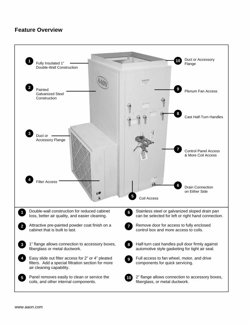
Feature Overview
Double-wall construction for reduced cabinet loss, better air quality, and easier cleaning.
Stainless steel or galvanized sloped drain pan can be selected for left or right hand connection.
Attractive pre-painted powder coat finish on a cabinet that is built to last.
Remove door for access to fully enclosed control box and more access to coils.
1” flange allows connection to accessory boxes, fiberglass or metal ductwork.
Half-turn cast handles pull door firmly against automotive style gasketing for tight air seal.
Easy slide out filter access for 2” or 4” pleated filters. Add a special filtration section for more air cleaning capability.
Full access to fan wheel, motor, and drive components for quick servicing.
Panel removes easily to clean or service the coils, and other internal components.
2” flange allows connection to accessory boxes, fiberglass, or metal ductwork.
1
2
3
4
5
6
7
8
9
10
9
4
3
1
2
6
10
7
8
Fully Insulated 1” Double-Wall Construction
Painted Galvanized Steel Construction
Duct or Accessory Flange
Duct or Accessory Flange
Filter Access Drain Connection on Either Side
Control Panel Access & More Coil Access
Cast Half-Turn Handles
Plenum Fan Access
5 Coil Access
3
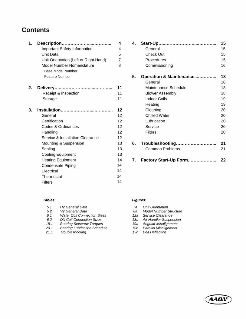
Contents
1. Description……………….....………... 4 4. Start-Up…...……………….....………... 15 Important Safety Information 4 General 15 Unit Data 5 Check Out 15 Unit Orientation (Left or Right Hand) 7 Procedures 15 Model Number Nomenclature 8 Commissioning 16 Base Model Number Feature Number 5. Operation & Maintenance....………... 18 General 18
2. Delivery…...……………….....………... 11 Maintenance Schedule 18 Receipt & Inspection 11 Blower Assembly 18 Storage 11 Indoor Coils 19 Heating 19
3. Installation……..………….....………... 12 Cleaning 20 General 12 Chilled Water 20 Certification 12 Lubrication 20 Codes & Ordinances 12 Service 20 Handling 12 Filters 20 Service & Installation Clearance 12 Mounting & Suspension 13 6. Troubleshooting…………….………... 21 Sealing 13 Common Problems 21 Cooling Equipment 13 Heating Equipment 14 7. Factory Start-Up Form.…….………... 22 Condensate Piping 14 Electrical 14 Thermostat 14 Filters 14
Tables: Figures:
5.1 5.2 6.1 6.2 18.1 20.1 21.1
H2 General Data V2 General Data Water Coil Connection Sizes DX Coil Connection Sizes Bearing Setscrew Torques Bearing Lubrication Schedule Troubleshooting
7a 8a
12a 13a 19a 19b 19c
Unit Orientation Model Number Structure Service Clearance Air Handler Suspension Angular Misalignment Parallel Misalignment Belt Deflection
www.aaon.com 4
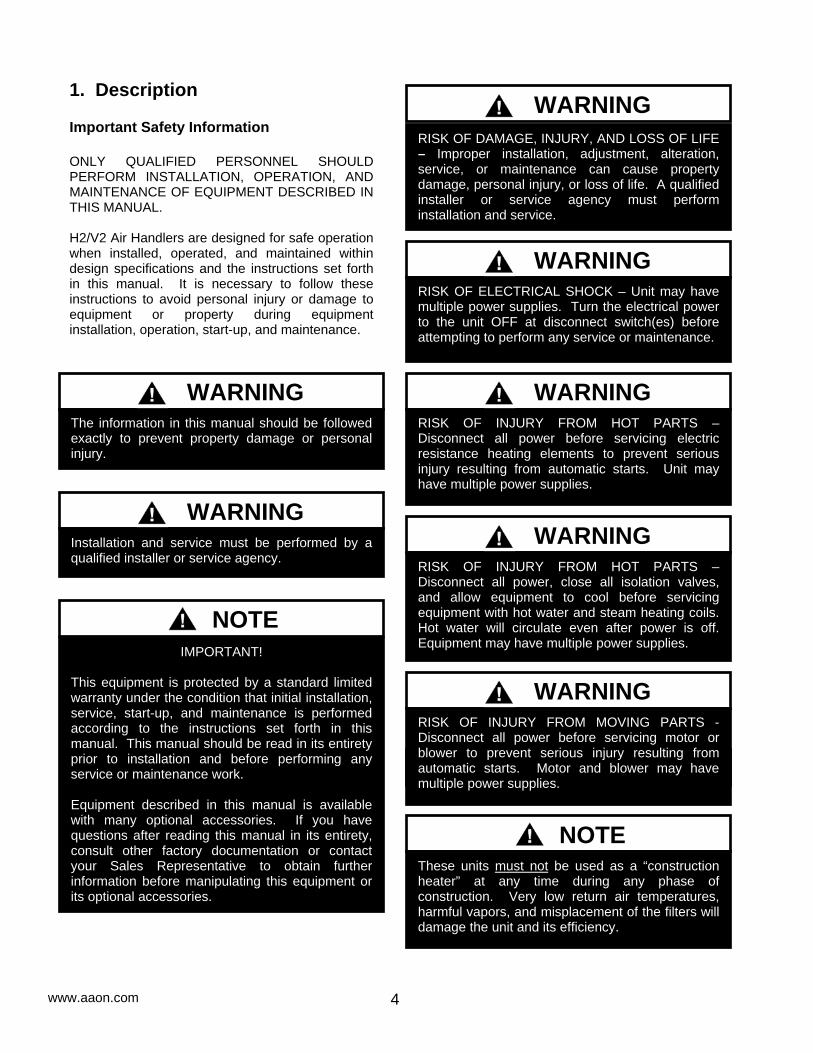
1. Description Important Safety Information ONLY QUALIFIED PERSONNEL SHOULD PERFORM INSTALLATION, OPERATION, AND MAINTENANCE OF EQUIPMENT DESCRIBED IN THIS MANUAL. H2/V2 Air Handlers are designed for safe operation when installed, operated, and maintained within design specifications and the instructions set forth in this manual. It is necessary to follow these instructions to avoid personal injury or damage to equipment or property during equipment installation, operation, start-up, and maintenance.
RISK OF ELECTRICAL SHOCK – Unit may have multiple power supplies. Turn the electrical power to the unit OFF at disconnect switch(es) before attempting to perform any service or maintenance.
WARNING
RISK OF INJURY FROM HOT PARTS – Disconnect all power before servicing electric resistance heating elements to prevent serious injury resulting from automatic starts. Unit may have multiple power supplies.
WARNING
RISK OF INJURY FROM HOT PARTS – Disconnect all power, close all isolation valves, and allow equipment to cool before servicing equipment with hot water and steam heating coils. Hot water will circulate even after power is off. Equipment may have multiple power supplies.
WARNING
WARNING
RISK OF INJURY FROM MOVING PARTS - Disconnect all power before servicing motor or blower to prevent serious injury resulting from automatic starts. Motor and blower may have multiple power supplies.
WARNING
Installation and service must be performed by a qualified installer or service agency.
WARNING
The information in this manual should be followed exactly to prevent property damage or personal injury.
WARNING
RISK OF DAMAGE, INJURY, AND LOSS OF LIFE – Improper installation, adjustment, alteration, service, or maintenance can cause property damage, personal injury, or loss of life. A qualified installer or service agency must perform installation and service.
WARNING
IMPORTANT! This equipment is protected by a standard limited warranty under the condition that initial installation, service, start-up, and maintenance is performed according to the instructions set forth in this manual. This manual should be read in its entirety prior to installation and before performing any service or maintenance work. Equipment described in this manual is available with many optional accessories. If you have questions after reading this manual in its entirety, consult other factory documentation or contact your Sales Representative to obtain further information before manipulating this equipment or its optional accessories.
NOTE
These units must not be used as a “construction heater” at any time during any phase of construction. Very low return air temperatures, harmful vapors, and misplacement of the filters will damage the unit and its efficiency.
NOTE
5
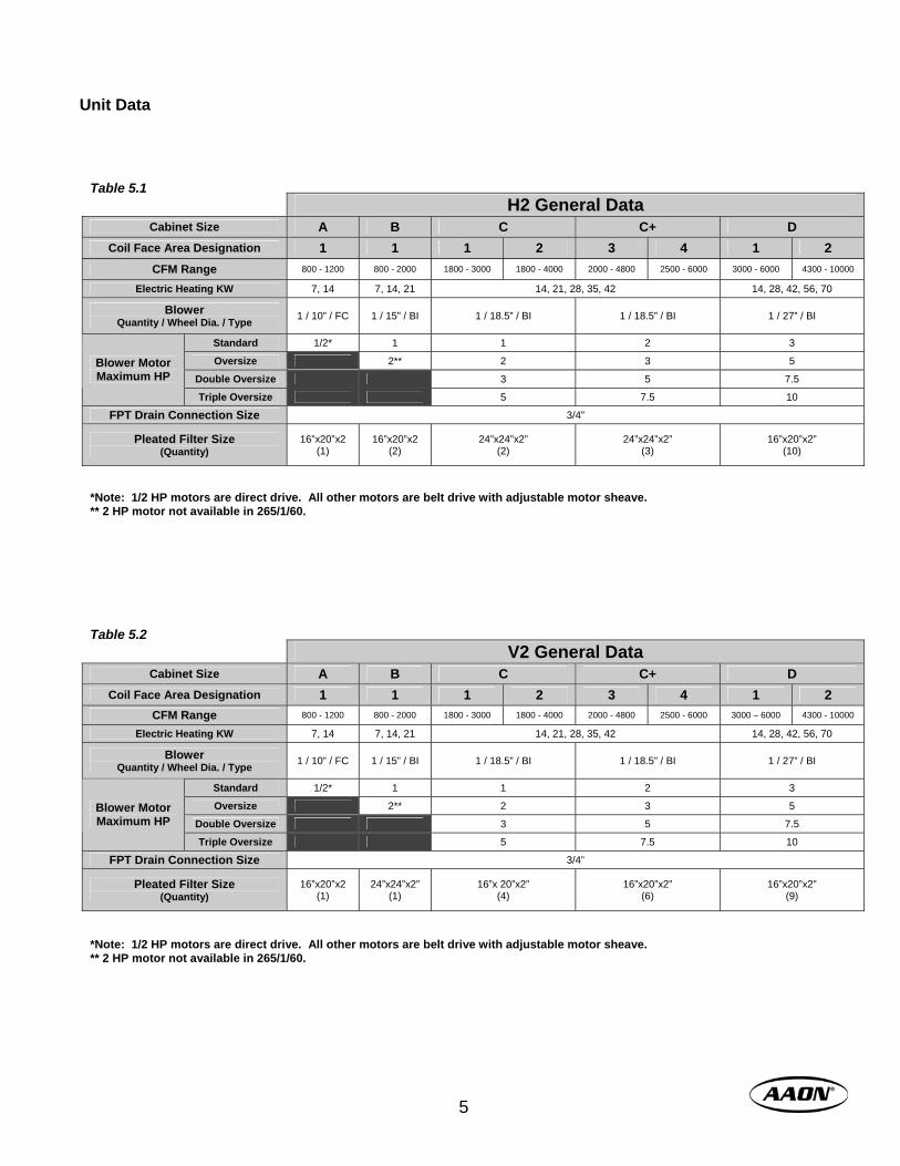
Unit Data
*Note: 1/2 HP motors are direct drive. All other motors are belt drive with adjustable motor sheave. ** 2 HP motor not available in 265/1/60.
V2 General Data Cabinet Size A B C C+ D
Coil Face Area Designation 1 1 1 2 3 4 1 2 CFM Range 800 - 1200 800 - 2000 1800 - 3000 1800 - 4000 2000 - 4800 2500 - 6000 3000 – 6000 4300 - 10000
Electric Heating KW 7, 14 7, 14, 21 14, 21, 28, 35, 42 14, 28, 42, 56, 70
Blower Quantity / Wheel Dia. / Type 1 / 10” / FC 1 / 15” / BI 1 / 18.5” / BI 1 / 18.5” / BI 1 / 27” / BI
Standard 1/2* 1 1 2 3
Oversize 2** 2 3 5
Double Oversize 3 5 7.5 Blower Motor Maximum HP
Triple Oversize 5 7.5 10
FPT Drain Connection Size 3/4”
Pleated Filter Size (Quantity)
16”x20”x2 (1)
24”x24”x2” (1)
16”x 20”x2” (4)
16”x20”x2” (6)
16”x20”x2” (9)
Table 5.2
H2 General Data Cabinet Size A B C C+ D
Coil Face Area Designation 1 1 1 2 3 4 1 2 CFM Range 800 - 1200 800 - 2000 1800 - 3000 1800 - 4000 2000 - 4800 2500 - 6000 3000 - 6000 4300 - 10000
Electric Heating KW 7, 14 7, 14, 21 14, 21, 28, 35, 42 14, 28, 42, 56, 70
Blower Quantity / Wheel Dia. / Type 1 / 10” / FC 1 / 15” / BI 1 / 18.5” / BI 1 / 18.5” / BI 1 / 27” / BI
Standard 1/2* 1 1 2 3
Oversize 2** 2 3 5
Double Oversize 3 5 7.5 Blower Motor Maximum HP
Triple Oversize 5 7.5 10
FPT Drain Connection Size 3/4”
Pleated Filter Size (Quantity)
16”x20”x2 (1)
16”x20”x2 (2)
24”x24”x2” (2)
24”x24”x2” (3)
16”x20”x2” (10)
Table 5.1
*Note: 1/2 HP motors are direct drive. All other motors are belt drive with adjustable motor sheave. ** 2 HP motor not available in 265/1/60.
www.aaon.com 6
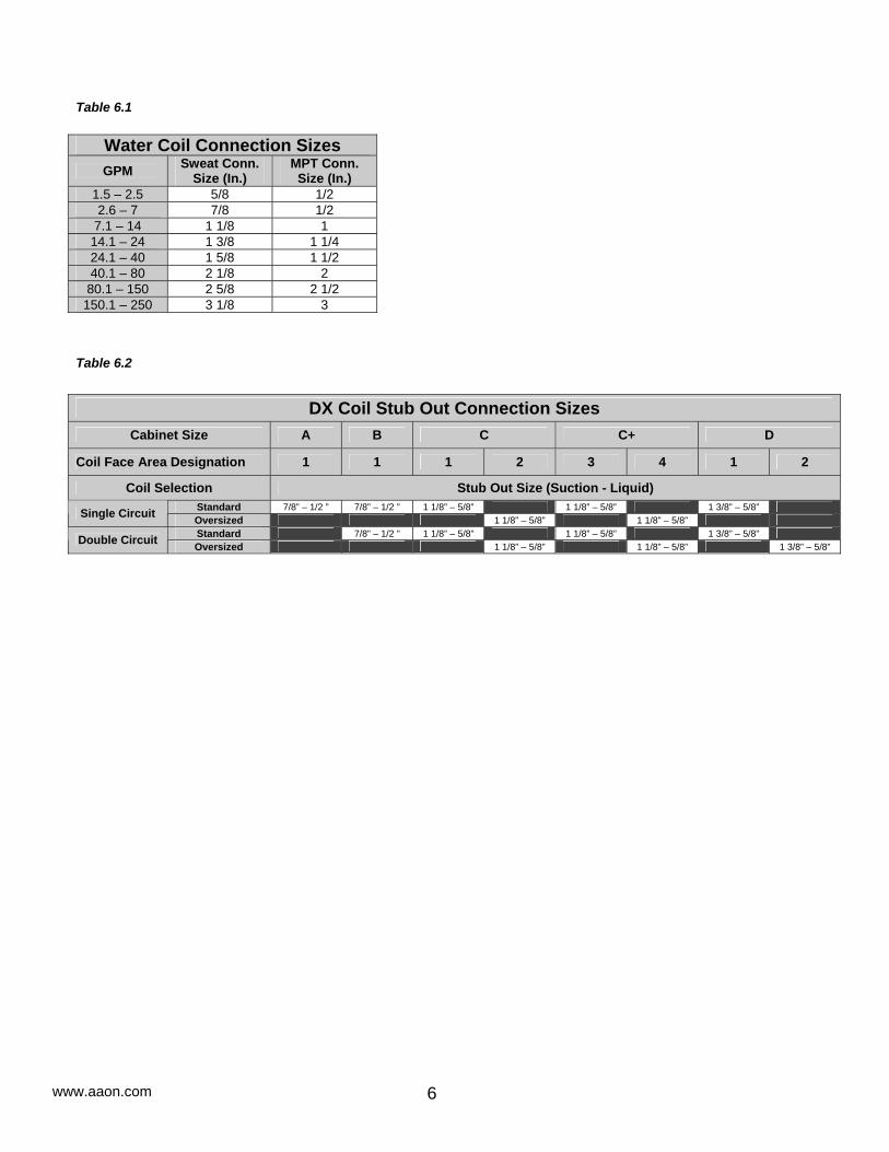
Water Coil Connection Sizes GPM Sweat Conn.
Size (In.) MPT Conn. Size (In.)
1.5 – 2.5 5/8 1/2 2.6 – 7 7/8 1/2
7.1 – 14 1 1/8 1 14.1 – 24 1 3/8 1 1/4 24.1 – 40 1 5/8 1 1/2 40.1 – 80 2 1/8 2 80.1 – 150 2 5/8 2 1/2
150.1 – 250 3 1/8 3
Table 6.1
DX Coil Stub Out Connection Sizes
Cabinet Size A B C C+ D
Coil Face Area Designation 1 1 1 2 3 4 1 2
Coil Selection Stub Out Size (Suction - Liquid) Standard 7/8” – 1/2 ” 7/8” – 1/2 ” 1 1/8” – 5/8” 1 1/8” – 5/8” 1 3/8” – 5/8” Single Circuit Oversized 1 1/8” – 5/8” 1 1/8” – 5/8” Standard 7/8” – 1/2 ” 1 1/8” – 5/8” 1 1/8” – 5/8” 1 3/8” – 5/8” Double Circuit Oversized 1 1/8” – 5/8” 1 1/8” – 5/8” 1 3/8” – 5/8”
Table 6.2
7
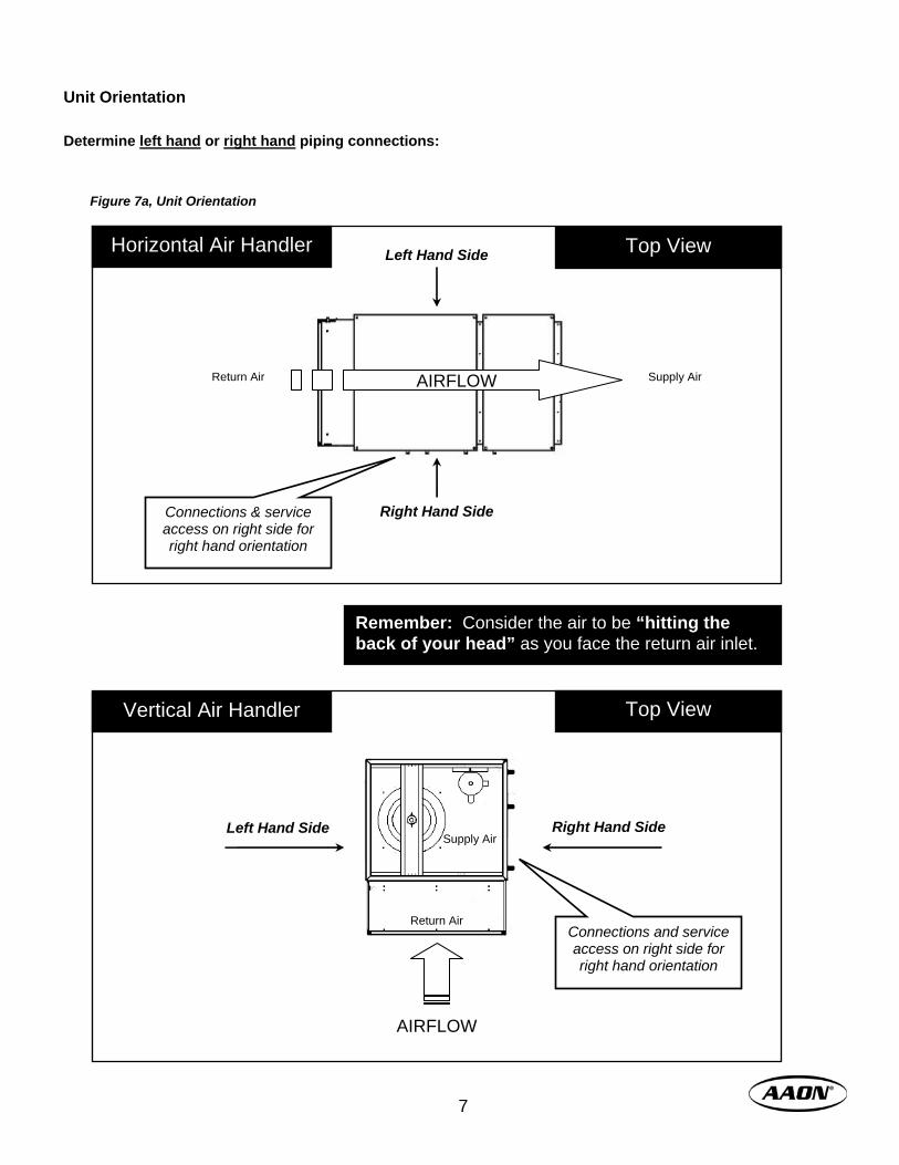
Determine left hand or right hand piping connections:
Unit Orientation
Remember: Consider the air to be “hitting the back of your head” as you face the return air inlet.
Connections and service access on right side for right hand orientation
Right Hand Side Left Hand Side Supply Air
Return Air
Top View Vertical Air Handler
AIRFLOW
Horizontal Air Handler
Return Air Supply Air
Right Hand Side
Left Hand Side
Connections & service access on right side for right hand orientation
Top View
AIRFLOW
Figure 7a, Unit Orientation

www.aaon.com 8
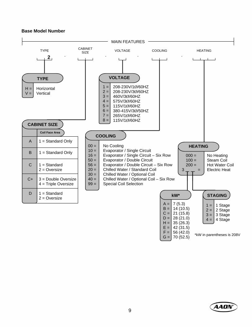
Model Number Nomenclature The base model number identifies main unit features. The feature number identifies optional features ordered with the equipment. Together, they comprise the complete model number.
H2 – C1 – 2 – 10 – 3B1
Complete Model Number
Base Model Number
Feature Number
: A 0 0 0 D 0 A 0 0 0
Figure 8a, Model Number Structure
9
COOLING
H = V =
Horizontal Vertical
TYPE
No Cooling Evaporator / Single Circuit Evaporator / Single Circuit – Six Row Evaporator / Double Circuit Evaporator / Double Circuit – Six Row Chilled Water / Standard Coil Chilled Water / Optional Coil Chilled Water / Optional Coil – Six Row Special Coil Selection
00 = 10 = 16 = 50 = 56 = 20 = 30 = 40 = 99 =
COOLING
VOLTAGE CABINET SIZE TYPE
2 HEATING
- - - -
No Heating Steam Coil Hot Water Coil Electric Heat
000 = 100 = 200 =
3 =
HEATING
A = B = C = D = H = E = F = G =
7 (5.3) 14 (10.5) 21 (15.8) 28 (21.0) 35 (26.3) 42 (31.5) 56 (42.0) 70 (52.5)
kW*
1 = 2 = 3 = 4 =
1 Stage 2 Stage 3 Stage 4 Stage
STAGING
208-230V/1Ø/60HZ 208-230V/3Ø/60HZ 460V/3Ø/60HZ 575V/3Ø/60HZ 115V/1Ø/60HZ 380-415V/3Ø/50HZ 265V/1Ø/60HZ 115V/1Ø/60HZ
1 = 2 = 3 = 4 = 5 = 6 = 7 = 8 =
VOLTAGE
*kW in parentheses is 208V
A
C
C+
D
1 = Standard Only 1 = Standard 2 = Oversize 3 = Double Oversize 4 = Triple Oversize 1 = Standard 2 = Oversize
Coil Face Area
CABINET SIZE
1 = Standard Only
B
MAIN FEATURES
Base Model Number

www.aaon.com 10
FEATURE OPTIONS ORIEN. REFRIG. OPEN
0 = A = B = C = E = F = G = H =
Standard Oversize Double Oversize Triple Oversize Standard High Efficiency Oversize High Efficiency Double Oversize High Efficiency Triple Oversize High Efficiency
MOTOR
CTRLS. FILTERS MOTOR ELECT.
0 = B =
Standard – Right Hand – Front or Top Discharge Left Hand – Front or Top Discharge
ORIENTATION*
0 = A = B =
Standard – 2” Pleated 4” Pleated No Filters (For Use w/ Mixing Box)
FILTERS
0 = A = B = C =
Standard All Electric Heat Units Phase and Brown Out Control Electric Heat Unit w/ Phase and Brown Out Control
CONTROLS
SPECIAL
0 =
X =
Standard (Lt. Beige Textured Paint) Special (SPA Req’d)
OPEN
0 = Standard
REFRIGERATION
0 = A = B = C = D =
Standard External Hot Gas Bypass – Single Circuit Evaporator External Hot Gas Bypass – Double Circuit Evaporator Heat Pump Modulating Hot Gas Reheat w/ External Hot Gas Bypass
PULLEYS
0 = A = B =
Standard – Combination 1 Combination 2 Combination 3
ELECTRICAL
0 = A =
CABINET
0 = A =
Standard Stainless Steel Drain Pan
PULLEY CABINET SPECIAL
Standard Auxiliary Module
*Front Discharge Available on Horizontals ONLY. Top Discharge Available on Verticals ONLY.
A 0 = Direct Drive - - 0 = Combination 1 1000 1400 A = Combination 2 1400 1800 B B = Combination 3 1800 2200 0 = Combination 1 900 1300 A = Combination 2 1300 1700 C B = Combination 3 1700 2100 0 = Combination 1 800 1100 A = Combination 2 1100 1300 D B = Combination 3 1300 1600
UNIT SIZE COMBINATION RPM
MIN MAX
The above selections are for general guidelines only. Refer to fan curves and software for best selection.
1 2 3 4 5 6 7 8 9 10
Feature Number
2. Delivery ALL SHIPMENTS ARE FOB THE FACTORY. IT IS THE RESPONSIBILITY OF THE RECEIVING PARTY TO INSPECT THE EQUIPMENT UPON ARRIVAL. Receipt & Inspection Units should be inspected for damage that may have occurred in transit. Please do not refuse shipments! Do the following upon receipt:
1. Assure that freight carrier is in compliance with Bill of Lading instructions.
2. Inspect delivery before signing Bill of Lading. If damage is found or if items are missing:
1. Note on Bill of Lading immediately. − Photograph damage if possible − Do not move or discard damaged
freight packaging materials 2. Call carrier immediately to file a freight claim
and to schedule an inspection. 3. After losses have been acknowledged by the
freight carrier, call the factory for a repair or replacement part quote: 1-903-236-4403
4. With permission of freight carrier, order parts and/or make repairs.
5. Stay in contact with freight carrier to ensure payment of your claim.
If repairs must be made to damaged goods, then the factory should be notified before any repair action is taken in order to protect the warranty. Certain equipment alteration, repair, and manipulation of equipment without the manufacturer’s consent may void the product warranty. Contact the Warranty Department for assistance with handling damaged goods, repairs, and freight claims: 1-903-236-4403.
Storage This equipment is not suitable for outdoor use or storage. Never place this equipment where it may be subjected to outdoor conditions such as rain, snow, humidity, extreme temperatures, or corrosive chemicals. If installation will not occur immediately following delivery, then store equipment in a dry, protected area away from construction traffic, and in the proper orientation as marked on the packaging with all internal packaging in place. Secure all loose-shipped items.
This unit must be stored indoors if installation is not to occur immediately following delivery. Damage resulting from improper storage will not be covered by the limited warranty.
WARNING
NOTICE OF PILFERING – Check packing list against delivered goods. Ensure that equipment and loose-shipped items have not been pilfered or misplaced during staging or transit. The factory is not responsible for missing items after shipment.
NOTE
LOOSE SHIPMENT ITEMS – Upon receipt check shipment for items that ship loose such as thermostats and other controls. Consult order and shipment documentation to identify potential loose-shipped items. Loose-shipped items may have been placed inside unit cabinet for security.
NOTE
11
www.aaon.com 12
3. Installation General H2/V2 air handling units are designed as a self-contained heating, cooling, or combination unit for indoor installation only. The use of refrigerant, chilled water, electric resistance, steam, or hot water as operating mediums will be dictated by design of the heating and cooling coils installed in the unit. Flexible connectors are required on all duct connections and installed to minimize air leaks. Certification Cooling Models
a) Certified for use with a commercial condensing or chilled water remote unit (with or without compressor(s))
b) Certified for indoor installation only. Steam or Hot Water Heat Models
a) Certified for indoor installation only. Electric Heat Models
a) Certified as an electric warm air furnace with or without cooling coil.
b) Certified for indoor installation only. Codes & Ordinances System should be sized in accordance with National Warm Air Heating and Air Conditioning Association Literature, or the Guide of American Society of Heating, Refrigeration and Air Conditioning Engineers. The installation must conform with local building codes, or in the absence of local codes, with (United States) “ANSI / UL 1995”, (Canada) current, C.S.A. Standard C22.2, No. 236, Canadian Electrical Code Part 1, and C.S.A. Standard B52 Mechanical Refrigeration Code, and Local Plumbing or Waste Water Codes.
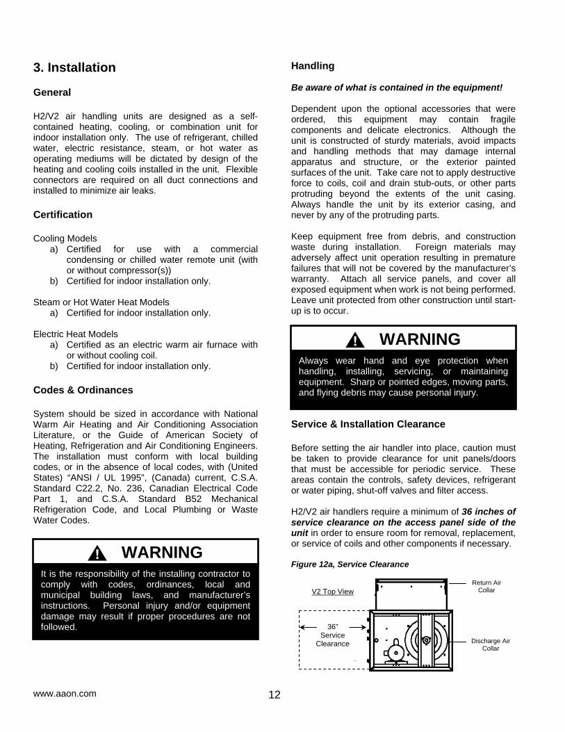
Handling Be aware of what is contained in the equipment! Dependent upon the optional accessories that were ordered, this equipment may contain fragile components and delicate electronics. Although the unit is constructed of sturdy materials, avoid impacts and handling methods that may damage internal apparatus and structure, or the exterior painted surfaces of the unit. Take care not to apply destructive force to coils, coil and drain stub-outs, or other parts protruding beyond the extents of the unit casing. Always handle the unit by its exterior casing, and never by any of the protruding parts. Keep equipment free from debris, and construction waste during installation. Foreign materials may adversely affect unit operation resulting in premature failures that will not be covered by the manufacturer’s warranty. Attach all service panels, and cover all exposed equipment when work is not being performed. Leave unit protected from other construction until start-up is to occur. Service & Installation Clearance Before setting the air handler into place, caution must be taken to provide clearance for unit panels/doors that must be accessible for periodic service. These areas contain the controls, safety devices, refrigerant or water piping, shut-off valves and filter access. H2/V2 air handlers require a minimum of 36 inches of service clearance on the access panel side of the unit in order to ensure room for removal, replacement, or service of coils and other components if necessary. Figure 12a, Service Clearance
36” Service
Clearance
V2 Top View Return Air
Collar
Discharge Air Collar
Always wear hand and eye protection when handling, installing, servicing, or maintaining equipment. Sharp or pointed edges, moving parts, and flying debris may cause personal injury.
WARNING
It is the responsibility of the installing contractor to comply with codes, ordinances, local and municipal building laws, and manufacturer’s instructions. Personal injury and/or equipment damage may result if proper procedures are not followed.
WARNING
13
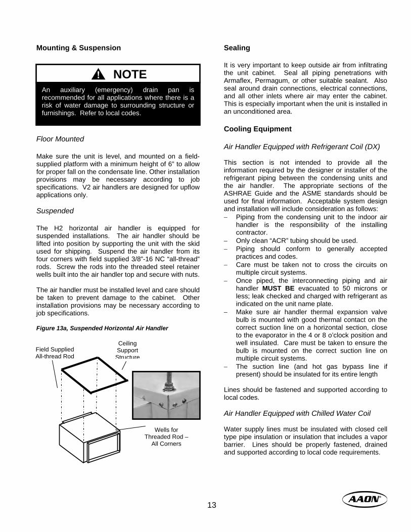
Mounting & Suspension Floor Mounted Make sure the unit is level, and mounted on a field-supplied platform with a minimum height of 6” to allow for proper fall on the condensate line. Other installation provisions may be necessary according to job specifications. V2 air handlers are designed for upflow applications only. Suspended The H2 horizontal air handler is equipped for suspended installations. The air handler should be lifted into position by supporting the unit with the skid used for shipping. Suspend the air handler from its four corners with field supplied 3/8”-16 NC “all-thread” rods. Screw the rods into the threaded steel retainer wells built into the air handler top and secure with nuts. The air handler must be installed level and care should be taken to prevent damage to the cabinet. Other installation provisions may be necessary according to job specifications. Figure 13a, Suspended Horizontal Air Handler
Sealing It is very important to keep outside air from infiltrating the unit cabinet. Seal all piping penetrations with Armaflex, Permagum, or other suitable sealant. Also seal around drain connections, electrical connections, and all other inlets where air may enter the cabinet. This is especially important when the unit is installed in an unconditioned area. Cooling Equipment Air Handler Equipped with Refrigerant Coil (DX) This section is not intended to provide all the information required by the designer or installer of the refrigerant piping between the condensing units and the air handler. The appropriate sections of the ASHRAE Guide and the ASME standards should be used for final information. Acceptable system design and installation will include consideration as follows: − Piping from the condensing unit to the indoor air
handler is the responsibility of the installing contractor.
− Only clean “ACR” tubing should be used. − Piping should conform to generally accepted
practices and codes. − Care must be taken not to cross the circuits on
multiple circuit systems. − Once piped, the interconnecting piping and air
handler MUST BE evacuated to 50 microns or less; leak checked and charged with refrigerant as indicated on the unit name plate.
− Make sure air handler thermal expansion valve bulb is mounted with good thermal contact on the correct suction line on a horizontal section, close to the evaporator in the 4 or 8 o’clock position and well insulated. Care must be taken to ensure the bulb is mounted on the correct suction line on multiple circuit systems.
− The suction line (and hot gas bypass line if present) should be insulated for its entire length
Lines should be fastened and supported according to local codes. Air Handler Equipped with Chilled Water Coil Water supply lines must be insulated with closed cell type pipe insulation or insulation that includes a vapor barrier. Lines should be properly fastened, drained and supported according to local code requirements.
Field Supplied All-thread Rod
Ceiling Support Structure
Wells for Threaded Rod –
All Corners
An auxiliary (emergency) drain pan is recommended for all applications where there is a risk of water damage to surrounding structure or furnishings. Refer to local codes.
NOTE
www.aaon.com 14
Heating Equipment When heat is called for, the cooling section is inoperable except for the indoor blower motor. Actual heating is accomplished by the air handling unit with hot water, steam or electric heating capabilities. Air Handler Equipped with Hot Water Coil Water supply lines must be insulated, properly fastened, drained and supported according to local code requirements. Air Handler Equipped with Steam Coils The air handling unit MUST BE installed high enough to allow for a minimum of one foot (1’) condensate drop leg off of the steam coil (or as recommended by the steam trap manufacturer). Lines should be insulated with approved insulation and be properly fastened, sloped and supported according to local code requirements. Air Handler Equipped with Electric Heating INSTALLATION IS TO BE ADJUSTED TO OBTAIN AN AIR TEMPERATURE RISE WITHIN THE RANGE SPECIFIED ON THE RATING PLATE. Heating is accomplished by passing electrical current through a specified amount of resistance heaters which will produce the required heat. The indoor blower motor will energize at the same time as the heaters. Wiring to the air handler must be done in accordance with local electrical codes and/or standards. Check specified electrical rating and install with proper wire size. Condensate Piping If the air handler is equipped with cooling, a drain trap must be connected to the drain pan at the unit. A condensate connection is provided on each side of the unit. Condensate piping should be installed according to local codes. The line should be the same pipe size as the drain nipple and should pitch downward toward the building drain. All cooling coils must have drain pans equipped with “P” traps to avoid pulling air from outside the unit back through the drain line. A plug is provided for the unused condensate connection. The trap should be located in warm ambient spaces. An additional drain pan may be installed under the air handler, and should include a separate drain line for overflow from the
primary drain. An air break should be used with long runs of condensate lines. Drain pans in any air conditioning equipment, even when they have a built-in slope to the drain, will have moisture present and will require periodic cleaning to prevent any build-up of algae or bacteria. Cleaning of the drain pans will also prevent any possible plugging of the drain lines, and overflow of the pan itself. Some means to clean out the “P” trap should be provided. Only qualified personnel should clean drain pans, drain lines, or the insides of equipment. Electrical Check the unit data plate to make sure it agrees with the power supply. Connect power to the unit according to the wiring diagram provided with the unit. The power and control wiring may be brought in through the holes provided on the unit. Protect the branch circuit in accordance with code requirements. If the control wires are to run inside the same conduit, use 600-volt wire or as required by applicable codes. The units must be electrically grounded in accordance with the National Electric Code, ANSI / UL 1995 when installed if an external source is utilized; in Canada use current C.S.A. Standard C22.2, No. 236, Canadian Electric Code Part 1. Power wiring is to the unit terminal block. The manufacturer has done all wiring beyond this point. Power can be applied to the unit after the control wiring is connected, and start up checks are complete. Thermostat The low voltage room thermostat should be located on an inside wall 4 to 5 feet a above the floor where it will not be subjected to drafts, sun exposure or heat from electrical fixtures or appliances. Control wire size must be large enough to prevent excess voltage drop that may cause improper operation of the equipment. Follow manufacturer’s instructions enclosed with thermostat for general installation procedure. Filters Open filter access door and slide correct filter in with arrow pointing towards the blower in the direction of airflow. For filter sizes see back cover.

15
4. Start-Up General ONLY QUALIFIED, AUTHORIZED PERSONNEL SHOULD POWER ON, OR START-UP THIS EQUIPMENT. The use of common sense, and good practice in the installation, and start-up of equipment will prevent many potential problems with the system in the future. Before starting up the equipment, building construction should be complete, and start-up personnel should:
− Have a working knowledge of general HVAC and mechanical commissioning procedures and practices;
− Be familiar with unit functions, features, optional unit accessories, and all control sequences;
− Have appropriate literature on hand for consultation.
Before the structure is occupied, the installation, and/or start-up personnel must take three essential steps:
1. Check Out 2. Start-Up 3. Commissioning
Check Out Equipment should be thoroughly checked for loose wiring, a free spinning blower wheel, and well fitting access panels. Air handlers should not be operated
without proper ductwork and access panels installed, except as required during start-up and air balancing.
1. Check all electrical connections to be sure they are tight.
2. Open all access panels, and remove all shipping screws, or restraints.
3. Clean out any debris that may have been left. 4. Check belt alignment, and tightness of fan
drives. 5. Check bearing locking collars, and fan wheel
set screws for tightness. 6. Turn fan wheels to assure free rotation. 7. Ensure electrical supply matches the unit
nameplate. 8. Ensure condensate lines are connected, and
glued. 9. Check local codes for any special provisions. 10. Replace, and/or close all access panels. 11. Ensure that return, and/or supply dampers in
ductwork are open. 12. Check electrical phasing to ensure fan rotates
in proper direction. Procedures Install gauges, voltmeter, and ammeter before start-up. Observe refrigerant pressures during initial operation. Note, and determine the cause of any excessive sound, or vibration. Follow start-up procedures outlined below to start each piece of equipment. Electric Heating Section Procedures
1. Perform final visual inspection. Check all equipment, ductwork, and piping to verify that all work is complete, and equipment is properly installed and mounted. Improperly installed equipment, or ductwork can affect readings.
Failure to adhere to the following start-up procedures will void all manufacturer’s warranties.
NOTE
Completed factory test sheets are in the equipment literature packet shipped inside the unit. Factory run-test readings recorded on the test sheets for may be helpful to reference during start-up.
NOTE
Equipment power should be on at least 24 hours before start-up to allow the crankcase heater to boil off refrigerant that may have accumulated in the compressor oil.
CAUTION
Equipment operation during construction is not recommended. Construction site pollution can affect unit operation, and seriously degrade performance. Operation during construction will void all manufacturer’s warranties.
CAUTION

www.aaon.com 16
2. Ensure there is no construction debris in the unit.
3. Check the unit for external damage. 4. Note all accessories installed. 5. Install a filter of the proper size and type. 6. Check all terminal blocks, fuses, fuse blocks,
and contactors for correctness. 7. Check all high and low voltage wiring
connections for correctness, and tightness. 8. Check unit for correct incoming voltage per the
data plate. 9. Check the security of the locking system on all
blower bearings 10. Turn the unit power on. 11. Turn the unit blower on, and check for correct
rotation. 12. If correct, take blower amp readings, and
compare to see if the amp draw is within the safety factor area of the motor. Once correct, turn blower off.
13. Turn on the first stage of heating − Check amp draw of each element of
each stage − Ensure blower started w/ electric heat − Check for temperature rise across
heating section while all stages are on − If temperature rise is within range, turn
all heating calls off − Check to see that blower stops
Refrigerant (DX) Cooling Section:
1. Perform final visual inspection. Check all
equipment, ductwork, and piping to verify that all work is complete, and equipment is properly installed and mounted. Improperly installed equipment, or ductwork can affect readings.
2. Perform condensing unit start-up checks in addition to these air handler checks according to the unit manufacturer’s instructions.
3. Ensure there is no construction debris in the unit.
4. Check the unit for external damage. 5. Note all accessories installed. 6. Install filter of the proper size and type. 7. Ensure that drain P-trap is installed. 8. Check all terminal blocks, fuses, fuse blocks,
and contactors for correctness. 9. Check all high, and low voltage wiring
connections for tightness. Check unit for correct incoming voltage per the data plate.
10. Check the security of the locking system on all blower bearings
11. Turn the unit power on. 12. Turn the unit blower on, and check for correct
rotation.
13. If correct, take blower amp readings, and compare to see if the amp draw is within the safety factor area of the motor.
14. Check, and record ambient temperature. 15. Check for Guaranteed Off Timers (GOT),
and/or Time Delay Relays (TDR). 16. Start the first stage cooling circuit, and blower
circuit. 17. After all stages of cooling have been on for at
least five minutes, record the return air temperature, and supply air temperature.
Optional Equipment Operation of each of the following, if equipped in the unit, must be checked according to that item’s manufacturer’s specifications:
− Phase and brownout monitor − Hot gas reheat − Hot gas bypass
Commissioning The commissioning of an air conditioning system is the process of achieving, verifying, and documenting the performance of that system to meet the operational needs of the building. This may not be a formal process in smaller structures, such as a normal residence, but some form of owner acceptance will occur. Adjustments made during the commissioning phase may include air, or water balancing, or configuration of controls, and operational sequences. Air Balancing High performance systems commonly have complex air distribution and fan systems. Unqualified personnel should not attempt to adjust fan operation, or air circulation, as all systems have unique operating characteristics. Professional air balance specialists should be employed to establish actual operating conditions, and to configure the air delivery system for optimal performance. Water Balancing A hydronic specialist with a complete working knowledge of water systems, controls, and operation must be employed to properly balance the entire system. Unqualified personnel should not attempt to manipulate temperatures, pressures, or flow rates, as all systems have unique operating characteristics, and improper balancing can result in undesirable noises and operation.
17
Controls A variety of controls and electrical accessories may be provided with the equipment. Identify the controls on each unit by consulting appropriate submittal, or order documents, and operate according to the control manufacturer’s instructions. If you cannot locate installation, operation, or maintenance information for the specific controls, then contact your sales representative, or the control manufacturer for assistance.
Do not alter factory wiring. Deviation from the supplied wiring diagram will void all warranties, and may result in equipment damage or personal injury. Contact the factory with wiring discrepancies.
WARNING

www.aaon.com 18
5. Operation & Maintenance General Immediately following building occupancy, the air conditioning system requires a maintenance schedule to assure continued successful operation. A maintenance program similar to the example given below should be scheduled for routine maintenance of this equipment in order to provide continued efficient, and reliable operation for the owner. Maintenance Schedule One week after start-up: − Check refrigerant charge. Evacuate and repair
coil if leaking. − Adjust belt tension on all fan drives. − Check filters for cleanliness. Measure pressure
loss if applicable. Replace if necessary. − Check cycling of compressors, fans, and valves.
Correct unusual cycling. Monthly: − Lubricate bearings if operating continuously at
1500 rpm, or higher, or in other extreme conditions.
− Check cleanliness of filters, and replace if necessary.
− Check cooling coil drain pan to assure proper drainage.
− Inspect evaporator, and condenser coils. Clean if dirty, or obstructed in any way.
Quarterly: − Lubricate bearings if operating at 1000 rpm, or
less, and in temperatures less than 150°F, or other extreme conditions.
− Check damper operation for freedom of movement. Correct any binding that may occur.
− Check belts, and pulleys on all fan drives for tension, and unusual wear.
− Check operation of heating, and cooling section if seasonal.
− Check inlet, and outlet air temperatures. Determine cause for abnormal changes.
Annually: − Clean the condenser, and evaporator coils with
steam, or a non-corrosive coil cleaner.
− Clean the drain line, “P” trap, and condensate pan. − Check refrigerant pressures, and temperatures
every Spring, and correct unusual operation. − Check heating section every Fall. Check all
electrical connections for tightness, and check heater elements for indications of overheating. Determine cause and replace elements if necessary.
Blower Assembly H2/V2 air handlers use backward inclined airfoil blower wheels* that are non-overloading, very efficient, and very easy to clean. Clean blower wheels are necessary to reduce electrical use, maintain capacity and reduce stress on the unit. The blower wheel, and blower section need to be inspected periodically, and cleaned of dust, or debris. To inspect and clean the blower; set thermostat to the “OFF” position; turn the electrical power to the unit to the “OFF” position at the disconnect switch. Clean the assembly, check the bearings for looseness, inspect the belt condition and tightness, check screws for tightness, rotate blower wheel while listening close to each bearing to check for noise or roughness in the bearing, which indicates a failing bearing. Bearings AAON uses pre-lubricated bearings, and bearings that have been sized for an average failure rate of 50% after 200,000 hours, or 22.8 years, of operation (see heading “Lubrication” in this section for more information). The bearing sizing tables below are based on rotational speeds, and radial loading. However, the alignment of the bearing to the shaft, and the security of the bearing inner race to the shaft will greatly affect bearing life. Even though the manufacturer is responsible for bearing tolerances, and mounting design, the installer or start-up technician is advised to check the security of the bearing locking system before start-up. Table 18.1, Bearing Setscrew Torque Recommendations
Setscrew Locking Skewzloc Locking Shaft Size (In.) Thread Torque (In-Lbs) Thread Torque (In-Lbs) 1 1/4 - 28 66 - 85 8 - 32 63 - 70
1 3/16 1/4 - 28 66 - 85 8 - 32 63 - 70 1 7/16 5/16 - 24 126 - 164 10 - 24 81 - 90 1 7/8 3/8 - 24 228 - 296 1/4 - 20 162 - 180
*Exception – Size A1 H2/V2 uses 10” forward curved fan

19
Belts Belt drive misalignment is one of the most common causes of premature belt failure. A belt can be destroyed in a matter of days if the drives have been aligned incorrectly. The most common tool for measuring misalignment is a straightedge. Hold the straightedge flush across one pulley to gauge the degree of misalignment of the two sheaves. The maximum allowed misalignment is one half degree of angular misalignment, and 1/10th of an inch per foot between sheave centers for parallel misalignment. Figure 19a, Angular Misalignment Corrected by moving the position of the motor. Figure 19b, Parallel Misalignment Corrected by adjusting sheaves on one, or both shafts. Frequent belt tensioning is highly recommended. Most belt manufacturers would suggest a retensioning after as little as 8 hours of operation. A simplified method of adjusting tension is to gauge the amount of force required to deflect the belt by 1/64th of an inch per inch of distance between sheave centers. For example, if the sheaves are 20 inches apart, then the amount of deflection with the forces listed below is 20/64th (5/16th) of an inch.
Figure 19c, Belt Deflection Indoor Coils Coils should be inspected and cleaned annually to ensure there is no obstruction to airflow. Dirty evaporator coils will eventually freeze up, and often result in a time consuming, and expensive service call. Clean filters will help to prevent dirt from accumulating on the evaporator, however the evaporator should be cleaned annually with a soft bristled brush, and/or a non-corrosive coil cleaning solution. Heating Electric Set thermostat in the heat mode; call for heat to engage all electric heat strips. Check blower for proper rotation and voltage. Measure the amperage and voltage. Compare them to the nameplate data. If applicable, check remote heat pump condensing unit as per the manufacturer’s recommendations. Steam or Hot Water Set thermostat in the heat mode. Observe supply blower for proper rotation and voltage. Check boiler or hot water operation according to the manufacturer’s instructions. Check control flow valves for correct operation and settings per the manufacturer’s instructions.
Straightedge
Pulley Pulley
Belt
Straightedge
Pulley Pulley Belt
Sheave Centers
Force
Deflection = 1/64th in. per inch of length
Deflections required for: “A” belts: 4 to 6 lbs. “B” belts: 6 to 10 lbs. “C” belts: 10 to 18 lbs.

www.aaon.com 20
Cleaning Inspect and clean unit interior at the beginning of each heating and cooling season and as operating conditions require. Chilled Water Check remote chiller operations as per the manufacturer’s instructions. Check coolant flow valves for correct operation and settings. Lubrication Most motors and bearings are permanently lubricated. Some applications, however, will require that bearings be re-lubricated periodically. The schedule will depend on the operating duty, temperature variations or other atmospheric conditions. For bearings equipped with lubrication fittings the lubrication schedule is dependent on operating temperatures, and rotational speeds as shown in table 24.1 below. Lithium based grease conforming to an NLGI grade No. 2 consistency is recommended. This medium viscosity, low torque grease is rust inhibiting, and water-resistant. It is satisfactory for operating temperatures in the range of –10°F to 250°F. Bearings should only be re-lubricated when at normal operating temperatures, and not running. Rotate the fan shaft by hand, adding only enough grease to purge the seals. A one-inch bearing has a total grease capacity of only .25 ounces. Added grease should be limited to .09 ounces. Recommended greases are: − SHELL OIL – DOLIUM R − CHEVRON OIL – SRI No. 2 − TEXACO INC. – PREMIUM RB
Table 20.1, Fan Bearing Lubrication Schedule
Fan Speed Temperature Environment Greasing Interval
500 rpm Up to 150 °F Clean 2 to 6 months 1000 rpm Up to 210 °F Clean 2 weeks to 2 months 1500 rpm Up to 210 °F Clean Monthly
Any Speed Up to 150 °F Dirty 1 week to 1 month Any Speed 210 - 250 °F Dirty Weekly
Service In the event the unit is not functioning correctly and a service company is required, only a company with service technicians qualified and experienced in both heating and air conditioning should be permitted to service the systems in order to keep warranties in effect. The service tech may call the factory if assistance is required. BEFORE CALLING, THE MODEL AND SERIAL NUMBER OF THE UNIT WILL BE NEEDED FOR THE WARRANTY SERVICE DEPARTMENT TO HELP ANSWER QUESTIONS REGARDING THE UNIT. AAON Coil Products Phone: 1-903-247-9242 Fax: 903-236-4463 Warranty Department Filters Open filter access door. Slide filters towards you and inspect. Replace old filters with the size indicated on each filter or as shown in the table on the back cover of this manual. Be sure arrow points toward the blower. Filters should be checked every 30 days and replaced or cleaned as necessary. IT IS IMPORTANT TO KEEP COILS, BLOWERS, AND FILTERS CLEAN!
DO NOT OVER LUBRICATE!
(for filter sizes see back cover)
21
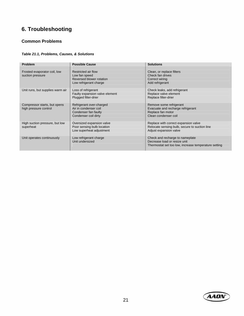
6. Troubleshooting Common Problems Table 21.1, Problems, Causes, & Solutions Problem Possible Cause Solutions Frosted evaporator coil, low suction pressure
Restricted air flow Low fan speed Reversed blower rotation Low refrigerant charge
Clean, or replace filters Check fan drives Correct wiring Add refrigerant
Unit runs, but supplies warm air Loss of refrigerant Faulty expansion valve element Plugged filter-drier
Check leaks, add refrigerant Replace valve element Replace filter-drier
Compressor starts, but opens high pressure control
Refrigerant over-charged Air in condenser coil Condenser fan faulty Condenser coil dirty
Remove some refrigerant Evacuate and recharge refrigerant Replace fan motor Clean condenser coil
High suction pressure, but low superheat
Oversized expansion valve Poor sensing bulb location Low superheat adjustment
Replace with correct expansion valve Relocate sensing bulb, secure to suction line Adjust expansion valve
Unit operates continuously Low refrigerant charge Unit undersized
Check and recharge to nameplate Decrease load or resize unit Thermostat set too low, increase temperature setting
www.aaon.com 22
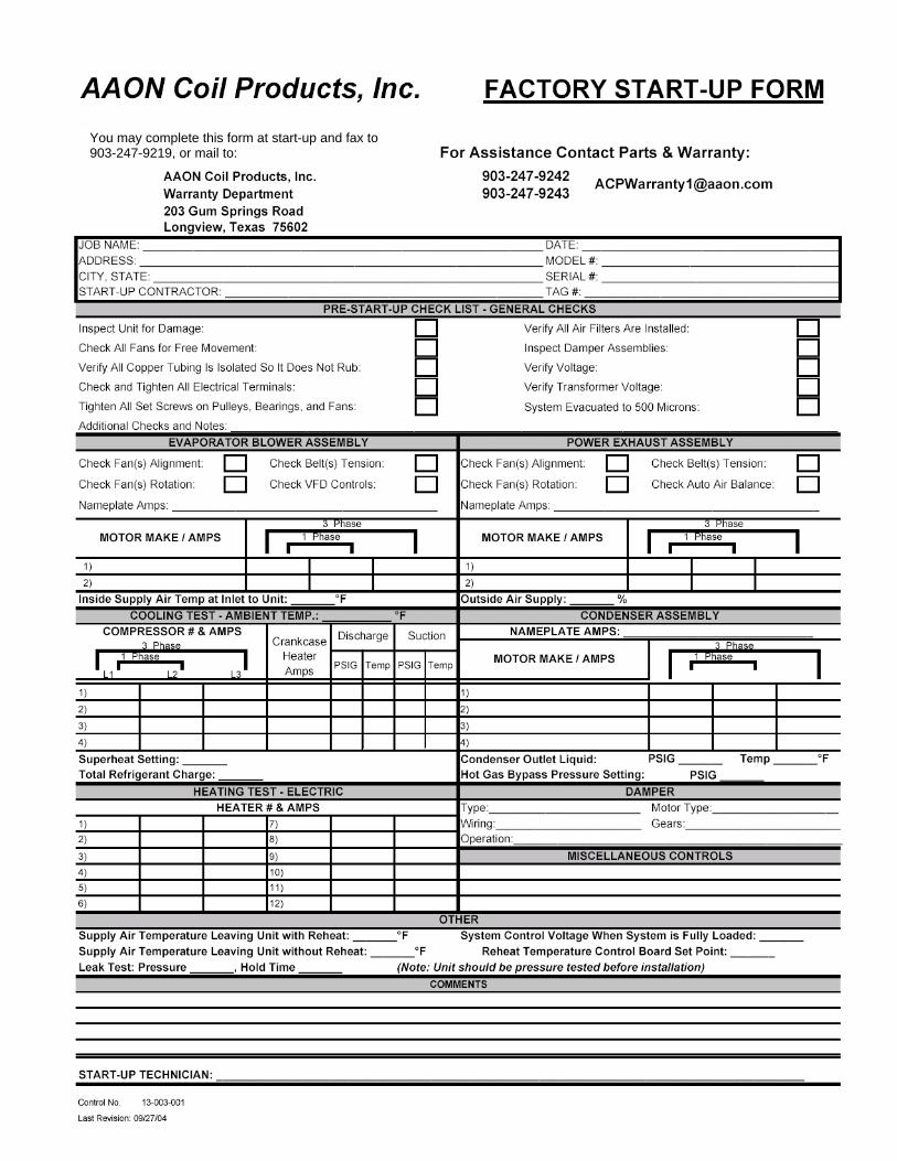
7. Factory Start-Up Form The factory start-up form is provided for the customer’s convenience only. It is not required to be returned to the factory. However, it is advisable to complete a start-up form to file with permanent unit records. Additionally, the form opposite this page may be completed and sent to the factory to be kept in the customer’s order file. You may complete and return the form to: AAON Coil Products, Inc. Warranty Department 203 Gum Springs Road Longview, Texas 75602 Fax: 903-247-9219 (please use fax cover sheet) Additional Start-Up Notes:
23
You may complete this form at start-up and fax to 903-247-9219, or mail to:
www.aaon.com 24
25

www.aaon.com 26

27
Pressure – Temperature Chart, R-410A & R-22
PSIG PSIG PSIG PSIG PSIG
(°F) R-410A R-22 (°F) R-410A R-22 (°F) R-410A R-22 (°F) R-410A R-22 (°F) R-410A R-22
20 78.3 43.1 50 142.2 84.1 80 234.9 143.6 110 364.1 226.4 140 540.1 337.4
21 80.0 44.2 51 144.8 85.7 81 238.6 146.0 111 369.1 229.6 141 547.0 341.6
22 81.8 45.3 52 147.4 87.4 82 242.3 148.4 112 374.2 232.8 142 553.9 345.9
23 83.6 46.5 53 150.1 89.1 83 246.0 150.8 113 379.4 236.1 143 560.9 350.3
24 85.4 47.6 54 152.8 90.8 84 249.8 153.2 114 384.6 239.4 144 567.9 354.6
25 87.2 48.8 55 155.5 92.6 85 253.7 155.7 115 389.9 242.8 145 575.1 359.0
26 89.1 50.0 56 158.2 94.4 86 257.5 158.2 116 395.2 246.1 146 582.3 363.5
27 91.0 51.2 57 161.0 96.1 87 261.4 160.7 117 400.5 249.5 147 589.6 368.0
28 92.9 52.4 58 163.8 98.0 88 265.4 163.2 118 405.9 253.0 148 596.9 372.5
29 94.9 53.7 59 166.7 99.8 89 269.4 165.8 119 411.4 256.5 149 604.4 377.1
30 96.8 55.0 60 169.6 101.6 90 273.5 168.4 120 416.9 260.0 150 611.9 381.7
31 98.8 56.2 61 172.5 103.5 91 277.6 171.0 121 422.5 263.5
32 100.9 57.5 62 175.4 105.4 92 281.7 173.7 122 428.2 267.1
33 102.9 58.8 63 178.4 107.3 93 285.9 176.4 123 433.9 270.7
34 105.0 60.2 64 181.5 109.3 94 290.1 179.1 124 439.6 274.3
35 107.1 61.5 65 184.5 111.2 95 294.4 181.8 125 445.4 278.0
36 109.2 62.9 66 187.6 113.2 96 298.7 184.6 126 451.3 281.7
37 111.4 64.3 67 190.7 115.3 97 303.0 187.4 127 457.3 285.4
38 113.6 65.7 68 193.9 117.3 98 307.5 190.2 128 463.2 289.2
39 115.8 67.1 69 197.1 119.4 99 311.9 193.0 129 469.3 293.0
40 118.1 68.6 70 200.4 121.4 100 316.4 195.9 130 475.4 296.9
41 120.3 70.0 71 203.6 123.5 101 321.0 198.8 131 481.6 300.8
42 122.7 71.5 72 207.0 125.7 102 325.6 201.8 132 487.8 304.7
43 125.0 73.0 73 210.3 127.8 103 330.2 204.7 133 494.1 308.7
44 127.4 74.5 74 213.7 130.0 104 334.9 207.7 134 500.5 312.6
45 129.8 76.1 75 217.1 132.2 105 339.6 210.8 135 506.9 316.7
46 132.2 77.6 76 220.6 134.5 106 344.4 213.8 136 513.4 320.7
47 134.7 79.2 77 224.1 136.7 107 349.3 216.9 137 520.0 324.8
48 137.2 80.8 78 227.7 139.0 108 354.2 220.0 138 526.6 329.0
49 139.7 82.4 79 231.3 141.3 109 359.1 223.2 139 533.3 333.2

www.aaon.com 28
AAON 2425 S. Yukon Ave. Tulsa, OK 74107-2728 Phone: 918-583-2266 Fax 918-583-6094 Download this manual and others from: www.aaon.com
It is the intent of AAON to provide accurate and current product information. However, in the interest of product improvement, AAON, Inc. reserves the right to change pricing, specifications, and/or design of its products without notice, obligation, or liability. AAON® is a registered trademark of AAON, Inc. Effective October 2007 Supersedes February 2006
P87860 02-06 (ACP 27294)
Cabinet Size (CFM Range)
Horizontal (H2) Units A (800 – 1,200)
B (1,200 – 2,000)
C (2,000 – 4,000)
C+ (3,000 – 6,000)
D (6,000 – 10,000)
16” x 20” x 2” Pleated Qty. 1 2 10
24” x 24” x 2” Pleated Qty. 2 3
Vertical (H2) Units A (800 – 1,200)
B (1,200 – 2,000)
C (2,000 – 4,000)
C+ (3,000 – 6,000)
D (6,000 – 10,000)
16” x 20” x 2” Pleated Qty. 1 4 6 9
24” x 24” x 2” Pleated Qty. 1
Optional 4”
Table 28.1, Pleated Filter Sizes
Typical Filter Sizes
H2V2 IOM 071019