Embed Size (px)
Citation preview

H.264 Main Profile Decoder on C64x+
User Guide
Literature Number: SPRUEB0B May 2007
IMPORTANT NOTICE Texas Instruments Incorporated and its subsidiaries (TI) reserve the right to make corrections, modifications, enhancements, improvements, and other changes to its products and services at any time and to discontinue any product or service without notice. Customers should obtain the latest relevant information before placing orders and should verify that such information is current and complete. All products are sold subject to TI’s terms and conditions of sale supplied at the time of order acknowledgment. TI warrants performance of its hardware products to the specifications applicable at the time of sale in accordance with TI’s standard warranty. Testing and other quality control techniques are used to the extent TI deems necessary to support this warranty. Except where mandated by government requirements, testing of all parameters of each product is not necessarily performed. TI assumes no liability for applications assistance or customer product design. Customers are responsible for their products and applications using TI components. To minimize the risks associated with customer products and applications, customers should provide adequate design and operating safeguards. TI does not warrant or represent that any license, either express or implied, is granted under any TI patent right, copyright, mask work right, or other TI intellectual property right relating to any combination, machine, or process in which TI products or services are used. Information published by TI regarding third-party products or services does not constitute a license from TI to use such products or services or a warranty or endorsement thereof. Use of such information may require a license from a third party under the patents or other intellectual property of the third party, or a license from TI under the patents or other intellectual property of TI. Reproduction of information in TI data books or data sheets is permissible only if reproduction is without alteration and is accompanied by all associated warranties, conditions, limitations, and notices. Reproduction of this information with alteration is an unfair and deceptive business practice. TI is not responsible or liable for such altered documentation. Resale of TI products or services with statements different from or beyond the parameters stated by TI for that product or service voids all express and any implied warranties for the associated TI product or service and is an unfair and deceptive business practice. TI is not responsible or liable for any such statements. TI products are not authorized for use in safety-critical applications (such as life support) where a failure of the TI product would reasonably be expected to cause severe personal injury or death, unless officers of the parties have executed an agreement specifically governing such use. Buyers represent that they have all necessary expertise in the safety and regulatory ramifications of their applications, and acknowledge and agree that they are solely responsible for all legal, regulatory and safety-related requirements concerning their products and any use of TI products in such safety-critical applications, notwithstanding any applications-related information or support that may be provided by TI. Further, Buyers must fully indemnify TI and its representatives against any damages arising out of the use of TI products in such safety-critical applications. TI products are neither designed nor intended for use in military/aerospace applications or environments unless the TI products are specifically designated by TI as military-grade or "enhanced plastic." Only products designated by TI as military-grade meet military specifications. Buyers acknowledge and agree that any such use of TI products which TI has not designated as military-grade is solely at the Buyer's risk, and that they are solely responsible for compliance with all legal and regulatory requirements in connection with such use. TI products are neither designed nor intended for use in automotive applications or environments unless the specific TI products are designated by TI as compliant with ISO/TS 16949 requirements. Buyers acknowledge and agree that, if they use any non-designated products in automotive applications, TI will not be responsible for any failure to meet such requirements. Following are URLs where you can obtain information on other Texas Instruments products and application solutions: Products Applications
Amplifiers amplifier.ti.com Audio www.ti.com/audio
Data Converters dataconverter.ti.com Automotive www.ti.com/automotive
DSP dsp.ti.com Broadband www.ti.com/broadband
Interface interface.ti.com Digital Control www.ti.com/digitalcontrol
Logic logic.ti.com Military www.ti.com/military
Power Mgmt power.ti.com Optical Networking www.ti.com/opticalnetwork
Microcontrollers microcontroller.ti.com Security www.ti.com/security
Low Power Wireless www.ti.com/lpw Telephony www.ti.com/telephony
Video & Imaging www.ti.com/video
Wireless www.ti.com/wireless
Mailing Address: Texas Instruments Post Office Box 655303 Dallas, Texas 75265
Copyright © 2007, Texas Instruments Incorporated
iii
Preface
Read This First
About This Manual
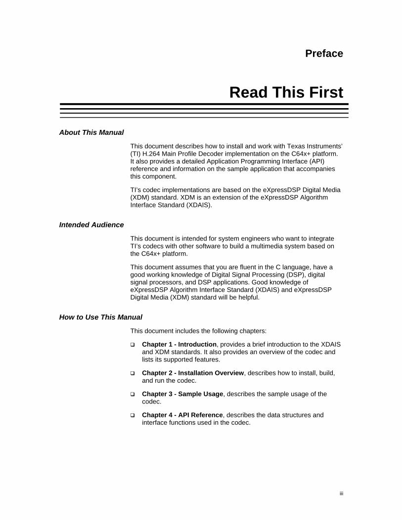
This document describes how to install and work with Texas Instruments’ (TI) H.264 Main Profile Decoder implementation on the C64x+ platform. It also provides a detailed Application Programming Interface (API) reference and information on the sample application that accompanies this component.
TI’s codec implementations are based on the eXpressDSP Digital Media (XDM) standard. XDM is an extension of the eXpressDSP Algorithm Interface Standard (XDAIS).
Intended Audience
This document is intended for system engineers who want to integrate TI’s codecs with other software to build a multimedia system based on the C64x+ platform.
This document assumes that you are fluent in the C language, have a good working knowledge of Digital Signal Processing (DSP), digital signal processors, and DSP applications. Good knowledge of eXpressDSP Algorithm Interface Standard (XDAIS) and eXpressDSP Digital Media (XDM) standard will be helpful.
How to Use This Manual
This document includes the following chapters:
Chapter 1 - Introduction, provides a brief introduction to the XDAIS and XDM standards. It also provides an overview of the codec and lists its supported features.
Chapter 2 - Installation Overview, describes how to install, build, and run the codec.
Chapter 3 - Sample Usage, describes the sample usage of the codec.
Chapter 4 - API Reference, describes the data structures and interface functions used in the codec.
Read This First
iv
Related Documentation From Texas Instruments
The following documents describe TI’s DSP algorithm standards such as, XDAIS and XDM. To obtain a copy of any of these TI documents, visit the Texas Instruments website at www.ti.com.
TMS320 DSP Algorithm Standard Rules and Guidelines (literature number SPRU352) defines a set of requirements for DSP algorithms that, if followed, allow system integrators to quickly assemble production-quality systems from one or more such algorithms.
TMS320 DSP Algorithm Standard API Reference (literature number SPRU360) describes all the APIs that are defined by the TMS320 DSP Algorithm Inteface Standard (also known as XDAIS) specification.
Technical Overview of eXpressDSP - Compliant Algorithms for DSP Software Producers (literature number SPRA579) describes how to make algorithms compliant with the TMS320 DSP Algorithm Standard which is part of TI’s eXpressDSP technology initiative.
Using the TMS320 DSP Algorithm Standard in a Static DSP System (literature number SPRA577) describes how an eXpressDSP-compliant algorithm may be used effectively in a static system with limited memory.
DMA Guide for eXpressDSP-Compliant Algorithm Producers and Consumers (literature number SPRA445) describes the DMA architecture specified by the TMS320 DSP Algorithm Standard (XDAIS). It also describes two sets of APIs used for accessing DMA resources: the IDMA2 abstract interface and the ACPY2 library.
eXpressDSP Digital Media (XDM) Standard API Reference (literature number SPRUEC8)
The following documents describe TMS320 devices and related support tools:
Design and Implementation of an eXpressDSP-Compliant DMA Manager for C6X1X (literature number SPRA789) describes a C6x1x-optimized (C6211, C6711) ACPY2 library implementation and DMA Resource Manager.
TMS320c64x+ Megamodule (literature number SPRAA68) describes the enhancements made to the internal memory and describes the new features which have been added to support the internal memory architecture's performance and protection.
TMS320C64x+ DSP Megamodule Reference Guide (literature number SPRU871) describes the C64x+ megamodule peripherals.
TMS320C64x to TMS320C64x+ CPU Migration Guide (literature number SPRAA84) describes migration from the Texas Instruments TMS320C64x™ digital signal processor (DSP) to the TMS320C64x+™ DSP.
TMS320C6000 Optimizing Compiler v 6.0 Beta User's Guide (literature number SPRU187N) explains how to use compiler tools
Read This First
v
such as compiler, assembly optimizer, standalone simulator, library-build utility, and C++ name demangler.
TMS320C64x/C64x+ DSP CPU and Instruction Set Reference Guide (literature number SPRU732) describes the CPU architecture, pipeline, instruction set, and interrupts of the C64x and C64x+ DSPs.
TMS320DM6446 Digital Media System-on-Chip (literature number SPRS283)
TMS320DM6446 Digital Media System-on-Chip Errata (Silicon Revision 1.0) (literature number SPRZ241) describes the known exceptions to the functional specifications for the TMS320DM6446 Digital Media System-on-Chip (DMSoC).
TMS320DM6443 Digital Media System-on-Chip (literature number SPRS282)
TMS320DM6443 Digital Media System-on-Chip Errata (Silicon Revision 1.0) (literature number SPRZ240) describes the known exceptions to the functional specifications for the TMS320DM6443 Digital Media System-on-Chip (DMSoC).
TMS320DM644x DMSoC DSP Subsystem Reference Guide (literature number SPRUE15) describes the digital signal processor (DSP) subsystem in the TMS320DM644x Digital Media System-on-Chip (DMSoC).
TMS320DM644x DMSoC ARM Subsystem Reference Guide (literature number SPRUE14) describes the ARM subsystem in the TMS320DM644x Digital Media System on a Chip (DMSoC).
DaVinci Technology - Digital Video Innovation Product Bulletin (Rev. A) (sprt378a.pdf)
The DaVinci Effect: Achieving Digital Video Without Complexity White Paper (spry079.pdf)
DaVinci Benchmarks Product Bulletin (sprt379.pdf)
DaVinci Technology for Digital Video White Paper (spry067.pdf)
The Future of Digital Video White Paper (spry066.pdf)
Related Documentation
You can use the following documents to supplement this user guide:
ISO/IEC 14496-10:2005 (E) Rec.- Information technology – Coding of audio-visual objects – H.264 (E) ITU-T Recommendation
Read This First
vi
Abbreviations
The following abbreviations are used in this document:
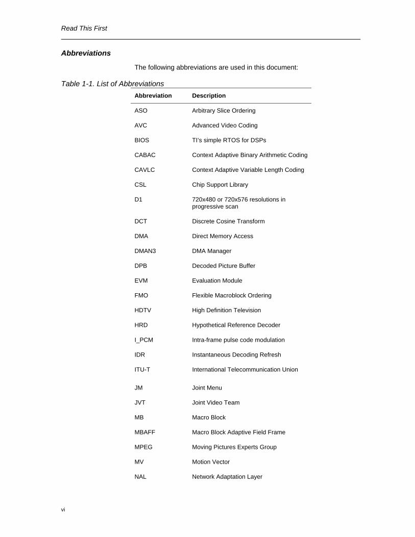
Table 1-1. List of Abbreviations Abbreviation Description
ASO Arbitrary Slice Ordering
AVC Advanced Video Coding
BIOS TI’s simple RTOS for DSPs
CABAC Context Adaptive Binary Arithmetic Coding
CAVLC Context Adaptive Variable Length Coding
CSL Chip Support Library
D1 720x480 or 720x576 resolutions in progressive scan
DCT Discrete Cosine Transform
DMA Direct Memory Access
DMAN3 DMA Manager
DPB Decoded Picture Buffer
EVM Evaluation Module
FMO Flexible Macroblock Ordering
HDTV High Definition Television
HRD Hypothetical Reference Decoder
I_PCM Intra-frame pulse code modulation
IDR Instantaneous Decoding Refresh
ITU-T International Telecommunication Union
JM Joint Menu
JVT Joint Video Team
MB Macro Block
MBAFF Macro Block Adaptive Field Frame
MPEG Moving Pictures Experts Group
MV Motion Vector
NAL Network Adaptation Layer
Read This First
vii
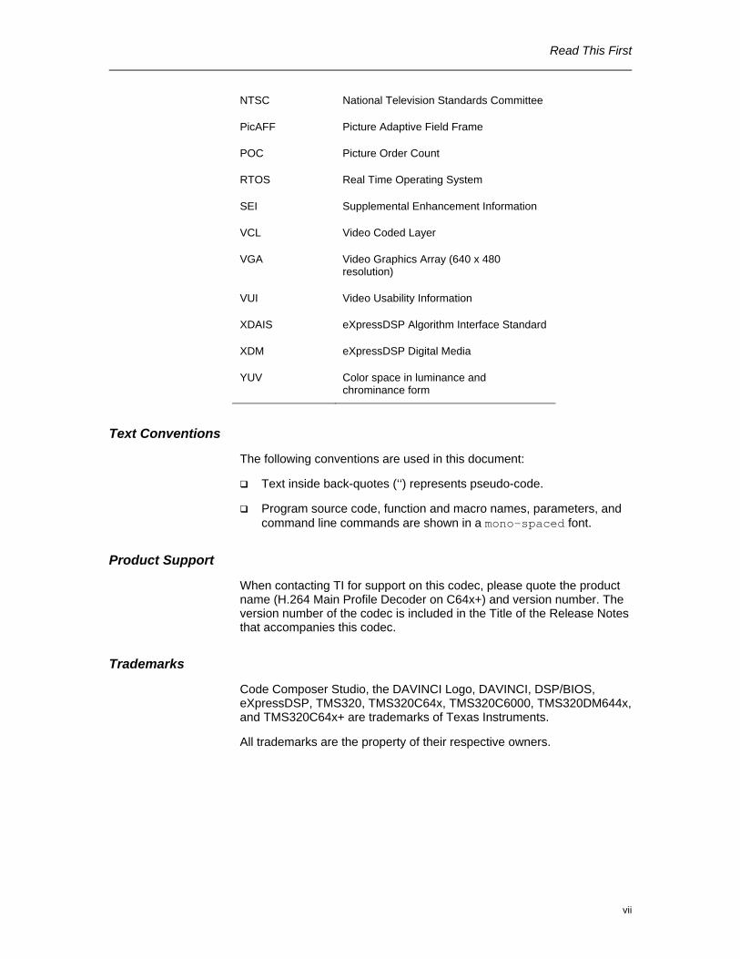
NTSC National Television Standards Committee
PicAFF Picture Adaptive Field Frame
POC Picture Order Count
RTOS Real Time Operating System
SEI Supplemental Enhancement Information
VCL Video Coded Layer
VGA Video Graphics Array (640 x 480 resolution)
VUI Video Usability Information
XDAIS eXpressDSP Algorithm Interface Standard
XDM eXpressDSP Digital Media
YUV Color space in luminance and chrominance form
Text Conventions
The following conventions are used in this document:
Text inside back-quotes (‘‘) represents pseudo-code.
Program source code, function and macro names, parameters, and command line commands are shown in a mono-spaced font.
Product Support
When contacting TI for support on this codec, please quote the product name (H.264 Main Profile Decoder on C64x+) and version number. The version number of the codec is included in the Title of the Release Notes that accompanies this codec.
Trademarks
Code Composer Studio, the DAVINCI Logo, DAVINCI, DSP/BIOS, eXpressDSP, TMS320, TMS320C64x, TMS320C6000, TMS320DM644x, and TMS320C64x+ are trademarks of Texas Instruments.
All trademarks are the property of their respective owners.

Read This First
viii
This page is intentionally left blank
ix
Contents Read This First .................................................................................................................. iii
About This Manual .......................................................................................................iii Intended Audience .......................................................................................................iii How to Use This Manual ..............................................................................................iii Related Documentation From Texas Instruments....................................................... iv Related Documentation................................................................................................ v Text Conventions ........................................................................................................vii Product Support ..........................................................................................................vii Trademarks .................................................................................................................vii
Contents............................................................................................................................. ix Figures ............................................................................................................................... xi Tables............................................................................................................................... xiii Introduction .....................................................................................................................1-1
1.1 Overview of XDAIS and XDM............................................................................1-2 1.1.1 XDAIS Overview ................................................................................................1-2 1.1.2 XDM Overview ...................................................................................................1-2
1.2 Overview of H.264 Main Profile Decoder ..........................................................1-3 1.3 Supported Services and Features.....................................................................1-5
Installation Overview ......................................................................................................2-1 2.1 System Requirements .......................................................................................2-2
2.1.1 Hardware............................................................................................................2-2 2.1.2 Software .............................................................................................................2-2
2.2 Installing the Component...................................................................................2-2 2.3 Before Building the Sample Test Application ....................................................2-3
2.3.1 Installing DSP/BIOS ...........................................................................................2-4 2.3.2 Installing Framework Component (FC) ..............................................................2-4
2.4 Building and Running the Sample Test Application ..........................................2-4 2.5 Configuration Files ............................................................................................2-5
2.5.1 Generic Configuration File .................................................................................2-5 2.5.2 Decoder Configuration File ................................................................................2-6
2.6 Standards Conformance and User-Defined Inputs ...........................................2-6 2.7 Uninstalling the Component ..............................................................................2-7 2.8 Evaluation Version ............................................................................................2-7
Sample Usage..................................................................................................................3-1 3.1 Overview of the Test Application.......................................................................3-2
3.1.1 Parameter Setup ................................................................................................3-3 3.1.2 Algorithm Instance Creation and Initialization....................................................3-3 3.1.3 Process Call .......................................................................................................3-4 3.1.4 Algorithm Instance Deletion ...............................................................................3-5
API Reference..................................................................................................................4-1 4.1 Symbolic Constants and Enumerated Data Types............................................4-2 4.2 Data Structures ...............................................................................................4-11
4.2.1 Common XDM Data Structures........................................................................4-11 4.2.2 H.264 Decoder Data Structures.......................................................................4-20
x
4.3 Interface Functions..........................................................................................4-33 4.3.1 Creation APIs ...................................................................................................4-33 4.3.2 Initialization API................................................................................................4-35 4.3.3 Control API .......................................................................................................4-36 4.3.4 Data Processing API ........................................................................................4-38 4.3.5 Termination API ...............................................................................................4-42
4.4 Error Handling .................................................................................................4-44
xi
Figures Figure 1-1. Block Diagram of H.264 Decoder ...............................................................1-5 Figure 2-1. Component Directory Structure .................................................................2-2 Figure 3-1. Test Application Sample Implementation..................................................3-2

xii
This page is intentionally left blank
xiii
Tables Table 1-1. List of Abbreviations....................................................................................... vi Table 2-1. Component Directories.................................................................................2-3 Table 4-1. List of Enumerated Data Types....................................................................4-2 Table 4-2. Error codes and values.................................................................................4-5

xiv
This page is intentionally left blank
1-1
Chapter 1
Introduction
This chapter provides a brief introduction to XDAIS and XDM. It also provides an overview of TI’s implementation of the H.264 Main Profile Decoder on the C64x+ platform and its supported features.
Topic Page
1.1 Overview of XDAIS and XDM 1-2
1.2 Overview of H.264 Main Profile Decoder 1-3
1.3 Supported Services and Features 1-5
Introduction
1-2
1.1 Overview of XDAIS and XDM
TI’s multimedia codec implementations are based on the eXpressDSP Digital Media (XDM) standard. XDM is an extension of the eXpressDSP Algorithm Interface Standard (XDAIS).
1.1.1 XDAIS Overview
An eXpressDSP-compliant algorithm is a module that implements the abstract interface IALG. The IALG API takes the memory management function away from the algorithm and places it in the hosting framework. Thus, an interaction occurs between the algorithm and the framework. This interaction allows the client application to allocate memory for the algorithm and also share memory between algorithms. It also allows the memory to be moved around while an algorithm is operating in the system. In order to facilitate these functionalities, the IALG interface defines the following APIs:
algAlloc()
algInit()
algActivate()
algDeactivate()
algFree()
The algAlloc() API allows the algorithm to communicate its memory requirements to the client application. The algInit() API allows the algorithm to initialize the memory allocated by the client application. The algFree() API allows the algorithm to communicate the memory to be freed when an instance is no longer required.
Once an algorithm instance object is created, it can be used to process data in real-time. The algActivate() API provides a notification to the algorithm instance that one or more algorithm processing methods is about to be run zero or more times in succession. After the processing methods have been run, the client application calls the algDeactivate() API prior to reusing any of the instance’s scratch memory.
The IALG interface also defines three more optional APIs algControl(), algNumAlloc(), and algMoved(). For more details on these APIs, see TMS320 DSP Algorithm Standard API Reference (literature number SPRU360).
1.1.2 XDM Overview
In the multimedia application space, you have the choice of integrating any codec into your multimedia system. For example, if you are building a video decoder system, you can use any of the available video decoders (such as MPEG4, H.263, or H.264) in your system. To enable easy integration with the client application, it is important that all codecs with similar functionality use similar APIs. XDM was primarily defined as an extension to XDAIS to ensure uniformity across different classes of codecs
Introduction
1-3
(for example audio, video, image, and speech). The XDM standard defines the following two APIs:
control()
process()
The control() API provides a standard way to control an algorithm instance and receive status information from the algorithm in real-time. The control() API replaces the algControl() API defined as part of the IALG interface. The process() API does the basic processing (encode/decode) of data.
Apart from defining standardized APIs for multimedia codecs, XDM also standardizes the generic parameters that the client application must pass to these APIs. The client application can define additional implementation specific parameters using extended data structures.
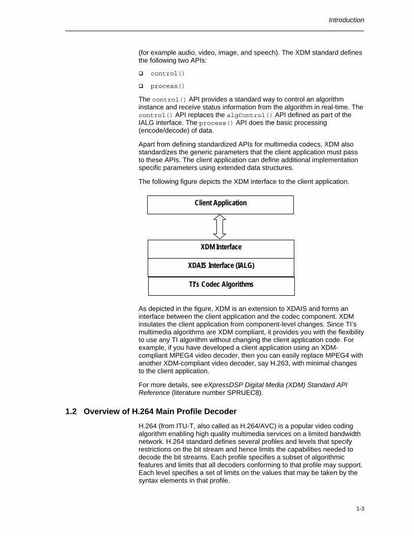
The following figure depicts the XDM interface to the client application.
As depicted in the figure, XDM is an extension to XDAIS and forms an interface between the client application and the codec component. XDM insulates the client application from component-level changes. Since TI’s multimedia algorithms are XDM compliant, it provides you with the flexibility to use any TI algorithm without changing the client application code. For example, if you have developed a client application using an XDM-compliant MPEG4 video decoder, then you can easily replace MPEG4 with another XDM-compliant video decoder, say H.263, with minimal changes to the client application.
For more details, see eXpressDSP Digital Media (XDM) Standard API Reference (literature number SPRUEC8).
1.2 Overview of H.264 Main Profile Decoder
H.264 (from ITU-T, also called as H.264/AVC) is a popular video coding algorithm enabling high quality multimedia services on a limited bandwidth network. H.264 standard defines several profiles and levels that specify restrictions on the bit stream and hence limits the capabilities needed to decode the bit streams. Each profile specifies a subset of algorithmic features and limits that all decoders conforming to that profile may support. Each level specifies a set of limits on the values that may be taken by the syntax elements in that profile.
Client Application
XDAIS Interface (IALG)
TI’s Codec Algorithms
XDM Interface
Introduction
1-4
Some important H.264 profiles and their special features are:
Baseline Profile:
o Only I and P type slices are present
o Only frame mode (progressive) picture types are present
o Only CAVLC is supported
o ASO/FMO and redundant slices for error concealment is supported
Main Profile:
o Only I, P, and B type slices are present
o Frame and field picture modes (in progressive and interlaced modes) picture types are present
o Both CAVLC and CABAC are supported
o ASO is not supported
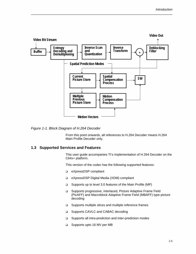
H.264 Main Profile Decoder is a completely programmable single-chip solution. The input to the decoder is a H.264 encoded bit stream in the byte-stream syntax. The byte stream consists of a sequence of byte stream NAL unit syntax structures. Each byte stream NAL unit syntax structure contains one start code prefix of size four bytes and value 0x00000001, followed by one NAL unit syntax structure. The encoded frame data is a group of slices each of which is encapsulated in NAL units. The slice consists of the following:
Intra coded data: Spatial prediction mode and prediction error data, which is subjected to DCT and later quantized.
Inter coded data: Motion information and residual error data (differential data between two frames), which is subjected to DCT and later quantized.
The first frame received by the decoder is IDR (Instantaneous Decode Refresh) picture frame. The decoder reconstructs the frame by spatial intra-prediction specified by the mode and by adding the prediction error. The subsequent frames may be intra or inter coded.
In case of inter coding, the decoder reconstructs the bit stream by adding the residual error data to the previously decoded image, at the location specified by the motion information. This process is repeated until the entire bit stream is decoded.
The output of the decoder is a YUV sequence, which can be of format 420 planar and 422 interleaved in little endian.
Figure 1-1 depicts the working of the decoder.
Introduction
1-5
Figure 1-1. Block Diagram of H.264 Decoder
From this point onwards, all references to H.264 Decoder means H.264 Main Profile Decoder only.
1.3 Supported Services and Features
This user guide accompanies TI’s implementation of H.264 Decoder on the C64x+ platform.
This version of the codec has the following supported features:
eXpressDSP compliant
eXpressDSP Digital Media (XDM) compliant
Supports up to level 3.0 features of the Main Profile (MP)
Supports progressive, interlaced, Picture Adaptive Frame Field (PicAFF) and Macroblock Adaptive Frame Field (MBAFF) type picture decoding
Supports multiple slices and multiple reference frames
Supports CAVLC and CABAC decoding
Supports all intra-prediction and inter-prediction modes
Supports upto 16 MV per MB
SW
Multiple Previous Picture Store
Motion Compensation Process
+
Motion Vectors
Spatial Compensation Process
Current Picture Store
Spatial Prediction Modes
Video Bit Stream
Buffer Entropy Decoding and Demultiplexing
Inverse Scan and Quantization
Inverse Transform
Deblocking Filter
Video Out
Introduction
1-6
Supports frame based decoding
Supports frame size being non-multiple of 16 through frame cropping
Supports frame width of the range of 32 to 720 pixels
Supports byte-stream syntax for the input bit stream
Supports parsing of Supplemental Enhancement Information (SEI) and Video Usability Information (VUI)
Supports long term reference frame and adaptive reference picture marking
Supports reference picture list reordering
Supports gaps in frame_num
Supports decoding of streams with IPCM coded macroblocks
Supports skipping of non reference pictures
Supports configurable delay for display of frames
Basic error concealment features
Outputs are available in YUV 420 planar and 422 interleaved little endian formats
Tested for compliance with JM version 11.0 reference decoder
Supports dynamic change in the frame size (ability to decode different frame sizes present in the very same stream)
H.264 decoder is fully compliant with Allegro test suites (non HD streams)
2-1
Chapter 2
Installation Overview
This chapter provides a brief description on the system requirements and instructions for installing the codec component. It also provides information on building and running the sample test application.
Topic Page
2.1 System Requirements 2-2
2.2 Installing the Component 2-2
2.3 Before Building the Sample Test Application 2-3
2.4 Building and Running the Sample Test Application 2-4
2.5 Configuration Files 2-5
2.6 Standards Conformance and User-Defined Inputs 2-6
2.7 Uninstalling the Component 2-7
2.8 Evaluation Version 2-7
Installation Overview
2-2
2.1 System Requirements
This section describes the hardware and software requirements for the normal functioning of the codec component.
2.1.1 Hardware
This codec has been built and tested on the DM6446 EVM with XDS560 USB.
2.1.2 Software
The following are the software requirements for the normal functioning of the codec:
Development Environment: This project is developed using Code Composer Studio (CCS) version 3.3.24.1.
Code Generation Tools: This project is compiled, assembled, archived, and linked using the code generation tools version 6.0.7.
2.2 Installing the Component
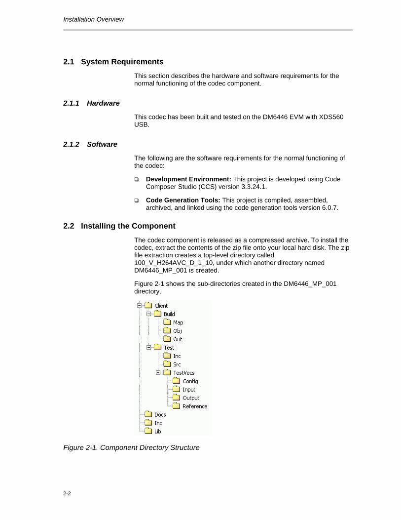
The codec component is released as a compressed archive. To install the codec, extract the contents of the zip file onto your local hard disk. The zip file extraction creates a top-level directory called 100_V_H264AVC_D_1_10, under which another directory named DM6446_MP_001 is created.
Figure 2-1 shows the sub-directories created in the DM6446_MP_001 directory.
Figure 2-1. Component Directory Structure

Installation Overview
2-3
Note:
If you are installing an evaluation version of this codec, the directory name will be 100E_V_H264AVC_D_1_10.
Table 2-1 provides a description of the sub-directories created in the DM6446_MP_001 directory.
Table 2-1. Component Directories Sub-Directory Description
\Inc Contains XDM related header files which allow interface to the codec library
\Lib Contains the codec library file
\Docs Contains user guide, datasheet, and release notes
\Client\Build Contains the sample test application project (.pjt) file
\Client\Build\Map Contains the memory map generated on compilation of the code
\Client\Build\Obj Contains the intermediate .asm and/or .obj file generated on compilation of the code
\Client\Build\Out Contains the final application executable (.out) file generated by the sample test application
\Client\Test\Src Contains application C files
\Client\Test\Inc Contains header files needed for the application code
\Client\Test\TestVecs\Input Contains input test vectors
\Client\Test\TestVecs\Output Contains output generated by the codec
\Client\Test\TestVecs\Reference Contains read-only reference output to be used for cross-checking against codec output
\Client\Test\TestVecs\Config Contains configuration parameter files
2.3 Before Building the Sample Test Application
This codec is accompanied by a sample test application. To run the sample test application, you need DSP/BIOS and TI Framework Components (FC).
This version of the codec has been validated with DSP/BIOS version 5.31.02 and Framework Component (FC) version 1.10.01.
Installation Overview
2-4
2.3.1 Installing DSP/BIOS
You can download DSP/BIOS from the TI external website:
https://www-a.ti.com/downloads/sds_support/targetcontent/bios/index.html
Install DSP/BIOS at the same location where you have installed Code Composer Studio. For example:
<install directory>\CCStudio_v3.2
The sample test application uses the following DSP/BIOS files:
Header file, bcache.h available in the <install directory>\CCStudio_v3.2\<bios_directory>\packages \ti\bios\include directory.
Library file, biosDM420.a64P available in the <install directory>\CCStudio_v3.2\<bios_directory>\packages \ti\bios\lib directory.
2.3.2 Installing Framework Component (FC)
You can download FC from the TI external website:
https://www-a.ti.com/downloads/sds_support/targetcontent/FC/index.html
Extract the FC zip file to the same location where you have installed Code Composer Studio. For example:
<install directory>\CCStudio_v3.2
The test application uses the following DMAN3 files:
Library file, dman3.a64P available in the <install directory>\CCStudio_v3.2\<fc_directory>\packages \ti\sdo\fc\dman3 directory.
Header file, dman3.h available in the <install directory>\CCStudio_v3.2\<fc_directory>\packages \ti\sdo\fc\dman3 directory.
Header file, idma3.h available in the <install directory>\CCStudio_v3.2\<fc_directory>\packages \ti\sdo\fc\acpy3 directory.
2.4 Building and Running the Sample Test Application
The sample test application that accompanies this codec component will run in TI’s Code Composer Studio (CCS) development environment. To build and run the sample test application in Code Composer Studio(CCS), follow these steps:
1) Verify that you have an installation of TI’s Code Composer Studio version 3.3.24.1 and code generation tools version 6.0.7.
Installation Overview
2-5
2) Verify that the codec object library, h264mpvdec_ti.l64P exists in the \Lib sub-directory.
3) Open the test application project file, TestAppDecoder.pjt in Code Composer Studio. This file is available in the \Client\Build sub-directory.
4) Select Project > Build to build the sample test application. This creates an executable file, TestAppDecoder.out in the \Client\Build\Out sub-directory.
5) Select File > Load, browse to the \Client\Build\Out sub-directory, select the codec executable created in step 4, and load it into Code Composer Studio in preparation for execution.
6) Select Debug > Run to execute the sample test application.
The sample test application takes the input files stored in the \Client\Test\TestVecs\Input sub-directory, runs the codec, and uses the reference files stored in the \Client\Test\TestVecs\Reference sub-directory to verify that the codec is functioning as expected.
On successful completion, the application displays one of the following messages for each frame:
o “Decoder compliance test passed/failed” (for compliance check mode)
o “Decoder output dump completed” (for output dump mode)
2.5 Configuration Files
This codec is shipped along with:
A generic configuration file (Testvecs.cfg) – specifies input and reference files for the sample test application.
A Decoder configuration file (Testparams.cfg) – specifies the configuration parameters used by the test application to configure the Decoder.
2.5.1 Generic Configuration File
The sample test application shipped along with the codec uses the configuration file, Testvecs.cfg for determining the input and reference files for running the codec and checking for compliance. The Testvecs.cfg file is available in the \Client\Test\TestVecs\Config sub-directory.
The format of the Testvecs.cfg file is:
X Config Input Output/Reference
where:
X may be set as:
o 1 - for compliance checking, no output file is created
Installation Overview
2-6
o 0 - for writing the output to the output file
Config is the Decoder configuration file. For details, see section 2.5.2
Input is the input file name (use complete path).
Output/Reference is the output file name (if X is 0) or reference file name (if X is 1).
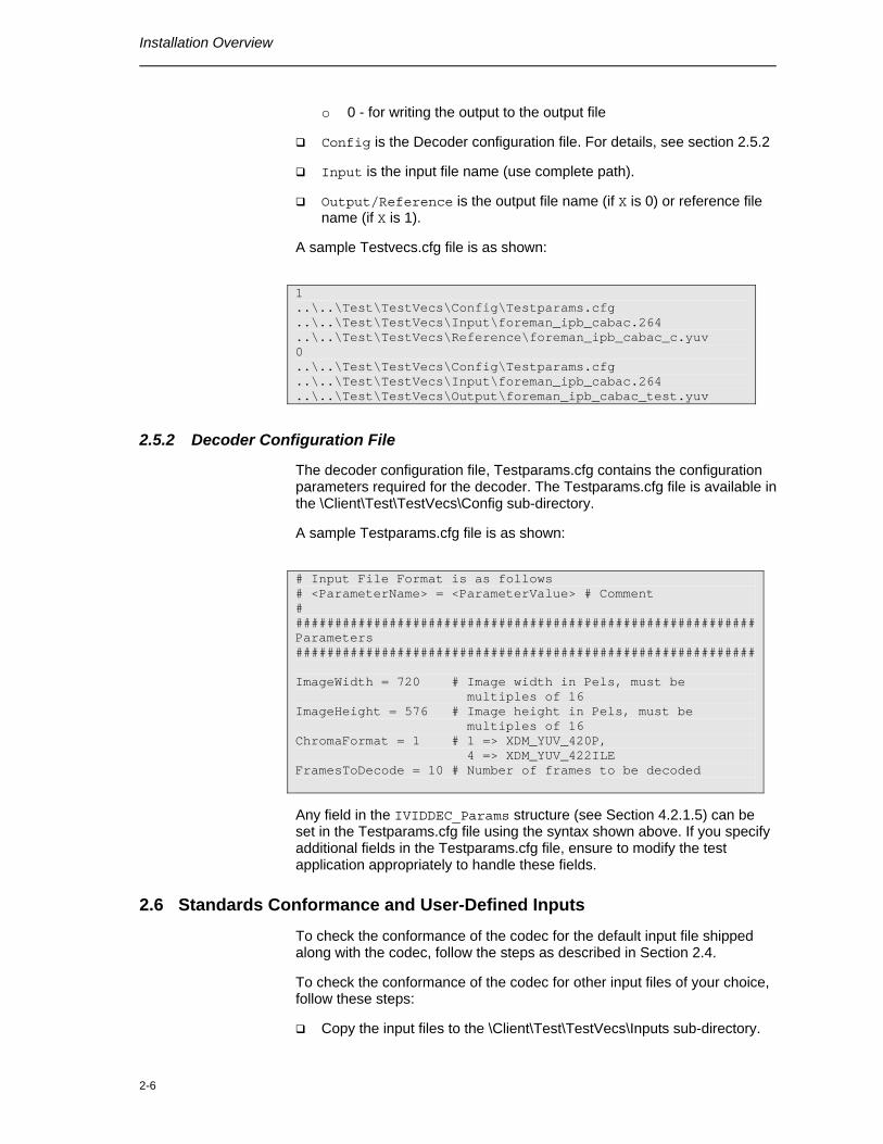
A sample Testvecs.cfg file is as shown:
1 ..\..\Test\TestVecs\Config\Testparams.cfg ..\..\Test\TestVecs\Input\foreman_ipb_cabac.264 ..\..\Test\TestVecs\Reference\foreman_ipb_cabac_c.yuv 0 ..\..\Test\TestVecs\Config\Testparams.cfg ..\..\Test\TestVecs\Input\foreman_ipb_cabac.264 ..\..\Test\TestVecs\Output\foreman_ipb_cabac_test.yuv
2.5.2 Decoder Configuration File
The decoder configuration file, Testparams.cfg contains the configuration parameters required for the decoder. The Testparams.cfg file is available in the \Client\Test\TestVecs\Config sub-directory.
A sample Testparams.cfg file is as shown:
# Input File Format is as follows # <ParameterName> = <ParameterValue> # Comment # ########################################################### Parameters ########################################################### ImageWidth = 720 # Image width in Pels, must be multiples of 16 ImageHeight = 576 # Image height in Pels, must be multiples of 16 ChromaFormat = 1 # 1 => XDM_YUV_420P, 4 => XDM_YUV_422ILE FramesToDecode = 10 # Number of frames to be decoded
Any field in the IVIDDEC_Params structure (see Section 4.2.1.5) can be set in the Testparams.cfg file using the syntax shown above. If you specify additional fields in the Testparams.cfg file, ensure to modify the test application appropriately to handle these fields.
2.6 Standards Conformance and User-Defined Inputs
To check the conformance of the codec for the default input file shipped along with the codec, follow the steps as described in Section 2.4.
To check the conformance of the codec for other input files of your choice, follow these steps:
Copy the input files to the \Client\Test\TestVecs\Inputs sub-directory.
Installation Overview
2-7
Copy the reference files to the \Client\Test\TestVecs\Reference sub-directory.
Edit the configuration file, Testvecs.cfg available in the \Client\Test\TestVecs\Config sub-directory. For details on the format of the Testvecs.cfg file, see section 2.5.1.
Execute the sample test application. On successful completion, the application displays one of the following message for each frame:
o “Decoder compliance test passed/failed” (if X is 1)
o “Decoder output dump completed” (if X is 0)
If you have chosen the option to write to an output file (X is 0), you can use any standard file comparison utility to compare the codec output with the reference output and check for conformance.
2.7 Uninstalling the Component
To uninstall the component, delete the codec directory from your hard disk.
2.8 Evaluation Version
If you are using an evaluation version of this codec a Texas Instruments logo will be visible in the output.

Installation Overview
2-8
This page is intentionally left blank
3-1
Chapter 3
Sample Usage
This chapter provides a detailed description of the sample test application that accompanies this codec component.
Sample Usage
3-2
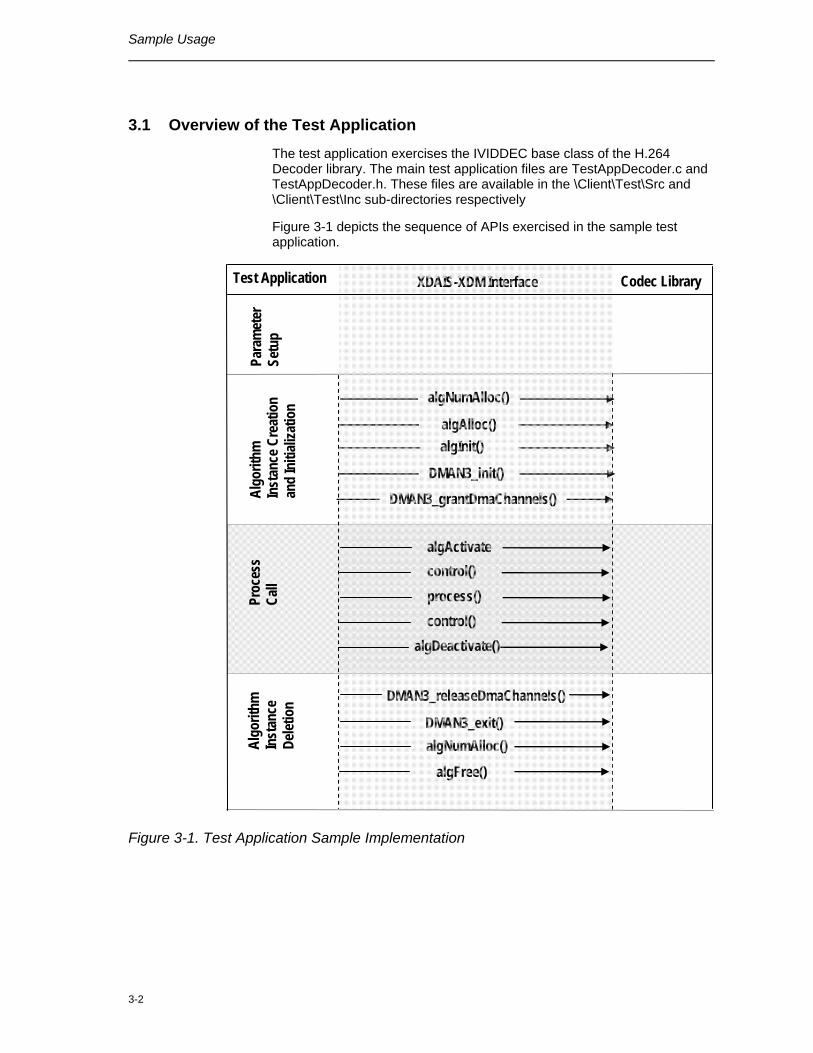
3.1 Overview of the Test Application
The test application exercises the IVIDDEC base class of the H.264 Decoder library. The main test application files are TestAppDecoder.c and TestAppDecoder.h. These files are available in the \Client\Test\Src and \Client\Test\Inc sub-directories respectively
Figure 3-1 depicts the sequence of APIs exercised in the sample test application.
XDAIS-XDM Interface Codec Library
Algo
rithm
In
stan
ce
Delet
ion
Algo
rithm
In
stan
ce C
reat
ion
and
Initi
aliza
tion
Para
met
er
Setu
p
DMAN3_init()
algInit() algAlloc()
algNumAlloc()
DMAN3_grantDmaChannels()
Proc
ess
Call
algActivatecontrol() process() control()
algDeactivate()
DMAN3_releaseDmaChannels()
DMAN3_exit() algNumAlloc() algFree()
Test Application
Figure 3-1. Test Application Sample Implementation
Sample Usage
3-3
The test application is divided into four logical blocks:
Parameter setup
Algorithm instance creation and initialization
Process call
Algorithm instance deletion
3.1.1 Parameter Setup
Each codec component requires various codec configuration parameters to be set at initialization. For example, a video codec requires parameters such as video height, video width, etc. The test application obtains the required parameters from the Decoder configuration files.
In this logical block, the test application does the following:
1) Opens the generic configuration file, Testvecs.cfg and reads the compliance checking parameter, Decoder configuration file name (Testparams.cfg), input file name, and output/reference file name.
2) Opens the Decoder configuration file, (Testparams.cfg) and reads the various configuration parameters required for the algorithm.
For more details on the configuration files, see Section 2.5.
3) Sets the IVIDDEC_Params structure based on the values it reads from the Testparams.cfg file.
4) Initializes the various DMAN3 parameters.
5) Reads the input bit stream into the application input buffer.
After successful completion of the above steps, the test application does the algorithm instance creation and initialization.
3.1.2 Algorithm Instance Creation and Initialization
In this logical block, the test application accepts the various initialization parameters and returns an algorithm instance pointer. The following APIs are called in sequence:
1) algNumAlloc() - To query the algorithm about the number of memory records it requires.
2) algAlloc() - To query the algorithm about the memory requirement to be filled in the memory records.
3) algInit() - To initialize the algorithm with the memory structures provided by the application.
A sample implementation of the create function that calls algNumAlloc(), algAlloc(), and algInit() in sequence is provided in the ALG_create() function implemented in the alg_create.c file.
Sample Usage
3-4
After successful creation of the algorithm instance, the test application does DMA resource allocation for the algorithm. This requires initialization of DMA Manager Module and grant of DMA resources. This is implemented by calling DMAN3 interface functions in the following sequence:
1) DMAN3_init() - To initialize the DMAN module.
2) DMAN3_grantDmaChannels() - To grant the DMA resources to the algorithm instance.
Note:
DMAN3 function implementations are provided in dman3.a64P library.
3.1.3 Process Call
After algorithm instance creation and initialization, the test application does the following:
1) Sets the dynamic parameters (if they change during run time) by calling the control() function with the XDM_SETPARAMS command.
2) Sets the input and output buffer descriptors required for the process() function call. The input and output buffer descriptors are obtained by calling the control() function with the XDM_GETBUFINFO command.
3) Calls the process() function to encode/decode a single frame of data. The behavior of the algorithm can be controlled using various dynamic parameters (see Section 4.2.1.6). The inputs to the process function are input and output buffer descriptors, pointer to the IVIDDEC_InArgs and IVIDDEC_OutArgs structures.
The control() and process() functions should be called only within the scope of the algActivate() and algDeactivate() XDAIS functions which activate and deactivate the algorithm instance respectively. Once an algorithm is activated, there could be any ordering of control() and process() functions. The following APIs are called in sequence:
1) algActivate() - To activate the algorithm instance.
2) control() (optional) - To query the algorithm on status or setting of dynamic parameters etc., using the six available control commands.
3) process() - To call the Decoder with appropriate input/output buffer and arguments information.
4) control() (optional) - To query the algorithm on status or setting of dynamic parameters etc., using the six available control commands.
5) algDeactivate() - To deactivate the algorithm instance.
The do-while loop encapsulates frame level process() call and updates the input buffer pointer every time before the next call. The do-while loop breaks off either when an error condition occurs or when the input buffer exhausts. It also protects the process() call from file operations by
Sample Usage
3-5
placing appropriate calls for cache operations as well. The test application does a cache invalidate for the valid input buffers before process() and a cache write back invalidate for output buffers after process().
To support frame reordering and B frames, delay is present between decoding of a frame and its display. This delay amount is configurable depending on the application requirement. (see Section 4.2.1.9 for details). The first frame to be displayed is returned after first N+1 frames are decoded by the decoder (N is the configured delay). Hence N buffers are locked within the decoder. On reaching end of sequence the control() API ‘XDM_FLUSH’is called. Subsequent process call returns the locked frames as output frame without performing any decoding.
Test application is configured for a delay of 5 frames and it utilizes 7 buffers to store decoded output in order to support frame reordering.
In the sample test application, after calling algDeactivate(), the output data is either dumped to a file or compared with a reference file.
3.1.4 Algorithm Instance Deletion
Once encoding/decoding is complete, the test application must release the DMA channels granted by the DMA Manager interface and delete the current algorithm instance. The following APIs are called in sequence:
1) DMAN3_releaseDmaChannels() - To remove logical channel resources from an algorithm instance.
2) DMAN3_exit() - To free DMAN3 memory resources.
3) algNumAlloc() - To query the algorithm about the number of memory records it used.
4) algFree() - To query the algorithm to get the memory record information.
A sample implementation of the delete function that calls algNumAlloc() and algFree() in sequence is provided in the ALG_delete() function implemented in the alg_create.c file.

Sample Usage
3-6
This page is intentionally left blank
4-1
Chapter 4
API Reference
This chapter provides a detailed description of the data structures and interfaces functions used in the codec component.
Topic Page
4.1 Symbolic Constants and Enumerated Data Types 4-2
4.2 Data Structures 4-4
4.3 Interface Functions 4-32
4.4 Error Handling 4-44
API Reference
4-2
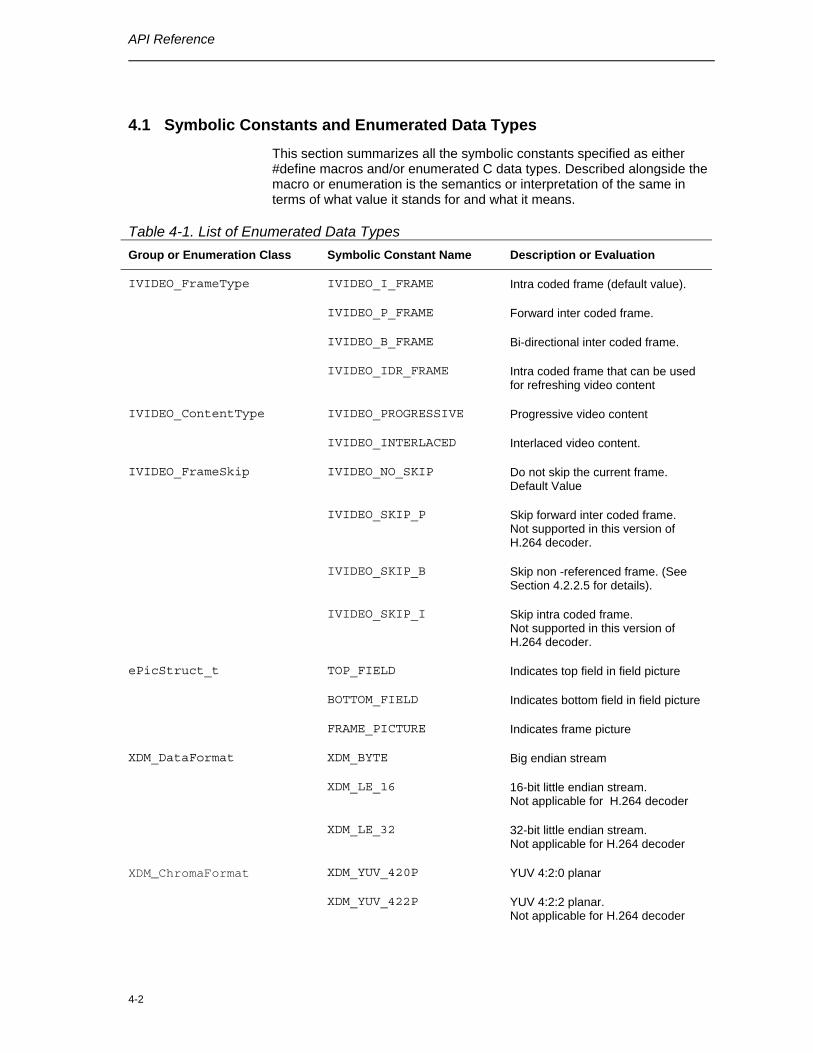
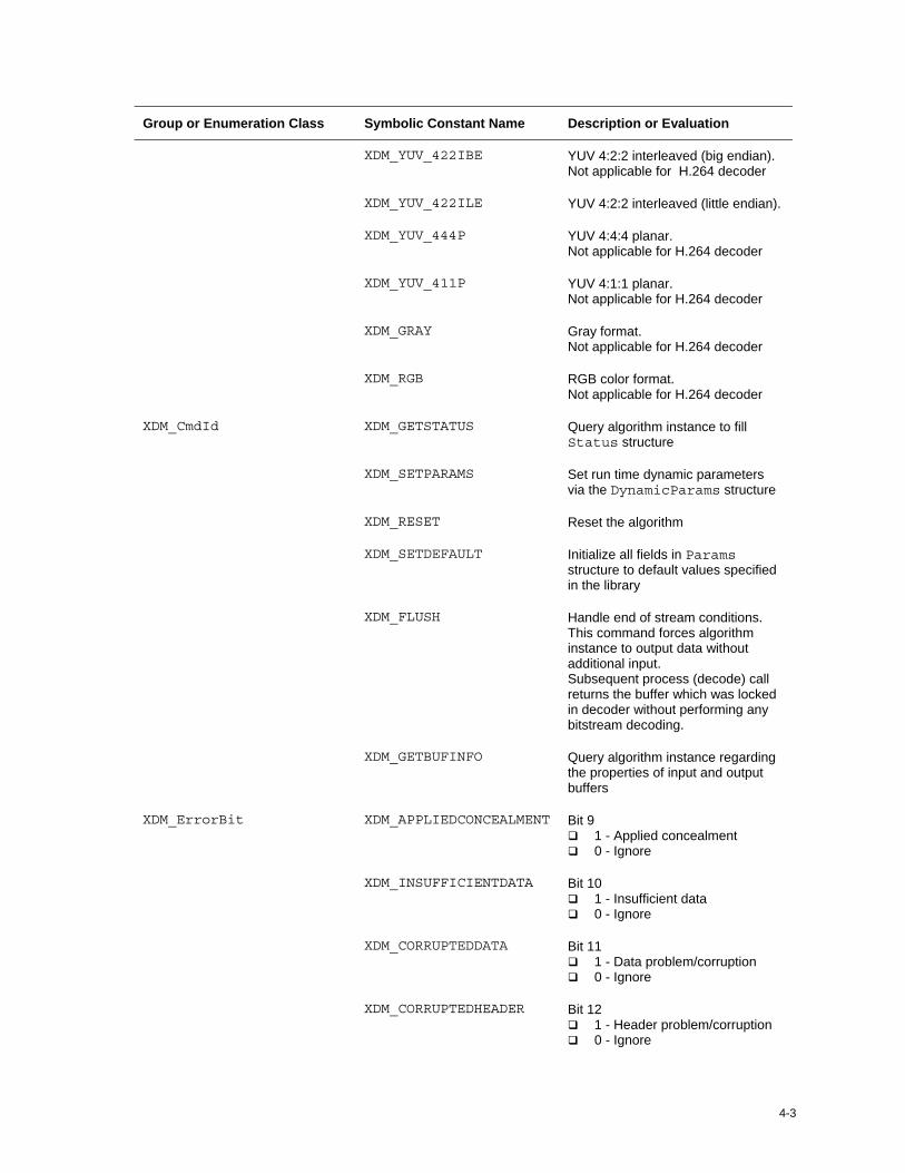
4.1 Symbolic Constants and Enumerated Data Types
This section summarizes all the symbolic constants specified as either #define macros and/or enumerated C data types. Described alongside the macro or enumeration is the semantics or interpretation of the same in terms of what value it stands for and what it means.
Table 4-1. List of Enumerated Data Types Group or Enumeration Class Symbolic Constant Name Description or Evaluation
IVIDEO_I_FRAME Intra coded frame (default value).
IVIDEO_P_FRAME Forward inter coded frame.
IVIDEO_B_FRAME Bi-directional inter coded frame.
IVIDEO_FrameType
IVIDEO_IDR_FRAME Intra coded frame that can be used for refreshing video content
IVIDEO_PROGRESSIVE Progressive video content IVIDEO_ContentType
IVIDEO_INTERLACED Interlaced video content.
IVIDEO_NO_SKIP Do not skip the current frame. Default Value
IVIDEO_SKIP_P Skip forward inter coded frame. Not supported in this version of H.264 decoder.
IVIDEO_SKIP_B Skip non -referenced frame. (See Section 4.2.2.5 for details).
IVIDEO_FrameSkip
IVIDEO_SKIP_I Skip intra coded frame. Not supported in this version of H.264 decoder.
TOP_FIELD Indicates top field in field picture
BOTTOM_FIELD Indicates bottom field in field picture
ePicStruct_t
FRAME_PICTURE Indicates frame picture
XDM_BYTE Big endian stream
XDM_LE_16 16-bit little endian stream. Not applicable for H.264 decoder
XDM_DataFormat
XDM_LE_32 32-bit little endian stream. Not applicable for H.264 decoder
XDM_YUV_420P YUV 4:2:0 planar XDM_ChromaFormat
XDM_YUV_422P YUV 4:2:2 planar. Not applicable for H.264 decoder
4-3
Group or Enumeration Class Symbolic Constant Name Description or Evaluation
XDM_YUV_422IBE YUV 4:2:2 interleaved (big endian). Not applicable for H.264 decoder
XDM_YUV_422ILE YUV 4:2:2 interleaved (little endian).
XDM_YUV_444P YUV 4:4:4 planar. Not applicable for H.264 decoder
XDM_YUV_411P YUV 4:1:1 planar. Not applicable for H.264 decoder
XDM_GRAY Gray format. Not applicable for H.264 decoder
XDM_RGB RGB color format. Not applicable for H.264 decoder
XDM_GETSTATUS Query algorithm instance to fill Status structure
XDM_SETPARAMS Set run time dynamic parameters via the DynamicParams structure
XDM_RESET Reset the algorithm
XDM_SETDEFAULT Initialize all fields in Params structure to default values specified in the library
XDM_FLUSH Handle end of stream conditions. This command forces algorithm instance to output data without additional input. Subsequent process (decode) call returns the buffer which was locked in decoder without performing any bitstream decoding.
XDM_CmdId
XDM_GETBUFINFO Query algorithm instance regarding the properties of input and output buffers
XDM_APPLIEDCONCEALMENT Bit 9 1 - Applied concealment 0 - Ignore
XDM_INSUFFICIENTDATA Bit 10 1 - Insufficient data 0 - Ignore
XDM_CORRUPTEDDATA Bit 11 1 - Data problem/corruption 0 - Ignore
XDM_ErrorBit
XDM_CORRUPTEDHEADER Bit 12 1 - Header problem/corruption 0 - Ignore
API Reference
4-4
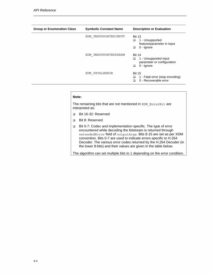
Group or Enumeration Class Symbolic Constant Name Description or Evaluation
XDM_UNSUPPORTEDINPUT Bit 13 1 - Unsupported
feature/parameter in input 0 - Ignore
XDM_UNSUPPORTEDPARAM Bit 14 1 - Unsupported input
parameter or configuration 0 - Ignore
XDM_FATALERROR Bit 15 1 - Fatal error (stop encoding) 0 - Recoverable error
Note:
The remaining bits that are not mentioned in XDM_ErrorBit are interpreted as:
Bit 16-32: Reserved
Bit 8: Reserved
Bit 0-7: Codec and implementation specific. The type of error encountered while decoding the bitstream is returned through extendedError field of outputArgs. Bits 8-15 are set as per XDM convention. Bits 0-7 are used to indicate errors specific to H.264 Decoder. The various error codes returned by the H.264 Decoder (in the lower 8-bits) and their values are given in the table below.
The algorithm can set multiple bits to 1 depending on the error condition.
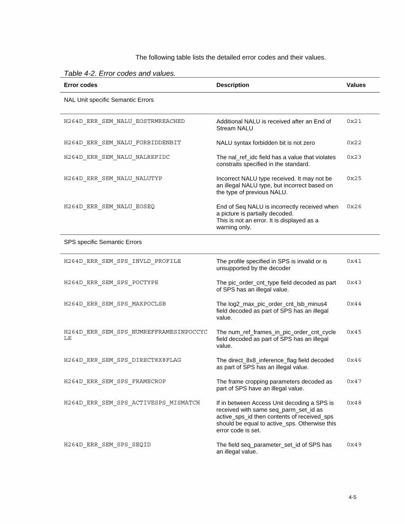
4-5
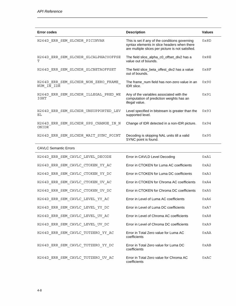
The following table lists the detailed error codes and their values.
Table 4-2. Error codes and values. Error codes Description Values
NAL Unit specific Semantic Errors
H264D_ERR_SEM_NALU_EOSTRMREACHED Additional NALU is received after an End of Stream NALU
0x21
H264D_ERR_SEM_NALU_FORBIDDENBIT NALU syntax forbidden bit is not zero 0x22
H264D_ERR_SEM_NALU_NALREFIDC The nal_ref_idc field has a value that violates constraits specified in the standard.
0x23
H264D_ERR_SEM_NALU_NALUTYP Incorrect NALU type received. It may not be an illegal NALU type, but incorrect based on the type of previous NALU.
0x25
H264D_ERR_SEM_NALU_EOSEQ End of Seq NALU is incorrectly received when a picture is partially decoded. This is not an error. It is displayed as a warning only.
0x26
SPS specific Semantic Errors
H264D_ERR_SEM_SPS_INVLD_PROFILE The profile specified in SPS is invalid or is unsupported by the decoder
0x41
H264D_ERR_SEM_SPS_POCTYPE The pic_order_cnt_type field decoded as part of SPS has an illegal value.
0x43
H264D_ERR_SEM_SPS_MAXPOCLSB The log2_max_pic_order_cnt_lsb_minus4 field decoded as part of SPS has an illegal value.
0x44
H264D_ERR_SEM_SPS_NUMREFFRAMESINPOCCYCLE
The num_ref_frames_in_pic_order_cnt_cycle field decoded as part of SPS has an illegal value.
0x45
H264D_ERR_SEM_SPS_DIRECT8X8FLAG The direct_8x8_inference_flag field decoded as part of SPS has an illegal value.
0x46
H264D_ERR_SEM_SPS_FRAMECROP The frame cropping parameters decoded as part of SPS have an illegal value.
0x47
H264D_ERR_SEM_SPS_ACTIVESPS_MISMATCH If in between Access Unit decoding a SPS is received with same seq_parm_set_id as active_sps_id then contents of received_sps should be equal to active_sps. Otherwise this error code is set.
0x48
H264D_ERR_SEM_SPS_SEQID The field seq_parameter_set_id of SPS has an illegal value.
0x49
API Reference
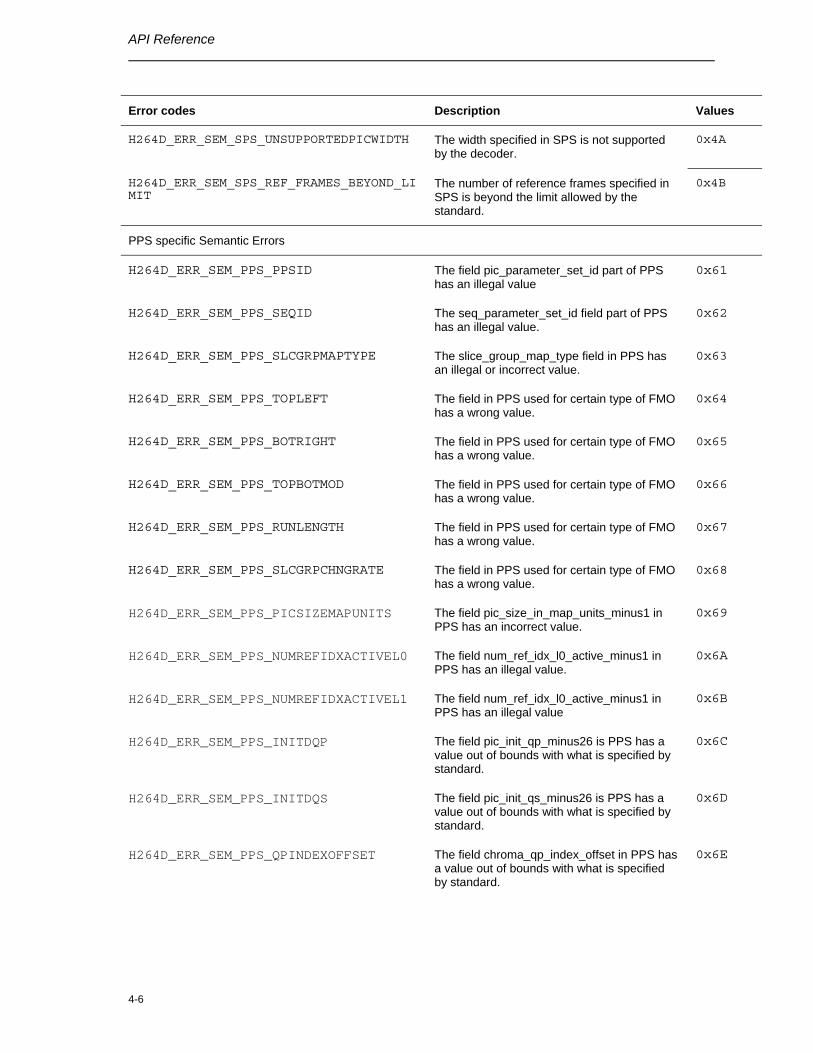
4-6
Error codes Description Values
H264D_ERR_SEM_SPS_UNSUPPORTEDPICWIDTH The width specified in SPS is not supported by the decoder.
0x4A
H264D_ERR_SEM_SPS_REF_FRAMES_BEYOND_LIMIT
The number of reference frames specified in SPS is beyond the limit allowed by the standard.
0x4B
PPS specific Semantic Errors
H264D_ERR_SEM_PPS_PPSID The field pic_parameter_set_id part of PPS has an illegal value
0x61
H264D_ERR_SEM_PPS_SEQID The seq_parameter_set_id field part of PPS has an illegal value.
0x62
H264D_ERR_SEM_PPS_SLCGRPMAPTYPE The slice_group_map_type field in PPS has an illegal or incorrect value.
0x63
H264D_ERR_SEM_PPS_TOPLEFT The field in PPS used for certain type of FMO has a wrong value.
0x64
H264D_ERR_SEM_PPS_BOTRIGHT The field in PPS used for certain type of FMO has a wrong value.
0x65
H264D_ERR_SEM_PPS_TOPBOTMOD The field in PPS used for certain type of FMO has a wrong value.
0x66
H264D_ERR_SEM_PPS_RUNLENGTH The field in PPS used for certain type of FMO has a wrong value.
0x67
H264D_ERR_SEM_PPS_SLCGRPCHNGRATE The field in PPS used for certain type of FMO has a wrong value.
0x68
H264D_ERR_SEM_PPS_PICSIZEMAPUNITS The field pic_size_in_map_units_minus1 in PPS has an incorrect value.
0x69
H264D_ERR_SEM_PPS_NUMREFIDXACTIVEL0 The field num_ref_idx_l0_active_minus1 in PPS has an illegal value.
0x6A
H264D_ERR_SEM_PPS_NUMREFIDXACTIVEL1 The field num_ref_idx_l0_active_minus1 in PPS has an illegal value
0x6B
H264D_ERR_SEM_PPS_INITDQP The field pic_init_qp_minus26 is PPS has a value out of bounds with what is specified by standard.
0x6C
H264D_ERR_SEM_PPS_INITDQS The field pic_init_qs_minus26 is PPS has a value out of bounds with what is specified by standard.
0x6D
H264D_ERR_SEM_PPS_QPINDEXOFFSET The field chroma_qp_index_offset in PPS has a value out of bounds with what is specified by standard.
0x6E
4-7
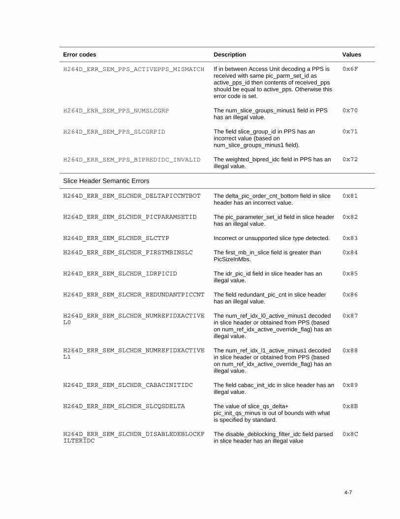
Error codes Description Values
H264D_ERR_SEM_PPS_ACTIVEPPS_MISMATCH If in between Access Unit decoding a PPS is received with same pic_parm_set_id as active_pps_id then contents of received_pps should be equal to active_pps. Otherwise this error code is set.
0x6F
H264D_ERR_SEM_PPS_NUMSLCGRP The num_slice_groups_minus1 field in PPS has an illegal value.
0x70
H264D_ERR_SEM_PPS_SLCGRPID The field slice_group_id in PPS has an incorrect value (based on num_slice_groups_minus1 field).
0x71
H264D_ERR_SEM_PPS_BIPREDIDC_INVALID The weighted_bipred_idc field in PPS has an illegal value.
0x72
Slice Header Semantic Errors
H264D_ERR_SEM_SLCHDR_DELTAPICCNTBOT The delta_pic_order_cnt_bottom field in slice header has an incorrect value.
0x81
H264D_ERR_SEM_SLCHDR_PICPARAMSETID The pic_parameter_set_id field in slice header has an illegal value.
0x82
H264D_ERR_SEM_SLCHDR_SLCTYP Incorrect or unsupported slice type detected. 0x83
H264D_ERR_SEM_SLCHDR_FIRSTMBINSLC The first_mb_in_slice field is greater than PicSizeInMbs.
0x84
H264D_ERR_SEM_SLCHDR_IDRPICID The idr_pic_id field in slice header has an illegal value.
0x85
H264D_ERR_SEM_SLCHDR_REDUNDANTPICCNT The field redundant_pic_cnt in slice header has an illegal value.
0x86
H264D_ERR_SEM_SLCHDR_NUMREFIDXACTIVEL0
The num_ref_idx_l0_active_minus1 decoded in slice header or obtained from PPS (based on num_ref_idx_active_override_flag) has an illegal value.
0x87
H264D_ERR_SEM_SLCHDR_NUMREFIDXACTIVEL1
The num_ref_idx_l1_active_minus1 decoded in slice header or obtained from PPS (based on num_ref_idx_active_override_flag) has an illegal value.
0x88
H264D_ERR_SEM_SLCHDR_CABACINITIDC The field cabac_init_idc in slice header has an illegal value.
0x89
H264D_ERR_SEM_SLCHDR_SLCQSDELTA The value of slice_qs_delta+ pic_init_qs_minus is out of bounds with what is specified by standard.
0x8B
H264D_ERR_SEM_SLCHDR_DISABLEDEBLOCKFILTERIDC
The disable_deblocking_filter_idc field parsed in slice header has an illegal value
0x8C
API Reference
4-8
Error codes Description Values
H264D_ERR_SEM_SLCHDR_PICINVAR This is set if any of the conditions governing syntax elements in slice headers when there are multiple slices per picture is not satisfied.
0x8D
H264D_ERR_SEM_SLCHDR_SLCALPHAC0OFFSET
The field slice_alpha_c0_offset_div2 has a value out of bounds.
0x8E
H264D_ERR_SEM_SLCHDR_SLCBETAOFFSET The field slice_beta_offest_div2 has a value out of bounds.
0x8F
H264D_ERR_SEM_SLCHDR_NON_ZERO_FRAME_NUM_IN_IDR
The frame_num field has non-zero value in an IDR slice.
0x90
H264D_ERR_SEM_SLCHDR_ILLEGAL_PRED_WEIGHT
Any of the variables associated with the computation of prediction weights has an illegal value.
0x91
H264D_ERR_SEM_SLCHDR_UNSUPPORTED_LEVEL
Level specified in bitstream is greater than the supported level.
0x93
H264D_ERR_SEM_SLCHDR_SPS_CHANGE_IN_NONIDR
Change of IDR detected in a non-IDR picture. 0x94
H264D_ERR_SEM_SLCHDR_WAIT_SYNC_POINT Decoding is skipping NAL units till a valid SYNC point is found.
0x95
CAVLC Semantic Errors
H264D_ERR_SEM_CAVLC_LEVEL_DECODE Error in CAVLD Level Decoding 0xA1
H264D_ERR_SEM_CAVLC_CTOKEN_YY_AC Error in CTOKEN for Luma AC coefficients 0xA2
H264D_ERR_SEM_CAVLC_CTOKEN_YY_DC Error in CTOKEN for Luma DC coefficients 0xA3
H264D_ERR_SEM_CAVLC_CTOKEN_UV_AC Error in CTOKEN for Chroma AC coefficients 0xA4
H264D_ERR_SEM_CAVLC_CTOKEN_UV_DC Error in CTOKEN for Chroma DC coefficients 0xA5
H264D_ERR_SEM_CAVLC_LEVEL_YY_AC Error in Level of Luma AC coefficients 0xA6
H264D_ERR_SEM_CAVLC_LEVEL_YY_DC Error in Level of Luma DC coefficients 0xA7
H264D_ERR_SEM_CAVLC_LEVEL_UV_AC Error in Level of Chroma AC coefficients 0xA8
H264D_ERR_SEM_CAVLC_LEVEL_UV_DC Error in Level of Chroma DC coefficients 0xA9
H264D_ERR_SEM_CAVLC_TOTZERO_YY_AC Error in Total Zero value for Luma AC coefficients
0xAA
H264D_ERR_SEM_CAVLC_TOTZERO_YY_DC Error in Total Zero value for Luma DC coefficients
0xAB
H264D_ERR_SEM_CAVLC_TOTZERO_UV_AC Error in Total Zero value for Chroma AC coefficients
0xAC
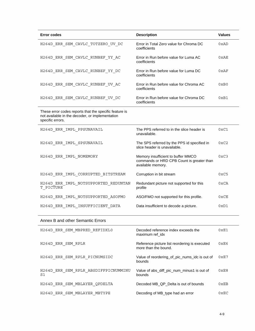
4-9
Error codes Description Values
H264D_ERR_SEM_CAVLC_TOTZERO_UV_DC Error in Total Zero value for Chroma DC coefficients
0xAD
H264D_ERR_SEM_CAVLC_RUNBEF_YY_AC Error in Run before value for Luma AC coefficients
0xAE
H264D_ERR_SEM_CAVLC_RUNBEF_YY_DC Error in Run before value for Luma DC coefficients
0xAF
H264D_ERR_SEM_CAVLC_RUNBEF_UV_AC Error in Run before value for Chroma AC coefficients
0xB0
H264D_ERR_SEM_CAVLC_RUNBEF_UV_DC Error in Run before value for Chroma DC coefficients
0xB1
These error codes reports that the specific feature is not available in the decoder, or implementation specific errors.
H264D_ERR_IMPL_PPSUNAVAIL The PPS referred to in the slice header is unavailable.
0xC1
H264D_ERR_IMPL_SPSUNAVAIL The SPS referred by the PPS id specified in slice header is unavailable.
0xC2
H264D_ERR_IMPL_NOMEMORY Memory insufficient to buffer MMCO commands or HRD CPB Count is greater than available memory.
0xC3
H264D_ERR_IMPL_CORRUPTED_BITSTREAM Corruption in bit stream 0xC5
H264D_ERR_IMPL_NOTSUPPORTED_REDUNTANT_PICTURE
Redundant picture not supported for this profile
0xCA
H264D_ERR_IMPL_NOTSUPPORTED_ASOFMO ASO/FMO not supported for this profile. 0xCE
H264D_ERR_IMPL_INSUFFICIENT_DATA Data insufficient to decode a picture. 0xD1
Annex B and other Semantic Errors
H264D_ERR_SEM_MBPRED_REFIDXL0 Decoded reference index exceeds the maximum ref_idx
0xE1
H264D_ERR_SEM_RPLR Reference picture list reordering is executed more than the bound.
0xE6
H264D_ERR_SEM_RPLR_PICNUMSIDC Value of reordering_of_pic_nums_idc is out of bounds
0xE7
H264D_ERR_SEM_RPLR_ABSDIFFPICNUMMINUS1
Value of abs_diff_pic_num_minus1 is out of bounds
0xE8
H264D_ERR_SEM_MBLAYER_QPDELTA Decoded MB_QP_Delta is out of bounds 0xEB
H264D_ERR_SEM_MBLAYER_MBTYPE Decoding of MB_type had an error 0xEC
API Reference
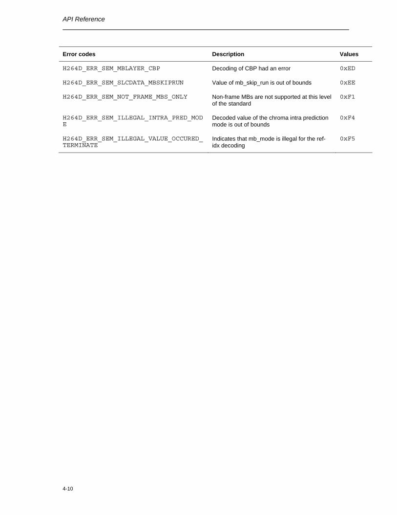
4-10
Error codes Description Values
H264D_ERR_SEM_MBLAYER_CBP Decoding of CBP had an error 0xED
H264D_ERR_SEM_SLCDATA_MBSKIPRUN Value of mb_skip_run is out of bounds 0xEE
H264D_ERR_SEM_NOT_FRAME_MBS_ONLY Non-frame MBs are not supported at this level of the standard
0xF1
H264D_ERR_SEM_ILLEGAL_INTRA_PRED_MODE
Decoded value of the chroma intra prediction mode is out of bounds
0xF4
H264D_ERR_SEM_ILLEGAL_VALUE_OCCURED_TERMINATE
Indicates that mb_mode is illegal for the ref-idx decoding
0xF5
4-11
4.2 Data Structures
This section describes the XDM defined data structures, that are common across codec classes. These XDM data structures can be extended to define any implementation specific parameters for a codec component.
4.2.1 Common XDM Data Structures
This section includes the following common XDM data structures:
XDM_BufDesc
XDM_AlgBufInfo
IVIDEO_BufDesc
IVIDDEC_Fxns
IVIDDEC_Params
IVIDDEC_DynamicParams
IVIDDEC_InArgs
IVIDDEC_Status
IVIDDEC_OutArgs
API Reference
4-12
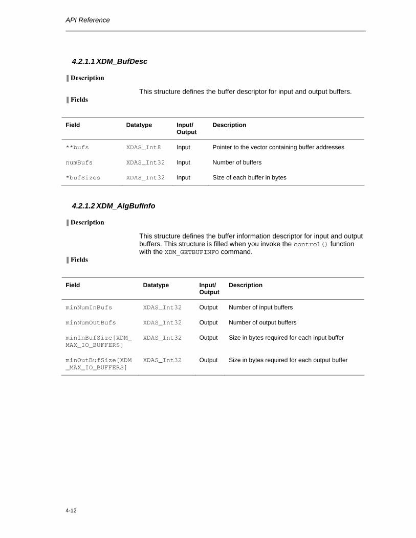
4.2.1.1 XDM_BufDesc
║ Description
This structure defines the buffer descriptor for input and output buffers. ║ Fields
Field Datatype Input/ Output
Description
**bufs XDAS_Int8 Input Pointer to the vector containing buffer addresses
numBufs XDAS_Int32 Input Number of buffers
*bufSizes XDAS_Int32 Input Size of each buffer in bytes
4.2.1.2 XDM_AlgBufInfo
║ Description
This structure defines the buffer information descriptor for input and output buffers. This structure is filled when you invoke the control() function with the XDM_GETBUFINFO command.
║ Fields
Field Datatype Input/ Output
Description
minNumInBufs XDAS_Int32 Output Number of input buffers
minNumOutBufs XDAS_Int32 Output Number of output buffers
minInBufSize[XDM_MAX_IO_BUFFERS]
XDAS_Int32 Output Size in bytes required for each input buffer
minOutBufSize[XDM_MAX_IO_BUFFERS]
XDAS_Int32 Output Size in bytes required for each output buffer
4-13
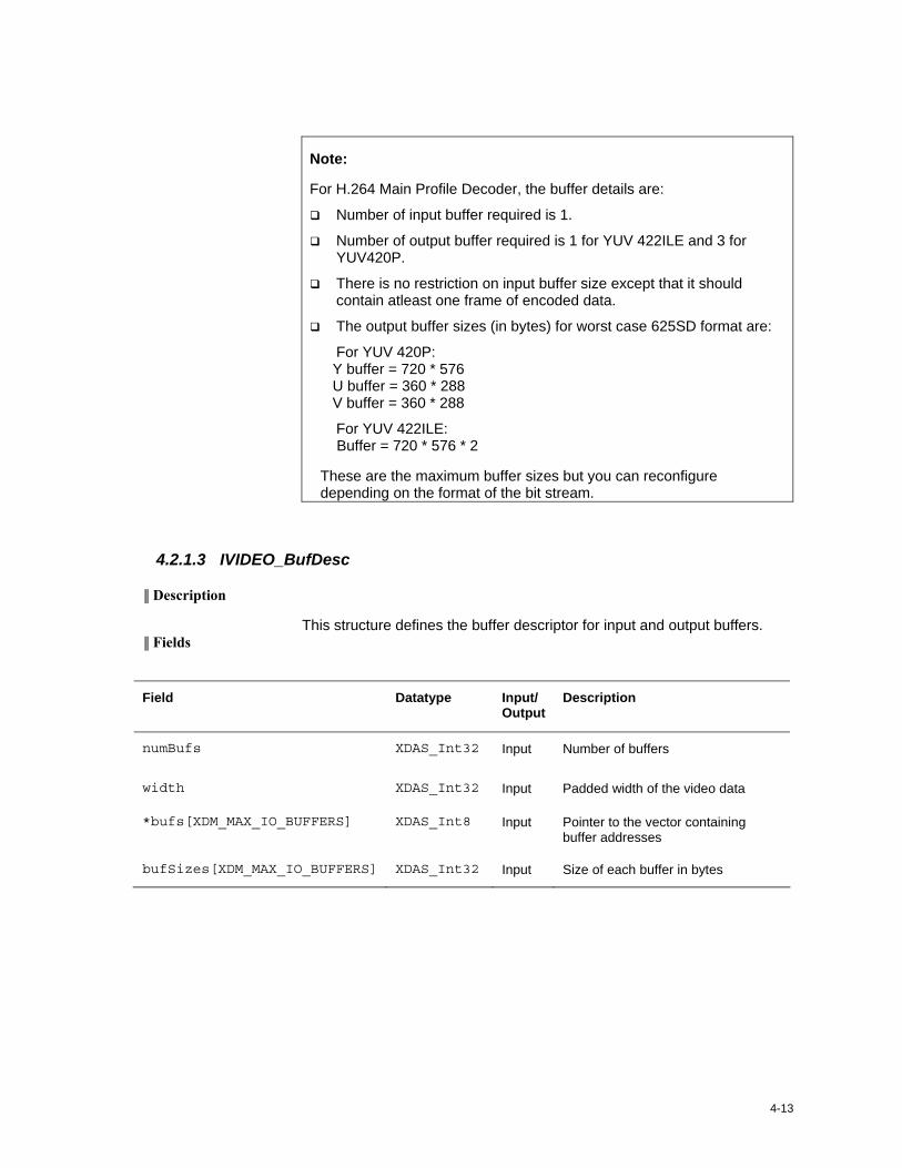
Note:
For H.264 Main Profile Decoder, the buffer details are:
Number of input buffer required is 1.
Number of output buffer required is 1 for YUV 422ILE and 3 for YUV420P.
There is no restriction on input buffer size except that it should contain atleast one frame of encoded data.
The output buffer sizes (in bytes) for worst case 625SD format are:
For YUV 420P: Y buffer = 720 * 576 U buffer = 360 * 288 V buffer = 360 * 288
For YUV 422ILE: Buffer = 720 * 576 * 2
These are the maximum buffer sizes but you can reconfigure depending on the format of the bit stream.
4.2.1.3 IVIDEO_BufDesc
║ Description
This structure defines the buffer descriptor for input and output buffers. ║ Fields
Field Datatype Input/ Output
Description
numBufs XDAS_Int32 Input Number of buffers
width XDAS_Int32 Input Padded width of the video data
*bufs[XDM_MAX_IO_BUFFERS] XDAS_Int8 Input Pointer to the vector containing buffer addresses
bufSizes[XDM_MAX_IO_BUFFERS] XDAS_Int32 Input Size of each buffer in bytes
API Reference
4-14
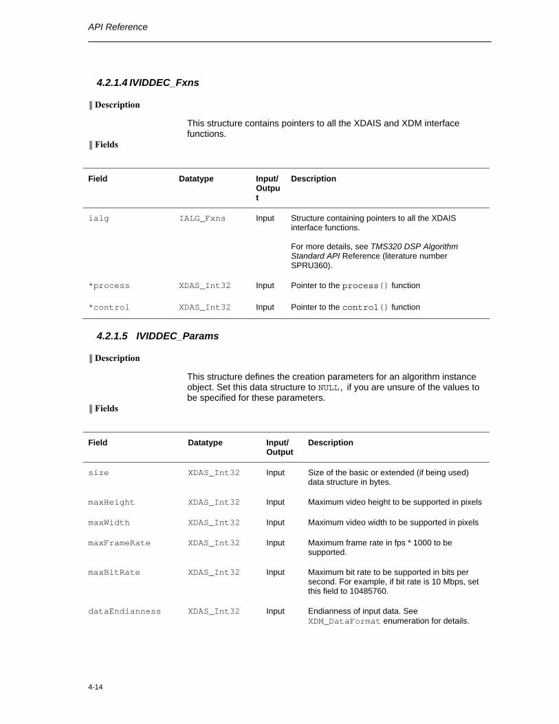
4.2.1.4 IVIDDEC_Fxns
║ Description
This structure contains pointers to all the XDAIS and XDM interface functions.
║ Fields
Field Datatype Input/ Output
Description
ialg IALG_Fxns Input Structure containing pointers to all the XDAIS interface functions. For more details, see TMS320 DSP Algorithm Standard API Reference (literature number SPRU360).
*process XDAS_Int32 Input Pointer to the process() function
*control XDAS_Int32 Input Pointer to the control() function
4.2.1.5 IVIDDEC_Params
║ Description
This structure defines the creation parameters for an algorithm instance object. Set this data structure to NULL, if you are unsure of the values to be specified for these parameters.
║ Fields
Field Datatype Input/ Output
Description
size XDAS_Int32 Input Size of the basic or extended (if being used) data structure in bytes.
maxHeight XDAS_Int32 Input Maximum video height to be supported in pixels
maxWidth XDAS_Int32 Input Maximum video width to be supported in pixels
maxFrameRate XDAS_Int32 Input Maximum frame rate in fps * 1000 to be supported.
maxBitRate XDAS_Int32 Input Maximum bit rate to be supported in bits per second. For example, if bit rate is 10 Mbps, set this field to 10485760.
dataEndianness XDAS_Int32 Input Endianness of input data. See XDM_DataFormat enumeration for details.
4-15
Field Datatype Input/ Output
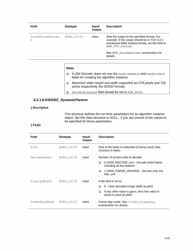
Description
forceChromaFormat
XDAS_Int32 Input Sets the output to the specified format. For example, if the output should be in YUV 4:2:2 interleaved (little endian) format, set this field to XDM_YUV_422ILE. See XDM_ChromaFormat enumeration for details.
Note:
H.264 Decoder does not use the maxFrameRate and maxBitRate fields for creating the algorithm instance.
Maximum video height and width supported are 576 pixels and 720 pixels respectively (for 625SD format).
dataEndianness field should be set to XDM_BYTE.
4.2.1.6 IVIDDEC_DynamicParams
║ Description
This structure defines the run time parameters for an algorithm instance object. Set this data structure to NULL, if you are unsure of the values to be specified for these parameters.
║ Fields
Field Datatype Input/ Output
Description
size XDAS_Int32 Input Size of the basic or extended (if being used) data structure in bytes.
decodeHeader XDAS_Int32 Input Number of access units to decode:
0 (XDM_DECODE_AU) - Decode entire frame including all the headers
1 (XDM_PARSE_HEADER) - Decode only one NAL unit
displayWidth XDAS_Int32 Input If the field is set to:
0 - Uses decoded image width as pitch
If any other value is given, then this value in pixels is used as pitch.
frameSkipMode XDAS_Int32 Input Frame skip mode. See IVIDEO_FrameSkip enumeration for details.
API Reference
4-16
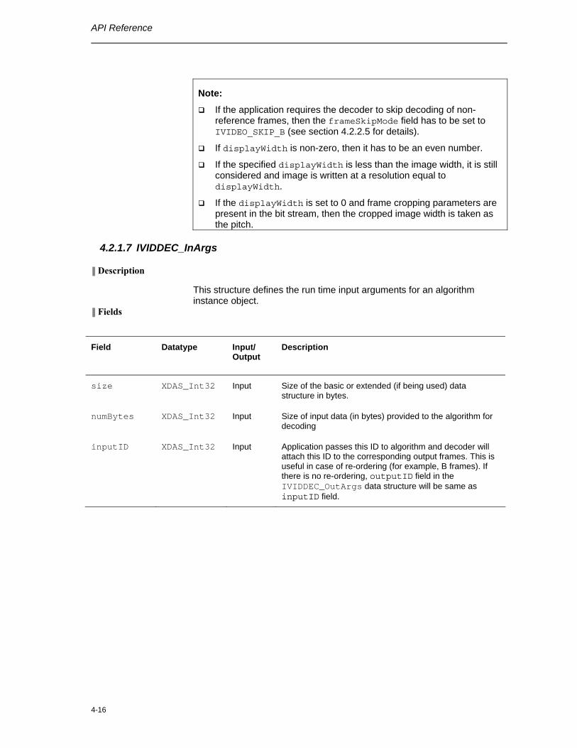
Note:
If the application requires the decoder to skip decoding of non-reference frames, then the frameSkipMode field has to be set to IVIDEO_SKIP_B (see section 4.2.2.5 for details).
If displayWidth is non-zero, then it has to be an even number.
If the specified displayWidth is less than the image width, it is still considered and image is written at a resolution equal to displayWidth.
If the displayWidth is set to 0 and frame cropping parameters are present in the bit stream, then the cropped image width is taken as the pitch.
4.2.1.7 IVIDDEC_InArgs
║ Description
This structure defines the run time input arguments for an algorithm instance object.
║ Fields
Field Datatype Input/ Output
Description
size XDAS_Int32 Input Size of the basic or extended (if being used) data structure in bytes.
numBytes XDAS_Int32 Input Size of input data (in bytes) provided to the algorithm for decoding
inputID XDAS_Int32 Input Application passes this ID to algorithm and decoder will attach this ID to the corresponding output frames. This is useful in case of re-ordering (for example, B frames). If there is no re-ordering, outputID field in the IVIDDEC_OutArgs data structure will be same as inputID field.
4-17
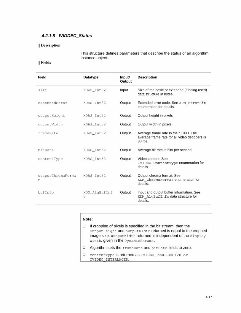
4.2.1.8 IVIDDEC_Status
║ Description
This structure defines parameters that describe the status of an algorithm instance object.
║ Fields
Field Datatype Input/ Output
Description
size XDAS_Int32 Input Size of the basic or extended (if being used) data structure in bytes.
extendedError XDAS_Int32 Output Extended error code. See XDM_ErrorBit enumeration for details.
outputHeight XDAS_Int32 Output Output height in pixels
outputWidth XDAS_Int32 Output Output width in pixels
frameRate XDAS_Int32 Output Average frame rate in fps * 1000. The average frame rate for all video decoders is 30 fps.
bitRate XDAS_Int32 Output Average bit rate in bits per second
contentType XDAS_Int32 Output Video content. See IVIDEO_ContentType enumeration for details.
outputChromaFormat
XDAS_Int32 Output Output chroma format. See XDM_ChromaFormat enumeration for details.
bufInfo XDM_AlgBufInfo
Output Input and output buffer information. See XDM_AlgBufInfo data structure for details.
Note:
If cropping of pixels is specified in the bit stream, then the outputHeight and outputWidth returned is equal to the cropped image size. outputWidth returned is independent of the display width, given in the DynamicParams.
Algorithm sets the frameRate and bitRate fields to zero.
contentType is returned as IVIDEO_PROGRESSIVE or IVIDEO_INTERLACED.
API Reference
4-18
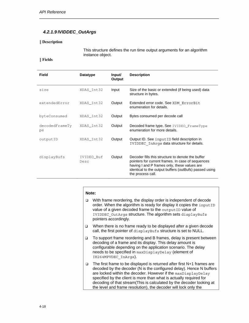
4.2.1.9 IVIDDEC_OutArgs
║ Description
This structure defines the run time output arguments for an algorithm instance object.
║ Fields
Field Datatype Input/ Output
Description
size XDAS_Int32 Input Size of the basic or extended (if being used) data structure in bytes.
extendedError XDAS_Int32 Output Extended error code. See XDM_ErrorBit enumeration for details.
byteConsumed XDAS_Int32 Output Bytes consumed per decode call
decodedFrameType
XDAS_Int32 Output Decoded frame type. See IVIDEO_FrameType enumeration for more details.
outputID XDAS_Int32 Output Output ID. See inputID field description in IVIDDEC_InArgs data structure for details.
displayBufs IVIDEO_BufDesc
Output Decoder fills this structure to denote the buffer pointers for current frames. In case of sequences having I and P frames only, these values are identical to the output buffers (outBufs) passed using the process call.
Note:
With frame reordering, the display order is independent of decode order. When the algorithm is ready for display it copies the inputID value of a given decoded frame to the outputID value of IVIDDEC_OutArgs structure. The algorithm sets displayBufs pointers accordingly.
When there is no frame ready to be displayed after a given decode call, the first pointer of displayBufs structure is set to NULL.
To support frame reordering and B frames, delay is present between decoding of a frame and its display. This delay amount is configurable depending on the application scenario. The delay needs to be specified in maxDisplayDelay (element of IH264MPVDEC_InArgs).
The first frame to be displayed is returned after first N+1 frames are decoded by the decoder (N is the configured delay). Hence N buffers are locked within the decoder. However if the maxDisplayDelay specified by the client is more than what is actually required for decoding of that stream(This is calculated by the decoder looking at the level and frame resolution), the decoder will lock only the
4-19
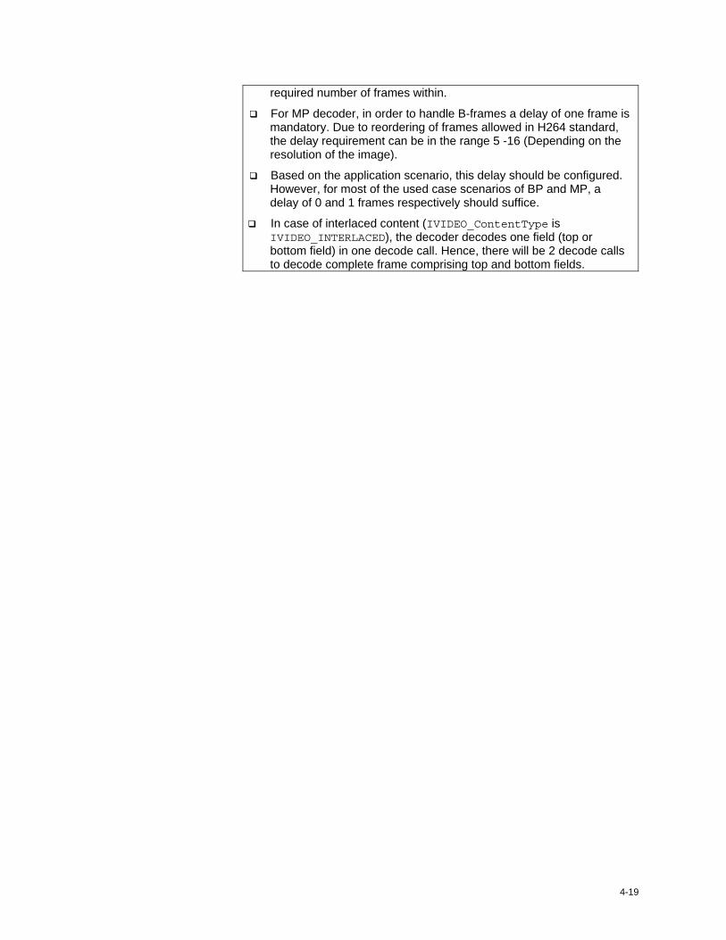
required number of frames within.
For MP decoder, in order to handle B-frames a delay of one frame is mandatory. Due to reordering of frames allowed in H264 standard, the delay requirement can be in the range 5 -16 (Depending on the resolution of the image).
Based on the application scenario, this delay should be configured. However, for most of the used case scenarios of BP and MP, a delay of 0 and 1 frames respectively should suffice.
In case of interlaced content (IVIDEO_ContentType is IVIDEO_INTERLACED), the decoder decodes one field (top or bottom field) in one decode call. Hence, there will be 2 decode calls to decode complete frame comprising top and bottom fields.
API Reference
4-20
4.2.2 H.264 Decoder Data Structures
This section includes the following H.264 decoder specific data structures:
IH264MPVDEC_Params
IH264MPVDEC_DynamicParams
IH264MPVDEC_InArgs
IH264MPVDEC_Status
IH264MPVDEC_OutArgs
4.2.2.1 IH264MPVDEC _Params
║ Description
This structure defines the creation parameters and any other implementation specific parameters for the H.264 Decoder instance object. The creation parameters are defined in the XDM data structure, IVIDDEC_Params.
║ Fields
Field Datatype Input/ Output
Description
viddecParams IVIDDEC_Params Input See IVIDDEC_Params data structure for details.
4.2.2.2 IH264MPVDEC_DynamicParams
║ Description
This structure defines the run time parameters and any other implementation specific parameters for the H.264 Decoder instance object. The run time parameters are defined in the XDM data structure, IVIDDEC_DynamicParams.
║ Fields
Field Datatype Input/ Output
Description
viddecDynamicParams IVIDDEC_DynamicParams Input See IVIDDEC_DynamicParams data structure for details.
4-21
4.2.2.3 IH264MPVDEC_InArgs
║ Description
This structure defines the run time input arguments for the H.264 Decoder instance object.
║ Fields
Field Datatype Input/ Output
Description
viddecInArgs IVIDDEC_InArgs Input See IVIDDEC_InArgs data
structure for details.
maxDisplayDelay XDAS_Int32 Input Maximum delay between decode
and display of a frame. (See section 4.2.1.9 for details).
Sei_Vui_parse_flag XDAS_Int32 Input If the application is interested in
SEI or VUI information, then this needs to be set to 1. Otherwise this needs to be set to 0.
SeiVui_buffer_ptr sSeiVuiParams_t* Input Pointer to the buffer, where the
SEI and VUI information will be written by the decoder.
4.2.2.3.1 sSeiVuiParams_t
║ Description
This structure defines Supplemental Enhancement Information (SEI ) messages and parameters that describe the values of various Video Usability parameters(VUI).
║ Fields
Field Datatype Input/ Output
Description
parsed_flag unsigned int Output 1 - Indicates that in the current process call, contents of the structure is updated
0 - Indicates contents of the structure is not updated
vui_params sVSP_t Output Video Usability Information
sei_messages sSeiMessages_t Output Supplemental Enhancement Information
API Reference
4-22
Note:
A brief description of SEI and VUI contents are given below. For details see H.264 standard (ISO/IEC 14496-10:2005 (E) Rec.- Information technology – Coding of audio-visual objects – H.264 (E) ITU-T Recommendation.)
4.2.2.3.2 sSeiMessages_t
║ Description
Structure containing supplemental enhancement information messages. ║ Fields
Field Datatype Input/ Output
Description
parsed_flag unsigned int Output 1 - Indicates that in the current process call, contents of the structure is updated
0 - Indicates contents of the structure is not updated
frame_freeze_repetition
sFullFrameFreezeRepetition_t
Output Specifies the persistence of the full-frame freeze SEI message and may specify a picture order count interval within which another full-frame freeze SEI message or a full-frame freeze release SEI or the end of the coded video sequence shall be present in the bitstream.
frame_freeze_release
sFullFrameFreezeRelease_t
Output Cancels the effect of any full-frame freeze SEI message sent with pictures that precede the current picture in output order.
prog_refine_start
sProgRefineStart_t Output Specifies the beginning of a set of consecutive coded pictures that is labelled as the current picture followed by a sequence of one or more pictures of refinement of the quality of the current picture, rather than as a representation of a continually moving scene.
prog_refine_end sProgRefineEnd_t Output Specifies end of progressive refinement.
recovery_pt_info sRecoveryPointInfo_t Output The recovery point SEI message
4-23
Field Datatype Input/ Output
Description
assists a decoder in determining when the decoding process will produce acceptable pictures for display after the decoder initiates random access or after the encoder indicates a broken link in the sequence.
pic_timing sPictureTiming_t Output Specifies timing information regarding cpb delays, dpb output delay etc.
4.2.2.3.3 sFullFrameFreezeRepetition_t
║ Description
Structure contains information regarding frame freeze. ║ Fields
4.2.2.3.4 sFullFrameFreezeRelease_t
║ Description
Structure contains information regarding frame freeze. ║ Fields
Field Datatype Input/ Output
Description
parsed_flag unsigned int Output 1 - Indicates that in the current process call, contents of the structure is updated
0 - Indicates contents of the structure is not updated
full_frame_freeze_ release_flag
unsigned char Output Cancels the effect of any full-frame freeze SEI message sent with pictures that precede the current picture in output order.
Field Datatype Input/ Output
Description
parsed_flag unsigned int Output 1 - Indicates that in the current process call, contents of the structure is updated
0 - Indicates contents of the structure is not updated
full_frame_freeze_ repetition_period
unsigned int Output Specifies the persistence of the full-frame freeze SEI message
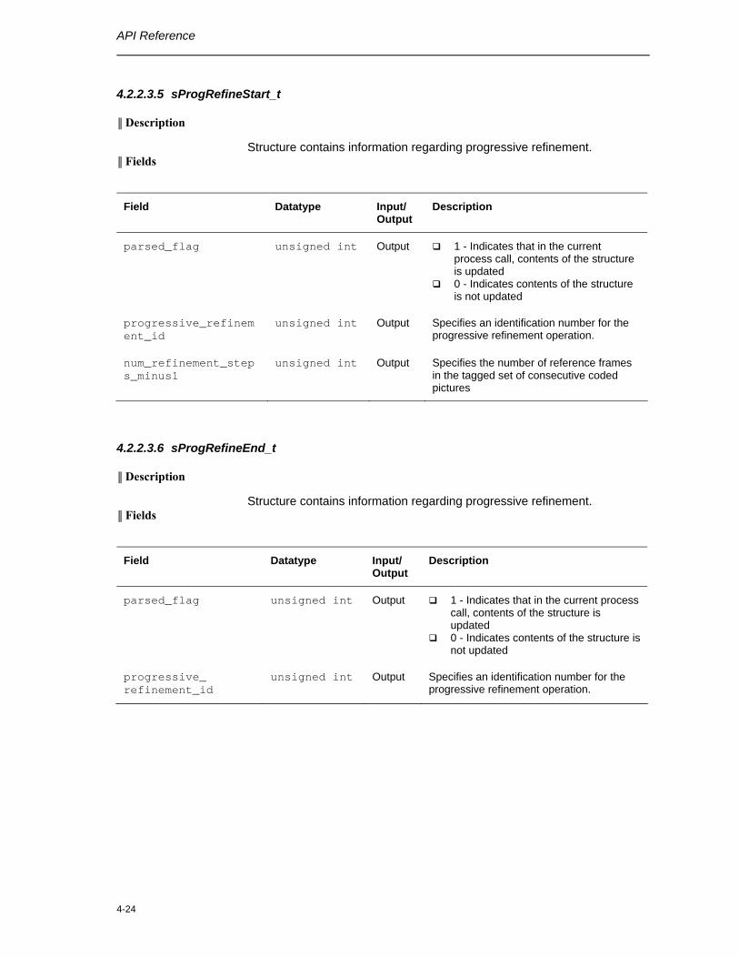
API Reference
4-24
4.2.2.3.5 sProgRefineStart_t
║ Description
Structure contains information regarding progressive refinement. ║ Fields
Field Datatype Input/ Output
Description
parsed_flag unsigned int Output 1 - Indicates that in the current process call, contents of the structure is updated
0 - Indicates contents of the structure is not updated
progressive_refinement_id
unsigned int Output Specifies an identification number for the progressive refinement operation.
num_refinement_steps_minus1
unsigned int Output Specifies the number of reference frames in the tagged set of consecutive coded pictures
4.2.2.3.6 sProgRefineEnd_t
║ Description
Structure contains information regarding progressive refinement. ║ Fields
Field Datatype Input/ Output
Description
parsed_flag unsigned int Output 1 - Indicates that in the current process call, contents of the structure is updated
0 - Indicates contents of the structure is not updated
progressive_ refinement_id
unsigned int Output Specifies an identification number for the progressive refinement operation.
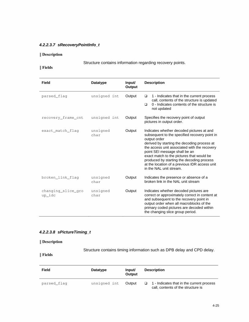
4-25
4.2.2.3.7 sRecoveryPointInfo_t
║ Description
Structure contains information regarding recovery points. ║ Fields
Field Datatype Input/ Output
Description
parsed_flag unsigned int Output 1 - Indicates that in the current process call, contents of the structure is updated
0 - Indicates contents of the structure is not updated
recovery_frame_cnt unsigned int Output Specifies the recovery point of output pictures in output order.
exact_match_flag unsigned char
Output Indicates whether decoded pictures at and subsequent to the specified recovery point in output order derived by starting the decoding process at the access unit associated with the recovery point SEI message shall be an exact match to the pictures that would be produced by starting the decoding process at the location of a previous IDR access unit in the NAL unit stream.
broken_link_flag unsigned char
Output Indicates the presence or absence of a broken link in the NAL unit stream
changing_slice_group_idc
unsigned char
Output Indicates whether decoded pictures are correct or approximately correct in content at and subsequent to the recovery point in output order when all macroblocks of the primary coded pictures are decoded within the changing slice group period.
4.2.2.3.8 sPictureTiming_t
║ Description
Structure contains timing information such as DPB delay and CPD delay. ║ Fields
Field Datatype Input/ Output
Description
parsed_flag unsigned int Output 1 - Indicates that in the current process call, contents of the structure is
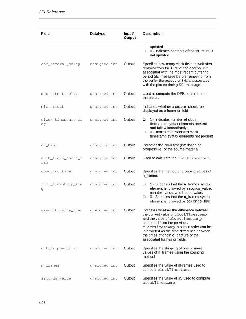
API Reference
4-26
Field Datatype Input/ Output
Description
updated 0 - Indicates contents of the structure is
not updated
cpb_removal_delay unsigned int Output Specifies how many clock ticks to wait after removal from the CPB of the access unit associated with the most recent buffering period SEI message before removing from the buffer the access unit data associated with the picture timing SEI message.
dpb_output_delay unsigned int Output Used to compute the DPB output time of the picture.
pic_struct unsigned int Output Indicates whether a picture should be displayed as a frame or field
clock_timestamp_flag
unsigned int Output 1 - Indicates number of clock timestamp syntax elements present and follow immediately
0 – Indicates associated clock timestamp syntax elements not present
ct_type unsigned int Output Indicates the scan type(interlaced or progressive) of the source material
nuit_field_based_flag
unsigned int Output Used to calculate the clockTimestamp
counting_type unsigned int Output Specifies the method of dropping values of n_frames
full_timestamp_flag
unsigned int Output 1 - Specifies that the n_frames syntax element is followed by seconds_value, minutes_value, and hours_value.
0 - Specifies that the n_frames syntax element is followed by seconds_flag
discontinuity_flag unsigned int Output Indicates whether the difference between the current value of clockTimestamp and the value of clockTimestamp computed from the previous clockTimestamp in output order can be interpreted as the time difference between the times of origin or capture of the associated frames or fields.
cnt_dropped_flag unsigned int Output Specifies the skipping of one or more values of n_frames using the counting method
n_frames unsigned int Output Specifies the value of nFrames used to compute clockTimestamp.
seconds_value unsigned int Output Specifies the value of sS used to compute clockTimestamp.
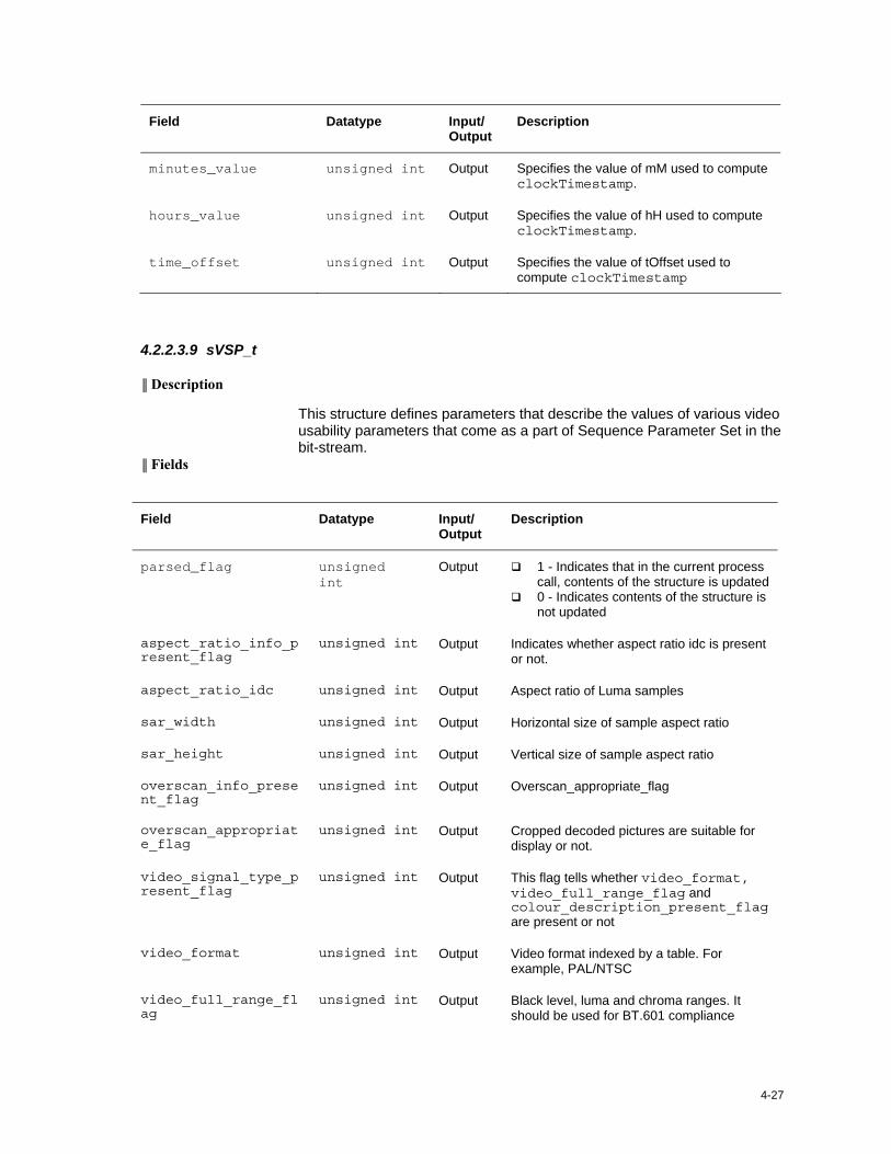
4-27
Field Datatype Input/ Output
Description
minutes_value unsigned int Output Specifies the value of mM used to compute clockTimestamp.
hours_value unsigned int Output Specifies the value of hH used to compute clockTimestamp.
time_offset unsigned int Output Specifies the value of tOffset used to compute clockTimestamp
4.2.2.3.9 sVSP_t
║ Description
This structure defines parameters that describe the values of various video usability parameters that come as a part of Sequence Parameter Set in the bit-stream.
║ Fields
Field Datatype Input/ Output
Description
parsed_flag unsigned int
Output 1 - Indicates that in the current process call, contents of the structure is updated
0 - Indicates contents of the structure is not updated
aspect_ratio_info_present_flag
unsigned int Output Indicates whether aspect ratio idc is present or not.
aspect_ratio_idc unsigned int Output Aspect ratio of Luma samples
sar_width unsigned int Output Horizontal size of sample aspect ratio
sar_height unsigned int Output Vertical size of sample aspect ratio
overscan_info_present_flag
unsigned int Output Overscan_appropriate_flag
overscan_appropriate_flag
unsigned int Output Cropped decoded pictures are suitable for display or not.
video_signal_type_present_flag
unsigned int Output This flag tells whether video_format, video_full_range_flag and colour_description_present_flag are present or not
video_format unsigned int Output Video format indexed by a table. For example, PAL/NTSC
video_full_range_flag
unsigned int Output Black level, luma and chroma ranges. It should be used for BT.601 compliance
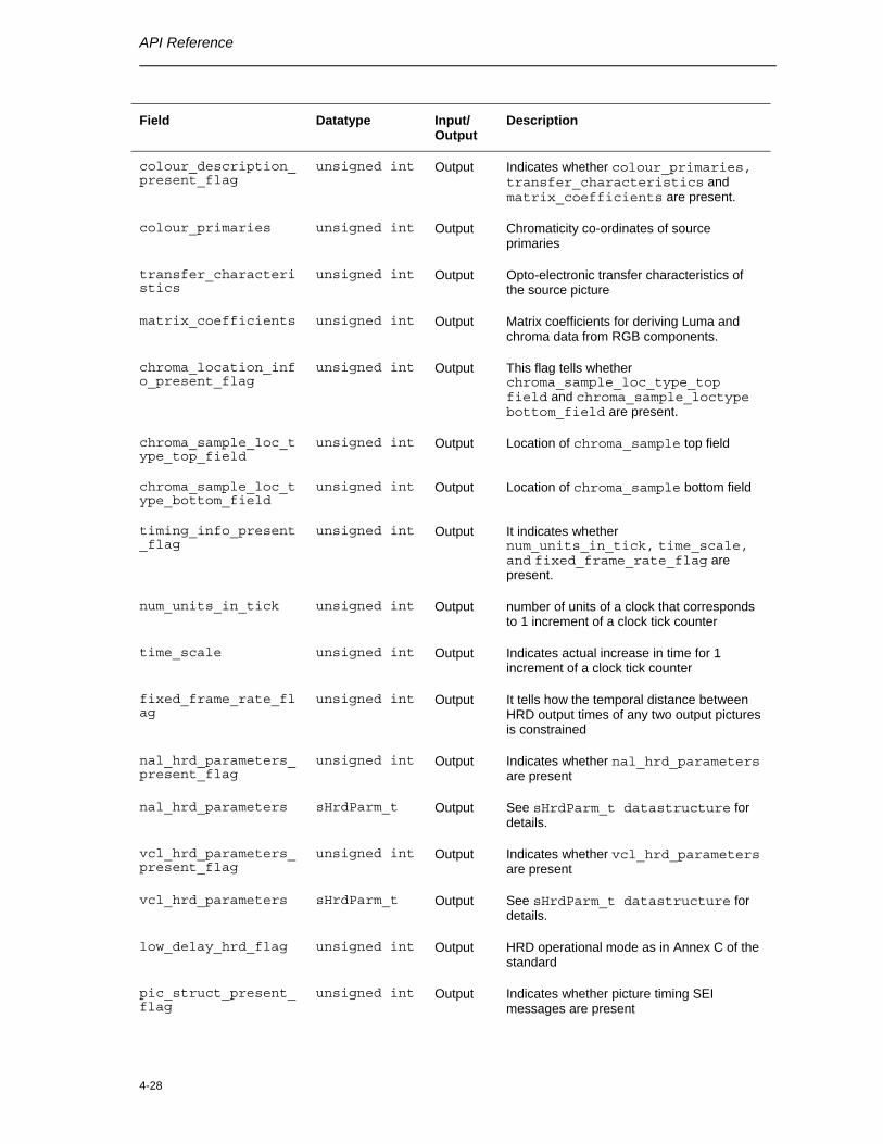
API Reference
4-28
Field Datatype Input/ Output
Description
colour_description_present_flag
unsigned int Output Indicates whether colour_primaries, transfer_characteristics and matrix_coefficients are present.
colour_primaries unsigned int Output Chromaticity co-ordinates of source primaries
transfer_characteristics
unsigned int Output Opto-electronic transfer characteristics of the source picture
matrix_coefficients unsigned int Output Matrix coefficients for deriving Luma and chroma data from RGB components.
chroma_location_info_present_flag
unsigned int Output This flag tells whether chroma_sample_loc_type_top field and chroma_sample_loctype bottom_field are present.
chroma_sample_loc_type_top_field
unsigned int Output Location of chroma_sample top field
chroma_sample_loc_type_bottom_field
unsigned int Output Location of chroma_sample bottom field
timing_info_present_flag
unsigned int Output It indicates whether num_units_in_tick, time_scale, and fixed_frame_rate_flag are present.
num_units_in_tick unsigned int Output number of units of a clock that corresponds to 1 increment of a clock tick counter
time_scale unsigned int Output Indicates actual increase in time for 1 increment of a clock tick counter
fixed_frame_rate_flag
unsigned int Output It tells how the temporal distance between HRD output times of any two output pictures is constrained
nal_hrd_parameters_present_flag
unsigned int Output Indicates whether nal_hrd_parameters are present
nal_hrd_parameters sHrdParm_t Output See sHrdParm_t datastructure for details.
vcl_hrd_parameters_present_flag
unsigned int Output Indicates whether vcl_hrd_parameters are present
vcl_hrd_parameters sHrdParm_t Output See sHrdParm_t datastructure for details.
low_delay_hrd_flag unsigned int Output HRD operational mode as in Annex C of the standard
pic_struct_present_flag
unsigned int Output Indicates whether picture timing SEI messages are present
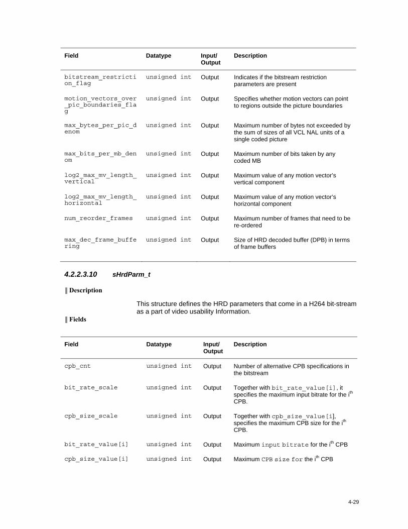
4-29
Field Datatype Input/ Output
Description
bitstream_restriction_flag
unsigned int Output Indicates if the bitstream restriction parameters are present
motion_vectors_over_pic_boundaries_flag
unsigned int Output Specifies whether motion vectors can point to regions outside the picture boundaries
max_bytes_per_pic_denom
unsigned int Output Maximum number of bytes not exceeded by the sum of sizes of all VCL NAL units of a single coded picture
max_bits_per_mb_denom
unsigned int Output Maximum number of bits taken by any coded MB
log2_max_mv_length_vertical
unsigned int Output Maximum value of any motion vector’s vertical component
log2_max_mv_length_horizontal
unsigned int Output Maximum value of any motion vector’s horizontal component
num_reorder_frames unsigned int Output Maximum number of frames that need to be re-ordered
max_dec_frame_buffering
unsigned int Output Size of HRD decoded buffer (DPB) in terms of frame buffers
4.2.2.3.10 sHrdParm_t
║ Description
This structure defines the HRD parameters that come in a H264 bit-stream as a part of video usability Information.
║ Fields
Field Datatype Input/ Output
Description
cpb_cnt unsigned int Output Number of alternative CPB specifications in the bitstream
bit_rate_scale unsigned int Output Together with bit_rate_value[i], it specifies the maximum input bitrate for the ith CPB.
cpb_size_scale unsigned int Output Together with cpb_size_value[i], specifies the maximum CPB size for the ith CPB.
bit_rate_value[i] unsigned int Output Maximum input bitrate for the ith CPB
cpb_size_value[i] unsigned int Output Maximum CPB size for the ith CPB
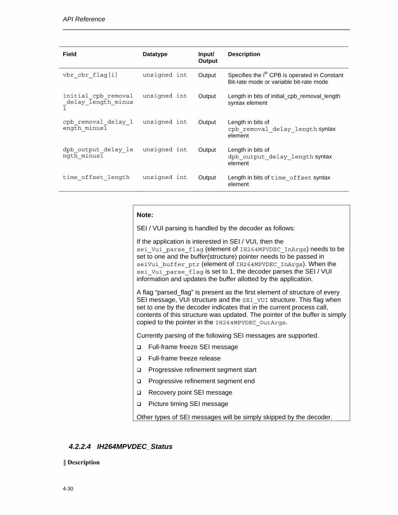
API Reference
4-30
Field Datatype Input/ Output
Description
vbr_cbr_flag[i] unsigned int Output Specifies the ith CPB is operated in Constant Bit-rate mode or variable bit-rate mode
initial_cpb_removal_delay_length_minus1
unsigned int Output Length in bits of initial_cpb_removal_length syntax element
cpb_removal_delay_length_minus1
unsigned int Output Length in bits of cpb_removal_delay_length syntax element
dpb_output_delay_length_minus1
unsigned int Output Length in bits of dpb_output_delay_length syntax element
time_offset_length unsigned int Output Length in bits of time_offset syntax element
Note:
SEI / VUI parsing is handled by the decoder as follows:
If the application is interested in SEI / VUI, then the sei_Vui_parse_flag (element of IH264MPVDEC_InArgs) needs to be set to one and the buffer(structure) pointer needs to be passed in seiVui_buffer_ptr (element of IH264MPVDEC_InArgs). When the sei_Vui_parse_flag is set to 1, the decoder parses the SEI / VUI information and updates the buffer allotted by the application.
A flag “parsed_flag” is present as the first element of structure of every SEI message, VUI structure and the SEI_VUI structure. This flag when set to one by the decoder indicates that in the current process call, contents of this structure was updated. The pointer of the buffer is simply copied to the pointer in the IH264MPVDEC_OutArgs.
Currently parsing of the following SEI messages are supported.
Full-frame freeze SEI message
Full-frame freeze release
Progressive refinement segment start
Progressive refinement segment end
Recovery point SEI message
Picture timing SEI message
Other types of SEI messages will be simply skipped by the decoder.
4.2.2.4 IH264MPVDEC_Status
║ Description
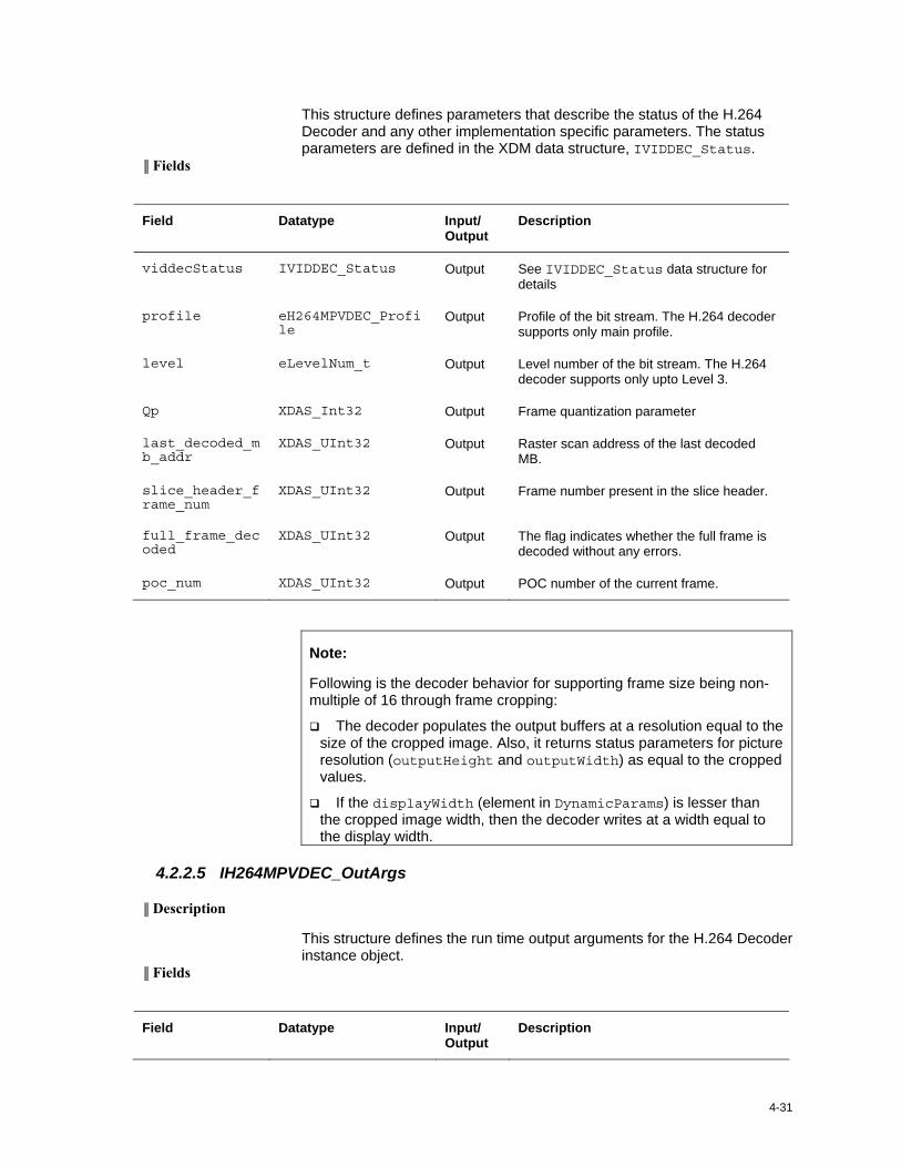
4-31
This structure defines parameters that describe the status of the H.264 Decoder and any other implementation specific parameters. The status parameters are defined in the XDM data structure, IVIDDEC_Status.
║ Fields
Field Datatype Input/ Output
Description
viddecStatus IVIDDEC_Status Output See IVIDDEC_Status data structure for details
profile eH264MPVDEC_Profile
Output Profile of the bit stream. The H.264 decoder supports only main profile.
level eLevelNum_t Output Level number of the bit stream. The H.264 decoder supports only upto Level 3.
Qp XDAS_Int32 Output Frame quantization parameter
last_decoded_mb_addr
XDAS_UInt32 Output Raster scan address of the last decoded MB.
slice_header_frame_num
XDAS_UInt32 Output Frame number present in the slice header.
full_frame_decoded
XDAS_UInt32 Output The flag indicates whether the full frame is decoded without any errors.
poc_num XDAS_UInt32 Output POC number of the current frame.
Note:
Following is the decoder behavior for supporting frame size being non-multiple of 16 through frame cropping:
The decoder populates the output buffers at a resolution equal to the size of the cropped image. Also, it returns status parameters for picture resolution (outputHeight and outputWidth) as equal to the cropped values.
If the displayWidth (element in DynamicParams) is lesser than the cropped image width, then the decoder writes at a width equal to the display width.
4.2.2.5 IH264MPVDEC_OutArgs
║ Description
This structure defines the run time output arguments for the H.264 Decoder instance object.
║ Fields
Field Datatype Input/ Output
Description
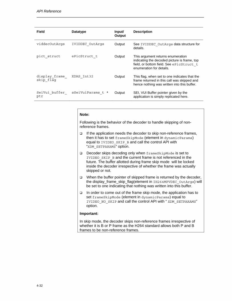
API Reference
4-32
Field Datatype Input/ Output
Description
viddecOutArgs IVIDDEC_OutArgs Output See IVIDDEC_OutArgs data structure for details.
pict_struct ePicStruct_t Output This argument returns enumeration indicating the decoded picture is frame, top field, or bottom field. See ePicStruct_t enumeration for details.
display_frame_skip_flag
XDAS_Int32 Output This flag, when set to one indicates that the frame returned in this call was skipped and hence nothing was written into this buffer.
SeiVui_buffer_ptr
sSeiVuiParams_t * Output SEI, VUI Buffer pointer given by the application is simply replicated here.
Note:
Following is the behavior of the decoder to handle skipping of non-reference frames.
If the application needs the decoder to skip non-reference frames, then it has to set frameSkipMode (element in dynamicParams) equal to IVIDEO_SKIP_B and call the control API with “XDM_SETPARAMS” option.
Decoder skips decoding only when frameSkipMode is set to IVIDEO_SKIP_B and the current frame is not referenced in the future. The buffer allotted during frame skip mode will be locked inside the decoder irrespective of whether the frame was actually skipped or not.
When the buffer pointer of skipped frame is returned by the decoder, the display_frame_skip_flag(element in IH264MPVDEC_OutArgs) will be set to one indicating that nothing was written into this buffer.
In order to come out of the frame skip mode, the application has to set frameSkipMode (element in dynamicParams) equal to IVIDEO_NO_SKIP and call the control API with “ XDM_SETPARAMS” option.
Important:
In skip mode, the decoder skips non-reference frames irrespective of whether it is B or P frame as the H264 standard allows both P and B frames to be non-reference frames.
4-33
4.3 Interface Functions
This section describes the Application Programming Interfaces (APIs) used in the H.264 Decoder. The APIs are logically grouped into the following categories:
Creation – algNumAlloc(), algAlloc()
Initialization – algInit()
Control – control()
Data processing – algActivate(), process(), algDeactivate()
Termination – algFree()
You must call these APIs in the following sequence:
1) algNumAlloc()
2) algAlloc()
3) algInit()
4) algActivate()
5) process()
6) algDeactivate()
7) algFree()
control() can be called any time after calling the algInit() API.
algNumAlloc(), algAlloc(), algInit(), algActivate(), algDeactivate(), and algFree() are standard XDAIS APIs. This document includes only a brief description for the standard XDAIS APIs. For more details, see TMS320 DSP Algorithm Standard API Reference (literature number SPRU360).
4.3.1 Creation APIs
Creation APIs are used to create an instance of the component. The term creation could mean allocating system resources, typically memory.
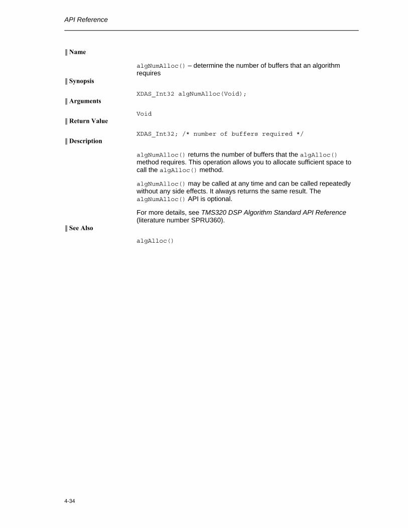
API Reference
4-34
║ Name
algNumAlloc() – determine the number of buffers that an algorithm requires
║ Synopsis
XDAS_Int32 algNumAlloc(Void); ║ Arguments
Void ║ Return Value
XDAS_Int32; /* number of buffers required */ ║ Description
algNumAlloc() returns the number of buffers that the algAlloc() method requires. This operation allows you to allocate sufficient space to call the algAlloc() method.
algNumAlloc() may be called at any time and can be called repeatedly without any side effects. It always returns the same result. The algNumAlloc() API is optional.
For more details, see TMS320 DSP Algorithm Standard API Reference (literature number SPRU360).
║ See Also
algAlloc()
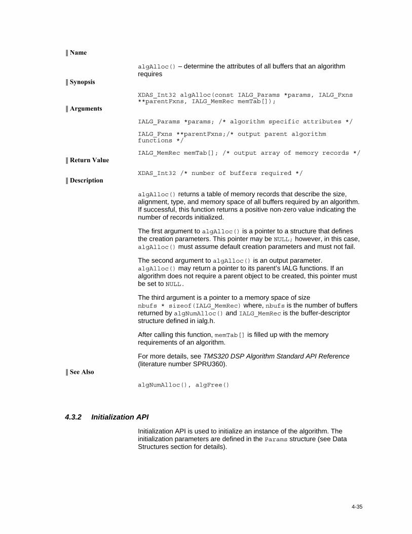
4-35
║ Name
algAlloc() – determine the attributes of all buffers that an algorithm requires
║ Synopsis
XDAS_Int32 algAlloc(const IALG_Params *params, IALG_Fxns **parentFxns, IALG_MemRec memTab[]);
║ Arguments
IALG_Params *params; /* algorithm specific attributes */
IALG_Fxns **parentFxns;/* output parent algorithm functions */
IALG_MemRec memTab[]; /* output array of memory records */ ║ Return Value
XDAS_Int32 /* number of buffers required */ ║ Description
algAlloc() returns a table of memory records that describe the size, alignment, type, and memory space of all buffers required by an algorithm. If successful, this function returns a positive non-zero value indicating the number of records initialized.
The first argument to algAlloc() is a pointer to a structure that defines the creation parameters. This pointer may be NULL; however, in this case, algAlloc() must assume default creation parameters and must not fail.
The second argument to algAlloc() is an output parameter. algAlloc() may return a pointer to its parent’s IALG functions. If an algorithm does not require a parent object to be created, this pointer must be set to NULL.
The third argument is a pointer to a memory space of size nbufs * sizeof(IALG_MemRec) where, nbufs is the number of buffers returned by algNumAlloc() and IALG_MemRec is the buffer-descriptor structure defined in ialg.h.
After calling this function, memTab[] is filled up with the memory requirements of an algorithm.
For more details, see TMS320 DSP Algorithm Standard API Reference (literature number SPRU360).
║ See Also
algNumAlloc(), algFree()
4.3.2 Initialization API
Initialization API is used to initialize an instance of the algorithm. The initialization parameters are defined in the Params structure (see Data Structures section for details).
API Reference
4-36
║ Name
algInit() – initialize an algorithm instance ║ Synopsis
XDAS_Int32 algInit(IALG_Handle handle, IALG_MemRec memTab[], IALG_Handle parent, IALG_Params *params);
║ Arguments
IALG_Handle handle; /* algorithm instance handle*/
IALG_memRec memTab[]; /* array of allocated buffers */
IALG_Handle parent; /* handle to the parent instance */
IALG_Params *params; /* algorithm initialization parameters */
║ Return Value
IALG_EOK; /* status indicating success */
IALG_EFAIL; /* status indicating failure */ ║ Description
algInit() performs all initialization necessary to complete the run time creation of an algorithm instance object. After a successful return from algInit(), the instance object is ready to be used to process data.
The first argument to algInit() is a handle to an algorithm instance. This value is initialized to the base field of memTab[0].
The second argument is a table of memory records that describe the base address, size, alignment, type, and memory space of all buffers allocated for an algorithm instance. The number of initialized records is identical to the number returned by a prior call to algAlloc().
The third argument is a handle to the parent instance object. If there is no parent object, this parameter must be set to NULL.
The last argument is a pointer to a structure that defines the algorithm initialization parameters.
For more details, see TMS320 DSP Algorithm Standard API Reference (literature number SPRU360).
║ See Also
algAlloc(), algMoved()
4.3.3 Control API
Control API is used for controlling the functioning of the algorithm instance during run time. This is done by changing the status of the controllable parameters of the algorithm during run time. These controllable parameters are defined in the Status data structure (see data structures section for details).
4-37
║ Name
control() – change run time parameters and query the status ║ Synopsis
XDAS_Int32 (*control) (IVIDDEC_Handle handle, IVIDDEC_Cmd id, IVIDDEC_DynamicParams *params, IVIDDEC_Status *status);
║ Arguments
IVIDDEC_Handle handle; /* algorithm instance handle */
IVIDDEC_Cmd id; /* algorithm specific control commands*/
IVIDDEC_DynamicParams *params /* algorithm run time parameters */
IVIDDEC_Status *status /* algorithm instance status parameters */
║ Return Value
IALG_EOK; /* status indicating success */
IALG_EFAIL; /* status indicating failure */ ║ Description
This function changes the run time parameters of an algorithm instance and queries the algorithm’s status. control() must only be called after a successful call to algInit() and must never be called after a call to algFree().
The first argument to control() is a handle to an algorithm instance.
The second argument is an algorithm specific control command. See XDM_CmdId enumeration for details.
The third and fourth arguments are pointers to the IVIDDEC_DynamicParams and IVIDDEC_Status data structures respectively.
Note:
If you are using extended data structures, the third and fourth arguments must be pointers to the extended DynamicParams and Status data structures respectively. Also, ensure that the size field is set to the size of the extended data structure. Depending on the value set for the size field, the algorithm uses either basic or extended parameters.
API Reference
4-38
║ Preconditions
The following conditions must be true prior to calling this function; otherwise, its operation is undefined.
control() can only be called after a successful return from algInit() and algActivate().
If algorithm uses DMA resources, control() can only be called after a successful return from DMAN3_init().
handle must be a valid handle for the algorithm’s instance object. ║ Postconditions
The following conditions are true immediately after returning from this function.
If the control operation is successful, the return value from this operation is equal to IALG_EOK; otherwise it is equal to either IALG_EFAIL or an algorithm specific return value.
If the control command is not recognized, the return value from this operation is not equal to IALG_EOK.
║ Example
See test application file, TestAppDecoder.c available in the \Client\Test\Src sub-directory.
║ See Also
algInit(), algActivate(), process()
4.3.4 Data Processing API
Data processing API is used for processing the input data.
4-39
║ Name
algActivate() – initialize scratch memory buffers prior to processing. ║ Synopsis
Void algActivate(IALG_Handle handle); ║ Arguments
IALG_Handle handle; /* algorithm instance handle */ ║ Return Value
Void ║ Description
algActivate() initializes any of the instance’s scratch buffers using the persistent memory that is part of the algorithm’s instance object.
The first (and only) argument to algActivate() is an algorithm instance handle. This handle is used by the algorithm to identify various buffers that must be initialized prior to calling any of the algorithm’s processing methods.
For more details, see TMS320 DSP Algorithm Standard API Reference. (literature number SPRU360).
║ See Also
algDeactivate()
API Reference
4-40
║ Name
process() – basic encoding/decoding call ║ Synopsis
XDAS_Int32 (*process)(IVIDDEC_Handle handle, XDM_BufDesc *inBufs, XDM_BufDesc *outBufs, IVIDDEC_InArgs *inargs, IVIDDEC_OutArgs *outargs);
║ Arguments
IVIDDEC_Handle handle; /* algorithm instance handle */
XDM_BufDesc *inBufs; /* algorithm input buffer descriptor */
XDM_BufDesc *outBufs; /* algorithm output buffer descriptor */
IVIDDEC_InArgs *inargs /* algorithm runtime input arguments */
IVIDDEC_OutArgs *outargs /* algorithm runtime output arguments */
║ Return Value
IALG_EOK; /* status indicating success */
IALG_EFAIL; /* status indicating failure */ ║ Description
This function does the basic encoding/decoding. The first argument to process() is a handle to an algorithm instance.
The second and third arguments are pointers to the input and output buffer descriptor data structures respectively (see XDM_BufDesc data structure for details).
The fourth argument is a pointer to the IVIDDEC_InArgs data structure that defines the run time input arguments for an algorithm instance object.
The last argument is a pointer to the IVIDDEC_OutArgs data structure that defines the run time output arguments for an algorithm instance object.
Note:
If you are using extended data structures, the fourth and fifth arguments must be pointers to the extended InArgs and OutArgs data structures respectively. Also, ensure that the size field is set to the size of the extended data structure. Depending on the value set for the size field, the algorithm uses either basic or extended parameters.
║ Preconditions
The following conditions must be true prior to calling this function; otherwise, its operation is undefined.
process() can only be called after a successful return from algInit() and algActivate().
4-41
If algorithm uses DMA resources, process() can only be called after a successful return from DMAN3_init().
handle must be a valid handle for the algorithm’s instance object.
Buffer descriptor for input and output buffers must be valid.
Input buffers must have valid input data. ║ Postconditions
The following conditions are true immediately after returning from this function.
If the process operation is successful, the return value from this operation is equal to IALG_EOK; otherwise it is equal to either IALG_EFAIL or an algorithm specific return value.
After successful return from process() function, algDeactivate() can be called.
║ Example
See test application file, TestAppDecoder.c available in the \Client\Test\Src sub-directory.
║ See Also
algInit(), algDeactivate(), control()
Note:
A video encoder or decoder cannot be pre-empted by any other video encoder or decoder instance. That is, you cannot perform task switching while encode/decode of a particular frame is in progress. Pre-emption can happen only at frame boundaries and after algDeactivate() is called.
API Reference
4-42
║ Name
algDeactivate() – save all persistent data to non-scratch memory ║ Synopsis
Void algDeactivate(IALG_Handle handle); ║ Arguments
IALG_Handle handle; /* algorithm instance handle */ ║ Return Value
Void ║ Description
algDeactivate() saves any persistent information to non-scratch buffers using the persistent memory that is part of the algorithm’s instance object.
The first (and only) argument to algDeactivate() is an algorithm instance handle. This handle is used by the algorithm to identify various buffers that must be saved prior to next cycle of algActivate() and processing.
For more details, see TMS320 DSP Algorithm Standard API Reference (literature number SPRU360).
║ See Also
algActivate()
4.3.5 Termination API
Termination API is used to terminate the algorithm instance and free up the memory space that it uses.
4-43
║ Name
algFree() – determine the addresses of all memory buffers used by the algorithm
║ Synopsis
XDAS_Int32 algFree(IALG_Handle handle, IALG_MemRec memTab[]);
║ Arguments
IALG_Handle handle; /* handle to the algorithm instance */
IALG_MemRec memTab[]; /* output array of memory records */ ║ Return Value
XDAS_Int32; /* Number of buffers used by the algorithm */ ║ Description
algFree() determines the addresses of all memory buffers used by the algorithm. The primary aim of doing so is to free up these memory regions after closing an instance of the algorithm.
The first argument to algFree() is a handle to the algorithm instance.
The second argument is a table of memory records that describe the base address, size, alignment, type, and memory space of all buffers previously allocated for the algorithm instance.
For more details, see TMS320 DSP Algorithm Standard API Reference (literature number SPRU360).
║ See Also
algAlloc()
API Reference
4-44
4.4 Error Handling
This section describes the errors in the bit stream, the expected behavior of the decoder, and the recommended actions on the application side.
When the decoder detects an error in the bitstream, the return value from the process call will be IALG_EFAIL.
The type of the detected error will be indicated in the extendedError field of OutArgs. See XDM_ErrorBit enumeration for details.
In any type of error scenario, there is no need for the application to reset the decoder.
Ouput/display buffer handling in error scenarios:
o If the maxDisplayDelay is zero, then the decoder always returns back the same display buffer passed by the system in the current process call
o If the maxDisplayDelay is greater than zero, then the decoder returns display buffers in an order based on the display order logic specified by the standard. However if the display order logic cannot be executed due to error XDM_CORRUPTEDHEADER, then decoder simply returns back the display buffer given by the system in the current process call. Note that the decoder attempts to return a non-NULL pointer for display in all scenarios, when the initial pipeup for maxDisplayDelay is completed.
When the error type is XDM_CORRUPTEDHEADER, the output height and width information present in the OutArgs or Status structure might not be reliable.
Note:
In certain scenarios, the decoder returns a non-zero extendedError, with the process call returning IALG_EOK. This happens, if decoder detects errors in the bit stream, which do not obstruct the further decoding and reconstruction. For example: An error detected during parsing of a PPS which is never referenced, will be reported in the extendedError, but the process call will still return IALG_EOK.