Embed Size (px)
Citation preview
H.264 Network DVR
- 1 -
H.264 Network DVR User Manual
Mar. 2009
H.264 Network DVR
- 2 -
Table of Contents
CHARP.1 Product Introduction ........................................................................................................ - 5 -
1.1 Overview ........................................................................................................................................ - 5 -
1.2 Features ................................................................................................................................................................................................................ - 6 -
CHARP.2 Mouse and Remote Control Operation ............................................................................. - 8 -
2.1 Mouse operation .................................................................................................................................................................................................... - 8 -
2.2 Remote Control Operation .................................................................................................................................................................................. - 11 -
CHARP.3 Basic Operations .............................................................................................................. - 15 -
3.1 Power on/Shut down ........................................................................................................................................................................................... - 15 -
3.1.1 Power on ......................................................................................................................................................................................................... - 15 -
3.4 Record .......................................................................................................................................................................................................... - 18 -
3.4.1 Recording ................................................................................................................................................................................................ - 18 -
3.4.2 Playback ................................................................................................................................................................................................... - 19 -
3.4.3 File Backup .............................................................................................................................................................................................. - 22 -
CHARP.4 Menu Operation ................................................................................................................. - 24 -
4.1 Menu Preview .............................................................................................................................................................................................. - 24 -
4.2 Menu Operation ........................................................................................................................................................................................... - 26 -
4.2.1 System Information ................................................................................................................................................................................ - 26 -
“Menu”→“SYSTEM INFO”. (Figure 4-2) ............................................................................................................................................................. - 26 -
4.2.2 Disk Management ................................................................................................................................................................................... - 32 -
5.1 PTZ Control .................................................................................................................................................................................................. - 33 -
5.1.1 Connection .............................................................................................................................................................................................. - 33 -
5.1.2 Preparation .............................................................................................................................................................................................. - 33 -
5.1.3 Operation ................................................................................................................................................................................................. - 33 -
5.3 Sound Monitoring ......................................................................................................................................................................................... - 35 -
5.4 Alarm Control ............................................................................................................................................................................................... - 35 -
H.264 Network DVR
- 3 -
5.4.1 Alarm Control .......................................................................................................................................................................................... - 35 -
5.4.2 Clear Alarm .............................................................................................................................................................................................. - 36 -
CHARP.6 System Setup .................................................................................................................... - 38 -
6.1 System Setup ............................................................................................................................................................................................... - 38 -
6.3 Recording Setup .......................................................................................................................................................................................... - 41 -
6.4 PTZ Setup .................................................................................................................................................................................................... - 43 -
"Main Menu"-"System"-"PTZ Setup" (Figure 6-5) .............................................................................................................................................. - 43 -
6.5 Network Setup .............................................................................................................................................................................................. - 44 -
6.6 Alarm Setup .................................................................................................................................................................................................. - 46 -
"Main Menu"-"System"-"Alarm Setup" (Figure 6-8). .......................................................................................................................................... - 46 -
6.7 Video Detection Setup ................................................................................................................................................................................. - 48 -
7.1 User Account ................................................................................................................................................................................................ - 55 -
7.2 Exception...................................................................................................................................................................................................... - 58 -
7.3 System Maintenance ................................................................................................................................................................................... - 59 -
7.5 Restore ......................................................................................................................................................................................................... - 61 -
CHARP.8 Remote Network Control and Management ................................................................. - 62 -
8.1 Remote Settings ........................................................................................................................................................................................... - 62 -
8.1.1 Network Security Settings ..................................................................................................................................................................... - 62 -
8.1.2 Connection Settings ............................................................................................................................................................................... - 65 -
8.1.3 ActiveX Download Installation ............................................................................................................................................................... - 68 -
8.2 Remote Connection ..................................................................................................................................................................................... - 68 -
8.2.1 Connection .............................................................................................................................................................................................. - 68 -
8.2.2 Multiple Servers Login ........................................................................................................................................................................... - 72 -
8.2.3 Channel Associated Menus ................................................................................................................................................................... - 72 -
8.3 Control .......................................................................................................................................................................................................... - 73 -
8.3.1 Common ................................................................................................................................................................................................... - 74 -
8.3.2 Video ......................................................................................................................................................................................................... - 75 -
8.3.3 Alarm ........................................................................................................................................................................................................ - 76 -
8.3.4 Log ............................................................................................................................................................................................................ - 77 -
8.3.5 Download ................................................................................................................................................................................................. - 79 -
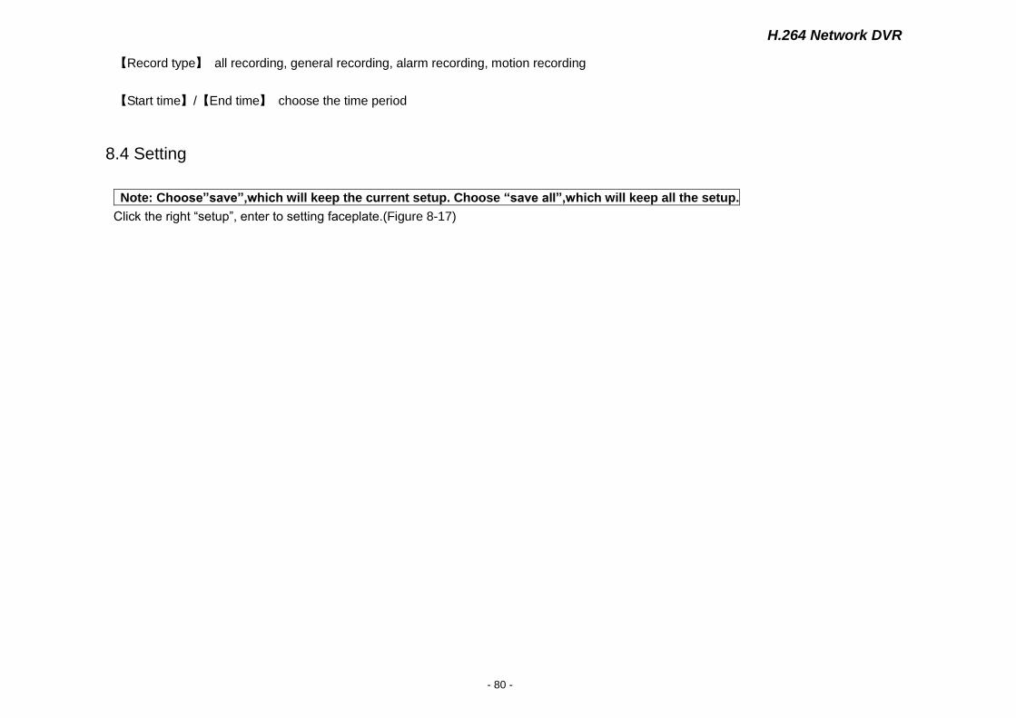
8.4 Setting .......................................................................................................................................................................................................... - 80 -
H.264 Network DVR
- 4 -
8.4.1 Local Setting ............................................................................................................................................................................................ - 82 -
8.4.2 Common Setting, Encoding Setting, Record Setting, Alarm Setting, PTZ Setting, Video Detect, Video Loss, Video Blind ...... - 82 -
8.5 Toolbar Introduction ...................................................................................................................................................................................... - 83 -
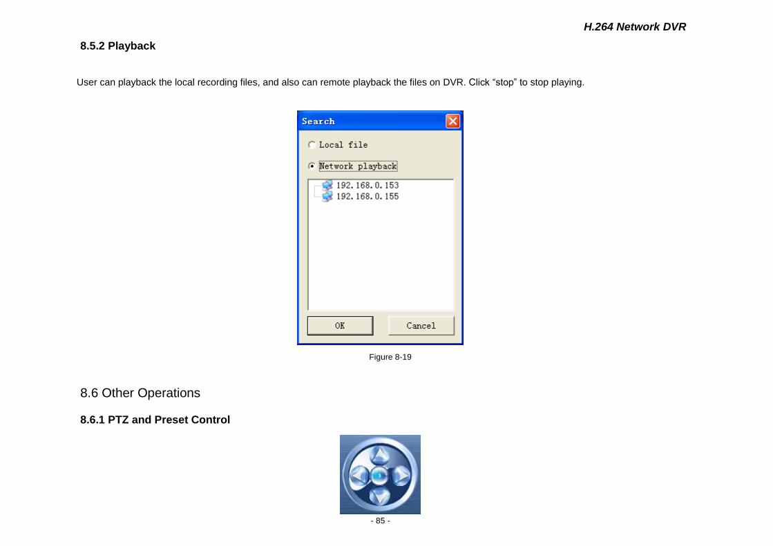
8.5.2 Playback ................................................................................................................................................................................................... - 85 -
User can playback the local recording files, and also can remote playback the files on DVR. Click “stop” to stop playing. ............................ - 85 -
8.6 Other Operations .......................................................................................................................................................................................... - 85 -
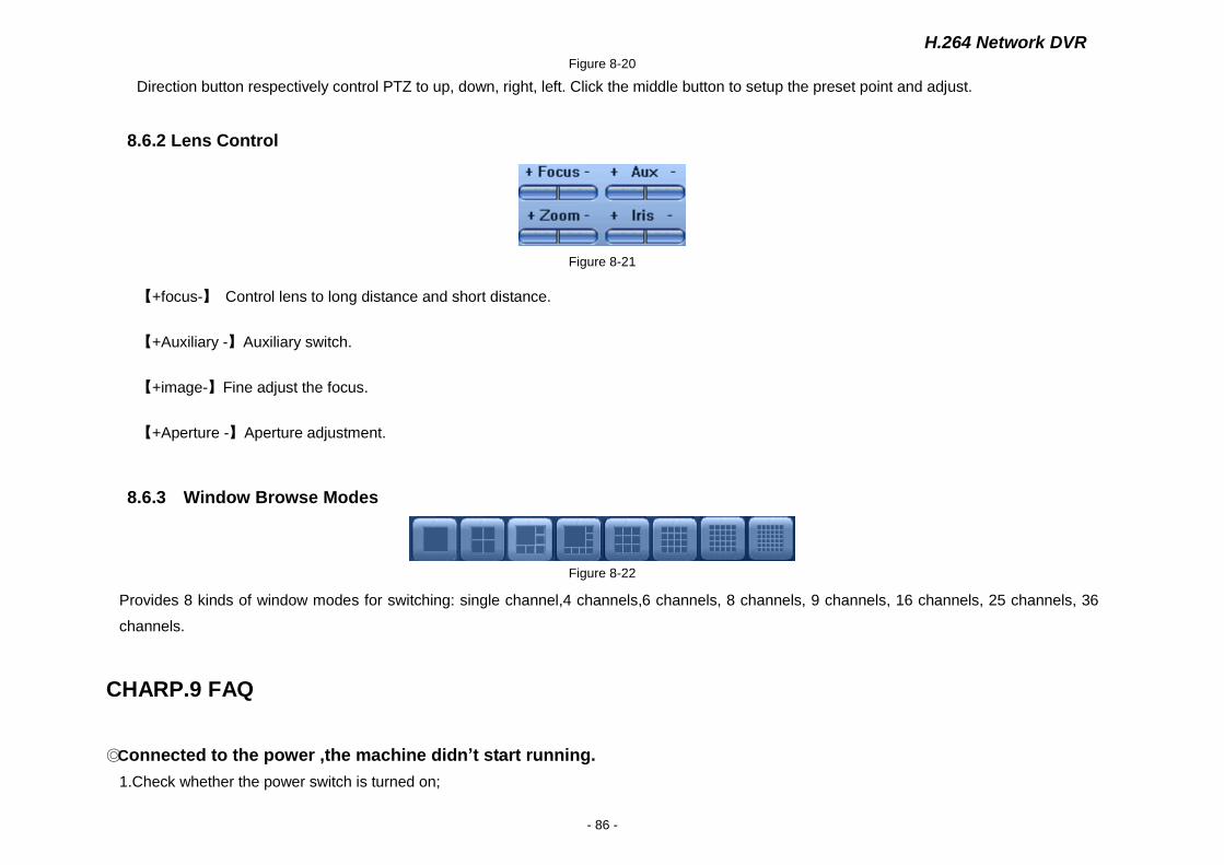
8.6.1 PTZ and Preset Control .......................................................................................................................................................................... - 85 -
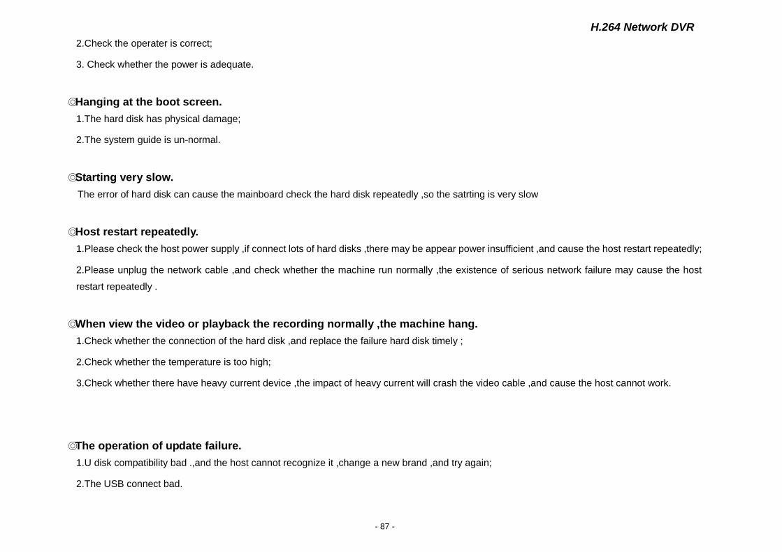
8.6.2 Lens Control ............................................................................................................................................................................................ - 86 -
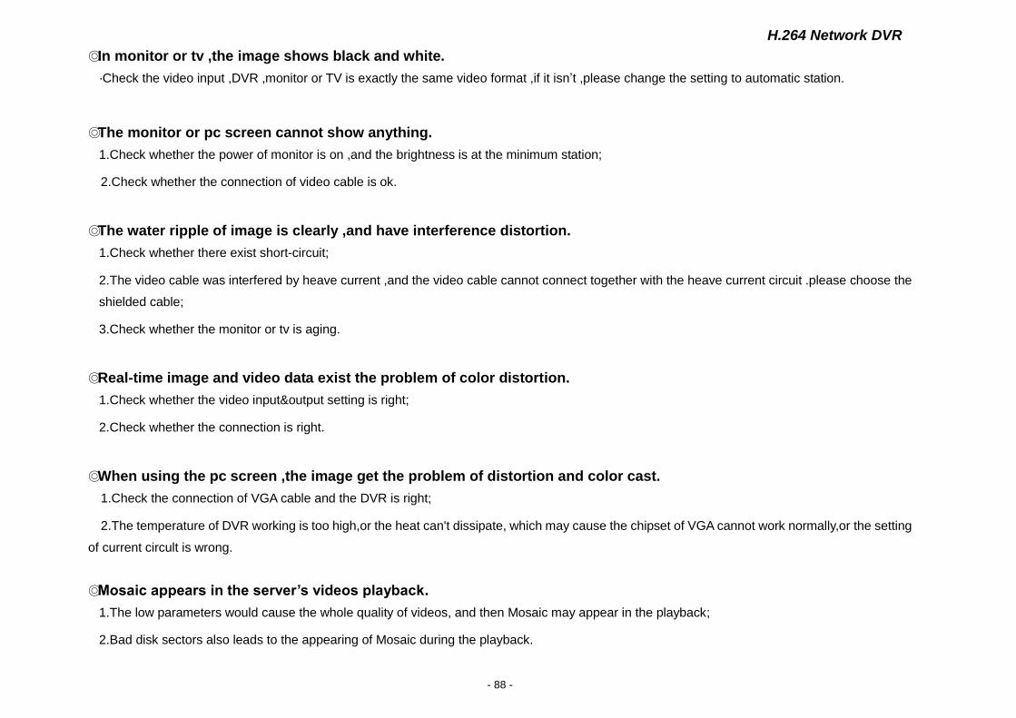
8.6.3 Window Browse Modes ....................................................................................................................................................................... - 86 -
CHARP.9 FAQ .................................................................................................................................... - 86 -
Appendix A: Technical Specifications .................................................................................................................................................................. - 89 -
Appendix B: Alarm Input Interface Instruction .................................................................................................................................................... - 90 -
Appendix C: Alarm Output Interface Instruction ................................................................................................................................................. - 92 -
H.264 Network DVR
- 5 -
Caution and Preventive Tips
Power Supply
This recorders work at 12V DC power supply, please confirm the power supply voltage before use. Please shut down the power if you don't use it for a long time, and pull the plug out the socket.
Safety
This machine is indoor equipment ,in order to prevent the risk of short circuit or electrics shock ,don’t put it on the rain or humid environment .
In case of any solid or liquid into the DVR, please cut off the power at once, don't open it until the qualified technician examined.
It is delicate machine, it is too difficult to repair it by user themselves. If there is any problems, please ask the qualified technician to examine, or contact the distributor.
Installation
DVR should be installed at horizontal place.
DVR shell should be grounded .
Make sure the hard disk is installed before the initial using .
Avoid opening the case or replacing the hard disk under the power state.
Recommend using the high-speed hard disk of 7200 transgenic/s or above.
Please select the appropriate installation place ,so that the air can flow free ,in order to prevent the machine overheating
The machine mustn’t be installed in those areas that near the heat source such as radiator ,or direct sunlight ,or excessive dust or mechanical
vibration areas.
CHARP.1 Product Introduction
1.1 Overview
This series standalone DVRs are high quality digital monitoring system products which are researched and designed specifically for cctv field ,which
adopt embedded processors and linux operating systems, apply of high-performance coding and decoding chipsets, bring in the most advanced IT
H.264 Network DVR
- 6 -
technological achievements, such as audio codec, high capacity storage hard disk, TCP / IP network and more, which fix the code in FLASH,
making the system more stable, the image more clearer and the function more powerful.
This series of digital video recorders can be used independently, but also can be networked to form a powerful network monitoring center, which
have been widely used in different areas and sectors’ security and surveillance, such as domestic and international bank, telecommunications,
power, justice, traffic, residential area, factory, storage resources, water resources,etc. In addition, which also play an very important role in home
monitoring system.
This user manual takes 8ch standalone DVR as sample to illuminate specifically, all the figures are based on this DVR, for the operation of 4ch and
16ch DVR, please take this for reference.
1.2 Features
Realtime
Monitoring
With analog output interface and VGA
interface, support monitor output and display
output;
1/4/8/9 multi-screen monitor;
Display the real-time video stream and how
many resources be occupied per hour;
Through the channel marks to prompt the
channel status, such as recording, motion
detection, video loss, video block, alarm
trigger,etc.;
Support search the system logs local.
HDD
Built-in four SATA interfaces, max support 4pcs hard disk;
The hard disk file, including cycle coverage records and
non-cycle records ;
Adopt special format to store data,so the data can’t be
tampered,and ensure the data security;
Compression
Format
Video compression format,: H.264;
8channel video and audio input, keep video
and audio synchronization stablely.
Backup
Through USB interface (such as USB disk and movable
hard disk, etc.) to back up;
Support DVD/W to back up;
The client computer can download the file on your hard
disk through network to backup;
Multi-tasking operations: It can achieve
not only realtime recording independently
each channel,but also searching and
Network
Functions
Remote monitoring through network;
PTZ control;
Recording files search and playback;

H.264 Network DVR
- 7 -
Playback
playback for single channel/four
channels,remote monitoring, record
searching and downloading;
Multi-recording modes:
manual,time,schedule,alarm linkage, motion
detection,etc. Support preview;
User can playback the recording files of DVR
through network;
It can achieve to search recording files fast
and search the recording file as types;
Multi-playback modes: slow playback, fast
playback and frame-by-frame playback;
It can display the exact time of the incident
when playback the recording file.
Changes the settings and parameters of the system or
software upgrade;
Remote alarm processing and system logs searching and
more functions;
Adopt Embedded TCP / IP protocol and linux operating
system, user can browse the system through IE browser;
Management modes: Adopt the enhanced user
management, only the qualified users can login, user can
set different users with different authorities flexible and
convenient according to their needs;
Alarm
8ch alarm input (the types of alarm can be
generated by setting the regular open or
normally closed the switch), and with video
loss alarm, motion detection alarm, the
alarm device can be a smoke detector,
temperature detectors, infrared detectors,
etc.;
With 4ch relay switch-values alarm output, it
can achieve alarm linkage and the live
lighting control conveniently;
Both the alarm input and alarm output
interfaces are with the protection circuit,
make sure that the main equipment from
damage;
Communication
Interfaces
With a special interface for the achievement of alarm input
and PTZ control;
With a standard Ethernet interface for viewing remotely
through network;
PTZ Control
Support PTZ decoder through the RS485
communications;
Scalable multiple decoder protocols for the
achievement of PTZ and speed dome
Smart Operations
Friendly Human-Computer Interaction interface, it can be
operated by mouse to achieve all functions.
H.264 Network DVR
- 8 -
control functions;
CHARP.2 Mouse and Remote Control Operation
2.1 Mouse operation
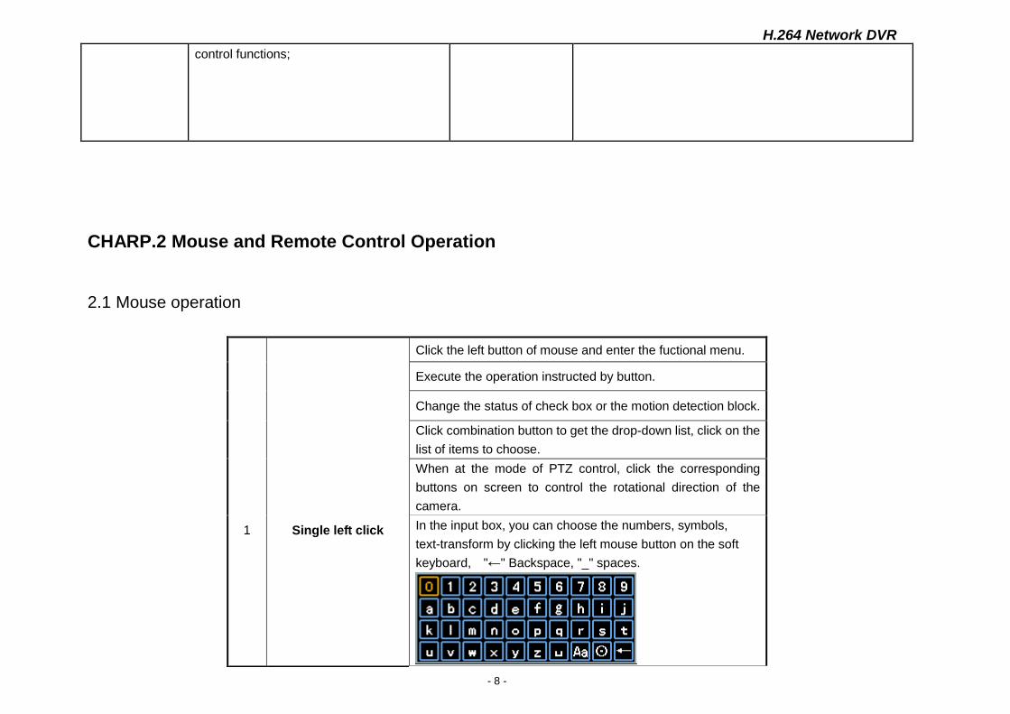
1
Single left click
Click the left button of mouse and enter the fuctional menu.
Execute the operation instructed by button.
Change the status of check box or the motion detection block.
Click combination button to get the drop-down list, click on the
list of items to choose.
When at the mode of PTZ control, click the corresponding
buttons on screen to control the rotational direction of the
camera.
In the input box, you can choose the numbers, symbols,
text-transform by clicking the left mouse button on the soft
keyboard, "←" Backspace, "_" spaces.
H.264 Network DVR
- 9 -
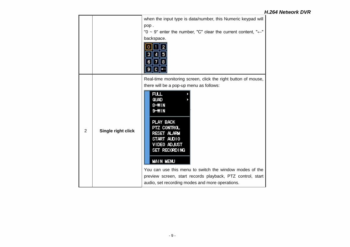
when the input type is data/number, this Numeric keypad will
pop .
"0 ~ 9" enter the number, "C" clear the current content, "←"
backspace.
2 Single right click
Real-time monitoring screen, click the right button of mouse,
there will be a pop-up menu as follows:
You can use this menu to switch the window modes of the
preview screen, start records playback, PTZ control, start
audio, set recording modes and more operations.
H.264 Network DVR
- 10 -
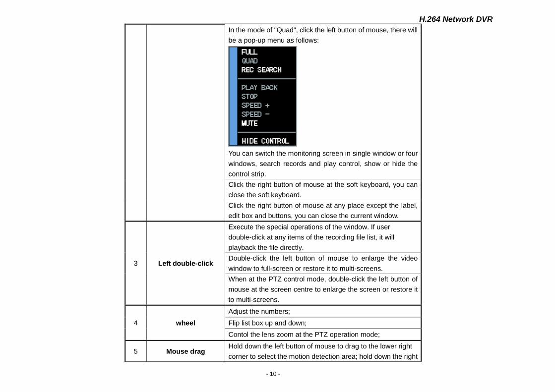
In the mode of "Quad", click the left button of mouse, there will
be a pop-up menu as follows:
You can switch the monitoring screen in single window or four
windows, search records and play control, show or hide the
control strip.
Click the right button of mouse at the soft keyboard, you can
close the soft keyboard.
Click the right button of mouse at any place except the label,
edit box and buttons, you can close the current window.
3 Left double-click
Execute the special operations of the window. If user
double-click at any items of the recording file list, it will
playback the file directly.
Double-click the left button of mouse to enlarge the video
window to full-screen or restore it to multi-screens.
When at the PTZ control mode, double-click the left button of
mouse at the screen centre to enlarge the screen or restore it
to multi-screens.
4 wheel
Adjust the numbers;
Flip list box up and down;
Contol the lens zoom at the PTZ operation mode;
5 Mouse drag Hold down the left button of mouse to drag to the lower right
corner to select the motion detection area; hold down the right
H.264 Network DVR
- 11 -
2.2 Remote Control Operation
Users can use the remote controller to control DVR,the remote control keys are distributed as follows:
button of mouse to drag to the lower right corner to cancel the
selected area.
Drag the play progress bar forwardly or backwardly to adjust
the location of the current record displaying; drag the slider
forwardly or backwardly to adjust the parameter.
H.264 Network DVR
- 12 -
1
2 3
4
5 6
7
8
9
10
11
12
13
14
H.264 Network DVR
- 13 -
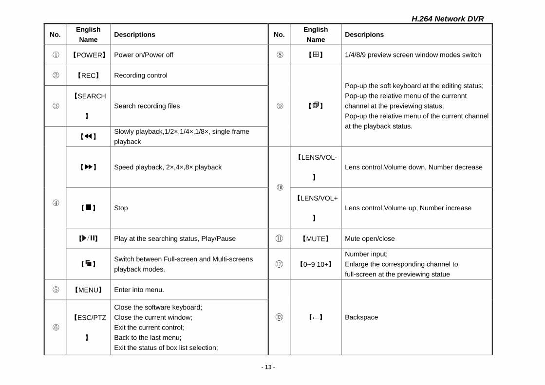
No. English
Name Descriptions No.
English
Name Descripions
① 【POWER】 Power on/Power off ⑧ 【 】 1/4/8/9 preview screen window modes switch
② 【REC】 Recording control
⑨ 【 】
Pop-up the soft keyboard at the editing status;
Pop-up the relative menu of the currennt
channel at the previewing status;
Pop-up the relative menu of the current channel
at the playback status.
③
【SEARCH
】
Search recording files
④
【 】 Slowly playback,1/2×,1/4×,1/8×, single frame
playback
【 】 Speed playback, 2×,4×,8× playback
⑩
【LENS/VOL-
】
Lens control,Volume down, Number decrease
【 】 Stop
【LENS/VOL+
】
Lens control,Volume up, Number increase
【 】 Play at the searching status, Play/Pause 【MUTE】 Mute open/close
【 】 Switch between Full-screen and Multi-screens
playback modes. 【0~9 10+】
Number input;
Enlarge the corresponding channel to
full-screen at the previewing statue
⑤ 【MENU】 Enter into menu.
【←】 Backspace
⑥
【ESC/PTZ
】
Close the software keyboard;
Close the current window;
Exit the current control;
Back to the last menu;
Exit the status of box list selection;
H.264 Network DVR
- 14 -
Enter into or exit the PTZ control at preview
status. 【DEV】 Device select
【OK】
Confrim the operations;
Switch the editing area(Time,date,IP address);
Switch between full-screen and multi-screens at
the previewing status;
Enter into the list box selection status and confirm
your selection;
Select/Cancel the status of the check box.
H.264 Network DVR
- 15 -
CHARP.3 Basic Operations
3.1 Power on/Shut down
3.1.1 Power on
◆ If the【POWER】mark lighting is out, please operate as follows:
First: If the power does not plug, please plug in the power, the DVR will start; if the DVR won’t start, please enter the next step;
Second: Open the power switch of the DVR, it will start.
◆ If the 【POWER】mark light is red, just please press the 【POWER】 key to start the DVR..
After started the DVR,the video output is the default multi-screen output mode, if the start-up time is in the recording time which have been
setted before, the system will automatically start recording function.
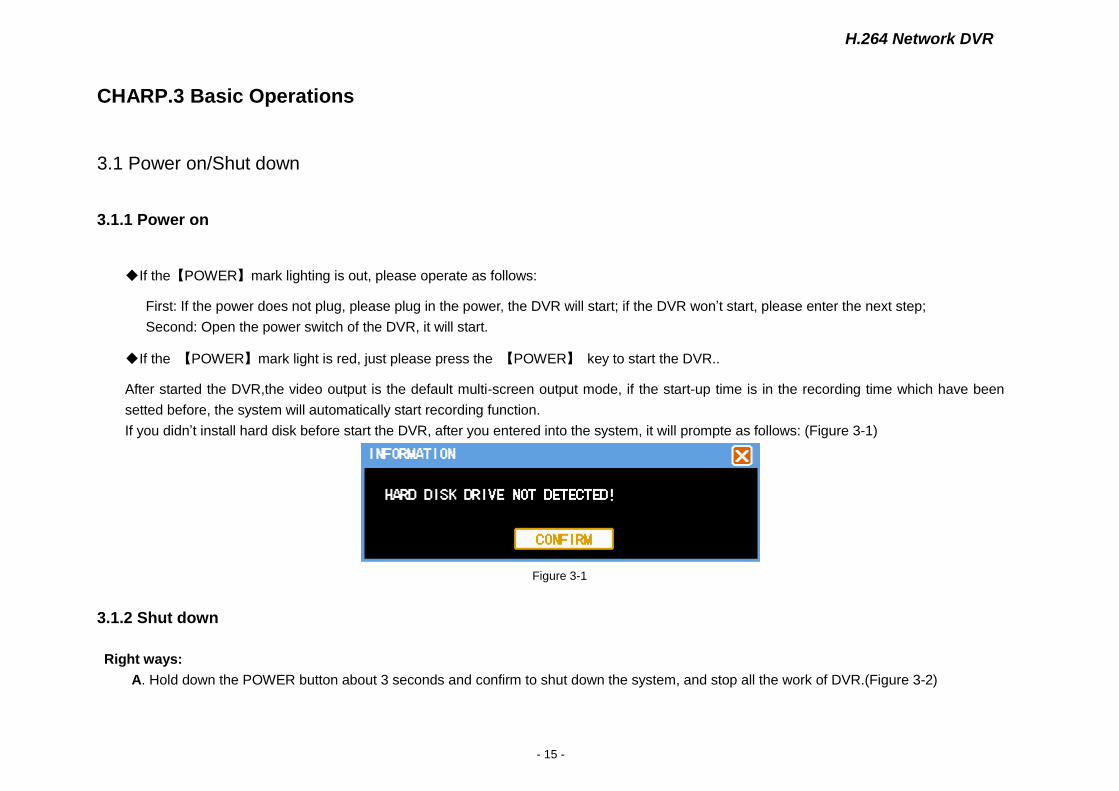
If you didn’t install hard disk before start the DVR, after you entered into the system, it will prompte as follows: (Figure 3-1)
Figure 3-1
3.1.2 Shut down
Right ways:
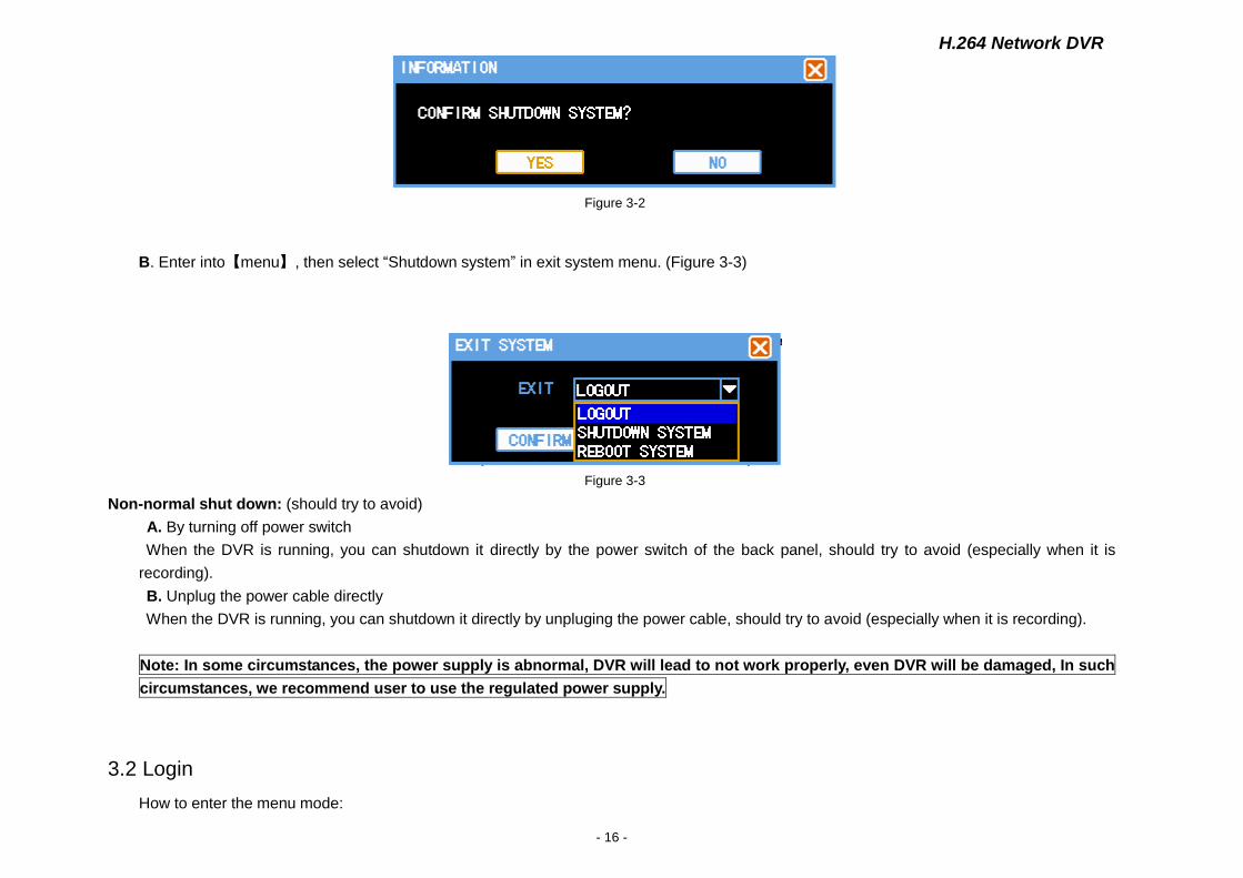
A. Hold down the POWER button about 3 seconds and confirm to shut down the system, and stop all the work of DVR.(Figure 3-2)
H.264 Network DVR
- 16 -
Figure 3-2
B. Enter into【menu】, then select “Shutdown system” in exit system menu. (Figure 3-3)
Figure 3-3
Non-normal shut down: (should try to avoid)
A. By turning off power switch
When the DVR is running, you can shutdown it directly by the power switch of the back panel, should try to avoid (especially when it is
recording).
B. Unplug the power cable directly
When the DVR is running, you can shutdown it directly by unpluging the power cable, should try to avoid (especially when it is recording).
Note: In some circumstances, the power supply is abnormal, DVR will lead to not work properly, even DVR will be damaged, In such
circumstances, we recommend user to use the regulated power supply.
3.2 Login
How to enter the menu mode:
H.264 Network DVR
- 17 -
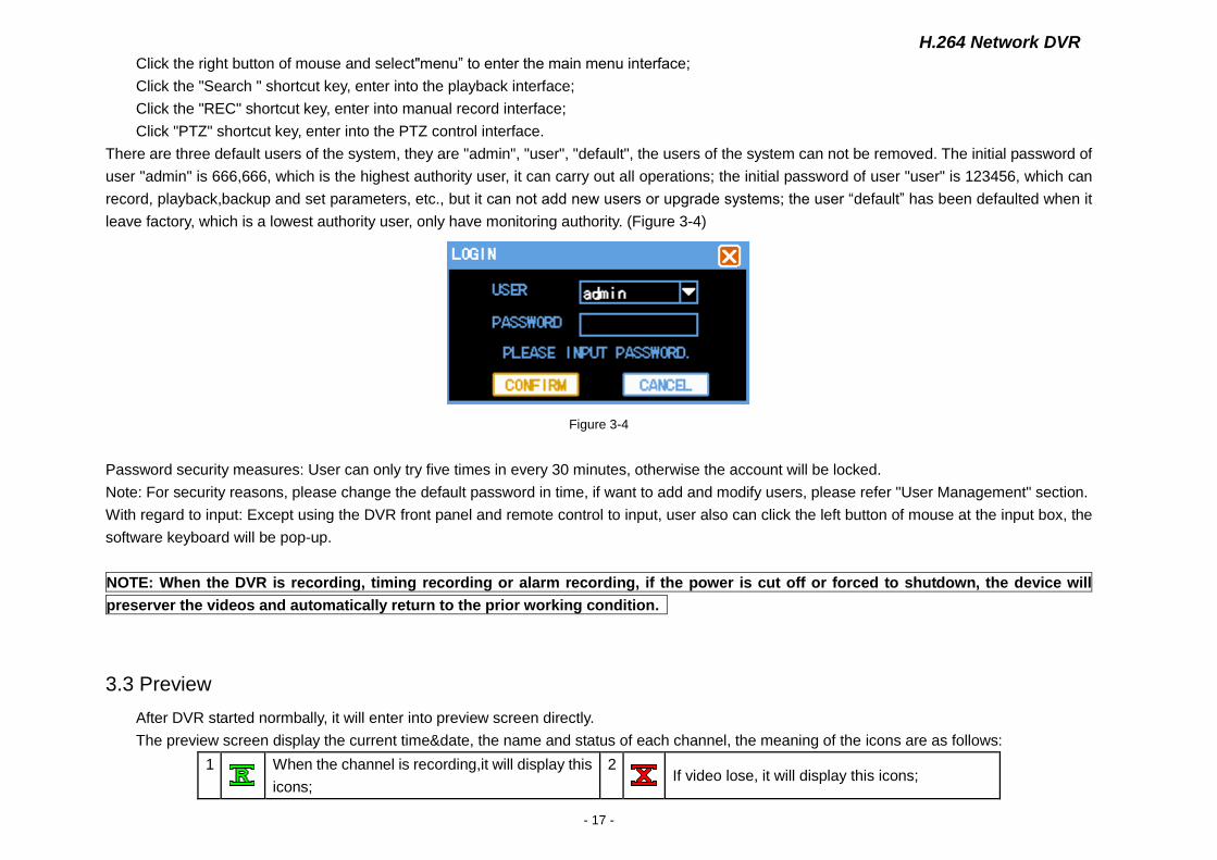
Click the right button of mouse and select"menu” to enter the main menu interface;
Click the "Search " shortcut key, enter into the playback interface;
Click the "REC" shortcut key, enter into manual record interface;
Click "PTZ" shortcut key, enter into the PTZ control interface.
There are three default users of the system, they are "admin", "user", "default", the users of the system can not be removed. The initial password of
user "admin" is 666,666, which is the highest authority user, it can carry out all operations; the initial password of user "user" is 123456, which can
record, playback,backup and set parameters, etc., but it can not add new users or upgrade systems; the user “default” has been defaulted when it
leave factory, which is a lowest authority user, only have monitoring authority. (Figure 3-4)
Figure 3-4
Password security measures: User can only try five times in every 30 minutes, otherwise the account will be locked.
Note: For security reasons, please change the default password in time, if want to add and modify users, please refer "User Management" section.
With regard to input: Except using the DVR front panel and remote control to input, user also can click the left button of mouse at the input box, the
software keyboard will be pop-up.
NOTE: When the DVR is recording, timing recording or alarm recording, if the power is cut off or forced to shutdown, the device will
preserver the videos and automatically return to the prior working condition.
3.3 Preview
After DVR started normbally, it will enter into preview screen directly.
The preview screen display the current time&date, the name and status of each channel, the meaning of the icons are as follows:
1
When the channel is recording,it will display this
icons;
2
If video lose, it will display this icons;
H.264 Network DVR
- 18 -
3
If there is motion, it will display this icons; 4 If there is video block, it will display this icon.
3.4 Record
Users can choose different recording modes according to their own needs. For different recording modes, when the channel is recording, it will
display a recording icon on the channel screen.
3.4.1 Recording
Notes: User must have recording operating authority to record. Before recording, please confirm that the DVR has been installed
hard disk, and the hard disk have been formated correctly.
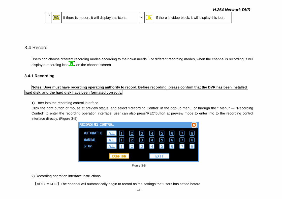
1) Enter into the recording control interface
Click the right button of mouse at preview status, and select “Recording Control” in the pop-up menu; or through the " Menu" → "Recording
Control" to enter the recording operation interface; user can also press”REC”button at preview mode to enter into to the recording control
interface directly: (Figure 3-5)
Figure 3-5
2) Recording operation interface instructions
【AUTOMATIC】The channel will automatically begin to record as the settings that users has setted before.
H.264 Network DVR
- 19 -
【MANUAL】 Which has the highest level of priority, no matter what the current state of the channels are, if user click "Manual" button, all the
relative channels will be recording;
【STOP】 Stop all recording;
【ALL】 Choose all channels;
3.4.2 Playback
There are two playback ways in the system: fast playback and advanced playback. User can search file to playback, or playback as time.
1) Fast Playback
Click "Search" or the right button of mouse under the preview screen, then choose"playback" in the pop-up menu to enter the fast playback, for
fast playback mode, it only support single-channel playback.
2) Advanced Playback
User Select"Menu"→“File playback”, then can enter into advanced playback. It not only support each channel playback independently, but also
support the 4channels to playback at the same time.
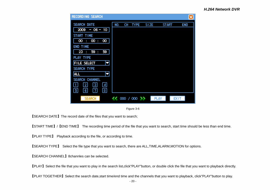
3) Recording Search (Figure 3-6)
H.264 Network DVR
- 20 -
Figure 3-6
【SEARCH DATE】The record date of the files that you want to search;
【START TIME】/【END TIME】 The recording time period of the file that you want to search, start time should be less than end time.
【PLAY TYPE】 Playback according to the file, or according to time.
【SEARCH TYPE】 Select the file type that you want to search, there are ALL,TIME,ALARM,MOTION for options.
【SEARCH CHANNEL】8channles can be selected.
【PLAY】Select the file that you want to play in the search list,click"PLAY"button, or double click the file that you want to playback directly.
【PLAY TOGETHER】Select the search date,start time/end time and the channels that you want to playback, click"PLAY"button to play.
H.264 Network DVR
- 21 -
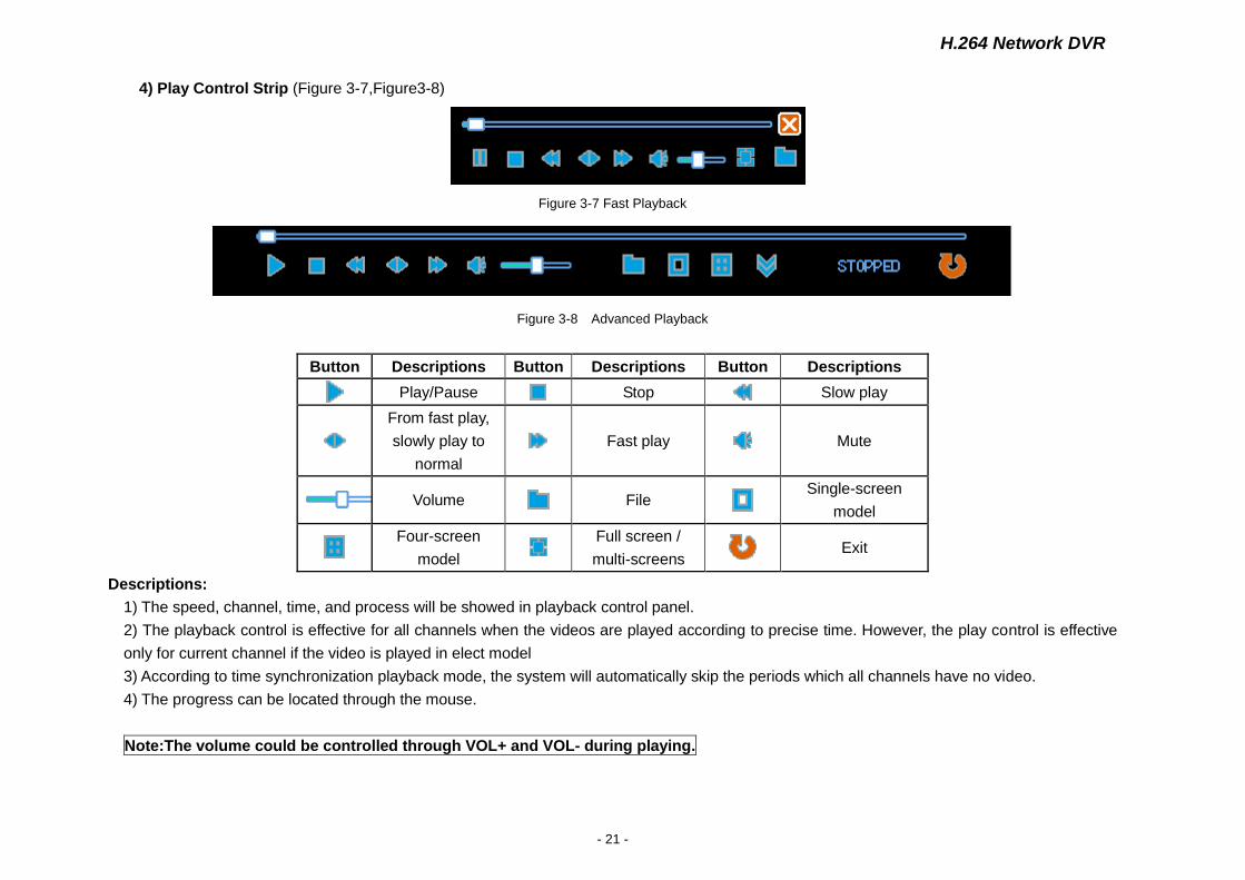
4) Play Control Strip (Figure 3-7,Figure3-8)
Figure 3-7 Fast Playback
Figure 3-8 Advanced Playback
Button Descriptions Button Descriptions Button Descriptions
Play/Pause Stop Slow play
From fast play,
slowly play to
normal
Fast play Mute
Volume File Single-screen
model
Four-screen
model
Full screen /
multi-screens Exit
Descriptions:
1) The speed, channel, time, and process will be showed in playback control panel.
2) The playback control is effective for all channels when the videos are played according to precise time. However, the play control is effective
only for current channel if the video is played in elect model
3) According to time synchronization playback mode, the system will automatically skip the periods which all channels have no video.
4) The progress can be located through the mouse.
Note:The volume could be controlled through VOL+ and VOL- during playing.
H.264 Network DVR
- 22 -
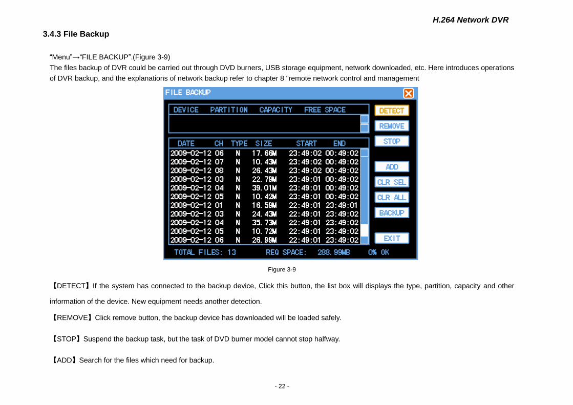
3.4.3 File Backup
“Menu”→“FILE BACKUP”.(Figure 3-9)
The files backup of DVR could be carried out through DVD burners, USB storage equipment, network downloaded, etc. Here introduces operations
of DVR backup, and the explanations of network backup refer to chapter 8 "remote network control and management
Figure 3-9
【DETECT】If the system has connected to the backup device, Click this button, the list box will displays the type, partition, capacity and other
information of the device. New equipment needs another detection.
【REMOVE】Click remove button, the backup device has downloaded will be loaded safely.
【STOP】Suspend the backup task, but the task of DVD burner model cannot stop halfway.
【ADD】Search for the files which need for backup.
H.264 Network DVR
- 23 -
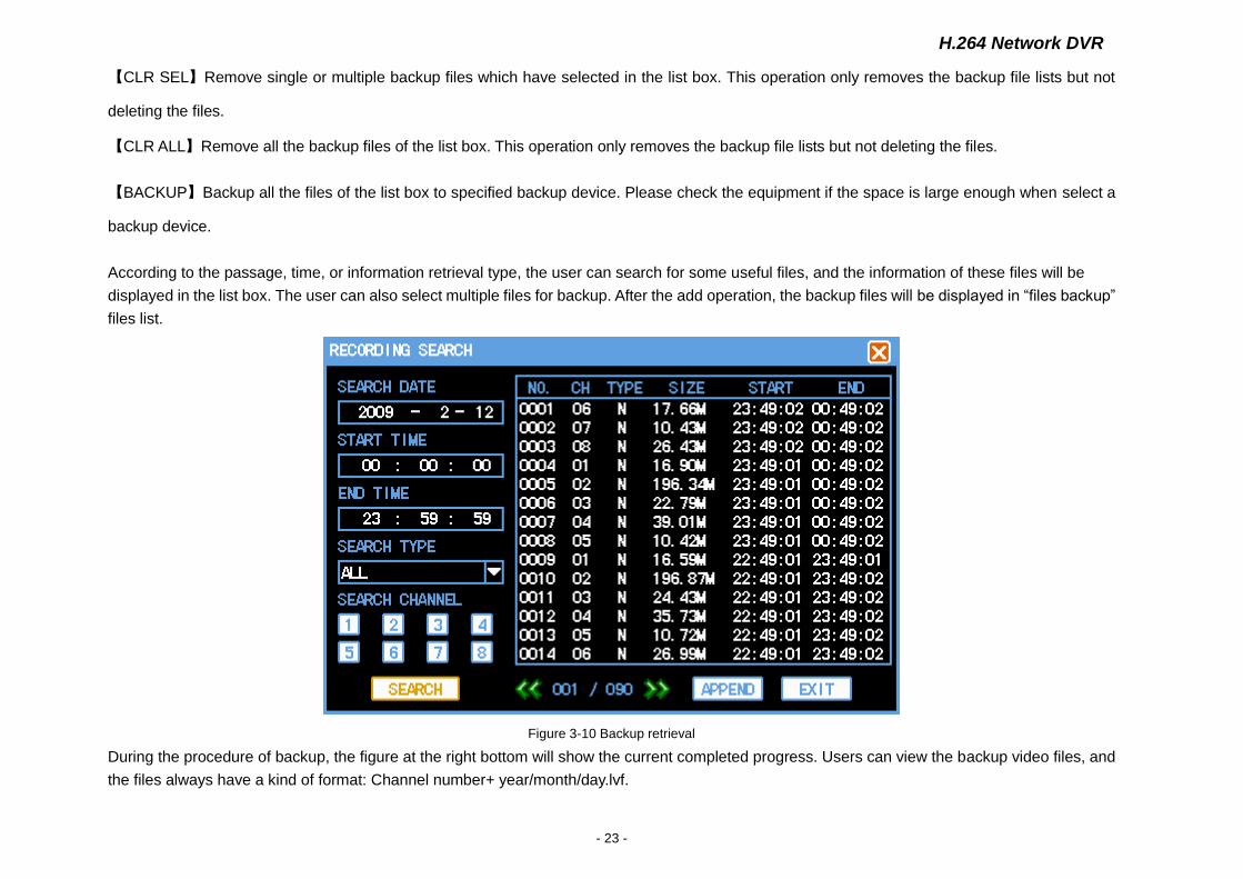
【CLR SEL】Remove single or multiple backup files which have selected in the list box. This operation only removes the backup file lists but not
deleting the files.
【CLR ALL】Remove all the backup files of the list box. This operation only removes the backup file lists but not deleting the files.
【BACKUP】Backup all the files of the list box to specified backup device. Please check the equipment if the space is large enough when select a
backup device.
According to the passage, time, or information retrieval type, the user can search for some useful files, and the information of these files will be
displayed in the list box. The user can also select multiple files for backup. After the add operation, the backup files will be displayed in “files backup”
files list.
Figure 3-10 Backup retrieval
During the procedure of backup, the figure at the right bottom will show the current completed progress. Users can view the backup video files, and
the files always have a kind of format: Channel number+ year/month/day.lvf.
H.264 Network DVR
- 24 -
NOTE:In the process of backup, the figures at the bottom will display the real-time progress. So users can do some other operations
before the system automatically giving a suggestion.
CHARP.4 Menu Operation
4.1 Menu Preview
Main Menu SubMenu Remark
PLAY BACK
Realizing video searching and playback. The search operations could be carried
out according to the type, channel, and time. The results will display in the list.
N-common video recording, A-alarm video recording、M-motion video recording.
SYSTEM INFO
HARD DISK Display the hard disk information, including the types, positions of the socket, the
total capacity and usable capacity.
LOG Display the event of the system according to the classification of log.
VERSION Display hardware and software versions or characteristics of the system such as
the release date.
NET USER Check the information of online user, including IP address, login account
SYSTEM SETUP
SYSTEM Settings of the basic parameters such as system time, date format, video format,
language and the number of this equipment.
ENCODING Settings of the video or audio coding mode, frame rate, quality and so on.
RECORDING
Settings of advance recording, timing video, dynamic detection, external alarm
timing and so on. The record plan can be carried out during a week, and each day
could be divided into four periods.
PTZ Settings of PTZ agreements and communication parameters
NETWORK Settings of network address, PPPoE port, and DDNS.
ALARM Settings of type of sensor, alarm video channels, alarm output and the
corresponding parameters.
DETECTION Settings of sensitivity and regional of the dynamic detection; handling methods
when the video lost or occlusion (alarm output and video channels)
H.264 Network DVR
- 25 -
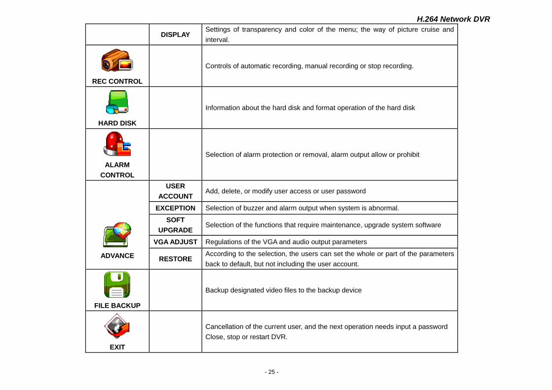
DISPLAY Settings of transparency and color of the menu; the way of picture cruise and
interval.
REC CONTROL
Controls of automatic recording, manual recording or stop recording.
HARD DISK
Information about the hard disk and format operation of the hard disk
ALARM
CONTROL
Selection of alarm protection or removal, alarm output allow or prohibit
ADVANCE
USER
ACCOUNT Add, delete, or modify user access or user password
EXCEPTION Selection of buzzer and alarm output when system is abnormal.
SOFT
UPGRADE Selection of the functions that require maintenance, upgrade system software
VGA ADJUST Regulations of the VGA and audio output parameters
RESTORE According to the selection, the users can set the whole or part of the parameters
back to default, but not including the user account.
FILE BACKUP
Backup designated video files to the backup device
EXIT
Cancellation of the current user, and the next operation needs input a password
Close, stop or restart DVR.

H.264 Network DVR
- 26 -
4.2 Menu Operation
"Menu”(Figure 4-1)
Figure 4-1
The main menu has nine functions including playback, system info, system setup, recording control, hard disk, alarm control, advance, file, files
backup and exit.
Explication: All of the following submenu settings become effective only when have been kept in confirmation, and the function is selected only
when the checkboxes has filled.
4.2.1 System Information
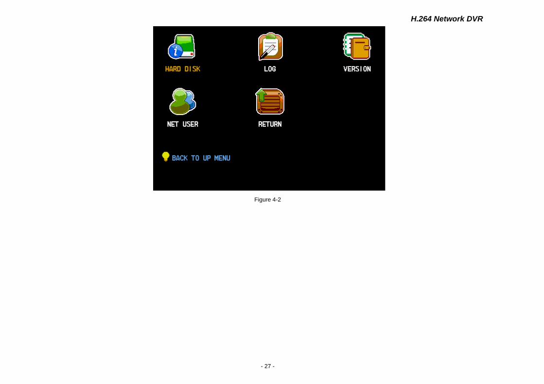
“Menu”→“SYSTEM INFO”. (Figure 4-2)
The system information includes: hard disk, log, version and net user.
H.264 Network DVR
- 27 -
Figure 4-2
H.264 Network DVR
- 28 -
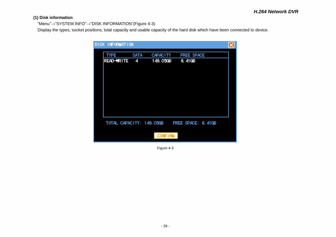
(1) Disk information “Menu”→“SYSTEM INFO”→“DISK INFORMATION”(Figure 4-3)
Display the types, socket positions, total capacity and usable capacity of the hard disk which have been connected to device.
Figure 4-3
H.264 Network DVR
- 29 -
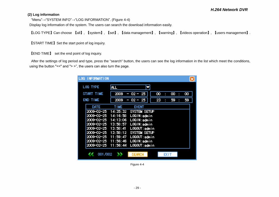
(2) Log information “Menu”→“SYSTEM INFO”→“LOG INFORMATION”. (Figure 4-4)
Display log information of the system. The users can search the download information easily.
【LOG TYPE】Can choose 【all】, 【system】, 【set】, 【data management】, 【warning】, 【videos operation】, 【users management】.
【START TIME】Set the start point of log inquiry.
【END TIME】 set the end point of log inquiry.
After the settings of log period and type, press the "search" button, the users can see the log information in the list which meet the conditions,
using the button "<<" and "> >”, the users can also turn the page.
Figure 4-4
H.264 Network DVR
- 30 -
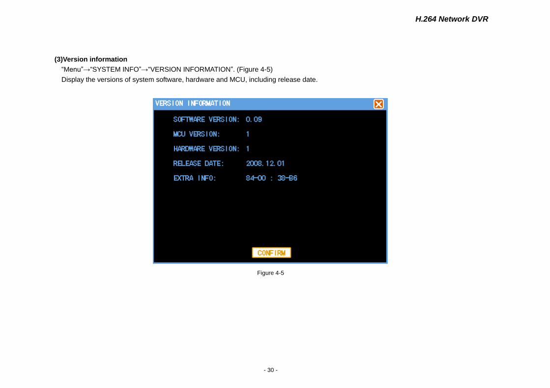
(3)Version information “Menu”→“SYSTEM INFO”→“VERSION INFORMATION”. (Figure 4-5)
Display the versions of system software, hardware and MCU, including release date.
Figure 4-5
H.264 Network DVR
- 31 -
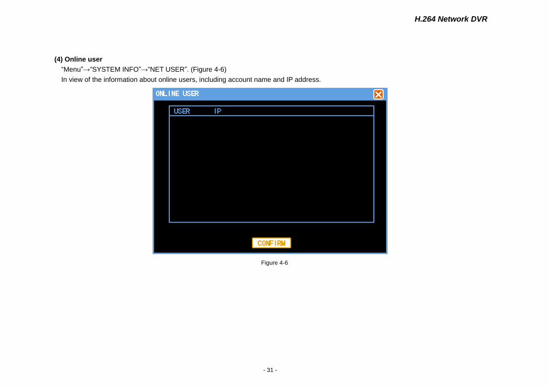
(4) Online user
“Menu”→“SYSTEM INFO”→“NET USER”. (Figure 4-6)
In view of the information about online users, including account name and IP address.
Figure 4-6
H.264 Network DVR
- 32 -
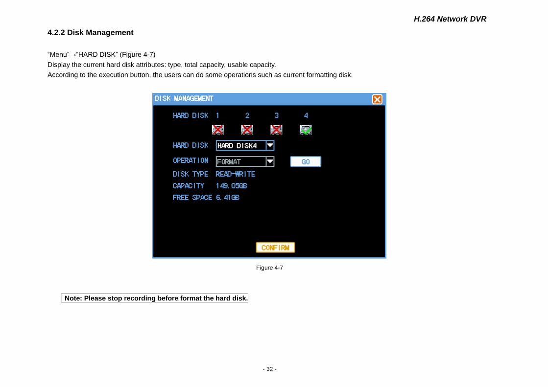
4.2.2 Disk Management
“Menu”→“HARD DISK” (Figure 4-7)
Display the current hard disk attributes: type, total capacity, usable capacity.
According to the execution button, the users can do some operations such as current formatting disk.
Figure 4-7
Note: Please stop recording before format the hard disk.
H.264 Network DVR
- 33 -
CHARP.5 System Control
5.1 PTZ Control
5.1.1 Connection
1) Connect the speed dome cameras's control cable to DVR's RS-485 port.pay attention to A, B match order.
2) Connect the cameras video cable to DVR video input.
3) Connect power to cameras.
5.1.2 Preparation
1) Setup the control address of speed dome camera,choose the corresponding protocol.
2) Switch the current picture to display channel.
5.1.3 Operation
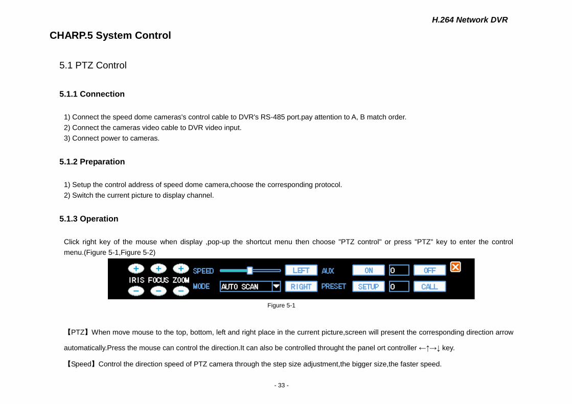
Click right key of the mouse when display ,pop-up the shortcut menu then choose "PTZ control" or press "PTZ" key to enter the control
menu.(Figure 5-1,Figure 5-2)
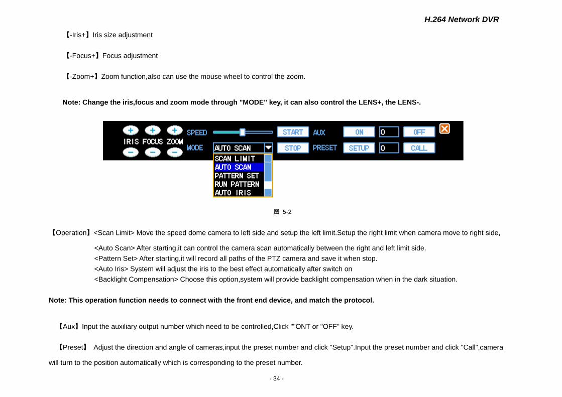
Figure 5-1
【PTZ】When move mouse to the top, bottom, left and right place in the current picture,screen will present the corresponding direction arrow
automatically.Press the mouse can control the direction.It can also be controlled throught the panel ort controller ←↑→↓ key.
【Speed】Control the direction speed of PTZ camera through the step size adjustment,the bigger size,the faster speed.
H.264 Network DVR
- 34 -
【-Iris+】Iris size adjustment
【-Focus+】Focus adjustment
【-Zoom+】Zoom function,also can use the mouse wheel to control the zoom.
Note: Change the iris,focus and zoom mode through "MODE" key, it can also control the LENS+, the LENS-.
图 5-2
【Operation】<Scan Limit> Move the speed dome camera to left side and setup the left limit.Setup the right limit when camera move to right side,
<Auto Scan> After starting,it can control the camera scan automatically between the right and left limit side.
<Pattern Set> After starting,it will record all paths of the PTZ camera and save it when stop.
<Auto Iris> System will adjust the iris to the best effect automatically after switch on
<Backlight Compensation> Choose this option,system will provide backlight compensation when in the dark situation.
Note: This operation function needs to connect with the front end device, and match the protocol.
【Aux】Input the auxiliary output number which need to be controlled,Click ""ONT or "OFF" key.
【Preset】 Adjust the direction and angle of cameras,input the preset number and click "Setup".Input the preset number and click "Call",camera
will turn to the position automatically which is corresponding to the preset number.
H.264 Network DVR
- 35 -
5.2 Video Control
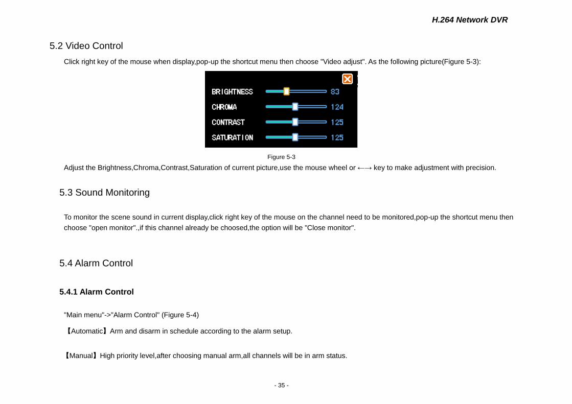
Click right key of the mouse when display,pop-up the shortcut menu then choose "Video adjust". As the following picture(Figure 5-3):
Figure 5-3
Adjust the Brightness,Chroma,Contrast,Saturation of current picture,use the mouse wheel or ←→ key to make adjustment with precision.
5.3 Sound Monitoring
To monitor the scene sound in current display,click right key of the mouse on the channel need to be monitored,pop-up the shortcut menu then
choose "open monitor".,if this channel already be choosed,the option will be "Close monitor".
5.4 Alarm Control
5.4.1 Alarm Control
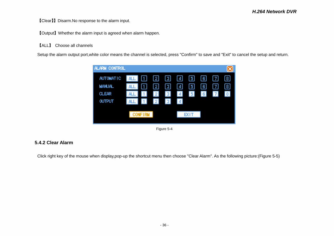
"Main menu"->"Alarm Control" (Figure 5-4)
【Automatic】Arm and disarm in schedule according to the alarm setup.
【Manual】High priority level,after choosing manual arm,all channels will be in arm status.
H.264 Network DVR
- 36 -
【Clear】】Disarm.No response to the alarm input.
【Output】Whether the alarm input is agreed when alarm happen.
【ALL】 Choose all channels
Setup the alarm output port,white color means the channel is selected, press "Confirm" to save and "Exit" to cancel the setup and return.
Figure 5-4
5.4.2 Clear Alarm
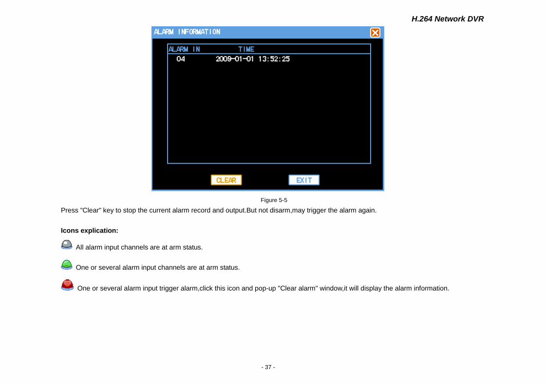
Click right key of the mouse when display,pop-up the shortcut menu then choose "Clear Alarm". As the following picture:(Figure 5-5)
H.264 Network DVR
- 37 -
Figure 5-5
Press "Clear" key to stop the current alarm record and output.But not disarm,may trigger the alarm again.
Icons explication:
All alarm input channels are at arm status.
One or several alarm input channels are at arm status.
One or several alarm input trigger alarm,click this icon and pop-up "Clear alarm" window,it will display the alarm information.

H.264 Network DVR
- 38 -
CHARP.6 System Setup
"Main Menu"-"System Setup" (Figure6-1)
System Setup is including“System”, “Encoding”, “Recording”, “PTZ”, “Network”, “Alarm”, “Detection ”, “Display”.
★ Note: The user can only enter into the system setup when he has authority.
Figure 6-1
6.1 System Setup
"Main Menu"-"System Setu"System Setup"(Figure 6-2)
H.264 Network DVR
- 39 -
Figure 6-2
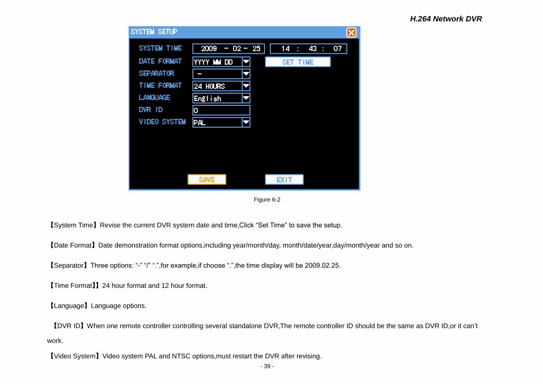
【System Time】Revise the current DVR system date and time,Click “Set Time” to save the setup.
【Date Format】Date demonstration format options,including year/month/day, month/date/year,day/month/year and so on.
【Separator】Three options: “-” “/” “.”,for example,if choose “.”,the time display will be 2009.02.25.
【Time Format】】24 hour format and 12 hour format.
【Language】Language options.
【DVR ID】When one remote controller controlling several standalone DVR,The remote controller ID should be the same as DVR ID,or it can’t
work.
【Video System】Video system PAL and NTSC options,must restart the DVR after revising.
H.264 Network DVR
- 40 -
★ Note: Stop current video recording before setting system time.
6.2 Encoding Setup
"Main Menu"-"System Setup"-"Encoding Setup". (Figure 6-3)
Figure 6-3
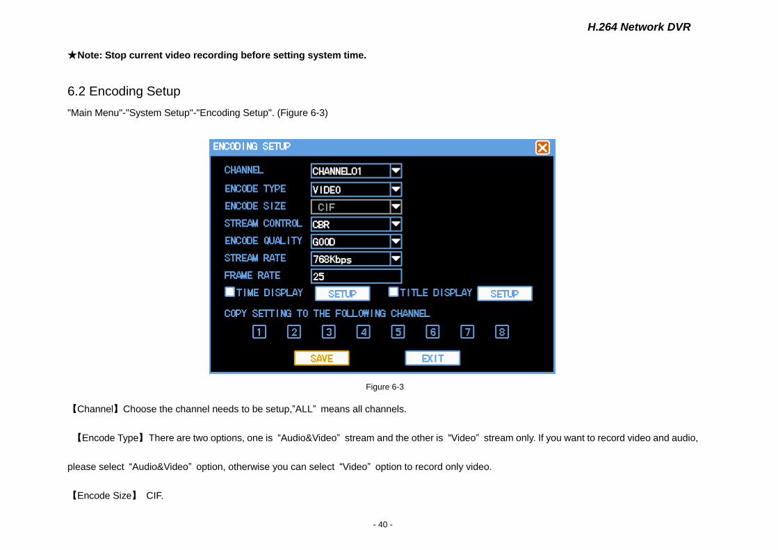
【Channel】Choose the channel needs to be setup,”ALL” means all channels.
【Encode Type】 There are two options, one is “Audio&Video” stream and the other is “Video” stream only. If you want to record video and audio,
please select “Audio&Video” option, otherwise you can select “Video” option to record only video.
【Encode Size】 CIF.

H.264 Network DVR
- 41 -
【Stream Control】 The option of "variable rate" and "fixed rate"
【Encode Quality】 6 grades of the picture quality: The best ,very good, good, In general, poor, bad.
【Stream Rate】 Encode rate options,the higher rate,the higher picture quality,and the more HDD space will be occupied.
【Frame Rate】1 ~25/seconds (PAL) or 1~30/seconds (NTSC) continuously adjustable.
【Time Display】,【Title Display】Each channel may superimpose the time and the channel title, Click “Setup” and drag the time title or channel
title to appropriate place then setup complete. The video will diaply the time and channel information when playback.
【Copy setting to the following channel】Copy the setup to all channels,realizes the same encoding setup
★ Note: When the code flow control set to dynamic bit-rate, 【Stream Rate】expressed the upper limit value
6.3 Recording Setup
"Main Menu"-"System"-"Recording Setup" (Figure 6-4)
The DVR default recording schedule is 24 hours continuously. It can be setup according to the schedule request,for example,record the video as the
type and time set.
H.264 Network DVR
- 42 -
Figure 6-4
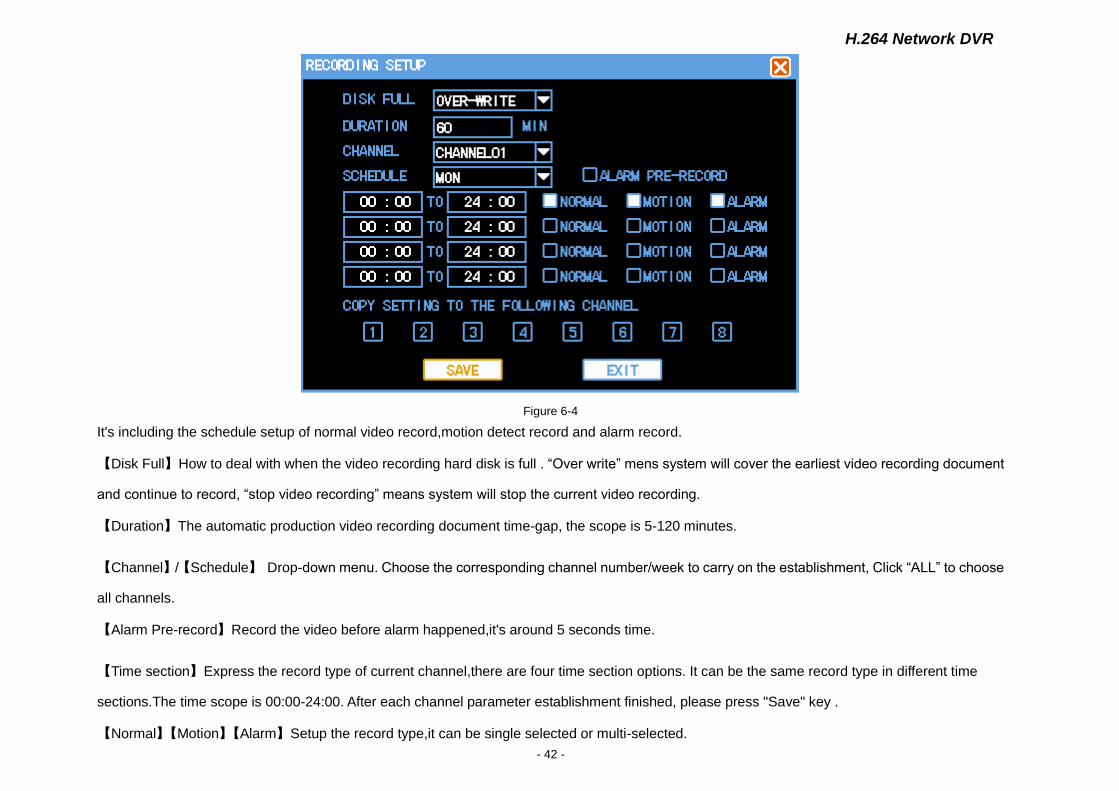
It's including the schedule setup of normal video record,motion detect record and alarm record.
【Disk Full】How to deal with when the video recording hard disk is full . “Over write” mens system will cover the earliest video recording document
and continue to record, “stop video recording” means system will stop the current video recording.
【Duration】The automatic production video recording document time-gap, the scope is 5-120 minutes.
【Channel】/【Schedule】 Drop-down menu. Choose the corresponding channel number/week to carry on the establishment, Click “ALL” to choose
all channels.
【Alarm Pre-record】Record the video before alarm happened,it's around 5 seconds time.
【Time section】Express the record type of current channel,there are four time section options. It can be the same record type in different time
sections.The time scope is 00:00-24:00. After each channel parameter establishment finished, please press "Save" key .
【Normal】【Motion】【Alarm】Setup the record type,it can be single selected or multi-selected.
H.264 Network DVR
- 43 -
【Copy setting to the following channel Copy the setup to all channels,realizes the same record establishment.
★ Note:Users should save each channels separately after setup complete.
6.4 PTZ Setup
"Main Menu"-"System"-"PTZ Setup" (Figure 6-5)
Figure 6-5
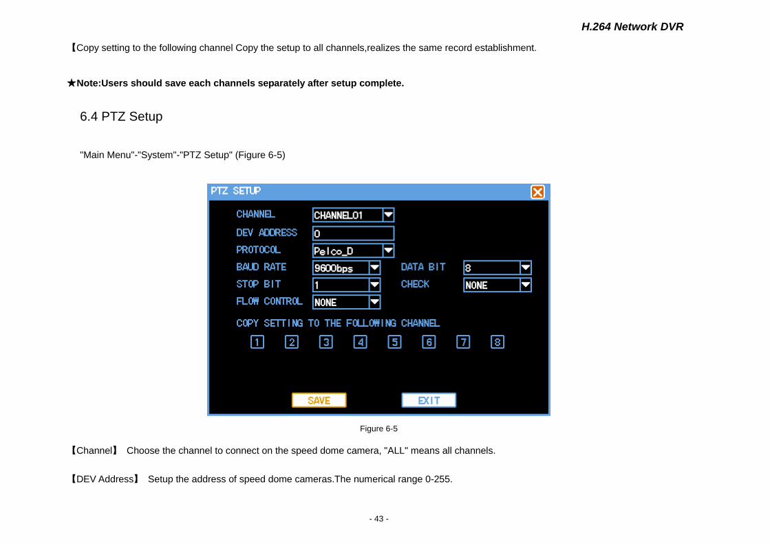
【Channel】 Choose the channel to connect on the speed dome camera, "ALL" means all channels.
【DEV Address】 Setup the address of speed dome cameras.The numerical range 0-255.
H.264 Network DVR
- 44 -
★ Note: The address must be consistent with the speed dome cameras,or DVR can't control the cameras.
【Protocol】 Choose the corresponding control protocol : Pelco_P, Pelco_D, the default is Pelco_D.
【Baud Rate】 Choose baud rate of the corresponding speed dome cameras, it can control the corresponding channel's PTZ and cameras, the
scope is 1200-115200, the default is 9600.
【Data Bit】 From 5 to 8, the default is 8.
【Stop Bit】 1,2, the default is 1.
【Check】 None,odd parity,Even Parity,default is none.
【Flow Control】 None,Xon/Xoff, the hardware, the default is None.
【Copy setting to the following channel】 Copy the setup to all channels,realizes the same PTZ establishment.
★ Note:Users should save each channels PTZ parameter separately after setup complete.
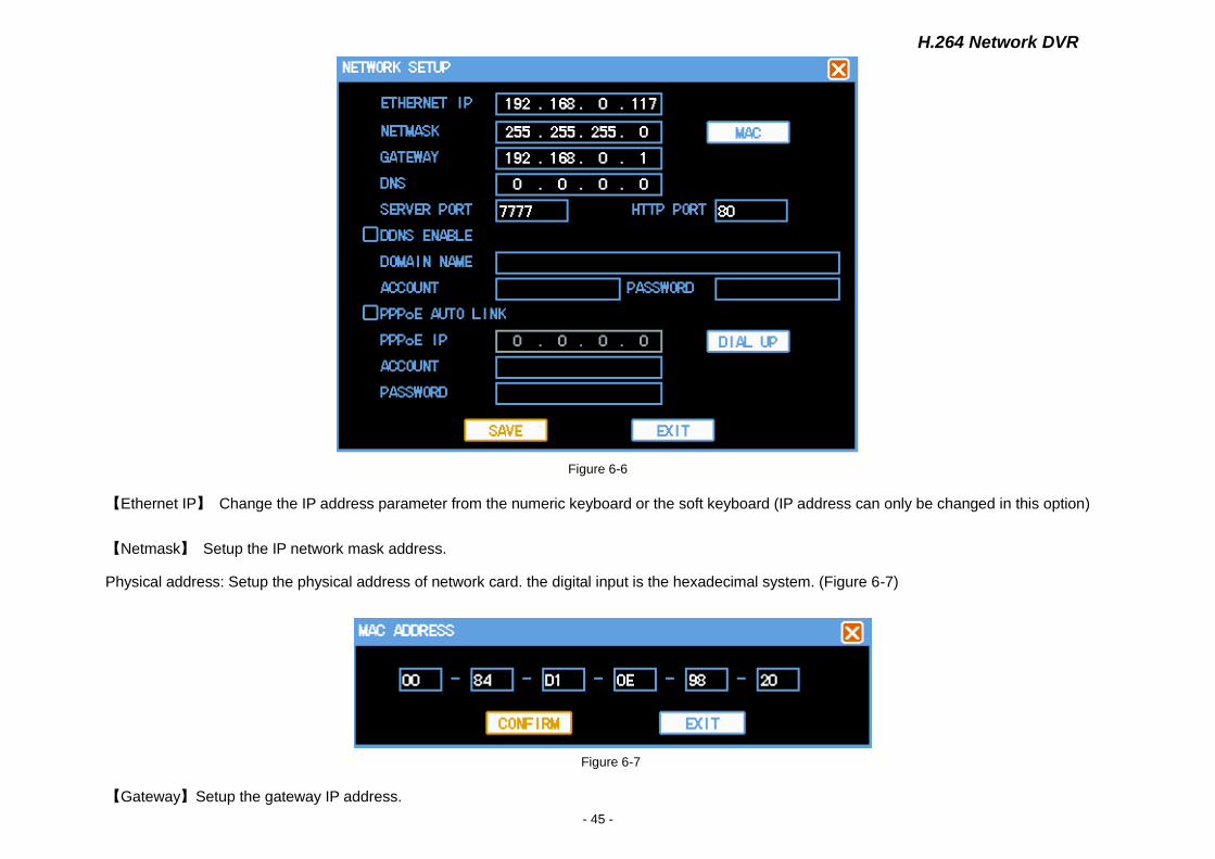
6.5 Network Setup
"Main Menu"-"System"-"Network Setup" (Figure 6-6)
H.264 Network DVR
- 45 -
Figure 6-6
【Ethernet IP】 Change the IP address parameter from the numeric keyboard or the soft keyboard (IP address can only be changed in this option)
【Netmask】 Setup the IP network mask address.
Physical address: Setup the physical address of network card. the digital input is the hexadecimal system. (Figure 6-7)
Figure 6-7
【Gateway】Setup the gateway IP address.
H.264 Network DVR
- 46 -
【DNS】Setup DNS server IP address.
【Server Port】 The default is 7777, may change it according to the user actual need and it will be effective after restart the system.
【HTTP port】 Default is 80, after the revision, restart the system and it will be effective.If the port has been changed,it must display the selected
HTTP port,such as:http://192.168.0.117:1234
【DDNS Enable】Pass the dynamic domain name analysis server. Supports 3322 free dynamic domain name analysis (Register account at
http://www.3322.org).
【PPPoE Auto Link】 Input ISP (Internet service provider)provided PPPoE user name and password,Click " Dial UP" then starts to connect. After
connecting successfully, “PPPoE IP” will display the automatically obtained WAN's dynamic IP address. If choose 【PPPoE Auto Link】 option, DVR
will try to connect PPPoE when power on.
★ Note: After PPPoE dial up successful, user may visit the DVR remotly according to【PPPoE IP】 displayed IP address, In local area
network,can visit the DVR through the network card.
6.6 Alarm Setup
"Main Menu"-"System"-"Alarm Setup" (Figure 6-8).

H.264 Network DVR
- 47 -
Figure 6-8
【Alarm Input】 Choose the corresponding alarm channel number, “ALL” means all channels.
【Device Type】 Alarm input “Normal Open” or “Normal Close” options. (voltage output mode).
【Alarm reset after】 Setup the corresponding delay time (5~255 seconds),after exterior warning cancelled, the system will delay the time
automatically. Then close the alarm the linkage output .
【SEQ Display】 When alarm singal happen.It will partrol display single channel which is setup to record. The patrol time can be setup in 【system
setup】【Output mode】.
【Recording Channel】 Select the channels need to be recorded,if alarm happen,when system is in "Automatic record" mode(3.4.1 channel record)
and The alarm record time is aviable in "Video setup" (video Setup),the system will open the alarm record.
【Schedule】 Make the week as alarm output time section unit.permit the alarm output and OSD output in the corresponding time.
H.264 Network DVR
- 48 -
【DEV output】 Alarm may linkage the corresponding alarm output device in selected time section.
【OSD Output】 Screen will disply information when alarm happen in selected time section.
★ Note:Users should save each channels separately after setup complete.
6.7 Video Detection Setup
"Main Menu" → "System Setup" → "Detection." (Figure 6-9)
Explication:
1) When in the switching type , set video loss detection and blocking the non-regional and sensitivity.
2 )When video channel changing is detected, the screen will show the dynamic-channel detection, video loss and video shelter signs.
3) Drag and drop with the mouse directly to choose the dynamic detection of the region, press and hold the left mouse button to set up the detection
regions,press and hold the right button of mouse to clear detection region, it is necessary to preserve the dynamics of the current detection
region,and press the “save” button after quit the region setting.
6.7.1 Video Detection
By analyzing the video image, system will open the motion detection alarm when the it detects that there is mobile signal that can achieve the
default sensitivity. (Figure 6-9)
H.264 Network DVR
- 49 -
Figure 6-9
【CHANNEL】Choose to the channel for motion detection , "all" means all the channels.
【ALARM TYPE】Select the type of detection settings: motion detection.
【ALARM DELAY】 set corresponding delay time (5 ~ 255 seconds), when the external alarm is abolished, system will correspond delay time
automatically, then close the alarm output and interaction.
【RECORDING】Select the desired video channel of the video channel (can repeat), when alarm occur, If the system is in"record automatically"
mode(video mode, see "3.4.1-channel video"),and the "alarm record" in the“record setting" is within the effective time (see" Video Settings 6.3 "),the
system will start the alarm record.
【ALARM DEV OUT】The alarm output linkage occurs with alarm
【SCHEDULE】To set the alarm output period for week, it means the alarm output and display are allowed within corresponding time
H.264 Network DVR
- 50 -
【SENSITIVITY】Can be set as follows: the highest, high, average, low.
【screen tips】within the time of selection,corresponding information will be shown when alarm occurs.
【Copy the current settings to the following】 users access to the channel settings can be copied to other channels, to achieve the same alarm
settings.
【dynamic inspection area】 click setting and then enter。The setting area is divided into 192(16X12)areas。
The green area is dynamic detection zones, the white areas is area without any deployment . Hold and press the left mouse button to set up
detection region, press and hold the right mouse button to clear the detection region.Press “save” button to save the y dnamic detection of regional
settings. (Figure 6-10)
Figure 6-10
★ Note: When copying the parameters, only copy detection parameters of the current settings, copy the dynamic detection of parameters
does not include the detection of regional.
H.264 Network DVR
- 51 -
6.7.2 Video Loss
When the video images do not exist or are interrupted, the system can be dealt with in accordance with the appropriate settings. (Figure 6-11)
Figure 6-11
【CHANNEL】Choose to the channel for video loss , "all" means all the channels.
【ALARM TYPE】Select the type of detection settings: video loss.
【ALARM DELAY】Set corresponding delay time (5 ~ 255 seconds), when the external alarm is abolished, system will orrespond delay time
automatically, then close the alarm output and interaction.
【ALARM DEV OUT】The alarm output linkage occurs with alarm
【SCHEDULE】Setting the alarm time period at week, means alarm output or screen display is allowed in the corresponding time.
H.264 Network DVR
- 52 -
【screen tips】Within the time of selection,corresponding information will be shown when alarm occurs.
【Copy the current settings to the following】Users access to the channel settings can be copied to other channels, to achieve the same alarm
settings.
6.7.3 Video Blind
When someone maliciously blocking the lens, or as a result of light and other factors leading to a video output in a single color screen,the image will
not be able to conduct on-site monitoring. By setting the shelter alarm,can effectively prevent the occurrence of this phenomenon. (Figure 6-12)
Figure 6-12
【CHANNEL】Choose to the channel for shelter alarm , "all" means all the channels.
【ALARM TYPE】Select the typeof detection: shelter detection.

H.264 Network DVR
- 53 -
【ALARM DELAY】Set corresponding delay time (5 ~ 255 seconds), when the external alarm is abolished, system will orrespond delay time
automatically, then close the alarm output and interaction.
【ALARM DEV OUT】The alarm output linkage occurs with alarm
【SCHEDULE】Setting the alarm time period at week, means alarm output or screen display is allowed in the corresponding time.
【screen tips】Within the time of selection,corresponding information will be shown when alarm occurs.
【Copy the current settings to the following】Users access to the channel settings can be copied to other channels, to achieve the same alarm
settings.
6.8 Local Display
“Main menu”→“System setup”→“Display”。(Figure 6-13)
H.264 Network DVR
- 54 -
Figure 6-13
【CHANNEL NAME】Click the channel name modification button,enter the channel name menu,and modify the channel name.
【WINDOW COLOR】Display stype for the widow and the menu: baby blue, fuchsin,heavy green are the three optional color.
【TRANSPARENCY】Setting for transparency of the backgroup: 25%,50%,75% are optional.
【Start the turning】Start the channel turning function,all the channels will display by turns.
【Turning alternation】Set up the schedule for turning,the time is from 5s to 120s.The turning page includes single channel,four channels,and nine
channels.The single channel option means turning page is in single chanel.The four channel option means the turning page is with four
channel( channel 1,2,3,4 formulate page 1,channe 5,6,7,8 formulate page 2).The nine channel page means the the turning is in 8 channels.The
turning sequence is single channel,four channels,nine channels in turn.
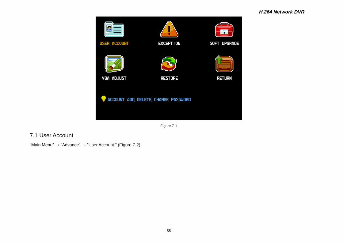
CHARP.7 System Management
"Main Menu" → "Advance" to show sub-menu, including: user accounts, exception handling, system maintenance, output regulation, restoring the
default. (Figure 7-1)
H.264 Network DVR
- 55 -
Figure 7-1
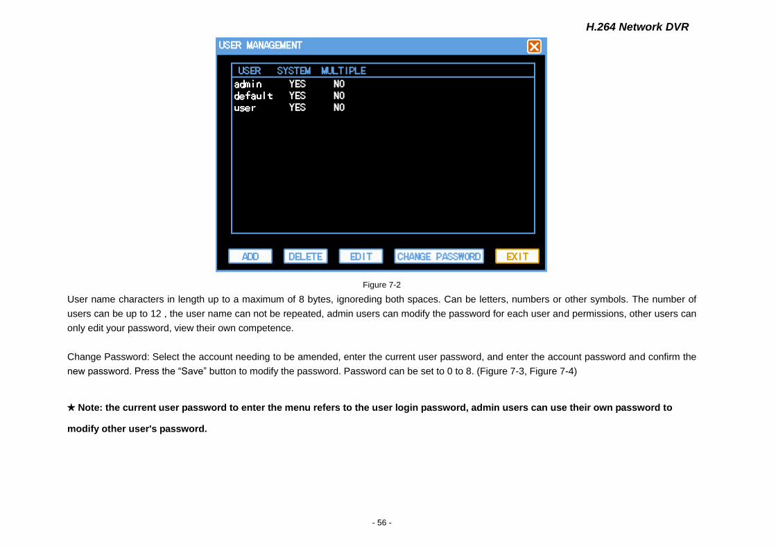
7.1 User Account
"Main Menu" → "Advance" → "User Account." (Figure 7-2)
H.264 Network DVR
- 56 -
Figure 7-2
User name characters in length up to a maximum of 8 bytes, ignoreding both spaces. Can be letters, numbers or other symbols. The number of
users can be up to 12 , the user name can not be repeated, admin users can modify the password for each user and permissions, other users can
only edit your password, view their own competence.
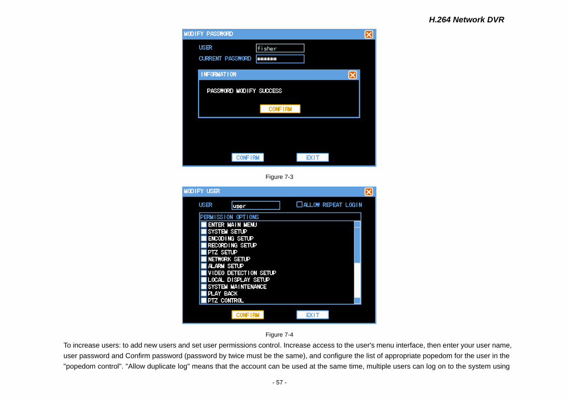
Change Password: Select the account needing to be amended, enter the current user password, and enter the account password and confirm the
new password. Press the “Save” button to modify the password. Password can be set to 0 to 8. (Figure 7-3, Figure 7-4)
★ Note: the current user password to enter the menu refers to the user login password, admin users can use their own password to
modify other user's password.
H.264 Network DVR
- 57 -
Figure 7-3
Figure 7-4
To increase users: to add new users and set user permissions control. Increase access to the user's menu interface, then enter your user name,
user password and Confirm password (password by twice must be the same), and configure the list of appropriate popedom for the user in the
"popedom control". "Allow duplicate log" means that the account can be used at the same time, multiple users can log on to the system using
H.264 Network DVR
- 58 -
the account. (Figure 7-5)
Figure 7-5
there are there default users:admin, usrer, default. The three users can not be deleted. admin user is a high authority, may carry out all operations,
and the default user is low in permissions to factory default. When there is no way users log on or write off the current user, the system will
automatically log on with this account. Users can modify this account through the authority to finish some permissions for which there is no need to
log on.
7.2 Exception
"Main Menu" → "Advance" → "Exception" (Figure 7-6)
H.264 Network DVR
- 59 -
Figure 7-6
【Exception】 To choose the type of abnormal situation: the hard disk is full, the hard disk error, network disconnection.
【Buzzer Alarm】 whether allow buzzer alarm prompt or not , when there is abnormal situation,.
【Alarm output】Where there is abnormal alarm ,start the joint output of alarm.
Note: the system can view the log records of detailed exception information.
7.3 System Maintenance
"Main Menu" → "Advance" → "Soft upgrade" (Figure 7-7)
Click to start to upgrade, the system automatically start to detect the upgrade file.
H.264 Network DVR
- 60 -
Figure 7-7
7.4 Output Adjustment
"Main Menu" → "Advance" → VGA Adjust." (Figure 7-8).
Manage the VGA output adjustment region, color brightness and resolution.
H.264 Network DVR
- 61 -
图 7-8
Note:"restore"→"Local display", select this,the output parameters will be changed to factory-set.
7.5 Restore
"Main Menu"→"Advance"→"Restore"(Figure 7-9)
The system back to factory-set, according to the options menu select the corresponding set to resume.
Note: Menu color, Language,Date&Time format, system, IP address,User account won't be back.
H.264 Network DVR
- 62 -
Figure 7-9
CHARP.8 Remote Network Control and Management
8.1 Remote Settings
8.1.1 Network Security Settings
Please setting internet security level before install ActiveX:
(1)Open IE Browser, select“Tools”-“Internet options”
(2) In the dialog box that appears, select the "Security" tab. (Figure 8-1)
H.264 Network DVR
- 63 -
Figure 8-1
H.264 Network DVR
- 64 -
(3)click on the "Custom Level", enter the security settings. (Figure 8-2)
Figure 8-2
ActiveX controls and plug-ins installed
ActiveX controls automatically prompt
to the marked safe for scripting of ActiveX controls to execute script
not marked as safe for the ActiveX controls Initialize and script
Binary and script behaviors
Binary and script behaviors
Download signed ActiveX controls
Run ActiveX controls and plug-ins
The above categories will be "Enable", which is very important.
Note: Install ActiveX, please close firewall and antivirus software.
H.264 Network DVR
- 65 -
8.1.2 Connection Settings
DVR through the remote access network, local area network connection, the client computer's IP address must be with the DVR at the same
network segment, in the wide area network connection through the dynamic IP address or domain name to connect, when the two sides need to
ensure that public network can access it. The following introduces the method of local area network connection settings:
1.right-click "My Network Places" in the pop-up menu, click on "Properties", open "Network Connections."
2.Double-click open the "Local Area Connection." (Figure 8-3)
Figure 8-3
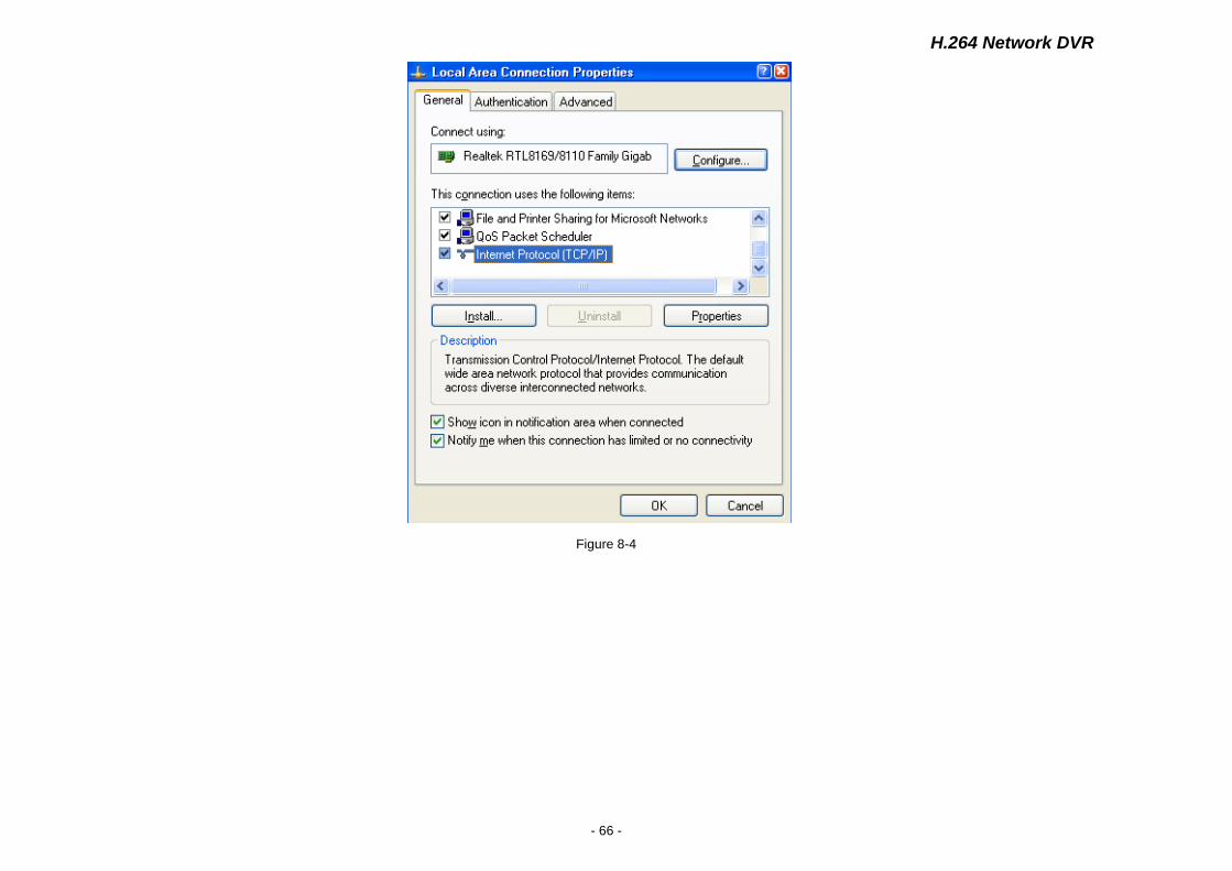
3.Click "Properties." (Figure 8-4)
H.264 Network DVR
- 66 -
Figure 8-4
H.264 Network DVR
- 67 -
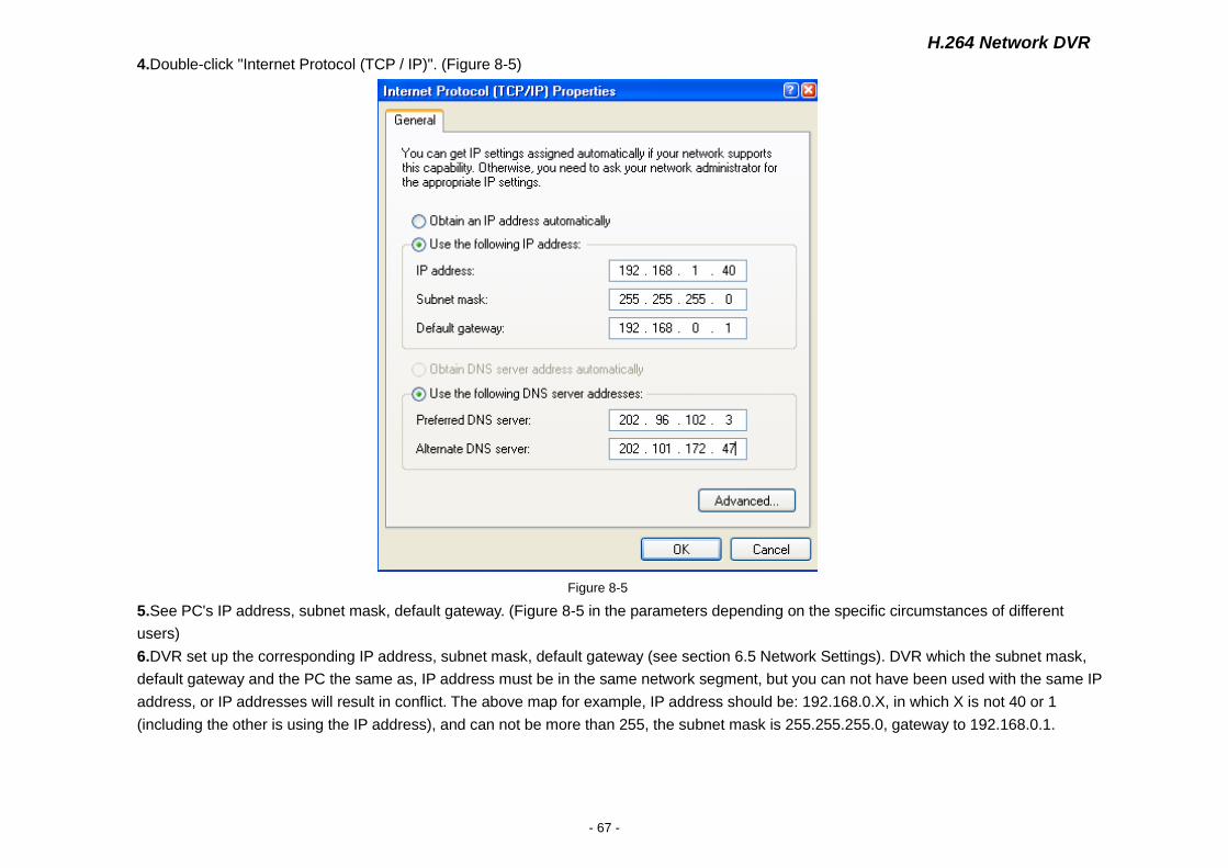
4.Double-click "Internet Protocol (TCP / IP)". (Figure 8-5)
Figure 8-5
5.See PC's IP address, subnet mask, default gateway. (Figure 8-5 in the parameters depending on the specific circumstances of different
users)
6.DVR set up the corresponding IP address, subnet mask, default gateway (see section 6.5 Network Settings). DVR which the subnet mask,
default gateway and the PC the same as, IP address must be in the same network segment, but you can not have been used with the same IP
address, or IP addresses will result in conflict. The above map for example, IP address should be: 192.168.0.X, in which X is not 40 or 1
(including the other is using the IP address), and can not be more than 255, the subnet mask is 255.255.255.0, gateway to 192.168.0.1.
H.264 Network DVR
- 68 -
8.1.3 ActiveX Download Installation
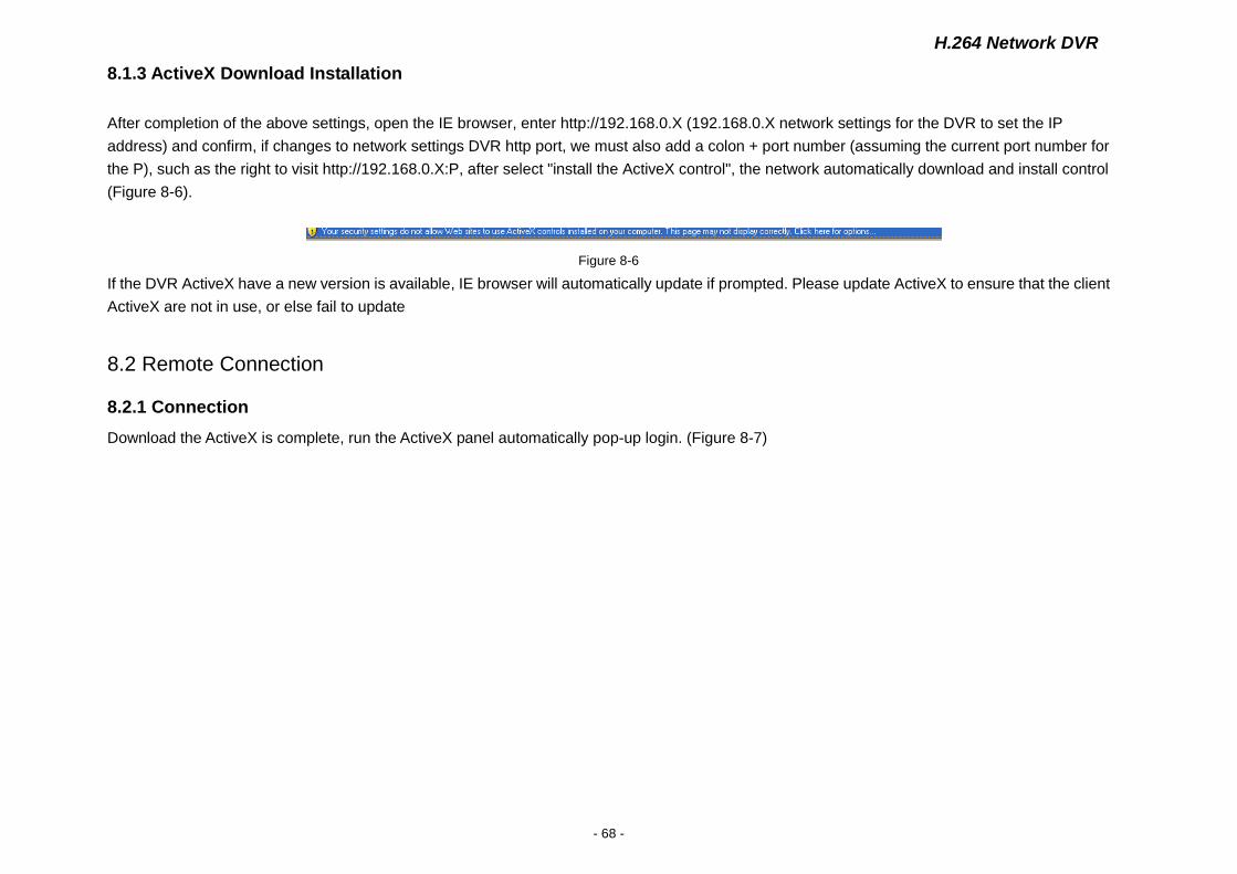
After completion of the above settings, open the IE browser, enter http://192.168.0.X (192.168.0.X network settings for the DVR to set the IP
address) and confirm, if changes to network settings DVR http port, we must also add a colon + port number (assuming the current port number for
the P), such as the right to visit http://192.168.0.X:P, after select "install the ActiveX control", the network automatically download and install control
(Figure 8-6).
Figure 8-6
If the DVR ActiveX have a new version is available, IE browser will automatically update if prompted. Please update ActiveX to ensure that the client
ActiveX are not in use, or else fail to update
8.2 Remote Connection
8.2.1 Connection
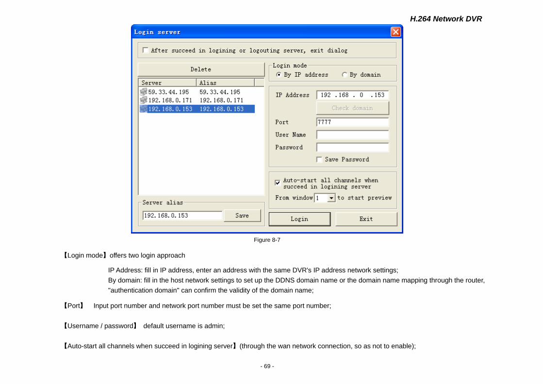
Download the ActiveX is complete, run the ActiveX panel automatically pop-up login. (Figure 8-7)
H.264 Network DVR
- 69 -
Figure 8-7
【Login mode】offers two login approach
IP Address: fill in IP address, enter an address with the same DVR's IP address network settings;
By domain: fill in the host network settings to set up the DDNS domain name or the domain name mapping through the router,
"authentication domain" can confirm the validity of the domain name;
【Port】 Input port number and network port number must be set the same port number;
【Username / password】 default username is admin;
【Auto-start all channels when succeed in logining server】(through the wan network connection, so as not to enable);
H.264 Network DVR
- 70 -
【From Window X to start preview】From which window to start previw
【After succeed in login or logout server, exit dialog】After succeed in login, exit dialog.
Delete Select to delete the corresponding server, can be deleted;
【Alias】To set the server Alias, Click save in order to management.
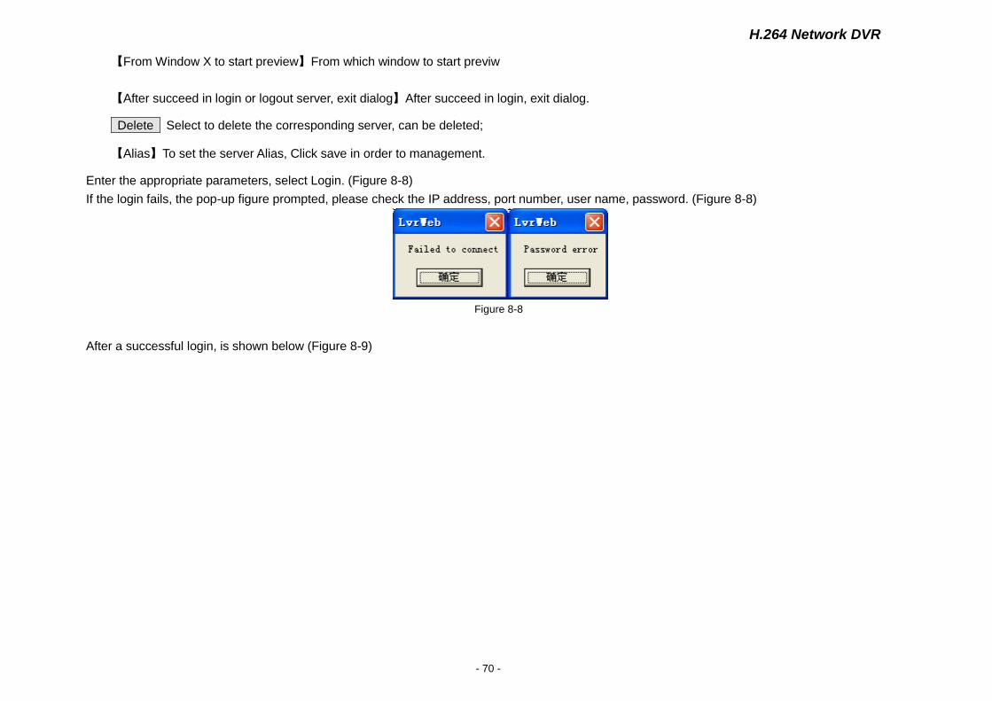
Enter the appropriate parameters, select Login. (Figure 8-8)
If the login fails, the pop-up figure prompted, please check the IP address, port number, user name, password. (Figure 8-8)
Figure 8-8
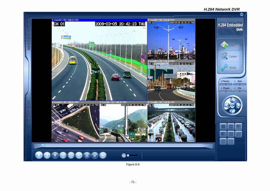
After a successful login, is shown below (Figure 8-9)
H.264 Network DVR
- 71 -
Figure 8-9
H.264 Network DVR
- 72 -
8.2.2 Multiple Servers Login
Click Login in right side of screen, can loggin other servers at the same time.
8.2.3 Channel Associated Menus
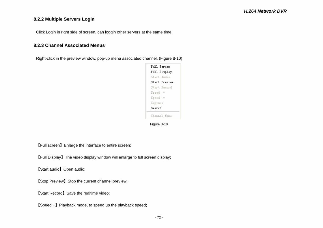
Right-click in the preview window, pop-up menu associated channel. (Figure 8-10)
Figure 8-10
【Full screen】Enlarge the interface to entire screen;
【Full Display】The video display window will enlarge to full screen display;
【Start audio】Open audio;
【Stop Preview】Stop the current channel preview;
【Start Record】Save the realtime video;
【Speed +】Playback mode, to speed up the playback speed;
H.264 Network DVR
- 73 -
【Speed -】To lower speed playback;
【Capture】Capture the current window picture and save;
【Search】Search video files, including local search and remote search;
【Channel Name】set the name of the DVR corresponding channel, preview and record overlay of the channel name will change.
8.3 Control
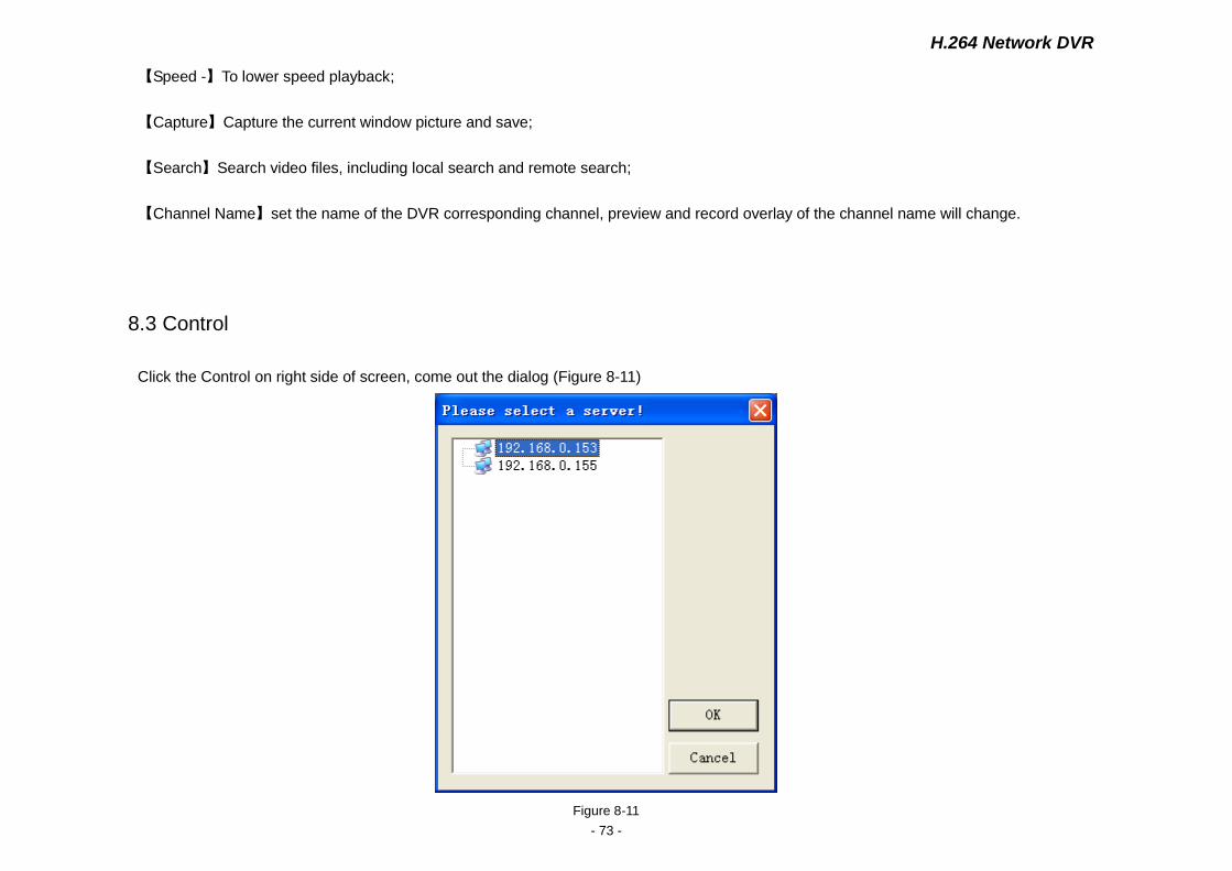
Click the Control on right side of screen, come out the dialog (Figure 8-11)
Figure 8-11
H.264 Network DVR
- 74 -
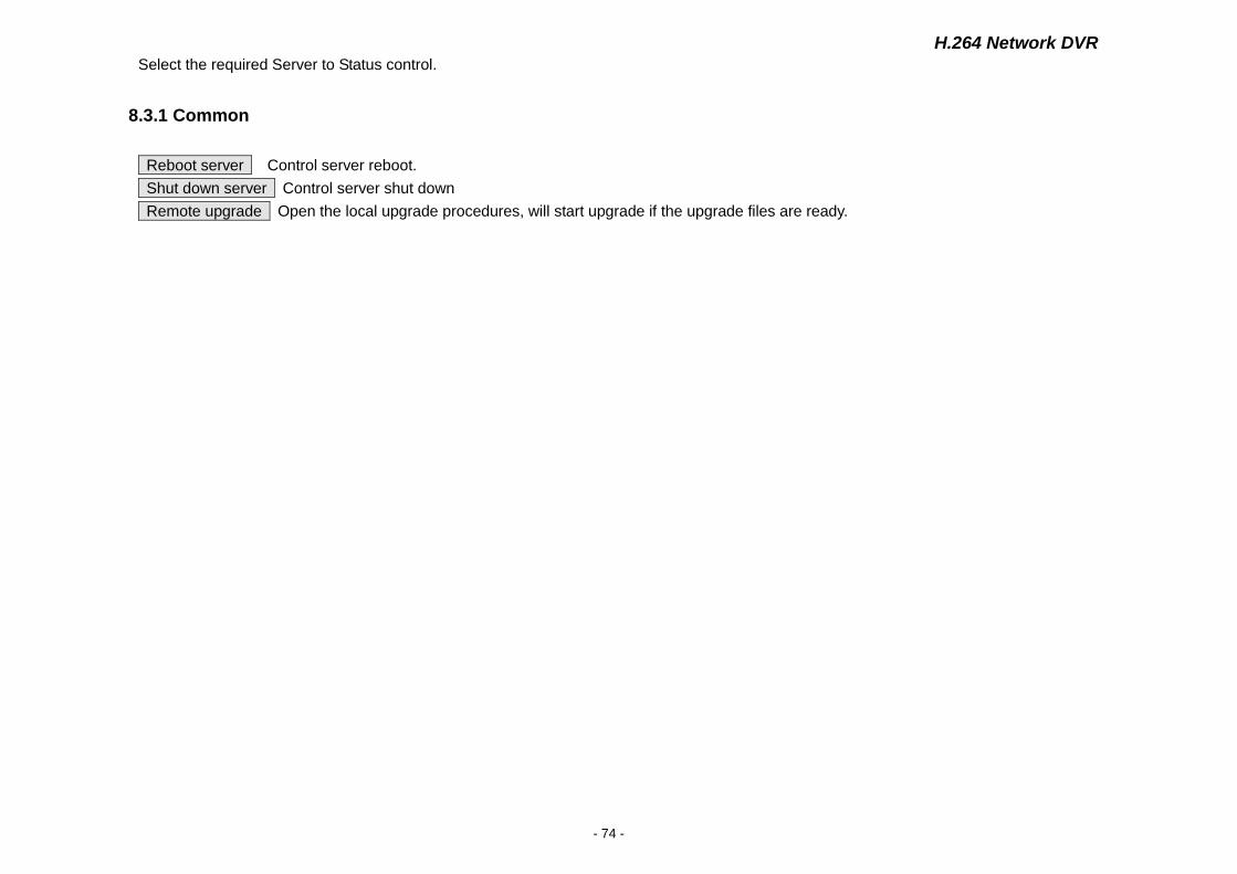
Select the required Server to Status control.
8.3.1 Common
Reboot server Control server reboot.
Shut down server Control server shut down
Remote upgrade Open the local upgrade procedures, will start upgrade if the upgrade files are ready.

H.264 Network DVR
- 75 -
Figure 8-12
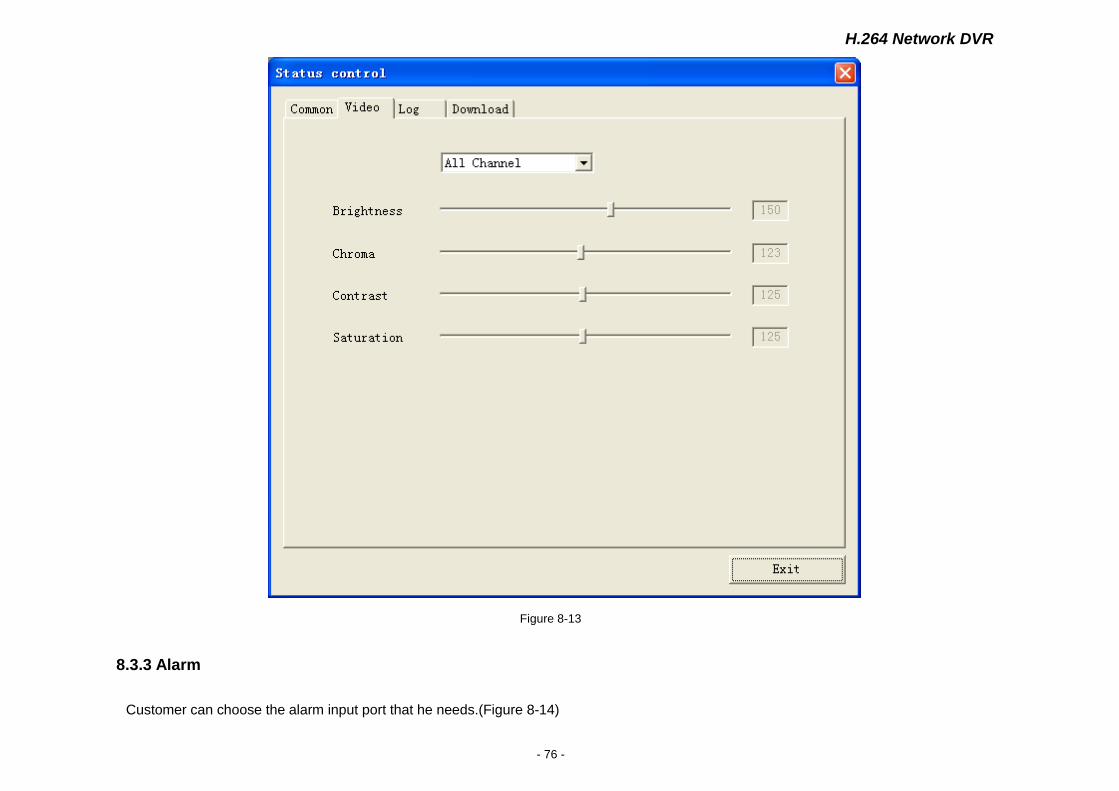
8.3.2 Video
Remote adjust the parameter of brightness, color, contrast, saturation of video, in order to achieve the best video effect
H.264 Network DVR
- 76 -
Figure 8-13
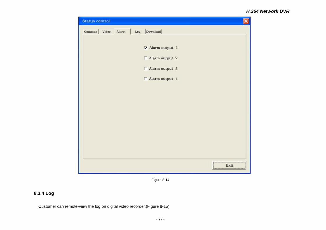
8.3.3 Alarm
Customer can choose the alarm input port that he needs.(Figure 8-14)
H.264 Network DVR
- 77 -
Figure 8-14
8.3.4 Log
Customer can remote-view the log on digital video recorder.(Figure 8-15)

H.264 Network DVR
- 78 -
Figure 8-15
【Start time】/【end time】 choose the time period
【Log type】Can choose all logs, system log, configuration log,data log,alarm log, picture recording log, and user management.
H.264 Network DVR
- 79 -
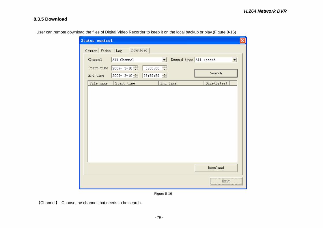
8.3.5 Download
User can remote download the files of Digital Video Recorder to keep it on the local backup or play.(Figure 8-16)
Figure 8-16
【Channel】 Choose the channel that needs to be search.
H.264 Network DVR
- 80 -
【Record type】 all recording, general recording, alarm recording, motion recording
【Start time】/【End time】 choose the time period
8.4 Setting
Note: Choose”save”,which will keep the current setup. Choose “save all”,which will keep all the setup.
Click the right “setup”, enter to setting faceplate.(Figure 8-17)
H.264 Network DVR
- 81 -
Figure 8-17
H.264 Network DVR
- 82 -
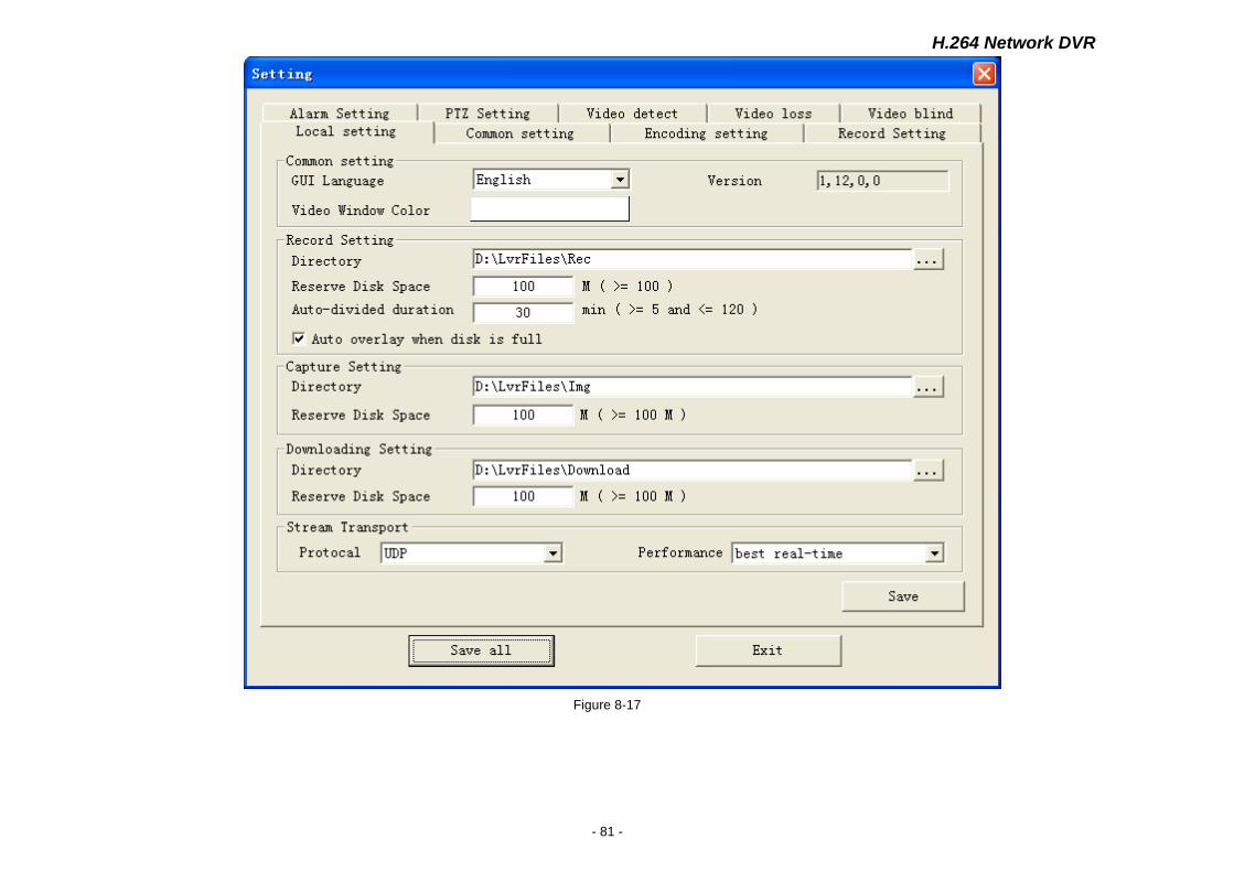
8.4.1 Local Setting
【Common Setting】GUI language: Chinese, English
Adjust WINDOWS COLOR:RGBColor parameters setup
Start heartbeat mechanism: real-time detecting of the network connection status
【Record Setting】 Catalogue:choose the storage place of local recording.
Disk retain space: the recording will not use this space
Automatic Segmentation cycle: setting range of 5-120 minutes
Can automatically cover when disc is full; Can do this again.
【Capture Setting】Catalogue:choose the storage place of local recording.
Disk retain space: the recording will not use this space
【Download Setup】Catalogue: choose the storage place of downloaded files.
Disk retain space: the downloaded files will not use this space
【Stream Transport】protocol:UDP,TCP be optional, choose UDP for general LAN; choose TCP for WAN.
Performance:The depth buffer that network data receives is according to network situation. The realtime better,the buffer
smaller; the degree of fluency better, the buffer bigger. In general,choose “ realtime best”for general LAN, choose “realtime
better” or “good both at realtime and degree of fluency” for WAN.
8.4.2 Common Setting, Encoding Setting, Record Setting, Alarm Setting, PTZ Setting, Video Detect, Video Loss, Video
Blind
Please refer to relative content of “Chapter 4 System Setup”
H.264 Network DVR
- 83 -
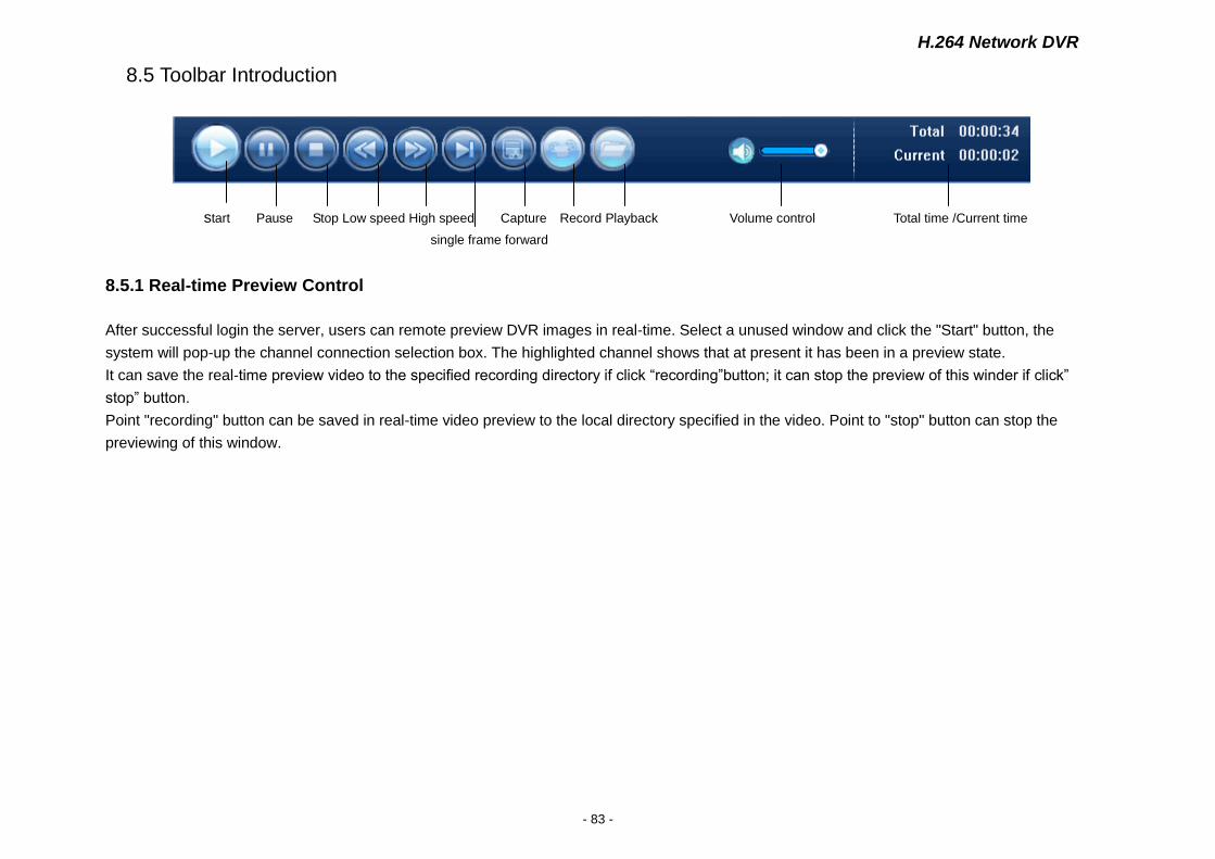
8.5 Toolbar Introduction
start Pause Stop Low speed High speed Capture Record Playback Volume control Total time /Current time
single frame forward
8.5.1 Real-time Preview Control
After successful login the server, users can remote preview DVR images in real-time. Select a unused window and click the "Start" button, the
system will pop-up the channel connection selection box. The highlighted channel shows that at present it has been in a preview state.
It can save the real-time preview video to the specified recording directory if click “recording”button; it can stop the preview of this winder if click”
stop” button.
Point "recording" button can be saved in real-time video preview to the local directory specified in the video. Point to "stop" button can stop the
previewing of this window.

H.264 Network DVR
- 84 -
Figure 8-18
H.264 Network DVR
- 85 -
8.5.2 Playback
User can playback the local recording files, and also can remote playback the files on DVR. Click “stop” to stop playing.
Figure 8-19
8.6 Other Operations
8.6.1 PTZ and Preset Control
H.264 Network DVR
- 86 -
Figure 8-20
Direction button respectively control PTZ to up, down, right, left. Click the middle button to setup the preset point and adjust.
8.6.2 Lens Control
Figure 8-21
【+focus-】 Control lens to long distance and short distance.
【+Auxiliary -】Auxiliary switch.
【+image-】Fine adjust the focus.
【+Aperture -】Aperture adjustment.
8.6.3 Window Browse Modes
Figure 8-22
Provides 8 kinds of window modes for switching: single channel,4 channels,6 channels, 8 channels, 9 channels, 16 channels, 25 channels, 36
channels.
CHARP.9 FAQ
◎Connected to the power ,the machine didn’t start running.
1.Check whether the power switch is turned on;
H.264 Network DVR
- 87 -
2.Check the operater is correct;
3. Check whether the power is adequate.
◎Hanging at the boot screen.
1.The hard disk has physical damage;
2.The system guide is un-normal.
◎Starting very slow.
The error of hard disk can cause the mainboard check the hard disk repeatedly ,so the satrting is very slow
◎Host restart repeatedly.
1.Please check the host power supply ,if connect lots of hard disks ,there may be appear power insufficient ,and cause the host restart repeatedly;
2.Please unplug the network cable ,and check whether the machine run normally ,the existence of serious network failure may cause the host
restart repeatedly .
◎When view the video or playback the recording normally ,the machine hang.
1.Check whether the connection of the hard disk ,and replace the failure hard disk timely ;
2.Check whether the temperature is too high;
3.Check whether there have heavy current device ,the impact of heavy current will crash the video cable ,and cause the host cannot work.
◎The operation of update failure.
1.U disk compatibility bad .,and the host cannot recognize it ,change a new brand ,and try again;
2.The USB connect bad.
H.264 Network DVR
- 88 -
◎In monitor or tv ,the image shows black and white.
·Check the video input ,DVR ,monitor or TV is exactly the same video format ,if it isn’t ,please change the setting to automatic station.
◎The monitor or pc screen cannot show anything.
1.Check whether the power of monitor is on ,and the brightness is at the minimum station;
2.Check whether the connection of video cable is ok.
◎The water ripple of image is clearly ,and have interference distortion.
1.Check whether there exist short-circuit;
2.The video cable was interfered by heave current ,and the video cable cannot connect together with the heave current circuit .please choose the
shielded cable;
3.Check whether the monitor or tv is aging.
◎Real-time image and video data exist the problem of color distortion.
1.Check whether the video input&output setting is right;
2.Check whether the connection is right.
◎When using the pc screen ,the image get the problem of distortion and color cast.
1.Check the connection of VGA cable and the DVR is right;
2.The temperature of DVR working is too high,or the heat can't dissipate, which may cause the chipset of VGA cannot work normally,or the setting
of current circult is wrong.
◎Mosaic appears in the server’s videos playback.
1.The low parameters would cause the whole quality of videos, and then Mosaic may appear in the playback;
2.Bad disk sectors also leads to the appearing of Mosaic during the playback.
H.264 Network DVR
- 89 -
◎ActiveX of client can’t be updated automatically.
1.Whether the IP address accessing server is correct;
2.Whether the settings of browser are correct (refer to 8.1.2);
3.Please turn off the window if it’s open;
4.Support the ActiveX control has some problems of compatibility, please use Microsoft Internet Explorer to access server.
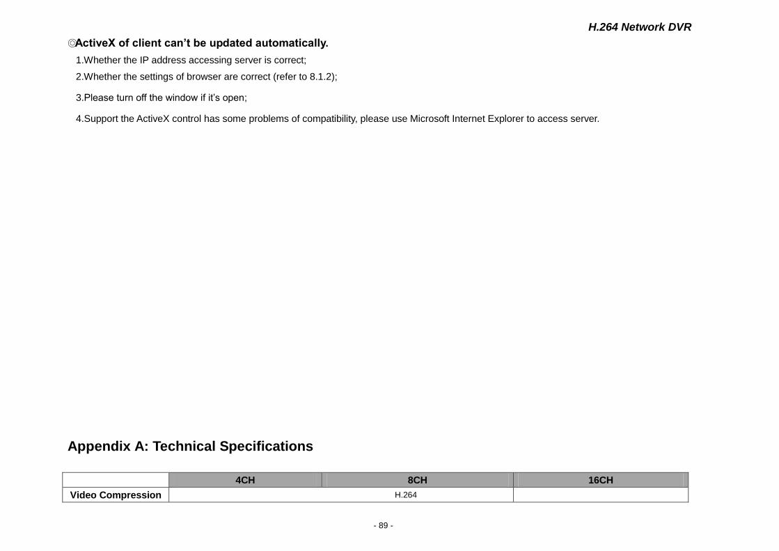
Appendix A: Technical Specifications
4CH 8CH 16CH
Video Compression H.264
H.264 Network DVR
- 90 -
Video Input 4ch (1.0Vp-p/75Ω,BNC) 8ch (1.0Vp-p/75Ω,BNC) 16ch (1.0Vp-p/75Ω,BNC)
Video Output 3ch (1.0Vp-p/75Ω,BNC×1;Super Video×1;VGA×1)
Resolution
Display: 720×576(PAL),720×480(NTSC)
Recording: D1:704×576(PAL),704×480(NTSC)
HD1:704×288(PAL),704×240(NTSC)
CIF: 352×288(PAL),320×240(NTSC)
Frame D1: 25FPS(PAL),30 FPS (NTSC)
CIF:100FPS(PAL),120 FPS(NTSC)
D1 :50 FPS(PAL),60 FPS (NTSC)
CIF:200 FPS(PAL),240 FPS(NTSC)
D1 :100 FPS(PAL),120 FPS (NTSC)
CIF:400 FPS(PAL),480 FPS(NTSC)
Audio Input BNC×4 BNC×8 BNC×16
Audio Output -8dB~92dB,BNC×1
Audio Codec ADPCM
Alarm Input 4CH 8CH 16CH
Alarm Output 2CH 4CH 4CH
Recording Modes Manual,Schedule,Motion, Alarm
Triplex Record, Playback, Network
Network Interface RJ45(10M/100M)
PTZ Control Enable,set up the preset and use the mouse to move or scale the picture
Communication
Interface RS485×1,USB2.0×1
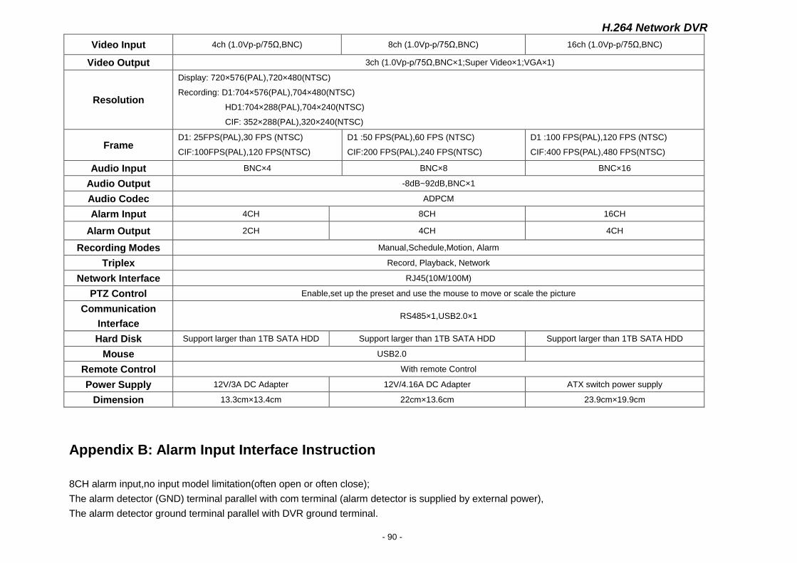
Hard Disk Support larger than 1TB SATA HDD Support larger than 1TB SATA HDD Support larger than 1TB SATA HDD
Mouse USB2.0
Remote Control With remote Control
Power Supply 12V/3A DC Adapter 12V/4.16A DC Adapter ATX switch power supply
Dimension 13.3cm×13.4cm 22cm×13.6cm 23.9cm×19.9cm
Appendix B: Alarm Input Interface Instruction
8CH alarm input,no input model limitation(often open or often close);
The alarm detector (GND) terminal parallel with com terminal (alarm detector is supplied by external power),
The alarm detector ground terminal parallel with DVR ground terminal.
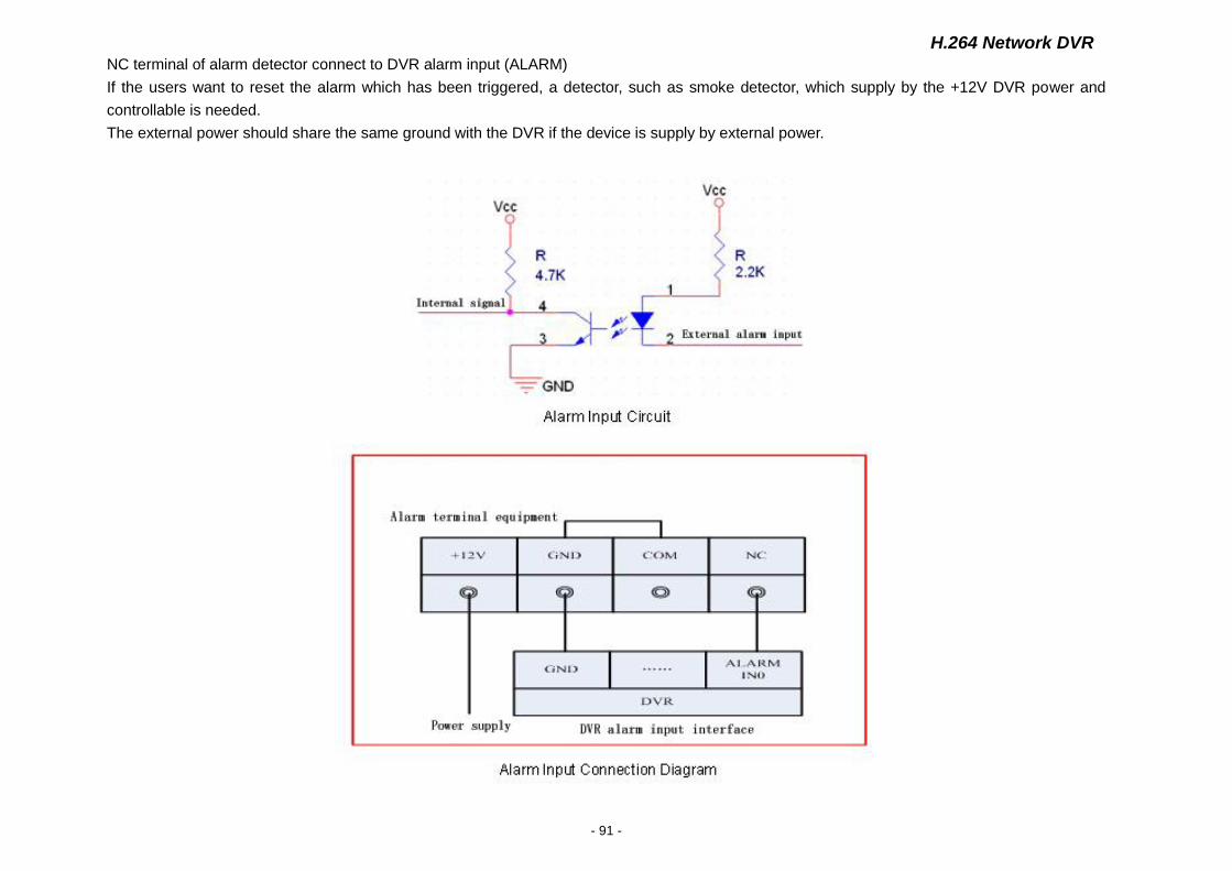
H.264 Network DVR
- 91 -
NC terminal of alarm detector connect to DVR alarm input (ALARM)
If the users want to reset the alarm which has been triggered, a detector, such as smoke detector, which supply by the +12V DVR power and
controllable is needed.
The external power should share the same ground with the DVR if the device is supply by external power.
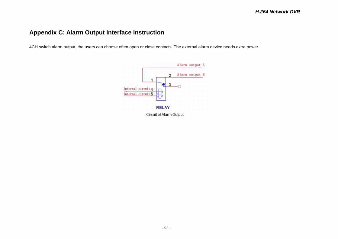
H.264 Network DVR
- 92 -
Appendix C: Alarm Output Interface Instruction
4CH switch alarm output, the users can choose often open or close contacts. The external alarm device needs extra power.
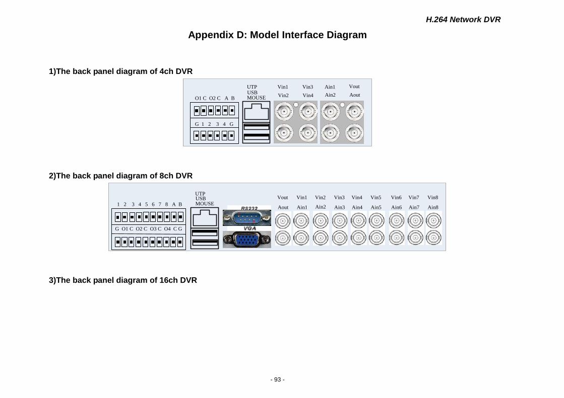
H.264 Network DVR
- 93 -
Appendix D: Model Interface Diagram
1)The back panel diagram of 4ch DVR
`
MOUSEUSB
O1 C O2 C A B
G 1 2 3 4 G
Vin1
Vin2
Vin3
Vin4
Ain1
Ain2
Vout
Aout
UTP
2)The back panel diagram of 8ch DVR
`
Vout
AoutMOUSEUSBUTP
Vin1
Ain1
Vin2
Ain2
Vin3
Ain3
Vin4
Ain4
Vin5
Ain5
Vin6
Ain6
Vin7
Ain7
Vin8
Ain8
G O1 C O2 C O3 C O4 C G
1 2 3 4 5 6 7 8 A B
3)The back panel diagram of 16ch DVR
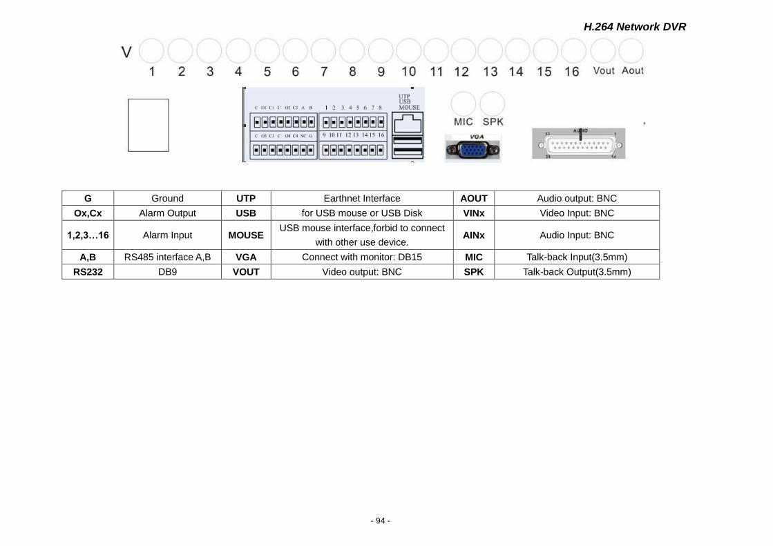
H.264 Network DVR
- 94 -
G Ground UTP Earthnet Interface AOUT Audio output: BNC
Ox,Cx Alarm Output USB for USB mouse or USB Disk VINx Video Input: BNC
1,2,3…16 Alarm Input MOUSE USB mouse interface,forbid to connect
with other use device. AINx Audio Input: BNC
A,B RS485 interface A,B VGA Connect with monitor: DB15 MIC Talk-back Input(3.5mm)
RS232 DB9 VOUT Video output: BNC SPK Talk-back Output(3.5mm)