Embed Size (px)
Citation preview

H3V3 Series
Horizontal and Vertical Indoor Air Handling Units
Installation Operation
amp Maintenance
If the information in this manual is not followed exactly a fire or explosion may result causing property damage personal injury or loss of life
FOR YOUR SAFETY
Do not store or use gasoline or other flammable vapors and liquids in the vicinity of this or any other appliance
WARNING
WARNING
QUALIFIED INSTALLER Improper installation adjustment alteration service or maintenance can cause property damage personal injury or loss of life Startup and service must be performed by a Factory Trained Service Technician A copy of this IOM should be kept with the unit
WARNING
3
Table of Contents
Safety 7
H3V3 Base Model Description 12
General Information 18
Codes and Ordinances 19
Receiving Unit 19
Storage 20
Direct Expansion (DX) Systems 20
Wiring Diagrams 21
Condensate Drain Pans 21
Installation 22
Locating the Unit 22
Lifting and Handling the Unit 26
Unit Assembly 26
Control Box 28
Duct Connection 28
Condensate Drain Piping 28
Heating Coils 29
Chilled Water Coil 30
Evaporator Coil 31
Thermal Expansion Valve 31
Hot Gas Reheat 31
Hot Gas Bypass 32
Electric Preheat 32
Energy Recovery Units 33
Initial Mechanical Check and Setup 33
Routine Maintenance and Handling 34
Cleaning 35
Wheel Drive Components 36
Startup Procedure 36
Service 37
Electrical 40
Startup 44
Supply Fans 44
Fan Air Flow Adjustment 44
Filters 45
Adjusting Refrigerant Charge 45
Operation 49
Electric Heating Operation 49
Steam or Hot Water Preheating Operation 49
Chilled Water or Non-Compressorized DX Cooling Operation 49
Modulating Electric Preheat 49
Maintenance 49
DX Cooling 49
Condensate Drain Pans 49
4
E-Coated Coil Cleaning 50
Supply Fans 51
Phase and Brownout Protection Module 52
Filter Replacement 54
Replacement Parts 54
AAON-Longview Product Support 54
Filter Information 55
Refrigerant Piping Diagrams 63
H3V3 Series Startup Form 75
Maintenance Log 80
Literature Change History 81
Index of Tables and Figures
Tables
Table 1 - H3 and V3 Series Clearances 22
Table 2 - Drain Trap Dimensions 29
Table 3 - Steam Distributing Coil Connection Sizes 30
Table 4 - Hot Water Coil Connection Sizes 30
Table 5 - Chilled Water Coil Connection Sizes 31
Table 6 - Control Wiring 42
Table 7 - Acceptable Air-Cooled Refrigeration Circuit Values 47
Table 8 - R-410A Refrigerant Temperature-Pressure Chart 48
Table 9 - V3 Series E Cabinet Pre-Filters 55
Table 10 - H3 Series A Cabinet Unit Filters 56
Table 11 - V3 Series A Cabinet Unit Filters 56
Table 12 - H3 Series B Cabinet Unit Filters 57
Table 13 - V3 Series B Cabinet Unit Filters 57
Table 14 - H3 Series C Cabinet Unit Filters 58
Table 15 - V3 Series C Cabinet Unit Filters 58
Table 16 - H3 Series D Cabinet Unit Filters 59
Table 17 - V3 Series D Cabinet Unit Filters 59
Table 18 - H3 Series E Cabinet Unit Filters 60
Table 19 - H3 Series A Cabinet Final Filters 61
Table 20 - H3 Series B Cabinet Final Filters 61
Table 21 - H3 Series C Cabinet Final Filters 61
Table 22 - H3 Series D Cabinet Final Filters 62
Table 23 - H3 Series E Cabinet Final Filters 62
Table 24 - V3 Series Energy Recovery OA Filters (Feature 13 = A-V) 62
5
Figures
Figure 1 - Lockable Handle 20
Figure 2 - Minimum Clearance Required for Access to Unit (V3 Series plan view) 22
Figure 3 - Minimum Clearance Required for Access to Unit (H3 Series plan view) 23
Figure 4 - H3 internal control panel with top access panel removed 23
Figure 5 - V3 internal control panel with rear removable access panel shown 23
Figure 6 - H3 Series Platform Suspension Installation 24
Figure 7 - H3 Series Parallel Beam Suspension Installation 24
Figure 8 - H3 Series Unit Orientation 25
Figure 9 - V3 Series Unit Orientation 25
Figure 10 - H3 Schematic with (1) Mixing Box (2) Air Handler (3) Final Filter and (4) Electric
Heat 26
Figure 11 - V3 Schematic with (1) Exhaust Fan (2) Energy Recovery (3) Air Handler and (4)
Electric Heat 26
Figure 12 - Connect Sections 27
Figure 13 - Bar Clamp 27
Figure 14 - Flange Overlap 27
Figure 15 - Self-Tapping Screw 27
Figure 16 - Strap Types 27
Figure 17 - Low Voltage Quick Connect 28
Figure 18 - Back View External Control Box 28
Figure 19 - Drain Trap 29
Figure 20 - Steam Distributing Piping 30
Figure 21 - Hot amp Chilled Water Piping 30
Figure 22 - TXV Bulb Position 31
Figure 23 - Energy Recovery Wheel 33
Figure 24 - Cross Section of Air Seal Structure 33
Figure 25 - Lifting Hole Locations 34
Figure 26 - Avoid Racking of Cassette Frame 36
Figure 27 - Diameter Seal Adjustment 37
Figure 28 - Hub Seal Adjustment 37
Figure 29 - Segment Retainer 38
Figure 30 - Segment Installation 38
Figure 31 - Belt Replacement 39
Figure 32 - External control box electrical connections 40
Figure 33 - H3 internal control panel electrical connections 40
Figure 34 - V3 internal control panel electrical connections 40
Figure 35- Typical wiring diagram with EC motor 44
Figure 36 - Shows the jumper that is to be removed (jumped between 9 and GS) 45
Figure 37 - Potentiometer 45
Figure 38 - AC only piping AHU above CU 63
Figure 39 - AC only piping AHU below CU 64
Figure 40 - Modulating hot gas reheat piping AHU above CU 65
Figure 41 - Modulating hot gas reheat piping AHU below CU 66
Figure 42 - Hot gas bypass piping AHU above CU 67
Figure 43 - Hot gas bypass piping AHU below CU 68
6
Figure 44 - Modulating hot gas reheat with hot gas bypass piping AHU above CU 69
Figure 45 - Modulating hot gas reheat with hot gas bypass piping AHU below CU 70
Figure 46 - Heat pump piping AHU above CU 71
Figure 47 - Heat pump piping AHU below CU 72
Figure 48 - Heat pump with modulating hot gas reheat piping AHU above CU 73
Figure 49 - Heat pump with modulating hot gas reheat piping AHU below CU 74
R94201 Rev B 161007
(ACP J00188)
7
Safety
Attention should be paid to the following statements
NOTE - Notes are intended to clarify the unit installation operation and maintenance
CAUTION - Caution statements are given to prevent actions that may result in
equipment damage property damage or personal injury
WARNING - Warning statements are given to prevent actions that could result in
equipment damage property damage personal injury or death
DANGER - Danger statements are given to prevent actions that will result in equipment
damage property damage severe personal injury or death
ELECTRIC SHOCK FIRE OR EXPLOSION HAZARD Failure to follow safety warnings exactly could result in dangerous operation serious injury death or property damage Improper servicing could result in dangerous operation serious injury death or property damage Before servicing disconnect all
electrical power to the unit More than one disconnect may be provided
When servicing controls label all wires prior to disconnecting Reconnect wires correctly
Verify proper operation after servicing Secure all doors with key-lock or nut and bolt
WARNING
Electric shock hazard Before servicing disconnect all electrical power to the unit including remote disconnects to avoid shock hazard or injury from rotating parts Follow proper Lockout-Tagout procedures
WARNING
FIRE EXPLOSION OR CARBON MONOXIDE POISONING HAZARD Failure to replace proper controls could result in fire explosion or carbon monoxide poisoning Failure to follow safety warnings exactly could result in serious injury death or property damage Do not store or use gasoline or other flammable vapors and liquids in the vicinity of this appliance
WARNING
8
GROUNDING REQUIRED All field installed wiring must be completed by qualified personnel Field installed wiring must comply with NECCEC local and state electrical code requirements Failure to follow code requirements could result in serious injury or death Provide proper unit ground in accordance with these code requirements
WARNING
During installation testing servicing and troubleshooting of the equipment it may be necessary to work with live electrical components Only a qualified licensed electrician or individual properly trained in handling live electrical components shall perform these tasks Standard NFPA-70E an OSHA regulation requiring an Arc Flash Boundary to be field established and marked for identification of where appropriate Personal Protective Equipment (PPE) be worn should be followed
WARNING
UNIT HANDLING To prevent injury or death lifting equipment capacity shall exceed unit weight by an adequate safety factor Always test-lift unit not more than 24 inches high to verify proper center of gravity lift point to avoid unit damage injury or death
WARNING
ROTATING COMPONENTS Unit contains fans with moving parts that can cause serious injury Do not open door containing fans until the power to the unit has been disconnected and fan wheel has stopped rotating
WARNING
Failure to properly drain and vent coils when not in use during freezing temperature may result in coil and equipment damage
CAUTION
Rotation must be checked on all MOTORS of 3 phase units at startup by a qualified service technician Fan motor rotation should be checked for proper operation Alterations should only be made at the unit power connection
CAUTION
9
Do not clean DX refrigerant coils with hot water or steam The use of hot water or steam on refrigerant coils will cause high pressure inside the coil tubing and damage to the coil
Some chemical coil cleaning compounds are caustic or toxic Use these substances only in accordance with the manufacturerrsquos usage instructions Failure to follow instructions may result in equipment damage injury or death
WATER PRESSURE Prior to connection of condensing water supply verify water pressure is less than maximum pressure shown on unit nameplate To prevent injury or death due to instantaneous release of high pressure water relief valves should be field supplied on system water piping
WARNING
To prevent damage to the unit do not use acidic chemical coil cleaners Do not use alkaline chemical coil cleaners with a pH value greater than 85 after mixing without first using an aluminum corrosion inhibitor in the cleaning solution
CAUTION WARNING
CAUTION
Do not use oxygen acetylene or air in place of refrigerant and dry nitrogen for leak testing A violent explosion may result causing injury or death
WARNING
Always use a pressure regulator valves and gauges to control incoming pressures when pressure testing a system Excessive pressure may cause line ruptures equipment damage or an explosion which may result in injury or death
WARNING
Do not work in a closed area where refrigerant or nitrogen gases may be leaking A sufficient quantity of vapors may be present and cause
injury or death
WARNING
Door compartments containing hazardous voltage or rotating parts are equipped with door latches to allow locks Door latch are shipped with nut and bolts requiring tooled access If you do not replace the shipping hardware with a pad lock always re-install the nut amp bolt after closing the door
CAUTION
10
1 Startup and service must be performed
by a Factory Trained Service
Technician
2 The unit is for indoor use only See
General Information section for more
unit information
3 Every unit has a unique equipment
nameplate with electrical operational
and unit clearance specifications
Always refer to the unit nameplate for
specific ratings unique to the model you
have purchased
4 READ THE ENTIRE INSTALLATION
OPERATION AND MAINTENANCE
MANUAL OTHER IMPORTANT
SAFETY PRECAUTIONS ARE
PROVIDED THROUGHOUT THIS
MANUAL
5 Keep this manual and all literature
safeguarded near or on the unit
PVC (Polyvinyl Chloride) and CPVC (Chlorinated Polyvinyl Chloride) are vulnerable to attack by certain chemicals Polyolester (POE) oils used with R-410A and other refrigerants even in trace amounts in a PVC or CPVC piping system will result in stress cracking of the piping and fittings and complete piping system failure
CAUTION
Do not weld or cut foam panel with plasma cutters or a cutting torch ndash When burnt the foam produces dangerous fumes
WARNING
Never attempt to open an access door or remove a panel while the unit is running Pressure in the unit can cause excessive force against the panel
WARNING
Ensure that sufficient dampers will be open to provide air path before fan is allowed to run
WARNING
11
H3V3 Series Feature String Nomenclature
Model Options Unit Feature Options G
EN
SIZ
E
OR
EN
T
MJ
RE
V
VL
T
CO
RR
A1
A2
A3
A4
B1
B2
B3
1A
1B
1C
1D
2
3
4
5A
5B
5C
6A
6B
6C
7
8
9
10
11
12
13
14A
14B
H3 - A R B - 3 - 0 - 1 6 1 C - 1 2 F A A B B - 0 C 0 - F T B - 0 G 0 - 0 0 A A A C 0 0 B
A 0 0 0 0 0 0 0 0
15
16
17
18
19
20
21
22
23
12
H3V3 Base Model Description
BASE MODEL SERIES AND GENERATION
H3 = Horizontal - Back Intake Front Discharge
V3 = Vertical - Back Intake Top Discharge
UNIT SIZE
A = Up to 1200 cfm
B = Up to 2000 cfm
C = Up to 4000 cfm
D = Up to 6000 cfm
E = Up to 10000 cfm
UNIT ORIENTATION
R = Right Hand Connections
L = Left Hand Connections
REVISION
A = First Revision
B = Second Revision
VOLTAGE
1 = 230V1Φ60Hz
2 = 230V3Φ60Hz
3 = 460V3Φ60Hz
4 = 575V3Φ60Hz
8 = 208V3Φ60Hz
9 = 208V1Φ60Hz
CORROSION PROTECTION
0 = None
A = Interior Corrosion Protection
Model Option A COOLING A1 COOLING TYPE
0 = No Cooling
1 = R-410A DX Cooling
2 = Chilled Water Cooling
A2 COOILNG ROWS
0 = No Cooling
4 = 4 Row Coil
6 = 6 Row Coil
8 = 8 Row Coil
A3 COOLING STAGES
0 = No Cooling
1 = Single Circuit
2 = Two Circuits - Interlaced Coil
D = Double Serpentine
F = Single Serpentine
H = Half Serpentine
Q = Quarter Serpentine
A4 COOLING FPI
0 = No Cooling
A = 10 fpi
B = 8 fpi
C = 12 fpi
D = 14 fpi
H3V3 Series Feature String Nomenclature
Model Options Unit Feature Options G
EN
SIZ
E
OR
EN
T
MJR
EV
VL
T
CO
RR
A1
A2
A3
A4
B1
B2
B3
1A
1B
1C
1D
2
3
4
5A
5B
5C
6A
6B
6C
7
8
9
10
11
12
13
14A
14B
H3 - A R B - 3 - 0 - 1 6 1 C - 1 2 F A A B B - 0 C 0 - F T B - 0 G 0 - 0 0 A A A C 0 0 B
A 0 0 0 0 0 0 0 0
15
16
17
18
19
20
21
22
23
13
Model Option B HEATING B1 HEATING TYPE
0 = No Heating
1 = Hot Water
3 = Electric Heating
4 = Steam Distributing
B2 HEATING DESIGNATION
0 = No Heating
1 = 1 Row Coil
2 = 2 Row Coil
A = 7 kW (53 kW 208V)
B = 14 kW (105 kW 208V)
C = 21 kW (158 kW 208V)
D = 28 kW (210 kW 208V)
E = 35 kW (263 kW 208V)
F = 42 kW (315 kW 208V)
G = 49 kW (370 kW 208V)
H = 56 kW (420 kW 208V)
J = 63 kW (473 kW 208V)
K = 70 kW (525 kW 208V)
L = 77 kW (578 kW 208V)
M = 84 kW (630 kW 208V)
B3 HEATING STAGES
0 = No Heating
1 = 1 Stage
2 = 2 Stage
3 = 3 Stage
4 = 4 Stage
S = ModulatingSCR Electric
F = Single Serpentine 12 fpi
H = Half Serpentine 12 fpi
Q = Quarter Serpentine 12 fpi
Feature 1 SUPPLY FAN 1A SUPPLY AIR BLOWER CONFIGURATION
0 = 1 Blower + Premium Eff Motor
1 = 1 Blower + Premium Eff Motor + 1 VFD
A = 1 Blower + 1 High Efficiency EC Motor
B = 2 Blowers + 2 High Efficiency EC Motors
1B SUPPLY AIR BLOWER
1 = 15rdquo Backward Curved Plenum Fan
2 = 15rdquo BC Plenum 50 Width with Banding
3 = 185rdquo Backward Curved Plenum Fan
4 = 185rdquo BC Plenum Fan 70 Width with Banding
5 = 22rdquo Backward Curved Plenum Fan
6 = 24rdquo Backward Curved Plenum Fan
7 = 27rdquo Backward Curved Plenum Fan
8 = 27rdquo BC Plenum Fan 70 Width with Banding
A = 310 mm Direct Drive BC Plenum Fan
B = 355 mm Direct Drive BC Plenum Fan
C = 450 mm Direct Drive BC Plenum Fan
D = 250 mm Direct Drive BC Plenum Fan
1C SUPPLY AIR BLOWER MOTOR
1 = 1 hp - 1760 rpm
2 = 2 hp - 1760 rpm
3 = 3 hp - 1760 rpm
4 = 5 hp - 1760 rpm
5 = 75 hp - 1760 rpm
6 = 10 hp - 1760 rpm
B = 10 kW (134 hp)
C = 17 kW (228 hp)
D = 30 kW (402 hp)
E = 60 kW (800 hp)
F = 08 kW (107 hp)
1D SUPPLY BLOWER CONTROLCONTROL
VENDORS
0 = Standard - Terminal Block
A = Potentiometer Supply Fan Control
B = WattMaster Orion Controls System
C = Field Installed Controls by Others
D= Field Installed Controls by Others + Isolation
Relays
H3V3 Series Feature String Nomenclature
Model Options Unit Feature Options
GE
N
SIZ
E
OR
EN
T
MJR
EV
VL
T
CO
RR
A1
A2
A3
A4
B1
B2
B3
1A
1B
1C
1D
2
3
4
5A
5B
5C
6A
6B
6C
7
8
9
10
11
12
13
14A
14B
H3 - A R B - 3 - 0 - 1 6 1 C - 1 2 F A A B B - 0 C 0 - F T B - 0 G 0 - 0 0 A A A C 0 0 B
A 0 0 0 0 0 0 0 0
15
16
17
18
19
20
21
22
23
14
Feature 2 REFRIGERATION OPTIONS 0 = Standard - None
A = Single Circuit External Hot Gas Bypass
B = Dual Circuit External Hot Gas Bypass
C = Heat Pump
D = Option B + H
F = Options C + H
H = Modulating Hot Gas Reheat
P = Option H (Circuit 1) + Option A (Circuit 2)
R = Option C + A
S = Option C + B
T = Option C + H + A
U = Option C + H + B
Feature 3 SPECIAL CONTROLS 0 = Standard - None
A = Constant Volume Controller - CV Cool + CV
Heat
B = Constant Volume Controller with Modulating
Hot Gas Reheat - CV Cool + CV Heat
C = VAV Controller - VAV Cool + CV Heat
D = VAV Controller with MHGR - VAV Cool + CV
Heat
E = Make Up Air Controller - CV Cool + CV Heat
F = Make Up Air Controller with Modulating Hot
Gas Reheat - CV Cool + CV Heat
G = WattMaster Modulating Hot Gas Reheat
Controller
Feature 4 ADDITIONAL CONTROLS 0 = Standard - None
A = Phase and Brownout Protection
B = Return and Supply Air Firestat
C = Return Air Smoke Detector
D = Options A + B
E = Options A + C
F = Options B + C
G = Options A + B + C
H = Remote Safety Shutdown Terminals
J = Energy Recovery Wheel Rotation Detection
K = Options A + H
L = Options A + J
M = Options B + H
Feature 4 ADDITIONAL CONTROLS
Continued N = Options B + J
P = Options C + H
Q = Options C + J
S = Options A + B + H
T = Options A + B + J
U = Options A + C + H
V = Options A + C + J
W = Options A + H + J
Y = Options B + C + H
Z = Options B + C + J
1 = Options B + H + J
2 = Options C + H + J
3 = Options A + B + C + H
4 = Options A + B + C + J
5 = Options A + B + H + J
6 = Options A + C + H + J
7 = Options B + C + H + J
8 = Options A + B + C + H + J
Feature 5 MIXING BOX 5A RETURN AIR DAMPER POSITION
0 = Standard - None
F = Front
L = Left Hand (Front OA Damper Required)
R = Right Hand (Front OA Damper Required)
T = Top (Front OA Damper Required)
5B OUTSIDE AIR DAMPER POSITION
0 = Standard - None
F = Front
L = Left Hand (Front RA Damper Required)
R = Right Hand (Front RA Damper Required)
T = Top (Front RA Damper Required)
5C MIXING BOX DAMPER CONTROL
0 = Standard - None
A = 2 Position Actuators (24V)
B = Fully Modulating Actuators (DDC)
C = Fixed Position Dampers
H3V3 Series Feature String Nomenclature
Model Options Unit Feature Options
GE
N
SIZ
E
OR
EN
T
MJR
EV
VL
T
CO
RR
A1
A2
A3
A4
B1
B2
B3
1A
1B
1C
1D
2
3
4
5A
5B
5C
6A
6B
6C
7
8
9
10
11
12
13
14A
14B
H3 - A R B - 3 - 0 - 1 6 1 C - 1 2 F A A B B - 0 C 0 - F T B - 0 G 0 - 0 0 A A A C 0 0 B
A 0 0 0 0 0 0 0 0
15
16
17
18
19
20
21
22
23
15
Feature 6 FILTER BOX 6A PRE FILTER BOX
0 = Standard - None
A = 2rdquo Pleated - 30 Eff - MERV 10
B = 4rdquo Pleated - 30 Eff - MERV 10
C = 4rdquo Pleated - 65 Eff - MERV 11
D = 4rdquo Pleated - 85 Eff - MERV 13
E = 4rdquo Pleated - 95 Eff - MERV 14
F = 2rdquo Pleated - 30 Eff - MERV 10 + 4rdquo Pleated -
30 Eff - MERV 10
G = 2rdquo Pleated - 30 Eff - MERV 10 + 4rdquo Pleated -
65 Eff - MERV 11
H = 2rdquo Pleated - 30 Eff - MERV 10 + 4rdquo Pleated -
85 Eff - MERV 13
J = 2rdquo Pleated - 30 Eff - MERV 10 + 4rdquo Pleated -
95 Eff - MERV 14
6B UNIT FILTER
0 = Standard - None
A = 2rdquo Pleated - 30 Eff - MERV 10
B = 4rdquo Pleated - 30 Eff - MERV 10
C = 4rdquo Pleated - 65 Eff - MERV 11
D = 4rdquo Pleated - 85 Eff - MERV 13
E = 4rdquo Pleated - 95 Eff - MERV 14
F = 2rdquo Pleated - 30 Eff - MERV 10 + 4rdquo Pleated -
30 Eff - MERV 10
G = 2rdquo Pleated - 30 Eff - MERV 10 + 4rdquo Pleated -
65 Eff - MERV 11
H = 2rdquo Pleated - 30 Eff - MERV 10 + 4rdquo Pleated -
85 Eff - MERV 13
J = 2rdquo Pleated - 30 Eff - MERV 10 + 4rdquo Pleated -
95 Eff - MERV 14
6C FINAL FILTER BOX
0 = Standard - None
A = 2rdquo Pleated - 30 Eff - MERV 10
B = 12rdquo Cartridge - 65 Eff - MERV 11
C = 12rdquo Cartridge - 85 Eff - MERV 13
D = 12rdquo Cartridge - 95 Eff - MERV 14
E = 2rdquo Pleated - 30 Eff - MERV 10 + 12rdquo
Cartridge - 65 Eff - MERV 11
F = 2rdquo Pleated - 30 Eff - MERV 10 + 12rdquo
Cartridge - 85 Eff - MERV 13
G = 2rdquo Pleated - 30 Eff - MERV 10 + 12rdquo
Cartridge - 95 Eff - MERV 14
Feature 7 FILTER OPTIONS 0 = Standard - None
A = Magnehelic Gauge
B = Clogged Filter Switch
C = Options A + B
Feature 8 COIL COATING 0 = Standard - None
A = E-coated Cooling and Heating Coils
B = Copper Finned Coils + Stainless Steel Coil
Casing
Feature 9 EXPANSION VALVE 0 = None
A = Thermal Expansion Valves
Feature 10 EXPANSION VALVE
CONTROLS 0 = None
A = Standard Control
Feature 11 EXTERNAL PAINT 0 = Standard - None
A = AAON Gray Paint
B = Special Paint
H3V3 Series Feature String Nomenclature
Model Options Unit Feature Options
GE
N
SIZ
E
OR
EN
T
MJR
EV
VL
T
CO
RR
A1
A2
A3
A4
B1
B2
B3
1A
1B
1C
1D
2
3
4
5A
5B
5C
6A
6B
6C
7
8
9
10
11
12
13
14A
14B
H3 - A R B - 3 - 0 - 1 6 1 C - 1 2 F A A B B - 0 C 0 - F T B - 0 G 0 - 0 0 A A A C 0 0 B A 0 0 0 0 0 0 0 0
15
16
17
18
19
20
21
22
23
16
Feature 12 TONNAGE 0 = Standard - None
A = 2 ton Capacity
B = 3 ton Capacity
C = 4 ton Capacity
D = 5 ton Capacity
E = 6 ton Capacity
F = 7 ton Capacity
G = 8 ton Capacity
U = 9 ton Capacity
H = 10 ton Capacity
V = 11 ton Capacity
W = 13 ton Capacity
J = 14 ton Capacity
Y = 15 ton Capacity
Z = 16 ton Capacity
K = 17 ton Capacity
1 = 18 ton Capacity
2 = 20 ton Capacity
L = 22 ton Capacity
M = 25 ton Capacity
3 = 26 ton Capacity
N = 30 ton Capacity
P = 31 ton Capacity
Q = 34 ton Capacity
R = 40-45 ton Capacity
S = 50-55 ton Capacity
4 = 60 ton Capacity
T = 63 ton Capacity
5 = 70 ton Capacity
Feature 13 ENERGY RECOVERY
TYPE 0 = Standard ndash None
A = Energy Recovery Wheel ndash Total + High CFM
Polymer
C = Energy Recovery Wheel ndash Total + High CFM
1 Purge Polymer
E = Energy Recovery Wheel ndash Sensible + High CFM
Polymer
G = Energy Recovery Wheel ndash Sensible + High
CFM 1 Purge Polymer
Feature 14 GPM 14A GPM COOLING COIL
0 = Standard - None
A = 15-25 gpm
B = 26-70 gpm
C = 71 -140 gpm
D = 141-240 gpm
E = 241-400 gpm
F = 401-800 gpm
G = 801-1500 gpm
H = 1501-2500 gpm
14B GPM HEATING COIL
0 = Standard - None
A = 15-25 gpm
B = 26-70 gpm
C = 71 -140 gpm
D = 141-240 gpm
E = 241-400 gpm
F = 401-800 gpm
G = 801-1500 gpm
H = 1501-2500 gpm
Feature 15 CONTROL PANEL 0 = Internal Control Panel
A = Small Control Panel - 12rdquo x 12rdquo
B = Medium Control Panel - 25rdquo x 22rdquo
C = Large Control Panel - 48rdquo x 22rdquo
Feature 16 SHIPPING SPLITS 0 = Standard ndash None
A = 1 Shipping Split (2 pallets)
B = 2 Shipping Splits (3 pallets)
C = 3 Shipping Splits (4 pallets)
D = 4 Shipping Splits (5 pallets)
E = 5 Shipping Splits (6 pallets)
H = Special Shipping Split (SPA Required)
H3V3 Series Feature String Nomenclature
Model Options Unit Feature Options
GE
N
SIZ
E
OR
EN
T
MJR
EV
VL
T
CO
RR
A1
A2
A3
A4
B1
B2
B3
1A
1B
1C
1D
2
3
4
5A
5B
5C
6A
6B
6C
7
8
9
10
11
12
13
14A
14B
H3 - A R B - 3 - 0 - 1 6 1 C - 1 2 F A A B B - 0 C 0 - F T B - 0 G 0 - 0 0 A A A C 0 0 B
A 0 0 0 0 0 0 0 0 1
5
16
17
18
19
20
21
22
23
17
Feature 17 ENERGY RECOVERY
CABINET 0 = Standard - None
A = Top RA + Back EA + Back OA Connections
G = OA + EA Dampers - Top RA + Back EA + Back
OA Connections
N = OA + Economizer Dampers - Top RA + Back
EA + Back Connections
U = OA + EA + Economizer Dampers - Top RA +
Back EA + Back OA Connections
Feature 18 MODULATING ELECTRIC
PREHEAT 0 = Standard - None
A = 75 kW
B = 15 kW
C = 20 kW
D = 225 kW
E = 30 kW
F = 40 kW
G = 50 kW
H = 60 kW
Feature 19 EXHAUST FAN 0 = Standard - None
A = 250 mm Exhaust Fan 800 W EC Motor
B = 310 mm Exhaust Fan 10 kW EC Motor
C = 310 mm Exhaust Fan 17 kW EC Motor
D = 355 mm Exhaust Fan 17 kW EC Motor
E = 450 mm Exhaust Fan 30 kW EC Motor
F = 450 mm Exhaust Fan 60 kW EC Motor
G = Dual 310 mm Exhaust Fan 10 kW EC Motor
H = Dual 310 mm Exhaust Fan 17 kW EC Motor
J = Dual 355 mm Exhaust Fan 17 kW EC Motor
K = Dual 450 mm Exhaust Fan 30 kW EC Motor
L = Dual 450 mm Exhaust Fan 60 kW EC Motor
Feature 20 CRATING 0 = Standard - None
A = Export Crating
B = Forkliftable Base - 5rdquo Base
C = Options A + E
D = Options A + B
E = Shipping Shrink Wrap
F = Options B + E
G = Options A + B + E
Feature 21 PULLEY COMBINATION 0 = Standard - None
A = 1000-1400 rpm
B = 1401-1800 rpm
C = 1801-2200 rpm
Feature 22 WARRANTY 0 = Standard - 1 Year Parts
Feature 23 TYPE 0 = Standard
X = Special Pricing Authorization
18
General Information
AAONreg
H3 and V3 Series indoor air
handling units have been designed for
indoor installation only Units are
assembled wired charged with dry nitrogen
and run-tested at the factory H3 and V3
Series units are not intended for residential
use Startup and service must be performed
by a Factory Trained Service Technician
Certification of Steam or Hot Water Heat
Models
a Certified as a forced air heating system
with or without cooling
b Certified for indoor installation only
Certification of Electric Heat Models
a Certified as an electric warm air furnace
with or without cooling
b Certified for indoor installation only
Certification of Cooling Models
a Certified as a commercial central air
conditioner with or without electrically
operated compressors
b Certified for indoor installation only
c Certified with refrigerant R-410A coils
or with chilled water cooling coils
Improper installation adjustment alteration service or maintenance can cause property damage personal injury or loss of life Startup and service must be performed by a Factory Trained Service Technician A copy of this IOM should be kept with the unit
WARNING
These units must not be used as a ldquoconstruction heaterrdquo at anytime during any phase of construction Very low return air temperatures harmful vapors and misplacement of the filters will damage the unit and its efficiency
CAUTION
This equipment is protected by a standard limited warranty under the condition that initial installation service startup and maintenance is performed according to the instructions set forth in this manual This manual should be read in its entirety prior to installation and before performing any service or maintenance work Equipment described in this manual is available with many optional accessories If you have questions after reading this manual in its entirety consult other factory documentation or contact your AAON Sales Representative to obtain further information before manipulating this equipment or its optional accessories
CAUTION
19
Codes and Ordinances
H3 and V3 Series units have been tested and
certified by ETL in accordance with UL
Safety Standard 1995CSA C222 No 236
System should be sized in accordance with
the American Society of Heating
Refrigeration and Air Conditioning
Engineers Handbook
Installation of H3 and V3 Series units must
conform to the ICC standards of the
International Mechanical Code the
International Building Code Installation of
Air Conditioning and Ventilating Systems
Standard NFPA 90A and local building
plumbing and waste water codes All
appliances must be electrically grounded in
accordance with local codes or in the
absence of local codes the current National
Electric Code ANSINFPA 70 or the
current Canadian Electrical Code CSA
C221
Receiving Unit
When received the unit should be checked
for damage that might have occurred in
transit If damage is found it should be noted
on the carrierrsquos Freight Bill A request for
inspection by carrierrsquos agent should be made
in writing at once
Nameplate should be checked to ensure the
correct model sizes and voltages have been
received to match the job requirements
If repairs must be made to damaged goods
then the factory should be notified before
any repair action is taken in order to protect
the warranty Certain equipment alteration
repair and manipulation of equipment
without the manufacturerrsquos consent may
void the product warranty Contact the
AAON Warranty Department for assistance
with handling damaged goods repairs and
freight claims (903) 236-4403
Note Upon receipt check shipment for
items that ship loose such as remote sensors
Consult order and shipment documentation
to identify potential loose-shipped items
Loose-shipped items may have been placed
inside unit cabinet for security Installers
and owners should secure all doors with
locks or nuts and bolts to prevent
unauthorized access
The Clean Air Act of 1990 bans the intentional venting of refrigerant as of July 1 1992 Approved methods of recovery recycling or reclaiming must be followed
CAUTION
Coils and sheet metal surfaces present sharp edges and care must be taken when working with equipment
WARNING
Failure to observe the following instructions will result in premature failure of your system and possible voiding of the warranty
WARNING
20
Figure 1 - Lockable Handle
Storage
This equipment is not suitable for outdoor
use of storage If installation will not occur
immediately following delivery store
equipment in a dry protected area away from
construction traffic and in the proper
orientation as marked on the packaging with
all internal packaging in place Secure all
loose-shipped items
Direct Expansion (DX) Systems
All DX refrigerant coils are factory charged
with a nitrogen holding charge All DX
systems include evaporator coils and
thermal expansion valves (TXV)
Never turn off the main power supply to the
unit except for servicing emergency or
complete shutdown of the unit When power
is cut off from the unit crankcase heaters
cannot prevent refrigerant migration into the
split system condensing unit compressors
This means the compressor may cool down
and liquid refrigerant may accumulate in the
compressor The compressor is designed to
pump refrigerant gas and damage may occur
when power is restored
If power to the unit must be off for more
than an hour turn the thermostat system
switch to OFF or turn the unit off at the
control panel and leave the unit off until the
main power switch has been turned on again
for at least 24 hours for units with
compressor crankcase heaters This will give
the crankcase heater time to clear any liquid
accumulation out of the compressor before it
is started
Always control the unit from the thermostat
or control panel never at the main power
supply except for emergency or complete
shutdown of the unit
During the cooling season if the air flow is
reduced due to dirty air filters or any other
reason the cooling coils can get too cold
which will cause excessive liquid to return
to the compressor As the liquid
concentration builds up oil is washed out of
the compressor leaving it starved for
lubrication
The compressor life will be seriously
shortened by reduced lubrication and the
pumping of excessive amounts of liquid oil
and refrigerant
CRANKCASE HEATER OPERATION
Some units are equipped with compressor crankcase heaters which should be energized at least 24 hours prior to cooling operation to clear any liquid refrigerant from the compressors
CAUTION
21
Note Low Ambient Operation
Air-cooled DX units without a low ambient
option such as condenser fan cycling or the
0degF low ambient option will not operate in
the cooling mode of operation properly
when the outdoor temperature is below
55degF Low ambient andor economizer
options are recommended if cooling
operation below 55degF is expected
Wiring Diagrams
Unit specific wiring diagrams are laminated
and affixed inside the controls compartment
door
Condensate Drain Pans
Units require field installed drain p-traps and
lines to be connected to the condensate drain
pans of the unit
For condensate drain lines the line should
be the same pipe size or larger than the drain
connection include a p-trap and pitch
downward toward drain An air break should
be used with long runs of condensate lines
See Installation section of this manual for
more information
Unit should not be operated without a p-trap Failure to install a p-trap may result in overflow of condensate water
CAUTION
Emergency drain pan is recommended for all applications where a risk of water damage to surrounding structure or furnishings Refer to local codes
CAUTION
22
Installation
AAON equipment has been designed for
quick and easy installation Startup and
service must be performed by Factory
Trained Service Technician
The H3V3 unit can either be shipped
assembled or shipped in sections See the
Unit Assembly section of this document for
instructions on assembling the sections
Locating the Unit
Placement of the unit relative to ductwork
electrical and plumbing must be carefully
considered Return air plenum or duct can be
mounted directly to the return air flanges
Use flexible gasket material to seal the duct
to the unit
Verify floor foundation or suspension
support can support the total unit weight
including accessory weights Unit must be
level in both horizontal axes to support the
unit and reduce noise and vibration from the
unit
Allow adequate space for piping access and
panel removal To ensure proper access
for field service maintain minimum
clearances for field piping and other
obstructions as indicated by Table 1 and
Figure 2 and Figure 3 Consult local
building codes for additional service
clearance requirements Condensate drain
connections are located on the access side of
the unit
Table 1 - H3 and V3 Series Clearances
Unit Size
Access Side
Clearance
(dimension X on
Figure 2 and
Figure 3)
All Other
Sides
V3-A
36 inches
6 inches
V3-B
V3-C
V3-D
V3-E
H3-A
H3-B
H3-C
H3-D 45 inches
H3-E 60 inches
Additional clearance may be required to
allow for coil removal
May be installed flush depending upon
local codes
Figure 2 - Minimum Clearance Required for
Access to Unit (V3 Series plan view)
X
(See Table 1)
Back Front
Left
Right
23
Figure 3 - Minimum Clearance Required for
Access to Unit (H3 Series plan view)
Internal Control Panel
H3 units with internal control panel have
removable access panels on the top and
bottom of the supply fan section V3 units
with internal control panel have removable
access panels on the front and back of the
supply fan section V3 units that have
energy recovery only have one removable
supply fan access panel on the front of the
unit The supply flanges can be
interchanged with the access panels if
necessary except on size E
Figure 4 - H3 internal control panel with top
access panel removed
Figure 5 - V3 internal control panel with
rear removable access panel shown
Floor Mounted Units
Make sure the unit is level and mounted on a
field supplied platform with a minimum
height to allow for proper depth of the
condensate line p-trap Other installation
provisions may be necessary according to
job specifications V3 Series vertical air
handling units are designed for upflow
applications only
Suspended Units
H3 Series horizontal air handling units are
equipped for suspended installations The
unit should be lifted into position by
supporting the unit with the skid used for
shipping The air handling unit must be
installed level and care should be taken to
prevent damage to the cabinet Other
installation provisions may be necessary
according to job specifications Figure 6
and Figure 7 show factory recommended
methods for suspended installations It is
the responsibility of the specifying engineer
or installing contractor to ensure the
installation is structurally safe and sound
X
(See Table 1)
Front
Back
Left Right
24
Figure 6 - H3 Series Platform Suspension Installation
Figure 7 - H3 Series Parallel Beam Suspension Installation
25
Figure 8 - H3 Series Unit Orientation
Figure 9 - V3 Series Unit Orientation
Note Access doors may be on the ldquoleftrdquo or ldquorightrdquo side as designated by the unit orientation on
the configurator string ldquoBackrdquo will always be the same side as the pre-filter and return air
opening ldquoFrontrdquo will always be the side opposite the pre-filter and return air opening
H3 Series
Return Air ldquoBackrdquo
Supply Air ldquoFrontrdquo
Right Hand Side
Left Hand Side
Connections and service access on right side for right hand orientation
Top View
Air Flow
Connections and service access on right side for right hand orientation
Right Hand Side Left Hand Side
Return Air ldquoBackrdquo
Top View V3 Series
Air Flow
Consider the air flow to be hitting the back of your head
Consider the air flow to be hitting the back of your head
Supply Air
ldquoFrontrdquo
26
Lifting and Handling the Unit
Before lifting unit be sure that all shipping
material has been removed from unit
Care should be taken if using spreader bars
blocking or other lifting devices to prevent
damage to the cabinet coil or fans
Unit Assembly
Although H3V3 Series units are shipped
factory assembled as standard the unit may
be ordered as shipping splits for certain
applications such as for assembly in existing
structures where modules must be
manipulated separately If the unit was
ordered as shipping splits then they must be
assembled in the field
Locate the schematic in the equipmentrsquos
literature packet
1 Identify and Situate Splits
a H3 Units can have the following
ship split sections
1 Mixing Box
2 Air Handler
3 Final Filter
4 Electric Heat
Figure 10 - H3 Schematic with (1) Mixing
Box (2) Air Handler (3) Final Filter and
(4) Electric Heat
b V3 Units can have the following
ship split sections
1 Exhaust Fan
2 Energy Recovery
3 Air Handler
4 Electric Heat
5 Pre filter
6 Mixing box
Figure 11 - V3 Schematic with (1) Exhaust
Fan (2) Energy Recovery (3) Air Handler
and (4) Electric Heat
2 Connect Sections
Using the V3 Schematic as an example
section 1 will have a duct flange and it will
connect to section 2 on the side that does not
have a flange First make sure gasket is on
the panel around the edges of the exposed
duct flanges Push section 1 and 2 together
UNIT HANDLING
Incorrect lifting can cause damage to the unit injury or death Lifting equipment capacity should exceed unit weight by an adequate safety factor Always test lift unit not more than 24 inches high to verify proper center of gravity lift point
WARNING
1 2 3 4
1 2
3
4
27
so that the flange from section 1 is inside of
section 2
Figure 12 - Connect Sections
Use bar clamps or other non-destructive
winching device to pull the tops of the
modules together tightly
Figure 13 - Bar Clamp
At each of the pre-drilled holes in the flange
drill 516 hex head self-tapping screws to
secure the two sections together
Figure 14 - Flange Overlap
Figure 15 - Self-Tapping Screw
All connection hardware is shipped with the
unit
3 Secure Module Joints
The metal straps are to be used to secure
module joints Straps are provided with pre-
drilled holes Self-tapping sheet metal
screws are provided to attach the straps to
the unit cabinet
Leave bar clamps in place until strap is
secure
Place the strap over a module joint ensure
the strap completely covers the joint and
that it is square with the unit casing
Insert self-tapping screws through pre-
drilled holes in strap and secure screws into
unit casing using a power drill For best
results use the lowest effective power drill
torque setting Be careful not to over tighten
the screws
Remove bar clamps and repeat for all
remaining module joints
Figure 16 - Strap Types
516rdquo Hex Head Self-Tapping Screws
Provided with Unit
1rdquo
Angle Strap
Top Strap
Section 2
Flange
28
4 Connect Power and Control Wiring
H3V3 Series units are equipped with low
and high voltage quick connects to connect
wiring from one section to the next Wire
from the unit to external controls and power
sources must be provided in the field
Figure 17 - Low Voltage Quick Connect
A color-coded wiring diagram is laminated
and affixed to the inside of the control
compartment access door H3V3 Series
units are equipped with a single point power
connection
5 Final Sealing
It is very important to keep air from
infiltrating the unit cabinet Seal all piping
penetrations with Armaflex Permagum or
other suitable sealant Also seal around drain
connections electrical connections and all
other inlets where air may enter the cabinet
This is especially important when the unit is
installed in an unconditioned area
Control Box
Some H3V3 units include an external
control box that must be mounted in the
field
Figure 18 - Back View External Control
Box
Duct Connection
Attach duct to flanges provided on the unit
The installer is responsible for sealing ducts
to the flanges to prevent water leaks
Refer to Figure 8 and Figure 9 for duct
connection locations The V3 supply air duct
is out to top of the unit Ductwork should be
sized in accordance with the ASHRAE
Handbook Ductwork should be installed in
accordance with NFPA Standard 90A
When attaching duct to the unit use a
flexiblecompressible material rated for duct
connections A three inch flexible connector
for both return and supply duct connections
is recommended
Condensate Drain Piping
Unit may be equipped with more than one
condensate drain pan connection A p-trap
and drain line must be installed on at least
one sectionrsquos drain connection with the p-
trap not to exceed 6rdquo from the drain
connection The lines should be the same
pipe size or larger than the drain connection
include a p-trap and pitch downward toward
drain An air break should be used with long
runs of condensate lines
Installing Contractor is responsible for proper sealing of the electrical and piping entries into the unit Failure to seal the entries may result in damage to the unit and property
CAUTION
29
Draw-through cooling coils will have a
negative static pressure in the drain pan area
This will cause an un-trapped drain to back
up due to air being pulled up through the
condensate drain piping
Condensate drain trapping and piping should
conform to all applicable governing codes
Note The drain pan connection(s) is a 1rdquo
MPT fitting
Figure 19 - Drain Trap
The X dimension on the draw-through trap
should be at least equal to the absolute value
of the negative static pressure in the drain
pan plus one inch To calculate the static
pressure at the drain pan add the pressure
drops of all components upstream of the
drain pan including the cooling coil and
add the return duct static pressure Include
the dirt allowance pressure drop for the
filters to account for the worst-case scenario
The height from top of the bottom bend of
the trap to the bottom of the leaving pipe
must be at least equal to one half of the X
dimension This ensures that enough water
is stored in the trap to prevent losing the
drain seal during unit startup
Note The absolute value of the fan inlet
pressure will always be greater than or equal
to the absolute value of the static pressure in
the drain pan on draw-through units so the
fan inlet pressure is a safe value to use for
the drain pan static pressure
Table 2 - Drain Trap Dimensions
Draw-Through
Drain Pan Pressure Trap Dimensions
Negative Static X X2
(inches of water) (inch) (inch)
-050 150 075
-100 200 100
-150 250 125
-200 300 150
-250 350 175
-300 400 200
-350 450 225
-400 500 250
Heating Coils
One or two row hot water and steam heating
and preheating coils can be factory installed
These coils are supplied from a building hot
water source All valve controls for heating
coil operation are field supplied and field
installed
Unit should not be operated without p-traps Failure to install a p-traps may result in overflow of condensate water
CAUTION
30
Always connect the steam heating supply to
the top of the coil and the return to the
bottom
Figure 20 - Steam Distributing Piping
Table 3 - Steam Distributing Coil
Connection Sizes
Model (H3- V3-) Supply and Return
Connection Size
A-E 2 18
Air handling units with steam heating coils
MUST BE installed high enough to allow
for a minimum of 1 foot condensate drop leg
off of the steam coil or as recommended by
the steam trap manufacturer Lines should
be insulated with approved insulation and be
properly fastened sloped and supported
according to local code requirements
Table 4 - Hot Water Coil Connection Sizes
Model (H3- V3-) Supply and Return
Connection Size
A 78
B 1 18
C 1 38
D amp E 1 58
Always connect the hot water heating supply
to the bottom of the coil and return to the
top
Figure 21 - Hot amp Chilled Water Piping
Water coils should not be subjected to
entering air temperatures below 38degF to
prevent coil freeze-up If air temperature
across the coil is going to be below this
value use a glycol solution to match the
coldest air expected
Water supply lines must be insulated
properly fastened drained and supported
according to local code requirements
Chilled Water Coil
Factory installed four six or eight row
chilled water cooling coils can be factory
mounted These coils are supplied from a
building chilled water source All valve
controls for the cooling coil operation are
field supplied and field installed
31
Table 5 - Chilled Water Coil Connection
Sizes
Model (H3- V3-) Supply and Return
Connection Size
A 1 18
B 1 38
C 1 58
D amp E 2 18
Always connect the chilled water supply to
the bottom of the coil and return to the top
Water supply lines must be insulated with
closed cell type pipe insulation or insulation
that includes a vapor barrier Lines should
be properly fastened drained and supported
according to local code requirements and
job specifications
Evaporator Coil
The air handling unit coils are pressurized
The copper caps must be punctured to
permit a gradual escape of the pressure prior
to un-sweating those caps Immediately
couple the tubing to the indoor unit to avoid
exposing the coils to moisture A properly
sized filter drier is furnished in the
condenser When making solder
connections make sure dry nitrogen flows
through the lines when heating the copper
to prevent oxidization inside of the copper
Field piping between the condensing unit
and the air handler is required Line
sizes must be selected to meet actual
installation conditions not simply based
on the connection sizes
Thermal Expansion Valve
Thermal expansion valve bulbs should be
mounted with good thermal contact on a
horizontal section of the suction line close to
the evaporator but outside the cabinet and
well insulated On suction lines less than or
equal to 78rdquo OD mount in the 12 orsquoclock
position On suction lines greater than 78rdquo
OD mount in either the 4 orsquoclock or 8
orsquoclock position
Figure 22 - TXV Bulb Position
Hot Gas Reheat
Hot Gas Reheat (HGRH) is available for use
with DX systems that need humidity control
The AAON modulating hot gas reheat
system diverts hot discharge gas from the
condenser to the air handling unit through
the hot gas line Field piping between the
condensing unit and the air handler is
required Line sizes must be selected to
meet actual installation conditions not
simply based on the connection sizes
The line delivers the hot discharge gas to the
reheat coil andor the hot gas bypass valve
so it is sized as a discharge line
Modulating Hot Gas Reheat Piping
1 Run a hot gas reheat line from the
condensing unit and connect it to the inlet of
the stub-out on the reheat coil The inlet
connection is the top (or highest) stub-out of
the reheat coil Connect the hot gas line
from the outdoor unit to the upper stub-out
connection of the reheat coil
2 Run a liquid line from the discharge of the
reheat coil through a tee connection Run a
liquid line from the condenser through a
REFRIGERANT PIPING
Line sizes must be selected to meet actual installation conditions not simply based on the connection sizes at the condensing unit or air handling unit
CAUTION
32
check valve to the other side of the tee Run
a liquid line from the tee to the liquid line
stub-out of the evaporator coil
3 Run a suction line from the evaporator
coil outlet stub-out to the condensing unit
Hot Gas Bypass
Hot Gas Bypass is available for use with DX
systems that may experience low suction
pressure during the operating cycle This
may be due to varying load conditions
associated with VAV applications or units
supplying a large percentage of outside air
Hot Gas Bypass is not necessary in units
with variable capacity compressors The
system is designed to divert refrigerant from
the compressor discharge to the low pressure
side of the system in order to keep the
evaporator from freezing and to maintain
adequate refrigerant velocity for oil return at
minimum load
Hot discharge gas is redirected to the
evaporator inlet via an auxiliary side
connector (ASC) to false load the evaporator
when reduced suction pressure is sensed
Field piping between the condensing unit
and the evaporator is required Line sizes
must be selected to meet actual
installation conditions not simply based
on the connection sizes
Electric Preheat
The modulating electric preheat option is
designed to temper the incoming outside air
to the unit based on an enable control signal
and the outside air conditions
A 24VAC enable signal must be provided to
the [PHE] terminal to enable the operation
of the electric preheat Once the preheat
controller is enabled it will monitor the
outside air temperature to determine if any
capacity of preheat is needed If the outside
air temperature falls below the outside air
temperature setpoint the electric preheat will
be started up and maintain the leaving air
temperature setpoint with both SCR
controlled and staged electric preheat Both
setpoints are set with push button LCD
interface on the preheat controller Outside
air temperature sensors and preheat
discharge supply air temperature sensors are
factory installed and wired to the preheat
controller Electric preheat has maximum
operating outside air temperature of 60degF
and a maximum preheat discharge air
temperature of 80degF
[COM] [PHO] amp [PHC] feedback terminals
are provided to communicate if the electric
preheat is in operation PHO is a normally
open contact PHC is a normally closed
contact and COM is the common These
terminals are not required to be connected
[PHE] is the electric preheat operation
enable [PH+] and [PH-] are the preheat set
point reset terminals
33
Energy Recovery Units
Some H3V3 units have been equipped with
an energy recovery wheel This section is
provided to assure the energy recovery
feature will be properly setup to perform in
accordance with the job specifications for
your particular application
Figure 23 - Energy Recovery Wheel
The Energy Recovery Cassette consists of a
frame wheel wheel drive system and
energy transfer segments Segments are
removable for cleaning or replacement The
segments rotate through counter flowing
exhaust and outdoor air supply streams
where they transfer heat andor water vapor
from the warm moist air stream to the
cooler andor drier air stream
The initial setup and servicing of the energy
recovery wheel is very important to maintain
proper operation efficiency and building
occupant comfort
Normal maintenance requires periodic
inspection of filters the cassette wheel
drive belts air seals wheel drive motor and
its electrical connections
Wiring diagrams are provided with each
motor When wired according to wiring
diagram motor rotates clockwise when
viewed from the shaftpulley side
By carefully reviewing the information
within this section and following the
instructions the risk of improper operation
andor component damage will be
minimized
It is important that periodic maintenance be
performed to help assure trouble free
operation
Initial Mechanical Check and Setup
Outdoor air intake adjustments should be
made according to building ventilation or
local code requirements
After the unit installation is complete open
the cassette access door and determine that
the energy wheel rotates freely when turned
by hand Apply power and observe that the
wheel rotates at approximately 30 RPM If
the wheel does not rotate when power is
applied it may be necessary to readjust the
ldquodiameter air sealsrdquo
Air Seal Adjustments
Pile type air seals across both sides of the
energy wheel diameter are factory adjusted
to provide close clearance between the air
seal and wheel Racking of the unit or
cassette during installation andor mounting
of the unit on a non-level support or in other
than the factory orientation can change seal
clearances Tight seals will prevent rotation
Figure 24 - Cross Section of Air Seal
Structure
34
Wheel to Air Seal Clearance
To check wheel to seal clearance first
disconnect power to the unit in some units
the energy recovery wheel assembly can be
pulled out from the cabinet to view the air
seals On larger units the energy recovery
wheel may be accessible inside the walk-in
cabinet
A business card or two pieces of paper can
be used as a feller gauge (typically each
004rdquo thick) by placing it between the face
of the wheel and pile seal
Using the paper determine if a loose slip fit
exist between the pile seal and wheel when
the wheel is rotated by hand
To adjust air seal clearance loosen all seal
plate retaining screws holding the separate
seal retaining plates to the bearing support
channels and slide the seals plates away
from the wheel Using the paper feeler
gauge readjust and retighten one seal plate
at a time to provide slip fit clearance when
the wheel is rotated by hand
Confirm that the wheel rotates freely Apply
power to the unit and confirm rotation
Airflow Balancing and Checking
High performance systems commonly have
complex air distribution and fan systems
Unqualified personnel should not attempt to
adjust fan operation or air circulation as all
systems have unique operations
characteristics Professional air balance
specialists should be employed to establish
actual operating conditions and to configure
the air delivery system for optimal
performance
Controls
A variety of controls and electrical
accessories may be provided with the
equipment Identify the controls on each unit
by consulting appropriate submittal or order
documents and operate according to the
control manufacturerrsquos instructions If you
cannot locate installation operation or
maintenance information for the specific
controls then contact your sales
representative or the control manufacturer
for assistance
Routine Maintenance and Handling
Handle cassettes with care All cassettes
should be lifted by the bearing support
beam Holes are provided on both sides of
the bearing support beams to facilitate
rigging as shown in the following
illustration
Figure 25 - Lifting Hole Locations
Routine maintenance of the Energy
Recovery Cassettes includes periodic
Do not alter factory wiring Deviation from the supplied wiring diagram will void all warranties and may result in equipment damage or personal injury Contact the factory with wiring discrepancies
WARNING
35
cleaning of the Energy Recovery Wheel as
well as inspection of the Air Seals and
Wheel Drive Components as follows
Cleaning
The need for periodic cleaning of the energy
recovery wheel will be a function of
operating schedule climate and
contaminants in the indoor air being
exhausted and the outdoor air being supplied
to the building
The energy recovery wheel is ldquoself-
cleaningrdquo with respect to dry particles due to
its laminar flow characteristics Smaller
particles pass through larger particles land
on the surface and are blown clear as the
flow direction is reversed Any material that
builds up on the face of the wheel can be
removed with a brush or vacuum The
primary need for cleaning is to remove oil
based aerosols that have condensed on
energy transfer surfaces
A characteristic of all dry desiccants such
films can close off micron sized pores at the
surface of the desiccant material reducing
the efficiency by which the desiccant can
adsorb and desorb moisture and also build
up so as to reduce airflow
In a reasonably clean indoor environment
such as a school or office building
measurable reductions of airflow or loss of
sensible (temperature) effectiveness may not
occur for several years Measurable changes
in latent energy (water vapor) transfer can
occur in shorter periods of time in
applications such as moderate occupant
smoking or cooking facilities In
applications experiencing unusually high
levels of occupant smoking or oil based
aerosols such as industrial applications
involving the ventilation of machine shop
areas for example annual washing of energy
transfer may be necessary to maintain latent
transfer efficiency Proper cleaning of the
energy recovery wheel will restore latent
effectiveness to near original performance
To clean gain access to the energy recovery
wheel and remove segments Brush foreign
material from the face of the wheel Wash
the segments or small wheels in a 5
solution of non-acid based coil cleaner or
alkaline detergent and warm water
Soak in the solution until grease and tar
deposits are loosened (Note some staining
of the desiccant may remain and is not
harmful to performance) Before removing
rapidly run finger across surface of segment
to separate polymer strips for better cleaning
action Rinse dirty solution from segment
and remove excess water before reinstalling
in wheel
Air Seals
Four adjustable diameter seals are provided
on each cassette to minimize transfer of air
between the counter flowing airstreams
To adjust diameter seals loosen diameter
seal adjusting screws and back seals away
from wheel surface Rotate wheel clockwise
until two opposing spokes are hidden behind
the bearing support beam Using a folded
piece of paper as a feeler gauge position
paper between the wheel surface and
diameter seals
Adjust seals towards wheel surface until a
slight friction on the feeler gauge (paper) is
detected when gauge is moved along the
length of the spoke Retighten adjusting
Do Not use acid based cleaners aromatic solvents steam or temperatures in excess of 170degF damage to the wheel may occur
CAUTION
36
screws and recheck clearance with ldquofeelerrdquo
gauge
Wheel Drive Components
The wheel drive motor bearings are pre-
lubricated and no further lubrication is
necessary
The wheel drive pulley is secured to the
drive motor shaft by a combination of either
a key or D slot and set screw
The set screw is secured with removable
locktite to prevent loosening Annually
confirm set screw is secure The wheel drive
belt is a urethane stretch belt designed to
provide constant tension through the life of
the belt No adjustment is required Inspect
the drive belt annually for proper tracking
and tension A properly tensioned belt will
turn the wheel immediately after power is
applied with no visible slippage during start-
up
Installation Considerations
Energy recovery cassettes are incorporated
within the design of packaged units
packaged air handlers and energy recovery
ventilators In each case it is recommended
that the following considerations be
addressed
Accessibility
The cassette and all its operative parts ie
motor belt pulley bearings seals and
energy transfer segments must be accessible
for service and maintenance This design
requires that adequate clearance be provided
outside the enclosure
Orientation amp Support
The Energy Recovery Cassette may be
mounted in any orientation However Care
must be taken to make certain that the
cassette frame remains flat and the bearing
beams are not racked
To verify make certain that the distance
between wheel rim and bearing beam is the
same at each end of the bearing beam to
within 14 of an inch (dimension A amp B)
This amount of racking can be compensated
for by adjusting the diameter seals
If greater than 14 inch (dimension C)
racking must be corrected to ensure that
drive belt will not disengage from wheel
Figure 26 - Avoid Racking of Cassette
Frame
Operation
Startup Procedure
1 By hand turn wheel clockwise (as viewed
from the pulley side) to verify wheel turns
freely through 360ordm rotation
2 Before applying power to drive motor
confirm wheel segments are fully engaged in
wheel frame and segment retainers are
completely fastened (See Segment
Installation Diagram)
B
C
A
Bearing beams shown racked
Frame
Wheel
Bearing beams (2)
Flat surface
Keep hands away from rotating wheel Contact with rotating wheel can cause physical injury
CAUTION
37
3 With hands and objects away from
moving parts activate unit and confirm
wheel rotation Wheel rotates clockwise (as
viewed from the pulley side)
4 If wheel has difficulty starting turn power
off and inspect for excessive interference
between the wheel surface and each of the
four (4) diameter seals To correct loosen
diameter seal adjusting screws and back
adjustable diameter seals away from surface
of wheel apply power to confirm wheel is
free to rotate then re-adjust and tighten hub
and diameter seals as shown in hub seal
adjustment diagram
5 Start and stop wheel several times to
confirm seal adjustment and to confirm belt
is tracking properly on wheel rim
(approximately 14rdquo from outer edge of
rim)
Figure 27 - Diameter Seal Adjustment
Figure 28 - Hub Seal Adjustment
Service
Segment Installation amp Replacement
Wheel segments are secured to the wheel
frame by a Segment Retainer which pivots
on the wheel rim and is held in place by a
Segment Retaining Catch
Disconnect electrical power before servicing energy recovery cassette Always keep hands away from bearing support beam when installing or removing segments Failure to do so could result in severe injury to fingers or hand
CAUTION
38
Figure 29 - Segment Retainer
To install wheel segments follow steps one
through five below Reverse procedure for
segment removal
1 Unlock two segment retainers (one on
each side of the selected segment opening
2 With the embedded stiffener facing the
motor side insert the nose of the segment
between the hub plates
Figure 30 - Segment Installation
3 Holding segment by the two outer
corners press the segment towards the
center of the wheel and inwards against the
spoke flanges If hand pressure does not
fully seat the segment insert the flat tip of a
screw driver between the wheel rim and
outer corners of the segment and apply
downward force while guiding the segment
into place
4 Close and latch each Segment Retainer
under Segment Retaining Catch
5 Slowly rotate the wheel 180ordm Install the
second segment opposite the first for
counterbalance Rotate the two installed
segments 90ordm to balance the wheel while the
third segment is installed Rotate the wheel
180ordm again to install the fourth segment
opposite the third Repeat this sequence with
the remaining four segments
Wheel Drive Motor and Pulley Replacement
1 Disconnect power to wheel drive motor
2 Remove belt from pulley and position
temporarily around wheel rim
3 Loosen set screw in wheel drive pulley
using a hex head wrench and remove pulley
from motor drive shaft
4 While supporting weight of drive motor in
one hand loosen and remove (4) mounting
bolts
5 Install replacement motor with hardware
kit supplied
6 Install pulley to dimension as shown and
secure set screw to drive shaft
7 Stretch belt over pulley and engage in
groove
8 Follow start-up procedure
Belt Replacement
1 Obtain access to the pulley side bearing
access plate if bearing access plates are
provided Remove two bearing access plate
retaining screws and the access plate
39
2 Using hexagonal wrench loosen set screw
in bearing locking collar Using light
hammer and drift (in drift pin hole) tap
collar in the direction of wheel rotation to
unlock collar Remove collar
3 Using socket wrench with extension
remove two nuts which secure bearing
housing to the bearing support beam Slide
bearing from shaft If not removable by
hand use bearing puller
4 Form a small loop of belt and pass it
through the hole in the bearing support
beam Grasp the belt at the wheel hub and
pull the entire belt down
Note Slight hand pressure against wheel
rim will lift weight of wheel from inner race
of bearing to assist bearing removal and
installation
5 Loop the trailing end of the belt over the
shaft (belt is partially through the opening)
6 Reinstall the bearing onto the wheel shaft
being careful to engage the two locating pins
into the holes in the bearing support beam
Secure the bearing with two self-locking
nuts
7 Install the belts around the wheel and
pulley according to the instructions provided
with the belt
8 Reinstall diameter seals or hub seal and
tighten retaining screws Rotate wheel in
clockwise direction to determine that wheel
rotates freely with slight drag on seals
9 Reinstall bearing locking collar Rotate
collar by hand in the direction the wheel
rotates (see label provided on each cassette
for wheel rotation)
10 Lock in position by tapping drift pin
hole with hammer and drift Secure in
position by tightening set screw
11 Reinstall Bearing Access Cover
12 Apply power to wheel and ensure that
the wheel rotates freely without interference
Figure 31 - Belt Replacement
Protect hands and belt from possible sharp edges of hole in Bearing Support Beam
CAUTION
40
Electrical
Verify the unit name plate agrees with
power supply H3 and V3 Series units are
provided with single point power wiring
connections Connection terminations are
made to the main terminal block A
complete set of unit specific wiring
diagrams showing factory and field wiring
are laminated in plastic and located inside
the control compartment door
Route power and control wiring separately
through the utility entry in the unit Do not
run power and control signal wires in the
same conduit
All units require field supplied electrical
overcurrent and short circuit protection
Device must not be sized larger than the
Maximum Overcurrent Protection (MOP)
shown on the unit nameplate
Codes may require a disconnect switch be
within sight of the unit
It is recommended that the field installed
overcurrent protection or disconnect switch
not be installed on the unit
On units with external control box electrical
supply can enter through either side of the
controls compartment
Figure 32 - External control box electrical
connections
On units with internal control panel
electrical supply can enter through the
supply air side (front) of the H3 unit and
through the return air side (rear) of the V3
unit
Figure 33 - H3 internal control panel
electrical connections
Figure 34 - V3 internal control panel
electrical connections
The foam insulation releases dangerous fumes when it is burnt Do not cut a foam part with a cutting torch or plasma cutter Do not weld to a foam filled part
WARNING
41
A single point connection to a terminal
block is provided High voltage conductors
should enter the control panel in a separate
opening and separate conduit than low
voltage conductors
To pass wires through the wall or roof of the
unit a hole should be cut and conduit passed
through it Use the following procedure to
cut a round hole in a foam panel
Cutting Electrical Openings
1 Locate the placement of the hole Be
sure that the conduit will not interfere
with the operation of any component or
prevent access of any door or
removable panel Field cut openings
must be a minimum of 6 inches away
from all components and wiring to
prevent damage due to drilling or
cutting
2 Drill a pilot hole all the way through the
foam panel
3 Using a hole saw cut the hole through
the metal on both sides of the foam
part
4 With a knife cut the foam out of the
hole
5 After the conduit is installed in the hole
caulk the entire perimeter of the hole on
both sides with an industrial grade
silicone sealant or a duct seal
compound
If a larger cut-out is needed for additional
duct connections not provided by the
factory or for any other reason it is very
important that the foam be completely
sealed Insulation covers should be
fabricated from sheet metal to cover the
foam at the cut The edges and corners that
are not covered should then be sealed using
silicone caulking or a duct seal compound
If a reciprocating saw is used to make the
cut-out take care that the metal skins of the
foam part do not separate from the foam
this would result in reduced structural
integrity of the part
Size supply conductors based on the unit
Minimum Current Ampacity (MCA) rating
Supply conductors must be rated a minimum
of 75degC
Protect the branch circuit in accordance with
code requirements The unit must be
electrically grounded in accordance with
local codes or in the absence of local codes
the current National Electric Code
ANSINFPA 70 or the current Canadian
Electrical Code CSA C221
Note Units are factory wired for 208V
230V 460V or 575V In some units the
208V and 230V options may also be
provided in single or three phase
configurations The transformer
Installing Contractor is responsible for proper sealing of the electrical and piping entries into the unit Failure to seal the entries may result in damage to the unit and property
Electric shock hazard Before attempting to perform any installation service or maintenance shut off all electrical power to the unit at the disconnect switches Unit may have multiple power supplies Failure to disconnect power could result in dangerous operation serious injury death or property damage
WARNING
CAUTION
42
configuration must be checked by a
qualified technician prior to startup
Wire power leads to the unitrsquos terminal
block or main disconnect All wiring beyond
this point has been completed by AAON and
cannot be modified without effecting the
unitrsquos agencysafety certification
Supply voltage must be within the minmax
range shown on the unit nameplate
Available short circuit current should not
exceed the short circuit current rating
(SCCR) shown on the unit nameplate
Three phase voltage imbalance will cause
motor overheating and premature failure
The maximum allowable imbalance is 20
Voltage imbalance is defined as 100 times
the maximum deviation from the average
voltage divided by the average voltage
Example
(221V+230V+227V)3 = 226V then
100(226V-221V)226V = 22 which
exceeds the allowable imbalance
Check voltage imbalance at the unit
disconnect switch and at the compressor
terminal Contact your local power company
for line voltage corrections
Installing contractor must check for proper
motor rotation and check blower motor
amperage listed on the motor nameplate is
not exceeded
Wire control signals to the unitrsquos low
voltage terminal block located in the
controls compartment
If any factory installed wiring must be
replaced use a minimum 105degC type AWM
insulated conductors
Thermostat Control Wiring
If a thermostat is used for unit control
thermostat should be located on an inside
wall 4-5 feet above the floor where it will
not be subjected to drafts sun exposure or
heat from electrical fixtures of appliances
Control wiring must deliver adequate
voltage to components to assure proper
operation Control voltage returning from
controller circuit must be a minimum of 21
VAC To assure proper wiring use the
following chart to determine the allowable
wiring distances
Table 6 - Control Wiring
Wire Size (Stranded)
- Copper Conductors
Only
Total Wire Distance
Allowable
20 AWG 200 ft
18 AWG 350 ft
16 AWG 500 ft
14 AWG 750 ft
12 AWG 1250 ft
Total Wire Distance Allowable =
(Quantity of Control Wires) x
(Control Wire Distance)
Three phase voltage imbalance will cause motor overheating and premature failure
CAUTION
Rotation must be checked on all MOTORS of three phase units Supply fan motors should all be checked by a qualified service technician at startup and any wiring alteration should only be made at the unit power connection
CAUTION
43
Take the total wire distance allowable and
divide by the number of wires to be
connected This indicates the distance
allowable for that size wire The wiring to
the unit must not exceed the total wire
distance allowable If the voltage at the
connectors is less than 21 VAC isolation
relays must be installed If under external
control 21 VAC must be field verified
All external devices must be powered via a
separate external power supply
Example
A total of 8 wires must be pulled 75ft to a
control the unit What size wire should be
used
According to the Table 6 16 AWG allows
for 63ft (500 ft8 wires) and 14 AWG allows
for 94ft (750 ft8 wires) Thus 14 AWG
should be used
44
Startup (See back of the manual for startup form)
During startup it is necessary to perform
routine checks on the performance of the
unit This includes checking of the air flow
the air filters and refrigerant charge
Supply Fans
H3 and V3 Series units are equipped with
direct drive backward curved plenum supply
fan assemblies or belt driven backward
curved plenum supply fans that deliver the
air volume specified according to unit size
and job requirements
Fan Air Flow Adjustment
A specific air volume is delivered by the
fans with Electronically Commutated
Motors (ECM) or Variable Frequency
Drives (VFD) Field air flow adjustment
may be required at startup
Electrically Commutated Motor Airflow
Adjustment
Figure 35- Typical wiring diagram with EC
motor
If the application is for the motor to run at a
constant speed the potentiometer can be
utilized without any change If the
application is to vary the motor speed for
changing conditions remove the jumper
indicated on the terminal strip (red wire)
Improper installation adjustment alteration service or maintenance can cause property damage personal injury or loss of life Startup and service must be performed by a Factory Trained Service Technician A copy of this IOM should be kept with the unit
WARNING
Electric shock hazard Shut off all electrical power to the unit to avoid shock hazard or injury from rotating parts
WARNING
45
Figure 36 - Shows the jumper that is to be
removed (jumped between 9 and GS)
Note the potentiometer is still active in the
electrical loop Refer to Figure 10
Figure 37 - Potentiometer
The potentiometer dial should be set for the
maximum fan speed for a particular
application Maximum fan speed is
determined by the ECat submittal
Typically this max speed will be the rpm set
at the factory
The fan speed can be modulated using the 0-
10 VDC input signal
To check fan output from the factory the
potentiometer can be dialed to 100 By
sending a 5V signal for instance the rpm
can be measured and this reading can be
converted to cubic feet of air moved by the
fan
It is advised that a medium range signal be
utilized for this procedure The highest
signal sent by the controller should then be
determined by adjustment
Filters
Do not operate the unit without filters in
place Operation of the equipment without
filters in place can result in clogged coils
Units are shipped with the selected filters
installed If filters have been removed
during installation open the filter access
door and re-install the correct filters with the
airflow indicator arrows pointing in the
direction of airflow
Filters should be checked after a few days of
operation after the unit has been started up
as dust and debris from construction may
cause premature filter loading Replace the
filters if necessary
Adjusting Refrigerant Charge
Adjusting the charge of a system in the field
must be based on determination of liquid
sub-cooling and evaporator superheat On a
system with a TXV liquid sub-cooling is
more representative of the charge than
Before completing startup and leaving the unit a complete operating cycle should be observed to verify that all components are functioning properly
CAUTION
46
evaporator superheat but both measurements
must be taken
Before Charging
Unit being charged must be at or near full
load conditions before adjusting the charge
Units equipped with hot gas reheat must be
charged with the hot gas reheat valves
closed while the unit is in cooling mode to
get the proper charge After charging unit
should be operated in reheat
(dehumidification) mode to check for
correct operation
After adding or removing charge the system
must be allowed to stabilize typically 10-15
minutes before making any other
adjustments
The type of unit and options determine the
ranges for liquid sub-cooling and evaporator
superheat Refer to the tables below when
determining the proper sub-cooling
Checking Liquid Sub-Cooling
Measure the temperature of the liquid line as
it leaves the condenser
Read the gauge pressure at the liquid line
close to the point where the temperature was
taken Use liquid line pressure as it will vary
from discharge pressure due to condenser
pressure drop
Convert the pressure obtained to a saturated
temperature using the appropriate refrigerant
temperature-pressure chart
Subtract the measured liquid line
temperature from the saturated temperature
to determine the liquid sub-cooling
Compare calculated sub-cooling to the table
below for the appropriate unit type and
options
Checking Evaporator Superheat
Measure the temperature of the suction line
close to the compressor
Read gauge pressure at the suction line close
to the compressor
Convert the pressure obtained to a saturated
temperature using the appropriate refrigerant
temperature-pressure chart
Subtract the saturated temperature from the
measured suction line temperature to
determine the evaporator superheat
Compare calculated superheat to the table
below for the appropriate unit type and
options
The Clean Air Act of 1990 bans the intentional venting of refrigerant (CFCrsquos and HCFCrsquos) as of July 1 1992 Approved methods of recovery recycling or reclaiming must be followed Fines andor incarceration may be levied for non-compliance
CAUTION
DO NOT OVERCHARGE Refrigerant overcharging leads to excess refrigerant in the condenser coils resulting in elevated compressor discharge pressure
CAUTION
47
Table 7 - Acceptable Air-Cooled
Refrigeration Circuit Values
Air-Cooled Condenser Air-Source Heat
Pump
Sub-Cooling
12-18degF 2-4degF (HP)
Sub-Cooling with
Hot Gas Reheat 15-22degF 2-6degF (HP)
Superheat
8-15degF
In cooling mode operation
Sub-cooling must be increased by 2degF per
20 feet of vertical liquid line rise for R-410A
Superheat will increase with long
suction line runs
Adjusting Sub-Cooling and Superheat
Temperatures
The system is overcharged if the sub-cooling
temperature is too high and the evaporator is
fully loaded (low loads on the evaporator
result in increased sub-cooling) and the
evaporator superheat is within the
temperature range as shown in the table
above (high superheat results in increased
sub-cooling)
Correct an overcharged system by reducing
the amount of refrigerant in the system to
lower the sub-cooling
The system is undercharged if the superheat
is too high and the sub-cooling is too low
Correct an undercharged system by adding
refrigerant to the system to reduce superheat
and raise sub-cooling
If the sub-cooling is correct and the
superheat is too high the TXV may need
adjustment to correct the superheat Before
adjusting the TXV verify the sensing bulb is
in the correct position according to Figure
22 and follows the guidelines below
1 The suction line is clean where the
sensing bulb is attached
2 The entire length of the sensing bulb is in
contact with the suction line
3 The sensing bulb should be placed several
inches downstream of the equalizer line
4 The sensing bulb is fully insulated
5 If the sensing bulb is installed on a
vertical portion of the suction line the
sensing bulb should be placed upstream of
suction line trap
Thermal expansion valve must be adjust to approximately 8-15degF of suction superheat Failure to have sufficient superheat will damage the compressor and void the warranty
CAUTION
DO NOT OVERCHARGE Refrigerant overcharging leads to excess refrigerant in the condenser coils resulting in elevated compressor discharge pressure
CAUTION
48
Table 8 - R-410A Refrigerant Temperature-Pressure Chart
degF PSIG degF PSIG degF PSIG degF PSIG degF PSIG
20 783 47 1347 74 2137 101 3210 128 4632
21 800 48 1372 75 2171 102 3256 129 4693
22 818 49 1397 76 2206 103 3302 130 4754
23 836 50 1422 77 2241 104 3349 131 4816
24 854 51 1448 78 2277 105 3396 132 4878
25 872 52 1474 79 2313 106 3444 133 4941
26 891 53 1501 80 2349 107 3493 134 5005
27 910 54 1528 81 2386 108 3542 135 5069
28 929 55 1555 82 2423 109 3591 136 5134
29 949 56 1582 83 2460 110 3641 137 5200
30 968 57 1610 84 2498 111 3691 138 5266
31 988 58 1638 85 2537 112 3742 139 5333
32 1009 59 1667 86 2575 113 3794 140 5401
33 1029 60 1696 87 2614 114 3846 141 5470
34 1050 61 1725 88 2654 115 3899 142 5539
35 1071 62 1754 89 2694 116 3952 143 5609
36 1092 63 1784 90 2735 117 4005 144 5679
37 1114 64 1815 91 2776 118 4059 145 5751
38 1136 65 1845 92 2817 119 4114 146 5823
39 1158 66 1876 93 2859 120 4169 147 5896
40 1181 67 1907 94 2901 121 4225 148 5969
41 1203 68 1939 95 2944 122 4282 149 6044
42 1227 69 1971 96 2987 123 4339 150 6119
43 1250 70 2004 97 3030 124 4396
44 1274 71 2036 98 3075 125 4454
45 1298 72 2070 99 3119 126 4513
46 1322 73 2103 100 3164 127 4573
49
Operation Unit operations should be controlled with
thermostat or unit controller never at the
main power supply except for emergency or
complete shutdown of the unit
Electric Heating Operation
When a call for heating (G and W1 W2
etc) is made the supply fan motors and
electric resistance heaters will energize
Heating is accomplished by passing
electrical current through a specified amount
of resistance heaters which will produce the
required heat
On a fault condition the main limit located
in the supply air or the auxiliary limit
located downstream the supply blower will
remove power from all contactors
Steam or Hot Water Preheating
Operation
Valve control for steam and hot water
heating coils are by others Heating is
accomplished by passing steam or hot water
through the steam or hot water coil
assembly
Chilled Water or Non-Compressorized
DX Cooling Operation
Valve controls for chilled water cooling coil
and non-compressorized DX coil are by
others
Modulating Electric Preheat
Electric preheat is used to temper the
incoming outside air to the unit based on an
enable control signal and outside air
conditions Electric preheat has a maximum
operation outside air temperature of 60degF
and a maximum preheat discharge air
temperature of 80degF
Maintenance (See back of the manual for maintenance
log)
At least once each year a qualified service
technician should check out the unit Supply
fans evaporator coils and air filters should
be inspected monthly
Periodically during operation it is necessary
to perform routine service checks on the
performance of the unit This includes
checking of the air flow the air filters
condenser water flow and refrigerant charge
See Startup section for information on air
flow adjustment and refrigerant charge
adjustment
DX Cooling
Set unit controls to cooling mode of
operation with supply fans on Check the
fans for correct operating direction
amperage and voltage Check compressor
operation rotation amperage and voltage to
the unit nameplate (check the amperage on
the load side of the compressor contactor)
Condensate Drain Pans
Drain pans will have moisture present and
require periodic cleaning to prevent
microbial growth Cleaning of the drain pans
will also prevent any possible plugging of
the drain lines and overflow of the pan itself
Cleaning of the drain pans and inside of the
unit should be done only by qualified
personnel
Improper installation adjustment alteration service or maintenance can cause property damage personal injury or loss of life Installation and service must be performed by a qualified installer A copy of this IOM should be kept with the unit
WARNING
50
E-Coated Coil Cleaning
Documented routine cleaning of e-coated
coils is required to maintain coating
warranty coverage
Surface loaded fibers or dirt should be
removed prior to water rinse to prevent
restriction of airflow If unable to back wash
the side of the coil opposite of the coils
entering air side then surface loaded fibers
or dirt should be removed with a vacuum
cleaner If a vacuum cleaner is not available
a soft non-metallic bristle brush may be
used In either case the tool should be
applied in the direction of the fins Coil
surfaces can be easily damaged (fin edges
bent over) if the tool is applied across the
fins
Use of a water stream such as a garden
hose against a surface loaded coil will drive
the fibers and dirt into the coil This will
make cleaning efforts more difficult Surface
loaded fibers must be completely removed
prior to using low velocity clean water rinse
A monthly clean water rinse is
recommended for coils that are applied in
coastal or industrial environments to help to
remove chlorides dirt and debris It is very
important when rinsing that water
temperature is less than 130degF and pressure
is than 100 psig to avoid damaging the fin
edges An elevated water temperature (not to
exceed 130degF) will reduce surface tension
increasing the ability to remove chlorides
and dirt
Quarterly cleaning is essential to extend
the life of an e-coated coil and is required
to maintain coating warranty coverage
Coil cleaning shall be part of the unitrsquos
regularly scheduled maintenance
procedures Failure to clean an e-coated coil
will void the warranty and may result in
reduced efficiency and durability
For routine quarterly cleaning first clean the
coil with the below approved coil
cleaner After cleaning the coils with the
approved cleaning agent use the approved
chloride remover to remove soluble salts and
revitalize the unit
Recommended Coil Cleaner
The following cleaning agent assuming it is
used in accordance with the manufacturerrsquos
directions on the container for proper mixing
and cleaning has been approved for use on
Electric shock hazard Shut off all electrical power to the unit to avoid shock hazard or injury from rotating parts
WARNING
Harsh chemicals household bleach or acid cleaners should not be used to clean outdoor or indoor e-coated coils These cleaners can be very difficult to rinse out of the coil and can accelerate corrosion and attack the e-coating If there is dirt below the surface of the coil use the recommended coil cleaners
High velocity water from a pressure washer or compressed air should only be used at a very low pressure to prevent fin andor coil damages The force of the water or air jet may bend the fin edges and increase airside pressure drop Reduced unit performance or nuisance unit shutdowns may occur
CAUTION
CAUTION
51
e-coated coils to remove mold mildew
dust soot greasy residue lint and other
particulate
Enviro-Coil Concentrate Part Number H-
EC01
Recommended Chloride Remover
CHLORRID DTStrade should be used to
remove soluble salts from the e-coated coil
but the directions must be followed closely
This product is not intended for use as a
degreaser Any grease or oil film should first
be removed with the approved cleaning
agent
Remove Barrier - Soluble salts adhere
themselves to the substrate For the effective
use of this product the product must be able
to come in contact with the salts These salts
may be beneath any soils grease or dirt
therefore these barriers must be removed
prior to application of this product As in all
surface preparation the best work yields the
best results
Apply CHLORRID DTS - Apply directly
onto the substrate Sufficient product must
be applied uniformly across the substrate to
thoroughly wet out surface with no areas
missed This may be accomplished by use of
a pump-up sprayer or conventional spray
gun The method does not matter as long as
the entire area to be cleaned is wetted After
the substrate has been thoroughly wetted
the salts will be soluble and is now only
necessary to rinse them off
Rinse - It is highly recommended that a hose
be used as a pressure washer will damage
the fins The water to be used for the rinse is
recommended to be of potable quality
though a lesser quality of water may be used
if a small amount of CHLORRID DTS is
added Check with CHLORRID
International Inc for recommendations on
lesser quality rinse water
Supply Fans
Supply Fan Lubrication
All original blower motors and bearings are
furnished with factory lubrication Some
applications will require that bearings be re-
lubricated periodically The schedule will
depend on the operating duty temperature
variations or other severe atmospheric
conditions
Bearings should be re-lubricated when at
normal operating temperatures but not
running Rotate the fan shaft by hand and
add only enough grease to purge the seals
DO NOT OVERLUBRICATE
Recommended greases are
SHELL OIL - DOLIUM R
CHEVRON OIL - SRI No 2
TEXACO INC - PREMIUM RB
Blower wheels must be inspected for excessive dust build up periodically and cleaned if required Excessive dust build up on blower wheels may cause an unbalanced state leading to vibration andor component failure Damages due to excessive dust build up will not be covered under factory warranty
CAUTION
Electric shock hazard Shut off all electrical power to the unit to avoid shock hazard or injury from rotating parts
WARNING
52
Phase and Brownout Protection Module
The DPM is a Digital Phase Monitor that
monitors line voltages from 200VAC to
240VAC 1ɸ and 200VAC to 600VAC 3ɸ
The DPM is 5060 Hz self-sensing DPM
should be wired according to unit specific
wiring diagram include in the control
compartment
When the DPM is connected to the line
voltage it will monitor the line and if
everything is within the setup parameters
the output contacts will be activated If the
line voltages fall outside the setup
parameters the output relay will be de-
energized after the trip delay
Once the line voltages recover the DPM
will re-energize the output relay after the
restart time delay All settings and the last 4
faults are retained even if there is a
complete loss of power
DPM Setup Procedure
With the supply voltage active to the
module you can setup all of the DPMrsquos
settings without the line voltage connected
To change the setpoint parameters use the
right arrow key to advance forward through
the setpoint parameters and the left arrow to
backup if needed When each parameter is
displayed use the updown keys to change
and set the parameter
After adjustments are made or if no
adjustments are made it will take 2 to 4
minutes before the DPM energizes the
output relay unless there is an out of
tolerance issue with the incoming line
voltage
Recommended Default Set-up
Line Voltage 460VAC 3Oslash
Over amp Undervoltage plusmn10
Trip Time Delay 5 Seconds
Re-Start Time Delay 2 Minutes
Phase Imbalance 5
53
Screens Manufacturerrsquos Screen
R-K Electronics
DPM v0000
Average Voltage Screen
VAvg Imb Hz
460 0 60 off
Default ndash the default screen shows the real time voltage detected in each of the 3 phases
A-B B-C C-A
460 459 461 ON
Voltage Selection Screen (Vertical Format) Default = 460V 3Oslash
200 1Oslash 208 1Oslash 220 1Oslash 230 1Oslash 240 1Oslash
200 3Oslash 208 3Oslash 220 3Oslash 230 3Oslash 240 3Oslash 380 3Oslash 415 3Oslash 440 3Oslash
460 3Oslash 480 3Oslash 575 3Oslash 600 3Oslash
OverUnder voltage Percentage Screen (Vertical Format) Default = 10
7 8 9 10 11 12 13 14 amp 15
Trip Time Delay Screen (Vertical Format) Default = 5 sec
2S 3S 4S 5S 6S 27S 8S 9S amp 10S
Re-Start Time Delay Screen (Vertical Format) Default = 2 sec
Manual 2S 3S 4S 5S 6S 7S 8S 9S 10S 30S 1M 2M 3M amp 4M
Phase Imbalance Percentage Screen (Vertical Format) Default = 5
3 4 5 6 7 8 9 amp 10
Fault Screen (Vertical Format)
ldquo0rdquo most recent faults ldquo1rdquo previous fault ldquo2rdquo third oldest fault amp ldquo3rdquo fourth oldest fault
Fault Words
ldquoPhase a Lossrdquo (There is no voltage sensed on 3-L1S)
ldquoVoltage Lowrdquo (Average line voltage is less than selected Undervoltage Percentage)
ldquoVoltage Highrdquo (Average line voltage is more than selected Overvoltage Percentage)
ldquoImbalancerdquo (One phase is lower than the average voltage by more than the Imbalance
percentage)
ldquoPhase Loss (One phase is more than 30 below the Line Voltage selection)
ldquoBad Rotationrdquo (The phase rotation sequence is reversed)
ldquoBad Freqrdquo (Line frequency out of allowable range of 45 to 65 Hz)
54
Filter Replacement
Monthly filter inspection is required to
maintain optimum unit efficiency
It is strongly recommended that filter media
be replaced monthly Filters are located
upstream of the evaporator coil Open access
panel and pull filters straight out to inspect
all of the filters Replace filters with the size
indicated on each filter Arrow on the
replacement filters must point towards the
blower
Replacement Parts
Parts for AAON equipment may be obtained
from your local representative When
ordering parts reference the unit serial
number and part number
AAON-Longview Product Support
203 Gum Springs Road
Longview TX 75602
Ph 903-236-4403
Fax 903-236-4463
wwwaaoncom
Note Before calling technician should have
model and serial number of the unit
available for the service department to help
answer questions regarding the unit
Electric shock hazard Shut off all electrical power to the unit to avoid shock hazard or injury from rotating parts
WARNING
55
Filter Information
Table 9 - V3 Series E Cabinet Pre-Filters
Feature 6A (Quantity) Size Type
0 No Pre Filters
A (6) 18rdquo x 24rdquo x 2 Pleated 30 Eff MERV 10
B
(6) 18rdquo x 24rdquo x 4
Pleated 30 Eff MERV 10
C Pleated 65 Eff MERV 11
D Pleated 85 Eff MERV 13
E Pleated 95 Eff MERV 14
F
(6) 18rdquo x 24rdquo x 2
and
(6) 18rdquo x 24rdquo x 4
Pleated 30 Eff MERV 10 and
Pleated 30 Eff MERV 10
G Pleated 30 Eff MERV 10 and
Pleated 65 Eff MERV 11
H Pleated 30 Eff MERV 10 and
Pleated 85 Eff MERV 13
J Pleated 30 Eff MERV 10 and
Pleated 95 Eff MERV 14
56
Table 10 - H3 Series A Cabinet Unit Filters
Feature 6B (Quantity) Size Type
0 No Pre Filters
A (1) 16rdquo x 25rdquo x 2rdquo Pleated 30 Eff MERV 10
B
(1) 16rdquo x 25rdquo x 4rdquo
Pleated 30 Eff MERV 10
C Pleated 65 Eff MERV 11
D Pleated 85 Eff MERV 13
E Pleated 95 Eff MERV 14
F
(1) 16rdquo x 25rdquo x 2rdquo and
(1) 16rdquo x 25rdquo x 4rdquo
Pleated 30 Eff MERV 10 and
Pleated 30 Eff MERV 10
G Pleated 30 Eff MERV 10 and
Pleated 65 Eff MERV 11
H Pleated 30 Eff MERV 10 and
Pleated 85 Eff MERV 13
J Pleated 30 Eff MERV 10 and
Pleated 95 Eff MERV 14
Table 11 - V3 Series A Cabinet Unit Filters
Feature 6B (Quantity) Size Type
0 No Pre Filters
A (1) 16rdquo x 25rdquo x 2rdquo Pleated 30 Eff MERV 10
B
(1) 16rdquo x 25rdquo x 4rdquo
Pleated 30 Eff MERV 10
C Pleated 65 Eff MERV 11
D Pleated 85 Eff MERV 13
E Pleated 95 Eff MERV 14
F
(1) 16rdquo x 25rdquo x 2rdquo and
(1) 16rdquo x 25rdquo x 4rdquo
Pleated 30 Eff MERV 10 and
Pleated 30 Eff MERV 10
G Pleated 30 Eff MERV 10 and
Pleated 65 Eff MERV 11
H Pleated 30 Eff MERV 10 and
Pleated 85 Eff MERV 13
J Pleated 30 Eff MERV 10 and
Pleated 95 Eff MERV 14
57
Table 12 - H3 Series B Cabinet Unit Filters
Feature 6B (Quantity) Size Type
0 No Pre Filters
A (2) 16rdquo x 20rdquo x 2rdquo Pleated 30 Eff MERV 10
B
(2) 16rdquo x 20rdquo x 4rdquo
Pleated 30 Eff MERV 10
C Pleated 65 Eff MERV 11
D Pleated 85 Eff MERV 13
E Pleated 95 Eff MERV 14
F
(2) 16rdquo x 20rdquo x 2rdquo and
(2) 16rdquo x 20rdquo x 4rdquo
Pleated 30 Eff MERV 10 and
Pleated 30 Eff MERV 10
G Pleated 30 Eff MERV 10 and
Pleated 65 Eff MERV 11
H Pleated 30 Eff MERV 10 and
Pleated 85 Eff MERV 13
J Pleated 30 Eff MERV 10 and
Pleated 95 Eff MERV 14
Table 13 - V3 Series B Cabinet Unit Filters
Feature 6B (Quantity) Size Type
0 No Pre Filters
A (1) 24rdquo x 24rdquo x 2rdquo Pleated 30 Eff MERV 10
B
(1) 24rdquo x 24rdquo x 4rdquo
Pleated 30 Eff MERV 10
C Pleated 65 Eff MERV 11
D Pleated 85 Eff MERV 13
E Pleated 95 Eff MERV 14
F
(1) 24rdquo x 24rdquo x 2rdquo and
(1) 24rdquo x 24rdquo x 4rdquo
Pleated 30 Eff MERV 10 and
Pleated 30 Eff MERV 10
G Pleated 30 Eff MERV 10 and
Pleated 65 Eff MERV 11
H Pleated 30 Eff MERV 10 and
Pleated 85 Eff MERV 13
J Pleated 30 Eff MERV 10 and
Pleated 95 Eff MERV 14
58
Table 14 - H3 Series C Cabinet Unit Filters
Feature 6B (Quantity) Size Type
0 No Pre Filters
A (2) 20rdquo x 20rdquo x 2 and
(1) 16rdquo x 20rdquo x 2 Pleated 30 Eff MERV 10
B
(2) 20rdquo x 20rdquo x 4 and
(1) 16rdquo x 20rdquo x 4
Pleated 30 Eff MERV 10
C Pleated 65 Eff MERV 11
D Pleated 85 Eff MERV 13
E Pleated 95 Eff MERV 14
F
(2) 20rdquo x 20rdquo x 2 and
(1) 16rdquo x 20rdquo x 2
and
(2) 20rdquo x 20rdquo x 4 and
(1) 16rdquo x 20rdquo x 4
Pleated 30 Eff MERV 10 and
Pleated 30 Eff MERV 10
G Pleated 30 Eff MERV 10 and
Pleated 65 Eff MERV 11
H Pleated 30 Eff MERV 10 and
Pleated 85 Eff MERV 13
J Pleated 30 Eff MERV 10 and
Pleated 95 Eff MERV 14
Table 15 - V3 Series C Cabinet Unit Filters
Feature 6B (Quantity) Size Type
0 No Pre Filters
A (4) 16rdquo x 20rdquo x 2rdquo Pleated 30 Eff MERV 10
B
(4) 16rdquo x 20rdquo x 4rdquo
Pleated 30 Eff MERV 10
C Pleated 65 Eff MERV 11
D Pleated 85 Eff MERV 13
E Pleated 95 Eff MERV 14
F
(4) 16rdquo x 20rdquo x 2rdquo and
(4) 16rdquo x 20rdquo x 4rdquo
Pleated 30 Eff MERV 10 and
Pleated 30 Eff MERV 10
G Pleated 30 Eff MERV 10 and
Pleated 65 Eff MERV 11
H Pleated 30 Eff MERV 10 and
Pleated 85 Eff MERV 13
J Pleated 30 Eff MERV 10 and
Pleated 95 Eff MERV 14
59
Table 16 - H3 Series D Cabinet Unit Filters
Feature 6B (Quantity) Size Type
0 No Pre Filters
A (1) 20rdquo x 20rdquo x 2rdquo and
(4) 16rdquo x 20rdquo x 2 Pleated 30 Eff MERV 10
B
(1) 20rdquo x 20rdquo x 4rdquo and
(4) 16rdquo x 20rdquo x 4
Pleated 30 Eff MERV 10
C Pleated 65 Eff MERV 11
D Pleated 85 Eff MERV 13
E Pleated 95 Eff MERV 14
F
(1) 20rdquo x 20rdquo x 2rdquo and
(4) 16rdquo x 20rdquo x 2
and
(1) 20rdquo x 20rdquo x 4rdquo and
(4) 16rdquo x 20rdquo x 4
Pleated 30 Eff MERV 10 and
Pleated 30 Eff MERV 10
G Pleated 30 Eff MERV 10 and
Pleated 65 Eff MERV 11
H Pleated 30 Eff MERV 10 and
Pleated 85 Eff MERV 13
J Pleated 30 Eff MERV 10 and
Pleated 95 Eff MERV 14
Table 17 - V3 Series D Cabinet Unit Filters
Feature 6B (Quantity) Size Type
0 No Pre Filters
A (4) 18rdquo x 24rdquo x 2 Pleated 30 Eff MERV 10
B
(4) 18rdquo x 24rdquo x 4
Pleated 30 Eff MERV 10
C Pleated 65 Eff MERV 11
D Pleated 85 Eff MERV 13
E Pleated 95 Eff MERV 14
F
(4) 18rdquo x 24rdquo x 2
and
(4) 18rdquo x 24rdquo x 4
Pleated 30 Eff MERV 10 and
Pleated 30 Eff MERV 10
G Pleated 30 Eff MERV 10 and
Pleated 65 Eff MERV 11
H Pleated 30 Eff MERV 10 and
Pleated 85 Eff MERV 13
J Pleated 30 Eff MERV 10 and
Pleated 95 Eff MERV 14
60
Table 18 - H3 Series E Cabinet Unit Filters
Feature 6B (Quantity) Size Type
0 No Pre Filters
A (6) 16rdquo x 25rdquo x 2rdquo Pleated 30 Eff MERV 10
B
(6) 16rdquo x 25rdquo x 4rdquo
Pleated 30 Eff MERV 10
C Pleated 65 Eff MERV 11
D Pleated 85 Eff MERV 13
E Pleated 95 Eff MERV 14
F
(6) 16rdquo x 25rdquo x 2rdquo and
(6) 16rdquo x 25rdquo x 4rdquo
Pleated 30 Eff MERV 10 and
Pleated 30 Eff MERV 10
G Pleated 30 Eff MERV 10 and
Pleated 65 Eff MERV 11
H Pleated 30 Eff MERV 10 and
Pleated 85 Eff MERV 13
J Pleated 30 Eff MERV 10 and
Pleated 95 Eff MERV 14
61
Table 19 - H3 Series A Cabinet Final Filters
Feature 6C (Quantity) Size Type
0 No Final Filters
A (1) 16rdquo x 25rdquo x 2rdquo Pleated 30 Eff MERV 10
B
(1) 16rdquo x 25rdquo x 12rdquo
Cartridge 65 Eff MERV 11
C Cartridge 85 Eff MERV 13
D Cartridge 95 Eff MERV 14
E
(1) 16rdquo x 25rdquo x 2rdquo and
(1) 16rdquo x 25rdquo x 12rdquo
Pleated 30 Eff MERV 10 and
Cartridge 65 Eff MERV 11
F Pleated 30 Eff MERV 10 and
Cartridge 85 Eff MERV 13
G Pleated 30 Eff MERV 10 and
Cartridge 95 Eff MERV 14
Table 20 - H3 Series B Cabinet Final Filters
Feature 6C (Quantity) Size Type
0 No Final Filters
A (2) 16rdquo x 20rdquo x 2rdquo Pleated 30 Eff MERV 10
B
(2) 16rdquo x 20rdquo x 12rdquo
Cartridge 65 Eff MERV 11
C Cartridge 85 Eff MERV 13
D Cartridge 95 Eff MERV 14
E
(2) 16rdquo x 20rdquo x 2rdquo and
(2) 16rdquo x 20rdquo x 12rdquo
Pleated 30 Eff MERV 10 and
Cartridge 65 Eff MERV 11
F Pleated 30 Eff MERV 10 and
Cartridge 85 Eff MERV 13
G Pleated 30 Eff MERV 10 and
Cartridge 95 Eff MERV 14
Table 21 - H3 Series C Cabinet Final Filters
Feature 6C (Quantity) Size Type
0 No Final Filters
A (2) 20rdquo x 20rdquo x 2rdquo and
(1) 16rdquo x 20rdquo x 2 Pleated 30 Eff MERV 10
B (2) 20rdquo x 20rdquo x12rdquo and
(1) 16rdquo x 20rdquo x 12
Cartridge 65 Eff MERV 11
C Cartridge 85 Eff MERV 13
D Cartridge 95 Eff MERV 14
E (2) 20rdquo x 20rdquo x 2rdquo and
(1) 16rdquo x 20rdquo x 2
and
(2) 20rdquo x 20rdquo x12rdquo and
(1) 16rdquo x 20rdquo x 12
Pleated 30 Eff MERV 10 and
Cartridge 65 Eff MERV 11
F Pleated 30 Eff MERV 10 and
Cartridge 85 Eff MERV 13
G Pleated 30 Eff MERV 10 and
Cartridge 95 Eff MERV 14
62
Table 22 - H3 Series D Cabinet Final Filters
Feature 6C (Quantity) Size Type
0 No Final Filters
A (4) 20rdquo x 20rdquo x 2 Pleated 30 Eff MERV 10
B
(4) 20rdquo x 20rdquo x 12
Cartridge 65 Eff MERV 11
C Cartridge 85 Eff MERV 13
D Cartridge 95 Eff MERV 14
E
(4) 20rdquo x 20rdquo x 2
and
(4) 20rdquo x 20rdquo x 12
Pleated 30 Eff MERV 10 and
Cartridge 65 Eff MERV 11
F Pleated 30 Eff MERV 10 and
Cartridge 85 Eff MERV 13
G Pleated 30 Eff MERV 10 and
Cartridge 95 Eff MERV 14
Table 23 - H3 Series E Cabinet Final Filters
Feature 6C (Quantity) Size Type
0 No Final Filters
A (6) 16rdquo x 25rdquo x 2rdquo Pleated 30 Eff MERV 10
B
(6) 16rdquo x 25rdquo x 12rdquo
Cartridge 65 Eff MERV 11
C Cartridge 85 Eff MERV 13
D Cartridge 95 Eff MERV 14
E
(6) 16rdquo x 25rdquo x 2rdquo and
(6) 16rdquo x 25rdquo x 12rdquo
Pleated 30 Eff MERV 10 and
Cartridge 65 Eff MERV 11
F Pleated 30 Eff MERV 10 and
Cartridge 85 Eff MERV 13
G Pleated 30 Eff MERV 10 and
Cartridge 95 Eff MERV 14
Table 24 - V3 Series Energy Recovery OA Filters (Feature 13 = A-V)
Unit Size (Quantity) Size Type
A (1) 16rdquo x 25rdquo x 2rdquo Pleated 30 Eff MERV 10
B (1) 24rdquo x 24rdquo x 2rdquo Pleated 30 Eff MERV 10
C (4) 16rdquo x 20rdquo x 2rdquo Pleated 30 Eff MERV 10
D (4) 18rdquo x 24rdquo x 2rdquo Pleated 30 Eff MERV 10
E (8) 16rdquo x 20rdquo x 2rdquo Pleated 30 Eff MERV 10
63
Refrigerant Piping Diagrams
Figure 38 - AC only piping AHU above CU
64
Figure 39 - AC only piping AHU below CU
65
Figure 40 - Modulating hot gas reheat piping AHU above CU
66
Figure 41 - Modulating hot gas reheat piping AHU below CU
67
Figure 42 - Hot gas bypass piping AHU above CU
68
Figure 43 - Hot gas bypass piping AHU below CU
69
Figure 44 - Modulating hot gas reheat with hot gas bypass piping AHU above CU
70
Figure 45 - Modulating hot gas reheat with hot gas bypass piping AHU below CU
71
Figure 46 - Heat pump piping AHU above CU
72
Figure 47 - Heat pump piping AHU below CU
73
Figure 48 - Heat pump with modulating hot gas reheat piping AHU above CU
74
Figure 49 - Heat pump with modulating hot gas reheat piping AHU below CU
75
H3V3 Series Startup Form
Job Name_______________________________________________
Date______________
Address______________________________________________________________________
______________________________________________________________________________
Model Number_________________________________________________________________
Serial Number_____________________________________________ Tag_______________
Startup Contractor______________________________________________________________
Address______________________________________________________________________
_______________________________________________________
Phone______________
Pre Startup Checklist
Installing contractor should verify the following items
1 Is there any visible shipping damage Yes No
2 Is the unit level Yes No
3 Are the unit clearances adequate for service and operation Yes No
4 Do all access doors open freely and are the handles operational Yes No
5 Have all shipping braces been removed Yes No
6 Have all electrical connections been tested for tightness Yes No
7 Does the electrical service correspond to the unit nameplate Yes No
8 On 208230V units has transformer tap been checked Yes No
9 Has overcurrent protection been installed to match the unit nameplate
requirement Yes No
10 Have all set screws on the fans been tightened Yes No
11 Do all fans rotate freely Yes No
12 Does the field water piping to the unit appear to be correct per design
parameters Yes No
13 Is all copper tubing isolated so that it does not rub Yes No
14 Have the damper assemblies been inspected Yes No
15 Are air filters installed with proper orientation Yes No
16 Have condensate drain and p-trap been connected Yes No
17 Is the TXV sensing bulb in the correct location Yes No
18 Does the TXV sensing bulb have proper thermal contact and is properly
insulated Yes No
76
Ambient Temperature
Ambient Dry Bulb Temperature ________degF
Ambient Wet Bulb Temperature ________degF
Supply Fan Assembly
Alignment
Check Rotation
Nameplate Amps________
Number hp L1 L2 L3
1
2
VFD Frequency________________
VAV Controls_________________
Power Exhaust Fan Assembly
Alignment
Check Rotation
Nameplate Amps________
Number hp L1 L2 L3
1
2
VFD Frequency________________
VAV Controls_________________
Energy Recovery Wheel Assembly
Wheels Spin Freely
Check Rotation
FLA ________
Number hp L1 L2 L3
1
2
Dampers
OA Operation Check
Damper Wiring Check
Gears Check
RA Operation Check
Damper Wiring Check
Gears Check
EA Operation Check
Damper Wiring Check
Gears Check
Damper Actuator Type__________________________________________________________
Economizer Changeover Type and Operation_______________________________________
77
Refrigeration System 1 - Cooling Mode
Pressure Saturated
Temperature
Line
Temperature Sub-cooling Superheat
Discharge NA NA
Suction NA
Liquid NA
Refrigeration System 2 - Cooling Mode
Pressure Saturated
Temperature
Line
Temperature Sub-cooling Superheat
Discharge NA NA
Suction NA
Liquid NA
Refrigeration System 3 - Cooling Mode
Pressure Saturated
Temperature
Line
Temperature Sub-cooling Superheat
Discharge NA NA
Suction NA
Liquid NA
Refrigeration System 4 - Cooling Mode
Pressure Saturated
Temperature
Line
Temperature Sub-cooling Superheat
Discharge NA NA
Suction NA
Liquid NA
CompressorsDX Cooling
Check Rotation
Number L1 L2 L3
Head
Pressure
PSIG
Suction
Pressure
PSIG
Crankcase
Heater
Amps
1
2
3
4
78
Air-Cooled Condenser Fans
Alignment
Check Rotation
Nameplate Amps________
Number hp L1 L2 L3
1
2
3
4
Refrigeration System 1 - Heating Mode (Heat Pump Only)
Pressure Saturated
Temperature
Line
Temperature Sub-cooling Superheat
Discharge NA NA
Suction NA
Liquid NA
Refrigeration System 2 - Heating Mode (Heat Pump Only)
Pressure Saturated
Temperature
Line
Temperature Sub-cooling Superheat
Discharge NA NA
Suction NA
Liquid NA
Refrigeration System 3 - Heating Mode (Heat Pump Only)
Pressure Saturated
Temperature
Line
Temperature Sub-cooling Superheat
Discharge NA NA
Suction NA
Liquid NA
Refrigeration System 4 - Heating Mode (Heat Pump Only)
Pressure Saturated
Temperature
Line
Temperature Sub-cooling Superheat
Discharge NA NA
Suction NA
Liquid NA
79
WaterGlycol System
1 Has the entire system been flushed and pressure checked Yes No
2 Has the entire system been filled with fluid Yes No
3 Has air been bled from the heat exchangers and piping Yes No
4 Is the glycol the proper type and concentration (NA if water) Yes No
5 Is there a minimum load of 50 of the design load Yes No
6 Has the water piping been insulated Yes No
7 What is the freeze point of the glycol (NA if water) ______________________________
Electric Heating
Stages__________ Limit Lockout Aux Limit Lockout
Stage Amps Stage Amps
1 5
2 6
3 7
4 8
Electric Preheating
Limit Lockout Aux Limit Lockout
Outside Air Temperature Setpoint__________degF
Preheat Leaving Air Temperature Setpoint__________degF
Stage Amps Stage Amps
1 3
2 4
Maintenance Log
This log must be kept with the unit It is the responsibility of the owner andor
maintenanceservice contractor to document any service repair or adjustments AAON Service
and Warranty Departments are available to advise and provide phone help for proper operation
and replacement parts The responsibility for proper startup maintenance and servicing of the
equipment falls to the owner and qualified licensed technician
Entry Date Action Taken NameTel
Literature Change History
June 2010
Revision of the IOM adding PVC and CPVC piping Caution
June 2011
Update of the IOM adding the electronic startup form
April 2012
Update of the IOM changing the 2rdquo pleated 30 efficient filter from MERV 7 to MERV 10
adding additional modulating hot gas reheat options to Feature 2 changing the Service
Clearances to allow for coil removal adding condensate drain connection size information
changing the required suction riser trap requirement for variable capacity scroll compressor
circuits to every 10 feet correcting the length of the drip line in piping diagrams to 120rdquo
correcting the Modulating Hot Gas Reheat and Modulating Hot Gas Reheat with Hot Gas Bypass
piping diagrams to show the liquid line tee connection factory installed adding the Heat Pump
with Field Installed Modulating Hot Gas Reheat Split System Piping Diagram adding the index
of tables and figures and updating the table of contents
July 2012
Update of the IOM showing that the steam heating coil option is stream distributing (Model
Option B1 = 4)
June 2013
Updated for Rev B design revision change updated configurator options updated the filter
information updated the minimum clearance definitions added suspension installation
recommendations and updated the piping diagrams New part number assigned
November 2013
Added proper sealing of electrical and gas entries caution
June 2014
Added electric preheat options and installation information and added TXV sensing bulb
installation instructions
July 2015
Feature 1D updated to include Option D Field Installed Controls by Others + Isolation Relays
November 2015
Added Electrically Commutated Motor Airflow Adjustment section
February 2016
Added Phase and Brownout Protection Module section
August 2016
Updated the Feature String Nomenclature to include energy recovery wheel Added Unit
Assembly section Added removable supply fan access information for units with internal
control box Added connection sizes for steam hot water and chill water coils Added Energy
Recovery Units section Added Heat Pump sub-cooling values to the Acceptable Refrigeration
Circuit Values Table Changed the pressure to 100 psig for cleaning E-coated coils Updated
filter sizes in V3-D amp E boxes and added filters for energy recovery OA filters Removed
refrigerant line sizing instructions see condensing unit IOM for this information
October 2016
Updated some pictures combined hot water and chilled water figure Added Option J = Energy
Recovery Wheel Rotation Detection to Feature 4
AAON
203 Gum Springs Rd
Longview TX 75602-1721
wwwaaoncom
H3V3 Series
Installation Operation amp
Maintenance
R94201 Rev B 161007
(ACP J00188)
Factory Technical Support 903-247-9894 Note Before calling Technical Support please have the model and serial number
of the unit available
Parts For replacement parts please contact your local AAON Representative
It is the intent of AAON to provide accurate and current product information However in the
interest of product improvement AAON reserves the right to change pricing specifications
andor design of its product without notice obligation or liability
Copyright copy AAON all rights reserved throughout the world
AAONreg
and AAONAIREreg
are registered trademarks of AAON Inc Tulsa OK

3
Table of Contents
Safety 7
H3V3 Base Model Description 12
General Information 18
Codes and Ordinances 19
Receiving Unit 19
Storage 20
Direct Expansion (DX) Systems 20
Wiring Diagrams 21
Condensate Drain Pans 21
Installation 22
Locating the Unit 22
Lifting and Handling the Unit 26
Unit Assembly 26
Control Box 28
Duct Connection 28
Condensate Drain Piping 28
Heating Coils 29
Chilled Water Coil 30
Evaporator Coil 31
Thermal Expansion Valve 31
Hot Gas Reheat 31
Hot Gas Bypass 32
Electric Preheat 32
Energy Recovery Units 33
Initial Mechanical Check and Setup 33
Routine Maintenance and Handling 34
Cleaning 35
Wheel Drive Components 36
Startup Procedure 36
Service 37
Electrical 40
Startup 44
Supply Fans 44
Fan Air Flow Adjustment 44
Filters 45
Adjusting Refrigerant Charge 45
Operation 49
Electric Heating Operation 49
Steam or Hot Water Preheating Operation 49
Chilled Water or Non-Compressorized DX Cooling Operation 49
Modulating Electric Preheat 49
Maintenance 49
DX Cooling 49
Condensate Drain Pans 49
4
E-Coated Coil Cleaning 50
Supply Fans 51
Phase and Brownout Protection Module 52
Filter Replacement 54
Replacement Parts 54
AAON-Longview Product Support 54
Filter Information 55
Refrigerant Piping Diagrams 63
H3V3 Series Startup Form 75
Maintenance Log 80
Literature Change History 81
Index of Tables and Figures
Tables
Table 1 - H3 and V3 Series Clearances 22
Table 2 - Drain Trap Dimensions 29
Table 3 - Steam Distributing Coil Connection Sizes 30
Table 4 - Hot Water Coil Connection Sizes 30
Table 5 - Chilled Water Coil Connection Sizes 31
Table 6 - Control Wiring 42
Table 7 - Acceptable Air-Cooled Refrigeration Circuit Values 47
Table 8 - R-410A Refrigerant Temperature-Pressure Chart 48
Table 9 - V3 Series E Cabinet Pre-Filters 55
Table 10 - H3 Series A Cabinet Unit Filters 56
Table 11 - V3 Series A Cabinet Unit Filters 56
Table 12 - H3 Series B Cabinet Unit Filters 57
Table 13 - V3 Series B Cabinet Unit Filters 57
Table 14 - H3 Series C Cabinet Unit Filters 58
Table 15 - V3 Series C Cabinet Unit Filters 58
Table 16 - H3 Series D Cabinet Unit Filters 59
Table 17 - V3 Series D Cabinet Unit Filters 59
Table 18 - H3 Series E Cabinet Unit Filters 60
Table 19 - H3 Series A Cabinet Final Filters 61
Table 20 - H3 Series B Cabinet Final Filters 61
Table 21 - H3 Series C Cabinet Final Filters 61
Table 22 - H3 Series D Cabinet Final Filters 62
Table 23 - H3 Series E Cabinet Final Filters 62
Table 24 - V3 Series Energy Recovery OA Filters (Feature 13 = A-V) 62
5
Figures
Figure 1 - Lockable Handle 20
Figure 2 - Minimum Clearance Required for Access to Unit (V3 Series plan view) 22
Figure 3 - Minimum Clearance Required for Access to Unit (H3 Series plan view) 23
Figure 4 - H3 internal control panel with top access panel removed 23
Figure 5 - V3 internal control panel with rear removable access panel shown 23
Figure 6 - H3 Series Platform Suspension Installation 24
Figure 7 - H3 Series Parallel Beam Suspension Installation 24
Figure 8 - H3 Series Unit Orientation 25
Figure 9 - V3 Series Unit Orientation 25
Figure 10 - H3 Schematic with (1) Mixing Box (2) Air Handler (3) Final Filter and (4) Electric
Heat 26
Figure 11 - V3 Schematic with (1) Exhaust Fan (2) Energy Recovery (3) Air Handler and (4)
Electric Heat 26
Figure 12 - Connect Sections 27
Figure 13 - Bar Clamp 27
Figure 14 - Flange Overlap 27
Figure 15 - Self-Tapping Screw 27
Figure 16 - Strap Types 27
Figure 17 - Low Voltage Quick Connect 28
Figure 18 - Back View External Control Box 28
Figure 19 - Drain Trap 29
Figure 20 - Steam Distributing Piping 30
Figure 21 - Hot amp Chilled Water Piping 30
Figure 22 - TXV Bulb Position 31
Figure 23 - Energy Recovery Wheel 33
Figure 24 - Cross Section of Air Seal Structure 33
Figure 25 - Lifting Hole Locations 34
Figure 26 - Avoid Racking of Cassette Frame 36
Figure 27 - Diameter Seal Adjustment 37
Figure 28 - Hub Seal Adjustment 37
Figure 29 - Segment Retainer 38
Figure 30 - Segment Installation 38
Figure 31 - Belt Replacement 39
Figure 32 - External control box electrical connections 40
Figure 33 - H3 internal control panel electrical connections 40
Figure 34 - V3 internal control panel electrical connections 40
Figure 35- Typical wiring diagram with EC motor 44
Figure 36 - Shows the jumper that is to be removed (jumped between 9 and GS) 45
Figure 37 - Potentiometer 45
Figure 38 - AC only piping AHU above CU 63
Figure 39 - AC only piping AHU below CU 64
Figure 40 - Modulating hot gas reheat piping AHU above CU 65
Figure 41 - Modulating hot gas reheat piping AHU below CU 66
Figure 42 - Hot gas bypass piping AHU above CU 67
Figure 43 - Hot gas bypass piping AHU below CU 68
6
Figure 44 - Modulating hot gas reheat with hot gas bypass piping AHU above CU 69
Figure 45 - Modulating hot gas reheat with hot gas bypass piping AHU below CU 70
Figure 46 - Heat pump piping AHU above CU 71
Figure 47 - Heat pump piping AHU below CU 72
Figure 48 - Heat pump with modulating hot gas reheat piping AHU above CU 73
Figure 49 - Heat pump with modulating hot gas reheat piping AHU below CU 74
R94201 Rev B 161007
(ACP J00188)
7
Safety
Attention should be paid to the following statements
NOTE - Notes are intended to clarify the unit installation operation and maintenance
CAUTION - Caution statements are given to prevent actions that may result in
equipment damage property damage or personal injury
WARNING - Warning statements are given to prevent actions that could result in
equipment damage property damage personal injury or death
DANGER - Danger statements are given to prevent actions that will result in equipment
damage property damage severe personal injury or death
ELECTRIC SHOCK FIRE OR EXPLOSION HAZARD Failure to follow safety warnings exactly could result in dangerous operation serious injury death or property damage Improper servicing could result in dangerous operation serious injury death or property damage Before servicing disconnect all
electrical power to the unit More than one disconnect may be provided
When servicing controls label all wires prior to disconnecting Reconnect wires correctly
Verify proper operation after servicing Secure all doors with key-lock or nut and bolt
WARNING
Electric shock hazard Before servicing disconnect all electrical power to the unit including remote disconnects to avoid shock hazard or injury from rotating parts Follow proper Lockout-Tagout procedures
WARNING
FIRE EXPLOSION OR CARBON MONOXIDE POISONING HAZARD Failure to replace proper controls could result in fire explosion or carbon monoxide poisoning Failure to follow safety warnings exactly could result in serious injury death or property damage Do not store or use gasoline or other flammable vapors and liquids in the vicinity of this appliance
WARNING
8
GROUNDING REQUIRED All field installed wiring must be completed by qualified personnel Field installed wiring must comply with NECCEC local and state electrical code requirements Failure to follow code requirements could result in serious injury or death Provide proper unit ground in accordance with these code requirements
WARNING
During installation testing servicing and troubleshooting of the equipment it may be necessary to work with live electrical components Only a qualified licensed electrician or individual properly trained in handling live electrical components shall perform these tasks Standard NFPA-70E an OSHA regulation requiring an Arc Flash Boundary to be field established and marked for identification of where appropriate Personal Protective Equipment (PPE) be worn should be followed
WARNING
UNIT HANDLING To prevent injury or death lifting equipment capacity shall exceed unit weight by an adequate safety factor Always test-lift unit not more than 24 inches high to verify proper center of gravity lift point to avoid unit damage injury or death
WARNING
ROTATING COMPONENTS Unit contains fans with moving parts that can cause serious injury Do not open door containing fans until the power to the unit has been disconnected and fan wheel has stopped rotating
WARNING
Failure to properly drain and vent coils when not in use during freezing temperature may result in coil and equipment damage
CAUTION
Rotation must be checked on all MOTORS of 3 phase units at startup by a qualified service technician Fan motor rotation should be checked for proper operation Alterations should only be made at the unit power connection
CAUTION
9
Do not clean DX refrigerant coils with hot water or steam The use of hot water or steam on refrigerant coils will cause high pressure inside the coil tubing and damage to the coil
Some chemical coil cleaning compounds are caustic or toxic Use these substances only in accordance with the manufacturerrsquos usage instructions Failure to follow instructions may result in equipment damage injury or death
WATER PRESSURE Prior to connection of condensing water supply verify water pressure is less than maximum pressure shown on unit nameplate To prevent injury or death due to instantaneous release of high pressure water relief valves should be field supplied on system water piping
WARNING
To prevent damage to the unit do not use acidic chemical coil cleaners Do not use alkaline chemical coil cleaners with a pH value greater than 85 after mixing without first using an aluminum corrosion inhibitor in the cleaning solution
CAUTION WARNING
CAUTION
Do not use oxygen acetylene or air in place of refrigerant and dry nitrogen for leak testing A violent explosion may result causing injury or death
WARNING
Always use a pressure regulator valves and gauges to control incoming pressures when pressure testing a system Excessive pressure may cause line ruptures equipment damage or an explosion which may result in injury or death
WARNING
Do not work in a closed area where refrigerant or nitrogen gases may be leaking A sufficient quantity of vapors may be present and cause
injury or death
WARNING
Door compartments containing hazardous voltage or rotating parts are equipped with door latches to allow locks Door latch are shipped with nut and bolts requiring tooled access If you do not replace the shipping hardware with a pad lock always re-install the nut amp bolt after closing the door
CAUTION
10
1 Startup and service must be performed
by a Factory Trained Service
Technician
2 The unit is for indoor use only See
General Information section for more
unit information
3 Every unit has a unique equipment
nameplate with electrical operational
and unit clearance specifications
Always refer to the unit nameplate for
specific ratings unique to the model you
have purchased
4 READ THE ENTIRE INSTALLATION
OPERATION AND MAINTENANCE
MANUAL OTHER IMPORTANT
SAFETY PRECAUTIONS ARE
PROVIDED THROUGHOUT THIS
MANUAL
5 Keep this manual and all literature
safeguarded near or on the unit
PVC (Polyvinyl Chloride) and CPVC (Chlorinated Polyvinyl Chloride) are vulnerable to attack by certain chemicals Polyolester (POE) oils used with R-410A and other refrigerants even in trace amounts in a PVC or CPVC piping system will result in stress cracking of the piping and fittings and complete piping system failure
CAUTION
Do not weld or cut foam panel with plasma cutters or a cutting torch ndash When burnt the foam produces dangerous fumes
WARNING
Never attempt to open an access door or remove a panel while the unit is running Pressure in the unit can cause excessive force against the panel
WARNING
Ensure that sufficient dampers will be open to provide air path before fan is allowed to run
WARNING
11
H3V3 Series Feature String Nomenclature
Model Options Unit Feature Options G
EN
SIZ
E
OR
EN
T
MJ
RE
V
VL
T
CO
RR
A1
A2
A3
A4
B1
B2
B3
1A
1B
1C
1D
2
3
4
5A
5B
5C
6A
6B
6C
7
8
9
10
11
12
13
14A
14B
H3 - A R B - 3 - 0 - 1 6 1 C - 1 2 F A A B B - 0 C 0 - F T B - 0 G 0 - 0 0 A A A C 0 0 B
A 0 0 0 0 0 0 0 0
15
16
17
18
19
20
21
22
23
12
H3V3 Base Model Description
BASE MODEL SERIES AND GENERATION
H3 = Horizontal - Back Intake Front Discharge
V3 = Vertical - Back Intake Top Discharge
UNIT SIZE
A = Up to 1200 cfm
B = Up to 2000 cfm
C = Up to 4000 cfm
D = Up to 6000 cfm
E = Up to 10000 cfm
UNIT ORIENTATION
R = Right Hand Connections
L = Left Hand Connections
REVISION
A = First Revision
B = Second Revision
VOLTAGE
1 = 230V1Φ60Hz
2 = 230V3Φ60Hz
3 = 460V3Φ60Hz
4 = 575V3Φ60Hz
8 = 208V3Φ60Hz
9 = 208V1Φ60Hz
CORROSION PROTECTION
0 = None
A = Interior Corrosion Protection
Model Option A COOLING A1 COOLING TYPE
0 = No Cooling
1 = R-410A DX Cooling
2 = Chilled Water Cooling
A2 COOILNG ROWS
0 = No Cooling
4 = 4 Row Coil
6 = 6 Row Coil
8 = 8 Row Coil
A3 COOLING STAGES
0 = No Cooling
1 = Single Circuit
2 = Two Circuits - Interlaced Coil
D = Double Serpentine
F = Single Serpentine
H = Half Serpentine
Q = Quarter Serpentine
A4 COOLING FPI
0 = No Cooling
A = 10 fpi
B = 8 fpi
C = 12 fpi
D = 14 fpi
H3V3 Series Feature String Nomenclature
Model Options Unit Feature Options G
EN
SIZ
E
OR
EN
T
MJR
EV
VL
T
CO
RR
A1
A2
A3
A4
B1
B2
B3
1A
1B
1C
1D
2
3
4
5A
5B
5C
6A
6B
6C
7
8
9
10
11
12
13
14A
14B
H3 - A R B - 3 - 0 - 1 6 1 C - 1 2 F A A B B - 0 C 0 - F T B - 0 G 0 - 0 0 A A A C 0 0 B
A 0 0 0 0 0 0 0 0
15
16
17
18
19
20
21
22
23
13
Model Option B HEATING B1 HEATING TYPE
0 = No Heating
1 = Hot Water
3 = Electric Heating
4 = Steam Distributing
B2 HEATING DESIGNATION
0 = No Heating
1 = 1 Row Coil
2 = 2 Row Coil
A = 7 kW (53 kW 208V)
B = 14 kW (105 kW 208V)
C = 21 kW (158 kW 208V)
D = 28 kW (210 kW 208V)
E = 35 kW (263 kW 208V)
F = 42 kW (315 kW 208V)
G = 49 kW (370 kW 208V)
H = 56 kW (420 kW 208V)
J = 63 kW (473 kW 208V)
K = 70 kW (525 kW 208V)
L = 77 kW (578 kW 208V)
M = 84 kW (630 kW 208V)
B3 HEATING STAGES
0 = No Heating
1 = 1 Stage
2 = 2 Stage
3 = 3 Stage
4 = 4 Stage
S = ModulatingSCR Electric
F = Single Serpentine 12 fpi
H = Half Serpentine 12 fpi
Q = Quarter Serpentine 12 fpi
Feature 1 SUPPLY FAN 1A SUPPLY AIR BLOWER CONFIGURATION
0 = 1 Blower + Premium Eff Motor
1 = 1 Blower + Premium Eff Motor + 1 VFD
A = 1 Blower + 1 High Efficiency EC Motor
B = 2 Blowers + 2 High Efficiency EC Motors
1B SUPPLY AIR BLOWER
1 = 15rdquo Backward Curved Plenum Fan
2 = 15rdquo BC Plenum 50 Width with Banding
3 = 185rdquo Backward Curved Plenum Fan
4 = 185rdquo BC Plenum Fan 70 Width with Banding
5 = 22rdquo Backward Curved Plenum Fan
6 = 24rdquo Backward Curved Plenum Fan
7 = 27rdquo Backward Curved Plenum Fan
8 = 27rdquo BC Plenum Fan 70 Width with Banding
A = 310 mm Direct Drive BC Plenum Fan
B = 355 mm Direct Drive BC Plenum Fan
C = 450 mm Direct Drive BC Plenum Fan
D = 250 mm Direct Drive BC Plenum Fan
1C SUPPLY AIR BLOWER MOTOR
1 = 1 hp - 1760 rpm
2 = 2 hp - 1760 rpm
3 = 3 hp - 1760 rpm
4 = 5 hp - 1760 rpm
5 = 75 hp - 1760 rpm
6 = 10 hp - 1760 rpm
B = 10 kW (134 hp)
C = 17 kW (228 hp)
D = 30 kW (402 hp)
E = 60 kW (800 hp)
F = 08 kW (107 hp)
1D SUPPLY BLOWER CONTROLCONTROL
VENDORS
0 = Standard - Terminal Block
A = Potentiometer Supply Fan Control
B = WattMaster Orion Controls System
C = Field Installed Controls by Others
D= Field Installed Controls by Others + Isolation
Relays
H3V3 Series Feature String Nomenclature
Model Options Unit Feature Options
GE
N
SIZ
E
OR
EN
T
MJR
EV
VL
T
CO
RR
A1
A2
A3
A4
B1
B2
B3
1A
1B
1C
1D
2
3
4
5A
5B
5C
6A
6B
6C
7
8
9
10
11
12
13
14A
14B
H3 - A R B - 3 - 0 - 1 6 1 C - 1 2 F A A B B - 0 C 0 - F T B - 0 G 0 - 0 0 A A A C 0 0 B
A 0 0 0 0 0 0 0 0
15
16
17
18
19
20
21
22
23
14
Feature 2 REFRIGERATION OPTIONS 0 = Standard - None
A = Single Circuit External Hot Gas Bypass
B = Dual Circuit External Hot Gas Bypass
C = Heat Pump
D = Option B + H
F = Options C + H
H = Modulating Hot Gas Reheat
P = Option H (Circuit 1) + Option A (Circuit 2)
R = Option C + A
S = Option C + B
T = Option C + H + A
U = Option C + H + B
Feature 3 SPECIAL CONTROLS 0 = Standard - None
A = Constant Volume Controller - CV Cool + CV
Heat
B = Constant Volume Controller with Modulating
Hot Gas Reheat - CV Cool + CV Heat
C = VAV Controller - VAV Cool + CV Heat
D = VAV Controller with MHGR - VAV Cool + CV
Heat
E = Make Up Air Controller - CV Cool + CV Heat
F = Make Up Air Controller with Modulating Hot
Gas Reheat - CV Cool + CV Heat
G = WattMaster Modulating Hot Gas Reheat
Controller
Feature 4 ADDITIONAL CONTROLS 0 = Standard - None
A = Phase and Brownout Protection
B = Return and Supply Air Firestat
C = Return Air Smoke Detector
D = Options A + B
E = Options A + C
F = Options B + C
G = Options A + B + C
H = Remote Safety Shutdown Terminals
J = Energy Recovery Wheel Rotation Detection
K = Options A + H
L = Options A + J
M = Options B + H
Feature 4 ADDITIONAL CONTROLS
Continued N = Options B + J
P = Options C + H
Q = Options C + J
S = Options A + B + H
T = Options A + B + J
U = Options A + C + H
V = Options A + C + J
W = Options A + H + J
Y = Options B + C + H
Z = Options B + C + J
1 = Options B + H + J
2 = Options C + H + J
3 = Options A + B + C + H
4 = Options A + B + C + J
5 = Options A + B + H + J
6 = Options A + C + H + J
7 = Options B + C + H + J
8 = Options A + B + C + H + J
Feature 5 MIXING BOX 5A RETURN AIR DAMPER POSITION
0 = Standard - None
F = Front
L = Left Hand (Front OA Damper Required)
R = Right Hand (Front OA Damper Required)
T = Top (Front OA Damper Required)
5B OUTSIDE AIR DAMPER POSITION
0 = Standard - None
F = Front
L = Left Hand (Front RA Damper Required)
R = Right Hand (Front RA Damper Required)
T = Top (Front RA Damper Required)
5C MIXING BOX DAMPER CONTROL
0 = Standard - None
A = 2 Position Actuators (24V)
B = Fully Modulating Actuators (DDC)
C = Fixed Position Dampers
H3V3 Series Feature String Nomenclature
Model Options Unit Feature Options
GE
N
SIZ
E
OR
EN
T
MJR
EV
VL
T
CO
RR
A1
A2
A3
A4
B1
B2
B3
1A
1B
1C
1D
2
3
4
5A
5B
5C
6A
6B
6C
7
8
9
10
11
12
13
14A
14B
H3 - A R B - 3 - 0 - 1 6 1 C - 1 2 F A A B B - 0 C 0 - F T B - 0 G 0 - 0 0 A A A C 0 0 B
A 0 0 0 0 0 0 0 0
15
16
17
18
19
20
21
22
23
15
Feature 6 FILTER BOX 6A PRE FILTER BOX
0 = Standard - None
A = 2rdquo Pleated - 30 Eff - MERV 10
B = 4rdquo Pleated - 30 Eff - MERV 10
C = 4rdquo Pleated - 65 Eff - MERV 11
D = 4rdquo Pleated - 85 Eff - MERV 13
E = 4rdquo Pleated - 95 Eff - MERV 14
F = 2rdquo Pleated - 30 Eff - MERV 10 + 4rdquo Pleated -
30 Eff - MERV 10
G = 2rdquo Pleated - 30 Eff - MERV 10 + 4rdquo Pleated -
65 Eff - MERV 11
H = 2rdquo Pleated - 30 Eff - MERV 10 + 4rdquo Pleated -
85 Eff - MERV 13
J = 2rdquo Pleated - 30 Eff - MERV 10 + 4rdquo Pleated -
95 Eff - MERV 14
6B UNIT FILTER
0 = Standard - None
A = 2rdquo Pleated - 30 Eff - MERV 10
B = 4rdquo Pleated - 30 Eff - MERV 10
C = 4rdquo Pleated - 65 Eff - MERV 11
D = 4rdquo Pleated - 85 Eff - MERV 13
E = 4rdquo Pleated - 95 Eff - MERV 14
F = 2rdquo Pleated - 30 Eff - MERV 10 + 4rdquo Pleated -
30 Eff - MERV 10
G = 2rdquo Pleated - 30 Eff - MERV 10 + 4rdquo Pleated -
65 Eff - MERV 11
H = 2rdquo Pleated - 30 Eff - MERV 10 + 4rdquo Pleated -
85 Eff - MERV 13
J = 2rdquo Pleated - 30 Eff - MERV 10 + 4rdquo Pleated -
95 Eff - MERV 14
6C FINAL FILTER BOX
0 = Standard - None
A = 2rdquo Pleated - 30 Eff - MERV 10
B = 12rdquo Cartridge - 65 Eff - MERV 11
C = 12rdquo Cartridge - 85 Eff - MERV 13
D = 12rdquo Cartridge - 95 Eff - MERV 14
E = 2rdquo Pleated - 30 Eff - MERV 10 + 12rdquo
Cartridge - 65 Eff - MERV 11
F = 2rdquo Pleated - 30 Eff - MERV 10 + 12rdquo
Cartridge - 85 Eff - MERV 13
G = 2rdquo Pleated - 30 Eff - MERV 10 + 12rdquo
Cartridge - 95 Eff - MERV 14
Feature 7 FILTER OPTIONS 0 = Standard - None
A = Magnehelic Gauge
B = Clogged Filter Switch
C = Options A + B
Feature 8 COIL COATING 0 = Standard - None
A = E-coated Cooling and Heating Coils
B = Copper Finned Coils + Stainless Steel Coil
Casing
Feature 9 EXPANSION VALVE 0 = None
A = Thermal Expansion Valves
Feature 10 EXPANSION VALVE
CONTROLS 0 = None
A = Standard Control
Feature 11 EXTERNAL PAINT 0 = Standard - None
A = AAON Gray Paint
B = Special Paint
H3V3 Series Feature String Nomenclature
Model Options Unit Feature Options
GE
N
SIZ
E
OR
EN
T
MJR
EV
VL
T
CO
RR
A1
A2
A3
A4
B1
B2
B3
1A
1B
1C
1D
2
3
4
5A
5B
5C
6A
6B
6C
7
8
9
10
11
12
13
14A
14B
H3 - A R B - 3 - 0 - 1 6 1 C - 1 2 F A A B B - 0 C 0 - F T B - 0 G 0 - 0 0 A A A C 0 0 B A 0 0 0 0 0 0 0 0
15
16
17
18
19
20
21
22
23
16
Feature 12 TONNAGE 0 = Standard - None
A = 2 ton Capacity
B = 3 ton Capacity
C = 4 ton Capacity
D = 5 ton Capacity
E = 6 ton Capacity
F = 7 ton Capacity
G = 8 ton Capacity
U = 9 ton Capacity
H = 10 ton Capacity
V = 11 ton Capacity
W = 13 ton Capacity
J = 14 ton Capacity
Y = 15 ton Capacity
Z = 16 ton Capacity
K = 17 ton Capacity
1 = 18 ton Capacity
2 = 20 ton Capacity
L = 22 ton Capacity
M = 25 ton Capacity
3 = 26 ton Capacity
N = 30 ton Capacity
P = 31 ton Capacity
Q = 34 ton Capacity
R = 40-45 ton Capacity
S = 50-55 ton Capacity
4 = 60 ton Capacity
T = 63 ton Capacity
5 = 70 ton Capacity
Feature 13 ENERGY RECOVERY
TYPE 0 = Standard ndash None
A = Energy Recovery Wheel ndash Total + High CFM
Polymer
C = Energy Recovery Wheel ndash Total + High CFM
1 Purge Polymer
E = Energy Recovery Wheel ndash Sensible + High CFM
Polymer
G = Energy Recovery Wheel ndash Sensible + High
CFM 1 Purge Polymer
Feature 14 GPM 14A GPM COOLING COIL
0 = Standard - None
A = 15-25 gpm
B = 26-70 gpm
C = 71 -140 gpm
D = 141-240 gpm
E = 241-400 gpm
F = 401-800 gpm
G = 801-1500 gpm
H = 1501-2500 gpm
14B GPM HEATING COIL
0 = Standard - None
A = 15-25 gpm
B = 26-70 gpm
C = 71 -140 gpm
D = 141-240 gpm
E = 241-400 gpm
F = 401-800 gpm
G = 801-1500 gpm
H = 1501-2500 gpm
Feature 15 CONTROL PANEL 0 = Internal Control Panel
A = Small Control Panel - 12rdquo x 12rdquo
B = Medium Control Panel - 25rdquo x 22rdquo
C = Large Control Panel - 48rdquo x 22rdquo
Feature 16 SHIPPING SPLITS 0 = Standard ndash None
A = 1 Shipping Split (2 pallets)
B = 2 Shipping Splits (3 pallets)
C = 3 Shipping Splits (4 pallets)
D = 4 Shipping Splits (5 pallets)
E = 5 Shipping Splits (6 pallets)
H = Special Shipping Split (SPA Required)
H3V3 Series Feature String Nomenclature
Model Options Unit Feature Options
GE
N
SIZ
E
OR
EN
T
MJR
EV
VL
T
CO
RR
A1
A2
A3
A4
B1
B2
B3
1A
1B
1C
1D
2
3
4
5A
5B
5C
6A
6B
6C
7
8
9
10
11
12
13
14A
14B
H3 - A R B - 3 - 0 - 1 6 1 C - 1 2 F A A B B - 0 C 0 - F T B - 0 G 0 - 0 0 A A A C 0 0 B
A 0 0 0 0 0 0 0 0 1
5
16
17
18
19
20
21
22
23
17
Feature 17 ENERGY RECOVERY
CABINET 0 = Standard - None
A = Top RA + Back EA + Back OA Connections
G = OA + EA Dampers - Top RA + Back EA + Back
OA Connections
N = OA + Economizer Dampers - Top RA + Back
EA + Back Connections
U = OA + EA + Economizer Dampers - Top RA +
Back EA + Back OA Connections
Feature 18 MODULATING ELECTRIC
PREHEAT 0 = Standard - None
A = 75 kW
B = 15 kW
C = 20 kW
D = 225 kW
E = 30 kW
F = 40 kW
G = 50 kW
H = 60 kW
Feature 19 EXHAUST FAN 0 = Standard - None
A = 250 mm Exhaust Fan 800 W EC Motor
B = 310 mm Exhaust Fan 10 kW EC Motor
C = 310 mm Exhaust Fan 17 kW EC Motor
D = 355 mm Exhaust Fan 17 kW EC Motor
E = 450 mm Exhaust Fan 30 kW EC Motor
F = 450 mm Exhaust Fan 60 kW EC Motor
G = Dual 310 mm Exhaust Fan 10 kW EC Motor
H = Dual 310 mm Exhaust Fan 17 kW EC Motor
J = Dual 355 mm Exhaust Fan 17 kW EC Motor
K = Dual 450 mm Exhaust Fan 30 kW EC Motor
L = Dual 450 mm Exhaust Fan 60 kW EC Motor
Feature 20 CRATING 0 = Standard - None
A = Export Crating
B = Forkliftable Base - 5rdquo Base
C = Options A + E
D = Options A + B
E = Shipping Shrink Wrap
F = Options B + E
G = Options A + B + E
Feature 21 PULLEY COMBINATION 0 = Standard - None
A = 1000-1400 rpm
B = 1401-1800 rpm
C = 1801-2200 rpm
Feature 22 WARRANTY 0 = Standard - 1 Year Parts
Feature 23 TYPE 0 = Standard
X = Special Pricing Authorization
18
General Information
AAONreg
H3 and V3 Series indoor air
handling units have been designed for
indoor installation only Units are
assembled wired charged with dry nitrogen
and run-tested at the factory H3 and V3
Series units are not intended for residential
use Startup and service must be performed
by a Factory Trained Service Technician
Certification of Steam or Hot Water Heat
Models
a Certified as a forced air heating system
with or without cooling
b Certified for indoor installation only
Certification of Electric Heat Models
a Certified as an electric warm air furnace
with or without cooling
b Certified for indoor installation only
Certification of Cooling Models
a Certified as a commercial central air
conditioner with or without electrically
operated compressors
b Certified for indoor installation only
c Certified with refrigerant R-410A coils
or with chilled water cooling coils
Improper installation adjustment alteration service or maintenance can cause property damage personal injury or loss of life Startup and service must be performed by a Factory Trained Service Technician A copy of this IOM should be kept with the unit
WARNING
These units must not be used as a ldquoconstruction heaterrdquo at anytime during any phase of construction Very low return air temperatures harmful vapors and misplacement of the filters will damage the unit and its efficiency
CAUTION
This equipment is protected by a standard limited warranty under the condition that initial installation service startup and maintenance is performed according to the instructions set forth in this manual This manual should be read in its entirety prior to installation and before performing any service or maintenance work Equipment described in this manual is available with many optional accessories If you have questions after reading this manual in its entirety consult other factory documentation or contact your AAON Sales Representative to obtain further information before manipulating this equipment or its optional accessories
CAUTION
19
Codes and Ordinances
H3 and V3 Series units have been tested and
certified by ETL in accordance with UL
Safety Standard 1995CSA C222 No 236
System should be sized in accordance with
the American Society of Heating
Refrigeration and Air Conditioning
Engineers Handbook
Installation of H3 and V3 Series units must
conform to the ICC standards of the
International Mechanical Code the
International Building Code Installation of
Air Conditioning and Ventilating Systems
Standard NFPA 90A and local building
plumbing and waste water codes All
appliances must be electrically grounded in
accordance with local codes or in the
absence of local codes the current National
Electric Code ANSINFPA 70 or the
current Canadian Electrical Code CSA
C221
Receiving Unit
When received the unit should be checked
for damage that might have occurred in
transit If damage is found it should be noted
on the carrierrsquos Freight Bill A request for
inspection by carrierrsquos agent should be made
in writing at once
Nameplate should be checked to ensure the
correct model sizes and voltages have been
received to match the job requirements
If repairs must be made to damaged goods
then the factory should be notified before
any repair action is taken in order to protect
the warranty Certain equipment alteration
repair and manipulation of equipment
without the manufacturerrsquos consent may
void the product warranty Contact the
AAON Warranty Department for assistance
with handling damaged goods repairs and
freight claims (903) 236-4403
Note Upon receipt check shipment for
items that ship loose such as remote sensors
Consult order and shipment documentation
to identify potential loose-shipped items
Loose-shipped items may have been placed
inside unit cabinet for security Installers
and owners should secure all doors with
locks or nuts and bolts to prevent
unauthorized access
The Clean Air Act of 1990 bans the intentional venting of refrigerant as of July 1 1992 Approved methods of recovery recycling or reclaiming must be followed
CAUTION
Coils and sheet metal surfaces present sharp edges and care must be taken when working with equipment
WARNING
Failure to observe the following instructions will result in premature failure of your system and possible voiding of the warranty
WARNING
20
Figure 1 - Lockable Handle
Storage
This equipment is not suitable for outdoor
use of storage If installation will not occur
immediately following delivery store
equipment in a dry protected area away from
construction traffic and in the proper
orientation as marked on the packaging with
all internal packaging in place Secure all
loose-shipped items
Direct Expansion (DX) Systems
All DX refrigerant coils are factory charged
with a nitrogen holding charge All DX
systems include evaporator coils and
thermal expansion valves (TXV)
Never turn off the main power supply to the
unit except for servicing emergency or
complete shutdown of the unit When power
is cut off from the unit crankcase heaters
cannot prevent refrigerant migration into the
split system condensing unit compressors
This means the compressor may cool down
and liquid refrigerant may accumulate in the
compressor The compressor is designed to
pump refrigerant gas and damage may occur
when power is restored
If power to the unit must be off for more
than an hour turn the thermostat system
switch to OFF or turn the unit off at the
control panel and leave the unit off until the
main power switch has been turned on again
for at least 24 hours for units with
compressor crankcase heaters This will give
the crankcase heater time to clear any liquid
accumulation out of the compressor before it
is started
Always control the unit from the thermostat
or control panel never at the main power
supply except for emergency or complete
shutdown of the unit
During the cooling season if the air flow is
reduced due to dirty air filters or any other
reason the cooling coils can get too cold
which will cause excessive liquid to return
to the compressor As the liquid
concentration builds up oil is washed out of
the compressor leaving it starved for
lubrication
The compressor life will be seriously
shortened by reduced lubrication and the
pumping of excessive amounts of liquid oil
and refrigerant
CRANKCASE HEATER OPERATION
Some units are equipped with compressor crankcase heaters which should be energized at least 24 hours prior to cooling operation to clear any liquid refrigerant from the compressors
CAUTION
21
Note Low Ambient Operation
Air-cooled DX units without a low ambient
option such as condenser fan cycling or the
0degF low ambient option will not operate in
the cooling mode of operation properly
when the outdoor temperature is below
55degF Low ambient andor economizer
options are recommended if cooling
operation below 55degF is expected
Wiring Diagrams
Unit specific wiring diagrams are laminated
and affixed inside the controls compartment
door
Condensate Drain Pans
Units require field installed drain p-traps and
lines to be connected to the condensate drain
pans of the unit
For condensate drain lines the line should
be the same pipe size or larger than the drain
connection include a p-trap and pitch
downward toward drain An air break should
be used with long runs of condensate lines
See Installation section of this manual for
more information
Unit should not be operated without a p-trap Failure to install a p-trap may result in overflow of condensate water
CAUTION
Emergency drain pan is recommended for all applications where a risk of water damage to surrounding structure or furnishings Refer to local codes
CAUTION
22
Installation
AAON equipment has been designed for
quick and easy installation Startup and
service must be performed by Factory
Trained Service Technician
The H3V3 unit can either be shipped
assembled or shipped in sections See the
Unit Assembly section of this document for
instructions on assembling the sections
Locating the Unit
Placement of the unit relative to ductwork
electrical and plumbing must be carefully
considered Return air plenum or duct can be
mounted directly to the return air flanges
Use flexible gasket material to seal the duct
to the unit
Verify floor foundation or suspension
support can support the total unit weight
including accessory weights Unit must be
level in both horizontal axes to support the
unit and reduce noise and vibration from the
unit
Allow adequate space for piping access and
panel removal To ensure proper access
for field service maintain minimum
clearances for field piping and other
obstructions as indicated by Table 1 and
Figure 2 and Figure 3 Consult local
building codes for additional service
clearance requirements Condensate drain
connections are located on the access side of
the unit
Table 1 - H3 and V3 Series Clearances
Unit Size
Access Side
Clearance
(dimension X on
Figure 2 and
Figure 3)
All Other
Sides
V3-A
36 inches
6 inches
V3-B
V3-C
V3-D
V3-E
H3-A
H3-B
H3-C
H3-D 45 inches
H3-E 60 inches
Additional clearance may be required to
allow for coil removal
May be installed flush depending upon
local codes
Figure 2 - Minimum Clearance Required for
Access to Unit (V3 Series plan view)
X
(See Table 1)
Back Front
Left
Right
23
Figure 3 - Minimum Clearance Required for
Access to Unit (H3 Series plan view)
Internal Control Panel
H3 units with internal control panel have
removable access panels on the top and
bottom of the supply fan section V3 units
with internal control panel have removable
access panels on the front and back of the
supply fan section V3 units that have
energy recovery only have one removable
supply fan access panel on the front of the
unit The supply flanges can be
interchanged with the access panels if
necessary except on size E
Figure 4 - H3 internal control panel with top
access panel removed
Figure 5 - V3 internal control panel with
rear removable access panel shown
Floor Mounted Units
Make sure the unit is level and mounted on a
field supplied platform with a minimum
height to allow for proper depth of the
condensate line p-trap Other installation
provisions may be necessary according to
job specifications V3 Series vertical air
handling units are designed for upflow
applications only
Suspended Units
H3 Series horizontal air handling units are
equipped for suspended installations The
unit should be lifted into position by
supporting the unit with the skid used for
shipping The air handling unit must be
installed level and care should be taken to
prevent damage to the cabinet Other
installation provisions may be necessary
according to job specifications Figure 6
and Figure 7 show factory recommended
methods for suspended installations It is
the responsibility of the specifying engineer
or installing contractor to ensure the
installation is structurally safe and sound
X
(See Table 1)
Front
Back
Left Right
24
Figure 6 - H3 Series Platform Suspension Installation
Figure 7 - H3 Series Parallel Beam Suspension Installation
25
Figure 8 - H3 Series Unit Orientation
Figure 9 - V3 Series Unit Orientation
Note Access doors may be on the ldquoleftrdquo or ldquorightrdquo side as designated by the unit orientation on
the configurator string ldquoBackrdquo will always be the same side as the pre-filter and return air
opening ldquoFrontrdquo will always be the side opposite the pre-filter and return air opening
H3 Series
Return Air ldquoBackrdquo
Supply Air ldquoFrontrdquo
Right Hand Side
Left Hand Side
Connections and service access on right side for right hand orientation
Top View
Air Flow
Connections and service access on right side for right hand orientation
Right Hand Side Left Hand Side
Return Air ldquoBackrdquo
Top View V3 Series
Air Flow
Consider the air flow to be hitting the back of your head
Consider the air flow to be hitting the back of your head
Supply Air
ldquoFrontrdquo
26
Lifting and Handling the Unit
Before lifting unit be sure that all shipping
material has been removed from unit
Care should be taken if using spreader bars
blocking or other lifting devices to prevent
damage to the cabinet coil or fans
Unit Assembly
Although H3V3 Series units are shipped
factory assembled as standard the unit may
be ordered as shipping splits for certain
applications such as for assembly in existing
structures where modules must be
manipulated separately If the unit was
ordered as shipping splits then they must be
assembled in the field
Locate the schematic in the equipmentrsquos
literature packet
1 Identify and Situate Splits
a H3 Units can have the following
ship split sections
1 Mixing Box
2 Air Handler
3 Final Filter
4 Electric Heat
Figure 10 - H3 Schematic with (1) Mixing
Box (2) Air Handler (3) Final Filter and
(4) Electric Heat
b V3 Units can have the following
ship split sections
1 Exhaust Fan
2 Energy Recovery
3 Air Handler
4 Electric Heat
5 Pre filter
6 Mixing box
Figure 11 - V3 Schematic with (1) Exhaust
Fan (2) Energy Recovery (3) Air Handler
and (4) Electric Heat
2 Connect Sections
Using the V3 Schematic as an example
section 1 will have a duct flange and it will
connect to section 2 on the side that does not
have a flange First make sure gasket is on
the panel around the edges of the exposed
duct flanges Push section 1 and 2 together
UNIT HANDLING
Incorrect lifting can cause damage to the unit injury or death Lifting equipment capacity should exceed unit weight by an adequate safety factor Always test lift unit not more than 24 inches high to verify proper center of gravity lift point
WARNING
1 2 3 4
1 2
3
4
27
so that the flange from section 1 is inside of
section 2
Figure 12 - Connect Sections
Use bar clamps or other non-destructive
winching device to pull the tops of the
modules together tightly
Figure 13 - Bar Clamp
At each of the pre-drilled holes in the flange
drill 516 hex head self-tapping screws to
secure the two sections together
Figure 14 - Flange Overlap
Figure 15 - Self-Tapping Screw
All connection hardware is shipped with the
unit
3 Secure Module Joints
The metal straps are to be used to secure
module joints Straps are provided with pre-
drilled holes Self-tapping sheet metal
screws are provided to attach the straps to
the unit cabinet
Leave bar clamps in place until strap is
secure
Place the strap over a module joint ensure
the strap completely covers the joint and
that it is square with the unit casing
Insert self-tapping screws through pre-
drilled holes in strap and secure screws into
unit casing using a power drill For best
results use the lowest effective power drill
torque setting Be careful not to over tighten
the screws
Remove bar clamps and repeat for all
remaining module joints
Figure 16 - Strap Types
516rdquo Hex Head Self-Tapping Screws
Provided with Unit
1rdquo
Angle Strap
Top Strap
Section 2
Flange
28
4 Connect Power and Control Wiring
H3V3 Series units are equipped with low
and high voltage quick connects to connect
wiring from one section to the next Wire
from the unit to external controls and power
sources must be provided in the field
Figure 17 - Low Voltage Quick Connect
A color-coded wiring diagram is laminated
and affixed to the inside of the control
compartment access door H3V3 Series
units are equipped with a single point power
connection
5 Final Sealing
It is very important to keep air from
infiltrating the unit cabinet Seal all piping
penetrations with Armaflex Permagum or
other suitable sealant Also seal around drain
connections electrical connections and all
other inlets where air may enter the cabinet
This is especially important when the unit is
installed in an unconditioned area
Control Box
Some H3V3 units include an external
control box that must be mounted in the
field
Figure 18 - Back View External Control
Box
Duct Connection
Attach duct to flanges provided on the unit
The installer is responsible for sealing ducts
to the flanges to prevent water leaks
Refer to Figure 8 and Figure 9 for duct
connection locations The V3 supply air duct
is out to top of the unit Ductwork should be
sized in accordance with the ASHRAE
Handbook Ductwork should be installed in
accordance with NFPA Standard 90A
When attaching duct to the unit use a
flexiblecompressible material rated for duct
connections A three inch flexible connector
for both return and supply duct connections
is recommended
Condensate Drain Piping
Unit may be equipped with more than one
condensate drain pan connection A p-trap
and drain line must be installed on at least
one sectionrsquos drain connection with the p-
trap not to exceed 6rdquo from the drain
connection The lines should be the same
pipe size or larger than the drain connection
include a p-trap and pitch downward toward
drain An air break should be used with long
runs of condensate lines
Installing Contractor is responsible for proper sealing of the electrical and piping entries into the unit Failure to seal the entries may result in damage to the unit and property
CAUTION
29
Draw-through cooling coils will have a
negative static pressure in the drain pan area
This will cause an un-trapped drain to back
up due to air being pulled up through the
condensate drain piping
Condensate drain trapping and piping should
conform to all applicable governing codes
Note The drain pan connection(s) is a 1rdquo
MPT fitting
Figure 19 - Drain Trap
The X dimension on the draw-through trap
should be at least equal to the absolute value
of the negative static pressure in the drain
pan plus one inch To calculate the static
pressure at the drain pan add the pressure
drops of all components upstream of the
drain pan including the cooling coil and
add the return duct static pressure Include
the dirt allowance pressure drop for the
filters to account for the worst-case scenario
The height from top of the bottom bend of
the trap to the bottom of the leaving pipe
must be at least equal to one half of the X
dimension This ensures that enough water
is stored in the trap to prevent losing the
drain seal during unit startup
Note The absolute value of the fan inlet
pressure will always be greater than or equal
to the absolute value of the static pressure in
the drain pan on draw-through units so the
fan inlet pressure is a safe value to use for
the drain pan static pressure
Table 2 - Drain Trap Dimensions
Draw-Through
Drain Pan Pressure Trap Dimensions
Negative Static X X2
(inches of water) (inch) (inch)
-050 150 075
-100 200 100
-150 250 125
-200 300 150
-250 350 175
-300 400 200
-350 450 225
-400 500 250
Heating Coils
One or two row hot water and steam heating
and preheating coils can be factory installed
These coils are supplied from a building hot
water source All valve controls for heating
coil operation are field supplied and field
installed
Unit should not be operated without p-traps Failure to install a p-traps may result in overflow of condensate water
CAUTION
30
Always connect the steam heating supply to
the top of the coil and the return to the
bottom
Figure 20 - Steam Distributing Piping
Table 3 - Steam Distributing Coil
Connection Sizes
Model (H3- V3-) Supply and Return
Connection Size
A-E 2 18
Air handling units with steam heating coils
MUST BE installed high enough to allow
for a minimum of 1 foot condensate drop leg
off of the steam coil or as recommended by
the steam trap manufacturer Lines should
be insulated with approved insulation and be
properly fastened sloped and supported
according to local code requirements
Table 4 - Hot Water Coil Connection Sizes
Model (H3- V3-) Supply and Return
Connection Size
A 78
B 1 18
C 1 38
D amp E 1 58
Always connect the hot water heating supply
to the bottom of the coil and return to the
top
Figure 21 - Hot amp Chilled Water Piping
Water coils should not be subjected to
entering air temperatures below 38degF to
prevent coil freeze-up If air temperature
across the coil is going to be below this
value use a glycol solution to match the
coldest air expected
Water supply lines must be insulated
properly fastened drained and supported
according to local code requirements
Chilled Water Coil
Factory installed four six or eight row
chilled water cooling coils can be factory
mounted These coils are supplied from a
building chilled water source All valve
controls for the cooling coil operation are
field supplied and field installed
31
Table 5 - Chilled Water Coil Connection
Sizes
Model (H3- V3-) Supply and Return
Connection Size
A 1 18
B 1 38
C 1 58
D amp E 2 18
Always connect the chilled water supply to
the bottom of the coil and return to the top
Water supply lines must be insulated with
closed cell type pipe insulation or insulation
that includes a vapor barrier Lines should
be properly fastened drained and supported
according to local code requirements and
job specifications
Evaporator Coil
The air handling unit coils are pressurized
The copper caps must be punctured to
permit a gradual escape of the pressure prior
to un-sweating those caps Immediately
couple the tubing to the indoor unit to avoid
exposing the coils to moisture A properly
sized filter drier is furnished in the
condenser When making solder
connections make sure dry nitrogen flows
through the lines when heating the copper
to prevent oxidization inside of the copper
Field piping between the condensing unit
and the air handler is required Line
sizes must be selected to meet actual
installation conditions not simply based
on the connection sizes
Thermal Expansion Valve
Thermal expansion valve bulbs should be
mounted with good thermal contact on a
horizontal section of the suction line close to
the evaporator but outside the cabinet and
well insulated On suction lines less than or
equal to 78rdquo OD mount in the 12 orsquoclock
position On suction lines greater than 78rdquo
OD mount in either the 4 orsquoclock or 8
orsquoclock position
Figure 22 - TXV Bulb Position
Hot Gas Reheat
Hot Gas Reheat (HGRH) is available for use
with DX systems that need humidity control
The AAON modulating hot gas reheat
system diverts hot discharge gas from the
condenser to the air handling unit through
the hot gas line Field piping between the
condensing unit and the air handler is
required Line sizes must be selected to
meet actual installation conditions not
simply based on the connection sizes
The line delivers the hot discharge gas to the
reheat coil andor the hot gas bypass valve
so it is sized as a discharge line
Modulating Hot Gas Reheat Piping
1 Run a hot gas reheat line from the
condensing unit and connect it to the inlet of
the stub-out on the reheat coil The inlet
connection is the top (or highest) stub-out of
the reheat coil Connect the hot gas line
from the outdoor unit to the upper stub-out
connection of the reheat coil
2 Run a liquid line from the discharge of the
reheat coil through a tee connection Run a
liquid line from the condenser through a
REFRIGERANT PIPING
Line sizes must be selected to meet actual installation conditions not simply based on the connection sizes at the condensing unit or air handling unit
CAUTION
32
check valve to the other side of the tee Run
a liquid line from the tee to the liquid line
stub-out of the evaporator coil
3 Run a suction line from the evaporator
coil outlet stub-out to the condensing unit
Hot Gas Bypass
Hot Gas Bypass is available for use with DX
systems that may experience low suction
pressure during the operating cycle This
may be due to varying load conditions
associated with VAV applications or units
supplying a large percentage of outside air
Hot Gas Bypass is not necessary in units
with variable capacity compressors The
system is designed to divert refrigerant from
the compressor discharge to the low pressure
side of the system in order to keep the
evaporator from freezing and to maintain
adequate refrigerant velocity for oil return at
minimum load
Hot discharge gas is redirected to the
evaporator inlet via an auxiliary side
connector (ASC) to false load the evaporator
when reduced suction pressure is sensed
Field piping between the condensing unit
and the evaporator is required Line sizes
must be selected to meet actual
installation conditions not simply based
on the connection sizes
Electric Preheat
The modulating electric preheat option is
designed to temper the incoming outside air
to the unit based on an enable control signal
and the outside air conditions
A 24VAC enable signal must be provided to
the [PHE] terminal to enable the operation
of the electric preheat Once the preheat
controller is enabled it will monitor the
outside air temperature to determine if any
capacity of preheat is needed If the outside
air temperature falls below the outside air
temperature setpoint the electric preheat will
be started up and maintain the leaving air
temperature setpoint with both SCR
controlled and staged electric preheat Both
setpoints are set with push button LCD
interface on the preheat controller Outside
air temperature sensors and preheat
discharge supply air temperature sensors are
factory installed and wired to the preheat
controller Electric preheat has maximum
operating outside air temperature of 60degF
and a maximum preheat discharge air
temperature of 80degF
[COM] [PHO] amp [PHC] feedback terminals
are provided to communicate if the electric
preheat is in operation PHO is a normally
open contact PHC is a normally closed
contact and COM is the common These
terminals are not required to be connected
[PHE] is the electric preheat operation
enable [PH+] and [PH-] are the preheat set
point reset terminals
33
Energy Recovery Units
Some H3V3 units have been equipped with
an energy recovery wheel This section is
provided to assure the energy recovery
feature will be properly setup to perform in
accordance with the job specifications for
your particular application
Figure 23 - Energy Recovery Wheel
The Energy Recovery Cassette consists of a
frame wheel wheel drive system and
energy transfer segments Segments are
removable for cleaning or replacement The
segments rotate through counter flowing
exhaust and outdoor air supply streams
where they transfer heat andor water vapor
from the warm moist air stream to the
cooler andor drier air stream
The initial setup and servicing of the energy
recovery wheel is very important to maintain
proper operation efficiency and building
occupant comfort
Normal maintenance requires periodic
inspection of filters the cassette wheel
drive belts air seals wheel drive motor and
its electrical connections
Wiring diagrams are provided with each
motor When wired according to wiring
diagram motor rotates clockwise when
viewed from the shaftpulley side
By carefully reviewing the information
within this section and following the
instructions the risk of improper operation
andor component damage will be
minimized
It is important that periodic maintenance be
performed to help assure trouble free
operation
Initial Mechanical Check and Setup
Outdoor air intake adjustments should be
made according to building ventilation or
local code requirements
After the unit installation is complete open
the cassette access door and determine that
the energy wheel rotates freely when turned
by hand Apply power and observe that the
wheel rotates at approximately 30 RPM If
the wheel does not rotate when power is
applied it may be necessary to readjust the
ldquodiameter air sealsrdquo
Air Seal Adjustments
Pile type air seals across both sides of the
energy wheel diameter are factory adjusted
to provide close clearance between the air
seal and wheel Racking of the unit or
cassette during installation andor mounting
of the unit on a non-level support or in other
than the factory orientation can change seal
clearances Tight seals will prevent rotation
Figure 24 - Cross Section of Air Seal
Structure
34
Wheel to Air Seal Clearance
To check wheel to seal clearance first
disconnect power to the unit in some units
the energy recovery wheel assembly can be
pulled out from the cabinet to view the air
seals On larger units the energy recovery
wheel may be accessible inside the walk-in
cabinet
A business card or two pieces of paper can
be used as a feller gauge (typically each
004rdquo thick) by placing it between the face
of the wheel and pile seal
Using the paper determine if a loose slip fit
exist between the pile seal and wheel when
the wheel is rotated by hand
To adjust air seal clearance loosen all seal
plate retaining screws holding the separate
seal retaining plates to the bearing support
channels and slide the seals plates away
from the wheel Using the paper feeler
gauge readjust and retighten one seal plate
at a time to provide slip fit clearance when
the wheel is rotated by hand
Confirm that the wheel rotates freely Apply
power to the unit and confirm rotation
Airflow Balancing and Checking
High performance systems commonly have
complex air distribution and fan systems
Unqualified personnel should not attempt to
adjust fan operation or air circulation as all
systems have unique operations
characteristics Professional air balance
specialists should be employed to establish
actual operating conditions and to configure
the air delivery system for optimal
performance
Controls
A variety of controls and electrical
accessories may be provided with the
equipment Identify the controls on each unit
by consulting appropriate submittal or order
documents and operate according to the
control manufacturerrsquos instructions If you
cannot locate installation operation or
maintenance information for the specific
controls then contact your sales
representative or the control manufacturer
for assistance
Routine Maintenance and Handling
Handle cassettes with care All cassettes
should be lifted by the bearing support
beam Holes are provided on both sides of
the bearing support beams to facilitate
rigging as shown in the following
illustration
Figure 25 - Lifting Hole Locations
Routine maintenance of the Energy
Recovery Cassettes includes periodic
Do not alter factory wiring Deviation from the supplied wiring diagram will void all warranties and may result in equipment damage or personal injury Contact the factory with wiring discrepancies
WARNING
35
cleaning of the Energy Recovery Wheel as
well as inspection of the Air Seals and
Wheel Drive Components as follows
Cleaning
The need for periodic cleaning of the energy
recovery wheel will be a function of
operating schedule climate and
contaminants in the indoor air being
exhausted and the outdoor air being supplied
to the building
The energy recovery wheel is ldquoself-
cleaningrdquo with respect to dry particles due to
its laminar flow characteristics Smaller
particles pass through larger particles land
on the surface and are blown clear as the
flow direction is reversed Any material that
builds up on the face of the wheel can be
removed with a brush or vacuum The
primary need for cleaning is to remove oil
based aerosols that have condensed on
energy transfer surfaces
A characteristic of all dry desiccants such
films can close off micron sized pores at the
surface of the desiccant material reducing
the efficiency by which the desiccant can
adsorb and desorb moisture and also build
up so as to reduce airflow
In a reasonably clean indoor environment
such as a school or office building
measurable reductions of airflow or loss of
sensible (temperature) effectiveness may not
occur for several years Measurable changes
in latent energy (water vapor) transfer can
occur in shorter periods of time in
applications such as moderate occupant
smoking or cooking facilities In
applications experiencing unusually high
levels of occupant smoking or oil based
aerosols such as industrial applications
involving the ventilation of machine shop
areas for example annual washing of energy
transfer may be necessary to maintain latent
transfer efficiency Proper cleaning of the
energy recovery wheel will restore latent
effectiveness to near original performance
To clean gain access to the energy recovery
wheel and remove segments Brush foreign
material from the face of the wheel Wash
the segments or small wheels in a 5
solution of non-acid based coil cleaner or
alkaline detergent and warm water
Soak in the solution until grease and tar
deposits are loosened (Note some staining
of the desiccant may remain and is not
harmful to performance) Before removing
rapidly run finger across surface of segment
to separate polymer strips for better cleaning
action Rinse dirty solution from segment
and remove excess water before reinstalling
in wheel
Air Seals
Four adjustable diameter seals are provided
on each cassette to minimize transfer of air
between the counter flowing airstreams
To adjust diameter seals loosen diameter
seal adjusting screws and back seals away
from wheel surface Rotate wheel clockwise
until two opposing spokes are hidden behind
the bearing support beam Using a folded
piece of paper as a feeler gauge position
paper between the wheel surface and
diameter seals
Adjust seals towards wheel surface until a
slight friction on the feeler gauge (paper) is
detected when gauge is moved along the
length of the spoke Retighten adjusting
Do Not use acid based cleaners aromatic solvents steam or temperatures in excess of 170degF damage to the wheel may occur
CAUTION
36
screws and recheck clearance with ldquofeelerrdquo
gauge
Wheel Drive Components
The wheel drive motor bearings are pre-
lubricated and no further lubrication is
necessary
The wheel drive pulley is secured to the
drive motor shaft by a combination of either
a key or D slot and set screw
The set screw is secured with removable
locktite to prevent loosening Annually
confirm set screw is secure The wheel drive
belt is a urethane stretch belt designed to
provide constant tension through the life of
the belt No adjustment is required Inspect
the drive belt annually for proper tracking
and tension A properly tensioned belt will
turn the wheel immediately after power is
applied with no visible slippage during start-
up
Installation Considerations
Energy recovery cassettes are incorporated
within the design of packaged units
packaged air handlers and energy recovery
ventilators In each case it is recommended
that the following considerations be
addressed
Accessibility
The cassette and all its operative parts ie
motor belt pulley bearings seals and
energy transfer segments must be accessible
for service and maintenance This design
requires that adequate clearance be provided
outside the enclosure
Orientation amp Support
The Energy Recovery Cassette may be
mounted in any orientation However Care
must be taken to make certain that the
cassette frame remains flat and the bearing
beams are not racked
To verify make certain that the distance
between wheel rim and bearing beam is the
same at each end of the bearing beam to
within 14 of an inch (dimension A amp B)
This amount of racking can be compensated
for by adjusting the diameter seals
If greater than 14 inch (dimension C)
racking must be corrected to ensure that
drive belt will not disengage from wheel
Figure 26 - Avoid Racking of Cassette
Frame
Operation
Startup Procedure
1 By hand turn wheel clockwise (as viewed
from the pulley side) to verify wheel turns
freely through 360ordm rotation
2 Before applying power to drive motor
confirm wheel segments are fully engaged in
wheel frame and segment retainers are
completely fastened (See Segment
Installation Diagram)
B
C
A
Bearing beams shown racked
Frame
Wheel
Bearing beams (2)
Flat surface
Keep hands away from rotating wheel Contact with rotating wheel can cause physical injury
CAUTION
37
3 With hands and objects away from
moving parts activate unit and confirm
wheel rotation Wheel rotates clockwise (as
viewed from the pulley side)
4 If wheel has difficulty starting turn power
off and inspect for excessive interference
between the wheel surface and each of the
four (4) diameter seals To correct loosen
diameter seal adjusting screws and back
adjustable diameter seals away from surface
of wheel apply power to confirm wheel is
free to rotate then re-adjust and tighten hub
and diameter seals as shown in hub seal
adjustment diagram
5 Start and stop wheel several times to
confirm seal adjustment and to confirm belt
is tracking properly on wheel rim
(approximately 14rdquo from outer edge of
rim)
Figure 27 - Diameter Seal Adjustment
Figure 28 - Hub Seal Adjustment
Service
Segment Installation amp Replacement
Wheel segments are secured to the wheel
frame by a Segment Retainer which pivots
on the wheel rim and is held in place by a
Segment Retaining Catch
Disconnect electrical power before servicing energy recovery cassette Always keep hands away from bearing support beam when installing or removing segments Failure to do so could result in severe injury to fingers or hand
CAUTION
38
Figure 29 - Segment Retainer
To install wheel segments follow steps one
through five below Reverse procedure for
segment removal
1 Unlock two segment retainers (one on
each side of the selected segment opening
2 With the embedded stiffener facing the
motor side insert the nose of the segment
between the hub plates
Figure 30 - Segment Installation
3 Holding segment by the two outer
corners press the segment towards the
center of the wheel and inwards against the
spoke flanges If hand pressure does not
fully seat the segment insert the flat tip of a
screw driver between the wheel rim and
outer corners of the segment and apply
downward force while guiding the segment
into place
4 Close and latch each Segment Retainer
under Segment Retaining Catch
5 Slowly rotate the wheel 180ordm Install the
second segment opposite the first for
counterbalance Rotate the two installed
segments 90ordm to balance the wheel while the
third segment is installed Rotate the wheel
180ordm again to install the fourth segment
opposite the third Repeat this sequence with
the remaining four segments
Wheel Drive Motor and Pulley Replacement
1 Disconnect power to wheel drive motor
2 Remove belt from pulley and position
temporarily around wheel rim
3 Loosen set screw in wheel drive pulley
using a hex head wrench and remove pulley
from motor drive shaft
4 While supporting weight of drive motor in
one hand loosen and remove (4) mounting
bolts
5 Install replacement motor with hardware
kit supplied
6 Install pulley to dimension as shown and
secure set screw to drive shaft
7 Stretch belt over pulley and engage in
groove
8 Follow start-up procedure
Belt Replacement
1 Obtain access to the pulley side bearing
access plate if bearing access plates are
provided Remove two bearing access plate
retaining screws and the access plate
39
2 Using hexagonal wrench loosen set screw
in bearing locking collar Using light
hammer and drift (in drift pin hole) tap
collar in the direction of wheel rotation to
unlock collar Remove collar
3 Using socket wrench with extension
remove two nuts which secure bearing
housing to the bearing support beam Slide
bearing from shaft If not removable by
hand use bearing puller
4 Form a small loop of belt and pass it
through the hole in the bearing support
beam Grasp the belt at the wheel hub and
pull the entire belt down
Note Slight hand pressure against wheel
rim will lift weight of wheel from inner race
of bearing to assist bearing removal and
installation
5 Loop the trailing end of the belt over the
shaft (belt is partially through the opening)
6 Reinstall the bearing onto the wheel shaft
being careful to engage the two locating pins
into the holes in the bearing support beam
Secure the bearing with two self-locking
nuts
7 Install the belts around the wheel and
pulley according to the instructions provided
with the belt
8 Reinstall diameter seals or hub seal and
tighten retaining screws Rotate wheel in
clockwise direction to determine that wheel
rotates freely with slight drag on seals
9 Reinstall bearing locking collar Rotate
collar by hand in the direction the wheel
rotates (see label provided on each cassette
for wheel rotation)
10 Lock in position by tapping drift pin
hole with hammer and drift Secure in
position by tightening set screw
11 Reinstall Bearing Access Cover
12 Apply power to wheel and ensure that
the wheel rotates freely without interference
Figure 31 - Belt Replacement
Protect hands and belt from possible sharp edges of hole in Bearing Support Beam
CAUTION
40
Electrical
Verify the unit name plate agrees with
power supply H3 and V3 Series units are
provided with single point power wiring
connections Connection terminations are
made to the main terminal block A
complete set of unit specific wiring
diagrams showing factory and field wiring
are laminated in plastic and located inside
the control compartment door
Route power and control wiring separately
through the utility entry in the unit Do not
run power and control signal wires in the
same conduit
All units require field supplied electrical
overcurrent and short circuit protection
Device must not be sized larger than the
Maximum Overcurrent Protection (MOP)
shown on the unit nameplate
Codes may require a disconnect switch be
within sight of the unit
It is recommended that the field installed
overcurrent protection or disconnect switch
not be installed on the unit
On units with external control box electrical
supply can enter through either side of the
controls compartment
Figure 32 - External control box electrical
connections
On units with internal control panel
electrical supply can enter through the
supply air side (front) of the H3 unit and
through the return air side (rear) of the V3
unit
Figure 33 - H3 internal control panel
electrical connections
Figure 34 - V3 internal control panel
electrical connections
The foam insulation releases dangerous fumes when it is burnt Do not cut a foam part with a cutting torch or plasma cutter Do not weld to a foam filled part
WARNING
41
A single point connection to a terminal
block is provided High voltage conductors
should enter the control panel in a separate
opening and separate conduit than low
voltage conductors
To pass wires through the wall or roof of the
unit a hole should be cut and conduit passed
through it Use the following procedure to
cut a round hole in a foam panel
Cutting Electrical Openings
1 Locate the placement of the hole Be
sure that the conduit will not interfere
with the operation of any component or
prevent access of any door or
removable panel Field cut openings
must be a minimum of 6 inches away
from all components and wiring to
prevent damage due to drilling or
cutting
2 Drill a pilot hole all the way through the
foam panel
3 Using a hole saw cut the hole through
the metal on both sides of the foam
part
4 With a knife cut the foam out of the
hole
5 After the conduit is installed in the hole
caulk the entire perimeter of the hole on
both sides with an industrial grade
silicone sealant or a duct seal
compound
If a larger cut-out is needed for additional
duct connections not provided by the
factory or for any other reason it is very
important that the foam be completely
sealed Insulation covers should be
fabricated from sheet metal to cover the
foam at the cut The edges and corners that
are not covered should then be sealed using
silicone caulking or a duct seal compound
If a reciprocating saw is used to make the
cut-out take care that the metal skins of the
foam part do not separate from the foam
this would result in reduced structural
integrity of the part
Size supply conductors based on the unit
Minimum Current Ampacity (MCA) rating
Supply conductors must be rated a minimum
of 75degC
Protect the branch circuit in accordance with
code requirements The unit must be
electrically grounded in accordance with
local codes or in the absence of local codes
the current National Electric Code
ANSINFPA 70 or the current Canadian
Electrical Code CSA C221
Note Units are factory wired for 208V
230V 460V or 575V In some units the
208V and 230V options may also be
provided in single or three phase
configurations The transformer
Installing Contractor is responsible for proper sealing of the electrical and piping entries into the unit Failure to seal the entries may result in damage to the unit and property
Electric shock hazard Before attempting to perform any installation service or maintenance shut off all electrical power to the unit at the disconnect switches Unit may have multiple power supplies Failure to disconnect power could result in dangerous operation serious injury death or property damage
WARNING
CAUTION
42
configuration must be checked by a
qualified technician prior to startup
Wire power leads to the unitrsquos terminal
block or main disconnect All wiring beyond
this point has been completed by AAON and
cannot be modified without effecting the
unitrsquos agencysafety certification
Supply voltage must be within the minmax
range shown on the unit nameplate
Available short circuit current should not
exceed the short circuit current rating
(SCCR) shown on the unit nameplate
Three phase voltage imbalance will cause
motor overheating and premature failure
The maximum allowable imbalance is 20
Voltage imbalance is defined as 100 times
the maximum deviation from the average
voltage divided by the average voltage
Example
(221V+230V+227V)3 = 226V then
100(226V-221V)226V = 22 which
exceeds the allowable imbalance
Check voltage imbalance at the unit
disconnect switch and at the compressor
terminal Contact your local power company
for line voltage corrections
Installing contractor must check for proper
motor rotation and check blower motor
amperage listed on the motor nameplate is
not exceeded
Wire control signals to the unitrsquos low
voltage terminal block located in the
controls compartment
If any factory installed wiring must be
replaced use a minimum 105degC type AWM
insulated conductors
Thermostat Control Wiring
If a thermostat is used for unit control
thermostat should be located on an inside
wall 4-5 feet above the floor where it will
not be subjected to drafts sun exposure or
heat from electrical fixtures of appliances
Control wiring must deliver adequate
voltage to components to assure proper
operation Control voltage returning from
controller circuit must be a minimum of 21
VAC To assure proper wiring use the
following chart to determine the allowable
wiring distances
Table 6 - Control Wiring
Wire Size (Stranded)
- Copper Conductors
Only
Total Wire Distance
Allowable
20 AWG 200 ft
18 AWG 350 ft
16 AWG 500 ft
14 AWG 750 ft
12 AWG 1250 ft
Total Wire Distance Allowable =
(Quantity of Control Wires) x
(Control Wire Distance)
Three phase voltage imbalance will cause motor overheating and premature failure
CAUTION
Rotation must be checked on all MOTORS of three phase units Supply fan motors should all be checked by a qualified service technician at startup and any wiring alteration should only be made at the unit power connection
CAUTION
43
Take the total wire distance allowable and
divide by the number of wires to be
connected This indicates the distance
allowable for that size wire The wiring to
the unit must not exceed the total wire
distance allowable If the voltage at the
connectors is less than 21 VAC isolation
relays must be installed If under external
control 21 VAC must be field verified
All external devices must be powered via a
separate external power supply
Example
A total of 8 wires must be pulled 75ft to a
control the unit What size wire should be
used
According to the Table 6 16 AWG allows
for 63ft (500 ft8 wires) and 14 AWG allows
for 94ft (750 ft8 wires) Thus 14 AWG
should be used
44
Startup (See back of the manual for startup form)
During startup it is necessary to perform
routine checks on the performance of the
unit This includes checking of the air flow
the air filters and refrigerant charge
Supply Fans
H3 and V3 Series units are equipped with
direct drive backward curved plenum supply
fan assemblies or belt driven backward
curved plenum supply fans that deliver the
air volume specified according to unit size
and job requirements
Fan Air Flow Adjustment
A specific air volume is delivered by the
fans with Electronically Commutated
Motors (ECM) or Variable Frequency
Drives (VFD) Field air flow adjustment
may be required at startup
Electrically Commutated Motor Airflow
Adjustment
Figure 35- Typical wiring diagram with EC
motor
If the application is for the motor to run at a
constant speed the potentiometer can be
utilized without any change If the
application is to vary the motor speed for
changing conditions remove the jumper
indicated on the terminal strip (red wire)
Improper installation adjustment alteration service or maintenance can cause property damage personal injury or loss of life Startup and service must be performed by a Factory Trained Service Technician A copy of this IOM should be kept with the unit
WARNING
Electric shock hazard Shut off all electrical power to the unit to avoid shock hazard or injury from rotating parts
WARNING
45
Figure 36 - Shows the jumper that is to be
removed (jumped between 9 and GS)
Note the potentiometer is still active in the
electrical loop Refer to Figure 10
Figure 37 - Potentiometer
The potentiometer dial should be set for the
maximum fan speed for a particular
application Maximum fan speed is
determined by the ECat submittal
Typically this max speed will be the rpm set
at the factory
The fan speed can be modulated using the 0-
10 VDC input signal
To check fan output from the factory the
potentiometer can be dialed to 100 By
sending a 5V signal for instance the rpm
can be measured and this reading can be
converted to cubic feet of air moved by the
fan
It is advised that a medium range signal be
utilized for this procedure The highest
signal sent by the controller should then be
determined by adjustment
Filters
Do not operate the unit without filters in
place Operation of the equipment without
filters in place can result in clogged coils
Units are shipped with the selected filters
installed If filters have been removed
during installation open the filter access
door and re-install the correct filters with the
airflow indicator arrows pointing in the
direction of airflow
Filters should be checked after a few days of
operation after the unit has been started up
as dust and debris from construction may
cause premature filter loading Replace the
filters if necessary
Adjusting Refrigerant Charge
Adjusting the charge of a system in the field
must be based on determination of liquid
sub-cooling and evaporator superheat On a
system with a TXV liquid sub-cooling is
more representative of the charge than
Before completing startup and leaving the unit a complete operating cycle should be observed to verify that all components are functioning properly
CAUTION
46
evaporator superheat but both measurements
must be taken
Before Charging
Unit being charged must be at or near full
load conditions before adjusting the charge
Units equipped with hot gas reheat must be
charged with the hot gas reheat valves
closed while the unit is in cooling mode to
get the proper charge After charging unit
should be operated in reheat
(dehumidification) mode to check for
correct operation
After adding or removing charge the system
must be allowed to stabilize typically 10-15
minutes before making any other
adjustments
The type of unit and options determine the
ranges for liquid sub-cooling and evaporator
superheat Refer to the tables below when
determining the proper sub-cooling
Checking Liquid Sub-Cooling
Measure the temperature of the liquid line as
it leaves the condenser
Read the gauge pressure at the liquid line
close to the point where the temperature was
taken Use liquid line pressure as it will vary
from discharge pressure due to condenser
pressure drop
Convert the pressure obtained to a saturated
temperature using the appropriate refrigerant
temperature-pressure chart
Subtract the measured liquid line
temperature from the saturated temperature
to determine the liquid sub-cooling
Compare calculated sub-cooling to the table
below for the appropriate unit type and
options
Checking Evaporator Superheat
Measure the temperature of the suction line
close to the compressor
Read gauge pressure at the suction line close
to the compressor
Convert the pressure obtained to a saturated
temperature using the appropriate refrigerant
temperature-pressure chart
Subtract the saturated temperature from the
measured suction line temperature to
determine the evaporator superheat
Compare calculated superheat to the table
below for the appropriate unit type and
options
The Clean Air Act of 1990 bans the intentional venting of refrigerant (CFCrsquos and HCFCrsquos) as of July 1 1992 Approved methods of recovery recycling or reclaiming must be followed Fines andor incarceration may be levied for non-compliance
CAUTION
DO NOT OVERCHARGE Refrigerant overcharging leads to excess refrigerant in the condenser coils resulting in elevated compressor discharge pressure
CAUTION
47
Table 7 - Acceptable Air-Cooled
Refrigeration Circuit Values
Air-Cooled Condenser Air-Source Heat
Pump
Sub-Cooling
12-18degF 2-4degF (HP)
Sub-Cooling with
Hot Gas Reheat 15-22degF 2-6degF (HP)
Superheat
8-15degF
In cooling mode operation
Sub-cooling must be increased by 2degF per
20 feet of vertical liquid line rise for R-410A
Superheat will increase with long
suction line runs
Adjusting Sub-Cooling and Superheat
Temperatures
The system is overcharged if the sub-cooling
temperature is too high and the evaporator is
fully loaded (low loads on the evaporator
result in increased sub-cooling) and the
evaporator superheat is within the
temperature range as shown in the table
above (high superheat results in increased
sub-cooling)
Correct an overcharged system by reducing
the amount of refrigerant in the system to
lower the sub-cooling
The system is undercharged if the superheat
is too high and the sub-cooling is too low
Correct an undercharged system by adding
refrigerant to the system to reduce superheat
and raise sub-cooling
If the sub-cooling is correct and the
superheat is too high the TXV may need
adjustment to correct the superheat Before
adjusting the TXV verify the sensing bulb is
in the correct position according to Figure
22 and follows the guidelines below
1 The suction line is clean where the
sensing bulb is attached
2 The entire length of the sensing bulb is in
contact with the suction line
3 The sensing bulb should be placed several
inches downstream of the equalizer line
4 The sensing bulb is fully insulated
5 If the sensing bulb is installed on a
vertical portion of the suction line the
sensing bulb should be placed upstream of
suction line trap
Thermal expansion valve must be adjust to approximately 8-15degF of suction superheat Failure to have sufficient superheat will damage the compressor and void the warranty
CAUTION
DO NOT OVERCHARGE Refrigerant overcharging leads to excess refrigerant in the condenser coils resulting in elevated compressor discharge pressure
CAUTION
48
Table 8 - R-410A Refrigerant Temperature-Pressure Chart
degF PSIG degF PSIG degF PSIG degF PSIG degF PSIG
20 783 47 1347 74 2137 101 3210 128 4632
21 800 48 1372 75 2171 102 3256 129 4693
22 818 49 1397 76 2206 103 3302 130 4754
23 836 50 1422 77 2241 104 3349 131 4816
24 854 51 1448 78 2277 105 3396 132 4878
25 872 52 1474 79 2313 106 3444 133 4941
26 891 53 1501 80 2349 107 3493 134 5005
27 910 54 1528 81 2386 108 3542 135 5069
28 929 55 1555 82 2423 109 3591 136 5134
29 949 56 1582 83 2460 110 3641 137 5200
30 968 57 1610 84 2498 111 3691 138 5266
31 988 58 1638 85 2537 112 3742 139 5333
32 1009 59 1667 86 2575 113 3794 140 5401
33 1029 60 1696 87 2614 114 3846 141 5470
34 1050 61 1725 88 2654 115 3899 142 5539
35 1071 62 1754 89 2694 116 3952 143 5609
36 1092 63 1784 90 2735 117 4005 144 5679
37 1114 64 1815 91 2776 118 4059 145 5751
38 1136 65 1845 92 2817 119 4114 146 5823
39 1158 66 1876 93 2859 120 4169 147 5896
40 1181 67 1907 94 2901 121 4225 148 5969
41 1203 68 1939 95 2944 122 4282 149 6044
42 1227 69 1971 96 2987 123 4339 150 6119
43 1250 70 2004 97 3030 124 4396
44 1274 71 2036 98 3075 125 4454
45 1298 72 2070 99 3119 126 4513
46 1322 73 2103 100 3164 127 4573
49
Operation Unit operations should be controlled with
thermostat or unit controller never at the
main power supply except for emergency or
complete shutdown of the unit
Electric Heating Operation
When a call for heating (G and W1 W2
etc) is made the supply fan motors and
electric resistance heaters will energize
Heating is accomplished by passing
electrical current through a specified amount
of resistance heaters which will produce the
required heat
On a fault condition the main limit located
in the supply air or the auxiliary limit
located downstream the supply blower will
remove power from all contactors
Steam or Hot Water Preheating
Operation
Valve control for steam and hot water
heating coils are by others Heating is
accomplished by passing steam or hot water
through the steam or hot water coil
assembly
Chilled Water or Non-Compressorized
DX Cooling Operation
Valve controls for chilled water cooling coil
and non-compressorized DX coil are by
others
Modulating Electric Preheat
Electric preheat is used to temper the
incoming outside air to the unit based on an
enable control signal and outside air
conditions Electric preheat has a maximum
operation outside air temperature of 60degF
and a maximum preheat discharge air
temperature of 80degF
Maintenance (See back of the manual for maintenance
log)
At least once each year a qualified service
technician should check out the unit Supply
fans evaporator coils and air filters should
be inspected monthly
Periodically during operation it is necessary
to perform routine service checks on the
performance of the unit This includes
checking of the air flow the air filters
condenser water flow and refrigerant charge
See Startup section for information on air
flow adjustment and refrigerant charge
adjustment
DX Cooling
Set unit controls to cooling mode of
operation with supply fans on Check the
fans for correct operating direction
amperage and voltage Check compressor
operation rotation amperage and voltage to
the unit nameplate (check the amperage on
the load side of the compressor contactor)
Condensate Drain Pans
Drain pans will have moisture present and
require periodic cleaning to prevent
microbial growth Cleaning of the drain pans
will also prevent any possible plugging of
the drain lines and overflow of the pan itself
Cleaning of the drain pans and inside of the
unit should be done only by qualified
personnel
Improper installation adjustment alteration service or maintenance can cause property damage personal injury or loss of life Installation and service must be performed by a qualified installer A copy of this IOM should be kept with the unit
WARNING
50
E-Coated Coil Cleaning
Documented routine cleaning of e-coated
coils is required to maintain coating
warranty coverage
Surface loaded fibers or dirt should be
removed prior to water rinse to prevent
restriction of airflow If unable to back wash
the side of the coil opposite of the coils
entering air side then surface loaded fibers
or dirt should be removed with a vacuum
cleaner If a vacuum cleaner is not available
a soft non-metallic bristle brush may be
used In either case the tool should be
applied in the direction of the fins Coil
surfaces can be easily damaged (fin edges
bent over) if the tool is applied across the
fins
Use of a water stream such as a garden
hose against a surface loaded coil will drive
the fibers and dirt into the coil This will
make cleaning efforts more difficult Surface
loaded fibers must be completely removed
prior to using low velocity clean water rinse
A monthly clean water rinse is
recommended for coils that are applied in
coastal or industrial environments to help to
remove chlorides dirt and debris It is very
important when rinsing that water
temperature is less than 130degF and pressure
is than 100 psig to avoid damaging the fin
edges An elevated water temperature (not to
exceed 130degF) will reduce surface tension
increasing the ability to remove chlorides
and dirt
Quarterly cleaning is essential to extend
the life of an e-coated coil and is required
to maintain coating warranty coverage
Coil cleaning shall be part of the unitrsquos
regularly scheduled maintenance
procedures Failure to clean an e-coated coil
will void the warranty and may result in
reduced efficiency and durability
For routine quarterly cleaning first clean the
coil with the below approved coil
cleaner After cleaning the coils with the
approved cleaning agent use the approved
chloride remover to remove soluble salts and
revitalize the unit
Recommended Coil Cleaner
The following cleaning agent assuming it is
used in accordance with the manufacturerrsquos
directions on the container for proper mixing
and cleaning has been approved for use on
Electric shock hazard Shut off all electrical power to the unit to avoid shock hazard or injury from rotating parts
WARNING
Harsh chemicals household bleach or acid cleaners should not be used to clean outdoor or indoor e-coated coils These cleaners can be very difficult to rinse out of the coil and can accelerate corrosion and attack the e-coating If there is dirt below the surface of the coil use the recommended coil cleaners
High velocity water from a pressure washer or compressed air should only be used at a very low pressure to prevent fin andor coil damages The force of the water or air jet may bend the fin edges and increase airside pressure drop Reduced unit performance or nuisance unit shutdowns may occur
CAUTION
CAUTION
51
e-coated coils to remove mold mildew
dust soot greasy residue lint and other
particulate
Enviro-Coil Concentrate Part Number H-
EC01
Recommended Chloride Remover
CHLORRID DTStrade should be used to
remove soluble salts from the e-coated coil
but the directions must be followed closely
This product is not intended for use as a
degreaser Any grease or oil film should first
be removed with the approved cleaning
agent
Remove Barrier - Soluble salts adhere
themselves to the substrate For the effective
use of this product the product must be able
to come in contact with the salts These salts
may be beneath any soils grease or dirt
therefore these barriers must be removed
prior to application of this product As in all
surface preparation the best work yields the
best results
Apply CHLORRID DTS - Apply directly
onto the substrate Sufficient product must
be applied uniformly across the substrate to
thoroughly wet out surface with no areas
missed This may be accomplished by use of
a pump-up sprayer or conventional spray
gun The method does not matter as long as
the entire area to be cleaned is wetted After
the substrate has been thoroughly wetted
the salts will be soluble and is now only
necessary to rinse them off
Rinse - It is highly recommended that a hose
be used as a pressure washer will damage
the fins The water to be used for the rinse is
recommended to be of potable quality
though a lesser quality of water may be used
if a small amount of CHLORRID DTS is
added Check with CHLORRID
International Inc for recommendations on
lesser quality rinse water
Supply Fans
Supply Fan Lubrication
All original blower motors and bearings are
furnished with factory lubrication Some
applications will require that bearings be re-
lubricated periodically The schedule will
depend on the operating duty temperature
variations or other severe atmospheric
conditions
Bearings should be re-lubricated when at
normal operating temperatures but not
running Rotate the fan shaft by hand and
add only enough grease to purge the seals
DO NOT OVERLUBRICATE
Recommended greases are
SHELL OIL - DOLIUM R
CHEVRON OIL - SRI No 2
TEXACO INC - PREMIUM RB
Blower wheels must be inspected for excessive dust build up periodically and cleaned if required Excessive dust build up on blower wheels may cause an unbalanced state leading to vibration andor component failure Damages due to excessive dust build up will not be covered under factory warranty
CAUTION
Electric shock hazard Shut off all electrical power to the unit to avoid shock hazard or injury from rotating parts
WARNING
52
Phase and Brownout Protection Module
The DPM is a Digital Phase Monitor that
monitors line voltages from 200VAC to
240VAC 1ɸ and 200VAC to 600VAC 3ɸ
The DPM is 5060 Hz self-sensing DPM
should be wired according to unit specific
wiring diagram include in the control
compartment
When the DPM is connected to the line
voltage it will monitor the line and if
everything is within the setup parameters
the output contacts will be activated If the
line voltages fall outside the setup
parameters the output relay will be de-
energized after the trip delay
Once the line voltages recover the DPM
will re-energize the output relay after the
restart time delay All settings and the last 4
faults are retained even if there is a
complete loss of power
DPM Setup Procedure
With the supply voltage active to the
module you can setup all of the DPMrsquos
settings without the line voltage connected
To change the setpoint parameters use the
right arrow key to advance forward through
the setpoint parameters and the left arrow to
backup if needed When each parameter is
displayed use the updown keys to change
and set the parameter
After adjustments are made or if no
adjustments are made it will take 2 to 4
minutes before the DPM energizes the
output relay unless there is an out of
tolerance issue with the incoming line
voltage
Recommended Default Set-up
Line Voltage 460VAC 3Oslash
Over amp Undervoltage plusmn10
Trip Time Delay 5 Seconds
Re-Start Time Delay 2 Minutes
Phase Imbalance 5
53
Screens Manufacturerrsquos Screen
R-K Electronics
DPM v0000
Average Voltage Screen
VAvg Imb Hz
460 0 60 off
Default ndash the default screen shows the real time voltage detected in each of the 3 phases
A-B B-C C-A
460 459 461 ON
Voltage Selection Screen (Vertical Format) Default = 460V 3Oslash
200 1Oslash 208 1Oslash 220 1Oslash 230 1Oslash 240 1Oslash
200 3Oslash 208 3Oslash 220 3Oslash 230 3Oslash 240 3Oslash 380 3Oslash 415 3Oslash 440 3Oslash
460 3Oslash 480 3Oslash 575 3Oslash 600 3Oslash
OverUnder voltage Percentage Screen (Vertical Format) Default = 10
7 8 9 10 11 12 13 14 amp 15
Trip Time Delay Screen (Vertical Format) Default = 5 sec
2S 3S 4S 5S 6S 27S 8S 9S amp 10S
Re-Start Time Delay Screen (Vertical Format) Default = 2 sec
Manual 2S 3S 4S 5S 6S 7S 8S 9S 10S 30S 1M 2M 3M amp 4M
Phase Imbalance Percentage Screen (Vertical Format) Default = 5
3 4 5 6 7 8 9 amp 10
Fault Screen (Vertical Format)
ldquo0rdquo most recent faults ldquo1rdquo previous fault ldquo2rdquo third oldest fault amp ldquo3rdquo fourth oldest fault
Fault Words
ldquoPhase a Lossrdquo (There is no voltage sensed on 3-L1S)
ldquoVoltage Lowrdquo (Average line voltage is less than selected Undervoltage Percentage)
ldquoVoltage Highrdquo (Average line voltage is more than selected Overvoltage Percentage)
ldquoImbalancerdquo (One phase is lower than the average voltage by more than the Imbalance
percentage)
ldquoPhase Loss (One phase is more than 30 below the Line Voltage selection)
ldquoBad Rotationrdquo (The phase rotation sequence is reversed)
ldquoBad Freqrdquo (Line frequency out of allowable range of 45 to 65 Hz)
54
Filter Replacement
Monthly filter inspection is required to
maintain optimum unit efficiency
It is strongly recommended that filter media
be replaced monthly Filters are located
upstream of the evaporator coil Open access
panel and pull filters straight out to inspect
all of the filters Replace filters with the size
indicated on each filter Arrow on the
replacement filters must point towards the
blower
Replacement Parts
Parts for AAON equipment may be obtained
from your local representative When
ordering parts reference the unit serial
number and part number
AAON-Longview Product Support
203 Gum Springs Road
Longview TX 75602
Ph 903-236-4403
Fax 903-236-4463
wwwaaoncom
Note Before calling technician should have
model and serial number of the unit
available for the service department to help
answer questions regarding the unit
Electric shock hazard Shut off all electrical power to the unit to avoid shock hazard or injury from rotating parts
WARNING
55
Filter Information
Table 9 - V3 Series E Cabinet Pre-Filters
Feature 6A (Quantity) Size Type
0 No Pre Filters
A (6) 18rdquo x 24rdquo x 2 Pleated 30 Eff MERV 10
B
(6) 18rdquo x 24rdquo x 4
Pleated 30 Eff MERV 10
C Pleated 65 Eff MERV 11
D Pleated 85 Eff MERV 13
E Pleated 95 Eff MERV 14
F
(6) 18rdquo x 24rdquo x 2
and
(6) 18rdquo x 24rdquo x 4
Pleated 30 Eff MERV 10 and
Pleated 30 Eff MERV 10
G Pleated 30 Eff MERV 10 and
Pleated 65 Eff MERV 11
H Pleated 30 Eff MERV 10 and
Pleated 85 Eff MERV 13
J Pleated 30 Eff MERV 10 and
Pleated 95 Eff MERV 14
56
Table 10 - H3 Series A Cabinet Unit Filters
Feature 6B (Quantity) Size Type
0 No Pre Filters
A (1) 16rdquo x 25rdquo x 2rdquo Pleated 30 Eff MERV 10
B
(1) 16rdquo x 25rdquo x 4rdquo
Pleated 30 Eff MERV 10
C Pleated 65 Eff MERV 11
D Pleated 85 Eff MERV 13
E Pleated 95 Eff MERV 14
F
(1) 16rdquo x 25rdquo x 2rdquo and
(1) 16rdquo x 25rdquo x 4rdquo
Pleated 30 Eff MERV 10 and
Pleated 30 Eff MERV 10
G Pleated 30 Eff MERV 10 and
Pleated 65 Eff MERV 11
H Pleated 30 Eff MERV 10 and
Pleated 85 Eff MERV 13
J Pleated 30 Eff MERV 10 and
Pleated 95 Eff MERV 14
Table 11 - V3 Series A Cabinet Unit Filters
Feature 6B (Quantity) Size Type
0 No Pre Filters
A (1) 16rdquo x 25rdquo x 2rdquo Pleated 30 Eff MERV 10
B
(1) 16rdquo x 25rdquo x 4rdquo
Pleated 30 Eff MERV 10
C Pleated 65 Eff MERV 11
D Pleated 85 Eff MERV 13
E Pleated 95 Eff MERV 14
F
(1) 16rdquo x 25rdquo x 2rdquo and
(1) 16rdquo x 25rdquo x 4rdquo
Pleated 30 Eff MERV 10 and
Pleated 30 Eff MERV 10
G Pleated 30 Eff MERV 10 and
Pleated 65 Eff MERV 11
H Pleated 30 Eff MERV 10 and
Pleated 85 Eff MERV 13
J Pleated 30 Eff MERV 10 and
Pleated 95 Eff MERV 14
57
Table 12 - H3 Series B Cabinet Unit Filters
Feature 6B (Quantity) Size Type
0 No Pre Filters
A (2) 16rdquo x 20rdquo x 2rdquo Pleated 30 Eff MERV 10
B
(2) 16rdquo x 20rdquo x 4rdquo
Pleated 30 Eff MERV 10
C Pleated 65 Eff MERV 11
D Pleated 85 Eff MERV 13
E Pleated 95 Eff MERV 14
F
(2) 16rdquo x 20rdquo x 2rdquo and
(2) 16rdquo x 20rdquo x 4rdquo
Pleated 30 Eff MERV 10 and
Pleated 30 Eff MERV 10
G Pleated 30 Eff MERV 10 and
Pleated 65 Eff MERV 11
H Pleated 30 Eff MERV 10 and
Pleated 85 Eff MERV 13
J Pleated 30 Eff MERV 10 and
Pleated 95 Eff MERV 14
Table 13 - V3 Series B Cabinet Unit Filters
Feature 6B (Quantity) Size Type
0 No Pre Filters
A (1) 24rdquo x 24rdquo x 2rdquo Pleated 30 Eff MERV 10
B
(1) 24rdquo x 24rdquo x 4rdquo
Pleated 30 Eff MERV 10
C Pleated 65 Eff MERV 11
D Pleated 85 Eff MERV 13
E Pleated 95 Eff MERV 14
F
(1) 24rdquo x 24rdquo x 2rdquo and
(1) 24rdquo x 24rdquo x 4rdquo
Pleated 30 Eff MERV 10 and
Pleated 30 Eff MERV 10
G Pleated 30 Eff MERV 10 and
Pleated 65 Eff MERV 11
H Pleated 30 Eff MERV 10 and
Pleated 85 Eff MERV 13
J Pleated 30 Eff MERV 10 and
Pleated 95 Eff MERV 14
58
Table 14 - H3 Series C Cabinet Unit Filters
Feature 6B (Quantity) Size Type
0 No Pre Filters
A (2) 20rdquo x 20rdquo x 2 and
(1) 16rdquo x 20rdquo x 2 Pleated 30 Eff MERV 10
B
(2) 20rdquo x 20rdquo x 4 and
(1) 16rdquo x 20rdquo x 4
Pleated 30 Eff MERV 10
C Pleated 65 Eff MERV 11
D Pleated 85 Eff MERV 13
E Pleated 95 Eff MERV 14
F
(2) 20rdquo x 20rdquo x 2 and
(1) 16rdquo x 20rdquo x 2
and
(2) 20rdquo x 20rdquo x 4 and
(1) 16rdquo x 20rdquo x 4
Pleated 30 Eff MERV 10 and
Pleated 30 Eff MERV 10
G Pleated 30 Eff MERV 10 and
Pleated 65 Eff MERV 11
H Pleated 30 Eff MERV 10 and
Pleated 85 Eff MERV 13
J Pleated 30 Eff MERV 10 and
Pleated 95 Eff MERV 14
Table 15 - V3 Series C Cabinet Unit Filters
Feature 6B (Quantity) Size Type
0 No Pre Filters
A (4) 16rdquo x 20rdquo x 2rdquo Pleated 30 Eff MERV 10
B
(4) 16rdquo x 20rdquo x 4rdquo
Pleated 30 Eff MERV 10
C Pleated 65 Eff MERV 11
D Pleated 85 Eff MERV 13
E Pleated 95 Eff MERV 14
F
(4) 16rdquo x 20rdquo x 2rdquo and
(4) 16rdquo x 20rdquo x 4rdquo
Pleated 30 Eff MERV 10 and
Pleated 30 Eff MERV 10
G Pleated 30 Eff MERV 10 and
Pleated 65 Eff MERV 11
H Pleated 30 Eff MERV 10 and
Pleated 85 Eff MERV 13
J Pleated 30 Eff MERV 10 and
Pleated 95 Eff MERV 14
59
Table 16 - H3 Series D Cabinet Unit Filters
Feature 6B (Quantity) Size Type
0 No Pre Filters
A (1) 20rdquo x 20rdquo x 2rdquo and
(4) 16rdquo x 20rdquo x 2 Pleated 30 Eff MERV 10
B
(1) 20rdquo x 20rdquo x 4rdquo and
(4) 16rdquo x 20rdquo x 4
Pleated 30 Eff MERV 10
C Pleated 65 Eff MERV 11
D Pleated 85 Eff MERV 13
E Pleated 95 Eff MERV 14
F
(1) 20rdquo x 20rdquo x 2rdquo and
(4) 16rdquo x 20rdquo x 2
and
(1) 20rdquo x 20rdquo x 4rdquo and
(4) 16rdquo x 20rdquo x 4
Pleated 30 Eff MERV 10 and
Pleated 30 Eff MERV 10
G Pleated 30 Eff MERV 10 and
Pleated 65 Eff MERV 11
H Pleated 30 Eff MERV 10 and
Pleated 85 Eff MERV 13
J Pleated 30 Eff MERV 10 and
Pleated 95 Eff MERV 14
Table 17 - V3 Series D Cabinet Unit Filters
Feature 6B (Quantity) Size Type
0 No Pre Filters
A (4) 18rdquo x 24rdquo x 2 Pleated 30 Eff MERV 10
B
(4) 18rdquo x 24rdquo x 4
Pleated 30 Eff MERV 10
C Pleated 65 Eff MERV 11
D Pleated 85 Eff MERV 13
E Pleated 95 Eff MERV 14
F
(4) 18rdquo x 24rdquo x 2
and
(4) 18rdquo x 24rdquo x 4
Pleated 30 Eff MERV 10 and
Pleated 30 Eff MERV 10
G Pleated 30 Eff MERV 10 and
Pleated 65 Eff MERV 11
H Pleated 30 Eff MERV 10 and
Pleated 85 Eff MERV 13
J Pleated 30 Eff MERV 10 and
Pleated 95 Eff MERV 14
60
Table 18 - H3 Series E Cabinet Unit Filters
Feature 6B (Quantity) Size Type
0 No Pre Filters
A (6) 16rdquo x 25rdquo x 2rdquo Pleated 30 Eff MERV 10
B
(6) 16rdquo x 25rdquo x 4rdquo
Pleated 30 Eff MERV 10
C Pleated 65 Eff MERV 11
D Pleated 85 Eff MERV 13
E Pleated 95 Eff MERV 14
F
(6) 16rdquo x 25rdquo x 2rdquo and
(6) 16rdquo x 25rdquo x 4rdquo
Pleated 30 Eff MERV 10 and
Pleated 30 Eff MERV 10
G Pleated 30 Eff MERV 10 and
Pleated 65 Eff MERV 11
H Pleated 30 Eff MERV 10 and
Pleated 85 Eff MERV 13
J Pleated 30 Eff MERV 10 and
Pleated 95 Eff MERV 14
61
Table 19 - H3 Series A Cabinet Final Filters
Feature 6C (Quantity) Size Type
0 No Final Filters
A (1) 16rdquo x 25rdquo x 2rdquo Pleated 30 Eff MERV 10
B
(1) 16rdquo x 25rdquo x 12rdquo
Cartridge 65 Eff MERV 11
C Cartridge 85 Eff MERV 13
D Cartridge 95 Eff MERV 14
E
(1) 16rdquo x 25rdquo x 2rdquo and
(1) 16rdquo x 25rdquo x 12rdquo
Pleated 30 Eff MERV 10 and
Cartridge 65 Eff MERV 11
F Pleated 30 Eff MERV 10 and
Cartridge 85 Eff MERV 13
G Pleated 30 Eff MERV 10 and
Cartridge 95 Eff MERV 14
Table 20 - H3 Series B Cabinet Final Filters
Feature 6C (Quantity) Size Type
0 No Final Filters
A (2) 16rdquo x 20rdquo x 2rdquo Pleated 30 Eff MERV 10
B
(2) 16rdquo x 20rdquo x 12rdquo
Cartridge 65 Eff MERV 11
C Cartridge 85 Eff MERV 13
D Cartridge 95 Eff MERV 14
E
(2) 16rdquo x 20rdquo x 2rdquo and
(2) 16rdquo x 20rdquo x 12rdquo
Pleated 30 Eff MERV 10 and
Cartridge 65 Eff MERV 11
F Pleated 30 Eff MERV 10 and
Cartridge 85 Eff MERV 13
G Pleated 30 Eff MERV 10 and
Cartridge 95 Eff MERV 14
Table 21 - H3 Series C Cabinet Final Filters
Feature 6C (Quantity) Size Type
0 No Final Filters
A (2) 20rdquo x 20rdquo x 2rdquo and
(1) 16rdquo x 20rdquo x 2 Pleated 30 Eff MERV 10
B (2) 20rdquo x 20rdquo x12rdquo and
(1) 16rdquo x 20rdquo x 12
Cartridge 65 Eff MERV 11
C Cartridge 85 Eff MERV 13
D Cartridge 95 Eff MERV 14
E (2) 20rdquo x 20rdquo x 2rdquo and
(1) 16rdquo x 20rdquo x 2
and
(2) 20rdquo x 20rdquo x12rdquo and
(1) 16rdquo x 20rdquo x 12
Pleated 30 Eff MERV 10 and
Cartridge 65 Eff MERV 11
F Pleated 30 Eff MERV 10 and
Cartridge 85 Eff MERV 13
G Pleated 30 Eff MERV 10 and
Cartridge 95 Eff MERV 14
62
Table 22 - H3 Series D Cabinet Final Filters
Feature 6C (Quantity) Size Type
0 No Final Filters
A (4) 20rdquo x 20rdquo x 2 Pleated 30 Eff MERV 10
B
(4) 20rdquo x 20rdquo x 12
Cartridge 65 Eff MERV 11
C Cartridge 85 Eff MERV 13
D Cartridge 95 Eff MERV 14
E
(4) 20rdquo x 20rdquo x 2
and
(4) 20rdquo x 20rdquo x 12
Pleated 30 Eff MERV 10 and
Cartridge 65 Eff MERV 11
F Pleated 30 Eff MERV 10 and
Cartridge 85 Eff MERV 13
G Pleated 30 Eff MERV 10 and
Cartridge 95 Eff MERV 14
Table 23 - H3 Series E Cabinet Final Filters
Feature 6C (Quantity) Size Type
0 No Final Filters
A (6) 16rdquo x 25rdquo x 2rdquo Pleated 30 Eff MERV 10
B
(6) 16rdquo x 25rdquo x 12rdquo
Cartridge 65 Eff MERV 11
C Cartridge 85 Eff MERV 13
D Cartridge 95 Eff MERV 14
E
(6) 16rdquo x 25rdquo x 2rdquo and
(6) 16rdquo x 25rdquo x 12rdquo
Pleated 30 Eff MERV 10 and
Cartridge 65 Eff MERV 11
F Pleated 30 Eff MERV 10 and
Cartridge 85 Eff MERV 13
G Pleated 30 Eff MERV 10 and
Cartridge 95 Eff MERV 14
Table 24 - V3 Series Energy Recovery OA Filters (Feature 13 = A-V)
Unit Size (Quantity) Size Type
A (1) 16rdquo x 25rdquo x 2rdquo Pleated 30 Eff MERV 10
B (1) 24rdquo x 24rdquo x 2rdquo Pleated 30 Eff MERV 10
C (4) 16rdquo x 20rdquo x 2rdquo Pleated 30 Eff MERV 10
D (4) 18rdquo x 24rdquo x 2rdquo Pleated 30 Eff MERV 10
E (8) 16rdquo x 20rdquo x 2rdquo Pleated 30 Eff MERV 10
63
Refrigerant Piping Diagrams
Figure 38 - AC only piping AHU above CU
64
Figure 39 - AC only piping AHU below CU
65
Figure 40 - Modulating hot gas reheat piping AHU above CU
66
Figure 41 - Modulating hot gas reheat piping AHU below CU
67
Figure 42 - Hot gas bypass piping AHU above CU
68
Figure 43 - Hot gas bypass piping AHU below CU
69
Figure 44 - Modulating hot gas reheat with hot gas bypass piping AHU above CU
70
Figure 45 - Modulating hot gas reheat with hot gas bypass piping AHU below CU
71
Figure 46 - Heat pump piping AHU above CU
72
Figure 47 - Heat pump piping AHU below CU
73
Figure 48 - Heat pump with modulating hot gas reheat piping AHU above CU
74
Figure 49 - Heat pump with modulating hot gas reheat piping AHU below CU
75
H3V3 Series Startup Form
Job Name_______________________________________________
Date______________
Address______________________________________________________________________
______________________________________________________________________________
Model Number_________________________________________________________________
Serial Number_____________________________________________ Tag_______________
Startup Contractor______________________________________________________________
Address______________________________________________________________________
_______________________________________________________
Phone______________
Pre Startup Checklist
Installing contractor should verify the following items
1 Is there any visible shipping damage Yes No
2 Is the unit level Yes No
3 Are the unit clearances adequate for service and operation Yes No
4 Do all access doors open freely and are the handles operational Yes No
5 Have all shipping braces been removed Yes No
6 Have all electrical connections been tested for tightness Yes No
7 Does the electrical service correspond to the unit nameplate Yes No
8 On 208230V units has transformer tap been checked Yes No
9 Has overcurrent protection been installed to match the unit nameplate
requirement Yes No
10 Have all set screws on the fans been tightened Yes No
11 Do all fans rotate freely Yes No
12 Does the field water piping to the unit appear to be correct per design
parameters Yes No
13 Is all copper tubing isolated so that it does not rub Yes No
14 Have the damper assemblies been inspected Yes No
15 Are air filters installed with proper orientation Yes No
16 Have condensate drain and p-trap been connected Yes No
17 Is the TXV sensing bulb in the correct location Yes No
18 Does the TXV sensing bulb have proper thermal contact and is properly
insulated Yes No
76
Ambient Temperature
Ambient Dry Bulb Temperature ________degF
Ambient Wet Bulb Temperature ________degF
Supply Fan Assembly
Alignment
Check Rotation
Nameplate Amps________
Number hp L1 L2 L3
1
2
VFD Frequency________________
VAV Controls_________________
Power Exhaust Fan Assembly
Alignment
Check Rotation
Nameplate Amps________
Number hp L1 L2 L3
1
2
VFD Frequency________________
VAV Controls_________________
Energy Recovery Wheel Assembly
Wheels Spin Freely
Check Rotation
FLA ________
Number hp L1 L2 L3
1
2
Dampers
OA Operation Check
Damper Wiring Check
Gears Check
RA Operation Check
Damper Wiring Check
Gears Check
EA Operation Check
Damper Wiring Check
Gears Check
Damper Actuator Type__________________________________________________________
Economizer Changeover Type and Operation_______________________________________
77
Refrigeration System 1 - Cooling Mode
Pressure Saturated
Temperature
Line
Temperature Sub-cooling Superheat
Discharge NA NA
Suction NA
Liquid NA
Refrigeration System 2 - Cooling Mode
Pressure Saturated
Temperature
Line
Temperature Sub-cooling Superheat
Discharge NA NA
Suction NA
Liquid NA
Refrigeration System 3 - Cooling Mode
Pressure Saturated
Temperature
Line
Temperature Sub-cooling Superheat
Discharge NA NA
Suction NA
Liquid NA
Refrigeration System 4 - Cooling Mode
Pressure Saturated
Temperature
Line
Temperature Sub-cooling Superheat
Discharge NA NA
Suction NA
Liquid NA
CompressorsDX Cooling
Check Rotation
Number L1 L2 L3
Head
Pressure
PSIG
Suction
Pressure
PSIG
Crankcase
Heater
Amps
1
2
3
4
78
Air-Cooled Condenser Fans
Alignment
Check Rotation
Nameplate Amps________
Number hp L1 L2 L3
1
2
3
4
Refrigeration System 1 - Heating Mode (Heat Pump Only)
Pressure Saturated
Temperature
Line
Temperature Sub-cooling Superheat
Discharge NA NA
Suction NA
Liquid NA
Refrigeration System 2 - Heating Mode (Heat Pump Only)
Pressure Saturated
Temperature
Line
Temperature Sub-cooling Superheat
Discharge NA NA
Suction NA
Liquid NA
Refrigeration System 3 - Heating Mode (Heat Pump Only)
Pressure Saturated
Temperature
Line
Temperature Sub-cooling Superheat
Discharge NA NA
Suction NA
Liquid NA
Refrigeration System 4 - Heating Mode (Heat Pump Only)
Pressure Saturated
Temperature
Line
Temperature Sub-cooling Superheat
Discharge NA NA
Suction NA
Liquid NA
79
WaterGlycol System
1 Has the entire system been flushed and pressure checked Yes No
2 Has the entire system been filled with fluid Yes No
3 Has air been bled from the heat exchangers and piping Yes No
4 Is the glycol the proper type and concentration (NA if water) Yes No
5 Is there a minimum load of 50 of the design load Yes No
6 Has the water piping been insulated Yes No
7 What is the freeze point of the glycol (NA if water) ______________________________
Electric Heating
Stages__________ Limit Lockout Aux Limit Lockout
Stage Amps Stage Amps
1 5
2 6
3 7
4 8
Electric Preheating
Limit Lockout Aux Limit Lockout
Outside Air Temperature Setpoint__________degF
Preheat Leaving Air Temperature Setpoint__________degF
Stage Amps Stage Amps
1 3
2 4
Maintenance Log
This log must be kept with the unit It is the responsibility of the owner andor
maintenanceservice contractor to document any service repair or adjustments AAON Service
and Warranty Departments are available to advise and provide phone help for proper operation
and replacement parts The responsibility for proper startup maintenance and servicing of the
equipment falls to the owner and qualified licensed technician
Entry Date Action Taken NameTel
Literature Change History
June 2010
Revision of the IOM adding PVC and CPVC piping Caution
June 2011
Update of the IOM adding the electronic startup form
April 2012
Update of the IOM changing the 2rdquo pleated 30 efficient filter from MERV 7 to MERV 10
adding additional modulating hot gas reheat options to Feature 2 changing the Service
Clearances to allow for coil removal adding condensate drain connection size information
changing the required suction riser trap requirement for variable capacity scroll compressor
circuits to every 10 feet correcting the length of the drip line in piping diagrams to 120rdquo
correcting the Modulating Hot Gas Reheat and Modulating Hot Gas Reheat with Hot Gas Bypass
piping diagrams to show the liquid line tee connection factory installed adding the Heat Pump
with Field Installed Modulating Hot Gas Reheat Split System Piping Diagram adding the index
of tables and figures and updating the table of contents
July 2012
Update of the IOM showing that the steam heating coil option is stream distributing (Model
Option B1 = 4)
June 2013
Updated for Rev B design revision change updated configurator options updated the filter
information updated the minimum clearance definitions added suspension installation
recommendations and updated the piping diagrams New part number assigned
November 2013
Added proper sealing of electrical and gas entries caution
June 2014
Added electric preheat options and installation information and added TXV sensing bulb
installation instructions
July 2015
Feature 1D updated to include Option D Field Installed Controls by Others + Isolation Relays
November 2015
Added Electrically Commutated Motor Airflow Adjustment section
February 2016
Added Phase and Brownout Protection Module section
August 2016
Updated the Feature String Nomenclature to include energy recovery wheel Added Unit
Assembly section Added removable supply fan access information for units with internal
control box Added connection sizes for steam hot water and chill water coils Added Energy
Recovery Units section Added Heat Pump sub-cooling values to the Acceptable Refrigeration
Circuit Values Table Changed the pressure to 100 psig for cleaning E-coated coils Updated
filter sizes in V3-D amp E boxes and added filters for energy recovery OA filters Removed
refrigerant line sizing instructions see condensing unit IOM for this information
October 2016
Updated some pictures combined hot water and chilled water figure Added Option J = Energy
Recovery Wheel Rotation Detection to Feature 4
AAON
203 Gum Springs Rd
Longview TX 75602-1721
wwwaaoncom
H3V3 Series
Installation Operation amp
Maintenance
R94201 Rev B 161007
(ACP J00188)
Factory Technical Support 903-247-9894 Note Before calling Technical Support please have the model and serial number
of the unit available
Parts For replacement parts please contact your local AAON Representative
It is the intent of AAON to provide accurate and current product information However in the
interest of product improvement AAON reserves the right to change pricing specifications
andor design of its product without notice obligation or liability
Copyright copy AAON all rights reserved throughout the world
AAONreg
and AAONAIREreg
are registered trademarks of AAON Inc Tulsa OK
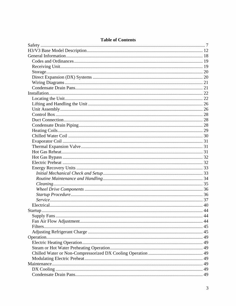
4
E-Coated Coil Cleaning 50
Supply Fans 51
Phase and Brownout Protection Module 52
Filter Replacement 54
Replacement Parts 54
AAON-Longview Product Support 54
Filter Information 55
Refrigerant Piping Diagrams 63
H3V3 Series Startup Form 75
Maintenance Log 80
Literature Change History 81
Index of Tables and Figures
Tables
Table 1 - H3 and V3 Series Clearances 22
Table 2 - Drain Trap Dimensions 29
Table 3 - Steam Distributing Coil Connection Sizes 30
Table 4 - Hot Water Coil Connection Sizes 30
Table 5 - Chilled Water Coil Connection Sizes 31
Table 6 - Control Wiring 42
Table 7 - Acceptable Air-Cooled Refrigeration Circuit Values 47
Table 8 - R-410A Refrigerant Temperature-Pressure Chart 48
Table 9 - V3 Series E Cabinet Pre-Filters 55
Table 10 - H3 Series A Cabinet Unit Filters 56
Table 11 - V3 Series A Cabinet Unit Filters 56
Table 12 - H3 Series B Cabinet Unit Filters 57
Table 13 - V3 Series B Cabinet Unit Filters 57
Table 14 - H3 Series C Cabinet Unit Filters 58
Table 15 - V3 Series C Cabinet Unit Filters 58
Table 16 - H3 Series D Cabinet Unit Filters 59
Table 17 - V3 Series D Cabinet Unit Filters 59
Table 18 - H3 Series E Cabinet Unit Filters 60
Table 19 - H3 Series A Cabinet Final Filters 61
Table 20 - H3 Series B Cabinet Final Filters 61
Table 21 - H3 Series C Cabinet Final Filters 61
Table 22 - H3 Series D Cabinet Final Filters 62
Table 23 - H3 Series E Cabinet Final Filters 62
Table 24 - V3 Series Energy Recovery OA Filters (Feature 13 = A-V) 62
5
Figures
Figure 1 - Lockable Handle 20
Figure 2 - Minimum Clearance Required for Access to Unit (V3 Series plan view) 22
Figure 3 - Minimum Clearance Required for Access to Unit (H3 Series plan view) 23
Figure 4 - H3 internal control panel with top access panel removed 23
Figure 5 - V3 internal control panel with rear removable access panel shown 23
Figure 6 - H3 Series Platform Suspension Installation 24
Figure 7 - H3 Series Parallel Beam Suspension Installation 24
Figure 8 - H3 Series Unit Orientation 25
Figure 9 - V3 Series Unit Orientation 25
Figure 10 - H3 Schematic with (1) Mixing Box (2) Air Handler (3) Final Filter and (4) Electric
Heat 26
Figure 11 - V3 Schematic with (1) Exhaust Fan (2) Energy Recovery (3) Air Handler and (4)
Electric Heat 26
Figure 12 - Connect Sections 27
Figure 13 - Bar Clamp 27
Figure 14 - Flange Overlap 27
Figure 15 - Self-Tapping Screw 27
Figure 16 - Strap Types 27
Figure 17 - Low Voltage Quick Connect 28
Figure 18 - Back View External Control Box 28
Figure 19 - Drain Trap 29
Figure 20 - Steam Distributing Piping 30
Figure 21 - Hot amp Chilled Water Piping 30
Figure 22 - TXV Bulb Position 31
Figure 23 - Energy Recovery Wheel 33
Figure 24 - Cross Section of Air Seal Structure 33
Figure 25 - Lifting Hole Locations 34
Figure 26 - Avoid Racking of Cassette Frame 36
Figure 27 - Diameter Seal Adjustment 37
Figure 28 - Hub Seal Adjustment 37
Figure 29 - Segment Retainer 38
Figure 30 - Segment Installation 38
Figure 31 - Belt Replacement 39
Figure 32 - External control box electrical connections 40
Figure 33 - H3 internal control panel electrical connections 40
Figure 34 - V3 internal control panel electrical connections 40
Figure 35- Typical wiring diagram with EC motor 44
Figure 36 - Shows the jumper that is to be removed (jumped between 9 and GS) 45
Figure 37 - Potentiometer 45
Figure 38 - AC only piping AHU above CU 63
Figure 39 - AC only piping AHU below CU 64
Figure 40 - Modulating hot gas reheat piping AHU above CU 65
Figure 41 - Modulating hot gas reheat piping AHU below CU 66
Figure 42 - Hot gas bypass piping AHU above CU 67
Figure 43 - Hot gas bypass piping AHU below CU 68
6
Figure 44 - Modulating hot gas reheat with hot gas bypass piping AHU above CU 69
Figure 45 - Modulating hot gas reheat with hot gas bypass piping AHU below CU 70
Figure 46 - Heat pump piping AHU above CU 71
Figure 47 - Heat pump piping AHU below CU 72
Figure 48 - Heat pump with modulating hot gas reheat piping AHU above CU 73
Figure 49 - Heat pump with modulating hot gas reheat piping AHU below CU 74
R94201 Rev B 161007
(ACP J00188)
7
Safety
Attention should be paid to the following statements
NOTE - Notes are intended to clarify the unit installation operation and maintenance
CAUTION - Caution statements are given to prevent actions that may result in
equipment damage property damage or personal injury
WARNING - Warning statements are given to prevent actions that could result in
equipment damage property damage personal injury or death
DANGER - Danger statements are given to prevent actions that will result in equipment
damage property damage severe personal injury or death
ELECTRIC SHOCK FIRE OR EXPLOSION HAZARD Failure to follow safety warnings exactly could result in dangerous operation serious injury death or property damage Improper servicing could result in dangerous operation serious injury death or property damage Before servicing disconnect all
electrical power to the unit More than one disconnect may be provided
When servicing controls label all wires prior to disconnecting Reconnect wires correctly
Verify proper operation after servicing Secure all doors with key-lock or nut and bolt
WARNING
Electric shock hazard Before servicing disconnect all electrical power to the unit including remote disconnects to avoid shock hazard or injury from rotating parts Follow proper Lockout-Tagout procedures
WARNING
FIRE EXPLOSION OR CARBON MONOXIDE POISONING HAZARD Failure to replace proper controls could result in fire explosion or carbon monoxide poisoning Failure to follow safety warnings exactly could result in serious injury death or property damage Do not store or use gasoline or other flammable vapors and liquids in the vicinity of this appliance
WARNING
8
GROUNDING REQUIRED All field installed wiring must be completed by qualified personnel Field installed wiring must comply with NECCEC local and state electrical code requirements Failure to follow code requirements could result in serious injury or death Provide proper unit ground in accordance with these code requirements
WARNING
During installation testing servicing and troubleshooting of the equipment it may be necessary to work with live electrical components Only a qualified licensed electrician or individual properly trained in handling live electrical components shall perform these tasks Standard NFPA-70E an OSHA regulation requiring an Arc Flash Boundary to be field established and marked for identification of where appropriate Personal Protective Equipment (PPE) be worn should be followed
WARNING
UNIT HANDLING To prevent injury or death lifting equipment capacity shall exceed unit weight by an adequate safety factor Always test-lift unit not more than 24 inches high to verify proper center of gravity lift point to avoid unit damage injury or death
WARNING
ROTATING COMPONENTS Unit contains fans with moving parts that can cause serious injury Do not open door containing fans until the power to the unit has been disconnected and fan wheel has stopped rotating
WARNING
Failure to properly drain and vent coils when not in use during freezing temperature may result in coil and equipment damage
CAUTION
Rotation must be checked on all MOTORS of 3 phase units at startup by a qualified service technician Fan motor rotation should be checked for proper operation Alterations should only be made at the unit power connection
CAUTION
9
Do not clean DX refrigerant coils with hot water or steam The use of hot water or steam on refrigerant coils will cause high pressure inside the coil tubing and damage to the coil
Some chemical coil cleaning compounds are caustic or toxic Use these substances only in accordance with the manufacturerrsquos usage instructions Failure to follow instructions may result in equipment damage injury or death
WATER PRESSURE Prior to connection of condensing water supply verify water pressure is less than maximum pressure shown on unit nameplate To prevent injury or death due to instantaneous release of high pressure water relief valves should be field supplied on system water piping
WARNING
To prevent damage to the unit do not use acidic chemical coil cleaners Do not use alkaline chemical coil cleaners with a pH value greater than 85 after mixing without first using an aluminum corrosion inhibitor in the cleaning solution
CAUTION WARNING
CAUTION
Do not use oxygen acetylene or air in place of refrigerant and dry nitrogen for leak testing A violent explosion may result causing injury or death
WARNING
Always use a pressure regulator valves and gauges to control incoming pressures when pressure testing a system Excessive pressure may cause line ruptures equipment damage or an explosion which may result in injury or death
WARNING
Do not work in a closed area where refrigerant or nitrogen gases may be leaking A sufficient quantity of vapors may be present and cause
injury or death
WARNING
Door compartments containing hazardous voltage or rotating parts are equipped with door latches to allow locks Door latch are shipped with nut and bolts requiring tooled access If you do not replace the shipping hardware with a pad lock always re-install the nut amp bolt after closing the door
CAUTION
10
1 Startup and service must be performed
by a Factory Trained Service
Technician
2 The unit is for indoor use only See
General Information section for more
unit information
3 Every unit has a unique equipment
nameplate with electrical operational
and unit clearance specifications
Always refer to the unit nameplate for
specific ratings unique to the model you
have purchased
4 READ THE ENTIRE INSTALLATION
OPERATION AND MAINTENANCE
MANUAL OTHER IMPORTANT
SAFETY PRECAUTIONS ARE
PROVIDED THROUGHOUT THIS
MANUAL
5 Keep this manual and all literature
safeguarded near or on the unit
PVC (Polyvinyl Chloride) and CPVC (Chlorinated Polyvinyl Chloride) are vulnerable to attack by certain chemicals Polyolester (POE) oils used with R-410A and other refrigerants even in trace amounts in a PVC or CPVC piping system will result in stress cracking of the piping and fittings and complete piping system failure
CAUTION
Do not weld or cut foam panel with plasma cutters or a cutting torch ndash When burnt the foam produces dangerous fumes
WARNING
Never attempt to open an access door or remove a panel while the unit is running Pressure in the unit can cause excessive force against the panel
WARNING
Ensure that sufficient dampers will be open to provide air path before fan is allowed to run
WARNING
11
H3V3 Series Feature String Nomenclature
Model Options Unit Feature Options G
EN
SIZ
E
OR
EN
T
MJ
RE
V
VL
T
CO
RR
A1
A2
A3
A4
B1
B2
B3
1A
1B
1C
1D
2
3
4
5A
5B
5C
6A
6B
6C
7
8
9
10
11
12
13
14A
14B
H3 - A R B - 3 - 0 - 1 6 1 C - 1 2 F A A B B - 0 C 0 - F T B - 0 G 0 - 0 0 A A A C 0 0 B
A 0 0 0 0 0 0 0 0
15
16
17
18
19
20
21
22
23
12
H3V3 Base Model Description
BASE MODEL SERIES AND GENERATION
H3 = Horizontal - Back Intake Front Discharge
V3 = Vertical - Back Intake Top Discharge
UNIT SIZE
A = Up to 1200 cfm
B = Up to 2000 cfm
C = Up to 4000 cfm
D = Up to 6000 cfm
E = Up to 10000 cfm
UNIT ORIENTATION
R = Right Hand Connections
L = Left Hand Connections
REVISION
A = First Revision
B = Second Revision
VOLTAGE
1 = 230V1Φ60Hz
2 = 230V3Φ60Hz
3 = 460V3Φ60Hz
4 = 575V3Φ60Hz
8 = 208V3Φ60Hz
9 = 208V1Φ60Hz
CORROSION PROTECTION
0 = None
A = Interior Corrosion Protection
Model Option A COOLING A1 COOLING TYPE
0 = No Cooling
1 = R-410A DX Cooling
2 = Chilled Water Cooling
A2 COOILNG ROWS
0 = No Cooling
4 = 4 Row Coil
6 = 6 Row Coil
8 = 8 Row Coil
A3 COOLING STAGES
0 = No Cooling
1 = Single Circuit
2 = Two Circuits - Interlaced Coil
D = Double Serpentine
F = Single Serpentine
H = Half Serpentine
Q = Quarter Serpentine
A4 COOLING FPI
0 = No Cooling
A = 10 fpi
B = 8 fpi
C = 12 fpi
D = 14 fpi
H3V3 Series Feature String Nomenclature
Model Options Unit Feature Options G
EN
SIZ
E
OR
EN
T
MJR
EV
VL
T
CO
RR
A1
A2
A3
A4
B1
B2
B3
1A
1B
1C
1D
2
3
4
5A
5B
5C
6A
6B
6C
7
8
9
10
11
12
13
14A
14B
H3 - A R B - 3 - 0 - 1 6 1 C - 1 2 F A A B B - 0 C 0 - F T B - 0 G 0 - 0 0 A A A C 0 0 B
A 0 0 0 0 0 0 0 0
15
16
17
18
19
20
21
22
23
13
Model Option B HEATING B1 HEATING TYPE
0 = No Heating
1 = Hot Water
3 = Electric Heating
4 = Steam Distributing
B2 HEATING DESIGNATION
0 = No Heating
1 = 1 Row Coil
2 = 2 Row Coil
A = 7 kW (53 kW 208V)
B = 14 kW (105 kW 208V)
C = 21 kW (158 kW 208V)
D = 28 kW (210 kW 208V)
E = 35 kW (263 kW 208V)
F = 42 kW (315 kW 208V)
G = 49 kW (370 kW 208V)
H = 56 kW (420 kW 208V)
J = 63 kW (473 kW 208V)
K = 70 kW (525 kW 208V)
L = 77 kW (578 kW 208V)
M = 84 kW (630 kW 208V)
B3 HEATING STAGES
0 = No Heating
1 = 1 Stage
2 = 2 Stage
3 = 3 Stage
4 = 4 Stage
S = ModulatingSCR Electric
F = Single Serpentine 12 fpi
H = Half Serpentine 12 fpi
Q = Quarter Serpentine 12 fpi
Feature 1 SUPPLY FAN 1A SUPPLY AIR BLOWER CONFIGURATION
0 = 1 Blower + Premium Eff Motor
1 = 1 Blower + Premium Eff Motor + 1 VFD
A = 1 Blower + 1 High Efficiency EC Motor
B = 2 Blowers + 2 High Efficiency EC Motors
1B SUPPLY AIR BLOWER
1 = 15rdquo Backward Curved Plenum Fan
2 = 15rdquo BC Plenum 50 Width with Banding
3 = 185rdquo Backward Curved Plenum Fan
4 = 185rdquo BC Plenum Fan 70 Width with Banding
5 = 22rdquo Backward Curved Plenum Fan
6 = 24rdquo Backward Curved Plenum Fan
7 = 27rdquo Backward Curved Plenum Fan
8 = 27rdquo BC Plenum Fan 70 Width with Banding
A = 310 mm Direct Drive BC Plenum Fan
B = 355 mm Direct Drive BC Plenum Fan
C = 450 mm Direct Drive BC Plenum Fan
D = 250 mm Direct Drive BC Plenum Fan
1C SUPPLY AIR BLOWER MOTOR
1 = 1 hp - 1760 rpm
2 = 2 hp - 1760 rpm
3 = 3 hp - 1760 rpm
4 = 5 hp - 1760 rpm
5 = 75 hp - 1760 rpm
6 = 10 hp - 1760 rpm
B = 10 kW (134 hp)
C = 17 kW (228 hp)
D = 30 kW (402 hp)
E = 60 kW (800 hp)
F = 08 kW (107 hp)
1D SUPPLY BLOWER CONTROLCONTROL
VENDORS
0 = Standard - Terminal Block
A = Potentiometer Supply Fan Control
B = WattMaster Orion Controls System
C = Field Installed Controls by Others
D= Field Installed Controls by Others + Isolation
Relays
H3V3 Series Feature String Nomenclature
Model Options Unit Feature Options
GE
N
SIZ
E
OR
EN
T
MJR
EV
VL
T
CO
RR
A1
A2
A3
A4
B1
B2
B3
1A
1B
1C
1D
2
3
4
5A
5B
5C
6A
6B
6C
7
8
9
10
11
12
13
14A
14B
H3 - A R B - 3 - 0 - 1 6 1 C - 1 2 F A A B B - 0 C 0 - F T B - 0 G 0 - 0 0 A A A C 0 0 B
A 0 0 0 0 0 0 0 0
15
16
17
18
19
20
21
22
23
14
Feature 2 REFRIGERATION OPTIONS 0 = Standard - None
A = Single Circuit External Hot Gas Bypass
B = Dual Circuit External Hot Gas Bypass
C = Heat Pump
D = Option B + H
F = Options C + H
H = Modulating Hot Gas Reheat
P = Option H (Circuit 1) + Option A (Circuit 2)
R = Option C + A
S = Option C + B
T = Option C + H + A
U = Option C + H + B
Feature 3 SPECIAL CONTROLS 0 = Standard - None
A = Constant Volume Controller - CV Cool + CV
Heat
B = Constant Volume Controller with Modulating
Hot Gas Reheat - CV Cool + CV Heat
C = VAV Controller - VAV Cool + CV Heat
D = VAV Controller with MHGR - VAV Cool + CV
Heat
E = Make Up Air Controller - CV Cool + CV Heat
F = Make Up Air Controller with Modulating Hot
Gas Reheat - CV Cool + CV Heat
G = WattMaster Modulating Hot Gas Reheat
Controller
Feature 4 ADDITIONAL CONTROLS 0 = Standard - None
A = Phase and Brownout Protection
B = Return and Supply Air Firestat
C = Return Air Smoke Detector
D = Options A + B
E = Options A + C
F = Options B + C
G = Options A + B + C
H = Remote Safety Shutdown Terminals
J = Energy Recovery Wheel Rotation Detection
K = Options A + H
L = Options A + J
M = Options B + H
Feature 4 ADDITIONAL CONTROLS
Continued N = Options B + J
P = Options C + H
Q = Options C + J
S = Options A + B + H
T = Options A + B + J
U = Options A + C + H
V = Options A + C + J
W = Options A + H + J
Y = Options B + C + H
Z = Options B + C + J
1 = Options B + H + J
2 = Options C + H + J
3 = Options A + B + C + H
4 = Options A + B + C + J
5 = Options A + B + H + J
6 = Options A + C + H + J
7 = Options B + C + H + J
8 = Options A + B + C + H + J
Feature 5 MIXING BOX 5A RETURN AIR DAMPER POSITION
0 = Standard - None
F = Front
L = Left Hand (Front OA Damper Required)
R = Right Hand (Front OA Damper Required)
T = Top (Front OA Damper Required)
5B OUTSIDE AIR DAMPER POSITION
0 = Standard - None
F = Front
L = Left Hand (Front RA Damper Required)
R = Right Hand (Front RA Damper Required)
T = Top (Front RA Damper Required)
5C MIXING BOX DAMPER CONTROL
0 = Standard - None
A = 2 Position Actuators (24V)
B = Fully Modulating Actuators (DDC)
C = Fixed Position Dampers
H3V3 Series Feature String Nomenclature
Model Options Unit Feature Options
GE
N
SIZ
E
OR
EN
T
MJR
EV
VL
T
CO
RR
A1
A2
A3
A4
B1
B2
B3
1A
1B
1C
1D
2
3
4
5A
5B
5C
6A
6B
6C
7
8
9
10
11
12
13
14A
14B
H3 - A R B - 3 - 0 - 1 6 1 C - 1 2 F A A B B - 0 C 0 - F T B - 0 G 0 - 0 0 A A A C 0 0 B
A 0 0 0 0 0 0 0 0
15
16
17
18
19
20
21
22
23
15
Feature 6 FILTER BOX 6A PRE FILTER BOX
0 = Standard - None
A = 2rdquo Pleated - 30 Eff - MERV 10
B = 4rdquo Pleated - 30 Eff - MERV 10
C = 4rdquo Pleated - 65 Eff - MERV 11
D = 4rdquo Pleated - 85 Eff - MERV 13
E = 4rdquo Pleated - 95 Eff - MERV 14
F = 2rdquo Pleated - 30 Eff - MERV 10 + 4rdquo Pleated -
30 Eff - MERV 10
G = 2rdquo Pleated - 30 Eff - MERV 10 + 4rdquo Pleated -
65 Eff - MERV 11
H = 2rdquo Pleated - 30 Eff - MERV 10 + 4rdquo Pleated -
85 Eff - MERV 13
J = 2rdquo Pleated - 30 Eff - MERV 10 + 4rdquo Pleated -
95 Eff - MERV 14
6B UNIT FILTER
0 = Standard - None
A = 2rdquo Pleated - 30 Eff - MERV 10
B = 4rdquo Pleated - 30 Eff - MERV 10
C = 4rdquo Pleated - 65 Eff - MERV 11
D = 4rdquo Pleated - 85 Eff - MERV 13
E = 4rdquo Pleated - 95 Eff - MERV 14
F = 2rdquo Pleated - 30 Eff - MERV 10 + 4rdquo Pleated -
30 Eff - MERV 10
G = 2rdquo Pleated - 30 Eff - MERV 10 + 4rdquo Pleated -
65 Eff - MERV 11
H = 2rdquo Pleated - 30 Eff - MERV 10 + 4rdquo Pleated -
85 Eff - MERV 13
J = 2rdquo Pleated - 30 Eff - MERV 10 + 4rdquo Pleated -
95 Eff - MERV 14
6C FINAL FILTER BOX
0 = Standard - None
A = 2rdquo Pleated - 30 Eff - MERV 10
B = 12rdquo Cartridge - 65 Eff - MERV 11
C = 12rdquo Cartridge - 85 Eff - MERV 13
D = 12rdquo Cartridge - 95 Eff - MERV 14
E = 2rdquo Pleated - 30 Eff - MERV 10 + 12rdquo
Cartridge - 65 Eff - MERV 11
F = 2rdquo Pleated - 30 Eff - MERV 10 + 12rdquo
Cartridge - 85 Eff - MERV 13
G = 2rdquo Pleated - 30 Eff - MERV 10 + 12rdquo
Cartridge - 95 Eff - MERV 14
Feature 7 FILTER OPTIONS 0 = Standard - None
A = Magnehelic Gauge
B = Clogged Filter Switch
C = Options A + B
Feature 8 COIL COATING 0 = Standard - None
A = E-coated Cooling and Heating Coils
B = Copper Finned Coils + Stainless Steel Coil
Casing
Feature 9 EXPANSION VALVE 0 = None
A = Thermal Expansion Valves
Feature 10 EXPANSION VALVE
CONTROLS 0 = None
A = Standard Control
Feature 11 EXTERNAL PAINT 0 = Standard - None
A = AAON Gray Paint
B = Special Paint
H3V3 Series Feature String Nomenclature
Model Options Unit Feature Options
GE
N
SIZ
E
OR
EN
T
MJR
EV
VL
T
CO
RR
A1
A2
A3
A4
B1
B2
B3
1A
1B
1C
1D
2
3
4
5A
5B
5C
6A
6B
6C
7
8
9
10
11
12
13
14A
14B
H3 - A R B - 3 - 0 - 1 6 1 C - 1 2 F A A B B - 0 C 0 - F T B - 0 G 0 - 0 0 A A A C 0 0 B A 0 0 0 0 0 0 0 0
15
16
17
18
19
20
21
22
23
16
Feature 12 TONNAGE 0 = Standard - None
A = 2 ton Capacity
B = 3 ton Capacity
C = 4 ton Capacity
D = 5 ton Capacity
E = 6 ton Capacity
F = 7 ton Capacity
G = 8 ton Capacity
U = 9 ton Capacity
H = 10 ton Capacity
V = 11 ton Capacity
W = 13 ton Capacity
J = 14 ton Capacity
Y = 15 ton Capacity
Z = 16 ton Capacity
K = 17 ton Capacity
1 = 18 ton Capacity
2 = 20 ton Capacity
L = 22 ton Capacity
M = 25 ton Capacity
3 = 26 ton Capacity
N = 30 ton Capacity
P = 31 ton Capacity
Q = 34 ton Capacity
R = 40-45 ton Capacity
S = 50-55 ton Capacity
4 = 60 ton Capacity
T = 63 ton Capacity
5 = 70 ton Capacity
Feature 13 ENERGY RECOVERY
TYPE 0 = Standard ndash None
A = Energy Recovery Wheel ndash Total + High CFM
Polymer
C = Energy Recovery Wheel ndash Total + High CFM
1 Purge Polymer
E = Energy Recovery Wheel ndash Sensible + High CFM
Polymer
G = Energy Recovery Wheel ndash Sensible + High
CFM 1 Purge Polymer
Feature 14 GPM 14A GPM COOLING COIL
0 = Standard - None
A = 15-25 gpm
B = 26-70 gpm
C = 71 -140 gpm
D = 141-240 gpm
E = 241-400 gpm
F = 401-800 gpm
G = 801-1500 gpm
H = 1501-2500 gpm
14B GPM HEATING COIL
0 = Standard - None
A = 15-25 gpm
B = 26-70 gpm
C = 71 -140 gpm
D = 141-240 gpm
E = 241-400 gpm
F = 401-800 gpm
G = 801-1500 gpm
H = 1501-2500 gpm
Feature 15 CONTROL PANEL 0 = Internal Control Panel
A = Small Control Panel - 12rdquo x 12rdquo
B = Medium Control Panel - 25rdquo x 22rdquo
C = Large Control Panel - 48rdquo x 22rdquo
Feature 16 SHIPPING SPLITS 0 = Standard ndash None
A = 1 Shipping Split (2 pallets)
B = 2 Shipping Splits (3 pallets)
C = 3 Shipping Splits (4 pallets)
D = 4 Shipping Splits (5 pallets)
E = 5 Shipping Splits (6 pallets)
H = Special Shipping Split (SPA Required)
H3V3 Series Feature String Nomenclature
Model Options Unit Feature Options
GE
N
SIZ
E
OR
EN
T
MJR
EV
VL
T
CO
RR
A1
A2
A3
A4
B1
B2
B3
1A
1B
1C
1D
2
3
4
5A
5B
5C
6A
6B
6C
7
8
9
10
11
12
13
14A
14B
H3 - A R B - 3 - 0 - 1 6 1 C - 1 2 F A A B B - 0 C 0 - F T B - 0 G 0 - 0 0 A A A C 0 0 B
A 0 0 0 0 0 0 0 0 1
5
16
17
18
19
20
21
22
23
17
Feature 17 ENERGY RECOVERY
CABINET 0 = Standard - None
A = Top RA + Back EA + Back OA Connections
G = OA + EA Dampers - Top RA + Back EA + Back
OA Connections
N = OA + Economizer Dampers - Top RA + Back
EA + Back Connections
U = OA + EA + Economizer Dampers - Top RA +
Back EA + Back OA Connections
Feature 18 MODULATING ELECTRIC
PREHEAT 0 = Standard - None
A = 75 kW
B = 15 kW
C = 20 kW
D = 225 kW
E = 30 kW
F = 40 kW
G = 50 kW
H = 60 kW
Feature 19 EXHAUST FAN 0 = Standard - None
A = 250 mm Exhaust Fan 800 W EC Motor
B = 310 mm Exhaust Fan 10 kW EC Motor
C = 310 mm Exhaust Fan 17 kW EC Motor
D = 355 mm Exhaust Fan 17 kW EC Motor
E = 450 mm Exhaust Fan 30 kW EC Motor
F = 450 mm Exhaust Fan 60 kW EC Motor
G = Dual 310 mm Exhaust Fan 10 kW EC Motor
H = Dual 310 mm Exhaust Fan 17 kW EC Motor
J = Dual 355 mm Exhaust Fan 17 kW EC Motor
K = Dual 450 mm Exhaust Fan 30 kW EC Motor
L = Dual 450 mm Exhaust Fan 60 kW EC Motor
Feature 20 CRATING 0 = Standard - None
A = Export Crating
B = Forkliftable Base - 5rdquo Base
C = Options A + E
D = Options A + B
E = Shipping Shrink Wrap
F = Options B + E
G = Options A + B + E
Feature 21 PULLEY COMBINATION 0 = Standard - None
A = 1000-1400 rpm
B = 1401-1800 rpm
C = 1801-2200 rpm
Feature 22 WARRANTY 0 = Standard - 1 Year Parts
Feature 23 TYPE 0 = Standard
X = Special Pricing Authorization
18
General Information
AAONreg
H3 and V3 Series indoor air
handling units have been designed for
indoor installation only Units are
assembled wired charged with dry nitrogen
and run-tested at the factory H3 and V3
Series units are not intended for residential
use Startup and service must be performed
by a Factory Trained Service Technician
Certification of Steam or Hot Water Heat
Models
a Certified as a forced air heating system
with or without cooling
b Certified for indoor installation only
Certification of Electric Heat Models
a Certified as an electric warm air furnace
with or without cooling
b Certified for indoor installation only
Certification of Cooling Models
a Certified as a commercial central air
conditioner with or without electrically
operated compressors
b Certified for indoor installation only
c Certified with refrigerant R-410A coils
or with chilled water cooling coils
Improper installation adjustment alteration service or maintenance can cause property damage personal injury or loss of life Startup and service must be performed by a Factory Trained Service Technician A copy of this IOM should be kept with the unit
WARNING
These units must not be used as a ldquoconstruction heaterrdquo at anytime during any phase of construction Very low return air temperatures harmful vapors and misplacement of the filters will damage the unit and its efficiency
CAUTION
This equipment is protected by a standard limited warranty under the condition that initial installation service startup and maintenance is performed according to the instructions set forth in this manual This manual should be read in its entirety prior to installation and before performing any service or maintenance work Equipment described in this manual is available with many optional accessories If you have questions after reading this manual in its entirety consult other factory documentation or contact your AAON Sales Representative to obtain further information before manipulating this equipment or its optional accessories
CAUTION
19
Codes and Ordinances
H3 and V3 Series units have been tested and
certified by ETL in accordance with UL
Safety Standard 1995CSA C222 No 236
System should be sized in accordance with
the American Society of Heating
Refrigeration and Air Conditioning
Engineers Handbook
Installation of H3 and V3 Series units must
conform to the ICC standards of the
International Mechanical Code the
International Building Code Installation of
Air Conditioning and Ventilating Systems
Standard NFPA 90A and local building
plumbing and waste water codes All
appliances must be electrically grounded in
accordance with local codes or in the
absence of local codes the current National
Electric Code ANSINFPA 70 or the
current Canadian Electrical Code CSA
C221
Receiving Unit
When received the unit should be checked
for damage that might have occurred in
transit If damage is found it should be noted
on the carrierrsquos Freight Bill A request for
inspection by carrierrsquos agent should be made
in writing at once
Nameplate should be checked to ensure the
correct model sizes and voltages have been
received to match the job requirements
If repairs must be made to damaged goods
then the factory should be notified before
any repair action is taken in order to protect
the warranty Certain equipment alteration
repair and manipulation of equipment
without the manufacturerrsquos consent may
void the product warranty Contact the
AAON Warranty Department for assistance
with handling damaged goods repairs and
freight claims (903) 236-4403
Note Upon receipt check shipment for
items that ship loose such as remote sensors
Consult order and shipment documentation
to identify potential loose-shipped items
Loose-shipped items may have been placed
inside unit cabinet for security Installers
and owners should secure all doors with
locks or nuts and bolts to prevent
unauthorized access
The Clean Air Act of 1990 bans the intentional venting of refrigerant as of July 1 1992 Approved methods of recovery recycling or reclaiming must be followed
CAUTION
Coils and sheet metal surfaces present sharp edges and care must be taken when working with equipment
WARNING
Failure to observe the following instructions will result in premature failure of your system and possible voiding of the warranty
WARNING
20
Figure 1 - Lockable Handle
Storage
This equipment is not suitable for outdoor
use of storage If installation will not occur
immediately following delivery store
equipment in a dry protected area away from
construction traffic and in the proper
orientation as marked on the packaging with
all internal packaging in place Secure all
loose-shipped items
Direct Expansion (DX) Systems
All DX refrigerant coils are factory charged
with a nitrogen holding charge All DX
systems include evaporator coils and
thermal expansion valves (TXV)
Never turn off the main power supply to the
unit except for servicing emergency or
complete shutdown of the unit When power
is cut off from the unit crankcase heaters
cannot prevent refrigerant migration into the
split system condensing unit compressors
This means the compressor may cool down
and liquid refrigerant may accumulate in the
compressor The compressor is designed to
pump refrigerant gas and damage may occur
when power is restored
If power to the unit must be off for more
than an hour turn the thermostat system
switch to OFF or turn the unit off at the
control panel and leave the unit off until the
main power switch has been turned on again
for at least 24 hours for units with
compressor crankcase heaters This will give
the crankcase heater time to clear any liquid
accumulation out of the compressor before it
is started
Always control the unit from the thermostat
or control panel never at the main power
supply except for emergency or complete
shutdown of the unit
During the cooling season if the air flow is
reduced due to dirty air filters or any other
reason the cooling coils can get too cold
which will cause excessive liquid to return
to the compressor As the liquid
concentration builds up oil is washed out of
the compressor leaving it starved for
lubrication
The compressor life will be seriously
shortened by reduced lubrication and the
pumping of excessive amounts of liquid oil
and refrigerant
CRANKCASE HEATER OPERATION
Some units are equipped with compressor crankcase heaters which should be energized at least 24 hours prior to cooling operation to clear any liquid refrigerant from the compressors
CAUTION
21
Note Low Ambient Operation
Air-cooled DX units without a low ambient
option such as condenser fan cycling or the
0degF low ambient option will not operate in
the cooling mode of operation properly
when the outdoor temperature is below
55degF Low ambient andor economizer
options are recommended if cooling
operation below 55degF is expected
Wiring Diagrams
Unit specific wiring diagrams are laminated
and affixed inside the controls compartment
door
Condensate Drain Pans
Units require field installed drain p-traps and
lines to be connected to the condensate drain
pans of the unit
For condensate drain lines the line should
be the same pipe size or larger than the drain
connection include a p-trap and pitch
downward toward drain An air break should
be used with long runs of condensate lines
See Installation section of this manual for
more information
Unit should not be operated without a p-trap Failure to install a p-trap may result in overflow of condensate water
CAUTION
Emergency drain pan is recommended for all applications where a risk of water damage to surrounding structure or furnishings Refer to local codes
CAUTION
22
Installation
AAON equipment has been designed for
quick and easy installation Startup and
service must be performed by Factory
Trained Service Technician
The H3V3 unit can either be shipped
assembled or shipped in sections See the
Unit Assembly section of this document for
instructions on assembling the sections
Locating the Unit
Placement of the unit relative to ductwork
electrical and plumbing must be carefully
considered Return air plenum or duct can be
mounted directly to the return air flanges
Use flexible gasket material to seal the duct
to the unit
Verify floor foundation or suspension
support can support the total unit weight
including accessory weights Unit must be
level in both horizontal axes to support the
unit and reduce noise and vibration from the
unit
Allow adequate space for piping access and
panel removal To ensure proper access
for field service maintain minimum
clearances for field piping and other
obstructions as indicated by Table 1 and
Figure 2 and Figure 3 Consult local
building codes for additional service
clearance requirements Condensate drain
connections are located on the access side of
the unit
Table 1 - H3 and V3 Series Clearances
Unit Size
Access Side
Clearance
(dimension X on
Figure 2 and
Figure 3)
All Other
Sides
V3-A
36 inches
6 inches
V3-B
V3-C
V3-D
V3-E
H3-A
H3-B
H3-C
H3-D 45 inches
H3-E 60 inches
Additional clearance may be required to
allow for coil removal
May be installed flush depending upon
local codes
Figure 2 - Minimum Clearance Required for
Access to Unit (V3 Series plan view)
X
(See Table 1)
Back Front
Left
Right
23
Figure 3 - Minimum Clearance Required for
Access to Unit (H3 Series plan view)
Internal Control Panel
H3 units with internal control panel have
removable access panels on the top and
bottom of the supply fan section V3 units
with internal control panel have removable
access panels on the front and back of the
supply fan section V3 units that have
energy recovery only have one removable
supply fan access panel on the front of the
unit The supply flanges can be
interchanged with the access panels if
necessary except on size E
Figure 4 - H3 internal control panel with top
access panel removed
Figure 5 - V3 internal control panel with
rear removable access panel shown
Floor Mounted Units
Make sure the unit is level and mounted on a
field supplied platform with a minimum
height to allow for proper depth of the
condensate line p-trap Other installation
provisions may be necessary according to
job specifications V3 Series vertical air
handling units are designed for upflow
applications only
Suspended Units
H3 Series horizontal air handling units are
equipped for suspended installations The
unit should be lifted into position by
supporting the unit with the skid used for
shipping The air handling unit must be
installed level and care should be taken to
prevent damage to the cabinet Other
installation provisions may be necessary
according to job specifications Figure 6
and Figure 7 show factory recommended
methods for suspended installations It is
the responsibility of the specifying engineer
or installing contractor to ensure the
installation is structurally safe and sound
X
(See Table 1)
Front
Back
Left Right
24
Figure 6 - H3 Series Platform Suspension Installation
Figure 7 - H3 Series Parallel Beam Suspension Installation
25
Figure 8 - H3 Series Unit Orientation
Figure 9 - V3 Series Unit Orientation
Note Access doors may be on the ldquoleftrdquo or ldquorightrdquo side as designated by the unit orientation on
the configurator string ldquoBackrdquo will always be the same side as the pre-filter and return air
opening ldquoFrontrdquo will always be the side opposite the pre-filter and return air opening
H3 Series
Return Air ldquoBackrdquo
Supply Air ldquoFrontrdquo
Right Hand Side
Left Hand Side
Connections and service access on right side for right hand orientation
Top View
Air Flow
Connections and service access on right side for right hand orientation
Right Hand Side Left Hand Side
Return Air ldquoBackrdquo
Top View V3 Series
Air Flow
Consider the air flow to be hitting the back of your head
Consider the air flow to be hitting the back of your head
Supply Air
ldquoFrontrdquo
26
Lifting and Handling the Unit
Before lifting unit be sure that all shipping
material has been removed from unit
Care should be taken if using spreader bars
blocking or other lifting devices to prevent
damage to the cabinet coil or fans
Unit Assembly
Although H3V3 Series units are shipped
factory assembled as standard the unit may
be ordered as shipping splits for certain
applications such as for assembly in existing
structures where modules must be
manipulated separately If the unit was
ordered as shipping splits then they must be
assembled in the field
Locate the schematic in the equipmentrsquos
literature packet
1 Identify and Situate Splits
a H3 Units can have the following
ship split sections
1 Mixing Box
2 Air Handler
3 Final Filter
4 Electric Heat
Figure 10 - H3 Schematic with (1) Mixing
Box (2) Air Handler (3) Final Filter and
(4) Electric Heat
b V3 Units can have the following
ship split sections
1 Exhaust Fan
2 Energy Recovery
3 Air Handler
4 Electric Heat
5 Pre filter
6 Mixing box
Figure 11 - V3 Schematic with (1) Exhaust
Fan (2) Energy Recovery (3) Air Handler
and (4) Electric Heat
2 Connect Sections
Using the V3 Schematic as an example
section 1 will have a duct flange and it will
connect to section 2 on the side that does not
have a flange First make sure gasket is on
the panel around the edges of the exposed
duct flanges Push section 1 and 2 together
UNIT HANDLING
Incorrect lifting can cause damage to the unit injury or death Lifting equipment capacity should exceed unit weight by an adequate safety factor Always test lift unit not more than 24 inches high to verify proper center of gravity lift point
WARNING
1 2 3 4
1 2
3
4
27
so that the flange from section 1 is inside of
section 2
Figure 12 - Connect Sections
Use bar clamps or other non-destructive
winching device to pull the tops of the
modules together tightly
Figure 13 - Bar Clamp
At each of the pre-drilled holes in the flange
drill 516 hex head self-tapping screws to
secure the two sections together
Figure 14 - Flange Overlap
Figure 15 - Self-Tapping Screw
All connection hardware is shipped with the
unit
3 Secure Module Joints
The metal straps are to be used to secure
module joints Straps are provided with pre-
drilled holes Self-tapping sheet metal
screws are provided to attach the straps to
the unit cabinet
Leave bar clamps in place until strap is
secure
Place the strap over a module joint ensure
the strap completely covers the joint and
that it is square with the unit casing
Insert self-tapping screws through pre-
drilled holes in strap and secure screws into
unit casing using a power drill For best
results use the lowest effective power drill
torque setting Be careful not to over tighten
the screws
Remove bar clamps and repeat for all
remaining module joints
Figure 16 - Strap Types
516rdquo Hex Head Self-Tapping Screws
Provided with Unit
1rdquo
Angle Strap
Top Strap
Section 2
Flange
28
4 Connect Power and Control Wiring
H3V3 Series units are equipped with low
and high voltage quick connects to connect
wiring from one section to the next Wire
from the unit to external controls and power
sources must be provided in the field
Figure 17 - Low Voltage Quick Connect
A color-coded wiring diagram is laminated
and affixed to the inside of the control
compartment access door H3V3 Series
units are equipped with a single point power
connection
5 Final Sealing
It is very important to keep air from
infiltrating the unit cabinet Seal all piping
penetrations with Armaflex Permagum or
other suitable sealant Also seal around drain
connections electrical connections and all
other inlets where air may enter the cabinet
This is especially important when the unit is
installed in an unconditioned area
Control Box
Some H3V3 units include an external
control box that must be mounted in the
field
Figure 18 - Back View External Control
Box
Duct Connection
Attach duct to flanges provided on the unit
The installer is responsible for sealing ducts
to the flanges to prevent water leaks
Refer to Figure 8 and Figure 9 for duct
connection locations The V3 supply air duct
is out to top of the unit Ductwork should be
sized in accordance with the ASHRAE
Handbook Ductwork should be installed in
accordance with NFPA Standard 90A
When attaching duct to the unit use a
flexiblecompressible material rated for duct
connections A three inch flexible connector
for both return and supply duct connections
is recommended
Condensate Drain Piping
Unit may be equipped with more than one
condensate drain pan connection A p-trap
and drain line must be installed on at least
one sectionrsquos drain connection with the p-
trap not to exceed 6rdquo from the drain
connection The lines should be the same
pipe size or larger than the drain connection
include a p-trap and pitch downward toward
drain An air break should be used with long
runs of condensate lines
Installing Contractor is responsible for proper sealing of the electrical and piping entries into the unit Failure to seal the entries may result in damage to the unit and property
CAUTION
29
Draw-through cooling coils will have a
negative static pressure in the drain pan area
This will cause an un-trapped drain to back
up due to air being pulled up through the
condensate drain piping
Condensate drain trapping and piping should
conform to all applicable governing codes
Note The drain pan connection(s) is a 1rdquo
MPT fitting
Figure 19 - Drain Trap
The X dimension on the draw-through trap
should be at least equal to the absolute value
of the negative static pressure in the drain
pan plus one inch To calculate the static
pressure at the drain pan add the pressure
drops of all components upstream of the
drain pan including the cooling coil and
add the return duct static pressure Include
the dirt allowance pressure drop for the
filters to account for the worst-case scenario
The height from top of the bottom bend of
the trap to the bottom of the leaving pipe
must be at least equal to one half of the X
dimension This ensures that enough water
is stored in the trap to prevent losing the
drain seal during unit startup
Note The absolute value of the fan inlet
pressure will always be greater than or equal
to the absolute value of the static pressure in
the drain pan on draw-through units so the
fan inlet pressure is a safe value to use for
the drain pan static pressure
Table 2 - Drain Trap Dimensions
Draw-Through
Drain Pan Pressure Trap Dimensions
Negative Static X X2
(inches of water) (inch) (inch)
-050 150 075
-100 200 100
-150 250 125
-200 300 150
-250 350 175
-300 400 200
-350 450 225
-400 500 250
Heating Coils
One or two row hot water and steam heating
and preheating coils can be factory installed
These coils are supplied from a building hot
water source All valve controls for heating
coil operation are field supplied and field
installed
Unit should not be operated without p-traps Failure to install a p-traps may result in overflow of condensate water
CAUTION
30
Always connect the steam heating supply to
the top of the coil and the return to the
bottom
Figure 20 - Steam Distributing Piping
Table 3 - Steam Distributing Coil
Connection Sizes
Model (H3- V3-) Supply and Return
Connection Size
A-E 2 18
Air handling units with steam heating coils
MUST BE installed high enough to allow
for a minimum of 1 foot condensate drop leg
off of the steam coil or as recommended by
the steam trap manufacturer Lines should
be insulated with approved insulation and be
properly fastened sloped and supported
according to local code requirements
Table 4 - Hot Water Coil Connection Sizes
Model (H3- V3-) Supply and Return
Connection Size
A 78
B 1 18
C 1 38
D amp E 1 58
Always connect the hot water heating supply
to the bottom of the coil and return to the
top
Figure 21 - Hot amp Chilled Water Piping
Water coils should not be subjected to
entering air temperatures below 38degF to
prevent coil freeze-up If air temperature
across the coil is going to be below this
value use a glycol solution to match the
coldest air expected
Water supply lines must be insulated
properly fastened drained and supported
according to local code requirements
Chilled Water Coil
Factory installed four six or eight row
chilled water cooling coils can be factory
mounted These coils are supplied from a
building chilled water source All valve
controls for the cooling coil operation are
field supplied and field installed
31
Table 5 - Chilled Water Coil Connection
Sizes
Model (H3- V3-) Supply and Return
Connection Size
A 1 18
B 1 38
C 1 58
D amp E 2 18
Always connect the chilled water supply to
the bottom of the coil and return to the top
Water supply lines must be insulated with
closed cell type pipe insulation or insulation
that includes a vapor barrier Lines should
be properly fastened drained and supported
according to local code requirements and
job specifications
Evaporator Coil
The air handling unit coils are pressurized
The copper caps must be punctured to
permit a gradual escape of the pressure prior
to un-sweating those caps Immediately
couple the tubing to the indoor unit to avoid
exposing the coils to moisture A properly
sized filter drier is furnished in the
condenser When making solder
connections make sure dry nitrogen flows
through the lines when heating the copper
to prevent oxidization inside of the copper
Field piping between the condensing unit
and the air handler is required Line
sizes must be selected to meet actual
installation conditions not simply based
on the connection sizes
Thermal Expansion Valve
Thermal expansion valve bulbs should be
mounted with good thermal contact on a
horizontal section of the suction line close to
the evaporator but outside the cabinet and
well insulated On suction lines less than or
equal to 78rdquo OD mount in the 12 orsquoclock
position On suction lines greater than 78rdquo
OD mount in either the 4 orsquoclock or 8
orsquoclock position
Figure 22 - TXV Bulb Position
Hot Gas Reheat
Hot Gas Reheat (HGRH) is available for use
with DX systems that need humidity control
The AAON modulating hot gas reheat
system diverts hot discharge gas from the
condenser to the air handling unit through
the hot gas line Field piping between the
condensing unit and the air handler is
required Line sizes must be selected to
meet actual installation conditions not
simply based on the connection sizes
The line delivers the hot discharge gas to the
reheat coil andor the hot gas bypass valve
so it is sized as a discharge line
Modulating Hot Gas Reheat Piping
1 Run a hot gas reheat line from the
condensing unit and connect it to the inlet of
the stub-out on the reheat coil The inlet
connection is the top (or highest) stub-out of
the reheat coil Connect the hot gas line
from the outdoor unit to the upper stub-out
connection of the reheat coil
2 Run a liquid line from the discharge of the
reheat coil through a tee connection Run a
liquid line from the condenser through a
REFRIGERANT PIPING
Line sizes must be selected to meet actual installation conditions not simply based on the connection sizes at the condensing unit or air handling unit
CAUTION
32
check valve to the other side of the tee Run
a liquid line from the tee to the liquid line
stub-out of the evaporator coil
3 Run a suction line from the evaporator
coil outlet stub-out to the condensing unit
Hot Gas Bypass
Hot Gas Bypass is available for use with DX
systems that may experience low suction
pressure during the operating cycle This
may be due to varying load conditions
associated with VAV applications or units
supplying a large percentage of outside air
Hot Gas Bypass is not necessary in units
with variable capacity compressors The
system is designed to divert refrigerant from
the compressor discharge to the low pressure
side of the system in order to keep the
evaporator from freezing and to maintain
adequate refrigerant velocity for oil return at
minimum load
Hot discharge gas is redirected to the
evaporator inlet via an auxiliary side
connector (ASC) to false load the evaporator
when reduced suction pressure is sensed
Field piping between the condensing unit
and the evaporator is required Line sizes
must be selected to meet actual
installation conditions not simply based
on the connection sizes
Electric Preheat
The modulating electric preheat option is
designed to temper the incoming outside air
to the unit based on an enable control signal
and the outside air conditions
A 24VAC enable signal must be provided to
the [PHE] terminal to enable the operation
of the electric preheat Once the preheat
controller is enabled it will monitor the
outside air temperature to determine if any
capacity of preheat is needed If the outside
air temperature falls below the outside air
temperature setpoint the electric preheat will
be started up and maintain the leaving air
temperature setpoint with both SCR
controlled and staged electric preheat Both
setpoints are set with push button LCD
interface on the preheat controller Outside
air temperature sensors and preheat
discharge supply air temperature sensors are
factory installed and wired to the preheat
controller Electric preheat has maximum
operating outside air temperature of 60degF
and a maximum preheat discharge air
temperature of 80degF
[COM] [PHO] amp [PHC] feedback terminals
are provided to communicate if the electric
preheat is in operation PHO is a normally
open contact PHC is a normally closed
contact and COM is the common These
terminals are not required to be connected
[PHE] is the electric preheat operation
enable [PH+] and [PH-] are the preheat set
point reset terminals
33
Energy Recovery Units
Some H3V3 units have been equipped with
an energy recovery wheel This section is
provided to assure the energy recovery
feature will be properly setup to perform in
accordance with the job specifications for
your particular application
Figure 23 - Energy Recovery Wheel
The Energy Recovery Cassette consists of a
frame wheel wheel drive system and
energy transfer segments Segments are
removable for cleaning or replacement The
segments rotate through counter flowing
exhaust and outdoor air supply streams
where they transfer heat andor water vapor
from the warm moist air stream to the
cooler andor drier air stream
The initial setup and servicing of the energy
recovery wheel is very important to maintain
proper operation efficiency and building
occupant comfort
Normal maintenance requires periodic
inspection of filters the cassette wheel
drive belts air seals wheel drive motor and
its electrical connections
Wiring diagrams are provided with each
motor When wired according to wiring
diagram motor rotates clockwise when
viewed from the shaftpulley side
By carefully reviewing the information
within this section and following the
instructions the risk of improper operation
andor component damage will be
minimized
It is important that periodic maintenance be
performed to help assure trouble free
operation
Initial Mechanical Check and Setup
Outdoor air intake adjustments should be
made according to building ventilation or
local code requirements
After the unit installation is complete open
the cassette access door and determine that
the energy wheel rotates freely when turned
by hand Apply power and observe that the
wheel rotates at approximately 30 RPM If
the wheel does not rotate when power is
applied it may be necessary to readjust the
ldquodiameter air sealsrdquo
Air Seal Adjustments
Pile type air seals across both sides of the
energy wheel diameter are factory adjusted
to provide close clearance between the air
seal and wheel Racking of the unit or
cassette during installation andor mounting
of the unit on a non-level support or in other
than the factory orientation can change seal
clearances Tight seals will prevent rotation
Figure 24 - Cross Section of Air Seal
Structure
34
Wheel to Air Seal Clearance
To check wheel to seal clearance first
disconnect power to the unit in some units
the energy recovery wheel assembly can be
pulled out from the cabinet to view the air
seals On larger units the energy recovery
wheel may be accessible inside the walk-in
cabinet
A business card or two pieces of paper can
be used as a feller gauge (typically each
004rdquo thick) by placing it between the face
of the wheel and pile seal
Using the paper determine if a loose slip fit
exist between the pile seal and wheel when
the wheel is rotated by hand
To adjust air seal clearance loosen all seal
plate retaining screws holding the separate
seal retaining plates to the bearing support
channels and slide the seals plates away
from the wheel Using the paper feeler
gauge readjust and retighten one seal plate
at a time to provide slip fit clearance when
the wheel is rotated by hand
Confirm that the wheel rotates freely Apply
power to the unit and confirm rotation
Airflow Balancing and Checking
High performance systems commonly have
complex air distribution and fan systems
Unqualified personnel should not attempt to
adjust fan operation or air circulation as all
systems have unique operations
characteristics Professional air balance
specialists should be employed to establish
actual operating conditions and to configure
the air delivery system for optimal
performance
Controls
A variety of controls and electrical
accessories may be provided with the
equipment Identify the controls on each unit
by consulting appropriate submittal or order
documents and operate according to the
control manufacturerrsquos instructions If you
cannot locate installation operation or
maintenance information for the specific
controls then contact your sales
representative or the control manufacturer
for assistance
Routine Maintenance and Handling
Handle cassettes with care All cassettes
should be lifted by the bearing support
beam Holes are provided on both sides of
the bearing support beams to facilitate
rigging as shown in the following
illustration
Figure 25 - Lifting Hole Locations
Routine maintenance of the Energy
Recovery Cassettes includes periodic
Do not alter factory wiring Deviation from the supplied wiring diagram will void all warranties and may result in equipment damage or personal injury Contact the factory with wiring discrepancies
WARNING
35
cleaning of the Energy Recovery Wheel as
well as inspection of the Air Seals and
Wheel Drive Components as follows
Cleaning
The need for periodic cleaning of the energy
recovery wheel will be a function of
operating schedule climate and
contaminants in the indoor air being
exhausted and the outdoor air being supplied
to the building
The energy recovery wheel is ldquoself-
cleaningrdquo with respect to dry particles due to
its laminar flow characteristics Smaller
particles pass through larger particles land
on the surface and are blown clear as the
flow direction is reversed Any material that
builds up on the face of the wheel can be
removed with a brush or vacuum The
primary need for cleaning is to remove oil
based aerosols that have condensed on
energy transfer surfaces
A characteristic of all dry desiccants such
films can close off micron sized pores at the
surface of the desiccant material reducing
the efficiency by which the desiccant can
adsorb and desorb moisture and also build
up so as to reduce airflow
In a reasonably clean indoor environment
such as a school or office building
measurable reductions of airflow or loss of
sensible (temperature) effectiveness may not
occur for several years Measurable changes
in latent energy (water vapor) transfer can
occur in shorter periods of time in
applications such as moderate occupant
smoking or cooking facilities In
applications experiencing unusually high
levels of occupant smoking or oil based
aerosols such as industrial applications
involving the ventilation of machine shop
areas for example annual washing of energy
transfer may be necessary to maintain latent
transfer efficiency Proper cleaning of the
energy recovery wheel will restore latent
effectiveness to near original performance
To clean gain access to the energy recovery
wheel and remove segments Brush foreign
material from the face of the wheel Wash
the segments or small wheels in a 5
solution of non-acid based coil cleaner or
alkaline detergent and warm water
Soak in the solution until grease and tar
deposits are loosened (Note some staining
of the desiccant may remain and is not
harmful to performance) Before removing
rapidly run finger across surface of segment
to separate polymer strips for better cleaning
action Rinse dirty solution from segment
and remove excess water before reinstalling
in wheel
Air Seals
Four adjustable diameter seals are provided
on each cassette to minimize transfer of air
between the counter flowing airstreams
To adjust diameter seals loosen diameter
seal adjusting screws and back seals away
from wheel surface Rotate wheel clockwise
until two opposing spokes are hidden behind
the bearing support beam Using a folded
piece of paper as a feeler gauge position
paper between the wheel surface and
diameter seals
Adjust seals towards wheel surface until a
slight friction on the feeler gauge (paper) is
detected when gauge is moved along the
length of the spoke Retighten adjusting
Do Not use acid based cleaners aromatic solvents steam or temperatures in excess of 170degF damage to the wheel may occur
CAUTION
36
screws and recheck clearance with ldquofeelerrdquo
gauge
Wheel Drive Components
The wheel drive motor bearings are pre-
lubricated and no further lubrication is
necessary
The wheel drive pulley is secured to the
drive motor shaft by a combination of either
a key or D slot and set screw
The set screw is secured with removable
locktite to prevent loosening Annually
confirm set screw is secure The wheel drive
belt is a urethane stretch belt designed to
provide constant tension through the life of
the belt No adjustment is required Inspect
the drive belt annually for proper tracking
and tension A properly tensioned belt will
turn the wheel immediately after power is
applied with no visible slippage during start-
up
Installation Considerations
Energy recovery cassettes are incorporated
within the design of packaged units
packaged air handlers and energy recovery
ventilators In each case it is recommended
that the following considerations be
addressed
Accessibility
The cassette and all its operative parts ie
motor belt pulley bearings seals and
energy transfer segments must be accessible
for service and maintenance This design
requires that adequate clearance be provided
outside the enclosure
Orientation amp Support
The Energy Recovery Cassette may be
mounted in any orientation However Care
must be taken to make certain that the
cassette frame remains flat and the bearing
beams are not racked
To verify make certain that the distance
between wheel rim and bearing beam is the
same at each end of the bearing beam to
within 14 of an inch (dimension A amp B)
This amount of racking can be compensated
for by adjusting the diameter seals
If greater than 14 inch (dimension C)
racking must be corrected to ensure that
drive belt will not disengage from wheel
Figure 26 - Avoid Racking of Cassette
Frame
Operation
Startup Procedure
1 By hand turn wheel clockwise (as viewed
from the pulley side) to verify wheel turns
freely through 360ordm rotation
2 Before applying power to drive motor
confirm wheel segments are fully engaged in
wheel frame and segment retainers are
completely fastened (See Segment
Installation Diagram)
B
C
A
Bearing beams shown racked
Frame
Wheel
Bearing beams (2)
Flat surface
Keep hands away from rotating wheel Contact with rotating wheel can cause physical injury
CAUTION
37
3 With hands and objects away from
moving parts activate unit and confirm
wheel rotation Wheel rotates clockwise (as
viewed from the pulley side)
4 If wheel has difficulty starting turn power
off and inspect for excessive interference
between the wheel surface and each of the
four (4) diameter seals To correct loosen
diameter seal adjusting screws and back
adjustable diameter seals away from surface
of wheel apply power to confirm wheel is
free to rotate then re-adjust and tighten hub
and diameter seals as shown in hub seal
adjustment diagram
5 Start and stop wheel several times to
confirm seal adjustment and to confirm belt
is tracking properly on wheel rim
(approximately 14rdquo from outer edge of
rim)
Figure 27 - Diameter Seal Adjustment
Figure 28 - Hub Seal Adjustment
Service
Segment Installation amp Replacement
Wheel segments are secured to the wheel
frame by a Segment Retainer which pivots
on the wheel rim and is held in place by a
Segment Retaining Catch
Disconnect electrical power before servicing energy recovery cassette Always keep hands away from bearing support beam when installing or removing segments Failure to do so could result in severe injury to fingers or hand
CAUTION
38
Figure 29 - Segment Retainer
To install wheel segments follow steps one
through five below Reverse procedure for
segment removal
1 Unlock two segment retainers (one on
each side of the selected segment opening
2 With the embedded stiffener facing the
motor side insert the nose of the segment
between the hub plates
Figure 30 - Segment Installation
3 Holding segment by the two outer
corners press the segment towards the
center of the wheel and inwards against the
spoke flanges If hand pressure does not
fully seat the segment insert the flat tip of a
screw driver between the wheel rim and
outer corners of the segment and apply
downward force while guiding the segment
into place
4 Close and latch each Segment Retainer
under Segment Retaining Catch
5 Slowly rotate the wheel 180ordm Install the
second segment opposite the first for
counterbalance Rotate the two installed
segments 90ordm to balance the wheel while the
third segment is installed Rotate the wheel
180ordm again to install the fourth segment
opposite the third Repeat this sequence with
the remaining four segments
Wheel Drive Motor and Pulley Replacement
1 Disconnect power to wheel drive motor
2 Remove belt from pulley and position
temporarily around wheel rim
3 Loosen set screw in wheel drive pulley
using a hex head wrench and remove pulley
from motor drive shaft
4 While supporting weight of drive motor in
one hand loosen and remove (4) mounting
bolts
5 Install replacement motor with hardware
kit supplied
6 Install pulley to dimension as shown and
secure set screw to drive shaft
7 Stretch belt over pulley and engage in
groove
8 Follow start-up procedure
Belt Replacement
1 Obtain access to the pulley side bearing
access plate if bearing access plates are
provided Remove two bearing access plate
retaining screws and the access plate
39
2 Using hexagonal wrench loosen set screw
in bearing locking collar Using light
hammer and drift (in drift pin hole) tap
collar in the direction of wheel rotation to
unlock collar Remove collar
3 Using socket wrench with extension
remove two nuts which secure bearing
housing to the bearing support beam Slide
bearing from shaft If not removable by
hand use bearing puller
4 Form a small loop of belt and pass it
through the hole in the bearing support
beam Grasp the belt at the wheel hub and
pull the entire belt down
Note Slight hand pressure against wheel
rim will lift weight of wheel from inner race
of bearing to assist bearing removal and
installation
5 Loop the trailing end of the belt over the
shaft (belt is partially through the opening)
6 Reinstall the bearing onto the wheel shaft
being careful to engage the two locating pins
into the holes in the bearing support beam
Secure the bearing with two self-locking
nuts
7 Install the belts around the wheel and
pulley according to the instructions provided
with the belt
8 Reinstall diameter seals or hub seal and
tighten retaining screws Rotate wheel in
clockwise direction to determine that wheel
rotates freely with slight drag on seals
9 Reinstall bearing locking collar Rotate
collar by hand in the direction the wheel
rotates (see label provided on each cassette
for wheel rotation)
10 Lock in position by tapping drift pin
hole with hammer and drift Secure in
position by tightening set screw
11 Reinstall Bearing Access Cover
12 Apply power to wheel and ensure that
the wheel rotates freely without interference
Figure 31 - Belt Replacement
Protect hands and belt from possible sharp edges of hole in Bearing Support Beam
CAUTION
40
Electrical
Verify the unit name plate agrees with
power supply H3 and V3 Series units are
provided with single point power wiring
connections Connection terminations are
made to the main terminal block A
complete set of unit specific wiring
diagrams showing factory and field wiring
are laminated in plastic and located inside
the control compartment door
Route power and control wiring separately
through the utility entry in the unit Do not
run power and control signal wires in the
same conduit
All units require field supplied electrical
overcurrent and short circuit protection
Device must not be sized larger than the
Maximum Overcurrent Protection (MOP)
shown on the unit nameplate
Codes may require a disconnect switch be
within sight of the unit
It is recommended that the field installed
overcurrent protection or disconnect switch
not be installed on the unit
On units with external control box electrical
supply can enter through either side of the
controls compartment
Figure 32 - External control box electrical
connections
On units with internal control panel
electrical supply can enter through the
supply air side (front) of the H3 unit and
through the return air side (rear) of the V3
unit
Figure 33 - H3 internal control panel
electrical connections
Figure 34 - V3 internal control panel
electrical connections
The foam insulation releases dangerous fumes when it is burnt Do not cut a foam part with a cutting torch or plasma cutter Do not weld to a foam filled part
WARNING
41
A single point connection to a terminal
block is provided High voltage conductors
should enter the control panel in a separate
opening and separate conduit than low
voltage conductors
To pass wires through the wall or roof of the
unit a hole should be cut and conduit passed
through it Use the following procedure to
cut a round hole in a foam panel
Cutting Electrical Openings
1 Locate the placement of the hole Be
sure that the conduit will not interfere
with the operation of any component or
prevent access of any door or
removable panel Field cut openings
must be a minimum of 6 inches away
from all components and wiring to
prevent damage due to drilling or
cutting
2 Drill a pilot hole all the way through the
foam panel
3 Using a hole saw cut the hole through
the metal on both sides of the foam
part
4 With a knife cut the foam out of the
hole
5 After the conduit is installed in the hole
caulk the entire perimeter of the hole on
both sides with an industrial grade
silicone sealant or a duct seal
compound
If a larger cut-out is needed for additional
duct connections not provided by the
factory or for any other reason it is very
important that the foam be completely
sealed Insulation covers should be
fabricated from sheet metal to cover the
foam at the cut The edges and corners that
are not covered should then be sealed using
silicone caulking or a duct seal compound
If a reciprocating saw is used to make the
cut-out take care that the metal skins of the
foam part do not separate from the foam
this would result in reduced structural
integrity of the part
Size supply conductors based on the unit
Minimum Current Ampacity (MCA) rating
Supply conductors must be rated a minimum
of 75degC
Protect the branch circuit in accordance with
code requirements The unit must be
electrically grounded in accordance with
local codes or in the absence of local codes
the current National Electric Code
ANSINFPA 70 or the current Canadian
Electrical Code CSA C221
Note Units are factory wired for 208V
230V 460V or 575V In some units the
208V and 230V options may also be
provided in single or three phase
configurations The transformer
Installing Contractor is responsible for proper sealing of the electrical and piping entries into the unit Failure to seal the entries may result in damage to the unit and property
Electric shock hazard Before attempting to perform any installation service or maintenance shut off all electrical power to the unit at the disconnect switches Unit may have multiple power supplies Failure to disconnect power could result in dangerous operation serious injury death or property damage
WARNING
CAUTION
42
configuration must be checked by a
qualified technician prior to startup
Wire power leads to the unitrsquos terminal
block or main disconnect All wiring beyond
this point has been completed by AAON and
cannot be modified without effecting the
unitrsquos agencysafety certification
Supply voltage must be within the minmax
range shown on the unit nameplate
Available short circuit current should not
exceed the short circuit current rating
(SCCR) shown on the unit nameplate
Three phase voltage imbalance will cause
motor overheating and premature failure
The maximum allowable imbalance is 20
Voltage imbalance is defined as 100 times
the maximum deviation from the average
voltage divided by the average voltage
Example
(221V+230V+227V)3 = 226V then
100(226V-221V)226V = 22 which
exceeds the allowable imbalance
Check voltage imbalance at the unit
disconnect switch and at the compressor
terminal Contact your local power company
for line voltage corrections
Installing contractor must check for proper
motor rotation and check blower motor
amperage listed on the motor nameplate is
not exceeded
Wire control signals to the unitrsquos low
voltage terminal block located in the
controls compartment
If any factory installed wiring must be
replaced use a minimum 105degC type AWM
insulated conductors
Thermostat Control Wiring
If a thermostat is used for unit control
thermostat should be located on an inside
wall 4-5 feet above the floor where it will
not be subjected to drafts sun exposure or
heat from electrical fixtures of appliances
Control wiring must deliver adequate
voltage to components to assure proper
operation Control voltage returning from
controller circuit must be a minimum of 21
VAC To assure proper wiring use the
following chart to determine the allowable
wiring distances
Table 6 - Control Wiring
Wire Size (Stranded)
- Copper Conductors
Only
Total Wire Distance
Allowable
20 AWG 200 ft
18 AWG 350 ft
16 AWG 500 ft
14 AWG 750 ft
12 AWG 1250 ft
Total Wire Distance Allowable =
(Quantity of Control Wires) x
(Control Wire Distance)
Three phase voltage imbalance will cause motor overheating and premature failure
CAUTION
Rotation must be checked on all MOTORS of three phase units Supply fan motors should all be checked by a qualified service technician at startup and any wiring alteration should only be made at the unit power connection
CAUTION
43
Take the total wire distance allowable and
divide by the number of wires to be
connected This indicates the distance
allowable for that size wire The wiring to
the unit must not exceed the total wire
distance allowable If the voltage at the
connectors is less than 21 VAC isolation
relays must be installed If under external
control 21 VAC must be field verified
All external devices must be powered via a
separate external power supply
Example
A total of 8 wires must be pulled 75ft to a
control the unit What size wire should be
used
According to the Table 6 16 AWG allows
for 63ft (500 ft8 wires) and 14 AWG allows
for 94ft (750 ft8 wires) Thus 14 AWG
should be used
44
Startup (See back of the manual for startup form)
During startup it is necessary to perform
routine checks on the performance of the
unit This includes checking of the air flow
the air filters and refrigerant charge
Supply Fans
H3 and V3 Series units are equipped with
direct drive backward curved plenum supply
fan assemblies or belt driven backward
curved plenum supply fans that deliver the
air volume specified according to unit size
and job requirements
Fan Air Flow Adjustment
A specific air volume is delivered by the
fans with Electronically Commutated
Motors (ECM) or Variable Frequency
Drives (VFD) Field air flow adjustment
may be required at startup
Electrically Commutated Motor Airflow
Adjustment
Figure 35- Typical wiring diagram with EC
motor
If the application is for the motor to run at a
constant speed the potentiometer can be
utilized without any change If the
application is to vary the motor speed for
changing conditions remove the jumper
indicated on the terminal strip (red wire)
Improper installation adjustment alteration service or maintenance can cause property damage personal injury or loss of life Startup and service must be performed by a Factory Trained Service Technician A copy of this IOM should be kept with the unit
WARNING
Electric shock hazard Shut off all electrical power to the unit to avoid shock hazard or injury from rotating parts
WARNING
45
Figure 36 - Shows the jumper that is to be
removed (jumped between 9 and GS)
Note the potentiometer is still active in the
electrical loop Refer to Figure 10
Figure 37 - Potentiometer
The potentiometer dial should be set for the
maximum fan speed for a particular
application Maximum fan speed is
determined by the ECat submittal
Typically this max speed will be the rpm set
at the factory
The fan speed can be modulated using the 0-
10 VDC input signal
To check fan output from the factory the
potentiometer can be dialed to 100 By
sending a 5V signal for instance the rpm
can be measured and this reading can be
converted to cubic feet of air moved by the
fan
It is advised that a medium range signal be
utilized for this procedure The highest
signal sent by the controller should then be
determined by adjustment
Filters
Do not operate the unit without filters in
place Operation of the equipment without
filters in place can result in clogged coils
Units are shipped with the selected filters
installed If filters have been removed
during installation open the filter access
door and re-install the correct filters with the
airflow indicator arrows pointing in the
direction of airflow
Filters should be checked after a few days of
operation after the unit has been started up
as dust and debris from construction may
cause premature filter loading Replace the
filters if necessary
Adjusting Refrigerant Charge
Adjusting the charge of a system in the field
must be based on determination of liquid
sub-cooling and evaporator superheat On a
system with a TXV liquid sub-cooling is
more representative of the charge than
Before completing startup and leaving the unit a complete operating cycle should be observed to verify that all components are functioning properly
CAUTION
46
evaporator superheat but both measurements
must be taken
Before Charging
Unit being charged must be at or near full
load conditions before adjusting the charge
Units equipped with hot gas reheat must be
charged with the hot gas reheat valves
closed while the unit is in cooling mode to
get the proper charge After charging unit
should be operated in reheat
(dehumidification) mode to check for
correct operation
After adding or removing charge the system
must be allowed to stabilize typically 10-15
minutes before making any other
adjustments
The type of unit and options determine the
ranges for liquid sub-cooling and evaporator
superheat Refer to the tables below when
determining the proper sub-cooling
Checking Liquid Sub-Cooling
Measure the temperature of the liquid line as
it leaves the condenser
Read the gauge pressure at the liquid line
close to the point where the temperature was
taken Use liquid line pressure as it will vary
from discharge pressure due to condenser
pressure drop
Convert the pressure obtained to a saturated
temperature using the appropriate refrigerant
temperature-pressure chart
Subtract the measured liquid line
temperature from the saturated temperature
to determine the liquid sub-cooling
Compare calculated sub-cooling to the table
below for the appropriate unit type and
options
Checking Evaporator Superheat
Measure the temperature of the suction line
close to the compressor
Read gauge pressure at the suction line close
to the compressor
Convert the pressure obtained to a saturated
temperature using the appropriate refrigerant
temperature-pressure chart
Subtract the saturated temperature from the
measured suction line temperature to
determine the evaporator superheat
Compare calculated superheat to the table
below for the appropriate unit type and
options
The Clean Air Act of 1990 bans the intentional venting of refrigerant (CFCrsquos and HCFCrsquos) as of July 1 1992 Approved methods of recovery recycling or reclaiming must be followed Fines andor incarceration may be levied for non-compliance
CAUTION
DO NOT OVERCHARGE Refrigerant overcharging leads to excess refrigerant in the condenser coils resulting in elevated compressor discharge pressure
CAUTION
47
Table 7 - Acceptable Air-Cooled
Refrigeration Circuit Values
Air-Cooled Condenser Air-Source Heat
Pump
Sub-Cooling
12-18degF 2-4degF (HP)
Sub-Cooling with
Hot Gas Reheat 15-22degF 2-6degF (HP)
Superheat
8-15degF
In cooling mode operation
Sub-cooling must be increased by 2degF per
20 feet of vertical liquid line rise for R-410A
Superheat will increase with long
suction line runs
Adjusting Sub-Cooling and Superheat
Temperatures
The system is overcharged if the sub-cooling
temperature is too high and the evaporator is
fully loaded (low loads on the evaporator
result in increased sub-cooling) and the
evaporator superheat is within the
temperature range as shown in the table
above (high superheat results in increased
sub-cooling)
Correct an overcharged system by reducing
the amount of refrigerant in the system to
lower the sub-cooling
The system is undercharged if the superheat
is too high and the sub-cooling is too low
Correct an undercharged system by adding
refrigerant to the system to reduce superheat
and raise sub-cooling
If the sub-cooling is correct and the
superheat is too high the TXV may need
adjustment to correct the superheat Before
adjusting the TXV verify the sensing bulb is
in the correct position according to Figure
22 and follows the guidelines below
1 The suction line is clean where the
sensing bulb is attached
2 The entire length of the sensing bulb is in
contact with the suction line
3 The sensing bulb should be placed several
inches downstream of the equalizer line
4 The sensing bulb is fully insulated
5 If the sensing bulb is installed on a
vertical portion of the suction line the
sensing bulb should be placed upstream of
suction line trap
Thermal expansion valve must be adjust to approximately 8-15degF of suction superheat Failure to have sufficient superheat will damage the compressor and void the warranty
CAUTION
DO NOT OVERCHARGE Refrigerant overcharging leads to excess refrigerant in the condenser coils resulting in elevated compressor discharge pressure
CAUTION
48
Table 8 - R-410A Refrigerant Temperature-Pressure Chart
degF PSIG degF PSIG degF PSIG degF PSIG degF PSIG
20 783 47 1347 74 2137 101 3210 128 4632
21 800 48 1372 75 2171 102 3256 129 4693
22 818 49 1397 76 2206 103 3302 130 4754
23 836 50 1422 77 2241 104 3349 131 4816
24 854 51 1448 78 2277 105 3396 132 4878
25 872 52 1474 79 2313 106 3444 133 4941
26 891 53 1501 80 2349 107 3493 134 5005
27 910 54 1528 81 2386 108 3542 135 5069
28 929 55 1555 82 2423 109 3591 136 5134
29 949 56 1582 83 2460 110 3641 137 5200
30 968 57 1610 84 2498 111 3691 138 5266
31 988 58 1638 85 2537 112 3742 139 5333
32 1009 59 1667 86 2575 113 3794 140 5401
33 1029 60 1696 87 2614 114 3846 141 5470
34 1050 61 1725 88 2654 115 3899 142 5539
35 1071 62 1754 89 2694 116 3952 143 5609
36 1092 63 1784 90 2735 117 4005 144 5679
37 1114 64 1815 91 2776 118 4059 145 5751
38 1136 65 1845 92 2817 119 4114 146 5823
39 1158 66 1876 93 2859 120 4169 147 5896
40 1181 67 1907 94 2901 121 4225 148 5969
41 1203 68 1939 95 2944 122 4282 149 6044
42 1227 69 1971 96 2987 123 4339 150 6119
43 1250 70 2004 97 3030 124 4396
44 1274 71 2036 98 3075 125 4454
45 1298 72 2070 99 3119 126 4513
46 1322 73 2103 100 3164 127 4573
49
Operation Unit operations should be controlled with
thermostat or unit controller never at the
main power supply except for emergency or
complete shutdown of the unit
Electric Heating Operation
When a call for heating (G and W1 W2
etc) is made the supply fan motors and
electric resistance heaters will energize
Heating is accomplished by passing
electrical current through a specified amount
of resistance heaters which will produce the
required heat
On a fault condition the main limit located
in the supply air or the auxiliary limit
located downstream the supply blower will
remove power from all contactors
Steam or Hot Water Preheating
Operation
Valve control for steam and hot water
heating coils are by others Heating is
accomplished by passing steam or hot water
through the steam or hot water coil
assembly
Chilled Water or Non-Compressorized
DX Cooling Operation
Valve controls for chilled water cooling coil
and non-compressorized DX coil are by
others
Modulating Electric Preheat
Electric preheat is used to temper the
incoming outside air to the unit based on an
enable control signal and outside air
conditions Electric preheat has a maximum
operation outside air temperature of 60degF
and a maximum preheat discharge air
temperature of 80degF
Maintenance (See back of the manual for maintenance
log)
At least once each year a qualified service
technician should check out the unit Supply
fans evaporator coils and air filters should
be inspected monthly
Periodically during operation it is necessary
to perform routine service checks on the
performance of the unit This includes
checking of the air flow the air filters
condenser water flow and refrigerant charge
See Startup section for information on air
flow adjustment and refrigerant charge
adjustment
DX Cooling
Set unit controls to cooling mode of
operation with supply fans on Check the
fans for correct operating direction
amperage and voltage Check compressor
operation rotation amperage and voltage to
the unit nameplate (check the amperage on
the load side of the compressor contactor)
Condensate Drain Pans
Drain pans will have moisture present and
require periodic cleaning to prevent
microbial growth Cleaning of the drain pans
will also prevent any possible plugging of
the drain lines and overflow of the pan itself
Cleaning of the drain pans and inside of the
unit should be done only by qualified
personnel
Improper installation adjustment alteration service or maintenance can cause property damage personal injury or loss of life Installation and service must be performed by a qualified installer A copy of this IOM should be kept with the unit
WARNING
50
E-Coated Coil Cleaning
Documented routine cleaning of e-coated
coils is required to maintain coating
warranty coverage
Surface loaded fibers or dirt should be
removed prior to water rinse to prevent
restriction of airflow If unable to back wash
the side of the coil opposite of the coils
entering air side then surface loaded fibers
or dirt should be removed with a vacuum
cleaner If a vacuum cleaner is not available
a soft non-metallic bristle brush may be
used In either case the tool should be
applied in the direction of the fins Coil
surfaces can be easily damaged (fin edges
bent over) if the tool is applied across the
fins
Use of a water stream such as a garden
hose against a surface loaded coil will drive
the fibers and dirt into the coil This will
make cleaning efforts more difficult Surface
loaded fibers must be completely removed
prior to using low velocity clean water rinse
A monthly clean water rinse is
recommended for coils that are applied in
coastal or industrial environments to help to
remove chlorides dirt and debris It is very
important when rinsing that water
temperature is less than 130degF and pressure
is than 100 psig to avoid damaging the fin
edges An elevated water temperature (not to
exceed 130degF) will reduce surface tension
increasing the ability to remove chlorides
and dirt
Quarterly cleaning is essential to extend
the life of an e-coated coil and is required
to maintain coating warranty coverage
Coil cleaning shall be part of the unitrsquos
regularly scheduled maintenance
procedures Failure to clean an e-coated coil
will void the warranty and may result in
reduced efficiency and durability
For routine quarterly cleaning first clean the
coil with the below approved coil
cleaner After cleaning the coils with the
approved cleaning agent use the approved
chloride remover to remove soluble salts and
revitalize the unit
Recommended Coil Cleaner
The following cleaning agent assuming it is
used in accordance with the manufacturerrsquos
directions on the container for proper mixing
and cleaning has been approved for use on
Electric shock hazard Shut off all electrical power to the unit to avoid shock hazard or injury from rotating parts
WARNING
Harsh chemicals household bleach or acid cleaners should not be used to clean outdoor or indoor e-coated coils These cleaners can be very difficult to rinse out of the coil and can accelerate corrosion and attack the e-coating If there is dirt below the surface of the coil use the recommended coil cleaners
High velocity water from a pressure washer or compressed air should only be used at a very low pressure to prevent fin andor coil damages The force of the water or air jet may bend the fin edges and increase airside pressure drop Reduced unit performance or nuisance unit shutdowns may occur
CAUTION
CAUTION
51
e-coated coils to remove mold mildew
dust soot greasy residue lint and other
particulate
Enviro-Coil Concentrate Part Number H-
EC01
Recommended Chloride Remover
CHLORRID DTStrade should be used to
remove soluble salts from the e-coated coil
but the directions must be followed closely
This product is not intended for use as a
degreaser Any grease or oil film should first
be removed with the approved cleaning
agent
Remove Barrier - Soluble salts adhere
themselves to the substrate For the effective
use of this product the product must be able
to come in contact with the salts These salts
may be beneath any soils grease or dirt
therefore these barriers must be removed
prior to application of this product As in all
surface preparation the best work yields the
best results
Apply CHLORRID DTS - Apply directly
onto the substrate Sufficient product must
be applied uniformly across the substrate to
thoroughly wet out surface with no areas
missed This may be accomplished by use of
a pump-up sprayer or conventional spray
gun The method does not matter as long as
the entire area to be cleaned is wetted After
the substrate has been thoroughly wetted
the salts will be soluble and is now only
necessary to rinse them off
Rinse - It is highly recommended that a hose
be used as a pressure washer will damage
the fins The water to be used for the rinse is
recommended to be of potable quality
though a lesser quality of water may be used
if a small amount of CHLORRID DTS is
added Check with CHLORRID
International Inc for recommendations on
lesser quality rinse water
Supply Fans
Supply Fan Lubrication
All original blower motors and bearings are
furnished with factory lubrication Some
applications will require that bearings be re-
lubricated periodically The schedule will
depend on the operating duty temperature
variations or other severe atmospheric
conditions
Bearings should be re-lubricated when at
normal operating temperatures but not
running Rotate the fan shaft by hand and
add only enough grease to purge the seals
DO NOT OVERLUBRICATE
Recommended greases are
SHELL OIL - DOLIUM R
CHEVRON OIL - SRI No 2
TEXACO INC - PREMIUM RB
Blower wheels must be inspected for excessive dust build up periodically and cleaned if required Excessive dust build up on blower wheels may cause an unbalanced state leading to vibration andor component failure Damages due to excessive dust build up will not be covered under factory warranty
CAUTION
Electric shock hazard Shut off all electrical power to the unit to avoid shock hazard or injury from rotating parts
WARNING
52
Phase and Brownout Protection Module
The DPM is a Digital Phase Monitor that
monitors line voltages from 200VAC to
240VAC 1ɸ and 200VAC to 600VAC 3ɸ
The DPM is 5060 Hz self-sensing DPM
should be wired according to unit specific
wiring diagram include in the control
compartment
When the DPM is connected to the line
voltage it will monitor the line and if
everything is within the setup parameters
the output contacts will be activated If the
line voltages fall outside the setup
parameters the output relay will be de-
energized after the trip delay
Once the line voltages recover the DPM
will re-energize the output relay after the
restart time delay All settings and the last 4
faults are retained even if there is a
complete loss of power
DPM Setup Procedure
With the supply voltage active to the
module you can setup all of the DPMrsquos
settings without the line voltage connected
To change the setpoint parameters use the
right arrow key to advance forward through
the setpoint parameters and the left arrow to
backup if needed When each parameter is
displayed use the updown keys to change
and set the parameter
After adjustments are made or if no
adjustments are made it will take 2 to 4
minutes before the DPM energizes the
output relay unless there is an out of
tolerance issue with the incoming line
voltage
Recommended Default Set-up
Line Voltage 460VAC 3Oslash
Over amp Undervoltage plusmn10
Trip Time Delay 5 Seconds
Re-Start Time Delay 2 Minutes
Phase Imbalance 5
53
Screens Manufacturerrsquos Screen
R-K Electronics
DPM v0000
Average Voltage Screen
VAvg Imb Hz
460 0 60 off
Default ndash the default screen shows the real time voltage detected in each of the 3 phases
A-B B-C C-A
460 459 461 ON
Voltage Selection Screen (Vertical Format) Default = 460V 3Oslash
200 1Oslash 208 1Oslash 220 1Oslash 230 1Oslash 240 1Oslash
200 3Oslash 208 3Oslash 220 3Oslash 230 3Oslash 240 3Oslash 380 3Oslash 415 3Oslash 440 3Oslash
460 3Oslash 480 3Oslash 575 3Oslash 600 3Oslash
OverUnder voltage Percentage Screen (Vertical Format) Default = 10
7 8 9 10 11 12 13 14 amp 15
Trip Time Delay Screen (Vertical Format) Default = 5 sec
2S 3S 4S 5S 6S 27S 8S 9S amp 10S
Re-Start Time Delay Screen (Vertical Format) Default = 2 sec
Manual 2S 3S 4S 5S 6S 7S 8S 9S 10S 30S 1M 2M 3M amp 4M
Phase Imbalance Percentage Screen (Vertical Format) Default = 5
3 4 5 6 7 8 9 amp 10
Fault Screen (Vertical Format)
ldquo0rdquo most recent faults ldquo1rdquo previous fault ldquo2rdquo third oldest fault amp ldquo3rdquo fourth oldest fault
Fault Words
ldquoPhase a Lossrdquo (There is no voltage sensed on 3-L1S)
ldquoVoltage Lowrdquo (Average line voltage is less than selected Undervoltage Percentage)
ldquoVoltage Highrdquo (Average line voltage is more than selected Overvoltage Percentage)
ldquoImbalancerdquo (One phase is lower than the average voltage by more than the Imbalance
percentage)
ldquoPhase Loss (One phase is more than 30 below the Line Voltage selection)
ldquoBad Rotationrdquo (The phase rotation sequence is reversed)
ldquoBad Freqrdquo (Line frequency out of allowable range of 45 to 65 Hz)
54
Filter Replacement
Monthly filter inspection is required to
maintain optimum unit efficiency
It is strongly recommended that filter media
be replaced monthly Filters are located
upstream of the evaporator coil Open access
panel and pull filters straight out to inspect
all of the filters Replace filters with the size
indicated on each filter Arrow on the
replacement filters must point towards the
blower
Replacement Parts
Parts for AAON equipment may be obtained
from your local representative When
ordering parts reference the unit serial
number and part number
AAON-Longview Product Support
203 Gum Springs Road
Longview TX 75602
Ph 903-236-4403
Fax 903-236-4463
wwwaaoncom
Note Before calling technician should have
model and serial number of the unit
available for the service department to help
answer questions regarding the unit
Electric shock hazard Shut off all electrical power to the unit to avoid shock hazard or injury from rotating parts
WARNING
55
Filter Information
Table 9 - V3 Series E Cabinet Pre-Filters
Feature 6A (Quantity) Size Type
0 No Pre Filters
A (6) 18rdquo x 24rdquo x 2 Pleated 30 Eff MERV 10
B
(6) 18rdquo x 24rdquo x 4
Pleated 30 Eff MERV 10
C Pleated 65 Eff MERV 11
D Pleated 85 Eff MERV 13
E Pleated 95 Eff MERV 14
F
(6) 18rdquo x 24rdquo x 2
and
(6) 18rdquo x 24rdquo x 4
Pleated 30 Eff MERV 10 and
Pleated 30 Eff MERV 10
G Pleated 30 Eff MERV 10 and
Pleated 65 Eff MERV 11
H Pleated 30 Eff MERV 10 and
Pleated 85 Eff MERV 13
J Pleated 30 Eff MERV 10 and
Pleated 95 Eff MERV 14
56
Table 10 - H3 Series A Cabinet Unit Filters
Feature 6B (Quantity) Size Type
0 No Pre Filters
A (1) 16rdquo x 25rdquo x 2rdquo Pleated 30 Eff MERV 10
B
(1) 16rdquo x 25rdquo x 4rdquo
Pleated 30 Eff MERV 10
C Pleated 65 Eff MERV 11
D Pleated 85 Eff MERV 13
E Pleated 95 Eff MERV 14
F
(1) 16rdquo x 25rdquo x 2rdquo and
(1) 16rdquo x 25rdquo x 4rdquo
Pleated 30 Eff MERV 10 and
Pleated 30 Eff MERV 10
G Pleated 30 Eff MERV 10 and
Pleated 65 Eff MERV 11
H Pleated 30 Eff MERV 10 and
Pleated 85 Eff MERV 13
J Pleated 30 Eff MERV 10 and
Pleated 95 Eff MERV 14
Table 11 - V3 Series A Cabinet Unit Filters
Feature 6B (Quantity) Size Type
0 No Pre Filters
A (1) 16rdquo x 25rdquo x 2rdquo Pleated 30 Eff MERV 10
B
(1) 16rdquo x 25rdquo x 4rdquo
Pleated 30 Eff MERV 10
C Pleated 65 Eff MERV 11
D Pleated 85 Eff MERV 13
E Pleated 95 Eff MERV 14
F
(1) 16rdquo x 25rdquo x 2rdquo and
(1) 16rdquo x 25rdquo x 4rdquo
Pleated 30 Eff MERV 10 and
Pleated 30 Eff MERV 10
G Pleated 30 Eff MERV 10 and
Pleated 65 Eff MERV 11
H Pleated 30 Eff MERV 10 and
Pleated 85 Eff MERV 13
J Pleated 30 Eff MERV 10 and
Pleated 95 Eff MERV 14
57
Table 12 - H3 Series B Cabinet Unit Filters
Feature 6B (Quantity) Size Type
0 No Pre Filters
A (2) 16rdquo x 20rdquo x 2rdquo Pleated 30 Eff MERV 10
B
(2) 16rdquo x 20rdquo x 4rdquo
Pleated 30 Eff MERV 10
C Pleated 65 Eff MERV 11
D Pleated 85 Eff MERV 13
E Pleated 95 Eff MERV 14
F
(2) 16rdquo x 20rdquo x 2rdquo and
(2) 16rdquo x 20rdquo x 4rdquo
Pleated 30 Eff MERV 10 and
Pleated 30 Eff MERV 10
G Pleated 30 Eff MERV 10 and
Pleated 65 Eff MERV 11
H Pleated 30 Eff MERV 10 and
Pleated 85 Eff MERV 13
J Pleated 30 Eff MERV 10 and
Pleated 95 Eff MERV 14
Table 13 - V3 Series B Cabinet Unit Filters
Feature 6B (Quantity) Size Type
0 No Pre Filters
A (1) 24rdquo x 24rdquo x 2rdquo Pleated 30 Eff MERV 10
B
(1) 24rdquo x 24rdquo x 4rdquo
Pleated 30 Eff MERV 10
C Pleated 65 Eff MERV 11
D Pleated 85 Eff MERV 13
E Pleated 95 Eff MERV 14
F
(1) 24rdquo x 24rdquo x 2rdquo and
(1) 24rdquo x 24rdquo x 4rdquo
Pleated 30 Eff MERV 10 and
Pleated 30 Eff MERV 10
G Pleated 30 Eff MERV 10 and
Pleated 65 Eff MERV 11
H Pleated 30 Eff MERV 10 and
Pleated 85 Eff MERV 13
J Pleated 30 Eff MERV 10 and
Pleated 95 Eff MERV 14
58
Table 14 - H3 Series C Cabinet Unit Filters
Feature 6B (Quantity) Size Type
0 No Pre Filters
A (2) 20rdquo x 20rdquo x 2 and
(1) 16rdquo x 20rdquo x 2 Pleated 30 Eff MERV 10
B
(2) 20rdquo x 20rdquo x 4 and
(1) 16rdquo x 20rdquo x 4
Pleated 30 Eff MERV 10
C Pleated 65 Eff MERV 11
D Pleated 85 Eff MERV 13
E Pleated 95 Eff MERV 14
F
(2) 20rdquo x 20rdquo x 2 and
(1) 16rdquo x 20rdquo x 2
and
(2) 20rdquo x 20rdquo x 4 and
(1) 16rdquo x 20rdquo x 4
Pleated 30 Eff MERV 10 and
Pleated 30 Eff MERV 10
G Pleated 30 Eff MERV 10 and
Pleated 65 Eff MERV 11
H Pleated 30 Eff MERV 10 and
Pleated 85 Eff MERV 13
J Pleated 30 Eff MERV 10 and
Pleated 95 Eff MERV 14
Table 15 - V3 Series C Cabinet Unit Filters
Feature 6B (Quantity) Size Type
0 No Pre Filters
A (4) 16rdquo x 20rdquo x 2rdquo Pleated 30 Eff MERV 10
B
(4) 16rdquo x 20rdquo x 4rdquo
Pleated 30 Eff MERV 10
C Pleated 65 Eff MERV 11
D Pleated 85 Eff MERV 13
E Pleated 95 Eff MERV 14
F
(4) 16rdquo x 20rdquo x 2rdquo and
(4) 16rdquo x 20rdquo x 4rdquo
Pleated 30 Eff MERV 10 and
Pleated 30 Eff MERV 10
G Pleated 30 Eff MERV 10 and
Pleated 65 Eff MERV 11
H Pleated 30 Eff MERV 10 and
Pleated 85 Eff MERV 13
J Pleated 30 Eff MERV 10 and
Pleated 95 Eff MERV 14
59
Table 16 - H3 Series D Cabinet Unit Filters
Feature 6B (Quantity) Size Type
0 No Pre Filters
A (1) 20rdquo x 20rdquo x 2rdquo and
(4) 16rdquo x 20rdquo x 2 Pleated 30 Eff MERV 10
B
(1) 20rdquo x 20rdquo x 4rdquo and
(4) 16rdquo x 20rdquo x 4
Pleated 30 Eff MERV 10
C Pleated 65 Eff MERV 11
D Pleated 85 Eff MERV 13
E Pleated 95 Eff MERV 14
F
(1) 20rdquo x 20rdquo x 2rdquo and
(4) 16rdquo x 20rdquo x 2
and
(1) 20rdquo x 20rdquo x 4rdquo and
(4) 16rdquo x 20rdquo x 4
Pleated 30 Eff MERV 10 and
Pleated 30 Eff MERV 10
G Pleated 30 Eff MERV 10 and
Pleated 65 Eff MERV 11
H Pleated 30 Eff MERV 10 and
Pleated 85 Eff MERV 13
J Pleated 30 Eff MERV 10 and
Pleated 95 Eff MERV 14
Table 17 - V3 Series D Cabinet Unit Filters
Feature 6B (Quantity) Size Type
0 No Pre Filters
A (4) 18rdquo x 24rdquo x 2 Pleated 30 Eff MERV 10
B
(4) 18rdquo x 24rdquo x 4
Pleated 30 Eff MERV 10
C Pleated 65 Eff MERV 11
D Pleated 85 Eff MERV 13
E Pleated 95 Eff MERV 14
F
(4) 18rdquo x 24rdquo x 2
and
(4) 18rdquo x 24rdquo x 4
Pleated 30 Eff MERV 10 and
Pleated 30 Eff MERV 10
G Pleated 30 Eff MERV 10 and
Pleated 65 Eff MERV 11
H Pleated 30 Eff MERV 10 and
Pleated 85 Eff MERV 13
J Pleated 30 Eff MERV 10 and
Pleated 95 Eff MERV 14
60
Table 18 - H3 Series E Cabinet Unit Filters
Feature 6B (Quantity) Size Type
0 No Pre Filters
A (6) 16rdquo x 25rdquo x 2rdquo Pleated 30 Eff MERV 10
B
(6) 16rdquo x 25rdquo x 4rdquo
Pleated 30 Eff MERV 10
C Pleated 65 Eff MERV 11
D Pleated 85 Eff MERV 13
E Pleated 95 Eff MERV 14
F
(6) 16rdquo x 25rdquo x 2rdquo and
(6) 16rdquo x 25rdquo x 4rdquo
Pleated 30 Eff MERV 10 and
Pleated 30 Eff MERV 10
G Pleated 30 Eff MERV 10 and
Pleated 65 Eff MERV 11
H Pleated 30 Eff MERV 10 and
Pleated 85 Eff MERV 13
J Pleated 30 Eff MERV 10 and
Pleated 95 Eff MERV 14
61
Table 19 - H3 Series A Cabinet Final Filters
Feature 6C (Quantity) Size Type
0 No Final Filters
A (1) 16rdquo x 25rdquo x 2rdquo Pleated 30 Eff MERV 10
B
(1) 16rdquo x 25rdquo x 12rdquo
Cartridge 65 Eff MERV 11
C Cartridge 85 Eff MERV 13
D Cartridge 95 Eff MERV 14
E
(1) 16rdquo x 25rdquo x 2rdquo and
(1) 16rdquo x 25rdquo x 12rdquo
Pleated 30 Eff MERV 10 and
Cartridge 65 Eff MERV 11
F Pleated 30 Eff MERV 10 and
Cartridge 85 Eff MERV 13
G Pleated 30 Eff MERV 10 and
Cartridge 95 Eff MERV 14
Table 20 - H3 Series B Cabinet Final Filters
Feature 6C (Quantity) Size Type
0 No Final Filters
A (2) 16rdquo x 20rdquo x 2rdquo Pleated 30 Eff MERV 10
B
(2) 16rdquo x 20rdquo x 12rdquo
Cartridge 65 Eff MERV 11
C Cartridge 85 Eff MERV 13
D Cartridge 95 Eff MERV 14
E
(2) 16rdquo x 20rdquo x 2rdquo and
(2) 16rdquo x 20rdquo x 12rdquo
Pleated 30 Eff MERV 10 and
Cartridge 65 Eff MERV 11
F Pleated 30 Eff MERV 10 and
Cartridge 85 Eff MERV 13
G Pleated 30 Eff MERV 10 and
Cartridge 95 Eff MERV 14
Table 21 - H3 Series C Cabinet Final Filters
Feature 6C (Quantity) Size Type
0 No Final Filters
A (2) 20rdquo x 20rdquo x 2rdquo and
(1) 16rdquo x 20rdquo x 2 Pleated 30 Eff MERV 10
B (2) 20rdquo x 20rdquo x12rdquo and
(1) 16rdquo x 20rdquo x 12
Cartridge 65 Eff MERV 11
C Cartridge 85 Eff MERV 13
D Cartridge 95 Eff MERV 14
E (2) 20rdquo x 20rdquo x 2rdquo and
(1) 16rdquo x 20rdquo x 2
and
(2) 20rdquo x 20rdquo x12rdquo and
(1) 16rdquo x 20rdquo x 12
Pleated 30 Eff MERV 10 and
Cartridge 65 Eff MERV 11
F Pleated 30 Eff MERV 10 and
Cartridge 85 Eff MERV 13
G Pleated 30 Eff MERV 10 and
Cartridge 95 Eff MERV 14
62
Table 22 - H3 Series D Cabinet Final Filters
Feature 6C (Quantity) Size Type
0 No Final Filters
A (4) 20rdquo x 20rdquo x 2 Pleated 30 Eff MERV 10
B
(4) 20rdquo x 20rdquo x 12
Cartridge 65 Eff MERV 11
C Cartridge 85 Eff MERV 13
D Cartridge 95 Eff MERV 14
E
(4) 20rdquo x 20rdquo x 2
and
(4) 20rdquo x 20rdquo x 12
Pleated 30 Eff MERV 10 and
Cartridge 65 Eff MERV 11
F Pleated 30 Eff MERV 10 and
Cartridge 85 Eff MERV 13
G Pleated 30 Eff MERV 10 and
Cartridge 95 Eff MERV 14
Table 23 - H3 Series E Cabinet Final Filters
Feature 6C (Quantity) Size Type
0 No Final Filters
A (6) 16rdquo x 25rdquo x 2rdquo Pleated 30 Eff MERV 10
B
(6) 16rdquo x 25rdquo x 12rdquo
Cartridge 65 Eff MERV 11
C Cartridge 85 Eff MERV 13
D Cartridge 95 Eff MERV 14
E
(6) 16rdquo x 25rdquo x 2rdquo and
(6) 16rdquo x 25rdquo x 12rdquo
Pleated 30 Eff MERV 10 and
Cartridge 65 Eff MERV 11
F Pleated 30 Eff MERV 10 and
Cartridge 85 Eff MERV 13
G Pleated 30 Eff MERV 10 and
Cartridge 95 Eff MERV 14
Table 24 - V3 Series Energy Recovery OA Filters (Feature 13 = A-V)
Unit Size (Quantity) Size Type
A (1) 16rdquo x 25rdquo x 2rdquo Pleated 30 Eff MERV 10
B (1) 24rdquo x 24rdquo x 2rdquo Pleated 30 Eff MERV 10
C (4) 16rdquo x 20rdquo x 2rdquo Pleated 30 Eff MERV 10
D (4) 18rdquo x 24rdquo x 2rdquo Pleated 30 Eff MERV 10
E (8) 16rdquo x 20rdquo x 2rdquo Pleated 30 Eff MERV 10
63
Refrigerant Piping Diagrams
Figure 38 - AC only piping AHU above CU
64
Figure 39 - AC only piping AHU below CU
65
Figure 40 - Modulating hot gas reheat piping AHU above CU
66
Figure 41 - Modulating hot gas reheat piping AHU below CU
67
Figure 42 - Hot gas bypass piping AHU above CU
68
Figure 43 - Hot gas bypass piping AHU below CU
69
Figure 44 - Modulating hot gas reheat with hot gas bypass piping AHU above CU
70
Figure 45 - Modulating hot gas reheat with hot gas bypass piping AHU below CU
71
Figure 46 - Heat pump piping AHU above CU
72
Figure 47 - Heat pump piping AHU below CU
73
Figure 48 - Heat pump with modulating hot gas reheat piping AHU above CU
74
Figure 49 - Heat pump with modulating hot gas reheat piping AHU below CU
75
H3V3 Series Startup Form
Job Name_______________________________________________
Date______________
Address______________________________________________________________________
______________________________________________________________________________
Model Number_________________________________________________________________
Serial Number_____________________________________________ Tag_______________
Startup Contractor______________________________________________________________
Address______________________________________________________________________
_______________________________________________________
Phone______________
Pre Startup Checklist
Installing contractor should verify the following items
1 Is there any visible shipping damage Yes No
2 Is the unit level Yes No
3 Are the unit clearances adequate for service and operation Yes No
4 Do all access doors open freely and are the handles operational Yes No
5 Have all shipping braces been removed Yes No
6 Have all electrical connections been tested for tightness Yes No
7 Does the electrical service correspond to the unit nameplate Yes No
8 On 208230V units has transformer tap been checked Yes No
9 Has overcurrent protection been installed to match the unit nameplate
requirement Yes No
10 Have all set screws on the fans been tightened Yes No
11 Do all fans rotate freely Yes No
12 Does the field water piping to the unit appear to be correct per design
parameters Yes No
13 Is all copper tubing isolated so that it does not rub Yes No
14 Have the damper assemblies been inspected Yes No
15 Are air filters installed with proper orientation Yes No
16 Have condensate drain and p-trap been connected Yes No
17 Is the TXV sensing bulb in the correct location Yes No
18 Does the TXV sensing bulb have proper thermal contact and is properly
insulated Yes No
76
Ambient Temperature
Ambient Dry Bulb Temperature ________degF
Ambient Wet Bulb Temperature ________degF
Supply Fan Assembly
Alignment
Check Rotation
Nameplate Amps________
Number hp L1 L2 L3
1
2
VFD Frequency________________
VAV Controls_________________
Power Exhaust Fan Assembly
Alignment
Check Rotation
Nameplate Amps________
Number hp L1 L2 L3
1
2
VFD Frequency________________
VAV Controls_________________
Energy Recovery Wheel Assembly
Wheels Spin Freely
Check Rotation
FLA ________
Number hp L1 L2 L3
1
2
Dampers
OA Operation Check
Damper Wiring Check
Gears Check
RA Operation Check
Damper Wiring Check
Gears Check
EA Operation Check
Damper Wiring Check
Gears Check
Damper Actuator Type__________________________________________________________
Economizer Changeover Type and Operation_______________________________________
77
Refrigeration System 1 - Cooling Mode
Pressure Saturated
Temperature
Line
Temperature Sub-cooling Superheat
Discharge NA NA
Suction NA
Liquid NA
Refrigeration System 2 - Cooling Mode
Pressure Saturated
Temperature
Line
Temperature Sub-cooling Superheat
Discharge NA NA
Suction NA
Liquid NA
Refrigeration System 3 - Cooling Mode
Pressure Saturated
Temperature
Line
Temperature Sub-cooling Superheat
Discharge NA NA
Suction NA
Liquid NA
Refrigeration System 4 - Cooling Mode
Pressure Saturated
Temperature
Line
Temperature Sub-cooling Superheat
Discharge NA NA
Suction NA
Liquid NA
CompressorsDX Cooling
Check Rotation
Number L1 L2 L3
Head
Pressure
PSIG
Suction
Pressure
PSIG
Crankcase
Heater
Amps
1
2
3
4
78
Air-Cooled Condenser Fans
Alignment
Check Rotation
Nameplate Amps________
Number hp L1 L2 L3
1
2
3
4
Refrigeration System 1 - Heating Mode (Heat Pump Only)
Pressure Saturated
Temperature
Line
Temperature Sub-cooling Superheat
Discharge NA NA
Suction NA
Liquid NA
Refrigeration System 2 - Heating Mode (Heat Pump Only)
Pressure Saturated
Temperature
Line
Temperature Sub-cooling Superheat
Discharge NA NA
Suction NA
Liquid NA
Refrigeration System 3 - Heating Mode (Heat Pump Only)
Pressure Saturated
Temperature
Line
Temperature Sub-cooling Superheat
Discharge NA NA
Suction NA
Liquid NA
Refrigeration System 4 - Heating Mode (Heat Pump Only)
Pressure Saturated
Temperature
Line
Temperature Sub-cooling Superheat
Discharge NA NA
Suction NA
Liquid NA
79
WaterGlycol System
1 Has the entire system been flushed and pressure checked Yes No
2 Has the entire system been filled with fluid Yes No
3 Has air been bled from the heat exchangers and piping Yes No
4 Is the glycol the proper type and concentration (NA if water) Yes No
5 Is there a minimum load of 50 of the design load Yes No
6 Has the water piping been insulated Yes No
7 What is the freeze point of the glycol (NA if water) ______________________________
Electric Heating
Stages__________ Limit Lockout Aux Limit Lockout
Stage Amps Stage Amps
1 5
2 6
3 7
4 8
Electric Preheating
Limit Lockout Aux Limit Lockout
Outside Air Temperature Setpoint__________degF
Preheat Leaving Air Temperature Setpoint__________degF
Stage Amps Stage Amps
1 3
2 4
Maintenance Log
This log must be kept with the unit It is the responsibility of the owner andor
maintenanceservice contractor to document any service repair or adjustments AAON Service
and Warranty Departments are available to advise and provide phone help for proper operation
and replacement parts The responsibility for proper startup maintenance and servicing of the
equipment falls to the owner and qualified licensed technician
Entry Date Action Taken NameTel
Literature Change History
June 2010
Revision of the IOM adding PVC and CPVC piping Caution
June 2011
Update of the IOM adding the electronic startup form
April 2012
Update of the IOM changing the 2rdquo pleated 30 efficient filter from MERV 7 to MERV 10
adding additional modulating hot gas reheat options to Feature 2 changing the Service
Clearances to allow for coil removal adding condensate drain connection size information
changing the required suction riser trap requirement for variable capacity scroll compressor
circuits to every 10 feet correcting the length of the drip line in piping diagrams to 120rdquo
correcting the Modulating Hot Gas Reheat and Modulating Hot Gas Reheat with Hot Gas Bypass
piping diagrams to show the liquid line tee connection factory installed adding the Heat Pump
with Field Installed Modulating Hot Gas Reheat Split System Piping Diagram adding the index
of tables and figures and updating the table of contents
July 2012
Update of the IOM showing that the steam heating coil option is stream distributing (Model
Option B1 = 4)
June 2013
Updated for Rev B design revision change updated configurator options updated the filter
information updated the minimum clearance definitions added suspension installation
recommendations and updated the piping diagrams New part number assigned
November 2013
Added proper sealing of electrical and gas entries caution
June 2014
Added electric preheat options and installation information and added TXV sensing bulb
installation instructions
July 2015
Feature 1D updated to include Option D Field Installed Controls by Others + Isolation Relays
November 2015
Added Electrically Commutated Motor Airflow Adjustment section
February 2016
Added Phase and Brownout Protection Module section
August 2016
Updated the Feature String Nomenclature to include energy recovery wheel Added Unit
Assembly section Added removable supply fan access information for units with internal
control box Added connection sizes for steam hot water and chill water coils Added Energy
Recovery Units section Added Heat Pump sub-cooling values to the Acceptable Refrigeration
Circuit Values Table Changed the pressure to 100 psig for cleaning E-coated coils Updated
filter sizes in V3-D amp E boxes and added filters for energy recovery OA filters Removed
refrigerant line sizing instructions see condensing unit IOM for this information
October 2016
Updated some pictures combined hot water and chilled water figure Added Option J = Energy
Recovery Wheel Rotation Detection to Feature 4
AAON
203 Gum Springs Rd
Longview TX 75602-1721
wwwaaoncom
H3V3 Series
Installation Operation amp
Maintenance
R94201 Rev B 161007
(ACP J00188)
Factory Technical Support 903-247-9894 Note Before calling Technical Support please have the model and serial number
of the unit available
Parts For replacement parts please contact your local AAON Representative
It is the intent of AAON to provide accurate and current product information However in the
interest of product improvement AAON reserves the right to change pricing specifications
andor design of its product without notice obligation or liability
Copyright copy AAON all rights reserved throughout the world
AAONreg
and AAONAIREreg
are registered trademarks of AAON Inc Tulsa OK
5
Figures
Figure 1 - Lockable Handle 20
Figure 2 - Minimum Clearance Required for Access to Unit (V3 Series plan view) 22
Figure 3 - Minimum Clearance Required for Access to Unit (H3 Series plan view) 23
Figure 4 - H3 internal control panel with top access panel removed 23
Figure 5 - V3 internal control panel with rear removable access panel shown 23
Figure 6 - H3 Series Platform Suspension Installation 24
Figure 7 - H3 Series Parallel Beam Suspension Installation 24
Figure 8 - H3 Series Unit Orientation 25
Figure 9 - V3 Series Unit Orientation 25
Figure 10 - H3 Schematic with (1) Mixing Box (2) Air Handler (3) Final Filter and (4) Electric
Heat 26
Figure 11 - V3 Schematic with (1) Exhaust Fan (2) Energy Recovery (3) Air Handler and (4)
Electric Heat 26
Figure 12 - Connect Sections 27
Figure 13 - Bar Clamp 27
Figure 14 - Flange Overlap 27
Figure 15 - Self-Tapping Screw 27
Figure 16 - Strap Types 27
Figure 17 - Low Voltage Quick Connect 28
Figure 18 - Back View External Control Box 28
Figure 19 - Drain Trap 29
Figure 20 - Steam Distributing Piping 30
Figure 21 - Hot amp Chilled Water Piping 30
Figure 22 - TXV Bulb Position 31
Figure 23 - Energy Recovery Wheel 33
Figure 24 - Cross Section of Air Seal Structure 33
Figure 25 - Lifting Hole Locations 34
Figure 26 - Avoid Racking of Cassette Frame 36
Figure 27 - Diameter Seal Adjustment 37
Figure 28 - Hub Seal Adjustment 37
Figure 29 - Segment Retainer 38
Figure 30 - Segment Installation 38
Figure 31 - Belt Replacement 39
Figure 32 - External control box electrical connections 40
Figure 33 - H3 internal control panel electrical connections 40
Figure 34 - V3 internal control panel electrical connections 40
Figure 35- Typical wiring diagram with EC motor 44
Figure 36 - Shows the jumper that is to be removed (jumped between 9 and GS) 45
Figure 37 - Potentiometer 45
Figure 38 - AC only piping AHU above CU 63
Figure 39 - AC only piping AHU below CU 64
Figure 40 - Modulating hot gas reheat piping AHU above CU 65
Figure 41 - Modulating hot gas reheat piping AHU below CU 66
Figure 42 - Hot gas bypass piping AHU above CU 67
Figure 43 - Hot gas bypass piping AHU below CU 68
6
Figure 44 - Modulating hot gas reheat with hot gas bypass piping AHU above CU 69
Figure 45 - Modulating hot gas reheat with hot gas bypass piping AHU below CU 70
Figure 46 - Heat pump piping AHU above CU 71
Figure 47 - Heat pump piping AHU below CU 72
Figure 48 - Heat pump with modulating hot gas reheat piping AHU above CU 73
Figure 49 - Heat pump with modulating hot gas reheat piping AHU below CU 74
R94201 Rev B 161007
(ACP J00188)
7
Safety
Attention should be paid to the following statements
NOTE - Notes are intended to clarify the unit installation operation and maintenance
CAUTION - Caution statements are given to prevent actions that may result in
equipment damage property damage or personal injury
WARNING - Warning statements are given to prevent actions that could result in
equipment damage property damage personal injury or death
DANGER - Danger statements are given to prevent actions that will result in equipment
damage property damage severe personal injury or death
ELECTRIC SHOCK FIRE OR EXPLOSION HAZARD Failure to follow safety warnings exactly could result in dangerous operation serious injury death or property damage Improper servicing could result in dangerous operation serious injury death or property damage Before servicing disconnect all
electrical power to the unit More than one disconnect may be provided
When servicing controls label all wires prior to disconnecting Reconnect wires correctly
Verify proper operation after servicing Secure all doors with key-lock or nut and bolt
WARNING
Electric shock hazard Before servicing disconnect all electrical power to the unit including remote disconnects to avoid shock hazard or injury from rotating parts Follow proper Lockout-Tagout procedures
WARNING
FIRE EXPLOSION OR CARBON MONOXIDE POISONING HAZARD Failure to replace proper controls could result in fire explosion or carbon monoxide poisoning Failure to follow safety warnings exactly could result in serious injury death or property damage Do not store or use gasoline or other flammable vapors and liquids in the vicinity of this appliance
WARNING
8
GROUNDING REQUIRED All field installed wiring must be completed by qualified personnel Field installed wiring must comply with NECCEC local and state electrical code requirements Failure to follow code requirements could result in serious injury or death Provide proper unit ground in accordance with these code requirements
WARNING
During installation testing servicing and troubleshooting of the equipment it may be necessary to work with live electrical components Only a qualified licensed electrician or individual properly trained in handling live electrical components shall perform these tasks Standard NFPA-70E an OSHA regulation requiring an Arc Flash Boundary to be field established and marked for identification of where appropriate Personal Protective Equipment (PPE) be worn should be followed
WARNING
UNIT HANDLING To prevent injury or death lifting equipment capacity shall exceed unit weight by an adequate safety factor Always test-lift unit not more than 24 inches high to verify proper center of gravity lift point to avoid unit damage injury or death
WARNING
ROTATING COMPONENTS Unit contains fans with moving parts that can cause serious injury Do not open door containing fans until the power to the unit has been disconnected and fan wheel has stopped rotating
WARNING
Failure to properly drain and vent coils when not in use during freezing temperature may result in coil and equipment damage
CAUTION
Rotation must be checked on all MOTORS of 3 phase units at startup by a qualified service technician Fan motor rotation should be checked for proper operation Alterations should only be made at the unit power connection
CAUTION
9
Do not clean DX refrigerant coils with hot water or steam The use of hot water or steam on refrigerant coils will cause high pressure inside the coil tubing and damage to the coil
Some chemical coil cleaning compounds are caustic or toxic Use these substances only in accordance with the manufacturerrsquos usage instructions Failure to follow instructions may result in equipment damage injury or death
WATER PRESSURE Prior to connection of condensing water supply verify water pressure is less than maximum pressure shown on unit nameplate To prevent injury or death due to instantaneous release of high pressure water relief valves should be field supplied on system water piping
WARNING
To prevent damage to the unit do not use acidic chemical coil cleaners Do not use alkaline chemical coil cleaners with a pH value greater than 85 after mixing without first using an aluminum corrosion inhibitor in the cleaning solution
CAUTION WARNING
CAUTION
Do not use oxygen acetylene or air in place of refrigerant and dry nitrogen for leak testing A violent explosion may result causing injury or death
WARNING
Always use a pressure regulator valves and gauges to control incoming pressures when pressure testing a system Excessive pressure may cause line ruptures equipment damage or an explosion which may result in injury or death
WARNING
Do not work in a closed area where refrigerant or nitrogen gases may be leaking A sufficient quantity of vapors may be present and cause
injury or death
WARNING
Door compartments containing hazardous voltage or rotating parts are equipped with door latches to allow locks Door latch are shipped with nut and bolts requiring tooled access If you do not replace the shipping hardware with a pad lock always re-install the nut amp bolt after closing the door
CAUTION
10
1 Startup and service must be performed
by a Factory Trained Service
Technician
2 The unit is for indoor use only See
General Information section for more
unit information
3 Every unit has a unique equipment
nameplate with electrical operational
and unit clearance specifications
Always refer to the unit nameplate for
specific ratings unique to the model you
have purchased
4 READ THE ENTIRE INSTALLATION
OPERATION AND MAINTENANCE
MANUAL OTHER IMPORTANT
SAFETY PRECAUTIONS ARE
PROVIDED THROUGHOUT THIS
MANUAL
5 Keep this manual and all literature
safeguarded near or on the unit
PVC (Polyvinyl Chloride) and CPVC (Chlorinated Polyvinyl Chloride) are vulnerable to attack by certain chemicals Polyolester (POE) oils used with R-410A and other refrigerants even in trace amounts in a PVC or CPVC piping system will result in stress cracking of the piping and fittings and complete piping system failure
CAUTION
Do not weld or cut foam panel with plasma cutters or a cutting torch ndash When burnt the foam produces dangerous fumes
WARNING
Never attempt to open an access door or remove a panel while the unit is running Pressure in the unit can cause excessive force against the panel
WARNING
Ensure that sufficient dampers will be open to provide air path before fan is allowed to run
WARNING
11
H3V3 Series Feature String Nomenclature
Model Options Unit Feature Options G
EN
SIZ
E
OR
EN
T
MJ
RE
V
VL
T
CO
RR
A1
A2
A3
A4
B1
B2
B3
1A
1B
1C
1D
2
3
4
5A
5B
5C
6A
6B
6C
7
8
9
10
11
12
13
14A
14B
H3 - A R B - 3 - 0 - 1 6 1 C - 1 2 F A A B B - 0 C 0 - F T B - 0 G 0 - 0 0 A A A C 0 0 B
A 0 0 0 0 0 0 0 0
15
16
17
18
19
20
21
22
23
12
H3V3 Base Model Description
BASE MODEL SERIES AND GENERATION
H3 = Horizontal - Back Intake Front Discharge
V3 = Vertical - Back Intake Top Discharge
UNIT SIZE
A = Up to 1200 cfm
B = Up to 2000 cfm
C = Up to 4000 cfm
D = Up to 6000 cfm
E = Up to 10000 cfm
UNIT ORIENTATION
R = Right Hand Connections
L = Left Hand Connections
REVISION
A = First Revision
B = Second Revision
VOLTAGE
1 = 230V1Φ60Hz
2 = 230V3Φ60Hz
3 = 460V3Φ60Hz
4 = 575V3Φ60Hz
8 = 208V3Φ60Hz
9 = 208V1Φ60Hz
CORROSION PROTECTION
0 = None
A = Interior Corrosion Protection
Model Option A COOLING A1 COOLING TYPE
0 = No Cooling
1 = R-410A DX Cooling
2 = Chilled Water Cooling
A2 COOILNG ROWS
0 = No Cooling
4 = 4 Row Coil
6 = 6 Row Coil
8 = 8 Row Coil
A3 COOLING STAGES
0 = No Cooling
1 = Single Circuit
2 = Two Circuits - Interlaced Coil
D = Double Serpentine
F = Single Serpentine
H = Half Serpentine
Q = Quarter Serpentine
A4 COOLING FPI
0 = No Cooling
A = 10 fpi
B = 8 fpi
C = 12 fpi
D = 14 fpi
H3V3 Series Feature String Nomenclature
Model Options Unit Feature Options G
EN
SIZ
E
OR
EN
T
MJR
EV
VL
T
CO
RR
A1
A2
A3
A4
B1
B2
B3
1A
1B
1C
1D
2
3
4
5A
5B
5C
6A
6B
6C
7
8
9
10
11
12
13
14A
14B
H3 - A R B - 3 - 0 - 1 6 1 C - 1 2 F A A B B - 0 C 0 - F T B - 0 G 0 - 0 0 A A A C 0 0 B
A 0 0 0 0 0 0 0 0
15
16
17
18
19
20
21
22
23
13
Model Option B HEATING B1 HEATING TYPE
0 = No Heating
1 = Hot Water
3 = Electric Heating
4 = Steam Distributing
B2 HEATING DESIGNATION
0 = No Heating
1 = 1 Row Coil
2 = 2 Row Coil
A = 7 kW (53 kW 208V)
B = 14 kW (105 kW 208V)
C = 21 kW (158 kW 208V)
D = 28 kW (210 kW 208V)
E = 35 kW (263 kW 208V)
F = 42 kW (315 kW 208V)
G = 49 kW (370 kW 208V)
H = 56 kW (420 kW 208V)
J = 63 kW (473 kW 208V)
K = 70 kW (525 kW 208V)
L = 77 kW (578 kW 208V)
M = 84 kW (630 kW 208V)
B3 HEATING STAGES
0 = No Heating
1 = 1 Stage
2 = 2 Stage
3 = 3 Stage
4 = 4 Stage
S = ModulatingSCR Electric
F = Single Serpentine 12 fpi
H = Half Serpentine 12 fpi
Q = Quarter Serpentine 12 fpi
Feature 1 SUPPLY FAN 1A SUPPLY AIR BLOWER CONFIGURATION
0 = 1 Blower + Premium Eff Motor
1 = 1 Blower + Premium Eff Motor + 1 VFD
A = 1 Blower + 1 High Efficiency EC Motor
B = 2 Blowers + 2 High Efficiency EC Motors
1B SUPPLY AIR BLOWER
1 = 15rdquo Backward Curved Plenum Fan
2 = 15rdquo BC Plenum 50 Width with Banding
3 = 185rdquo Backward Curved Plenum Fan
4 = 185rdquo BC Plenum Fan 70 Width with Banding
5 = 22rdquo Backward Curved Plenum Fan
6 = 24rdquo Backward Curved Plenum Fan
7 = 27rdquo Backward Curved Plenum Fan
8 = 27rdquo BC Plenum Fan 70 Width with Banding
A = 310 mm Direct Drive BC Plenum Fan
B = 355 mm Direct Drive BC Plenum Fan
C = 450 mm Direct Drive BC Plenum Fan
D = 250 mm Direct Drive BC Plenum Fan
1C SUPPLY AIR BLOWER MOTOR
1 = 1 hp - 1760 rpm
2 = 2 hp - 1760 rpm
3 = 3 hp - 1760 rpm
4 = 5 hp - 1760 rpm
5 = 75 hp - 1760 rpm
6 = 10 hp - 1760 rpm
B = 10 kW (134 hp)
C = 17 kW (228 hp)
D = 30 kW (402 hp)
E = 60 kW (800 hp)
F = 08 kW (107 hp)
1D SUPPLY BLOWER CONTROLCONTROL
VENDORS
0 = Standard - Terminal Block
A = Potentiometer Supply Fan Control
B = WattMaster Orion Controls System
C = Field Installed Controls by Others
D= Field Installed Controls by Others + Isolation
Relays
H3V3 Series Feature String Nomenclature
Model Options Unit Feature Options
GE
N
SIZ
E
OR
EN
T
MJR
EV
VL
T
CO
RR
A1
A2
A3
A4
B1
B2
B3
1A
1B
1C
1D
2
3
4
5A
5B
5C
6A
6B
6C
7
8
9
10
11
12
13
14A
14B
H3 - A R B - 3 - 0 - 1 6 1 C - 1 2 F A A B B - 0 C 0 - F T B - 0 G 0 - 0 0 A A A C 0 0 B
A 0 0 0 0 0 0 0 0
15
16
17
18
19
20
21
22
23
14
Feature 2 REFRIGERATION OPTIONS 0 = Standard - None
A = Single Circuit External Hot Gas Bypass
B = Dual Circuit External Hot Gas Bypass
C = Heat Pump
D = Option B + H
F = Options C + H
H = Modulating Hot Gas Reheat
P = Option H (Circuit 1) + Option A (Circuit 2)
R = Option C + A
S = Option C + B
T = Option C + H + A
U = Option C + H + B
Feature 3 SPECIAL CONTROLS 0 = Standard - None
A = Constant Volume Controller - CV Cool + CV
Heat
B = Constant Volume Controller with Modulating
Hot Gas Reheat - CV Cool + CV Heat
C = VAV Controller - VAV Cool + CV Heat
D = VAV Controller with MHGR - VAV Cool + CV
Heat
E = Make Up Air Controller - CV Cool + CV Heat
F = Make Up Air Controller with Modulating Hot
Gas Reheat - CV Cool + CV Heat
G = WattMaster Modulating Hot Gas Reheat
Controller
Feature 4 ADDITIONAL CONTROLS 0 = Standard - None
A = Phase and Brownout Protection
B = Return and Supply Air Firestat
C = Return Air Smoke Detector
D = Options A + B
E = Options A + C
F = Options B + C
G = Options A + B + C
H = Remote Safety Shutdown Terminals
J = Energy Recovery Wheel Rotation Detection
K = Options A + H
L = Options A + J
M = Options B + H
Feature 4 ADDITIONAL CONTROLS
Continued N = Options B + J
P = Options C + H
Q = Options C + J
S = Options A + B + H
T = Options A + B + J
U = Options A + C + H
V = Options A + C + J
W = Options A + H + J
Y = Options B + C + H
Z = Options B + C + J
1 = Options B + H + J
2 = Options C + H + J
3 = Options A + B + C + H
4 = Options A + B + C + J
5 = Options A + B + H + J
6 = Options A + C + H + J
7 = Options B + C + H + J
8 = Options A + B + C + H + J
Feature 5 MIXING BOX 5A RETURN AIR DAMPER POSITION
0 = Standard - None
F = Front
L = Left Hand (Front OA Damper Required)
R = Right Hand (Front OA Damper Required)
T = Top (Front OA Damper Required)
5B OUTSIDE AIR DAMPER POSITION
0 = Standard - None
F = Front
L = Left Hand (Front RA Damper Required)
R = Right Hand (Front RA Damper Required)
T = Top (Front RA Damper Required)
5C MIXING BOX DAMPER CONTROL
0 = Standard - None
A = 2 Position Actuators (24V)
B = Fully Modulating Actuators (DDC)
C = Fixed Position Dampers
H3V3 Series Feature String Nomenclature
Model Options Unit Feature Options
GE
N
SIZ
E
OR
EN
T
MJR
EV
VL
T
CO
RR
A1
A2
A3
A4
B1
B2
B3
1A
1B
1C
1D
2
3
4
5A
5B
5C
6A
6B
6C
7
8
9
10
11
12
13
14A
14B
H3 - A R B - 3 - 0 - 1 6 1 C - 1 2 F A A B B - 0 C 0 - F T B - 0 G 0 - 0 0 A A A C 0 0 B
A 0 0 0 0 0 0 0 0
15
16
17
18
19
20
21
22
23
15
Feature 6 FILTER BOX 6A PRE FILTER BOX
0 = Standard - None
A = 2rdquo Pleated - 30 Eff - MERV 10
B = 4rdquo Pleated - 30 Eff - MERV 10
C = 4rdquo Pleated - 65 Eff - MERV 11
D = 4rdquo Pleated - 85 Eff - MERV 13
E = 4rdquo Pleated - 95 Eff - MERV 14
F = 2rdquo Pleated - 30 Eff - MERV 10 + 4rdquo Pleated -
30 Eff - MERV 10
G = 2rdquo Pleated - 30 Eff - MERV 10 + 4rdquo Pleated -
65 Eff - MERV 11
H = 2rdquo Pleated - 30 Eff - MERV 10 + 4rdquo Pleated -
85 Eff - MERV 13
J = 2rdquo Pleated - 30 Eff - MERV 10 + 4rdquo Pleated -
95 Eff - MERV 14
6B UNIT FILTER
0 = Standard - None
A = 2rdquo Pleated - 30 Eff - MERV 10
B = 4rdquo Pleated - 30 Eff - MERV 10
C = 4rdquo Pleated - 65 Eff - MERV 11
D = 4rdquo Pleated - 85 Eff - MERV 13
E = 4rdquo Pleated - 95 Eff - MERV 14
F = 2rdquo Pleated - 30 Eff - MERV 10 + 4rdquo Pleated -
30 Eff - MERV 10
G = 2rdquo Pleated - 30 Eff - MERV 10 + 4rdquo Pleated -
65 Eff - MERV 11
H = 2rdquo Pleated - 30 Eff - MERV 10 + 4rdquo Pleated -
85 Eff - MERV 13
J = 2rdquo Pleated - 30 Eff - MERV 10 + 4rdquo Pleated -
95 Eff - MERV 14
6C FINAL FILTER BOX
0 = Standard - None
A = 2rdquo Pleated - 30 Eff - MERV 10
B = 12rdquo Cartridge - 65 Eff - MERV 11
C = 12rdquo Cartridge - 85 Eff - MERV 13
D = 12rdquo Cartridge - 95 Eff - MERV 14
E = 2rdquo Pleated - 30 Eff - MERV 10 + 12rdquo
Cartridge - 65 Eff - MERV 11
F = 2rdquo Pleated - 30 Eff - MERV 10 + 12rdquo
Cartridge - 85 Eff - MERV 13
G = 2rdquo Pleated - 30 Eff - MERV 10 + 12rdquo
Cartridge - 95 Eff - MERV 14
Feature 7 FILTER OPTIONS 0 = Standard - None
A = Magnehelic Gauge
B = Clogged Filter Switch
C = Options A + B
Feature 8 COIL COATING 0 = Standard - None
A = E-coated Cooling and Heating Coils
B = Copper Finned Coils + Stainless Steel Coil
Casing
Feature 9 EXPANSION VALVE 0 = None
A = Thermal Expansion Valves
Feature 10 EXPANSION VALVE
CONTROLS 0 = None
A = Standard Control
Feature 11 EXTERNAL PAINT 0 = Standard - None
A = AAON Gray Paint
B = Special Paint
H3V3 Series Feature String Nomenclature
Model Options Unit Feature Options
GE
N
SIZ
E
OR
EN
T
MJR
EV
VL
T
CO
RR
A1
A2
A3
A4
B1
B2
B3
1A
1B
1C
1D
2
3
4
5A
5B
5C
6A
6B
6C
7
8
9
10
11
12
13
14A
14B
H3 - A R B - 3 - 0 - 1 6 1 C - 1 2 F A A B B - 0 C 0 - F T B - 0 G 0 - 0 0 A A A C 0 0 B A 0 0 0 0 0 0 0 0
15
16
17
18
19
20
21
22
23
16
Feature 12 TONNAGE 0 = Standard - None
A = 2 ton Capacity
B = 3 ton Capacity
C = 4 ton Capacity
D = 5 ton Capacity
E = 6 ton Capacity
F = 7 ton Capacity
G = 8 ton Capacity
U = 9 ton Capacity
H = 10 ton Capacity
V = 11 ton Capacity
W = 13 ton Capacity
J = 14 ton Capacity
Y = 15 ton Capacity
Z = 16 ton Capacity
K = 17 ton Capacity
1 = 18 ton Capacity
2 = 20 ton Capacity
L = 22 ton Capacity
M = 25 ton Capacity
3 = 26 ton Capacity
N = 30 ton Capacity
P = 31 ton Capacity
Q = 34 ton Capacity
R = 40-45 ton Capacity
S = 50-55 ton Capacity
4 = 60 ton Capacity
T = 63 ton Capacity
5 = 70 ton Capacity
Feature 13 ENERGY RECOVERY
TYPE 0 = Standard ndash None
A = Energy Recovery Wheel ndash Total + High CFM
Polymer
C = Energy Recovery Wheel ndash Total + High CFM
1 Purge Polymer
E = Energy Recovery Wheel ndash Sensible + High CFM
Polymer
G = Energy Recovery Wheel ndash Sensible + High
CFM 1 Purge Polymer
Feature 14 GPM 14A GPM COOLING COIL
0 = Standard - None
A = 15-25 gpm
B = 26-70 gpm
C = 71 -140 gpm
D = 141-240 gpm
E = 241-400 gpm
F = 401-800 gpm
G = 801-1500 gpm
H = 1501-2500 gpm
14B GPM HEATING COIL
0 = Standard - None
A = 15-25 gpm
B = 26-70 gpm
C = 71 -140 gpm
D = 141-240 gpm
E = 241-400 gpm
F = 401-800 gpm
G = 801-1500 gpm
H = 1501-2500 gpm
Feature 15 CONTROL PANEL 0 = Internal Control Panel
A = Small Control Panel - 12rdquo x 12rdquo
B = Medium Control Panel - 25rdquo x 22rdquo
C = Large Control Panel - 48rdquo x 22rdquo
Feature 16 SHIPPING SPLITS 0 = Standard ndash None
A = 1 Shipping Split (2 pallets)
B = 2 Shipping Splits (3 pallets)
C = 3 Shipping Splits (4 pallets)
D = 4 Shipping Splits (5 pallets)
E = 5 Shipping Splits (6 pallets)
H = Special Shipping Split (SPA Required)
H3V3 Series Feature String Nomenclature
Model Options Unit Feature Options
GE
N
SIZ
E
OR
EN
T
MJR
EV
VL
T
CO
RR
A1
A2
A3
A4
B1
B2
B3
1A
1B
1C
1D
2
3
4
5A
5B
5C
6A
6B
6C
7
8
9
10
11
12
13
14A
14B
H3 - A R B - 3 - 0 - 1 6 1 C - 1 2 F A A B B - 0 C 0 - F T B - 0 G 0 - 0 0 A A A C 0 0 B
A 0 0 0 0 0 0 0 0 1
5
16
17
18
19
20
21
22
23
17
Feature 17 ENERGY RECOVERY
CABINET 0 = Standard - None
A = Top RA + Back EA + Back OA Connections
G = OA + EA Dampers - Top RA + Back EA + Back
OA Connections
N = OA + Economizer Dampers - Top RA + Back
EA + Back Connections
U = OA + EA + Economizer Dampers - Top RA +
Back EA + Back OA Connections
Feature 18 MODULATING ELECTRIC
PREHEAT 0 = Standard - None
A = 75 kW
B = 15 kW
C = 20 kW
D = 225 kW
E = 30 kW
F = 40 kW
G = 50 kW
H = 60 kW
Feature 19 EXHAUST FAN 0 = Standard - None
A = 250 mm Exhaust Fan 800 W EC Motor
B = 310 mm Exhaust Fan 10 kW EC Motor
C = 310 mm Exhaust Fan 17 kW EC Motor
D = 355 mm Exhaust Fan 17 kW EC Motor
E = 450 mm Exhaust Fan 30 kW EC Motor
F = 450 mm Exhaust Fan 60 kW EC Motor
G = Dual 310 mm Exhaust Fan 10 kW EC Motor
H = Dual 310 mm Exhaust Fan 17 kW EC Motor
J = Dual 355 mm Exhaust Fan 17 kW EC Motor
K = Dual 450 mm Exhaust Fan 30 kW EC Motor
L = Dual 450 mm Exhaust Fan 60 kW EC Motor
Feature 20 CRATING 0 = Standard - None
A = Export Crating
B = Forkliftable Base - 5rdquo Base
C = Options A + E
D = Options A + B
E = Shipping Shrink Wrap
F = Options B + E
G = Options A + B + E
Feature 21 PULLEY COMBINATION 0 = Standard - None
A = 1000-1400 rpm
B = 1401-1800 rpm
C = 1801-2200 rpm
Feature 22 WARRANTY 0 = Standard - 1 Year Parts
Feature 23 TYPE 0 = Standard
X = Special Pricing Authorization
18
General Information
AAONreg
H3 and V3 Series indoor air
handling units have been designed for
indoor installation only Units are
assembled wired charged with dry nitrogen
and run-tested at the factory H3 and V3
Series units are not intended for residential
use Startup and service must be performed
by a Factory Trained Service Technician
Certification of Steam or Hot Water Heat
Models
a Certified as a forced air heating system
with or without cooling
b Certified for indoor installation only
Certification of Electric Heat Models
a Certified as an electric warm air furnace
with or without cooling
b Certified for indoor installation only
Certification of Cooling Models
a Certified as a commercial central air
conditioner with or without electrically
operated compressors
b Certified for indoor installation only
c Certified with refrigerant R-410A coils
or with chilled water cooling coils
Improper installation adjustment alteration service or maintenance can cause property damage personal injury or loss of life Startup and service must be performed by a Factory Trained Service Technician A copy of this IOM should be kept with the unit
WARNING
These units must not be used as a ldquoconstruction heaterrdquo at anytime during any phase of construction Very low return air temperatures harmful vapors and misplacement of the filters will damage the unit and its efficiency
CAUTION
This equipment is protected by a standard limited warranty under the condition that initial installation service startup and maintenance is performed according to the instructions set forth in this manual This manual should be read in its entirety prior to installation and before performing any service or maintenance work Equipment described in this manual is available with many optional accessories If you have questions after reading this manual in its entirety consult other factory documentation or contact your AAON Sales Representative to obtain further information before manipulating this equipment or its optional accessories
CAUTION
19
Codes and Ordinances
H3 and V3 Series units have been tested and
certified by ETL in accordance with UL
Safety Standard 1995CSA C222 No 236
System should be sized in accordance with
the American Society of Heating
Refrigeration and Air Conditioning
Engineers Handbook
Installation of H3 and V3 Series units must
conform to the ICC standards of the
International Mechanical Code the
International Building Code Installation of
Air Conditioning and Ventilating Systems
Standard NFPA 90A and local building
plumbing and waste water codes All
appliances must be electrically grounded in
accordance with local codes or in the
absence of local codes the current National
Electric Code ANSINFPA 70 or the
current Canadian Electrical Code CSA
C221
Receiving Unit
When received the unit should be checked
for damage that might have occurred in
transit If damage is found it should be noted
on the carrierrsquos Freight Bill A request for
inspection by carrierrsquos agent should be made
in writing at once
Nameplate should be checked to ensure the
correct model sizes and voltages have been
received to match the job requirements
If repairs must be made to damaged goods
then the factory should be notified before
any repair action is taken in order to protect
the warranty Certain equipment alteration
repair and manipulation of equipment
without the manufacturerrsquos consent may
void the product warranty Contact the
AAON Warranty Department for assistance
with handling damaged goods repairs and
freight claims (903) 236-4403
Note Upon receipt check shipment for
items that ship loose such as remote sensors
Consult order and shipment documentation
to identify potential loose-shipped items
Loose-shipped items may have been placed
inside unit cabinet for security Installers
and owners should secure all doors with
locks or nuts and bolts to prevent
unauthorized access
The Clean Air Act of 1990 bans the intentional venting of refrigerant as of July 1 1992 Approved methods of recovery recycling or reclaiming must be followed
CAUTION
Coils and sheet metal surfaces present sharp edges and care must be taken when working with equipment
WARNING
Failure to observe the following instructions will result in premature failure of your system and possible voiding of the warranty
WARNING
20
Figure 1 - Lockable Handle
Storage
This equipment is not suitable for outdoor
use of storage If installation will not occur
immediately following delivery store
equipment in a dry protected area away from
construction traffic and in the proper
orientation as marked on the packaging with
all internal packaging in place Secure all
loose-shipped items
Direct Expansion (DX) Systems
All DX refrigerant coils are factory charged
with a nitrogen holding charge All DX
systems include evaporator coils and
thermal expansion valves (TXV)
Never turn off the main power supply to the
unit except for servicing emergency or
complete shutdown of the unit When power
is cut off from the unit crankcase heaters
cannot prevent refrigerant migration into the
split system condensing unit compressors
This means the compressor may cool down
and liquid refrigerant may accumulate in the
compressor The compressor is designed to
pump refrigerant gas and damage may occur
when power is restored
If power to the unit must be off for more
than an hour turn the thermostat system
switch to OFF or turn the unit off at the
control panel and leave the unit off until the
main power switch has been turned on again
for at least 24 hours for units with
compressor crankcase heaters This will give
the crankcase heater time to clear any liquid
accumulation out of the compressor before it
is started
Always control the unit from the thermostat
or control panel never at the main power
supply except for emergency or complete
shutdown of the unit
During the cooling season if the air flow is
reduced due to dirty air filters or any other
reason the cooling coils can get too cold
which will cause excessive liquid to return
to the compressor As the liquid
concentration builds up oil is washed out of
the compressor leaving it starved for
lubrication
The compressor life will be seriously
shortened by reduced lubrication and the
pumping of excessive amounts of liquid oil
and refrigerant
CRANKCASE HEATER OPERATION
Some units are equipped with compressor crankcase heaters which should be energized at least 24 hours prior to cooling operation to clear any liquid refrigerant from the compressors
CAUTION
21
Note Low Ambient Operation
Air-cooled DX units without a low ambient
option such as condenser fan cycling or the
0degF low ambient option will not operate in
the cooling mode of operation properly
when the outdoor temperature is below
55degF Low ambient andor economizer
options are recommended if cooling
operation below 55degF is expected
Wiring Diagrams
Unit specific wiring diagrams are laminated
and affixed inside the controls compartment
door
Condensate Drain Pans
Units require field installed drain p-traps and
lines to be connected to the condensate drain
pans of the unit
For condensate drain lines the line should
be the same pipe size or larger than the drain
connection include a p-trap and pitch
downward toward drain An air break should
be used with long runs of condensate lines
See Installation section of this manual for
more information
Unit should not be operated without a p-trap Failure to install a p-trap may result in overflow of condensate water
CAUTION
Emergency drain pan is recommended for all applications where a risk of water damage to surrounding structure or furnishings Refer to local codes
CAUTION
22
Installation
AAON equipment has been designed for
quick and easy installation Startup and
service must be performed by Factory
Trained Service Technician
The H3V3 unit can either be shipped
assembled or shipped in sections See the
Unit Assembly section of this document for
instructions on assembling the sections
Locating the Unit
Placement of the unit relative to ductwork
electrical and plumbing must be carefully
considered Return air plenum or duct can be
mounted directly to the return air flanges
Use flexible gasket material to seal the duct
to the unit
Verify floor foundation or suspension
support can support the total unit weight
including accessory weights Unit must be
level in both horizontal axes to support the
unit and reduce noise and vibration from the
unit
Allow adequate space for piping access and
panel removal To ensure proper access
for field service maintain minimum
clearances for field piping and other
obstructions as indicated by Table 1 and
Figure 2 and Figure 3 Consult local
building codes for additional service
clearance requirements Condensate drain
connections are located on the access side of
the unit
Table 1 - H3 and V3 Series Clearances
Unit Size
Access Side
Clearance
(dimension X on
Figure 2 and
Figure 3)
All Other
Sides
V3-A
36 inches
6 inches
V3-B
V3-C
V3-D
V3-E
H3-A
H3-B
H3-C
H3-D 45 inches
H3-E 60 inches
Additional clearance may be required to
allow for coil removal
May be installed flush depending upon
local codes
Figure 2 - Minimum Clearance Required for
Access to Unit (V3 Series plan view)
X
(See Table 1)
Back Front
Left
Right
23
Figure 3 - Minimum Clearance Required for
Access to Unit (H3 Series plan view)
Internal Control Panel
H3 units with internal control panel have
removable access panels on the top and
bottom of the supply fan section V3 units
with internal control panel have removable
access panels on the front and back of the
supply fan section V3 units that have
energy recovery only have one removable
supply fan access panel on the front of the
unit The supply flanges can be
interchanged with the access panels if
necessary except on size E
Figure 4 - H3 internal control panel with top
access panel removed
Figure 5 - V3 internal control panel with
rear removable access panel shown
Floor Mounted Units
Make sure the unit is level and mounted on a
field supplied platform with a minimum
height to allow for proper depth of the
condensate line p-trap Other installation
provisions may be necessary according to
job specifications V3 Series vertical air
handling units are designed for upflow
applications only
Suspended Units
H3 Series horizontal air handling units are
equipped for suspended installations The
unit should be lifted into position by
supporting the unit with the skid used for
shipping The air handling unit must be
installed level and care should be taken to
prevent damage to the cabinet Other
installation provisions may be necessary
according to job specifications Figure 6
and Figure 7 show factory recommended
methods for suspended installations It is
the responsibility of the specifying engineer
or installing contractor to ensure the
installation is structurally safe and sound
X
(See Table 1)
Front
Back
Left Right
24
Figure 6 - H3 Series Platform Suspension Installation
Figure 7 - H3 Series Parallel Beam Suspension Installation
25
Figure 8 - H3 Series Unit Orientation
Figure 9 - V3 Series Unit Orientation
Note Access doors may be on the ldquoleftrdquo or ldquorightrdquo side as designated by the unit orientation on
the configurator string ldquoBackrdquo will always be the same side as the pre-filter and return air
opening ldquoFrontrdquo will always be the side opposite the pre-filter and return air opening
H3 Series
Return Air ldquoBackrdquo
Supply Air ldquoFrontrdquo
Right Hand Side
Left Hand Side
Connections and service access on right side for right hand orientation
Top View
Air Flow
Connections and service access on right side for right hand orientation
Right Hand Side Left Hand Side
Return Air ldquoBackrdquo
Top View V3 Series
Air Flow
Consider the air flow to be hitting the back of your head
Consider the air flow to be hitting the back of your head
Supply Air
ldquoFrontrdquo
26
Lifting and Handling the Unit
Before lifting unit be sure that all shipping
material has been removed from unit
Care should be taken if using spreader bars
blocking or other lifting devices to prevent
damage to the cabinet coil or fans
Unit Assembly
Although H3V3 Series units are shipped
factory assembled as standard the unit may
be ordered as shipping splits for certain
applications such as for assembly in existing
structures where modules must be
manipulated separately If the unit was
ordered as shipping splits then they must be
assembled in the field
Locate the schematic in the equipmentrsquos
literature packet
1 Identify and Situate Splits
a H3 Units can have the following
ship split sections
1 Mixing Box
2 Air Handler
3 Final Filter
4 Electric Heat
Figure 10 - H3 Schematic with (1) Mixing
Box (2) Air Handler (3) Final Filter and
(4) Electric Heat
b V3 Units can have the following
ship split sections
1 Exhaust Fan
2 Energy Recovery
3 Air Handler
4 Electric Heat
5 Pre filter
6 Mixing box
Figure 11 - V3 Schematic with (1) Exhaust
Fan (2) Energy Recovery (3) Air Handler
and (4) Electric Heat
2 Connect Sections
Using the V3 Schematic as an example
section 1 will have a duct flange and it will
connect to section 2 on the side that does not
have a flange First make sure gasket is on
the panel around the edges of the exposed
duct flanges Push section 1 and 2 together
UNIT HANDLING
Incorrect lifting can cause damage to the unit injury or death Lifting equipment capacity should exceed unit weight by an adequate safety factor Always test lift unit not more than 24 inches high to verify proper center of gravity lift point
WARNING
1 2 3 4
1 2
3
4
27
so that the flange from section 1 is inside of
section 2
Figure 12 - Connect Sections
Use bar clamps or other non-destructive
winching device to pull the tops of the
modules together tightly
Figure 13 - Bar Clamp
At each of the pre-drilled holes in the flange
drill 516 hex head self-tapping screws to
secure the two sections together
Figure 14 - Flange Overlap
Figure 15 - Self-Tapping Screw
All connection hardware is shipped with the
unit
3 Secure Module Joints
The metal straps are to be used to secure
module joints Straps are provided with pre-
drilled holes Self-tapping sheet metal
screws are provided to attach the straps to
the unit cabinet
Leave bar clamps in place until strap is
secure
Place the strap over a module joint ensure
the strap completely covers the joint and
that it is square with the unit casing
Insert self-tapping screws through pre-
drilled holes in strap and secure screws into
unit casing using a power drill For best
results use the lowest effective power drill
torque setting Be careful not to over tighten
the screws
Remove bar clamps and repeat for all
remaining module joints
Figure 16 - Strap Types
516rdquo Hex Head Self-Tapping Screws
Provided with Unit
1rdquo
Angle Strap
Top Strap
Section 2
Flange
28
4 Connect Power and Control Wiring
H3V3 Series units are equipped with low
and high voltage quick connects to connect
wiring from one section to the next Wire
from the unit to external controls and power
sources must be provided in the field
Figure 17 - Low Voltage Quick Connect
A color-coded wiring diagram is laminated
and affixed to the inside of the control
compartment access door H3V3 Series
units are equipped with a single point power
connection
5 Final Sealing
It is very important to keep air from
infiltrating the unit cabinet Seal all piping
penetrations with Armaflex Permagum or
other suitable sealant Also seal around drain
connections electrical connections and all
other inlets where air may enter the cabinet
This is especially important when the unit is
installed in an unconditioned area
Control Box
Some H3V3 units include an external
control box that must be mounted in the
field
Figure 18 - Back View External Control
Box
Duct Connection
Attach duct to flanges provided on the unit
The installer is responsible for sealing ducts
to the flanges to prevent water leaks
Refer to Figure 8 and Figure 9 for duct
connection locations The V3 supply air duct
is out to top of the unit Ductwork should be
sized in accordance with the ASHRAE
Handbook Ductwork should be installed in
accordance with NFPA Standard 90A
When attaching duct to the unit use a
flexiblecompressible material rated for duct
connections A three inch flexible connector
for both return and supply duct connections
is recommended
Condensate Drain Piping
Unit may be equipped with more than one
condensate drain pan connection A p-trap
and drain line must be installed on at least
one sectionrsquos drain connection with the p-
trap not to exceed 6rdquo from the drain
connection The lines should be the same
pipe size or larger than the drain connection
include a p-trap and pitch downward toward
drain An air break should be used with long
runs of condensate lines
Installing Contractor is responsible for proper sealing of the electrical and piping entries into the unit Failure to seal the entries may result in damage to the unit and property
CAUTION
29
Draw-through cooling coils will have a
negative static pressure in the drain pan area
This will cause an un-trapped drain to back
up due to air being pulled up through the
condensate drain piping
Condensate drain trapping and piping should
conform to all applicable governing codes
Note The drain pan connection(s) is a 1rdquo
MPT fitting
Figure 19 - Drain Trap
The X dimension on the draw-through trap
should be at least equal to the absolute value
of the negative static pressure in the drain
pan plus one inch To calculate the static
pressure at the drain pan add the pressure
drops of all components upstream of the
drain pan including the cooling coil and
add the return duct static pressure Include
the dirt allowance pressure drop for the
filters to account for the worst-case scenario
The height from top of the bottom bend of
the trap to the bottom of the leaving pipe
must be at least equal to one half of the X
dimension This ensures that enough water
is stored in the trap to prevent losing the
drain seal during unit startup
Note The absolute value of the fan inlet
pressure will always be greater than or equal
to the absolute value of the static pressure in
the drain pan on draw-through units so the
fan inlet pressure is a safe value to use for
the drain pan static pressure
Table 2 - Drain Trap Dimensions
Draw-Through
Drain Pan Pressure Trap Dimensions
Negative Static X X2
(inches of water) (inch) (inch)
-050 150 075
-100 200 100
-150 250 125
-200 300 150
-250 350 175
-300 400 200
-350 450 225
-400 500 250
Heating Coils
One or two row hot water and steam heating
and preheating coils can be factory installed
These coils are supplied from a building hot
water source All valve controls for heating
coil operation are field supplied and field
installed
Unit should not be operated without p-traps Failure to install a p-traps may result in overflow of condensate water
CAUTION
30
Always connect the steam heating supply to
the top of the coil and the return to the
bottom
Figure 20 - Steam Distributing Piping
Table 3 - Steam Distributing Coil
Connection Sizes
Model (H3- V3-) Supply and Return
Connection Size
A-E 2 18
Air handling units with steam heating coils
MUST BE installed high enough to allow
for a minimum of 1 foot condensate drop leg
off of the steam coil or as recommended by
the steam trap manufacturer Lines should
be insulated with approved insulation and be
properly fastened sloped and supported
according to local code requirements
Table 4 - Hot Water Coil Connection Sizes
Model (H3- V3-) Supply and Return
Connection Size
A 78
B 1 18
C 1 38
D amp E 1 58
Always connect the hot water heating supply
to the bottom of the coil and return to the
top
Figure 21 - Hot amp Chilled Water Piping
Water coils should not be subjected to
entering air temperatures below 38degF to
prevent coil freeze-up If air temperature
across the coil is going to be below this
value use a glycol solution to match the
coldest air expected
Water supply lines must be insulated
properly fastened drained and supported
according to local code requirements
Chilled Water Coil
Factory installed four six or eight row
chilled water cooling coils can be factory
mounted These coils are supplied from a
building chilled water source All valve
controls for the cooling coil operation are
field supplied and field installed
31
Table 5 - Chilled Water Coil Connection
Sizes
Model (H3- V3-) Supply and Return
Connection Size
A 1 18
B 1 38
C 1 58
D amp E 2 18
Always connect the chilled water supply to
the bottom of the coil and return to the top
Water supply lines must be insulated with
closed cell type pipe insulation or insulation
that includes a vapor barrier Lines should
be properly fastened drained and supported
according to local code requirements and
job specifications
Evaporator Coil
The air handling unit coils are pressurized
The copper caps must be punctured to
permit a gradual escape of the pressure prior
to un-sweating those caps Immediately
couple the tubing to the indoor unit to avoid
exposing the coils to moisture A properly
sized filter drier is furnished in the
condenser When making solder
connections make sure dry nitrogen flows
through the lines when heating the copper
to prevent oxidization inside of the copper
Field piping between the condensing unit
and the air handler is required Line
sizes must be selected to meet actual
installation conditions not simply based
on the connection sizes
Thermal Expansion Valve
Thermal expansion valve bulbs should be
mounted with good thermal contact on a
horizontal section of the suction line close to
the evaporator but outside the cabinet and
well insulated On suction lines less than or
equal to 78rdquo OD mount in the 12 orsquoclock
position On suction lines greater than 78rdquo
OD mount in either the 4 orsquoclock or 8
orsquoclock position
Figure 22 - TXV Bulb Position
Hot Gas Reheat
Hot Gas Reheat (HGRH) is available for use
with DX systems that need humidity control
The AAON modulating hot gas reheat
system diverts hot discharge gas from the
condenser to the air handling unit through
the hot gas line Field piping between the
condensing unit and the air handler is
required Line sizes must be selected to
meet actual installation conditions not
simply based on the connection sizes
The line delivers the hot discharge gas to the
reheat coil andor the hot gas bypass valve
so it is sized as a discharge line
Modulating Hot Gas Reheat Piping
1 Run a hot gas reheat line from the
condensing unit and connect it to the inlet of
the stub-out on the reheat coil The inlet
connection is the top (or highest) stub-out of
the reheat coil Connect the hot gas line
from the outdoor unit to the upper stub-out
connection of the reheat coil
2 Run a liquid line from the discharge of the
reheat coil through a tee connection Run a
liquid line from the condenser through a
REFRIGERANT PIPING
Line sizes must be selected to meet actual installation conditions not simply based on the connection sizes at the condensing unit or air handling unit
CAUTION
32
check valve to the other side of the tee Run
a liquid line from the tee to the liquid line
stub-out of the evaporator coil
3 Run a suction line from the evaporator
coil outlet stub-out to the condensing unit
Hot Gas Bypass
Hot Gas Bypass is available for use with DX
systems that may experience low suction
pressure during the operating cycle This
may be due to varying load conditions
associated with VAV applications or units
supplying a large percentage of outside air
Hot Gas Bypass is not necessary in units
with variable capacity compressors The
system is designed to divert refrigerant from
the compressor discharge to the low pressure
side of the system in order to keep the
evaporator from freezing and to maintain
adequate refrigerant velocity for oil return at
minimum load
Hot discharge gas is redirected to the
evaporator inlet via an auxiliary side
connector (ASC) to false load the evaporator
when reduced suction pressure is sensed
Field piping between the condensing unit
and the evaporator is required Line sizes
must be selected to meet actual
installation conditions not simply based
on the connection sizes
Electric Preheat
The modulating electric preheat option is
designed to temper the incoming outside air
to the unit based on an enable control signal
and the outside air conditions
A 24VAC enable signal must be provided to
the [PHE] terminal to enable the operation
of the electric preheat Once the preheat
controller is enabled it will monitor the
outside air temperature to determine if any
capacity of preheat is needed If the outside
air temperature falls below the outside air
temperature setpoint the electric preheat will
be started up and maintain the leaving air
temperature setpoint with both SCR
controlled and staged electric preheat Both
setpoints are set with push button LCD
interface on the preheat controller Outside
air temperature sensors and preheat
discharge supply air temperature sensors are
factory installed and wired to the preheat
controller Electric preheat has maximum
operating outside air temperature of 60degF
and a maximum preheat discharge air
temperature of 80degF
[COM] [PHO] amp [PHC] feedback terminals
are provided to communicate if the electric
preheat is in operation PHO is a normally
open contact PHC is a normally closed
contact and COM is the common These
terminals are not required to be connected
[PHE] is the electric preheat operation
enable [PH+] and [PH-] are the preheat set
point reset terminals
33
Energy Recovery Units
Some H3V3 units have been equipped with
an energy recovery wheel This section is
provided to assure the energy recovery
feature will be properly setup to perform in
accordance with the job specifications for
your particular application
Figure 23 - Energy Recovery Wheel
The Energy Recovery Cassette consists of a
frame wheel wheel drive system and
energy transfer segments Segments are
removable for cleaning or replacement The
segments rotate through counter flowing
exhaust and outdoor air supply streams
where they transfer heat andor water vapor
from the warm moist air stream to the
cooler andor drier air stream
The initial setup and servicing of the energy
recovery wheel is very important to maintain
proper operation efficiency and building
occupant comfort
Normal maintenance requires periodic
inspection of filters the cassette wheel
drive belts air seals wheel drive motor and
its electrical connections
Wiring diagrams are provided with each
motor When wired according to wiring
diagram motor rotates clockwise when
viewed from the shaftpulley side
By carefully reviewing the information
within this section and following the
instructions the risk of improper operation
andor component damage will be
minimized
It is important that periodic maintenance be
performed to help assure trouble free
operation
Initial Mechanical Check and Setup
Outdoor air intake adjustments should be
made according to building ventilation or
local code requirements
After the unit installation is complete open
the cassette access door and determine that
the energy wheel rotates freely when turned
by hand Apply power and observe that the
wheel rotates at approximately 30 RPM If
the wheel does not rotate when power is
applied it may be necessary to readjust the
ldquodiameter air sealsrdquo
Air Seal Adjustments
Pile type air seals across both sides of the
energy wheel diameter are factory adjusted
to provide close clearance between the air
seal and wheel Racking of the unit or
cassette during installation andor mounting
of the unit on a non-level support or in other
than the factory orientation can change seal
clearances Tight seals will prevent rotation
Figure 24 - Cross Section of Air Seal
Structure
34
Wheel to Air Seal Clearance
To check wheel to seal clearance first
disconnect power to the unit in some units
the energy recovery wheel assembly can be
pulled out from the cabinet to view the air
seals On larger units the energy recovery
wheel may be accessible inside the walk-in
cabinet
A business card or two pieces of paper can
be used as a feller gauge (typically each
004rdquo thick) by placing it between the face
of the wheel and pile seal
Using the paper determine if a loose slip fit
exist between the pile seal and wheel when
the wheel is rotated by hand
To adjust air seal clearance loosen all seal
plate retaining screws holding the separate
seal retaining plates to the bearing support
channels and slide the seals plates away
from the wheel Using the paper feeler
gauge readjust and retighten one seal plate
at a time to provide slip fit clearance when
the wheel is rotated by hand
Confirm that the wheel rotates freely Apply
power to the unit and confirm rotation
Airflow Balancing and Checking
High performance systems commonly have
complex air distribution and fan systems
Unqualified personnel should not attempt to
adjust fan operation or air circulation as all
systems have unique operations
characteristics Professional air balance
specialists should be employed to establish
actual operating conditions and to configure
the air delivery system for optimal
performance
Controls
A variety of controls and electrical
accessories may be provided with the
equipment Identify the controls on each unit
by consulting appropriate submittal or order
documents and operate according to the
control manufacturerrsquos instructions If you
cannot locate installation operation or
maintenance information for the specific
controls then contact your sales
representative or the control manufacturer
for assistance
Routine Maintenance and Handling
Handle cassettes with care All cassettes
should be lifted by the bearing support
beam Holes are provided on both sides of
the bearing support beams to facilitate
rigging as shown in the following
illustration
Figure 25 - Lifting Hole Locations
Routine maintenance of the Energy
Recovery Cassettes includes periodic
Do not alter factory wiring Deviation from the supplied wiring diagram will void all warranties and may result in equipment damage or personal injury Contact the factory with wiring discrepancies
WARNING
35
cleaning of the Energy Recovery Wheel as
well as inspection of the Air Seals and
Wheel Drive Components as follows
Cleaning
The need for periodic cleaning of the energy
recovery wheel will be a function of
operating schedule climate and
contaminants in the indoor air being
exhausted and the outdoor air being supplied
to the building
The energy recovery wheel is ldquoself-
cleaningrdquo with respect to dry particles due to
its laminar flow characteristics Smaller
particles pass through larger particles land
on the surface and are blown clear as the
flow direction is reversed Any material that
builds up on the face of the wheel can be
removed with a brush or vacuum The
primary need for cleaning is to remove oil
based aerosols that have condensed on
energy transfer surfaces
A characteristic of all dry desiccants such
films can close off micron sized pores at the
surface of the desiccant material reducing
the efficiency by which the desiccant can
adsorb and desorb moisture and also build
up so as to reduce airflow
In a reasonably clean indoor environment
such as a school or office building
measurable reductions of airflow or loss of
sensible (temperature) effectiveness may not
occur for several years Measurable changes
in latent energy (water vapor) transfer can
occur in shorter periods of time in
applications such as moderate occupant
smoking or cooking facilities In
applications experiencing unusually high
levels of occupant smoking or oil based
aerosols such as industrial applications
involving the ventilation of machine shop
areas for example annual washing of energy
transfer may be necessary to maintain latent
transfer efficiency Proper cleaning of the
energy recovery wheel will restore latent
effectiveness to near original performance
To clean gain access to the energy recovery
wheel and remove segments Brush foreign
material from the face of the wheel Wash
the segments or small wheels in a 5
solution of non-acid based coil cleaner or
alkaline detergent and warm water
Soak in the solution until grease and tar
deposits are loosened (Note some staining
of the desiccant may remain and is not
harmful to performance) Before removing
rapidly run finger across surface of segment
to separate polymer strips for better cleaning
action Rinse dirty solution from segment
and remove excess water before reinstalling
in wheel
Air Seals
Four adjustable diameter seals are provided
on each cassette to minimize transfer of air
between the counter flowing airstreams
To adjust diameter seals loosen diameter
seal adjusting screws and back seals away
from wheel surface Rotate wheel clockwise
until two opposing spokes are hidden behind
the bearing support beam Using a folded
piece of paper as a feeler gauge position
paper between the wheel surface and
diameter seals
Adjust seals towards wheel surface until a
slight friction on the feeler gauge (paper) is
detected when gauge is moved along the
length of the spoke Retighten adjusting
Do Not use acid based cleaners aromatic solvents steam or temperatures in excess of 170degF damage to the wheel may occur
CAUTION
36
screws and recheck clearance with ldquofeelerrdquo
gauge
Wheel Drive Components
The wheel drive motor bearings are pre-
lubricated and no further lubrication is
necessary
The wheel drive pulley is secured to the
drive motor shaft by a combination of either
a key or D slot and set screw
The set screw is secured with removable
locktite to prevent loosening Annually
confirm set screw is secure The wheel drive
belt is a urethane stretch belt designed to
provide constant tension through the life of
the belt No adjustment is required Inspect
the drive belt annually for proper tracking
and tension A properly tensioned belt will
turn the wheel immediately after power is
applied with no visible slippage during start-
up
Installation Considerations
Energy recovery cassettes are incorporated
within the design of packaged units
packaged air handlers and energy recovery
ventilators In each case it is recommended
that the following considerations be
addressed
Accessibility
The cassette and all its operative parts ie
motor belt pulley bearings seals and
energy transfer segments must be accessible
for service and maintenance This design
requires that adequate clearance be provided
outside the enclosure
Orientation amp Support
The Energy Recovery Cassette may be
mounted in any orientation However Care
must be taken to make certain that the
cassette frame remains flat and the bearing
beams are not racked
To verify make certain that the distance
between wheel rim and bearing beam is the
same at each end of the bearing beam to
within 14 of an inch (dimension A amp B)
This amount of racking can be compensated
for by adjusting the diameter seals
If greater than 14 inch (dimension C)
racking must be corrected to ensure that
drive belt will not disengage from wheel
Figure 26 - Avoid Racking of Cassette
Frame
Operation
Startup Procedure
1 By hand turn wheel clockwise (as viewed
from the pulley side) to verify wheel turns
freely through 360ordm rotation
2 Before applying power to drive motor
confirm wheel segments are fully engaged in
wheel frame and segment retainers are
completely fastened (See Segment
Installation Diagram)
B
C
A
Bearing beams shown racked
Frame
Wheel
Bearing beams (2)
Flat surface
Keep hands away from rotating wheel Contact with rotating wheel can cause physical injury
CAUTION
37
3 With hands and objects away from
moving parts activate unit and confirm
wheel rotation Wheel rotates clockwise (as
viewed from the pulley side)
4 If wheel has difficulty starting turn power
off and inspect for excessive interference
between the wheel surface and each of the
four (4) diameter seals To correct loosen
diameter seal adjusting screws and back
adjustable diameter seals away from surface
of wheel apply power to confirm wheel is
free to rotate then re-adjust and tighten hub
and diameter seals as shown in hub seal
adjustment diagram
5 Start and stop wheel several times to
confirm seal adjustment and to confirm belt
is tracking properly on wheel rim
(approximately 14rdquo from outer edge of
rim)
Figure 27 - Diameter Seal Adjustment
Figure 28 - Hub Seal Adjustment
Service
Segment Installation amp Replacement
Wheel segments are secured to the wheel
frame by a Segment Retainer which pivots
on the wheel rim and is held in place by a
Segment Retaining Catch
Disconnect electrical power before servicing energy recovery cassette Always keep hands away from bearing support beam when installing or removing segments Failure to do so could result in severe injury to fingers or hand
CAUTION
38
Figure 29 - Segment Retainer
To install wheel segments follow steps one
through five below Reverse procedure for
segment removal
1 Unlock two segment retainers (one on
each side of the selected segment opening
2 With the embedded stiffener facing the
motor side insert the nose of the segment
between the hub plates
Figure 30 - Segment Installation
3 Holding segment by the two outer
corners press the segment towards the
center of the wheel and inwards against the
spoke flanges If hand pressure does not
fully seat the segment insert the flat tip of a
screw driver between the wheel rim and
outer corners of the segment and apply
downward force while guiding the segment
into place
4 Close and latch each Segment Retainer
under Segment Retaining Catch
5 Slowly rotate the wheel 180ordm Install the
second segment opposite the first for
counterbalance Rotate the two installed
segments 90ordm to balance the wheel while the
third segment is installed Rotate the wheel
180ordm again to install the fourth segment
opposite the third Repeat this sequence with
the remaining four segments
Wheel Drive Motor and Pulley Replacement
1 Disconnect power to wheel drive motor
2 Remove belt from pulley and position
temporarily around wheel rim
3 Loosen set screw in wheel drive pulley
using a hex head wrench and remove pulley
from motor drive shaft
4 While supporting weight of drive motor in
one hand loosen and remove (4) mounting
bolts
5 Install replacement motor with hardware
kit supplied
6 Install pulley to dimension as shown and
secure set screw to drive shaft
7 Stretch belt over pulley and engage in
groove
8 Follow start-up procedure
Belt Replacement
1 Obtain access to the pulley side bearing
access plate if bearing access plates are
provided Remove two bearing access plate
retaining screws and the access plate
39
2 Using hexagonal wrench loosen set screw
in bearing locking collar Using light
hammer and drift (in drift pin hole) tap
collar in the direction of wheel rotation to
unlock collar Remove collar
3 Using socket wrench with extension
remove two nuts which secure bearing
housing to the bearing support beam Slide
bearing from shaft If not removable by
hand use bearing puller
4 Form a small loop of belt and pass it
through the hole in the bearing support
beam Grasp the belt at the wheel hub and
pull the entire belt down
Note Slight hand pressure against wheel
rim will lift weight of wheel from inner race
of bearing to assist bearing removal and
installation
5 Loop the trailing end of the belt over the
shaft (belt is partially through the opening)
6 Reinstall the bearing onto the wheel shaft
being careful to engage the two locating pins
into the holes in the bearing support beam
Secure the bearing with two self-locking
nuts
7 Install the belts around the wheel and
pulley according to the instructions provided
with the belt
8 Reinstall diameter seals or hub seal and
tighten retaining screws Rotate wheel in
clockwise direction to determine that wheel
rotates freely with slight drag on seals
9 Reinstall bearing locking collar Rotate
collar by hand in the direction the wheel
rotates (see label provided on each cassette
for wheel rotation)
10 Lock in position by tapping drift pin
hole with hammer and drift Secure in
position by tightening set screw
11 Reinstall Bearing Access Cover
12 Apply power to wheel and ensure that
the wheel rotates freely without interference
Figure 31 - Belt Replacement
Protect hands and belt from possible sharp edges of hole in Bearing Support Beam
CAUTION
40
Electrical
Verify the unit name plate agrees with
power supply H3 and V3 Series units are
provided with single point power wiring
connections Connection terminations are
made to the main terminal block A
complete set of unit specific wiring
diagrams showing factory and field wiring
are laminated in plastic and located inside
the control compartment door
Route power and control wiring separately
through the utility entry in the unit Do not
run power and control signal wires in the
same conduit
All units require field supplied electrical
overcurrent and short circuit protection
Device must not be sized larger than the
Maximum Overcurrent Protection (MOP)
shown on the unit nameplate
Codes may require a disconnect switch be
within sight of the unit
It is recommended that the field installed
overcurrent protection or disconnect switch
not be installed on the unit
On units with external control box electrical
supply can enter through either side of the
controls compartment
Figure 32 - External control box electrical
connections
On units with internal control panel
electrical supply can enter through the
supply air side (front) of the H3 unit and
through the return air side (rear) of the V3
unit
Figure 33 - H3 internal control panel
electrical connections
Figure 34 - V3 internal control panel
electrical connections
The foam insulation releases dangerous fumes when it is burnt Do not cut a foam part with a cutting torch or plasma cutter Do not weld to a foam filled part
WARNING
41
A single point connection to a terminal
block is provided High voltage conductors
should enter the control panel in a separate
opening and separate conduit than low
voltage conductors
To pass wires through the wall or roof of the
unit a hole should be cut and conduit passed
through it Use the following procedure to
cut a round hole in a foam panel
Cutting Electrical Openings
1 Locate the placement of the hole Be
sure that the conduit will not interfere
with the operation of any component or
prevent access of any door or
removable panel Field cut openings
must be a minimum of 6 inches away
from all components and wiring to
prevent damage due to drilling or
cutting
2 Drill a pilot hole all the way through the
foam panel
3 Using a hole saw cut the hole through
the metal on both sides of the foam
part
4 With a knife cut the foam out of the
hole
5 After the conduit is installed in the hole
caulk the entire perimeter of the hole on
both sides with an industrial grade
silicone sealant or a duct seal
compound
If a larger cut-out is needed for additional
duct connections not provided by the
factory or for any other reason it is very
important that the foam be completely
sealed Insulation covers should be
fabricated from sheet metal to cover the
foam at the cut The edges and corners that
are not covered should then be sealed using
silicone caulking or a duct seal compound
If a reciprocating saw is used to make the
cut-out take care that the metal skins of the
foam part do not separate from the foam
this would result in reduced structural
integrity of the part
Size supply conductors based on the unit
Minimum Current Ampacity (MCA) rating
Supply conductors must be rated a minimum
of 75degC
Protect the branch circuit in accordance with
code requirements The unit must be
electrically grounded in accordance with
local codes or in the absence of local codes
the current National Electric Code
ANSINFPA 70 or the current Canadian
Electrical Code CSA C221
Note Units are factory wired for 208V
230V 460V or 575V In some units the
208V and 230V options may also be
provided in single or three phase
configurations The transformer
Installing Contractor is responsible for proper sealing of the electrical and piping entries into the unit Failure to seal the entries may result in damage to the unit and property
Electric shock hazard Before attempting to perform any installation service or maintenance shut off all electrical power to the unit at the disconnect switches Unit may have multiple power supplies Failure to disconnect power could result in dangerous operation serious injury death or property damage
WARNING
CAUTION
42
configuration must be checked by a
qualified technician prior to startup
Wire power leads to the unitrsquos terminal
block or main disconnect All wiring beyond
this point has been completed by AAON and
cannot be modified without effecting the
unitrsquos agencysafety certification
Supply voltage must be within the minmax
range shown on the unit nameplate
Available short circuit current should not
exceed the short circuit current rating
(SCCR) shown on the unit nameplate
Three phase voltage imbalance will cause
motor overheating and premature failure
The maximum allowable imbalance is 20
Voltage imbalance is defined as 100 times
the maximum deviation from the average
voltage divided by the average voltage
Example
(221V+230V+227V)3 = 226V then
100(226V-221V)226V = 22 which
exceeds the allowable imbalance
Check voltage imbalance at the unit
disconnect switch and at the compressor
terminal Contact your local power company
for line voltage corrections
Installing contractor must check for proper
motor rotation and check blower motor
amperage listed on the motor nameplate is
not exceeded
Wire control signals to the unitrsquos low
voltage terminal block located in the
controls compartment
If any factory installed wiring must be
replaced use a minimum 105degC type AWM
insulated conductors
Thermostat Control Wiring
If a thermostat is used for unit control
thermostat should be located on an inside
wall 4-5 feet above the floor where it will
not be subjected to drafts sun exposure or
heat from electrical fixtures of appliances
Control wiring must deliver adequate
voltage to components to assure proper
operation Control voltage returning from
controller circuit must be a minimum of 21
VAC To assure proper wiring use the
following chart to determine the allowable
wiring distances
Table 6 - Control Wiring
Wire Size (Stranded)
- Copper Conductors
Only
Total Wire Distance
Allowable
20 AWG 200 ft
18 AWG 350 ft
16 AWG 500 ft
14 AWG 750 ft
12 AWG 1250 ft
Total Wire Distance Allowable =
(Quantity of Control Wires) x
(Control Wire Distance)
Three phase voltage imbalance will cause motor overheating and premature failure
CAUTION
Rotation must be checked on all MOTORS of three phase units Supply fan motors should all be checked by a qualified service technician at startup and any wiring alteration should only be made at the unit power connection
CAUTION
43
Take the total wire distance allowable and
divide by the number of wires to be
connected This indicates the distance
allowable for that size wire The wiring to
the unit must not exceed the total wire
distance allowable If the voltage at the
connectors is less than 21 VAC isolation
relays must be installed If under external
control 21 VAC must be field verified
All external devices must be powered via a
separate external power supply
Example
A total of 8 wires must be pulled 75ft to a
control the unit What size wire should be
used
According to the Table 6 16 AWG allows
for 63ft (500 ft8 wires) and 14 AWG allows
for 94ft (750 ft8 wires) Thus 14 AWG
should be used
44
Startup (See back of the manual for startup form)
During startup it is necessary to perform
routine checks on the performance of the
unit This includes checking of the air flow
the air filters and refrigerant charge
Supply Fans
H3 and V3 Series units are equipped with
direct drive backward curved plenum supply
fan assemblies or belt driven backward
curved plenum supply fans that deliver the
air volume specified according to unit size
and job requirements
Fan Air Flow Adjustment
A specific air volume is delivered by the
fans with Electronically Commutated
Motors (ECM) or Variable Frequency
Drives (VFD) Field air flow adjustment
may be required at startup
Electrically Commutated Motor Airflow
Adjustment
Figure 35- Typical wiring diagram with EC
motor
If the application is for the motor to run at a
constant speed the potentiometer can be
utilized without any change If the
application is to vary the motor speed for
changing conditions remove the jumper
indicated on the terminal strip (red wire)
Improper installation adjustment alteration service or maintenance can cause property damage personal injury or loss of life Startup and service must be performed by a Factory Trained Service Technician A copy of this IOM should be kept with the unit
WARNING
Electric shock hazard Shut off all electrical power to the unit to avoid shock hazard or injury from rotating parts
WARNING
45
Figure 36 - Shows the jumper that is to be
removed (jumped between 9 and GS)
Note the potentiometer is still active in the
electrical loop Refer to Figure 10
Figure 37 - Potentiometer
The potentiometer dial should be set for the
maximum fan speed for a particular
application Maximum fan speed is
determined by the ECat submittal
Typically this max speed will be the rpm set
at the factory
The fan speed can be modulated using the 0-
10 VDC input signal
To check fan output from the factory the
potentiometer can be dialed to 100 By
sending a 5V signal for instance the rpm
can be measured and this reading can be
converted to cubic feet of air moved by the
fan
It is advised that a medium range signal be
utilized for this procedure The highest
signal sent by the controller should then be
determined by adjustment
Filters
Do not operate the unit without filters in
place Operation of the equipment without
filters in place can result in clogged coils
Units are shipped with the selected filters
installed If filters have been removed
during installation open the filter access
door and re-install the correct filters with the
airflow indicator arrows pointing in the
direction of airflow
Filters should be checked after a few days of
operation after the unit has been started up
as dust and debris from construction may
cause premature filter loading Replace the
filters if necessary
Adjusting Refrigerant Charge
Adjusting the charge of a system in the field
must be based on determination of liquid
sub-cooling and evaporator superheat On a
system with a TXV liquid sub-cooling is
more representative of the charge than
Before completing startup and leaving the unit a complete operating cycle should be observed to verify that all components are functioning properly
CAUTION
46
evaporator superheat but both measurements
must be taken
Before Charging
Unit being charged must be at or near full
load conditions before adjusting the charge
Units equipped with hot gas reheat must be
charged with the hot gas reheat valves
closed while the unit is in cooling mode to
get the proper charge After charging unit
should be operated in reheat
(dehumidification) mode to check for
correct operation
After adding or removing charge the system
must be allowed to stabilize typically 10-15
minutes before making any other
adjustments
The type of unit and options determine the
ranges for liquid sub-cooling and evaporator
superheat Refer to the tables below when
determining the proper sub-cooling
Checking Liquid Sub-Cooling
Measure the temperature of the liquid line as
it leaves the condenser
Read the gauge pressure at the liquid line
close to the point where the temperature was
taken Use liquid line pressure as it will vary
from discharge pressure due to condenser
pressure drop
Convert the pressure obtained to a saturated
temperature using the appropriate refrigerant
temperature-pressure chart
Subtract the measured liquid line
temperature from the saturated temperature
to determine the liquid sub-cooling
Compare calculated sub-cooling to the table
below for the appropriate unit type and
options
Checking Evaporator Superheat
Measure the temperature of the suction line
close to the compressor
Read gauge pressure at the suction line close
to the compressor
Convert the pressure obtained to a saturated
temperature using the appropriate refrigerant
temperature-pressure chart
Subtract the saturated temperature from the
measured suction line temperature to
determine the evaporator superheat
Compare calculated superheat to the table
below for the appropriate unit type and
options
The Clean Air Act of 1990 bans the intentional venting of refrigerant (CFCrsquos and HCFCrsquos) as of July 1 1992 Approved methods of recovery recycling or reclaiming must be followed Fines andor incarceration may be levied for non-compliance
CAUTION
DO NOT OVERCHARGE Refrigerant overcharging leads to excess refrigerant in the condenser coils resulting in elevated compressor discharge pressure
CAUTION
47
Table 7 - Acceptable Air-Cooled
Refrigeration Circuit Values
Air-Cooled Condenser Air-Source Heat
Pump
Sub-Cooling
12-18degF 2-4degF (HP)
Sub-Cooling with
Hot Gas Reheat 15-22degF 2-6degF (HP)
Superheat
8-15degF
In cooling mode operation
Sub-cooling must be increased by 2degF per
20 feet of vertical liquid line rise for R-410A
Superheat will increase with long
suction line runs
Adjusting Sub-Cooling and Superheat
Temperatures
The system is overcharged if the sub-cooling
temperature is too high and the evaporator is
fully loaded (low loads on the evaporator
result in increased sub-cooling) and the
evaporator superheat is within the
temperature range as shown in the table
above (high superheat results in increased
sub-cooling)
Correct an overcharged system by reducing
the amount of refrigerant in the system to
lower the sub-cooling
The system is undercharged if the superheat
is too high and the sub-cooling is too low
Correct an undercharged system by adding
refrigerant to the system to reduce superheat
and raise sub-cooling
If the sub-cooling is correct and the
superheat is too high the TXV may need
adjustment to correct the superheat Before
adjusting the TXV verify the sensing bulb is
in the correct position according to Figure
22 and follows the guidelines below
1 The suction line is clean where the
sensing bulb is attached
2 The entire length of the sensing bulb is in
contact with the suction line
3 The sensing bulb should be placed several
inches downstream of the equalizer line
4 The sensing bulb is fully insulated
5 If the sensing bulb is installed on a
vertical portion of the suction line the
sensing bulb should be placed upstream of
suction line trap
Thermal expansion valve must be adjust to approximately 8-15degF of suction superheat Failure to have sufficient superheat will damage the compressor and void the warranty
CAUTION
DO NOT OVERCHARGE Refrigerant overcharging leads to excess refrigerant in the condenser coils resulting in elevated compressor discharge pressure
CAUTION
48
Table 8 - R-410A Refrigerant Temperature-Pressure Chart
degF PSIG degF PSIG degF PSIG degF PSIG degF PSIG
20 783 47 1347 74 2137 101 3210 128 4632
21 800 48 1372 75 2171 102 3256 129 4693
22 818 49 1397 76 2206 103 3302 130 4754
23 836 50 1422 77 2241 104 3349 131 4816
24 854 51 1448 78 2277 105 3396 132 4878
25 872 52 1474 79 2313 106 3444 133 4941
26 891 53 1501 80 2349 107 3493 134 5005
27 910 54 1528 81 2386 108 3542 135 5069
28 929 55 1555 82 2423 109 3591 136 5134
29 949 56 1582 83 2460 110 3641 137 5200
30 968 57 1610 84 2498 111 3691 138 5266
31 988 58 1638 85 2537 112 3742 139 5333
32 1009 59 1667 86 2575 113 3794 140 5401
33 1029 60 1696 87 2614 114 3846 141 5470
34 1050 61 1725 88 2654 115 3899 142 5539
35 1071 62 1754 89 2694 116 3952 143 5609
36 1092 63 1784 90 2735 117 4005 144 5679
37 1114 64 1815 91 2776 118 4059 145 5751
38 1136 65 1845 92 2817 119 4114 146 5823
39 1158 66 1876 93 2859 120 4169 147 5896
40 1181 67 1907 94 2901 121 4225 148 5969
41 1203 68 1939 95 2944 122 4282 149 6044
42 1227 69 1971 96 2987 123 4339 150 6119
43 1250 70 2004 97 3030 124 4396
44 1274 71 2036 98 3075 125 4454
45 1298 72 2070 99 3119 126 4513
46 1322 73 2103 100 3164 127 4573
49
Operation Unit operations should be controlled with
thermostat or unit controller never at the
main power supply except for emergency or
complete shutdown of the unit
Electric Heating Operation
When a call for heating (G and W1 W2
etc) is made the supply fan motors and
electric resistance heaters will energize
Heating is accomplished by passing
electrical current through a specified amount
of resistance heaters which will produce the
required heat
On a fault condition the main limit located
in the supply air or the auxiliary limit
located downstream the supply blower will
remove power from all contactors
Steam or Hot Water Preheating
Operation
Valve control for steam and hot water
heating coils are by others Heating is
accomplished by passing steam or hot water
through the steam or hot water coil
assembly
Chilled Water or Non-Compressorized
DX Cooling Operation
Valve controls for chilled water cooling coil
and non-compressorized DX coil are by
others
Modulating Electric Preheat
Electric preheat is used to temper the
incoming outside air to the unit based on an
enable control signal and outside air
conditions Electric preheat has a maximum
operation outside air temperature of 60degF
and a maximum preheat discharge air
temperature of 80degF
Maintenance (See back of the manual for maintenance
log)
At least once each year a qualified service
technician should check out the unit Supply
fans evaporator coils and air filters should
be inspected monthly
Periodically during operation it is necessary
to perform routine service checks on the
performance of the unit This includes
checking of the air flow the air filters
condenser water flow and refrigerant charge
See Startup section for information on air
flow adjustment and refrigerant charge
adjustment
DX Cooling
Set unit controls to cooling mode of
operation with supply fans on Check the
fans for correct operating direction
amperage and voltage Check compressor
operation rotation amperage and voltage to
the unit nameplate (check the amperage on
the load side of the compressor contactor)
Condensate Drain Pans
Drain pans will have moisture present and
require periodic cleaning to prevent
microbial growth Cleaning of the drain pans
will also prevent any possible plugging of
the drain lines and overflow of the pan itself
Cleaning of the drain pans and inside of the
unit should be done only by qualified
personnel
Improper installation adjustment alteration service or maintenance can cause property damage personal injury or loss of life Installation and service must be performed by a qualified installer A copy of this IOM should be kept with the unit
WARNING
50
E-Coated Coil Cleaning
Documented routine cleaning of e-coated
coils is required to maintain coating
warranty coverage
Surface loaded fibers or dirt should be
removed prior to water rinse to prevent
restriction of airflow If unable to back wash
the side of the coil opposite of the coils
entering air side then surface loaded fibers
or dirt should be removed with a vacuum
cleaner If a vacuum cleaner is not available
a soft non-metallic bristle brush may be
used In either case the tool should be
applied in the direction of the fins Coil
surfaces can be easily damaged (fin edges
bent over) if the tool is applied across the
fins
Use of a water stream such as a garden
hose against a surface loaded coil will drive
the fibers and dirt into the coil This will
make cleaning efforts more difficult Surface
loaded fibers must be completely removed
prior to using low velocity clean water rinse
A monthly clean water rinse is
recommended for coils that are applied in
coastal or industrial environments to help to
remove chlorides dirt and debris It is very
important when rinsing that water
temperature is less than 130degF and pressure
is than 100 psig to avoid damaging the fin
edges An elevated water temperature (not to
exceed 130degF) will reduce surface tension
increasing the ability to remove chlorides
and dirt
Quarterly cleaning is essential to extend
the life of an e-coated coil and is required
to maintain coating warranty coverage
Coil cleaning shall be part of the unitrsquos
regularly scheduled maintenance
procedures Failure to clean an e-coated coil
will void the warranty and may result in
reduced efficiency and durability
For routine quarterly cleaning first clean the
coil with the below approved coil
cleaner After cleaning the coils with the
approved cleaning agent use the approved
chloride remover to remove soluble salts and
revitalize the unit
Recommended Coil Cleaner
The following cleaning agent assuming it is
used in accordance with the manufacturerrsquos
directions on the container for proper mixing
and cleaning has been approved for use on
Electric shock hazard Shut off all electrical power to the unit to avoid shock hazard or injury from rotating parts
WARNING
Harsh chemicals household bleach or acid cleaners should not be used to clean outdoor or indoor e-coated coils These cleaners can be very difficult to rinse out of the coil and can accelerate corrosion and attack the e-coating If there is dirt below the surface of the coil use the recommended coil cleaners
High velocity water from a pressure washer or compressed air should only be used at a very low pressure to prevent fin andor coil damages The force of the water or air jet may bend the fin edges and increase airside pressure drop Reduced unit performance or nuisance unit shutdowns may occur
CAUTION
CAUTION
51
e-coated coils to remove mold mildew
dust soot greasy residue lint and other
particulate
Enviro-Coil Concentrate Part Number H-
EC01
Recommended Chloride Remover
CHLORRID DTStrade should be used to
remove soluble salts from the e-coated coil
but the directions must be followed closely
This product is not intended for use as a
degreaser Any grease or oil film should first
be removed with the approved cleaning
agent
Remove Barrier - Soluble salts adhere
themselves to the substrate For the effective
use of this product the product must be able
to come in contact with the salts These salts
may be beneath any soils grease or dirt
therefore these barriers must be removed
prior to application of this product As in all
surface preparation the best work yields the
best results
Apply CHLORRID DTS - Apply directly
onto the substrate Sufficient product must
be applied uniformly across the substrate to
thoroughly wet out surface with no areas
missed This may be accomplished by use of
a pump-up sprayer or conventional spray
gun The method does not matter as long as
the entire area to be cleaned is wetted After
the substrate has been thoroughly wetted
the salts will be soluble and is now only
necessary to rinse them off
Rinse - It is highly recommended that a hose
be used as a pressure washer will damage
the fins The water to be used for the rinse is
recommended to be of potable quality
though a lesser quality of water may be used
if a small amount of CHLORRID DTS is
added Check with CHLORRID
International Inc for recommendations on
lesser quality rinse water
Supply Fans
Supply Fan Lubrication
All original blower motors and bearings are
furnished with factory lubrication Some
applications will require that bearings be re-
lubricated periodically The schedule will
depend on the operating duty temperature
variations or other severe atmospheric
conditions
Bearings should be re-lubricated when at
normal operating temperatures but not
running Rotate the fan shaft by hand and
add only enough grease to purge the seals
DO NOT OVERLUBRICATE
Recommended greases are
SHELL OIL - DOLIUM R
CHEVRON OIL - SRI No 2
TEXACO INC - PREMIUM RB
Blower wheels must be inspected for excessive dust build up periodically and cleaned if required Excessive dust build up on blower wheels may cause an unbalanced state leading to vibration andor component failure Damages due to excessive dust build up will not be covered under factory warranty
CAUTION
Electric shock hazard Shut off all electrical power to the unit to avoid shock hazard or injury from rotating parts
WARNING
52
Phase and Brownout Protection Module
The DPM is a Digital Phase Monitor that
monitors line voltages from 200VAC to
240VAC 1ɸ and 200VAC to 600VAC 3ɸ
The DPM is 5060 Hz self-sensing DPM
should be wired according to unit specific
wiring diagram include in the control
compartment
When the DPM is connected to the line
voltage it will monitor the line and if
everything is within the setup parameters
the output contacts will be activated If the
line voltages fall outside the setup
parameters the output relay will be de-
energized after the trip delay
Once the line voltages recover the DPM
will re-energize the output relay after the
restart time delay All settings and the last 4
faults are retained even if there is a
complete loss of power
DPM Setup Procedure
With the supply voltage active to the
module you can setup all of the DPMrsquos
settings without the line voltage connected
To change the setpoint parameters use the
right arrow key to advance forward through
the setpoint parameters and the left arrow to
backup if needed When each parameter is
displayed use the updown keys to change
and set the parameter
After adjustments are made or if no
adjustments are made it will take 2 to 4
minutes before the DPM energizes the
output relay unless there is an out of
tolerance issue with the incoming line
voltage
Recommended Default Set-up
Line Voltage 460VAC 3Oslash
Over amp Undervoltage plusmn10
Trip Time Delay 5 Seconds
Re-Start Time Delay 2 Minutes
Phase Imbalance 5
53
Screens Manufacturerrsquos Screen
R-K Electronics
DPM v0000
Average Voltage Screen
VAvg Imb Hz
460 0 60 off
Default ndash the default screen shows the real time voltage detected in each of the 3 phases
A-B B-C C-A
460 459 461 ON
Voltage Selection Screen (Vertical Format) Default = 460V 3Oslash
200 1Oslash 208 1Oslash 220 1Oslash 230 1Oslash 240 1Oslash
200 3Oslash 208 3Oslash 220 3Oslash 230 3Oslash 240 3Oslash 380 3Oslash 415 3Oslash 440 3Oslash
460 3Oslash 480 3Oslash 575 3Oslash 600 3Oslash
OverUnder voltage Percentage Screen (Vertical Format) Default = 10
7 8 9 10 11 12 13 14 amp 15
Trip Time Delay Screen (Vertical Format) Default = 5 sec
2S 3S 4S 5S 6S 27S 8S 9S amp 10S
Re-Start Time Delay Screen (Vertical Format) Default = 2 sec
Manual 2S 3S 4S 5S 6S 7S 8S 9S 10S 30S 1M 2M 3M amp 4M
Phase Imbalance Percentage Screen (Vertical Format) Default = 5
3 4 5 6 7 8 9 amp 10
Fault Screen (Vertical Format)
ldquo0rdquo most recent faults ldquo1rdquo previous fault ldquo2rdquo third oldest fault amp ldquo3rdquo fourth oldest fault
Fault Words
ldquoPhase a Lossrdquo (There is no voltage sensed on 3-L1S)
ldquoVoltage Lowrdquo (Average line voltage is less than selected Undervoltage Percentage)
ldquoVoltage Highrdquo (Average line voltage is more than selected Overvoltage Percentage)
ldquoImbalancerdquo (One phase is lower than the average voltage by more than the Imbalance
percentage)
ldquoPhase Loss (One phase is more than 30 below the Line Voltage selection)
ldquoBad Rotationrdquo (The phase rotation sequence is reversed)
ldquoBad Freqrdquo (Line frequency out of allowable range of 45 to 65 Hz)
54
Filter Replacement
Monthly filter inspection is required to
maintain optimum unit efficiency
It is strongly recommended that filter media
be replaced monthly Filters are located
upstream of the evaporator coil Open access
panel and pull filters straight out to inspect
all of the filters Replace filters with the size
indicated on each filter Arrow on the
replacement filters must point towards the
blower
Replacement Parts
Parts for AAON equipment may be obtained
from your local representative When
ordering parts reference the unit serial
number and part number
AAON-Longview Product Support
203 Gum Springs Road
Longview TX 75602
Ph 903-236-4403
Fax 903-236-4463
wwwaaoncom
Note Before calling technician should have
model and serial number of the unit
available for the service department to help
answer questions regarding the unit
Electric shock hazard Shut off all electrical power to the unit to avoid shock hazard or injury from rotating parts
WARNING
55
Filter Information
Table 9 - V3 Series E Cabinet Pre-Filters
Feature 6A (Quantity) Size Type
0 No Pre Filters
A (6) 18rdquo x 24rdquo x 2 Pleated 30 Eff MERV 10
B
(6) 18rdquo x 24rdquo x 4
Pleated 30 Eff MERV 10
C Pleated 65 Eff MERV 11
D Pleated 85 Eff MERV 13
E Pleated 95 Eff MERV 14
F
(6) 18rdquo x 24rdquo x 2
and
(6) 18rdquo x 24rdquo x 4
Pleated 30 Eff MERV 10 and
Pleated 30 Eff MERV 10
G Pleated 30 Eff MERV 10 and
Pleated 65 Eff MERV 11
H Pleated 30 Eff MERV 10 and
Pleated 85 Eff MERV 13
J Pleated 30 Eff MERV 10 and
Pleated 95 Eff MERV 14
56
Table 10 - H3 Series A Cabinet Unit Filters
Feature 6B (Quantity) Size Type
0 No Pre Filters
A (1) 16rdquo x 25rdquo x 2rdquo Pleated 30 Eff MERV 10
B
(1) 16rdquo x 25rdquo x 4rdquo
Pleated 30 Eff MERV 10
C Pleated 65 Eff MERV 11
D Pleated 85 Eff MERV 13
E Pleated 95 Eff MERV 14
F
(1) 16rdquo x 25rdquo x 2rdquo and
(1) 16rdquo x 25rdquo x 4rdquo
Pleated 30 Eff MERV 10 and
Pleated 30 Eff MERV 10
G Pleated 30 Eff MERV 10 and
Pleated 65 Eff MERV 11
H Pleated 30 Eff MERV 10 and
Pleated 85 Eff MERV 13
J Pleated 30 Eff MERV 10 and
Pleated 95 Eff MERV 14
Table 11 - V3 Series A Cabinet Unit Filters
Feature 6B (Quantity) Size Type
0 No Pre Filters
A (1) 16rdquo x 25rdquo x 2rdquo Pleated 30 Eff MERV 10
B
(1) 16rdquo x 25rdquo x 4rdquo
Pleated 30 Eff MERV 10
C Pleated 65 Eff MERV 11
D Pleated 85 Eff MERV 13
E Pleated 95 Eff MERV 14
F
(1) 16rdquo x 25rdquo x 2rdquo and
(1) 16rdquo x 25rdquo x 4rdquo
Pleated 30 Eff MERV 10 and
Pleated 30 Eff MERV 10
G Pleated 30 Eff MERV 10 and
Pleated 65 Eff MERV 11
H Pleated 30 Eff MERV 10 and
Pleated 85 Eff MERV 13
J Pleated 30 Eff MERV 10 and
Pleated 95 Eff MERV 14
57
Table 12 - H3 Series B Cabinet Unit Filters
Feature 6B (Quantity) Size Type
0 No Pre Filters
A (2) 16rdquo x 20rdquo x 2rdquo Pleated 30 Eff MERV 10
B
(2) 16rdquo x 20rdquo x 4rdquo
Pleated 30 Eff MERV 10
C Pleated 65 Eff MERV 11
D Pleated 85 Eff MERV 13
E Pleated 95 Eff MERV 14
F
(2) 16rdquo x 20rdquo x 2rdquo and
(2) 16rdquo x 20rdquo x 4rdquo
Pleated 30 Eff MERV 10 and
Pleated 30 Eff MERV 10
G Pleated 30 Eff MERV 10 and
Pleated 65 Eff MERV 11
H Pleated 30 Eff MERV 10 and
Pleated 85 Eff MERV 13
J Pleated 30 Eff MERV 10 and
Pleated 95 Eff MERV 14
Table 13 - V3 Series B Cabinet Unit Filters
Feature 6B (Quantity) Size Type
0 No Pre Filters
A (1) 24rdquo x 24rdquo x 2rdquo Pleated 30 Eff MERV 10
B
(1) 24rdquo x 24rdquo x 4rdquo
Pleated 30 Eff MERV 10
C Pleated 65 Eff MERV 11
D Pleated 85 Eff MERV 13
E Pleated 95 Eff MERV 14
F
(1) 24rdquo x 24rdquo x 2rdquo and
(1) 24rdquo x 24rdquo x 4rdquo
Pleated 30 Eff MERV 10 and
Pleated 30 Eff MERV 10
G Pleated 30 Eff MERV 10 and
Pleated 65 Eff MERV 11
H Pleated 30 Eff MERV 10 and
Pleated 85 Eff MERV 13
J Pleated 30 Eff MERV 10 and
Pleated 95 Eff MERV 14
58
Table 14 - H3 Series C Cabinet Unit Filters
Feature 6B (Quantity) Size Type
0 No Pre Filters
A (2) 20rdquo x 20rdquo x 2 and
(1) 16rdquo x 20rdquo x 2 Pleated 30 Eff MERV 10
B
(2) 20rdquo x 20rdquo x 4 and
(1) 16rdquo x 20rdquo x 4
Pleated 30 Eff MERV 10
C Pleated 65 Eff MERV 11
D Pleated 85 Eff MERV 13
E Pleated 95 Eff MERV 14
F
(2) 20rdquo x 20rdquo x 2 and
(1) 16rdquo x 20rdquo x 2
and
(2) 20rdquo x 20rdquo x 4 and
(1) 16rdquo x 20rdquo x 4
Pleated 30 Eff MERV 10 and
Pleated 30 Eff MERV 10
G Pleated 30 Eff MERV 10 and
Pleated 65 Eff MERV 11
H Pleated 30 Eff MERV 10 and
Pleated 85 Eff MERV 13
J Pleated 30 Eff MERV 10 and
Pleated 95 Eff MERV 14
Table 15 - V3 Series C Cabinet Unit Filters
Feature 6B (Quantity) Size Type
0 No Pre Filters
A (4) 16rdquo x 20rdquo x 2rdquo Pleated 30 Eff MERV 10
B
(4) 16rdquo x 20rdquo x 4rdquo
Pleated 30 Eff MERV 10
C Pleated 65 Eff MERV 11
D Pleated 85 Eff MERV 13
E Pleated 95 Eff MERV 14
F
(4) 16rdquo x 20rdquo x 2rdquo and
(4) 16rdquo x 20rdquo x 4rdquo
Pleated 30 Eff MERV 10 and
Pleated 30 Eff MERV 10
G Pleated 30 Eff MERV 10 and
Pleated 65 Eff MERV 11
H Pleated 30 Eff MERV 10 and
Pleated 85 Eff MERV 13
J Pleated 30 Eff MERV 10 and
Pleated 95 Eff MERV 14
59
Table 16 - H3 Series D Cabinet Unit Filters
Feature 6B (Quantity) Size Type
0 No Pre Filters
A (1) 20rdquo x 20rdquo x 2rdquo and
(4) 16rdquo x 20rdquo x 2 Pleated 30 Eff MERV 10
B
(1) 20rdquo x 20rdquo x 4rdquo and
(4) 16rdquo x 20rdquo x 4
Pleated 30 Eff MERV 10
C Pleated 65 Eff MERV 11
D Pleated 85 Eff MERV 13
E Pleated 95 Eff MERV 14
F
(1) 20rdquo x 20rdquo x 2rdquo and
(4) 16rdquo x 20rdquo x 2
and
(1) 20rdquo x 20rdquo x 4rdquo and
(4) 16rdquo x 20rdquo x 4
Pleated 30 Eff MERV 10 and
Pleated 30 Eff MERV 10
G Pleated 30 Eff MERV 10 and
Pleated 65 Eff MERV 11
H Pleated 30 Eff MERV 10 and
Pleated 85 Eff MERV 13
J Pleated 30 Eff MERV 10 and
Pleated 95 Eff MERV 14
Table 17 - V3 Series D Cabinet Unit Filters
Feature 6B (Quantity) Size Type
0 No Pre Filters
A (4) 18rdquo x 24rdquo x 2 Pleated 30 Eff MERV 10
B
(4) 18rdquo x 24rdquo x 4
Pleated 30 Eff MERV 10
C Pleated 65 Eff MERV 11
D Pleated 85 Eff MERV 13
E Pleated 95 Eff MERV 14
F
(4) 18rdquo x 24rdquo x 2
and
(4) 18rdquo x 24rdquo x 4
Pleated 30 Eff MERV 10 and
Pleated 30 Eff MERV 10
G Pleated 30 Eff MERV 10 and
Pleated 65 Eff MERV 11
H Pleated 30 Eff MERV 10 and
Pleated 85 Eff MERV 13
J Pleated 30 Eff MERV 10 and
Pleated 95 Eff MERV 14
60
Table 18 - H3 Series E Cabinet Unit Filters
Feature 6B (Quantity) Size Type
0 No Pre Filters
A (6) 16rdquo x 25rdquo x 2rdquo Pleated 30 Eff MERV 10
B
(6) 16rdquo x 25rdquo x 4rdquo
Pleated 30 Eff MERV 10
C Pleated 65 Eff MERV 11
D Pleated 85 Eff MERV 13
E Pleated 95 Eff MERV 14
F
(6) 16rdquo x 25rdquo x 2rdquo and
(6) 16rdquo x 25rdquo x 4rdquo
Pleated 30 Eff MERV 10 and
Pleated 30 Eff MERV 10
G Pleated 30 Eff MERV 10 and
Pleated 65 Eff MERV 11
H Pleated 30 Eff MERV 10 and
Pleated 85 Eff MERV 13
J Pleated 30 Eff MERV 10 and
Pleated 95 Eff MERV 14
61
Table 19 - H3 Series A Cabinet Final Filters
Feature 6C (Quantity) Size Type
0 No Final Filters
A (1) 16rdquo x 25rdquo x 2rdquo Pleated 30 Eff MERV 10
B
(1) 16rdquo x 25rdquo x 12rdquo
Cartridge 65 Eff MERV 11
C Cartridge 85 Eff MERV 13
D Cartridge 95 Eff MERV 14
E
(1) 16rdquo x 25rdquo x 2rdquo and
(1) 16rdquo x 25rdquo x 12rdquo
Pleated 30 Eff MERV 10 and
Cartridge 65 Eff MERV 11
F Pleated 30 Eff MERV 10 and
Cartridge 85 Eff MERV 13
G Pleated 30 Eff MERV 10 and
Cartridge 95 Eff MERV 14
Table 20 - H3 Series B Cabinet Final Filters
Feature 6C (Quantity) Size Type
0 No Final Filters
A (2) 16rdquo x 20rdquo x 2rdquo Pleated 30 Eff MERV 10
B
(2) 16rdquo x 20rdquo x 12rdquo
Cartridge 65 Eff MERV 11
C Cartridge 85 Eff MERV 13
D Cartridge 95 Eff MERV 14
E
(2) 16rdquo x 20rdquo x 2rdquo and
(2) 16rdquo x 20rdquo x 12rdquo
Pleated 30 Eff MERV 10 and
Cartridge 65 Eff MERV 11
F Pleated 30 Eff MERV 10 and
Cartridge 85 Eff MERV 13
G Pleated 30 Eff MERV 10 and
Cartridge 95 Eff MERV 14
Table 21 - H3 Series C Cabinet Final Filters
Feature 6C (Quantity) Size Type
0 No Final Filters
A (2) 20rdquo x 20rdquo x 2rdquo and
(1) 16rdquo x 20rdquo x 2 Pleated 30 Eff MERV 10
B (2) 20rdquo x 20rdquo x12rdquo and
(1) 16rdquo x 20rdquo x 12
Cartridge 65 Eff MERV 11
C Cartridge 85 Eff MERV 13
D Cartridge 95 Eff MERV 14
E (2) 20rdquo x 20rdquo x 2rdquo and
(1) 16rdquo x 20rdquo x 2
and
(2) 20rdquo x 20rdquo x12rdquo and
(1) 16rdquo x 20rdquo x 12
Pleated 30 Eff MERV 10 and
Cartridge 65 Eff MERV 11
F Pleated 30 Eff MERV 10 and
Cartridge 85 Eff MERV 13
G Pleated 30 Eff MERV 10 and
Cartridge 95 Eff MERV 14
62
Table 22 - H3 Series D Cabinet Final Filters
Feature 6C (Quantity) Size Type
0 No Final Filters
A (4) 20rdquo x 20rdquo x 2 Pleated 30 Eff MERV 10
B
(4) 20rdquo x 20rdquo x 12
Cartridge 65 Eff MERV 11
C Cartridge 85 Eff MERV 13
D Cartridge 95 Eff MERV 14
E
(4) 20rdquo x 20rdquo x 2
and
(4) 20rdquo x 20rdquo x 12
Pleated 30 Eff MERV 10 and
Cartridge 65 Eff MERV 11
F Pleated 30 Eff MERV 10 and
Cartridge 85 Eff MERV 13
G Pleated 30 Eff MERV 10 and
Cartridge 95 Eff MERV 14
Table 23 - H3 Series E Cabinet Final Filters
Feature 6C (Quantity) Size Type
0 No Final Filters
A (6) 16rdquo x 25rdquo x 2rdquo Pleated 30 Eff MERV 10
B
(6) 16rdquo x 25rdquo x 12rdquo
Cartridge 65 Eff MERV 11
C Cartridge 85 Eff MERV 13
D Cartridge 95 Eff MERV 14
E
(6) 16rdquo x 25rdquo x 2rdquo and
(6) 16rdquo x 25rdquo x 12rdquo
Pleated 30 Eff MERV 10 and
Cartridge 65 Eff MERV 11
F Pleated 30 Eff MERV 10 and
Cartridge 85 Eff MERV 13
G Pleated 30 Eff MERV 10 and
Cartridge 95 Eff MERV 14
Table 24 - V3 Series Energy Recovery OA Filters (Feature 13 = A-V)
Unit Size (Quantity) Size Type
A (1) 16rdquo x 25rdquo x 2rdquo Pleated 30 Eff MERV 10
B (1) 24rdquo x 24rdquo x 2rdquo Pleated 30 Eff MERV 10
C (4) 16rdquo x 20rdquo x 2rdquo Pleated 30 Eff MERV 10
D (4) 18rdquo x 24rdquo x 2rdquo Pleated 30 Eff MERV 10
E (8) 16rdquo x 20rdquo x 2rdquo Pleated 30 Eff MERV 10
63
Refrigerant Piping Diagrams
Figure 38 - AC only piping AHU above CU
64
Figure 39 - AC only piping AHU below CU
65
Figure 40 - Modulating hot gas reheat piping AHU above CU
66
Figure 41 - Modulating hot gas reheat piping AHU below CU
67
Figure 42 - Hot gas bypass piping AHU above CU
68
Figure 43 - Hot gas bypass piping AHU below CU
69
Figure 44 - Modulating hot gas reheat with hot gas bypass piping AHU above CU
70
Figure 45 - Modulating hot gas reheat with hot gas bypass piping AHU below CU
71
Figure 46 - Heat pump piping AHU above CU
72
Figure 47 - Heat pump piping AHU below CU
73
Figure 48 - Heat pump with modulating hot gas reheat piping AHU above CU
74
Figure 49 - Heat pump with modulating hot gas reheat piping AHU below CU
75
H3V3 Series Startup Form
Job Name_______________________________________________
Date______________
Address______________________________________________________________________
______________________________________________________________________________
Model Number_________________________________________________________________
Serial Number_____________________________________________ Tag_______________
Startup Contractor______________________________________________________________
Address______________________________________________________________________
_______________________________________________________
Phone______________
Pre Startup Checklist
Installing contractor should verify the following items
1 Is there any visible shipping damage Yes No
2 Is the unit level Yes No
3 Are the unit clearances adequate for service and operation Yes No
4 Do all access doors open freely and are the handles operational Yes No
5 Have all shipping braces been removed Yes No
6 Have all electrical connections been tested for tightness Yes No
7 Does the electrical service correspond to the unit nameplate Yes No
8 On 208230V units has transformer tap been checked Yes No
9 Has overcurrent protection been installed to match the unit nameplate
requirement Yes No
10 Have all set screws on the fans been tightened Yes No
11 Do all fans rotate freely Yes No
12 Does the field water piping to the unit appear to be correct per design
parameters Yes No
13 Is all copper tubing isolated so that it does not rub Yes No
14 Have the damper assemblies been inspected Yes No
15 Are air filters installed with proper orientation Yes No
16 Have condensate drain and p-trap been connected Yes No
17 Is the TXV sensing bulb in the correct location Yes No
18 Does the TXV sensing bulb have proper thermal contact and is properly
insulated Yes No
76
Ambient Temperature
Ambient Dry Bulb Temperature ________degF
Ambient Wet Bulb Temperature ________degF
Supply Fan Assembly
Alignment
Check Rotation
Nameplate Amps________
Number hp L1 L2 L3
1
2
VFD Frequency________________
VAV Controls_________________
Power Exhaust Fan Assembly
Alignment
Check Rotation
Nameplate Amps________
Number hp L1 L2 L3
1
2
VFD Frequency________________
VAV Controls_________________
Energy Recovery Wheel Assembly
Wheels Spin Freely
Check Rotation
FLA ________
Number hp L1 L2 L3
1
2
Dampers
OA Operation Check
Damper Wiring Check
Gears Check
RA Operation Check
Damper Wiring Check
Gears Check
EA Operation Check
Damper Wiring Check
Gears Check
Damper Actuator Type__________________________________________________________
Economizer Changeover Type and Operation_______________________________________
77
Refrigeration System 1 - Cooling Mode
Pressure Saturated
Temperature
Line
Temperature Sub-cooling Superheat
Discharge NA NA
Suction NA
Liquid NA
Refrigeration System 2 - Cooling Mode
Pressure Saturated
Temperature
Line
Temperature Sub-cooling Superheat
Discharge NA NA
Suction NA
Liquid NA
Refrigeration System 3 - Cooling Mode
Pressure Saturated
Temperature
Line
Temperature Sub-cooling Superheat
Discharge NA NA
Suction NA
Liquid NA
Refrigeration System 4 - Cooling Mode
Pressure Saturated
Temperature
Line
Temperature Sub-cooling Superheat
Discharge NA NA
Suction NA
Liquid NA
CompressorsDX Cooling
Check Rotation
Number L1 L2 L3
Head
Pressure
PSIG
Suction
Pressure
PSIG
Crankcase
Heater
Amps
1
2
3
4
78
Air-Cooled Condenser Fans
Alignment
Check Rotation
Nameplate Amps________
Number hp L1 L2 L3
1
2
3
4
Refrigeration System 1 - Heating Mode (Heat Pump Only)
Pressure Saturated
Temperature
Line
Temperature Sub-cooling Superheat
Discharge NA NA
Suction NA
Liquid NA
Refrigeration System 2 - Heating Mode (Heat Pump Only)
Pressure Saturated
Temperature
Line
Temperature Sub-cooling Superheat
Discharge NA NA
Suction NA
Liquid NA
Refrigeration System 3 - Heating Mode (Heat Pump Only)
Pressure Saturated
Temperature
Line
Temperature Sub-cooling Superheat
Discharge NA NA
Suction NA
Liquid NA
Refrigeration System 4 - Heating Mode (Heat Pump Only)
Pressure Saturated
Temperature
Line
Temperature Sub-cooling Superheat
Discharge NA NA
Suction NA
Liquid NA
79
WaterGlycol System
1 Has the entire system been flushed and pressure checked Yes No
2 Has the entire system been filled with fluid Yes No
3 Has air been bled from the heat exchangers and piping Yes No
4 Is the glycol the proper type and concentration (NA if water) Yes No
5 Is there a minimum load of 50 of the design load Yes No
6 Has the water piping been insulated Yes No
7 What is the freeze point of the glycol (NA if water) ______________________________
Electric Heating
Stages__________ Limit Lockout Aux Limit Lockout
Stage Amps Stage Amps
1 5
2 6
3 7
4 8
Electric Preheating
Limit Lockout Aux Limit Lockout
Outside Air Temperature Setpoint__________degF
Preheat Leaving Air Temperature Setpoint__________degF
Stage Amps Stage Amps
1 3
2 4
Maintenance Log
This log must be kept with the unit It is the responsibility of the owner andor
maintenanceservice contractor to document any service repair or adjustments AAON Service
and Warranty Departments are available to advise and provide phone help for proper operation
and replacement parts The responsibility for proper startup maintenance and servicing of the
equipment falls to the owner and qualified licensed technician
Entry Date Action Taken NameTel
Literature Change History
June 2010
Revision of the IOM adding PVC and CPVC piping Caution
June 2011
Update of the IOM adding the electronic startup form
April 2012
Update of the IOM changing the 2rdquo pleated 30 efficient filter from MERV 7 to MERV 10
adding additional modulating hot gas reheat options to Feature 2 changing the Service
Clearances to allow for coil removal adding condensate drain connection size information
changing the required suction riser trap requirement for variable capacity scroll compressor
circuits to every 10 feet correcting the length of the drip line in piping diagrams to 120rdquo
correcting the Modulating Hot Gas Reheat and Modulating Hot Gas Reheat with Hot Gas Bypass
piping diagrams to show the liquid line tee connection factory installed adding the Heat Pump
with Field Installed Modulating Hot Gas Reheat Split System Piping Diagram adding the index
of tables and figures and updating the table of contents
July 2012
Update of the IOM showing that the steam heating coil option is stream distributing (Model
Option B1 = 4)
June 2013
Updated for Rev B design revision change updated configurator options updated the filter
information updated the minimum clearance definitions added suspension installation
recommendations and updated the piping diagrams New part number assigned
November 2013
Added proper sealing of electrical and gas entries caution
June 2014
Added electric preheat options and installation information and added TXV sensing bulb
installation instructions
July 2015
Feature 1D updated to include Option D Field Installed Controls by Others + Isolation Relays
November 2015
Added Electrically Commutated Motor Airflow Adjustment section
February 2016
Added Phase and Brownout Protection Module section
August 2016
Updated the Feature String Nomenclature to include energy recovery wheel Added Unit
Assembly section Added removable supply fan access information for units with internal
control box Added connection sizes for steam hot water and chill water coils Added Energy
Recovery Units section Added Heat Pump sub-cooling values to the Acceptable Refrigeration
Circuit Values Table Changed the pressure to 100 psig for cleaning E-coated coils Updated
filter sizes in V3-D amp E boxes and added filters for energy recovery OA filters Removed
refrigerant line sizing instructions see condensing unit IOM for this information
October 2016
Updated some pictures combined hot water and chilled water figure Added Option J = Energy
Recovery Wheel Rotation Detection to Feature 4
AAON
203 Gum Springs Rd
Longview TX 75602-1721
wwwaaoncom
H3V3 Series
Installation Operation amp
Maintenance
R94201 Rev B 161007
(ACP J00188)
Factory Technical Support 903-247-9894 Note Before calling Technical Support please have the model and serial number
of the unit available
Parts For replacement parts please contact your local AAON Representative
It is the intent of AAON to provide accurate and current product information However in the
interest of product improvement AAON reserves the right to change pricing specifications
andor design of its product without notice obligation or liability
Copyright copy AAON all rights reserved throughout the world
AAONreg
and AAONAIREreg
are registered trademarks of AAON Inc Tulsa OK
7
Safety
Attention should be paid to the following statements
NOTE - Notes are intended to clarify the unit installation operation and maintenance
CAUTION - Caution statements are given to prevent actions that may result in
equipment damage property damage or personal injury
WARNING - Warning statements are given to prevent actions that could result in
equipment damage property damage personal injury or death
DANGER - Danger statements are given to prevent actions that will result in equipment
damage property damage severe personal injury or death
ELECTRIC SHOCK FIRE OR EXPLOSION HAZARD Failure to follow safety warnings exactly could result in dangerous operation serious injury death or property damage Improper servicing could result in dangerous operation serious injury death or property damage Before servicing disconnect all
electrical power to the unit More than one disconnect may be provided
When servicing controls label all wires prior to disconnecting Reconnect wires correctly
Verify proper operation after servicing Secure all doors with key-lock or nut and bolt
WARNING
Electric shock hazard Before servicing disconnect all electrical power to the unit including remote disconnects to avoid shock hazard or injury from rotating parts Follow proper Lockout-Tagout procedures
WARNING
FIRE EXPLOSION OR CARBON MONOXIDE POISONING HAZARD Failure to replace proper controls could result in fire explosion or carbon monoxide poisoning Failure to follow safety warnings exactly could result in serious injury death or property damage Do not store or use gasoline or other flammable vapors and liquids in the vicinity of this appliance
WARNING
8
GROUNDING REQUIRED All field installed wiring must be completed by qualified personnel Field installed wiring must comply with NECCEC local and state electrical code requirements Failure to follow code requirements could result in serious injury or death Provide proper unit ground in accordance with these code requirements
WARNING
During installation testing servicing and troubleshooting of the equipment it may be necessary to work with live electrical components Only a qualified licensed electrician or individual properly trained in handling live electrical components shall perform these tasks Standard NFPA-70E an OSHA regulation requiring an Arc Flash Boundary to be field established and marked for identification of where appropriate Personal Protective Equipment (PPE) be worn should be followed
WARNING
UNIT HANDLING To prevent injury or death lifting equipment capacity shall exceed unit weight by an adequate safety factor Always test-lift unit not more than 24 inches high to verify proper center of gravity lift point to avoid unit damage injury or death
WARNING
ROTATING COMPONENTS Unit contains fans with moving parts that can cause serious injury Do not open door containing fans until the power to the unit has been disconnected and fan wheel has stopped rotating
WARNING
Failure to properly drain and vent coils when not in use during freezing temperature may result in coil and equipment damage
CAUTION
Rotation must be checked on all MOTORS of 3 phase units at startup by a qualified service technician Fan motor rotation should be checked for proper operation Alterations should only be made at the unit power connection
CAUTION
9
Do not clean DX refrigerant coils with hot water or steam The use of hot water or steam on refrigerant coils will cause high pressure inside the coil tubing and damage to the coil
Some chemical coil cleaning compounds are caustic or toxic Use these substances only in accordance with the manufacturerrsquos usage instructions Failure to follow instructions may result in equipment damage injury or death
WATER PRESSURE Prior to connection of condensing water supply verify water pressure is less than maximum pressure shown on unit nameplate To prevent injury or death due to instantaneous release of high pressure water relief valves should be field supplied on system water piping
WARNING
To prevent damage to the unit do not use acidic chemical coil cleaners Do not use alkaline chemical coil cleaners with a pH value greater than 85 after mixing without first using an aluminum corrosion inhibitor in the cleaning solution
CAUTION WARNING
CAUTION
Do not use oxygen acetylene or air in place of refrigerant and dry nitrogen for leak testing A violent explosion may result causing injury or death
WARNING
Always use a pressure regulator valves and gauges to control incoming pressures when pressure testing a system Excessive pressure may cause line ruptures equipment damage or an explosion which may result in injury or death
WARNING
Do not work in a closed area where refrigerant or nitrogen gases may be leaking A sufficient quantity of vapors may be present and cause
injury or death
WARNING
Door compartments containing hazardous voltage or rotating parts are equipped with door latches to allow locks Door latch are shipped with nut and bolts requiring tooled access If you do not replace the shipping hardware with a pad lock always re-install the nut amp bolt after closing the door
CAUTION
10
1 Startup and service must be performed
by a Factory Trained Service
Technician
2 The unit is for indoor use only See
General Information section for more
unit information
3 Every unit has a unique equipment
nameplate with electrical operational
and unit clearance specifications
Always refer to the unit nameplate for
specific ratings unique to the model you
have purchased
4 READ THE ENTIRE INSTALLATION
OPERATION AND MAINTENANCE
MANUAL OTHER IMPORTANT
SAFETY PRECAUTIONS ARE
PROVIDED THROUGHOUT THIS
MANUAL
5 Keep this manual and all literature
safeguarded near or on the unit
PVC (Polyvinyl Chloride) and CPVC (Chlorinated Polyvinyl Chloride) are vulnerable to attack by certain chemicals Polyolester (POE) oils used with R-410A and other refrigerants even in trace amounts in a PVC or CPVC piping system will result in stress cracking of the piping and fittings and complete piping system failure
CAUTION
Do not weld or cut foam panel with plasma cutters or a cutting torch ndash When burnt the foam produces dangerous fumes
WARNING
Never attempt to open an access door or remove a panel while the unit is running Pressure in the unit can cause excessive force against the panel
WARNING
Ensure that sufficient dampers will be open to provide air path before fan is allowed to run
WARNING
11
H3V3 Series Feature String Nomenclature
Model Options Unit Feature Options G
EN
SIZ
E
OR
EN
T
MJ
RE
V
VL
T
CO
RR
A1
A2
A3
A4
B1
B2
B3
1A
1B
1C
1D
2
3
4
5A
5B
5C
6A
6B
6C
7
8
9
10
11
12
13
14A
14B
H3 - A R B - 3 - 0 - 1 6 1 C - 1 2 F A A B B - 0 C 0 - F T B - 0 G 0 - 0 0 A A A C 0 0 B
A 0 0 0 0 0 0 0 0
15
16
17
18
19
20
21
22
23
12
H3V3 Base Model Description
BASE MODEL SERIES AND GENERATION
H3 = Horizontal - Back Intake Front Discharge
V3 = Vertical - Back Intake Top Discharge
UNIT SIZE
A = Up to 1200 cfm
B = Up to 2000 cfm
C = Up to 4000 cfm
D = Up to 6000 cfm
E = Up to 10000 cfm
UNIT ORIENTATION
R = Right Hand Connections
L = Left Hand Connections
REVISION
A = First Revision
B = Second Revision
VOLTAGE
1 = 230V1Φ60Hz
2 = 230V3Φ60Hz
3 = 460V3Φ60Hz
4 = 575V3Φ60Hz
8 = 208V3Φ60Hz
9 = 208V1Φ60Hz
CORROSION PROTECTION
0 = None
A = Interior Corrosion Protection
Model Option A COOLING A1 COOLING TYPE
0 = No Cooling
1 = R-410A DX Cooling
2 = Chilled Water Cooling
A2 COOILNG ROWS
0 = No Cooling
4 = 4 Row Coil
6 = 6 Row Coil
8 = 8 Row Coil
A3 COOLING STAGES
0 = No Cooling
1 = Single Circuit
2 = Two Circuits - Interlaced Coil
D = Double Serpentine
F = Single Serpentine
H = Half Serpentine
Q = Quarter Serpentine
A4 COOLING FPI
0 = No Cooling
A = 10 fpi
B = 8 fpi
C = 12 fpi
D = 14 fpi
H3V3 Series Feature String Nomenclature
Model Options Unit Feature Options G
EN
SIZ
E
OR
EN
T
MJR
EV
VL
T
CO
RR
A1
A2
A3
A4
B1
B2
B3
1A
1B
1C
1D
2
3
4
5A
5B
5C
6A
6B
6C
7
8
9
10
11
12
13
14A
14B
H3 - A R B - 3 - 0 - 1 6 1 C - 1 2 F A A B B - 0 C 0 - F T B - 0 G 0 - 0 0 A A A C 0 0 B
A 0 0 0 0 0 0 0 0
15
16
17
18
19
20
21
22
23
13
Model Option B HEATING B1 HEATING TYPE
0 = No Heating
1 = Hot Water
3 = Electric Heating
4 = Steam Distributing
B2 HEATING DESIGNATION
0 = No Heating
1 = 1 Row Coil
2 = 2 Row Coil
A = 7 kW (53 kW 208V)
B = 14 kW (105 kW 208V)
C = 21 kW (158 kW 208V)
D = 28 kW (210 kW 208V)
E = 35 kW (263 kW 208V)
F = 42 kW (315 kW 208V)
G = 49 kW (370 kW 208V)
H = 56 kW (420 kW 208V)
J = 63 kW (473 kW 208V)
K = 70 kW (525 kW 208V)
L = 77 kW (578 kW 208V)
M = 84 kW (630 kW 208V)
B3 HEATING STAGES
0 = No Heating
1 = 1 Stage
2 = 2 Stage
3 = 3 Stage
4 = 4 Stage
S = ModulatingSCR Electric
F = Single Serpentine 12 fpi
H = Half Serpentine 12 fpi
Q = Quarter Serpentine 12 fpi
Feature 1 SUPPLY FAN 1A SUPPLY AIR BLOWER CONFIGURATION
0 = 1 Blower + Premium Eff Motor
1 = 1 Blower + Premium Eff Motor + 1 VFD
A = 1 Blower + 1 High Efficiency EC Motor
B = 2 Blowers + 2 High Efficiency EC Motors
1B SUPPLY AIR BLOWER
1 = 15rdquo Backward Curved Plenum Fan
2 = 15rdquo BC Plenum 50 Width with Banding
3 = 185rdquo Backward Curved Plenum Fan
4 = 185rdquo BC Plenum Fan 70 Width with Banding
5 = 22rdquo Backward Curved Plenum Fan
6 = 24rdquo Backward Curved Plenum Fan
7 = 27rdquo Backward Curved Plenum Fan
8 = 27rdquo BC Plenum Fan 70 Width with Banding
A = 310 mm Direct Drive BC Plenum Fan
B = 355 mm Direct Drive BC Plenum Fan
C = 450 mm Direct Drive BC Plenum Fan
D = 250 mm Direct Drive BC Plenum Fan
1C SUPPLY AIR BLOWER MOTOR
1 = 1 hp - 1760 rpm
2 = 2 hp - 1760 rpm
3 = 3 hp - 1760 rpm
4 = 5 hp - 1760 rpm
5 = 75 hp - 1760 rpm
6 = 10 hp - 1760 rpm
B = 10 kW (134 hp)
C = 17 kW (228 hp)
D = 30 kW (402 hp)
E = 60 kW (800 hp)
F = 08 kW (107 hp)
1D SUPPLY BLOWER CONTROLCONTROL
VENDORS
0 = Standard - Terminal Block
A = Potentiometer Supply Fan Control
B = WattMaster Orion Controls System
C = Field Installed Controls by Others
D= Field Installed Controls by Others + Isolation
Relays
H3V3 Series Feature String Nomenclature
Model Options Unit Feature Options
GE
N
SIZ
E
OR
EN
T
MJR
EV
VL
T
CO
RR
A1
A2
A3
A4
B1
B2
B3
1A
1B
1C
1D
2
3
4
5A
5B
5C
6A
6B
6C
7
8
9
10
11
12
13
14A
14B
H3 - A R B - 3 - 0 - 1 6 1 C - 1 2 F A A B B - 0 C 0 - F T B - 0 G 0 - 0 0 A A A C 0 0 B
A 0 0 0 0 0 0 0 0
15
16
17
18
19
20
21
22
23
14
Feature 2 REFRIGERATION OPTIONS 0 = Standard - None
A = Single Circuit External Hot Gas Bypass
B = Dual Circuit External Hot Gas Bypass
C = Heat Pump
D = Option B + H
F = Options C + H
H = Modulating Hot Gas Reheat
P = Option H (Circuit 1) + Option A (Circuit 2)
R = Option C + A
S = Option C + B
T = Option C + H + A
U = Option C + H + B
Feature 3 SPECIAL CONTROLS 0 = Standard - None
A = Constant Volume Controller - CV Cool + CV
Heat
B = Constant Volume Controller with Modulating
Hot Gas Reheat - CV Cool + CV Heat
C = VAV Controller - VAV Cool + CV Heat
D = VAV Controller with MHGR - VAV Cool + CV
Heat
E = Make Up Air Controller - CV Cool + CV Heat
F = Make Up Air Controller with Modulating Hot
Gas Reheat - CV Cool + CV Heat
G = WattMaster Modulating Hot Gas Reheat
Controller
Feature 4 ADDITIONAL CONTROLS 0 = Standard - None
A = Phase and Brownout Protection
B = Return and Supply Air Firestat
C = Return Air Smoke Detector
D = Options A + B
E = Options A + C
F = Options B + C
G = Options A + B + C
H = Remote Safety Shutdown Terminals
J = Energy Recovery Wheel Rotation Detection
K = Options A + H
L = Options A + J
M = Options B + H
Feature 4 ADDITIONAL CONTROLS
Continued N = Options B + J
P = Options C + H
Q = Options C + J
S = Options A + B + H
T = Options A + B + J
U = Options A + C + H
V = Options A + C + J
W = Options A + H + J
Y = Options B + C + H
Z = Options B + C + J
1 = Options B + H + J
2 = Options C + H + J
3 = Options A + B + C + H
4 = Options A + B + C + J
5 = Options A + B + H + J
6 = Options A + C + H + J
7 = Options B + C + H + J
8 = Options A + B + C + H + J
Feature 5 MIXING BOX 5A RETURN AIR DAMPER POSITION
0 = Standard - None
F = Front
L = Left Hand (Front OA Damper Required)
R = Right Hand (Front OA Damper Required)
T = Top (Front OA Damper Required)
5B OUTSIDE AIR DAMPER POSITION
0 = Standard - None
F = Front
L = Left Hand (Front RA Damper Required)
R = Right Hand (Front RA Damper Required)
T = Top (Front RA Damper Required)
5C MIXING BOX DAMPER CONTROL
0 = Standard - None
A = 2 Position Actuators (24V)
B = Fully Modulating Actuators (DDC)
C = Fixed Position Dampers
H3V3 Series Feature String Nomenclature
Model Options Unit Feature Options
GE
N
SIZ
E
OR
EN
T
MJR
EV
VL
T
CO
RR
A1
A2
A3
A4
B1
B2
B3
1A
1B
1C
1D
2
3
4
5A
5B
5C
6A
6B
6C
7
8
9
10
11
12
13
14A
14B
H3 - A R B - 3 - 0 - 1 6 1 C - 1 2 F A A B B - 0 C 0 - F T B - 0 G 0 - 0 0 A A A C 0 0 B
A 0 0 0 0 0 0 0 0
15
16
17
18
19
20
21
22
23
15
Feature 6 FILTER BOX 6A PRE FILTER BOX
0 = Standard - None
A = 2rdquo Pleated - 30 Eff - MERV 10
B = 4rdquo Pleated - 30 Eff - MERV 10
C = 4rdquo Pleated - 65 Eff - MERV 11
D = 4rdquo Pleated - 85 Eff - MERV 13
E = 4rdquo Pleated - 95 Eff - MERV 14
F = 2rdquo Pleated - 30 Eff - MERV 10 + 4rdquo Pleated -
30 Eff - MERV 10
G = 2rdquo Pleated - 30 Eff - MERV 10 + 4rdquo Pleated -
65 Eff - MERV 11
H = 2rdquo Pleated - 30 Eff - MERV 10 + 4rdquo Pleated -
85 Eff - MERV 13
J = 2rdquo Pleated - 30 Eff - MERV 10 + 4rdquo Pleated -
95 Eff - MERV 14
6B UNIT FILTER
0 = Standard - None
A = 2rdquo Pleated - 30 Eff - MERV 10
B = 4rdquo Pleated - 30 Eff - MERV 10
C = 4rdquo Pleated - 65 Eff - MERV 11
D = 4rdquo Pleated - 85 Eff - MERV 13
E = 4rdquo Pleated - 95 Eff - MERV 14
F = 2rdquo Pleated - 30 Eff - MERV 10 + 4rdquo Pleated -
30 Eff - MERV 10
G = 2rdquo Pleated - 30 Eff - MERV 10 + 4rdquo Pleated -
65 Eff - MERV 11
H = 2rdquo Pleated - 30 Eff - MERV 10 + 4rdquo Pleated -
85 Eff - MERV 13
J = 2rdquo Pleated - 30 Eff - MERV 10 + 4rdquo Pleated -
95 Eff - MERV 14
6C FINAL FILTER BOX
0 = Standard - None
A = 2rdquo Pleated - 30 Eff - MERV 10
B = 12rdquo Cartridge - 65 Eff - MERV 11
C = 12rdquo Cartridge - 85 Eff - MERV 13
D = 12rdquo Cartridge - 95 Eff - MERV 14
E = 2rdquo Pleated - 30 Eff - MERV 10 + 12rdquo
Cartridge - 65 Eff - MERV 11
F = 2rdquo Pleated - 30 Eff - MERV 10 + 12rdquo
Cartridge - 85 Eff - MERV 13
G = 2rdquo Pleated - 30 Eff - MERV 10 + 12rdquo
Cartridge - 95 Eff - MERV 14
Feature 7 FILTER OPTIONS 0 = Standard - None
A = Magnehelic Gauge
B = Clogged Filter Switch
C = Options A + B
Feature 8 COIL COATING 0 = Standard - None
A = E-coated Cooling and Heating Coils
B = Copper Finned Coils + Stainless Steel Coil
Casing
Feature 9 EXPANSION VALVE 0 = None
A = Thermal Expansion Valves
Feature 10 EXPANSION VALVE
CONTROLS 0 = None
A = Standard Control
Feature 11 EXTERNAL PAINT 0 = Standard - None
A = AAON Gray Paint
B = Special Paint
H3V3 Series Feature String Nomenclature
Model Options Unit Feature Options
GE
N
SIZ
E
OR
EN
T
MJR
EV
VL
T
CO
RR
A1
A2
A3
A4
B1
B2
B3
1A
1B
1C
1D
2
3
4
5A
5B
5C
6A
6B
6C
7
8
9
10
11
12
13
14A
14B
H3 - A R B - 3 - 0 - 1 6 1 C - 1 2 F A A B B - 0 C 0 - F T B - 0 G 0 - 0 0 A A A C 0 0 B A 0 0 0 0 0 0 0 0
15
16
17
18
19
20
21
22
23
16
Feature 12 TONNAGE 0 = Standard - None
A = 2 ton Capacity
B = 3 ton Capacity
C = 4 ton Capacity
D = 5 ton Capacity
E = 6 ton Capacity
F = 7 ton Capacity
G = 8 ton Capacity
U = 9 ton Capacity
H = 10 ton Capacity
V = 11 ton Capacity
W = 13 ton Capacity
J = 14 ton Capacity
Y = 15 ton Capacity
Z = 16 ton Capacity
K = 17 ton Capacity
1 = 18 ton Capacity
2 = 20 ton Capacity
L = 22 ton Capacity
M = 25 ton Capacity
3 = 26 ton Capacity
N = 30 ton Capacity
P = 31 ton Capacity
Q = 34 ton Capacity
R = 40-45 ton Capacity
S = 50-55 ton Capacity
4 = 60 ton Capacity
T = 63 ton Capacity
5 = 70 ton Capacity
Feature 13 ENERGY RECOVERY
TYPE 0 = Standard ndash None
A = Energy Recovery Wheel ndash Total + High CFM
Polymer
C = Energy Recovery Wheel ndash Total + High CFM
1 Purge Polymer
E = Energy Recovery Wheel ndash Sensible + High CFM
Polymer
G = Energy Recovery Wheel ndash Sensible + High
CFM 1 Purge Polymer
Feature 14 GPM 14A GPM COOLING COIL
0 = Standard - None
A = 15-25 gpm
B = 26-70 gpm
C = 71 -140 gpm
D = 141-240 gpm
E = 241-400 gpm
F = 401-800 gpm
G = 801-1500 gpm
H = 1501-2500 gpm
14B GPM HEATING COIL
0 = Standard - None
A = 15-25 gpm
B = 26-70 gpm
C = 71 -140 gpm
D = 141-240 gpm
E = 241-400 gpm
F = 401-800 gpm
G = 801-1500 gpm
H = 1501-2500 gpm
Feature 15 CONTROL PANEL 0 = Internal Control Panel
A = Small Control Panel - 12rdquo x 12rdquo
B = Medium Control Panel - 25rdquo x 22rdquo
C = Large Control Panel - 48rdquo x 22rdquo
Feature 16 SHIPPING SPLITS 0 = Standard ndash None
A = 1 Shipping Split (2 pallets)
B = 2 Shipping Splits (3 pallets)
C = 3 Shipping Splits (4 pallets)
D = 4 Shipping Splits (5 pallets)
E = 5 Shipping Splits (6 pallets)
H = Special Shipping Split (SPA Required)
H3V3 Series Feature String Nomenclature
Model Options Unit Feature Options
GE
N
SIZ
E
OR
EN
T
MJR
EV
VL
T
CO
RR
A1
A2
A3
A4
B1
B2
B3
1A
1B
1C
1D
2
3
4
5A
5B
5C
6A
6B
6C
7
8
9
10
11
12
13
14A
14B
H3 - A R B - 3 - 0 - 1 6 1 C - 1 2 F A A B B - 0 C 0 - F T B - 0 G 0 - 0 0 A A A C 0 0 B
A 0 0 0 0 0 0 0 0 1
5
16
17
18
19
20
21
22
23
17
Feature 17 ENERGY RECOVERY
CABINET 0 = Standard - None
A = Top RA + Back EA + Back OA Connections
G = OA + EA Dampers - Top RA + Back EA + Back
OA Connections
N = OA + Economizer Dampers - Top RA + Back
EA + Back Connections
U = OA + EA + Economizer Dampers - Top RA +
Back EA + Back OA Connections
Feature 18 MODULATING ELECTRIC
PREHEAT 0 = Standard - None
A = 75 kW
B = 15 kW
C = 20 kW
D = 225 kW
E = 30 kW
F = 40 kW
G = 50 kW
H = 60 kW
Feature 19 EXHAUST FAN 0 = Standard - None
A = 250 mm Exhaust Fan 800 W EC Motor
B = 310 mm Exhaust Fan 10 kW EC Motor
C = 310 mm Exhaust Fan 17 kW EC Motor
D = 355 mm Exhaust Fan 17 kW EC Motor
E = 450 mm Exhaust Fan 30 kW EC Motor
F = 450 mm Exhaust Fan 60 kW EC Motor
G = Dual 310 mm Exhaust Fan 10 kW EC Motor
H = Dual 310 mm Exhaust Fan 17 kW EC Motor
J = Dual 355 mm Exhaust Fan 17 kW EC Motor
K = Dual 450 mm Exhaust Fan 30 kW EC Motor
L = Dual 450 mm Exhaust Fan 60 kW EC Motor
Feature 20 CRATING 0 = Standard - None
A = Export Crating
B = Forkliftable Base - 5rdquo Base
C = Options A + E
D = Options A + B
E = Shipping Shrink Wrap
F = Options B + E
G = Options A + B + E
Feature 21 PULLEY COMBINATION 0 = Standard - None
A = 1000-1400 rpm
B = 1401-1800 rpm
C = 1801-2200 rpm
Feature 22 WARRANTY 0 = Standard - 1 Year Parts
Feature 23 TYPE 0 = Standard
X = Special Pricing Authorization
18
General Information
AAONreg
H3 and V3 Series indoor air
handling units have been designed for
indoor installation only Units are
assembled wired charged with dry nitrogen
and run-tested at the factory H3 and V3
Series units are not intended for residential
use Startup and service must be performed
by a Factory Trained Service Technician
Certification of Steam or Hot Water Heat
Models
a Certified as a forced air heating system
with or without cooling
b Certified for indoor installation only
Certification of Electric Heat Models
a Certified as an electric warm air furnace
with or without cooling
b Certified for indoor installation only
Certification of Cooling Models
a Certified as a commercial central air
conditioner with or without electrically
operated compressors
b Certified for indoor installation only
c Certified with refrigerant R-410A coils
or with chilled water cooling coils
Improper installation adjustment alteration service or maintenance can cause property damage personal injury or loss of life Startup and service must be performed by a Factory Trained Service Technician A copy of this IOM should be kept with the unit
WARNING
These units must not be used as a ldquoconstruction heaterrdquo at anytime during any phase of construction Very low return air temperatures harmful vapors and misplacement of the filters will damage the unit and its efficiency
CAUTION
This equipment is protected by a standard limited warranty under the condition that initial installation service startup and maintenance is performed according to the instructions set forth in this manual This manual should be read in its entirety prior to installation and before performing any service or maintenance work Equipment described in this manual is available with many optional accessories If you have questions after reading this manual in its entirety consult other factory documentation or contact your AAON Sales Representative to obtain further information before manipulating this equipment or its optional accessories
CAUTION
19
Codes and Ordinances
H3 and V3 Series units have been tested and
certified by ETL in accordance with UL
Safety Standard 1995CSA C222 No 236
System should be sized in accordance with
the American Society of Heating
Refrigeration and Air Conditioning
Engineers Handbook
Installation of H3 and V3 Series units must
conform to the ICC standards of the
International Mechanical Code the
International Building Code Installation of
Air Conditioning and Ventilating Systems
Standard NFPA 90A and local building
plumbing and waste water codes All
appliances must be electrically grounded in
accordance with local codes or in the
absence of local codes the current National
Electric Code ANSINFPA 70 or the
current Canadian Electrical Code CSA
C221
Receiving Unit
When received the unit should be checked
for damage that might have occurred in
transit If damage is found it should be noted
on the carrierrsquos Freight Bill A request for
inspection by carrierrsquos agent should be made
in writing at once
Nameplate should be checked to ensure the
correct model sizes and voltages have been
received to match the job requirements
If repairs must be made to damaged goods
then the factory should be notified before
any repair action is taken in order to protect
the warranty Certain equipment alteration
repair and manipulation of equipment
without the manufacturerrsquos consent may
void the product warranty Contact the
AAON Warranty Department for assistance
with handling damaged goods repairs and
freight claims (903) 236-4403
Note Upon receipt check shipment for
items that ship loose such as remote sensors
Consult order and shipment documentation
to identify potential loose-shipped items
Loose-shipped items may have been placed
inside unit cabinet for security Installers
and owners should secure all doors with
locks or nuts and bolts to prevent
unauthorized access
The Clean Air Act of 1990 bans the intentional venting of refrigerant as of July 1 1992 Approved methods of recovery recycling or reclaiming must be followed
CAUTION
Coils and sheet metal surfaces present sharp edges and care must be taken when working with equipment
WARNING
Failure to observe the following instructions will result in premature failure of your system and possible voiding of the warranty
WARNING
20
Figure 1 - Lockable Handle
Storage
This equipment is not suitable for outdoor
use of storage If installation will not occur
immediately following delivery store
equipment in a dry protected area away from
construction traffic and in the proper
orientation as marked on the packaging with
all internal packaging in place Secure all
loose-shipped items
Direct Expansion (DX) Systems
All DX refrigerant coils are factory charged
with a nitrogen holding charge All DX
systems include evaporator coils and
thermal expansion valves (TXV)
Never turn off the main power supply to the
unit except for servicing emergency or
complete shutdown of the unit When power
is cut off from the unit crankcase heaters
cannot prevent refrigerant migration into the
split system condensing unit compressors
This means the compressor may cool down
and liquid refrigerant may accumulate in the
compressor The compressor is designed to
pump refrigerant gas and damage may occur
when power is restored
If power to the unit must be off for more
than an hour turn the thermostat system
switch to OFF or turn the unit off at the
control panel and leave the unit off until the
main power switch has been turned on again
for at least 24 hours for units with
compressor crankcase heaters This will give
the crankcase heater time to clear any liquid
accumulation out of the compressor before it
is started
Always control the unit from the thermostat
or control panel never at the main power
supply except for emergency or complete
shutdown of the unit
During the cooling season if the air flow is
reduced due to dirty air filters or any other
reason the cooling coils can get too cold
which will cause excessive liquid to return
to the compressor As the liquid
concentration builds up oil is washed out of
the compressor leaving it starved for
lubrication
The compressor life will be seriously
shortened by reduced lubrication and the
pumping of excessive amounts of liquid oil
and refrigerant
CRANKCASE HEATER OPERATION
Some units are equipped with compressor crankcase heaters which should be energized at least 24 hours prior to cooling operation to clear any liquid refrigerant from the compressors
CAUTION
21
Note Low Ambient Operation
Air-cooled DX units without a low ambient
option such as condenser fan cycling or the
0degF low ambient option will not operate in
the cooling mode of operation properly
when the outdoor temperature is below
55degF Low ambient andor economizer
options are recommended if cooling
operation below 55degF is expected
Wiring Diagrams
Unit specific wiring diagrams are laminated
and affixed inside the controls compartment
door
Condensate Drain Pans
Units require field installed drain p-traps and
lines to be connected to the condensate drain
pans of the unit
For condensate drain lines the line should
be the same pipe size or larger than the drain
connection include a p-trap and pitch
downward toward drain An air break should
be used with long runs of condensate lines
See Installation section of this manual for
more information
Unit should not be operated without a p-trap Failure to install a p-trap may result in overflow of condensate water
CAUTION
Emergency drain pan is recommended for all applications where a risk of water damage to surrounding structure or furnishings Refer to local codes
CAUTION
22
Installation
AAON equipment has been designed for
quick and easy installation Startup and
service must be performed by Factory
Trained Service Technician
The H3V3 unit can either be shipped
assembled or shipped in sections See the
Unit Assembly section of this document for
instructions on assembling the sections
Locating the Unit
Placement of the unit relative to ductwork
electrical and plumbing must be carefully
considered Return air plenum or duct can be
mounted directly to the return air flanges
Use flexible gasket material to seal the duct
to the unit
Verify floor foundation or suspension
support can support the total unit weight
including accessory weights Unit must be
level in both horizontal axes to support the
unit and reduce noise and vibration from the
unit
Allow adequate space for piping access and
panel removal To ensure proper access
for field service maintain minimum
clearances for field piping and other
obstructions as indicated by Table 1 and
Figure 2 and Figure 3 Consult local
building codes for additional service
clearance requirements Condensate drain
connections are located on the access side of
the unit
Table 1 - H3 and V3 Series Clearances
Unit Size
Access Side
Clearance
(dimension X on
Figure 2 and
Figure 3)
All Other
Sides
V3-A
36 inches
6 inches
V3-B
V3-C
V3-D
V3-E
H3-A
H3-B
H3-C
H3-D 45 inches
H3-E 60 inches
Additional clearance may be required to
allow for coil removal
May be installed flush depending upon
local codes
Figure 2 - Minimum Clearance Required for
Access to Unit (V3 Series plan view)
X
(See Table 1)
Back Front
Left
Right
23
Figure 3 - Minimum Clearance Required for
Access to Unit (H3 Series plan view)
Internal Control Panel
H3 units with internal control panel have
removable access panels on the top and
bottom of the supply fan section V3 units
with internal control panel have removable
access panels on the front and back of the
supply fan section V3 units that have
energy recovery only have one removable
supply fan access panel on the front of the
unit The supply flanges can be
interchanged with the access panels if
necessary except on size E
Figure 4 - H3 internal control panel with top
access panel removed
Figure 5 - V3 internal control panel with
rear removable access panel shown
Floor Mounted Units
Make sure the unit is level and mounted on a
field supplied platform with a minimum
height to allow for proper depth of the
condensate line p-trap Other installation
provisions may be necessary according to
job specifications V3 Series vertical air
handling units are designed for upflow
applications only
Suspended Units
H3 Series horizontal air handling units are
equipped for suspended installations The
unit should be lifted into position by
supporting the unit with the skid used for
shipping The air handling unit must be
installed level and care should be taken to
prevent damage to the cabinet Other
installation provisions may be necessary
according to job specifications Figure 6
and Figure 7 show factory recommended
methods for suspended installations It is
the responsibility of the specifying engineer
or installing contractor to ensure the
installation is structurally safe and sound
X
(See Table 1)
Front
Back
Left Right
24
Figure 6 - H3 Series Platform Suspension Installation
Figure 7 - H3 Series Parallel Beam Suspension Installation
25
Figure 8 - H3 Series Unit Orientation
Figure 9 - V3 Series Unit Orientation
Note Access doors may be on the ldquoleftrdquo or ldquorightrdquo side as designated by the unit orientation on
the configurator string ldquoBackrdquo will always be the same side as the pre-filter and return air
opening ldquoFrontrdquo will always be the side opposite the pre-filter and return air opening
H3 Series
Return Air ldquoBackrdquo
Supply Air ldquoFrontrdquo
Right Hand Side
Left Hand Side
Connections and service access on right side for right hand orientation
Top View
Air Flow
Connections and service access on right side for right hand orientation
Right Hand Side Left Hand Side
Return Air ldquoBackrdquo
Top View V3 Series
Air Flow
Consider the air flow to be hitting the back of your head
Consider the air flow to be hitting the back of your head
Supply Air
ldquoFrontrdquo
26
Lifting and Handling the Unit
Before lifting unit be sure that all shipping
material has been removed from unit
Care should be taken if using spreader bars
blocking or other lifting devices to prevent
damage to the cabinet coil or fans
Unit Assembly
Although H3V3 Series units are shipped
factory assembled as standard the unit may
be ordered as shipping splits for certain
applications such as for assembly in existing
structures where modules must be
manipulated separately If the unit was
ordered as shipping splits then they must be
assembled in the field
Locate the schematic in the equipmentrsquos
literature packet
1 Identify and Situate Splits
a H3 Units can have the following
ship split sections
1 Mixing Box
2 Air Handler
3 Final Filter
4 Electric Heat
Figure 10 - H3 Schematic with (1) Mixing
Box (2) Air Handler (3) Final Filter and
(4) Electric Heat
b V3 Units can have the following
ship split sections
1 Exhaust Fan
2 Energy Recovery
3 Air Handler
4 Electric Heat
5 Pre filter
6 Mixing box
Figure 11 - V3 Schematic with (1) Exhaust
Fan (2) Energy Recovery (3) Air Handler
and (4) Electric Heat
2 Connect Sections
Using the V3 Schematic as an example
section 1 will have a duct flange and it will
connect to section 2 on the side that does not
have a flange First make sure gasket is on
the panel around the edges of the exposed
duct flanges Push section 1 and 2 together
UNIT HANDLING
Incorrect lifting can cause damage to the unit injury or death Lifting equipment capacity should exceed unit weight by an adequate safety factor Always test lift unit not more than 24 inches high to verify proper center of gravity lift point
WARNING
1 2 3 4
1 2
3
4
27
so that the flange from section 1 is inside of
section 2
Figure 12 - Connect Sections
Use bar clamps or other non-destructive
winching device to pull the tops of the
modules together tightly
Figure 13 - Bar Clamp
At each of the pre-drilled holes in the flange
drill 516 hex head self-tapping screws to
secure the two sections together
Figure 14 - Flange Overlap
Figure 15 - Self-Tapping Screw
All connection hardware is shipped with the
unit
3 Secure Module Joints
The metal straps are to be used to secure
module joints Straps are provided with pre-
drilled holes Self-tapping sheet metal
screws are provided to attach the straps to
the unit cabinet
Leave bar clamps in place until strap is
secure
Place the strap over a module joint ensure
the strap completely covers the joint and
that it is square with the unit casing
Insert self-tapping screws through pre-
drilled holes in strap and secure screws into
unit casing using a power drill For best
results use the lowest effective power drill
torque setting Be careful not to over tighten
the screws
Remove bar clamps and repeat for all
remaining module joints
Figure 16 - Strap Types
516rdquo Hex Head Self-Tapping Screws
Provided with Unit
1rdquo
Angle Strap
Top Strap
Section 2
Flange
28
4 Connect Power and Control Wiring
H3V3 Series units are equipped with low
and high voltage quick connects to connect
wiring from one section to the next Wire
from the unit to external controls and power
sources must be provided in the field
Figure 17 - Low Voltage Quick Connect
A color-coded wiring diagram is laminated
and affixed to the inside of the control
compartment access door H3V3 Series
units are equipped with a single point power
connection
5 Final Sealing
It is very important to keep air from
infiltrating the unit cabinet Seal all piping
penetrations with Armaflex Permagum or
other suitable sealant Also seal around drain
connections electrical connections and all
other inlets where air may enter the cabinet
This is especially important when the unit is
installed in an unconditioned area
Control Box
Some H3V3 units include an external
control box that must be mounted in the
field
Figure 18 - Back View External Control
Box
Duct Connection
Attach duct to flanges provided on the unit
The installer is responsible for sealing ducts
to the flanges to prevent water leaks
Refer to Figure 8 and Figure 9 for duct
connection locations The V3 supply air duct
is out to top of the unit Ductwork should be
sized in accordance with the ASHRAE
Handbook Ductwork should be installed in
accordance with NFPA Standard 90A
When attaching duct to the unit use a
flexiblecompressible material rated for duct
connections A three inch flexible connector
for both return and supply duct connections
is recommended
Condensate Drain Piping
Unit may be equipped with more than one
condensate drain pan connection A p-trap
and drain line must be installed on at least
one sectionrsquos drain connection with the p-
trap not to exceed 6rdquo from the drain
connection The lines should be the same
pipe size or larger than the drain connection
include a p-trap and pitch downward toward
drain An air break should be used with long
runs of condensate lines
Installing Contractor is responsible for proper sealing of the electrical and piping entries into the unit Failure to seal the entries may result in damage to the unit and property
CAUTION
29
Draw-through cooling coils will have a
negative static pressure in the drain pan area
This will cause an un-trapped drain to back
up due to air being pulled up through the
condensate drain piping
Condensate drain trapping and piping should
conform to all applicable governing codes
Note The drain pan connection(s) is a 1rdquo
MPT fitting
Figure 19 - Drain Trap
The X dimension on the draw-through trap
should be at least equal to the absolute value
of the negative static pressure in the drain
pan plus one inch To calculate the static
pressure at the drain pan add the pressure
drops of all components upstream of the
drain pan including the cooling coil and
add the return duct static pressure Include
the dirt allowance pressure drop for the
filters to account for the worst-case scenario
The height from top of the bottom bend of
the trap to the bottom of the leaving pipe
must be at least equal to one half of the X
dimension This ensures that enough water
is stored in the trap to prevent losing the
drain seal during unit startup
Note The absolute value of the fan inlet
pressure will always be greater than or equal
to the absolute value of the static pressure in
the drain pan on draw-through units so the
fan inlet pressure is a safe value to use for
the drain pan static pressure
Table 2 - Drain Trap Dimensions
Draw-Through
Drain Pan Pressure Trap Dimensions
Negative Static X X2
(inches of water) (inch) (inch)
-050 150 075
-100 200 100
-150 250 125
-200 300 150
-250 350 175
-300 400 200
-350 450 225
-400 500 250
Heating Coils
One or two row hot water and steam heating
and preheating coils can be factory installed
These coils are supplied from a building hot
water source All valve controls for heating
coil operation are field supplied and field
installed
Unit should not be operated without p-traps Failure to install a p-traps may result in overflow of condensate water
CAUTION
30
Always connect the steam heating supply to
the top of the coil and the return to the
bottom
Figure 20 - Steam Distributing Piping
Table 3 - Steam Distributing Coil
Connection Sizes
Model (H3- V3-) Supply and Return
Connection Size
A-E 2 18
Air handling units with steam heating coils
MUST BE installed high enough to allow
for a minimum of 1 foot condensate drop leg
off of the steam coil or as recommended by
the steam trap manufacturer Lines should
be insulated with approved insulation and be
properly fastened sloped and supported
according to local code requirements
Table 4 - Hot Water Coil Connection Sizes
Model (H3- V3-) Supply and Return
Connection Size
A 78
B 1 18
C 1 38
D amp E 1 58
Always connect the hot water heating supply
to the bottom of the coil and return to the
top
Figure 21 - Hot amp Chilled Water Piping
Water coils should not be subjected to
entering air temperatures below 38degF to
prevent coil freeze-up If air temperature
across the coil is going to be below this
value use a glycol solution to match the
coldest air expected
Water supply lines must be insulated
properly fastened drained and supported
according to local code requirements
Chilled Water Coil
Factory installed four six or eight row
chilled water cooling coils can be factory
mounted These coils are supplied from a
building chilled water source All valve
controls for the cooling coil operation are
field supplied and field installed
31
Table 5 - Chilled Water Coil Connection
Sizes
Model (H3- V3-) Supply and Return
Connection Size
A 1 18
B 1 38
C 1 58
D amp E 2 18
Always connect the chilled water supply to
the bottom of the coil and return to the top
Water supply lines must be insulated with
closed cell type pipe insulation or insulation
that includes a vapor barrier Lines should
be properly fastened drained and supported
according to local code requirements and
job specifications
Evaporator Coil
The air handling unit coils are pressurized
The copper caps must be punctured to
permit a gradual escape of the pressure prior
to un-sweating those caps Immediately
couple the tubing to the indoor unit to avoid
exposing the coils to moisture A properly
sized filter drier is furnished in the
condenser When making solder
connections make sure dry nitrogen flows
through the lines when heating the copper
to prevent oxidization inside of the copper
Field piping between the condensing unit
and the air handler is required Line
sizes must be selected to meet actual
installation conditions not simply based
on the connection sizes
Thermal Expansion Valve
Thermal expansion valve bulbs should be
mounted with good thermal contact on a
horizontal section of the suction line close to
the evaporator but outside the cabinet and
well insulated On suction lines less than or
equal to 78rdquo OD mount in the 12 orsquoclock
position On suction lines greater than 78rdquo
OD mount in either the 4 orsquoclock or 8
orsquoclock position
Figure 22 - TXV Bulb Position
Hot Gas Reheat
Hot Gas Reheat (HGRH) is available for use
with DX systems that need humidity control
The AAON modulating hot gas reheat
system diverts hot discharge gas from the
condenser to the air handling unit through
the hot gas line Field piping between the
condensing unit and the air handler is
required Line sizes must be selected to
meet actual installation conditions not
simply based on the connection sizes
The line delivers the hot discharge gas to the
reheat coil andor the hot gas bypass valve
so it is sized as a discharge line
Modulating Hot Gas Reheat Piping
1 Run a hot gas reheat line from the
condensing unit and connect it to the inlet of
the stub-out on the reheat coil The inlet
connection is the top (or highest) stub-out of
the reheat coil Connect the hot gas line
from the outdoor unit to the upper stub-out
connection of the reheat coil
2 Run a liquid line from the discharge of the
reheat coil through a tee connection Run a
liquid line from the condenser through a
REFRIGERANT PIPING
Line sizes must be selected to meet actual installation conditions not simply based on the connection sizes at the condensing unit or air handling unit
CAUTION
32
check valve to the other side of the tee Run
a liquid line from the tee to the liquid line
stub-out of the evaporator coil
3 Run a suction line from the evaporator
coil outlet stub-out to the condensing unit
Hot Gas Bypass
Hot Gas Bypass is available for use with DX
systems that may experience low suction
pressure during the operating cycle This
may be due to varying load conditions
associated with VAV applications or units
supplying a large percentage of outside air
Hot Gas Bypass is not necessary in units
with variable capacity compressors The
system is designed to divert refrigerant from
the compressor discharge to the low pressure
side of the system in order to keep the
evaporator from freezing and to maintain
adequate refrigerant velocity for oil return at
minimum load
Hot discharge gas is redirected to the
evaporator inlet via an auxiliary side
connector (ASC) to false load the evaporator
when reduced suction pressure is sensed
Field piping between the condensing unit
and the evaporator is required Line sizes
must be selected to meet actual
installation conditions not simply based
on the connection sizes
Electric Preheat
The modulating electric preheat option is
designed to temper the incoming outside air
to the unit based on an enable control signal
and the outside air conditions
A 24VAC enable signal must be provided to
the [PHE] terminal to enable the operation
of the electric preheat Once the preheat
controller is enabled it will monitor the
outside air temperature to determine if any
capacity of preheat is needed If the outside
air temperature falls below the outside air
temperature setpoint the electric preheat will
be started up and maintain the leaving air
temperature setpoint with both SCR
controlled and staged electric preheat Both
setpoints are set with push button LCD
interface on the preheat controller Outside
air temperature sensors and preheat
discharge supply air temperature sensors are
factory installed and wired to the preheat
controller Electric preheat has maximum
operating outside air temperature of 60degF
and a maximum preheat discharge air
temperature of 80degF
[COM] [PHO] amp [PHC] feedback terminals
are provided to communicate if the electric
preheat is in operation PHO is a normally
open contact PHC is a normally closed
contact and COM is the common These
terminals are not required to be connected
[PHE] is the electric preheat operation
enable [PH+] and [PH-] are the preheat set
point reset terminals
33
Energy Recovery Units
Some H3V3 units have been equipped with
an energy recovery wheel This section is
provided to assure the energy recovery
feature will be properly setup to perform in
accordance with the job specifications for
your particular application
Figure 23 - Energy Recovery Wheel
The Energy Recovery Cassette consists of a
frame wheel wheel drive system and
energy transfer segments Segments are
removable for cleaning or replacement The
segments rotate through counter flowing
exhaust and outdoor air supply streams
where they transfer heat andor water vapor
from the warm moist air stream to the
cooler andor drier air stream
The initial setup and servicing of the energy
recovery wheel is very important to maintain
proper operation efficiency and building
occupant comfort
Normal maintenance requires periodic
inspection of filters the cassette wheel
drive belts air seals wheel drive motor and
its electrical connections
Wiring diagrams are provided with each
motor When wired according to wiring
diagram motor rotates clockwise when
viewed from the shaftpulley side
By carefully reviewing the information
within this section and following the
instructions the risk of improper operation
andor component damage will be
minimized
It is important that periodic maintenance be
performed to help assure trouble free
operation
Initial Mechanical Check and Setup
Outdoor air intake adjustments should be
made according to building ventilation or
local code requirements
After the unit installation is complete open
the cassette access door and determine that
the energy wheel rotates freely when turned
by hand Apply power and observe that the
wheel rotates at approximately 30 RPM If
the wheel does not rotate when power is
applied it may be necessary to readjust the
ldquodiameter air sealsrdquo
Air Seal Adjustments
Pile type air seals across both sides of the
energy wheel diameter are factory adjusted
to provide close clearance between the air
seal and wheel Racking of the unit or
cassette during installation andor mounting
of the unit on a non-level support or in other
than the factory orientation can change seal
clearances Tight seals will prevent rotation
Figure 24 - Cross Section of Air Seal
Structure
34
Wheel to Air Seal Clearance
To check wheel to seal clearance first
disconnect power to the unit in some units
the energy recovery wheel assembly can be
pulled out from the cabinet to view the air
seals On larger units the energy recovery
wheel may be accessible inside the walk-in
cabinet
A business card or two pieces of paper can
be used as a feller gauge (typically each
004rdquo thick) by placing it between the face
of the wheel and pile seal
Using the paper determine if a loose slip fit
exist between the pile seal and wheel when
the wheel is rotated by hand
To adjust air seal clearance loosen all seal
plate retaining screws holding the separate
seal retaining plates to the bearing support
channels and slide the seals plates away
from the wheel Using the paper feeler
gauge readjust and retighten one seal plate
at a time to provide slip fit clearance when
the wheel is rotated by hand
Confirm that the wheel rotates freely Apply
power to the unit and confirm rotation
Airflow Balancing and Checking
High performance systems commonly have
complex air distribution and fan systems
Unqualified personnel should not attempt to
adjust fan operation or air circulation as all
systems have unique operations
characteristics Professional air balance
specialists should be employed to establish
actual operating conditions and to configure
the air delivery system for optimal
performance
Controls
A variety of controls and electrical
accessories may be provided with the
equipment Identify the controls on each unit
by consulting appropriate submittal or order
documents and operate according to the
control manufacturerrsquos instructions If you
cannot locate installation operation or
maintenance information for the specific
controls then contact your sales
representative or the control manufacturer
for assistance
Routine Maintenance and Handling
Handle cassettes with care All cassettes
should be lifted by the bearing support
beam Holes are provided on both sides of
the bearing support beams to facilitate
rigging as shown in the following
illustration
Figure 25 - Lifting Hole Locations
Routine maintenance of the Energy
Recovery Cassettes includes periodic
Do not alter factory wiring Deviation from the supplied wiring diagram will void all warranties and may result in equipment damage or personal injury Contact the factory with wiring discrepancies
WARNING
35
cleaning of the Energy Recovery Wheel as
well as inspection of the Air Seals and
Wheel Drive Components as follows
Cleaning
The need for periodic cleaning of the energy
recovery wheel will be a function of
operating schedule climate and
contaminants in the indoor air being
exhausted and the outdoor air being supplied
to the building
The energy recovery wheel is ldquoself-
cleaningrdquo with respect to dry particles due to
its laminar flow characteristics Smaller
particles pass through larger particles land
on the surface and are blown clear as the
flow direction is reversed Any material that
builds up on the face of the wheel can be
removed with a brush or vacuum The
primary need for cleaning is to remove oil
based aerosols that have condensed on
energy transfer surfaces
A characteristic of all dry desiccants such
films can close off micron sized pores at the
surface of the desiccant material reducing
the efficiency by which the desiccant can
adsorb and desorb moisture and also build
up so as to reduce airflow
In a reasonably clean indoor environment
such as a school or office building
measurable reductions of airflow or loss of
sensible (temperature) effectiveness may not
occur for several years Measurable changes
in latent energy (water vapor) transfer can
occur in shorter periods of time in
applications such as moderate occupant
smoking or cooking facilities In
applications experiencing unusually high
levels of occupant smoking or oil based
aerosols such as industrial applications
involving the ventilation of machine shop
areas for example annual washing of energy
transfer may be necessary to maintain latent
transfer efficiency Proper cleaning of the
energy recovery wheel will restore latent
effectiveness to near original performance
To clean gain access to the energy recovery
wheel and remove segments Brush foreign
material from the face of the wheel Wash
the segments or small wheels in a 5
solution of non-acid based coil cleaner or
alkaline detergent and warm water
Soak in the solution until grease and tar
deposits are loosened (Note some staining
of the desiccant may remain and is not
harmful to performance) Before removing
rapidly run finger across surface of segment
to separate polymer strips for better cleaning
action Rinse dirty solution from segment
and remove excess water before reinstalling
in wheel
Air Seals
Four adjustable diameter seals are provided
on each cassette to minimize transfer of air
between the counter flowing airstreams
To adjust diameter seals loosen diameter
seal adjusting screws and back seals away
from wheel surface Rotate wheel clockwise
until two opposing spokes are hidden behind
the bearing support beam Using a folded
piece of paper as a feeler gauge position
paper between the wheel surface and
diameter seals
Adjust seals towards wheel surface until a
slight friction on the feeler gauge (paper) is
detected when gauge is moved along the
length of the spoke Retighten adjusting
Do Not use acid based cleaners aromatic solvents steam or temperatures in excess of 170degF damage to the wheel may occur
CAUTION
36
screws and recheck clearance with ldquofeelerrdquo
gauge
Wheel Drive Components
The wheel drive motor bearings are pre-
lubricated and no further lubrication is
necessary
The wheel drive pulley is secured to the
drive motor shaft by a combination of either
a key or D slot and set screw
The set screw is secured with removable
locktite to prevent loosening Annually
confirm set screw is secure The wheel drive
belt is a urethane stretch belt designed to
provide constant tension through the life of
the belt No adjustment is required Inspect
the drive belt annually for proper tracking
and tension A properly tensioned belt will
turn the wheel immediately after power is
applied with no visible slippage during start-
up
Installation Considerations
Energy recovery cassettes are incorporated
within the design of packaged units
packaged air handlers and energy recovery
ventilators In each case it is recommended
that the following considerations be
addressed
Accessibility
The cassette and all its operative parts ie
motor belt pulley bearings seals and
energy transfer segments must be accessible
for service and maintenance This design
requires that adequate clearance be provided
outside the enclosure
Orientation amp Support
The Energy Recovery Cassette may be
mounted in any orientation However Care
must be taken to make certain that the
cassette frame remains flat and the bearing
beams are not racked
To verify make certain that the distance
between wheel rim and bearing beam is the
same at each end of the bearing beam to
within 14 of an inch (dimension A amp B)
This amount of racking can be compensated
for by adjusting the diameter seals
If greater than 14 inch (dimension C)
racking must be corrected to ensure that
drive belt will not disengage from wheel
Figure 26 - Avoid Racking of Cassette
Frame
Operation
Startup Procedure
1 By hand turn wheel clockwise (as viewed
from the pulley side) to verify wheel turns
freely through 360ordm rotation
2 Before applying power to drive motor
confirm wheel segments are fully engaged in
wheel frame and segment retainers are
completely fastened (See Segment
Installation Diagram)
B
C
A
Bearing beams shown racked
Frame
Wheel
Bearing beams (2)
Flat surface
Keep hands away from rotating wheel Contact with rotating wheel can cause physical injury
CAUTION
37
3 With hands and objects away from
moving parts activate unit and confirm
wheel rotation Wheel rotates clockwise (as
viewed from the pulley side)
4 If wheel has difficulty starting turn power
off and inspect for excessive interference
between the wheel surface and each of the
four (4) diameter seals To correct loosen
diameter seal adjusting screws and back
adjustable diameter seals away from surface
of wheel apply power to confirm wheel is
free to rotate then re-adjust and tighten hub
and diameter seals as shown in hub seal
adjustment diagram
5 Start and stop wheel several times to
confirm seal adjustment and to confirm belt
is tracking properly on wheel rim
(approximately 14rdquo from outer edge of
rim)
Figure 27 - Diameter Seal Adjustment
Figure 28 - Hub Seal Adjustment
Service
Segment Installation amp Replacement
Wheel segments are secured to the wheel
frame by a Segment Retainer which pivots
on the wheel rim and is held in place by a
Segment Retaining Catch
Disconnect electrical power before servicing energy recovery cassette Always keep hands away from bearing support beam when installing or removing segments Failure to do so could result in severe injury to fingers or hand
CAUTION
38
Figure 29 - Segment Retainer
To install wheel segments follow steps one
through five below Reverse procedure for
segment removal
1 Unlock two segment retainers (one on
each side of the selected segment opening
2 With the embedded stiffener facing the
motor side insert the nose of the segment
between the hub plates
Figure 30 - Segment Installation
3 Holding segment by the two outer
corners press the segment towards the
center of the wheel and inwards against the
spoke flanges If hand pressure does not
fully seat the segment insert the flat tip of a
screw driver between the wheel rim and
outer corners of the segment and apply
downward force while guiding the segment
into place
4 Close and latch each Segment Retainer
under Segment Retaining Catch
5 Slowly rotate the wheel 180ordm Install the
second segment opposite the first for
counterbalance Rotate the two installed
segments 90ordm to balance the wheel while the
third segment is installed Rotate the wheel
180ordm again to install the fourth segment
opposite the third Repeat this sequence with
the remaining four segments
Wheel Drive Motor and Pulley Replacement
1 Disconnect power to wheel drive motor
2 Remove belt from pulley and position
temporarily around wheel rim
3 Loosen set screw in wheel drive pulley
using a hex head wrench and remove pulley
from motor drive shaft
4 While supporting weight of drive motor in
one hand loosen and remove (4) mounting
bolts
5 Install replacement motor with hardware
kit supplied
6 Install pulley to dimension as shown and
secure set screw to drive shaft
7 Stretch belt over pulley and engage in
groove
8 Follow start-up procedure
Belt Replacement
1 Obtain access to the pulley side bearing
access plate if bearing access plates are
provided Remove two bearing access plate
retaining screws and the access plate
39
2 Using hexagonal wrench loosen set screw
in bearing locking collar Using light
hammer and drift (in drift pin hole) tap
collar in the direction of wheel rotation to
unlock collar Remove collar
3 Using socket wrench with extension
remove two nuts which secure bearing
housing to the bearing support beam Slide
bearing from shaft If not removable by
hand use bearing puller
4 Form a small loop of belt and pass it
through the hole in the bearing support
beam Grasp the belt at the wheel hub and
pull the entire belt down
Note Slight hand pressure against wheel
rim will lift weight of wheel from inner race
of bearing to assist bearing removal and
installation
5 Loop the trailing end of the belt over the
shaft (belt is partially through the opening)
6 Reinstall the bearing onto the wheel shaft
being careful to engage the two locating pins
into the holes in the bearing support beam
Secure the bearing with two self-locking
nuts
7 Install the belts around the wheel and
pulley according to the instructions provided
with the belt
8 Reinstall diameter seals or hub seal and
tighten retaining screws Rotate wheel in
clockwise direction to determine that wheel
rotates freely with slight drag on seals
9 Reinstall bearing locking collar Rotate
collar by hand in the direction the wheel
rotates (see label provided on each cassette
for wheel rotation)
10 Lock in position by tapping drift pin
hole with hammer and drift Secure in
position by tightening set screw
11 Reinstall Bearing Access Cover
12 Apply power to wheel and ensure that
the wheel rotates freely without interference
Figure 31 - Belt Replacement
Protect hands and belt from possible sharp edges of hole in Bearing Support Beam
CAUTION
40
Electrical
Verify the unit name plate agrees with
power supply H3 and V3 Series units are
provided with single point power wiring
connections Connection terminations are
made to the main terminal block A
complete set of unit specific wiring
diagrams showing factory and field wiring
are laminated in plastic and located inside
the control compartment door
Route power and control wiring separately
through the utility entry in the unit Do not
run power and control signal wires in the
same conduit
All units require field supplied electrical
overcurrent and short circuit protection
Device must not be sized larger than the
Maximum Overcurrent Protection (MOP)
shown on the unit nameplate
Codes may require a disconnect switch be
within sight of the unit
It is recommended that the field installed
overcurrent protection or disconnect switch
not be installed on the unit
On units with external control box electrical
supply can enter through either side of the
controls compartment
Figure 32 - External control box electrical
connections
On units with internal control panel
electrical supply can enter through the
supply air side (front) of the H3 unit and
through the return air side (rear) of the V3
unit
Figure 33 - H3 internal control panel
electrical connections
Figure 34 - V3 internal control panel
electrical connections
The foam insulation releases dangerous fumes when it is burnt Do not cut a foam part with a cutting torch or plasma cutter Do not weld to a foam filled part
WARNING
41
A single point connection to a terminal
block is provided High voltage conductors
should enter the control panel in a separate
opening and separate conduit than low
voltage conductors
To pass wires through the wall or roof of the
unit a hole should be cut and conduit passed
through it Use the following procedure to
cut a round hole in a foam panel
Cutting Electrical Openings
1 Locate the placement of the hole Be
sure that the conduit will not interfere
with the operation of any component or
prevent access of any door or
removable panel Field cut openings
must be a minimum of 6 inches away
from all components and wiring to
prevent damage due to drilling or
cutting
2 Drill a pilot hole all the way through the
foam panel
3 Using a hole saw cut the hole through
the metal on both sides of the foam
part
4 With a knife cut the foam out of the
hole
5 After the conduit is installed in the hole
caulk the entire perimeter of the hole on
both sides with an industrial grade
silicone sealant or a duct seal
compound
If a larger cut-out is needed for additional
duct connections not provided by the
factory or for any other reason it is very
important that the foam be completely
sealed Insulation covers should be
fabricated from sheet metal to cover the
foam at the cut The edges and corners that
are not covered should then be sealed using
silicone caulking or a duct seal compound
If a reciprocating saw is used to make the
cut-out take care that the metal skins of the
foam part do not separate from the foam
this would result in reduced structural
integrity of the part
Size supply conductors based on the unit
Minimum Current Ampacity (MCA) rating
Supply conductors must be rated a minimum
of 75degC
Protect the branch circuit in accordance with
code requirements The unit must be
electrically grounded in accordance with
local codes or in the absence of local codes
the current National Electric Code
ANSINFPA 70 or the current Canadian
Electrical Code CSA C221
Note Units are factory wired for 208V
230V 460V or 575V In some units the
208V and 230V options may also be
provided in single or three phase
configurations The transformer
Installing Contractor is responsible for proper sealing of the electrical and piping entries into the unit Failure to seal the entries may result in damage to the unit and property
Electric shock hazard Before attempting to perform any installation service or maintenance shut off all electrical power to the unit at the disconnect switches Unit may have multiple power supplies Failure to disconnect power could result in dangerous operation serious injury death or property damage
WARNING
CAUTION
42
configuration must be checked by a
qualified technician prior to startup
Wire power leads to the unitrsquos terminal
block or main disconnect All wiring beyond
this point has been completed by AAON and
cannot be modified without effecting the
unitrsquos agencysafety certification
Supply voltage must be within the minmax
range shown on the unit nameplate
Available short circuit current should not
exceed the short circuit current rating
(SCCR) shown on the unit nameplate
Three phase voltage imbalance will cause
motor overheating and premature failure
The maximum allowable imbalance is 20
Voltage imbalance is defined as 100 times
the maximum deviation from the average
voltage divided by the average voltage
Example
(221V+230V+227V)3 = 226V then
100(226V-221V)226V = 22 which
exceeds the allowable imbalance
Check voltage imbalance at the unit
disconnect switch and at the compressor
terminal Contact your local power company
for line voltage corrections
Installing contractor must check for proper
motor rotation and check blower motor
amperage listed on the motor nameplate is
not exceeded
Wire control signals to the unitrsquos low
voltage terminal block located in the
controls compartment
If any factory installed wiring must be
replaced use a minimum 105degC type AWM
insulated conductors
Thermostat Control Wiring
If a thermostat is used for unit control
thermostat should be located on an inside
wall 4-5 feet above the floor where it will
not be subjected to drafts sun exposure or
heat from electrical fixtures of appliances
Control wiring must deliver adequate
voltage to components to assure proper
operation Control voltage returning from
controller circuit must be a minimum of 21
VAC To assure proper wiring use the
following chart to determine the allowable
wiring distances
Table 6 - Control Wiring
Wire Size (Stranded)
- Copper Conductors
Only
Total Wire Distance
Allowable
20 AWG 200 ft
18 AWG 350 ft
16 AWG 500 ft
14 AWG 750 ft
12 AWG 1250 ft
Total Wire Distance Allowable =
(Quantity of Control Wires) x
(Control Wire Distance)
Three phase voltage imbalance will cause motor overheating and premature failure
CAUTION
Rotation must be checked on all MOTORS of three phase units Supply fan motors should all be checked by a qualified service technician at startup and any wiring alteration should only be made at the unit power connection
CAUTION
43
Take the total wire distance allowable and
divide by the number of wires to be
connected This indicates the distance
allowable for that size wire The wiring to
the unit must not exceed the total wire
distance allowable If the voltage at the
connectors is less than 21 VAC isolation
relays must be installed If under external
control 21 VAC must be field verified
All external devices must be powered via a
separate external power supply
Example
A total of 8 wires must be pulled 75ft to a
control the unit What size wire should be
used
According to the Table 6 16 AWG allows
for 63ft (500 ft8 wires) and 14 AWG allows
for 94ft (750 ft8 wires) Thus 14 AWG
should be used
44
Startup (See back of the manual for startup form)
During startup it is necessary to perform
routine checks on the performance of the
unit This includes checking of the air flow
the air filters and refrigerant charge
Supply Fans
H3 and V3 Series units are equipped with
direct drive backward curved plenum supply
fan assemblies or belt driven backward
curved plenum supply fans that deliver the
air volume specified according to unit size
and job requirements
Fan Air Flow Adjustment
A specific air volume is delivered by the
fans with Electronically Commutated
Motors (ECM) or Variable Frequency
Drives (VFD) Field air flow adjustment
may be required at startup
Electrically Commutated Motor Airflow
Adjustment
Figure 35- Typical wiring diagram with EC
motor
If the application is for the motor to run at a
constant speed the potentiometer can be
utilized without any change If the
application is to vary the motor speed for
changing conditions remove the jumper
indicated on the terminal strip (red wire)
Improper installation adjustment alteration service or maintenance can cause property damage personal injury or loss of life Startup and service must be performed by a Factory Trained Service Technician A copy of this IOM should be kept with the unit
WARNING
Electric shock hazard Shut off all electrical power to the unit to avoid shock hazard or injury from rotating parts
WARNING
45
Figure 36 - Shows the jumper that is to be
removed (jumped between 9 and GS)
Note the potentiometer is still active in the
electrical loop Refer to Figure 10
Figure 37 - Potentiometer
The potentiometer dial should be set for the
maximum fan speed for a particular
application Maximum fan speed is
determined by the ECat submittal
Typically this max speed will be the rpm set
at the factory
The fan speed can be modulated using the 0-
10 VDC input signal
To check fan output from the factory the
potentiometer can be dialed to 100 By
sending a 5V signal for instance the rpm
can be measured and this reading can be
converted to cubic feet of air moved by the
fan
It is advised that a medium range signal be
utilized for this procedure The highest
signal sent by the controller should then be
determined by adjustment
Filters
Do not operate the unit without filters in
place Operation of the equipment without
filters in place can result in clogged coils
Units are shipped with the selected filters
installed If filters have been removed
during installation open the filter access
door and re-install the correct filters with the
airflow indicator arrows pointing in the
direction of airflow
Filters should be checked after a few days of
operation after the unit has been started up
as dust and debris from construction may
cause premature filter loading Replace the
filters if necessary
Adjusting Refrigerant Charge
Adjusting the charge of a system in the field
must be based on determination of liquid
sub-cooling and evaporator superheat On a
system with a TXV liquid sub-cooling is
more representative of the charge than
Before completing startup and leaving the unit a complete operating cycle should be observed to verify that all components are functioning properly
CAUTION
46
evaporator superheat but both measurements
must be taken
Before Charging
Unit being charged must be at or near full
load conditions before adjusting the charge
Units equipped with hot gas reheat must be
charged with the hot gas reheat valves
closed while the unit is in cooling mode to
get the proper charge After charging unit
should be operated in reheat
(dehumidification) mode to check for
correct operation
After adding or removing charge the system
must be allowed to stabilize typically 10-15
minutes before making any other
adjustments
The type of unit and options determine the
ranges for liquid sub-cooling and evaporator
superheat Refer to the tables below when
determining the proper sub-cooling
Checking Liquid Sub-Cooling
Measure the temperature of the liquid line as
it leaves the condenser
Read the gauge pressure at the liquid line
close to the point where the temperature was
taken Use liquid line pressure as it will vary
from discharge pressure due to condenser
pressure drop
Convert the pressure obtained to a saturated
temperature using the appropriate refrigerant
temperature-pressure chart
Subtract the measured liquid line
temperature from the saturated temperature
to determine the liquid sub-cooling
Compare calculated sub-cooling to the table
below for the appropriate unit type and
options
Checking Evaporator Superheat
Measure the temperature of the suction line
close to the compressor
Read gauge pressure at the suction line close
to the compressor
Convert the pressure obtained to a saturated
temperature using the appropriate refrigerant
temperature-pressure chart
Subtract the saturated temperature from the
measured suction line temperature to
determine the evaporator superheat
Compare calculated superheat to the table
below for the appropriate unit type and
options
The Clean Air Act of 1990 bans the intentional venting of refrigerant (CFCrsquos and HCFCrsquos) as of July 1 1992 Approved methods of recovery recycling or reclaiming must be followed Fines andor incarceration may be levied for non-compliance
CAUTION
DO NOT OVERCHARGE Refrigerant overcharging leads to excess refrigerant in the condenser coils resulting in elevated compressor discharge pressure
CAUTION
47
Table 7 - Acceptable Air-Cooled
Refrigeration Circuit Values
Air-Cooled Condenser Air-Source Heat
Pump
Sub-Cooling
12-18degF 2-4degF (HP)
Sub-Cooling with
Hot Gas Reheat 15-22degF 2-6degF (HP)
Superheat
8-15degF
In cooling mode operation
Sub-cooling must be increased by 2degF per
20 feet of vertical liquid line rise for R-410A
Superheat will increase with long
suction line runs
Adjusting Sub-Cooling and Superheat
Temperatures
The system is overcharged if the sub-cooling
temperature is too high and the evaporator is
fully loaded (low loads on the evaporator
result in increased sub-cooling) and the
evaporator superheat is within the
temperature range as shown in the table
above (high superheat results in increased
sub-cooling)
Correct an overcharged system by reducing
the amount of refrigerant in the system to
lower the sub-cooling
The system is undercharged if the superheat
is too high and the sub-cooling is too low
Correct an undercharged system by adding
refrigerant to the system to reduce superheat
and raise sub-cooling
If the sub-cooling is correct and the
superheat is too high the TXV may need
adjustment to correct the superheat Before
adjusting the TXV verify the sensing bulb is
in the correct position according to Figure
22 and follows the guidelines below
1 The suction line is clean where the
sensing bulb is attached
2 The entire length of the sensing bulb is in
contact with the suction line
3 The sensing bulb should be placed several
inches downstream of the equalizer line
4 The sensing bulb is fully insulated
5 If the sensing bulb is installed on a
vertical portion of the suction line the
sensing bulb should be placed upstream of
suction line trap
Thermal expansion valve must be adjust to approximately 8-15degF of suction superheat Failure to have sufficient superheat will damage the compressor and void the warranty
CAUTION
DO NOT OVERCHARGE Refrigerant overcharging leads to excess refrigerant in the condenser coils resulting in elevated compressor discharge pressure
CAUTION
48
Table 8 - R-410A Refrigerant Temperature-Pressure Chart
degF PSIG degF PSIG degF PSIG degF PSIG degF PSIG
20 783 47 1347 74 2137 101 3210 128 4632
21 800 48 1372 75 2171 102 3256 129 4693
22 818 49 1397 76 2206 103 3302 130 4754
23 836 50 1422 77 2241 104 3349 131 4816
24 854 51 1448 78 2277 105 3396 132 4878
25 872 52 1474 79 2313 106 3444 133 4941
26 891 53 1501 80 2349 107 3493 134 5005
27 910 54 1528 81 2386 108 3542 135 5069
28 929 55 1555 82 2423 109 3591 136 5134
29 949 56 1582 83 2460 110 3641 137 5200
30 968 57 1610 84 2498 111 3691 138 5266
31 988 58 1638 85 2537 112 3742 139 5333
32 1009 59 1667 86 2575 113 3794 140 5401
33 1029 60 1696 87 2614 114 3846 141 5470
34 1050 61 1725 88 2654 115 3899 142 5539
35 1071 62 1754 89 2694 116 3952 143 5609
36 1092 63 1784 90 2735 117 4005 144 5679
37 1114 64 1815 91 2776 118 4059 145 5751
38 1136 65 1845 92 2817 119 4114 146 5823
39 1158 66 1876 93 2859 120 4169 147 5896
40 1181 67 1907 94 2901 121 4225 148 5969
41 1203 68 1939 95 2944 122 4282 149 6044
42 1227 69 1971 96 2987 123 4339 150 6119
43 1250 70 2004 97 3030 124 4396
44 1274 71 2036 98 3075 125 4454
45 1298 72 2070 99 3119 126 4513
46 1322 73 2103 100 3164 127 4573
49
Operation Unit operations should be controlled with
thermostat or unit controller never at the
main power supply except for emergency or
complete shutdown of the unit
Electric Heating Operation
When a call for heating (G and W1 W2
etc) is made the supply fan motors and
electric resistance heaters will energize
Heating is accomplished by passing
electrical current through a specified amount
of resistance heaters which will produce the
required heat
On a fault condition the main limit located
in the supply air or the auxiliary limit
located downstream the supply blower will
remove power from all contactors
Steam or Hot Water Preheating
Operation
Valve control for steam and hot water
heating coils are by others Heating is
accomplished by passing steam or hot water
through the steam or hot water coil
assembly
Chilled Water or Non-Compressorized
DX Cooling Operation
Valve controls for chilled water cooling coil
and non-compressorized DX coil are by
others
Modulating Electric Preheat
Electric preheat is used to temper the
incoming outside air to the unit based on an
enable control signal and outside air
conditions Electric preheat has a maximum
operation outside air temperature of 60degF
and a maximum preheat discharge air
temperature of 80degF
Maintenance (See back of the manual for maintenance
log)
At least once each year a qualified service
technician should check out the unit Supply
fans evaporator coils and air filters should
be inspected monthly
Periodically during operation it is necessary
to perform routine service checks on the
performance of the unit This includes
checking of the air flow the air filters
condenser water flow and refrigerant charge
See Startup section for information on air
flow adjustment and refrigerant charge
adjustment
DX Cooling
Set unit controls to cooling mode of
operation with supply fans on Check the
fans for correct operating direction
amperage and voltage Check compressor
operation rotation amperage and voltage to
the unit nameplate (check the amperage on
the load side of the compressor contactor)
Condensate Drain Pans
Drain pans will have moisture present and
require periodic cleaning to prevent
microbial growth Cleaning of the drain pans
will also prevent any possible plugging of
the drain lines and overflow of the pan itself
Cleaning of the drain pans and inside of the
unit should be done only by qualified
personnel
Improper installation adjustment alteration service or maintenance can cause property damage personal injury or loss of life Installation and service must be performed by a qualified installer A copy of this IOM should be kept with the unit
WARNING
50
E-Coated Coil Cleaning
Documented routine cleaning of e-coated
coils is required to maintain coating
warranty coverage
Surface loaded fibers or dirt should be
removed prior to water rinse to prevent
restriction of airflow If unable to back wash
the side of the coil opposite of the coils
entering air side then surface loaded fibers
or dirt should be removed with a vacuum
cleaner If a vacuum cleaner is not available
a soft non-metallic bristle brush may be
used In either case the tool should be
applied in the direction of the fins Coil
surfaces can be easily damaged (fin edges
bent over) if the tool is applied across the
fins
Use of a water stream such as a garden
hose against a surface loaded coil will drive
the fibers and dirt into the coil This will
make cleaning efforts more difficult Surface
loaded fibers must be completely removed
prior to using low velocity clean water rinse
A monthly clean water rinse is
recommended for coils that are applied in
coastal or industrial environments to help to
remove chlorides dirt and debris It is very
important when rinsing that water
temperature is less than 130degF and pressure
is than 100 psig to avoid damaging the fin
edges An elevated water temperature (not to
exceed 130degF) will reduce surface tension
increasing the ability to remove chlorides
and dirt
Quarterly cleaning is essential to extend
the life of an e-coated coil and is required
to maintain coating warranty coverage
Coil cleaning shall be part of the unitrsquos
regularly scheduled maintenance
procedures Failure to clean an e-coated coil
will void the warranty and may result in
reduced efficiency and durability
For routine quarterly cleaning first clean the
coil with the below approved coil
cleaner After cleaning the coils with the
approved cleaning agent use the approved
chloride remover to remove soluble salts and
revitalize the unit
Recommended Coil Cleaner
The following cleaning agent assuming it is
used in accordance with the manufacturerrsquos
directions on the container for proper mixing
and cleaning has been approved for use on
Electric shock hazard Shut off all electrical power to the unit to avoid shock hazard or injury from rotating parts
WARNING
Harsh chemicals household bleach or acid cleaners should not be used to clean outdoor or indoor e-coated coils These cleaners can be very difficult to rinse out of the coil and can accelerate corrosion and attack the e-coating If there is dirt below the surface of the coil use the recommended coil cleaners
High velocity water from a pressure washer or compressed air should only be used at a very low pressure to prevent fin andor coil damages The force of the water or air jet may bend the fin edges and increase airside pressure drop Reduced unit performance or nuisance unit shutdowns may occur
CAUTION
CAUTION
51
e-coated coils to remove mold mildew
dust soot greasy residue lint and other
particulate
Enviro-Coil Concentrate Part Number H-
EC01
Recommended Chloride Remover
CHLORRID DTStrade should be used to
remove soluble salts from the e-coated coil
but the directions must be followed closely
This product is not intended for use as a
degreaser Any grease or oil film should first
be removed with the approved cleaning
agent
Remove Barrier - Soluble salts adhere
themselves to the substrate For the effective
use of this product the product must be able
to come in contact with the salts These salts
may be beneath any soils grease or dirt
therefore these barriers must be removed
prior to application of this product As in all
surface preparation the best work yields the
best results
Apply CHLORRID DTS - Apply directly
onto the substrate Sufficient product must
be applied uniformly across the substrate to
thoroughly wet out surface with no areas
missed This may be accomplished by use of
a pump-up sprayer or conventional spray
gun The method does not matter as long as
the entire area to be cleaned is wetted After
the substrate has been thoroughly wetted
the salts will be soluble and is now only
necessary to rinse them off
Rinse - It is highly recommended that a hose
be used as a pressure washer will damage
the fins The water to be used for the rinse is
recommended to be of potable quality
though a lesser quality of water may be used
if a small amount of CHLORRID DTS is
added Check with CHLORRID
International Inc for recommendations on
lesser quality rinse water
Supply Fans
Supply Fan Lubrication
All original blower motors and bearings are
furnished with factory lubrication Some
applications will require that bearings be re-
lubricated periodically The schedule will
depend on the operating duty temperature
variations or other severe atmospheric
conditions
Bearings should be re-lubricated when at
normal operating temperatures but not
running Rotate the fan shaft by hand and
add only enough grease to purge the seals
DO NOT OVERLUBRICATE
Recommended greases are
SHELL OIL - DOLIUM R
CHEVRON OIL - SRI No 2
TEXACO INC - PREMIUM RB
Blower wheels must be inspected for excessive dust build up periodically and cleaned if required Excessive dust build up on blower wheels may cause an unbalanced state leading to vibration andor component failure Damages due to excessive dust build up will not be covered under factory warranty
CAUTION
Electric shock hazard Shut off all electrical power to the unit to avoid shock hazard or injury from rotating parts
WARNING
52
Phase and Brownout Protection Module
The DPM is a Digital Phase Monitor that
monitors line voltages from 200VAC to
240VAC 1ɸ and 200VAC to 600VAC 3ɸ
The DPM is 5060 Hz self-sensing DPM
should be wired according to unit specific
wiring diagram include in the control
compartment
When the DPM is connected to the line
voltage it will monitor the line and if
everything is within the setup parameters
the output contacts will be activated If the
line voltages fall outside the setup
parameters the output relay will be de-
energized after the trip delay
Once the line voltages recover the DPM
will re-energize the output relay after the
restart time delay All settings and the last 4
faults are retained even if there is a
complete loss of power
DPM Setup Procedure
With the supply voltage active to the
module you can setup all of the DPMrsquos
settings without the line voltage connected
To change the setpoint parameters use the
right arrow key to advance forward through
the setpoint parameters and the left arrow to
backup if needed When each parameter is
displayed use the updown keys to change
and set the parameter
After adjustments are made or if no
adjustments are made it will take 2 to 4
minutes before the DPM energizes the
output relay unless there is an out of
tolerance issue with the incoming line
voltage
Recommended Default Set-up
Line Voltage 460VAC 3Oslash
Over amp Undervoltage plusmn10
Trip Time Delay 5 Seconds
Re-Start Time Delay 2 Minutes
Phase Imbalance 5
53
Screens Manufacturerrsquos Screen
R-K Electronics
DPM v0000
Average Voltage Screen
VAvg Imb Hz
460 0 60 off
Default ndash the default screen shows the real time voltage detected in each of the 3 phases
A-B B-C C-A
460 459 461 ON
Voltage Selection Screen (Vertical Format) Default = 460V 3Oslash
200 1Oslash 208 1Oslash 220 1Oslash 230 1Oslash 240 1Oslash
200 3Oslash 208 3Oslash 220 3Oslash 230 3Oslash 240 3Oslash 380 3Oslash 415 3Oslash 440 3Oslash
460 3Oslash 480 3Oslash 575 3Oslash 600 3Oslash
OverUnder voltage Percentage Screen (Vertical Format) Default = 10
7 8 9 10 11 12 13 14 amp 15
Trip Time Delay Screen (Vertical Format) Default = 5 sec
2S 3S 4S 5S 6S 27S 8S 9S amp 10S
Re-Start Time Delay Screen (Vertical Format) Default = 2 sec
Manual 2S 3S 4S 5S 6S 7S 8S 9S 10S 30S 1M 2M 3M amp 4M
Phase Imbalance Percentage Screen (Vertical Format) Default = 5
3 4 5 6 7 8 9 amp 10
Fault Screen (Vertical Format)
ldquo0rdquo most recent faults ldquo1rdquo previous fault ldquo2rdquo third oldest fault amp ldquo3rdquo fourth oldest fault
Fault Words
ldquoPhase a Lossrdquo (There is no voltage sensed on 3-L1S)
ldquoVoltage Lowrdquo (Average line voltage is less than selected Undervoltage Percentage)
ldquoVoltage Highrdquo (Average line voltage is more than selected Overvoltage Percentage)
ldquoImbalancerdquo (One phase is lower than the average voltage by more than the Imbalance
percentage)
ldquoPhase Loss (One phase is more than 30 below the Line Voltage selection)
ldquoBad Rotationrdquo (The phase rotation sequence is reversed)
ldquoBad Freqrdquo (Line frequency out of allowable range of 45 to 65 Hz)
54
Filter Replacement
Monthly filter inspection is required to
maintain optimum unit efficiency
It is strongly recommended that filter media
be replaced monthly Filters are located
upstream of the evaporator coil Open access
panel and pull filters straight out to inspect
all of the filters Replace filters with the size
indicated on each filter Arrow on the
replacement filters must point towards the
blower
Replacement Parts
Parts for AAON equipment may be obtained
from your local representative When
ordering parts reference the unit serial
number and part number
AAON-Longview Product Support
203 Gum Springs Road
Longview TX 75602
Ph 903-236-4403
Fax 903-236-4463
wwwaaoncom
Note Before calling technician should have
model and serial number of the unit
available for the service department to help
answer questions regarding the unit
Electric shock hazard Shut off all electrical power to the unit to avoid shock hazard or injury from rotating parts
WARNING
55
Filter Information
Table 9 - V3 Series E Cabinet Pre-Filters
Feature 6A (Quantity) Size Type
0 No Pre Filters
A (6) 18rdquo x 24rdquo x 2 Pleated 30 Eff MERV 10
B
(6) 18rdquo x 24rdquo x 4
Pleated 30 Eff MERV 10
C Pleated 65 Eff MERV 11
D Pleated 85 Eff MERV 13
E Pleated 95 Eff MERV 14
F
(6) 18rdquo x 24rdquo x 2
and
(6) 18rdquo x 24rdquo x 4
Pleated 30 Eff MERV 10 and
Pleated 30 Eff MERV 10
G Pleated 30 Eff MERV 10 and
Pleated 65 Eff MERV 11
H Pleated 30 Eff MERV 10 and
Pleated 85 Eff MERV 13
J Pleated 30 Eff MERV 10 and
Pleated 95 Eff MERV 14
56
Table 10 - H3 Series A Cabinet Unit Filters
Feature 6B (Quantity) Size Type
0 No Pre Filters
A (1) 16rdquo x 25rdquo x 2rdquo Pleated 30 Eff MERV 10
B
(1) 16rdquo x 25rdquo x 4rdquo
Pleated 30 Eff MERV 10
C Pleated 65 Eff MERV 11
D Pleated 85 Eff MERV 13
E Pleated 95 Eff MERV 14
F
(1) 16rdquo x 25rdquo x 2rdquo and
(1) 16rdquo x 25rdquo x 4rdquo
Pleated 30 Eff MERV 10 and
Pleated 30 Eff MERV 10
G Pleated 30 Eff MERV 10 and
Pleated 65 Eff MERV 11
H Pleated 30 Eff MERV 10 and
Pleated 85 Eff MERV 13
J Pleated 30 Eff MERV 10 and
Pleated 95 Eff MERV 14
Table 11 - V3 Series A Cabinet Unit Filters
Feature 6B (Quantity) Size Type
0 No Pre Filters
A (1) 16rdquo x 25rdquo x 2rdquo Pleated 30 Eff MERV 10
B
(1) 16rdquo x 25rdquo x 4rdquo
Pleated 30 Eff MERV 10
C Pleated 65 Eff MERV 11
D Pleated 85 Eff MERV 13
E Pleated 95 Eff MERV 14
F
(1) 16rdquo x 25rdquo x 2rdquo and
(1) 16rdquo x 25rdquo x 4rdquo
Pleated 30 Eff MERV 10 and
Pleated 30 Eff MERV 10
G Pleated 30 Eff MERV 10 and
Pleated 65 Eff MERV 11
H Pleated 30 Eff MERV 10 and
Pleated 85 Eff MERV 13
J Pleated 30 Eff MERV 10 and
Pleated 95 Eff MERV 14
57
Table 12 - H3 Series B Cabinet Unit Filters
Feature 6B (Quantity) Size Type
0 No Pre Filters
A (2) 16rdquo x 20rdquo x 2rdquo Pleated 30 Eff MERV 10
B
(2) 16rdquo x 20rdquo x 4rdquo
Pleated 30 Eff MERV 10
C Pleated 65 Eff MERV 11
D Pleated 85 Eff MERV 13
E Pleated 95 Eff MERV 14
F
(2) 16rdquo x 20rdquo x 2rdquo and
(2) 16rdquo x 20rdquo x 4rdquo
Pleated 30 Eff MERV 10 and
Pleated 30 Eff MERV 10
G Pleated 30 Eff MERV 10 and
Pleated 65 Eff MERV 11
H Pleated 30 Eff MERV 10 and
Pleated 85 Eff MERV 13
J Pleated 30 Eff MERV 10 and
Pleated 95 Eff MERV 14
Table 13 - V3 Series B Cabinet Unit Filters
Feature 6B (Quantity) Size Type
0 No Pre Filters
A (1) 24rdquo x 24rdquo x 2rdquo Pleated 30 Eff MERV 10
B
(1) 24rdquo x 24rdquo x 4rdquo
Pleated 30 Eff MERV 10
C Pleated 65 Eff MERV 11
D Pleated 85 Eff MERV 13
E Pleated 95 Eff MERV 14
F
(1) 24rdquo x 24rdquo x 2rdquo and
(1) 24rdquo x 24rdquo x 4rdquo
Pleated 30 Eff MERV 10 and
Pleated 30 Eff MERV 10
G Pleated 30 Eff MERV 10 and
Pleated 65 Eff MERV 11
H Pleated 30 Eff MERV 10 and
Pleated 85 Eff MERV 13
J Pleated 30 Eff MERV 10 and
Pleated 95 Eff MERV 14
58
Table 14 - H3 Series C Cabinet Unit Filters
Feature 6B (Quantity) Size Type
0 No Pre Filters
A (2) 20rdquo x 20rdquo x 2 and
(1) 16rdquo x 20rdquo x 2 Pleated 30 Eff MERV 10
B
(2) 20rdquo x 20rdquo x 4 and
(1) 16rdquo x 20rdquo x 4
Pleated 30 Eff MERV 10
C Pleated 65 Eff MERV 11
D Pleated 85 Eff MERV 13
E Pleated 95 Eff MERV 14
F
(2) 20rdquo x 20rdquo x 2 and
(1) 16rdquo x 20rdquo x 2
and
(2) 20rdquo x 20rdquo x 4 and
(1) 16rdquo x 20rdquo x 4
Pleated 30 Eff MERV 10 and
Pleated 30 Eff MERV 10
G Pleated 30 Eff MERV 10 and
Pleated 65 Eff MERV 11
H Pleated 30 Eff MERV 10 and
Pleated 85 Eff MERV 13
J Pleated 30 Eff MERV 10 and
Pleated 95 Eff MERV 14
Table 15 - V3 Series C Cabinet Unit Filters
Feature 6B (Quantity) Size Type
0 No Pre Filters
A (4) 16rdquo x 20rdquo x 2rdquo Pleated 30 Eff MERV 10
B
(4) 16rdquo x 20rdquo x 4rdquo
Pleated 30 Eff MERV 10
C Pleated 65 Eff MERV 11
D Pleated 85 Eff MERV 13
E Pleated 95 Eff MERV 14
F
(4) 16rdquo x 20rdquo x 2rdquo and
(4) 16rdquo x 20rdquo x 4rdquo
Pleated 30 Eff MERV 10 and
Pleated 30 Eff MERV 10
G Pleated 30 Eff MERV 10 and
Pleated 65 Eff MERV 11
H Pleated 30 Eff MERV 10 and
Pleated 85 Eff MERV 13
J Pleated 30 Eff MERV 10 and
Pleated 95 Eff MERV 14
59
Table 16 - H3 Series D Cabinet Unit Filters
Feature 6B (Quantity) Size Type
0 No Pre Filters
A (1) 20rdquo x 20rdquo x 2rdquo and
(4) 16rdquo x 20rdquo x 2 Pleated 30 Eff MERV 10
B
(1) 20rdquo x 20rdquo x 4rdquo and
(4) 16rdquo x 20rdquo x 4
Pleated 30 Eff MERV 10
C Pleated 65 Eff MERV 11
D Pleated 85 Eff MERV 13
E Pleated 95 Eff MERV 14
F
(1) 20rdquo x 20rdquo x 2rdquo and
(4) 16rdquo x 20rdquo x 2
and
(1) 20rdquo x 20rdquo x 4rdquo and
(4) 16rdquo x 20rdquo x 4
Pleated 30 Eff MERV 10 and
Pleated 30 Eff MERV 10
G Pleated 30 Eff MERV 10 and
Pleated 65 Eff MERV 11
H Pleated 30 Eff MERV 10 and
Pleated 85 Eff MERV 13
J Pleated 30 Eff MERV 10 and
Pleated 95 Eff MERV 14
Table 17 - V3 Series D Cabinet Unit Filters
Feature 6B (Quantity) Size Type
0 No Pre Filters
A (4) 18rdquo x 24rdquo x 2 Pleated 30 Eff MERV 10
B
(4) 18rdquo x 24rdquo x 4
Pleated 30 Eff MERV 10
C Pleated 65 Eff MERV 11
D Pleated 85 Eff MERV 13
E Pleated 95 Eff MERV 14
F
(4) 18rdquo x 24rdquo x 2
and
(4) 18rdquo x 24rdquo x 4
Pleated 30 Eff MERV 10 and
Pleated 30 Eff MERV 10
G Pleated 30 Eff MERV 10 and
Pleated 65 Eff MERV 11
H Pleated 30 Eff MERV 10 and
Pleated 85 Eff MERV 13
J Pleated 30 Eff MERV 10 and
Pleated 95 Eff MERV 14
60
Table 18 - H3 Series E Cabinet Unit Filters
Feature 6B (Quantity) Size Type
0 No Pre Filters
A (6) 16rdquo x 25rdquo x 2rdquo Pleated 30 Eff MERV 10
B
(6) 16rdquo x 25rdquo x 4rdquo
Pleated 30 Eff MERV 10
C Pleated 65 Eff MERV 11
D Pleated 85 Eff MERV 13
E Pleated 95 Eff MERV 14
F
(6) 16rdquo x 25rdquo x 2rdquo and
(6) 16rdquo x 25rdquo x 4rdquo
Pleated 30 Eff MERV 10 and
Pleated 30 Eff MERV 10
G Pleated 30 Eff MERV 10 and
Pleated 65 Eff MERV 11
H Pleated 30 Eff MERV 10 and
Pleated 85 Eff MERV 13
J Pleated 30 Eff MERV 10 and
Pleated 95 Eff MERV 14
61
Table 19 - H3 Series A Cabinet Final Filters
Feature 6C (Quantity) Size Type
0 No Final Filters
A (1) 16rdquo x 25rdquo x 2rdquo Pleated 30 Eff MERV 10
B
(1) 16rdquo x 25rdquo x 12rdquo
Cartridge 65 Eff MERV 11
C Cartridge 85 Eff MERV 13
D Cartridge 95 Eff MERV 14
E
(1) 16rdquo x 25rdquo x 2rdquo and
(1) 16rdquo x 25rdquo x 12rdquo
Pleated 30 Eff MERV 10 and
Cartridge 65 Eff MERV 11
F Pleated 30 Eff MERV 10 and
Cartridge 85 Eff MERV 13
G Pleated 30 Eff MERV 10 and
Cartridge 95 Eff MERV 14
Table 20 - H3 Series B Cabinet Final Filters
Feature 6C (Quantity) Size Type
0 No Final Filters
A (2) 16rdquo x 20rdquo x 2rdquo Pleated 30 Eff MERV 10
B
(2) 16rdquo x 20rdquo x 12rdquo
Cartridge 65 Eff MERV 11
C Cartridge 85 Eff MERV 13
D Cartridge 95 Eff MERV 14
E
(2) 16rdquo x 20rdquo x 2rdquo and
(2) 16rdquo x 20rdquo x 12rdquo
Pleated 30 Eff MERV 10 and
Cartridge 65 Eff MERV 11
F Pleated 30 Eff MERV 10 and
Cartridge 85 Eff MERV 13
G Pleated 30 Eff MERV 10 and
Cartridge 95 Eff MERV 14
Table 21 - H3 Series C Cabinet Final Filters
Feature 6C (Quantity) Size Type
0 No Final Filters
A (2) 20rdquo x 20rdquo x 2rdquo and
(1) 16rdquo x 20rdquo x 2 Pleated 30 Eff MERV 10
B (2) 20rdquo x 20rdquo x12rdquo and
(1) 16rdquo x 20rdquo x 12
Cartridge 65 Eff MERV 11
C Cartridge 85 Eff MERV 13
D Cartridge 95 Eff MERV 14
E (2) 20rdquo x 20rdquo x 2rdquo and
(1) 16rdquo x 20rdquo x 2
and
(2) 20rdquo x 20rdquo x12rdquo and
(1) 16rdquo x 20rdquo x 12
Pleated 30 Eff MERV 10 and
Cartridge 65 Eff MERV 11
F Pleated 30 Eff MERV 10 and
Cartridge 85 Eff MERV 13
G Pleated 30 Eff MERV 10 and
Cartridge 95 Eff MERV 14
62
Table 22 - H3 Series D Cabinet Final Filters
Feature 6C (Quantity) Size Type
0 No Final Filters
A (4) 20rdquo x 20rdquo x 2 Pleated 30 Eff MERV 10
B
(4) 20rdquo x 20rdquo x 12
Cartridge 65 Eff MERV 11
C Cartridge 85 Eff MERV 13
D Cartridge 95 Eff MERV 14
E
(4) 20rdquo x 20rdquo x 2
and
(4) 20rdquo x 20rdquo x 12
Pleated 30 Eff MERV 10 and
Cartridge 65 Eff MERV 11
F Pleated 30 Eff MERV 10 and
Cartridge 85 Eff MERV 13
G Pleated 30 Eff MERV 10 and
Cartridge 95 Eff MERV 14
Table 23 - H3 Series E Cabinet Final Filters
Feature 6C (Quantity) Size Type
0 No Final Filters
A (6) 16rdquo x 25rdquo x 2rdquo Pleated 30 Eff MERV 10
B
(6) 16rdquo x 25rdquo x 12rdquo
Cartridge 65 Eff MERV 11
C Cartridge 85 Eff MERV 13
D Cartridge 95 Eff MERV 14
E
(6) 16rdquo x 25rdquo x 2rdquo and
(6) 16rdquo x 25rdquo x 12rdquo
Pleated 30 Eff MERV 10 and
Cartridge 65 Eff MERV 11
F Pleated 30 Eff MERV 10 and
Cartridge 85 Eff MERV 13
G Pleated 30 Eff MERV 10 and
Cartridge 95 Eff MERV 14
Table 24 - V3 Series Energy Recovery OA Filters (Feature 13 = A-V)
Unit Size (Quantity) Size Type
A (1) 16rdquo x 25rdquo x 2rdquo Pleated 30 Eff MERV 10
B (1) 24rdquo x 24rdquo x 2rdquo Pleated 30 Eff MERV 10
C (4) 16rdquo x 20rdquo x 2rdquo Pleated 30 Eff MERV 10
D (4) 18rdquo x 24rdquo x 2rdquo Pleated 30 Eff MERV 10
E (8) 16rdquo x 20rdquo x 2rdquo Pleated 30 Eff MERV 10
63
Refrigerant Piping Diagrams
Figure 38 - AC only piping AHU above CU
64
Figure 39 - AC only piping AHU below CU
65
Figure 40 - Modulating hot gas reheat piping AHU above CU
66
Figure 41 - Modulating hot gas reheat piping AHU below CU
67
Figure 42 - Hot gas bypass piping AHU above CU
68
Figure 43 - Hot gas bypass piping AHU below CU
69
Figure 44 - Modulating hot gas reheat with hot gas bypass piping AHU above CU
70
Figure 45 - Modulating hot gas reheat with hot gas bypass piping AHU below CU
71
Figure 46 - Heat pump piping AHU above CU
72
Figure 47 - Heat pump piping AHU below CU
73
Figure 48 - Heat pump with modulating hot gas reheat piping AHU above CU
74
Figure 49 - Heat pump with modulating hot gas reheat piping AHU below CU
75
H3V3 Series Startup Form
Job Name_______________________________________________
Date______________
Address______________________________________________________________________
______________________________________________________________________________
Model Number_________________________________________________________________
Serial Number_____________________________________________ Tag_______________
Startup Contractor______________________________________________________________
Address______________________________________________________________________
_______________________________________________________
Phone______________
Pre Startup Checklist
Installing contractor should verify the following items
1 Is there any visible shipping damage Yes No
2 Is the unit level Yes No
3 Are the unit clearances adequate for service and operation Yes No
4 Do all access doors open freely and are the handles operational Yes No
5 Have all shipping braces been removed Yes No
6 Have all electrical connections been tested for tightness Yes No
7 Does the electrical service correspond to the unit nameplate Yes No
8 On 208230V units has transformer tap been checked Yes No
9 Has overcurrent protection been installed to match the unit nameplate
requirement Yes No
10 Have all set screws on the fans been tightened Yes No
11 Do all fans rotate freely Yes No
12 Does the field water piping to the unit appear to be correct per design
parameters Yes No
13 Is all copper tubing isolated so that it does not rub Yes No
14 Have the damper assemblies been inspected Yes No
15 Are air filters installed with proper orientation Yes No
16 Have condensate drain and p-trap been connected Yes No
17 Is the TXV sensing bulb in the correct location Yes No
18 Does the TXV sensing bulb have proper thermal contact and is properly
insulated Yes No
76
Ambient Temperature
Ambient Dry Bulb Temperature ________degF
Ambient Wet Bulb Temperature ________degF
Supply Fan Assembly
Alignment
Check Rotation
Nameplate Amps________
Number hp L1 L2 L3
1
2
VFD Frequency________________
VAV Controls_________________
Power Exhaust Fan Assembly
Alignment
Check Rotation
Nameplate Amps________
Number hp L1 L2 L3
1
2
VFD Frequency________________
VAV Controls_________________
Energy Recovery Wheel Assembly
Wheels Spin Freely
Check Rotation
FLA ________
Number hp L1 L2 L3
1
2
Dampers
OA Operation Check
Damper Wiring Check
Gears Check
RA Operation Check
Damper Wiring Check
Gears Check
EA Operation Check
Damper Wiring Check
Gears Check
Damper Actuator Type__________________________________________________________
Economizer Changeover Type and Operation_______________________________________
77
Refrigeration System 1 - Cooling Mode
Pressure Saturated
Temperature
Line
Temperature Sub-cooling Superheat
Discharge NA NA
Suction NA
Liquid NA
Refrigeration System 2 - Cooling Mode
Pressure Saturated
Temperature
Line
Temperature Sub-cooling Superheat
Discharge NA NA
Suction NA
Liquid NA
Refrigeration System 3 - Cooling Mode
Pressure Saturated
Temperature
Line
Temperature Sub-cooling Superheat
Discharge NA NA
Suction NA
Liquid NA
Refrigeration System 4 - Cooling Mode
Pressure Saturated
Temperature
Line
Temperature Sub-cooling Superheat
Discharge NA NA
Suction NA
Liquid NA
CompressorsDX Cooling
Check Rotation
Number L1 L2 L3
Head
Pressure
PSIG
Suction
Pressure
PSIG
Crankcase
Heater
Amps
1
2
3
4
78
Air-Cooled Condenser Fans
Alignment
Check Rotation
Nameplate Amps________
Number hp L1 L2 L3
1
2
3
4
Refrigeration System 1 - Heating Mode (Heat Pump Only)
Pressure Saturated
Temperature
Line
Temperature Sub-cooling Superheat
Discharge NA NA
Suction NA
Liquid NA
Refrigeration System 2 - Heating Mode (Heat Pump Only)
Pressure Saturated
Temperature
Line
Temperature Sub-cooling Superheat
Discharge NA NA
Suction NA
Liquid NA
Refrigeration System 3 - Heating Mode (Heat Pump Only)
Pressure Saturated
Temperature
Line
Temperature Sub-cooling Superheat
Discharge NA NA
Suction NA
Liquid NA
Refrigeration System 4 - Heating Mode (Heat Pump Only)
Pressure Saturated
Temperature
Line
Temperature Sub-cooling Superheat
Discharge NA NA
Suction NA
Liquid NA
79
WaterGlycol System
1 Has the entire system been flushed and pressure checked Yes No
2 Has the entire system been filled with fluid Yes No
3 Has air been bled from the heat exchangers and piping Yes No
4 Is the glycol the proper type and concentration (NA if water) Yes No
5 Is there a minimum load of 50 of the design load Yes No
6 Has the water piping been insulated Yes No
7 What is the freeze point of the glycol (NA if water) ______________________________
Electric Heating
Stages__________ Limit Lockout Aux Limit Lockout
Stage Amps Stage Amps
1 5
2 6
3 7
4 8
Electric Preheating
Limit Lockout Aux Limit Lockout
Outside Air Temperature Setpoint__________degF
Preheat Leaving Air Temperature Setpoint__________degF
Stage Amps Stage Amps
1 3
2 4
Maintenance Log
This log must be kept with the unit It is the responsibility of the owner andor
maintenanceservice contractor to document any service repair or adjustments AAON Service
and Warranty Departments are available to advise and provide phone help for proper operation
and replacement parts The responsibility for proper startup maintenance and servicing of the
equipment falls to the owner and qualified licensed technician
Entry Date Action Taken NameTel
Literature Change History
June 2010
Revision of the IOM adding PVC and CPVC piping Caution
June 2011
Update of the IOM adding the electronic startup form
April 2012
Update of the IOM changing the 2rdquo pleated 30 efficient filter from MERV 7 to MERV 10
adding additional modulating hot gas reheat options to Feature 2 changing the Service
Clearances to allow for coil removal adding condensate drain connection size information
changing the required suction riser trap requirement for variable capacity scroll compressor
circuits to every 10 feet correcting the length of the drip line in piping diagrams to 120rdquo
correcting the Modulating Hot Gas Reheat and Modulating Hot Gas Reheat with Hot Gas Bypass
piping diagrams to show the liquid line tee connection factory installed adding the Heat Pump
with Field Installed Modulating Hot Gas Reheat Split System Piping Diagram adding the index
of tables and figures and updating the table of contents
July 2012
Update of the IOM showing that the steam heating coil option is stream distributing (Model
Option B1 = 4)
June 2013
Updated for Rev B design revision change updated configurator options updated the filter
information updated the minimum clearance definitions added suspension installation
recommendations and updated the piping diagrams New part number assigned
November 2013
Added proper sealing of electrical and gas entries caution
June 2014
Added electric preheat options and installation information and added TXV sensing bulb
installation instructions
July 2015
Feature 1D updated to include Option D Field Installed Controls by Others + Isolation Relays
November 2015
Added Electrically Commutated Motor Airflow Adjustment section
February 2016
Added Phase and Brownout Protection Module section
August 2016
Updated the Feature String Nomenclature to include energy recovery wheel Added Unit
Assembly section Added removable supply fan access information for units with internal
control box Added connection sizes for steam hot water and chill water coils Added Energy
Recovery Units section Added Heat Pump sub-cooling values to the Acceptable Refrigeration
Circuit Values Table Changed the pressure to 100 psig for cleaning E-coated coils Updated
filter sizes in V3-D amp E boxes and added filters for energy recovery OA filters Removed
refrigerant line sizing instructions see condensing unit IOM for this information
October 2016
Updated some pictures combined hot water and chilled water figure Added Option J = Energy
Recovery Wheel Rotation Detection to Feature 4
AAON
203 Gum Springs Rd
Longview TX 75602-1721
wwwaaoncom
H3V3 Series
Installation Operation amp
Maintenance
R94201 Rev B 161007
(ACP J00188)
Factory Technical Support 903-247-9894 Note Before calling Technical Support please have the model and serial number
of the unit available
Parts For replacement parts please contact your local AAON Representative
It is the intent of AAON to provide accurate and current product information However in the
interest of product improvement AAON reserves the right to change pricing specifications
andor design of its product without notice obligation or liability
Copyright copy AAON all rights reserved throughout the world
AAONreg
and AAONAIREreg
are registered trademarks of AAON Inc Tulsa OK
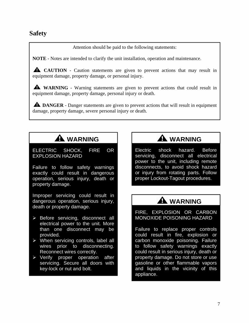
8
GROUNDING REQUIRED All field installed wiring must be completed by qualified personnel Field installed wiring must comply with NECCEC local and state electrical code requirements Failure to follow code requirements could result in serious injury or death Provide proper unit ground in accordance with these code requirements
WARNING
During installation testing servicing and troubleshooting of the equipment it may be necessary to work with live electrical components Only a qualified licensed electrician or individual properly trained in handling live electrical components shall perform these tasks Standard NFPA-70E an OSHA regulation requiring an Arc Flash Boundary to be field established and marked for identification of where appropriate Personal Protective Equipment (PPE) be worn should be followed
WARNING
UNIT HANDLING To prevent injury or death lifting equipment capacity shall exceed unit weight by an adequate safety factor Always test-lift unit not more than 24 inches high to verify proper center of gravity lift point to avoid unit damage injury or death
WARNING
ROTATING COMPONENTS Unit contains fans with moving parts that can cause serious injury Do not open door containing fans until the power to the unit has been disconnected and fan wheel has stopped rotating
WARNING
Failure to properly drain and vent coils when not in use during freezing temperature may result in coil and equipment damage
CAUTION
Rotation must be checked on all MOTORS of 3 phase units at startup by a qualified service technician Fan motor rotation should be checked for proper operation Alterations should only be made at the unit power connection
CAUTION
9
Do not clean DX refrigerant coils with hot water or steam The use of hot water or steam on refrigerant coils will cause high pressure inside the coil tubing and damage to the coil
Some chemical coil cleaning compounds are caustic or toxic Use these substances only in accordance with the manufacturerrsquos usage instructions Failure to follow instructions may result in equipment damage injury or death
WATER PRESSURE Prior to connection of condensing water supply verify water pressure is less than maximum pressure shown on unit nameplate To prevent injury or death due to instantaneous release of high pressure water relief valves should be field supplied on system water piping
WARNING
To prevent damage to the unit do not use acidic chemical coil cleaners Do not use alkaline chemical coil cleaners with a pH value greater than 85 after mixing without first using an aluminum corrosion inhibitor in the cleaning solution
CAUTION WARNING
CAUTION
Do not use oxygen acetylene or air in place of refrigerant and dry nitrogen for leak testing A violent explosion may result causing injury or death
WARNING
Always use a pressure regulator valves and gauges to control incoming pressures when pressure testing a system Excessive pressure may cause line ruptures equipment damage or an explosion which may result in injury or death
WARNING
Do not work in a closed area where refrigerant or nitrogen gases may be leaking A sufficient quantity of vapors may be present and cause
injury or death
WARNING
Door compartments containing hazardous voltage or rotating parts are equipped with door latches to allow locks Door latch are shipped with nut and bolts requiring tooled access If you do not replace the shipping hardware with a pad lock always re-install the nut amp bolt after closing the door
CAUTION
10
1 Startup and service must be performed
by a Factory Trained Service
Technician
2 The unit is for indoor use only See
General Information section for more
unit information
3 Every unit has a unique equipment
nameplate with electrical operational
and unit clearance specifications
Always refer to the unit nameplate for
specific ratings unique to the model you
have purchased
4 READ THE ENTIRE INSTALLATION
OPERATION AND MAINTENANCE
MANUAL OTHER IMPORTANT
SAFETY PRECAUTIONS ARE
PROVIDED THROUGHOUT THIS
MANUAL
5 Keep this manual and all literature
safeguarded near or on the unit
PVC (Polyvinyl Chloride) and CPVC (Chlorinated Polyvinyl Chloride) are vulnerable to attack by certain chemicals Polyolester (POE) oils used with R-410A and other refrigerants even in trace amounts in a PVC or CPVC piping system will result in stress cracking of the piping and fittings and complete piping system failure
CAUTION
Do not weld or cut foam panel with plasma cutters or a cutting torch ndash When burnt the foam produces dangerous fumes
WARNING
Never attempt to open an access door or remove a panel while the unit is running Pressure in the unit can cause excessive force against the panel
WARNING
Ensure that sufficient dampers will be open to provide air path before fan is allowed to run
WARNING
11
H3V3 Series Feature String Nomenclature
Model Options Unit Feature Options G
EN
SIZ
E
OR
EN
T
MJ
RE
V
VL
T
CO
RR
A1
A2
A3
A4
B1
B2
B3
1A
1B
1C
1D
2
3
4
5A
5B
5C
6A
6B
6C
7
8
9
10
11
12
13
14A
14B
H3 - A R B - 3 - 0 - 1 6 1 C - 1 2 F A A B B - 0 C 0 - F T B - 0 G 0 - 0 0 A A A C 0 0 B
A 0 0 0 0 0 0 0 0
15
16
17
18
19
20
21
22
23
12
H3V3 Base Model Description
BASE MODEL SERIES AND GENERATION
H3 = Horizontal - Back Intake Front Discharge
V3 = Vertical - Back Intake Top Discharge
UNIT SIZE
A = Up to 1200 cfm
B = Up to 2000 cfm
C = Up to 4000 cfm
D = Up to 6000 cfm
E = Up to 10000 cfm
UNIT ORIENTATION
R = Right Hand Connections
L = Left Hand Connections
REVISION
A = First Revision
B = Second Revision
VOLTAGE
1 = 230V1Φ60Hz
2 = 230V3Φ60Hz
3 = 460V3Φ60Hz
4 = 575V3Φ60Hz
8 = 208V3Φ60Hz
9 = 208V1Φ60Hz
CORROSION PROTECTION
0 = None
A = Interior Corrosion Protection
Model Option A COOLING A1 COOLING TYPE
0 = No Cooling
1 = R-410A DX Cooling
2 = Chilled Water Cooling
A2 COOILNG ROWS
0 = No Cooling
4 = 4 Row Coil
6 = 6 Row Coil
8 = 8 Row Coil
A3 COOLING STAGES
0 = No Cooling
1 = Single Circuit
2 = Two Circuits - Interlaced Coil
D = Double Serpentine
F = Single Serpentine
H = Half Serpentine
Q = Quarter Serpentine
A4 COOLING FPI
0 = No Cooling
A = 10 fpi
B = 8 fpi
C = 12 fpi
D = 14 fpi
H3V3 Series Feature String Nomenclature
Model Options Unit Feature Options G
EN
SIZ
E
OR
EN
T
MJR
EV
VL
T
CO
RR
A1
A2
A3
A4
B1
B2
B3
1A
1B
1C
1D
2
3
4
5A
5B
5C
6A
6B
6C
7
8
9
10
11
12
13
14A
14B
H3 - A R B - 3 - 0 - 1 6 1 C - 1 2 F A A B B - 0 C 0 - F T B - 0 G 0 - 0 0 A A A C 0 0 B
A 0 0 0 0 0 0 0 0
15
16
17
18
19
20
21
22
23
13
Model Option B HEATING B1 HEATING TYPE
0 = No Heating
1 = Hot Water
3 = Electric Heating
4 = Steam Distributing
B2 HEATING DESIGNATION
0 = No Heating
1 = 1 Row Coil
2 = 2 Row Coil
A = 7 kW (53 kW 208V)
B = 14 kW (105 kW 208V)
C = 21 kW (158 kW 208V)
D = 28 kW (210 kW 208V)
E = 35 kW (263 kW 208V)
F = 42 kW (315 kW 208V)
G = 49 kW (370 kW 208V)
H = 56 kW (420 kW 208V)
J = 63 kW (473 kW 208V)
K = 70 kW (525 kW 208V)
L = 77 kW (578 kW 208V)
M = 84 kW (630 kW 208V)
B3 HEATING STAGES
0 = No Heating
1 = 1 Stage
2 = 2 Stage
3 = 3 Stage
4 = 4 Stage
S = ModulatingSCR Electric
F = Single Serpentine 12 fpi
H = Half Serpentine 12 fpi
Q = Quarter Serpentine 12 fpi
Feature 1 SUPPLY FAN 1A SUPPLY AIR BLOWER CONFIGURATION
0 = 1 Blower + Premium Eff Motor
1 = 1 Blower + Premium Eff Motor + 1 VFD
A = 1 Blower + 1 High Efficiency EC Motor
B = 2 Blowers + 2 High Efficiency EC Motors
1B SUPPLY AIR BLOWER
1 = 15rdquo Backward Curved Plenum Fan
2 = 15rdquo BC Plenum 50 Width with Banding
3 = 185rdquo Backward Curved Plenum Fan
4 = 185rdquo BC Plenum Fan 70 Width with Banding
5 = 22rdquo Backward Curved Plenum Fan
6 = 24rdquo Backward Curved Plenum Fan
7 = 27rdquo Backward Curved Plenum Fan
8 = 27rdquo BC Plenum Fan 70 Width with Banding
A = 310 mm Direct Drive BC Plenum Fan
B = 355 mm Direct Drive BC Plenum Fan
C = 450 mm Direct Drive BC Plenum Fan
D = 250 mm Direct Drive BC Plenum Fan
1C SUPPLY AIR BLOWER MOTOR
1 = 1 hp - 1760 rpm
2 = 2 hp - 1760 rpm
3 = 3 hp - 1760 rpm
4 = 5 hp - 1760 rpm
5 = 75 hp - 1760 rpm
6 = 10 hp - 1760 rpm
B = 10 kW (134 hp)
C = 17 kW (228 hp)
D = 30 kW (402 hp)
E = 60 kW (800 hp)
F = 08 kW (107 hp)
1D SUPPLY BLOWER CONTROLCONTROL
VENDORS
0 = Standard - Terminal Block
A = Potentiometer Supply Fan Control
B = WattMaster Orion Controls System
C = Field Installed Controls by Others
D= Field Installed Controls by Others + Isolation
Relays
H3V3 Series Feature String Nomenclature
Model Options Unit Feature Options
GE
N
SIZ
E
OR
EN
T
MJR
EV
VL
T
CO
RR
A1
A2
A3
A4
B1
B2
B3
1A
1B
1C
1D
2
3
4
5A
5B
5C
6A
6B
6C
7
8
9
10
11
12
13
14A
14B
H3 - A R B - 3 - 0 - 1 6 1 C - 1 2 F A A B B - 0 C 0 - F T B - 0 G 0 - 0 0 A A A C 0 0 B
A 0 0 0 0 0 0 0 0
15
16
17
18
19
20
21
22
23
14
Feature 2 REFRIGERATION OPTIONS 0 = Standard - None
A = Single Circuit External Hot Gas Bypass
B = Dual Circuit External Hot Gas Bypass
C = Heat Pump
D = Option B + H
F = Options C + H
H = Modulating Hot Gas Reheat
P = Option H (Circuit 1) + Option A (Circuit 2)
R = Option C + A
S = Option C + B
T = Option C + H + A
U = Option C + H + B
Feature 3 SPECIAL CONTROLS 0 = Standard - None
A = Constant Volume Controller - CV Cool + CV
Heat
B = Constant Volume Controller with Modulating
Hot Gas Reheat - CV Cool + CV Heat
C = VAV Controller - VAV Cool + CV Heat
D = VAV Controller with MHGR - VAV Cool + CV
Heat
E = Make Up Air Controller - CV Cool + CV Heat
F = Make Up Air Controller with Modulating Hot
Gas Reheat - CV Cool + CV Heat
G = WattMaster Modulating Hot Gas Reheat
Controller
Feature 4 ADDITIONAL CONTROLS 0 = Standard - None
A = Phase and Brownout Protection
B = Return and Supply Air Firestat
C = Return Air Smoke Detector
D = Options A + B
E = Options A + C
F = Options B + C
G = Options A + B + C
H = Remote Safety Shutdown Terminals
J = Energy Recovery Wheel Rotation Detection
K = Options A + H
L = Options A + J
M = Options B + H
Feature 4 ADDITIONAL CONTROLS
Continued N = Options B + J
P = Options C + H
Q = Options C + J
S = Options A + B + H
T = Options A + B + J
U = Options A + C + H
V = Options A + C + J
W = Options A + H + J
Y = Options B + C + H
Z = Options B + C + J
1 = Options B + H + J
2 = Options C + H + J
3 = Options A + B + C + H
4 = Options A + B + C + J
5 = Options A + B + H + J
6 = Options A + C + H + J
7 = Options B + C + H + J
8 = Options A + B + C + H + J
Feature 5 MIXING BOX 5A RETURN AIR DAMPER POSITION
0 = Standard - None
F = Front
L = Left Hand (Front OA Damper Required)
R = Right Hand (Front OA Damper Required)
T = Top (Front OA Damper Required)
5B OUTSIDE AIR DAMPER POSITION
0 = Standard - None
F = Front
L = Left Hand (Front RA Damper Required)
R = Right Hand (Front RA Damper Required)
T = Top (Front RA Damper Required)
5C MIXING BOX DAMPER CONTROL
0 = Standard - None
A = 2 Position Actuators (24V)
B = Fully Modulating Actuators (DDC)
C = Fixed Position Dampers
H3V3 Series Feature String Nomenclature
Model Options Unit Feature Options
GE
N
SIZ
E
OR
EN
T
MJR
EV
VL
T
CO
RR
A1
A2
A3
A4
B1
B2
B3
1A
1B
1C
1D
2
3
4
5A
5B
5C
6A
6B
6C
7
8
9
10
11
12
13
14A
14B
H3 - A R B - 3 - 0 - 1 6 1 C - 1 2 F A A B B - 0 C 0 - F T B - 0 G 0 - 0 0 A A A C 0 0 B
A 0 0 0 0 0 0 0 0
15
16
17
18
19
20
21
22
23
15
Feature 6 FILTER BOX 6A PRE FILTER BOX
0 = Standard - None
A = 2rdquo Pleated - 30 Eff - MERV 10
B = 4rdquo Pleated - 30 Eff - MERV 10
C = 4rdquo Pleated - 65 Eff - MERV 11
D = 4rdquo Pleated - 85 Eff - MERV 13
E = 4rdquo Pleated - 95 Eff - MERV 14
F = 2rdquo Pleated - 30 Eff - MERV 10 + 4rdquo Pleated -
30 Eff - MERV 10
G = 2rdquo Pleated - 30 Eff - MERV 10 + 4rdquo Pleated -
65 Eff - MERV 11
H = 2rdquo Pleated - 30 Eff - MERV 10 + 4rdquo Pleated -
85 Eff - MERV 13
J = 2rdquo Pleated - 30 Eff - MERV 10 + 4rdquo Pleated -
95 Eff - MERV 14
6B UNIT FILTER
0 = Standard - None
A = 2rdquo Pleated - 30 Eff - MERV 10
B = 4rdquo Pleated - 30 Eff - MERV 10
C = 4rdquo Pleated - 65 Eff - MERV 11
D = 4rdquo Pleated - 85 Eff - MERV 13
E = 4rdquo Pleated - 95 Eff - MERV 14
F = 2rdquo Pleated - 30 Eff - MERV 10 + 4rdquo Pleated -
30 Eff - MERV 10
G = 2rdquo Pleated - 30 Eff - MERV 10 + 4rdquo Pleated -
65 Eff - MERV 11
H = 2rdquo Pleated - 30 Eff - MERV 10 + 4rdquo Pleated -
85 Eff - MERV 13
J = 2rdquo Pleated - 30 Eff - MERV 10 + 4rdquo Pleated -
95 Eff - MERV 14
6C FINAL FILTER BOX
0 = Standard - None
A = 2rdquo Pleated - 30 Eff - MERV 10
B = 12rdquo Cartridge - 65 Eff - MERV 11
C = 12rdquo Cartridge - 85 Eff - MERV 13
D = 12rdquo Cartridge - 95 Eff - MERV 14
E = 2rdquo Pleated - 30 Eff - MERV 10 + 12rdquo
Cartridge - 65 Eff - MERV 11
F = 2rdquo Pleated - 30 Eff - MERV 10 + 12rdquo
Cartridge - 85 Eff - MERV 13
G = 2rdquo Pleated - 30 Eff - MERV 10 + 12rdquo
Cartridge - 95 Eff - MERV 14
Feature 7 FILTER OPTIONS 0 = Standard - None
A = Magnehelic Gauge
B = Clogged Filter Switch
C = Options A + B
Feature 8 COIL COATING 0 = Standard - None
A = E-coated Cooling and Heating Coils
B = Copper Finned Coils + Stainless Steel Coil
Casing
Feature 9 EXPANSION VALVE 0 = None
A = Thermal Expansion Valves
Feature 10 EXPANSION VALVE
CONTROLS 0 = None
A = Standard Control
Feature 11 EXTERNAL PAINT 0 = Standard - None
A = AAON Gray Paint
B = Special Paint
H3V3 Series Feature String Nomenclature
Model Options Unit Feature Options
GE
N
SIZ
E
OR
EN
T
MJR
EV
VL
T
CO
RR
A1
A2
A3
A4
B1
B2
B3
1A
1B
1C
1D
2
3
4
5A
5B
5C
6A
6B
6C
7
8
9
10
11
12
13
14A
14B
H3 - A R B - 3 - 0 - 1 6 1 C - 1 2 F A A B B - 0 C 0 - F T B - 0 G 0 - 0 0 A A A C 0 0 B A 0 0 0 0 0 0 0 0
15
16
17
18
19
20
21
22
23
16
Feature 12 TONNAGE 0 = Standard - None
A = 2 ton Capacity
B = 3 ton Capacity
C = 4 ton Capacity
D = 5 ton Capacity
E = 6 ton Capacity
F = 7 ton Capacity
G = 8 ton Capacity
U = 9 ton Capacity
H = 10 ton Capacity
V = 11 ton Capacity
W = 13 ton Capacity
J = 14 ton Capacity
Y = 15 ton Capacity
Z = 16 ton Capacity
K = 17 ton Capacity
1 = 18 ton Capacity
2 = 20 ton Capacity
L = 22 ton Capacity
M = 25 ton Capacity
3 = 26 ton Capacity
N = 30 ton Capacity
P = 31 ton Capacity
Q = 34 ton Capacity
R = 40-45 ton Capacity
S = 50-55 ton Capacity
4 = 60 ton Capacity
T = 63 ton Capacity
5 = 70 ton Capacity
Feature 13 ENERGY RECOVERY
TYPE 0 = Standard ndash None
A = Energy Recovery Wheel ndash Total + High CFM
Polymer
C = Energy Recovery Wheel ndash Total + High CFM
1 Purge Polymer
E = Energy Recovery Wheel ndash Sensible + High CFM
Polymer
G = Energy Recovery Wheel ndash Sensible + High
CFM 1 Purge Polymer
Feature 14 GPM 14A GPM COOLING COIL
0 = Standard - None
A = 15-25 gpm
B = 26-70 gpm
C = 71 -140 gpm
D = 141-240 gpm
E = 241-400 gpm
F = 401-800 gpm
G = 801-1500 gpm
H = 1501-2500 gpm
14B GPM HEATING COIL
0 = Standard - None
A = 15-25 gpm
B = 26-70 gpm
C = 71 -140 gpm
D = 141-240 gpm
E = 241-400 gpm
F = 401-800 gpm
G = 801-1500 gpm
H = 1501-2500 gpm
Feature 15 CONTROL PANEL 0 = Internal Control Panel
A = Small Control Panel - 12rdquo x 12rdquo
B = Medium Control Panel - 25rdquo x 22rdquo
C = Large Control Panel - 48rdquo x 22rdquo
Feature 16 SHIPPING SPLITS 0 = Standard ndash None
A = 1 Shipping Split (2 pallets)
B = 2 Shipping Splits (3 pallets)
C = 3 Shipping Splits (4 pallets)
D = 4 Shipping Splits (5 pallets)
E = 5 Shipping Splits (6 pallets)
H = Special Shipping Split (SPA Required)
H3V3 Series Feature String Nomenclature
Model Options Unit Feature Options
GE
N
SIZ
E
OR
EN
T
MJR
EV
VL
T
CO
RR
A1
A2
A3
A4
B1
B2
B3
1A
1B
1C
1D
2
3
4
5A
5B
5C
6A
6B
6C
7
8
9
10
11
12
13
14A
14B
H3 - A R B - 3 - 0 - 1 6 1 C - 1 2 F A A B B - 0 C 0 - F T B - 0 G 0 - 0 0 A A A C 0 0 B
A 0 0 0 0 0 0 0 0 1
5
16
17
18
19
20
21
22
23
17
Feature 17 ENERGY RECOVERY
CABINET 0 = Standard - None
A = Top RA + Back EA + Back OA Connections
G = OA + EA Dampers - Top RA + Back EA + Back
OA Connections
N = OA + Economizer Dampers - Top RA + Back
EA + Back Connections
U = OA + EA + Economizer Dampers - Top RA +
Back EA + Back OA Connections
Feature 18 MODULATING ELECTRIC
PREHEAT 0 = Standard - None
A = 75 kW
B = 15 kW
C = 20 kW
D = 225 kW
E = 30 kW
F = 40 kW
G = 50 kW
H = 60 kW
Feature 19 EXHAUST FAN 0 = Standard - None
A = 250 mm Exhaust Fan 800 W EC Motor
B = 310 mm Exhaust Fan 10 kW EC Motor
C = 310 mm Exhaust Fan 17 kW EC Motor
D = 355 mm Exhaust Fan 17 kW EC Motor
E = 450 mm Exhaust Fan 30 kW EC Motor
F = 450 mm Exhaust Fan 60 kW EC Motor
G = Dual 310 mm Exhaust Fan 10 kW EC Motor
H = Dual 310 mm Exhaust Fan 17 kW EC Motor
J = Dual 355 mm Exhaust Fan 17 kW EC Motor
K = Dual 450 mm Exhaust Fan 30 kW EC Motor
L = Dual 450 mm Exhaust Fan 60 kW EC Motor
Feature 20 CRATING 0 = Standard - None
A = Export Crating
B = Forkliftable Base - 5rdquo Base
C = Options A + E
D = Options A + B
E = Shipping Shrink Wrap
F = Options B + E
G = Options A + B + E
Feature 21 PULLEY COMBINATION 0 = Standard - None
A = 1000-1400 rpm
B = 1401-1800 rpm
C = 1801-2200 rpm
Feature 22 WARRANTY 0 = Standard - 1 Year Parts
Feature 23 TYPE 0 = Standard
X = Special Pricing Authorization
18
General Information
AAONreg
H3 and V3 Series indoor air
handling units have been designed for
indoor installation only Units are
assembled wired charged with dry nitrogen
and run-tested at the factory H3 and V3
Series units are not intended for residential
use Startup and service must be performed
by a Factory Trained Service Technician
Certification of Steam or Hot Water Heat
Models
a Certified as a forced air heating system
with or without cooling
b Certified for indoor installation only
Certification of Electric Heat Models
a Certified as an electric warm air furnace
with or without cooling
b Certified for indoor installation only
Certification of Cooling Models
a Certified as a commercial central air
conditioner with or without electrically
operated compressors
b Certified for indoor installation only
c Certified with refrigerant R-410A coils
or with chilled water cooling coils
Improper installation adjustment alteration service or maintenance can cause property damage personal injury or loss of life Startup and service must be performed by a Factory Trained Service Technician A copy of this IOM should be kept with the unit
WARNING
These units must not be used as a ldquoconstruction heaterrdquo at anytime during any phase of construction Very low return air temperatures harmful vapors and misplacement of the filters will damage the unit and its efficiency
CAUTION
This equipment is protected by a standard limited warranty under the condition that initial installation service startup and maintenance is performed according to the instructions set forth in this manual This manual should be read in its entirety prior to installation and before performing any service or maintenance work Equipment described in this manual is available with many optional accessories If you have questions after reading this manual in its entirety consult other factory documentation or contact your AAON Sales Representative to obtain further information before manipulating this equipment or its optional accessories
CAUTION
19
Codes and Ordinances
H3 and V3 Series units have been tested and
certified by ETL in accordance with UL
Safety Standard 1995CSA C222 No 236
System should be sized in accordance with
the American Society of Heating
Refrigeration and Air Conditioning
Engineers Handbook
Installation of H3 and V3 Series units must
conform to the ICC standards of the
International Mechanical Code the
International Building Code Installation of
Air Conditioning and Ventilating Systems
Standard NFPA 90A and local building
plumbing and waste water codes All
appliances must be electrically grounded in
accordance with local codes or in the
absence of local codes the current National
Electric Code ANSINFPA 70 or the
current Canadian Electrical Code CSA
C221
Receiving Unit
When received the unit should be checked
for damage that might have occurred in
transit If damage is found it should be noted
on the carrierrsquos Freight Bill A request for
inspection by carrierrsquos agent should be made
in writing at once
Nameplate should be checked to ensure the
correct model sizes and voltages have been
received to match the job requirements
If repairs must be made to damaged goods
then the factory should be notified before
any repair action is taken in order to protect
the warranty Certain equipment alteration
repair and manipulation of equipment
without the manufacturerrsquos consent may
void the product warranty Contact the
AAON Warranty Department for assistance
with handling damaged goods repairs and
freight claims (903) 236-4403
Note Upon receipt check shipment for
items that ship loose such as remote sensors
Consult order and shipment documentation
to identify potential loose-shipped items
Loose-shipped items may have been placed
inside unit cabinet for security Installers
and owners should secure all doors with
locks or nuts and bolts to prevent
unauthorized access
The Clean Air Act of 1990 bans the intentional venting of refrigerant as of July 1 1992 Approved methods of recovery recycling or reclaiming must be followed
CAUTION
Coils and sheet metal surfaces present sharp edges and care must be taken when working with equipment
WARNING
Failure to observe the following instructions will result in premature failure of your system and possible voiding of the warranty
WARNING
20
Figure 1 - Lockable Handle
Storage
This equipment is not suitable for outdoor
use of storage If installation will not occur
immediately following delivery store
equipment in a dry protected area away from
construction traffic and in the proper
orientation as marked on the packaging with
all internal packaging in place Secure all
loose-shipped items
Direct Expansion (DX) Systems
All DX refrigerant coils are factory charged
with a nitrogen holding charge All DX
systems include evaporator coils and
thermal expansion valves (TXV)
Never turn off the main power supply to the
unit except for servicing emergency or
complete shutdown of the unit When power
is cut off from the unit crankcase heaters
cannot prevent refrigerant migration into the
split system condensing unit compressors
This means the compressor may cool down
and liquid refrigerant may accumulate in the
compressor The compressor is designed to
pump refrigerant gas and damage may occur
when power is restored
If power to the unit must be off for more
than an hour turn the thermostat system
switch to OFF or turn the unit off at the
control panel and leave the unit off until the
main power switch has been turned on again
for at least 24 hours for units with
compressor crankcase heaters This will give
the crankcase heater time to clear any liquid
accumulation out of the compressor before it
is started
Always control the unit from the thermostat
or control panel never at the main power
supply except for emergency or complete
shutdown of the unit
During the cooling season if the air flow is
reduced due to dirty air filters or any other
reason the cooling coils can get too cold
which will cause excessive liquid to return
to the compressor As the liquid
concentration builds up oil is washed out of
the compressor leaving it starved for
lubrication
The compressor life will be seriously
shortened by reduced lubrication and the
pumping of excessive amounts of liquid oil
and refrigerant
CRANKCASE HEATER OPERATION
Some units are equipped with compressor crankcase heaters which should be energized at least 24 hours prior to cooling operation to clear any liquid refrigerant from the compressors
CAUTION
21
Note Low Ambient Operation
Air-cooled DX units without a low ambient
option such as condenser fan cycling or the
0degF low ambient option will not operate in
the cooling mode of operation properly
when the outdoor temperature is below
55degF Low ambient andor economizer
options are recommended if cooling
operation below 55degF is expected
Wiring Diagrams
Unit specific wiring diagrams are laminated
and affixed inside the controls compartment
door
Condensate Drain Pans
Units require field installed drain p-traps and
lines to be connected to the condensate drain
pans of the unit
For condensate drain lines the line should
be the same pipe size or larger than the drain
connection include a p-trap and pitch
downward toward drain An air break should
be used with long runs of condensate lines
See Installation section of this manual for
more information
Unit should not be operated without a p-trap Failure to install a p-trap may result in overflow of condensate water
CAUTION
Emergency drain pan is recommended for all applications where a risk of water damage to surrounding structure or furnishings Refer to local codes
CAUTION
22
Installation
AAON equipment has been designed for
quick and easy installation Startup and
service must be performed by Factory
Trained Service Technician
The H3V3 unit can either be shipped
assembled or shipped in sections See the
Unit Assembly section of this document for
instructions on assembling the sections
Locating the Unit
Placement of the unit relative to ductwork
electrical and plumbing must be carefully
considered Return air plenum or duct can be
mounted directly to the return air flanges
Use flexible gasket material to seal the duct
to the unit
Verify floor foundation or suspension
support can support the total unit weight
including accessory weights Unit must be
level in both horizontal axes to support the
unit and reduce noise and vibration from the
unit
Allow adequate space for piping access and
panel removal To ensure proper access
for field service maintain minimum
clearances for field piping and other
obstructions as indicated by Table 1 and
Figure 2 and Figure 3 Consult local
building codes for additional service
clearance requirements Condensate drain
connections are located on the access side of
the unit
Table 1 - H3 and V3 Series Clearances
Unit Size
Access Side
Clearance
(dimension X on
Figure 2 and
Figure 3)
All Other
Sides
V3-A
36 inches
6 inches
V3-B
V3-C
V3-D
V3-E
H3-A
H3-B
H3-C
H3-D 45 inches
H3-E 60 inches
Additional clearance may be required to
allow for coil removal
May be installed flush depending upon
local codes
Figure 2 - Minimum Clearance Required for
Access to Unit (V3 Series plan view)
X
(See Table 1)
Back Front
Left
Right
23
Figure 3 - Minimum Clearance Required for
Access to Unit (H3 Series plan view)
Internal Control Panel
H3 units with internal control panel have
removable access panels on the top and
bottom of the supply fan section V3 units
with internal control panel have removable
access panels on the front and back of the
supply fan section V3 units that have
energy recovery only have one removable
supply fan access panel on the front of the
unit The supply flanges can be
interchanged with the access panels if
necessary except on size E
Figure 4 - H3 internal control panel with top
access panel removed
Figure 5 - V3 internal control panel with
rear removable access panel shown
Floor Mounted Units
Make sure the unit is level and mounted on a
field supplied platform with a minimum
height to allow for proper depth of the
condensate line p-trap Other installation
provisions may be necessary according to
job specifications V3 Series vertical air
handling units are designed for upflow
applications only
Suspended Units
H3 Series horizontal air handling units are
equipped for suspended installations The
unit should be lifted into position by
supporting the unit with the skid used for
shipping The air handling unit must be
installed level and care should be taken to
prevent damage to the cabinet Other
installation provisions may be necessary
according to job specifications Figure 6
and Figure 7 show factory recommended
methods for suspended installations It is
the responsibility of the specifying engineer
or installing contractor to ensure the
installation is structurally safe and sound
X
(See Table 1)
Front
Back
Left Right
24
Figure 6 - H3 Series Platform Suspension Installation
Figure 7 - H3 Series Parallel Beam Suspension Installation
25
Figure 8 - H3 Series Unit Orientation
Figure 9 - V3 Series Unit Orientation
Note Access doors may be on the ldquoleftrdquo or ldquorightrdquo side as designated by the unit orientation on
the configurator string ldquoBackrdquo will always be the same side as the pre-filter and return air
opening ldquoFrontrdquo will always be the side opposite the pre-filter and return air opening
H3 Series
Return Air ldquoBackrdquo
Supply Air ldquoFrontrdquo
Right Hand Side
Left Hand Side
Connections and service access on right side for right hand orientation
Top View
Air Flow
Connections and service access on right side for right hand orientation
Right Hand Side Left Hand Side
Return Air ldquoBackrdquo
Top View V3 Series
Air Flow
Consider the air flow to be hitting the back of your head
Consider the air flow to be hitting the back of your head
Supply Air
ldquoFrontrdquo
26
Lifting and Handling the Unit
Before lifting unit be sure that all shipping
material has been removed from unit
Care should be taken if using spreader bars
blocking or other lifting devices to prevent
damage to the cabinet coil or fans
Unit Assembly
Although H3V3 Series units are shipped
factory assembled as standard the unit may
be ordered as shipping splits for certain
applications such as for assembly in existing
structures where modules must be
manipulated separately If the unit was
ordered as shipping splits then they must be
assembled in the field
Locate the schematic in the equipmentrsquos
literature packet
1 Identify and Situate Splits
a H3 Units can have the following
ship split sections
1 Mixing Box
2 Air Handler
3 Final Filter
4 Electric Heat
Figure 10 - H3 Schematic with (1) Mixing
Box (2) Air Handler (3) Final Filter and
(4) Electric Heat
b V3 Units can have the following
ship split sections
1 Exhaust Fan
2 Energy Recovery
3 Air Handler
4 Electric Heat
5 Pre filter
6 Mixing box
Figure 11 - V3 Schematic with (1) Exhaust
Fan (2) Energy Recovery (3) Air Handler
and (4) Electric Heat
2 Connect Sections
Using the V3 Schematic as an example
section 1 will have a duct flange and it will
connect to section 2 on the side that does not
have a flange First make sure gasket is on
the panel around the edges of the exposed
duct flanges Push section 1 and 2 together
UNIT HANDLING
Incorrect lifting can cause damage to the unit injury or death Lifting equipment capacity should exceed unit weight by an adequate safety factor Always test lift unit not more than 24 inches high to verify proper center of gravity lift point
WARNING
1 2 3 4
1 2
3
4
27
so that the flange from section 1 is inside of
section 2
Figure 12 - Connect Sections
Use bar clamps or other non-destructive
winching device to pull the tops of the
modules together tightly
Figure 13 - Bar Clamp
At each of the pre-drilled holes in the flange
drill 516 hex head self-tapping screws to
secure the two sections together
Figure 14 - Flange Overlap
Figure 15 - Self-Tapping Screw
All connection hardware is shipped with the
unit
3 Secure Module Joints
The metal straps are to be used to secure
module joints Straps are provided with pre-
drilled holes Self-tapping sheet metal
screws are provided to attach the straps to
the unit cabinet
Leave bar clamps in place until strap is
secure
Place the strap over a module joint ensure
the strap completely covers the joint and
that it is square with the unit casing
Insert self-tapping screws through pre-
drilled holes in strap and secure screws into
unit casing using a power drill For best
results use the lowest effective power drill
torque setting Be careful not to over tighten
the screws
Remove bar clamps and repeat for all
remaining module joints
Figure 16 - Strap Types
516rdquo Hex Head Self-Tapping Screws
Provided with Unit
1rdquo
Angle Strap
Top Strap
Section 2
Flange
28
4 Connect Power and Control Wiring
H3V3 Series units are equipped with low
and high voltage quick connects to connect
wiring from one section to the next Wire
from the unit to external controls and power
sources must be provided in the field
Figure 17 - Low Voltage Quick Connect
A color-coded wiring diagram is laminated
and affixed to the inside of the control
compartment access door H3V3 Series
units are equipped with a single point power
connection
5 Final Sealing
It is very important to keep air from
infiltrating the unit cabinet Seal all piping
penetrations with Armaflex Permagum or
other suitable sealant Also seal around drain
connections electrical connections and all
other inlets where air may enter the cabinet
This is especially important when the unit is
installed in an unconditioned area
Control Box
Some H3V3 units include an external
control box that must be mounted in the
field
Figure 18 - Back View External Control
Box
Duct Connection
Attach duct to flanges provided on the unit
The installer is responsible for sealing ducts
to the flanges to prevent water leaks
Refer to Figure 8 and Figure 9 for duct
connection locations The V3 supply air duct
is out to top of the unit Ductwork should be
sized in accordance with the ASHRAE
Handbook Ductwork should be installed in
accordance with NFPA Standard 90A
When attaching duct to the unit use a
flexiblecompressible material rated for duct
connections A three inch flexible connector
for both return and supply duct connections
is recommended
Condensate Drain Piping
Unit may be equipped with more than one
condensate drain pan connection A p-trap
and drain line must be installed on at least
one sectionrsquos drain connection with the p-
trap not to exceed 6rdquo from the drain
connection The lines should be the same
pipe size or larger than the drain connection
include a p-trap and pitch downward toward
drain An air break should be used with long
runs of condensate lines
Installing Contractor is responsible for proper sealing of the electrical and piping entries into the unit Failure to seal the entries may result in damage to the unit and property
CAUTION
29
Draw-through cooling coils will have a
negative static pressure in the drain pan area
This will cause an un-trapped drain to back
up due to air being pulled up through the
condensate drain piping
Condensate drain trapping and piping should
conform to all applicable governing codes
Note The drain pan connection(s) is a 1rdquo
MPT fitting
Figure 19 - Drain Trap
The X dimension on the draw-through trap
should be at least equal to the absolute value
of the negative static pressure in the drain
pan plus one inch To calculate the static
pressure at the drain pan add the pressure
drops of all components upstream of the
drain pan including the cooling coil and
add the return duct static pressure Include
the dirt allowance pressure drop for the
filters to account for the worst-case scenario
The height from top of the bottom bend of
the trap to the bottom of the leaving pipe
must be at least equal to one half of the X
dimension This ensures that enough water
is stored in the trap to prevent losing the
drain seal during unit startup
Note The absolute value of the fan inlet
pressure will always be greater than or equal
to the absolute value of the static pressure in
the drain pan on draw-through units so the
fan inlet pressure is a safe value to use for
the drain pan static pressure
Table 2 - Drain Trap Dimensions
Draw-Through
Drain Pan Pressure Trap Dimensions
Negative Static X X2
(inches of water) (inch) (inch)
-050 150 075
-100 200 100
-150 250 125
-200 300 150
-250 350 175
-300 400 200
-350 450 225
-400 500 250
Heating Coils
One or two row hot water and steam heating
and preheating coils can be factory installed
These coils are supplied from a building hot
water source All valve controls for heating
coil operation are field supplied and field
installed
Unit should not be operated without p-traps Failure to install a p-traps may result in overflow of condensate water
CAUTION
30
Always connect the steam heating supply to
the top of the coil and the return to the
bottom
Figure 20 - Steam Distributing Piping
Table 3 - Steam Distributing Coil
Connection Sizes
Model (H3- V3-) Supply and Return
Connection Size
A-E 2 18
Air handling units with steam heating coils
MUST BE installed high enough to allow
for a minimum of 1 foot condensate drop leg
off of the steam coil or as recommended by
the steam trap manufacturer Lines should
be insulated with approved insulation and be
properly fastened sloped and supported
according to local code requirements
Table 4 - Hot Water Coil Connection Sizes
Model (H3- V3-) Supply and Return
Connection Size
A 78
B 1 18
C 1 38
D amp E 1 58
Always connect the hot water heating supply
to the bottom of the coil and return to the
top
Figure 21 - Hot amp Chilled Water Piping
Water coils should not be subjected to
entering air temperatures below 38degF to
prevent coil freeze-up If air temperature
across the coil is going to be below this
value use a glycol solution to match the
coldest air expected
Water supply lines must be insulated
properly fastened drained and supported
according to local code requirements
Chilled Water Coil
Factory installed four six or eight row
chilled water cooling coils can be factory
mounted These coils are supplied from a
building chilled water source All valve
controls for the cooling coil operation are
field supplied and field installed
31
Table 5 - Chilled Water Coil Connection
Sizes
Model (H3- V3-) Supply and Return
Connection Size
A 1 18
B 1 38
C 1 58
D amp E 2 18
Always connect the chilled water supply to
the bottom of the coil and return to the top
Water supply lines must be insulated with
closed cell type pipe insulation or insulation
that includes a vapor barrier Lines should
be properly fastened drained and supported
according to local code requirements and
job specifications
Evaporator Coil
The air handling unit coils are pressurized
The copper caps must be punctured to
permit a gradual escape of the pressure prior
to un-sweating those caps Immediately
couple the tubing to the indoor unit to avoid
exposing the coils to moisture A properly
sized filter drier is furnished in the
condenser When making solder
connections make sure dry nitrogen flows
through the lines when heating the copper
to prevent oxidization inside of the copper
Field piping between the condensing unit
and the air handler is required Line
sizes must be selected to meet actual
installation conditions not simply based
on the connection sizes
Thermal Expansion Valve
Thermal expansion valve bulbs should be
mounted with good thermal contact on a
horizontal section of the suction line close to
the evaporator but outside the cabinet and
well insulated On suction lines less than or
equal to 78rdquo OD mount in the 12 orsquoclock
position On suction lines greater than 78rdquo
OD mount in either the 4 orsquoclock or 8
orsquoclock position
Figure 22 - TXV Bulb Position
Hot Gas Reheat
Hot Gas Reheat (HGRH) is available for use
with DX systems that need humidity control
The AAON modulating hot gas reheat
system diverts hot discharge gas from the
condenser to the air handling unit through
the hot gas line Field piping between the
condensing unit and the air handler is
required Line sizes must be selected to
meet actual installation conditions not
simply based on the connection sizes
The line delivers the hot discharge gas to the
reheat coil andor the hot gas bypass valve
so it is sized as a discharge line
Modulating Hot Gas Reheat Piping
1 Run a hot gas reheat line from the
condensing unit and connect it to the inlet of
the stub-out on the reheat coil The inlet
connection is the top (or highest) stub-out of
the reheat coil Connect the hot gas line
from the outdoor unit to the upper stub-out
connection of the reheat coil
2 Run a liquid line from the discharge of the
reheat coil through a tee connection Run a
liquid line from the condenser through a
REFRIGERANT PIPING
Line sizes must be selected to meet actual installation conditions not simply based on the connection sizes at the condensing unit or air handling unit
CAUTION
32
check valve to the other side of the tee Run
a liquid line from the tee to the liquid line
stub-out of the evaporator coil
3 Run a suction line from the evaporator
coil outlet stub-out to the condensing unit
Hot Gas Bypass
Hot Gas Bypass is available for use with DX
systems that may experience low suction
pressure during the operating cycle This
may be due to varying load conditions
associated with VAV applications or units
supplying a large percentage of outside air
Hot Gas Bypass is not necessary in units
with variable capacity compressors The
system is designed to divert refrigerant from
the compressor discharge to the low pressure
side of the system in order to keep the
evaporator from freezing and to maintain
adequate refrigerant velocity for oil return at
minimum load
Hot discharge gas is redirected to the
evaporator inlet via an auxiliary side
connector (ASC) to false load the evaporator
when reduced suction pressure is sensed
Field piping between the condensing unit
and the evaporator is required Line sizes
must be selected to meet actual
installation conditions not simply based
on the connection sizes
Electric Preheat
The modulating electric preheat option is
designed to temper the incoming outside air
to the unit based on an enable control signal
and the outside air conditions
A 24VAC enable signal must be provided to
the [PHE] terminal to enable the operation
of the electric preheat Once the preheat
controller is enabled it will monitor the
outside air temperature to determine if any
capacity of preheat is needed If the outside
air temperature falls below the outside air
temperature setpoint the electric preheat will
be started up and maintain the leaving air
temperature setpoint with both SCR
controlled and staged electric preheat Both
setpoints are set with push button LCD
interface on the preheat controller Outside
air temperature sensors and preheat
discharge supply air temperature sensors are
factory installed and wired to the preheat
controller Electric preheat has maximum
operating outside air temperature of 60degF
and a maximum preheat discharge air
temperature of 80degF
[COM] [PHO] amp [PHC] feedback terminals
are provided to communicate if the electric
preheat is in operation PHO is a normally
open contact PHC is a normally closed
contact and COM is the common These
terminals are not required to be connected
[PHE] is the electric preheat operation
enable [PH+] and [PH-] are the preheat set
point reset terminals
33
Energy Recovery Units
Some H3V3 units have been equipped with
an energy recovery wheel This section is
provided to assure the energy recovery
feature will be properly setup to perform in
accordance with the job specifications for
your particular application
Figure 23 - Energy Recovery Wheel
The Energy Recovery Cassette consists of a
frame wheel wheel drive system and
energy transfer segments Segments are
removable for cleaning or replacement The
segments rotate through counter flowing
exhaust and outdoor air supply streams
where they transfer heat andor water vapor
from the warm moist air stream to the
cooler andor drier air stream
The initial setup and servicing of the energy
recovery wheel is very important to maintain
proper operation efficiency and building
occupant comfort
Normal maintenance requires periodic
inspection of filters the cassette wheel
drive belts air seals wheel drive motor and
its electrical connections
Wiring diagrams are provided with each
motor When wired according to wiring
diagram motor rotates clockwise when
viewed from the shaftpulley side
By carefully reviewing the information
within this section and following the
instructions the risk of improper operation
andor component damage will be
minimized
It is important that periodic maintenance be
performed to help assure trouble free
operation
Initial Mechanical Check and Setup
Outdoor air intake adjustments should be
made according to building ventilation or
local code requirements
After the unit installation is complete open
the cassette access door and determine that
the energy wheel rotates freely when turned
by hand Apply power and observe that the
wheel rotates at approximately 30 RPM If
the wheel does not rotate when power is
applied it may be necessary to readjust the
ldquodiameter air sealsrdquo
Air Seal Adjustments
Pile type air seals across both sides of the
energy wheel diameter are factory adjusted
to provide close clearance between the air
seal and wheel Racking of the unit or
cassette during installation andor mounting
of the unit on a non-level support or in other
than the factory orientation can change seal
clearances Tight seals will prevent rotation
Figure 24 - Cross Section of Air Seal
Structure
34
Wheel to Air Seal Clearance
To check wheel to seal clearance first
disconnect power to the unit in some units
the energy recovery wheel assembly can be
pulled out from the cabinet to view the air
seals On larger units the energy recovery
wheel may be accessible inside the walk-in
cabinet
A business card or two pieces of paper can
be used as a feller gauge (typically each
004rdquo thick) by placing it between the face
of the wheel and pile seal
Using the paper determine if a loose slip fit
exist between the pile seal and wheel when
the wheel is rotated by hand
To adjust air seal clearance loosen all seal
plate retaining screws holding the separate
seal retaining plates to the bearing support
channels and slide the seals plates away
from the wheel Using the paper feeler
gauge readjust and retighten one seal plate
at a time to provide slip fit clearance when
the wheel is rotated by hand
Confirm that the wheel rotates freely Apply
power to the unit and confirm rotation
Airflow Balancing and Checking
High performance systems commonly have
complex air distribution and fan systems
Unqualified personnel should not attempt to
adjust fan operation or air circulation as all
systems have unique operations
characteristics Professional air balance
specialists should be employed to establish
actual operating conditions and to configure
the air delivery system for optimal
performance
Controls
A variety of controls and electrical
accessories may be provided with the
equipment Identify the controls on each unit
by consulting appropriate submittal or order
documents and operate according to the
control manufacturerrsquos instructions If you
cannot locate installation operation or
maintenance information for the specific
controls then contact your sales
representative or the control manufacturer
for assistance
Routine Maintenance and Handling
Handle cassettes with care All cassettes
should be lifted by the bearing support
beam Holes are provided on both sides of
the bearing support beams to facilitate
rigging as shown in the following
illustration
Figure 25 - Lifting Hole Locations
Routine maintenance of the Energy
Recovery Cassettes includes periodic
Do not alter factory wiring Deviation from the supplied wiring diagram will void all warranties and may result in equipment damage or personal injury Contact the factory with wiring discrepancies
WARNING
35
cleaning of the Energy Recovery Wheel as
well as inspection of the Air Seals and
Wheel Drive Components as follows
Cleaning
The need for periodic cleaning of the energy
recovery wheel will be a function of
operating schedule climate and
contaminants in the indoor air being
exhausted and the outdoor air being supplied
to the building
The energy recovery wheel is ldquoself-
cleaningrdquo with respect to dry particles due to
its laminar flow characteristics Smaller
particles pass through larger particles land
on the surface and are blown clear as the
flow direction is reversed Any material that
builds up on the face of the wheel can be
removed with a brush or vacuum The
primary need for cleaning is to remove oil
based aerosols that have condensed on
energy transfer surfaces
A characteristic of all dry desiccants such
films can close off micron sized pores at the
surface of the desiccant material reducing
the efficiency by which the desiccant can
adsorb and desorb moisture and also build
up so as to reduce airflow
In a reasonably clean indoor environment
such as a school or office building
measurable reductions of airflow or loss of
sensible (temperature) effectiveness may not
occur for several years Measurable changes
in latent energy (water vapor) transfer can
occur in shorter periods of time in
applications such as moderate occupant
smoking or cooking facilities In
applications experiencing unusually high
levels of occupant smoking or oil based
aerosols such as industrial applications
involving the ventilation of machine shop
areas for example annual washing of energy
transfer may be necessary to maintain latent
transfer efficiency Proper cleaning of the
energy recovery wheel will restore latent
effectiveness to near original performance
To clean gain access to the energy recovery
wheel and remove segments Brush foreign
material from the face of the wheel Wash
the segments or small wheels in a 5
solution of non-acid based coil cleaner or
alkaline detergent and warm water
Soak in the solution until grease and tar
deposits are loosened (Note some staining
of the desiccant may remain and is not
harmful to performance) Before removing
rapidly run finger across surface of segment
to separate polymer strips for better cleaning
action Rinse dirty solution from segment
and remove excess water before reinstalling
in wheel
Air Seals
Four adjustable diameter seals are provided
on each cassette to minimize transfer of air
between the counter flowing airstreams
To adjust diameter seals loosen diameter
seal adjusting screws and back seals away
from wheel surface Rotate wheel clockwise
until two opposing spokes are hidden behind
the bearing support beam Using a folded
piece of paper as a feeler gauge position
paper between the wheel surface and
diameter seals
Adjust seals towards wheel surface until a
slight friction on the feeler gauge (paper) is
detected when gauge is moved along the
length of the spoke Retighten adjusting
Do Not use acid based cleaners aromatic solvents steam or temperatures in excess of 170degF damage to the wheel may occur
CAUTION
36
screws and recheck clearance with ldquofeelerrdquo
gauge
Wheel Drive Components
The wheel drive motor bearings are pre-
lubricated and no further lubrication is
necessary
The wheel drive pulley is secured to the
drive motor shaft by a combination of either
a key or D slot and set screw
The set screw is secured with removable
locktite to prevent loosening Annually
confirm set screw is secure The wheel drive
belt is a urethane stretch belt designed to
provide constant tension through the life of
the belt No adjustment is required Inspect
the drive belt annually for proper tracking
and tension A properly tensioned belt will
turn the wheel immediately after power is
applied with no visible slippage during start-
up
Installation Considerations
Energy recovery cassettes are incorporated
within the design of packaged units
packaged air handlers and energy recovery
ventilators In each case it is recommended
that the following considerations be
addressed
Accessibility
The cassette and all its operative parts ie
motor belt pulley bearings seals and
energy transfer segments must be accessible
for service and maintenance This design
requires that adequate clearance be provided
outside the enclosure
Orientation amp Support
The Energy Recovery Cassette may be
mounted in any orientation However Care
must be taken to make certain that the
cassette frame remains flat and the bearing
beams are not racked
To verify make certain that the distance
between wheel rim and bearing beam is the
same at each end of the bearing beam to
within 14 of an inch (dimension A amp B)
This amount of racking can be compensated
for by adjusting the diameter seals
If greater than 14 inch (dimension C)
racking must be corrected to ensure that
drive belt will not disengage from wheel
Figure 26 - Avoid Racking of Cassette
Frame
Operation
Startup Procedure
1 By hand turn wheel clockwise (as viewed
from the pulley side) to verify wheel turns
freely through 360ordm rotation
2 Before applying power to drive motor
confirm wheel segments are fully engaged in
wheel frame and segment retainers are
completely fastened (See Segment
Installation Diagram)
B
C
A
Bearing beams shown racked
Frame
Wheel
Bearing beams (2)
Flat surface
Keep hands away from rotating wheel Contact with rotating wheel can cause physical injury
CAUTION
37
3 With hands and objects away from
moving parts activate unit and confirm
wheel rotation Wheel rotates clockwise (as
viewed from the pulley side)
4 If wheel has difficulty starting turn power
off and inspect for excessive interference
between the wheel surface and each of the
four (4) diameter seals To correct loosen
diameter seal adjusting screws and back
adjustable diameter seals away from surface
of wheel apply power to confirm wheel is
free to rotate then re-adjust and tighten hub
and diameter seals as shown in hub seal
adjustment diagram
5 Start and stop wheel several times to
confirm seal adjustment and to confirm belt
is tracking properly on wheel rim
(approximately 14rdquo from outer edge of
rim)
Figure 27 - Diameter Seal Adjustment
Figure 28 - Hub Seal Adjustment
Service
Segment Installation amp Replacement
Wheel segments are secured to the wheel
frame by a Segment Retainer which pivots
on the wheel rim and is held in place by a
Segment Retaining Catch
Disconnect electrical power before servicing energy recovery cassette Always keep hands away from bearing support beam when installing or removing segments Failure to do so could result in severe injury to fingers or hand
CAUTION
38
Figure 29 - Segment Retainer
To install wheel segments follow steps one
through five below Reverse procedure for
segment removal
1 Unlock two segment retainers (one on
each side of the selected segment opening
2 With the embedded stiffener facing the
motor side insert the nose of the segment
between the hub plates
Figure 30 - Segment Installation
3 Holding segment by the two outer
corners press the segment towards the
center of the wheel and inwards against the
spoke flanges If hand pressure does not
fully seat the segment insert the flat tip of a
screw driver between the wheel rim and
outer corners of the segment and apply
downward force while guiding the segment
into place
4 Close and latch each Segment Retainer
under Segment Retaining Catch
5 Slowly rotate the wheel 180ordm Install the
second segment opposite the first for
counterbalance Rotate the two installed
segments 90ordm to balance the wheel while the
third segment is installed Rotate the wheel
180ordm again to install the fourth segment
opposite the third Repeat this sequence with
the remaining four segments
Wheel Drive Motor and Pulley Replacement
1 Disconnect power to wheel drive motor
2 Remove belt from pulley and position
temporarily around wheel rim
3 Loosen set screw in wheel drive pulley
using a hex head wrench and remove pulley
from motor drive shaft
4 While supporting weight of drive motor in
one hand loosen and remove (4) mounting
bolts
5 Install replacement motor with hardware
kit supplied
6 Install pulley to dimension as shown and
secure set screw to drive shaft
7 Stretch belt over pulley and engage in
groove
8 Follow start-up procedure
Belt Replacement
1 Obtain access to the pulley side bearing
access plate if bearing access plates are
provided Remove two bearing access plate
retaining screws and the access plate
39
2 Using hexagonal wrench loosen set screw
in bearing locking collar Using light
hammer and drift (in drift pin hole) tap
collar in the direction of wheel rotation to
unlock collar Remove collar
3 Using socket wrench with extension
remove two nuts which secure bearing
housing to the bearing support beam Slide
bearing from shaft If not removable by
hand use bearing puller
4 Form a small loop of belt and pass it
through the hole in the bearing support
beam Grasp the belt at the wheel hub and
pull the entire belt down
Note Slight hand pressure against wheel
rim will lift weight of wheel from inner race
of bearing to assist bearing removal and
installation
5 Loop the trailing end of the belt over the
shaft (belt is partially through the opening)
6 Reinstall the bearing onto the wheel shaft
being careful to engage the two locating pins
into the holes in the bearing support beam
Secure the bearing with two self-locking
nuts
7 Install the belts around the wheel and
pulley according to the instructions provided
with the belt
8 Reinstall diameter seals or hub seal and
tighten retaining screws Rotate wheel in
clockwise direction to determine that wheel
rotates freely with slight drag on seals
9 Reinstall bearing locking collar Rotate
collar by hand in the direction the wheel
rotates (see label provided on each cassette
for wheel rotation)
10 Lock in position by tapping drift pin
hole with hammer and drift Secure in
position by tightening set screw
11 Reinstall Bearing Access Cover
12 Apply power to wheel and ensure that
the wheel rotates freely without interference
Figure 31 - Belt Replacement
Protect hands and belt from possible sharp edges of hole in Bearing Support Beam
CAUTION
40
Electrical
Verify the unit name plate agrees with
power supply H3 and V3 Series units are
provided with single point power wiring
connections Connection terminations are
made to the main terminal block A
complete set of unit specific wiring
diagrams showing factory and field wiring
are laminated in plastic and located inside
the control compartment door
Route power and control wiring separately
through the utility entry in the unit Do not
run power and control signal wires in the
same conduit
All units require field supplied electrical
overcurrent and short circuit protection
Device must not be sized larger than the
Maximum Overcurrent Protection (MOP)
shown on the unit nameplate
Codes may require a disconnect switch be
within sight of the unit
It is recommended that the field installed
overcurrent protection or disconnect switch
not be installed on the unit
On units with external control box electrical
supply can enter through either side of the
controls compartment
Figure 32 - External control box electrical
connections
On units with internal control panel
electrical supply can enter through the
supply air side (front) of the H3 unit and
through the return air side (rear) of the V3
unit
Figure 33 - H3 internal control panel
electrical connections
Figure 34 - V3 internal control panel
electrical connections
The foam insulation releases dangerous fumes when it is burnt Do not cut a foam part with a cutting torch or plasma cutter Do not weld to a foam filled part
WARNING
41
A single point connection to a terminal
block is provided High voltage conductors
should enter the control panel in a separate
opening and separate conduit than low
voltage conductors
To pass wires through the wall or roof of the
unit a hole should be cut and conduit passed
through it Use the following procedure to
cut a round hole in a foam panel
Cutting Electrical Openings
1 Locate the placement of the hole Be
sure that the conduit will not interfere
with the operation of any component or
prevent access of any door or
removable panel Field cut openings
must be a minimum of 6 inches away
from all components and wiring to
prevent damage due to drilling or
cutting
2 Drill a pilot hole all the way through the
foam panel
3 Using a hole saw cut the hole through
the metal on both sides of the foam
part
4 With a knife cut the foam out of the
hole
5 After the conduit is installed in the hole
caulk the entire perimeter of the hole on
both sides with an industrial grade
silicone sealant or a duct seal
compound
If a larger cut-out is needed for additional
duct connections not provided by the
factory or for any other reason it is very
important that the foam be completely
sealed Insulation covers should be
fabricated from sheet metal to cover the
foam at the cut The edges and corners that
are not covered should then be sealed using
silicone caulking or a duct seal compound
If a reciprocating saw is used to make the
cut-out take care that the metal skins of the
foam part do not separate from the foam
this would result in reduced structural
integrity of the part
Size supply conductors based on the unit
Minimum Current Ampacity (MCA) rating
Supply conductors must be rated a minimum
of 75degC
Protect the branch circuit in accordance with
code requirements The unit must be
electrically grounded in accordance with
local codes or in the absence of local codes
the current National Electric Code
ANSINFPA 70 or the current Canadian
Electrical Code CSA C221
Note Units are factory wired for 208V
230V 460V or 575V In some units the
208V and 230V options may also be
provided in single or three phase
configurations The transformer
Installing Contractor is responsible for proper sealing of the electrical and piping entries into the unit Failure to seal the entries may result in damage to the unit and property
Electric shock hazard Before attempting to perform any installation service or maintenance shut off all electrical power to the unit at the disconnect switches Unit may have multiple power supplies Failure to disconnect power could result in dangerous operation serious injury death or property damage
WARNING
CAUTION
42
configuration must be checked by a
qualified technician prior to startup
Wire power leads to the unitrsquos terminal
block or main disconnect All wiring beyond
this point has been completed by AAON and
cannot be modified without effecting the
unitrsquos agencysafety certification
Supply voltage must be within the minmax
range shown on the unit nameplate
Available short circuit current should not
exceed the short circuit current rating
(SCCR) shown on the unit nameplate
Three phase voltage imbalance will cause
motor overheating and premature failure
The maximum allowable imbalance is 20
Voltage imbalance is defined as 100 times
the maximum deviation from the average
voltage divided by the average voltage
Example
(221V+230V+227V)3 = 226V then
100(226V-221V)226V = 22 which
exceeds the allowable imbalance
Check voltage imbalance at the unit
disconnect switch and at the compressor
terminal Contact your local power company
for line voltage corrections
Installing contractor must check for proper
motor rotation and check blower motor
amperage listed on the motor nameplate is
not exceeded
Wire control signals to the unitrsquos low
voltage terminal block located in the
controls compartment
If any factory installed wiring must be
replaced use a minimum 105degC type AWM
insulated conductors
Thermostat Control Wiring
If a thermostat is used for unit control
thermostat should be located on an inside
wall 4-5 feet above the floor where it will
not be subjected to drafts sun exposure or
heat from electrical fixtures of appliances
Control wiring must deliver adequate
voltage to components to assure proper
operation Control voltage returning from
controller circuit must be a minimum of 21
VAC To assure proper wiring use the
following chart to determine the allowable
wiring distances
Table 6 - Control Wiring
Wire Size (Stranded)
- Copper Conductors
Only
Total Wire Distance
Allowable
20 AWG 200 ft
18 AWG 350 ft
16 AWG 500 ft
14 AWG 750 ft
12 AWG 1250 ft
Total Wire Distance Allowable =
(Quantity of Control Wires) x
(Control Wire Distance)
Three phase voltage imbalance will cause motor overheating and premature failure
CAUTION
Rotation must be checked on all MOTORS of three phase units Supply fan motors should all be checked by a qualified service technician at startup and any wiring alteration should only be made at the unit power connection
CAUTION
43
Take the total wire distance allowable and
divide by the number of wires to be
connected This indicates the distance
allowable for that size wire The wiring to
the unit must not exceed the total wire
distance allowable If the voltage at the
connectors is less than 21 VAC isolation
relays must be installed If under external
control 21 VAC must be field verified
All external devices must be powered via a
separate external power supply
Example
A total of 8 wires must be pulled 75ft to a
control the unit What size wire should be
used
According to the Table 6 16 AWG allows
for 63ft (500 ft8 wires) and 14 AWG allows
for 94ft (750 ft8 wires) Thus 14 AWG
should be used
44
Startup (See back of the manual for startup form)
During startup it is necessary to perform
routine checks on the performance of the
unit This includes checking of the air flow
the air filters and refrigerant charge
Supply Fans
H3 and V3 Series units are equipped with
direct drive backward curved plenum supply
fan assemblies or belt driven backward
curved plenum supply fans that deliver the
air volume specified according to unit size
and job requirements
Fan Air Flow Adjustment
A specific air volume is delivered by the
fans with Electronically Commutated
Motors (ECM) or Variable Frequency
Drives (VFD) Field air flow adjustment
may be required at startup
Electrically Commutated Motor Airflow
Adjustment
Figure 35- Typical wiring diagram with EC
motor
If the application is for the motor to run at a
constant speed the potentiometer can be
utilized without any change If the
application is to vary the motor speed for
changing conditions remove the jumper
indicated on the terminal strip (red wire)
Improper installation adjustment alteration service or maintenance can cause property damage personal injury or loss of life Startup and service must be performed by a Factory Trained Service Technician A copy of this IOM should be kept with the unit
WARNING
Electric shock hazard Shut off all electrical power to the unit to avoid shock hazard or injury from rotating parts
WARNING
45
Figure 36 - Shows the jumper that is to be
removed (jumped between 9 and GS)
Note the potentiometer is still active in the
electrical loop Refer to Figure 10
Figure 37 - Potentiometer
The potentiometer dial should be set for the
maximum fan speed for a particular
application Maximum fan speed is
determined by the ECat submittal
Typically this max speed will be the rpm set
at the factory
The fan speed can be modulated using the 0-
10 VDC input signal
To check fan output from the factory the
potentiometer can be dialed to 100 By
sending a 5V signal for instance the rpm
can be measured and this reading can be
converted to cubic feet of air moved by the
fan
It is advised that a medium range signal be
utilized for this procedure The highest
signal sent by the controller should then be
determined by adjustment
Filters
Do not operate the unit without filters in
place Operation of the equipment without
filters in place can result in clogged coils
Units are shipped with the selected filters
installed If filters have been removed
during installation open the filter access
door and re-install the correct filters with the
airflow indicator arrows pointing in the
direction of airflow
Filters should be checked after a few days of
operation after the unit has been started up
as dust and debris from construction may
cause premature filter loading Replace the
filters if necessary
Adjusting Refrigerant Charge
Adjusting the charge of a system in the field
must be based on determination of liquid
sub-cooling and evaporator superheat On a
system with a TXV liquid sub-cooling is
more representative of the charge than
Before completing startup and leaving the unit a complete operating cycle should be observed to verify that all components are functioning properly
CAUTION
46
evaporator superheat but both measurements
must be taken
Before Charging
Unit being charged must be at or near full
load conditions before adjusting the charge
Units equipped with hot gas reheat must be
charged with the hot gas reheat valves
closed while the unit is in cooling mode to
get the proper charge After charging unit
should be operated in reheat
(dehumidification) mode to check for
correct operation
After adding or removing charge the system
must be allowed to stabilize typically 10-15
minutes before making any other
adjustments
The type of unit and options determine the
ranges for liquid sub-cooling and evaporator
superheat Refer to the tables below when
determining the proper sub-cooling
Checking Liquid Sub-Cooling
Measure the temperature of the liquid line as
it leaves the condenser
Read the gauge pressure at the liquid line
close to the point where the temperature was
taken Use liquid line pressure as it will vary
from discharge pressure due to condenser
pressure drop
Convert the pressure obtained to a saturated
temperature using the appropriate refrigerant
temperature-pressure chart
Subtract the measured liquid line
temperature from the saturated temperature
to determine the liquid sub-cooling
Compare calculated sub-cooling to the table
below for the appropriate unit type and
options
Checking Evaporator Superheat
Measure the temperature of the suction line
close to the compressor
Read gauge pressure at the suction line close
to the compressor
Convert the pressure obtained to a saturated
temperature using the appropriate refrigerant
temperature-pressure chart
Subtract the saturated temperature from the
measured suction line temperature to
determine the evaporator superheat
Compare calculated superheat to the table
below for the appropriate unit type and
options
The Clean Air Act of 1990 bans the intentional venting of refrigerant (CFCrsquos and HCFCrsquos) as of July 1 1992 Approved methods of recovery recycling or reclaiming must be followed Fines andor incarceration may be levied for non-compliance
CAUTION
DO NOT OVERCHARGE Refrigerant overcharging leads to excess refrigerant in the condenser coils resulting in elevated compressor discharge pressure
CAUTION
47
Table 7 - Acceptable Air-Cooled
Refrigeration Circuit Values
Air-Cooled Condenser Air-Source Heat
Pump
Sub-Cooling
12-18degF 2-4degF (HP)
Sub-Cooling with
Hot Gas Reheat 15-22degF 2-6degF (HP)
Superheat
8-15degF
In cooling mode operation
Sub-cooling must be increased by 2degF per
20 feet of vertical liquid line rise for R-410A
Superheat will increase with long
suction line runs
Adjusting Sub-Cooling and Superheat
Temperatures
The system is overcharged if the sub-cooling
temperature is too high and the evaporator is
fully loaded (low loads on the evaporator
result in increased sub-cooling) and the
evaporator superheat is within the
temperature range as shown in the table
above (high superheat results in increased
sub-cooling)
Correct an overcharged system by reducing
the amount of refrigerant in the system to
lower the sub-cooling
The system is undercharged if the superheat
is too high and the sub-cooling is too low
Correct an undercharged system by adding
refrigerant to the system to reduce superheat
and raise sub-cooling
If the sub-cooling is correct and the
superheat is too high the TXV may need
adjustment to correct the superheat Before
adjusting the TXV verify the sensing bulb is
in the correct position according to Figure
22 and follows the guidelines below
1 The suction line is clean where the
sensing bulb is attached
2 The entire length of the sensing bulb is in
contact with the suction line
3 The sensing bulb should be placed several
inches downstream of the equalizer line
4 The sensing bulb is fully insulated
5 If the sensing bulb is installed on a
vertical portion of the suction line the
sensing bulb should be placed upstream of
suction line trap
Thermal expansion valve must be adjust to approximately 8-15degF of suction superheat Failure to have sufficient superheat will damage the compressor and void the warranty
CAUTION
DO NOT OVERCHARGE Refrigerant overcharging leads to excess refrigerant in the condenser coils resulting in elevated compressor discharge pressure
CAUTION
48
Table 8 - R-410A Refrigerant Temperature-Pressure Chart
degF PSIG degF PSIG degF PSIG degF PSIG degF PSIG
20 783 47 1347 74 2137 101 3210 128 4632
21 800 48 1372 75 2171 102 3256 129 4693
22 818 49 1397 76 2206 103 3302 130 4754
23 836 50 1422 77 2241 104 3349 131 4816
24 854 51 1448 78 2277 105 3396 132 4878
25 872 52 1474 79 2313 106 3444 133 4941
26 891 53 1501 80 2349 107 3493 134 5005
27 910 54 1528 81 2386 108 3542 135 5069
28 929 55 1555 82 2423 109 3591 136 5134
29 949 56 1582 83 2460 110 3641 137 5200
30 968 57 1610 84 2498 111 3691 138 5266
31 988 58 1638 85 2537 112 3742 139 5333
32 1009 59 1667 86 2575 113 3794 140 5401
33 1029 60 1696 87 2614 114 3846 141 5470
34 1050 61 1725 88 2654 115 3899 142 5539
35 1071 62 1754 89 2694 116 3952 143 5609
36 1092 63 1784 90 2735 117 4005 144 5679
37 1114 64 1815 91 2776 118 4059 145 5751
38 1136 65 1845 92 2817 119 4114 146 5823
39 1158 66 1876 93 2859 120 4169 147 5896
40 1181 67 1907 94 2901 121 4225 148 5969
41 1203 68 1939 95 2944 122 4282 149 6044
42 1227 69 1971 96 2987 123 4339 150 6119
43 1250 70 2004 97 3030 124 4396
44 1274 71 2036 98 3075 125 4454
45 1298 72 2070 99 3119 126 4513
46 1322 73 2103 100 3164 127 4573
49
Operation Unit operations should be controlled with
thermostat or unit controller never at the
main power supply except for emergency or
complete shutdown of the unit
Electric Heating Operation
When a call for heating (G and W1 W2
etc) is made the supply fan motors and
electric resistance heaters will energize
Heating is accomplished by passing
electrical current through a specified amount
of resistance heaters which will produce the
required heat
On a fault condition the main limit located
in the supply air or the auxiliary limit
located downstream the supply blower will
remove power from all contactors
Steam or Hot Water Preheating
Operation
Valve control for steam and hot water
heating coils are by others Heating is
accomplished by passing steam or hot water
through the steam or hot water coil
assembly
Chilled Water or Non-Compressorized
DX Cooling Operation
Valve controls for chilled water cooling coil
and non-compressorized DX coil are by
others
Modulating Electric Preheat
Electric preheat is used to temper the
incoming outside air to the unit based on an
enable control signal and outside air
conditions Electric preheat has a maximum
operation outside air temperature of 60degF
and a maximum preheat discharge air
temperature of 80degF
Maintenance (See back of the manual for maintenance
log)
At least once each year a qualified service
technician should check out the unit Supply
fans evaporator coils and air filters should
be inspected monthly
Periodically during operation it is necessary
to perform routine service checks on the
performance of the unit This includes
checking of the air flow the air filters
condenser water flow and refrigerant charge
See Startup section for information on air
flow adjustment and refrigerant charge
adjustment
DX Cooling
Set unit controls to cooling mode of
operation with supply fans on Check the
fans for correct operating direction
amperage and voltage Check compressor
operation rotation amperage and voltage to
the unit nameplate (check the amperage on
the load side of the compressor contactor)
Condensate Drain Pans
Drain pans will have moisture present and
require periodic cleaning to prevent
microbial growth Cleaning of the drain pans
will also prevent any possible plugging of
the drain lines and overflow of the pan itself
Cleaning of the drain pans and inside of the
unit should be done only by qualified
personnel
Improper installation adjustment alteration service or maintenance can cause property damage personal injury or loss of life Installation and service must be performed by a qualified installer A copy of this IOM should be kept with the unit
WARNING
50
E-Coated Coil Cleaning
Documented routine cleaning of e-coated
coils is required to maintain coating
warranty coverage
Surface loaded fibers or dirt should be
removed prior to water rinse to prevent
restriction of airflow If unable to back wash
the side of the coil opposite of the coils
entering air side then surface loaded fibers
or dirt should be removed with a vacuum
cleaner If a vacuum cleaner is not available
a soft non-metallic bristle brush may be
used In either case the tool should be
applied in the direction of the fins Coil
surfaces can be easily damaged (fin edges
bent over) if the tool is applied across the
fins
Use of a water stream such as a garden
hose against a surface loaded coil will drive
the fibers and dirt into the coil This will
make cleaning efforts more difficult Surface
loaded fibers must be completely removed
prior to using low velocity clean water rinse
A monthly clean water rinse is
recommended for coils that are applied in
coastal or industrial environments to help to
remove chlorides dirt and debris It is very
important when rinsing that water
temperature is less than 130degF and pressure
is than 100 psig to avoid damaging the fin
edges An elevated water temperature (not to
exceed 130degF) will reduce surface tension
increasing the ability to remove chlorides
and dirt
Quarterly cleaning is essential to extend
the life of an e-coated coil and is required
to maintain coating warranty coverage
Coil cleaning shall be part of the unitrsquos
regularly scheduled maintenance
procedures Failure to clean an e-coated coil
will void the warranty and may result in
reduced efficiency and durability
For routine quarterly cleaning first clean the
coil with the below approved coil
cleaner After cleaning the coils with the
approved cleaning agent use the approved
chloride remover to remove soluble salts and
revitalize the unit
Recommended Coil Cleaner
The following cleaning agent assuming it is
used in accordance with the manufacturerrsquos
directions on the container for proper mixing
and cleaning has been approved for use on
Electric shock hazard Shut off all electrical power to the unit to avoid shock hazard or injury from rotating parts
WARNING
Harsh chemicals household bleach or acid cleaners should not be used to clean outdoor or indoor e-coated coils These cleaners can be very difficult to rinse out of the coil and can accelerate corrosion and attack the e-coating If there is dirt below the surface of the coil use the recommended coil cleaners
High velocity water from a pressure washer or compressed air should only be used at a very low pressure to prevent fin andor coil damages The force of the water or air jet may bend the fin edges and increase airside pressure drop Reduced unit performance or nuisance unit shutdowns may occur
CAUTION
CAUTION
51
e-coated coils to remove mold mildew
dust soot greasy residue lint and other
particulate
Enviro-Coil Concentrate Part Number H-
EC01
Recommended Chloride Remover
CHLORRID DTStrade should be used to
remove soluble salts from the e-coated coil
but the directions must be followed closely
This product is not intended for use as a
degreaser Any grease or oil film should first
be removed with the approved cleaning
agent
Remove Barrier - Soluble salts adhere
themselves to the substrate For the effective
use of this product the product must be able
to come in contact with the salts These salts
may be beneath any soils grease or dirt
therefore these barriers must be removed
prior to application of this product As in all
surface preparation the best work yields the
best results
Apply CHLORRID DTS - Apply directly
onto the substrate Sufficient product must
be applied uniformly across the substrate to
thoroughly wet out surface with no areas
missed This may be accomplished by use of
a pump-up sprayer or conventional spray
gun The method does not matter as long as
the entire area to be cleaned is wetted After
the substrate has been thoroughly wetted
the salts will be soluble and is now only
necessary to rinse them off
Rinse - It is highly recommended that a hose
be used as a pressure washer will damage
the fins The water to be used for the rinse is
recommended to be of potable quality
though a lesser quality of water may be used
if a small amount of CHLORRID DTS is
added Check with CHLORRID
International Inc for recommendations on
lesser quality rinse water
Supply Fans
Supply Fan Lubrication
All original blower motors and bearings are
furnished with factory lubrication Some
applications will require that bearings be re-
lubricated periodically The schedule will
depend on the operating duty temperature
variations or other severe atmospheric
conditions
Bearings should be re-lubricated when at
normal operating temperatures but not
running Rotate the fan shaft by hand and
add only enough grease to purge the seals
DO NOT OVERLUBRICATE
Recommended greases are
SHELL OIL - DOLIUM R
CHEVRON OIL - SRI No 2
TEXACO INC - PREMIUM RB
Blower wheels must be inspected for excessive dust build up periodically and cleaned if required Excessive dust build up on blower wheels may cause an unbalanced state leading to vibration andor component failure Damages due to excessive dust build up will not be covered under factory warranty
CAUTION
Electric shock hazard Shut off all electrical power to the unit to avoid shock hazard or injury from rotating parts
WARNING
52
Phase and Brownout Protection Module
The DPM is a Digital Phase Monitor that
monitors line voltages from 200VAC to
240VAC 1ɸ and 200VAC to 600VAC 3ɸ
The DPM is 5060 Hz self-sensing DPM
should be wired according to unit specific
wiring diagram include in the control
compartment
When the DPM is connected to the line
voltage it will monitor the line and if
everything is within the setup parameters
the output contacts will be activated If the
line voltages fall outside the setup
parameters the output relay will be de-
energized after the trip delay
Once the line voltages recover the DPM
will re-energize the output relay after the
restart time delay All settings and the last 4
faults are retained even if there is a
complete loss of power
DPM Setup Procedure
With the supply voltage active to the
module you can setup all of the DPMrsquos
settings without the line voltage connected
To change the setpoint parameters use the
right arrow key to advance forward through
the setpoint parameters and the left arrow to
backup if needed When each parameter is
displayed use the updown keys to change
and set the parameter
After adjustments are made or if no
adjustments are made it will take 2 to 4
minutes before the DPM energizes the
output relay unless there is an out of
tolerance issue with the incoming line
voltage
Recommended Default Set-up
Line Voltage 460VAC 3Oslash
Over amp Undervoltage plusmn10
Trip Time Delay 5 Seconds
Re-Start Time Delay 2 Minutes
Phase Imbalance 5
53
Screens Manufacturerrsquos Screen
R-K Electronics
DPM v0000
Average Voltage Screen
VAvg Imb Hz
460 0 60 off
Default ndash the default screen shows the real time voltage detected in each of the 3 phases
A-B B-C C-A
460 459 461 ON
Voltage Selection Screen (Vertical Format) Default = 460V 3Oslash
200 1Oslash 208 1Oslash 220 1Oslash 230 1Oslash 240 1Oslash
200 3Oslash 208 3Oslash 220 3Oslash 230 3Oslash 240 3Oslash 380 3Oslash 415 3Oslash 440 3Oslash
460 3Oslash 480 3Oslash 575 3Oslash 600 3Oslash
OverUnder voltage Percentage Screen (Vertical Format) Default = 10
7 8 9 10 11 12 13 14 amp 15
Trip Time Delay Screen (Vertical Format) Default = 5 sec
2S 3S 4S 5S 6S 27S 8S 9S amp 10S
Re-Start Time Delay Screen (Vertical Format) Default = 2 sec
Manual 2S 3S 4S 5S 6S 7S 8S 9S 10S 30S 1M 2M 3M amp 4M
Phase Imbalance Percentage Screen (Vertical Format) Default = 5
3 4 5 6 7 8 9 amp 10
Fault Screen (Vertical Format)
ldquo0rdquo most recent faults ldquo1rdquo previous fault ldquo2rdquo third oldest fault amp ldquo3rdquo fourth oldest fault
Fault Words
ldquoPhase a Lossrdquo (There is no voltage sensed on 3-L1S)
ldquoVoltage Lowrdquo (Average line voltage is less than selected Undervoltage Percentage)
ldquoVoltage Highrdquo (Average line voltage is more than selected Overvoltage Percentage)
ldquoImbalancerdquo (One phase is lower than the average voltage by more than the Imbalance
percentage)
ldquoPhase Loss (One phase is more than 30 below the Line Voltage selection)
ldquoBad Rotationrdquo (The phase rotation sequence is reversed)
ldquoBad Freqrdquo (Line frequency out of allowable range of 45 to 65 Hz)
54
Filter Replacement
Monthly filter inspection is required to
maintain optimum unit efficiency
It is strongly recommended that filter media
be replaced monthly Filters are located
upstream of the evaporator coil Open access
panel and pull filters straight out to inspect
all of the filters Replace filters with the size
indicated on each filter Arrow on the
replacement filters must point towards the
blower
Replacement Parts
Parts for AAON equipment may be obtained
from your local representative When
ordering parts reference the unit serial
number and part number
AAON-Longview Product Support
203 Gum Springs Road
Longview TX 75602
Ph 903-236-4403
Fax 903-236-4463
wwwaaoncom
Note Before calling technician should have
model and serial number of the unit
available for the service department to help
answer questions regarding the unit
Electric shock hazard Shut off all electrical power to the unit to avoid shock hazard or injury from rotating parts
WARNING
55
Filter Information
Table 9 - V3 Series E Cabinet Pre-Filters
Feature 6A (Quantity) Size Type
0 No Pre Filters
A (6) 18rdquo x 24rdquo x 2 Pleated 30 Eff MERV 10
B
(6) 18rdquo x 24rdquo x 4
Pleated 30 Eff MERV 10
C Pleated 65 Eff MERV 11
D Pleated 85 Eff MERV 13
E Pleated 95 Eff MERV 14
F
(6) 18rdquo x 24rdquo x 2
and
(6) 18rdquo x 24rdquo x 4
Pleated 30 Eff MERV 10 and
Pleated 30 Eff MERV 10
G Pleated 30 Eff MERV 10 and
Pleated 65 Eff MERV 11
H Pleated 30 Eff MERV 10 and
Pleated 85 Eff MERV 13
J Pleated 30 Eff MERV 10 and
Pleated 95 Eff MERV 14
56
Table 10 - H3 Series A Cabinet Unit Filters
Feature 6B (Quantity) Size Type
0 No Pre Filters
A (1) 16rdquo x 25rdquo x 2rdquo Pleated 30 Eff MERV 10
B
(1) 16rdquo x 25rdquo x 4rdquo
Pleated 30 Eff MERV 10
C Pleated 65 Eff MERV 11
D Pleated 85 Eff MERV 13
E Pleated 95 Eff MERV 14
F
(1) 16rdquo x 25rdquo x 2rdquo and
(1) 16rdquo x 25rdquo x 4rdquo
Pleated 30 Eff MERV 10 and
Pleated 30 Eff MERV 10
G Pleated 30 Eff MERV 10 and
Pleated 65 Eff MERV 11
H Pleated 30 Eff MERV 10 and
Pleated 85 Eff MERV 13
J Pleated 30 Eff MERV 10 and
Pleated 95 Eff MERV 14
Table 11 - V3 Series A Cabinet Unit Filters
Feature 6B (Quantity) Size Type
0 No Pre Filters
A (1) 16rdquo x 25rdquo x 2rdquo Pleated 30 Eff MERV 10
B
(1) 16rdquo x 25rdquo x 4rdquo
Pleated 30 Eff MERV 10
C Pleated 65 Eff MERV 11
D Pleated 85 Eff MERV 13
E Pleated 95 Eff MERV 14
F
(1) 16rdquo x 25rdquo x 2rdquo and
(1) 16rdquo x 25rdquo x 4rdquo
Pleated 30 Eff MERV 10 and
Pleated 30 Eff MERV 10
G Pleated 30 Eff MERV 10 and
Pleated 65 Eff MERV 11
H Pleated 30 Eff MERV 10 and
Pleated 85 Eff MERV 13
J Pleated 30 Eff MERV 10 and
Pleated 95 Eff MERV 14
57
Table 12 - H3 Series B Cabinet Unit Filters
Feature 6B (Quantity) Size Type
0 No Pre Filters
A (2) 16rdquo x 20rdquo x 2rdquo Pleated 30 Eff MERV 10
B
(2) 16rdquo x 20rdquo x 4rdquo
Pleated 30 Eff MERV 10
C Pleated 65 Eff MERV 11
D Pleated 85 Eff MERV 13
E Pleated 95 Eff MERV 14
F
(2) 16rdquo x 20rdquo x 2rdquo and
(2) 16rdquo x 20rdquo x 4rdquo
Pleated 30 Eff MERV 10 and
Pleated 30 Eff MERV 10
G Pleated 30 Eff MERV 10 and
Pleated 65 Eff MERV 11
H Pleated 30 Eff MERV 10 and
Pleated 85 Eff MERV 13
J Pleated 30 Eff MERV 10 and
Pleated 95 Eff MERV 14
Table 13 - V3 Series B Cabinet Unit Filters
Feature 6B (Quantity) Size Type
0 No Pre Filters
A (1) 24rdquo x 24rdquo x 2rdquo Pleated 30 Eff MERV 10
B
(1) 24rdquo x 24rdquo x 4rdquo
Pleated 30 Eff MERV 10
C Pleated 65 Eff MERV 11
D Pleated 85 Eff MERV 13
E Pleated 95 Eff MERV 14
F
(1) 24rdquo x 24rdquo x 2rdquo and
(1) 24rdquo x 24rdquo x 4rdquo
Pleated 30 Eff MERV 10 and
Pleated 30 Eff MERV 10
G Pleated 30 Eff MERV 10 and
Pleated 65 Eff MERV 11
H Pleated 30 Eff MERV 10 and
Pleated 85 Eff MERV 13
J Pleated 30 Eff MERV 10 and
Pleated 95 Eff MERV 14
58
Table 14 - H3 Series C Cabinet Unit Filters
Feature 6B (Quantity) Size Type
0 No Pre Filters
A (2) 20rdquo x 20rdquo x 2 and
(1) 16rdquo x 20rdquo x 2 Pleated 30 Eff MERV 10
B
(2) 20rdquo x 20rdquo x 4 and
(1) 16rdquo x 20rdquo x 4
Pleated 30 Eff MERV 10
C Pleated 65 Eff MERV 11
D Pleated 85 Eff MERV 13
E Pleated 95 Eff MERV 14
F
(2) 20rdquo x 20rdquo x 2 and
(1) 16rdquo x 20rdquo x 2
and
(2) 20rdquo x 20rdquo x 4 and
(1) 16rdquo x 20rdquo x 4
Pleated 30 Eff MERV 10 and
Pleated 30 Eff MERV 10
G Pleated 30 Eff MERV 10 and
Pleated 65 Eff MERV 11
H Pleated 30 Eff MERV 10 and
Pleated 85 Eff MERV 13
J Pleated 30 Eff MERV 10 and
Pleated 95 Eff MERV 14
Table 15 - V3 Series C Cabinet Unit Filters
Feature 6B (Quantity) Size Type
0 No Pre Filters
A (4) 16rdquo x 20rdquo x 2rdquo Pleated 30 Eff MERV 10
B
(4) 16rdquo x 20rdquo x 4rdquo
Pleated 30 Eff MERV 10
C Pleated 65 Eff MERV 11
D Pleated 85 Eff MERV 13
E Pleated 95 Eff MERV 14
F
(4) 16rdquo x 20rdquo x 2rdquo and
(4) 16rdquo x 20rdquo x 4rdquo
Pleated 30 Eff MERV 10 and
Pleated 30 Eff MERV 10
G Pleated 30 Eff MERV 10 and
Pleated 65 Eff MERV 11
H Pleated 30 Eff MERV 10 and
Pleated 85 Eff MERV 13
J Pleated 30 Eff MERV 10 and
Pleated 95 Eff MERV 14
59
Table 16 - H3 Series D Cabinet Unit Filters
Feature 6B (Quantity) Size Type
0 No Pre Filters
A (1) 20rdquo x 20rdquo x 2rdquo and
(4) 16rdquo x 20rdquo x 2 Pleated 30 Eff MERV 10
B
(1) 20rdquo x 20rdquo x 4rdquo and
(4) 16rdquo x 20rdquo x 4
Pleated 30 Eff MERV 10
C Pleated 65 Eff MERV 11
D Pleated 85 Eff MERV 13
E Pleated 95 Eff MERV 14
F
(1) 20rdquo x 20rdquo x 2rdquo and
(4) 16rdquo x 20rdquo x 2
and
(1) 20rdquo x 20rdquo x 4rdquo and
(4) 16rdquo x 20rdquo x 4
Pleated 30 Eff MERV 10 and
Pleated 30 Eff MERV 10
G Pleated 30 Eff MERV 10 and
Pleated 65 Eff MERV 11
H Pleated 30 Eff MERV 10 and
Pleated 85 Eff MERV 13
J Pleated 30 Eff MERV 10 and
Pleated 95 Eff MERV 14
Table 17 - V3 Series D Cabinet Unit Filters
Feature 6B (Quantity) Size Type
0 No Pre Filters
A (4) 18rdquo x 24rdquo x 2 Pleated 30 Eff MERV 10
B
(4) 18rdquo x 24rdquo x 4
Pleated 30 Eff MERV 10
C Pleated 65 Eff MERV 11
D Pleated 85 Eff MERV 13
E Pleated 95 Eff MERV 14
F
(4) 18rdquo x 24rdquo x 2
and
(4) 18rdquo x 24rdquo x 4
Pleated 30 Eff MERV 10 and
Pleated 30 Eff MERV 10
G Pleated 30 Eff MERV 10 and
Pleated 65 Eff MERV 11
H Pleated 30 Eff MERV 10 and
Pleated 85 Eff MERV 13
J Pleated 30 Eff MERV 10 and
Pleated 95 Eff MERV 14
60
Table 18 - H3 Series E Cabinet Unit Filters
Feature 6B (Quantity) Size Type
0 No Pre Filters
A (6) 16rdquo x 25rdquo x 2rdquo Pleated 30 Eff MERV 10
B
(6) 16rdquo x 25rdquo x 4rdquo
Pleated 30 Eff MERV 10
C Pleated 65 Eff MERV 11
D Pleated 85 Eff MERV 13
E Pleated 95 Eff MERV 14
F
(6) 16rdquo x 25rdquo x 2rdquo and
(6) 16rdquo x 25rdquo x 4rdquo
Pleated 30 Eff MERV 10 and
Pleated 30 Eff MERV 10
G Pleated 30 Eff MERV 10 and
Pleated 65 Eff MERV 11
H Pleated 30 Eff MERV 10 and
Pleated 85 Eff MERV 13
J Pleated 30 Eff MERV 10 and
Pleated 95 Eff MERV 14
61
Table 19 - H3 Series A Cabinet Final Filters
Feature 6C (Quantity) Size Type
0 No Final Filters
A (1) 16rdquo x 25rdquo x 2rdquo Pleated 30 Eff MERV 10
B
(1) 16rdquo x 25rdquo x 12rdquo
Cartridge 65 Eff MERV 11
C Cartridge 85 Eff MERV 13
D Cartridge 95 Eff MERV 14
E
(1) 16rdquo x 25rdquo x 2rdquo and
(1) 16rdquo x 25rdquo x 12rdquo
Pleated 30 Eff MERV 10 and
Cartridge 65 Eff MERV 11
F Pleated 30 Eff MERV 10 and
Cartridge 85 Eff MERV 13
G Pleated 30 Eff MERV 10 and
Cartridge 95 Eff MERV 14
Table 20 - H3 Series B Cabinet Final Filters
Feature 6C (Quantity) Size Type
0 No Final Filters
A (2) 16rdquo x 20rdquo x 2rdquo Pleated 30 Eff MERV 10
B
(2) 16rdquo x 20rdquo x 12rdquo
Cartridge 65 Eff MERV 11
C Cartridge 85 Eff MERV 13
D Cartridge 95 Eff MERV 14
E
(2) 16rdquo x 20rdquo x 2rdquo and
(2) 16rdquo x 20rdquo x 12rdquo
Pleated 30 Eff MERV 10 and
Cartridge 65 Eff MERV 11
F Pleated 30 Eff MERV 10 and
Cartridge 85 Eff MERV 13
G Pleated 30 Eff MERV 10 and
Cartridge 95 Eff MERV 14
Table 21 - H3 Series C Cabinet Final Filters
Feature 6C (Quantity) Size Type
0 No Final Filters
A (2) 20rdquo x 20rdquo x 2rdquo and
(1) 16rdquo x 20rdquo x 2 Pleated 30 Eff MERV 10
B (2) 20rdquo x 20rdquo x12rdquo and
(1) 16rdquo x 20rdquo x 12
Cartridge 65 Eff MERV 11
C Cartridge 85 Eff MERV 13
D Cartridge 95 Eff MERV 14
E (2) 20rdquo x 20rdquo x 2rdquo and
(1) 16rdquo x 20rdquo x 2
and
(2) 20rdquo x 20rdquo x12rdquo and
(1) 16rdquo x 20rdquo x 12
Pleated 30 Eff MERV 10 and
Cartridge 65 Eff MERV 11
F Pleated 30 Eff MERV 10 and
Cartridge 85 Eff MERV 13
G Pleated 30 Eff MERV 10 and
Cartridge 95 Eff MERV 14
62
Table 22 - H3 Series D Cabinet Final Filters
Feature 6C (Quantity) Size Type
0 No Final Filters
A (4) 20rdquo x 20rdquo x 2 Pleated 30 Eff MERV 10
B
(4) 20rdquo x 20rdquo x 12
Cartridge 65 Eff MERV 11
C Cartridge 85 Eff MERV 13
D Cartridge 95 Eff MERV 14
E
(4) 20rdquo x 20rdquo x 2
and
(4) 20rdquo x 20rdquo x 12
Pleated 30 Eff MERV 10 and
Cartridge 65 Eff MERV 11
F Pleated 30 Eff MERV 10 and
Cartridge 85 Eff MERV 13
G Pleated 30 Eff MERV 10 and
Cartridge 95 Eff MERV 14
Table 23 - H3 Series E Cabinet Final Filters
Feature 6C (Quantity) Size Type
0 No Final Filters
A (6) 16rdquo x 25rdquo x 2rdquo Pleated 30 Eff MERV 10
B
(6) 16rdquo x 25rdquo x 12rdquo
Cartridge 65 Eff MERV 11
C Cartridge 85 Eff MERV 13
D Cartridge 95 Eff MERV 14
E
(6) 16rdquo x 25rdquo x 2rdquo and
(6) 16rdquo x 25rdquo x 12rdquo
Pleated 30 Eff MERV 10 and
Cartridge 65 Eff MERV 11
F Pleated 30 Eff MERV 10 and
Cartridge 85 Eff MERV 13
G Pleated 30 Eff MERV 10 and
Cartridge 95 Eff MERV 14
Table 24 - V3 Series Energy Recovery OA Filters (Feature 13 = A-V)
Unit Size (Quantity) Size Type
A (1) 16rdquo x 25rdquo x 2rdquo Pleated 30 Eff MERV 10
B (1) 24rdquo x 24rdquo x 2rdquo Pleated 30 Eff MERV 10
C (4) 16rdquo x 20rdquo x 2rdquo Pleated 30 Eff MERV 10
D (4) 18rdquo x 24rdquo x 2rdquo Pleated 30 Eff MERV 10
E (8) 16rdquo x 20rdquo x 2rdquo Pleated 30 Eff MERV 10
63
Refrigerant Piping Diagrams
Figure 38 - AC only piping AHU above CU
64
Figure 39 - AC only piping AHU below CU
65
Figure 40 - Modulating hot gas reheat piping AHU above CU
66
Figure 41 - Modulating hot gas reheat piping AHU below CU
67
Figure 42 - Hot gas bypass piping AHU above CU
68
Figure 43 - Hot gas bypass piping AHU below CU
69
Figure 44 - Modulating hot gas reheat with hot gas bypass piping AHU above CU
70
Figure 45 - Modulating hot gas reheat with hot gas bypass piping AHU below CU
71
Figure 46 - Heat pump piping AHU above CU
72
Figure 47 - Heat pump piping AHU below CU
73
Figure 48 - Heat pump with modulating hot gas reheat piping AHU above CU
74
Figure 49 - Heat pump with modulating hot gas reheat piping AHU below CU
75
H3V3 Series Startup Form
Job Name_______________________________________________
Date______________
Address______________________________________________________________________
______________________________________________________________________________
Model Number_________________________________________________________________
Serial Number_____________________________________________ Tag_______________
Startup Contractor______________________________________________________________
Address______________________________________________________________________
_______________________________________________________
Phone______________
Pre Startup Checklist
Installing contractor should verify the following items
1 Is there any visible shipping damage Yes No
2 Is the unit level Yes No
3 Are the unit clearances adequate for service and operation Yes No
4 Do all access doors open freely and are the handles operational Yes No
5 Have all shipping braces been removed Yes No
6 Have all electrical connections been tested for tightness Yes No
7 Does the electrical service correspond to the unit nameplate Yes No
8 On 208230V units has transformer tap been checked Yes No
9 Has overcurrent protection been installed to match the unit nameplate
requirement Yes No
10 Have all set screws on the fans been tightened Yes No
11 Do all fans rotate freely Yes No
12 Does the field water piping to the unit appear to be correct per design
parameters Yes No
13 Is all copper tubing isolated so that it does not rub Yes No
14 Have the damper assemblies been inspected Yes No
15 Are air filters installed with proper orientation Yes No
16 Have condensate drain and p-trap been connected Yes No
17 Is the TXV sensing bulb in the correct location Yes No
18 Does the TXV sensing bulb have proper thermal contact and is properly
insulated Yes No
76
Ambient Temperature
Ambient Dry Bulb Temperature ________degF
Ambient Wet Bulb Temperature ________degF
Supply Fan Assembly
Alignment
Check Rotation
Nameplate Amps________
Number hp L1 L2 L3
1
2
VFD Frequency________________
VAV Controls_________________
Power Exhaust Fan Assembly
Alignment
Check Rotation
Nameplate Amps________
Number hp L1 L2 L3
1
2
VFD Frequency________________
VAV Controls_________________
Energy Recovery Wheel Assembly
Wheels Spin Freely
Check Rotation
FLA ________
Number hp L1 L2 L3
1
2
Dampers
OA Operation Check
Damper Wiring Check
Gears Check
RA Operation Check
Damper Wiring Check
Gears Check
EA Operation Check
Damper Wiring Check
Gears Check
Damper Actuator Type__________________________________________________________
Economizer Changeover Type and Operation_______________________________________
77
Refrigeration System 1 - Cooling Mode
Pressure Saturated
Temperature
Line
Temperature Sub-cooling Superheat
Discharge NA NA
Suction NA
Liquid NA
Refrigeration System 2 - Cooling Mode
Pressure Saturated
Temperature
Line
Temperature Sub-cooling Superheat
Discharge NA NA
Suction NA
Liquid NA
Refrigeration System 3 - Cooling Mode
Pressure Saturated
Temperature
Line
Temperature Sub-cooling Superheat
Discharge NA NA
Suction NA
Liquid NA
Refrigeration System 4 - Cooling Mode
Pressure Saturated
Temperature
Line
Temperature Sub-cooling Superheat
Discharge NA NA
Suction NA
Liquid NA
CompressorsDX Cooling
Check Rotation
Number L1 L2 L3
Head
Pressure
PSIG
Suction
Pressure
PSIG
Crankcase
Heater
Amps
1
2
3
4
78
Air-Cooled Condenser Fans
Alignment
Check Rotation
Nameplate Amps________
Number hp L1 L2 L3
1
2
3
4
Refrigeration System 1 - Heating Mode (Heat Pump Only)
Pressure Saturated
Temperature
Line
Temperature Sub-cooling Superheat
Discharge NA NA
Suction NA
Liquid NA
Refrigeration System 2 - Heating Mode (Heat Pump Only)
Pressure Saturated
Temperature
Line
Temperature Sub-cooling Superheat
Discharge NA NA
Suction NA
Liquid NA
Refrigeration System 3 - Heating Mode (Heat Pump Only)
Pressure Saturated
Temperature
Line
Temperature Sub-cooling Superheat
Discharge NA NA
Suction NA
Liquid NA
Refrigeration System 4 - Heating Mode (Heat Pump Only)
Pressure Saturated
Temperature
Line
Temperature Sub-cooling Superheat
Discharge NA NA
Suction NA
Liquid NA
79
WaterGlycol System
1 Has the entire system been flushed and pressure checked Yes No
2 Has the entire system been filled with fluid Yes No
3 Has air been bled from the heat exchangers and piping Yes No
4 Is the glycol the proper type and concentration (NA if water) Yes No
5 Is there a minimum load of 50 of the design load Yes No
6 Has the water piping been insulated Yes No
7 What is the freeze point of the glycol (NA if water) ______________________________
Electric Heating
Stages__________ Limit Lockout Aux Limit Lockout
Stage Amps Stage Amps
1 5
2 6
3 7
4 8
Electric Preheating
Limit Lockout Aux Limit Lockout
Outside Air Temperature Setpoint__________degF
Preheat Leaving Air Temperature Setpoint__________degF
Stage Amps Stage Amps
1 3
2 4
Maintenance Log
This log must be kept with the unit It is the responsibility of the owner andor
maintenanceservice contractor to document any service repair or adjustments AAON Service
and Warranty Departments are available to advise and provide phone help for proper operation
and replacement parts The responsibility for proper startup maintenance and servicing of the
equipment falls to the owner and qualified licensed technician
Entry Date Action Taken NameTel
Literature Change History
June 2010
Revision of the IOM adding PVC and CPVC piping Caution
June 2011
Update of the IOM adding the electronic startup form
April 2012
Update of the IOM changing the 2rdquo pleated 30 efficient filter from MERV 7 to MERV 10
adding additional modulating hot gas reheat options to Feature 2 changing the Service
Clearances to allow for coil removal adding condensate drain connection size information
changing the required suction riser trap requirement for variable capacity scroll compressor
circuits to every 10 feet correcting the length of the drip line in piping diagrams to 120rdquo
correcting the Modulating Hot Gas Reheat and Modulating Hot Gas Reheat with Hot Gas Bypass
piping diagrams to show the liquid line tee connection factory installed adding the Heat Pump
with Field Installed Modulating Hot Gas Reheat Split System Piping Diagram adding the index
of tables and figures and updating the table of contents
July 2012
Update of the IOM showing that the steam heating coil option is stream distributing (Model
Option B1 = 4)
June 2013
Updated for Rev B design revision change updated configurator options updated the filter
information updated the minimum clearance definitions added suspension installation
recommendations and updated the piping diagrams New part number assigned
November 2013
Added proper sealing of electrical and gas entries caution
June 2014
Added electric preheat options and installation information and added TXV sensing bulb
installation instructions
July 2015
Feature 1D updated to include Option D Field Installed Controls by Others + Isolation Relays
November 2015
Added Electrically Commutated Motor Airflow Adjustment section
February 2016
Added Phase and Brownout Protection Module section
August 2016
Updated the Feature String Nomenclature to include energy recovery wheel Added Unit
Assembly section Added removable supply fan access information for units with internal
control box Added connection sizes for steam hot water and chill water coils Added Energy
Recovery Units section Added Heat Pump sub-cooling values to the Acceptable Refrigeration
Circuit Values Table Changed the pressure to 100 psig for cleaning E-coated coils Updated
filter sizes in V3-D amp E boxes and added filters for energy recovery OA filters Removed
refrigerant line sizing instructions see condensing unit IOM for this information
October 2016
Updated some pictures combined hot water and chilled water figure Added Option J = Energy
Recovery Wheel Rotation Detection to Feature 4
AAON
203 Gum Springs Rd
Longview TX 75602-1721
wwwaaoncom
H3V3 Series
Installation Operation amp
Maintenance
R94201 Rev B 161007
(ACP J00188)
Factory Technical Support 903-247-9894 Note Before calling Technical Support please have the model and serial number
of the unit available
Parts For replacement parts please contact your local AAON Representative
It is the intent of AAON to provide accurate and current product information However in the
interest of product improvement AAON reserves the right to change pricing specifications
andor design of its product without notice obligation or liability
Copyright copy AAON all rights reserved throughout the world
AAONreg
and AAONAIREreg
are registered trademarks of AAON Inc Tulsa OK

9
Do not clean DX refrigerant coils with hot water or steam The use of hot water or steam on refrigerant coils will cause high pressure inside the coil tubing and damage to the coil
Some chemical coil cleaning compounds are caustic or toxic Use these substances only in accordance with the manufacturerrsquos usage instructions Failure to follow instructions may result in equipment damage injury or death
WATER PRESSURE Prior to connection of condensing water supply verify water pressure is less than maximum pressure shown on unit nameplate To prevent injury or death due to instantaneous release of high pressure water relief valves should be field supplied on system water piping
WARNING
To prevent damage to the unit do not use acidic chemical coil cleaners Do not use alkaline chemical coil cleaners with a pH value greater than 85 after mixing without first using an aluminum corrosion inhibitor in the cleaning solution
CAUTION WARNING
CAUTION
Do not use oxygen acetylene or air in place of refrigerant and dry nitrogen for leak testing A violent explosion may result causing injury or death
WARNING
Always use a pressure regulator valves and gauges to control incoming pressures when pressure testing a system Excessive pressure may cause line ruptures equipment damage or an explosion which may result in injury or death
WARNING
Do not work in a closed area where refrigerant or nitrogen gases may be leaking A sufficient quantity of vapors may be present and cause
injury or death
WARNING
Door compartments containing hazardous voltage or rotating parts are equipped with door latches to allow locks Door latch are shipped with nut and bolts requiring tooled access If you do not replace the shipping hardware with a pad lock always re-install the nut amp bolt after closing the door
CAUTION
10
1 Startup and service must be performed
by a Factory Trained Service
Technician
2 The unit is for indoor use only See
General Information section for more
unit information
3 Every unit has a unique equipment
nameplate with electrical operational
and unit clearance specifications
Always refer to the unit nameplate for
specific ratings unique to the model you
have purchased
4 READ THE ENTIRE INSTALLATION
OPERATION AND MAINTENANCE
MANUAL OTHER IMPORTANT
SAFETY PRECAUTIONS ARE
PROVIDED THROUGHOUT THIS
MANUAL
5 Keep this manual and all literature
safeguarded near or on the unit
PVC (Polyvinyl Chloride) and CPVC (Chlorinated Polyvinyl Chloride) are vulnerable to attack by certain chemicals Polyolester (POE) oils used with R-410A and other refrigerants even in trace amounts in a PVC or CPVC piping system will result in stress cracking of the piping and fittings and complete piping system failure
CAUTION
Do not weld or cut foam panel with plasma cutters or a cutting torch ndash When burnt the foam produces dangerous fumes
WARNING
Never attempt to open an access door or remove a panel while the unit is running Pressure in the unit can cause excessive force against the panel
WARNING
Ensure that sufficient dampers will be open to provide air path before fan is allowed to run
WARNING
11
H3V3 Series Feature String Nomenclature
Model Options Unit Feature Options G
EN
SIZ
E
OR
EN
T
MJ
RE
V
VL
T
CO
RR
A1
A2
A3
A4
B1
B2
B3
1A
1B
1C
1D
2
3
4
5A
5B
5C
6A
6B
6C
7
8
9
10
11
12
13
14A
14B
H3 - A R B - 3 - 0 - 1 6 1 C - 1 2 F A A B B - 0 C 0 - F T B - 0 G 0 - 0 0 A A A C 0 0 B
A 0 0 0 0 0 0 0 0
15
16
17
18
19
20
21
22
23
12
H3V3 Base Model Description
BASE MODEL SERIES AND GENERATION
H3 = Horizontal - Back Intake Front Discharge
V3 = Vertical - Back Intake Top Discharge
UNIT SIZE
A = Up to 1200 cfm
B = Up to 2000 cfm
C = Up to 4000 cfm
D = Up to 6000 cfm
E = Up to 10000 cfm
UNIT ORIENTATION
R = Right Hand Connections
L = Left Hand Connections
REVISION
A = First Revision
B = Second Revision
VOLTAGE
1 = 230V1Φ60Hz
2 = 230V3Φ60Hz
3 = 460V3Φ60Hz
4 = 575V3Φ60Hz
8 = 208V3Φ60Hz
9 = 208V1Φ60Hz
CORROSION PROTECTION
0 = None
A = Interior Corrosion Protection
Model Option A COOLING A1 COOLING TYPE
0 = No Cooling
1 = R-410A DX Cooling
2 = Chilled Water Cooling
A2 COOILNG ROWS
0 = No Cooling
4 = 4 Row Coil
6 = 6 Row Coil
8 = 8 Row Coil
A3 COOLING STAGES
0 = No Cooling
1 = Single Circuit
2 = Two Circuits - Interlaced Coil
D = Double Serpentine
F = Single Serpentine
H = Half Serpentine
Q = Quarter Serpentine
A4 COOLING FPI
0 = No Cooling
A = 10 fpi
B = 8 fpi
C = 12 fpi
D = 14 fpi
H3V3 Series Feature String Nomenclature
Model Options Unit Feature Options G
EN
SIZ
E
OR
EN
T
MJR
EV
VL
T
CO
RR
A1
A2
A3
A4
B1
B2
B3
1A
1B
1C
1D
2
3
4
5A
5B
5C
6A
6B
6C
7
8
9
10
11
12
13
14A
14B
H3 - A R B - 3 - 0 - 1 6 1 C - 1 2 F A A B B - 0 C 0 - F T B - 0 G 0 - 0 0 A A A C 0 0 B
A 0 0 0 0 0 0 0 0
15
16
17
18
19
20
21
22
23
13
Model Option B HEATING B1 HEATING TYPE
0 = No Heating
1 = Hot Water
3 = Electric Heating
4 = Steam Distributing
B2 HEATING DESIGNATION
0 = No Heating
1 = 1 Row Coil
2 = 2 Row Coil
A = 7 kW (53 kW 208V)
B = 14 kW (105 kW 208V)
C = 21 kW (158 kW 208V)
D = 28 kW (210 kW 208V)
E = 35 kW (263 kW 208V)
F = 42 kW (315 kW 208V)
G = 49 kW (370 kW 208V)
H = 56 kW (420 kW 208V)
J = 63 kW (473 kW 208V)
K = 70 kW (525 kW 208V)
L = 77 kW (578 kW 208V)
M = 84 kW (630 kW 208V)
B3 HEATING STAGES
0 = No Heating
1 = 1 Stage
2 = 2 Stage
3 = 3 Stage
4 = 4 Stage
S = ModulatingSCR Electric
F = Single Serpentine 12 fpi
H = Half Serpentine 12 fpi
Q = Quarter Serpentine 12 fpi
Feature 1 SUPPLY FAN 1A SUPPLY AIR BLOWER CONFIGURATION
0 = 1 Blower + Premium Eff Motor
1 = 1 Blower + Premium Eff Motor + 1 VFD
A = 1 Blower + 1 High Efficiency EC Motor
B = 2 Blowers + 2 High Efficiency EC Motors
1B SUPPLY AIR BLOWER
1 = 15rdquo Backward Curved Plenum Fan
2 = 15rdquo BC Plenum 50 Width with Banding
3 = 185rdquo Backward Curved Plenum Fan
4 = 185rdquo BC Plenum Fan 70 Width with Banding
5 = 22rdquo Backward Curved Plenum Fan
6 = 24rdquo Backward Curved Plenum Fan
7 = 27rdquo Backward Curved Plenum Fan
8 = 27rdquo BC Plenum Fan 70 Width with Banding
A = 310 mm Direct Drive BC Plenum Fan
B = 355 mm Direct Drive BC Plenum Fan
C = 450 mm Direct Drive BC Plenum Fan
D = 250 mm Direct Drive BC Plenum Fan
1C SUPPLY AIR BLOWER MOTOR
1 = 1 hp - 1760 rpm
2 = 2 hp - 1760 rpm
3 = 3 hp - 1760 rpm
4 = 5 hp - 1760 rpm
5 = 75 hp - 1760 rpm
6 = 10 hp - 1760 rpm
B = 10 kW (134 hp)
C = 17 kW (228 hp)
D = 30 kW (402 hp)
E = 60 kW (800 hp)
F = 08 kW (107 hp)
1D SUPPLY BLOWER CONTROLCONTROL
VENDORS
0 = Standard - Terminal Block
A = Potentiometer Supply Fan Control
B = WattMaster Orion Controls System
C = Field Installed Controls by Others
D= Field Installed Controls by Others + Isolation
Relays
H3V3 Series Feature String Nomenclature
Model Options Unit Feature Options
GE
N
SIZ
E
OR
EN
T
MJR
EV
VL
T
CO
RR
A1
A2
A3
A4
B1
B2
B3
1A
1B
1C
1D
2
3
4
5A
5B
5C
6A
6B
6C
7
8
9
10
11
12
13
14A
14B
H3 - A R B - 3 - 0 - 1 6 1 C - 1 2 F A A B B - 0 C 0 - F T B - 0 G 0 - 0 0 A A A C 0 0 B
A 0 0 0 0 0 0 0 0
15
16
17
18
19
20
21
22
23
14
Feature 2 REFRIGERATION OPTIONS 0 = Standard - None
A = Single Circuit External Hot Gas Bypass
B = Dual Circuit External Hot Gas Bypass
C = Heat Pump
D = Option B + H
F = Options C + H
H = Modulating Hot Gas Reheat
P = Option H (Circuit 1) + Option A (Circuit 2)
R = Option C + A
S = Option C + B
T = Option C + H + A
U = Option C + H + B
Feature 3 SPECIAL CONTROLS 0 = Standard - None
A = Constant Volume Controller - CV Cool + CV
Heat
B = Constant Volume Controller with Modulating
Hot Gas Reheat - CV Cool + CV Heat
C = VAV Controller - VAV Cool + CV Heat
D = VAV Controller with MHGR - VAV Cool + CV
Heat
E = Make Up Air Controller - CV Cool + CV Heat
F = Make Up Air Controller with Modulating Hot
Gas Reheat - CV Cool + CV Heat
G = WattMaster Modulating Hot Gas Reheat
Controller
Feature 4 ADDITIONAL CONTROLS 0 = Standard - None
A = Phase and Brownout Protection
B = Return and Supply Air Firestat
C = Return Air Smoke Detector
D = Options A + B
E = Options A + C
F = Options B + C
G = Options A + B + C
H = Remote Safety Shutdown Terminals
J = Energy Recovery Wheel Rotation Detection
K = Options A + H
L = Options A + J
M = Options B + H
Feature 4 ADDITIONAL CONTROLS
Continued N = Options B + J
P = Options C + H
Q = Options C + J
S = Options A + B + H
T = Options A + B + J
U = Options A + C + H
V = Options A + C + J
W = Options A + H + J
Y = Options B + C + H
Z = Options B + C + J
1 = Options B + H + J
2 = Options C + H + J
3 = Options A + B + C + H
4 = Options A + B + C + J
5 = Options A + B + H + J
6 = Options A + C + H + J
7 = Options B + C + H + J
8 = Options A + B + C + H + J
Feature 5 MIXING BOX 5A RETURN AIR DAMPER POSITION
0 = Standard - None
F = Front
L = Left Hand (Front OA Damper Required)
R = Right Hand (Front OA Damper Required)
T = Top (Front OA Damper Required)
5B OUTSIDE AIR DAMPER POSITION
0 = Standard - None
F = Front
L = Left Hand (Front RA Damper Required)
R = Right Hand (Front RA Damper Required)
T = Top (Front RA Damper Required)
5C MIXING BOX DAMPER CONTROL
0 = Standard - None
A = 2 Position Actuators (24V)
B = Fully Modulating Actuators (DDC)
C = Fixed Position Dampers
H3V3 Series Feature String Nomenclature
Model Options Unit Feature Options
GE
N
SIZ
E
OR
EN
T
MJR
EV
VL
T
CO
RR
A1
A2
A3
A4
B1
B2
B3
1A
1B
1C
1D
2
3
4
5A
5B
5C
6A
6B
6C
7
8
9
10
11
12
13
14A
14B
H3 - A R B - 3 - 0 - 1 6 1 C - 1 2 F A A B B - 0 C 0 - F T B - 0 G 0 - 0 0 A A A C 0 0 B
A 0 0 0 0 0 0 0 0
15
16
17
18
19
20
21
22
23
15
Feature 6 FILTER BOX 6A PRE FILTER BOX
0 = Standard - None
A = 2rdquo Pleated - 30 Eff - MERV 10
B = 4rdquo Pleated - 30 Eff - MERV 10
C = 4rdquo Pleated - 65 Eff - MERV 11
D = 4rdquo Pleated - 85 Eff - MERV 13
E = 4rdquo Pleated - 95 Eff - MERV 14
F = 2rdquo Pleated - 30 Eff - MERV 10 + 4rdquo Pleated -
30 Eff - MERV 10
G = 2rdquo Pleated - 30 Eff - MERV 10 + 4rdquo Pleated -
65 Eff - MERV 11
H = 2rdquo Pleated - 30 Eff - MERV 10 + 4rdquo Pleated -
85 Eff - MERV 13
J = 2rdquo Pleated - 30 Eff - MERV 10 + 4rdquo Pleated -
95 Eff - MERV 14
6B UNIT FILTER
0 = Standard - None
A = 2rdquo Pleated - 30 Eff - MERV 10
B = 4rdquo Pleated - 30 Eff - MERV 10
C = 4rdquo Pleated - 65 Eff - MERV 11
D = 4rdquo Pleated - 85 Eff - MERV 13
E = 4rdquo Pleated - 95 Eff - MERV 14
F = 2rdquo Pleated - 30 Eff - MERV 10 + 4rdquo Pleated -
30 Eff - MERV 10
G = 2rdquo Pleated - 30 Eff - MERV 10 + 4rdquo Pleated -
65 Eff - MERV 11
H = 2rdquo Pleated - 30 Eff - MERV 10 + 4rdquo Pleated -
85 Eff - MERV 13
J = 2rdquo Pleated - 30 Eff - MERV 10 + 4rdquo Pleated -
95 Eff - MERV 14
6C FINAL FILTER BOX
0 = Standard - None
A = 2rdquo Pleated - 30 Eff - MERV 10
B = 12rdquo Cartridge - 65 Eff - MERV 11
C = 12rdquo Cartridge - 85 Eff - MERV 13
D = 12rdquo Cartridge - 95 Eff - MERV 14
E = 2rdquo Pleated - 30 Eff - MERV 10 + 12rdquo
Cartridge - 65 Eff - MERV 11
F = 2rdquo Pleated - 30 Eff - MERV 10 + 12rdquo
Cartridge - 85 Eff - MERV 13
G = 2rdquo Pleated - 30 Eff - MERV 10 + 12rdquo
Cartridge - 95 Eff - MERV 14
Feature 7 FILTER OPTIONS 0 = Standard - None
A = Magnehelic Gauge
B = Clogged Filter Switch
C = Options A + B
Feature 8 COIL COATING 0 = Standard - None
A = E-coated Cooling and Heating Coils
B = Copper Finned Coils + Stainless Steel Coil
Casing
Feature 9 EXPANSION VALVE 0 = None
A = Thermal Expansion Valves
Feature 10 EXPANSION VALVE
CONTROLS 0 = None
A = Standard Control
Feature 11 EXTERNAL PAINT 0 = Standard - None
A = AAON Gray Paint
B = Special Paint
H3V3 Series Feature String Nomenclature
Model Options Unit Feature Options
GE
N
SIZ
E
OR
EN
T
MJR
EV
VL
T
CO
RR
A1
A2
A3
A4
B1
B2
B3
1A
1B
1C
1D
2
3
4
5A
5B
5C
6A
6B
6C
7
8
9
10
11
12
13
14A
14B
H3 - A R B - 3 - 0 - 1 6 1 C - 1 2 F A A B B - 0 C 0 - F T B - 0 G 0 - 0 0 A A A C 0 0 B A 0 0 0 0 0 0 0 0
15
16
17
18
19
20
21
22
23
16
Feature 12 TONNAGE 0 = Standard - None
A = 2 ton Capacity
B = 3 ton Capacity
C = 4 ton Capacity
D = 5 ton Capacity
E = 6 ton Capacity
F = 7 ton Capacity
G = 8 ton Capacity
U = 9 ton Capacity
H = 10 ton Capacity
V = 11 ton Capacity
W = 13 ton Capacity
J = 14 ton Capacity
Y = 15 ton Capacity
Z = 16 ton Capacity
K = 17 ton Capacity
1 = 18 ton Capacity
2 = 20 ton Capacity
L = 22 ton Capacity
M = 25 ton Capacity
3 = 26 ton Capacity
N = 30 ton Capacity
P = 31 ton Capacity
Q = 34 ton Capacity
R = 40-45 ton Capacity
S = 50-55 ton Capacity
4 = 60 ton Capacity
T = 63 ton Capacity
5 = 70 ton Capacity
Feature 13 ENERGY RECOVERY
TYPE 0 = Standard ndash None
A = Energy Recovery Wheel ndash Total + High CFM
Polymer
C = Energy Recovery Wheel ndash Total + High CFM
1 Purge Polymer
E = Energy Recovery Wheel ndash Sensible + High CFM
Polymer
G = Energy Recovery Wheel ndash Sensible + High
CFM 1 Purge Polymer
Feature 14 GPM 14A GPM COOLING COIL
0 = Standard - None
A = 15-25 gpm
B = 26-70 gpm
C = 71 -140 gpm
D = 141-240 gpm
E = 241-400 gpm
F = 401-800 gpm
G = 801-1500 gpm
H = 1501-2500 gpm
14B GPM HEATING COIL
0 = Standard - None
A = 15-25 gpm
B = 26-70 gpm
C = 71 -140 gpm
D = 141-240 gpm
E = 241-400 gpm
F = 401-800 gpm
G = 801-1500 gpm
H = 1501-2500 gpm
Feature 15 CONTROL PANEL 0 = Internal Control Panel
A = Small Control Panel - 12rdquo x 12rdquo
B = Medium Control Panel - 25rdquo x 22rdquo
C = Large Control Panel - 48rdquo x 22rdquo
Feature 16 SHIPPING SPLITS 0 = Standard ndash None
A = 1 Shipping Split (2 pallets)
B = 2 Shipping Splits (3 pallets)
C = 3 Shipping Splits (4 pallets)
D = 4 Shipping Splits (5 pallets)
E = 5 Shipping Splits (6 pallets)
H = Special Shipping Split (SPA Required)
H3V3 Series Feature String Nomenclature
Model Options Unit Feature Options
GE
N
SIZ
E
OR
EN
T
MJR
EV
VL
T
CO
RR
A1
A2
A3
A4
B1
B2
B3
1A
1B
1C
1D
2
3
4
5A
5B
5C
6A
6B
6C
7
8
9
10
11
12
13
14A
14B
H3 - A R B - 3 - 0 - 1 6 1 C - 1 2 F A A B B - 0 C 0 - F T B - 0 G 0 - 0 0 A A A C 0 0 B
A 0 0 0 0 0 0 0 0 1
5
16
17
18
19
20
21
22
23
17
Feature 17 ENERGY RECOVERY
CABINET 0 = Standard - None
A = Top RA + Back EA + Back OA Connections
G = OA + EA Dampers - Top RA + Back EA + Back
OA Connections
N = OA + Economizer Dampers - Top RA + Back
EA + Back Connections
U = OA + EA + Economizer Dampers - Top RA +
Back EA + Back OA Connections
Feature 18 MODULATING ELECTRIC
PREHEAT 0 = Standard - None
A = 75 kW
B = 15 kW
C = 20 kW
D = 225 kW
E = 30 kW
F = 40 kW
G = 50 kW
H = 60 kW
Feature 19 EXHAUST FAN 0 = Standard - None
A = 250 mm Exhaust Fan 800 W EC Motor
B = 310 mm Exhaust Fan 10 kW EC Motor
C = 310 mm Exhaust Fan 17 kW EC Motor
D = 355 mm Exhaust Fan 17 kW EC Motor
E = 450 mm Exhaust Fan 30 kW EC Motor
F = 450 mm Exhaust Fan 60 kW EC Motor
G = Dual 310 mm Exhaust Fan 10 kW EC Motor
H = Dual 310 mm Exhaust Fan 17 kW EC Motor
J = Dual 355 mm Exhaust Fan 17 kW EC Motor
K = Dual 450 mm Exhaust Fan 30 kW EC Motor
L = Dual 450 mm Exhaust Fan 60 kW EC Motor
Feature 20 CRATING 0 = Standard - None
A = Export Crating
B = Forkliftable Base - 5rdquo Base
C = Options A + E
D = Options A + B
E = Shipping Shrink Wrap
F = Options B + E
G = Options A + B + E
Feature 21 PULLEY COMBINATION 0 = Standard - None
A = 1000-1400 rpm
B = 1401-1800 rpm
C = 1801-2200 rpm
Feature 22 WARRANTY 0 = Standard - 1 Year Parts
Feature 23 TYPE 0 = Standard
X = Special Pricing Authorization
18
General Information
AAONreg
H3 and V3 Series indoor air
handling units have been designed for
indoor installation only Units are
assembled wired charged with dry nitrogen
and run-tested at the factory H3 and V3
Series units are not intended for residential
use Startup and service must be performed
by a Factory Trained Service Technician
Certification of Steam or Hot Water Heat
Models
a Certified as a forced air heating system
with or without cooling
b Certified for indoor installation only
Certification of Electric Heat Models
a Certified as an electric warm air furnace
with or without cooling
b Certified for indoor installation only
Certification of Cooling Models
a Certified as a commercial central air
conditioner with or without electrically
operated compressors
b Certified for indoor installation only
c Certified with refrigerant R-410A coils
or with chilled water cooling coils
Improper installation adjustment alteration service or maintenance can cause property damage personal injury or loss of life Startup and service must be performed by a Factory Trained Service Technician A copy of this IOM should be kept with the unit
WARNING
These units must not be used as a ldquoconstruction heaterrdquo at anytime during any phase of construction Very low return air temperatures harmful vapors and misplacement of the filters will damage the unit and its efficiency
CAUTION
This equipment is protected by a standard limited warranty under the condition that initial installation service startup and maintenance is performed according to the instructions set forth in this manual This manual should be read in its entirety prior to installation and before performing any service or maintenance work Equipment described in this manual is available with many optional accessories If you have questions after reading this manual in its entirety consult other factory documentation or contact your AAON Sales Representative to obtain further information before manipulating this equipment or its optional accessories
CAUTION
19
Codes and Ordinances
H3 and V3 Series units have been tested and
certified by ETL in accordance with UL
Safety Standard 1995CSA C222 No 236
System should be sized in accordance with
the American Society of Heating
Refrigeration and Air Conditioning
Engineers Handbook
Installation of H3 and V3 Series units must
conform to the ICC standards of the
International Mechanical Code the
International Building Code Installation of
Air Conditioning and Ventilating Systems
Standard NFPA 90A and local building
plumbing and waste water codes All
appliances must be electrically grounded in
accordance with local codes or in the
absence of local codes the current National
Electric Code ANSINFPA 70 or the
current Canadian Electrical Code CSA
C221
Receiving Unit
When received the unit should be checked
for damage that might have occurred in
transit If damage is found it should be noted
on the carrierrsquos Freight Bill A request for
inspection by carrierrsquos agent should be made
in writing at once
Nameplate should be checked to ensure the
correct model sizes and voltages have been
received to match the job requirements
If repairs must be made to damaged goods
then the factory should be notified before
any repair action is taken in order to protect
the warranty Certain equipment alteration
repair and manipulation of equipment
without the manufacturerrsquos consent may
void the product warranty Contact the
AAON Warranty Department for assistance
with handling damaged goods repairs and
freight claims (903) 236-4403
Note Upon receipt check shipment for
items that ship loose such as remote sensors
Consult order and shipment documentation
to identify potential loose-shipped items
Loose-shipped items may have been placed
inside unit cabinet for security Installers
and owners should secure all doors with
locks or nuts and bolts to prevent
unauthorized access
The Clean Air Act of 1990 bans the intentional venting of refrigerant as of July 1 1992 Approved methods of recovery recycling or reclaiming must be followed
CAUTION
Coils and sheet metal surfaces present sharp edges and care must be taken when working with equipment
WARNING
Failure to observe the following instructions will result in premature failure of your system and possible voiding of the warranty
WARNING
20
Figure 1 - Lockable Handle
Storage
This equipment is not suitable for outdoor
use of storage If installation will not occur
immediately following delivery store
equipment in a dry protected area away from
construction traffic and in the proper
orientation as marked on the packaging with
all internal packaging in place Secure all
loose-shipped items
Direct Expansion (DX) Systems
All DX refrigerant coils are factory charged
with a nitrogen holding charge All DX
systems include evaporator coils and
thermal expansion valves (TXV)
Never turn off the main power supply to the
unit except for servicing emergency or
complete shutdown of the unit When power
is cut off from the unit crankcase heaters
cannot prevent refrigerant migration into the
split system condensing unit compressors
This means the compressor may cool down
and liquid refrigerant may accumulate in the
compressor The compressor is designed to
pump refrigerant gas and damage may occur
when power is restored
If power to the unit must be off for more
than an hour turn the thermostat system
switch to OFF or turn the unit off at the
control panel and leave the unit off until the
main power switch has been turned on again
for at least 24 hours for units with
compressor crankcase heaters This will give
the crankcase heater time to clear any liquid
accumulation out of the compressor before it
is started
Always control the unit from the thermostat
or control panel never at the main power
supply except for emergency or complete
shutdown of the unit
During the cooling season if the air flow is
reduced due to dirty air filters or any other
reason the cooling coils can get too cold
which will cause excessive liquid to return
to the compressor As the liquid
concentration builds up oil is washed out of
the compressor leaving it starved for
lubrication
The compressor life will be seriously
shortened by reduced lubrication and the
pumping of excessive amounts of liquid oil
and refrigerant
CRANKCASE HEATER OPERATION
Some units are equipped with compressor crankcase heaters which should be energized at least 24 hours prior to cooling operation to clear any liquid refrigerant from the compressors
CAUTION
21
Note Low Ambient Operation
Air-cooled DX units without a low ambient
option such as condenser fan cycling or the
0degF low ambient option will not operate in
the cooling mode of operation properly
when the outdoor temperature is below
55degF Low ambient andor economizer
options are recommended if cooling
operation below 55degF is expected
Wiring Diagrams
Unit specific wiring diagrams are laminated
and affixed inside the controls compartment
door
Condensate Drain Pans
Units require field installed drain p-traps and
lines to be connected to the condensate drain
pans of the unit
For condensate drain lines the line should
be the same pipe size or larger than the drain
connection include a p-trap and pitch
downward toward drain An air break should
be used with long runs of condensate lines
See Installation section of this manual for
more information
Unit should not be operated without a p-trap Failure to install a p-trap may result in overflow of condensate water
CAUTION
Emergency drain pan is recommended for all applications where a risk of water damage to surrounding structure or furnishings Refer to local codes
CAUTION
22
Installation
AAON equipment has been designed for
quick and easy installation Startup and
service must be performed by Factory
Trained Service Technician
The H3V3 unit can either be shipped
assembled or shipped in sections See the
Unit Assembly section of this document for
instructions on assembling the sections
Locating the Unit
Placement of the unit relative to ductwork
electrical and plumbing must be carefully
considered Return air plenum or duct can be
mounted directly to the return air flanges
Use flexible gasket material to seal the duct
to the unit
Verify floor foundation or suspension
support can support the total unit weight
including accessory weights Unit must be
level in both horizontal axes to support the
unit and reduce noise and vibration from the
unit
Allow adequate space for piping access and
panel removal To ensure proper access
for field service maintain minimum
clearances for field piping and other
obstructions as indicated by Table 1 and
Figure 2 and Figure 3 Consult local
building codes for additional service
clearance requirements Condensate drain
connections are located on the access side of
the unit
Table 1 - H3 and V3 Series Clearances
Unit Size
Access Side
Clearance
(dimension X on
Figure 2 and
Figure 3)
All Other
Sides
V3-A
36 inches
6 inches
V3-B
V3-C
V3-D
V3-E
H3-A
H3-B
H3-C
H3-D 45 inches
H3-E 60 inches
Additional clearance may be required to
allow for coil removal
May be installed flush depending upon
local codes
Figure 2 - Minimum Clearance Required for
Access to Unit (V3 Series plan view)
X
(See Table 1)
Back Front
Left
Right
23
Figure 3 - Minimum Clearance Required for
Access to Unit (H3 Series plan view)
Internal Control Panel
H3 units with internal control panel have
removable access panels on the top and
bottom of the supply fan section V3 units
with internal control panel have removable
access panels on the front and back of the
supply fan section V3 units that have
energy recovery only have one removable
supply fan access panel on the front of the
unit The supply flanges can be
interchanged with the access panels if
necessary except on size E
Figure 4 - H3 internal control panel with top
access panel removed
Figure 5 - V3 internal control panel with
rear removable access panel shown
Floor Mounted Units
Make sure the unit is level and mounted on a
field supplied platform with a minimum
height to allow for proper depth of the
condensate line p-trap Other installation
provisions may be necessary according to
job specifications V3 Series vertical air
handling units are designed for upflow
applications only
Suspended Units
H3 Series horizontal air handling units are
equipped for suspended installations The
unit should be lifted into position by
supporting the unit with the skid used for
shipping The air handling unit must be
installed level and care should be taken to
prevent damage to the cabinet Other
installation provisions may be necessary
according to job specifications Figure 6
and Figure 7 show factory recommended
methods for suspended installations It is
the responsibility of the specifying engineer
or installing contractor to ensure the
installation is structurally safe and sound
X
(See Table 1)
Front
Back
Left Right
24
Figure 6 - H3 Series Platform Suspension Installation
Figure 7 - H3 Series Parallel Beam Suspension Installation
25
Figure 8 - H3 Series Unit Orientation
Figure 9 - V3 Series Unit Orientation
Note Access doors may be on the ldquoleftrdquo or ldquorightrdquo side as designated by the unit orientation on
the configurator string ldquoBackrdquo will always be the same side as the pre-filter and return air
opening ldquoFrontrdquo will always be the side opposite the pre-filter and return air opening
H3 Series
Return Air ldquoBackrdquo
Supply Air ldquoFrontrdquo
Right Hand Side
Left Hand Side
Connections and service access on right side for right hand orientation
Top View
Air Flow
Connections and service access on right side for right hand orientation
Right Hand Side Left Hand Side
Return Air ldquoBackrdquo
Top View V3 Series
Air Flow
Consider the air flow to be hitting the back of your head
Consider the air flow to be hitting the back of your head
Supply Air
ldquoFrontrdquo
26
Lifting and Handling the Unit
Before lifting unit be sure that all shipping
material has been removed from unit
Care should be taken if using spreader bars
blocking or other lifting devices to prevent
damage to the cabinet coil or fans
Unit Assembly
Although H3V3 Series units are shipped
factory assembled as standard the unit may
be ordered as shipping splits for certain
applications such as for assembly in existing
structures where modules must be
manipulated separately If the unit was
ordered as shipping splits then they must be
assembled in the field
Locate the schematic in the equipmentrsquos
literature packet
1 Identify and Situate Splits
a H3 Units can have the following
ship split sections
1 Mixing Box
2 Air Handler
3 Final Filter
4 Electric Heat
Figure 10 - H3 Schematic with (1) Mixing
Box (2) Air Handler (3) Final Filter and
(4) Electric Heat
b V3 Units can have the following
ship split sections
1 Exhaust Fan
2 Energy Recovery
3 Air Handler
4 Electric Heat
5 Pre filter
6 Mixing box
Figure 11 - V3 Schematic with (1) Exhaust
Fan (2) Energy Recovery (3) Air Handler
and (4) Electric Heat
2 Connect Sections
Using the V3 Schematic as an example
section 1 will have a duct flange and it will
connect to section 2 on the side that does not
have a flange First make sure gasket is on
the panel around the edges of the exposed
duct flanges Push section 1 and 2 together
UNIT HANDLING
Incorrect lifting can cause damage to the unit injury or death Lifting equipment capacity should exceed unit weight by an adequate safety factor Always test lift unit not more than 24 inches high to verify proper center of gravity lift point
WARNING
1 2 3 4
1 2
3
4
27
so that the flange from section 1 is inside of
section 2
Figure 12 - Connect Sections
Use bar clamps or other non-destructive
winching device to pull the tops of the
modules together tightly
Figure 13 - Bar Clamp
At each of the pre-drilled holes in the flange
drill 516 hex head self-tapping screws to
secure the two sections together
Figure 14 - Flange Overlap
Figure 15 - Self-Tapping Screw
All connection hardware is shipped with the
unit
3 Secure Module Joints
The metal straps are to be used to secure
module joints Straps are provided with pre-
drilled holes Self-tapping sheet metal
screws are provided to attach the straps to
the unit cabinet
Leave bar clamps in place until strap is
secure
Place the strap over a module joint ensure
the strap completely covers the joint and
that it is square with the unit casing
Insert self-tapping screws through pre-
drilled holes in strap and secure screws into
unit casing using a power drill For best
results use the lowest effective power drill
torque setting Be careful not to over tighten
the screws
Remove bar clamps and repeat for all
remaining module joints
Figure 16 - Strap Types
516rdquo Hex Head Self-Tapping Screws
Provided with Unit
1rdquo
Angle Strap
Top Strap
Section 2
Flange
28
4 Connect Power and Control Wiring
H3V3 Series units are equipped with low
and high voltage quick connects to connect
wiring from one section to the next Wire
from the unit to external controls and power
sources must be provided in the field
Figure 17 - Low Voltage Quick Connect
A color-coded wiring diagram is laminated
and affixed to the inside of the control
compartment access door H3V3 Series
units are equipped with a single point power
connection
5 Final Sealing
It is very important to keep air from
infiltrating the unit cabinet Seal all piping
penetrations with Armaflex Permagum or
other suitable sealant Also seal around drain
connections electrical connections and all
other inlets where air may enter the cabinet
This is especially important when the unit is
installed in an unconditioned area
Control Box
Some H3V3 units include an external
control box that must be mounted in the
field
Figure 18 - Back View External Control
Box
Duct Connection
Attach duct to flanges provided on the unit
The installer is responsible for sealing ducts
to the flanges to prevent water leaks
Refer to Figure 8 and Figure 9 for duct
connection locations The V3 supply air duct
is out to top of the unit Ductwork should be
sized in accordance with the ASHRAE
Handbook Ductwork should be installed in
accordance with NFPA Standard 90A
When attaching duct to the unit use a
flexiblecompressible material rated for duct
connections A three inch flexible connector
for both return and supply duct connections
is recommended
Condensate Drain Piping
Unit may be equipped with more than one
condensate drain pan connection A p-trap
and drain line must be installed on at least
one sectionrsquos drain connection with the p-
trap not to exceed 6rdquo from the drain
connection The lines should be the same
pipe size or larger than the drain connection
include a p-trap and pitch downward toward
drain An air break should be used with long
runs of condensate lines
Installing Contractor is responsible for proper sealing of the electrical and piping entries into the unit Failure to seal the entries may result in damage to the unit and property
CAUTION
29
Draw-through cooling coils will have a
negative static pressure in the drain pan area
This will cause an un-trapped drain to back
up due to air being pulled up through the
condensate drain piping
Condensate drain trapping and piping should
conform to all applicable governing codes
Note The drain pan connection(s) is a 1rdquo
MPT fitting
Figure 19 - Drain Trap
The X dimension on the draw-through trap
should be at least equal to the absolute value
of the negative static pressure in the drain
pan plus one inch To calculate the static
pressure at the drain pan add the pressure
drops of all components upstream of the
drain pan including the cooling coil and
add the return duct static pressure Include
the dirt allowance pressure drop for the
filters to account for the worst-case scenario
The height from top of the bottom bend of
the trap to the bottom of the leaving pipe
must be at least equal to one half of the X
dimension This ensures that enough water
is stored in the trap to prevent losing the
drain seal during unit startup
Note The absolute value of the fan inlet
pressure will always be greater than or equal
to the absolute value of the static pressure in
the drain pan on draw-through units so the
fan inlet pressure is a safe value to use for
the drain pan static pressure
Table 2 - Drain Trap Dimensions
Draw-Through
Drain Pan Pressure Trap Dimensions
Negative Static X X2
(inches of water) (inch) (inch)
-050 150 075
-100 200 100
-150 250 125
-200 300 150
-250 350 175
-300 400 200
-350 450 225
-400 500 250
Heating Coils
One or two row hot water and steam heating
and preheating coils can be factory installed
These coils are supplied from a building hot
water source All valve controls for heating
coil operation are field supplied and field
installed
Unit should not be operated without p-traps Failure to install a p-traps may result in overflow of condensate water
CAUTION
30
Always connect the steam heating supply to
the top of the coil and the return to the
bottom
Figure 20 - Steam Distributing Piping
Table 3 - Steam Distributing Coil
Connection Sizes
Model (H3- V3-) Supply and Return
Connection Size
A-E 2 18
Air handling units with steam heating coils
MUST BE installed high enough to allow
for a minimum of 1 foot condensate drop leg
off of the steam coil or as recommended by
the steam trap manufacturer Lines should
be insulated with approved insulation and be
properly fastened sloped and supported
according to local code requirements
Table 4 - Hot Water Coil Connection Sizes
Model (H3- V3-) Supply and Return
Connection Size
A 78
B 1 18
C 1 38
D amp E 1 58
Always connect the hot water heating supply
to the bottom of the coil and return to the
top
Figure 21 - Hot amp Chilled Water Piping
Water coils should not be subjected to
entering air temperatures below 38degF to
prevent coil freeze-up If air temperature
across the coil is going to be below this
value use a glycol solution to match the
coldest air expected
Water supply lines must be insulated
properly fastened drained and supported
according to local code requirements
Chilled Water Coil
Factory installed four six or eight row
chilled water cooling coils can be factory
mounted These coils are supplied from a
building chilled water source All valve
controls for the cooling coil operation are
field supplied and field installed
31
Table 5 - Chilled Water Coil Connection
Sizes
Model (H3- V3-) Supply and Return
Connection Size
A 1 18
B 1 38
C 1 58
D amp E 2 18
Always connect the chilled water supply to
the bottom of the coil and return to the top
Water supply lines must be insulated with
closed cell type pipe insulation or insulation
that includes a vapor barrier Lines should
be properly fastened drained and supported
according to local code requirements and
job specifications
Evaporator Coil
The air handling unit coils are pressurized
The copper caps must be punctured to
permit a gradual escape of the pressure prior
to un-sweating those caps Immediately
couple the tubing to the indoor unit to avoid
exposing the coils to moisture A properly
sized filter drier is furnished in the
condenser When making solder
connections make sure dry nitrogen flows
through the lines when heating the copper
to prevent oxidization inside of the copper
Field piping between the condensing unit
and the air handler is required Line
sizes must be selected to meet actual
installation conditions not simply based
on the connection sizes
Thermal Expansion Valve
Thermal expansion valve bulbs should be
mounted with good thermal contact on a
horizontal section of the suction line close to
the evaporator but outside the cabinet and
well insulated On suction lines less than or
equal to 78rdquo OD mount in the 12 orsquoclock
position On suction lines greater than 78rdquo
OD mount in either the 4 orsquoclock or 8
orsquoclock position
Figure 22 - TXV Bulb Position
Hot Gas Reheat
Hot Gas Reheat (HGRH) is available for use
with DX systems that need humidity control
The AAON modulating hot gas reheat
system diverts hot discharge gas from the
condenser to the air handling unit through
the hot gas line Field piping between the
condensing unit and the air handler is
required Line sizes must be selected to
meet actual installation conditions not
simply based on the connection sizes
The line delivers the hot discharge gas to the
reheat coil andor the hot gas bypass valve
so it is sized as a discharge line
Modulating Hot Gas Reheat Piping
1 Run a hot gas reheat line from the
condensing unit and connect it to the inlet of
the stub-out on the reheat coil The inlet
connection is the top (or highest) stub-out of
the reheat coil Connect the hot gas line
from the outdoor unit to the upper stub-out
connection of the reheat coil
2 Run a liquid line from the discharge of the
reheat coil through a tee connection Run a
liquid line from the condenser through a
REFRIGERANT PIPING
Line sizes must be selected to meet actual installation conditions not simply based on the connection sizes at the condensing unit or air handling unit
CAUTION
32
check valve to the other side of the tee Run
a liquid line from the tee to the liquid line
stub-out of the evaporator coil
3 Run a suction line from the evaporator
coil outlet stub-out to the condensing unit
Hot Gas Bypass
Hot Gas Bypass is available for use with DX
systems that may experience low suction
pressure during the operating cycle This
may be due to varying load conditions
associated with VAV applications or units
supplying a large percentage of outside air
Hot Gas Bypass is not necessary in units
with variable capacity compressors The
system is designed to divert refrigerant from
the compressor discharge to the low pressure
side of the system in order to keep the
evaporator from freezing and to maintain
adequate refrigerant velocity for oil return at
minimum load
Hot discharge gas is redirected to the
evaporator inlet via an auxiliary side
connector (ASC) to false load the evaporator
when reduced suction pressure is sensed
Field piping between the condensing unit
and the evaporator is required Line sizes
must be selected to meet actual
installation conditions not simply based
on the connection sizes
Electric Preheat
The modulating electric preheat option is
designed to temper the incoming outside air
to the unit based on an enable control signal
and the outside air conditions
A 24VAC enable signal must be provided to
the [PHE] terminal to enable the operation
of the electric preheat Once the preheat
controller is enabled it will monitor the
outside air temperature to determine if any
capacity of preheat is needed If the outside
air temperature falls below the outside air
temperature setpoint the electric preheat will
be started up and maintain the leaving air
temperature setpoint with both SCR
controlled and staged electric preheat Both
setpoints are set with push button LCD
interface on the preheat controller Outside
air temperature sensors and preheat
discharge supply air temperature sensors are
factory installed and wired to the preheat
controller Electric preheat has maximum
operating outside air temperature of 60degF
and a maximum preheat discharge air
temperature of 80degF
[COM] [PHO] amp [PHC] feedback terminals
are provided to communicate if the electric
preheat is in operation PHO is a normally
open contact PHC is a normally closed
contact and COM is the common These
terminals are not required to be connected
[PHE] is the electric preheat operation
enable [PH+] and [PH-] are the preheat set
point reset terminals
33
Energy Recovery Units
Some H3V3 units have been equipped with
an energy recovery wheel This section is
provided to assure the energy recovery
feature will be properly setup to perform in
accordance with the job specifications for
your particular application
Figure 23 - Energy Recovery Wheel
The Energy Recovery Cassette consists of a
frame wheel wheel drive system and
energy transfer segments Segments are
removable for cleaning or replacement The
segments rotate through counter flowing
exhaust and outdoor air supply streams
where they transfer heat andor water vapor
from the warm moist air stream to the
cooler andor drier air stream
The initial setup and servicing of the energy
recovery wheel is very important to maintain
proper operation efficiency and building
occupant comfort
Normal maintenance requires periodic
inspection of filters the cassette wheel
drive belts air seals wheel drive motor and
its electrical connections
Wiring diagrams are provided with each
motor When wired according to wiring
diagram motor rotates clockwise when
viewed from the shaftpulley side
By carefully reviewing the information
within this section and following the
instructions the risk of improper operation
andor component damage will be
minimized
It is important that periodic maintenance be
performed to help assure trouble free
operation
Initial Mechanical Check and Setup
Outdoor air intake adjustments should be
made according to building ventilation or
local code requirements
After the unit installation is complete open
the cassette access door and determine that
the energy wheel rotates freely when turned
by hand Apply power and observe that the
wheel rotates at approximately 30 RPM If
the wheel does not rotate when power is
applied it may be necessary to readjust the
ldquodiameter air sealsrdquo
Air Seal Adjustments
Pile type air seals across both sides of the
energy wheel diameter are factory adjusted
to provide close clearance between the air
seal and wheel Racking of the unit or
cassette during installation andor mounting
of the unit on a non-level support or in other
than the factory orientation can change seal
clearances Tight seals will prevent rotation
Figure 24 - Cross Section of Air Seal
Structure
34
Wheel to Air Seal Clearance
To check wheel to seal clearance first
disconnect power to the unit in some units
the energy recovery wheel assembly can be
pulled out from the cabinet to view the air
seals On larger units the energy recovery
wheel may be accessible inside the walk-in
cabinet
A business card or two pieces of paper can
be used as a feller gauge (typically each
004rdquo thick) by placing it between the face
of the wheel and pile seal
Using the paper determine if a loose slip fit
exist between the pile seal and wheel when
the wheel is rotated by hand
To adjust air seal clearance loosen all seal
plate retaining screws holding the separate
seal retaining plates to the bearing support
channels and slide the seals plates away
from the wheel Using the paper feeler
gauge readjust and retighten one seal plate
at a time to provide slip fit clearance when
the wheel is rotated by hand
Confirm that the wheel rotates freely Apply
power to the unit and confirm rotation
Airflow Balancing and Checking
High performance systems commonly have
complex air distribution and fan systems
Unqualified personnel should not attempt to
adjust fan operation or air circulation as all
systems have unique operations
characteristics Professional air balance
specialists should be employed to establish
actual operating conditions and to configure
the air delivery system for optimal
performance
Controls
A variety of controls and electrical
accessories may be provided with the
equipment Identify the controls on each unit
by consulting appropriate submittal or order
documents and operate according to the
control manufacturerrsquos instructions If you
cannot locate installation operation or
maintenance information for the specific
controls then contact your sales
representative or the control manufacturer
for assistance
Routine Maintenance and Handling
Handle cassettes with care All cassettes
should be lifted by the bearing support
beam Holes are provided on both sides of
the bearing support beams to facilitate
rigging as shown in the following
illustration
Figure 25 - Lifting Hole Locations
Routine maintenance of the Energy
Recovery Cassettes includes periodic
Do not alter factory wiring Deviation from the supplied wiring diagram will void all warranties and may result in equipment damage or personal injury Contact the factory with wiring discrepancies
WARNING
35
cleaning of the Energy Recovery Wheel as
well as inspection of the Air Seals and
Wheel Drive Components as follows
Cleaning
The need for periodic cleaning of the energy
recovery wheel will be a function of
operating schedule climate and
contaminants in the indoor air being
exhausted and the outdoor air being supplied
to the building
The energy recovery wheel is ldquoself-
cleaningrdquo with respect to dry particles due to
its laminar flow characteristics Smaller
particles pass through larger particles land
on the surface and are blown clear as the
flow direction is reversed Any material that
builds up on the face of the wheel can be
removed with a brush or vacuum The
primary need for cleaning is to remove oil
based aerosols that have condensed on
energy transfer surfaces
A characteristic of all dry desiccants such
films can close off micron sized pores at the
surface of the desiccant material reducing
the efficiency by which the desiccant can
adsorb and desorb moisture and also build
up so as to reduce airflow
In a reasonably clean indoor environment
such as a school or office building
measurable reductions of airflow or loss of
sensible (temperature) effectiveness may not
occur for several years Measurable changes
in latent energy (water vapor) transfer can
occur in shorter periods of time in
applications such as moderate occupant
smoking or cooking facilities In
applications experiencing unusually high
levels of occupant smoking or oil based
aerosols such as industrial applications
involving the ventilation of machine shop
areas for example annual washing of energy
transfer may be necessary to maintain latent
transfer efficiency Proper cleaning of the
energy recovery wheel will restore latent
effectiveness to near original performance
To clean gain access to the energy recovery
wheel and remove segments Brush foreign
material from the face of the wheel Wash
the segments or small wheels in a 5
solution of non-acid based coil cleaner or
alkaline detergent and warm water
Soak in the solution until grease and tar
deposits are loosened (Note some staining
of the desiccant may remain and is not
harmful to performance) Before removing
rapidly run finger across surface of segment
to separate polymer strips for better cleaning
action Rinse dirty solution from segment
and remove excess water before reinstalling
in wheel
Air Seals
Four adjustable diameter seals are provided
on each cassette to minimize transfer of air
between the counter flowing airstreams
To adjust diameter seals loosen diameter
seal adjusting screws and back seals away
from wheel surface Rotate wheel clockwise
until two opposing spokes are hidden behind
the bearing support beam Using a folded
piece of paper as a feeler gauge position
paper between the wheel surface and
diameter seals
Adjust seals towards wheel surface until a
slight friction on the feeler gauge (paper) is
detected when gauge is moved along the
length of the spoke Retighten adjusting
Do Not use acid based cleaners aromatic solvents steam or temperatures in excess of 170degF damage to the wheel may occur
CAUTION
36
screws and recheck clearance with ldquofeelerrdquo
gauge
Wheel Drive Components
The wheel drive motor bearings are pre-
lubricated and no further lubrication is
necessary
The wheel drive pulley is secured to the
drive motor shaft by a combination of either
a key or D slot and set screw
The set screw is secured with removable
locktite to prevent loosening Annually
confirm set screw is secure The wheel drive
belt is a urethane stretch belt designed to
provide constant tension through the life of
the belt No adjustment is required Inspect
the drive belt annually for proper tracking
and tension A properly tensioned belt will
turn the wheel immediately after power is
applied with no visible slippage during start-
up
Installation Considerations
Energy recovery cassettes are incorporated
within the design of packaged units
packaged air handlers and energy recovery
ventilators In each case it is recommended
that the following considerations be
addressed
Accessibility
The cassette and all its operative parts ie
motor belt pulley bearings seals and
energy transfer segments must be accessible
for service and maintenance This design
requires that adequate clearance be provided
outside the enclosure
Orientation amp Support
The Energy Recovery Cassette may be
mounted in any orientation However Care
must be taken to make certain that the
cassette frame remains flat and the bearing
beams are not racked
To verify make certain that the distance
between wheel rim and bearing beam is the
same at each end of the bearing beam to
within 14 of an inch (dimension A amp B)
This amount of racking can be compensated
for by adjusting the diameter seals
If greater than 14 inch (dimension C)
racking must be corrected to ensure that
drive belt will not disengage from wheel
Figure 26 - Avoid Racking of Cassette
Frame
Operation
Startup Procedure
1 By hand turn wheel clockwise (as viewed
from the pulley side) to verify wheel turns
freely through 360ordm rotation
2 Before applying power to drive motor
confirm wheel segments are fully engaged in
wheel frame and segment retainers are
completely fastened (See Segment
Installation Diagram)
B
C
A
Bearing beams shown racked
Frame
Wheel
Bearing beams (2)
Flat surface
Keep hands away from rotating wheel Contact with rotating wheel can cause physical injury
CAUTION
37
3 With hands and objects away from
moving parts activate unit and confirm
wheel rotation Wheel rotates clockwise (as
viewed from the pulley side)
4 If wheel has difficulty starting turn power
off and inspect for excessive interference
between the wheel surface and each of the
four (4) diameter seals To correct loosen
diameter seal adjusting screws and back
adjustable diameter seals away from surface
of wheel apply power to confirm wheel is
free to rotate then re-adjust and tighten hub
and diameter seals as shown in hub seal
adjustment diagram
5 Start and stop wheel several times to
confirm seal adjustment and to confirm belt
is tracking properly on wheel rim
(approximately 14rdquo from outer edge of
rim)
Figure 27 - Diameter Seal Adjustment
Figure 28 - Hub Seal Adjustment
Service
Segment Installation amp Replacement
Wheel segments are secured to the wheel
frame by a Segment Retainer which pivots
on the wheel rim and is held in place by a
Segment Retaining Catch
Disconnect electrical power before servicing energy recovery cassette Always keep hands away from bearing support beam when installing or removing segments Failure to do so could result in severe injury to fingers or hand
CAUTION
38
Figure 29 - Segment Retainer
To install wheel segments follow steps one
through five below Reverse procedure for
segment removal
1 Unlock two segment retainers (one on
each side of the selected segment opening
2 With the embedded stiffener facing the
motor side insert the nose of the segment
between the hub plates
Figure 30 - Segment Installation
3 Holding segment by the two outer
corners press the segment towards the
center of the wheel and inwards against the
spoke flanges If hand pressure does not
fully seat the segment insert the flat tip of a
screw driver between the wheel rim and
outer corners of the segment and apply
downward force while guiding the segment
into place
4 Close and latch each Segment Retainer
under Segment Retaining Catch
5 Slowly rotate the wheel 180ordm Install the
second segment opposite the first for
counterbalance Rotate the two installed
segments 90ordm to balance the wheel while the
third segment is installed Rotate the wheel
180ordm again to install the fourth segment
opposite the third Repeat this sequence with
the remaining four segments
Wheel Drive Motor and Pulley Replacement
1 Disconnect power to wheel drive motor
2 Remove belt from pulley and position
temporarily around wheel rim
3 Loosen set screw in wheel drive pulley
using a hex head wrench and remove pulley
from motor drive shaft
4 While supporting weight of drive motor in
one hand loosen and remove (4) mounting
bolts
5 Install replacement motor with hardware
kit supplied
6 Install pulley to dimension as shown and
secure set screw to drive shaft
7 Stretch belt over pulley and engage in
groove
8 Follow start-up procedure
Belt Replacement
1 Obtain access to the pulley side bearing
access plate if bearing access plates are
provided Remove two bearing access plate
retaining screws and the access plate
39
2 Using hexagonal wrench loosen set screw
in bearing locking collar Using light
hammer and drift (in drift pin hole) tap
collar in the direction of wheel rotation to
unlock collar Remove collar
3 Using socket wrench with extension
remove two nuts which secure bearing
housing to the bearing support beam Slide
bearing from shaft If not removable by
hand use bearing puller
4 Form a small loop of belt and pass it
through the hole in the bearing support
beam Grasp the belt at the wheel hub and
pull the entire belt down
Note Slight hand pressure against wheel
rim will lift weight of wheel from inner race
of bearing to assist bearing removal and
installation
5 Loop the trailing end of the belt over the
shaft (belt is partially through the opening)
6 Reinstall the bearing onto the wheel shaft
being careful to engage the two locating pins
into the holes in the bearing support beam
Secure the bearing with two self-locking
nuts
7 Install the belts around the wheel and
pulley according to the instructions provided
with the belt
8 Reinstall diameter seals or hub seal and
tighten retaining screws Rotate wheel in
clockwise direction to determine that wheel
rotates freely with slight drag on seals
9 Reinstall bearing locking collar Rotate
collar by hand in the direction the wheel
rotates (see label provided on each cassette
for wheel rotation)
10 Lock in position by tapping drift pin
hole with hammer and drift Secure in
position by tightening set screw
11 Reinstall Bearing Access Cover
12 Apply power to wheel and ensure that
the wheel rotates freely without interference
Figure 31 - Belt Replacement
Protect hands and belt from possible sharp edges of hole in Bearing Support Beam
CAUTION
40
Electrical
Verify the unit name plate agrees with
power supply H3 and V3 Series units are
provided with single point power wiring
connections Connection terminations are
made to the main terminal block A
complete set of unit specific wiring
diagrams showing factory and field wiring
are laminated in plastic and located inside
the control compartment door
Route power and control wiring separately
through the utility entry in the unit Do not
run power and control signal wires in the
same conduit
All units require field supplied electrical
overcurrent and short circuit protection
Device must not be sized larger than the
Maximum Overcurrent Protection (MOP)
shown on the unit nameplate
Codes may require a disconnect switch be
within sight of the unit
It is recommended that the field installed
overcurrent protection or disconnect switch
not be installed on the unit
On units with external control box electrical
supply can enter through either side of the
controls compartment
Figure 32 - External control box electrical
connections
On units with internal control panel
electrical supply can enter through the
supply air side (front) of the H3 unit and
through the return air side (rear) of the V3
unit
Figure 33 - H3 internal control panel
electrical connections
Figure 34 - V3 internal control panel
electrical connections
The foam insulation releases dangerous fumes when it is burnt Do not cut a foam part with a cutting torch or plasma cutter Do not weld to a foam filled part
WARNING
41
A single point connection to a terminal
block is provided High voltage conductors
should enter the control panel in a separate
opening and separate conduit than low
voltage conductors
To pass wires through the wall or roof of the
unit a hole should be cut and conduit passed
through it Use the following procedure to
cut a round hole in a foam panel
Cutting Electrical Openings
1 Locate the placement of the hole Be
sure that the conduit will not interfere
with the operation of any component or
prevent access of any door or
removable panel Field cut openings
must be a minimum of 6 inches away
from all components and wiring to
prevent damage due to drilling or
cutting
2 Drill a pilot hole all the way through the
foam panel
3 Using a hole saw cut the hole through
the metal on both sides of the foam
part
4 With a knife cut the foam out of the
hole
5 After the conduit is installed in the hole
caulk the entire perimeter of the hole on
both sides with an industrial grade
silicone sealant or a duct seal
compound
If a larger cut-out is needed for additional
duct connections not provided by the
factory or for any other reason it is very
important that the foam be completely
sealed Insulation covers should be
fabricated from sheet metal to cover the
foam at the cut The edges and corners that
are not covered should then be sealed using
silicone caulking or a duct seal compound
If a reciprocating saw is used to make the
cut-out take care that the metal skins of the
foam part do not separate from the foam
this would result in reduced structural
integrity of the part
Size supply conductors based on the unit
Minimum Current Ampacity (MCA) rating
Supply conductors must be rated a minimum
of 75degC
Protect the branch circuit in accordance with
code requirements The unit must be
electrically grounded in accordance with
local codes or in the absence of local codes
the current National Electric Code
ANSINFPA 70 or the current Canadian
Electrical Code CSA C221
Note Units are factory wired for 208V
230V 460V or 575V In some units the
208V and 230V options may also be
provided in single or three phase
configurations The transformer
Installing Contractor is responsible for proper sealing of the electrical and piping entries into the unit Failure to seal the entries may result in damage to the unit and property
Electric shock hazard Before attempting to perform any installation service or maintenance shut off all electrical power to the unit at the disconnect switches Unit may have multiple power supplies Failure to disconnect power could result in dangerous operation serious injury death or property damage
WARNING
CAUTION
42
configuration must be checked by a
qualified technician prior to startup
Wire power leads to the unitrsquos terminal
block or main disconnect All wiring beyond
this point has been completed by AAON and
cannot be modified without effecting the
unitrsquos agencysafety certification
Supply voltage must be within the minmax
range shown on the unit nameplate
Available short circuit current should not
exceed the short circuit current rating
(SCCR) shown on the unit nameplate
Three phase voltage imbalance will cause
motor overheating and premature failure
The maximum allowable imbalance is 20
Voltage imbalance is defined as 100 times
the maximum deviation from the average
voltage divided by the average voltage
Example
(221V+230V+227V)3 = 226V then
100(226V-221V)226V = 22 which
exceeds the allowable imbalance
Check voltage imbalance at the unit
disconnect switch and at the compressor
terminal Contact your local power company
for line voltage corrections
Installing contractor must check for proper
motor rotation and check blower motor
amperage listed on the motor nameplate is
not exceeded
Wire control signals to the unitrsquos low
voltage terminal block located in the
controls compartment
If any factory installed wiring must be
replaced use a minimum 105degC type AWM
insulated conductors
Thermostat Control Wiring
If a thermostat is used for unit control
thermostat should be located on an inside
wall 4-5 feet above the floor where it will
not be subjected to drafts sun exposure or
heat from electrical fixtures of appliances
Control wiring must deliver adequate
voltage to components to assure proper
operation Control voltage returning from
controller circuit must be a minimum of 21
VAC To assure proper wiring use the
following chart to determine the allowable
wiring distances
Table 6 - Control Wiring
Wire Size (Stranded)
- Copper Conductors
Only
Total Wire Distance
Allowable
20 AWG 200 ft
18 AWG 350 ft
16 AWG 500 ft
14 AWG 750 ft
12 AWG 1250 ft
Total Wire Distance Allowable =
(Quantity of Control Wires) x
(Control Wire Distance)
Three phase voltage imbalance will cause motor overheating and premature failure
CAUTION
Rotation must be checked on all MOTORS of three phase units Supply fan motors should all be checked by a qualified service technician at startup and any wiring alteration should only be made at the unit power connection
CAUTION
43
Take the total wire distance allowable and
divide by the number of wires to be
connected This indicates the distance
allowable for that size wire The wiring to
the unit must not exceed the total wire
distance allowable If the voltage at the
connectors is less than 21 VAC isolation
relays must be installed If under external
control 21 VAC must be field verified
All external devices must be powered via a
separate external power supply
Example
A total of 8 wires must be pulled 75ft to a
control the unit What size wire should be
used
According to the Table 6 16 AWG allows
for 63ft (500 ft8 wires) and 14 AWG allows
for 94ft (750 ft8 wires) Thus 14 AWG
should be used
44
Startup (See back of the manual for startup form)
During startup it is necessary to perform
routine checks on the performance of the
unit This includes checking of the air flow
the air filters and refrigerant charge
Supply Fans
H3 and V3 Series units are equipped with
direct drive backward curved plenum supply
fan assemblies or belt driven backward
curved plenum supply fans that deliver the
air volume specified according to unit size
and job requirements
Fan Air Flow Adjustment
A specific air volume is delivered by the
fans with Electronically Commutated
Motors (ECM) or Variable Frequency
Drives (VFD) Field air flow adjustment
may be required at startup
Electrically Commutated Motor Airflow
Adjustment
Figure 35- Typical wiring diagram with EC
motor
If the application is for the motor to run at a
constant speed the potentiometer can be
utilized without any change If the
application is to vary the motor speed for
changing conditions remove the jumper
indicated on the terminal strip (red wire)
Improper installation adjustment alteration service or maintenance can cause property damage personal injury or loss of life Startup and service must be performed by a Factory Trained Service Technician A copy of this IOM should be kept with the unit
WARNING
Electric shock hazard Shut off all electrical power to the unit to avoid shock hazard or injury from rotating parts
WARNING
45
Figure 36 - Shows the jumper that is to be
removed (jumped between 9 and GS)
Note the potentiometer is still active in the
electrical loop Refer to Figure 10
Figure 37 - Potentiometer
The potentiometer dial should be set for the
maximum fan speed for a particular
application Maximum fan speed is
determined by the ECat submittal
Typically this max speed will be the rpm set
at the factory
The fan speed can be modulated using the 0-
10 VDC input signal
To check fan output from the factory the
potentiometer can be dialed to 100 By
sending a 5V signal for instance the rpm
can be measured and this reading can be
converted to cubic feet of air moved by the
fan
It is advised that a medium range signal be
utilized for this procedure The highest
signal sent by the controller should then be
determined by adjustment
Filters
Do not operate the unit without filters in
place Operation of the equipment without
filters in place can result in clogged coils
Units are shipped with the selected filters
installed If filters have been removed
during installation open the filter access
door and re-install the correct filters with the
airflow indicator arrows pointing in the
direction of airflow
Filters should be checked after a few days of
operation after the unit has been started up
as dust and debris from construction may
cause premature filter loading Replace the
filters if necessary
Adjusting Refrigerant Charge
Adjusting the charge of a system in the field
must be based on determination of liquid
sub-cooling and evaporator superheat On a
system with a TXV liquid sub-cooling is
more representative of the charge than
Before completing startup and leaving the unit a complete operating cycle should be observed to verify that all components are functioning properly
CAUTION
46
evaporator superheat but both measurements
must be taken
Before Charging
Unit being charged must be at or near full
load conditions before adjusting the charge
Units equipped with hot gas reheat must be
charged with the hot gas reheat valves
closed while the unit is in cooling mode to
get the proper charge After charging unit
should be operated in reheat
(dehumidification) mode to check for
correct operation
After adding or removing charge the system
must be allowed to stabilize typically 10-15
minutes before making any other
adjustments
The type of unit and options determine the
ranges for liquid sub-cooling and evaporator
superheat Refer to the tables below when
determining the proper sub-cooling
Checking Liquid Sub-Cooling
Measure the temperature of the liquid line as
it leaves the condenser
Read the gauge pressure at the liquid line
close to the point where the temperature was
taken Use liquid line pressure as it will vary
from discharge pressure due to condenser
pressure drop
Convert the pressure obtained to a saturated
temperature using the appropriate refrigerant
temperature-pressure chart
Subtract the measured liquid line
temperature from the saturated temperature
to determine the liquid sub-cooling
Compare calculated sub-cooling to the table
below for the appropriate unit type and
options
Checking Evaporator Superheat
Measure the temperature of the suction line
close to the compressor
Read gauge pressure at the suction line close
to the compressor
Convert the pressure obtained to a saturated
temperature using the appropriate refrigerant
temperature-pressure chart
Subtract the saturated temperature from the
measured suction line temperature to
determine the evaporator superheat
Compare calculated superheat to the table
below for the appropriate unit type and
options
The Clean Air Act of 1990 bans the intentional venting of refrigerant (CFCrsquos and HCFCrsquos) as of July 1 1992 Approved methods of recovery recycling or reclaiming must be followed Fines andor incarceration may be levied for non-compliance
CAUTION
DO NOT OVERCHARGE Refrigerant overcharging leads to excess refrigerant in the condenser coils resulting in elevated compressor discharge pressure
CAUTION
47
Table 7 - Acceptable Air-Cooled
Refrigeration Circuit Values
Air-Cooled Condenser Air-Source Heat
Pump
Sub-Cooling
12-18degF 2-4degF (HP)
Sub-Cooling with
Hot Gas Reheat 15-22degF 2-6degF (HP)
Superheat
8-15degF
In cooling mode operation
Sub-cooling must be increased by 2degF per
20 feet of vertical liquid line rise for R-410A
Superheat will increase with long
suction line runs
Adjusting Sub-Cooling and Superheat
Temperatures
The system is overcharged if the sub-cooling
temperature is too high and the evaporator is
fully loaded (low loads on the evaporator
result in increased sub-cooling) and the
evaporator superheat is within the
temperature range as shown in the table
above (high superheat results in increased
sub-cooling)
Correct an overcharged system by reducing
the amount of refrigerant in the system to
lower the sub-cooling
The system is undercharged if the superheat
is too high and the sub-cooling is too low
Correct an undercharged system by adding
refrigerant to the system to reduce superheat
and raise sub-cooling
If the sub-cooling is correct and the
superheat is too high the TXV may need
adjustment to correct the superheat Before
adjusting the TXV verify the sensing bulb is
in the correct position according to Figure
22 and follows the guidelines below
1 The suction line is clean where the
sensing bulb is attached
2 The entire length of the sensing bulb is in
contact with the suction line
3 The sensing bulb should be placed several
inches downstream of the equalizer line
4 The sensing bulb is fully insulated
5 If the sensing bulb is installed on a
vertical portion of the suction line the
sensing bulb should be placed upstream of
suction line trap
Thermal expansion valve must be adjust to approximately 8-15degF of suction superheat Failure to have sufficient superheat will damage the compressor and void the warranty
CAUTION
DO NOT OVERCHARGE Refrigerant overcharging leads to excess refrigerant in the condenser coils resulting in elevated compressor discharge pressure
CAUTION
48
Table 8 - R-410A Refrigerant Temperature-Pressure Chart
degF PSIG degF PSIG degF PSIG degF PSIG degF PSIG
20 783 47 1347 74 2137 101 3210 128 4632
21 800 48 1372 75 2171 102 3256 129 4693
22 818 49 1397 76 2206 103 3302 130 4754
23 836 50 1422 77 2241 104 3349 131 4816
24 854 51 1448 78 2277 105 3396 132 4878
25 872 52 1474 79 2313 106 3444 133 4941
26 891 53 1501 80 2349 107 3493 134 5005
27 910 54 1528 81 2386 108 3542 135 5069
28 929 55 1555 82 2423 109 3591 136 5134
29 949 56 1582 83 2460 110 3641 137 5200
30 968 57 1610 84 2498 111 3691 138 5266
31 988 58 1638 85 2537 112 3742 139 5333
32 1009 59 1667 86 2575 113 3794 140 5401
33 1029 60 1696 87 2614 114 3846 141 5470
34 1050 61 1725 88 2654 115 3899 142 5539
35 1071 62 1754 89 2694 116 3952 143 5609
36 1092 63 1784 90 2735 117 4005 144 5679
37 1114 64 1815 91 2776 118 4059 145 5751
38 1136 65 1845 92 2817 119 4114 146 5823
39 1158 66 1876 93 2859 120 4169 147 5896
40 1181 67 1907 94 2901 121 4225 148 5969
41 1203 68 1939 95 2944 122 4282 149 6044
42 1227 69 1971 96 2987 123 4339 150 6119
43 1250 70 2004 97 3030 124 4396
44 1274 71 2036 98 3075 125 4454
45 1298 72 2070 99 3119 126 4513
46 1322 73 2103 100 3164 127 4573
49
Operation Unit operations should be controlled with
thermostat or unit controller never at the
main power supply except for emergency or
complete shutdown of the unit
Electric Heating Operation
When a call for heating (G and W1 W2
etc) is made the supply fan motors and
electric resistance heaters will energize
Heating is accomplished by passing
electrical current through a specified amount
of resistance heaters which will produce the
required heat
On a fault condition the main limit located
in the supply air or the auxiliary limit
located downstream the supply blower will
remove power from all contactors
Steam or Hot Water Preheating
Operation
Valve control for steam and hot water
heating coils are by others Heating is
accomplished by passing steam or hot water
through the steam or hot water coil
assembly
Chilled Water or Non-Compressorized
DX Cooling Operation
Valve controls for chilled water cooling coil
and non-compressorized DX coil are by
others
Modulating Electric Preheat
Electric preheat is used to temper the
incoming outside air to the unit based on an
enable control signal and outside air
conditions Electric preheat has a maximum
operation outside air temperature of 60degF
and a maximum preheat discharge air
temperature of 80degF
Maintenance (See back of the manual for maintenance
log)
At least once each year a qualified service
technician should check out the unit Supply
fans evaporator coils and air filters should
be inspected monthly
Periodically during operation it is necessary
to perform routine service checks on the
performance of the unit This includes
checking of the air flow the air filters
condenser water flow and refrigerant charge
See Startup section for information on air
flow adjustment and refrigerant charge
adjustment
DX Cooling
Set unit controls to cooling mode of
operation with supply fans on Check the
fans for correct operating direction
amperage and voltage Check compressor
operation rotation amperage and voltage to
the unit nameplate (check the amperage on
the load side of the compressor contactor)
Condensate Drain Pans
Drain pans will have moisture present and
require periodic cleaning to prevent
microbial growth Cleaning of the drain pans
will also prevent any possible plugging of
the drain lines and overflow of the pan itself
Cleaning of the drain pans and inside of the
unit should be done only by qualified
personnel
Improper installation adjustment alteration service or maintenance can cause property damage personal injury or loss of life Installation and service must be performed by a qualified installer A copy of this IOM should be kept with the unit
WARNING
50
E-Coated Coil Cleaning
Documented routine cleaning of e-coated
coils is required to maintain coating
warranty coverage
Surface loaded fibers or dirt should be
removed prior to water rinse to prevent
restriction of airflow If unable to back wash
the side of the coil opposite of the coils
entering air side then surface loaded fibers
or dirt should be removed with a vacuum
cleaner If a vacuum cleaner is not available
a soft non-metallic bristle brush may be
used In either case the tool should be
applied in the direction of the fins Coil
surfaces can be easily damaged (fin edges
bent over) if the tool is applied across the
fins
Use of a water stream such as a garden
hose against a surface loaded coil will drive
the fibers and dirt into the coil This will
make cleaning efforts more difficult Surface
loaded fibers must be completely removed
prior to using low velocity clean water rinse
A monthly clean water rinse is
recommended for coils that are applied in
coastal or industrial environments to help to
remove chlorides dirt and debris It is very
important when rinsing that water
temperature is less than 130degF and pressure
is than 100 psig to avoid damaging the fin
edges An elevated water temperature (not to
exceed 130degF) will reduce surface tension
increasing the ability to remove chlorides
and dirt
Quarterly cleaning is essential to extend
the life of an e-coated coil and is required
to maintain coating warranty coverage
Coil cleaning shall be part of the unitrsquos
regularly scheduled maintenance
procedures Failure to clean an e-coated coil
will void the warranty and may result in
reduced efficiency and durability
For routine quarterly cleaning first clean the
coil with the below approved coil
cleaner After cleaning the coils with the
approved cleaning agent use the approved
chloride remover to remove soluble salts and
revitalize the unit
Recommended Coil Cleaner
The following cleaning agent assuming it is
used in accordance with the manufacturerrsquos
directions on the container for proper mixing
and cleaning has been approved for use on
Electric shock hazard Shut off all electrical power to the unit to avoid shock hazard or injury from rotating parts
WARNING
Harsh chemicals household bleach or acid cleaners should not be used to clean outdoor or indoor e-coated coils These cleaners can be very difficult to rinse out of the coil and can accelerate corrosion and attack the e-coating If there is dirt below the surface of the coil use the recommended coil cleaners
High velocity water from a pressure washer or compressed air should only be used at a very low pressure to prevent fin andor coil damages The force of the water or air jet may bend the fin edges and increase airside pressure drop Reduced unit performance or nuisance unit shutdowns may occur
CAUTION
CAUTION
51
e-coated coils to remove mold mildew
dust soot greasy residue lint and other
particulate
Enviro-Coil Concentrate Part Number H-
EC01
Recommended Chloride Remover
CHLORRID DTStrade should be used to
remove soluble salts from the e-coated coil
but the directions must be followed closely
This product is not intended for use as a
degreaser Any grease or oil film should first
be removed with the approved cleaning
agent
Remove Barrier - Soluble salts adhere
themselves to the substrate For the effective
use of this product the product must be able
to come in contact with the salts These salts
may be beneath any soils grease or dirt
therefore these barriers must be removed
prior to application of this product As in all
surface preparation the best work yields the
best results
Apply CHLORRID DTS - Apply directly
onto the substrate Sufficient product must
be applied uniformly across the substrate to
thoroughly wet out surface with no areas
missed This may be accomplished by use of
a pump-up sprayer or conventional spray
gun The method does not matter as long as
the entire area to be cleaned is wetted After
the substrate has been thoroughly wetted
the salts will be soluble and is now only
necessary to rinse them off
Rinse - It is highly recommended that a hose
be used as a pressure washer will damage
the fins The water to be used for the rinse is
recommended to be of potable quality
though a lesser quality of water may be used
if a small amount of CHLORRID DTS is
added Check with CHLORRID
International Inc for recommendations on
lesser quality rinse water
Supply Fans
Supply Fan Lubrication
All original blower motors and bearings are
furnished with factory lubrication Some
applications will require that bearings be re-
lubricated periodically The schedule will
depend on the operating duty temperature
variations or other severe atmospheric
conditions
Bearings should be re-lubricated when at
normal operating temperatures but not
running Rotate the fan shaft by hand and
add only enough grease to purge the seals
DO NOT OVERLUBRICATE
Recommended greases are
SHELL OIL - DOLIUM R
CHEVRON OIL - SRI No 2
TEXACO INC - PREMIUM RB
Blower wheels must be inspected for excessive dust build up periodically and cleaned if required Excessive dust build up on blower wheels may cause an unbalanced state leading to vibration andor component failure Damages due to excessive dust build up will not be covered under factory warranty
CAUTION
Electric shock hazard Shut off all electrical power to the unit to avoid shock hazard or injury from rotating parts
WARNING
52
Phase and Brownout Protection Module
The DPM is a Digital Phase Monitor that
monitors line voltages from 200VAC to
240VAC 1ɸ and 200VAC to 600VAC 3ɸ
The DPM is 5060 Hz self-sensing DPM
should be wired according to unit specific
wiring diagram include in the control
compartment
When the DPM is connected to the line
voltage it will monitor the line and if
everything is within the setup parameters
the output contacts will be activated If the
line voltages fall outside the setup
parameters the output relay will be de-
energized after the trip delay
Once the line voltages recover the DPM
will re-energize the output relay after the
restart time delay All settings and the last 4
faults are retained even if there is a
complete loss of power
DPM Setup Procedure
With the supply voltage active to the
module you can setup all of the DPMrsquos
settings without the line voltage connected
To change the setpoint parameters use the
right arrow key to advance forward through
the setpoint parameters and the left arrow to
backup if needed When each parameter is
displayed use the updown keys to change
and set the parameter
After adjustments are made or if no
adjustments are made it will take 2 to 4
minutes before the DPM energizes the
output relay unless there is an out of
tolerance issue with the incoming line
voltage
Recommended Default Set-up
Line Voltage 460VAC 3Oslash
Over amp Undervoltage plusmn10
Trip Time Delay 5 Seconds
Re-Start Time Delay 2 Minutes
Phase Imbalance 5
53
Screens Manufacturerrsquos Screen
R-K Electronics
DPM v0000
Average Voltage Screen
VAvg Imb Hz
460 0 60 off
Default ndash the default screen shows the real time voltage detected in each of the 3 phases
A-B B-C C-A
460 459 461 ON
Voltage Selection Screen (Vertical Format) Default = 460V 3Oslash
200 1Oslash 208 1Oslash 220 1Oslash 230 1Oslash 240 1Oslash
200 3Oslash 208 3Oslash 220 3Oslash 230 3Oslash 240 3Oslash 380 3Oslash 415 3Oslash 440 3Oslash
460 3Oslash 480 3Oslash 575 3Oslash 600 3Oslash
OverUnder voltage Percentage Screen (Vertical Format) Default = 10
7 8 9 10 11 12 13 14 amp 15
Trip Time Delay Screen (Vertical Format) Default = 5 sec
2S 3S 4S 5S 6S 27S 8S 9S amp 10S
Re-Start Time Delay Screen (Vertical Format) Default = 2 sec
Manual 2S 3S 4S 5S 6S 7S 8S 9S 10S 30S 1M 2M 3M amp 4M
Phase Imbalance Percentage Screen (Vertical Format) Default = 5
3 4 5 6 7 8 9 amp 10
Fault Screen (Vertical Format)
ldquo0rdquo most recent faults ldquo1rdquo previous fault ldquo2rdquo third oldest fault amp ldquo3rdquo fourth oldest fault
Fault Words
ldquoPhase a Lossrdquo (There is no voltage sensed on 3-L1S)
ldquoVoltage Lowrdquo (Average line voltage is less than selected Undervoltage Percentage)
ldquoVoltage Highrdquo (Average line voltage is more than selected Overvoltage Percentage)
ldquoImbalancerdquo (One phase is lower than the average voltage by more than the Imbalance
percentage)
ldquoPhase Loss (One phase is more than 30 below the Line Voltage selection)
ldquoBad Rotationrdquo (The phase rotation sequence is reversed)
ldquoBad Freqrdquo (Line frequency out of allowable range of 45 to 65 Hz)
54
Filter Replacement
Monthly filter inspection is required to
maintain optimum unit efficiency
It is strongly recommended that filter media
be replaced monthly Filters are located
upstream of the evaporator coil Open access
panel and pull filters straight out to inspect
all of the filters Replace filters with the size
indicated on each filter Arrow on the
replacement filters must point towards the
blower
Replacement Parts
Parts for AAON equipment may be obtained
from your local representative When
ordering parts reference the unit serial
number and part number
AAON-Longview Product Support
203 Gum Springs Road
Longview TX 75602
Ph 903-236-4403
Fax 903-236-4463
wwwaaoncom
Note Before calling technician should have
model and serial number of the unit
available for the service department to help
answer questions regarding the unit
Electric shock hazard Shut off all electrical power to the unit to avoid shock hazard or injury from rotating parts
WARNING
55
Filter Information
Table 9 - V3 Series E Cabinet Pre-Filters
Feature 6A (Quantity) Size Type
0 No Pre Filters
A (6) 18rdquo x 24rdquo x 2 Pleated 30 Eff MERV 10
B
(6) 18rdquo x 24rdquo x 4
Pleated 30 Eff MERV 10
C Pleated 65 Eff MERV 11
D Pleated 85 Eff MERV 13
E Pleated 95 Eff MERV 14
F
(6) 18rdquo x 24rdquo x 2
and
(6) 18rdquo x 24rdquo x 4
Pleated 30 Eff MERV 10 and
Pleated 30 Eff MERV 10
G Pleated 30 Eff MERV 10 and
Pleated 65 Eff MERV 11
H Pleated 30 Eff MERV 10 and
Pleated 85 Eff MERV 13
J Pleated 30 Eff MERV 10 and
Pleated 95 Eff MERV 14
56
Table 10 - H3 Series A Cabinet Unit Filters
Feature 6B (Quantity) Size Type
0 No Pre Filters
A (1) 16rdquo x 25rdquo x 2rdquo Pleated 30 Eff MERV 10
B
(1) 16rdquo x 25rdquo x 4rdquo
Pleated 30 Eff MERV 10
C Pleated 65 Eff MERV 11
D Pleated 85 Eff MERV 13
E Pleated 95 Eff MERV 14
F
(1) 16rdquo x 25rdquo x 2rdquo and
(1) 16rdquo x 25rdquo x 4rdquo
Pleated 30 Eff MERV 10 and
Pleated 30 Eff MERV 10
G Pleated 30 Eff MERV 10 and
Pleated 65 Eff MERV 11
H Pleated 30 Eff MERV 10 and
Pleated 85 Eff MERV 13
J Pleated 30 Eff MERV 10 and
Pleated 95 Eff MERV 14
Table 11 - V3 Series A Cabinet Unit Filters
Feature 6B (Quantity) Size Type
0 No Pre Filters
A (1) 16rdquo x 25rdquo x 2rdquo Pleated 30 Eff MERV 10
B
(1) 16rdquo x 25rdquo x 4rdquo
Pleated 30 Eff MERV 10
C Pleated 65 Eff MERV 11
D Pleated 85 Eff MERV 13
E Pleated 95 Eff MERV 14
F
(1) 16rdquo x 25rdquo x 2rdquo and
(1) 16rdquo x 25rdquo x 4rdquo
Pleated 30 Eff MERV 10 and
Pleated 30 Eff MERV 10
G Pleated 30 Eff MERV 10 and
Pleated 65 Eff MERV 11
H Pleated 30 Eff MERV 10 and
Pleated 85 Eff MERV 13
J Pleated 30 Eff MERV 10 and
Pleated 95 Eff MERV 14
57
Table 12 - H3 Series B Cabinet Unit Filters
Feature 6B (Quantity) Size Type
0 No Pre Filters
A (2) 16rdquo x 20rdquo x 2rdquo Pleated 30 Eff MERV 10
B
(2) 16rdquo x 20rdquo x 4rdquo
Pleated 30 Eff MERV 10
C Pleated 65 Eff MERV 11
D Pleated 85 Eff MERV 13
E Pleated 95 Eff MERV 14
F
(2) 16rdquo x 20rdquo x 2rdquo and
(2) 16rdquo x 20rdquo x 4rdquo
Pleated 30 Eff MERV 10 and
Pleated 30 Eff MERV 10
G Pleated 30 Eff MERV 10 and
Pleated 65 Eff MERV 11
H Pleated 30 Eff MERV 10 and
Pleated 85 Eff MERV 13
J Pleated 30 Eff MERV 10 and
Pleated 95 Eff MERV 14
Table 13 - V3 Series B Cabinet Unit Filters
Feature 6B (Quantity) Size Type
0 No Pre Filters
A (1) 24rdquo x 24rdquo x 2rdquo Pleated 30 Eff MERV 10
B
(1) 24rdquo x 24rdquo x 4rdquo
Pleated 30 Eff MERV 10
C Pleated 65 Eff MERV 11
D Pleated 85 Eff MERV 13
E Pleated 95 Eff MERV 14
F
(1) 24rdquo x 24rdquo x 2rdquo and
(1) 24rdquo x 24rdquo x 4rdquo
Pleated 30 Eff MERV 10 and
Pleated 30 Eff MERV 10
G Pleated 30 Eff MERV 10 and
Pleated 65 Eff MERV 11
H Pleated 30 Eff MERV 10 and
Pleated 85 Eff MERV 13
J Pleated 30 Eff MERV 10 and
Pleated 95 Eff MERV 14
58
Table 14 - H3 Series C Cabinet Unit Filters
Feature 6B (Quantity) Size Type
0 No Pre Filters
A (2) 20rdquo x 20rdquo x 2 and
(1) 16rdquo x 20rdquo x 2 Pleated 30 Eff MERV 10
B
(2) 20rdquo x 20rdquo x 4 and
(1) 16rdquo x 20rdquo x 4
Pleated 30 Eff MERV 10
C Pleated 65 Eff MERV 11
D Pleated 85 Eff MERV 13
E Pleated 95 Eff MERV 14
F
(2) 20rdquo x 20rdquo x 2 and
(1) 16rdquo x 20rdquo x 2
and
(2) 20rdquo x 20rdquo x 4 and
(1) 16rdquo x 20rdquo x 4
Pleated 30 Eff MERV 10 and
Pleated 30 Eff MERV 10
G Pleated 30 Eff MERV 10 and
Pleated 65 Eff MERV 11
H Pleated 30 Eff MERV 10 and
Pleated 85 Eff MERV 13
J Pleated 30 Eff MERV 10 and
Pleated 95 Eff MERV 14
Table 15 - V3 Series C Cabinet Unit Filters
Feature 6B (Quantity) Size Type
0 No Pre Filters
A (4) 16rdquo x 20rdquo x 2rdquo Pleated 30 Eff MERV 10
B
(4) 16rdquo x 20rdquo x 4rdquo
Pleated 30 Eff MERV 10
C Pleated 65 Eff MERV 11
D Pleated 85 Eff MERV 13
E Pleated 95 Eff MERV 14
F
(4) 16rdquo x 20rdquo x 2rdquo and
(4) 16rdquo x 20rdquo x 4rdquo
Pleated 30 Eff MERV 10 and
Pleated 30 Eff MERV 10
G Pleated 30 Eff MERV 10 and
Pleated 65 Eff MERV 11
H Pleated 30 Eff MERV 10 and
Pleated 85 Eff MERV 13
J Pleated 30 Eff MERV 10 and
Pleated 95 Eff MERV 14
59
Table 16 - H3 Series D Cabinet Unit Filters
Feature 6B (Quantity) Size Type
0 No Pre Filters
A (1) 20rdquo x 20rdquo x 2rdquo and
(4) 16rdquo x 20rdquo x 2 Pleated 30 Eff MERV 10
B
(1) 20rdquo x 20rdquo x 4rdquo and
(4) 16rdquo x 20rdquo x 4
Pleated 30 Eff MERV 10
C Pleated 65 Eff MERV 11
D Pleated 85 Eff MERV 13
E Pleated 95 Eff MERV 14
F
(1) 20rdquo x 20rdquo x 2rdquo and
(4) 16rdquo x 20rdquo x 2
and
(1) 20rdquo x 20rdquo x 4rdquo and
(4) 16rdquo x 20rdquo x 4
Pleated 30 Eff MERV 10 and
Pleated 30 Eff MERV 10
G Pleated 30 Eff MERV 10 and
Pleated 65 Eff MERV 11
H Pleated 30 Eff MERV 10 and
Pleated 85 Eff MERV 13
J Pleated 30 Eff MERV 10 and
Pleated 95 Eff MERV 14
Table 17 - V3 Series D Cabinet Unit Filters
Feature 6B (Quantity) Size Type
0 No Pre Filters
A (4) 18rdquo x 24rdquo x 2 Pleated 30 Eff MERV 10
B
(4) 18rdquo x 24rdquo x 4
Pleated 30 Eff MERV 10
C Pleated 65 Eff MERV 11
D Pleated 85 Eff MERV 13
E Pleated 95 Eff MERV 14
F
(4) 18rdquo x 24rdquo x 2
and
(4) 18rdquo x 24rdquo x 4
Pleated 30 Eff MERV 10 and
Pleated 30 Eff MERV 10
G Pleated 30 Eff MERV 10 and
Pleated 65 Eff MERV 11
H Pleated 30 Eff MERV 10 and
Pleated 85 Eff MERV 13
J Pleated 30 Eff MERV 10 and
Pleated 95 Eff MERV 14
60
Table 18 - H3 Series E Cabinet Unit Filters
Feature 6B (Quantity) Size Type
0 No Pre Filters
A (6) 16rdquo x 25rdquo x 2rdquo Pleated 30 Eff MERV 10
B
(6) 16rdquo x 25rdquo x 4rdquo
Pleated 30 Eff MERV 10
C Pleated 65 Eff MERV 11
D Pleated 85 Eff MERV 13
E Pleated 95 Eff MERV 14
F
(6) 16rdquo x 25rdquo x 2rdquo and
(6) 16rdquo x 25rdquo x 4rdquo
Pleated 30 Eff MERV 10 and
Pleated 30 Eff MERV 10
G Pleated 30 Eff MERV 10 and
Pleated 65 Eff MERV 11
H Pleated 30 Eff MERV 10 and
Pleated 85 Eff MERV 13
J Pleated 30 Eff MERV 10 and
Pleated 95 Eff MERV 14
61
Table 19 - H3 Series A Cabinet Final Filters
Feature 6C (Quantity) Size Type
0 No Final Filters
A (1) 16rdquo x 25rdquo x 2rdquo Pleated 30 Eff MERV 10
B
(1) 16rdquo x 25rdquo x 12rdquo
Cartridge 65 Eff MERV 11
C Cartridge 85 Eff MERV 13
D Cartridge 95 Eff MERV 14
E
(1) 16rdquo x 25rdquo x 2rdquo and
(1) 16rdquo x 25rdquo x 12rdquo
Pleated 30 Eff MERV 10 and
Cartridge 65 Eff MERV 11
F Pleated 30 Eff MERV 10 and
Cartridge 85 Eff MERV 13
G Pleated 30 Eff MERV 10 and
Cartridge 95 Eff MERV 14
Table 20 - H3 Series B Cabinet Final Filters
Feature 6C (Quantity) Size Type
0 No Final Filters
A (2) 16rdquo x 20rdquo x 2rdquo Pleated 30 Eff MERV 10
B
(2) 16rdquo x 20rdquo x 12rdquo
Cartridge 65 Eff MERV 11
C Cartridge 85 Eff MERV 13
D Cartridge 95 Eff MERV 14
E
(2) 16rdquo x 20rdquo x 2rdquo and
(2) 16rdquo x 20rdquo x 12rdquo
Pleated 30 Eff MERV 10 and
Cartridge 65 Eff MERV 11
F Pleated 30 Eff MERV 10 and
Cartridge 85 Eff MERV 13
G Pleated 30 Eff MERV 10 and
Cartridge 95 Eff MERV 14
Table 21 - H3 Series C Cabinet Final Filters
Feature 6C (Quantity) Size Type
0 No Final Filters
A (2) 20rdquo x 20rdquo x 2rdquo and
(1) 16rdquo x 20rdquo x 2 Pleated 30 Eff MERV 10
B (2) 20rdquo x 20rdquo x12rdquo and
(1) 16rdquo x 20rdquo x 12
Cartridge 65 Eff MERV 11
C Cartridge 85 Eff MERV 13
D Cartridge 95 Eff MERV 14
E (2) 20rdquo x 20rdquo x 2rdquo and
(1) 16rdquo x 20rdquo x 2
and
(2) 20rdquo x 20rdquo x12rdquo and
(1) 16rdquo x 20rdquo x 12
Pleated 30 Eff MERV 10 and
Cartridge 65 Eff MERV 11
F Pleated 30 Eff MERV 10 and
Cartridge 85 Eff MERV 13
G Pleated 30 Eff MERV 10 and
Cartridge 95 Eff MERV 14
62
Table 22 - H3 Series D Cabinet Final Filters
Feature 6C (Quantity) Size Type
0 No Final Filters
A (4) 20rdquo x 20rdquo x 2 Pleated 30 Eff MERV 10
B
(4) 20rdquo x 20rdquo x 12
Cartridge 65 Eff MERV 11
C Cartridge 85 Eff MERV 13
D Cartridge 95 Eff MERV 14
E
(4) 20rdquo x 20rdquo x 2
and
(4) 20rdquo x 20rdquo x 12
Pleated 30 Eff MERV 10 and
Cartridge 65 Eff MERV 11
F Pleated 30 Eff MERV 10 and
Cartridge 85 Eff MERV 13
G Pleated 30 Eff MERV 10 and
Cartridge 95 Eff MERV 14
Table 23 - H3 Series E Cabinet Final Filters
Feature 6C (Quantity) Size Type
0 No Final Filters
A (6) 16rdquo x 25rdquo x 2rdquo Pleated 30 Eff MERV 10
B
(6) 16rdquo x 25rdquo x 12rdquo
Cartridge 65 Eff MERV 11
C Cartridge 85 Eff MERV 13
D Cartridge 95 Eff MERV 14
E
(6) 16rdquo x 25rdquo x 2rdquo and
(6) 16rdquo x 25rdquo x 12rdquo
Pleated 30 Eff MERV 10 and
Cartridge 65 Eff MERV 11
F Pleated 30 Eff MERV 10 and
Cartridge 85 Eff MERV 13
G Pleated 30 Eff MERV 10 and
Cartridge 95 Eff MERV 14
Table 24 - V3 Series Energy Recovery OA Filters (Feature 13 = A-V)
Unit Size (Quantity) Size Type
A (1) 16rdquo x 25rdquo x 2rdquo Pleated 30 Eff MERV 10
B (1) 24rdquo x 24rdquo x 2rdquo Pleated 30 Eff MERV 10
C (4) 16rdquo x 20rdquo x 2rdquo Pleated 30 Eff MERV 10
D (4) 18rdquo x 24rdquo x 2rdquo Pleated 30 Eff MERV 10
E (8) 16rdquo x 20rdquo x 2rdquo Pleated 30 Eff MERV 10
63
Refrigerant Piping Diagrams
Figure 38 - AC only piping AHU above CU
64
Figure 39 - AC only piping AHU below CU
65
Figure 40 - Modulating hot gas reheat piping AHU above CU
66
Figure 41 - Modulating hot gas reheat piping AHU below CU
67
Figure 42 - Hot gas bypass piping AHU above CU
68
Figure 43 - Hot gas bypass piping AHU below CU
69
Figure 44 - Modulating hot gas reheat with hot gas bypass piping AHU above CU
70
Figure 45 - Modulating hot gas reheat with hot gas bypass piping AHU below CU
71
Figure 46 - Heat pump piping AHU above CU
72
Figure 47 - Heat pump piping AHU below CU
73
Figure 48 - Heat pump with modulating hot gas reheat piping AHU above CU
74
Figure 49 - Heat pump with modulating hot gas reheat piping AHU below CU
75
H3V3 Series Startup Form
Job Name_______________________________________________
Date______________
Address______________________________________________________________________
______________________________________________________________________________
Model Number_________________________________________________________________
Serial Number_____________________________________________ Tag_______________
Startup Contractor______________________________________________________________
Address______________________________________________________________________
_______________________________________________________
Phone______________
Pre Startup Checklist
Installing contractor should verify the following items
1 Is there any visible shipping damage Yes No
2 Is the unit level Yes No
3 Are the unit clearances adequate for service and operation Yes No
4 Do all access doors open freely and are the handles operational Yes No
5 Have all shipping braces been removed Yes No
6 Have all electrical connections been tested for tightness Yes No
7 Does the electrical service correspond to the unit nameplate Yes No
8 On 208230V units has transformer tap been checked Yes No
9 Has overcurrent protection been installed to match the unit nameplate
requirement Yes No
10 Have all set screws on the fans been tightened Yes No
11 Do all fans rotate freely Yes No
12 Does the field water piping to the unit appear to be correct per design
parameters Yes No
13 Is all copper tubing isolated so that it does not rub Yes No
14 Have the damper assemblies been inspected Yes No
15 Are air filters installed with proper orientation Yes No
16 Have condensate drain and p-trap been connected Yes No
17 Is the TXV sensing bulb in the correct location Yes No
18 Does the TXV sensing bulb have proper thermal contact and is properly
insulated Yes No
76
Ambient Temperature
Ambient Dry Bulb Temperature ________degF
Ambient Wet Bulb Temperature ________degF
Supply Fan Assembly
Alignment
Check Rotation
Nameplate Amps________
Number hp L1 L2 L3
1
2
VFD Frequency________________
VAV Controls_________________
Power Exhaust Fan Assembly
Alignment
Check Rotation
Nameplate Amps________
Number hp L1 L2 L3
1
2
VFD Frequency________________
VAV Controls_________________
Energy Recovery Wheel Assembly
Wheels Spin Freely
Check Rotation
FLA ________
Number hp L1 L2 L3
1
2
Dampers
OA Operation Check
Damper Wiring Check
Gears Check
RA Operation Check
Damper Wiring Check
Gears Check
EA Operation Check
Damper Wiring Check
Gears Check
Damper Actuator Type__________________________________________________________
Economizer Changeover Type and Operation_______________________________________
77
Refrigeration System 1 - Cooling Mode
Pressure Saturated
Temperature
Line
Temperature Sub-cooling Superheat
Discharge NA NA
Suction NA
Liquid NA
Refrigeration System 2 - Cooling Mode
Pressure Saturated
Temperature
Line
Temperature Sub-cooling Superheat
Discharge NA NA
Suction NA
Liquid NA
Refrigeration System 3 - Cooling Mode
Pressure Saturated
Temperature
Line
Temperature Sub-cooling Superheat
Discharge NA NA
Suction NA
Liquid NA
Refrigeration System 4 - Cooling Mode
Pressure Saturated
Temperature
Line
Temperature Sub-cooling Superheat
Discharge NA NA
Suction NA
Liquid NA
CompressorsDX Cooling
Check Rotation
Number L1 L2 L3
Head
Pressure
PSIG
Suction
Pressure
PSIG
Crankcase
Heater
Amps
1
2
3
4
78
Air-Cooled Condenser Fans
Alignment
Check Rotation
Nameplate Amps________
Number hp L1 L2 L3
1
2
3
4
Refrigeration System 1 - Heating Mode (Heat Pump Only)
Pressure Saturated
Temperature
Line
Temperature Sub-cooling Superheat
Discharge NA NA
Suction NA
Liquid NA
Refrigeration System 2 - Heating Mode (Heat Pump Only)
Pressure Saturated
Temperature
Line
Temperature Sub-cooling Superheat
Discharge NA NA
Suction NA
Liquid NA
Refrigeration System 3 - Heating Mode (Heat Pump Only)
Pressure Saturated
Temperature
Line
Temperature Sub-cooling Superheat
Discharge NA NA
Suction NA
Liquid NA
Refrigeration System 4 - Heating Mode (Heat Pump Only)
Pressure Saturated
Temperature
Line
Temperature Sub-cooling Superheat
Discharge NA NA
Suction NA
Liquid NA
79
WaterGlycol System
1 Has the entire system been flushed and pressure checked Yes No
2 Has the entire system been filled with fluid Yes No
3 Has air been bled from the heat exchangers and piping Yes No
4 Is the glycol the proper type and concentration (NA if water) Yes No
5 Is there a minimum load of 50 of the design load Yes No
6 Has the water piping been insulated Yes No
7 What is the freeze point of the glycol (NA if water) ______________________________
Electric Heating
Stages__________ Limit Lockout Aux Limit Lockout
Stage Amps Stage Amps
1 5
2 6
3 7
4 8
Electric Preheating
Limit Lockout Aux Limit Lockout
Outside Air Temperature Setpoint__________degF
Preheat Leaving Air Temperature Setpoint__________degF
Stage Amps Stage Amps
1 3
2 4
Maintenance Log
This log must be kept with the unit It is the responsibility of the owner andor
maintenanceservice contractor to document any service repair or adjustments AAON Service
and Warranty Departments are available to advise and provide phone help for proper operation
and replacement parts The responsibility for proper startup maintenance and servicing of the
equipment falls to the owner and qualified licensed technician
Entry Date Action Taken NameTel
Literature Change History
June 2010
Revision of the IOM adding PVC and CPVC piping Caution
June 2011
Update of the IOM adding the electronic startup form
April 2012
Update of the IOM changing the 2rdquo pleated 30 efficient filter from MERV 7 to MERV 10
adding additional modulating hot gas reheat options to Feature 2 changing the Service
Clearances to allow for coil removal adding condensate drain connection size information
changing the required suction riser trap requirement for variable capacity scroll compressor
circuits to every 10 feet correcting the length of the drip line in piping diagrams to 120rdquo
correcting the Modulating Hot Gas Reheat and Modulating Hot Gas Reheat with Hot Gas Bypass
piping diagrams to show the liquid line tee connection factory installed adding the Heat Pump
with Field Installed Modulating Hot Gas Reheat Split System Piping Diagram adding the index
of tables and figures and updating the table of contents
July 2012
Update of the IOM showing that the steam heating coil option is stream distributing (Model
Option B1 = 4)
June 2013
Updated for Rev B design revision change updated configurator options updated the filter
information updated the minimum clearance definitions added suspension installation
recommendations and updated the piping diagrams New part number assigned
November 2013
Added proper sealing of electrical and gas entries caution
June 2014
Added electric preheat options and installation information and added TXV sensing bulb
installation instructions
July 2015
Feature 1D updated to include Option D Field Installed Controls by Others + Isolation Relays
November 2015
Added Electrically Commutated Motor Airflow Adjustment section
February 2016
Added Phase and Brownout Protection Module section
August 2016
Updated the Feature String Nomenclature to include energy recovery wheel Added Unit
Assembly section Added removable supply fan access information for units with internal
control box Added connection sizes for steam hot water and chill water coils Added Energy
Recovery Units section Added Heat Pump sub-cooling values to the Acceptable Refrigeration
Circuit Values Table Changed the pressure to 100 psig for cleaning E-coated coils Updated
filter sizes in V3-D amp E boxes and added filters for energy recovery OA filters Removed
refrigerant line sizing instructions see condensing unit IOM for this information
October 2016
Updated some pictures combined hot water and chilled water figure Added Option J = Energy
Recovery Wheel Rotation Detection to Feature 4
AAON
203 Gum Springs Rd
Longview TX 75602-1721
wwwaaoncom
H3V3 Series
Installation Operation amp
Maintenance
R94201 Rev B 161007
(ACP J00188)
Factory Technical Support 903-247-9894 Note Before calling Technical Support please have the model and serial number
of the unit available
Parts For replacement parts please contact your local AAON Representative
It is the intent of AAON to provide accurate and current product information However in the
interest of product improvement AAON reserves the right to change pricing specifications
andor design of its product without notice obligation or liability
Copyright copy AAON all rights reserved throughout the world
AAONreg
and AAONAIREreg
are registered trademarks of AAON Inc Tulsa OK

10
1 Startup and service must be performed
by a Factory Trained Service
Technician
2 The unit is for indoor use only See
General Information section for more
unit information
3 Every unit has a unique equipment
nameplate with electrical operational
and unit clearance specifications
Always refer to the unit nameplate for
specific ratings unique to the model you
have purchased
4 READ THE ENTIRE INSTALLATION
OPERATION AND MAINTENANCE
MANUAL OTHER IMPORTANT
SAFETY PRECAUTIONS ARE
PROVIDED THROUGHOUT THIS
MANUAL
5 Keep this manual and all literature
safeguarded near or on the unit
PVC (Polyvinyl Chloride) and CPVC (Chlorinated Polyvinyl Chloride) are vulnerable to attack by certain chemicals Polyolester (POE) oils used with R-410A and other refrigerants even in trace amounts in a PVC or CPVC piping system will result in stress cracking of the piping and fittings and complete piping system failure
CAUTION
Do not weld or cut foam panel with plasma cutters or a cutting torch ndash When burnt the foam produces dangerous fumes
WARNING
Never attempt to open an access door or remove a panel while the unit is running Pressure in the unit can cause excessive force against the panel
WARNING
Ensure that sufficient dampers will be open to provide air path before fan is allowed to run
WARNING
11
H3V3 Series Feature String Nomenclature
Model Options Unit Feature Options G
EN
SIZ
E
OR
EN
T
MJ
RE
V
VL
T
CO
RR
A1
A2
A3
A4
B1
B2
B3
1A
1B
1C
1D
2
3
4
5A
5B
5C
6A
6B
6C
7
8
9
10
11
12
13
14A
14B
H3 - A R B - 3 - 0 - 1 6 1 C - 1 2 F A A B B - 0 C 0 - F T B - 0 G 0 - 0 0 A A A C 0 0 B
A 0 0 0 0 0 0 0 0
15
16
17
18
19
20
21
22
23
12
H3V3 Base Model Description
BASE MODEL SERIES AND GENERATION
H3 = Horizontal - Back Intake Front Discharge
V3 = Vertical - Back Intake Top Discharge
UNIT SIZE
A = Up to 1200 cfm
B = Up to 2000 cfm
C = Up to 4000 cfm
D = Up to 6000 cfm
E = Up to 10000 cfm
UNIT ORIENTATION
R = Right Hand Connections
L = Left Hand Connections
REVISION
A = First Revision
B = Second Revision
VOLTAGE
1 = 230V1Φ60Hz
2 = 230V3Φ60Hz
3 = 460V3Φ60Hz
4 = 575V3Φ60Hz
8 = 208V3Φ60Hz
9 = 208V1Φ60Hz
CORROSION PROTECTION
0 = None
A = Interior Corrosion Protection
Model Option A COOLING A1 COOLING TYPE
0 = No Cooling
1 = R-410A DX Cooling
2 = Chilled Water Cooling
A2 COOILNG ROWS
0 = No Cooling
4 = 4 Row Coil
6 = 6 Row Coil
8 = 8 Row Coil
A3 COOLING STAGES
0 = No Cooling
1 = Single Circuit
2 = Two Circuits - Interlaced Coil
D = Double Serpentine
F = Single Serpentine
H = Half Serpentine
Q = Quarter Serpentine
A4 COOLING FPI
0 = No Cooling
A = 10 fpi
B = 8 fpi
C = 12 fpi
D = 14 fpi
H3V3 Series Feature String Nomenclature
Model Options Unit Feature Options G
EN
SIZ
E
OR
EN
T
MJR
EV
VL
T
CO
RR
A1
A2
A3
A4
B1
B2
B3
1A
1B
1C
1D
2
3
4
5A
5B
5C
6A
6B
6C
7
8
9
10
11
12
13
14A
14B
H3 - A R B - 3 - 0 - 1 6 1 C - 1 2 F A A B B - 0 C 0 - F T B - 0 G 0 - 0 0 A A A C 0 0 B
A 0 0 0 0 0 0 0 0
15
16
17
18
19
20
21
22
23
13
Model Option B HEATING B1 HEATING TYPE
0 = No Heating
1 = Hot Water
3 = Electric Heating
4 = Steam Distributing
B2 HEATING DESIGNATION
0 = No Heating
1 = 1 Row Coil
2 = 2 Row Coil
A = 7 kW (53 kW 208V)
B = 14 kW (105 kW 208V)
C = 21 kW (158 kW 208V)
D = 28 kW (210 kW 208V)
E = 35 kW (263 kW 208V)
F = 42 kW (315 kW 208V)
G = 49 kW (370 kW 208V)
H = 56 kW (420 kW 208V)
J = 63 kW (473 kW 208V)
K = 70 kW (525 kW 208V)
L = 77 kW (578 kW 208V)
M = 84 kW (630 kW 208V)
B3 HEATING STAGES
0 = No Heating
1 = 1 Stage
2 = 2 Stage
3 = 3 Stage
4 = 4 Stage
S = ModulatingSCR Electric
F = Single Serpentine 12 fpi
H = Half Serpentine 12 fpi
Q = Quarter Serpentine 12 fpi
Feature 1 SUPPLY FAN 1A SUPPLY AIR BLOWER CONFIGURATION
0 = 1 Blower + Premium Eff Motor
1 = 1 Blower + Premium Eff Motor + 1 VFD
A = 1 Blower + 1 High Efficiency EC Motor
B = 2 Blowers + 2 High Efficiency EC Motors
1B SUPPLY AIR BLOWER
1 = 15rdquo Backward Curved Plenum Fan
2 = 15rdquo BC Plenum 50 Width with Banding
3 = 185rdquo Backward Curved Plenum Fan
4 = 185rdquo BC Plenum Fan 70 Width with Banding
5 = 22rdquo Backward Curved Plenum Fan
6 = 24rdquo Backward Curved Plenum Fan
7 = 27rdquo Backward Curved Plenum Fan
8 = 27rdquo BC Plenum Fan 70 Width with Banding
A = 310 mm Direct Drive BC Plenum Fan
B = 355 mm Direct Drive BC Plenum Fan
C = 450 mm Direct Drive BC Plenum Fan
D = 250 mm Direct Drive BC Plenum Fan
1C SUPPLY AIR BLOWER MOTOR
1 = 1 hp - 1760 rpm
2 = 2 hp - 1760 rpm
3 = 3 hp - 1760 rpm
4 = 5 hp - 1760 rpm
5 = 75 hp - 1760 rpm
6 = 10 hp - 1760 rpm
B = 10 kW (134 hp)
C = 17 kW (228 hp)
D = 30 kW (402 hp)
E = 60 kW (800 hp)
F = 08 kW (107 hp)
1D SUPPLY BLOWER CONTROLCONTROL
VENDORS
0 = Standard - Terminal Block
A = Potentiometer Supply Fan Control
B = WattMaster Orion Controls System
C = Field Installed Controls by Others
D= Field Installed Controls by Others + Isolation
Relays
H3V3 Series Feature String Nomenclature
Model Options Unit Feature Options
GE
N
SIZ
E
OR
EN
T
MJR
EV
VL
T
CO
RR
A1
A2
A3
A4
B1
B2
B3
1A
1B
1C
1D
2
3
4
5A
5B
5C
6A
6B
6C
7
8
9
10
11
12
13
14A
14B
H3 - A R B - 3 - 0 - 1 6 1 C - 1 2 F A A B B - 0 C 0 - F T B - 0 G 0 - 0 0 A A A C 0 0 B
A 0 0 0 0 0 0 0 0
15
16
17
18
19
20
21
22
23
14
Feature 2 REFRIGERATION OPTIONS 0 = Standard - None
A = Single Circuit External Hot Gas Bypass
B = Dual Circuit External Hot Gas Bypass
C = Heat Pump
D = Option B + H
F = Options C + H
H = Modulating Hot Gas Reheat
P = Option H (Circuit 1) + Option A (Circuit 2)
R = Option C + A
S = Option C + B
T = Option C + H + A
U = Option C + H + B
Feature 3 SPECIAL CONTROLS 0 = Standard - None
A = Constant Volume Controller - CV Cool + CV
Heat
B = Constant Volume Controller with Modulating
Hot Gas Reheat - CV Cool + CV Heat
C = VAV Controller - VAV Cool + CV Heat
D = VAV Controller with MHGR - VAV Cool + CV
Heat
E = Make Up Air Controller - CV Cool + CV Heat
F = Make Up Air Controller with Modulating Hot
Gas Reheat - CV Cool + CV Heat
G = WattMaster Modulating Hot Gas Reheat
Controller
Feature 4 ADDITIONAL CONTROLS 0 = Standard - None
A = Phase and Brownout Protection
B = Return and Supply Air Firestat
C = Return Air Smoke Detector
D = Options A + B
E = Options A + C
F = Options B + C
G = Options A + B + C
H = Remote Safety Shutdown Terminals
J = Energy Recovery Wheel Rotation Detection
K = Options A + H
L = Options A + J
M = Options B + H
Feature 4 ADDITIONAL CONTROLS
Continued N = Options B + J
P = Options C + H
Q = Options C + J
S = Options A + B + H
T = Options A + B + J
U = Options A + C + H
V = Options A + C + J
W = Options A + H + J
Y = Options B + C + H
Z = Options B + C + J
1 = Options B + H + J
2 = Options C + H + J
3 = Options A + B + C + H
4 = Options A + B + C + J
5 = Options A + B + H + J
6 = Options A + C + H + J
7 = Options B + C + H + J
8 = Options A + B + C + H + J
Feature 5 MIXING BOX 5A RETURN AIR DAMPER POSITION
0 = Standard - None
F = Front
L = Left Hand (Front OA Damper Required)
R = Right Hand (Front OA Damper Required)
T = Top (Front OA Damper Required)
5B OUTSIDE AIR DAMPER POSITION
0 = Standard - None
F = Front
L = Left Hand (Front RA Damper Required)
R = Right Hand (Front RA Damper Required)
T = Top (Front RA Damper Required)
5C MIXING BOX DAMPER CONTROL
0 = Standard - None
A = 2 Position Actuators (24V)
B = Fully Modulating Actuators (DDC)
C = Fixed Position Dampers
H3V3 Series Feature String Nomenclature
Model Options Unit Feature Options
GE
N
SIZ
E
OR
EN
T
MJR
EV
VL
T
CO
RR
A1
A2
A3
A4
B1
B2
B3
1A
1B
1C
1D
2
3
4
5A
5B
5C
6A
6B
6C
7
8
9
10
11
12
13
14A
14B
H3 - A R B - 3 - 0 - 1 6 1 C - 1 2 F A A B B - 0 C 0 - F T B - 0 G 0 - 0 0 A A A C 0 0 B
A 0 0 0 0 0 0 0 0
15
16
17
18
19
20
21
22
23
15
Feature 6 FILTER BOX 6A PRE FILTER BOX
0 = Standard - None
A = 2rdquo Pleated - 30 Eff - MERV 10
B = 4rdquo Pleated - 30 Eff - MERV 10
C = 4rdquo Pleated - 65 Eff - MERV 11
D = 4rdquo Pleated - 85 Eff - MERV 13
E = 4rdquo Pleated - 95 Eff - MERV 14
F = 2rdquo Pleated - 30 Eff - MERV 10 + 4rdquo Pleated -
30 Eff - MERV 10
G = 2rdquo Pleated - 30 Eff - MERV 10 + 4rdquo Pleated -
65 Eff - MERV 11
H = 2rdquo Pleated - 30 Eff - MERV 10 + 4rdquo Pleated -
85 Eff - MERV 13
J = 2rdquo Pleated - 30 Eff - MERV 10 + 4rdquo Pleated -
95 Eff - MERV 14
6B UNIT FILTER
0 = Standard - None
A = 2rdquo Pleated - 30 Eff - MERV 10
B = 4rdquo Pleated - 30 Eff - MERV 10
C = 4rdquo Pleated - 65 Eff - MERV 11
D = 4rdquo Pleated - 85 Eff - MERV 13
E = 4rdquo Pleated - 95 Eff - MERV 14
F = 2rdquo Pleated - 30 Eff - MERV 10 + 4rdquo Pleated -
30 Eff - MERV 10
G = 2rdquo Pleated - 30 Eff - MERV 10 + 4rdquo Pleated -
65 Eff - MERV 11
H = 2rdquo Pleated - 30 Eff - MERV 10 + 4rdquo Pleated -
85 Eff - MERV 13
J = 2rdquo Pleated - 30 Eff - MERV 10 + 4rdquo Pleated -
95 Eff - MERV 14
6C FINAL FILTER BOX
0 = Standard - None
A = 2rdquo Pleated - 30 Eff - MERV 10
B = 12rdquo Cartridge - 65 Eff - MERV 11
C = 12rdquo Cartridge - 85 Eff - MERV 13
D = 12rdquo Cartridge - 95 Eff - MERV 14
E = 2rdquo Pleated - 30 Eff - MERV 10 + 12rdquo
Cartridge - 65 Eff - MERV 11
F = 2rdquo Pleated - 30 Eff - MERV 10 + 12rdquo
Cartridge - 85 Eff - MERV 13
G = 2rdquo Pleated - 30 Eff - MERV 10 + 12rdquo
Cartridge - 95 Eff - MERV 14
Feature 7 FILTER OPTIONS 0 = Standard - None
A = Magnehelic Gauge
B = Clogged Filter Switch
C = Options A + B
Feature 8 COIL COATING 0 = Standard - None
A = E-coated Cooling and Heating Coils
B = Copper Finned Coils + Stainless Steel Coil
Casing
Feature 9 EXPANSION VALVE 0 = None
A = Thermal Expansion Valves
Feature 10 EXPANSION VALVE
CONTROLS 0 = None
A = Standard Control
Feature 11 EXTERNAL PAINT 0 = Standard - None
A = AAON Gray Paint
B = Special Paint
H3V3 Series Feature String Nomenclature
Model Options Unit Feature Options
GE
N
SIZ
E
OR
EN
T
MJR
EV
VL
T
CO
RR
A1
A2
A3
A4
B1
B2
B3
1A
1B
1C
1D
2
3
4
5A
5B
5C
6A
6B
6C
7
8
9
10
11
12
13
14A
14B
H3 - A R B - 3 - 0 - 1 6 1 C - 1 2 F A A B B - 0 C 0 - F T B - 0 G 0 - 0 0 A A A C 0 0 B A 0 0 0 0 0 0 0 0
15
16
17
18
19
20
21
22
23
16
Feature 12 TONNAGE 0 = Standard - None
A = 2 ton Capacity
B = 3 ton Capacity
C = 4 ton Capacity
D = 5 ton Capacity
E = 6 ton Capacity
F = 7 ton Capacity
G = 8 ton Capacity
U = 9 ton Capacity
H = 10 ton Capacity
V = 11 ton Capacity
W = 13 ton Capacity
J = 14 ton Capacity
Y = 15 ton Capacity
Z = 16 ton Capacity
K = 17 ton Capacity
1 = 18 ton Capacity
2 = 20 ton Capacity
L = 22 ton Capacity
M = 25 ton Capacity
3 = 26 ton Capacity
N = 30 ton Capacity
P = 31 ton Capacity
Q = 34 ton Capacity
R = 40-45 ton Capacity
S = 50-55 ton Capacity
4 = 60 ton Capacity
T = 63 ton Capacity
5 = 70 ton Capacity
Feature 13 ENERGY RECOVERY
TYPE 0 = Standard ndash None
A = Energy Recovery Wheel ndash Total + High CFM
Polymer
C = Energy Recovery Wheel ndash Total + High CFM
1 Purge Polymer
E = Energy Recovery Wheel ndash Sensible + High CFM
Polymer
G = Energy Recovery Wheel ndash Sensible + High
CFM 1 Purge Polymer
Feature 14 GPM 14A GPM COOLING COIL
0 = Standard - None
A = 15-25 gpm
B = 26-70 gpm
C = 71 -140 gpm
D = 141-240 gpm
E = 241-400 gpm
F = 401-800 gpm
G = 801-1500 gpm
H = 1501-2500 gpm
14B GPM HEATING COIL
0 = Standard - None
A = 15-25 gpm
B = 26-70 gpm
C = 71 -140 gpm
D = 141-240 gpm
E = 241-400 gpm
F = 401-800 gpm
G = 801-1500 gpm
H = 1501-2500 gpm
Feature 15 CONTROL PANEL 0 = Internal Control Panel
A = Small Control Panel - 12rdquo x 12rdquo
B = Medium Control Panel - 25rdquo x 22rdquo
C = Large Control Panel - 48rdquo x 22rdquo
Feature 16 SHIPPING SPLITS 0 = Standard ndash None
A = 1 Shipping Split (2 pallets)
B = 2 Shipping Splits (3 pallets)
C = 3 Shipping Splits (4 pallets)
D = 4 Shipping Splits (5 pallets)
E = 5 Shipping Splits (6 pallets)
H = Special Shipping Split (SPA Required)
H3V3 Series Feature String Nomenclature
Model Options Unit Feature Options
GE
N
SIZ
E
OR
EN
T
MJR
EV
VL
T
CO
RR
A1
A2
A3
A4
B1
B2
B3
1A
1B
1C
1D
2
3
4
5A
5B
5C
6A
6B
6C
7
8
9
10
11
12
13
14A
14B
H3 - A R B - 3 - 0 - 1 6 1 C - 1 2 F A A B B - 0 C 0 - F T B - 0 G 0 - 0 0 A A A C 0 0 B
A 0 0 0 0 0 0 0 0 1
5
16
17
18
19
20
21
22
23
17
Feature 17 ENERGY RECOVERY
CABINET 0 = Standard - None
A = Top RA + Back EA + Back OA Connections
G = OA + EA Dampers - Top RA + Back EA + Back
OA Connections
N = OA + Economizer Dampers - Top RA + Back
EA + Back Connections
U = OA + EA + Economizer Dampers - Top RA +
Back EA + Back OA Connections
Feature 18 MODULATING ELECTRIC
PREHEAT 0 = Standard - None
A = 75 kW
B = 15 kW
C = 20 kW
D = 225 kW
E = 30 kW
F = 40 kW
G = 50 kW
H = 60 kW
Feature 19 EXHAUST FAN 0 = Standard - None
A = 250 mm Exhaust Fan 800 W EC Motor
B = 310 mm Exhaust Fan 10 kW EC Motor
C = 310 mm Exhaust Fan 17 kW EC Motor
D = 355 mm Exhaust Fan 17 kW EC Motor
E = 450 mm Exhaust Fan 30 kW EC Motor
F = 450 mm Exhaust Fan 60 kW EC Motor
G = Dual 310 mm Exhaust Fan 10 kW EC Motor
H = Dual 310 mm Exhaust Fan 17 kW EC Motor
J = Dual 355 mm Exhaust Fan 17 kW EC Motor
K = Dual 450 mm Exhaust Fan 30 kW EC Motor
L = Dual 450 mm Exhaust Fan 60 kW EC Motor
Feature 20 CRATING 0 = Standard - None
A = Export Crating
B = Forkliftable Base - 5rdquo Base
C = Options A + E
D = Options A + B
E = Shipping Shrink Wrap
F = Options B + E
G = Options A + B + E
Feature 21 PULLEY COMBINATION 0 = Standard - None
A = 1000-1400 rpm
B = 1401-1800 rpm
C = 1801-2200 rpm
Feature 22 WARRANTY 0 = Standard - 1 Year Parts
Feature 23 TYPE 0 = Standard
X = Special Pricing Authorization
18
General Information
AAONreg
H3 and V3 Series indoor air
handling units have been designed for
indoor installation only Units are
assembled wired charged with dry nitrogen
and run-tested at the factory H3 and V3
Series units are not intended for residential
use Startup and service must be performed
by a Factory Trained Service Technician
Certification of Steam or Hot Water Heat
Models
a Certified as a forced air heating system
with or without cooling
b Certified for indoor installation only
Certification of Electric Heat Models
a Certified as an electric warm air furnace
with or without cooling
b Certified for indoor installation only
Certification of Cooling Models
a Certified as a commercial central air
conditioner with or without electrically
operated compressors
b Certified for indoor installation only
c Certified with refrigerant R-410A coils
or with chilled water cooling coils
Improper installation adjustment alteration service or maintenance can cause property damage personal injury or loss of life Startup and service must be performed by a Factory Trained Service Technician A copy of this IOM should be kept with the unit
WARNING
These units must not be used as a ldquoconstruction heaterrdquo at anytime during any phase of construction Very low return air temperatures harmful vapors and misplacement of the filters will damage the unit and its efficiency
CAUTION
This equipment is protected by a standard limited warranty under the condition that initial installation service startup and maintenance is performed according to the instructions set forth in this manual This manual should be read in its entirety prior to installation and before performing any service or maintenance work Equipment described in this manual is available with many optional accessories If you have questions after reading this manual in its entirety consult other factory documentation or contact your AAON Sales Representative to obtain further information before manipulating this equipment or its optional accessories
CAUTION
19
Codes and Ordinances
H3 and V3 Series units have been tested and
certified by ETL in accordance with UL
Safety Standard 1995CSA C222 No 236
System should be sized in accordance with
the American Society of Heating
Refrigeration and Air Conditioning
Engineers Handbook
Installation of H3 and V3 Series units must
conform to the ICC standards of the
International Mechanical Code the
International Building Code Installation of
Air Conditioning and Ventilating Systems
Standard NFPA 90A and local building
plumbing and waste water codes All
appliances must be electrically grounded in
accordance with local codes or in the
absence of local codes the current National
Electric Code ANSINFPA 70 or the
current Canadian Electrical Code CSA
C221
Receiving Unit
When received the unit should be checked
for damage that might have occurred in
transit If damage is found it should be noted
on the carrierrsquos Freight Bill A request for
inspection by carrierrsquos agent should be made
in writing at once
Nameplate should be checked to ensure the
correct model sizes and voltages have been
received to match the job requirements
If repairs must be made to damaged goods
then the factory should be notified before
any repair action is taken in order to protect
the warranty Certain equipment alteration
repair and manipulation of equipment
without the manufacturerrsquos consent may
void the product warranty Contact the
AAON Warranty Department for assistance
with handling damaged goods repairs and
freight claims (903) 236-4403
Note Upon receipt check shipment for
items that ship loose such as remote sensors
Consult order and shipment documentation
to identify potential loose-shipped items
Loose-shipped items may have been placed
inside unit cabinet for security Installers
and owners should secure all doors with
locks or nuts and bolts to prevent
unauthorized access
The Clean Air Act of 1990 bans the intentional venting of refrigerant as of July 1 1992 Approved methods of recovery recycling or reclaiming must be followed
CAUTION
Coils and sheet metal surfaces present sharp edges and care must be taken when working with equipment
WARNING
Failure to observe the following instructions will result in premature failure of your system and possible voiding of the warranty
WARNING
20
Figure 1 - Lockable Handle
Storage
This equipment is not suitable for outdoor
use of storage If installation will not occur
immediately following delivery store
equipment in a dry protected area away from
construction traffic and in the proper
orientation as marked on the packaging with
all internal packaging in place Secure all
loose-shipped items
Direct Expansion (DX) Systems
All DX refrigerant coils are factory charged
with a nitrogen holding charge All DX
systems include evaporator coils and
thermal expansion valves (TXV)
Never turn off the main power supply to the
unit except for servicing emergency or
complete shutdown of the unit When power
is cut off from the unit crankcase heaters
cannot prevent refrigerant migration into the
split system condensing unit compressors
This means the compressor may cool down
and liquid refrigerant may accumulate in the
compressor The compressor is designed to
pump refrigerant gas and damage may occur
when power is restored
If power to the unit must be off for more
than an hour turn the thermostat system
switch to OFF or turn the unit off at the
control panel and leave the unit off until the
main power switch has been turned on again
for at least 24 hours for units with
compressor crankcase heaters This will give
the crankcase heater time to clear any liquid
accumulation out of the compressor before it
is started
Always control the unit from the thermostat
or control panel never at the main power
supply except for emergency or complete
shutdown of the unit
During the cooling season if the air flow is
reduced due to dirty air filters or any other
reason the cooling coils can get too cold
which will cause excessive liquid to return
to the compressor As the liquid
concentration builds up oil is washed out of
the compressor leaving it starved for
lubrication
The compressor life will be seriously
shortened by reduced lubrication and the
pumping of excessive amounts of liquid oil
and refrigerant
CRANKCASE HEATER OPERATION
Some units are equipped with compressor crankcase heaters which should be energized at least 24 hours prior to cooling operation to clear any liquid refrigerant from the compressors
CAUTION
21
Note Low Ambient Operation
Air-cooled DX units without a low ambient
option such as condenser fan cycling or the
0degF low ambient option will not operate in
the cooling mode of operation properly
when the outdoor temperature is below
55degF Low ambient andor economizer
options are recommended if cooling
operation below 55degF is expected
Wiring Diagrams
Unit specific wiring diagrams are laminated
and affixed inside the controls compartment
door
Condensate Drain Pans
Units require field installed drain p-traps and
lines to be connected to the condensate drain
pans of the unit
For condensate drain lines the line should
be the same pipe size or larger than the drain
connection include a p-trap and pitch
downward toward drain An air break should
be used with long runs of condensate lines
See Installation section of this manual for
more information
Unit should not be operated without a p-trap Failure to install a p-trap may result in overflow of condensate water
CAUTION
Emergency drain pan is recommended for all applications where a risk of water damage to surrounding structure or furnishings Refer to local codes
CAUTION
22
Installation
AAON equipment has been designed for
quick and easy installation Startup and
service must be performed by Factory
Trained Service Technician
The H3V3 unit can either be shipped
assembled or shipped in sections See the
Unit Assembly section of this document for
instructions on assembling the sections
Locating the Unit
Placement of the unit relative to ductwork
electrical and plumbing must be carefully
considered Return air plenum or duct can be
mounted directly to the return air flanges
Use flexible gasket material to seal the duct
to the unit
Verify floor foundation or suspension
support can support the total unit weight
including accessory weights Unit must be
level in both horizontal axes to support the
unit and reduce noise and vibration from the
unit
Allow adequate space for piping access and
panel removal To ensure proper access
for field service maintain minimum
clearances for field piping and other
obstructions as indicated by Table 1 and
Figure 2 and Figure 3 Consult local
building codes for additional service
clearance requirements Condensate drain
connections are located on the access side of
the unit
Table 1 - H3 and V3 Series Clearances
Unit Size
Access Side
Clearance
(dimension X on
Figure 2 and
Figure 3)
All Other
Sides
V3-A
36 inches
6 inches
V3-B
V3-C
V3-D
V3-E
H3-A
H3-B
H3-C
H3-D 45 inches
H3-E 60 inches
Additional clearance may be required to
allow for coil removal
May be installed flush depending upon
local codes
Figure 2 - Minimum Clearance Required for
Access to Unit (V3 Series plan view)
X
(See Table 1)
Back Front
Left
Right
23
Figure 3 - Minimum Clearance Required for
Access to Unit (H3 Series plan view)
Internal Control Panel
H3 units with internal control panel have
removable access panels on the top and
bottom of the supply fan section V3 units
with internal control panel have removable
access panels on the front and back of the
supply fan section V3 units that have
energy recovery only have one removable
supply fan access panel on the front of the
unit The supply flanges can be
interchanged with the access panels if
necessary except on size E
Figure 4 - H3 internal control panel with top
access panel removed
Figure 5 - V3 internal control panel with
rear removable access panel shown
Floor Mounted Units
Make sure the unit is level and mounted on a
field supplied platform with a minimum
height to allow for proper depth of the
condensate line p-trap Other installation
provisions may be necessary according to
job specifications V3 Series vertical air
handling units are designed for upflow
applications only
Suspended Units
H3 Series horizontal air handling units are
equipped for suspended installations The
unit should be lifted into position by
supporting the unit with the skid used for
shipping The air handling unit must be
installed level and care should be taken to
prevent damage to the cabinet Other
installation provisions may be necessary
according to job specifications Figure 6
and Figure 7 show factory recommended
methods for suspended installations It is
the responsibility of the specifying engineer
or installing contractor to ensure the
installation is structurally safe and sound
X
(See Table 1)
Front
Back
Left Right
24
Figure 6 - H3 Series Platform Suspension Installation
Figure 7 - H3 Series Parallel Beam Suspension Installation
25
Figure 8 - H3 Series Unit Orientation
Figure 9 - V3 Series Unit Orientation
Note Access doors may be on the ldquoleftrdquo or ldquorightrdquo side as designated by the unit orientation on
the configurator string ldquoBackrdquo will always be the same side as the pre-filter and return air
opening ldquoFrontrdquo will always be the side opposite the pre-filter and return air opening
H3 Series
Return Air ldquoBackrdquo
Supply Air ldquoFrontrdquo
Right Hand Side
Left Hand Side
Connections and service access on right side for right hand orientation
Top View
Air Flow
Connections and service access on right side for right hand orientation
Right Hand Side Left Hand Side
Return Air ldquoBackrdquo
Top View V3 Series
Air Flow
Consider the air flow to be hitting the back of your head
Consider the air flow to be hitting the back of your head
Supply Air
ldquoFrontrdquo
26
Lifting and Handling the Unit
Before lifting unit be sure that all shipping
material has been removed from unit
Care should be taken if using spreader bars
blocking or other lifting devices to prevent
damage to the cabinet coil or fans
Unit Assembly
Although H3V3 Series units are shipped
factory assembled as standard the unit may
be ordered as shipping splits for certain
applications such as for assembly in existing
structures where modules must be
manipulated separately If the unit was
ordered as shipping splits then they must be
assembled in the field
Locate the schematic in the equipmentrsquos
literature packet
1 Identify and Situate Splits
a H3 Units can have the following
ship split sections
1 Mixing Box
2 Air Handler
3 Final Filter
4 Electric Heat
Figure 10 - H3 Schematic with (1) Mixing
Box (2) Air Handler (3) Final Filter and
(4) Electric Heat
b V3 Units can have the following
ship split sections
1 Exhaust Fan
2 Energy Recovery
3 Air Handler
4 Electric Heat
5 Pre filter
6 Mixing box
Figure 11 - V3 Schematic with (1) Exhaust
Fan (2) Energy Recovery (3) Air Handler
and (4) Electric Heat
2 Connect Sections
Using the V3 Schematic as an example
section 1 will have a duct flange and it will
connect to section 2 on the side that does not
have a flange First make sure gasket is on
the panel around the edges of the exposed
duct flanges Push section 1 and 2 together
UNIT HANDLING
Incorrect lifting can cause damage to the unit injury or death Lifting equipment capacity should exceed unit weight by an adequate safety factor Always test lift unit not more than 24 inches high to verify proper center of gravity lift point
WARNING
1 2 3 4
1 2
3
4
27
so that the flange from section 1 is inside of
section 2
Figure 12 - Connect Sections
Use bar clamps or other non-destructive
winching device to pull the tops of the
modules together tightly
Figure 13 - Bar Clamp
At each of the pre-drilled holes in the flange
drill 516 hex head self-tapping screws to
secure the two sections together
Figure 14 - Flange Overlap
Figure 15 - Self-Tapping Screw
All connection hardware is shipped with the
unit
3 Secure Module Joints
The metal straps are to be used to secure
module joints Straps are provided with pre-
drilled holes Self-tapping sheet metal
screws are provided to attach the straps to
the unit cabinet
Leave bar clamps in place until strap is
secure
Place the strap over a module joint ensure
the strap completely covers the joint and
that it is square with the unit casing
Insert self-tapping screws through pre-
drilled holes in strap and secure screws into
unit casing using a power drill For best
results use the lowest effective power drill
torque setting Be careful not to over tighten
the screws
Remove bar clamps and repeat for all
remaining module joints
Figure 16 - Strap Types
516rdquo Hex Head Self-Tapping Screws
Provided with Unit
1rdquo
Angle Strap
Top Strap
Section 2
Flange
28
4 Connect Power and Control Wiring
H3V3 Series units are equipped with low
and high voltage quick connects to connect
wiring from one section to the next Wire
from the unit to external controls and power
sources must be provided in the field
Figure 17 - Low Voltage Quick Connect
A color-coded wiring diagram is laminated
and affixed to the inside of the control
compartment access door H3V3 Series
units are equipped with a single point power
connection
5 Final Sealing
It is very important to keep air from
infiltrating the unit cabinet Seal all piping
penetrations with Armaflex Permagum or
other suitable sealant Also seal around drain
connections electrical connections and all
other inlets where air may enter the cabinet
This is especially important when the unit is
installed in an unconditioned area
Control Box
Some H3V3 units include an external
control box that must be mounted in the
field
Figure 18 - Back View External Control
Box
Duct Connection
Attach duct to flanges provided on the unit
The installer is responsible for sealing ducts
to the flanges to prevent water leaks
Refer to Figure 8 and Figure 9 for duct
connection locations The V3 supply air duct
is out to top of the unit Ductwork should be
sized in accordance with the ASHRAE
Handbook Ductwork should be installed in
accordance with NFPA Standard 90A
When attaching duct to the unit use a
flexiblecompressible material rated for duct
connections A three inch flexible connector
for both return and supply duct connections
is recommended
Condensate Drain Piping
Unit may be equipped with more than one
condensate drain pan connection A p-trap
and drain line must be installed on at least
one sectionrsquos drain connection with the p-
trap not to exceed 6rdquo from the drain
connection The lines should be the same
pipe size or larger than the drain connection
include a p-trap and pitch downward toward
drain An air break should be used with long
runs of condensate lines
Installing Contractor is responsible for proper sealing of the electrical and piping entries into the unit Failure to seal the entries may result in damage to the unit and property
CAUTION
29
Draw-through cooling coils will have a
negative static pressure in the drain pan area
This will cause an un-trapped drain to back
up due to air being pulled up through the
condensate drain piping
Condensate drain trapping and piping should
conform to all applicable governing codes
Note The drain pan connection(s) is a 1rdquo
MPT fitting
Figure 19 - Drain Trap
The X dimension on the draw-through trap
should be at least equal to the absolute value
of the negative static pressure in the drain
pan plus one inch To calculate the static
pressure at the drain pan add the pressure
drops of all components upstream of the
drain pan including the cooling coil and
add the return duct static pressure Include
the dirt allowance pressure drop for the
filters to account for the worst-case scenario
The height from top of the bottom bend of
the trap to the bottom of the leaving pipe
must be at least equal to one half of the X
dimension This ensures that enough water
is stored in the trap to prevent losing the
drain seal during unit startup
Note The absolute value of the fan inlet
pressure will always be greater than or equal
to the absolute value of the static pressure in
the drain pan on draw-through units so the
fan inlet pressure is a safe value to use for
the drain pan static pressure
Table 2 - Drain Trap Dimensions
Draw-Through
Drain Pan Pressure Trap Dimensions
Negative Static X X2
(inches of water) (inch) (inch)
-050 150 075
-100 200 100
-150 250 125
-200 300 150
-250 350 175
-300 400 200
-350 450 225
-400 500 250
Heating Coils
One or two row hot water and steam heating
and preheating coils can be factory installed
These coils are supplied from a building hot
water source All valve controls for heating
coil operation are field supplied and field
installed
Unit should not be operated without p-traps Failure to install a p-traps may result in overflow of condensate water
CAUTION
30
Always connect the steam heating supply to
the top of the coil and the return to the
bottom
Figure 20 - Steam Distributing Piping
Table 3 - Steam Distributing Coil
Connection Sizes
Model (H3- V3-) Supply and Return
Connection Size
A-E 2 18
Air handling units with steam heating coils
MUST BE installed high enough to allow
for a minimum of 1 foot condensate drop leg
off of the steam coil or as recommended by
the steam trap manufacturer Lines should
be insulated with approved insulation and be
properly fastened sloped and supported
according to local code requirements
Table 4 - Hot Water Coil Connection Sizes
Model (H3- V3-) Supply and Return
Connection Size
A 78
B 1 18
C 1 38
D amp E 1 58
Always connect the hot water heating supply
to the bottom of the coil and return to the
top
Figure 21 - Hot amp Chilled Water Piping
Water coils should not be subjected to
entering air temperatures below 38degF to
prevent coil freeze-up If air temperature
across the coil is going to be below this
value use a glycol solution to match the
coldest air expected
Water supply lines must be insulated
properly fastened drained and supported
according to local code requirements
Chilled Water Coil
Factory installed four six or eight row
chilled water cooling coils can be factory
mounted These coils are supplied from a
building chilled water source All valve
controls for the cooling coil operation are
field supplied and field installed
31
Table 5 - Chilled Water Coil Connection
Sizes
Model (H3- V3-) Supply and Return
Connection Size
A 1 18
B 1 38
C 1 58
D amp E 2 18
Always connect the chilled water supply to
the bottom of the coil and return to the top
Water supply lines must be insulated with
closed cell type pipe insulation or insulation
that includes a vapor barrier Lines should
be properly fastened drained and supported
according to local code requirements and
job specifications
Evaporator Coil
The air handling unit coils are pressurized
The copper caps must be punctured to
permit a gradual escape of the pressure prior
to un-sweating those caps Immediately
couple the tubing to the indoor unit to avoid
exposing the coils to moisture A properly
sized filter drier is furnished in the
condenser When making solder
connections make sure dry nitrogen flows
through the lines when heating the copper
to prevent oxidization inside of the copper
Field piping between the condensing unit
and the air handler is required Line
sizes must be selected to meet actual
installation conditions not simply based
on the connection sizes
Thermal Expansion Valve
Thermal expansion valve bulbs should be
mounted with good thermal contact on a
horizontal section of the suction line close to
the evaporator but outside the cabinet and
well insulated On suction lines less than or
equal to 78rdquo OD mount in the 12 orsquoclock
position On suction lines greater than 78rdquo
OD mount in either the 4 orsquoclock or 8
orsquoclock position
Figure 22 - TXV Bulb Position
Hot Gas Reheat
Hot Gas Reheat (HGRH) is available for use
with DX systems that need humidity control
The AAON modulating hot gas reheat
system diverts hot discharge gas from the
condenser to the air handling unit through
the hot gas line Field piping between the
condensing unit and the air handler is
required Line sizes must be selected to
meet actual installation conditions not
simply based on the connection sizes
The line delivers the hot discharge gas to the
reheat coil andor the hot gas bypass valve
so it is sized as a discharge line
Modulating Hot Gas Reheat Piping
1 Run a hot gas reheat line from the
condensing unit and connect it to the inlet of
the stub-out on the reheat coil The inlet
connection is the top (or highest) stub-out of
the reheat coil Connect the hot gas line
from the outdoor unit to the upper stub-out
connection of the reheat coil
2 Run a liquid line from the discharge of the
reheat coil through a tee connection Run a
liquid line from the condenser through a
REFRIGERANT PIPING
Line sizes must be selected to meet actual installation conditions not simply based on the connection sizes at the condensing unit or air handling unit
CAUTION
32
check valve to the other side of the tee Run
a liquid line from the tee to the liquid line
stub-out of the evaporator coil
3 Run a suction line from the evaporator
coil outlet stub-out to the condensing unit
Hot Gas Bypass
Hot Gas Bypass is available for use with DX
systems that may experience low suction
pressure during the operating cycle This
may be due to varying load conditions
associated with VAV applications or units
supplying a large percentage of outside air
Hot Gas Bypass is not necessary in units
with variable capacity compressors The
system is designed to divert refrigerant from
the compressor discharge to the low pressure
side of the system in order to keep the
evaporator from freezing and to maintain
adequate refrigerant velocity for oil return at
minimum load
Hot discharge gas is redirected to the
evaporator inlet via an auxiliary side
connector (ASC) to false load the evaporator
when reduced suction pressure is sensed
Field piping between the condensing unit
and the evaporator is required Line sizes
must be selected to meet actual
installation conditions not simply based
on the connection sizes
Electric Preheat
The modulating electric preheat option is
designed to temper the incoming outside air
to the unit based on an enable control signal
and the outside air conditions
A 24VAC enable signal must be provided to
the [PHE] terminal to enable the operation
of the electric preheat Once the preheat
controller is enabled it will monitor the
outside air temperature to determine if any
capacity of preheat is needed If the outside
air temperature falls below the outside air
temperature setpoint the electric preheat will
be started up and maintain the leaving air
temperature setpoint with both SCR
controlled and staged electric preheat Both
setpoints are set with push button LCD
interface on the preheat controller Outside
air temperature sensors and preheat
discharge supply air temperature sensors are
factory installed and wired to the preheat
controller Electric preheat has maximum
operating outside air temperature of 60degF
and a maximum preheat discharge air
temperature of 80degF
[COM] [PHO] amp [PHC] feedback terminals
are provided to communicate if the electric
preheat is in operation PHO is a normally
open contact PHC is a normally closed
contact and COM is the common These
terminals are not required to be connected
[PHE] is the electric preheat operation
enable [PH+] and [PH-] are the preheat set
point reset terminals
33
Energy Recovery Units
Some H3V3 units have been equipped with
an energy recovery wheel This section is
provided to assure the energy recovery
feature will be properly setup to perform in
accordance with the job specifications for
your particular application
Figure 23 - Energy Recovery Wheel
The Energy Recovery Cassette consists of a
frame wheel wheel drive system and
energy transfer segments Segments are
removable for cleaning or replacement The
segments rotate through counter flowing
exhaust and outdoor air supply streams
where they transfer heat andor water vapor
from the warm moist air stream to the
cooler andor drier air stream
The initial setup and servicing of the energy
recovery wheel is very important to maintain
proper operation efficiency and building
occupant comfort
Normal maintenance requires periodic
inspection of filters the cassette wheel
drive belts air seals wheel drive motor and
its electrical connections
Wiring diagrams are provided with each
motor When wired according to wiring
diagram motor rotates clockwise when
viewed from the shaftpulley side
By carefully reviewing the information
within this section and following the
instructions the risk of improper operation
andor component damage will be
minimized
It is important that periodic maintenance be
performed to help assure trouble free
operation
Initial Mechanical Check and Setup
Outdoor air intake adjustments should be
made according to building ventilation or
local code requirements
After the unit installation is complete open
the cassette access door and determine that
the energy wheel rotates freely when turned
by hand Apply power and observe that the
wheel rotates at approximately 30 RPM If
the wheel does not rotate when power is
applied it may be necessary to readjust the
ldquodiameter air sealsrdquo
Air Seal Adjustments
Pile type air seals across both sides of the
energy wheel diameter are factory adjusted
to provide close clearance between the air
seal and wheel Racking of the unit or
cassette during installation andor mounting
of the unit on a non-level support or in other
than the factory orientation can change seal
clearances Tight seals will prevent rotation
Figure 24 - Cross Section of Air Seal
Structure
34
Wheel to Air Seal Clearance
To check wheel to seal clearance first
disconnect power to the unit in some units
the energy recovery wheel assembly can be
pulled out from the cabinet to view the air
seals On larger units the energy recovery
wheel may be accessible inside the walk-in
cabinet
A business card or two pieces of paper can
be used as a feller gauge (typically each
004rdquo thick) by placing it between the face
of the wheel and pile seal
Using the paper determine if a loose slip fit
exist between the pile seal and wheel when
the wheel is rotated by hand
To adjust air seal clearance loosen all seal
plate retaining screws holding the separate
seal retaining plates to the bearing support
channels and slide the seals plates away
from the wheel Using the paper feeler
gauge readjust and retighten one seal plate
at a time to provide slip fit clearance when
the wheel is rotated by hand
Confirm that the wheel rotates freely Apply
power to the unit and confirm rotation
Airflow Balancing and Checking
High performance systems commonly have
complex air distribution and fan systems
Unqualified personnel should not attempt to
adjust fan operation or air circulation as all
systems have unique operations
characteristics Professional air balance
specialists should be employed to establish
actual operating conditions and to configure
the air delivery system for optimal
performance
Controls
A variety of controls and electrical
accessories may be provided with the
equipment Identify the controls on each unit
by consulting appropriate submittal or order
documents and operate according to the
control manufacturerrsquos instructions If you
cannot locate installation operation or
maintenance information for the specific
controls then contact your sales
representative or the control manufacturer
for assistance
Routine Maintenance and Handling
Handle cassettes with care All cassettes
should be lifted by the bearing support
beam Holes are provided on both sides of
the bearing support beams to facilitate
rigging as shown in the following
illustration
Figure 25 - Lifting Hole Locations
Routine maintenance of the Energy
Recovery Cassettes includes periodic
Do not alter factory wiring Deviation from the supplied wiring diagram will void all warranties and may result in equipment damage or personal injury Contact the factory with wiring discrepancies
WARNING
35
cleaning of the Energy Recovery Wheel as
well as inspection of the Air Seals and
Wheel Drive Components as follows
Cleaning
The need for periodic cleaning of the energy
recovery wheel will be a function of
operating schedule climate and
contaminants in the indoor air being
exhausted and the outdoor air being supplied
to the building
The energy recovery wheel is ldquoself-
cleaningrdquo with respect to dry particles due to
its laminar flow characteristics Smaller
particles pass through larger particles land
on the surface and are blown clear as the
flow direction is reversed Any material that
builds up on the face of the wheel can be
removed with a brush or vacuum The
primary need for cleaning is to remove oil
based aerosols that have condensed on
energy transfer surfaces
A characteristic of all dry desiccants such
films can close off micron sized pores at the
surface of the desiccant material reducing
the efficiency by which the desiccant can
adsorb and desorb moisture and also build
up so as to reduce airflow
In a reasonably clean indoor environment
such as a school or office building
measurable reductions of airflow or loss of
sensible (temperature) effectiveness may not
occur for several years Measurable changes
in latent energy (water vapor) transfer can
occur in shorter periods of time in
applications such as moderate occupant
smoking or cooking facilities In
applications experiencing unusually high
levels of occupant smoking or oil based
aerosols such as industrial applications
involving the ventilation of machine shop
areas for example annual washing of energy
transfer may be necessary to maintain latent
transfer efficiency Proper cleaning of the
energy recovery wheel will restore latent
effectiveness to near original performance
To clean gain access to the energy recovery
wheel and remove segments Brush foreign
material from the face of the wheel Wash
the segments or small wheels in a 5
solution of non-acid based coil cleaner or
alkaline detergent and warm water
Soak in the solution until grease and tar
deposits are loosened (Note some staining
of the desiccant may remain and is not
harmful to performance) Before removing
rapidly run finger across surface of segment
to separate polymer strips for better cleaning
action Rinse dirty solution from segment
and remove excess water before reinstalling
in wheel
Air Seals
Four adjustable diameter seals are provided
on each cassette to minimize transfer of air
between the counter flowing airstreams
To adjust diameter seals loosen diameter
seal adjusting screws and back seals away
from wheel surface Rotate wheel clockwise
until two opposing spokes are hidden behind
the bearing support beam Using a folded
piece of paper as a feeler gauge position
paper between the wheel surface and
diameter seals
Adjust seals towards wheel surface until a
slight friction on the feeler gauge (paper) is
detected when gauge is moved along the
length of the spoke Retighten adjusting
Do Not use acid based cleaners aromatic solvents steam or temperatures in excess of 170degF damage to the wheel may occur
CAUTION
36
screws and recheck clearance with ldquofeelerrdquo
gauge
Wheel Drive Components
The wheel drive motor bearings are pre-
lubricated and no further lubrication is
necessary
The wheel drive pulley is secured to the
drive motor shaft by a combination of either
a key or D slot and set screw
The set screw is secured with removable
locktite to prevent loosening Annually
confirm set screw is secure The wheel drive
belt is a urethane stretch belt designed to
provide constant tension through the life of
the belt No adjustment is required Inspect
the drive belt annually for proper tracking
and tension A properly tensioned belt will
turn the wheel immediately after power is
applied with no visible slippage during start-
up
Installation Considerations
Energy recovery cassettes are incorporated
within the design of packaged units
packaged air handlers and energy recovery
ventilators In each case it is recommended
that the following considerations be
addressed
Accessibility
The cassette and all its operative parts ie
motor belt pulley bearings seals and
energy transfer segments must be accessible
for service and maintenance This design
requires that adequate clearance be provided
outside the enclosure
Orientation amp Support
The Energy Recovery Cassette may be
mounted in any orientation However Care
must be taken to make certain that the
cassette frame remains flat and the bearing
beams are not racked
To verify make certain that the distance
between wheel rim and bearing beam is the
same at each end of the bearing beam to
within 14 of an inch (dimension A amp B)
This amount of racking can be compensated
for by adjusting the diameter seals
If greater than 14 inch (dimension C)
racking must be corrected to ensure that
drive belt will not disengage from wheel
Figure 26 - Avoid Racking of Cassette
Frame
Operation
Startup Procedure
1 By hand turn wheel clockwise (as viewed
from the pulley side) to verify wheel turns
freely through 360ordm rotation
2 Before applying power to drive motor
confirm wheel segments are fully engaged in
wheel frame and segment retainers are
completely fastened (See Segment
Installation Diagram)
B
C
A
Bearing beams shown racked
Frame
Wheel
Bearing beams (2)
Flat surface
Keep hands away from rotating wheel Contact with rotating wheel can cause physical injury
CAUTION
37
3 With hands and objects away from
moving parts activate unit and confirm
wheel rotation Wheel rotates clockwise (as
viewed from the pulley side)
4 If wheel has difficulty starting turn power
off and inspect for excessive interference
between the wheel surface and each of the
four (4) diameter seals To correct loosen
diameter seal adjusting screws and back
adjustable diameter seals away from surface
of wheel apply power to confirm wheel is
free to rotate then re-adjust and tighten hub
and diameter seals as shown in hub seal
adjustment diagram
5 Start and stop wheel several times to
confirm seal adjustment and to confirm belt
is tracking properly on wheel rim
(approximately 14rdquo from outer edge of
rim)
Figure 27 - Diameter Seal Adjustment
Figure 28 - Hub Seal Adjustment
Service
Segment Installation amp Replacement
Wheel segments are secured to the wheel
frame by a Segment Retainer which pivots
on the wheel rim and is held in place by a
Segment Retaining Catch
Disconnect electrical power before servicing energy recovery cassette Always keep hands away from bearing support beam when installing or removing segments Failure to do so could result in severe injury to fingers or hand
CAUTION
38
Figure 29 - Segment Retainer
To install wheel segments follow steps one
through five below Reverse procedure for
segment removal
1 Unlock two segment retainers (one on
each side of the selected segment opening
2 With the embedded stiffener facing the
motor side insert the nose of the segment
between the hub plates
Figure 30 - Segment Installation
3 Holding segment by the two outer
corners press the segment towards the
center of the wheel and inwards against the
spoke flanges If hand pressure does not
fully seat the segment insert the flat tip of a
screw driver between the wheel rim and
outer corners of the segment and apply
downward force while guiding the segment
into place
4 Close and latch each Segment Retainer
under Segment Retaining Catch
5 Slowly rotate the wheel 180ordm Install the
second segment opposite the first for
counterbalance Rotate the two installed
segments 90ordm to balance the wheel while the
third segment is installed Rotate the wheel
180ordm again to install the fourth segment
opposite the third Repeat this sequence with
the remaining four segments
Wheel Drive Motor and Pulley Replacement
1 Disconnect power to wheel drive motor
2 Remove belt from pulley and position
temporarily around wheel rim
3 Loosen set screw in wheel drive pulley
using a hex head wrench and remove pulley
from motor drive shaft
4 While supporting weight of drive motor in
one hand loosen and remove (4) mounting
bolts
5 Install replacement motor with hardware
kit supplied
6 Install pulley to dimension as shown and
secure set screw to drive shaft
7 Stretch belt over pulley and engage in
groove
8 Follow start-up procedure
Belt Replacement
1 Obtain access to the pulley side bearing
access plate if bearing access plates are
provided Remove two bearing access plate
retaining screws and the access plate
39
2 Using hexagonal wrench loosen set screw
in bearing locking collar Using light
hammer and drift (in drift pin hole) tap
collar in the direction of wheel rotation to
unlock collar Remove collar
3 Using socket wrench with extension
remove two nuts which secure bearing
housing to the bearing support beam Slide
bearing from shaft If not removable by
hand use bearing puller
4 Form a small loop of belt and pass it
through the hole in the bearing support
beam Grasp the belt at the wheel hub and
pull the entire belt down
Note Slight hand pressure against wheel
rim will lift weight of wheel from inner race
of bearing to assist bearing removal and
installation
5 Loop the trailing end of the belt over the
shaft (belt is partially through the opening)
6 Reinstall the bearing onto the wheel shaft
being careful to engage the two locating pins
into the holes in the bearing support beam
Secure the bearing with two self-locking
nuts
7 Install the belts around the wheel and
pulley according to the instructions provided
with the belt
8 Reinstall diameter seals or hub seal and
tighten retaining screws Rotate wheel in
clockwise direction to determine that wheel
rotates freely with slight drag on seals
9 Reinstall bearing locking collar Rotate
collar by hand in the direction the wheel
rotates (see label provided on each cassette
for wheel rotation)
10 Lock in position by tapping drift pin
hole with hammer and drift Secure in
position by tightening set screw
11 Reinstall Bearing Access Cover
12 Apply power to wheel and ensure that
the wheel rotates freely without interference
Figure 31 - Belt Replacement
Protect hands and belt from possible sharp edges of hole in Bearing Support Beam
CAUTION
40
Electrical
Verify the unit name plate agrees with
power supply H3 and V3 Series units are
provided with single point power wiring
connections Connection terminations are
made to the main terminal block A
complete set of unit specific wiring
diagrams showing factory and field wiring
are laminated in plastic and located inside
the control compartment door
Route power and control wiring separately
through the utility entry in the unit Do not
run power and control signal wires in the
same conduit
All units require field supplied electrical
overcurrent and short circuit protection
Device must not be sized larger than the
Maximum Overcurrent Protection (MOP)
shown on the unit nameplate
Codes may require a disconnect switch be
within sight of the unit
It is recommended that the field installed
overcurrent protection or disconnect switch
not be installed on the unit
On units with external control box electrical
supply can enter through either side of the
controls compartment
Figure 32 - External control box electrical
connections
On units with internal control panel
electrical supply can enter through the
supply air side (front) of the H3 unit and
through the return air side (rear) of the V3
unit
Figure 33 - H3 internal control panel
electrical connections
Figure 34 - V3 internal control panel
electrical connections
The foam insulation releases dangerous fumes when it is burnt Do not cut a foam part with a cutting torch or plasma cutter Do not weld to a foam filled part
WARNING
41
A single point connection to a terminal
block is provided High voltage conductors
should enter the control panel in a separate
opening and separate conduit than low
voltage conductors
To pass wires through the wall or roof of the
unit a hole should be cut and conduit passed
through it Use the following procedure to
cut a round hole in a foam panel
Cutting Electrical Openings
1 Locate the placement of the hole Be
sure that the conduit will not interfere
with the operation of any component or
prevent access of any door or
removable panel Field cut openings
must be a minimum of 6 inches away
from all components and wiring to
prevent damage due to drilling or
cutting
2 Drill a pilot hole all the way through the
foam panel
3 Using a hole saw cut the hole through
the metal on both sides of the foam
part
4 With a knife cut the foam out of the
hole
5 After the conduit is installed in the hole
caulk the entire perimeter of the hole on
both sides with an industrial grade
silicone sealant or a duct seal
compound
If a larger cut-out is needed for additional
duct connections not provided by the
factory or for any other reason it is very
important that the foam be completely
sealed Insulation covers should be
fabricated from sheet metal to cover the
foam at the cut The edges and corners that
are not covered should then be sealed using
silicone caulking or a duct seal compound
If a reciprocating saw is used to make the
cut-out take care that the metal skins of the
foam part do not separate from the foam
this would result in reduced structural
integrity of the part
Size supply conductors based on the unit
Minimum Current Ampacity (MCA) rating
Supply conductors must be rated a minimum
of 75degC
Protect the branch circuit in accordance with
code requirements The unit must be
electrically grounded in accordance with
local codes or in the absence of local codes
the current National Electric Code
ANSINFPA 70 or the current Canadian
Electrical Code CSA C221
Note Units are factory wired for 208V
230V 460V or 575V In some units the
208V and 230V options may also be
provided in single or three phase
configurations The transformer
Installing Contractor is responsible for proper sealing of the electrical and piping entries into the unit Failure to seal the entries may result in damage to the unit and property
Electric shock hazard Before attempting to perform any installation service or maintenance shut off all electrical power to the unit at the disconnect switches Unit may have multiple power supplies Failure to disconnect power could result in dangerous operation serious injury death or property damage
WARNING
CAUTION
42
configuration must be checked by a
qualified technician prior to startup
Wire power leads to the unitrsquos terminal
block or main disconnect All wiring beyond
this point has been completed by AAON and
cannot be modified without effecting the
unitrsquos agencysafety certification
Supply voltage must be within the minmax
range shown on the unit nameplate
Available short circuit current should not
exceed the short circuit current rating
(SCCR) shown on the unit nameplate
Three phase voltage imbalance will cause
motor overheating and premature failure
The maximum allowable imbalance is 20
Voltage imbalance is defined as 100 times
the maximum deviation from the average
voltage divided by the average voltage
Example
(221V+230V+227V)3 = 226V then
100(226V-221V)226V = 22 which
exceeds the allowable imbalance
Check voltage imbalance at the unit
disconnect switch and at the compressor
terminal Contact your local power company
for line voltage corrections
Installing contractor must check for proper
motor rotation and check blower motor
amperage listed on the motor nameplate is
not exceeded
Wire control signals to the unitrsquos low
voltage terminal block located in the
controls compartment
If any factory installed wiring must be
replaced use a minimum 105degC type AWM
insulated conductors
Thermostat Control Wiring
If a thermostat is used for unit control
thermostat should be located on an inside
wall 4-5 feet above the floor where it will
not be subjected to drafts sun exposure or
heat from electrical fixtures of appliances
Control wiring must deliver adequate
voltage to components to assure proper
operation Control voltage returning from
controller circuit must be a minimum of 21
VAC To assure proper wiring use the
following chart to determine the allowable
wiring distances
Table 6 - Control Wiring
Wire Size (Stranded)
- Copper Conductors
Only
Total Wire Distance
Allowable
20 AWG 200 ft
18 AWG 350 ft
16 AWG 500 ft
14 AWG 750 ft
12 AWG 1250 ft
Total Wire Distance Allowable =
(Quantity of Control Wires) x
(Control Wire Distance)
Three phase voltage imbalance will cause motor overheating and premature failure
CAUTION
Rotation must be checked on all MOTORS of three phase units Supply fan motors should all be checked by a qualified service technician at startup and any wiring alteration should only be made at the unit power connection
CAUTION
43
Take the total wire distance allowable and
divide by the number of wires to be
connected This indicates the distance
allowable for that size wire The wiring to
the unit must not exceed the total wire
distance allowable If the voltage at the
connectors is less than 21 VAC isolation
relays must be installed If under external
control 21 VAC must be field verified
All external devices must be powered via a
separate external power supply
Example
A total of 8 wires must be pulled 75ft to a
control the unit What size wire should be
used
According to the Table 6 16 AWG allows
for 63ft (500 ft8 wires) and 14 AWG allows
for 94ft (750 ft8 wires) Thus 14 AWG
should be used
44
Startup (See back of the manual for startup form)
During startup it is necessary to perform
routine checks on the performance of the
unit This includes checking of the air flow
the air filters and refrigerant charge
Supply Fans
H3 and V3 Series units are equipped with
direct drive backward curved plenum supply
fan assemblies or belt driven backward
curved plenum supply fans that deliver the
air volume specified according to unit size
and job requirements
Fan Air Flow Adjustment
A specific air volume is delivered by the
fans with Electronically Commutated
Motors (ECM) or Variable Frequency
Drives (VFD) Field air flow adjustment
may be required at startup
Electrically Commutated Motor Airflow
Adjustment
Figure 35- Typical wiring diagram with EC
motor
If the application is for the motor to run at a
constant speed the potentiometer can be
utilized without any change If the
application is to vary the motor speed for
changing conditions remove the jumper
indicated on the terminal strip (red wire)
Improper installation adjustment alteration service or maintenance can cause property damage personal injury or loss of life Startup and service must be performed by a Factory Trained Service Technician A copy of this IOM should be kept with the unit
WARNING
Electric shock hazard Shut off all electrical power to the unit to avoid shock hazard or injury from rotating parts
WARNING
45
Figure 36 - Shows the jumper that is to be
removed (jumped between 9 and GS)
Note the potentiometer is still active in the
electrical loop Refer to Figure 10
Figure 37 - Potentiometer
The potentiometer dial should be set for the
maximum fan speed for a particular
application Maximum fan speed is
determined by the ECat submittal
Typically this max speed will be the rpm set
at the factory
The fan speed can be modulated using the 0-
10 VDC input signal
To check fan output from the factory the
potentiometer can be dialed to 100 By
sending a 5V signal for instance the rpm
can be measured and this reading can be
converted to cubic feet of air moved by the
fan
It is advised that a medium range signal be
utilized for this procedure The highest
signal sent by the controller should then be
determined by adjustment
Filters
Do not operate the unit without filters in
place Operation of the equipment without
filters in place can result in clogged coils
Units are shipped with the selected filters
installed If filters have been removed
during installation open the filter access
door and re-install the correct filters with the
airflow indicator arrows pointing in the
direction of airflow
Filters should be checked after a few days of
operation after the unit has been started up
as dust and debris from construction may
cause premature filter loading Replace the
filters if necessary
Adjusting Refrigerant Charge
Adjusting the charge of a system in the field
must be based on determination of liquid
sub-cooling and evaporator superheat On a
system with a TXV liquid sub-cooling is
more representative of the charge than
Before completing startup and leaving the unit a complete operating cycle should be observed to verify that all components are functioning properly
CAUTION
46
evaporator superheat but both measurements
must be taken
Before Charging
Unit being charged must be at or near full
load conditions before adjusting the charge
Units equipped with hot gas reheat must be
charged with the hot gas reheat valves
closed while the unit is in cooling mode to
get the proper charge After charging unit
should be operated in reheat
(dehumidification) mode to check for
correct operation
After adding or removing charge the system
must be allowed to stabilize typically 10-15
minutes before making any other
adjustments
The type of unit and options determine the
ranges for liquid sub-cooling and evaporator
superheat Refer to the tables below when
determining the proper sub-cooling
Checking Liquid Sub-Cooling
Measure the temperature of the liquid line as
it leaves the condenser
Read the gauge pressure at the liquid line
close to the point where the temperature was
taken Use liquid line pressure as it will vary
from discharge pressure due to condenser
pressure drop
Convert the pressure obtained to a saturated
temperature using the appropriate refrigerant
temperature-pressure chart
Subtract the measured liquid line
temperature from the saturated temperature
to determine the liquid sub-cooling
Compare calculated sub-cooling to the table
below for the appropriate unit type and
options
Checking Evaporator Superheat
Measure the temperature of the suction line
close to the compressor
Read gauge pressure at the suction line close
to the compressor
Convert the pressure obtained to a saturated
temperature using the appropriate refrigerant
temperature-pressure chart
Subtract the saturated temperature from the
measured suction line temperature to
determine the evaporator superheat
Compare calculated superheat to the table
below for the appropriate unit type and
options
The Clean Air Act of 1990 bans the intentional venting of refrigerant (CFCrsquos and HCFCrsquos) as of July 1 1992 Approved methods of recovery recycling or reclaiming must be followed Fines andor incarceration may be levied for non-compliance
CAUTION
DO NOT OVERCHARGE Refrigerant overcharging leads to excess refrigerant in the condenser coils resulting in elevated compressor discharge pressure
CAUTION
47
Table 7 - Acceptable Air-Cooled
Refrigeration Circuit Values
Air-Cooled Condenser Air-Source Heat
Pump
Sub-Cooling
12-18degF 2-4degF (HP)
Sub-Cooling with
Hot Gas Reheat 15-22degF 2-6degF (HP)
Superheat
8-15degF
In cooling mode operation
Sub-cooling must be increased by 2degF per
20 feet of vertical liquid line rise for R-410A
Superheat will increase with long
suction line runs
Adjusting Sub-Cooling and Superheat
Temperatures
The system is overcharged if the sub-cooling
temperature is too high and the evaporator is
fully loaded (low loads on the evaporator
result in increased sub-cooling) and the
evaporator superheat is within the
temperature range as shown in the table
above (high superheat results in increased
sub-cooling)
Correct an overcharged system by reducing
the amount of refrigerant in the system to
lower the sub-cooling
The system is undercharged if the superheat
is too high and the sub-cooling is too low
Correct an undercharged system by adding
refrigerant to the system to reduce superheat
and raise sub-cooling
If the sub-cooling is correct and the
superheat is too high the TXV may need
adjustment to correct the superheat Before
adjusting the TXV verify the sensing bulb is
in the correct position according to Figure
22 and follows the guidelines below
1 The suction line is clean where the
sensing bulb is attached
2 The entire length of the sensing bulb is in
contact with the suction line
3 The sensing bulb should be placed several
inches downstream of the equalizer line
4 The sensing bulb is fully insulated
5 If the sensing bulb is installed on a
vertical portion of the suction line the
sensing bulb should be placed upstream of
suction line trap
Thermal expansion valve must be adjust to approximately 8-15degF of suction superheat Failure to have sufficient superheat will damage the compressor and void the warranty
CAUTION
DO NOT OVERCHARGE Refrigerant overcharging leads to excess refrigerant in the condenser coils resulting in elevated compressor discharge pressure
CAUTION
48
Table 8 - R-410A Refrigerant Temperature-Pressure Chart
degF PSIG degF PSIG degF PSIG degF PSIG degF PSIG
20 783 47 1347 74 2137 101 3210 128 4632
21 800 48 1372 75 2171 102 3256 129 4693
22 818 49 1397 76 2206 103 3302 130 4754
23 836 50 1422 77 2241 104 3349 131 4816
24 854 51 1448 78 2277 105 3396 132 4878
25 872 52 1474 79 2313 106 3444 133 4941
26 891 53 1501 80 2349 107 3493 134 5005
27 910 54 1528 81 2386 108 3542 135 5069
28 929 55 1555 82 2423 109 3591 136 5134
29 949 56 1582 83 2460 110 3641 137 5200
30 968 57 1610 84 2498 111 3691 138 5266
31 988 58 1638 85 2537 112 3742 139 5333
32 1009 59 1667 86 2575 113 3794 140 5401
33 1029 60 1696 87 2614 114 3846 141 5470
34 1050 61 1725 88 2654 115 3899 142 5539
35 1071 62 1754 89 2694 116 3952 143 5609
36 1092 63 1784 90 2735 117 4005 144 5679
37 1114 64 1815 91 2776 118 4059 145 5751
38 1136 65 1845 92 2817 119 4114 146 5823
39 1158 66 1876 93 2859 120 4169 147 5896
40 1181 67 1907 94 2901 121 4225 148 5969
41 1203 68 1939 95 2944 122 4282 149 6044
42 1227 69 1971 96 2987 123 4339 150 6119
43 1250 70 2004 97 3030 124 4396
44 1274 71 2036 98 3075 125 4454
45 1298 72 2070 99 3119 126 4513
46 1322 73 2103 100 3164 127 4573
49
Operation Unit operations should be controlled with
thermostat or unit controller never at the
main power supply except for emergency or
complete shutdown of the unit
Electric Heating Operation
When a call for heating (G and W1 W2
etc) is made the supply fan motors and
electric resistance heaters will energize
Heating is accomplished by passing
electrical current through a specified amount
of resistance heaters which will produce the
required heat
On a fault condition the main limit located
in the supply air or the auxiliary limit
located downstream the supply blower will
remove power from all contactors
Steam or Hot Water Preheating
Operation
Valve control for steam and hot water
heating coils are by others Heating is
accomplished by passing steam or hot water
through the steam or hot water coil
assembly
Chilled Water or Non-Compressorized
DX Cooling Operation
Valve controls for chilled water cooling coil
and non-compressorized DX coil are by
others
Modulating Electric Preheat
Electric preheat is used to temper the
incoming outside air to the unit based on an
enable control signal and outside air
conditions Electric preheat has a maximum
operation outside air temperature of 60degF
and a maximum preheat discharge air
temperature of 80degF
Maintenance (See back of the manual for maintenance
log)
At least once each year a qualified service
technician should check out the unit Supply
fans evaporator coils and air filters should
be inspected monthly
Periodically during operation it is necessary
to perform routine service checks on the
performance of the unit This includes
checking of the air flow the air filters
condenser water flow and refrigerant charge
See Startup section for information on air
flow adjustment and refrigerant charge
adjustment
DX Cooling
Set unit controls to cooling mode of
operation with supply fans on Check the
fans for correct operating direction
amperage and voltage Check compressor
operation rotation amperage and voltage to
the unit nameplate (check the amperage on
the load side of the compressor contactor)
Condensate Drain Pans
Drain pans will have moisture present and
require periodic cleaning to prevent
microbial growth Cleaning of the drain pans
will also prevent any possible plugging of
the drain lines and overflow of the pan itself
Cleaning of the drain pans and inside of the
unit should be done only by qualified
personnel
Improper installation adjustment alteration service or maintenance can cause property damage personal injury or loss of life Installation and service must be performed by a qualified installer A copy of this IOM should be kept with the unit
WARNING
50
E-Coated Coil Cleaning
Documented routine cleaning of e-coated
coils is required to maintain coating
warranty coverage
Surface loaded fibers or dirt should be
removed prior to water rinse to prevent
restriction of airflow If unable to back wash
the side of the coil opposite of the coils
entering air side then surface loaded fibers
or dirt should be removed with a vacuum
cleaner If a vacuum cleaner is not available
a soft non-metallic bristle brush may be
used In either case the tool should be
applied in the direction of the fins Coil
surfaces can be easily damaged (fin edges
bent over) if the tool is applied across the
fins
Use of a water stream such as a garden
hose against a surface loaded coil will drive
the fibers and dirt into the coil This will
make cleaning efforts more difficult Surface
loaded fibers must be completely removed
prior to using low velocity clean water rinse
A monthly clean water rinse is
recommended for coils that are applied in
coastal or industrial environments to help to
remove chlorides dirt and debris It is very
important when rinsing that water
temperature is less than 130degF and pressure
is than 100 psig to avoid damaging the fin
edges An elevated water temperature (not to
exceed 130degF) will reduce surface tension
increasing the ability to remove chlorides
and dirt
Quarterly cleaning is essential to extend
the life of an e-coated coil and is required
to maintain coating warranty coverage
Coil cleaning shall be part of the unitrsquos
regularly scheduled maintenance
procedures Failure to clean an e-coated coil
will void the warranty and may result in
reduced efficiency and durability
For routine quarterly cleaning first clean the
coil with the below approved coil
cleaner After cleaning the coils with the
approved cleaning agent use the approved
chloride remover to remove soluble salts and
revitalize the unit
Recommended Coil Cleaner
The following cleaning agent assuming it is
used in accordance with the manufacturerrsquos
directions on the container for proper mixing
and cleaning has been approved for use on
Electric shock hazard Shut off all electrical power to the unit to avoid shock hazard or injury from rotating parts
WARNING
Harsh chemicals household bleach or acid cleaners should not be used to clean outdoor or indoor e-coated coils These cleaners can be very difficult to rinse out of the coil and can accelerate corrosion and attack the e-coating If there is dirt below the surface of the coil use the recommended coil cleaners
High velocity water from a pressure washer or compressed air should only be used at a very low pressure to prevent fin andor coil damages The force of the water or air jet may bend the fin edges and increase airside pressure drop Reduced unit performance or nuisance unit shutdowns may occur
CAUTION
CAUTION
51
e-coated coils to remove mold mildew
dust soot greasy residue lint and other
particulate
Enviro-Coil Concentrate Part Number H-
EC01
Recommended Chloride Remover
CHLORRID DTStrade should be used to
remove soluble salts from the e-coated coil
but the directions must be followed closely
This product is not intended for use as a
degreaser Any grease or oil film should first
be removed with the approved cleaning
agent
Remove Barrier - Soluble salts adhere
themselves to the substrate For the effective
use of this product the product must be able
to come in contact with the salts These salts
may be beneath any soils grease or dirt
therefore these barriers must be removed
prior to application of this product As in all
surface preparation the best work yields the
best results
Apply CHLORRID DTS - Apply directly
onto the substrate Sufficient product must
be applied uniformly across the substrate to
thoroughly wet out surface with no areas
missed This may be accomplished by use of
a pump-up sprayer or conventional spray
gun The method does not matter as long as
the entire area to be cleaned is wetted After
the substrate has been thoroughly wetted
the salts will be soluble and is now only
necessary to rinse them off
Rinse - It is highly recommended that a hose
be used as a pressure washer will damage
the fins The water to be used for the rinse is
recommended to be of potable quality
though a lesser quality of water may be used
if a small amount of CHLORRID DTS is
added Check with CHLORRID
International Inc for recommendations on
lesser quality rinse water
Supply Fans
Supply Fan Lubrication
All original blower motors and bearings are
furnished with factory lubrication Some
applications will require that bearings be re-
lubricated periodically The schedule will
depend on the operating duty temperature
variations or other severe atmospheric
conditions
Bearings should be re-lubricated when at
normal operating temperatures but not
running Rotate the fan shaft by hand and
add only enough grease to purge the seals
DO NOT OVERLUBRICATE
Recommended greases are
SHELL OIL - DOLIUM R
CHEVRON OIL - SRI No 2
TEXACO INC - PREMIUM RB
Blower wheels must be inspected for excessive dust build up periodically and cleaned if required Excessive dust build up on blower wheels may cause an unbalanced state leading to vibration andor component failure Damages due to excessive dust build up will not be covered under factory warranty
CAUTION
Electric shock hazard Shut off all electrical power to the unit to avoid shock hazard or injury from rotating parts
WARNING
52
Phase and Brownout Protection Module
The DPM is a Digital Phase Monitor that
monitors line voltages from 200VAC to
240VAC 1ɸ and 200VAC to 600VAC 3ɸ
The DPM is 5060 Hz self-sensing DPM
should be wired according to unit specific
wiring diagram include in the control
compartment
When the DPM is connected to the line
voltage it will monitor the line and if
everything is within the setup parameters
the output contacts will be activated If the
line voltages fall outside the setup
parameters the output relay will be de-
energized after the trip delay
Once the line voltages recover the DPM
will re-energize the output relay after the
restart time delay All settings and the last 4
faults are retained even if there is a
complete loss of power
DPM Setup Procedure
With the supply voltage active to the
module you can setup all of the DPMrsquos
settings without the line voltage connected
To change the setpoint parameters use the
right arrow key to advance forward through
the setpoint parameters and the left arrow to
backup if needed When each parameter is
displayed use the updown keys to change
and set the parameter
After adjustments are made or if no
adjustments are made it will take 2 to 4
minutes before the DPM energizes the
output relay unless there is an out of
tolerance issue with the incoming line
voltage
Recommended Default Set-up
Line Voltage 460VAC 3Oslash
Over amp Undervoltage plusmn10
Trip Time Delay 5 Seconds
Re-Start Time Delay 2 Minutes
Phase Imbalance 5
53
Screens Manufacturerrsquos Screen
R-K Electronics
DPM v0000
Average Voltage Screen
VAvg Imb Hz
460 0 60 off
Default ndash the default screen shows the real time voltage detected in each of the 3 phases
A-B B-C C-A
460 459 461 ON
Voltage Selection Screen (Vertical Format) Default = 460V 3Oslash
200 1Oslash 208 1Oslash 220 1Oslash 230 1Oslash 240 1Oslash
200 3Oslash 208 3Oslash 220 3Oslash 230 3Oslash 240 3Oslash 380 3Oslash 415 3Oslash 440 3Oslash
460 3Oslash 480 3Oslash 575 3Oslash 600 3Oslash
OverUnder voltage Percentage Screen (Vertical Format) Default = 10
7 8 9 10 11 12 13 14 amp 15
Trip Time Delay Screen (Vertical Format) Default = 5 sec
2S 3S 4S 5S 6S 27S 8S 9S amp 10S
Re-Start Time Delay Screen (Vertical Format) Default = 2 sec
Manual 2S 3S 4S 5S 6S 7S 8S 9S 10S 30S 1M 2M 3M amp 4M
Phase Imbalance Percentage Screen (Vertical Format) Default = 5
3 4 5 6 7 8 9 amp 10
Fault Screen (Vertical Format)
ldquo0rdquo most recent faults ldquo1rdquo previous fault ldquo2rdquo third oldest fault amp ldquo3rdquo fourth oldest fault
Fault Words
ldquoPhase a Lossrdquo (There is no voltage sensed on 3-L1S)
ldquoVoltage Lowrdquo (Average line voltage is less than selected Undervoltage Percentage)
ldquoVoltage Highrdquo (Average line voltage is more than selected Overvoltage Percentage)
ldquoImbalancerdquo (One phase is lower than the average voltage by more than the Imbalance
percentage)
ldquoPhase Loss (One phase is more than 30 below the Line Voltage selection)
ldquoBad Rotationrdquo (The phase rotation sequence is reversed)
ldquoBad Freqrdquo (Line frequency out of allowable range of 45 to 65 Hz)
54
Filter Replacement
Monthly filter inspection is required to
maintain optimum unit efficiency
It is strongly recommended that filter media
be replaced monthly Filters are located
upstream of the evaporator coil Open access
panel and pull filters straight out to inspect
all of the filters Replace filters with the size
indicated on each filter Arrow on the
replacement filters must point towards the
blower
Replacement Parts
Parts for AAON equipment may be obtained
from your local representative When
ordering parts reference the unit serial
number and part number
AAON-Longview Product Support
203 Gum Springs Road
Longview TX 75602
Ph 903-236-4403
Fax 903-236-4463
wwwaaoncom
Note Before calling technician should have
model and serial number of the unit
available for the service department to help
answer questions regarding the unit
Electric shock hazard Shut off all electrical power to the unit to avoid shock hazard or injury from rotating parts
WARNING
55
Filter Information
Table 9 - V3 Series E Cabinet Pre-Filters
Feature 6A (Quantity) Size Type
0 No Pre Filters
A (6) 18rdquo x 24rdquo x 2 Pleated 30 Eff MERV 10
B
(6) 18rdquo x 24rdquo x 4
Pleated 30 Eff MERV 10
C Pleated 65 Eff MERV 11
D Pleated 85 Eff MERV 13
E Pleated 95 Eff MERV 14
F
(6) 18rdquo x 24rdquo x 2
and
(6) 18rdquo x 24rdquo x 4
Pleated 30 Eff MERV 10 and
Pleated 30 Eff MERV 10
G Pleated 30 Eff MERV 10 and
Pleated 65 Eff MERV 11
H Pleated 30 Eff MERV 10 and
Pleated 85 Eff MERV 13
J Pleated 30 Eff MERV 10 and
Pleated 95 Eff MERV 14
56
Table 10 - H3 Series A Cabinet Unit Filters
Feature 6B (Quantity) Size Type
0 No Pre Filters
A (1) 16rdquo x 25rdquo x 2rdquo Pleated 30 Eff MERV 10
B
(1) 16rdquo x 25rdquo x 4rdquo
Pleated 30 Eff MERV 10
C Pleated 65 Eff MERV 11
D Pleated 85 Eff MERV 13
E Pleated 95 Eff MERV 14
F
(1) 16rdquo x 25rdquo x 2rdquo and
(1) 16rdquo x 25rdquo x 4rdquo
Pleated 30 Eff MERV 10 and
Pleated 30 Eff MERV 10
G Pleated 30 Eff MERV 10 and
Pleated 65 Eff MERV 11
H Pleated 30 Eff MERV 10 and
Pleated 85 Eff MERV 13
J Pleated 30 Eff MERV 10 and
Pleated 95 Eff MERV 14
Table 11 - V3 Series A Cabinet Unit Filters
Feature 6B (Quantity) Size Type
0 No Pre Filters
A (1) 16rdquo x 25rdquo x 2rdquo Pleated 30 Eff MERV 10
B
(1) 16rdquo x 25rdquo x 4rdquo
Pleated 30 Eff MERV 10
C Pleated 65 Eff MERV 11
D Pleated 85 Eff MERV 13
E Pleated 95 Eff MERV 14
F
(1) 16rdquo x 25rdquo x 2rdquo and
(1) 16rdquo x 25rdquo x 4rdquo
Pleated 30 Eff MERV 10 and
Pleated 30 Eff MERV 10
G Pleated 30 Eff MERV 10 and
Pleated 65 Eff MERV 11
H Pleated 30 Eff MERV 10 and
Pleated 85 Eff MERV 13
J Pleated 30 Eff MERV 10 and
Pleated 95 Eff MERV 14
57
Table 12 - H3 Series B Cabinet Unit Filters
Feature 6B (Quantity) Size Type
0 No Pre Filters
A (2) 16rdquo x 20rdquo x 2rdquo Pleated 30 Eff MERV 10
B
(2) 16rdquo x 20rdquo x 4rdquo
Pleated 30 Eff MERV 10
C Pleated 65 Eff MERV 11
D Pleated 85 Eff MERV 13
E Pleated 95 Eff MERV 14
F
(2) 16rdquo x 20rdquo x 2rdquo and
(2) 16rdquo x 20rdquo x 4rdquo
Pleated 30 Eff MERV 10 and
Pleated 30 Eff MERV 10
G Pleated 30 Eff MERV 10 and
Pleated 65 Eff MERV 11
H Pleated 30 Eff MERV 10 and
Pleated 85 Eff MERV 13
J Pleated 30 Eff MERV 10 and
Pleated 95 Eff MERV 14
Table 13 - V3 Series B Cabinet Unit Filters
Feature 6B (Quantity) Size Type
0 No Pre Filters
A (1) 24rdquo x 24rdquo x 2rdquo Pleated 30 Eff MERV 10
B
(1) 24rdquo x 24rdquo x 4rdquo
Pleated 30 Eff MERV 10
C Pleated 65 Eff MERV 11
D Pleated 85 Eff MERV 13
E Pleated 95 Eff MERV 14
F
(1) 24rdquo x 24rdquo x 2rdquo and
(1) 24rdquo x 24rdquo x 4rdquo
Pleated 30 Eff MERV 10 and
Pleated 30 Eff MERV 10
G Pleated 30 Eff MERV 10 and
Pleated 65 Eff MERV 11
H Pleated 30 Eff MERV 10 and
Pleated 85 Eff MERV 13
J Pleated 30 Eff MERV 10 and
Pleated 95 Eff MERV 14
58
Table 14 - H3 Series C Cabinet Unit Filters
Feature 6B (Quantity) Size Type
0 No Pre Filters
A (2) 20rdquo x 20rdquo x 2 and
(1) 16rdquo x 20rdquo x 2 Pleated 30 Eff MERV 10
B
(2) 20rdquo x 20rdquo x 4 and
(1) 16rdquo x 20rdquo x 4
Pleated 30 Eff MERV 10
C Pleated 65 Eff MERV 11
D Pleated 85 Eff MERV 13
E Pleated 95 Eff MERV 14
F
(2) 20rdquo x 20rdquo x 2 and
(1) 16rdquo x 20rdquo x 2
and
(2) 20rdquo x 20rdquo x 4 and
(1) 16rdquo x 20rdquo x 4
Pleated 30 Eff MERV 10 and
Pleated 30 Eff MERV 10
G Pleated 30 Eff MERV 10 and
Pleated 65 Eff MERV 11
H Pleated 30 Eff MERV 10 and
Pleated 85 Eff MERV 13
J Pleated 30 Eff MERV 10 and
Pleated 95 Eff MERV 14
Table 15 - V3 Series C Cabinet Unit Filters
Feature 6B (Quantity) Size Type
0 No Pre Filters
A (4) 16rdquo x 20rdquo x 2rdquo Pleated 30 Eff MERV 10
B
(4) 16rdquo x 20rdquo x 4rdquo
Pleated 30 Eff MERV 10
C Pleated 65 Eff MERV 11
D Pleated 85 Eff MERV 13
E Pleated 95 Eff MERV 14
F
(4) 16rdquo x 20rdquo x 2rdquo and
(4) 16rdquo x 20rdquo x 4rdquo
Pleated 30 Eff MERV 10 and
Pleated 30 Eff MERV 10
G Pleated 30 Eff MERV 10 and
Pleated 65 Eff MERV 11
H Pleated 30 Eff MERV 10 and
Pleated 85 Eff MERV 13
J Pleated 30 Eff MERV 10 and
Pleated 95 Eff MERV 14
59
Table 16 - H3 Series D Cabinet Unit Filters
Feature 6B (Quantity) Size Type
0 No Pre Filters
A (1) 20rdquo x 20rdquo x 2rdquo and
(4) 16rdquo x 20rdquo x 2 Pleated 30 Eff MERV 10
B
(1) 20rdquo x 20rdquo x 4rdquo and
(4) 16rdquo x 20rdquo x 4
Pleated 30 Eff MERV 10
C Pleated 65 Eff MERV 11
D Pleated 85 Eff MERV 13
E Pleated 95 Eff MERV 14
F
(1) 20rdquo x 20rdquo x 2rdquo and
(4) 16rdquo x 20rdquo x 2
and
(1) 20rdquo x 20rdquo x 4rdquo and
(4) 16rdquo x 20rdquo x 4
Pleated 30 Eff MERV 10 and
Pleated 30 Eff MERV 10
G Pleated 30 Eff MERV 10 and
Pleated 65 Eff MERV 11
H Pleated 30 Eff MERV 10 and
Pleated 85 Eff MERV 13
J Pleated 30 Eff MERV 10 and
Pleated 95 Eff MERV 14
Table 17 - V3 Series D Cabinet Unit Filters
Feature 6B (Quantity) Size Type
0 No Pre Filters
A (4) 18rdquo x 24rdquo x 2 Pleated 30 Eff MERV 10
B
(4) 18rdquo x 24rdquo x 4
Pleated 30 Eff MERV 10
C Pleated 65 Eff MERV 11
D Pleated 85 Eff MERV 13
E Pleated 95 Eff MERV 14
F
(4) 18rdquo x 24rdquo x 2
and
(4) 18rdquo x 24rdquo x 4
Pleated 30 Eff MERV 10 and
Pleated 30 Eff MERV 10
G Pleated 30 Eff MERV 10 and
Pleated 65 Eff MERV 11
H Pleated 30 Eff MERV 10 and
Pleated 85 Eff MERV 13
J Pleated 30 Eff MERV 10 and
Pleated 95 Eff MERV 14
60
Table 18 - H3 Series E Cabinet Unit Filters
Feature 6B (Quantity) Size Type
0 No Pre Filters
A (6) 16rdquo x 25rdquo x 2rdquo Pleated 30 Eff MERV 10
B
(6) 16rdquo x 25rdquo x 4rdquo
Pleated 30 Eff MERV 10
C Pleated 65 Eff MERV 11
D Pleated 85 Eff MERV 13
E Pleated 95 Eff MERV 14
F
(6) 16rdquo x 25rdquo x 2rdquo and
(6) 16rdquo x 25rdquo x 4rdquo
Pleated 30 Eff MERV 10 and
Pleated 30 Eff MERV 10
G Pleated 30 Eff MERV 10 and
Pleated 65 Eff MERV 11
H Pleated 30 Eff MERV 10 and
Pleated 85 Eff MERV 13
J Pleated 30 Eff MERV 10 and
Pleated 95 Eff MERV 14
61
Table 19 - H3 Series A Cabinet Final Filters
Feature 6C (Quantity) Size Type
0 No Final Filters
A (1) 16rdquo x 25rdquo x 2rdquo Pleated 30 Eff MERV 10
B
(1) 16rdquo x 25rdquo x 12rdquo
Cartridge 65 Eff MERV 11
C Cartridge 85 Eff MERV 13
D Cartridge 95 Eff MERV 14
E
(1) 16rdquo x 25rdquo x 2rdquo and
(1) 16rdquo x 25rdquo x 12rdquo
Pleated 30 Eff MERV 10 and
Cartridge 65 Eff MERV 11
F Pleated 30 Eff MERV 10 and
Cartridge 85 Eff MERV 13
G Pleated 30 Eff MERV 10 and
Cartridge 95 Eff MERV 14
Table 20 - H3 Series B Cabinet Final Filters
Feature 6C (Quantity) Size Type
0 No Final Filters
A (2) 16rdquo x 20rdquo x 2rdquo Pleated 30 Eff MERV 10
B
(2) 16rdquo x 20rdquo x 12rdquo
Cartridge 65 Eff MERV 11
C Cartridge 85 Eff MERV 13
D Cartridge 95 Eff MERV 14
E
(2) 16rdquo x 20rdquo x 2rdquo and
(2) 16rdquo x 20rdquo x 12rdquo
Pleated 30 Eff MERV 10 and
Cartridge 65 Eff MERV 11
F Pleated 30 Eff MERV 10 and
Cartridge 85 Eff MERV 13
G Pleated 30 Eff MERV 10 and
Cartridge 95 Eff MERV 14
Table 21 - H3 Series C Cabinet Final Filters
Feature 6C (Quantity) Size Type
0 No Final Filters
A (2) 20rdquo x 20rdquo x 2rdquo and
(1) 16rdquo x 20rdquo x 2 Pleated 30 Eff MERV 10
B (2) 20rdquo x 20rdquo x12rdquo and
(1) 16rdquo x 20rdquo x 12
Cartridge 65 Eff MERV 11
C Cartridge 85 Eff MERV 13
D Cartridge 95 Eff MERV 14
E (2) 20rdquo x 20rdquo x 2rdquo and
(1) 16rdquo x 20rdquo x 2
and
(2) 20rdquo x 20rdquo x12rdquo and
(1) 16rdquo x 20rdquo x 12
Pleated 30 Eff MERV 10 and
Cartridge 65 Eff MERV 11
F Pleated 30 Eff MERV 10 and
Cartridge 85 Eff MERV 13
G Pleated 30 Eff MERV 10 and
Cartridge 95 Eff MERV 14
62
Table 22 - H3 Series D Cabinet Final Filters
Feature 6C (Quantity) Size Type
0 No Final Filters
A (4) 20rdquo x 20rdquo x 2 Pleated 30 Eff MERV 10
B
(4) 20rdquo x 20rdquo x 12
Cartridge 65 Eff MERV 11
C Cartridge 85 Eff MERV 13
D Cartridge 95 Eff MERV 14
E
(4) 20rdquo x 20rdquo x 2
and
(4) 20rdquo x 20rdquo x 12
Pleated 30 Eff MERV 10 and
Cartridge 65 Eff MERV 11
F Pleated 30 Eff MERV 10 and
Cartridge 85 Eff MERV 13
G Pleated 30 Eff MERV 10 and
Cartridge 95 Eff MERV 14
Table 23 - H3 Series E Cabinet Final Filters
Feature 6C (Quantity) Size Type
0 No Final Filters
A (6) 16rdquo x 25rdquo x 2rdquo Pleated 30 Eff MERV 10
B
(6) 16rdquo x 25rdquo x 12rdquo
Cartridge 65 Eff MERV 11
C Cartridge 85 Eff MERV 13
D Cartridge 95 Eff MERV 14
E
(6) 16rdquo x 25rdquo x 2rdquo and
(6) 16rdquo x 25rdquo x 12rdquo
Pleated 30 Eff MERV 10 and
Cartridge 65 Eff MERV 11
F Pleated 30 Eff MERV 10 and
Cartridge 85 Eff MERV 13
G Pleated 30 Eff MERV 10 and
Cartridge 95 Eff MERV 14
Table 24 - V3 Series Energy Recovery OA Filters (Feature 13 = A-V)
Unit Size (Quantity) Size Type
A (1) 16rdquo x 25rdquo x 2rdquo Pleated 30 Eff MERV 10
B (1) 24rdquo x 24rdquo x 2rdquo Pleated 30 Eff MERV 10
C (4) 16rdquo x 20rdquo x 2rdquo Pleated 30 Eff MERV 10
D (4) 18rdquo x 24rdquo x 2rdquo Pleated 30 Eff MERV 10
E (8) 16rdquo x 20rdquo x 2rdquo Pleated 30 Eff MERV 10
63
Refrigerant Piping Diagrams
Figure 38 - AC only piping AHU above CU
64
Figure 39 - AC only piping AHU below CU
65
Figure 40 - Modulating hot gas reheat piping AHU above CU
66
Figure 41 - Modulating hot gas reheat piping AHU below CU
67
Figure 42 - Hot gas bypass piping AHU above CU
68
Figure 43 - Hot gas bypass piping AHU below CU
69
Figure 44 - Modulating hot gas reheat with hot gas bypass piping AHU above CU
70
Figure 45 - Modulating hot gas reheat with hot gas bypass piping AHU below CU
71
Figure 46 - Heat pump piping AHU above CU
72
Figure 47 - Heat pump piping AHU below CU
73
Figure 48 - Heat pump with modulating hot gas reheat piping AHU above CU
74
Figure 49 - Heat pump with modulating hot gas reheat piping AHU below CU
75
H3V3 Series Startup Form
Job Name_______________________________________________
Date______________
Address______________________________________________________________________
______________________________________________________________________________
Model Number_________________________________________________________________
Serial Number_____________________________________________ Tag_______________
Startup Contractor______________________________________________________________
Address______________________________________________________________________
_______________________________________________________
Phone______________
Pre Startup Checklist
Installing contractor should verify the following items
1 Is there any visible shipping damage Yes No
2 Is the unit level Yes No
3 Are the unit clearances adequate for service and operation Yes No
4 Do all access doors open freely and are the handles operational Yes No
5 Have all shipping braces been removed Yes No
6 Have all electrical connections been tested for tightness Yes No
7 Does the electrical service correspond to the unit nameplate Yes No
8 On 208230V units has transformer tap been checked Yes No
9 Has overcurrent protection been installed to match the unit nameplate
requirement Yes No
10 Have all set screws on the fans been tightened Yes No
11 Do all fans rotate freely Yes No
12 Does the field water piping to the unit appear to be correct per design
parameters Yes No
13 Is all copper tubing isolated so that it does not rub Yes No
14 Have the damper assemblies been inspected Yes No
15 Are air filters installed with proper orientation Yes No
16 Have condensate drain and p-trap been connected Yes No
17 Is the TXV sensing bulb in the correct location Yes No
18 Does the TXV sensing bulb have proper thermal contact and is properly
insulated Yes No
76
Ambient Temperature
Ambient Dry Bulb Temperature ________degF
Ambient Wet Bulb Temperature ________degF
Supply Fan Assembly
Alignment
Check Rotation
Nameplate Amps________
Number hp L1 L2 L3
1
2
VFD Frequency________________
VAV Controls_________________
Power Exhaust Fan Assembly
Alignment
Check Rotation
Nameplate Amps________
Number hp L1 L2 L3
1
2
VFD Frequency________________
VAV Controls_________________
Energy Recovery Wheel Assembly
Wheels Spin Freely
Check Rotation
FLA ________
Number hp L1 L2 L3
1
2
Dampers
OA Operation Check
Damper Wiring Check
Gears Check
RA Operation Check
Damper Wiring Check
Gears Check
EA Operation Check
Damper Wiring Check
Gears Check
Damper Actuator Type__________________________________________________________
Economizer Changeover Type and Operation_______________________________________
77
Refrigeration System 1 - Cooling Mode
Pressure Saturated
Temperature
Line
Temperature Sub-cooling Superheat
Discharge NA NA
Suction NA
Liquid NA
Refrigeration System 2 - Cooling Mode
Pressure Saturated
Temperature
Line
Temperature Sub-cooling Superheat
Discharge NA NA
Suction NA
Liquid NA
Refrigeration System 3 - Cooling Mode
Pressure Saturated
Temperature
Line
Temperature Sub-cooling Superheat
Discharge NA NA
Suction NA
Liquid NA
Refrigeration System 4 - Cooling Mode
Pressure Saturated
Temperature
Line
Temperature Sub-cooling Superheat
Discharge NA NA
Suction NA
Liquid NA
CompressorsDX Cooling
Check Rotation
Number L1 L2 L3
Head
Pressure
PSIG
Suction
Pressure
PSIG
Crankcase
Heater
Amps
1
2
3
4
78
Air-Cooled Condenser Fans
Alignment
Check Rotation
Nameplate Amps________
Number hp L1 L2 L3
1
2
3
4
Refrigeration System 1 - Heating Mode (Heat Pump Only)
Pressure Saturated
Temperature
Line
Temperature Sub-cooling Superheat
Discharge NA NA
Suction NA
Liquid NA
Refrigeration System 2 - Heating Mode (Heat Pump Only)
Pressure Saturated
Temperature
Line
Temperature Sub-cooling Superheat
Discharge NA NA
Suction NA
Liquid NA
Refrigeration System 3 - Heating Mode (Heat Pump Only)
Pressure Saturated
Temperature
Line
Temperature Sub-cooling Superheat
Discharge NA NA
Suction NA
Liquid NA
Refrigeration System 4 - Heating Mode (Heat Pump Only)
Pressure Saturated
Temperature
Line
Temperature Sub-cooling Superheat
Discharge NA NA
Suction NA
Liquid NA
79
WaterGlycol System
1 Has the entire system been flushed and pressure checked Yes No
2 Has the entire system been filled with fluid Yes No
3 Has air been bled from the heat exchangers and piping Yes No
4 Is the glycol the proper type and concentration (NA if water) Yes No
5 Is there a minimum load of 50 of the design load Yes No
6 Has the water piping been insulated Yes No
7 What is the freeze point of the glycol (NA if water) ______________________________
Electric Heating
Stages__________ Limit Lockout Aux Limit Lockout
Stage Amps Stage Amps
1 5
2 6
3 7
4 8
Electric Preheating
Limit Lockout Aux Limit Lockout
Outside Air Temperature Setpoint__________degF
Preheat Leaving Air Temperature Setpoint__________degF
Stage Amps Stage Amps
1 3
2 4
Maintenance Log
This log must be kept with the unit It is the responsibility of the owner andor
maintenanceservice contractor to document any service repair or adjustments AAON Service
and Warranty Departments are available to advise and provide phone help for proper operation
and replacement parts The responsibility for proper startup maintenance and servicing of the
equipment falls to the owner and qualified licensed technician
Entry Date Action Taken NameTel
Literature Change History
June 2010
Revision of the IOM adding PVC and CPVC piping Caution
June 2011
Update of the IOM adding the electronic startup form
April 2012
Update of the IOM changing the 2rdquo pleated 30 efficient filter from MERV 7 to MERV 10
adding additional modulating hot gas reheat options to Feature 2 changing the Service
Clearances to allow for coil removal adding condensate drain connection size information
changing the required suction riser trap requirement for variable capacity scroll compressor
circuits to every 10 feet correcting the length of the drip line in piping diagrams to 120rdquo
correcting the Modulating Hot Gas Reheat and Modulating Hot Gas Reheat with Hot Gas Bypass
piping diagrams to show the liquid line tee connection factory installed adding the Heat Pump
with Field Installed Modulating Hot Gas Reheat Split System Piping Diagram adding the index
of tables and figures and updating the table of contents
July 2012
Update of the IOM showing that the steam heating coil option is stream distributing (Model
Option B1 = 4)
June 2013
Updated for Rev B design revision change updated configurator options updated the filter
information updated the minimum clearance definitions added suspension installation
recommendations and updated the piping diagrams New part number assigned
November 2013
Added proper sealing of electrical and gas entries caution
June 2014
Added electric preheat options and installation information and added TXV sensing bulb
installation instructions
July 2015
Feature 1D updated to include Option D Field Installed Controls by Others + Isolation Relays
November 2015
Added Electrically Commutated Motor Airflow Adjustment section
February 2016
Added Phase and Brownout Protection Module section
August 2016
Updated the Feature String Nomenclature to include energy recovery wheel Added Unit
Assembly section Added removable supply fan access information for units with internal
control box Added connection sizes for steam hot water and chill water coils Added Energy
Recovery Units section Added Heat Pump sub-cooling values to the Acceptable Refrigeration
Circuit Values Table Changed the pressure to 100 psig for cleaning E-coated coils Updated
filter sizes in V3-D amp E boxes and added filters for energy recovery OA filters Removed
refrigerant line sizing instructions see condensing unit IOM for this information
October 2016
Updated some pictures combined hot water and chilled water figure Added Option J = Energy
Recovery Wheel Rotation Detection to Feature 4
AAON
203 Gum Springs Rd
Longview TX 75602-1721
wwwaaoncom
H3V3 Series
Installation Operation amp
Maintenance
R94201 Rev B 161007
(ACP J00188)
Factory Technical Support 903-247-9894 Note Before calling Technical Support please have the model and serial number
of the unit available
Parts For replacement parts please contact your local AAON Representative
It is the intent of AAON to provide accurate and current product information However in the
interest of product improvement AAON reserves the right to change pricing specifications
andor design of its product without notice obligation or liability
Copyright copy AAON all rights reserved throughout the world
AAONreg
and AAONAIREreg
are registered trademarks of AAON Inc Tulsa OK
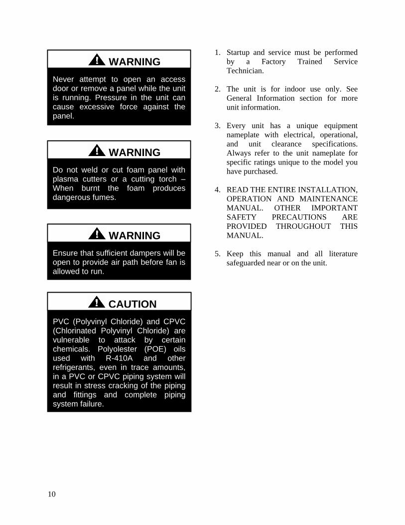
11
H3V3 Series Feature String Nomenclature
Model Options Unit Feature Options G
EN
SIZ
E
OR
EN
T
MJ
RE
V
VL
T
CO
RR
A1
A2
A3
A4
B1
B2
B3
1A
1B
1C
1D
2
3
4
5A
5B
5C
6A
6B
6C
7
8
9
10
11
12
13
14A
14B
H3 - A R B - 3 - 0 - 1 6 1 C - 1 2 F A A B B - 0 C 0 - F T B - 0 G 0 - 0 0 A A A C 0 0 B
A 0 0 0 0 0 0 0 0
15
16
17
18
19
20
21
22
23
12
H3V3 Base Model Description
BASE MODEL SERIES AND GENERATION
H3 = Horizontal - Back Intake Front Discharge
V3 = Vertical - Back Intake Top Discharge
UNIT SIZE
A = Up to 1200 cfm
B = Up to 2000 cfm
C = Up to 4000 cfm
D = Up to 6000 cfm
E = Up to 10000 cfm
UNIT ORIENTATION
R = Right Hand Connections
L = Left Hand Connections
REVISION
A = First Revision
B = Second Revision
VOLTAGE
1 = 230V1Φ60Hz
2 = 230V3Φ60Hz
3 = 460V3Φ60Hz
4 = 575V3Φ60Hz
8 = 208V3Φ60Hz
9 = 208V1Φ60Hz
CORROSION PROTECTION
0 = None
A = Interior Corrosion Protection
Model Option A COOLING A1 COOLING TYPE
0 = No Cooling
1 = R-410A DX Cooling
2 = Chilled Water Cooling
A2 COOILNG ROWS
0 = No Cooling
4 = 4 Row Coil
6 = 6 Row Coil
8 = 8 Row Coil
A3 COOLING STAGES
0 = No Cooling
1 = Single Circuit
2 = Two Circuits - Interlaced Coil
D = Double Serpentine
F = Single Serpentine
H = Half Serpentine
Q = Quarter Serpentine
A4 COOLING FPI
0 = No Cooling
A = 10 fpi
B = 8 fpi
C = 12 fpi
D = 14 fpi
H3V3 Series Feature String Nomenclature
Model Options Unit Feature Options G
EN
SIZ
E
OR
EN
T
MJR
EV
VL
T
CO
RR
A1
A2
A3
A4
B1
B2
B3
1A
1B
1C
1D
2
3
4
5A
5B
5C
6A
6B
6C
7
8
9
10
11
12
13
14A
14B
H3 - A R B - 3 - 0 - 1 6 1 C - 1 2 F A A B B - 0 C 0 - F T B - 0 G 0 - 0 0 A A A C 0 0 B
A 0 0 0 0 0 0 0 0
15
16
17
18
19
20
21
22
23
13
Model Option B HEATING B1 HEATING TYPE
0 = No Heating
1 = Hot Water
3 = Electric Heating
4 = Steam Distributing
B2 HEATING DESIGNATION
0 = No Heating
1 = 1 Row Coil
2 = 2 Row Coil
A = 7 kW (53 kW 208V)
B = 14 kW (105 kW 208V)
C = 21 kW (158 kW 208V)
D = 28 kW (210 kW 208V)
E = 35 kW (263 kW 208V)
F = 42 kW (315 kW 208V)
G = 49 kW (370 kW 208V)
H = 56 kW (420 kW 208V)
J = 63 kW (473 kW 208V)
K = 70 kW (525 kW 208V)
L = 77 kW (578 kW 208V)
M = 84 kW (630 kW 208V)
B3 HEATING STAGES
0 = No Heating
1 = 1 Stage
2 = 2 Stage
3 = 3 Stage
4 = 4 Stage
S = ModulatingSCR Electric
F = Single Serpentine 12 fpi
H = Half Serpentine 12 fpi
Q = Quarter Serpentine 12 fpi
Feature 1 SUPPLY FAN 1A SUPPLY AIR BLOWER CONFIGURATION
0 = 1 Blower + Premium Eff Motor
1 = 1 Blower + Premium Eff Motor + 1 VFD
A = 1 Blower + 1 High Efficiency EC Motor
B = 2 Blowers + 2 High Efficiency EC Motors
1B SUPPLY AIR BLOWER
1 = 15rdquo Backward Curved Plenum Fan
2 = 15rdquo BC Plenum 50 Width with Banding
3 = 185rdquo Backward Curved Plenum Fan
4 = 185rdquo BC Plenum Fan 70 Width with Banding
5 = 22rdquo Backward Curved Plenum Fan
6 = 24rdquo Backward Curved Plenum Fan
7 = 27rdquo Backward Curved Plenum Fan
8 = 27rdquo BC Plenum Fan 70 Width with Banding
A = 310 mm Direct Drive BC Plenum Fan
B = 355 mm Direct Drive BC Plenum Fan
C = 450 mm Direct Drive BC Plenum Fan
D = 250 mm Direct Drive BC Plenum Fan
1C SUPPLY AIR BLOWER MOTOR
1 = 1 hp - 1760 rpm
2 = 2 hp - 1760 rpm
3 = 3 hp - 1760 rpm
4 = 5 hp - 1760 rpm
5 = 75 hp - 1760 rpm
6 = 10 hp - 1760 rpm
B = 10 kW (134 hp)
C = 17 kW (228 hp)
D = 30 kW (402 hp)
E = 60 kW (800 hp)
F = 08 kW (107 hp)
1D SUPPLY BLOWER CONTROLCONTROL
VENDORS
0 = Standard - Terminal Block
A = Potentiometer Supply Fan Control
B = WattMaster Orion Controls System
C = Field Installed Controls by Others
D= Field Installed Controls by Others + Isolation
Relays
H3V3 Series Feature String Nomenclature
Model Options Unit Feature Options
GE
N
SIZ
E
OR
EN
T
MJR
EV
VL
T
CO
RR
A1
A2
A3
A4
B1
B2
B3
1A
1B
1C
1D
2
3
4
5A
5B
5C
6A
6B
6C
7
8
9
10
11
12
13
14A
14B
H3 - A R B - 3 - 0 - 1 6 1 C - 1 2 F A A B B - 0 C 0 - F T B - 0 G 0 - 0 0 A A A C 0 0 B
A 0 0 0 0 0 0 0 0
15
16
17
18
19
20
21
22
23
14
Feature 2 REFRIGERATION OPTIONS 0 = Standard - None
A = Single Circuit External Hot Gas Bypass
B = Dual Circuit External Hot Gas Bypass
C = Heat Pump
D = Option B + H
F = Options C + H
H = Modulating Hot Gas Reheat
P = Option H (Circuit 1) + Option A (Circuit 2)
R = Option C + A
S = Option C + B
T = Option C + H + A
U = Option C + H + B
Feature 3 SPECIAL CONTROLS 0 = Standard - None
A = Constant Volume Controller - CV Cool + CV
Heat
B = Constant Volume Controller with Modulating
Hot Gas Reheat - CV Cool + CV Heat
C = VAV Controller - VAV Cool + CV Heat
D = VAV Controller with MHGR - VAV Cool + CV
Heat
E = Make Up Air Controller - CV Cool + CV Heat
F = Make Up Air Controller with Modulating Hot
Gas Reheat - CV Cool + CV Heat
G = WattMaster Modulating Hot Gas Reheat
Controller
Feature 4 ADDITIONAL CONTROLS 0 = Standard - None
A = Phase and Brownout Protection
B = Return and Supply Air Firestat
C = Return Air Smoke Detector
D = Options A + B
E = Options A + C
F = Options B + C
G = Options A + B + C
H = Remote Safety Shutdown Terminals
J = Energy Recovery Wheel Rotation Detection
K = Options A + H
L = Options A + J
M = Options B + H
Feature 4 ADDITIONAL CONTROLS
Continued N = Options B + J
P = Options C + H
Q = Options C + J
S = Options A + B + H
T = Options A + B + J
U = Options A + C + H
V = Options A + C + J
W = Options A + H + J
Y = Options B + C + H
Z = Options B + C + J
1 = Options B + H + J
2 = Options C + H + J
3 = Options A + B + C + H
4 = Options A + B + C + J
5 = Options A + B + H + J
6 = Options A + C + H + J
7 = Options B + C + H + J
8 = Options A + B + C + H + J
Feature 5 MIXING BOX 5A RETURN AIR DAMPER POSITION
0 = Standard - None
F = Front
L = Left Hand (Front OA Damper Required)
R = Right Hand (Front OA Damper Required)
T = Top (Front OA Damper Required)
5B OUTSIDE AIR DAMPER POSITION
0 = Standard - None
F = Front
L = Left Hand (Front RA Damper Required)
R = Right Hand (Front RA Damper Required)
T = Top (Front RA Damper Required)
5C MIXING BOX DAMPER CONTROL
0 = Standard - None
A = 2 Position Actuators (24V)
B = Fully Modulating Actuators (DDC)
C = Fixed Position Dampers
H3V3 Series Feature String Nomenclature
Model Options Unit Feature Options
GE
N
SIZ
E
OR
EN
T
MJR
EV
VL
T
CO
RR
A1
A2
A3
A4
B1
B2
B3
1A
1B
1C
1D
2
3
4
5A
5B
5C
6A
6B
6C
7
8
9
10
11
12
13
14A
14B
H3 - A R B - 3 - 0 - 1 6 1 C - 1 2 F A A B B - 0 C 0 - F T B - 0 G 0 - 0 0 A A A C 0 0 B
A 0 0 0 0 0 0 0 0
15
16
17
18
19
20
21
22
23
15
Feature 6 FILTER BOX 6A PRE FILTER BOX
0 = Standard - None
A = 2rdquo Pleated - 30 Eff - MERV 10
B = 4rdquo Pleated - 30 Eff - MERV 10
C = 4rdquo Pleated - 65 Eff - MERV 11
D = 4rdquo Pleated - 85 Eff - MERV 13
E = 4rdquo Pleated - 95 Eff - MERV 14
F = 2rdquo Pleated - 30 Eff - MERV 10 + 4rdquo Pleated -
30 Eff - MERV 10
G = 2rdquo Pleated - 30 Eff - MERV 10 + 4rdquo Pleated -
65 Eff - MERV 11
H = 2rdquo Pleated - 30 Eff - MERV 10 + 4rdquo Pleated -
85 Eff - MERV 13
J = 2rdquo Pleated - 30 Eff - MERV 10 + 4rdquo Pleated -
95 Eff - MERV 14
6B UNIT FILTER
0 = Standard - None
A = 2rdquo Pleated - 30 Eff - MERV 10
B = 4rdquo Pleated - 30 Eff - MERV 10
C = 4rdquo Pleated - 65 Eff - MERV 11
D = 4rdquo Pleated - 85 Eff - MERV 13
E = 4rdquo Pleated - 95 Eff - MERV 14
F = 2rdquo Pleated - 30 Eff - MERV 10 + 4rdquo Pleated -
30 Eff - MERV 10
G = 2rdquo Pleated - 30 Eff - MERV 10 + 4rdquo Pleated -
65 Eff - MERV 11
H = 2rdquo Pleated - 30 Eff - MERV 10 + 4rdquo Pleated -
85 Eff - MERV 13
J = 2rdquo Pleated - 30 Eff - MERV 10 + 4rdquo Pleated -
95 Eff - MERV 14
6C FINAL FILTER BOX
0 = Standard - None
A = 2rdquo Pleated - 30 Eff - MERV 10
B = 12rdquo Cartridge - 65 Eff - MERV 11
C = 12rdquo Cartridge - 85 Eff - MERV 13
D = 12rdquo Cartridge - 95 Eff - MERV 14
E = 2rdquo Pleated - 30 Eff - MERV 10 + 12rdquo
Cartridge - 65 Eff - MERV 11
F = 2rdquo Pleated - 30 Eff - MERV 10 + 12rdquo
Cartridge - 85 Eff - MERV 13
G = 2rdquo Pleated - 30 Eff - MERV 10 + 12rdquo
Cartridge - 95 Eff - MERV 14
Feature 7 FILTER OPTIONS 0 = Standard - None
A = Magnehelic Gauge
B = Clogged Filter Switch
C = Options A + B
Feature 8 COIL COATING 0 = Standard - None
A = E-coated Cooling and Heating Coils
B = Copper Finned Coils + Stainless Steel Coil
Casing
Feature 9 EXPANSION VALVE 0 = None
A = Thermal Expansion Valves
Feature 10 EXPANSION VALVE
CONTROLS 0 = None
A = Standard Control
Feature 11 EXTERNAL PAINT 0 = Standard - None
A = AAON Gray Paint
B = Special Paint
H3V3 Series Feature String Nomenclature
Model Options Unit Feature Options
GE
N
SIZ
E
OR
EN
T
MJR
EV
VL
T
CO
RR
A1
A2
A3
A4
B1
B2
B3
1A
1B
1C
1D
2
3
4
5A
5B
5C
6A
6B
6C
7
8
9
10
11
12
13
14A
14B
H3 - A R B - 3 - 0 - 1 6 1 C - 1 2 F A A B B - 0 C 0 - F T B - 0 G 0 - 0 0 A A A C 0 0 B A 0 0 0 0 0 0 0 0
15
16
17
18
19
20
21
22
23
16
Feature 12 TONNAGE 0 = Standard - None
A = 2 ton Capacity
B = 3 ton Capacity
C = 4 ton Capacity
D = 5 ton Capacity
E = 6 ton Capacity
F = 7 ton Capacity
G = 8 ton Capacity
U = 9 ton Capacity
H = 10 ton Capacity
V = 11 ton Capacity
W = 13 ton Capacity
J = 14 ton Capacity
Y = 15 ton Capacity
Z = 16 ton Capacity
K = 17 ton Capacity
1 = 18 ton Capacity
2 = 20 ton Capacity
L = 22 ton Capacity
M = 25 ton Capacity
3 = 26 ton Capacity
N = 30 ton Capacity
P = 31 ton Capacity
Q = 34 ton Capacity
R = 40-45 ton Capacity
S = 50-55 ton Capacity
4 = 60 ton Capacity
T = 63 ton Capacity
5 = 70 ton Capacity
Feature 13 ENERGY RECOVERY
TYPE 0 = Standard ndash None
A = Energy Recovery Wheel ndash Total + High CFM
Polymer
C = Energy Recovery Wheel ndash Total + High CFM
1 Purge Polymer
E = Energy Recovery Wheel ndash Sensible + High CFM
Polymer
G = Energy Recovery Wheel ndash Sensible + High
CFM 1 Purge Polymer
Feature 14 GPM 14A GPM COOLING COIL
0 = Standard - None
A = 15-25 gpm
B = 26-70 gpm
C = 71 -140 gpm
D = 141-240 gpm
E = 241-400 gpm
F = 401-800 gpm
G = 801-1500 gpm
H = 1501-2500 gpm
14B GPM HEATING COIL
0 = Standard - None
A = 15-25 gpm
B = 26-70 gpm
C = 71 -140 gpm
D = 141-240 gpm
E = 241-400 gpm
F = 401-800 gpm
G = 801-1500 gpm
H = 1501-2500 gpm
Feature 15 CONTROL PANEL 0 = Internal Control Panel
A = Small Control Panel - 12rdquo x 12rdquo
B = Medium Control Panel - 25rdquo x 22rdquo
C = Large Control Panel - 48rdquo x 22rdquo
Feature 16 SHIPPING SPLITS 0 = Standard ndash None
A = 1 Shipping Split (2 pallets)
B = 2 Shipping Splits (3 pallets)
C = 3 Shipping Splits (4 pallets)
D = 4 Shipping Splits (5 pallets)
E = 5 Shipping Splits (6 pallets)
H = Special Shipping Split (SPA Required)
H3V3 Series Feature String Nomenclature
Model Options Unit Feature Options
GE
N
SIZ
E
OR
EN
T
MJR
EV
VL
T
CO
RR
A1
A2
A3
A4
B1
B2
B3
1A
1B
1C
1D
2
3
4
5A
5B
5C
6A
6B
6C
7
8
9
10
11
12
13
14A
14B
H3 - A R B - 3 - 0 - 1 6 1 C - 1 2 F A A B B - 0 C 0 - F T B - 0 G 0 - 0 0 A A A C 0 0 B
A 0 0 0 0 0 0 0 0 1
5
16
17
18
19
20
21
22
23
17
Feature 17 ENERGY RECOVERY
CABINET 0 = Standard - None
A = Top RA + Back EA + Back OA Connections
G = OA + EA Dampers - Top RA + Back EA + Back
OA Connections
N = OA + Economizer Dampers - Top RA + Back
EA + Back Connections
U = OA + EA + Economizer Dampers - Top RA +
Back EA + Back OA Connections
Feature 18 MODULATING ELECTRIC
PREHEAT 0 = Standard - None
A = 75 kW
B = 15 kW
C = 20 kW
D = 225 kW
E = 30 kW
F = 40 kW
G = 50 kW
H = 60 kW
Feature 19 EXHAUST FAN 0 = Standard - None
A = 250 mm Exhaust Fan 800 W EC Motor
B = 310 mm Exhaust Fan 10 kW EC Motor
C = 310 mm Exhaust Fan 17 kW EC Motor
D = 355 mm Exhaust Fan 17 kW EC Motor
E = 450 mm Exhaust Fan 30 kW EC Motor
F = 450 mm Exhaust Fan 60 kW EC Motor
G = Dual 310 mm Exhaust Fan 10 kW EC Motor
H = Dual 310 mm Exhaust Fan 17 kW EC Motor
J = Dual 355 mm Exhaust Fan 17 kW EC Motor
K = Dual 450 mm Exhaust Fan 30 kW EC Motor
L = Dual 450 mm Exhaust Fan 60 kW EC Motor
Feature 20 CRATING 0 = Standard - None
A = Export Crating
B = Forkliftable Base - 5rdquo Base
C = Options A + E
D = Options A + B
E = Shipping Shrink Wrap
F = Options B + E
G = Options A + B + E
Feature 21 PULLEY COMBINATION 0 = Standard - None
A = 1000-1400 rpm
B = 1401-1800 rpm
C = 1801-2200 rpm
Feature 22 WARRANTY 0 = Standard - 1 Year Parts
Feature 23 TYPE 0 = Standard
X = Special Pricing Authorization
18
General Information
AAONreg
H3 and V3 Series indoor air
handling units have been designed for
indoor installation only Units are
assembled wired charged with dry nitrogen
and run-tested at the factory H3 and V3
Series units are not intended for residential
use Startup and service must be performed
by a Factory Trained Service Technician
Certification of Steam or Hot Water Heat
Models
a Certified as a forced air heating system
with or without cooling
b Certified for indoor installation only
Certification of Electric Heat Models
a Certified as an electric warm air furnace
with or without cooling
b Certified for indoor installation only
Certification of Cooling Models
a Certified as a commercial central air
conditioner with or without electrically
operated compressors
b Certified for indoor installation only
c Certified with refrigerant R-410A coils
or with chilled water cooling coils
Improper installation adjustment alteration service or maintenance can cause property damage personal injury or loss of life Startup and service must be performed by a Factory Trained Service Technician A copy of this IOM should be kept with the unit
WARNING
These units must not be used as a ldquoconstruction heaterrdquo at anytime during any phase of construction Very low return air temperatures harmful vapors and misplacement of the filters will damage the unit and its efficiency
CAUTION
This equipment is protected by a standard limited warranty under the condition that initial installation service startup and maintenance is performed according to the instructions set forth in this manual This manual should be read in its entirety prior to installation and before performing any service or maintenance work Equipment described in this manual is available with many optional accessories If you have questions after reading this manual in its entirety consult other factory documentation or contact your AAON Sales Representative to obtain further information before manipulating this equipment or its optional accessories
CAUTION
19
Codes and Ordinances
H3 and V3 Series units have been tested and
certified by ETL in accordance with UL
Safety Standard 1995CSA C222 No 236
System should be sized in accordance with
the American Society of Heating
Refrigeration and Air Conditioning
Engineers Handbook
Installation of H3 and V3 Series units must
conform to the ICC standards of the
International Mechanical Code the
International Building Code Installation of
Air Conditioning and Ventilating Systems
Standard NFPA 90A and local building
plumbing and waste water codes All
appliances must be electrically grounded in
accordance with local codes or in the
absence of local codes the current National
Electric Code ANSINFPA 70 or the
current Canadian Electrical Code CSA
C221
Receiving Unit
When received the unit should be checked
for damage that might have occurred in
transit If damage is found it should be noted
on the carrierrsquos Freight Bill A request for
inspection by carrierrsquos agent should be made
in writing at once
Nameplate should be checked to ensure the
correct model sizes and voltages have been
received to match the job requirements
If repairs must be made to damaged goods
then the factory should be notified before
any repair action is taken in order to protect
the warranty Certain equipment alteration
repair and manipulation of equipment
without the manufacturerrsquos consent may
void the product warranty Contact the
AAON Warranty Department for assistance
with handling damaged goods repairs and
freight claims (903) 236-4403
Note Upon receipt check shipment for
items that ship loose such as remote sensors
Consult order and shipment documentation
to identify potential loose-shipped items
Loose-shipped items may have been placed
inside unit cabinet for security Installers
and owners should secure all doors with
locks or nuts and bolts to prevent
unauthorized access
The Clean Air Act of 1990 bans the intentional venting of refrigerant as of July 1 1992 Approved methods of recovery recycling or reclaiming must be followed
CAUTION
Coils and sheet metal surfaces present sharp edges and care must be taken when working with equipment
WARNING
Failure to observe the following instructions will result in premature failure of your system and possible voiding of the warranty
WARNING
20
Figure 1 - Lockable Handle
Storage
This equipment is not suitable for outdoor
use of storage If installation will not occur
immediately following delivery store
equipment in a dry protected area away from
construction traffic and in the proper
orientation as marked on the packaging with
all internal packaging in place Secure all
loose-shipped items
Direct Expansion (DX) Systems
All DX refrigerant coils are factory charged
with a nitrogen holding charge All DX
systems include evaporator coils and
thermal expansion valves (TXV)
Never turn off the main power supply to the
unit except for servicing emergency or
complete shutdown of the unit When power
is cut off from the unit crankcase heaters
cannot prevent refrigerant migration into the
split system condensing unit compressors
This means the compressor may cool down
and liquid refrigerant may accumulate in the
compressor The compressor is designed to
pump refrigerant gas and damage may occur
when power is restored
If power to the unit must be off for more
than an hour turn the thermostat system
switch to OFF or turn the unit off at the
control panel and leave the unit off until the
main power switch has been turned on again
for at least 24 hours for units with
compressor crankcase heaters This will give
the crankcase heater time to clear any liquid
accumulation out of the compressor before it
is started
Always control the unit from the thermostat
or control panel never at the main power
supply except for emergency or complete
shutdown of the unit
During the cooling season if the air flow is
reduced due to dirty air filters or any other
reason the cooling coils can get too cold
which will cause excessive liquid to return
to the compressor As the liquid
concentration builds up oil is washed out of
the compressor leaving it starved for
lubrication
The compressor life will be seriously
shortened by reduced lubrication and the
pumping of excessive amounts of liquid oil
and refrigerant
CRANKCASE HEATER OPERATION
Some units are equipped with compressor crankcase heaters which should be energized at least 24 hours prior to cooling operation to clear any liquid refrigerant from the compressors
CAUTION
21
Note Low Ambient Operation
Air-cooled DX units without a low ambient
option such as condenser fan cycling or the
0degF low ambient option will not operate in
the cooling mode of operation properly
when the outdoor temperature is below
55degF Low ambient andor economizer
options are recommended if cooling
operation below 55degF is expected
Wiring Diagrams
Unit specific wiring diagrams are laminated
and affixed inside the controls compartment
door
Condensate Drain Pans
Units require field installed drain p-traps and
lines to be connected to the condensate drain
pans of the unit
For condensate drain lines the line should
be the same pipe size or larger than the drain
connection include a p-trap and pitch
downward toward drain An air break should
be used with long runs of condensate lines
See Installation section of this manual for
more information
Unit should not be operated without a p-trap Failure to install a p-trap may result in overflow of condensate water
CAUTION
Emergency drain pan is recommended for all applications where a risk of water damage to surrounding structure or furnishings Refer to local codes
CAUTION
22
Installation
AAON equipment has been designed for
quick and easy installation Startup and
service must be performed by Factory
Trained Service Technician
The H3V3 unit can either be shipped
assembled or shipped in sections See the
Unit Assembly section of this document for
instructions on assembling the sections
Locating the Unit
Placement of the unit relative to ductwork
electrical and plumbing must be carefully
considered Return air plenum or duct can be
mounted directly to the return air flanges
Use flexible gasket material to seal the duct
to the unit
Verify floor foundation or suspension
support can support the total unit weight
including accessory weights Unit must be
level in both horizontal axes to support the
unit and reduce noise and vibration from the
unit
Allow adequate space for piping access and
panel removal To ensure proper access
for field service maintain minimum
clearances for field piping and other
obstructions as indicated by Table 1 and
Figure 2 and Figure 3 Consult local
building codes for additional service
clearance requirements Condensate drain
connections are located on the access side of
the unit
Table 1 - H3 and V3 Series Clearances
Unit Size
Access Side
Clearance
(dimension X on
Figure 2 and
Figure 3)
All Other
Sides
V3-A
36 inches
6 inches
V3-B
V3-C
V3-D
V3-E
H3-A
H3-B
H3-C
H3-D 45 inches
H3-E 60 inches
Additional clearance may be required to
allow for coil removal
May be installed flush depending upon
local codes
Figure 2 - Minimum Clearance Required for
Access to Unit (V3 Series plan view)
X
(See Table 1)
Back Front
Left
Right
23
Figure 3 - Minimum Clearance Required for
Access to Unit (H3 Series plan view)
Internal Control Panel
H3 units with internal control panel have
removable access panels on the top and
bottom of the supply fan section V3 units
with internal control panel have removable
access panels on the front and back of the
supply fan section V3 units that have
energy recovery only have one removable
supply fan access panel on the front of the
unit The supply flanges can be
interchanged with the access panels if
necessary except on size E
Figure 4 - H3 internal control panel with top
access panel removed
Figure 5 - V3 internal control panel with
rear removable access panel shown
Floor Mounted Units
Make sure the unit is level and mounted on a
field supplied platform with a minimum
height to allow for proper depth of the
condensate line p-trap Other installation
provisions may be necessary according to
job specifications V3 Series vertical air
handling units are designed for upflow
applications only
Suspended Units
H3 Series horizontal air handling units are
equipped for suspended installations The
unit should be lifted into position by
supporting the unit with the skid used for
shipping The air handling unit must be
installed level and care should be taken to
prevent damage to the cabinet Other
installation provisions may be necessary
according to job specifications Figure 6
and Figure 7 show factory recommended
methods for suspended installations It is
the responsibility of the specifying engineer
or installing contractor to ensure the
installation is structurally safe and sound
X
(See Table 1)
Front
Back
Left Right
24
Figure 6 - H3 Series Platform Suspension Installation
Figure 7 - H3 Series Parallel Beam Suspension Installation
25
Figure 8 - H3 Series Unit Orientation
Figure 9 - V3 Series Unit Orientation
Note Access doors may be on the ldquoleftrdquo or ldquorightrdquo side as designated by the unit orientation on
the configurator string ldquoBackrdquo will always be the same side as the pre-filter and return air
opening ldquoFrontrdquo will always be the side opposite the pre-filter and return air opening
H3 Series
Return Air ldquoBackrdquo
Supply Air ldquoFrontrdquo
Right Hand Side
Left Hand Side
Connections and service access on right side for right hand orientation
Top View
Air Flow
Connections and service access on right side for right hand orientation
Right Hand Side Left Hand Side
Return Air ldquoBackrdquo
Top View V3 Series
Air Flow
Consider the air flow to be hitting the back of your head
Consider the air flow to be hitting the back of your head
Supply Air
ldquoFrontrdquo
26
Lifting and Handling the Unit
Before lifting unit be sure that all shipping
material has been removed from unit
Care should be taken if using spreader bars
blocking or other lifting devices to prevent
damage to the cabinet coil or fans
Unit Assembly
Although H3V3 Series units are shipped
factory assembled as standard the unit may
be ordered as shipping splits for certain
applications such as for assembly in existing
structures where modules must be
manipulated separately If the unit was
ordered as shipping splits then they must be
assembled in the field
Locate the schematic in the equipmentrsquos
literature packet
1 Identify and Situate Splits
a H3 Units can have the following
ship split sections
1 Mixing Box
2 Air Handler
3 Final Filter
4 Electric Heat
Figure 10 - H3 Schematic with (1) Mixing
Box (2) Air Handler (3) Final Filter and
(4) Electric Heat
b V3 Units can have the following
ship split sections
1 Exhaust Fan
2 Energy Recovery
3 Air Handler
4 Electric Heat
5 Pre filter
6 Mixing box
Figure 11 - V3 Schematic with (1) Exhaust
Fan (2) Energy Recovery (3) Air Handler
and (4) Electric Heat
2 Connect Sections
Using the V3 Schematic as an example
section 1 will have a duct flange and it will
connect to section 2 on the side that does not
have a flange First make sure gasket is on
the panel around the edges of the exposed
duct flanges Push section 1 and 2 together
UNIT HANDLING
Incorrect lifting can cause damage to the unit injury or death Lifting equipment capacity should exceed unit weight by an adequate safety factor Always test lift unit not more than 24 inches high to verify proper center of gravity lift point
WARNING
1 2 3 4
1 2
3
4
27
so that the flange from section 1 is inside of
section 2
Figure 12 - Connect Sections
Use bar clamps or other non-destructive
winching device to pull the tops of the
modules together tightly
Figure 13 - Bar Clamp
At each of the pre-drilled holes in the flange
drill 516 hex head self-tapping screws to
secure the two sections together
Figure 14 - Flange Overlap
Figure 15 - Self-Tapping Screw
All connection hardware is shipped with the
unit
3 Secure Module Joints
The metal straps are to be used to secure
module joints Straps are provided with pre-
drilled holes Self-tapping sheet metal
screws are provided to attach the straps to
the unit cabinet
Leave bar clamps in place until strap is
secure
Place the strap over a module joint ensure
the strap completely covers the joint and
that it is square with the unit casing
Insert self-tapping screws through pre-
drilled holes in strap and secure screws into
unit casing using a power drill For best
results use the lowest effective power drill
torque setting Be careful not to over tighten
the screws
Remove bar clamps and repeat for all
remaining module joints
Figure 16 - Strap Types
516rdquo Hex Head Self-Tapping Screws
Provided with Unit
1rdquo
Angle Strap
Top Strap
Section 2
Flange
28
4 Connect Power and Control Wiring
H3V3 Series units are equipped with low
and high voltage quick connects to connect
wiring from one section to the next Wire
from the unit to external controls and power
sources must be provided in the field
Figure 17 - Low Voltage Quick Connect
A color-coded wiring diagram is laminated
and affixed to the inside of the control
compartment access door H3V3 Series
units are equipped with a single point power
connection
5 Final Sealing
It is very important to keep air from
infiltrating the unit cabinet Seal all piping
penetrations with Armaflex Permagum or
other suitable sealant Also seal around drain
connections electrical connections and all
other inlets where air may enter the cabinet
This is especially important when the unit is
installed in an unconditioned area
Control Box
Some H3V3 units include an external
control box that must be mounted in the
field
Figure 18 - Back View External Control
Box
Duct Connection
Attach duct to flanges provided on the unit
The installer is responsible for sealing ducts
to the flanges to prevent water leaks
Refer to Figure 8 and Figure 9 for duct
connection locations The V3 supply air duct
is out to top of the unit Ductwork should be
sized in accordance with the ASHRAE
Handbook Ductwork should be installed in
accordance with NFPA Standard 90A
When attaching duct to the unit use a
flexiblecompressible material rated for duct
connections A three inch flexible connector
for both return and supply duct connections
is recommended
Condensate Drain Piping
Unit may be equipped with more than one
condensate drain pan connection A p-trap
and drain line must be installed on at least
one sectionrsquos drain connection with the p-
trap not to exceed 6rdquo from the drain
connection The lines should be the same
pipe size or larger than the drain connection
include a p-trap and pitch downward toward
drain An air break should be used with long
runs of condensate lines
Installing Contractor is responsible for proper sealing of the electrical and piping entries into the unit Failure to seal the entries may result in damage to the unit and property
CAUTION
29
Draw-through cooling coils will have a
negative static pressure in the drain pan area
This will cause an un-trapped drain to back
up due to air being pulled up through the
condensate drain piping
Condensate drain trapping and piping should
conform to all applicable governing codes
Note The drain pan connection(s) is a 1rdquo
MPT fitting
Figure 19 - Drain Trap
The X dimension on the draw-through trap
should be at least equal to the absolute value
of the negative static pressure in the drain
pan plus one inch To calculate the static
pressure at the drain pan add the pressure
drops of all components upstream of the
drain pan including the cooling coil and
add the return duct static pressure Include
the dirt allowance pressure drop for the
filters to account for the worst-case scenario
The height from top of the bottom bend of
the trap to the bottom of the leaving pipe
must be at least equal to one half of the X
dimension This ensures that enough water
is stored in the trap to prevent losing the
drain seal during unit startup
Note The absolute value of the fan inlet
pressure will always be greater than or equal
to the absolute value of the static pressure in
the drain pan on draw-through units so the
fan inlet pressure is a safe value to use for
the drain pan static pressure
Table 2 - Drain Trap Dimensions
Draw-Through
Drain Pan Pressure Trap Dimensions
Negative Static X X2
(inches of water) (inch) (inch)
-050 150 075
-100 200 100
-150 250 125
-200 300 150
-250 350 175
-300 400 200
-350 450 225
-400 500 250
Heating Coils
One or two row hot water and steam heating
and preheating coils can be factory installed
These coils are supplied from a building hot
water source All valve controls for heating
coil operation are field supplied and field
installed
Unit should not be operated without p-traps Failure to install a p-traps may result in overflow of condensate water
CAUTION
30
Always connect the steam heating supply to
the top of the coil and the return to the
bottom
Figure 20 - Steam Distributing Piping
Table 3 - Steam Distributing Coil
Connection Sizes
Model (H3- V3-) Supply and Return
Connection Size
A-E 2 18
Air handling units with steam heating coils
MUST BE installed high enough to allow
for a minimum of 1 foot condensate drop leg
off of the steam coil or as recommended by
the steam trap manufacturer Lines should
be insulated with approved insulation and be
properly fastened sloped and supported
according to local code requirements
Table 4 - Hot Water Coil Connection Sizes
Model (H3- V3-) Supply and Return
Connection Size
A 78
B 1 18
C 1 38
D amp E 1 58
Always connect the hot water heating supply
to the bottom of the coil and return to the
top
Figure 21 - Hot amp Chilled Water Piping
Water coils should not be subjected to
entering air temperatures below 38degF to
prevent coil freeze-up If air temperature
across the coil is going to be below this
value use a glycol solution to match the
coldest air expected
Water supply lines must be insulated
properly fastened drained and supported
according to local code requirements
Chilled Water Coil
Factory installed four six or eight row
chilled water cooling coils can be factory
mounted These coils are supplied from a
building chilled water source All valve
controls for the cooling coil operation are
field supplied and field installed
31
Table 5 - Chilled Water Coil Connection
Sizes
Model (H3- V3-) Supply and Return
Connection Size
A 1 18
B 1 38
C 1 58
D amp E 2 18
Always connect the chilled water supply to
the bottom of the coil and return to the top
Water supply lines must be insulated with
closed cell type pipe insulation or insulation
that includes a vapor barrier Lines should
be properly fastened drained and supported
according to local code requirements and
job specifications
Evaporator Coil
The air handling unit coils are pressurized
The copper caps must be punctured to
permit a gradual escape of the pressure prior
to un-sweating those caps Immediately
couple the tubing to the indoor unit to avoid
exposing the coils to moisture A properly
sized filter drier is furnished in the
condenser When making solder
connections make sure dry nitrogen flows
through the lines when heating the copper
to prevent oxidization inside of the copper
Field piping between the condensing unit
and the air handler is required Line
sizes must be selected to meet actual
installation conditions not simply based
on the connection sizes
Thermal Expansion Valve
Thermal expansion valve bulbs should be
mounted with good thermal contact on a
horizontal section of the suction line close to
the evaporator but outside the cabinet and
well insulated On suction lines less than or
equal to 78rdquo OD mount in the 12 orsquoclock
position On suction lines greater than 78rdquo
OD mount in either the 4 orsquoclock or 8
orsquoclock position
Figure 22 - TXV Bulb Position
Hot Gas Reheat
Hot Gas Reheat (HGRH) is available for use
with DX systems that need humidity control
The AAON modulating hot gas reheat
system diverts hot discharge gas from the
condenser to the air handling unit through
the hot gas line Field piping between the
condensing unit and the air handler is
required Line sizes must be selected to
meet actual installation conditions not
simply based on the connection sizes
The line delivers the hot discharge gas to the
reheat coil andor the hot gas bypass valve
so it is sized as a discharge line
Modulating Hot Gas Reheat Piping
1 Run a hot gas reheat line from the
condensing unit and connect it to the inlet of
the stub-out on the reheat coil The inlet
connection is the top (or highest) stub-out of
the reheat coil Connect the hot gas line
from the outdoor unit to the upper stub-out
connection of the reheat coil
2 Run a liquid line from the discharge of the
reheat coil through a tee connection Run a
liquid line from the condenser through a
REFRIGERANT PIPING
Line sizes must be selected to meet actual installation conditions not simply based on the connection sizes at the condensing unit or air handling unit
CAUTION
32
check valve to the other side of the tee Run
a liquid line from the tee to the liquid line
stub-out of the evaporator coil
3 Run a suction line from the evaporator
coil outlet stub-out to the condensing unit
Hot Gas Bypass
Hot Gas Bypass is available for use with DX
systems that may experience low suction
pressure during the operating cycle This
may be due to varying load conditions
associated with VAV applications or units
supplying a large percentage of outside air
Hot Gas Bypass is not necessary in units
with variable capacity compressors The
system is designed to divert refrigerant from
the compressor discharge to the low pressure
side of the system in order to keep the
evaporator from freezing and to maintain
adequate refrigerant velocity for oil return at
minimum load
Hot discharge gas is redirected to the
evaporator inlet via an auxiliary side
connector (ASC) to false load the evaporator
when reduced suction pressure is sensed
Field piping between the condensing unit
and the evaporator is required Line sizes
must be selected to meet actual
installation conditions not simply based
on the connection sizes
Electric Preheat
The modulating electric preheat option is
designed to temper the incoming outside air
to the unit based on an enable control signal
and the outside air conditions
A 24VAC enable signal must be provided to
the [PHE] terminal to enable the operation
of the electric preheat Once the preheat
controller is enabled it will monitor the
outside air temperature to determine if any
capacity of preheat is needed If the outside
air temperature falls below the outside air
temperature setpoint the electric preheat will
be started up and maintain the leaving air
temperature setpoint with both SCR
controlled and staged electric preheat Both
setpoints are set with push button LCD
interface on the preheat controller Outside
air temperature sensors and preheat
discharge supply air temperature sensors are
factory installed and wired to the preheat
controller Electric preheat has maximum
operating outside air temperature of 60degF
and a maximum preheat discharge air
temperature of 80degF
[COM] [PHO] amp [PHC] feedback terminals
are provided to communicate if the electric
preheat is in operation PHO is a normally
open contact PHC is a normally closed
contact and COM is the common These
terminals are not required to be connected
[PHE] is the electric preheat operation
enable [PH+] and [PH-] are the preheat set
point reset terminals
33
Energy Recovery Units
Some H3V3 units have been equipped with
an energy recovery wheel This section is
provided to assure the energy recovery
feature will be properly setup to perform in
accordance with the job specifications for
your particular application
Figure 23 - Energy Recovery Wheel
The Energy Recovery Cassette consists of a
frame wheel wheel drive system and
energy transfer segments Segments are
removable for cleaning or replacement The
segments rotate through counter flowing
exhaust and outdoor air supply streams
where they transfer heat andor water vapor
from the warm moist air stream to the
cooler andor drier air stream
The initial setup and servicing of the energy
recovery wheel is very important to maintain
proper operation efficiency and building
occupant comfort
Normal maintenance requires periodic
inspection of filters the cassette wheel
drive belts air seals wheel drive motor and
its electrical connections
Wiring diagrams are provided with each
motor When wired according to wiring
diagram motor rotates clockwise when
viewed from the shaftpulley side
By carefully reviewing the information
within this section and following the
instructions the risk of improper operation
andor component damage will be
minimized
It is important that periodic maintenance be
performed to help assure trouble free
operation
Initial Mechanical Check and Setup
Outdoor air intake adjustments should be
made according to building ventilation or
local code requirements
After the unit installation is complete open
the cassette access door and determine that
the energy wheel rotates freely when turned
by hand Apply power and observe that the
wheel rotates at approximately 30 RPM If
the wheel does not rotate when power is
applied it may be necessary to readjust the
ldquodiameter air sealsrdquo
Air Seal Adjustments
Pile type air seals across both sides of the
energy wheel diameter are factory adjusted
to provide close clearance between the air
seal and wheel Racking of the unit or
cassette during installation andor mounting
of the unit on a non-level support or in other
than the factory orientation can change seal
clearances Tight seals will prevent rotation
Figure 24 - Cross Section of Air Seal
Structure
34
Wheel to Air Seal Clearance
To check wheel to seal clearance first
disconnect power to the unit in some units
the energy recovery wheel assembly can be
pulled out from the cabinet to view the air
seals On larger units the energy recovery
wheel may be accessible inside the walk-in
cabinet
A business card or two pieces of paper can
be used as a feller gauge (typically each
004rdquo thick) by placing it between the face
of the wheel and pile seal
Using the paper determine if a loose slip fit
exist between the pile seal and wheel when
the wheel is rotated by hand
To adjust air seal clearance loosen all seal
plate retaining screws holding the separate
seal retaining plates to the bearing support
channels and slide the seals plates away
from the wheel Using the paper feeler
gauge readjust and retighten one seal plate
at a time to provide slip fit clearance when
the wheel is rotated by hand
Confirm that the wheel rotates freely Apply
power to the unit and confirm rotation
Airflow Balancing and Checking
High performance systems commonly have
complex air distribution and fan systems
Unqualified personnel should not attempt to
adjust fan operation or air circulation as all
systems have unique operations
characteristics Professional air balance
specialists should be employed to establish
actual operating conditions and to configure
the air delivery system for optimal
performance
Controls
A variety of controls and electrical
accessories may be provided with the
equipment Identify the controls on each unit
by consulting appropriate submittal or order
documents and operate according to the
control manufacturerrsquos instructions If you
cannot locate installation operation or
maintenance information for the specific
controls then contact your sales
representative or the control manufacturer
for assistance
Routine Maintenance and Handling
Handle cassettes with care All cassettes
should be lifted by the bearing support
beam Holes are provided on both sides of
the bearing support beams to facilitate
rigging as shown in the following
illustration
Figure 25 - Lifting Hole Locations
Routine maintenance of the Energy
Recovery Cassettes includes periodic
Do not alter factory wiring Deviation from the supplied wiring diagram will void all warranties and may result in equipment damage or personal injury Contact the factory with wiring discrepancies
WARNING
35
cleaning of the Energy Recovery Wheel as
well as inspection of the Air Seals and
Wheel Drive Components as follows
Cleaning
The need for periodic cleaning of the energy
recovery wheel will be a function of
operating schedule climate and
contaminants in the indoor air being
exhausted and the outdoor air being supplied
to the building
The energy recovery wheel is ldquoself-
cleaningrdquo with respect to dry particles due to
its laminar flow characteristics Smaller
particles pass through larger particles land
on the surface and are blown clear as the
flow direction is reversed Any material that
builds up on the face of the wheel can be
removed with a brush or vacuum The
primary need for cleaning is to remove oil
based aerosols that have condensed on
energy transfer surfaces
A characteristic of all dry desiccants such
films can close off micron sized pores at the
surface of the desiccant material reducing
the efficiency by which the desiccant can
adsorb and desorb moisture and also build
up so as to reduce airflow
In a reasonably clean indoor environment
such as a school or office building
measurable reductions of airflow or loss of
sensible (temperature) effectiveness may not
occur for several years Measurable changes
in latent energy (water vapor) transfer can
occur in shorter periods of time in
applications such as moderate occupant
smoking or cooking facilities In
applications experiencing unusually high
levels of occupant smoking or oil based
aerosols such as industrial applications
involving the ventilation of machine shop
areas for example annual washing of energy
transfer may be necessary to maintain latent
transfer efficiency Proper cleaning of the
energy recovery wheel will restore latent
effectiveness to near original performance
To clean gain access to the energy recovery
wheel and remove segments Brush foreign
material from the face of the wheel Wash
the segments or small wheels in a 5
solution of non-acid based coil cleaner or
alkaline detergent and warm water
Soak in the solution until grease and tar
deposits are loosened (Note some staining
of the desiccant may remain and is not
harmful to performance) Before removing
rapidly run finger across surface of segment
to separate polymer strips for better cleaning
action Rinse dirty solution from segment
and remove excess water before reinstalling
in wheel
Air Seals
Four adjustable diameter seals are provided
on each cassette to minimize transfer of air
between the counter flowing airstreams
To adjust diameter seals loosen diameter
seal adjusting screws and back seals away
from wheel surface Rotate wheel clockwise
until two opposing spokes are hidden behind
the bearing support beam Using a folded
piece of paper as a feeler gauge position
paper between the wheel surface and
diameter seals
Adjust seals towards wheel surface until a
slight friction on the feeler gauge (paper) is
detected when gauge is moved along the
length of the spoke Retighten adjusting
Do Not use acid based cleaners aromatic solvents steam or temperatures in excess of 170degF damage to the wheel may occur
CAUTION
36
screws and recheck clearance with ldquofeelerrdquo
gauge
Wheel Drive Components
The wheel drive motor bearings are pre-
lubricated and no further lubrication is
necessary
The wheel drive pulley is secured to the
drive motor shaft by a combination of either
a key or D slot and set screw
The set screw is secured with removable
locktite to prevent loosening Annually
confirm set screw is secure The wheel drive
belt is a urethane stretch belt designed to
provide constant tension through the life of
the belt No adjustment is required Inspect
the drive belt annually for proper tracking
and tension A properly tensioned belt will
turn the wheel immediately after power is
applied with no visible slippage during start-
up
Installation Considerations
Energy recovery cassettes are incorporated
within the design of packaged units
packaged air handlers and energy recovery
ventilators In each case it is recommended
that the following considerations be
addressed
Accessibility
The cassette and all its operative parts ie
motor belt pulley bearings seals and
energy transfer segments must be accessible
for service and maintenance This design
requires that adequate clearance be provided
outside the enclosure
Orientation amp Support
The Energy Recovery Cassette may be
mounted in any orientation However Care
must be taken to make certain that the
cassette frame remains flat and the bearing
beams are not racked
To verify make certain that the distance
between wheel rim and bearing beam is the
same at each end of the bearing beam to
within 14 of an inch (dimension A amp B)
This amount of racking can be compensated
for by adjusting the diameter seals
If greater than 14 inch (dimension C)
racking must be corrected to ensure that
drive belt will not disengage from wheel
Figure 26 - Avoid Racking of Cassette
Frame
Operation
Startup Procedure
1 By hand turn wheel clockwise (as viewed
from the pulley side) to verify wheel turns
freely through 360ordm rotation
2 Before applying power to drive motor
confirm wheel segments are fully engaged in
wheel frame and segment retainers are
completely fastened (See Segment
Installation Diagram)
B
C
A
Bearing beams shown racked
Frame
Wheel
Bearing beams (2)
Flat surface
Keep hands away from rotating wheel Contact with rotating wheel can cause physical injury
CAUTION
37
3 With hands and objects away from
moving parts activate unit and confirm
wheel rotation Wheel rotates clockwise (as
viewed from the pulley side)
4 If wheel has difficulty starting turn power
off and inspect for excessive interference
between the wheel surface and each of the
four (4) diameter seals To correct loosen
diameter seal adjusting screws and back
adjustable diameter seals away from surface
of wheel apply power to confirm wheel is
free to rotate then re-adjust and tighten hub
and diameter seals as shown in hub seal
adjustment diagram
5 Start and stop wheel several times to
confirm seal adjustment and to confirm belt
is tracking properly on wheel rim
(approximately 14rdquo from outer edge of
rim)
Figure 27 - Diameter Seal Adjustment
Figure 28 - Hub Seal Adjustment
Service
Segment Installation amp Replacement
Wheel segments are secured to the wheel
frame by a Segment Retainer which pivots
on the wheel rim and is held in place by a
Segment Retaining Catch
Disconnect electrical power before servicing energy recovery cassette Always keep hands away from bearing support beam when installing or removing segments Failure to do so could result in severe injury to fingers or hand
CAUTION
38
Figure 29 - Segment Retainer
To install wheel segments follow steps one
through five below Reverse procedure for
segment removal
1 Unlock two segment retainers (one on
each side of the selected segment opening
2 With the embedded stiffener facing the
motor side insert the nose of the segment
between the hub plates
Figure 30 - Segment Installation
3 Holding segment by the two outer
corners press the segment towards the
center of the wheel and inwards against the
spoke flanges If hand pressure does not
fully seat the segment insert the flat tip of a
screw driver between the wheel rim and
outer corners of the segment and apply
downward force while guiding the segment
into place
4 Close and latch each Segment Retainer
under Segment Retaining Catch
5 Slowly rotate the wheel 180ordm Install the
second segment opposite the first for
counterbalance Rotate the two installed
segments 90ordm to balance the wheel while the
third segment is installed Rotate the wheel
180ordm again to install the fourth segment
opposite the third Repeat this sequence with
the remaining four segments
Wheel Drive Motor and Pulley Replacement
1 Disconnect power to wheel drive motor
2 Remove belt from pulley and position
temporarily around wheel rim
3 Loosen set screw in wheel drive pulley
using a hex head wrench and remove pulley
from motor drive shaft
4 While supporting weight of drive motor in
one hand loosen and remove (4) mounting
bolts
5 Install replacement motor with hardware
kit supplied
6 Install pulley to dimension as shown and
secure set screw to drive shaft
7 Stretch belt over pulley and engage in
groove
8 Follow start-up procedure
Belt Replacement
1 Obtain access to the pulley side bearing
access plate if bearing access plates are
provided Remove two bearing access plate
retaining screws and the access plate
39
2 Using hexagonal wrench loosen set screw
in bearing locking collar Using light
hammer and drift (in drift pin hole) tap
collar in the direction of wheel rotation to
unlock collar Remove collar
3 Using socket wrench with extension
remove two nuts which secure bearing
housing to the bearing support beam Slide
bearing from shaft If not removable by
hand use bearing puller
4 Form a small loop of belt and pass it
through the hole in the bearing support
beam Grasp the belt at the wheel hub and
pull the entire belt down
Note Slight hand pressure against wheel
rim will lift weight of wheel from inner race
of bearing to assist bearing removal and
installation
5 Loop the trailing end of the belt over the
shaft (belt is partially through the opening)
6 Reinstall the bearing onto the wheel shaft
being careful to engage the two locating pins
into the holes in the bearing support beam
Secure the bearing with two self-locking
nuts
7 Install the belts around the wheel and
pulley according to the instructions provided
with the belt
8 Reinstall diameter seals or hub seal and
tighten retaining screws Rotate wheel in
clockwise direction to determine that wheel
rotates freely with slight drag on seals
9 Reinstall bearing locking collar Rotate
collar by hand in the direction the wheel
rotates (see label provided on each cassette
for wheel rotation)
10 Lock in position by tapping drift pin
hole with hammer and drift Secure in
position by tightening set screw
11 Reinstall Bearing Access Cover
12 Apply power to wheel and ensure that
the wheel rotates freely without interference
Figure 31 - Belt Replacement
Protect hands and belt from possible sharp edges of hole in Bearing Support Beam
CAUTION
40
Electrical
Verify the unit name plate agrees with
power supply H3 and V3 Series units are
provided with single point power wiring
connections Connection terminations are
made to the main terminal block A
complete set of unit specific wiring
diagrams showing factory and field wiring
are laminated in plastic and located inside
the control compartment door
Route power and control wiring separately
through the utility entry in the unit Do not
run power and control signal wires in the
same conduit
All units require field supplied electrical
overcurrent and short circuit protection
Device must not be sized larger than the
Maximum Overcurrent Protection (MOP)
shown on the unit nameplate
Codes may require a disconnect switch be
within sight of the unit
It is recommended that the field installed
overcurrent protection or disconnect switch
not be installed on the unit
On units with external control box electrical
supply can enter through either side of the
controls compartment
Figure 32 - External control box electrical
connections
On units with internal control panel
electrical supply can enter through the
supply air side (front) of the H3 unit and
through the return air side (rear) of the V3
unit
Figure 33 - H3 internal control panel
electrical connections
Figure 34 - V3 internal control panel
electrical connections
The foam insulation releases dangerous fumes when it is burnt Do not cut a foam part with a cutting torch or plasma cutter Do not weld to a foam filled part
WARNING
41
A single point connection to a terminal
block is provided High voltage conductors
should enter the control panel in a separate
opening and separate conduit than low
voltage conductors
To pass wires through the wall or roof of the
unit a hole should be cut and conduit passed
through it Use the following procedure to
cut a round hole in a foam panel
Cutting Electrical Openings
1 Locate the placement of the hole Be
sure that the conduit will not interfere
with the operation of any component or
prevent access of any door or
removable panel Field cut openings
must be a minimum of 6 inches away
from all components and wiring to
prevent damage due to drilling or
cutting
2 Drill a pilot hole all the way through the
foam panel
3 Using a hole saw cut the hole through
the metal on both sides of the foam
part
4 With a knife cut the foam out of the
hole
5 After the conduit is installed in the hole
caulk the entire perimeter of the hole on
both sides with an industrial grade
silicone sealant or a duct seal
compound
If a larger cut-out is needed for additional
duct connections not provided by the
factory or for any other reason it is very
important that the foam be completely
sealed Insulation covers should be
fabricated from sheet metal to cover the
foam at the cut The edges and corners that
are not covered should then be sealed using
silicone caulking or a duct seal compound
If a reciprocating saw is used to make the
cut-out take care that the metal skins of the
foam part do not separate from the foam
this would result in reduced structural
integrity of the part
Size supply conductors based on the unit
Minimum Current Ampacity (MCA) rating
Supply conductors must be rated a minimum
of 75degC
Protect the branch circuit in accordance with
code requirements The unit must be
electrically grounded in accordance with
local codes or in the absence of local codes
the current National Electric Code
ANSINFPA 70 or the current Canadian
Electrical Code CSA C221
Note Units are factory wired for 208V
230V 460V or 575V In some units the
208V and 230V options may also be
provided in single or three phase
configurations The transformer
Installing Contractor is responsible for proper sealing of the electrical and piping entries into the unit Failure to seal the entries may result in damage to the unit and property
Electric shock hazard Before attempting to perform any installation service or maintenance shut off all electrical power to the unit at the disconnect switches Unit may have multiple power supplies Failure to disconnect power could result in dangerous operation serious injury death or property damage
WARNING
CAUTION
42
configuration must be checked by a
qualified technician prior to startup
Wire power leads to the unitrsquos terminal
block or main disconnect All wiring beyond
this point has been completed by AAON and
cannot be modified without effecting the
unitrsquos agencysafety certification
Supply voltage must be within the minmax
range shown on the unit nameplate
Available short circuit current should not
exceed the short circuit current rating
(SCCR) shown on the unit nameplate
Three phase voltage imbalance will cause
motor overheating and premature failure
The maximum allowable imbalance is 20
Voltage imbalance is defined as 100 times
the maximum deviation from the average
voltage divided by the average voltage
Example
(221V+230V+227V)3 = 226V then
100(226V-221V)226V = 22 which
exceeds the allowable imbalance
Check voltage imbalance at the unit
disconnect switch and at the compressor
terminal Contact your local power company
for line voltage corrections
Installing contractor must check for proper
motor rotation and check blower motor
amperage listed on the motor nameplate is
not exceeded
Wire control signals to the unitrsquos low
voltage terminal block located in the
controls compartment
If any factory installed wiring must be
replaced use a minimum 105degC type AWM
insulated conductors
Thermostat Control Wiring
If a thermostat is used for unit control
thermostat should be located on an inside
wall 4-5 feet above the floor where it will
not be subjected to drafts sun exposure or
heat from electrical fixtures of appliances
Control wiring must deliver adequate
voltage to components to assure proper
operation Control voltage returning from
controller circuit must be a minimum of 21
VAC To assure proper wiring use the
following chart to determine the allowable
wiring distances
Table 6 - Control Wiring
Wire Size (Stranded)
- Copper Conductors
Only
Total Wire Distance
Allowable
20 AWG 200 ft
18 AWG 350 ft
16 AWG 500 ft
14 AWG 750 ft
12 AWG 1250 ft
Total Wire Distance Allowable =
(Quantity of Control Wires) x
(Control Wire Distance)
Three phase voltage imbalance will cause motor overheating and premature failure
CAUTION
Rotation must be checked on all MOTORS of three phase units Supply fan motors should all be checked by a qualified service technician at startup and any wiring alteration should only be made at the unit power connection
CAUTION
43
Take the total wire distance allowable and
divide by the number of wires to be
connected This indicates the distance
allowable for that size wire The wiring to
the unit must not exceed the total wire
distance allowable If the voltage at the
connectors is less than 21 VAC isolation
relays must be installed If under external
control 21 VAC must be field verified
All external devices must be powered via a
separate external power supply
Example
A total of 8 wires must be pulled 75ft to a
control the unit What size wire should be
used
According to the Table 6 16 AWG allows
for 63ft (500 ft8 wires) and 14 AWG allows
for 94ft (750 ft8 wires) Thus 14 AWG
should be used
44
Startup (See back of the manual for startup form)
During startup it is necessary to perform
routine checks on the performance of the
unit This includes checking of the air flow
the air filters and refrigerant charge
Supply Fans
H3 and V3 Series units are equipped with
direct drive backward curved plenum supply
fan assemblies or belt driven backward
curved plenum supply fans that deliver the
air volume specified according to unit size
and job requirements
Fan Air Flow Adjustment
A specific air volume is delivered by the
fans with Electronically Commutated
Motors (ECM) or Variable Frequency
Drives (VFD) Field air flow adjustment
may be required at startup
Electrically Commutated Motor Airflow
Adjustment
Figure 35- Typical wiring diagram with EC
motor
If the application is for the motor to run at a
constant speed the potentiometer can be
utilized without any change If the
application is to vary the motor speed for
changing conditions remove the jumper
indicated on the terminal strip (red wire)
Improper installation adjustment alteration service or maintenance can cause property damage personal injury or loss of life Startup and service must be performed by a Factory Trained Service Technician A copy of this IOM should be kept with the unit
WARNING
Electric shock hazard Shut off all electrical power to the unit to avoid shock hazard or injury from rotating parts
WARNING
45
Figure 36 - Shows the jumper that is to be
removed (jumped between 9 and GS)
Note the potentiometer is still active in the
electrical loop Refer to Figure 10
Figure 37 - Potentiometer
The potentiometer dial should be set for the
maximum fan speed for a particular
application Maximum fan speed is
determined by the ECat submittal
Typically this max speed will be the rpm set
at the factory
The fan speed can be modulated using the 0-
10 VDC input signal
To check fan output from the factory the
potentiometer can be dialed to 100 By
sending a 5V signal for instance the rpm
can be measured and this reading can be
converted to cubic feet of air moved by the
fan
It is advised that a medium range signal be
utilized for this procedure The highest
signal sent by the controller should then be
determined by adjustment
Filters
Do not operate the unit without filters in
place Operation of the equipment without
filters in place can result in clogged coils
Units are shipped with the selected filters
installed If filters have been removed
during installation open the filter access
door and re-install the correct filters with the
airflow indicator arrows pointing in the
direction of airflow
Filters should be checked after a few days of
operation after the unit has been started up
as dust and debris from construction may
cause premature filter loading Replace the
filters if necessary
Adjusting Refrigerant Charge
Adjusting the charge of a system in the field
must be based on determination of liquid
sub-cooling and evaporator superheat On a
system with a TXV liquid sub-cooling is
more representative of the charge than
Before completing startup and leaving the unit a complete operating cycle should be observed to verify that all components are functioning properly
CAUTION
46
evaporator superheat but both measurements
must be taken
Before Charging
Unit being charged must be at or near full
load conditions before adjusting the charge
Units equipped with hot gas reheat must be
charged with the hot gas reheat valves
closed while the unit is in cooling mode to
get the proper charge After charging unit
should be operated in reheat
(dehumidification) mode to check for
correct operation
After adding or removing charge the system
must be allowed to stabilize typically 10-15
minutes before making any other
adjustments
The type of unit and options determine the
ranges for liquid sub-cooling and evaporator
superheat Refer to the tables below when
determining the proper sub-cooling
Checking Liquid Sub-Cooling
Measure the temperature of the liquid line as
it leaves the condenser
Read the gauge pressure at the liquid line
close to the point where the temperature was
taken Use liquid line pressure as it will vary
from discharge pressure due to condenser
pressure drop
Convert the pressure obtained to a saturated
temperature using the appropriate refrigerant
temperature-pressure chart
Subtract the measured liquid line
temperature from the saturated temperature
to determine the liquid sub-cooling
Compare calculated sub-cooling to the table
below for the appropriate unit type and
options
Checking Evaporator Superheat
Measure the temperature of the suction line
close to the compressor
Read gauge pressure at the suction line close
to the compressor
Convert the pressure obtained to a saturated
temperature using the appropriate refrigerant
temperature-pressure chart
Subtract the saturated temperature from the
measured suction line temperature to
determine the evaporator superheat
Compare calculated superheat to the table
below for the appropriate unit type and
options
The Clean Air Act of 1990 bans the intentional venting of refrigerant (CFCrsquos and HCFCrsquos) as of July 1 1992 Approved methods of recovery recycling or reclaiming must be followed Fines andor incarceration may be levied for non-compliance
CAUTION
DO NOT OVERCHARGE Refrigerant overcharging leads to excess refrigerant in the condenser coils resulting in elevated compressor discharge pressure
CAUTION
47
Table 7 - Acceptable Air-Cooled
Refrigeration Circuit Values
Air-Cooled Condenser Air-Source Heat
Pump
Sub-Cooling
12-18degF 2-4degF (HP)
Sub-Cooling with
Hot Gas Reheat 15-22degF 2-6degF (HP)
Superheat
8-15degF
In cooling mode operation
Sub-cooling must be increased by 2degF per
20 feet of vertical liquid line rise for R-410A
Superheat will increase with long
suction line runs
Adjusting Sub-Cooling and Superheat
Temperatures
The system is overcharged if the sub-cooling
temperature is too high and the evaporator is
fully loaded (low loads on the evaporator
result in increased sub-cooling) and the
evaporator superheat is within the
temperature range as shown in the table
above (high superheat results in increased
sub-cooling)
Correct an overcharged system by reducing
the amount of refrigerant in the system to
lower the sub-cooling
The system is undercharged if the superheat
is too high and the sub-cooling is too low
Correct an undercharged system by adding
refrigerant to the system to reduce superheat
and raise sub-cooling
If the sub-cooling is correct and the
superheat is too high the TXV may need
adjustment to correct the superheat Before
adjusting the TXV verify the sensing bulb is
in the correct position according to Figure
22 and follows the guidelines below
1 The suction line is clean where the
sensing bulb is attached
2 The entire length of the sensing bulb is in
contact with the suction line
3 The sensing bulb should be placed several
inches downstream of the equalizer line
4 The sensing bulb is fully insulated
5 If the sensing bulb is installed on a
vertical portion of the suction line the
sensing bulb should be placed upstream of
suction line trap
Thermal expansion valve must be adjust to approximately 8-15degF of suction superheat Failure to have sufficient superheat will damage the compressor and void the warranty
CAUTION
DO NOT OVERCHARGE Refrigerant overcharging leads to excess refrigerant in the condenser coils resulting in elevated compressor discharge pressure
CAUTION
48
Table 8 - R-410A Refrigerant Temperature-Pressure Chart
degF PSIG degF PSIG degF PSIG degF PSIG degF PSIG
20 783 47 1347 74 2137 101 3210 128 4632
21 800 48 1372 75 2171 102 3256 129 4693
22 818 49 1397 76 2206 103 3302 130 4754
23 836 50 1422 77 2241 104 3349 131 4816
24 854 51 1448 78 2277 105 3396 132 4878
25 872 52 1474 79 2313 106 3444 133 4941
26 891 53 1501 80 2349 107 3493 134 5005
27 910 54 1528 81 2386 108 3542 135 5069
28 929 55 1555 82 2423 109 3591 136 5134
29 949 56 1582 83 2460 110 3641 137 5200
30 968 57 1610 84 2498 111 3691 138 5266
31 988 58 1638 85 2537 112 3742 139 5333
32 1009 59 1667 86 2575 113 3794 140 5401
33 1029 60 1696 87 2614 114 3846 141 5470
34 1050 61 1725 88 2654 115 3899 142 5539
35 1071 62 1754 89 2694 116 3952 143 5609
36 1092 63 1784 90 2735 117 4005 144 5679
37 1114 64 1815 91 2776 118 4059 145 5751
38 1136 65 1845 92 2817 119 4114 146 5823
39 1158 66 1876 93 2859 120 4169 147 5896
40 1181 67 1907 94 2901 121 4225 148 5969
41 1203 68 1939 95 2944 122 4282 149 6044
42 1227 69 1971 96 2987 123 4339 150 6119
43 1250 70 2004 97 3030 124 4396
44 1274 71 2036 98 3075 125 4454
45 1298 72 2070 99 3119 126 4513
46 1322 73 2103 100 3164 127 4573
49
Operation Unit operations should be controlled with
thermostat or unit controller never at the
main power supply except for emergency or
complete shutdown of the unit
Electric Heating Operation
When a call for heating (G and W1 W2
etc) is made the supply fan motors and
electric resistance heaters will energize
Heating is accomplished by passing
electrical current through a specified amount
of resistance heaters which will produce the
required heat
On a fault condition the main limit located
in the supply air or the auxiliary limit
located downstream the supply blower will
remove power from all contactors
Steam or Hot Water Preheating
Operation
Valve control for steam and hot water
heating coils are by others Heating is
accomplished by passing steam or hot water
through the steam or hot water coil
assembly
Chilled Water or Non-Compressorized
DX Cooling Operation
Valve controls for chilled water cooling coil
and non-compressorized DX coil are by
others
Modulating Electric Preheat
Electric preheat is used to temper the
incoming outside air to the unit based on an
enable control signal and outside air
conditions Electric preheat has a maximum
operation outside air temperature of 60degF
and a maximum preheat discharge air
temperature of 80degF
Maintenance (See back of the manual for maintenance
log)
At least once each year a qualified service
technician should check out the unit Supply
fans evaporator coils and air filters should
be inspected monthly
Periodically during operation it is necessary
to perform routine service checks on the
performance of the unit This includes
checking of the air flow the air filters
condenser water flow and refrigerant charge
See Startup section for information on air
flow adjustment and refrigerant charge
adjustment
DX Cooling
Set unit controls to cooling mode of
operation with supply fans on Check the
fans for correct operating direction
amperage and voltage Check compressor
operation rotation amperage and voltage to
the unit nameplate (check the amperage on
the load side of the compressor contactor)
Condensate Drain Pans
Drain pans will have moisture present and
require periodic cleaning to prevent
microbial growth Cleaning of the drain pans
will also prevent any possible plugging of
the drain lines and overflow of the pan itself
Cleaning of the drain pans and inside of the
unit should be done only by qualified
personnel
Improper installation adjustment alteration service or maintenance can cause property damage personal injury or loss of life Installation and service must be performed by a qualified installer A copy of this IOM should be kept with the unit
WARNING
50
E-Coated Coil Cleaning
Documented routine cleaning of e-coated
coils is required to maintain coating
warranty coverage
Surface loaded fibers or dirt should be
removed prior to water rinse to prevent
restriction of airflow If unable to back wash
the side of the coil opposite of the coils
entering air side then surface loaded fibers
or dirt should be removed with a vacuum
cleaner If a vacuum cleaner is not available
a soft non-metallic bristle brush may be
used In either case the tool should be
applied in the direction of the fins Coil
surfaces can be easily damaged (fin edges
bent over) if the tool is applied across the
fins
Use of a water stream such as a garden
hose against a surface loaded coil will drive
the fibers and dirt into the coil This will
make cleaning efforts more difficult Surface
loaded fibers must be completely removed
prior to using low velocity clean water rinse
A monthly clean water rinse is
recommended for coils that are applied in
coastal or industrial environments to help to
remove chlorides dirt and debris It is very
important when rinsing that water
temperature is less than 130degF and pressure
is than 100 psig to avoid damaging the fin
edges An elevated water temperature (not to
exceed 130degF) will reduce surface tension
increasing the ability to remove chlorides
and dirt
Quarterly cleaning is essential to extend
the life of an e-coated coil and is required
to maintain coating warranty coverage
Coil cleaning shall be part of the unitrsquos
regularly scheduled maintenance
procedures Failure to clean an e-coated coil
will void the warranty and may result in
reduced efficiency and durability
For routine quarterly cleaning first clean the
coil with the below approved coil
cleaner After cleaning the coils with the
approved cleaning agent use the approved
chloride remover to remove soluble salts and
revitalize the unit
Recommended Coil Cleaner
The following cleaning agent assuming it is
used in accordance with the manufacturerrsquos
directions on the container for proper mixing
and cleaning has been approved for use on
Electric shock hazard Shut off all electrical power to the unit to avoid shock hazard or injury from rotating parts
WARNING
Harsh chemicals household bleach or acid cleaners should not be used to clean outdoor or indoor e-coated coils These cleaners can be very difficult to rinse out of the coil and can accelerate corrosion and attack the e-coating If there is dirt below the surface of the coil use the recommended coil cleaners
High velocity water from a pressure washer or compressed air should only be used at a very low pressure to prevent fin andor coil damages The force of the water or air jet may bend the fin edges and increase airside pressure drop Reduced unit performance or nuisance unit shutdowns may occur
CAUTION
CAUTION
51
e-coated coils to remove mold mildew
dust soot greasy residue lint and other
particulate
Enviro-Coil Concentrate Part Number H-
EC01
Recommended Chloride Remover
CHLORRID DTStrade should be used to
remove soluble salts from the e-coated coil
but the directions must be followed closely
This product is not intended for use as a
degreaser Any grease or oil film should first
be removed with the approved cleaning
agent
Remove Barrier - Soluble salts adhere
themselves to the substrate For the effective
use of this product the product must be able
to come in contact with the salts These salts
may be beneath any soils grease or dirt
therefore these barriers must be removed
prior to application of this product As in all
surface preparation the best work yields the
best results
Apply CHLORRID DTS - Apply directly
onto the substrate Sufficient product must
be applied uniformly across the substrate to
thoroughly wet out surface with no areas
missed This may be accomplished by use of
a pump-up sprayer or conventional spray
gun The method does not matter as long as
the entire area to be cleaned is wetted After
the substrate has been thoroughly wetted
the salts will be soluble and is now only
necessary to rinse them off
Rinse - It is highly recommended that a hose
be used as a pressure washer will damage
the fins The water to be used for the rinse is
recommended to be of potable quality
though a lesser quality of water may be used
if a small amount of CHLORRID DTS is
added Check with CHLORRID
International Inc for recommendations on
lesser quality rinse water
Supply Fans
Supply Fan Lubrication
All original blower motors and bearings are
furnished with factory lubrication Some
applications will require that bearings be re-
lubricated periodically The schedule will
depend on the operating duty temperature
variations or other severe atmospheric
conditions
Bearings should be re-lubricated when at
normal operating temperatures but not
running Rotate the fan shaft by hand and
add only enough grease to purge the seals
DO NOT OVERLUBRICATE
Recommended greases are
SHELL OIL - DOLIUM R
CHEVRON OIL - SRI No 2
TEXACO INC - PREMIUM RB
Blower wheels must be inspected for excessive dust build up periodically and cleaned if required Excessive dust build up on blower wheels may cause an unbalanced state leading to vibration andor component failure Damages due to excessive dust build up will not be covered under factory warranty
CAUTION
Electric shock hazard Shut off all electrical power to the unit to avoid shock hazard or injury from rotating parts
WARNING
52
Phase and Brownout Protection Module
The DPM is a Digital Phase Monitor that
monitors line voltages from 200VAC to
240VAC 1ɸ and 200VAC to 600VAC 3ɸ
The DPM is 5060 Hz self-sensing DPM
should be wired according to unit specific
wiring diagram include in the control
compartment
When the DPM is connected to the line
voltage it will monitor the line and if
everything is within the setup parameters
the output contacts will be activated If the
line voltages fall outside the setup
parameters the output relay will be de-
energized after the trip delay
Once the line voltages recover the DPM
will re-energize the output relay after the
restart time delay All settings and the last 4
faults are retained even if there is a
complete loss of power
DPM Setup Procedure
With the supply voltage active to the
module you can setup all of the DPMrsquos
settings without the line voltage connected
To change the setpoint parameters use the
right arrow key to advance forward through
the setpoint parameters and the left arrow to
backup if needed When each parameter is
displayed use the updown keys to change
and set the parameter
After adjustments are made or if no
adjustments are made it will take 2 to 4
minutes before the DPM energizes the
output relay unless there is an out of
tolerance issue with the incoming line
voltage
Recommended Default Set-up
Line Voltage 460VAC 3Oslash
Over amp Undervoltage plusmn10
Trip Time Delay 5 Seconds
Re-Start Time Delay 2 Minutes
Phase Imbalance 5
53
Screens Manufacturerrsquos Screen
R-K Electronics
DPM v0000
Average Voltage Screen
VAvg Imb Hz
460 0 60 off
Default ndash the default screen shows the real time voltage detected in each of the 3 phases
A-B B-C C-A
460 459 461 ON
Voltage Selection Screen (Vertical Format) Default = 460V 3Oslash
200 1Oslash 208 1Oslash 220 1Oslash 230 1Oslash 240 1Oslash
200 3Oslash 208 3Oslash 220 3Oslash 230 3Oslash 240 3Oslash 380 3Oslash 415 3Oslash 440 3Oslash
460 3Oslash 480 3Oslash 575 3Oslash 600 3Oslash
OverUnder voltage Percentage Screen (Vertical Format) Default = 10
7 8 9 10 11 12 13 14 amp 15
Trip Time Delay Screen (Vertical Format) Default = 5 sec
2S 3S 4S 5S 6S 27S 8S 9S amp 10S
Re-Start Time Delay Screen (Vertical Format) Default = 2 sec
Manual 2S 3S 4S 5S 6S 7S 8S 9S 10S 30S 1M 2M 3M amp 4M
Phase Imbalance Percentage Screen (Vertical Format) Default = 5
3 4 5 6 7 8 9 amp 10
Fault Screen (Vertical Format)
ldquo0rdquo most recent faults ldquo1rdquo previous fault ldquo2rdquo third oldest fault amp ldquo3rdquo fourth oldest fault
Fault Words
ldquoPhase a Lossrdquo (There is no voltage sensed on 3-L1S)
ldquoVoltage Lowrdquo (Average line voltage is less than selected Undervoltage Percentage)
ldquoVoltage Highrdquo (Average line voltage is more than selected Overvoltage Percentage)
ldquoImbalancerdquo (One phase is lower than the average voltage by more than the Imbalance
percentage)
ldquoPhase Loss (One phase is more than 30 below the Line Voltage selection)
ldquoBad Rotationrdquo (The phase rotation sequence is reversed)
ldquoBad Freqrdquo (Line frequency out of allowable range of 45 to 65 Hz)
54
Filter Replacement
Monthly filter inspection is required to
maintain optimum unit efficiency
It is strongly recommended that filter media
be replaced monthly Filters are located
upstream of the evaporator coil Open access
panel and pull filters straight out to inspect
all of the filters Replace filters with the size
indicated on each filter Arrow on the
replacement filters must point towards the
blower
Replacement Parts
Parts for AAON equipment may be obtained
from your local representative When
ordering parts reference the unit serial
number and part number
AAON-Longview Product Support
203 Gum Springs Road
Longview TX 75602
Ph 903-236-4403
Fax 903-236-4463
wwwaaoncom
Note Before calling technician should have
model and serial number of the unit
available for the service department to help
answer questions regarding the unit
Electric shock hazard Shut off all electrical power to the unit to avoid shock hazard or injury from rotating parts
WARNING
55
Filter Information
Table 9 - V3 Series E Cabinet Pre-Filters
Feature 6A (Quantity) Size Type
0 No Pre Filters
A (6) 18rdquo x 24rdquo x 2 Pleated 30 Eff MERV 10
B
(6) 18rdquo x 24rdquo x 4
Pleated 30 Eff MERV 10
C Pleated 65 Eff MERV 11
D Pleated 85 Eff MERV 13
E Pleated 95 Eff MERV 14
F
(6) 18rdquo x 24rdquo x 2
and
(6) 18rdquo x 24rdquo x 4
Pleated 30 Eff MERV 10 and
Pleated 30 Eff MERV 10
G Pleated 30 Eff MERV 10 and
Pleated 65 Eff MERV 11
H Pleated 30 Eff MERV 10 and
Pleated 85 Eff MERV 13
J Pleated 30 Eff MERV 10 and
Pleated 95 Eff MERV 14
56
Table 10 - H3 Series A Cabinet Unit Filters
Feature 6B (Quantity) Size Type
0 No Pre Filters
A (1) 16rdquo x 25rdquo x 2rdquo Pleated 30 Eff MERV 10
B
(1) 16rdquo x 25rdquo x 4rdquo
Pleated 30 Eff MERV 10
C Pleated 65 Eff MERV 11
D Pleated 85 Eff MERV 13
E Pleated 95 Eff MERV 14
F
(1) 16rdquo x 25rdquo x 2rdquo and
(1) 16rdquo x 25rdquo x 4rdquo
Pleated 30 Eff MERV 10 and
Pleated 30 Eff MERV 10
G Pleated 30 Eff MERV 10 and
Pleated 65 Eff MERV 11
H Pleated 30 Eff MERV 10 and
Pleated 85 Eff MERV 13
J Pleated 30 Eff MERV 10 and
Pleated 95 Eff MERV 14
Table 11 - V3 Series A Cabinet Unit Filters
Feature 6B (Quantity) Size Type
0 No Pre Filters
A (1) 16rdquo x 25rdquo x 2rdquo Pleated 30 Eff MERV 10
B
(1) 16rdquo x 25rdquo x 4rdquo
Pleated 30 Eff MERV 10
C Pleated 65 Eff MERV 11
D Pleated 85 Eff MERV 13
E Pleated 95 Eff MERV 14
F
(1) 16rdquo x 25rdquo x 2rdquo and
(1) 16rdquo x 25rdquo x 4rdquo
Pleated 30 Eff MERV 10 and
Pleated 30 Eff MERV 10
G Pleated 30 Eff MERV 10 and
Pleated 65 Eff MERV 11
H Pleated 30 Eff MERV 10 and
Pleated 85 Eff MERV 13
J Pleated 30 Eff MERV 10 and
Pleated 95 Eff MERV 14
57
Table 12 - H3 Series B Cabinet Unit Filters
Feature 6B (Quantity) Size Type
0 No Pre Filters
A (2) 16rdquo x 20rdquo x 2rdquo Pleated 30 Eff MERV 10
B
(2) 16rdquo x 20rdquo x 4rdquo
Pleated 30 Eff MERV 10
C Pleated 65 Eff MERV 11
D Pleated 85 Eff MERV 13
E Pleated 95 Eff MERV 14
F
(2) 16rdquo x 20rdquo x 2rdquo and
(2) 16rdquo x 20rdquo x 4rdquo
Pleated 30 Eff MERV 10 and
Pleated 30 Eff MERV 10
G Pleated 30 Eff MERV 10 and
Pleated 65 Eff MERV 11
H Pleated 30 Eff MERV 10 and
Pleated 85 Eff MERV 13
J Pleated 30 Eff MERV 10 and
Pleated 95 Eff MERV 14
Table 13 - V3 Series B Cabinet Unit Filters
Feature 6B (Quantity) Size Type
0 No Pre Filters
A (1) 24rdquo x 24rdquo x 2rdquo Pleated 30 Eff MERV 10
B
(1) 24rdquo x 24rdquo x 4rdquo
Pleated 30 Eff MERV 10
C Pleated 65 Eff MERV 11
D Pleated 85 Eff MERV 13
E Pleated 95 Eff MERV 14
F
(1) 24rdquo x 24rdquo x 2rdquo and
(1) 24rdquo x 24rdquo x 4rdquo
Pleated 30 Eff MERV 10 and
Pleated 30 Eff MERV 10
G Pleated 30 Eff MERV 10 and
Pleated 65 Eff MERV 11
H Pleated 30 Eff MERV 10 and
Pleated 85 Eff MERV 13
J Pleated 30 Eff MERV 10 and
Pleated 95 Eff MERV 14
58
Table 14 - H3 Series C Cabinet Unit Filters
Feature 6B (Quantity) Size Type
0 No Pre Filters
A (2) 20rdquo x 20rdquo x 2 and
(1) 16rdquo x 20rdquo x 2 Pleated 30 Eff MERV 10
B
(2) 20rdquo x 20rdquo x 4 and
(1) 16rdquo x 20rdquo x 4
Pleated 30 Eff MERV 10
C Pleated 65 Eff MERV 11
D Pleated 85 Eff MERV 13
E Pleated 95 Eff MERV 14
F
(2) 20rdquo x 20rdquo x 2 and
(1) 16rdquo x 20rdquo x 2
and
(2) 20rdquo x 20rdquo x 4 and
(1) 16rdquo x 20rdquo x 4
Pleated 30 Eff MERV 10 and
Pleated 30 Eff MERV 10
G Pleated 30 Eff MERV 10 and
Pleated 65 Eff MERV 11
H Pleated 30 Eff MERV 10 and
Pleated 85 Eff MERV 13
J Pleated 30 Eff MERV 10 and
Pleated 95 Eff MERV 14
Table 15 - V3 Series C Cabinet Unit Filters
Feature 6B (Quantity) Size Type
0 No Pre Filters
A (4) 16rdquo x 20rdquo x 2rdquo Pleated 30 Eff MERV 10
B
(4) 16rdquo x 20rdquo x 4rdquo
Pleated 30 Eff MERV 10
C Pleated 65 Eff MERV 11
D Pleated 85 Eff MERV 13
E Pleated 95 Eff MERV 14
F
(4) 16rdquo x 20rdquo x 2rdquo and
(4) 16rdquo x 20rdquo x 4rdquo
Pleated 30 Eff MERV 10 and
Pleated 30 Eff MERV 10
G Pleated 30 Eff MERV 10 and
Pleated 65 Eff MERV 11
H Pleated 30 Eff MERV 10 and
Pleated 85 Eff MERV 13
J Pleated 30 Eff MERV 10 and
Pleated 95 Eff MERV 14
59
Table 16 - H3 Series D Cabinet Unit Filters
Feature 6B (Quantity) Size Type
0 No Pre Filters
A (1) 20rdquo x 20rdquo x 2rdquo and
(4) 16rdquo x 20rdquo x 2 Pleated 30 Eff MERV 10
B
(1) 20rdquo x 20rdquo x 4rdquo and
(4) 16rdquo x 20rdquo x 4
Pleated 30 Eff MERV 10
C Pleated 65 Eff MERV 11
D Pleated 85 Eff MERV 13
E Pleated 95 Eff MERV 14
F
(1) 20rdquo x 20rdquo x 2rdquo and
(4) 16rdquo x 20rdquo x 2
and
(1) 20rdquo x 20rdquo x 4rdquo and
(4) 16rdquo x 20rdquo x 4
Pleated 30 Eff MERV 10 and
Pleated 30 Eff MERV 10
G Pleated 30 Eff MERV 10 and
Pleated 65 Eff MERV 11
H Pleated 30 Eff MERV 10 and
Pleated 85 Eff MERV 13
J Pleated 30 Eff MERV 10 and
Pleated 95 Eff MERV 14
Table 17 - V3 Series D Cabinet Unit Filters
Feature 6B (Quantity) Size Type
0 No Pre Filters
A (4) 18rdquo x 24rdquo x 2 Pleated 30 Eff MERV 10
B
(4) 18rdquo x 24rdquo x 4
Pleated 30 Eff MERV 10
C Pleated 65 Eff MERV 11
D Pleated 85 Eff MERV 13
E Pleated 95 Eff MERV 14
F
(4) 18rdquo x 24rdquo x 2
and
(4) 18rdquo x 24rdquo x 4
Pleated 30 Eff MERV 10 and
Pleated 30 Eff MERV 10
G Pleated 30 Eff MERV 10 and
Pleated 65 Eff MERV 11
H Pleated 30 Eff MERV 10 and
Pleated 85 Eff MERV 13
J Pleated 30 Eff MERV 10 and
Pleated 95 Eff MERV 14
60
Table 18 - H3 Series E Cabinet Unit Filters
Feature 6B (Quantity) Size Type
0 No Pre Filters
A (6) 16rdquo x 25rdquo x 2rdquo Pleated 30 Eff MERV 10
B
(6) 16rdquo x 25rdquo x 4rdquo
Pleated 30 Eff MERV 10
C Pleated 65 Eff MERV 11
D Pleated 85 Eff MERV 13
E Pleated 95 Eff MERV 14
F
(6) 16rdquo x 25rdquo x 2rdquo and
(6) 16rdquo x 25rdquo x 4rdquo
Pleated 30 Eff MERV 10 and
Pleated 30 Eff MERV 10
G Pleated 30 Eff MERV 10 and
Pleated 65 Eff MERV 11
H Pleated 30 Eff MERV 10 and
Pleated 85 Eff MERV 13
J Pleated 30 Eff MERV 10 and
Pleated 95 Eff MERV 14
61
Table 19 - H3 Series A Cabinet Final Filters
Feature 6C (Quantity) Size Type
0 No Final Filters
A (1) 16rdquo x 25rdquo x 2rdquo Pleated 30 Eff MERV 10
B
(1) 16rdquo x 25rdquo x 12rdquo
Cartridge 65 Eff MERV 11
C Cartridge 85 Eff MERV 13
D Cartridge 95 Eff MERV 14
E
(1) 16rdquo x 25rdquo x 2rdquo and
(1) 16rdquo x 25rdquo x 12rdquo
Pleated 30 Eff MERV 10 and
Cartridge 65 Eff MERV 11
F Pleated 30 Eff MERV 10 and
Cartridge 85 Eff MERV 13
G Pleated 30 Eff MERV 10 and
Cartridge 95 Eff MERV 14
Table 20 - H3 Series B Cabinet Final Filters
Feature 6C (Quantity) Size Type
0 No Final Filters
A (2) 16rdquo x 20rdquo x 2rdquo Pleated 30 Eff MERV 10
B
(2) 16rdquo x 20rdquo x 12rdquo
Cartridge 65 Eff MERV 11
C Cartridge 85 Eff MERV 13
D Cartridge 95 Eff MERV 14
E
(2) 16rdquo x 20rdquo x 2rdquo and
(2) 16rdquo x 20rdquo x 12rdquo
Pleated 30 Eff MERV 10 and
Cartridge 65 Eff MERV 11
F Pleated 30 Eff MERV 10 and
Cartridge 85 Eff MERV 13
G Pleated 30 Eff MERV 10 and
Cartridge 95 Eff MERV 14
Table 21 - H3 Series C Cabinet Final Filters
Feature 6C (Quantity) Size Type
0 No Final Filters
A (2) 20rdquo x 20rdquo x 2rdquo and
(1) 16rdquo x 20rdquo x 2 Pleated 30 Eff MERV 10
B (2) 20rdquo x 20rdquo x12rdquo and
(1) 16rdquo x 20rdquo x 12
Cartridge 65 Eff MERV 11
C Cartridge 85 Eff MERV 13
D Cartridge 95 Eff MERV 14
E (2) 20rdquo x 20rdquo x 2rdquo and
(1) 16rdquo x 20rdquo x 2
and
(2) 20rdquo x 20rdquo x12rdquo and
(1) 16rdquo x 20rdquo x 12
Pleated 30 Eff MERV 10 and
Cartridge 65 Eff MERV 11
F Pleated 30 Eff MERV 10 and
Cartridge 85 Eff MERV 13
G Pleated 30 Eff MERV 10 and
Cartridge 95 Eff MERV 14
62
Table 22 - H3 Series D Cabinet Final Filters
Feature 6C (Quantity) Size Type
0 No Final Filters
A (4) 20rdquo x 20rdquo x 2 Pleated 30 Eff MERV 10
B
(4) 20rdquo x 20rdquo x 12
Cartridge 65 Eff MERV 11
C Cartridge 85 Eff MERV 13
D Cartridge 95 Eff MERV 14
E
(4) 20rdquo x 20rdquo x 2
and
(4) 20rdquo x 20rdquo x 12
Pleated 30 Eff MERV 10 and
Cartridge 65 Eff MERV 11
F Pleated 30 Eff MERV 10 and
Cartridge 85 Eff MERV 13
G Pleated 30 Eff MERV 10 and
Cartridge 95 Eff MERV 14
Table 23 - H3 Series E Cabinet Final Filters
Feature 6C (Quantity) Size Type
0 No Final Filters
A (6) 16rdquo x 25rdquo x 2rdquo Pleated 30 Eff MERV 10
B
(6) 16rdquo x 25rdquo x 12rdquo
Cartridge 65 Eff MERV 11
C Cartridge 85 Eff MERV 13
D Cartridge 95 Eff MERV 14
E
(6) 16rdquo x 25rdquo x 2rdquo and
(6) 16rdquo x 25rdquo x 12rdquo
Pleated 30 Eff MERV 10 and
Cartridge 65 Eff MERV 11
F Pleated 30 Eff MERV 10 and
Cartridge 85 Eff MERV 13
G Pleated 30 Eff MERV 10 and
Cartridge 95 Eff MERV 14
Table 24 - V3 Series Energy Recovery OA Filters (Feature 13 = A-V)
Unit Size (Quantity) Size Type
A (1) 16rdquo x 25rdquo x 2rdquo Pleated 30 Eff MERV 10
B (1) 24rdquo x 24rdquo x 2rdquo Pleated 30 Eff MERV 10
C (4) 16rdquo x 20rdquo x 2rdquo Pleated 30 Eff MERV 10
D (4) 18rdquo x 24rdquo x 2rdquo Pleated 30 Eff MERV 10
E (8) 16rdquo x 20rdquo x 2rdquo Pleated 30 Eff MERV 10
63
Refrigerant Piping Diagrams
Figure 38 - AC only piping AHU above CU
64
Figure 39 - AC only piping AHU below CU
65
Figure 40 - Modulating hot gas reheat piping AHU above CU
66
Figure 41 - Modulating hot gas reheat piping AHU below CU
67
Figure 42 - Hot gas bypass piping AHU above CU
68
Figure 43 - Hot gas bypass piping AHU below CU
69
Figure 44 - Modulating hot gas reheat with hot gas bypass piping AHU above CU
70
Figure 45 - Modulating hot gas reheat with hot gas bypass piping AHU below CU
71
Figure 46 - Heat pump piping AHU above CU
72
Figure 47 - Heat pump piping AHU below CU
73
Figure 48 - Heat pump with modulating hot gas reheat piping AHU above CU
74
Figure 49 - Heat pump with modulating hot gas reheat piping AHU below CU
75
H3V3 Series Startup Form
Job Name_______________________________________________
Date______________
Address______________________________________________________________________
______________________________________________________________________________
Model Number_________________________________________________________________
Serial Number_____________________________________________ Tag_______________
Startup Contractor______________________________________________________________
Address______________________________________________________________________
_______________________________________________________
Phone______________
Pre Startup Checklist
Installing contractor should verify the following items
1 Is there any visible shipping damage Yes No
2 Is the unit level Yes No
3 Are the unit clearances adequate for service and operation Yes No
4 Do all access doors open freely and are the handles operational Yes No
5 Have all shipping braces been removed Yes No
6 Have all electrical connections been tested for tightness Yes No
7 Does the electrical service correspond to the unit nameplate Yes No
8 On 208230V units has transformer tap been checked Yes No
9 Has overcurrent protection been installed to match the unit nameplate
requirement Yes No
10 Have all set screws on the fans been tightened Yes No
11 Do all fans rotate freely Yes No
12 Does the field water piping to the unit appear to be correct per design
parameters Yes No
13 Is all copper tubing isolated so that it does not rub Yes No
14 Have the damper assemblies been inspected Yes No
15 Are air filters installed with proper orientation Yes No
16 Have condensate drain and p-trap been connected Yes No
17 Is the TXV sensing bulb in the correct location Yes No
18 Does the TXV sensing bulb have proper thermal contact and is properly
insulated Yes No
76
Ambient Temperature
Ambient Dry Bulb Temperature ________degF
Ambient Wet Bulb Temperature ________degF
Supply Fan Assembly
Alignment
Check Rotation
Nameplate Amps________
Number hp L1 L2 L3
1
2
VFD Frequency________________
VAV Controls_________________
Power Exhaust Fan Assembly
Alignment
Check Rotation
Nameplate Amps________
Number hp L1 L2 L3
1
2
VFD Frequency________________
VAV Controls_________________
Energy Recovery Wheel Assembly
Wheels Spin Freely
Check Rotation
FLA ________
Number hp L1 L2 L3
1
2
Dampers
OA Operation Check
Damper Wiring Check
Gears Check
RA Operation Check
Damper Wiring Check
Gears Check
EA Operation Check
Damper Wiring Check
Gears Check
Damper Actuator Type__________________________________________________________
Economizer Changeover Type and Operation_______________________________________
77
Refrigeration System 1 - Cooling Mode
Pressure Saturated
Temperature
Line
Temperature Sub-cooling Superheat
Discharge NA NA
Suction NA
Liquid NA
Refrigeration System 2 - Cooling Mode
Pressure Saturated
Temperature
Line
Temperature Sub-cooling Superheat
Discharge NA NA
Suction NA
Liquid NA
Refrigeration System 3 - Cooling Mode
Pressure Saturated
Temperature
Line
Temperature Sub-cooling Superheat
Discharge NA NA
Suction NA
Liquid NA
Refrigeration System 4 - Cooling Mode
Pressure Saturated
Temperature
Line
Temperature Sub-cooling Superheat
Discharge NA NA
Suction NA
Liquid NA
CompressorsDX Cooling
Check Rotation
Number L1 L2 L3
Head
Pressure
PSIG
Suction
Pressure
PSIG
Crankcase
Heater
Amps
1
2
3
4
78
Air-Cooled Condenser Fans
Alignment
Check Rotation
Nameplate Amps________
Number hp L1 L2 L3
1
2
3
4
Refrigeration System 1 - Heating Mode (Heat Pump Only)
Pressure Saturated
Temperature
Line
Temperature Sub-cooling Superheat
Discharge NA NA
Suction NA
Liquid NA
Refrigeration System 2 - Heating Mode (Heat Pump Only)
Pressure Saturated
Temperature
Line
Temperature Sub-cooling Superheat
Discharge NA NA
Suction NA
Liquid NA
Refrigeration System 3 - Heating Mode (Heat Pump Only)
Pressure Saturated
Temperature
Line
Temperature Sub-cooling Superheat
Discharge NA NA
Suction NA
Liquid NA
Refrigeration System 4 - Heating Mode (Heat Pump Only)
Pressure Saturated
Temperature
Line
Temperature Sub-cooling Superheat
Discharge NA NA
Suction NA
Liquid NA
79
WaterGlycol System
1 Has the entire system been flushed and pressure checked Yes No
2 Has the entire system been filled with fluid Yes No
3 Has air been bled from the heat exchangers and piping Yes No
4 Is the glycol the proper type and concentration (NA if water) Yes No
5 Is there a minimum load of 50 of the design load Yes No
6 Has the water piping been insulated Yes No
7 What is the freeze point of the glycol (NA if water) ______________________________
Electric Heating
Stages__________ Limit Lockout Aux Limit Lockout
Stage Amps Stage Amps
1 5
2 6
3 7
4 8
Electric Preheating
Limit Lockout Aux Limit Lockout
Outside Air Temperature Setpoint__________degF
Preheat Leaving Air Temperature Setpoint__________degF
Stage Amps Stage Amps
1 3
2 4
Maintenance Log
This log must be kept with the unit It is the responsibility of the owner andor
maintenanceservice contractor to document any service repair or adjustments AAON Service
and Warranty Departments are available to advise and provide phone help for proper operation
and replacement parts The responsibility for proper startup maintenance and servicing of the
equipment falls to the owner and qualified licensed technician
Entry Date Action Taken NameTel
Literature Change History
June 2010
Revision of the IOM adding PVC and CPVC piping Caution
June 2011
Update of the IOM adding the electronic startup form
April 2012
Update of the IOM changing the 2rdquo pleated 30 efficient filter from MERV 7 to MERV 10
adding additional modulating hot gas reheat options to Feature 2 changing the Service
Clearances to allow for coil removal adding condensate drain connection size information
changing the required suction riser trap requirement for variable capacity scroll compressor
circuits to every 10 feet correcting the length of the drip line in piping diagrams to 120rdquo
correcting the Modulating Hot Gas Reheat and Modulating Hot Gas Reheat with Hot Gas Bypass
piping diagrams to show the liquid line tee connection factory installed adding the Heat Pump
with Field Installed Modulating Hot Gas Reheat Split System Piping Diagram adding the index
of tables and figures and updating the table of contents
July 2012
Update of the IOM showing that the steam heating coil option is stream distributing (Model
Option B1 = 4)
June 2013
Updated for Rev B design revision change updated configurator options updated the filter
information updated the minimum clearance definitions added suspension installation
recommendations and updated the piping diagrams New part number assigned
November 2013
Added proper sealing of electrical and gas entries caution
June 2014
Added electric preheat options and installation information and added TXV sensing bulb
installation instructions
July 2015
Feature 1D updated to include Option D Field Installed Controls by Others + Isolation Relays
November 2015
Added Electrically Commutated Motor Airflow Adjustment section
February 2016
Added Phase and Brownout Protection Module section
August 2016
Updated the Feature String Nomenclature to include energy recovery wheel Added Unit
Assembly section Added removable supply fan access information for units with internal
control box Added connection sizes for steam hot water and chill water coils Added Energy
Recovery Units section Added Heat Pump sub-cooling values to the Acceptable Refrigeration
Circuit Values Table Changed the pressure to 100 psig for cleaning E-coated coils Updated
filter sizes in V3-D amp E boxes and added filters for energy recovery OA filters Removed
refrigerant line sizing instructions see condensing unit IOM for this information
October 2016
Updated some pictures combined hot water and chilled water figure Added Option J = Energy
Recovery Wheel Rotation Detection to Feature 4
AAON
203 Gum Springs Rd
Longview TX 75602-1721
wwwaaoncom
H3V3 Series
Installation Operation amp
Maintenance
R94201 Rev B 161007
(ACP J00188)
Factory Technical Support 903-247-9894 Note Before calling Technical Support please have the model and serial number
of the unit available
Parts For replacement parts please contact your local AAON Representative
It is the intent of AAON to provide accurate and current product information However in the
interest of product improvement AAON reserves the right to change pricing specifications
andor design of its product without notice obligation or liability
Copyright copy AAON all rights reserved throughout the world
AAONreg
and AAONAIREreg
are registered trademarks of AAON Inc Tulsa OK

H3V3 Series Feature String Nomenclature
Model Options Unit Feature Options G
EN
SIZ
E
OR
EN
T
MJR
EV
VL
T
CO
RR
A1
A2
A3
A4
B1
B2
B3
1A
1B
1C
1D
2
3
4
5A
5B
5C
6A
6B
6C
7
8
9
10
11
12
13
14A
14B
H3 - A R B - 3 - 0 - 1 6 1 C - 1 2 F A A B B - 0 C 0 - F T B - 0 G 0 - 0 0 A A A C 0 0 B
A 0 0 0 0 0 0 0 0
15
16
17
18
19
20
21
22
23
13
Model Option B HEATING B1 HEATING TYPE
0 = No Heating
1 = Hot Water
3 = Electric Heating
4 = Steam Distributing
B2 HEATING DESIGNATION
0 = No Heating
1 = 1 Row Coil
2 = 2 Row Coil
A = 7 kW (53 kW 208V)
B = 14 kW (105 kW 208V)
C = 21 kW (158 kW 208V)
D = 28 kW (210 kW 208V)
E = 35 kW (263 kW 208V)
F = 42 kW (315 kW 208V)
G = 49 kW (370 kW 208V)
H = 56 kW (420 kW 208V)
J = 63 kW (473 kW 208V)
K = 70 kW (525 kW 208V)
L = 77 kW (578 kW 208V)
M = 84 kW (630 kW 208V)
B3 HEATING STAGES
0 = No Heating
1 = 1 Stage
2 = 2 Stage
3 = 3 Stage
4 = 4 Stage
S = ModulatingSCR Electric
F = Single Serpentine 12 fpi
H = Half Serpentine 12 fpi
Q = Quarter Serpentine 12 fpi
Feature 1 SUPPLY FAN 1A SUPPLY AIR BLOWER CONFIGURATION
0 = 1 Blower + Premium Eff Motor
1 = 1 Blower + Premium Eff Motor + 1 VFD
A = 1 Blower + 1 High Efficiency EC Motor
B = 2 Blowers + 2 High Efficiency EC Motors
1B SUPPLY AIR BLOWER
1 = 15rdquo Backward Curved Plenum Fan
2 = 15rdquo BC Plenum 50 Width with Banding
3 = 185rdquo Backward Curved Plenum Fan
4 = 185rdquo BC Plenum Fan 70 Width with Banding
5 = 22rdquo Backward Curved Plenum Fan
6 = 24rdquo Backward Curved Plenum Fan
7 = 27rdquo Backward Curved Plenum Fan
8 = 27rdquo BC Plenum Fan 70 Width with Banding
A = 310 mm Direct Drive BC Plenum Fan
B = 355 mm Direct Drive BC Plenum Fan
C = 450 mm Direct Drive BC Plenum Fan
D = 250 mm Direct Drive BC Plenum Fan
1C SUPPLY AIR BLOWER MOTOR
1 = 1 hp - 1760 rpm
2 = 2 hp - 1760 rpm
3 = 3 hp - 1760 rpm
4 = 5 hp - 1760 rpm
5 = 75 hp - 1760 rpm
6 = 10 hp - 1760 rpm
B = 10 kW (134 hp)
C = 17 kW (228 hp)
D = 30 kW (402 hp)
E = 60 kW (800 hp)
F = 08 kW (107 hp)
1D SUPPLY BLOWER CONTROLCONTROL
VENDORS
0 = Standard - Terminal Block
A = Potentiometer Supply Fan Control
B = WattMaster Orion Controls System
C = Field Installed Controls by Others
D= Field Installed Controls by Others + Isolation
Relays
H3V3 Series Feature String Nomenclature
Model Options Unit Feature Options
GE
N
SIZ
E
OR
EN
T
MJR
EV
VL
T
CO
RR
A1
A2
A3
A4
B1
B2
B3
1A
1B
1C
1D
2
3
4
5A
5B
5C
6A
6B
6C
7
8
9
10
11
12
13
14A
14B
H3 - A R B - 3 - 0 - 1 6 1 C - 1 2 F A A B B - 0 C 0 - F T B - 0 G 0 - 0 0 A A A C 0 0 B
A 0 0 0 0 0 0 0 0
15
16
17
18
19
20
21
22
23
14
Feature 2 REFRIGERATION OPTIONS 0 = Standard - None
A = Single Circuit External Hot Gas Bypass
B = Dual Circuit External Hot Gas Bypass
C = Heat Pump
D = Option B + H
F = Options C + H
H = Modulating Hot Gas Reheat
P = Option H (Circuit 1) + Option A (Circuit 2)
R = Option C + A
S = Option C + B
T = Option C + H + A
U = Option C + H + B
Feature 3 SPECIAL CONTROLS 0 = Standard - None
A = Constant Volume Controller - CV Cool + CV
Heat
B = Constant Volume Controller with Modulating
Hot Gas Reheat - CV Cool + CV Heat
C = VAV Controller - VAV Cool + CV Heat
D = VAV Controller with MHGR - VAV Cool + CV
Heat
E = Make Up Air Controller - CV Cool + CV Heat
F = Make Up Air Controller with Modulating Hot
Gas Reheat - CV Cool + CV Heat
G = WattMaster Modulating Hot Gas Reheat
Controller
Feature 4 ADDITIONAL CONTROLS 0 = Standard - None
A = Phase and Brownout Protection
B = Return and Supply Air Firestat
C = Return Air Smoke Detector
D = Options A + B
E = Options A + C
F = Options B + C
G = Options A + B + C
H = Remote Safety Shutdown Terminals
J = Energy Recovery Wheel Rotation Detection
K = Options A + H
L = Options A + J
M = Options B + H
Feature 4 ADDITIONAL CONTROLS
Continued N = Options B + J
P = Options C + H
Q = Options C + J
S = Options A + B + H
T = Options A + B + J
U = Options A + C + H
V = Options A + C + J
W = Options A + H + J
Y = Options B + C + H
Z = Options B + C + J
1 = Options B + H + J
2 = Options C + H + J
3 = Options A + B + C + H
4 = Options A + B + C + J
5 = Options A + B + H + J
6 = Options A + C + H + J
7 = Options B + C + H + J
8 = Options A + B + C + H + J
Feature 5 MIXING BOX 5A RETURN AIR DAMPER POSITION
0 = Standard - None
F = Front
L = Left Hand (Front OA Damper Required)
R = Right Hand (Front OA Damper Required)
T = Top (Front OA Damper Required)
5B OUTSIDE AIR DAMPER POSITION
0 = Standard - None
F = Front
L = Left Hand (Front RA Damper Required)
R = Right Hand (Front RA Damper Required)
T = Top (Front RA Damper Required)
5C MIXING BOX DAMPER CONTROL
0 = Standard - None
A = 2 Position Actuators (24V)
B = Fully Modulating Actuators (DDC)
C = Fixed Position Dampers
H3V3 Series Feature String Nomenclature
Model Options Unit Feature Options
GE
N
SIZ
E
OR
EN
T
MJR
EV
VL
T
CO
RR
A1
A2
A3
A4
B1
B2
B3
1A
1B
1C
1D
2
3
4
5A
5B
5C
6A
6B
6C
7
8
9
10
11
12
13
14A
14B
H3 - A R B - 3 - 0 - 1 6 1 C - 1 2 F A A B B - 0 C 0 - F T B - 0 G 0 - 0 0 A A A C 0 0 B
A 0 0 0 0 0 0 0 0
15
16
17
18
19
20
21
22
23
15
Feature 6 FILTER BOX 6A PRE FILTER BOX
0 = Standard - None
A = 2rdquo Pleated - 30 Eff - MERV 10
B = 4rdquo Pleated - 30 Eff - MERV 10
C = 4rdquo Pleated - 65 Eff - MERV 11
D = 4rdquo Pleated - 85 Eff - MERV 13
E = 4rdquo Pleated - 95 Eff - MERV 14
F = 2rdquo Pleated - 30 Eff - MERV 10 + 4rdquo Pleated -
30 Eff - MERV 10
G = 2rdquo Pleated - 30 Eff - MERV 10 + 4rdquo Pleated -
65 Eff - MERV 11
H = 2rdquo Pleated - 30 Eff - MERV 10 + 4rdquo Pleated -
85 Eff - MERV 13
J = 2rdquo Pleated - 30 Eff - MERV 10 + 4rdquo Pleated -
95 Eff - MERV 14
6B UNIT FILTER
0 = Standard - None
A = 2rdquo Pleated - 30 Eff - MERV 10
B = 4rdquo Pleated - 30 Eff - MERV 10
C = 4rdquo Pleated - 65 Eff - MERV 11
D = 4rdquo Pleated - 85 Eff - MERV 13
E = 4rdquo Pleated - 95 Eff - MERV 14
F = 2rdquo Pleated - 30 Eff - MERV 10 + 4rdquo Pleated -
30 Eff - MERV 10
G = 2rdquo Pleated - 30 Eff - MERV 10 + 4rdquo Pleated -
65 Eff - MERV 11
H = 2rdquo Pleated - 30 Eff - MERV 10 + 4rdquo Pleated -
85 Eff - MERV 13
J = 2rdquo Pleated - 30 Eff - MERV 10 + 4rdquo Pleated -
95 Eff - MERV 14
6C FINAL FILTER BOX
0 = Standard - None
A = 2rdquo Pleated - 30 Eff - MERV 10
B = 12rdquo Cartridge - 65 Eff - MERV 11
C = 12rdquo Cartridge - 85 Eff - MERV 13
D = 12rdquo Cartridge - 95 Eff - MERV 14
E = 2rdquo Pleated - 30 Eff - MERV 10 + 12rdquo
Cartridge - 65 Eff - MERV 11
F = 2rdquo Pleated - 30 Eff - MERV 10 + 12rdquo
Cartridge - 85 Eff - MERV 13
G = 2rdquo Pleated - 30 Eff - MERV 10 + 12rdquo
Cartridge - 95 Eff - MERV 14
Feature 7 FILTER OPTIONS 0 = Standard - None
A = Magnehelic Gauge
B = Clogged Filter Switch
C = Options A + B
Feature 8 COIL COATING 0 = Standard - None
A = E-coated Cooling and Heating Coils
B = Copper Finned Coils + Stainless Steel Coil
Casing
Feature 9 EXPANSION VALVE 0 = None
A = Thermal Expansion Valves
Feature 10 EXPANSION VALVE
CONTROLS 0 = None
A = Standard Control
Feature 11 EXTERNAL PAINT 0 = Standard - None
A = AAON Gray Paint
B = Special Paint
H3V3 Series Feature String Nomenclature
Model Options Unit Feature Options
GE
N
SIZ
E
OR
EN
T
MJR
EV
VL
T
CO
RR
A1
A2
A3
A4
B1
B2
B3
1A
1B
1C
1D
2
3
4
5A
5B
5C
6A
6B
6C
7
8
9
10
11
12
13
14A
14B
H3 - A R B - 3 - 0 - 1 6 1 C - 1 2 F A A B B - 0 C 0 - F T B - 0 G 0 - 0 0 A A A C 0 0 B A 0 0 0 0 0 0 0 0
15
16
17
18
19
20
21
22
23
16
Feature 12 TONNAGE 0 = Standard - None
A = 2 ton Capacity
B = 3 ton Capacity
C = 4 ton Capacity
D = 5 ton Capacity
E = 6 ton Capacity
F = 7 ton Capacity
G = 8 ton Capacity
U = 9 ton Capacity
H = 10 ton Capacity
V = 11 ton Capacity
W = 13 ton Capacity
J = 14 ton Capacity
Y = 15 ton Capacity
Z = 16 ton Capacity
K = 17 ton Capacity
1 = 18 ton Capacity
2 = 20 ton Capacity
L = 22 ton Capacity
M = 25 ton Capacity
3 = 26 ton Capacity
N = 30 ton Capacity
P = 31 ton Capacity
Q = 34 ton Capacity
R = 40-45 ton Capacity
S = 50-55 ton Capacity
4 = 60 ton Capacity
T = 63 ton Capacity
5 = 70 ton Capacity
Feature 13 ENERGY RECOVERY
TYPE 0 = Standard ndash None
A = Energy Recovery Wheel ndash Total + High CFM
Polymer
C = Energy Recovery Wheel ndash Total + High CFM
1 Purge Polymer
E = Energy Recovery Wheel ndash Sensible + High CFM
Polymer
G = Energy Recovery Wheel ndash Sensible + High
CFM 1 Purge Polymer
Feature 14 GPM 14A GPM COOLING COIL
0 = Standard - None
A = 15-25 gpm
B = 26-70 gpm
C = 71 -140 gpm
D = 141-240 gpm
E = 241-400 gpm
F = 401-800 gpm
G = 801-1500 gpm
H = 1501-2500 gpm
14B GPM HEATING COIL
0 = Standard - None
A = 15-25 gpm
B = 26-70 gpm
C = 71 -140 gpm
D = 141-240 gpm
E = 241-400 gpm
F = 401-800 gpm
G = 801-1500 gpm
H = 1501-2500 gpm
Feature 15 CONTROL PANEL 0 = Internal Control Panel
A = Small Control Panel - 12rdquo x 12rdquo
B = Medium Control Panel - 25rdquo x 22rdquo
C = Large Control Panel - 48rdquo x 22rdquo
Feature 16 SHIPPING SPLITS 0 = Standard ndash None
A = 1 Shipping Split (2 pallets)
B = 2 Shipping Splits (3 pallets)
C = 3 Shipping Splits (4 pallets)
D = 4 Shipping Splits (5 pallets)
E = 5 Shipping Splits (6 pallets)
H = Special Shipping Split (SPA Required)
H3V3 Series Feature String Nomenclature
Model Options Unit Feature Options
GE
N
SIZ
E
OR
EN
T
MJR
EV
VL
T
CO
RR
A1
A2
A3
A4
B1
B2
B3
1A
1B
1C
1D
2
3
4
5A
5B
5C
6A
6B
6C
7
8
9
10
11
12
13
14A
14B
H3 - A R B - 3 - 0 - 1 6 1 C - 1 2 F A A B B - 0 C 0 - F T B - 0 G 0 - 0 0 A A A C 0 0 B
A 0 0 0 0 0 0 0 0 1
5
16
17
18
19
20
21
22
23
17
Feature 17 ENERGY RECOVERY
CABINET 0 = Standard - None
A = Top RA + Back EA + Back OA Connections
G = OA + EA Dampers - Top RA + Back EA + Back
OA Connections
N = OA + Economizer Dampers - Top RA + Back
EA + Back Connections
U = OA + EA + Economizer Dampers - Top RA +
Back EA + Back OA Connections
Feature 18 MODULATING ELECTRIC
PREHEAT 0 = Standard - None
A = 75 kW
B = 15 kW
C = 20 kW
D = 225 kW
E = 30 kW
F = 40 kW
G = 50 kW
H = 60 kW
Feature 19 EXHAUST FAN 0 = Standard - None
A = 250 mm Exhaust Fan 800 W EC Motor
B = 310 mm Exhaust Fan 10 kW EC Motor
C = 310 mm Exhaust Fan 17 kW EC Motor
D = 355 mm Exhaust Fan 17 kW EC Motor
E = 450 mm Exhaust Fan 30 kW EC Motor
F = 450 mm Exhaust Fan 60 kW EC Motor
G = Dual 310 mm Exhaust Fan 10 kW EC Motor
H = Dual 310 mm Exhaust Fan 17 kW EC Motor
J = Dual 355 mm Exhaust Fan 17 kW EC Motor
K = Dual 450 mm Exhaust Fan 30 kW EC Motor
L = Dual 450 mm Exhaust Fan 60 kW EC Motor
Feature 20 CRATING 0 = Standard - None
A = Export Crating
B = Forkliftable Base - 5rdquo Base
C = Options A + E
D = Options A + B
E = Shipping Shrink Wrap
F = Options B + E
G = Options A + B + E
Feature 21 PULLEY COMBINATION 0 = Standard - None
A = 1000-1400 rpm
B = 1401-1800 rpm
C = 1801-2200 rpm
Feature 22 WARRANTY 0 = Standard - 1 Year Parts
Feature 23 TYPE 0 = Standard
X = Special Pricing Authorization
18
General Information
AAONreg
H3 and V3 Series indoor air
handling units have been designed for
indoor installation only Units are
assembled wired charged with dry nitrogen
and run-tested at the factory H3 and V3
Series units are not intended for residential
use Startup and service must be performed
by a Factory Trained Service Technician
Certification of Steam or Hot Water Heat
Models
a Certified as a forced air heating system
with or without cooling
b Certified for indoor installation only
Certification of Electric Heat Models
a Certified as an electric warm air furnace
with or without cooling
b Certified for indoor installation only
Certification of Cooling Models
a Certified as a commercial central air
conditioner with or without electrically
operated compressors
b Certified for indoor installation only
c Certified with refrigerant R-410A coils
or with chilled water cooling coils
Improper installation adjustment alteration service or maintenance can cause property damage personal injury or loss of life Startup and service must be performed by a Factory Trained Service Technician A copy of this IOM should be kept with the unit
WARNING
These units must not be used as a ldquoconstruction heaterrdquo at anytime during any phase of construction Very low return air temperatures harmful vapors and misplacement of the filters will damage the unit and its efficiency
CAUTION
This equipment is protected by a standard limited warranty under the condition that initial installation service startup and maintenance is performed according to the instructions set forth in this manual This manual should be read in its entirety prior to installation and before performing any service or maintenance work Equipment described in this manual is available with many optional accessories If you have questions after reading this manual in its entirety consult other factory documentation or contact your AAON Sales Representative to obtain further information before manipulating this equipment or its optional accessories
CAUTION
19
Codes and Ordinances
H3 and V3 Series units have been tested and
certified by ETL in accordance with UL
Safety Standard 1995CSA C222 No 236
System should be sized in accordance with
the American Society of Heating
Refrigeration and Air Conditioning
Engineers Handbook
Installation of H3 and V3 Series units must
conform to the ICC standards of the
International Mechanical Code the
International Building Code Installation of
Air Conditioning and Ventilating Systems
Standard NFPA 90A and local building
plumbing and waste water codes All
appliances must be electrically grounded in
accordance with local codes or in the
absence of local codes the current National
Electric Code ANSINFPA 70 or the
current Canadian Electrical Code CSA
C221
Receiving Unit
When received the unit should be checked
for damage that might have occurred in
transit If damage is found it should be noted
on the carrierrsquos Freight Bill A request for
inspection by carrierrsquos agent should be made
in writing at once
Nameplate should be checked to ensure the
correct model sizes and voltages have been
received to match the job requirements
If repairs must be made to damaged goods
then the factory should be notified before
any repair action is taken in order to protect
the warranty Certain equipment alteration
repair and manipulation of equipment
without the manufacturerrsquos consent may
void the product warranty Contact the
AAON Warranty Department for assistance
with handling damaged goods repairs and
freight claims (903) 236-4403
Note Upon receipt check shipment for
items that ship loose such as remote sensors
Consult order and shipment documentation
to identify potential loose-shipped items
Loose-shipped items may have been placed
inside unit cabinet for security Installers
and owners should secure all doors with
locks or nuts and bolts to prevent
unauthorized access
The Clean Air Act of 1990 bans the intentional venting of refrigerant as of July 1 1992 Approved methods of recovery recycling or reclaiming must be followed
CAUTION
Coils and sheet metal surfaces present sharp edges and care must be taken when working with equipment
WARNING
Failure to observe the following instructions will result in premature failure of your system and possible voiding of the warranty
WARNING
20
Figure 1 - Lockable Handle
Storage
This equipment is not suitable for outdoor
use of storage If installation will not occur
immediately following delivery store
equipment in a dry protected area away from
construction traffic and in the proper
orientation as marked on the packaging with
all internal packaging in place Secure all
loose-shipped items
Direct Expansion (DX) Systems
All DX refrigerant coils are factory charged
with a nitrogen holding charge All DX
systems include evaporator coils and
thermal expansion valves (TXV)
Never turn off the main power supply to the
unit except for servicing emergency or
complete shutdown of the unit When power
is cut off from the unit crankcase heaters
cannot prevent refrigerant migration into the
split system condensing unit compressors
This means the compressor may cool down
and liquid refrigerant may accumulate in the
compressor The compressor is designed to
pump refrigerant gas and damage may occur
when power is restored
If power to the unit must be off for more
than an hour turn the thermostat system
switch to OFF or turn the unit off at the
control panel and leave the unit off until the
main power switch has been turned on again
for at least 24 hours for units with
compressor crankcase heaters This will give
the crankcase heater time to clear any liquid
accumulation out of the compressor before it
is started
Always control the unit from the thermostat
or control panel never at the main power
supply except for emergency or complete
shutdown of the unit
During the cooling season if the air flow is
reduced due to dirty air filters or any other
reason the cooling coils can get too cold
which will cause excessive liquid to return
to the compressor As the liquid
concentration builds up oil is washed out of
the compressor leaving it starved for
lubrication
The compressor life will be seriously
shortened by reduced lubrication and the
pumping of excessive amounts of liquid oil
and refrigerant
CRANKCASE HEATER OPERATION
Some units are equipped with compressor crankcase heaters which should be energized at least 24 hours prior to cooling operation to clear any liquid refrigerant from the compressors
CAUTION
21
Note Low Ambient Operation
Air-cooled DX units without a low ambient
option such as condenser fan cycling or the
0degF low ambient option will not operate in
the cooling mode of operation properly
when the outdoor temperature is below
55degF Low ambient andor economizer
options are recommended if cooling
operation below 55degF is expected
Wiring Diagrams
Unit specific wiring diagrams are laminated
and affixed inside the controls compartment
door
Condensate Drain Pans
Units require field installed drain p-traps and
lines to be connected to the condensate drain
pans of the unit
For condensate drain lines the line should
be the same pipe size or larger than the drain
connection include a p-trap and pitch
downward toward drain An air break should
be used with long runs of condensate lines
See Installation section of this manual for
more information
Unit should not be operated without a p-trap Failure to install a p-trap may result in overflow of condensate water
CAUTION
Emergency drain pan is recommended for all applications where a risk of water damage to surrounding structure or furnishings Refer to local codes
CAUTION
22
Installation
AAON equipment has been designed for
quick and easy installation Startup and
service must be performed by Factory
Trained Service Technician
The H3V3 unit can either be shipped
assembled or shipped in sections See the
Unit Assembly section of this document for
instructions on assembling the sections
Locating the Unit
Placement of the unit relative to ductwork
electrical and plumbing must be carefully
considered Return air plenum or duct can be
mounted directly to the return air flanges
Use flexible gasket material to seal the duct
to the unit
Verify floor foundation or suspension
support can support the total unit weight
including accessory weights Unit must be
level in both horizontal axes to support the
unit and reduce noise and vibration from the
unit
Allow adequate space for piping access and
panel removal To ensure proper access
for field service maintain minimum
clearances for field piping and other
obstructions as indicated by Table 1 and
Figure 2 and Figure 3 Consult local
building codes for additional service
clearance requirements Condensate drain
connections are located on the access side of
the unit
Table 1 - H3 and V3 Series Clearances
Unit Size
Access Side
Clearance
(dimension X on
Figure 2 and
Figure 3)
All Other
Sides
V3-A
36 inches
6 inches
V3-B
V3-C
V3-D
V3-E
H3-A
H3-B
H3-C
H3-D 45 inches
H3-E 60 inches
Additional clearance may be required to
allow for coil removal
May be installed flush depending upon
local codes
Figure 2 - Minimum Clearance Required for
Access to Unit (V3 Series plan view)
X
(See Table 1)
Back Front
Left
Right
23
Figure 3 - Minimum Clearance Required for
Access to Unit (H3 Series plan view)
Internal Control Panel
H3 units with internal control panel have
removable access panels on the top and
bottom of the supply fan section V3 units
with internal control panel have removable
access panels on the front and back of the
supply fan section V3 units that have
energy recovery only have one removable
supply fan access panel on the front of the
unit The supply flanges can be
interchanged with the access panels if
necessary except on size E
Figure 4 - H3 internal control panel with top
access panel removed
Figure 5 - V3 internal control panel with
rear removable access panel shown
Floor Mounted Units
Make sure the unit is level and mounted on a
field supplied platform with a minimum
height to allow for proper depth of the
condensate line p-trap Other installation
provisions may be necessary according to
job specifications V3 Series vertical air
handling units are designed for upflow
applications only
Suspended Units
H3 Series horizontal air handling units are
equipped for suspended installations The
unit should be lifted into position by
supporting the unit with the skid used for
shipping The air handling unit must be
installed level and care should be taken to
prevent damage to the cabinet Other
installation provisions may be necessary
according to job specifications Figure 6
and Figure 7 show factory recommended
methods for suspended installations It is
the responsibility of the specifying engineer
or installing contractor to ensure the
installation is structurally safe and sound
X
(See Table 1)
Front
Back
Left Right
24
Figure 6 - H3 Series Platform Suspension Installation
Figure 7 - H3 Series Parallel Beam Suspension Installation
25
Figure 8 - H3 Series Unit Orientation
Figure 9 - V3 Series Unit Orientation
Note Access doors may be on the ldquoleftrdquo or ldquorightrdquo side as designated by the unit orientation on
the configurator string ldquoBackrdquo will always be the same side as the pre-filter and return air
opening ldquoFrontrdquo will always be the side opposite the pre-filter and return air opening
H3 Series
Return Air ldquoBackrdquo
Supply Air ldquoFrontrdquo
Right Hand Side
Left Hand Side
Connections and service access on right side for right hand orientation
Top View
Air Flow
Connections and service access on right side for right hand orientation
Right Hand Side Left Hand Side
Return Air ldquoBackrdquo
Top View V3 Series
Air Flow
Consider the air flow to be hitting the back of your head
Consider the air flow to be hitting the back of your head
Supply Air
ldquoFrontrdquo
26
Lifting and Handling the Unit
Before lifting unit be sure that all shipping
material has been removed from unit
Care should be taken if using spreader bars
blocking or other lifting devices to prevent
damage to the cabinet coil or fans
Unit Assembly
Although H3V3 Series units are shipped
factory assembled as standard the unit may
be ordered as shipping splits for certain
applications such as for assembly in existing
structures where modules must be
manipulated separately If the unit was
ordered as shipping splits then they must be
assembled in the field
Locate the schematic in the equipmentrsquos
literature packet
1 Identify and Situate Splits
a H3 Units can have the following
ship split sections
1 Mixing Box
2 Air Handler
3 Final Filter
4 Electric Heat
Figure 10 - H3 Schematic with (1) Mixing
Box (2) Air Handler (3) Final Filter and
(4) Electric Heat
b V3 Units can have the following
ship split sections
1 Exhaust Fan
2 Energy Recovery
3 Air Handler
4 Electric Heat
5 Pre filter
6 Mixing box
Figure 11 - V3 Schematic with (1) Exhaust
Fan (2) Energy Recovery (3) Air Handler
and (4) Electric Heat
2 Connect Sections
Using the V3 Schematic as an example
section 1 will have a duct flange and it will
connect to section 2 on the side that does not
have a flange First make sure gasket is on
the panel around the edges of the exposed
duct flanges Push section 1 and 2 together
UNIT HANDLING
Incorrect lifting can cause damage to the unit injury or death Lifting equipment capacity should exceed unit weight by an adequate safety factor Always test lift unit not more than 24 inches high to verify proper center of gravity lift point
WARNING
1 2 3 4
1 2
3
4
27
so that the flange from section 1 is inside of
section 2
Figure 12 - Connect Sections
Use bar clamps or other non-destructive
winching device to pull the tops of the
modules together tightly
Figure 13 - Bar Clamp
At each of the pre-drilled holes in the flange
drill 516 hex head self-tapping screws to
secure the two sections together
Figure 14 - Flange Overlap
Figure 15 - Self-Tapping Screw
All connection hardware is shipped with the
unit
3 Secure Module Joints
The metal straps are to be used to secure
module joints Straps are provided with pre-
drilled holes Self-tapping sheet metal
screws are provided to attach the straps to
the unit cabinet
Leave bar clamps in place until strap is
secure
Place the strap over a module joint ensure
the strap completely covers the joint and
that it is square with the unit casing
Insert self-tapping screws through pre-
drilled holes in strap and secure screws into
unit casing using a power drill For best
results use the lowest effective power drill
torque setting Be careful not to over tighten
the screws
Remove bar clamps and repeat for all
remaining module joints
Figure 16 - Strap Types
516rdquo Hex Head Self-Tapping Screws
Provided with Unit
1rdquo
Angle Strap
Top Strap
Section 2
Flange
28
4 Connect Power and Control Wiring
H3V3 Series units are equipped with low
and high voltage quick connects to connect
wiring from one section to the next Wire
from the unit to external controls and power
sources must be provided in the field
Figure 17 - Low Voltage Quick Connect
A color-coded wiring diagram is laminated
and affixed to the inside of the control
compartment access door H3V3 Series
units are equipped with a single point power
connection
5 Final Sealing
It is very important to keep air from
infiltrating the unit cabinet Seal all piping
penetrations with Armaflex Permagum or
other suitable sealant Also seal around drain
connections electrical connections and all
other inlets where air may enter the cabinet
This is especially important when the unit is
installed in an unconditioned area
Control Box
Some H3V3 units include an external
control box that must be mounted in the
field
Figure 18 - Back View External Control
Box
Duct Connection
Attach duct to flanges provided on the unit
The installer is responsible for sealing ducts
to the flanges to prevent water leaks
Refer to Figure 8 and Figure 9 for duct
connection locations The V3 supply air duct
is out to top of the unit Ductwork should be
sized in accordance with the ASHRAE
Handbook Ductwork should be installed in
accordance with NFPA Standard 90A
When attaching duct to the unit use a
flexiblecompressible material rated for duct
connections A three inch flexible connector
for both return and supply duct connections
is recommended
Condensate Drain Piping
Unit may be equipped with more than one
condensate drain pan connection A p-trap
and drain line must be installed on at least
one sectionrsquos drain connection with the p-
trap not to exceed 6rdquo from the drain
connection The lines should be the same
pipe size or larger than the drain connection
include a p-trap and pitch downward toward
drain An air break should be used with long
runs of condensate lines
Installing Contractor is responsible for proper sealing of the electrical and piping entries into the unit Failure to seal the entries may result in damage to the unit and property
CAUTION
29
Draw-through cooling coils will have a
negative static pressure in the drain pan area
This will cause an un-trapped drain to back
up due to air being pulled up through the
condensate drain piping
Condensate drain trapping and piping should
conform to all applicable governing codes
Note The drain pan connection(s) is a 1rdquo
MPT fitting
Figure 19 - Drain Trap
The X dimension on the draw-through trap
should be at least equal to the absolute value
of the negative static pressure in the drain
pan plus one inch To calculate the static
pressure at the drain pan add the pressure
drops of all components upstream of the
drain pan including the cooling coil and
add the return duct static pressure Include
the dirt allowance pressure drop for the
filters to account for the worst-case scenario
The height from top of the bottom bend of
the trap to the bottom of the leaving pipe
must be at least equal to one half of the X
dimension This ensures that enough water
is stored in the trap to prevent losing the
drain seal during unit startup
Note The absolute value of the fan inlet
pressure will always be greater than or equal
to the absolute value of the static pressure in
the drain pan on draw-through units so the
fan inlet pressure is a safe value to use for
the drain pan static pressure
Table 2 - Drain Trap Dimensions
Draw-Through
Drain Pan Pressure Trap Dimensions
Negative Static X X2
(inches of water) (inch) (inch)
-050 150 075
-100 200 100
-150 250 125
-200 300 150
-250 350 175
-300 400 200
-350 450 225
-400 500 250
Heating Coils
One or two row hot water and steam heating
and preheating coils can be factory installed
These coils are supplied from a building hot
water source All valve controls for heating
coil operation are field supplied and field
installed
Unit should not be operated without p-traps Failure to install a p-traps may result in overflow of condensate water
CAUTION
30
Always connect the steam heating supply to
the top of the coil and the return to the
bottom
Figure 20 - Steam Distributing Piping
Table 3 - Steam Distributing Coil
Connection Sizes
Model (H3- V3-) Supply and Return
Connection Size
A-E 2 18
Air handling units with steam heating coils
MUST BE installed high enough to allow
for a minimum of 1 foot condensate drop leg
off of the steam coil or as recommended by
the steam trap manufacturer Lines should
be insulated with approved insulation and be
properly fastened sloped and supported
according to local code requirements
Table 4 - Hot Water Coil Connection Sizes
Model (H3- V3-) Supply and Return
Connection Size
A 78
B 1 18
C 1 38
D amp E 1 58
Always connect the hot water heating supply
to the bottom of the coil and return to the
top
Figure 21 - Hot amp Chilled Water Piping
Water coils should not be subjected to
entering air temperatures below 38degF to
prevent coil freeze-up If air temperature
across the coil is going to be below this
value use a glycol solution to match the
coldest air expected
Water supply lines must be insulated
properly fastened drained and supported
according to local code requirements
Chilled Water Coil
Factory installed four six or eight row
chilled water cooling coils can be factory
mounted These coils are supplied from a
building chilled water source All valve
controls for the cooling coil operation are
field supplied and field installed
31
Table 5 - Chilled Water Coil Connection
Sizes
Model (H3- V3-) Supply and Return
Connection Size
A 1 18
B 1 38
C 1 58
D amp E 2 18
Always connect the chilled water supply to
the bottom of the coil and return to the top
Water supply lines must be insulated with
closed cell type pipe insulation or insulation
that includes a vapor barrier Lines should
be properly fastened drained and supported
according to local code requirements and
job specifications
Evaporator Coil
The air handling unit coils are pressurized
The copper caps must be punctured to
permit a gradual escape of the pressure prior
to un-sweating those caps Immediately
couple the tubing to the indoor unit to avoid
exposing the coils to moisture A properly
sized filter drier is furnished in the
condenser When making solder
connections make sure dry nitrogen flows
through the lines when heating the copper
to prevent oxidization inside of the copper
Field piping between the condensing unit
and the air handler is required Line
sizes must be selected to meet actual
installation conditions not simply based
on the connection sizes
Thermal Expansion Valve
Thermal expansion valve bulbs should be
mounted with good thermal contact on a
horizontal section of the suction line close to
the evaporator but outside the cabinet and
well insulated On suction lines less than or
equal to 78rdquo OD mount in the 12 orsquoclock
position On suction lines greater than 78rdquo
OD mount in either the 4 orsquoclock or 8
orsquoclock position
Figure 22 - TXV Bulb Position
Hot Gas Reheat
Hot Gas Reheat (HGRH) is available for use
with DX systems that need humidity control
The AAON modulating hot gas reheat
system diverts hot discharge gas from the
condenser to the air handling unit through
the hot gas line Field piping between the
condensing unit and the air handler is
required Line sizes must be selected to
meet actual installation conditions not
simply based on the connection sizes
The line delivers the hot discharge gas to the
reheat coil andor the hot gas bypass valve
so it is sized as a discharge line
Modulating Hot Gas Reheat Piping
1 Run a hot gas reheat line from the
condensing unit and connect it to the inlet of
the stub-out on the reheat coil The inlet
connection is the top (or highest) stub-out of
the reheat coil Connect the hot gas line
from the outdoor unit to the upper stub-out
connection of the reheat coil
2 Run a liquid line from the discharge of the
reheat coil through a tee connection Run a
liquid line from the condenser through a
REFRIGERANT PIPING
Line sizes must be selected to meet actual installation conditions not simply based on the connection sizes at the condensing unit or air handling unit
CAUTION
32
check valve to the other side of the tee Run
a liquid line from the tee to the liquid line
stub-out of the evaporator coil
3 Run a suction line from the evaporator
coil outlet stub-out to the condensing unit
Hot Gas Bypass
Hot Gas Bypass is available for use with DX
systems that may experience low suction
pressure during the operating cycle This
may be due to varying load conditions
associated with VAV applications or units
supplying a large percentage of outside air
Hot Gas Bypass is not necessary in units
with variable capacity compressors The
system is designed to divert refrigerant from
the compressor discharge to the low pressure
side of the system in order to keep the
evaporator from freezing and to maintain
adequate refrigerant velocity for oil return at
minimum load
Hot discharge gas is redirected to the
evaporator inlet via an auxiliary side
connector (ASC) to false load the evaporator
when reduced suction pressure is sensed
Field piping between the condensing unit
and the evaporator is required Line sizes
must be selected to meet actual
installation conditions not simply based
on the connection sizes
Electric Preheat
The modulating electric preheat option is
designed to temper the incoming outside air
to the unit based on an enable control signal
and the outside air conditions
A 24VAC enable signal must be provided to
the [PHE] terminal to enable the operation
of the electric preheat Once the preheat
controller is enabled it will monitor the
outside air temperature to determine if any
capacity of preheat is needed If the outside
air temperature falls below the outside air
temperature setpoint the electric preheat will
be started up and maintain the leaving air
temperature setpoint with both SCR
controlled and staged electric preheat Both
setpoints are set with push button LCD
interface on the preheat controller Outside
air temperature sensors and preheat
discharge supply air temperature sensors are
factory installed and wired to the preheat
controller Electric preheat has maximum
operating outside air temperature of 60degF
and a maximum preheat discharge air
temperature of 80degF
[COM] [PHO] amp [PHC] feedback terminals
are provided to communicate if the electric
preheat is in operation PHO is a normally
open contact PHC is a normally closed
contact and COM is the common These
terminals are not required to be connected
[PHE] is the electric preheat operation
enable [PH+] and [PH-] are the preheat set
point reset terminals
33
Energy Recovery Units
Some H3V3 units have been equipped with
an energy recovery wheel This section is
provided to assure the energy recovery
feature will be properly setup to perform in
accordance with the job specifications for
your particular application
Figure 23 - Energy Recovery Wheel
The Energy Recovery Cassette consists of a
frame wheel wheel drive system and
energy transfer segments Segments are
removable for cleaning or replacement The
segments rotate through counter flowing
exhaust and outdoor air supply streams
where they transfer heat andor water vapor
from the warm moist air stream to the
cooler andor drier air stream
The initial setup and servicing of the energy
recovery wheel is very important to maintain
proper operation efficiency and building
occupant comfort
Normal maintenance requires periodic
inspection of filters the cassette wheel
drive belts air seals wheel drive motor and
its electrical connections
Wiring diagrams are provided with each
motor When wired according to wiring
diagram motor rotates clockwise when
viewed from the shaftpulley side
By carefully reviewing the information
within this section and following the
instructions the risk of improper operation
andor component damage will be
minimized
It is important that periodic maintenance be
performed to help assure trouble free
operation
Initial Mechanical Check and Setup
Outdoor air intake adjustments should be
made according to building ventilation or
local code requirements
After the unit installation is complete open
the cassette access door and determine that
the energy wheel rotates freely when turned
by hand Apply power and observe that the
wheel rotates at approximately 30 RPM If
the wheel does not rotate when power is
applied it may be necessary to readjust the
ldquodiameter air sealsrdquo
Air Seal Adjustments
Pile type air seals across both sides of the
energy wheel diameter are factory adjusted
to provide close clearance between the air
seal and wheel Racking of the unit or
cassette during installation andor mounting
of the unit on a non-level support or in other
than the factory orientation can change seal
clearances Tight seals will prevent rotation
Figure 24 - Cross Section of Air Seal
Structure
34
Wheel to Air Seal Clearance
To check wheel to seal clearance first
disconnect power to the unit in some units
the energy recovery wheel assembly can be
pulled out from the cabinet to view the air
seals On larger units the energy recovery
wheel may be accessible inside the walk-in
cabinet
A business card or two pieces of paper can
be used as a feller gauge (typically each
004rdquo thick) by placing it between the face
of the wheel and pile seal
Using the paper determine if a loose slip fit
exist between the pile seal and wheel when
the wheel is rotated by hand
To adjust air seal clearance loosen all seal
plate retaining screws holding the separate
seal retaining plates to the bearing support
channels and slide the seals plates away
from the wheel Using the paper feeler
gauge readjust and retighten one seal plate
at a time to provide slip fit clearance when
the wheel is rotated by hand
Confirm that the wheel rotates freely Apply
power to the unit and confirm rotation
Airflow Balancing and Checking
High performance systems commonly have
complex air distribution and fan systems
Unqualified personnel should not attempt to
adjust fan operation or air circulation as all
systems have unique operations
characteristics Professional air balance
specialists should be employed to establish
actual operating conditions and to configure
the air delivery system for optimal
performance
Controls
A variety of controls and electrical
accessories may be provided with the
equipment Identify the controls on each unit
by consulting appropriate submittal or order
documents and operate according to the
control manufacturerrsquos instructions If you
cannot locate installation operation or
maintenance information for the specific
controls then contact your sales
representative or the control manufacturer
for assistance
Routine Maintenance and Handling
Handle cassettes with care All cassettes
should be lifted by the bearing support
beam Holes are provided on both sides of
the bearing support beams to facilitate
rigging as shown in the following
illustration
Figure 25 - Lifting Hole Locations
Routine maintenance of the Energy
Recovery Cassettes includes periodic
Do not alter factory wiring Deviation from the supplied wiring diagram will void all warranties and may result in equipment damage or personal injury Contact the factory with wiring discrepancies
WARNING
35
cleaning of the Energy Recovery Wheel as
well as inspection of the Air Seals and
Wheel Drive Components as follows
Cleaning
The need for periodic cleaning of the energy
recovery wheel will be a function of
operating schedule climate and
contaminants in the indoor air being
exhausted and the outdoor air being supplied
to the building
The energy recovery wheel is ldquoself-
cleaningrdquo with respect to dry particles due to
its laminar flow characteristics Smaller
particles pass through larger particles land
on the surface and are blown clear as the
flow direction is reversed Any material that
builds up on the face of the wheel can be
removed with a brush or vacuum The
primary need for cleaning is to remove oil
based aerosols that have condensed on
energy transfer surfaces
A characteristic of all dry desiccants such
films can close off micron sized pores at the
surface of the desiccant material reducing
the efficiency by which the desiccant can
adsorb and desorb moisture and also build
up so as to reduce airflow
In a reasonably clean indoor environment
such as a school or office building
measurable reductions of airflow or loss of
sensible (temperature) effectiveness may not
occur for several years Measurable changes
in latent energy (water vapor) transfer can
occur in shorter periods of time in
applications such as moderate occupant
smoking or cooking facilities In
applications experiencing unusually high
levels of occupant smoking or oil based
aerosols such as industrial applications
involving the ventilation of machine shop
areas for example annual washing of energy
transfer may be necessary to maintain latent
transfer efficiency Proper cleaning of the
energy recovery wheel will restore latent
effectiveness to near original performance
To clean gain access to the energy recovery
wheel and remove segments Brush foreign
material from the face of the wheel Wash
the segments or small wheels in a 5
solution of non-acid based coil cleaner or
alkaline detergent and warm water
Soak in the solution until grease and tar
deposits are loosened (Note some staining
of the desiccant may remain and is not
harmful to performance) Before removing
rapidly run finger across surface of segment
to separate polymer strips for better cleaning
action Rinse dirty solution from segment
and remove excess water before reinstalling
in wheel
Air Seals
Four adjustable diameter seals are provided
on each cassette to minimize transfer of air
between the counter flowing airstreams
To adjust diameter seals loosen diameter
seal adjusting screws and back seals away
from wheel surface Rotate wheel clockwise
until two opposing spokes are hidden behind
the bearing support beam Using a folded
piece of paper as a feeler gauge position
paper between the wheel surface and
diameter seals
Adjust seals towards wheel surface until a
slight friction on the feeler gauge (paper) is
detected when gauge is moved along the
length of the spoke Retighten adjusting
Do Not use acid based cleaners aromatic solvents steam or temperatures in excess of 170degF damage to the wheel may occur
CAUTION
36
screws and recheck clearance with ldquofeelerrdquo
gauge
Wheel Drive Components
The wheel drive motor bearings are pre-
lubricated and no further lubrication is
necessary
The wheel drive pulley is secured to the
drive motor shaft by a combination of either
a key or D slot and set screw
The set screw is secured with removable
locktite to prevent loosening Annually
confirm set screw is secure The wheel drive
belt is a urethane stretch belt designed to
provide constant tension through the life of
the belt No adjustment is required Inspect
the drive belt annually for proper tracking
and tension A properly tensioned belt will
turn the wheel immediately after power is
applied with no visible slippage during start-
up
Installation Considerations
Energy recovery cassettes are incorporated
within the design of packaged units
packaged air handlers and energy recovery
ventilators In each case it is recommended
that the following considerations be
addressed
Accessibility
The cassette and all its operative parts ie
motor belt pulley bearings seals and
energy transfer segments must be accessible
for service and maintenance This design
requires that adequate clearance be provided
outside the enclosure
Orientation amp Support
The Energy Recovery Cassette may be
mounted in any orientation However Care
must be taken to make certain that the
cassette frame remains flat and the bearing
beams are not racked
To verify make certain that the distance
between wheel rim and bearing beam is the
same at each end of the bearing beam to
within 14 of an inch (dimension A amp B)
This amount of racking can be compensated
for by adjusting the diameter seals
If greater than 14 inch (dimension C)
racking must be corrected to ensure that
drive belt will not disengage from wheel
Figure 26 - Avoid Racking of Cassette
Frame
Operation
Startup Procedure
1 By hand turn wheel clockwise (as viewed
from the pulley side) to verify wheel turns
freely through 360ordm rotation
2 Before applying power to drive motor
confirm wheel segments are fully engaged in
wheel frame and segment retainers are
completely fastened (See Segment
Installation Diagram)
B
C
A
Bearing beams shown racked
Frame
Wheel
Bearing beams (2)
Flat surface
Keep hands away from rotating wheel Contact with rotating wheel can cause physical injury
CAUTION
37
3 With hands and objects away from
moving parts activate unit and confirm
wheel rotation Wheel rotates clockwise (as
viewed from the pulley side)
4 If wheel has difficulty starting turn power
off and inspect for excessive interference
between the wheel surface and each of the
four (4) diameter seals To correct loosen
diameter seal adjusting screws and back
adjustable diameter seals away from surface
of wheel apply power to confirm wheel is
free to rotate then re-adjust and tighten hub
and diameter seals as shown in hub seal
adjustment diagram
5 Start and stop wheel several times to
confirm seal adjustment and to confirm belt
is tracking properly on wheel rim
(approximately 14rdquo from outer edge of
rim)
Figure 27 - Diameter Seal Adjustment
Figure 28 - Hub Seal Adjustment
Service
Segment Installation amp Replacement
Wheel segments are secured to the wheel
frame by a Segment Retainer which pivots
on the wheel rim and is held in place by a
Segment Retaining Catch
Disconnect electrical power before servicing energy recovery cassette Always keep hands away from bearing support beam when installing or removing segments Failure to do so could result in severe injury to fingers or hand
CAUTION
38
Figure 29 - Segment Retainer
To install wheel segments follow steps one
through five below Reverse procedure for
segment removal
1 Unlock two segment retainers (one on
each side of the selected segment opening
2 With the embedded stiffener facing the
motor side insert the nose of the segment
between the hub plates
Figure 30 - Segment Installation
3 Holding segment by the two outer
corners press the segment towards the
center of the wheel and inwards against the
spoke flanges If hand pressure does not
fully seat the segment insert the flat tip of a
screw driver between the wheel rim and
outer corners of the segment and apply
downward force while guiding the segment
into place
4 Close and latch each Segment Retainer
under Segment Retaining Catch
5 Slowly rotate the wheel 180ordm Install the
second segment opposite the first for
counterbalance Rotate the two installed
segments 90ordm to balance the wheel while the
third segment is installed Rotate the wheel
180ordm again to install the fourth segment
opposite the third Repeat this sequence with
the remaining four segments
Wheel Drive Motor and Pulley Replacement
1 Disconnect power to wheel drive motor
2 Remove belt from pulley and position
temporarily around wheel rim
3 Loosen set screw in wheel drive pulley
using a hex head wrench and remove pulley
from motor drive shaft
4 While supporting weight of drive motor in
one hand loosen and remove (4) mounting
bolts
5 Install replacement motor with hardware
kit supplied
6 Install pulley to dimension as shown and
secure set screw to drive shaft
7 Stretch belt over pulley and engage in
groove
8 Follow start-up procedure
Belt Replacement
1 Obtain access to the pulley side bearing
access plate if bearing access plates are
provided Remove two bearing access plate
retaining screws and the access plate
39
2 Using hexagonal wrench loosen set screw
in bearing locking collar Using light
hammer and drift (in drift pin hole) tap
collar in the direction of wheel rotation to
unlock collar Remove collar
3 Using socket wrench with extension
remove two nuts which secure bearing
housing to the bearing support beam Slide
bearing from shaft If not removable by
hand use bearing puller
4 Form a small loop of belt and pass it
through the hole in the bearing support
beam Grasp the belt at the wheel hub and
pull the entire belt down
Note Slight hand pressure against wheel
rim will lift weight of wheel from inner race
of bearing to assist bearing removal and
installation
5 Loop the trailing end of the belt over the
shaft (belt is partially through the opening)
6 Reinstall the bearing onto the wheel shaft
being careful to engage the two locating pins
into the holes in the bearing support beam
Secure the bearing with two self-locking
nuts
7 Install the belts around the wheel and
pulley according to the instructions provided
with the belt
8 Reinstall diameter seals or hub seal and
tighten retaining screws Rotate wheel in
clockwise direction to determine that wheel
rotates freely with slight drag on seals
9 Reinstall bearing locking collar Rotate
collar by hand in the direction the wheel
rotates (see label provided on each cassette
for wheel rotation)
10 Lock in position by tapping drift pin
hole with hammer and drift Secure in
position by tightening set screw
11 Reinstall Bearing Access Cover
12 Apply power to wheel and ensure that
the wheel rotates freely without interference
Figure 31 - Belt Replacement
Protect hands and belt from possible sharp edges of hole in Bearing Support Beam
CAUTION
40
Electrical
Verify the unit name plate agrees with
power supply H3 and V3 Series units are
provided with single point power wiring
connections Connection terminations are
made to the main terminal block A
complete set of unit specific wiring
diagrams showing factory and field wiring
are laminated in plastic and located inside
the control compartment door
Route power and control wiring separately
through the utility entry in the unit Do not
run power and control signal wires in the
same conduit
All units require field supplied electrical
overcurrent and short circuit protection
Device must not be sized larger than the
Maximum Overcurrent Protection (MOP)
shown on the unit nameplate
Codes may require a disconnect switch be
within sight of the unit
It is recommended that the field installed
overcurrent protection or disconnect switch
not be installed on the unit
On units with external control box electrical
supply can enter through either side of the
controls compartment
Figure 32 - External control box electrical
connections
On units with internal control panel
electrical supply can enter through the
supply air side (front) of the H3 unit and
through the return air side (rear) of the V3
unit
Figure 33 - H3 internal control panel
electrical connections
Figure 34 - V3 internal control panel
electrical connections
The foam insulation releases dangerous fumes when it is burnt Do not cut a foam part with a cutting torch or plasma cutter Do not weld to a foam filled part
WARNING
41
A single point connection to a terminal
block is provided High voltage conductors
should enter the control panel in a separate
opening and separate conduit than low
voltage conductors
To pass wires through the wall or roof of the
unit a hole should be cut and conduit passed
through it Use the following procedure to
cut a round hole in a foam panel
Cutting Electrical Openings
1 Locate the placement of the hole Be
sure that the conduit will not interfere
with the operation of any component or
prevent access of any door or
removable panel Field cut openings
must be a minimum of 6 inches away
from all components and wiring to
prevent damage due to drilling or
cutting
2 Drill a pilot hole all the way through the
foam panel
3 Using a hole saw cut the hole through
the metal on both sides of the foam
part
4 With a knife cut the foam out of the
hole
5 After the conduit is installed in the hole
caulk the entire perimeter of the hole on
both sides with an industrial grade
silicone sealant or a duct seal
compound
If a larger cut-out is needed for additional
duct connections not provided by the
factory or for any other reason it is very
important that the foam be completely
sealed Insulation covers should be
fabricated from sheet metal to cover the
foam at the cut The edges and corners that
are not covered should then be sealed using
silicone caulking or a duct seal compound
If a reciprocating saw is used to make the
cut-out take care that the metal skins of the
foam part do not separate from the foam
this would result in reduced structural
integrity of the part
Size supply conductors based on the unit
Minimum Current Ampacity (MCA) rating
Supply conductors must be rated a minimum
of 75degC
Protect the branch circuit in accordance with
code requirements The unit must be
electrically grounded in accordance with
local codes or in the absence of local codes
the current National Electric Code
ANSINFPA 70 or the current Canadian
Electrical Code CSA C221
Note Units are factory wired for 208V
230V 460V or 575V In some units the
208V and 230V options may also be
provided in single or three phase
configurations The transformer
Installing Contractor is responsible for proper sealing of the electrical and piping entries into the unit Failure to seal the entries may result in damage to the unit and property
Electric shock hazard Before attempting to perform any installation service or maintenance shut off all electrical power to the unit at the disconnect switches Unit may have multiple power supplies Failure to disconnect power could result in dangerous operation serious injury death or property damage
WARNING
CAUTION
42
configuration must be checked by a
qualified technician prior to startup
Wire power leads to the unitrsquos terminal
block or main disconnect All wiring beyond
this point has been completed by AAON and
cannot be modified without effecting the
unitrsquos agencysafety certification
Supply voltage must be within the minmax
range shown on the unit nameplate
Available short circuit current should not
exceed the short circuit current rating
(SCCR) shown on the unit nameplate
Three phase voltage imbalance will cause
motor overheating and premature failure
The maximum allowable imbalance is 20
Voltage imbalance is defined as 100 times
the maximum deviation from the average
voltage divided by the average voltage
Example
(221V+230V+227V)3 = 226V then
100(226V-221V)226V = 22 which
exceeds the allowable imbalance
Check voltage imbalance at the unit
disconnect switch and at the compressor
terminal Contact your local power company
for line voltage corrections
Installing contractor must check for proper
motor rotation and check blower motor
amperage listed on the motor nameplate is
not exceeded
Wire control signals to the unitrsquos low
voltage terminal block located in the
controls compartment
If any factory installed wiring must be
replaced use a minimum 105degC type AWM
insulated conductors
Thermostat Control Wiring
If a thermostat is used for unit control
thermostat should be located on an inside
wall 4-5 feet above the floor where it will
not be subjected to drafts sun exposure or
heat from electrical fixtures of appliances
Control wiring must deliver adequate
voltage to components to assure proper
operation Control voltage returning from
controller circuit must be a minimum of 21
VAC To assure proper wiring use the
following chart to determine the allowable
wiring distances
Table 6 - Control Wiring
Wire Size (Stranded)
- Copper Conductors
Only
Total Wire Distance
Allowable
20 AWG 200 ft
18 AWG 350 ft
16 AWG 500 ft
14 AWG 750 ft
12 AWG 1250 ft
Total Wire Distance Allowable =
(Quantity of Control Wires) x
(Control Wire Distance)
Three phase voltage imbalance will cause motor overheating and premature failure
CAUTION
Rotation must be checked on all MOTORS of three phase units Supply fan motors should all be checked by a qualified service technician at startup and any wiring alteration should only be made at the unit power connection
CAUTION
43
Take the total wire distance allowable and
divide by the number of wires to be
connected This indicates the distance
allowable for that size wire The wiring to
the unit must not exceed the total wire
distance allowable If the voltage at the
connectors is less than 21 VAC isolation
relays must be installed If under external
control 21 VAC must be field verified
All external devices must be powered via a
separate external power supply
Example
A total of 8 wires must be pulled 75ft to a
control the unit What size wire should be
used
According to the Table 6 16 AWG allows
for 63ft (500 ft8 wires) and 14 AWG allows
for 94ft (750 ft8 wires) Thus 14 AWG
should be used
44
Startup (See back of the manual for startup form)
During startup it is necessary to perform
routine checks on the performance of the
unit This includes checking of the air flow
the air filters and refrigerant charge
Supply Fans
H3 and V3 Series units are equipped with
direct drive backward curved plenum supply
fan assemblies or belt driven backward
curved plenum supply fans that deliver the
air volume specified according to unit size
and job requirements
Fan Air Flow Adjustment
A specific air volume is delivered by the
fans with Electronically Commutated
Motors (ECM) or Variable Frequency
Drives (VFD) Field air flow adjustment
may be required at startup
Electrically Commutated Motor Airflow
Adjustment
Figure 35- Typical wiring diagram with EC
motor
If the application is for the motor to run at a
constant speed the potentiometer can be
utilized without any change If the
application is to vary the motor speed for
changing conditions remove the jumper
indicated on the terminal strip (red wire)
Improper installation adjustment alteration service or maintenance can cause property damage personal injury or loss of life Startup and service must be performed by a Factory Trained Service Technician A copy of this IOM should be kept with the unit
WARNING
Electric shock hazard Shut off all electrical power to the unit to avoid shock hazard or injury from rotating parts
WARNING
45
Figure 36 - Shows the jumper that is to be
removed (jumped between 9 and GS)
Note the potentiometer is still active in the
electrical loop Refer to Figure 10
Figure 37 - Potentiometer
The potentiometer dial should be set for the
maximum fan speed for a particular
application Maximum fan speed is
determined by the ECat submittal
Typically this max speed will be the rpm set
at the factory
The fan speed can be modulated using the 0-
10 VDC input signal
To check fan output from the factory the
potentiometer can be dialed to 100 By
sending a 5V signal for instance the rpm
can be measured and this reading can be
converted to cubic feet of air moved by the
fan
It is advised that a medium range signal be
utilized for this procedure The highest
signal sent by the controller should then be
determined by adjustment
Filters
Do not operate the unit without filters in
place Operation of the equipment without
filters in place can result in clogged coils
Units are shipped with the selected filters
installed If filters have been removed
during installation open the filter access
door and re-install the correct filters with the
airflow indicator arrows pointing in the
direction of airflow
Filters should be checked after a few days of
operation after the unit has been started up
as dust and debris from construction may
cause premature filter loading Replace the
filters if necessary
Adjusting Refrigerant Charge
Adjusting the charge of a system in the field
must be based on determination of liquid
sub-cooling and evaporator superheat On a
system with a TXV liquid sub-cooling is
more representative of the charge than
Before completing startup and leaving the unit a complete operating cycle should be observed to verify that all components are functioning properly
CAUTION
46
evaporator superheat but both measurements
must be taken
Before Charging
Unit being charged must be at or near full
load conditions before adjusting the charge
Units equipped with hot gas reheat must be
charged with the hot gas reheat valves
closed while the unit is in cooling mode to
get the proper charge After charging unit
should be operated in reheat
(dehumidification) mode to check for
correct operation
After adding or removing charge the system
must be allowed to stabilize typically 10-15
minutes before making any other
adjustments
The type of unit and options determine the
ranges for liquid sub-cooling and evaporator
superheat Refer to the tables below when
determining the proper sub-cooling
Checking Liquid Sub-Cooling
Measure the temperature of the liquid line as
it leaves the condenser
Read the gauge pressure at the liquid line
close to the point where the temperature was
taken Use liquid line pressure as it will vary
from discharge pressure due to condenser
pressure drop
Convert the pressure obtained to a saturated
temperature using the appropriate refrigerant
temperature-pressure chart
Subtract the measured liquid line
temperature from the saturated temperature
to determine the liquid sub-cooling
Compare calculated sub-cooling to the table
below for the appropriate unit type and
options
Checking Evaporator Superheat
Measure the temperature of the suction line
close to the compressor
Read gauge pressure at the suction line close
to the compressor
Convert the pressure obtained to a saturated
temperature using the appropriate refrigerant
temperature-pressure chart
Subtract the saturated temperature from the
measured suction line temperature to
determine the evaporator superheat
Compare calculated superheat to the table
below for the appropriate unit type and
options
The Clean Air Act of 1990 bans the intentional venting of refrigerant (CFCrsquos and HCFCrsquos) as of July 1 1992 Approved methods of recovery recycling or reclaiming must be followed Fines andor incarceration may be levied for non-compliance
CAUTION
DO NOT OVERCHARGE Refrigerant overcharging leads to excess refrigerant in the condenser coils resulting in elevated compressor discharge pressure
CAUTION
47
Table 7 - Acceptable Air-Cooled
Refrigeration Circuit Values
Air-Cooled Condenser Air-Source Heat
Pump
Sub-Cooling
12-18degF 2-4degF (HP)
Sub-Cooling with
Hot Gas Reheat 15-22degF 2-6degF (HP)
Superheat
8-15degF
In cooling mode operation
Sub-cooling must be increased by 2degF per
20 feet of vertical liquid line rise for R-410A
Superheat will increase with long
suction line runs
Adjusting Sub-Cooling and Superheat
Temperatures
The system is overcharged if the sub-cooling
temperature is too high and the evaporator is
fully loaded (low loads on the evaporator
result in increased sub-cooling) and the
evaporator superheat is within the
temperature range as shown in the table
above (high superheat results in increased
sub-cooling)
Correct an overcharged system by reducing
the amount of refrigerant in the system to
lower the sub-cooling
The system is undercharged if the superheat
is too high and the sub-cooling is too low
Correct an undercharged system by adding
refrigerant to the system to reduce superheat
and raise sub-cooling
If the sub-cooling is correct and the
superheat is too high the TXV may need
adjustment to correct the superheat Before
adjusting the TXV verify the sensing bulb is
in the correct position according to Figure
22 and follows the guidelines below
1 The suction line is clean where the
sensing bulb is attached
2 The entire length of the sensing bulb is in
contact with the suction line
3 The sensing bulb should be placed several
inches downstream of the equalizer line
4 The sensing bulb is fully insulated
5 If the sensing bulb is installed on a
vertical portion of the suction line the
sensing bulb should be placed upstream of
suction line trap
Thermal expansion valve must be adjust to approximately 8-15degF of suction superheat Failure to have sufficient superheat will damage the compressor and void the warranty
CAUTION
DO NOT OVERCHARGE Refrigerant overcharging leads to excess refrigerant in the condenser coils resulting in elevated compressor discharge pressure
CAUTION
48
Table 8 - R-410A Refrigerant Temperature-Pressure Chart
degF PSIG degF PSIG degF PSIG degF PSIG degF PSIG
20 783 47 1347 74 2137 101 3210 128 4632
21 800 48 1372 75 2171 102 3256 129 4693
22 818 49 1397 76 2206 103 3302 130 4754
23 836 50 1422 77 2241 104 3349 131 4816
24 854 51 1448 78 2277 105 3396 132 4878
25 872 52 1474 79 2313 106 3444 133 4941
26 891 53 1501 80 2349 107 3493 134 5005
27 910 54 1528 81 2386 108 3542 135 5069
28 929 55 1555 82 2423 109 3591 136 5134
29 949 56 1582 83 2460 110 3641 137 5200
30 968 57 1610 84 2498 111 3691 138 5266
31 988 58 1638 85 2537 112 3742 139 5333
32 1009 59 1667 86 2575 113 3794 140 5401
33 1029 60 1696 87 2614 114 3846 141 5470
34 1050 61 1725 88 2654 115 3899 142 5539
35 1071 62 1754 89 2694 116 3952 143 5609
36 1092 63 1784 90 2735 117 4005 144 5679
37 1114 64 1815 91 2776 118 4059 145 5751
38 1136 65 1845 92 2817 119 4114 146 5823
39 1158 66 1876 93 2859 120 4169 147 5896
40 1181 67 1907 94 2901 121 4225 148 5969
41 1203 68 1939 95 2944 122 4282 149 6044
42 1227 69 1971 96 2987 123 4339 150 6119
43 1250 70 2004 97 3030 124 4396
44 1274 71 2036 98 3075 125 4454
45 1298 72 2070 99 3119 126 4513
46 1322 73 2103 100 3164 127 4573
49
Operation Unit operations should be controlled with
thermostat or unit controller never at the
main power supply except for emergency or
complete shutdown of the unit
Electric Heating Operation
When a call for heating (G and W1 W2
etc) is made the supply fan motors and
electric resistance heaters will energize
Heating is accomplished by passing
electrical current through a specified amount
of resistance heaters which will produce the
required heat
On a fault condition the main limit located
in the supply air or the auxiliary limit
located downstream the supply blower will
remove power from all contactors
Steam or Hot Water Preheating
Operation
Valve control for steam and hot water
heating coils are by others Heating is
accomplished by passing steam or hot water
through the steam or hot water coil
assembly
Chilled Water or Non-Compressorized
DX Cooling Operation
Valve controls for chilled water cooling coil
and non-compressorized DX coil are by
others
Modulating Electric Preheat
Electric preheat is used to temper the
incoming outside air to the unit based on an
enable control signal and outside air
conditions Electric preheat has a maximum
operation outside air temperature of 60degF
and a maximum preheat discharge air
temperature of 80degF
Maintenance (See back of the manual for maintenance
log)
At least once each year a qualified service
technician should check out the unit Supply
fans evaporator coils and air filters should
be inspected monthly
Periodically during operation it is necessary
to perform routine service checks on the
performance of the unit This includes
checking of the air flow the air filters
condenser water flow and refrigerant charge
See Startup section for information on air
flow adjustment and refrigerant charge
adjustment
DX Cooling
Set unit controls to cooling mode of
operation with supply fans on Check the
fans for correct operating direction
amperage and voltage Check compressor
operation rotation amperage and voltage to
the unit nameplate (check the amperage on
the load side of the compressor contactor)
Condensate Drain Pans
Drain pans will have moisture present and
require periodic cleaning to prevent
microbial growth Cleaning of the drain pans
will also prevent any possible plugging of
the drain lines and overflow of the pan itself
Cleaning of the drain pans and inside of the
unit should be done only by qualified
personnel
Improper installation adjustment alteration service or maintenance can cause property damage personal injury or loss of life Installation and service must be performed by a qualified installer A copy of this IOM should be kept with the unit
WARNING
50
E-Coated Coil Cleaning
Documented routine cleaning of e-coated
coils is required to maintain coating
warranty coverage
Surface loaded fibers or dirt should be
removed prior to water rinse to prevent
restriction of airflow If unable to back wash
the side of the coil opposite of the coils
entering air side then surface loaded fibers
or dirt should be removed with a vacuum
cleaner If a vacuum cleaner is not available
a soft non-metallic bristle brush may be
used In either case the tool should be
applied in the direction of the fins Coil
surfaces can be easily damaged (fin edges
bent over) if the tool is applied across the
fins
Use of a water stream such as a garden
hose against a surface loaded coil will drive
the fibers and dirt into the coil This will
make cleaning efforts more difficult Surface
loaded fibers must be completely removed
prior to using low velocity clean water rinse
A monthly clean water rinse is
recommended for coils that are applied in
coastal or industrial environments to help to
remove chlorides dirt and debris It is very
important when rinsing that water
temperature is less than 130degF and pressure
is than 100 psig to avoid damaging the fin
edges An elevated water temperature (not to
exceed 130degF) will reduce surface tension
increasing the ability to remove chlorides
and dirt
Quarterly cleaning is essential to extend
the life of an e-coated coil and is required
to maintain coating warranty coverage
Coil cleaning shall be part of the unitrsquos
regularly scheduled maintenance
procedures Failure to clean an e-coated coil
will void the warranty and may result in
reduced efficiency and durability
For routine quarterly cleaning first clean the
coil with the below approved coil
cleaner After cleaning the coils with the
approved cleaning agent use the approved
chloride remover to remove soluble salts and
revitalize the unit
Recommended Coil Cleaner
The following cleaning agent assuming it is
used in accordance with the manufacturerrsquos
directions on the container for proper mixing
and cleaning has been approved for use on
Electric shock hazard Shut off all electrical power to the unit to avoid shock hazard or injury from rotating parts
WARNING
Harsh chemicals household bleach or acid cleaners should not be used to clean outdoor or indoor e-coated coils These cleaners can be very difficult to rinse out of the coil and can accelerate corrosion and attack the e-coating If there is dirt below the surface of the coil use the recommended coil cleaners
High velocity water from a pressure washer or compressed air should only be used at a very low pressure to prevent fin andor coil damages The force of the water or air jet may bend the fin edges and increase airside pressure drop Reduced unit performance or nuisance unit shutdowns may occur
CAUTION
CAUTION
51
e-coated coils to remove mold mildew
dust soot greasy residue lint and other
particulate
Enviro-Coil Concentrate Part Number H-
EC01
Recommended Chloride Remover
CHLORRID DTStrade should be used to
remove soluble salts from the e-coated coil
but the directions must be followed closely
This product is not intended for use as a
degreaser Any grease or oil film should first
be removed with the approved cleaning
agent
Remove Barrier - Soluble salts adhere
themselves to the substrate For the effective
use of this product the product must be able
to come in contact with the salts These salts
may be beneath any soils grease or dirt
therefore these barriers must be removed
prior to application of this product As in all
surface preparation the best work yields the
best results
Apply CHLORRID DTS - Apply directly
onto the substrate Sufficient product must
be applied uniformly across the substrate to
thoroughly wet out surface with no areas
missed This may be accomplished by use of
a pump-up sprayer or conventional spray
gun The method does not matter as long as
the entire area to be cleaned is wetted After
the substrate has been thoroughly wetted
the salts will be soluble and is now only
necessary to rinse them off
Rinse - It is highly recommended that a hose
be used as a pressure washer will damage
the fins The water to be used for the rinse is
recommended to be of potable quality
though a lesser quality of water may be used
if a small amount of CHLORRID DTS is
added Check with CHLORRID
International Inc for recommendations on
lesser quality rinse water
Supply Fans
Supply Fan Lubrication
All original blower motors and bearings are
furnished with factory lubrication Some
applications will require that bearings be re-
lubricated periodically The schedule will
depend on the operating duty temperature
variations or other severe atmospheric
conditions
Bearings should be re-lubricated when at
normal operating temperatures but not
running Rotate the fan shaft by hand and
add only enough grease to purge the seals
DO NOT OVERLUBRICATE
Recommended greases are
SHELL OIL - DOLIUM R
CHEVRON OIL - SRI No 2
TEXACO INC - PREMIUM RB
Blower wheels must be inspected for excessive dust build up periodically and cleaned if required Excessive dust build up on blower wheels may cause an unbalanced state leading to vibration andor component failure Damages due to excessive dust build up will not be covered under factory warranty
CAUTION
Electric shock hazard Shut off all electrical power to the unit to avoid shock hazard or injury from rotating parts
WARNING
52
Phase and Brownout Protection Module
The DPM is a Digital Phase Monitor that
monitors line voltages from 200VAC to
240VAC 1ɸ and 200VAC to 600VAC 3ɸ
The DPM is 5060 Hz self-sensing DPM
should be wired according to unit specific
wiring diagram include in the control
compartment
When the DPM is connected to the line
voltage it will monitor the line and if
everything is within the setup parameters
the output contacts will be activated If the
line voltages fall outside the setup
parameters the output relay will be de-
energized after the trip delay
Once the line voltages recover the DPM
will re-energize the output relay after the
restart time delay All settings and the last 4
faults are retained even if there is a
complete loss of power
DPM Setup Procedure
With the supply voltage active to the
module you can setup all of the DPMrsquos
settings without the line voltage connected
To change the setpoint parameters use the
right arrow key to advance forward through
the setpoint parameters and the left arrow to
backup if needed When each parameter is
displayed use the updown keys to change
and set the parameter
After adjustments are made or if no
adjustments are made it will take 2 to 4
minutes before the DPM energizes the
output relay unless there is an out of
tolerance issue with the incoming line
voltage
Recommended Default Set-up
Line Voltage 460VAC 3Oslash
Over amp Undervoltage plusmn10
Trip Time Delay 5 Seconds
Re-Start Time Delay 2 Minutes
Phase Imbalance 5
53
Screens Manufacturerrsquos Screen
R-K Electronics
DPM v0000
Average Voltage Screen
VAvg Imb Hz
460 0 60 off
Default ndash the default screen shows the real time voltage detected in each of the 3 phases
A-B B-C C-A
460 459 461 ON
Voltage Selection Screen (Vertical Format) Default = 460V 3Oslash
200 1Oslash 208 1Oslash 220 1Oslash 230 1Oslash 240 1Oslash
200 3Oslash 208 3Oslash 220 3Oslash 230 3Oslash 240 3Oslash 380 3Oslash 415 3Oslash 440 3Oslash
460 3Oslash 480 3Oslash 575 3Oslash 600 3Oslash
OverUnder voltage Percentage Screen (Vertical Format) Default = 10
7 8 9 10 11 12 13 14 amp 15
Trip Time Delay Screen (Vertical Format) Default = 5 sec
2S 3S 4S 5S 6S 27S 8S 9S amp 10S
Re-Start Time Delay Screen (Vertical Format) Default = 2 sec
Manual 2S 3S 4S 5S 6S 7S 8S 9S 10S 30S 1M 2M 3M amp 4M
Phase Imbalance Percentage Screen (Vertical Format) Default = 5
3 4 5 6 7 8 9 amp 10
Fault Screen (Vertical Format)
ldquo0rdquo most recent faults ldquo1rdquo previous fault ldquo2rdquo third oldest fault amp ldquo3rdquo fourth oldest fault
Fault Words
ldquoPhase a Lossrdquo (There is no voltage sensed on 3-L1S)
ldquoVoltage Lowrdquo (Average line voltage is less than selected Undervoltage Percentage)
ldquoVoltage Highrdquo (Average line voltage is more than selected Overvoltage Percentage)
ldquoImbalancerdquo (One phase is lower than the average voltage by more than the Imbalance
percentage)
ldquoPhase Loss (One phase is more than 30 below the Line Voltage selection)
ldquoBad Rotationrdquo (The phase rotation sequence is reversed)
ldquoBad Freqrdquo (Line frequency out of allowable range of 45 to 65 Hz)
54
Filter Replacement
Monthly filter inspection is required to
maintain optimum unit efficiency
It is strongly recommended that filter media
be replaced monthly Filters are located
upstream of the evaporator coil Open access
panel and pull filters straight out to inspect
all of the filters Replace filters with the size
indicated on each filter Arrow on the
replacement filters must point towards the
blower
Replacement Parts
Parts for AAON equipment may be obtained
from your local representative When
ordering parts reference the unit serial
number and part number
AAON-Longview Product Support
203 Gum Springs Road
Longview TX 75602
Ph 903-236-4403
Fax 903-236-4463
wwwaaoncom
Note Before calling technician should have
model and serial number of the unit
available for the service department to help
answer questions regarding the unit
Electric shock hazard Shut off all electrical power to the unit to avoid shock hazard or injury from rotating parts
WARNING
55
Filter Information
Table 9 - V3 Series E Cabinet Pre-Filters
Feature 6A (Quantity) Size Type
0 No Pre Filters
A (6) 18rdquo x 24rdquo x 2 Pleated 30 Eff MERV 10
B
(6) 18rdquo x 24rdquo x 4
Pleated 30 Eff MERV 10
C Pleated 65 Eff MERV 11
D Pleated 85 Eff MERV 13
E Pleated 95 Eff MERV 14
F
(6) 18rdquo x 24rdquo x 2
and
(6) 18rdquo x 24rdquo x 4
Pleated 30 Eff MERV 10 and
Pleated 30 Eff MERV 10
G Pleated 30 Eff MERV 10 and
Pleated 65 Eff MERV 11
H Pleated 30 Eff MERV 10 and
Pleated 85 Eff MERV 13
J Pleated 30 Eff MERV 10 and
Pleated 95 Eff MERV 14
56
Table 10 - H3 Series A Cabinet Unit Filters
Feature 6B (Quantity) Size Type
0 No Pre Filters
A (1) 16rdquo x 25rdquo x 2rdquo Pleated 30 Eff MERV 10
B
(1) 16rdquo x 25rdquo x 4rdquo
Pleated 30 Eff MERV 10
C Pleated 65 Eff MERV 11
D Pleated 85 Eff MERV 13
E Pleated 95 Eff MERV 14
F
(1) 16rdquo x 25rdquo x 2rdquo and
(1) 16rdquo x 25rdquo x 4rdquo
Pleated 30 Eff MERV 10 and
Pleated 30 Eff MERV 10
G Pleated 30 Eff MERV 10 and
Pleated 65 Eff MERV 11
H Pleated 30 Eff MERV 10 and
Pleated 85 Eff MERV 13
J Pleated 30 Eff MERV 10 and
Pleated 95 Eff MERV 14
Table 11 - V3 Series A Cabinet Unit Filters
Feature 6B (Quantity) Size Type
0 No Pre Filters
A (1) 16rdquo x 25rdquo x 2rdquo Pleated 30 Eff MERV 10
B
(1) 16rdquo x 25rdquo x 4rdquo
Pleated 30 Eff MERV 10
C Pleated 65 Eff MERV 11
D Pleated 85 Eff MERV 13
E Pleated 95 Eff MERV 14
F
(1) 16rdquo x 25rdquo x 2rdquo and
(1) 16rdquo x 25rdquo x 4rdquo
Pleated 30 Eff MERV 10 and
Pleated 30 Eff MERV 10
G Pleated 30 Eff MERV 10 and
Pleated 65 Eff MERV 11
H Pleated 30 Eff MERV 10 and
Pleated 85 Eff MERV 13
J Pleated 30 Eff MERV 10 and
Pleated 95 Eff MERV 14
57
Table 12 - H3 Series B Cabinet Unit Filters
Feature 6B (Quantity) Size Type
0 No Pre Filters
A (2) 16rdquo x 20rdquo x 2rdquo Pleated 30 Eff MERV 10
B
(2) 16rdquo x 20rdquo x 4rdquo
Pleated 30 Eff MERV 10
C Pleated 65 Eff MERV 11
D Pleated 85 Eff MERV 13
E Pleated 95 Eff MERV 14
F
(2) 16rdquo x 20rdquo x 2rdquo and
(2) 16rdquo x 20rdquo x 4rdquo
Pleated 30 Eff MERV 10 and
Pleated 30 Eff MERV 10
G Pleated 30 Eff MERV 10 and
Pleated 65 Eff MERV 11
H Pleated 30 Eff MERV 10 and
Pleated 85 Eff MERV 13
J Pleated 30 Eff MERV 10 and
Pleated 95 Eff MERV 14
Table 13 - V3 Series B Cabinet Unit Filters
Feature 6B (Quantity) Size Type
0 No Pre Filters
A (1) 24rdquo x 24rdquo x 2rdquo Pleated 30 Eff MERV 10
B
(1) 24rdquo x 24rdquo x 4rdquo
Pleated 30 Eff MERV 10
C Pleated 65 Eff MERV 11
D Pleated 85 Eff MERV 13
E Pleated 95 Eff MERV 14
F
(1) 24rdquo x 24rdquo x 2rdquo and
(1) 24rdquo x 24rdquo x 4rdquo
Pleated 30 Eff MERV 10 and
Pleated 30 Eff MERV 10
G Pleated 30 Eff MERV 10 and
Pleated 65 Eff MERV 11
H Pleated 30 Eff MERV 10 and
Pleated 85 Eff MERV 13
J Pleated 30 Eff MERV 10 and
Pleated 95 Eff MERV 14
58
Table 14 - H3 Series C Cabinet Unit Filters
Feature 6B (Quantity) Size Type
0 No Pre Filters
A (2) 20rdquo x 20rdquo x 2 and
(1) 16rdquo x 20rdquo x 2 Pleated 30 Eff MERV 10
B
(2) 20rdquo x 20rdquo x 4 and
(1) 16rdquo x 20rdquo x 4
Pleated 30 Eff MERV 10
C Pleated 65 Eff MERV 11
D Pleated 85 Eff MERV 13
E Pleated 95 Eff MERV 14
F
(2) 20rdquo x 20rdquo x 2 and
(1) 16rdquo x 20rdquo x 2
and
(2) 20rdquo x 20rdquo x 4 and
(1) 16rdquo x 20rdquo x 4
Pleated 30 Eff MERV 10 and
Pleated 30 Eff MERV 10
G Pleated 30 Eff MERV 10 and
Pleated 65 Eff MERV 11
H Pleated 30 Eff MERV 10 and
Pleated 85 Eff MERV 13
J Pleated 30 Eff MERV 10 and
Pleated 95 Eff MERV 14
Table 15 - V3 Series C Cabinet Unit Filters
Feature 6B (Quantity) Size Type
0 No Pre Filters
A (4) 16rdquo x 20rdquo x 2rdquo Pleated 30 Eff MERV 10
B
(4) 16rdquo x 20rdquo x 4rdquo
Pleated 30 Eff MERV 10
C Pleated 65 Eff MERV 11
D Pleated 85 Eff MERV 13
E Pleated 95 Eff MERV 14
F
(4) 16rdquo x 20rdquo x 2rdquo and
(4) 16rdquo x 20rdquo x 4rdquo
Pleated 30 Eff MERV 10 and
Pleated 30 Eff MERV 10
G Pleated 30 Eff MERV 10 and
Pleated 65 Eff MERV 11
H Pleated 30 Eff MERV 10 and
Pleated 85 Eff MERV 13
J Pleated 30 Eff MERV 10 and
Pleated 95 Eff MERV 14
59
Table 16 - H3 Series D Cabinet Unit Filters
Feature 6B (Quantity) Size Type
0 No Pre Filters
A (1) 20rdquo x 20rdquo x 2rdquo and
(4) 16rdquo x 20rdquo x 2 Pleated 30 Eff MERV 10
B
(1) 20rdquo x 20rdquo x 4rdquo and
(4) 16rdquo x 20rdquo x 4
Pleated 30 Eff MERV 10
C Pleated 65 Eff MERV 11
D Pleated 85 Eff MERV 13
E Pleated 95 Eff MERV 14
F
(1) 20rdquo x 20rdquo x 2rdquo and
(4) 16rdquo x 20rdquo x 2
and
(1) 20rdquo x 20rdquo x 4rdquo and
(4) 16rdquo x 20rdquo x 4
Pleated 30 Eff MERV 10 and
Pleated 30 Eff MERV 10
G Pleated 30 Eff MERV 10 and
Pleated 65 Eff MERV 11
H Pleated 30 Eff MERV 10 and
Pleated 85 Eff MERV 13
J Pleated 30 Eff MERV 10 and
Pleated 95 Eff MERV 14
Table 17 - V3 Series D Cabinet Unit Filters
Feature 6B (Quantity) Size Type
0 No Pre Filters
A (4) 18rdquo x 24rdquo x 2 Pleated 30 Eff MERV 10
B
(4) 18rdquo x 24rdquo x 4
Pleated 30 Eff MERV 10
C Pleated 65 Eff MERV 11
D Pleated 85 Eff MERV 13
E Pleated 95 Eff MERV 14
F
(4) 18rdquo x 24rdquo x 2
and
(4) 18rdquo x 24rdquo x 4
Pleated 30 Eff MERV 10 and
Pleated 30 Eff MERV 10
G Pleated 30 Eff MERV 10 and
Pleated 65 Eff MERV 11
H Pleated 30 Eff MERV 10 and
Pleated 85 Eff MERV 13
J Pleated 30 Eff MERV 10 and
Pleated 95 Eff MERV 14
60
Table 18 - H3 Series E Cabinet Unit Filters
Feature 6B (Quantity) Size Type
0 No Pre Filters
A (6) 16rdquo x 25rdquo x 2rdquo Pleated 30 Eff MERV 10
B
(6) 16rdquo x 25rdquo x 4rdquo
Pleated 30 Eff MERV 10
C Pleated 65 Eff MERV 11
D Pleated 85 Eff MERV 13
E Pleated 95 Eff MERV 14
F
(6) 16rdquo x 25rdquo x 2rdquo and
(6) 16rdquo x 25rdquo x 4rdquo
Pleated 30 Eff MERV 10 and
Pleated 30 Eff MERV 10
G Pleated 30 Eff MERV 10 and
Pleated 65 Eff MERV 11
H Pleated 30 Eff MERV 10 and
Pleated 85 Eff MERV 13
J Pleated 30 Eff MERV 10 and
Pleated 95 Eff MERV 14
61
Table 19 - H3 Series A Cabinet Final Filters
Feature 6C (Quantity) Size Type
0 No Final Filters
A (1) 16rdquo x 25rdquo x 2rdquo Pleated 30 Eff MERV 10
B
(1) 16rdquo x 25rdquo x 12rdquo
Cartridge 65 Eff MERV 11
C Cartridge 85 Eff MERV 13
D Cartridge 95 Eff MERV 14
E
(1) 16rdquo x 25rdquo x 2rdquo and
(1) 16rdquo x 25rdquo x 12rdquo
Pleated 30 Eff MERV 10 and
Cartridge 65 Eff MERV 11
F Pleated 30 Eff MERV 10 and
Cartridge 85 Eff MERV 13
G Pleated 30 Eff MERV 10 and
Cartridge 95 Eff MERV 14
Table 20 - H3 Series B Cabinet Final Filters
Feature 6C (Quantity) Size Type
0 No Final Filters
A (2) 16rdquo x 20rdquo x 2rdquo Pleated 30 Eff MERV 10
B
(2) 16rdquo x 20rdquo x 12rdquo
Cartridge 65 Eff MERV 11
C Cartridge 85 Eff MERV 13
D Cartridge 95 Eff MERV 14
E
(2) 16rdquo x 20rdquo x 2rdquo and
(2) 16rdquo x 20rdquo x 12rdquo
Pleated 30 Eff MERV 10 and
Cartridge 65 Eff MERV 11
F Pleated 30 Eff MERV 10 and
Cartridge 85 Eff MERV 13
G Pleated 30 Eff MERV 10 and
Cartridge 95 Eff MERV 14
Table 21 - H3 Series C Cabinet Final Filters
Feature 6C (Quantity) Size Type
0 No Final Filters
A (2) 20rdquo x 20rdquo x 2rdquo and
(1) 16rdquo x 20rdquo x 2 Pleated 30 Eff MERV 10
B (2) 20rdquo x 20rdquo x12rdquo and
(1) 16rdquo x 20rdquo x 12
Cartridge 65 Eff MERV 11
C Cartridge 85 Eff MERV 13
D Cartridge 95 Eff MERV 14
E (2) 20rdquo x 20rdquo x 2rdquo and
(1) 16rdquo x 20rdquo x 2
and
(2) 20rdquo x 20rdquo x12rdquo and
(1) 16rdquo x 20rdquo x 12
Pleated 30 Eff MERV 10 and
Cartridge 65 Eff MERV 11
F Pleated 30 Eff MERV 10 and
Cartridge 85 Eff MERV 13
G Pleated 30 Eff MERV 10 and
Cartridge 95 Eff MERV 14
62
Table 22 - H3 Series D Cabinet Final Filters
Feature 6C (Quantity) Size Type
0 No Final Filters
A (4) 20rdquo x 20rdquo x 2 Pleated 30 Eff MERV 10
B
(4) 20rdquo x 20rdquo x 12
Cartridge 65 Eff MERV 11
C Cartridge 85 Eff MERV 13
D Cartridge 95 Eff MERV 14
E
(4) 20rdquo x 20rdquo x 2
and
(4) 20rdquo x 20rdquo x 12
Pleated 30 Eff MERV 10 and
Cartridge 65 Eff MERV 11
F Pleated 30 Eff MERV 10 and
Cartridge 85 Eff MERV 13
G Pleated 30 Eff MERV 10 and
Cartridge 95 Eff MERV 14
Table 23 - H3 Series E Cabinet Final Filters
Feature 6C (Quantity) Size Type
0 No Final Filters
A (6) 16rdquo x 25rdquo x 2rdquo Pleated 30 Eff MERV 10
B
(6) 16rdquo x 25rdquo x 12rdquo
Cartridge 65 Eff MERV 11
C Cartridge 85 Eff MERV 13
D Cartridge 95 Eff MERV 14
E
(6) 16rdquo x 25rdquo x 2rdquo and
(6) 16rdquo x 25rdquo x 12rdquo
Pleated 30 Eff MERV 10 and
Cartridge 65 Eff MERV 11
F Pleated 30 Eff MERV 10 and
Cartridge 85 Eff MERV 13
G Pleated 30 Eff MERV 10 and
Cartridge 95 Eff MERV 14
Table 24 - V3 Series Energy Recovery OA Filters (Feature 13 = A-V)
Unit Size (Quantity) Size Type
A (1) 16rdquo x 25rdquo x 2rdquo Pleated 30 Eff MERV 10
B (1) 24rdquo x 24rdquo x 2rdquo Pleated 30 Eff MERV 10
C (4) 16rdquo x 20rdquo x 2rdquo Pleated 30 Eff MERV 10
D (4) 18rdquo x 24rdquo x 2rdquo Pleated 30 Eff MERV 10
E (8) 16rdquo x 20rdquo x 2rdquo Pleated 30 Eff MERV 10
63
Refrigerant Piping Diagrams
Figure 38 - AC only piping AHU above CU
64
Figure 39 - AC only piping AHU below CU
65
Figure 40 - Modulating hot gas reheat piping AHU above CU
66
Figure 41 - Modulating hot gas reheat piping AHU below CU
67
Figure 42 - Hot gas bypass piping AHU above CU
68
Figure 43 - Hot gas bypass piping AHU below CU
69
Figure 44 - Modulating hot gas reheat with hot gas bypass piping AHU above CU
70
Figure 45 - Modulating hot gas reheat with hot gas bypass piping AHU below CU
71
Figure 46 - Heat pump piping AHU above CU
72
Figure 47 - Heat pump piping AHU below CU
73
Figure 48 - Heat pump with modulating hot gas reheat piping AHU above CU
74
Figure 49 - Heat pump with modulating hot gas reheat piping AHU below CU
75
H3V3 Series Startup Form
Job Name_______________________________________________
Date______________
Address______________________________________________________________________
______________________________________________________________________________
Model Number_________________________________________________________________
Serial Number_____________________________________________ Tag_______________
Startup Contractor______________________________________________________________
Address______________________________________________________________________
_______________________________________________________
Phone______________
Pre Startup Checklist
Installing contractor should verify the following items
1 Is there any visible shipping damage Yes No
2 Is the unit level Yes No
3 Are the unit clearances adequate for service and operation Yes No
4 Do all access doors open freely and are the handles operational Yes No
5 Have all shipping braces been removed Yes No
6 Have all electrical connections been tested for tightness Yes No
7 Does the electrical service correspond to the unit nameplate Yes No
8 On 208230V units has transformer tap been checked Yes No
9 Has overcurrent protection been installed to match the unit nameplate
requirement Yes No
10 Have all set screws on the fans been tightened Yes No
11 Do all fans rotate freely Yes No
12 Does the field water piping to the unit appear to be correct per design
parameters Yes No
13 Is all copper tubing isolated so that it does not rub Yes No
14 Have the damper assemblies been inspected Yes No
15 Are air filters installed with proper orientation Yes No
16 Have condensate drain and p-trap been connected Yes No
17 Is the TXV sensing bulb in the correct location Yes No
18 Does the TXV sensing bulb have proper thermal contact and is properly
insulated Yes No
76
Ambient Temperature
Ambient Dry Bulb Temperature ________degF
Ambient Wet Bulb Temperature ________degF
Supply Fan Assembly
Alignment
Check Rotation
Nameplate Amps________
Number hp L1 L2 L3
1
2
VFD Frequency________________
VAV Controls_________________
Power Exhaust Fan Assembly
Alignment
Check Rotation
Nameplate Amps________
Number hp L1 L2 L3
1
2
VFD Frequency________________
VAV Controls_________________
Energy Recovery Wheel Assembly
Wheels Spin Freely
Check Rotation
FLA ________
Number hp L1 L2 L3
1
2
Dampers
OA Operation Check
Damper Wiring Check
Gears Check
RA Operation Check
Damper Wiring Check
Gears Check
EA Operation Check
Damper Wiring Check
Gears Check
Damper Actuator Type__________________________________________________________
Economizer Changeover Type and Operation_______________________________________
77
Refrigeration System 1 - Cooling Mode
Pressure Saturated
Temperature
Line
Temperature Sub-cooling Superheat
Discharge NA NA
Suction NA
Liquid NA
Refrigeration System 2 - Cooling Mode
Pressure Saturated
Temperature
Line
Temperature Sub-cooling Superheat
Discharge NA NA
Suction NA
Liquid NA
Refrigeration System 3 - Cooling Mode
Pressure Saturated
Temperature
Line
Temperature Sub-cooling Superheat
Discharge NA NA
Suction NA
Liquid NA
Refrigeration System 4 - Cooling Mode
Pressure Saturated
Temperature
Line
Temperature Sub-cooling Superheat
Discharge NA NA
Suction NA
Liquid NA
CompressorsDX Cooling
Check Rotation
Number L1 L2 L3
Head
Pressure
PSIG
Suction
Pressure
PSIG
Crankcase
Heater
Amps
1
2
3
4
78
Air-Cooled Condenser Fans
Alignment
Check Rotation
Nameplate Amps________
Number hp L1 L2 L3
1
2
3
4
Refrigeration System 1 - Heating Mode (Heat Pump Only)
Pressure Saturated
Temperature
Line
Temperature Sub-cooling Superheat
Discharge NA NA
Suction NA
Liquid NA
Refrigeration System 2 - Heating Mode (Heat Pump Only)
Pressure Saturated
Temperature
Line
Temperature Sub-cooling Superheat
Discharge NA NA
Suction NA
Liquid NA
Refrigeration System 3 - Heating Mode (Heat Pump Only)
Pressure Saturated
Temperature
Line
Temperature Sub-cooling Superheat
Discharge NA NA
Suction NA
Liquid NA
Refrigeration System 4 - Heating Mode (Heat Pump Only)
Pressure Saturated
Temperature
Line
Temperature Sub-cooling Superheat
Discharge NA NA
Suction NA
Liquid NA
79
WaterGlycol System
1 Has the entire system been flushed and pressure checked Yes No
2 Has the entire system been filled with fluid Yes No
3 Has air been bled from the heat exchangers and piping Yes No
4 Is the glycol the proper type and concentration (NA if water) Yes No
5 Is there a minimum load of 50 of the design load Yes No
6 Has the water piping been insulated Yes No
7 What is the freeze point of the glycol (NA if water) ______________________________
Electric Heating
Stages__________ Limit Lockout Aux Limit Lockout
Stage Amps Stage Amps
1 5
2 6
3 7
4 8
Electric Preheating
Limit Lockout Aux Limit Lockout
Outside Air Temperature Setpoint__________degF
Preheat Leaving Air Temperature Setpoint__________degF
Stage Amps Stage Amps
1 3
2 4
Maintenance Log
This log must be kept with the unit It is the responsibility of the owner andor
maintenanceservice contractor to document any service repair or adjustments AAON Service
and Warranty Departments are available to advise and provide phone help for proper operation
and replacement parts The responsibility for proper startup maintenance and servicing of the
equipment falls to the owner and qualified licensed technician
Entry Date Action Taken NameTel
Literature Change History
June 2010
Revision of the IOM adding PVC and CPVC piping Caution
June 2011
Update of the IOM adding the electronic startup form
April 2012
Update of the IOM changing the 2rdquo pleated 30 efficient filter from MERV 7 to MERV 10
adding additional modulating hot gas reheat options to Feature 2 changing the Service
Clearances to allow for coil removal adding condensate drain connection size information
changing the required suction riser trap requirement for variable capacity scroll compressor
circuits to every 10 feet correcting the length of the drip line in piping diagrams to 120rdquo
correcting the Modulating Hot Gas Reheat and Modulating Hot Gas Reheat with Hot Gas Bypass
piping diagrams to show the liquid line tee connection factory installed adding the Heat Pump
with Field Installed Modulating Hot Gas Reheat Split System Piping Diagram adding the index
of tables and figures and updating the table of contents
July 2012
Update of the IOM showing that the steam heating coil option is stream distributing (Model
Option B1 = 4)
June 2013
Updated for Rev B design revision change updated configurator options updated the filter
information updated the minimum clearance definitions added suspension installation
recommendations and updated the piping diagrams New part number assigned
November 2013
Added proper sealing of electrical and gas entries caution
June 2014
Added electric preheat options and installation information and added TXV sensing bulb
installation instructions
July 2015
Feature 1D updated to include Option D Field Installed Controls by Others + Isolation Relays
November 2015
Added Electrically Commutated Motor Airflow Adjustment section
February 2016
Added Phase and Brownout Protection Module section
August 2016
Updated the Feature String Nomenclature to include energy recovery wheel Added Unit
Assembly section Added removable supply fan access information for units with internal
control box Added connection sizes for steam hot water and chill water coils Added Energy
Recovery Units section Added Heat Pump sub-cooling values to the Acceptable Refrigeration
Circuit Values Table Changed the pressure to 100 psig for cleaning E-coated coils Updated
filter sizes in V3-D amp E boxes and added filters for energy recovery OA filters Removed
refrigerant line sizing instructions see condensing unit IOM for this information
October 2016
Updated some pictures combined hot water and chilled water figure Added Option J = Energy
Recovery Wheel Rotation Detection to Feature 4
AAON
203 Gum Springs Rd
Longview TX 75602-1721
wwwaaoncom
H3V3 Series
Installation Operation amp
Maintenance
R94201 Rev B 161007
(ACP J00188)
Factory Technical Support 903-247-9894 Note Before calling Technical Support please have the model and serial number
of the unit available
Parts For replacement parts please contact your local AAON Representative
It is the intent of AAON to provide accurate and current product information However in the
interest of product improvement AAON reserves the right to change pricing specifications
andor design of its product without notice obligation or liability
Copyright copy AAON all rights reserved throughout the world
AAONreg
and AAONAIREreg
are registered trademarks of AAON Inc Tulsa OK
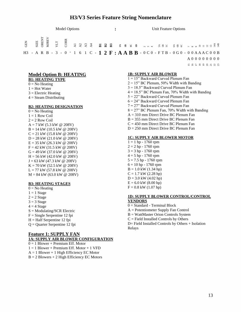
H3V3 Series Feature String Nomenclature
Model Options Unit Feature Options
GE
N
SIZ
E
OR
EN
T
MJR
EV
VL
T
CO
RR
A1
A2
A3
A4
B1
B2
B3
1A
1B
1C
1D
2
3
4
5A
5B
5C
6A
6B
6C
7
8
9
10
11
12
13
14A
14B
H3 - A R B - 3 - 0 - 1 6 1 C - 1 2 F A A B B - 0 C 0 - F T B - 0 G 0 - 0 0 A A A C 0 0 B
A 0 0 0 0 0 0 0 0
15
16
17
18
19
20
21
22
23
14
Feature 2 REFRIGERATION OPTIONS 0 = Standard - None
A = Single Circuit External Hot Gas Bypass
B = Dual Circuit External Hot Gas Bypass
C = Heat Pump
D = Option B + H
F = Options C + H
H = Modulating Hot Gas Reheat
P = Option H (Circuit 1) + Option A (Circuit 2)
R = Option C + A
S = Option C + B
T = Option C + H + A
U = Option C + H + B
Feature 3 SPECIAL CONTROLS 0 = Standard - None
A = Constant Volume Controller - CV Cool + CV
Heat
B = Constant Volume Controller with Modulating
Hot Gas Reheat - CV Cool + CV Heat
C = VAV Controller - VAV Cool + CV Heat
D = VAV Controller with MHGR - VAV Cool + CV
Heat
E = Make Up Air Controller - CV Cool + CV Heat
F = Make Up Air Controller with Modulating Hot
Gas Reheat - CV Cool + CV Heat
G = WattMaster Modulating Hot Gas Reheat
Controller
Feature 4 ADDITIONAL CONTROLS 0 = Standard - None
A = Phase and Brownout Protection
B = Return and Supply Air Firestat
C = Return Air Smoke Detector
D = Options A + B
E = Options A + C
F = Options B + C
G = Options A + B + C
H = Remote Safety Shutdown Terminals
J = Energy Recovery Wheel Rotation Detection
K = Options A + H
L = Options A + J
M = Options B + H
Feature 4 ADDITIONAL CONTROLS
Continued N = Options B + J
P = Options C + H
Q = Options C + J
S = Options A + B + H
T = Options A + B + J
U = Options A + C + H
V = Options A + C + J
W = Options A + H + J
Y = Options B + C + H
Z = Options B + C + J
1 = Options B + H + J
2 = Options C + H + J
3 = Options A + B + C + H
4 = Options A + B + C + J
5 = Options A + B + H + J
6 = Options A + C + H + J
7 = Options B + C + H + J
8 = Options A + B + C + H + J
Feature 5 MIXING BOX 5A RETURN AIR DAMPER POSITION
0 = Standard - None
F = Front
L = Left Hand (Front OA Damper Required)
R = Right Hand (Front OA Damper Required)
T = Top (Front OA Damper Required)
5B OUTSIDE AIR DAMPER POSITION
0 = Standard - None
F = Front
L = Left Hand (Front RA Damper Required)
R = Right Hand (Front RA Damper Required)
T = Top (Front RA Damper Required)
5C MIXING BOX DAMPER CONTROL
0 = Standard - None
A = 2 Position Actuators (24V)
B = Fully Modulating Actuators (DDC)
C = Fixed Position Dampers
H3V3 Series Feature String Nomenclature
Model Options Unit Feature Options
GE
N
SIZ
E
OR
EN
T
MJR
EV
VL
T
CO
RR
A1
A2
A3
A4
B1
B2
B3
1A
1B
1C
1D
2
3
4
5A
5B
5C
6A
6B
6C
7
8
9
10
11
12
13
14A
14B
H3 - A R B - 3 - 0 - 1 6 1 C - 1 2 F A A B B - 0 C 0 - F T B - 0 G 0 - 0 0 A A A C 0 0 B
A 0 0 0 0 0 0 0 0
15
16
17
18
19
20
21
22
23
15
Feature 6 FILTER BOX 6A PRE FILTER BOX
0 = Standard - None
A = 2rdquo Pleated - 30 Eff - MERV 10
B = 4rdquo Pleated - 30 Eff - MERV 10
C = 4rdquo Pleated - 65 Eff - MERV 11
D = 4rdquo Pleated - 85 Eff - MERV 13
E = 4rdquo Pleated - 95 Eff - MERV 14
F = 2rdquo Pleated - 30 Eff - MERV 10 + 4rdquo Pleated -
30 Eff - MERV 10
G = 2rdquo Pleated - 30 Eff - MERV 10 + 4rdquo Pleated -
65 Eff - MERV 11
H = 2rdquo Pleated - 30 Eff - MERV 10 + 4rdquo Pleated -
85 Eff - MERV 13
J = 2rdquo Pleated - 30 Eff - MERV 10 + 4rdquo Pleated -
95 Eff - MERV 14
6B UNIT FILTER
0 = Standard - None
A = 2rdquo Pleated - 30 Eff - MERV 10
B = 4rdquo Pleated - 30 Eff - MERV 10
C = 4rdquo Pleated - 65 Eff - MERV 11
D = 4rdquo Pleated - 85 Eff - MERV 13
E = 4rdquo Pleated - 95 Eff - MERV 14
F = 2rdquo Pleated - 30 Eff - MERV 10 + 4rdquo Pleated -
30 Eff - MERV 10
G = 2rdquo Pleated - 30 Eff - MERV 10 + 4rdquo Pleated -
65 Eff - MERV 11
H = 2rdquo Pleated - 30 Eff - MERV 10 + 4rdquo Pleated -
85 Eff - MERV 13
J = 2rdquo Pleated - 30 Eff - MERV 10 + 4rdquo Pleated -
95 Eff - MERV 14
6C FINAL FILTER BOX
0 = Standard - None
A = 2rdquo Pleated - 30 Eff - MERV 10
B = 12rdquo Cartridge - 65 Eff - MERV 11
C = 12rdquo Cartridge - 85 Eff - MERV 13
D = 12rdquo Cartridge - 95 Eff - MERV 14
E = 2rdquo Pleated - 30 Eff - MERV 10 + 12rdquo
Cartridge - 65 Eff - MERV 11
F = 2rdquo Pleated - 30 Eff - MERV 10 + 12rdquo
Cartridge - 85 Eff - MERV 13
G = 2rdquo Pleated - 30 Eff - MERV 10 + 12rdquo
Cartridge - 95 Eff - MERV 14
Feature 7 FILTER OPTIONS 0 = Standard - None
A = Magnehelic Gauge
B = Clogged Filter Switch
C = Options A + B
Feature 8 COIL COATING 0 = Standard - None
A = E-coated Cooling and Heating Coils
B = Copper Finned Coils + Stainless Steel Coil
Casing
Feature 9 EXPANSION VALVE 0 = None
A = Thermal Expansion Valves
Feature 10 EXPANSION VALVE
CONTROLS 0 = None
A = Standard Control
Feature 11 EXTERNAL PAINT 0 = Standard - None
A = AAON Gray Paint
B = Special Paint
H3V3 Series Feature String Nomenclature
Model Options Unit Feature Options
GE
N
SIZ
E
OR
EN
T
MJR
EV
VL
T
CO
RR
A1
A2
A3
A4
B1
B2
B3
1A
1B
1C
1D
2
3
4
5A
5B
5C
6A
6B
6C
7
8
9
10
11
12
13
14A
14B
H3 - A R B - 3 - 0 - 1 6 1 C - 1 2 F A A B B - 0 C 0 - F T B - 0 G 0 - 0 0 A A A C 0 0 B A 0 0 0 0 0 0 0 0
15
16
17
18
19
20
21
22
23
16
Feature 12 TONNAGE 0 = Standard - None
A = 2 ton Capacity
B = 3 ton Capacity
C = 4 ton Capacity
D = 5 ton Capacity
E = 6 ton Capacity
F = 7 ton Capacity
G = 8 ton Capacity
U = 9 ton Capacity
H = 10 ton Capacity
V = 11 ton Capacity
W = 13 ton Capacity
J = 14 ton Capacity
Y = 15 ton Capacity
Z = 16 ton Capacity
K = 17 ton Capacity
1 = 18 ton Capacity
2 = 20 ton Capacity
L = 22 ton Capacity
M = 25 ton Capacity
3 = 26 ton Capacity
N = 30 ton Capacity
P = 31 ton Capacity
Q = 34 ton Capacity
R = 40-45 ton Capacity
S = 50-55 ton Capacity
4 = 60 ton Capacity
T = 63 ton Capacity
5 = 70 ton Capacity
Feature 13 ENERGY RECOVERY
TYPE 0 = Standard ndash None
A = Energy Recovery Wheel ndash Total + High CFM
Polymer
C = Energy Recovery Wheel ndash Total + High CFM
1 Purge Polymer
E = Energy Recovery Wheel ndash Sensible + High CFM
Polymer
G = Energy Recovery Wheel ndash Sensible + High
CFM 1 Purge Polymer
Feature 14 GPM 14A GPM COOLING COIL
0 = Standard - None
A = 15-25 gpm
B = 26-70 gpm
C = 71 -140 gpm
D = 141-240 gpm
E = 241-400 gpm
F = 401-800 gpm
G = 801-1500 gpm
H = 1501-2500 gpm
14B GPM HEATING COIL
0 = Standard - None
A = 15-25 gpm
B = 26-70 gpm
C = 71 -140 gpm
D = 141-240 gpm
E = 241-400 gpm
F = 401-800 gpm
G = 801-1500 gpm
H = 1501-2500 gpm
Feature 15 CONTROL PANEL 0 = Internal Control Panel
A = Small Control Panel - 12rdquo x 12rdquo
B = Medium Control Panel - 25rdquo x 22rdquo
C = Large Control Panel - 48rdquo x 22rdquo
Feature 16 SHIPPING SPLITS 0 = Standard ndash None
A = 1 Shipping Split (2 pallets)
B = 2 Shipping Splits (3 pallets)
C = 3 Shipping Splits (4 pallets)
D = 4 Shipping Splits (5 pallets)
E = 5 Shipping Splits (6 pallets)
H = Special Shipping Split (SPA Required)
H3V3 Series Feature String Nomenclature
Model Options Unit Feature Options
GE
N
SIZ
E
OR
EN
T
MJR
EV
VL
T
CO
RR
A1
A2
A3
A4
B1
B2
B3
1A
1B
1C
1D
2
3
4
5A
5B
5C
6A
6B
6C
7
8
9
10
11
12
13
14A
14B
H3 - A R B - 3 - 0 - 1 6 1 C - 1 2 F A A B B - 0 C 0 - F T B - 0 G 0 - 0 0 A A A C 0 0 B
A 0 0 0 0 0 0 0 0 1
5
16
17
18
19
20
21
22
23
17
Feature 17 ENERGY RECOVERY
CABINET 0 = Standard - None
A = Top RA + Back EA + Back OA Connections
G = OA + EA Dampers - Top RA + Back EA + Back
OA Connections
N = OA + Economizer Dampers - Top RA + Back
EA + Back Connections
U = OA + EA + Economizer Dampers - Top RA +
Back EA + Back OA Connections
Feature 18 MODULATING ELECTRIC
PREHEAT 0 = Standard - None
A = 75 kW
B = 15 kW
C = 20 kW
D = 225 kW
E = 30 kW
F = 40 kW
G = 50 kW
H = 60 kW
Feature 19 EXHAUST FAN 0 = Standard - None
A = 250 mm Exhaust Fan 800 W EC Motor
B = 310 mm Exhaust Fan 10 kW EC Motor
C = 310 mm Exhaust Fan 17 kW EC Motor
D = 355 mm Exhaust Fan 17 kW EC Motor
E = 450 mm Exhaust Fan 30 kW EC Motor
F = 450 mm Exhaust Fan 60 kW EC Motor
G = Dual 310 mm Exhaust Fan 10 kW EC Motor
H = Dual 310 mm Exhaust Fan 17 kW EC Motor
J = Dual 355 mm Exhaust Fan 17 kW EC Motor
K = Dual 450 mm Exhaust Fan 30 kW EC Motor
L = Dual 450 mm Exhaust Fan 60 kW EC Motor
Feature 20 CRATING 0 = Standard - None
A = Export Crating
B = Forkliftable Base - 5rdquo Base
C = Options A + E
D = Options A + B
E = Shipping Shrink Wrap
F = Options B + E
G = Options A + B + E
Feature 21 PULLEY COMBINATION 0 = Standard - None
A = 1000-1400 rpm
B = 1401-1800 rpm
C = 1801-2200 rpm
Feature 22 WARRANTY 0 = Standard - 1 Year Parts
Feature 23 TYPE 0 = Standard
X = Special Pricing Authorization
18
General Information
AAONreg
H3 and V3 Series indoor air
handling units have been designed for
indoor installation only Units are
assembled wired charged with dry nitrogen
and run-tested at the factory H3 and V3
Series units are not intended for residential
use Startup and service must be performed
by a Factory Trained Service Technician
Certification of Steam or Hot Water Heat
Models
a Certified as a forced air heating system
with or without cooling
b Certified for indoor installation only
Certification of Electric Heat Models
a Certified as an electric warm air furnace
with or without cooling
b Certified for indoor installation only
Certification of Cooling Models
a Certified as a commercial central air
conditioner with or without electrically
operated compressors
b Certified for indoor installation only
c Certified with refrigerant R-410A coils
or with chilled water cooling coils
Improper installation adjustment alteration service or maintenance can cause property damage personal injury or loss of life Startup and service must be performed by a Factory Trained Service Technician A copy of this IOM should be kept with the unit
WARNING
These units must not be used as a ldquoconstruction heaterrdquo at anytime during any phase of construction Very low return air temperatures harmful vapors and misplacement of the filters will damage the unit and its efficiency
CAUTION
This equipment is protected by a standard limited warranty under the condition that initial installation service startup and maintenance is performed according to the instructions set forth in this manual This manual should be read in its entirety prior to installation and before performing any service or maintenance work Equipment described in this manual is available with many optional accessories If you have questions after reading this manual in its entirety consult other factory documentation or contact your AAON Sales Representative to obtain further information before manipulating this equipment or its optional accessories
CAUTION
19
Codes and Ordinances
H3 and V3 Series units have been tested and
certified by ETL in accordance with UL
Safety Standard 1995CSA C222 No 236
System should be sized in accordance with
the American Society of Heating
Refrigeration and Air Conditioning
Engineers Handbook
Installation of H3 and V3 Series units must
conform to the ICC standards of the
International Mechanical Code the
International Building Code Installation of
Air Conditioning and Ventilating Systems
Standard NFPA 90A and local building
plumbing and waste water codes All
appliances must be electrically grounded in
accordance with local codes or in the
absence of local codes the current National
Electric Code ANSINFPA 70 or the
current Canadian Electrical Code CSA
C221
Receiving Unit
When received the unit should be checked
for damage that might have occurred in
transit If damage is found it should be noted
on the carrierrsquos Freight Bill A request for
inspection by carrierrsquos agent should be made
in writing at once
Nameplate should be checked to ensure the
correct model sizes and voltages have been
received to match the job requirements
If repairs must be made to damaged goods
then the factory should be notified before
any repair action is taken in order to protect
the warranty Certain equipment alteration
repair and manipulation of equipment
without the manufacturerrsquos consent may
void the product warranty Contact the
AAON Warranty Department for assistance
with handling damaged goods repairs and
freight claims (903) 236-4403
Note Upon receipt check shipment for
items that ship loose such as remote sensors
Consult order and shipment documentation
to identify potential loose-shipped items
Loose-shipped items may have been placed
inside unit cabinet for security Installers
and owners should secure all doors with
locks or nuts and bolts to prevent
unauthorized access
The Clean Air Act of 1990 bans the intentional venting of refrigerant as of July 1 1992 Approved methods of recovery recycling or reclaiming must be followed
CAUTION
Coils and sheet metal surfaces present sharp edges and care must be taken when working with equipment
WARNING
Failure to observe the following instructions will result in premature failure of your system and possible voiding of the warranty
WARNING
20
Figure 1 - Lockable Handle
Storage
This equipment is not suitable for outdoor
use of storage If installation will not occur
immediately following delivery store
equipment in a dry protected area away from
construction traffic and in the proper
orientation as marked on the packaging with
all internal packaging in place Secure all
loose-shipped items
Direct Expansion (DX) Systems
All DX refrigerant coils are factory charged
with a nitrogen holding charge All DX
systems include evaporator coils and
thermal expansion valves (TXV)
Never turn off the main power supply to the
unit except for servicing emergency or
complete shutdown of the unit When power
is cut off from the unit crankcase heaters
cannot prevent refrigerant migration into the
split system condensing unit compressors
This means the compressor may cool down
and liquid refrigerant may accumulate in the
compressor The compressor is designed to
pump refrigerant gas and damage may occur
when power is restored
If power to the unit must be off for more
than an hour turn the thermostat system
switch to OFF or turn the unit off at the
control panel and leave the unit off until the
main power switch has been turned on again
for at least 24 hours for units with
compressor crankcase heaters This will give
the crankcase heater time to clear any liquid
accumulation out of the compressor before it
is started
Always control the unit from the thermostat
or control panel never at the main power
supply except for emergency or complete
shutdown of the unit
During the cooling season if the air flow is
reduced due to dirty air filters or any other
reason the cooling coils can get too cold
which will cause excessive liquid to return
to the compressor As the liquid
concentration builds up oil is washed out of
the compressor leaving it starved for
lubrication
The compressor life will be seriously
shortened by reduced lubrication and the
pumping of excessive amounts of liquid oil
and refrigerant
CRANKCASE HEATER OPERATION
Some units are equipped with compressor crankcase heaters which should be energized at least 24 hours prior to cooling operation to clear any liquid refrigerant from the compressors
CAUTION
21
Note Low Ambient Operation
Air-cooled DX units without a low ambient
option such as condenser fan cycling or the
0degF low ambient option will not operate in
the cooling mode of operation properly
when the outdoor temperature is below
55degF Low ambient andor economizer
options are recommended if cooling
operation below 55degF is expected
Wiring Diagrams
Unit specific wiring diagrams are laminated
and affixed inside the controls compartment
door
Condensate Drain Pans
Units require field installed drain p-traps and
lines to be connected to the condensate drain
pans of the unit
For condensate drain lines the line should
be the same pipe size or larger than the drain
connection include a p-trap and pitch
downward toward drain An air break should
be used with long runs of condensate lines
See Installation section of this manual for
more information
Unit should not be operated without a p-trap Failure to install a p-trap may result in overflow of condensate water
CAUTION
Emergency drain pan is recommended for all applications where a risk of water damage to surrounding structure or furnishings Refer to local codes
CAUTION
22
Installation
AAON equipment has been designed for
quick and easy installation Startup and
service must be performed by Factory
Trained Service Technician
The H3V3 unit can either be shipped
assembled or shipped in sections See the
Unit Assembly section of this document for
instructions on assembling the sections
Locating the Unit
Placement of the unit relative to ductwork
electrical and plumbing must be carefully
considered Return air plenum or duct can be
mounted directly to the return air flanges
Use flexible gasket material to seal the duct
to the unit
Verify floor foundation or suspension
support can support the total unit weight
including accessory weights Unit must be
level in both horizontal axes to support the
unit and reduce noise and vibration from the
unit
Allow adequate space for piping access and
panel removal To ensure proper access
for field service maintain minimum
clearances for field piping and other
obstructions as indicated by Table 1 and
Figure 2 and Figure 3 Consult local
building codes for additional service
clearance requirements Condensate drain
connections are located on the access side of
the unit
Table 1 - H3 and V3 Series Clearances
Unit Size
Access Side
Clearance
(dimension X on
Figure 2 and
Figure 3)
All Other
Sides
V3-A
36 inches
6 inches
V3-B
V3-C
V3-D
V3-E
H3-A
H3-B
H3-C
H3-D 45 inches
H3-E 60 inches
Additional clearance may be required to
allow for coil removal
May be installed flush depending upon
local codes
Figure 2 - Minimum Clearance Required for
Access to Unit (V3 Series plan view)
X
(See Table 1)
Back Front
Left
Right
23
Figure 3 - Minimum Clearance Required for
Access to Unit (H3 Series plan view)
Internal Control Panel
H3 units with internal control panel have
removable access panels on the top and
bottom of the supply fan section V3 units
with internal control panel have removable
access panels on the front and back of the
supply fan section V3 units that have
energy recovery only have one removable
supply fan access panel on the front of the
unit The supply flanges can be
interchanged with the access panels if
necessary except on size E
Figure 4 - H3 internal control panel with top
access panel removed
Figure 5 - V3 internal control panel with
rear removable access panel shown
Floor Mounted Units
Make sure the unit is level and mounted on a
field supplied platform with a minimum
height to allow for proper depth of the
condensate line p-trap Other installation
provisions may be necessary according to
job specifications V3 Series vertical air
handling units are designed for upflow
applications only
Suspended Units
H3 Series horizontal air handling units are
equipped for suspended installations The
unit should be lifted into position by
supporting the unit with the skid used for
shipping The air handling unit must be
installed level and care should be taken to
prevent damage to the cabinet Other
installation provisions may be necessary
according to job specifications Figure 6
and Figure 7 show factory recommended
methods for suspended installations It is
the responsibility of the specifying engineer
or installing contractor to ensure the
installation is structurally safe and sound
X
(See Table 1)
Front
Back
Left Right
24
Figure 6 - H3 Series Platform Suspension Installation
Figure 7 - H3 Series Parallel Beam Suspension Installation
25
Figure 8 - H3 Series Unit Orientation
Figure 9 - V3 Series Unit Orientation
Note Access doors may be on the ldquoleftrdquo or ldquorightrdquo side as designated by the unit orientation on
the configurator string ldquoBackrdquo will always be the same side as the pre-filter and return air
opening ldquoFrontrdquo will always be the side opposite the pre-filter and return air opening
H3 Series
Return Air ldquoBackrdquo
Supply Air ldquoFrontrdquo
Right Hand Side
Left Hand Side
Connections and service access on right side for right hand orientation
Top View
Air Flow
Connections and service access on right side for right hand orientation
Right Hand Side Left Hand Side
Return Air ldquoBackrdquo
Top View V3 Series
Air Flow
Consider the air flow to be hitting the back of your head
Consider the air flow to be hitting the back of your head
Supply Air
ldquoFrontrdquo
26
Lifting and Handling the Unit
Before lifting unit be sure that all shipping
material has been removed from unit
Care should be taken if using spreader bars
blocking or other lifting devices to prevent
damage to the cabinet coil or fans
Unit Assembly
Although H3V3 Series units are shipped
factory assembled as standard the unit may
be ordered as shipping splits for certain
applications such as for assembly in existing
structures where modules must be
manipulated separately If the unit was
ordered as shipping splits then they must be
assembled in the field
Locate the schematic in the equipmentrsquos
literature packet
1 Identify and Situate Splits
a H3 Units can have the following
ship split sections
1 Mixing Box
2 Air Handler
3 Final Filter
4 Electric Heat
Figure 10 - H3 Schematic with (1) Mixing
Box (2) Air Handler (3) Final Filter and
(4) Electric Heat
b V3 Units can have the following
ship split sections
1 Exhaust Fan
2 Energy Recovery
3 Air Handler
4 Electric Heat
5 Pre filter
6 Mixing box
Figure 11 - V3 Schematic with (1) Exhaust
Fan (2) Energy Recovery (3) Air Handler
and (4) Electric Heat
2 Connect Sections
Using the V3 Schematic as an example
section 1 will have a duct flange and it will
connect to section 2 on the side that does not
have a flange First make sure gasket is on
the panel around the edges of the exposed
duct flanges Push section 1 and 2 together
UNIT HANDLING
Incorrect lifting can cause damage to the unit injury or death Lifting equipment capacity should exceed unit weight by an adequate safety factor Always test lift unit not more than 24 inches high to verify proper center of gravity lift point
WARNING
1 2 3 4
1 2
3
4
27
so that the flange from section 1 is inside of
section 2
Figure 12 - Connect Sections
Use bar clamps or other non-destructive
winching device to pull the tops of the
modules together tightly
Figure 13 - Bar Clamp
At each of the pre-drilled holes in the flange
drill 516 hex head self-tapping screws to
secure the two sections together
Figure 14 - Flange Overlap
Figure 15 - Self-Tapping Screw
All connection hardware is shipped with the
unit
3 Secure Module Joints
The metal straps are to be used to secure
module joints Straps are provided with pre-
drilled holes Self-tapping sheet metal
screws are provided to attach the straps to
the unit cabinet
Leave bar clamps in place until strap is
secure
Place the strap over a module joint ensure
the strap completely covers the joint and
that it is square with the unit casing
Insert self-tapping screws through pre-
drilled holes in strap and secure screws into
unit casing using a power drill For best
results use the lowest effective power drill
torque setting Be careful not to over tighten
the screws
Remove bar clamps and repeat for all
remaining module joints
Figure 16 - Strap Types
516rdquo Hex Head Self-Tapping Screws
Provided with Unit
1rdquo
Angle Strap
Top Strap
Section 2
Flange
28
4 Connect Power and Control Wiring
H3V3 Series units are equipped with low
and high voltage quick connects to connect
wiring from one section to the next Wire
from the unit to external controls and power
sources must be provided in the field
Figure 17 - Low Voltage Quick Connect
A color-coded wiring diagram is laminated
and affixed to the inside of the control
compartment access door H3V3 Series
units are equipped with a single point power
connection
5 Final Sealing
It is very important to keep air from
infiltrating the unit cabinet Seal all piping
penetrations with Armaflex Permagum or
other suitable sealant Also seal around drain
connections electrical connections and all
other inlets where air may enter the cabinet
This is especially important when the unit is
installed in an unconditioned area
Control Box
Some H3V3 units include an external
control box that must be mounted in the
field
Figure 18 - Back View External Control
Box
Duct Connection
Attach duct to flanges provided on the unit
The installer is responsible for sealing ducts
to the flanges to prevent water leaks
Refer to Figure 8 and Figure 9 for duct
connection locations The V3 supply air duct
is out to top of the unit Ductwork should be
sized in accordance with the ASHRAE
Handbook Ductwork should be installed in
accordance with NFPA Standard 90A
When attaching duct to the unit use a
flexiblecompressible material rated for duct
connections A three inch flexible connector
for both return and supply duct connections
is recommended
Condensate Drain Piping
Unit may be equipped with more than one
condensate drain pan connection A p-trap
and drain line must be installed on at least
one sectionrsquos drain connection with the p-
trap not to exceed 6rdquo from the drain
connection The lines should be the same
pipe size or larger than the drain connection
include a p-trap and pitch downward toward
drain An air break should be used with long
runs of condensate lines
Installing Contractor is responsible for proper sealing of the electrical and piping entries into the unit Failure to seal the entries may result in damage to the unit and property
CAUTION
29
Draw-through cooling coils will have a
negative static pressure in the drain pan area
This will cause an un-trapped drain to back
up due to air being pulled up through the
condensate drain piping
Condensate drain trapping and piping should
conform to all applicable governing codes
Note The drain pan connection(s) is a 1rdquo
MPT fitting
Figure 19 - Drain Trap
The X dimension on the draw-through trap
should be at least equal to the absolute value
of the negative static pressure in the drain
pan plus one inch To calculate the static
pressure at the drain pan add the pressure
drops of all components upstream of the
drain pan including the cooling coil and
add the return duct static pressure Include
the dirt allowance pressure drop for the
filters to account for the worst-case scenario
The height from top of the bottom bend of
the trap to the bottom of the leaving pipe
must be at least equal to one half of the X
dimension This ensures that enough water
is stored in the trap to prevent losing the
drain seal during unit startup
Note The absolute value of the fan inlet
pressure will always be greater than or equal
to the absolute value of the static pressure in
the drain pan on draw-through units so the
fan inlet pressure is a safe value to use for
the drain pan static pressure
Table 2 - Drain Trap Dimensions
Draw-Through
Drain Pan Pressure Trap Dimensions
Negative Static X X2
(inches of water) (inch) (inch)
-050 150 075
-100 200 100
-150 250 125
-200 300 150
-250 350 175
-300 400 200
-350 450 225
-400 500 250
Heating Coils
One or two row hot water and steam heating
and preheating coils can be factory installed
These coils are supplied from a building hot
water source All valve controls for heating
coil operation are field supplied and field
installed
Unit should not be operated without p-traps Failure to install a p-traps may result in overflow of condensate water
CAUTION
30
Always connect the steam heating supply to
the top of the coil and the return to the
bottom
Figure 20 - Steam Distributing Piping
Table 3 - Steam Distributing Coil
Connection Sizes
Model (H3- V3-) Supply and Return
Connection Size
A-E 2 18
Air handling units with steam heating coils
MUST BE installed high enough to allow
for a minimum of 1 foot condensate drop leg
off of the steam coil or as recommended by
the steam trap manufacturer Lines should
be insulated with approved insulation and be
properly fastened sloped and supported
according to local code requirements
Table 4 - Hot Water Coil Connection Sizes
Model (H3- V3-) Supply and Return
Connection Size
A 78
B 1 18
C 1 38
D amp E 1 58
Always connect the hot water heating supply
to the bottom of the coil and return to the
top
Figure 21 - Hot amp Chilled Water Piping
Water coils should not be subjected to
entering air temperatures below 38degF to
prevent coil freeze-up If air temperature
across the coil is going to be below this
value use a glycol solution to match the
coldest air expected
Water supply lines must be insulated
properly fastened drained and supported
according to local code requirements
Chilled Water Coil
Factory installed four six or eight row
chilled water cooling coils can be factory
mounted These coils are supplied from a
building chilled water source All valve
controls for the cooling coil operation are
field supplied and field installed
31
Table 5 - Chilled Water Coil Connection
Sizes
Model (H3- V3-) Supply and Return
Connection Size
A 1 18
B 1 38
C 1 58
D amp E 2 18
Always connect the chilled water supply to
the bottom of the coil and return to the top
Water supply lines must be insulated with
closed cell type pipe insulation or insulation
that includes a vapor barrier Lines should
be properly fastened drained and supported
according to local code requirements and
job specifications
Evaporator Coil
The air handling unit coils are pressurized
The copper caps must be punctured to
permit a gradual escape of the pressure prior
to un-sweating those caps Immediately
couple the tubing to the indoor unit to avoid
exposing the coils to moisture A properly
sized filter drier is furnished in the
condenser When making solder
connections make sure dry nitrogen flows
through the lines when heating the copper
to prevent oxidization inside of the copper
Field piping between the condensing unit
and the air handler is required Line
sizes must be selected to meet actual
installation conditions not simply based
on the connection sizes
Thermal Expansion Valve
Thermal expansion valve bulbs should be
mounted with good thermal contact on a
horizontal section of the suction line close to
the evaporator but outside the cabinet and
well insulated On suction lines less than or
equal to 78rdquo OD mount in the 12 orsquoclock
position On suction lines greater than 78rdquo
OD mount in either the 4 orsquoclock or 8
orsquoclock position
Figure 22 - TXV Bulb Position
Hot Gas Reheat
Hot Gas Reheat (HGRH) is available for use
with DX systems that need humidity control
The AAON modulating hot gas reheat
system diverts hot discharge gas from the
condenser to the air handling unit through
the hot gas line Field piping between the
condensing unit and the air handler is
required Line sizes must be selected to
meet actual installation conditions not
simply based on the connection sizes
The line delivers the hot discharge gas to the
reheat coil andor the hot gas bypass valve
so it is sized as a discharge line
Modulating Hot Gas Reheat Piping
1 Run a hot gas reheat line from the
condensing unit and connect it to the inlet of
the stub-out on the reheat coil The inlet
connection is the top (or highest) stub-out of
the reheat coil Connect the hot gas line
from the outdoor unit to the upper stub-out
connection of the reheat coil
2 Run a liquid line from the discharge of the
reheat coil through a tee connection Run a
liquid line from the condenser through a
REFRIGERANT PIPING
Line sizes must be selected to meet actual installation conditions not simply based on the connection sizes at the condensing unit or air handling unit
CAUTION
32
check valve to the other side of the tee Run
a liquid line from the tee to the liquid line
stub-out of the evaporator coil
3 Run a suction line from the evaporator
coil outlet stub-out to the condensing unit
Hot Gas Bypass
Hot Gas Bypass is available for use with DX
systems that may experience low suction
pressure during the operating cycle This
may be due to varying load conditions
associated with VAV applications or units
supplying a large percentage of outside air
Hot Gas Bypass is not necessary in units
with variable capacity compressors The
system is designed to divert refrigerant from
the compressor discharge to the low pressure
side of the system in order to keep the
evaporator from freezing and to maintain
adequate refrigerant velocity for oil return at
minimum load
Hot discharge gas is redirected to the
evaporator inlet via an auxiliary side
connector (ASC) to false load the evaporator
when reduced suction pressure is sensed
Field piping between the condensing unit
and the evaporator is required Line sizes
must be selected to meet actual
installation conditions not simply based
on the connection sizes
Electric Preheat
The modulating electric preheat option is
designed to temper the incoming outside air
to the unit based on an enable control signal
and the outside air conditions
A 24VAC enable signal must be provided to
the [PHE] terminal to enable the operation
of the electric preheat Once the preheat
controller is enabled it will monitor the
outside air temperature to determine if any
capacity of preheat is needed If the outside
air temperature falls below the outside air
temperature setpoint the electric preheat will
be started up and maintain the leaving air
temperature setpoint with both SCR
controlled and staged electric preheat Both
setpoints are set with push button LCD
interface on the preheat controller Outside
air temperature sensors and preheat
discharge supply air temperature sensors are
factory installed and wired to the preheat
controller Electric preheat has maximum
operating outside air temperature of 60degF
and a maximum preheat discharge air
temperature of 80degF
[COM] [PHO] amp [PHC] feedback terminals
are provided to communicate if the electric
preheat is in operation PHO is a normally
open contact PHC is a normally closed
contact and COM is the common These
terminals are not required to be connected
[PHE] is the electric preheat operation
enable [PH+] and [PH-] are the preheat set
point reset terminals
33
Energy Recovery Units
Some H3V3 units have been equipped with
an energy recovery wheel This section is
provided to assure the energy recovery
feature will be properly setup to perform in
accordance with the job specifications for
your particular application
Figure 23 - Energy Recovery Wheel
The Energy Recovery Cassette consists of a
frame wheel wheel drive system and
energy transfer segments Segments are
removable for cleaning or replacement The
segments rotate through counter flowing
exhaust and outdoor air supply streams
where they transfer heat andor water vapor
from the warm moist air stream to the
cooler andor drier air stream
The initial setup and servicing of the energy
recovery wheel is very important to maintain
proper operation efficiency and building
occupant comfort
Normal maintenance requires periodic
inspection of filters the cassette wheel
drive belts air seals wheel drive motor and
its electrical connections
Wiring diagrams are provided with each
motor When wired according to wiring
diagram motor rotates clockwise when
viewed from the shaftpulley side
By carefully reviewing the information
within this section and following the
instructions the risk of improper operation
andor component damage will be
minimized
It is important that periodic maintenance be
performed to help assure trouble free
operation
Initial Mechanical Check and Setup
Outdoor air intake adjustments should be
made according to building ventilation or
local code requirements
After the unit installation is complete open
the cassette access door and determine that
the energy wheel rotates freely when turned
by hand Apply power and observe that the
wheel rotates at approximately 30 RPM If
the wheel does not rotate when power is
applied it may be necessary to readjust the
ldquodiameter air sealsrdquo
Air Seal Adjustments
Pile type air seals across both sides of the
energy wheel diameter are factory adjusted
to provide close clearance between the air
seal and wheel Racking of the unit or
cassette during installation andor mounting
of the unit on a non-level support or in other
than the factory orientation can change seal
clearances Tight seals will prevent rotation
Figure 24 - Cross Section of Air Seal
Structure
34
Wheel to Air Seal Clearance
To check wheel to seal clearance first
disconnect power to the unit in some units
the energy recovery wheel assembly can be
pulled out from the cabinet to view the air
seals On larger units the energy recovery
wheel may be accessible inside the walk-in
cabinet
A business card or two pieces of paper can
be used as a feller gauge (typically each
004rdquo thick) by placing it between the face
of the wheel and pile seal
Using the paper determine if a loose slip fit
exist between the pile seal and wheel when
the wheel is rotated by hand
To adjust air seal clearance loosen all seal
plate retaining screws holding the separate
seal retaining plates to the bearing support
channels and slide the seals plates away
from the wheel Using the paper feeler
gauge readjust and retighten one seal plate
at a time to provide slip fit clearance when
the wheel is rotated by hand
Confirm that the wheel rotates freely Apply
power to the unit and confirm rotation
Airflow Balancing and Checking
High performance systems commonly have
complex air distribution and fan systems
Unqualified personnel should not attempt to
adjust fan operation or air circulation as all
systems have unique operations
characteristics Professional air balance
specialists should be employed to establish
actual operating conditions and to configure
the air delivery system for optimal
performance
Controls
A variety of controls and electrical
accessories may be provided with the
equipment Identify the controls on each unit
by consulting appropriate submittal or order
documents and operate according to the
control manufacturerrsquos instructions If you
cannot locate installation operation or
maintenance information for the specific
controls then contact your sales
representative or the control manufacturer
for assistance
Routine Maintenance and Handling
Handle cassettes with care All cassettes
should be lifted by the bearing support
beam Holes are provided on both sides of
the bearing support beams to facilitate
rigging as shown in the following
illustration
Figure 25 - Lifting Hole Locations
Routine maintenance of the Energy
Recovery Cassettes includes periodic
Do not alter factory wiring Deviation from the supplied wiring diagram will void all warranties and may result in equipment damage or personal injury Contact the factory with wiring discrepancies
WARNING
35
cleaning of the Energy Recovery Wheel as
well as inspection of the Air Seals and
Wheel Drive Components as follows
Cleaning
The need for periodic cleaning of the energy
recovery wheel will be a function of
operating schedule climate and
contaminants in the indoor air being
exhausted and the outdoor air being supplied
to the building
The energy recovery wheel is ldquoself-
cleaningrdquo with respect to dry particles due to
its laminar flow characteristics Smaller
particles pass through larger particles land
on the surface and are blown clear as the
flow direction is reversed Any material that
builds up on the face of the wheel can be
removed with a brush or vacuum The
primary need for cleaning is to remove oil
based aerosols that have condensed on
energy transfer surfaces
A characteristic of all dry desiccants such
films can close off micron sized pores at the
surface of the desiccant material reducing
the efficiency by which the desiccant can
adsorb and desorb moisture and also build
up so as to reduce airflow
In a reasonably clean indoor environment
such as a school or office building
measurable reductions of airflow or loss of
sensible (temperature) effectiveness may not
occur for several years Measurable changes
in latent energy (water vapor) transfer can
occur in shorter periods of time in
applications such as moderate occupant
smoking or cooking facilities In
applications experiencing unusually high
levels of occupant smoking or oil based
aerosols such as industrial applications
involving the ventilation of machine shop
areas for example annual washing of energy
transfer may be necessary to maintain latent
transfer efficiency Proper cleaning of the
energy recovery wheel will restore latent
effectiveness to near original performance
To clean gain access to the energy recovery
wheel and remove segments Brush foreign
material from the face of the wheel Wash
the segments or small wheels in a 5
solution of non-acid based coil cleaner or
alkaline detergent and warm water
Soak in the solution until grease and tar
deposits are loosened (Note some staining
of the desiccant may remain and is not
harmful to performance) Before removing
rapidly run finger across surface of segment
to separate polymer strips for better cleaning
action Rinse dirty solution from segment
and remove excess water before reinstalling
in wheel
Air Seals
Four adjustable diameter seals are provided
on each cassette to minimize transfer of air
between the counter flowing airstreams
To adjust diameter seals loosen diameter
seal adjusting screws and back seals away
from wheel surface Rotate wheel clockwise
until two opposing spokes are hidden behind
the bearing support beam Using a folded
piece of paper as a feeler gauge position
paper between the wheel surface and
diameter seals
Adjust seals towards wheel surface until a
slight friction on the feeler gauge (paper) is
detected when gauge is moved along the
length of the spoke Retighten adjusting
Do Not use acid based cleaners aromatic solvents steam or temperatures in excess of 170degF damage to the wheel may occur
CAUTION
36
screws and recheck clearance with ldquofeelerrdquo
gauge
Wheel Drive Components
The wheel drive motor bearings are pre-
lubricated and no further lubrication is
necessary
The wheel drive pulley is secured to the
drive motor shaft by a combination of either
a key or D slot and set screw
The set screw is secured with removable
locktite to prevent loosening Annually
confirm set screw is secure The wheel drive
belt is a urethane stretch belt designed to
provide constant tension through the life of
the belt No adjustment is required Inspect
the drive belt annually for proper tracking
and tension A properly tensioned belt will
turn the wheel immediately after power is
applied with no visible slippage during start-
up
Installation Considerations
Energy recovery cassettes are incorporated
within the design of packaged units
packaged air handlers and energy recovery
ventilators In each case it is recommended
that the following considerations be
addressed
Accessibility
The cassette and all its operative parts ie
motor belt pulley bearings seals and
energy transfer segments must be accessible
for service and maintenance This design
requires that adequate clearance be provided
outside the enclosure
Orientation amp Support
The Energy Recovery Cassette may be
mounted in any orientation However Care
must be taken to make certain that the
cassette frame remains flat and the bearing
beams are not racked
To verify make certain that the distance
between wheel rim and bearing beam is the
same at each end of the bearing beam to
within 14 of an inch (dimension A amp B)
This amount of racking can be compensated
for by adjusting the diameter seals
If greater than 14 inch (dimension C)
racking must be corrected to ensure that
drive belt will not disengage from wheel
Figure 26 - Avoid Racking of Cassette
Frame
Operation
Startup Procedure
1 By hand turn wheel clockwise (as viewed
from the pulley side) to verify wheel turns
freely through 360ordm rotation
2 Before applying power to drive motor
confirm wheel segments are fully engaged in
wheel frame and segment retainers are
completely fastened (See Segment
Installation Diagram)
B
C
A
Bearing beams shown racked
Frame
Wheel
Bearing beams (2)
Flat surface
Keep hands away from rotating wheel Contact with rotating wheel can cause physical injury
CAUTION
37
3 With hands and objects away from
moving parts activate unit and confirm
wheel rotation Wheel rotates clockwise (as
viewed from the pulley side)
4 If wheel has difficulty starting turn power
off and inspect for excessive interference
between the wheel surface and each of the
four (4) diameter seals To correct loosen
diameter seal adjusting screws and back
adjustable diameter seals away from surface
of wheel apply power to confirm wheel is
free to rotate then re-adjust and tighten hub
and diameter seals as shown in hub seal
adjustment diagram
5 Start and stop wheel several times to
confirm seal adjustment and to confirm belt
is tracking properly on wheel rim
(approximately 14rdquo from outer edge of
rim)
Figure 27 - Diameter Seal Adjustment
Figure 28 - Hub Seal Adjustment
Service
Segment Installation amp Replacement
Wheel segments are secured to the wheel
frame by a Segment Retainer which pivots
on the wheel rim and is held in place by a
Segment Retaining Catch
Disconnect electrical power before servicing energy recovery cassette Always keep hands away from bearing support beam when installing or removing segments Failure to do so could result in severe injury to fingers or hand
CAUTION
38
Figure 29 - Segment Retainer
To install wheel segments follow steps one
through five below Reverse procedure for
segment removal
1 Unlock two segment retainers (one on
each side of the selected segment opening
2 With the embedded stiffener facing the
motor side insert the nose of the segment
between the hub plates
Figure 30 - Segment Installation
3 Holding segment by the two outer
corners press the segment towards the
center of the wheel and inwards against the
spoke flanges If hand pressure does not
fully seat the segment insert the flat tip of a
screw driver between the wheel rim and
outer corners of the segment and apply
downward force while guiding the segment
into place
4 Close and latch each Segment Retainer
under Segment Retaining Catch
5 Slowly rotate the wheel 180ordm Install the
second segment opposite the first for
counterbalance Rotate the two installed
segments 90ordm to balance the wheel while the
third segment is installed Rotate the wheel
180ordm again to install the fourth segment
opposite the third Repeat this sequence with
the remaining four segments
Wheel Drive Motor and Pulley Replacement
1 Disconnect power to wheel drive motor
2 Remove belt from pulley and position
temporarily around wheel rim
3 Loosen set screw in wheel drive pulley
using a hex head wrench and remove pulley
from motor drive shaft
4 While supporting weight of drive motor in
one hand loosen and remove (4) mounting
bolts
5 Install replacement motor with hardware
kit supplied
6 Install pulley to dimension as shown and
secure set screw to drive shaft
7 Stretch belt over pulley and engage in
groove
8 Follow start-up procedure
Belt Replacement
1 Obtain access to the pulley side bearing
access plate if bearing access plates are
provided Remove two bearing access plate
retaining screws and the access plate
39
2 Using hexagonal wrench loosen set screw
in bearing locking collar Using light
hammer and drift (in drift pin hole) tap
collar in the direction of wheel rotation to
unlock collar Remove collar
3 Using socket wrench with extension
remove two nuts which secure bearing
housing to the bearing support beam Slide
bearing from shaft If not removable by
hand use bearing puller
4 Form a small loop of belt and pass it
through the hole in the bearing support
beam Grasp the belt at the wheel hub and
pull the entire belt down
Note Slight hand pressure against wheel
rim will lift weight of wheel from inner race
of bearing to assist bearing removal and
installation
5 Loop the trailing end of the belt over the
shaft (belt is partially through the opening)
6 Reinstall the bearing onto the wheel shaft
being careful to engage the two locating pins
into the holes in the bearing support beam
Secure the bearing with two self-locking
nuts
7 Install the belts around the wheel and
pulley according to the instructions provided
with the belt
8 Reinstall diameter seals or hub seal and
tighten retaining screws Rotate wheel in
clockwise direction to determine that wheel
rotates freely with slight drag on seals
9 Reinstall bearing locking collar Rotate
collar by hand in the direction the wheel
rotates (see label provided on each cassette
for wheel rotation)
10 Lock in position by tapping drift pin
hole with hammer and drift Secure in
position by tightening set screw
11 Reinstall Bearing Access Cover
12 Apply power to wheel and ensure that
the wheel rotates freely without interference
Figure 31 - Belt Replacement
Protect hands and belt from possible sharp edges of hole in Bearing Support Beam
CAUTION
40
Electrical
Verify the unit name plate agrees with
power supply H3 and V3 Series units are
provided with single point power wiring
connections Connection terminations are
made to the main terminal block A
complete set of unit specific wiring
diagrams showing factory and field wiring
are laminated in plastic and located inside
the control compartment door
Route power and control wiring separately
through the utility entry in the unit Do not
run power and control signal wires in the
same conduit
All units require field supplied electrical
overcurrent and short circuit protection
Device must not be sized larger than the
Maximum Overcurrent Protection (MOP)
shown on the unit nameplate
Codes may require a disconnect switch be
within sight of the unit
It is recommended that the field installed
overcurrent protection or disconnect switch
not be installed on the unit
On units with external control box electrical
supply can enter through either side of the
controls compartment
Figure 32 - External control box electrical
connections
On units with internal control panel
electrical supply can enter through the
supply air side (front) of the H3 unit and
through the return air side (rear) of the V3
unit
Figure 33 - H3 internal control panel
electrical connections
Figure 34 - V3 internal control panel
electrical connections
The foam insulation releases dangerous fumes when it is burnt Do not cut a foam part with a cutting torch or plasma cutter Do not weld to a foam filled part
WARNING
41
A single point connection to a terminal
block is provided High voltage conductors
should enter the control panel in a separate
opening and separate conduit than low
voltage conductors
To pass wires through the wall or roof of the
unit a hole should be cut and conduit passed
through it Use the following procedure to
cut a round hole in a foam panel
Cutting Electrical Openings
1 Locate the placement of the hole Be
sure that the conduit will not interfere
with the operation of any component or
prevent access of any door or
removable panel Field cut openings
must be a minimum of 6 inches away
from all components and wiring to
prevent damage due to drilling or
cutting
2 Drill a pilot hole all the way through the
foam panel
3 Using a hole saw cut the hole through
the metal on both sides of the foam
part
4 With a knife cut the foam out of the
hole
5 After the conduit is installed in the hole
caulk the entire perimeter of the hole on
both sides with an industrial grade
silicone sealant or a duct seal
compound
If a larger cut-out is needed for additional
duct connections not provided by the
factory or for any other reason it is very
important that the foam be completely
sealed Insulation covers should be
fabricated from sheet metal to cover the
foam at the cut The edges and corners that
are not covered should then be sealed using
silicone caulking or a duct seal compound
If a reciprocating saw is used to make the
cut-out take care that the metal skins of the
foam part do not separate from the foam
this would result in reduced structural
integrity of the part
Size supply conductors based on the unit
Minimum Current Ampacity (MCA) rating
Supply conductors must be rated a minimum
of 75degC
Protect the branch circuit in accordance with
code requirements The unit must be
electrically grounded in accordance with
local codes or in the absence of local codes
the current National Electric Code
ANSINFPA 70 or the current Canadian
Electrical Code CSA C221
Note Units are factory wired for 208V
230V 460V or 575V In some units the
208V and 230V options may also be
provided in single or three phase
configurations The transformer
Installing Contractor is responsible for proper sealing of the electrical and piping entries into the unit Failure to seal the entries may result in damage to the unit and property
Electric shock hazard Before attempting to perform any installation service or maintenance shut off all electrical power to the unit at the disconnect switches Unit may have multiple power supplies Failure to disconnect power could result in dangerous operation serious injury death or property damage
WARNING
CAUTION
42
configuration must be checked by a
qualified technician prior to startup
Wire power leads to the unitrsquos terminal
block or main disconnect All wiring beyond
this point has been completed by AAON and
cannot be modified without effecting the
unitrsquos agencysafety certification
Supply voltage must be within the minmax
range shown on the unit nameplate
Available short circuit current should not
exceed the short circuit current rating
(SCCR) shown on the unit nameplate
Three phase voltage imbalance will cause
motor overheating and premature failure
The maximum allowable imbalance is 20
Voltage imbalance is defined as 100 times
the maximum deviation from the average
voltage divided by the average voltage
Example
(221V+230V+227V)3 = 226V then
100(226V-221V)226V = 22 which
exceeds the allowable imbalance
Check voltage imbalance at the unit
disconnect switch and at the compressor
terminal Contact your local power company
for line voltage corrections
Installing contractor must check for proper
motor rotation and check blower motor
amperage listed on the motor nameplate is
not exceeded
Wire control signals to the unitrsquos low
voltage terminal block located in the
controls compartment
If any factory installed wiring must be
replaced use a minimum 105degC type AWM
insulated conductors
Thermostat Control Wiring
If a thermostat is used for unit control
thermostat should be located on an inside
wall 4-5 feet above the floor where it will
not be subjected to drafts sun exposure or
heat from electrical fixtures of appliances
Control wiring must deliver adequate
voltage to components to assure proper
operation Control voltage returning from
controller circuit must be a minimum of 21
VAC To assure proper wiring use the
following chart to determine the allowable
wiring distances
Table 6 - Control Wiring
Wire Size (Stranded)
- Copper Conductors
Only
Total Wire Distance
Allowable
20 AWG 200 ft
18 AWG 350 ft
16 AWG 500 ft
14 AWG 750 ft
12 AWG 1250 ft
Total Wire Distance Allowable =
(Quantity of Control Wires) x
(Control Wire Distance)
Three phase voltage imbalance will cause motor overheating and premature failure
CAUTION
Rotation must be checked on all MOTORS of three phase units Supply fan motors should all be checked by a qualified service technician at startup and any wiring alteration should only be made at the unit power connection
CAUTION
43
Take the total wire distance allowable and
divide by the number of wires to be
connected This indicates the distance
allowable for that size wire The wiring to
the unit must not exceed the total wire
distance allowable If the voltage at the
connectors is less than 21 VAC isolation
relays must be installed If under external
control 21 VAC must be field verified
All external devices must be powered via a
separate external power supply
Example
A total of 8 wires must be pulled 75ft to a
control the unit What size wire should be
used
According to the Table 6 16 AWG allows
for 63ft (500 ft8 wires) and 14 AWG allows
for 94ft (750 ft8 wires) Thus 14 AWG
should be used
44
Startup (See back of the manual for startup form)
During startup it is necessary to perform
routine checks on the performance of the
unit This includes checking of the air flow
the air filters and refrigerant charge
Supply Fans
H3 and V3 Series units are equipped with
direct drive backward curved plenum supply
fan assemblies or belt driven backward
curved plenum supply fans that deliver the
air volume specified according to unit size
and job requirements
Fan Air Flow Adjustment
A specific air volume is delivered by the
fans with Electronically Commutated
Motors (ECM) or Variable Frequency
Drives (VFD) Field air flow adjustment
may be required at startup
Electrically Commutated Motor Airflow
Adjustment
Figure 35- Typical wiring diagram with EC
motor
If the application is for the motor to run at a
constant speed the potentiometer can be
utilized without any change If the
application is to vary the motor speed for
changing conditions remove the jumper
indicated on the terminal strip (red wire)
Improper installation adjustment alteration service or maintenance can cause property damage personal injury or loss of life Startup and service must be performed by a Factory Trained Service Technician A copy of this IOM should be kept with the unit
WARNING
Electric shock hazard Shut off all electrical power to the unit to avoid shock hazard or injury from rotating parts
WARNING
45
Figure 36 - Shows the jumper that is to be
removed (jumped between 9 and GS)
Note the potentiometer is still active in the
electrical loop Refer to Figure 10
Figure 37 - Potentiometer
The potentiometer dial should be set for the
maximum fan speed for a particular
application Maximum fan speed is
determined by the ECat submittal
Typically this max speed will be the rpm set
at the factory
The fan speed can be modulated using the 0-
10 VDC input signal
To check fan output from the factory the
potentiometer can be dialed to 100 By
sending a 5V signal for instance the rpm
can be measured and this reading can be
converted to cubic feet of air moved by the
fan
It is advised that a medium range signal be
utilized for this procedure The highest
signal sent by the controller should then be
determined by adjustment
Filters
Do not operate the unit without filters in
place Operation of the equipment without
filters in place can result in clogged coils
Units are shipped with the selected filters
installed If filters have been removed
during installation open the filter access
door and re-install the correct filters with the
airflow indicator arrows pointing in the
direction of airflow
Filters should be checked after a few days of
operation after the unit has been started up
as dust and debris from construction may
cause premature filter loading Replace the
filters if necessary
Adjusting Refrigerant Charge
Adjusting the charge of a system in the field
must be based on determination of liquid
sub-cooling and evaporator superheat On a
system with a TXV liquid sub-cooling is
more representative of the charge than
Before completing startup and leaving the unit a complete operating cycle should be observed to verify that all components are functioning properly
CAUTION
46
evaporator superheat but both measurements
must be taken
Before Charging
Unit being charged must be at or near full
load conditions before adjusting the charge
Units equipped with hot gas reheat must be
charged with the hot gas reheat valves
closed while the unit is in cooling mode to
get the proper charge After charging unit
should be operated in reheat
(dehumidification) mode to check for
correct operation
After adding or removing charge the system
must be allowed to stabilize typically 10-15
minutes before making any other
adjustments
The type of unit and options determine the
ranges for liquid sub-cooling and evaporator
superheat Refer to the tables below when
determining the proper sub-cooling
Checking Liquid Sub-Cooling
Measure the temperature of the liquid line as
it leaves the condenser
Read the gauge pressure at the liquid line
close to the point where the temperature was
taken Use liquid line pressure as it will vary
from discharge pressure due to condenser
pressure drop
Convert the pressure obtained to a saturated
temperature using the appropriate refrigerant
temperature-pressure chart
Subtract the measured liquid line
temperature from the saturated temperature
to determine the liquid sub-cooling
Compare calculated sub-cooling to the table
below for the appropriate unit type and
options
Checking Evaporator Superheat
Measure the temperature of the suction line
close to the compressor
Read gauge pressure at the suction line close
to the compressor
Convert the pressure obtained to a saturated
temperature using the appropriate refrigerant
temperature-pressure chart
Subtract the saturated temperature from the
measured suction line temperature to
determine the evaporator superheat
Compare calculated superheat to the table
below for the appropriate unit type and
options
The Clean Air Act of 1990 bans the intentional venting of refrigerant (CFCrsquos and HCFCrsquos) as of July 1 1992 Approved methods of recovery recycling or reclaiming must be followed Fines andor incarceration may be levied for non-compliance
CAUTION
DO NOT OVERCHARGE Refrigerant overcharging leads to excess refrigerant in the condenser coils resulting in elevated compressor discharge pressure
CAUTION
47
Table 7 - Acceptable Air-Cooled
Refrigeration Circuit Values
Air-Cooled Condenser Air-Source Heat
Pump
Sub-Cooling
12-18degF 2-4degF (HP)
Sub-Cooling with
Hot Gas Reheat 15-22degF 2-6degF (HP)
Superheat
8-15degF
In cooling mode operation
Sub-cooling must be increased by 2degF per
20 feet of vertical liquid line rise for R-410A
Superheat will increase with long
suction line runs
Adjusting Sub-Cooling and Superheat
Temperatures
The system is overcharged if the sub-cooling
temperature is too high and the evaporator is
fully loaded (low loads on the evaporator
result in increased sub-cooling) and the
evaporator superheat is within the
temperature range as shown in the table
above (high superheat results in increased
sub-cooling)
Correct an overcharged system by reducing
the amount of refrigerant in the system to
lower the sub-cooling
The system is undercharged if the superheat
is too high and the sub-cooling is too low
Correct an undercharged system by adding
refrigerant to the system to reduce superheat
and raise sub-cooling
If the sub-cooling is correct and the
superheat is too high the TXV may need
adjustment to correct the superheat Before
adjusting the TXV verify the sensing bulb is
in the correct position according to Figure
22 and follows the guidelines below
1 The suction line is clean where the
sensing bulb is attached
2 The entire length of the sensing bulb is in
contact with the suction line
3 The sensing bulb should be placed several
inches downstream of the equalizer line
4 The sensing bulb is fully insulated
5 If the sensing bulb is installed on a
vertical portion of the suction line the
sensing bulb should be placed upstream of
suction line trap
Thermal expansion valve must be adjust to approximately 8-15degF of suction superheat Failure to have sufficient superheat will damage the compressor and void the warranty
CAUTION
DO NOT OVERCHARGE Refrigerant overcharging leads to excess refrigerant in the condenser coils resulting in elevated compressor discharge pressure
CAUTION
48
Table 8 - R-410A Refrigerant Temperature-Pressure Chart
degF PSIG degF PSIG degF PSIG degF PSIG degF PSIG
20 783 47 1347 74 2137 101 3210 128 4632
21 800 48 1372 75 2171 102 3256 129 4693
22 818 49 1397 76 2206 103 3302 130 4754
23 836 50 1422 77 2241 104 3349 131 4816
24 854 51 1448 78 2277 105 3396 132 4878
25 872 52 1474 79 2313 106 3444 133 4941
26 891 53 1501 80 2349 107 3493 134 5005
27 910 54 1528 81 2386 108 3542 135 5069
28 929 55 1555 82 2423 109 3591 136 5134
29 949 56 1582 83 2460 110 3641 137 5200
30 968 57 1610 84 2498 111 3691 138 5266
31 988 58 1638 85 2537 112 3742 139 5333
32 1009 59 1667 86 2575 113 3794 140 5401
33 1029 60 1696 87 2614 114 3846 141 5470
34 1050 61 1725 88 2654 115 3899 142 5539
35 1071 62 1754 89 2694 116 3952 143 5609
36 1092 63 1784 90 2735 117 4005 144 5679
37 1114 64 1815 91 2776 118 4059 145 5751
38 1136 65 1845 92 2817 119 4114 146 5823
39 1158 66 1876 93 2859 120 4169 147 5896
40 1181 67 1907 94 2901 121 4225 148 5969
41 1203 68 1939 95 2944 122 4282 149 6044
42 1227 69 1971 96 2987 123 4339 150 6119
43 1250 70 2004 97 3030 124 4396
44 1274 71 2036 98 3075 125 4454
45 1298 72 2070 99 3119 126 4513
46 1322 73 2103 100 3164 127 4573
49
Operation Unit operations should be controlled with
thermostat or unit controller never at the
main power supply except for emergency or
complete shutdown of the unit
Electric Heating Operation
When a call for heating (G and W1 W2
etc) is made the supply fan motors and
electric resistance heaters will energize
Heating is accomplished by passing
electrical current through a specified amount
of resistance heaters which will produce the
required heat
On a fault condition the main limit located
in the supply air or the auxiliary limit
located downstream the supply blower will
remove power from all contactors
Steam or Hot Water Preheating
Operation
Valve control for steam and hot water
heating coils are by others Heating is
accomplished by passing steam or hot water
through the steam or hot water coil
assembly
Chilled Water or Non-Compressorized
DX Cooling Operation
Valve controls for chilled water cooling coil
and non-compressorized DX coil are by
others
Modulating Electric Preheat
Electric preheat is used to temper the
incoming outside air to the unit based on an
enable control signal and outside air
conditions Electric preheat has a maximum
operation outside air temperature of 60degF
and a maximum preheat discharge air
temperature of 80degF
Maintenance (See back of the manual for maintenance
log)
At least once each year a qualified service
technician should check out the unit Supply
fans evaporator coils and air filters should
be inspected monthly
Periodically during operation it is necessary
to perform routine service checks on the
performance of the unit This includes
checking of the air flow the air filters
condenser water flow and refrigerant charge
See Startup section for information on air
flow adjustment and refrigerant charge
adjustment
DX Cooling
Set unit controls to cooling mode of
operation with supply fans on Check the
fans for correct operating direction
amperage and voltage Check compressor
operation rotation amperage and voltage to
the unit nameplate (check the amperage on
the load side of the compressor contactor)
Condensate Drain Pans
Drain pans will have moisture present and
require periodic cleaning to prevent
microbial growth Cleaning of the drain pans
will also prevent any possible plugging of
the drain lines and overflow of the pan itself
Cleaning of the drain pans and inside of the
unit should be done only by qualified
personnel
Improper installation adjustment alteration service or maintenance can cause property damage personal injury or loss of life Installation and service must be performed by a qualified installer A copy of this IOM should be kept with the unit
WARNING
50
E-Coated Coil Cleaning
Documented routine cleaning of e-coated
coils is required to maintain coating
warranty coverage
Surface loaded fibers or dirt should be
removed prior to water rinse to prevent
restriction of airflow If unable to back wash
the side of the coil opposite of the coils
entering air side then surface loaded fibers
or dirt should be removed with a vacuum
cleaner If a vacuum cleaner is not available
a soft non-metallic bristle brush may be
used In either case the tool should be
applied in the direction of the fins Coil
surfaces can be easily damaged (fin edges
bent over) if the tool is applied across the
fins
Use of a water stream such as a garden
hose against a surface loaded coil will drive
the fibers and dirt into the coil This will
make cleaning efforts more difficult Surface
loaded fibers must be completely removed
prior to using low velocity clean water rinse
A monthly clean water rinse is
recommended for coils that are applied in
coastal or industrial environments to help to
remove chlorides dirt and debris It is very
important when rinsing that water
temperature is less than 130degF and pressure
is than 100 psig to avoid damaging the fin
edges An elevated water temperature (not to
exceed 130degF) will reduce surface tension
increasing the ability to remove chlorides
and dirt
Quarterly cleaning is essential to extend
the life of an e-coated coil and is required
to maintain coating warranty coverage
Coil cleaning shall be part of the unitrsquos
regularly scheduled maintenance
procedures Failure to clean an e-coated coil
will void the warranty and may result in
reduced efficiency and durability
For routine quarterly cleaning first clean the
coil with the below approved coil
cleaner After cleaning the coils with the
approved cleaning agent use the approved
chloride remover to remove soluble salts and
revitalize the unit
Recommended Coil Cleaner
The following cleaning agent assuming it is
used in accordance with the manufacturerrsquos
directions on the container for proper mixing
and cleaning has been approved for use on
Electric shock hazard Shut off all electrical power to the unit to avoid shock hazard or injury from rotating parts
WARNING
Harsh chemicals household bleach or acid cleaners should not be used to clean outdoor or indoor e-coated coils These cleaners can be very difficult to rinse out of the coil and can accelerate corrosion and attack the e-coating If there is dirt below the surface of the coil use the recommended coil cleaners
High velocity water from a pressure washer or compressed air should only be used at a very low pressure to prevent fin andor coil damages The force of the water or air jet may bend the fin edges and increase airside pressure drop Reduced unit performance or nuisance unit shutdowns may occur
CAUTION
CAUTION
51
e-coated coils to remove mold mildew
dust soot greasy residue lint and other
particulate
Enviro-Coil Concentrate Part Number H-
EC01
Recommended Chloride Remover
CHLORRID DTStrade should be used to
remove soluble salts from the e-coated coil
but the directions must be followed closely
This product is not intended for use as a
degreaser Any grease or oil film should first
be removed with the approved cleaning
agent
Remove Barrier - Soluble salts adhere
themselves to the substrate For the effective
use of this product the product must be able
to come in contact with the salts These salts
may be beneath any soils grease or dirt
therefore these barriers must be removed
prior to application of this product As in all
surface preparation the best work yields the
best results
Apply CHLORRID DTS - Apply directly
onto the substrate Sufficient product must
be applied uniformly across the substrate to
thoroughly wet out surface with no areas
missed This may be accomplished by use of
a pump-up sprayer or conventional spray
gun The method does not matter as long as
the entire area to be cleaned is wetted After
the substrate has been thoroughly wetted
the salts will be soluble and is now only
necessary to rinse them off
Rinse - It is highly recommended that a hose
be used as a pressure washer will damage
the fins The water to be used for the rinse is
recommended to be of potable quality
though a lesser quality of water may be used
if a small amount of CHLORRID DTS is
added Check with CHLORRID
International Inc for recommendations on
lesser quality rinse water
Supply Fans
Supply Fan Lubrication
All original blower motors and bearings are
furnished with factory lubrication Some
applications will require that bearings be re-
lubricated periodically The schedule will
depend on the operating duty temperature
variations or other severe atmospheric
conditions
Bearings should be re-lubricated when at
normal operating temperatures but not
running Rotate the fan shaft by hand and
add only enough grease to purge the seals
DO NOT OVERLUBRICATE
Recommended greases are
SHELL OIL - DOLIUM R
CHEVRON OIL - SRI No 2
TEXACO INC - PREMIUM RB
Blower wheels must be inspected for excessive dust build up periodically and cleaned if required Excessive dust build up on blower wheels may cause an unbalanced state leading to vibration andor component failure Damages due to excessive dust build up will not be covered under factory warranty
CAUTION
Electric shock hazard Shut off all electrical power to the unit to avoid shock hazard or injury from rotating parts
WARNING
52
Phase and Brownout Protection Module
The DPM is a Digital Phase Monitor that
monitors line voltages from 200VAC to
240VAC 1ɸ and 200VAC to 600VAC 3ɸ
The DPM is 5060 Hz self-sensing DPM
should be wired according to unit specific
wiring diagram include in the control
compartment
When the DPM is connected to the line
voltage it will monitor the line and if
everything is within the setup parameters
the output contacts will be activated If the
line voltages fall outside the setup
parameters the output relay will be de-
energized after the trip delay
Once the line voltages recover the DPM
will re-energize the output relay after the
restart time delay All settings and the last 4
faults are retained even if there is a
complete loss of power
DPM Setup Procedure
With the supply voltage active to the
module you can setup all of the DPMrsquos
settings without the line voltage connected
To change the setpoint parameters use the
right arrow key to advance forward through
the setpoint parameters and the left arrow to
backup if needed When each parameter is
displayed use the updown keys to change
and set the parameter
After adjustments are made or if no
adjustments are made it will take 2 to 4
minutes before the DPM energizes the
output relay unless there is an out of
tolerance issue with the incoming line
voltage
Recommended Default Set-up
Line Voltage 460VAC 3Oslash
Over amp Undervoltage plusmn10
Trip Time Delay 5 Seconds
Re-Start Time Delay 2 Minutes
Phase Imbalance 5
53
Screens Manufacturerrsquos Screen
R-K Electronics
DPM v0000
Average Voltage Screen
VAvg Imb Hz
460 0 60 off
Default ndash the default screen shows the real time voltage detected in each of the 3 phases
A-B B-C C-A
460 459 461 ON
Voltage Selection Screen (Vertical Format) Default = 460V 3Oslash
200 1Oslash 208 1Oslash 220 1Oslash 230 1Oslash 240 1Oslash
200 3Oslash 208 3Oslash 220 3Oslash 230 3Oslash 240 3Oslash 380 3Oslash 415 3Oslash 440 3Oslash
460 3Oslash 480 3Oslash 575 3Oslash 600 3Oslash
OverUnder voltage Percentage Screen (Vertical Format) Default = 10
7 8 9 10 11 12 13 14 amp 15
Trip Time Delay Screen (Vertical Format) Default = 5 sec
2S 3S 4S 5S 6S 27S 8S 9S amp 10S
Re-Start Time Delay Screen (Vertical Format) Default = 2 sec
Manual 2S 3S 4S 5S 6S 7S 8S 9S 10S 30S 1M 2M 3M amp 4M
Phase Imbalance Percentage Screen (Vertical Format) Default = 5
3 4 5 6 7 8 9 amp 10
Fault Screen (Vertical Format)
ldquo0rdquo most recent faults ldquo1rdquo previous fault ldquo2rdquo third oldest fault amp ldquo3rdquo fourth oldest fault
Fault Words
ldquoPhase a Lossrdquo (There is no voltage sensed on 3-L1S)
ldquoVoltage Lowrdquo (Average line voltage is less than selected Undervoltage Percentage)
ldquoVoltage Highrdquo (Average line voltage is more than selected Overvoltage Percentage)
ldquoImbalancerdquo (One phase is lower than the average voltage by more than the Imbalance
percentage)
ldquoPhase Loss (One phase is more than 30 below the Line Voltage selection)
ldquoBad Rotationrdquo (The phase rotation sequence is reversed)
ldquoBad Freqrdquo (Line frequency out of allowable range of 45 to 65 Hz)
54
Filter Replacement
Monthly filter inspection is required to
maintain optimum unit efficiency
It is strongly recommended that filter media
be replaced monthly Filters are located
upstream of the evaporator coil Open access
panel and pull filters straight out to inspect
all of the filters Replace filters with the size
indicated on each filter Arrow on the
replacement filters must point towards the
blower
Replacement Parts
Parts for AAON equipment may be obtained
from your local representative When
ordering parts reference the unit serial
number and part number
AAON-Longview Product Support
203 Gum Springs Road
Longview TX 75602
Ph 903-236-4403
Fax 903-236-4463
wwwaaoncom
Note Before calling technician should have
model and serial number of the unit
available for the service department to help
answer questions regarding the unit
Electric shock hazard Shut off all electrical power to the unit to avoid shock hazard or injury from rotating parts
WARNING
55
Filter Information
Table 9 - V3 Series E Cabinet Pre-Filters
Feature 6A (Quantity) Size Type
0 No Pre Filters
A (6) 18rdquo x 24rdquo x 2 Pleated 30 Eff MERV 10
B
(6) 18rdquo x 24rdquo x 4
Pleated 30 Eff MERV 10
C Pleated 65 Eff MERV 11
D Pleated 85 Eff MERV 13
E Pleated 95 Eff MERV 14
F
(6) 18rdquo x 24rdquo x 2
and
(6) 18rdquo x 24rdquo x 4
Pleated 30 Eff MERV 10 and
Pleated 30 Eff MERV 10
G Pleated 30 Eff MERV 10 and
Pleated 65 Eff MERV 11
H Pleated 30 Eff MERV 10 and
Pleated 85 Eff MERV 13
J Pleated 30 Eff MERV 10 and
Pleated 95 Eff MERV 14
56
Table 10 - H3 Series A Cabinet Unit Filters
Feature 6B (Quantity) Size Type
0 No Pre Filters
A (1) 16rdquo x 25rdquo x 2rdquo Pleated 30 Eff MERV 10
B
(1) 16rdquo x 25rdquo x 4rdquo
Pleated 30 Eff MERV 10
C Pleated 65 Eff MERV 11
D Pleated 85 Eff MERV 13
E Pleated 95 Eff MERV 14
F
(1) 16rdquo x 25rdquo x 2rdquo and
(1) 16rdquo x 25rdquo x 4rdquo
Pleated 30 Eff MERV 10 and
Pleated 30 Eff MERV 10
G Pleated 30 Eff MERV 10 and
Pleated 65 Eff MERV 11
H Pleated 30 Eff MERV 10 and
Pleated 85 Eff MERV 13
J Pleated 30 Eff MERV 10 and
Pleated 95 Eff MERV 14
Table 11 - V3 Series A Cabinet Unit Filters
Feature 6B (Quantity) Size Type
0 No Pre Filters
A (1) 16rdquo x 25rdquo x 2rdquo Pleated 30 Eff MERV 10
B
(1) 16rdquo x 25rdquo x 4rdquo
Pleated 30 Eff MERV 10
C Pleated 65 Eff MERV 11
D Pleated 85 Eff MERV 13
E Pleated 95 Eff MERV 14
F
(1) 16rdquo x 25rdquo x 2rdquo and
(1) 16rdquo x 25rdquo x 4rdquo
Pleated 30 Eff MERV 10 and
Pleated 30 Eff MERV 10
G Pleated 30 Eff MERV 10 and
Pleated 65 Eff MERV 11
H Pleated 30 Eff MERV 10 and
Pleated 85 Eff MERV 13
J Pleated 30 Eff MERV 10 and
Pleated 95 Eff MERV 14
57
Table 12 - H3 Series B Cabinet Unit Filters
Feature 6B (Quantity) Size Type
0 No Pre Filters
A (2) 16rdquo x 20rdquo x 2rdquo Pleated 30 Eff MERV 10
B
(2) 16rdquo x 20rdquo x 4rdquo
Pleated 30 Eff MERV 10
C Pleated 65 Eff MERV 11
D Pleated 85 Eff MERV 13
E Pleated 95 Eff MERV 14
F
(2) 16rdquo x 20rdquo x 2rdquo and
(2) 16rdquo x 20rdquo x 4rdquo
Pleated 30 Eff MERV 10 and
Pleated 30 Eff MERV 10
G Pleated 30 Eff MERV 10 and
Pleated 65 Eff MERV 11
H Pleated 30 Eff MERV 10 and
Pleated 85 Eff MERV 13
J Pleated 30 Eff MERV 10 and
Pleated 95 Eff MERV 14
Table 13 - V3 Series B Cabinet Unit Filters
Feature 6B (Quantity) Size Type
0 No Pre Filters
A (1) 24rdquo x 24rdquo x 2rdquo Pleated 30 Eff MERV 10
B
(1) 24rdquo x 24rdquo x 4rdquo
Pleated 30 Eff MERV 10
C Pleated 65 Eff MERV 11
D Pleated 85 Eff MERV 13
E Pleated 95 Eff MERV 14
F
(1) 24rdquo x 24rdquo x 2rdquo and
(1) 24rdquo x 24rdquo x 4rdquo
Pleated 30 Eff MERV 10 and
Pleated 30 Eff MERV 10
G Pleated 30 Eff MERV 10 and
Pleated 65 Eff MERV 11
H Pleated 30 Eff MERV 10 and
Pleated 85 Eff MERV 13
J Pleated 30 Eff MERV 10 and
Pleated 95 Eff MERV 14
58
Table 14 - H3 Series C Cabinet Unit Filters
Feature 6B (Quantity) Size Type
0 No Pre Filters
A (2) 20rdquo x 20rdquo x 2 and
(1) 16rdquo x 20rdquo x 2 Pleated 30 Eff MERV 10
B
(2) 20rdquo x 20rdquo x 4 and
(1) 16rdquo x 20rdquo x 4
Pleated 30 Eff MERV 10
C Pleated 65 Eff MERV 11
D Pleated 85 Eff MERV 13
E Pleated 95 Eff MERV 14
F
(2) 20rdquo x 20rdquo x 2 and
(1) 16rdquo x 20rdquo x 2
and
(2) 20rdquo x 20rdquo x 4 and
(1) 16rdquo x 20rdquo x 4
Pleated 30 Eff MERV 10 and
Pleated 30 Eff MERV 10
G Pleated 30 Eff MERV 10 and
Pleated 65 Eff MERV 11
H Pleated 30 Eff MERV 10 and
Pleated 85 Eff MERV 13
J Pleated 30 Eff MERV 10 and
Pleated 95 Eff MERV 14
Table 15 - V3 Series C Cabinet Unit Filters
Feature 6B (Quantity) Size Type
0 No Pre Filters
A (4) 16rdquo x 20rdquo x 2rdquo Pleated 30 Eff MERV 10
B
(4) 16rdquo x 20rdquo x 4rdquo
Pleated 30 Eff MERV 10
C Pleated 65 Eff MERV 11
D Pleated 85 Eff MERV 13
E Pleated 95 Eff MERV 14
F
(4) 16rdquo x 20rdquo x 2rdquo and
(4) 16rdquo x 20rdquo x 4rdquo
Pleated 30 Eff MERV 10 and
Pleated 30 Eff MERV 10
G Pleated 30 Eff MERV 10 and
Pleated 65 Eff MERV 11
H Pleated 30 Eff MERV 10 and
Pleated 85 Eff MERV 13
J Pleated 30 Eff MERV 10 and
Pleated 95 Eff MERV 14
59
Table 16 - H3 Series D Cabinet Unit Filters
Feature 6B (Quantity) Size Type
0 No Pre Filters
A (1) 20rdquo x 20rdquo x 2rdquo and
(4) 16rdquo x 20rdquo x 2 Pleated 30 Eff MERV 10
B
(1) 20rdquo x 20rdquo x 4rdquo and
(4) 16rdquo x 20rdquo x 4
Pleated 30 Eff MERV 10
C Pleated 65 Eff MERV 11
D Pleated 85 Eff MERV 13
E Pleated 95 Eff MERV 14
F
(1) 20rdquo x 20rdquo x 2rdquo and
(4) 16rdquo x 20rdquo x 2
and
(1) 20rdquo x 20rdquo x 4rdquo and
(4) 16rdquo x 20rdquo x 4
Pleated 30 Eff MERV 10 and
Pleated 30 Eff MERV 10
G Pleated 30 Eff MERV 10 and
Pleated 65 Eff MERV 11
H Pleated 30 Eff MERV 10 and
Pleated 85 Eff MERV 13
J Pleated 30 Eff MERV 10 and
Pleated 95 Eff MERV 14
Table 17 - V3 Series D Cabinet Unit Filters
Feature 6B (Quantity) Size Type
0 No Pre Filters
A (4) 18rdquo x 24rdquo x 2 Pleated 30 Eff MERV 10
B
(4) 18rdquo x 24rdquo x 4
Pleated 30 Eff MERV 10
C Pleated 65 Eff MERV 11
D Pleated 85 Eff MERV 13
E Pleated 95 Eff MERV 14
F
(4) 18rdquo x 24rdquo x 2
and
(4) 18rdquo x 24rdquo x 4
Pleated 30 Eff MERV 10 and
Pleated 30 Eff MERV 10
G Pleated 30 Eff MERV 10 and
Pleated 65 Eff MERV 11
H Pleated 30 Eff MERV 10 and
Pleated 85 Eff MERV 13
J Pleated 30 Eff MERV 10 and
Pleated 95 Eff MERV 14
60
Table 18 - H3 Series E Cabinet Unit Filters
Feature 6B (Quantity) Size Type
0 No Pre Filters
A (6) 16rdquo x 25rdquo x 2rdquo Pleated 30 Eff MERV 10
B
(6) 16rdquo x 25rdquo x 4rdquo
Pleated 30 Eff MERV 10
C Pleated 65 Eff MERV 11
D Pleated 85 Eff MERV 13
E Pleated 95 Eff MERV 14
F
(6) 16rdquo x 25rdquo x 2rdquo and
(6) 16rdquo x 25rdquo x 4rdquo
Pleated 30 Eff MERV 10 and
Pleated 30 Eff MERV 10
G Pleated 30 Eff MERV 10 and
Pleated 65 Eff MERV 11
H Pleated 30 Eff MERV 10 and
Pleated 85 Eff MERV 13
J Pleated 30 Eff MERV 10 and
Pleated 95 Eff MERV 14
61
Table 19 - H3 Series A Cabinet Final Filters
Feature 6C (Quantity) Size Type
0 No Final Filters
A (1) 16rdquo x 25rdquo x 2rdquo Pleated 30 Eff MERV 10
B
(1) 16rdquo x 25rdquo x 12rdquo
Cartridge 65 Eff MERV 11
C Cartridge 85 Eff MERV 13
D Cartridge 95 Eff MERV 14
E
(1) 16rdquo x 25rdquo x 2rdquo and
(1) 16rdquo x 25rdquo x 12rdquo
Pleated 30 Eff MERV 10 and
Cartridge 65 Eff MERV 11
F Pleated 30 Eff MERV 10 and
Cartridge 85 Eff MERV 13
G Pleated 30 Eff MERV 10 and
Cartridge 95 Eff MERV 14
Table 20 - H3 Series B Cabinet Final Filters
Feature 6C (Quantity) Size Type
0 No Final Filters
A (2) 16rdquo x 20rdquo x 2rdquo Pleated 30 Eff MERV 10
B
(2) 16rdquo x 20rdquo x 12rdquo
Cartridge 65 Eff MERV 11
C Cartridge 85 Eff MERV 13
D Cartridge 95 Eff MERV 14
E
(2) 16rdquo x 20rdquo x 2rdquo and
(2) 16rdquo x 20rdquo x 12rdquo
Pleated 30 Eff MERV 10 and
Cartridge 65 Eff MERV 11
F Pleated 30 Eff MERV 10 and
Cartridge 85 Eff MERV 13
G Pleated 30 Eff MERV 10 and
Cartridge 95 Eff MERV 14
Table 21 - H3 Series C Cabinet Final Filters
Feature 6C (Quantity) Size Type
0 No Final Filters
A (2) 20rdquo x 20rdquo x 2rdquo and
(1) 16rdquo x 20rdquo x 2 Pleated 30 Eff MERV 10
B (2) 20rdquo x 20rdquo x12rdquo and
(1) 16rdquo x 20rdquo x 12
Cartridge 65 Eff MERV 11
C Cartridge 85 Eff MERV 13
D Cartridge 95 Eff MERV 14
E (2) 20rdquo x 20rdquo x 2rdquo and
(1) 16rdquo x 20rdquo x 2
and
(2) 20rdquo x 20rdquo x12rdquo and
(1) 16rdquo x 20rdquo x 12
Pleated 30 Eff MERV 10 and
Cartridge 65 Eff MERV 11
F Pleated 30 Eff MERV 10 and
Cartridge 85 Eff MERV 13
G Pleated 30 Eff MERV 10 and
Cartridge 95 Eff MERV 14
62
Table 22 - H3 Series D Cabinet Final Filters
Feature 6C (Quantity) Size Type
0 No Final Filters
A (4) 20rdquo x 20rdquo x 2 Pleated 30 Eff MERV 10
B
(4) 20rdquo x 20rdquo x 12
Cartridge 65 Eff MERV 11
C Cartridge 85 Eff MERV 13
D Cartridge 95 Eff MERV 14
E
(4) 20rdquo x 20rdquo x 2
and
(4) 20rdquo x 20rdquo x 12
Pleated 30 Eff MERV 10 and
Cartridge 65 Eff MERV 11
F Pleated 30 Eff MERV 10 and
Cartridge 85 Eff MERV 13
G Pleated 30 Eff MERV 10 and
Cartridge 95 Eff MERV 14
Table 23 - H3 Series E Cabinet Final Filters
Feature 6C (Quantity) Size Type
0 No Final Filters
A (6) 16rdquo x 25rdquo x 2rdquo Pleated 30 Eff MERV 10
B
(6) 16rdquo x 25rdquo x 12rdquo
Cartridge 65 Eff MERV 11
C Cartridge 85 Eff MERV 13
D Cartridge 95 Eff MERV 14
E
(6) 16rdquo x 25rdquo x 2rdquo and
(6) 16rdquo x 25rdquo x 12rdquo
Pleated 30 Eff MERV 10 and
Cartridge 65 Eff MERV 11
F Pleated 30 Eff MERV 10 and
Cartridge 85 Eff MERV 13
G Pleated 30 Eff MERV 10 and
Cartridge 95 Eff MERV 14
Table 24 - V3 Series Energy Recovery OA Filters (Feature 13 = A-V)
Unit Size (Quantity) Size Type
A (1) 16rdquo x 25rdquo x 2rdquo Pleated 30 Eff MERV 10
B (1) 24rdquo x 24rdquo x 2rdquo Pleated 30 Eff MERV 10
C (4) 16rdquo x 20rdquo x 2rdquo Pleated 30 Eff MERV 10
D (4) 18rdquo x 24rdquo x 2rdquo Pleated 30 Eff MERV 10
E (8) 16rdquo x 20rdquo x 2rdquo Pleated 30 Eff MERV 10
63
Refrigerant Piping Diagrams
Figure 38 - AC only piping AHU above CU
64
Figure 39 - AC only piping AHU below CU
65
Figure 40 - Modulating hot gas reheat piping AHU above CU
66
Figure 41 - Modulating hot gas reheat piping AHU below CU
67
Figure 42 - Hot gas bypass piping AHU above CU
68
Figure 43 - Hot gas bypass piping AHU below CU
69
Figure 44 - Modulating hot gas reheat with hot gas bypass piping AHU above CU
70
Figure 45 - Modulating hot gas reheat with hot gas bypass piping AHU below CU
71
Figure 46 - Heat pump piping AHU above CU
72
Figure 47 - Heat pump piping AHU below CU
73
Figure 48 - Heat pump with modulating hot gas reheat piping AHU above CU
74
Figure 49 - Heat pump with modulating hot gas reheat piping AHU below CU
75
H3V3 Series Startup Form
Job Name_______________________________________________
Date______________
Address______________________________________________________________________
______________________________________________________________________________
Model Number_________________________________________________________________
Serial Number_____________________________________________ Tag_______________
Startup Contractor______________________________________________________________
Address______________________________________________________________________
_______________________________________________________
Phone______________
Pre Startup Checklist
Installing contractor should verify the following items
1 Is there any visible shipping damage Yes No
2 Is the unit level Yes No
3 Are the unit clearances adequate for service and operation Yes No
4 Do all access doors open freely and are the handles operational Yes No
5 Have all shipping braces been removed Yes No
6 Have all electrical connections been tested for tightness Yes No
7 Does the electrical service correspond to the unit nameplate Yes No
8 On 208230V units has transformer tap been checked Yes No
9 Has overcurrent protection been installed to match the unit nameplate
requirement Yes No
10 Have all set screws on the fans been tightened Yes No
11 Do all fans rotate freely Yes No
12 Does the field water piping to the unit appear to be correct per design
parameters Yes No
13 Is all copper tubing isolated so that it does not rub Yes No
14 Have the damper assemblies been inspected Yes No
15 Are air filters installed with proper orientation Yes No
16 Have condensate drain and p-trap been connected Yes No
17 Is the TXV sensing bulb in the correct location Yes No
18 Does the TXV sensing bulb have proper thermal contact and is properly
insulated Yes No
76
Ambient Temperature
Ambient Dry Bulb Temperature ________degF
Ambient Wet Bulb Temperature ________degF
Supply Fan Assembly
Alignment
Check Rotation
Nameplate Amps________
Number hp L1 L2 L3
1
2
VFD Frequency________________
VAV Controls_________________
Power Exhaust Fan Assembly
Alignment
Check Rotation
Nameplate Amps________
Number hp L1 L2 L3
1
2
VFD Frequency________________
VAV Controls_________________
Energy Recovery Wheel Assembly
Wheels Spin Freely
Check Rotation
FLA ________
Number hp L1 L2 L3
1
2
Dampers
OA Operation Check
Damper Wiring Check
Gears Check
RA Operation Check
Damper Wiring Check
Gears Check
EA Operation Check
Damper Wiring Check
Gears Check
Damper Actuator Type__________________________________________________________
Economizer Changeover Type and Operation_______________________________________
77
Refrigeration System 1 - Cooling Mode
Pressure Saturated
Temperature
Line
Temperature Sub-cooling Superheat
Discharge NA NA
Suction NA
Liquid NA
Refrigeration System 2 - Cooling Mode
Pressure Saturated
Temperature
Line
Temperature Sub-cooling Superheat
Discharge NA NA
Suction NA
Liquid NA
Refrigeration System 3 - Cooling Mode
Pressure Saturated
Temperature
Line
Temperature Sub-cooling Superheat
Discharge NA NA
Suction NA
Liquid NA
Refrigeration System 4 - Cooling Mode
Pressure Saturated
Temperature
Line
Temperature Sub-cooling Superheat
Discharge NA NA
Suction NA
Liquid NA
CompressorsDX Cooling
Check Rotation
Number L1 L2 L3
Head
Pressure
PSIG
Suction
Pressure
PSIG
Crankcase
Heater
Amps
1
2
3
4
78
Air-Cooled Condenser Fans
Alignment
Check Rotation
Nameplate Amps________
Number hp L1 L2 L3
1
2
3
4
Refrigeration System 1 - Heating Mode (Heat Pump Only)
Pressure Saturated
Temperature
Line
Temperature Sub-cooling Superheat
Discharge NA NA
Suction NA
Liquid NA
Refrigeration System 2 - Heating Mode (Heat Pump Only)
Pressure Saturated
Temperature
Line
Temperature Sub-cooling Superheat
Discharge NA NA
Suction NA
Liquid NA
Refrigeration System 3 - Heating Mode (Heat Pump Only)
Pressure Saturated
Temperature
Line
Temperature Sub-cooling Superheat
Discharge NA NA
Suction NA
Liquid NA
Refrigeration System 4 - Heating Mode (Heat Pump Only)
Pressure Saturated
Temperature
Line
Temperature Sub-cooling Superheat
Discharge NA NA
Suction NA
Liquid NA
79
WaterGlycol System
1 Has the entire system been flushed and pressure checked Yes No
2 Has the entire system been filled with fluid Yes No
3 Has air been bled from the heat exchangers and piping Yes No
4 Is the glycol the proper type and concentration (NA if water) Yes No
5 Is there a minimum load of 50 of the design load Yes No
6 Has the water piping been insulated Yes No
7 What is the freeze point of the glycol (NA if water) ______________________________
Electric Heating
Stages__________ Limit Lockout Aux Limit Lockout
Stage Amps Stage Amps
1 5
2 6
3 7
4 8
Electric Preheating
Limit Lockout Aux Limit Lockout
Outside Air Temperature Setpoint__________degF
Preheat Leaving Air Temperature Setpoint__________degF
Stage Amps Stage Amps
1 3
2 4
Maintenance Log
This log must be kept with the unit It is the responsibility of the owner andor
maintenanceservice contractor to document any service repair or adjustments AAON Service
and Warranty Departments are available to advise and provide phone help for proper operation
and replacement parts The responsibility for proper startup maintenance and servicing of the
equipment falls to the owner and qualified licensed technician
Entry Date Action Taken NameTel
Literature Change History
June 2010
Revision of the IOM adding PVC and CPVC piping Caution
June 2011
Update of the IOM adding the electronic startup form
April 2012
Update of the IOM changing the 2rdquo pleated 30 efficient filter from MERV 7 to MERV 10
adding additional modulating hot gas reheat options to Feature 2 changing the Service
Clearances to allow for coil removal adding condensate drain connection size information
changing the required suction riser trap requirement for variable capacity scroll compressor
circuits to every 10 feet correcting the length of the drip line in piping diagrams to 120rdquo
correcting the Modulating Hot Gas Reheat and Modulating Hot Gas Reheat with Hot Gas Bypass
piping diagrams to show the liquid line tee connection factory installed adding the Heat Pump
with Field Installed Modulating Hot Gas Reheat Split System Piping Diagram adding the index
of tables and figures and updating the table of contents
July 2012
Update of the IOM showing that the steam heating coil option is stream distributing (Model
Option B1 = 4)
June 2013
Updated for Rev B design revision change updated configurator options updated the filter
information updated the minimum clearance definitions added suspension installation
recommendations and updated the piping diagrams New part number assigned
November 2013
Added proper sealing of electrical and gas entries caution
June 2014
Added electric preheat options and installation information and added TXV sensing bulb
installation instructions
July 2015
Feature 1D updated to include Option D Field Installed Controls by Others + Isolation Relays
November 2015
Added Electrically Commutated Motor Airflow Adjustment section
February 2016
Added Phase and Brownout Protection Module section
August 2016
Updated the Feature String Nomenclature to include energy recovery wheel Added Unit
Assembly section Added removable supply fan access information for units with internal
control box Added connection sizes for steam hot water and chill water coils Added Energy
Recovery Units section Added Heat Pump sub-cooling values to the Acceptable Refrigeration
Circuit Values Table Changed the pressure to 100 psig for cleaning E-coated coils Updated
filter sizes in V3-D amp E boxes and added filters for energy recovery OA filters Removed
refrigerant line sizing instructions see condensing unit IOM for this information
October 2016
Updated some pictures combined hot water and chilled water figure Added Option J = Energy
Recovery Wheel Rotation Detection to Feature 4
AAON
203 Gum Springs Rd
Longview TX 75602-1721
wwwaaoncom
H3V3 Series
Installation Operation amp
Maintenance
R94201 Rev B 161007
(ACP J00188)
Factory Technical Support 903-247-9894 Note Before calling Technical Support please have the model and serial number
of the unit available
Parts For replacement parts please contact your local AAON Representative
It is the intent of AAON to provide accurate and current product information However in the
interest of product improvement AAON reserves the right to change pricing specifications
andor design of its product without notice obligation or liability
Copyright copy AAON all rights reserved throughout the world
AAONreg
and AAONAIREreg
are registered trademarks of AAON Inc Tulsa OK
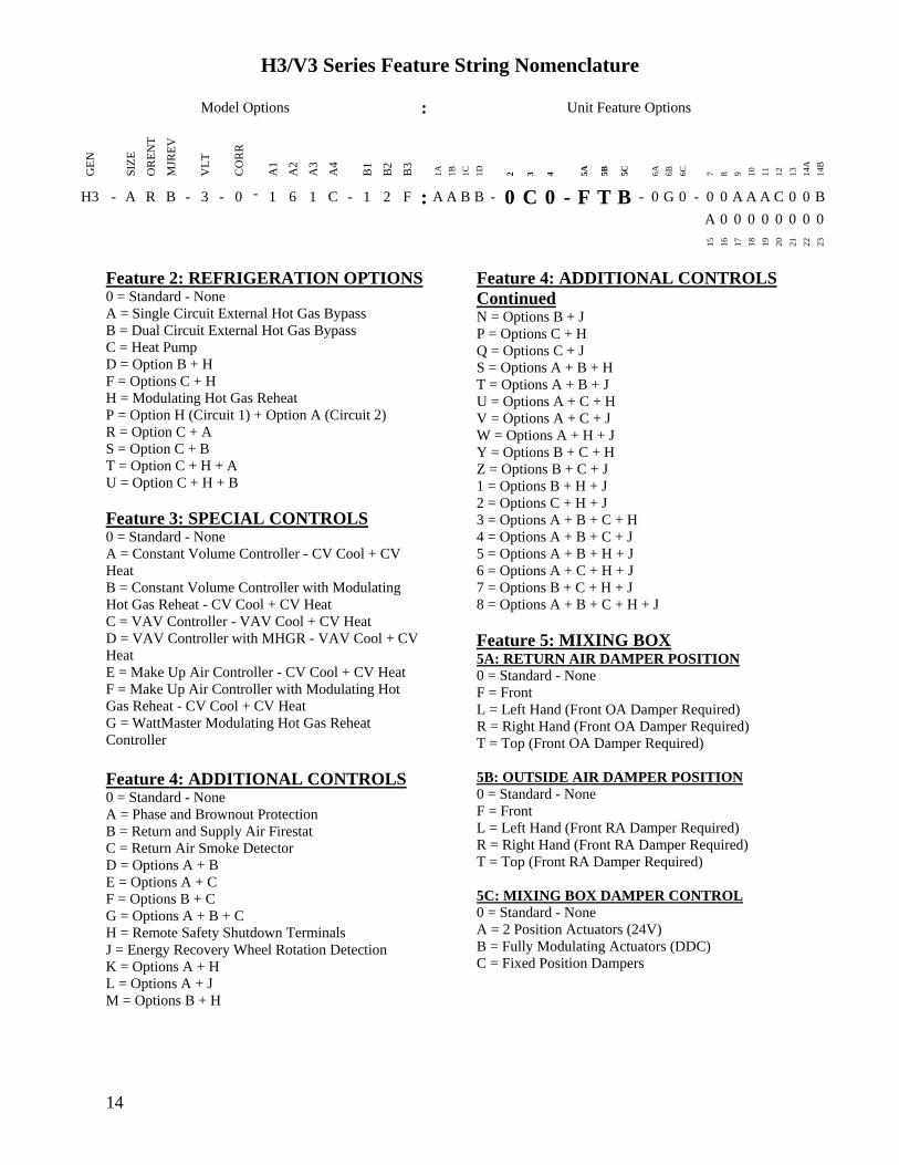
H3V3 Series Feature String Nomenclature
Model Options Unit Feature Options
GE
N
SIZ
E
OR
EN
T
MJR
EV
VL
T
CO
RR
A1
A2
A3
A4
B1
B2
B3
1A
1B
1C
1D
2
3
4
5A
5B
5C
6A
6B
6C
7
8
9
10
11
12
13
14A
14B
H3 - A R B - 3 - 0 - 1 6 1 C - 1 2 F A A B B - 0 C 0 - F T B - 0 G 0 - 0 0 A A A C 0 0 B
A 0 0 0 0 0 0 0 0
15
16
17
18
19
20
21
22
23
15
Feature 6 FILTER BOX 6A PRE FILTER BOX
0 = Standard - None
A = 2rdquo Pleated - 30 Eff - MERV 10
B = 4rdquo Pleated - 30 Eff - MERV 10
C = 4rdquo Pleated - 65 Eff - MERV 11
D = 4rdquo Pleated - 85 Eff - MERV 13
E = 4rdquo Pleated - 95 Eff - MERV 14
F = 2rdquo Pleated - 30 Eff - MERV 10 + 4rdquo Pleated -
30 Eff - MERV 10
G = 2rdquo Pleated - 30 Eff - MERV 10 + 4rdquo Pleated -
65 Eff - MERV 11
H = 2rdquo Pleated - 30 Eff - MERV 10 + 4rdquo Pleated -
85 Eff - MERV 13
J = 2rdquo Pleated - 30 Eff - MERV 10 + 4rdquo Pleated -
95 Eff - MERV 14
6B UNIT FILTER
0 = Standard - None
A = 2rdquo Pleated - 30 Eff - MERV 10
B = 4rdquo Pleated - 30 Eff - MERV 10
C = 4rdquo Pleated - 65 Eff - MERV 11
D = 4rdquo Pleated - 85 Eff - MERV 13
E = 4rdquo Pleated - 95 Eff - MERV 14
F = 2rdquo Pleated - 30 Eff - MERV 10 + 4rdquo Pleated -
30 Eff - MERV 10
G = 2rdquo Pleated - 30 Eff - MERV 10 + 4rdquo Pleated -
65 Eff - MERV 11
H = 2rdquo Pleated - 30 Eff - MERV 10 + 4rdquo Pleated -
85 Eff - MERV 13
J = 2rdquo Pleated - 30 Eff - MERV 10 + 4rdquo Pleated -
95 Eff - MERV 14
6C FINAL FILTER BOX
0 = Standard - None
A = 2rdquo Pleated - 30 Eff - MERV 10
B = 12rdquo Cartridge - 65 Eff - MERV 11
C = 12rdquo Cartridge - 85 Eff - MERV 13
D = 12rdquo Cartridge - 95 Eff - MERV 14
E = 2rdquo Pleated - 30 Eff - MERV 10 + 12rdquo
Cartridge - 65 Eff - MERV 11
F = 2rdquo Pleated - 30 Eff - MERV 10 + 12rdquo
Cartridge - 85 Eff - MERV 13
G = 2rdquo Pleated - 30 Eff - MERV 10 + 12rdquo
Cartridge - 95 Eff - MERV 14
Feature 7 FILTER OPTIONS 0 = Standard - None
A = Magnehelic Gauge
B = Clogged Filter Switch
C = Options A + B
Feature 8 COIL COATING 0 = Standard - None
A = E-coated Cooling and Heating Coils
B = Copper Finned Coils + Stainless Steel Coil
Casing
Feature 9 EXPANSION VALVE 0 = None
A = Thermal Expansion Valves
Feature 10 EXPANSION VALVE
CONTROLS 0 = None
A = Standard Control
Feature 11 EXTERNAL PAINT 0 = Standard - None
A = AAON Gray Paint
B = Special Paint
H3V3 Series Feature String Nomenclature
Model Options Unit Feature Options
GE
N
SIZ
E
OR
EN
T
MJR
EV
VL
T
CO
RR
A1
A2
A3
A4
B1
B2
B3
1A
1B
1C
1D
2
3
4
5A
5B
5C
6A
6B
6C
7
8
9
10
11
12
13
14A
14B
H3 - A R B - 3 - 0 - 1 6 1 C - 1 2 F A A B B - 0 C 0 - F T B - 0 G 0 - 0 0 A A A C 0 0 B A 0 0 0 0 0 0 0 0
15
16
17
18
19
20
21
22
23
16
Feature 12 TONNAGE 0 = Standard - None
A = 2 ton Capacity
B = 3 ton Capacity
C = 4 ton Capacity
D = 5 ton Capacity
E = 6 ton Capacity
F = 7 ton Capacity
G = 8 ton Capacity
U = 9 ton Capacity
H = 10 ton Capacity
V = 11 ton Capacity
W = 13 ton Capacity
J = 14 ton Capacity
Y = 15 ton Capacity
Z = 16 ton Capacity
K = 17 ton Capacity
1 = 18 ton Capacity
2 = 20 ton Capacity
L = 22 ton Capacity
M = 25 ton Capacity
3 = 26 ton Capacity
N = 30 ton Capacity
P = 31 ton Capacity
Q = 34 ton Capacity
R = 40-45 ton Capacity
S = 50-55 ton Capacity
4 = 60 ton Capacity
T = 63 ton Capacity
5 = 70 ton Capacity
Feature 13 ENERGY RECOVERY
TYPE 0 = Standard ndash None
A = Energy Recovery Wheel ndash Total + High CFM
Polymer
C = Energy Recovery Wheel ndash Total + High CFM
1 Purge Polymer
E = Energy Recovery Wheel ndash Sensible + High CFM
Polymer
G = Energy Recovery Wheel ndash Sensible + High
CFM 1 Purge Polymer
Feature 14 GPM 14A GPM COOLING COIL
0 = Standard - None
A = 15-25 gpm
B = 26-70 gpm
C = 71 -140 gpm
D = 141-240 gpm
E = 241-400 gpm
F = 401-800 gpm
G = 801-1500 gpm
H = 1501-2500 gpm
14B GPM HEATING COIL
0 = Standard - None
A = 15-25 gpm
B = 26-70 gpm
C = 71 -140 gpm
D = 141-240 gpm
E = 241-400 gpm
F = 401-800 gpm
G = 801-1500 gpm
H = 1501-2500 gpm
Feature 15 CONTROL PANEL 0 = Internal Control Panel
A = Small Control Panel - 12rdquo x 12rdquo
B = Medium Control Panel - 25rdquo x 22rdquo
C = Large Control Panel - 48rdquo x 22rdquo
Feature 16 SHIPPING SPLITS 0 = Standard ndash None
A = 1 Shipping Split (2 pallets)
B = 2 Shipping Splits (3 pallets)
C = 3 Shipping Splits (4 pallets)
D = 4 Shipping Splits (5 pallets)
E = 5 Shipping Splits (6 pallets)
H = Special Shipping Split (SPA Required)
H3V3 Series Feature String Nomenclature
Model Options Unit Feature Options
GE
N
SIZ
E
OR
EN
T
MJR
EV
VL
T
CO
RR
A1
A2
A3
A4
B1
B2
B3
1A
1B
1C
1D
2
3
4
5A
5B
5C
6A
6B
6C
7
8
9
10
11
12
13
14A
14B
H3 - A R B - 3 - 0 - 1 6 1 C - 1 2 F A A B B - 0 C 0 - F T B - 0 G 0 - 0 0 A A A C 0 0 B
A 0 0 0 0 0 0 0 0 1
5
16
17
18
19
20
21
22
23
17
Feature 17 ENERGY RECOVERY
CABINET 0 = Standard - None
A = Top RA + Back EA + Back OA Connections
G = OA + EA Dampers - Top RA + Back EA + Back
OA Connections
N = OA + Economizer Dampers - Top RA + Back
EA + Back Connections
U = OA + EA + Economizer Dampers - Top RA +
Back EA + Back OA Connections
Feature 18 MODULATING ELECTRIC
PREHEAT 0 = Standard - None
A = 75 kW
B = 15 kW
C = 20 kW
D = 225 kW
E = 30 kW
F = 40 kW
G = 50 kW
H = 60 kW
Feature 19 EXHAUST FAN 0 = Standard - None
A = 250 mm Exhaust Fan 800 W EC Motor
B = 310 mm Exhaust Fan 10 kW EC Motor
C = 310 mm Exhaust Fan 17 kW EC Motor
D = 355 mm Exhaust Fan 17 kW EC Motor
E = 450 mm Exhaust Fan 30 kW EC Motor
F = 450 mm Exhaust Fan 60 kW EC Motor
G = Dual 310 mm Exhaust Fan 10 kW EC Motor
H = Dual 310 mm Exhaust Fan 17 kW EC Motor
J = Dual 355 mm Exhaust Fan 17 kW EC Motor
K = Dual 450 mm Exhaust Fan 30 kW EC Motor
L = Dual 450 mm Exhaust Fan 60 kW EC Motor
Feature 20 CRATING 0 = Standard - None
A = Export Crating
B = Forkliftable Base - 5rdquo Base
C = Options A + E
D = Options A + B
E = Shipping Shrink Wrap
F = Options B + E
G = Options A + B + E
Feature 21 PULLEY COMBINATION 0 = Standard - None
A = 1000-1400 rpm
B = 1401-1800 rpm
C = 1801-2200 rpm
Feature 22 WARRANTY 0 = Standard - 1 Year Parts
Feature 23 TYPE 0 = Standard
X = Special Pricing Authorization
18
General Information
AAONreg
H3 and V3 Series indoor air
handling units have been designed for
indoor installation only Units are
assembled wired charged with dry nitrogen
and run-tested at the factory H3 and V3
Series units are not intended for residential
use Startup and service must be performed
by a Factory Trained Service Technician
Certification of Steam or Hot Water Heat
Models
a Certified as a forced air heating system
with or without cooling
b Certified for indoor installation only
Certification of Electric Heat Models
a Certified as an electric warm air furnace
with or without cooling
b Certified for indoor installation only
Certification of Cooling Models
a Certified as a commercial central air
conditioner with or without electrically
operated compressors
b Certified for indoor installation only
c Certified with refrigerant R-410A coils
or with chilled water cooling coils
Improper installation adjustment alteration service or maintenance can cause property damage personal injury or loss of life Startup and service must be performed by a Factory Trained Service Technician A copy of this IOM should be kept with the unit
WARNING
These units must not be used as a ldquoconstruction heaterrdquo at anytime during any phase of construction Very low return air temperatures harmful vapors and misplacement of the filters will damage the unit and its efficiency
CAUTION
This equipment is protected by a standard limited warranty under the condition that initial installation service startup and maintenance is performed according to the instructions set forth in this manual This manual should be read in its entirety prior to installation and before performing any service or maintenance work Equipment described in this manual is available with many optional accessories If you have questions after reading this manual in its entirety consult other factory documentation or contact your AAON Sales Representative to obtain further information before manipulating this equipment or its optional accessories
CAUTION
19
Codes and Ordinances
H3 and V3 Series units have been tested and
certified by ETL in accordance with UL
Safety Standard 1995CSA C222 No 236
System should be sized in accordance with
the American Society of Heating
Refrigeration and Air Conditioning
Engineers Handbook
Installation of H3 and V3 Series units must
conform to the ICC standards of the
International Mechanical Code the
International Building Code Installation of
Air Conditioning and Ventilating Systems
Standard NFPA 90A and local building
plumbing and waste water codes All
appliances must be electrically grounded in
accordance with local codes or in the
absence of local codes the current National
Electric Code ANSINFPA 70 or the
current Canadian Electrical Code CSA
C221
Receiving Unit
When received the unit should be checked
for damage that might have occurred in
transit If damage is found it should be noted
on the carrierrsquos Freight Bill A request for
inspection by carrierrsquos agent should be made
in writing at once
Nameplate should be checked to ensure the
correct model sizes and voltages have been
received to match the job requirements
If repairs must be made to damaged goods
then the factory should be notified before
any repair action is taken in order to protect
the warranty Certain equipment alteration
repair and manipulation of equipment
without the manufacturerrsquos consent may
void the product warranty Contact the
AAON Warranty Department for assistance
with handling damaged goods repairs and
freight claims (903) 236-4403
Note Upon receipt check shipment for
items that ship loose such as remote sensors
Consult order and shipment documentation
to identify potential loose-shipped items
Loose-shipped items may have been placed
inside unit cabinet for security Installers
and owners should secure all doors with
locks or nuts and bolts to prevent
unauthorized access
The Clean Air Act of 1990 bans the intentional venting of refrigerant as of July 1 1992 Approved methods of recovery recycling or reclaiming must be followed
CAUTION
Coils and sheet metal surfaces present sharp edges and care must be taken when working with equipment
WARNING
Failure to observe the following instructions will result in premature failure of your system and possible voiding of the warranty
WARNING
20
Figure 1 - Lockable Handle
Storage
This equipment is not suitable for outdoor
use of storage If installation will not occur
immediately following delivery store
equipment in a dry protected area away from
construction traffic and in the proper
orientation as marked on the packaging with
all internal packaging in place Secure all
loose-shipped items
Direct Expansion (DX) Systems
All DX refrigerant coils are factory charged
with a nitrogen holding charge All DX
systems include evaporator coils and
thermal expansion valves (TXV)
Never turn off the main power supply to the
unit except for servicing emergency or
complete shutdown of the unit When power
is cut off from the unit crankcase heaters
cannot prevent refrigerant migration into the
split system condensing unit compressors
This means the compressor may cool down
and liquid refrigerant may accumulate in the
compressor The compressor is designed to
pump refrigerant gas and damage may occur
when power is restored
If power to the unit must be off for more
than an hour turn the thermostat system
switch to OFF or turn the unit off at the
control panel and leave the unit off until the
main power switch has been turned on again
for at least 24 hours for units with
compressor crankcase heaters This will give
the crankcase heater time to clear any liquid
accumulation out of the compressor before it
is started
Always control the unit from the thermostat
or control panel never at the main power
supply except for emergency or complete
shutdown of the unit
During the cooling season if the air flow is
reduced due to dirty air filters or any other
reason the cooling coils can get too cold
which will cause excessive liquid to return
to the compressor As the liquid
concentration builds up oil is washed out of
the compressor leaving it starved for
lubrication
The compressor life will be seriously
shortened by reduced lubrication and the
pumping of excessive amounts of liquid oil
and refrigerant
CRANKCASE HEATER OPERATION
Some units are equipped with compressor crankcase heaters which should be energized at least 24 hours prior to cooling operation to clear any liquid refrigerant from the compressors
CAUTION
21
Note Low Ambient Operation
Air-cooled DX units without a low ambient
option such as condenser fan cycling or the
0degF low ambient option will not operate in
the cooling mode of operation properly
when the outdoor temperature is below
55degF Low ambient andor economizer
options are recommended if cooling
operation below 55degF is expected
Wiring Diagrams
Unit specific wiring diagrams are laminated
and affixed inside the controls compartment
door
Condensate Drain Pans
Units require field installed drain p-traps and
lines to be connected to the condensate drain
pans of the unit
For condensate drain lines the line should
be the same pipe size or larger than the drain
connection include a p-trap and pitch
downward toward drain An air break should
be used with long runs of condensate lines
See Installation section of this manual for
more information
Unit should not be operated without a p-trap Failure to install a p-trap may result in overflow of condensate water
CAUTION
Emergency drain pan is recommended for all applications where a risk of water damage to surrounding structure or furnishings Refer to local codes
CAUTION
22
Installation
AAON equipment has been designed for
quick and easy installation Startup and
service must be performed by Factory
Trained Service Technician
The H3V3 unit can either be shipped
assembled or shipped in sections See the
Unit Assembly section of this document for
instructions on assembling the sections
Locating the Unit
Placement of the unit relative to ductwork
electrical and plumbing must be carefully
considered Return air plenum or duct can be
mounted directly to the return air flanges
Use flexible gasket material to seal the duct
to the unit
Verify floor foundation or suspension
support can support the total unit weight
including accessory weights Unit must be
level in both horizontal axes to support the
unit and reduce noise and vibration from the
unit
Allow adequate space for piping access and
panel removal To ensure proper access
for field service maintain minimum
clearances for field piping and other
obstructions as indicated by Table 1 and
Figure 2 and Figure 3 Consult local
building codes for additional service
clearance requirements Condensate drain
connections are located on the access side of
the unit
Table 1 - H3 and V3 Series Clearances
Unit Size
Access Side
Clearance
(dimension X on
Figure 2 and
Figure 3)
All Other
Sides
V3-A
36 inches
6 inches
V3-B
V3-C
V3-D
V3-E
H3-A
H3-B
H3-C
H3-D 45 inches
H3-E 60 inches
Additional clearance may be required to
allow for coil removal
May be installed flush depending upon
local codes
Figure 2 - Minimum Clearance Required for
Access to Unit (V3 Series plan view)
X
(See Table 1)
Back Front
Left
Right
23
Figure 3 - Minimum Clearance Required for
Access to Unit (H3 Series plan view)
Internal Control Panel
H3 units with internal control panel have
removable access panels on the top and
bottom of the supply fan section V3 units
with internal control panel have removable
access panels on the front and back of the
supply fan section V3 units that have
energy recovery only have one removable
supply fan access panel on the front of the
unit The supply flanges can be
interchanged with the access panels if
necessary except on size E
Figure 4 - H3 internal control panel with top
access panel removed
Figure 5 - V3 internal control panel with
rear removable access panel shown
Floor Mounted Units
Make sure the unit is level and mounted on a
field supplied platform with a minimum
height to allow for proper depth of the
condensate line p-trap Other installation
provisions may be necessary according to
job specifications V3 Series vertical air
handling units are designed for upflow
applications only
Suspended Units
H3 Series horizontal air handling units are
equipped for suspended installations The
unit should be lifted into position by
supporting the unit with the skid used for
shipping The air handling unit must be
installed level and care should be taken to
prevent damage to the cabinet Other
installation provisions may be necessary
according to job specifications Figure 6
and Figure 7 show factory recommended
methods for suspended installations It is
the responsibility of the specifying engineer
or installing contractor to ensure the
installation is structurally safe and sound
X
(See Table 1)
Front
Back
Left Right
24
Figure 6 - H3 Series Platform Suspension Installation
Figure 7 - H3 Series Parallel Beam Suspension Installation
25
Figure 8 - H3 Series Unit Orientation
Figure 9 - V3 Series Unit Orientation
Note Access doors may be on the ldquoleftrdquo or ldquorightrdquo side as designated by the unit orientation on
the configurator string ldquoBackrdquo will always be the same side as the pre-filter and return air
opening ldquoFrontrdquo will always be the side opposite the pre-filter and return air opening
H3 Series
Return Air ldquoBackrdquo
Supply Air ldquoFrontrdquo
Right Hand Side
Left Hand Side
Connections and service access on right side for right hand orientation
Top View
Air Flow
Connections and service access on right side for right hand orientation
Right Hand Side Left Hand Side
Return Air ldquoBackrdquo
Top View V3 Series
Air Flow
Consider the air flow to be hitting the back of your head
Consider the air flow to be hitting the back of your head
Supply Air
ldquoFrontrdquo
26
Lifting and Handling the Unit
Before lifting unit be sure that all shipping
material has been removed from unit
Care should be taken if using spreader bars
blocking or other lifting devices to prevent
damage to the cabinet coil or fans
Unit Assembly
Although H3V3 Series units are shipped
factory assembled as standard the unit may
be ordered as shipping splits for certain
applications such as for assembly in existing
structures where modules must be
manipulated separately If the unit was
ordered as shipping splits then they must be
assembled in the field
Locate the schematic in the equipmentrsquos
literature packet
1 Identify and Situate Splits
a H3 Units can have the following
ship split sections
1 Mixing Box
2 Air Handler
3 Final Filter
4 Electric Heat
Figure 10 - H3 Schematic with (1) Mixing
Box (2) Air Handler (3) Final Filter and
(4) Electric Heat
b V3 Units can have the following
ship split sections
1 Exhaust Fan
2 Energy Recovery
3 Air Handler
4 Electric Heat
5 Pre filter
6 Mixing box
Figure 11 - V3 Schematic with (1) Exhaust
Fan (2) Energy Recovery (3) Air Handler
and (4) Electric Heat
2 Connect Sections
Using the V3 Schematic as an example
section 1 will have a duct flange and it will
connect to section 2 on the side that does not
have a flange First make sure gasket is on
the panel around the edges of the exposed
duct flanges Push section 1 and 2 together
UNIT HANDLING
Incorrect lifting can cause damage to the unit injury or death Lifting equipment capacity should exceed unit weight by an adequate safety factor Always test lift unit not more than 24 inches high to verify proper center of gravity lift point
WARNING
1 2 3 4
1 2
3
4
27
so that the flange from section 1 is inside of
section 2
Figure 12 - Connect Sections
Use bar clamps or other non-destructive
winching device to pull the tops of the
modules together tightly
Figure 13 - Bar Clamp
At each of the pre-drilled holes in the flange
drill 516 hex head self-tapping screws to
secure the two sections together
Figure 14 - Flange Overlap
Figure 15 - Self-Tapping Screw
All connection hardware is shipped with the
unit
3 Secure Module Joints
The metal straps are to be used to secure
module joints Straps are provided with pre-
drilled holes Self-tapping sheet metal
screws are provided to attach the straps to
the unit cabinet
Leave bar clamps in place until strap is
secure
Place the strap over a module joint ensure
the strap completely covers the joint and
that it is square with the unit casing
Insert self-tapping screws through pre-
drilled holes in strap and secure screws into
unit casing using a power drill For best
results use the lowest effective power drill
torque setting Be careful not to over tighten
the screws
Remove bar clamps and repeat for all
remaining module joints
Figure 16 - Strap Types
516rdquo Hex Head Self-Tapping Screws
Provided with Unit
1rdquo
Angle Strap
Top Strap
Section 2
Flange
28
4 Connect Power and Control Wiring
H3V3 Series units are equipped with low
and high voltage quick connects to connect
wiring from one section to the next Wire
from the unit to external controls and power
sources must be provided in the field
Figure 17 - Low Voltage Quick Connect
A color-coded wiring diagram is laminated
and affixed to the inside of the control
compartment access door H3V3 Series
units are equipped with a single point power
connection
5 Final Sealing
It is very important to keep air from
infiltrating the unit cabinet Seal all piping
penetrations with Armaflex Permagum or
other suitable sealant Also seal around drain
connections electrical connections and all
other inlets where air may enter the cabinet
This is especially important when the unit is
installed in an unconditioned area
Control Box
Some H3V3 units include an external
control box that must be mounted in the
field
Figure 18 - Back View External Control
Box
Duct Connection
Attach duct to flanges provided on the unit
The installer is responsible for sealing ducts
to the flanges to prevent water leaks
Refer to Figure 8 and Figure 9 for duct
connection locations The V3 supply air duct
is out to top of the unit Ductwork should be
sized in accordance with the ASHRAE
Handbook Ductwork should be installed in
accordance with NFPA Standard 90A
When attaching duct to the unit use a
flexiblecompressible material rated for duct
connections A three inch flexible connector
for both return and supply duct connections
is recommended
Condensate Drain Piping
Unit may be equipped with more than one
condensate drain pan connection A p-trap
and drain line must be installed on at least
one sectionrsquos drain connection with the p-
trap not to exceed 6rdquo from the drain
connection The lines should be the same
pipe size or larger than the drain connection
include a p-trap and pitch downward toward
drain An air break should be used with long
runs of condensate lines
Installing Contractor is responsible for proper sealing of the electrical and piping entries into the unit Failure to seal the entries may result in damage to the unit and property
CAUTION
29
Draw-through cooling coils will have a
negative static pressure in the drain pan area
This will cause an un-trapped drain to back
up due to air being pulled up through the
condensate drain piping
Condensate drain trapping and piping should
conform to all applicable governing codes
Note The drain pan connection(s) is a 1rdquo
MPT fitting
Figure 19 - Drain Trap
The X dimension on the draw-through trap
should be at least equal to the absolute value
of the negative static pressure in the drain
pan plus one inch To calculate the static
pressure at the drain pan add the pressure
drops of all components upstream of the
drain pan including the cooling coil and
add the return duct static pressure Include
the dirt allowance pressure drop for the
filters to account for the worst-case scenario
The height from top of the bottom bend of
the trap to the bottom of the leaving pipe
must be at least equal to one half of the X
dimension This ensures that enough water
is stored in the trap to prevent losing the
drain seal during unit startup
Note The absolute value of the fan inlet
pressure will always be greater than or equal
to the absolute value of the static pressure in
the drain pan on draw-through units so the
fan inlet pressure is a safe value to use for
the drain pan static pressure
Table 2 - Drain Trap Dimensions
Draw-Through
Drain Pan Pressure Trap Dimensions
Negative Static X X2
(inches of water) (inch) (inch)
-050 150 075
-100 200 100
-150 250 125
-200 300 150
-250 350 175
-300 400 200
-350 450 225
-400 500 250
Heating Coils
One or two row hot water and steam heating
and preheating coils can be factory installed
These coils are supplied from a building hot
water source All valve controls for heating
coil operation are field supplied and field
installed
Unit should not be operated without p-traps Failure to install a p-traps may result in overflow of condensate water
CAUTION
30
Always connect the steam heating supply to
the top of the coil and the return to the
bottom
Figure 20 - Steam Distributing Piping
Table 3 - Steam Distributing Coil
Connection Sizes
Model (H3- V3-) Supply and Return
Connection Size
A-E 2 18
Air handling units with steam heating coils
MUST BE installed high enough to allow
for a minimum of 1 foot condensate drop leg
off of the steam coil or as recommended by
the steam trap manufacturer Lines should
be insulated with approved insulation and be
properly fastened sloped and supported
according to local code requirements
Table 4 - Hot Water Coil Connection Sizes
Model (H3- V3-) Supply and Return
Connection Size
A 78
B 1 18
C 1 38
D amp E 1 58
Always connect the hot water heating supply
to the bottom of the coil and return to the
top
Figure 21 - Hot amp Chilled Water Piping
Water coils should not be subjected to
entering air temperatures below 38degF to
prevent coil freeze-up If air temperature
across the coil is going to be below this
value use a glycol solution to match the
coldest air expected
Water supply lines must be insulated
properly fastened drained and supported
according to local code requirements
Chilled Water Coil
Factory installed four six or eight row
chilled water cooling coils can be factory
mounted These coils are supplied from a
building chilled water source All valve
controls for the cooling coil operation are
field supplied and field installed
31
Table 5 - Chilled Water Coil Connection
Sizes
Model (H3- V3-) Supply and Return
Connection Size
A 1 18
B 1 38
C 1 58
D amp E 2 18
Always connect the chilled water supply to
the bottom of the coil and return to the top
Water supply lines must be insulated with
closed cell type pipe insulation or insulation
that includes a vapor barrier Lines should
be properly fastened drained and supported
according to local code requirements and
job specifications
Evaporator Coil
The air handling unit coils are pressurized
The copper caps must be punctured to
permit a gradual escape of the pressure prior
to un-sweating those caps Immediately
couple the tubing to the indoor unit to avoid
exposing the coils to moisture A properly
sized filter drier is furnished in the
condenser When making solder
connections make sure dry nitrogen flows
through the lines when heating the copper
to prevent oxidization inside of the copper
Field piping between the condensing unit
and the air handler is required Line
sizes must be selected to meet actual
installation conditions not simply based
on the connection sizes
Thermal Expansion Valve
Thermal expansion valve bulbs should be
mounted with good thermal contact on a
horizontal section of the suction line close to
the evaporator but outside the cabinet and
well insulated On suction lines less than or
equal to 78rdquo OD mount in the 12 orsquoclock
position On suction lines greater than 78rdquo
OD mount in either the 4 orsquoclock or 8
orsquoclock position
Figure 22 - TXV Bulb Position
Hot Gas Reheat
Hot Gas Reheat (HGRH) is available for use
with DX systems that need humidity control
The AAON modulating hot gas reheat
system diverts hot discharge gas from the
condenser to the air handling unit through
the hot gas line Field piping between the
condensing unit and the air handler is
required Line sizes must be selected to
meet actual installation conditions not
simply based on the connection sizes
The line delivers the hot discharge gas to the
reheat coil andor the hot gas bypass valve
so it is sized as a discharge line
Modulating Hot Gas Reheat Piping
1 Run a hot gas reheat line from the
condensing unit and connect it to the inlet of
the stub-out on the reheat coil The inlet
connection is the top (or highest) stub-out of
the reheat coil Connect the hot gas line
from the outdoor unit to the upper stub-out
connection of the reheat coil
2 Run a liquid line from the discharge of the
reheat coil through a tee connection Run a
liquid line from the condenser through a
REFRIGERANT PIPING
Line sizes must be selected to meet actual installation conditions not simply based on the connection sizes at the condensing unit or air handling unit
CAUTION
32
check valve to the other side of the tee Run
a liquid line from the tee to the liquid line
stub-out of the evaporator coil
3 Run a suction line from the evaporator
coil outlet stub-out to the condensing unit
Hot Gas Bypass
Hot Gas Bypass is available for use with DX
systems that may experience low suction
pressure during the operating cycle This
may be due to varying load conditions
associated with VAV applications or units
supplying a large percentage of outside air
Hot Gas Bypass is not necessary in units
with variable capacity compressors The
system is designed to divert refrigerant from
the compressor discharge to the low pressure
side of the system in order to keep the
evaporator from freezing and to maintain
adequate refrigerant velocity for oil return at
minimum load
Hot discharge gas is redirected to the
evaporator inlet via an auxiliary side
connector (ASC) to false load the evaporator
when reduced suction pressure is sensed
Field piping between the condensing unit
and the evaporator is required Line sizes
must be selected to meet actual
installation conditions not simply based
on the connection sizes
Electric Preheat
The modulating electric preheat option is
designed to temper the incoming outside air
to the unit based on an enable control signal
and the outside air conditions
A 24VAC enable signal must be provided to
the [PHE] terminal to enable the operation
of the electric preheat Once the preheat
controller is enabled it will monitor the
outside air temperature to determine if any
capacity of preheat is needed If the outside
air temperature falls below the outside air
temperature setpoint the electric preheat will
be started up and maintain the leaving air
temperature setpoint with both SCR
controlled and staged electric preheat Both
setpoints are set with push button LCD
interface on the preheat controller Outside
air temperature sensors and preheat
discharge supply air temperature sensors are
factory installed and wired to the preheat
controller Electric preheat has maximum
operating outside air temperature of 60degF
and a maximum preheat discharge air
temperature of 80degF
[COM] [PHO] amp [PHC] feedback terminals
are provided to communicate if the electric
preheat is in operation PHO is a normally
open contact PHC is a normally closed
contact and COM is the common These
terminals are not required to be connected
[PHE] is the electric preheat operation
enable [PH+] and [PH-] are the preheat set
point reset terminals
33
Energy Recovery Units
Some H3V3 units have been equipped with
an energy recovery wheel This section is
provided to assure the energy recovery
feature will be properly setup to perform in
accordance with the job specifications for
your particular application
Figure 23 - Energy Recovery Wheel
The Energy Recovery Cassette consists of a
frame wheel wheel drive system and
energy transfer segments Segments are
removable for cleaning or replacement The
segments rotate through counter flowing
exhaust and outdoor air supply streams
where they transfer heat andor water vapor
from the warm moist air stream to the
cooler andor drier air stream
The initial setup and servicing of the energy
recovery wheel is very important to maintain
proper operation efficiency and building
occupant comfort
Normal maintenance requires periodic
inspection of filters the cassette wheel
drive belts air seals wheel drive motor and
its electrical connections
Wiring diagrams are provided with each
motor When wired according to wiring
diagram motor rotates clockwise when
viewed from the shaftpulley side
By carefully reviewing the information
within this section and following the
instructions the risk of improper operation
andor component damage will be
minimized
It is important that periodic maintenance be
performed to help assure trouble free
operation
Initial Mechanical Check and Setup
Outdoor air intake adjustments should be
made according to building ventilation or
local code requirements
After the unit installation is complete open
the cassette access door and determine that
the energy wheel rotates freely when turned
by hand Apply power and observe that the
wheel rotates at approximately 30 RPM If
the wheel does not rotate when power is
applied it may be necessary to readjust the
ldquodiameter air sealsrdquo
Air Seal Adjustments
Pile type air seals across both sides of the
energy wheel diameter are factory adjusted
to provide close clearance between the air
seal and wheel Racking of the unit or
cassette during installation andor mounting
of the unit on a non-level support or in other
than the factory orientation can change seal
clearances Tight seals will prevent rotation
Figure 24 - Cross Section of Air Seal
Structure
34
Wheel to Air Seal Clearance
To check wheel to seal clearance first
disconnect power to the unit in some units
the energy recovery wheel assembly can be
pulled out from the cabinet to view the air
seals On larger units the energy recovery
wheel may be accessible inside the walk-in
cabinet
A business card or two pieces of paper can
be used as a feller gauge (typically each
004rdquo thick) by placing it between the face
of the wheel and pile seal
Using the paper determine if a loose slip fit
exist between the pile seal and wheel when
the wheel is rotated by hand
To adjust air seal clearance loosen all seal
plate retaining screws holding the separate
seal retaining plates to the bearing support
channels and slide the seals plates away
from the wheel Using the paper feeler
gauge readjust and retighten one seal plate
at a time to provide slip fit clearance when
the wheel is rotated by hand
Confirm that the wheel rotates freely Apply
power to the unit and confirm rotation
Airflow Balancing and Checking
High performance systems commonly have
complex air distribution and fan systems
Unqualified personnel should not attempt to
adjust fan operation or air circulation as all
systems have unique operations
characteristics Professional air balance
specialists should be employed to establish
actual operating conditions and to configure
the air delivery system for optimal
performance
Controls
A variety of controls and electrical
accessories may be provided with the
equipment Identify the controls on each unit
by consulting appropriate submittal or order
documents and operate according to the
control manufacturerrsquos instructions If you
cannot locate installation operation or
maintenance information for the specific
controls then contact your sales
representative or the control manufacturer
for assistance
Routine Maintenance and Handling
Handle cassettes with care All cassettes
should be lifted by the bearing support
beam Holes are provided on both sides of
the bearing support beams to facilitate
rigging as shown in the following
illustration
Figure 25 - Lifting Hole Locations
Routine maintenance of the Energy
Recovery Cassettes includes periodic
Do not alter factory wiring Deviation from the supplied wiring diagram will void all warranties and may result in equipment damage or personal injury Contact the factory with wiring discrepancies
WARNING
35
cleaning of the Energy Recovery Wheel as
well as inspection of the Air Seals and
Wheel Drive Components as follows
Cleaning
The need for periodic cleaning of the energy
recovery wheel will be a function of
operating schedule climate and
contaminants in the indoor air being
exhausted and the outdoor air being supplied
to the building
The energy recovery wheel is ldquoself-
cleaningrdquo with respect to dry particles due to
its laminar flow characteristics Smaller
particles pass through larger particles land
on the surface and are blown clear as the
flow direction is reversed Any material that
builds up on the face of the wheel can be
removed with a brush or vacuum The
primary need for cleaning is to remove oil
based aerosols that have condensed on
energy transfer surfaces
A characteristic of all dry desiccants such
films can close off micron sized pores at the
surface of the desiccant material reducing
the efficiency by which the desiccant can
adsorb and desorb moisture and also build
up so as to reduce airflow
In a reasonably clean indoor environment
such as a school or office building
measurable reductions of airflow or loss of
sensible (temperature) effectiveness may not
occur for several years Measurable changes
in latent energy (water vapor) transfer can
occur in shorter periods of time in
applications such as moderate occupant
smoking or cooking facilities In
applications experiencing unusually high
levels of occupant smoking or oil based
aerosols such as industrial applications
involving the ventilation of machine shop
areas for example annual washing of energy
transfer may be necessary to maintain latent
transfer efficiency Proper cleaning of the
energy recovery wheel will restore latent
effectiveness to near original performance
To clean gain access to the energy recovery
wheel and remove segments Brush foreign
material from the face of the wheel Wash
the segments or small wheels in a 5
solution of non-acid based coil cleaner or
alkaline detergent and warm water
Soak in the solution until grease and tar
deposits are loosened (Note some staining
of the desiccant may remain and is not
harmful to performance) Before removing
rapidly run finger across surface of segment
to separate polymer strips for better cleaning
action Rinse dirty solution from segment
and remove excess water before reinstalling
in wheel
Air Seals
Four adjustable diameter seals are provided
on each cassette to minimize transfer of air
between the counter flowing airstreams
To adjust diameter seals loosen diameter
seal adjusting screws and back seals away
from wheel surface Rotate wheel clockwise
until two opposing spokes are hidden behind
the bearing support beam Using a folded
piece of paper as a feeler gauge position
paper between the wheel surface and
diameter seals
Adjust seals towards wheel surface until a
slight friction on the feeler gauge (paper) is
detected when gauge is moved along the
length of the spoke Retighten adjusting
Do Not use acid based cleaners aromatic solvents steam or temperatures in excess of 170degF damage to the wheel may occur
CAUTION
36
screws and recheck clearance with ldquofeelerrdquo
gauge
Wheel Drive Components
The wheel drive motor bearings are pre-
lubricated and no further lubrication is
necessary
The wheel drive pulley is secured to the
drive motor shaft by a combination of either
a key or D slot and set screw
The set screw is secured with removable
locktite to prevent loosening Annually
confirm set screw is secure The wheel drive
belt is a urethane stretch belt designed to
provide constant tension through the life of
the belt No adjustment is required Inspect
the drive belt annually for proper tracking
and tension A properly tensioned belt will
turn the wheel immediately after power is
applied with no visible slippage during start-
up
Installation Considerations
Energy recovery cassettes are incorporated
within the design of packaged units
packaged air handlers and energy recovery
ventilators In each case it is recommended
that the following considerations be
addressed
Accessibility
The cassette and all its operative parts ie
motor belt pulley bearings seals and
energy transfer segments must be accessible
for service and maintenance This design
requires that adequate clearance be provided
outside the enclosure
Orientation amp Support
The Energy Recovery Cassette may be
mounted in any orientation However Care
must be taken to make certain that the
cassette frame remains flat and the bearing
beams are not racked
To verify make certain that the distance
between wheel rim and bearing beam is the
same at each end of the bearing beam to
within 14 of an inch (dimension A amp B)
This amount of racking can be compensated
for by adjusting the diameter seals
If greater than 14 inch (dimension C)
racking must be corrected to ensure that
drive belt will not disengage from wheel
Figure 26 - Avoid Racking of Cassette
Frame
Operation
Startup Procedure
1 By hand turn wheel clockwise (as viewed
from the pulley side) to verify wheel turns
freely through 360ordm rotation
2 Before applying power to drive motor
confirm wheel segments are fully engaged in
wheel frame and segment retainers are
completely fastened (See Segment
Installation Diagram)
B
C
A
Bearing beams shown racked
Frame
Wheel
Bearing beams (2)
Flat surface
Keep hands away from rotating wheel Contact with rotating wheel can cause physical injury
CAUTION
37
3 With hands and objects away from
moving parts activate unit and confirm
wheel rotation Wheel rotates clockwise (as
viewed from the pulley side)
4 If wheel has difficulty starting turn power
off and inspect for excessive interference
between the wheel surface and each of the
four (4) diameter seals To correct loosen
diameter seal adjusting screws and back
adjustable diameter seals away from surface
of wheel apply power to confirm wheel is
free to rotate then re-adjust and tighten hub
and diameter seals as shown in hub seal
adjustment diagram
5 Start and stop wheel several times to
confirm seal adjustment and to confirm belt
is tracking properly on wheel rim
(approximately 14rdquo from outer edge of
rim)
Figure 27 - Diameter Seal Adjustment
Figure 28 - Hub Seal Adjustment
Service
Segment Installation amp Replacement
Wheel segments are secured to the wheel
frame by a Segment Retainer which pivots
on the wheel rim and is held in place by a
Segment Retaining Catch
Disconnect electrical power before servicing energy recovery cassette Always keep hands away from bearing support beam when installing or removing segments Failure to do so could result in severe injury to fingers or hand
CAUTION
38
Figure 29 - Segment Retainer
To install wheel segments follow steps one
through five below Reverse procedure for
segment removal
1 Unlock two segment retainers (one on
each side of the selected segment opening
2 With the embedded stiffener facing the
motor side insert the nose of the segment
between the hub plates
Figure 30 - Segment Installation
3 Holding segment by the two outer
corners press the segment towards the
center of the wheel and inwards against the
spoke flanges If hand pressure does not
fully seat the segment insert the flat tip of a
screw driver between the wheel rim and
outer corners of the segment and apply
downward force while guiding the segment
into place
4 Close and latch each Segment Retainer
under Segment Retaining Catch
5 Slowly rotate the wheel 180ordm Install the
second segment opposite the first for
counterbalance Rotate the two installed
segments 90ordm to balance the wheel while the
third segment is installed Rotate the wheel
180ordm again to install the fourth segment
opposite the third Repeat this sequence with
the remaining four segments
Wheel Drive Motor and Pulley Replacement
1 Disconnect power to wheel drive motor
2 Remove belt from pulley and position
temporarily around wheel rim
3 Loosen set screw in wheel drive pulley
using a hex head wrench and remove pulley
from motor drive shaft
4 While supporting weight of drive motor in
one hand loosen and remove (4) mounting
bolts
5 Install replacement motor with hardware
kit supplied
6 Install pulley to dimension as shown and
secure set screw to drive shaft
7 Stretch belt over pulley and engage in
groove
8 Follow start-up procedure
Belt Replacement
1 Obtain access to the pulley side bearing
access plate if bearing access plates are
provided Remove two bearing access plate
retaining screws and the access plate
39
2 Using hexagonal wrench loosen set screw
in bearing locking collar Using light
hammer and drift (in drift pin hole) tap
collar in the direction of wheel rotation to
unlock collar Remove collar
3 Using socket wrench with extension
remove two nuts which secure bearing
housing to the bearing support beam Slide
bearing from shaft If not removable by
hand use bearing puller
4 Form a small loop of belt and pass it
through the hole in the bearing support
beam Grasp the belt at the wheel hub and
pull the entire belt down
Note Slight hand pressure against wheel
rim will lift weight of wheel from inner race
of bearing to assist bearing removal and
installation
5 Loop the trailing end of the belt over the
shaft (belt is partially through the opening)
6 Reinstall the bearing onto the wheel shaft
being careful to engage the two locating pins
into the holes in the bearing support beam
Secure the bearing with two self-locking
nuts
7 Install the belts around the wheel and
pulley according to the instructions provided
with the belt
8 Reinstall diameter seals or hub seal and
tighten retaining screws Rotate wheel in
clockwise direction to determine that wheel
rotates freely with slight drag on seals
9 Reinstall bearing locking collar Rotate
collar by hand in the direction the wheel
rotates (see label provided on each cassette
for wheel rotation)
10 Lock in position by tapping drift pin
hole with hammer and drift Secure in
position by tightening set screw
11 Reinstall Bearing Access Cover
12 Apply power to wheel and ensure that
the wheel rotates freely without interference
Figure 31 - Belt Replacement
Protect hands and belt from possible sharp edges of hole in Bearing Support Beam
CAUTION
40
Electrical
Verify the unit name plate agrees with
power supply H3 and V3 Series units are
provided with single point power wiring
connections Connection terminations are
made to the main terminal block A
complete set of unit specific wiring
diagrams showing factory and field wiring
are laminated in plastic and located inside
the control compartment door
Route power and control wiring separately
through the utility entry in the unit Do not
run power and control signal wires in the
same conduit
All units require field supplied electrical
overcurrent and short circuit protection
Device must not be sized larger than the
Maximum Overcurrent Protection (MOP)
shown on the unit nameplate
Codes may require a disconnect switch be
within sight of the unit
It is recommended that the field installed
overcurrent protection or disconnect switch
not be installed on the unit
On units with external control box electrical
supply can enter through either side of the
controls compartment
Figure 32 - External control box electrical
connections
On units with internal control panel
electrical supply can enter through the
supply air side (front) of the H3 unit and
through the return air side (rear) of the V3
unit
Figure 33 - H3 internal control panel
electrical connections
Figure 34 - V3 internal control panel
electrical connections
The foam insulation releases dangerous fumes when it is burnt Do not cut a foam part with a cutting torch or plasma cutter Do not weld to a foam filled part
WARNING
41
A single point connection to a terminal
block is provided High voltage conductors
should enter the control panel in a separate
opening and separate conduit than low
voltage conductors
To pass wires through the wall or roof of the
unit a hole should be cut and conduit passed
through it Use the following procedure to
cut a round hole in a foam panel
Cutting Electrical Openings
1 Locate the placement of the hole Be
sure that the conduit will not interfere
with the operation of any component or
prevent access of any door or
removable panel Field cut openings
must be a minimum of 6 inches away
from all components and wiring to
prevent damage due to drilling or
cutting
2 Drill a pilot hole all the way through the
foam panel
3 Using a hole saw cut the hole through
the metal on both sides of the foam
part
4 With a knife cut the foam out of the
hole
5 After the conduit is installed in the hole
caulk the entire perimeter of the hole on
both sides with an industrial grade
silicone sealant or a duct seal
compound
If a larger cut-out is needed for additional
duct connections not provided by the
factory or for any other reason it is very
important that the foam be completely
sealed Insulation covers should be
fabricated from sheet metal to cover the
foam at the cut The edges and corners that
are not covered should then be sealed using
silicone caulking or a duct seal compound
If a reciprocating saw is used to make the
cut-out take care that the metal skins of the
foam part do not separate from the foam
this would result in reduced structural
integrity of the part
Size supply conductors based on the unit
Minimum Current Ampacity (MCA) rating
Supply conductors must be rated a minimum
of 75degC
Protect the branch circuit in accordance with
code requirements The unit must be
electrically grounded in accordance with
local codes or in the absence of local codes
the current National Electric Code
ANSINFPA 70 or the current Canadian
Electrical Code CSA C221
Note Units are factory wired for 208V
230V 460V or 575V In some units the
208V and 230V options may also be
provided in single or three phase
configurations The transformer
Installing Contractor is responsible for proper sealing of the electrical and piping entries into the unit Failure to seal the entries may result in damage to the unit and property
Electric shock hazard Before attempting to perform any installation service or maintenance shut off all electrical power to the unit at the disconnect switches Unit may have multiple power supplies Failure to disconnect power could result in dangerous operation serious injury death or property damage
WARNING
CAUTION
42
configuration must be checked by a
qualified technician prior to startup
Wire power leads to the unitrsquos terminal
block or main disconnect All wiring beyond
this point has been completed by AAON and
cannot be modified without effecting the
unitrsquos agencysafety certification
Supply voltage must be within the minmax
range shown on the unit nameplate
Available short circuit current should not
exceed the short circuit current rating
(SCCR) shown on the unit nameplate
Three phase voltage imbalance will cause
motor overheating and premature failure
The maximum allowable imbalance is 20
Voltage imbalance is defined as 100 times
the maximum deviation from the average
voltage divided by the average voltage
Example
(221V+230V+227V)3 = 226V then
100(226V-221V)226V = 22 which
exceeds the allowable imbalance
Check voltage imbalance at the unit
disconnect switch and at the compressor
terminal Contact your local power company
for line voltage corrections
Installing contractor must check for proper
motor rotation and check blower motor
amperage listed on the motor nameplate is
not exceeded
Wire control signals to the unitrsquos low
voltage terminal block located in the
controls compartment
If any factory installed wiring must be
replaced use a minimum 105degC type AWM
insulated conductors
Thermostat Control Wiring
If a thermostat is used for unit control
thermostat should be located on an inside
wall 4-5 feet above the floor where it will
not be subjected to drafts sun exposure or
heat from electrical fixtures of appliances
Control wiring must deliver adequate
voltage to components to assure proper
operation Control voltage returning from
controller circuit must be a minimum of 21
VAC To assure proper wiring use the
following chart to determine the allowable
wiring distances
Table 6 - Control Wiring
Wire Size (Stranded)
- Copper Conductors
Only
Total Wire Distance
Allowable
20 AWG 200 ft
18 AWG 350 ft
16 AWG 500 ft
14 AWG 750 ft
12 AWG 1250 ft
Total Wire Distance Allowable =
(Quantity of Control Wires) x
(Control Wire Distance)
Three phase voltage imbalance will cause motor overheating and premature failure
CAUTION
Rotation must be checked on all MOTORS of three phase units Supply fan motors should all be checked by a qualified service technician at startup and any wiring alteration should only be made at the unit power connection
CAUTION
43
Take the total wire distance allowable and
divide by the number of wires to be
connected This indicates the distance
allowable for that size wire The wiring to
the unit must not exceed the total wire
distance allowable If the voltage at the
connectors is less than 21 VAC isolation
relays must be installed If under external
control 21 VAC must be field verified
All external devices must be powered via a
separate external power supply
Example
A total of 8 wires must be pulled 75ft to a
control the unit What size wire should be
used
According to the Table 6 16 AWG allows
for 63ft (500 ft8 wires) and 14 AWG allows
for 94ft (750 ft8 wires) Thus 14 AWG
should be used
44
Startup (See back of the manual for startup form)
During startup it is necessary to perform
routine checks on the performance of the
unit This includes checking of the air flow
the air filters and refrigerant charge
Supply Fans
H3 and V3 Series units are equipped with
direct drive backward curved plenum supply
fan assemblies or belt driven backward
curved plenum supply fans that deliver the
air volume specified according to unit size
and job requirements
Fan Air Flow Adjustment
A specific air volume is delivered by the
fans with Electronically Commutated
Motors (ECM) or Variable Frequency
Drives (VFD) Field air flow adjustment
may be required at startup
Electrically Commutated Motor Airflow
Adjustment
Figure 35- Typical wiring diagram with EC
motor
If the application is for the motor to run at a
constant speed the potentiometer can be
utilized without any change If the
application is to vary the motor speed for
changing conditions remove the jumper
indicated on the terminal strip (red wire)
Improper installation adjustment alteration service or maintenance can cause property damage personal injury or loss of life Startup and service must be performed by a Factory Trained Service Technician A copy of this IOM should be kept with the unit
WARNING
Electric shock hazard Shut off all electrical power to the unit to avoid shock hazard or injury from rotating parts
WARNING
45
Figure 36 - Shows the jumper that is to be
removed (jumped between 9 and GS)
Note the potentiometer is still active in the
electrical loop Refer to Figure 10
Figure 37 - Potentiometer
The potentiometer dial should be set for the
maximum fan speed for a particular
application Maximum fan speed is
determined by the ECat submittal
Typically this max speed will be the rpm set
at the factory
The fan speed can be modulated using the 0-
10 VDC input signal
To check fan output from the factory the
potentiometer can be dialed to 100 By
sending a 5V signal for instance the rpm
can be measured and this reading can be
converted to cubic feet of air moved by the
fan
It is advised that a medium range signal be
utilized for this procedure The highest
signal sent by the controller should then be
determined by adjustment
Filters
Do not operate the unit without filters in
place Operation of the equipment without
filters in place can result in clogged coils
Units are shipped with the selected filters
installed If filters have been removed
during installation open the filter access
door and re-install the correct filters with the
airflow indicator arrows pointing in the
direction of airflow
Filters should be checked after a few days of
operation after the unit has been started up
as dust and debris from construction may
cause premature filter loading Replace the
filters if necessary
Adjusting Refrigerant Charge
Adjusting the charge of a system in the field
must be based on determination of liquid
sub-cooling and evaporator superheat On a
system with a TXV liquid sub-cooling is
more representative of the charge than
Before completing startup and leaving the unit a complete operating cycle should be observed to verify that all components are functioning properly
CAUTION
46
evaporator superheat but both measurements
must be taken
Before Charging
Unit being charged must be at or near full
load conditions before adjusting the charge
Units equipped with hot gas reheat must be
charged with the hot gas reheat valves
closed while the unit is in cooling mode to
get the proper charge After charging unit
should be operated in reheat
(dehumidification) mode to check for
correct operation
After adding or removing charge the system
must be allowed to stabilize typically 10-15
minutes before making any other
adjustments
The type of unit and options determine the
ranges for liquid sub-cooling and evaporator
superheat Refer to the tables below when
determining the proper sub-cooling
Checking Liquid Sub-Cooling
Measure the temperature of the liquid line as
it leaves the condenser
Read the gauge pressure at the liquid line
close to the point where the temperature was
taken Use liquid line pressure as it will vary
from discharge pressure due to condenser
pressure drop
Convert the pressure obtained to a saturated
temperature using the appropriate refrigerant
temperature-pressure chart
Subtract the measured liquid line
temperature from the saturated temperature
to determine the liquid sub-cooling
Compare calculated sub-cooling to the table
below for the appropriate unit type and
options
Checking Evaporator Superheat
Measure the temperature of the suction line
close to the compressor
Read gauge pressure at the suction line close
to the compressor
Convert the pressure obtained to a saturated
temperature using the appropriate refrigerant
temperature-pressure chart
Subtract the saturated temperature from the
measured suction line temperature to
determine the evaporator superheat
Compare calculated superheat to the table
below for the appropriate unit type and
options
The Clean Air Act of 1990 bans the intentional venting of refrigerant (CFCrsquos and HCFCrsquos) as of July 1 1992 Approved methods of recovery recycling or reclaiming must be followed Fines andor incarceration may be levied for non-compliance
CAUTION
DO NOT OVERCHARGE Refrigerant overcharging leads to excess refrigerant in the condenser coils resulting in elevated compressor discharge pressure
CAUTION
47
Table 7 - Acceptable Air-Cooled
Refrigeration Circuit Values
Air-Cooled Condenser Air-Source Heat
Pump
Sub-Cooling
12-18degF 2-4degF (HP)
Sub-Cooling with
Hot Gas Reheat 15-22degF 2-6degF (HP)
Superheat
8-15degF
In cooling mode operation
Sub-cooling must be increased by 2degF per
20 feet of vertical liquid line rise for R-410A
Superheat will increase with long
suction line runs
Adjusting Sub-Cooling and Superheat
Temperatures
The system is overcharged if the sub-cooling
temperature is too high and the evaporator is
fully loaded (low loads on the evaporator
result in increased sub-cooling) and the
evaporator superheat is within the
temperature range as shown in the table
above (high superheat results in increased
sub-cooling)
Correct an overcharged system by reducing
the amount of refrigerant in the system to
lower the sub-cooling
The system is undercharged if the superheat
is too high and the sub-cooling is too low
Correct an undercharged system by adding
refrigerant to the system to reduce superheat
and raise sub-cooling
If the sub-cooling is correct and the
superheat is too high the TXV may need
adjustment to correct the superheat Before
adjusting the TXV verify the sensing bulb is
in the correct position according to Figure
22 and follows the guidelines below
1 The suction line is clean where the
sensing bulb is attached
2 The entire length of the sensing bulb is in
contact with the suction line
3 The sensing bulb should be placed several
inches downstream of the equalizer line
4 The sensing bulb is fully insulated
5 If the sensing bulb is installed on a
vertical portion of the suction line the
sensing bulb should be placed upstream of
suction line trap
Thermal expansion valve must be adjust to approximately 8-15degF of suction superheat Failure to have sufficient superheat will damage the compressor and void the warranty
CAUTION
DO NOT OVERCHARGE Refrigerant overcharging leads to excess refrigerant in the condenser coils resulting in elevated compressor discharge pressure
CAUTION
48
Table 8 - R-410A Refrigerant Temperature-Pressure Chart
degF PSIG degF PSIG degF PSIG degF PSIG degF PSIG
20 783 47 1347 74 2137 101 3210 128 4632
21 800 48 1372 75 2171 102 3256 129 4693
22 818 49 1397 76 2206 103 3302 130 4754
23 836 50 1422 77 2241 104 3349 131 4816
24 854 51 1448 78 2277 105 3396 132 4878
25 872 52 1474 79 2313 106 3444 133 4941
26 891 53 1501 80 2349 107 3493 134 5005
27 910 54 1528 81 2386 108 3542 135 5069
28 929 55 1555 82 2423 109 3591 136 5134
29 949 56 1582 83 2460 110 3641 137 5200
30 968 57 1610 84 2498 111 3691 138 5266
31 988 58 1638 85 2537 112 3742 139 5333
32 1009 59 1667 86 2575 113 3794 140 5401
33 1029 60 1696 87 2614 114 3846 141 5470
34 1050 61 1725 88 2654 115 3899 142 5539
35 1071 62 1754 89 2694 116 3952 143 5609
36 1092 63 1784 90 2735 117 4005 144 5679
37 1114 64 1815 91 2776 118 4059 145 5751
38 1136 65 1845 92 2817 119 4114 146 5823
39 1158 66 1876 93 2859 120 4169 147 5896
40 1181 67 1907 94 2901 121 4225 148 5969
41 1203 68 1939 95 2944 122 4282 149 6044
42 1227 69 1971 96 2987 123 4339 150 6119
43 1250 70 2004 97 3030 124 4396
44 1274 71 2036 98 3075 125 4454
45 1298 72 2070 99 3119 126 4513
46 1322 73 2103 100 3164 127 4573
49
Operation Unit operations should be controlled with
thermostat or unit controller never at the
main power supply except for emergency or
complete shutdown of the unit
Electric Heating Operation
When a call for heating (G and W1 W2
etc) is made the supply fan motors and
electric resistance heaters will energize
Heating is accomplished by passing
electrical current through a specified amount
of resistance heaters which will produce the
required heat
On a fault condition the main limit located
in the supply air or the auxiliary limit
located downstream the supply blower will
remove power from all contactors
Steam or Hot Water Preheating
Operation
Valve control for steam and hot water
heating coils are by others Heating is
accomplished by passing steam or hot water
through the steam or hot water coil
assembly
Chilled Water or Non-Compressorized
DX Cooling Operation
Valve controls for chilled water cooling coil
and non-compressorized DX coil are by
others
Modulating Electric Preheat
Electric preheat is used to temper the
incoming outside air to the unit based on an
enable control signal and outside air
conditions Electric preheat has a maximum
operation outside air temperature of 60degF
and a maximum preheat discharge air
temperature of 80degF
Maintenance (See back of the manual for maintenance
log)
At least once each year a qualified service
technician should check out the unit Supply
fans evaporator coils and air filters should
be inspected monthly
Periodically during operation it is necessary
to perform routine service checks on the
performance of the unit This includes
checking of the air flow the air filters
condenser water flow and refrigerant charge
See Startup section for information on air
flow adjustment and refrigerant charge
adjustment
DX Cooling
Set unit controls to cooling mode of
operation with supply fans on Check the
fans for correct operating direction
amperage and voltage Check compressor
operation rotation amperage and voltage to
the unit nameplate (check the amperage on
the load side of the compressor contactor)
Condensate Drain Pans
Drain pans will have moisture present and
require periodic cleaning to prevent
microbial growth Cleaning of the drain pans
will also prevent any possible plugging of
the drain lines and overflow of the pan itself
Cleaning of the drain pans and inside of the
unit should be done only by qualified
personnel
Improper installation adjustment alteration service or maintenance can cause property damage personal injury or loss of life Installation and service must be performed by a qualified installer A copy of this IOM should be kept with the unit
WARNING
50
E-Coated Coil Cleaning
Documented routine cleaning of e-coated
coils is required to maintain coating
warranty coverage
Surface loaded fibers or dirt should be
removed prior to water rinse to prevent
restriction of airflow If unable to back wash
the side of the coil opposite of the coils
entering air side then surface loaded fibers
or dirt should be removed with a vacuum
cleaner If a vacuum cleaner is not available
a soft non-metallic bristle brush may be
used In either case the tool should be
applied in the direction of the fins Coil
surfaces can be easily damaged (fin edges
bent over) if the tool is applied across the
fins
Use of a water stream such as a garden
hose against a surface loaded coil will drive
the fibers and dirt into the coil This will
make cleaning efforts more difficult Surface
loaded fibers must be completely removed
prior to using low velocity clean water rinse
A monthly clean water rinse is
recommended for coils that are applied in
coastal or industrial environments to help to
remove chlorides dirt and debris It is very
important when rinsing that water
temperature is less than 130degF and pressure
is than 100 psig to avoid damaging the fin
edges An elevated water temperature (not to
exceed 130degF) will reduce surface tension
increasing the ability to remove chlorides
and dirt
Quarterly cleaning is essential to extend
the life of an e-coated coil and is required
to maintain coating warranty coverage
Coil cleaning shall be part of the unitrsquos
regularly scheduled maintenance
procedures Failure to clean an e-coated coil
will void the warranty and may result in
reduced efficiency and durability
For routine quarterly cleaning first clean the
coil with the below approved coil
cleaner After cleaning the coils with the
approved cleaning agent use the approved
chloride remover to remove soluble salts and
revitalize the unit
Recommended Coil Cleaner
The following cleaning agent assuming it is
used in accordance with the manufacturerrsquos
directions on the container for proper mixing
and cleaning has been approved for use on
Electric shock hazard Shut off all electrical power to the unit to avoid shock hazard or injury from rotating parts
WARNING
Harsh chemicals household bleach or acid cleaners should not be used to clean outdoor or indoor e-coated coils These cleaners can be very difficult to rinse out of the coil and can accelerate corrosion and attack the e-coating If there is dirt below the surface of the coil use the recommended coil cleaners
High velocity water from a pressure washer or compressed air should only be used at a very low pressure to prevent fin andor coil damages The force of the water or air jet may bend the fin edges and increase airside pressure drop Reduced unit performance or nuisance unit shutdowns may occur
CAUTION
CAUTION
51
e-coated coils to remove mold mildew
dust soot greasy residue lint and other
particulate
Enviro-Coil Concentrate Part Number H-
EC01
Recommended Chloride Remover
CHLORRID DTStrade should be used to
remove soluble salts from the e-coated coil
but the directions must be followed closely
This product is not intended for use as a
degreaser Any grease or oil film should first
be removed with the approved cleaning
agent
Remove Barrier - Soluble salts adhere
themselves to the substrate For the effective
use of this product the product must be able
to come in contact with the salts These salts
may be beneath any soils grease or dirt
therefore these barriers must be removed
prior to application of this product As in all
surface preparation the best work yields the
best results
Apply CHLORRID DTS - Apply directly
onto the substrate Sufficient product must
be applied uniformly across the substrate to
thoroughly wet out surface with no areas
missed This may be accomplished by use of
a pump-up sprayer or conventional spray
gun The method does not matter as long as
the entire area to be cleaned is wetted After
the substrate has been thoroughly wetted
the salts will be soluble and is now only
necessary to rinse them off
Rinse - It is highly recommended that a hose
be used as a pressure washer will damage
the fins The water to be used for the rinse is
recommended to be of potable quality
though a lesser quality of water may be used
if a small amount of CHLORRID DTS is
added Check with CHLORRID
International Inc for recommendations on
lesser quality rinse water
Supply Fans
Supply Fan Lubrication
All original blower motors and bearings are
furnished with factory lubrication Some
applications will require that bearings be re-
lubricated periodically The schedule will
depend on the operating duty temperature
variations or other severe atmospheric
conditions
Bearings should be re-lubricated when at
normal operating temperatures but not
running Rotate the fan shaft by hand and
add only enough grease to purge the seals
DO NOT OVERLUBRICATE
Recommended greases are
SHELL OIL - DOLIUM R
CHEVRON OIL - SRI No 2
TEXACO INC - PREMIUM RB
Blower wheels must be inspected for excessive dust build up periodically and cleaned if required Excessive dust build up on blower wheels may cause an unbalanced state leading to vibration andor component failure Damages due to excessive dust build up will not be covered under factory warranty
CAUTION
Electric shock hazard Shut off all electrical power to the unit to avoid shock hazard or injury from rotating parts
WARNING
52
Phase and Brownout Protection Module
The DPM is a Digital Phase Monitor that
monitors line voltages from 200VAC to
240VAC 1ɸ and 200VAC to 600VAC 3ɸ
The DPM is 5060 Hz self-sensing DPM
should be wired according to unit specific
wiring diagram include in the control
compartment
When the DPM is connected to the line
voltage it will monitor the line and if
everything is within the setup parameters
the output contacts will be activated If the
line voltages fall outside the setup
parameters the output relay will be de-
energized after the trip delay
Once the line voltages recover the DPM
will re-energize the output relay after the
restart time delay All settings and the last 4
faults are retained even if there is a
complete loss of power
DPM Setup Procedure
With the supply voltage active to the
module you can setup all of the DPMrsquos
settings without the line voltage connected
To change the setpoint parameters use the
right arrow key to advance forward through
the setpoint parameters and the left arrow to
backup if needed When each parameter is
displayed use the updown keys to change
and set the parameter
After adjustments are made or if no
adjustments are made it will take 2 to 4
minutes before the DPM energizes the
output relay unless there is an out of
tolerance issue with the incoming line
voltage
Recommended Default Set-up
Line Voltage 460VAC 3Oslash
Over amp Undervoltage plusmn10
Trip Time Delay 5 Seconds
Re-Start Time Delay 2 Minutes
Phase Imbalance 5
53
Screens Manufacturerrsquos Screen
R-K Electronics
DPM v0000
Average Voltage Screen
VAvg Imb Hz
460 0 60 off
Default ndash the default screen shows the real time voltage detected in each of the 3 phases
A-B B-C C-A
460 459 461 ON
Voltage Selection Screen (Vertical Format) Default = 460V 3Oslash
200 1Oslash 208 1Oslash 220 1Oslash 230 1Oslash 240 1Oslash
200 3Oslash 208 3Oslash 220 3Oslash 230 3Oslash 240 3Oslash 380 3Oslash 415 3Oslash 440 3Oslash
460 3Oslash 480 3Oslash 575 3Oslash 600 3Oslash
OverUnder voltage Percentage Screen (Vertical Format) Default = 10
7 8 9 10 11 12 13 14 amp 15
Trip Time Delay Screen (Vertical Format) Default = 5 sec
2S 3S 4S 5S 6S 27S 8S 9S amp 10S
Re-Start Time Delay Screen (Vertical Format) Default = 2 sec
Manual 2S 3S 4S 5S 6S 7S 8S 9S 10S 30S 1M 2M 3M amp 4M
Phase Imbalance Percentage Screen (Vertical Format) Default = 5
3 4 5 6 7 8 9 amp 10
Fault Screen (Vertical Format)
ldquo0rdquo most recent faults ldquo1rdquo previous fault ldquo2rdquo third oldest fault amp ldquo3rdquo fourth oldest fault
Fault Words
ldquoPhase a Lossrdquo (There is no voltage sensed on 3-L1S)
ldquoVoltage Lowrdquo (Average line voltage is less than selected Undervoltage Percentage)
ldquoVoltage Highrdquo (Average line voltage is more than selected Overvoltage Percentage)
ldquoImbalancerdquo (One phase is lower than the average voltage by more than the Imbalance
percentage)
ldquoPhase Loss (One phase is more than 30 below the Line Voltage selection)
ldquoBad Rotationrdquo (The phase rotation sequence is reversed)
ldquoBad Freqrdquo (Line frequency out of allowable range of 45 to 65 Hz)
54
Filter Replacement
Monthly filter inspection is required to
maintain optimum unit efficiency
It is strongly recommended that filter media
be replaced monthly Filters are located
upstream of the evaporator coil Open access
panel and pull filters straight out to inspect
all of the filters Replace filters with the size
indicated on each filter Arrow on the
replacement filters must point towards the
blower
Replacement Parts
Parts for AAON equipment may be obtained
from your local representative When
ordering parts reference the unit serial
number and part number
AAON-Longview Product Support
203 Gum Springs Road
Longview TX 75602
Ph 903-236-4403
Fax 903-236-4463
wwwaaoncom
Note Before calling technician should have
model and serial number of the unit
available for the service department to help
answer questions regarding the unit
Electric shock hazard Shut off all electrical power to the unit to avoid shock hazard or injury from rotating parts
WARNING
55
Filter Information
Table 9 - V3 Series E Cabinet Pre-Filters
Feature 6A (Quantity) Size Type
0 No Pre Filters
A (6) 18rdquo x 24rdquo x 2 Pleated 30 Eff MERV 10
B
(6) 18rdquo x 24rdquo x 4
Pleated 30 Eff MERV 10
C Pleated 65 Eff MERV 11
D Pleated 85 Eff MERV 13
E Pleated 95 Eff MERV 14
F
(6) 18rdquo x 24rdquo x 2
and
(6) 18rdquo x 24rdquo x 4
Pleated 30 Eff MERV 10 and
Pleated 30 Eff MERV 10
G Pleated 30 Eff MERV 10 and
Pleated 65 Eff MERV 11
H Pleated 30 Eff MERV 10 and
Pleated 85 Eff MERV 13
J Pleated 30 Eff MERV 10 and
Pleated 95 Eff MERV 14
56
Table 10 - H3 Series A Cabinet Unit Filters
Feature 6B (Quantity) Size Type
0 No Pre Filters
A (1) 16rdquo x 25rdquo x 2rdquo Pleated 30 Eff MERV 10
B
(1) 16rdquo x 25rdquo x 4rdquo
Pleated 30 Eff MERV 10
C Pleated 65 Eff MERV 11
D Pleated 85 Eff MERV 13
E Pleated 95 Eff MERV 14
F
(1) 16rdquo x 25rdquo x 2rdquo and
(1) 16rdquo x 25rdquo x 4rdquo
Pleated 30 Eff MERV 10 and
Pleated 30 Eff MERV 10
G Pleated 30 Eff MERV 10 and
Pleated 65 Eff MERV 11
H Pleated 30 Eff MERV 10 and
Pleated 85 Eff MERV 13
J Pleated 30 Eff MERV 10 and
Pleated 95 Eff MERV 14
Table 11 - V3 Series A Cabinet Unit Filters
Feature 6B (Quantity) Size Type
0 No Pre Filters
A (1) 16rdquo x 25rdquo x 2rdquo Pleated 30 Eff MERV 10
B
(1) 16rdquo x 25rdquo x 4rdquo
Pleated 30 Eff MERV 10
C Pleated 65 Eff MERV 11
D Pleated 85 Eff MERV 13
E Pleated 95 Eff MERV 14
F
(1) 16rdquo x 25rdquo x 2rdquo and
(1) 16rdquo x 25rdquo x 4rdquo
Pleated 30 Eff MERV 10 and
Pleated 30 Eff MERV 10
G Pleated 30 Eff MERV 10 and
Pleated 65 Eff MERV 11
H Pleated 30 Eff MERV 10 and
Pleated 85 Eff MERV 13
J Pleated 30 Eff MERV 10 and
Pleated 95 Eff MERV 14
57
Table 12 - H3 Series B Cabinet Unit Filters
Feature 6B (Quantity) Size Type
0 No Pre Filters
A (2) 16rdquo x 20rdquo x 2rdquo Pleated 30 Eff MERV 10
B
(2) 16rdquo x 20rdquo x 4rdquo
Pleated 30 Eff MERV 10
C Pleated 65 Eff MERV 11
D Pleated 85 Eff MERV 13
E Pleated 95 Eff MERV 14
F
(2) 16rdquo x 20rdquo x 2rdquo and
(2) 16rdquo x 20rdquo x 4rdquo
Pleated 30 Eff MERV 10 and
Pleated 30 Eff MERV 10
G Pleated 30 Eff MERV 10 and
Pleated 65 Eff MERV 11
H Pleated 30 Eff MERV 10 and
Pleated 85 Eff MERV 13
J Pleated 30 Eff MERV 10 and
Pleated 95 Eff MERV 14
Table 13 - V3 Series B Cabinet Unit Filters
Feature 6B (Quantity) Size Type
0 No Pre Filters
A (1) 24rdquo x 24rdquo x 2rdquo Pleated 30 Eff MERV 10
B
(1) 24rdquo x 24rdquo x 4rdquo
Pleated 30 Eff MERV 10
C Pleated 65 Eff MERV 11
D Pleated 85 Eff MERV 13
E Pleated 95 Eff MERV 14
F
(1) 24rdquo x 24rdquo x 2rdquo and
(1) 24rdquo x 24rdquo x 4rdquo
Pleated 30 Eff MERV 10 and
Pleated 30 Eff MERV 10
G Pleated 30 Eff MERV 10 and
Pleated 65 Eff MERV 11
H Pleated 30 Eff MERV 10 and
Pleated 85 Eff MERV 13
J Pleated 30 Eff MERV 10 and
Pleated 95 Eff MERV 14
58
Table 14 - H3 Series C Cabinet Unit Filters
Feature 6B (Quantity) Size Type
0 No Pre Filters
A (2) 20rdquo x 20rdquo x 2 and
(1) 16rdquo x 20rdquo x 2 Pleated 30 Eff MERV 10
B
(2) 20rdquo x 20rdquo x 4 and
(1) 16rdquo x 20rdquo x 4
Pleated 30 Eff MERV 10
C Pleated 65 Eff MERV 11
D Pleated 85 Eff MERV 13
E Pleated 95 Eff MERV 14
F
(2) 20rdquo x 20rdquo x 2 and
(1) 16rdquo x 20rdquo x 2
and
(2) 20rdquo x 20rdquo x 4 and
(1) 16rdquo x 20rdquo x 4
Pleated 30 Eff MERV 10 and
Pleated 30 Eff MERV 10
G Pleated 30 Eff MERV 10 and
Pleated 65 Eff MERV 11
H Pleated 30 Eff MERV 10 and
Pleated 85 Eff MERV 13
J Pleated 30 Eff MERV 10 and
Pleated 95 Eff MERV 14
Table 15 - V3 Series C Cabinet Unit Filters
Feature 6B (Quantity) Size Type
0 No Pre Filters
A (4) 16rdquo x 20rdquo x 2rdquo Pleated 30 Eff MERV 10
B
(4) 16rdquo x 20rdquo x 4rdquo
Pleated 30 Eff MERV 10
C Pleated 65 Eff MERV 11
D Pleated 85 Eff MERV 13
E Pleated 95 Eff MERV 14
F
(4) 16rdquo x 20rdquo x 2rdquo and
(4) 16rdquo x 20rdquo x 4rdquo
Pleated 30 Eff MERV 10 and
Pleated 30 Eff MERV 10
G Pleated 30 Eff MERV 10 and
Pleated 65 Eff MERV 11
H Pleated 30 Eff MERV 10 and
Pleated 85 Eff MERV 13
J Pleated 30 Eff MERV 10 and
Pleated 95 Eff MERV 14
59
Table 16 - H3 Series D Cabinet Unit Filters
Feature 6B (Quantity) Size Type
0 No Pre Filters
A (1) 20rdquo x 20rdquo x 2rdquo and
(4) 16rdquo x 20rdquo x 2 Pleated 30 Eff MERV 10
B
(1) 20rdquo x 20rdquo x 4rdquo and
(4) 16rdquo x 20rdquo x 4
Pleated 30 Eff MERV 10
C Pleated 65 Eff MERV 11
D Pleated 85 Eff MERV 13
E Pleated 95 Eff MERV 14
F
(1) 20rdquo x 20rdquo x 2rdquo and
(4) 16rdquo x 20rdquo x 2
and
(1) 20rdquo x 20rdquo x 4rdquo and
(4) 16rdquo x 20rdquo x 4
Pleated 30 Eff MERV 10 and
Pleated 30 Eff MERV 10
G Pleated 30 Eff MERV 10 and
Pleated 65 Eff MERV 11
H Pleated 30 Eff MERV 10 and
Pleated 85 Eff MERV 13
J Pleated 30 Eff MERV 10 and
Pleated 95 Eff MERV 14
Table 17 - V3 Series D Cabinet Unit Filters
Feature 6B (Quantity) Size Type
0 No Pre Filters
A (4) 18rdquo x 24rdquo x 2 Pleated 30 Eff MERV 10
B
(4) 18rdquo x 24rdquo x 4
Pleated 30 Eff MERV 10
C Pleated 65 Eff MERV 11
D Pleated 85 Eff MERV 13
E Pleated 95 Eff MERV 14
F
(4) 18rdquo x 24rdquo x 2
and
(4) 18rdquo x 24rdquo x 4
Pleated 30 Eff MERV 10 and
Pleated 30 Eff MERV 10
G Pleated 30 Eff MERV 10 and
Pleated 65 Eff MERV 11
H Pleated 30 Eff MERV 10 and
Pleated 85 Eff MERV 13
J Pleated 30 Eff MERV 10 and
Pleated 95 Eff MERV 14
60
Table 18 - H3 Series E Cabinet Unit Filters
Feature 6B (Quantity) Size Type
0 No Pre Filters
A (6) 16rdquo x 25rdquo x 2rdquo Pleated 30 Eff MERV 10
B
(6) 16rdquo x 25rdquo x 4rdquo
Pleated 30 Eff MERV 10
C Pleated 65 Eff MERV 11
D Pleated 85 Eff MERV 13
E Pleated 95 Eff MERV 14
F
(6) 16rdquo x 25rdquo x 2rdquo and
(6) 16rdquo x 25rdquo x 4rdquo
Pleated 30 Eff MERV 10 and
Pleated 30 Eff MERV 10
G Pleated 30 Eff MERV 10 and
Pleated 65 Eff MERV 11
H Pleated 30 Eff MERV 10 and
Pleated 85 Eff MERV 13
J Pleated 30 Eff MERV 10 and
Pleated 95 Eff MERV 14
61
Table 19 - H3 Series A Cabinet Final Filters
Feature 6C (Quantity) Size Type
0 No Final Filters
A (1) 16rdquo x 25rdquo x 2rdquo Pleated 30 Eff MERV 10
B
(1) 16rdquo x 25rdquo x 12rdquo
Cartridge 65 Eff MERV 11
C Cartridge 85 Eff MERV 13
D Cartridge 95 Eff MERV 14
E
(1) 16rdquo x 25rdquo x 2rdquo and
(1) 16rdquo x 25rdquo x 12rdquo
Pleated 30 Eff MERV 10 and
Cartridge 65 Eff MERV 11
F Pleated 30 Eff MERV 10 and
Cartridge 85 Eff MERV 13
G Pleated 30 Eff MERV 10 and
Cartridge 95 Eff MERV 14
Table 20 - H3 Series B Cabinet Final Filters
Feature 6C (Quantity) Size Type
0 No Final Filters
A (2) 16rdquo x 20rdquo x 2rdquo Pleated 30 Eff MERV 10
B
(2) 16rdquo x 20rdquo x 12rdquo
Cartridge 65 Eff MERV 11
C Cartridge 85 Eff MERV 13
D Cartridge 95 Eff MERV 14
E
(2) 16rdquo x 20rdquo x 2rdquo and
(2) 16rdquo x 20rdquo x 12rdquo
Pleated 30 Eff MERV 10 and
Cartridge 65 Eff MERV 11
F Pleated 30 Eff MERV 10 and
Cartridge 85 Eff MERV 13
G Pleated 30 Eff MERV 10 and
Cartridge 95 Eff MERV 14
Table 21 - H3 Series C Cabinet Final Filters
Feature 6C (Quantity) Size Type
0 No Final Filters
A (2) 20rdquo x 20rdquo x 2rdquo and
(1) 16rdquo x 20rdquo x 2 Pleated 30 Eff MERV 10
B (2) 20rdquo x 20rdquo x12rdquo and
(1) 16rdquo x 20rdquo x 12
Cartridge 65 Eff MERV 11
C Cartridge 85 Eff MERV 13
D Cartridge 95 Eff MERV 14
E (2) 20rdquo x 20rdquo x 2rdquo and
(1) 16rdquo x 20rdquo x 2
and
(2) 20rdquo x 20rdquo x12rdquo and
(1) 16rdquo x 20rdquo x 12
Pleated 30 Eff MERV 10 and
Cartridge 65 Eff MERV 11
F Pleated 30 Eff MERV 10 and
Cartridge 85 Eff MERV 13
G Pleated 30 Eff MERV 10 and
Cartridge 95 Eff MERV 14
62
Table 22 - H3 Series D Cabinet Final Filters
Feature 6C (Quantity) Size Type
0 No Final Filters
A (4) 20rdquo x 20rdquo x 2 Pleated 30 Eff MERV 10
B
(4) 20rdquo x 20rdquo x 12
Cartridge 65 Eff MERV 11
C Cartridge 85 Eff MERV 13
D Cartridge 95 Eff MERV 14
E
(4) 20rdquo x 20rdquo x 2
and
(4) 20rdquo x 20rdquo x 12
Pleated 30 Eff MERV 10 and
Cartridge 65 Eff MERV 11
F Pleated 30 Eff MERV 10 and
Cartridge 85 Eff MERV 13
G Pleated 30 Eff MERV 10 and
Cartridge 95 Eff MERV 14
Table 23 - H3 Series E Cabinet Final Filters
Feature 6C (Quantity) Size Type
0 No Final Filters
A (6) 16rdquo x 25rdquo x 2rdquo Pleated 30 Eff MERV 10
B
(6) 16rdquo x 25rdquo x 12rdquo
Cartridge 65 Eff MERV 11
C Cartridge 85 Eff MERV 13
D Cartridge 95 Eff MERV 14
E
(6) 16rdquo x 25rdquo x 2rdquo and
(6) 16rdquo x 25rdquo x 12rdquo
Pleated 30 Eff MERV 10 and
Cartridge 65 Eff MERV 11
F Pleated 30 Eff MERV 10 and
Cartridge 85 Eff MERV 13
G Pleated 30 Eff MERV 10 and
Cartridge 95 Eff MERV 14
Table 24 - V3 Series Energy Recovery OA Filters (Feature 13 = A-V)
Unit Size (Quantity) Size Type
A (1) 16rdquo x 25rdquo x 2rdquo Pleated 30 Eff MERV 10
B (1) 24rdquo x 24rdquo x 2rdquo Pleated 30 Eff MERV 10
C (4) 16rdquo x 20rdquo x 2rdquo Pleated 30 Eff MERV 10
D (4) 18rdquo x 24rdquo x 2rdquo Pleated 30 Eff MERV 10
E (8) 16rdquo x 20rdquo x 2rdquo Pleated 30 Eff MERV 10
63
Refrigerant Piping Diagrams
Figure 38 - AC only piping AHU above CU
64
Figure 39 - AC only piping AHU below CU
65
Figure 40 - Modulating hot gas reheat piping AHU above CU
66
Figure 41 - Modulating hot gas reheat piping AHU below CU
67
Figure 42 - Hot gas bypass piping AHU above CU
68
Figure 43 - Hot gas bypass piping AHU below CU
69
Figure 44 - Modulating hot gas reheat with hot gas bypass piping AHU above CU
70
Figure 45 - Modulating hot gas reheat with hot gas bypass piping AHU below CU
71
Figure 46 - Heat pump piping AHU above CU
72
Figure 47 - Heat pump piping AHU below CU
73
Figure 48 - Heat pump with modulating hot gas reheat piping AHU above CU
74
Figure 49 - Heat pump with modulating hot gas reheat piping AHU below CU
75
H3V3 Series Startup Form
Job Name_______________________________________________
Date______________
Address______________________________________________________________________
______________________________________________________________________________
Model Number_________________________________________________________________
Serial Number_____________________________________________ Tag_______________
Startup Contractor______________________________________________________________
Address______________________________________________________________________
_______________________________________________________
Phone______________
Pre Startup Checklist
Installing contractor should verify the following items
1 Is there any visible shipping damage Yes No
2 Is the unit level Yes No
3 Are the unit clearances adequate for service and operation Yes No
4 Do all access doors open freely and are the handles operational Yes No
5 Have all shipping braces been removed Yes No
6 Have all electrical connections been tested for tightness Yes No
7 Does the electrical service correspond to the unit nameplate Yes No
8 On 208230V units has transformer tap been checked Yes No
9 Has overcurrent protection been installed to match the unit nameplate
requirement Yes No
10 Have all set screws on the fans been tightened Yes No
11 Do all fans rotate freely Yes No
12 Does the field water piping to the unit appear to be correct per design
parameters Yes No
13 Is all copper tubing isolated so that it does not rub Yes No
14 Have the damper assemblies been inspected Yes No
15 Are air filters installed with proper orientation Yes No
16 Have condensate drain and p-trap been connected Yes No
17 Is the TXV sensing bulb in the correct location Yes No
18 Does the TXV sensing bulb have proper thermal contact and is properly
insulated Yes No
76
Ambient Temperature
Ambient Dry Bulb Temperature ________degF
Ambient Wet Bulb Temperature ________degF
Supply Fan Assembly
Alignment
Check Rotation
Nameplate Amps________
Number hp L1 L2 L3
1
2
VFD Frequency________________
VAV Controls_________________
Power Exhaust Fan Assembly
Alignment
Check Rotation
Nameplate Amps________
Number hp L1 L2 L3
1
2
VFD Frequency________________
VAV Controls_________________
Energy Recovery Wheel Assembly
Wheels Spin Freely
Check Rotation
FLA ________
Number hp L1 L2 L3
1
2
Dampers
OA Operation Check
Damper Wiring Check
Gears Check
RA Operation Check
Damper Wiring Check
Gears Check
EA Operation Check
Damper Wiring Check
Gears Check
Damper Actuator Type__________________________________________________________
Economizer Changeover Type and Operation_______________________________________
77
Refrigeration System 1 - Cooling Mode
Pressure Saturated
Temperature
Line
Temperature Sub-cooling Superheat
Discharge NA NA
Suction NA
Liquid NA
Refrigeration System 2 - Cooling Mode
Pressure Saturated
Temperature
Line
Temperature Sub-cooling Superheat
Discharge NA NA
Suction NA
Liquid NA
Refrigeration System 3 - Cooling Mode
Pressure Saturated
Temperature
Line
Temperature Sub-cooling Superheat
Discharge NA NA
Suction NA
Liquid NA
Refrigeration System 4 - Cooling Mode
Pressure Saturated
Temperature
Line
Temperature Sub-cooling Superheat
Discharge NA NA
Suction NA
Liquid NA
CompressorsDX Cooling
Check Rotation
Number L1 L2 L3
Head
Pressure
PSIG
Suction
Pressure
PSIG
Crankcase
Heater
Amps
1
2
3
4
78
Air-Cooled Condenser Fans
Alignment
Check Rotation
Nameplate Amps________
Number hp L1 L2 L3
1
2
3
4
Refrigeration System 1 - Heating Mode (Heat Pump Only)
Pressure Saturated
Temperature
Line
Temperature Sub-cooling Superheat
Discharge NA NA
Suction NA
Liquid NA
Refrigeration System 2 - Heating Mode (Heat Pump Only)
Pressure Saturated
Temperature
Line
Temperature Sub-cooling Superheat
Discharge NA NA
Suction NA
Liquid NA
Refrigeration System 3 - Heating Mode (Heat Pump Only)
Pressure Saturated
Temperature
Line
Temperature Sub-cooling Superheat
Discharge NA NA
Suction NA
Liquid NA
Refrigeration System 4 - Heating Mode (Heat Pump Only)
Pressure Saturated
Temperature
Line
Temperature Sub-cooling Superheat
Discharge NA NA
Suction NA
Liquid NA
79
WaterGlycol System
1 Has the entire system been flushed and pressure checked Yes No
2 Has the entire system been filled with fluid Yes No
3 Has air been bled from the heat exchangers and piping Yes No
4 Is the glycol the proper type and concentration (NA if water) Yes No
5 Is there a minimum load of 50 of the design load Yes No
6 Has the water piping been insulated Yes No
7 What is the freeze point of the glycol (NA if water) ______________________________
Electric Heating
Stages__________ Limit Lockout Aux Limit Lockout
Stage Amps Stage Amps
1 5
2 6
3 7
4 8
Electric Preheating
Limit Lockout Aux Limit Lockout
Outside Air Temperature Setpoint__________degF
Preheat Leaving Air Temperature Setpoint__________degF
Stage Amps Stage Amps
1 3
2 4
Maintenance Log
This log must be kept with the unit It is the responsibility of the owner andor
maintenanceservice contractor to document any service repair or adjustments AAON Service
and Warranty Departments are available to advise and provide phone help for proper operation
and replacement parts The responsibility for proper startup maintenance and servicing of the
equipment falls to the owner and qualified licensed technician
Entry Date Action Taken NameTel
Literature Change History
June 2010
Revision of the IOM adding PVC and CPVC piping Caution
June 2011
Update of the IOM adding the electronic startup form
April 2012
Update of the IOM changing the 2rdquo pleated 30 efficient filter from MERV 7 to MERV 10
adding additional modulating hot gas reheat options to Feature 2 changing the Service
Clearances to allow for coil removal adding condensate drain connection size information
changing the required suction riser trap requirement for variable capacity scroll compressor
circuits to every 10 feet correcting the length of the drip line in piping diagrams to 120rdquo
correcting the Modulating Hot Gas Reheat and Modulating Hot Gas Reheat with Hot Gas Bypass
piping diagrams to show the liquid line tee connection factory installed adding the Heat Pump
with Field Installed Modulating Hot Gas Reheat Split System Piping Diagram adding the index
of tables and figures and updating the table of contents
July 2012
Update of the IOM showing that the steam heating coil option is stream distributing (Model
Option B1 = 4)
June 2013
Updated for Rev B design revision change updated configurator options updated the filter
information updated the minimum clearance definitions added suspension installation
recommendations and updated the piping diagrams New part number assigned
November 2013
Added proper sealing of electrical and gas entries caution
June 2014
Added electric preheat options and installation information and added TXV sensing bulb
installation instructions
July 2015
Feature 1D updated to include Option D Field Installed Controls by Others + Isolation Relays
November 2015
Added Electrically Commutated Motor Airflow Adjustment section
February 2016
Added Phase and Brownout Protection Module section
August 2016
Updated the Feature String Nomenclature to include energy recovery wheel Added Unit
Assembly section Added removable supply fan access information for units with internal
control box Added connection sizes for steam hot water and chill water coils Added Energy
Recovery Units section Added Heat Pump sub-cooling values to the Acceptable Refrigeration
Circuit Values Table Changed the pressure to 100 psig for cleaning E-coated coils Updated
filter sizes in V3-D amp E boxes and added filters for energy recovery OA filters Removed
refrigerant line sizing instructions see condensing unit IOM for this information
October 2016
Updated some pictures combined hot water and chilled water figure Added Option J = Energy
Recovery Wheel Rotation Detection to Feature 4
AAON
203 Gum Springs Rd
Longview TX 75602-1721
wwwaaoncom
H3V3 Series
Installation Operation amp
Maintenance
R94201 Rev B 161007
(ACP J00188)
Factory Technical Support 903-247-9894 Note Before calling Technical Support please have the model and serial number
of the unit available
Parts For replacement parts please contact your local AAON Representative
It is the intent of AAON to provide accurate and current product information However in the
interest of product improvement AAON reserves the right to change pricing specifications
andor design of its product without notice obligation or liability
Copyright copy AAON all rights reserved throughout the world
AAONreg
and AAONAIREreg
are registered trademarks of AAON Inc Tulsa OK

H3V3 Series Feature String Nomenclature
Model Options Unit Feature Options
GE
N
SIZ
E
OR
EN
T
MJR
EV
VL
T
CO
RR
A1
A2
A3
A4
B1
B2
B3
1A
1B
1C
1D
2
3
4
5A
5B
5C
6A
6B
6C
7
8
9
10
11
12
13
14A
14B
H3 - A R B - 3 - 0 - 1 6 1 C - 1 2 F A A B B - 0 C 0 - F T B - 0 G 0 - 0 0 A A A C 0 0 B A 0 0 0 0 0 0 0 0
15
16
17
18
19
20
21
22
23
16
Feature 12 TONNAGE 0 = Standard - None
A = 2 ton Capacity
B = 3 ton Capacity
C = 4 ton Capacity
D = 5 ton Capacity
E = 6 ton Capacity
F = 7 ton Capacity
G = 8 ton Capacity
U = 9 ton Capacity
H = 10 ton Capacity
V = 11 ton Capacity
W = 13 ton Capacity
J = 14 ton Capacity
Y = 15 ton Capacity
Z = 16 ton Capacity
K = 17 ton Capacity
1 = 18 ton Capacity
2 = 20 ton Capacity
L = 22 ton Capacity
M = 25 ton Capacity
3 = 26 ton Capacity
N = 30 ton Capacity
P = 31 ton Capacity
Q = 34 ton Capacity
R = 40-45 ton Capacity
S = 50-55 ton Capacity
4 = 60 ton Capacity
T = 63 ton Capacity
5 = 70 ton Capacity
Feature 13 ENERGY RECOVERY
TYPE 0 = Standard ndash None
A = Energy Recovery Wheel ndash Total + High CFM
Polymer
C = Energy Recovery Wheel ndash Total + High CFM
1 Purge Polymer
E = Energy Recovery Wheel ndash Sensible + High CFM
Polymer
G = Energy Recovery Wheel ndash Sensible + High
CFM 1 Purge Polymer
Feature 14 GPM 14A GPM COOLING COIL
0 = Standard - None
A = 15-25 gpm
B = 26-70 gpm
C = 71 -140 gpm
D = 141-240 gpm
E = 241-400 gpm
F = 401-800 gpm
G = 801-1500 gpm
H = 1501-2500 gpm
14B GPM HEATING COIL
0 = Standard - None
A = 15-25 gpm
B = 26-70 gpm
C = 71 -140 gpm
D = 141-240 gpm
E = 241-400 gpm
F = 401-800 gpm
G = 801-1500 gpm
H = 1501-2500 gpm
Feature 15 CONTROL PANEL 0 = Internal Control Panel
A = Small Control Panel - 12rdquo x 12rdquo
B = Medium Control Panel - 25rdquo x 22rdquo
C = Large Control Panel - 48rdquo x 22rdquo
Feature 16 SHIPPING SPLITS 0 = Standard ndash None
A = 1 Shipping Split (2 pallets)
B = 2 Shipping Splits (3 pallets)
C = 3 Shipping Splits (4 pallets)
D = 4 Shipping Splits (5 pallets)
E = 5 Shipping Splits (6 pallets)
H = Special Shipping Split (SPA Required)
H3V3 Series Feature String Nomenclature
Model Options Unit Feature Options
GE
N
SIZ
E
OR
EN
T
MJR
EV
VL
T
CO
RR
A1
A2
A3
A4
B1
B2
B3
1A
1B
1C
1D
2
3
4
5A
5B
5C
6A
6B
6C
7
8
9
10
11
12
13
14A
14B
H3 - A R B - 3 - 0 - 1 6 1 C - 1 2 F A A B B - 0 C 0 - F T B - 0 G 0 - 0 0 A A A C 0 0 B
A 0 0 0 0 0 0 0 0 1
5
16
17
18
19
20
21
22
23
17
Feature 17 ENERGY RECOVERY
CABINET 0 = Standard - None
A = Top RA + Back EA + Back OA Connections
G = OA + EA Dampers - Top RA + Back EA + Back
OA Connections
N = OA + Economizer Dampers - Top RA + Back
EA + Back Connections
U = OA + EA + Economizer Dampers - Top RA +
Back EA + Back OA Connections
Feature 18 MODULATING ELECTRIC
PREHEAT 0 = Standard - None
A = 75 kW
B = 15 kW
C = 20 kW
D = 225 kW
E = 30 kW
F = 40 kW
G = 50 kW
H = 60 kW
Feature 19 EXHAUST FAN 0 = Standard - None
A = 250 mm Exhaust Fan 800 W EC Motor
B = 310 mm Exhaust Fan 10 kW EC Motor
C = 310 mm Exhaust Fan 17 kW EC Motor
D = 355 mm Exhaust Fan 17 kW EC Motor
E = 450 mm Exhaust Fan 30 kW EC Motor
F = 450 mm Exhaust Fan 60 kW EC Motor
G = Dual 310 mm Exhaust Fan 10 kW EC Motor
H = Dual 310 mm Exhaust Fan 17 kW EC Motor
J = Dual 355 mm Exhaust Fan 17 kW EC Motor
K = Dual 450 mm Exhaust Fan 30 kW EC Motor
L = Dual 450 mm Exhaust Fan 60 kW EC Motor
Feature 20 CRATING 0 = Standard - None
A = Export Crating
B = Forkliftable Base - 5rdquo Base
C = Options A + E
D = Options A + B
E = Shipping Shrink Wrap
F = Options B + E
G = Options A + B + E
Feature 21 PULLEY COMBINATION 0 = Standard - None
A = 1000-1400 rpm
B = 1401-1800 rpm
C = 1801-2200 rpm
Feature 22 WARRANTY 0 = Standard - 1 Year Parts
Feature 23 TYPE 0 = Standard
X = Special Pricing Authorization
18
General Information
AAONreg
H3 and V3 Series indoor air
handling units have been designed for
indoor installation only Units are
assembled wired charged with dry nitrogen
and run-tested at the factory H3 and V3
Series units are not intended for residential
use Startup and service must be performed
by a Factory Trained Service Technician
Certification of Steam or Hot Water Heat
Models
a Certified as a forced air heating system
with or without cooling
b Certified for indoor installation only
Certification of Electric Heat Models
a Certified as an electric warm air furnace
with or without cooling
b Certified for indoor installation only
Certification of Cooling Models
a Certified as a commercial central air
conditioner with or without electrically
operated compressors
b Certified for indoor installation only
c Certified with refrigerant R-410A coils
or with chilled water cooling coils
Improper installation adjustment alteration service or maintenance can cause property damage personal injury or loss of life Startup and service must be performed by a Factory Trained Service Technician A copy of this IOM should be kept with the unit
WARNING
These units must not be used as a ldquoconstruction heaterrdquo at anytime during any phase of construction Very low return air temperatures harmful vapors and misplacement of the filters will damage the unit and its efficiency
CAUTION
This equipment is protected by a standard limited warranty under the condition that initial installation service startup and maintenance is performed according to the instructions set forth in this manual This manual should be read in its entirety prior to installation and before performing any service or maintenance work Equipment described in this manual is available with many optional accessories If you have questions after reading this manual in its entirety consult other factory documentation or contact your AAON Sales Representative to obtain further information before manipulating this equipment or its optional accessories
CAUTION
19
Codes and Ordinances
H3 and V3 Series units have been tested and
certified by ETL in accordance with UL
Safety Standard 1995CSA C222 No 236
System should be sized in accordance with
the American Society of Heating
Refrigeration and Air Conditioning
Engineers Handbook
Installation of H3 and V3 Series units must
conform to the ICC standards of the
International Mechanical Code the
International Building Code Installation of
Air Conditioning and Ventilating Systems
Standard NFPA 90A and local building
plumbing and waste water codes All
appliances must be electrically grounded in
accordance with local codes or in the
absence of local codes the current National
Electric Code ANSINFPA 70 or the
current Canadian Electrical Code CSA
C221
Receiving Unit
When received the unit should be checked
for damage that might have occurred in
transit If damage is found it should be noted
on the carrierrsquos Freight Bill A request for
inspection by carrierrsquos agent should be made
in writing at once
Nameplate should be checked to ensure the
correct model sizes and voltages have been
received to match the job requirements
If repairs must be made to damaged goods
then the factory should be notified before
any repair action is taken in order to protect
the warranty Certain equipment alteration
repair and manipulation of equipment
without the manufacturerrsquos consent may
void the product warranty Contact the
AAON Warranty Department for assistance
with handling damaged goods repairs and
freight claims (903) 236-4403
Note Upon receipt check shipment for
items that ship loose such as remote sensors
Consult order and shipment documentation
to identify potential loose-shipped items
Loose-shipped items may have been placed
inside unit cabinet for security Installers
and owners should secure all doors with
locks or nuts and bolts to prevent
unauthorized access
The Clean Air Act of 1990 bans the intentional venting of refrigerant as of July 1 1992 Approved methods of recovery recycling or reclaiming must be followed
CAUTION
Coils and sheet metal surfaces present sharp edges and care must be taken when working with equipment
WARNING
Failure to observe the following instructions will result in premature failure of your system and possible voiding of the warranty
WARNING
20
Figure 1 - Lockable Handle
Storage
This equipment is not suitable for outdoor
use of storage If installation will not occur
immediately following delivery store
equipment in a dry protected area away from
construction traffic and in the proper
orientation as marked on the packaging with
all internal packaging in place Secure all
loose-shipped items
Direct Expansion (DX) Systems
All DX refrigerant coils are factory charged
with a nitrogen holding charge All DX
systems include evaporator coils and
thermal expansion valves (TXV)
Never turn off the main power supply to the
unit except for servicing emergency or
complete shutdown of the unit When power
is cut off from the unit crankcase heaters
cannot prevent refrigerant migration into the
split system condensing unit compressors
This means the compressor may cool down
and liquid refrigerant may accumulate in the
compressor The compressor is designed to
pump refrigerant gas and damage may occur
when power is restored
If power to the unit must be off for more
than an hour turn the thermostat system
switch to OFF or turn the unit off at the
control panel and leave the unit off until the
main power switch has been turned on again
for at least 24 hours for units with
compressor crankcase heaters This will give
the crankcase heater time to clear any liquid
accumulation out of the compressor before it
is started
Always control the unit from the thermostat
or control panel never at the main power
supply except for emergency or complete
shutdown of the unit
During the cooling season if the air flow is
reduced due to dirty air filters or any other
reason the cooling coils can get too cold
which will cause excessive liquid to return
to the compressor As the liquid
concentration builds up oil is washed out of
the compressor leaving it starved for
lubrication
The compressor life will be seriously
shortened by reduced lubrication and the
pumping of excessive amounts of liquid oil
and refrigerant
CRANKCASE HEATER OPERATION
Some units are equipped with compressor crankcase heaters which should be energized at least 24 hours prior to cooling operation to clear any liquid refrigerant from the compressors
CAUTION
21
Note Low Ambient Operation
Air-cooled DX units without a low ambient
option such as condenser fan cycling or the
0degF low ambient option will not operate in
the cooling mode of operation properly
when the outdoor temperature is below
55degF Low ambient andor economizer
options are recommended if cooling
operation below 55degF is expected
Wiring Diagrams
Unit specific wiring diagrams are laminated
and affixed inside the controls compartment
door
Condensate Drain Pans
Units require field installed drain p-traps and
lines to be connected to the condensate drain
pans of the unit
For condensate drain lines the line should
be the same pipe size or larger than the drain
connection include a p-trap and pitch
downward toward drain An air break should
be used with long runs of condensate lines
See Installation section of this manual for
more information
Unit should not be operated without a p-trap Failure to install a p-trap may result in overflow of condensate water
CAUTION
Emergency drain pan is recommended for all applications where a risk of water damage to surrounding structure or furnishings Refer to local codes
CAUTION
22
Installation
AAON equipment has been designed for
quick and easy installation Startup and
service must be performed by Factory
Trained Service Technician
The H3V3 unit can either be shipped
assembled or shipped in sections See the
Unit Assembly section of this document for
instructions on assembling the sections
Locating the Unit
Placement of the unit relative to ductwork
electrical and plumbing must be carefully
considered Return air plenum or duct can be
mounted directly to the return air flanges
Use flexible gasket material to seal the duct
to the unit
Verify floor foundation or suspension
support can support the total unit weight
including accessory weights Unit must be
level in both horizontal axes to support the
unit and reduce noise and vibration from the
unit
Allow adequate space for piping access and
panel removal To ensure proper access
for field service maintain minimum
clearances for field piping and other
obstructions as indicated by Table 1 and
Figure 2 and Figure 3 Consult local
building codes for additional service
clearance requirements Condensate drain
connections are located on the access side of
the unit
Table 1 - H3 and V3 Series Clearances
Unit Size
Access Side
Clearance
(dimension X on
Figure 2 and
Figure 3)
All Other
Sides
V3-A
36 inches
6 inches
V3-B
V3-C
V3-D
V3-E
H3-A
H3-B
H3-C
H3-D 45 inches
H3-E 60 inches
Additional clearance may be required to
allow for coil removal
May be installed flush depending upon
local codes
Figure 2 - Minimum Clearance Required for
Access to Unit (V3 Series plan view)
X
(See Table 1)
Back Front
Left
Right
23
Figure 3 - Minimum Clearance Required for
Access to Unit (H3 Series plan view)
Internal Control Panel
H3 units with internal control panel have
removable access panels on the top and
bottom of the supply fan section V3 units
with internal control panel have removable
access panels on the front and back of the
supply fan section V3 units that have
energy recovery only have one removable
supply fan access panel on the front of the
unit The supply flanges can be
interchanged with the access panels if
necessary except on size E
Figure 4 - H3 internal control panel with top
access panel removed
Figure 5 - V3 internal control panel with
rear removable access panel shown
Floor Mounted Units
Make sure the unit is level and mounted on a
field supplied platform with a minimum
height to allow for proper depth of the
condensate line p-trap Other installation
provisions may be necessary according to
job specifications V3 Series vertical air
handling units are designed for upflow
applications only
Suspended Units
H3 Series horizontal air handling units are
equipped for suspended installations The
unit should be lifted into position by
supporting the unit with the skid used for
shipping The air handling unit must be
installed level and care should be taken to
prevent damage to the cabinet Other
installation provisions may be necessary
according to job specifications Figure 6
and Figure 7 show factory recommended
methods for suspended installations It is
the responsibility of the specifying engineer
or installing contractor to ensure the
installation is structurally safe and sound
X
(See Table 1)
Front
Back
Left Right
24
Figure 6 - H3 Series Platform Suspension Installation
Figure 7 - H3 Series Parallel Beam Suspension Installation
25
Figure 8 - H3 Series Unit Orientation
Figure 9 - V3 Series Unit Orientation
Note Access doors may be on the ldquoleftrdquo or ldquorightrdquo side as designated by the unit orientation on
the configurator string ldquoBackrdquo will always be the same side as the pre-filter and return air
opening ldquoFrontrdquo will always be the side opposite the pre-filter and return air opening
H3 Series
Return Air ldquoBackrdquo
Supply Air ldquoFrontrdquo
Right Hand Side
Left Hand Side
Connections and service access on right side for right hand orientation
Top View
Air Flow
Connections and service access on right side for right hand orientation
Right Hand Side Left Hand Side
Return Air ldquoBackrdquo
Top View V3 Series
Air Flow
Consider the air flow to be hitting the back of your head
Consider the air flow to be hitting the back of your head
Supply Air
ldquoFrontrdquo
26
Lifting and Handling the Unit
Before lifting unit be sure that all shipping
material has been removed from unit
Care should be taken if using spreader bars
blocking or other lifting devices to prevent
damage to the cabinet coil or fans
Unit Assembly
Although H3V3 Series units are shipped
factory assembled as standard the unit may
be ordered as shipping splits for certain
applications such as for assembly in existing
structures where modules must be
manipulated separately If the unit was
ordered as shipping splits then they must be
assembled in the field
Locate the schematic in the equipmentrsquos
literature packet
1 Identify and Situate Splits
a H3 Units can have the following
ship split sections
1 Mixing Box
2 Air Handler
3 Final Filter
4 Electric Heat
Figure 10 - H3 Schematic with (1) Mixing
Box (2) Air Handler (3) Final Filter and
(4) Electric Heat
b V3 Units can have the following
ship split sections
1 Exhaust Fan
2 Energy Recovery
3 Air Handler
4 Electric Heat
5 Pre filter
6 Mixing box
Figure 11 - V3 Schematic with (1) Exhaust
Fan (2) Energy Recovery (3) Air Handler
and (4) Electric Heat
2 Connect Sections
Using the V3 Schematic as an example
section 1 will have a duct flange and it will
connect to section 2 on the side that does not
have a flange First make sure gasket is on
the panel around the edges of the exposed
duct flanges Push section 1 and 2 together
UNIT HANDLING
Incorrect lifting can cause damage to the unit injury or death Lifting equipment capacity should exceed unit weight by an adequate safety factor Always test lift unit not more than 24 inches high to verify proper center of gravity lift point
WARNING
1 2 3 4
1 2
3
4
27
so that the flange from section 1 is inside of
section 2
Figure 12 - Connect Sections
Use bar clamps or other non-destructive
winching device to pull the tops of the
modules together tightly
Figure 13 - Bar Clamp
At each of the pre-drilled holes in the flange
drill 516 hex head self-tapping screws to
secure the two sections together
Figure 14 - Flange Overlap
Figure 15 - Self-Tapping Screw
All connection hardware is shipped with the
unit
3 Secure Module Joints
The metal straps are to be used to secure
module joints Straps are provided with pre-
drilled holes Self-tapping sheet metal
screws are provided to attach the straps to
the unit cabinet
Leave bar clamps in place until strap is
secure
Place the strap over a module joint ensure
the strap completely covers the joint and
that it is square with the unit casing
Insert self-tapping screws through pre-
drilled holes in strap and secure screws into
unit casing using a power drill For best
results use the lowest effective power drill
torque setting Be careful not to over tighten
the screws
Remove bar clamps and repeat for all
remaining module joints
Figure 16 - Strap Types
516rdquo Hex Head Self-Tapping Screws
Provided with Unit
1rdquo
Angle Strap
Top Strap
Section 2
Flange
28
4 Connect Power and Control Wiring
H3V3 Series units are equipped with low
and high voltage quick connects to connect
wiring from one section to the next Wire
from the unit to external controls and power
sources must be provided in the field
Figure 17 - Low Voltage Quick Connect
A color-coded wiring diagram is laminated
and affixed to the inside of the control
compartment access door H3V3 Series
units are equipped with a single point power
connection
5 Final Sealing
It is very important to keep air from
infiltrating the unit cabinet Seal all piping
penetrations with Armaflex Permagum or
other suitable sealant Also seal around drain
connections electrical connections and all
other inlets where air may enter the cabinet
This is especially important when the unit is
installed in an unconditioned area
Control Box
Some H3V3 units include an external
control box that must be mounted in the
field
Figure 18 - Back View External Control
Box
Duct Connection
Attach duct to flanges provided on the unit
The installer is responsible for sealing ducts
to the flanges to prevent water leaks
Refer to Figure 8 and Figure 9 for duct
connection locations The V3 supply air duct
is out to top of the unit Ductwork should be
sized in accordance with the ASHRAE
Handbook Ductwork should be installed in
accordance with NFPA Standard 90A
When attaching duct to the unit use a
flexiblecompressible material rated for duct
connections A three inch flexible connector
for both return and supply duct connections
is recommended
Condensate Drain Piping
Unit may be equipped with more than one
condensate drain pan connection A p-trap
and drain line must be installed on at least
one sectionrsquos drain connection with the p-
trap not to exceed 6rdquo from the drain
connection The lines should be the same
pipe size or larger than the drain connection
include a p-trap and pitch downward toward
drain An air break should be used with long
runs of condensate lines
Installing Contractor is responsible for proper sealing of the electrical and piping entries into the unit Failure to seal the entries may result in damage to the unit and property
CAUTION
29
Draw-through cooling coils will have a
negative static pressure in the drain pan area
This will cause an un-trapped drain to back
up due to air being pulled up through the
condensate drain piping
Condensate drain trapping and piping should
conform to all applicable governing codes
Note The drain pan connection(s) is a 1rdquo
MPT fitting
Figure 19 - Drain Trap
The X dimension on the draw-through trap
should be at least equal to the absolute value
of the negative static pressure in the drain
pan plus one inch To calculate the static
pressure at the drain pan add the pressure
drops of all components upstream of the
drain pan including the cooling coil and
add the return duct static pressure Include
the dirt allowance pressure drop for the
filters to account for the worst-case scenario
The height from top of the bottom bend of
the trap to the bottom of the leaving pipe
must be at least equal to one half of the X
dimension This ensures that enough water
is stored in the trap to prevent losing the
drain seal during unit startup
Note The absolute value of the fan inlet
pressure will always be greater than or equal
to the absolute value of the static pressure in
the drain pan on draw-through units so the
fan inlet pressure is a safe value to use for
the drain pan static pressure
Table 2 - Drain Trap Dimensions
Draw-Through
Drain Pan Pressure Trap Dimensions
Negative Static X X2
(inches of water) (inch) (inch)
-050 150 075
-100 200 100
-150 250 125
-200 300 150
-250 350 175
-300 400 200
-350 450 225
-400 500 250
Heating Coils
One or two row hot water and steam heating
and preheating coils can be factory installed
These coils are supplied from a building hot
water source All valve controls for heating
coil operation are field supplied and field
installed
Unit should not be operated without p-traps Failure to install a p-traps may result in overflow of condensate water
CAUTION
30
Always connect the steam heating supply to
the top of the coil and the return to the
bottom
Figure 20 - Steam Distributing Piping
Table 3 - Steam Distributing Coil
Connection Sizes
Model (H3- V3-) Supply and Return
Connection Size
A-E 2 18
Air handling units with steam heating coils
MUST BE installed high enough to allow
for a minimum of 1 foot condensate drop leg
off of the steam coil or as recommended by
the steam trap manufacturer Lines should
be insulated with approved insulation and be
properly fastened sloped and supported
according to local code requirements
Table 4 - Hot Water Coil Connection Sizes
Model (H3- V3-) Supply and Return
Connection Size
A 78
B 1 18
C 1 38
D amp E 1 58
Always connect the hot water heating supply
to the bottom of the coil and return to the
top
Figure 21 - Hot amp Chilled Water Piping
Water coils should not be subjected to
entering air temperatures below 38degF to
prevent coil freeze-up If air temperature
across the coil is going to be below this
value use a glycol solution to match the
coldest air expected
Water supply lines must be insulated
properly fastened drained and supported
according to local code requirements
Chilled Water Coil
Factory installed four six or eight row
chilled water cooling coils can be factory
mounted These coils are supplied from a
building chilled water source All valve
controls for the cooling coil operation are
field supplied and field installed
31
Table 5 - Chilled Water Coil Connection
Sizes
Model (H3- V3-) Supply and Return
Connection Size
A 1 18
B 1 38
C 1 58
D amp E 2 18
Always connect the chilled water supply to
the bottom of the coil and return to the top
Water supply lines must be insulated with
closed cell type pipe insulation or insulation
that includes a vapor barrier Lines should
be properly fastened drained and supported
according to local code requirements and
job specifications
Evaporator Coil
The air handling unit coils are pressurized
The copper caps must be punctured to
permit a gradual escape of the pressure prior
to un-sweating those caps Immediately
couple the tubing to the indoor unit to avoid
exposing the coils to moisture A properly
sized filter drier is furnished in the
condenser When making solder
connections make sure dry nitrogen flows
through the lines when heating the copper
to prevent oxidization inside of the copper
Field piping between the condensing unit
and the air handler is required Line
sizes must be selected to meet actual
installation conditions not simply based
on the connection sizes
Thermal Expansion Valve
Thermal expansion valve bulbs should be
mounted with good thermal contact on a
horizontal section of the suction line close to
the evaporator but outside the cabinet and
well insulated On suction lines less than or
equal to 78rdquo OD mount in the 12 orsquoclock
position On suction lines greater than 78rdquo
OD mount in either the 4 orsquoclock or 8
orsquoclock position
Figure 22 - TXV Bulb Position
Hot Gas Reheat
Hot Gas Reheat (HGRH) is available for use
with DX systems that need humidity control
The AAON modulating hot gas reheat
system diverts hot discharge gas from the
condenser to the air handling unit through
the hot gas line Field piping between the
condensing unit and the air handler is
required Line sizes must be selected to
meet actual installation conditions not
simply based on the connection sizes
The line delivers the hot discharge gas to the
reheat coil andor the hot gas bypass valve
so it is sized as a discharge line
Modulating Hot Gas Reheat Piping
1 Run a hot gas reheat line from the
condensing unit and connect it to the inlet of
the stub-out on the reheat coil The inlet
connection is the top (or highest) stub-out of
the reheat coil Connect the hot gas line
from the outdoor unit to the upper stub-out
connection of the reheat coil
2 Run a liquid line from the discharge of the
reheat coil through a tee connection Run a
liquid line from the condenser through a
REFRIGERANT PIPING
Line sizes must be selected to meet actual installation conditions not simply based on the connection sizes at the condensing unit or air handling unit
CAUTION
32
check valve to the other side of the tee Run
a liquid line from the tee to the liquid line
stub-out of the evaporator coil
3 Run a suction line from the evaporator
coil outlet stub-out to the condensing unit
Hot Gas Bypass
Hot Gas Bypass is available for use with DX
systems that may experience low suction
pressure during the operating cycle This
may be due to varying load conditions
associated with VAV applications or units
supplying a large percentage of outside air
Hot Gas Bypass is not necessary in units
with variable capacity compressors The
system is designed to divert refrigerant from
the compressor discharge to the low pressure
side of the system in order to keep the
evaporator from freezing and to maintain
adequate refrigerant velocity for oil return at
minimum load
Hot discharge gas is redirected to the
evaporator inlet via an auxiliary side
connector (ASC) to false load the evaporator
when reduced suction pressure is sensed
Field piping between the condensing unit
and the evaporator is required Line sizes
must be selected to meet actual
installation conditions not simply based
on the connection sizes
Electric Preheat
The modulating electric preheat option is
designed to temper the incoming outside air
to the unit based on an enable control signal
and the outside air conditions
A 24VAC enable signal must be provided to
the [PHE] terminal to enable the operation
of the electric preheat Once the preheat
controller is enabled it will monitor the
outside air temperature to determine if any
capacity of preheat is needed If the outside
air temperature falls below the outside air
temperature setpoint the electric preheat will
be started up and maintain the leaving air
temperature setpoint with both SCR
controlled and staged electric preheat Both
setpoints are set with push button LCD
interface on the preheat controller Outside
air temperature sensors and preheat
discharge supply air temperature sensors are
factory installed and wired to the preheat
controller Electric preheat has maximum
operating outside air temperature of 60degF
and a maximum preheat discharge air
temperature of 80degF
[COM] [PHO] amp [PHC] feedback terminals
are provided to communicate if the electric
preheat is in operation PHO is a normally
open contact PHC is a normally closed
contact and COM is the common These
terminals are not required to be connected
[PHE] is the electric preheat operation
enable [PH+] and [PH-] are the preheat set
point reset terminals
33
Energy Recovery Units
Some H3V3 units have been equipped with
an energy recovery wheel This section is
provided to assure the energy recovery
feature will be properly setup to perform in
accordance with the job specifications for
your particular application
Figure 23 - Energy Recovery Wheel
The Energy Recovery Cassette consists of a
frame wheel wheel drive system and
energy transfer segments Segments are
removable for cleaning or replacement The
segments rotate through counter flowing
exhaust and outdoor air supply streams
where they transfer heat andor water vapor
from the warm moist air stream to the
cooler andor drier air stream
The initial setup and servicing of the energy
recovery wheel is very important to maintain
proper operation efficiency and building
occupant comfort
Normal maintenance requires periodic
inspection of filters the cassette wheel
drive belts air seals wheel drive motor and
its electrical connections
Wiring diagrams are provided with each
motor When wired according to wiring
diagram motor rotates clockwise when
viewed from the shaftpulley side
By carefully reviewing the information
within this section and following the
instructions the risk of improper operation
andor component damage will be
minimized
It is important that periodic maintenance be
performed to help assure trouble free
operation
Initial Mechanical Check and Setup
Outdoor air intake adjustments should be
made according to building ventilation or
local code requirements
After the unit installation is complete open
the cassette access door and determine that
the energy wheel rotates freely when turned
by hand Apply power and observe that the
wheel rotates at approximately 30 RPM If
the wheel does not rotate when power is
applied it may be necessary to readjust the
ldquodiameter air sealsrdquo
Air Seal Adjustments
Pile type air seals across both sides of the
energy wheel diameter are factory adjusted
to provide close clearance between the air
seal and wheel Racking of the unit or
cassette during installation andor mounting
of the unit on a non-level support or in other
than the factory orientation can change seal
clearances Tight seals will prevent rotation
Figure 24 - Cross Section of Air Seal
Structure
34
Wheel to Air Seal Clearance
To check wheel to seal clearance first
disconnect power to the unit in some units
the energy recovery wheel assembly can be
pulled out from the cabinet to view the air
seals On larger units the energy recovery
wheel may be accessible inside the walk-in
cabinet
A business card or two pieces of paper can
be used as a feller gauge (typically each
004rdquo thick) by placing it between the face
of the wheel and pile seal
Using the paper determine if a loose slip fit
exist between the pile seal and wheel when
the wheel is rotated by hand
To adjust air seal clearance loosen all seal
plate retaining screws holding the separate
seal retaining plates to the bearing support
channels and slide the seals plates away
from the wheel Using the paper feeler
gauge readjust and retighten one seal plate
at a time to provide slip fit clearance when
the wheel is rotated by hand
Confirm that the wheel rotates freely Apply
power to the unit and confirm rotation
Airflow Balancing and Checking
High performance systems commonly have
complex air distribution and fan systems
Unqualified personnel should not attempt to
adjust fan operation or air circulation as all
systems have unique operations
characteristics Professional air balance
specialists should be employed to establish
actual operating conditions and to configure
the air delivery system for optimal
performance
Controls
A variety of controls and electrical
accessories may be provided with the
equipment Identify the controls on each unit
by consulting appropriate submittal or order
documents and operate according to the
control manufacturerrsquos instructions If you
cannot locate installation operation or
maintenance information for the specific
controls then contact your sales
representative or the control manufacturer
for assistance
Routine Maintenance and Handling
Handle cassettes with care All cassettes
should be lifted by the bearing support
beam Holes are provided on both sides of
the bearing support beams to facilitate
rigging as shown in the following
illustration
Figure 25 - Lifting Hole Locations
Routine maintenance of the Energy
Recovery Cassettes includes periodic
Do not alter factory wiring Deviation from the supplied wiring diagram will void all warranties and may result in equipment damage or personal injury Contact the factory with wiring discrepancies
WARNING
35
cleaning of the Energy Recovery Wheel as
well as inspection of the Air Seals and
Wheel Drive Components as follows
Cleaning
The need for periodic cleaning of the energy
recovery wheel will be a function of
operating schedule climate and
contaminants in the indoor air being
exhausted and the outdoor air being supplied
to the building
The energy recovery wheel is ldquoself-
cleaningrdquo with respect to dry particles due to
its laminar flow characteristics Smaller
particles pass through larger particles land
on the surface and are blown clear as the
flow direction is reversed Any material that
builds up on the face of the wheel can be
removed with a brush or vacuum The
primary need for cleaning is to remove oil
based aerosols that have condensed on
energy transfer surfaces
A characteristic of all dry desiccants such
films can close off micron sized pores at the
surface of the desiccant material reducing
the efficiency by which the desiccant can
adsorb and desorb moisture and also build
up so as to reduce airflow
In a reasonably clean indoor environment
such as a school or office building
measurable reductions of airflow or loss of
sensible (temperature) effectiveness may not
occur for several years Measurable changes
in latent energy (water vapor) transfer can
occur in shorter periods of time in
applications such as moderate occupant
smoking or cooking facilities In
applications experiencing unusually high
levels of occupant smoking or oil based
aerosols such as industrial applications
involving the ventilation of machine shop
areas for example annual washing of energy
transfer may be necessary to maintain latent
transfer efficiency Proper cleaning of the
energy recovery wheel will restore latent
effectiveness to near original performance
To clean gain access to the energy recovery
wheel and remove segments Brush foreign
material from the face of the wheel Wash
the segments or small wheels in a 5
solution of non-acid based coil cleaner or
alkaline detergent and warm water
Soak in the solution until grease and tar
deposits are loosened (Note some staining
of the desiccant may remain and is not
harmful to performance) Before removing
rapidly run finger across surface of segment
to separate polymer strips for better cleaning
action Rinse dirty solution from segment
and remove excess water before reinstalling
in wheel
Air Seals
Four adjustable diameter seals are provided
on each cassette to minimize transfer of air
between the counter flowing airstreams
To adjust diameter seals loosen diameter
seal adjusting screws and back seals away
from wheel surface Rotate wheel clockwise
until two opposing spokes are hidden behind
the bearing support beam Using a folded
piece of paper as a feeler gauge position
paper between the wheel surface and
diameter seals
Adjust seals towards wheel surface until a
slight friction on the feeler gauge (paper) is
detected when gauge is moved along the
length of the spoke Retighten adjusting
Do Not use acid based cleaners aromatic solvents steam or temperatures in excess of 170degF damage to the wheel may occur
CAUTION
36
screws and recheck clearance with ldquofeelerrdquo
gauge
Wheel Drive Components
The wheel drive motor bearings are pre-
lubricated and no further lubrication is
necessary
The wheel drive pulley is secured to the
drive motor shaft by a combination of either
a key or D slot and set screw
The set screw is secured with removable
locktite to prevent loosening Annually
confirm set screw is secure The wheel drive
belt is a urethane stretch belt designed to
provide constant tension through the life of
the belt No adjustment is required Inspect
the drive belt annually for proper tracking
and tension A properly tensioned belt will
turn the wheel immediately after power is
applied with no visible slippage during start-
up
Installation Considerations
Energy recovery cassettes are incorporated
within the design of packaged units
packaged air handlers and energy recovery
ventilators In each case it is recommended
that the following considerations be
addressed
Accessibility
The cassette and all its operative parts ie
motor belt pulley bearings seals and
energy transfer segments must be accessible
for service and maintenance This design
requires that adequate clearance be provided
outside the enclosure
Orientation amp Support
The Energy Recovery Cassette may be
mounted in any orientation However Care
must be taken to make certain that the
cassette frame remains flat and the bearing
beams are not racked
To verify make certain that the distance
between wheel rim and bearing beam is the
same at each end of the bearing beam to
within 14 of an inch (dimension A amp B)
This amount of racking can be compensated
for by adjusting the diameter seals
If greater than 14 inch (dimension C)
racking must be corrected to ensure that
drive belt will not disengage from wheel
Figure 26 - Avoid Racking of Cassette
Frame
Operation
Startup Procedure
1 By hand turn wheel clockwise (as viewed
from the pulley side) to verify wheel turns
freely through 360ordm rotation
2 Before applying power to drive motor
confirm wheel segments are fully engaged in
wheel frame and segment retainers are
completely fastened (See Segment
Installation Diagram)
B
C
A
Bearing beams shown racked
Frame
Wheel
Bearing beams (2)
Flat surface
Keep hands away from rotating wheel Contact with rotating wheel can cause physical injury
CAUTION
37
3 With hands and objects away from
moving parts activate unit and confirm
wheel rotation Wheel rotates clockwise (as
viewed from the pulley side)
4 If wheel has difficulty starting turn power
off and inspect for excessive interference
between the wheel surface and each of the
four (4) diameter seals To correct loosen
diameter seal adjusting screws and back
adjustable diameter seals away from surface
of wheel apply power to confirm wheel is
free to rotate then re-adjust and tighten hub
and diameter seals as shown in hub seal
adjustment diagram
5 Start and stop wheel several times to
confirm seal adjustment and to confirm belt
is tracking properly on wheel rim
(approximately 14rdquo from outer edge of
rim)
Figure 27 - Diameter Seal Adjustment
Figure 28 - Hub Seal Adjustment
Service
Segment Installation amp Replacement
Wheel segments are secured to the wheel
frame by a Segment Retainer which pivots
on the wheel rim and is held in place by a
Segment Retaining Catch
Disconnect electrical power before servicing energy recovery cassette Always keep hands away from bearing support beam when installing or removing segments Failure to do so could result in severe injury to fingers or hand
CAUTION
38
Figure 29 - Segment Retainer
To install wheel segments follow steps one
through five below Reverse procedure for
segment removal
1 Unlock two segment retainers (one on
each side of the selected segment opening
2 With the embedded stiffener facing the
motor side insert the nose of the segment
between the hub plates
Figure 30 - Segment Installation
3 Holding segment by the two outer
corners press the segment towards the
center of the wheel and inwards against the
spoke flanges If hand pressure does not
fully seat the segment insert the flat tip of a
screw driver between the wheel rim and
outer corners of the segment and apply
downward force while guiding the segment
into place
4 Close and latch each Segment Retainer
under Segment Retaining Catch
5 Slowly rotate the wheel 180ordm Install the
second segment opposite the first for
counterbalance Rotate the two installed
segments 90ordm to balance the wheel while the
third segment is installed Rotate the wheel
180ordm again to install the fourth segment
opposite the third Repeat this sequence with
the remaining four segments
Wheel Drive Motor and Pulley Replacement
1 Disconnect power to wheel drive motor
2 Remove belt from pulley and position
temporarily around wheel rim
3 Loosen set screw in wheel drive pulley
using a hex head wrench and remove pulley
from motor drive shaft
4 While supporting weight of drive motor in
one hand loosen and remove (4) mounting
bolts
5 Install replacement motor with hardware
kit supplied
6 Install pulley to dimension as shown and
secure set screw to drive shaft
7 Stretch belt over pulley and engage in
groove
8 Follow start-up procedure
Belt Replacement
1 Obtain access to the pulley side bearing
access plate if bearing access plates are
provided Remove two bearing access plate
retaining screws and the access plate
39
2 Using hexagonal wrench loosen set screw
in bearing locking collar Using light
hammer and drift (in drift pin hole) tap
collar in the direction of wheel rotation to
unlock collar Remove collar
3 Using socket wrench with extension
remove two nuts which secure bearing
housing to the bearing support beam Slide
bearing from shaft If not removable by
hand use bearing puller
4 Form a small loop of belt and pass it
through the hole in the bearing support
beam Grasp the belt at the wheel hub and
pull the entire belt down
Note Slight hand pressure against wheel
rim will lift weight of wheel from inner race
of bearing to assist bearing removal and
installation
5 Loop the trailing end of the belt over the
shaft (belt is partially through the opening)
6 Reinstall the bearing onto the wheel shaft
being careful to engage the two locating pins
into the holes in the bearing support beam
Secure the bearing with two self-locking
nuts
7 Install the belts around the wheel and
pulley according to the instructions provided
with the belt
8 Reinstall diameter seals or hub seal and
tighten retaining screws Rotate wheel in
clockwise direction to determine that wheel
rotates freely with slight drag on seals
9 Reinstall bearing locking collar Rotate
collar by hand in the direction the wheel
rotates (see label provided on each cassette
for wheel rotation)
10 Lock in position by tapping drift pin
hole with hammer and drift Secure in
position by tightening set screw
11 Reinstall Bearing Access Cover
12 Apply power to wheel and ensure that
the wheel rotates freely without interference
Figure 31 - Belt Replacement
Protect hands and belt from possible sharp edges of hole in Bearing Support Beam
CAUTION
40
Electrical
Verify the unit name plate agrees with
power supply H3 and V3 Series units are
provided with single point power wiring
connections Connection terminations are
made to the main terminal block A
complete set of unit specific wiring
diagrams showing factory and field wiring
are laminated in plastic and located inside
the control compartment door
Route power and control wiring separately
through the utility entry in the unit Do not
run power and control signal wires in the
same conduit
All units require field supplied electrical
overcurrent and short circuit protection
Device must not be sized larger than the
Maximum Overcurrent Protection (MOP)
shown on the unit nameplate
Codes may require a disconnect switch be
within sight of the unit
It is recommended that the field installed
overcurrent protection or disconnect switch
not be installed on the unit
On units with external control box electrical
supply can enter through either side of the
controls compartment
Figure 32 - External control box electrical
connections
On units with internal control panel
electrical supply can enter through the
supply air side (front) of the H3 unit and
through the return air side (rear) of the V3
unit
Figure 33 - H3 internal control panel
electrical connections
Figure 34 - V3 internal control panel
electrical connections
The foam insulation releases dangerous fumes when it is burnt Do not cut a foam part with a cutting torch or plasma cutter Do not weld to a foam filled part
WARNING
41
A single point connection to a terminal
block is provided High voltage conductors
should enter the control panel in a separate
opening and separate conduit than low
voltage conductors
To pass wires through the wall or roof of the
unit a hole should be cut and conduit passed
through it Use the following procedure to
cut a round hole in a foam panel
Cutting Electrical Openings
1 Locate the placement of the hole Be
sure that the conduit will not interfere
with the operation of any component or
prevent access of any door or
removable panel Field cut openings
must be a minimum of 6 inches away
from all components and wiring to
prevent damage due to drilling or
cutting
2 Drill a pilot hole all the way through the
foam panel
3 Using a hole saw cut the hole through
the metal on both sides of the foam
part
4 With a knife cut the foam out of the
hole
5 After the conduit is installed in the hole
caulk the entire perimeter of the hole on
both sides with an industrial grade
silicone sealant or a duct seal
compound
If a larger cut-out is needed for additional
duct connections not provided by the
factory or for any other reason it is very
important that the foam be completely
sealed Insulation covers should be
fabricated from sheet metal to cover the
foam at the cut The edges and corners that
are not covered should then be sealed using
silicone caulking or a duct seal compound
If a reciprocating saw is used to make the
cut-out take care that the metal skins of the
foam part do not separate from the foam
this would result in reduced structural
integrity of the part
Size supply conductors based on the unit
Minimum Current Ampacity (MCA) rating
Supply conductors must be rated a minimum
of 75degC
Protect the branch circuit in accordance with
code requirements The unit must be
electrically grounded in accordance with
local codes or in the absence of local codes
the current National Electric Code
ANSINFPA 70 or the current Canadian
Electrical Code CSA C221
Note Units are factory wired for 208V
230V 460V or 575V In some units the
208V and 230V options may also be
provided in single or three phase
configurations The transformer
Installing Contractor is responsible for proper sealing of the electrical and piping entries into the unit Failure to seal the entries may result in damage to the unit and property
Electric shock hazard Before attempting to perform any installation service or maintenance shut off all electrical power to the unit at the disconnect switches Unit may have multiple power supplies Failure to disconnect power could result in dangerous operation serious injury death or property damage
WARNING
CAUTION
42
configuration must be checked by a
qualified technician prior to startup
Wire power leads to the unitrsquos terminal
block or main disconnect All wiring beyond
this point has been completed by AAON and
cannot be modified without effecting the
unitrsquos agencysafety certification
Supply voltage must be within the minmax
range shown on the unit nameplate
Available short circuit current should not
exceed the short circuit current rating
(SCCR) shown on the unit nameplate
Three phase voltage imbalance will cause
motor overheating and premature failure
The maximum allowable imbalance is 20
Voltage imbalance is defined as 100 times
the maximum deviation from the average
voltage divided by the average voltage
Example
(221V+230V+227V)3 = 226V then
100(226V-221V)226V = 22 which
exceeds the allowable imbalance
Check voltage imbalance at the unit
disconnect switch and at the compressor
terminal Contact your local power company
for line voltage corrections
Installing contractor must check for proper
motor rotation and check blower motor
amperage listed on the motor nameplate is
not exceeded
Wire control signals to the unitrsquos low
voltage terminal block located in the
controls compartment
If any factory installed wiring must be
replaced use a minimum 105degC type AWM
insulated conductors
Thermostat Control Wiring
If a thermostat is used for unit control
thermostat should be located on an inside
wall 4-5 feet above the floor where it will
not be subjected to drafts sun exposure or
heat from electrical fixtures of appliances
Control wiring must deliver adequate
voltage to components to assure proper
operation Control voltage returning from
controller circuit must be a minimum of 21
VAC To assure proper wiring use the
following chart to determine the allowable
wiring distances
Table 6 - Control Wiring
Wire Size (Stranded)
- Copper Conductors
Only
Total Wire Distance
Allowable
20 AWG 200 ft
18 AWG 350 ft
16 AWG 500 ft
14 AWG 750 ft
12 AWG 1250 ft
Total Wire Distance Allowable =
(Quantity of Control Wires) x
(Control Wire Distance)
Three phase voltage imbalance will cause motor overheating and premature failure
CAUTION
Rotation must be checked on all MOTORS of three phase units Supply fan motors should all be checked by a qualified service technician at startup and any wiring alteration should only be made at the unit power connection
CAUTION
43
Take the total wire distance allowable and
divide by the number of wires to be
connected This indicates the distance
allowable for that size wire The wiring to
the unit must not exceed the total wire
distance allowable If the voltage at the
connectors is less than 21 VAC isolation
relays must be installed If under external
control 21 VAC must be field verified
All external devices must be powered via a
separate external power supply
Example
A total of 8 wires must be pulled 75ft to a
control the unit What size wire should be
used
According to the Table 6 16 AWG allows
for 63ft (500 ft8 wires) and 14 AWG allows
for 94ft (750 ft8 wires) Thus 14 AWG
should be used
44
Startup (See back of the manual for startup form)
During startup it is necessary to perform
routine checks on the performance of the
unit This includes checking of the air flow
the air filters and refrigerant charge
Supply Fans
H3 and V3 Series units are equipped with
direct drive backward curved plenum supply
fan assemblies or belt driven backward
curved plenum supply fans that deliver the
air volume specified according to unit size
and job requirements
Fan Air Flow Adjustment
A specific air volume is delivered by the
fans with Electronically Commutated
Motors (ECM) or Variable Frequency
Drives (VFD) Field air flow adjustment
may be required at startup
Electrically Commutated Motor Airflow
Adjustment
Figure 35- Typical wiring diagram with EC
motor
If the application is for the motor to run at a
constant speed the potentiometer can be
utilized without any change If the
application is to vary the motor speed for
changing conditions remove the jumper
indicated on the terminal strip (red wire)
Improper installation adjustment alteration service or maintenance can cause property damage personal injury or loss of life Startup and service must be performed by a Factory Trained Service Technician A copy of this IOM should be kept with the unit
WARNING
Electric shock hazard Shut off all electrical power to the unit to avoid shock hazard or injury from rotating parts
WARNING
45
Figure 36 - Shows the jumper that is to be
removed (jumped between 9 and GS)
Note the potentiometer is still active in the
electrical loop Refer to Figure 10
Figure 37 - Potentiometer
The potentiometer dial should be set for the
maximum fan speed for a particular
application Maximum fan speed is
determined by the ECat submittal
Typically this max speed will be the rpm set
at the factory
The fan speed can be modulated using the 0-
10 VDC input signal
To check fan output from the factory the
potentiometer can be dialed to 100 By
sending a 5V signal for instance the rpm
can be measured and this reading can be
converted to cubic feet of air moved by the
fan
It is advised that a medium range signal be
utilized for this procedure The highest
signal sent by the controller should then be
determined by adjustment
Filters
Do not operate the unit without filters in
place Operation of the equipment without
filters in place can result in clogged coils
Units are shipped with the selected filters
installed If filters have been removed
during installation open the filter access
door and re-install the correct filters with the
airflow indicator arrows pointing in the
direction of airflow
Filters should be checked after a few days of
operation after the unit has been started up
as dust and debris from construction may
cause premature filter loading Replace the
filters if necessary
Adjusting Refrigerant Charge
Adjusting the charge of a system in the field
must be based on determination of liquid
sub-cooling and evaporator superheat On a
system with a TXV liquid sub-cooling is
more representative of the charge than
Before completing startup and leaving the unit a complete operating cycle should be observed to verify that all components are functioning properly
CAUTION
46
evaporator superheat but both measurements
must be taken
Before Charging
Unit being charged must be at or near full
load conditions before adjusting the charge
Units equipped with hot gas reheat must be
charged with the hot gas reheat valves
closed while the unit is in cooling mode to
get the proper charge After charging unit
should be operated in reheat
(dehumidification) mode to check for
correct operation
After adding or removing charge the system
must be allowed to stabilize typically 10-15
minutes before making any other
adjustments
The type of unit and options determine the
ranges for liquid sub-cooling and evaporator
superheat Refer to the tables below when
determining the proper sub-cooling
Checking Liquid Sub-Cooling
Measure the temperature of the liquid line as
it leaves the condenser
Read the gauge pressure at the liquid line
close to the point where the temperature was
taken Use liquid line pressure as it will vary
from discharge pressure due to condenser
pressure drop
Convert the pressure obtained to a saturated
temperature using the appropriate refrigerant
temperature-pressure chart
Subtract the measured liquid line
temperature from the saturated temperature
to determine the liquid sub-cooling
Compare calculated sub-cooling to the table
below for the appropriate unit type and
options
Checking Evaporator Superheat
Measure the temperature of the suction line
close to the compressor
Read gauge pressure at the suction line close
to the compressor
Convert the pressure obtained to a saturated
temperature using the appropriate refrigerant
temperature-pressure chart
Subtract the saturated temperature from the
measured suction line temperature to
determine the evaporator superheat
Compare calculated superheat to the table
below for the appropriate unit type and
options
The Clean Air Act of 1990 bans the intentional venting of refrigerant (CFCrsquos and HCFCrsquos) as of July 1 1992 Approved methods of recovery recycling or reclaiming must be followed Fines andor incarceration may be levied for non-compliance
CAUTION
DO NOT OVERCHARGE Refrigerant overcharging leads to excess refrigerant in the condenser coils resulting in elevated compressor discharge pressure
CAUTION
47
Table 7 - Acceptable Air-Cooled
Refrigeration Circuit Values
Air-Cooled Condenser Air-Source Heat
Pump
Sub-Cooling
12-18degF 2-4degF (HP)
Sub-Cooling with
Hot Gas Reheat 15-22degF 2-6degF (HP)
Superheat
8-15degF
In cooling mode operation
Sub-cooling must be increased by 2degF per
20 feet of vertical liquid line rise for R-410A
Superheat will increase with long
suction line runs
Adjusting Sub-Cooling and Superheat
Temperatures
The system is overcharged if the sub-cooling
temperature is too high and the evaporator is
fully loaded (low loads on the evaporator
result in increased sub-cooling) and the
evaporator superheat is within the
temperature range as shown in the table
above (high superheat results in increased
sub-cooling)
Correct an overcharged system by reducing
the amount of refrigerant in the system to
lower the sub-cooling
The system is undercharged if the superheat
is too high and the sub-cooling is too low
Correct an undercharged system by adding
refrigerant to the system to reduce superheat
and raise sub-cooling
If the sub-cooling is correct and the
superheat is too high the TXV may need
adjustment to correct the superheat Before
adjusting the TXV verify the sensing bulb is
in the correct position according to Figure
22 and follows the guidelines below
1 The suction line is clean where the
sensing bulb is attached
2 The entire length of the sensing bulb is in
contact with the suction line
3 The sensing bulb should be placed several
inches downstream of the equalizer line
4 The sensing bulb is fully insulated
5 If the sensing bulb is installed on a
vertical portion of the suction line the
sensing bulb should be placed upstream of
suction line trap
Thermal expansion valve must be adjust to approximately 8-15degF of suction superheat Failure to have sufficient superheat will damage the compressor and void the warranty
CAUTION
DO NOT OVERCHARGE Refrigerant overcharging leads to excess refrigerant in the condenser coils resulting in elevated compressor discharge pressure
CAUTION
48
Table 8 - R-410A Refrigerant Temperature-Pressure Chart
degF PSIG degF PSIG degF PSIG degF PSIG degF PSIG
20 783 47 1347 74 2137 101 3210 128 4632
21 800 48 1372 75 2171 102 3256 129 4693
22 818 49 1397 76 2206 103 3302 130 4754
23 836 50 1422 77 2241 104 3349 131 4816
24 854 51 1448 78 2277 105 3396 132 4878
25 872 52 1474 79 2313 106 3444 133 4941
26 891 53 1501 80 2349 107 3493 134 5005
27 910 54 1528 81 2386 108 3542 135 5069
28 929 55 1555 82 2423 109 3591 136 5134
29 949 56 1582 83 2460 110 3641 137 5200
30 968 57 1610 84 2498 111 3691 138 5266
31 988 58 1638 85 2537 112 3742 139 5333
32 1009 59 1667 86 2575 113 3794 140 5401
33 1029 60 1696 87 2614 114 3846 141 5470
34 1050 61 1725 88 2654 115 3899 142 5539
35 1071 62 1754 89 2694 116 3952 143 5609
36 1092 63 1784 90 2735 117 4005 144 5679
37 1114 64 1815 91 2776 118 4059 145 5751
38 1136 65 1845 92 2817 119 4114 146 5823
39 1158 66 1876 93 2859 120 4169 147 5896
40 1181 67 1907 94 2901 121 4225 148 5969
41 1203 68 1939 95 2944 122 4282 149 6044
42 1227 69 1971 96 2987 123 4339 150 6119
43 1250 70 2004 97 3030 124 4396
44 1274 71 2036 98 3075 125 4454
45 1298 72 2070 99 3119 126 4513
46 1322 73 2103 100 3164 127 4573
49
Operation Unit operations should be controlled with
thermostat or unit controller never at the
main power supply except for emergency or
complete shutdown of the unit
Electric Heating Operation
When a call for heating (G and W1 W2
etc) is made the supply fan motors and
electric resistance heaters will energize
Heating is accomplished by passing
electrical current through a specified amount
of resistance heaters which will produce the
required heat
On a fault condition the main limit located
in the supply air or the auxiliary limit
located downstream the supply blower will
remove power from all contactors
Steam or Hot Water Preheating
Operation
Valve control for steam and hot water
heating coils are by others Heating is
accomplished by passing steam or hot water
through the steam or hot water coil
assembly
Chilled Water or Non-Compressorized
DX Cooling Operation
Valve controls for chilled water cooling coil
and non-compressorized DX coil are by
others
Modulating Electric Preheat
Electric preheat is used to temper the
incoming outside air to the unit based on an
enable control signal and outside air
conditions Electric preheat has a maximum
operation outside air temperature of 60degF
and a maximum preheat discharge air
temperature of 80degF
Maintenance (See back of the manual for maintenance
log)
At least once each year a qualified service
technician should check out the unit Supply
fans evaporator coils and air filters should
be inspected monthly
Periodically during operation it is necessary
to perform routine service checks on the
performance of the unit This includes
checking of the air flow the air filters
condenser water flow and refrigerant charge
See Startup section for information on air
flow adjustment and refrigerant charge
adjustment
DX Cooling
Set unit controls to cooling mode of
operation with supply fans on Check the
fans for correct operating direction
amperage and voltage Check compressor
operation rotation amperage and voltage to
the unit nameplate (check the amperage on
the load side of the compressor contactor)
Condensate Drain Pans
Drain pans will have moisture present and
require periodic cleaning to prevent
microbial growth Cleaning of the drain pans
will also prevent any possible plugging of
the drain lines and overflow of the pan itself
Cleaning of the drain pans and inside of the
unit should be done only by qualified
personnel
Improper installation adjustment alteration service or maintenance can cause property damage personal injury or loss of life Installation and service must be performed by a qualified installer A copy of this IOM should be kept with the unit
WARNING
50
E-Coated Coil Cleaning
Documented routine cleaning of e-coated
coils is required to maintain coating
warranty coverage
Surface loaded fibers or dirt should be
removed prior to water rinse to prevent
restriction of airflow If unable to back wash
the side of the coil opposite of the coils
entering air side then surface loaded fibers
or dirt should be removed with a vacuum
cleaner If a vacuum cleaner is not available
a soft non-metallic bristle brush may be
used In either case the tool should be
applied in the direction of the fins Coil
surfaces can be easily damaged (fin edges
bent over) if the tool is applied across the
fins
Use of a water stream such as a garden
hose against a surface loaded coil will drive
the fibers and dirt into the coil This will
make cleaning efforts more difficult Surface
loaded fibers must be completely removed
prior to using low velocity clean water rinse
A monthly clean water rinse is
recommended for coils that are applied in
coastal or industrial environments to help to
remove chlorides dirt and debris It is very
important when rinsing that water
temperature is less than 130degF and pressure
is than 100 psig to avoid damaging the fin
edges An elevated water temperature (not to
exceed 130degF) will reduce surface tension
increasing the ability to remove chlorides
and dirt
Quarterly cleaning is essential to extend
the life of an e-coated coil and is required
to maintain coating warranty coverage
Coil cleaning shall be part of the unitrsquos
regularly scheduled maintenance
procedures Failure to clean an e-coated coil
will void the warranty and may result in
reduced efficiency and durability
For routine quarterly cleaning first clean the
coil with the below approved coil
cleaner After cleaning the coils with the
approved cleaning agent use the approved
chloride remover to remove soluble salts and
revitalize the unit
Recommended Coil Cleaner
The following cleaning agent assuming it is
used in accordance with the manufacturerrsquos
directions on the container for proper mixing
and cleaning has been approved for use on
Electric shock hazard Shut off all electrical power to the unit to avoid shock hazard or injury from rotating parts
WARNING
Harsh chemicals household bleach or acid cleaners should not be used to clean outdoor or indoor e-coated coils These cleaners can be very difficult to rinse out of the coil and can accelerate corrosion and attack the e-coating If there is dirt below the surface of the coil use the recommended coil cleaners
High velocity water from a pressure washer or compressed air should only be used at a very low pressure to prevent fin andor coil damages The force of the water or air jet may bend the fin edges and increase airside pressure drop Reduced unit performance or nuisance unit shutdowns may occur
CAUTION
CAUTION
51
e-coated coils to remove mold mildew
dust soot greasy residue lint and other
particulate
Enviro-Coil Concentrate Part Number H-
EC01
Recommended Chloride Remover
CHLORRID DTStrade should be used to
remove soluble salts from the e-coated coil
but the directions must be followed closely
This product is not intended for use as a
degreaser Any grease or oil film should first
be removed with the approved cleaning
agent
Remove Barrier - Soluble salts adhere
themselves to the substrate For the effective
use of this product the product must be able
to come in contact with the salts These salts
may be beneath any soils grease or dirt
therefore these barriers must be removed
prior to application of this product As in all
surface preparation the best work yields the
best results
Apply CHLORRID DTS - Apply directly
onto the substrate Sufficient product must
be applied uniformly across the substrate to
thoroughly wet out surface with no areas
missed This may be accomplished by use of
a pump-up sprayer or conventional spray
gun The method does not matter as long as
the entire area to be cleaned is wetted After
the substrate has been thoroughly wetted
the salts will be soluble and is now only
necessary to rinse them off
Rinse - It is highly recommended that a hose
be used as a pressure washer will damage
the fins The water to be used for the rinse is
recommended to be of potable quality
though a lesser quality of water may be used
if a small amount of CHLORRID DTS is
added Check with CHLORRID
International Inc for recommendations on
lesser quality rinse water
Supply Fans
Supply Fan Lubrication
All original blower motors and bearings are
furnished with factory lubrication Some
applications will require that bearings be re-
lubricated periodically The schedule will
depend on the operating duty temperature
variations or other severe atmospheric
conditions
Bearings should be re-lubricated when at
normal operating temperatures but not
running Rotate the fan shaft by hand and
add only enough grease to purge the seals
DO NOT OVERLUBRICATE
Recommended greases are
SHELL OIL - DOLIUM R
CHEVRON OIL - SRI No 2
TEXACO INC - PREMIUM RB
Blower wheels must be inspected for excessive dust build up periodically and cleaned if required Excessive dust build up on blower wheels may cause an unbalanced state leading to vibration andor component failure Damages due to excessive dust build up will not be covered under factory warranty
CAUTION
Electric shock hazard Shut off all electrical power to the unit to avoid shock hazard or injury from rotating parts
WARNING
52
Phase and Brownout Protection Module
The DPM is a Digital Phase Monitor that
monitors line voltages from 200VAC to
240VAC 1ɸ and 200VAC to 600VAC 3ɸ
The DPM is 5060 Hz self-sensing DPM
should be wired according to unit specific
wiring diagram include in the control
compartment
When the DPM is connected to the line
voltage it will monitor the line and if
everything is within the setup parameters
the output contacts will be activated If the
line voltages fall outside the setup
parameters the output relay will be de-
energized after the trip delay
Once the line voltages recover the DPM
will re-energize the output relay after the
restart time delay All settings and the last 4
faults are retained even if there is a
complete loss of power
DPM Setup Procedure
With the supply voltage active to the
module you can setup all of the DPMrsquos
settings without the line voltage connected
To change the setpoint parameters use the
right arrow key to advance forward through
the setpoint parameters and the left arrow to
backup if needed When each parameter is
displayed use the updown keys to change
and set the parameter
After adjustments are made or if no
adjustments are made it will take 2 to 4
minutes before the DPM energizes the
output relay unless there is an out of
tolerance issue with the incoming line
voltage
Recommended Default Set-up
Line Voltage 460VAC 3Oslash
Over amp Undervoltage plusmn10
Trip Time Delay 5 Seconds
Re-Start Time Delay 2 Minutes
Phase Imbalance 5
53
Screens Manufacturerrsquos Screen
R-K Electronics
DPM v0000
Average Voltage Screen
VAvg Imb Hz
460 0 60 off
Default ndash the default screen shows the real time voltage detected in each of the 3 phases
A-B B-C C-A
460 459 461 ON
Voltage Selection Screen (Vertical Format) Default = 460V 3Oslash
200 1Oslash 208 1Oslash 220 1Oslash 230 1Oslash 240 1Oslash
200 3Oslash 208 3Oslash 220 3Oslash 230 3Oslash 240 3Oslash 380 3Oslash 415 3Oslash 440 3Oslash
460 3Oslash 480 3Oslash 575 3Oslash 600 3Oslash
OverUnder voltage Percentage Screen (Vertical Format) Default = 10
7 8 9 10 11 12 13 14 amp 15
Trip Time Delay Screen (Vertical Format) Default = 5 sec
2S 3S 4S 5S 6S 27S 8S 9S amp 10S
Re-Start Time Delay Screen (Vertical Format) Default = 2 sec
Manual 2S 3S 4S 5S 6S 7S 8S 9S 10S 30S 1M 2M 3M amp 4M
Phase Imbalance Percentage Screen (Vertical Format) Default = 5
3 4 5 6 7 8 9 amp 10
Fault Screen (Vertical Format)
ldquo0rdquo most recent faults ldquo1rdquo previous fault ldquo2rdquo third oldest fault amp ldquo3rdquo fourth oldest fault
Fault Words
ldquoPhase a Lossrdquo (There is no voltage sensed on 3-L1S)
ldquoVoltage Lowrdquo (Average line voltage is less than selected Undervoltage Percentage)
ldquoVoltage Highrdquo (Average line voltage is more than selected Overvoltage Percentage)
ldquoImbalancerdquo (One phase is lower than the average voltage by more than the Imbalance
percentage)
ldquoPhase Loss (One phase is more than 30 below the Line Voltage selection)
ldquoBad Rotationrdquo (The phase rotation sequence is reversed)
ldquoBad Freqrdquo (Line frequency out of allowable range of 45 to 65 Hz)
54
Filter Replacement
Monthly filter inspection is required to
maintain optimum unit efficiency
It is strongly recommended that filter media
be replaced monthly Filters are located
upstream of the evaporator coil Open access
panel and pull filters straight out to inspect
all of the filters Replace filters with the size
indicated on each filter Arrow on the
replacement filters must point towards the
blower
Replacement Parts
Parts for AAON equipment may be obtained
from your local representative When
ordering parts reference the unit serial
number and part number
AAON-Longview Product Support
203 Gum Springs Road
Longview TX 75602
Ph 903-236-4403
Fax 903-236-4463
wwwaaoncom
Note Before calling technician should have
model and serial number of the unit
available for the service department to help
answer questions regarding the unit
Electric shock hazard Shut off all electrical power to the unit to avoid shock hazard or injury from rotating parts
WARNING
55
Filter Information
Table 9 - V3 Series E Cabinet Pre-Filters
Feature 6A (Quantity) Size Type
0 No Pre Filters
A (6) 18rdquo x 24rdquo x 2 Pleated 30 Eff MERV 10
B
(6) 18rdquo x 24rdquo x 4
Pleated 30 Eff MERV 10
C Pleated 65 Eff MERV 11
D Pleated 85 Eff MERV 13
E Pleated 95 Eff MERV 14
F
(6) 18rdquo x 24rdquo x 2
and
(6) 18rdquo x 24rdquo x 4
Pleated 30 Eff MERV 10 and
Pleated 30 Eff MERV 10
G Pleated 30 Eff MERV 10 and
Pleated 65 Eff MERV 11
H Pleated 30 Eff MERV 10 and
Pleated 85 Eff MERV 13
J Pleated 30 Eff MERV 10 and
Pleated 95 Eff MERV 14
56
Table 10 - H3 Series A Cabinet Unit Filters
Feature 6B (Quantity) Size Type
0 No Pre Filters
A (1) 16rdquo x 25rdquo x 2rdquo Pleated 30 Eff MERV 10
B
(1) 16rdquo x 25rdquo x 4rdquo
Pleated 30 Eff MERV 10
C Pleated 65 Eff MERV 11
D Pleated 85 Eff MERV 13
E Pleated 95 Eff MERV 14
F
(1) 16rdquo x 25rdquo x 2rdquo and
(1) 16rdquo x 25rdquo x 4rdquo
Pleated 30 Eff MERV 10 and
Pleated 30 Eff MERV 10
G Pleated 30 Eff MERV 10 and
Pleated 65 Eff MERV 11
H Pleated 30 Eff MERV 10 and
Pleated 85 Eff MERV 13
J Pleated 30 Eff MERV 10 and
Pleated 95 Eff MERV 14
Table 11 - V3 Series A Cabinet Unit Filters
Feature 6B (Quantity) Size Type
0 No Pre Filters
A (1) 16rdquo x 25rdquo x 2rdquo Pleated 30 Eff MERV 10
B
(1) 16rdquo x 25rdquo x 4rdquo
Pleated 30 Eff MERV 10
C Pleated 65 Eff MERV 11
D Pleated 85 Eff MERV 13
E Pleated 95 Eff MERV 14
F
(1) 16rdquo x 25rdquo x 2rdquo and
(1) 16rdquo x 25rdquo x 4rdquo
Pleated 30 Eff MERV 10 and
Pleated 30 Eff MERV 10
G Pleated 30 Eff MERV 10 and
Pleated 65 Eff MERV 11
H Pleated 30 Eff MERV 10 and
Pleated 85 Eff MERV 13
J Pleated 30 Eff MERV 10 and
Pleated 95 Eff MERV 14
57
Table 12 - H3 Series B Cabinet Unit Filters
Feature 6B (Quantity) Size Type
0 No Pre Filters
A (2) 16rdquo x 20rdquo x 2rdquo Pleated 30 Eff MERV 10
B
(2) 16rdquo x 20rdquo x 4rdquo
Pleated 30 Eff MERV 10
C Pleated 65 Eff MERV 11
D Pleated 85 Eff MERV 13
E Pleated 95 Eff MERV 14
F
(2) 16rdquo x 20rdquo x 2rdquo and
(2) 16rdquo x 20rdquo x 4rdquo
Pleated 30 Eff MERV 10 and
Pleated 30 Eff MERV 10
G Pleated 30 Eff MERV 10 and
Pleated 65 Eff MERV 11
H Pleated 30 Eff MERV 10 and
Pleated 85 Eff MERV 13
J Pleated 30 Eff MERV 10 and
Pleated 95 Eff MERV 14
Table 13 - V3 Series B Cabinet Unit Filters
Feature 6B (Quantity) Size Type
0 No Pre Filters
A (1) 24rdquo x 24rdquo x 2rdquo Pleated 30 Eff MERV 10
B
(1) 24rdquo x 24rdquo x 4rdquo
Pleated 30 Eff MERV 10
C Pleated 65 Eff MERV 11
D Pleated 85 Eff MERV 13
E Pleated 95 Eff MERV 14
F
(1) 24rdquo x 24rdquo x 2rdquo and
(1) 24rdquo x 24rdquo x 4rdquo
Pleated 30 Eff MERV 10 and
Pleated 30 Eff MERV 10
G Pleated 30 Eff MERV 10 and
Pleated 65 Eff MERV 11
H Pleated 30 Eff MERV 10 and
Pleated 85 Eff MERV 13
J Pleated 30 Eff MERV 10 and
Pleated 95 Eff MERV 14
58
Table 14 - H3 Series C Cabinet Unit Filters
Feature 6B (Quantity) Size Type
0 No Pre Filters
A (2) 20rdquo x 20rdquo x 2 and
(1) 16rdquo x 20rdquo x 2 Pleated 30 Eff MERV 10
B
(2) 20rdquo x 20rdquo x 4 and
(1) 16rdquo x 20rdquo x 4
Pleated 30 Eff MERV 10
C Pleated 65 Eff MERV 11
D Pleated 85 Eff MERV 13
E Pleated 95 Eff MERV 14
F
(2) 20rdquo x 20rdquo x 2 and
(1) 16rdquo x 20rdquo x 2
and
(2) 20rdquo x 20rdquo x 4 and
(1) 16rdquo x 20rdquo x 4
Pleated 30 Eff MERV 10 and
Pleated 30 Eff MERV 10
G Pleated 30 Eff MERV 10 and
Pleated 65 Eff MERV 11
H Pleated 30 Eff MERV 10 and
Pleated 85 Eff MERV 13
J Pleated 30 Eff MERV 10 and
Pleated 95 Eff MERV 14
Table 15 - V3 Series C Cabinet Unit Filters
Feature 6B (Quantity) Size Type
0 No Pre Filters
A (4) 16rdquo x 20rdquo x 2rdquo Pleated 30 Eff MERV 10
B
(4) 16rdquo x 20rdquo x 4rdquo
Pleated 30 Eff MERV 10
C Pleated 65 Eff MERV 11
D Pleated 85 Eff MERV 13
E Pleated 95 Eff MERV 14
F
(4) 16rdquo x 20rdquo x 2rdquo and
(4) 16rdquo x 20rdquo x 4rdquo
Pleated 30 Eff MERV 10 and
Pleated 30 Eff MERV 10
G Pleated 30 Eff MERV 10 and
Pleated 65 Eff MERV 11
H Pleated 30 Eff MERV 10 and
Pleated 85 Eff MERV 13
J Pleated 30 Eff MERV 10 and
Pleated 95 Eff MERV 14
59
Table 16 - H3 Series D Cabinet Unit Filters
Feature 6B (Quantity) Size Type
0 No Pre Filters
A (1) 20rdquo x 20rdquo x 2rdquo and
(4) 16rdquo x 20rdquo x 2 Pleated 30 Eff MERV 10
B
(1) 20rdquo x 20rdquo x 4rdquo and
(4) 16rdquo x 20rdquo x 4
Pleated 30 Eff MERV 10
C Pleated 65 Eff MERV 11
D Pleated 85 Eff MERV 13
E Pleated 95 Eff MERV 14
F
(1) 20rdquo x 20rdquo x 2rdquo and
(4) 16rdquo x 20rdquo x 2
and
(1) 20rdquo x 20rdquo x 4rdquo and
(4) 16rdquo x 20rdquo x 4
Pleated 30 Eff MERV 10 and
Pleated 30 Eff MERV 10
G Pleated 30 Eff MERV 10 and
Pleated 65 Eff MERV 11
H Pleated 30 Eff MERV 10 and
Pleated 85 Eff MERV 13
J Pleated 30 Eff MERV 10 and
Pleated 95 Eff MERV 14
Table 17 - V3 Series D Cabinet Unit Filters
Feature 6B (Quantity) Size Type
0 No Pre Filters
A (4) 18rdquo x 24rdquo x 2 Pleated 30 Eff MERV 10
B
(4) 18rdquo x 24rdquo x 4
Pleated 30 Eff MERV 10
C Pleated 65 Eff MERV 11
D Pleated 85 Eff MERV 13
E Pleated 95 Eff MERV 14
F
(4) 18rdquo x 24rdquo x 2
and
(4) 18rdquo x 24rdquo x 4
Pleated 30 Eff MERV 10 and
Pleated 30 Eff MERV 10
G Pleated 30 Eff MERV 10 and
Pleated 65 Eff MERV 11
H Pleated 30 Eff MERV 10 and
Pleated 85 Eff MERV 13
J Pleated 30 Eff MERV 10 and
Pleated 95 Eff MERV 14
60
Table 18 - H3 Series E Cabinet Unit Filters
Feature 6B (Quantity) Size Type
0 No Pre Filters
A (6) 16rdquo x 25rdquo x 2rdquo Pleated 30 Eff MERV 10
B
(6) 16rdquo x 25rdquo x 4rdquo
Pleated 30 Eff MERV 10
C Pleated 65 Eff MERV 11
D Pleated 85 Eff MERV 13
E Pleated 95 Eff MERV 14
F
(6) 16rdquo x 25rdquo x 2rdquo and
(6) 16rdquo x 25rdquo x 4rdquo
Pleated 30 Eff MERV 10 and
Pleated 30 Eff MERV 10
G Pleated 30 Eff MERV 10 and
Pleated 65 Eff MERV 11
H Pleated 30 Eff MERV 10 and
Pleated 85 Eff MERV 13
J Pleated 30 Eff MERV 10 and
Pleated 95 Eff MERV 14
61
Table 19 - H3 Series A Cabinet Final Filters
Feature 6C (Quantity) Size Type
0 No Final Filters
A (1) 16rdquo x 25rdquo x 2rdquo Pleated 30 Eff MERV 10
B
(1) 16rdquo x 25rdquo x 12rdquo
Cartridge 65 Eff MERV 11
C Cartridge 85 Eff MERV 13
D Cartridge 95 Eff MERV 14
E
(1) 16rdquo x 25rdquo x 2rdquo and
(1) 16rdquo x 25rdquo x 12rdquo
Pleated 30 Eff MERV 10 and
Cartridge 65 Eff MERV 11
F Pleated 30 Eff MERV 10 and
Cartridge 85 Eff MERV 13
G Pleated 30 Eff MERV 10 and
Cartridge 95 Eff MERV 14
Table 20 - H3 Series B Cabinet Final Filters
Feature 6C (Quantity) Size Type
0 No Final Filters
A (2) 16rdquo x 20rdquo x 2rdquo Pleated 30 Eff MERV 10
B
(2) 16rdquo x 20rdquo x 12rdquo
Cartridge 65 Eff MERV 11
C Cartridge 85 Eff MERV 13
D Cartridge 95 Eff MERV 14
E
(2) 16rdquo x 20rdquo x 2rdquo and
(2) 16rdquo x 20rdquo x 12rdquo
Pleated 30 Eff MERV 10 and
Cartridge 65 Eff MERV 11
F Pleated 30 Eff MERV 10 and
Cartridge 85 Eff MERV 13
G Pleated 30 Eff MERV 10 and
Cartridge 95 Eff MERV 14
Table 21 - H3 Series C Cabinet Final Filters
Feature 6C (Quantity) Size Type
0 No Final Filters
A (2) 20rdquo x 20rdquo x 2rdquo and
(1) 16rdquo x 20rdquo x 2 Pleated 30 Eff MERV 10
B (2) 20rdquo x 20rdquo x12rdquo and
(1) 16rdquo x 20rdquo x 12
Cartridge 65 Eff MERV 11
C Cartridge 85 Eff MERV 13
D Cartridge 95 Eff MERV 14
E (2) 20rdquo x 20rdquo x 2rdquo and
(1) 16rdquo x 20rdquo x 2
and
(2) 20rdquo x 20rdquo x12rdquo and
(1) 16rdquo x 20rdquo x 12
Pleated 30 Eff MERV 10 and
Cartridge 65 Eff MERV 11
F Pleated 30 Eff MERV 10 and
Cartridge 85 Eff MERV 13
G Pleated 30 Eff MERV 10 and
Cartridge 95 Eff MERV 14
62
Table 22 - H3 Series D Cabinet Final Filters
Feature 6C (Quantity) Size Type
0 No Final Filters
A (4) 20rdquo x 20rdquo x 2 Pleated 30 Eff MERV 10
B
(4) 20rdquo x 20rdquo x 12
Cartridge 65 Eff MERV 11
C Cartridge 85 Eff MERV 13
D Cartridge 95 Eff MERV 14
E
(4) 20rdquo x 20rdquo x 2
and
(4) 20rdquo x 20rdquo x 12
Pleated 30 Eff MERV 10 and
Cartridge 65 Eff MERV 11
F Pleated 30 Eff MERV 10 and
Cartridge 85 Eff MERV 13
G Pleated 30 Eff MERV 10 and
Cartridge 95 Eff MERV 14
Table 23 - H3 Series E Cabinet Final Filters
Feature 6C (Quantity) Size Type
0 No Final Filters
A (6) 16rdquo x 25rdquo x 2rdquo Pleated 30 Eff MERV 10
B
(6) 16rdquo x 25rdquo x 12rdquo
Cartridge 65 Eff MERV 11
C Cartridge 85 Eff MERV 13
D Cartridge 95 Eff MERV 14
E
(6) 16rdquo x 25rdquo x 2rdquo and
(6) 16rdquo x 25rdquo x 12rdquo
Pleated 30 Eff MERV 10 and
Cartridge 65 Eff MERV 11
F Pleated 30 Eff MERV 10 and
Cartridge 85 Eff MERV 13
G Pleated 30 Eff MERV 10 and
Cartridge 95 Eff MERV 14
Table 24 - V3 Series Energy Recovery OA Filters (Feature 13 = A-V)
Unit Size (Quantity) Size Type
A (1) 16rdquo x 25rdquo x 2rdquo Pleated 30 Eff MERV 10
B (1) 24rdquo x 24rdquo x 2rdquo Pleated 30 Eff MERV 10
C (4) 16rdquo x 20rdquo x 2rdquo Pleated 30 Eff MERV 10
D (4) 18rdquo x 24rdquo x 2rdquo Pleated 30 Eff MERV 10
E (8) 16rdquo x 20rdquo x 2rdquo Pleated 30 Eff MERV 10
63
Refrigerant Piping Diagrams
Figure 38 - AC only piping AHU above CU
64
Figure 39 - AC only piping AHU below CU
65
Figure 40 - Modulating hot gas reheat piping AHU above CU
66
Figure 41 - Modulating hot gas reheat piping AHU below CU
67
Figure 42 - Hot gas bypass piping AHU above CU
68
Figure 43 - Hot gas bypass piping AHU below CU
69
Figure 44 - Modulating hot gas reheat with hot gas bypass piping AHU above CU
70
Figure 45 - Modulating hot gas reheat with hot gas bypass piping AHU below CU
71
Figure 46 - Heat pump piping AHU above CU
72
Figure 47 - Heat pump piping AHU below CU
73
Figure 48 - Heat pump with modulating hot gas reheat piping AHU above CU
74
Figure 49 - Heat pump with modulating hot gas reheat piping AHU below CU
75
H3V3 Series Startup Form
Job Name_______________________________________________
Date______________
Address______________________________________________________________________
______________________________________________________________________________
Model Number_________________________________________________________________
Serial Number_____________________________________________ Tag_______________
Startup Contractor______________________________________________________________
Address______________________________________________________________________
_______________________________________________________
Phone______________
Pre Startup Checklist
Installing contractor should verify the following items
1 Is there any visible shipping damage Yes No
2 Is the unit level Yes No
3 Are the unit clearances adequate for service and operation Yes No
4 Do all access doors open freely and are the handles operational Yes No
5 Have all shipping braces been removed Yes No
6 Have all electrical connections been tested for tightness Yes No
7 Does the electrical service correspond to the unit nameplate Yes No
8 On 208230V units has transformer tap been checked Yes No
9 Has overcurrent protection been installed to match the unit nameplate
requirement Yes No
10 Have all set screws on the fans been tightened Yes No
11 Do all fans rotate freely Yes No
12 Does the field water piping to the unit appear to be correct per design
parameters Yes No
13 Is all copper tubing isolated so that it does not rub Yes No
14 Have the damper assemblies been inspected Yes No
15 Are air filters installed with proper orientation Yes No
16 Have condensate drain and p-trap been connected Yes No
17 Is the TXV sensing bulb in the correct location Yes No
18 Does the TXV sensing bulb have proper thermal contact and is properly
insulated Yes No
76
Ambient Temperature
Ambient Dry Bulb Temperature ________degF
Ambient Wet Bulb Temperature ________degF
Supply Fan Assembly
Alignment
Check Rotation
Nameplate Amps________
Number hp L1 L2 L3
1
2
VFD Frequency________________
VAV Controls_________________
Power Exhaust Fan Assembly
Alignment
Check Rotation
Nameplate Amps________
Number hp L1 L2 L3
1
2
VFD Frequency________________
VAV Controls_________________
Energy Recovery Wheel Assembly
Wheels Spin Freely
Check Rotation
FLA ________
Number hp L1 L2 L3
1
2
Dampers
OA Operation Check
Damper Wiring Check
Gears Check
RA Operation Check
Damper Wiring Check
Gears Check
EA Operation Check
Damper Wiring Check
Gears Check
Damper Actuator Type__________________________________________________________
Economizer Changeover Type and Operation_______________________________________
77
Refrigeration System 1 - Cooling Mode
Pressure Saturated
Temperature
Line
Temperature Sub-cooling Superheat
Discharge NA NA
Suction NA
Liquid NA
Refrigeration System 2 - Cooling Mode
Pressure Saturated
Temperature
Line
Temperature Sub-cooling Superheat
Discharge NA NA
Suction NA
Liquid NA
Refrigeration System 3 - Cooling Mode
Pressure Saturated
Temperature
Line
Temperature Sub-cooling Superheat
Discharge NA NA
Suction NA
Liquid NA
Refrigeration System 4 - Cooling Mode
Pressure Saturated
Temperature
Line
Temperature Sub-cooling Superheat
Discharge NA NA
Suction NA
Liquid NA
CompressorsDX Cooling
Check Rotation
Number L1 L2 L3
Head
Pressure
PSIG
Suction
Pressure
PSIG
Crankcase
Heater
Amps
1
2
3
4
78
Air-Cooled Condenser Fans
Alignment
Check Rotation
Nameplate Amps________
Number hp L1 L2 L3
1
2
3
4
Refrigeration System 1 - Heating Mode (Heat Pump Only)
Pressure Saturated
Temperature
Line
Temperature Sub-cooling Superheat
Discharge NA NA
Suction NA
Liquid NA
Refrigeration System 2 - Heating Mode (Heat Pump Only)
Pressure Saturated
Temperature
Line
Temperature Sub-cooling Superheat
Discharge NA NA
Suction NA
Liquid NA
Refrigeration System 3 - Heating Mode (Heat Pump Only)
Pressure Saturated
Temperature
Line
Temperature Sub-cooling Superheat
Discharge NA NA
Suction NA
Liquid NA
Refrigeration System 4 - Heating Mode (Heat Pump Only)
Pressure Saturated
Temperature
Line
Temperature Sub-cooling Superheat
Discharge NA NA
Suction NA
Liquid NA
79
WaterGlycol System
1 Has the entire system been flushed and pressure checked Yes No
2 Has the entire system been filled with fluid Yes No
3 Has air been bled from the heat exchangers and piping Yes No
4 Is the glycol the proper type and concentration (NA if water) Yes No
5 Is there a minimum load of 50 of the design load Yes No
6 Has the water piping been insulated Yes No
7 What is the freeze point of the glycol (NA if water) ______________________________
Electric Heating
Stages__________ Limit Lockout Aux Limit Lockout
Stage Amps Stage Amps
1 5
2 6
3 7
4 8
Electric Preheating
Limit Lockout Aux Limit Lockout
Outside Air Temperature Setpoint__________degF
Preheat Leaving Air Temperature Setpoint__________degF
Stage Amps Stage Amps
1 3
2 4
Maintenance Log
This log must be kept with the unit It is the responsibility of the owner andor
maintenanceservice contractor to document any service repair or adjustments AAON Service
and Warranty Departments are available to advise and provide phone help for proper operation
and replacement parts The responsibility for proper startup maintenance and servicing of the
equipment falls to the owner and qualified licensed technician
Entry Date Action Taken NameTel
Literature Change History
June 2010
Revision of the IOM adding PVC and CPVC piping Caution
June 2011
Update of the IOM adding the electronic startup form
April 2012
Update of the IOM changing the 2rdquo pleated 30 efficient filter from MERV 7 to MERV 10
adding additional modulating hot gas reheat options to Feature 2 changing the Service
Clearances to allow for coil removal adding condensate drain connection size information
changing the required suction riser trap requirement for variable capacity scroll compressor
circuits to every 10 feet correcting the length of the drip line in piping diagrams to 120rdquo
correcting the Modulating Hot Gas Reheat and Modulating Hot Gas Reheat with Hot Gas Bypass
piping diagrams to show the liquid line tee connection factory installed adding the Heat Pump
with Field Installed Modulating Hot Gas Reheat Split System Piping Diagram adding the index
of tables and figures and updating the table of contents
July 2012
Update of the IOM showing that the steam heating coil option is stream distributing (Model
Option B1 = 4)
June 2013
Updated for Rev B design revision change updated configurator options updated the filter
information updated the minimum clearance definitions added suspension installation
recommendations and updated the piping diagrams New part number assigned
November 2013
Added proper sealing of electrical and gas entries caution
June 2014
Added electric preheat options and installation information and added TXV sensing bulb
installation instructions
July 2015
Feature 1D updated to include Option D Field Installed Controls by Others + Isolation Relays
November 2015
Added Electrically Commutated Motor Airflow Adjustment section
February 2016
Added Phase and Brownout Protection Module section
August 2016
Updated the Feature String Nomenclature to include energy recovery wheel Added Unit
Assembly section Added removable supply fan access information for units with internal
control box Added connection sizes for steam hot water and chill water coils Added Energy
Recovery Units section Added Heat Pump sub-cooling values to the Acceptable Refrigeration
Circuit Values Table Changed the pressure to 100 psig for cleaning E-coated coils Updated
filter sizes in V3-D amp E boxes and added filters for energy recovery OA filters Removed
refrigerant line sizing instructions see condensing unit IOM for this information
October 2016
Updated some pictures combined hot water and chilled water figure Added Option J = Energy
Recovery Wheel Rotation Detection to Feature 4
AAON
203 Gum Springs Rd
Longview TX 75602-1721
wwwaaoncom
H3V3 Series
Installation Operation amp
Maintenance
R94201 Rev B 161007
(ACP J00188)
Factory Technical Support 903-247-9894 Note Before calling Technical Support please have the model and serial number
of the unit available
Parts For replacement parts please contact your local AAON Representative
It is the intent of AAON to provide accurate and current product information However in the
interest of product improvement AAON reserves the right to change pricing specifications
andor design of its product without notice obligation or liability
Copyright copy AAON all rights reserved throughout the world
AAONreg
and AAONAIREreg
are registered trademarks of AAON Inc Tulsa OK
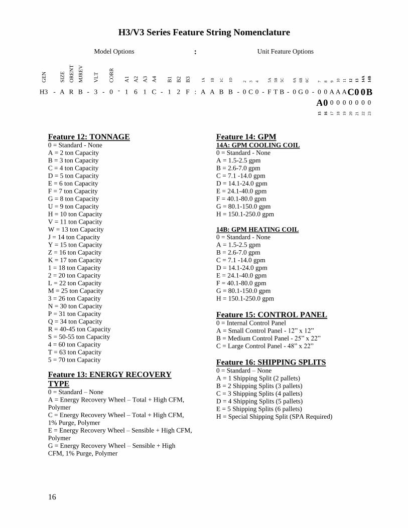
H3V3 Series Feature String Nomenclature
Model Options Unit Feature Options
GE
N
SIZ
E
OR
EN
T
MJR
EV
VL
T
CO
RR
A1
A2
A3
A4
B1
B2
B3
1A
1B
1C
1D
2
3
4
5A
5B
5C
6A
6B
6C
7
8
9
10
11
12
13
14A
14B
H3 - A R B - 3 - 0 - 1 6 1 C - 1 2 F A A B B - 0 C 0 - F T B - 0 G 0 - 0 0 A A A C 0 0 B
A 0 0 0 0 0 0 0 0 1
5
16
17
18
19
20
21
22
23
17
Feature 17 ENERGY RECOVERY
CABINET 0 = Standard - None
A = Top RA + Back EA + Back OA Connections
G = OA + EA Dampers - Top RA + Back EA + Back
OA Connections
N = OA + Economizer Dampers - Top RA + Back
EA + Back Connections
U = OA + EA + Economizer Dampers - Top RA +
Back EA + Back OA Connections
Feature 18 MODULATING ELECTRIC
PREHEAT 0 = Standard - None
A = 75 kW
B = 15 kW
C = 20 kW
D = 225 kW
E = 30 kW
F = 40 kW
G = 50 kW
H = 60 kW
Feature 19 EXHAUST FAN 0 = Standard - None
A = 250 mm Exhaust Fan 800 W EC Motor
B = 310 mm Exhaust Fan 10 kW EC Motor
C = 310 mm Exhaust Fan 17 kW EC Motor
D = 355 mm Exhaust Fan 17 kW EC Motor
E = 450 mm Exhaust Fan 30 kW EC Motor
F = 450 mm Exhaust Fan 60 kW EC Motor
G = Dual 310 mm Exhaust Fan 10 kW EC Motor
H = Dual 310 mm Exhaust Fan 17 kW EC Motor
J = Dual 355 mm Exhaust Fan 17 kW EC Motor
K = Dual 450 mm Exhaust Fan 30 kW EC Motor
L = Dual 450 mm Exhaust Fan 60 kW EC Motor
Feature 20 CRATING 0 = Standard - None
A = Export Crating
B = Forkliftable Base - 5rdquo Base
C = Options A + E
D = Options A + B
E = Shipping Shrink Wrap
F = Options B + E
G = Options A + B + E
Feature 21 PULLEY COMBINATION 0 = Standard - None
A = 1000-1400 rpm
B = 1401-1800 rpm
C = 1801-2200 rpm
Feature 22 WARRANTY 0 = Standard - 1 Year Parts
Feature 23 TYPE 0 = Standard
X = Special Pricing Authorization
18
General Information
AAONreg
H3 and V3 Series indoor air
handling units have been designed for
indoor installation only Units are
assembled wired charged with dry nitrogen
and run-tested at the factory H3 and V3
Series units are not intended for residential
use Startup and service must be performed
by a Factory Trained Service Technician
Certification of Steam or Hot Water Heat
Models
a Certified as a forced air heating system
with or without cooling
b Certified for indoor installation only
Certification of Electric Heat Models
a Certified as an electric warm air furnace
with or without cooling
b Certified for indoor installation only
Certification of Cooling Models
a Certified as a commercial central air
conditioner with or without electrically
operated compressors
b Certified for indoor installation only
c Certified with refrigerant R-410A coils
or with chilled water cooling coils
Improper installation adjustment alteration service or maintenance can cause property damage personal injury or loss of life Startup and service must be performed by a Factory Trained Service Technician A copy of this IOM should be kept with the unit
WARNING
These units must not be used as a ldquoconstruction heaterrdquo at anytime during any phase of construction Very low return air temperatures harmful vapors and misplacement of the filters will damage the unit and its efficiency
CAUTION
This equipment is protected by a standard limited warranty under the condition that initial installation service startup and maintenance is performed according to the instructions set forth in this manual This manual should be read in its entirety prior to installation and before performing any service or maintenance work Equipment described in this manual is available with many optional accessories If you have questions after reading this manual in its entirety consult other factory documentation or contact your AAON Sales Representative to obtain further information before manipulating this equipment or its optional accessories
CAUTION
19
Codes and Ordinances
H3 and V3 Series units have been tested and
certified by ETL in accordance with UL
Safety Standard 1995CSA C222 No 236
System should be sized in accordance with
the American Society of Heating
Refrigeration and Air Conditioning
Engineers Handbook
Installation of H3 and V3 Series units must
conform to the ICC standards of the
International Mechanical Code the
International Building Code Installation of
Air Conditioning and Ventilating Systems
Standard NFPA 90A and local building
plumbing and waste water codes All
appliances must be electrically grounded in
accordance with local codes or in the
absence of local codes the current National
Electric Code ANSINFPA 70 or the
current Canadian Electrical Code CSA
C221
Receiving Unit
When received the unit should be checked
for damage that might have occurred in
transit If damage is found it should be noted
on the carrierrsquos Freight Bill A request for
inspection by carrierrsquos agent should be made
in writing at once
Nameplate should be checked to ensure the
correct model sizes and voltages have been
received to match the job requirements
If repairs must be made to damaged goods
then the factory should be notified before
any repair action is taken in order to protect
the warranty Certain equipment alteration
repair and manipulation of equipment
without the manufacturerrsquos consent may
void the product warranty Contact the
AAON Warranty Department for assistance
with handling damaged goods repairs and
freight claims (903) 236-4403
Note Upon receipt check shipment for
items that ship loose such as remote sensors
Consult order and shipment documentation
to identify potential loose-shipped items
Loose-shipped items may have been placed
inside unit cabinet for security Installers
and owners should secure all doors with
locks or nuts and bolts to prevent
unauthorized access
The Clean Air Act of 1990 bans the intentional venting of refrigerant as of July 1 1992 Approved methods of recovery recycling or reclaiming must be followed
CAUTION
Coils and sheet metal surfaces present sharp edges and care must be taken when working with equipment
WARNING
Failure to observe the following instructions will result in premature failure of your system and possible voiding of the warranty
WARNING
20
Figure 1 - Lockable Handle
Storage
This equipment is not suitable for outdoor
use of storage If installation will not occur
immediately following delivery store
equipment in a dry protected area away from
construction traffic and in the proper
orientation as marked on the packaging with
all internal packaging in place Secure all
loose-shipped items
Direct Expansion (DX) Systems
All DX refrigerant coils are factory charged
with a nitrogen holding charge All DX
systems include evaporator coils and
thermal expansion valves (TXV)
Never turn off the main power supply to the
unit except for servicing emergency or
complete shutdown of the unit When power
is cut off from the unit crankcase heaters
cannot prevent refrigerant migration into the
split system condensing unit compressors
This means the compressor may cool down
and liquid refrigerant may accumulate in the
compressor The compressor is designed to
pump refrigerant gas and damage may occur
when power is restored
If power to the unit must be off for more
than an hour turn the thermostat system
switch to OFF or turn the unit off at the
control panel and leave the unit off until the
main power switch has been turned on again
for at least 24 hours for units with
compressor crankcase heaters This will give
the crankcase heater time to clear any liquid
accumulation out of the compressor before it
is started
Always control the unit from the thermostat
or control panel never at the main power
supply except for emergency or complete
shutdown of the unit
During the cooling season if the air flow is
reduced due to dirty air filters or any other
reason the cooling coils can get too cold
which will cause excessive liquid to return
to the compressor As the liquid
concentration builds up oil is washed out of
the compressor leaving it starved for
lubrication
The compressor life will be seriously
shortened by reduced lubrication and the
pumping of excessive amounts of liquid oil
and refrigerant
CRANKCASE HEATER OPERATION
Some units are equipped with compressor crankcase heaters which should be energized at least 24 hours prior to cooling operation to clear any liquid refrigerant from the compressors
CAUTION
21
Note Low Ambient Operation
Air-cooled DX units without a low ambient
option such as condenser fan cycling or the
0degF low ambient option will not operate in
the cooling mode of operation properly
when the outdoor temperature is below
55degF Low ambient andor economizer
options are recommended if cooling
operation below 55degF is expected
Wiring Diagrams
Unit specific wiring diagrams are laminated
and affixed inside the controls compartment
door
Condensate Drain Pans
Units require field installed drain p-traps and
lines to be connected to the condensate drain
pans of the unit
For condensate drain lines the line should
be the same pipe size or larger than the drain
connection include a p-trap and pitch
downward toward drain An air break should
be used with long runs of condensate lines
See Installation section of this manual for
more information
Unit should not be operated without a p-trap Failure to install a p-trap may result in overflow of condensate water
CAUTION
Emergency drain pan is recommended for all applications where a risk of water damage to surrounding structure or furnishings Refer to local codes
CAUTION
22
Installation
AAON equipment has been designed for
quick and easy installation Startup and
service must be performed by Factory
Trained Service Technician
The H3V3 unit can either be shipped
assembled or shipped in sections See the
Unit Assembly section of this document for
instructions on assembling the sections
Locating the Unit
Placement of the unit relative to ductwork
electrical and plumbing must be carefully
considered Return air plenum or duct can be
mounted directly to the return air flanges
Use flexible gasket material to seal the duct
to the unit
Verify floor foundation or suspension
support can support the total unit weight
including accessory weights Unit must be
level in both horizontal axes to support the
unit and reduce noise and vibration from the
unit
Allow adequate space for piping access and
panel removal To ensure proper access
for field service maintain minimum
clearances for field piping and other
obstructions as indicated by Table 1 and
Figure 2 and Figure 3 Consult local
building codes for additional service
clearance requirements Condensate drain
connections are located on the access side of
the unit
Table 1 - H3 and V3 Series Clearances
Unit Size
Access Side
Clearance
(dimension X on
Figure 2 and
Figure 3)
All Other
Sides
V3-A
36 inches
6 inches
V3-B
V3-C
V3-D
V3-E
H3-A
H3-B
H3-C
H3-D 45 inches
H3-E 60 inches
Additional clearance may be required to
allow for coil removal
May be installed flush depending upon
local codes
Figure 2 - Minimum Clearance Required for
Access to Unit (V3 Series plan view)
X
(See Table 1)
Back Front
Left
Right
23
Figure 3 - Minimum Clearance Required for
Access to Unit (H3 Series plan view)
Internal Control Panel
H3 units with internal control panel have
removable access panels on the top and
bottom of the supply fan section V3 units
with internal control panel have removable
access panels on the front and back of the
supply fan section V3 units that have
energy recovery only have one removable
supply fan access panel on the front of the
unit The supply flanges can be
interchanged with the access panels if
necessary except on size E
Figure 4 - H3 internal control panel with top
access panel removed
Figure 5 - V3 internal control panel with
rear removable access panel shown
Floor Mounted Units
Make sure the unit is level and mounted on a
field supplied platform with a minimum
height to allow for proper depth of the
condensate line p-trap Other installation
provisions may be necessary according to
job specifications V3 Series vertical air
handling units are designed for upflow
applications only
Suspended Units
H3 Series horizontal air handling units are
equipped for suspended installations The
unit should be lifted into position by
supporting the unit with the skid used for
shipping The air handling unit must be
installed level and care should be taken to
prevent damage to the cabinet Other
installation provisions may be necessary
according to job specifications Figure 6
and Figure 7 show factory recommended
methods for suspended installations It is
the responsibility of the specifying engineer
or installing contractor to ensure the
installation is structurally safe and sound
X
(See Table 1)
Front
Back
Left Right
24
Figure 6 - H3 Series Platform Suspension Installation
Figure 7 - H3 Series Parallel Beam Suspension Installation
25
Figure 8 - H3 Series Unit Orientation
Figure 9 - V3 Series Unit Orientation
Note Access doors may be on the ldquoleftrdquo or ldquorightrdquo side as designated by the unit orientation on
the configurator string ldquoBackrdquo will always be the same side as the pre-filter and return air
opening ldquoFrontrdquo will always be the side opposite the pre-filter and return air opening
H3 Series
Return Air ldquoBackrdquo
Supply Air ldquoFrontrdquo
Right Hand Side
Left Hand Side
Connections and service access on right side for right hand orientation
Top View
Air Flow
Connections and service access on right side for right hand orientation
Right Hand Side Left Hand Side
Return Air ldquoBackrdquo
Top View V3 Series
Air Flow
Consider the air flow to be hitting the back of your head
Consider the air flow to be hitting the back of your head
Supply Air
ldquoFrontrdquo
26
Lifting and Handling the Unit
Before lifting unit be sure that all shipping
material has been removed from unit
Care should be taken if using spreader bars
blocking or other lifting devices to prevent
damage to the cabinet coil or fans
Unit Assembly
Although H3V3 Series units are shipped
factory assembled as standard the unit may
be ordered as shipping splits for certain
applications such as for assembly in existing
structures where modules must be
manipulated separately If the unit was
ordered as shipping splits then they must be
assembled in the field
Locate the schematic in the equipmentrsquos
literature packet
1 Identify and Situate Splits
a H3 Units can have the following
ship split sections
1 Mixing Box
2 Air Handler
3 Final Filter
4 Electric Heat
Figure 10 - H3 Schematic with (1) Mixing
Box (2) Air Handler (3) Final Filter and
(4) Electric Heat
b V3 Units can have the following
ship split sections
1 Exhaust Fan
2 Energy Recovery
3 Air Handler
4 Electric Heat
5 Pre filter
6 Mixing box
Figure 11 - V3 Schematic with (1) Exhaust
Fan (2) Energy Recovery (3) Air Handler
and (4) Electric Heat
2 Connect Sections
Using the V3 Schematic as an example
section 1 will have a duct flange and it will
connect to section 2 on the side that does not
have a flange First make sure gasket is on
the panel around the edges of the exposed
duct flanges Push section 1 and 2 together
UNIT HANDLING
Incorrect lifting can cause damage to the unit injury or death Lifting equipment capacity should exceed unit weight by an adequate safety factor Always test lift unit not more than 24 inches high to verify proper center of gravity lift point
WARNING
1 2 3 4
1 2
3
4
27
so that the flange from section 1 is inside of
section 2
Figure 12 - Connect Sections
Use bar clamps or other non-destructive
winching device to pull the tops of the
modules together tightly
Figure 13 - Bar Clamp
At each of the pre-drilled holes in the flange
drill 516 hex head self-tapping screws to
secure the two sections together
Figure 14 - Flange Overlap
Figure 15 - Self-Tapping Screw
All connection hardware is shipped with the
unit
3 Secure Module Joints
The metal straps are to be used to secure
module joints Straps are provided with pre-
drilled holes Self-tapping sheet metal
screws are provided to attach the straps to
the unit cabinet
Leave bar clamps in place until strap is
secure
Place the strap over a module joint ensure
the strap completely covers the joint and
that it is square with the unit casing
Insert self-tapping screws through pre-
drilled holes in strap and secure screws into
unit casing using a power drill For best
results use the lowest effective power drill
torque setting Be careful not to over tighten
the screws
Remove bar clamps and repeat for all
remaining module joints
Figure 16 - Strap Types
516rdquo Hex Head Self-Tapping Screws
Provided with Unit
1rdquo
Angle Strap
Top Strap
Section 2
Flange
28
4 Connect Power and Control Wiring
H3V3 Series units are equipped with low
and high voltage quick connects to connect
wiring from one section to the next Wire
from the unit to external controls and power
sources must be provided in the field
Figure 17 - Low Voltage Quick Connect
A color-coded wiring diagram is laminated
and affixed to the inside of the control
compartment access door H3V3 Series
units are equipped with a single point power
connection
5 Final Sealing
It is very important to keep air from
infiltrating the unit cabinet Seal all piping
penetrations with Armaflex Permagum or
other suitable sealant Also seal around drain
connections electrical connections and all
other inlets where air may enter the cabinet
This is especially important when the unit is
installed in an unconditioned area
Control Box
Some H3V3 units include an external
control box that must be mounted in the
field
Figure 18 - Back View External Control
Box
Duct Connection
Attach duct to flanges provided on the unit
The installer is responsible for sealing ducts
to the flanges to prevent water leaks
Refer to Figure 8 and Figure 9 for duct
connection locations The V3 supply air duct
is out to top of the unit Ductwork should be
sized in accordance with the ASHRAE
Handbook Ductwork should be installed in
accordance with NFPA Standard 90A
When attaching duct to the unit use a
flexiblecompressible material rated for duct
connections A three inch flexible connector
for both return and supply duct connections
is recommended
Condensate Drain Piping
Unit may be equipped with more than one
condensate drain pan connection A p-trap
and drain line must be installed on at least
one sectionrsquos drain connection with the p-
trap not to exceed 6rdquo from the drain
connection The lines should be the same
pipe size or larger than the drain connection
include a p-trap and pitch downward toward
drain An air break should be used with long
runs of condensate lines
Installing Contractor is responsible for proper sealing of the electrical and piping entries into the unit Failure to seal the entries may result in damage to the unit and property
CAUTION
29
Draw-through cooling coils will have a
negative static pressure in the drain pan area
This will cause an un-trapped drain to back
up due to air being pulled up through the
condensate drain piping
Condensate drain trapping and piping should
conform to all applicable governing codes
Note The drain pan connection(s) is a 1rdquo
MPT fitting
Figure 19 - Drain Trap
The X dimension on the draw-through trap
should be at least equal to the absolute value
of the negative static pressure in the drain
pan plus one inch To calculate the static
pressure at the drain pan add the pressure
drops of all components upstream of the
drain pan including the cooling coil and
add the return duct static pressure Include
the dirt allowance pressure drop for the
filters to account for the worst-case scenario
The height from top of the bottom bend of
the trap to the bottom of the leaving pipe
must be at least equal to one half of the X
dimension This ensures that enough water
is stored in the trap to prevent losing the
drain seal during unit startup
Note The absolute value of the fan inlet
pressure will always be greater than or equal
to the absolute value of the static pressure in
the drain pan on draw-through units so the
fan inlet pressure is a safe value to use for
the drain pan static pressure
Table 2 - Drain Trap Dimensions
Draw-Through
Drain Pan Pressure Trap Dimensions
Negative Static X X2
(inches of water) (inch) (inch)
-050 150 075
-100 200 100
-150 250 125
-200 300 150
-250 350 175
-300 400 200
-350 450 225
-400 500 250
Heating Coils
One or two row hot water and steam heating
and preheating coils can be factory installed
These coils are supplied from a building hot
water source All valve controls for heating
coil operation are field supplied and field
installed
Unit should not be operated without p-traps Failure to install a p-traps may result in overflow of condensate water
CAUTION
30
Always connect the steam heating supply to
the top of the coil and the return to the
bottom
Figure 20 - Steam Distributing Piping
Table 3 - Steam Distributing Coil
Connection Sizes
Model (H3- V3-) Supply and Return
Connection Size
A-E 2 18
Air handling units with steam heating coils
MUST BE installed high enough to allow
for a minimum of 1 foot condensate drop leg
off of the steam coil or as recommended by
the steam trap manufacturer Lines should
be insulated with approved insulation and be
properly fastened sloped and supported
according to local code requirements
Table 4 - Hot Water Coil Connection Sizes
Model (H3- V3-) Supply and Return
Connection Size
A 78
B 1 18
C 1 38
D amp E 1 58
Always connect the hot water heating supply
to the bottom of the coil and return to the
top
Figure 21 - Hot amp Chilled Water Piping
Water coils should not be subjected to
entering air temperatures below 38degF to
prevent coil freeze-up If air temperature
across the coil is going to be below this
value use a glycol solution to match the
coldest air expected
Water supply lines must be insulated
properly fastened drained and supported
according to local code requirements
Chilled Water Coil
Factory installed four six or eight row
chilled water cooling coils can be factory
mounted These coils are supplied from a
building chilled water source All valve
controls for the cooling coil operation are
field supplied and field installed
31
Table 5 - Chilled Water Coil Connection
Sizes
Model (H3- V3-) Supply and Return
Connection Size
A 1 18
B 1 38
C 1 58
D amp E 2 18
Always connect the chilled water supply to
the bottom of the coil and return to the top
Water supply lines must be insulated with
closed cell type pipe insulation or insulation
that includes a vapor barrier Lines should
be properly fastened drained and supported
according to local code requirements and
job specifications
Evaporator Coil
The air handling unit coils are pressurized
The copper caps must be punctured to
permit a gradual escape of the pressure prior
to un-sweating those caps Immediately
couple the tubing to the indoor unit to avoid
exposing the coils to moisture A properly
sized filter drier is furnished in the
condenser When making solder
connections make sure dry nitrogen flows
through the lines when heating the copper
to prevent oxidization inside of the copper
Field piping between the condensing unit
and the air handler is required Line
sizes must be selected to meet actual
installation conditions not simply based
on the connection sizes
Thermal Expansion Valve
Thermal expansion valve bulbs should be
mounted with good thermal contact on a
horizontal section of the suction line close to
the evaporator but outside the cabinet and
well insulated On suction lines less than or
equal to 78rdquo OD mount in the 12 orsquoclock
position On suction lines greater than 78rdquo
OD mount in either the 4 orsquoclock or 8
orsquoclock position
Figure 22 - TXV Bulb Position
Hot Gas Reheat
Hot Gas Reheat (HGRH) is available for use
with DX systems that need humidity control
The AAON modulating hot gas reheat
system diverts hot discharge gas from the
condenser to the air handling unit through
the hot gas line Field piping between the
condensing unit and the air handler is
required Line sizes must be selected to
meet actual installation conditions not
simply based on the connection sizes
The line delivers the hot discharge gas to the
reheat coil andor the hot gas bypass valve
so it is sized as a discharge line
Modulating Hot Gas Reheat Piping
1 Run a hot gas reheat line from the
condensing unit and connect it to the inlet of
the stub-out on the reheat coil The inlet
connection is the top (or highest) stub-out of
the reheat coil Connect the hot gas line
from the outdoor unit to the upper stub-out
connection of the reheat coil
2 Run a liquid line from the discharge of the
reheat coil through a tee connection Run a
liquid line from the condenser through a
REFRIGERANT PIPING
Line sizes must be selected to meet actual installation conditions not simply based on the connection sizes at the condensing unit or air handling unit
CAUTION
32
check valve to the other side of the tee Run
a liquid line from the tee to the liquid line
stub-out of the evaporator coil
3 Run a suction line from the evaporator
coil outlet stub-out to the condensing unit
Hot Gas Bypass
Hot Gas Bypass is available for use with DX
systems that may experience low suction
pressure during the operating cycle This
may be due to varying load conditions
associated with VAV applications or units
supplying a large percentage of outside air
Hot Gas Bypass is not necessary in units
with variable capacity compressors The
system is designed to divert refrigerant from
the compressor discharge to the low pressure
side of the system in order to keep the
evaporator from freezing and to maintain
adequate refrigerant velocity for oil return at
minimum load
Hot discharge gas is redirected to the
evaporator inlet via an auxiliary side
connector (ASC) to false load the evaporator
when reduced suction pressure is sensed
Field piping between the condensing unit
and the evaporator is required Line sizes
must be selected to meet actual
installation conditions not simply based
on the connection sizes
Electric Preheat
The modulating electric preheat option is
designed to temper the incoming outside air
to the unit based on an enable control signal
and the outside air conditions
A 24VAC enable signal must be provided to
the [PHE] terminal to enable the operation
of the electric preheat Once the preheat
controller is enabled it will monitor the
outside air temperature to determine if any
capacity of preheat is needed If the outside
air temperature falls below the outside air
temperature setpoint the electric preheat will
be started up and maintain the leaving air
temperature setpoint with both SCR
controlled and staged electric preheat Both
setpoints are set with push button LCD
interface on the preheat controller Outside
air temperature sensors and preheat
discharge supply air temperature sensors are
factory installed and wired to the preheat
controller Electric preheat has maximum
operating outside air temperature of 60degF
and a maximum preheat discharge air
temperature of 80degF
[COM] [PHO] amp [PHC] feedback terminals
are provided to communicate if the electric
preheat is in operation PHO is a normally
open contact PHC is a normally closed
contact and COM is the common These
terminals are not required to be connected
[PHE] is the electric preheat operation
enable [PH+] and [PH-] are the preheat set
point reset terminals
33
Energy Recovery Units
Some H3V3 units have been equipped with
an energy recovery wheel This section is
provided to assure the energy recovery
feature will be properly setup to perform in
accordance with the job specifications for
your particular application
Figure 23 - Energy Recovery Wheel
The Energy Recovery Cassette consists of a
frame wheel wheel drive system and
energy transfer segments Segments are
removable for cleaning or replacement The
segments rotate through counter flowing
exhaust and outdoor air supply streams
where they transfer heat andor water vapor
from the warm moist air stream to the
cooler andor drier air stream
The initial setup and servicing of the energy
recovery wheel is very important to maintain
proper operation efficiency and building
occupant comfort
Normal maintenance requires periodic
inspection of filters the cassette wheel
drive belts air seals wheel drive motor and
its electrical connections
Wiring diagrams are provided with each
motor When wired according to wiring
diagram motor rotates clockwise when
viewed from the shaftpulley side
By carefully reviewing the information
within this section and following the
instructions the risk of improper operation
andor component damage will be
minimized
It is important that periodic maintenance be
performed to help assure trouble free
operation
Initial Mechanical Check and Setup
Outdoor air intake adjustments should be
made according to building ventilation or
local code requirements
After the unit installation is complete open
the cassette access door and determine that
the energy wheel rotates freely when turned
by hand Apply power and observe that the
wheel rotates at approximately 30 RPM If
the wheel does not rotate when power is
applied it may be necessary to readjust the
ldquodiameter air sealsrdquo
Air Seal Adjustments
Pile type air seals across both sides of the
energy wheel diameter are factory adjusted
to provide close clearance between the air
seal and wheel Racking of the unit or
cassette during installation andor mounting
of the unit on a non-level support or in other
than the factory orientation can change seal
clearances Tight seals will prevent rotation
Figure 24 - Cross Section of Air Seal
Structure
34
Wheel to Air Seal Clearance
To check wheel to seal clearance first
disconnect power to the unit in some units
the energy recovery wheel assembly can be
pulled out from the cabinet to view the air
seals On larger units the energy recovery
wheel may be accessible inside the walk-in
cabinet
A business card or two pieces of paper can
be used as a feller gauge (typically each
004rdquo thick) by placing it between the face
of the wheel and pile seal
Using the paper determine if a loose slip fit
exist between the pile seal and wheel when
the wheel is rotated by hand
To adjust air seal clearance loosen all seal
plate retaining screws holding the separate
seal retaining plates to the bearing support
channels and slide the seals plates away
from the wheel Using the paper feeler
gauge readjust and retighten one seal plate
at a time to provide slip fit clearance when
the wheel is rotated by hand
Confirm that the wheel rotates freely Apply
power to the unit and confirm rotation
Airflow Balancing and Checking
High performance systems commonly have
complex air distribution and fan systems
Unqualified personnel should not attempt to
adjust fan operation or air circulation as all
systems have unique operations
characteristics Professional air balance
specialists should be employed to establish
actual operating conditions and to configure
the air delivery system for optimal
performance
Controls
A variety of controls and electrical
accessories may be provided with the
equipment Identify the controls on each unit
by consulting appropriate submittal or order
documents and operate according to the
control manufacturerrsquos instructions If you
cannot locate installation operation or
maintenance information for the specific
controls then contact your sales
representative or the control manufacturer
for assistance
Routine Maintenance and Handling
Handle cassettes with care All cassettes
should be lifted by the bearing support
beam Holes are provided on both sides of
the bearing support beams to facilitate
rigging as shown in the following
illustration
Figure 25 - Lifting Hole Locations
Routine maintenance of the Energy
Recovery Cassettes includes periodic
Do not alter factory wiring Deviation from the supplied wiring diagram will void all warranties and may result in equipment damage or personal injury Contact the factory with wiring discrepancies
WARNING
35
cleaning of the Energy Recovery Wheel as
well as inspection of the Air Seals and
Wheel Drive Components as follows
Cleaning
The need for periodic cleaning of the energy
recovery wheel will be a function of
operating schedule climate and
contaminants in the indoor air being
exhausted and the outdoor air being supplied
to the building
The energy recovery wheel is ldquoself-
cleaningrdquo with respect to dry particles due to
its laminar flow characteristics Smaller
particles pass through larger particles land
on the surface and are blown clear as the
flow direction is reversed Any material that
builds up on the face of the wheel can be
removed with a brush or vacuum The
primary need for cleaning is to remove oil
based aerosols that have condensed on
energy transfer surfaces
A characteristic of all dry desiccants such
films can close off micron sized pores at the
surface of the desiccant material reducing
the efficiency by which the desiccant can
adsorb and desorb moisture and also build
up so as to reduce airflow
In a reasonably clean indoor environment
such as a school or office building
measurable reductions of airflow or loss of
sensible (temperature) effectiveness may not
occur for several years Measurable changes
in latent energy (water vapor) transfer can
occur in shorter periods of time in
applications such as moderate occupant
smoking or cooking facilities In
applications experiencing unusually high
levels of occupant smoking or oil based
aerosols such as industrial applications
involving the ventilation of machine shop
areas for example annual washing of energy
transfer may be necessary to maintain latent
transfer efficiency Proper cleaning of the
energy recovery wheel will restore latent
effectiveness to near original performance
To clean gain access to the energy recovery
wheel and remove segments Brush foreign
material from the face of the wheel Wash
the segments or small wheels in a 5
solution of non-acid based coil cleaner or
alkaline detergent and warm water
Soak in the solution until grease and tar
deposits are loosened (Note some staining
of the desiccant may remain and is not
harmful to performance) Before removing
rapidly run finger across surface of segment
to separate polymer strips for better cleaning
action Rinse dirty solution from segment
and remove excess water before reinstalling
in wheel
Air Seals
Four adjustable diameter seals are provided
on each cassette to minimize transfer of air
between the counter flowing airstreams
To adjust diameter seals loosen diameter
seal adjusting screws and back seals away
from wheel surface Rotate wheel clockwise
until two opposing spokes are hidden behind
the bearing support beam Using a folded
piece of paper as a feeler gauge position
paper between the wheel surface and
diameter seals
Adjust seals towards wheel surface until a
slight friction on the feeler gauge (paper) is
detected when gauge is moved along the
length of the spoke Retighten adjusting
Do Not use acid based cleaners aromatic solvents steam or temperatures in excess of 170degF damage to the wheel may occur
CAUTION
36
screws and recheck clearance with ldquofeelerrdquo
gauge
Wheel Drive Components
The wheel drive motor bearings are pre-
lubricated and no further lubrication is
necessary
The wheel drive pulley is secured to the
drive motor shaft by a combination of either
a key or D slot and set screw
The set screw is secured with removable
locktite to prevent loosening Annually
confirm set screw is secure The wheel drive
belt is a urethane stretch belt designed to
provide constant tension through the life of
the belt No adjustment is required Inspect
the drive belt annually for proper tracking
and tension A properly tensioned belt will
turn the wheel immediately after power is
applied with no visible slippage during start-
up
Installation Considerations
Energy recovery cassettes are incorporated
within the design of packaged units
packaged air handlers and energy recovery
ventilators In each case it is recommended
that the following considerations be
addressed
Accessibility
The cassette and all its operative parts ie
motor belt pulley bearings seals and
energy transfer segments must be accessible
for service and maintenance This design
requires that adequate clearance be provided
outside the enclosure
Orientation amp Support
The Energy Recovery Cassette may be
mounted in any orientation However Care
must be taken to make certain that the
cassette frame remains flat and the bearing
beams are not racked
To verify make certain that the distance
between wheel rim and bearing beam is the
same at each end of the bearing beam to
within 14 of an inch (dimension A amp B)
This amount of racking can be compensated
for by adjusting the diameter seals
If greater than 14 inch (dimension C)
racking must be corrected to ensure that
drive belt will not disengage from wheel
Figure 26 - Avoid Racking of Cassette
Frame
Operation
Startup Procedure
1 By hand turn wheel clockwise (as viewed
from the pulley side) to verify wheel turns
freely through 360ordm rotation
2 Before applying power to drive motor
confirm wheel segments are fully engaged in
wheel frame and segment retainers are
completely fastened (See Segment
Installation Diagram)
B
C
A
Bearing beams shown racked
Frame
Wheel
Bearing beams (2)
Flat surface
Keep hands away from rotating wheel Contact with rotating wheel can cause physical injury
CAUTION
37
3 With hands and objects away from
moving parts activate unit and confirm
wheel rotation Wheel rotates clockwise (as
viewed from the pulley side)
4 If wheel has difficulty starting turn power
off and inspect for excessive interference
between the wheel surface and each of the
four (4) diameter seals To correct loosen
diameter seal adjusting screws and back
adjustable diameter seals away from surface
of wheel apply power to confirm wheel is
free to rotate then re-adjust and tighten hub
and diameter seals as shown in hub seal
adjustment diagram
5 Start and stop wheel several times to
confirm seal adjustment and to confirm belt
is tracking properly on wheel rim
(approximately 14rdquo from outer edge of
rim)
Figure 27 - Diameter Seal Adjustment
Figure 28 - Hub Seal Adjustment
Service
Segment Installation amp Replacement
Wheel segments are secured to the wheel
frame by a Segment Retainer which pivots
on the wheel rim and is held in place by a
Segment Retaining Catch
Disconnect electrical power before servicing energy recovery cassette Always keep hands away from bearing support beam when installing or removing segments Failure to do so could result in severe injury to fingers or hand
CAUTION
38
Figure 29 - Segment Retainer
To install wheel segments follow steps one
through five below Reverse procedure for
segment removal
1 Unlock two segment retainers (one on
each side of the selected segment opening
2 With the embedded stiffener facing the
motor side insert the nose of the segment
between the hub plates
Figure 30 - Segment Installation
3 Holding segment by the two outer
corners press the segment towards the
center of the wheel and inwards against the
spoke flanges If hand pressure does not
fully seat the segment insert the flat tip of a
screw driver between the wheel rim and
outer corners of the segment and apply
downward force while guiding the segment
into place
4 Close and latch each Segment Retainer
under Segment Retaining Catch
5 Slowly rotate the wheel 180ordm Install the
second segment opposite the first for
counterbalance Rotate the two installed
segments 90ordm to balance the wheel while the
third segment is installed Rotate the wheel
180ordm again to install the fourth segment
opposite the third Repeat this sequence with
the remaining four segments
Wheel Drive Motor and Pulley Replacement
1 Disconnect power to wheel drive motor
2 Remove belt from pulley and position
temporarily around wheel rim
3 Loosen set screw in wheel drive pulley
using a hex head wrench and remove pulley
from motor drive shaft
4 While supporting weight of drive motor in
one hand loosen and remove (4) mounting
bolts
5 Install replacement motor with hardware
kit supplied
6 Install pulley to dimension as shown and
secure set screw to drive shaft
7 Stretch belt over pulley and engage in
groove
8 Follow start-up procedure
Belt Replacement
1 Obtain access to the pulley side bearing
access plate if bearing access plates are
provided Remove two bearing access plate
retaining screws and the access plate
39
2 Using hexagonal wrench loosen set screw
in bearing locking collar Using light
hammer and drift (in drift pin hole) tap
collar in the direction of wheel rotation to
unlock collar Remove collar
3 Using socket wrench with extension
remove two nuts which secure bearing
housing to the bearing support beam Slide
bearing from shaft If not removable by
hand use bearing puller
4 Form a small loop of belt and pass it
through the hole in the bearing support
beam Grasp the belt at the wheel hub and
pull the entire belt down
Note Slight hand pressure against wheel
rim will lift weight of wheel from inner race
of bearing to assist bearing removal and
installation
5 Loop the trailing end of the belt over the
shaft (belt is partially through the opening)
6 Reinstall the bearing onto the wheel shaft
being careful to engage the two locating pins
into the holes in the bearing support beam
Secure the bearing with two self-locking
nuts
7 Install the belts around the wheel and
pulley according to the instructions provided
with the belt
8 Reinstall diameter seals or hub seal and
tighten retaining screws Rotate wheel in
clockwise direction to determine that wheel
rotates freely with slight drag on seals
9 Reinstall bearing locking collar Rotate
collar by hand in the direction the wheel
rotates (see label provided on each cassette
for wheel rotation)
10 Lock in position by tapping drift pin
hole with hammer and drift Secure in
position by tightening set screw
11 Reinstall Bearing Access Cover
12 Apply power to wheel and ensure that
the wheel rotates freely without interference
Figure 31 - Belt Replacement
Protect hands and belt from possible sharp edges of hole in Bearing Support Beam
CAUTION
40
Electrical
Verify the unit name plate agrees with
power supply H3 and V3 Series units are
provided with single point power wiring
connections Connection terminations are
made to the main terminal block A
complete set of unit specific wiring
diagrams showing factory and field wiring
are laminated in plastic and located inside
the control compartment door
Route power and control wiring separately
through the utility entry in the unit Do not
run power and control signal wires in the
same conduit
All units require field supplied electrical
overcurrent and short circuit protection
Device must not be sized larger than the
Maximum Overcurrent Protection (MOP)
shown on the unit nameplate
Codes may require a disconnect switch be
within sight of the unit
It is recommended that the field installed
overcurrent protection or disconnect switch
not be installed on the unit
On units with external control box electrical
supply can enter through either side of the
controls compartment
Figure 32 - External control box electrical
connections
On units with internal control panel
electrical supply can enter through the
supply air side (front) of the H3 unit and
through the return air side (rear) of the V3
unit
Figure 33 - H3 internal control panel
electrical connections
Figure 34 - V3 internal control panel
electrical connections
The foam insulation releases dangerous fumes when it is burnt Do not cut a foam part with a cutting torch or plasma cutter Do not weld to a foam filled part
WARNING
41
A single point connection to a terminal
block is provided High voltage conductors
should enter the control panel in a separate
opening and separate conduit than low
voltage conductors
To pass wires through the wall or roof of the
unit a hole should be cut and conduit passed
through it Use the following procedure to
cut a round hole in a foam panel
Cutting Electrical Openings
1 Locate the placement of the hole Be
sure that the conduit will not interfere
with the operation of any component or
prevent access of any door or
removable panel Field cut openings
must be a minimum of 6 inches away
from all components and wiring to
prevent damage due to drilling or
cutting
2 Drill a pilot hole all the way through the
foam panel
3 Using a hole saw cut the hole through
the metal on both sides of the foam
part
4 With a knife cut the foam out of the
hole
5 After the conduit is installed in the hole
caulk the entire perimeter of the hole on
both sides with an industrial grade
silicone sealant or a duct seal
compound
If a larger cut-out is needed for additional
duct connections not provided by the
factory or for any other reason it is very
important that the foam be completely
sealed Insulation covers should be
fabricated from sheet metal to cover the
foam at the cut The edges and corners that
are not covered should then be sealed using
silicone caulking or a duct seal compound
If a reciprocating saw is used to make the
cut-out take care that the metal skins of the
foam part do not separate from the foam
this would result in reduced structural
integrity of the part
Size supply conductors based on the unit
Minimum Current Ampacity (MCA) rating
Supply conductors must be rated a minimum
of 75degC
Protect the branch circuit in accordance with
code requirements The unit must be
electrically grounded in accordance with
local codes or in the absence of local codes
the current National Electric Code
ANSINFPA 70 or the current Canadian
Electrical Code CSA C221
Note Units are factory wired for 208V
230V 460V or 575V In some units the
208V and 230V options may also be
provided in single or three phase
configurations The transformer
Installing Contractor is responsible for proper sealing of the electrical and piping entries into the unit Failure to seal the entries may result in damage to the unit and property
Electric shock hazard Before attempting to perform any installation service or maintenance shut off all electrical power to the unit at the disconnect switches Unit may have multiple power supplies Failure to disconnect power could result in dangerous operation serious injury death or property damage
WARNING
CAUTION
42
configuration must be checked by a
qualified technician prior to startup
Wire power leads to the unitrsquos terminal
block or main disconnect All wiring beyond
this point has been completed by AAON and
cannot be modified without effecting the
unitrsquos agencysafety certification
Supply voltage must be within the minmax
range shown on the unit nameplate
Available short circuit current should not
exceed the short circuit current rating
(SCCR) shown on the unit nameplate
Three phase voltage imbalance will cause
motor overheating and premature failure
The maximum allowable imbalance is 20
Voltage imbalance is defined as 100 times
the maximum deviation from the average
voltage divided by the average voltage
Example
(221V+230V+227V)3 = 226V then
100(226V-221V)226V = 22 which
exceeds the allowable imbalance
Check voltage imbalance at the unit
disconnect switch and at the compressor
terminal Contact your local power company
for line voltage corrections
Installing contractor must check for proper
motor rotation and check blower motor
amperage listed on the motor nameplate is
not exceeded
Wire control signals to the unitrsquos low
voltage terminal block located in the
controls compartment
If any factory installed wiring must be
replaced use a minimum 105degC type AWM
insulated conductors
Thermostat Control Wiring
If a thermostat is used for unit control
thermostat should be located on an inside
wall 4-5 feet above the floor where it will
not be subjected to drafts sun exposure or
heat from electrical fixtures of appliances
Control wiring must deliver adequate
voltage to components to assure proper
operation Control voltage returning from
controller circuit must be a minimum of 21
VAC To assure proper wiring use the
following chart to determine the allowable
wiring distances
Table 6 - Control Wiring
Wire Size (Stranded)
- Copper Conductors
Only
Total Wire Distance
Allowable
20 AWG 200 ft
18 AWG 350 ft
16 AWG 500 ft
14 AWG 750 ft
12 AWG 1250 ft
Total Wire Distance Allowable =
(Quantity of Control Wires) x
(Control Wire Distance)
Three phase voltage imbalance will cause motor overheating and premature failure
CAUTION
Rotation must be checked on all MOTORS of three phase units Supply fan motors should all be checked by a qualified service technician at startup and any wiring alteration should only be made at the unit power connection
CAUTION
43
Take the total wire distance allowable and
divide by the number of wires to be
connected This indicates the distance
allowable for that size wire The wiring to
the unit must not exceed the total wire
distance allowable If the voltage at the
connectors is less than 21 VAC isolation
relays must be installed If under external
control 21 VAC must be field verified
All external devices must be powered via a
separate external power supply
Example
A total of 8 wires must be pulled 75ft to a
control the unit What size wire should be
used
According to the Table 6 16 AWG allows
for 63ft (500 ft8 wires) and 14 AWG allows
for 94ft (750 ft8 wires) Thus 14 AWG
should be used
44
Startup (See back of the manual for startup form)
During startup it is necessary to perform
routine checks on the performance of the
unit This includes checking of the air flow
the air filters and refrigerant charge
Supply Fans
H3 and V3 Series units are equipped with
direct drive backward curved plenum supply
fan assemblies or belt driven backward
curved plenum supply fans that deliver the
air volume specified according to unit size
and job requirements
Fan Air Flow Adjustment
A specific air volume is delivered by the
fans with Electronically Commutated
Motors (ECM) or Variable Frequency
Drives (VFD) Field air flow adjustment
may be required at startup
Electrically Commutated Motor Airflow
Adjustment
Figure 35- Typical wiring diagram with EC
motor
If the application is for the motor to run at a
constant speed the potentiometer can be
utilized without any change If the
application is to vary the motor speed for
changing conditions remove the jumper
indicated on the terminal strip (red wire)
Improper installation adjustment alteration service or maintenance can cause property damage personal injury or loss of life Startup and service must be performed by a Factory Trained Service Technician A copy of this IOM should be kept with the unit
WARNING
Electric shock hazard Shut off all electrical power to the unit to avoid shock hazard or injury from rotating parts
WARNING
45
Figure 36 - Shows the jumper that is to be
removed (jumped between 9 and GS)
Note the potentiometer is still active in the
electrical loop Refer to Figure 10
Figure 37 - Potentiometer
The potentiometer dial should be set for the
maximum fan speed for a particular
application Maximum fan speed is
determined by the ECat submittal
Typically this max speed will be the rpm set
at the factory
The fan speed can be modulated using the 0-
10 VDC input signal
To check fan output from the factory the
potentiometer can be dialed to 100 By
sending a 5V signal for instance the rpm
can be measured and this reading can be
converted to cubic feet of air moved by the
fan
It is advised that a medium range signal be
utilized for this procedure The highest
signal sent by the controller should then be
determined by adjustment
Filters
Do not operate the unit without filters in
place Operation of the equipment without
filters in place can result in clogged coils
Units are shipped with the selected filters
installed If filters have been removed
during installation open the filter access
door and re-install the correct filters with the
airflow indicator arrows pointing in the
direction of airflow
Filters should be checked after a few days of
operation after the unit has been started up
as dust and debris from construction may
cause premature filter loading Replace the
filters if necessary
Adjusting Refrigerant Charge
Adjusting the charge of a system in the field
must be based on determination of liquid
sub-cooling and evaporator superheat On a
system with a TXV liquid sub-cooling is
more representative of the charge than
Before completing startup and leaving the unit a complete operating cycle should be observed to verify that all components are functioning properly
CAUTION
46
evaporator superheat but both measurements
must be taken
Before Charging
Unit being charged must be at or near full
load conditions before adjusting the charge
Units equipped with hot gas reheat must be
charged with the hot gas reheat valves
closed while the unit is in cooling mode to
get the proper charge After charging unit
should be operated in reheat
(dehumidification) mode to check for
correct operation
After adding or removing charge the system
must be allowed to stabilize typically 10-15
minutes before making any other
adjustments
The type of unit and options determine the
ranges for liquid sub-cooling and evaporator
superheat Refer to the tables below when
determining the proper sub-cooling
Checking Liquid Sub-Cooling
Measure the temperature of the liquid line as
it leaves the condenser
Read the gauge pressure at the liquid line
close to the point where the temperature was
taken Use liquid line pressure as it will vary
from discharge pressure due to condenser
pressure drop
Convert the pressure obtained to a saturated
temperature using the appropriate refrigerant
temperature-pressure chart
Subtract the measured liquid line
temperature from the saturated temperature
to determine the liquid sub-cooling
Compare calculated sub-cooling to the table
below for the appropriate unit type and
options
Checking Evaporator Superheat
Measure the temperature of the suction line
close to the compressor
Read gauge pressure at the suction line close
to the compressor
Convert the pressure obtained to a saturated
temperature using the appropriate refrigerant
temperature-pressure chart
Subtract the saturated temperature from the
measured suction line temperature to
determine the evaporator superheat
Compare calculated superheat to the table
below for the appropriate unit type and
options
The Clean Air Act of 1990 bans the intentional venting of refrigerant (CFCrsquos and HCFCrsquos) as of July 1 1992 Approved methods of recovery recycling or reclaiming must be followed Fines andor incarceration may be levied for non-compliance
CAUTION
DO NOT OVERCHARGE Refrigerant overcharging leads to excess refrigerant in the condenser coils resulting in elevated compressor discharge pressure
CAUTION
47
Table 7 - Acceptable Air-Cooled
Refrigeration Circuit Values
Air-Cooled Condenser Air-Source Heat
Pump
Sub-Cooling
12-18degF 2-4degF (HP)
Sub-Cooling with
Hot Gas Reheat 15-22degF 2-6degF (HP)
Superheat
8-15degF
In cooling mode operation
Sub-cooling must be increased by 2degF per
20 feet of vertical liquid line rise for R-410A
Superheat will increase with long
suction line runs
Adjusting Sub-Cooling and Superheat
Temperatures
The system is overcharged if the sub-cooling
temperature is too high and the evaporator is
fully loaded (low loads on the evaporator
result in increased sub-cooling) and the
evaporator superheat is within the
temperature range as shown in the table
above (high superheat results in increased
sub-cooling)
Correct an overcharged system by reducing
the amount of refrigerant in the system to
lower the sub-cooling
The system is undercharged if the superheat
is too high and the sub-cooling is too low
Correct an undercharged system by adding
refrigerant to the system to reduce superheat
and raise sub-cooling
If the sub-cooling is correct and the
superheat is too high the TXV may need
adjustment to correct the superheat Before
adjusting the TXV verify the sensing bulb is
in the correct position according to Figure
22 and follows the guidelines below
1 The suction line is clean where the
sensing bulb is attached
2 The entire length of the sensing bulb is in
contact with the suction line
3 The sensing bulb should be placed several
inches downstream of the equalizer line
4 The sensing bulb is fully insulated
5 If the sensing bulb is installed on a
vertical portion of the suction line the
sensing bulb should be placed upstream of
suction line trap
Thermal expansion valve must be adjust to approximately 8-15degF of suction superheat Failure to have sufficient superheat will damage the compressor and void the warranty
CAUTION
DO NOT OVERCHARGE Refrigerant overcharging leads to excess refrigerant in the condenser coils resulting in elevated compressor discharge pressure
CAUTION
48
Table 8 - R-410A Refrigerant Temperature-Pressure Chart
degF PSIG degF PSIG degF PSIG degF PSIG degF PSIG
20 783 47 1347 74 2137 101 3210 128 4632
21 800 48 1372 75 2171 102 3256 129 4693
22 818 49 1397 76 2206 103 3302 130 4754
23 836 50 1422 77 2241 104 3349 131 4816
24 854 51 1448 78 2277 105 3396 132 4878
25 872 52 1474 79 2313 106 3444 133 4941
26 891 53 1501 80 2349 107 3493 134 5005
27 910 54 1528 81 2386 108 3542 135 5069
28 929 55 1555 82 2423 109 3591 136 5134
29 949 56 1582 83 2460 110 3641 137 5200
30 968 57 1610 84 2498 111 3691 138 5266
31 988 58 1638 85 2537 112 3742 139 5333
32 1009 59 1667 86 2575 113 3794 140 5401
33 1029 60 1696 87 2614 114 3846 141 5470
34 1050 61 1725 88 2654 115 3899 142 5539
35 1071 62 1754 89 2694 116 3952 143 5609
36 1092 63 1784 90 2735 117 4005 144 5679
37 1114 64 1815 91 2776 118 4059 145 5751
38 1136 65 1845 92 2817 119 4114 146 5823
39 1158 66 1876 93 2859 120 4169 147 5896
40 1181 67 1907 94 2901 121 4225 148 5969
41 1203 68 1939 95 2944 122 4282 149 6044
42 1227 69 1971 96 2987 123 4339 150 6119
43 1250 70 2004 97 3030 124 4396
44 1274 71 2036 98 3075 125 4454
45 1298 72 2070 99 3119 126 4513
46 1322 73 2103 100 3164 127 4573
49
Operation Unit operations should be controlled with
thermostat or unit controller never at the
main power supply except for emergency or
complete shutdown of the unit
Electric Heating Operation
When a call for heating (G and W1 W2
etc) is made the supply fan motors and
electric resistance heaters will energize
Heating is accomplished by passing
electrical current through a specified amount
of resistance heaters which will produce the
required heat
On a fault condition the main limit located
in the supply air or the auxiliary limit
located downstream the supply blower will
remove power from all contactors
Steam or Hot Water Preheating
Operation
Valve control for steam and hot water
heating coils are by others Heating is
accomplished by passing steam or hot water
through the steam or hot water coil
assembly
Chilled Water or Non-Compressorized
DX Cooling Operation
Valve controls for chilled water cooling coil
and non-compressorized DX coil are by
others
Modulating Electric Preheat
Electric preheat is used to temper the
incoming outside air to the unit based on an
enable control signal and outside air
conditions Electric preheat has a maximum
operation outside air temperature of 60degF
and a maximum preheat discharge air
temperature of 80degF
Maintenance (See back of the manual for maintenance
log)
At least once each year a qualified service
technician should check out the unit Supply
fans evaporator coils and air filters should
be inspected monthly
Periodically during operation it is necessary
to perform routine service checks on the
performance of the unit This includes
checking of the air flow the air filters
condenser water flow and refrigerant charge
See Startup section for information on air
flow adjustment and refrigerant charge
adjustment
DX Cooling
Set unit controls to cooling mode of
operation with supply fans on Check the
fans for correct operating direction
amperage and voltage Check compressor
operation rotation amperage and voltage to
the unit nameplate (check the amperage on
the load side of the compressor contactor)
Condensate Drain Pans
Drain pans will have moisture present and
require periodic cleaning to prevent
microbial growth Cleaning of the drain pans
will also prevent any possible plugging of
the drain lines and overflow of the pan itself
Cleaning of the drain pans and inside of the
unit should be done only by qualified
personnel
Improper installation adjustment alteration service or maintenance can cause property damage personal injury or loss of life Installation and service must be performed by a qualified installer A copy of this IOM should be kept with the unit
WARNING
50
E-Coated Coil Cleaning
Documented routine cleaning of e-coated
coils is required to maintain coating
warranty coverage
Surface loaded fibers or dirt should be
removed prior to water rinse to prevent
restriction of airflow If unable to back wash
the side of the coil opposite of the coils
entering air side then surface loaded fibers
or dirt should be removed with a vacuum
cleaner If a vacuum cleaner is not available
a soft non-metallic bristle brush may be
used In either case the tool should be
applied in the direction of the fins Coil
surfaces can be easily damaged (fin edges
bent over) if the tool is applied across the
fins
Use of a water stream such as a garden
hose against a surface loaded coil will drive
the fibers and dirt into the coil This will
make cleaning efforts more difficult Surface
loaded fibers must be completely removed
prior to using low velocity clean water rinse
A monthly clean water rinse is
recommended for coils that are applied in
coastal or industrial environments to help to
remove chlorides dirt and debris It is very
important when rinsing that water
temperature is less than 130degF and pressure
is than 100 psig to avoid damaging the fin
edges An elevated water temperature (not to
exceed 130degF) will reduce surface tension
increasing the ability to remove chlorides
and dirt
Quarterly cleaning is essential to extend
the life of an e-coated coil and is required
to maintain coating warranty coverage
Coil cleaning shall be part of the unitrsquos
regularly scheduled maintenance
procedures Failure to clean an e-coated coil
will void the warranty and may result in
reduced efficiency and durability
For routine quarterly cleaning first clean the
coil with the below approved coil
cleaner After cleaning the coils with the
approved cleaning agent use the approved
chloride remover to remove soluble salts and
revitalize the unit
Recommended Coil Cleaner
The following cleaning agent assuming it is
used in accordance with the manufacturerrsquos
directions on the container for proper mixing
and cleaning has been approved for use on
Electric shock hazard Shut off all electrical power to the unit to avoid shock hazard or injury from rotating parts
WARNING
Harsh chemicals household bleach or acid cleaners should not be used to clean outdoor or indoor e-coated coils These cleaners can be very difficult to rinse out of the coil and can accelerate corrosion and attack the e-coating If there is dirt below the surface of the coil use the recommended coil cleaners
High velocity water from a pressure washer or compressed air should only be used at a very low pressure to prevent fin andor coil damages The force of the water or air jet may bend the fin edges and increase airside pressure drop Reduced unit performance or nuisance unit shutdowns may occur
CAUTION
CAUTION
51
e-coated coils to remove mold mildew
dust soot greasy residue lint and other
particulate
Enviro-Coil Concentrate Part Number H-
EC01
Recommended Chloride Remover
CHLORRID DTStrade should be used to
remove soluble salts from the e-coated coil
but the directions must be followed closely
This product is not intended for use as a
degreaser Any grease or oil film should first
be removed with the approved cleaning
agent
Remove Barrier - Soluble salts adhere
themselves to the substrate For the effective
use of this product the product must be able
to come in contact with the salts These salts
may be beneath any soils grease or dirt
therefore these barriers must be removed
prior to application of this product As in all
surface preparation the best work yields the
best results
Apply CHLORRID DTS - Apply directly
onto the substrate Sufficient product must
be applied uniformly across the substrate to
thoroughly wet out surface with no areas
missed This may be accomplished by use of
a pump-up sprayer or conventional spray
gun The method does not matter as long as
the entire area to be cleaned is wetted After
the substrate has been thoroughly wetted
the salts will be soluble and is now only
necessary to rinse them off
Rinse - It is highly recommended that a hose
be used as a pressure washer will damage
the fins The water to be used for the rinse is
recommended to be of potable quality
though a lesser quality of water may be used
if a small amount of CHLORRID DTS is
added Check with CHLORRID
International Inc for recommendations on
lesser quality rinse water
Supply Fans
Supply Fan Lubrication
All original blower motors and bearings are
furnished with factory lubrication Some
applications will require that bearings be re-
lubricated periodically The schedule will
depend on the operating duty temperature
variations or other severe atmospheric
conditions
Bearings should be re-lubricated when at
normal operating temperatures but not
running Rotate the fan shaft by hand and
add only enough grease to purge the seals
DO NOT OVERLUBRICATE
Recommended greases are
SHELL OIL - DOLIUM R
CHEVRON OIL - SRI No 2
TEXACO INC - PREMIUM RB
Blower wheels must be inspected for excessive dust build up periodically and cleaned if required Excessive dust build up on blower wheels may cause an unbalanced state leading to vibration andor component failure Damages due to excessive dust build up will not be covered under factory warranty
CAUTION
Electric shock hazard Shut off all electrical power to the unit to avoid shock hazard or injury from rotating parts
WARNING
52
Phase and Brownout Protection Module
The DPM is a Digital Phase Monitor that
monitors line voltages from 200VAC to
240VAC 1ɸ and 200VAC to 600VAC 3ɸ
The DPM is 5060 Hz self-sensing DPM
should be wired according to unit specific
wiring diagram include in the control
compartment
When the DPM is connected to the line
voltage it will monitor the line and if
everything is within the setup parameters
the output contacts will be activated If the
line voltages fall outside the setup
parameters the output relay will be de-
energized after the trip delay
Once the line voltages recover the DPM
will re-energize the output relay after the
restart time delay All settings and the last 4
faults are retained even if there is a
complete loss of power
DPM Setup Procedure
With the supply voltage active to the
module you can setup all of the DPMrsquos
settings without the line voltage connected
To change the setpoint parameters use the
right arrow key to advance forward through
the setpoint parameters and the left arrow to
backup if needed When each parameter is
displayed use the updown keys to change
and set the parameter
After adjustments are made or if no
adjustments are made it will take 2 to 4
minutes before the DPM energizes the
output relay unless there is an out of
tolerance issue with the incoming line
voltage
Recommended Default Set-up
Line Voltage 460VAC 3Oslash
Over amp Undervoltage plusmn10
Trip Time Delay 5 Seconds
Re-Start Time Delay 2 Minutes
Phase Imbalance 5
53
Screens Manufacturerrsquos Screen
R-K Electronics
DPM v0000
Average Voltage Screen
VAvg Imb Hz
460 0 60 off
Default ndash the default screen shows the real time voltage detected in each of the 3 phases
A-B B-C C-A
460 459 461 ON
Voltage Selection Screen (Vertical Format) Default = 460V 3Oslash
200 1Oslash 208 1Oslash 220 1Oslash 230 1Oslash 240 1Oslash
200 3Oslash 208 3Oslash 220 3Oslash 230 3Oslash 240 3Oslash 380 3Oslash 415 3Oslash 440 3Oslash
460 3Oslash 480 3Oslash 575 3Oslash 600 3Oslash
OverUnder voltage Percentage Screen (Vertical Format) Default = 10
7 8 9 10 11 12 13 14 amp 15
Trip Time Delay Screen (Vertical Format) Default = 5 sec
2S 3S 4S 5S 6S 27S 8S 9S amp 10S
Re-Start Time Delay Screen (Vertical Format) Default = 2 sec
Manual 2S 3S 4S 5S 6S 7S 8S 9S 10S 30S 1M 2M 3M amp 4M
Phase Imbalance Percentage Screen (Vertical Format) Default = 5
3 4 5 6 7 8 9 amp 10
Fault Screen (Vertical Format)
ldquo0rdquo most recent faults ldquo1rdquo previous fault ldquo2rdquo third oldest fault amp ldquo3rdquo fourth oldest fault
Fault Words
ldquoPhase a Lossrdquo (There is no voltage sensed on 3-L1S)
ldquoVoltage Lowrdquo (Average line voltage is less than selected Undervoltage Percentage)
ldquoVoltage Highrdquo (Average line voltage is more than selected Overvoltage Percentage)
ldquoImbalancerdquo (One phase is lower than the average voltage by more than the Imbalance
percentage)
ldquoPhase Loss (One phase is more than 30 below the Line Voltage selection)
ldquoBad Rotationrdquo (The phase rotation sequence is reversed)
ldquoBad Freqrdquo (Line frequency out of allowable range of 45 to 65 Hz)
54
Filter Replacement
Monthly filter inspection is required to
maintain optimum unit efficiency
It is strongly recommended that filter media
be replaced monthly Filters are located
upstream of the evaporator coil Open access
panel and pull filters straight out to inspect
all of the filters Replace filters with the size
indicated on each filter Arrow on the
replacement filters must point towards the
blower
Replacement Parts
Parts for AAON equipment may be obtained
from your local representative When
ordering parts reference the unit serial
number and part number
AAON-Longview Product Support
203 Gum Springs Road
Longview TX 75602
Ph 903-236-4403
Fax 903-236-4463
wwwaaoncom
Note Before calling technician should have
model and serial number of the unit
available for the service department to help
answer questions regarding the unit
Electric shock hazard Shut off all electrical power to the unit to avoid shock hazard or injury from rotating parts
WARNING
55
Filter Information
Table 9 - V3 Series E Cabinet Pre-Filters
Feature 6A (Quantity) Size Type
0 No Pre Filters
A (6) 18rdquo x 24rdquo x 2 Pleated 30 Eff MERV 10
B
(6) 18rdquo x 24rdquo x 4
Pleated 30 Eff MERV 10
C Pleated 65 Eff MERV 11
D Pleated 85 Eff MERV 13
E Pleated 95 Eff MERV 14
F
(6) 18rdquo x 24rdquo x 2
and
(6) 18rdquo x 24rdquo x 4
Pleated 30 Eff MERV 10 and
Pleated 30 Eff MERV 10
G Pleated 30 Eff MERV 10 and
Pleated 65 Eff MERV 11
H Pleated 30 Eff MERV 10 and
Pleated 85 Eff MERV 13
J Pleated 30 Eff MERV 10 and
Pleated 95 Eff MERV 14
56
Table 10 - H3 Series A Cabinet Unit Filters
Feature 6B (Quantity) Size Type
0 No Pre Filters
A (1) 16rdquo x 25rdquo x 2rdquo Pleated 30 Eff MERV 10
B
(1) 16rdquo x 25rdquo x 4rdquo
Pleated 30 Eff MERV 10
C Pleated 65 Eff MERV 11
D Pleated 85 Eff MERV 13
E Pleated 95 Eff MERV 14
F
(1) 16rdquo x 25rdquo x 2rdquo and
(1) 16rdquo x 25rdquo x 4rdquo
Pleated 30 Eff MERV 10 and
Pleated 30 Eff MERV 10
G Pleated 30 Eff MERV 10 and
Pleated 65 Eff MERV 11
H Pleated 30 Eff MERV 10 and
Pleated 85 Eff MERV 13
J Pleated 30 Eff MERV 10 and
Pleated 95 Eff MERV 14
Table 11 - V3 Series A Cabinet Unit Filters
Feature 6B (Quantity) Size Type
0 No Pre Filters
A (1) 16rdquo x 25rdquo x 2rdquo Pleated 30 Eff MERV 10
B
(1) 16rdquo x 25rdquo x 4rdquo
Pleated 30 Eff MERV 10
C Pleated 65 Eff MERV 11
D Pleated 85 Eff MERV 13
E Pleated 95 Eff MERV 14
F
(1) 16rdquo x 25rdquo x 2rdquo and
(1) 16rdquo x 25rdquo x 4rdquo
Pleated 30 Eff MERV 10 and
Pleated 30 Eff MERV 10
G Pleated 30 Eff MERV 10 and
Pleated 65 Eff MERV 11
H Pleated 30 Eff MERV 10 and
Pleated 85 Eff MERV 13
J Pleated 30 Eff MERV 10 and
Pleated 95 Eff MERV 14
57
Table 12 - H3 Series B Cabinet Unit Filters
Feature 6B (Quantity) Size Type
0 No Pre Filters
A (2) 16rdquo x 20rdquo x 2rdquo Pleated 30 Eff MERV 10
B
(2) 16rdquo x 20rdquo x 4rdquo
Pleated 30 Eff MERV 10
C Pleated 65 Eff MERV 11
D Pleated 85 Eff MERV 13
E Pleated 95 Eff MERV 14
F
(2) 16rdquo x 20rdquo x 2rdquo and
(2) 16rdquo x 20rdquo x 4rdquo
Pleated 30 Eff MERV 10 and
Pleated 30 Eff MERV 10
G Pleated 30 Eff MERV 10 and
Pleated 65 Eff MERV 11
H Pleated 30 Eff MERV 10 and
Pleated 85 Eff MERV 13
J Pleated 30 Eff MERV 10 and
Pleated 95 Eff MERV 14
Table 13 - V3 Series B Cabinet Unit Filters
Feature 6B (Quantity) Size Type
0 No Pre Filters
A (1) 24rdquo x 24rdquo x 2rdquo Pleated 30 Eff MERV 10
B
(1) 24rdquo x 24rdquo x 4rdquo
Pleated 30 Eff MERV 10
C Pleated 65 Eff MERV 11
D Pleated 85 Eff MERV 13
E Pleated 95 Eff MERV 14
F
(1) 24rdquo x 24rdquo x 2rdquo and
(1) 24rdquo x 24rdquo x 4rdquo
Pleated 30 Eff MERV 10 and
Pleated 30 Eff MERV 10
G Pleated 30 Eff MERV 10 and
Pleated 65 Eff MERV 11
H Pleated 30 Eff MERV 10 and
Pleated 85 Eff MERV 13
J Pleated 30 Eff MERV 10 and
Pleated 95 Eff MERV 14
58
Table 14 - H3 Series C Cabinet Unit Filters
Feature 6B (Quantity) Size Type
0 No Pre Filters
A (2) 20rdquo x 20rdquo x 2 and
(1) 16rdquo x 20rdquo x 2 Pleated 30 Eff MERV 10
B
(2) 20rdquo x 20rdquo x 4 and
(1) 16rdquo x 20rdquo x 4
Pleated 30 Eff MERV 10
C Pleated 65 Eff MERV 11
D Pleated 85 Eff MERV 13
E Pleated 95 Eff MERV 14
F
(2) 20rdquo x 20rdquo x 2 and
(1) 16rdquo x 20rdquo x 2
and
(2) 20rdquo x 20rdquo x 4 and
(1) 16rdquo x 20rdquo x 4
Pleated 30 Eff MERV 10 and
Pleated 30 Eff MERV 10
G Pleated 30 Eff MERV 10 and
Pleated 65 Eff MERV 11
H Pleated 30 Eff MERV 10 and
Pleated 85 Eff MERV 13
J Pleated 30 Eff MERV 10 and
Pleated 95 Eff MERV 14
Table 15 - V3 Series C Cabinet Unit Filters
Feature 6B (Quantity) Size Type
0 No Pre Filters
A (4) 16rdquo x 20rdquo x 2rdquo Pleated 30 Eff MERV 10
B
(4) 16rdquo x 20rdquo x 4rdquo
Pleated 30 Eff MERV 10
C Pleated 65 Eff MERV 11
D Pleated 85 Eff MERV 13
E Pleated 95 Eff MERV 14
F
(4) 16rdquo x 20rdquo x 2rdquo and
(4) 16rdquo x 20rdquo x 4rdquo
Pleated 30 Eff MERV 10 and
Pleated 30 Eff MERV 10
G Pleated 30 Eff MERV 10 and
Pleated 65 Eff MERV 11
H Pleated 30 Eff MERV 10 and
Pleated 85 Eff MERV 13
J Pleated 30 Eff MERV 10 and
Pleated 95 Eff MERV 14
59
Table 16 - H3 Series D Cabinet Unit Filters
Feature 6B (Quantity) Size Type
0 No Pre Filters
A (1) 20rdquo x 20rdquo x 2rdquo and
(4) 16rdquo x 20rdquo x 2 Pleated 30 Eff MERV 10
B
(1) 20rdquo x 20rdquo x 4rdquo and
(4) 16rdquo x 20rdquo x 4
Pleated 30 Eff MERV 10
C Pleated 65 Eff MERV 11
D Pleated 85 Eff MERV 13
E Pleated 95 Eff MERV 14
F
(1) 20rdquo x 20rdquo x 2rdquo and
(4) 16rdquo x 20rdquo x 2
and
(1) 20rdquo x 20rdquo x 4rdquo and
(4) 16rdquo x 20rdquo x 4
Pleated 30 Eff MERV 10 and
Pleated 30 Eff MERV 10
G Pleated 30 Eff MERV 10 and
Pleated 65 Eff MERV 11
H Pleated 30 Eff MERV 10 and
Pleated 85 Eff MERV 13
J Pleated 30 Eff MERV 10 and
Pleated 95 Eff MERV 14
Table 17 - V3 Series D Cabinet Unit Filters
Feature 6B (Quantity) Size Type
0 No Pre Filters
A (4) 18rdquo x 24rdquo x 2 Pleated 30 Eff MERV 10
B
(4) 18rdquo x 24rdquo x 4
Pleated 30 Eff MERV 10
C Pleated 65 Eff MERV 11
D Pleated 85 Eff MERV 13
E Pleated 95 Eff MERV 14
F
(4) 18rdquo x 24rdquo x 2
and
(4) 18rdquo x 24rdquo x 4
Pleated 30 Eff MERV 10 and
Pleated 30 Eff MERV 10
G Pleated 30 Eff MERV 10 and
Pleated 65 Eff MERV 11
H Pleated 30 Eff MERV 10 and
Pleated 85 Eff MERV 13
J Pleated 30 Eff MERV 10 and
Pleated 95 Eff MERV 14
60
Table 18 - H3 Series E Cabinet Unit Filters
Feature 6B (Quantity) Size Type
0 No Pre Filters
A (6) 16rdquo x 25rdquo x 2rdquo Pleated 30 Eff MERV 10
B
(6) 16rdquo x 25rdquo x 4rdquo
Pleated 30 Eff MERV 10
C Pleated 65 Eff MERV 11
D Pleated 85 Eff MERV 13
E Pleated 95 Eff MERV 14
F
(6) 16rdquo x 25rdquo x 2rdquo and
(6) 16rdquo x 25rdquo x 4rdquo
Pleated 30 Eff MERV 10 and
Pleated 30 Eff MERV 10
G Pleated 30 Eff MERV 10 and
Pleated 65 Eff MERV 11
H Pleated 30 Eff MERV 10 and
Pleated 85 Eff MERV 13
J Pleated 30 Eff MERV 10 and
Pleated 95 Eff MERV 14
61
Table 19 - H3 Series A Cabinet Final Filters
Feature 6C (Quantity) Size Type
0 No Final Filters
A (1) 16rdquo x 25rdquo x 2rdquo Pleated 30 Eff MERV 10
B
(1) 16rdquo x 25rdquo x 12rdquo
Cartridge 65 Eff MERV 11
C Cartridge 85 Eff MERV 13
D Cartridge 95 Eff MERV 14
E
(1) 16rdquo x 25rdquo x 2rdquo and
(1) 16rdquo x 25rdquo x 12rdquo
Pleated 30 Eff MERV 10 and
Cartridge 65 Eff MERV 11
F Pleated 30 Eff MERV 10 and
Cartridge 85 Eff MERV 13
G Pleated 30 Eff MERV 10 and
Cartridge 95 Eff MERV 14
Table 20 - H3 Series B Cabinet Final Filters
Feature 6C (Quantity) Size Type
0 No Final Filters
A (2) 16rdquo x 20rdquo x 2rdquo Pleated 30 Eff MERV 10
B
(2) 16rdquo x 20rdquo x 12rdquo
Cartridge 65 Eff MERV 11
C Cartridge 85 Eff MERV 13
D Cartridge 95 Eff MERV 14
E
(2) 16rdquo x 20rdquo x 2rdquo and
(2) 16rdquo x 20rdquo x 12rdquo
Pleated 30 Eff MERV 10 and
Cartridge 65 Eff MERV 11
F Pleated 30 Eff MERV 10 and
Cartridge 85 Eff MERV 13
G Pleated 30 Eff MERV 10 and
Cartridge 95 Eff MERV 14
Table 21 - H3 Series C Cabinet Final Filters
Feature 6C (Quantity) Size Type
0 No Final Filters
A (2) 20rdquo x 20rdquo x 2rdquo and
(1) 16rdquo x 20rdquo x 2 Pleated 30 Eff MERV 10
B (2) 20rdquo x 20rdquo x12rdquo and
(1) 16rdquo x 20rdquo x 12
Cartridge 65 Eff MERV 11
C Cartridge 85 Eff MERV 13
D Cartridge 95 Eff MERV 14
E (2) 20rdquo x 20rdquo x 2rdquo and
(1) 16rdquo x 20rdquo x 2
and
(2) 20rdquo x 20rdquo x12rdquo and
(1) 16rdquo x 20rdquo x 12
Pleated 30 Eff MERV 10 and
Cartridge 65 Eff MERV 11
F Pleated 30 Eff MERV 10 and
Cartridge 85 Eff MERV 13
G Pleated 30 Eff MERV 10 and
Cartridge 95 Eff MERV 14
62
Table 22 - H3 Series D Cabinet Final Filters
Feature 6C (Quantity) Size Type
0 No Final Filters
A (4) 20rdquo x 20rdquo x 2 Pleated 30 Eff MERV 10
B
(4) 20rdquo x 20rdquo x 12
Cartridge 65 Eff MERV 11
C Cartridge 85 Eff MERV 13
D Cartridge 95 Eff MERV 14
E
(4) 20rdquo x 20rdquo x 2
and
(4) 20rdquo x 20rdquo x 12
Pleated 30 Eff MERV 10 and
Cartridge 65 Eff MERV 11
F Pleated 30 Eff MERV 10 and
Cartridge 85 Eff MERV 13
G Pleated 30 Eff MERV 10 and
Cartridge 95 Eff MERV 14
Table 23 - H3 Series E Cabinet Final Filters
Feature 6C (Quantity) Size Type
0 No Final Filters
A (6) 16rdquo x 25rdquo x 2rdquo Pleated 30 Eff MERV 10
B
(6) 16rdquo x 25rdquo x 12rdquo
Cartridge 65 Eff MERV 11
C Cartridge 85 Eff MERV 13
D Cartridge 95 Eff MERV 14
E
(6) 16rdquo x 25rdquo x 2rdquo and
(6) 16rdquo x 25rdquo x 12rdquo
Pleated 30 Eff MERV 10 and
Cartridge 65 Eff MERV 11
F Pleated 30 Eff MERV 10 and
Cartridge 85 Eff MERV 13
G Pleated 30 Eff MERV 10 and
Cartridge 95 Eff MERV 14
Table 24 - V3 Series Energy Recovery OA Filters (Feature 13 = A-V)
Unit Size (Quantity) Size Type
A (1) 16rdquo x 25rdquo x 2rdquo Pleated 30 Eff MERV 10
B (1) 24rdquo x 24rdquo x 2rdquo Pleated 30 Eff MERV 10
C (4) 16rdquo x 20rdquo x 2rdquo Pleated 30 Eff MERV 10
D (4) 18rdquo x 24rdquo x 2rdquo Pleated 30 Eff MERV 10
E (8) 16rdquo x 20rdquo x 2rdquo Pleated 30 Eff MERV 10
63
Refrigerant Piping Diagrams
Figure 38 - AC only piping AHU above CU
64
Figure 39 - AC only piping AHU below CU
65
Figure 40 - Modulating hot gas reheat piping AHU above CU
66
Figure 41 - Modulating hot gas reheat piping AHU below CU
67
Figure 42 - Hot gas bypass piping AHU above CU
68
Figure 43 - Hot gas bypass piping AHU below CU
69
Figure 44 - Modulating hot gas reheat with hot gas bypass piping AHU above CU
70
Figure 45 - Modulating hot gas reheat with hot gas bypass piping AHU below CU
71
Figure 46 - Heat pump piping AHU above CU
72
Figure 47 - Heat pump piping AHU below CU
73
Figure 48 - Heat pump with modulating hot gas reheat piping AHU above CU
74
Figure 49 - Heat pump with modulating hot gas reheat piping AHU below CU
75
H3V3 Series Startup Form
Job Name_______________________________________________
Date______________
Address______________________________________________________________________
______________________________________________________________________________
Model Number_________________________________________________________________
Serial Number_____________________________________________ Tag_______________
Startup Contractor______________________________________________________________
Address______________________________________________________________________
_______________________________________________________
Phone______________
Pre Startup Checklist
Installing contractor should verify the following items
1 Is there any visible shipping damage Yes No
2 Is the unit level Yes No
3 Are the unit clearances adequate for service and operation Yes No
4 Do all access doors open freely and are the handles operational Yes No
5 Have all shipping braces been removed Yes No
6 Have all electrical connections been tested for tightness Yes No
7 Does the electrical service correspond to the unit nameplate Yes No
8 On 208230V units has transformer tap been checked Yes No
9 Has overcurrent protection been installed to match the unit nameplate
requirement Yes No
10 Have all set screws on the fans been tightened Yes No
11 Do all fans rotate freely Yes No
12 Does the field water piping to the unit appear to be correct per design
parameters Yes No
13 Is all copper tubing isolated so that it does not rub Yes No
14 Have the damper assemblies been inspected Yes No
15 Are air filters installed with proper orientation Yes No
16 Have condensate drain and p-trap been connected Yes No
17 Is the TXV sensing bulb in the correct location Yes No
18 Does the TXV sensing bulb have proper thermal contact and is properly
insulated Yes No
76
Ambient Temperature
Ambient Dry Bulb Temperature ________degF
Ambient Wet Bulb Temperature ________degF
Supply Fan Assembly
Alignment
Check Rotation
Nameplate Amps________
Number hp L1 L2 L3
1
2
VFD Frequency________________
VAV Controls_________________
Power Exhaust Fan Assembly
Alignment
Check Rotation
Nameplate Amps________
Number hp L1 L2 L3
1
2
VFD Frequency________________
VAV Controls_________________
Energy Recovery Wheel Assembly
Wheels Spin Freely
Check Rotation
FLA ________
Number hp L1 L2 L3
1
2
Dampers
OA Operation Check
Damper Wiring Check
Gears Check
RA Operation Check
Damper Wiring Check
Gears Check
EA Operation Check
Damper Wiring Check
Gears Check
Damper Actuator Type__________________________________________________________
Economizer Changeover Type and Operation_______________________________________
77
Refrigeration System 1 - Cooling Mode
Pressure Saturated
Temperature
Line
Temperature Sub-cooling Superheat
Discharge NA NA
Suction NA
Liquid NA
Refrigeration System 2 - Cooling Mode
Pressure Saturated
Temperature
Line
Temperature Sub-cooling Superheat
Discharge NA NA
Suction NA
Liquid NA
Refrigeration System 3 - Cooling Mode
Pressure Saturated
Temperature
Line
Temperature Sub-cooling Superheat
Discharge NA NA
Suction NA
Liquid NA
Refrigeration System 4 - Cooling Mode
Pressure Saturated
Temperature
Line
Temperature Sub-cooling Superheat
Discharge NA NA
Suction NA
Liquid NA
CompressorsDX Cooling
Check Rotation
Number L1 L2 L3
Head
Pressure
PSIG
Suction
Pressure
PSIG
Crankcase
Heater
Amps
1
2
3
4
78
Air-Cooled Condenser Fans
Alignment
Check Rotation
Nameplate Amps________
Number hp L1 L2 L3
1
2
3
4
Refrigeration System 1 - Heating Mode (Heat Pump Only)
Pressure Saturated
Temperature
Line
Temperature Sub-cooling Superheat
Discharge NA NA
Suction NA
Liquid NA
Refrigeration System 2 - Heating Mode (Heat Pump Only)
Pressure Saturated
Temperature
Line
Temperature Sub-cooling Superheat
Discharge NA NA
Suction NA
Liquid NA
Refrigeration System 3 - Heating Mode (Heat Pump Only)
Pressure Saturated
Temperature
Line
Temperature Sub-cooling Superheat
Discharge NA NA
Suction NA
Liquid NA
Refrigeration System 4 - Heating Mode (Heat Pump Only)
Pressure Saturated
Temperature
Line
Temperature Sub-cooling Superheat
Discharge NA NA
Suction NA
Liquid NA
79
WaterGlycol System
1 Has the entire system been flushed and pressure checked Yes No
2 Has the entire system been filled with fluid Yes No
3 Has air been bled from the heat exchangers and piping Yes No
4 Is the glycol the proper type and concentration (NA if water) Yes No
5 Is there a minimum load of 50 of the design load Yes No
6 Has the water piping been insulated Yes No
7 What is the freeze point of the glycol (NA if water) ______________________________
Electric Heating
Stages__________ Limit Lockout Aux Limit Lockout
Stage Amps Stage Amps
1 5
2 6
3 7
4 8
Electric Preheating
Limit Lockout Aux Limit Lockout
Outside Air Temperature Setpoint__________degF
Preheat Leaving Air Temperature Setpoint__________degF
Stage Amps Stage Amps
1 3
2 4
Maintenance Log
This log must be kept with the unit It is the responsibility of the owner andor
maintenanceservice contractor to document any service repair or adjustments AAON Service
and Warranty Departments are available to advise and provide phone help for proper operation
and replacement parts The responsibility for proper startup maintenance and servicing of the
equipment falls to the owner and qualified licensed technician
Entry Date Action Taken NameTel
Literature Change History
June 2010
Revision of the IOM adding PVC and CPVC piping Caution
June 2011
Update of the IOM adding the electronic startup form
April 2012
Update of the IOM changing the 2rdquo pleated 30 efficient filter from MERV 7 to MERV 10
adding additional modulating hot gas reheat options to Feature 2 changing the Service
Clearances to allow for coil removal adding condensate drain connection size information
changing the required suction riser trap requirement for variable capacity scroll compressor
circuits to every 10 feet correcting the length of the drip line in piping diagrams to 120rdquo
correcting the Modulating Hot Gas Reheat and Modulating Hot Gas Reheat with Hot Gas Bypass
piping diagrams to show the liquid line tee connection factory installed adding the Heat Pump
with Field Installed Modulating Hot Gas Reheat Split System Piping Diagram adding the index
of tables and figures and updating the table of contents
July 2012
Update of the IOM showing that the steam heating coil option is stream distributing (Model
Option B1 = 4)
June 2013
Updated for Rev B design revision change updated configurator options updated the filter
information updated the minimum clearance definitions added suspension installation
recommendations and updated the piping diagrams New part number assigned
November 2013
Added proper sealing of electrical and gas entries caution
June 2014
Added electric preheat options and installation information and added TXV sensing bulb
installation instructions
July 2015
Feature 1D updated to include Option D Field Installed Controls by Others + Isolation Relays
November 2015
Added Electrically Commutated Motor Airflow Adjustment section
February 2016
Added Phase and Brownout Protection Module section
August 2016
Updated the Feature String Nomenclature to include energy recovery wheel Added Unit
Assembly section Added removable supply fan access information for units with internal
control box Added connection sizes for steam hot water and chill water coils Added Energy
Recovery Units section Added Heat Pump sub-cooling values to the Acceptable Refrigeration
Circuit Values Table Changed the pressure to 100 psig for cleaning E-coated coils Updated
filter sizes in V3-D amp E boxes and added filters for energy recovery OA filters Removed
refrigerant line sizing instructions see condensing unit IOM for this information
October 2016
Updated some pictures combined hot water and chilled water figure Added Option J = Energy
Recovery Wheel Rotation Detection to Feature 4
AAON
203 Gum Springs Rd
Longview TX 75602-1721
wwwaaoncom
H3V3 Series
Installation Operation amp
Maintenance
R94201 Rev B 161007
(ACP J00188)
Factory Technical Support 903-247-9894 Note Before calling Technical Support please have the model and serial number
of the unit available
Parts For replacement parts please contact your local AAON Representative
It is the intent of AAON to provide accurate and current product information However in the
interest of product improvement AAON reserves the right to change pricing specifications
andor design of its product without notice obligation or liability
Copyright copy AAON all rights reserved throughout the world
AAONreg
and AAONAIREreg
are registered trademarks of AAON Inc Tulsa OK
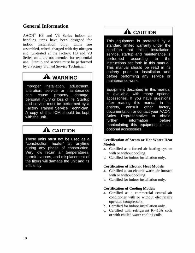
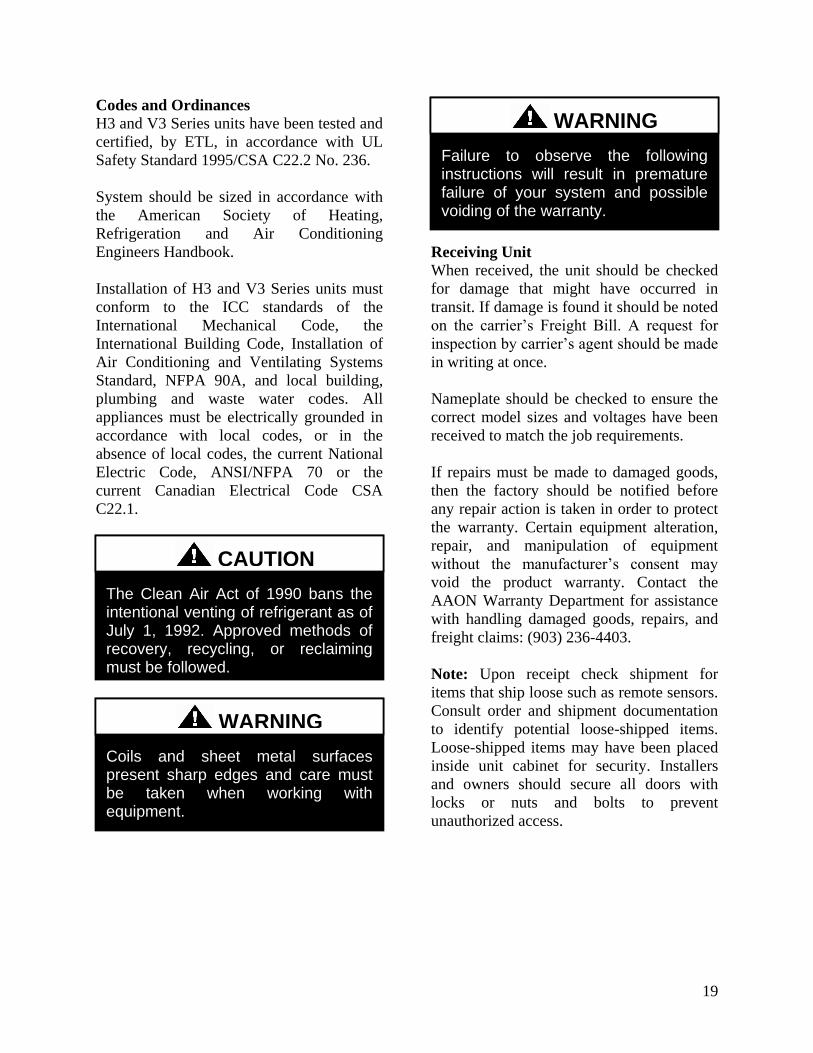
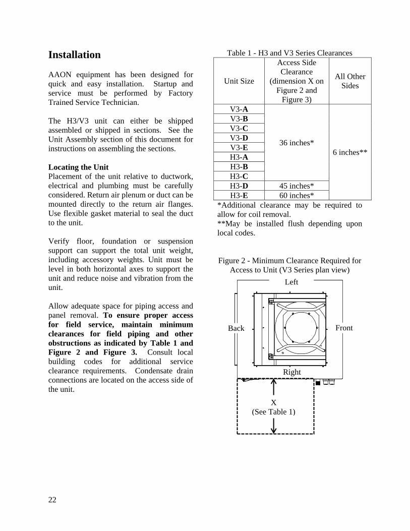
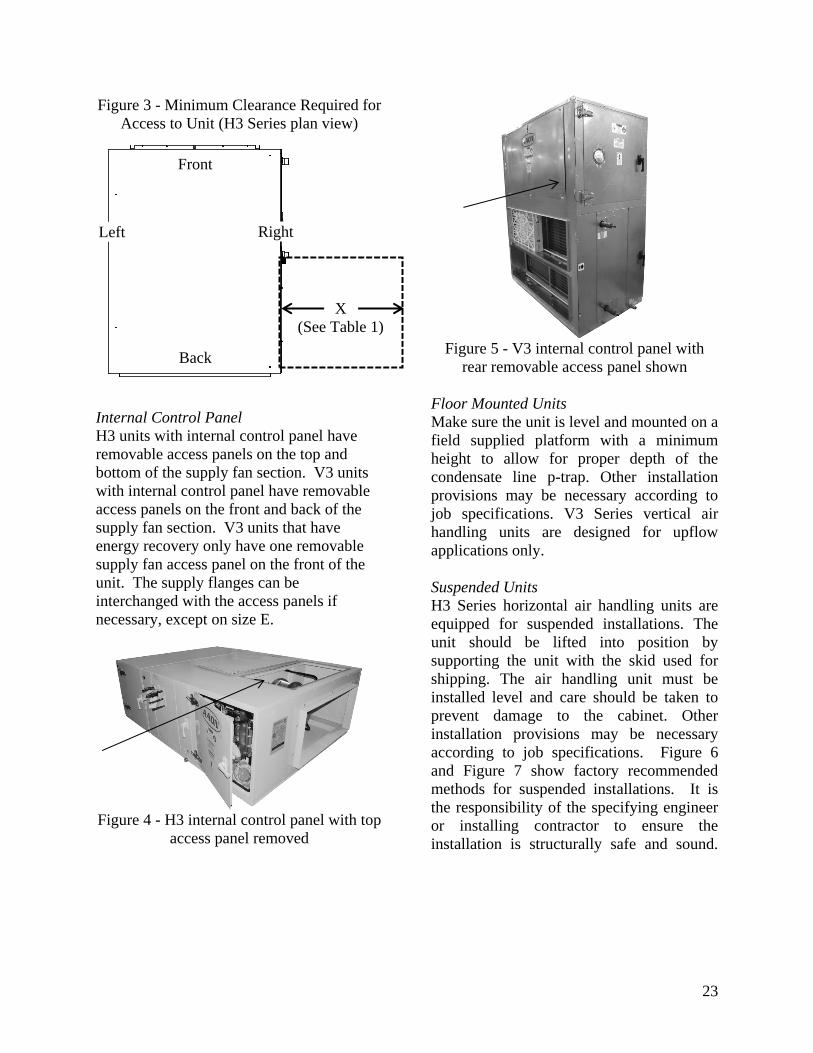
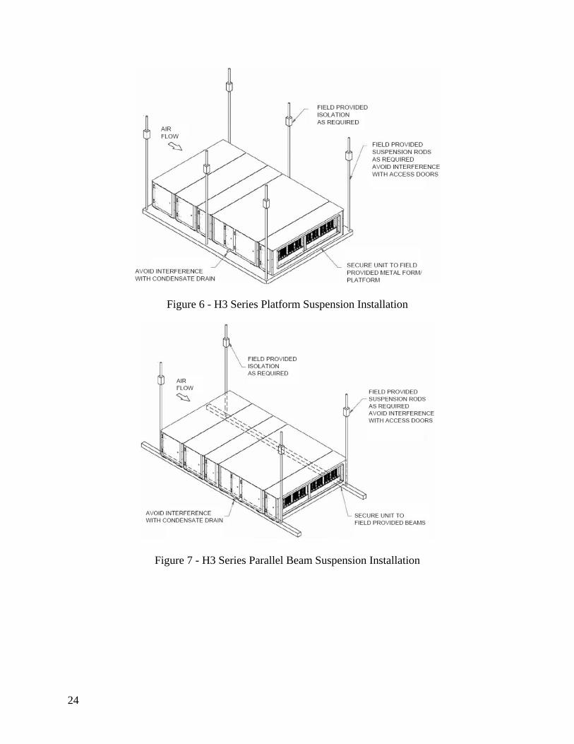
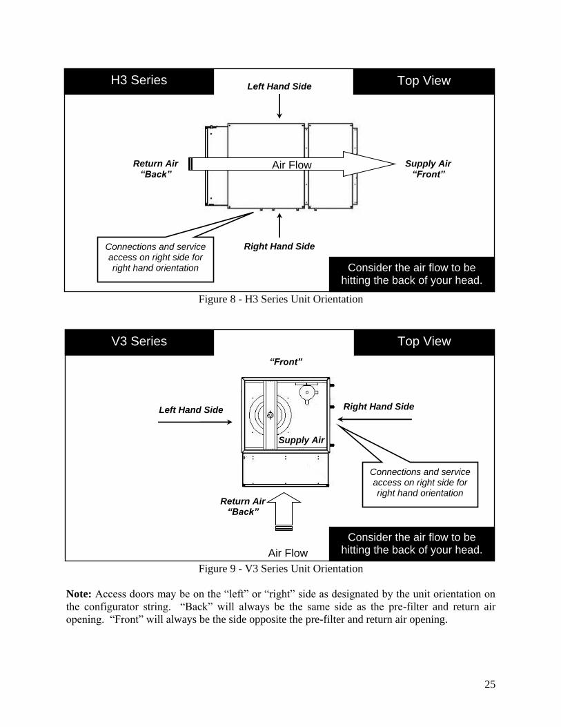
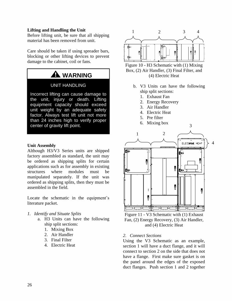
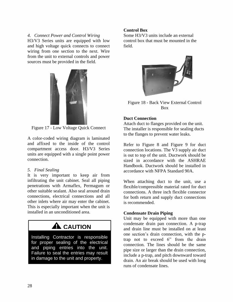
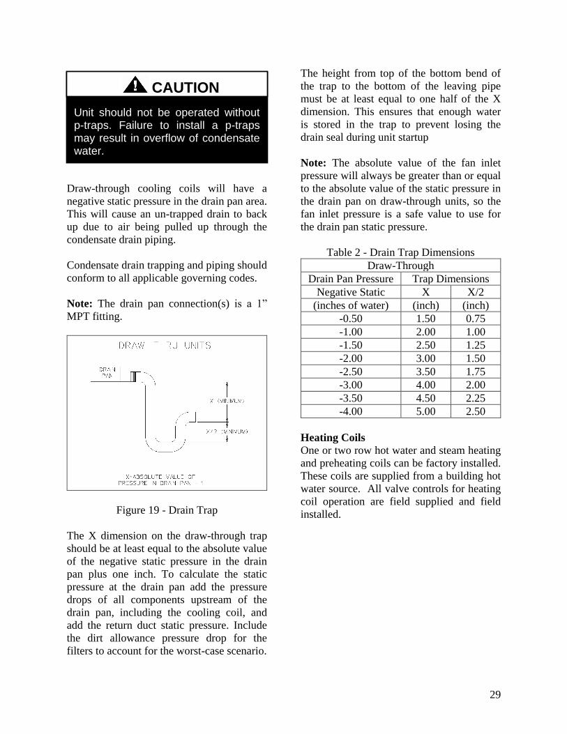
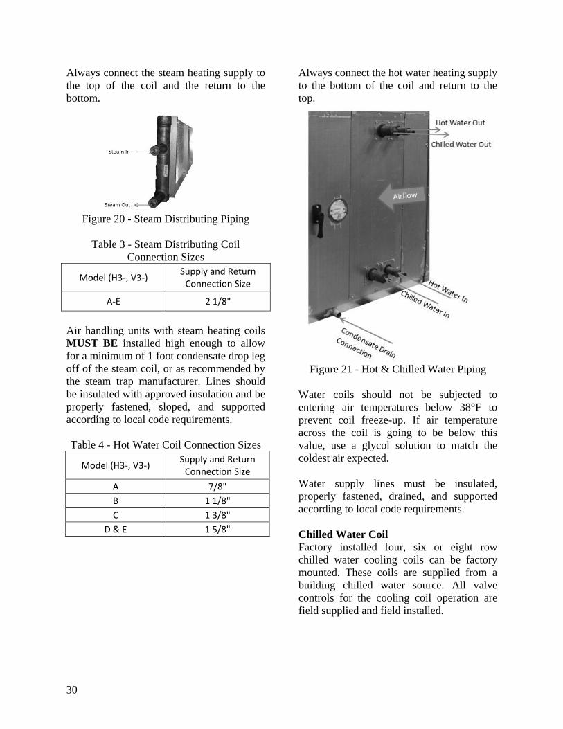
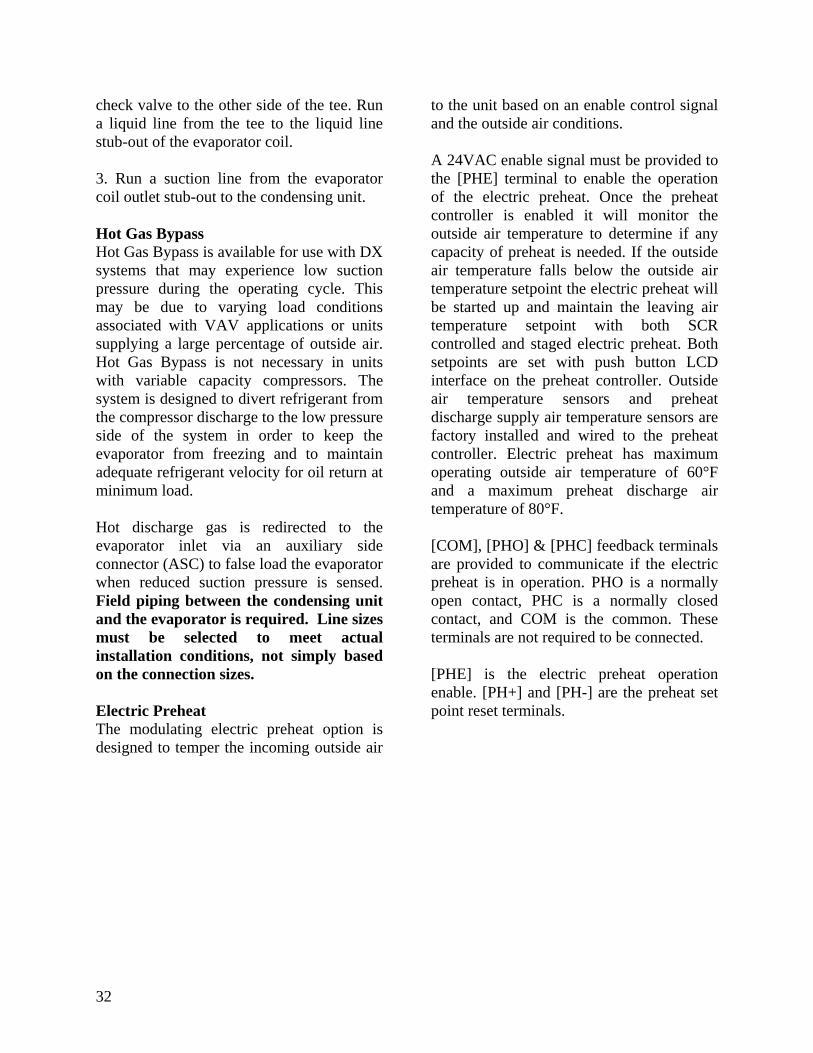
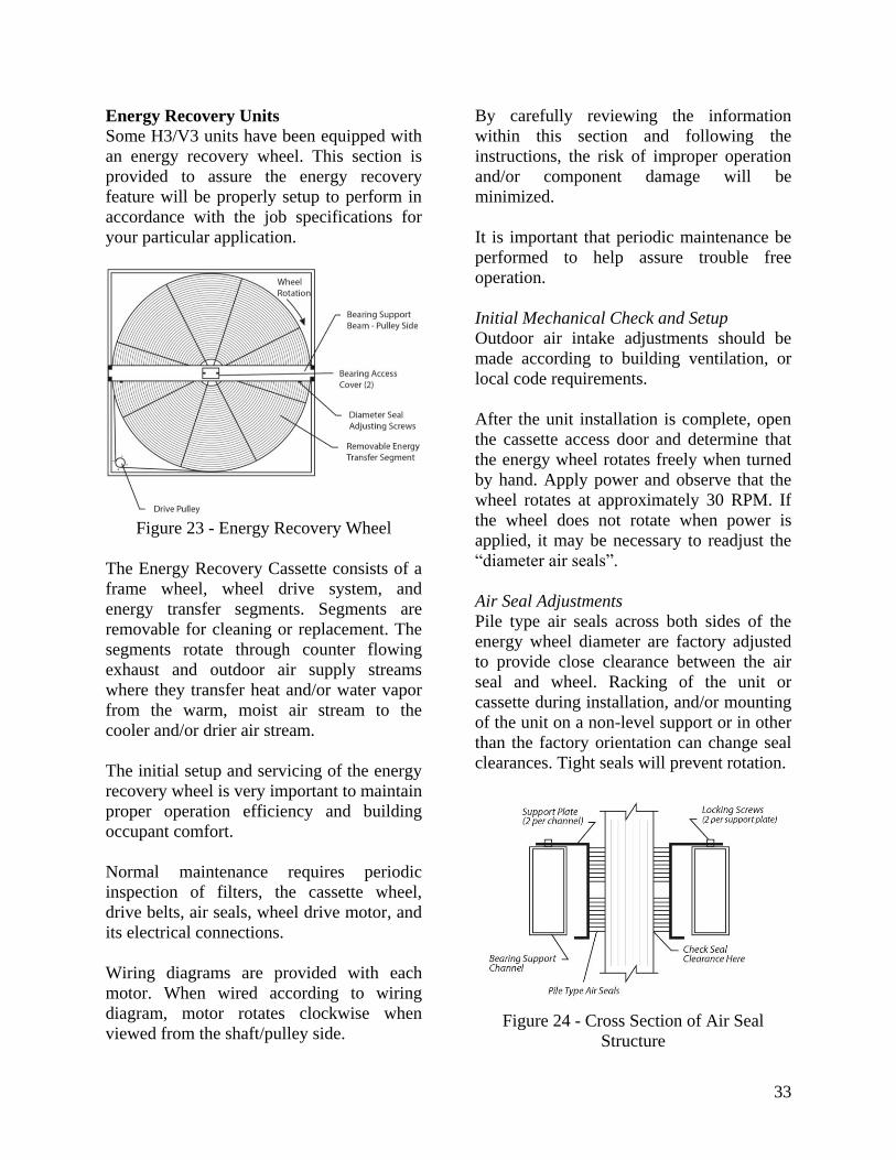
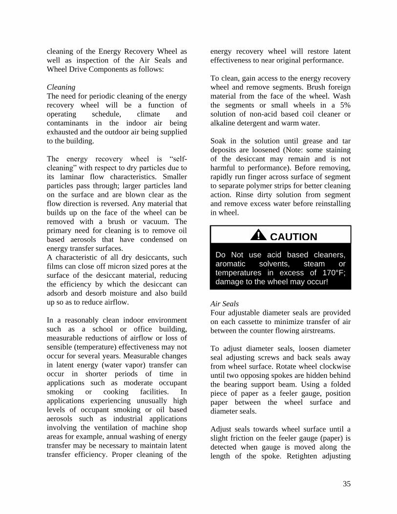
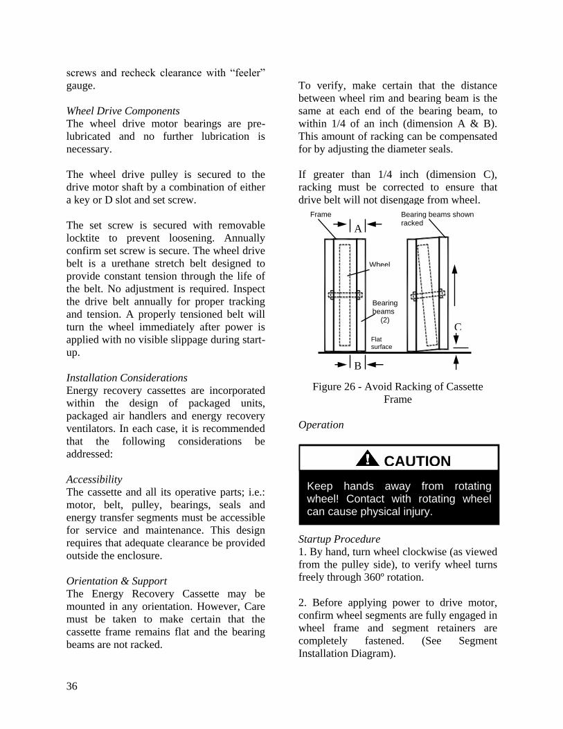
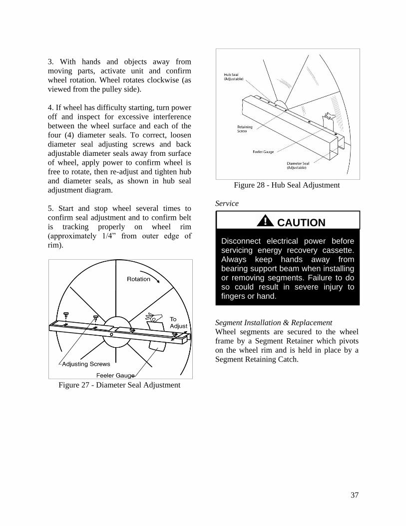
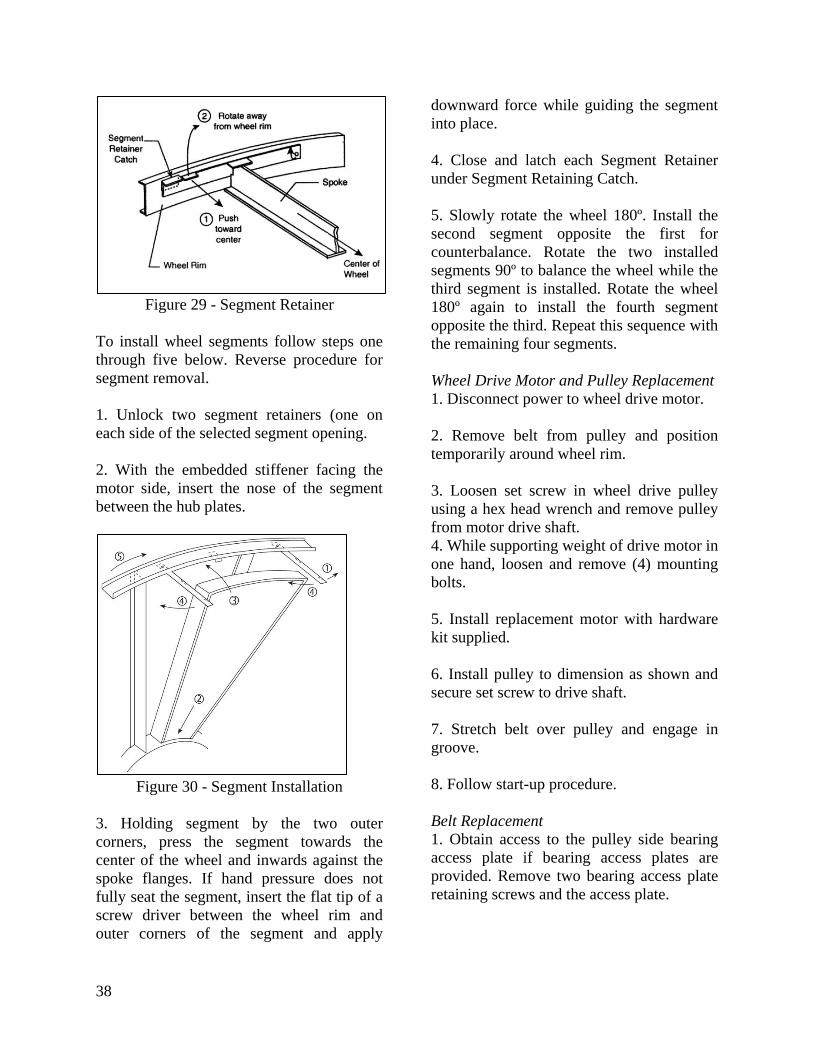
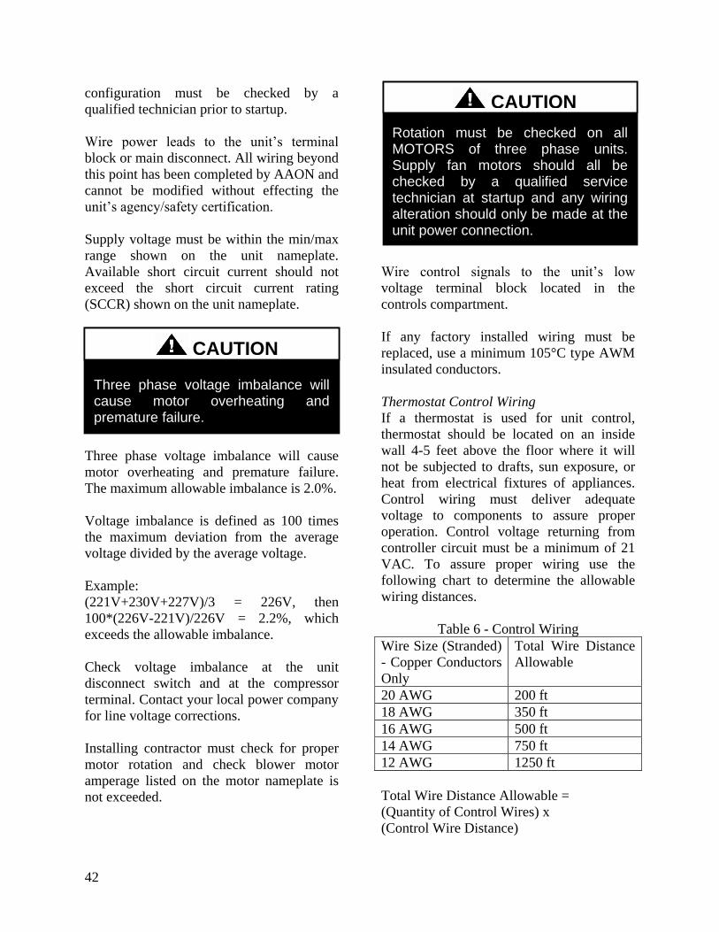
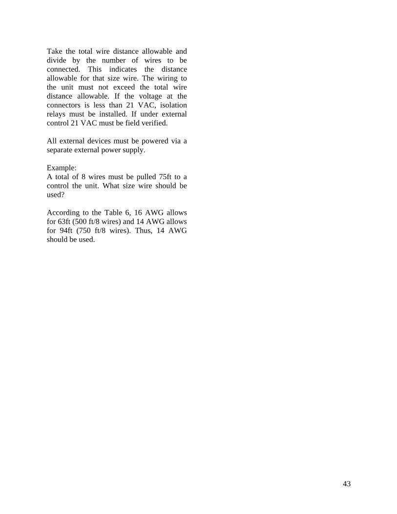
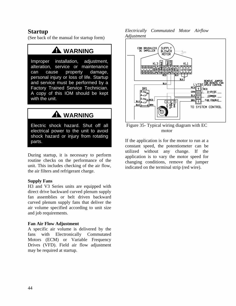
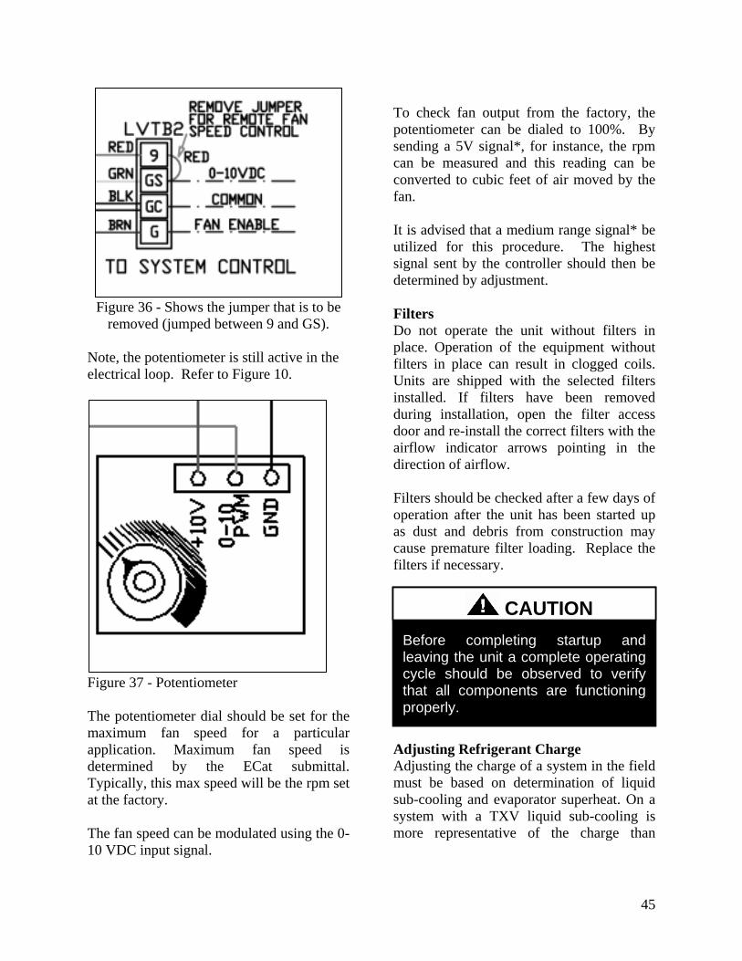
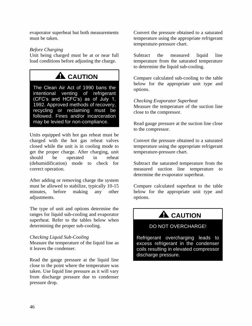
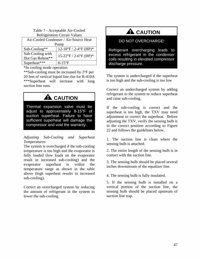
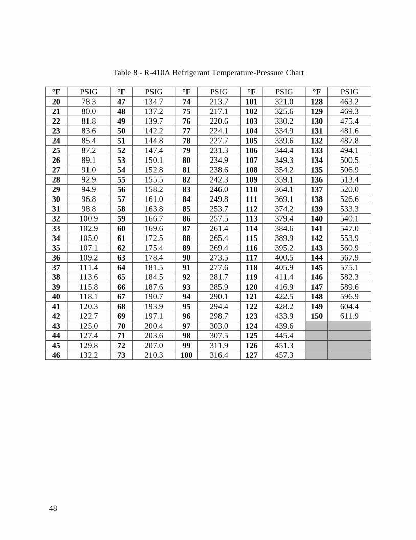
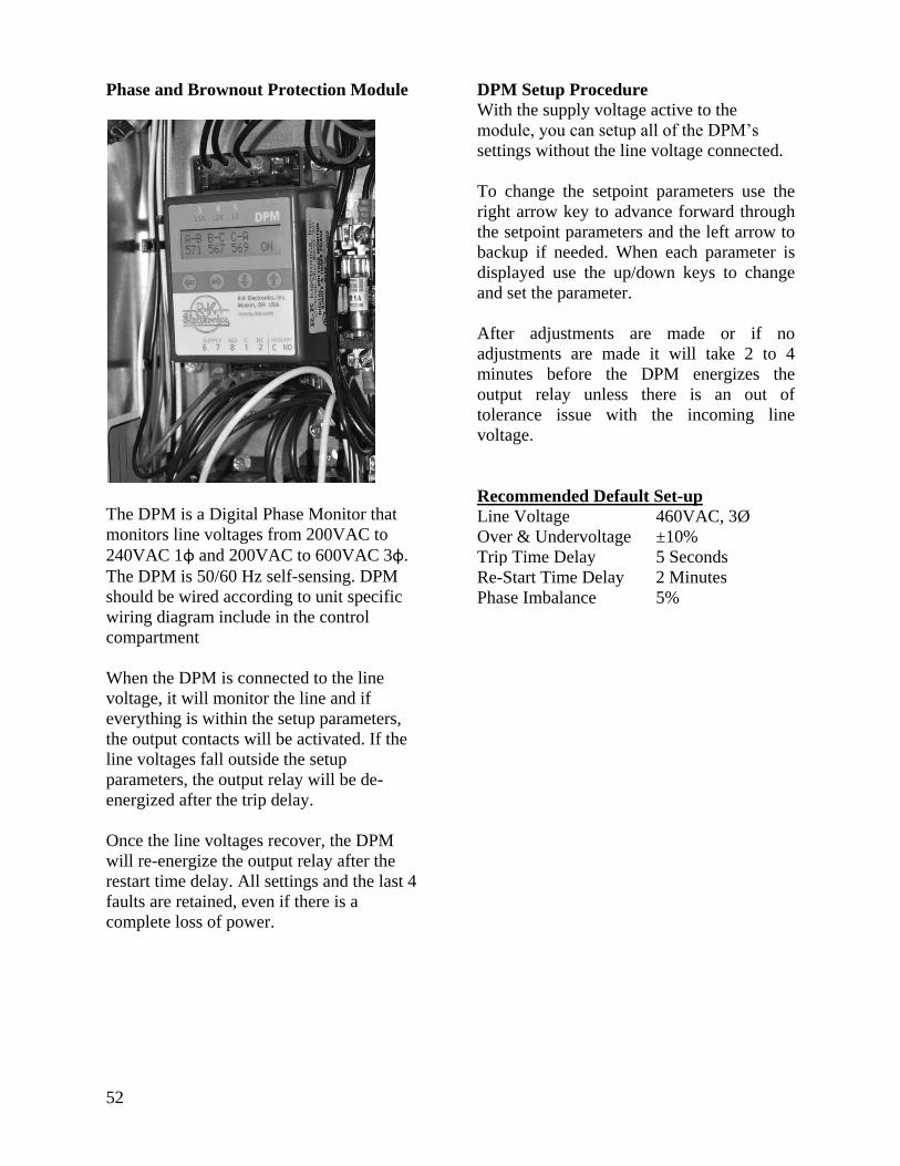
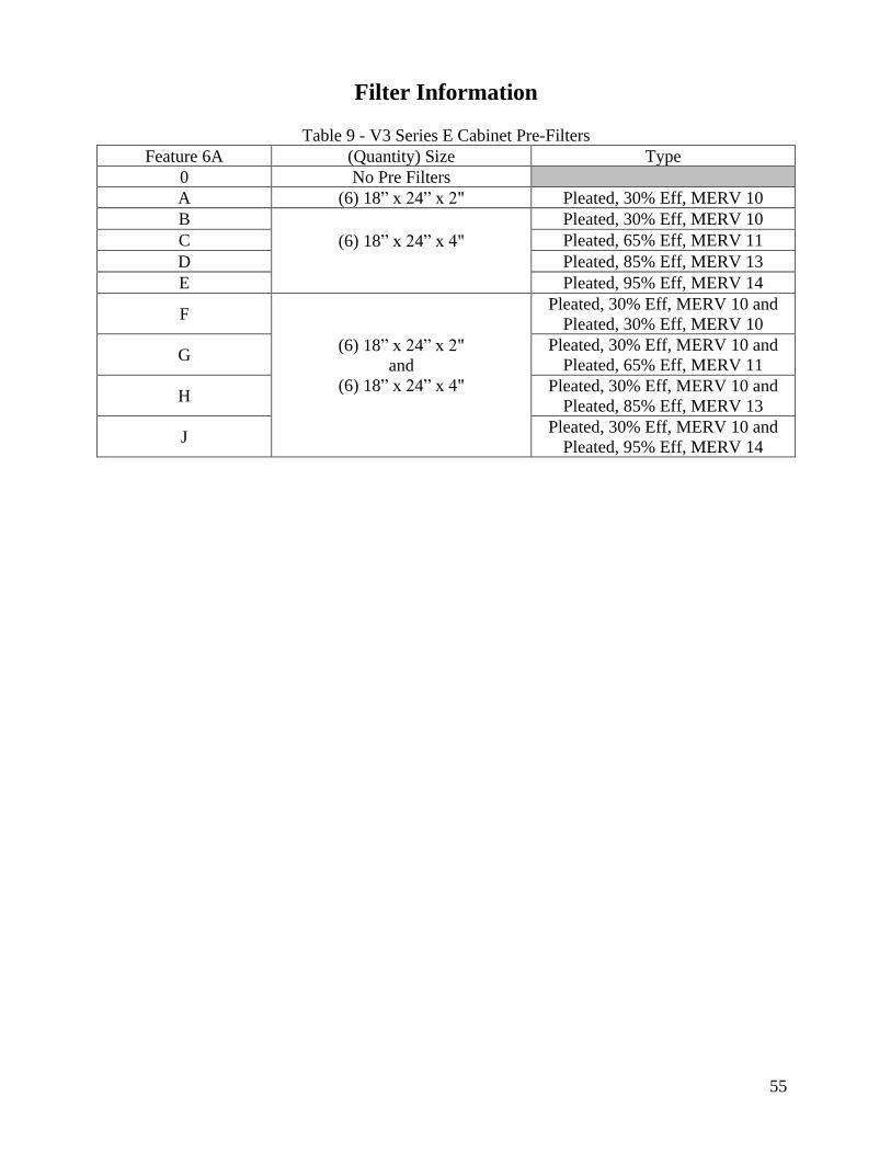
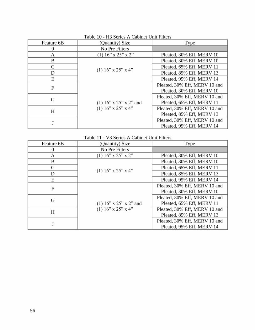
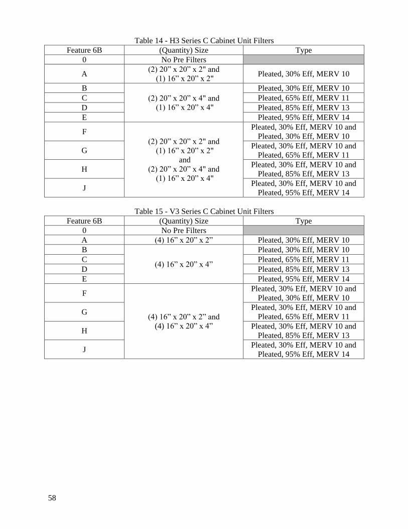
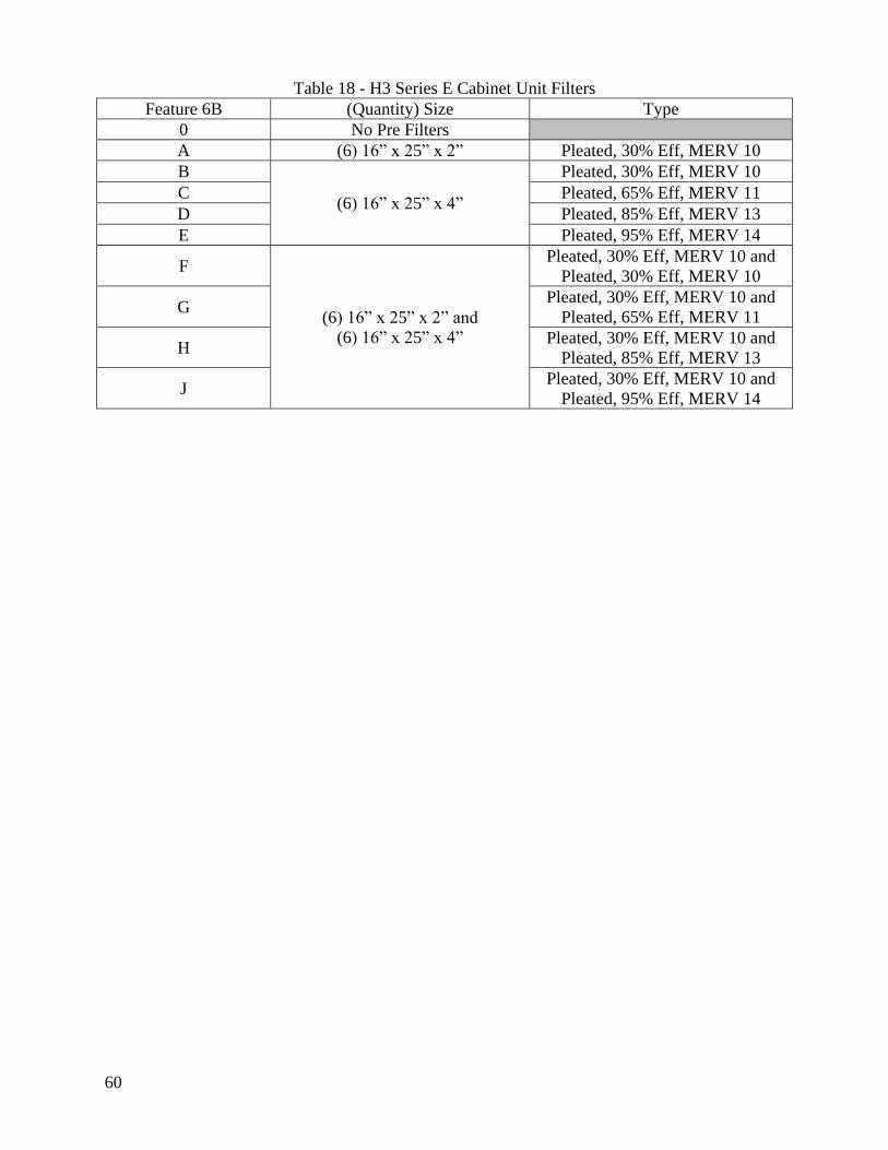
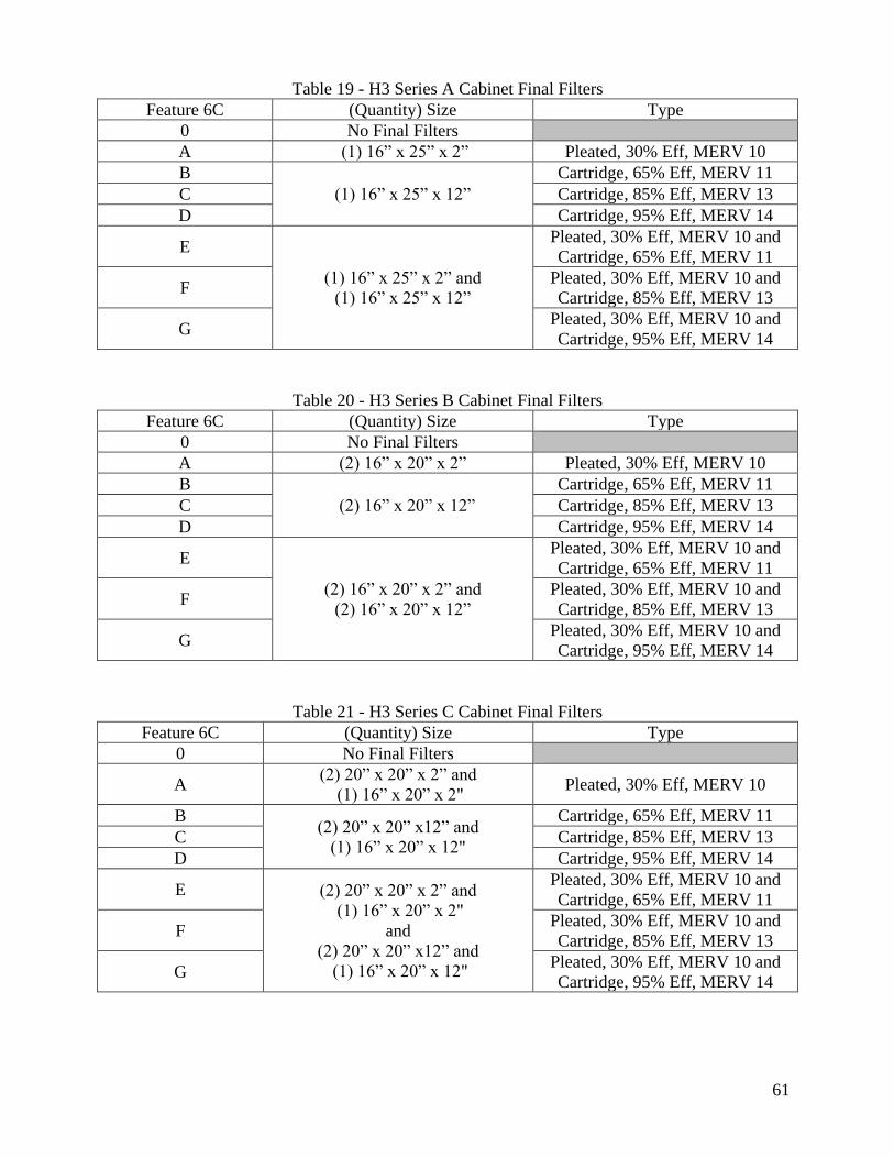
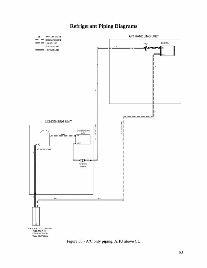
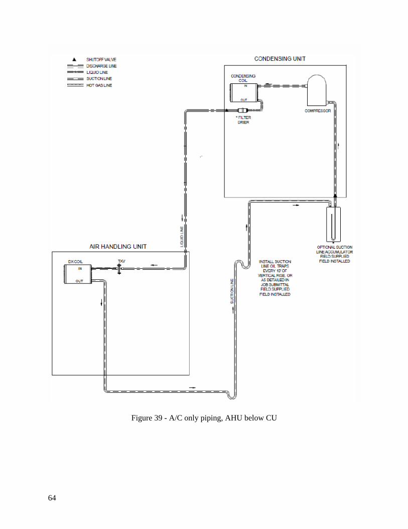
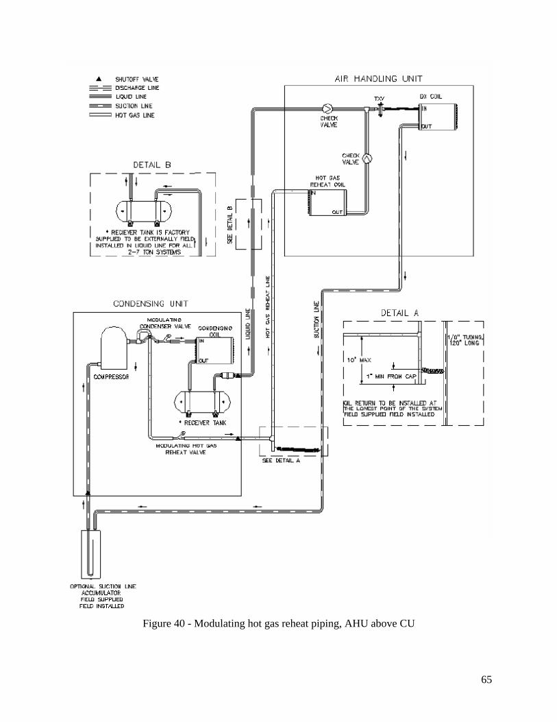
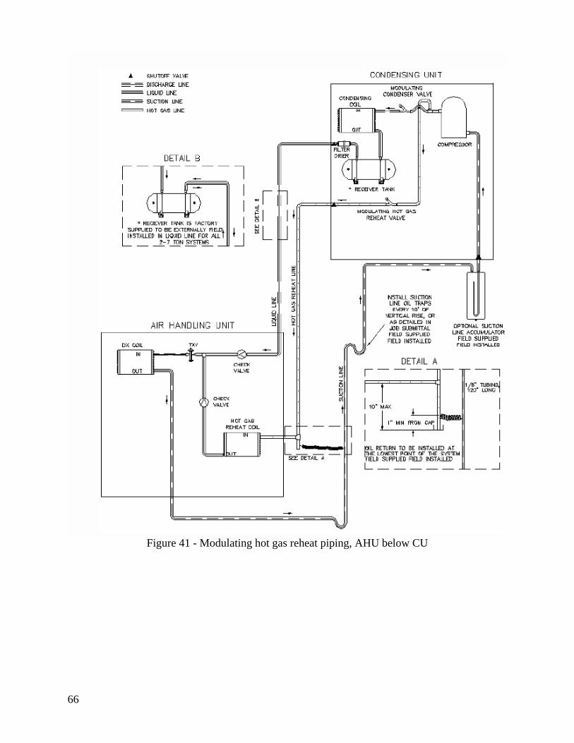
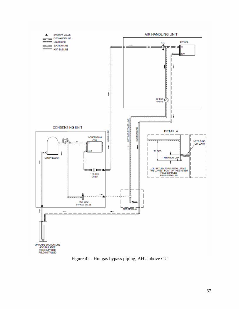
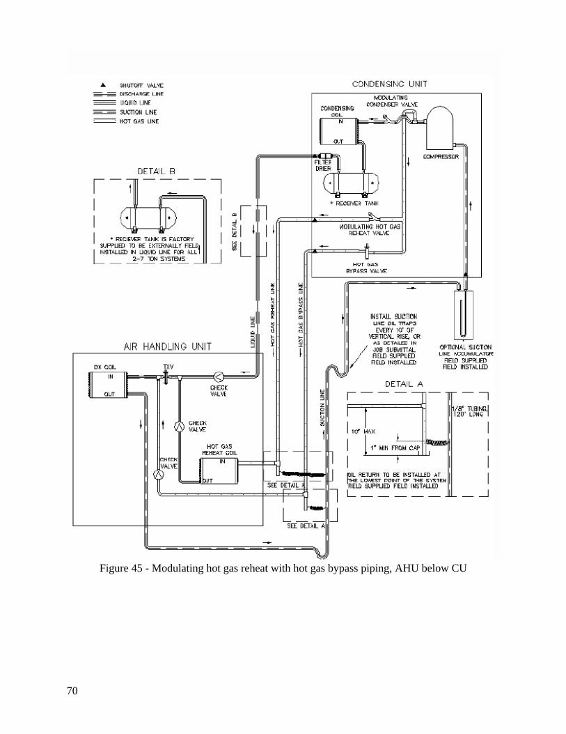
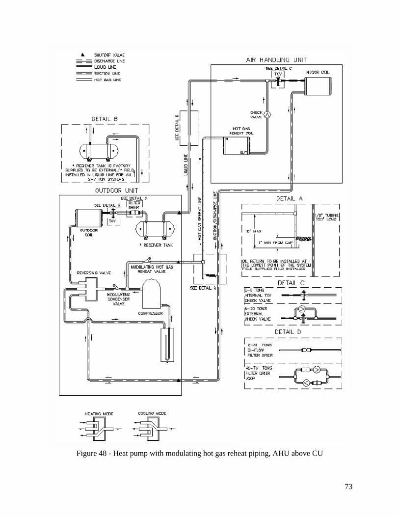
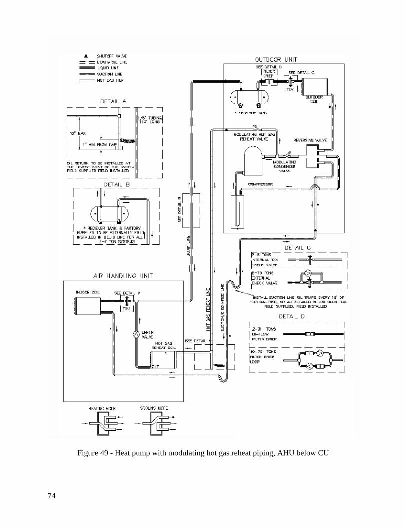
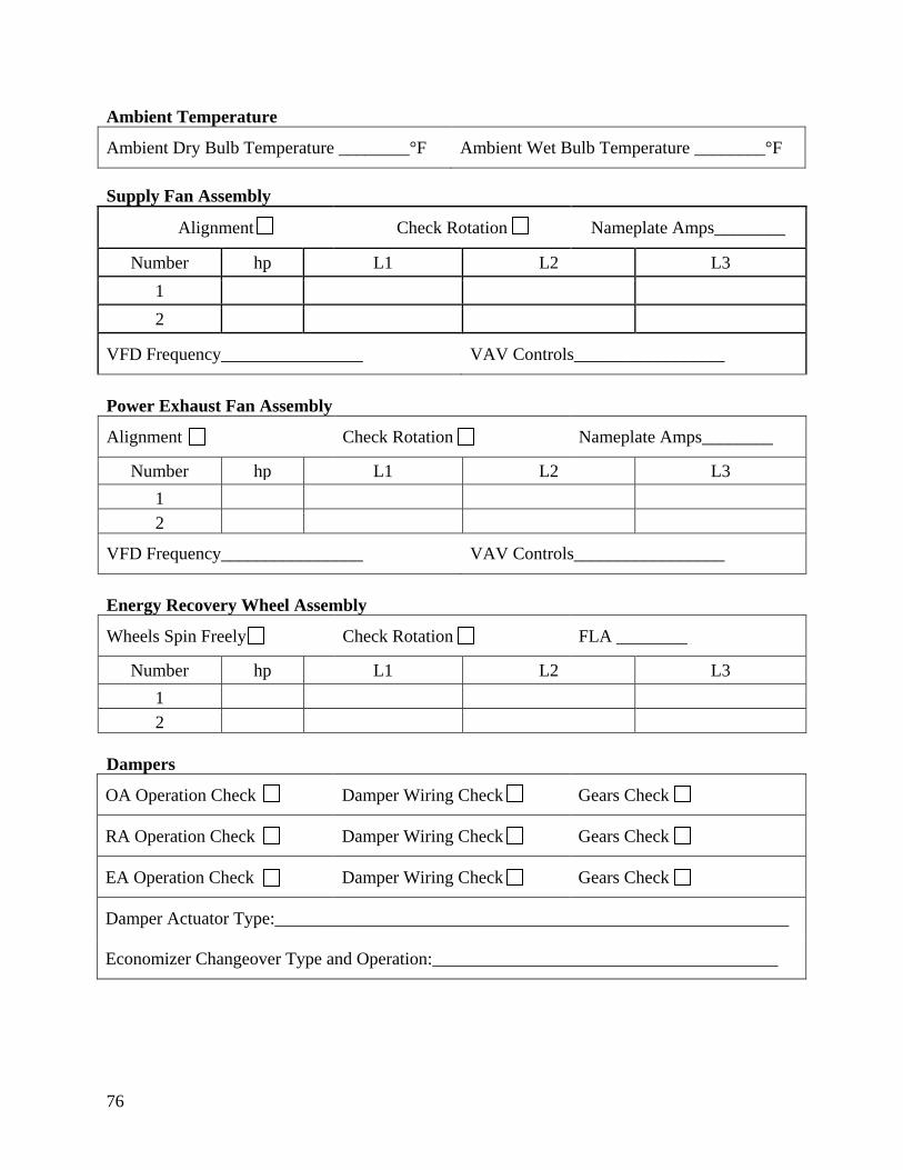
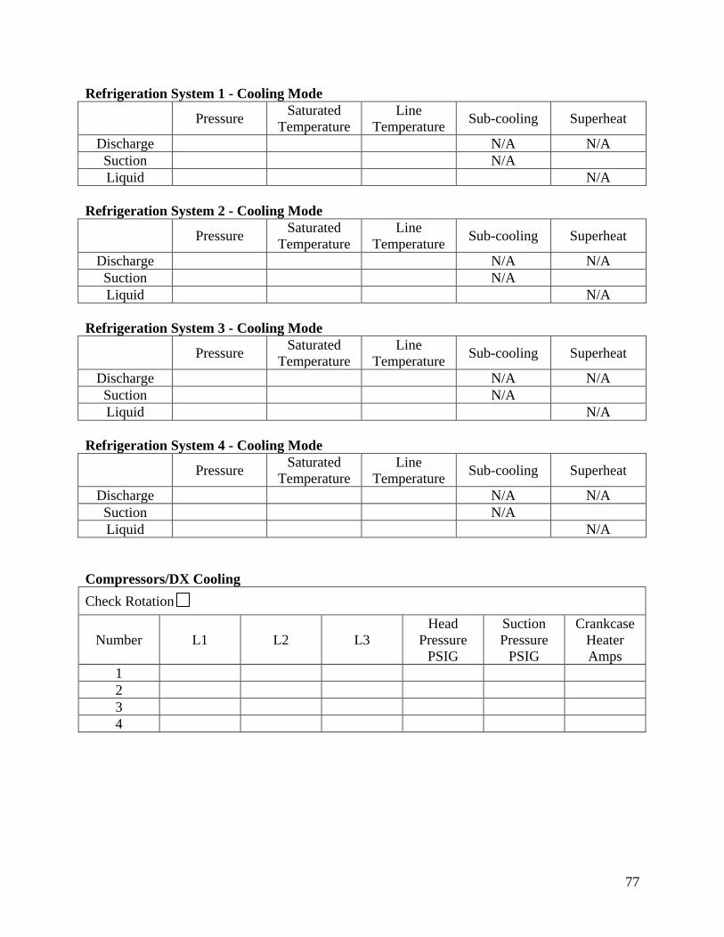
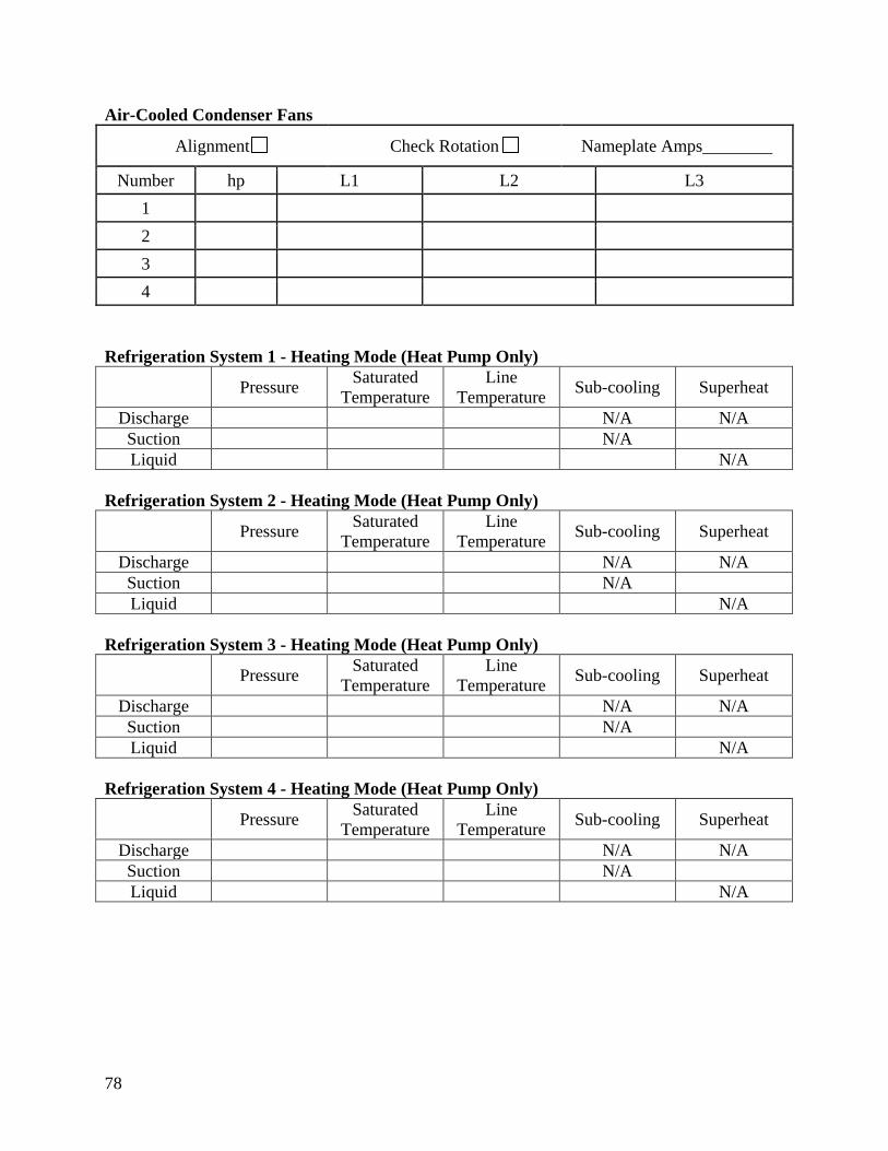
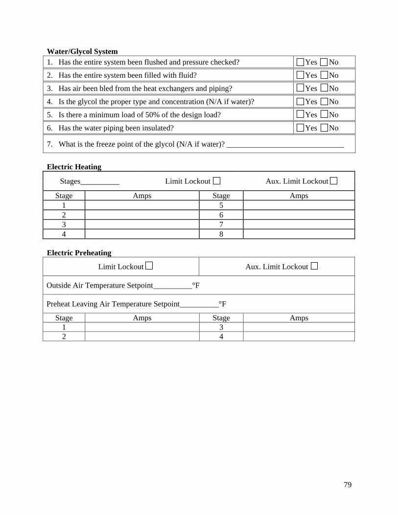
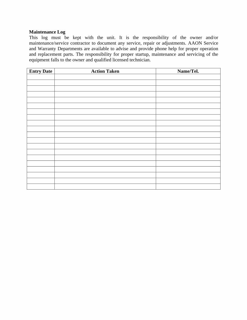