Embed Size (px)
Citation preview
OPERATING, SERVICE AND MAINTENANCE
MANUAL
MODEL H-930 SERIES DOW-LOK® EQUIPPED
INDUSTRIAL LOW-MOUNT WINCHES
CAUTION: READ AND UNDERSTAND THIS MANUAL BEFORE INSTALLATION AND OPERATION OF WINCH. SEE SAFEGUARDS AND WARNING!
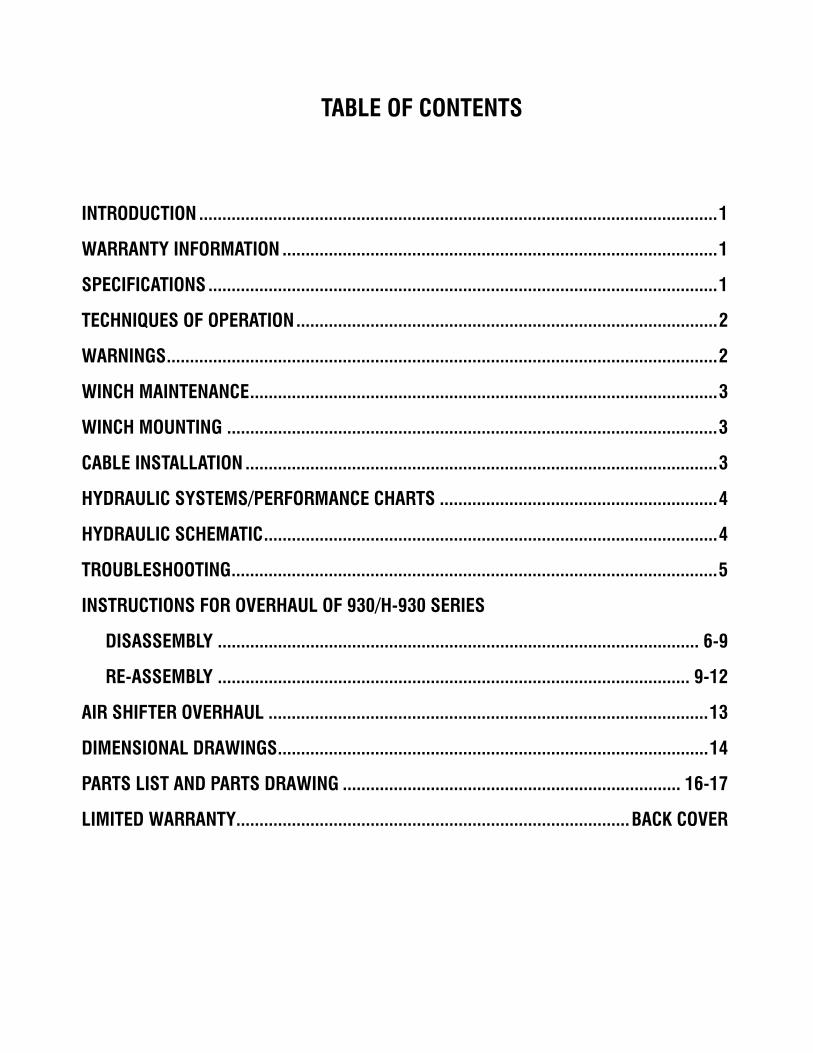
TABLE OF CONTENTS
INTRODUCTION ................................................................................................................1
WARRANTY INFORMATION ..............................................................................................1
SPECIFICATIONS ..............................................................................................................1
TECHNIQUES OF OPERATION...........................................................................................2
WARNINGS.......................................................................................................................2
WINCH MAINTENANCE.....................................................................................................3
WINCH MOUNTING ..........................................................................................................3
CABLE INSTALLATION ......................................................................................................3
HYDRAULIC SYSTEMS/PERFORMANCE CHARTS ............................................................4
HYDRAULIC SCHEMATIC..................................................................................................4
TROUBLESHOOTING.........................................................................................................5
INSTRUCTIONS FOR OVERHAUL OF 930/H-930 SERIES
DISASSEMBLY ........................................................................................................ 6-9
RE-ASSEMBLY ...................................................................................................... 9-12
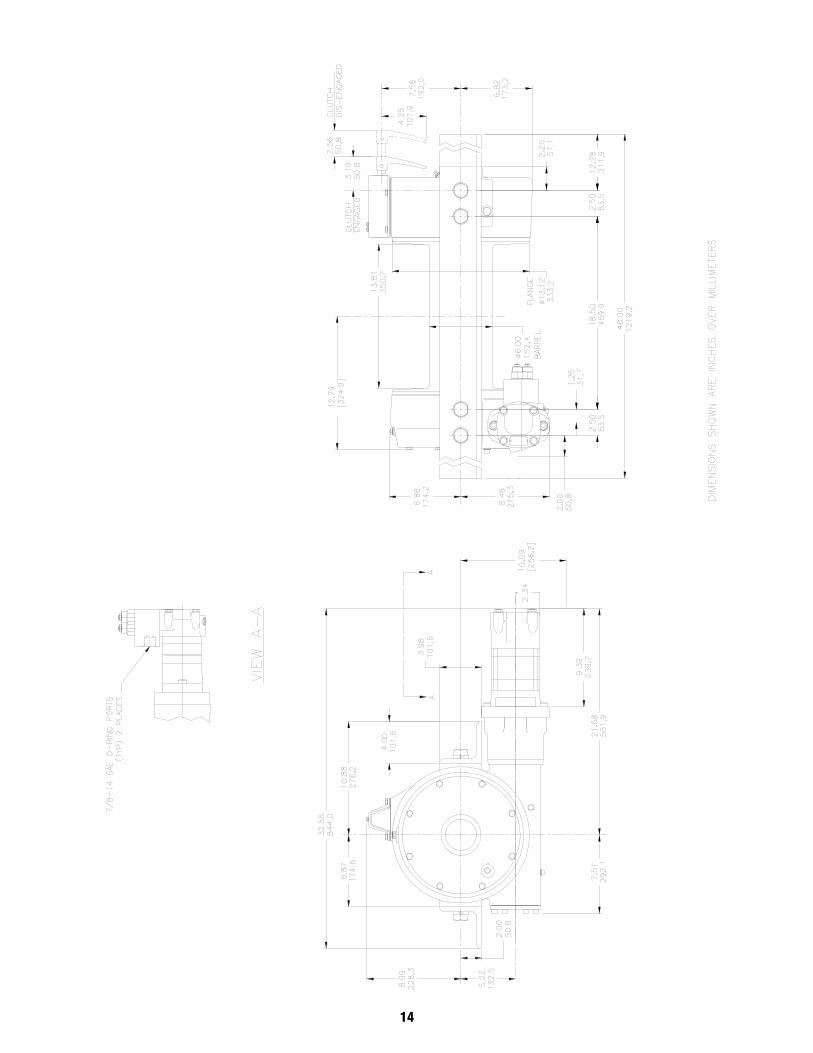
AIR SHIFTER OVERHAUL ...............................................................................................13
DIMENSIONAL DRAWINGS.............................................................................................14
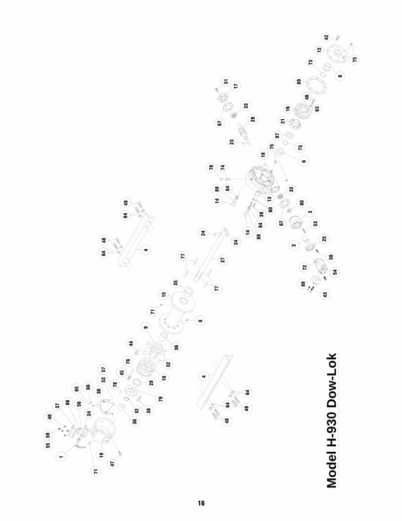
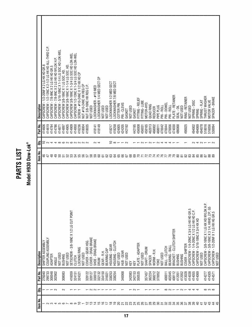
PARTS LIST AND PARTS DRAWING ......................................................................... 16-17
LIMITED WARRANTY.....................................................................................BACK COVER
1
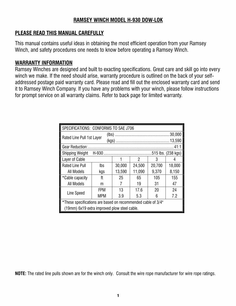
RAMSEY WINCH MODEL H-930 DOW-LOK PLEASE READ THIS MANUAL CAREFULLY
This manual contains useful ideas in obtaining the most efficient operation from your Ramsey Winch, and safety procedures one needs to know before operating a Ramsey Winch. WARRANTY INFORMATION Ramsey Winches are designed and built to exacting specifications. Great care and skill go into every winch we make. If the need should arise, warranty procedure is outlined on the back of your self-addressed postage paid warranty card. Please read and fill out the enclosed warranty card and send it to Ramsey Winch Company. If you have any problems with your winch, please follow instructions for prompt service on all warranty claims. Refer to back page for limited warranty.
NOTE: The rated line pulls shown are for the winch only. Consult the wire rope manufacturer for wire rope ratings.
SPECIFICATIONS: CONFORMS TO SAE J706
Rated Line Pull 1st Layer (lbs) .................................................... 30,000 (kgs) ................................................... 13,590
Gear Reduction: .................................................................................. 41:1 Shipping Weight H-930 .............................................. 515 lbs. (238 kgs) Layer of Cable 1 2 3 4 Rated Line Pull lbs 30,000 24,500 20,700 18,000
All Models kgs 13,590 11,090 9,370 8,150 *Cable capacity ft 25 65 105 155
All Models m 7 19 31 47
Line Speed FPM 13 17.6 20 24 MPM 3.9 5.3 6 7.2
*These specifications are based on recommended cable of 3/4" (19mm) 6x19 extra improved plow steel cable.
2
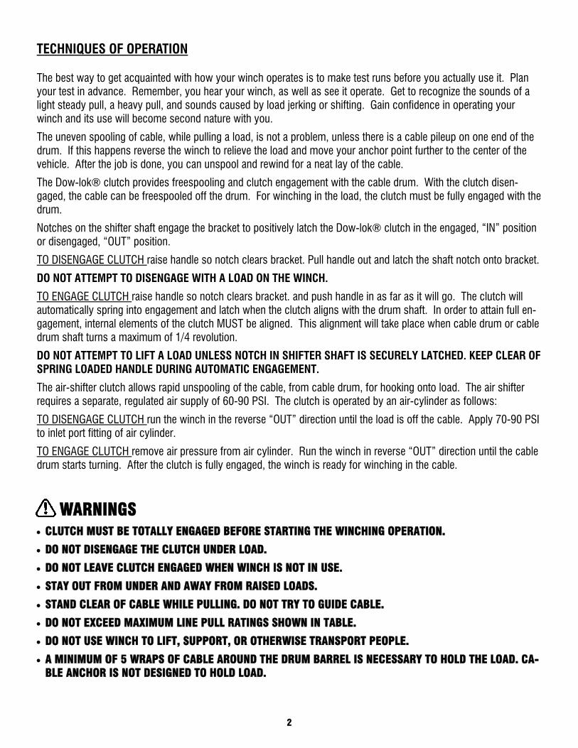
TECHNIQUES OF OPERATION
The best way to get acquainted with how your winch operates is to make test runs before you actually use it. Plan your test in advance. Remember, you hear your winch, as well as see it operate. Get to recognize the sounds of a light steady pull, a heavy pull, and sounds caused by load jerking or shifting. Gain confidence in operating your winch and its use will become second nature with you.
The uneven spooling of cable, while pulling a load, is not a problem, unless there is a cable pileup on one end of the drum. If this happens reverse the winch to relieve the load and move your anchor point further to the center of the vehicle. After the job is done, you can unspool and rewind for a neat lay of the cable.
The Dow-lok® clutch provides freespooling and clutch engagement with the cable drum. With the clutch disen-gaged, the cable can be freespooled off the drum. For winching in the load, the clutch must be fully engaged with the drum.
Notches on the shifter shaft engage the bracket to positively latch the Dow-lok® clutch in the engaged, “IN” position or disengaged, “OUT” position.
TO DISENGAGE CLUTCH raise handle so notch clears bracket. Pull handle out and latch the shaft notch onto bracket.
DO NOT ATTEMPT TO DISENGAGE WITH A LOAD ON THE WINCH.
TO ENGAGE CLUTCH raise handle so notch clears bracket. and push handle in as far as it will go. The clutch will automatically spring into engagement and latch when the clutch aligns with the drum shaft. In order to attain full en-gagement, internal elements of the clutch MUST be aligned. This alignment will take place when cable drum or cable drum shaft turns a maximum of 1/4 revolution.
DO NOT ATTEMPT TO LIFT A LOAD UNLESS NOTCH IN SHIFTER SHAFT IS SECURELY LATCHED. KEEP CLEAR OF SPRING LOADED HANDLE DURING AUTOMATIC ENGAGEMENT.
The air-shifter clutch allows rapid unspooling of the cable, from cable drum, for hooking onto load. The air shifter requires a separate, regulated air supply of 60-90 PSI. The clutch is operated by an air-cylinder as follows:
TO DISENGAGE CLUTCH run the winch in the reverse “OUT” direction until the load is off the cable. Apply 70-90 PSI to inlet port fitting of air cylinder.
TO ENGAGE CLUTCH remove air pressure from air cylinder. Run the winch in reverse “OUT” direction until the cable drum starts turning. After the clutch is fully engaged, the winch is ready for winching in the cable.
WARNINGS • CLUTCH MUST BE TOTALLY ENGAGED BEFORE STARTING THE WINCHING OPERATION.
• DO NOT DISENGAGE THE CLUTCH UNDER LOAD.
• DO NOT LEAVE CLUTCH ENGAGED WHEN WINCH IS NOT IN USE.
• STAY OUT FROM UNDER AND AWAY FROM RAISED LOADS.
• STAND CLEAR OF CABLE WHILE PULLING. DO NOT TRY TO GUIDE CABLE.
• DO NOT EXCEED MAXIMUM LINE PULL RATINGS SHOWN IN TABLE.
• DO NOT USE WINCH TO LIFT, SUPPORT, OR OTHERWISE TRANSPORT PEOPLE.
• A MINIMUM OF 5 WRAPS OF CABLE AROUND THE DRUM BARREL IS NECESSARY TO HOLD THE LOAD. CA-BLE ANCHOR IS NOT DESIGNED TO HOLD LOAD.
3
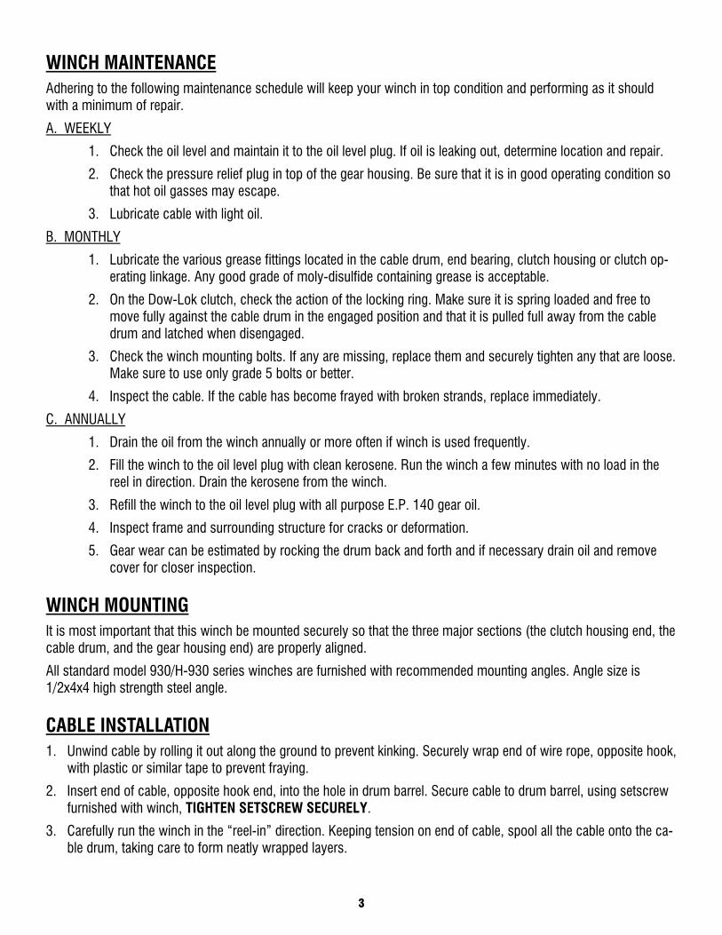
WINCH MAINTENANCE Adhering to the following maintenance schedule will keep your winch in top condition and performing as it should with a minimum of repair.
A. WEEKLY
1. Check the oil level and maintain it to the oil level plug. If oil is leaking out, determine location and repair.
2. Check the pressure relief plug in top of the gear housing. Be sure that it is in good operating condition so that hot oil gasses may escape.
3. Lubricate cable with light oil.
B. MONTHLY
1. Lubricate the various grease fittings located in the cable drum, end bearing, clutch housing or clutch op-erating linkage. Any good grade of moly-disulfide containing grease is acceptable.
2. On the Dow-Lok clutch, check the action of the locking ring. Make sure it is spring loaded and free to move fully against the cable drum in the engaged position and that it is pulled full away from the cable drum and latched when disengaged.
3. Check the winch mounting bolts. If any are missing, replace them and securely tighten any that are loose. Make sure to use only grade 5 bolts or better.
4. Inspect the cable. If the cable has become frayed with broken strands, replace immediately.
C. ANNUALLY
1. Drain the oil from the winch annually or more often if winch is used frequently.
2. Fill the winch to the oil level plug with clean kerosene. Run the winch a few minutes with no load in the reel in direction. Drain the kerosene from the winch.
3. Refill the winch to the oil level plug with all purpose E.P. 140 gear oil.
4. Inspect frame and surrounding structure for cracks or deformation.
5. Gear wear can be estimated by rocking the drum back and forth and if necessary drain oil and remove cover for closer inspection.
WINCH MOUNTING It is most important that this winch be mounted securely so that the three major sections (the clutch housing end, the cable drum, and the gear housing end) are properly aligned.
All standard model 930/H-930 series winches are furnished with recommended mounting angles. Angle size is 1/2x4x4 high strength steel angle.
CABLE INSTALLATION 1. Unwind cable by rolling it out along the ground to prevent kinking. Securely wrap end of wire rope, opposite hook,
with plastic or similar tape to prevent fraying.
2. Insert end of cable, opposite hook end, into the hole in drum barrel. Secure cable to drum barrel, using setscrew furnished with winch, TIGHTEN SETSCREW SECURELY.
3. Carefully run the winch in the “reel-in” direction. Keeping tension on end of cable, spool all the cable onto the ca-ble drum, taking care to form neatly wrapped layers.
4
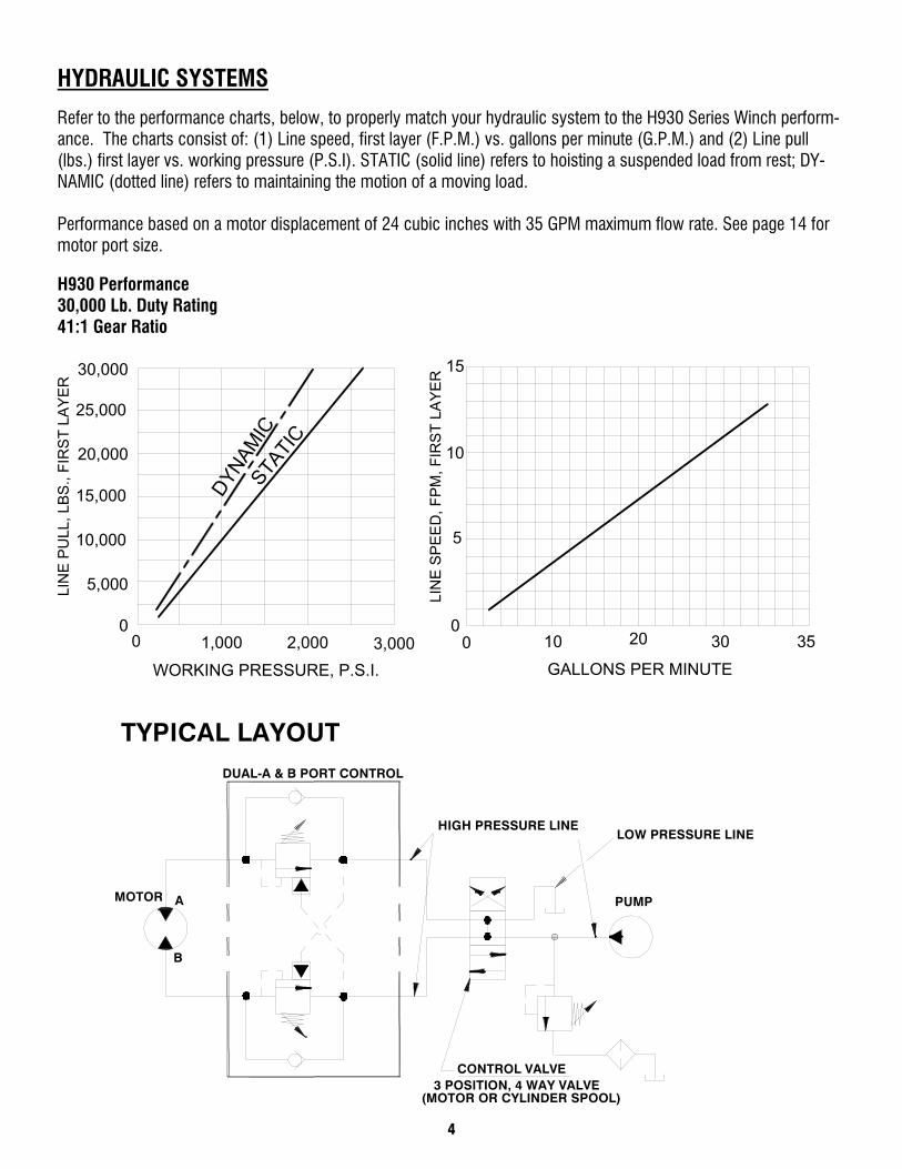
HYDRAULIC SYSTEMS
Refer to the performance charts, below, to properly match your hydraulic system to the H930 Series Winch perform-ance. The charts consist of: (1) Line speed, first layer (F.P.M.) vs. gallons per minute (G.P.M.) and (2) Line pull (lbs.) first layer vs. working pressure (P.S.I). STATIC (solid line) refers to hoisting a suspended load from rest; DY-NAMIC (dotted line) refers to maintaining the motion of a moving load. Performance based on a motor displacement of 24 cubic inches with 35 GPM maximum flow rate. See page 14 for motor port size. H930 Performance 30,000 Lb. Duty Rating 41:1 Gear Ratio
CONTROL VALVE3 POSITION, 4 WAY VALVE
(MOTOR OR CYLINDER SPOOL)
HIGH PRESSURE LINE
DUAL-A & B PORT CONTROL
B
MOTOR A
TYPICAL LAYOUT
LOW PRESSURE LINE
PUMP
GALLONS PER MINUTE
20
LIN
E P
ULL
, LB
S.,
FIR
ST
LAY
ER
5,000
00
20,000
15,000
10,000
30,000
25,000LI
NE
SP
EE
D, F
PM
, FIR
ST
LAY
ER
3,000WORKING PRESSURE, P.S.I.
2,0001,000 00
10
DYNAM
ICSTA
TIC
5
10
15
30 35
5
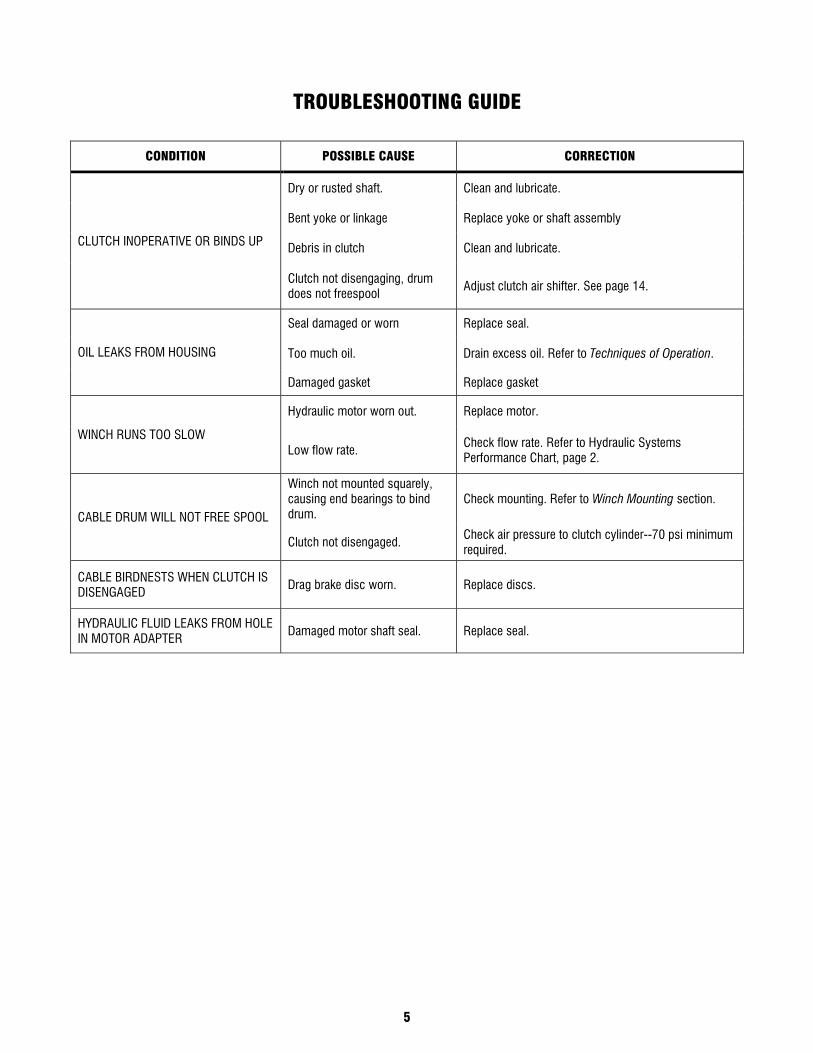
TROUBLESHOOTING GUIDE
CONDITION POSSIBLE CAUSE CORRECTION
CLUTCH INOPERATIVE OR BINDS UP
Dry or rusted shaft. Clean and lubricate.
Bent yoke or linkage Replace yoke or shaft assembly
Debris in clutch Clean and lubricate.
Clutch not disengaging, drum does not freespool
Adjust clutch air shifter. See page 14.
OIL LEAKS FROM HOUSING
Seal damaged or worn Replace seal.
Too much oil. Drain excess oil. Refer to Techniques of Operation.
Damaged gasket Replace gasket
WINCH RUNS TOO SLOW
Hydraulic motor worn out. Replace motor.
Low flow rate. Check flow rate. Refer to Hydraulic Systems Performance Chart, page 2.
CABLE DRUM WILL NOT FREE SPOOL
Winch not mounted squarely, causing end bearings to bind drum.
Check mounting. Refer to Winch Mounting section.
Clutch not disengaged. Check air pressure to clutch cylinder--70 psi minimum required.
CABLE BIRDNESTS WHEN CLUTCH IS DISENGAGED
Drag brake disc worn. Replace discs.
HYDRAULIC FLUID LEAKS FROM HOLE IN MOTOR ADAPTER
Damaged motor shaft seal. Replace seal.
6
INSTRUCTIONS FOR OVERHAUL FOR MODEL H930 “DOW-LOK” WINCH DISASSEMBLY
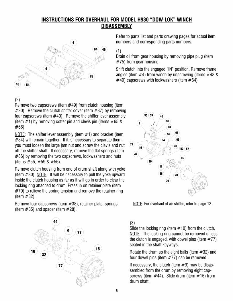
(1) Drain oil from gear housing by removing pipe plug (item #75) from gear housing.
Shift clutch into the engaged “IN” position. Remove frame angles (item #4) from winch by unscrewing (items #48 & #49) capscrews with lockwashers (item #64)
Refer to parts list and parts drawing pages for actual item numbers and corresponding parts numbers.
(2) Remove two capscrews (item #49) from clutch housing (item #20). Remove the clutch shifter cover (item #37) by removing four capscrews (item #40). Remove the shifter lever assembly (item #1) by removing cotter pin and clevis pin (items #65 & #66).
NOTE: The shifter lever assembly (item #1) and bracket (item #34) will remain together. If it is necessary to separate them, you must loosen the large jam nut and screw the clevis and nut off the shifter shaft. If necessary, remove the flat springs (item #86) by removing the two capscrews, lockwashers and nuts (items #55, #59 & #56).
Remove clutch housing from end of drum shaft along with yoke (item #30). NOTE: It will be necessary to pull the yoke upward inside the clutch housing as far as it will go in order to clear the locking ring attached to drum. Press in on retainer plate (item #79) to relieve the spring tension and remove the retainer ring (item #82).
Remove four capscrews (item #38), retainer plate, springs (item #85) and spacer (item #28).
NOTE: For overhaul of air shifter, refer to page 13.
(3) Slide the locking ring (item #10) from the clutch. NOTE: The locking ring cannot be removed unless the clutch is engaged, with dowel pins (item #77) seated in the shaft keyways.
Rotate the drum so the eight balls (item #32) and four dowel pins (item #77) can be removed.
If necessary, the clutch (item #9) may be disas-sembled from the drum by removing eight cap-screws (item #44). Slide drum (item #15) from drum shaft.
49
4
64
48 64
4
75
55
1
59 40
37
86
56
34
65
30
66
1971
20
28
79
38
47
5752
44
1032
9
15
77
77
7
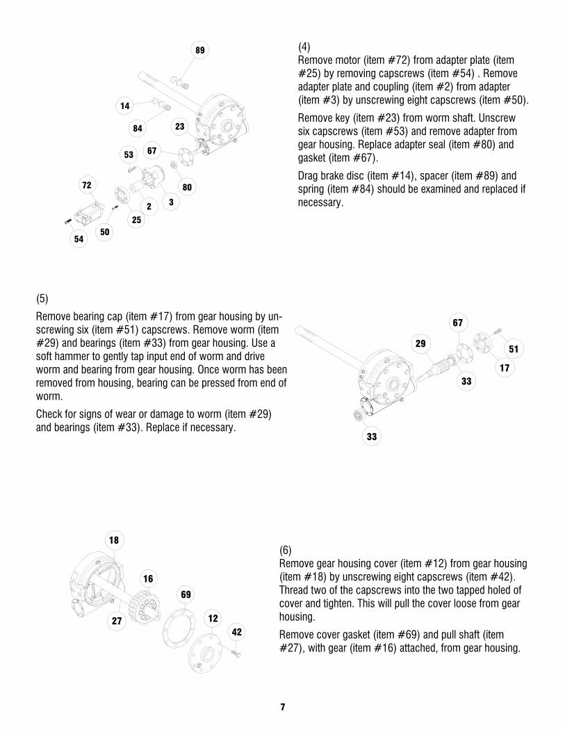
(4) Remove motor (item #72) from adapter plate (item #25) by removing capscrews (item #54) . Remove adapter plate and coupling (item #2) from adapter (item #3) by unscrewing eight capscrews (item #50).
Remove key (item #23) from worm shaft. Unscrew six capscrews (item #53) and remove adapter from gear housing. Replace adapter seal (item #80) and gasket (item #67).
Drag brake disc (item #14), spacer (item #89) and spring (item #84) should be examined and replaced if necessary.
(5)
Remove bearing cap (item #17) from gear housing by un-screwing six (item #51) capscrews. Remove worm (item #29) and bearings (item #33) from gear housing. Use a soft hammer to gently tap input end of worm and drive worm and bearing from gear housing. Once worm has been removed from housing, bearing can be pressed from end of worm.
Check for signs of wear or damage to worm (item #29) and bearings (item #33). Replace if necessary.
(6) Remove gear housing cover (item #12) from gear housing (item #18) by unscrewing eight capscrews (item #42). Thread two of the capscrews into the two tapped holed of cover and tighten. This will pull the cover loose from gear housing.
Remove cover gasket (item #69) and pull shaft (item #27), with gear (item #16) attached, from gear housing.
23
67
3
80
53
72
5450
25
2
14
89
84
33
17
5129
67
33
27
16
69
4212
18
8
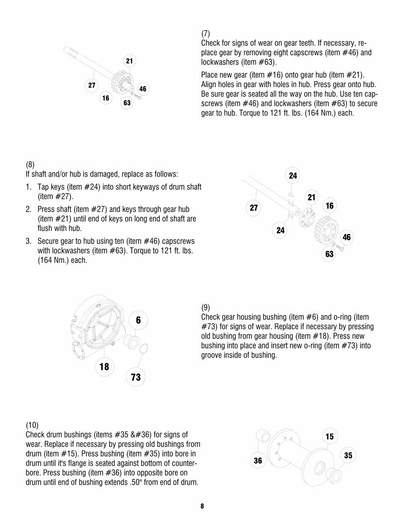
(7) Check for signs of wear on gear teeth. If necessary, re-place gear by removing eight capscrews (item #46) and lockwashers (item #63).
Place new gear (item #16) onto gear hub (item #21). Align holes in gear with holes in hub. Press gear onto hub. Be sure gear is seated all the way on the hub. Use ten cap-screws (item #46) and lockwashers (item #63) to secure gear to hub. Torque to 121 ft. lbs. (164 Nm.) each.
(8) If shaft and/or hub is damaged, replace as follows:
1. Tap keys (item #24) into short keyways of drum shaft (item #27).
2. Press shaft (item #27) and keys through gear hub (item #21) until end of keys on long end of shaft are flush with hub.
3. Secure gear to hub using ten (item #46) capscrews with lockwashers (item #63). Torque to 121 ft. lbs. (164 Nm.) each.
(9) Check gear housing bushing (item #6) and o-ring (item #73) for signs of wear. Replace if necessary by pressing old bushing from gear housing (item #18). Press new bushing into place and insert new o-ring (item #73) into groove inside of bushing.
(10) Check drum bushings (items #35 $) for signs of wear. Replace if necessary by pressing old bushings from drum (item #15). Press bushing (item #35) into bore in drum until it's flange is seated against bottom of counter-bore. Press bushing (item #36) into opposite bore on drum until end of bushing extends .50" from end of drum.
27
16
21
46
63
27
24
24
2116
63
46
1873
6
15
3536
9
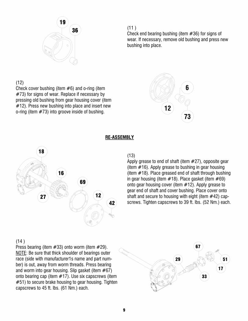
(11 ) Check end bearing bushing (item #36) for signs of wear. If necessary, remove old bushing and press new bushing into place.
(12) Check cover bushing (item #6) and o-ring (item #73) for signs of wear. Replace if necessary by pressing old bushing from gear housing cover (item #12). Press new bushing into place and insert new o-ring (item #73) into groove inside of bushing.
RE-ASSEMBLY
(13) Apply grease to end of shaft (item #27), opposite gear (item #16). Apply grease to bushing in gear housing (item #18). Place greased end of shaft through bushing in gear housing (item #18). Place gasket (item #69) onto gear housing cover (item #12). Apply grease to gear end of shaft and cover bushing. Place cover onto shaft and secure to housing with eight (item #42) cap-screws. Tighten capscrews to 39 ft. lbs. (52 Nm.) each.
(14 ) Press bearing (item #33) onto worm (item #29). NOTE: Be sure that thick shoulder of bearings outer race (side with manufacturer1s name and part num-ber) is out, away from worm threads. Press bearing and worm into gear housing. Slip gasket (item #67) onto bearing cap (item #17). Use six capscrews (item #51) to secure brake housing to gear housing. Tighten capscrews to 45 ft. lbs. (61 Nm.) each.
18
1242
69
16
27
7312
6
67
29 51
17
33
1936
10
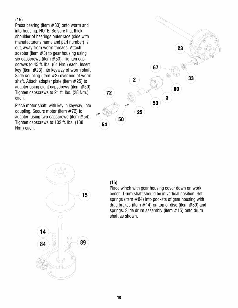
(15) Press bearing (item #33) onto worm and into housing. NOTE: Be sure that thick shoulder of bearings outer race (side with manufacturer's name and part number) is out, away from worm threads. Attach adapter (item #3) to gear housing using six capscrews (item #53). Tighten cap-screws to 45 ft. lbs. (61 Nm.) each. Insert key (item #23) into keyway of worm shaft. Slide coupling (item #2) over end of worm shaft. Attach adapter plate (item #25) to adapter using eight capscrews (item #50). Tighten capscrews to 21 ft. lbs. (28 Nm.) each.
Place motor shaft, with key in keyway, into coupling. Secure motor (item #72) to adapter, using two capscrews (item #54). Tighten capscrews to 102 ft. lbs. (138 Nm.) each.
(16) Place winch with gear housing cover down on work bench. Drum shaft should be in vertical position. Set springs (item #84) into pockets of gear housing with drag brakes (item #14) on top of disc (item #89) and springs. Slide drum assembly (item #15) onto drum shaft as shown.
53
80
3
67
23
72
5450
25
2 33
15
8984
14
11
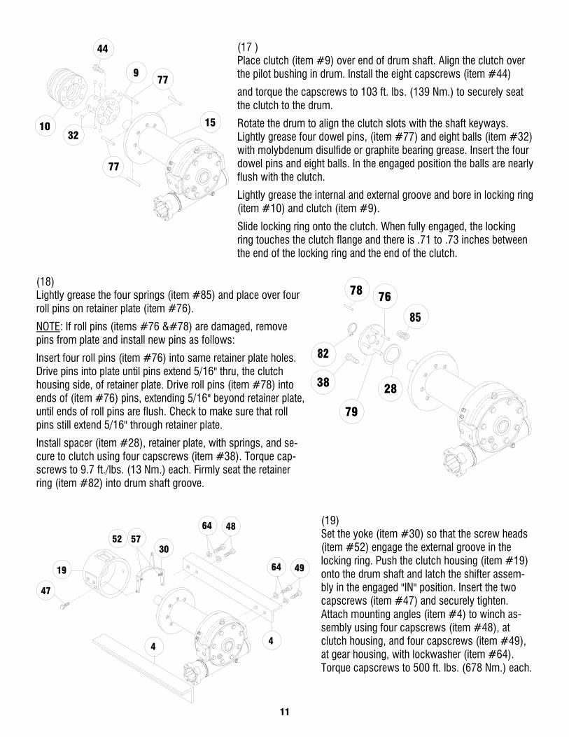
(17 ) Place clutch (item #9) over end of drum shaft. Align the clutch over the pilot bushing in drum. Install the eight capscrews (item #44)
and torque the capscrews to 103 ft. lbs. (139 Nm.) to securely seat the clutch to the drum.
Rotate the drum to align the clutch slots with the shaft keyways. Lightly grease four dowel pins, (item #77) and eight balls (item #32) with molybdenum disulfide or graphite bearing grease. Insert the four dowel pins and eight balls. In the engaged position the balls are nearly flush with the clutch.
Lightly grease the internal and external groove and bore in locking ring (item #10) and clutch (item #9).
Slide locking ring onto the clutch. When fully engaged, the locking ring touches the clutch flange and there is .71 to .73 inches between the end of the locking ring and the end of the clutch.
(18) Lightly grease the four springs (item #85) and place over four roll pins on retainer plate (item #76).
NOTE: If roll pins (items #76 N) are damaged, remove pins from plate and install new pins as follows:
Insert four roll pins (item #76) into same retainer plate holes. Drive pins into plate until pins extend 5/16" thru, the clutch housing side, of retainer plate. Drive roll pins (item #78) into ends of (item #76) pins, extending 5/16" beyond retainer plate, until ends of roll pins are flush. Check to make sure that roll pins still extend 5/16" through retainer plate.
Install spacer (item #28), retainer plate, with springs, and se-cure to clutch using four capscrews (item #38). Torque cap-screws to 9.7 ft./lbs. (13 Nm.) each. Firmly seat the retainer ring (item #82) into drum shaft groove.
(19) Set the yoke (item #30) so that the screw heads (item #52) engage the external groove in the locking ring. Push the clutch housing (item #19) onto the drum shaft and latch the shifter assem-bly in the engaged "IN" position. Insert the two capscrews (item #47) and securely tighten. Attach mounting angles (item #4) to winch as-sembly using four capscrews (item #48), at clutch housing, and four capscrews (item #49), at gear housing, with lockwasher (item #64). Torque capscrews to 500 ft. lbs. (678 Nm.) each.
77
77
15
9
3210
44
7678
38 28
79
52 57
47
19
30
4
4864
64
4
49
12
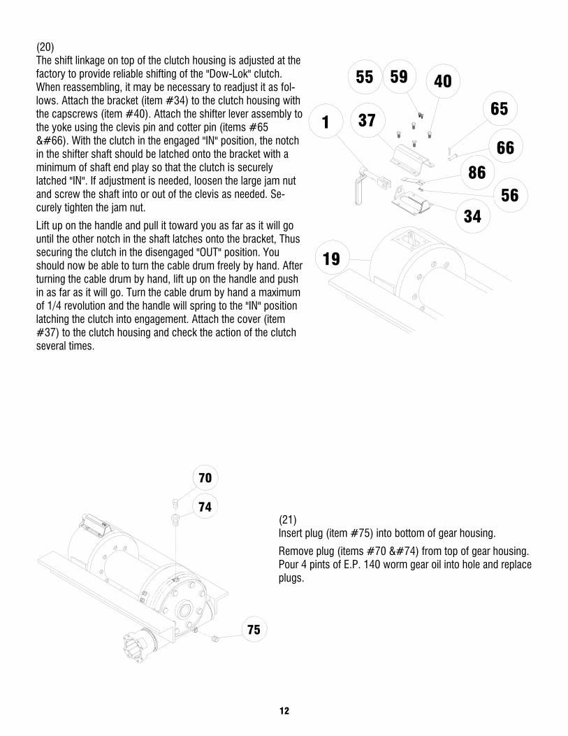
(20) The shift linkage on top of the clutch housing is adjusted at the factory to provide reliable shifting of the "Dow-Lok" clutch. When reassembling, it may be necessary to readjust it as fol-lows. Attach the bracket (item #34) to the clutch housing with the capscrews (item #40). Attach the shifter lever assembly to the yoke using the clevis pin and cotter pin (items #65 B). With the clutch in the engaged "IN" position, the notch in the shifter shaft should be latched onto the bracket with a minimum of shaft end play so that the clutch is securely latched "IN". If adjustment is needed, loosen the large jam nut and screw the shaft into or out of the clevis as needed. Se-curely tighten the jam nut.
Lift up on the handle and pull it toward you as far as it will go until the other notch in the shaft latches onto the bracket, Thus securing the clutch in the disengaged "OUT" position. You should now be able to turn the cable drum freely by hand. After turning the cable drum by hand, lift up on the handle and push in as far as it will go. Turn the cable drum by hand a maximum of 1/4 revolution and the handle will spring to the "IN" position latching the clutch into engagement. Attach the cover (item #37) to the clutch housing and check the action of the clutch several times.
(21) Insert plug (item #75) into bottom of gear housing.
Remove plug (items #70 J) from top of gear housing. Pour 4 pints of E.P. 140 worm gear oil into hole and replace plugs.
55
1
59 40
8656
34
19
65
66
37
74
70
75
13
AIR SHIFTER OVERHAUL DISASSEMBLY
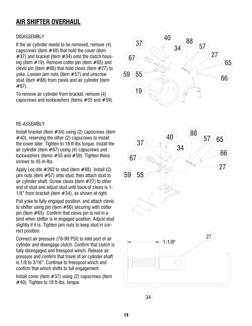
If the air cylinder needs to be removed, remove (4) capscrews (item #40) that hold the cover (item #37) and bracket (item #34) onto the clutch hous-ing (item #19). Remove cotter pin (item #65) and clevis pin (item #66) that hold clevis (item #27) to yoke. Loosen jam nuts (item #57) and unscrew stud (item #88) from clevis and air cylinder (item #67).
To remove air cylinder from bracket, remove (4) capscrews and lockwashers (items #55 and #59).
RE-ASSEMBLY
Install bracket (Item #34) using (2) capscrews (item #40), reserving the other (2) capscrews to install the cover later. Tighten to 18 ft-lbs torque. Install the air cylinder (item #67) using (4) capscrews and lockwashers (items #55 and #59). Tighten these screws to 45 in-lbs.
Apply Loc-tite #262 to stud (item #88). Install (2) jam nuts (item #57) onto stud, then attach stud to air cylinder shaft. Screw clevis (item #27) to other end of stud and adjust stud until back of clevis is 1-1/8” from bracket (item #34), as shown at right.
Pull yoke to fully engaged position, and attach clevis to shifter using pin (item #66) securing with cotter pin (item #65). Confirm that clevis pin is not in a bind when shifter is in engaged position. Adjust stud slightly if it is. Tighten jam nuts to keep stud in cor-rect position.
Connect air pressure (70-90 PSI) to inlet port of air cylinder and disengage clutch. Confirm that clutch is fully disengaged and freespool winch. Release air pressure and confirm that travel of air cylinder shaft is 1/8 to 3/16”. Continue to freespool winch and confirm that winch shifts to full engagement.
Install cover (item #37) using (2) capscrews (item #40). Tighten to 18 ft-lbs. torque.
66
57 6540
34
88
67
37
275559
27
34
1-1/8"
59
37
67
55
40
19
5727
65
66
8834
14

15
NOTES
16
12
33
67
33
67
75
42
32
5257
47
38
7910
28
36
78
7119
66
3065
14
8
67375
18
46
63
6
73
1621
69
49
9
3635
15
714
4476
64
70 74
6448
23
29
4864
4
4964
14 1360
39
34
5686
37
4059
1
24
77
2777
24
87
51
17
80
353
2
2550
54
7288
43
89
89
84
84
55
Mod
el H
-930
Dow
-Lok
17
PART
S LI
ST
Mod
el H
930
Dow
-Lok
®
Item
No.
Qt
y.
Part
No.
Desc
riptio
n Ite
m N
o.
Qty.
Pa
rt N
o.
Desc
riptio
n 1
1 27
6040
SH
IFTE
R AS
SEM
BLY
46
10
4146
06
CAPS
CREW
- 1/
2-20
NF X
2 L
G HX
HD
GR.8
2
1 29
9733
CO
UPLI
NG A
SSEM
BLY
47
2 41
4619
CA
PSCR
EW -
1/2-
13NC
X 2
-1/2
LG
HX H
D AL
L-TH
RD C
.P.
3 1
3000
48
ADAP
TER
48
4 41
4784
CA
PSCR
EW -
7/8-
9NC
X 2
LG H
X HD
GR.
5 4
2 30
2902
AN
GLE
49
4 41
4786
CA
PSCR
EW -
7/8-
9NC
X 2
LG H
X HD
NYL
OK H
.P.
5
NO
T US
ED
50
8 41
4871
CA
PSCR
EW -
5/16
-18N
C X
1-1/
4 LG
SOC
HD
LOK-
WEL
6
2 30
8083
BU
SHIN
G 51
6
4148
97
CAPS
CREW
3/8
-16N
C X
1 LG
SOC
. HD.
7
NOT
USED
52
2
4149
05
CAPS
CREW
3/8
-16N
C X
1-1/
4 LG
SOC
. HD.
8
1 41
6059
SE
TSCR
EW -
3/8-
16NC
X 1
/2 L
G CU
T PO
INT
53
6 41
4909
CA
PSCR
EW 3
/8-1
6NC
X 1-
3/4
LG S
OC H
D LO
K-W
EL
9 1
3241
51
CLUT
CH
54
2 41
4950
CA
PSCR
EW 1
/2-1
3NC
X 1-
3/4
LG S
OC H
D LO
K-W
EL
10
1 32
4321
LO
CKIN
G RI
NG
55
2 41
6236
SC
REW
- #
10-2
4NC
X 1/
2 HX
HD
CP
1
NO
T US
ED
56
2 41
8004
NU
T #
10-2
4NC
HX R
EG C
P 12
1
3281
22
COVE
R - G
EAR
HSG.
57
2
4180
35
NUT
3/8-
16NC
HX
REG
C.P.
13
2
3281
27
COVE
R - D
RAG
BRAK
E 58
NO
T US
ED
14
2 33
0010
SH
OE -
DRAG
BRA
KE
59
2 41
8141
LO
CKW
ASHE
R - #
10 M
ED
15
1 33
2132
DR
UM
60
4 41
8149
LO
CKW
ASHE
R 1/
4 M
ED S
ECT
CP
16
1 33
4150
GE
AR -
R.H.
61
NO
T US
ED
17
1 31
6021
BE
ARIN
G CA
P 62
NO
T US
ED
18
1 33
8253
HO
USIN
G - G
EAR
63
10
4182
17
LOCK
WAS
HER
1/2
MED
SEC
T 19
1
3382
54
HOUS
ING
- CLU
TCH
64
8 41
8258
LO
CKW
ASHE
R 7/
8 M
ED S
ECT
20
NOT
USED
65
1
4240
05
COTT
ER P
IN
21
1 34
0068
HU
B - G
EAR
66
1 42
4205
PI
N - C
LEVI
S 22
NO
T US
ED
67
2 44
2192
GA
SKET
23
1
3420
83
KEY
68
NOT
USED
24
2
3421
53
KEY
69
1 44
2195
GA
SKET
25
1
3505
35
PLAT
E - A
DAPT
ER
70
1 45
6008
FI
TTIN
G - R
ELIE
F 26
NO
T US
ED
71
2 45
6031
FI
TTIN
G- L
UBE
27
1 35
7457
SH
AFT
- DRU
M
72
1 45
8165
M
OTOR
-HYD
. 28
1
3622
24
SPAC
ER
73
2 46
2013
QU
AD R
ING
29
1 36
8212
W
ORM
- R.
H.
74
1 46
8002
RE
DUCE
R 30
1
3700
52
YOKE
75
2
4680
11
PIPE
PLU
G 31
NO
T US
ED
76
4 47
0042
PI
N - R
OLL
32
8 40
0011
BA
LL -
CLUT
CH
77
4 47
0044
PI
N - D
OWEL
33
2
4020
45
BEAR
ING
- BAL
L 78
4
4700
56
PIN
- ROL
L 34
1
4081
12
BRAC
KET
- CLU
TCH
SHIF
TER
79
1 47
4030
PL
ATE
- RET
AINE
R 35
1
4120
51
BUSH
ING
80
1 48
6068
SE
AL -
OIL
36
2 41
2052
BU
SHIN
G 81
NO
T US
ED
37
1 41
3028
CO
VER
- SHI
FTER
82
1
4900
25
RING
- RE
TAIN
ER
38
4 41
4038
CA
PSCR
EW -
1/4-
20NC
X 3
/4 L
G HX
HD
GR.5
83
NO
T US
ED
39
4 41
4055
CA
PSCR
EW -
1/4-
20NC
X 1
/2 L
G HX
HD
C.P.
84
2
4940
02
SPRI
NG -
DISC
40
4
4140
69
CAPS
CREW
- 5/
16-1
8NC
X 3/
4 HX
HD
85
4 49
4069
SP
RING
41
NO
T US
ED
86
2 49
4078
SP
RING
- FL
AT
42
8 41
4277
CA
PSCR
EW -
3/8-
16NC
X 1
LG
HX H
D NY
LOK
H.P.
87
1
5180
16
THRU
ST W
ASHE
R 43
3
4143
05
CAPS
CREW
- 3/
8-16
NC X
3 1
/4, H
XHD,
Z/P
, G5
88
1 51
6056
M
OTOR
VAL
VE
44
8 41
4571
CA
PSCR
EW -
1/2-
20NF
X 1
LG
HX H
G GR
.5
89
2 53
0094
SP
ACER
- BR
AKE
45
NOT
USED
LIMITED WARRANTY RAMSEY WINCH warrants each new RAMSEY Winch to be free from defects in material and workmanship for a period of one (1) year from date of purchase.
The obligation under this warranty, statutory or otherwise, is lim-ited to the replacement or repair at the Manufacturer’s factory, or at a point designated by the Manufacturer, of such part that shall appear to the Manufacturer, upon inspection of such part, to have been defective in material or workmanship.
This warranty does not obligate RAMSEY WINCH to bear the cost of labor or transportation charges in connection with the replace-ment or repair of defective parts, nor shall it apply to a product upon which repairs or alterations have been made, unless author-ized by the Manufacturer, or for equipment misused, neglected or which has not been installed correctly.
RAMSEY WINCH, whose policy is one of continuous improve-ment, reserves the right to improve its products through changes in design or materials as it may deem desirable without being ob-ligated to incorporate such changes in products of prior manufac-ture.
If field service at the request of the Buyer is rendered and the fault is found not to be with Ramsey Winch’s product, the Buyer shall pay the time and expense of the field representative. Bills for ser-vice, labor or other expenses that have been incurred by the Buyer without approval or authorization by Ramsey Winch will not be accepted.
Ramsey Winch Company Post Office Box 581510 ● Tulsa, Oklahoma 74158 Telephone: (918) 438-2760 ● www.ramsey.com FAX: (918) 438-6688
914226-0109-A