Embed Size (px)
Citation preview
®
ETA_HB-B 05/18-E
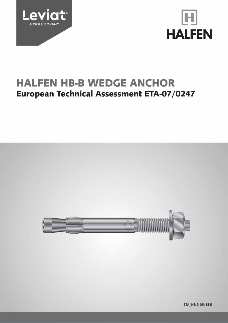
HALFEN HB-B WEDGE ANCHOREuropean Technical Assessment ETA-07/0247
This approval only applies to original HALFEN products. The specifications in this approval are not transferable to other products. Users are fully liable for personal injuries and material damage caused by third-party products used instead of HALFEN products.
Use of third-party products
HALFEN HB-B WEDGE ANCHORGeneral Note
Deutsches Institut
für Bautechnik OIBt
Approval body for construction products and types of construction
Bautechnisches Prüfamt
An institut ion established by the Federal and Laender Governments
European Technical Assessment
* * * Deslgnated * accordlng to * Article 29 of Regula-* tion (EU) No 305/2011 *
and member of EOTA (European Organi-* sation forTechnical *
Assessment)
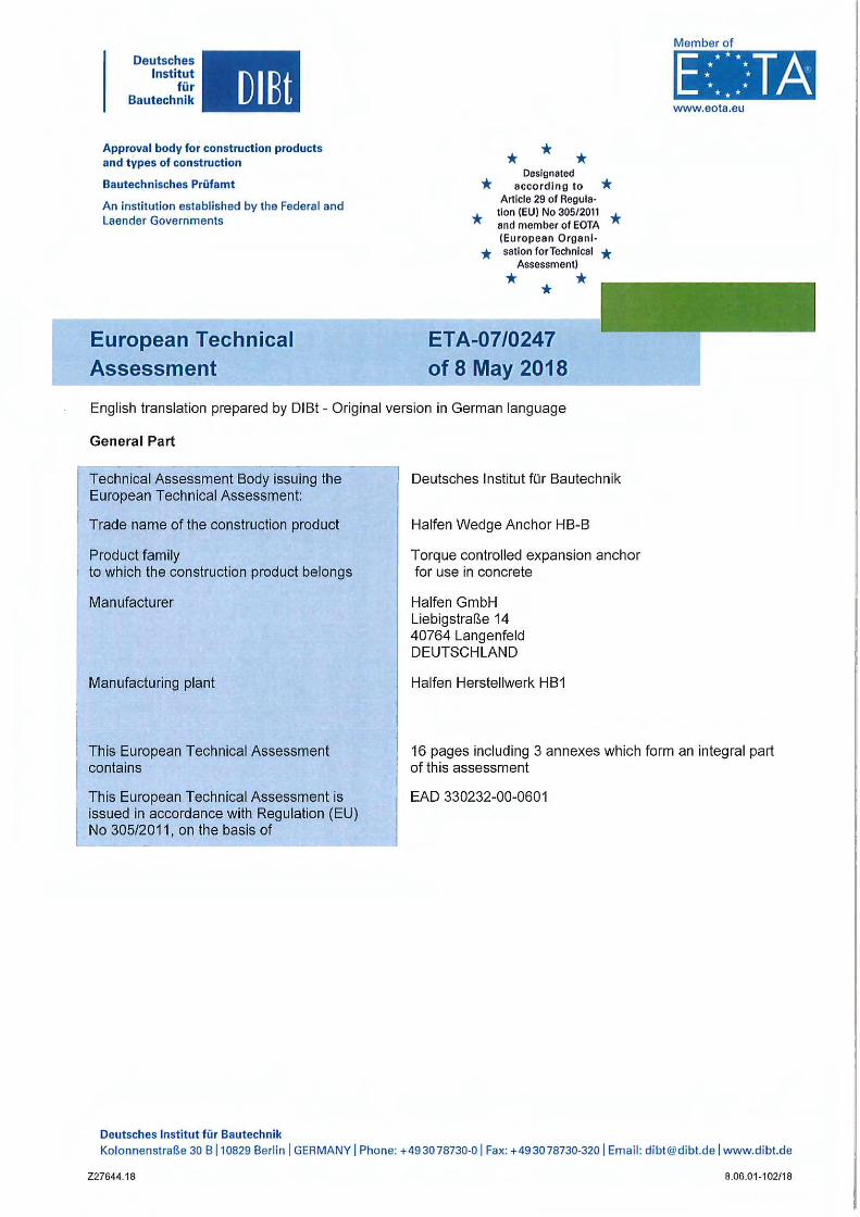
* * * ETA-07/0247 of 8 May 2018
Member of
www.eota.eu
English translation prepared by DIBt - Originalversion in German language
General Part
Technical Assessment Body issuing the European Technical Assessment:
Trade name of the construction product
Product family to which the construction product belongs
Manufacturer
Manufacturing plant
This European Technical Assessment contains
This European Technical Assessment is issued in accordance with Regulation (EU) No 305/2011, on the basis of
Deutsches Institut für Bautechnik
Deutsches Institut für Bautechnik
Halfen Wedge Anchor HB-B
Torque controlled expansion anchor for use in concrete
Halfen GmbH Liebigstraße 14 40764 Langenfeld DEUTSCHLAND
Halfen Herstellwerk HB1
16 pages including 3 annexes which form an integral part of this assessment
EAD 330232-00-0601
Kolonnenstraße 30 B l 10829 Berlin I GERMANY I Phone: +49 3078730-01 Fax: +49 3078730-3201 Email: [email protected]
227644.18 8.06.01-102/18
European Technical Assessment ET A-07 /024 7
English translation prepared by DIBt
Deutsches Institut
für Bautechnik DIBt
Page 2 of 16 18 May 2018
The European Technical Assessment is issued by the Technical Assessment Body in its official language. Translations of this European Technical Assessment in other languages shall fully correspond to the original issued document and shall be identified as such.
Communication of this European Technical Assessment, including transmission by electronic means, shall be in full. However, partial reproduction may only be made with the written consent of the issuing Technical Assessment Body. Any partial reproduction shall be identified as such.
This European Technical Assessment may be withdrawn by the issuing Technical Assessment Body, in particular pursuant to information by the Commission in accordance with Article 25(3) of Regulation (EU) No 305/2011.
227644.18 8.06.01-102/18
Deutsches Institut
für Bautechnik OIBt
European Technical Assessment ET A-07 /024 7 Page 3 of 16 18 May 2018
English translation prepared by DIBt
Specific Part
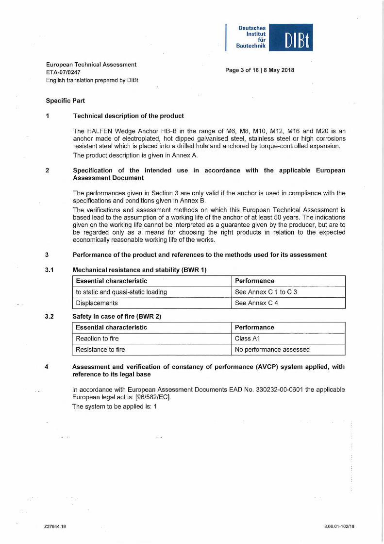
1 Technical description of the product
The HALFEN Wedge Anchor HB-B in the range of M6, M8, M10, M12, M16 and M20 is an anchor made of electroplated, hot dipped galvanised steel, stainless steel or high corrosions resistant steel which is placed into a drilled hole and anchored by torque-controlled expansion.
The product description is given in Annex A.
2 Specification of the intended use in accordance with the applicable European Assessment Document
3
3.1
3.2
4
227644.18
The performances given in Section 3 are only valid if the anchor is used in compliance with the specifications and conditions given in Annex B.
The verifications and assessment methods on which this European Technical Assessment is based lead to the assumption of a working life of the anchor of at least 50 years. The indications given on the working life cannot be interpreted as a guarantee given by the producer, but are to be regarded only as a means for choosing the right products in relation to the expected economically reasonable working life of the works.
Performance of the product and references to the methods used for its assessment
Mechanical resistance and stability (BWR 1)
Essential characteristic Performance
to static and quasi-static loading See Annex C 1 to C 3
Displacements See Annex C 4
Safety in case of fire (BWR 2)
Essential characteristic Performance
Reaction to fire Class A1
Resistance to fire No performance assessed
Assessment and verification of constancy of performance (AVCP) system applied, with reference to its legal base
In accordance with European Assessment Documents EAD No. 330232-00-0601 the applicable European legal act is: [96/582/EC].
The system to be applied is: 1
8.06.01-1 02/1 8
European Technical Assessment ETA-07/0247 English translation prepared by DIBt
Deutsches Institut
für Bautechnik DIBt
Page 4 of 1618 May 2018
5 Technical details necessary for the implementation of the AVCP system, as provided for in the applicable European Assessment Document Technical details necessary for the implementation of the AVCP system are laid down in the control plan deposited with Deutsches Institut für Bautechnik.
lssued in Berlin on 8 May 2018 by Deutsches Institut für Bautechnik
BD Dipl.-Ing. Andreas Kummerow
Head of Department
227644.18
beglaubigt:
Baderschneider
8.06.01-102/18
Page 5 of European Technical Assessment ETA-07/0247 of8 May 2018
English trans/ation prepared by O/Bt
Wedge Anchor HB-B
Deutsches Institut
für Bautechnik
Conical bolt Expansion sleeve Washer
1--------------------------1
-~.:a.a-t----------- • , ____________ -------------
Cold formed version
Free cut version
OIBt
Hexagon nut
Concrete
HALFEN Wedge Anchor HB-B
Product descrlptlon Installation situation
227659.18
h ~ hmin
het
hnom
Annex A1
8.06.01-102/18
Page 6 of European Technical Assessment ETA-07/0247 of 8 May 2018
English translation prepared by 0/Bt
Marking: e.g. • 15/21 -
<> ldentifying mark of manufacturing plant
15 Maximum thickness of fixtu re for her
21 Maximum thickness of fixture for her.red
1 2
C :,,__ t 3
Deutsches Institut
für Bautechnik
sw
,
OIBt
4
~ 0 dk R- 7 ' u :--------------·- ----- ----- - 11 l- -- 0d -•-t--- -- rr Marking J B M10 II:_ ____________ ---- S ------
1 ~ -- of length Marking: B Anchor identity M10 Anchor size L
Marking of length A B C D E F G H 1 J K L M
Length of anchor min :?: 38, 1 50,8 63,5 76,2 88,9 101,6 114,3 127,0 139,7 152,4 165, 1 177,8 190,5
Length of anchor max < 50,8 63,5 76,2 88,9 101,6 114,3 127,0 139,7 152,4 165, 1 177,8 190,5 203,2
Marklng of length N 0 p Q R s T u V w X y z Length of anchor min c! 203,2 215,9 228,6 241,3 254,0 279,4 304,8 330,2 355,6 381,0 406,4 431,8 457,2
Length of anchor max < 215,9 228,6 241,3 254,0 279,4 304,8 330,2 355,6 381,0 406,4 431,8 457,2 483,0
Dimensions in mm
Table A1: Dimensions, steel zinc plated
Anchor length L Wrench Anchor size 0 dk 0 ds Standard anchorage Reduced anchorage slze
depth depth [SWJ
Steel electroplated and hot-dip 1alvanised
M6 6 6 / 5,3 I/ l lix + 57,4 lux hcl,red + 47,4 10
MB 8 8 /7,1 l/ l !ix + 66,4 lrix hol.red + 57,4 13 M10 10 10 /8,9 11 l1;x + 74,0 l1ix hol.red + 68,0 17
M12 12 12/ 10,7 11 l r;x + 97,3 ltix hel,red + 82,3 19
M16 16 16 / 14,5 11 tr;x + 121,0 l1ix hel.red + 1 03, 0 24
M20 20 20 / 18,2 11 llix+ 142,7 l r,x hol.red + 120, 7 30 11 cold formed version
Table A2: Material properties, steel zinc plated
Material
Part Designation Steel, electroplated ~ 5 µm Steel, hot-dip galvanised ~ 40 µm, acc. to EN ISO 4042:1999 acc. to EN ISO 1461 :2009
1 Conical bolt Cold formed or machined steel Cold formed or machined steel
2 Expansion sleeve Steel, acc. to EN 10088:2005, Steel, acc. to EN 10088:2005, material No. 1.4301 or 1 .4303 material No. 1.4301 or 1.4303
3 Washer Steel Steel
4 Hexagon nut Property class 8 Property class 8 acc. to EN ISO 898-2:2012 acc. to EN ISO 898-2:2012
HALFEN Wedge Anchor HB-B
Product description Annex A2 Anchor dimensions, marking and materials, steel zinc plated
227659.1 8 8,06,01-102/18
Page 7 of European Technical Assessment ETA-07/0247 of 8 May 2018
English trans/ation prepared by O/Bt
Marking: e.g. 015/21 A4 -
0 ldentifying mark of manufacturing plant
15 Maximum thickness of flxture for hat
21 Maximum thickness of fixture for hat.red
1 2 A4 Slainless steel A4
L HCR Stalnless steel HCr
3
Deutsches Institut
für Bautechnik
sw
.,
OIBt
4
0dk 7 V lll :------------------------ -
K (® - t- - -- 0ds -• ~-- -- Marking 1 B 1!10 rfl ! ____ ---• ------------------
1 -~
of length ---Marking: B Anchor identlty M 10 Anchor size L
Marking of length A B C D E F G H 1 J K L M
Length of anchor min ~ 38,1 50,8 63,5 76,2 88,9 101 ,6 114,3 127,0 139,7 152,4 165,1 177,8 190,5
Length of anchor max < 50,8 63,5 76,2 88,9 101 ,6 114,3 127,0 139,7 152,4 165, 1 177,8 190,5 203,2
Marking of length N 0 p Q R s T u V w X V z Length of anchor min ~ 203,2 215,9 228,6 241 ,3 254,0 279,4 304,8 330,2 355,6 381,0 406,4 431 ,8 457,2
Length of anchor max < 215,9 228,6 241,3 254,0 279,4 304,8 330,2 355,6 381,0 406,4 431,8 457,2 483,0
Dimensions in mm
Table A3: Dimensions, stainless steel A4/HCR Anchor length L Wrench
Anchor size 0dk 0ds Standard anchorage Reduced anchorage size
depth depth [SW]
Stainless steel A4/HCR M6 6 6 / 5,31T lrix + 57,4 lrixhef,rcd + 47,4 10 M8 8 8 /7,1 l) lrix + 66,4 lrix hef,red + 57,4 13
M10 10 10 / 8,9 11 lux + 74,0 lrix hel.red + 68,0 17 M12 12 12 / 10,7 l) lrix + 96,5 lr,x hef,red + 81,5 19 M16 16 16 / 14,5 l) l1;x + 117,8 lrixhef,red + 101 ,8 24 M20 19,7 19,7 / 18,2 l) l1;x + 142,7 lr,x hel,red + 120, 7 30
1 l cold formed version
Table A4: Designations and Materials, stainless steel A4/HCR
Part Designation Stainless steel A4 High corrosion reslstant steel HCR
Stainless steel 1.4401, 1.4404, High corrosion resistant steel 1.4529, 1 Conical bolt 1.4571, 1.4578, 1.4362,
EN 10088:2005, coated 1.4565, EN 10088:2005, coated
2 Expansion sleeve Stainless steel 1.4401 , 1.4571, 1.4362, EN 10088:2005
3 Washer Stainless steel 1.4401, 1.4571, High corrosion resistant steel 1.4529, 1.4362, EN 10088:2005 1.4565, EN 10088:2005 ISO 3506:2009, A4-70, stainless steel ISO 3506:2009, strength class 70,
4 Hexagon nut 1.4401 , 1.4571, 1.4362, high corrosion resistant steel 1.4529, EN 10088:2005, coated 1.4565, EN 10088:2005, coated
HALFEN Wedge Anchor HB-B
Product description Annex A3 Anchor dimensions, marking and materials, stalnless steel A4/HCR
227659.18 8.06.01 -102/18
Page 8 of European Technical Assessment ETA-07/0247 of 8 May 2018
English translation prepared by O/Bt
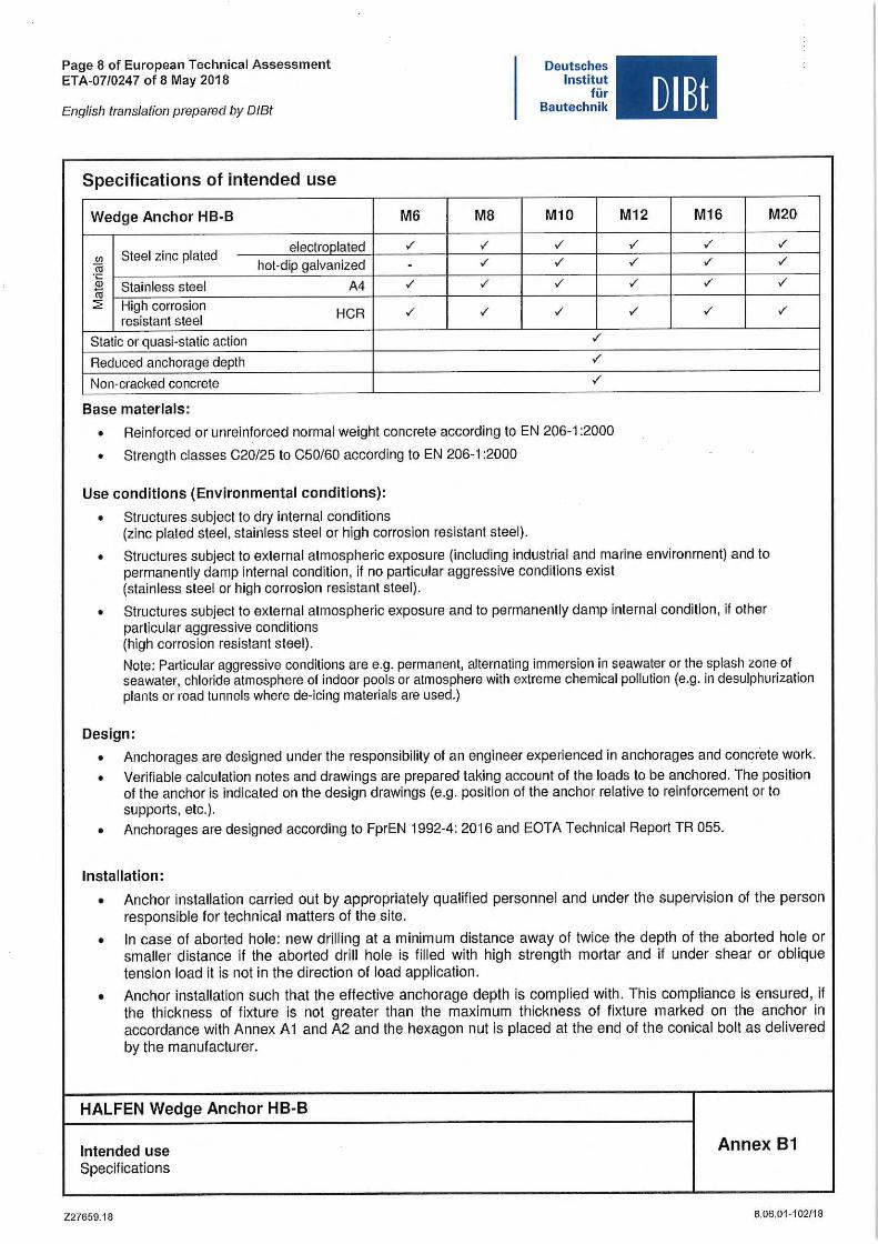
Specifications of intended use
Wedge Anchor HB-B
Steel zinc plated electroolated
(/)
hot-dip galvanized iij
"&i Stainless steel A4 iii ~ High corrosion
resistant steel HCR
Static or quasi-static action
Reduced anchorage depth
Non-cracked concrete
Base materials:
M6 M8
✓ ✓
- ✓
✓ ✓
✓ ✓
Deutsches Institut
für Bautechnik
M10
✓
✓
✓
✓
✓
✓
✓
• Reinforced or unreinforced normal weight concrete according to EN 206-1 :2000
• Strength classes C20/25 to C50/60 according to EN 206-1 :2000
Use conditions (Envlronmental conditions):
• Structures subject to dry Interna! conditions (zinc plated steel, stainless steel or high corrosion resistant steel).
DIBt
M12 M16 M20
✓ ✓ ✓
✓ ✓ ✓
✓ ✓ ✓
✓ ✓ ✓
• Structures subject to external atmospheric exposure (including industrial and marine environment) and to permanently damp internal condition, if no particular aggressive conditions exist (stainless steel or high corrosion resistant steel).
• Structures subject to external atmospheric exposure and to permanently damp internal condition, if other particular aggressive conditions (high corrosion resistant steel).
Note: Particular aggressive conditions are e.g. permanent, alternating immersion in seawater or the splash zone of seawater, chloride atmosphere of indoor pools or atmosphere with extreme chemical pollution (e.g. in desulphurization plants or road tunnels where de-icing materials are used.)
Design:
• Anchorages are designed under the responsibility of an engineer experienced in anchorages and concrete work .
• Verifiable calculation notes and drawings are prepared taking account of the loads tobe anchored. The positlon of the anchor is indicated on the design drawings (e.g. position of the anchor relative to reinforcement or to supports, etc.).
• Anchorages are designed according to FprEN 1992-4: 2016 and EOTA Technical Report TR 055 .
Installation:
• Anchor installation carried out by appropriately qualified personnel and under the supervision of the person responsible for technical matters of the site .
• In case of aborted hole: new drilling at a minimum distance away of twice the depth of the aborted hole or smaller distance if the aborted drill hole is filled with high strength mortar and if under shear or oblique tension load it is not in the direction of load application.
• Anchor installation such that the effective anchorage depth is complied with. This compliance is ensured, if the thickness of fixture is not greater than the maximum thickness of fixture marked on the anchor in accordance with Annex A 1 and A2 and the hexagon nut is placed at the end of the conical bolt as delivered by the manufacturer.
HALFEN Wedge Anchor HB-8
lntended use Annex 81 Specifications
227659.18 8.06.01-102/18
Page 9 of European Technical Assessment ETA-07/0247 of 8 May 2018
Eng/ish trans/ation prepared by O/Bt
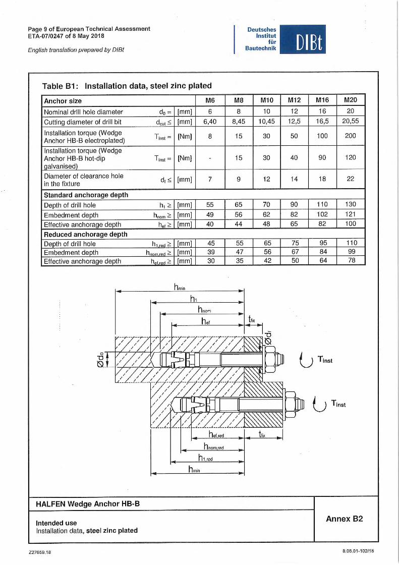
Table B1: Installation data, steel zinc plated
Anchor size M6
Nominal drill hole diameter do = [mm] 6 Gulling diameter of drill bit dcut ::; [mm] 6,40
Installation torque (Wedge T1nst = (Nm] 8
Anchor HB-B electroplated)
Installation torque (Wedge Anchor HB-B hot-dip Tins! = (Nm] -Qalvanised)
Diameter of clearance hole d,::; [mm] 7 in the fixture
Standard anchorage depth
Depth of drill hole h12: [mm] 55
Embedment depth hnom 2: [mm] 49 Effective anchorage depth her 2: [mm] 40 Reduced anchorage depth Depth of drill hole h1 ron > [mm] 45 Embedment depth hn"m ron > [mm] 39 Effective anchorage depth h0 t red> [mml 30
h min
h,
M8
8 8,45
15
15
9
65 56 44
55 47 35
Deutsches Institut
für Bautechnik
M10
10 10,45
30
30
12
70 62 48
65 56 42
oTi7777~'7rF:fr°'li=:i-f=±~~:f:::~~~ 'O
0_L__J!--,L-,!..,,~~~~J::;l-.Jp::r=~~~~
hnom rnd
h min
HALFEN Wedge Anchor HB-B
lntended use Installation data, steel zlnc plated
227659.18
UIBt
M12 M16 M20
12 16 20 12,5 16,5 20,55
50 100 200
40 90 120
14 18 22
90 110 130 82 102 121 65 82 100
75 95 110 67 84 99 50 64 78
Annex B2
8.06.01 -1 02/18
Page 10 of European Technical Assessment ETA-07/0247 of 8 May 2018
Eng/ish translation prepared by O/Bt
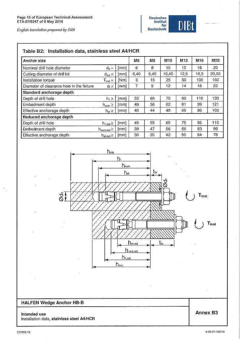
Table B2: Installation data, stainless steel A4/HCR
Anchor slze M6
Nominal drill hole diameter do = [mm] 6 Cutting diameter of drill bit dcut:,; [mm] 6,40 Installation torque Tins!= [Nm] 6 Diameter of clearance hole in the fixture d, :,; [mm] 7
Standard anchorage depth
Depth of drill hole h, ~ (mm] 55 Embedment depth hnom ~ (mm] 49 Effective anchorage depth her ~ [mm] 40
Reduced anchorage depth
Depth of drill hole h1.,ed ~ [mm] 45 Embedment depth hnom.red ~ [mm] 39 Effective anchorage depth her.red~ [mm] 30
hmin
hnom
Deutsches Institut
für Bautechnik
M8 M10
8 10 8,45 10,45 15 25 9 12
65 70 56 62 44 48
55 65 47 56 35 42
0,17'-;-'77'-f'.r,=FF'::fi''=-'n::FF=======.t=~~~~~ "O ~~~~~~~~~;::::::,=~;=;-~~
h nomred
HALFEN Wedge Anchor HB-B
lntended use Installation data, stainless steel A4/HCR
Z27659.18
DIBt
M12 M16 M20
12 16 20 12,5 16,5 20,55 50 100 160 14 18 22
90 110 130 81 99 121 65 80 100
75 95 110 66 83 99 50 64 78
Annex B3
8.06.01-102/18
Page 11 of European Technical Assessment ETA-07/0247 of 8 May 2018
English trans/ation prepared by O/Bt
Deutsches Institut
für Bautechnik DIBt
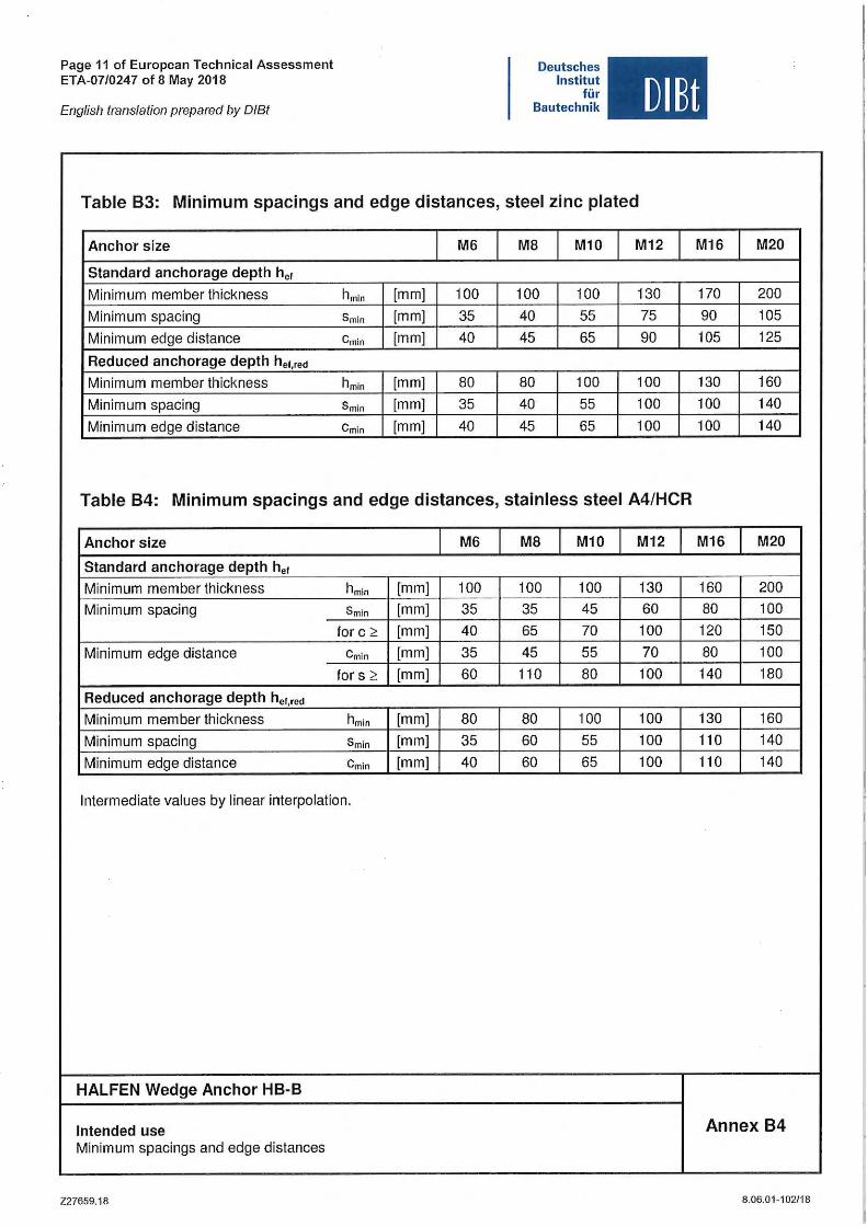
Table B3: Minimum spacings and edge distances, steel zinc plated
Anchor slze M6 M8 M10 M12 M16 M20
Standard anchorage depth her
Minimum member thickness hmln (mm] 100 100 100 130 170 200
Minimum spacing Smin [mm] 35 40 55 75 90 105
Minimum edge distance Cmin [mm] 40 45 65 90 105 125
Reduced anchorage depth het,red
Minimum member thickness hmin [mm] 80 80 100 100 130 160
Minimum spacing Smin [mm] 35 40 55 100 100 140
Minimum edge distance Cmin (mm] 40 45 65 100 100 140
Table B4: Minimum spacings and edge distances, stainless steel A4/HCR
Anchor size M6 M8 M10 M12 M16 M20
Standard anchorage depth her
Minimum member thickness hm1n (mm] 100 100 100 130 160 200 Minimum spacing Smln [mm] 35 35 45 60 80 100
for c ~ [mm] 40 65 70 100 120 150
Minimum edge distance Cmin (mm] 35 45 55 70 80 100
for s ~ (mm] 60 110 80 100 140 180
Reduced anchorage depth he1,,ed
Minimum member thickness hmin (mm] 80 80 100 100 130 160
Minimum spacing Smln [mm] 35 60 55 100 110 140
Minimum edge distance Cmin [mm] 40 60 65 100 110 140
lntermediate values by linear interpolation.
HALFEN Wedge Anchor HB-B
lntended use Annex B4 Minimum spacings and edge distances
227659.18 8.06.01-102/18
Page 12 of European Technical Assessment ETA-07/0247 of 8 May 2018
Deutsches Institut
für Bautechnik OIBt English translation prepared by D/Bt
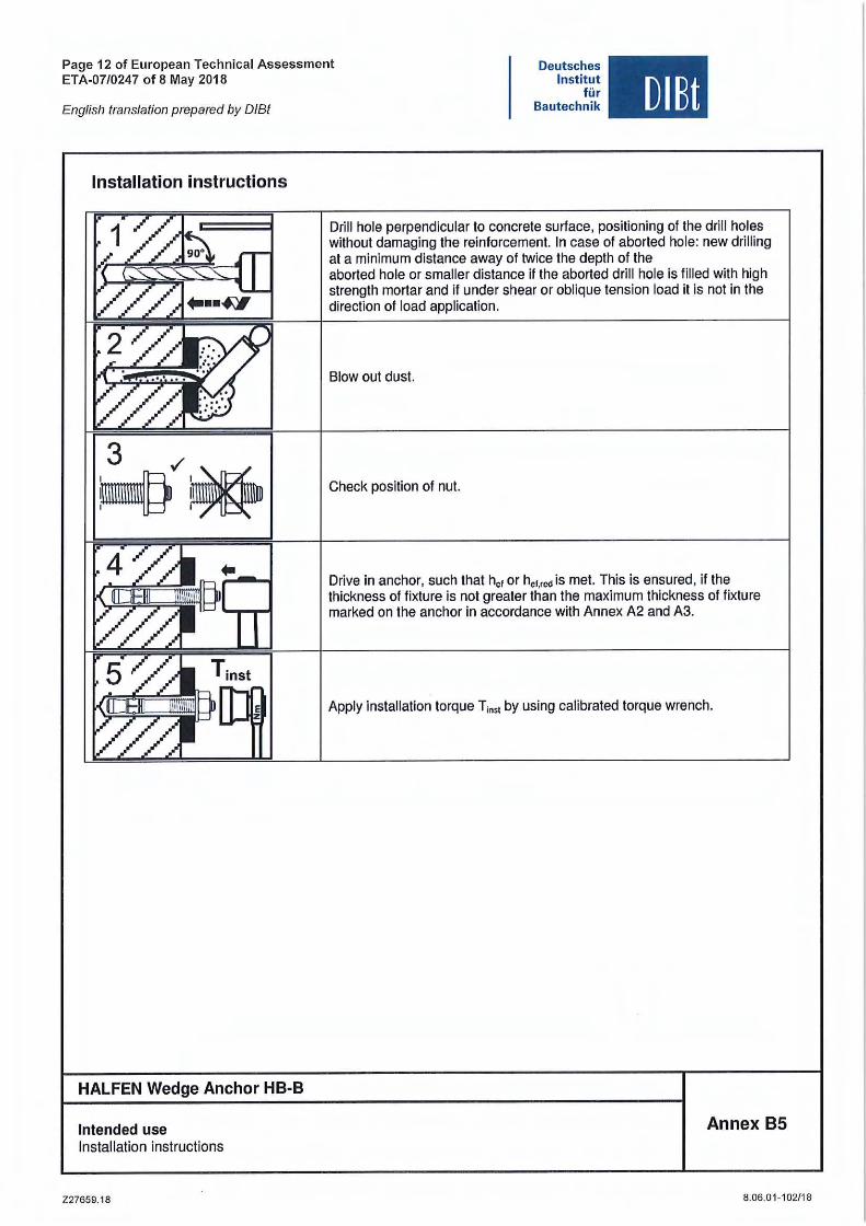
Installation instructions
3 ✓
~~
HALFEN Wedge Anchor HB-B
lntended use Installation instructions
Z27659.18
Drill hole perpendicular to concrete surface, positioning of the drill holes without damaging the reinforcement. In case of aborted hole: new drilling at a minimum distance away of twice the depth of the aborted hole or smaller distance if the aborted drill hole is filled with high strength mortar and if under shear or oblique tension load it is not in the direction of load application.
Blow out dust.
Check position of nut.
Drive in anchor, such that her or her,,e<1 is met. This is ensured, if the thickness of fixture is not greater than the maximum thickness of fixture marked on the anchor in accordance with Annex A2 and A3.
Apply installation torque T;nsi by using calibrated torque wrench.
Annex B5
8.06 .01-102/18
Page 13 of European Technical Assessment ETA-07/0247 of 8 May 2018
English translation prepared by O/Bt
Deutsches Institut
für Bautechnik OIBt
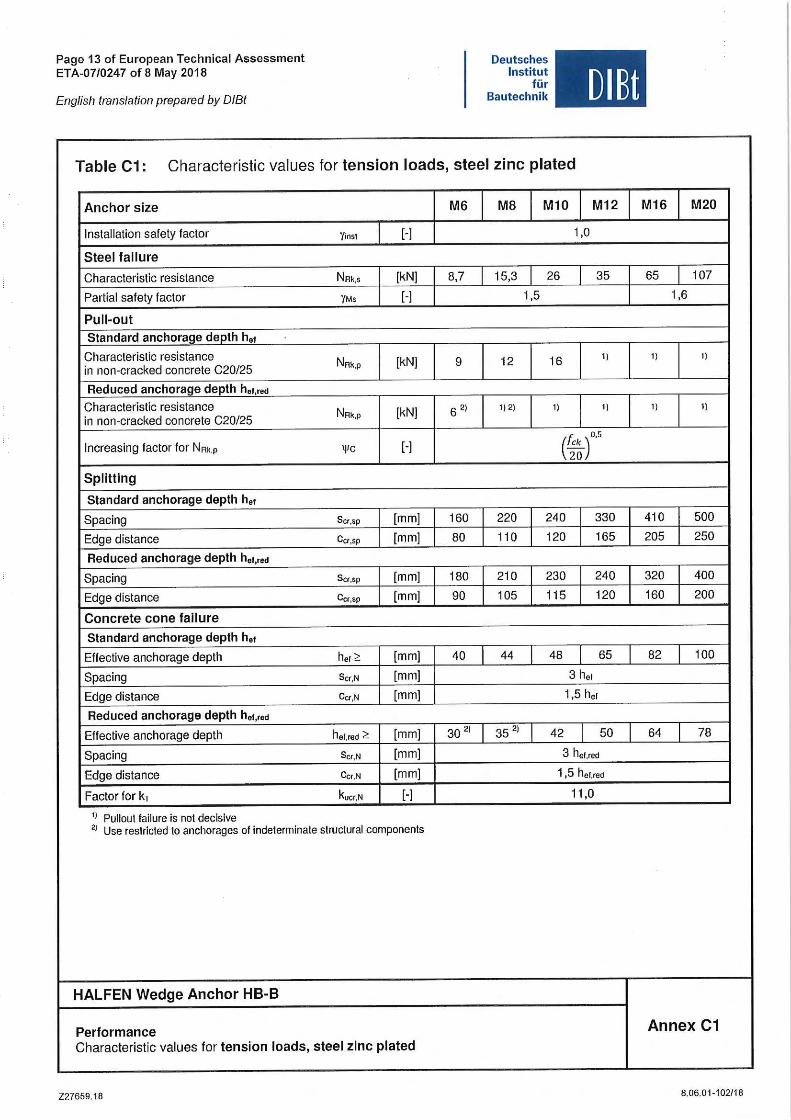
Table C1: Characteristic values for tension loads, steel zinc plated
Anchor size M6 MB M10 M12
Installation safety factor Yinsl (-] 1,0
Steel failure
Characteristic resistance NRk,s [kN] 8,7 15,3 26 35
Partial safety factor YMs [-] 1,5
Pull-out Standard anchorage deoth he,
Characteristic resistance NRk,p [kN] 9 12 16 1)
in non-cracked concrete C20/25
Reduced anchorage depth het,red
Characteristic resistance NRk,p [kN] 6 2) 1) 2) 1) 1)
in non-cracked concrete C20/25
lncreasing factor for NRk,p ,,,c [-] (t;~)°'s Splitting
Standard anchorage depth he,
Spacing Scr,sp [mm] 160 220 240 330
Edge distance Ccr,sp [mm] 80 110 120 165
Reduced anchorage depth het,red
Spacing Scr,sp [mm] 180 210 230 240
Edge distance Ccr,sp (mm] 90 105 115 120
Concrete cone fallure
Standard anchorage depth h.,
Effective anchorage depth her~ [mm] 40 44 48 65
Spacing Scr,N [mm] 3 he1
Edge distance Ccr,N [mm] 1,5 hc1
Reduced anchorage depth her,,ed
Effective anchorage depth hel,red ~ [mm] 30 2) 35 2) 42 50
Spacing Scr,N [mm] 3 her.red
Edge distance Ccr,N [mm] 1,5 he1,red
Factor for k1 kucr,N [-] 11,0
1' Pullout failure is not decisive
2' Use restricted to anchorages of indeterminate structural components
HALFEN Wedge Anchor HB-B
Performance Characteristic values for tension loads, steel zlnc plated
227659.18
M16 M20
65 107
1,6
1) 1)
1) 1)
410 500
205 250
320 400
160 200
82 100
64 78
Annex C1
8,06,01-102/18
Page 14 of European Technical Assessment ETA-07/0247 of8 May 2018
English translation prepared by O/Bt
Deutsches Institut
für Bautechnik
, OIBt
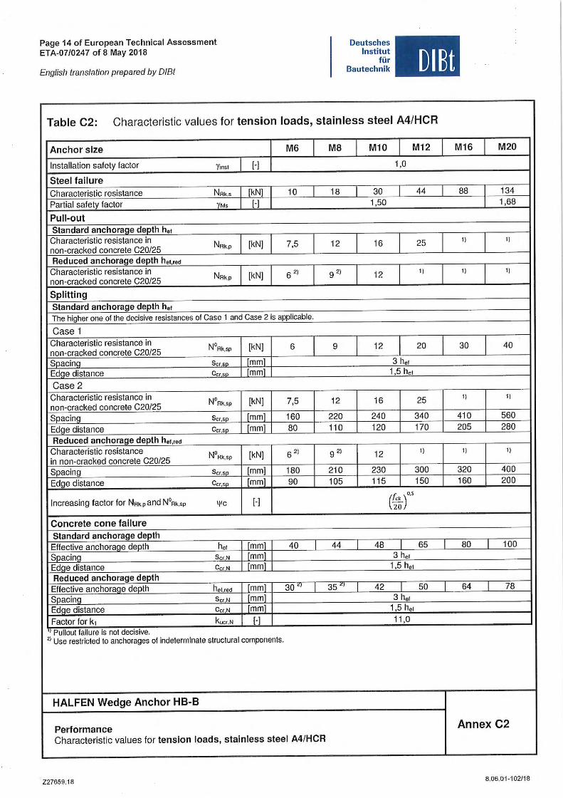
Table C2: Characteristic values for tension loads, stainless steel A4/HCR
Anchor size M6 MB M10 M12
Installation safety factor Yinst [-] 1,0
Steel failure Characteristic resistance NAk,s [kN 10 18 30 44
Partial safety factor YMs [-] 1,50
Pull-out Standard anchorage depth h., Characteristic resistance in NAk,p [kN] non-cracked concrete C20/25
7,5 12 16 25
Reduced anchorage depth he1,,ed
Characteristic resistance in NAk,p [kN] 6 2) 9 2) 12 1)
non-cracked concrete C20/25
Splitting Standard anchorage depth her The higher one of the decisive resistances of Gase 1 and Gase 2 is applicable.
Gase 1 Characteristic resistance in N°Ak,sp [kN] non-cracked concrete C20/25
6 9 12 20
Soacina Scrsn mm 3 her Edqe distance Ccrsn mm 1,5 her
Gase 2 Characteristic resistance in N°Ak,sp [kN] 7,5 12 16 25 non-cracked concrete C20/25 Spacing Scr,sn [mm] 160 220 240 340
Edge distance Ccr,sn mm 80 110 120 170
Reduced anchorage depth he1,red
Characteristic resistance N°Ak,sp [kN] in non-cracked concrete C20/25
6 2) 9 2) 12 1)
Spacing Scr,sn [mm] 180 210 230 300
Edge distance Ccr.sn [mm 90 105 115 150
lncreasing factor for NAk.pand N°Ak,sp 111c [-] ('ck) o,s
20
Concrete cone failure Standard anchorage depth Effective anchorane deoth her mm 40 44 48 65
Soacinq ScrN mm 3 her Edae distance Cc,N mm 1,5 her Reduced anchorage depth Effective anchoraae deoth her red mm 30 ~, 35 l!) 42 50
Soacina Sc,N mm 3 her
Edqe distance Ce, N mm 1,5 her
Factor for k, kucr,N 1-1 11,0
' 1 Pullout failure Is not decisive. 21 Use restricted to anchorages of indeterminate structural components.
HALFEN Wedge Anchor HB-B
Performance Gharacteristic values for tenslon loads, stainless steel A4/HCR
227659.18
M16 M20
88 134 1,68
1) 1)
1) 1)
30 40
1) 1)
410 560 205 280
1) 1)
320 400 160 200
80 100
64 78
Annex C2
8.06,01-102/18
Page 15 of European Technical Assessment ETA-07/0247 of 8 May 2018
English translation prepared by O/Bt
Deutsches Institut
für Bautechnik
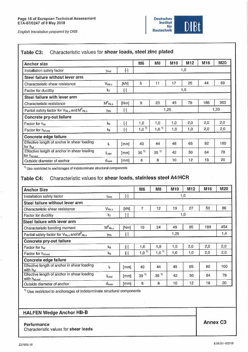
Table C3: Characteristic values for shear loads, steel zinc plated
Anchor size M6 MS M10
Installation safety factor 'Yinsl [-)
Steel failure wlthout lever arm
Characteristic shear resistance VAk.s [kN] 5 11 17
Factor for ductility k1 [-)
Steel failure with lever arm
Characteristic resistance M0Ak.s [Nm] 9 23 45
Partial safety factor for VAk,s and M0Ak,s 'YMs [-) 1,25
Concrete pry-out failure
Factor for he1 ka [·] 1,0 1,0 1,0
Factor for her.red ka [·] 1,0 11 1,0 I ) 1,0
Concrete edge failure Effective length of anchor in shear loading 11 [mm] for he1
40 44 48
Effective length of anchor in shear loading li,red [mm]
for he1 red 30 l) 35 l) 42
Outside diameter of anchor dnom [mm] 6 8 10
11 Use restricted to anchorages of indeterminate structural components
OIEt
M12
1,0
25
1,0
78
2,0
1,0
65
50
12
Table C4: Characteristic values for shear loads, stainless steel A4/HCR
Anchor Slze M6 MS M10 M12
Installation safety factor 'Yinsl [-) 1,0
Steel fallure without lever arm
Characteristic shear resistance VRk,s [kN] 7 12 19 27
Factor for ductility k7 [-] 1,0
Steel failure with lever arm
Characteristic bending moment M0Ak,s [Nm] 10 24 49 85
Partial safety factor for VAk.s and M0Ak,s 'YMs [-) 1,25
Concrete pry-out failure
Factor for he1 ka [-) 1,0 1,0 1,0 2,0
Factor for he1,re<1 ks [-) 1,0 I) 1,0 I) 1,0 1,0
Concrete edge fallure Effective length of anchor in shear loading
" [mm] with he1
40 44 48 65
Effective length of anchor in shear loading 11,red [mm] with he1 red
30 I) 35 l) 42 50
Outside diameter of anchor dnom [mm] 6 8 10 12
11 Use restricted to anchorages of indeterminate structural components
HALFEN Wedge Anchor HB-B
Performance Characteristic values for shear loads
227659.18
M16 M20
44 69
186 363
1,33
2,0 2,0
2,0 2,0
82 100
64 78
16 20
M16 M20
50 86
199 454
1,4
2,0 2,0
2,0 2,0
80 100
64 78
16 20
Annex C3
8.06.01-102/18
Page 16 of European Technical Assessment ETA-07/0247 of 8 May 2018
English translation prepared by O/Bt
Deutsches Institut
für Bautechnik OIEt
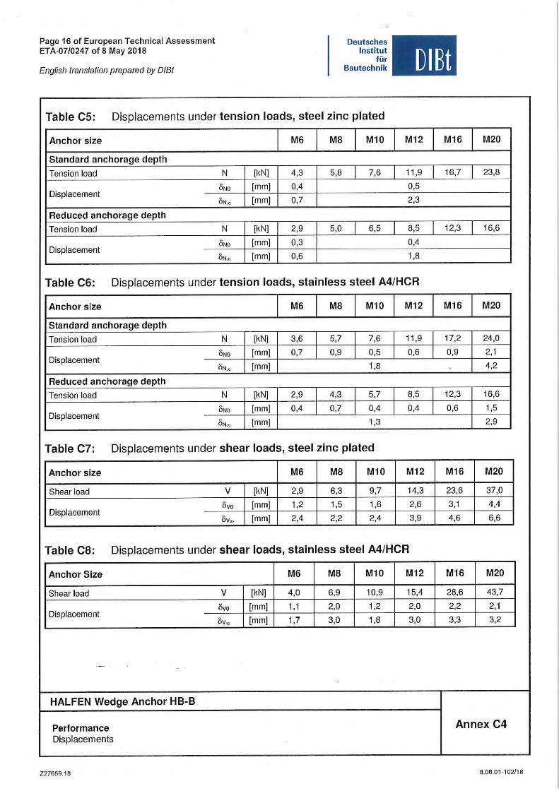
Table CS: Displacements under tension loads, steel zinc plated
Anchor size M6 MB M10 M12 M16 M20
Standard anchorage depth
Tension load N [kN] 4,3 5,8 7,6 11 ,9 16,7 23,8
Displacement ÖNo (mm] 0,4 0,5
ÖN.,, [mm] 0,7 2,3
Reduced anchorage depth
Tension load N [kN] 2,9 5,0 6,5 8,5 12,3 16,6
Displacement ONO [mm] 0,3 0,4
ON„ [mm] 0,6 1,8
Table C6: Displacements under tension loads, stainless steel A4/HCR
Anchor size M6 MB M10 M12 M16 M20
Standard anchorage depth
Tension load N [kN] 3,6 5,7 7,6 11,9 17,2 24,0
Displacement ÖNO [mm] 0,7 0,9 0,5 0,6 0,9 2, 1
ÖN„ [mm] 1,8 4,2
Reduced anchorage depth
Tension load N [kN] 2,9 4,3 5,7 8,5 12,3 16,6
Displacement ÖNo [mm] 0,4 0,7 0,4 0,4 0,6 1,5
ÖN„ [mm) 1,3 2,9
Table C7: Displacements under shear loads, steel zinc plated
Anchor size M6 MB M10 M12 M16 M20
Shear load V [kN) 2,9 6,3 9,7 14,3 23,6 37,0
Displacement livo [mm] 1,2 1,5 1,6 2,6 3, 1 4,4
öv"' [mm] 2,4 2,2 2,4 3,9 4,6 6,6
Table CS: Displacements under shear loads, stainless steel A4/HCR
Anchor Size M6 MS M10 M12 M16 M20
Shear load V [kN] 4,0 6,9 10,9 15,4 28,6 43,7
Displacement Övo [mm] 1, 1 2,0 1,2 2,0 2,2 2, 1
öv.., [mm] 1,7 3,0 1,8 3,0 3,3 3,2
HALFEN Wedge Anchor HB-B
Performance Annex C4 Displacements
227659.18 8.06.01 -102/18
For more information on the products featured here, please contact Leviat:
Notes regarding this catalogue
© Protected by copyright. The construction applications and details provided in this publication are indicative only. In every case, project working details should be entrusted to appropriately qualified and experienced persons. Whilst every care has been exercised in the preparation of this publication to ensure that any advice, recommendations or information is accurate, no liability or responsibility of any kind is accepted by Leviat for inaccuracies or printing errors. Technical and design changes are reserved. With a policy of continuous product development, Leviat reserves the right to modify product design and specification at any time.
For information on certified management systems and standards, see www.halfen.com
AustraliaLeviat
98 Kurrajong Avenue,
Mount Druitt Sydney, NSW 2770
Tel: +61 - 2 8808 3100
Email: [email protected]
AustriaLeviat
Leonard-Bernstein-Str. 10
Saturn Tower, 1220 Wien
Tel: +43 - 1 - 259 6770
Email: [email protected]
Belgium Leviat
Borkelstraat 131
2900 Schoten
Tel: +32 - 3 - 658 07 20
Email: [email protected]
China Leviat
Room 601 Tower D,
Vantone Centre
No. A6 Chao Yang Men Wai Street
Chaoyang District
Beijing · P.R. China 100020
Tel: +86 - 10 5907 3200
Email: [email protected]
Czech Republic Leviat
Business Center Šafránkova
Šafránkova 1238/1
155 00 Praha 5
Tel: +420 - 311 - 690 060
Email: [email protected]
France Leviat
18, rue Goubet
75019 Paris
Tel: +33 - 1 - 44 52 31 00
Email: [email protected]
Germany Leviat
Liebigstrasse 14
40764 Langenfeld
Tel: +49 - 2173 - 970 - 0
Email: [email protected]
Italy Leviat
Via F.lli Bronzetti N° 28
24124 Bergamo
Tel: +39 - 035 - 0760711
Email: [email protected]
MalaysiaLeviat
28 Jalan Anggerik Mokara 31/59
Kota Kemuning,
40460 Shah Alam Selangor
Tel: +603 - 5122 4182
Email: [email protected]
Netherlands Leviat
Oostermaat 3
7623 CS Borne
Tel: +31 - 74 - 267 14 49
Email: [email protected]
New ZealandLeviat
2/19 Nuttall Drive, Hillsborough,
Christchurch 8022
Tel: +64 - 3 376 5205
Email: [email protected]
Norway Leviat
Vestre Svanholmen 5
4313 Sandnes
Tel: +47 - 51 82 34 00
Email: [email protected]
Poland Leviat
Ul. Obornicka 287
60-691 Poznan
Tel: +48 - 61 - 622 14 14
Email: [email protected]
SingaporeLeviat
14 Benoi Crescent
Singapore 629977
Tel: +65 - 6266 6802
Email: [email protected]
Spain Leviat
Polígono Industrial Santa Ana
c/ Ignacio Zuloaga, 20
28522 Rivas-Vaciamadrid
Tel: +34 - 91 632 18 40
Email: [email protected]
Sweden Leviat
Vädursgatan 5
412 50 Göteborg
Tel: +46 - 31 - 98 58 00
Email: [email protected]
Switzerland Leviat
Hertistrasse 25
8304 Wallisellen
Tel: +41 - 44 - 849 78 78
Email: [email protected]
United Kingdom Leviat
A1/A2 Portland Close
Houghton Regis LU5 5AW
Tel: +44 - 1582 - 470 300
E-Mail: [email protected]
United States of America Leviat
6467 S Falkenburg Rd.
Riverview, FL 33578
Tel: (800) 423-9140
Email: [email protected]
For countries not listedEmail: [email protected]
Leviat.com Halfen.com
Imagine. Model. Make. Leviat.com
© 2
02
0
B-1
30
-E –
06
/18
P
DF
10
/20