Embed Size (px)
Citation preview
THIS MANUAL IS THE PROPERTY OF THE OWNER. PLEASE BE SURE TO LEAVE IT WITH THE OWNER WHEN YOU LEAVE THE JOB.
Inspection on Arrival1. Inspect unit upon arrival. .2. Check rating plate on unit to verify that power supply meets
available electric power at the point of installation.3. Inspect unit upon arrival for conformance with description of
product ordered (including specifications where applicable).For technical assistance and Warranty Administration,contact Hamilton Home Products at 1.800.879.0123. Do notreturn equipment to the home center.
Table of ContentsInspection on Arrival . . . . . . . . . . . . . . . . . . . . . . . . . . . . . . . . .1Special Precautions . . . . . . . . . . . . . . . . . . . . . . . . . . . . . . . . . .2SI (Metric) Conversion Factors . . . . . . . . . . . . . . . . . . . . . . . . .3Unit Location . . . . . . . . . . . . . . . . . . . . . . . . . . . . . . . . . . . . . . .3
Combustible Material and Service Clearances . . . . . . . . .3Unit Mounting . . . . . . . . . . . . . . . . . . . . . . . . . . . . . . . . . . .4
Unit Installation . . . . . . . . . . . . . . . . . . . . . . . . . . . . . . . . . . . . .6Venting . . . . . . . . . . . . . . . . . . . . . . . . . . . . . . . . . . . . . . . .5Gas Connections . . . . . . . . . . . . . . . . . . . . . . . . . . . . . . .10Electrical Connections . . . . . . . . . . . . . . . . . . . . . . . . . . .11Checking Input Rate . . . . . . . . . . . . . . . . . . . . . . . . . . . . .12
Unit Components . . . . . . . . . . . . . . . . . . . . . . . . . . . . . . . . . . .14Dimensions . . . . . . . . . . . . . . . . . . . . . . . . . . . . . . . . . . . . . . .16Service/Trouble Shooting . . . . . . . . . . . . . . . . . . . . . . . . . . . .17Wiring . . . . . . . . . . . . . . . . . . . . . . . . . . . . . . . . . . . . . . . . . . .21Warranty . . . . . . . . . . . . . . . . . . . . . . . . . . . . . . . . . . . . . . . . .35
INSTALLATION AND SERVICE MANUALgas-fired unit heaters
model WGH
VHHP6-576.5Part 5H76253 Rev. E
March, 2004
All models approved for use in California by the CEC, in NewYork by the MEA division, and in Massachusetts. Unit heater is certified for residential and commercial applications.
WARNINGImproper installation, adjustment, alteration,service or maintenance can cause propertydamage, injury or death, and could causeexposure to substances which have beendetermined by various state agencies to causecancer, birth defects or other reproductiveharm. Read the installation, operating andmaintenance instructions thoroughly beforeinstalling or servicing this equipment.
FOR YOUR SAFETYThe use and storage of gasoline or otherflammable vapors and liquids in opencontainers in the vicinity of this applianceis hazardous.
CAUTIONTo prevent premature heat exchanger failuredo not locate ANY gas-fired units in areaswhere chlorinated, halogenated or acidvapors are present in the atmosphere.
FOR YOUR SAFETYWHAT TO DO IF YOU SMELL GAS:
1. Open windows.2. Do not try to light any appliance.3. Do not touch any electrical switch; do not
use any phone in your building.4. Immediately call your gas supplier from
a neighbor’s phone. Follow the gas supplier’s instructions. If you can not reach your gas supplier, call your fire department.
IMPORTANTThe use of this manual is specificallyintended for a qualified installation andservice agency. All installation and serviceof these units must be performed by aqualified installation and service agency.
Hamilton Home Products, Inc.
SPECIAL PRECAUTIONS/TABLE OF CONTENTS
2
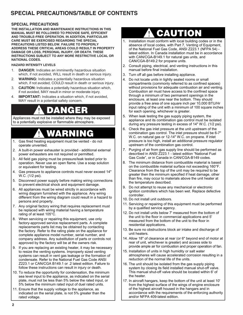
SPECIAL PRECAUTIONSTHE INSTALLATION AND MAINTENANCE INSTRUCTIONS IN THISMANUAL MUST BE FOLLOWED TO PROVIDE SAFE, EFFICIENTAND TROUBLE-FREE OPERATION. IN ADDITION, PARTICULARCARE MUST BE EXERCISED REGARDING THE SPECIALPRECAUTIONS LISTED BELOW. FAILURE TO PROPERLYADDRESS THESE CRITICAL AREAS COULD RESULT IN PROPERTYDAMAGE OR LOSS, PERSONAL INJURY, OR DEATH. THESEINSTRUCTIONS SUBJECT TO ANY MORE RESTRICTIVE LOCAL ORNATIONAL CODES.
HAZARD INTENSITY LEVELS
1. DANGER: Indicates an imminently hazardous situation which, if not avoided, WILL result in death or serious injury.
2. WARNING: Indicates a potentially hazardous situation which, if not avoided, COULD result in death or serious injury.
3. CAUTION: Indicates a potentially hazardous situation which, if not avoided, MAY result in minor or moderate injury.
4. IMPORTANT: Indicates a situation which, if not avoided, MAY result in a potential safety concern.
DANGERAppliances must not be installed where they may be exposedto a potentially explosive or flammable atmosphere.
WARNING1. Gas fired heating equipment must be vented - do not
operate unvented.2. A built-in power exhauster is provided - additional external
power exhausters are not required or permitted.3. All field gas piping must be pressure/leak tested prior to
operation. Never use an open flame. Use a soap solution or equivalent for testing.
4. Gas pressure to appliance controls must never exceed 14" W.C. (1/2 psi).
5. Disconnect power supply before making wiring connectionsto prevent electrical shock and equipment damage.
6. All appliances must be wired strictly in accordance with wiring diagram furnished with the appliance. Any wiring different from the wiring diagram could result in a hazard to persons and property.
7. Any original factory wiring that requires replacement must be replaced with wiring material having a temperature rating of at least 105°C.
8. When servicing or repairing this equipment, use only factory-approved service replacement parts. A complete replacements parts list may be obtained by contacting the factory. Refer to the rating plate on the appliance for complete appliance model number, serial number, and company address. Any substitution of parts or controls not approved by the factory will be at the owners risk.
9. If you are replacing an existing heater, it may be necessary to resize the venting systems. Improperly sized venting systems can result in vent gas leakage or the formation of condensate. Refer to the National Fuel Gas Code ANSI Z223.1 or CAN/CGA B149.1 or .2 latest edition. Failure to follow these instructions can result in injury or death.
10. To reduce the opportunity for condensation, the minimum sea level input to the appliance, as indicated on the serial plate, must not be less than 5% below the rated input, or 5% below the minimum rated input of duel rated units.
11. Ensure that the supply voltage to the appliance, as indicated on the serial plate, is not 5% greater than the rated voltage.
CAUTION1. Installation must conform with local building codes or in the
absence of local codes, with Part 7, Venting of Equipment, of the National Fuel Gas Code, ANSI Z223.1 (NFPA 54) - latest edition. In Canada installation must be in accordance with CAN/CGA-B149.1 for natural gas units, and CAN/CGA-B149.2 for propane units.
2. Consult piping, electrical, and venting instructions in this manual before final installation.
3. Turn off all gas before installing appliance.4. Do not locate units in tightly sealed rooms or small
compartments (commonly referred to as confined spaces) without provisions for adequate combustion air and venting.Combustion air must have access to the confined space through a minimum of two permanent openings in the enclosure, at least one near the bottom. They should provide a free area of one square inch per 10,000 BTU/Hr input rating of the unit with a minimum of 100 square inchesfor each opening, whichever is greater.
5. When leak testing the gas supply piping system, the appliance and its combination gas control must be isolated during any pressure testing in excess of 14" W.C. (1/2 psi).
6. Check the gas inlet pressure at the unit upstream of the combination gas control. The inlet pressure should be 6-7" W.C. on natural gas or 12-14" W.C. on propane. If inlet pressure is too high, install an additional pressure regulatorupstream of the combination gas control.
7. Purging of air from gas supply line should be performed as described in ANSI Z223.1 - latest edition “National Fuel Gas Code”, or in Canada in CAN/CGA-B149 codes.
8. The minimum distance from combustible material is based on the combustible material surface not exceeding 160°F. Clearance from the top of the unit may be required to be greater then the minimum specified if heat damage, other than fire, may occur to materials above the unit heater at the temperature described.
9. Do not attempt to reuse any mechanical or electronic ignition controllers which has been wet. Replace defective controller.
10. Do not install unit outdoors.11. Servicing or repairing of this equipment must be performed
by a qualified service agency.12. Do not install units below 7' measured from the bottom of
the unit to the floor in commercial applications and 5' measured from the bottom of the unit to the floor in residential applications.
13. Be sure no obstructions block air intake and discharge of unit heaters.
14. Allow 18" of clearance at rear (or 6" beyond end of motor atrear of unit, whichever is greater) and access side to provide ample air for combustion and proper operation of fan.
15. Installation of units in high humidity or salt water atmospheres will cause accelerated corrosion resulting in areduction of the normal life of the units.
16. The unit should be isolated from the gas supply piping system by closing its field installed manual shut-off valve. This manual shut-off valve should be located within 6' of the heater.
17. In aircraft hangars, keep the bottom of the unit at least 10' from the highest surface of the wings of engine enclosure of the highest aircraft housed in the hangars and in accordance with the requirements of the enforcing authorityand/or NFPA 409-latest edition.
33
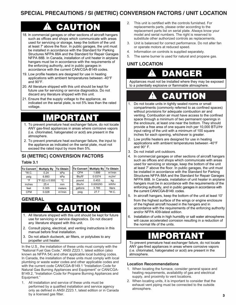
SI (METRIC) CONVERSION FACTORSTable 3.1
GENERAL
In the U.S., the installation of these units must comply with the“National Fuel Gas Code,” ANSI Z223.1, latest edition (alsoknown as NFPA 54) and other applicable local building codes.In Canada, the installation of these units must comply with localplumbing or waste water codes and other applicable codes andwith the current code CAN/CGA-B149.1 “Installation Code forNatural Gas Burning Appliances and Equipment” or CAN/CGA-B149.2, “Installation Code for Propane Burning Appliances andEquipment.”1. All installation and service of these units must be
performed by a qualified installation and service agency only as defined in ANSI Z223.1, latest edition or in Canada by a licensed gas fitter.
2. This unit is certified with the controls furnished. For replacements parts, please order according to the replacement parts list on serial plate. Always know your model and serial numbers. The right is reserved to substitute other authorized controls as replacements.
3. Unit is balanced for correct performance. Do not alter fan or operate motors at reduced speed.
4. Information on controls is supplied separately.5. The same burner is used for natural and propane gas.
UNIT LOCATION
Location Recommendations1. When locating the furnace, consider general space and
heating requirements, availability of gas and electricalsupply, and proximity to vent locations.
2. When locating units, it is important to consider that theexhaust vent piping must be connected to the outsideatmosphere.
SPECIAL PRECAUTIONS / SI (METRIC) CONVERSION FACTORS / UNIT LOCATION
CAUTION1. Do not locate units in tightly sealed rooms or small
compartments (commonly referred to as confined spaces) without provisions for adequate combustion air and venting. Combustion air must have access to the confined space through a minimum of two permanent openings in the enclosure, at least one near the bottom. They should provide a free area of one square inch per 10,000 BTU/Hr input rating of the unit with a minimum of 100 square inches for each opening, whichever is greater.
2. Low profile heaters are designed for use in heating applications with ambient temperatures between -40°F and 90° F.
3. Do not install unit outdoors.4. In commercial garages or other sections of aircraft hangars
such as offices and shops which communicate with areas used for servicing or storage, keep the bottom of the unit at least 7' above the floor. In public garages, the unit must be installed in accordance with the Standard for Parking Structures NFPA 88A and the Standard for Repair GaragesNFPA 88B. In Canada, installation of unit heater in airplanehangars must be in accordance with the requirements of the enforcing authority, and in public garages in accordance with the current CAN/CGA-B149. codes.
5. In aircraft hangars, keep the bottom of the unit at least 10'from the highest surface of the wings or engine enclosure of the highest aircraft housed in the hangars and in accordance with the requirements of the enforcing authorityand/or NFPA 409-latest edition.
6. Installation of units in high humidity or salt water atmosphereswill cause accelerated corrosion resulting in a reduction of the normal life of the units.
DANGERAppliances must not be installed where they may be exposedto a potentially explosive or flammable atmosphere.
To Convert Multiply By To Obtain"W.C. 0.24 kPapsig 6.893 kPa°F (°F-32) x 0.555 °C
inches 25.4 mmfeet 0.305 metersCFM 0.028 m3/min
To Convert Multiply By To ObtainCFH 1.699 m3/min
Btu/ft3 0.0374 mJ/m3
pound 0.453 kgBtu/hr 0.000293 kW/hrgallons 3.785 liters
psig 27.7 "W.C.
CAUTION1. All literature shipped with this unit should be kept for future
use for servicing or service diagnostics. Do not discard any literature shipped with this unit.
2. Consult piping, electrical, and venting instructions in this manual before final installation.
3. Do not attach ductwork, air filters, or polytubes to any propeller unit heater.
CAUTION18. In commercial garages or other sections of aircraft hangars
such as offices and shops which communicate with areas used for servicing or storage, keep the bottom of the unit at least 7' above the floor. In public garages, the unit must be installed in accordance with the Standard for Parking Structures NFPA 88A and the Standard for Repair GaragesNFPA 88B. In Canada, installation of unit heater in airplanehangars must be in accordance with the requirements of the enforcing authority, and in public garages in accordance with the current CAN/CGA-B149 codes.
19. Low profile heaters are designed for use in heating applications with ambient temperatures between -40°F and 90°F.
20. All literature shipped with this unit should be kept for future use for servicing or service diagnostics. Do not discard any literature shipped with this unit.
21. Ensure that the supply voltage to the appliance, as indicated on the serial plate, is not 5% less than the rated voltage.
IMPORTANT1. To prevent premature heat exchanger failure, do not locate
ANY gas-fired appliances in areas where corrosive vapors (i.e. chlorinated, halogenated or acid) are present in the atmosphere.
2. To prevent premature heat exchanger failure, the input to the appliance as indicated on the serial plate, must not exceed the rated input by more then 5%.
IMPORTANTTo prevent premature heat exchanger failure, do not locate ANY gas-fired appliances in areas where corrosive vapors (i.e. chlorinated, halogenated or acid) are present in the atmosphere.
3. Be sure the structural support at the unit location site isadequate to support the weight of the unit. For properoperation the unit must be installed in a level horizontalposition.
4. Do not install units in locations where the flue products canbe drawn into the adjacent building openings such aswindows, fresh air intakes, etc.
5. Be sure that the minimum clearances to combustiblematerials and recommended service clearances aremaintained. Units are designed for installation with theminimum clearances below:
Top and bottom 1" Non-Access Side 1"Vent Connector 4" Rear 18"Access Side 18"
6. Do not install units in locations where gas ignition system isexposed to water spray, rain, or dripping water.
7. Mounting Height (measured from bottom of unit) at which unitheaters are installed is critical. Refer to mounting heightinformation and heat throw data on page 16 of this manual.The maximum mounting height for any unit is that heightabove which the unit will not deliver heated air to the floor.
Combustion Air RequirementsThe National Fuel Gas Code defines an “unconfined space” as a space whose volume is greater than 50 cubic feet per 1,000Btu/Hr input of the installed appliance(s). A confined space is 50cubic feet or less per 1,000 Btu/Hr input of the installedappliance(s).It is not recommended to install these unit heaters into residentialconfined spaces. This recommendation is due to the concernthat at some point in time, the combustion air openings providedby the installer may become blocked or eliminated by the owner,either intentionally or unintentionally. Despite this commendation,if these units are installed into a residential confined space, seeNational Fuel Gas Code ANSI Z223.1 or CAN/CGA B149.1 or .2Installation Code, latest edition, for detailed combustion airprovisions. These requirements must be adheard to.Units installed into confined spaces in industrial/commercialinstallations, must be provided with two permanent openings,one near the top of the confined space and one near the bottomof the confined space. Each opening should have a free area ofnot less than one square inch per 1,000 BTU per hour of the totalinput rating of all units in the confined space, freelycommunicating with interior areas having, in turn, adequateinfiltration from the outside.For further details on supplying combustion or to a confined(tightly sealed) space or unconfined space, see the National FuelGas Code ANSI Z223.1 or CAN/CGA B149.1 or .2 InstallationCode, latest edition.
Turning The Unit 180°All units are produced at the factory with left-side controls, whenlooking at the unit. If the installation requires that the controls beon the right side, the unit heater can be “turned over”. In addition,the following instructions must be followed:
• By turning the unit 180° from the way it was received fromthe factory, the sides become opposite but the front andback remain in the same relative position. The bottom panelnow becomes the top panel and vice-versa.
• Remove the access panel, turn it 180°, and re-attach it tothe unit. This is important so that all the information labelscan be read.
• Remove the spring loaded deflector blades, turn them over,replace, and adjust so they are open and in a position todirect the heated air down to the floor.
1. Be sure the means of suspension is adequate to support the weight of the unit (see page 16 for unit weights).
2. For proper operation, the unit must be installed in a level horizontal position.
3. Clearances to combustibles as previously specified must bestrictly maintained.
4. Mounting bracket installation: Before lifting the heater for suspension, the mounting brackets must be installed. Decide if the unit will be installed as standard; that is with left-side controls when looking at the front of the unit or with right-side controls.For standard (left side)remove brackets from shipping position and remove the (3) screws along the top edge of both the front and back of unit. Align screw holes on mounting bracket with holes along front and back top edges. Secure (1) mounting bracket to front of unit with retained screws. Secure the other mounting bracket to backof unit in a similar way. For right-hand, the mounting brackets are attached in a similar manner after the unit is turned over.
5a. Suspension by screws/lag bolts: Secure the mounting brackets to the ceiling joists or truss, using 1/4" screws with 1/2" washers. These 1" - angle, mounting brackets are slotted to accommodate joists on 16"or 24" centerlines.
5b. Suspension by threaded rod:This heater can also be hung utilizing the same mounting brackets and threaded rod. Attach the threaded rod to the unit mounting brackets, securing with a top and bottom nut. Next, drill holes into a steel channel or angle iron at the same centerline dimensions as those chosen for the heater that is being installed. The steel channels or angle iron pieces need to span and be fastened to appropriate structural members. Cut the threaded rods to the preferred length, push them through the holes in the steel channel or angle iron and secure with washers and lock nuts, lock washers and nuts, or a double nut arrangement like used onthe unit heater mounting brackets.
5c. Shelf mounted units:The unit heater can also be installed on a shelf, if so desired. The mounting brackets will need to be attached to the heater the same manner as explained earlier, however, to mount on a shelf the brackets must go on the bottom of the heater. The brackets must be affixed to the shelf using similar screws (1/4" screw with 1/2" washer) as overhead joist or truss mounting. Be sure all clearance to combustible requirements are met.
4
CAUTION1. Do not install units below 7' measured from the bottom
of the unit to the floor in commercial applications and 5' measured from the bottom of the unit to the floor in residential applications.
2. Be sure no obstructions block air intake and discharge of unit heaters.
3. The minimum distance from combustible material is based on the combustible material surface not exceeding 160°F. Clearance from the top of the unit may be requited to be greater than the minimum specified if heat damage, other than fire, may occur to materials above the unit heater at the temperature described.
4. Allow 18" clearance at rear (or 6" beyond end of motor at rear of unit, whichever is greater) and access side to provide ample air for combustion and proper operation of fan.
UNIT LOCATION / UNIT MOUNTING UNIT SUSPENSION

Before you start use the following steps to verifythat the venting system is adequately sized:1. Seal any unused openings in the venting system.2. Inspect the venting system for proper size and horizontal
pitch, as required in the National Fuel Gas Code ANSIZ223.1 or CAN/CGA B149.1 or .2 Installation Code-latestedition and these instructions. Determine that there is noblockage or restriction, leakage, corrosion and otherdeficiencies, which could cause an unsafe condition.
3. In so far as practical, close all building doors and windowsand all doors between the space in which the appliance(s)connected to the venting system are located and otherspaces of the building. Turn on clothes dryers and anyexhaust fans such as range hoods and bathroom exhausts,so they shall operate at maximum speed. Do not operate asummer exhaust fan. Close fireplace dampers.
4. Follow the lighting instructions. Place the appliance beinginspected in operation. Adjust thermostat so that theappliance will operate continuously.
5. After it has been determined that each appliance connectedto the venting system properly vents when tested asoutlined above, return doors, windows, exhaust fans,fireplace dampers and any other gas-burning appliance totheir previous conditions of use.
6. If improper venting is observed during any of the abovetests, the venting system must be corrected.
Note: A vent is the vertical passageway used to convey flue gases from the unit or the vent connector to the outside atmosphere. A vent connector is the pipe which connects the unit to a vent or chimney. Vent connectors serving Category I appliances shall not be connected into any portion of mechanical draft systems operating under positive pressure.
Venting Instructions1. All vertically vented heaters are category I venting.
All horizontally vented heaters are category I or IIIdepending on venting. For a unit to be classified vertical,the horizontal run may not exceed 75% of the vertical rise.
2. Using Table 5.1, determine the venting requirements for thecategory determined above. A category III heater mustconform to the venting requirements called out in Table 5.1,which are detailed in the following sections, as well asadditional requirements also detailed in following sections.
3. Vertically vented heaters may be vented with either singlewall or double wall vent pipe. Follow the double wallmanufacturers clearances to combustibles.
4. All heaters come with a factory installed 3" vent adapter forattaching the vent pipe to the heater. Attach the vent pipe tothe adapter with 3 non-corrosive screws. (Drill pilot holesthrough the vent pipe and adapter prior to screwing in place)
5. Do not use any vent pipe smaller than 3". Refer to theNational Fuel Gas Code for the minimum material thickness.
6. A minimum of 12" straight pipe is recommended from thepower exhauster outlet before turns in the vent system.Suspend horizontal runs at a minimum of 3' intervals.
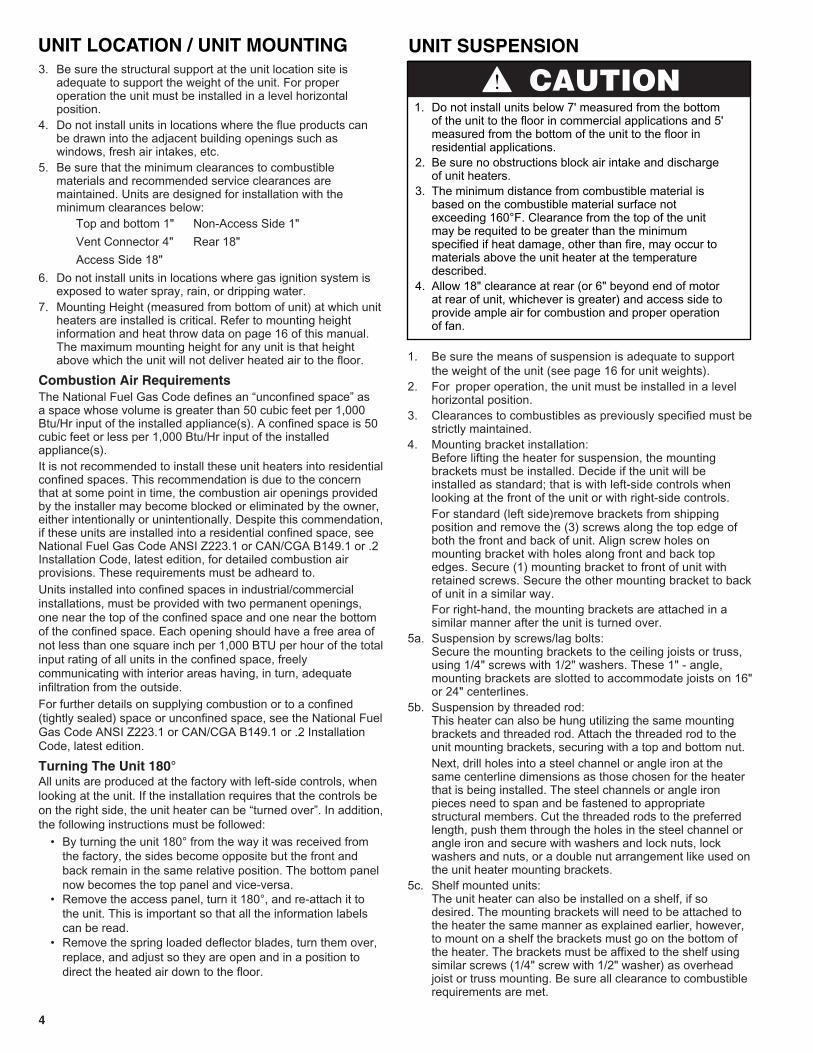
7. Avoid venting through unheated spaces when possible.When single wall pipe does pass through an unheatedspace, insulate runs greater than 5' to minimizecondensation. Inspect for leakage prior to insulating anduse insulation that is noncombustible with a rating of notless 350°F. Install a tee fitting at the low point of the ventsystem and provide a drip leg with a cleanout cap as shown in Figures 6.2 and 6.3. The drip leg should becleaned annually.
8. Keep single wall vent pipe at least 6" from combustiblematerial. The minimum distance from combustible materialis based on the combustible material surface not exceeding160°F. Clearances from the vent pipe (or top of the unit)may be required to be greater than the minimum clearanceif heat damage (such as material distortion or discoloration)may occur.
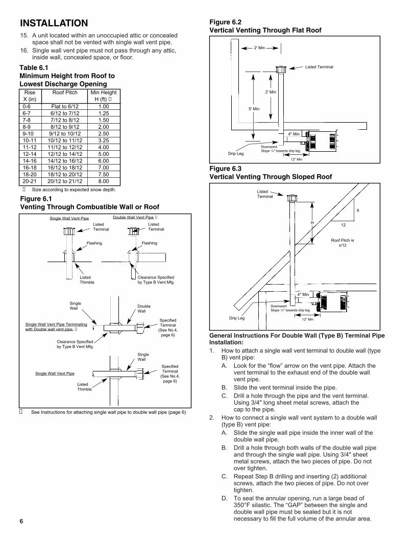
9. When a single wall vent passes through a combustible wallor floor, a listed thimble must be used. When a type Bdouble wall vent passes through a combustible wall or floor,follow the vent pipe manufacturers clearances tocombustibles. Refer to Figure 6.1.
10. This heater is equipped with a power exhaust system. DO NOT use any additional power exhaust systems or ventdampers. FAILURE TO FOLLOW THESE INSTRUCTIONScould result in serious injury or death.
11. All vertically vented heaters are category I and must beconnected to a factory built chimney or vent complying witha recognized standard, or a masonry (or concrete) linedchimney with a material acceptable to the authority havingjurisdiction. Venting into an unlined masonry chimney is not permitted. Refer to the National Fuel Gas Code forcommon venting.
12. Secure all vent joints with at least 3 corrosion-resistantscrews. Use an approved vent terminal to reduce downdrafts and moisture in the vent.
13. The vent must terminate no less than 5' above the ventconnector. The top of the vertical stack should extendabove any portion of a building within a horizontal distanceof 2' (see Figure 6.2).
14. The outlet of the vent should extend as shown in Figure 6.3 and Table 6.1 if the following conditions are met:Vent diameter is less than 12 inches, vent is of double wallconstruction and is a listed product, and the vent does notterminate within 10' of a vertical wall or similar obstruction.For vents that have a diameter of 12 inches or larger,constructed of single wall, or terminate within 2' of a verticalwall or similar obstruction, the vent pipe shall extend atleast 2' higher than any portion of a building within ahorizontal distance of 2' (refer to Figure 6.2). 55
Table 5.1ANSI Unit Heater Venting Requirements
VentingCategory Description Requirements
I Negative vent pressure Follow standardNon-condensing venting requirements.
II Negative vent pressure Condensate mustCondensing be drained.
III Positive vent pressure Vent must be gas tight.Non-condensing
IV Positive vent pressure Vent must be liquid andCondensing gastight. Condensate
must be drained.
INSTALLATION
WARNING1. Gas fired heating equipment must be vented - do not
operate unvented.2. A built-in power exhauster is provided - additional external
power exhausters are not required or permitted.3. If you are replacing an existing heater, it may be necessary
to resize the venting systems. Improperly sized venting systems can result in vent gas leakage or the formation of condensate. Refer to the National Fuel Gas Code ANSI Z223.1 or CAN/CGA B149.1 or .2 latest edition. Failure to follow these instructions can result in serious injury or death.
CAUTIONInstallation must conform with local building codes or in theabsence of local codes, with Part 7, Venting of Equipment, ofthe National Fuel Gas Code, ANSI Z223.1 (NFPA 54) - latestedition. In Canada installation must be in accordance withCAN/CGA-B149.1 for natural gas units, and CAN/CGA-B149.2for propane units.
Venting
15. A unit located within an unoccupied attic or concealed space shall not be vented with single wall vent pipe.
16. Single wall vent pipe must not pass through any attic, inside wall, concealed space, or floor.
General Instructions For Double Wall (Type B) Terminal PipeInstallation:1. How to attach a single wall vent terminal to double wall (type
B) vent pipe:A. Look for the “flow” arrow on the vent pipe. Attach the
vent terminal to the exhaust end of the double wall vent pipe.
B. Slide the vent terminal inside the pipe.C. Drill a hole through the pipe and the vent terminal.
Using 3/4" long sheet metal screws, attach the cap to the pipe.
2. How to connect a single wall vent system to a double wall (type B) vent pipe:A. Slide the single wall pipe inside the inner wall of the
double wall pipe.B. Drill a hole through both walls of the double wall pipe
and through the single wall pipe. Using 3/4" sheet metal screws, attach the two pieces of pipe. Do not over tighten.
C. Repeat Step B drilling and inserting (2) additional screws, attach the two pieces of pipe. Do not over tighten.
D. To seal the annular opening, run a large bead of 350°F silastic. The “GAP” between the single and double wall pipe must be sealed but it is not necessary to fill the full volume of the annular area.6
Figure 6.2Vertical Venting Through Flat Roof
Figure 6.3Vertical Venting Through Sloped Roof
2' Min
5' Min
Drip Leg
Drip Leg
2' Min
4" Min
12" Min
DownwardSlope 1/4" towards drip leg.
4" Min
ListedTerminal
Listed Terminal
12" Min
DownwardSlope 1/4" towards drip leg.
Figure 6.1Venting Through Combustible Wall or Roof
ListedTerminal
Flashing
ListedThimble
ListedTerminal
Flashing
Clearance Specifiedby Type B Vent Mfg.
SpecifiedTerminal
(See No.4,page 6)
Clearance Specifiedby Type B Vent Mfg.
ListedThimble
Single Wall Vent Pipe Double Wall Vent Pipe ➀
SpecifiedTerminal
(See No.4,page 6)
Single Wall Vent Pipe Terminatingwith Double wall vent pipe. ➁
Single Wall Vent Pipe
INSTALLATION
Rise Roof Pitch Min HeightX (in) H (ft) ➀0-6 Flat to 6/12 1.006-7 6/12 to 7/12 1.257-8 7/12 to 8/12 1.508-9 8/12 to 9/12 2.009-10 9/12 to 10/12 2.5010-11 10/12 to 11/12 3.2511-12 11/12 to 12/12 4.0012-14 12/12 to 14/12 5.0014-16 14/12 to 16/12 6.0016-18 16/12 to 18/12 7.0018-20 18/12 to 20/12 7.5020-21 20/12 to 21/12 8.00
Table 6.1Minimum Height from Roof to Lowest Discharge Opening
➁ See Instructions for attaching single wall pipe to double wall pipe (page 6)
DoubleWall
SingleWall
SingleWall
H
X
12
Roof Pitch isx/12
➀ Size according to expected snow depth.
Additional Requirements For Horizontal Category IIIVenting: 1. All heaters that are horizontally vented with 3" vent pipe,
perform as category III appliance. Category III venting hasspecial venting requirements as follows:
A. All residential, horizontally vented category III heatersmust be vented with an agency certified category IIIventing system. Agency certified category III ventingsystems are available from your local vent pipedistributor. Follow the agency certified category III ventmanufacturers instructions for installations.
B. For commercial and industrial horizontally ventedheaters you may use either agency certified category IIIventing systems or single wall galvanized or stainlesssteel vent pipe. If uncertified single wall vent pipe isused, all joints must be sealed with metallic tape orsilastic suitable for temperatures up to 400°F. Wraptape (2) full turns around the vent pipe.
2. Limit the total equivalent vent pipe length to a minimum of3' and a maximum of 30', making the vent system asstraight as possible. see Figure 7.3. (The equivalent lengthof a 3" elbow is 1').
3. The vent system shall terminate at least 3' above anyforced air inlet (except direct vent units) located within 10',and at least 4' below, 4' horizontally from, or 1' above anydoor, window, or gravity air inlet into any building. Thebottom of the vent terminal shall be located above the snowline or at least 1’ above grade; whichever is greater. Whenlocated adjacent to public walkways the vent system shallterminate not less than 7' above grade.
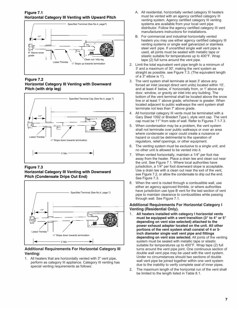
4. All horizontal category III vents must be terminated with aGary Steel 1092 or Breidert Type L style vent cap. The ventcap must be 11" from side of wall. Refer to Figures 7.1-7.3.
5. When condensation may be a problem, the vent systemshall not terminate over public walkways or over an areawhere condensate or vapor could create a nuisance orhazard or could be detrimental to the operation ofregulators, relief openings, or other equipment.
6. The venting system must be exclusive to a single unit, andno other unit is allowed to be vented into it.
7. When vented horizontally, maintain a 1/4" per foot riseaway from the heater. Place a drain tee and clean out nearthe unit. See Figure 7.1. Where local authorities havejurisdiction, a 1/4" per foot downward slope is acceptable.Use a drain tee with a clean out near the exit of the vent,see Figure 7.2, or allow the condensate to drip out the end.See Figure 7.3.
8. When the vent is routed through a combustible wall, useeither an agency approved thimble, or where authoritieshave jurisdiction use type B vent for the last section of ventpipe to maintain clearance to combustibles while passingthrough wall. See Figure 7.1.
Additional Requirements For Horizontal Category IVenting (Residential Only).1. All heaters installed with category I horizontal vents
must be equipped with a vent transition (3" to 4" or 5"depending on vent size selected) attached to thepower exhaust adapter located on the unit. All otherportions of the vent system shall consist of 4 or 5-inch diameter single wall vent pipe and fittingsdepending on vent size selected. All joints of the ventingsystem must be sealed with metallic tape or silasticsuitable for temperatures up to 400°F. Wrap tape (2) fullturns around the vent pipe joint. One continuous section ofdouble wall vent pipe may be used with the vent system.Under no circumstances should two sections of doublewall vent pipe be joined together within one vent systemdue to the inability to verify complete seal of inner pipes.
2. The maximum length of the horizontal run of the vent shallbe limited to the length listed in Table 8.1.
77
Figure 7.2Horizontal Category III Venting with DownwardPitch (with drip leg)
Figure 7.3Horizontal Category III Venting with DownwardPitch (Condensate Drips Out End)
1/4" Slope down towards terminationListed Thimble
11"
3' Min
Listed Thimble
3' Min
Specified Terminal Cap (See No.4, page 7)
Figure 7.1Horizontal Category III Venting with Upward Pitch
1/4" Slope up towards termination
Clean out / drip leg
6" Above snowgrade
Listed Thimble
11"
Specified Terminal (See No.4, page7)
1/4" Slope down towards termination
11"
Specified Terminal (See No.4, page 7)
8
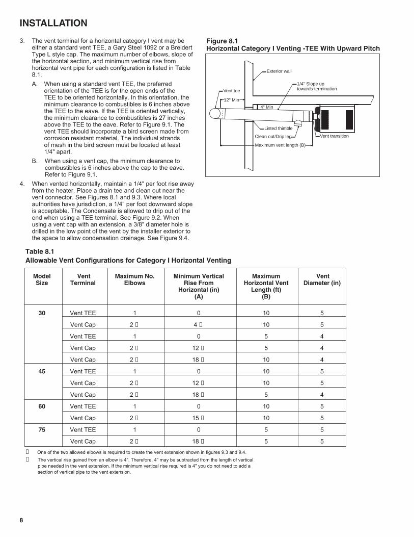
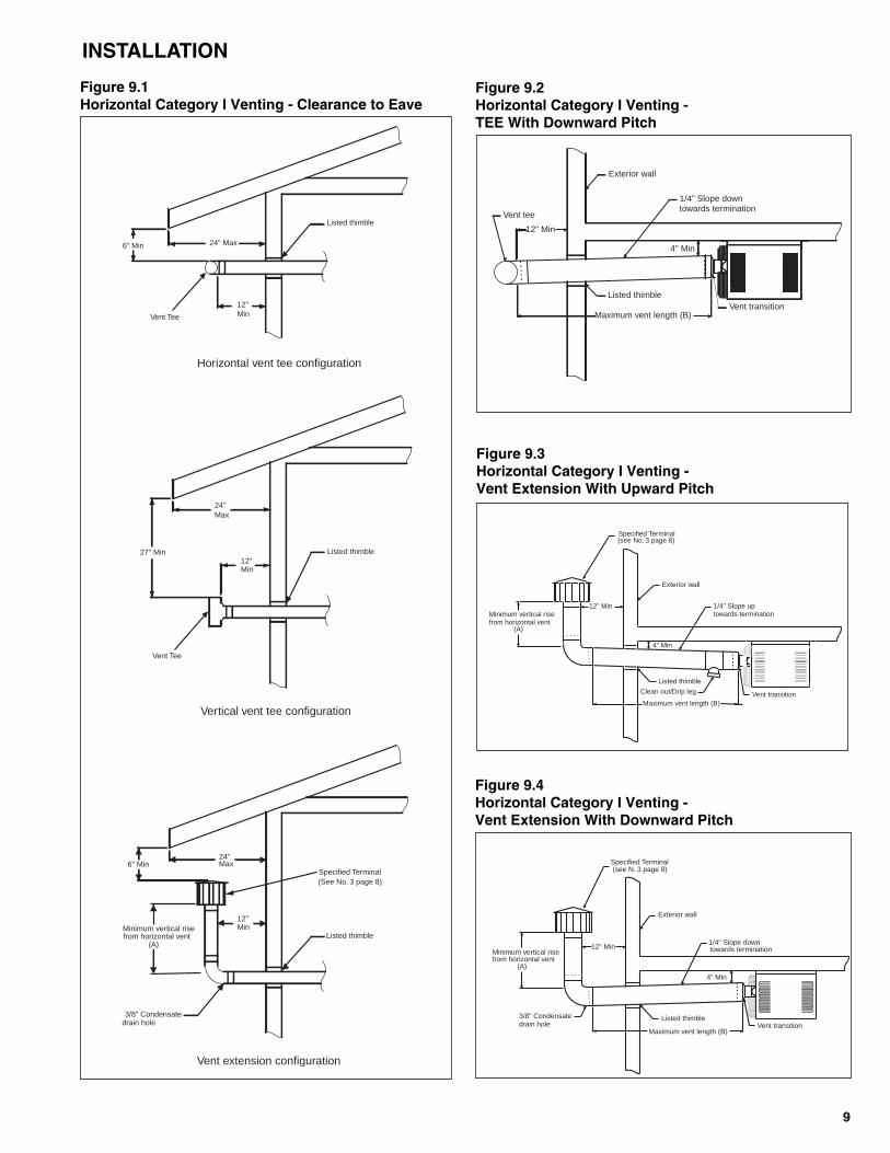
3. The vent terminal for a horizontal category I vent may beeither a standard vent TEE, a Gary Steel 1092 or a BreidertType L style cap. The maximum number of elbows, slope ofthe horizontal section, and minimum vertical rise fromhorizontal vent pipe for each configuration is listed in Table8.1.A. When using a standard vent TEE, the preferred
orientation of the TEE is for the open ends of the TEE to be oriented horizontally. In this orientation, theminimum clearance to combustibles is 6 inches abovethe TEE to the eave. If the TEE is oriented vertically,the minimum clearance to combustibles is 27 inchesabove the TEE to the eave. Refer to Figure 9.1. Thevent TEE should incorporate a bird screen made fromcorrosion resistant material. The individual strands of mesh in the bird screen must be located at least 1/4" apart.
B. When using a vent cap, the minimum clearance tocombustibles is 6 inches above the cap to the eave.Refer to Figure 9.1.
4. When vented horizontally, maintain a 1/4" per foot rise awayfrom the heater. Place a drain tee and clean out near thevent connector. See Figures 8.1 and 9.3. Where localauthorities have jurisdiction, a 1/4" per foot downward slopeis acceptable. The Condensate is allowed to drip out of theend when using a TEE terminal. See Figure 9.2. Whenusing a vent cap with an extension, a 3/8" diameter hole isdrilled in the low point of the vent by the installer exterior tothe space to allow condensation drainage. See Figure 9.4.
Figure 8.1Horizontal Category I Venting -TEE With Upward Pitch
Table 8.1Allowable Vent Configurations for Category I Horizontal Venting
Model Vent Maximum No. Minimum Vertical Maximum Vent Size Terminal Elbows Rise From Horizontal Vent Diameter (in)
Horizontal (in) Length (ft)(A) (B)
30 Vent TEE 1 0 10 5
Vent Cap 2 ① 4 ② 10 5
Vent TEE 1 0 5 4
Vent Cap 2 ① 12 ② 5 4
Vent Cap 2 ① 18 ② 10 4
45 Vent TEE 1 0 10 5
Vent Cap 2 ① 12 ② 10 5
Vent Cap 2 ① 18 ② 5 4
60 Vent TEE 1 0 10 5
Vent Cap 2 ① 15 ② 10 5
75 Vent TEE 1 0 5 5
Vent Cap 2 ① 18 ② 5 5
① One of the two allowed elbows is required to create the vent extension shown in figures 9.3 and 9.4.② The vertical rise gained from an elbow is 4". Therefore, 4" may be subtracted from the length of vertical
pipe needed in the vent extension. If the minimum vertical rise required is 4" you do not need to add a section of vertical pipe to the vent extension.
INSTALLATION
Vent transitionClean out/Drip leg
Listed thimble
Vent tee
1/4" Slope uptowards termination
Exterior wall
12" Min
4" Min
Maximum vent length (B)
99
3/8" Condensatedrain hole
Listed thimble
Listed thimble
Listed thimble
Minimum vertical rise from horizontal vent
(A)
6" Min24"Max
12"Min
24"Max
27" Min
12"Min
12"Min
6" Min 24" Max
Vent extension configuration
Vertical vent tee configuration
Horizontal vent tee configuration
Vent Tee
Vent Tee
Specified Terminal(See No. 3 page 8)
Vent transition
Exterior wall
1/4" Slope downtowards termination
Listed thimble
Vent tee
4" Min
Maximum vent length (B)
12" Min
Vent transitionClean out/Drip leg
Listed thimble
1/4" Slope uptowards termination
Exterior wall
4" Min
12" Min
Maximum vent length (B)
Minimum vertical risefrom horizontal vent
(A)
Specified Terminal(see No. 3 page 8)
Vent transitionListed thimble
1/4" Slope downtowards termination
Exterior wall
3/8" Condensatedrain hole
Minimum vertical risefrom horizontal vent
(A)
12" Min
Maximum vent length (B)
4" Min
Specified Terminal(see N. 3 page 8)
Figure 9.1Horizontal Category I Venting - Clearance to Eave
Figure 9.2Horizontal Category I Venting -TEE With Downward Pitch
Figure 9.3Horizontal Category I Venting -Vent Extension With Upward Pitch
Figure 9.4Horizontal Category I Venting -Vent Extension With Downward Pitch
INSTALLATION
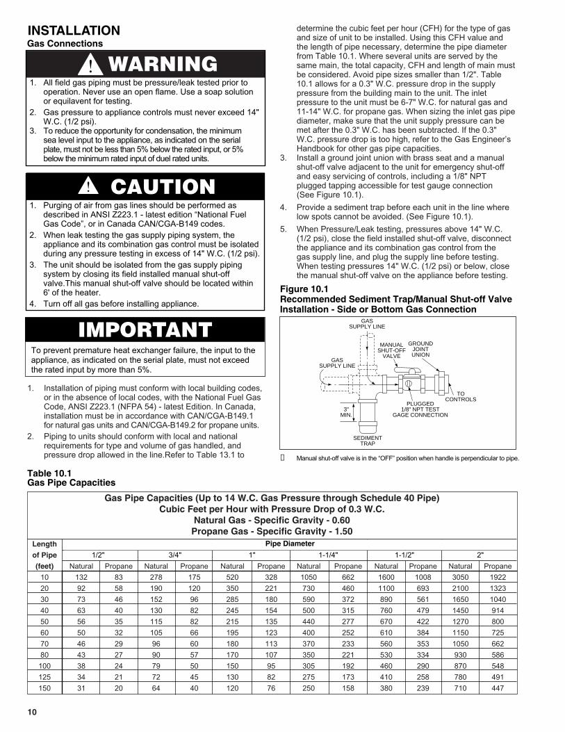
Length
of Pipe
(feet) Natural Propane Natural Propane Natural Propane Natural Propane Natural Propane Natural Propane10 132 83 278 175 520 328 1050 662 1600 1008 3050 192220 92 58 190 120 350 221 730 460 1100 693 2100 132330 73 46 152 96 285 180 590 372 890 561 1650 104040 63 40 130 82 245 154 500 315 760 479 1450 91450 56 35 115 82 215 135 440 277 670 422 1270 80060 50 32 105 66 195 123 400 252 610 384 1150 72570 46 29 96 60 180 113 370 233 560 353 1050 66280 43 27 90 57 170 107 350 221 530 334 930 586
100 38 24 79 50 150 95 305 192 460 290 870 548125 34 21 72 45 130 82 275 173 410 258 780 491150 31 20 64 40 120 76 250 158 380 239 710 447
Gas Pipe Capacities (Up to 14 W.C. Gas Pressure through Schedule 40 Pipe)Cubic Feet per Hour with Pressure Drop of 0.3 W.C.
Natural Gas - Specific Gravity - 0.60Propane Gas - Specific Gravity - 1.50
1. Installation of piping must conform with local building codes,or in the absence of local codes, with the National Fuel Gas Code, ANSI Z223.1 (NFPA 54) - latest Edition. In Canada, installation must be in accordance with CAN/CGA-B149.1 for natural gas units and CAN/CGA-B149.2 for propane units.
2. Piping to units should conform with local and national requirements for type and volume of gas handled, and pressure drop allowed in the line.Refer to Table 13.1 to
determine the cubic feet per hour (CFH) for the type of gas and size of unit to be installed. Using this CFH value and the length of pipe necessary, determine the pipe diameter from Table 10.1. Where several units are served by the same main, the total capacity, CFH and length of main mustbe considered. Avoid pipe sizes smaller than 1/2". Table 10.1 allows for a 0.3" W.C. pressure drop in the supply pressure from the building main to the unit. The inlet pressure to the unit must be 6-7" W.C. for natural gas and 11-14" W.C. for propane gas. When sizing the inlet gas pipediameter, make sure that the unit supply pressure can be met after the 0.3" W.C. has been subtracted. If the 0.3" W.C. pressure drop is too high, refer to the Gas Engineer’s Handbook for other gas pipe capacities.
3. Install a ground joint union with brass seat and a manual shut-off valve adjacent to the unit for emergency shut-off and easy servicing of controls, including a 1/8" NPT plugged tapping accessible for test gauge connection (See Figure 10.1).
4. Provide a sediment trap before each unit in the line where low spots cannot be avoided. (See Figure 10.1).
5. When Pressure/Leak testing, pressures above 14" W.C. (1/2 psi), close the field installed shut-off valve, disconnect the appliance and its combination gas control from the gas supply line, and plug the supply line before testing. When testing pressures 14" W.C. (1/2 psi) or below, close the manual shut-off valve on the appliance before testing.
10
WARNING1. All field gas piping must be pressure/leak tested prior to
operation. Never use an open flame. Use a soap solution or equilavent for testing.
2. Gas pressure to appliance controls must never exceed 14" W.C. (1/2 psi).
3. To reduce the opportunity for condensation, the minimum sea level input to the appliance, as indicated on the serial plate, must not be less than 5% below the rated input, or 5% below the minimum rated input of duel rated units.
CAUTION1. Purging of air from gas lines should be performed as
described in ANSI Z223.1 - latest edition “National Fuel Gas Code”, or in Canada CAN/CGA-B149 codes.
2. When leak testing the gas supply piping system, the appliance and its combination gas control must be isolated during any pressure testing in excess of 14" W.C. (1/2 psi).
3. The unit should be isolated from the gas supply piping system by closing its field installed manual shut-off valve.This manual shut-off valve should be located within 6' of the heater.
4. Turn off all gas before installing appliance.
Figure 10.1Recommended Sediment Trap/Manual Shut-off ValveInstallation - Side or Bottom Gas Connection
GASSUPPLY LINE
GASSUPPLY LINE
GROUNDJOINTUNION
MANUALSHUT-OFF
VALVE
3"MIN.
SEDIMENTTRAP
PLUGGED1/8" NPT TEST
GAGE CONNECTION
TOCONTROLS
➀ Manual shut-off valve is in the “OFF” position when handle is perpendicular to pipe.
INSTALLATIONGas Connections
Table 10.1Gas Pipe Capacities
1/2" 3/4" 1" 1-1/4" 1-1/2" 2"Pipe Diameter
IMPORTANTTo prevent premature heat exchanger failure, the input to theappliance, as indicated on the serial plate, must not exceedthe rated input by more than 5%.

1111
Wiring
All field installed wiring must be done in accordance with theNational Electrical Code ANSI/NFPA 70 – latest edition orCanadian Electrical Code CSA C22.1 Part 1 or local codes. Unitmust be electrically grounded according to these codes. If anyof the original wire supplied with the heater must be replaced,replace it with wiring material having a temperature rating of atleast 105°C.The power to these unit heaters should be protected with acircuit breaker. Location of thermostat should be determined by heatingrequirements and be mounted on an inside wall about 5' abovefloor level where it will not be affected by heat from the unit orother sources, or drafts from frequently opened doors. Seeinstructions packed with thermostat.
Prior to OperationAlthough this unit has been assembled and fire-tested at thefactory, the following pre-operational procedures should beperformed to assure proper on-site operation.1. Turn off power.2. Check fan clearance. Fan should not contact casing when
spun by hand.3. Check all electrical connections to be sure they are secure.4. If you are not familiar with the unit’s controls (i.e.
combination gas control), refer to the control manufacturer’sliterature supplied with the unit.
5. Check that all horizontal deflector blades are open aminimum of 30° as measured from vertical.
FOR YOUR SAFETY READ BEFORE OPERATINGWARNING: If you do not follow these instructions exactly, a fireor explosion may result causing property damage, personalinjury or loss of life.A. This appliance does not have a pilot. It is equipped with an
ignition device which automatically lights the burner. Do nottry to light the burner by hand.
B. BEFORE OPERATING smell all around the appliance areafor gas. Be sure to smell next to the floor because some gasis heavier than air and will settle on the floor.
WHAT TO DO IF YOU SMELL GAS• Do not try to light any appliance.• Do not touch any electric switch; do not use any
phone in your building.• Immediately call your gas supplier from a
neighbors phone. Follow the gas supplier’sinstructions.
• If you cannot reach your gas supplier, call thefire department.
C. Use only your hand to move the gas control switch. Neveruse tools. If the switch will not move by hand, don’t try torepair it, call a qualified service technician. Force orattempted repair may result in a fire or explosion.
D. Do not use this appliance if any part has been under water.Immediately call a qualified service technician to inspect theappliance and to replace any part to the control system andany gas control which has been under water.
OPERATING INSTRUCTIONS
1. STOP! Read the safety information above.2. Set thermostat to lowest setting.3. Turn off all electric power to the appliance.4. This appliance is equipped with an ignition device which
automatically lights the pilot. Do not try to light the pilot byhand.
5. Remove the access panel.6. Move the gas control switch to the “OFF” position.7. Wait five (5) minutes to clear out any gas. Then smell for
gas, including near the floor. If you smell gas, STOP! follow“B” in the safety information above. If you don’t smell gas, goto the next step.
8. Move the gas control switch to the “ON” position.9. Replace control access panel.10. Turn on all electric power to the appliance.11. Set the thermostat to the desired setting.12. If the appliance will not operate, follow the instructions “To
Turn Off Gas to Appliance” and call your service technicianor gas supplier.
TO TURN OFF GAS TO APPLIANCE
1. Set thermostat to lowest setting.2 Turn manual shut-off valve located outside of the unit to the
closed position.3. Turn off all electric power to the appliance if service is to be
performed. 4. Remove access panel.5. Turn the gas valve switch to the “OFF” position.6. Replace the access panel.
INSTALLATION
OPERATION
WARNING1. Disconnect power supply before making wiring
connections to prevent electrical shock and equipment damage.
2. All appliances must be wired strictly in accordance with wiring diagram furnished with the appliance. Any wiring different from the wiring diagram could result in a hazard topersons and property.
3. Any original factory wiring that requires replacement must be replaced with wiring material having a temperature rating of at least 105°C.
4. Ensure that the supply voltage to the appliance, as indicated on the serial plate, is not 5% greater than rated voltage.
CAUTION1. Ensure that the supply voltage to the appliance, as
indicated on the serial plate, is not 5% less than the rated voltage.
12
Input AdjustmentsThe gas pressure regulator (part of the combination gas control)is adjusted at the factory for average gas conditions. It isimportant that gas be supplied to the heater in accordance withthe input rating stamped on the serial plate. Actual input shouldbe checked and necessary adjustments made after the heater isinstalled. Over-firing, a result of too high an input, reduces thelife of the unit, and increases maintenance. Under no circumstancesshould the input exceed that shown on the rating plate.Input can be determined by the meter-timing method providedother gas equipment connected to the meter is off during thetest. If this is not possible, use the pressure method.Important – Inlet pressure and manifold pressure must bechecked with unit in operation when making final adjustments.
(A) Meter Timing Method1. Shut off all other gas-burning equipment, including other
pilot lights served by the gas meter.2. Start the heater and determine the number of seconds it
takes to consume 1 cu. ft. of gas. Two basic formulas areuseful:
F1 = 3600 C/T F2 = F1/C
where F1 = input to heater, Btuh. F2 = input to heater, cu. ft. per hr. C = heating value of gas, Btu per cu. ft. T = time to consume 1 cu. ft. of gas in sec.
The heating value of gas may be determined from the localutility or gas dealer.
These are representative values:GAS Btu per cu. ft.
Natural 1000-1150Propane 2500
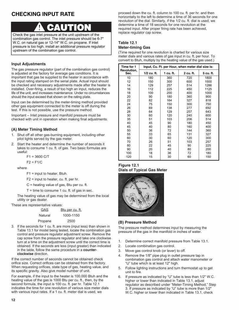
3. If the seconds for 1 cu. ft. are more (input less) than shown inTable 13.1 for model being tested, locate the combination gascontrol and pressure regulator adjustment screw. Remove thecap screw from the pressure regulator and take one clockwiseturn at a time on the adjustment screw until the correct time isobtained. If the seconds are less (input greater) than indicatedin the table, follow the same procedure in a counter-clockwise direction.
If the correct number of seconds cannot be obtained checkorifice size. Correct orifices can be obtained from the factory.When requesting orifices, state type of gas, heating value, andits specific gravity. Also give model number of unit.For example, if the input to the heater is 100,000 Btuh and theheating value of the gas is 1000 Btu per cu. ft., then, by thesecond formula, the input is 100 cu. ft. per hr. Table 12.1indicates the time for one revolution of various size meter dialswith various input rates. If a 1 cu. ft. meter dial is used, we
proceed down the cu. ft. column to 100 cu. ft. per hr. and thenhorizontally to the left to determine a time of 36 seconds for onerevolution of the dial. Similarly, if the 1/2 cu. ft. dial is used, wedetermine a time of 18 seconds for one revolution at therequired input. After proper firing rate has been achieved,replace regulator cap screw.
Table 12.1Meter-timing Gas(Time required for one revolution is charted for various sizemeter dials and various rates of gas input in cu. ft. per hour. Toconvert to Btuh, multiply by the heating value of the gas used.)
(B) Pressure MethodThe pressure method determines input by measuring thepressure of the gas in the manifold in inches of water.
1. Determine correct manifold pressure from Table 13.1.2. Locate combination gas control.3. Move gas control knob (or lever) to off.4. Remove the 1/8" pipe plug in outlet pressure tap in
combination gas control and attach water manometer or “U” tube which is at least 12" high.
5. Follow lighting instructions and turn thermostat up to get unit to fire.
6. If pressure as indicated by “U” tube is less than 1/2" W.C. higher or lower than indicated in Table 13.1, adjust regulator as described under “Meter-Timing Method,” Step 3. If pressure as indicated by “U” tube is more than 1/2" W.C. higher or lower than indicated in Table 13.1, check
Figure 12.1Dials of Typical Gas Meter
Time for 1 Input, Cu. Ft. per Hour, when meter dial size is:Revolution,
Sec. 1/2 cu. ft. 1 cu. ft. 2 cu. ft. 5 cu. ft.10 180 360 720 180012 150 300 600 150014 129 257 514 128616 112 225 450 112518 100 200 400 100020 90 180 360 90022 82 164 327 81824 75 150 300 75026 69 138 277 69228 64 129 257 64330 60 120 240 60035 51 103 206 51440 45 90 180 45045 40 80 160 40050 36 72 144 36055 33 65 131 32760 30 60 120 30070 26 51 103 25780 22 45 90 22590 20 40 80 200
100 18 36 72 180120 15 30 60 150
CCAAUUTTIIOONNCheck the gas inlet pressure at the unit upstream of thecombination gas control. The inlet pressure should be 6-7"W.C. on natural gas or 12-14" W.C. on propane. If inletpressure is too high, install an additional pressure regulatorupstream of the combination gas control.
CHECKING INPUT RATE
1313
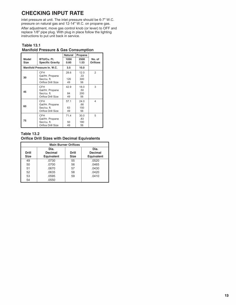
Table 13.2Orifice Drill Sizes with Decimal Equivalents
Main Burner OrificesDia. Dia.
Drill Decimal Drill DecimalSize Equivalent Size Equivalent49 .0730 55 .052050 .0700 56 .046551 .0670 57 .043052 .0635 58 .042053 .0595 59 .041054 .0550
inlet pressure at unit. The inlet pressure should be 6-7" W.C.pressure on natural gas and 12-14" W.C. on propane gas.After adjustment, move gas control knob (or lever) to OFF andreplace 1/8" pipe plug. With plug in place follow the lightinginstructions to put unit back in service.
Table 13.1Manifold Pressure & Gas Consumption
Natural Propane
Model BTU/Cu. Ft. 1050 2500 No. ofSize Specific Gravity 0.60 1.53 Orifices
Manifold Pressure In. W.C. 3.5 10.0
CFH 28.6 12.0 2Gal/Hr. Propane .33Sec/cu. ft. 126 300Orifice Drill Size 49 56
CFH 42.9 18.0 3Gal/Hr. Propane .50Sec/cu. ft. 84 200Orifice Drill Size 49 56
CFH 57.1 24.0 4Gal/Hr. Propane .66Sec/cu. ft. 63 150Orifice Drill Size 49 56
CFH 71.4 30.0 5Gal/Hr. Propane .83Sec/cu. ft. 50 180Orifice Drill Size 49 56
30
45
60
75
CHECKING INPUT RATE
14
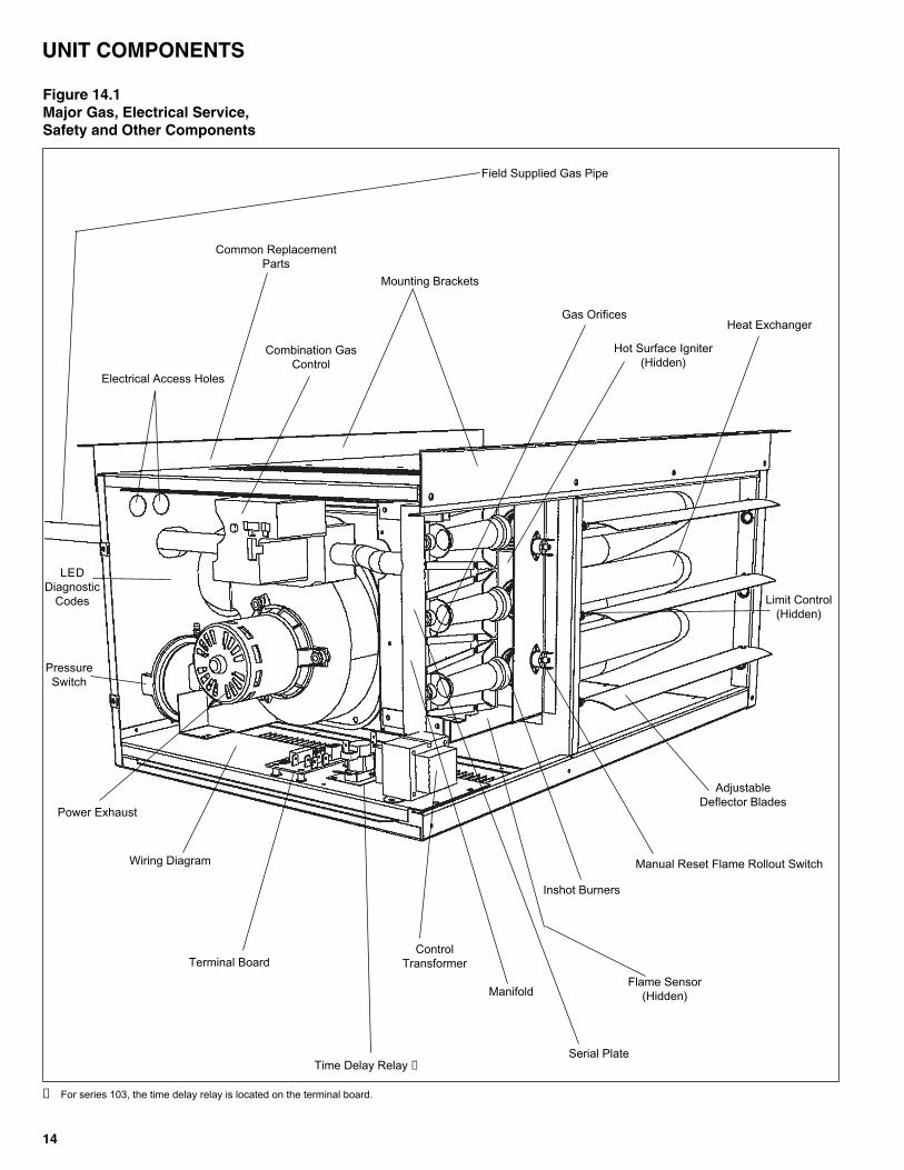
Figure 14.1Major Gas, Electrical Service,Safety and Other Components
Field Supplied Gas Pipe
Combination GasControl
Common ReplacementParts
Heat Exchanger
Inshot Burners
Flame Sensor(Hidden)
Wiring Diagram
Terminal Board
AdjustableDeflector Blades
Gas Orifices
Manifold
Serial Plate
Power Exhaust
Time Delay Relay ➀
PressureSwitch
LEDDiagnostic
Codes
ControlTransformer
Electrical Access Holes
Limit Control(Hidden)
Hot Surface Igniter(Hidden)
Mounting Brackets
Manual Reset Flame Rollout Switch
UNIT COMPONENTS
➀ For series 103, the time delay relay is located on the terminal board.
1515
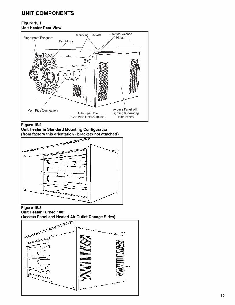
Fingerproof Fanguard
Vent Pipe ConnectionGas Pipe Hole
(Gas Pipe Field Supplied)
Access Panel withLighting / Operating
Instructions
Electrical AccessHoles
Fan Motor
Figure 15.1Unit Heater Rear View
Figure 15.2Unit Heater in Standard Mounting Configuration(from factory this orientation - brackets not attached)
Figure 15.3Unit Heater Turned 180° (Access Panel and Heated Air Outlet Change Sides)
Mounting Brackets
UNIT COMPONENTS

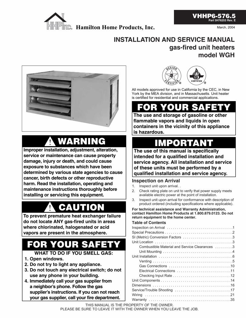
16
Access Side
G
I
OpeningE
C
J
AdjustableDeflectorBlades
Mounting Holes Typ5/16 x 2.5" Long
Back View
B
1.00
F
H
A
DOpening
Vent PipeConnection
GasConnection
ElectricalConnections
AccessPanel
Power Venter
MountingBrackets
Mounting1” - angle, mounting brackets are slotted toaccommodate joists on 16” or 24” centerlines.
Clearances to CombustiblesTop and Bottom 1"Vent Connector 4"Access Side 18"Non-Access Side 1"Rear 18"
30 45 60 75
30,000 45,000 60,000 75,00024,000 36,000 48,000 60,000
505 720 990 1,160523 749 653 76944 46 45 4810 10 12 1425 27 36 38
1/25 1/15 1/12 1/121,550 1,550 1,625 1,625S.P. S.P. P.S.C. P.S.C.1.5 2.4 1.2 1.22.8 3.7 2.5 2.53 3 3 3
Model Size
Btu/Hr InputBtu/Hr Output
Entering Airflow (CFM)Outlet Velocity
Air Temp. Rise (°F)Mounting Height (Max ft.)
Heat Throw (ft.)
Unit Total AmpsVent Diameter (in.)
Performance
HorsepowerRPMTypeAmps
MotorData
30 45 60 75
26.8 26.8 26.8 26.812.2 12.2 18.0 18.016.5 16.5 16.5 16.514.9 14.9 14.9 14.910.1 10.1 15.9 15.97.5 7.5 10.7 10.7
18.5 18.5 18.5 18.57.6 7.6 7.8 7.81/2 1/2 1/2 1/2
34.5 34.5 34.5 34.522 22 25 2510 10 14 1455 60 80 85
Model Size
ABCDEFGH
Gas ConnectionIJ
Fan DiameterApprox. Shipping Weight (lbs.)
Dimensions (inches)
• Ratings shown are for elevation up to 2000 feet above sea level (in Canada, refer to rating plate). For elevations above 2000 ft.,ratings should be reduced by approximately 4% for each 1000 ft. above sea level.
• Mounting Height is measured from the bottom of the unit.• Heat Throws are calculated at 65°F ambient and unit fired at full rated input. Throws for model sizes 30 and 45 are based on 8-foot
mounting heights and at 10-foot heights for model sizes 60 and 75.• S.P. = shaded pole, P.S.C. = permanent split capacitor
Control Codes
Single Stage, Hot Surface Ignition, 100% Shut-Off, Multiple Retry with Auto Reset fromLockout. - Utilizes a single-stage combination gas control with built-in ignition control. Gas is lit with ahot surface igniter on call for heat.
3474
115V115V
24V24V
naturalpropane
Control System Description ControlCode No.
Service Voltage
ThermostatVoltage
Type ofGas
25.1
0
23.1
0
21.1
0
19.1
0
17.1
0
9.10
7.10
5.10
3.10
1.10
0.00
Top View
DIMENSIONS / GENERAL PERFORMANCE DATA
1717
CONTROL OPERATING SEQUENCE
For Hot Surface IgnitionUpon a call for heat from the thermostat, power is supplied tothe power exhauster motor. The unit will go through a purgeperiod and then the hot surface igniter will be energized. Afterthe igniter has warmed up, the main valve in the combinationcontrol valve will open to allow gas to flow to the burners. If thefan motor has not already started it will start shortly. If a flame isnot sensed for any reason the main valve will close and therewill be a short purge period before ignition is tried again. If theflame is not sensed after four tries there will be at least a onehour wait before ignition is tried again.
18
SERVICE / MAINTENANCE / TROUBLESHOOTING
General MaintenanceThe unit and venting system must be checked once a year bya qualified service technician.Only people trained and familiar with the operation of unitheaters and their controls should service this equipment.Before any service, BE SURE TO TURN OFF GAS AT THEMANUAL SHUT-OFF VALVE AHEAD OF THECOMBINATION GAS CONTROL AND TURN OFF ALLELECTRIC POWER TO THE HEATER.1. Service air moving components annually.
a. Check fan for fit on motor shaft and for damage toblades.
2. Keep unit free from dust, dirt, grease, and foreign matter,paying particular attention to:a. Combustion air inlets.b. Burners and burner orifices. Turn off gas ahead of the
combination gas control and shut off electric power tothe heater. Remove the access panel, open the unionon the gas line, and disconnect the igniter and sensorwires. Remove the screws that attach the burner trayto the header plate and remove the burner tray andmanifold assembly from the heater. Carefully clean theburners with a wire brush or other suitable means.Replace any damaged or deteriorating burners ororifices. Install the burner assembly back on to theheader making certain that all screws, pipes andelectrical connections are tight.CAUTION: Be careful when handling the igniter.1. Inspect the flame sensor and igniter for
deterioration and/or cracks.2. Verify that the burners are touching each other at
the carryover points. This will ensure flamecarryover from burner to burner.
c. Clean exterior of heat exchanger tubes.d. Fan blade.
3. Check wiring for possible loose connections.4. Controls – See control instruction sheets furnished
separately with the unit heater.5. Power exhaust assembly – The power exhaust motor
bearings have been lubricated for long life and do notrequire additional lubrication. In dirty atmosphere, it may bedesirable to clean the motor and blower housing and blowout the cooling air passages of the motor with compressed air.
Service Instructions – Safety DevicesLimit Control (Overheat Switch)The limit control, mounted in airstream (on access side), willshut off the gas supply to the burners in the event ofoverheating. It is a single pole, single throw switch. Thecontacts open to shut the electric gas valve off in the event theunit should overheat. This limit control should operate onlywhen something is seriously wrong with the unit. Anytime thiscontrol operates, correct the difficulty immediately or seriousdamage may result. If the limit control cuts off the gas supplyduring normal operation:1. Make certain the deflector blades are open and that there
are not any obstructions in the air inlet or outlet.2. Check actual input to unit against rated input.3. Check to be sure motor is operating.4. Check that fan is not loose on motor shaft.5. Check fan speed against speed on motor nameplate.6. Check to make sure the venting system is not damaged or
blocked. Also check to be sure unit is venting normally andthat there is not negative pressure in the building adverselyaffecting draft.
7. Clean heat exchanger tubes inside and out if necessary.8. If items 1-7 do not solve the problem, check limit control
and replace if necessary. To remove control, first removeaccess door then remove screws holding control to header.
IMPORTANT NOTE:
The limit control (overheat switch) on this unit heater willshut off the gas should excessive discharge temperaturesoccur. Do not attempt to control the fan with the limitcontrol. Any change in wiring to attempt to control the fanwith the limit control will result in hazardous conditionsand void the warranty.
Flame Rollout Switch (or Switches)The switch (switches), mounted on a bracket above theburners, will shut off the gas supply to the burners in the eventof flame rollout. They are a single pole, single throw, manualreset switch. Anytime this control operates, correct thedifficulty immediately or serious damage may result.1. Make sure louvers in casing are not restricted.2. Make sure power exhaust is operating properly.3. Make sure vent is not blocked.4. Clean inside of heat exchanger tubes.5. Make sure area around orifices is clear.
Pressure SwitchThe pressure switch (located behind the access panel) willshut off the gas supply to the burners in the event of a problemwith the venting system. It is a single pole, single throw switchthat is normally open. The contacts close as the powerexhauster develops the necessary pressure in the vent systemto discharge the flue gases. If it is suspected the pressureswitch is not closing or if the switch may be opening undernormal conditions;1. Check the vent system and remove any obstructions in the
vent.2. Check the rubber tube behind the access panel, make sure
it is securely connected to the pressure switch and thepower exhauster housing.
CAUTION1. Servicing or repairing of this equipment must be performed
by a qualified service agency.2. Do not attempt to reuse any mechanical or electrical
controllers which have been wet. Replace defective controller.
WARNINGWhen servicing or repairing of this equipment, use onlyfactory- approved service replacement parts. A completereplacement parts list may be obtained by contacting thefactory. Refer to the rating plate on the appliance for completeappliance model number, serial number, and companyaddress. Any substitution of parts or controls not approved bythe factory will be at the owner’s risk.
IMPORTANTTo check most of the Possible Remedies in the troubleshootingguide listed in Table 54.1, refer to the applicable sections ofthe manual.
1919
3. Check if there is flow at the vent terminal, if there is flowreplace the pressure switch, if there is no flow check thepower exhauster.
Hot Surface igniterThe hot surface igniter (located behind the access panel andunder the combination gas control) will ignite the gas. It is aceramic device that will glow red when it heats up to ignite thegas. If the hot surface igniter does not glow red after the purgeperiod, check the resistance of the igniter. If the resistance isgreater than 100 ohms then the igniter must be replaced.To replace the igniter; unplug the lead from the igniter to thecombination gas control, remove the two screws holding theigniter (if desired you can remove the manifold assembly to geteasier access to the screws). VERY CAREFULLY install thenew igniter into the panel and plug into the wire harness
LED Diagnostic CapabilityThe LED on top of the combination gas control indicates thecondition of the control system. The following codes and whatthey mean follows:(this information also appears on the unit)
FOR SERVICEIf a qualified service person cannot solve the problem, consultyour local gas company or local Hamilton Home Products, Inc.representative.When servicing, repairing or replacing parts on these unitsalways give the complete Model Number and Serial Numberfrom the unit rating plate.
The samples below show where these numbers can be found.
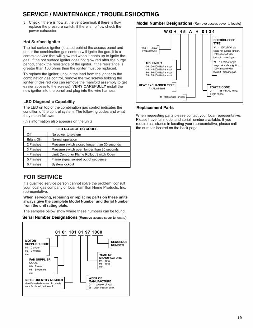
Serial Number Designations (Remove access cover to locate)
01 01 101 01 97 1000
MOTOR SUPPLIER CODE01- Century05- Universaletc. YEAR OF
MANUFACTURE97- 199798- 1998etc.
WEEK OFMANUFACTURE01- 1st week of year26- 26th week of year.
SEQUENCENUMBER
FAN SUPPLIERCODE01- Revcor08- Brooksideetc.
SERIES IDENTITY NUMBERIdentifies which series of controlswere furnished on the unit.
Model Number Designations (Remove access cover to locate)
WGH - TubularPropeller Unit
MBH INPUT30 - 30,000 Btu/hr input45 - 45,000 Btu/hr input60 - 60,000 Btu/hr input75 - 75,000 Btu/hr input
HEAT EXCHANGER TYPEA - Aluminized
H - Hot surface ignition
CONTROL CODETYPE34 - 115V/25V singlestage hot surface ignition,100% shut-off withlockout - natural gas.
74 - 115V/25V singlestage hot surface ignition,100% shut-off withlockout - propane gas.
POWER CODE01 - 115 volt, 60 hertz,single phase
W G H 4 5 A H 0 1 3 4
LED DIAGNOSTIC CODES
Off No power to systemBright-Dim Normal operation2 Flashes Pressure switch closed longer than 30 seconds3 Flashes Pressure switch open longer than 30 seconds4 Flashes Limit Control or Flame Rollout Switch Open5 Flashes Flame signal sensed out of sequence6 Flashes System lockout
SERVICE / MAINTENANCE / TROUBLESHOOTING
Replacement Parts
When requesting parts please contact your local representative.Please have full model and serial number available. If yourequire assistance in locating your representative, please callthe number located on the back page.

Table 20.1Troubleshooting
20
SERVICE / MAINTENANCE / TROUBLESHOOTING
TROUBLE POSSIBLE CAUSE POSSIBLE REMEDYUnit does nothing. 1. Power supply is off 1. Turn on main power.
2. No 24V power to thermostat 2 a. Check control transformer b. If failed transformer - check thermostat wire gage and length
3. Thermostat malfunction 3 a. Verify wire connections to R&W terminals only b. Check / replace thermostat
4. If LED flashes bright / dim check 4. Check LED code at gas valve thermostat and connection5. Defective control 5. Replace control
LED light off or flashing. 1. Light off - no power 1. Check main power2. Two flashes - pressure switch closed. 2 a. Check for blocked or improper venting.
b. Check vent motor hose / connection replace or reconnectc. Check pressure switch. d. Check power exhauster motor.
3. Three flashes - pressure switch open. 3 a. Check to insure control switch in "ON" positionb. Check for incorrect or blocked ventingc. Check pressure switch
4. Four flashes - limit or flame rollout switch 4 a. Check limit and flame controls and connectionsb. If flame rollout switch OK, but tripped:
1. Main gas pressure too high2. Manifold orifice incorrect - too large3. Incorrect unit clearance to surrounding wall/ceiling4. Check for negative pressure in building5. Incorrect or blocked venting6. Access panel vent louvers wrong direction - reverse panel.7. Area around main gas orifices blocked with debris8. Unit louvers closed.9. Heat exchanger tube(s) blocked with debris
5. Five flashes - Flame signal sensed 5. Flame at main burnersout of sequence.
6. Six flashes - System lockout 6 a. Gas supply off or too low.b. Damaged or broken Ignitor.c. No line voltage.d. Unit not properly grounded.e. Check flame sense rod.
Unit starts but does 1. Main gas is off. 1. Open manual gas valve .not ignite. 2. Air in gas line. 2. Purge gas line.
3. Main or manifold gas pressure 3. Set gas pressures per manual instructions4. Check gas valve switch. 4. Set gas valve switch to "ON" position
Unit goes through cycle 1. Reversed main power polarity 1. Black wire - HOT, White wire - NEUTRAL, Green wire - Groundbut the burners go out in 2. Unit not grounded 2. Ground unit and verify quality of ground connection.less then 10 seconds 3. Flame not sensed 3. Check flame sense probe and connectionAir circulating fan 1. Loose connections 1. Check all connectionsinoperable 2. Defective Fan time delay relay 2. Check fan time delay relay
3. Defective fan motor 3. Check fan motor
21
UNIT WIRING
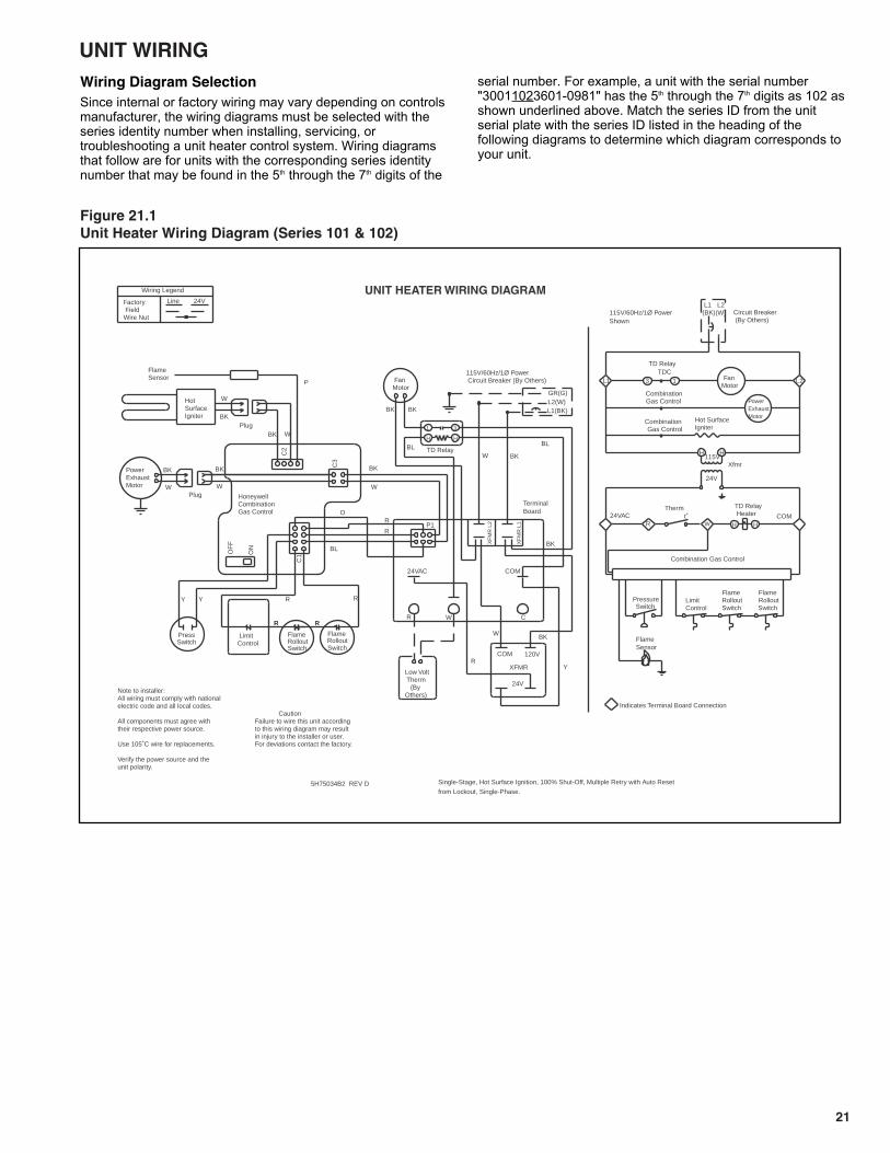
Figure 21.1Unit Heater Wiring Diagram (Series 101 & 102)
5H75034B2 REV Dfrom Lockout, Single-Phase.
Single-Stage, Hot Surface Ignition, 100% Shut-Off, Multiple Retry with Auto Reset
unit polarity.Verify the power source and the
Use 105˚C wire for replacements. For deviations contact the factory.in injury to the installer or user.
CombinationGas Control
Hot SurfaceIgniter
PowerExhaust Motor
CombinationGas Control
FlameSensor
PressureSwitch
COMR
HH
L2L1
R
GR(G)
BK
Y
YY
R
BL
BK BK
BL
BK
BK
W
W
W
BK
XFMR
PressSwitch
FanMotor
TD Relay
1 3
HH
FlameRolloutSwitch
LimitControl
FlameSensor
BL
W
BK
WBK
P
Plug
BK
HotSurfaceIgniter
O
RR
WPlug
PowerExhaust Motor W
BK
HoneywellCombinationGas Control
R
R
TerminalBoard
24V
115VXfmr
L2(W)
L1(BK)
Low Volt Therm (ByOthers)
Wiring Legend
Line 24VFactory FieldWire Nut
CautionFailure to wire this unit accordingto this wiring diagram may result
Note to installer:All wiring must comply with nationalelectric code and all local codes.
All components must agree withtheir respective power source.
Combination Gas Control
Circuit Breaker (By Others)
Thermt˚
TD Relay Heater
HH
TD Relay
FanMotor
13TDC
UNIT HEATER WIRING DIAGRAM
FlameRollout Switch
Indicates Terminal Board Connection
LimitControl
24VACW
115V/60Hz/1Ø Power Shown
115V/60Hz/1Ø Power Circuit Breaker (By Others)
L1(BK)L2(W)
R
FlameRolloutSwitch
RR
FlameRollout Switch
24V
120VCOM
P1
C3
C2
C1O
N
OF
F XF
MR
L1
COM
XF
MR
L2
24VAC
CWR
Wiring Diagram SelectionSince internal or factory wiring may vary depending on controlsmanufacturer, the wiring diagrams must be selected with theseries identity number when installing, servicing, ortroubleshooting a unit heater control system. Wiring diagramsthat follow are for units with the corresponding series identitynumber that may be found in the 5th through the 7th digits of the
serial number. For example, a unit with the serial number"30011023601-0981" has the 5th through the 7th digits as 102 asshown underlined above. Match the series ID from the unitserial plate with the series ID listed in the heading of thefollowing diagrams to determine which diagram corresponds toyour unit.
22
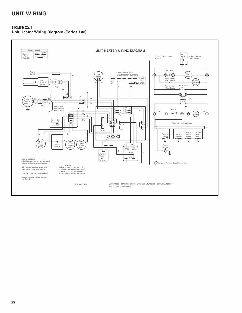
UNIT WIRING
Figure 22.1Unit Heater Wiring Diagram (Series 103)
5H78166B REV from Lockout, Single-Phase.
Single-Stage, Hot Surface Ignition, 100% Shut-Off, Multiple Retry with Auto Reset
unit polarity.Verify the power source and the
Use 105˚C wire for replacements. For deviations contact the factory.in injury to the installer or user.
CombinationGas Control
Hot SurfaceIgniter
PowerExhaust Motor
CombinationGas Control
FlameSensor
PressureSwitch
COMR
HH
L2L1
R
GR(G)
Y
YY
R
BK BK
W
W
BK
XFMR
PressSwitch
FanMotor
FlameRolloutSwitch
LimitControl
FlameSensor
BL
W
BK
WBK
P
Plug
BK
HotSurfaceIgniter
O
RR
WPlug
PowerExhaust Motor W
BK
HoneywellCombinationGas Control
RR
24V
115VXfmr
L2(W)
L1(BK)
Low Volt Therm (ByOthers)
Wiring LegendLine 24V
Factory FieldWire Nut
CautionFailure to wire this unit accordingto this wiring diagram may result
Note to installer:All wiring must comply with nationalelectric code and all local codes.
All components must agree withtheir respective power source.
Combination Gas Control
Circuit Breaker (By Others)
Thermt˚
TD Relay
FanMotor
TDC
UNIT HEATER WIRING DIAGRAM
FlameRollout Switch
Indicates Terminal Board Connection
LimitControl
24VACW
115V/60Hz/1Ø Power Shown
115V/60Hz/1Ø Power Circuit Breaker (By Others)
L1(BK)L2(W)
R
FlameRolloutSwitch
RR
G
TR1 TR2
FlameRollout Switch
24V
120VCOM
C3
C2
C1O
N
OF
F
WR
TDRelay
24 VAC TR2
TR1
BK
G
COM
G2
XF
MR
L2
XF
MR
L1
W BK
BK
23
HAMILTON HOME PRODUCTS, INC.LIMITED WARRANTY(Residential Use Only)
WHAT THIS WARRANTY COVERSThis warranty covers all defects in material and workmanship inyour Hamilton unit heater, when used for your home or garage.WHAT THIS WARRANTY DOES NOT COVERUnit heater, or any of its parts:1. which have been improperly installed or removed.2. which have been damaged other than by normal use.3. which have not been properly maintained.4. which have been exposed to gas input more than 5% higher
than specified on the serial plate of the unit heater, resultingin over-firing of the heater.
5. which have been exposed to possibly corrosive chemicals orchemical vapors (such as found in swimming pools), orpotentially explosive or flammable atmospheres laden withgrain dust, sawdust, or similar air-borne materials.
6. where any defect has been caused by abuse, misuse,neglect, carelessness, or accident.
7. where the serial number of the unit heater has been altered,defaced, or removed.
8. which are used in a confined space without adequatecombustion air, such as can be found in more air-tightconstruction.
WHO THIS WARRANTY COVERSThis warranty covers the purchaser of the unit heater or anyoneelse who owns it during the warranty period.HOW LONG THE WARRANTY LASTS1. The warranty for the heat exchanger of the unit heater
remains in force for ten years from the date you purchasedthe unit heater.
2. The warranty on all other parts of the heater remains in forcefor two years from the date you purchased the unit heater.
WHAT HAMILTON WILL DO TO CORRECT ANY PART OREQUIPMENT FAILURES DURING THE WARRANTY PERIODShould your Garage Heater fail within the warranty period,Hamilton will provide replacement part(s) at no charge,excluding shipping and handling charges. To file a warrantyclaim and/or obtain warranty replacement parts, you must first,within the period of warranty coverage, contact Hamilton HomeProducts, Inc. at 1.800.879.0123.WHAT HAMILTON WILL NOT DOHamilton will not reimburse you for any labor costs or servicecharges related to warranty repairs or replacements.INCIDENTAL AND CONSEQUENTIAL DAMAGESDISCLAIMEDThis warranty does not cover incidental damages, such as useof substitute heating equipment, or other costs arising from theloss of use of the unit heater. This warranty also does not coverconsequential damages, such as the cost of repairing orreplacing other property which is damaged when this unit heaterdoes not work properly.HOW STATE LAW RELATES TO THIS WARRANTYSome states do not allow the exclusion or limitation of incidentalor consequential damages so the above limitations orexclusions may not apply to you.This warranty gives you specific legal rights, and you may alsohave other rights which vary from state to state.

COMMERCIAL WARRANTY
Seller warrants its products to be free from defects in material and workmanship,EXCLUSIVE, HOWEVER, of failures attributable to the use of materials substitutedunder emergency conditions for materials normally employed. This warranty coversreplacement of any parts furnished from the factory of Seller, but does not coverlabor of any kind and materials not furnished by Seller, or any charges for any suchlabor or materials, whether such labor, materials or charges thereon are due toreplacement of parts, adjustments, repairs, or any other work done. This warrantydoes not apply to any equipment which shall have been repaired or altered outsidethe factory of Seller in any way so as, in the judgment of Seller, to affect its stability,nor which has been subjected to misuse, negligence, or operating conditions inexcess of those for which such equipment was designed. This warranty does notcover the effects of physical or chemical properties of water or steam or otherliquids or gases used in the equipment.BUYER AGREES THAT SELLER’S WARRANTY OF ITS PRODUCTS TO BEFREE FROM DEFECT IN MATERIAL AND WORKMANSHIP, AS LIMITEDHEREIN, SHALL BE IN LIEU OF AND EXCLUSIVE OF ALL OTHERWARRANTIES, EITHER EXPRESS OR IMPLIED, WHETHER ARISING FROMLAW, COURSE OF DEALING, USAGE OF TRADE, OR OTHERWISE, THEREARE NO OTHER WARRANTIES, INCLUDING WARRANTY OFMERCHANTABILITY OR FITNESS FOR PURPOSE, WHICH EXTEND BEYONDTHE PRODUCT DESCRIPTION CONFIRMED BY BUYER AND SELLER AS OFTHE DATE OF FINAL AGREEMENT.This warranty is void if the input to the product exceeds the rated input as indicatedon the product serial plate by more than 5% on gas-fired and oil-fired units, or if theproduct in the judgment of SELLER has been installed in a corrosive atmosphere,or subjected to corrosive fluids or gases, been subjected to misuse, negligence,accident, excessive thermal shock, excessive humidity, physical damage, impact,abrasion, unauthorized alterations, or operation contrary to SELLER’S printedinstructions, or if the serial number has been altered, defaced or removed.
Heat ExchangersFor Seller’s non-separated combustion Gas-Fired Unit HeatersBUYER’S REMEDY FOR BREACH OF WARRANTY, EXCLUSIVE OF ALLOTHER REMEDIES PROVIDED BY LAW, IS LIMITED TO REPAIR ORREPLACEMENT AT THE FACTORY OF SELLER, ANY HEAT EXCHANGERWHICH SHALL, WITHIN TEN YEARS FROM DATE OF FIRST BENEFICIALUSE BY BUYER OR ANY OTHER USER, WITHIN TEN YEARS FROM DATEOF RESALE BY BUYER OR ANY OTHER USER, WITHIN TEN YEARS FROMDATE OF RESALE BY BUYER IN ANY UNCHANGED CONDITION, ORWITHIN ONE HUNDRED TWENTY-SIX MONTHS FROM DATE OFSHIPMENT FROM SELLER, WHICHEVER OCCURS FIRST, BE RETURNEDTO SELLER WITH TRANSPORTATION CHARGES PREPAID AND WHICHTHE EXAMINATION OF SELLER SHALL DISCLOSE TO HAVE BEENDEFECTIVE; EXCEPT THAT WHEN THE PRODUCT IS TO BE USED BYBUYER AS A COMPONENT PART OF EQUIPMENT MANUFACTURED BYBUYER, BUYER’S REMEDY FOR BREACH, AS LIMITED HEREIN, SHALL BELIMITED TO ONE YEAR FROM DATE OF SHIPMENT FROM SELLER. FORGAS-FIRED PRODUCTS INSTALLED IN HIGH HUMIDITY APPLICATIONSAND UTILIZING STAINLESS STEEL HEAT EXCHANGERS, BUYER’SREMEDY FOR BREACH, AS LIMITED HEREIN, SHALL BE LIMITED TO TENYEARS FROM DATE OF SHIPMENT FROM SELLER.For Seller's Low Intensity Gas-Fired Infrared HeatersBUYER'S REMEDY FOR BREACH OF WARRANTY, EXCLUSIVE OF ALLOTHER REMEDIES PROVIDED BY LAW, IS LIMITED TO REPAIR ORREPLACEMENT AT THE FACTORY OF SELLER, ANY HEAT EXCHANGERWHICH SHALL, WITHIN FIVE YEARS FROM DATE OF FIRST BENEFICIALUSE BY BUYER OR ANY OTHER USER, WITHIN FIVE YEARS FROM DATEOF RESALE BY BUYER OR ANY OTHER USER, WITHIN FIVE YEARSFROM DATE OF RESALE BY BUYER IN ANY UNCHANGED CONDITION,OR WITHIN 66 MONTHS FROM DATE OF SHIPMENT FROM SELLER,WHICHEVER OCCURS FIRST, BE RETURNED TO SELLER WITHTRANSPORTATION CHARGES PREPAID AND WHICH THE EXAMINATIONOF SELLER SHALL DISCLOSE TO HAVE BEEN DEFECTIVE; EXCEPT THATWHEN THE PRODUCT IS TO BE USED BY BUYER AS A COMPONENTPART OF EQUIPMENT MANUFACTURED BY BUYER, BUYER'S REMEDYFOR BREACH, AS LIMITED HEREIN, SHALL BE LIMITED TO ONE YEARFROM DATE OF SHIPMENT FROM SELLER. Heat Exchanger (Condensers) for all Seller’s products except non-separated combustion Gas-Fired Unit Heaters and Infrared Heaters, allBurners except Infrared Heaters, and Sheet Metal for all Seller's productsBUYER’S REMEDY FOR BREACH OF WARRANTY, EXCLUSIVE OF ALLOTHER REMEDIES PROVIDED BY LAW, IS LIMITED TO REPAIR ORREPLACEMENT AT THE FACTORY OF SELLER, ANY HEAT EXCHANGER(CONDENSER) OR BURNER WHICH SHALL, WITHIN ONE YEAR FROMDATE OF FIRST BENEFICIAL USE BY BUYER OR ANY OTHER USER,WITHIN ONE YEAR FROM DATE OF RESALE BY BUYER IN ANY
UNCHANGED CONDITION, OR WITHIN EIGHTEEN MONTHS FROM DATEOF SHIPMENT FROM SELLER, WHICHEVER OCCURS FIRST, BERETURNED TO SELLER WITH TRANSPORTATION CHARGES PREPAIDAND WHICH THE EXAMINATION OF SELLER SHALL DISCLOSE TO HAVEBEEN DEFECTIVE; EXCEPT THAT WHEN THE PRODUCT IS TO BE USEDBY BUYER AS A COMPONENT PART OF EQUIPMENT MANUFACTUREDBY BUYER, BUYER’S REMEDY FOR BREACH, AS LIMITED HEREIN, SHALLBE LIMITED TO ONE YEAR FROM DATE OF SHIPMENT FROM SELLER.BurnersFor Seller's Low Intensity Gas-Fired Infrared HeatersBUYER'S REMEDY FOR BREACH OF WARRANTY, EXCLUSIVE OF ALLOTHER REMEDIES PROVIDED BY LAW, IS LIMITED TO REPAIR ORREPLACEMENT AT THE FACTORY OF SELLER, ANY BURNER WHICHSHALL, WITHIN TWO YEARS FROM DATE OF FIRST BENEFICIAL USE BYBUYER OR ANY OTHER USER, WITHIN TWO YEARS FROM DATE OFRESALE BY BUYER IN ANY UNCHANGED CONDITION, OR WITHIN 30MONTHS FROM DATE OF SHIPMENT FROM SELLER, WHICHEVEROCCURS FIRST, BE RETURNED TO SELLER WITH TRANSPORTATIONCHARGES PREPAID AND WHICH THE EXAMINATION OF SELLER SHALLDISCLOSE TO HAVE BEEN DEFECTIVE; EXCEPT THAT WHEN THEPRODUCT IS TO BE USED BY BUYER AS A COMPONENT PART OFEQUIPMENT MANUFACTURED BY BUYER, BUYER'S REMEDY FORBREACH, AS LIMITED HEREIN, SHALL BE LIMITED TO ONE YEAR FROMDATE OF SHIPMENT FROM SELLER.For Seller's High Intensity Gas-Fired Infrared HeatersBUYER'S REMEDY FOR BREACH OF WARRANTY, EXCLUSIVE OF ALLOTHER REMEDIES PROVIDED BY LAW, IS LIMITED TO REPAIR ORREPLACEMENT AT THE FACTORY OF SELLER, ANY BURNER WHICHSHALL, WITHIN TEN YEARS FROM DATE OF FIRST BENEFICIAL USE BYBUYER OR ANY OTHER USER, WITHIN TEN YEARS FROM DATE OFRESALE BY BUYER IN ANY UNCHANGED CONDITION, OR WITHIN 126MONTHS FROM DATE OF SHIPMENT FROM SELLER, WHICHEVEROCCURS FIRST, BE RETURNED TO SELLER WITH TRANSPORTATIONCHARGES PREPAID AND WHICH THE EXAMINATION OF SELLER SHALLDISCLOSE TO HAVE BEEN DEFECTIVE; EXCEPT THAT WHEN THEPRODUCT IS TO BE USED BY BUYER AS A COMPONENT PART OFEQUIPMENT MANUFACTURED BY BUYER, BUYER'S REMEDY FORBREACH, AS LIMITED HEREIN, SHALL BE LIMITED TO ONE YEAR FROMDATE OF SHIPMENT FROM SELLER.All Other Components Excluding Heat Exchanger (Condenser), Burner,and Sheet MetalFor all Seller's products except Direct-Fired Heaters and High Intensity Gas-Fired Infrared HeatersBUYER’S REMEDY FOR BREACH OF WARRANTY, EXCLUSIVE OF ALLOTHER REMEDIES PROVIDED BY LAW, IS LIMITED TO REPAIR ORREPLACEMENT AT THE FACTORY OF SELLER, ANY PART OR PARTSWHICH SHALL, WITHIN TWO YEARS FROM DATE OF FIRST BENEFICIALUSE BY BUYER OR ANY OTHER USER, WITHIN TWO YEARS FROM DATEOF RESALE BY BUYER IN ANY UNCHANGED CONDITION, OR WITHINTHIRTY MONTHS FROM DATE OF SHIPMENT FROM SELLER,WHICHEVER OCCURS FIRST, BE RETURNED TO SELLER WITHTRANSPORTATION CHARGES PREPAID AND WHICH THE EXAMINATIONOF SELLER SHALL DISCLOSE TO HAVE BEEN DEFECTIVE; EXCEPT THATWHEN THE PRODUCT IS TO BE USED BY BUYER AS A COMPONENTPART OF EQUIPMENT MANUFACTURED BY BUYER, BUYER’S REMEDYFOR BREACH, AS LIMITED HEREIN, SHALL BE LIMITED TO ONE YEARFROM DATE OF SHIPMENT FROM SELLER.For Seller's Direct-Fired Heaters and High Intensity Gas-Fired Infrared HeatersBUYER’S REMEDY FOR BREACH OF WARRANTY EXCLUSIVE OF ALLOTHER REMEDIES PROVIDED BY LAW IS LIMITED TO REPAIR ORREPLACEMENT AT THE SELLER’S OPTION ANY PART OR PARTS WHICHSHALL WITHIN A PERIOD OF ONE YEAR FROM DATE OF FIRSTBENEFICIAL USE BY BUYER OR ANY OTHER USER, WITHIN ONE YEARFROM DATE OF RESALE BY BUYER IN ANY UNCHANGED CONDITION,OR WITHIN 18 MONTHS FROM DATE OF SHIPMENT FROM SELLER,WHICHEVER OCCURS FIRST, BE RETURNED TO SELLER WITHTRANSPORTATION CHARGES PREPAID AND WHICH THE EXAMINATIONOF THE SELLER SHALL DISCLOSE TO HAVE BEEN DEFECTIVE.
BUYER AGREES THAT IN NO EVENT WILL SELLER BE LIABLE FOR COSTSOF PROCESSING, LOST PROFITS, INJURY TO GOODWILL, OR ANY OTHERCONSEQUENTIAL OR INCIDENTAL DAMAGES OF ANY KIND RESULTINGFROM THE ORDER OR USE OF ITS PRODUCT, WHETHER ARISING FROMBREACH OF WARRANTY, NONCONFORMITY TO ORDEREDSPECIFICATIONS, DELAY IN DELIVERY, OR ANY LOSS SUSTAINED BY THEBUYER.
Hamilton Home Products, Inc. has a continuous product improvement program; it reserves the right to change design and specifications without notice.
• FOR RESIDENTIAL USE SEE LIMITED CONSUMER WARRANTY ON PREVIOUS PAGE.
Hamilton Home Products, Inc.Columbus, Ohio 43212Phone: 1.800.879.0123www.hamiltonhomeproducts.comHamilton Home Products, Inc.
3/04 - M Litho in USA