Embed Size (px)
Citation preview
Hamilton Rapid Transit Preliminary Design and Feasibility Study
B-LINE
TRACKWORK DESIGN BRIEFVersion:2.0

February 2012
Hamilton Rapid Transit Preliminary Design and Feasibility Study
B-LINE
TRACKWORK DESIGN BRIEFVersion:2.0


File:
© 2010 SNC-Lavalin Inc. All rights reserved –i– Confidential
Hamilton B-Line LRT
Trackwork Design Brief
Table of ContentsTable of ContentsTable of ContentsTable of Contents
1.0 INTRODUCTION ............................................................................................................ 1
2.0 GENERAL PERFORMANCE SPECIFICATION ............................................................. 2
2.1 GENERAL ...................................................................................................................... 2
2.2 TRACKWORK TYPES ................................................................................................... 3
2.2.1 MAINLINE TRACK ......................................................................................................... 3
2.2.2 EMBEDDED TRACK ...................................................................................................... 3
2.2.3 DIRECT FIXATION TRACK ............................................................................................ 6
2.2.4 BALLASTED TRACK ...................................................................................................... 6
2.2.5 MAINTENANCE AND STORAGE FACILITY TRACKWORK .......................................... 7
2.2.6 TRACK CONSTRUCTION TOLERANCES ..................................................................... 8
2.2.7 RUNNING RAIL .............................................................................................................. 8
2.2.8 DIRECT FIXATION FASTENERS .................................................................................. 9
2.2.9 SPECIAL TRACKWORK ................................................................................................ 9
2.2.10 RAIL ARRESTORS .....................................................................................................12
2.2.11 DRAINAGE .................................................................................................................13
3.0 TRACKPLAN AND KEY SEGMENTS ..........................................................................15
3.1 TRACKPLAN .................................................................................................................15
4.0 NOISE AND VIBRATION – DESIGN CONSIDERATIONS ............................................17
5.0 SPECIFIC SEGMENT DESIGN .....................................................................................18
5.1 QUEENSTON ROAD BRIDGE OVER RED HILL VALLEY PKWY ................................18
5.2 CROSSING OVER HIGHWAY 403 ..............................................................................21
APPENDICES
Appendix A: Details of Flexible Rail Fixing
File: Hamilton LRT Line B Trackwork report Version 2.0 January 2012.doc
© 2010 SNC-Lavalin Inc. All rights reserved –1– Confidential
Hamilton B-Line LRT
Trackwork Design Brief
1.0 Introduction
This report summarizes the proposed trackwork elements for the Hamilton LRT B-Line. It includes the general performance specifications, typical cross sections, special trackwork and recommended types of trackwork and track elements to be considered for various alignment segments. As the location of the Maintenance and Storage Facility (MSF) at the time of the preparation of this report has not been determined, the details of the access track to the MSF and the tracks within the yards are not included. The Trackwork for the Hamilton LRT B-Line will be based on proven transit technology and design, as used in many similar operating systems around the World. The design, supply, installation and construction will be in accordance with applicable standards including AREMA. The selection process for trackwork components and materials will take into consideration functionality, ease of construction, minimal maintenance, durability and suitability. During the detailed design stage, drawings and specifications should be prepared for the installation and construction work, clearly showing the infrastructure constraints and tolerances to which the guideway structure and trackwork will be built to ensure the overall integrity and performance of the operational system. The installation and construction of trackwork will ensure that the finished product meets the overall performance requirements established in the design process. The control of the alignment will provide us with the greatest flexibility in addressing utility diversions, interfaces with streetworks, structures, and ensuring that service Reliability, Availability, Maintainability and Safety (RAMS) objectives are met or exceeded.
File: Hamilton LRT Line B Trackwork report Version 2.0 January 2012.doc
© 2010 SNC-Lavalin Inc. All rights reserved –2– Confidential
Hamilton B-Line LRT
Trackwork Design Brief
2.0 General Performance Specification
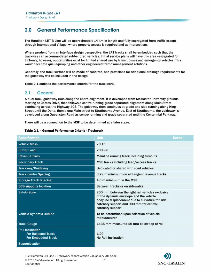
The Hamilton LRT B-Line will be approximately 14 km in length and fully segregated from traffic except through International Village, where property access is required and at intersections. Where prudent from an interface design perspective, the LRT tracks shall be embedded such that the trackway can accommodated rubber tired vehicles. Initial service plans will have this area segregated for LRT-only; however, opportunities exist for limited shared use by transit buses and emergency vehicles. This would facilitate queue-jumping and other engineered traffic management solutions. Generally, the track surface will be made of concrete, and provisions for additional drainage requirements for the guideway will be included in the design.
Table 2.1 outlines the performance criteria for the trackwork.
2.1 General
A dual track guideway runs along the entire alignment. It is developed from McMaster University grounds starting at Cootes Drive, then follows a centre running grade separated alignment along Main Street continuing across the Highway 403. The guideway then continues at grade and side running along King Street until the Delta, then along Main street to Strathearne Avenue. East of Strathearne, the guideway is developed along Queenston Road as centre running and grade separated until the Centennial Parkway. There will be a connection to the MSF to be determined at a later stage.
Table 2.1 Table 2.1 Table 2.1 Table 2.1 –––– General Performance Criteria General Performance Criteria General Performance Criteria General Performance Criteria ---- TrackworkTrackworkTrackworkTrackwork
SpecificationSpecificationSpecificationSpecification UnitUnitUnitUnit NotesNotesNotesNotes
Vehicle Mass 70.1t
Buffer Load 200 kN
Revenue Track Mainline running track including turnouts
Secondary Track MSF tracks including lead/access tracks
Trackway/Guideway Dedicated or shared with road vehicles
Track Centre Spacing 3.29 m minimum on all tangent revenue tracks
Storage Track Spacing 4.0 m minimum in the MSF
OCS supports location Between tracks or on sidewalks
Safety Zone 200 mm between the light rail vehicles exclusive of the dynamic envelope and the vehicle bodyline displacement due to curvature for side catenary support and 900 mm for central catenary support.
Vehicle Dynamic Outline To be determined upon selection of vehicle manufacturer
Track Gauge 1435 mm measured 16 mm below top of rail
Rail inclination - For Ballasted Track - For Embedded Track
1:20 No Rail Inclination
Superelevation
File: Hamilton LRT Line B Trackwork report Version 2.0 January 2012.doc
© 2010 SNC-Lavalin Inc. All rights reserved –3– Confidential
Hamilton B-Line LRT
Trackwork Design Brief
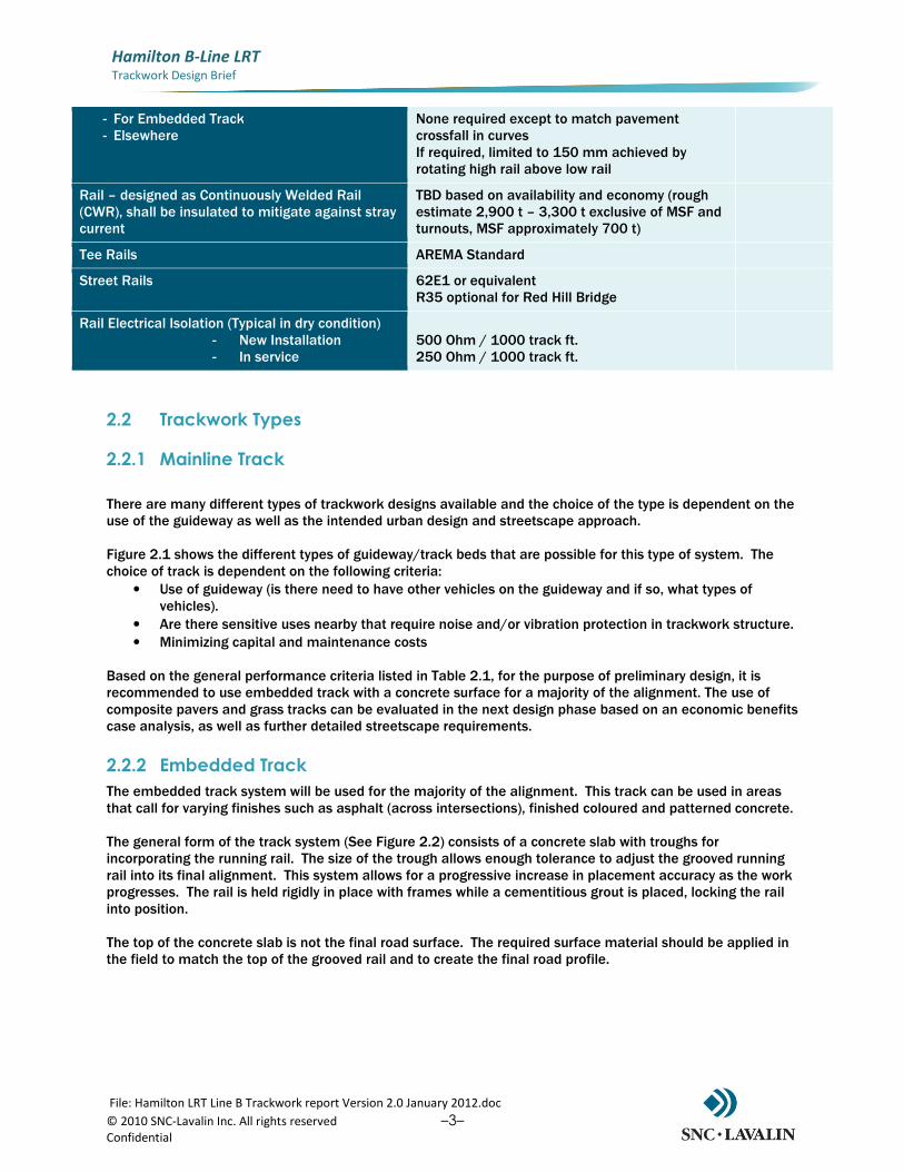
- For Embedded Track - Elsewhere
None required except to match pavement crossfall in curves If required, limited to 150 mm achieved by rotating high rail above low rail
Rail – designed as Continuously Welded Rail (CWR), shall be insulated to mitigate against stray current
TBD based on availability and economy (rough estimate 2,900 t – 3,300 t exclusive of MSF and turnouts, MSF approximately 700 t)
Tee Rails AREMA Standard
Street Rails 62E1 or equivalent R35 optional for Red Hill Bridge
Rail Electrical Isolation (Typical in dry condition) - New Installation - In service
500 Ohm / 1000 track ft. 250 Ohm / 1000 track ft.
2.2 Trackwork Types
2.2.1 Mainline Track
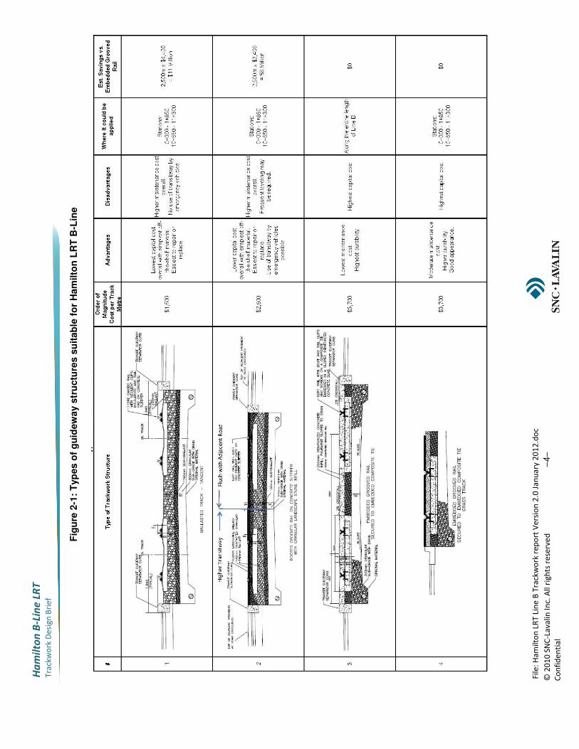
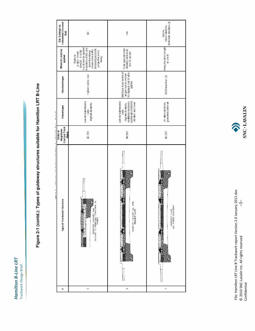
There are many different types of trackwork designs available and the choice of the type is dependent on the use of the guideway as well as the intended urban design and streetscape approach. Figure 2.1 shows the different types of guideway/track beds that are possible for this type of system. The choice of track is dependent on the following criteria:
• Use of guideway (is there need to have other vehicles on the guideway and if so, what types of vehicles).
• Are there sensitive uses nearby that require noise and/or vibration protection in trackwork structure.
• Minimizing capital and maintenance costs Based on the general performance criteria listed in Table 2.1, for the purpose of preliminary design, it is recommended to use embedded track with a concrete surface for a majority of the alignment. The use of composite pavers and grass tracks can be evaluated in the next design phase based on an economic benefits case analysis, as well as further detailed streetscape requirements.
2.2.2 Embedded Track
The embedded track system will be used for the majority of the alignment. This track can be used in areas that call for varying finishes such as asphalt (across intersections), finished coloured and patterned concrete. The general form of the track system (See Figure 2.2) consists of a concrete slab with troughs for incorporating the running rail. The size of the trough allows enough tolerance to adjust the grooved running rail into its final alignment. This system allows for a progressive increase in placement accuracy as the work progresses. The rail is held rigidly in place with frames while a cementitious grout is placed, locking the rail into position. The top of the concrete slab is not the final road surface. The required surface material should be applied in the field to match the top of the grooved rail and to create the final road profile.
File
: H
am
ilto
n L
RT
Lin
e B
Tra
ckw
ork
re
po
rt V
ers
ion
2.0
Ja
nu
ary
20
12
.do
c
© 2
01
0 S
NC
-La
va
lin
In
c. A
ll r
igh
ts r
ese
rve
d
–4–
Co
nfi
de
nti
al
Ha
mil
to
n B
-Lin
e L
RT
Tra
ckw
ork
De
sig
n B
rie
f
Fig
ure
2-1
: T
yp
es o
f g
uid
ew
ay s
tru
ctu
res s
uit
ab
le f
or
Ham
ilto
n L
RT
B-L
ine
File
: H
am
ilto
n L
RT
Lin
e B
Tra
ckw
ork
re
po
rt V
ers
ion
2.0
Ja
nu
ary
20
12
.do
c
© 2
01
0 S
NC
-La
va
lin
In
c. A
ll r
igh
ts r
ese
rve
d
–5–
Co
nfi
de
nti
al
Ha
mil
to
n B
-Lin
e L
RT
Tra
ckw
ork
De
sig
n B
rie
f
F
igu
re 2
-1 (
co
ntd
.):
Typ
es
of
gu
idew
ay s
tru
ctu
res
su
itab
le f
or
Ham
ilto
n L
RT
B-L
ine
File: Hamilton LRT Line B Trackwork report Version 2.0 January 2012.doc
© 2010 SNC-Lavalin Inc. All rights reserved –6– Confidential
Hamilton B-Line LRT
Trackwork Design Brief
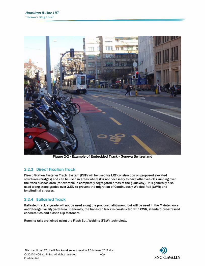
Figure 2-2 - Example of Embedded Track - Geneva Switzerland
2.2.3 Direct Fixation Track
Direct Fixation Fastener Track System (DFF) will be used for LRT construction on proposed elevated structures (bridges) and can be used in areas where it is not necessary to have other vehicles running over the track surface area (for example in completely segregated areas of the guideway). It is generally also used along steep grades over 3.5% to prevent the migration of Continuously Welded Rail (CWR) and longitudinal stresses.
2.2.4 Ballasted Track
Ballasted track at grade will not be used along the proposed alignment, but will be used in the Maintenance and Storage Facility yard area. Generally, the ballasted track is constructed with CWR, standard pre-stressed concrete ties and elastic clip fasteners. Running rails are joined using the Flash Butt Welding (FBW) technology.
File: Hamilton LRT Line B Trackwork report Version 2.0 January 2012.doc
© 2010 SNC-Lavalin Inc. All rights reserved –7– Confidential
Hamilton B-Line LRT
Trackwork Design Brief
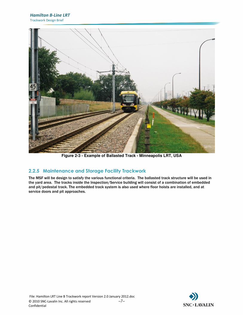
Figure 2-3 - Example of Ballasted Track - Minneapolis LRT, USA
2.2.5 Maintenance and Storage Facility Trackwork
The MSF will be design to satisfy the various functional criteria. The ballasted track structure will be used in the yard area. The tracks inside the Inspection/Service building will consist of a combination of embedded and pit/pedestal track. The embedded track system is also used where floor hoists are installed, and at service doors and pit approaches.
File: Hamilton LRT Line B Trackwork report Version 2.0 January 2012.doc
© 2010 SNC-Lavalin Inc. All rights reserved –8– Confidential
Hamilton B-Line LRT
Trackwork Design Brief
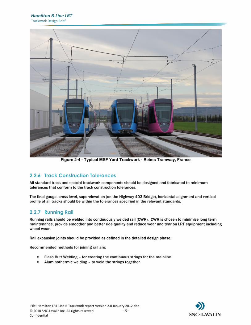
Figure 2-4 - Typical MSF Yard Trackwork - Reims Tramway, France
2.2.6 Track Construction Tolerances
All standard track and special trackwork components should be designed and fabricated to minimum tolerances that conform to the track construction tolerances. The final gauge, cross level, superelevation (on the Highway 403 Bridge), horizontal alignment and vertical profile of all tracks should be within the tolerances specified in the relevant standards.
2.2.7 Running Rail
Running rails should be welded into continuously welded rail (CWR). CWR is chosen to minimize long term maintenance, provide smoother and better ride quality and reduce wear and tear on LRT equipment including wheel wear. Rail expansion joints should be provided as defined in the detailed design phase. Recommended methods for joining rail are:
• Flash Butt Welding – for creating the continuous strings for the mainline
• Aluminothermic welding – to weld the strings together
File: Hamilton LRT Line B Trackwork report Version 2.0 January 2012.doc
© 2010 SNC-Lavalin Inc. All rights reserved –9– Confidential
Hamilton B-Line LRT
Trackwork Design Brief
2.2.8 Direct Fixation Fasteners
Direct fixation rail fasteners should be designed to attach the rail to the concrete trackbed on all primary tracks. Direct fixation rail fasteners consist of hardware, which supports and connects the rail to the concrete track bed. They should be chosen based on the following criteria:
• CWR/Structure interface forces
• The ability to achieve and maintain desired rail tolerances
• The ability to prevent rail buckling under high temperatures
• The ability to permit the structure to move longitudinally owing to structural flexure and thermal expansion or contraction beneath the rail which remains fixed
• The ability to withstand fatigue and wear of fasteners components with low maintenance requirements.
• The ability to reduce airborne noise and vibration to an acceptable level
• The ability to withstand the local environment without the need to replace components. The maximum effective load carried per track fixation fasteners must be determined from quasi-static loading of the track structure, schematized as an elastically supported beam, with an increment added for dynamic influence.
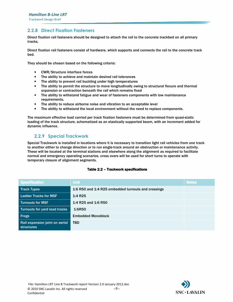
2.2.9 Special Trackwork
Special Trackwork is installed in locations where it is necessary to transition light rail vehicles from one track to another either to change direction or to run single-track around an obstruction or maintenance activity. These will be located at the terminal stations and elsewhere along the alignment as required to facilitate normal and emergency operating scenarios. cross overs will be used for short turns to operate with temporary closure of alignment segments.
Table 2.2 Table 2.2 Table 2.2 Table 2.2 –––– Trackwork specificationsTrackwork specificationsTrackwork specificationsTrackwork specifications
SpecificationSpecificationSpecificationSpecification UnitUnitUnitUnit NotesNotesNotesNotes
Track Types 1:6 R50 and 1:4 R25 embedded turnouts and crossings
Ladder Tracks for MSF 1:4 R25
Turnouts for MSF 1:4 R25 and 1:6 R50
Turnouts for yard lead tracks 1:6R50
Frogs Embedded Monoblock
Rail expansion joint on aerial structures
TBD
File
: H
am
ilto
n L
RT
Lin
e B
Tra
ckw
ork
re
po
rt V
ers
ion
2.0
Ja
nu
ary
20
12
.do
c
© 2
01
0 S
NC
-La
va
lin
In
c. A
ll r
igh
ts r
ese
rve
d
–10–
Co
nfi
de
nti
al
Ha
mil
to
n B
-Lin
e L
RT
Tra
ckw
ork
De
sig
n B
rie
f
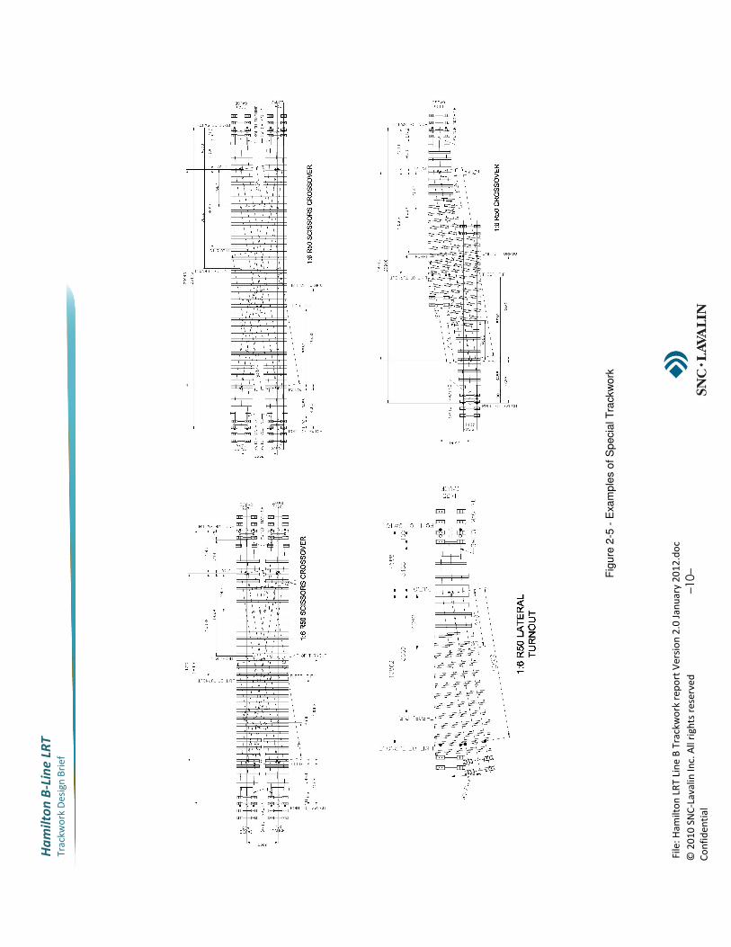
Fig
ure
2-5
- E
xa
mp
les o
f S
pecia
l T
rackw
ork
File: Hamilton LRT Line B Trackwork report Version 2.0 January 2012.doc
© 2010 SNC-Lavalin Inc. All rights reserved –11– Confidential
Hamilton B-Line LRT
Trackwork Design Brief
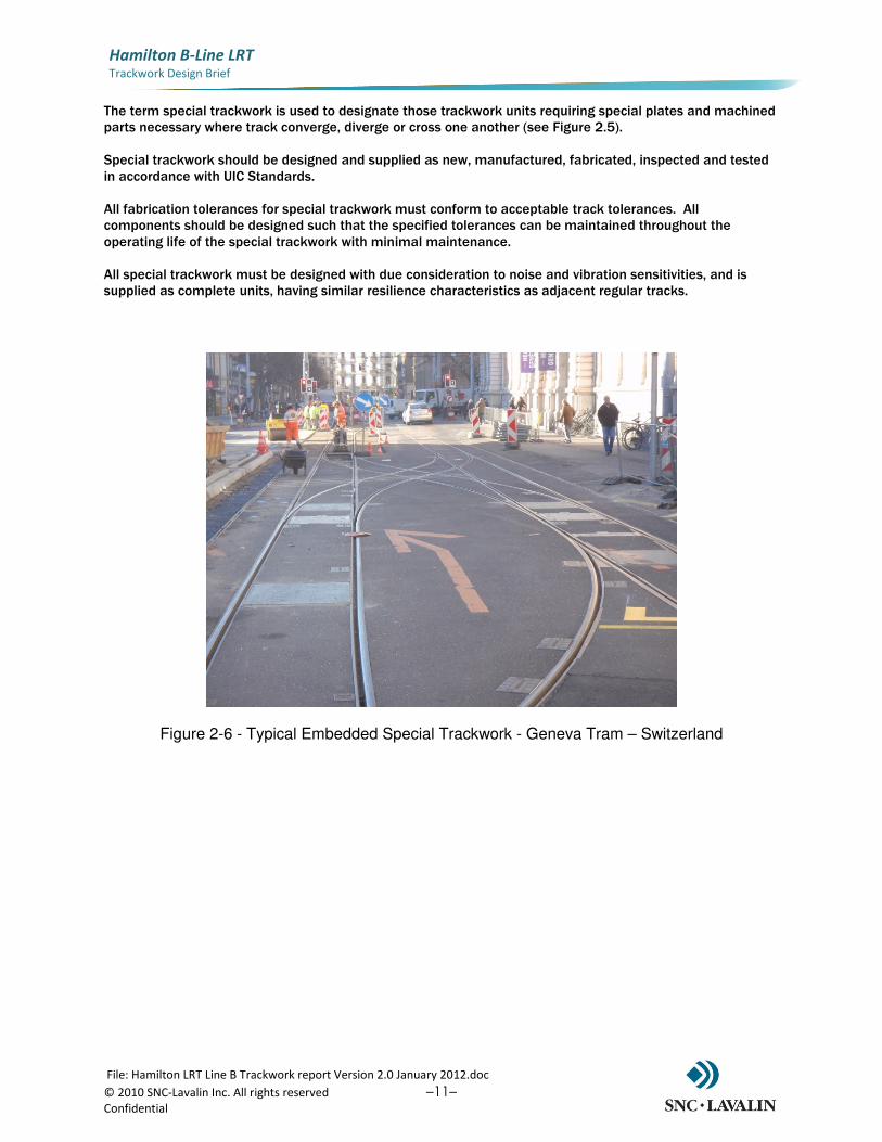
The term special trackwork is used to designate those trackwork units requiring special plates and machined parts necessary where track converge, diverge or cross one another (see Figure 2.5). Special trackwork should be designed and supplied as new, manufactured, fabricated, inspected and tested in accordance with UIC Standards. All fabrication tolerances for special trackwork must conform to acceptable track tolerances. All components should be designed such that the specified tolerances can be maintained throughout the operating life of the special trackwork with minimal maintenance. All special trackwork must be designed with due consideration to noise and vibration sensitivities, and is supplied as complete units, having similar resilience characteristics as adjacent regular tracks.
Figure 2-6 - Typical Embedded Special Trackwork - Geneva Tram – Switzerland
File: Hamilton LRT Line B Trackwork report Version 2.0 January 2012.doc
© 2010 SNC-Lavalin Inc. All rights reserved –12– Confidential
Hamilton B-Line LRT
Trackwork Design Brief
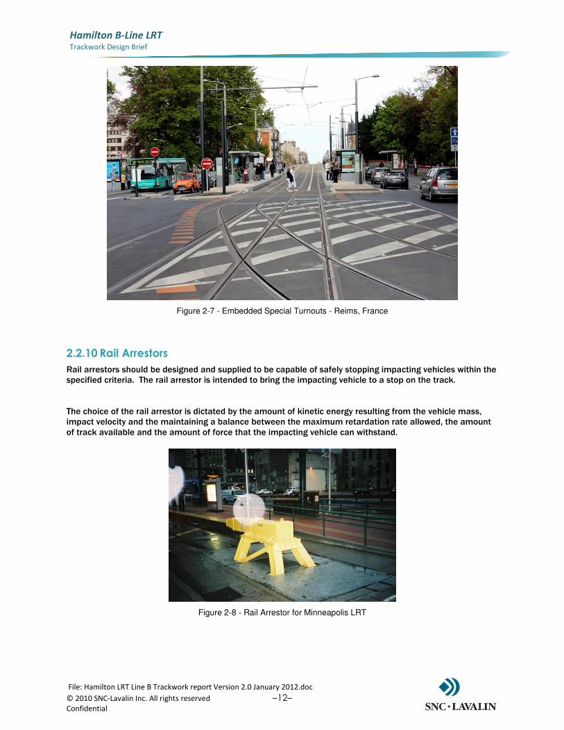
Figure 2-7 - Embedded Special Turnouts - Reims, France
2.2.10 Rail Arrestors
Rail arrestors should be designed and supplied to be capable of safely stopping impacting vehicles within the specified criteria. The rail arrestor is intended to bring the impacting vehicle to a stop on the track. The choice of the rail arrestor is dictated by the amount of kinetic energy resulting from the vehicle mass, impact velocity and the maintaining a balance between the maximum retardation rate allowed, the amount of track available and the amount of force that the impacting vehicle can withstand.
Figure 2-8 - Rail Arrestor for Minneapolis LRT
File: Hamilton LRT Line B Trackwork report Version 2.0 January 2012.doc
© 2010 SNC-Lavalin Inc. All rights reserved –13– Confidential
Hamilton B-Line LRT
Trackwork Design Brief
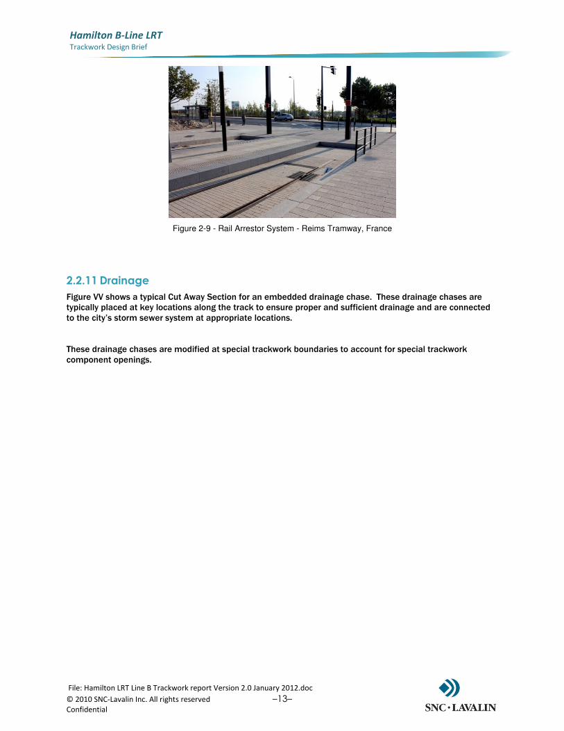
Figure 2-9 - Rail Arrestor System - Reims Tramway, France
2.2.11 Drainage
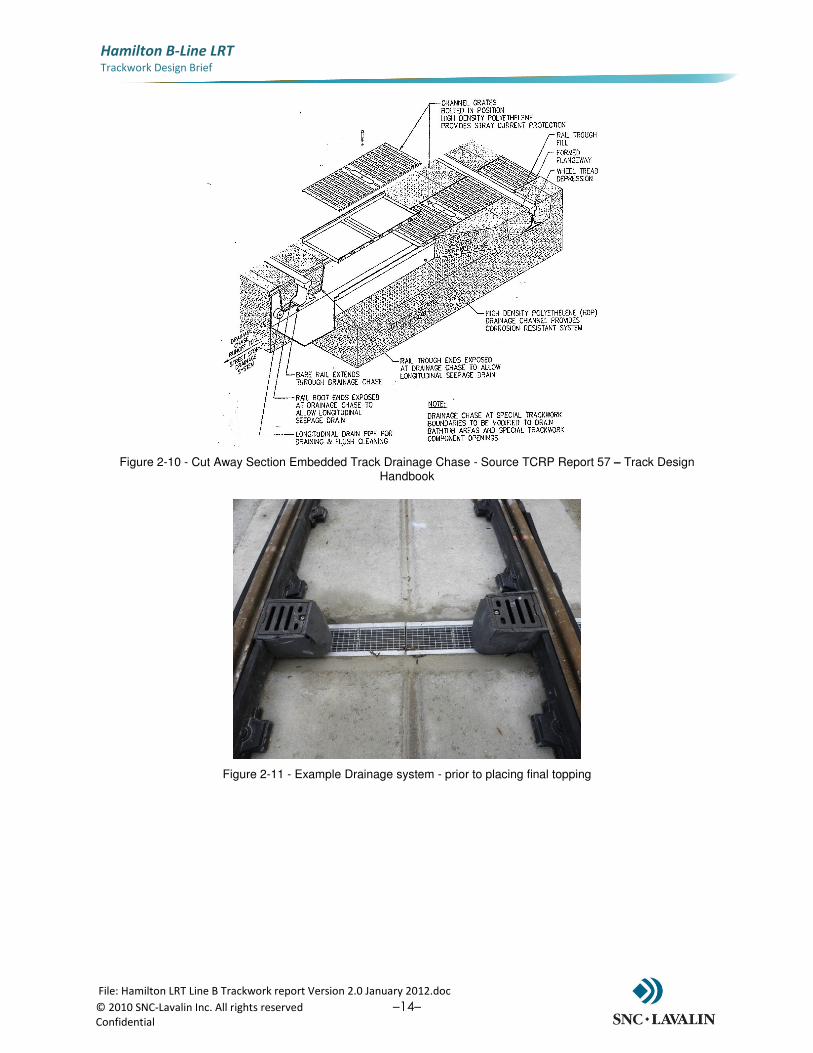
Figure VV shows a typical Cut Away Section for an embedded drainage chase. These drainage chases are typically placed at key locations along the track to ensure proper and sufficient drainage and are connected to the city’s storm sewer system at appropriate locations. These drainage chases are modified at special trackwork boundaries to account for special trackwork component openings.
File: Hamilton LRT Line B Trackwork report Version 2.0 January 2012.doc
© 2010 SNC-Lavalin Inc. All rights reserved –14– Confidential
Hamilton B-Line LRT
Trackwork Design Brief
Figure 2-10 - Cut Away Section Embedded Track Drainage Chase - Source TCRP Report 57 – Track Design Handbook
Figure 2-11 - Example Drainage system - prior to placing final topping
File: Hamilton LRT Line B Trackwork report Version 2.0 January 2012.doc
© 2010 SNC-Lavalin Inc. All rights reserved –15– Confidential
Hamilton B-Line LRT
Trackwork Design Brief
3.0 Trackplan and Key Segments
3.1 Trackplan
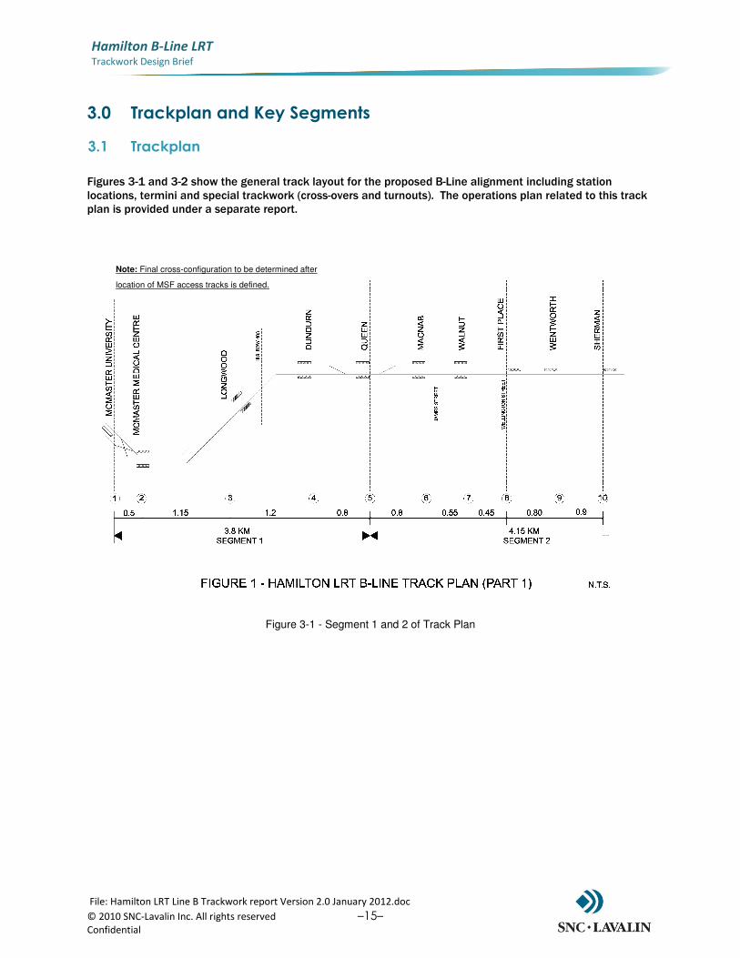
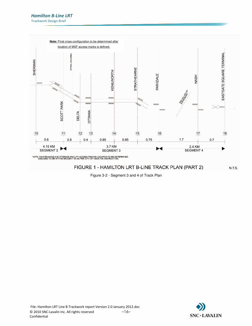
Figures 3-1 and 3-2 show the general track layout for the proposed B-Line alignment including station locations, termini and special trackwork (cross-overs and turnouts). The operations plan related to this track plan is provided under a separate report.
Figure 3-1 - Segment 1 and 2 of Track Plan
Note: Final cross-configuration to be determined after
location of MSF access tracks is defined.
File: Hamilton LRT Line B Trackwork report Version 2.0 January 2012.doc
© 2010 SNC-Lavalin Inc. All rights reserved –16– Confidential
Hamilton B-Line LRT
Trackwork Design Brief
Figure 3-2 - Segment 3 and 4 of Track Plan
Note: Final cross-configuration to be determined after
location of MSF access tracks is defined.
File: Hamilton LRT Line B Trackwork report Version 2.0 January 2012.doc
© 2010 SNC-Lavalin Inc. All rights reserved –17– Confidential
Hamilton B-Line LRT
Trackwork Design Brief
4.0 Noise and Vibration – Design Considerations
There are three zones that have been established to address the recommendations in the Hamilton LRT - Noise and Vibration Assessment Report. These zones have levels of mitigation against groundborn vibration that can be addressed in the trackform design. These zones are required due to proximity of residential, commercial, and institutional areas that are sensitive to identifiable frequencies of vibration. The basic methodology is to isolate certain vehicle/rail vibration frequencies from propagating from the trackform through the subgrade and away from the guideway. It is important that further study considers proposed future land uses and built form along the corridor. Nodes and Corridors staff should be consulted as further study is done to ensure land uses and built form under consider for mitigation are appropriate. The trackform will be developed to mitigate against these frequencies in the most appropriate, effective and economical way.
Level 1Level 1Level 1Level 1 trackform is rail that is encapsulated in a boot and embedded in the pavement. This encapsulated structure has some attenuation in lateral, vertical and longitudinal axis. This is the basic trackform for Hamilton LRT. Level 2Level 2Level 2Level 2 trackform requires more isolation. This can be accomplished by means of a softer, thicker boot system or by means of fully encapsulating the rail in an elastomeric medium. This level of isolation can also be accomplished by isolating the base slab with commercially available vibration isolation pads or a combination of the two. Level 3Level 3Level 3Level 3 requires the most isolation. This level is accomplished by means of isolating the majority or the entirety of the trackform. This structure may require a direct isolation of the track slabs or a thicker isolating layer consisting of a vibration mitigating material below the supporting trackbed. This can also be used in combination with the structures mentioned in Level 2 to enhance the required mitigation. These trackform designs are conceptual and only address the condition of groundborn vibration. Design particulars such as detailed dimensions, fastener spacings and appropriate materials are to be determined. Further study must be done to assess the particular level and frequency of the mitigation required. Cross-sections 6 and 7 on Table 2.1 show alternative treatments which address the above mentioned levels.
File: Hamilton LRT Line B Trackwork report Version 2.0 January 2012.doc
© 2010 SNC-Lavalin Inc. All rights reserved –18– Confidential
Hamilton B-Line LRT
Trackwork Design Brief
5.0 Specific Segment Design
5.1 QUEENSTON ROAD BRIDGE OVER RED HILL VALLEY PKWY
The Queenston Bridge over the Red Hill Valley Parkway is considered a special structure, Hence, the following will need to be taken into consideration when designing the trackwork along this structure.
• It will not be possible to drill anchors into the bridge deck due to its hollow core slab design.
• A glued anchor option is recommended (details of such trackwork construction is included in Appendix A)
• The 90mm asphalt would be removed and the deck prepared for the glued on fasteners.
• Supershort Ri35G grooved rail is recommended so that the pavement at the two ramp intersections can be as close to flush with the existing pavement as possible.
• A protective seal to cover the glued base plates to protect from any water damage to the glued surface
• The top surface can be asphalt or concrete to embed the track system
• Only emergency vehicles should be allowed on the LRT guideway (on the bridge)
• There will be need to review drainage for the guideway in detailed design
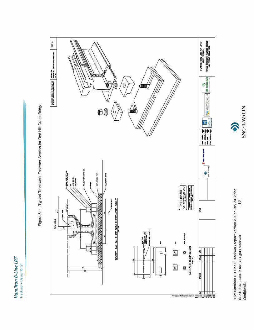
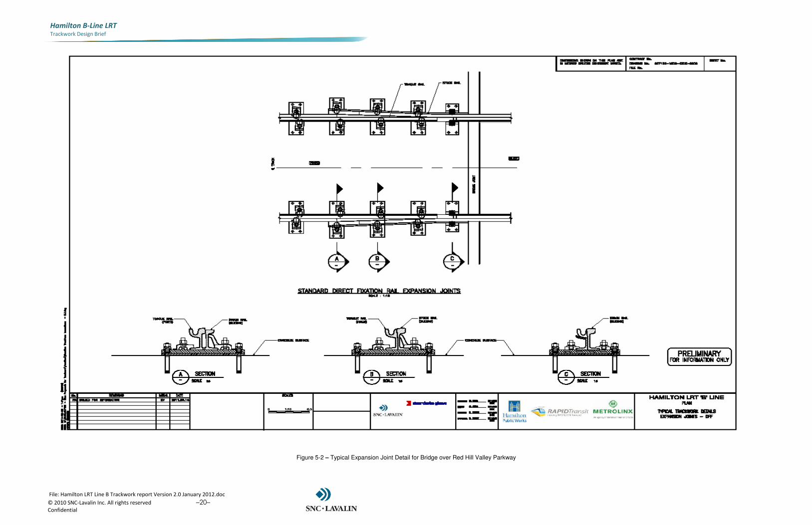
A detailed investigation will be required at the detailed design stage including an inspection of the deck surface conditions and evaluate its suitability for using the glued method of rail fixation, and a loading test of the bridge to assess its extra carrying capacities. Figure 5-1 shows the typical design for the fastening system proposed. As mentioned above, a flexible rail fixing by means of glued anchor is illustrated in Appendix A with an example of one manufacturer’s construction methods and experience. Features of this method which are relevant to the Queenston Road Bridge track design include the capability of direct fixation without anchor bolts, and the ability of the fixation material to withstand temperatures ranging from -30°C to +60°C. Please note, Appendix A provides the information of one manufacturer for information purposes only, and alternative suppliers can be assessed in the next design phase. The track over the bridge will require special trackwork in the form of a joint to accommodate the longitudinal displacements of the existing structure. Figure 5-2 shows the typical trackwork detail for the expansion joint over the bridge, such detail is for a standard direct fixation as it is not foreseen for traffic to required crossing the tracks in this location.
File
: H
am
ilto
n L
RT
Lin
e B
Tra
ckw
ork
re
po
rt V
ers
ion
2.0
Ja
nu
ary
20
12
.do
c
© 2
01
0 S
NC
-La
va
lin
In
c. A
ll r
igh
ts r
ese
rve
d
–19–
Co
nfi
de
nti
al
Ha
mil
to
n B
-Lin
e L
RT
Tra
ckw
ork
De
sig
n B
rie
f
Fig
ure
5-1
- T
yp
ica
l T
rackw
ork
Fa
ste
ne
r S
ectio
n fo
r R
ed H
ill C
ree
k B
rid
ge
File: Hamilton LRT Line B Trackwork report Version 2.0 January 2012.doc
© 2010 SNC-Lavalin Inc. All rights reserved –20– Confidential
Hamilton B-Line LRT
Trackwork Design Brief
Figure 5-2 – Typical Expansion Joint Detail for Bridge over Red Hill Valley Parkway
File: Hamilton LRT Line B Trackwork report Version 2.0 January 2012.doc
© 2010 SNC-Lavalin Inc. All rights reserved –21– Confidential
Hamilton B-Line LRT
Trackwork Design Brief
5.2 Crossing over Highway 403
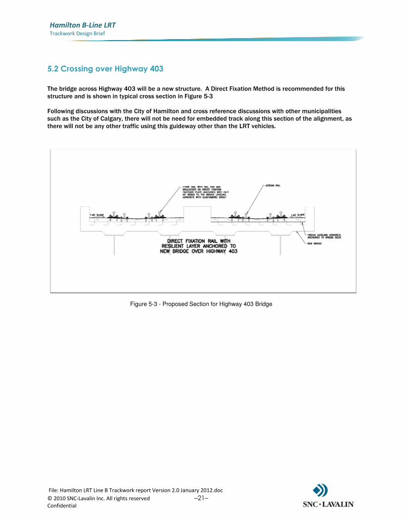
The bridge across Highway 403 will be a new structure. A Direct Fixation Method is recommended for this structure and is shown in typical cross section in Figure 5-3 Following discussions with the City of Hamilton and cross reference discussions with other municipalities such as the City of Calgary, there will not be need for embedded track along this section of the alignment, as there will not be any other traffic using this guideway other than the LRT vehicles.
Figure 5-3 - Proposed Section for Highway 403 Bridge
File: Hamilton LRT Line B Trackwork report Version 2.0 January 2012.doc
© 2010 SNC-Lavalin Inc. All rights reserved –22– Confidential
Hamilton B-Line LRT
Trackwork Design Brief
Disclaimer
This document contains the expression of the professional opinion of Steer Davies Gleave North America Inc. and/or its sub-consultants (hereinafter referred to collectively as “the consultant team”) as to the matters set out herein, using their professional judgment and reasonable care. It is to be read in the context of the agreement (the “Agreement”) between Steer Davies Gleave North America Inc. and the City of Hamilton (the “Client”) for the Rapid Transit Preliminary Design and Feasibility Study (reference C11-12-10), and the methodology, procedures, techniques and assumptions used, and the circumstances and constraints under which its mandate was performed. This document is written solely for the purpose stated in the Agreement, and for the sole and exclusive benefit of the Client, whose remedies are limited to those set out in the Agreement. This document is meant to be read as a whole, and sections or parts thereof should thus not be read or relied upon out of context.
The consultant team has, in preparing the Agreement outputs, followed methodology and procedures, and exercised due care consistent with the intended level of accuracy, using professional judgment and reasonable care.
However, no warranty should be implied as to the accuracy of the Agreement outputs, forecasts and estimates. This analysis is based on data supplied by the client/collected by third parties. This has been checked whenever possible; however the consultant team cannot guarantee the accuracy of such data and does not take responsibility for estimates in so far as they are based on such data.
Steer Davies Gleave North America Inc. disclaims any liability to the Client and to third parties in respect of the publication, reference, quoting, or distribution of this report or any of its contents to and reliance thereon by any third party.
DOCUMENT END
File: Hamilton LRT Line B Trackwork report Version 2.0 January 2012.doc
© 2010 SNC-Lavalin Inc. All rights reserved –23– Confidential
Hamilton B-Line LRT
Trackwork Design Brief
APPENDIX A
VENDOR EXAMPLE OF FLEXIBLE RAIL FIXING
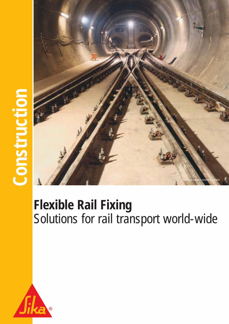
Flexible Rail FixingSolutions for rail transport world-wide
Cons
truc
tion
Heathrow Express crossover, London
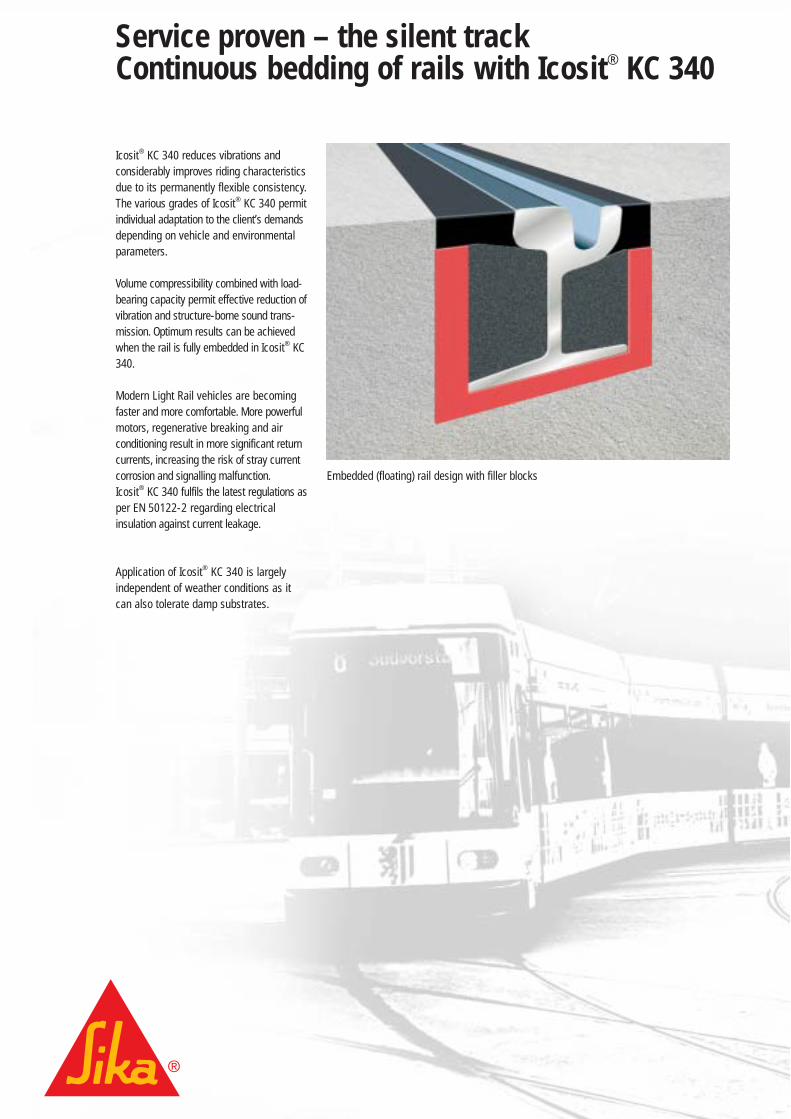
Service proven – the silent track Continuous bedding of rails with Icosit® KC 340
Icosit® KC 340 reduces vibrations andconsiderably improves riding characteristicsdue to its permanently flexible consistency.The various grades of Icosit® KC 340 permitindividual adaptation to the client’s demandsdepending on vehicle and environmentalparameters.
Volume compressibility combined with load-bearing capacity permit effective reduction ofvibration and structure-borne sound trans-mission. Optimum results can be achievedwhen the rail is fully embedded in Icosit® KC340.
Modern Light Rail vehicles are becomingfaster and more comfortable. More powerfulmotors, regenerative breaking and airconditioning result in more significant returncurrents, increasing the risk of stray currentcorrosion and signalling malfunction.Icosit® KC 340 fulfils the latest regulations asper EN 50122-2 regarding electricalinsulation against current leakage.
Application of Icosit® KC 340 is largelyindependent of weather conditions as itcan also tolerate damp substrates.
Embedded (floating) rail design with filler blocks
2|3
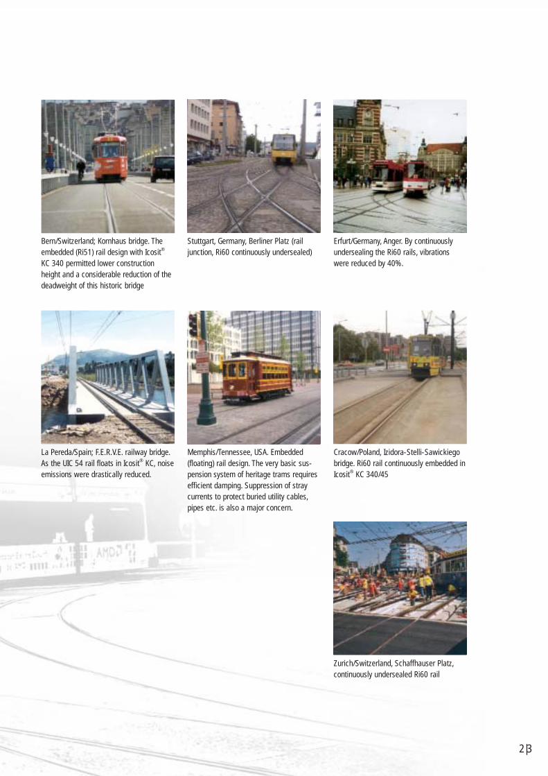
La Pereda/Spain; F.E.R.V.E. railway bridge.As the UIC 54 rail floats in Icosit® KC, noiseemissions were drastically reduced.
Bern/Switzerland; Kornhaus bridge. Theembedded (Ri51) rail design with Icosit®
KC 340 permitted lower constructionheight and a considerable reduction of thedeadweight of this historic bridge
Stuttgart, Germany, Berliner Platz (railjunction, Ri60 continuously undersealed)
Cracow/Poland, Izidora-Stelli-Sawickiegobridge. Ri60 rail continuously embedded inIcosit® KC 340/45
Memphis/Tennessee, USA. Embedded(floating) rail design. The very basic sus-pension system of heritage trams requiresefficient damping. Suppression of straycurrents to protect buried utility cables,pipes etc. is also a major concern.
Erfurt/Germany, Anger. By continuouslyundersealing the Ri60 rails, vibrationswere reduced by 40%.
Zurich/Switzerland, Schaffhauser Platz,continuously undersealed Ri60 rail
Discrete fixation of rails with Icosit® KC 340- public transport the discreet way
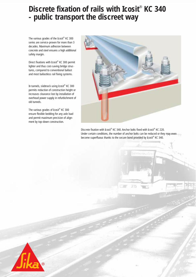
The various grades of the Icosit® KC 300series are service-proven for more than 3decades. Maximum adhesion betweenconcrete and steel ensures a high additionalsafety margin.
Direct fixations with Icosit® KC 300 permitlighter and thus cost-saving bridge struc-tures, compared to conventional ballastand most ballastless rail fixing systems.
In tunnels, slabtrack using Icosit® KC 300permits reduction of construction height orincreases clearance lost by installation ofoverhead power supply in refurbishment ofold tunnels.
The various grades of Icosit® KC 300ensure flexible bedding for any axle loadand permit maximum precision of align-ment by top-down construction.
Discrete fixation with Icosit® KC 340. Anchor bolts fixed with Icosit® KC 220.Under certain conditions, the number of anchor bolts can be reduced or they may evenbecome superfluous thanks to the secure bond provided by Icosit® KC 340.
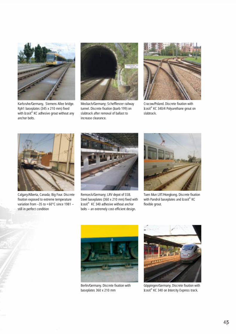
Karlsruhe/Germany, Siemens Allee bridge.Rph1 baseplates (345 x 210 mm) fixedwith Icosit® KC adhesive grout without anyanchor bolts.
Calgary/Alberta, Canada; Big Four. Discretefixation exposed to extreme temperaturevariation from –35 to +60°C since 1981 –still in perfect condition
Mosbach/Germany; Schefflenzer railwaytunnel. Discrete fixation (Ioarb 199) onslabtrack after removal of ballast toincrease clearance.
Cracow/Poland. Discrete fixation withIcosit® KC 340/4 Polyurethane grout onslabtrack.
Remseck/Germany; LRV depot of SSB.Steel baseplates (360 x 210 mm) fixed withIcosit® KC 340 adhesive without anchorbolts – an extremely cost-efficient design.
Tuen Mun LRT/Hongkong. Discrete fixationwith Pandrol baseplates and Icosit® KCflexible grout.
Göppingen/Germany. Discrete fixation withIcosit® KC 340 on Intercity Express track.
4|5
Berlin/Germany. Discrete fixation withbaseplates 360 x 210 mm
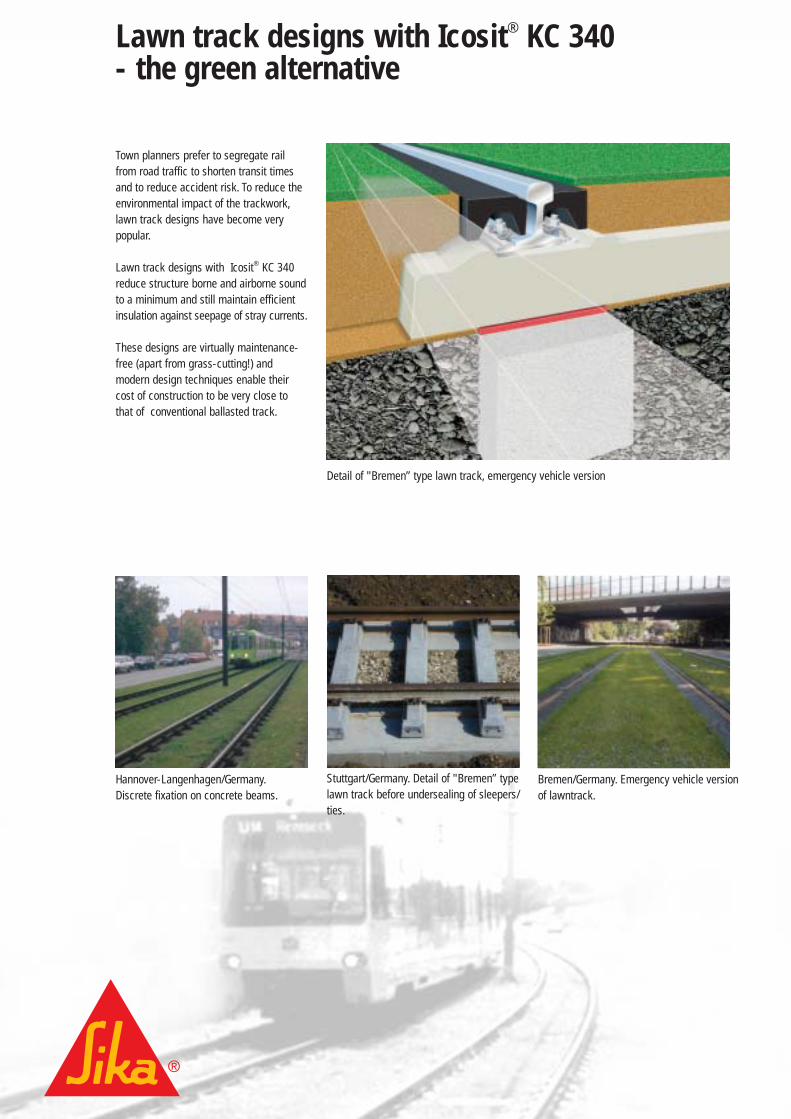
Lawn track designs with Icosit® KC 340- the green alternative
Hannover-Langenhagen/Germany.Discrete fixation on concrete beams.
Bremen/Germany. Emergency vehicle versionof lawntrack.
Stuttgart/Germany. Detail of "Bremen” typelawn track before undersealing of sleepers/ties.
Town planners prefer to segregate railfrom road traffic to shorten transit timesand to reduce accident risk. To reduce theenvironmental impact of the trackwork,lawn track designs have become verypopular.
Lawn track designs with Icosit® KC 340reduce structure borne and airborne soundto a minimum and still maintain efficientinsulation against seepage of stray currents.
These designs are virtually maintenance-free (apart from grass-cutting!) andmodern design techniques enable theircost of construction to be very close tothat of conventional ballasted track.
Detail of "Bremen” type lawn track, emergency vehicle version
6|7
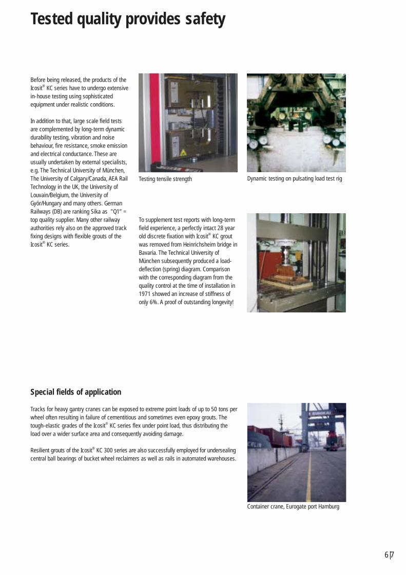
Tested quality provides safety
Testing tensile strength Dynamic testing on pulsating load test rig
Container crane, Eurogate port Hamburg
Before being released, the products of theIcosit® KC series have to undergo extensivein-house testing using sophisticatedequipment under realistic conditions.
In addition to that, large scale field testsare complemented by long-term dynamicdurability testing, vibration and noisebehaviour, fire resistance, smoke emissionand electrical conductance. These areusually undertaken by external specialists,e.g. The Technical University of München,The University of Calgary/Canada, AEA RailTechnology in the UK, the University ofLouvain/Belgium, the University ofGyör/Hungary and many others. GermanRailways (DB) are ranking Sika as "Q1” =top quality supplier. Many other railwayauthorities rely also on the approved trackfixing designs with flexible grouts of theIcosit® KC series.
To supplement test reports with long-termfield experience, a perfectly intact 28 yearold discrete fixation with Icosit® KC groutwas removed from Heinrichsheim bridge inBavaria. The Technical University ofMünchen subsequently produced a load-deflection (spring) diagram. Comparisonwith the corresponding diagram from thequality control at the time of installation in1971 showed an increase of stiffness ofonly 6%. A proof of outstanding longevity!
Special fields of application
Tracks for heavy gantry cranes can be exposed to extreme point loads of up to 50 tons perwheel often resulting in failure of cementitious and sometimes even epoxy grouts. Thetough-elastic grades of the Icosit® KC series flex under point load, thus distributing theload over a wider surface area and consequently avoiding damage.
Resilient grouts of the Icosit® KC 300 series are also successfully employed for undersealingcentral ball bearings of bucket wheel reclaimers as well as rails in automated warehouses.
Sika system solutions
Sika Deutschland GmbHKornwestheimer Straße 103-107D-70439 StuttgartPhone +49 711 8009 605Fax +49 711 8009 [email protected]
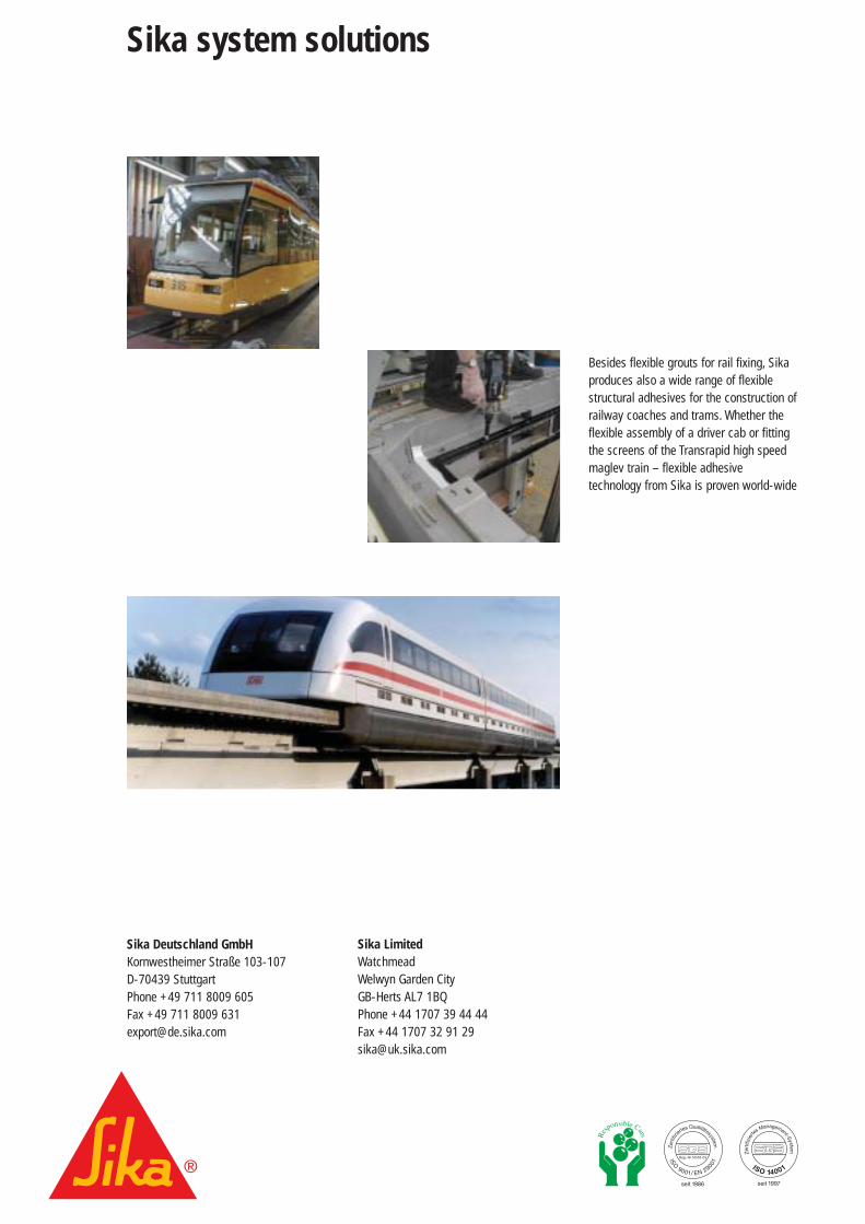
Besides flexible grouts for rail fixing, Sikaproduces also a wide range of flexiblestructural adhesives for the construction ofrailway coaches and trams. Whether theflexible assembly of a driver cab or fittingthe screens of the Transrapid high speedmaglev train – flexible adhesivetechnology from Sika is proven world-wide
Sika LimitedWatchmeadWelwyn Garden CityGB-Herts AL7 1BQPhone +44 1707 39 44 44 Fax +44 1707 32 91 29 [email protected]


![Woodbury Transit Hub Feasibility [Analysis]](https://img.pdfslide.net/doc/110x75/5868e77a1a28aba27d8b9882/woodbury-transit-hub-feasibility-analysis.jpg)


