Embed Size (px)
Citation preview
Hand-Held Pendant Station with Display
HBAS Manual

EUCHNER Hand-Held Pendant Station
092491-07-01/09 Subject to technical modifications Page 2 / 34
Table of contents
1. Mechanical dimensions and Pin assignment .......................................................................3 1.1 Mechanical dimensions.................................................................................................................3 1.2 Pin assignment..............................................................................................................................3
2. Features ...............................................................................................................................3
3. Data transfer.........................................................................................................................5 3.1 Protocol 3964 R.............................................................................................................................5 3.2 Definition of the characters ...........................................................................................................6 3.3 BCC Block Check Character.........................................................................................................7 3.4 Examples for the determination of the BCC..................................................................................7
4. Priorities on a data collision..................................................................................................9
5. Behavior on switch on / initialization...................................................................................11 5.1 Configuration (Konfiguration) menu ........................................................................................... 11
5.1.1 Change PIN (PIN ändern) ..................................................................................................... 12 5.1.2 Priority (Priorität) ................................................................................................................... 12 5.1.3 Version information (Versionsabfrage) ................................................................................. 12 5.1.4 Pulse generator (Impulsgeber) ............................................................................................. 12 5.1.5 Key click (Tasten-Klick)......................................................................................................... 14 5.1.6 Firmware Update................................................................................................................... 14
5.2 Setting the baud rate .................................................................................................................. 14 6. Signaling.............................................................................................................................15
6.1 Acoustic signaling (command byte 52H).................................................................................... 15 6.2 Optical signaling: Status LED.................................................................................................... 15 6.3 Optical signaling: Power LED.................................................................................................... 16
7. Signaling a key change ......................................................................................................16
8. Pulse generator function ....................................................................................................18
9. Initialization.........................................................................................................................19 9.1 Status polling (command byte 23H) ........................................................................................... 19 9.2 Configuration parameter transfer (command byte 53H) ............................................................ 20 9.3 Software reset (command byte 54H) ......................................................................................... 22
10. LC display.........................................................................................................................23 10.1 Character set............................................................................................................................ 24 10.2 LCD functions (identifier 6CH) ................................................................................................. 25
10.2.1 Cursor functions .................................................................................................................. 25 10.2.2 Character output ................................................................................................................. 25 10.2.3 Text attributes...................................................................................................................... 26 10.2.4 Clear commands ................................................................................................................. 27 10.2.5 Text commands................................................................................................................... 27 10.2.6 Area commands .................................................................................................................. 29
10.3 Overview of commands............................................................................................................ 31 11. Installation instructions.....................................................................................................32
12. Technical Data: Pulse generator ......................................................................................32
13. Technical Data: General...................................................................................................33
EUCHNER Hand-Held Pendant Station
1. Mechanical dimensions and Pin assignment
1.1 Mechanical dimensions See data-sheet and operating instruction enclosed to the product.
1.2 Pin assignment See data-sheet and operating instruction enclosed to the product.
2. Features
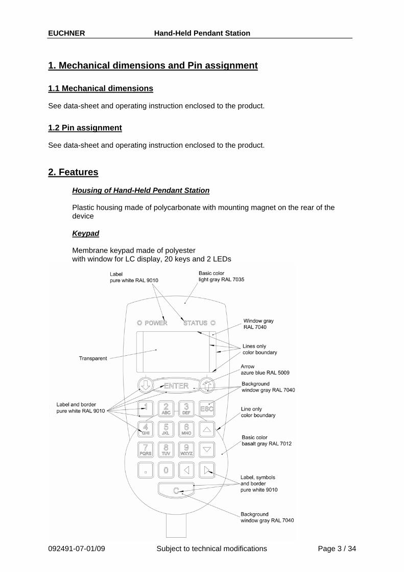
Housing of Hand-Held Pendant Station Plastic housing made of polycarbonate with mounting magnet on the rear of the device
Keypad Membrane keypad made of polyester with window for LC display, 20 keys and 2 LEDs
092491-07-01/09 Subject to technical modifications Page 3 / 34

EUCHNER Hand-Held Pendant Station Switching elements / display elements
On the membrane keypad there are 20 keys with labels, as well as a green POWER LED and a green STATUS LED. The EMERGENCY STOP device is on the top of the device and has rotary unlocking according to EN 418 with 2 normally closed contacts. An enabling switch with a normally open contact is integrated into each side. The contacts are wired separately (see Pin assignment).
Display Gray LC display with LED background lighting 128 x 64 dots, text operating mode
Window: 45.2 x 27.0 mm (W x H) Pixel size: 0.28 mm x 0.34 mm (W x H) Small font: Large font:
Character size: 2.2 mm x 2.62 mm Character size: 4.44 mm x 5.28 mm 16 characters per line, 8 lines 8 characters per line, 4 lines
5.28
mm
4.44 mm
2.2 mm
2.62
mm
Device connection The hand-held pendant station is connected using a 3.5 m spiral cable and a 19-pin round plug connector with pin contacts. The cross-section of all cores is 0.14 mm². The related flange socket is available as an accessory.
092491-07-01/09 Subject to technical modifications Page 4 / 34
EUCHNER Hand-Held Pendant Station
092491-07-01/09 Subject to technical modifications Page 5 / 34
3. Data transfer
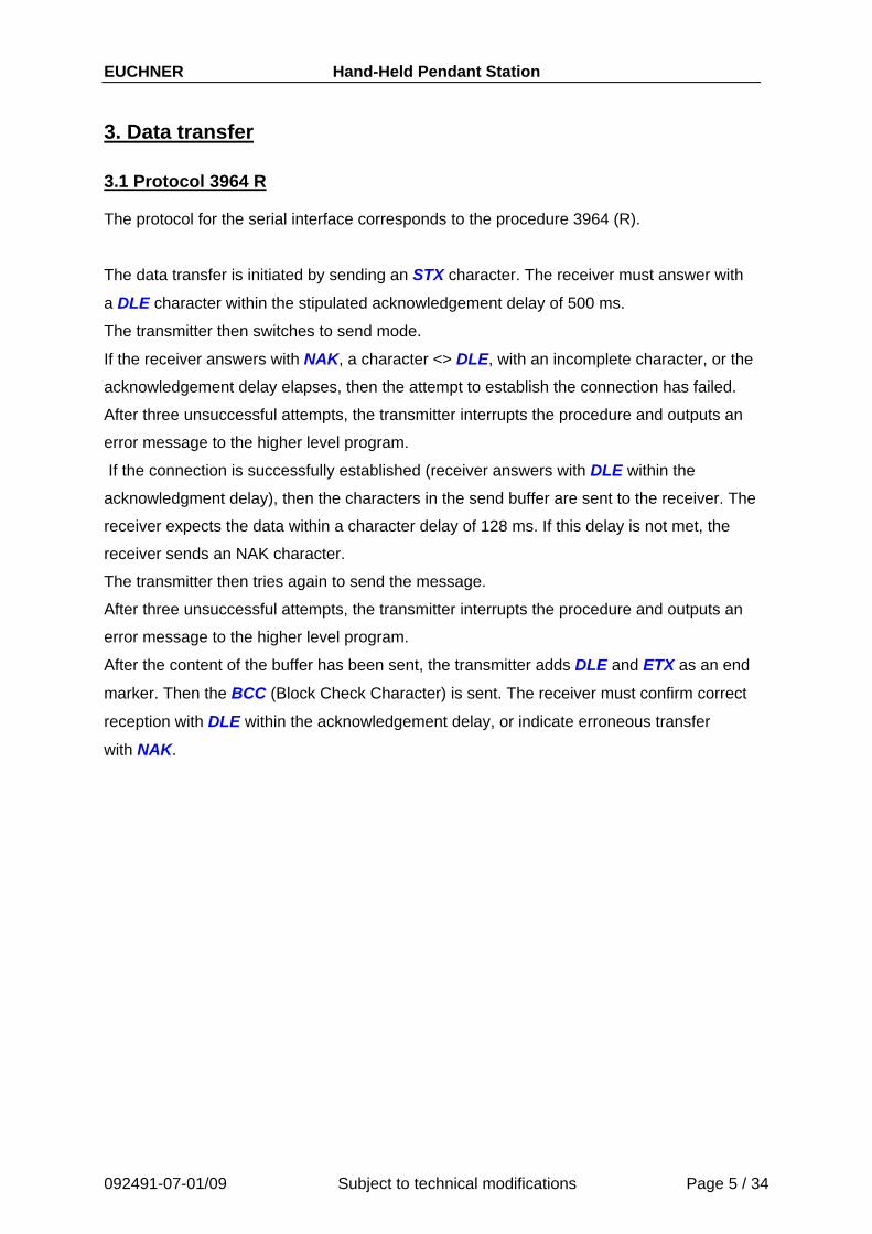
3.1 Protocol 3964 R The protocol for the serial interface corresponds to the procedure 3964 (R).
The data transfer is initiated by sending an STX character. The receiver must answer with
a DLE character within the stipulated acknowledgement delay of 500 ms.
The transmitter then switches to send mode.
If the receiver answers with NAK, a character <> DLE, with an incomplete character, or the
acknowledgement delay elapses, then the attempt to establish the connection has failed.
After three unsuccessful attempts, the transmitter interrupts the procedure and outputs an
error message to the higher level program.
If the connection is successfully established (receiver answers with DLE within the
acknowledgment delay), then the characters in the send buffer are sent to the receiver. The
receiver expects the data within a character delay of 128 ms. If this delay is not met, the
receiver sends an NAK character.
The transmitter then tries again to send the message.
After three unsuccessful attempts, the transmitter interrupts the procedure and outputs an
error message to the higher level program.
After the content of the buffer has been sent, the transmitter adds DLE and ETX as an end
marker. Then the BCC (Block Check Character) is sent. The receiver must confirm correct
reception with DLE within the acknowledgement delay, or indicate erroneous transfer
with NAK.
EUCHNER Hand-Held Pendant Station
092491-07-01/09 Subject to technical modifications Page 6 / 34
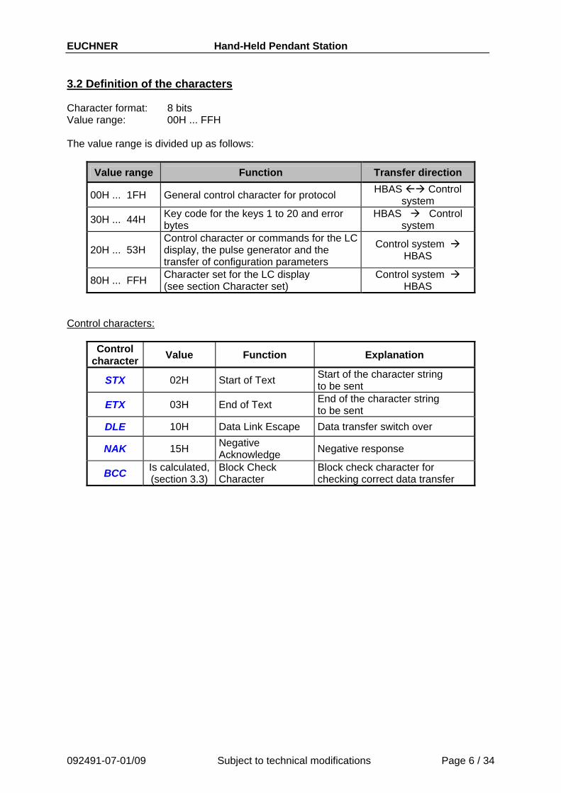
3.2 Definition of the characters Character format: 8 bits Value range: 00H ... FFH The value range is divided up as follows:
Value range Function Transfer direction
00H ... 1FH General control character for protocol HBAS Control system
30H ... 44H Key code for the keys 1 to 20 and error bytes
HBAS Control system
20H ... 53H Control character or commands for the LC display, the pulse generator and the transfer of configuration parameters
Control system HBAS
80H ... FFH Character set for the LC display (see section Character set)
Control system HBAS
Control characters:
Control character Value Function Explanation
STX 02H Start of Text Start of the character string to be sent
ETX 03H End of Text End of the character string to be sent
DLE 10H Data Link Escape Data transfer switch over
NAK 15H Negative Acknowledge Negative response
BCC Is calculated, (section 3.3)
Block Check Character
Block check character for checking correct data transfer
EUCHNER Hand-Held Pendant Station
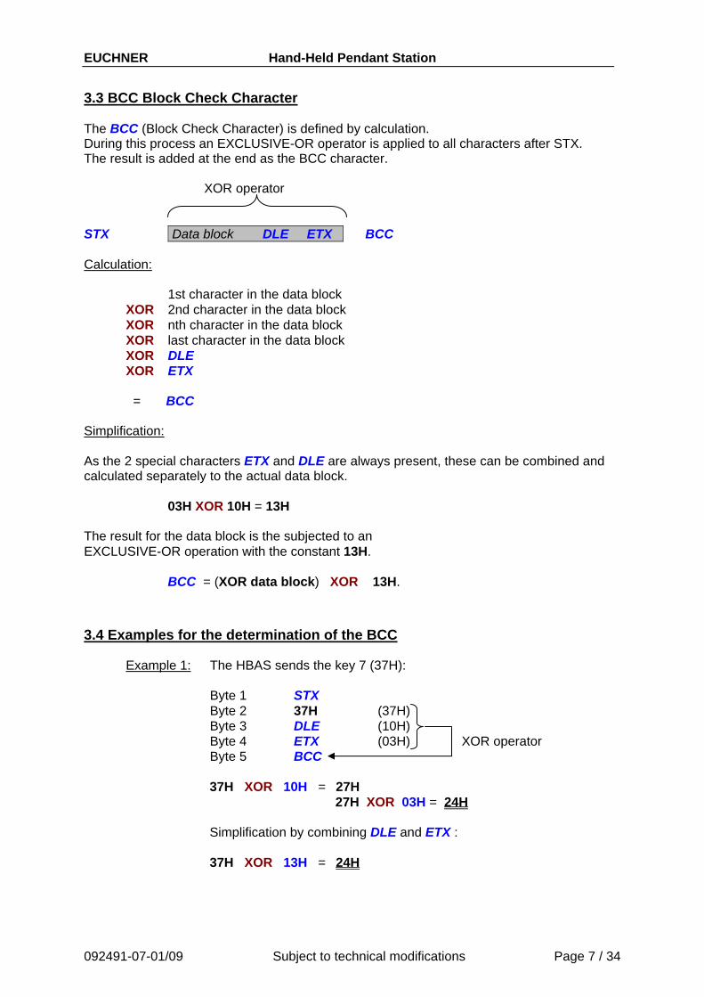
3.3 BCC Block Check Character The BCC (Block Check Character) is defined by calculation. During this process an EXCLUSIVE-OR operator is applied to all characters after STX. The result is added at the end as the BCC character. XOR operator STX Data block DLE ETX BCC Calculation: 1st character in the data block XOR 2nd character in the data block
XOR nth character in the data block XOR last character in the data block XOR DLE XOR ETX
= BCC Simplification: As the 2 special characters ETX and DLE are always present, these can be combined and calculated separately to the actual data block.
03H XOR 10H = 13H
The result for the data block is the subjected to an EXCLUSIVE-OR operation with the constant 13H.
BCC = (XOR data block) XOR 13H.
3.4 Examples for the determination of the BCC
Example 1: The HBAS sends the key 7 (37H): Byte 1 STX Byte 2 37H (37H) Byte 3 DLE (10H) Byte 4 ETX (03H) XOR operator Byte 5 BCC
37H XOR 10H = 27H 27H XOR 03H = 24H
Simplification by combining DLE and ETX :
37H XOR 13H = 24H
092491-07-01/09 Subject to technical modifications Page 7 / 34

EUCHNER Hand-Held Pendant Station
Example 2: The text "Euchner" is output on the display at the current cursor position:
092491-07-01/09 Subject to technical modifications Page 8 / 34
Control system STX 6CH A5H D5H C3H C8H CEH C5H D2H DLE ETX BCC
HBAS DLE DLE
Byte 1 STX Byte 2 6CH LCD identifier byte Byte 3 A5H Byte 4 D5H Byte 5 C3H Byte 6 C8H Byte 7 CEH Byte 8 C5H Byte 9 D2H Byte 10 DLE (10H) Byte 11 ETX (03H) Byte 12 BCC (formed across bytes 2 to 11)
Euchner
Euchner
XOR operator
Calculation:
6CH XOR A5H = C9H Byte 2 XOR Byte 3
C9H XOR D5H = 1CH XOR Byte 4
1CH XOR C3H = DFH XOR Byte 5 DFH XOR C8H = 17H XOR Byte 6 17H XOR CEH = D9H XOR Byte 7 D9H XOR C5H = 1CH XOR Byte 8 1CH XOR D2H = CEH XOR Byte 9 CEH XOR 10H = DEH XOR Byte 10 DEH XOR 03H = DDH XOR Byte 11
BCC = DDH
Simplification by combining DLE and ETX :
6CH XOR A5H XOR D5H XOR C3H XOR C8H XOR CEH XOR C5H XOR D2H = CEH
CEH XOR 13H = DDH
EUCHNER Hand-Held Pendant Station
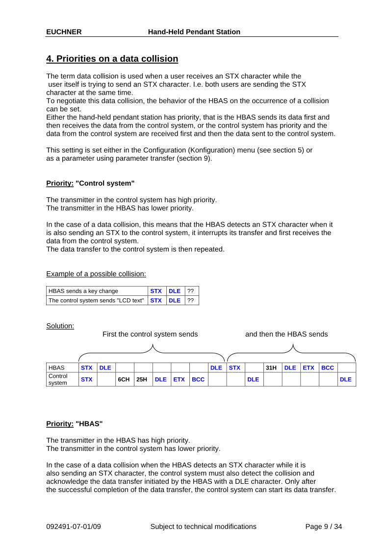
4. Priorities on a data collision The term data collision is used when a user receives an STX character while the user itself is trying to send an STX character. I.e. both users are sending the STX character at the same time. To negotiate this data collision, the behavior of the HBAS on the occurrence of a collision can be set. Either the hand-held pendant station has priority, that is the HBAS sends its data first and then receives the data from the control system, or the control system has priority and the data from the control system are received first and then the data sent to the control system. This setting is set either in the Configuration (Konfiguration) menu (see section 5) or as a parameter using parameter transfer (section 9). Priority: "Control system" The transmitter in the control system has high priority. The transmitter in the HBAS has lower priority. In the case of a data collision, this means that the HBAS detects an STX character when it is also sending an STX to the control system, it interrupts its transfer and first receives the data from the control system. The data transfer to the control system is then repeated. Example of a possible collision: HBAS sends a key change STX DLE ?? The control system sends "LCD text" STX DLE ??
Solution: First the control system sends and then the HBAS sends
092491-07-01/09 Subject to technical modifications Page 9 / 34
HBAS STX DLE DLE STX 31H DLE ETX BCC Control system STX 6CH 25H DLE ETX BCC DLE DLE
Priority: "HBAS" The transmitter in the HBAS has high priority. The transmitter in the control system has lower priority. In the case of a data collision when the HBAS detects an STX character while it is also sending an STX character, the control system must also detect the collision and acknowledge the data transfer initiated by the HBAS with a DLE character. Only after the successful completion of the data transfer, the control system can start its data transfer.

EUCHNER Hand-Held Pendant Station Example of a possible collision: HBAS sends a key change STX ?? The control system sends "LCD text" STX ??
Solution: First the HBAS sends then the control system sends
092491-07-01/09 Subject to technical modifications Page 10 / 34
HBAS STX 31H DLE ETX BCC DLE DLE Control system STX DLE DLE STX 6CH 25H DLE ETX BCC
Structure chart send/receive routine for the control
Check input buffer for new character
If receive new character
then else
call Receive routine
Wait for new character
If new character = DLE
then else
If new character = STX
then else
If new character = DLE
then else
Send NAK
Send NAK
call Status check
call Status checkSend data
Wait for new character
Send dataStart new transfer routine
Send STX
Receive routine Status check
Send status request (#)
Wait for status information
Evaluate status
Send DLE
Check input buffer for new character
If receive new character
then
else
If new character = STX
then
Receive data block
Check BCC
If BCC = ok
elsethen
Send DLE
Send NAKEvaluate key change + error byte
Send NAK
exit sub
else
EUCHNER Hand-Held Pendant Station
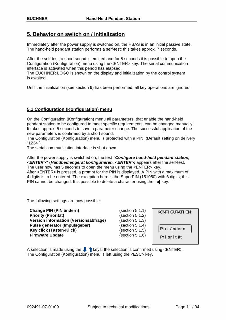
5. Behavior on switch on / initialization Immediately after the power supply is switched on, the HBAS is in an initial passive state. The hand-held pendant station performs a self-test; this takes approx. 7 seconds. After the self-test, a short sound is emitted and for 5 seconds it is possible to open the Configuration (Konfiguration) menu using the <ENTER> key. The serial communication interface is activated when this period has elapsed. The EUCHNER LOGO is shown on the display and initialization by the control system is awaited. Until the initialization (see section 9) has been performed, all key operations are ignored.
5.1 Configuration (Konfiguration) menu On the Configuration (Konfiguration) menu all parameters, that enable the hand-held pendant station to be configured to meet specific requirements, can be changed manually. It takes approx. 5 seconds to save a parameter change. The successful application of the new parameters is confirmed by a short sound. The Configuration (Konfiguration) menu is protected with a PIN. (Default setting on delivery "1234"). The serial communication interface is shut down. After the power supply is switched on, the text "Configure hand-held pendant station, <ENTER>“ (Handbediengerät konfigurieren, <ENTER>) appears after the self-test. The user now has 5 seconds to open the menu using the <ENTER> key. After <ENTER> is pressed, a prompt for the PIN is displayed. A PIN with a maximum of 4 digits is to be entered. The exception here is the SuperPIN (151050) with 6 digits; this PIN cannot be changed. It is possible to delete a character using the key. The following settings are now possible:
Change PIN (PIN ändern) (section 5.1.1) Priority (Priorität) (section 5.1.2) Version information (Versionsabfrage) (section 5.1.3)
092491-07-01/09 Subject to technical modifications Page 11 / 34
Pulse generator (Impulsgeber) (section 5.1.4) Key click (Tasten-Klick) (section 5.1.5) Firmware Update (section 5.1.6)
Pin ändern Priorität
KONFIGURATION:
A selection is made using the keys, the selection is confirmed using <ENTER>. The Configuration (Konfiguration) menu is left using the <ESC> key.
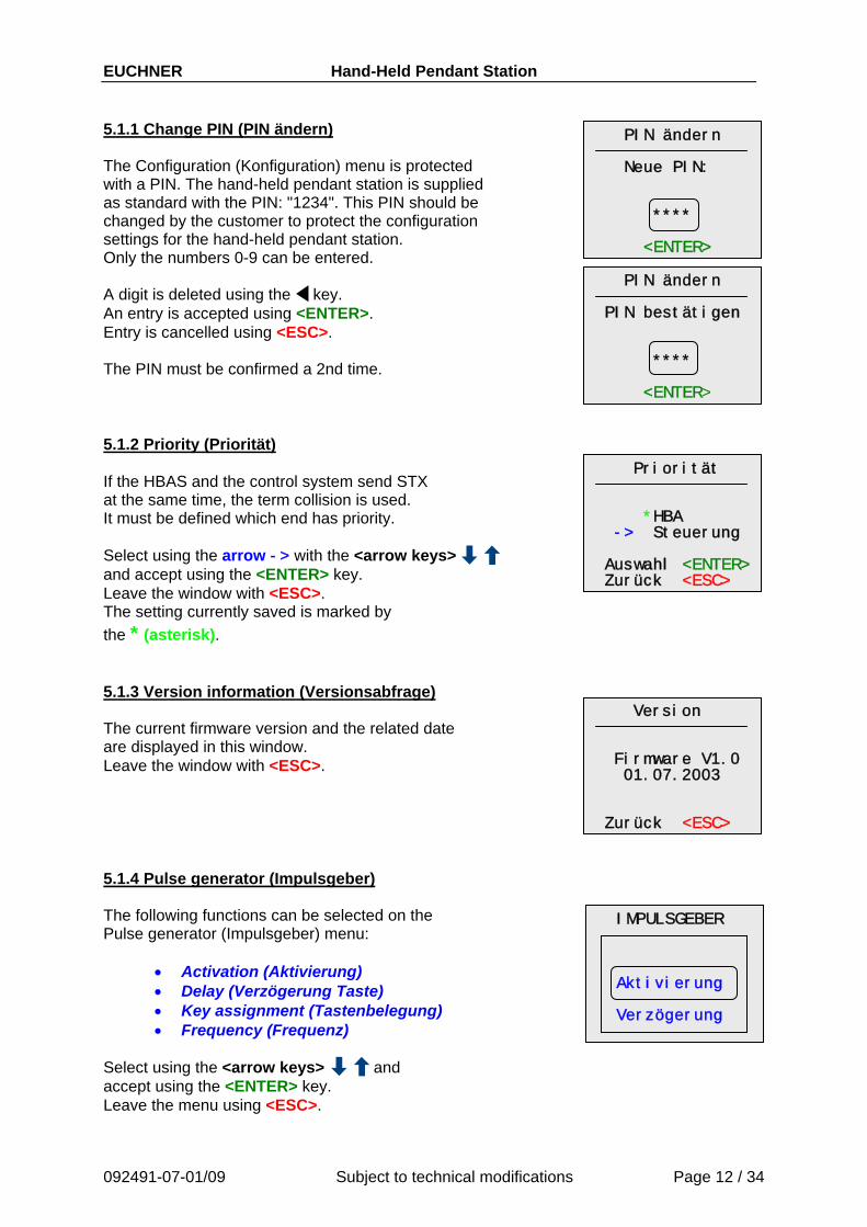
EUCHNER Hand-Held Pendant Station 5.1.1 Change PIN (PIN ändern) PIN ändern
Neue PIN: **** <ENTER>
PIN ändern PIN bestätigen **** <ENTER>
Priorität *HBA -> Steuerung Auswahl <ENTER> Zurück <ESC>
The Configuration (Konfiguration) menu is protected with a PIN. The hand-held pendant station is supplied as standard with the PIN: "1234". This PIN should be changed by the customer to protect the configuration settings for the hand-held pendant station. Only the numbers 0-9 can be entered. A digit is deleted using the key. An entry is accepted using <ENTER>. Entry is cancelled using <ESC>. The PIN must be confirmed a 2nd time. 5.1.2 Priority (Priorität) If the HBAS and the control system send STX at the same time, the term collision is used. It must be defined which end has priority. Select using the arrow -> with the <arrow keys> and accept using the <ENTER> key. Leave the window with <ESC>. The setting currently saved is marked by the * (asterisk). 5.1.3 Version information (Versionsabfrage)
Version Firmware V1.0 01.07.2003 Zurück <ESC>
The current firmware version and the related date are displayed in this window. Leave the window with <ESC>. 5.1.4 Pulse generator (Impulsgeber) The following functions can be selected on the Pulse generator (Impulsgeber) menu:
IMPULSGEBER Aktivierung Verzögerung
• Activation (Aktivierung) • Delay (Verzögerung Taste) • Key assignment (Tastenbelegung) • Frequency (Frequenz)
Select using the <arrow keys> and accept using the <ENTER> key. Leave the menu using <ESC>.
092491-07-01/09 Subject to technical modifications Page 12 / 34
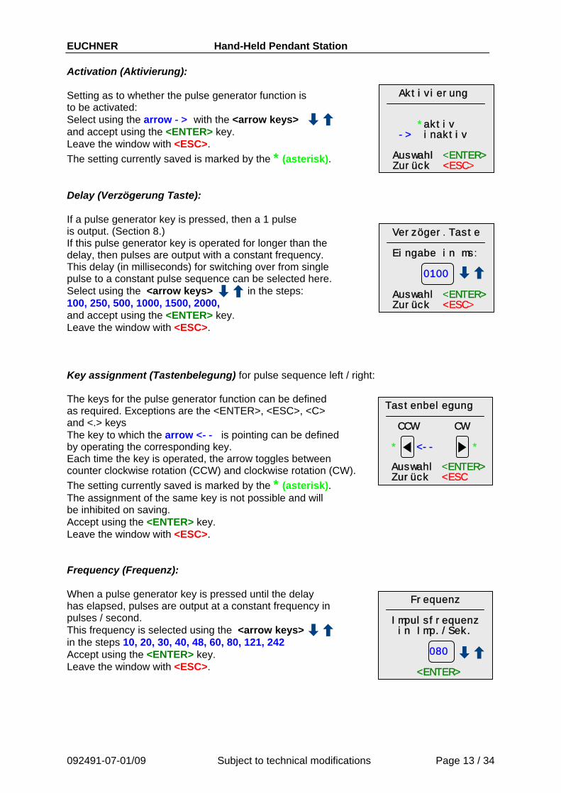
EUCHNER Hand-Held Pendant Station Activation (Aktivierung):
Aktivierung *aktiv -> inaktiv Auswahl <ENTER> Zurück <ESC>
Setting as to whether the pulse generator function is to be activated: Select using the arrow -> with the <arrow keys> and accept using the <ENTER> key. Leave the window with <ESC>. The setting currently saved is marked by the * (asterisk). Delay (Verzögerung Taste): If a pulse generator key is pressed, then a 1 pulse is output. (Section 8.) Verzöger.Taste
Eingabe in ms: 0100 Auswahl <ENTER> Zurück <ESC>
If this pulse generator key is operated for longer than the delay, then pulses are output with a constant frequency. This delay (in milliseconds) for switching over from single pulse to a constant pulse sequence can be selected here. Select using the <arrow keys> in the steps: 100, 250, 500, 1000, 1500, 2000, and accept using the <ENTER> key. Leave the window with <ESC>. Key assignment (Tastenbelegung) for pulse sequence left / right: The keys for the pulse generator function can be defined as required. Exceptions are the <ENTER>, <ESC>, <C> and <.> keys
Tastenbelegung CCW CW * <-- * Auswahl <ENTER> Zurück <ESC
The key to which the arrow <-- is pointing can be defined by operating the corresponding key. Each time the key is operated, the arrow toggles between counter clockwise rotation (CCW) and clockwise rotation (CW). The setting currently saved is marked by the * (asterisk). The assignment of the same key is not possible and will be inhibited on saving. Accept using the <ENTER> key. Leave the window with <ESC>. Frequency (Frequenz): When a pulse generator key is pressed until the delay has elapsed, pulses are output at a constant frequency in pulses / second.
Frequenz Impulsfrequenz in Imp./Sek. 080 <ENTER>
This frequency is selected using the <arrow keys> in the steps 10, 20, 30, 40, 48, 60, 80, 121, 242 Accept using the <ENTER> key. Leave the window with <ESC>.
092491-07-01/09 Subject to technical modifications Page 13 / 34
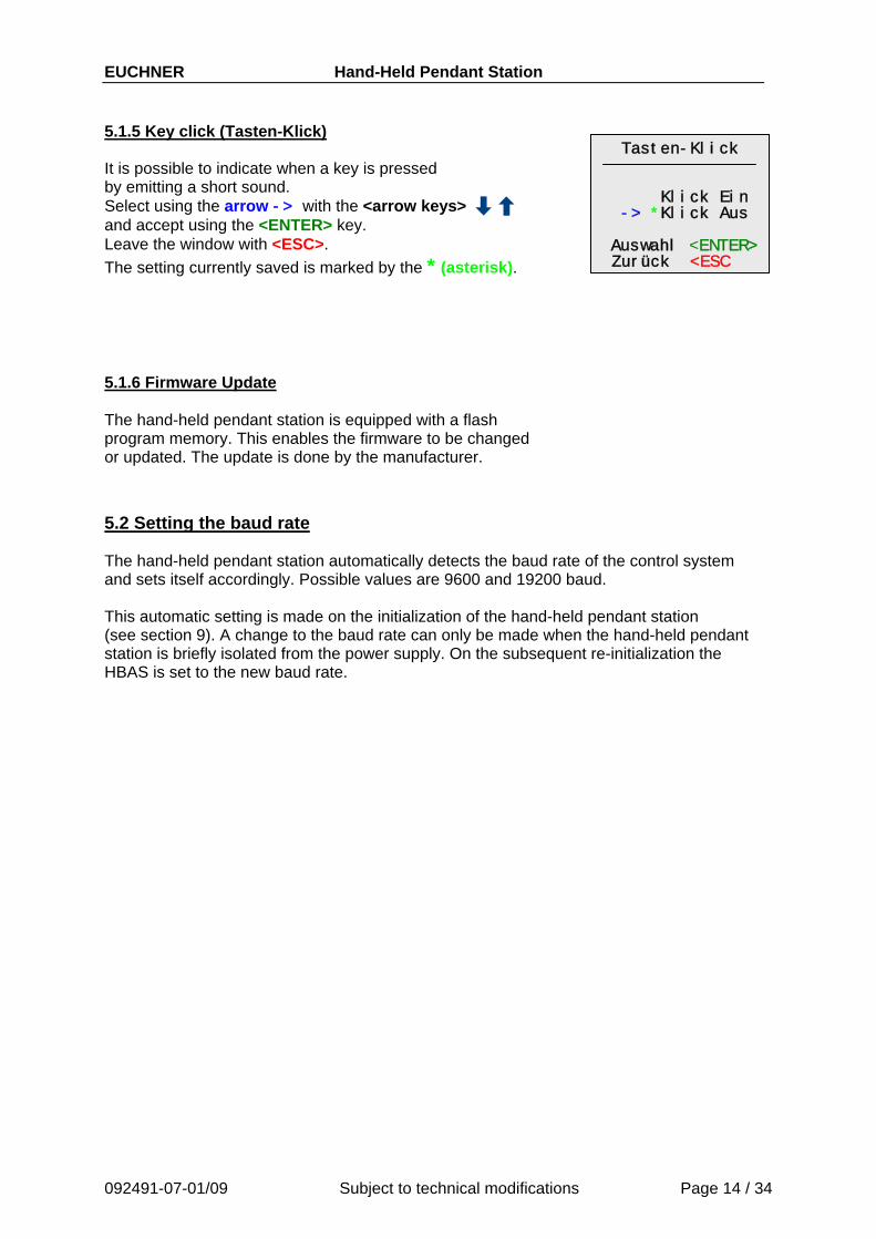
EUCHNER Hand-Held Pendant Station 5.1.5 Key click (Tasten-Klick)
Tasten-Klick Klick Ein -> *Klick Aus Auswahl <ENTER> Zurück <ESC
It is possible to indicate when a key is pressed by emitting a short sound. Select using the arrow -> with the <arrow keys> and accept using the <ENTER> key. Leave the window with <ESC>. The setting currently saved is marked by the * (asterisk). 5.1.6 Firmware Update The hand-held pendant station is equipped with a flash program memory. This enables the firmware to be changed or updated. The update is done by the manufacturer.
5.2 Setting the baud rate The hand-held pendant station automatically detects the baud rate of the control system and sets itself accordingly. Possible values are 9600 and 19200 baud. This automatic setting is made on the initialization of the hand-held pendant station (see section 9). A change to the baud rate can only be made when the hand-held pendant station is briefly isolated from the power supply. On the subsequent re-initialization the HBAS is set to the new baud rate.
092491-07-01/09 Subject to technical modifications Page 14 / 34
EUCHNER Hand-Held Pendant Station
092491-07-01/09 Subject to technical modifications Page 15 / 34
6. Signaling
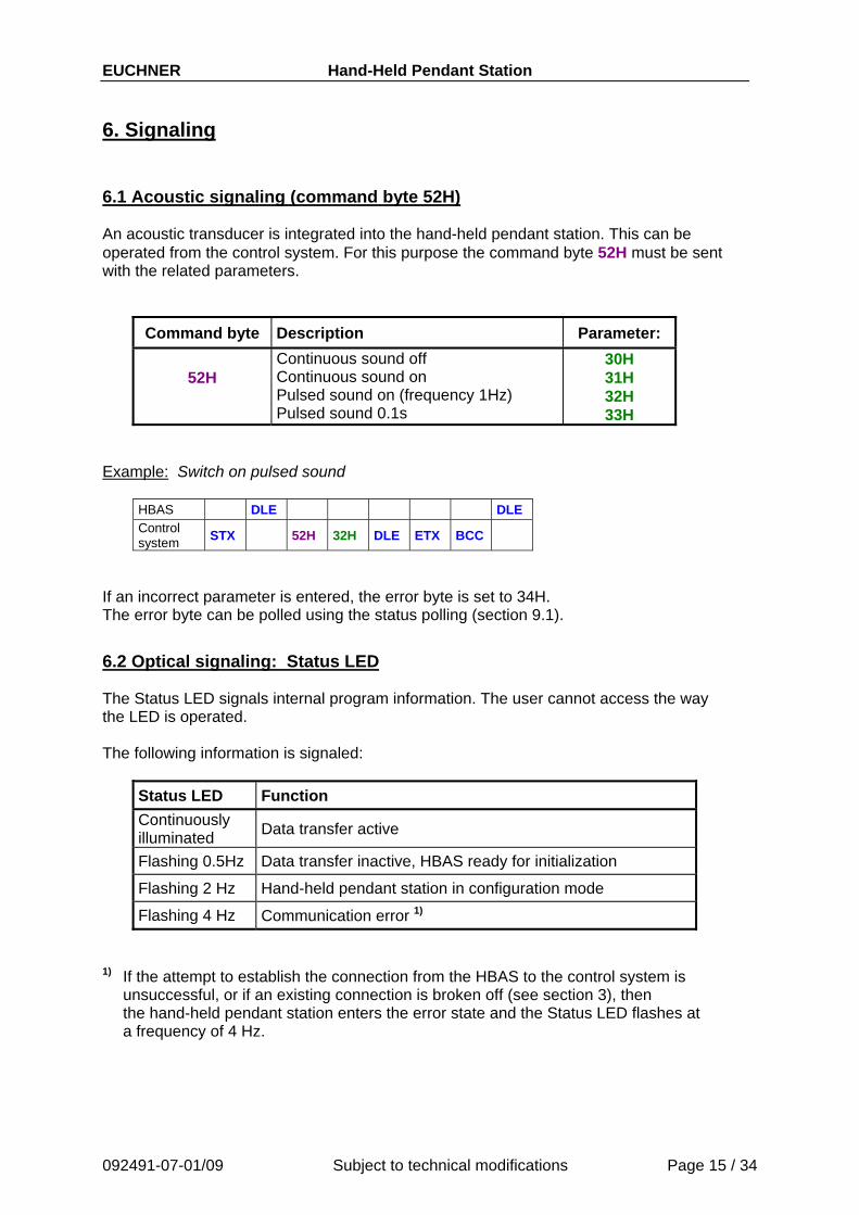
6.1 Acoustic signaling (command byte 52H) An acoustic transducer is integrated into the hand-held pendant station. This can be operated from the control system. For this purpose the command byte 52H must be sent with the related parameters.
Command byte Description Parameter:
52H Continuous sound off Continuous sound on Pulsed sound on (frequency 1Hz) Pulsed sound 0.1s
30H 31H 32H 33H
Example: Switch on pulsed sound
HBAS DLE DLE Control system STX 52H 32H DLE ETX BCC
If an incorrect parameter is entered, the error byte is set to 34H. The error byte can be polled using the status polling (section 9.1).
6.2 Optical signaling: Status LED The Status LED signals internal program information. The user cannot access the way the LED is operated. The following information is signaled:
Status LED Function Continuously illuminated Data transfer active
Flashing 0.5Hz Data transfer inactive, HBAS ready for initialization
Flashing 2 Hz Hand-held pendant station in configuration mode
Flashing 4 Hz Communication error 1) 1) If the attempt to establish the connection from the HBAS to the control system is
unsuccessful, or if an existing connection is broken off (see section 3), then the hand-held pendant station enters the error state and the Status LED flashes at a frequency of 4 Hz.
EUCHNER Hand-Held Pendant Station 6.3 Optical signaling: Power LED The Power LED signals the correct supply of power. The following information is indicated:
Power LED Function Off Voltage too low Flashing Power supply in the critical range. no function Continuously illuminated Power supply correct
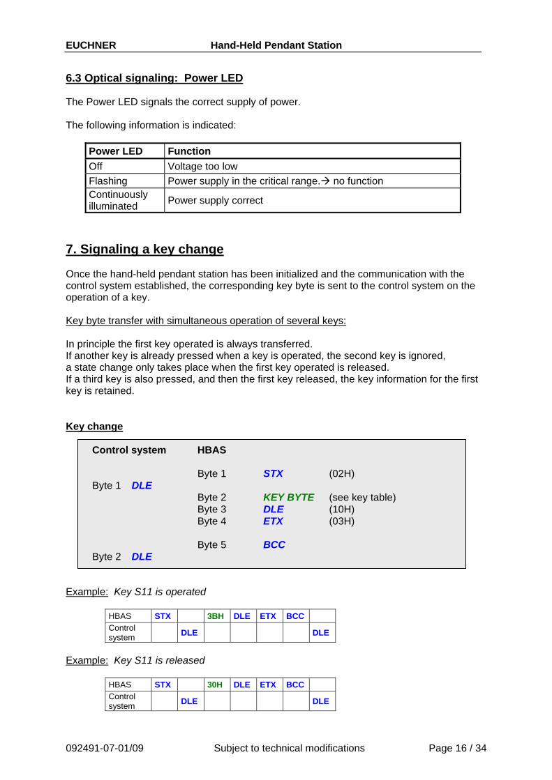
7. Signaling a key change Once the hand-held pendant station has been initialized and the communication with the control system established, the corresponding key byte is sent to the control system on the operation of a key. Key byte transfer with simultaneous operation of several keys: In principle the first key operated is always transferred. If another key is already pressed when a key is operated, the second key is ignored, a state change only takes place when the first key operated is released. If a third key is also pressed, and then the first key released, the key information for the first key is retained. Key change
Control system HBAS Byte 1 STX (02H) Byte 1 DLE Byte 2 KEY BYTE (see key table)
Byte 3 DLE (10H) Byte 4 ETX (03H) Byte 5 BCC Byte 2 DLE
Example: Key S11 is operated
HBAS STX 3BH DLE ETX BCC Control system DLE DLE
Example: Key S11 is released
HBAS STX 30H DLE ETX BCC Control system DLE DLE
092491-07-01/09 Subject to technical modifications Page 16 / 34
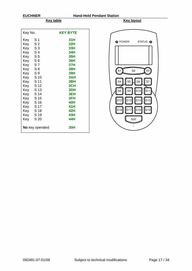
EUCHNER Hand-Held Pendant Station Key table Key layout
Key No. KEY BYTE
092491-07-01/09 Subject to technical modifications Page 17 / 34
Key S 1 31H Key S 2 32H Key S 3 33H Key S 4 34H Key S 5 35H Key S 6 36H Key S 7 37H Key S 8 38H Key S 9 39H Key S 10 3AH Key S 11 3BH Key S 12 3CH Key S 13 3DH Key S 14 3EH Key S 15 3FH Key S 16 40H Key S 17 41H Key S 18 42H Key S 19 43H Key S 20 44H No key operated 30H
POWER STATUS
S1 S2 S3
S4 S5 S6 S7
S8 S9 S10 S11
S14 S15S12 S13
S18 S19S16 S17
S20
EUCHNER Hand-Held Pendant Station
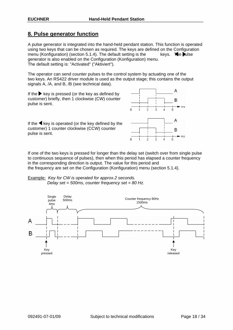
8. Pulse generator function A pulse generator is integrated into the hand-held pendant station. This function is operated using two keys that can be chosen as required. The keys are defined on the Configuration menu (Konfiguration) (section 5.1.4). The default setting is the keys. The pulse generator is also enabled on the Configuration (Konfiguration) menu. The default setting is: "Activated" ("Aktiviert"). The operator can send counter pulses to the control system by actuating one of the two keys. An RS422 driver module is used as the output stage; this contains the output signals A, /A, and B, /B (see technical data). If the key is pressed (or the key as defined by customer) briefly, then 1 clockwise (CW) counter pulse is sent. If the key is operated (or the key defined by the customer) 1 counter clockwise (CCW) counter pulse is sent. If one of the two keys is pressed for longer than the delay set (switch over from single pulse to continuous sequence of pulses), then when this period has elapsed a counter frequency in the corresponding direction is output. The value for this period and the frequency are set on the Configuration (Konfiguration) menu (section 5.1.4). Example: Key for CW is operated for approx.2 seconds.
Delay set = 500ms, counter frequency set = 80 Hz.
Delay 500ms
Single pulse 4ms
Counter frequency 80Hz 1500ms
Key pressed
Key released
092491-07-01/09 Subject to technical modifications Page 18 / 34
EUCHNER Hand-Held Pendant Station
9. Initialization To enable the communication interface, the hand-held pendant station must be initialized. The initialization is performed either by polling the current states of the keys with the "Status polling" ("Statusabfrage") function (section 9.1) and the transfer of parameters (section 9.2), or by sending another valid command byte (section 10.3 Overview of commands). The baud rate is also set on initialization (see section 5).
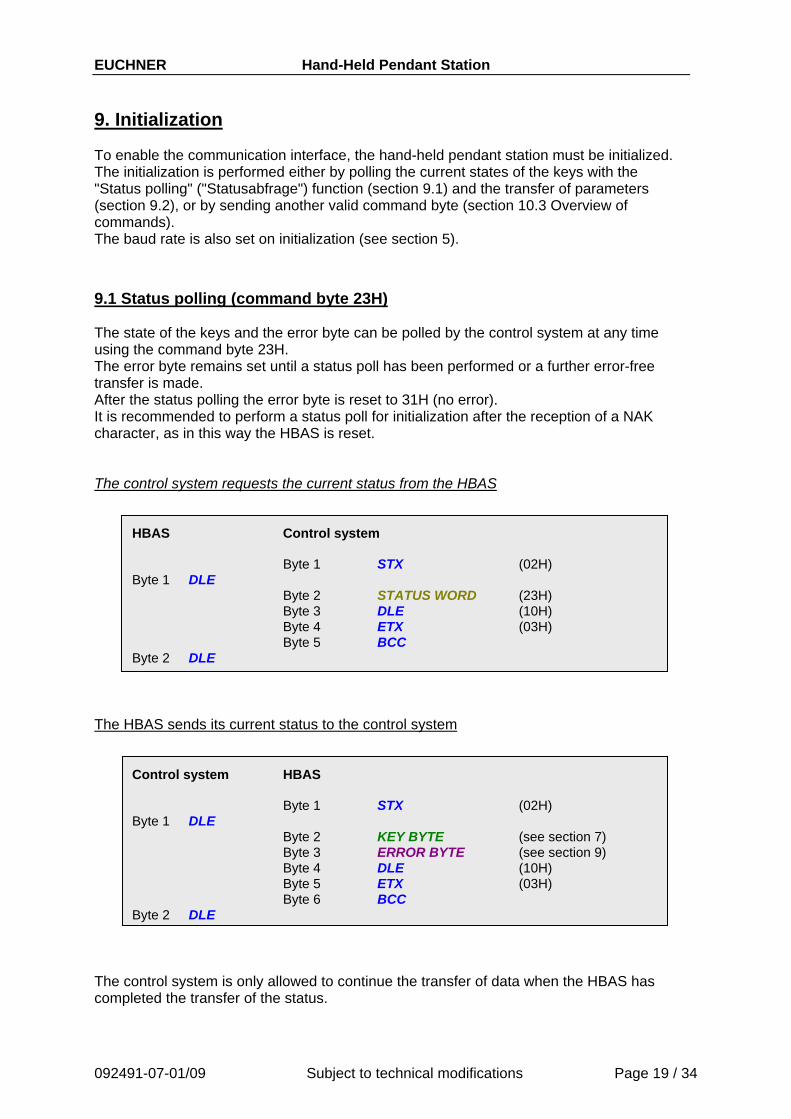
9.1 Status polling (command byte 23H) The state of the keys and the error byte can be polled by the control system at any time using the command byte 23H. The error byte remains set until a status poll has been performed or a further error-free transfer is made. After the status polling the error byte is reset to 31H (no error). It is recommended to perform a status poll for initialization after the reception of a NAK character, as in this way the HBAS is reset. The control system requests the current status from the HBAS
HBAS Control system Byte 1 STX (02H) Byte 1 DLE Byte 2 STATUS WORD (23H) Byte 3 DLE (10H) Byte 4 ETX (03H) Byte 5 BCC Byte 2 DLE
The HBAS sends its current status to the control system
Control system HBAS Byte 1 STX (02H) Byte 1 DLE Byte 2 KEY BYTE (see section 7) Byte 3 ERROR BYTE (see section 9) Byte 4 DLE (10H) Byte 5 ETX (03H) Byte 6 BCC Byte 2 DLE
The control system is only allowed to continue the transfer of data when the HBAS has completed the transfer of the status.
092491-07-01/09 Subject to technical modifications Page 19 / 34

EUCHNER Hand-Held Pendant Station Example: Status request and sending key S11 and error byte 31H
092491-07-01/09 Subject to technical modifications Page 20 / 34
HBAS DLE DLE STX 3BH 31H DLE ETX BCC
Control system requests status
HBAS sends key and error byte
Control system STX 23H DLE ETX BCC DLE DLE
Error bytes If an incorrect parameter is transferred for a command that requires a parameter, this error byte can be polled by polling the status. The error byte is sent after the key information. The following error messages are possible:
Error byte Error Explanation
31H No error Error-free operating state
32H Text not defined An item of text opened with a short command has not yet been defined
33H Area not defined An area opened with a short command has not yet been defined
34H Parameter invalid A parameter entered is outside the valid value range
35H Too many parameters The number of the parameters given does not correspond to the number expected
36H Area invalid An area opened overlaps with a character that is displayed with the large font. (Section 10.2.6)
9.2 Configuration parameter transfer (command byte 53H) All parameters that can be set on the Configuration (Konfiguration) menu can be transferred from the control system at any time. For this purpose the command byte 53H must be set before the parameter data. After the data transfer has been started, the STATUS LED goes out. The display is cleared and the text "Save param." ("Par. speichern") output. A short sound is emitted by the HBAS as an acknowledgement of the correct storage of the data in the flash and the text "Save param." ("Par. speichern") is cleared. If a parameter is not given correctly, then the error byte "34H" is set. The error byte can be polled by the control system by polling the status.

EUCHNER Hand-Held Pendant Station
092491-07-01/09 Subject to technical modifications Page 21 / 34
It is imperative that the following sequence for the individual parameters is observed!
1. PIN 2. Priority 3. Key click 4. Pulse generator activation 5. Pulse generator delay (when pulse generator active) 6. Pulse generator CW key (when pulse generator active) 7. Pulse generator CCW key (when pulse generator active) 8. Pulse generator frequency (when pulse generator active)
If the pulse generator function is not activated, then the pulse generator parameters
"Pulse generator delay", "Pulse generator CW key", "Pulse generator CCW key" "Pulse generator frequency"
do not need to be transferred. Parameter
no. Explanation Parameter value
1 PIN: 1000s digit Only figures 0-9 in HEX format 30H ... 39H
2 PIN: 100s digit Only figures 0-9 in HEX format 30H ... 39H
3 PIN: 10s digit Only figures 0-9 in HEX format 30H ... 39H
4 PIN: 1s digit Only figures 0-9 in HEX format 30H ... 39H
5 Priority: 30H = Control system has priority 31H = HBAS has priority
6 Key click 30H = Key click off 31H = Key click on
7 Pulse generator activation 30H = Pulse generator inactive 31H= Pulse generator active
8 Pulse generator delay 1000s Only figures 0-9 in HEX format 30H ... 39H
9 Pulse generator delay 100s Only figures 0-9 in HEX format 30H ... 39H
10 Pulse generator delay 10s Only figures 0-9 in HEX format 30H ... 39H
11 Pulse generator delay 1s Only figures 0-9 in HEX format 30H ... 39H
12 Pulse generator CW key All keys except S2 (32H), S7 (37H), S16 (40H), and S20 (44H)
13 Pulse generator CCW key All keys except S2 (32H), S7 (37H), S16 (40H), and S20 (44H)
14 Pulse generator freq. in Hz 100s Only figures 0-9 in HEX format 30H ... 39H
15 Pulse generator freq. in Hz 10s Only figures 0-9 in HEX format 30H ... 39H
16 Pulse generator freq. in Hz 1s Only figures 0-9 in HEX format 30H ... 39H
Error byte:
31H: Parameters transferred correctly 34H: Parameter transfer erroneous

EUCHNER Hand-Held Pendant Station Example: Pulse generator active
Cmd. byte PIN Priority Click
Pulse gen.
activeDelay 1500 ms CW CCW Freq.121Hz
Control system STX 53H 36H 37H 38H 39H 30H 30H 31H 31H 35H 30H 30H 43H 42H 31H 32H 31H DLE ETX BCC
HBAS DLE DLE
Example: Pulse generator inactive
Cmd. byte PIN Priority Click
Pulse gen.
active
Control system STX 53H 36H 37H 38H 39H 30H 30H 30H DLE ETX BCC
HBAS DLE DLE
Default parameters When the hand-held pendant station is delivered, the following parameters are set:
Parameters Value PIN 1234 Priority Control system Key click off Pulse generator activation on Pulse generator delay 1000 ms Pulse generator CW key key Pulse generator CCW key key Pulse generator frequency 80 pulses/sec.
9.3 Software reset (command byte 54H) The control system can initiate a software reset in the HBAS. Therefor the command byte 54H must be sent. The hand-held pendant station restarts. See section 5. Example:
Control system STX 54H DLE ETX BCC HBAS DLE DLE
092491-07-01/09 Subject to technical modifications Page 22 / 34

EUCHNER Hand-Held Pendant Station
10. LC display The display on the hand-held pendant station is operated in text mode. To display text, the control system must send information on the type and the content of the display. Text to be displayed frequently can be transferred to the HBAS at any time after initialization and saved in the HBAS in a data memory (RAM). These items of text can then be displayed using a short command (section 10.2.5). It is also possible to define areas and to assign attributes to them. These areas can also be displayed with a short command (section 10.2.6). Controlling the LC display Each LCD data block that contains a command for controlling the display must have the LCD identifier byte as the first character. This is defined as 6CH. An LCD data block can contain several LCD commands, however the block must not exceed the length of 135 bytes. Command to the LC display:
Control system HBAS/LCD Byte 1 STX (02H)
Byte 1 DLE (10H) Byte 2 LCD data block Byte 3 DLE (10H) Byte 4 ETX (03H) Byte 5 BCC
Byte 2 DLE (10H)
Important! It is not allowed to interrupt a data block that has already been confirmed with DLE. Prior to a new transfer, it is necessary to check the receive buffer for a STX from the HBAS.
092491-07-01/09 Subject to technical modifications Page 23 / 34

EUCHNER Hand-Held Pendant Station
092491-07-01/09 Subject to technical modifications Page 24 / 34
10.1 Character set ASCII character set from 80H ... FFH
0 1 2 3 4 5 6 7 8 9 A B C D E F 8 ! “ # $ % & ´ ( ) * + , - . / 9 0 1 2 3 4 5 6 7 8 9 : ; < = > ? A @ A B C D E F G H I J K L M N O B P Q R S T U V W X Y Z [ \ ] ^ _ C ` a b c d e f g h i j k l m n o D p q r s t u v w x y z { ¦ } ~ E Ç ü é â ä à å ç ê ë è ï î ì Ä Å F É æ Æ ô ö ò û ù ÿ Ö Ü ø £ Ø × ƒ
EUCHNER Hand-Held Pendant Station
092491-07-01/09 Subject to technical modifications Page 25 / 34
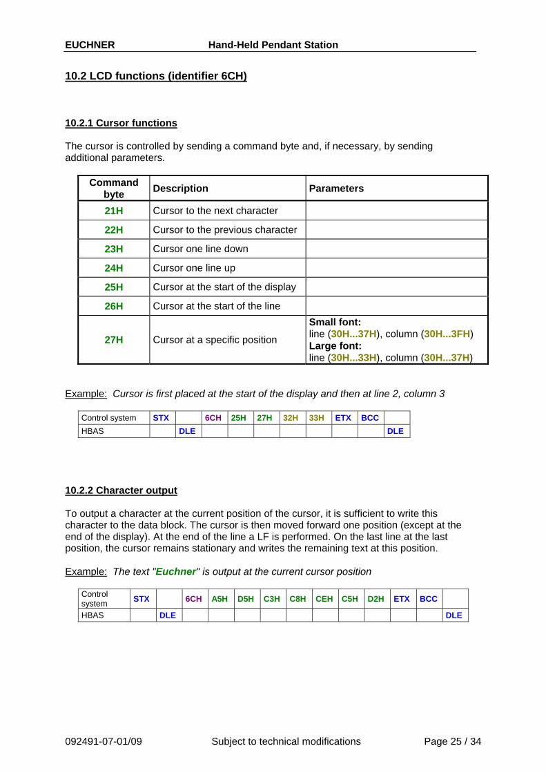
10.2 LCD functions (identifier 6CH) 10.2.1 Cursor functions The cursor is controlled by sending a command byte and, if necessary, by sending additional parameters.
Command byte Description Parameters
21H Cursor to the next character
22H Cursor to the previous character
23H Cursor one line down
24H Cursor one line up
25H Cursor at the start of the display
26H Cursor at the start of the line
27H Cursor at a specific position
Small font: line (30H...37H), column (30H...3FH) Large font: line (30H...33H), column (30H...37H)
Example: Cursor is first placed at the start of the display and then at line 2, column 3
Control system STX 6CH 25H 27H 32H 33H ETX BCC HBAS DLE DLE
10.2.2 Character output To output a character at the current position of the cursor, it is sufficient to write this character to the data block. The cursor is then moved forward one position (except at the end of the display). At the end of the line a LF is performed. On the last line at the last position, the cursor remains stationary and writes the remaining text at this position. Example: The text "Euchner" is output at the current cursor position
Control system STX 6CH A5H D5H C3H C8H CEH C5H D2H ETX BCC
HBAS DLE DLE
EUCHNER Hand-Held Pendant Station
092491-07-01/09 Subject to technical modifications Page 26 / 34
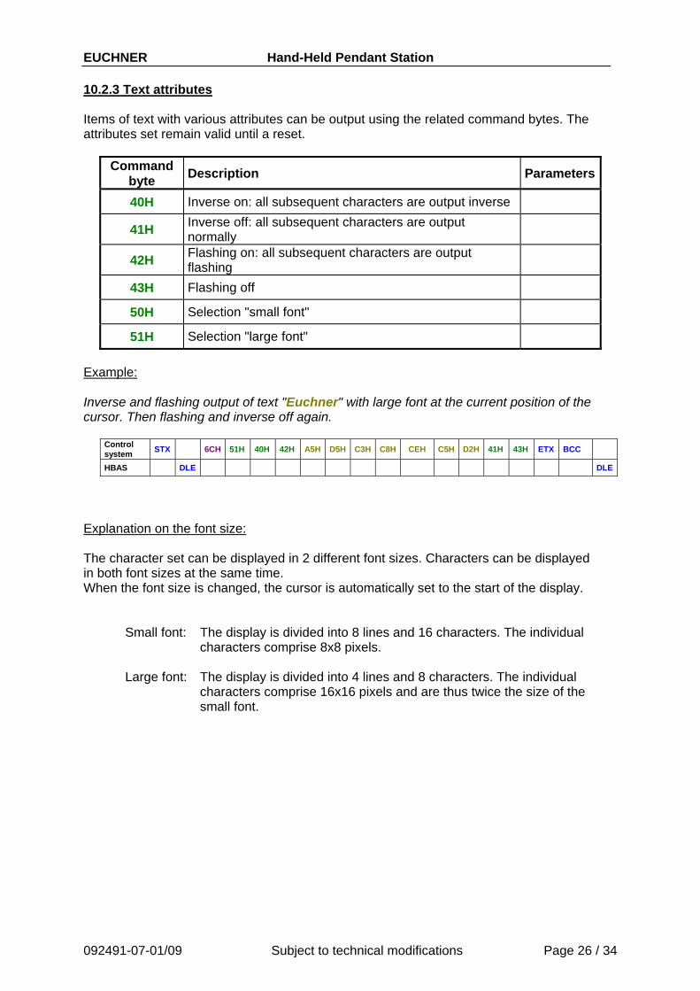
10.2.3 Text attributes
Items of text with various attributes can be output using the related command bytes. The attributes set remain valid until a reset.
Command byte Description Parameters
40H Inverse on: all subsequent characters are output inverse
41H Inverse off: all subsequent characters are output normally
42H Flashing on: all subsequent characters are output flashing
43H Flashing off
50H Selection "small font"
51H Selection "large font" Example: Inverse and flashing output of text "Euchner" with large font at the current position of the cursor. Then flashing and inverse off again.
Control system STX 6CH 51H 40H 42H A5H D5H C3H C8H CEH C5H D2H 41H 43H ETX BCC
HBAS DLE DLE
Explanation on the font size: The character set can be displayed in 2 different font sizes. Characters can be displayed in both font sizes at the same time. When the font size is changed, the cursor is automatically set to the start of the display.
Small font: The display is divided into 8 lines and 16 characters. The individual characters comprise 8x8 pixels.
Large font: The display is divided into 4 lines and 8 characters. The individual
characters comprise 16x16 pixels and are thus twice the size of the small font.
EUCHNER Hand-Held Pendant Station
092491-07-01/09 Subject to technical modifications Page 27 / 34
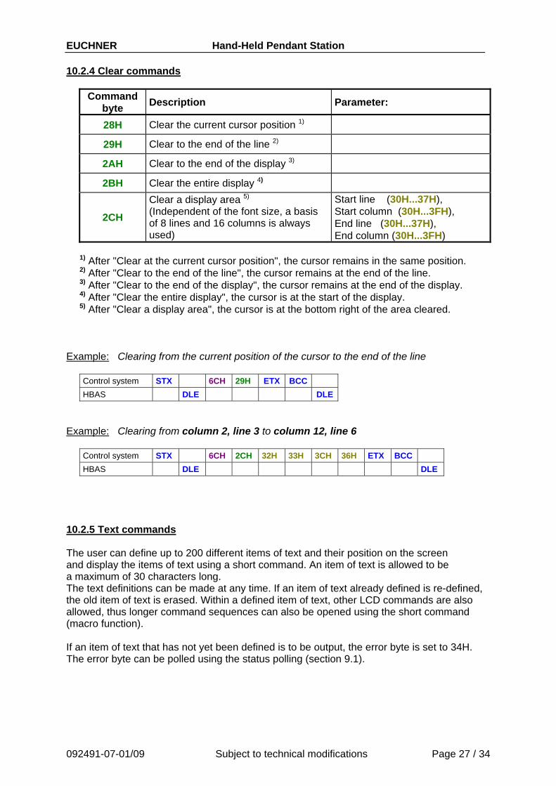
10.2.4 Clear commands
Command byte Description Parameter:
28H Clear the current cursor position 1)
29H Clear to the end of the line 2)
2AH Clear to the end of the display 3)
2BH Clear the entire display 4)
2CH
Clear a display area 5) (Independent of the font size, a basis of 8 lines and 16 columns is always used)
Start line (30H...37H), Start column (30H...3FH), End line (30H...37H), End column (30H...3FH)
1) After "Clear at the current cursor position", the cursor remains in the same position. 2) After "Clear to the end of the line", the cursor remains at the end of the line. 3) After "Clear to the end of the display", the cursor remains at the end of the display. 4) After "Clear the entire display", the cursor is at the start of the display. 5) After "Clear a display area", the cursor is at the bottom right of the area cleared.
Example: Clearing from the current position of the cursor to the end of the line
Control system STX 6CH 29H ETX BCC
HBAS DLE DLE Example: Clearing from column 2, line 3 to column 12, line 6
Control system STX 6CH 2CH 32H 33H 3CH 36H ETX BCC HBAS DLE DLE
10.2.5 Text commands The user can define up to 200 different items of text and their position on the screen and display the items of text using a short command. An item of text is allowed to be a maximum of 30 characters long. The text definitions can be made at any time. If an item of text already defined is re-defined, the old item of text is erased. Within a defined item of text, other LCD commands are also allowed, thus longer command sequences can also be opened using the short command (macro function). If an item of text that has not yet been defined is to be output, the error byte is set to 34H. The error byte can be polled using the status polling (section 9.1).
EUCHNER Hand-Held Pendant Station
092491-07-01/09 Subject to technical modifications Page 28 / 34
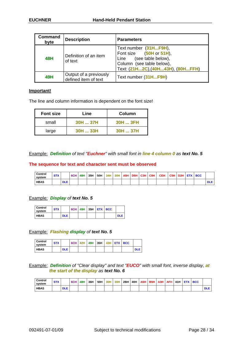
Command byte Description Parameters
48H Definition of an item of text
Text number (31H...F9H), Font size (50H or 51H), Line (see table below), Column (see table below), Text: (21H...2C),(40H...43H), (80H...FFH)
49H Output of a previously defined item of text Text number (31H...F9H)
Important! The line and column information is dependent on the font size!
Font size Line Column
small 30H ... 37H 30H ... 3FH
large 30H ... 33H 30H ... 37H Example: Definition of text "Euchner" with small font in line 4 column 0 as text No. 5 The sequence for text and character sent must be observed
Control system STX 6CH 48H 35H 50H 34H 30H A5H D5H C3H C8H CEH C5H D2H ETX BCC
HBAS DLE DLE
Example: Display of text No. 5
Control system STX 6CH 49H 35H ETX BCC
HBAS DLE DLE
Example: Flashing display of text No. 5
Control system STX 6CH 42H 49H 35H 43H ETX BCC
HBAS DLE DLE
Example: Definition of "Clear display" and text "EUCO" with small font, inverse display, at
the start of the display as text No. 6
Control system STX 6CH 48H 36H 50H 30H 30H 2BH 40H A5H B5H A3H AFH 41H ETX BCC
HBAS DLE DLE
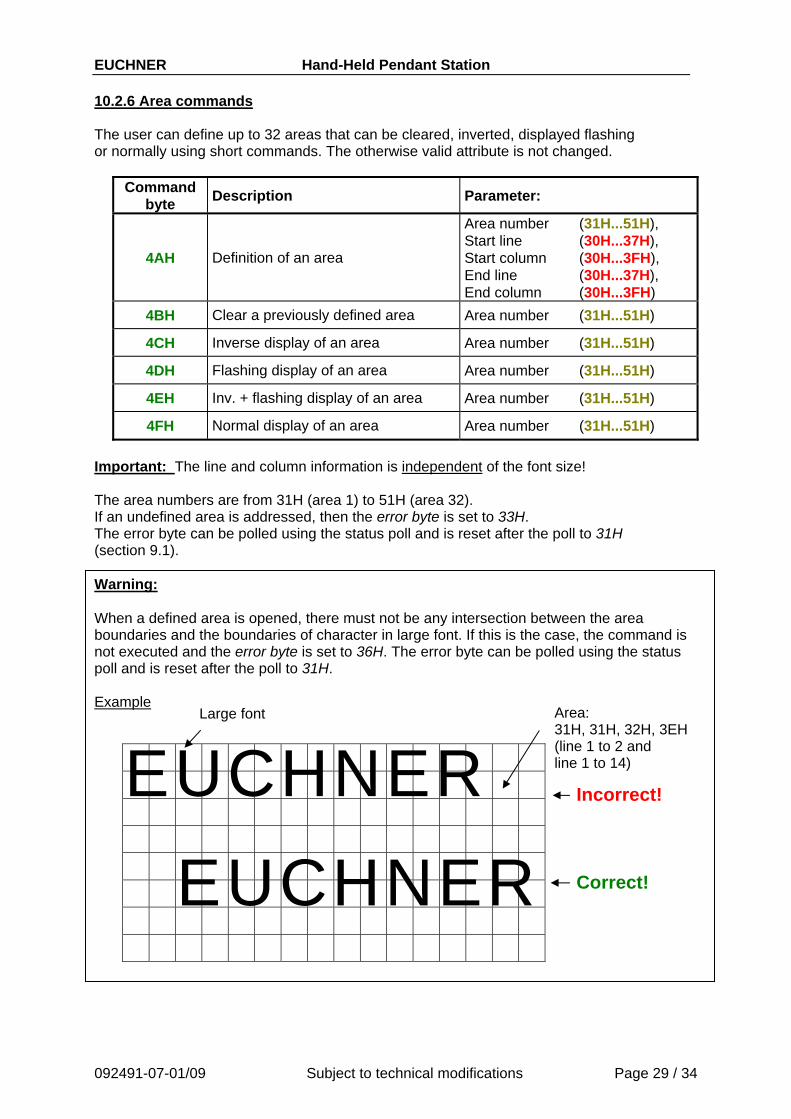
EUCHNER Hand-Held Pendant Station 10.2.6 Area commands The user can define up to 32 areas that can be cleared, inverted, displayed flashing or normally using short commands. The otherwise valid attribute is not changed.
Command byte Description Parameter:
4AH Definition of an area
Area number (31H...51H), Start line (30H...37H), Start column (30H...3FH), End line (30H...37H), End column (30H...3FH)
4BH Clear a previously defined area Area number (31H...51H)
4CH Inverse display of an area Area number (31H...51H)
4DH Flashing display of an area Area number (31H...51H)
4EH Inv. + flashing display of an area Area number (31H...51H)
4FH Normal display of an area Area number (31H...51H) Important: The line and column information is independent of the font size! The area numbers are from 31H (area 1) to 51H (area 32). If an undefined area is addressed, then the error byte is set to 33H. The error byte can be polled using the status poll and is reset after the poll to 31H (section 9.1). Warning: When a defined area is opened, there must not be any intersection between the area boundaries and the boundaries of character in large font. If this is the case, the command is not executed and the error byte is set to 36H. The error byte can be polled using the status poll and is reset after the poll to 31H. Example
E U C HNERE U CHNER Correct!
Incorrect!
Area: 31H, 31H, 32H, 3EH (line 1 to 2 and line 1 to 14)
Large font
092491-07-01/09 Subject to technical modifications Page 29 / 34
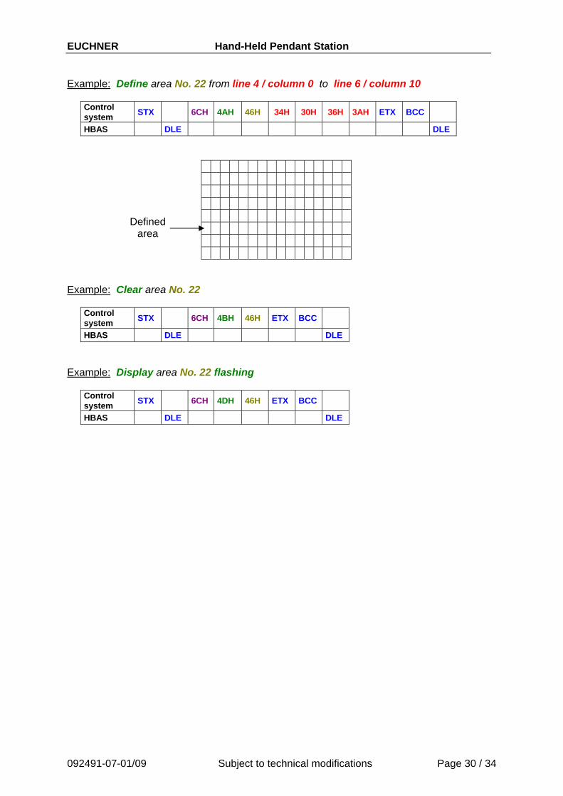
EUCHNER Hand-Held Pendant Station Example: Define area No. 22 from line 4 / column 0 to line 6 / column 10
Control system STX 6CH 4AH 46H 34H 30H 36H 3AH ETX BCC
HBAS DLE DLE
Defined area
Example: Clear area No. 22
Control system STX 6CH 4BH 46H ETX BCC
HBAS DLE DLE Example: Display area No. 22 flashing
Control system STX 6CH 4DH 46H ETX BCC
HBAS DLE DLE
092491-07-01/09 Subject to technical modifications Page 30 / 34
EUCHNER Hand-Held Pendant Station
092491-07-01/09 Subject to technical modifications Page 31 / 34
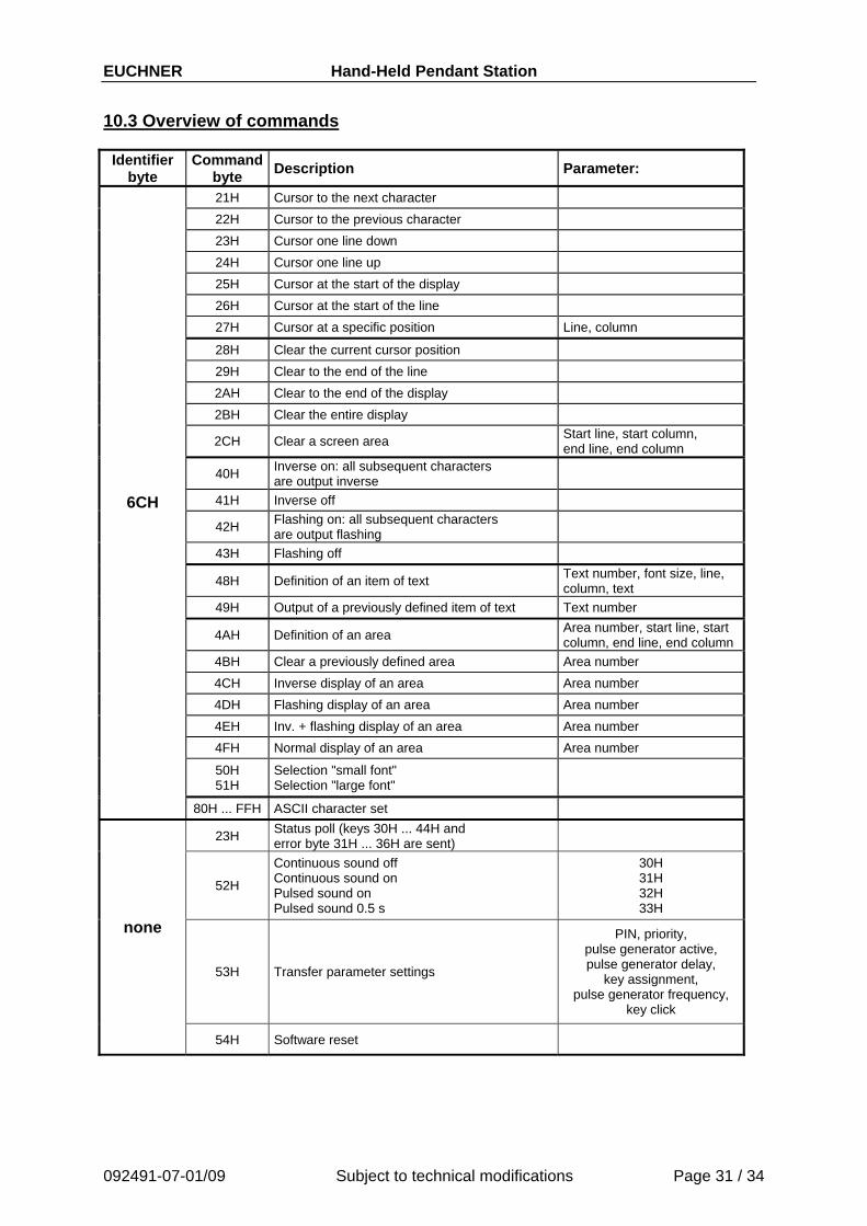
10.3 Overview of commands
Identifier byte
Commandbyte Description Parameter:
21H Cursor to the next character 22H Cursor to the previous character 23H Cursor one line down 24H Cursor one line up 25H Cursor at the start of the display 26H Cursor at the start of the line 27H Cursor at a specific position Line, column
28H Clear the current cursor position 29H Clear to the end of the line 2AH Clear to the end of the display 2BH Clear the entire display
2CH Clear a screen area Start line, start column, end line, end column
40H Inverse on: all subsequent characters are output inverse
41H Inverse off
42H Flashing on: all subsequent characters are output flashing
43H Flashing off
48H Definition of an item of text Text number, font size, line, column, text
49H Output of a previously defined item of text Text number
4AH Definition of an area Area number, start line, start column, end line, end column
4BH Clear a previously defined area Area number 4CH Inverse display of an area Area number 4DH Flashing display of an area Area number 4EH Inv. + flashing display of an area Area number 4FH Normal display of an area Area number
50H 51H
Selection "small font" Selection "large font"
6CH
80H ... FFH ASCII character set
23H Status poll (keys 30H ... 44H and error byte 31H ... 36H are sent)
52H
Continuous sound off Continuous sound on Pulsed sound on Pulsed sound 0.5 s
30H 31H 32H 33H
53H Transfer parameter settings
PIN, priority, pulse generator active, pulse generator delay,
key assignment, pulse generator frequency,
key click
none
54H Software reset
EUCHNER Hand-Held Pendant Station
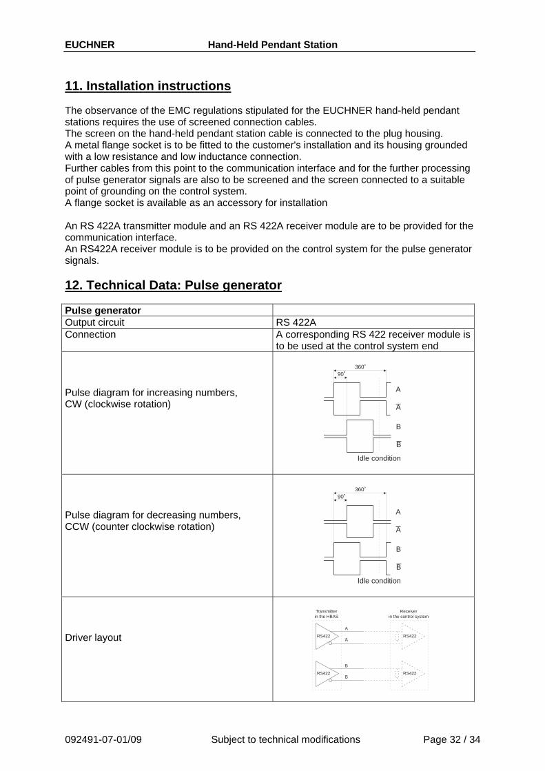
11. Installation instructions The observance of the EMC regulations stipulated for the EUCHNER hand-held pendant stations requires the use of screened connection cables. The screen on the hand-held pendant station cable is connected to the plug housing. A metal flange socket is to be fitted to the customer's installation and its housing grounded with a low resistance and low inductance connection. Further cables from this point to the communication interface and for the further processing of pulse generator signals are also to be screened and the screen connected to a suitable point of grounding on the control system. A flange socket is available as an accessory for installation An RS 422A transmitter module and an RS 422A receiver module are to be provided for the communication interface. An RS422A receiver module is to be provided on the control system for the pulse generator signals.
12. Technical Data: Pulse generator Pulse generator Output circuit RS 422A Connection A corresponding RS 422 receiver module is
to be used at the control system end Pulse diagram for increasing numbers, CW (clockwise rotation)
90˚360˚
A
A
B
B
Idle condition
Pulse diagram for decreasing numbers, CCW (counter clockwise rotation)
90˚360˚
A
A
B
B
Idle condition
Driver layout
RS422
A
ARS422
Transmitterin the HBAS
Receiverin the control system
RS422
B
BRS422
092491-07-01/09 Subject to technical modifications Page 32 / 34
EUCHNER Hand-Held Pendant Station
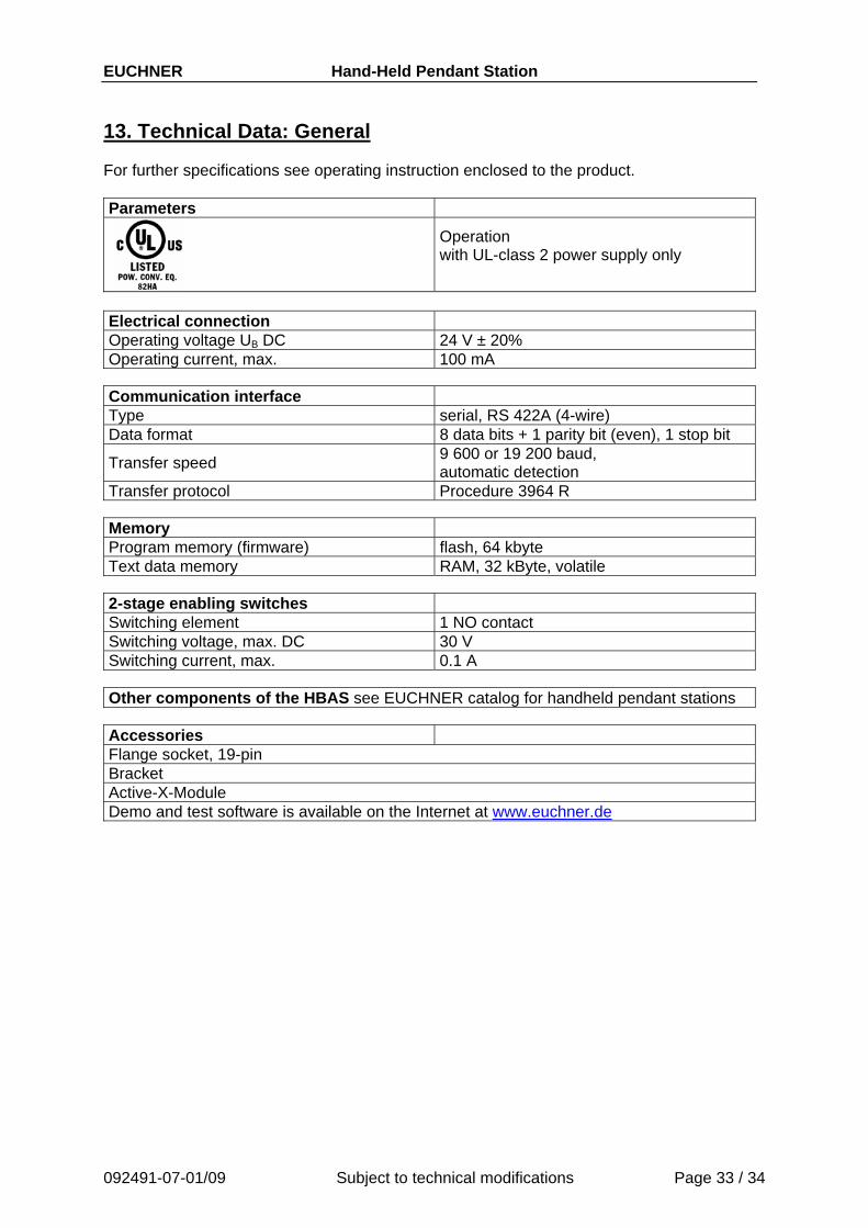
13. Technical Data: General For further specifications see operating instruction enclosed to the product. Parameters
Operation with UL-class 2 power supply only
Electrical connection Operating voltage UB DC 24 V ± 20% Operating current, max. 100 mA
Communication interface Type serial, RS 422A (4-wire) Data format 8 data bits + 1 parity bit (even), 1 stop bit
Transfer speed 9 600 or 19 200 baud, automatic detection
Transfer protocol Procedure 3964 R Memory Program memory (firmware) flash, 64 kbyte Text data memory RAM, 32 kByte, volatile
2-stage enabling switches Switching element 1 NO contact Switching voltage, max. DC 30 V Switching current, max. 0.1 A
Other components of the HBAS see EUCHNER catalog for handheld pendant stations
Accessories Flange socket, 19-pin Bracket Active-X-Module Demo and test software is available on the Internet at www.euchner.de
092491-07-01/09 Subject to technical modifications Page 33 / 34

EUCHNER GmbH + Co. KG Telefon 0711 / 75 97 - 0 Kohlhammerstraße 16 Telefax 0711 / 75 33 16 D-70771 Leinfelden-Echterdingen www.euchner.de Germany [email protected]