Embed Size (px)
Citation preview

Handbook for Use of Laboratory in Kibo
E-version, revised Feb. 2014 Japan Aerospace Exploration Agency

Table of Contents Introduction ........................................................................................................................................ 1 I. Outline of the Pressurized Module (PM) and experimental systems in Kibo .......................................... 2 1 Laboratory in Kibo ................................................................................................................... 3
1.1 What is the Pressurized Module (PM) in Kibo? ............................................................................ 3 1.2 Environment in Kibo’s Pressurized Module (PM).................................................................... 5 1.3 Operation of the ISS and Kibo ............................................................................................... 8 1.4 Japanese experimental and other devices mounted on Kibo’s PM ........................................... 12
2 Life Sciences Experiment Facility............................................................................................ 14 2.1 Biological Experiment Unit (BEU) ...................................................................................... 14 2.1.1 Cell Experiment Unit (CEU) ........................................................................................ 14 2.1.2 Plant Experiment Unit (PEU) ............................................................................................. 18 2.1.3 Measurement Unit (MEU) .................................................................................................. 22
2.2 Cell Biology Experiment Facility (CBEF) ............................................................................ 25 2.3 Clean Bench (CB) ............................................................................................................... 29 2.4 Minus Eighty Degree Celsius Laboratory Freezer for ISS (MELFI) ........................................ 34 2.5 Aquatic Habitat (AQH) ................................................................................................... 36 2.6 Passive Dosimeter for Life Science Experiments in Space (PADLES) .......................................... 41 2.7 Particle Counter .................................................................................................................. 44
3 Experimental facilities for material science .............................................................................. 46 3.1 Fluid Physics Experiment Facility (FPEF) ............................................................................ 46 3.2 Solution Crystal Observation Facility (SCOF) ............................................................. 49 3.3 Protein Crystallization Research Facility (PCRF) .................................................................. 57 3.4 Gradient Heating Furnace (GHF) ......................................................................................... 61 3.5 Electrostatic Levitation Furnace ........................................................................................... 64
4 Devices for experiments with human subjects and for physiological research .............................. 67 4.1 Simplified biological function monitoring device (Holter electrocardiograph) ......................... 67 4.2 Onboard Diagnostic Kit....................................................................................................... 69 4.3 Devices for space medicine research by agencies other than JAXA ........................................ 72
5 Devices common to multiple fields ............................................................................................... 74 5.1 Multipurpose Small Payload Rack (MSPR) .......................................................................... 74 5.2 Super-Sensitive High-Definition Television Camera (SS-HDTV) system................................ 78 5.3 Microscope Observation System .......................................................................................... 79 5.4 Laboratory Support Equipment (LSE) .................................................................................. 83
6 Other Reference Information ........................................................................................................ 90 II. Precautions for Planning Space Experiments ................................................................................... 91
1. Features in proposing space experiments..................................................................................... 92 2. Feasibility for mounting ............................................................................................................ 92 3. Experiment resources ................................................................................................................ 93 4. Safety requirements ................................................................................................................... 94 5. Specific restrictions for space experiments and precautions for planning space experiments ........... 96 5.1 Life science experiments........................................................................................................... 96 5.2 Space medicine experiments ................................................................................................... 102 5.3 Material and Physical Science ....................................................................................... 106 The collection of abbreviation .................................................................................................. 111

International Space Station (shot in May 2011)
Japanese Experiment Module (Kibo) at International Space Station (shot in May 2010)
1
Introduction
Because it is not completely gravity-free inside Kibo and small changes in gravity of 10-4 g or smaller may be unavoidable for various reasons, the term “microgravity” is used. Stable microgravity can be considered the most prominent characteristic of the space environment because it is impossible to achieve microgravity for a long period on earth. It is also an environment in which objects are exposed to cosmic radiation; this differs from the radiation on earth’s surface, which is shielded by terrestrial magnetism and the atmospheric layer.
The idea of addressing problems that we cannot solve on earth by actively exploiting these differences is space environment utilization, and its implementations are called space experiments.
This document provides an overview of the experimental environment in the
Pressurized Module (PM), the experimental systems and specimens (container, apparatus to put a sample to test in combination with an experimental devise ) that can be used, various control conditions for managing experiments, and other information. It serves as a guideline for those who are considering planning or proposing space experiments using the PM of Kibo.
Although this document was prepared using the latest information at the time of its preparation, please use it strictly as a reference document, because some items may be changed in the future.

2
I. Outline of the Pressurized Module (PM) and experimental systems in Kibo

3
1 Laboratory in Kibo
1.1 What is the Pressurized Module (PM) in Kibo?
The PM is used to accommodate the astronauts, conduct experiments, and control the entire facility in the experimental module Kibo. The inside of the PM is maintained at 1 atm, and the atmospheric composition is similar to that of Earth. Its temperature and humidity are constantly controlled to provide a comfortable environment for astronaut activities. Therefore, astronauts can work in clothing similar to what we normally wear on earth instead of in space suits. Most of the devices that are installed in the PM can be described as experimental devices for conducting experiments or system devices that are necessary for maintaining the facilities of Kibo. [Experimental devices]
The experimental devices are a set of special apparatuses for conducting various experiments in the PM, and they provide their functions only when they are organically linked with the system devices mentioned above. The PM can accommodate up to 10 units of experiment racks (5 for the U.S. and 5 units for Japan), and they are used for various space experiments, mainly in biological and materials science.
[System devices]
These devices provide functions that are crucial to the operation of Kibo and the activities of the astronauts. They include devices that supply electrical power to the entire Kibo facility, enable communication, provide air conditioning, control the cooling water used to cool many of the electronic devices, and support space experiments. The manipulator console for exchanging devices on the Experiment Logistics Module-Exposed Section (ELM-ES), the Inter-Orbit Communication equipment, and air lock for passing devices to or from the ELM-ES are also important system devices, and loss of any of these functions seriously affects operation. Table 1.1 shows an outline of Kibo.
Table 1.1 Outline of PM and stowage module in Kibo Item Laboratory Stowage module
Shape Cylindrical Cylindrical Diameter Inner diameter: 4.4 m,
outer diameter: 4.2 m Inner diameter: 4.4 m, outer diameter: 4.2 m
Length 11.2 m 4.2 m Weight 15.9 t 4.2 t
Number of
racks mounted
Total number of racks: 23 (including 10 experiment racks)
8 inboard experiment racks
Power 24 kW, 120 V (DC) at max. Environmental
control performance
Temperature: 18.3 to 26.7, humidity: 25% to 70%

4
Fig. 1.1-1 External view of Japanese Experiment Module Kibo
Fig. 1.1-2 Inside the PM in Kibo
Stowage module
Robot arm
Pressurized Module
Air lock
Experiment Logistics Module-Exposed Section (ELM-ES)

5
1.2 Environment in Kibo’s Pressurized Module (PM)
(1) The International Space Station (ISS) orbit The ISS usually circles Earth in approximately 90 min in a circular orbit with a nominal
altitude of approximately 400 km and an orbital inclination of 51.6. Although the orbital altitude of the ISS drops by about 200 m per day on average because of atmospheric drag, the altitude is recovered (the ISS is reboosted) regularly by the thrusters of the ISS itself or the transport vehicle to compensate for this. Thus, the altitude fluctuates between approximately 350 km and 460 km.
Fig. 1.2-1 ISS orbit
Fig. 1.2-2 Ground track of ISS orbit (red line)
6
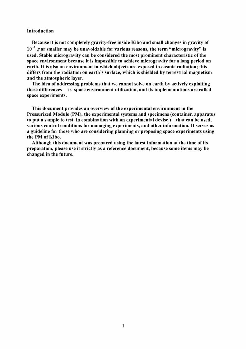
(2) Microgravity environment
Disturbances such as atmospheric drag and a gravity gradient apply constantly on the ISS, generating quasi-static acceleration. As shown in Fig. 1.2-3, quasi-static acceleration in the order of 10-6 g (μg) is predicted for the ISS. In addition, the internal disturbances affecting the quasi-static acceleration of the ISS include crew activities (e.g., exercise) and the rotation of the solar cell array.
Note: The above figure shows the results of an analysis based on the ISS assembly sequence Rev. D. It is strictly for reference, as the actual assembly sequence, mass properties of the ISS, and other factors will vary.
Fig. 1.2-3 Quasi-static acceleration environment for ISS (example of NASA analysis results) (Source) ISS Microgravity Environment, SSUAS, June 23, 1999

7
(3) Radiation environment The environment outside the ISS orbit contains particle radiation released in solar
activities including solar flares, proton beams captured by Earth’s magnetic field, and galactic cosmic rays arriving from outside the solar system.
The interior of the ISS becomes a complex radiation environment as these cosmic rays collide with the ISS’s structural and atmospheric components and generate secondary cosmic rays.
Fig. 1.2-4 Assumed cosmic radiation energy spectrum inside ISS on orbit
According to measurements by the Passive Dosimeter for Life Science Experiments in
Space (PADLES, see Chapter 2.6), within the Russian module of the ISS, the radiation to date is 150 to 300 μGy/day and 300 to 600 μSy/day during a period equivalent to the maximum solar activity period. The exposure dose may vary depending on the shielding environment or solar activity.
Table 1.2-1 Results of cosmic radiation measurement in ISS on orbit
Flight
Location of
measurement
Measurement period
Detector
Measurement results
Absorbed dose
Dose equiv.
Quality factor
ISS Russian service module
Aug. 21, 2001 to Oct. 31, 2001 (71 days)
PADLES
0.28
0.53
1.9
Aug. 21, 2001 to May 5, 2002 (257 days)
PADLES
0.23
0.41
1.8
Aug. 21, 2001 to Nov. 10, 2002 (446 days)
PADLES
0.18
0.37
2.1
Jan. 29, 2004 to Oct. 11, 2005 (621 days)
PADLES
0.16
0.32
2.0
Dec. 23, 2005 to Apr. 9, 2006 (107 days)
PADLES
0.26
0.51
1.9
See Chapter 2.6 for details on PADLES. See International Space Environment Utilization Research Data Base (ISRDB): http://idb.exst.jaxa.jp/db_data/padles/NI005.html.
Secondary cosmic rays: Generated as primary cosmic rays interact with experimental devices, such as station wall, experiment racks, and Cell Biology Experiment Facility, or in nuclear reactions inside biological samples.
Energy [MeV or MeV/u] Assumed cosmic radiation energy spectrum inside station on ISS orbit Manned Support Committee, National Space Development Agency, interim report guideline examination material, March 1999.
Outside the station
Primary cosmic rays flying in free space: - Particle radiation released from the sun in solar flares, etc. - Cosmic rays arriving from outside the solar system - Proton beams captured by Earth’s magnetic field
Inside the station
International Space Station Altitude: 407.44 km Inclination angle: 51.6 Station wall (9.5-mm-thick aluminum)
Minimum solar activity periodMaximum solar activity period
Neutron from flare protons
N group Si groupBe group
Proton Helium
Cosmic rays
Fe group
Electron
Neutron from captured protons
Photon Proton from flare protons
Proton from captured protons
Flux

8
1.3 Operation of the ISS and Kibo
(1) Transportation of goods Starting in 2010, goods have been launched to and collected from the ISS by the
Russian Soyuz and Progress, European ATV, Japanese KOUNOTORI (HTV), and other commercial transport services to replace the space shuttles. The capacities of the transport vehicles that are currently in operation are listed in Table 1.3-1.
Table 1.3-1 Transport vehicles to ISS (as of February 2012)
Launch vehicle Launch base
Load capacity Load capacity for collection
Remarks
Progress (Russia)
Soyuz rocket Baikonur Launch Complex
1,800 kg at max. -
Docks on Russian side Reboost function Replenishment of fuel, water, and gas
Soyuz (Russia)
Soyuz rocket Baikonur Launch Complex
30 kg at max. 50 kg at max. Docks on Russian side Manned
ATV (ESA) Ariane-5 rocket Guyana Space Center
5,500 kg at max. -
Docks on Russian side. Reboost function Replenishment of fuel, water, and gas
KOUNOTORI HTV (JAXA)
H-II B rocket Tanegashima Space Center
Approx. 6,000 kg Pressurized 4,500 kgExposed 1,500 kg
-
Docks on U.S. side Transport in units of racks possible in pressurized cabin; transport of exposed goods also possible
Dragon (SpaceX) Falcon 9 rocket Cape Canaveral Air Station
3,000 kg 2,500 kg Docking by grasping with robotic arm
Cygnus (OSC) Antares rocket NASA Wallops Flight Facility
2,000 kg 1,200 kg Docking by grasping with robotic arm
Fig. 1.3-1 Progress (©S.P. Korolev RSC Energia) Fig. 1.3-2 Soyuz (Photo: NASA)

9
Fig. 1.3-3 ATV (Photo: NASA)
Fig. 1.3-4 KOUNOTORI (HTV)
Fig. 1.3-5 Dragon (Photo: NASA) Fig. 1.3-6 Cygnus (Photo: NASA) (2) Operation of Kibo
Although the U.S. makes adjustments affecting the overall operation of the ISS, the relevant government or agency for the U.S., Russia, Japan, Europe (11 ESA countries), and Canada is responsible for operating the ISS systems or devices they developed.
ISS operation has two aspects: system operation, which controls the orbit, posture, power, internal environment, and so forth, and experimental operation, which controls various devices mounted for research and experiments.
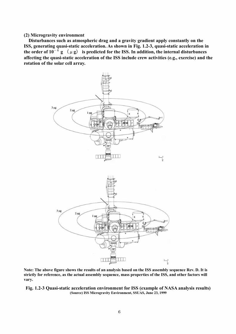
System operation and experimental operation in the Japanese Experiment Module
(Kibo) are conducted from Tsukuba Space Center. In principle, communication is maintained between Tsukuba Space Center and Kibo via the U.S. tracking and data relay satellite. It is also possible to directly transmit experimental data to Tsukuba Space Center using Kodama, a data relay technology satellite (DRTS).
[Tsukuba Space Center]
System operation: A team of more than 50 flight directors and flight controllers monitors Kibo in
a three-shift system for 24 h/day. They constantly check that data indicating the conditions of various systems,
including the thermal control system, power system, communication system,

10
environmental control/life support system, and robotics system, are normal during system operation. In addition, they provide instructions so that the astronauts staying in the ISS can take appropriate actions in case of fire, emergency pressure reduction, or air pollution.
They also select the goods to be transported and replenished at Kibo and examine the measures, timing, and other aspects of transport on the basis of the Kibo maintenance plan.
Experimental operation:
The Japanese experimental operation plan which is prepared by Tsukuba Space Center is incorporated into the overall operation plan for the ISS after adjustments at the George C. Marshall Space Flight Center. Experiments are then conducted accordingly. Experiment users can monitor their own experiments from the User Operations Area of Tsukuba Space Center and conduct the experiments while communicating with the ISS.
Fig. 1.3-7 User Operations Area [Tanegashima Space Center]
KOUNOTORI(HTVs) loaded with goods to be carried to the ISS are launched from Tanegashima Space Center using the H-IIB rocket. Processes such as assembly of the H-IIB rocket, preparation for launch, preparation of the HTV, and loading of the HTV onto the H-IIB rocket are also conducted in Tanegashima Space Center.
11
Fig. 1.3-8 Outline of Kibo operation system

12
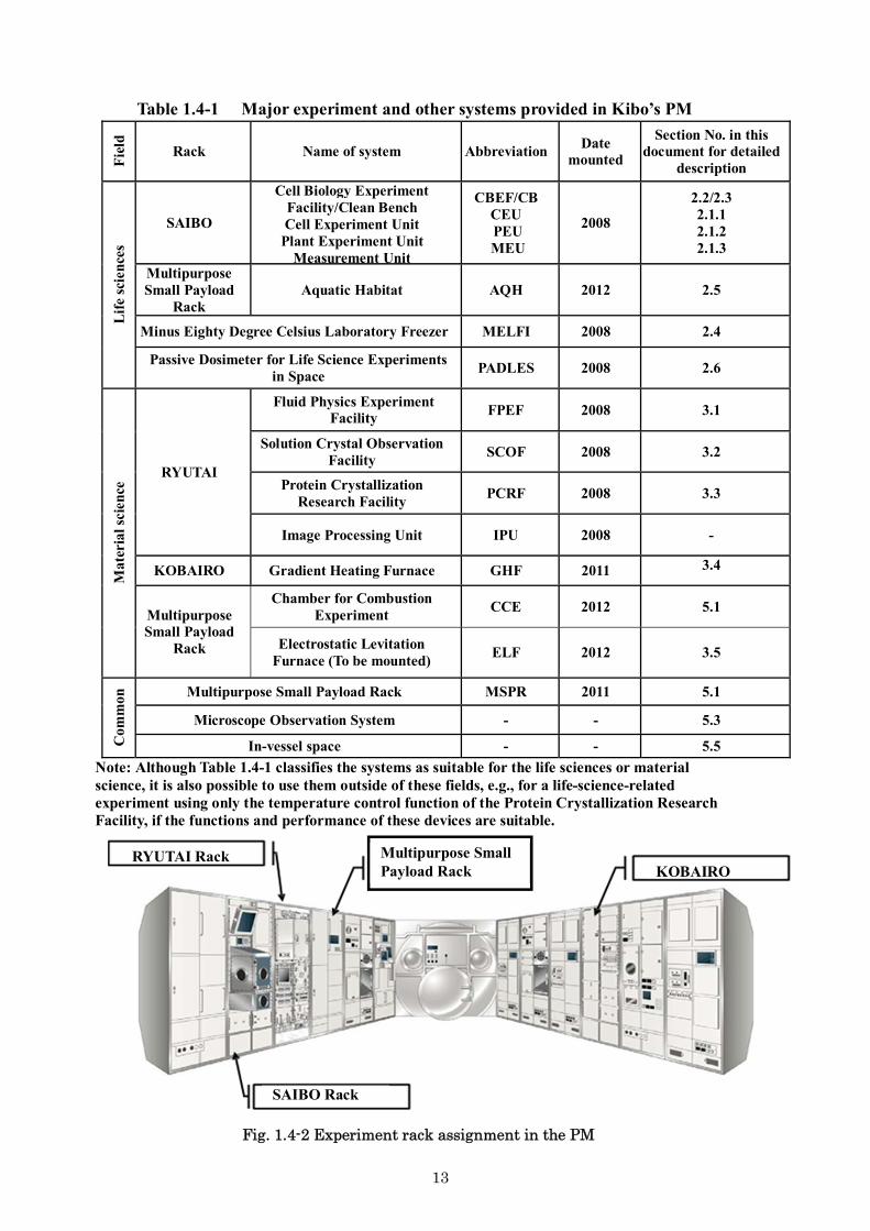
1.4 Japanese experimental and other devices mounted on Kibo’s PM
Until now, three experiment racks for life science and material science research, the SAIBO Rack, RYUTAI Rack, and KOBAIRO Rack, were mounted in Kibo. Moreover, the Multipurpose Small Payload Rack which provides experimental space to unstall the various experimental devices and supplies power was mounted. Experiments using the devices mounted in these Racks as shown in Table 1.4, will be possible. In-vessel space can be used in addition to this equipment.
The above experiment systems in Kibo were prepared with basic necessary functions and common measurement functions for various experimental fields, and experiments are conducted by combining them with specimens, which include the experimental sample and its container, and the necessary functions specific to the experiment. In planning experiments using these systems, specimens, and functions, it is necessary to check the details for each component and make sure that the experimental specifications are within the performance and functions of each system.
13
Table 1.4-1 Major experiment and other systems provided in Kibo’s PM
Fie
ld
Rack Name of system Abbreviation Date mounted
Section No. in this document for detailed
description
Lif
e sc
ienc
es
SAIBO
Cell Biology Experiment Facility/Clean Bench Cell Experiment Unit
Plant Experiment Unit Measurement Unit
CBEF/CB CEU PEU MEU
2008
2.2/2.3 2.1.1 2.1.2 2.1.3
Multipurpose Small Payload
Rack Aquatic Habitat AQH 2012 2.5
Minus Eighty Degree Celsius Laboratory Freezer MELFI 2008 2.4
Passive Dosimeter for Life Science Experiments in Space
PADLES 2008 2.6
Mat
eria
l sci
ence
RYUTAI
Fluid Physics Experiment Facility FPEF 2008 3.1
Solution Crystal Observation Facility
SCOF 2008 3.2
Protein Crystallization Research Facility
PCRF 2008 3.3
Image Processing Unit IPU 2008 -
KOBAIRO Gradient Heating Furnace GHF 2011 3.4
Multipurpose Small Payload
Rack
Chamber for Combustion Experiment
CCE 2012 5.1
Electrostatic Levitation Furnace (To be mounted)
ELF 2012 3.5
Com
mon
Multipurpose Small Payload Rack MSPR 2011 5.1
Microscope Observation System - - 5.3
In-vessel space - - 5.5
Note: Although Table 1.4-1 classifies the systems as suitable for the life sciences or material science, it is also possible to use them outside of these fields, e.g., for a life-science-related experiment using only the temperature control function of the Protein Crystallization Research Facility, if the functions and performance of these devices are suitable.
Fig. 1.4-2 Experiment rack assignment in the PM
RYUTAI Rack
SAIBO Rack
Multipurpose Small Payload Rack KOBAIRO
14
2 Life Sciences Experiment Facility 2.1 Biological Experiment Unit (BEU) The Biological Experiment Unit (BEU) is an automated experiment unit for conducting experiments in life sciences in combination with the Cell Biology Experiment Facility (CBEF) and Clean Bench (CB), which are described later.
The BEUs developed for use in the Pressurized Module (PM) of Kibo to date are the Cell Experiment Unit (CEU), Plant Experiment Unit (PEU), and Measurement Experiment Unit (MEU). - The CEU is used to conduct cell culture experiments using animal cells and so forth
as samples; it contains large and small culture chambers. - The PEU was developed to conduct a series of life cycle experiments from
germination to seed formation using plant seeds as samples. - The MEU is equipped with an internal temperature measurement sensor, and
experiments can be conducted by setting various culture chambers inside the unit.
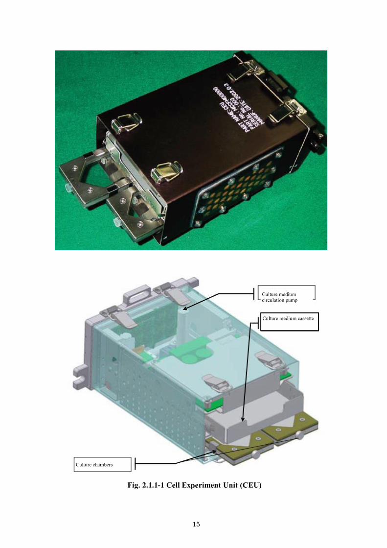
2.1.1 Cell Experiment Unit (CEU)
The CEU contains a small pump, a temperature sensor, and the control unit in a medium-size canister [210 mm (W) × 80 mm (H) × 130 mm (D)], and samples can be cultured in one each of the large chamber (30 cm2 cultivation area) and small chamber (15 cm2 cultivation area). Culture medium replacement, circulation, and other functions, as well as monitoring of the culture environment, can be executed automatically. Each chamber has an independent culture circulation system, which can be attached or removed easily with a sterilized quick disconnector. The detailed functions and performance are outlined in Table 2.1.1-1.
The culture chambers are assembled types with a surface for cell growth equivalent to that of commercial flasks and a membrane structure with high gas exchangeability. They are made of materials that can be treated with chemicals.
By removing only the chamber from the CEU and using the Pre-Fixation Kit (PFK) and Cell Fixation Kit (CFK), which are available as accessory devices, a series of sample treatment processes, including culture medium ejection, washing with a buffer, and injection of a chemical fixing agent, can be conducted. There are both large and small PFKs and CFKs, and two each of the large and small chambers can be treated. After treatment with a chemical fixing agent and other treatment, the culture chambers can be stored in the Minus Eighty Degree Celsius Laboratory Freezer for ISS (MELFI) and other locations set inside the CFK.
15
Fig. 2.1.1-1 Cell Experiment Unit (CEU)
Culture medium circulation pump
Culture medium cassette
Culture chambers

16
Fig. 2.1.1-2 Culture chambers: large (right) and small (left)
Fig. 2.1.1-3 Pre-Fixation Kit (PFK) Fig. 2.1.1-4 Cell Fixation Kit (CFK)

17
Table 2.1.1-1 Specifications of CEU
Item Design specifications Canister Type: Special-order canister (dimensions equivalent to those of a
medium canister) Number of canisters that can be mounted: six (microgravity compartment), four (artificial gravity compartment)
Specimen configuration
Culture chambers, culture medium cassette, control segment, liquid feeding pump, gas separator
Culture chamber
- A culture chamber has a single-layer structure with a gas exchange membrane on the top surface. - Chemical fixation is possible by using accessories. - Phase difference/fluorescence microscopy observation is possible using a microscope inside CB.
Type Large Small Size 55 × 116 × 10 (mm) 55 × 64 × 10 (mm) Cultivation area
Approx. 30 cm2 Approx. 10 cm2
Culture medium capacity
Approx. 9 mL Approx. 3 mL
Cultivation plate
Material: Polystyrene or polycarbonate Surface treatment: Surface treatment equivalent to commercial dish is possible. Note: Cultivation plate can be attached or removed, and is discarded after every experiment.
Culture medium cassette
Cassette size: 110 × 80 × 20 (mm) Contains two sets each of fresh medium bags, spent medium bags (combinations of bags for large and small chambers)
Bag for large chamber: 60 × 72 (mm), 50 mL Bag for small chamber: 40 × 72 (mm), 20 mL
Automated functions
Culture medium replacement: Automatic culture medium replacement is possible using liquid feeding pump (drift method, replacement rate approximately 70%).
Control Controlled by built-in CPU and laptop computer for experiments (ULT: User Laptop Computer). Control from the ground also possible via ULT.
External interface
Utility connector: With power supplied from CBEF, conducts command input and sensor output (specimen inner circuit board block temperature) RS-485: Connected to ULT. ULT is capable of communication with the ground via Ethernet in Kibo.
Observation
- Uses phase difference/fluorescence microscope in CB
- Object lens magnification: 40× for fluorescence (phase difference lens can also be used for cases other than UV excitation), 4, 10, 20, and 40× for phase difference - Microscope image: Microscope image data are sent to Image Processing Unit (IPU) via CB to be recorded or down-linked with MPEG2 compression.
Other Temperature and humidity measurement near the culture chamber. Air with temperature, humidity, CO2 concentration, and other parameters controlled by CBEF is taken in as the specimen tmosphere.

18
2.1.2 Plant Experiment Unit (PEU)
The PEU encompasses the plant chamber, a LED illumination unit for growth, a ventilation pump for humidity control, a water supply pump, temperature and humidity sensors, a water content sensor, and the control unit in a medium canister size [210 mm (W) × 80 mm (H) × 130 mm (D)], and can be used to cultivate small plants in the plant chamber (20 cm2 sowing area). It is capable of water delivery control, humidity control, and illumination and video observation under automatic control, and the entire life cycle from germination to seed formation can be studied for small plants such as Arabidpsis thaliana. The detailed functions and performance are outlined in Table 2.1.2-1.
The plant growth container can be separated into top and bottom parts, and plants are cultivated by inserting a supporting bed such as rock wool in the bottom part. Although the height for plant growth is as small as 50 mm because of restrictions on the rotor radius of the artificial gravity compartment, approximately 110 μmol/m2s of light can be delivered to plant area using the thin illumination unit for growth (red and blue LEDs). The humidity is controlled passively; toxic or undesirable gases are ejected and the humidity is reduced by taking in cabin air for ventilation.
The illumination switches to a special white LED during video observation so that the video image can be recorded or transmitted to the ground.
Plant samples are harvested by the astronauts, chemically fixed using the KSC Fixation Tube (KFT), and stored in Minus Eighty Degree Celsius Laboratory Freezer for ISS (MELFI) or other facility.
Fig. 2.1.2-1 Plant Experiment Unit (PEU)

19
Fig. 2.1.2-2 Plant Experiment Unit (PEU)
Fig. 2.1.2-3 Arabidpsis thaliana growth Fig. 2.1.2-4 Plant chamber
Fig. 2.1.2-5 KFC Fixation Tube
Water supply pump
Ventilation pump
Control circuit
LED illumination unit
Plant chamber
CCD camera

20
Table 2.1.2-1 Specifications of PEU Item Design specifications
Canister
Type: Special-order canister (dimensions equivalent to those of a medium canister) Number of canisters that can be mounted: six (microgravity compartment), four (artificial gravity compartment)
Specimen configuration
Plant chamber, control segment, water supply pump, ventilation pump, LED illumination unit, CCD camera, water content sensor, and temperature and humidity sensors
Plant chamber
Structure: Two-part (top and bottom) type (Bottom) Rock wool bed and bed moisture sensor port (Top) Temperature and humidity sensor and ventilation port
Size: (External) 60 × 50 × 60 (mm) (Internal) 56 × 46 × 58 (mm) Capacity: 149 mL Support bed sowing area: Approx. 20 cm2 Support bed size: 42 × 52 × 10 (mm)
LED illumination
Illumination for plant growth: - LED illumination provided from the side of the container
- Red (660 nm) and blue (470 nm) LEDs are combined for use. - Brightness of 26 μmol/m2s at center of plant area
Illumination for image observation: White LED is used (switched from illumination for plant growth)
Water bag
Size: 85 × 75 × 25 (mm) Capacity: Approx. 100 mL Stowed in plant container block and maintained at experiment temperature
Automated functions
Water delivery: Water content in bed is measured by near-infrared absorption to conduct active automatic water delivery with liquid feeding pump or regular water delivery operation.
Humidity control: Humidity detection with sensor for active control with ventilation pump Gas phase components: Forced ventilation of container by operation of
ventilation pump (air in CBEF is taken in) Illumination: Arbitrary light/dark cycle setting possible Image observation: Automatic image observation using built-in CCD camera (pan-focus)
Control Controlled by built-in CPU and laptop computer for experiment (ULT: User Laptop Computer). Control from the ground also possible via ULT.

21
External interface
Utility connector: With power supplied from CBEF, conducts command input and sensor output (specimen inner circuit board block temperature) Image: The image data from inside each specimen are switched by CBEF as necessary so that one string of data is output to IPU. Recording or down link with MPEG2 compression possible with IPU. RS-485: Connected to ULT. ULT can communicate with the ground via the Ethernet in Kibo.
Observation
Built-in 1/3-in. color CCD camera Lens: Brightness: f1.4, focal length: 4.5 mm Light source: White LED is used for color image observation; illumination for plant growth is turned OFF during this time. Valid pixels: 400,000 pixels Image output: NTSC
Other
Temperature and humidity are measured near the plant chamber. Air with temperature, humidity, CO2 concentration, and other parameters controlled by CBEF is taken in as the specimen atmosphere.

22
2.1.3 Measurement Unit (MEU)
The MEU has a casing that contains various cultivation chambers and two temperature sensors inside a medium-size canister [210 mm (W) × 80 mm (H) × 130 mm (D)]. It can contain up to six commercial T-25 flasks. In combination with Sample Holder A or B prepared for cell culturing, our original cell culturing bag (for floating cells) or disposal containers (for adherent cells; Disposable Cultivation Chamber: DCC) can be placed inside the MEU, which is then attached to the CBEF for stationary culturing. When the DCC is used, culture medium exchange and buffer replacement are possible simultaneously for four units by astronaut operation using the Pre-Fixation Kit 2 (PFK2) (although the use of reagents such as RNAlater is possible, it would be necessary to develop new equipment to keep hazardous substances enclosed during use of fixing agents and other chemicals). The detailed functions and performance are outlined on Table 2.1.3-1.
The Video Measurement Unit (V-MEU) is an experiment unit equipped with a CCD camera for the PEU and sample container retaining unit inside the MEU canister. It is suitable for experiments in which users would like astronauts to manually conduct the initial operations, such as supplying water, and implement only observation within the unit.
The current V-MEU contains two white LEDs that provide illumination for observation and two types of sample containers (plant type and tank type) 60 mm × 90 mm × 95 mm in size. The containers need to be prepared to suit each experiment sample, and the unit needs to be modified if observation at infrared or other wavelengths is desired.
Fig. 2.1.3-1 Measurement Unit (MEU & V-MEU)

23
Fig. 2.1.3-2 Sample Holder A Fig. 2.1.3-3 Sample Holder B
Fig. 2.1.3-4 Original culturing bag
Fig. 2.1.3-5 DCC case (left) and DCC (right)

24
Fig. 2.1.3-6 PFK2
Table 2.1.3-1 Specifications of MEU and V-MEU Item Design specifications
Canister
Type: Medium canister Number of canisters that can be mounted: six (microgravity compartment), four (artificial gravity compartment)
Specimen configuration
Casing, control segment, two temperature sensors Optional: CCD camera, illumination for observation (V-MEU)
Automated functions
Temperature measurement: Temperature detected at two temperature sensors and transmitted to the ground Optional (V-MEU) Image observation: Automatic image observation with CCD camera (pan-focus)
Units that can be set
Sample Holder A: Has 15 slots (5 mm (T) × 17 cm (H) × 50 mm (D) ) Sample Holder B: Attaches two cases capable of containing four
DCCs and holds them in MEU. A case has one slot to hold such as a moisture bag.
Containers that can be
used
- Commercial T-25 flasks: Up to six can be used - Original culturing bag: Plastic bag to culture floating cells and
other material. Used by pouring in approximately 20 mL cell suspension and sealing bag with heat.
- DCC: Has cell attachment plate with culturing area of 15 cm2, gas permeation membrane, and septum; liquid exchange possible

25
2.2 Cell Biology Experiment Facility (CBEF)
The Cell Biology Experiment Facility (CEBF) is used to cultivate various cells, microorganisms, small plants, and so forth to conduct life science experiments in the Pressurized Module (PM) of Kibo. The CBEF consists of an incubator and a control unit that controls the incubator and communicates with the Kibo system. The incubator unit has a microgravity compartment and an artificial gravity compartment (centrifugal type), the gravity in which can be set within a range of 0.1 to 2.0g for comparison experiments with the microgravity compartment on orbit. The culture chamber and automated devices (Biological Experiment Unit, BEU) are inserted into a container called a canister that is placed in the incubator of the facility.
In the incubator unit, the temperature, humidity, and carbon dioxide concentration can be controlled in the range of 15 to 40C, 30% to 80% (humidity control only), and 0% to 10%, respectively. These environments are constantly monitored with a sensor, and the environmental data are transmitted to the ground.
The canisters (up to six for the microgravity compartment and four for the artificial gravity compartment) are connected to the facility’s main unit with a connector so that the BEU can be controlled and image and sensor data can be obtained.
The detailed functions and performance are shown in Table 2.2-1.
Fig. 2.2-1 Cell Biology Experiment Facility
(Left: Facility with its door closed, right: with six medium canisters in the microgravity compartment and four in the artificial gravity compartment)

26
Fig. 2.2-2 Artificial gravity compartment Fig. 2.2-3 Medium canister attachment conditions

27
Table 2.2-1 Specifications for CBEF Item Design specifications
S
tructu
re
Volume Incubator unit: 130 l
Incubator unit
- Consists of microgravity compartment and artificial gravity compartment, each of which has equipment for environmental control and various sensors
- Capable of maintaining and controlling the temperature, humidity, and CO2 concentration within the incubator unit with canisters installed
- The artificial gravity compartment can generate an arbitrary artificial gravity of 0.1–2.0g using the artificial gravity generator and provides nearly the same environment as the microgravity compartment except for the gravity. These compartments can be used to conduct parallel experiments.
- A canister and canister tray are prepared as accessories to place the sample inside the canister for experiments.
- An interface provides the necessary power/signal/video to user-prepared devices inside the canister for experiments.
Control unit
- Capable of various controls upon command input using application software and user program input from the ground or a User Laptop Computer for experiments.
Incu
bator u
nit
Canister type
Size: Medium (default specification) Style: Closed, gas permeation type Closed: Seals against gas and liquid under pressurized
environment in Kibo’s PM
Gas permeation type: Has a window of gas-permeable membrane and delivers gas permeation function under normal environment. Seals against liquid under pressurized environment in Kibo’s PM
Medium-size canister
External dimensions: 127.5 × 205 × 83 (mm) Internal dimensions: 120 × 195 × 71 (mm)
[However, the minimum internal dimension is 106 × 175 × 57 (mm) because there is a dead space at each corner.]
Number of canisters mounted
Microgravity compartment
Artificial gravity compartment
Medium 6 4
28
Table 2.2-1 Specifications of CBEF (continued)
Item Design specifications
Tem
peratu
re control system
Temperature control 15 to 40°C ± 1°C (when canister does not generate heat)
Humidity control
30% to 80%RH ± 5%RH (The minimum humidity that can be provided depends on the environmental humidity outside the container and the maximum humidity at the set temperature.)
CO2 concentration control
0% to 10% by volume
Gravity generation method
Centrifugal force
Gravity value setting0.1 to 2.0g (value at a point 112.5 mm from the rotation center); gravity value setting is controlled by varying the number of revolutions (1 rpm)
User in
terface
Number of utility connectors installed
Microgravity compartment
Artificial gravity
compartment Utilities (e.g.,
power, command sensor output)
6 in total
4 in total
Image 6 in total 4 in total RS-485 connection 6 in total 4 in total
※There is only one output system to outside of the CBEF.
Utility breakdown
The following resources can be used as utilities for each connector when a medium canister is used:
Microgravity compartment
Artificial gravity
compartment Power +5 V (DC)
+12 V (DC) −15 V (DC) +15 V (DC)
1 1 1 1
1 1 1 1
Command (1 bit) 2 2 Sensor output (0–5 V) 2 2
Shield (GND) 1 1 Video output 1 1
RS-485 connection 1 1
User programs
Users can implement intermittent operation of the incubator, temperature/humidity cycle control, canister operation control, and other procedures using the special language provided by the CBEF. - 16 kB per program - Up to three programs can be executed simultaneously.
Acquisition of video data
Video output from six points in microgravity compartment and two points in artificial gravity compartment (four points in total, as each branches into two on the turntable) is switched at the control unit, and only one point is output to Kibo’s PM. Video output is switched by command or program.

29
2.3 Clean Bench (CB)
The Clean Bench (CB) provides a sterile closed work space to manipulate various cells and microbial tools and so on used in life science experiments in the Pressurized Module (PM) of Kibo. This system consists of the Operation Chamber, the Disinfection Chamber for material introduction, and a control unit to control them and communicate with the Kibo system.
The capacities of the Operation Chamber and Disinfection Chamber can be expanded by drawing them out from the experiment rack. The Operation Chamber is equipped with an inverted phase difference/fluorescence microscope and a CCD camera for monitoring. The CB is also equipped with a color display that can show images from the microscope.
The temperature in the Operation Chamber can be controlled in the range 20 to 38C. Cleanliness is maintained by using a high-efficiency particulate absorption (HEPA) filter and an ultraviolet lamp and wiping with disinfectants such as ethyl alcohol. To adjust the atmospheric components of the Operation Chamber, cabin air is introduced through the HEPA filter. Disinfectants such as alcohol are absorbed and treated by a special activated charcoal after the disinfection process. The sensors monitor the temperature, humidity, ethyl alcohol concentration, and other environmental factors in the Operation Chamber (the use of alcohol within the ISS is limited).
Teleoperation of the inverted phase difference/fluorescence microscope has been enabled, and switching between phase difference and fluorescence, movement of the microscope stage in the X-, Y-, and Z-axis directions, and object lens selection can be executed by remote operation from the ground. Observations are made by obtaining the object lens image directly using a CCD camera; object lenses with magnifications of 4, 10, 20, and 40× are installed for phase difference observations, and one with a magnification of 40× is installed for fluorescence observations. Fluorescence observations adopt the epifluorescence method, which uses a xenon lamp as the excitation light source. The observation images from the microscope are displayed on the control system screen and can also be transmitted to the video system in the PM in Kibo for recording or down link. The detailed functions and performance are outlined in Table 2.3-1.

30
Fig. 2.3-1 CB (with Astronaut Furukawa operating)
Fig. 2.3-2 Built-in phase difference/fluorescence microscope Fig. 2.3-3 Work in the Operation Chamber

31
Table 2.3-1 Specifications of CB No System Design specifications
1 Structural system
Airtight case Shape: Drawer, airtight case, three operation gloves Sterilization: Ultraviolet lamp Volume: 50 L Work area: 0.04 m2 OC door: 180 mm × 250 mm
2 Disinfection
Chamber (DC) system
Space to wipe the experimental tools, etc. with wipe Shape: Airtight case, two operation gloves Volume: 16 L Work area: 0.07 m2 DC door: 180 mm × 250 mm
3
Operation Chamber (OC) system
The following devices are installed inside the Operation Chamber (OC): (1) Inverted phase difference/fluorescence microscope (2) Internal monitoring camera (OC Observation Camera)
4 Environmental
control system for OC and DC
4.1 Gas monitoring mechanism Detects when concentrations of the following gases are at specified value or higher in OC: Ethanol, glutaraldehyde, formaldehyde, methanol, glacial acetic acid, chloroform, acetone, and ammonia
4.2 Environmental control mechanism (1) Average temperature at inlet/outlet for circulated air: Controlled at 20C to 38 ± 2C (2) Temperature is controlled using low-temperature cooling water. 4.3 Disinfection and disinfectant treatment device (1) DC: Wiping with sterilizing agents (Rebulus, ethanol),
ultraviolet lamp (8 W × 2, 28 V, 260 nm)
(2) OC: Wiping with sterilizing agents (Rebulus, ethanol) (3) Absorption treatment of ethanol gas generated in
wiping processes in OC or DC using activated charcoal
4.4 Particulate removal system Installation of two HEPA filters at outlet and inlet of circulated air for OC
4.5 Illumination OC illumination lamp: 20 W OC work floor: 108 lx or higher
5 Control system
(1) Operation panel: Operation display (4.8", 320 × 256 dots), controls the operation of various devices with switch set on front surface of CB
(2) Partial control also possible from joystick and the OC switchbox (inside the OC)
32
6 Experiment support devices
6.1 Inverted phase difference/fluorescence microscope Image taken by built-in CCD camera is displayed on LCD monitor, etc. Object lens magnification: 4, 10, 20, and 40×
(for phase difference and light field) 40× (for fluorescence)
Focusing range: 0–10 mm on stage (range of stage movement on Z axis)
Stage movement range: ±12.5 mm each on X and Y axes Illumination: Halogen lamp, 12 V, 50 W
(for phase difference and light field) Xenon lamp, 125 W (for fluorescence)
6.2 Internal monitoring camera
Work inside the OC can be observed.
6.3 Joystick
Installed on front surface outside OC. It can be used to change the microscope stage movement focus adjustment.
6.4 OC switchbox
Provides camera switching, microscope stage movement, focus adjustment, and magnification change without glove removal.
6.5 LCD monitor 10.5-in. thin-film transistor display
Displays the images from the microscope, internal monitoring camera, and user camera
6.6 Other
Shading cover, storage bag, and storage case 7 User interface 7.1 Connection terminals for cameras supplied by the
user NTSC method: one system Displayed on LCD monitor
7.2 Power supply outlet 5 V (DC): 0.2 A, +12 V (DC): 2 A, ±15 V (DC): 0.2 A
7.3 Pressurized block and penetrating connector with the OC Round 22-pin × 1 system
7.4 Microscope Equipped with mounts for external CCD camera that can connect cameras provided by the user (C mount and F mount)
7.5 User cell interface Absorption cell for gas removal specific to the
experiment can be installed.

33
8 Other
8.1 Telescience The following operations are possible from the gorund: (1) Some phase difference/fluorescence microscope operations (2) Switching among images from CCD camera inside
the microscope, internal monitoring camera, and camera supplied by the user
(3) Changing temperature setting inside OC
8.2 CB peripheral device stowage block
Power supply block and storage case are stowed inside
1/8DR.

34
2.4 Minus Eighty Degree Celsius Laboratory Freezer for ISS (MELFI)
The Minus Eighty Degree Celsius Laboratory Freezer for ISS (MELFI) has been prepared to store experimental samples, chemical agents, and other materials on orbit for experiments in space, especially those in biotechnology and the life sciences. It is installed inside the Pressurized Module (PM) of Kibo.
Experimental samples are launched and brought to Kibo’s PM in cultured, frozen, dried, and other conditions to conduct culturing experiments inside the PM. When an experiment is completed, the experimental samples can be stored in a refrigerated or frozen condition until they are returned to the ground. The assumed experimental temperatures are +4C, –26C, and –80C. Currently, it has been operating at -95 and 2 .
The freezer’s capacity is 300 L, which is divided into four 75-L compartments. Each compartment can be set to one of the above temperatures independently.
Fig. 2.4-1 MELFI
Cold Box
Dewar 2
Dewar 4
Stowage Compartment
Dewar 1
Dewar 3
35
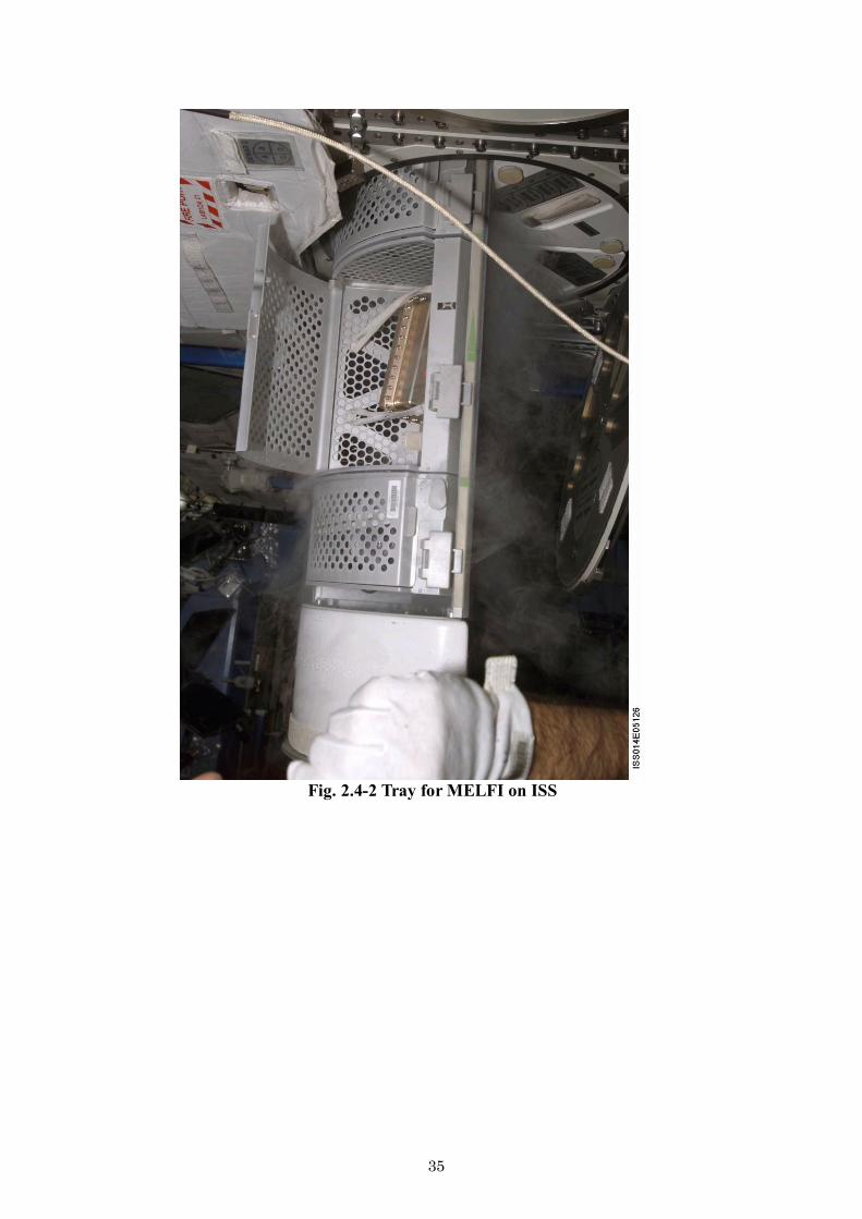
Fig. 2.4-2 Tray for MELFI on ISS

36
2.5 Aquatic Habitat (AQH)
(1) AQH outline
Aquatic Habitat (AQH) has the capabilities to accommodate small freshwater fish, medaka or zebrafish, which have many advantages as vertebrate model. The AQH is installed in Multi-Purpose Small Payload Rack (MSPR) in Japanese Experiment Module (Kibo) of ISS and is utilized for the experiments to investigate how microgravity and the space radiation environment, particularly over the long term, affect living things including human being. The AQH is composed of one closed water circulation system with two aquariums. The aquarium has automatic feeding system, LED light for day/night cycle and CCD camera for observation. The aquarium environment will be maintained by water flow rate control, water temperature control, dissolved gas exchange with air, and biological/physical filtrations. Also, the AQH will have on-orbit maintenance capabilities, such as water quality check, water exchange, and waste filter replacement and so on, to achieve long-term experiments up to 90days. Outline of the AQH is shown in Fig. 2.5-1 and Fig. 2.5-2. AQH water flow diagram is shown in Fig. 2.5-3.
Fig. 2.5-1 Outline of AQH
Medaka (Oryzias latipes)
Zebrafish (Danio rerio)
LED Light
Water Circulation Unit
Waste Filter Controller
Biological Filter
Gas Exchanger
CCD Camera
Aquarium
Multi-Purpose Small payload Rack (MPSR) Work Volume

37
Fig. 2.5-2 AQH installed in MSPR WV in “Kibo”
Fig. 2.5-3 Water flow diagram of AQH
Fig. 2.5-4 Medaka in AQH Aquarium Fig.2.5-5 Zebrafish in AQH Aquarium (Space experiment) (Ground experiment)
Air
Pump
Accumulator
Flow Sensor Aquarium
Auto Feeder
Waste
Filter
Water Pump
Biological
Filter
Gas
Exchanger
Temp
Controller pH/DO
Sensor Unit
Water Pump
Flow Sensor
Waste
Filter Aquarium
Auto Feeder

38
(2) AQH major specifications
Experiment duration Up to 90 days
Water circulation system One closed water loop with two aquariums Total water volume: 3.2 L
Aquarium Inner dimensions: 150 X 70 X 70mm Inner water volume: 0.7 L/aquarium Air Stabilizer is equipped for air/water interface control and Access Port is equipped for fish sampling
Water temperature control Water temperature range: 25-30 degree C Water temperature accuracy: ±1 degree C of set point
Water flow rate control Water flow rate can be controlled for each aquarium Water flow rate range: 0-0.4 L/min Water flow rate accuracy: ±10 % of set point
O2 supply/CO2 removal Gas exchange with air by artificial lung (gas permeable membrane)
Water quality maintenance Biological filter with nitrifying bacteria for NH4/NO2 removal Water exchange for NO3 removal Physical filter with activated carbon for waste trap and organic material adsorption
Day/night cycle Two LED lights for each aquarium Light intensity: selectable in the range of 0-1000 Lux Light/dark cycle: selectable within total 24 hours
Automatic feeding Artificial powdery food can be used Feeding amount and timing are programmable according to fish developmental stages Feeding frequency: selectable
Observation Two CCD cameras for each aquarium Infrared camera observation is available
Data monitor Water temperature, water flow rate, water pressure, dissolved oxygen, pH, lighting status, feeding status
Commanding Water temperature set point, water flow rate set point, lighting control, feeding control, CCD camera control
(3) AQH Accessories
Auto Feeder
Air Stabilizer Access Port
Waste Filter
Fig.2.5-6 AQH Aquairum
Feeding point of Auto Feeder

39
The AQH has various accessories for fish transportation to “Kibo” of ISS, fish sampling and preservation for post-flight analysis, generational separation and change for supporting medaka multi-generational experiment and also AQH maintenance.
Fish Carrier Container for live fish transportation from launch site to “Kibo”
Fish Retriever Container for live fish transportation from “Kibo” to landing site
Fish Catcher Apparatus to catch fish in the aquarium and took out for chemical treatment or generational change
Fish Fixation Apparatus Apparatus to fix fish chemically and retrieve for post-flight analysis
Egg Collection Kit Kit to collect medaka eggs in the aquarium and maintain them until hatch for multi-generational experiment
Water Quality Test Kit Kit to check NH4, NO2, NO3 concentrations of sampled AQH circulation water
Water Exchange Kit Kit to exchange AQH circulation water
(4) AQH Operations
The AQH Breeding Unit including Aquariums and AQH accessories are supposed to be transported to “Kibo” by HII Transfer Vehicle (HTV) from Tanegashima Space Center in Japan or other vehicles for each experiment. Biological samples such as fish will be transported by Soyuz or Progress from Baikonur Cosmodrome due to their late loading requirements and the experiment will be started just after their arrival. Samples for post-flight analysis will be retrieved by Soyuz Descent Module or Dragon Spacecraft. The AQH operational flow is shown in Fig.2.5-7.

40
Fig.2.5-7 AQH operational flow
Soyuz DescentModule or Dragon Spacecraft
Soyuz/Progress HTV
Tanegashima Space Center
Baikonur Cosmodrome
ISS “Kibo”
Sample (Fish Fixation Apparatus, Fish Retriever) Fish Carrier
AQH MPSR
Space Experiment
AQH
AQH
Fish Carrier
Kazakhstan or United States

41
2.6 Passive Dosimeter for Life Science Experiments in Space (PADLES)
Using the Passive Dosimeter for Life Science Experiment in Space (PADLES), the Japan Space Utilization Promotion Center at JAXA has implemented cosmic radiation environmental monitoring in Kibo (Area PADLES), dose measurement to evaluate the effect of radiation on biological samples used in life science experiments (Bio PADLES), and measurement of individual exposure doses for the Japanese astronauts staying at the International Space Station (ISS) for long periods (Crew PADLES) since Kibo docked with the ISS.
It is important to measure the cosmic radiation environment in space experiments in the life sciences conducted in the ISS and on the space shuttle as an indicator for physical and chemical analysis of the effects of cosmic radiation on biological samples. JAXA provides measurement of the exposure doses for biological samples, data analysis, and disclosure, which are important for space experiments in the life sciences (Fig. 2.6-1).
The dosimeter package (Figs. 2.6-1 and 2.6-2) combines two types of dosimeter device (the nuclear track detector, CR-39, and thermoluminescent dosimeter, TLD), which were developed by JAXA to be optimal for cosmic radiation environment measurements. The PADLES analyzes the measurement results automatically. Data from a dosimeter package mounted with biological samples are analyzed approximately two weeks after the return to the ground and presented as a summarized report in English on the detailed dosimeter mounting environment and dose analysis results (Fig. 2.6-3).
The analysis items provided by the PADLES are as follows (Table 2.6-1): - Absorbed dose (units of mGy): Absorbed energy per unit weight - Linear energy transfer (LET) spectrum: Measurement of LET spectrum, which is
necessary to calculate the load coefficient - Equivalent dose (units of mSv): The product value of the load coefficient for the
absorbed dose depending on the radiation quality and absorbed dose
Fig. 2.6-1 Devices comprising PADLES dosimeter package (CR-39, TLD)
Nuclear track detector CR-39
Thermoluminescent dosimetry TLD-MSO
Nuclear track detector CR-39

42
Fig. 2.6-2 (left) PADLES dosimeter package may have the device enclosed in heated aluminum sealing (3 cm × 3 cm × 0.5 mm) or polycarbonate case (4.6 cm × 4.6 cm × 0.9 mm) depending on the application. (right) Nuclear track detector CR-39, which was mounted inside ISS Kibo for 278 days. The tracks of heavy charged particles that passed through the dosimeter on orbit (etch pits) were visualized. The LET spectrum can be calculated by measuring the shapes and number of these etch pits.
Fig.2.6-3 Radiation measurement flow in space experiments in life sciences
For astronauts For biological samples For environmental measurement

43
Table 2.6-1 PADLES package specifications
Device Measurement function
Subject radiation type
LET range (keV/μm)
TLD MSO-S Absorbed dose*1 Photons, charged particles
0.2–10
CR-39 HARZLAS (TD-1/TNF-1) LET spectrum for particle fluence
Charged particles 2–1000
BARYOTRK/HARZLAS (TD1) Particle tracking
High Z, high E charged
particles
40 or higher*3
TLD MSO-S Absorbed dose*1 Photons, charged particles
0.2–1000
CR-39 HARZLAS (TD-1/TNF-1) Equivalent dose*1 Photons, charged particles
Effective quality factor*2
Photons, charged particles
Temperature range -80–40C
Atmosphere 1 atm, in air
Dimensions 25 mm(W) × 25 mm(L) × 4 mm (H)
[Minimum area for CR-39, 20 mm (W) × 15 mm (L) × 0.45 mm(H)]
Mounting period Three months by default (one week minimum, one year maximum)
*1 Integrated value during period of biological sample mounting *2 Average value during period of biological sample mounting *3 Equivalent to charged particles with Z equal to or higher than the Si atom in relativistic energy

44
2.7 Particle Counter
This handy measuring instrument detects airborne particles in air and records the value for each particle size. It can measure the temperature and humidity while also recording data on six particle size classes: 0.5 μm and larger, 1.0 μm and larger, 2.0 μm and larger, 3.0 μm and larger, 5.0 μm and larger, and 10.0 μm and larger. It can take measurements at an arbitrary interval and accumulate up to 500 measurement results in the main unit. The accumulated data are transmitted to the laptop PC located in the International Space Station (ISS) Kibo for down link to the ground.
This particle counter was developed for “Microbial dynamics in International Space Station, OpNom (Microbe),” a theme for Kibo Pressurized Module use in the second period. It is based on a commercial product (RION Co., Ltd., KR-12A) and modified for mounting in the ISS and for this experiment theme. The specifications of the particle counter are listed in Table 2.7-1, and a photograph is shown in Fig. 2.7-1.
Table 2.7-1 Specifications of Particle Counter Item Specification
Optical system Sideways scattering methodLight source Semiconductor laser (Class 1) Photodetector Photodiode Rated flow rate 2.83 L/min
Particle size classes for
measurement
six classes 0.5 μm and larger, 1.0 μm and larger, 2.0 μm and larger, 3.0 μm and larger, 5.0 μm and larger, and 10.0 μm and larger
Maximum rated particle number and concentration
70,000 particles/L
Inspiration time for
measurement
6 s (0.01 CF), 21 s (1 L), 1 min (0.1 CF, 2.83 L), 3 min and 32
s (10 L), 10 min (1 CF, 28.3 L), arbitrary (1 s– 59 min and 59
sec or manual on/off). CF: Cubic foot
Number of measurements 1 to 100 and infinite
Sample exhaust Filter (0.1 μm) Memory capacity Memorizing and recalling up to 500 measurement values
External data recording Utility software installation on PC Connected to a PC via USB cable for storage in CSV format
LCD display Maximum digits indicated: 8 (with a backlight) Possible measurement range for temperature and humidity sensors
10 to 40C, 20% to 90% (guideline)
Operating conditions 10 to 40C, 20% to 90%
Power supply Size D alkaline batteries (four), capable of taking
measurements every 15 min for 24 h or longer continuously

45
Accessories USB cable Other With Velcro and tether (1 m) for prevention of floating loss
Dimensions 115 mm (W), 104 mm (D), 334 mm (H) (main unit dimensions)
Weight Total weight: 2.01 kg (Main unit: 1459 g, cable: 23 g, four batteries: 532 g)
Fig. 2.7-1 Particle Counter (Silver part at the bottom is the size D battery box.)

46
3 Experimental facilities for material science
3.1 Fluid Physics Experiment Facility (FPEF)
(1) Outline This is an experimental facility for conducting basic experiments related mainly to fluid
physics around room temperature (such as Marangoni convection experiments). It is equipped with a three-dimensional observation camera, infrared thermometer, strobe light, overall observation camera, and other equipment.
It has an electrical interface with the experiment cell that can transmit data from the
control/measurement/observation devices inside the experiment cell and transmit the image signals to the Image Processing Unit (IPU, described later). It also has an interface with the fluid system (gas/water, QD).
Because the FPEF performs its major functions in conjunction with a general-purpose
experiment cell, they are described in the next section. Fig. 3.1-1 shows a photograph and schematic drawing of the FPEF.
Fig. 3.1-1 Photograph and schematic drawing of FPEF (2) Experiment cell
The removable experimental cell stows the sample and devices around the sample. As long as certain interface and safety conditions are satisfied between the cell and the
main body of the FPEF system, the experiment cell can be customized to suit the purpose of an experiment.
Table 3.1-1 shows the system functions and resources (user interfaces provided by the system) that are available to the experiment cell, and Fig. 3.1-2 shows the envelope that can be used for the experiment cell.
As an example, the general-purpose experiment cell for Marangoni convection experiments that were actually conducted in Kibo is shown in Fig. 3.1-3, and its specifications are listed in Table 3.1-2.
Motor driver
Strobe controller
Infrared thermometer
Three-dimensional flow velocity measurement system
FPEF control system

47
Table 3.1-1 System functions and resources available to experiment cell
Item Functions and resources
Power supply 12 V ± 2 V, ≤4 A, 1 ch 24 V ± 2 V, ≤3.5 A, 1 ch ±15 V ± 0.5 V, ≤0.8 A/ch, 3 ch
Power control 4–65 V/5–180 W, 3 ch 1–30 V/5–180 W, 1 ch
Solenoid valve driving 24 V ± 2 V, ≤1.3 A, 3 ch Power supply for motor 24 V, 3 A, 4 ch (motor: For PK543-A) General-purpose analog
input0–10 V, 8 ch
General-purpose digital input
8 ch
General-purpose digital output
8 ch
Contact signal input 15 ch Platinum temperature
sensor input5 ch
Thermocouple temperature sensor input
6 ch, K thermocouple supported
CCD camera input IK-TU40D supported, 1 ch Video input NTSC, 2 ch
Tolerable size (See Fig. 3.1-2.)
230 (W) × 580 (L) × 363 (H) mm(Some parts cannot be used even in the above envelope.)
Ar gas 88.2–101.3 kPa, 20 nL/min Cooling water 8.5 kg/h, in: 16–23C, out: ≤43C
Exhaust pressure 0.13 Pa–101 kPa
Exhaust heat rate ≤255 W (with room for adjustment) Weight 38 kg or smaller
Fig. 3.1-2 Available dimensions of experiment cell
(External dimensions for general-purpose experiment cell for Marangoni convection experiments)
A-A cross section

48
Fig. 3.1-3 Photograph and illustration of general-purpose experiment cell for Marangoni convection experiments
Table 3.1-2 Specifications of general-purpose experiment cell for Marangoni convection experiments
Item Specifications
Liquid bridge formation
Sample: Silicone oil (5 cSt/10 cSt) Diameter: Ø30/Ø50 (mm) Length: ≤60 mm Liquid volume adjustment range: ±9.6 mL
Temperature monitor
Heating disk temperature: 10–100C Cooling disk temperature: Room temperature to 0C Observation window temperature: Room temperature to 60CAmbient temperature: Room temperature to 100C Liquid bridge internal temperature: 0–100C
Temperature control Heating disk: ≤90C Cooling disk: ≥5C Observation window: ≤50C
Three-dimensional flow velocity measurement*1*3
CCD camera pixel number: 768 (H) × 494 (V) Strobe illumination frequency: 60 Hz
Overall observation*3 CCD camera pixel number: 768 (H) × 494 (V)
Surface temperature distribution
measurement*3
Infrared thermometer Detection wavelength range: 8–14 μm Measurement temperature range: 0–100C
Surface velocity measurement*2
Laser radiation: two points Illumination frequency: 4.57 × 10⁻⁴ to 10 Hz (±1%) Illumination count: 1–4097 times
*1 For observing the behavior of tracer particles mixing in liquid bridge using the three-dimensional observation camera *2 For visualizing the flow on the liquid bridge by developing pixel color mixing in the liquid bridge by
irradiating the laser intermittently *3 Among the acquired data, image data are recorded and transmitted to Earth mainly via the IPU.
Although the data rates are set to 17–42 Mbps/ch (MPEG/MotionJPEG compression) for video recording and 15 Mbps max/ch (MPEG2 compression) for transmission to Earth, they are subject to change because of various operational restrictions.
Structure Surface velocity measurement system
Liquid bridge formation equipment
Signal conditioner

49
3.2 Solution Crystal Observation Facility (SCOF)
(1) Outline This is a system for observing the crystal forms and environmental phase
temperature/concentration field on site during crystal growth in a supersaturated solution or supercooled melt prepared by temperature/pressure control. It is equipped with a two-wavelength Mach–Zehnder interference microscope, amplitude modulation microscope, and other equipment as observation devices.
It has an electrical interface with the Experiment Cell Cartridge that can supply power
to the Experiment Cell Cartridge and control its temperature. Further, it transmits the measurement data, such as the temperature, and transmits the image signals to the Image Processing Unit (IPU, described later). It also has an interface to the fluid system (nitrogen gas, gas exhaust).
Fig. 3.2-1 shows a photographs and schematic drawings of the external appearance and
internal structure of the SCOF. Fig. 3.2-2 shows the optical path for the entire observation system, and Table 3.2-1 lists the main functions and basic specifications of the SCOF.
(a) (b) (c) (d)
Fig. 3.2-1 Photographs and schematic drawings of SCOF
(a) External photograph, (b) schematic drawing of external appearance, (c) photograph of internal structure, (d) schematic drawing of internal structure
Microscopes - Amplitude modulated - Polarizing - Bright field
Status indicator
Microscope control block
Video terminal
Temperature/pressure indicator
Experiment start switch
Communication port
Cell stage driving unit control indication
Mach–Zehnder interference microscope
Optical window
Gas supply port
Electronics control unit
Laser light source
Experiment Cell Cartridge
Cell stage driving unit

50
Fig. 3.2-2 Optical path for entire observation system
Mach–Zehnder light source (532 nm laser)
Transmission microscope light source (660 nm LED)
Experiment Cell Cartridge
Polarizing microscope analyzer
Reflecting prism
CCD camera (for ×2 observation)
Koester prism
Mach–Zehnder light source (780 nm laser)
Reflecting prism
Experimental cell (temperature control: -10–220C)
Reflecting microscope light source (660 nm LED)
Koester prism
CCD camera (for ×4observation)

51
Table 3.2-1 Main functions of SCOF (excerpt)
Main function Basic specifications Experimental control (1) Experiments are mostly controlled automatically using a program.
(2) System is capable of telescience operation.
Ob
servation system
Crystal surface observation
Method: Amplitude modulation microscope (installed on Mach–Zehnder two-wavelength interference microscope)
Magnification: 2 and 4× Light source: LED (wavelength 660 mm) Observation field: 2.4 × 3.2 mm/2×, 1.2 × 1.6 mm/4 × Phase resolution: ≥0.2 wavelength (132 nm) Sample illumination: Transmitted beam observation/reflected light observation switching Imaging device: ½-in. CCD camera Focus adjustment: By Experiment Cell Cartridge driving Other: Light field/polarization observation possible
Measurement of temperature/ concentration distribution in liquid phase
Method: Mach–Zehnder-type two-wavelength interference microscope Magnification: 2 and 4× Light source: laser diode (LD) and LD excitation solid laser (wavelength 780/532 mm) Observation field: 2.4 × 3.2 mm/2× to 1.2 × 1.6 mm/4× Phase resolution: ≥0.2 wavelength Imaging device: ½-in. CCD camera
Particle size distribution
measurement
Method: Dynamic light scattering measuring device (with delayed fluorescence measurement function) Light source: LD (wavelength 532 nm) Particle detection capacity: 100 nm Analysis method: Multiple hard correlator method Minimum gate time: 200 ns Other: Detector is installed on the Experiment Cell Cartridge side.
Experiment Unique Cartridge driving system
Method: Stage method Movement axes: X, Y, Z, θ X = 3.55 to -3.73 mm Y = 3.67 to -3.61 mm Z = 3.65 to -3.5 mm θ = ±5 (X, Y, and Z stroke: ≥±3 mm)
Pressure control function Pressure control range: 1–147.10 MPa (interface to pressure control block necessary on Experiment Cell Cartridge side) Pressure increase function: None (installed on Experiment Cell Cartridge side)
Gas supply/exhaust N2 gas supply pressure: 0 to approx. 827.4 kPa Gas exhaust operation pressure: 101 kPa to 0.13 Pa [interface (QD) to pressure control block necessary on Experiment Cell Cartridge side]
Temperature measurement/control
system
Described in Table 3.2-2 because it depends on the functions of the Experiment Cell Cartridge
Note: Amongthe obtained data, image data are recorded and transmitted to the earth mainly via the IPU. Although the data rates are set to 17–42 Mbps/ch (MPEG/MotionJPEG compression) for video recording and 15 Mbps max/ch (MPEG2 compression) for transmission to Earth, they are subject to change because of various operational restrictions.
52
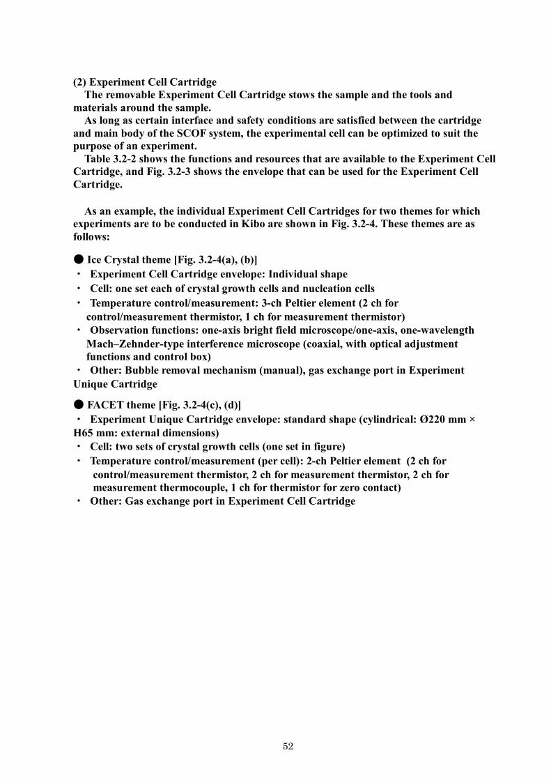
(2) Experiment Cell Cartridge
The removable Experiment Cell Cartridge stows the sample and the tools and materials around the sample.
As long as certain interface and safety conditions are satisfied between the cartridge and main body of the SCOF system, the experimental cell can be optimized to suit the purpose of an experiment.
Table 3.2-2 shows the functions and resources that are available to the Experiment Cell Cartridge, and Fig. 3.2-3 shows the envelope that can be used for the Experiment Cell Cartridge.
As an example, the individual Experiment Cell Cartridges for two themes for which experiments are to be conducted in Kibo are shown in Fig. 3.2-4. These themes are as follows:
Ice Crystal theme [Fig. 3.2-4(a), (b)] ・ Experiment Cell Cartridge envelope: Individual shape ・ Cell: one set each of crystal growth cells and nucleation cells ・ Temperature control/measurement: 3-ch Peltier element (2 ch for
control/measurement thermistor, 1 ch for measurement thermistor) ・ Observation functions: one-axis bright field microscope/one-axis, one-wavelength
Mach–Zehnder-type interference microscope (coaxial, with optical adjustment functions and control box)
・ Other: Bubble removal mechanism (manual), gas exchange port in Experiment Unique Cartridge
FACET theme [Fig. 3.2-4(c), (d)] ・ Experiment Unique Cartridge envelope: standard shape (cylindrical: Ø220 mm × H65 mm: external dimensions) ・ Cell: two sets of crystal growth cells (one set in figure) ・ Temperature control/measurement (per cell): 2-ch Peltier element (2 ch for
control/measurement thermistor, 2 ch for measurement thermistor, 2 ch for measurement thermocouple, 1 ch for thermistor for zero contact)
・ Other: Gas exchange port in Experiment Cell Cartridge

53
Table 3.2-2(1) System functions available to Experiment Cell Cartridge when electrical parts are prepared (1)
(The system has electronic circuits corresponding to the specifications below.)Item System specifications No. of ch
Temperature measurement
/control
Thermistor (for standard measurement)
[TS1–8]
・Measurement range: -20–230C ・Measurement precision: ±0.70C [-20 to -10C]
±0.45C [-10–70ºC] ±2.19C [70–220ºC] ±2.60C [220–230ºC]
・Resistance: 72.24–0.0808 kΩ ・Measurement frequency: 10 Hz
8
Thermistor (for high-precision
measurement 1) [TS9–16]
・Measurement range: 10–80C ・Measurement precision: ±0.130C [10–20C]
±0.097C [20–70C] ±0.120C [70–80C]
・Resistance: 18.26–1.625 kΩ ・Measurement frequency: 10 Hz
8
Thermistor (for cold contact
temperature measurement) [TS17]
・Measurement range: 15–65C ・Measurement precision: ±0.097C ・Resistance: 14.86–2.527 kΩ ・Measurement frequency: 10 Hz
1
Thermistor (for high-precision
measurement 2) [TS18–21]
・Measurement range: -1.5–0.5C or 2.5–4.5C*
・Measurement precision: ±0.044C ・Resolution: 0.001C (target value) ・Resistance: 30.11–27.52 kΩ (TBD) ・Measurement frequency: 10 Hz
4
Thermocouple (K type) [TC1–12]
・Measurement range: -10–220C ・Measurement precision: ±0.8% FS ・Voltage: -2.209–8.301 mV ・Measurement frequency: 10 Hz
12
Thermocouple (J type) [TC13]
・Measurement range: -10–70 ºC ・Measurement precision: ±1.6% FS ・Voltage: -2.822–2.836 mV ・Measurement frequency: 10 Hz
1
Heating/cooling
Peltier element [TM1–12]
・Driving current: ≤4.2 A/ch (≤13 A・ 12 ch)
・Driving precision: ±5% FS ・Supplied power: ≤30 W/ch
12
Heater (for standard control)
[HT1,2]
・Driving voltage: 0–10 V ・Driving precision: ±5% FS ・Supplied power: ≤30 W
2

54
Table 3.2-2(2) System functions available to Experiment Cell Cartridge when electrical parts are prepared (2)
(the system has electronic circuits corresponding to the specifications below.)
Item System specification No. of ch
Motor driving
DC motor [MT1, 2]
・Driving voltage: ≤±6 V ・Driving precision: ±10% FS ・Supplied power: ≤1.1 W ・Direction of rotation: CW/CCW
2
Stepping motor [MT3, 4]
・Number of phases: two ・Driving current: ≤0.75 A/phase ・Direction of rotation: CW/CCW
2
Pressure measurement
Pressure sensor [PR2]
・Power supply voltage: 24 V ± 1% ・Measurement range: -3–33 mV,
0–69.03 MPa 1
Pressure sensor [PR3]
・Power supply voltage: 24 V ± 10% ・Available current: ≤50 mA ・Measurement range: 0–5 V, 0–147.10 MPa ・Measurement precision: ±1% FS
1
Detection
Limit switch [LM1–4]
・Contact current: 2 mA ・Mechanical type
4
Photo sensor [PM15]
・Power supply voltage: 1.2 V ・Detected current: ≥0.5 mA (with light
entrance), ≤10 μA (shading) 1
Light source LED driver
[LED1] ・Supplied current: ≤50 mA ・Driving voltage: 6 V
1
Note: The measurement range can be selected according to the experimental parameters.

55
Fig. 3.2-3 Outline of SCOF Experiment Cell Cartridge envelope
Experiment Cell Cartridge axis
Arrow A
Cross section B-B
Experiment Cell Cartridge axis
Experiment Cell Cartridge axis
Experiment Cell Cartridge axis
Experiment Cell Cartridge axis
Experiment Cell Cartridge axis
Experiment Cell Cartridge axis
Experiment Cell Cartridge axis
Experiment Cell Cartridge axis
Experiment CellCartridge axis
Arrow C
Cross section A-A
Arrow B

56
(a) (b)
(c) (d)
Fig. 3.2-4 Examples of Experiment Cell Cartridge (Engineering Model) (a), (b): Experiment Cell Cartridge for Ice Crystal theme
(c), (d): Experiment Cell Cartridge for FACET theme

57
3.3 Protein Crystallization Research Facility (PCRF)
(1) Outline The Protein Crystallization Research Facility (PCRF) is a system for generating high-
quality protein crystals by using the space environment. It can mount up to six cell cartridges with electrical and thermal interfaces in the cell tray.
An operable CCD camera and illumination LED, which can be used to observe the
actual sample, are installed in the cell tray.
Table 3.3-1 shows the main functions and basic specifications of the PCRF, and Fig. 3.3-1
shows photographs and schematic drawings of the exterior of the PCRF and interior of the cell tray.
Table 3.3-1 Main functions of PCRF (excerpts)
Main function Basic specifications
Experimental control
(1) Experiment is conducted mostly by automatic control based on a program. (2) Telescience operation is possible
Observation system
Light source: LED (660 μm, 3000 mcd ×2) Valid pixels: 768 × 494 pixels Observation field: Ø6.7 mm ± 0.1 mm Resolution: ≥40 μm Sample illumination: Switching between transmitted light observation/reflected light observation Imaging device: 1/2-in. CCD camera Focus adjustment: Pan-focus Depth of field: 6 mm
Cell tray (see 2.5.2)
Allowable space: 300 mm (W) × 300 mm (L) × 80 mm (H) Electric interface: six systems (= number of cell cartridges that can be mounted simultaneously) Heat exhaust: By cold plate on bottom surface of cell
Temperature measurement/control
system
Described in Table 3.3-2; depends on cell cartridge functions
Note: Among the obtained data, the image data are recorded and transmitted to Earth mainly via the Image Processing Unit (IPU). Although the data rates are set to a maximum of 25 Mbps (MPEG/MotionJPEG compression) for video recording and a maximum of 15 Mbps (MPEG2 compression) for transmission to Earth, they are subject to change because of various operational restrictions.

58
(a) (b) (c) (d)
Fig. 3.3-1 External photographs and schematic drawings of PCRF: (a) External photograph, (b) schematic drawing of external appearance,
(c) photograph of cell tray interior, (d) schematic drawing of cell tray interior (2) Cell cartridge
The removable cell cartridge stows the sample and the tools and materials around the sample.
As long as certain interface and safety conditions are satisfied between the cartridge and the main body of the PCRF system, the cell cartridge can be customized to suit the purpose of an experiment.
Table 3.3-2 shows the functions and resources available to the cell cartridge, and Figs.
3.3-2 and 3.3-3 show the available envelope, installation position, and heat exhaust surface.
Numeric keypad for camera position adjustment
CCD camera
Cell cartridge
Status indicator
Experiment start switch
Temperature indicator
Video terminalCommunication port
Cell tray
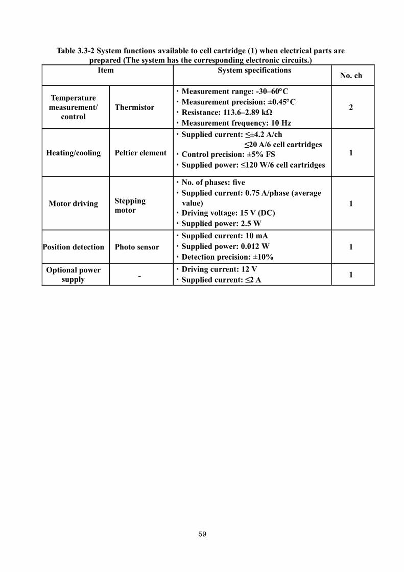
59
Table 3.3-2 System functions available to cell cartridge (1) when electrical parts are prepared (The system has the corresponding electronic circuits.)
Item System specifications No. ch
Temperature measurement/
control Thermistor
・Measurement range: -30–60C ・Measurement precision: ±0.45C ・Resistance: 113.6–2.89 kΩ ・Measurement frequency: 10 Hz
2
Heating/cooling Peltier element
・Supplied current: ≤±4.2 A/ch ≤20 A/6 cell cartridges
・Control precision: ±5% FS ・Supplied power: ≤120 W/6 cell cartridges
1
Motor driving
Stepping motor
・No. of phases: five ・Supplied current: 0.75 A/phase (average
value) ・Driving voltage: 15 V (DC) ・Supplied power: 2.5 W
1
Position detection Photo sensor ・Supplied current: 10 mA ・Supplied power: 0.012 W ・Detection precision: ±10%
1
Optional power supply
- ・Driving current: 12 V ・Supplied current: ≤2 A
1

60
Fig. 3.3-2 Interface for cell unit installation part
Fig. 3.3-3 Movement range of observation field center
Operation panel
Helisert tap through
From X axis From Y axis
All six sets of cell cartridges must fit inside the dotted range with the cell cartridge assembled and installed.
Cell cartridge assembly
Observation field center movement range
Cell tray datum from PCRF datum X direction: Y direction: Z direction
Positioning guide pin for cell cartridge assembly and installation (12 sets) 12- (φ4.0 through) (four points)
(six points)
Cell cartridge assembly
Cell tray datum (from PCRF datum) X direction: Y direction: Z direction
Note 1: There are counterbores with depths of 1 ± 0.4 mm in the shaded section, which are used as the contact surface for heat exhaust. Note 2: Cell cartridge assembly number in cell tray is as shown in this figure. Note 3: Open circles at cell tray pin positions indicate the reference datum for each cell cartridge. Note 4: The dimensional tolerance is ±0.2 unless otherwise specified.

61
3.4 Gradient Heating Furnace (GHF)
(1) Outline The Gradient Heating Furnace (GHF) is a vacuum heating furnace capable of providing
various temperature profiles by high-precision operation of three heating zones (central zone, end zone, and auxiliary zone), whose temperature can be controlled independently, installed inside the vacuum chamber. The temperatures of the zones can be controlled independently to support unidirectional solidification or crystal growth of the sample.
Table 3.4-1 shows the system specifications. Fig. 3.4-1 shows an external photograph and
schematic drawing of the furnace main body, and Fig. 3.4-2 shows the sample cartridge and an example assignment of the three heating zones.
Table 3.4-1 Basic specifications of GHF
Item Specifications Method Resistance heating, moving heating zone type
Heating temperature
range
End zone: 500–1600C (range of motion: ≤200 mm) Central zone: 500–1600C (range of motion: ≤250 mm) Auxiliary zone: 500–1150C (range of motion: ≤250 mm)
Temperature stability
≤ ±0.2C
Temperature setting precision
≤ ±0.4%
Temperature gradient
≥ 150C/cm (@1450C)
Moving speed 0.1–200 mm/h and 600 mm/h
Moving speed stability
Moving speed setting value ≤ ±1% (moving speed 10–200 mm/h) Moving speed setting value ≤ ±10% or lower (moving speed 0.1–10 mm/h)
Heating zone insertion slot
diameter
Ø40 mm
Measurement functions
Temperature: 10 points × 2 systems (individual sample cartridge: for high/medium to low temperatures)
5 points × 2 systems (for standard sample cartridge: for high/medium to low temperatures)
Furnace pressure: Diaphragm-type pressure gauge, Pirani gauge, ion gauge
Marking mechanism
Has an interface capable of supplying pulse current to the sample cartridge
Operable cumulative time
300 h (@ maximum temperature)
Power consumption
≤ 5300 W

62
Fig. 3.4-1 External photograph and schematic drawing of furnace main unit
Fig. 3.4-2 Sample cartridge and example assignment of three heating zones
Vacuum chamber wall
Experiment sample cartridge
Vacuum chamber
Heating zones
Motor
Auxiliary zoneCentral zone End zone

63
(2) Sample cartridge Experiments are conducted in units of sample cartridges.
At present, one type of standard sample cartridge is defined. By presetting up to 15 of these standard sample cartridges in the Sample Cartridge Automatic Exchange Mechanism, experiments can be conducted fully automatically.
Table 3.4-2 shows the standard sample cartridge’s specifications, and Fig. 3.4-3 shows its cross section.
Table 3.4-2 Basic specifications of standard sample cartridge
Item Specifications
Dimensions Boss part: - 93 mm Cartridge part: - 505 mm (Ø34.4–36.1 mm)
Weight characteristics
≤6 kg
Maximum sample
dimensions
Ø31 mm × 370 mmL
Temperature measurement
function
Normally at 5 points (≤10 points)
Fig. 3.4-3 Cross section of standard sample cartridge
Cartridge part Boss part
(Interface part with the system)
92.95 mm 505 mm

64
3.5 Electrostatic Levitation Furnace
The Electrostatic Levitation Furnace is a material experiment system capable of heating or cooling a sample without a container by charging it to make it levitate under the Coulomb force and heating it with a laser (Fig. 3.5-1). Because this process does not require containers, it can be used to measure the thermophysical properties of high-temperature melts or search for new substances by supercooling solidification. Other types of levitation furnaces include the electromagnetic, ultrasonic, and gas levitation furnace. In comparison with these types, the Electrostatic Levitation Furnace has the following characteristics: - Any substance that can be charged, metal or insulator, can be used as the experimental sample. - The atmosphere can be vacuum or gas.
Fig. 3.5-1 Floating and heating in Electrostatic Levitation Furnace on earth
This system is mounted on the Multipurpose Small Payload Rack (MSPR) of the Japanese Experiment Module (Kibo) on the International Space Station. Because experiments using the Electrostatic Levitation Furnace under microgravity do not require large electric fields to balance gravity, the system has the following advantages: - Position control is easily realized for oxides with small charges and samples that are
heavier than those used in levitation furnace experiments on earth. - Because position control is realized in a gas atmosphere, in which discharge between
electrodes tends to occur, experiments on alloys and oxides that evaporate in vacuum can be conducted. The Electrostatic Levitation Furnace consists of the main unit mounted in the MSPR Work Volume (WV), a UV light block mounted in the Small Experiment Area, and an Ar gas supply mounted at the bottom of the MSPR. By setting the sample holder packed with 15 samples into the sample cartridge and inserting it into the furnace’s main unit, experiments can be conducted by command control from a terminal on Earth. The thermophysical properties, density, surface tension, and viscosity coefficient of the sample can be measured, and solidification phenomena can be observed in a supercooling solidification experiment; further, the solidified sample can be collected for investigation on Earth.
Schematic drawings of the Electrostatic Levitation Furnace main unit and the other
components are shown in Fig. 3.5-2, and a schematic drawing of the sample placement is shown in Fig. 3.5-3. The basic specifications are listed in Table 3.5-1.

65
Fig. 3.5-2 Electrostatic Levitation Furnace
Sample (15 pieces) Sample holder Sample cartridge Electrostatic Levitation
Furnace (with MSPR mounted)
Fig. 3.5-3 Schematic drawing of sample placement
UV light section
Electrostatic Levitation Furnacemain unit
Multipurpose Small Payload Rack Ar gas supply
MSPR-WV door for Electrostatic Levitation Furnace

66
Table 3.5-1 Specifications of Electrostatic Levitation Furnace
Item Specifications
Subject sample
Mainly oxides. Metals, alloys, and semiconductors can also be used. - Shape: Spheres with diameter of 1.5 to 2.1 mm (Diameters of up to 5 mm can be obtained by sample cartridge replacement.)
Position control Three-axis control - Control cycle: 1 kHz at max. - Control precision: ±100 μm or lower
Atmosphere control
- 2 atm air (oxygen concentration 10%) - 2 atm nitrogen - 2 atm argon - Vacuum (JEM exhaust system is used.)
Heating function
Heating laser (semiconductor laser) - Wavelength: 980 nm - Maximum optical output: 40 W × 4
Temperature measurement
- Measurement range: 300C to 3000C - Measurement frequency: 100 Hz
Density measurement
By using UV background light, the outline of a sample emitting light at high temperatures can be observed at 140 pixels/radius or better when the diameter is 2 mm.
Surface tension/viscosity
measurement
Surface tension: Measurement using resonant frequency of melt Viscosity: Measurement using vibration damping factor - Vibration excitation: 1 to 600 Hz
Solidification status
observation
- Resolution: 640 × 480 dots - Frame rate: 30 fps - Dynamic range: 120 dB or higher

67
4 Devices for experiments with human subjects and for physiological research 4.1 Simplified biological function monitoring device (Holter electrocardiograph) The simplified biological function monitoring device is a commercial Holter electrocardiograph (manufactured by Fukuda Denshi, Model FM-180, dimensions: 65 mm × 62 mm × 18 mm), which is a digital electrocardiogram recorder used for measurement and recording of electrocardiographic waveforms continuously for 24 h on orbit as sold commercially. The Holter electrocardiograph is shown in Fig. 4.1-1, and its specifications are listed in Table 4.1-1.
The electrocardiograph signals indicate the action potential of the heart, which is input from the special electrodes attached to the body surface [there are two intake channels (bipolar leads); see Fig. 4.1-2 for the electrode positions]. The action potential is converted into digital signals and recorded in a specially initialized multimedia card. After the measurement is complete, the data are first stored in the on-orbit PC to implement a down link to Earth. To reproduce and analyze the electrocardiographic data on Earth, special analysis software (manufactured by Fukuda Denshi, SCM-510J or SCM-510W) will be required.
Fig. 4.1-1 Holter electrocardiograph
(1) Ch1 lead name: CM5 lead
Ch1 (-): Red electrode, upper end of breast bone Ch1 (+): Yellow electrode, V5 position
(2) Ch2 lead name: NASA lead Ch2 (-): Orange electrode, upper end of breast bone Ch2 (+): Blue electrode, lower end of breast bone
* Gray electrode is for grounding, V5R position.
Fig. 4.1-2 Electrode positions (Measurement points: Bipolar leads)

68
Table 4.1-1 Specifications of Holter electrocardiograph
Item Specifications
Dimensions (reference: weight)
65 mm × 62 mm × 18 mm (78 g, including battery and memory card)
Power supply 1 AAA alkaline battery
Internal clock RTC
Recording time 24 h
Recording media Multimedia card (MMC-64)
CPU 16-bit single chip
Recording channels Bipolar, two channels
Electrode voltage ±350 mV
Input impedance 10 MΩ or higher
Suppression of in-phase signal
60 dB or higher
Amplification rate 300 times (A/D input, monitor output)
Frequency characteristic 0.05/0.067 to 40 Hz
Monitor output 300 mV/1 mV
Quantization bit number 10-bit
Sampling frequency 125 Hz
Maximum input ±5.00 mV
Minimum resolution ±9.76 μV
Sensitivity precision, stability
Precision: Less than 5%, stability: maximum change 3% or smaller
Noise level 50 μVp-p or smaller
Interference between channels
0.2 mVp-p or smaller
Although the electrocardiograph also has acceleration sensors in the directions of the three axes (static position information detection), pacemaker pulse detection, and functions related to subject event recording functions, they are omitted from the range and procedures for on-orbit operation.

69
4.2 Onboard Diagnostic Kit
Onboard Diagnostic Kit (ODK) is a health-monitoring system capable of integrated management on orbit and simple analysis for the medical experiment data acquired from small high-performance various medical equipment. The various experimental devices such as electric stechoscope, sleep monitor, USB camera are used. USB camera is used to make a medical examination in the situation of eyes and teeth from the ground. The data of USB camera and electric stechoscope can be sent to the ground in real time. We plan to establish additional components in stages in the future for the development of space medicine research.
Constitution of the medical equipment which medical experiment data are collected and maneged in a space medicine experiment support system. Main equipments are as follows. (1) Laptop PC for medical experiments (Lenovo, Thinkpad T61p)
This is a standard laptop PC for use on orbit and is equipped with a special software program for medical experiments. The software is designed to take in medical data from the medical devices connected to the laptop and execute control, indication, and other functions on orbit through a simple interface.
The experimental devices that are supported include the USB camera, electronic stethoscope, and pulse oxymeter listed below, and it is also possible to take in the data from the Holter electrocardiograph described in Section 4.1. The data obtained from these devices are synchronized using the same software mounted on the ground system after a simple analysis on orbit so that medical personnel on Earth can check an electronic chart similar to that on orbit.
Furthermore, it is possible to easily down link the data from the laptop PC with a command from Earth, as long as the data can be saved on the laptop PC even if they have been obtained from a new device.

70
Laptop PC for medical experiments Electronic chart software for on-orbit diagnosis
(2) USB camera (Logitec, Webcam C905)
This is a standard on-orbit USB camera, and it is used to check for changes in physical conditions by imaging the eyes, tongue, and other areas or to support on-orbit work as an alternative in-station camera. It can also be used to connect with the ground system in a TV conference for real-time medical interviews and other communication. Video: Up to 2 million pixels
(HD720p wide-screen mode supported) Still images: Up to 8 million pixels Communication with PC: USB 2.0 (3) Electronic stethoscope (3M Littman, Model 3200)
This can be used to convert the auscultatory sound into digital sound and transmit it to the laptop PC in real time via a Bluetooth interface. The obtained data are analyzed on site to detect heart murmurs. It can also transmit the auscultatory sound to the ear tips on Earth in real time; this enables on-orbit diagnosis while the physician stays on Earth. Filter: Bell mode, Diaphragm, Extended mode Power supply: 1 AA alkaline battery Communication with PC: Class 2 Bluetooth (4) Pulse oxymeter (Japan Precision Instruments, Inc., OxiHeart OX-700)
This can be used to measure the blood oxygen saturation and pulse rate by a simple procedure. The data can be checked visually and input manually on the laptop PC.
Measurement range: Blood oxygen saturation and pulse rate Power supply: Two AAA alkaline batteries
USB camera
Eelectronic stethoscope
Pulse oxymeter

71
(5) Head set (Sennheiser Communications, CC550) This is a monaural head set for both ears that can be used to
connect with Earth in TV conferences for real-time medical interviews and other communication. It is connected to the laptop PC with a USB connector via the head set cable (UUSB6). Its strong noise-canceling function improves the voice quality even in environments with high levels of noise.
Cable length: 1 m [3 m in total in combination with head set cable (2 m in length)]

72
4.3 Devices for space medicine research by agencies other than JAXA
There are other devices and systems that are owned by PIs other than JAXA and that can be used for space medicine research as follows. These devices are used by international cooperation, and they are not always available depending on the space experiment plans.
Table 4.3-1 Devices and systems used for space medicine research Hardware Available to Support Human Subject Research
Agency Website
Physiological Monitoring
Blood Pressure/Electrocardiograph NASA Sally Davis, CheCS Hardware, [email protected]
Automatic Blood Pressure Cuff NASA
ESA
Sally Davis, CheCS Hardware, [email protected] http://www.cnes.fr/web/CNES-fr/8781-epm.php
Continuous Blood Pressure Device NASA ESA
http://www.nasa.gov/mission_pages/station/research/experiments/625.htmlhttp://www.cnes.fr/web/CNES-fr/8781-epm.php
Pulmonary Function System NASA/ESA
http://www.nasa.gov/mission_pages/station/research/experiments/336.html http://www.esa.int/Our_Activities/Human_Spaceflight/Human_Spaceflight_Research/Pulmonary_Function_System_PFS
Portable Pulmonary Function System
ESA http://www.esa.int/Our_Activities/Human_Spaceflight/Human_Spaceflight_Research/Pulmonary Function_System_PFS
ECG Holter Monitor NASA/ JAXA/ESA
http://www.nasa.gov/mission_pages/station/research/experiments/614.htmlhttp://kibo.jaxa.jp/en/experiment/pm/holter/holter.pdf http://www.cnes.fr/web/CNES-fr/8781-epm.php
JAXA Onboard Diagnostic Kit JAXA Ask the JAXA contact person http://www.nasa.gov/mission_pages/station/research/experiments/843.html
Ultrasound 2 Doppler NASA http://www.nasa.gov/mission_pages/station/research/experiments/749.html
Thermolab ESA http://eea.spaceflight.esa.int/portal/exp/?id=9338
SKIN B H/W Kit DLR http://eea.spaceflight.esa.int/portal/exp/?id=9392
Space Linear Acceleration Mass Measurement Device NASA
http://www.nasa.gov/mission_pages/station/research/experiments/640.html
Sample Collection and Stowage
Human Sample Collection Kits NASA TBD
Refrigerated* Centrifuge *refrigeration function is failed NASA http://www.nasa.gov/mission_pages/station/research/experiments/639.html
Exercise
Cycle Ergometer NASA http://www.nasa.gov/mission_pages/station/research/experiments/841.html
Treadmill NASA http://www.nasa.gov/mission_pages/station/research/experiments/765.html

73
Cycle Ergometer NASA http://www.nasa.gov/mission_pages/station/research/experiments/841.html
Treadmill NASA http://www.nasa.gov/mission_pages/station/research/experiments/765.html
Advanced Resistive Exercise Device
NASA http://www.nasa.gov/mission_pages/station/research/experiments/1001.html
Muscle Strength, Torque, and Joint Angle
Muscle Atrophy Research and Exercise System
NASA/ESA
http://www.nasa.gov/mission_pages/station/research/experiments/352.html http://www.esa.int/Our_Activities/Human_Spaceflight/Human_Spaceflight_Research/Muscle_Atrophy_Research_Exercise_System_MARES http://www.cnes.fr/web/CNES-fr/8783-mares.php
Percutaneous Electrical Muscle Stimulator
NASA/ESA http://www.esa.int/Our_Activities/Human_Spaceflight/Human_Spaceflight_Research/Percutaneous_Electrical_Muscle_Stimulator_PEMS
Hand Grip/Pinch Force Dynamometer
NASA/ESA http://www.esa.int/Our_Activities/Human_Spaceflight/Human_Spaceflight_Research/Hand_grip
Activity Monitoring
Actiwatch NASA http://www.nasa.gov/mission_pages/station/research/experiments/858.html
Armband monitoring ESA http://www.cnes.fr/web/CNES-fr/8914-energy.php
Coordination
ELITE-S2 ASI http://www.nasa.gov/mission_pages/station/research/experiments/78.html
Eye Tracking Device (ETD) DLR http://eea.spaceflight.esa.int/portal/exp/?id=8225
HPA ASI http://www.nasa.gov/mission_pages/station/research/experiments/223.html
European Physiology Modules
Multi Electrode EEG Mapping Module
ESA
http://www.esa.int/Our_Activities/Human_Spaceflight/International_Space_Station/European_Physiology_Modules http://www.cnes.fr/web/CNES-fr/8781-epm.php
Portable EEG (PORTEEMM) ESA http://www.esa.int/Our_Activities/Human_Spaceflight/International_Space_Station/European_Physiology_Modules http://www.cnes.fr/web/CNES-fr/8781-epm.php
Sample Collection Kit (SCK) ESA http://www.esa.int/Our_Activities/Human_Spaceflight/International_Space_Station/European_Physiology_Modules http://www.cnes.fr/web/CNES-fr/8781-epm.php
CARDIOLAB ESA http://www.esa.int/Our_Activities/Human_Spaceflight/International_Space_Station/European_Physiology_Modules http://www.cnes.fr/web/CNES-fr/8781-epm.php

74
5 Devices common to multiple fields
5.1 Multipurpose Small Payload Rack (MSPR) The Multipurpose Small Payload Rack (MSPR) has been developed to provide a work space equipped with a power supply, communication functions, and other functions assuming that users would develop and install their own equipment and conduct experiments.
The MSPR provides three experimental spaces: the Work Volume (WV), Work Bench
(WB), and Small Experiment Area (SEA). The WB is a table that can be used for sample adjustment, maintenance work, and similar activities, and experimental devices can be installed in the WV and SEA.
For users who wish to conduct combustion experiments, the Chamber for Combustion Experiments (CCE), which can be installed in the WV, is provided as a component of the MSPR. The CCE comes with an explosion-proof structure against the Japanese Experiment Module (JEM) and an interface (I/F) with the JEM gas supply and exhaust system. It simplifies the development of combustion experiment devices by users because the power/communication I/F inside the WV can be used via the CCE.
The MSPR is shown in Fig. 5.1-1, and its proposed basic specifications are listed in Table 5.1-1.
Fig. 5.1-1 Schematic drawing of MSPR
Chamber for Combustion Experiments (CCE)
Work Volume (WV)
Work Bench (WB)
Small Experiment Area (SEA)
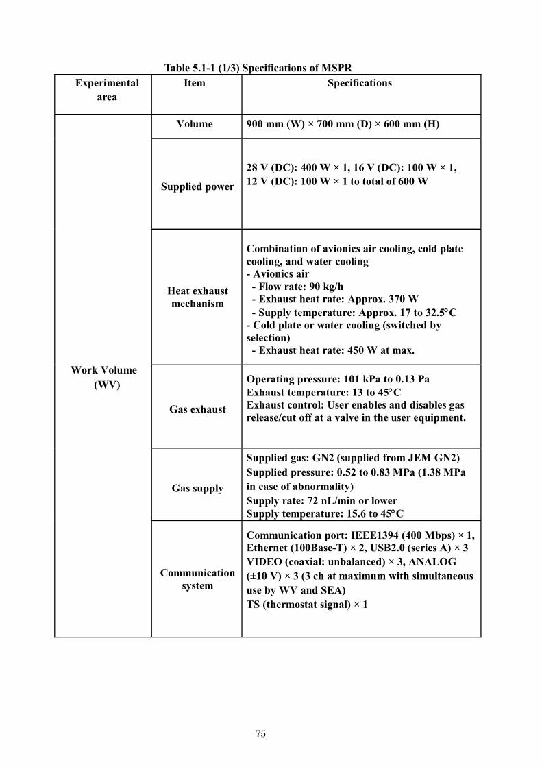
75
Table 5.1-1 (1/3) Specifications of MSPR Experimental
area Item Specifications
Work Volume (WV)
Volume 900 mm (W) × 700 mm (D) × 600 mm (H)
Supplied power
28 V (DC): 400 W × 1, 16 V (DC): 100 W × 1, 12 V (DC): 100 W × 1 to total of 600 W
Heat exhaust mechanism
Combination of avionics air cooling, cold plate cooling, and water cooling - Avionics air - Flow rate: 90 kg/h - Exhaust heat rate: Approx. 370 W - Supply temperature: Approx. 17 to 32.5C
- Cold plate or water cooling (switched by selection) - Exhaust heat rate: 450 W at max.
Gas exhaust
Operating pressure: 101 kPa to 0.13 Pa Exhaust temperature: 13 to 45C Exhaust control: User enables and disables gas release/cut off at a valve in the user equipment.
Gas supply
Supplied gas: GN2 (supplied from JEM GN2) Supplied pressure: 0.52 to 0.83 MPa (1.38 MPa in case of abnormality) Supply rate: 72 nL/min or lower Supply temperature: 15.6 to 45C
Communication system
Communication port: IEEE1394 (400 Mbps) × 1,Ethernet (100Base-T) × 2, USB2.0 (series A) × 3 VIDEO (coaxial: unbalanced) × 3, ANALOG (±10 V) × 3 (3 ch at maximum with simultaneous use by WV and SEA) TS (thermostat signal) × 1

76
Table 5.1-1 (2/3) Specifications of MSPR Experimental
area System Design specifications
Work Bench (WB)
Size 900 mm (W) (TBD) × 540 mm (D) (TBD)
Supplied power
16 V (DC): 100 W × 2 [of these, one system is branched and shared with the 16 V (DC) for the WV, 100 W in total]: For laptop PC
Communication system
Communication port: IEEE1394 (400 Mbps) × 1 Ethernet (100Base-T) × 3 USB2.0 (series A) × 1 USB2.0 (series B) × 2 VIDEO (coaxial: unbalanced) × 2 TS (thermostat signal) × 1
Small Experiment Area (SEA)
Volume 412 mm (W) × 530 mm (D) × 300 mm (H)
Supplied power
12 V (DC): 100 W × 1
Commun-ication system
Communication port: Ethernet (100Base-T) × 1 USB2.0 (series A) × 1 VIDEO (coaxial: unbalanced) × 2 ANALOG (±10 V) × 3 (3 ch at maximum with simultaneous use by WV and SEA) TS (thermostat signal) × 1
Heat exhaust
mechanism
Avionics air cooling - Flow rate: 35 kg/h - Exhaust heat rate: Approx. 140 W - Supply temperature: Approx. 17 to 30C

77
Table 5.1-1 (3/3) Specifications of MSPR
Experimental area
Item Specifications
Chamber for Combustion Experiments
(CCE)
Size
Space available for user equipment: (from the bottom surface inside CCE to 20 mm in height)
550 mm (W) × 351 mm (D) × 520 mm (H) (Height 20 mm to 520 mm)
550 mm (W) × 354 mm (D) × 520 mm (H)
Supplied power
In accordance with WV specifications above (WV supply power is introduced into the chamber via a hermetic seal connector on chamber wall.)
Heat exhaust
mechanism
Avionic air cooling (CCE external surface) and cold plate cooling (CCE bottom surface) See the section on the WV above for heat exhaust capacity. However, the user equipment exhausts heat by thermal contact conductance on the bottom surface inside the CCE.
Gas exhaust
Exhaust performance conforms to specifications for WV above. However, it also depends on the pressure drop inside the CCE internal piping, including the user equipment. It also has an area and connection port to install a contamination removal filter prepared by the user for combustion gas exhaust. The gas exhaust method depends on the nature of the experiment; the options are a method in which gas passes through the filter once (one path) and a circulation method that removes contamination sufficiently by letting it pass through the filter several times.
Gas supply
- N2 gas supply (from JEM GN2 line) - Supply pressure: 0.2 MPa (controlled by CCE regulator) - Maximum supply flow rate: 4.47 L/min @27C, 0.1 MPa (TBD) - Supply temperature: 15.6 to 45C
- User gas bomb A (prepared by user) The user installs gas bomb A for the experiment inside the SEA and supplies it to the chamber using the penetration port between the WV and SEA. Flammable gas cannot be used. - Bomb volume: Selected from two options (1 L and 2.25 L) - Maximum filling pressure: 10 MPa or lower - Maximum supply flow rate: 4.8 L/min @27C, 0.1 MPa (TBD)
- User gas bomb B (prepared by user) An area and connection port are available in which the user can prepare gas bomb B for an experiment on the chamber’s inner wall. - Bomb volume: Selected from two options (1 L and 300 cc) - Maximum filling pressure: 10 MPa or lower - Maximum supply flow rate: 73.82 L/min @27C, 0.1 MPa (TBD)
Commun-ication system
The communication port conforms to that in the WV described above (like the supplied power). However, the user cannot use ANALOG × 3 because they are used for a pressure sensor (× 1) and CO2 sensors (× 2) in the CCE. ANALOG cannot be used in WV or SEA in addition to the CCE because the CCE uses all three lines.
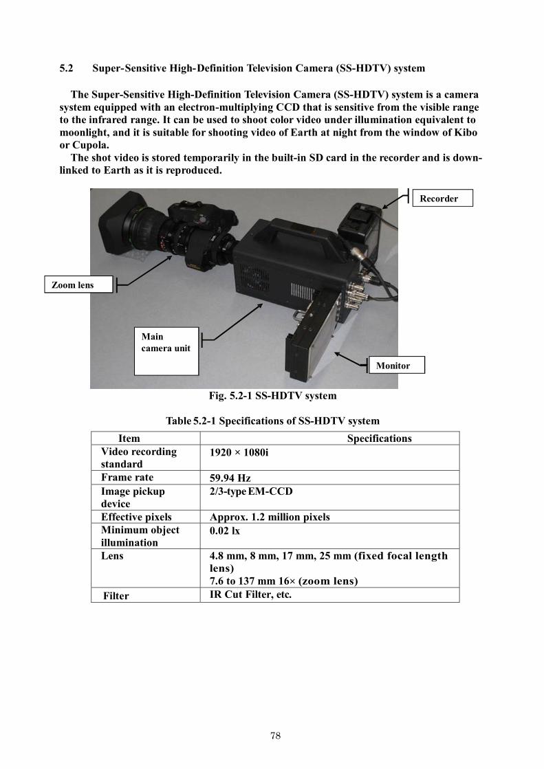
78
Recorder
Monitor
Main camera unit
Zoom lens
5.2 Super-Sensitive High-Definition Television Camera (SS-HDTV) system
The Super-Sensitive High-Definition Television Camera (SS-HDTV) system is a camera system equipped with an electron-multiplying CCD that is sensitive from the visible range to the infrared range. It can be used to shoot color video under illumination equivalent to moonlight, and it is suitable for shooting video of Earth at night from the window of Kibo or Cupola.
The shot video is stored temporarily in the built-in SD card in the recorder and is down-linked to Earth as it is reproduced.
Fig. 5.2-1 SS-HDTV system
Table 5.2-1 Specifications of SS-HDTV system
Item Specifications Video recording standard
1920 × 1080i
Frame rate 59.94 Hz Image pickup device
2/3-type EM-CCD
Effective pixels Approx. 1.2 million pixelsMinimum object illumination
0.02 lx
Lens 4.8 mm, 8 mm, 17 mm, 25 mm (fixed focal length lens) 7.6 to 137 mm 16× (zoom lens)
Filter IR Cut Filter, etc.

79
5.3 Microscope Observation System
The Microscope Observation System consists of a microscope, a power supply and control unit (Microscope Controller), a VGA-NTSC converter, and an Experiment Laptop Terminal (ELT). It is used to conduct transmitted light observation, phase difference observations, and fluorescence observations. It also supports live imaging for use of gene recombinants such as cyprinodonts and zebrafish. A schematic drawing of the system is shown in Fig. 5.3-1. It is installed inside the Work Volume of the Multipurpose Small Payload Rack (MSPR) or on top of the Maintenance Work Area (MWA) in Kibo. During an experiment, the crew at the International Space Station set up the biological sample, and remote observations and operations are conducted by command from Earth via the ELT. The recorded image files are transferred to Earth.
Fig. 5.3-1 Microscope Observation System
VGA-NTSC converter
MSPR Work Volume
Experiment Laptop Terminal
Microscope
Power supply and control unit
Experiment Laptop Terminal
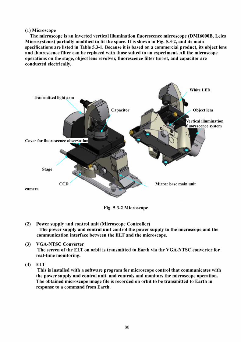
80
(1) Microscope The microscope is an inverted vertical illumination fluorescence microscope (DMI6000B, Leica
Microsystems) partially modified to fit the space. It is shown in Fig. 5.3-2, and its main specifications are listed in Table 5.3-1. Because it is based on a commercial product, its object lens and fluorescence filter can be replaced with those suited to an experiment. All the microscope operations on the stage, object lens revolver, fluorescence filter turret, and capacitor are conducted electrically.
Transmitted light arm
White LED
Capacitor Object lens
Vertical illumination fluorescence system
Cover for fluorescence observation
Stage
CCD camera
Mirror base main unit
Fig. 5.3-2 Microscope (2) Power supply and control unit (Microscope Controller)
The power supply and control unit control the power supply to the microscope and the communication interface between the ELT and the microscope.
(3) VGA-NTSC Converter The screen of the ELT on orbit is transmitted to Earth via the VGA-NTSC converter for real-time monitoring.
(4) ELT This is installed with a software program for microscope control that communicates with the power supply and control unit, and controls and monitors the microscope operation. The obtained microscope image file is recorded on orbit to be transmitted to Earth in response to a command from Earth.

81
Table 5.3-1 Specifications of microscope (1/2)
Item Specifications Remarks
Mirror base main unit
Basic specifications - Electric object lens revolver (six at max.) - Electric Z drive focus (stroke 9 mm) - Camera port (left-side port) Transmitted light path control - Aperture stop/field stop (electric) - Filter magazine (electric) Vertical illumination light path control - Brightness/aperture stop/field stop (electric) - Filter turret (electric/filter cube, six sets at max.)
Binocular tube is already removed for operation and observation via PC.
Object lens
- N PLAN 5X/0.12 PH0 (working distance 14 mm) - N PLAN 10X/0.25 PH1 (working distance 17.6 mm) - N PLAN 20X/0.35 PH1 (working distance 6.9 mm) - HI PLAN I 40X/0.50 PH2 (working distance 2.0 mm) - PLAN APO 20X/0.70 PH2 HC (working distance 0.59 mm) - PL APO 40X/0.75 PH2 HCX (working distance 0.28 mm)
For fluorescence, phase difference, and bright field observations
Capacitor
Capacitor (mot S70) - Capacitor turret (seven holes) - Supports object lens magnifications of 1.25× to 100× - Built-in aperture stop (electric) Light ring - PH0 (object lens 5×, phase difference observation) - PH1 (object lens 10×, 20×, phase difference observation) - PH2 (object lens 20×, phase difference observation)
Stage
XY scanning stage - Stepping motor operation - Range of motion 83 × 127 mm Holder for microtiter - Microtiter plate (83 × 127 mm) supported - Clamp is used to maintain sample container holder.
Sample container holder is customized for the mounted sample.
Transmitted light arm
TL arm mot. - Built-in electric shutter - Built-in gray filter N2 Collimated white light LED - Wavelength 435 to 675 nm
Collimated white light LED is used as the transmitted light source.
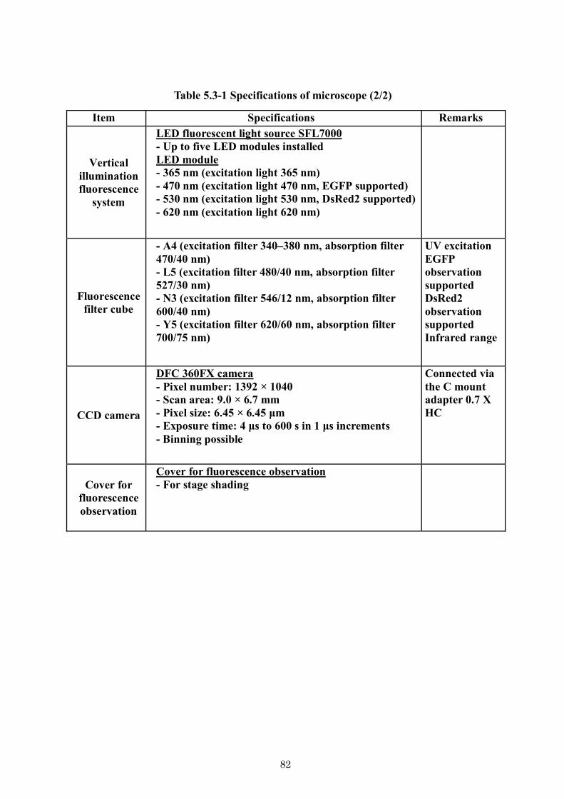
82
Table 5.3-1 Specifications of microscope (2/2)
Item Specifications Remarks
Vertical illumination fluorescence
system
LED fluorescent light source SFL7000 - Up to five LED modules installed LED module - 365 nm (excitation light 365 nm) - 470 nm (excitation light 470 nm, EGFP supported) - 530 nm (excitation light 530 nm, DsRed2 supported) - 620 nm (excitation light 620 nm)
Fluorescence filter cube
- A4 (excitation filter 340–380 nm, absorption filter 470/40 nm) - L5 (excitation filter 480/40 nm, absorption filter 527/30 nm) - N3 (excitation filter 546/12 nm, absorption filter 600/40 nm) - Y5 (excitation filter 620/60 nm, absorption filter 700/75 nm)
UV excitation EGFP observation supported DsRed2 observation supported Infrared range
CCD camera
DFC 360FX camera - Pixel number: 1392 × 1040 - Scan area: 9.0 × 6.7 mm - Pixel size: 6.45 × 6.45 μm - Exposure time: 4 μs to 600 s in 1 μs increments - Binning possible
Connected via the C mount adapter 0.7 X HC
Cover for fluorescence observation
Cover for fluorescence observation - For stage shading

83
5.4 Laboratory Support Equipment (LSE)
The laboratory support equipment that can be used in Kibo is listed on the following pages. This equipment can be mounted immediately because various certifications for mounting have already been completed.
To pack the launched samples, air cushions (List No. 34-36), foam cushions (No. 44), and similar materials can be used. Please take their weight into consideration.

84
Name Product Dimensions Weight Remarks Photo
298 g/93 pieces Includes weight of box
310 g/30 pieces Includes weight of box
244 g/12 pieces Includes weight of box
354 g/3 pieces Includes weight of box
246 g/100 pieces Includes weight of box
296 g/40 pieces Includes weight of box
350 g/4 pieces Includes weight of box
130 g/20 pieces Includes weight of box
Sandwich bag has no printing. Product procured by Japan has “freezer” printed on it.
30 pieces/box
12 pieces/box
4 pieces/box
3 pieces/box
LSE (Laboratory Support Equipment) catalog
7 in. × 8 in. (medium)(17.8 cm × 20.3 cm)
One gallon (large) (26.8 cm × 27.9 cm/109/16 in. × 11 in.)

85
Remarks
Antistatic clean vinyl zipper-type bags
Antistatic clean vinyl zipper-type bags
New nitrile ultrathin glove
New nitrile ultrathin glove
Antistatic clean vinyl zipper-type bags
Import of this product into Japan is prohibited. Ref/ Recorder No. D35100, NDC10619-3737-1
Antistatic clean vinyl zipper-type bags
Antistatic clean vinyl zipper-type bags
Antistatic clean vinyl zipper-type bags
LSE (Laboratory Support Equipment) catalog
Name Product No. Dimensions Weight Photo
Antistatic ziploc bag
Antistatic ziploc bag
Antistatic ziploc bag
Antistatic ziploc bag
1 in. wide
1 in. wide
13 cm × 250 cm × 80 cm (box size)
5 cm × 5.5 cm thickness: 3 mm
15 cm × 23 cm (box size) thickness: 0.5 mm (when spread out)
8 in. × 12 in. (size: 200 × 300)
10 in. × 14 in. (size: 250 × 350)
12 in. × 16 in. (size: 300 × 400)
4 in. × 6 in. (size: 100 × 150)
558 g/42 pieces
950 g/90 pieces
85 g/5 pieces
212 g/110 pieces
742 g/100 pieces Includes weight of box
686 g/100 pieces Includes weight of box
4 g/1 piece
Antistatic ziploc bag
Antistatic ziploc bag
Antistatic ziploc bag
8 in. × 12 in. (size: 200 × 300)
4 in. × 6 in. (size: 100 × 150)
85 g/5 pieces
212 g/110 pieces

86
LSE (Laboratory Support Equipment) catalog
Name Product No. Dimensions Weight Remarks Photo
Kimtech Pure CL4 critical task wiper (crew) 100% Polypropylene
Rating A Halar material L: 102 mm, W: 2.5 mm, T: 101 mm
Rating A Halar material L: 188 mm, W: 25 mm, T: 1.1 mm
Quick type for fungi
Jet blower (black)
Super wiping cloth, gray
Wiping cloth
Knitted fabric waste cloth (1 kg type)
Blower
Waste cloth (small)
Waste cloth (large)
Towel 32 cm × 35 cm thickness: 0.5 mm
Width 0.8 cm (max) × 19 cm; height 6 mm (max)
29 cm × 60 cm thickness: 2 mm
28 cm × 30 cm thickness: 2 mm
30.4 cm × 30.4 cm; thickness: 1 mm
Width 0.5 cm (max) × 10 cm; height 5 mm (max)
50 g/1 piece
30 g/48 pieces
116 g/50 pieces
28 g/1 pieces
56 g/1 pieces
1234 g/54 pieces
1298 g/100 pieces

87
LSE (Laboratory Support Equipment) catalog
Name Product No. Dimensions Weight Remarks Photo
静電気帯電防止機能付
きエアークッション
静電気帯電防止機能付
きエアークッション
静電気帯電防止機能付
きエアークッション
綿球:片綿、綿径:
8.0(±0.5)mm、軸
質:紙軸、軸長:
150.0(±3.0)mm、袋
入数:30
Cotton swabs
Ziploc bag with holes (Velcro?)
Kapten tape (polyimide tape)
Double-sided tape
Paper diapers
Electrostatic discharge (ESD) bubble wrap (large)
Electrostatic discharge (ESD) bubble wrap (medium)
Electrostatic discharge (ESD) bubble wrap (small)
15 mm (0.59 in.)
No. 5413 (1 in. wide)
φ10 cm wide 2.5 cm
Width 1 in.
92 g/1 roll
Cotton ball: One end, cotton diameter: 1.0 (±0.5) mm, stick material: Paper, stick length: 150.0 (±3.0) mm, bag qty: 30
Air cushion with antistatic function
Air cushion with antistatic function
Air cushion with antistatic function
Cotton swabs
Kapten tape (polyimide tape)
15 mm (0.59 in.)
No. 5413 (1 in. wide)
φ10 cm wide 2.5 cm
92 g/1 roll

88
LSE (Laboratory Support Equipment) catalog
Foam cushioning material for launch 25% compression supported: 45 kPa Density: 30 kg/m3 Antistatic
Bags for launch/storage in ISS
Bags for launch/storage in ISS
Bags for disposal
Bags for launch/storage in ISS
Bags for launch/storage in ISS
Bags for launch/storage in ISS
Mini-DV tape for high definition
New Belca
名称 製品番号 寸法 重量 備考 写真Name Product No. Dimensions Weight Remarks Photo

89
5.5 Other (in-vessel space)
Although adjustments need to be made individually for the use of in-vessel laboratory spaces, the rough restrictions at present are listed in Table 5.5-1.
Table 5.5-1 Outline of restrictions on use of in-vessel laboratory spaces
Item Restriction Weight ≤24 kg recommended (soft bag launching assumed) Volume - Projection from rack surface: 43 cm
- Air flow must not be blocked.
Mechanical interface Seat track (standard installation position) Thermal interface (exhaust heat)
≤40 W (air cooling by avionics)
Electrical interface (supplied power)
- 120 V (DC) or 28 V (DC) - Payload laptop terminal (PC; USB port/PCMI card slot): 5 V (DC)
Communication interface (data)
Ethernet use: It is assumed that the connection with Earth is not constant, but instead communication is conducted in bulk at appropriate times.
Communication interface (video)
- Video shooting: Use of common devices at station (described later) - Down link from camera in user-supplied system: Via Image
Processing Unit (IPU)*1 or Multipurpose Small Payload Rack
Fluid system interface None
Safety (typical example)
- Off gas (check possible on test by JAXA) - Sharp edges - Device surface temperature (≤49C) - Electromagnetic compatibility
Noise/microgravity disturbance
- Noise: Compliance with NC-40 specification (when operating continuously for 8 h or longer) - Vibration: Indicating that there is no problem with analysis, etc.
Other devices that can be used
- Payload laptop terminal - DV camera - HDV camera - Digital still camera, etc.
*1: Among the obtained data, image data are recorded and transmitted to Earth via the IPU. Although the data rates are set to 17–42 Mbps/ch (MPEG/MotionJPEG compression) for video recording and 15 Mbps max/ch (MPEG2 compression) for transmission to Earth, they are subject to change because of various operational restrictions.

90
6 Other Reference Information The web sites listed below provide information regarding experimental devices and other matters. Please refer to them for reference.
Overall information on use of Kibo http://iss.jaxa.jp/kiboexp/
Information on experimental devices http://iss.jaxa.jp/kiboexp/equipment/pm/
Information on experimental themes http://iss.jaxa.jp/kiboexp/field/scientific/ http://iss.jaxa.jp/kiboexp/field/applied/ http://iss.jaxa.jp/kiboexp/field/medical/

91
II. Precautions for Planning Space Experiments

92
1. Features in proposing space experiments The environment and operating conditions in the Pressurized Module (PM) of Kibo (as described below) vary
widely from those of most laboratories on earth. Because it is extremely difficult to conduct experiments in space using similar methods and scales to those used in laboratories on earth, a thorough understanding of these restrictions is necessary in order to plan feasible space experiments. - Uniqueness of the space environment: Working and processing must be possible under microgravity conditions (especially liquid behavior). - Restrictions due to the use of manned facilities in space: Strict safety precautions (i.e., completely sealing toxic substances such as samples and chemical fixing agents) - Restrictions in transport opportunities and capacities: Although the volume and weight that can be launched by spacecraft are subject to important restrictions, the volume and weight that can be collected are subject to even more rigid restrictions, given the limited number of spacecraft that can collect samples. - Work period on orbit: The work period by astronauts is extremely limited, with the average work period that can be assigned to each experiment being approximately 10 hours. Considering the microgravity conditions and the unique sealing requirements mentioned above, a work volume that is equivalent to only several hours of laboratory work on earth can be ensured. - Refrigeration and freezing capacity: The on-orbit refrigerator/freezer capacity is limited and there are also restrictions due to the extremely small refrigeration and freezing volume allocated for launching and collection.
Clearly, there are many differences between proposals for space experiments and proposals for normal
experiments. In the actual examination and selection of space experiment proposals, technical evaluation will be conducted in addition to scientific evaluation on the proposed study. Even if their scientific merit is high, proposals that are expected to have many technical difficulties in implementation or that have extremely low mounting feasibilities are not likely to be selected. 2. Feasibility for mounting
Principle investigators of space experiments are required to specify “experiment requirements,” including the type of experiment to be conducted, the methods and procedures used, and the rationale.
Experiment requirements that conflict with the “restrictions unique to space experiments” in Section 5 of this document are considered risk factors that reduce the mounting feasibility. For example, an experimental requirement to mount a quantity of sample that exceeds the launch capacity will be considered a risk factor.
The level of mounting feasibility will be determined by how many risk factors there are and how difficult it is to overcome them. Proposals with extremely low mounting feasibility levels will never be selected.
In addition, the mounting feasibility evaluation results, including problems identified in the technical evaluation and suggested improvement measures to overcome them, are returned to the proposing party. For researchers whose proposals are selected, working on solving the identified problems will be added to the criteria for being selected during the space experiment preparation stage.
The planning of space experiments with minimized risk factors will be described in Section 5. Life science and material science are two different fields and have two different requirements when it comes to experiment samples, devices, tools, and whether astronauts are needed for space experiments. Therefore, the concepts and procedures involved in planning space experiments for life science and material science will be listed separately in this handbook.

93
3. Experiment resources To conduct experiments on Kibo, information regarding experiment samples, material to be launched,
weight that will be collected and transported to earth, work period of astronauts (crew time) necessary for experimental operations on orbit, electric power needed to operate the experiment system, heat exhaust, and data communication will be necessary.
There are strict restrictions regarding these resources due to launch opportunities, the capacity for transport in spacecraft, the number of astronauts staying on the ISS, and the capacity of ISS devices. Furthermore, these resources ensured for the ISS as a whole are first assigned to the activities necessary to maintain the ISS and the life of the astronauts. The remaining resources are then distributed based on the set rate for each international partner (12.8% for Japan).
The experiment resources necessary to conduct the research plan will be digitized through joint examination with JAXA to develop specific experiment plans after getting selected as a candidate theme. - Launch weight: Samples (including transport containers and equipment), consumable goods, and devices required in experiment - Collection weight: Items including samples (including transport containers and equipment) and data recording media - Work period: Every step in the experiment that the astronaut conducts will be included in the work period (including removal of sample from the storage location, installation of the equipment, observation of sample, replacement of consumable goods, removal of sample from the system, treatment for storage, stowing of sample into the storage space, data transmission processes, reading of the work instructions). In experiments where astronauts are used as the test subjects, the work period will be the total experiment periods for both test subject and operator. - Electric power, exhaust heat, data communication: Calculated from operation plan for the experiment device - Refrigeration and freezing requirements: Requirement to use refrigeration or freezing facilities common to the ISS, temperature zone and volume
When planning experiments, please use Table 1 as a reference for calculating the scale of resources. Experiments need to be planned with high efficiency using the least amount of resources in order to deliver the most effective outcomes.
Table 1 Reference information used to calculate experiment resources
System Guideline Remarks
Life science experiments (e.g., cell culturing, plant experiments)
For plant growth: 2 kg/pieceFor cell culturing: 1 kg/8 containers
Medium replacement tool: 2 kg/piece Chemical fixing tool: 1 kg/piece
Specimen includes the sample and sample container. The experiment scale (n value) must be multiplied.
Work period: 10 h per experiment theme
Processes such as specimen installation, fixing process, and storage in refrigerator are assumed. A work period twice that on earth should be expected considering the microgravity environment.
Space medicine experiments
Specimen weight: 1–5 kg/piece Depends on the experiment details
10 h per experiment theme Total time for test subject and operator. The experiment count must be multiplied for repeated experiments.
Fluid physics experiments
Specimen weight: 40 kg/piece Items such as packing materials for transport must be considered separately.
20 h per experiment theme Installation and replacement of specimen are assumed.
Liquid crystallization observation experiments
Specimen weight: 15 kg/piece Items such as packing materials for transport are also necessary.
3 h/experiment theme Installation and replacement of specimen are assumed.
Semiconductor crystal experiments
Specimen weight: 5 kg/piece
Items such as packing materials for transport are also necessary. Multiple specimens may be necessary depending on the experiment conditions.
1 h/experiment theme Installation and removal of specimen are assumed.

94
4. Safety requirements For each individual experiment theme, it is necessary to ensure the safety of the experiment specimen,
the experiment samples, and the operation procedures (i.e., that there will be no risk of damage to the astronauts, the ISS, or Kibo). The planning and design of experiments as well as the testing of experiments on specimens must be conducted based on the following safety requirements, and the results must pass the safety examination. While this work will be mainly implemented by JAXA after the selection of the experiment theme, it will be necessary for the proposing party to provide alternative ideas if the safety of the experiment samples or reagents cannot be ensured.
Hazards will be identified for safety requirements. If a hazard is identified, proper control of the hazard and an appropriate method of verification must be indicated.
In general, the following hazards are considered. Proper control and verification methods must also be indicated if there are any mission-specific hazards besides those listed below.
(1) Structural damage
Any structural damage in experiment devices that may cause harm to the transport spacecraft or station will be prevented. The safety of the structure must be ensured through design using specified safety coefficients regarding launch, emergency landing, and on-orbit load (including crew load) as well as use of proper parts and materials.
(2) Movable parts If there are rotary bodies such as motors and shafts, such equipment must be designed such that
contact with the astronaut is prevented. The equipment must also have a mechanism in which damage to the rotary body itself will not result in any harm to the station and so forth.
(3) Temperature of the parts with which astronauts come in contact The temperatures of parts that astronauts may touch must be controlled such that they reach a
maximum of 49 °C. (4) Sharp edges
To prevent injury to astronauts, any equipment surfaces must be smooth and free of burring. Chamfering and so forth according to the NASA specifications (SSP500050) must be conducted on corners and edges.
(5) Prevention of catching Gaps in movable parts need to be protected or designed with spaces of specified size or greater to prevent astronauts from getting their hands caught.
(6) Pollution The equipment must be designed to not release substances that may be hazardous to the transport
spacecraft or space station. Specifically, sealing properties must be assured at the corresponding level of single, double, or triple barriers according to toxicity (level 1/2/3). This is done by requesting a toxicity evaluation from NASA for experiment samples and reagents.
(7) Materials that are used Volatile gases generated from mounted equipment must be lower than the specified value. If
there is a possibility that the specified value may be exceeded, measures must be taken to reduce the level to or below the specified value by either changing the material or by releasing the gas beforehand at a tolerable maximum temperature.
Regarding flammability of materials, specified materials shall be used to ensure prevention of
fire and permission to use other materials must be obtained by demonstrating that the fire will not be propagated.
(8) Glass parts If glass is used, protective measures must be taken not to cause hazards to astronauts in case of breakage.
(9) Pressure containers and sealed containers
Sealed containers that contain gas and that may contain internal energy of approximately 2 × 10⁴ J or more (based on adiabatic expansion of perfect gas), containers that are subjected to maximum design load of approximately 7 × 10⁵ Pa or more, and containers that contain fluid with approximately 1 × 10⁵ Pa or more may pose release hazards and are defined as pressure containers, while other containers are defined as sealed containers. Safety must be verified for each by conducting proof tests and fatigue analysis for the specified pressure corresponding to each classification.

95
(10) Electric shock Equipment must be designed according to the station rules (SSP30240 and SSP30245) regarding grounding and continuity so that there will be no harm to the astronauts through electric shock. It shall be designed so that astronauts will not come in contact with high-voltage parts (30 V or higher).
(11) Electric circuits Protective circuits such as current limiters and fuses shall be provided, or wiring of proper size
must be established to prevent propagation of failure to the upstream parts (such as the stations) by overcurrents or short-circuiting. It also needs a design for connectors to prevent 2 or more of the hazard suppression functions from becoming invalid simultaneously by short-circuiting between connector pins, caused by bent pins.
(12) Electromagnetic compatibility test (EMC) The equipment needs an EMC designed according to station rules (SSP30237) to prevent
malfunctions that may result in loss of safety features (of the equipment itself or other station devices) through electromagnetic interference.
(13) Optical devices Any equipment using lasers and so forth must be designed so that the laser will not irradiate the
astronaut by mistake during operation.

96
5. Specific restrictions for space experiments and precautions for planning space experiments
Restrictions and matters to be noted in planning space experiments are listed as follows, ordered by stages from the date of spacecraft launch until the completion of all experiments. Experiments should be proposed within feasible scope with due consideration of these items, and any points that do not have sufficient examination will be examined in cooperation with JAXA after the selection process. 5.1 Life science experiments
Item Restriction Matters to be noted in planning space experiments
Date of spacecraft launch
Since the date of launch is determined overall by ISS management, adjustment and preparations need to be made to match the date (the researcher’s wish will not be reflected). The launch date is also often changed due to progress in management plans, spacecraft servicing conditions, weather, and so forth.
- Biological samples need to be prepared and procured to meet the planned launch date. When seasonal biological species or samples at specific development stages are to be used, they need to be prepared as necessary to be mounted.
- If the life of a biological sample is short, backup samples need to be prepared at the location of launch in case launch is delayed.
Mounted samples and goods
[Sample species – quantity] There are restrictions to the sample species and quantity that can be mounted for each type of equipment to be used.
The launch weight and volume need to be minimized as much as possible so that the experiment is planned efficiently. - It is necessary to provide information on all samples and devices
used, including biological conditions on the name of sample species, strain used, weight, age, and so forth.
- The quantity of prepared and arranged samples must be several times larger than that of the on-orbit experiment sample in order to prepare for any sudden changes in launch date. These samples should be considered in addition to the sample quantity necessary for on-orbit control experiments and control experiments on earth.
- Experimentation on the sample should be possible within the equipment range based on checks of its functions and performance.
- Although there are restrictions on the quantity of samples that can be mounted, it is necessary to set up an experiment system that can ensure the “N value” necessary to obtain statistically significant difference. It is recommended that the optimal quantity and minimum quantity to allow sufficient analysis are specified in the proposal.

97
[Experiment system and specimen] In principle, experiments are conducted on the experiment systems that are mounted. To use experiment tools or systems typically used on earth, modification to use them on the ISS and tests to confirm their safety need to be conducted.
When the experiment is to be conducted using the experiment systems in Table 1.4 of the 1.4 chapter, the following are true. - The experiment must be executable within the equipment
range based on checks of its functions and performance. - In principle, experiment systems provided by JAXA cannot
be modified. - Regarding the requirements for individual experiments,
experiments need to be addressed within the range of the specimen, in conjunction with the system used to conduct the experiments.
When the experiment uses experiment tools and so forth belonging to the proposing party and that are not in Table 1.4 of the 1.4 chapter, the following are true. - To use experiment tools and so forth belonging to the
proposing party, the weight, dimensions, structure, component materials, functions, and performance for each of these tools need to be clearly described.
- Development, manufacture, and function verification need to be completed at least 1 year before experiment implementation.
- The goods for space experiments are quite different from the goods used regularly in laboratories on earth in terms of required levels of safety and operability. Whether or not the tools will operate properly in a microgravity environment also must be checked in advance. They must be designed, manufactured, and tested with sufficient examination.
[Characteristics of space experiment systems] - The mounted systems have characteristics different from
those on earth. For example, special caution is required in handling liquids under a microgravity environment. It is impossible to separate air bubbles by using gravity, and the solution will be distributed inside the container by the relationship with the container wall (wettability) as it is released from the governing force of gravity. Therefore, liquids are generally handled by fully finning the container in a sealed system without bubbles.
- Liquids must always be sealed in containers, even if they are not toxic (even water). Multiple levels of sealing (depending on the toxicity) must be ensured for toxic samples or reagents in all phases.
- Since there is no heat convection, disturbances such as stirring will be necessary in order to ensure temperature uniformity.
- Although the Cell Biology Experiment Facility (CBEF) can generate artificial gravity using centrifugal force, the conditions of gravity vary with the distance from the rotation center.

98
[Reagents, goods, etc.] The Pressurized Module of Kibo is a closed environment, and any leak of reagents such as chemical fixing agent will cause a safety problem. There are strict regulations for using reagents on orbit, even if the type or quantity of reagent can be used without problem in laboratories on earth.
- Information on all reagents and tools that will be used shall be provided and all objects used must pass the safety evaluation.
- While hazardous materials can be used by sealing them in special containers, there are also goods whose use will not be permitted. In this case, examination of alternative ideas will be necessary.
- In principle, use of tools with sharp edges cannot be allowed, even including scissors and tweezers, which are used casually on earth.
- Having water droplets floating inside the ISS and allowing them to adhere to or enter devices must be avoided. Therefore, it must be ensured that liquids do not leak from their containers, even in the case of water.
Loading onto the spacecraft for transport
[Difficulty in mounting fresh samples] The experiment materials need to be mounted by several days to 14 hours before launch at the latest, and about several days will be necessary before experiments can be started on the ISS. [Sample storage conditions for launch] There are restrictions in the capacities of hot storage, freezer, and refrigerator units for the space craft that transports the samples.
Loading experimental materials into the transfer rocket for launch varies by the model. <<Doragon >> Loading is possible until 24 h before launch. It takes about 2 days until arrival at the ISS. During this period, room temperature (about 15–30 °C), refrigeration (+4 °C), or freezing (-95 °C) environments can be used for the samples. <<Soyuz/Progress>> Loading is possible until 14 h before launch. It takes 6 to 48 h until arrival at the ISS. During this period, the samples are placed in the room temperature (15–30 °C) environment. <<ATV/HTV>> Final loading occurs several days prior to launch, and it takes about 1 week until it arrives at the station. During this period, the samples are placed in the room temperature (15–30 °C) environment. - The sample must be maintained for a period after the sample is
loaded until the experiment is started in the above range. It is necessary to design the experiment system with consideration of the characteristics of samples and so forth and without exceeding the loading capacity and environmental restrictions of the transport spacecraft.
- It takes at least 5 days after launch until experiments can be started. The requirements for temperature and storage conditions for the samples during this period need to be clearly presented, including the tolerated ranges.

99
Time until experiment start
At least 5 days will be required after launch until the experiment is started in the Pressurized Module of Kibo.
- In principle, experiment procedures cannot be undertaken for at least 5 days after launch. Therefore, it is difficult to conduct space experiments on study subjects whose intended phenomenon will end within the 5 days before on-orbit experiments can be started. Although it may be possible to reduce the waiting period by using Russian spacecraft, there are great restrictions in place at the launch complex.
- It may be possible to select methods to start the experiment by launching plant seeds and supplying water on orbit, to launch frozen cells and defrost them on orbit to start culturing and so forth.
[Steps until on-orbit experiments are started] - Final preparation of samples to be loaded on earth -> handing
over to person in charge of launch -> loading on spacecraft for transport -> transport to the ISS -> setting up experiment system on the ISS
- It takes about 5 days after launch until the experiment can be started.
On-orbit experiment
[Experiment period] Due to management reasons, it may not be possible to ensure the requested experiment period.
- It is necessary to clearly specify the optimal experiment period as well as the tolerable range that can be compromised.
- It is necessary to determine how long is required to detect the
effects of the space environment (microgravity and cosmic radiation) based on assumptions with high probability in experiments on earth.
[Experiment operation procedures] Experiment operations may not always be conducted as requested.
- The operation procedures need to be described for each step from experiment start to completion.
- Devices, tools, and other objects required to carry out each step
shall be specifically described. - The timing of execution and tolerable time range need to be
specified for each step. It is somewhat possible to monitor the progress in experiments carried out in Kibo from earth and give instructions to change the operation procedures from earth based on observation; however, such actions are restricted in many cases.

100
[Operations to be implemented by the astronauts] The astronauts may not be specialists in experiments. The hours that can be spent in experiments are limited.
[It is desired that the operation procedures are as simplified as possible.] - Although astronauts receive training on experiment operations
before launch, in many cases they are not specialists in the field of experiments. It is recommended that the construction of the experiment system and experiment procedures be developed as simply as possible so that it will not be complicated or require time in execution.
- Experiments that require continuous operation for 30 minutes
or longer, operation periods of at least 6 h/week, or total operation periods of 10 hours or more will have low mounting feasibility.
[An operation period twice that of earth is usually required.] - Experiment operations that can be conducted on earth in only
30 minutes will usually take twice that time (60 minutes) in space.
[Monitoring of on-orbit experiments] Progress in experiment or sample conditions at all stages from experiment start to completion cannot be monitored constantly.
- Due to the restrictions applied to communications satellites, communication between the ISS and earth is not always maintained. Although the conditions vary every day, communication is typically cut off for about 10–50% of the time.
- It is possible to downlink important data, such as confirmation of
the start or completion of experiment operations or operating conditions for the experiment system (data or images from the temperature sensors and so forth equipped on the system), to earth, although this may not occur in real time.
- It is recommended that there be a differentiation between data
for real-time downlink and data for downlink when possible after recording and that the experiment be planned with flexibility.
[Interference in on-orbit experiments] It may be difficult to change procedures depending on sample conditions.
- Although it is possible to change the experiment procedures based on the above downlink information, including changes in operating conditions for the on-orbit experiment system, there are restrictions (similar to those above) limiting the amount of data that can be uplinked to address changes or timing issues.

101
Sample storage on orbit and sample collection
It may take time after experiment completion before the samples can be collected on earth. It takes time after the transport aircraft lands before the sample can be retrieved, and the landing point may not have the facilities for sample processing.
- Only small amounts of experiment samples, systems, tools, and so forth can be collected and brought back to earth. This is limited to several kg, including the sample containers, packing materials, and so forth, and it is very difficult to collect such items under frozen or refrigerated conditions.
- The trip of spacecraft to and from the ISS occurs about every 3 months. Thus, it is necessary to check before launch if there are changes such as denaturation and deterioration during the storage period, even for samples that have been frozen, treated chemically, and so forth at completion of the experiment.

102
5.2 Space medicine experiments Consent of the test subject
Agreement on implementation
- It is necessary for the experiment which uses astronauts as test subject to explain experiment description to candidate's crew through the approval of each space agency and Ethical Review Board between IP agencies, and to obtain the consent of participation.
- Explanation to subjects is usually given 1.5 years before a space stay start. The data acquisition on the ground becomes possible after the consents and nine months before a space stay start.
Date of spacecraft launch
Astronauts are launched in Russian Soyuz. Since the date of launch is determined overall by ISS management, adjustment and preparations need to be made to match the date
- BDC is usually conducted at Johnson Space Center in Houston, U.S.A. It is also possible to conduct it in Japan to coincide with a particular astronaut’s visit to Japan. Two sets of experiment systems will be necessary if experiments need to be conducted after returning to earth.
- Since astronauts move to Russia several weeks before launch, feasibility is low for ground experiments immediately before launch (baseline data collection or BDC). These should be set up 1 month or more prior to launch.
Number of test subjects, mounted goods
It is necessary to plan an efficient experiment by minimizing the number of test subjects and the weight and volume of goods.
Experimental equipment
[Experiment system and specimen] In principle, experiments are conducted on the experiment systems that are mounted. To use experiment tools or systems typically used on earth, modification to use them on the ISS and tests to confirm their safety need to be conducted.
When the experiment is to be conducted using the experiment systems in Table 1.4 of the 1.4 chapter, the following are true.
- The experiment must be executable within the equipment range based on checks of its functions and performance.
- In principle, experiment systems provided by JAXA cannot be modified.
When the experiment uses experiment tools and so forth
belonging to the proposing party and that are not in Table 1.4 of the 1.4 chapter, the following are true.
- To use experiment tools and so forth belonging to the proposing party, the weight, dimensions, structure, component materials, functions, and performance for each of these tools need to be clearly described.
- Development, manufacture, and function verification need to be completed at least 1 year before experiment implementation.
- Even systems and tools that have been approved as medical devices on earth need to be re-evaluated for safety in space use.

103
Mounted samples and goods
[Reagents, goods, etc.] The Pressurized Module of Kibo is a closed environment, and any leak of reagents such as chemical fixing agent will cause a safety problem.
There are strict regulations for using reagents on orbit, even if the type or quantity of reagent can be used without problem in laboratories on earth.
- Information on all reagents and tools that will be used shall be provided and all objects used must pass the safety evaluation.
- While hazardous materials can be used by sealing them in special containers, there are also goods whose use will not be permitted. In this case, examination of alternative ideas will be necessary.
- Having water droplets floating inside the ISS and allowing them to adhere to or enter devices must be avoided. Therefore, it must be ensured that liquids do not leak from their containers, even in the case of water.
- In principle, use of tools with sharp edges cannot be allowed, even including scissors and tweezers, which are used casually on earth.
- Special conditions must be set up for use of injection needles and any instrument with sharp tips or edges.
The intervention conditions to a subjects
[The requirements for subjects, intervention conditions] It is necessary to consider restrictions, intervention conditions and the number of subjects.
- The description is required about all the necessity of experiment operators other than the number of subjects, the requirements for a subject, intervention conditions (medication, movement load, etc.), the measurement item, the use apparatus, the number of times and time of an experiment on an orbit, the measurement item, the number of times and the enforcement schedule of the experiment before and behind boarding, and a subject.
- There is the necessity to indicate all the matter which may affect the measurement items for human experiments.
- It is necessary to indicate all the matter which restricts the activities (use of the large business of physical and mental loads, such as operation of an airplane and activities outboard, movement, mental health care, and medical supplies, the meal containing alcoholic caffeine, sleep, etc.) of a crew including the time of ground stay for the purpose of an experiment.
- On ISS, six (6) astronauts (half year stay) are planning to stay as a set, and three (3) astronauts who belong to Japan, the U.S., Europe, and Canada in principle. Two (2) of them may be test subjects in half a year. If four (4) astronauts are required as a subject, it will be required for completion of an experiment for at least one year. If six astronauts are required as a subject, it will be required for completion of an experiment for one and a half year. PI should consider duration (yeas) to satisfy statistically significant "N number".
It is assumed that at least about 1 week is required after launch until an experiment can be started.
- In principle, experiment operations for space medicine cannot be conducted for at least ~1 week after launch. There are also many restrictions during the first few weeks. Therefore, it is difficult to conduct space experiments on study subjects whose intended phenomenon will end before on-orbit experiments can be started.

104
On-orbit experiment
[Experiment period] Due to management reasons, it may not be possible to ensure the requested experiment period.
- It is necessary to clearly specify the optimal experiment period as well as the tolerable range that can be compromised.
- The time required for an experiment appropriate for detecting
the effects of the space environment (e.g., microgravity, closed system, cosmic radiation) must be determined based on assumptions with high probability from experiments conducted on earth.
- There are restrictions on experiments to be conducted
immediately before return as well as immediately after launch.
[Experiment operation procedures] Experiment operations may not always be conducted as requested.
- The operation procedures need to be described for each step from experiment start to completion.
- Devices, tools, and other objects required to carry out each step
shall be specifically described. - The timing of execution and tolerable time range need to be
specified for each step. It is somewhat possible to monitor the progress in experiments carried out in Kibo from earth and give instructions to change the operation procedures from earth based on observation; however, such actions are restricted in many cases.
[Operations to be implemented by the astronauts] The astronauts may not be specialists in experiments. The hours that can be spent in experiments are limited.
[It is desired that the operation procedures are as simplified as possible.] - Although astronauts receive training on experiment operations
before launch, in many cases they are not specialists in the field of experiments. It is recommended that the construction of the experiment system and experiment procedures be developed as simply as possible so that it will not be complicated or require time in execution.
- Experiments that require continuous operation for 30 minutes
or longer, operation periods of at least 6 h/week, or total operation periods of 10 hours or more will have low mounting feasibility.
[An operation period twice that of earth is usually required.] - Experiment operations that can be conducted on earth in only
30 minutes will usually take twice that time (60 minutes) in space.
- Considerations designed to keep the body steady must be
made, including footholds in the microgravity environment.
[Monitoring of on-orbit experiments]
Progress in experiment or sample conditions at all stages from experiment start to completion cannot be monitored constantly.
- Due to the restrictions applied to communications satellites, communication between the ISS and earth is not always maintained. Although the conditions vary every day, communication is typically cut off for about 10–50% of the time.
- It is recommended that there be a differentiation between data
for real-time downlink and data for downlink when possible after recording and that the experiment be planned with flexibility.

105
- It is possible to downlink important data, such as confirmation of the start or completion of experiment operations or operating conditions for the experiment system (data or images from the temperature sensors and so forth equipped on the system), to earth, although this may not occur in real time.
[Interference in on-
orbit experiments] It may be difficult to change procedures depending on the conditions of test subjects.
- Although it is possible to change the experiment procedures based on the above downlink information, including changes in operating conditions for the on-orbit experiment system, there are restrictions (similar to those above) limiting the amount of data that can be uplinked to address changes or timing issues.
- There are restrictions in downlinking images of the astronauts
to ptotect personal information .
Experiment after return to earth
Astronauts return to Kazakhstan and go back to Houston within 24 hours (except for Russian and European astronauts).
- In principle, experiments after returning are conducted at Johnson Space Center in Houston, U.S.A.
- The period for experiments on the day of return (day of arrival in Houston) is extremely limited.
- There are many restrictions for 10 days after return. - BDC at several weeks or several months after return will also
be conducted at Houston. - The astronaut will need to take trips to Houston for the
number of BDCs to be taken in addition to the experiment before launch (for example, an astronaut may need to take a maximum of 20 trips to Houston in total, when there is 1 experiment before launch and 3 after return, and the number of test subjects may be 5 (N = 5)).

106
5.3 Material and Physical Science Date of spacecraft launch
Since the date of launch is determined overall by ISS management, adjustment and preparations need to be made to match the date .
- If experiments are to be conducted by mixing multiple samples, it must be assumed that the samples may be mixed before launch and stored in the spacecraft for launch and transport or on the ISS for several months in the mixed condition.
Mounted samples and goods
[Sample species – quantity] There are restrictions to the sample species and quantity that can be mounted for each type of equipment to be used.
The launch weight and volume need to be minimized as much as possible so that the experiment is planned efficiently. - Experimentation on the sample should be possible within the
equipment range based on checks of its functions and performance.
- Although there are restrictions on the quantity of samples that can be mounted, it is necessary to set up an experiment system that can ensure the “N value” necessary to obtain statistically significant difference. It is recommended that the optimal quantity and minimum quantity to allow sufficient analysis are specified in the proposal.

107
Experiment system
[Experiment system and specimen] In principle, experiments are conducted on the experiment systems that are mounted. To use experiment tools or systems typically used on earth, modification to use them on the ISS and tests to confirm their safety need to be conducted.
When the experiment is to be conducted using the experiment systems in Table 1.4 of the 1.4 chapter, the following are true. - The experiment must be executable within the equipment
range based on checks of its functions and performance. - In principle, experiment systems provided by JAXA cannot
be modified. - Regarding the requirements for individual experiments,
experiments need to be addressed within the range of the specimen, in conjunction with the system used to conduct the experiments.
When the experiment uses experiment tools and so forth belonging to the proposing party and that are not in Table 1.4 of the 1.4 chapter, the following are true. - To use experiment tools and so forth belonging to the
proposing party, the weight, dimensions, structure, component materials, functions, and performance for each of these tools need to be clearly described.
- The goods for space experiments are quite different from the goods used regularly in laboratories on earth in terms of required levels of safety and operability. Whether or not the tools will operate properly in a microgravity environment also must be checked in advance. They must be designed, manufactured, and tested with sufficient examination.
- Development, manufacture, and function verification need to be completed at least 1 year before experiment implementation.
[Characteristics of space experiment systems] - The mounted systems have characteristics different from
those on earth. For example, special caution is required in handling liquids under a microgravity environment. It is impossible to separate air bubbles by using gravity, and the solution will be distributed inside the container by the relationship with the container wall (wettability) as it is released from the governing force of gravity. Therefore, liquids are generally handled by fully finning the container in a sealed system without bubbles.
- Liquids must always be sealed in containers, even if they are not toxic (even water). Multiple levels of sealing (depending on the toxicity) must be ensured for toxic samples or reagents in all phases.

108
Mounted samples and goods
[Reagents, goods, etc.] The Pressurized Module of Kibo is a closed environment, and any leak of reagents such as chemical fixing agent will cause a safety problem. There are strict regulations for using reagents on orbit, even if the type or quantity of reagent can be used without problem in laboratories on earth.
- Information on all reagents and tools that will be used shall beprovided and all objects used must pass the safety evaluation.
- While hazardous materials can be used by sealing them in special containers, there are also goods whose use will not be permitted. In this case, examination of alternative ideas will be necessary.
- In principle, use of tools with sharp edges cannot be allowed, even including scissors and tweezers, which are used casually on earth.
- Having water droplets floating inside the ISS and allowing them to adhere to or enter devices must be avoided. Therefore, it must be ensured that liquids do not leak from their containers, even in the case of water.
Loading onto the spacecraft for transport
[Difficulty in mounting fresh samples] The experiment materials need to be transported to Johnson Space Center in Houston, U.S.A by several months before launch at the latest, [Sample storage conditions for launch] There are restrictions in the capacities of hot storage, freezer, and refrigerator units for the space craft that transports the samples.
- If samples need to be loaded within 1 month before launch, the basis for this must be clearly indicated along with clearly defined timing. It is recommended that the experiment system be assembled without exceeding the restrictions by taking into consideration the characteristics of the sample and so forth.
Time until experiment start
At least 35 days will be required after launch until the experiment is started in the Pressurized Module of Kibo.
- In principle, experiment procedures cannot be undertaken for at least 5 days after launch.
[Steps until on-orbit experiments are started] - Final preparation of samples to be loaded on earth -> handing
over to person in charge of launch -> loading on spacecraft for transport -> transport to the ISS -> setting up experiment system on the ISS
- It takes about 5 days after launch until the experiment can be started.

109
On-orbit experiment
[Experiment period] Due to management reasons, it may not be possible to ensure the requested experiment period.
- It is necessary to clearly specify the optimal experiment period as well as the tolerable range that can be compromised.
- The interval between experiments must be specified for
repeated experiments (for sample replacement and so forth). - The operation procedures need to be described for each step
from experiment start to completion.
- Devices, tools, and other objects required to carry out each step shall be specifically described.
- The timing of execution and tolerable time range need to be
specified for each step. It is somewhat possible to monitor the progress in experiments carried out in Kibo from earth and give instructions to change the operation procedures from earth based on observation; however, such actions are restricted in many cases.
[Operations to be
implemented by the astronauts] The astronauts may not be specialists in experiments.
The hours that can be spent in experiments are limited.
[It is desired that the operation procedures are as simplified as possible.] - Although astronauts receive training on experiment operations
before launch, in many cases they are not specialists in the field of experiments. It is recommended that the construction of the experiment system and experiment procedures be developed as simply as possible so that it will not be complicated or require time in execution.
- Experiments that require continuous operation for 30 minutes
or longer, operation periods of at least 6 h/week, or total operation periods of 10 hours or more will have low mounting feasibility.
[An operation period twice that of earth is usually required.] - Experiment operations that can be conducted on earth in only
30 minutes will usually take twice that time (60 minutes) in space.
[Monitoring of on-orbit experiments]
Progress in experiment or sample conditions at all stages from experiment start to completion cannot be monitored constantly.
- Due to the restrictions applied to communications satellites, communication between the ISS and earth is not always maintained. Although the conditions vary every day, communication is typically cut off for about 10–50% of the time.
- It is possible to downlink important data, such as confirmation
of the start or completion of experiment operations or operating conditions for the experiment system (data or images from the temperature sensors and so forth equipped on the system), to earth, although this may not occur in real time.
- It is recommended that there be a differentiation between data
for real-time downlink and data for downlink when possible after recording and that the experiment be planned with flexibility.

110
[Interference in on-orbit experiments] It may be difficult to change procedures depending on sample conditions.
- Although it is possible to change the experiment procedures based on the above downlink information, including changes in operating conditions for the on-orbit experiment system, there are restrictions (similar to those above) limiting the amount of data that can be uplinked to address changes or timing issues.
Sample storage on orbit and sample collection
It may take time after experiment completion before the samples can be collected on earth. It takes time after the transport aircraft lands before the sample can be retrieved, and the landing point may not have the facilities for sample processing.
- Only small amounts of experiment samples, systems, tools, and so forth can be collected and brought back to earth. This is limited to several kg, including the sample containers, packing materials, and so forth, and it is very difficult to collect such items under frozen or refrigerated conditions.
- The trip of spacecraft to and from the ISS occurs about every 3 months. Thus, it is necessary to check before launch if there are changes such as denaturation and deterioration during the storage period, even for samples that have been frozen, treated chemically, and so forth at completion of the experiment.
- Normally, experiment samples are handed over at Johnson Space Center in Houston, U.S.A., about 1 month after landing. Then, time for processing and transport to Japan, among other activities, will also be required.

111
The collection of abbreviation ATV Arian Transfer Vehicle
AQH Aquatic Habitat
BEU Biological Experiment Unit
CB Clean Bench
CBEF Cell Biology Experiment Facility
CEU Cell Experiment Unit
CFK Cell Fixation Kit
DC Disinfecting Chamber
DCC Disposable Cultivation Chamber
DRTS Data Relay Test Satellite
DV Digital Vide
ESA European Space Agency
FPEF Fluid Physics Experiment Facility
GHF Gradient Heating Furnace
HDV High-Definition Video
HTV H-II Transfer Vehicle
IPU Image Processing Unit
ISS International Space Station
JAXA Japan Aerospace Exploration Agency
JEMOCS JEM Operation Control System
JSC Johnson Space Center
KFT KSC Fixation Tube
KSC Kennedy Space Center
KOBAIRO
MELFI Minus Eighty degree Celsius Laboratory Freezer
MEU Measurement Experiment Unit
MSPR Multi-purpose Small Payload Rack
NASA National Aeronautics and Space
Administration
OC Operation Chamber
PADLES Passive Dosimeter for Life science Experiments in Space
PCRF Protein Crystallization Research Facility
PEU Plant Experiment Unit
PFK Pre Fixation Kit
POIC Payload Operation Integration Center
QD Quick Disconnector

112
RRMDIII Real-time Radiation Measurement Device III
RYUTAI
SAIBO
SCAM Sample Cartridge Automatic Exchange Mechanism
SCOF Solution Crystal Observation Facility
SSCC Space Station Control Center
SSIPC Space Station Integration and Promotion
Center
STS Space Transportation System
TDRS Tracking and Data Relay Satellite
TNSC Tanegashima Space Center
ULT User Laptop Computer
V-MEU Video Measurement Experiment Unit
WSC White Sands Complex