Embed Size (px)
Citation preview

Handbook on theManagement of MunitionsResponse Actions
Interim Final
United States Office of Solid Waste and EPA 505-B-01-001Environmental Protection Emergency Response May 2005Agency Washington, DC 20460
EPA
000735

EPA Handbook on The Management of Munitions Response Actions
INTERIM FINAL
May 2005
000736

This page intentionally left blank.
000737

Disclaimer
This handbook provides guidance to EPA staff. The document does not substitute for EPA’sstatutes or regulations, nor is it a regulation itself. Thus, it cannot impose legally binding
requirements on EPA, States, or the regulated community, and may not apply to a particularsituation based upon the circumstances. This handbook is an Interim Final document and
allows for future revisions as applicable.
000738

This page intentionally left blank.
000739

INTERIM FINALTable of Contents May 2005iii
TABLE OF CONTENTS
GLOSSARY OF TERMS . . . . . . . . . . . . . . . . . . . . . . . . . . . . . . . . . . . . . . . . . . . . . . . . . . . . . xiii
ACRONYMS . . . . . . . . . . . . . . . . . . . . . . . . . . . . . . . . . . . . . . . . . . . . . . . . . . . . . . . . . . . . . . . xxv
1.0 INTRODUCTION . . . . . . . . . . . . . . . . . . . . . . . . . . . . . . . . . . . . . . . . . . . . . . . . . . . . . 1-11.1 Overview . . . . . . . . . . . . . . . . . . . . . . . . . . . . . . . . . . . . . . . . . . . . . . . . . . . . . . 1-11.2 The Common Nomenclature . . . . . . . . . . . . . . . . . . . . . . . . . . . . . . . . . . . . . . . 1-21.3 Organization of This Handbook . . . . . . . . . . . . . . . . . . . . . . . . . . . . . . . . . . . . 1-5
2.0 REGULATORY OVERVIEW . . . . . . . . . . . . . . . . . . . . . . . . . . . . . . . . . . . . . . . . . . . 2-12.1 Regulatory Overview . . . . . . . . . . . . . . . . . . . . . . . . . . . . . . . . . . . . . . . . . . . . . 2-2
2.1.1 Defense Environmental Restoration Program . . . . . . . . . . . . . . . . . . . . 2-22.1.2 CERCLA . . . . . . . . . . . . . . . . . . . . . . . . . . . . . . . . . . . . . . . . . . . . . . . . 2-32.1.3 CERCLA Section 120 . . . . . . . . . . . . . . . . . . . . . . . . . . . . . . . . . . . . . . 2-52.1.4 Resource Conservation and Recovery Act (RCRA) . . . . . . . . . . . . . . . 2-62.1.5 Department of Defense Explosives Safety Board (DDESB) . . . . . . . . . 2-8
2.2 Conclusion . . . . . . . . . . . . . . . . . . . . . . . . . . . . . . . . . . . . . . . . . . . . . . . . . . . . . 2-9
SOURCES AND RESOURCES . . . . . . . . . . . . . . . . . . . . . . . . . . . . . . . . . . . . . . . . . . . . . . . 2-10
DoD and EPA Management Principles for Implementing Response Actions atClosed, Transferring, and Transferred (CTT) Ranges . . . . . . . . . . . . . . . . . . . . . . . . . . . . . . . 2-15
3.0 CHARACTERISTICS OF MUNITIONS AND EXPLOSIVES OF CONCERN . . . . . 3-13.1 Overview of Explosives . . . . . . . . . . . . . . . . . . . . . . . . . . . . . . . . . . . . . . . . . . . 3-1
3.1.1 History of Explosives in the United States . . . . . . . . . . . . . . . . . . . . . . 3-13.1.1.1 Early Development . . . . . . . . . . . . . . . . . . . . . . . . . . . . . . . . . . 3-23.1.1.2 Developments in the Nineteenth Century . . . . . . . . . . . . . . . . . 3-23.1.1.3 World War I . . . . . . . . . . . . . . . . . . . . . . . . . . . . . . . . . . . . . . . . 3-33.1.1.4 The Decades Between the Two World Wars . . . . . . . . . . . . . . . 3-33.1.1.5 World War II . . . . . . . . . . . . . . . . . . . . . . . . . . . . . . . . . . . . . . . 3-43.1.1.6 Modern Era . . . . . . . . . . . . . . . . . . . . . . . . . . . . . . . . . . . . . . . . 3-4
3.1.2 Classification of Military Energetic Materials . . . . . . . . . . . . . . . . . . . 3-53.1.3 Classification of Explosives . . . . . . . . . . . . . . . . . . . . . . . . . . . . . . . . . . 3-7
3.1.3.1 Low Explosives, Pyrotechnics, Propellants, and Practice Ordnance . . . . . . . . . . . . . . . . . . . . . . . . . . . . . . . . . . . . . . . . . . . . . . . . 3-73.1.3.2 High Explosives . . . . . . . . . . . . . . . . . . . . . . . . . . . . . . . . . . . . 3-103.1.3.3 Incendiaries . . . . . . . . . . . . . . . . . . . . . . . . . . . . . . . . . . . . . . . 3-11
3.2 Characteristics and Location of MEC . . . . . . . . . . . . . . . . . . . . . . . . . . . . . . . 3-113.2.1 Hazards Associated with Common Types of Munitions . . . . . . . . . . . 3-113.2.2 Areas Where MEC is Found . . . . . . . . . . . . . . . . . . . . . . . . . . . . . . . . 3-133.2.3 Release Mechanisms for MEC . . . . . . . . . . . . . . . . . . . . . . . . . . . . . . . 3-14
000740
INTERIM FINALTable of Contents May 2005iv
TABLE OF CONTENTS (continued)
3.2.4 Chemical Reactivity of Explosives . . . . . . . . . . . . . . . . . . . . . . . . . . . 3-153.3 Sources and Nature of the Potential Hazards Posed by Conventional
Munitions . . . . . . . . . . . . . . . . . . . . . . . . . . . . . . . . . . . . . . . . . . . . . . . . . . . . . 3-153.3.1 Probability of Detonation as a Function of Fuze Characteristics . . . . 3-163.3.2 Types of Explosive Hazards . . . . . . . . . . . . . . . . . . . . . . . . . . . . . . . . 3-183.3.3 Factors Affecting Potential for Munitions Exposure to
Human Activity . . . . . . . . . . . . . . . . . . . . . . . . . . . . . . . . . . . . . . . . . . 3-193.3.4 Depth of MEC . . . . . . . . . . . . . . . . . . . . . . . . . . . . . . . . . . . . . . . . . . . 3-203.3.5 Environmental Factors Affecting Decomposition of MEC . . . . . . . . . 3-213.3.6 Explosives-Contaminated Soils . . . . . . . . . . . . . . . . . . . . . . . . . . . . . . 3-23
3.4 Toxicity and Human Health and Ecological Impacts of Explosives andOther Munitions Constituents . . . . . . . . . . . . . . . . . . . . . . . . . . . . . . . . . . . . . 3-243.4.1 Human Health Effects . . . . . . . . . . . . . . . . . . . . . . . . . . . . . . . . . . . . . 3-243.4.2 Ecological Effects . . . . . . . . . . . . . . . . . . . . . . . . . . . . . . . . . . . . . . . . 3-283.4.3 Human and Ecological Effects from Exposure to Specific
Compounds . . . . . . . . . . . . . . . . . . . . . . . . . . . . . . . . . . . . . . . . . . . . . 3-313.5 Other Sources of Conventional Munitions Constituents . . . . . . . . . . . . . . . . . 3-33
3.5.1 Open Burning/Open Detonation (OB/OD) . . . . . . . . . . . . . . . . . . . . . 3-333.5.2 Explosives Manufacturing and Demilitarization . . . . . . . . . . . . . . . . . 3-34
3.6 Conclusions . . . . . . . . . . . . . . . . . . . . . . . . . . . . . . . . . . . . . . . . . . . . . . . . . . . 3-34
SOURCES AND RESOURCES . . . . . . . . . . . . . . . . . . . . . . . . . . . . . . . . . . . . . . . . . . . . . . . 3-35
4.0 DETECTION OF UXO AND BURIED MUNITIONS . . . . . . . . . . . . . . . . . . . . . . . . 4-14.1 Introduction . . . . . . . . . . . . . . . . . . . . . . . . . . . . . . . . . . . . . . . . . . . . . . . . . . . . 4-14.2 Selection of the Geophysical Detection System . . . . . . . . . . . . . . . . . . . . . . . . 4-3
4.2.1 Geophysical Sensors in Use Today . . . . . . . . . . . . . . . . . . . . . . . . . . . . 4-34.2.1.1 Electromagnetic Induction (EMI) . . . . . . . . . . . . . . . . . . . . . . . 4-34.2.1.2 Magnetometry . . . . . . . . . . . . . . . . . . . . . . . . . . . . . . . . . . . . . . 4-44.2.1.3 Multisensor Systems . . . . . . . . . . . . . . . . . . . . . . . . . . . . . . . . . 4-44.2.1.4 Ground Penetrating Radar . . . . . . . . . . . . . . . . . . . . . . . . . . . . . 4-4
4.2.2 Selection of the Geophysical Detection System . . . . . . . . . . . . . . . . . . 4-54.2.3 MEC Detection System Components . . . . . . . . . . . . . . . . . . . . . . . . . . 4-7
4.2.3.1 Positioning Systems . . . . . . . . . . . . . . . . . . . . . . . . . . . . . . . . . 4-84.2.3.2 Anomaly Identification . . . . . . . . . . . . . . . . . . . . . . . . . . . . . . 4-10
4.2.4 Costs of UXO Detection Systems . . . . . . . . . . . . . . . . . . . . . . . . . . . . 4-104.2.5 Quality Assurance/Quality Control . . . . . . . . . . . . . . . . . . . . . . . . . . . 4-11
4.3 Emerging UXO Detection Systems . . . . . . . . . . . . . . . . . . . . . . . . . . . . . . . . . 4-114.3.1 Advanced EMI Systems . . . . . . . . . . . . . . . . . . . . . . . . . . . . . . . . . . . . 4-114.3.2 Airborne Detection . . . . . . . . . . . . . . . . . . . . . . . . . . . . . . . . . . . . . . . 4-12
4.4 Use of Processing and Modeling To Discriminate UXO . . . . . . . . . . . . . . . . 4-144.5 MEC Detection Demonstration Programs . . . . . . . . . . . . . . . . . . . . . . . . . . . . 4-15
4.5.1 Jefferson Proving Ground Technology Demonstration Program . . . . 4-16
000741
INTERIM FINALTable of Contents May 2005v
TABLE OF CONTENTS (continued)
4.5.2 Former Fort Ord Ordnance Detection and Discrimination Study(ODDS) . . . . . . . . . . . . . . . . . . . . . . . . . . . . . . . . . . . . . . . . . . . . . . . . 4-18
4.5.3 UXO Technology Standardized Demonstration Sites . . . . . . . . . . . . . 4-194.6 Fact Sheets and Case Studies on Detection Technologies and Systems . . . . . 4-204.7 Conclusion . . . . . . . . . . . . . . . . . . . . . . . . . . . . . . . . . . . . . . . . . . . . . . . . . . . . 4-20
SOURCES AND RESOURCES . . . . . . . . . . . . . . . . . . . . . . . . . . . . . . . . . . . . . . . . . . . . . . . 4-34
5.0 RESPONSE TECHNOLOGIES . . . . . . . . . . . . . . . . . . . . . . . . . . . . . . . . . . . . . . . . . . 5-15.1 Treatment and Disposal of MEC: An Overview . . . . . . . . . . . . . . . . . . . . . . . . 5-3
5.1.1 Safe Handling of MEC . . . . . . . . . . . . . . . . . . . . . . . . . . . . . . . . . . . . . . 5-65.1.2 Render-Safe Procedures . . . . . . . . . . . . . . . . . . . . . . . . . . . . . . . . . . . . . 5-6
5.2 Treatment of MEC . . . . . . . . . . . . . . . . . . . . . . . . . . . . . . . . . . . . . . . . . . . . . . . 5-65.2.1 Open Detonation . . . . . . . . . . . . . . . . . . . . . . . . . . . . . . . . . . . . . . . . . . 5-65.2.2 Open Burning . . . . . . . . . . . . . . . . . . . . . . . . . . . . . . . . . . . . . . . . . . . . . 5-95.2.3 Alternative Treatment Technologies . . . . . . . . . . . . . . . . . . . . . . . . . . . 5-9
5.2.3.1 Incineration . . . . . . . . . . . . . . . . . . . . . . . . . . . . . . . . . . . . . . . . 5-95.2.3.2 Contained Detonation Chambers . . . . . . . . . . . . . . . . . . . . . . . 5-12
5.3 Treatment of Soils That Contain Reactive and/or Ignitable Compounds . . . . 5-135.3.1 Biological Treatment Technologies . . . . . . . . . . . . . . . . . . . . . . . . . . . 5-13
5.3.1.1 Monitored Natural Attenuation . . . . . . . . . . . . . . . . . . . . . . . . 5-145.3.1.2 Composting . . . . . . . . . . . . . . . . . . . . . . . . . . . . . . . . . . . . . . . 5-155.3.1.3 Soil Slurry Biotreatment . . . . . . . . . . . . . . . . . . . . . . . . . . . . . 5-165.3.1.4 In-Situ Chemical and Biological Remediation . . . . . . . . . . . . 5-17
5.3.2 Soil Washing . . . . . . . . . . . . . . . . . . . . . . . . . . . . . . . . . . . . . . . . . . . . 5-185.3.3 Wet Air Oxidation . . . . . . . . . . . . . . . . . . . . . . . . . . . . . . . . . . . . . . . . 5-185.3.4 Low-Temperature Thermal Desorption . . . . . . . . . . . . . . . . . . . . . . . . 5-19
5.4 Decontamination of Equipment and Scrap . . . . . . . . . . . . . . . . . . . . . . . . . . . 5-195.5 Safe Deactivation of Energetic Materials and Beneficial Use of Byproducts . 5-205.6 Conclusion . . . . . . . . . . . . . . . . . . . . . . . . . . . . . . . . . . . . . . . . . . . . . . . . . . . . 5-21
SOURCES AND RESOURCES . . . . . . . . . . . . . . . . . . . . . . . . . . . . . . . . . . . . . . . . . . . . . . . 5-22
6.0 EXPLOSIVES SAFETY . . . . . . . . . . . . . . . . . . . . . . . . . . . . . . . . . . . . . . . . . . . . . . . . 6-16.1 Introduction to DoD Explosives Safety Requirements and the DoD
Explosives Safety Board (DDESB) . . . . . . . . . . . . . . . . . . . . . . . . . . . . . . . . . . 6-16.2 Explosives Safety Requirements . . . . . . . . . . . . . . . . . . . . . . . . . . . . . . . . . . . . 6-3
6.2.1 General Safety Rules . . . . . . . . . . . . . . . . . . . . . . . . . . . . . . . . . . . . . . . 6-46.2.2 Transportation and Storage Requirements . . . . . . . . . . . . . . . . . . . . . . . 6-46.2.3 Quantity-Distance (Q-D) Requirements . . . . . . . . . . . . . . . . . . . . . . . . 6-56.2.4 Protective Measures for UXO/EOD Personnel . . . . . . . . . . . . . . . . . . . 6-66.2.5 Emergency Response and Contingency Procedures . . . . . . . . . . . . . . . 6-66.2.6 Personal Protective Equipment (PPE) . . . . . . . . . . . . . . . . . . . . . . . . . . 6-7
000742

INTERIM FINALTable of Contents May 2005vi
TABLE OF CONTENTS (continued)
6.2.7 Personnel Standards . . . . . . . . . . . . . . . . . . . . . . . . . . . . . . . . . . . . . . . . 6-76.2.8 Assessment Depths . . . . . . . . . . . . . . . . . . . . . . . . . . . . . . . . . . . . . . . . 6-86.2.9 Land Use Controls . . . . . . . . . . . . . . . . . . . . . . . . . . . . . . . . . . . . . . . . . 6-9
6.3 Managing Explosives Safety . . . . . . . . . . . . . . . . . . . . . . . . . . . . . . . . . . . . . . 6-106.3.1 Site Safety and Health Plans . . . . . . . . . . . . . . . . . . . . . . . . . . . . . . . . 6-116.3.2 Explosives Safety Submissions for Munitions Response Actions . . . . 6-126.3.3 Explosives Safety Submission Requirements . . . . . . . . . . . . . . . . . . . 6-146.3.4 Explosives Safety Plans . . . . . . . . . . . . . . . . . . . . . . . . . . . . . . . . . . . . 6-15
6.4 Public Education About UXO Safety . . . . . . . . . . . . . . . . . . . . . . . . . . . . . . . 6-166.5 Conclusion . . . . . . . . . . . . . . . . . . . . . . . . . . . . . . . . . . . . . . . . . . . . . . . . . . . . 6-18
SOURCES AND RESOURCES . . . . . . . . . . . . . . . . . . . . . . . . . . . . . . . . . . . . . . . . . 6-20
7.0 PLANNING MUNITIONS RESPONSE INVESTIGATIONS . . . . . . . . . . . . . . . . . . . 7-17.1 Overview of Elements of Site Characterization . . . . . . . . . . . . . . . . . . . . . . . . 7-27.2 Overview of Systematic Planning . . . . . . . . . . . . . . . . . . . . . . . . . . . . . . . . . . . 7-37.3 Stage 1: Establishing the Goal(s) of the Investigation . . . . . . . . . . . . . . . . . . . . 7-4
7.3.1 Establishing the Team . . . . . . . . . . . . . . . . . . . . . . . . . . . . . . . . . . . . . . 7-47.3.2 Establishing the Goals of the Site Characterization Process . . . . . . . . . 7-5
7.4 Stage 2: Preparing for the Investigation: Gathering Information ToDesign a Conceptual Site Model and Establishing Sampling and AnalysisObjectives . . . . . . . . . . . . . . . . . . . . . . . . . . . . . . . . . . . . . . . . . . . . . . . . . . . . . 7-67.4.1 The Conceptual Site Model (CSM) . . . . . . . . . . . . . . . . . . . . . . . . . . . . 7-67.4.2 Assessment of Currently Available Information To Determine Data
Needs . . . . . . . . . . . . . . . . . . . . . . . . . . . . . . . . . . . . . . . . . . . . . . . . . . . 7-77.4.2.1 Historical Information on Range Use and Munition
Types . . . . . . . . . . . . . . . . . . . . . . . . . . . . . . . . . . . . . . . . . . . . . 7-77.4.2.2 Geophysical and Environmental Information . . . . . . . . . . . . . . 7-9
7.4.3 Key Components of Munitions-Related CSMs . . . . . . . . . . . . . . . . . . 7-107.4.3.1 Developing the CSM . . . . . . . . . . . . . . . . . . . . . . . . . . . . . . . . 7-107.4.3.2 Groundtruthing the CSM . . . . . . . . . . . . . . . . . . . . . . . . . . . . . 7-147.4.3.3 Documentation of the CSM . . . . . . . . . . . . . . . . . . . . . . . . . . . 7-15
7.4.4 Preliminary Remediation Goals . . . . . . . . . . . . . . . . . . . . . . . . . . . . . . 7-187.4.5 Project Schedule, Milestones, Resources, and Regulatory
Requirements . . . . . . . . . . . . . . . . . . . . . . . . . . . . . . . . . . . . . . . . . . . . 7-207.4.5.1 Resources . . . . . . . . . . . . . . . . . . . . . . . . . . . . . . . . . . . . . . . . 7-207.4.5.2 Regulatory Requirements . . . . . . . . . . . . . . . . . . . . . . . . . . . . 7-22
7.4.6 Identification of Remedial Objectives . . . . . . . . . . . . . . . . . . . . . . . . . 7-227.4.7 The Data Quality Objectives of the Investigation . . . . . . . . . . . . . . . . 7-23
7.4.7.1 Developing DQOs . . . . . . . . . . . . . . . . . . . . . . . . . . . . . . . . . . 7-237.4.7.2 Planning for Uncertainty . . . . . . . . . . . . . . . . . . . . . . . . . . . . . 7-24
SOURCES AND RESOURCES . . . . . . . . . . . . . . . . . . . . . . . . . . . . . . . . . . . . . . . . . . . . . . . 7-26
000743

INTERIM FINALTable of Contents May 2005vii
TABLE OF CONTENTS (continued)
8.0 DEVISING INVESTIGATION AND RESPONSE STRATEGIES . . . . . . . . . . . . . . . 8-18.1 Identification of Appropriate Detection Technologies . . . . . . . . . . . . . . . . . . . 8-38.2 UXO Detection Methods . . . . . . . . . . . . . . . . . . . . . . . . . . . . . . . . . . . . . . . . . . 8-48.3 Methodologies for Identifying Munitions Response Areas . . . . . . . . . . . . . . . . 8-6
8.3.1 CSM-Based Sampling Design . . . . . . . . . . . . . . . . . . . . . . . . . . . . . . . . . 8-78.3.1.1 Searching for Munitions Response Areas . . . . . . . . . . . . . . . . . 8-78.3.1.2 Boundary Delineation and Characterization of Munitions
Response Areas . . . . . . . . . . . . . . . . . . . . . . . . . . . . . . . . . . . . 8-108.3.1.3 Site Conditions and Geophysical Sensor Capabilities . . . . . . 8-108.3.1.4 Anomaly Identification and Prioritization . . . . . . . . . . . . . . . 8-118.3.1.5 Anomaly Reacquisition . . . . . . . . . . . . . . . . . . . . . . . . . . . . . . 8-11
8.3.2 Use of Statistically Based Methodologies To Identify UXO . . . . . . . 8-128.3.2.1 Rationale for Statistical Sampling . . . . . . . . . . . . . . . . . . . . . 8-128.3.2.2 Historical Use of Statistical Sampling Tools . . . . . . . . . . . . . 8-128.3.2.3 Regulator Concerns Regarding the Historical Use of
Statistical Sampling Tools . . . . . . . . . . . . . . . . . . . . . . . . . . . 8-168.3.2.4 Recommendations on the Use of Statistical Sampling . . . . . . 8-178.3.2.5 Research and Development of New Statistical Sampling
Tools . . . . . . . . . . . . . . . . . . . . . . . . . . . . . . . . . . . . . . . . . . . . 8-188.4 Incorporating QA/QC Measures Throughout the Investigation . . . . . . . . . . . 8-198.5 Devising an Investigation Strategy for Munitions Constituents . . . . . . . . . . . 8-21
8.5.1 Sampling Strategy . . . . . . . . . . . . . . . . . . . . . . . . . . . . . . . . . . . . . . . . 8-218.5.1.1 Knowing Where To Sample . . . . . . . . . . . . . . . . . . . . . . . . . . . 8-218.5.1.2 Collecting Soil Samples . . . . . . . . . . . . . . . . . . . . . . . . . . . . . . 8-22
8.5.2 Selecting Analytical Methodologies . . . . . . . . . . . . . . . . . . . . . . . . . . 8-258.5.3 Field Methods . . . . . . . . . . . . . . . . . . . . . . . . . . . . . . . . . . . . . . . . . . . 8-258.5.4 Fixed Laboratory Methods . . . . . . . . . . . . . . . . . . . . . . . . . . . . . . . . . . 8-28
8.5.4.1 EPA Method 8330 . . . . . . . . . . . . . . . . . . . . . . . . . . . . . . . . . . 8-298.5.4.2 EPA Method 8095 . . . . . . . . . . . . . . . . . . . . . . . . . . . . . . . . . . 8-298.5.4.3 Other Laboratory Methods for Explosive Compounds . . . . . . 8-308.5.4.4 EPA Method 7580 . . . . . . . . . . . . . . . . . . . . . . . . . . . . . . . . . . 8-308.5.4.5 Perchlorate Analytical Methods . . . . . . . . . . . . . . . . . . . . . . . . 8-30
8.6 Developing the Site Response Strategy . . . . . . . . . . . . . . . . . . . . . . . . . . . . . 8-318.6.1 Assumptions of the Site Response Strategy . . . . . . . . . . . . . . . . . . . . 8-328.6.2 Attributes of the Site Response Strategy . . . . . . . . . . . . . . . . . . . . . . . 8-338.6.3 Questions Addressed in the Development of the Site Response
Strategy . . . . . . . . . . . . . . . . . . . . . . . . . . . . . . . . . . . . . . . . . . . . . . . . 8-358.6.3.1 Determining the Presence of Munitions with
Explosive Potential . . . . . . . . . . . . . . . . . . . . . . . . . . . . . . . . . 8-35
000744
INTERIM FINALTable of Contents May 2005viii
TABLE OF CONTENTS (continued)
8.6.3.2 Identifying Potential Pathways of Exposure . . . . . . . . . . . . . . 8-388.6.3.3 Determining Potential for Human Exposure to MEC . . . . . . . 8-388.6.3.4 Considering Uncertainty . . . . . . . . . . . . . . . . . . . . . . . . . . . . . 8-39
8.7 Framework for Making the Decision . . . . . . . . . . . . . . . . . . . . . . . . . . . . . . . 8-398.8 Conclusion . . . . . . . . . . . . . . . . . . . . . . . . . . . . . . . . . . . . . . . . . . . . . . . . . . . . 8-39
SOURCES AND RESOURCES . . . . . . . . . . . . . . . . . . . . . . . . . . . . . . . . . . . . . . . . . . . . . . . 8-41
9.0 UNDERWATER MUNITIONS AND EXPLOSIVES OF CONCERN . . . . . . . . . . . . 9-19.1 Conceptual Site Model for Underwater Environments . . . . . . . . . . . . . . . . . . . 9-1
9.1.1 Areas Where Underwater MEC Is Found . . . . . . . . . . . . . . . . . . . . . . . 9-29.1.2 Potential for Exposure to MEC . . . . . . . . . . . . . . . . . . . . . . . . . . . . . . . 9-29.1.3 Environmental Factors Affecting Decomposition of Underwater MEC
Resulting in Releases of Munitions Constituents . . . . . . . . . . . . . . . . . 9-49.1.4 Environmental Fate and Transport of Munitions Constituents . . . . . . . 9-69.1.5 Ecological and Human Health Effects and Toxicity of Explosive
Compounds and Other Munitions Constituents in the UnderwaterEnvironment . . . . . . . . . . . . . . . . . . . . . . . . . . . . . . . . . . . . . . . . . . . . . . 9-8
9.1.6 An Example Conceptual Site Model . . . . . . . . . . . . . . . . . . . . . . . . . . . 9-99.2 Detection of Underwater MEC . . . . . . . . . . . . . . . . . . . . . . . . . . . . . . . . . . . . . 9-9
9.2.1 Detection Technologies . . . . . . . . . . . . . . . . . . . . . . . . . . . . . . . . . . . . 9-119.2.2 Platform, Positioning, and Discrimination . . . . . . . . . . . . . . . . . . . . . 9-129.2.3 Use of Divers for Detection . . . . . . . . . . . . . . . . . . . . . . . . . . . . . . . . . 9-149.2.4 Other Technological Approaches for Detecting Underwater MEC
and UXO . . . . . . . . . . . . . . . . . . . . . . . . . . . . . . . . . . . . . . . . . . . . . . . 9-149.2.4.1 Case Studies . . . . . . . . . . . . . . . . . . . . . . . . . . . . . . . . . . . . . . . 9-14Case Study 1: Use of Hand-Held Detectors . . . . . . . . . . . . . . . . . . . . . 9-14Case Study 2: Use of a Towed-Array Magnetometer . . . . . . . . . . . . . 9-15Case Study 3: Use of Modified EM-61 . . . . . . . . . . . . . . . . . . . . . . . . 9-16Case Study 4: Mare Island Naval Shipyard Validation of Detection
Systems Test Program . . . . . . . . . . . . . . . . . . . . . . . . . . . . . . . 9-17Case Study 5: Use of a Helicopter . . . . . . . . . . . . . . . . . . . . . . . . . . . . 9-189.2.4.2 Mobile Underwater Debris Survey System . . . . . . . . . . . . . . . 9-219.2.4.3 Chemical Sensors . . . . . . . . . . . . . . . . . . . . . . . . . . . . . . . . . . . 9-22
9.3 Safety . . . . . . . . . . . . . . . . . . . . . . . . . . . . . . . . . . . . . . . . . . . . . . . . . . . . . . . . 9-229.4 Underwater Response Technologies . . . . . . . . . . . . . . . . . . . . . . . . . . . . . . . . 9-23
9.4.1 Blowing in Place . . . . . . . . . . . . . . . . . . . . . . . . . . . . . . . . . . . . . . . . . 9-239.4.2 Dredging . . . . . . . . . . . . . . . . . . . . . . . . . . . . . . . . . . . . . . . . . . . . . . . 9-24
SOURCES AND RESOURCES . . . . . . . . . . . . . . . . . . . . . . . . . . . . . . . . . . . . . . . . . . . . . . . 9-26
000745

INTERIM FINALTable of Contents May 2005ix
TABLE OF CONTENTS (continued)
10.0 CHEMICAL MUNITIONS AND AGENTS . . . . . . . . . . . . . . . . . . . . . . . . . . . . . . . . 10-110.1 Introduction to Chemical Munitions and Agents . . . . . . . . . . . . . . . . . . . . . . . 10-110.2 Where Chemical Munitions and Agents Are Found . . . . . . . . . . . . . . . . . . . . 10-2
10.2.1 Background . . . . . . . . . . . . . . . . . . . . . . . . . . . . . . . . . . . . . . . . . . . . . 10-210.2.2 Stockpile and Non-stockpile CWM Sites . . . . . . . . . . . . . . . . . . . . . . 10-3
10.3 Regulatory Requirements . . . . . . . . . . . . . . . . . . . . . . . . . . . . . . . . . . . . . . . . 10-410.4 Classifications and Acute Effects of Chemical Agents . . . . . . . . . . . . . . . . . . 10-5
10.4.1 Chronic Human Health Effects of Chemical Agents . . . . . . . . . . . . . . 10-710.4.2 Persistence of Chemical Agents . . . . . . . . . . . . . . . . . . . . . . . . . . . . 10-1110.4.3 Acute Toxicity of Chemical Agents . . . . . . . . . . . . . . . . . . . . . . . . . 10-1310.4.4 Degradation Products of Chemical Munitions and Agents . . . . . . . . 10-16
10.5 Detection of CWM . . . . . . . . . . . . . . . . . . . . . . . . . . . . . . . . . . . . . . . . . . . . . 10-1810.5.1 Laboratory Analysis of CWM . . . . . . . . . . . . . . . . . . . . . . . . . . . . . . 10-23
10.6 Response, Treatment and Decontamination of Chemical Agent(s) andResidues . . . . . . . . . . . . . . . . . . . . . . . . . . . . . . . . . . . . . . . . . . . . . . . . . . . . . 10-2310.6.1 Response . . . . . . . . . . . . . . . . . . . . . . . . . . . . . . . . . . . . . . . . . . . . . . 10-2310.6.2 Treatment . . . . . . . . . . . . . . . . . . . . . . . . . . . . . . . . . . . . . . . . . . . . . . 10-24
10.6.2.1 Non-stockpile Facilities . . . . . . . . . . . . . . . . . . . . . . . . . . . 10-2710.6.2.2 Research and Development Facilities . . . . . . . . . . . . . . . . 10-2710.6.2.3 Treatment, Storage and Disposal Facilities . . . . . . . . . . . . 10-2710.6.2.4 Mobile Treatment Facilities . . . . . . . . . . . . . . . . . . . . . . . 10-2710.6.2.5 Individual Treatment Facilities . . . . . . . . . . . . . . . . . . . . . 10-27
10.6.3 Technical Aspects of CWM Remediation Decontamination . . . . . . . 10-2810.7 Safety Considerations at Sites Containing Chemical Agents . . . . . . . . . . . . 10-29
10.7.1 DoD Chemical Safety Requirements in the DoD Ammunition andExplosives Safety Standards . . . . . . . . . . . . . . . . . . . . . . . . . . . . . . . 10-29
10.7.2 Chemical Safety Requirements . . . . . . . . . . . . . . . . . . . . . . . . . . . . . 10-3010.7.2.1 Preoperational Safety Surveys . . . . . . . . . . . . . . . . . . . . . . 10-3010.7.2.2 Personnel Protective Equipment . . . . . . . . . . . . . . . . . . . . 10-31
10.7.3 Managing Chemical Agent Safety . . . . . . . . . . . . . . . . . . . . . . . . . . 10-3110.8 Conclusion . . . . . . . . . . . . . . . . . . . . . . . . . . . . . . . . . . . . . . . . . . . . . . . . . . . 10-32
SOURCES AND RESOURCES . . . . . . . . . . . . . . . . . . . . . . . . . . . . . . . . . . . . . . . . . . . . . . 10-33
LIST OF TABLES
Table 3-1. Pyrotechnic Special Effects . . . . . . . . . . . . . . . . . . . . . . . . . . . . . . . . . . . . . . . . . . . 3-8Table 3-2. Examples of Depths of Ordnance Penetration into Soil . . . . . . . . . . . . . . . . . . . . 3-21Table 3-3. Primary Uses of Explosive Materials . . . . . . . . . . . . . . . . . . . . . . . . . . . . . . . . . . 3-24Table 3-4. Potential Toxic Effects of Explosive Chemicals and Components on Human
Receptors . . . . . . . . . . . . . . . . . . . . . . . . . . . . . . . . . . . . . . . . . . . . . . . . . . . . . 3-26
000746
INTERIM FINALTable of Contents May 2005x
LIST OF TABLES (continued)
Table 3-5. Potential Effects of Explosive Chemicals and Compounds on EcologicalReceptors . . . . . . . . . . . . . . . . . . . . . . . . . . . . . . . . . . . . . . . . . . . . . . . . . . . . . 3-29
Table 4-1. Examples of Site-Specific Factors To Be Considered in Selecting aDetection System . . . . . . . . . . . . . . . . . . . . . . . . . . . . . . . . . . . . . . . . . . . . . . . . 4-6
Table 4-2. System Element Influences on Detection System Performance . . . . . . . . . . . . . . . 4-7Table 4-3. Description of Positioning Systems . . . . . . . . . . . . . . . . . . . . . . . . . . . . . . . . . . . . 4-9Table 5-1. Overview of Remediation Technologies for Explosives and Residues . . . . . . . . . 5-4Table 5-2. Characteristics of Incinerators . . . . . . . . . . . . . . . . . . . . . . . . . . . . . . . . . . . . . . . . 5-12Table 7-1. Potential Information for Munitions Response Investigation . . . . . . . . . . . . . . . . 7-10Table 7-2. Munitions-Related Activities and Associated Primary Sources and Release
Mechanisms . . . . . . . . . . . . . . . . . . . . . . . . . . . . . . . . . . . . . . . . . . . . . . . . . . . 7-11Table 7-3. Release Mechanisms and Expected MEC Contamination . . . . . . . . . . . . . . . . . . 7-11Table 7-4. Example of CSM Elements for Firing Range . . . . . . . . . . . . . . . . . . . . . . . . . . . . 7-12Table 7-5. Munitions-Related Activities and Associated Primary Sources and Release
Mechanisms for Explosives and Munitions Manufacturing . . . . . . . . . . . . . . 7-12Table 7-6. Release Mechanisms and Expected MEC Contamination for Munitions
Manufacturing . . . . . . . . . . . . . . . . . . . . . . . . . . . . . . . . . . . . . . . . . . . . . . . . . 7-13Table 8-1. UXO Calculator and SiteStats/GridStats . . . . . . . . . . . . . . . . . . . . . . . . . . . . . . . . 8-14Table 8-2. General Summary of Statistical Geophysical Survey Patterns . . . . . . . . . . . . . . . 8-15Table 8-3. Explosive Compounds Detectable by Common Field Analytical Methods . . . . . 8-27Table 9-1. Exposure Scenarios from Underwater MEC and UXO . . . . . . . . . . . . . . . . . . . . . . 9-3Table 10-1. Chemical Agents and Their Potential Chronic Effects . . . . . . . . . . . . . . . . . . . . 10-7Table 10-2. Persistence in the Environment of CW Agents . . . . . . . . . . . . . . . . . . . . . . . . . 10-11Table 10-3. Acute Human Toxicity Data for Chemical Warfare Agents . . . . . . . . . . . . . . 10-13Table 10-4. Summary of Known Persistent or Toxic Chemical Agent Degradation
Products . . . . . . . . . . . . . . . . . . . . . . . . . . . . . . . . . . . . . . . . . . . . . . . . . . . . . 10-17Table 10-5. Common Methods for Monitoring for and Sensing Chemical Agents . . . . . . . 10-19Table 10-6. Potential Treatment Facilities for NSCWM . . . . . . . . . . . . . . . . . . . . . . . . . . . 10-25
LIST OF FIGURES
Figure 3-1. Schematic of an Explosive Train . . . . . . . . . . . . . . . . . . . . . . . . . . . . . . . . . . . . . . 3-6Figure 3-2. Explosive Trains in a Round of Artillery Ammunition . . . . . . . . . . . . . . . . . . . . . 3-6Figure 3-3. Mechanical All-Way-Acting Fuze . . . . . . . . . . . . . . . . . . . . . . . . . . . . . . . . . . . . 3-17Figure 3-4. Mechanical Time Super-Quick Fuze . . . . . . . . . . . . . . . . . . . . . . . . . . . . . . . . . . 3-17Figure 5-1. Windrow Composting . . . . . . . . . . . . . . . . . . . . . . . . . . . . . . . . . . . . . . . . . . . . . . 5-15Figure 5-2. Typical Windrow Composting Process . . . . . . . . . . . . . . . . . . . . . . . . . . . . . . . . . 5-15Figure 5-3. Side and Top View of Windrow Composting System . . . . . . . . . . . . . . . . . . . . . 5-16Figure 5-4. Slurry Reactor . . . . . . . . . . . . . . . . . . . . . . . . . . . . . . . . . . . . . . . . . . . . . . . . . . . . 5-17Figure 6-1. Routing and Approval of Explosives Safety Submission (ESS) for Munitions
Response Actions . . . . . . . . . . . . . . . . . . . . . . . . . . . . . . . . . . . . . . . . . . . . . . . 6-14Figure 7-1. Systematic Planning Process . . . . . . . . . . . . . . . . . . . . . . . . . . . . . . . . . . . . . . . . . . 7-3
000747

INTERIM FINALTable of Contents May 2005xi
LIST OF FIGURES (continued)
Figure 7-2. Conceptual Site Model: Vertical View . . . . . . . . . . . . . . . . . . . . . . . . . . . . . . . . . 7-15Figure 7-3. Conceptual Site Model: Plan View of a Range Investigation Area . . . . . . . . . . . 7-16Figure 7-4. Conceptual Site Model: Plan View of a Closed TNT Manufacturing Plant . . . . . 7-17Figure 8-1. Example of Search Transects . . . . . . . . . . . . . . . . . . . . . . . . . . . . . . . . . . . . . . . . . 8-8Figure 8-2. Example of a Sample Grid . . . . . . . . . . . . . . . . . . . . . . . . . . . . . . . . . . . . . . . . . . 8-10Figure 8-3. Sampling Scheme for Short-Range Heterogeneity Study: Monite Site, Sampling
Location 1; Major Analyte: TNT (mg/kg) . . . . . . . . . . . . . . . . . . . . . . . . . . . 8-23Figure 8-4. Results of Composite and Discrete Samples: Soil Analyses: On-Site and Laboratory
Methods, Monite Site and Hawthorne AAP . . . . . . . . . . . . . . . . . . . . . . . . . . 8-24Figure 8-5. Comparison of Field and Fixed Laboratory Methods; Valcartier ATR: TNT
Concentrations On-Site vs. Laboratory Results . . . . . . . . . . . . . . . . . . . . . . . . 8-28Figure 8-6. Developing a Site Response Strategy . . . . . . . . . . . . . . . . . . . . . . . . . . . . . . . . . . 8-36Figure 9-1. Example of Offshore Clearance Zones . . . . . . . . . . . . . . . . . . . . . . . . . . . . . . . . . . 9-4Figure 9-2. Example of a Conceptual Site Model . . . . . . . . . . . . . . . . . . . . . . . . . . . . . . . . . . 9-10Figure 9-3. Airborne Geophysical Survey Helicopter Platform (from ORNL, 2002). . . . . . . 9-18Figure 9-4. Orthophoto of North Beach Area, former Camp Wellfleet, Massachusetts with
Detected Targets Indicated with Orange Triangles (from ORNL, 2002). . . . . 9-19Figure 9-5. Map of the Analytic Signal of North Beach Area, Former Camp Wellfleet,
Massachusetts (from ORNL, 2002). . . . . . . . . . . . . . . . . . . . . . . . . . . . . . . . . 9-20
LIST OF ATTACHMENTS
ATTACHMENT 4-1. FACT SHEET #1: MAGNETOMETRY . . . . . . . . . . . . . . . . . . . . . . 4-22ATTACHMENT 4-2. FACT SHEET #2: ELECTROMAGNETIC INDUCTION (EMI) . . 4-26ATTACHMENT 4-3. FACT SHEET #3: GROUND PENETRATING RADAR (GPR) . . . 4-29ATTACHMENT 4-4. CASE STUDY #1: MULTISENSOR SYSTEM . . . . . . . . . . . . . . . . 4-31ATTACHMENT 4-5. CASE STUDY #2: MAGNETOMETRY SYSTEM . . . . . . . . . . . . . 4-32ATTACHMENT 4-6. CASE STUDY #3: GROUND PENETRATING RADAR SYSTEM 4-33ATTACHMENT 6-1. ASSESSMENT DEPTHS TO BE USED FOR PLANNING
PURPOSES . . . . . . . . . . . . . . . . . . . . . . . . . . . . . . . . . . . . . . . . . . . . . 6-19
000748

This page intentionally left blank.
000749

INTERIM FINALGlossary May 2005xiii
GLOSSARY OF TERMS
Anomaly. Any identified subsurface mass that may be geologic in origin, unexploded ordnance(UXO), or some other man-made material. Such identification is made through geophysicalinvestigation and reflects the response of the sensor used to conduct the investigation.
Anomaly reacquisition. The process of confirming the location of an anomaly after the initialgeophysical mapping conducted on a range. The most accurate reacquisition is accomplished usingthe same instrument used in the geophysical survey to pinpoint the anomaly and reduce the area theexcavation team needs to search to find the item.1
Archives search report. An investigation to report past ordnance and explosives (OE) activitiesconducted on an installation.2
Arming device. A device designed to perform the electrical and/or mechanical alignment necessaryto initiate an explosive train.
Blast overpressure. The pressure, exceeding the ambient pressure, manifested in the shock waveof an explosion.6
Blow-in-place. Method used to destroy UXO, by use of explosives, in the location the item isencountered.
Buried munitions. Munitions that have been intentionally discarded by being buried with the intentof disposal. Such munitions may be either used or unused military munitions. Such munitions do notinclude unexploded ordnance that become buried through use.
Caliber. The diameter of a projectile or the diameter of the bore of a gun or launching tube. Caliberis usually expressed in millimeters or inches. In some instances (primarily with naval ordnance),caliber is also used as a measure of the length of a weapon’s barrel. For example, the term “5 inch38 caliber” describes ordnance used in a 5-inch gun with a barrel length that is 38 times the diameterof the bore.5
Casing. The fabricated outer part of ordnance designed to hold an explosive charge and themechanism required to detonate this charge.
Chemical warfare agent. A substance that is intended for military use with lethal or incapacitatingeffects upon personnel through its chemical properties.3
Clearance. The removal of UXO from the surface or subsurface at active and inactive ranges.
Comprehensive Environmental Response, Compensation, and Liability Act (CERCLA).CERCLA, commonly known as Superfund, is a Federal law that provides for the cleanup of releasesfrom abandoned waste sites that contain hazardous substances, pollutants, and contaminants.5
000750

INTERIM FINALGlossary May 2005xiv
Defense Sites. Locations that are or were owned by, leased to, or otherwise possessed or used bythe Department of Defense. The term does not include any operational range, operating storage ormanufacturing facility, or facility that is used for or was permitted for the treatment or disposal ofmilitary munitions.
Deflagration. A rapid chemical reaction occurring at a rate of less than 3,300 feet per second inwhich the output of heat is enough to enable the reaction to proceed and be accelerated without inputof heat from another source. The effect of a true deflagration under confinement is an explosion.Confinement of the reaction increases pressure, rate of reaction, and temperature, and may causetransition into a detonation.6
Demilitarization. The act of disassembling chemical or conventional military munitions for thepurpose of recycling, reclamation, or reuse of components. Also, rendering chemical or conventionalmilitary munitions innocuous or ineffectual for military use. The term encompasses variousapproved demilitarization methods such as mutilation, alteration, or destruction to prevent furtheruse for its originally intended military purpose.8
Department of Defense Explosives Safety Board (DDESB). The DoD organization charged withpromulgation of ammunition and explosives safety policy and standards, and with reporting on theeffectiveness of the implementation of such policy and standards.6
Detonation. A violent chemical reaction within a chemical compound or mechanical mixtureevolving heat and pressure. The result of the chemical reaction is exertion of extremely highpressure on the surrounding medium. The rate of a detonation is supersonic, above 3,300 feet persecond.3
Discarded Military Munitions (DMM). Military munitions that have been abandoned withoutproper disposal or removed from storage in a military magazine or other storage area for the purposeof disposal. The term does not include unexploded ordnance, military munitions that are being heldfor future use or planned disposal, or military munitions that have been properly disposed ofconsistent with applicable environmental laws and regulations 10 U.S.C. 2710 (e)(2).14
Disposal. The discharge, deposit, injection, dumping, spilling, leaking, or placing of any solid wasteor hazardous waste into or on any land or water so that such solid waste or hazardous waste or anyconstituent thereof may enter the environment or be emitted into the air or discharged into anywaters, including groundwaters.7
Dud-fired. Munitions that failed to function as intended or as designed. They can be armed or notarmed as intended or at some stage in between.
Electromagnetic induction. Transfer of electrical power from one circuit to another by varying themagnetic linkage.
Excavation of anomalies. The excavation, identification, and proper disposition of a subsurfaceanomaly.1
000751
INTERIM FINALGlossary May 2005xv
Explosion. A chemical reaction of any chemical compound or mechanical mixture that, wheninitiated, undergoes a very rapid combustion or decomposition, releasing large volumes of highlyheated gases that exert pressure on the surrounding medium. Also, a mechanical reaction in whichfailure of the container causes sudden release of pressure from within a pressure vessel. Dependingon the rate of energy release, an explosion can be categorized as a deflagration, a detonation, orpressure rupture.3
Explosive. A substance or mixture of substances, which is capable, by chemical reaction, ofproducing gas at such a temperature, pressure and rate as to be capable of causing damage to thesurroundings.
Explosive filler. The energetic compound or mixture inside a munitions item.
Explosive ordnance disposal (EOD). The detection, identification, field evaluation, rendering-saferecovery, and final disposal of unexploded ordnance or munitions. It may also include the rendering-safe and/or disposal of explosive ordnance that has become hazardous by damage or deterioration,when the disposal of such explosive ordnance is beyond the capabilities of the personnel normallyassigned the responsibilities for routine disposal. EOD activities are performed by active dutymilitary personnel.9
EOD incident. The suspected or detected presence of a UXO or damaged military munition thatconstitutes a hazard to operations, installations, personnel, or material. Each EOD response to areported UXO is an EOD incident. Not included are accidental arming or other conditions thatdevelop during the manufacture of high explosives material, technical service assembly operations,or the laying of land mines or demolition charges. Explosive soil. Explosive soil refers to any mixture of explosives in soil, sand, clay, or other solidmedia at concentrations such that the mixture itself is reactive or ignitable. The concentration of aparticular explosive in soil necessary to present an explosion hazard depends on whether theexplosive is classified as “primary” or “secondary.” Guidance on whether an explosive is classifiedas “primary” or “secondary” can be obtained from Chapters 7 and 8 of TM 9-1300-214, MilitaryExplosives.2
Explosive train. The arrangement of different explosives in munitions arranged according to themost sensitive and least powerful to the least sensitive and most powerful (initiator - booster -burster). A small quantify of an initiating compound or mixture, such as lead azide, is used todetonate a larger quantity of a booster compound, such as tetryl, that results in the main or boostercharge of a RDX composition, TNT, or other compound or mixture detonating.
Explosives safety. A condition in which operational capability, personnel, property, and theenvironment are protected from the unacceptable effects of an ammunition or explosives mishap.7
Explosives Safety Submission. The document that serves as the specifications for conducting workactivities at the project. It details the scope of the project, the planned work activities and potentialhazards, and the methods for their control.2 It is prepared, submitted, and approved per DDESBrequirements. It is required for all response actions that deal with energetic material (e.g., UXO,
000752

INTERIM FINALGlossary May 2005xvi
buried munitions), including time-critical removal actions, non-time-critical removal actions, andremedial actions involving explosive hazards.
False alarm. The incorrect classification of nonordnance (e.g., clutter) as ordnance, or a declaredgeophysical target location that does not correspond to the actual target location.
False negative. The incorrect declaration of an ordnance item as nonordnance by the geophysicalinstrument used, or such misidentification in post-processing; this results in potential risks remainingfollowing UXO investigations.
False positive. When the geophysical sensor indicates an anomaly and nothing is found that causethe instrument to detect the anomaly.
Federal land manager. With respect to any lands owned by the United States Government, thesecretary of the department with authority over such lands.
Formerly Used Defense Site (FUDS). Real property that was formerly owned by, leased by,possessed by, or otherwise under the jurisdiction of the Secretary of Defense or the components,including organizations that predate DoD.2
Fragmentation. The breaking up of the confining material of a chemical compound or mechanicalmixture when an explosion occurs. Fragments may be complete items, subassemblies, or piecesthereof, or pieces of equipment or buildings containing the items.3
Fuze. 1. A device with explosive components designed to initiate a train of fire or detonation inordnance. 2. A nonexplosive device designed to initiate an explosion in ordnance.4
Gradiometer. Magnetometer for measuring the rate of change of a magnetic field.
Ground-penetrating radar. A system that uses pulsed radio waves to penetrate the ground andmeasure the distance and direction of subsurface targets through radio waves that are reflected backto the system.
Hazard ranking system (HRS). The principal mechanism EPA uses to place waste sites on theNational Priorities List (NPL). It is a numerically based screening system that uses information frominitial, limited investigations — the preliminary assessment and the site inspection — to assess therelative potential of sites to pose a threat to human health or the environment.5
Hazardous substance. Any substance designated pursuant to Section 311(b)(2)(A) of the CleanWater Act (CWA); any element, compound, mixture, solution, or substance designated pursuant toSection 102 of CERCLA; any hazardous waste having the characteristics identified under or listedpursuant to Section 3001 of the Solid Waste Disposal Act (but not including any waste theregulation of which under the Solid Waste Disposal Act has been suspended by an Act of Congress);any toxic pollutant listed under Section 307(a) of the CWA; any hazardous air pollutant listed underSection 112 of the Clean Air Act; and any imminently hazardous chemical substance or mixture with
000753

INTERIM FINALGlossary May 2005xvii
respect to which the EPA Administrator has taken action pursuant to Section 7 of the ToxicSubstances Control Act.10
Hazardous waste. A solid waste, or combination of solid waste, which because of its quantity,concentration, or physical, chemical, or infectious characteristics may (a) cause, or significantlycontribute to an increase in mortality or an increase in serious irreversible, or incapacitatingreversible, illness; or (b) pose a substantial present or potential hazard to human health or theenvironment when improperly treated, stored, transported, or disposed of, or otherwise managed.6Chemical agents and munitions become hazardous wastes if (a) they become a solid waste under 40CFR 266.202, and (b) they are listed as a hazardous waste or exhibit a hazardous wastecharacteristic; chemical agents and munitions that are hazardous wastes must be managed inaccordance with all applicable requirements of RCRA.11
Ignitable soil. Any mixture of explosives in soil, sand, clay, or other solid media at concentrationssuch that the mixture itself exhibits any of the properties of ignitability as defined in 40 CFR 261.21.
Inactive range. A military range that is not currently being used, but that is still under militarycontrol and considered by the military to be a potential range area, and that has not been put to a newuse that is incompatible with range activities.11
Incendiary. Any flammable material that is used as a filler in ordnance intended to destroy a targetby fire.
Indian Tribe. Any Indian Tribe, band, nation, or other organized group or community, includingany Alaska Native village but not including any Alaska Native regional or village corporation,which is recognized as eligible for the special programs and services provided by the United Statesto Indians because of their status as Indians.10
Inert. The state of some types of ordnance that have functioned as designed, leaving a harmlesscarrier, or ordnance manufactured without explosive, propellant, or pyrotechnic content to serve aspecific training purpose. Inert ordnance poses no explosive hazard to personnel or material.12
Installation Restoration Program (IRP). A program within DoD that funds the identification,investigation, and cleanup of hazardous substances, pollutants, and contaminants associated withpast DoD activities at operating and closing installations and at FUDS.
Institutional controls. Nonengineering measures designed to prevent or limit exposure to hazardoussubstances left in place at a site or to ensure effectiveness of the chosen remedy. Institutionalcontrols are usually, but not always, legal controls, such as easements, restrictive covenants, andzoning ordinances.13
Land use controls. Any type of physical, legal, or administrative mechanism that restricts the useof, or limits access to, real property to prevent or reduce risks to human health and the environment.
000754

INTERIM FINALGlossary May 2005xviii
Lead agency. The agency that provides the on-scene coordinator or remedial project manager toplan and implement response actions under the National Contingency Plan (NCP). EPA, the U.S.Coast Guard, another Federal agency, or a State – operating pursuant to a contract or cooperativeagreement executed pursuant to Section 104(d)(1) of CERCLA, or designated pursuant to aSuperfund Memorandum of Agreement (SMOA) entered into pursuant to subpart F of the NCP orother agreements – may be the lead agency for a response action. In the case of a release or ahazardous substance, pollutant, or contaminant, where the release is on, or the sole source of therelease is from, any facility or vessel under the jurisdiction, custody or control of a Federal agency,that agency will be the lead agency.5
Magnetometer. An instrument for measuring the intensity of magnetic fields.
Maximum credible event. The worst single event that is likely to occur from a given quantity anddisposition of ammunition and explosives. Used in hazards evaluation as a basis for effectscalculations and casualty predictions.2
Military munitions. All ammunition products and components produced for or used by the armedforces for national defense and security, including ammunition products or components under thecontrol of the Department of Defense, the Coast Guard, the Department of Energy, and the NationalGuard. The term includes confined gaseous, liquid, and solid propellants, explosives, pyrotechnics,chemical and riot control agents, chemical munitions, rockets, guided and ballistic missiles, bombs,warheads, mortar rounds, artillery ammunition, small arms ammunition, grenades, mines, torpedoes,depth charges, cluster munitions and dispensers, demolition charges, and devices and componentsthereof.
The term does not include wholly inert items, improvised explosive devices, and nuclear weapons,nuclear devices, and nuclear components, other than non-nuclear components of nuclear devices thatare managed under the nuclear weapons program of the Department of Energy after all requiredsanitization operations under the Atomic Energy Act of 1954 (42 U.S.C. 2011 et seq.) have beencompleted (10 U.S.C. 101 (e)(4).14
Mishap. An accident or an unexpected event involving DoD ammunition and explosives.7
Most Probable Munition (MPM). For a Munitions Response Site (MRS) the MEC item that hasthe greatest hazard distance based on calculations of the explosion effects of the MEC itemsanticipated to be found at a site. Typically, the MPM is the MEC item with the greatestfragmentation or overpressure distance based on the type of munitions that were historically usedat the site.1
Munitions constituents (MC). Any materials originating from unexploded ordnance, discardedmilitary munitions, or other military munitions, including explosive and nonexplosive materials, andemission, degradation, or breakdown elements of such ordnance or munitions. (10 U.S.C. 2710(e)(4)).14 Munitions constituents may be subject to other statutory authorities, including but notlimited to CERCLA (42 U.S.C. 9601 et seq.) and RCRA (42 U.S.C. 6901 et seq.).
000755

INTERIM FINALGlossary May 2005xix
Munitions and Explosives of Concern (MEC). This term, which distinguishes specific categoriesof military munitions that may pose unique explosives safety risks, means: (1) Unexploded ordnance(UXO); (2) Discarded military munitions (DMM); or (3) Munitions Constituents (e.g. TNT, RDX)present in high enough concentrations to pose an explosive hazard. Formerly known as Ordnanceand Explosives (OE).14
Munitions response. Response actions, including investigation, removal and remedial actions toaddress the explosives safety, human health, or environmental risks presented by unexplodedordnance (UXO), discarded military munitions (DMM), or munitions constituents.14 The term isconsistent with the definitions of removal and remedial actions that are found in the NationalContingency Plan. The response could be as simple as an administrative or legal controls thatpreserve a compatible land use (i.e., institutional controls) or as complicated as a long-term responseaction involving sophisticated technology, specialized expertise, and significant resources.
Munitions Response Area (MRA). Any area on a defense site that is known or suspected to containUXO, DMM, or MC. Examples include former ranges and munitions burial areas. A munitionsresponse area is comprised of one or more munitions response sites. An MRA is equivalent to aresponse area on a range that was formerly referred to as “closed, transferred or transferring” orCTT.14
Munitions Response Site (MRS). A discrete location within a MRA that is known to require amunitions response.14
National Oil and Hazardous Substances Pollution Contingency Plan, or National ContingencyPlan (NCP). The regulations for responding to releases and threatened releases of hazardoussubstances, pollutants, or contaminants under CERCLA.5
National Priorities List (NPL). A national list of hazardous waste sites that have been assessedagainst the Hazard Ranking System and score above 28.5. The listing of a site on the NPL takesplace under the authority of CERCLA and is published in the Federal Register.5
Obscurant. Man-made or naturally occurring particles suspended in the air that block or weakenthe transmission of a particular part or parts of the electromagnetic spectrum.
On-scene coordinator (OSC). The Federal Official designated by EPA, DoD, or the U.S. CoastGuard or the official designated by the lead agency to coordinate and direct response actions. Also,the Federal official designated by EPA or the U.S. Coast Guard to coordinate and direct Federalresponses under subpart D, or the official designated by the lead agency to coordinate and directremoval actions under subpart E of the NCP.5
Open burning. The combustion of any material without (1) control of combustion air, (2)containment of the combustion reaction in an enclosed device, (3) mixing for complete combustion,and (4) control of emission of the gaseous combustion products.8
000756

INTERIM FINALGlossary May 2005xx
Open detonation. A chemical process used for the treatment of unserviceable, obsolete, and/orwaste munitions whereby an explosive donor charge initiates the munitions to be detonated.8
Operational range. A range that is under the jurisdiction, custody, or control of the Secretary ofDefense and (A) that is used for range activities; or (B) although not currently being used for rangeactivities, that is still considered by the Secretary to be a range and has not been put to a new usethat is incompatible with range activities.14
Overpressure. The blast wave or sudden pressure increase resulting from a violent release of energyfrom a detonation in a gaseous medium.9
Practice ordnance. Ordnance manufactured to serve a training purpose. Practice ordnance generallydoes not carry a full payload. Practice ordnance may still contain explosive components such asspotting charges, bursters, and propulsion charges.12
Preliminary assessment (PA) and site inspection (SI). A PA/SI is a preliminary evaluation of theexistence of a release or the potential for a release. The PA is a limited-scope investigation basedon existing information. The SI is a limited-scope field investigation. The decision that no furtheraction is needed or that further investigation is needed is based on information gathered from oneor both types of investigation. The results of the PA/SI are used by DoD to determine if an areashould be designated as a “site” under the Installation Restoration Program. EPA uses theinformation generated by a PA/SI to rank sites against Hazard Ranking System criteria and decideif the site should be proposed for listing on the NPL.
Projectile. An object projected by an applied force and continuing in motion by its own inertia, asmortar, small arms, and artillery projectiles. Also applied to rockets and to guided missiles.
Propellant. An agent such as an explosive powder or fuel that can be made to provide the necessaryenergy for propelling ordnance.
Quantity-distance (Q-D). The relationship between the quantity of explosive material and thedistance separation between the explosive and people or structures. These relationships are basedon levels of risk considered acceptable for protection from defined types of exposures. These are notabsolute safe distances, but are relative protective or safe distances.2
Range. Means designated land and water areas set aside, managed, and used to research, develop,test and evaluate military munitions and explosives, other ordnance, or weapon systems, or to trainmilitary personnel in their use and handling. Ranges include firing lines and positions, maneuverareas, firing lanes, test pads, detonation pads, impact areas, and buffer zones with restricted accessand exclusionary areas. (40 CFR 266.601) A recent statutory change added Airspace areasdesignated for military use in accordance with regulations and procedures prescribed by theAdministrator of the Federal Aviation Administration. (10 U.S.C. 101 (e)(3))
Reactive soil. Any mixture of explosives in soil, sand, clay, or other solid media at concentrationssuch that the mixture itself exhibits any of the properties of reactivity as defined in 40 CFR 261.23.
000757

INTERIM FINALGlossary May 2005xxi
Real property. Land, buildings, structures, utility systems, improvements, and appurtenancesthereto. Includes equipment attached to and made part of buildings and structures (such as heatingsystems) but not movable equipment (such as plant equipment).
Record of Decision (ROD). A public decision document for a Superfund site that explains the basisof the remedy decision and, if cleanup is required, which cleanup alternative will be used. It providesthe legal record of the manner in which the selected remedy complies with the statutory andregulatory requirements of CERCLA and the NCP.5
Release. Any spilling, leaking, pumping, pouring, emitting, emptying, discharging, injecting,escaping, leaching, dumping, or disposing into the environment (including the abandonment ordiscarding of barrels, containers, and other closed receptacles containing any hazardous substanceor pollutant or contaminant).10
Remedial action. A type of response action under CERCLA. Remedial actions are those actionsconsistent with a permanent remedy, instead of or in addition to removal actions, to prevent orminimize the release of hazardous substances into the environment.10
Remedial investigation and feasibility study (RI/FS). The process used under the remedialprogram to investigate a site, determine if action is needed, and select a remedy that (a) protectshuman health and the environment; (b) complies with the applicable or relevant and appropriaterequirements; and (c) provides for a cost-effective, permanent remedy that treats the principal threatat the site to the maximum extent practicable. The RI serves as the mechanism for collecting datato determine if there is a potential risk to human health and the environment from releases orpotential releases at the site. The FS is the mechanism for developing, screening, and evaluatingalternative remedial actions against nine criteria outlined in the NCP that guide the remedy selectionprocess.
Remedial project manager (RPM). The official designated by the lead agency to coordinate,monitor, and direct remedial or other response actions.5
Removal action. Short-term response actions under CERCLA that address immediate threats topublic health and the environment.10
Render-safe procedures. The portion of EOD procedures involving the application of special EODmethods and tools to provide for the interruption of functions or separation of essential componentsof UXO to prevent an unacceptable detonation.9
Resource Conservation and Recovery Act (RCRA). The Federal statute that governs themanagement of all hazardous waste from cradle to grave. RCRA covers requirements regardingidentification, management, and cleanup of waste, including (1) identification of when a waste issolid or hazardous; (2) management of waste — transportation, storage, treatment, and disposal; and(3) corrective action, including investigation and cleanup, of old solid waste management units.6
000758

INTERIM FINALGlossary May 2005xxii
Response action. As defined in Section 101 of CERCLA, “remove, removal, remedy, or remedialaction, including enforcement activities related thereto.” As used in this handbook, the term responseaction incorporates cleanup activities undertaken under any statutory authority.10
Solid waste. Any garbage, refuse, sludge from a waste treatment plant, water supply treatment plant,or air pollution control facility and other discarded material, including solid, liquid, semisolid, orcontained gaseous material resulting from industrial, commercial, mining, and agriculturaloperations, and from community activities, but not including solid or dissolved material in domesticsewage, or solid or dissolved materials in irrigation return flows or industrial discharges that arepoint sources subject to permits under Section 402 of the Federal Water Pollution Control Act asamended, or source, special nuclear, or byproduct material as defined by the Atomic Energy Act of1954, as amended.6 When a military munition is identified as a solid waste is defined in 40 CFR266.202.11
State. The several States of the United States, the District of Columbia, the Commonwealth ofPuerto Rico, Guam, American Samoa, the Virgin Islands, the Commonwealth of Northern Marianas,and any other territory or possession over which the United States has jurisdiction. Includes IndianTribes as defined in CERCLA Chapter 103 § 9671.5
Treatment. When used in conjunction with hazardous waste, means any method, technique, orprocess, including neutralization, designed to change the physical, chemical, or biological characteror composition of any hazardous waste so as to neutralize such waste or so as to render such wastenonhazardous, safer for transport, amenable for recovery, amenable for storage, or reduced involume. Such term includes any activity or processing designed to change the physical form orchemical composition of hazardous waste so as to render it nonhazardous.6
Unexploded ordnance (UXO). These Guidelines will use the term “UXO” as defined in theMilitary Munitions Rule. “UXO means military munitions that have been primed, fuzed, armed, orotherwise prepared for action, and have been fired, dropped, launched, projected, or placed in sucha manner as to constitute a hazard to operations, installation, personnel, or material and that remainunexploded either by malfunction, design, or any other cause.” This definition also covers allordnance-related items (e.g., low-order fragments) existing on a non-operational range. (40 CFR Part266.201, 62 FR 6654, February 12, 1997).11
Warhead. The payload section of a guided missile, rocket, or torpedo.
Sources:
1. Department of Defense. EM 1110-1-4009. June 23, 2000.2. U.S. Army Corps of Engineers Pamphlet No. 1110-1-18, “Engineering and Design Ordnance and Explosives
Response,” April 24, 2000.3. DoD 6055.9-STD, Department of Defense Ammunition and Explosives Safety Standards.4. Federal Advisory Committee for the Development of Innovative Technologies, “Unexploded Ordnance (UXO):
An Overview,” Naval Explosive Ordnance Disposal Technology Division, UXO Countermeasures Department,October 1996.
5. National Oil and Hazardous Substances Pollution Contingency Plan (more commonly called the NationalContingency Plan), 40 C.F.R. § 300 et seq.
000759

INTERIM FINALGlossary May 2005xxiii
6. Department of Defense Directive 6055.9. “DoD Explosives Safety Board (DDESB) and DoD ComponentExplosives Safety Responsibilities,” July 29, 1996.
7. Resource Conservation and Recovery Act (RCRA), 42 U.S.C. § 6901 et seq.8. Department of Defense. Policy to Implement the EPA’s Military Munitions Rule. July 1, 1998.9. Joint Publication 1-02, “DoD Dictionary of Military and Associated Terms,” April 12, 2001.10. Comprehensive Environmental Response, Compensation, and Liability Act (CERCLA), 42 U.S.C. § 9601 et seq.11. Military Munitions Rule: Hazardous Waste Identification and Management; Explosives Emergencies; Manifest
Exception for Transport of Hazardous Waste on Right-of-Ways on Contiguous Properties, Final Rule, 40 C.F.R.§ 260 et seq.
12. Former Fort Ord, California, Draft Ordnance Detection and Discrimination Study Work Plan, Sacramento District,U.S. Army Corps of Engineers. Prepared by Parsons. August 18, 1999.
13. EPA Federal Facilities Restoration and Reuse Office. Institutional Controls and Transfer of Real Property UnderCERCLA Section 120(h)(3)(A), (B), or (C), Interim Final Guidance, January 2000.
14. Department of Defense Memorandum,“Definitions Related to Munitions Response Actions,” from the Office ofthe Under Secretary of Defense, December 18, 2003.
000760

This page intentionally left blank.
000761

INTERIM FINALAcronyms May 2005xxv
ACRONYMS
ARAR applicable or relevant and appropriate requirementsATR aided or automatic target recognition ATSDR Agency for Toxic Substances and Disease RegistryATV autonomous tow vehicleBIP blow-in-placeBRAC Base Realignment and Closure ActCERCLA Comprehensive Environmental Response, Compensation, and Liability Act CSM conceptual site modelDDESB Department of Defense Explosives Safety BoardDERP Defense Environmental Restoration ProgramDGPS differential global positioning systemDMM discarded military munitionsDoD Department of DefenseDOE Department of EnergyDQO data quality objectiveEMI electromagnetic induction EMR electromagnetic radiationEOD explosive ordnance disposalEPA Environmental Protection AgencyEPCRA Emergency Planning and Community Right-to-Know ActESS Explosives Safety SubmissionFFA Federal facility agreementFFCA Federal Facility Compliance Act FUDS Formerly Used Defense SitesGIS geographic information systemGPR ground-penetrating radar GPS global positioning systemHMX Her Majesty’s Explosive, High Melting ExplosiveIAG interagency agreementIR infrared IRIS Integrated Risk Information SystemJPGTD Jefferson Proving Ground Technology Demonstration Program JUXOCO Joint UXO Coordination Office MCE maximum credible eventMEC munitions and explosives of concernMRA munitions response areaMRS munitions response siteMTADS Multisensor Towed-Array Detection System NCP National Contingency PlanNPL National Priorities ListOB/OD open burning/open detonationPA/SI preliminary assessment/site inspection PEP propellants, explosives, and pyrotechnics
000762

INTERIM FINALAcronyms May 2005xxvi
PPE personal protective equipmentPRG preliminary remediation goal QA/QC quality assurance/quality controlQ-D quantity-distanceRCRA Resource Conservation and Recovery ActRDX Research Demolition Explosive RF radio frequencyRI/FS remedial investigation/feasibility studyROD Record of DecisionRSP render-safe procedureSAR synthetic aperture radar SARA Superfund Amendments and Reauthorization ActSERDP Strategic Environmental Research and Development Program TNT 2,4,6-TrinitrotolueneUSACE U.S. Army Corps of EngineersUSAEC U.S. Army Environmental CenterUWB ultra wide band UXO unexploded ordnance
000763

INTERIM FINALChapter 1. Introduction May 20051-1
1.0 INTRODUCTION
1.1 Overview
This handbook has been written for regulators and the interested public to facilitateunderstanding of the wide variety of technical issues that surround the munitions response actionsat current and former Department of Defense (DoD) facilities (see text box below). The handbookis designed to provide a common nomenclature to aid in the management of munitions andexplosives of concern (MEC) which includes:
C Unexploded ordnance (UXO),C Abandoned and/or buried munitions (discarded military munitions, or DMM), andC Soil with properties that are reactive and/or ignitable due to contamination with
munitions constituents.
The definition of MEC also includes facilities and equipment; however, the focus of this handbookis on the three items above.
The handbook also discusses common chemical residues (called munitions constituents) ofexplosives that may or may not retain reactive and/or ignitable properties but could have a potentialimpact on human health and the environment through a variety of pathways (surface and subsurface,soil, air and water).
For the purposes of simplifying the discussion, when the term munitions and explosives ofconcern (MEC) is used, the handbook is referring to the three groups listed above. When thehandbook is referring to chemical residues that may or may not have reactive and/or ignitablecharacteristics, they are called munitions constituents (MC).
Why Does This Handbook Focus on Munitions Response Areas/Sites?
EPA’s major regulatory concern is MRAs that were former ranges and sites where the industrial activity may haveceased and MEC and munitions constituents may be present. This focus occurs for several reasons:
C MRAs are often either in or about to be in the public domain. EPA, States, Tribes, and local governments haveregulatory responsibility at the Base Realignment and Closure Act (BRAC) facilities and the Formerly UsedDefense Sites (FUDS) that represent a significant portion of those sites.
C EPA, States, Tribes, and local governments have encountered numerous instances where issues have beenraised about whether former defense sites are safe for both their current use and the uses to which they maybe put in the future.
C Ranges at active bases may have been taken out of service as a range and could be put to multiple uses in thefuture that may not be compatible with the former range use.
C The most likely sites where used and fired military munitions will be a regulated solid waste, and thereforea potential hazardous waste, are at defense sites that were formerly used as ranges.
C Other sites that are addressed by this handbook include nonrange defense sites where MEC may beencountered, such as scrap yards, disposal pits, ammunition plants, DoD ammunition depots, and research andtesting facilities.
C Finally, EPA anticipates that the military will oversee and manage environmental releases at their active andinactive ranges and at permitted facilities as part of their compliance program.
000764

INTERIM FINALChapter 1. Introduction May 20051-2
Buried or stored bulk explosives are not often found at former ranges, but may be found atother MRSs (e.g., old manufacturing facilities). Although bulk explosives are not explicitlyidentified as a separate MEC item, the information in this handbook often applies to bulk explosives,as well as other MEC items.
The handbook is designed to facilitate a common understanding of the state of the art ofMEC detection and munitions response, and to present U.S. Environmental Protection Agency(EPA) guidance on the management of munitions response actions. The handbook is currentlyorganized into 10 chapters that are designed to be used as resources for regulators and the public.Each of the chapters presents basic information and defines key terms. The handbook is a livingdocument and future revisions are likely. A number of areas covered by the handbook are the subjectof substantial ongoing research and development and may change in the future (see text box below).Therefore, the handbook is presented in a notebook format so that replacement pages can be insertedas new technical information becomes available and as policies and procedures evolve.Replacement pages will be posted on the Federal Facilities Restoration and Reuse Office web page,a website of the Office of Solid Waste and Emergency Response (www.epa.gov/swerffrr).
1.2 The Common Nomenclature
Listed below are selected key terms that are necessary for understanding the scope of thishandbook (see text box at right). For additional definitions, the user is directed to the glossary at thebeginning of this document.
Changing Terminology
The terminology related to munitions and explosives of concern and related activities, is evolving. On December 18,2003, the Department of Defense published a memorandum titled Definitions Related to Munitions Response Actions.The memorandum explained that these definitions are part of an evolving effort to implement a Military MunitionsResponse Program (MMRP) and are designed to “promote understanding, provide clarity, and consistency in bothinternal and external discussions.” The most current terms and definitions from the Department of Defense are usedin this publication. However, previously existing publications and references may use older terminology such as“ordnance and explosives (OE)” to refer to MEC and “closed, transferring, and transferred (CTT) ranges” to referto ranges that are no longer operational. Titles of, and quotes from, these prior documents have not been changed.to reflect the new terms.
1. Unexploded ordnance — The term UXO, or unexploded ordnance, means militarymunitions that have been primed, fuzed, armed, or otherwise prepared for action, andhave been fired, dropped, launched, projected, or placed in such a manner as to
Policy Background on Range Cleanup
The regulatory basis for MEC investigation and cleanup is evolving. This handbook has been prepared within thecontext of extensive discussion involving Congress, DoD, EPA, Federal land managers, States, Tribes, and thepublic about the cleanup and regulation of MRSs ranges.
000765

INTERIM FINALChapter 1. Introduction May 20051-3
constitute a hazard to operations,installations, personnel, or materialand remain unexploded either bymalfunction, design, or any othercause.
2. Range — The term “range,” whenused in a geographic sense, meansa designated land or water areathat is set aside, managed, andused for range activities of theDepartment of Defense. Suchterms includes the following: (a)firing lines and positions,maneuver areas, firing lanes, testpads, detonation pads, impact areas, electronic scoring lines, buffer zones withrestricted access, and exclusionary areas; (b) airspace areas designated for military usein accordance with regulations and procedures prescribed by the administrator of theFederal Aviation Commission.
3. Operational range — A range that is under the jurisdiction, custody, or control of theSecretary of Defense and (a) that is used for range activities, or (b), although notcurrently used for range activities, that is still considered by the Secretary of Defenseto be a range and has not been put to a new use that is incompatible with rangeactivities.16
4. Munitions and Explosives of Concern (MEC) — This term, which distinguishesspecific categories of military munitions that may pose unique explosives safety risks,means: (1) unexploded ordnance (UXO), (2) discarded military munitions (DMM) (e.g.,buried munitions), or (3) munitions constituents (e.g., TNT, RDX) present in highenough concentrations to pose an explosive hazard. Formerly called ordnance andexplosives (OE).16
5. Munitions Response Area (MRA). Any area on a defense site that is known orsuspected to contain UXO, DMM, or MC. Examples include former ranges andmunitions burial areas. A munitions response area is a large area where MEC may beknown or suspected to be present. An MRA is typically comprised of one or moremunitions response sites.
6. Munitions Response Site (MRS). A discrete location within a MRA that is known torequire a munitions response.
7. Discarded Military Munitions (DMM). Military munitions that have been abandonedwithout proper disposal or removed from storage in a military magazine or other storagearea for the purpose of disposal. The term does not include unexploded ordnance,military munitions that are being held for future use or planned disposal, or military
About These Definitions
The user of this handbook should be aware that thedefinitions below are not necessarily official orregulatory definitions. Instead, they are an attempt to“translate” the formal definition into “plain English.”However, the glossary associated with this handbookuses official definitions when available. Thosedefinitions that come from official sources (e.g.,statutes, regulations, formal policy, or standards) areappropriately footnoted. The user should not rely onthe definitions in this chapter or the glossary for legalunderstanding of a key term, but should instead refer tothe promulgated and/or other official documents.
000766
INTERIM FINALChapter 1. Introduction May 20051-4
munitions that have been properly disposed of consistent with applicable environmentallaws and regulations. It does include buried munitions that have been disposed of withor without authorization.
8. Buried munitions — Buried munitions are used or unused military munitions that havebeen intentionally discarded and buried under the land surface with the intent ofdisposal. The overarching term for buried munitions is discarded military munitions.
9. Defense sites — Locations that are or were owned by, leased to, or otherwise possessedor used by the Department of Defense. The term does not include any operational range,operating storage or manufacturing facility, or facility that is used for or was permittedfor the treatment or disposal of military munitions.
10. Explosive soil — Soil is considered explosive when it contains concentrations ofexplosives or propellants such that an explosion hazard is present and the soil is reactiveor ignitable.
11. Munitions constituents — This term refers to the chemical constituents of militarymunitions that remain in the environment, including (1) residuals of munitions thatretain reactive and/or ignitable properties, and (2) chemical residuals of explosives thatare not reactive and/or ignitable but may pose a potential threat to human health and theenvironment through their toxic properties.
12. Anomaly — The term is applied to any identified subsurface mass that may be geologicin origin, UXO, or some other man-made material. Such identification is made throughgeophysical investigations and reflects the response of the sensor used to conduct theinvestigation.
13. Clearance — The removal of UXO from the surface or subsurface at active andinactive ranges. This term used to be in widespread use at ranges that are no longeroperational. Many published documents use this term when referring to removal ofMEC at MRSs. The official term now used is Munitions Response (see below).
14. Munitions response — Response actions, including investigation and removal andremedial actions to address the explosives safety, human health, or environmental riskspresented by UXO, discarded military munitions (DMM), or munitions constituents.The term is consistent with the definitions of removal and remedial actions that arefound in the National Contingency Plan. The response could be as simple asadministrative or legal controls that preserve a compatible land use (i.e., institutionalcontrols) or as complicated as a long-term response action involving sophisticatedtechnology, specialized expertise, and significant resources.
000767

INTERIM FINALChapter 1. Introduction May 20051-5
1.3 Organization of This Handbook
The remaining nine chapters of this handbook are organized as follows:
Chapter 2 — Regulatory OverviewChapter 3 — Characteristics of Ordnance and ExplosivesChapter 4 — Detection of UXO and Buried MunitionsChapter 5 — Response TechnologiesChapter 6 — Explosives SafetyChapter 7 — Planning OE InvestigationsChapter 8 — Devising Investigation and Response StrategiesChapter 9 — Underwater Ordnance and ExplosivesChapter 10 — Chemical Munitions and Agents
At the end of each chapter is a section titled “Sources and Resources.” The information onthose pages directs the reader to source material, websites, and contacts that may be helpful inproviding additional information on subjects within the chapter. In addition, it documents some ofthe publications and materials used in the preparation of this handbook.
The handbook is organized in a notebook format because of the potential for change in anumber of important areas, including the regulatory framework and detection and remediationtechnologies. Notes are used to indicate that a section is under development.
Warning
Unexploded ordnance poses a threat to life and safety. All areas suspected of having UXO should be consideredunsafe, and potential UXO items should be considered dangerous. All UXO should be considered fuzed andcapable of detonation. Only qualified UXO technicians or military explosive ordnance disposal (EOD) personnelshould consider handling suspected or actual UXO. All entry into suspected UXO areas should be with qualifiedUXO technicians or EOD escorts.
000768

This page intentionally left blank.
000769

1DoD, Deputy Under Secretary of Defense for Environmental Security, and U.S. EPA Office of Solid Wasteand Emergency Response. Interim Final Management Principles for Implementing Response Actions at Closed,Transferring, and Transferred (CTT) Ranges, March 7, 2000. These principles are provided in their entirety at the endof this chapter.
INTERIM FINALChapter 2. Regulatory Overview May 20052-1
2.0 REGULATORY OVERVIEW
Munitions response actions are governed by numerous Federal, State, Tribal and local lawsand may involve interaction among multiple regulatory and nonregulatory authorities.
On March 7, 2000, the U.S. Environmental Protection Agency and the Department of Defenseentered into an interim final agreement to resolve some of the issues between the two agencies.1Some of the central management principles developed by DoD and EPA are quoted in the next textbox. A number of other important issues are addressed by the principles, which are reprinted as anattachment to this chapter. Some of these will be referred to in other parts of this regulatoryoverview, as well as in other chapters of this handbook.
The discussion that follows describes the current regulatory framework for munitionsresponse actions identifies issues that remain uncertain, and identifies specific areas of regulatoryconcern. The reader should be aware that interpretations may change and that final EPA and DoDpolicy guidance and/or regulations may alter some assumptions.
Finally, it is not the purpose of this chapter to provide detailed regulatory analysis of issuesthat should be decided site-specifically. Instead, this chapter discusses the regulatory components ofdecisions and offers direction on where to obtain more information (see “Sources and Resources” atthe end of this chapter).
Key DoD/EPA Interim Final Management Principles
C The legal authorities that support site-specific munitions response actions include, but are not limited to:CERCLA, as delegated by Executive Order (EO 12580) and the National Oil and Hazardous SubstancesPollution Contingency Plan (the National Contingency Plan, or NCP); the Defense Environmental RestorationProgram (DERP); and the standards of the DoD Explosives Safety Board (DDESB).
C A process consistent with CERCLA and these management principles will be the preferred responsemechanisms used to address MEC. This process is expected to meet any RCRA corrective actionrequirements.
C DoD will conduct munitions response actions when necessary to address explosives safety, human health, andthe environment. DoD and the regulators must consider explosives safety in determining the appropriateresponse actions.
C DoD and EPA commit to the substantive involvement of States and Indian Tribes in all phases of the responseprocess, and acknowledge that States and Indian Tribes may be the lead regulators in some cases.
C Public involvement in all phases of the response process is considered to be crucial to the effectiveimplementation of a response.
C These principles do not affect Federal, State, and Tribal regulatory or enforcement powers or authority... nordo they expand or constrict the waiver of sovereign immunity by the United States in any environmental law.
000770

2EPA, Office of Solid Waste and Emergency Response, Federal Facilities Restoration and Reuse Office. Policyfor Addressing Ordnance and Explosives at Closed, Transferring, and Transferred Ranges and Other Sites, July 16,2001, Draft.
INTERIM FINALChapter 2. Regulatory Overview May 20052-2
2.1 Regulatory Overview
As recognized in the DoD/EPA Interim Final Management Principles cited above and inEPA’s draft MEC policy,2 the principal regulatory programs that guide the cleanup of MRSs rangesinclude CERCLA, the Defense Environmental Restoration Program (DERP), and the requirementsof the DoD Explosives Safety Board (DDESB). In addition, the principles assert a preference forcleanups that are consistent with CERCLA and the CERCLA response process. A number of otherregulatory processes provide important requirements.
Federal, State, and Tribal laws applicable to off-site response actions (e.g., waste materialremoved from the contaminated site or facility), must be complied with. In addition, State regulatoryagencies will frequently use their own hazardous waste authorities to assert their role in oversight ofrange investigation and cleanup. The RCRA program provides a particularly important regulatoryframework for the management of munitions response actions. The substantive requirements of theResource Conservation and Recovery Act (RCRA) must be achieved when response proceeds underCERCLA and if those requirements are eitherapplicable, or relevant and appropriate (ARAR)to the site situation (see Section 2.1.4).Substantive requirements of other Federal, Stateand Tribal environmental laws must also be metwhen such laws are ARARs.
The following sections briefly describethe Federal regulatory programs that may beimportant in the management of munitionsresponse actions.
2.1.1 Defense Environmental Restoration Program
Although the Department of Defense has been implementing its Installation RestorationProgram since the mid-1970s, it was not until the passage of the Superfund Amendments andReauthorization Act of 1986 (SARA), which amended CERCLA, that the program was formalizedby statute. Section 211 of SARA established the Defense Environmental Restoration Program(DERP), to be carried out in consultation with the Administrator of EPA and the States (includingTribal authorities). In addition, State, Tribal, and local governments are to be given the opportunityto review and comment on response actions, except when emergency requirements make thisunrealistic. The program has three goals:
1. Cleanup of contamination from hazardous substances, pollutants, and contaminants,consistent with CERCLA cleanup requirements as embodied in Section 120 ofCERCLA and the National Oil and Hazardous Substances Pollution Contingency Plan(NCP).
2. Correction of environmental damage, such as the detecting and disposing ofunexploded ordnance, that creates an imminent and substantial endangerment to
Military Instructions
Each service has its own set of instructions on how tocomply with environmental regulations. These areusually expressed as standards or regulations (e.g.,Army uses AR 200-1 and 200-2 for environmentalregulations). Some of the commonly referred to DoDregulations are listed in the “Sources and Resources”section of this chapter but are not discussed here.
000771

INTERIM FINALChapter 2. Regulatory Overview May 20052-3
public health and the environment. 3. Demolition and removal of unsafe buildings and structures, including those at
formerly used defense sites (FUDS).
2.1.2 CERCLA
CERCLA (otherwise known as Superfund) is an important Federal law that provides for thecleanup of releases of hazardous substances, pollutants, or contaminants. The National Oil andHazardous Substances Pollution Contingency Plan (NCP) (40 CFR 300) provides the blueprint toimplement CERCLA. Although the Federal Government (through EPA and/or the other Federalagencies) is responsible for implementation of CERCLA, the States, Federally recognized Tribalgovernments, and communities play a significant role in the law’s implementation.
CERCLA (Section 104) authorizes a response when:
C There is a release or threat of a release of a hazardous substance into the environment,or
C There is a release or threat of a release into the environment of any pollutant orcontaminant that may present an imminent and substantial danger to the public healthor welfare.
The CERCLA process (described briefly below) examines the nature of the releases (orpotential releases) to determine if there is an unacceptable threat to human health and theenvironment.
The principal investigation and cleanup processes implemented under CERCLA may involveremoval or remedial actions. Generally, they involve the following:
1. Removal actions are time-sensitive actions often designed to address emergencyproblems or immediate concerns, or to put in place a temporary or permanent remedyto abate, prevent, minimize, stabilize, or mitigate a release or a threat of release.
2. Remedial actions are actions consistent with a permanent remedy, taken instead ofor in addition to removal actions to prevent or minimize the release of hazardoussubstances. Remedial actions often provide for a more detailed and thoroughevaluation of risks and response options than removal actions. In addition, remedialactions have as a specific goal attaining a remedy that “permanently reduces thevolume, toxicity, or mobility of hazardous substances, pollutants, or contaminants.”
Whether a removal or remedial action is undertaken is a site-specific determination. In eithercase, the process generally involves a number of steps, including timely assessment of whether amore comprehensive investigation is required, a detailed investigation of the site or area to determineif there is unacceptable risk, and identification of appropriate alternatives for cleanup, documentationof the decisions, and design and implementation of a remedy. As noted in the DoD and EPA InterimFinal Management Principles, CERCLA response actions may include removal actions, remedialactions, or a combination of the two.
000772

3Generally, actions taken at private party sites that are not NPL sites are removal actions. However, in somecases, remedial response actions are taken at these sites as well.
INTERIM FINALChapter 2. Regulatory Overview May 20052-4
For the most part, the CERCLA process is implemented at three kinds of sites:
C Sites placed on the National Priorities List (NPL) (both privately owned sites andthose owned or operated by governmental entities). These are sites that have beenassessed using a series of criteria, the application of which results in a numeric score.Those sites that score above 28.5 are proposed for inclusion on the NPL. The listingof a site on the NPL is a regulatory action that is published in the Federal Register.Both removal and remedial actions can be implemented at these sites.
C Private-party sites that are not placed on the NPL but are addressed under the removalprogram.3
C Non-NPL sites owned or controlled by Federal agencies (e.g., Department of Defense,Department of Energy). Both removal and remedial actions may be implemented atthese sites. These sites generally are investigated and cleaned up in accordance withCERCLA.
The authority to implement the CERCLA program is granted to the President of the UnitedStates. Executive Order 12580 (January 23, 1987) delegates most of the management of the program
DoD/EPA Interim Final Management Principles Related to Response Actions
DoD components may conduct CERCLA response actions to address explosives safety hazards, to include UXO,at MRSs ranges per the NCP. Response activities may include removal actions, remedial actions, or a combinationof the two.
Interim Final Management Principles and Response Actions
The Interim Final Management Principles signed by EPA and DoD make a number of statements that bring keyelements of the Superfund program into a range cleanup program regardless of the authority under which it isconducted. Some of the more significant statements of principle are quoted here:
C Characterization plans seek to gather sufficient site-specific information to identify the location, extent, and typeof any explosives safety hazards (particularly UXO), hazardous substances, pollutants or contaminants, and“other constituents”; identify the reasonably anticipated future land uses; and develop and evaluate effectiveresponse alternatives.
C In some cases, explosives safety, cost, and/or technical limitations may limit the ability to conduct a responseand thereby limit the reasonably anticipated future land uses....
C DoD will incorporate any Technical Impracticability (TI) determinations and waiver decisions in appropriatedecision documents and review those decisions periodically in coordination with regulators.
C Final land use controls for a given MRS will be considered as part of the development and evaluation of theresponse alternatives using the nine criteria established under CERCLA regulations (i.e., NCP)....This willensure that any land use controls are chosen based on a detailed analysis of response alternatives and are notpresumptively selected.
C DoD will conduct periodic reviews consistent with the Decision Document to ensure long-term effectivenessof the response, including any land use controls, and allow for evaluation of new technology for addressingtechnical impracticability determinations.
000773
INTERIM FINALChapter 2. Regulatory Overview May 20052-5
to the Environmental Protection Agency. However, DoD, and the Department of Energy (DOE), andother Federal land managers (e.g., Department of Interior), are delegated response authority at theirnon-NPL facilities, for remedial actions and removal actions other than emergencies. They must stillconsult with Federal, State, and Tribal regulatory authorities, but make the “final” decision at theirsites. DoD and DOE are delegated responsibility for response authorities at NPL facilities as well.When a DoD or DOE facility is on the NPL, however, under Section 120, EPA must concur with theRecord of Decision (decision document).
Whether EPA concurrence is required or not, EPA and the States have substantial oversightresponsibilities that are grounded in both the CERCLA and DERP statutes, such as the following:
C Extensive State and Tribal involvement in the removal and remedial programs isprovided for (CERCLA Section 121(f)). A number of very specific provisionsaddressing State and Tribal involvement are contained in the NCP (particularly, butnot exclusively, subpart F).
C Notification requirements apply to all removal actions, no matter what the timeperiod. Whether or not the notification occurs before or after the removal is afunction of time available and whether it is an emergency action. State, Tribal, andcommunity involvement is related to the amount of time available before a removalaction must start. If the removal action will not be completed within 4 months (120days), then a community relations plan is to be developed and implemented. If theremoval action is a non-time-critical removal action, and more than 6 months willpass before it will be initiated, issuance of the community relations plan, and reviewand comment on the proposed action, occurs before the action is initiated, (NationalContingency Plan, 40 CFR 300.415).
In addition, DERP also explicitly discusses State involvement with regard to releases ofhazardous substances:
C DoD is to promptly notify Regional EPA and appropriate State and local authoritiesof (1) the discovery of releases or threatened releases of hazardous substances and theextent of the threat to public health and the environment associated with the release,and (2) proposals made by DoD to carry out response actions at these sites, and of thestart of any response action and the commencement of each distinct phase of suchactivities.
C DoD must ensure that EPA and appropriate State and local authorities are consulted(i.e., have an opportunity to review and comment) at these sites before takingresponse actions (unless emergency circumstances make such consultationimpractical) (10 U.S.C. § 2705).
2.1.3 CERCLA Section 120
Section 120 of CERCLA is explicit as to the manner in which CERCLA requirements are tobe carried out at Federal facilities. Specifically, Section 120 mandates the following:
C Federal agencies (including DoD) are subject to the requirements of CERCLA in thesame manner as nongovernmental entities.
000774

4Under CERCLA §120(h)(3)(C), contaminated property may be transferred outside the Federal Governmentprovided the responsible Federal agency makes certain assurances, including that the property is suitable for transferand that the cleanup will be completed post-transfer.
INTERIM FINALChapter 2. Regulatory Overview May 20052-6
C The guidelines, regulations, and other criteria that are applicable to assessments,evaluations, and remedial actions by other entities apply also to Federal agencies.
C Federal agencies must comply with State laws governing removal and remedialactions to the same degree as private parties when such facilities are not included onthe NPL.
C When the facility or site is on the NPL, an interagency agreement (IAG) is signedbetween EPA and the Federal agency to ensure expeditious cleanup of the facility.This IAG must be signed within 6 months of completion of EPA review of a remedialinvestigation/feasibility study (RI/FS) at the facility.
C When hazardous substances were stored for one or more years, and are known to havebeen released or disposed of, each deed transferring real property from the UnitedStates to another party must contain a covenant that warrants that all remedial actionsnecessary to protect human health and the environment with respect to any such[hazardous] substance remaining on the property have been taken (120(h)(3)).4
C Amendments to CERCLA (Section 120(h)(4)) through the Community EnvironmentalResponse Facilitation Act (CERFA, PL 102-426) require that EPA (for NPLinstallations) or the States (for non-NPL installations) concur with uncontaminatedproperty determinations made by DoD.
2.1.4 Resource Conservation and Recovery Act (RCRA)
The Federal RCRA statute governs the management of all hazardous waste from generationto disposal, also referred to as “cradle to grave” management of hazardous waste. RCRArequirements include:
C Identification of when a material is a solid or hazardous wasteC Management of hazardous waste — transportation, storage, treatment, and disposalC Corrective action, including investigation and cleanup, of solid waste management
units at facilities that treat, store, or dispose of hazardous waste
The RCRA requirements are generally implemented by the States, which, once they adoptequivalent or more stringent standards, act through their own State permitting and enforcementprocesses in lieu of EPA’s to implement the program. Thus, each State that is authorized toimplement the RCRA requirements may have its own set of hazardous waste laws that must beconsidered.
When on-site responses are conducted under CERCLA, the substantive (as opposed toadministrative) RCRA requirements may be considered to be either applicable, or relevant andappropriate, and must be complied with accordingly; however, DoD, the lead agency, need not obtainpermits for on-site cleanup activities. Similarly, all substantive requirements of other Federal andState environmental laws that are ARARs must be met under CERCLA.
000775

INTERIM FINALChapter 2. Regulatory Overview May 20052-7
The Federal Facility Compliance Act of1992, or FFCA (PL 102-386), amended RCRA.FFCA required the EPA Administrator toidentify when military munitions becomehazardous wastes regulated under RCRASubtitle C, and to provide for the safe transportand storage of such waste.
As required by the FFCA, EPA promulgated the Military Munitions Rule (62 FR 6622,February 12, 1997; the Munitions Rule), which identified when conventional and chemical militarymunitions become solid wastes, and therefore potentially hazardous wastes subject to the RCRASubtitle C hazardous waste management requirements. Under the rule, routine range clearanceactivities – those directed at munitions used for their intended purpose at active and inactive ranges– are deemed to not render the used munition a regulated solid or potential hazardous waste. Thephrase “used for their intended purpose” does not apply to on-range disposal (e.g., recovery,collection, and subsequent burial or placement in a landfill). Such waste will be considered a solidwaste (and potential hazardous waste) when burial is not a result of a product use.
Unused munitions are not a solid orhazardous waste when being managed (e.g.,stored or transported) in conjunction with theirintended use. They may become regulated as asolid waste and potential hazardous waste undercertain circumstances. An unused munition isnot a solid waste or potential hazardous wastewhen it is being repaired, reused, recycled,reclaimed, disassembled, reconfigured, orotherwise subjected to materials recoveryactions.
Finally, the Military Munitions Ruleprovides an exemption from RCRA procedures(e.g., permitting or manifesting) and substantiverequirements (e.g., risk assessment for openburning/open detonation, Subpart X) in theresponse to an explosive or munitionsemergency. The rule defines an explosive ormunitions emergency as:
A situation involving the suspected ordetected presence of unexploded ordnance(UXO), damaged or deteriorated explosives or munitions, an improvised explosive device (IED) orother potentially harmful chemical munitions or device that creates an actual or potential imminentthreat to human health, including safety or the environment.
In general, the emergency situations described in this exemption parallel the CERCLAdescription of emergency removals — action must be taken in hours or days. However, the decision
What Is a Military Munition?
According to the Military Munitions Rule, a militarymunition is all ammunition products and componentsproduced or used by or for DoD or the U.S. ArmedServices for national defense and security.
Unused Munitions Are a Solid (and PotentiallyHazardous) Waste When They Are...
C Discarded and buried in an on-site landfillC Destroyed through open burning and/or open
detonation or some other form of treatmentC Deteriorated to the point where they cannot be
used, repaired, or recycled or used for otherpurposes
C Removed from storage for the purposes ofdisposal
C Designated as solid waste by a military official
Used or Fired Munitions
Military munitions that (1) have been primed, fuzed,armed, or otherwise prepared for action and have beenfired, dropped, launched, projected, placed, orotherwise used; (2) are munitions fragments (e.g.,shrapnel, casings, fins, and other components thatresult from the use of military munitions); or (3) aremalfunctions or misfires.
000776
INTERIM FINALChapter 2. Regulatory Overview May 20052-8
as to whether a permit exemption is required is made by an explosives or munitions emergencyresponse specialist.
2.1.5 Department of Defense Explosives Safety Board (DDESB)
The DDESB was established by Congress in 1928 as a result of a major disaster at the NavalAmmunition Depot in Lake Denmark, New Jersey, in 1926. The accident caused heavy damage tothe depot and surrounding areas and communities, killed 21 people, and seriously injured 51 others.The mission of the DDESB is to provide objective expert advice to the Secretary of Defense and theService Secretaries on matters concerning explosives safety, as well as to prevent hazardousconditions for life and property, both on and off DoD installations, that result from the presence ofexplosives and the environmental effects of DoD munitions. The roles and responsibilities of theDDESB were expanded in 1996 with the issuance of DoD Directive 6055.9, on July 29, 1996. Thedirective gives DDESB responsibility for serving as the DoD advocate for resolving issues betweenexplosives safety standards and environmental standards.
DDESB is responsible for promulgating safety requirements and overseeing theirimplementation throughout DoD. These requirements provide for extensive management of explosivematerials, such as the following:
C Safe transportation and storage of munitionsC Safety standards for the handling of different kinds of munitionsC Safe clearance of real property that may be contaminated with munitions
Chapter 6 expands on and describes the roles and responsibilities of DDESB, as well asoutlines its safety and real property requirements.
In addition to promulgating safety requirements, DDESB has established requirements for thesubmission, review, and approval of Explosives Safety Submissions for all DoD responses regardingUXO at FUDS and at BRAC facilities.
2.2 Conclusion
The regulatory framework for the management of munitions response actions is both complexand extensive. The DoD/EPA Interim Final Management Principles for Implementing ResponseActions at Closed, Transferring, and Transferred (CTT) Ranges were a first step to providing guiding
DoD/EPA Interim Final Management Principles Related to DDESB Standards
C In listing the legal authorities that support site-specific response actions, the management principles listCERCLA, DERP, and the DDESB together.
C With regard to response actions, in general the principles state that “DoD and the regulators must considerexplosives safety in determining the appropriate response actions.”
C Regarding response actions under CERCLA, the principles state that “Explosives Safety Submissions (ESS),prepared, submitted, and approved per DDESB requirements, are required for Time-Critical Removal Actions,Non-Time-Critical Removal Actions, and Remedial Actions involving explosives safety hazards, particularlyUXO.”
000777

INTERIM FINALChapter 2. Regulatory Overview May 20052-9
principles to the implementation of these requirements. EPA’s own draft policy for addressingmunitions and explosives of concern is another step. As DoD works with EPA, States, and Tribalorganizations and other stakeholders to consider the appropriate nature of range regulation at MRSs,it is expected that the outlines of this framework will evolve further.
Dialogue will continue over the next few years on a number of important implementationissues, including many that are addressed in this handbook. For this reason, the handbook is presentedin a notebook format. Sections of this handbook that become outdated can be updated with the newinformation.
000778

INTERIM FINALChapter 2. Regulatory Overview May 20052-10
SOURCES AND RESOURCES
The following publications, offices, laboratories, and websites are provided as a guide forhandbook users to obtain additional information about the subject matter addressed in each chapter.Several of these publications, offices, laboratories, or websites were also used in the development ofthis handbook.
Publications
Defense Science Board Task Force on Unexploded Ordnance. Report on Unexploded Ordnance(UXO) Clearance, Active Range UXO Clearance, and Explosive Ordnance Disposal (EOD)Programs. Washington, DC: Department of Defense, Office of the Under Secretary of Defense for(Acquisition and Technology), Apr. 1998.
U.S. Department of Defense, Operation and Environmental Executive Steering Committee forMunitions (OEESCM). Munitions Action Plan: Maintaining Readiness through EnvironmentalStewardship and Enhancement of Explosives Safety in the Life Cycle Management of Munitions.Nov. 2001.
U.S. Department of Defense and U.S. Environmental Protection Agency. Management Principlesfor Implementing Response Actions at Closed, Transferring, and Transferred (CTT) Ranges.Interim final. Mar. 7, 2000.
U.S. EPA, Federal Facilities Restoration and Reuse Office. EPA Issues at Closed, Transferring, andTransferred Military Ranges. Letter to the Deputy Under Secretary of Defense (EnvironmentalSecurity), Apr. 22, 1999.
Information Sources
U.S. Department of DefenseWashington Headquarters ServicesDirectives and Records Branch (Directives Section)http://www.dtic.mil/whs/directives
Department of Defense Environmental Cleanup (contains reports, policies, generalpublications, as well as extensive information about BRAC and community involvement)http://www.dtic.mil/envirodod/index.html
Department of Defense Explosives Safety Board (DDESB)2461 Eisenhower AvenueAlexandria, VA 22331-0600Fax: (703) 325-6227 http://www.ddesb.pentagon.mil
000779

INTERIM FINALChapter 2. Regulatory Overview May 20052-11
Department of Defense, Office of the Deputy Under Secretary of Defense (Installations and Environment, formerly Environmental Security)http://www.acq.osd.mil/ens/
Environmental Protection AgencyFederal Facilities Restoration and Reuse Officehttp://www.epa.gov/swerffrr/
Environmental Protection AgencyOffice of Solid WasteRCRA, Superfund, and EPCRA HotlineTel: (800) 424-9346 – Toll free(703) 412-9810 – Metropolitan DC area and international calls, (800) 553-7672 – Toll free TDD(703) 412-3323 – Metropolitan DC area and international TDD callshttp://www.epa.gov/epaoswer/hotline
U.S. Army Corps of EngineersU.S. Army Engineering and Support CenterOrdnance and Explosives Mandatory Center of ExpertiseP.O. Box 16004820 University SquareHuntsville, AL 35807-4301http://www.hnd.usace.army.mil/
Guidance
U.S. Air Force. Environmental Restoration Programs. Air Force Instruction (AFI) 32-7020, Feb.7, 2001.
U.S. Air Force. Air Quality Compliance. AFI 32-7040, May 9, 1994.
U.S. Air Force. Cultural Resources Management. AFI 32-7065, June 13, 1994.
U.S. Air Force. Solid and Hazardous Waste Compliance. AFI 32-7042, May 12, 1994.
U.S. Air Force. Water Quality Compliance. AFI 32-7041, May 13, 1994.
U.S. Army. Cultural Resources Management. AR 200-4, Oct. 1, 1998.
U.S. Army. Environmental Analysis of Army Actions. Final Rule, 32 CFR Part 651; AR 200-2,Mar. 29, 2002.
U.S. Army. Environmental Protection and Enhancement. AR 200-1, Feb. 21, 1997.
U.S. Army. Environmental Restoration Programs Guidance Manual. Apr. 1998.
U.S. Army. Natural Resources – Land, Forest, and Wildlife Management. AR 200-3, Feb. 28, 1995.
000780

INTERIM FINALChapter 2. Regulatory Overview May 20052-12
USACE (U.S. Army Corps of Engineers). Engineering and Design – Ordnance and ExplosivesResponse. EP 1110-1-18, Apr. 24, 2000.
USACE (U.S. Army Corps of Engineers). Engineering and Design – Ordnance and ExplosivesResponse. EM 1110-1-4009, June 23, 2000.
U.S. DoD (Department of Defense). Environmental Restoration Program. Instruction 4715.7, Apr.22, 1996.
U.S. DoD, Deputy Secretary of Defense. DoD Guidance on the Environmental Review Processto Reach a Finding of Suitability to Transfer (FOST) for Property Where Release or DisposalHas Occurred; and DoD Guidance on the Environmental Review Process to Reach a Findingof Suitability to Transfer (FOST) for Property Where No Release or Disposal Has Occurred.Memorandum of June 1, 1994, and guidance documents are available at URL:http://www.acq.osd.mil/installation/reinvest/manual/fosts.html.
U.S. DoD, Office of the Deputy Under Secretary of Defense (Installations and Environment).Management Guidance for the Defense Environmental Restoration Program. Sept. 2001; URL:http://www.dtic.mil/envirodod/COffice/DERP_MGT_GUIDANCE_0901.pdf.
U.S. DoD, Office of the Under Secretary of Defense (Acquisition and Technology). DoD Policyon Responsibility for Additional Environmental Cleanup after Transfer of Real Property (25July 1997). Available as attachments to Base Reuse Implementation Manual, DoD 4165.66-Mat(Appendix F, Part 2). URL: http://emissary.acq.osd.mil/oea/BRIM97.nsf/.
U.S. DoD and U.S. EPA. Environmental Site Closeout Process Guide. Sept. 1999; available atEPA and DoD URLs: http://newweb.ead.anl.gov/ecorisk/closeout/docs/section1.pdf; alsohttp://www.epa.gov/swerffrr/pdf/site_closeout.pdf.
U.S. EPA (U.S. Environmental Protection Agency). CERCLA Compliance with Other LawsManual. Washington, DC: U.S. EPA, Office of Solid Waste and Emergency Response; InterimFinal, Part 1, Aug. 1988, EPA/540/G-89/006; Interim Final, Part 2, Aug. 1989, EPA/540/G-89/009.
U.S. EPA. EPA Guidance on the Transfer of Federal Property by Deed Before All NecessaryRemedial Action Has Been Taken Pursuant to CERCLA Section 120(h)(3) (known as the EarlyTransfer Authority Guidance). June 16, 1998; available at URL:http://www.epa.gov/swerffrr/documents/hkfin.htm.
U.S. EPA, Office of Solid Waste and Emergency Response. Guidance on Conducting Non-Time-Critical Removal Actions Under CERCLA. Aug. 1993; NTIS No. PB93-963422. An EPAfact sheet (EPA/540/F-94/009) on the guidance is available at URL:http://www.epa.gov/oerrpage/superfund/resources/remedy/pdf/540f-94009-s.pdf.
U.S. EPA. Guide to Preparing Superfund Proposed Plans, Records of Decision, and OtherRemedy Selection Decision Documents (known as the ROD Guidance). July 1999; NTIS No.PB98-963241; EPA/540/R-98-031. Available at URL:http://www.epa.gov/superfund/resources/remedy/rods/.
000781
INTERIM FINALChapter 2. Regulatory Overview May 20052-13
U.S. EPA, Office of Solid Waste and Emergency Response (OSWER), Federal FacilitiesRestoration and Reuse Office (FFRRO). Guidelines for Addressing Ordnance and Explosives atMunitions Response Areas and other Sites. Draft. July 10, 2002.
U.S. EPA. Institutional Controls and Transfer of Real Property Under CERCLA Section120(h)(3)(A), (B) or (C). Feb. 2000. Available at URL:http://www.epa.gov/swerffrr/documents/fi-icops_106.htm.
U.S. EPA, Office of Emergency and Remedial Response. Use of Non-Time-Critical RemovalAuthority in Superfund Response Actions. Memo from Steven Luftig, Director, OERR, Feb. 14,2000; available at URL: http://www.epa.gov/superfund/resources/remedy/pdf/memofeb2000.pdf.
U.S. Marine Corps. Environmental Compliance and Protection Manual. Directive P5090.2A,July 10, 1998.
U.S. Navy. Department of the Navy Cultural Resources Program. SECNAV Instruction4000.35, Apr. 9, 2001.
U.S. Navy. Environmental and Natural Resources Program Manual. OPNAV Instruction5090.1B, Nov. 1, 1994.
U.S. Navy. Environmental Protection Program for the Naval Supply Systems Command.NAVSUP Instruction 5090.1, Nov. 1, 1994.
U.S. Navy. Evaluation of Environmental Effects from Department of the Navy Actions.SECNAV Instruction 5090.6, July 26, 1991.
U.S. Navy. Storage & Handling of Hazardous Materials. NAVSUP PUB 573, January 13, 1999.
Statutes and Regulations
Comprehensive Environmental Response, Compensation, and Liability Act (CERCLA),42 U.S.C. § 9601 et seq.
Defense Environmental Restoration Program (DERP), 10 U.S.C. § 2701-2708, 2810.
Department of Defense Ammunition and Explosives Safety Standards, DoD Directive 6055.9-STD, July 1999.
Department of Defense Explosives Safety Board, 10 U.S.C. § 172.
Military Munitions Rule: Hazardous Waste Identification and Management; ExplosivesEmergencies; Manifest Exception for Transport of Hazardous Waste on Right-of-Ways onContiguous Properties; Final Rule, 40 C.F.R. § 260 et seq.
National Oil and Hazardous Substances Pollution Contingency Plan (more commonly called theNational Contingency Plan), 40 C.F.R. § 300 et seq.
000782

INTERIM FINALChapter 2. Regulatory Overview May 20052-14
Resource Conservation and Recovery Act (RCRA), 42 U.S.C. § 6901 et seq.
Superfund Implementation, Executive Order (EO) 12580, Jan. 13, 1987; and EO 13016,amendment to EO 12580, Aug. 28, 1996.
000783
Interim Final March 7, 2000
1
DoD and EPAManagement Principles for Implementing Response Actions at
Closed, Transferring, and Transferred (CTT) Ranges
Preamble
Many closed, transferring, and transferred (CTT) military ranges are now or soon will be in the publicdomain. DoD and EPA agree that human health, environmental and explosive safety concerns atthese ranges need to be evaluated and addressed. On occasion, DoD, EPA and other stakeholders,however, have had differing views concerning what process should be followed in order to effectivelyaddress human health, environmental, and explosive safety concerns at CTT ranges. Active andinactive ranges are beyond the scope of these principles.
To address concerns regarding response actions at CTT ranges, DoD and EPA engaged in discussionsbetween July 1999 and March 2000 to address specific policy and technical issues related tocharacterization and response actions at CTT ranges. The discussions resulted in the developmentof this Management Principles document, which sets forth areas of agreement between DoD and EPAon conducting response actions at CTT ranges.
These principles are intended to assist DoD personnel, regulators, Tribes, and other stakeholders toachieve a common approach to investigate and respond appropriately at CTT ranges.
General Principles
DoD is committed to promulgating the Range Rule as a framework for response actions at CTTmilitary ranges. EPA is committed to assist in the development of this Rule. To address specificconcerns with respect to response actions at CTT ranges prior to implementation of the Range Rule,DoD and EPA agree to the following management principles:
C DoD will conduct response actions on CTT ranges when necessary to address explosivessafety, human health and the environment. DoD and the regulators must consider explosivessafety in determining the appropriate response actions.
C DoD is committed to communicating information regarding explosives safety to the publicand regulators to the maximum extent practicable.
C DoD and EPA agree to attempt to resolve issues at the lowest level. When necessary, issuesmay be raised to the appropriate Headquarters level. This agreement should not impede anemergency response.
C The legal authorities that support site-specific response actions at CTT ranges include, butare not limited to, the Comprehensive Environmental Response, Compensation, and Liability
000784

Interim Final March 7, 2000
2
Act (CERCLA), as delegated by Executive Order (E.O.) 12580 and the National Oil andHazardous Substances Contingency Plan (NCP); the Defense Environmental RestorationProgram (DERP); and the DoD Explosives Safety Board (DDESB).
C A process consistent with CERCLA and these management principles will be the preferredresponse mechanism used to address UXO at a CTT range. EPA and DoD further expect thatwhere this process is followed, it would also meet any applicable RCRA corrective actionrequirements.
C These principles do not affect federal, state, and Tribal regulatory or enforcement powers orauthority concerning hazardous waste, hazardous substances, pollutants or contaminants,including imminent and substantial endangerment authorities; nor do they expand or constrictthe waiver of sovereign immunity by the United States contained in any environmental law.
1. State and Tribal Participation
DoD and EPA are fully committed to the substantive involvement of States and Indian Tribesthroughout the response process at CTT ranges. In many cases, a State or Indian Tribe will be thelead regulator at a CTT range. In working with the State or Indian Tribe, DoD will provide themopportunities to:
C Participate in the response process, to the extent practicable, with the DoD Component.
C Participate in the development of project documents associated with the response process.
C Review and comment on draft project documents generated as part of investigations andresponse actions.
C Review records and reports.
2. Response Activities under CERCLA
DoD Components may conduct CERCLA response actions to address explosives safety hazards, toinclude UXO, on CTT military ranges per the NCP. Response activities may include removalactions, remedial actions, or a combination of the two.
C DoD may conduct response actions to address human health, environmental, and explosivessafety concerns on CTT ranges. Under certain circumstances, other federal and state agenciesmay also conduct response actions on CTT ranges.
C Removal action alternatives will be evaluated under the criteria set forth in the NationalContingency Plan (NCP), particularly NCP §300.410 and §300.415.
000785
Interim Final March 7, 2000
3
C DoD Components will notify regulators and other stakeholders, as soon as possible and to theextent practicable, prior to beginning a removal action.
C Regulators and other stakeholders will be provided an opportunity for timely consultation,review, and comment on all phases of a removal response, except in the case of an emergencyresponse taken because of an imminent and substantial endangerment to human health andthe environment and consultation would be impracticable (see 10 USC 2705).
C Explosives Safety Submissions (ESS), prepared, submitted, and approved per DDESBrequirements, are required for Time Critical Removal Actions, Non-Time Critical RemovalActions, and Remedial Actions involving explosives safety hazards, particularly UXO.
C The DoD Component will make available to the regulators, National Response Team, orRegional Response Team, upon request, a complete report, consistent with NCP §300.165,on the removal operation and the actions taken.
C Removal actions shall, to the extent practicable, contribute to the efficient performance of anyanticipated long-term remedial action. If the DoD Component determines, in consultationwith the regulators and based on these Management Principles and human health,environmental, and explosives safety concerns, that the removal action will not fully addressthe threat posed and remedial action may be required, the DoD Component will ensure anorderly transition from removal to remedial response activities.
3. Characterization and Response Selection
Adequate site characterization at each CTT military range is necessary to understand the conditions,make informed risk management decisions, and conduct effective response actions.
C Discussions with local land use planning authorities, local officials and the public, asappropriate, should be conducted as early as possible in the response process to determine thereasonably anticipated future land use(s). These discussions should be used to scope effortsto characterize the site, conduct risk assessments, and select the appropriate response(s).
C Characterization plans seek to gather sufficient site-specific information to: identify thelocation, extent, and type of any explosives safety hazards (particularly UXO), hazardoussubstances, pollutants or contaminants, and "Other Constituents"; identify the reasonablyanticipated future land uses; and develop and evaluate effective response alternatives.
C Site characterization may be accomplished through a variety of methods, used individuallyor in concert with one another, including, but not limited to: records searches, site visits, oractual data acquisition, such as sampling. Statistical or other mathematical analyses (e.g.,models) should recognize the assumptions imbedded within those analyses. Thoseassumptions, along with the intended use(s) of the analyses, should be communicated at thefront end to the regulator(s) and the communities so the results may be better understood.
000786

Interim Final March 7, 2000
4
Statistical or other mathematical analyses should be updated to include actual site data as itbecomes available.
C Site-specific data quality objectives (DQOs) and QA/QC approaches, developed through aprocess of close and meaningful cooperation among the various governmental departmentsand agencies involved at a given CTT military range, are necessary to define the nature,quality, and quantity of information required to characterize each CTT military range and toselect appropriate response actions.
C A permanent record of the data gathered to characterize a site and a clear audit trail ofpertinent data analysis and resulting decisions and actions are required. To the maximumextent practicable, the permanent record shall include sensor data that is digitally-recordedand geo-referenced. Exceptions to the collection of sensor data that is digitally-recorded andgeo-referenced should be limited primarily to emergency response actions or cases whereimpracticable. The permanent record shall be included in the Administrative Record.Appropriate notification regarding the availability of this information shall be made.
C The most appropriate and effective detection technologies should be selected for each site.The performance of a technology should be assessed using the metrics and criteria forevaluating UXO detection technology described in Section 4.
C The criteria and process of selection of the most appropriate and effective technologies tocharacterize each CTT military range should be discussed with appropriate EPA, otherFederal State, or Tribal agencies, local officials, and the public prior to the selection of atechnology.
C In some cases, explosives safety, cost, and/or technical limitations, may limit the ability toconduct a response and thereby limit the reasonably anticipated future land uses. Where thesefactors come into play, they should be discussed with appropriate EPA, other federal, Stateor Tribal agencies, local officials, and members of the public and an adequate opportunity fortimely review and comment should be provided. Where these factors affect a proposedresponse action, they should be adequately addressed in any response decision document. Inthese cases, the scope of characterization should be appropriate for the site conditions.Characterization planning should ensure that the cost of characterization does not becomeprohibitive or disproportionate to the potential benefits of more extensive characterization orfurther reductions in the uncertainty of the characterization.
C DoD will incorporate any Technical Impracticability (TI) determination and waiver decisionsin appropriate decision documents and review those decisions periodically in coordinationwith regulators.
C Selection of site-specific response actions should consider risk plus other factors and meetappropriate internal and external requirements.
000787
Interim Final March 7, 2000
5
4. UXO Technology
Advances in technology can provide a significant improvement to characterization at CTT ranges.This information will be shared with EPA and other stakeholders.
C The critical metrics for the evaluation of the performance of a detection technology are theprobabilities of detection and false alarms. A UXO detection technology is most completelydefined by a plot of the probability of detection versus the probability or rate of false alarms.The performance will depend on the technology’s capabilities in relation to factors such astype and size of munitions, the munitions depth distribution, the extent of clutter, and otherenvironmental factors (e.g., soil, terrain, temperature, geology, diurnal cycle, moisture,vegetation). The performance of a technology cannot be properly defined by its probabilityof detection without identifying the corresponding probability of false alarms. Identifyingsolely one of these measures yields an ill-defined capability. Of the two, probability ofdetection is a paramount consideration in selecting a UXO detection technology.
C Explosives safety is a paramount consideration in the decision to deploy a technology at aspecific site.
C General trends and reasonable estimates can often be made based on demonstratedperformance at other sites. As more tests and demonstrations are completed, transfer ofperformance information to new sites will become more reliable.
C Full project cost must be considered when evaluating a detection technology. Project costincludes, but is not limited to, the cost of deploying the technology, the cost of excavationresulting from the false alarm rate, and the costs associated with recurring reviews andinadequate detection.
C Rapid employment of the better performing, demonstrated technologies needs to occur.
C Research, development, and demonstration investments are required to improve detection,discrimination, recovery, identification, and destruction technologies.
5. Land Use Controls
Land use controls must be clearly defined, established in coordination with affected parties (e.g., inthe case of FUDS, the current owner; in the case of BRAC property, the prospective transferee), andenforceable.
C Because of technical impracticability, inordinately high costs, and other reasons, completeclearance of CTT military ranges may not be possible to the degree that allows certain uses,especially unrestricted use. In almost all cases, land use controls will be necessary to ensureprotection of human health and public safety.
000788

Interim Final March 7, 2000
6
C DoD shall provide timely notice to the appropriate regulatory agencies and prospectivefederal land managers of the intent to use Land Use Controls. Regulatory comments receivedduring the development of draft documents will be incorporated into the final land usecontrols, as appropriate. For Base Realignment and Closure properties, any unresolvedregulatory comments will be included as attachments to the Finding of Suitability to Transfer(FOST).
C Roles and responsibilities for monitoring, reporting and enforcing the restrictions must beclear to all affected parties.
C The land use controls must be enforceable.
C Land use controls (e.g., institutional controls, site access, and engineering controls) may beidentified and implemented early in the response process to provide protectiveness until afinal remedy has been selected for a CTT range.
C Land use controls must be clearly defined and set forth in a decision document.
C Final land use controls for a given CTT range will be considered as part of the developmentand evaluation of response alternatives using the nine criteria established under CERCLAregulations (i.e., NCP), supported by a site characterization adequate to evaluate thefeasibility of reasonably anticipated future land uses. This will ensure that land use controlsare chosen based on a detailed analysis of response alternatives and are not presumptivelyselected.
C DoD will conduct periodic reviews consistent with the Decision Document to ensure long-term effectiveness of the response, including any land use controls, and allow for evaluationof new technology for addressing technical impracticability determinations.
C When complete UXO clearance is not possible at military CTT ranges, DoD will notify thecurrent land owners and appropriate local authority of the potential presence of an explosivessafety hazard. DoD will work with the appropriate authority to implement additional land usecontrols where necessary.
6. Public Involvement
Public involvement in all phases of the CTT range response process is crucial to effectiveimplementation of a response.
C In addition to being a requirement when taking response actions under CERCLA, publicinvolvement in all phases of the range response process is crucial to effective implementationof a response.
000789

Interim Final March 7, 2000
7
C Agencies responsible for conducting and overseeing range response activities should takesteps to proactively identify and address issues and concerns of all stakeholders in theprocess. These efforts should have the overall goal of ensuring that decisions made regardingresponse actions on CTT reflect a broad spectrum of stakeholder input.
C Meaningful stakeholder involvement should be considered as a cost of doing business thathas the potential of efficiently determining and achieving acceptable goals.
C Public involvement programs related to management of response actions on CTT should bedeveloped and implemented in accordance with DOD and EPA removal and remedialresponse community involvement policy and guidance.
7. Enforcement
Regulator oversight and involvement in all phases of CTT range investigations are crucial to aneffective response, increase credibility of the response, and promote acceptance by the public. Suchoversight and involvement includes timely coordination between DoD components and EPA, state,or Tribal regulators, and, where appropriate, the negotiation and execution of enforceable site-specific agreements.
C DoD and EPA agree that, in some instances, negotiated agreements under CERCLA and otherauthorities play a critical role in both setting priorities for range investigations and responseand for providing a means to balance respective interdependent roles and responsibilities.When negotiated and executed in good faith, enforceable agreements provide a good vehiclefor setting priorities and establishing a productive framework to achieve common goals.Where range investigations and responses are occurring, DoD and the regulator(s) shouldcome together and attempt to reach a consensus on whether an enforceable agreement isappropriate. Examples of situations where an enforceable agreement might be desirableinclude locations where there is a high level of public concern and/or where there issignificant risk. DoD and EPA are optimistic that field level agreement can be reached atmost installations on the desirability of an enforceable agreement.
C To avoid, and where necessary to resolve, disputes concerning the investigations,assessments, or response at CTT ranges, the responsible DoD Component, EPA, state, andTribe each should give substantial deference to the expertise of the other party.
C At NPL sites, disputes that cannot be mutually resolved at the field or project manager levelshould be elevated for disposition through the tiered process negotiated between DoD andEPA as part of the Agreement for the site, based upon the Model Federal Facility Agreement.
C At non-NPL sites where there are negotiated agreements, disputes that cannot be mutuallyresolved at the field or project manager level also should be elevated for disposition througha tiered process set forth in the site-specific agreement.
000790
Interim Final March 7, 2000
8
C To the extent feasible, conditions that might give rise to an explosives or munitionsemergency (e.g., ordnance explosives) are to be set out in any workplan prepared inaccordance with the requirements of any applicable agreement, and the appropriate responsesto such conditions described, for example as has been done In the Matter of FormerNansemond Ordnance Depot Site, Suffolk, Virginia, Inter Agency Agreement to Perform aTime Critical Removal Action for Ordnance and Explosives Safety Hazards.
C Within any dispute resolution process, the parties will give great weight and deference toDoD's technical expertise on explosive safety issues.
8. Federal-to-Federal Transfers
DoD will involve current and prospective Federal land managers in addressing explosives safetyhazards on CTT ranges, where appropriate.
C DoD may transfer land with potential explosives safety hazards to another federal authorityfor management purposes prior to completion of a response action, on condition that DoDprovides notice of the potential presence of an explosives safety hazard and appropriateinstitutional controls will be in place upon transfer to ensure that human health and safety isprotected.
C Generally, DoD should retain ownership or control of those areas at which DoD has not yetassessed or responded to potential explosives safety hazards.
9. Funding for Characterization and Response
DoD should seek adequate funding to characterize and respond to explosives safety hazards(particularly UXO) and other constituents at CTT ranges when necessary to address human healthand the environment.
C Where currently identified CTT ranges are known to pose a threat to human health and theenvironment, DoD will apply appropriate resources to reduce risk.
C DoD is developing and will maintain an inventory of CTT ranges.
C DoD will maintain information on funding for UXO detection technology development, andcurrent and planned response actions at CTT ranges.
000791

Interim Final March 7, 2000
9
10. Standards for Depths of Clearance
Per DoD 6055.9-STD, removal depths are determined by an evaluation of site-specific data and riskanalysis based on the reasonably anticipated future land use.
C In the absence of site-specific data, a table of assessment depths is used for interim planningpurposes until the required site-specific information is developed.
C Site specific data is necessary to determine the actual depth of clearance.
11. Other Constituent (OC) Hazards
CTT ranges will be investigated as appropriate to determine the nature and extent of OtherConstituents contamination.
C Cleanup of other constituents at CTT ranges should meet applicable standards underappropriate environmental laws and explosives safety requirements.
C Responses to other constituents will be integrated with responses to military munitions, ratherthan requiring different responses under various other regulatory authorities.
000792

10
References
A. Comprehensive Environmental Response, Compensation, and Liability Act (CERCLA), 42U.S.C. § 9601 et seq.
B. National Oil and Hazardous Substances Pollution Contingency Plan (more commonly called theNational Contingency Plan), 40 C.F.R. § 300 et seq.
C. Resource Conservation and Recovery Act (RCRA), 42 U.S.C. § 6901 et seq.
D. Military Munitions Rule: Hazardous Waste Identification and Management; ExplosivesEmergencies; Manifest Exception for Transport of Hazardous Waste on Right-of-Ways onContiguous Properties; Final Rule, 40 C.F.R. § 260, et al.
E. Defense Environmental Restoration Program, 10 U.S.C. § 2701-2708, 2810.
F. Department of Defense Explosives Safety Board, 10 U.S.C. § 172
G. Executive Order (E.O.) 12580, Superfund Implementation, January 13, 1987, and E.O. 13016,Amendment to Executive Order 12580, August 28, 1996.
H. DoD Ammunition and Explosives Safety Standards, DoD Directive 6055.9-STD, dated July1999.
000793

INTERIM FINALChapter 3. Characteristics of MEC May 20053-1
3.0 CHARACTERISTICS OF MUNITIONS AND EXPLOSIVES OF CONCERN
By their nature, munitions and explosives of concern (MEC), (including UXO, buriedmunitions, and reactive or ignitable soil) may present explosive, human health, and/or environmentalrisks. When disturbed, MEC may present an imminent hazard and can cause immediate death ordisablement to those nearby. Different types of MEC vary in their likelihood of detonation. Theexplosive hazards depend upon the nature and condition of the explosive fillers and fuzes.
Nonexplosive risks from MEC result from the munitions’ constituents and include bothhuman health and environmental risks. As the munitions constituents of MEC come into contact withsoils, groundwater, and air, they may affect humans and ecological receptors through a wide varietyof pathways including, but not limited to, ingestion of groundwater, dermal exposure to soil, andvarious surface water pathways.
This chapter provides an overview of some of the information on MEC that you will want toconsider when planning for an investigation of MEC. As will be discussed in Chapter 7, planningan investigation requires a careful and thorough examination of the actual use of munitions at the sitethat is under investigation. Many MRAs/MRSs were used for decades and had different missions thatrequired the use of different types of munitions. Even careful archives searches will likely revealknowledge gaps in how the ranges were used. This chapter provides basic information on munitionsand factors that affect when they were used, where they may be found, and the human health andenvironmental concerns that may be associated with them. Information in this chapter provides anoverview of:
C The history of explosives, chemicals used, and explosive functions.C The nature of the hazards from conventional munitions and munitions constituents.C The human health and environmental effects of munitions constituents that come from
conventional munitions.C Other activities that may result in releases of munitions constituents.
3.1 Overview of Explosives
In this section, the history of explosives in the United States, the nature of the explosive train,the different classifications of explosives and the kinds of chemicals associated with them isdiscussed.
3.1.1 History of Explosives in the United States
The following section presents only a brief summary of the history of explosives in the UnitedStates. Its purpose is to provide an overview of the types of explosive materials and chemicals in useduring different time periods. This overview may be used in determining the potential types ofexplosives that could be present at a particular site.
000794

5A mixture of potassium nitrate, sulfur, and powdered charcoal or coal.
6Military Explosives, TM 9-1300-214, Department of the Army, September 1984.
7A. Bailey and S.G. Murray. Explosives, Propellants and Pyrotechnics. Brassey’s (UK) Ltd., 1989.
8Picric acid, 2,4,6-Trinitrophenol.
9Military Explosives, 1984.
INTERIM FINALChapter 3. Characteristics of MEC May 20053-2
3.1.1.1 Early Development
The earliest known explosive mixture discovered was what is now commonly referred to asblack powder.A mixture of potassium nitrate, sulfur, and powdered charcoal or coal. 5 For over 1,200 years,black powder was the universal explosive and was used as a propellant for guns. For example, whenignited by fire or a spark from a flint, a loose charge of black powder above a gun’s borehole or ina priming pan served as a priming composition. The train of black powder in the borehole served asa fuze composition. This combination resulted in the ignition of the propellant charge of blackpowder in the gun’s barrel. When the projectile in the gun was a shrapnel type, the black powder inthe delay fuze was ignited by the hot gases produced by the propellant charge, and the fuze thenignited the bursting charge of black powder.6
3.1.1.2 Developments in the Nineteenth Century
Black powder had its limitations; for example, it lacked the power to blast through rock forthe purpose of making tunnels. The modern era of explosives began in 1838 with the first preparationof nitrocellulose. Like black powder, it was used both as a propellant and as an explosive. In the1840s, nitroglycerine was first prepared and its explosive properties described. It was first used asan explosive by Alfred Nobel in 1864. The attempts by the Nobel family to market nitroglycerinewere hampered by the danger of handling the liquid material and by the difficulty of safely detonatingit by flame, the common method for detonating black powder. Alfred Nobel would solve theseproblems by mixing the liquid nitroglycerine with an absorbent, making it much safer to handle, andby developing the mercury fulminate detonator. The resulting material was called dynamite. Nobelcontinued with his research and in 1869 discovered that mixing nitroglycerine with nitrates andcombustible material created a new class of explosives he named “straight dynamite.” In 1875 Nobeldiscovered that a mixture of nitroglycerine and nitrocellulose formed a gel. This led to thedevelopment of blasting gelatin, gelatin dynamites, and the first double-base gun propellant,ballistite.7
In the latter half of the nineteenth century, events evolved rapidly with the first commercialproduction of nitroglycerine and a form of nitrocellulose as a gun propellant called smokelesspowder. The usefulness of ammonium nitrate and additional uses of guncotton (another form ofnitrocellulose) were discovered. Shortly thereafter, picric acid8 began to be used as a bursting chargefor projectiles. Additional diverse mixtures of various compounds with inert or stabilizing fillers weredeveloped for use as propellants and as bursting charges.9
During the Spanish-American War, the United States continued its use of black powder asan artillery propellant. During this period, the U.S. Navy Powder Factory at Indian Head started
000795

10Ibid.
11TNT, 2,4,6-Trinitrotoluene.
12Military Explosives, 1984.
13RDX, Hexahydro-1,3,5-trinitro-1,3,5-triazine.
14Use of PETN, or pentaerythrite tetranitrate, was not used on a practical basis until after World War I. It isused extensively in mixtures with TNT for the loading of small-caliber projectiles and grenades. It has been used indetonating fuzes, boosters, and detonators.
15DEGDN, Diethylene glycol dinitrate.
16An equal mixture of TNT and PETN.
17Military Explosives, 1984.
INTERIM FINALChapter 3. Characteristics of MEC May 20053-3
manufacturing single-base powder. However, the U.S. Army was slow to adopt this material, notmanufacturing single-base powder until about 1900. This pyrocellulose powder was manufacturedby gelatinizing nitrocellulose by means of an ether-ethanol mixture, extruding the resulting colloidmaterial, and removing the solvent by evaporation.10 By 1909, diphenylamine had been introducedas a stabilizer.
Because of its corrosive action on metal casings to form shock-sensitive metal salts, picricacid was replaced by TNT11 as a bursting charge for artillery projectiles. Ammonium picrate, alsoknown as “Explosive D,” was also standardized in the United States as the bursting charge for armor-piercing projectiles.
3.1.1.3 World War I
The advent of the First World War saw the introduction of lead azide as an initiator and theuse of TNT substitutes, containing mixtures of TNT, ammonium nitrate, and in some casesaluminum, by all the warring nations. One TNT substitute developed was amatol, which consistedof a mixture of 80 percent ammonium nitrate and 20 percent TNT. (Modern amatols contain no morethan 50 percent ammonium nitrate.) Tetryl was introduced as a booster explosive for projectilecharges.12
3.1.1.4 The Decades Between the Two World Wars
The decades following World War I saw the development of RDX,13 PETN,14 lead styphnate,DEGDN,15 and lead azide as military explosives. In the United States, the production of toluene frompetroleum resulted in the increased production of TNT. This led to the production of more powerfuland castable explosives such as pentolite.16 Flashless propellants were developed in the UnitedStates, as well as diazodinitrophenol as an initiator.17
000796

18A binary bursting charge explosive containing 70% tetryl and 30% TNT.
19A binary bursting charge explosive containing 52% ammonium picrate (Explosive D) and 48% TNT.
20Military Explosives, 1984.
21HMX, Octahydro-1,3,5,7-tetranitro-1,3,5,7-tetrazocine.
22Bailey and Murray.
23A mixture of 80% TNT and 20% flaked aluminum.
24A mixture of 41% RDX, 41% TNT, and 18% aluminum.
25A mixture of TNT, ammonium nitrate, and aluminum.
26Military Explosives, 1984.
INTERIM FINALChapter 3. Characteristics of MEC May 20053-4
3.1.1.5 World War II
The industrial development and manufacturing of synthetic toluene from petroleum just priorto World War II in the United States resulted in a nearly limitless supply of this chemical precursorof TNT. Because of its suitability for melt-loading, a process that heats the mixture to a near liquidstate for introducing into the bomb casing, and for forming mixtures with other explosive compoundsthat could be melt-loaded, TNT was produced and used on an enormous scale during World War II.World War II also saw the development of rocket propellants based on a mixture of nitrocelluloseand nitroglycerine or nitrocellulose and DEGDN. Tetrytol18 and picratol,19 special-purpose binaryexplosives used in demolition work and in semi-armor-piercing bombs, were also developed by theUnited States.20
RDX and HMX21 came into use during World War II, but HMX was not produced in largequantities, so its use was limited.22 Cyclotols, which are mixtures of TNT and RDX, werestandardized early in World War II. Three formulations are currently used: 75 percent RDX and 25percent TNT, 70 percent RDX and 30 percent TNT, and 65 percent RDX and 35 percent TNT.
A number of plastic explosives for demolition work were developed including the RDX-basedC-3. The addition of powdered aluminum to explosives was found to increase their power. This ledto the development of tritonal,23 torpex,24 and minol,25 which have powerful blast effects. Alsodeveloped was the shaped charge, which permits the explosive force to be focused in a specificdirection and led to its use for armor-piercing explosive rounds.26
3.1.1.6 Modern Era
Since 1945, military researchers have recognized that, based on both performance and cost,RDX, TNT, and HMX are not likely to be replaced as explosives of choice for military applications.Research has been directed into the optimization of explosive mixtures for special applications andfor identifying and solving safety problems. Mixing RDX, HMX, or PETN into oily or polymermatrices has produced plastic or flexible explosives for demolition. Other polymers will producetough, rigid, heat-resistant compositions for conventional missile warheads and for the conventional
000797

27Bailey and Murray.
28Military Explosives, 1984.
29Military Explosives, Department of the Army, TM 9-1910, April 1955.
30Ibid.
INTERIM FINALChapter 3. Characteristics of MEC May 20053-5
implosion devices used in nuclear weapons.27
3.1.2 Classification of Military Energetic Materials
Energetic materials used by the military consist of energetic chemical compounds or mixturesof chemical compounds. These are divided into three uses: explosives, propellants, and pyrotechnics.Explosives and propellants, if properly initiated, will evolve large volumes of gas over a short periodof time. The key difference between explosives and propellants is the reaction rate. Explosives reactrapidly, creating a high-pressure shock wave. Propellants react at a slower rate, creating a sustainedlower pressure. Pyrotechnics produce heat but less gas than explosives or propellants.28
The characteristic effects of explosives result from a vast change in temperature and pressuredeveloped when a solid, liquid, or gas is converted into a much greater volume of gas and heat. Therate of decomposition of particular explosives varies greatly and determines the classification ofexplosives into broadly defined groups.29
Military explosives are grouped into three classes:30
1. Inorganic compounds, including lead azide and ammonium nitrate2. Organic compounds, including:
a. Nitrate esters, such as nitroglycerine and nitrocelluloseb. Nitro compounds, such as TNT and Explosive Dc. Nitramines, such as RDX and HMXd. Nitroso compounds, such as tetrazenee. Metallic derivatives, such as mercury fulminate and lead styphnate
3. Mixtures of oxidizable materials, such as fuels, and oxidizing agents that are notexplosive when separate. These are also known as binary explosives.
The unique properties of each class of explosives are utilized to make the “explosive train.”One example of an explosive train is the initiation by a firing pin of a priming composition thatdetonates a charge of lead azide. The lead azide initiates the detonation of a booster charge of tetryl.The tetryl in turn detonates the surrounding bursting or main charge of TNT. The explosive train isillustrated in Figures 3-1 and 3-2.
000798

INTERIM FINALChapter 3. Characteristics of MEC May 20053-6
Figure 3-1. Schematic of an Explosive Train
Figure 3-2. Explosive Trains in a Round of Artillery Ammunition
000799

31R.N. Shreve. Chemical Process Industries. 3rd ed., McGraw-Hill, NY, NY, 1967.
32Ibid.
INTERIM FINALChapter 3. Characteristics of MEC May 20053-7
3.1.3 Classification of Explosives
An explosive is defined as a chemical material that, under the influence of thermal ormechanical shock, decomposes rapidly with the evolution of large amounts of heat and gas.31 Thecategories low explosive and high explosive are based on the velocity of the explosion. Highexplosives are characterized by their extremely rapid rate of decomposition. When a high explosiveis initiated by a blow or shock, it decomposes almost instantaneously, a process called detonation.A detonation is a reaction that proceeds through the reacted material toward the unreacted materialat a supersonic velocity (greater than 3,300 feet per second). High explosives are further divisible bytheir susceptibility to initiation into primary and secondary high explosives. Primary or initiatinghigh explosives are extremely sensitive and are used to set off secondary high explosives, which aremuch less sensitive but will explode violently when ignited. Low explosives, such as smokelesspowder and black powder, on the other hand, combust at a slowerrate when set off and produce large volumes of gas in acontrollable manner. Examples of primary high explosives are leadazide and mercury fulminate. TNT, tetryl, RDX, and HMX aresecondary high explosives. There are hundreds of different kindsof explosives and this handbook does not attempt to address all ofthem. Rather, it discusses the major classifications of explosivesused in military munitions.
3.1.3.1 Low Explosives, Pyrotechnics, Propellants, and PracticeOrdnance
Low explosives include such materials as smokelesspowder and black powder. Low explosives undergo chemicalreactions, such as decomposition or autocombustion, at rates froma few centimeters per minute to approximately 400 meters persecond. Examples and uses of low explosives are provided below.
Pyrotechnics are used to send signals, to illuminate areasof interest, to simulate other weapons during training, and asignition elements for certain weapons. Pyrotechnics, when ignited,undergo an energetic chemical reaction at a controlled rateintended to produce, on demand in various combinations, specifictime delays or quantities of heat, noise, smoke, light, or infraredradiation. Pyrotechnics consist of a wide range of materials that incombination produce the desired effects. Some examples of thesematerials are found in the text box to the right.32 Some pyrotechnic devices are used as militarysimulators and are designed to explode. For example, the M80 simulator, a paper cylinder containing the charge composition, is used to simulate rifle or artillery fire, hand grenades, booby
Chemicals Found inPyrotechnics
AluminumBariumChromiumHexachlorobenzeneHexachloroethaneIronMagnesiumManganeseTitaniumTungstenZirconiumBoronCarbonSiliconSulfurWhite PhosphorusZinc
ChloratesChromatesDichromatesHalocarbonsIodatesNitratesOxidesPerchlorates
000800

33Pyrotechnic Simulators, TM 9-1370-207-10, Headquarters, Department of the Army, March 31, 1991.
34Bailey and Murray.
35Military Explosives, 1984.
36Bailey and Murray.
INTERIM FINALChapter 3. Characteristics of MEC May 20053-8
traps, or land mines.33 Table 3-1 shows examples of pyrotechnic special effects.34
Table 3-1. Pyrotechnic Special Effects
Effect Examples
Heat Igniters, incendiaries, delays, metal producers, heaters
Light* Illumination (both long and short periods), tracking, signaling, decoys
Smoke Signaling, screening
Sound Signaling, distraction
* Includes not only visible light but also nonvisible light, such as infrared.
Propellants are explosives that can be used to provide controlled propulsion for a projectile.Projectiles include bullets, mortar rounds, artillery rounds, rockets, and missiles. Because theprojectile must be directed with respect to range and direction, the explosive process must berestrained. In order to allow a controlled reaction that falls short of an actual detonation, the physicalproperties of the propellant, such as the grain size and form, must be carefully controlled.
Historically, the first propellant used was black powder. However, the use of black powder(in the form of a dust or fine powder) as a propellant for guns did not allow accurate control of agun’s ballistic effects. The development of denser and larger grains of fixed geometric shapespermitted greater control of a gun’s ballistic effects.35
Modern gun propellants consist of one or more explosives and additives (see text box). Thesegun propellants are often referred to as “smokeless powders” to distinguish these materials fromblack powder. They are largely smokeless on firing compared to black powder, which gives off morethan 50 percent of its weight as solid products.36
All solid gun propellants contain nitrocellulose. As a nitratednatural polymer, nitrocellulose has the required mechanical strengthand resilience to maintain its integrity during handling and firing.Nitrocellulose is partially soluble in some organic solvents. Thesesolvents include acetone, ethanol, ether/ethanol, and nitroglycerine.When a mixture of nitrocellulose and solvent is worked, a gel forms.This gel retains the strength of the polymer structure of
Chemicals Found in GunPropellants
Dinitrotoluenes (2,4 and 2,6)DiphenylamineEthyl centraliteN-nitroso-diphenylamineNitrocelluloseNitroglycerineNitroguanidinePhthalates
000801

37Ibid.
38Ammunition, General. Department of the Army, TM 9-1300-200, October 3, 1969..
39Ibid.
40Ibid.
INTERIM FINALChapter 3. Characteristics of MEC May 20053-9
nitrocellulose. Other propellant ingredients include nitroglycerine and nitroguanidine.37
Modern gun propellants, classified according to composition, include the following:38
C Single-base. Nitrocellulose is the chief ingredient. In addition to a stabilizer, single-basepropellants may contain inorganic nitrates, nitrocompounds, and nonexplosive materialsas metallic salts, metals, carbohydrates, and dyes.
C Double-base. In addition to nitrocellulose, a double-base propellant contains a liquidorganic nitrate such as nitroglycerine. Double-base propellants frequently containadditives, in addition to a stabilizer.
C Composite. Composite propellants do not contain nitrocellulose or organic nitrates.Generally, they are a physical mixture of an organic fuel and an inorganic oxidizingagent. An organic binding agent holds the mixture together in a heterogeneous physicalstructure.
Rocket propellants are explosives designed to burn smoothly without risk of detonation, thusproviding smooth propulsion. Some classes of rocket propellants are similar in composition to thepreviously described gun propellants. However, due to the different requirements and operatingconditions, there are differences in formulation. Gun propellants have a very short burn time with ahigh internal pressure. Rocket propellants can burn for a longer time and operate at a lower pressurethan gun propellants.39
Rocket propellants can be liquid or solid. There are two types of liquid propellants:monopropellants, which have a single material, and bipropellants, which have both a fuel and anoxidizer. Currently, the most commonly used monopropellant is hydrazine. Bipropellants are usedon very powerful launch systems such as space vehicle launchers. One or both of the componentscould be cryogenic material, such as liquid hydrogen and liquid oxygen. Noncryogenic systemsinclude those used on the U.S. Army’s tactical Lance missile. The Lance missile’s fuel is anunsymmetrical demethylhydrazine. The oxidizer is an inhibited fuming nitric acid that contains nitricacid, dinitrogen tetroxide, and 0.5 percent hydrofluoric acid as a corrosion inhibitor.40
Unlike the liquid-fueled rocket motors, in which the propellant is introduced into acombustion chamber, the solid fuel motor contains all of its propellant in the combustion chamber.Solid fuel propellants for rocket motors consist of double-base, modified double-base, andcomposites. Double-base rocket propellants are similar to the double-base gun propellants discussedearlier. Thus, they consist of a colloidal mixture of nitrocellulose and nitroglycerine with a stabilizer.A typical composition for a double-base propellant consists of nitrocellulose (51.5%), nitroglycerine(43%), diethylphthalate (3%), potassium sulfate (1.25%), ethyl centralite (1%), carbon black (0.2%),and wax (0.05%).
000802

INTERIM FINALChapter 3. Characteristics of MEC May 20053-10
Modified double-base propellants provide a higher performance than double-base propellants.Two typical compositions for modified double-base propellants are (a) nitrocellulose (20%),nitroglycerine (30%), triacetin (6%), ammonium perchlorate (11%), aluminum (20%), HMX (11%),and a stabilizer (2%); or (b) nitrocellulose (22%), nitroglycerine (30%), triacetin (5%), ammoniumperchlorate (20%), aluminum (21%), and a stabilizer (2%). Composite propellants consist of apolymer structure and an oxidizer. The oxidizer of choice is ammonium perchlorate.
Practice ordnance is ordnance used to simulate the weight and flight characteristics of anactual weapon. Practice ordnance usually carries a small spotting device to permit the accuracy ofimpact to be assessed.
3.1.3.2 High Explosives
High explosives includes compounds such as TNT, tetryl, RDX, HMX, and nitroglycerine.These compounds undergo reaction or detonation at rates of 1,000 to 8,500 meters per second. Highexplosives undergo much greater and more rapid reaction than low explosives (see 3.1.3.1). Somehigh explosives, such as nitrocellulose and nitroglycerine, are used in propellant mixtures. Thisconditioning often consists of mixing the explosive with other materials that permit the resultingmixture to be cut or shaped. This process allows for a greater amount of control over the reaction toachieve the desired effect as a propellant.
High explosives are further divisible into primary andsecondary high explosives according to their susceptibility toinitiation. Primary or initiating high explosives are extremelysensitive and are used to set off secondary high explosives, bothbooster and burster explosives, which are less sensitive but willdetonate violently when ignited.
Primary or initiating explosives are high explosives thatare generally used in small quantities to detonate larger quantitiesof high explosives. Initiating explosives will not burn, but if ignited, they will detonate. Initiatingagents are detonated by a spark, friction, or impact, and can initiate the detonation of less sensitiveexplosives. These agents include lead azide, lead styphnate, mercury fulminate, tetrazene, anddiazodinitrophenol.
Booster or auxiliary explosives are used to increase theflame or shock of the initiating explosive to ensure a stabledetonation in the main charge explosive. High explosives used asauxiliary explosives are less sensitive than those used in initiators,primers, and detonators, but are more sensitive than those used asfiller charges or bursting explosives. Booster explosives, such asRDX, tetryl, and PETN, are initiated by the primary explosive anddetonate at high rates.
Primary Explosives
Lead azideLead styphnateMercury fulminateTetrazeneDiazodinitrophenol
Booster Explosives
RDXTetrylPETN
000803

41Naval Explosive Ordnance Disposal Technology Division, Countermeasures Department. UnexplodedOrdnance: An Overview, 1996.
INTERIM FINALChapter 3. Characteristics of MEC May 20053-11
Bursting explosives, main charge, or fillers are highexplosive charges that are used as part of the explosive charge inmines, bombs, missiles, and projectiles. Bursting charge explos-ives, such as TNT, RDX compositions, HMX, and Explosive D,must be initiated by means of a booster explosive. Some commonexplosive compositions are discussed in the following text box.
3.1.3.3 Incendiaries
Incendiaries are neither high nor low explosives but are any flammable materials used asfillers for the purpose of destroying a target by fire,41 such as napalm, thermite, magnesium, andzirconium. In order to be effective, incendiary devices should be used against targets that aresusceptible to destruction or damage by fire or heat. In other words, the target must contain a largepercentage of combustible material.
3.2 Characteristics and Location of MEC
This section describes the sources of safety hazards posed by explosives and munitions.
3.2.1 Hazards Associated with Common Types of Munitions
The condition in which a munition is found is an important factor in assessing its likelihoodof detonation. Munitions are designed for safe transport and handling prior to use. However,munitions that were abandoned or buried cannot be assumed to meet the criteria for safe shipmentand handling without investigation. In addition, munitions that have been used but failed to functionas designed (called unexploded ordnance, duds, or dud-fired) may be armed or partially armed. Asa category of munitions, UXO is the most hazardous and is normally not safe to handle or transport.Although it may be easy to identify the status (fuzed or not fuzed) of some munitions (e.g.,abandoned), this is generally not the case with buried munitions or UXO. Many munitions usemultiple fuzing options; one fuze may be armed and others may not be armed. Therefore, commonsense dictates that all munitions initially be considered armed until the fuze can be properlyinvestigated and the fuze condition determined.
Explosive Compositions
Explosive compounds are the active ingredients in many types of explosive compositions, such as CompositionsA, B, and C. Composition A is a wax-coated, granular explosive consisting of RDX and plasticizing wax that isused as the bursting charge in Navy 2.75- and 5-inch rockets and land mines. Composition B consists of castablemixtures (substances that are able to be molded or shaped) of RDX and TNT and, in some instances, desensitizingagents that are added to the mixture to make it less likely to explode. Composition B is used as a burster in Armyprojectiles and in rockets and land mines. Composition C is a plastic demolition explosive consisting of RDX, otherexplosives, and plasticizers. It can be molded by hand for use in demolition work and packed by hand into shapedcharge devices.
Bursting Explosives
TNTRDX compositionsHMXExplosive D
000804

INTERIM FINALChapter 3. Characteristics of MEC May 20053-12
Ammunition Classification
Ammunition is typically classified in accordance with the following five factors:
C Type: see following text boxC Use: service, practice, inertC Filler: explosive, chemical, leaflet, or inertC Storage: amount of explosives (quantity-distance classes)C Compatibility: for storage purposes
Munitions that detonate only partially are said to have undergone a “low order” detonation,which may result in exposed explosives scattered in the immediate vicinity. In addition to thedetonation hazard of UXO varying with the condition in which it is found, the explosive hazard alsovaries with the type of munition, as briefly described in the following text box.
Ammunition Types
Ammunition is classified according to the following types:
(1) Small arms ammunition. Small arms ammunition (less that 20mm) consists of cartridges used in rifles,carbines, revolvers, pistols, submachine guns, and machine guns and shells used in shotguns. They do not containexplosives; therefore, they present minimal explosive risks (propellant or tracer only) but do contain lead projectilesand may cause lead contamination.(2) Grenades. Grenades are explosive- or chemical-filled projectiles of a size and shape convenient for throwingby hand or projecting from a rifle. These munitions are designed to land on the ground surface and therefore aremore accessible. Fragmentation grenades, most commonly used, break into small, lethal, high-velocity fragmentsand pose the most hazards.(3) Artillery ammunition. Artillery ammunition consists of cartridges or shells that are filled with high-explosive,chemical, or other active agents; and projectiles that are used in guns, howitzers, mortars, and recoilless rifles. Theyare typically deployed from the ground, but may also be placed on aircraft and generally used in the indirect firemode. Fuze types include proximity, impact, or time-delay, depending on the mission and the intended target. Theymay also contain submunitions that are sensitive to any movement.(4) Bombs. Bombs are containers filled with explosive, chemical, or other active agents, designed for release fromaircraft. Bombs penetrate the ground to depths than other munitions due to the size and weight of the munition.They may also contain submunitions that are very sensitive to movement.(5) Pyrotechnics. Pyrotechnics consist of containers filled with low-explosive composition, designed for releasefrom aircraft or for projection from the ground for illumination or signals (colored smokes).(6) Rockets. Rockets are propellant-type motors fitted with rocket heads containing high-explosive or chemicalagents. The residual propellant may burn violently if subjected to sharp impact, heat, flame, or sparks.(7) Jet Assisted Take-Off System (JATOS). JATOS consists of propellant-type motors used to furnish auxiliarythrust in the launching of aircraft, rockets, guided missiles, target drones, and mine-clearing detonating cables.(8) Land mines. Land mines are metal or plastic containers that contain high-explosive or chemical agents designedfor laying in (normally within the first 12 inches or the topsoil) or on the ground for initiation by, and effect against,enemy vehicles or personnel.(9) Guided missiles. Guided missiles consist of propellant-type motors fitted with warheads containinghigh-explosive or other active agent and equipped with electronic guidance devices.
000805

INTERIM FINALChapter 3. Characteristics of MEC May 20053-13
3.2.2 Areas Where MEC is Found
Areas that are most likely to contain MEC include munitions manufacturing plants; load,assemble, and pack operations; military supply depots; ammunition depots; proving grounds; opendetonation (OD) and open burning (OB) grounds; range impact areas; range buffer zones; explosiveordnance disposal sites; live-fire areas; training ranges; and ordnance test and evaluation (T&E)facilities and ranges. The primary ordnance-related activity will also assist planners in determiningthe potential MEC hazards at the site; for example, an impact area will have predominantlyunexploded ordnance (fuzed and armed), whereas munitions manufacturing plants should have onlyordnance items (fuzed or unfuzed but unarmed). At all of these sites, a variety of munition typescould have been used, potentially resulting in awide array of MEC items at the site. The typesand quantities of munitions employed may havechanged over time as a result of changes in themilitary mission and advances in munitionstechnologies, thus increasing the variety ofMEC items that may be present at anyindividual site. Changes in training needs alsocontribute to the presence of different MECtypes found at former military facilities.
The types of munitions constituentspotentially present on ranges varies, de-pendingon the range type and its use. For example, arifle range would be expected to becontaminated with lead rounds and metalcasings. For ranges used for bombing, the mostcommonly found munitions constituents wouldconsist of explosive compounds such as TNTand RDX. This has been confirmed byenvironmental samples collected at numerousfacilities. For example, TNT or RDX is usuallypresent in explosives-contaminated soils.
Military Ranges
The typical setup of bombing and gunnery ranges(including live-fire and training ranges) consists ofone or more “targets” or “impact areas,” where firedmunitions are supposed to land. Surrounding theimpact area is a buffer zone that separates the impactarea from the firing/release zone (the area from whichthe military munitions are fired, dropped, or placed).Within the live fire area, the impact area usuallycontains the greatest concentration of UXO. Buriedmunitions may be found in other areas, including thefiring area itself.
A training range, troop maneuver area, or trooptraining area is used for conducting military exercisesin a simulated conflict area or war zone. A trainingrange can also be used for other nonwar simulationssuch as UXO training. Training aids and militarymunitions simulators such as training ammunition,artillery simulators, smoke grenades, pyrotechnics,mine simulators, and riot control agents are used on thetraining range. While these training aids are safer thanlive munitions, they may still present explosivehazards.
Ammunition Types (continued)
(10) Demolition materials. Demolition materials consist of explosives and explosive devices designed for usein demolition and in connection with blasting for military construction.(11) Cartridge-actuated devices (CAD). Cartridge-actuated devices are devices designed to facilitate anemergency escape from high-speed aircraft.
Adapted from:
JCS PUB 1-02. DoD Dictionary of Military and Associated Terms. March 23, 1994.AR 310-25. Dictionary of United States Army Terms. May 21, 1996.TM 9-1300-200. Ammunition, General.FM 21-16. Unexploded Ordnance (UXO) Procedures. August 30, 1994.
000806

42A.B. Crockett, H.D. Craig, T.F. Jenkins, and W.E. Sisk. Field Sampling and Selecting On-Site AnalyticalMethods for Explosives in Soils, U.S. Environmental Protection Agency, EPA/540/R-97/501, November 1996.
43A.B. Crockett, H.D. Craig, and T.F. Jenkins. Field Sampling and Selecting On-Site Analytical Methods forExplosives in Water, U.S. Environmental Protection Agency, EPA/600/S-99/002, May 19, 1999.
INTERIM FINALChapter 3. Characteristics of MEC May 20053-14
Studies of sampling and analysis at a number of explosives-contaminated sites reported “hits” of TNTor RDX in 72 percent of the contaminated soil samples collected42 and up to 94 percent ofcontaminated water samples collected.43
Early (World War I era) munitions tended to be TNT- or Explosive D (ammonium picrate)-based. To a lesser extent, tetryl and ammonium nitrate were used as well. TNT is still used, butmixtures of RDX, HMX, ammonium picrate, PETN, tetryl, and aluminum came into use duringWorld War II. Incendiary charges also were used in World War II.
3.2.3 Release Mechanisms for MEC
The primary mechanisms for the occurrence and/or release of MEC at MRS are based on thetype of MEC activity or are the result of improper functioning (e.g., detonation) of the MEC. Forexample, when a bomb or artillery projectile is dropped or fired, it will do one of three things:
C It will detonate completely. This is also called a “high order” detonation. Completedetonation causes a “release” of both munitions debris (e.g., fragments) and smallquantities of munitions constituents (e.g., energetic compounds such as TNT and RDX,lead and other heavy metals) into the environment. Release also may occur during opendetonation of munitions during range-clearing operations.
C It will undergo an incomplete det-onation, also called a “low order”detonation. This causes a release ofnot only munitions debris and largeramounts of munitions constituentsinto the environment, but also largerpieces of the actual munition itself.
C It will fail to function, or “dud fire,”which results in UXO. The UXOmay be completely intact, in whichcase releases of munitions constituents are less likely; or theUXO may be damaged or in anenvironment that subjects it to corrosion, thus releasing munitions constituents over time.
In addition, MEC could be lost, abandoned, or buried, resulting in bulk munitions that couldbe fuzed or unfuzed. If such an MEC item is in an environment that is corrosive or otherwisedamaging to the MEC item, or if the MEC item has been damaged, munitions constituents couldleach out of the ordnance item.
The fate and transport of some munitions constituents in the environment have not yet
Sampling of Detonation Residues
Analysis of soil samples for explosive residues in areasof high-order and low-order detonation reveals thatsignificantly higher quantities of residue are present atlow-order detonation sites. The levels of munitionsconstituents released from high-order detonations areso low as to be measured in micrograms.
Source: Sampling for Explosives Residues at FortGreely, Alaska, Reconnaissance Site Visit July 2000,ERDC/CRREL TR-01-015, November 2001.
000807

44Military Explosives, 1955.
45Ibid.
INTERIM FINALChapter 3. Characteristics of MEC May 20053-15
received the level of focus of some more commonly found chemicals associated with other militaryoperations (such as petroleum hydrocarbons in groundwater from jet fuels). For example, TNTadsorbs to soil particles and is therefore not expected to migrate rapidly through soil to groundwater.However, the behavior in the environment of TNT’s degradation products is not well understood atthis time, nor is the degree to which TNT in soil might be a continuing low-level source ofgroundwater contamination.
DoD is currently investing additional resources to better understand the potential for corrosionof intact UXO in different environments and to better quantify the fate and transport of othermunitions constituents.
3.2.4 Chemical Reactivity of Explosives
Standard military explosives are reactive to varying degrees, depending on the material,conditions of storage, or environmental exposure. Precautions must be taken to prevent their reactingwith other materials. For example, lead azide will react with copper in the presence of water andcarbon dioxide to form copper azide, which is an even more sensitive explosive.44 Ammonium nitratewill react with iron or aluminum in the presence of water to form ammonia and metal oxide. TNTwill react with alkalis to form dangerously sensitive compounds.45 Picric acid easily forms metalliccompounds, many of which are very shock sensitive.
Because of these reactions, and others not listed, military munitions are designed to be freeof moisture and any other impurities. Therefore, munitions that have not been properly stored maybe more unstable and unpredictable in their behavior, and more dangerous to deal with than normalmunitions. This is also true for munitions that are no longer intact, have been exposed to weatheringprocesses, or have been improperly disposed of. These conditions may exist on ranges.
3.3 Sources and Nature of the Potential Hazards Posed by Conventional Munitions
This section of the handbook addresses two factors that affect the potential hazards posed byconventional munitions: (1) the sensitivity of the munition and its components (primarily the fuze andfuze type) to detonation, and (2) the environmental and human factors that affect the deteriorationof the MEC or the depth at which MEC is found.
The potential for the hazards posed by conventional munitions is a result of the following:
C Type of munitionC Type and amount of explosive(s) contained in the munitionC Type of fuzeC The potential for deterioration of the intact UXO and the release of munitions constituentsC The likelihood that the munition will be in a location where disturbance is possible or
probable
000808

46Major N. Lantzer et al. Risk Assessment: Unexploded Ordnance, Prepared for NAVEODTECHDIV, 1995.
INTERIM FINALChapter 3. Characteristics of MEC May 20053-16
However, a full understanding of the potential hazards posed by conventional munitions isnot possible prior to initiating an investigation unless the munition items have been identified inadvance, the state of the munitions is known, and the human and environmental factors (e.g., frostheave) are well understood.
3.3.1 Probability of Detonation as a Function of Fuze Characteristics
Most military munitions contain a fuze that is designed to either ignite or cause the detonationof the payload containing the munition. Although there are many types of fuzes, all are in one of threebroad categories — mechanical, electronic, or a combination of both. These fuze types describe themethod by which a fuze is armed and fired. Modern fuzes are generally not armed until the munitionhas been launched. For safety purposes, DoD policy is that all munitions and MEC found on rangesshould be assumed to be armed and prepared to detonate and should be approached with extremecaution (see Chapter 6, “Explosives Safety”).
The type of fuze and its condition (armed or unarmed) directly determine its sensitivity. Itshould always be assumed that a fuzed piece of ordnance is armed. Many fuzes have backupfeatures in addition to their normal method of firing. For example, a proximity fuze may also havean impact or self-destruct feature. Also, certain types of fuzes are more sensitive than others and maybe more likely to explode upon disturbance. Some of the most common fuzes are described below.
C Impact fuzes are designed to function upon direct impact with the target. Some impactfuzes may have a delay element. This delay lasts fractions of a second and is designed toallow the projectile to penetrate the target before functioning. Examples of specific impactfuzes include impact inertia, concrete piercing, base detonating, all-way acting, and multi-option. (An example of an all-way-acting fuze is shown in Figure 3-3.) In order for aproximity or impact fuze to arm, the projectile must be accelerating at a predeterminedminimum rate. If the acceleration is too slow or extends over too short a period of time,the arming mechanism returns to its safety position; however, munitions with armedproximity fuzes that have not exploded may be ready to detonate on the slightestdisturbance, especially if the movement generates a static electric charge.
C Mechanical time fuzes use internal movement to function at a predetermined time afterfiring. Some of these fuzes may have a backup impact fuze. Moving UXO with this typeof fuze may also cause a detonation. An example of a mechanical time super-quick fuzeis shown in Figure 3-4.
C Powder train time fuzes use a black powder train to function at a predetermined timeafter firing.
C Proximity fuzes are designed to function only when they are at a predetermined distancefrom a target.46 They are used in air-to-ground and ground-to-ground operations to createairbursts above the target, and they do not penetrate and detonate within the target, as doimpact fuzes. A proximity fuze by design uses a sophisticated sensor to signal theproximity to the target as the initiation source for the detonation. In a dud-fired condition,the main concern is the outside influence exerted by an electromagnetic (EM) source. EMsources include two-way radios and cell phones; therefore, the use of such items must not
000809

INTERIM FINALChapter 3. Characteristics of MEC May 20053-17
be permitted in these types of environments. EM sources also include certain geophysicalinstruments, such as the EM-61 (see discussion of EM-61 and related geophysical sensorsin Chapter 4). Proximity fuzes sometimes are backed up with an impact fuze designed tofunction on target impact if the proximity mode fails to function.
Figure 3-3. Mechanical All-Way-Acting Fuze
Figure 3-4. Mechanical Time Super-Quick Fuze
000810

47DoD Ammunition and Explosives Safety Standards, DoD 6055.9-STD, Chapters 2, 5, and 8, July 1999.
INTERIM FINALChapter 3. Characteristics of MEC May 20053-18
3.3.2 Types of Explosive Hazards
Both planned and accidental detonations can cause serious injury or even death and canseriously damage structures in the vicinity of the explosion. Explosive hazards from munitions varywith the munition components, explosive quantities, and distance from potential receptors. TheDDESB has established minimum safety standards for the quantity of explosives and their minimumseparation distance from surrounding populations, structures, and public areas for the protection ofpersonnel and facilities during intentional and accidental explosions.47 (DDESB is currently in theprocess of revising the safety standards.) These DDESB standards, called Quantity-Distance
Arming of Fuzes
The material that follows is designed to provide an example of how fuzes are armed. This example relates to onespecific type of weapons system.
Rocket fuzes are classified according to location in the warhead as point detonating (PD), base detonating (BD), orpoint initiating, base detonating (PIBD). They are further classified according to method of functioning as time,proximity, or impact.
a. Time fuzes function a preselected number of seconds after the round is fired. Impact fuzes function upon impactwith super-quick, delay, or nondelay action.
(1) In the case of super-quick action, the warhead functions almost instantaneously on impact, initiated by a firingpin driven into a detonator.
(2) In delay action fuzes, the warhead functions a fixed time after impact to permit penetration of the target beforethe warhead explodes. The amount of delay, usually between 0.025 and 0.15 second, depends on the delay elementincorporated in the fuze. Arming may be accomplished by mechanical means utilizing gear trains, air stream (airarming), spring action, centrifugal force or inertia, gas pressure (pressure arming), or a combination thereof.
(3) Nondelay action, somewhat slower than super-quick, occurs in delay-action fuzes when the black powdernormally contained in the delay element has been removed.
b. The proximity fuze detonates the warhead at a distance from the target to produce optimum blast effect. It isessentially a radio transmitting and receiving unit and requires no prior setting or adjustment. Upon firing, after theminimum arming time, the fuze arms and continually emits radio waves. As the rocket approaches the target, thewaves are reflected back to the fuze. The reflected waves are then received by the fuze with a predeterminedintensity, as on approaching close to the target, this operates an electronic switch in the fuze. This permits electriccurrent to flow through an electric squib, initiating the explosive train and detonating the rocket.
c. The PIBD fuze detonates the rocket on impact with the target. The fuze consists of a nose assembly and a baseassembly connected by a wire passing through a conduit in the rocket head. Pressure of impact on a piezoelectriccrystal in the nose assembly generates a surge of electricity. This is transmitted to a low-energy detonator in the baseassembly, detonating it. Some PIBD fuzes have a graze-sensitive element which will actuate the fuze if impact doesnot initiate the piezoelectric crystal.
TM 9-1300-200, Section VI. FUZES
000811
INTERIM FINALChapter 3. Characteristics of MEC May 20053-19
Standards, are based on research and accident data on the size of areas affected by different types ofexplosions and their potential human health and environmental impacts (see Chapter 6 for adiscussion of quantity-distance standards). State and local authorities may have additional or morestringent quantity-distance requirements.
Understanding the explosive hazards specific to the munitions at your site will help you planthe appropriate safety precautions and notification of authorities. The primary effects of explosiveoutputs include blast pressure, fragmentation, and thermal hazards. Shock hazards are also a concernbut are more of an issue with respect to storage of munitions in underground bunkers at active ranges.Each of these hazards is described below. Many MEC hazards in the field may result in more thanone type of explosive output.
Blast pressure (overpressure) is the almost instantaneous pressure increase resulting froma violent release of energy from a detonation in a gaseous medium (e.g., air). The health hazards ofblast pressure depend on the amount of explosive material, the duration of the explosion, and thedistance from the explosion, and can include serious damage to the thorax or the abdominal region,eardrum rupture, and death.
Fragmentation hazards result from the shattering of an explosive container or from thesecondary fragmentation of items in close proximity to an explosion. Fragmentation can cause avariety of physical problems ranging from skin abrasions to fatal injuries.
Thermal hazards are those resulting from heat and flame caused by a deflagration ordetonation. Direct contact with flame, as well as intense heat, can cause serious injury or death.
Shock hazards result from underground detonations and are less likely to occur at MRSs thanat active ranges or industrial facilities where munitions are found. When a munitions item is buriedin the earth (e.g., stored underground), if detonation occurs, it will cause a violent expansion of gases,heat, and shock. A blast wave will be transmitted through the earth or water in the form of a shockwave. This shock wave is comparable to a short, powerful earthquake. The wave will pass throughearth or water just as it does through air, and when it strikes an object such as a foundation, the shockwave will impart its energy to the structure.
Practice rounds of ordnance may have their own explosive hazards. They often containspotting charges, which are low explosives or pyrotechnic fillers designed to produce a flash andsmoke when detonated, providing observers or spotters a visual reference of ordnance impact.Practice UXO found on the ranges must be checked for the presence of unexpended spotting chargesthat could cause severe burns.
3.3.3 Factors Affecting Potential for Exposure to MEC
Because exposure to MEC is a key element of explosive risk, any action that makes MECmore accessible adds to its potential explosive risks. The combined factors of naturally occurringand human activities, such as the following, increase the risk of explosion from MEC:
C Flooding and erosionC Frost heaving
000812

48DoD Ammunition and Explosives Safety Standards, DoD 6055.9-STD, Chapter 12, July 1999.
INTERIM FINALChapter 3. Characteristics of MEC May 20053-20
C Agricultural activitiesC ConstructionC Recreational use (may provide open access)
Heavy flooding can loosen and displace soils, causing MEC located on or beneath the groundsurface to be moved or exposed. In flooded soils, MEC could potentially be moved to the surfaceor to another location beneath the ground surface. Similarly, soil erosion due to high winds, flooding,or inadequate soil conservation could displace soils and expose MEC, or it could cause MEC tomigrate to another location beneath the surface or up to the ground surface. Frost heaving is themovement of soils during the freeze-thaw cycle. Water expands as it freezes, creating uplift pressure.In nongranular soils, MEC buried above the frost line may migrate with frost heaving. The effectsof these and other geophysical processes on the movement of MEC in the environment, while knownto occur, are being studied more extensively by DoD.
Human activities can also increase the potential for exposure to MEC. Depending on the depthof munitions and explosives, agricultural activities such as plowing and tilling may loosen and disturbthe soil enough to cause MEC to migrate to the surface, or such activities may increase the chancesof soil erosion and MEC displacement during flooding. Further, development of land containingMEC may cause the MEC to be exposed and possibly to detonate during construction activities.Excavating soils during construction can expose MEC, and the vibration of some constructionactivities may create conditions in which MEC may detonate. All of these human and naturallyoccurring factors can increase the likelihood of MEC exposure, and therefore the explosive risks, ofMEC.
3.3.4 Depth of MEC
The depth at which MEC is located is a primary determinant of both potential humanexposure and the cost of investigation and response. In addition, the DoD Ammunition and SafetyStandards require that an estimate of expected depth of MEC be included in the site-specific analysisfor determining response depth.48 A wide variety of factors may affect the depth at which MEC isfound, including penetration depth — a function of munition size, shape, propellant charge used, soilcharacteristics, and other factors — as well as movement of MEC due to frost heave or other factors,as discussed in Section 3.3.3.
There are several methods for estimating the ground penetration depths of ordnance. Thesemethods vary in the level of detail required for data input (e.g., ordnance weight, geometry, angle ofentry), the time and level of effort needed to conduct analysis, and the assumptions used to obtainresults. Some of the specific soil characteristics that affect ordnance penetration depth include soiltype (e.g., sand, loam, clay), whether vegetation is present, and soil moisture. Other factors affectingpenetration depth include munition geometry, striking velocity and angle, relative location of firingpoint and striking point, topography between firing point and striking point, and angle of entry.Table 3-2 provides examples of the potential effects that different soil characteristics can have onpenetration depth. These depths do not reflect the variety of other factors (e.g., different strikingvelocities and angles) that affect the actual depth at which the munition may be found. The depths
000813

49U.S. Army Corps of Engineers. Interim Guidance for Conventional Ordnance and Explosives RemovalActions, October 1998.
50U.S. Army Corps of Engineers. Ordnance and Explosives (MEC) Response Workshop. Control #399, USACEProfessional Development Support Center, FY01.
INTERIM FINALChapter 3. Characteristics of MEC May 20053-21
provided in Table 3-2 are taken from a controlled study to determine munition penetration into earth.They are presented here to give the reader an understanding of the wide variability in the depths atwhich individual munitions may be found, based on soil characteristics alone.
While Table 3-2 provides a few examples of penetration depths, it does not illustrate thedramatic differences possible within ordnance categories. For example, rockets can penetrate sandto depths of between 0.4 and 8.1 feet, and clay to depths of between 0.8 and 16.3 feet, depending onthe type of rocket and a host of site-specific conditions.49
Table 3-2. Examples of Depths of Ordnance Penetration into Soil
Type ofMunition
OrdnanceItem
Depth of Penetration (ft)
Limestone Sand Soil Containing Vegetation ClayProjectile 155 mm M107 2 14 18.4 28Projectile 75 mm M48 0.7 4.9 6.5 9.9Projectile 37 mm M63 0.6 3.9 5.2 7.9Grenade 40 mm M822 0.5 3.2 4.2 6.4Projectile 105 mm M1 1.1 7.7 10.1 15.4Rocket 2.36" Rocket 0.1 0.4 0.5 0.8
Sources: U.S. Army Corps of Engineers, Ordnance and Explosives Response: Engineering and Design, EM 1110-1-4009,June 23, 2000; Ordata II, NAVEODTECHDIV, Version 1.0; and Crull Michelle et al., Estimating Ordnance PenetrationInto Earth, paper presented at UXO Forum 1999, May 1999.
A unique challenge in any investigation of MEC is the presence of underground munitionburial pits, which often contain a mixture of used, unused, or fired munitions as well as other wastes.Munition burial pits, particularly those containing a mixture of deteriorated munitions, can poseexplosive and environmental risks. The possibility of detonation is due to the potentially decreasedstability and increased likelihood of explosion of commingled and/or degraded munitionsconstituents.
Buried munitions may detonate from friction, impact, pressure, heat, or flames of a nearbymunitions item that has been disturbed. Adding to the challenge, some burial pits are quite old andmay not be secured with technologically advanced liners or other types of controls. Further, becausesome burial pits are very old, records of their contents or location may be incomplete or absentaltogether.
3.3.5 Environmental Factors Affecting Decomposition of MEC
Deteriorated MEC can present serious explosive hazards. As MEC ages, the explosivecompound/mixtures in MEC items can remain viable and could increase in sensitivity.50
000814

51MEC specifically designed for use in a marine environment, such as sea mines and torpedoes, would not beincluded in this scenario.
INTERIM FINALChapter 3. Characteristics of MEC May 20053-22
The probability of corrosion of an intact MEC item is highly site specific. MEC can resistcorrosion under certain conditions. There are sites dating back to World War I in Europe that containsubsurface MEC that remains intact and does not appear to be releasing any munitions constituents.However, there are certain environments, such as MEC exposed to seawater, that can cause theMEC51 to degrade. In addition, as MEC casings degrade under certain environmental conditions, orif the casings were damaged upon impact, their fillers, propellants, and other constituents may leachinto the surrounding soils and groundwater.
In general, the likelihood of deterioration depends on the integrity and thickness of the MECcasing, as well as the environmental conditions in which the MEC item is located and the degree ofdamage to the item after being initially fired. Most munitions are designed for safe transport andhandling prior to use. However, if they fail to explode upon impact, undergo a low-order detonation,or are otherwise damaged, it is possible that the fillers, propellants, and other munitions constituentsmay leach into surrounding soils and groundwater, potentially polluting the soil and groundwaterand/or creating a mixture of explosives and their breakdown products. Anecdotal evidence at anumber of facilities suggests adverse impacts to soil and groundwater from ordnance-relatedactivities.
The soil characteristics that may affect the likelihood and rate of MEC casing corrosioninclude but are not limited to the following:
C Soil moistureC Soil typeC Soil pHC Buffering capacityC ResistivityC Electrochemical potential oxidation-
reduction (“redox”)C Oxygen C Microbial corrosion
Moisture, including precipitation, high soil moisture, and the presence of groundwater,contribute to the corrosion of UXO and to the deterioration of explosive compounds. Soils with a lowwater content (i.e., below 20 percent) are slightly corrosive on UXO casings, and soils with periodic groundwater inundation are moderately corrosive.
The texture and structure of soil affect its corrosivity. Cohesive soils, those with a highpercentage of clay and silt material, are much less corrosive than sandy soils. Soils with high organiccarbon content, such as swamps, peat, fens, or marshes, as well as soils that are severely polluted withfuel ash, slag coal, or wastewater, tend to be highly corrosive.
The pH level also affects soil corrosivity. Normal soils with pH levels between 5 and 8 do notcontribute to corrosivity. In fact, soils with pH above 5 may form a calcium carbonate coating on
Study of Corrosion Rates in Soils
The potential extent of corrosion of the metal casing ofintact UXO remains an area of scientific uncertainty.Conditions that facilitate or retard corrosion are clearlysite-specific. The Army Environmental Center isundertaking a study of metallic corrosion rates as afunction of soil and climatic conditions to create apredictive database of such information.
000815

52Federal Remediation Technologies Roundtable and USACE. ETL Ordnance and Explosives Response, 1110-1-8153, May 14, 1999.
53U.S. Army Corps of Engineers. Ordnance and Explosives Response: Engineering Design, EP 1110-1-18,April 2000.
INTERIM FINALChapter 3. Characteristics of MEC May 20053-23
buried metals, protecting them from extensive corrosion. However, highly acidic soils, such as thosewith a pH below 4, tend to be highly corrosive.
Buffering capacity, the measure of the soil’s ability to withstand extreme changes in pHlevels, also affects its corrosion potential. Soils with a high buffering capacity can maintain pH levelseven under changing conditions, thereby potentially inhibiting corrosive conditions. However, soilswith a low buffering capacity that are subject to acid rain or industrial pollutants may drop in pHlevels and promote corrosivity.
Another factor affecting the corrosive potential of soils is resistivity, or electricalconductivity, which is dependent on moisture content and is produced by the action of soil moistureon minerals. At high resistivity levels (greater than 20,000 ohm/cm) there is no significant impact oncorrosion; however, corrosion can be extreme at very low resistivity levels (below 1,000 ohm/cm).High electrochemical potential can also contribute significantly to UXO casing corrosion. Theelectrochemical or “redox” potential is the ability of the soil to reduce or oxidize UXO casings (theoxidation-reduction potential). Aerated soils have the necessary oxygen to oxidize metals.
3.3.6 Explosives-Contaminated Soils
A variety of situations can create conditions of contaminated and potentially reactive and/orignitable soils, including the potential for low-order detonations, deterioration of the UXO containerand leaching of munitions constituents into the environment, residual propellants ending up in soils,and OB/OD, which may disperse chunks of bulk explosives and munitions constituents. Soils witha 12 percent or greater concentration of secondary explosives, such as TNT and RDX, are capableof propagating (transmitting) a detonation if initiated by flame. Soils containing more than 15percent secondary explosives by weight are susceptible to initiation by shock. In addition, chunksof bulk explosives in soils will detonate or burn if initiated, but a detonation will not move throughthe soil without a minimum explosive concentration of 12 percent. To be safe, the U.S. ArmyEnvironmental Center considers all soils containing 10 percent or more of secondary explosives ormixtures of secondary explosives to be reactive or ignitable soil.52 Therefore, soils suspected of beingcontaminated with primary explosives may be very dangerous, and no work should be attempted untilsoil analysis has determined the extent of contamination and a detailed work procedure has beenapproved.53 The soil analysis can be qualitative, that is, based on visual observations, as soilscontaminated in the percent range are easy to spot; or analysis can be quantitative, using a fieldanalysis kit such as those described in Chapter 8. Under no circumstances should soil visiblycontaminated with munitions constituents be sampled or shipped offsite to a laboratory as it maycreate a hazard for the sampling crew members and the laboratory.
000816

INTERIM FINALChapter 3. Characteristics of MEC May 20053-24
3.4 Toxicity and Human Health and Ecological Impacts of Explosives and Other MunitionsConstituents
The human health and environmental risks of other munitions constituents from MEC arecaused by explosives or other chemical components, including lead and mercury, in munitions andfrom the compounds used in or produced during munitions operations. When exposed to some ofthese munitions constituents, humans may potentially face long-term health problems, includingcancer. Similarly, exposure of ecosystems may cause disturbance of habitat and development ofhealth and behavioral problems in the exposed receptors. The adverse effects of munitionsconstituents are dependent on the concentration of the chemicals and the pathways by whichreceptors become exposed. Understanding the human health and environmental risks of munitionsconstituents and byproducts requires information about the inherent toxicity of these chemicals andthe manner in which they may migrate through soil and water toward potential human andenvironmental receptors. This section provides an overview of some commonly found explosivecompounds and their potential health and ecological impacts.
Explosive compounds that have been used in or are byproducts of munitions use, production,operations (load, assemble, and pack), and demilitarization or destruction operations include, but arenot limited to, the list of substances in Table 3-3. Other toxic materials, such as lead, are found in theprojectiles of small arms. These explosive and otherwise potentially toxic compounds can be foundin soils, groundwater, surface waters, and air and have potentially serious human health andecological impacts. The nature of these impacts, and whether they pose an unacceptable risk tohuman health and the environment, depend upon the dose, duration, and pathway of exposure, as wellas the sensitivity of the exposed populations.
3.4.1 Human Health Effects
Table 3-3 lists common munitionsconstituents and their uses. Many compoundshave multiple uses, such as white phosphorus,which is both a bursting smoke and incendiaryand can function as a pyrotechnic. The list ofclassifications in Table 3-3 is not intended to beall-inclusive but to provide a summary of someof the more common uses for various explosivematerials.
Table 3-3. Primary Uses of Explosive Materials
Compound PropellantPrimary or
Initiator BoosterBursterCharge Pyrotechnics Incendiary
TNT C
RDX C C
HMX C C
Perchlorate
Perchlorate is a component of solid rocket fuel that hasrecently been detected in drinking water in Statesacross the United States. Perchlorate interacts with thethyroid gland in mammals, with potential impacts ongrowth and development. Research continues todetermine the maximum safe level for human drinkingwater. While perchlorate is not currently listed onEPA’s IRIS database, several States, includingCalifornia, have developed interim risk levels.
000817

Table 3-3. Primary Uses of Explosive Materials (continued)
INTERIM FINALChapter 3. Characteristics of MEC May 20053-25
Compound PropellantPrimary or
Initiator BoosterBursterCharge Pyrotechnics Incendiary
PETN C C
Tetryl C
Picric acid C
Explosive D C
Tetrazene C
DEGDN C
Nitrocellulose C
2,4-Dinitrotoluene
C C
2,6-Dinitrotoluene
C C
Ammoniumnitrate
C C
Nitroglycerine C C
Lead azide C
Lead styphnate C
Mercuryfulminate
C
Whitephosphorus*
C C
Perchlorates C C
Hydrazine C
Nitroguanidine C
* Classified as a bursting smoke and incendiary.
Table 3-4 illustrates the chemical compounds used in munitions and their potential humanhealth effects as provided by EPA’s Integrated Risk Information System (IRIS), the National Libraryof Medicine’s Toxicology Data Network (TOXNET) Hazardous Substances Data Bank, the Agencyfor Toxic Substances and Disease Registry (ATSDR), and material safety data sheets (MSDS).
000818
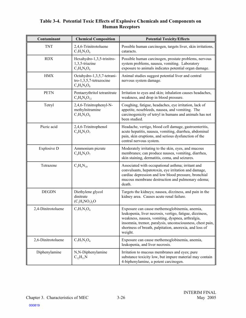
INTERIM FINALChapter 3. Characteristics of MEC May 20053-26
Table 3-4. Potential Toxic Effects of Explosive Chemicals and Components on Human Receptors
Contaminant Chemical Composition Potential Toxicity/Effects
TNT 2,4,6-TrinitrotolueneC7H5N3O6
Possible human carcinogen, targets liver, skin irritations,cataracts.
RDX Hexahydro-1,3,5-trinitro-1,3,5-triazineC3H6N6O6
Possible human carcinogen, prostate problems, nervoussystem problems, nausea, vomiting. Laboratoryexposure to animals indicates potential organ damage.
HMX Octahydro-1,3,5,7-tetrani-tro-1,3,5,7-tetrazocineC4H8N8O8
Animal studies suggest potential liver and centralnervous system damage.
PETN Pentaerythritol tetranitrateC5H8N4O12
Irritation to eyes and skin; inhalation causes headaches,weakness, and drop in blood pressure.
Tetryl 2,4,6-Trinitrophenyl-N-methylnitramineC7H5N5O8
Coughing, fatigue, headaches, eye irritation, lack ofappetite, nosebleeds, nausea, and vomiting. Thecarcinogenicity of tetryl in humans and animals has notbeen studied.
Picric acid 2,4,6-TrinitrophenolC6H4N3O7
Headache, vertigo, blood cell damage, gastroenteritis,acute hepatitis, nausea, vomiting, diarrhea, abdominalpain, skin eruptions, and serious dysfunction of thecentral nervous system.
Explosive D Ammonium picrateC6H6N4O7
Moderately irritating to the skin, eyes, and mucousmembranes; can produce nausea, vomiting, diarrhea,skin staining, dermatitis, coma, and seizures.
Tetrazene C2H6N10 Associated with occupational asthma; irritant andconvulsants, hepatotoxin, eye irritation and damage,cardiac depression and low blood pressure, bronchialmucous membrane destruction and pulmonary edema;death.
DEGDN Diethylene glycoldinitrate (C2H4NO3)2O
Targets the kidneys; nausea, dizziness, and pain in thekidney area. Causes acute renal failure.
2,4-Dinitrotoluene C7H7N2O4 Exposure can cause methemoglobinemia, anemia,leukopenia, liver necrosis, vertigo, fatigue, dizziness,weakness, nausea, vomiting, dyspnea, arthralgia,insomnia, tremor, paralysis, unconsciousness, chest pain,shortness of breath, palpitation, anorexia, and loss ofweight.
2,6-Dinitrotoluene C7H7N2O4 Exposure can cause methemoglobinemia, anemia,leukopenia, and liver necrosis.
Diphenylamine N,N-DiphenylamineC12H11N
Irritation to mucous membranes and eyes; puresubstance toxicity low, but impure material may contain4-biphenylamine, a potent carcinogen.
000819

Table 3-4. Potential Toxic Effects of Explosive Chemicals and Compounds on Human Receptors (continued)
Contaminant Chemical Composition Potential Toxicity/Effects
INTERIM FINALChapter 3. Characteristics of MEC May 20053-27
N-Nitrosodiphenylamine C12H10N2O Probable human carcinogen based on an increasedincidence of bladder tumors in male and female rats andreticulum cell sarcomas in mice, and structuralrelationship to carcinogenic nitrosamines.
Phthalates Various An increase in toxic polyneuritis has been reported inworkers exposed primarily to dibutyl phthalates;otherwise very low acute oral toxicity with possible eye,skin, or mucous membrane irritation from exposure tophthalic anhydride during phthalate synthesis.
Ammonium nitrate NH4NO3 Prompt fall in blood pressure; roaring sound in the earswith headache and associated vertigo; nausea andvomiting; collapse and coma.
Nitroglycerine (Glyceroltrinitrate)
C3H5N3O9 Eye irritation, potential cardiovascular system effectsincluding blood pressure drop and circulatory collapse.
Lead azide N6Pb Headache, irritability, reduced memory, sleepdisturbance, potential kidney and brain damage, anemia.
Lead styphnate PbC6HN3O8 CH2O Widespread organ and systemic effects including centralnervous system, immune system, and kidneys. Muscleand joint pains, weakness, risk of high blood pressure,poor appetite, colic, upset stomach, and nausea.
Mercury fulminate Hg(OCN)2 Inadequate evidence in humans for carcinogenicity;causes conjunctival irritation and itching; mercurypoisoning including chills, swelling of hands, feet,cheeks, and nose followed by loss of hair and ulceration;severe abdominal cramps, bloody diarrhea, corrosiveulceration, bleeding, and necrosis of the gastrointestinaltract; shock and circulatory collapse, and renal failure.
White phosphorus P4 Reproductive effects. Liver, heart, or kidney damage;death; skin burns, irritation of throat and lungs,vomiting, stomach cramps, drowsiness.
Perchlorates ClO4- Exposure causes itching, tearing, and pain; ingestion
may cause gastroenteritis with abdominal pain, nauseavomiting, and diarrhea; systemic effects may follow andmay include ringing of ears, dizziness, elevated bloodpressure, blurred vision, and tremors. Chronic effectsmay include metabolic disorders of the thyroid.
Hydrazine N2H4 Possible human carcinogen; liver, pulmonary, CNS, andrespiratory damage; death.
Nitroguanidine CH4N4O2 No human or animal carcinogenicity data available. Specific toxic effects are not documented.
000820

54U.S. EPA. Office of Research and Development. Wildlife Exposure Factors Handbook, EPA/600/R-93/187,December 1993.
55S. Talmage, D. Opresko, C. Maxwell, C. Welsh, M. Cretella, P. Reno, and F. Daniel. Nitroaromatic MunitionCompounds: Environmental Effects and Screening Values. Review of Environmental Contamination Toxicology 161:1-156, 1999.
INTERIM FINALChapter 3. Characteristics of MEC May 20053-28
Screening Benchmarks
As used in this discussion, screening benchmarks arevery conservative levels of a chemical that can produceadverse effects in selected species. Practically speak-ing, these levels are extrapolated and applied to relatedspecies to provide conservative levels that, if exceeded,should trigger a site-specific ecological risk assess-ment. Exceedence of a screening level benchmark neednot mean that the potential ecological threat is real, asa variety of site-specific and species-specific factorsmust be considered.
3.4.2 Ecological Effects
As with human health effects, ecological effects from chemical compounds associated withmunitions usage depend on a combination of factors: the toxicity of the compound itself, the pathwayby which the compound gets to a receptor, the concentration to which a receptor is exposed, and thereaction of the particular receptor to the compound. Site-specific assessment of the potential for anecological impact is necessary to understand the manner in which a particular ecosystem (e.g., awetlands environment) makes munitions constituents available to potential receptors. Ultimatereceptors may include not only animal species, but also their habitat, including terrestrial and aquaticplant life. In some cases the habitat may act to biologically remediate concentrations that mayotherwise seem harmful.
Guidance documents are available to assist in the conduct of ecological risk assessment. Inaddition, the Wildlife Exposure Factors Handbook developed by the EPA provides data, references,and guidance for conducting exposure assessments for 35 common wildlife species potentiallyexposed to toxic chemicals in their environment.54 A variety of exposure factors (e.g., feeding habits,body weight) are examined and organized to allow the calculation of the potential for exposure.
Research on ecological effects ofmunitions constituents has been varied andfragmented. Conservative screening levels of themost common munitions constituents have beendeveloped based on literature searches of toxiceffects on a variety of species. The generalapproach is to compile a number of studies onsimilar categories of species and extrapolateconservative screening estimates based on theresults of this compiled research. Little of thisdata is generated from real-world environmentalobservations, and instead is often derived fromlaboratory studies evaluated as part of humanhealth toxicity assessments. Toxicity data on amphibians and reptiles are in general less developedthan those for birds and mammals.
Two recent efforts to derive screening-level benchmarks for ecotoxicity data are worthparticular attention. Oak Ridge National Laboratory (ORNL), under a project sponsored by the U.S.Army and EPA, has developed ecotoxicity screening criteria and benchmarks using available dataon eight nitroaromatic compounds, including TNT, RDX, HMX, picric acid, and tetryl.55 In additionUSCHPPM (U.S. Army Center for Health Promotion and Preventive Munitions) has developedWildlife Toxicity Assessments (WTAs) for military compounds such as TNT, RDX, and HMX.
000821

INTERIM FINALChapter 3. Characteristics of MEC May 20053-29
Table 3-5 presents a compilation of potential adverse effects that these compounds may haveon wildlife according to the sources described in the preceding paragraphs.
Table 3-5. Potential Effects of Explosive Chemicals and Compounds on Ecological Receptors
Contaminant Potential Toxicity and Ecological EffectsTNT TNT can be taken up by plants from contaminated soil, including edible varieties of
garden plants, aquatic and wetland plants and tree species. Male animals treated withhigh doses of TNT have developed serious reproductive system effects; signs of acutetoxicity to TNT include ataxia, tremors, and mild convulsions.a Screening benchmarksof toxicity for mammalian and bird wildlife species have been developed by ORNLb andCHPPM.c
RDX ATSDR studies conclude that RDX does not build up in fish or in people.a Public healthassessments conducted at the Iowa AAP concluded that crops are not bioaccumulatingRDX and that they are safe for human consumption. In addition, studies at other Armyfacilities and laboratory studies suggest that deer and cattle do not bioaccumulate RDXin their tissue.d However, research does conclude that RDX is taken up by plants fromcontaminated soils and could be a potential exposure route for herbivorous wildlife.Screening benchmarks of toxicity for mammalian and bird wildlife species have beendeveloped by ORNL and CHPPM. b,c
HMX Research conducted by the ATSDR conclude that it is not known if plants, fish, oranimals living in contaminated areas build up levels of HMX in their tissues. It isunknown whether or not HMX can cause cancer or reproductive problems in animals.a
Screening benchmarks of toxicity for mammalian wildlife species have been developedby ORNL and CHPPM.b,c
PETN Screening benchmarks of toxicity for mammalian wildlife species have been developedby CHPPM. Toxicological effects to laboratory animals studies used to develop TRVsincluded weight loss, blood pressure and respiratory problems.c
Tetryl Adverse effects on plant and animal species have been identified for this contaminant.The ATSDR cites that it is not known if tetryl builds up in fish, plants, or land animals,nor if it causes birth defects or carcinogenicity in wildlife.a Screening benchmarks oftoxicity for mammalian wildlife species have been developed by ORNL and are inpreparation by CHPPM.b
Picric acid Adverse effects on plant and animal species have been identified for this contaminant.The ATSDR states that these compounds are not likely to build up in fish or people.Results of studies in laboratory rats and wildlife species, such as white footed mice showanemia effects on the blood, behavioral changes, and male reproductive system damage.a
Screening benchmarks of toxicity for mammalian and bird wildlife species have beendeveloped by ORNL and CHPPM. Data for toxicity to birds, amphibians or reptiles isunavailable.c
Explosive D UnavailableTetrazene UnavailableDEGDN Unavailable
2,4-Dinitrotoluene According to the ATSDR profile, DNT can be transferred to plants by root uptake fromcontaminated water or soil. Animals exposed to high levels of DNT had lowered numberof sperm and reduced fertility. Animals also showed a reduction in red blood cells,nervous system disorders, liver cancer and liver and kidney damage.a Screeningbenchmarks of toxicity for wildlife species are being prepared by CHPPM.
2,6-Dinitrotoluene The ATSDR profile states that 2,6-DNT has the same effect as 2,4-DNT on biota.a
Screening benchmarks of toxicity for wildlife species are in preparation by CHPPM.Diphenylamine Unavailable
000822

Table 3-5. Potential Effects of Explosive Chemicals and Compounds on EcologicalReceptors (continued)
Contaminant Potential Toxicity and Ecological Effects
INTERIM FINALChapter 3. Characteristics of MEC May 20053-30
N-Nitrosodiphenylamine
According to the ATSDR aquatic organisms take some n-nitrosodiphenylamine into theirbodies, but they don’t appear to build up high levels. It is not known if land animals orplants take it up and store it in their bodies. Animal studies have identified levels andexposures that can cause death. Animals given high levels of n-nitrosodiphenylamine intheir diets for long periods of time developed swelling, cancer of the bladder, andchanges in body weight.a
Phthalates UnavailableAmmonium nitrate Unavailable
Nitroglycerine(Glycerol trinitrate)
Screening benchmarks of toxicity for mammalian and bird wildlife species have beendeveloped by CHPPM. Mammalian effects included cardiovascular malfunction,decreased weight, and liver, blood, and reproductive problems.c
Lead azide UnavailableLead styphnate Unavailable
Mercury fulminate UnavailableWhite phosphorus CRREL studies have shown that particles of white phosphorus that entered the bottom
sediments of shallow ponds as a result of military training with white-phosphorus arehighly toxic and contributed to the death of thousands of waterfowl at Eagle River Flats,Fort Richardson, AK.a,e,f
Perchlorates UnavailableHydrazine The ATSDR profile states hydrazines may build up in some fish living in contaminated
water, but are not expected to remain at high levels over long periods of time. Tumorshave been seen in many organs (lungs, blood vessels, and colon) of animals that wereexposed to hydrazines by ingestion or breathing.a
Nitroguanidine UnavailableNotes:
aData were taken from the toxicological profiles of these compounds prepared by the Agency for Toxic Substances andDisease Registry (ATSDR), Atlanta, GA: U.S. Department of Health and Human Services, Public Health Service,between 1993 and 1998.bS. Talmage, D. Opresko, C. Maxwell, C. Welsh, M. Cretella, P. Reno, and F. Daniel. Nitroaromatic MunitionCompounds: Environmental Effects and Screening Values. Prepared for Oak Ridge National Laboratory, Life SciencesDivision, and the EPA National Exposure Research Laboratory, and published in Rev Environ Contam Toxicol 161:1-156, 1999.cData were taken from wildlife toxicity assessments performed for the U.S. Army Center for Health Promotion andPreventive Medicine (USACHPPM), Aberdeen Proving Ground, MD, 2001-2002.dW.M. Weber and G. Campbell. Public Health Assessment, Iowa Army Ammunitions Plant, Middletown, Iowa. FederalFacilities Assessment Branch Division of Health Assessment and Consultation, CERCLIS No. IA7213820445, 1999.eData on white phosphorus were taken from C.H. Racine, M.E. Walsh, C.M. Collins, S. Taylor, B.D. Roebuck, and L.Reitsma. Waterfowl Mortality in Eagle River Flats, Alaska: The Role of Munitions Residue, and White PhosphorusContamination of Salt Marsh Pond Sediments at Eagle River Flats, Alaska. USACE, Cold Regions Research andEngineering Laboratory (CRREL), Hanover, NH, May 1992.fC.H. Racine, M.E. Walsh, C.M. Collins, S. Taylor, and B.D. Roebuck. White Phosphorus Contamination of Salt MarshPond Sediments at Eagle River Flats, Alaska. USACE, CRREL, Hanover, NH, May 1992.
000823

56Joint Technical Bulletin, Department of Defense Ammunition and Explosive Classification Procedures, 5 January 1998, (TB 700–2/NAVSEAINST 8020.8B/TO 11A-1-47/DLAR 8220.1
57ATSDR. Toxicological Profile for White Phosphorous. Atlanta, GA: U.S. Department of Health and HumanServices, Public Health Service, 1997.
58C.H. Racine, M.E. Walsh, C.M. Collins, S. Taylor, B.D. Roebuck, and L. Reitsma. Waterfowl Mortality inEagle River Flats, Alaska: The Role of Munitions Residue. Hanover, NH: USACE, Cold Regions Research andEngineering Lab, May 1992.
59C.H. Racine, M.E. Walsh, C.M. Collins, S. Taylor, and B.D. Roebuck. White Phosphorus Contamination ofSalt Marsh Pond Sediments at Eagle River Flats, Alaska. Hanover, NH: USACE, CRREL, May 1992.
INTERIM FINALChapter 3. Characteristics of MEC May 20053-31
3.4.3 Human and Ecological Effects from Exposure to Specific Compounds
This section further discusses known effects of specific compounds on human and ecologicalreceptors.
White Phosphorus
One of the most frequently used bursting smoke fillers (also classified as an incendiary) iswhite phosphorus.56 White phosphorus burns rapidly when exposed to oxygen. In soils with lowoxygen, unreacted white phosphorus can lie dormant for years, but as soon as it is exposed to oxygen,it may react. If ingested, white phosphorus can cause reproductive, liver, heart, or kidney damage,or death. Skin contact can burn the skin or cause organ damage. White phosphorus has been foundin fish caught in contaminated water and in game birds from contaminated areas.57 Researchconducted by CRREL has shown that an unusually high mortality of migratory waterfowl,particularly dabbling species such as ducks and swans, is attributable to the ingestion of elementalwhite phosphorus particles in the salt marsh sediments at Eagle River Flats, Alaska. Between 1982and 1988, field and air surveys of the area were conducted. Nearly1,000 dead waterfowl werecounted. The highest species-specific numbers included over 200 Northern pintail and over 150Mallard ducks. Because of its use as an artillery training impact area (with nearly 7,000 rounds ofwhite phosphorus fired in 1989), munitions contamination was suspected as the cause. Tissue studiesof gizzard contents, fat tissue, liver, and kidneys found white phosphorus content in all field-collectedducks and swans analyzed. Behavior of exposed birds prior to death included increased thirst, headrolling, and violent convulsions.58,59
Trinitrotoluene (TNT)
TNT is soluble and mobile in surface water and groundwater. It is rapidly broken down intoother chemical compounds by sunlight, and is broken down more slowly by microorganisms in waterand sediments. TNT is not expected to bioaccumulate under normal environmental conditions.Human exposure to TNT may result from breathing air contaminated with TNT and TNT-contaminated soil particles stirred up by wind or construction activities. Workers in explosivemanufacturing who are exposed to high concentrations of TNT in workplace air experience a varietyof organ and immune system problems, as well as skin irritations and cataracts. Both EPA andATSDR have identified TNT as a possible human carcinogen.
000824

60Carcinogenicity Assessment for Lifetime Exposure of Hexahydro-1,3,5-trinitro-1,3,5-triazine (RDX), andCarcinogenicity Assessment for 2,4,6-trinitrotoluene (TNT) for Lifetime Exposure, EPA Integrated Risk InformationSystem, 1993.
61Agency for Toxic Substances and Disease Registry. Toxicological Profile for 2,4,6-trinitrotoluene (update),and Toxicological Profile for RDX, U.S. Department of Health and Human Services, Public Health Service, Atlanta,GA, 1995.
62K. Schneider, J. Oltmanns, T. Radenberg, T. Schneider, and D. Pauly-mundegar. Uptake of NitroaromaticCompounds in Plants: Implications for Risk Assessment of Ammunition Sites. Environmental Science and PollutionResearch International 3(3)135-138, 1996.
INTERIM FINALChapter 3. Characteristics of MEC May 20053-32
Toxicological Profiles of RDX and TNT
EPA’s IRIS uses a weight-of-evidence classification for carcinogenicity that characterizes the extent to which theavailable data support the hypothesis that an agent causes cancer in humans. IRIS classifies carcinogenicityalphabetically from A through E, with Group A being known human carcinogens and Group E being agents withevidence of noncarcinogenicity. IRIS classifies both TNT and RDX as Group C, possible human carcinogens, andprovides a narrative explanation of the basis for these classifications.60
The ATSDR is tasked with preventing exposure and adverse human health effects and diminished quality of lifeassociated with exposure to hazardous substances from waste sites, unplanned releases, and other sources of pollutionpresent in the environment.
The ATSDR has developed toxicological profiles for RDX and TNT to document the health effects of exposure tothese substances. The ATSDR has identified both TNT and RDX as possible human carcinogens.61
The ecological impacts of TNT include blood, liver, and immune system effects in wildlife.In addition, in laboratory tests, male test animals treated with high doses of TNT developed seriousreproductive system effects.
Research has concluded that RDX, TNT, and other nitroaromatic compounds can beaccumulated by plants from contaminated soils and could be a potential exposure route forherbivorous wildlife. Plant studies conducted using TNT-contaminated soil taken from ammunitionsites found a direct correlation between concentrations in soil and plants. Large-scale uptake of TNTwas found to take place in plants, including edible varieties such as lettuce, beans, and carrots.Studies suggest that because of the prevalence of TNT-contaminated sites, risk assessors shouldconsider the hazard posed to organisms higher in the food chain, including humans and wildlife,which could also be affected by exposure. In addition, seed germination and growth studiesconducted on terrestrial higher plants found varied thresholds for phytotoxicity. Some plants (e.g.,oat plants) have shown such high tolerances for TNT that they have been considered potentialbioremediation species.62
Research Demolition Explosive (RDX)
RDX, also known as Research Demolition Explosive, is another frequently found syntheticexplosive chemical. RDX dissolves in and evaporates from water very slowly. RDX does not bind
000825

INTERIM FINALChapter 3. Characteristics of MEC May 20053-33
well to soil particles and can migrate to groundwater, but the rate of migration depends on the soilcomposition. If released to water, RDX is degraded mainly by direct photochemical degradation thattakes place over several weeks. RDX does not biologically degrade in the presence of oxygen, butanaerobic degradation is a possible fate process under certain conditions. RDX’s potential forbioaccumulation is low. Human exposure to RDX results from breathing dust with RDX particlesin it, drinking contaminated water, or coming into contact with contaminated soils. RDX inhalationor ingestion can create nervous system problems and possibly organ damage. As discussedpreviously, RDX has been identified as a possible human carcinogen.
The ecological effects of RDX suggested by laboratory studies include neurological damageincluding seizures and behavioral changes in wildlife that ingest or inhale RDX. Wildlife exposureto RDX may also cause damage to the liver and the reproductive system.
3.5 Other Sources of Conventional Munitions Constituents
Contamination of soils and groundwater with explosive compounds results from a variety ofactivities. These activities include the release of other munitions constituents during plannedmunitions training and testing, munitions disposal/burial pits associated with military ranges, andmunition storage sites and build-up locations. Contamination may also result from the deteriorationof intact munitions, the open burning and open detonation of munitions, and the land disposal ofexplosives-contaminated process water from explosives manufacturing or demilitarization plants.Munitions constituents include heavy metals, particularly lead and mercury, because they arecomponents of primary or initiating explosives such as lead azide and mercury fulminate. Thesemetals are released to the environment after a detonation or possibly by leaching out of damaged orcorroded munitions. The sections below describe specific sources of munitions constituents.
3.5.1 Open Burning/Open Detonation (OB/OD)
Concentrations of munitions constituents, such as explosives and metals, and bulk explosiveshave been found at former OB/OD areas at levels requiring a response. OB/OD operations are usedto destroy excess, obsolete, or unserviceable munitions and energetic materials. OB operationsemploy self-sustained combustion, which is ignited by an external source. In OD operations,explosives and munitions are destroyed by a detonation, which is normally initiated by the detonationof an energetic charge. In the past, OB/OD operations have been conducted on the land surface orin shallow burn pits. More recently, burn trays and blast boxes have been used to help control andcontain emissions and other contamination resulting from OB/OD operations. See Chapter 5 for afuller discussion of OB/OD.
Incomplete combustion of munitions and energetic materials can leave uncombusted TNT,RDX, HMX, PETN, and other explosives. These materials can possibly be spread beyond theimmediate vicinity of the OB/OD operation by the kick-out these operations generate and cancontribute to potentially adverse human health and ecological effects.
000826

INTERIM FINALChapter 3. Characteristics of MEC May 20053-34
Demilitarization of Munitions
Demilitarization is the processing of munitions so theyare no longer suitable for military use.
Demilitarization of munitions involves severaltechniques, including both destructive and nonde-structive methods. Destructive methods includeOB/OD and incineration. Nondestructive methodsinclude the physical removal of explosive componentsfrom munitions. Munitions are generally demilitarizedbecause they are obsolete or their chemical com-ponents are deteriorated.
3.5.2 Explosives Manufacturing and Demilitarization
Explosives manufacturing and demilit-arization plants are also sources of munitionsconstituents. These facilities are usually comm-ercial sites that are not usually co-located withdefense sites. Many of these facilities havecontaminated soils and ground-water. Themanufacture; load, assemble, and packoperations; and demilitarization of munitionscreate processing waters that in the past wereoften disposed of in unlined lagoons, leavingmunitions constituents behind after infiltrationand evaporation.
Red water, the effluent from TNTmanufacturing, was a major source of munitions constituents in soils and groundwater at armyammunition plants. TNT production ended in the mid-1980s in the United States; however,contamination of soils and groundwater from red water remains in some areas.
In the demilitarization operations conducted up to the 1970s, explosives were removed frommunitions with jets of hot water or steam. The effluent, called pink water, flowed into settling basins,and the remaining water was disposed of in unlined lagoons or pits, often leaving highly concentratedmunitions constituents behind. In more advanced demilitarization operations developed in the 1980s,once the solid explosive particles settled out of the effluent, filters such as diatomaceous earth filtersand activated carbon filters were employed to further reduce the explosive compounds, and the waterswere evaporated from lagoons or discharged into water systems.
3.6 Conclusions
The potential for explosive damage by different types of MEC, including buried munitions,UXO, and munitions constituents, depends on many different factors. These factors include themagnitude of the potential explosion, the sensitivity of the explosive compounds and their breakdownproducts, fuze sensitivity, the potential for deflagration or detonation, the potential for MECdeterioration, and the likelihood that the item will be disturbed, which depends on environmental andhuman activities.
MEC items may also present other human health, ecological and environmental risks,depending on the state of the item. Specifically, a MEC item that is degraded may releasepropellants, explosives, pyrotechnics, and other munitions constituents into the surrounding area,thereby potentially contaminating the environment and affecting human health. Other human healthand environmental risks may result from the explosives and from other chemicals used or producedin munitions operations such as OB/OD; manufacturing; demilitarization; and load, assemble, andpack operations.
000827

INTERIM FINALChapter 3. Characteristics of MEC May 20053-35
SOURCES AND RESOURCES
The following publications, offices, laboratories, and websites are provided as a guide forhandbook users to obtain additional information about the subject matter addressed in each chapter.Several of these publications, offices, laboratories, or websites were also used in the development ofthis handbook.
Publications
Agency for Toxic Substances and Disease Registry (ATSDR). Toxicological Profile for 1,3-dinitrobenzene/1,3,5-trinitrobenzene (update). Atlanta, GA: U.S. Department of Health and HumanServices, Public Health Service, 1995.
ATSDR. Toxicological Profile for 2,4,6-trinitrotoluene (update). Atlanta, GA: U.S.Department of Health and Human Services, Public Health Service, 1995.
ATSDR. Toxicological Profile for 2,4- and 2,6-dinitrotoluene. Atlanta, GA: U.S. Departmentof Health and Human Services, Public Health Service, 1998.
ATSDR. Toxicological Profile for HMX. Atlanta, GA: U.S. Department of Health and HumanServices, Public Health Service, 1997.
ATSDR. Toxicological Profile for Hydrazines. Atlanta, GA: U.S. Department of Health andHuman Services, Public Health Service, 1997.
ATSDR. Toxicological Profile for n-nitrosodiphenylamine. Atlanta, GA: U.S. Department ofHealth and Human Services, Public Health Service, 1993.
ATSDR. Toxicological Profile for RDX. Atlanta, GA: U.S. Department of Health and HumanServices, Public Health Service, 1995.
ATSDR. Toxicological Profile for Tetryl (update). Atlanta, GA: U.S. Department of Health andHuman Services, Public Health Service, 1995.
ATSDR. Toxicological Profile for White Phosphorous. Atlanta, GA: U.S. Department ofHealth and Human Services, Public Health Service, 1997.
Bailey, A., and S.G. Murray. Explosives, Propellants and Pyrotechnics. Brassey’s (UK) Ltd.,1989.
Bucci, J.E., and P.F. Buckley. Modeling the Degradation of Unexploded Ordnance (UXO) andIts Use as a Tool in the Development of Risk Assessments. Paper presented at the UXO Forum1998. Available at http://uxocoe.brtrc.com/UXOForumDocs/Forum98/Bucci.pdf.
Cooper, P.W. Explosives Engineering. New York, NY: Wiley-VCH, 1996.
000828

INTERIM FINALChapter 3. Characteristics of MEC May 20053-36
Crockett, A.B., H.D. Craig, and T.F. Jenkins. Field Sampling and Selecting On-site AnalyticalMethods for Explosives in Water. U.S. EPA Federal Facilities Forum Issue, May 1999,EPA/540/R-97/501.
Crull, M.L., L. Taylor, and J. Tipton. Estimating Ordnance Penetration Into Earth. Paperpresented at UXO Forum 1999, Atlanta, GA., May 25-27, 1999.
Federal Advisory Committee for the Development of Innovative Technologies. UnexplodedOrdnance (UXO): An Overview. U.S. Navy, Naval Explosive Ordnance Disposal TechnologyDivision, UXO Countermeasures Department, Oct. 1996.
Johnson, M.S., and J.J. McAtee. Wildlife Toxicity Assessment for 2,4,6 5-trinitrotoluene. U.S.Army Center for Health Promotion and Preventive Medicine (USACHPPM) Project Number 39-EJ-1138-00. Aberdeen Proving Ground, MD, Oct. 2000.
Kleine, H., and A. Makris. Protection Against Blast Effects in UXO Clearance Operations. UXO Forum 1999 Proceedings, 1999.
Racine, C.H., M.E. Walsh, C.M. Collins, S. Taylor, B.D. Roebuck, and L. Reitsma. WaterfowlMortality in Eagle River Flats, Alaska: The Role of Munitions Residue. Hanover, NH:USACE, Cold Regions Research and Engineering Lab, May 1992.
Racine, C.H., M.E. Walsh, C.M. Collins, S. Taylor, and B.D. Roebuck, White PhosphorusContamination of Salt Marsh Pond Sediments at Eagle River Flats, Alaska. Hanover, NH: USACE, CRREL, May 1992.
Roberts, W.C., and W.R. Hartley. Drinking Water Health Advisory: Munitions. Boca Raton,FL: Lewis Publishers, 1992.
Schneider K., J. Oltmanns, T. Radenberg, T. Schneider, and D. Pauly-mundegar. Uptake ofNitroaromatic Compounds in Plants: Implications for Risk Assessment of Ammunition Sites. Environmental Science and Pollution Research International 3(3)135-138, 1996.
Talmage S., D. Opresko, C. Maxwell, C. Welsh, M. Cretella, P. Reno, and F. Daniel. Nitroaromatic Munition Compounds: Environmental Effects and Screening Values. Review ofEnvironmental Contamination and Toxicology 161:1-156, 1999.
U.S. Army Center for Health Promotion and Preventive Medicine (USACHPPM), StandardPractice for Wildlife Toxicity Reference Values, Technical Guide 254 (USACHPPM TG 254), Environmental Health Risk Assessment Program and Health Effects Research Program, AberdeenProving Ground, MD, Oct. 2000.
Wildlife Toxicity Assessment for 1,3,5-trinitrobenzene. U.S. Army Center for Health Promotionand Preventive Medicine (CHPPMUSA) Project Number 39-EJ-1138-01B, Aberdeen ProvingGround, MD, Nov. 2001.
000829

INTERIM FINALChapter 3. Characteristics of MEC May 20053-37
Wildlife Toxicity Assessment for 1,3,5-trinitrohexahydro-1,3,5- triazine (RDX). U.S. ArmyCenter for Health Promotion and Preventive Medicine (CHPPMUSA) Project Number 39-EJ-1138-01B, Aberdeen Proving Ground, MD, May 2002.
U.S. Army Center for Health Promotion and Preventive Medicine (USACHPPM). WildlifeToxicity Assessment for HMX, Project Number 39-EJ-1138-01E, Aberdeen Proving Ground,MD, Oct. 2001.
U.S. Army Center for Health Promotion and Preventive Medicine (USACHPPM). WildlifeToxicity Assessment for Nitroglycerin, Project Number 39-EJ-1138-01F, Aberdeen Provingground, MD, Oct. 2001.
U.S. Army Center for Health Promotion and Preventive Medicine (USACHPPM). WildlifeToxicity Assessment for Pentaerythritol Tetranitrate (PETN), Project Number 37-EJ-1138-01G,Aberdeen Proving Ground, MD, Nov. 2001.
U.S. Army Corps of Engineers. Ordnance and Explosives Response: Engineering and Design. No. 1110-1-4009, June 23, 2000.
U.S. Department of Defense, Office of the Under Secretary of Defense (Acquisition andTechnology). Report to Congress, Unexploded Ordnance Clearance: A Coordinated Approachto Requirements and Technology Development. Joint Unexploded Ordnance Clearance SteeringGroup, Mar. 25, 1997.
U.S. Environmental Protection Agency (U.S. EPA). Handbook: Approaches for theRemediation of Federal Facility Sites Contaminated With Explosive or Radioactive Wastes.EPA/625/R-93/013, Sept. 1993.
U.S. EPA, Criteria and Standards Division, Office of Drinking Water. Health Advisory forHexahydro-1,3,5-Trinitro-1,3,5-Triazine (RDX). Nov. 1988.
U.S. EPA, Office of Drinking Water. Health Advisory for Octahydro-1,3,5,7-tetranitro-1,3,5,7-tetrazocine (HMX). NTIS No. SPB90-273525. Nov. 1988.
U.S. EPA, Office of Drinking Water. Health Advisory for 2,4,6–Trinitrotoluene, Jan. 1989.
U.S. EPA, Office of Research and Development, Wildlife Exposure Factors Handbook.EPA/600/R-93/187, Dec. 1993.
Weber, W.M., and G. Campbell. Public Health Assessment, Iowa Army Ammunitions Plant.Middletown, Iowa, Federal Facilities Assessment Branch, Division of Health Assessment andConsultation, CERCLIS No. IA7213820445, 1999.
Wilcher, B.L., D. Eisen, and R. Booth. Evaluation of Potential Soil Contamination from OpenDetonation During Ordnance and Explosives Removal Actions, Former Fort Ord, California.Paper presented at UXO Forum 1999, Atlanta, GA, May 25-27, 1999.
000830
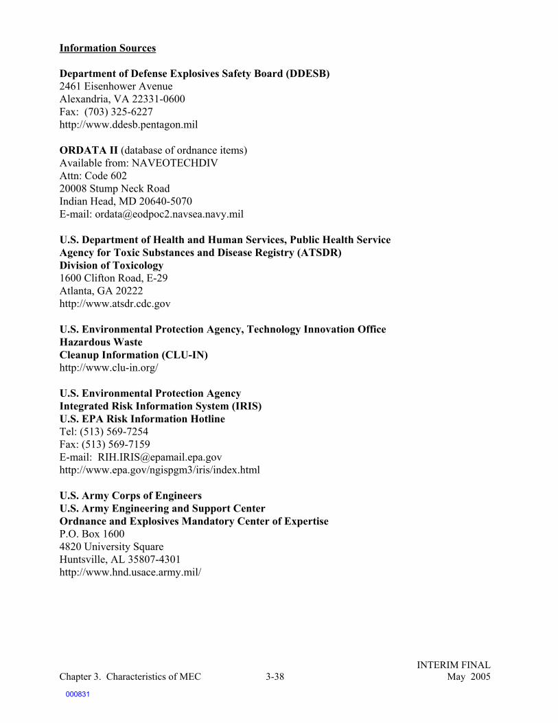
INTERIM FINALChapter 3. Characteristics of MEC May 20053-38
Information Sources
Department of Defense Explosives Safety Board (DDESB)2461 Eisenhower AvenueAlexandria, VA 22331-0600Fax: (703) 325-6227 http://www.ddesb.pentagon.mil
ORDATA II (database of ordnance items)Available from: NAVEOTECHDIVAttn: Code 60220008 Stump Neck RoadIndian Head, MD 20640-5070E-mail: [email protected]
U.S. Department of Health and Human Services, Public Health ServiceAgency for Toxic Substances and Disease Registry (ATSDR)Division of Toxicology1600 Clifton Road, E-29Atlanta, GA 20222http://www.atsdr.cdc.gov
U.S. Environmental Protection Agency, Technology Innovation OfficeHazardous WasteCleanup Information (CLU-IN)http://www.clu-in.org/
U.S. Environmental Protection AgencyIntegrated Risk Information System (IRIS)U.S. EPA Risk Information Hotline Tel: (513) 569-7254 Fax: (513) 569-7159E-mail: [email protected]://www.epa.gov/ngispgm3/iris/index.html
U.S. Army Corps of EngineersU.S. Army Engineering and Support CenterOrdnance and Explosives Mandatory Center of ExpertiseP.O. Box 1600 4820 University SquareHuntsville, AL 35807-4301http://www.hnd.usace.army.mil/
000831
INTERIM FINALChapter 4. Detection of UXO/Buried Munitions May 20054-1
4.0 DETECTION OF UXO AND BURIED MUNITIONS
4.1 Introduction
Geophysical detection technologies are deployed in a nonintrusive manner to locate surfaceand subsurface anomalies that may be UXO or buried munitions. (For purposes of brevity,discussions of UXO and buried munitions will be referred to as MEC throughout this chapter.)Proper selection and use of these technologies is an important part of the site investigation, whichoften takes place on ranges or parts of ranges that cover many acres. Since excavating all the land todepth is usually not practical, MEC detection technologies are used to locate anomalies that aresubsequently verified as UXO or non-UXO. Given the high cost of MEC excavation (due to bothrange size and safety considerations), the challenge of most MEC investigations is the accurate andappropriate deployment of nonintrusive geophysical detection technologies to maximize probabilityof detection and minimize false alarms.
Since the early 1990s, existing geophysical survey technologies have improved in theircapabilities to efficiently and cost-effectively detect MEC. Much of the improvement is the result ofgreater understanding of operational requirements for the use of detection technologies. However,the primary challenge in MEC detection today is the achievement of high levels of subsurfacedetection of actual MEC in a consistent, reproducible manner with a high level of quality assurance.Distinguishing ordnance from fragments and other nonordnance materials based solely on thegeophysical signature, called target discrimination, is also a major challenge in MEC detection andthe focus of research and development activities. This problem is known as a false alarm, asdescribed in the text box below. Poor discrimination results in lower probability of detection, highercosts, longer time frames for cleanups, and potentially greater risks following cleanup actions.
It should be noted that a particular technology or combination of technologies will never havethe highest effectiveness, best implementability, and lowest cost at every site. In other words, thereis no “silver bullet” detection technology. It is also important to note that no existing technology orcombination of existing technologies can guarantee that a site is completely MEC-free. As discussedin Section 4.2 below and in Chapter 7, a combination of information from a variety of sources(including historical data, results of previous environmental data collection, and knowledge of field
False Alarms
The term false alarm is used when a declared UXO detection location does not correspond to an actual UXOlocation based upon the groundtruth data. False positives are anomalous indications where nothing is found thatcaused the instrument to detect an anomaly at that location. False positives can result in incorrect estimations ofUXO density and often lead to expensive or unnecessary excavation of an anomaly if it is not UXO. Dependingon the site-specific conditions, as few as 1 percent of anomalies may actually be UXO items. Because of thedifficulty, danger, and time required to excavate UXO, high costs per acre are exacerbated by a high false positiverate. False negatives occur when ordnance items are not detected by the geophysical instrument used or aremisidentified in post-processing, resulting in potential risks remaining following UXO investigations.
000832
INTERIM FINALChapter 4. Detection of UXO/Buried Munitions May 20054-2
and terrain conditions) will be used to make decisions about the detection system to be used,including the particular sensor(s), the platform on which it is deployed, and data acquisition andprocessing techniques. Detailed fact sheets on each of the detection sensors currently in use are foundat the end of this chapter.
Experts in the MEC research and development community have indicated that currentlyavailable detection technologies will improve with time and that no revolutionary new systems arelikely to be developed that uniformly improve all MEC detection. Much of the performanceimprovement of current detection technologies has come from a better understanding of how to usethe technologies and from the use of combinations of technologies at a site to improve anomalydetection rates. Current improvements in detection systems generally focus on discriminatingordnance from nonordnance. Emerging processing and numerical modeling programs will enhancethe target discrimination capabilities of detection systems. In general, these programs rely onidentifying UXO and clutter based on their “signatures” (e.g., spatial pattern of magnetic signal).
Geophysical sensors have specific capabilities and limitations that must be evaluated whenselecting a detection system for a site. The primary types of sensors in use today are:
C Magnetometry — a passive sensor that measures a magnetic field. Subsurface ferrousitems create irregularities in the Earth’s magnetic field and may contain remnant magneticfields of their own that are detected by magnetometers.
C Electromagnetic Induction (EMI) — an active sensor that induces electrical currentsbeneath the earth’s surface. Conductivity readings of the secondary magnetic field createdby the electrical currents are used to detect both ferrous and nonferrous ordnance items.
In addition, under specific and limited conditions, ground-penetrating radar (GPR) has beensuccessfully used to detect MEC. This sensor is mainly helpful when the location of larger munitionsburial sites is known and boundaries must be identified. Magnetometers, EMI sensors, and GPRsensors are discussed in detail in Section 4.2 and in the fact sheets at the end of the chapter. Theresults of investigations using any sensor can vary dramatically depending not only on the siteconditions, but also on the components of the detection system, the skill of the operator, and theprocessing method used to interpret the data.
Detection systems that will be available in the near future include advanced electromagneticsystems and airborne magnetometers. Long-term research endeavors include a GPR that can identifyUXO at discrete locations, and an airborne EMI sensor. An overview of emerging detectiontechnologies, as well as data processing and modeling for target discrimination, is presented inSections 4.3 and 4.4.
In response to the stagnancy of detection technology development at the beginning of theBase Realignment and Closure (BRAC) Program, the U.S. Congress established the JeffersonProving Ground Technology Demonstration (JPGTD) program in Madison, Indiana. The JPGTDprogram was established to demonstrate and promote advanced and innovative UXO systems thatare more cost-efficient, effective, and safer. In the program, vendors of geophysical systems wereinvited to test and compare the efficiency and reliability of the systems. It is important to note thatthe test did not look at the process by which the system was deployed and was not structured todetermine why certain approaches worked better than others. In subsequent phases of the JPGTDprogram, vendors improved the processes by which sensors were deployed, and significantly
000833

INTERIM FINALChapter 4. Detection of UXO/Buried Munitions May 20054-3
improved their detection rates. The JPGTD and other demonstration programs, such as theEnvironmental Security Technology Certification Program UXO Technology StandardizedDemonstration Sites and the Fort Ord Ordnance Detection and Discrimination Study (ODDS), arediscussed in Section 4.5.
4.2 Selection of the Geophysical Detection System
Many factors should be considered when identifying the detection system appropriate to yoursite. First, information about the detection sensors currently available, and the factors that contributeto their successful application, should be evaluated. Next, basic site conditions should be evaluated,such as expected targets (size, location, density, depths), terrain, vegetation, and electromagneticfields. Finally, the role of each system component and how it affects overall performance should beexamined to ensure maximum effectiveness.
4.2.1 Geophysical Sensors in Use Today
Magnetometry and electromagnetic induction are the most frequently used sensors fordetecting MEC. Both sensors are commercially available and are employed on a variety of systemsusing various operational platforms, data processing techniques, and geolocation devices.
4.2.1.1 Electromagnetic Induction (EMI)
EMI sensors are perhaps the most widely used systems for detecting MEC. Theelectromagnetic induction system is based on physical principles of inducing and detecting electricalcurrent flow within nearby conducting objects. EMI surveys work by inducing time-varying magneticfields in the ground from a transmitter coil. The resulting secondary electromagnetic field set up byground conductors is then measured at a receiver coil. EMI systems can detect all conductivematerials but are at times limited by interference from surface or near-surface metallic objects. Ingeneral, the EMI response will be stronger the closer the detector head is to the buried target, butclose proximity to the ground surface may subject the sensor to interference from shallow fragments.In areas of heavy vegetation, the distance between the detector head and the earth’s surface isincreased, potentially decreasing signal strength and decreasing the probability of detection. Soil typealso plays a role in EMI system detection. EMI systems may have difficulty detecting small itemsin conductive soils, such as those containing magnetite, or in soils with cultural interferences, suchas buildings, metal fences, vehicles, cables, and electrical wires. Because the difficulties withdetecting small items in conductive soils are also present for magnetometry, this issue is usually nota limiting factor in selection of an EMI system.
EMI systems operate in time orf r e q u e n c y d o m a i n s . T i m e - d o m a i nelectromagnetic (TDEM) systems operate bytransmitting a magnetic pulse that inducescurrents in and near conducting objects. Thesecurrents produce secondary magnetic fields thatare measured by the sensor after the transmitterpulse has ended. The sensor integrates theinduced voltage over a fixed time gate andaverages over the number of pulses. When
EMI and Electronic Fuzes
EMI is an active system for which there has beenconcern about increasing the risk of initiating MECwith electronic fuzing. However, there is no evidencethat the current generation of EMI-based systems,when used in accordance with the manufacturerspecifications (e.g., EM-61), generate enough power tocause this effect. This may be an issue to watch in thefuture, however, if more powerful systems aredeveloped.
000834

INTERIM FINALChapter 4. Detection of UXO/Buried Munitions May 20054-4
TDEM detectors are hand-held or smaller they may have less penetration depth than the morecommonly used large-coil EMI.
Frequency-domain electromagnetic (FDEM) instruments operate by transmitting continuouselectronic signals and measuring the resulting eddy currents. FDEM instruments are able to detectdeeply buried munitions that are grouped together. In addition, some types of FDEM instruments arecapable of detecting very small individual MEC items that are buried just beneath the ground surface,such as metal firing pins in plastic land mines. FDEM instruments are currently not typically usedwhen detecting individual, deeply buried munitions, because of the sensor’s decreased resolution andthe difficulty of measuring the amplitude of return of individual targets.
4.2.1.2 Magnetometry
Magnetometers are passive systems that use the Earth’s magnetic field as the source of thesignal. Magnetometers detect distortions in the magnetic field caused by ferrous objects. Themagnetometer has the ability to detect ferrous items to a greater depth than can be achieved by othersystems. Magnetometers can identify small anomalies because of the instrument’s high levels ofsensitivity. However, magnetometers are also sensitive to many iron-bearing minerals and “hotrocks” (rocks with high iron content), which affects the detection probability by creating falsepositives and masking signals from real ordnance.
The two most common magnetometry systems used to detect buried munitions are cesiumvapor or fluxgate. Cesium vapor magnetometers measure the magnitude of a magnetic field. Thesesystems produce digital system output. The fluxgate systems measure the relative intensity of thegradient in the Earth’s magnetic field. These systems are inexpensive, reliable, and rugged and havelow energy consumption.
4.2.1.3 Multisensor Systems
Multisensor systems combine two or more sensor technologies in order to improve UXOdetection performance. The technologies that have proved to be most effective in multisensor systemsare arrays of full-field cesium vapor magnetometers and time-domain EMI pulsed sensors.Multisensor systems can enhance detector performance by providing complementary data sets thatcan be used to confirm the presence of MEC.
Multisensor systems are available both as man-portable configurations and as linear arrayson platforms that do not themselves produce a significant geophysical signature while they tow thearray over survey sites by all-terrain vehicles.
4.2.1.4 Ground Penetrating Radar
GPR is another sensor technology that is currently commercially available, although it is notused as frequently as EMI and magnetometry and is generally not as reliable. GPR systems use high-frequency (approximately 10 to1,000 MHz) electromagnetic waves to excite the conducting object,thus producing currents. The currents flow around the object, producing electromagnetic fields thatradiate from the target. The signals are received by the GPR antenna and stored for furtherprocessing. Most commercial systems measure total energy return and select potential targets basedon contrast from background. More advanced processing uses the radar information to produce two-
000835

INTERIM FINALChapter 4. Detection of UXO/Buried Munitions May 20054-5
or three-dimensional images of the subsurface or to estimate features of the target, such as length ora spectra. Such processing systems are not generally in use at this time.
The GPR system is more accurate when used in areas of dry soil. Water in the soil absorbsthe energy from the GPR, thus interfering with UXO detection. GPR may be used to find theboundaries of large caches of buried munitions. Because the GPR system uses active electromagneticwaves to locate buried objects, there is concern that electronic fuzes on MEC items could be initiatedby these systems. As with EMI, there is no evidence that deployment of GPR has initiated electronicfuzes during MEC investigations.
4.2.2 Selection of the Geophysical Detection System
The selection of a detection system is a site-specific decision. Some of the factors that shouldbe considered in selecting a detection system include, but are not limited to, the following:
C Site sizeC Soil type, vegetation, and terrainC Subsurface lithologyC Depth, size, shape, composition, and type of MECC Geological and cultural noise (e.g., ferrous rocks and soils, electromagnetic fields from
power lines)C Non-MEC clutter on-siteC Historical land useC Reasonably anticipated future land useC MEC density
Each of the above factors should be considered against the decision goals of the investigation in orderto select the most appropriate detection system. Table 4-1 highlights the effects of each factor on theinvestigation process. This list of considerations is not all-inclusive.
000836

INTERIM FINALChapter 4. Detection of UXO/Buried Munitions May 20054-6
Table 4-1. Examples of Site-Specific Factors To Be Considered in Selecting a Detection System
Site Factors Considerations
Site size Different operational platforms cover areas at different speeds. If a large area needsto be surveyed, operational platforms such as towed-array or airborne may beconsidered, if appropriate.
Soil properties Potential for high conductivity levels to interfere with target signals; potentiallyreduced detection capabilities using magnetometers in ferrous soils.
Vegetation Heavy vegetation obstructs view of MEC items on surface and may interfere withsensor’s ability to detect subsurface anomalies, as well as access to the site andoperation of the sensor.
Terrain Easily accessible areas can accommodate any operational platform; difficult terrainmay require man-portable platform.
Subsurface lithology Soil and rock layers and configurations beneath the ground surface will influencethe depth of the UXO and the ability of the sensor to “see” anomalies.
Target size and orientation Capability of detector to find objects of various sizes and at various orientations.
Target penetration depth Capability of detector to find targets at depths. Potential for decreased signal whendetecting deeply buried targets.
Composition of UXO Projectile and fuze composition may dictate sensor selection. Magnetometersdetect only ferrous materials, while EMI systems detect all metals.
Noise Both geological noise (e.g., hot rocks or high ferrous content in soil) and culturalnoise (e.g., buried cables, overhead utilities) potentially increase false alarms andmask ordnance signals.
Non-UXO clutter Potential difficulty discriminating between small objects and metallic scrap,resulting in high numbers of false alarms.
Historical land use Information about expected target location, types, and density.
Future land use Enables setting of realistic decision goals for investigation.
UXO density Enables sensor strengths (e.g., ability to see individual items as opposed to largecaches of targets) to be maximized.
000837

INTERIM FINALChapter 4. Detection of UXO/Buried Munitions May 20054-7
4.2.3 MEC Detection System Components
Table 4-2 identifies the various elements of a detection system and highlights how eachelement may affect the overall system performance. For example, the three operational platforms —man-held, towed-array, and airborne — directly affect the sensor’s distance from the target, which,in turn, affects the sensor’s ability to detect targets. The ability of all sensors to “see” targetsdecreases as distance from the target increases. However, the rate at which the performance dropsoff with distance varies by individual sensor. An additional consideration when selecting theoperational platform includes what is expected to be found beneath the surface. Large caches ofmunitions buried deep beneath the surface may remain detectable from large distances, whereassmaller items may be more easily missed by the sensor at a distance.
Table 4-2. System Element Influences on Detection System Performance
System Element Factors To Be Considered
Geophysical sensor Site-specific conditions and the results of the geophysical prove-out are usedto determine the sensor and system configuration best suited to achieve thegoals of the investigation.
Positioning system Accuracy and precision in positioning and navigation are needed to locatetargets in relation to coordinate systems. Tree cover, terrain, and need forline of sight may restrict choices.
Geophysical prove-out The accuracy with which geophysical prove-out represents field conditionsand sampling methods helps to ensure the development of data with a knownlevel of certainty in field operations.
DoD/EPA Management Principles on Detection Technologies
EPA and DoD identified the critical metrics for evaluating the performance of a detection technology as theprobabilities of detection and false alarms. Specifically, they call for the performance evaluation of detectiontechnologies to consider the following factors:
C Types of munitionsC Size of munitionsC Depth distribution of munitionsC Extent of clutterC Environmental factors (e.g., soil, terrain, temperature, and vegetation)
“The performance of a technology cannot be properly defined by its probability of detection without identifyingthe corresponding probability of false alarms. Identifying solely one of these measures yields an ill-definedcapability. Of the two, probability of detection is a paramount consideration in selecting a UXO detectiontechnology.”
000838
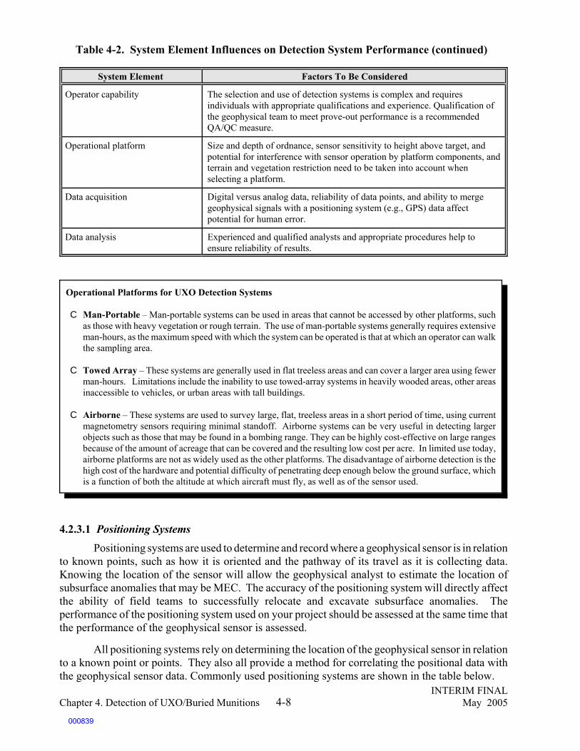
Table 4-2. System Element Influences on Detection System Performance (continued)
System Element Factors To Be Considered
INTERIM FINALChapter 4. Detection of UXO/Buried Munitions May 20054-8
Operator capability The selection and use of detection systems is complex and requiresindividuals with appropriate qualifications and experience. Qualification ofthe geophysical team to meet prove-out performance is a recommendedQA/QC measure.
Operational platform Size and depth of ordnance, sensor sensitivity to height above target, andpotential for interference with sensor operation by platform components, andterrain and vegetation restriction need to be taken into account whenselecting a platform.
Data acquisition Digital versus analog data, reliability of data points, and ability to mergegeophysical signals with a positioning system (e.g., GPS) data affectpotential for human error.
Data analysis Experienced and qualified analysts and appropriate procedures help toensure reliability of results.
4.2.3.1 Positioning Systems
Positioning systems are used to determine and record where a geophysical sensor is in relationto known points, such as how it is oriented and the pathway of its travel as it is collecting data.Knowing the location of the sensor will allow the geophysical analyst to estimate the location ofsubsurface anomalies that may be MEC. The accuracy of the positioning system will directly affectthe ability of field teams to successfully relocate and excavate subsurface anomalies. Theperformance of the positioning system used on your project should be assessed at the same time thatthe performance of the geophysical sensor is assessed.
All positioning systems rely on determining the location of the geophysical sensor in relationto a known point or points. They also all provide a method for correlating the positional data withthe geophysical sensor data. Commonly used positioning systems are shown in the table below.
Operational Platforms for UXO Detection Systems
C Man-Portable – Man-portable systems can be used in areas that cannot be accessed by other platforms, suchas those with heavy vegetation or rough terrain. The use of man-portable systems generally requires extensiveman-hours, as the maximum speed with which the system can be operated is that at which an operator can walkthe sampling area.
C Towed Array – These systems are generally used in flat treeless areas and can cover a larger area using fewerman-hours. Limitations include the inability to use towed-array systems in heavily wooded areas, other areasinaccessible to vehicles, or urban areas with tall buildings.
C Airborne – These systems are used to survey large, flat, treeless areas in a short period of time, using currentmagnetometry sensors requiring minimal standoff. Airborne systems can be very useful in detecting largerobjects such as those that may be found in a bombing range. They can be highly cost-effective on large rangesbecause of the amount of acreage that can be covered and the resulting low cost per acre. In limited use today,airborne platforms are not as widely used as the other platforms. The disadvantage of airborne detection is thehigh cost of the hardware and potential difficulty of penetrating deep enough below the ground surface, whichis a function of both the altitude at which aircraft must fly, as well as of the sensor used.
000839

INTERIM FINALChapter 4. Detection of UXO/Buried Munitions May 20054-9
Table 4-3. Description of Positioning Systems
Positioning System Description
Differential GlobalPositioning System (DGPS)
C Triangulates the position of the Differential global positioning systemreceiver with respect to several satellites and terrestrial base stations
C Can yield accuracy on the order of 20 cm.
C Differential global positioning system signal can be blocked by heavyoverhead tree canopy; satellite availability will also strongly influenceaccuracy.
C Differential global positioning system receiver must be in close proximity tothe geophysical sensor; with man-portable sensor configurations, the extraweight of the Differential global positioning system receiver and recorder(usually over 50 pounds) can increase personnel requirements during theperformance of the geophysical survey.
Acoustic Ranging and TotalStation Electronic DistanceMeter (EDM)
C Calculates the distance between the receiver and a known point based onreturn time for either an acoustic or optical (infrared, laser) signal.
C Accuracy depends on atmospheric and other conditions that may distortacoustic or optical signal.
C Methods require a line of sight between receiver and known points.
Digital Thread C Hybrid technology uses odometer wheel turned by survey thread; opticalswitch embeds position mark every 4-6 cm.
C Works well in rugged, forested terrain.
“Dead Reckoning”Techniques
C Extrapolates current position from a previously know point by applyinginformation on direction, speed, and time traveled. Locations determined bymeasurements from known points using survey tapes and trigonometry.
C Highly dependent on the competence of the operator.
C Assumes geophysical sensor has traveled in a straight line from a knownpoint to the point of measurement.
000840

INTERIM FINALChapter 4. Detection of UXO/Buried Munitions May 20054-10
4.2.3.2 Anomaly Identification
The geophysical sensor and positional data collected during the survey are analyzed toidentify geophysical “anomalies,” that is, readings that are different from the surroundingbackground. There are two steps to the anomaly identification process; data processing and dataanalysis. The quality of the anomaly identification process is critical to the performance of thegeophysical detection system.
In general, data processing consists of the merging of the geophysical sensor and thepositional data, and the creation of a map of the geophysical data. The output from this step shouldinclude the aforementioned map showing the locations of the sensor readings, a text narrative or atable describing the data acquisition parameters (e.g., sensor and positioning devices used, adjacentlane overlap for grids), and a narrative describing the data processing details (e.g., method used tosynchronize geophysical and positional data, any signal filtering or background leveling applied).Digital outputs should include all raw data, field acquisition and data processing notes, and themerged database.
The primary objective of the data analysis step is to determine if a given geophysical anomalymeets the minimum threshold selection criteria of subsurface munitions. The determination of theseselection criteria will be based on the geophysical sensor, the survey pattern, and the type ofmunitions under investigation, as well as the geological conditions and the analyst’s experience. Theoutput from this step should include a clear description of the selection criteria and the rationale forthat criteria, a prioritized dig list with a unique identifier for each anomaly, the spatial location (thex and y coordinates) of each anomaly, and the metric attributes of each anomaly (e.g., the magnitudeof the reading above background).
4.2.4 Costs of UXO Detection Systems
The factors influencing the costs of deploying MEC detection systems are complex, and muchbroader the simple rental or purchase of a detector or sensor. The entire life cycle of the responseprocess and the nature of the detection system must be considered. Life-cycle issues include:
C Costs of capital equipmentC Acreage that can be covered by your detection system over a specific period of timeC Rate of false positives, and costs of unnecessary excavationC Costs of rework if it is later proven that the system deployed resulted in a number of false
negativesC Required clearance of vegetationC Costs of responseC Costs of operator salaries, based on the complexity and sophistication of the detection
system (including training and certification of operators)
Evaluation of the factors may lead to site-specific decisions related to certain cost tradeoffs,for example:
C That high capital expenditures (e.g., airborne platforms) will result in reduced costs whenlarge acreage is involved.
C Extensive use of expensive target discrimination equipment may be more worthwhile at
000841

63ERDC/EL TR-01-20, Advanced UXO Detection/Discrimination Technology Demonstration, U.S. ArmyJefferson Proving Ground, Madison, Indiana, Ernesto Cespedes, September 2001.
INTERIM FINALChapter 4. Detection of UXO/Buried Munitions May 20054-11
a transferring base where land uses are uncertain, and transfer will not occur until theproperty is “cleaned” for the particular use.
C For small acreage, equipment producing a high rate of false positives may be acceptableif excavation is less costly than extensive data processing.
C Investments in systems with sensitive detectors and extensive data processing may beconsidered worthwhile when the potential for rework, or for lack of acceptance of cleanupdecisions, is considered.
4.2.5 Quality Assurance/Quality Control
As discussed in Chapter 8, a comprehensive quality assurance/quality control (QA/QC)process that addresses every aspect of the selection and use of geophysical detection equipment, aswell as evaluation of findings, is absolutely essential. Specifically, data acquisition quality is afunction of appropriate data management, including acquisition of data in the field, data processing,data entry, and more. In addition, field observation of data acquisition, reacquisition, and excavationprocedures will help to ensure that proper procedures that directly affect data quality are followed.General practices that help to ensure quality include monitoring the functionality of all instrumentson a daily basis, ensuring that the full site was surveyed and ensuring that there are no data gaps.Finally, qualification of geophysical operators is critical to ensuring that those operating theequipment can repeat the anticipated performance of the detection system. Chapter 8 describesqualification of geophysical operators in more detail.
4.3 Emerging UXO Detection Systems
The detection systems discussed in the following sections are in various stages ofdevelopment and implementation. Some are still being researched and tested, while others will beavailable for operational use in the near future. All of the systems discussed are advanced versionsof EMI and magnetometry technologies. The EMI systems discussed below collect vast quantitiesof data at each position that is used for identification and discrimination purposes, while themagnetometry systems are modifications to accommodate additional operational platforms.
4.3.1 Advanced EMI Systems
There is a whole class of advanced EMI systems in research and development at DoD.
GEM-3 (Geophex Ltd.) — The Geophex Ltd. GEM-3 is a multichannel frequency-domainEMI system that collects the EMI data over many audio frequencies. In other words, the GEM-3collects multiple channels of information at each survey point. Frequency response data are used forthe discrimination of UXO targets from clutter (both manmade and natural). This system hasperformed well in field tests for discrimination and identification of UXO.
EM-63 (Geonics Ltd.) — The EM-63 is a time-domain EM sensor that records multiplechannels of time-domain data at each survey point. It is already commercially available.63 Processingapproaches to fully exploit the additional data measured by the EM-63 are currently being researched.
000842

64Evaluation of Footprint Reduction Methodology at the Cuny Table in the Former Badlands Bombing Range,Environmental Security Technology Certification Program, July 2000.
INTERIM FINALChapter 4. Detection of UXO/Buried Munitions May 20054-12
NAEVA Geophysics has demonstrated good performance with the EM-63 in field tests. ZongeEngineering has also developed a multitime gate, multiaxis system currently being characterized.
4.3.2 Airborne Detection
Airborne detection platforms have been tested at the Badlands Bombing Range, near Interior,South Dakota. Tests suggest that this platform can be very cost-effective in large expanses of flat,open, and treeless ranges found in the arid and semi-arid climate of the western United States, whereaircraft are able to fly close to the ground. Other types of sites where speculation suggests airborneplatforms may be appropriate include areas where access is made difficult, such as marshes, swamps,wetlands, and shallow water.
Airborne Magnetometry — Low-altitude airborne magnetometry has proved promising intests on the Cuny Table at the Badlands Bombing Range, near Interior, South Dakota. Because ofthe conditions at Badlands Bombing Range, aircraft are able to fly close to the ground, providing forincreased detection capabilities. Originally, the mission envisioned for airborne magnetics was theidentification of the concentrations of munitions for further investigation by ground-based sensors.However, performance in initial tests of commercial, off-the-shelf equipment indicated that for largeordnance (210 kg), individual items were detectable at about 50 percent of the rate of ground-basedsensors. Research to improve the probability of detection is ongoing. Aircraft-mountedmagnetometers may present a viable option for detecting and characterizing UXO at certain ranges,because the relatively low operation time required to characterize a very large range makes thedetection time and cost per acre potentially reasonable despite the high setup and equipment costs.64
Airborne MTADS — A second major type of airborne detection is the Airborne MTADS,an adapted version of the vehicular MTADS magnetometry technology for deployment on anairborne platform. The array consists of seven full-field cesium vapor magnetometers (a variant ofthe Geometrics 822 sensor designated as Model 822A) mounted on a model 206L Bell rangehelicopter. All sensors are interfaced to a data acquisition computer.
The intent of the adaptation was to provide a MEC site characterization capability forextended, large areas that are inappropriate for vehicular surveys. Because the sensors are deployedfurther from the ground surface than the vehicular systems, it was understood that some detectionsensitivity would be lost. The primary goal of the development was to retain as much detectionsensitivity as possible for individual MEC targets. The second primary objective was that the finalsystem must have a production rate and costs appropriate for deployment to explore very large sitesthat would be prohibitively expensive to survey by other techniques.
000843

65J.R. McDonald, D. Wright, N. Khadr, AETC Inc., and H.H. Nelson, Chemical Dynamics and DiagnosticsBranch, Naval Research Laboratory. Airborne MTADS Demonstration on the Impact Area of the Badlands BombingRange, September 2001.
INTERIM FINALChapter 4. Detection of UXO/Buried Munitions May 20054-13
Demonstrations of airborne MTADS at Badlands Bombing Range, near Interior, SouthDakota, indicate that the system generates high production rates while maintaining reasonable costswhen characterizing very large, open areas. Production rates of 300-400 acres/day were demon-strated with airborne MTADS as compared with 18-24 acres/day with vehicular MTADS. Thisindicates that the airborne MTADS, rates can be 15 times greater than the vehicular system’s. It isexpected that the cost per acre is three to five times less with airborne MTADS than with a vehiculararray. These rates have yet to be tested. As expected, the demonstrations indicated that a majordisadvantage associated with the use of airborne MTADS is the system’s inability to detect smallclasses of UXO buried at significant depth. In addition, using airborne MTADS doesn’t prove to beas cost-effective on smaller areas compared with vehicular MTADS because of the deployment costsassociated with the airborne platform.65
Airborne EM — Airborne electromagnetic induction is under research and development foruse at ranges with characteristics similar to those discussed above (e.g., vast, open, treeless, and flatareas). However, unlike airborne magnetometry, airborne EMI could be used at sites with ferroussoils. Because EM signals fall off more quickly with increased distances, the challenge of using thistechnique from an airborne platform will be greater. Initial tests have shown detectability of largeitems on seeded sites.
Ground Penetrating Radar Identification — Studies of various GPR systems have beenconducted. One study, by Ohio State University with the U.S. Army Corps of Engineers Researchand Development Center and the Cold Regions Research and Engineering Laboratory, examined the
Defense Science Board Recommendations, December 2003
In December 2003 the DoD Defense Science Board released the report of its Task Force on Unexploded Ordnance(UXO). One recommendation was for a national assessment of 10 million acres of former ranges contaminated withUXO. The purpose of the assessment to reduce the footprint of the 10 million acres for which the presence of UXOis uncertain to as few as 2 million acres where cleanup should be focused. The assessment would use of low-flyingairborne platforms for sensors in appropriate circumstances.
“The Task force sees this approach as most useful for initial, large scale, wide area assessments of UXO sites todetermine in a quick survey fashion where there are metallic objects in the ground and where there are not. We donot see it as the final instrument in the UXO detection discrimination process.”
Although the recommendation is an interesting idea, the reader should keep in mind the following :
C The effective use of any detection system to reduce the footprint of the range is limited by ourknowledge of what was done at the site, and what we are looking for. In other words, a goodconceptual site model is essential.
C Effective use of airborne systems platforms currently occurs under specific conditions:– The airborne system is able to be deployed fairly close to the ground (e.g., relatively flat terrains).– Such platforms are most useful for detecting larger munitions items.– With current technologies false alarms are likely to continue to be a problem.
000844

66M. Higgins, C.C. Chen, and K. O’Neill, U.S. Army Corps of Engineers Research and Development Center(ERDC), Cold Regions Research and Engineering Laboratory. ESTCP Project 199902 – Tyndall AFB Site Demo: DataProcessing Results for UXO Classification Using UWB Full-Polarization GPR System, 1999.
67Notes from the Aided Target Recognition Workshop, Unexploded Ordnance Center for Excellence, January28-29, 1998.
INTERIM FINALChapter 4. Detection of UXO/Buried Munitions May 20054-14
capabilities of an ultra-wideband, fully polarimetric GPR system to provide information about thesize and shape of buried objects. This study was based on UXO with known target locations, andfocused on both detecting the UXO items and classifying specific ordnance types.66
4.4 Use of Processing and Modeling To Discriminate UXO
The development of advanced processing and modeling to reduce the false alarm rates, evenas ordnance detection performance improves, is evolving. Rather than using a simple amplitude ofresponse in raw physical dataexclusively, advanced processingmethods organize large quantities ofdata. In efforts to encourage thedevelopment of algorithms for targetdiscrimination without the expense andburden of field data collection, they havemade standard sensor data sets for bothcontrolled and live sites publiclyavailable. One example of a sensor dataset is EM data in the time-frequency orspatial domain to discriminate particularobjects of interest. Statistical methodscan be used to associate fieldgeophysical data with signatures ofordnance items that have either been measured or calculated using EM modeling tools. Alternatively,good data can be used to calculate the essential parameters of the targets, such as size, shape, anddepth, which can be used to infer the nature of the item giving rise to the return.
Aided or automatic target recognition, or ATR, is a term used to describe a hardware/software system that receives sensor data as input and provides target classes, probabilities, andlocations in the sensor data as output. ATR is used to design algorithms to improve detection andclassification of targets and assist in discriminating system responses from clutter and other noisesignals, thereby reducing the false alarm rate.67 These techniques are under development and are notyet available for use in the field.
About Signatures
The various methodologies deployed to detect UXO producedigital data that is recorded at each survey location. Thesedata are displayed as graphs, charts, and maps that indicate thepresence of an anomalous measurement. The graphicalreports produce patterns that may be used to estimate the sizes,types, and orientations of UXO. These patterns are called“signatures.” Signatures are being used in emergingtechnologies and rely on databases of electronic signatures tohelp discriminate between types of UXO, fragments of UXO,naturally occurring metals, and non-MEC scrap.
000845

68EMI signature database in Microsoft Access available at FTP host: server.hgl.com, log in ID: anonymous,File:/pub/SERDP/GEM3.data.zip.
69T. Bell, J. Miller, D. Keiswetter, B. Barrow, I.J. Won. Processing Techniques for Discrimination BetweenBuried UXO and Clutter Using Multisensor Array Data, Partners in Environmental Technology Conference, December2, 1999.
70J.R. McDonald. Model-Based Data Fusion and Discrimination of UXO in Magnetometry and EM Surveys,Naval Research Laboratory, May 18, 1999.
INTERIM FINALChapter 4. Detection of UXO/Buried Munitions May 20054-15
AETC, Inc., and Geophex Ltd., under contractto SERDP, have developed a database of GEM-3 electromagnetic induction data to supportidentification of UXO and nonordnance itemsbased on their frequency-domain electro-magnetic signature. The signature library for awide variety of UXO and clutter objects wasdeveloped at frequencies between 30 Hz and 30kHz. The database has been set up to organizeand make available results from over 60,000measurements of different sizes andshapes of UXO and non-UXO objects.68 Inaddition, software has been developed toanalyze the data and identify a wide variety ofanomalies.69
The Naval Research Laboratory has developed a technique that uses data fusion todiscriminate objects detected in magnetometry and electromagnetic surveys. The laboratory hasdeveloped model-based quantitative routines to identify the target’s position, depth, shape, andorientation (see Fact Sheet 2 for a full description of MTADS). In addition, location information,including position, size, and depth, is expected to be improved to a small degree.70 This data fusionmethod is primarily effective in the discrimination of large MEC items. However, the majorcontribution of this system and the AETC/Geophex system described above is anticipated to be theirability to differentiate MEC from fragments of ordnance and other clutter.
DoD is funding multiple universities for advanced processing research. Duke University, forexample, has engaged in both physics-based modeling and statistical signal processing and has shownperformance improvements in many diverse data sets, including EMI, magnetometer, and GPR/SAR.
4.5 MEC Detection Demonstration Programs
Several demonstration programs have been developed to test the effectiveness of variousUXO detection sensors and systems in controlled environments. Because of the lack of technologiesavailable to effectively locate UXO on thousands of acres of DoD ranges being closed or realignedunder the BRAC program, Congress established the Jefferson Proving Ground TechnologyDemonstration Program. Since then, other programs such as the former Fort Ord Detection andDiscrimination Study and the Environmental Security Technology Certification Program (ESTCP)UXO Technology Standardized Demonstration Sites have been established to further thedevelopment of UXO detection technologies.
SERDP and ESTCP
The Department of Defense (DoD) operates twoprograms designed to develop and move innovativetechnologies into the field to address DoD’senvironmental concerns. SERDP is DoD’s StrategicEnvironmental Research and DevelopmentProgram. Executed in partnership with both theDepartment of Energy and EPA, SERDP is designed toidentify, develop, and transition technologies thatsupport the defense mission. The second program isthe Environmental Security TechnologyCertification Program (ESTCP). The goal of theESTCP is to demonstrate and validate promisinginnovative technologies. Both organizations havemade heavy investments in detection, discrimination,and cleanup technologies for UXO.
000846

INTERIM FINALChapter 4. Detection of UXO/Buried Munitions May 20054-16
4.5.1 Jefferson Proving Ground Technology Demonstration Program
Congress established the JPGTD program in response to the realization that the BRACprocess could not take place until thousands of acres of military property littered with UXO werecleaned up. Available technologies were also inefficient and inadequate to address the widespreadneed to detect and remove UXO on such a large scale. (See Chapter 7; “Mag and Flag” had been inuse for several decades with few advances or improvements.)
The JPGTD program was established under the management of the U.S. Army EnvironmentalCenter (USAEC) to identify innovative technologies that would provide more effective, economical,and safe methods for detecting and removing munitions from former DoD testing and training areas.The program also was created to examine the capability of commercial and military equipment todetect, classify, and remove UXO and to develop baseline performance standards for UXO systems.The JPGTD program aimed to (1) establish criteria and metrics to provide a framework forunderstanding and assessing UXO technology, (2) provide funding for technology demonstrations,(3) document the performance of advanced technologies to give decision makers a betterunderstanding of the capabilities and limitations of the technologies; and (4) improve demonstrationmethodologies so that the results would be applicable to actual UXO clearance operations anddecision making. The objectives and results of each of the demonstration projects are outlined in thenext text box.
UXO detection technologies such asmagnetometry, electromagnetic induction, groundpenetrating radar, and Multisensor systems weretested and analyzed using a variety of platforms anddata processing systems at the JPGTD. Theplatforms analyzed for the detection technologiesincluded airborne, man-portable, vehicle-towed,and combination man-portable and vehicle-towed.Systems were analyzed using evaluation criteriasuch as probability of detection, false alarm rate,and other parameters, as described in the adjacent text box. Certain local and regional conditions andsoil characteristics (e.g., soil type, moisture, resistivity) may impact the effectiveness of detectionsystems. Specifically, detector performance may differ significantly at sites with conditions differentfrom those at Jefferson Proving Ground (e.g., ranges in the western U.S. with different soilresistivity/conductivity).
Each of the four phases of JPGTD provided useful data about UXO detection and remediationtechnologies. In Phase I, conducted in 1994, 26 demonstrators, representing magnetometry,electromagnetic induction (EMI), ground penetrating radar (GPR), synthetic aperture radar (SAR),and infrared (IR) sensors, performed using 20 vehicle-mounted and man-towed platforms and sixairborne platforms. Only one demonstrator achieved over a 50 percent detection rate and the falsealarm rate was high, an especially disappointing rate considering most of the clutter had beenremoved prior to the demonstration. Electromagnetic induction, magnetometry, and Gradiometerproved to be the most effective sensors, while GPR, IR, and other imaging technologies were noteffective. Airborne systems performed the worst of all the platforms, detecting less than 8 percentof buried ordnance, while hand-held systems had the best performance. At the conclusion of PhaseI it was suggested that the geological conditions at the Jefferson Proving Ground may reduce the
Demonstrator Evaluation Criteria
C Detection capability C False negative rateC False positive rateC Target position and accuracyC Target classification capabilityC Survey rate (used in Phase I only)C Survey costs (used in Phase I only)
000847

INTERIM FINALChapter 4. Detection of UXO/Buried Munitions May 20054-17
capabilities of certain sensors.
Therefore, live test sites at five other installations were used to compare the detection dataobtained in different geological conditions. Results from the live test sites showed that magnetometryand EMI continued to be the best performers. The average probability of detection at the live testsites was 0.44, and there was a continued inability to distinguish between ordnance and nonordnance.
In Phase II, conducted in 1995, demonstrators had better detection performance, with somesensors detecting over 80 percent of buried ordnance. However, the false alarm rates increased asoverall anomaly detection increased. The best performing sensors in Phase II were Multisensorsystems combining EMI and magnetometry.
In Phase III, conducted in 1996, four different range scenarios were used to facilitate thedevelopment of performance data for technologies used in specific site conditions. Over 40 percentof demonstrators had greater than 85 percent detection, and combination magnetometry and EMIsystems repeatedly detected close to 100 percent of buried ordnance. In addition, the Multisensorsystem, which consisted of electromagnetic induction and either magnetometry or Gradiometer, hada slightly lower than average false alarm rate. However, no sensor or combination of sensorsdemonstrated an ability to distinguish baseline ordnance from nonordnance, and no system performedbetter than chance in this area.
Phase IV, conducted in 1998, was aimed at improving the ability to distinguish ordnance andnonordnance. Fifty percent of the demonstrators showed a better than chance probability ofdiscriminating UXO from clutter, with one demonstrator correctly identifying 75 percent of ordnanceand nonordnance items. While advanced data processing has greatly improved target discriminationcapabilities in pilot testing, these methods need to be further developed and tested. In order to makeadvanced processing techniques widely used and to develop a market for constantly improvingsystems, they need to be made commercially available. With reliable and readily available targetdiscrimination technologies, false alarm rates could be greatly reduced, thereby significantlyimproving the efficiency and reducing the costs of UXO detection and remediation.
000848

INTERIM FINALChapter 4. Detection of UXO/Buried Munitions May 20054-18
4.5.2 Former Fort Ord Ordnance Detection and Discrimination Study (ODDS)
A phased geophysical study of ordnance detection and discrimination specific to the formerFort Ord, California, environment has been in existence since 1994. In November 1998, the U.S.Army evaluated MEC at Fort Ord in an “Ordnance and Explosives Remedial Investigation/FeasibilityStudy (OE RI/FS)” concurrently with removal actions. The RI/FS evaluated long-term responsealternatives for cleanup and risk management at Fort Ord. The technologies considered for use duringthe Fort Ord study were demonstrated during the Jefferson Proving Ground study. The following textbox describes the four phases of the Fort Ord study.
Synopsis of Objectives and Results of Jefferson Proving Ground Technology Demonstration Program, PhasesI through IV
Phase I, 1994Objective: Evaluate existing and promising technologies for detecting and remediating UXO.Results: Limited detection and localization capabilities and inability to discriminate between ordnance andnonordnance. Average false alarm rate was 149 per hectare. Airborne platforms and ground penetrating radarsensors performed poorly; combination electromagnetic induction and magnetometry sensors were the bestperformers, but also had modest probabilities of detection and very high false alarm rates.
Phase II, 1995Objective: Evaluate technologies effective for detecting, identifying, and remediating UXO, and measuring theseresults against the Phase I baseline.Results: Significant improvement in detection capabilities with commensurate increases in false alarms among betterperforming technologies. Continued inability to distinguish ordnance from nonordnance. Again, airborne platformsand ground penetrating radar sensors performed poorly; combination electromagnetic induction and magnetometrysensors were the better performers, but continued to have very high false alarm rates.
Phase III, 1996Objective: Develop relevant performance data of technologies used in site-specific situations to search, detect,characterize, and excavate UXO. Four different range scenarios were used, which had typical groups of UXO. Results: Improvement in detection, but continued inability to distinguish ordnance from nonordnance. Localizationperformance for ground-based systems improved. Probability of detection is partially dependent on target size.False alarm rates ranged from 2 to 241 per hectare.
Phase IV, 1998Objectives: Demonstrate the capabilities of technology to discriminate between UXO and non-UXO; establishdiscrimination performance baselines for sensors and systems; make raw sensor data available to the public;establish state of the art for predicting ordnance “type”; direct future R&D efforts.Results: Capability to distinguish between ordnance and nonordnance is developing. Five demonstrators showeda better than chance probability of successful discrimination.
000849

INTERIM FINALChapter 4. Detection of UXO/Buried Munitions May 20054-19
The first phase of the ODDS found the electromagnetic and magnetometer systems to beeffective in the detection and location of buried MEC items. Phase II was conducted in a controlledtesting environment. The controlled area consisted of five “seeded” plots. Two of the plots consistedof items with known depths and orientations, while the other three areas consisted of “unknown”plots where target information was withheld. The plots were designed to be representative of theterrain of Fort Ord. The seeded tests concluded that the noise levels of the EMI systems increased3 to 35 times from the static to seeded tests. In Phase III it was concluded that the effects of terrain,vegetation, and range residues can significantly alter detection and discrimination capabilities of thedetectors. Phase IV of the study determined that discrimination capability of the instruments testedwas minimal. The Phase IV study also determined that both EMI and magnetometer systemsperformed well in finding the larger and deeper items, whereas only the EMI systems consistentlyfound smaller and shallower items. The results indicated that different systems are required fordifferent types of sites, depending on the MEC expected and the site-specific environmental andgeological conditions.
4.5.3 UXO Technology Standardized Demonstration Sites
The U.S. Army Environmental Center (USAEC) is conducting an ESTCP-funded programto provide UXO technology developers with test sites for the evaluation of UXO detection anddiscrimination technologies using standardized protocols. The USAEC is developing standardizedtest methodologies, procedures, and facilities to help ensure accuracy and replicability inmeasurements of detection capability, false alarms, discrimination, target reacquisition, and systemefficiency. Data generated from these standardized sites will be compiled into a technology-screening
Synopsis of Objectives and Results of the Former Fort Ord Ordnance Detection and Discrimination Study(ODDS), Phases I through IV
Phase IObjective: Evaluate detection technologies “Static” measurements in free air (i.e., in the air above and away fromground influences/effects) given variable ordnance items, depths, and orientations.Results: Signal drop-off in the electromagnetic (EM) response is proportional to the depth of the object to the 6th
power. For horizontally oriented ordnance items, the EM signal response was predicted fairly well.
Phase IIObjective: Evaluate the effectiveness of geophysical instruments’ ability to detect and locate “seeded” or plantedordnance items.Result: Noise levels increased 3 to 35 times from the static to seeded tests. There was a significant degradation ofprofile signatures between static and field trial tests.
Phase IIIObjective: Evaluate geophysical instruments and survey processes at actual uninvestigated munitions response sites.Results: The effects of rough terrain and vegetation on detection and discrimination capabilities can be significant.Removal of range residue before the munitions response investigation began would have reduced time and effortspent on unnecessary excavations.
Phase IVObjective: Evaluate discrimination capabilities of ordnance detection systems.Results: The instruments with the highest detection rate required the most intrusive investigation. Conversely,instruments with lower detection rates required less intrusive investigations. The ODDS determined that no oneinstrument provides the single solution to meet the ordnance detection needs at Fort Ord.
000850

INTERIM FINALChapter 4. Detection of UXO/Buried Munitions May 20054-20
matrix to assist UXO project managers in selecting the appropriate detection systems for theirapplication.
Standardized test sites will be made up of three areas – the calibration lane, the blind grid, andthe open field. The calibration area will contain targets from a standardized target list at six primary orientations and at three depths. The target depth, orientation, type, and location will beprovided to demonstrators. The calibration area will allow demonstrators to test their equipment,build a site library, document signal strength, and deal with site-specific variables. In the blind gridarea, demonstrators will know possible locations of targets and will be required to report whether ornot a UXO target clutter or nothing actually exists there. If a UXO target is found, they must reportthe type of target, classification of target, and target depth and a confidence level. The blind gridallows testing of sensors without ambiguities introduced by the system, site coverage, or otheroperational concerns. The open field will be a 10 or more acre area with clutter and geolocationtargets about which demonstrators will be given no information and will be required to perform asif they were performing at an actual DoD range. Testers will report the location of all anomalies,classify them as clutter or UXO, and provide type, classification, and depth information. The openfield conditions will document the performance of the system in an actual range operation mode.
In addition to the construction of test sites available to the UXO community, the primaryproducts of this program will be the creation of a series of protocols to establish procedures necessaryfor constructing and operating a standardized UXO test site. A standardized target repository will beamassed that can be used by installations, technology developers, and demonstrators.
4.6 Fact Sheets and Case Studies on Detection Technologies and Systems
Three fact sheets on MEC sensors and three case studies describing detection systems arefound at the end of this chapter as Attachments 1 through 6. Information on the nature of thetechnology and its benefits and limitations is provided. Since the performance of the instruments isnot solely based upon the sensors deployed, the case studies provide more insights on the operationof the systems. The performance of detection systems is dependent upon platform characteristics,survey methodology and quality, data processing, personnel operation/performance, site character-ization, and appropriate quality control measures that should be taken throughout the investigation.
4.7 Conclusion
The performance of many existing and emerging technologies for MEC detection anddiscrimination is limited by specific site characteristics such as soil type and composition,topography, terrain, and type and extent of contamination. What works at one site may not work atanother. Our ability to find MEC in subsurface locations has improved dramatically. The JPGTDstudies have shown that we have gotten much smarter about how to deploy these technologies andhow to locate a high percentage of UXO. However, the results of a controlled study such as theJPGTD should not give us unrealistic expectations about the capabilities of these technologies whenused in range investigation. Studies at true MEC areas, such as at Fort Ord, provide additionalinformation about the challenges and issues that have to be considered in selecting MEC detectionsystems. For example, the nature of the targets (e.g., composition, size, and mass), the depth of MECpenetration (a function of the soil and the ordnance item), and expected spatial and depth distributionshould be considered along with the geology, terrain, and vegetation. Other factors affecting theresults include operator performance and postprocessing techniques. Given the sizes of the ranges
000851

INTERIM FINALChapter 4. Detection of UXO/Buried Munitions May 20054-21
and the cost of investigating anomalies, the greatest challenge to improving MEC detection is beingable to discriminate MEC from other subsurface anomalies. Although there have been improvementsin this area, much developmental work remains.
000852

INTERIM FINALChapter 4. Detection of UXO/Buried Munitions May 20054-22
ATTACHMENT 4-1. FACT SHEET #1: MAGNETOMETRY
FACT SHEET #1:MEC DETECTIONTECHNOLOGIES
Magnetometry
What ismagnetometry?
Magnetometry is the science of measurement and interpretation of magnetic fields.Magnetometry, which involves the use of magnetometers and gradiometers, locatesburied ordnance by detecting irregularities in the Earth’s magnetic field caused by theferromagnetic materials in the ordnance assembly. The magnetometer can sense onlyferrous materials, such as iron and steel; other metals, such as copper, tin, aluminum, andbrass, are not ferromagnetic and cannot be located with a magnetometer. Although theyhave been in use for many years and many newer technologies are available,magnetometers are still considered one of the most effective technologies for detectingsubsurface MEC and other ferromagnetic objects. Magnetometry remains the most widelyused subsurface detection system today.
The two basic categories of magnetometer are total-field and vector.
C The total-field magnetometer is a device that measures the magnitude of themagnetic field without regard to the orientation of the field.
C The vector magnetometer is a device that measures the projection of the magneticfield in a particular direction.
A magnetic gradiometer is a device that measures the spatial rate of change of themagnetic field. Gradiometers generally consist of two magnetometers configured tomeasure the spatial rate of change in the Earth’s magnetic field. The gradiometerconfiguration was designed to overcome large-scale diurnal intensity changes in theEarth’s magnetic field; this design may also be used to minimize the lateral effects ofnearby fences, buildings, and geologic features.
How aremagnetometersused to detectMEC?
Magnetometers can theoretically detect every MEC target that contains ferrous material,from small, shallow-buried MEC to large, deep-buried MEC, provided that the magneticsignature is larger than the background noise. A magnetometer detects a perturbation inthe geomagnetic field caused by an object that contains ferrous material. The size, depth,orientation, magnetic moment, and shape of the target, along with local noise fields(including ferrous clutter), must all be considered when assessing the response of themagnetometer.
000853

FACT SHEET #1:MEC DETECTIONTECHNOLOGIES
Magnetometry
INTERIM FINALChapter 4. Detection of UXO/Buried Munitions May 20054-23
What are thedifferent types ofmagnetometers?
There are numerous types of magnetometers, which were developed to improve detectionsensitivity. Three of the most common are the cesium vapor, proton precession, andfluxgate magnetometers.
C Cesium vapor magnetometers – These magnetometers are lightweight andportable. The sensor can also be mounted on a nonmagnetic platform. Theprincipal advantage of this type of magnetometer is its rapid data collectioncapability. The common hand-held sensors are capable of measuring at a rate of 10times per second, and specially designed sensors are capable of measuring at a rateof 50 times per second. The one disadvantage of this magnetometer is that it isinsensitive to the magnetic field in certain directions, and dropouts can occur wherethe magnetic field is not measured. However, this can be avoided with proper fieldprocedures.
C Proton precession magnetometers – These magnetometers have been used inclearing Munitions Response Sites (MRS), but achieving the data density requiredfor a MRS is time consuming. The primary disadvantage of these types ofmagnetometers is that accurate measurements require stationary positioning of thesensor for a period of several seconds. Also, these magnetometers require tuningof the local magnetic field. The primary use of these magnetometers today is as abase station for monitoring diurnal variations in the Earth’s magnetic field andpossible geomagnetic storms.
C Fluxgate magnetometers – These magnetometers are used primarily to sweepareas to be surveyed. They are also used in locating MEC items duringreacquisition. These magnetometers are relatively inexpensive, locate magneticobjects rapidly, and are relatively easy to operate. The disadvantage of these typesof magnetometers is that most of them do not digitally record the data, and accuratemeasurements require leveling of the instrument.
What are thecomponents of amagnetometer?
A passive magnetometer system includes the following components:
C The detection sensor C A power supply C A computer data system C A means to record locations of detected anomalies
More technologically advanced systems typically incorporate a navigation system, suchas a differential global positioning system (DGPS), to determine locations. Advancednavigation systems may also include a graphical output device (printer), a mass datastorage recorder, and telecom systems.
000854

FACT SHEET #1:MEC DETECTIONTECHNOLOGIES
Magnetometry
INTERIM FINALChapter 4. Detection of UXO/Buried Munitions May 20054-24
Figure 4-1. Hand-HeldMagnetometer
What are theoperationalplatforms for amagnetometer?
Magnetometers can be transported in a variety of ways:
C Man-portable C Towed by a vehicle C Airborne platforms
Magnetometers are most frequently used on man-portable platform, but they also canperform well when towed on a vehicular platforms, as long as the vehicular platform andsensor array have been carefully designed to minimize magnetic noise and ensure highquality data collection. These platforms are restricted to areas accessible to vehicles.Airborne systems are currently being evaluated for commercial use as discussed in Section4.3.
One of the most commonly used and oldestUXO detection methods is the “Mag andFlag” process. Mag and Flag involves theuse of hand-held magnetometers by MECtechnicians, who slowly walk across asurvey area and flag those areas where MECmay be located for later excavation. Thesuccess of the method is dependent on thecompetence and alertness of the technicianand his ability to identify changes in theaudible or visible signals from themagnetometer indicating the presence of ananomaly.
What are thebenefits of usingmagnetometry fordetecting MEC?
The benefits of using magnetometry for MEC detection include the following:
C Magnetometry is considered one of the most effective technologies for detectingsubsurface MEC and other ferromagnetic objects.
C Magnetometry is one of the more developed technologies for detection of MEC.C Magnetometers are fairly simple devices.C Magnetometers are nonintrusive. C Relative to other detection technologies, magnetometers have low data acquisition
costs.C Magnetometers have the ability to detect ferrous items to a greater depth than can be
achieved using other methods.C Depending on the data acquisition and post processing systems used magnetometers
can provide fair to good information on the size of the detected object.C Because magnetometers have been in use since World War II, the limitations are well
understood.
000855

FACT SHEET #1:MEC DETECTIONTECHNOLOGIES
Magnetometry
INTERIM FINALChapter 4. Detection of UXO/Buried Munitions May 20054-25
What are thelimitations of usingmagnetometry fordetecting MEC?
The limitations of using magnetometry for MEC detection include the following:
C The effectiveness of a magnetometer can be reduced or inhibited by interference(noise) from magnetic minerals or other ferrous objects in the soil, such as rocks,pipes, drums, tools, fences, buildings, and vehicles, as well as MEC debris.
C Depending on the data analysis systems used, magnetometers may suffer from highfalse alarm rates, which lead to expensive excavation efforts.
C Depending on the site conditions, vegetation and terrain may limit the ability toplace magnetometers (especially vehicle-mounted systems) near the groundsurface, which is needed for maximum effectiveness.
C Magnetometers have limited capability to distinguish targets that are located neareach other. Clusters of ordnance of smaller size may be identified as clutter, anddistributed shallow sources (MEC or not) may appear as localized deep targets. Accurately distinguishing between targets depends heavily on coordinationbetween sensors, navigation, and processing.
000856

INTERIM FINALChapter 4. Detection of UXO/Buried Munitions May 20054-26
ATTACHMENT 4-2. FACT SHEET #2: ELECTROMAGNETIC INDUCTION (EMI)
FACT SHEET #2: MECDETECTION
TECHNOLOGIESElectromagnetic Induction (EMI)
What iselectromagneticinduction (EMI)and how is it usedto detect MEC?
Electromagnetic induction is a geophysical technology used to induce a magnetic fieldbeneath the Earth’s surface, which in turn causes a secondary magnetic field to form aroundnearby objects that have conductive properties. The secondary magnetic field is thenmeasured and used to detect buried objects. Electromagnetic induction systems are used todetect both ferrous and nonferrous MEC.
In electromagnetic induction, a primary transmitter coil creates a time-dependentelectromagnetic field that induces eddy currents in the subsurface. The intensity of thecurrents is a function of ground conductivity and the possible presence of metallic objectsin the subsurface. The secondary, or induced, electromagnetic field caused by the eddycurrents is measured by a receiver coil. The voltage measured in the receiver coil is relatedto the physical properties of the subsurface conductor. The strength and duration of theinduced field depend on the size, shape, conductivity, and orientation of the object.
There are two basic types of EMI methods: frequency domain and time domain.
C Frequency-domain EMI measures the response of the subsurface as a fraction offrequency. Generally, a receiver coil shielded from the transmitted field is used tomeasure the response of targets. Frequency-domain sensors, such as the mono-static,multi-frequency Geophex GEM-3, are used for MEC detection. In addition, theGeonics EM31 has been used for detecting boundaries of trenches that may be MECdisposal sites.
C Time-domain EMI measures the response of the subsurface to a pulsedelectromagnetic field. After the transmitted pulse is turned off, the receiving coilmeasures the signal generated by the decay of the eddy currents in any nearbyconductor. These measurements can be made at single time gates, which may beselected to maximize the signal of targets sought. In more advanced instruments,measurements can be made in several time gates, which will increase the informationobtained about the physical properties of the targets. The time-domain EMI sensorthat is commonly used for MEC detection is the Geonics EM-61. Under idealconditions, the EM-61 instrument is capable of detecting large UXO items at depthsof as much as 10 feet below ground surface when ground clutter from debris does notexceed the signal level. The instrument can detect small objects, such as a 20 mmprojectile, to depths of approximately 1 foot below ground surface, if noise (terrainand instrument) conditions are less than the response of the object.
How effective isEMI for detectingMEC?
The effectiveness of EMI systems in detecting MEC depends on many factors, includingdistance between sensor and UXO, metallic content of MEC, concentrations of surfaceordnance fragments, and background noise levels. EMI methods are well suited forreconnaissance of large open areas because data collection is rapid. Vertical resolution istransmitter and target dependent. The range of frequencies for electromagnetic instrumentsused in MEC site characterization is from approximately 75 Hz (cycles per second) toapproximately 1,000 kHz.
000857

FACT SHEET #2: MECDETECTION
TECHNOLOGIESElectromagnetic Induction (EMI)
INTERIM FINALChapter 4. Detection of UXO/Buried Munitions May 20054-27
Figure 4-2. EM-61 System
What are thecomponents of anEMI system?
The components of an EMI system include the following:
C Transmitting and receiving units C A power supply C A computer data acquisition systemC A means of recording locations of detected metallic anomalies
Advanced systems incorporate a navigation system as well, such as a differential globalpositioning system (DGPS).
What are theoperationalplatforms for anEMI system?
In general, EMI systems are configured on man-portable units. Such units often consistof the following items:
C A small, wheeled cart used to transport the transmitter and receiver assemblyC A power supplyC An electronics backpackC A hand-held data recorder
In general, EMI systems are configured tobe man portable or towed by a vehicle.However, vehicle-towed systems are limitedin that the platform can be a source ofbackground noise and interference withtarget detection and they have high potentialfor mechanical failures. In addition,vehicle-towed systems can only be used onrelatively flat and unvegetated areas. Man-portable systems provide easier access toareas of a site that are accessible topersonnel. In general, man-portablesystems are the most durable and requirethe least maintenance.
What are thebenefits of usingEMI for detectingMEC?
The benefits of using EMI include the following:
C EMI can be used for detecting all metallic objects near the surface of the soil, notonly ferrous objects.
C EMI has potential to discriminate clusters of MEC from a single item. C EMI sensors permit some measure of control over their response to ordnance and
other metal objects.C EMI systems are generally easy to use.C EMI is nonintrusive. C Man-portable EMI systems provide access to all areas of a site, including uneven
and forested terrain.
000858

FACT SHEET #2: MECDETECTION
TECHNOLOGIESElectromagnetic Induction (EMI)
INTERIM FINALChapter 4. Detection of UXO/Buried Munitions May 20054-28
What are thelimitations ofusing EMI fordetecting MEC?
The limitations of using EMI to detect MEC include the following:
C Depending on the data acquisition and processing systems used EMI may suffer fromfairly large false alarm rates, particularly in areas with high concentrations ofsurface ordnance fragments. (Some buried metallic debris can produce EMIsignatures that look similar to signatures obtained from MEC, which results in alarge false alarm rate.) Specifically, EMI sensors that utilize traditional detectionalgorithms based solely on the signal magnitude suffer from high false alarm rates aswell.
C Implementing EMI systems in areas on the range that may contain electronicallyfuzed ordnance could be unsafe because the induced magnetic field could detonatethe ordnance. (However, this is very unlikely because the EMI power density andinduced current is very low in most systems.)
C Large metal objects can cause interference, typically when EMI is applied within 5to 20 feet of power lines, radio transmitters, fences, vehicles, or buildings.
What are the costsof using EMI todetect MEC?
Per acre costs for EMI vary depending on the operational platform, the terrain, and otherfactors.
000859
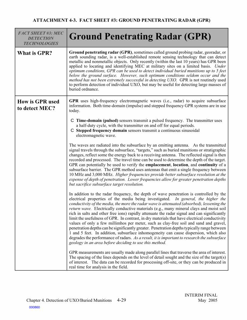
INTERIM FINALChapter 4. Detection of UXO/Buried Munitions May 20054-29
ATTACHMENT 4-3. FACT SHEET #3: GROUND PENETRATING RADAR (GPR)
FACT SHEET #3: MECDETECTION
TECHNOLOGIESGround Penetrating Radar (GPR)
What is GPR? Ground penetrating radar (GPR), sometimes called ground probing radar, georadar, orearth sounding radar, is a well-established remote sensing technology that can detectmetallic and nonmetallic objects. Only recently (within the last 10 years) has GPR beenapplied to locating and identifying MEC at military sites on a limited basis. Underoptimum conditions, GPR can be used to detect individual buried munitions up to 5 feetbelow the ground surface. However, such optimum conditions seldom occur and themethod has not been extremely successful in detecting UXO. GPR is not routinely usedto perform detection of individual UXO, but may be useful for detecting large masses ofburied ordnance.
How is GPR usedto detect MEC?
GPR uses high-frequency electromagnetic waves (i.e., radar) to acquire subsurfaceinformation. Both time-domain (impulse) and stepped frequency GPR systems are in usetoday.
C Time-domain (pulsed) sensors transmit a pulsed frequency. The transmitter uses a half-duty cycle, with the transmitter on and off for equal periods.
C Stepped frequency domain sensors transmit a continuous sinusoidalelectromagnetic wave.
The waves are radiated into the subsurface by an emitting antenna. As the transmittedsignal travels through the subsurface, “targets,” such as buried munitions or stratigraphicchanges, reflect some the energy back to a receiving antenna. The reflected signal is thenrecorded and processed. The travel time can be used to determine the depth of the target.GPR can potentially be used to verify the emplacement, location, and continuity of asubsurface barrier. The GPR method uses antennas that emit a single frequency between10 MHz and 3,000 MHz. Higher frequencies provide better subsurface resolution at theexpense of depth of penetration. Lower frequencies allow for greater penetration depthsbut sacrifice subsurface target resolution.
In addition to the radar frequency, the depth of wave penetration is controlled by theelectrical properties of the media being investigated. In general, the higher theconductivity of the media, the more the radar wave is attenuated (absorbed), lessening thereturn wave. Electrically conductive materials (e.g., many mineral clays and moist soilrich in salts and other free ions) rapidly attenuate the radar signal and can significantlylimit the usefulness of GPR. In contrast, in dry materials that have electrical conductivityvalues of only a few millimhos per meter, such as clay-free soil and sand and gravel,penetration depths can be significantly greater. Penetration depths typically range between1 and 5 feet. In addition, subsurface inhomogeneity can cause dispersion, which alsodegrades the performance of radars. As a result, it is important to research the subsurfacegeology in an area before deciding to use this method.
GPR measurements are usually made along parallel lines that traverse the area of interest.The spacing of the lines depends on the level of detail sought and the size of the target(s)of interest. The data can be recorded for processing off-site, or they can be produced inreal time for analysis in the field.
000860

FACT SHEET #3: MECDETECTION
TECHNOLOGIESGround Penetrating Radar (GPR)
INTERIM FINALChapter 4. Detection of UXO/Buried Munitions May 20054-30
What are thecomponents of aGPR system?
The components of a GPR systems consist of the following:
C A transmitter/receiver unitC A power supply C An antenna C A control unit C A display and recorder unit C Geolocation ability
GPR systems are available for commercial use. The pulsed systems are the most commonlyused and are available from a variety of vendors. Physically commercial systems providea selection of antennas that operate at frequency bandwidths. Antennas are available fromthe gigahertz range for extremely shallow targets to the megahertz range for greater depthsof ground penetration.
What are thebenefits of usingGPR for detectingMEC?
The benefits of using GPR to detect MEC are as follows:
C GPR is nonintrusive. C GPR is potentially able to identify breach and discontinuity and determine the size
of both.C GPR may provide a three-dimensional image of the structure. (Requires very
sophisticated processing and data collection.)C GPR can help define boundaries, if you know the location of buried munitions.C Under optimum conditions, GPR may be used to detect individual buried munitions
several meters deep. In areas with dry soils and sparse vegetation, GPR systemsmay produce accurate images as long as the antenna is positioned perpendicularlyto the ground.
What are thelimitations of usingGPR for detectingMEC?
The limitations of using GPR to detect UXO include the following:
C The primary limitation of the GPR system is that its success is site specific and notreliable. Low-conductivity soils are necessary if the method is to penetrate theground. Soils with high electrical conductivity (e.g., many mineral clays and moistsoil rich in salts) rapidly attenuate the radar signal, inhibiting the transmission ofsignals and significantly limiting usefulness. Even a small amount of clay mineralsin the subsurface greatly degrade GPR’s effectiveness.
C Lower frequencies can penetrate to a greater depth, but result in a loss ofsubsurface resolution. Higher frequencies provide better subsurface resolution, butat the expense of depth of penetration.
C Interpretation of GPR data is complex; an experienced data analyst is required.C High signal attenuation decreases the ability of GPR systems to discriminate UXO
and increases the relative amount of subsurface inhomogeneity (i.e., soil layers,pockets of moisture, and rocks).
C Airborne GPR signals may not even contact the soil surface because the signals arereflected by the vegetation or are absorbed by water in the vegetation.
000861

INTERIM FINALChapter 4. Detection of UXO/Buried Munitions May 20054-31
ATTACHMENT 4-4. CASE STUDY #1: MULTISENSOR SYSTEM
Case Study on the Use of a Multisensor SystemThe Multisensor system combines two or more sensor technologies with the objective of improving UXO detectionperformance. With multiple-sensor systems operating in a given area, complementary data sets can be collected toconfirm the presence of UXO, or one system may detect a characteristic that another system does not.
The technologies that have proven to be most effective both individually and deployed in Multisensor systems are theGeonics EM61 electromagnetic detection system and the cesium vapor magnetometer. Other types of sensors havebeen tested and evaluated, but they are still under development and research continues.
The Naval Research Laboratory’s MTADS represents a state-of-the-art, automated, MEC detection system. The systemincorporates arrays of full-field cesium vapor magnetometers and time-domain EMI pulsed sensors. The sensorsare mounted as linear arrays on low-signature platforms that are towed over survey sites by an all-terrain vehicle. Theposition over ground is plotted using state-of-the-art real-time kinematic Differential global positioning systemtechnology that also provides vehicle guidance during the survey. An integrated data analysis system processesMTADS data to locate, identify, and categorize all military ordnance at maximum probable self-burial depths.
During the summer of 1997 the system was used to survey about 150 acres at a bombing target and an aerial gunnerytarget on the Badlands Bombing Range on the Oglala Sioux Reservation in Pine Ridge, South Dakota. Following thesurvey and target analysis, UXO contractors and personnel from the U.S. Army Corps of Engineers, Huntsville,selectively remediated targets to evaluate both the detection and discrimination capabilities of MTADS. Tworemediation teams worked in parallel with the surveying operations. The full distribution of target sizes was dug on eachtarget range because one goal of the effort was to create a database of both ordnance and ordnance clutter signals for eachsensor system that could be used to develop an algorithm for future data analysis.
An initial area of 18.5 acres was chosen as a test/training range. All 89 analyzed targets were uncovered, documented,and remediated. Recovered targets in the training areas included 40 M-38 100-pound practice bombs, four rocket bodiesand warheads, and 33 pieces of ordnance scrap (mostly tail fins and casing parts). The smallest intact ordnance itemsrecovered were 2.25-inch SCAR rocket bodies and 2.75-inch aerial rocket warheads. Information from the training areawas used to guide remediation on the remainder of both ranges.
Magnetometry and EM data analysis identified a total of 1,462 targets on both ranges. Of these, 398 targets wereselected for remediation. For each target, an extensive digsheet was filled out by the remediation team to augment thephotographic and digital electronic GPS records. Recovered ordnance-related targets included 67 sand-filled M-38practice bombs, four M-57 250-pound practice bombs, and 50 2.25-inch and 2.75-inch rocket bodies and rocketwarheads. In addition, 220 items of ordnance-related scrap were recovered. The target depths were generally predictedto within 20 percent of the actual depths of the target centers.
MTADS has the sensitivity to detect all ordnance at its likely maximum self-burial depths and to locate targets generallywithin the dimensions of the ordnance. On the basis of all evaluation criteria, the MTADS demonstration, survey, andremediation were found to be one of the most promising system configurations given appropriate site-specific conditionsand appropriately skilled operators.
000862
INTERIM FINALChapter 4. Detection of UXO/Buried Munitions May 20054-32
ATTACHMENT 4-5. CASE STUDY #2: MAGNETOMETRY SYSTEM
Case Study of a Detection System withMagnetometryIn August 1998, Geophysical Technology Limited (GTL) used an eight-sensor magnetometer system towed by anautonomous tow vehicle (ATV) to detect UXO over approximately 200 acres of the flat and treeless Helena Valley inHelena, Montana. The system was navigated by a real-time differential global positioning system (DGPS).
The system had the following main features:
C The trailer used was low cost, and any standard four-wheel bike could be used to tow the array. This means thatthe system can be easily duplicated, and multiple systems can be run on large or concurrent projects.
C The system had a high-speed traverse, a 4-meter swath, and complete Differential global positioning systemcoverage, making it very efficient.
C The TM-4 magnetometer at the center of the system was the same instrument used in the hand-held applicationfor surveying fill-in areas inaccessible to the trailer system.
The one-operator trailer system did not require a grid setup prior to the commencement of the surveys. The surveycomputer guided the operator along the survey lanes with an absolute cross-track accuracy of 0.75 meters (vegetationand terrain permitting). An expandable array of magnetic sensors with adjustable height and separation allowed theoperators to optimize the system for this application. Eight sensors, 0.5 meters apart, were used in the survey.
GTL’s proprietary MAGSYS program was used for detailed anomaly interpretation and the printing of color images.Magnetic targets that were identified were then modeled using a semiautomatic computer-aided procedure withinMAGSYS. A selection of key parameters (position, depth, approximate mass, and magnetic inclination) was used toadjust the model for best fit. The confidence that the interpreted items were UXO was scaled as high, medium, and lowaccording to their least squares fit value. GTL’s system successfully detected over 95 percent of the emplaced 76 mmand 81 mm mortar projectiles.
In Montana accurate real-time Differential global positioning system positioning and navigation resulted in goodcoverage of the survey areas using the trailer system. The GTL trailer system enables practical, fast collection of high-resolution, accurately positioned magnetic data, as required for UXO detection.
The GTL trailer system opens new possibilities of covering large areas efficiently, and it is an important milestone inachieving large-scale remediation with performance that is quantifiable.
000863
INTERIM FINALChapter 4. Detection of UXO/Buried Munitions May 20054-33
ATTACHMENT 4-6. CASE STUDY #3: GROUND PENETRATING RADAR SYSTEM
Case Study on the Use of Ground PenetratingRadar in a Multisensor Data Acquisition SystemGPR is not often used as a stand-alone MEC detection technology because its detection capabilities are limited. GPRis most commonly used as part of a Multisensor system, such as the one described below.
The Air Force Research Laboratory at Tyndall AFB has developed a semiautonomous MEC detection, characterization,and mapping system. The system consists of two major functional components: an unmanned autonomous tow vehicle(ATV) and a Multisensor data acquisition system. By combining an ATV, the GPR’s highly accurate positioning andmapping systems, and a multiple-sensor platform, operators plan, execute, and analyze collected data while monitoringthe vehicle and data acquisition system at a safe distance from the survey site.
The multiple-sensor platform (MSP) provides a mounting structure for an array of four cesium vapor 3- to 5-nanosecondmagnetometers, three Geonics EM61 inductance coils, and an impulse GPR system. The GPR is suspended below theplatform frame using a pinned hanger. An encoder at the GPR hanger point measures the relative GPR angulardisplacement from the platform frame. In general, the ATV/MSP GPR transmits a series of 3-to 5 - nanosecond, 100-to 250-volt impulses into the ground at a specific pulse repetition interval. Signals received from objects with electricalproperties that vary from the surrounding soil are fed through an adjustable attenuator, to a band pass filter, and finallyto track-and-hold circuitry, which digitizes and stores collected data. The system uses a single broad-bandwidth antenna,which covers a frequency range of 20 to 250 MHz.
To date, data collection has been conducted at several sites, one of them being Tyndall AFB. The test site in the 9700area of Tyndall AFB is composed of a loose sandy top layer approximately 20 cm deep and a packed sandy layer thatreaches the water table, which starts at a depth of less than 1 meter. The test site provides a homogeneous backgroundin which inert ordnance items, 60 mm mortar projectiles, 105 mm artillery projectiles, miscellaneous clutter, angle iron,barbed wire, concrete blocks, and steel plates were placed to simulate an active range. Data collected at the Tyndall testsite included those from the magnetometer, electromagnetic induction (EMI), and GPR.
Analysis of magnetometer, EMI, and GPR cursory calibration raw data was performed in situ at the mobile commandstation. Synthetic aperture radar (SAR) processing was used to focus the complex and large bandwidth informationinherent in GPR data. In order to perform this focusing of the SAR images, the waveforms generated by the GPR mustbe accurately registered in the time domain, with an associated registration of position in the spatial domain.
The original purpose of the ATV/MSP was to evaluate various sensor systems. It quickly became clear that its higherpurpose was to provide a powerful aid to the process of analysis. The accuracy, repeatability, and completeness ofcoverage obtained during autonomous surveys cannot be matched using manual operations.
The GPR system tested at Tyndall AFB achieved an approximate false alarm rate of 51 percent. Overall, the measureddata from the targets and GPR measurements were somewhat close. Currently, the GPR is unable to distinguish betweenUXO and non-UXO targets if the length-to-diameter (L/D) ratio is greater than 3. The GPR system also had problemsidentifying UXO-like items buried at an angle greater than 45 degrees, as well as UXO partially buried in the water table.
000864

INTERIM FINALChapter 4. Detection of UXO/Buried Munitions May 20054-34
SOURCES AND RESOURCES
The following publications, offices, laboratories, and websites are provided as a guide forhandbook users to obtain additional information about the subject matter addressed in each chapter.Several of these publications, offices, laboratories, or websites were also used in the developmentof this handbook.
Publications
ESTCP (Environmental Security Technology Certification Program). Evaluation of FootprintReduction Methodology at the Cuny Table in the former Badlands Bombing Range(2000 ESTCPProject), January 2004.
USACE (U.S. Army Corps of Engineers), Research and Development Center (ERDC). DataProcessing Results for UXO Classification Using UWB Full-Polarization GRP System. ESTCPProject 199902, Tyndall AFB Site Demo, 1999.
USACE. Geophysical Investigations for Unexploded Ordnance (UXO). EM 1110-1-4009, Chapter7, June 23, 2000.
USACE. Former Fort Ord Ordnance Detection and Discrimination Study (ODDS). ExecutiveSummary, 2000. [Final Report, January 2002.]
U.S. Army Environmental Center (USAEC). Evaluation of Individual Demonstrator Performanceat the Unexploded Ordnance Advanced Technology Demonstration Program at Jefferson ProvingGround (Phase I). Mar. 1995.
USAEC. Unexploded Ordnance Advanced Technology Demonstration Program at JeffersonProving Ground (Phase II). June 1996.
USAEC. UXO Technology Demonstration Program at Jefferson Proving Ground, Madison,Indiana, (Phase III). Apr. 1997.
U.S. Department of Defense (DoD). Unexploded Ordnance (UXO). BRAC Environmental FactSheet, Spring 1999.
U.S. DoD. Evaluation of Unexploded Ordnance Detection and Interrogation Technologies, ForUse in Panama: Empire, Balboa West, and Pina Ranges. Final Report. Feb. 1997.
U.S. DoD. Final Report of the Defense Science Board Task Force on Unexploded Ordnance,December 2003.
000865

INTERIM FINALChapter 4. Detection of UXO/Buried Munitions May 20054-35
Information Sources
Air Force Research Laboratory AFRL/MLQC104 Research Road, Bldg. 9738Tyndall AFB, FL 32403-5353Tel: (850) 283-3725http://www.afrl.af.mil
Colorado School of Mines1500 Illinois StreetGolden, CO 80401-1887Tel: (303) 273-3000http://www.mines.edu
Department of Defense Explosives Safety Board (DDESB)2461 Eisenhower AvenueAlexandria, VA 22331-0600Fax: (703) 325-6227 http://www.ddesb.pentagon.mil
Environmental Security Technology Certification Program (ESTCP)901 North Stuart Street, Suite 303Arlington, VA 22203Tel: (703) 696-2127 Fax: (703) 696-2114http://www.estcp.org
Joint UXO Coordination Office (JUXOCO)10221 Burbeck Road, Suite 430Fort Belvoir, VA 22060-5806Tel: (703) 704-1090http://www.denix.osd.mil/UXOCOE
Naval Explosive Ordnance Disposal Technology Division (NAVEODTECHDIV)UXO Countermeasures Department, Code 30U2008 Stump Neck RoadIndian Head, MD 20640-5070http://www.ih.navy.mil/
Naval Ordnance Environmental Support OfficeNaval Ordnance Safety and Security Activity23 Strauss Avenue, Bldg. D-323Indian Head, MD 26040Tel: (301) 744-4450/6752http://enviro.nfesc.navy.mil/nepss/oeso.htm
000866

INTERIM FINALChapter 4. Detection of UXO/Buried Munitions May 20054-34
Naval Research LaboratoryChemistry Division, Code 6110Washington, DC 20375-5342Tel: (202) 767-3340http://chemdiv-www.nrl.navy.mil/6110/index.html
Strategic Environmental Research and Development Program (SERDP)901 North Stuart Street, Suite 303Arlington, VA 22203Tel: (703) 696-2117http://www.serdp.org
U.S. Army Corps of EngineersEngineering and Support Center, Huntsville4820 University SquareHuntsville, AL 35816-1822Tel: (256) 895-1545 http://www.hnd.usace.army.mil
U.S. Army Corps of EngineersEngineer Research and Development Center3909 Halls Ferry RoadVicksburg, MS 39180-6199Tel: (601) 634-3723http://www.erdc.usace.army.mil
U.S. Army Environmental Center (USAEC)Aberdeen Proving Ground, MD 21010-5401Tel: (800) USA-3845http://www.aec.army.mil
U.S. Army Research Laboratory (ARL)Attn: AMSRL-CS-EA-PA2800 Powder Mill RoadAdelphi, MD 20783-1197Tel: (301) 394-2952http://www.arl.army.mil
000867

INTERIM FINALChapter 5. Response Technologies May 20055-1
5.0 RESPONSE TECHNOLOGIES
Munitions and Explosives of Concern, which may include buried or abandoned munitions,UXO, or reactive or ignitable soil, not only pose explosive hazards but also present disposalchallenges to personnel conducting munition response and cleanup. This chapter briefly discussesrecovery in addition to treatment technologies. Recovery technologies are often dependent on thesubsequent remediation technique. For example, blow-in-place requires no relocation of MEC;however, contained detonation chambers require movement of the MEC to a secondary location forsafe disposal. See the following text box for a discussion of MEC relocation techniques.
Treatment technologies have been developed to destroy the reactive and/or ignitable material,reduce the amount of contaminated material at a site, remove the component of the waste that makesit hazardous, or immobilize the contaminant within the waste. However, different forms of energeticmaterial require different technological approaches to their treatment and disposal. The types ofhazards are divided into the following three categories:
C UXOC Reactive and/or ignitable soils and debrisC Buried and abandoned munitions, including bulk explosives
The most commonly used technique for treating MEC at MRSs is in-place open detonation,also known as blow-in-place. In BIP, the explosive materials in MEC are detonated so that they nolonger pose explosive hazards. It is often the preferred choice for managing MEC because ofoverarching safety concerns if the items were to be moved. However, BIP is controversial becauseof the concerns of the regulatory community and environmentalists that harmful emissions andresidues will contaminate air, soils, and groundwater. This chapter also addresses several alternativetreatments for MEC.
Reactive and/or ignitable residues found in soils at concentrations above 12 percent can posehazards similar to those of the munitions themselves. The treatment of these wastes can be extremelydifficult because they may be prone to detonate when disturbed or exposed to friction or heat,depending on the nature and extent of contamination. However, treatments have been developed thatallow reactive and/or ignitable soil and debris to be decontaminated to levels that make it safe todispose of them or leave them in place for in-situ remediation.
000868

INTERIM FINALChapter 5. Response Technologies May 20055-2
Excavating MEC
There are three general techniques used to excavate subsurface MEC once it is detected: manual, mechanized,and remote control. The selection of a retrieval method or, frequently, a combination of retrieval methods, is basedon the types and characteristics of MEC detected, their depth, and site-specific soil and geological conditions.Retrieval actions should only be conducted by qualified workers after determination by a qualified EOD technicianor UXO technician that the risk associated with movement is acceptable.
The only equipment used in manual excavation is shovels and/or other digging tools to move the top layers of soil.Manual excavation is extremely labor-intensive and can be hazardous to workers, as there is no barrier protectingthem from an accidental explosion. When using manual retrieval methods in heavily vegetated areas, the vegetationshould be removed in order to increase surface visibility and reduce the possibility of an accidental explosion.Also, additional MEC detection activities are usually performed when using these methods in order to confirmtarget removals and increase the probability of clearing all MEC in the area. Manual excavation methods are bestsuited for surface and near-surface MEC and are most effective when retrieving smaller items, such as small armsmunitions, grenades, and small-caliber artillery projectiles. MEC located in remote areas, areas with saturated soils,and areas with steep slopes and/or forest may be best suited for manual methods. The retrieval of larger, morehazardous MEC items at greater subsurface depths should be reserved for mechanized retrieval methods, as theexcavation involved is much more labor-intensive and hazardous.
Mechanized MEC retrieval methods involve the use of heavy construction equipment, such as excavators,bulldozers, and front-end loaders to remove overburden from the site. Excavation below the groundwater tablemight require pumping equipment. Mechanized methods are best suited for excavation efforts where large MECitems are buried at significant subsurface depths, such as 1-3 meters below ground surface. Mechanized methodswork most efficiently in easy-to-access areas with dry soils. Site preparation, such as vegetation removal and theconstruction or improvement of access roads, may be required as well. In the future, mechanized methods may havea role in excavating heavily contaminated surface areas. It should also be noted that large excavation efforts,usually performed by mechanized methods, can have a significant negative impact on the environment, as they candestroy soil structure and disrupt nutrient cycling. It is important to note that although mechanized methods canbe used, the final excavation is always done using the EOD technician manual methods so that the condition of theordnance item can be assessed (fuzed or not fuzed), so the item can be identified, and so it can be determined if itis safe to move the item.
The effective use of remote-controlled mechanized methods generally requires site conditions similar to thoserequired for mechanized excavation. The primary difference between the two methods is that remote-controlledsystems are much safer because the operator of the system remains outside the hazardous area. Remotely controlledretrieval methods may involve the use of telerobotic and/or autonomous systems with navigation and positioncontrols, typically a real-time differential global positioning system (DGPS). Differential global positioning systemsignals, however, can be obstructed by trees and dense vegetation, limiting the accuracy and implementability ofremote-controlled systems.
Remote-controlled systems are still being developed and improved. Two remote-controlled systems weredemonstrated at the Jefferson Proving Ground Technology Demonstration Program, Phase III. The systems weregenerally adept at excavating large items; however, they did not reduce the time or cost of MEC retrieval. Currentsystems have variable weather and terrain capabilities, but demonstrate better performance in relatively flat, dry,easy-to-access grassy or unvegetated areas.
000869

INTERIM FINALChapter 5. Response Technologies May 20055-3
5.1 Treatment and Disposal of MEC: An Overview
In-place open detonation, or blow-in-place (BIP), is the most commonly used method todestroy MEC. However, other techniques, such as incineration (small arms only), consolidateddetonation, and contained detonation may be viable alternatives to blow-in-place, depending on thespecific situation. In addition, bioremediation (in-situ, windrow composting, and bioslurry methods),low-temperature thermal desorption, wet air oxidation, and plasma arc destruction are alternativesthat can be applied to reactive and/or ignitable soils. Each technology or combination of technologieshas different advantages and disadvantages. A combination of safety, logistical, throughput, and costissues often determines the practicality of treatment technologies.
Significant statutory and regulatory requirements may apply to the destruction and treatmentof all MEC (see Chapter 2, “Regulatory Overview”). The particular requirements that will be eithermost applicable or most relevant and appropriate to MEC remediation are the Federal and StateRCRA substantive requirements for open burning and open detonation (OB/OD) and incineration.While the regulations may vary among States and individual sites, they generally include stringentclosure requirements for sites at which OB/OD is used, trial burn tests prior to operating incinerators,and a variety of other requirements. Familiarity with the State and Federal requirements will becritical in determining your approach to munitions response.
Table 5-1 summarizes the effective uses of treatment technologies for remediating MEC andmunitions constituents found in soils and debris. These technologies are addressed in more detail insubsequent sections of this chapter. Readers should note that many of these treatment technologiesare not standard practice for munitions responses. Some technologies are currently used primarilyat industrial facilities, while others are still in the early stages of development. However, whenappropriate, alternatives to blow-in-place should be considered in the evaluation of alternatives forthe munitions response. The evaluation of treatment technologies will vary from site to site and willdepend on several factors, including, but not limited to:
C Safety considerationsC Scale of project (or throughput) C Cost and cost-effectivenessC Size of material to be treated and capacity of technologyC Logistics considerations such as accessibility of range and transportability of technologyC CERCLA nine criteria remedy evaluation and selection process
000870

INTERIM FINALChapter 5. Response Technologies May 20055-4
Table 5-1. Overview of Remediation Technologies for Explosives and Residues
ExplosiveProblem
TreatmentOptions Situations/Characteristics That Affect Treatment Suitability
Munitions orfragmentscontaminatedwith munitionsresidue
Open burning (OB) Limits the explosive hazard to the public and response personnel.Inexpensive and efficient, but highly controversial due to public andregulator concern over health and safety hazards. Noise issues. Significant regulatory controls. Used infrequently at MRSs. Historically, used primarily for bulk explosives.
Munitions orfragmentscontaminatedwith munitionsresidue
Open detonation(OD)
Limits the explosive hazard to the public and response personnel.Inexpensive and efficient, similar to OB, but OD is generally cleaner. This technique can be used to dispose of higher order explosives. Acharacteristic of OD is complete, unconstrained detonation, which doesnot allow for the creation of intermediaries and, if successfullyimplemented, results in more complete combustion. Residuals fromdonor charges may present a concern.
Variable calibermunitions
Containeddetonationchamber
Significantly reduces noise and harmful emissions, as well as theoverpressure, shock wave, and fragmentation hazards of OB/OD. Available as transportable units. Actual case throughput of anontransportable unit destroyed 12,500 projectiles (155 mm in size) in 1year.
Small-calibermunitions orfragments,debris, soil, andliquid waste
Rotary kilnincinerator
Generally effective for removing explosives and meeting regulatoryresponse requirements. Requires large capital investment, especiallyincinerators that can handle detonation. For incinerators that treat soil,quench tanks clog frequently; clayey, wet soils jam feed systems; andcold conditions exacerbate clogging problems. Controversial due toregulator and public concerns over air emissions and ash byproducts. Nonportable units require transport of all material to be treated, whichcan be dangerous and costly. Project scale should be considered. Average throughput is 8,700 pounds of 20 mm ammunition per 15-houroperating day.
Small-calibermunitions orfragments, soil
Deactivationfurnace
Thick-walled primary combustion chamber withstands smalldetonations. Renders munitions unreactive. The average throughput is8,700 pounds of 20 mm ammunition per 15-hour operating day.
Munitions orfragments, soil,and debris
Safe deactivationof energeticmaterials andbeneficial use ofbyproducts
Still under development. At low temperatures, reacts explosives withorganic amines that neutralize the explosives without causingdetonation. Some of the liquid byproducts have been found to beeffective curing agents for conventional epoxy resins. Low or no discharge of toxic chemicals.
Soil and debris Wet air oxidation Treats slurries containing reactive and/or ignitable material. Veryeffective in treating RDX; however, may produce hazardous byproductsand gaseous effluents that require further treatment. High capital costsand frequent downtime.
Soil(munitionsconstituentsresidue)
Windrowcomposting
Microorganisms break down reactive and/or ignitable residues into lessreactive substances. Requires relatively long time periods and large landareas. Highly effective and low process cost, but ineffective withextremely high concentrations of explosives.
000871

Table 5-1. Overview of Remediation Technologies for Explosives and Residues (continued)
ExplosiveProblem
TreatmentOptions Situations/Characteristics That Affect Treatment Suitability
INTERIM FINALChapter 5. Response Technologies May 20055-5
Soil(munitionsconstituentsresidue)
Bioslurry (soilslurrybiotreatment)
Optimizes conditions for maximum microorganism growth anddegradation of reactive and/or ignitable material. Slurry processes arefaster than many other biological processes and can be either aerobic oranaerobic or both, depending on contaminants and remediation goals.Effective on soil with high clay content. In general, treated slurry issuitable for direct land application.
Soil/Groundwater(Munitionsconstituentsresidue)
Bioremediation Conditions are maintained that promote growth of microorganisms thatdegrade reactive and/or ignitable compounds. May not be effective inclayey or highly layered soils and can take years to achieve cleanupgoals. Chlorinated compounds may be difficult to degrade.
Soil/Groundwater(Munitionsconstituentsresidue)
Chemicalremediation
Chemicals are pushed into a medium through injection wells ordelivered by pipes or sprinklers to shallow contaminated soils. Thesechemicals oxidize/reduce reactive and/or ignitable compounds,transforming them to non-toxic compounds. Some reagents may bedangerous.
Soil(Munitionsconstituentsresidue)
Soil washing Reduces the total volume of contaminated soil and removes reactiveand/or ignitable compounds from soil particles. Requires additionaltreatment for wastewater and, potentially, for treated soils.
Soil(Munitionsconstituentsresidue)
Low-temperaturethermal desorption
Used to treat soils with low concentrations of some reactive and/orignitable material. Contaminated soil is heated to separate contaminantsby volatilizing them. They are then destroyed. Not very effective fortreating explosives.
Equipment,debris, andscrap
Hot gasdecontamination
Process uses heated gas to clean reactive and/or ignitable residue fromequipment and scrap. The system is designed to clean up to 1 pound oftotal explosives from 3,000 pounds of material. The advantage of thissystem is that it does not destroy the equipment it cleans.
Debris andscrap
Base hydrolysis Process uses heated acid to clean reactive and/or ignitable residue frommaterial. This system can be designed to accommodate a range ofthroughput needs.
Note: This table is not exhaustive. Each of the treatment technologies is discussed in more detail in the succeeding pages.
000872

INTERIM FINALChapter 5. Response Technologies May 20055-6
5.1.1 Safe Handling of MEC
The safety of handling MEC depends on the types of munitions found and the site-specificsituation. There is no single approach for every munition, or every site. The complete identificationand disarming of munitions is often dangerous and difficult, if not impossible. In most cases, thesafest method to address munition items is open detonation (OD) using blow-in-place (BIP) methods.This is particularly true when the munition is located in an area where its detonation would not placethe public at risk. It is most appropriate when the munition or its fuzing mechanism cannot beidentified, or identification would place a response worker at unacceptable risk. Great weight anddeference will be given, with regard to the appropriate treatment, to the explosives safety expertiseof on-site technical experts. When required, DDESB-approved safety controls (e.g., sandbagging)can be used to provide additional protection to potential harmful effects of BIP. In cases in whichexperts determine that BIP poses an unacceptable risk to the public or critical assets (e.g., natural orcultural resources) and the risk to workers is acceptable, munitions items may be transported toanother, single location for consolidated detonation. This location is one where the threats to thecritical assets and the public can be minimized. Such transport must be done carefully under thesupervision of experts, taking into account safety concerns. Movement with remote-control systemssometimes will be appropriate to minimize danger to personnel. Instead of detonating all MEC itemsin place, consolidated treatment allows for improved efficiency and control over the destruction (e.g.,safe zones surround the OD area; blast boxes and burn trays are used).
5.1.2 Render-Safe Procedures
In rare cases when munitions pose an immediate, certain, and unacceptable risk to personnel,critical operations, facilities, or equipment, as determined by on-scene EOD personnel, render-safeprocedures (RSPs) may be performed to reduce or eliminate the explosive hazards. For ordnance ofquestionable condition, RSPs may be unsafe, are not 100 percent effective, and can result in anaccidental high-order detonation. RSPs are conducted by active duty military EOD experts andtypically involve disarming MEC (removing or disabling the fuze and/or detonator), or usingspecialized procedures. Such procedures can dramatically increase explosives safety risks to EODpersonnel, and DoD considers their use only in the most extraordinary circumstances. During theseprocedures, blast mitigation factors are taken into account (i.e., distance and engineering controls),and EOD personnel disarm the MEC items and move them from the location at which they werefound to a central area on-site for destruction.
5.2 Treatment of MEC
5.2.1 Open Detonation
In most situations, open detonation (OD) remains the safest and most frequently used methodfor treating UXO. When open detonation takes place where UXO is found, it is called blow-in-place.In munitions response, demolition is almost always conducted on-site, most frequently in the placeit is found, because of the inherent safety concerns and the regulatory restrictions on transportingeven disarmed explosive materials. Blow-in-place detonation is accomplished by placing anddetonating a donor explosive charge next to the munition which causes a sympathetic detonation ofthe munition to be disposed of. Blow-in-place can also be accomplished using laser-initiatedtechniques and is considered by explosives safety experts to be the safest, quickest, and most cost-
000873

71U.S. EPA Office of Research and Development. Approaches for the Remediation of Federal Facility SitesContaminated with Explosive or Radioactive Wastes, Handbook, September 1993.
INTERIM FINALChapter 5. Response Technologies May 20055-7
effective remedy for destroying UXO.
When open detonation takes place in an area other than that where the UXO was found, it iscalled consolidated detonation. In these cases, experts have determined that the location of the UXOposes an unacceptable risk to the public or critical assets (e.g., a hospital, natural or culturalresources, historic buildings) if it is blown in place. If the risk to the workers is deemed acceptableand the items can be moved, the munitions will be relocated to a place on-site that has minimal or norisk to the public or critical assets. Typically, when consolidated detonations are used on a site,multiple munition items are consolidated into one “shot” to minimize the threat to the public ofmultiple detonations. The decision to move the UXO from the location in which it is found is madeby the explosives safety officer and is based on an assessment that the risks to workers and others inmoving this material is acceptable. Movement of the UXO is rarely considered safe, and the safetyofficer generally tries to minimize the distance moved.
Increasing regulatory restrictions and public concern over its human health and environmentalimpacts may create significant barriers to conducting open detonation in both BIP and consolidationdetonation in the future. The development of alternatives to OD in recent years is a direct result ofthese growing concerns and increased restrictions on the use of OD (see text box on following page).
There are significant environmental and technical challenges to treating ordnance andexplosives with OD.71 These limitations include the following:
C Restrictions on emissions — Harmful emissions may pose human health andenvironmental risks and are difficult to capture sufficiently for treatment. Areas withemissions limitations may not permit OD operations.
C Soil and groundwater contamination — Soil and groundwater can becomecontaminated with byproducts of incomplete combustion and detonation as well as withresiduals from donor charges.
C Area of operation — Large spaces are required for OD operations in order to maintainminimum distance requirements for safety purposes (see Chapter 6, “Explosives Safety”).
C Location — Environmental conditions may constrain the use of OD. For example, in ODoperations, emissions must be carried away from populated areas, so prevailing windsmust be steady. Ideal wind speeds are 4-15 mph, because winds at these speeds are notlikely to change direction and they tend to dissipate smoke rapidly. In addition, any typeof storm (including sand, snow, and electrical) that is capable of producing staticelectricity can potentially cause premature detonation.
Open Detonation and DMM
Discarded Military Munitions are frequently tracked in the same manner as UXO and blown in place. However, itmay be less risky to move DMM elsewhere. If there is any doubt about whether a munitions item is DMM or UXO,it must be tracked as if it is UXO.
000874

INTERIM FINALChapter 5. Response Technologies May 20055-8
C Legal restrictions — Legal actions and regulatory requirements, such as restrictions onRCRA Subpart X permits, emissions restrictions, and other restrictions placed on OD,may reduce the use of OD in the future. However, for munitions responses addressedunder CERCLA, no permits are currently required.
C Noise — Extreme noise created by a detonation limits where and when OD can beperformed.
The Debate Over OD
Because of the danger associated with moving MEC, the conventional wisdom, based on DoD’s explosive safetyexpertise, is to treat UXO on-site using OD, usually blow-in-place. However, coalitions of environmentalists, NativeAmericans, and community activists across the country have voiced concerns and filed lawsuits against militaryinstallations that perform OB/OD for polluting the environment, endangering their health, and diminishing theirquality of life. While much of this debate has focused on high-throughput industrial facilities and active ranges, andnot on the practices at ranges, similar concerns have also been voiced at ranges. Preliminary studies of ODoperations at Massachusetts Military Reservation revealed that during the course of open detonation, explosiveresidues are emitted in the air and deposited on the soil in concentrations that exceed conservative action levels morethan 50 percent of the time. When this occurs, some response action or cleanup is required. It is not uncommon forthese exceedances to be significantly above action levels.
Several debates are currently underway regarding the use of blow-in-place OD ranges. One debate is about whetherOD is in fact a contributor to contamination and the significance of that contribution. A second debate is whethera contained detonation chamber (CDC) is a reasonable alternative that is cleaner than OD (albeit limited by the sizeof munitions it can handle, and the ability to move munitions safety). Another study at Massachusetts MilitaryReservation revealed that particulates trapped in the CDC exhaust filter contain levels of chlorinated andnitroaromatic compounds that must be disposed of as hazardous waste, thus suggesting the potential for hazardousair emissions in OD. The pea gravel at the bottom of the chamber, after repeated detonations, contains no detectablequantities of explosives, thus suggesting that the CDC is highly effective. The RPM at Massachusetts MilitaryReservation has suggested that when full life-cycle costs of OD are considered, including the cost of responseactions at a number of the OD areas, the cost of using OD when compared to a CDC may be even more.
Additional information will help shed light on the costs and environmental OD versus CDC. The decision on whichalternative to use, however, will involve explosive safety experts who must decide that the munitions are safe tomove if they will be detonated in a CDC. In addition, current limitations on the size of munitions that can be handledin a CDC must also be considered.
UXO Model Clearance Project
In 1996 the U.S. Navy conducted a UXO Model Clearance Project at Kaho\olawe Island, Hawaii, that demonstratedthe effectiveness of using protective works to minimize the adverse effects of detonation in areas of known culturaland/or historical resources. The results of the demonstrations and practical applications revealed that if appropriateprotective works are used, the adverse effects of the blast and fragments resulting from a high-order UXO detonationare not as detrimental as originally anticipated. Protective works are physical barriers designed to limit, control, orreduce adverse effects of blast and fragmentation generated during the high-order detonation of UXO. Protectiveworks used at Kaho\olawe included: tire barricades, deflector shields, trenches/pits, directional detonations,fragmentation blankets, and plywood sheets. Source: UXO Model Clearance Report, Kaho\olawe Island, Hawaii, Protective Works Demonstration Report. Prepared for U.S. Navy PacificDivision Naval Facilities, Engineering Command, Kapolei, Ha. Contract No. N62742-93-D-0610 1996.
000875

72J. Stratta et al. Alternatives to Open Burning/Open Detonation of Energetic Materials, U.S. Army Corps ofEngineers, Construction Engineering Research Lab, August 1998.
INTERIM FINALChapter 5. Response Technologies May 20055-9
In open detonation, an explosive charge is used to create a sympathetic detonation in theenergetic materials and munitions to be destroyed. Engineering controls and protective measures canbe used, when appropriate, to significantly reduce the effects and hazards associated with blast andhigh-speed fragments during OD operations. Common techniques for reducing these effects includeconstructing berms and barricades that physically block and/or deflect the blast and fragments,tamping the explosives with sandbags and/or earth to absorb energy and fragmentation, using blastmitigation foams, and trenching to prevent transmission of blast-shock through the ground. Thesemethods have been effective in reducing the size of exclusion zones required for safe OD and limitinglocal disruptions due to shock and noise. In some instances (e.g., low-explosive-weight MEC), well-engineered protective measures can reduce the effects and hazards associated with OD to levelscomparable to contained detonation chambers (see Section 5.2.3.2).
5.2.2 Open Burning
Although open burning (OB) and open detonation (OD) are often discussed together, they arenot often used at the same time. In fact, the use of open burning is limited today due to significantair emissions released during burning and strict environmental regulations that many times prohibitthis. The environmental and technical challenges to using OB are the same as those listed in Section5.2.1 for OD. When OB is used, it is usually applied to munitions areas for treatment of bulkexplosives or excess propellant. OB operations have been implicated in the release of perchlorate intothe environment, specifically groundwater.
5.2.3 Alternative Treatment Technologies
Because of growing concern and regulatory constraints on the use of OD, alternativetreatments have been developed that aim to be safer, commercially available or readily constructed,cost-effective, versatile in their ability to handle a variety of energetics, and able to meet the needsof the Army.72 Although some of these alternative treatments have applicability for field use, themajority are designed for industrial-level demilitarization of excess or obsolete munitions that havenot been used.
5.2.3.1 Incineration
Incineration is primarily used to treat soils containing reactive and/or ignitable compounds.In addition, small quantities of MEC, bulk explosives, and debris containing reactive and/or ignitablematerial may be treated using incineration. Most MEC is not suitable for incineration. This techniquemay be used for small-caliber ammunition (less than 0.50 caliber), but even the largest incineratorswith strong reinforcement cannot handle the detonations of very large munitions. Like OB/OD,incineration is not widely accepted by regulators and the public because of concerns over the
000876

73U.S. EPA, Office of Research and Development. Approaches for the Remediation of Federal Facility SitesContaminated with Explosive or Radioactive Wastes, Handbook, September 1993.
INTERIM FINALChapter 5. Response Technologies May 20055-10
environmental and health impacts of incinerator emissions and residues.
The strengths and weaknesses of incineration are summarized as follows:
C Effectiveness — In most cases, incineration reduces levels of organics to nondetectionlevels, thus simplifying response efforts.
C Proven success — Incineration technology has been used for years, and many companiesoffer incineration services. In addition, a diverse selection of incineration equipment isavailable, making it an appropriate operation for sites of different sizes and containingdifferent types of contaminants.
C Safety issues — The treatment of hazardous and reactive and/or ignitable materials withextremely high temperatures is inherently hazardous.
C Emissions — Incinerator stacks emit compounds that may include nitrogen oxides (NOx),volatile metals (including lead) and products of incomplete combustion.
C Noise — Incinerators may have 400 to 500-horsepower fans, which generate substantialnoise, a common complaint of residents living near incinerators.
C Costs — The capital costs of mobilizing and demobilizing incinerators can range from$1 million to $2 million. However, on a large scale (above 30,000 tons of soil treated),incineration can be a cost-effective treatment option. Specifically, at the CornhuskerArmy Ammunition Plant, 40,000 tons of soil were incinerated at an average total cost of$260 per ton. At the Louisiana Army Ammunition Plant, 102,000 tons of soil wereincinerated at $330 per ton.73
C Public perception — The public generally views incineration with suspicion and as apotentially serious health threat caused by possible emission of hazardous chemicals fromincinerator smokestacks.
C Trial burn tests — An incinerator must demonstrate that it can remove 99.99 percent oforganic material before it can be permitted to treat a large volume of hazardous waste.
C Ash byproducts — Like OB/OD, most types of incineration produce ash that containshigh concentrations of inorganic contaminants.
C Materials handling — Soils with a high clay content can be difficult to feed intoincinerators because they clog the feed mechanisms. Often, clayey soils requirepretreatment in order to reduce moisture and viscosity.
C Resource demands — Operation of incinerators requires large quantities of electricityand water.
The most commonly used type of incineration system is the rotary kiln incinerator. Rotarykilns come in different capacities and are used primarily for soils and debris contaminated withreactive and/or ignitable material. Rotary kilns are available as transportable units for use on-site, oras permanent fixed units for off-site treatment. When considering the type of incinerator to use atyour site, one element that you should consider is the potential risk of transporting reactive and/orignitable materials.
The rotary kiln incinerator is equipped with an afterburner, a quench, and an air pollution
000877

74U.S. EPA, Office of Solid Waste and Emergency Response, Technology Innovation Office. On-SiteIncineration at the Celanese Corporation Shelby Fiber Operations Superfund Site, Shelby, North Carolina, October1999.
75Federal Remediation Technologies Roundtable. Incineration at the Former Nebraska Ordnance Plant Site,Mead, Nebraska, Roundtable Report, October 1998.
76U.S. EPA, Office of Research and Development. Approaches for the Remediation of Federal Facility SitesContaminated with Explosive or Radioactive Wastes, Handbook, September 1993.
77 DoD, Environmental Technology Transfer Committee. Remediation Technologies Screening Matrix andReference Guide, Second Edition, October 1994.
78Federal Remediation Technologies Roundtable, Incineration at the Former Nebraska Ordnance Plant Site,Mead, Nebraska, Roundtable Report, October 1998.
INTERIM FINALChapter 5. Response Technologies May 20055-11
control system to remove particulates and neutralize and remove acid gases. The rotary kiln servesas a combustion chamber and is a slightly inclined, rotating cylinder that is lined with a heat-resistantceramic coating. This system has had proven success in reducing contamination levels to destructionand removal efficiencies (DRE) that meet RCRA requirements (40 CFR 264, Subpart O).74
Specifically, reactive and/or ignitable soil was treated on-site at the former Nebraska Ordnance Plantsite in Mead, Nebraska, using a rotary kiln followed by a secondary combustion chamber,successfully reducing constituents of concern that included TNT, RDX, TNB, DNT, DNB, HMX,tetryl, and NT to DRE of 99.99 percent.75
For deactivating large quantities of small arms munitions at industrial operations (e.g., smallarms cartridges, 50-caliber machine gun ammunition), the Army generally uses deactivation furnaces.Deactivation furnaces have a thick-walled primary detonation chamber capable of withstanding smalldetonations. In addition, they do not completely destroy the vaporized reactive and/or ignitablematerial, but rather render the munitions unreactive.76
For large quantities of material, on-site incineration is generally more cost-effective than off-site treatment, which includes transportation costs. The cost of soil treatment at off-site incineratorsranges from $220 to $1,100 per metric ton (or $200 to $1,000 per ton).77 At the former NebraskaOrdnance Plant site, the cost of on-site incineration was $394 per ton of contaminated material.78
Two major types of incinerators used by the Army are discussed in Table 5-2. While incineration isused most often in industrial operations, it may be considered in the evaluation of alternatives formunitions responses as well.
The operation and maintenance requirements of incineration include sorting and blendingwastes to achieve levels safe for handling (below 12 percent explosive concentration for soils),burning wastes, and treating gas emissions to control air pollution. Additional operation andmaintenance factors to consider include feed systems that are likely to clog when soils with high claycontent are treated, quench tanks that are prone to clog from slag in the secondary combustionchamber, and the effects of cold temperatures, which have been known to exacerbate these problems.
000878

INTERIM FINALChapter 5. Response Technologies May 20055-12
Table 5-2. Characteristics of Incinerators
IncineratorType Description Operating Temps
Strengths andWeaknesses Effective Uses
Rotary Kiln A rotary kiln is a combustionchamber that may bedesigned to withstanddetonations. The secondarycombustion chamberdestroys residual organicsfrom off-gases. Off-gasesthen pass into the quenchtank for cooling. The airpollution control systemconsists of a venturiscrubber, baghouse filters,and/or wet electrostaticprecipitators, which removeparticulates prior to releasefrom the stack.
Primary chamber –Gases: 800-1,500 EF Soils: 600-800 EF
Secondary chamber –Gases: 1,400-1,800EF
Renders munitionsunreactive. Debrisor reactive and/orignitable materialsmust be removedfrom soils prior toincineration; quenchtank clogs; clayey,wet soils can jamthe feed system;cold conditionsexacerbate cloggingproblems. Requiresair pollution controldevices.
Commerciallyavailable fordestructionof bulkexplosives andsmall MEC,as well ascontaminatedsoil and debris.
DeactivationFurnace
Designed to withstand smalldetonations from small arms.Operates in a manner similarto the rotary kiln except itdoes not have a secondarycombustion chamber.
1,200-1,500 EF Renders munitionsunreactive.
Large quantitiesof small armscartridges, 50-caliber machinegun ammunition,mines, andgrenades.
Source: U.S. EPA, Office of Research and Development. Approaches for the Remediation of Federal Facility Sites Contaminated with Explosive orRadioactive Wastes, Handbook, September 1993.
New incineration systems under development include a circulating fluidized bed that useshigh-velocity air to circulate and suspend waste particles in a combustion loop. In addition, aninfrared unit uses electrical resistance heating elements or indirect-fired radiant U-tubes to heatmaterial passing through the chamber on a conveyor belt.
5.2.3.2 Contained Detonation Chambers
Contained detonation chambers (CDCs) are capable of repeated detonations of a variety ofordnance items, with significant reductions in the air and noise pollution problems of OD; however,the use of CDCs assumes that the munition item is safe to move. CDCs, or blast chambers, are usedby the Army at a few ammunition plants to treat waste pyrotechnics, explosives, and propellants. Inaddition, several types of transportable detonation chambers are available for emergency responsesfor small quantities of MEC. In general, blast chambers do not contain all of the detonation gases,but vent them through an expansion vessel and an air pollution control unit. Such a vented systemminimizes the overpressure and shock wave hazards. In addition, CDCs contain debris fromdetonations as well, eliminating the fragmentation hazards.
Several manufacturers have developed CDCs for both commercial and military use. However,DoD has not implemented CDCs at many military installations because of safety issues relating tothe moving of munitions, rate of throughput, transportability, and cost.
000879

79DeMil International, Inc. The “Donovan Blast Chamber” Technology for Production Demilitarization at BlueGrass Army Depot and for UXO Remediation, Paper presented at the Global Demilitarization Symposium andExhibition, 1999.
INTERIM FINALChapter 5. Response Technologies May 20055-13
Both industrial-level (fixed) and mobile (designed for use in the field) CDCs display a rangeof capabilities. CDCs designed for field use are limited in the amount of explosives they can contain,the types of munitions they can handle, and their throughput capability. Portable units have sizeconstraints and are not designed to destroy munitions larger than 81 mm HE or 10 pounds of HMX,but the nonportable units can handle munitions up to 155 mm or 100 pounds of HMX (130 lb TNTequivalent).79
5.3 Treatment of Soils That Contain Reactive and/or Ignitable Compounds
Some of the technologies described in Section 5.2 can also be used to treat reactive and/orignitable soil (e.g., thermal treatment). However, there are a number of alternative treatmenttechnologies that are specifically applicable to soils containing reactive and/or ignitable materials.These are described in the sections that follow.
5.3.1 Biological Treatment Technologies
Biological treatment, or bioremediation, is a broad category of systems that usemicroorganisms to decompose reactive and ignitable residues in soils into byproducts such as waterand carbon dioxide. Bioremediation includes ex-situ treatments such as composting and slurry reactorbiotreatment that require the excavation of soils and debris, as well as in-situ methods such asbioventing, monitored natural attenuation, and nutrient amendment. Bioremediation is used to treatlarge volumes of contaminated soils, and it is generally more publicly accepted than incineration.However, highly contaminated soils may not be treatable using bioremediation or may requirepretreatment, because high concentrations of reactive and/or ignitable materials, heavy metals, orinorganic salts are frequently toxic to the microorganisms that are the foundation of biologicalsystems. Blending highly reactive material with clean soil is frequently used to ensure that theexplosive content of the soil is below 10 percent. This is not considered treatment but rather is apreparation technique to allow the waste to be safely treated.
While biological treatment systems generally require significantly lower capital investmentsthan incinerators or other technology-intensive systems, they also often take longer to achievecleanup goals. Therefore, the operation and monitoring costs of bioremediation must be taken intoaccount. Because bioremediation includes a wide range of technological options, its costs can varydramatically from site to site. The benefits and limitations of bioremediation include the following:
C Easily implemented — Bioremediation systems are simple to operate and can beimplemented using commercially available equipment.
C Relatively low costs — In general, the total cost of bioremediation is significantly lessthan more technology-intensive treatment options.
C Suitability for direct land application — In general, soil treated using mostbioremediation systems is suitable for land application.
C Limited concentrations of reactive and/or ignitable materials and othercontaminants — Soil with very high levels of reactive and/or ignitable material may not
000880

80DoD, Environmental Technology Transfer Committee, Remediation Technologies Screening Matrix andReference Guide, Second Edition, October 1994.
81U.S. EPA, Office of Solid Waste and Emergency Response. Use of Monitored Natural Attenuation atSuperfund RCRA Corrective Action and Underground Storage Tank Sites, OSWER Directive 9200.4-17, November1997.
INTERIM FINALChapter 5. Response Technologies May 20055-14
be treatable using bioremediation, so pretreatment to reduce contaminant levels may berequired. In addition, the presence of other contaminants, such as metals, may renderbioremediation ineffective.
C Temperature limitations — Cold temperatures limit the effectiveness of bioreme-diation.
C Resource demands — With the exception of bioslurry treatments, bioremediationsystems require large land areas. In addition, many biological treatment systems requiresubstantial quantities of water to maintain adequate moisture levels.
C Long time frame — With the exception of bioslurry treatments, bioremediation systemsmay require long time periods to degrade reactive and/or ignitable materials.
C Post-treatment — In some systems, process waters and off-gases may require treatmentprior to disposal.80
There are many different options to choose from in selecting your biological treatmentsystems, but your selection will depend on the following factors:
C Types of contaminantsC Soil typeC Climate and weather conditionsC Cost and time constraints C Response goals at your site
Biological treatment systems that are available can be in-situ and can be open or closed,depending on air emission standards. Other available features include irrigation to maintain optimalmoisture and nutrition conditions, and aeration systems to control odors and oxygen levels in aerobicsystems. In general, bioremediation takes longer to achieve cleanup goals than incineration.
Biological treatment can be conducted in-situ or ex-situ; however, because reactive and/orignitable materials in the soil are usually not well mixed, removing them for ex-situ treatment isusually recommended, as the removal process results in thorough mixing of the soil, increasing theuniformity of degradation. Also, the likelihood of migration of reactive and/or ignitable materials andtheir breakdown products is reduced with controlled ex-situ remediation of removed soils. Both ex-situ and in-situ treatment systems are discussed below.
5.3.1.1 Monitored Natural Attenuation
Monitored natural attenuation (MNA) is a response action that relies on natural attenuationprocesses (within the context of a carefully controlled and monitored site cleanup approach) toachieve site-specific remediation objectives within a timeframe that is reasonable compared to thatoffered by more active methods.81
000881

INTERIM FINALChapter 5. Response Technologies May 20055-15
Figure 5-1. WindrowComposting
Monitored natural attenuation uses microbes already present in the soil or groundwater todegrade contaminants. It is never a default or presumptive remedy, but is carefully evaluated priorto selection. The burden of proof as to whether MNA is appropriate rests with the party proposingMNA. EPA’s directive on the use of MNA at sites requires substantial analysis and continuousmonitoring to prove that MNA can achieve cleanup goals on the particular chemicals of concernwithin a reasonable timeframe when compared to other response methods. In addition to acomparable timeframe, MNA may be appropriate when plumes are no longer increasing (or areshrinking), and/or when used in conjunction with active remediation measures (e.g., source control,sampling, and treating of hot spots). Monitored natural attenuation is currently employed at severalgroundwater sites containing reactive and/or ignitable compounds. Louisiana Army AmmunitionPlant has used MNA to reduce TNT and RDX in groundwater. Initial results show a marked decreasein both of those compounds. The suitability to use MNA for explosive compounds must be carefullyevaluated based on site-specific factors, since explosive compounds do not act in the same manneras the solvents for which MNA has been most frequently used.
5.3.1.2 Composting
Composting is an ex-situ process that involves tilling thecontaminated soils with large quantities of organic matter andinorganic nutrients to create a microorganism-rich environment. Anorganic agent such as straw, sawdust, or wood chips is usually addedto increase the number of microorganism growth sites and toimprove aeration. Additional nutrient-rich amendments may beadded to maximize the growth conditions for microorganisms andtherefore the efficiency with which reactive and/or ignitablecompounds biodegrade.
In windrow composting, the soil mixture is layered into long piles known as windrows. Eachwindrow is mixed by turning with a composting machine as shown in Figure 5-1. Figures 5-2 and5-3 provide schematic diagrams of a typical windrow composting process and system.
Figure 5-2. Typical Windrow Composting Process
000882

82Federal Remediation Technologies Roundtable. Technology Application Analysis: Windrow Composting ofExplosives Contaminated Soil at Umatilla Army Depot Activity, Hermiston, Oregon, October 1998.
INTERIM FINALChapter 5. Response Technologies May 20055-16
Figure 5-4. SlurryReactor
Figure 5-3. Side and Top View of Windrow Composting System
Windrow composting has proved to be highly successful in achieving cleanup goals at a fielddemonstration at the Umatilla Army Depot Activity in Hermiston, Oregon.82 At Umatilla, soil wasmixed with soil amendments and composted in both aerated and nonaerated windrows for a total of40 days. The resulting compost generally reduced the levels of the target explosives (TNT, RDX, andHMX) to below cleanup goals. Specifically, TNT reductions were as high as 99.7 percent at 30percent soil in 40 days of operation, with the majority of removal occurring in the first 20 days.Destruction and removal efficiencies for RDX and HMX were 99.8 and 96.8 percent, respectively.The field demonstration showed the relative simplicity and cost-effectiveness of windrow compostingwhen compared with nonbiological treatment technologies.
5.3.1.3 Soil Slurry Biotreatment
Soil slurry biotreatment (also known as bioslurry or slurryreactor treatment) is an ex-situ process that involves the submersion ofcontaminated soils or sludge in water in a tank, lagoon, or bioreactor tocreate a slurry (Figure 5-4). The nutrient content, pH, and temperature arecarefully controlled, and the slurry is agitated to maximize the nutrient,microorganism, and contaminant contact. Because the conditions areoptimized for the microorganisms, slurry processes are faster than thosein many other biological processes and, therefore, the operation andmaintenance (O&M) costs are lower than in other biological processes.However, the highly controlled environment requires capital investmentsbeyond those of other biological treatment systems. The treated slurry canbe used directly on land without any additional treatment.
000883
83J.F. Manning, R. Boopathy, and E.R. Breyfogle. Field Demonstration of Slurry Reactor Biotreatment ofExplosives-Contaminated Soils, 1996.
84DoD Environmental Technology Transfer Committee. Remediation Technologies Screening Matrix andReference Guide, Second Edition, October 1994.
INTERIM FINALChapter 5. Response Technologies May 20055-17
Bioslurry treatment can be conducted under both aerobic and anaerobic conditions. In aerobicbioslurry, the oxygen content is carefully controlled. In anaerobic bioslurry, anaerobic bacteriaconsume the carbon supply, resulting in the depletion of oxygen in the soil slurry. Findings of a fielddemonstration at the Joliet Army Ammunition Plant demonstrated that maximum removal of reactiveand/or ignitable materials occurred with operation of a slurry reactor in an aerobic-anaerobicsequence, with an organic cosubstrate, operated in warm temperatures. The same demonstrationproject showed that bioslurry treatment can remove TNT, RDX, TNB, and DNT to levels that meeta variety of treatment goals.83 Soil slurry biotreatment is expected to cost about one-third less thanincineration.84 The primary limitations of soil slurry biotreatment include the following:
C Soil excavation — Soils must be excavated prior to treatment.C Pretreatment requirements — Nonhomogeneous soils can potentially lead to materials-
handling problems; therefore, pretreatment of soils is often necessary to obtain uniformlysized materials.
C Post-treatment — Dewatering following treatment can be costly, and nonrecycledwastewaters must be treated before being disposed of.
C Emissions — Off-gases may require treatment if volatile compounds are present.
5.3.1.4 In-Situ Chemical and Biological Remediation
Treating contaminated soils in-situ involves the introduction of microbes (enhanced oraugmented bioremediation), or the addition of nutrients with the intention of inducing a suitableenvironment for the biological degradation of pollutants. Alternatively, selected reactive compoundsmay be introduced into the soil to chemically transform reactive and/or ignitable compounds throughoxidative or reductive processes. For aqueous media, hydrogen peroxide, oxygen release compounds(e.g., magnesium peroxide), ozone, or microorganisms are added to the water to degrade reactiveand/or ignitable materials more rapidly. Depending on the depth of the contaminants, spray irrigationmay be used, or for deeper contamination, injection wells may be used. The primary advantage of in-situ remediation is that soils do not need to be excavated or screened prior to treatment, thus resultingin cost savings. In addition, soils and groundwater can be treated simultaneously. The primarylimitation of in-situ remediation is that it may allow reactive and/or ignitable materials to migratedeeper into the soil or into the groundwater under existing site-specific hydrodynamic conditions.Other limitations of this type of remediation include the following:
C There is a high degree of uncertainty about the uniformity of treatment and a longtreatment period may be required.
C Nutrient and water injection wells may clog frequently.C The heterogeneity of soils and preferential flow paths may limit contact between injected
fluids and contaminants.C The method should not be used for clay, highly layered, or highly heterogeneous
subsurface environments (such as complex karst or fractured rock subsurface form-ations).
000884

85Ibid.
86J. Stratta, R. Schneider, N. Adrian, R. Weber, B. Donahue. Alternatives to Open Burning/Open Detonationof Energetic Materials: A Summary of Current Technologies. USACERL Technical Report 98/104, 1998.
INTERIM FINALChapter 5. Response Technologies May 20055-18
C High concentrations of heavy metals, highly chlorinated organics, long-chain hydro-carbons, or inorganic salts are likely to be toxic to microorganisms.
C The method is sensitive to temperature (i.e., it works faster at high temperatures andslower at colder temperatures).
C The use of certain reagents (e.g., Fenton’s reagent) can create potentially hazardousconditions.
5.3.2 Soil Washing
Soil washing is a widely used treatment technology that reduces contaminated soil volumeand removes contamination from soil particles. Reactive and/or ignitable materials are removed fromsoils by separating contaminated particles from clean particles using particle size separation, gravityseparation, and attrition scrubbing. The smaller particles (which generally are the ones to whichreactive and/or ignitable materials adhere) are then treated using mechanical scrubbing, or aredissolved or suspended and treated in a solution of chemical additives (e.g., surfactants, acids, alkalis,chelating agents, and oxidizing or reducing agents) or treated using conventional wash-watertreatment methods. In some cases, the reduced volume of contaminated soil is treated using othertreatment technologies, such as incineration or bioremediation. Following soil washing, thecontaminated wash water is treated using wastewater treatment processes.
Soil washing is least effective in soils with large amounts of clay and organic matter to whichreactive and/or ignitable materials bind readily. Soil washing systems are transportable and can bebrought to the site. In addition, soil washing is relatively inexpensive ($120 to $200 per ton), but inmany cases it is only a step toward reducing the volume of soil that requires additional treatment,such as when another technology is used to treat the reduced volume of contaminated soil followingsoil washing.
The operation and maintenance components of soil washing include preparing soils fortreatment (moving soils, screening debris from soils), treating washing agents and soil fines followingtreatment, and returning clean soils to the site. The time required for treating a 20,000-ton site usingsoil washing would likely be less than 3 months.85
5.3.3 Wet Air Oxidation
Wet air oxidation (WAO) is a high-temperature, high-pressure oxidation process that can beused to treat contaminated soil. Contaminated slurries are pumped into a heat exchanger and heatedto temperatures of 650-1,150 EF. The slurries are then pumped into a reactor where they are oxidizedin an aqueous solution at pressures of 1,000 to 1,800 psi.
WAO has been proven to be highly effective in treating RDX. However, the method alsoproduces hazardous byproducts of TNT and gaseous effluents that require additional treatment. Thetechnology has high capital costs and a high level of downtime resulting from frequent blockages ofthe pump system and heat exchange lines. Laboratory tests have indicated that some WAO effluentscan be further treated using biological methods such as composting.86
000885

87DoD Environmental Technology Transfer Committee. Remediation Technologies Screening Matrix andReference Guide, Second Edition, October 1994.
88EPA Superfund Innovative Technology Evaluation (SITE) Program, Thermal Desorption System (TDS),Clean Berkshires, Inc., October 1999.
INTERIM FINALChapter 5. Response Technologies May 20055-19
5.3.4 Low-Temperature Thermal Desorption
Low-temperature thermal desorption (LTTD) is a commercially available physical separationprocess that heats contaminated soils to volatilize contaminants. The volatilized contaminants arethen transported for treatment. While this system has been tested extensively for use on reactiveand/or ignitable materials, it is not one of the more effective technologies. In general, a carrier gasor vacuum system transports volatilized water and reactive and/or ignitable materials to a gastreatment system such as an afterburner or activated carbon. The relatively low temperatures (200-600 EF) and residence times in LTTD typically volatilize low levels of reactive and/or ignitablematerials and allow decontaminated soil to retain its physical properties.87 In general, LTTD is usedto treat volatile organic compounds and fuels, but it can potentially be used on soil containing lowconcentrations of reactive and/or ignitable materials that have boiling points within the LTTDtemperature range (e.g., TNT).
The two commonly used LTTD systems are the rotary dryer and the thermal screw. Rotarydryers are horizontal cylinders that are inclined and rotated. In thermal screw units, screw conveyorsor hollow augers are used to transport the soil or debris through an enclosed trough. Hot oil or steamcirculates through the augur to indirectly heat the soil. The off-gas is treated using devices such aswet scrubbers or fabric filters to remove particulates, and combustion or oxidation is employed todestroy the contaminants.88 The primary limitations of LTTD include the following:
C It is only marginally effective for treating reactive and/or ignitable materials.C Extensive safety precautions must be taken to prevent explosions when exposing
contaminated soil and debris to heat.C Explosives concentration and particle size can affect the applicability and cost of LTTD.C Plastic materials should not be treated using LTTD, as their decomposition products could
damage the system.C Soil with a high clay and silt content or with a high humic content will increase the
residence time required for effective treatment. C Soil or sediments with a high moisture content may require dewatering prior to treatment.C Air pollution control devices are often necessary. C Additional leaching of metals is a concern with this process.
5.4 Decontamination of Equipment and Scrap
Decontamination of equipment and scrap is essential in order to ensure that explosive residuesno longer remain on the material. Attention to this process can significantly decrease safety hazardsto workers and the public. Several instances of improperly treated range scrap sent to scrap yards forrecycling have resulted in deaths in association with unplanned explosions. Various chemical andmechanical methods are available for the cleaning and decontamination of equipment and scrapmetal. One such method is hot gas decontamination. Demonstrations have shown that a 99.9999percent decontamination of structural components is possible using this method. Residue from
000886

89U.S. Army Environmental Center. Hot-Gas Decontamination: Proven Technology Transferred for Army SiteCleanups, December 2000.
90UXB International, Inc. UXBase: Non-Thermal Destruction of Propellant and Explosive Residues onOrdnance and Explosive Scrap, 2001.
91D.R. Felt, S.L. Larson, and L.D. Hansen. Kinetics of Base-Catalyzed 2,4,6-Trinitrotoluene Transformation,August 2001.
92R.L. Bishop et al. “Base Hydrolysis of HMX and HMX-Based Plastic Bonded Explosives with SodiumHydroxide between 100 and 155EC.” Ind. Eng. Chem. Res. 1999, 38:2254-2259.
93SERDP and ESTCP. “Safe Deactivation of Energetic Materials and Beneficial Use of By-Products,” Partnersin Environmental Technology Newsletter, Issue 2, 1999.
INTERIM FINALChapter 5. Response Technologies May 20055-20
reactive and/or ignitable compounds is volatilized or decomposed during the process when gas isheated to 600 EF for 1 hour. Any off-gases are destroyed in a thermal oxidizer, and emissions aremonitored to ensure compliance with requirements. Specifications state that the furnace can accepta maximum of 3,000 pounds of contaminated materials containing less than 1 pound of totalexplosives. Up to four batch runs can be processed by a two-person crew every 24 hours.89
Base hydrolysis is a chemical method of decontaminating material of reactive and/or ignitablecompounds. A tank of heated sodium hydroxide is prepared at a concentration of 3 moles per liter.The high pH and high temperature have the effect of breaking apart any reactive and/or ignitablecompounds on the scrap metal. Following decontamination, hydrochloric acid is added to lower thepH to a range of 6 to 9. The cleaned material has no detectable level of reactive and/or ignitablecontaminants following the procedure. This process is scalable to accommodate a variablethroughput.90,91,92 Other decontamination methods include pressure washing, steam cleaning, andincineration.
5.5 Safe Deactivation of Energetic Materials and Beneficial Use of Byproducts
A technique for safely eliminating energetic materials and developing safe and usefulbyproducts is currently under development with funding from the Strategic Environmental Researchand Development Program (SERDP). One such process reacts energetic materials, specifically TNT,RDX, and Composition B, with organic amines, which neutralize the energetic materials. Thereaction is conducted at low temperatures, safely breaking down the energetic materials withoutcausing detonation.
The gaseous byproducts of this process consist of nitrous oxide, nitrogen, water, and carbondioxide. The liquid byproducts contain amide groups and carbon-nitrogen bonds. The liquidbyproducts of TNT and RDX were discovered to be effective curing agents for conventional epoxyresins. The epoxy polymers produced using the curing agents derived from the liquid byproductswere subjected to safety and structural tests. It was determined that they have comparable mechanicalproperties to epoxy formed using conventional resins and curing agents. Testing is currentlyunderway to verify their safety and resistance to leaching of toxic compounds.
In preliminary testing, this process has been shown to be a viable alternative to OB/OD andappears to have the potential to achieve high throughput, be cost-effective and safe, and dischargeno toxic chemicals into the environment.93
000887

INTERIM FINALChapter 5. Response Technologies May 20055-21
5.6 Conclusion
The treatment of MEC and reactive and/or ignitable soil and debris is a complex issue interms of technical capabilities, regulatory requirements, and environmental, public health, and safetyconsiderations. Public concern over OB/OD and incineration has encouraged the development ofnew technologies to treat reactive and/or ignitable wastes, but there is still a long way to go beforesome of the newer technologies, such as plasma arc destruction, become commercially available andwidely used. Further, many of the newer technologies have been developed for industrial facilitieswith high throughput levels usually not found at MRS. However, with the appropriate site-specificconditions, alternative technologies may be considered for munitions responses.
000888

INTERIM FINALChapter 5. Response Technologies May 20055-22
SOURCES AND RESOURCES
The following publications, offices, laboratories, and websites are provided as a guide forhandbook users to obtain additional information about the subject matter addressed in each chapter.Several of these publications, offices, laboratories, or websites were also used in the development ofthis handbook.
PublicationsStratta, J., R. Schneider, N. Adrian, R. Weber, and B. Donahue. Alternatives to Open Burning/OpenDetonation of Energetic Materials: A Summary of Current Technologies. U.S. Army Corps ofEngineers, Construction Engineering Research Laboratories, Aug. 1998.
U.S. Department of Defense, Environmental Technology Transfer Committee. RemediationTechnologies Screening Matrix. 2d ed., Oct. 1994.
U.S. Environmental Protection Agency. Handbook: Approaches for the Remediation of FederalFacility Sites Contaminated with Explosive or Radioactive Wastes. EPA/625/R-93/013, Sept. 1993.
U.S. Environmental Protection Agency, Office of Solid Waste and Emergency Response. CompletedNorth American Innovative Remediation Technology Demonstration Projects. NTIS No. PB96-153127; Aug. 1996.
Information SourcesCenter for Public Environmental Oversightc/o PSC 222B View StreetMountain View, CA 94041Tel: (650) 961-8918Fax: (650) 968-1126http://www.cpeo.org
Environmental Security Technology Certification Program (ESTCP)901 North Stuart Street, Suite 303Arlington, VA 22203Tel: (703) 696-2127Fax: (703) 696-2114http://www.estcp.org
Federal Remediation Technologies RoundtableU.S. EPA, Chair(5102G) 401 M Street, S.W.Washington, DC 20460 http://www.frtr.gov
Joint UXO Coordination Office (JUXOCO)10221 Burbeck Road, Suite 430Fort Belvoir, VA 22060Tel: (703) 704-1090Fax: (703) 704-2074http://www.denix.osd.mil/UXOCOE
000889
INTERIM FINALChapter 5. Response Technologies May 20055-23
Naval Explosive Ordnance Disposal Technology Division(NAVEODTECHDIV)UXO Countermeasures Department, Code 30U2008 Stump Neck RoadIndian Head, MD 20640-5070http://www.ih.navy.mil/
Strategic Environmental Research and Development Program (SERDP)901 North Stuart Street, Suite 303Arlington, VA 22203Tel: (703) 696-2117http://www.serdp.org
U.S. Army Corps of EngineersU.S. Army Engineering and Support Center, Ordnance and Explosives Mandatory Center of ExpertiseP.O. Box 1600 4820 University SquareHuntsville, AL 35807-4301http://www.hnd.usace.army.mil/
U.S. Army Environmental Center (USAEC)Aberdeen Proving Ground, MD 21010-5401Tel: (800) USA-3845http://aec.army.mil
U.S. Environmental Protection Agency, Office of Research and Development Alternative Treatment Technology Information Center (ATTIC)(a database of innovative treatment technologies)http://www.epa.gov/bbsnrmrl/attic/index.html
U.S. EPA, Technology Information Office Remediation and Characterization Innovative Technologies (REACH-IT) http://www.epareachit.org/index.html
U.S. EPA, Technology Information Office Hazardous Waste Clean-Up Information (CLU-IN)http://www.clu-in.org/
Guidance
U.S. EPA, Office of Solid Waste and Emergency Response. Use of Monitored Natural Attenuationat Superfund, RCRA Corrective Action, Underground Storage Tank Sites. Directive 9200.4-17P;Apr. 21, 1999.
000890

This page intentionally left blank.
000891

INTERIM FINALChapter 6. Site/Range Characterization May 20056-1
6.0 EXPLOSIVES SAFETY
Substantial safety issues are associated with investigation and munition response activitiesat sites that may contain MEC. This section describes the statutory and regulatory requirements onexplosives safety, as well as common practices for managing explosives safety. General safetypractices are addressed, as are the specific requirements for the health and safety of munitionsresponse personnel, explosive ordnance disposal (EOD) personnel, and protection of the public.
6.1 Introduction to DoD Explosives Safety Requirements and the DoD Explosives SafetyBoard (DDESB)
Explosives safety is overseen within theDoD by the DoD Explosives Safety Board(DDESB). This centralized DoD organization ischarged with setting and overseeing explosivessafety requirements throughout DoD (see textbox on next page). DoD Directive 6055.9 (DoDExplosives Safety Board and DoD ComponentExplosives Safety Responsibilities) authorizedthe DoD Ammunition and Explosives SafetyStandards (July 1999, 6055.9-STD). Thisdirective requires the implementation andmaintenance of an “aggressive” explosives safetyprogram that addresses environmentalconsiderations and requires the militarycomponents to act jointly.
The policies of DoD 6055.9-STD (the DoD explosives safety standard) include thefollowing:
C Provide the maximum possible protection to personnel and property, both inside andoutside the installation, from the damaging effects of potential accidents involvingDoD ammunition and explosives.
C Limit the exposure to a minimum number of persons, for a minimum time, to theminimum amount of ammunition and explosives consistent with safe and efficientoperations.
These policies apply to MEC contaminated property currently owned by DoD, propertyundergoing realignment or closure, and Formerly Used Defense Sites (FUDS), and require that everymeans possible be used to protect the public from exposure to explosive hazards. Property known tobe or suspected of being contaminated with MEC must be decontaminated with the most appropriatetechnology to ensure protection of the public, taking into consideration the proposed end use of theproperty and the capabilities and limitations of the most current MEC detection and discriminationtechnologies.
Revision of Safety Standards
The 6055.9-STD is currently under revision by theDDESB. The revised standards are posted on theDDESB website as soon as they are voted in by theboard (www.ddesb.pentagon.mil). Revisions of thestandard dated October 2004 have been published onthe DDESB website, and its use is mandated byDDESB. Several important revisions, however,including changes to Chapter 12 and a chapter onUXO, have not yet been completed or posted. Thischapter of the handbook will be revised when therevision of the standards are complete.
000892
94DoD Ammunition and Explosives Safety Standards, DoD Directive 6055.9-STD, Chapter 12, July 1999.
95Occupational Safety and Health Administration Standard, 29 C.F.R. § 1910.120 (b)(4), § 1926.65 (b)(4).
96National Oil and Hazardous Substances Pollution Contingency Plan, 40 C.F.R. § 300.430 (b)(6).
97Chapter titles reflect changes in DoD’s 6055.9-STD, rev. 5 dated June 2004.INTERIM FINAL
Chapter 6. Site/Range Characterization May 20056-2
To protect human health and property from hazards from explosives, the DDESB (or theorganizations to which it delegates authority) has established requirements for overseeing allactivities relating to munitions at property currently owned by DoD, property undergoing realignmentor closure, and FUDS. As part of those responsibilities, the DDESB or its delegates must review andapprove the explosives safety aspects of all plans for leasing, transferring, excessing, disposing of,or remediating DoD real property when MEC contamination exists or is suspected to exist. Plans toconduct munitions response actions at FUDS are also submitted to the DDESB for approval of theexplosives safety aspects.94 All explosives safety plans are to be documented in Explosives SafetySubmissions (ESSs), which are submitted to DDESB for approval prior to any munitions responseaction being undertaken, or prior to any transfer of real property where MEC may be present (seeSection 6.3.2 for a discussion on ESSs). Several investigation and documentation requirements mustbe fulfilled in order to complete an ESS (see Section 6.3.3).
The DoD explosives safety standard (6055.9-STD) also applies to any investigation (eitherintrusive or nonintrusive) of any ranges or other areas that are known or suspected to have MEC.Adherence to DoD safety standards and to the standards and requirements of the Occupational Safetyand Health Administration (OSHA) is documented in approved, project-specific Site Safety andHealth Plans (SSHPs) for investigations and cleanup actions.95,96 The DDESB may review SSHPs ifrequested to do so, but approval of these plans is generally overseen by the individual component’sexplosives safety center. Elements of the SSHP and the ESS are likely to overlap, particularly whenthe SSHP addresses response actions.
The DoD explosives safety standard is a lengthy document with a great deal of technicaldetail. It is organized around 13 technical chapters97, plus an introduction. These chapters address thefollowing:
The Role of the DoD Explosives Safety Board
The DDESB was established by Congress in 1928 as a result of a major disaster at the Naval Ammunition Depotin Lake Denmark, New Jersey, in 1926. The accident caused heavy damage to the depot and surrounding areasand communities, killed 21 people, and seriously injured 51 others.
The mission of the DDESB is to provide objective advice to the Secretary of Defense and Service Secretaries onmatters concerning explosives safety and to prevent conditions that may be hazardous to life and property, bothon and off DoD installations, that may result from explosives or the environmental effects of military munitions.
The roles and responsibilities of the DDESB were expanded in 1996 with the reissuance of DoD Directive 6055.9,on July 29, 1996. The directive gives the DDESB responsibility for resolving any potential conflicts betweenexplosives safety standards and environmental standards.
000893

98Hazard classification procedures have been updated in Changes to Department of Defense Ammunition andExplosives Hazard Classification Procedures, DDESB-KT, July 25, 2001.
INTERIM FINALChapter 6. Site/Range Characterization May 20056-3
C Reaction effects — as they relate to buildings, transportation, and personnel.C Hazard classification, storage principles, and compatibility groups — to guide
the kinds of explosives that may and may not be stored together.98
C Personnel protection — from blast, fragmentation, and thermal hazards.C Construction criteria permitting reduced separation distances — as they apply
to potential explosion sites.C Electrical standards — establishing minimum requirements for DoD buildings
and areas containing explosives.C Lightning protection — for ammunition and explosives facilities, including
safety criteria for the design, maintenance, testing, and inspection of lightningprotection systems.
C Hazard identification for fire fighting and emergency planning — providingcriteria to minimize risk in fighting fires involving ammunition and explosives.
C Quantity-distance (Q-D) and siting — minimum standards for separating apotential explosion site from an exposed site.
C Contingencies, combat operations, military operations other than war(MOOTW) and associated training — setting standards outside the continentalUnited States and inside the United States in certain CONUS training situationswhere the premise “to train as we fight” would be compromised.
C Toxic chemical munitions and agents — for protecting workers and the generalpublic from the harmful effects of chemical agents.
C Real property contaminated with ammunition, explosives, or chemical agents— establishing the policies and procedures necessary to protect personnel exposed“as a result of DoD ammunition, explosives, or chemical agent contamination ofreal property currently and formerly owned, leased, or used by the Department ofDefense.”
C Accident notification and reporting requirements — establishing proceduresand data to be reported for all munition and explosive mishaps.
C Special storage procedures for waste military munitions — under a conditionalexemption from certain RCRA requirements or a new RCRA storage unit standard,as set forth in the Military Munitions Rule (40 C.F.R 260) Federal Register62(29): 6621-6657 (February 12, 1997)
6.2 Explosives Safety Requirements
Safety standards published by DDESB are to be considered minimum protection criteria. In addition to 6055.9-STD, explosives safety organizations are in place in each of the militarycomponents. Each has established its own procedures. A number of these centers have developedadditional technical guidance. The following sections highlight key safety considerations asdescribed in 6055.9-STD or in various other guidance documents published by militarycomponents. While they often contain similar requirements, guidance documents produced bydifferent components may use different terminology.
000894

99Changes to Department of Defense Ammunition and Explosives Hazard Classification Procedures, DDESB-KT, July 25, 2001.
INTERIM FINALChapter 6. Site/Range Characterization May 20056-4
6.2.1 General Safety Rules
The following commonsense safety rules apply to all munitions response actions andexplosives ordnance disposal (EOD) activities:
C Only qualified UXO/EOD personnel canbe involved in munitions response actions.However, non-UXO-qualified personnelmay be used to perform UXO-relatedprocedures when supervised by UXO-qualified personnel. All personnel must betrained in explosives safety and be capableof recognizing hazardous situations.
C An exclusion zone (a safety zone establishedaround an MEC work area) must beestablished. Only essential project personneland authorized, escorted visitors are allowedwithin the exclusion zone. Essentialpersonnel are those who are needed for theoperations being performed. Unauthorizedpersonnel must not be permitted to enter thearea of activity.
C Warning signs must be posted to warn the public to stay off the site.C Proper supervision of the operation must be provided.C Personnel are not allowed to work alone during operations.C Exposure should be limited to the minimum number of personnel needed for a
minimum period of time. C Appropriate use of protective barriers or distance separation must be enforced.C Personnel must not be allowed to become careless by reason of familiarity with
munitions.
6.2.2 Transportation and Storage Requirements
The DoD explosives safety standard requires that explosives be stored and transported withthe highest possible level of safety. The standard calls for implementation of the international systemof classification developed by the United Nations Committee of Experts for the Transport ofDangerous Goods and the hazardous material transportation requirements of the U.S. Department ofTransportation. The classification system comprises nine hazard classes, two of which are applicableto munitions and explosives. Guidelines are also provided for segregating munitions and explosivesinto compatibility groups that have similar characteristics, properties, and potential accident effectsso that they can be transported together without increasing significantly either the probability of anaccident or, for a given quantity, the magnitude of the effects of such an accident.
The DoD Ammunition and Explosives Hazard Classification Procedures calls for thefollowing safety precautions for transporting conventional UXO in a nonemergency response:99
Radio Frequencies
Some types of ordnance are susceptibleto electro-magnetic radiation (EMR)devices in the radio frequency (RF)range (i.e., radio, radar, cellular phone,and television transmitters). Preventivesteps should be taken if such ordnanceis encountered in a suspected EMR/RFenvironment. The presence of antennasand communication and radar devicesshould be noted before initiating anyordnance-related activities. Whenpotential EMR hazards exist, the siteshould be electronically surveyed forEMR/RF emissions and the appropriate
000895

100Written comment from U.S. Army.
101For the sake of convenience, the term munition has been used throughout this chapter, in some cases wherethe source used the term ammunition.
INTERIM FINALChapter 6. Site/Range Characterization May 20056-5
C EOD-qualified personnel must evaluate the UXO and affirm in writing that the itemis safe for transport prior to transport from the installation or FUDS.
C UXO should be transported in a military vehicle using military personnel wherepossible. For FUDS, such transport, when it occurs, will be by UXO personnel inaccordance with the work plan.100
C All UXO shall be transported and stored as hazard class 1.1 (defined as UXO capableof mass explosion) and with the appropriate compatibility group. UXO shall be storedseparately from serviceable munitions.101
C Military components, working with EOD units, will determine the appropriatepackaging, blocking and bracing, marking, and labeling, and any special handlingrequirements for transporting UXO over public transportation routes.
Similarly, storage principles require that munitions and explosives be assigned tocompatibility groups, munitions that can be stored together without increasing the likelihood of anaccident or increasing the magnitude of the effects of an accident. The considerations used to developthese compatibility groups include chemical and physical properties, design characteristics, inner andouter packing configurations, Q-D classification, net explosive weight, rate of deterioration,sensitivity to initiation, and effects of deflagration, explosion, or detonation.
6.2.3 Quantity-Distance (Q-D) Requirements
The DoD explosives safety standard establishes guidelines for maintaining separation betweenthe explosive material expected to be encountered in the response action and potential receptors suchas personnel, buildings, explosive storage magazines, and public traffic routes. These encountersmay be planned encounters (e.g., open burning/open detonation) or accidental (e.g., contact with anordnance item during investigation). The standard provides formulas for estimating the damage orinjury potential based on the nature and quantity of the explosives, and the minimum separationdistance from receptors at which explosives would not cause damage or injury.
These Q-D siting requirements must be met in the ESS for all munitions response actions, forstorage magazines used to store demolition explosives and recovered MEC, and for planned orestablished demolition areas. In addition, “footprint” areas, those in which render-safe or blow-in-place procedures will occur during the response action, are also subject to Q-D siting requirements,but they are not included in the ESS because they are determined during the actual removal process.
000896

INTERIM FINALChapter 6. Site/Range Characterization May 20056-6
6.2.4 Protective Measures for UXO/EOD Personnel
The DoD safety standard and CERCLA, OSHA, and component guidance documents requirethat protective measures be taken to protect personnel during investigation and response actions. TheDDESB and military components have established guidelines for implementing such measures.UXO/EOD personnel conducting MEC investigations and response actions face potential risk ofinjury and death during these activities. Therefore, in addition to general precautions, DoD health andsafety requirements include (but are not limited to) medical surveillance and proper training ofpersonnel, as well as the preparation and implementation of emergency response and personalprotective equipment (PPE) programs.
6.2.5 Emergency Response and Contingency Procedures
In the event that an MEC incident occurs during response actions or disposal, injuries can belimited by maintaining a high degree of organization and preparedness. CERCLA, OSHA, andmilitary component regulations call for the development and implementation of emergency responseprocedures before any ordnance-related activities take place. The minimum elements of anemergency response plan include the following:
C Ensure availability of a nearby qualified emergency medical technician (EMT) witha first-aid kit.
C Ensure that communication lines and transportation (i.e., a designated vehicle) arereadily available to effectively care for injured personnel.
C Maintain drenching and/or flushing facilities in the area for immediate use in theevent of contact with toxic or corrosive materials.
C Develop procedures for reporting incidents to appropriate authorities.C Determine personnel roles, lines of authority, and communications procedures.C Post emergency instructions and a list of emergency contacts.C Train personnel in emergency recognition and prevention.C Establish the criteria and procedures for site evacuation (emergency alerting
procedures, place of refuge, evacuation routes, site security, and control).
Examples of Quantity-Distance Siting Requirements
The following are examples of key concepts used in establishing Q-D requirements (USACE Engineering Manual1110-1-4009, June 2000):
! Extensive and well-documented historical information is essential to understanding the blast and damagepotential at a given MRS.
! For all MRSs, a most probable munition (MPM) is determined on the basis of munitions items anticipated tobe found at the site. The MPM is the item that has the greatest hazard distance (the maximum range fragmentsand debris will be thrown), based on calculations of explosive effects. The two key elements considered inestablishing the hazard distance for the MPM are fragmentation (the breaking up of the confining material ofa chemical compound or mechanical mixture when an explosion takes place) and overpressure (the blast waveor sudden pressure increase).
! For explosive soils, a different concept, called maximum credible event (MCE), applies. The MCE is calculatedby relating the concentration of explosives in soil to the weight of the mix. Overpressure and soil ejection radiusare considered in determining Q-D requirements for explosive soils.
000897

INTERIM FINALChapter 6. Site/Range Characterization May 20056-7
C Plan specific procedures for decontamination and medical treatment of injuredpersonnel.
C Have route maps to nearest prenotified medical facility readily available.C Establish the criteria for initiating a community alert program, contacts, and
responsibilities.C Critique the emergency responses and follow-up activities after each incident.C Develop procedures for the safe transport and/or disposal of any live MEC items. In
addition, handle practice rounds with extreme caution and use chain-of-custodyprocedures similar to those for live UXO items (practice rounds may containexplosive charges).
C Plan the procedures for acquisition, transport, and storage following demolition ofrecovered UXO items.
Equipment such as first-aid supplies, fire extinguishers, a designated emergency vehicle, andemergency eyewashes/showers should be immediately available in the event of an emergency.
6.2.6 Personnel Protective Equipment (PPE)
As required by CERCLA, OSHA, and military component regulations, a PPE program shouldbe in place for all munitions response actions. Prior to initiating any ordnance-related activity, ahazard assessment should be performed to select the appropriate equipment, shielding, engineeringcontrols, and protective clothing to best protect personnel. Examples of PPE include flame-resistantclothing and eye and face protection equipment. A PPE plan is also highly recommended to ensureproper selection, use, and maintenance of PPE. The plan should address the following activities:
C PPE selection based on site-specific hazards C Use and limitations of PPE C Maintenance and storage of PPE C Decontamination and disposal of PPE C PPE training and fitting C Equipment donning and removal procedures C Procedures for inspecting equipment before, during, and after use C Evaluation of the effectiveness of the PPE plan C Medical considerations (e.g., work limitations due to temperature extremes)
6.2.7 Personnel Standards
Personnel standards are designed to ensure that the personnel working on or overseeing thesite are appropriately trained. Typical requirements for personnel training vary by level and type ofresponsibility, but will specify graduation from one of DoD’s training programs. USACE, forexample, requires that all military and contractor personnel be graduates of one of the followingschools or courses:
C The U.S. Army Bomb Disposal School, Aberdeen Proving Ground, MarylandC U.S. Naval Explosive Ordnance Disposal School, Eglin Air Force Base, Florida (or
Indian Head, Maryland, prior to spring 1999)C The EOD Assistant’s Course, Redstone Arsenal, AlabamaC The EOD Assistant’s Course, Eglin Air Force Base, FloridaC Other DoD-certified course
000898

102Ordnance and Explosives Response: Engineering and Design, U.S. Army Corps of Engineers, EP 1110-1-18,April 24, 2000.
103Attachment 1 at the conclusion of this chapter contains a table that has historically been part of the DDESBstandard in Chapter 12. This table provided assessment depths to be used for planning purposes when site-specificinformation is not available. It is provided to the reader for historical reference.
INTERIM FINALChapter 6. Site/Range Characterization May 20056-8
USACE specifically requires that UXO safety officers be graduates of the Army BombDisposal School and/or the Naval EOD School and have at least 10 years of experience in all phasesof UXO remediation and applicable safety standards. Senior UXO supervisors must be graduates ofthe same programs and have had at least 15 years of experience in all aspects of UXO remediationand at least 5 years of experience in a supervisory capacity.102
6.2.8 Assessment Depths
In addition to safeguarding UXO personnel from the hazards from explosives, the DoDexplosives safety standard also mandates protecting the public from MEC hazards. Even at a site thatis thought to be fully remediated, there is no way to know with certainty that every MEC item hasbeen removed. Therefore, the public must be protected from MEC even after a munitions responseaction has been completed. The types and levels of public safeguards will vary with the level ofuncertainty and risk at a site. Public safeguards include property clearance (e.g., depth of response)to the appropriate depth for planned land uses and enforcement of designated land uses.
ESS approvals rely on the developmentof site-specific information to determineresponse depth requirements. The responsedepth selected for response actions isdetermined using site-specific information suchas the following:
C Geophysical characteristicssuch as bedrock depth and frostline (see Chapters 3 and 7 andtext box on the next page).
C Estimated MEC depth based on surface detection and intrusive sampling.C In the absence of sampling data, information about the maximum depth of ordnance
used on-site based on maximum penetration source documents.C Actual planned land use that may require deeper excavation than the default clearance
depths (e.g., a commercial or industrial building with foundations deeper than 10feet).
C Remediation response depth a minimum of 4 feet below the excavation depth plannedfor construction (DDESB requirement).
C Presence of cultural or natural resources (e.g., potential risk to soil biota orarcheologically sensitive areas)
Other factors that affect the munitions response depth include the size of the range, the costof the munition response (depends on many variables, including range size and terrain), and thepracticality of finding and excavating all of the MEC. 103
EPA/DoD Management Principles on Standards forDepths of Clearance
! In the absence of site-specific data, a table ofassessment depths is used for interim planningpurposes until the site-specific information isdeveloped.
! Site-specific data are necessary to determine theactual depth of clearance.
000899

104Department of Defense. DoD Ammunition and Explosives Safety Standard, DoD 6055.9-STD, July 1999.
INTERIM FINALChapter 6. Site/Range Characterization May 20056-9
If MEC detection capabilities are notsensitive enough or funds are not available toremove MEC to the depth needed to meet sitespecific response requirements, then theproposed land use must be changed so that risksto human health and the environment aremanaged appropriately. Site records shouldinclude information concerning the depth towhich MEC was removed, the process bywhich that depth was determined, and notice ofthe risks to safety if the end land use isviolated.
6.2.9 Land Use Controls
Land use controls include institutionalcontrols (e.g., legal or governmental), site access(e.g., fences), and engineering controls (e.g.,caps over contaminated areas) that separatepeople from potential hazards. They are designedto reduce ordnance and explosive risk over thelong term without physically removing all of theMEC. Land use controls are necessary at manysites because of the technical limitations andprohibitive costs of adequately conductingmunitions responses to allow for certain end uses, particularly unrestricted use (see text box).
The DoD explosives safety standard specifically addresses a requirement for institutionalcontrols when MEC contamination has been or may still be on the site: “Property transfer recordsshall detail past munition and explosive contamination and decontamination efforts; provide requisiteresidual contamination information; and advise the user not to excavate or drill in a residualcontamination area without a metal detection survey.”104
The appropriate land use control depends on site-specific factors such as proximity topopulations, land use, risk of encountering MEC, community involvement, and site ownership (bothcurrent and future). It is important to coordinate activities with the appropriate Federal, State, local,and Tribal governments in the development and implementation of land use controls to ensure theireffectiveness even after the response action has been completed (see text box on next page).
The EPA policy “Institutional Controls and Transfer of Real Property under CERCLA Section120 (h)(3)(A), (B), or (C)” recognizes that although a variety of land use controls may be used tomanage risk at sites, the maintenance of site access and engineering controls depends on institutionalcontrols. Institutional controls include the governmental and legal management controls that helpensure that engineering and site access controls are maintained. The Federal agency in charge of asite has responsibilities beyond implementing the institutional controls. EPA policy requires the
Frost Line and Erosion
The ultimate removal depth must consider the frost lineof the site and the potential for erosion. A phenomenonknown as frost heave can move ordnance to thesurface during the freeze and thaw cycles. If ordnanceis not cleared to the frost line depth, or if the siteconditions indicate erosion potential (such as inagricultural areas), a procedure must be put in place tomonitor the site for migration of ordnance. (SeeChapter 3, Section 3.3.3, for more information on thistopic.)
Examples of Land Use Controls
C Security fencing or other measures to limit accessC Warning signs C Postremoval site control (maintenance and
surveillance) C Land repurchase C Deed restrictions
000900

105U.S. EPA. Institutional Controls and Transfer of Real Property Under CERCLA Section 120 (h)(3)(A), (B),or (C), Interim Final Guidance, January 2000.
INTERIM FINALChapter 6. Site/Range Characterization May 20056-10
responsible agency to perform the following activities:105
C Monitor the institutional controls’ effectiveness and integrity.C Report the results of such
monitoring, including notice ofviolation or failure of controls, to theappropriate EPA and/or Stateregulator, local or Tribalgovernment, and designated party orentity responsible for enforcement.
C Enforce the institutional controlsshould a violation or failure of thecontrols occur.
In order to ensure long-term protection ofhuman health and safety in the presence of potentialexplosive hazards, institutional controls must beenforceable against whomever may gain ownershipor control of the property in the future.
6.3 Managing Explosives Safety
DoD Directive 6055.9 establishes the roles and responsibilities for DDESB and each of themilitary components. DDESB oversees implementation of safety standards throughout DoD and mayconduct surveys to identify whether such standards are appropriately implemented. The militarycomponents conduct similar reviews within their respective services. At ranges where investigation,response action, and real property transfer are the major focus, the implementation of explosivessafety requirements is normally documented in two ways:
C Site Safety and Health Plans (SSHPs) describe activities to be taken to comply withoccupational health and safety regulations. SSHPs are often part of a work plan forinvestigation and response. Approval of specific SSHPs is typically conducted by theindividual military component responsible for the response action (e.g., Army, Navy,or Air Force) through their explosives safety organizations. SSHPs and othercomponents of the work plan are used to incorporate the requirements of 6055.9-STDinto investigation plans. They are not reviewed individually by DDESB.
C Explosives Safety Submissions (ESSs) describe the safety considerations of the planned response actions, including the impact of planned clearance depths on currentand future land use. All DoD ESSs are submitted to and approved by DDESB, asdescribed in Sections 6.3.2 and 6.3.3.Many requirements documented in detail in the SSHP are summarized in the ESS.
EPA/DoD Interim Final ManagementPrinciples on Land Use Controls
C Land use controls must be clearly defined,established in coordination with affectedparties, and enforceable.
C Land use controls will be considered as partof the development and evaluation ofresponse alternatives for a given munitionsresponse.
C DoD will conduct periodic reviews to ensurethe long-term effectiveness of responseactions, including land use controls.
000901

106Department of Defense. DoD Ammunition and Explosives Safety Standard, Chapter 10, DoD 6055.9-STD,October 2004.
107National Oil and Hazardous Substances Pollution Contingency Plan, 40 C.F.R. § 300.430 (b)(6).
108Occupational Safety and Health Administration Standard, 29 C.F.R. § 1910.120 (b)(4), § 1926.65 (b)(4).
109Ordnance and Explosives Response: Engineering and Design, U.S. Army Corps of Engineers, EP 1110-1-18,April 24, 2000.
110Safety and Health Requirements, U.S. Army Corps of Engineers, EM 385-1-1, September 3, 1996.
111Safety and Occupational Health Requirements for Hazardous, Toxic, and Radioactive Waste (HTRW)Activities, ER 385-1-92, September 1, 2000.
112Ordnance and Explosives Response: Engineering and Design, U.S. Army Corps of Engineers, EP 1110-1-18,April 24, 2000.
INTERIM FINALChapter 6. Site/Range Characterization May 20056-11
C Explosive Safety Plans (ESPs) describe safety considerations associated withanomaly disposal, treatment, and storage during investigations. DDESB approval ofsuch plans is required when locations used for such activities are permanent (morethan 12 months) or recurring.106
6.3.1 Site Safety and Health Plans
SSHPs fulfill detailed requirements for compliance with the occupational safety and healthprogram requirements of CERCLA, OSHA, and the military components.107,108,109 SSHPs are basedon the premise of limiting the exposure to the minimum amount of MEC and to the fewest personnelfor the shortest possible period of time. Prior to the initiation of on-site investigations, or any design,construction, or operation and maintenance activities, an SSHP must be prepared and submitted forreview and acceptance for each site task and operation described in the work plan.110 SSHPs aretypically prepared by industrial hygiene personnel at the installation level.111 The SSHP review andapproval processes vary with the type of property (e.g., FUDS, BRAC, active installations), the stageof the investigation, and the military component responsible. Typically, however, the component’ssafety organization will be responsible for the review and approval of SSHPs (see text box on nextpage).
The SSHP describes the safety and health procedures, practices, and equipment to be used toprotect personnel from the MEC hazards of each phase of the site activity. The level of detail to beincluded in the SSHP should reflect the requirements of the site-specific project, including the levelof complexity and anticipated hazards. Nonintrusive investigation activities such as site visits or pre-work-plan visits may require abbreviated SSHPs.112 Specific elements to be addressed in the SSHPinclude several of those discussed in previous sections, including:
C Personnel protective equipment,C Emergency response and contingency planning, and C Employee training.
Other commonly required elements of SSHPs include, but are not limited to:
C Employee medical surveillance programs;C Frequency and type of air monitoring, personnel monitoring, and environmental
000902

INTERIM FINALChapter 6. Site/Range Characterization May 20056-12
sampling techniques and instrumentation to be used;C Site control measures to limit access; andC Documented standard operating procedures for investigating or remediating MEC.
6.3.2 Explosives Safety Submissions for Munitions Response Actions
An Explosives Safety Submission (ESS)must be completed by those wishing to conduct anMEC investigation and response action andapproved by appropriate authorities prior tocommencing work (see text box at right).Although the DDESB oversees the approvalprocess, the internal approval processes areslightly different for each military component.However, all ESSs should be written incoordination with the DDESB, as well as withstakeholder, public, and Tribal participation. Inaddition, the DDESB’s role in approving ESSs isslightly different, depending on whether it is related to a FUDS project, a BRAC-related projectinvolving property disposal, or a project at an active facility:
C For all DoD-owned facilities, the ESS is prepared at the installation level (either the
Implementation of Explosives Safety at the Site Level
Each military component has its own set of specific requirements for work plans and Site Safety and Health Plans(SSHPs). The nomenclature and organization may vary by component. USACE requires the following plans inthe implementation of explosives safety requirements. These will not necessarily be separate plans, but may besubplans of response action work plans.
C Explosives Management Plan, regarding the procedures and materials that will be used to manage explosivesat the site, including acquisition, receipt, storage, transportation, and inventory.
C Explosives Siting Plan, providing the safety criteria for siting explosives operations at the site. This planshould provide a description of explosives, storage magazines, including the net explosive weight (NEW) andquantity-distance (Q-D) criteria, and MRSs, including separation distances and demolition areas, all of whichshould be identified on a site map. The footprint of all areas handling explosives also should be identified.Explosives siting plans should be incorporated into the Q-D section of the ESS.
C Site Safety and Health Plan (SSHP), addressing the safety and health hazards of each phase of site activityand the procedures for their control. The SSHP includes, but is not limited to, the following elements:— Safety and health risk or hazard analysis for each site task identified in the work plan— Employee training assignments — Personal protective equipment program— Medical surveillance requirements— Frequency and type of air monitoring, personnel monitoring, and environmental sampling techniques and
instrumentation to be used— Emergency response plan— Site control program
Sources: Engineering and Design of Ordnance and Explosives Response, U.S. Army Corps of Engineers, EM 1110-1-4009, June 23, 2000; and Safety and Health Requirements Manual, U.S. Army Corps of Engineers, EM-385-1-1,September 3, 1996.
EPA/DoD Interim Final Management Principleson Explosives Safety Submissions
Explosives Safety Submissions (ESS), prepared,submitted, and approved per DDESBrequirements, are required for time-criticalremoval actions, non-time-critical removal actions,and remedial actions involving explosives safetyhazards, particularly UXO.
000903

INTERIM FINALChapter 6. Site/Range Characterization May 20056-13
active installation or the BRAC facility) and sent through the designated explosivessafety office for initial approval. The role of the explosives safety organization in theapproval chain differs slightly by component.
C For FUDS, the initial ESS is prepared by the USACE district with responsibility forthe site.
C The DDESB reviews and gives approval to all ESSs at BRAC facilities and otherclosed facilities (i.e., a facility that has been closed by a component but is not part ofthe BRAC program).
C Final approval of ESSs for closed ranges at active facilities is provided by thecommand (e.g., MAJCOM, MACOM, or Major Claimant) often in coordination withthe DDESB.
An ESS is not required for military EOD emergency response actions (on DoD or non-DoDproperty); for interim removal actions taken to abate an immediate, extremely high hazard; and fornormal maintenance operations conducted on active ranges. Figure 6-1 outlines the approvalprocesses for MEC projects under different types of DoD ownership. “Sources and Resources,” atthe end of this chapter, lists the location of the various explosives safety offices for each of themilitary components.
Coordination Prior to Submission of the ESS
ESSs, reviewed by the DDESB, must include a description of public and regulator involvement in the selection ofthe response before they are approved. The extent to which involved parties agree with the proposed response actionis important to avoiding unnecessary conflict and delay of the proposed cleanup. This issue has received specificattention during development of the UXO Interim Final Management Principles.
Source: Interview with DDESB secretariat member.
000904

113U.S. Army. Explosives Safety Policy for Real Property Containing Conventional Ordnance and Explosives,DACS-SF HQDA LTR 385-00-2, June 30, 2000.
INTERIM FINALChapter 6. Site/Range Characterization May 20056-14
BRAC or otherclosed facilities
Sources: Personal communication w ith Clif ford H. Doyle, Safety and Occupational Health Manager, USATACES, June 1, 2004NAVSEA OP 5, Ammunition and Explosives Ashore: Safety Regulations for Handling, Storing, Production, Renovation and Shipping, Vol. 1, Rev. 6, Chg. 4.Air Force Manual 91-201, Explosives Safety Standards, 7 March 2000
FUDS projects
USACE geographicdistrict sends ESS toUS Army Engineeringand Support Center
(Huntsv ille) f or rev iew
USACEgeographic
district preparesESS(1)
The DDESBrev iews and
giv es approv al
All Services
The USATCESapprov es ESS and
f orwards to DDESBf or f inal approv al
(1) If requested by theGeographic District, or if theGeographic District is not anauthorized design center f or MEC,the ESS may be prepared by theHuntsv ille center. In this case,USACE Huntsv ille will not rev iewthe ESS, but will send it on toUSATCES
The BRAC of f iceprepares ESS (2)
BRAC of f ice sendsESS to USATCES
The USATCESapprov es ESS and
f orwards to DDESBf or f inal approv al
Army
The DDESBrev iews and
giv es approv al
(2) The U.S. ArmyEngineering and SupportCenter in Huntsv ille mayprepare the ESS as an agentof the BRAC of f ice, at theirrequest.
The Host Wing,Installation
Commander, orspecif ic AF Agency
prepare ESS
ESS sent toNumbered Air
Force (NAF) (ifone exists)
Air Force
NAF sends ESSto MAJCOM
MAJCOM prov idesrev iew and concurrenceand f orwards ESS to Air
Force Saf ety Center(AFSC/SEW), andappropriate Armyagency , if one is
inv olv ed
AFSC/SEWsends ESS to
DDESB f orrev iew and
approv al
The DDESBrev iews and
giv es approv al
Activ ity orNAVFAC
prepares ESS
Navy
Activ ity explosiv esaf ety
representativ erev iews ESSs
Activ ity sendsESS to Major
claimant
Claimant f orwardsESS to
NAVORDCEN f orrev iew and
approv al and copyis sent to Nav al
Ordnance Saf etyand Security
Activ ity (NOSSA)
NOSSA sendsESS to DDESB f or
rev iew andapprov al
The DDESBrev iews and
giv es approv al
Closed Ranges atActive Facilities
All ServicesInstallation, HostWing, agency , orActiv ity prepares
ESS
Installation (orother
organization)prov ides ESS to
componentexplosiv es saf ety
of f ice.
MACOM, MAJCOM, orMajor Claimant prov ides
f inal approv al
Figure 6-1. Routing and Approval of Explosives Safety Submission (ESS) for Munitions Response Actions
6.3.3 Explosives Safety Submission Requirements
Safety planning involves a thorough assessment of the explosive hazards likely to beencountered on-site during the investigation and response actions. The potential explosive hazardsmust be assessed and documented prior to submitting an explosives safety plan, as outlined in thenext text box.113
000905

114Explosives Safety Submissions for Removal of Ordnance and Explosives (OE) from Real Property, Guidancefor Clearance Plans, DDESB-KO, February 27, 1998.
INTERIM FINALChapter 6. Site/Range Characterization May 20056-15
The ESS often includes information obtained in preliminary studies, historical research,previous MEC sampling reports, and SSHPs. Specific information required in the submissionincludes the following:
C Quantity-distance (Q-D) maps describing the location of MEC, storage magazines,and demolition areas
C Soil sampling maps for explosives-contaminated soilsC The amounts and types of MEC expected based on historical research and site
samplingC Planned techniques to detect, recover, and destroy MEC114
The amount and type of MEC expected in each MRS is identified in the ESS. The submissionmust specify the most probable munition likely to be present. The most probable munition is theround with the greatest fragmentation distance that is anticipated to be found in any particular MRS.The ESS also identifies explosives-contaminated soils, which are expressed as the maximum credibleevent (established by multiplying the concentration of explosives times the weight of the explosives-contaminated soil). These data are input into formulas for establishing the damage or injury potentialof the MEC on-site. See the text box in Section 6.2.3 on Q-D requirements for additional informationabout the use of these data in the ESS.
6.3.4 Explosives Safety Plans
An Explosive Safety Plan (ESP) is another document through which the components andDDESB implement the 6055.9-STD at ammunition and explosive locations. Such plans are requiredto be prepared with regard to the siting of locations used for the treatment or disposal of MEC (e.g.,open burn or open detonation), prior to disposal. These plans must be approved by DDESB when
Explosives Safety Submission Requirements
Safety plans are submitted at least 60 days prior to the planned response action and typically cover the followingelements:
1. Reason for MEC presence2. Maps (regional, site, quantity-distance, and soil sampling)3. Amounts and types of MEC4. Start date of removal action5. Frost line depth and provisions for surveillance (if necessary)6. Clearance techniques (to detect, recover, and destroy MEC)7. Alternate techniques (to destroy MEC on-site if detonation is not used)8. Q-D criteria (MRAs, magazines, demolition areas, “footprint” areas)9. Off-site disposal (method and transportation precautions, if necessary)10. Technical support11. Land use restrictions and other institutional controls12. Public involvement13. After-action report (list MEC found by type, location, and depth)14. Amendments and corrections to submission
000906

115Department of Defense. DoD Ammunition and Explosives Safety Standard, DoD 6055.9-STD, rev. 5, June2004.
INTERIM FINALChapter 6. Site/Range Characterization May 20056-16
they are either permanent locations (in use more than 12 months) or in recurrent use (periodic use,regardless of the duration of the operation). Plans for temporary operations or those for whichadvanced planning and approval is impracticable are approved by the applicable commander.115
General requirements for Explosive Safety Plans include, but are not limited to:
C Description of the use of the location;C Maps;C Quantity distance areas and all activities;C Facilities and infrastructure potentially impacted by the location;C Design procedures for engineering protections that DDESB has not already approved;C Information on the type and arrangement of explosives operations or chemical
processing equipment; andC A topography map with contours.
When chemical agents are involved, a variety of specific information such as personnelprotective clothing and equipment, wind direction and speed, warming and detection systems; andother requirements related to chemical safety.
6.4 Public Education About UXO Safety
Public education is an important component of managing explosive hazards and their potentialimpacts on human health and safety. At some sites, such as at Naval Air Station Adak in Alaska, itis technically and economically impossible to remove all of the MEC littered throughout the island.In such a situation, educating the public about hazards posed by MEC is a necessity in protecting thepublic. Also, at other, less contaminated sites where cleared areas are being opened to the public butwhere a small number of UXO items may remain, public education is also necessary in the event thatsomeone encounters a previously undetected UXO item. A discussion of the highly successful publiceducation program at NAS Adak is presented in the following text box.
000907

INTERIM FINALChapter 6. Site/Range Characterization May 20056-17
Education about the hazards associated with MEC should be available to everyone in thecommunity, with special attention paid to those who reside, work, and play at or near affected areas.Public education should be directed at both the adults and children of the community and should bereinforced on a regular basis. However, a balance must be found between addressing explosivessafety and alarming the public. The types of information conveyed to the public should include thefact that any MEC item poses the risk of injury or death to anyone in the vicinity. MEC can be foundanywhere – on the ground surface, or partially or fully buried. MEC can be found in any state – fullyintact or in parts or fragments. An encounter with MEC should be reported immediately – either tosite EOD personnel or, if they are not available, the military provost marshal or the local lawenforcement agency.
Adak Island, Alaska
The northern half of Adak Island was used by the Army Air Corps and then the Navy for over 50 years, resultingin UXO and MEC materials in and around the former range areas. Some portions of the property have been madesuitable for transfer while others have been/are being retained by the Navy because of the presence of knownordnance. The parcels of land that are being transferred to local commercial interests may still contain isolated MECin developed and undeveloped portions of the property. The Reuse Safety Plan stipulates permitted land useactivities and regulatory, legal, and educational requirements to ensure the safety of residents (both current andfuture) and visitors to the island.
Historically, the U.S. Fish and Wildlife Service (USFWS), which now owns the land, implemented a comprehen-sive program to provide education about ordnance to visitors to Adak. This program, along with other institutionalcontrols, has resulted in a very low number of ordnance-related injuries on Adak Island over the past 50 years.
The islandwide ordnance education program now includes several approaches:
C Ordnance safety videos are shown to new visitors or future residents before they are allowed to work or resideon the island. The videos cover the following topics: — Dig permit requirements — MEC identification — Safety requirements for construction personnel — Geophysical screening — Locations of UXO sites and clearance activities — Ordnance descriptions — Safety protocols — Access restrictions and warning signs — Emergency procedures
C An ordnance education program is incorporated into the educational system at the lower grades to educateand protect local children.
C The Adak On-line Safety Program was developed by the Navy to assist in the annual ordnance safety certifi-cation process for residents and visitors. The program includes a description of the types of ordnance hazardsthat may potentially exist, an automated dig permit application, an on-line graphic glossary of historical ord-nance locations and schematics of the most commonly found ordnance types, emergency procedures, and adatabase to record the training records of everyone who has taken the on-line training.
C Deed restrictions ensure that future purchasers of property are aware of potential contamination on theproperty.
C Signage for restricted and nonrestricted property is posted at entrances and exits and at specified intervals alongthe perimeter.
000908

INTERIM FINALChapter 6. Site/Range Characterization May 20056-18
Those living, working, or recreating in or near areas thought to contain MEC should be taughtwhat to do and what not to do in the event of an encounter with MEC, including whom they shouldnotify. The Navy EOD Technology Division has developed instructions for the public and sitepersonnel to follow in the event of an encounter with MEC, as described in the following text box.
6.5 Conclusion
DoD has developed extensive requirements aimed at protecting MEC workers and the publicfrom explosive hazards. These safeguards include general precautions as well as highly technicalexplosives safety and personnel health and safety requirements. Management requirements includepreparing and submitting SSHPs for all MEC investigations and response actions, and ESSs formunitions removal actions. SSHPs require that protective measures be taken for MEC personnel,including the development and implementation of emergency response and contingency plans,personnel training, medical surveillance, and personnel protective equipment programs. Thedevelopment of ESSs requires knowledge about the munitions likely to be found on-site and thedevising of plans for separating explosive hazards from potential receptors.
DoD safety guidance also addresses the protection of public health and safety. The DoDexplosives safety standard (6055.9-STD) provides assessment depths to be used for planningpurposes, storage and transport principles, and land use controls, all of which are designed to ensurelong-term protection of human health and safety.
Public health and safety can also be protected by educating the public about explosives safety.In addition, educating the public about procedures to follow upon encountering MEC will help toprevent accidents and to give the public control over protecting themselves from explosive hazards.
Instructions for Responding to and Reporting MEC Hazards
1. After identifying the potential presence of MEC, do not move any closer to it. Some types of ordnance havemagnetic or motion-sensitive proximity fuzes that may detonate when they sense a target. Others may have self-destruct timers built in.
2. Do not transmit any radio frequencies in the vicinity of a suspected MEC hazard. Signals transmitted fromitems such as walkie-talkies, short-wave radios, citizens band (CB) radios, cellular phone, or othercommunication or navigation devices may detonate the MEC.
3. Do not attempt to remove any object on, attached to, or near a MEC. Some fuzes are motion-sensitive, and theMEC may explode.
4. Do not move or disturb a MEC because the motion could activate the fuze, causing the MEC to explode.5. If possible, mark the MEC hazard site with a standard MEC marker or with other suitable materials, such as
engineer’s tape, colored cloth, or colored ribbon. Attach the marker to an object so that it is about 3 feet offthe ground and visible from all approaches. Place the marker no closer than the point where you firstrecognized the MEC hazard.
6. Leave the MEC hazard area.7. Report the MEC to the proper authorities.8. Stay away from areas of known or suspected MEC. This is the best way to prevent accidental injury or death.
REMEMBER: “IF YOU DID NOT DROP IT, DO NOT PICK IT UP!”
000909

INTERIM FINALChapter 6. Site/Range Characterization May 20056-19
ATTACHMENT 6.1
ASSESSMENT DEPTHS TO BE USED FOR PLANNING PURPOSES
Planned Land Use Depth
Unrestricted – Commercial, Residential, Utility, Subsurface, Recreational (e.g., camping),Construction Activity 10 ft*
Public Access – Agricultural, Surface Recreational, Vehicle Parking, Surface Supply Storage 4 ft (1.22 m)
Limited Public Access – Livestock Grazing, Wildlife Preserve 1 ft (0.30 m)
Not Yet Determined Surface*Assessment planning at construction sites for any projected end use requires looking at the possibility of UXO presence 4 feet below plannedexcavation depths.
Source: DoD Ammunition and Explosives Safety Standards, DoD Directive 6055.9-STD, Chapter 12, June 2004, rev. 5. The DDESB is in the process of revising Chapter 12 of DoD 6055.9-STD.
000910
INTERIM FINALChapter 6. Site/Range Characterization May 20056-20
SOURCES AND RESOURCES
The following publications, offices, laboratories, and websites are provided as a guide forhandbook users to obtain additional information about the subject matter addressed in each chapter.Several of these publications, offices, laboratories, or websites were also used in the development ofthis handbook.
Publications
U.S. Department of Defense, Operation and Environmental Executive Steering Committee forMunitions (OEESCM). Draft Munitions Action Plan: Maintaining Readiness throughEnvironmental Stewardship and Enhancement of Explosives Safety in the Life CycleManagement of Munitions. Draft Revision 4.3, Feb. 25, 2000.
U.S. Department of Defense and U.S. Environmental Protection Agency. Management Principlesfor Implementing Response Actions at Closed, Transferring, and Transferred (MRSs) Ranges. Mar. 7, 2000.
Information Sources
Department of Defense Explosives Safety Board (DDESB) 2461 Eisenhower Avenue Alexandria, VA 22331-0600 Fax: (703) 325-6227 http://www.ddesb.pentagon.mil
Joint UXO Coordination Office (JUXOCO) 10221 Burbeck Road, Suite 430 Fort Belvoir, VA 22060-5806 Tel: (703) 704-1090 Fax: (703) 704-2074 http://www.denix.osd.mil/UXOCOE
Naval Safety Center, Code 40 375 A Street Norfolk, VA 23511-4399 Tel: (757) 444-3520 http://www.safetycenter.navy.mil/
Naval Explosive Ordnance Disposal Technology Division (NAVEODTECHDIV) UXO Countermeasures Department, Code 30U 2008 Stump Neck Road Indian Head, MD 20640-5070 http://www.ih.navy.mil/
000911

INTERIM FINALChapter 6. Site/Range Characterization May 20056-21
Naval Ordnance Environmental Support Office Naval Ordnance Safety and Security Activity 23 Strauss Avenue, Bldg. D-323 Indian Head, MD 26040 Tel: (301) 744-4450/6752
Ordata II (database of ordnance items) Available from: NAVEODTECHDIV, Code 602 2008 Stump Neck Road Indian Head, MD 20640-5070 e-mail: [email protected]
U.S. Air Force Safety Center HQ AFSC 9700 G Avenue SE Kirtland AFB, NM 87117-5670 http://www-afsc.saia.af.mil/
U.S. Army Corps of Engineers U.S. Army Engineering and Support Center Ordnance and Explosives Mandatory Center of Expertise P.O. Box 1600 4820 University Square Huntsville, AL 35807-4301 http://www.hnd.usace.army.mil/
U.S. Army Technical Center for Explosives Safety Attn: SIOAC-ESL, Building 35 1C Tree Road McAlester, OK 74501-9053 e-mail: [email protected] http://www.dac.army.mil/es
Guidance Documents
U.S. Air Force. Civil Engineering – Disposal of Real Property. AFI 32-9004; July 21, 1994.
U.S. Air Force. Explosive Ordnance Disposal. AFI 32-3001; Oct. 1, 1999.
U.S. Air Force, Explosive Ordnance Disposal. Directive AFPD 32-30, July 10, 1994.
U.S. Air Force. Inspection, Storage, and Maintenance of Non-Nuclear Munitions. AFI 21-201;Dec. 1, 2000.
U.S. Air Force. Non-nuclear Munitions Safety Board. AFI 91-205; July 1, 1998.
U.S. Air Force. Safety: Explosives Safety Standards. Air Force Manual 91-201; Mar. 7, 2000.
U.S. Army, Headquarters, Explosives Safety Policy for Real Property Containing ConventionalOrdnance and Explosives. DACS-SF HQDA LTR 385-00-2, June 30, 2000.
000912
INTERIM FINALChapter 6. Site/Range Characterization May 20056-22
U.S. Army Corps of Engineers. Engineering and Design – Ordnance and Explosives Response.Manual No. 1110-1-4009, June 23, 2000.
U.S. Army Corps of Engineers. Engineering and Design – Safety and Health Aspects of HTRWRemediation Technologies. Engineer Manual (EM) 1110-1-4007; Sept. 30, 1999.
U.S. Army Corps of Engineers, Engineering and Design – Ordnance and Explosives Response.Pamphlet No. 1110-1-18; Apr. 24, 2000.
U.S. Army Corps of Engineers. Safety and Occupational Health Requirements for Hazardous,Toxic, and Radioactive Waste (HTRW) Activities. ER 385-1-92; Sept. 1, 2000.
U.S. Army Corps of Engineers, Huntsville Center. Basic Safety Concepts and Considerations forOrdnance and Explosives Operations. EP 385-1-95a; June 29, 2001.
U.S. Army Corps of Engineers, Huntsville Center, Ordnance and Explosives Center of Expertise.Public Involvement Plan for Ordnance and Explosives Response. Interim Guidance (Draft ETL1110-1-170); Sept. 15, 1995.
U.S. Departments of the Army, Navy, and Air Force. Interservice Responsibilities for ExplosiveOrdnance Disposal. Joint Army Regulation 75-14, OPNAVINST 8027.1G, MCO 8027.1D, AFI32-3002; Feb. 14, 1992.
U.S. DoD. Defense Transportation Regulation Part II, Cargo Movement. DoD 4500.9-R; May2003. Website: http://www.transcom.mil/j5/pt/dtr.html.
U.S. DoD (Department of Defense). DoD Ammunition and Explosives Safety Standards. DoD6055.9-STD; July 1999.
U.S. DoD. DoD Ammunition and Explosives Safety Standards. DoD 6055.9-STD, Rewrite 4.5;January 2004.
U.S. DoD. DoD Ammunition and Explosives Safety Standards. DoD 6055.9-STD, October 2004.
U.S. DoD. DoD Contractors’ Safety Requirements for Ammunition and Explosives. Instruction4125.26; Apr. 4, 1996 (updated Dec. 6, 1996).
U.S. DoD. DoD Explosives Safety Board (DDESB) and DoD Component Explosives SafetyResponsibilities. Directive 6055.9; July 29, 1996.
U.S. DoD. Environmental and Explosives Safety Management on Department of Defense Activeand Inactive Ranges Within the United States. Directive 4715.11; Aug. 17, 1999.
U.S. DoD Explosives Safety Board. Changes to Department of Defense Ammunition andExplosives Hazard Classification Procedures. DDESB-KT, July 25, 2001.
U.S. DoD Explosives Safety Board, DDESB-KO. Guidance for Clearance Plans. Feb. 27, 1998.
U.S. EPA, Institutional Controls and Transfer of Real Property Under CERCLA Section120(h)(3)(A), (B) or (C). Feb. 2000.
U.S. Marine Corps. Ammunition and Explosives Safety Policies, Programs, Requirements, andProcedures for Class V Material. Directive 8020.1; Oct. 18, 1995.
000913

INTERIM FINALChapter 6. Site/Range Characterization May 20056-23
U.S. Marine Corps. Explosive Ordnance Disposal (EOD) Program. Directive 3571.2F; Aug. 18,1990.
U.S. Navy. Department of the Navy Explosives Safety Policy. Instruction 8020.14; Oct. 1, 1999.
U.S. Navy. Procedures for Conducting Ammunition and Hazardous Materials (Amhaz)Handling Review Boards. Instruction 8023.13F; Mar. 6, 1985.
U.S. Navy. Naval Responsibilities for Explosive Ordnance Disposal. Instruction 8027.6E; June1994.
U.S. Navy. Navy Munitions Disposition Policy. Instruction 8026.2A; June 15, 2000.
U.S. Navy. Resource Conservation and Recovery Act (RCRA) Hazardous Waste ManagementRequirements to Conventional Explosive Ordnance Operations. Navy Memorandum 93-20,Nov. 10, 1993.
U.S. Navy, U.S. Navy Explosives Safety Policies, Requirements, and Procedures, ExplosivesSafety Policy Manual. OPNAV Instruction 8023.2C.; Jan. 29, 1986.
U.S. Navy, Ammunition and Explosives Ashore: Safety Regulations for Handling, Storing,Production, Renovation and Shipping. NAVSEA, OP 5, Vol. 1, Rev. 6, Chg. 4; Mar., 1999.
000914

This page intentionally left blank.
000915
Chapter 7. Planning Munitions INTERIM FINALResponse Investigations May 20057-1
7.0 PLANNING MUNITIONS RESPONSE INVESTIGATIONS
Characterizing MEC contamination is a challenging process that requires specializedinvestigative techniques. Unlike traditional hazardous waste contamination, MEC may not bedistributed in a predictable manner; MEC contamination is not contiguous, and every ordnance itemand fragment is discrete. The use of existing technologies by investigators to detect anomalies, andfind the ordnance, and then discriminate between UXO, fragments of exploded ordnance, andbackground levels of ferrous materials in soils may be technically challenging or infeasible. Locatingburied munitions whose burial may not have been well documented can also be difficult. Thetechnical and cost issues become even more daunting when the large land areas associated with manyranges (potentially tens of thousands of acres), as well as other range characteristics, such as heavyvegetation or rock strata and soils, are considered. Some level of uncertainty is expected for anysubsurface environmental investigation; however, the consequences of potential uncertainties relatedto munitions response investigations (e.g., accidental explosion resulting in possible death ordismemberment) elevate the level of public and regulatory concern.
The purpose of this chapter is to outlinean approach to planning a munitions responseinvestigation using a systematic planningprocess and to identify the choices you willmake to tailor the investigation to your site.Specifically, this chapter is designed to:
C Present an overview of the elementsand issues associated with samplingand the systematic planning process(SPP).
C Discuss development of the goals ofthe investigation.
C Help you prepare for the investi-gation: gathering information, pre-paring the conceptual site model,and establishing data qualityobjectives.
Chapter 8 continues the discussion of theplanning process, focusing on considerations inthe development of investigation and responsestrategies that will meet the goals and objectivesfor the site.
Neither Chapter 7 nor Chapter 8 focuses on the investigation of munitions constituents exceptwhere there are issues unique to such constituents that should be addressed. Except for unique issuesassociated with munitions constituents such an investigation would be similar to the investigation ofother hazardous wastes, and the numerous guidance documents that have been written on theinvestigation of hazardous wastes would apply. (See “Sources and Resources” at the end of thischapter for guidance on conducting hazardous waste investigations.) Instead, this chapter addressessite investigations of MEC, which generally consists of one of three types of waste products:
What Is the Systematic Planning Process?
“Systematic planning” is a generic term used todescribe a logic-based scientific process for planningenvironmental investigations and other activities. EPAdeveloped a systematic planning process called theData Quality Objectives Process and published adocument called Guidance for the Data QualityObjectives (DQO) Process (EPA/600/R-96/055, 1996).While not mandatory, this seven-step process isrecommended for many EPA data collection activities.The planning processes used by other Federal agenciesdo not necessarily follow the seven steps of the DQOprocess. For example, using different terminology, buta similar systematic planning process, the U.S. ArmyCorps of Engineers adopted a four-step TechnicalProject Planning Process to implement systematicplanning for cleanup activities. Confusion is caused bythe different names applied to similar processes usedby different Federal agencies and departments.Therefore, EPA is moving toward a more generaldescriptor of this important process that can be used todescribe a number of different systematic planningprocesses. (EPA Order, “Policy and Program Require-ments for the Mandatory Quality System” (5360.1 A2,May 2000).
000916

Chapter 7. Planning Munitions INTERIM FINALResponse Investigations May 20057-2
C Munitions that have not exploded, including UXO (e.g., duds) or buried or otherwisediscarded munitions, including bulk explosives
C Ordnance fragments from exploded munitions that may retain residues of sufficientquantity and type to be explosive
C Concentrations of reactive and/or ignitable materials in soil (e.g., munitions constituentsin soil from partly exploded, i.e., low-order detonation, or corroded munitions items thatare present in sufficient quantity and weight to pose explosive hazards)
7.1 Overview of Elements of Site Characterization
An effective strategy for site characterization uses a variety of tools and techniques to locateand excavate MEC and to ensure understanding of uncertainties that may remain. The selection andeffective deployment of these tools and techniques for the particular investigation will be determinedthrough the systematic planning process. The following steps are included in a typical investigation:
C Use of historical information to:
— Identify what types of ordnance were used at the facility and where they were used— Identify areas of the facility where there is no evidence of ordnance use, thereby
reducing the size of the area to be investigated— Prioritize the investigation in terms of likelihood of ordnance presence, type of
ordnance used, potential hazard of ordnance, public access to the area, and plannedend uses
— Consider the need to address explosives safety issues prior to initiating theinvestigation
C Visual inspection of range areas to be investigated, and surface response actions tofacilitate investigation
C Selection of appropriate geophysical system(s) and determination of site-specificperformance of the selected geophysical detection system
C Establishment and verification of measurement quality objectives in the sampling andanalysis methodologies (QA/QC measurements)
C Geophysical survey of areas of concern (i.e., areas likely to be contaminated)C Analysis of geophysical survey data to identify metallic anomalies, and possibly to help
discriminate between MEC, ordnance fragments, and non-MEC-related metal waste, andQA/QC of that analysis
C Anomaly reacquisition and excavation to identify the sources of the geophysicalanomalies, to verify geophysical mapping results, and to gather data on the nature andextent of MEC contamination
C Analysis of investigation results to test assumptions and set priorities for future work
Some of the particular challenges and issues to consider in using these tools include thefollowing:
000917

Chapter 7. Planning Munitions INTERIM FINALResponse Investigations May 20057-3
C Finding adequate and reliable historical information on the former uses of ranges and thetypes of munitions likely to be found
C Matching the particular detection technology to the type of UXO expected and to thegeology, vegetation, and the topography of the range
C Confirming the field detection dataC Establishing a clear understanding of the nature and extent of UXO contamination and
resulting uncertaintyC Performing the investigation in stages that refine its focus in order to ensure that the data
collected are appropriate to the decision requiredC Optimizing available resources
There is no single solution for resolving the challenges of a MRS characterization, but thestarting place for every investigation is to establish the decisions to be made and the resulting goal(s)of the investigation.
7.2 Overview of Systematic Planning
As with any environmental investi-gation, designing the range investigation andjudiciously applying investigative tools musttake place in the context of a systematicplanning process (Figure 7-1). The processstarts with identifying the decision goals of theproject. Available information is then used toidentify data requirements that support thedecision goals and to define the objectives ofthe investigation. Finally, the sampling strategyof the investigation is tailored to ensure that thedata gathered are of appropriate quantity andquality to support the decision goals. Each stageof the systematic planning process is carefullyrefined by the succeeding stages. Figure 7-1outlines how the systematic planning process isused to design the investigation to meet therequirements of the project.
Although the figure outlines anapparently sequential process, in practice, theprocess involves a number of concurrent stepsand iterative decisions.
The steps you will take to plan and carryout your investigation will be similar regardlessof which regulatory program governs theinvestigation (e.g., removal or remedial actionunder CERCLA or investigations performedunder RCRA). The significance and complexityof any particular step will depend on your
Stage 3:Design Sampling
and AnalysisEffort
Stage 2:Identify objectives
of investigation
Stage 1:Set goals ofInvestigation
Establish team to directproject.
Identify decisions thatwill be made as a result
of investigation.
Develop conceptualsite model (CSM) and
preliminary remediationgoals (PRGs).
Gather existinginformation.
Identify uncertainties.Determine required
additional information.
Identify remedialobjectives.
Determine how, when,and where data will be
collected.
Identify projectschedule, resources,
milestones, andregulatory
requirements.
Determine quantity ofdata needed and
specific performancecriteria.
Specify QA/QCactivities.
Identify data qualityobjectives.
Figure 7-1. Systematic Planning Process
000918

Chapter 7. Planning Munitions INTERIM FINALResponse Investigations May 20057-4
decision goals, the data quality objectives (DQOs), and a variety of site-specific conditions.
The purpose of any investigation is to obtain enough information to make the decisions thatwere identified as decision goals of the investigation. It is important, however, that you understandthe uncertainty associated with the available data on the presence, absence, or types of MEC so thatdecisions you make are not based on erroneous assumptions. For example, using limited samplingdata to estimate the density of UXO may be sufficient to estimate the cost of a response to a 2-footdepth. On the other hand, a higher level of certainty will be required when the decision goal is a no-action decision and the planned land use is unrestricted.
As with any environmental investigation, you will want to collect data in appropriate stagesand be prepared to make changes in the field. Some kinds of information may not be needed if theinitial information you collect answers basic questions. In addition, as you collect data, you may findthat your initial hypotheses about the site were not correct. New information may cause yourinvestigation to go in different directions. Anticipating field conditions that may potentially modifyyour investigation, and planning and articulating the decision rules that can lead to such changes, willfoster cooperation among your project team, the DoD investigators, the regulators, and the public.
7.3 Stage 1: Establishing the Goal(s) of the Investigation
The goal of the investigation is to obtain the information required to make site-specificdecisions. Therefore, the stated goal will reflect the final decision goal (e.g., action or no-actiondecision). As used in the discussion that follows, the goals of the investigation differ from theobjectives of the investigation. The objectives are the specific data needs for achieving the goals.
Establishing the goals of the investigation requires two key steps. The first step involvesselecting an appropriate project team to guide the investigation. The second step is to identify thedecisions that will be made at the conclusion of the site characterization process. Both elements willguide the remaining steps of the investigation process.
7.3.1 Establishing the Team
To be scientifically based, the investigation must be planned and managed by those peoplewho will use the data to make decisions. This approach ensures that all of the data needed fordecision making are acquired at an appropriate level of quality for the decision. The project teamgenerally includes an experienced project manager, MEC personnel, data processing experts,chemists, geophysicists, a logistics coordinator, health and safety personnel, natural/cultural resourceexperts, and regulatory personnel from the appropriate Federal, State, Tribal, and local regulatoryagencies. Involving all of the potential end users in the planning process also has other importantoutcomes:
C Common understanding among all of the parties of how the data will be used —Subsequent review of work plans, with a clear understanding of the decision goals inmind, will result in comments targeted to the agreed-upon goals of the investigation, notunspoken assumptions about those goals.
000919

Chapter 7. Planning Munitions INTERIM FINALResponse Investigations May 20057-5
C Minimization of rework — If all of the decision makers and data users are involvedfrom the beginning of the study, the study design will be more likely to include objectivesthat clearly relate to the goals, and the various investigative tools will be targetedappropriately.
A team-based approach can expedite the process of making decisions and, ultimately, ofreaching project goals. By definition, this consensus-oriented approach allows all team members tohave input into the project goals, as well as to identify the information needed and methods to beemployed to achieve the goals. Further, with this approach, the outcome of the project is more likelyto be accepted by all parties later, resulting in a more efficient and less contentious decision-makingprocess.
It may also be important to include non-DoD landowners of munitions response areas(MRAs), and other stakeholders with contributions to make to the planning process. This inclusioncan either be as a member of the team or through various public involvement mechanisms.
7.3.2 Establishing the Goals of the Site Characterization Process
Establishing the decision goals of the project will ultimately determine the amount ofuncertainty to be tolerated, the area to be investigated, and the level of investigation required. Thefollowing are examples of decision goals:
C Confirm that a land area has or has not been used for munitions related activity in thepast.
C Prioritize one or more MRS for response.C Conduct a limited surface clearance effort to provide for immediate protection of nearby
human activity.C Identify if response action will be required on the MRS under investigation (to decide if
there is a potential hazard, and to make an action/no-action decision).C Identify the appropriate clearance depths and select appropriate removal technologies for
the MRS under investigation.C Transfer clean property for community use.
A particular investigation may address one or several decision goals, depending on the scopeof the project.
000920

Chapter 7. Planning Munitions INTERIM FINALResponse Investigations May 20057-6
Conducting Investigations in Phases
Most range investigations take place in phases. The first phase of the process involves determining what areas areto be investigated. The range is divided into MRAs using a variety of factors, including, but not limited to, evidenceof past ordnance use and safety factors, cost/prioritization issues, and characteristics of the areas to be investigated.
The individual munitions response activities also often proceed in stages. Prior to detailed subsurface investigation,a surface removal action is usually conducted to ensure that the property is “safe” for the subsurface investigations.The subsurface investigations themselves often take place in stages. The first is a nonintrusive stage that usesgeophysical detection equipment designed to detect subsurface anomalies. Generally, positional data are collectedas the geophysical survey is being conducted. The second stage involves processing of data to co-locate geophysicaldata with geographic positional data and analyzing the resulting data set to identify and locate geophysicalanomalies that may be MEC. The third stage, called anomaly reacquisition, is designed to verify the location ofanomalies. Finally, anomaly excavation is conducted, and the results are fed back into the anomaly identificationprocess. Anomaly excavation includes a verification of clearance using geophysical detectors.
7.4 Stage 2: Preparing for the Investigation: Gathering Information To Design aConceptual Site Model and Establishing Sampling and Analysis Objectives
Once the decision goals of the investigation are identified, five steps provide the foundationfor designing the sampling and analysis plan that will provide the information required to achieve thedesired decision. These five steps result in the project objectives:
C Developing a working hypothesis of the sources, pathways, and receptors at the site(conceptual site model, or CSM) and their locations on the site
C Developing preliminary remediation goals (PRGs) C Comparing known information to the CSM, and identifying information needsC Identifying project constraints (schedules, resources, milestones, and regulatory
requirements)C Identifying remedial objectives
These steps are iterative, so both the PRGs and the CSM will likely change as moreinformation is gathered. Documentation of the CSM is explained at the conclusion of this section.
7.4.1 The Conceptual Site Model (CSM)
The CSM establishes a working hypothesis of the nature and extent of MEC contaminationand the likely pathways of exposure to current and future human and ecological receptors. A goodCSM is used to guide the investigation at the site. The initial CSM is created once project decisiongoals are defined and historical information on range use and the results of previous environmentalinvestigations are gathered. It then continues to evolve as new data about the site are collected. Inother words, as information is gathered at each stage of the site characterization process, the new dataare used to review initial hypotheses and revise the CSM. The CSM describes the site and itsenvironmental setting, and presents hypotheses about the types of contaminants, their routes ofmigration, and potential receptors and exposures routes. Key pieces of initial data to be recorded inthe CSM include, but are not limited to:
C The topography and vegetative cover of various land areas C Past munitions-related activities (e.g., munitions handling, weapons training, munitions
disposal) and the potential releases that may be associated with these activities (e.g.,buried munitions, dud-fired UXO, kick-outs from OB/OD areas)
000921
Chapter 7. Planning Munitions INTERIM FINALResponse Investigations May 20057-7
C Expected locations and the depth and extent of contamination (based on the MECactivities)
C Likely key contaminants of concern C Potential exposure pathways to human and ecological receptors (including threatened and
endangered species)C Environmental factors such as frost line, erosion activity, and the groundwater and surface
water flows that influence or have the potential to change pathways to receptorsC Human factors that influence pathways to receptors, such as unauthorized transport of
MECC Location of cultural or archeological resourcesC The current, future, and surrounding land uses
7.4.2 Assessment of Currently Available Information To Determine Data Needs
The site-specific objectives of the investigation are ultimately based on acquiring missinginformation that is needed to make the required decision. In order to establish the objectives of theinvestigation, it is necessary to first identify what is known (and unknown) about the MRS. Yourinvestigation will focus on what is not known, and key questions will improve your understandingof the elements of the risk management decision that is to be made (such as explosive potential of theordnance, pathways of exposure, and likelihood of exposure), and the costs, effectiveness, and risksassociated with remediation. The following are typical questions with which you will be concerned:
C What types of ordnance were used on the range?C What are the likely range boundaries?C Is there evidence of any underground burial pits possibly containing MEC on the site?C At what depth is the MEC likely to be located?C What are the environmental factors that affect both the location and potential corrosion
of MEC?C Is there explosive residue in the soil?C Is there explosive residue in ordnance fragments?
7.4.2.1 Historical Information on Range Use and Munition Types
Historical data are an important elementin effectively planning site characterization.Because many ranges and other ordnance-related sites have not been used in years, andbecause many ranges encompass thousands ofacres of potentially contaminated land, historicalinformation is critically important in focusingthe investigation.
Historical information can be obtainedfrom many sources, including old maps, aerialphotographs, satellite imagery, interviews withformer or current personnel, records of militaryoperations, archives of range histories and typesof munitions used, and records from old ammunition supply points, storage facilities, and disposal
Sources of Historical Data
C National ArchivesC U.S. Center of Military HistoryC History offices of DoD components such as the
Naval Facilities Command Historian’s Office andthe Air Force Historical Research Agency
C Repositories of individual service mishap reportsC Smithsonian Historical Information and Research
CenterC Real estate documentsC Historical photos, maps, and drawingsC Interviews with base personnel
000922

Chapter 7. Planning Munitions INTERIM FINALResponse Investigations May 20057-8
Munition Burial Pits
Underground munitions burial pits present uniquechallenges to a site characterization. Frequently, theexistence of burial pits is not known; if they are knownto exist, their exact locations may not be known. Manymunitions burial pits are so old that records do not existand individuals who were aware of their existence atone time are no longer alive. An example of an oldmunitions burial pit is the Washington, DC, ArmyMunitions Site at Spring Valley. This site was last usedfor military purposes during World War I and wasdeveloped as residential housing beginning in the1920s. In 1993, MEC was found, and removal andremedial actions were performed. However, in 1999,an additional cache of ordnance was found adjacent toa university on the former installation, necessitatingemergency removal actions.
areas. Historical information is important to determining the presence of MEC, the likely type ofordnance present at the MRA/MRS, the density of the ordnance, and the likely location (bothhorizontal and vertical) of the ordnance. (See “Sources and Resources” at the end of this chapter.)
Historical information is important forassessing the types of munitions likely to befound on the range, their age, and the nature ofthe explosive risk. Potential sources of thisinformation include ammunition storagerecords, firing orders, and EOD and local lawenforcement reports. This information can beused to select the appropriate detection tools anddata processing programs to be used during thecharacterization, as well as to establish safetyprocedures and boundaries based on anticipatedexplosive sensitivity and blast potential.Historical information based on past UXO andscrap finds may provide data about the type,size, and shape of the munitions items on therange, which could simplify MEC identificationand clarify safety requirements during thedetection phase. Such historical data could helpinvestigators plan for the potential explosive hazards (e.g., thermal, blast overpressure, orfragmentation grenades, or shock hazards), which will dictate separation distance requirements forexcavation sites, open detonation areas, and surrounding buildings; public traffic routes; and otherareas to be protected.
Historical information is also necessary for estimating the probable locations of MEC in theMRA under investigation. This information will affect the phasing of the investigation, the technicalapproach to detection and discrimination of anomalies, the extent of sampling required, the cost ofremediation, and the safety plan and procedures used. There may be some areas where, given the siteconditions, extent, or type of UXO present, physical entry onto the site or intrusive investigations willbe too dangerous. In some cases the suspected amount of UXO at the MRS will lead to a decision tonot clear the area because of the high number of short-term risks.
Historical information is needed in order to estimate the location of potential MECcontamination, both to focus the investigation (and identify likely MRS) and to reduce the footprintof potential MEC contamination by eliminating clean areas from the investigation. Identifying areasof potential MEC contamination may be more difficult than is at first apparent. For decades, manyfacilities have served a number of different training purposes. Although an impact area for a bombingrange may be obvious, the boundaries of that area (including where bombs may have accidentallydropped) are often not clear. In addition, land uses on military bases change, just as they do incivilian communities around the country. Training activities using munitions may have taken placein any number of locations. In some cases, land uses will change and a building or a recreational area,such as a golf course, will be built over an MRS. In many cases ranges were closed shortly afterWorld War II, thus giving ample time for forests and other vegetative regrowth to obscure pastures.Finally, munitions may have been buried at various locations on the base, sometimes in smallquantities, without the knowledge or approval of the base commanders.
000923

Chapter 7. Planning Munitions INTERIM FINALResponse Investigations May 20057-9
While historical information is more likely to be used to determine the presence (as opposedto the absence) of MEC, comprehensive and reliable historical information may make it possible toreduce the area to be investigated or to eliminate areas from munitions response investigation. Earlyelimination of clean areas on bases where a lot of range-related training activity took place mayrequire a higher degree of certainty than on bases where there was no known ordnance-relatedtraining activity. For example, an isolated forested wetland might be eliminated from furtherinvestigation under certain circumstances. This might be possible if an archives search reportindicates the area was never used for training or testing, it was never accessible by vehicle, and theseassumptions can be documented through a series of aerial photographs, beginning at the time thebase was acquired by the military through the time of base closure. Alternatively, potential MRAson bases with a history of a variety of ordnance-related training activities, and large amounts ofundocumented open space (or forested lands), may be more difficult to eliminate.
Historical data are often incorporated into an archives search report, a historical recordssearch report, or an inventory project report, management tools that are often compiled by MECexperts. These reports incorporate all types of documents, such as memoranda, letters, manuals, aerialphotos, real estate documents, and so forth, from many sources. After an analysis of the collectedinformation and an on-site visit by technical personnel, a map is produced that shows all known orsuspected MRSs on the site at the location.
7.4.2.2 Geophysical and Environmental Information
Depending on the level of detail required for the investigation, additional informationmight be gathered, such as:
C Results of previous investigations that may have identified both UXO and explosives-contaminated soil.
C Geological data that affect the movement (and therefore location) of UXO, thepotential corrosion of MEC containers/casings, and the ability of detection equipmentto locate UXO.
Information about geological conditions that will affect the movement, location, detection,and potential deterioration of ordnance and nonordnance explosives may be available on-site fromprevious environmental investigations (e.g., investigations conducted on behalf of the InstallationRestoration Program). The significance of this information is discussed in more detail in Chapter 3.
A limited list of specific types of information that may be important (depending on thepurpose of the investigation) is provided in Table 7-1. Some of the information may be so critical tothe planning of the investigation that it should be obtained during the planning phase and prior to themore detailed investigation. Other information will be more challenging to gather, such as depth andflow direction of groundwater. If the necessary information is not available from previousinvestigations, it will likely be an important aspect of the MRA investigation.
000924

Table 7-1. Potential Information for Munitions Response Investigation
Chapter 7. Planning Munitions INTERIM FINALResponse Investigations May 20057-10
Information Purpose for Which Information Will Be Used
Background levels of ferrousmetals
Selection of detection technology. Potential interference with detectiontechnologies, such as magnetometers.
Location of bedrock Potential depth of MEC and difficulties associated with investigation.
Location of frost line Location of MEC. Frost heave potential to move MEC from anticipateddepth.
Soil type and moisture content Penetration depth of MEC. Reliability of geophysical detection. Potentialfor deterioration/corrosion of casings. Potential for release of munitionsconstituents.
Depth and movement ofgroundwater
Potential for movement of MEC and for deterioration/corrosion ofcontainment. Potential for leaching of munition residues.
Location of surface water,floodplains, and wetlands
Potential location of explosive material. Potential pathway to humanreceptors; potential for movement of MEC and for deterioration/corrosionof munition casings; potential leaching of munition residues; selection ofdetection methods.
Depth of sediments MEC located in wetlands or under water. Location, leaching, and corrosionof MEC; selection of detection methods.
Topography and vegetative cover Potential difficulties in investigation, areas where clearance may berequired. Selection of potential detection technologies.
Location of current landpopulation
Potential for exposure.
Current use of range andsurrounding land areas
Potential for exposure.
Information on future land useplans
Potential for exposure.
7.4.3 Key Components of Munitions-Related CSMs
7.4.3.1 Developing the CSM
The ability to develop a good working hypothesis of the sources and potential releasesassociated with MEC will depend on your understanding the munitions-related activities that tookplace on the land area to be investigated, the primary sources of MEC contamination, the associatedrelease mechanisms, and the expected MEC contamination. Tables 7-2 and 7-3 summarize thesecharacteristics for typically expected ordnance-related activities. Table 7-4 describes the elementsof the firing range that should be located on your CSM.
000925

Chapter 7. Planning Munitions INTERIM FINALResponse Investigations May 20057-11
Table 7-2. Munitions-Related Activities and Associated Primary Sources and Release Mechanisms
Munitions-Related Activity Primary Source Release Mechanisms
Munitions storage andtransfer
Ammunition pier Mishandling/loss (usually into water)Storage magazine Mishandling/loss, abandonment, burialAmmunition transfer point Mishandling/loss, abandonment, burial
Weapons training
Firing points Mishandling/loss, abandonment, burialTarget/impact areas FiringAerial bombing targets DroppingRange safety fans Firing, dropping
Troop trainingTraining/maneuver areas Firing, intentional placement (minefields),
mishandling/loss, abandonment, burialBivouac areas Mishandling/loss, abandonment, burial
Munitions disposalOpen burn/open detonationareas
Kick-outs, low-order detonations
Large-scale burials Burial
Table 7-3. Release Mechanisms and Expected MEC Contamination
Release Mechanism Expected MEC Contamination
Mishandling or loss Fuzed or unfuzed ordnance, possibly retrograde, bulk MEC, MC
Abandonment
Burial
Firing or dropping – complete detonation MEC debris (fragmentation), munitions
Firing or dropping – incomplete detonation MEC debris (fragmentation), pieces of MEC, MC
Firing or dropping – dud fired UXO
Intentional placement Mines (usually training), booby traps
Kick-outs MEC debris, munitions components, UXO
Low-order detonations MEC debris (fragmentation), pieces of MEC, MC
000926

Chapter 7. Planning Munitions INTERIM FINALResponse Investigations May 20057-12
Table 7-4. Example of CSM Elements for Firing Range
Range Configuration Description MEC Concerns
Range fan The entire range, includingfiring points, target areas, andbuffer areas
All of those listed below, depending upon area
Target or impact area The point(s) on the range towhich the munitions firedwere directed
Dud-fired UXO, low-order detonations withmunition fragments and containing munitionsconstituents that may be reactive or ignitable;munitions constituents
Firing points The area from which themunitions were fired
Munitions constituents from propellants; buriedor abandoned munitions.
Buffer zone Area outside of the target orimpact area that was designedto be free of human activityand act as a safety zone formunitions that do not hittargets
Same as target or impact area, but likely muchlower density of UXO and, therefore,munitions constituents
The same process is used to develop the CSM for explosives and ordnance manufacturingareas. Tables 7-5 and Table 7-6 illustrate the types of munitions-related activities, sources andreleases associated with explosives and ordnance manufacturing.
Table 7-5. Munitions-Related Activities and Associated Primary Sources and ReleaseMechanisms for Explosives and Munitions Manufacturing
Munitions-Related Activity Primary Source Release Mechanisms
Explosives manufacturing(e.g., TNT)
Manufacturing areas Spillage, mishandling, routing of effluent
Storage areas Mishandling, abandonment, or loss
Transfer areas Mishandling, abandonment, or loss
Burning and associateddisposal areas
Incomplete burning and associated leaching
Burial areas Burial
Munitions manufacturing(load, assemble, and pack)
Loading areas Spillage or mishandling
Storage areas Spillage, and mishandling, abandonment, or loss
Test ranges See Table 7-2
Disposal areas See Table 7-2
000927

Chapter 7. Planning Munitions INTERIM FINALResponse Investigations May 20057-13
Table 7-6. Release Mechanisms and Expected MEC Contamination for Munitions Manufacturing
Primary Source Release Mechanism Expected MEC Contamination
Explosivesmanufacturing areas
Spillage, mishandling, or routing ofeffluent
Toluene, sulfuric acid, nitric acid, waste acids,nitroaromatic compounds
Explosives storageareas
Mishandling, abandonment, or loss TNT, sulfuric acid, nitric acid, toluene, wasteacids, yellow/red water, nitroaromatic compounds
Explosives transferareas
Mishandling, abandonment, or loss TNT, yellow/red water, nitroaromatic compounds
Explosives burningand associateddisposal areas
Incomplete burning and associatedleaching
Waste acids, TNT, nitroaromatic compounds
Explosives burialareas
Burial Waste acids, nitroaromatic compounds
Munitions loadingareas
Spillage, mishandling, abandonment,or loss
Explosives, propellants, pyrotechnics
Munitions storageareas
Spillage, mishandling, abandonment,or loss
Explosives, propellants, pyrotechnics
Munitions washoutplants
Storing of treating water fromdemilitarization processes
TNT, pink water, any constituent or explosivetrain
The process of constructing the CSM involves mapping data obtained from historical records,conducting an operational analysis of the munition activity, and analyzing the ordnance-relatedactivities that occurred on the site. Historical information on the type of activity that took place andthe munitions used will be particularly important to help you identify patterns in the distribution ofordnance and the depth at which it may be found. As shown in Table 7-1, if the site was used as aprojectile range, you would expect to find fired ordnance (including dud-fired rounds) primarily inthe target area, buried munitions at the firing point, dud-fired rounds along the projectile path, anda few projectiles in the buffer zone. Ranges used for different purposes have different firing patternsand different distributions of MEC. At a troop training range, you might find buried munitionsscattered throughout the training area if troops decided to bury their remaining munitions rather thancarry them out with them.
The boundaries of suspected contamination, the geology and topography, and the areas ofpotential concern should be delineated during this process. Using the historical data as inputs, three-dimensional operational analyses of the anticipated locations of MEC are developed that address theexpected dispersion of munitions and range fan areas as well as the maximum penetration or burialdepths of the munitions used at the site. Using these data sources, you can develop an assessment ofthe ordnance-related activities that were conducted to develop a full picture of what is likely to befound at the site.
The purpose of developing this early CSM is to ensure that the collection of initialinformation will be useful for your investigation. If the conceptual understanding of the site is poor,you may need to conduct limited preliminary investigations before you develop the sampling andanalysis plan. Such investigations could include a physical walk-through of the area, collection of
000928

116The process of using operational analysis to design a CSM-based sampling plan is described more fully inthe paper Conceptual Site Model-Based Sampling Design, presented to the UXO Countermine Forum 2001 by NorellLantzer, Laura Wrench, and others.
Chapter 7. Planning Munitions INTERIM FINALResponse Investigations May 20057-14
limited geophysical data, or collection of additional historical information. In any case, you shouldanticipate revising the CSM at least once in this early planning phase as more data are gathered.
Specific data regarding MEC that should be addressed in a CSM include, but are not limitedto:
C Munitions types C Munitions category (e.g., unfired, inert, dud-fired)C Filler type C Fuze typeC Net explosive weight of fillerC Condition (e.g., intact, corroded)C Location (coordinates)C Depth (below ground surface)C Compass bearingC Propellant type
7.4.3.2 Groundtruthing the CSM
No matter how extensive your historical research on past ordnance-related activities is, noCSM should be completed without groundtruthing your hypothesis. Groundtruthing should consistof on-site reconnaissance of the area to be investigated in order to provide the following:
C Forensic evidence of ordnance use, including depressions in the ground caused by theimpact of an ordnance item and subsequent detonation, as well as fragmented remnantsof ordnance
C Verification of geological features such as topography, water bodies, and outcroppingsC Identification of environmental factors that may be at work to move ordnance, including
erosion, tidal action, and frost heaveC Identification of surface ordnance that may require clearance prior to beginning the
investigation, as well as provide additional evidence about past ordnance useC Identification of vegetative features that may interfere with the investigationC Evidence of past ordnance use not identified in historical recordsC Evidence of on-site receptor activity
One of the most important considerations in the design of a good sampling and analysis planfor locating UXO may be an operational analysis of the type of weapon system (e.g., mortar, artillery)used on the range. For example, Army field manuals provide information and data that allow thecalculation of areas of probable high, medium, and low impact in a normal distribution. Usingavailable operational information, it is possible to assess the most likely distribution of UXO for aparticular weapons activity and to plan a sampling strategy that optimizes the probability that UXOmay be present.116
000929

Chapter 7. Planning Munitions INTERIM FINALResponse Investigations May 20057-15
As with any site visit of a suspected MRA, a site reconnaissance should be conducted inaccordance with DDESB safety requirements and in the company of a qualified UXO technician orEOD expert.
7.4.3.3 Documentation of the CSM
The data points of a CSM are usually documented schematically and supplemented by a tableand a diagram of relationships. The simplistic example of a CSM in Figure 7-2 illustrates the typesof information often conveyed in a CSM. Depending on the complexity and number of MRAs to beinvestigated, the CSM may be required to show several impact areas as well as overlapping rangefans. A CSM may also be presented from a top view (also called a plan view), as illustrated in Figure7-3, and overlaid with a map created using a GIS.
Figures 7-2 and 7-3 illustrate the configuration of a typical firing range.
Figure 7-2. Conceptual Site Model: Vertical View
000930
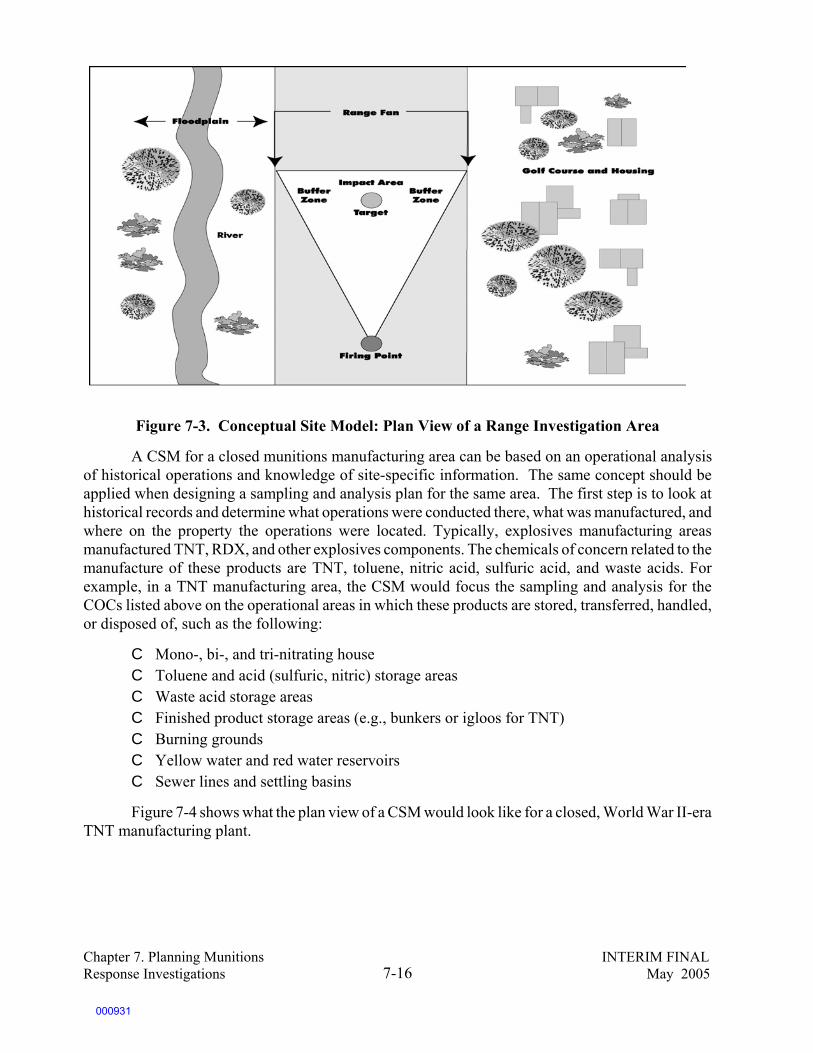
Chapter 7. Planning Munitions INTERIM FINALResponse Investigations May 20057-16
Figure 7-3. Conceptual Site Model: Plan View of a Range Investigation Area
A CSM for a closed munitions manufacturing area can be based on an operational analysisof historical operations and knowledge of site-specific information. The same concept should beapplied when designing a sampling and analysis plan for the same area. The first step is to look athistorical records and determine what operations were conducted there, what was manufactured, andwhere on the property the operations were located. Typically, explosives manufacturing areasmanufactured TNT, RDX, and other explosives components. The chemicals of concern related to themanufacture of these products are TNT, toluene, nitric acid, sulfuric acid, and waste acids. Forexample, in a TNT manufacturing area, the CSM would focus the sampling and analysis for theCOCs listed above on the operational areas in which these products are stored, transferred, handled,or disposed of, such as the following:
C Mono-, bi-, and tri-nitrating houseC Toluene and acid (sulfuric, nitric) storage areasC Waste acid storage areasC Finished product storage areas (e.g., bunkers or igloos for TNT)C Burning groundsC Yellow water and red water reservoirsC Sewer lines and settling basins
Figure 7-4 shows what the plan view of a CSM would look like for a closed, World War II-eraTNT manufacturing plant.
000931
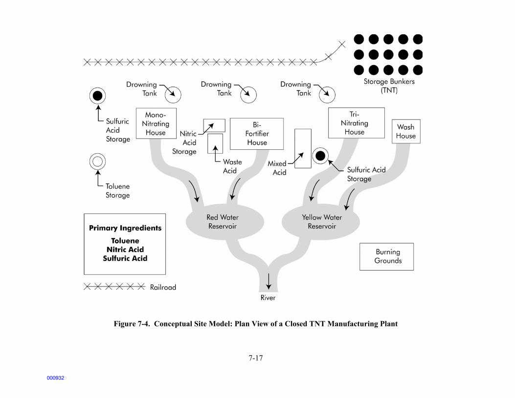
7-17
Figure 7-4. Conceptual Site Model: Plan View of a Closed TNT Manufacturing Plant
000932
Chapter 7. Planning Munitions INTERIM FINALResponse Investigations May 20057-18
7.4.4 Preliminary Remediation Goals
Preliminary remediation goals (PRGs) fora munitions response are the preliminary goalspertaining to the depth of that response actionand are used for planning purposes. PRGs aredirectly related to the specific media that areidentified in your CSM as potential pathways forMEC exposure (e.g., vadose zone, river bottom,wetland area). The PRGs for response depths formunitions are a function of the goal of theinvestigation and the reasonably anticipated landuse on the range. For example, if the goal of theinvestigation is to render the land surface safe fornonintrusive investigations, then the PRGs willbe designed to promote surface removal of MEC from the land area. Therefore, the PRGs will requirethat no MEC remains on the surface of the land. On the other hand, if the goal of the investigationis to establish final response depths to protect human health from MEC hazards, then the PRGs willbe based on the reasonably anticipated future land use. The PRGs in this instance may be to ensurethat no MEC is present in the top 10 feet of the subsurface or above the frost line.
The PRGs may change at several points during the investigation or at the conclusion of theinvestigation, as more information becomes available about the likely future land use, about theactual likely depth of the MEC, about environmental conditions that may cause movement of MEC,or about the complexity and cost of the response process. The PRGs may also change during theremedy selection process as the team makes its risk management decisions and weighs factors suchas protection of human health and the environment, costs, short-term risks of cleanup, long-termeffectiveness, permanence, and community and State/Tribal preferences.
The first step in establishing the PRGs is to determine the current and reasonably anticipatedfuture land use. While munitions response depth PRGs are conceptually easier to understand thanchemical-specific PRGs, widely accepted algorithms and extensive guidance have been developedto establish chemical- and media-specific PRGs depending on the land use. Identifying theappropriate PRGs for MRSs can be a complex and controversial process. One approach you mayconsider is to use the DDESB default safety standards for range clearance as the initial PRGs untiladequate site-specific data become available.
DDESB safety standards establishinterim planning assessment depths that arebased on different land uses, to be used forplanning until site-specific data becomeavailable. In the absence of site-specific data,these standards call for a clearance depth of 10feet for planned uses such as residential andcommercial development and constructionactivities. For areas accessible to the public,such as those used for agriculture, surfacerecreation, and vehicle parking, the DDESBrecommends planning for response depth of 4
Preliminary Remediation Goals (PRGs)
PRGs provide the project team with long-term targetsto use during analysis and selection of remedialalternatives. Chemical-specific PRGs are goals for theconcentration of individual chemicals in the media inwhich they are found. For UXO, the PRG willgenerally address the clearance depth for UXO.
Source: U.S. EPA. Risk Assessment Guidance forSuperfund (RAGS), Volume 1, Human HealthEvaluation Manual, Part B, Interim, December 1991.
DoD/EPA Interim Final Management Principles onStandards for Depths of Clearance
Per DoD 6055.9-STD, removal depths are determinedby an evaluation of site-specific data and risk analysisbased on the reasonably anticipated future land use.
C In the absence of site-specific data, a table ofassessment depths is used for interim planningpurposes until the required site-specific informa-tion is developed.
C Site-specific data are necessary to determine theactual depth of clearance.
000933

117DoD Directive 6055.9, DoD Explosives Safety Board (DDESB) and DoD Component Explosives SafetyResponsibilities, July 29, 1996.
118Department of Defense. Explosive Safety Submissions for Removal of Ordnance and Explosives (MEC) fromReal Property, Memorandum from DDESB Chairman, Col. W. Richard Wright, February 1998.
119USEPA, OSWER Directive No. 9355.7-04, Land Use in the CERCLA Remedy Selection Process, May 25,1995.
Chapter 7. Planning Munitions INTERIM FINALResponse Investigations May 20057-19
feet. For areas with limited public access and areas used for livestock grazing or wildlife preserves,the DDESB recommends planning for a response depth of 1 foot.117 In all cases, the standards callfor a response depth of 4 feet below any construction. (See Chapter 6 for a more detailed descriptionof DDESB standards.) None of these removal depths should be used automatically. For example, ifsite-specific information suggests that a commercial or industrial building will be constructed thatrequires a much deeper excavation than 10 feet, greater response depth must considered. In addition,if the response depth is above the frost line, then DDESB standards require continued surveillanceof the area for frost heave movement.118
Site-specific information may also lead to the decision that a more shallow response actionis protective. For example, if historicalinformation and results of geophysical studiessuggest that the only MEC to be found is withinthe top 1 foot of soil, then the actual munitionsresponse will obviously address the depth wheremunitions are found (e.g., 1 foot).
You should consider a variety of factorswhen identifying the reasonably anticipatedfuture land use of the property. Current and long-term ownership of the property, current use, andpressure for changes in future use are some of theimportant considerations.119 The text box belowlists a number of other possible factors. In the face of uncertainty, a more conservative approach,such as assuming unrestricted land use, is prudent. In determining the reasonably anticipated futureland use at a Base Realignment and Closure (BRAC) facility, you should consider not only the formalreuse plans, but also the nature of economic activity in the area and the historical ability of the localgovernment to control future land use through deed restrictions and other institutional controls.Several sources of information about planned and potential land use at BRAC sites are available,including base reuse plans.
DoD/EPA Interim Final Management Principles onLand Use
Discussions with local planning authorities, localofficials, and the public, as appropriate, should beconducted as early as possible in the response processto determine the reasonably anticipated land use(s).These discussions should be used to scope efforts tocharacterize the site, conduct risk assessments, andselect the appropriate response.
000934

Chapter 7. Planning Munitions INTERIM FINALResponse Investigations May 20057-20
7.4.5 Project Schedule, Milestones, Resources, and Regulatory Requirements
Other information used to plan the investigation includes the proposed project schedule,milestones, resources, and regulatory requirements. These elements will not only dictate much of theinvestigation, they will also determine its scope and help determine the adequacy of the data to meetthe goals of the investigation. If resources are limited and the tolerance for uncertainty is determinedto be low, it may be necessary to review the goals of the investigation and consider modifying themin the following ways:
C Reduce the geographic scope of the investigation (e.g., focus on fewer MRA/MRSs)C Focus on surface response rather than subsurface responseC Reduce the decision scope of the investigation (e.g., focus on prioritization for future
investigations, rather than property transfer)
In considering the schedule and milestones associated with the project, it is important toconsider the regulatory requirements, including the key technical processes and public involvementrequirements associated with the CERCLA and RCRA processes under which much of theinvestigation may occur, as well as any Federal facility agreements (FFAs) or compliance orders thatare in place for the facility. (See Chapter 2, “Regulatory Overview.”)
7.4.5.1 Resources
Many factors affect the scope and therefore the costs of an investigation. Although large rangesize is often associated with high costs, other factors can affect the scope and costs of aninvestigation:
C Difficult terrain (e.g., rocky, mountainous, dense vegetation)C High density of MECC Depth of MECC Anticipated sensitivity of MEC to disturbance or other factors that may require
Factors To Consider in Developing Assumptions About Reasonably Anticipated Future Land Uses
C Current land useC Zoning lawsC Zoning mapsC Comprehensive community master plansC Population growth patterns and projectionsC Accessibility of site to existing infrastructure (including transportation and public utilities)C Institutional controls currently in placeC Site location in relation to existing developmentC Federal/State land use designationsC Development patterns over timeC Cultural and archeological resourcesC Natural resources, and geographic and geologic informationC Potential vulnerability of groundwater to contaminants that may migrate from soilC Environmental justice issuesC Location of on-site or nearby wetlandsC Proximity to a floodplain and to critical habitats of endangered or threatened speciesC Location of wellhead protection areas, recharge areas, and other such areas
000935

Chapter 7. Planning Munitions INTERIM FINALResponse Investigations May 20057-21
extraordinary safety measures
Key factors to consider when estimating the cost of the investigation include the following:
C Site preparation may include vegetation clearance, surface UXO removal, and theestablishment of survey control points. If there is little vegetation at the site and/or if theUXO detection can be conducted without removing the vegetation, the costs can besignificantly reduced. In addition, limiting the vegetation clearance can also reduce theimpacts on natural and cultural resources, as discussed in the next text box.
C Geophysical mapping requires personnel, mapping, and navigation equipment. Theoperational platform for the selected detection tool can have a major impact on the costsof a site characterization.
C The data analysis process requires hardware and software to analyze the data gatheredduring the geophysical mapping to identify and classify anomalies. Data analysis can beconducted in real time during the investigation phase or off-site following the detection,with the latter generally being more expensive than the former.
C Anomaly investigation includes anomaly reacquisition and excavation to determineanomaly sources and to test the working hypotheses. Excavation can be very expensive;the greater the number of anomalies identified as potential UXO, the higher the cost.
Because the costs of investigation activities are based in large part on the acreage of the areato be characterized, most methods used to reduce the cost of the investigation involve reducing thesize of the sampling area. Some of the techniques used to reduce costs overlap with other toolsalready described that improve the accuracy of an investigation. For example, a comprehensivehistorical search enables the project team to minimize the size of the area requiring investigation.Statistical sampling methods are frequently used to reduce the costs of site investigation. Thesemethods and the controversy over the methods are discussed in Section 8.3.2.
Vegetation Clearance
In addition to the high monetary costs of preparing an area to be cleared of UXO, the environmental costs can alsobe very high. If the project team decides that vegetation clearance is necessary in order to safely and effectivelyclear UXO from a site, they should aim to minimize the potentially serious environmental impacts, such asincreased erosion and habitat destruction, that can result from removing vegetation. The following are three landclearing methodologies:
C Manual removal is the easiest technique to control and allows a minimum amount of vegetation to be removedto facilitate the UXO investigation. Tree removal should be minimized, with selective pruning used to enableinstrument detection near the trunks. If trees must be removed, tree trunks should be left in place to helpmaintain the soil profile. Manual removal results in the highest level of potential exposure to UXO of thepersonnel involved and should not be used where vegetation obscures the view of likely UXO locations.
C Controlled burning allows grass and other types of ground cover to be burned away from the surface withoutaffecting subsurface root networks. The primary considerations when using controlled burning are ensuring thatnatural or manmade firebreaks exist and that potential air pollution is controlled. Favorable weather conditionswill be required.
C Defoliation relies on herbicides to defoliate grasses, shrubs, and tree leaves. Manual removal of the remainingvegetation may be necessary. Sensitivity of groundwater and surface water bodies to leaching and surface runoffof herbicides will be important considerations.
000936

12040 CFR Section 300.400(g), National Oil and Hazardous Substances Pollution Contingency Plan.
Chapter 7. Planning Munitions INTERIM FINALResponse Investigations May 20057-22
7.4.5.2 Regulatory Requirements
Regulatory requirements come from a variety of laws and regulations, both State and Federal.The particular requirements that will be most applicable (or relevant and appropriate) to rangecleanup activities are the Federal and State RCRA requirements for hazardous waste transportation,treatment, storage, and disposal. Other regulatory requirements may be related to the specificpathways of concern, for example, groundwater cleanup levels. Chapter 2 of this handbook providesan overview of regulatory requirements that may apply, since knowledge of the applicablerequirements will be important to planning the investigation.
Since many munitions response investigations will take place under the authority of theComprehensive Environmental Response, Compensation, and Liability Act (CERCLA), it isimportant to keep in mind that even if not directly and legally applicable to the MEC activity orinvestigation, Federal and State laws may be considered to be “relevant and appropriate” byregulators. If the laws are considered relevant and appropriate, they are fully and legally applicableto a CERCLA cleanup activity.120
Important regulatory requirements that may affect both the investigation and the cleanupof the MRA include, but are not limited to, the following:
C CERCLA requirements for removal and remedial actions (including public andState/Tribal involvement in the process)
C RCRA requirements that determine whether the waste material is to be considered a solidwaste and/or a hazardous waste
C Requirements concerning the transportation and disposal of solid and hazardous wastesC Regulatory requirements concerning open burning/open detonation of wasteC Regulatory requirements concerning incineration/thermal treatment of hazardous wasteC Other hazardous waste treatment requirements (e.g., land disposal restrictions)C Air pollution requirements C DDESB safety requirementsC Other applicable Federal statutes such as the Endangered Species Act, the Native
Americans Graves Protection and Repatriation Act, and the National HistoricPreservation Act
This handbook does not present a comprehensive listing of these requirements. Chapter 2 ofthis handbook provides an overview of regulatory structures. Chapter 6 presents an overview of theDDESB safety requirements.
7.4.6 Identification of Remedial Objectives
Decisions regarding cleanup have two components: the remediation goal (or cleanup standard)and the response strategy. Remediation goals were described in the discussion of PRGs (Section7.4.6). The response strategy is the manner in which the waste will be managed (e.g., use ofinstitutional controls, removal of waste, treatment of waste once it’s removed), including theengineering or treatment technologies involved. PRGs represent the first step in determining thecleanup standard. PRGs are revised as new information is gathered and will be a central part of final
000937

Chapter 7. Planning Munitions INTERIM FINALResponse Investigations May 20057-23
cleanup decisions. It is equally important to identify potential cleanup technologies early in theprocess so that information required to assess the appropriate technology can be obtained during theinvestigation process (i.e., site findings affecting treatment selection).
The final step in planning the investigation is therefore identifying remedial objectives. Whatkind of cleanup activities do you anticipate? Like the PRGs and the CSM, this is a workinghypothesis of what you will find (which may change later), the volume of material that you must dealwith, the media with which it will be associated (if it is explosive residue), and the nature of thetechnology that will be used to conduct the cleanup. Early screening of alternatives to establishremedial action objectives is important. Identifying appropriate alternatives may direct thegeophysical investigations to help determine if a particular technology, such as bioremediation, willwork at the site. Chapter 4 has a substantial discussion of MEC detection technologies.
Finally, in addressing remedial objectives at the site, you will want to consider the disposaloptions for what may be an enormous amount of nonexplosive material. Typical range clearanceactivities excavate tons of trash and fragments of ordnance. In addition, open burning or detonationwill leave additional potentially contaminated materials and media to be disposed of. Some of thetrash, such as target practice material, may be contaminated with hazardous waste. Some of the metalfragments may be appropriate for recycling. Information collected during the investigation will beused to assess not only the treatment and the potential for recycling of explosive and nonexplosiveresidue, but also the disposal of other contaminated materials and media from the site.
7.4.7 The Data Quality Objectives of the Investigation
7.4.7.1 Developing DQOs
You now have the information necessary to develop the data quality objectives of theinvestigation. The DQOs will reflect the information that you require to achieve the decision goalsidentified at the beginning of the planning phase. DQOs are based on gaps in the data needed to makeyour decision. They should be as narrow and specific as possible and should reflect the certaintyrequired for each step of the investigation. Objective statements that are carefully crafted, withregulator involvement and community review, will help ensure that discussions at the end of theinvestigation are about the risk management decisions, not about the relevance or quality of the data.
Examples of typical DQOs may include the following:
C Determine the outer boundaries of potential UXO contamination on a range within plusor minus ___ feet.
C Determine, with ___ percent probability of detection at ___ percent confidence level, theamount of UXO found in the top 2 feet of soil.
DoD/EPA Interim Final Management Principles on DQOs
Site-specific data quality objectives (DQOs) and QA/QC approaches, developed through a process of close andmeaningful cooperation among the various governmental departments and agencies involved at a given militaryrange , are necessary to define the nature, quality, and quantity of information required to characterize each militaryrange and to select appropriate response actions.
000938

Chapter 7. Planning Munitions INTERIM FINALResponse Investigations May 20057-24
C Verify that there are no buried munitions pits under the range (___ percent probability ofdetection, ___ percent confidence level).
C Determine with __ percent certainty if there is UXO in the sediments that form the riverbottom.
C Determine the direction of groundwater flow with ___ percent certainty.
The DQOs for your site will determine the amount and quality of data required, as well as thelevel of certainty required. Which statements are appropriate for your site will depend on thepreviously identified goals of the investigation, the information that is already known about the site,and the acceptable levels of uncertainty.
7.4.7.2 Planning for Uncertainty
To a significant degree, data quality objectives will depend on the project team’s and thepublic’s tolerance for uncertainty. Ultimately, the amount of uncertainty that is acceptable, althoughexpressed in quantitative terms, is a qualitative judgment that must be made by all of the involvedparties acting together. For example, it may be possible to quantify the probability that a detector canfind subsurface anomalies. However, that probability will be less than 100 percent. The acceptabilityof a given probability of detection (e.g., 85 percent or 60 percent) will depend on a qualitativejudgment based on the decision to be made.
As in any subsurface investigation, it is impossible to resolve all uncertainties. For example,regardless of the resources expended on an investigation, it is not possible to identify 100 percent ofMEC on an MRS. Likewise, unless the entire range is dug up, it is often impossible to prove with 100percent certainty that the land area is clean and that no MEC is present. The project team will needto decide whether uncertainties in the investigation are to be reduced, mitigated, or deemedacceptable. Planned land use is an important factor in determining the acceptable level of uncertainty.Some uncertainties may be more acceptable if the military will continue to control the land andmonitor the site than if the site is to be transferred to outside ownership.
Uncertainties can be reduced through process design, such as a thorough sampling strategy,and through the use of stringent data quality acceptance procedures. Uncertainties can also bereduced by planning for contingencies during the course of investigation. For example, it may bepossible to develop decision rules for the investigation that recognize uncertainties and identifyactions that will be taken if the investigation finds something. A decision rule might say that if X isfound, then Y happens. (In the simplest example, if any anomalies excavated prove to be ordnancerelated, either ordnance fragments or UXO, then a more intensive sampling process will be initiated.)
The results of uncertainties can be mitigated in a variety of ways, including by monitoring andcontingency planning. A situation in which some uncertainties were mitigated occurred at FortRitchie Army Garrison, a BRAC facility. MEC contamination was suspected beneath buildings thatwere constructed decades ago and were located on property designated for residential development.Because the buildings were to be reused following the land transfer, regulators chose not to requirean investigation beneath the buildings because it would have necessitated razing them. As a riskmanagement procedure, legal restrictions were established to ensure Army supervision of any futuredemolition of these buildings. The presence of MEC under buildings on land slated for transfer is anuncertainty the project team at Fort Ritchie chose to accept. Risks are mitigated through the use ofinstitutional controls.
000939

Chapter 7. Planning Munitions INTERIM FINALResponse Investigations May 20057-25
Finally, uncertainties in the investigation may be deemed acceptable if they will beinsignificant to the final decision. Information collected to “characterize the site” should beconsidered complete when there is sufficient information to determine the extent of contamination,and the proposed response depth and the appropriate remedial technology. If information has beencollected that makes it clear that action will be required, it may not be necessary to fully understandthe boundaries of the range or the density or distribution of MEC prior to making the remediationdecision and starting response activities. Some amount of uncertainty will be acceptable, since theinformation required will be obtained during the response operation. (Note: This scenario assumesthat there is sufficient information both for safety planning and for estimating the costs of theremediation.)
000940

Chapter 7. Planning Munitions INTERIM FINALResponse Investigations May 20057-26
SOURCES AND RESOURCES
The following publications, offices, laboratories, and websites are provided as a guide forhandbook users to obtain additional information about the subject matter addressed in each chapter.Several of these publications, offices, laboratories, or websites were also used in the development ofthis handbook.
Publications
American Society for Testing and Materials. Standard Guide for Developing Conceptual SiteModels for Contaminated Sites. Guide E1689-95; 2001.
Interstate Technology and Regulatory Council, Technical/Regulatory Guidelines, MunitionsResponse Historical Records Review, November 2003.
Information Sources
Joint UXO Coordination Office (JUXOCO)10221 Burbeck Road, Suite 430Fort Belvoir, VA 22060-5806Tel: (703) 704-1090Fax: (703) 704-2074http://www.denix.osd.mil/UXOCMECU.S. Army Corps of Engineers
U.S. Army Engineering and Support Center Ordnance and Explosives Mandatory Center of ExpertiseP.O. Box 1600 4820 University SquareHuntsville, AL 35807-4301http://www.hnd.usace.army.mil/
Department of Defense Explosives Safety Board (DDESB) 2461 Eisenhower AvenueAlexandria, VA 22331-0600Fax: (703) 325-6227 http://www.ddesb.pentagon.mil
U.S. Environmental Protection Agency Superfund Risk Assessmenthttp://www.epa.gov/superfund/programs/risk/index.htm
Guidance Documents
U.S. Army Corps of Engineers. Conceptual Site Models for Ordnance and Explosives (MEC)and Hazardous, Toxic, and Radioactive Waste (HTRW) Projects. Engineer Manual. EM 1110-1-1200, Feb. 3, 2003.
U.S. Army Corps of Engineers. Technical Project Planning (TPP) Process. Engineer Manual200-1-2; Aug. 31, 1998.
U.S. Department of Defense. DoD Ammunition and Explosives Safety Standards. DoD 6055.9-STD; July 1999.
000941

Chapter 7. Planning Munitions INTERIM FINALResponse Investigations May 20057-27
U.S. EPA (Environmental Protection Agency). Compliance with Other Laws (Vols 1 & 2). Aug.8, 1988.
U.S. EPA. EPA Guidance for Quality Assurance Project Plans. EPA QA/G-5, Feb. 1998.
U.S. EPA. Guidance for Conducting Remedial Investigations and Feasibility Studies UnderCERCLA. Interim Final. NTIS No. PB89-184626; Oct. 1989.
Sources of Data for Historical Investigations
Air Photographics, Inc. (aerial photographs)Route 4, Box 500 Martinsburg, WV 25401Tel: (800) 624-8993Fax: (304) 267-0918 e-mail: [email protected] http://www.airphotographics.com
Environmental Data Resources, Inc.(aerial photographs; city directories; insurance, wetlands, flood plain, and topographical maps)3530 Post RoadSouthport, CT 06490 Tel: (800) 352-0050 http://www.edrnet.com
National Archives and Records Administration National Cartographic and ArchitecturalBranchCollege Park, MDhttp://www.nara.gov
National Exposure Research LaboratoryEnvironmental Photographic Interpretation Center (EPIC)U.S. Environmental Protection AgencyLandscape Ecology Branch12201 Sunrise Drive555 National CenterReston, VA 20192Tel: (703) 648-4288Fax: (703) 648-4290http://www.epa.gov/nerlesd1/land-sci/epic/aboutepic.htm
U.S. Department of Agriculture, Natural Resources Conservation Service(national, regional, and some state and local data and maps of plants, soils, water and climate,watershed boundaries, wetlands, land cover, water quality, and other parameters)14th and Independence AvenueWashington, DC 20250http://www.nrcs.usda.gov/
000942

Chapter 7. Planning Munitions INTERIM FINALResponse Investigations May 20057-28
U.S. Geological Survey, EROS Data Center(satellite images, aerial photographs, and topographic maps)Customer Services 47914 252nd Street Sioux Falls, SD 57198-0001 Tel: (800) 252-4547 Tel: (605) 594-6151 Fax: (605) 594-6589 e-mail: [email protected] http://edc.usgs.gov/
Repositories of Explosive Mishap Reports
U.S. Air ForceAir Force Safety CenterHQ AFSC/JA9700 G Avenue SEKirtland AFB, NM 87117-5670Tel: (505) 846-1193Fax: (505) 853-5798
U.S. ArmyU.S. Army Safety Center 5th Avenue, Bldg. 4905Fort Rucker, AL 36362-5363
U.S. Army Technical Center for Explosives Safety (maintains a database of explosives accidents)Attn: SIOAC-ESL, Building 351C Tree RoadMcAlester, OK 74501-9053e-mail: [email protected]://www.dac.army.mil/esmam/default.htm
U.S. NavyCommander, Naval Safety CenterNaval Air Station Norfolk375 A Street, Code 03Norfolk, VA 23511Tel: (757) 444-3520http://www.safetycenter.navy.mil/
000943

Chapter 8. Devising Investigation INTERIM FINALand Response Strategies May 20058-1
8.0 DEVISING INVESTIGATION AND RESPONSE STRATEGIES
The previous chapter provided a framework for organizing what is currently known about asite so that a project team can systematically identify the goals and objectives of an investigation.The focus of this chapter is to identify geophysical and munitions constituents sampling, analysis,and response strategies that will meet those goals and objectives.
The discussion that follows outlines major considerations in the development of yourinvestigation and response plan. Keep in mind, however, that the foundation of your sampling andanalysis plan rests on your conceptual site model (see Chapter 7).
Developing the geophysical investigation is often the most difficult part of the MECinvestigation. Given the size of the ranges and the costs involved in investigating and removingMEC, judgments of acceptable levels of uncertainty often come into conflict with practical costconsiderations when determining the extent of the field investigation.
Sampling and measurement errors in locating MEC on your MRS will come from severalsources:
C Inadequacy of geophysical detection methods to locate and correctly identifyanomalies that may be potential MEC
C Inappropriate extrapolation of the results of statistical geophysical sampling to largerareas
C Difficulty in collecting representative soil samples for munitions constituentsC Measurement errors introduced in laboratory analysis of soil samples (either on-site
or off-site), including subsampling and analysis
Given that no subsurface investigation technique can eliminate all uncertainty, the samplingdesign (and supporting laboratory analysis) should be structured to account for the measurement errorand to ensure that the data collected are of a known quality.
Field sampling activities include the following basic considerations:
C Explosives safety concerns, safety planning, and Explosives Safety Submissions (seeChapter 6)
C Detection technologies that are matched to the characteristics of the site and the UXOand to the objectives of the investigation (see Chapter 4)
C Specification of QA/QC measurementsC Determination of the quantity and quality of data needed and data acceptance criteriaC Determination of how, when, and where data will be collectedC Appropriate use of field analysis and fixed laboratory analysis to screen for explosive
residues
There are typically four types of data collection methods employed during UXOinvestigations:
C Nonintrusive identification of anomalies using surface-based detection equipment
000944

Chapter 8. Devising Investigation INTERIM FINALand Response Strategies May 20058-2
C Intrusive excavation of anomalies (usually to verify the results of geophysicalinvestigations)
C Soil sampling for potential munition constituentsC Environmental sampling to establish the basic geophysical characteristics of the site
(e.g., stratigraphy, groundwater depth and flow), including background levels
The following decisions are to be made when designing the data collection plan:
C Establishment of your desired level of confidence in the capabilities of subsurfacedetection techniques
C How to phase the investigation so that data collected in one phase can be used to plansubsequent phases
C Establishment of decision rules for addressing shifts in investigation techniquesdetermined by field information
C The degree to which statistical sampling methods are used to estimate potential futurerisks
C How to verify data obtained through the application of statistical sampling approachesC The types of field analytical methods that should be used to test for explosive residuesC The appropriate means of separating and storing waste from the investigationC Information required for the Explosives Safety Submission
The design of the sampling and analysis effort usually includes one or more iterations ofgeophysical studies, which incorporate geophysical survey data processing and anomaly investigationto obtain a level of precision that will help you achieve your project objectives. Depending on yourproject objectives, more extensive geophysical studies may be necessary to evaluate the potential forMEC impacts at the site. For example, if your project objective is to confirm that an area is “clean”(free from MEC), and you detect a MEC item during your first geophysical sweep of the groundsurface, you can conclude that the area should not be considered clean and you must modify yourobjective. However, no additional geophysical data collection is necessary at that point.
Conversely, your objective may be to cleanup a target area that is expected to contain artilleryitems (e.g., 105 mm projectiles) using the combination of detection tools and data processingtechniques deemed appropriate to the site and the objective specified by your project team. However,initial excavations reveal the presence of much smaller munitions (e.g., 40 mm anti-aircraftprojectiles), in addition to the artillery items. You may have to modify your geophysical detectionprocesses in order to address this unanticipated type of munition, which will be more difficult todetect.
The design of the sampling and analysis effort should recognize that fieldwork takes placein stages. The first stage will often be a surface response effort to render the MRA/MRSs underinvestigation safe for geophysical investigation. The second stage will field test the detectiontechnologies that you plan to use to verify QA/QC measurement criteria and establish a known levelof precision in the investigation. The subsequent stage will involve the iterative geophysical studiesdiscussed above. Observations in the field could cause a redirection of the sampling activities.
The bullets and discussion below address five important elements of the design of thesampling and analysis effort:
000945

Chapter 8. Devising Investigation INTERIM FINALand Response Strategies May 20058-3
C Selection of munitions detection technologiesC Operational analysis of the munitions activities that took place at the siteC Selection of the methodology for determining the location and amount of both intrusive
and nonintrusive samplingC Development of QA/QC measures for your sampling strategyC Use of both fixed lab and field screening analytical techniques for sampling for munition
constituents
8.1 Identification of Appropriate Detection Technologies
Selection of the appropriate detection technology is not an easy task, as there is not one besttool that has the greatest effectiveness, ease of implementation, and cost-effectiveness in everysituation. Rather, a combination of systems that includes sensors, data processing systems, andoperational platforms should be configured to meet the site-specific conditions. The project teamshould develop a process to identify the best system for the particular site.
The site-specific factors affecting the selection of appropriate technologies include thefollowing:
C The ultimate goals of the investigation and the level of certainty required for MECdetection
C The amount and quality of historical information available about the siteC The nature of the MEC anticipated to be found on-site, including its material makeup and
the depth at which it is expected to be foundC Background materials or geological, topographical, or vegetative factors that may
interfere with MEC detection
Site-specific information should be used with information about the different detectionsystems (see Chapter 4) to select the system most appropriate for the project. Three key factors inselecting a detection technology are effectiveness, ease of implementation, and cost.
The effectiveness of a system may be measured by its proven ability to achieve detectionobjectives. Measures of effectiveness include probability of detection, maximum depth of detection,false positive (“false alarm”) rate, and sensor data characteristics such as signal and noise. Thescience of ordnance and explosives detection has improved significantly over the past decade;however, the limited ability to discriminate between ordnance and non-ordnance remains a seriousdeficiency. (See Chapter 4 for a discussion of detection systems.)
The ease of implementation, although a characteristic of the technology, is influenced by theproject requirements. For example, a towed operational platform (typically a multisensor array towedbehind a vehicle) may not be implementable in mountainous and rocky terrain. For another site,implementability might mean that a single detection system has to work on all types of terrainbecause of budgetary or other constraints.
Detection system costs generally depend on the operational platform and the data processingrequirements. For example, hardware costs are higher for an airborne platform than for a land-basedsystem, but an airborne platform can survey a site much faster than a land-based system, thus
000946

Chapter 8. Devising Investigation INTERIM FINALand Response Strategies May 20058-4
reducing the cost per acre. Similarly, digital georeferencing systems cost more than a GIS that canbe used to manually calculate the position of anomalies, but the time saved by digitallygeoreferencing anomaly position data, and the associated potential reduction in errors, may speed theprocess and save money in the end.
8.2 UXO Detection Methods
Until the Jefferson Proving GroundTechnology Demonstration (JPGTD) Projectwas established in 1994 to advance the state ofmunition detection, classification, and removal,“Mag and Flag” had been the default MECdetection method, with only marginalimprovement in its detection and identificationcapabilities since World War II. Using Magand Flag, an operator responds to audible orvisible signals representing anomalies asdetected by a hand-held magnetometer (orother detection device such as an EMinstrument), and places flags into the groundcorresponding to the locations where signalswere produced. While Mag and Flag hasimproved with advances in magnetometry, itproduces higher false alarm rates than otheravailable technologies. This is particularly truein areas with high background levels of ferrousmetals. In addition, the Mag and Flag system ishighly dependent on the capabilities of theoperator. Efficiency and effectiveness havebeen shown to trail off at the end of the daywith operator fatigue or when the operator istrying to cover a large area quickly. Becausethe data from a Mag and Flag operation are notdigitally recorded, it is more difficult toreplicate and verify the data. This lack ofdigital recording also makes it difficult toassess whether an area has been completelysurveyed using this technique. The certainty of the actual location of the anomaly is highly dependenton the operator’s proficiency as well as on the systemic errors associated with the technique. Becauseof these limitations and the availability of more reliable systems, the use of Mag and Flag isdecreasing. However, under certain conditions, such as very difficult terrain (e.g., mountainous,densely forested), Mag and Flag may be the most cost-effective method for detecting UXO.
Under the JPGTD program, developers test and analyze UXO detection technologies such asmagnetometry, electromagnetic induction, ground penetrating radar, and multisensor systems.Emerging technologies such as infrared, seismic, synthetic aperture radar, and others are tested anddeveloped at JPGTD. A discussion of different technologies is provided in Chapter 4.
What Is the Effectiveness Rate of MEC DetectionUsing Existing Technologies?
The answer to this question is centered around thedefinition of “detection.” Debates over the answer to thisapparently simple question reflect underlying valuesabout how to conduct a UXO investigation and whatcosts are “worthwhile” to incur.
UXO objects are “seen” as underground anomalies thatmust be interpreted. It is often difficult to distinguishbetween UXO, fragments of MEC, other metallic objects,and magnetic rocks, boulders, and other undergroundformations. This inability to discriminate, and theresulting high number of false positives, is a contributingfactor to the high cost of UXO clearance. The overalleffectiveness of a detection technology is intrinsicallytied to the ability of the sensor to discriminate betweenmunitions items and other subsurface anomalies. Themore sensitive the detector, the more anomalies arefound. Finding the balance between reducing false alarmsand ensuring that hazardous items are found is the key toa cost effective investigation.
DoD/EPA Interim Final Management Principles onUXO Detection
The critical metrics for the evaluation of the performanceof a detection technology are the probabilities ofdetection and false alarms. Identifying only one of thesemeasures yields ill-defined capability. Of the two,probability of detection is a paramount consideration inselecting a UXO detection technology.
000947

Chapter 8. Devising Investigation INTERIM FINALand Response Strategies May 20058-5
Although many detection technologies do an adequate job of responding to the presence ofmetallic items below the ground surface, they may also (depending on site conditions and the typeof detection technology) respond to geologic anomaly sources, such as ferrous rocks. One class offalse positives is the response of sensors to nonmetallic sources. In addition, currently availabletechnologies do not discriminate between metallic items of concern (i.e., UXO and buried munitions),fragmentation from exploded munitions, and non-ordnance-related metal waste. These false positiveanomalies from geologic sources and non-ordnance related metallic items can greatly increase thenumber of anomaly excavations that must be undertaken during investigations and remedialresponses, as well as during QA/QC of these activities. Development of reliable means ofdistinguishing between ordnance items and other subsurface anomaly sources will minimize falsepositives and, therefore, reduce the cost and time needed for a project.
In an attempt to address this issue, Phase IV of the JPGTD was initiated with the primary goalof improving the ability to distinguish between ordnance and nonordnance. Although progress hasbeen made in distinguishing UXO from clutter such as UXO fragments, additional work is stillneeded to further advance target discrimination technologies, to make them commercially available,and to increase their use. With reliable and readily available target discrimination technologies, thenumber of false positives should be greatly reduced, thereby significantly reducing the costs of UXOinvestigations.
A number of data processing and modeling tools have been developed to screen munitionstargets from raw detection data. These discrimination methods are typically based on one of twoapproaches. One approach is to rely on a comparison of the signatures of potential targets againsta database of known UXO (with a variety of sizes, shapes, depths, and orientations) and cluttersignatures. A more effective approach is to model the expected geophsysical signals based on thephysics of the sensor and its expected response to the item being searched for. Additional informationabout data processing for UXO discrimination is provided in Chapter 4.
000948

Chapter 8. Devising Investigation INTERIM FINALand Response Strategies May 20058-6
8.3 Methodologies forIdentifying MunitionsResponse Areas
The next key element ofyour investigation will be to selectthe quantity and location ofsamples. In reality, there are threequestions to be answered:
C Where to deploy yourdetection equipment
C Where and how manyanomalies are to beexcavated to see whatyou have actually found
C How to use thein fo r ma t i on f romdetection, anomalyreacquisi t ion, and
Identifying UXO Locations
In the past, the primary method used by UXO personnel to identify the location of anomalies was to manually markor flag the locations at which UXO detection tools produced a signal indicating the presence of an anomaly. Ifoperators wished to record the UXO location data, they would use GIS or other geographic programs to calculatethe UTM (Universal Transverse Mercator) grid coordinates for each flag. Since the development of automatic data-recording devices and digital georeference systems, data quality has improved significantly. Using digitalgeophysical mapping, a UXO detection device identifies the anomaly, and a differential global positioning systemlocates the position of the anomaly on the earth’s surface. The accuracy of the positional data depends upon siteconditions such as vegetative cover that could interfere with the GPS satellite. Under ideal conditions, however, thedifferential GPS can be accurate to within several centimeters. The data are then merged and the location of eachanomaly is recorded. Therefore, flags are not needed to record and find the location of the UXO. Because digitalgeophysical mapping records location data automatically, the risk of an operator missing or misrecording a location,as occurs when operators manually record anomaly locations based on analog signals, is minimized, and the data canbe made available for future investigations and for further data processing. However, the potential exists for analysterrors in the merging of the anomaly and positional data. Therefore, anomaly reacquisition is used to verify the fielddata. Section 8.3.1.5 discusses anomaly reacquisition, and Section 4.2.3.1 describes the application of positioningtechnologies to geophysical data collection.
DoD/EPA Interim Final Management Principles on Data Recording
A permanent record of the data gathered to characterize a site and a clear audit trail of pertinent data analysis andresulting decisions and actions are required. To the maximum extent practicable, the permanent record shall includesensor data that is digitally recorded and georeferenced. Exceptions to the collection of sensor data that is digitallyrecorded and georeferenced should be limited primarily to emergency response actions or cases where their use isimpracticable. The permanent record shall be included in the Administrative Record. Appropriate notificationregarding the availability of this information shall be made.
Terms Used in MEC Sampling
Because many familiar terms are used in slightly different ways in thediscussion of statistical sampling, the following definitions areprovided for clarification:
Detection – Determining the presence of geophysical anomaliestargets from system responses (UXO Center of Excellence Glossary,2000).Discrimination – Distinguishing the presence of UXO from non-UXOfrom system responses or post-processing.Sampling – The act of investigating a given area to determine thepresence of UXO. It may encompass both the nonintrusive detectionof surface and subsurface anomalies and excavation of anomalies.Location – Determination of the precise geographic position ofdetected UXO. Includes actions to map locations of detected UXO.(UXO Center of Excellence Glossary, 2000).Recovery – Removal of UXO from the location where detected (UXOCenter of Excellence Glossary, 2000).Identification/evaluation – Determination of the specific type,characteristics, hazards, and present condition of UXO (UXO Centerof Excellence Glossary, 2000).
000949

Chapter 8. Devising Investigation INTERIM FINALand Response Strategies May 20058-7
excavation to make a decision at your siteTwo methodologies have been developed to answer these questions – CSM-based and
statistically based sampling. The two methods are discussed in the following sections. It is importantto remember that the methods are not mutually exclusive, but can be used together to characterizethe ordnance at your site.
8.3.1 CSM-Based Sampling Design
Your sampling design will be driven by your CSM (and the historical information gatheredto support your CSM), the purpose of the investigation, and the terrain being investigated. In thesimplest terms, two functional purposes affect the nature of your sampling design:
C Purpose 1— search for munitions response sites (e.g., a target area) to determine thepossible location of munitions and the need for and location of further investigation.
C Purpose 2 — establish boundaries for and further characterize (e.g., ordnance type, depth)the sites where munitions have been located to guide the risk management decision thatwill lead to removal or remediation of the munitions.
Two types of geophysical survey patterns can be used to meet these two sampling purposes:
C Transects take a one-dimensional “slice” of a sampling area, the width of which is thewidth of the geophysical sensor.
C Grids, or 100% surveys, consist of overlapping, parallel transects that are used to createa two-dimensional map of a small, defined sampling area.
The following sections describe how and when these two patterns can be applied toaccomplish the two different sampling purposes.
8.3.1.1 Searching for Munitions Response Areas
Regularly spaced parallel transects can be used to efficiently search a large area for evidenceof concentrated areas of UXO. This approach can be especially useful to determine the location oftarget areas within a known or suspected firing range, and knowledge of the weapons systems usedon the range can be used to determine appropriate search transect spacing. Field manuals for eachweapon system are maintained and provide the expected high medium and low distribution of impactaround targets under normal operating conditions. This information can be used to calculate spacingbetween parallel transects that will allow for less than 100 percent sampling and provide confidencethat evidence of an impact area such as munitions fragments or UXO can be located. Figure 8-1illustrates an example of a search using transect sampling.
000950

Chapter 8. Devising Investigation INTERIM FINALand Response Strategies May 20058-8
Figure 8-1. Example of Search Transects
000951

Chapter 8. Devising Investigation INTERIM FINALand Response Strategies May 20058-9
Use of a grid pattern when performing a search is appropriate when the primary releasemechanism indicated by the CSM is loss/abandonment or unsanctioned burial (e.g., at firing points,bivouac/encampment areas, and transfer points), and the area of the search is relatively small (seeFigure 8-2). In this case, the location and size of the grid should be determined from sitereconnaissance information and knowledge of past ordnance activities (e.g., unsanctioned burials mayhave occurred near firing points). The lane spacing of the grid survey should be based on the sensorbeing used, the expected depth, and the size of the expected ordnance type, and should be influencedby the results of the geophysical prove-out.
Transect-Based Searches for Target Areas: Adak Island, Alaska
While planning the remedial investigation of Adak, the project team was faced with the issue of adequatelyinvestigating several large combat ranges (between approximately 3,400 and 6,800 acres). These areas weredesignated as combat ranges in June of 1943, during the time that much of Adak was in use as a training area forWorld War II troops preparing to retake the island of Kiska from the Japanese. Preliminary site investigation resultsprovided evidence that at least some of the ranges had been used for live-fire 60 mm and 81 mm mortar training.The objective of the project team was to develop an investigation approach that would be cost-effective while stillproviding confidence that any target areas likely to contain UXO had been located.
The project team decided that a systematic search of the combat ranges using parallel transects would meet theinvestigation objectives. An operational analysis of the weapon systems of concern was undertaken to determinethe spacing of these parallel transects. This analysis consisted of creating a “model” of the impacts that would resultfrom small-scale target practice, based on information contained in Army field manuals for the weapon systems.Information from the field manuals was also used to determine the radius around an impact that would containfragmentation of sufficient quantity to be detected by the geophysical sensor. This information was combined toestimate the minimum dimensions of potential target areas. The recommended spacing between the parallel transectswas set at 75 percent of these minimum dimensions in order to obtain certainty that a transect would traverse anytarget areas.1
One of the key features of this approach was the agreement by the project team that fragmentation provided evidenceof potential target areas and that areas in which fragmentation was located warranted further investigation, even ifno UXO was found during the initial parallel transect search. This allowed the team to feel confident that themajority of the combat ranges could be designated for no further action upon the completion of the remedialinvestigation. The approach also located several previously unknown target areas, as well as an undocumentedordnance disposal area.
1Conceptual Site Model-Based Sampling Design, the UXO Countermine Forum 2001.
000952
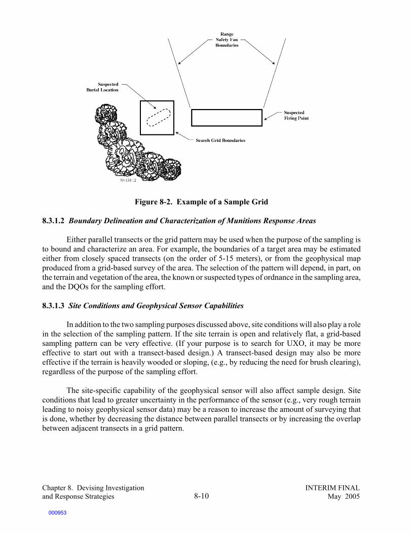
Chapter 8. Devising Investigation INTERIM FINALand Response Strategies May 20058-10
Figure 8-2. Example of a Sample Grid
8.3.1.2 Boundary Delineation and Characterization of Munitions Response Areas
Either parallel transects or the grid pattern may be used when the purpose of the sampling isto bound and characterize an area. For example, the boundaries of a target area may be estimatedeither from closely spaced transects (on the order of 5-15 meters), or from the geophysical mapproduced from a grid-based survey of the area. The selection of the pattern will depend, in part, onthe terrain and vegetation of the area, the known or suspected types of ordnance in the sampling area,and the DQOs for the sampling effort.
8.3.1.3 Site Conditions and Geophysical Sensor Capabilities
In addition to the two sampling purposes discussed above, site conditions will also play a rolein the selection of the sampling pattern. If the site terrain is open and relatively flat, a grid-basedsampling pattern can be very effective. (If your purpose is to search for UXO, it may be moreeffective to start out with a transect-based design.) A transect-based design may also be moreeffective if the terrain is heavily wooded or sloping, (e.g., by reducing the need for brush clearing),regardless of the purpose of the sampling effort.
The site-specific capability of the geophysical sensor will also affect sample design. Siteconditions that lead to greater uncertainty in the performance of the sensor (e.g., very rough terrainleading to noisy geophysical sensor data) may be a reason to increase the amount of surveying thatis done, whether by decreasing the distance between parallel transects or by increasing the overlapbetween adjacent transects in a grid pattern.
000953
Chapter 8. Devising Investigation INTERIM FINALand Response Strategies May 20058-11
8.3.1.4 Anomaly Identification and Prioritization
After the survey has been completed, the geophysical and positional data are processed andanalyzed to identify and locate geophysical anomalies that may be MEC (see Chapter 4 for adiscussion of the anomaly identification process). The outputs from this process, often called a “diglist,” are the locations, signal amplitudes, and estimated depths of the sources of the anomalies. Onmany sites, the anomalies included on the dig list are prioritized based on the geophysical analyst’sjudgments about which anomalies are most likely to be caused by subsurface ordnance items. Thisprioritization process is often an ad hoc form of anomaly discrimination, based on the analyst’sgeneral and site-specific experience (see the discussion in Section 8.2). The effectiveness of thisprioritization depends on whether or not information from a geophysical prove-out has been usedsuccessfully to inform the prioritization process, and whether the analyst is receiving and usingfeedback from the anomaly excavation results.
Use of a prioritized dig list can increase the efficiency of the anomaly excavation process byfocusing the excavation efforts on the anomalies most likely to be of interest. However, a sample ofall anomalies that meet threshold criteria for identification (even those judged not likely to beordnance) should be excavated in order to provide information about the effectiveness of theprioritization process.
8.3.1.5 Anomaly Reacquisition
In general, before an anomaly is excavated, its location will be “reacquired” by the anomalyexcavation team. The accuracy of anomaly locations entered on dig lists depends on both the surveypattern and the accuracy of the positioning system used during the geophysical survey. Therefore,the search radius used during anomaly reacquisition is another parameter that must be consideredduring the development of the sampling methodology.
In general, the locations of anomalies identified from a grid survey will be more accurate thanthose identified from a transect survey. This is because multiple passes of the geophysical detectorover or near an anomaly source will give the analyst more data to use to estimate its location. Andalthough differential global positioning system (DGPS) will provide the most accurate positionaldata, site conditions (especially dense tree canopy) may preclude the use of this system, and lessaccurate positioning methods may need to be used. All of these issues should be considered whenspecifying the search radius to be used during anomaly reacquisition.
The other factor to consider is the geophysical sensor used to reacquire the anomaly positions.Ideally, this will be the same device that was used to perform the original geophysical survey.However, logistical circumstances may not make it possible to use the same device (for example, thequalified geophysical survey personnel may have already left the site by the time anomaly excavationis undertaken). In this case, the excavation team may use a hand-held sensor to reacquire anomalylocations. It is important that this hand-held sensor be of the same type (magnetometer orelectromagnetic) as the sensor originally used to perform the survey.
000954

Chapter 8. Devising Investigation INTERIM FINALand Response Strategies May 20058-12
8.3.2 Use of Statistically Based Methodologies To Identify UXO
Given the variation in the size of the ranges investigated, a variety of statistical samplingapproaches have also been used to investigate MRS/MRAs.
This section addresses four topics pertinent to statistically based sampling: the rationale forstatistical sampling, how DoD currently uses the data from such sampling programs, regulatorconcerns with the use of statistically based data, and recommendations on appropriate use of thesedata to make appropriate closure decisions for a range.
8.3.2.1 Rationale for Statistical Sampling
Statistically based sampling was developed to address the limitations of noninvasive UXOdetection technologies and the use of those technologies on the large land areas that may make upa range. Current methodologies for identifying anomalies in a suspected UXO area have variouslimiting deficiencies, as described previously. The most common deficiencies include low probabilityof detection and low ability to differentiate between UXO and/or fragments and backgroundinterference (objects or natural material not related to ordnance). Thus, most detection technologieshave a moderate to high false alarm rate. This means that there is a high degree of uncertaintyassociated with the data generated by the various detection methods. No analogous situation existsfor identifying compounds usually found at conventional hazardous waste sites. The problem ofhighly uncertain anomaly data is magnified for three reasons:
• The areas suspected of containing UXO could be hundreds or even thousands of acres;therefore, it is often not practicable to deploy detection equipment over the entire area.
• Even within sectors suspected of containing UXO, it is often not practicable to excavateall detected anomalies during sampling to confirm whether they are in fact UXO.Excavation to the level appropriate for the future land use is normally done during theremediation phase.
• When detection tools detect anomalies in areas where it is not known if ordnance has beenused, it is difficult to know (in the absence of excavation) if the detected anomaly is in factordnance.
Statistically based sampling methods were developed to address the issue of how toeffectively characterize a range area without conducting either nonintrusive detection or intrusivesampling on 100 percent of the land area. Statistically based sampling methods extrapolate the resultsof small sample areas to larger areas.
8.3.2.2 Historical Use of Statistical Sampling Tools
A variety of statistical sampling methodologies exist, each serving a different purpose, andeach with its own strengths and weaknesses. The two common statistical sampling tools historicallyused by DoD are SiteStats/GridStats and the UXO Calculator. The general principles of the twoapproaches are similar. First, the sector is evaluated to determine if it is homogeneous. If it is nothomogeneous, a subsector is then evaluated for homogeneity, and so forth, until the area to beinvestigated is determined to be homogeneous. The sampling area is divided into a series of grids anddetection devices used to identify subsurface anomalies. The software, using an underlyingprobability distribution, randomly generates the location and number of subsequent samples withina grid, or the user can select the location of subsequent samples. Based on the results of each dig, the
000955

121“Site/Grid Statistical Sampling Based Methodology Documentation,” available at USACE website:www/hnd/usace.army.mil/oew/policy/sitestats/siteindx.htm.
122U.S. Army Corps of Engineers. Ordnance and Explosives Cost Effectiveness Risk Tool (OECert), FinalReport (Version E), Huntsville, AL: Ordnance and Explosives Mandatory Center for Excellence, 1995.
Chapter 8. Devising Investigation INTERIM FINALand Response Strategies May 20058-13
model determines which and how many additional anomalies to excavate, when to move on to thenext grid, and when enough information is known to characterize the grid. (See the following text boxfor a discussion of homogeneity.)
There are two main differences between SiteStats/GridStats and the UXO Calculator. First,the technologies typically used for input differ. SiteStats/GridStats is most commonly used with adetection tool or combination of tools, whereas UXO Calculator is used with both a detection tooland a digital geophysical mapping device. Second, SiteStats/GridStats produces a UXO densityestimate based only on the statistical model. The data from SiteStats/GridStats are then input intoOECert, a model that contains a risk management tool as well as a screening-level estimator for thecost of remediation.121
The SiteStats/GridStats results are generally presented as having a confidence level that isbased on a set of assumptions and may not be justified. The UXO density estimates are often usedas input to OECert to evaluate the public risk and to estimate the cost of removal alternatives. TheOECert model compares the costs of remediation alternatives to the number of public exposureslikely under each remediation scenario. The model then develops recommendations that minimizeremediation costs. The risk levels used for the recommendations are acceptable to the U.S. ArmyCorps of Engineers (USACE).122
UXO Calculator also estimates UXO density, but the program contains an additional riskmanagement tool that allows the operator to input an assumed acceptable UXO density based on landuse, assuming UXO distribution is homogeneous within a sector. UXO Calculator then calculates thenumber of samples required to determine if this density has been exceeded. However, acceptableUXO target densities are neither known nor approved by regulators. As with SiteStats/GridStats, the
The Importance of Homogeneity
The applicability of statistical sampling depends on whether the sector being sampled is representative of the largersite. Statistical sampling as incorporated in SiteStats/GridStats and UXO Calculator assumes that a sector ishomogeneous in terms of the likelihood of UXO being present, the past and future land uses, the types of munitionsused and likely to be found, the depths at which UXO is suspected, and the soils and geology. Because statisticalsampling assumes an equal probability of detecting UXO in one location as in another, if the distribution of UXOis not truly homogeneous, the sampling methodologies could overlook UXO items. Environmental conditions suchas soils and geology affect the depth and orientation at which munitions land on or beneath the ground surface. If,on one part of a range, munitions hit bedrock within a few inches of the ground surface, they will be much closerto the surface (and probably easier to detect) than others that hit sandy soil on top of deeper bedrock. In addition,different types and sizes of munitions reach greater depths beneath the surface.
Attempts to assess homogeneity can include, but should not be limited to, the following activities: conductingextensive historical research about the types of munitions employed and the boundaries of the range, surveying thesite, or using previously collected geophysical data.
000956

Chapter 8. Devising Investigation INTERIM FINALand Response Strategies May 20058-14
sample size obtained is also based on an assumption of homogeneity within a sector. The UXOCalculator software contains a density estimation model, risk management tool, and cost estimatortool. The risk management tool requires assumptions about land use and from that informationassumes a value for the number of people who will frequent a site. The justification of the land useassumptions and the resulting population exposure are not well documented.
Table 8-1 summarizes these two tools and their strengths and weaknesses. Table 8-2 identifiesfour survey patterns and summarizes their strengths, weaknesses, and applications.
Table 8-1. UXO Calculator and SiteStats/GridStats
StatisticalSamplingMethod Description
Strengths andWeaknesses
Intensity of
Coverage Typical DoD Use
UXO Calculator Determines the size ofthe area to beinvestigated in order tomeet investigation goals,confidence levels inordnance contaminationpredications, and UXOdensity in a given area.
Investigates a very smallarea to prove to varyinglevels of confidence thata site is “safe” fortransfer. Allcomputations are basedon an assumption ofsector homogeneity withrespect to UXOdistribution.
Low Used with digitalgeophysical mapping data. Used to make a yes or nodecision as to the presenceor absence of ordnance. Used to determineconfidence levels inordnance contaminationpredictions.
SiteStats/GridStats
Random sampling isbased on a computerprogram. Usually lessthan 5 percent of a totalsite is investigated and25 to 33 percent ofanomalies detected areexcavated.
Potentially huge gapsbetween sampling plots,very small investigationareas, no considerationof fragments or areassuspected ofcontamination. Relies ona rarely validassumption that UXOcontamination isuniformly distributed. Hot spots may not beidentified.
Low Designed for use with Magand Flag data. Reduces therequired amount ofexcavation to less than 50percent of levels requiredby other techniques. Usedby DoD to extrapolateresults to larger area.
000957

Chapter 8. Devising Investigation INTERIM FINALand Response Strategies May 20058-15
Table 8-2. General Summary of Statistical Geophysical Survey Patterns
SurveyPatterns Description
Strengths andWeaknesses
Intensityof
Coverage Typical DoD Use
Fixed patternsampling
Survey conducted alongevenly spaced grids. Apercentage of the site (e.g.,10 percent) is investigated.
Even coverage of entiresite. Gaps betweenplots can be minimized.
Medium Useful for locating hot spotsand for testing clean sites.
Hybrid gridsampling
Biased grids investigated inareas suspected ofcontamination or in areaswith especially large gapsbetween SiteStats/GridStatssampling plots.
Compensates for someof the limitations ofSiteStats/GridStats. Relies on invalidassumption that UXOcontamination isuniformly distributed.
Medium Used to direct samplingactivity to make sitedeterminations.
Transectsampling
Survey conducted alongevenly spaced transects.
Used in areas with highUXO concentrations.
Medium Useful for locatingboundaries of high-densityUXO areas.
Meanderingpath sampling
Survey conducted along aserpentine grid path throughentire site using GPS anddigital geophysicalmapping.
Reduced distancesbetween samplingpoints; environmentallybenign becausevegetation clearance isnot required. Digitalgeophysical mappingrecords anomalylocations withimproved accuracy.
Medium Used to direct samplingactivity to make sitedeterminations inecologically sensitive areas.
*Any of these survey patterns may include limited excavation of anomalies to verify findings.
000958

123“Interim Guidance on the Use of SiteStats/GridStats and Other Army Corps of Engineers StatisticalTechniques Used to Characterize Military Ranges.” Memo from James E. Woolford, Director, EPA Federal FacilitiesRestoration and Reuse Office, to EPA Regional Superfund National Policy Managers, January 19, 2001.
Chapter 8. Devising Investigation INTERIM FINALand Response Strategies May 20058-16
8.3.2.3 Regulator Concerns Regarding the Historical Use of Statistical Sampling Tools
The use of statistical sampling is asource of debate between the regulatorycommunity (EPA and the States) and DoD.123
Faced with large land areas requiring investi-gation, and the high costs of such investigation,DoD has used several statistical approaches toprovide an estimate of the UXO density at asite as a basis for selecting remedies or makingno-action decisions. Regulatory concerns havegenerally focused on four areas: (1) theinability of site personnel to demonstrate thatthe assumptions of statistical sampling havebeen met, (2) the extrapolation of statisticalsampling results to a larger range area withoutconfirmation or verification, (3) the use of thedensity estimates in risk algorithms to makemanagement decisions regarding the acceptablefuture use of the area, and (4) the use of statistical sampling alone to make site-based decisions.Criticisms of statistical sampling have centered around the use of the statistical tools embodied in theSiteStats/GridStats, and UXO Calculator. However, some of the criticisms may be applicable toother statistical methods as well. Criticisms include the following:
• Historically, the use of statistical sampling tools has been based on assumptions that thearea being sampled is homogeneous in terms of the number of anomalies, geology,topography, soils, types of munitions used and depths at which they are likely to be found,and other factors. Often, too little is known to ensure that the statistical samplingassumptions are met and the procedures used to test sector homogeneity are not effectiveenough to detect sector nonhomogeneity.
• Statistical procedures used in SiteStats/GridStats to determine when the sector has beensufficiently characterized and to test sector homogeneity are not statistically valid.
• In practice, statistical procedures are often overridden by ad hoc procedures; however, thesubsequent analysis does not take this into account.
• The use of statistical techniques often results in the sampling of a relatively small area incomparison with the size of the total area suspected of contamination. The small samplingarea may not necessarily be representative of the larger area.
• The ability of statistical sampling to identify UXO in areas where munitions activitiesoccurred is questionable.
• The capabilities of current statistical methods to identify hot spots are limited.• A nonconforming distribution may not be identified by the program and thus not be
adequately investigated.
DoD/EPA Interim Final Management Principleson Statistical Sampling
Site characterization may be accomplishedthrough a variety of methods, used individually or inconcert with one another, and including, but notlimited to, records searches, site visits, or actual dataacquisition, such as sampling. Statistical or othermathematical analyses (e.g., models) shouldrecognize the assumptions embedded within thoseanalyses. Those assumptions, along with the intendeduses of the analyses, should be communicated at thefront end to the regulators and the communities so theresults may be better understood. Statistical or othermathematical analyses should be updated to includeactual site data as it becomes available.
000959

Chapter 8. Devising Investigation INTERIM FINALand Response Strategies May 20058-17
• The distances between sampling grids are often large. • Relying exclusively on actual UXO effectively ignores UXO fragments as potential
indicators of nearby UXO. • Confidence statements based on the assumed probability distribution do not account for
uncertainties in the detection data.• Confidence statements also relate to an expected land use that is not carefully justified.• Results of confirmatory sampling are not presented or summarized in a manner that
allows a regulator to evaluate the quality and limitations of the data that are used in therisk management algorithms.
• There is no sensitivity analysis of the applicability of the risk management tools to theinput parameters. For example, there is nothing analogous to EPA’s “most probable,”“most exposed individual,” and “worst case” assumptions for baseline risk assessmentsat Superfund sites.
• The levels of exposure risks developed by the OECert program have not been acceptedby regulators or the public.
8.3.2.4 Recommendations on the Use of Statistical Sampling
In general, regulatory agencies believe that statistical sampling is best used as a screening toolor to provide preliminary information that will be confirmed during the clearance process.Statistically based sampling tools, when used in conjunction with other tools, may be used for thefollowing purposes:
• Prioritizing range areas for thorough investigation and/or clearance• Analyzing the practicality and cost of different clearance approaches, as well as the
usefulness of different remedial alternatives• Establishing the potential costs of clearance for different land uses• Facilitating a determination of which land uses may be appropriate following
remediation, and the levels and types of institutional controls to be imposed
Regulatory agencies also believe that statistical sampling alone should not be used to makeno-action decisions. Other significant data also will be required, including the following:
• Extensive historical information• Groundtruthing (comparing the results of statistical sampling to actual site conditions) of
randomly selected areas to which results will be extrapolated
Even the use of historical and groundtruth information, combined with statistical samplingresults, will be suspect when the presence of ordnance fragments suggests that active range-relatedactivities occurred in the past. Range investigation practices are evolving, but many regulatory andtechnical personnel agree that statistical sampling tools must be used in conjunction with the otherelements of the systematic planning process (including historical research). In examining the useof statistical sampling tools, you should consider the following:
• The assumptions on which statistical sampling techniques are based should be bothclearly documented and appropriate to the particular site under investigation.
000960

Chapter 8. Devising Investigation INTERIM FINALand Response Strategies May 20058-18
• The density estimates from the statistical sampling procedure should be carefullyscrutinized and computed using statistically correct algorithms.
• Any risk estimates based on computer algorithms (e.g., OECert) should beadequately documented for regulatory review.
Given the size of many MRAs, it is likely that some form of statistical sampling will be usedat your site. Decisions regarding the acceptability of statistical sampling involve the followingissues:
• The nature of the decision to be made • Agreement on the criteria on which the decision will be made • Agreement on the assumptions and decision rules that are used in the statistical
model• The level of confidence in the detection technology • The use and amount of anomaly reacquisition and excavation to verify findings of
detection technology • The presentation of these data, summarized in an appropriate format• The quality and quantity of information from historical investigations
8.3.2.5 Research and Development of New Statistical Sampling Tools
The perceived ongoing need for statistical sampling has led the DoD’s StrategicEnvironmental Research and Development Program (SERDP) to identify as high priority any projectsthat have the potential to develop “defensible statistical sampling schemes for bounding UXOcontaminated areas.” Three research projects in the MEC and UXO arena are currently under way.
Statistical Methods and Tools for UXO Site Characterization — This project will evaluateand develop statistical methods and tools that can be used for characterization and verification plansand data evaluation schemes. The development of the statistical sampling methods and tools will beconsistent with the EPA’s data quality objective (DQO) process. This process is used to plan anycharacterization activity to ensure that the right type, quantity, and quality of data are gathered tosupport confident decision-making. It is intended that the methods will strike an appropriate balancebetween the probability of missing UXO and the costs of characterization or unnecessary remediation(false positives). Statistical methods will be evaluated, adapted, or developed, and prototype toolswill be developed and demonstrated. The methods will allow quick evaluation of trade-offs involvingcosts, risk of missing UXO, acceptable probabilities for decision errors, percentage of the sitecharacterized or the number of swaths, false-positive error rates, grid sizes, etc. One statistical tooldeveloped under this program is the Visual Sample Plan (VSP) software tool (developed by PacificNorthwest National Laboratory through a SERDP-sponsored project) for developing and visualizingtransect survey design. The methods incorporate elements of the DQO approach for developing anoptimal transect sampling design based on specified decision rules and tolerable decision errorprobabilities. Site-specific DQOs are specified and transect patterns (parallel, square, rectangular, ormeandering) are identified and visually displayed using VSP. The VSP software is used to illustratedecision rules and associated transect sampling schemes that will provide the user’s required highprobability of traversing and detecting a target area of concern of specified size, shape, and anomaly(or UXO) density.
000961

Chapter 8. Devising Investigation INTERIM FINALand Response Strategies May 20058-19
Bayesian Approach to UXO Site Characterization with Incorporation of GeophysicalInformation — The objective of this project is to develop a sampling protocol for estimating theintensity of UXO contamination across a site. This protocol uses an inherently Bayesian approachthat allows for incorporation of historical information and geophysical data into the sitecharacterization process. This protocol will use a sample optimization procedure to be incorporatedto allow for straightforward field deployment of this characterization approach. A data worthframework will be used to optimize sampling locations and to determine when characterization iscomplete.
Statistical Spatial Models and Optimal Survey Design for Rapid GeophysicalCharacterization of UXO Sites — This project seeks to identify the mathematical foundations andstatistical protocols in the domain of point process theory of spatial statistics by focusing on threeobjectives: (1) develop the statistical spatial models needed to produce the mathematical foundationfor UXO distribution characterization, (2) develop optimal sampling strategies using experimentalsurvey design, and (3) improve confidence levels for contamination estimates from measured databy improving discrimination techniques.
8.4 Incorporating QA/QC Measures Throughout the Investigation
Quality assurance and quality control should be incorporated into every aspect of yourinvestigation. Begin planning for quality at the start of a project by developing DQOs and standardoperating procedures (SOPs). Throughout the process, all data should be managed so as to providean auditable trail of all data points and every geophysical anomaly detected.
The quality assurance and quality control (QA/QC) requirements for MEC investigationsdiffer from other types of environmental investigations because of the unique characteristics of MECand the tools available for characterizing MRSs. For example, the probability of detection when usingany detection system depends on site-specific conditions; therefore, the technology and its capability(performance criteria) must be established for each site at which it will be used. You can determinethe effectiveness by conducting tests of the technology on seeded areas representative of the rangeitself, using the sampling methods to be used in the actual investigation. Similarly, because of thecomplexities of operating detection systems and analyzing detection data, and the potentialramifications of mischaracterizing an area as clear, operator and analyst skills and capabilities are ofparamount importance. Therefore, all personnel working on a site must be appropriately trained andqualified to work on the site using the detection system that will be used. What does not differ fromother types of environmental investigations is the applicability of using a graded approach to theQA/QC of the investigation.
The resources dedicated to QA/QC should be appropriate to the kind of decision being made(e.g., preliminary screening vs. definitive determination of site response), as well as the size andcomplexity of the investigation. Specific QA/QC measures that could be taken include the following:
• Development of data quality objectives — DQOs should clearly relate to the databeing collected and to the decisions being made. The DQOs should state the acceptablelevels of uncertainty and provide acceptance criteria for assessing data quality.
000962

Chapter 8. Devising Investigation INTERIM FINALand Response Strategies May 20058-20
• Sampling and analysis plan — The geophysical survey and the intrusive investigationshould be based on a comprehensive CSM. The sampling methods should considerrelease mechanisms and weapons systems. All primary sources should be addressed andfollow-up searches should be performed.
• Geophysical prove-out — The geophysical prove-out is used to select the geophysicalequipment to be used. In this process, the performance of the geophysical equipment isassessed in conditions representative of the actual field conditions, sampling methods tobe used, and targets likely to be encountered at specific depths. In general, the capabilityof the detection instruments to meet project-specific performance requirements isdemonstrated in the field using geophysical prove-out sites in areas that have geologyand topography similar to the area being investigated. The accuracy of thisdemonstration depends on the number, types, orientations, and depths of the test itemsburied in the prove-out site. Various metrics can be used to assess this capability,including probability of detection at a specified confidence level, maximum requireddetection depth, and geophsycial sensor signal and noise characteristics. Project goalsmay be based on any or all of these measures, and the geophysical prove-out designshould support the assessment of the detection process performance against thesemetrics.
• Geophysical qualification — All members of the geophysical survey team are qualifiedby demonstrating their ability to meet prove-out performance results to ensure precisionof geophysical data. An example of qualification for surface sweeps would be “searcheffectiveness probability validation,” which is used to test the team and the detectionequipment. In search effectiveness probability validation, the area being investigated is“salted” with controlled inert ordnance items that are flagged or collected as the sweepteam proceeds through the salted area. The number of items planted collected iscompared with the total number of items planted, and a percentage for searcheffectiveness probability is calculated.
• Site preparation — Prior to the geophysical survey, the site is prepared by settingsurvey stakes and by removing all metallic debris that could mask subsurface anomalies.In this process, all ordnance-related items found on the surface are documented andremoved.
• Geophysical survey — The output of the geophysical survey is geophysical andpositional data about subsurface anomalies encountered. The results of the survey areaffected by the method used to collect positional data and by the performance of the fieldteam. Quality control is conducted on the geophysical survey using several mechanisms:(1) confirmation of proper functioning of detectors, (2) field surveillance to confirmadherence to SOPs, and (3) independent resurvey of a portion of the area underinvestigation. UXO survey teams may independently perform distance or angularmeasurements two times to identify deviations resulting from human error. Forgeophysical mapping performed without digital geophysical reference systems,Universal Transverse Mercator (UTM) grid coordinate values created in GIS or othergeographic programs are verified by QC teams using a differential GPS to ensure correcttarget locations.
• Anomaly identification — The merged geophysical and positional data are analyzedto identify and locate anomalies. The QC aspects of anomaly identification includeaccurately merging data points, incorporating feedback from intrusive investigations, andapplying objective criteria to the identification process.
000963

124T.F. Jenkins, P.G. Thorne, S. Thiboutot, G. Ampleman, and T. Ranney. Coping with Spatial HeterogeneityEffects on Sampling and Analysis at an HMX-Contaminated Antitank Firing Range, Field Analytical Chemistry andTechnology 3(1): 19-28, 1999.
Chapter 8. Devising Investigation INTERIM FINALand Response Strategies May 20058-21
• Anomaly reacquisition — Areas in which anomalies were initially detected arereexamined, and the estimated anomaly location is flagged. This process helps to ensurethe accuracy of the anomaly location and depth data.
• Anomaly excavation — Sources of anomalies are identified and excavated, and thecleared hole is then verified by a detector. Results are fed back into the anomalyidentification process. Quality control is then conducted over the entire area to ensurethat anomalies have been excavated.
• Quality Control Program — The contractor responsible for implementation of theinvestigation should have a comprehensive quality control program, including planned
periodic surveillance of both field and data processing and analysis activities, as well asquality control acceptance sampling after the completion of fieldwork to confirm theadequacy of the work done.
8.5 Devising an Investigation Strategy for Munitions Constituents
This section introduces unique considerations in the design of an investigation strategy fordetermining the nature and extent of contamination from munitions constituents. Two aspects ofthe investigation strategy are discussed: the location and type of sample to be taken and methods forchemical analysis.
8.5.1 Sampling Strategy
As with a more routine hazardous waste site, the manner in which sampling is conductedrepresents the greatest potential for uncertainty and error to be introduced into the environmentaldecision process. However, increasing evidence from extensive studies by the Cold RegionsResearch and Engineering Laboratory (CRREL)124 suggests that, given the extreme spatialheterogeneity of munition constituents, sampling of contaminated soils should be approacheddifferently than the traditional hazardous waste investigation.
8.5.1.1 Knowing Where To Sample
A good sampling strategy should be based on a clear CSM that indicates all primary sourceand release mechanisms associated with each ordnance-related activity. The more you know aboutthe ordnance activities on the site, the more representative the locations will be of ordnance-relatedcontamination in that area of concern. Tables 7-1 through 7-6 in Chapter 7 show examples ofordnance-related activities and associated sources, release mechanisms, and expected MECcontamination. Thorough examination of historical records, aerial photographs, and base operationalrecords will facilitate sufficient reconstruction of past ordnance-related operations. In many cases,however, design of an effective strategy for munitions constituents will depend on having the resultsof the MEC investigation. Confirming the location of target areas (and associated low-orderdetonations), firing points, and detonation areas will be a prerequisite for knowing where to sample.
000964

125T.F. Jenkins, M.E. Walsh. Field-Based Analytical Methods for Explosive Compounds. USA EngineerResearch and Development Center, Cold Regions Research and Engineering Laboratory.
126T.F. Jenkins, C.L. Grant, G.S. Brar, P.G. Thorne, P.W. Schumacher, and T.A. Raney. Sampling ErrorAssociated with Collection and Analysis of Soil Samples at TNT Contaminated Sites, Field Analytical Chemistry andTechnology 1: 151-163 (1997).
Chapter 8. Devising Investigation INTERIM FINALand Response Strategies May 20058-22
8.5.1.2 Collecting Soil Samples
Recent research by CRREL suggests that composite sampling provides a more accuratedepiction of soil concentrations of MC. This same research also suggests that use of field analyticaltechniques is beneficial in a number of respects and has a high level of agreement with the use ofoff-site analytical methods for measuring MC. The use of field analytical methods also has theadvantage of increasing sample density and, therefore, improving sample representativeness.
The traditional approach to collecting samples for chemical analysis uses large samplinggrids and a small number of discrete samples. Usually, suspect areas of sites are divided into gridswith dimensions ranging from tens to hundreds of meters. This approach involves the collection ofa single core sample within a grid. The sample is divided into depth intervals, which are analyzedat an off-site commercial laboratory. Contaminant concentrations obtained from discrete sampleanalysis are then compared with background levels and action levels established for the site todetermine the need for cleanup. This approach assumes that contaminant concentrations in thesamples adequately represent the average concentrations within grid boundaries.
The problem with this approach in sampling for MC contamination is the spatialheterogeneity of munitions constituents. Concentrations of MC in adjacent soil samples may varyexponentially; therefore, you may miss the presence of MC altogether if too few samples are takenor the sampling locations are not correctly placed.
Sampling for any chemical residue is affected by the spatial heterogeneity of the residue.In traditional chemical residue sampling, the cause of the heterogeneity may be spills or leaks thatoccur in several locations, or hot spots. In addition, concentrations vary depending on the distancefrom the source and on the different fate and transport mechanisms that work on the particularchemicals of concern (e.g., the degree to which particular chemicals adsorb to soil, are taken up inplants, or are taken up in solution during rain events). However, in general, the traditional chemicalrelease is expected to follow a pattern of concentration flow from the release point based on knowncharacteristics of the chemical and its common fate and transport mechanisms.
In the case of explosive material, substantial research conducted by CRREL hasdemonstrated that the manner in which explosive residues are distributed when released by anexplosive force results in such a heterogeneous distribution of material that soil samples taken rightnext to each other can show vastly different concentrations. One sample may be a nondetect, whileanother a few feet away may show concentrations above action levels. Conducting a traditional riskassessment using discrete samples may cause the risk assessment to erroneously report no risk,simply because the munitions constituents were missed.
Recent studies illustrated that compositing samples provides more representative data forcharacterization of an area suspected of being contaminated with explosive compounds thananalyzing discrete samples does.125 ,126 The following paragraphs present the results of the studies.
000965

Chapter 8. Devising Investigation INTERIM FINALand Response Strategies May 20058-23
5 4
1
27
6 3
39,800 On-site41,400 Lab
500 O n-site416 Lab
164 O n-site136 Lab
27,800 O n-site42,800 Lab
24,400 O n-site27,700 Lab
1,280 O n-site1,220 Lab
331 O n-site286 Lab
In both studies, seven discrete samples were collected with a hand corer in a wheel pattern(radius 61 cm) and field analyzed for TNT, HMX, and RDX. The results of the discrete samplingover a very short distance indicate a wide range of concentrations. Figure 8-3 shows the samplingscheme and the results of the discrete samples. The resulting comparison of the composite sampleanalysis as compared with the mean of the discrete sample results is shown on Figure 8-4. Each ofthe sampling points are two feet apart.
Figure 8-4 shows that the resulting standard deviation is much lower with compositesampling. All duplicate samples were sent to an independent commercial laboratory for analysiswith acetonitrile extraction and RP-HPLC-UX as described in EPA Method 8330. The results of thelaboratory analysis are also presented in Figure 8-4.
Figure 8-3. Sampling Scheme for Short-Range Heterogeneity Study: Monite Site, SamplingLocation 1; Major Analyte: TNT (mg/kg)
000966

Chapter 8. Devising Investigation INTERIM FINALand Response Strategies May 20058-24
(Source: T.F. Jenkins, M.E. Walsh. Field-Based Analytical Methods for Explosive Compounds.)
Figure 8-4. Results of Composite and Discrete Samples: Soil Analyses: On-Site andLaboratory Methods, Monite Site and Hawthorne AAP (Source: Ibid.)
These findings reinforce the hypothesis that preparing a homogeneous and representativecomposite from a set of discrete samples is feasible and does not require sophisticated equipmentnor exceptional time or effort. The use of composite samples also seems to effectively deal with thespatial heterogeneity associated with explosive residues.
In addition, the studies also indicate that distribution of explosive material within one fieldsample can vary so significantly that it can misrepresent the true concentration of explosiveconstituents in the area. To compound the matter even further, the traditional laboratory approachto soil sample preparation of a field sample usually involves taking a small amount of soil materialfrom the top of the field sample container. This approach may miss explosive constituentsaltogether. For this reason, subsamples should be taken within a composite sample, with samplepreparation consisting of mixing and grinding. CRREL studies have shown that mixing and grindingsamples and subsamples can solve the problem.
There are many acceptable ways to collect and combine area-integrated samples intocomposite samples. The specific procedure chosen should be tailored to the conditions at the site tobe characterized. By combining the ability to produce representative samples using on-sitehomogenization and compositing with the ability to obtain accurate analytical estimates with on-sitemethods, site investigators can minimize the problem of spatial heterogeneity for explosives-contaminated areas and the high costs normally associated with this sampling effort.
Discrete Samples Composite Samples
Sampling Location Major AnalyteField or
Lab Mean ± SD* Mean ± SD
Monite, location 1 TNT FL
13,50016,300
±±
16,80020,200
13,10014,100
±±
5321,420
Monite, location 2 DNT FL
16,10034,800
±±
11,70042,200
23,80033,600
±±
3,1402,390
Monite, location 3 TNT FL
19.812.9
±±
42.029.0
12.64.16
±±
1.20.7
Hawthorne, location 4 TNT FL
1,9702,160
±±
1,9802,160
1,7502,000
±±
178298
Hawthorne, location 5 TNT FL
156168
±±
121131
139193
±±
16.67.7
Hawthorne, location 6 Ammonium Picrate FL
869901
± ±
1,6001,600
9701,010
±±
3292
*The discrete sample standard deviations for locations 1, 2, 3, and 6 are larger than theircorresponding means because the results from these locations are not distributed normally.
000967

Chapter 8. Devising Investigation INTERIM FINALand Response Strategies May 20058-25
8.5.2 Selecting Analytical Methodologies
Two approaches may be used to determine the presence and concentration of munitions andmunitions constituents in the environment. One approach is to conduct analysis in the field. Thisapproach generates quantitative and qualitative data, depending on the exact method chosen, thecompounds present, and their concentration range. The other approach is to collect samples in thefield and analyze the samples in a laboratory. The laboratory can be either an on-site mobilelaboratory or an off-site fixed laboratory. However, all shipments of materials with elevatedconcentrations of explosives must be conducted under Department of Transportation hazardousmaterial transportation requirements.
The integrated use of both on-site field methods and laboratory methods provides acomprehensive tool for determining the horizontal and vertical extent of contamination, identifyingpotential detonation hazards, indicating the volume of contaminated media requiring remediation,and determining whether remediation activities have met the cleanup goals.
Field analysis provides nearly immediate results, usually in less than 2 hours, at lower coststhan laboratory methods. It has been thought in general that field analysis is less accurate thanlaboratory methods (especially near the quantitation limit), that the methods have lower selectivitywhen the samples contain mixtures of munitions constituents, and that they are subject to moreinterferences. For these reasons, it was common practice that a set percentage of samples, between10 and 20 percent of the total samples, was sent to a laboratory for additional analysis. In addition,fixed laboratory methods offer greater specificity, as most field methods respond to classes ofmunitions constituents.
However, recent studies described in the previous section may cause the reevaluation of thiscommon practice. These studies demonstrate that the use of composite sampling, combined withon-site sample analysis and appropriate representative confirmation of results at an off-siteenvironmental laboratory, (less than the typical 10 to 20 percent described above) can significantlyreduce costs while maintaining accuracy.
8.5.3 Field Methods
Because of the heterogeneous distribution of explosive compounds in the environment, fieldanalytical methods can be a cost-effective way to assess the nature and extent of contamination. Thelarge number of samples that can be collected, combined with the relative speed with which data canbe generated using field analysis, allows investigators to redirect the sampling during a samplingevent.
Two basic types of on-site analytical methods are widely used for explosives in soil:colorimetric and immunoassay. Colorimetric methods generally detect broad classes of compounds,such as nitroaromatics, including TNT, or nitramines, such as RDX, while immunoassay methods aremore compound-specific. Most on-site analytical methods have a detection range at or near 1 mg/kgfor soil and 0.07 to 15 Fg/L for water.
000968

127A.B. Crockett et al. Field Sampling and Selecting On-Site Analytical Methods for Explosives in Soils, U.S.Environmental Protection Agency, EPA/540/R-97/501, November 1996.
128A.B. Crockett et al. Field Sampling and Selecting On-Site Analytical Methods for Explosives in Water, U.S.Environmental Protection Agency, EPA/600/S-99/002, May 19, 1999.
129Thomas F. Jenkins et al. Laboratory and Analytical Methods for Explosives Residues in Soil, U.S. Army ColdRegions Research and Engineering Laboratory, Hanover, N.H.
Chapter 8. Devising Investigation INTERIM FINALand Response Strategies May 20058-26
Because TNT or RDX or both are usually present in explosives-contaminated soils, focusingon these two compounds during sampling can quickly identify areas of contamination. Studies ofsampling and analysis at a number of explosives-contaminated sites reported “hits” of TNT or RDXin 72 percent of the contaminated soil samples collected and up to 94 percent of water samplescollected that contained munition residues.127,128 Another source reported that at least 95 percent ofthe soils contaminated with secondary explosive residues contained TNT and/or RDX.129 Thus, theuse of field methods for both of these compounds can be effective in characterizing explosivescontamination at a site.
Field methods can be subject to positive matrix interferences from humic substances foundin soils. For colorimetric methods, these interferences can be significant for samples containing lessthan 10 mg/kg of the target compound. In the presence of these interferences, many immunoassaymethods can give sample results that are biased high compared to laboratory results. Commonlyapplied fertilizers, such as nitrates and nitrites, also interfere with many of these methods. Therefore,it is considered good practice to send a percentage of the samples collected to a fixed laboratory forconfirmatory analysis.
Colorimetric methods treat a sample with an organic solvent, such as acetone, to extract theexplosives. For example, for soil, a 2 to 20 gram sample is extracted with 6.5 to 100 mL of acetone.After 1 to 3 minutes, the acetone is removed and filtered. A strong base, such as potassiumhydroxide, is added to the acetone, and the resulting solution’s absorbency at a specific lightwavelength is measured using a spectrophotometer. The resulting intensity is compared with acontrol sample to obtain the concentration of the compound of interest.
Colorimetric methods, though designated for a specific compound, such as TNT or RDX,will respond to chemically similar compounds. For example, the TNT methods will respond to TNB,DNB, 2,4-DNT, and 2,6-DNT. The RDX methods will respond to HMX. Therefore, if the targetcompound, TNT or RDX, is the only compound present, the method will measure it. If multiplecompounds are present, the concentration that you determine will be influenced by the presence ofthe interfering compound.
000969

Chapter 8. Devising Investigation INTERIM FINALand Response Strategies May 20058-27
The various immunoassay and biosensormethods differ considerably. However, theunderlying basis can be illustrated by one of thesimpler methods. Antibodies specific for TNTare linked to solid particles. The contaminatedmedia are extracted and the TNT molecules inthe extract are captured by the solid particles. Acolor-developing solution is added. The pre-sence or absence of TNT is determined bycomparing it to a color card or a field test meter.
Whereas colorimetric methods willrespond to other chemically similar compounds,immunoassay methods are more specific to aparticular compound. For example, the TNTimmunoassay methods will also respond to apercentage of TNB, 2,4-DNT, and 2,6-DNTwhen multiple nitroaromatic compounds arepresent. The RDX immunoassay method hasvery little response (less than 3 percent) to othernitramines such as HMX.
The explosive compounds that can bedetected by colorimetric and immunoassaymethods are indicated in Table 8-3. In addition,TNT and RDX can be detected and measured inwater samples using biosensor methods.
Table 8-3. Explosive Compounds Detectable by Common Field Analytical Methods
Compound Colorimetric Test Immunoassay Test
Nitroaromatics2,4,6-Trinitrotoluene (TNT) X X
1,3-Dinitrobenzene (DNB) X
1,3,5-Trinitrobenzene (TNB) X X
2,4-Dinitrotoluene (2,4-DNT) X
2,6-Dinitrotoluene (2,6-DNT) X X
Methyl-2,4,6-trinitrophenylnitramine (Tetryl) X
Examples of Field Analytical Methods
The EXPRAY Kit (Plexus Scientific) is the simplestcolorimetric screening kit. It is useful for screeningsurfaces and unknown solids. It can also be used toprovide qualitative tests for soil. It has a detection limitof about 20 nanograms. Each kit contains three spraycans:
EXPRAY 1 – Nitroaromatics (TNT)EXPRAY 2 – Nitramines (RDX) and nitrateesters (NG) EXPRAY 3 – Black powder, ANFO
EnSys Colorimetric Test Kits (EPA SW-846 Methods8515 and 8510) consist of separate colorimetricmethods for TNT and RDX/HMX. The TNT test willalso respond to 2,4-DNT, tetryl, and TNB. TheRDX/HMX test will also respond to NG, PETN, NC,and tetryl. It is also subject to interference from thenitrate ion unless an optional ion exchange step is used.The results of these kits in the field correlate well withSW-846 Method 8330.
DTECH Immunoassay Test Kits (EPA SW-846Methods 4050 and 4051) are immunoassay methodsfor TNT and RDX. Immunoassay assay tests are moreselective than colorimetric test kits. The results arepresented as concentration ranges. These rangescorrelate well with SW-846 Method 8330.
The EPA Environmental Technology VerificationProgram (http://www.epa.gov/etv) continues to testnew methods.
000970

Table 8-3. Explosive Compounds Detectable by Common Field Analytical Methods(continued)
Compound Colorimetric Test Immunoassay Test
Chapter 8. Devising Investigation INTERIM FINALand Response Strategies May 20058-28
< d
5
1 0
1 5
2 0
2 5
3 0
< d 5 1 0 1 5 2 0 2 5 3 0
y = 1 .0 4 x + 0 .6 7r = 0 .9 9 7
H P L C (m g /k g )
Fiel
d (m
g/kg
)
NitraminesHexahydro-1,3,5-trinitro-1,3,5-triazine (RDX) X X
Octahydro-1,3,5,7-tetranitro-1,3,5,7-tetrazocine (HMX)
X
Nitrocellulose X
Nitroglycerine X
Nitroguanidine X
PETN X
Figure 8-5 illustrates the results of regression analysis of the TNT results from the on-sitecolorimetric method compared with those of the laboratory HPLC method. The slope is very closeto 1.0, which indicates that the on-site method provides essentially the same level of accuracy as thelaboratory method. In addition, the correlation coefficient is high and the intercept value is low.
Figure 8-5. Comparison of Field and Fixed Laboratory Methods; Valcartier ATR: TNTConcentrations On-Site vs. Laboratory Results
8.5.4 Fixed Laboratory Methods
Explosive compounds such as TNT and RDX, as well as the impurities created during theirmanufacture and their environmental transformation compounds, are classified as semivolatileorganic compounds (SVOCs). However, these compounds have a number of important chemical andphysical properties that make their analysis by methods used for other SVOCs problematic. Forexample, if the concentration of energetic/explosive compounds is high enough (approaching 10
000971

130SW-846 Method 8330, Nitroaromatics and Nitramines by High Performance Liquid Chromatography(HPLC), U.S. Environmental Protection Agency, Revision 0, September 1994.
131Method 8095, Explosives by Gas Chromatography, U.S. Environmental Protection Agency, Revision 0,November 2000.
Chapter 8. Devising Investigation INTERIM FINALand Response Strategies May 20058-29
percent or less, depending on the specific compound), the possibility of detonation increases withthe preparation of samples for analysis. Caution must be employed when using gas chromatographymethods for the analysis of these compounds. Other problems exist when using gas chromatographydue to the thermal lability and likelihood of degradation of certain compounds (e.g., HMX). Thesecompounds are also very polar; thus, the use of the nonpolar solvents used in typical semivolatileanalytical methods is not recommended.
8.5.4.1 EPA Method 8330
Samples containing or suspected of containing explosive compounds are usually analyzedusing high-performance liquid chromatography (HPLC) with ultraviolet detection. If explosivecompounds are detected, then the samples must be rerun using a second, different HPLC column forconfirmation. The currently approved EPA method is SW-846 Method 8330, which provides for thedetection of parts per billion (ppb) of explosive compounds in soil, water, and sediments.130
The compounds that can be detected and quantified by Method 8330 are listed in the text boxto the right.
Samples can be extracted with methanolor acetonitrile for TNT, but acetonitrile ispreferred for RDX. The sample extracts areinjected into the HPLC and eluted with am e t h a n o l - w a t e r m i x t u r e . T h eestimatedquantitation limits in soil can rangefrom 0.25 mg/kg to 2.2 mg/kg for eachcompound. The estimated quantitation limits inwater can range from 0.02 to 0.84 Fg/L for low-level samples and 4.0 to 14.0 Fg/L for high-level samples. However, Method 8330 can givefalse positive results, especially at lowconcentrations. In such cases, the use of a liquidchromatography-mass spectrometry method,such as 8321, should be used for definitiveconfirmation. (See 8.5.4.3.)
8.5.4.2 EPA Method 8095
Method 8330, described above, is the standard EPA test method for explosive compounds.However, Method 8330 has a number of problems associated with it. These problems include highsolvent usage, multiple compound coelutions (one or more compounds coming out at the same time)in sample matrices with complex mixtures, and long run times. In order to address these problems,EPA Method 8095 has been proposed as an alternative analytical method.131 Method 8095 uses gaschromatography with electron capture detection (see text box). It can detect and quantify the same
Compounds That Can Be Detected and Quantifiedby SW-846 Method 8330 (EPA)
C 1,3-Dinitrobenzene (DNB)C 1,3,5-Trinitrobenzene (TNB)C 2-Amino-4,6-dinitrotoluene (2AmDNT)C 2-NitrotolueneC 2,4-Dinitrotoluene (2,4-DNT)C 2,4,6-Trinitrotoluene (TNT)C 2,6-Dinitrotoluene (2,6-DNT)C 3-NitrotolueneC 4-Amino-2,6-dinitrotoluene (4AmDNT)C 4-NitrotolueneC Hexahydro-1,3,5-trinitro-1,3,5-triazine (RDX)C Methyl-2,4,6-trinitrophenylnitramine (Tetryl)C NitrobenzeneC Octahydro-1,3,5,7-tetranitro-1,3,5,7-tetrazocine
(HMX)
000972

132Method 7580, White Phosphorus (P4) by Solvent Extraction and Gas Chromatography, U.S. EnvironmentalProtection Agency, Revision 0, December 1996.
Chapter 8. Devising Investigation INTERIM FINALand Response Strategies May 20058-30
compounds as Method 8330. In addition, Method 8095 can also detect and quantify 3,5-dinitroaniline, nitroglycerine, and pentaerythritol tetranitrate (PETN).
Samples are extracted using either the solid-phase extraction techniques provided in Method3535 (for aqueous samples) or the ultrasonic extraction techniques described in Method 8330 (forsolid samples). Acetonitrile is the extraction solvent. Further concentration of the extract is onlyrequired for low detection limits. The extracts are injected into the inlet port of a gaschromatography equipped with an electron capture detector. Each analyte is resolved on a short,wide-bore, fused-silica capillary column coated with polydimethylsiloxane. Positive peaks must beconfirmed on a different chromatography column. The major disadvantage of this method is the lackof commercial availability.
8.5.4.3 Other Laboratory Methods for Explosive Compounds
Two other methods can be mentioned briefly. The first is a CHPPM method for explosivesin water. It is a gas chromatography electron capture detection method developed by Hable andothers in 1991. Although it is considered to be an excellent method, it is not commercially available.The second, SW-846 Method 8321, is an LC-MS method that is available at a few commerciallaboratories. Explosives are not the target analytes for which the method was developed; however,the method claims to be applicable to the analysis of other nonvolatile or semivolatile compounds.
8.5.4.4 EPA Method 7580
In addition to explosive compounds, other materials used in military ordnance presenthazards to human health and the environment. White phosphorus (P4) is a toxic, synthetic substancethat has been used in smoke-producing munitions since World War I. Due to the instability of P4in the presence of oxygen, it was originally not considered an environmental contaminant. However,after a catastrophic die-off of waterfowl at a U.S. military facility was traced to the presence of P4in salt marsh sediments, it was discovered that P4 can persist in anoxic sedimentary environments.
Method 7580, gas chromatography with nitrogen/phosphorus detector, may be used for theanalysis of P4 in soil, sediment, and water samples.132 Two different extraction methods may be usedfor water samples. The first procedure provides a detection limit on the order of 0.01 Fg/L. It maybe used to assess compliance with Federal water quality criteria. The second procedure provides foradetection limit of 0.1 Fg/L. The extraction method for solids provides a sensitivity of 1.0 Fg/kg.Because this method uses the nitrogen/phosphorus detector, no interferences have been reported.
Because P4 reacts with oxygen, sample preparation must be done in an oxygen-freeenvironment, such as a glove box. Samples are extracted with either diethyl ether (low watermethod), isooctane (high water method), or degassed reagent water/isooctane (solids). The extractsare then injected into the gas chromatograph that has been calibrated with five standards.
8.5.4.5 Perchlorate Analytical Methods
One munitions constituent that has appeared on the scene in recent years is the perchlorateanion. Ammonium perchlorate is a major component of solid rocket fuel. Perchlorate compoundsare also used in a variety of other items, including mines, torpedo warheads, smoke-generating
000973

133P.G. Thorn. Field Screening Method for Perchlorate in Water and Soil. Cold Regions Research andEngineering Laboratory. ERDC/CRREL TR-04-8. April 2004
Chapter 8. Devising Investigation INTERIM FINALand Response Strategies May 20058-31
compounds, signal flares, parachute flares, star rounds for Very pistols, spotting charges for trainingrounds, thermite-type incendiaries, small arms tracers, fireworks, and airbags. As a result of variousactivities with these assorted items, including manufacturing, storage, weapons training, washout,burning, burial, and detonations, perchlorate contamination has become very widespread. It isbelieved to have migrated into the groundwater of at least 30 States. Most of the reportedcontamination in the United States ranges from 4 to 100 Fg/L.
The most controversial aspect of perchlorate contamination is the level at which perchlorateposes a human health risk. Some States have advocated a drinking water standard for perchloratein the low parts per billion range. Though EPA currently does not officially regulate perchlorate, itis requiring monitoring for it under the Safe Drinking Water Act’s Unregulated ContaminantMonitoring Rule (UCMR). Perchlorate in waste water may also be monitored under a NationalPollutant Discharge Elimination System (NPDES) permit. Several States, including California, areissuing interim action levels that are close to the low end of the range.
The only analysis method for perchlorate approved by EPA is Method 314.0. This methodwas developed for use with drinking water and is required by the UCMR. Its use may also berequired in individual NPDES permits. Method 314.0 uses ion chromatography with conductivitydetection. The detector is nonspecific, that is, it does not measure perchlorate specifically. It onlymeasures the change in the conductivity of the water eluting from the chromatography column. Theidentification of perchlorate is made based on the retention time for the ion in the chromatographycolumn. Though the method requires calibration, the presence of unknown interferences and shiftsin retention time caused by high total dissolved solids can result in erroneous data (false positivesor false negatives), particularly at the low end of detection (about 4 Fg/L). These sources ofinterference are more common in non-drinking-water samples (e.g., groundwater or wastewater).DoD policy currently requires confirmation of positive detections made by Method 314.0 such asthose using mass spectrometry.
Several methods for perchlorate analysis are under development. An improved method 314that uses additional cleanup and a second confirmatory column is expected to be promulgated by theEPA Office of Water soon, as are methods that make use of mass spectrometry (MS) or MS/MSdetectors and ion-pair ratio monitoring, with or without O18 spiking. Work has also been done ona method that uses an ion-specific electrode. The use of these newer methods as they come onlinewill result in a higher level of confidence in the analytical data. In addition to the definitive methodsdescribed above, a number of field methods are in the process of development and testing.133
8.6 Developing the Site Response Strategy
Most of this chapter has focused on the essential components of the systematic planningprocess that will be used to devise the sampling and analysis strategy appropriate for your site. Thequestion remains – what do you do with this information?
The information from your site investigation will be documented in an investigation report(called a remedial investigation report in the CERCLA program and a RCRA facility investigationreport in the RCRA program). In the standard CERCLA process addressing chemical contamination,this information will be evaluated with a site-specific risk assessment to determine whether the
000974

134U.S. EPA. Risk Assessment Guidance for Superfund (RAGS), Volume 1, Human Health Evaluation Manual,Part B, Interim, September 1991.
Chapter 8. Devising Investigation INTERIM FINALand Response Strategies May 20058-32
concentrations of chemicals present at the site provide a potential risk to human health and theenvironment and whether pathways between chemicals present at the site and potential receptors willexpose receptors to unacceptable levels of risk. When evaluating the munition constituents of MEC,the standard risk assessment process will be used.134
When evaluating the information associated with an MRS (UXO, explosive soil, and buriedmunitions), two questions are asked:
C Is any MEC present or potentially present that could pose a risk to human health orthe environment?
C What is the appropriate site response strategy if MEC is present or potentiallypresent? Three fundamental choices are evaluated:
– Further investigation is required.
– Response action is required (either an active response such as clearance orcontainment, or a limited response such as institutional controls andmonitoring).
– No action or no further action is required.
8.6.1 Assumptions of the Site Response Strategy
The site response strategy is based on several basic assumptions built on discussions withDoD MEC experts:
C There is no quantifiable risklevel for MEC exposure belowwhich you can definitively statethat such potential exposure isacceptable. This is becauseexposure to only one MEC itemcan result in instantaneousphysical trauma. In other words,if the MEC item has a potentialfor exposure, and a receptorcomes into contact with it andthe MEC item explodes, theresult will be death or injury.Unlike noncarcinogenic chemicals, MEC does not have an acceptable risk level thatcan be quantified, above which level there is a risk that injury will occur. Unlikecarcinogenic chemicals, there is no risk range that is considered to be acceptable.Explosive risk either is or is not present. It is not possible to establish a thresholdbelow which there would be no risk, other than the absence of MEC. Therefore, noattempt is made to quantify the level of explosive risks.
C Once MEC is determined to be present or potentially present, a response action will
What Does “Unacceptable Risk” Mean
If there is no acceptable risk level, does that mean 100percent cleanup at all sites?
The short answer is no. Institutional controls (ICs) willbe used along with the active response when thatresponse allows a land use that does not provide forunrestricted use. ICs may be used as the sole responsein those circumstances where the CERCLA decisionprocess finds that active response actions areimpracticable or unsafe.
000975

135Institutional controls are nonengineered measures designed to limit exposure to hazardous substances,pollutants, or contaminants that have been left in place and that are above levels that support unrestricted use. They aresometimes referred to by the broader term “land use controls.” The latter term encompasses engineered access controlssuch as fences, as well as the institutional or administrative mechanisms required to maintain the fence.
Chapter 8. Devising Investigation INTERIM FINALand Response Strategies May 20058-33
be necessary. This response action may involve removal, treatment, or containmentof MEC, or it may be a limited action such as the use of institutional controls andmonitoring. In any case, whenever the response action will leave MEC present orpotentially present on-site after the action is complete, some kind of institutionalcontrols will be required.135
C A no-action alternative (i.e., not even institutional controls are required) will usuallybe selected only where there is a high level of certainty that no MEC is present on-site. The selection of “further investigation” will usually occur when the siteinformation is qualitatively assessed and deemed sufficiently uncertain thatproceeding to some sort of response action (or no action) is inappropriate.
C The final decision at the site (no action, or selection of a type of action) is formallyevaluated through whatever regulatory process is appropriate for the site. Forexample, if your decision is to be made under the CERCLA remedial process, youwould use the nine CERCLA criteria to evaluate the acceptability of a no-actiondecision and to select appropriate response actions (including depth of response orcontainment, or limited response actions such as institutional controls andmonitoring).
8.6.2 Attributes of the Site Response Strategy
It will not be necessary to create a new report to document your site response strategy. Thesite response strategy is not a new document or a new process. Rather, it is the pulling together ofthe information from your investigation to set the stage for the next steps in the MEC managementprocess at your site. The site response strategy can be developed whenever there is enoughinformation available to make the decision you were initially trying to make (or to determine thatadditional information is necessary). The site response strategy can be documented through anumber of existing documents, including:
EPA/DoD Interim Final Management Principles on Land Use and Clearance
C Because of technical impracticability, inordinately high costs, and other reasons, complete clearance of MRSsmay not be possible to the degree that allows certain uses, especially unrestricted use. In almost all cases, landuse controls will be necessary to ensure protection of human health and public safety.
C Land use controls must be clearly defined and set forth in a decision document.C Final land use controls for a given MRS will be considered as part of the development and evaluation of
response alternatives using the nine criteria established under CERCLA regulations (i.e., the NationalContingency Plan, or NCP) or equivalent RCRA process. The decision will be supported by a sitecharacterization adequate to evaluate the feasibility of reasonably anticipated future land uses. This will ensurethat land use controls are chosen based on a detailed analysis of response alternatives and are not presumptivelyselected.
000976

Chapter 8. Devising Investigation INTERIM FINALand Response Strategies May 20058-34
C The work plan for the next stage of work (if more investigation is necessary). C The conclusion section of the RI or RFI (if no action is recommended). C The feasibility study (if a response action is planned).
Key attributes of the site response strategy include the following:
1. It uses a weight-of-evidence approach to decision making. Converging lines ofevidence are weighed qualitatively to determine the level and significance ofuncertainty. In the process of developing a site response strategy, information isgathered from a variety of sources – historical data, facility and communityinterviews, surface inspections, geophysical inspections, and land use and planninginformation. Decisions are based on a qualitative analysis of the data collected. Thegathering of this information takes place during the site characterization phase.
2. The site response strategy may be determined using varying levels of data atdifferent points in the data collection process and is thoroughly integrated withthe site characterization process. It is not a separate step. The project team isasked to examine the weight of evidence present, and the amount of uncertaintypresent, at any stage in your data collection process to determine the next course ofaction (e.g., more investigation, response, institutional controls only, or no action).Three examples are used to illustrate this point:
— If historical information from multiple sources over continuous timeframesprovides sufficient certainty that no MEC is present, then it may not benecessary to conduct geophysical studies to detect MEC and determine thedepth and boundaries of the MEC.
— If there is uncertainty as to whether ordnance with explosive potential ispresent, or is present at depths that could lead to exposure, then extensivegeophysical investigations may be required to determine the presence orabsence of MEC and the depth at which it may be found.
— If ordnance with explosive potential is known to be present at a depth wherehuman exposure is likely, then it may not be necessary to conduct extensivegeophysical studies to determine if factors are present that would cause MECitems to migrate.
3. The purpose of the site response strategy is to enable the project team to makea risk management decision (the remedy selection process). The site responsestrategy considers information gathered in the site characterization phase thatvalidates and/or changes the conceptual site model. The type and location of MEC,the availability of pathways to potential receptors, the accessibility of the site(s) toreceptors, and the current, future, and surrounding land uses are assessed todetermine the type and magnitude of risks that are associated with the site(s). Thesite response strategy informs the risk management process, which compares therisks associated with clearance with those of exposure management (throughphysical or institutional controls). The strategy then uses the appropriate regulatoryprocesses (e.g., CERCLA, RCRA, SDWA, etc.) to determine the final remedy at thesite.
000977
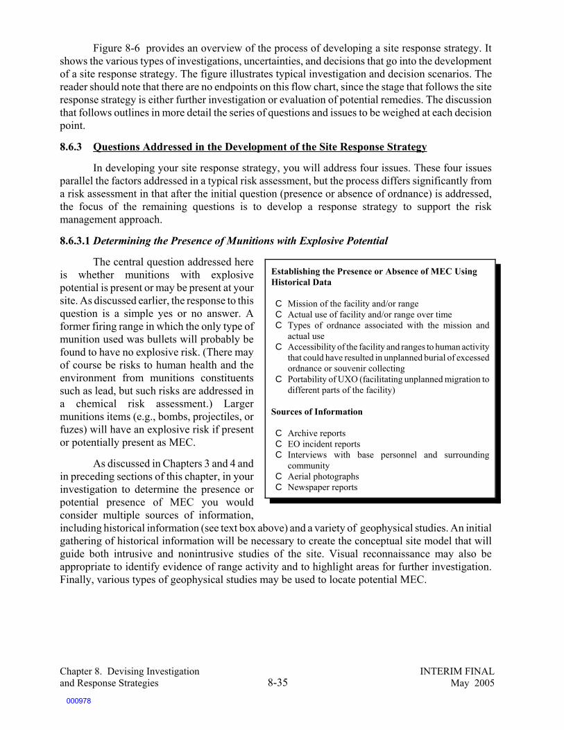
Chapter 8. Devising Investigation INTERIM FINALand Response Strategies May 20058-35
Figure 8-6 provides an overview of the process of developing a site response strategy. Itshows the various types of investigations, uncertainties, and decisions that go into the developmentof a site response strategy. The figure illustrates typical investigation and decision scenarios. Thereader should note that there are no endpoints on this flow chart, since the stage that follows the siteresponse strategy is either further investigation or evaluation of potential remedies. The discussionthat follows outlines in more detail the series of questions and issues to be weighed at each decisionpoint.
8.6.3 Questions Addressed in the Development of the Site Response Strategy
In developing your site response strategy, you will address four issues. These four issuesparallel the factors addressed in a typical risk assessment, but the process differs significantly froma risk assessment in that after the initial question (presence or absence of ordnance) is addressed,the focus of the remaining questions is to develop a response strategy to support the riskmanagement approach.
8.6.3.1 Determining the Presence of Munitions with Explosive Potential
The central question addressed hereis whether munitions with explosivepotential is present or may be present at yoursite. As discussed earlier, the response to thisquestion is a simple yes or no answer. Aformer firing range in which the only type ofmunition used was bullets will probably befound to have no explosive risk. (There mayof course be risks to human health and theenvironment from munitions constituentssuch as lead, but such risks are addressed ina chemical risk assessment.) Largermunitions items (e.g., bombs, projectiles, orfuzes) will have an explosive risk if presentor potentially present as MEC.
As discussed in Chapters 3 and 4 andin preceding sections of this chapter, in yourinvestigation to determine the presence orpotential presence of MEC you wouldconsider multiple sources of information,including historical information (see text box above) and a variety of geophysical studies. An initialgathering of historical information will be necessary to create the conceptual site model that willguide both intrusive and nonintrusive studies of the site. Visual reconnaissance may also beappropriate to identify evidence of range activity and to highlight areas for further investigation.Finally, various types of geophysical studies may be used to locate potential MEC.
Establishing the Presence or Absence of MEC UsingHistorical Data
C Mission of the facility and/or rangeC Actual use of facility and/or range over timeC Types of ordnance associated with the mission and
actual useC Accessibility of the facility and ranges to human activity
that could have resulted in unplanned burial of excessedordnance or souvenir collecting
C Portability of UXO (facilitating unplanned migration todifferent parts of the facility)
Sources of Information
C Archive reportsC EO incident reportsC Interviews with base personnel and surrounding
communityC Aerial photographsC Newspaper reports
000978

Chapter 8. Devising Investigation INTERIM FINALand Response Strategies May 20058-36
2
Qualitative Assessment ofUncertainties--Weight of EvidenceConsider: Are measurement qualityobjectiv es being met by historicalinf ormation and geophy sicalstudies? Are measurement qualityobjectiv es set at a lev el that supportsa high lev el of certainty ?
Is thereany ev idence that
MEC may hav e beenused or disposed of at
the site?
No
Doesavailability and
quality of historicalinformation suggestmoderate to high
levels ofuncertainty?
No
Conductgeophy scial
studies (detection)
Conduct HistoricalResearch
Yes
Are theboundaries of
the areaknown?
Yes
No Yes
Qualitative Assessment ofUncertainties--Weight of EvidenceConsider: How many sources of dataare av ailable, are thereinconsistencies in the data, isinf ormation av ailable ov er time?
No
Do y ouhav e a high lev elof conf idence in
results of thegeophy sical
studies?
No
Yes
Havemunitions or f ragments
been detected that suggesta ty pe of munitions
capable of explosiv edamage?
Geophysical munitions detectionstudiesStudies to detect potential presence,ty pe, depth and boundaries of MEC.May include detection, anomalyexcav ation, QA/QC, statisticalsampling (see Chapter 8.0)
Areadditional
geophy sical studiestechnically andeconomically
practical?
Conduct additionalgeophy sicalstudies as
required by gaps/uncertainties
Yes
No
Yes
Potentially change PRG/land use. Implement
appropriate institutionalcontrols. Use regulatorydecision process to make
hazard managementdecision.
Historical Research1) Archiv al Research2) EOD Incident Reports3) Aerial Photos4) Base/Community Interv iews5) Surf ace Observ ation
Explosive PotentialPathw
ays of Exposure
1
No action or limited action(e.g., institutional controls
and monitoring).Use regulatory decision
process (e.g., CERCLA ninecriteria, RCRA, DDESB,DERP) to make hazardmanagement decision
Figure 8-6. Developing a Site Response Strategy
000979
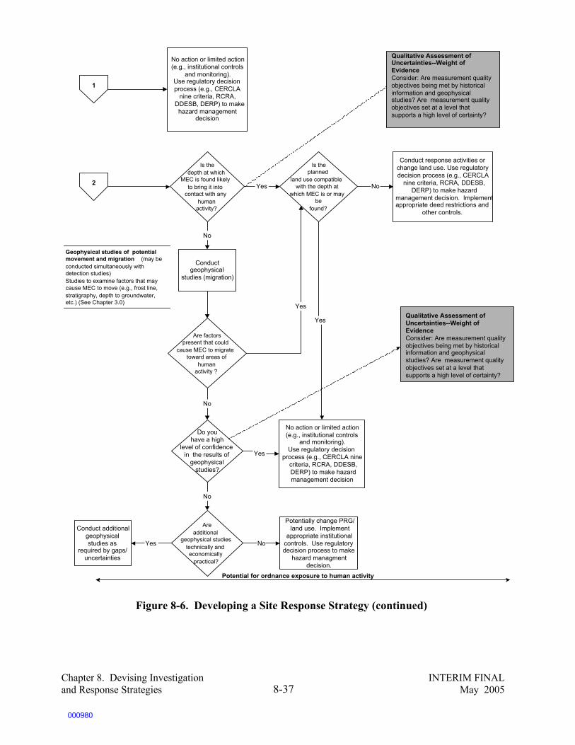
Chapter 8. Devising Investigation INTERIM FINALand Response Strategies May 20058-37
2
No action or limited action(e.g., institutional controls
and monitoring).Use regulatory decisionprocess (e.g., CERCLA
nine criteria, RCRA,DDESB, DERP) to makehazard management
decision
Is the depth at which
MEC is found likelyto bring it into
contact with anyhuman
activity?
Qualitative Assessment ofUncertainties--Weight ofEvidenceConsider: Are measurement qualityobjectives being met by historicalinformation and geophysicalstudies? Are measurement qualityobjectives set at a level thatsupports a high level of certainty?
1
Is theplanned
land use compatiblewith the depth at
which MEC is or maybe
found?
Yes
Conduct response activities orchange land use. Use regulatorydecision process (e.g., CERCLA
nine criteria, RCRA, DDESB,DERP) to make hazard
management decision. Implementappropriate deed restrictions and
other controls.
No
Conductgeophysical
studies (migration)
No
Are factorspresent that could
cause MEC to migratetoward areas of
humanactivity ?
Do youhave a high
level of confidencein the results of
geophysicalstudies?
No
Yes
Yes
No action or limited action(e.g., institutional controls
and monitoring).Use regulatory decision
process (e.g., CERCLA ninecriteria, RCRA, DDESB,DERP) to make hazardmanagement decision
Yes
Qualitative Assessment ofUncertainties--Weight ofEvidenceConsider: Are measurement qualityobjectives being met by historicalinformation and geophysicalstudies? Are measurement qualityobjectives set at a level thatsupports a high level of certainty?
Areadditional
geophysical studiestechnically andeconomically
practical?
No
Conduct additionalgeophysicalstudies as
required by gaps/uncertainties
Yes
Potential for ordnance exposure to human activity
Potentially change PRG/land use. Implement
appropriate institutionalcontrols. Use regulatorydecision process to make
hazard managmentdecision.
No
Geophysical studies of potentialmovement and migration (may beconducted simultaneously withdetection studies)Studies to examine factors that maycause MEC to move (e.g., frost line,stratigraphy, depth to groundwater,etc.) (See Chapter 3.0)
Figure 8-6. Developing a Site Response Strategy (continued)
000980

Chapter 8. Devising Investigation INTERIM FINALand Response Strategies May 20058-38
8.6.3.2 Identifying Potential Pathways of Exposure
Once the actual or potential presence of MEC has been established, you will then need toidentify the potential exposure routes. The essential question in this phase is whether the ordnancethat is found in the area is, or could be, at a depth that will bring it into contact with human activity.In the site characterization, you established the preliminary remediation goal (PRG), which specifiesthe depth to which clearance will be required to support the anticipated land use. Using historicalinformation and geophysical data, you should consider two questions:
C Has ordnance, fragments ofordnance, or explosives-contaminated soil been detected,suggesting the presence ofMEC? (Is there munitions withexplosive potential?)
C Is this material found at a depththat is shallower than the PRG(and likely to bring it intocontact with human activity)?
If the ordnance is not found at a depththat is shallower than the PRG, additionalgeophysical studies may be necessary todetermine if there are factors that may causeordnance to move (e.g., frost line orstratigraphy). (See Chapter 3 and earlier in thischapter.)
If ordnance is found to be present or potentially present, you may need additionalgeophysical information in order to ensure that the boundaries of the range and the density ofordnance are well understood for the purposes ofassessing the complexity (and cost) ofremediation.
8.6.3.3 Determining Potential for HumanExposure to MEC
The potential for human exposure isassessed by looking at the types of humanactivities that might bring people into contactwith MEC. Key issues for determining thepotential of human receptors to come intocontact with MEC include:
C Depth of ordnance MEC andexposure pathways of concern
C Potential for naturally caused migration to depths of concern
Factors To Be Evaluated in Identifying PotentialPathways of Exposure
In addition to the information highlighted in theprevious box (regarding the historical uses of, andlikely ordnance at, the site), factors that affectpathways of exposure include:
C Current and future land use, and depth to whichland must be clear of MEC to support that landuse; level of intrusive activity expected now andin the future
C Maximum depths at which ordnance is or may befound, considering the nature of the ordnance
C Location of frost lineC Erosion potentialC Portability of type of ordnance for souvenir
handling and illegal burialC Potential that excessed ordnance may have been
buried
About Portability
The potential of exposure to MEC through humanactivity goes beyond the actual uses of ranges.Potential exposures to MEC can also occur as a resultof human activity that causes MEC to migrate todifferent locations. Examples of such common humanactivities include:
C Burial of chemical protective kits (containingchemical waste material) by soldiers in trainingexercises.
C Transport of UXO as souvenirs to residentialareas of the base and off base by soldiers orcivilians.
000981

Chapter 8. Devising Investigation INTERIM FINALand Response Strategies May 20058-39
C Accessibility of areas where MEC is known or suspected to be present to workers,trespassers, etc.
C Potential for intrusive activity (e.g., construction in the MRS)C Current and potential future ownership of the site(s) C Current and potential future land use of the site(s) and the surrounding areas
(including potential groundwater use)C Potential portability of the MEC (for potential human-caused migration off range)
During the final phase of the analysis, you should consider information and uncertaintiesfrom all phases of the investigation to determine whether there is a risk at the depth of concern. Ifthe planned land use is not compatible with the depth at which ordnance is or may be found, thentwo options are possible:
C Remediate to a depth appropriate for the planned land use. C Change the planned future land use to be consistent with the depth of cleanup.
Both of these decisions will be made during the risk management decision process under theapplicable regulatory framework (e.g., CERCLA or RCRA). Unless you have a high level ofcertainty that remediation will clear the land for an unrestricted land use, appropriate institutionalcontrols will be required.
8.6.3.4 Considering Uncertainty
In every stage of site characterization, including the development of a site response strategy,a qualitative evaluation of uncertainty will help you decide the level of confidence you have in theinformation collected to determine your next steps. No single source is likely to provide theinformation required to assess the level of certainty or uncertainty associated with your analysis.Therefore, your qualitative uncertainty analysis will rely on the weight of the evidence that hasconverged from a number of different sources of data, including historical information (archives,EOD incident reports, interviews, etc.), results of detection studies and sampling, results of othergeophysical studies, assessment of current and future land use, and accessibility of MRAs/MRSs.
8.7 Framework for Making the Decision
The Interim Final Management Principles agreed to by senior DoD and EPA managers(described in and provided as an attachment to Chapter 2, “Regulatory Overview”) establish aframework for making risk management decisions. These principles state that “a process consistentwith CERCLA and these management principles will be the preferred response mechanism used toaddress UXO at a range.” The principles go on to state that response actions may include CERCLAremoval or remedial activities, or some combination of these, in conducting the investigation andcleanup.
8.8 Conclusion
The focus of this chapter has been on planning your investigation. In the course of theinvestigation, the initial plan will undoubtedly change. The conclusion of the investigation shouldresult in answers to the questions posed in the data quality objectives at a level of certainty that isacceptable to the DoD decision makers, the regulators, and the public.
000982

Chapter 8. Devising Investigation INTERIM FINALand Response Strategies May 20058-40
The purpose of this chapter has been to take you through the design of the MEC investigationto the development of a site response strategy. As pointed out in the introduction, this chapter hasfocused primarily on MEC and energetic materials, not the environmental contamination of mediaby munition constituents. Chapter 3 describes common chemicals of concern that are found inassociation with MRAs. Typically, the approaches used to investigate explosive compounds will notdiffer substantially from other environmental investigations of hazardous wastes, pollutants, andcontaminants, except that safety considerations will require more extensive health and safety plansand generally be more costly since the potential for MEC in the subsurface must be considered.
The development of a site response strategy is based on the Interim Final ManagementPrinciples, which call for investigation and cleanup actions to be consistent with both the CERCLAprocess (either removal or remedial activities, or a combination of these) and the principlesthemselves. The actual selection of a response will be conducted through the risk managementprocesses defined by the CERCLA removal and remedial programs (or the RCRA Corrective ActionProgram).
000983

Chapter 8. Devising Investigation INTERIM FINALand Response Strategies May 20058-41
SOURCES AND RESOURCES
The following publications, offices, laboratories, and websites are provided as a guide forhandbook users to obtain additional information about the subject matter addressed in each chapter.Several of these publications, offices, laboratories, or websites were also used in the developmentof this handbook.
Publications
Crockett, A.B., H.D. Craig, T.F. Jenkins, and W.E. Sisk. Field Sampling and Selecting On-siteAnalytical Methods for Explosives in Soil. U.S. EPA, Federal Facilities Forum, Dec. 1996;EPA/540/S-97/501. Available at URL: http://www.epa.gov/nerlesd1/tsc/images/fld-smpl.pdf.
Crockett, A.B., H.D. Craig, and T.F. Jenkins. Field Sampling and Selecting On-site AnalyticalMethods for Explosives in Water. U.S. EPA, Federal Facilities Forum, May 19, 1999; EPA/600/S-99/002.Available at URL: http://www.epa.gov/nerlesd1/tsc/images/water.pdf.
U.S. Army. Military Explosives. Department of the Army Technical Manual. TM 9-1300-214.September 1984.
Wilcox, R.G. Institutional Controls for Ordnance Response. Paper presented at UXO Forum 1997,May 1997.
Information Sources
Joint UXO Coordination Office (JUXOCO)10221 Burbeck Road, Suite 430Fort Belvoir, VA 22060-5806Tel: (703) 704-1090Fax: (703) 704-2074http://www.denix.osd.mil/UXOCOE
U.S. Army Corps of EngineersEngineering Research and Development CenterCold Regions Research and Engineering Laboratory72 Lyme RoadHanover, NH 03755-1280http://www.crrel.usace.army.mil
U.S. Army Corps of EngineersU.S. Army Engineering and Support CenterOrdnance and Explosives Mandatory Center of ExpertiseP.O. Box 1600 4820 University SquareHuntsville, AL 35807-4301http://www.hnd.usace.army.mil/
000984
Chapter 8. Devising Investigation INTERIM FINALand Response Strategies May 20058-42
Department of Defense Explosives Safety Board (DDESB) 2461 Eisenhower AvenueAlexandria, VA 22331-0600Fax: (703) 325-6227 http://www.ddesb.pentagon.mil
U.S. Environmental Protection AgencySuperfund Risk Assessmenthttp://www.epa.gov/superfund/programs/risk/index.htm
Guidance Documents
U.S. Air Force, Headquarters, Air Force Center for Environmental Excellence. Technical ServicesQuality Assurance Program. Version 1.0, Aug. 1996.
U.S. Army Corps of Engineers. Requirements for the Preparation of Sampling and Analysis Plans.Manual EM 200-1-3. February 1, 2001.
U.S. Army Corps of Engineers. Chemical Data Quality Management for Hazardous, Toxic,Radioactive Waste Remedial Activities. ER 1110-1-263. April 30, 1998.
U.S. EPA. Guidance on Conducting Non-time-critical Removal Actions Under CERCLA. NTISNo. PB93-963402; Aug. 1993.
U.S. EPA. Guidance for Data Usability in Risk Assessment (Part A). NTIS No. PB92-963356;Apr. 1992.
U.S. EPA. Guide to Preparing Superfund Proposed Plans, Records of Decision, and OtherRemedy Selection Decision Documents. NTIS No. PB98-963241; July 1999.
U.S. EPA. Institutional Controls and Transfer of Real Property Under CERCLA Section120(h)(3)(A), (B) or (C). Feb. 2000.
U.S. EPA. Risk Assessment Guidance for Superfund (RAGS), Volume I – Human HealthEvaluation Manual, Part A. Interim Final. Dec. 1989.
U.S. EPA. Risk Assessment Guidance for Superfund (RAGS), Volume I – Human HealthEvaluation Manual, Part C (Risk Evaluation of Remedial Alternatives). Interim Final. Oct. 1991.
U.S. EPA. Risk Assessment Guidance for Superfund (RAGS), Volume I – Human HealthEvaluation Manual, Part B. Interim Final. Dec. 1991.
U.S. EPA. Risk Assessment Guidance for Superfund (RAGS), Volume I – Human HealthEvaluation Manual, Part D (Standardized Planning, Reporting, and Review of Superfund RiskAssessments). Interim Final. Jan. 1998.
U.S. Navy. Environmental Compliance Sampling and Field Testing Procedures Manual.NAVSEA T0300-AZ-PRO-0010; July 1997.
000985

Chapter 9. Underwater INTERIM FINALMunitions and Explosives May 20059-1
9.0 UNDERWATER MUNITIONS AND EXPLOSIVES OF CONCERN
Throughout this handbook, we havediscussed a wide range of technical issuesassociated with MEC when it is found on land.All of the problems, issues, and concerns can bemultiplied several times when MEC is foundunderwater. As with land-based MEC, theconcerns involve risks to human health, theenvironment, and explosive hazards. However,the routes of exposure and the fate and transportfor land-based and underwater ordnance can bedifferent. There are a number of uncertaintiesthat affect our decision-making regarding themanagement of MEC in the underwater environ-ment. These include, but are not limited to, thefollowing:
C Information on the fate and transport of munitions constituents in the underwaterenvironment is lacking or not widely distributed.
C Finding underwater MEC offers additional complexities in detection, discrimination, andpositioning.
C Safety issues can be magnified in the underwater environment.C For reasons of personal safety, blowing in place (BIP) is (as it is on land) the common
method for disposing of UXO unless the UXO item has been determined to be safe tomove. (However, if conducting underwater BIP, the effects of underwater detonation tohumans and the underwater ecosystem must be addressed.)
This chapter addresses what is known about the areas listed above, as well as the uncertaintyin each area. The chapter is divided into four parts.
C Design of a conceptual site model for underwater rangesC Detection of underwater MECC SafetyC Underwater response technologies
9.1 Conceptual Site Model for Underwater EnvironmentsThis section addresses the unique factors in designing a conceptual site model (CSM) for
underwater MEC, including the following:
C The areas where underwater MEC is found,C The potential for exposure to MEC,C The environmental factors affecting decomposition of underwater MEC, resulting in
potential for releases of munition constituents,C The environmental fate and transport of munitions constituents, andC The ecological and human health effects and toxicity of explosive compounds and other
munitions constituents in the underwater environment.
Snagging WWII Underwater Munitions
In July 1965, a fishing trawler off the coast of NorthCarolina snagged a World War II German torpedo inits nets. As the crew attempted to lift the torpedo clearof the water in heavy seas, the warhead hit the side ofthe trawler and detonated. Eight of the twelve crewmendied and the vessel sank.
Source: A. Pedersen, The Challenges of UXO in theMarine Environment, Naval EOD TechnologyDivision. Modified by written communication.
000986

135As used in this handbook, the term offshore refers to the area that is in the intertidal area and further out.
Chapter 9. Underwater INTERIM FINALMunitions and Explosives May 20059-2
9.1.1 Areas Where Underwater MEC Is Found
Much of the U.S. underwater MEC presence has occurred near military practice and testranges. Activities at locations such as ammunition piers, coastal bombing ranges, and dredge spoilponds, among others, have also resulted in a wide variety of MEC items. In addition, war,intentional dumping, and accidental dumping have contributed to the problem.
Some of the military activities that have historically resulted in underwater MECcontamination are described below:
C Ammunition storage and transfer activities – MEC may be deliberately oraccidentally dumped near piers where ships load and unload munitions or materiel(mishandling/loss).
C Weapons training and testing – For some kinds of training, the underwaterenvironment, particularly the deep ocean, may be target impact areas and areaswhere underwater munitions such as sea mines or torpedoes were used. These areasinclude ships that are used as practice targets. Other weapons training activities mayhave a range safety fan that includes a body of water where munitions that miss thetarget might land. MEC can include dud-fired munitions, low-order detonations,intact munitions, and dumped munitions (mishandling/loss).
C Troop training areas – Training areas may be on shorelines (near wetlands, oceanbeaches, tidal wetland areas, etc.) or over rivers, lakes, or ponds. As in land-basedtraining, unauthorized disposal, or loss of material, can result in MEC in underwaterareas. Overshoots and undershoots on islands used as targets for aerial bombing,missiles, and naval artillery can also result in MEC in underwater areas. Examplesof where such events have occurred include Nomans Land Island, Massachusetts,Kaho’olawe Island, Hawaii, and Adak, Alaska.
C Disposal of MEC – In the past, large- or small-scale dumping of military munitionsoccurred offshore.135 In addition, disposal of underwater UXO may result in chunksof MEC released from low-order detonations. These disposal operations could haveresulted in the introduction of munitions constituents to the aquatic environment.
9.1.2 Potential for Exposure to MEC
Potential human exposures to underwater MEC or UXO result from different factors than land-based exposures. Both land-based and underwater exposure can be from recreational and industrialuses, but other potential exposures are unique to the underwater environment (see Figure 9-1). Table9-1 shows examples of activities and potential exposure. In addition, underwater MEC can migrateas a result of tides, surf, currents, floods, or other factors.
000987

Chapter 9. Underwater INTERIM FINALMunitions and Explosives May 20059-3
Table 9-1. Exposure Scenarios from Underwater MEC and UXO
Potential Receptor Activity Exposure Pathway MEC Hazard and Risk Type
Near-shore recreational use, (e.g.,swimming, fishing)
Beaches, shorelines,river bottoms, sediments
Explosive hazard,munitions residue
Port and channel maintenancesuch as dredging and dredge spoildisposal
River bottoms, sediments Explosive hazard,munitions residue
Commercial fishing, trawling forfish
Fishing activity that brings upunknown items
Explosive hazard
Deep sea recreational use such asdiving
Coral reefs, other underwaterformations, sunken ships
Explosive hazard
Consumption of seafood Food chain Munitions residue
Fish feeding areas, nurseries Sediments, benthic organisms Munitions residue
In addition to the potential receptor activities and related exposure pathways listed in the table,the disposal of ordnance in the underwater environment is another exposure pathway that may bedifficult to control. As discussed in Chapter 5, blow-in-place is usually the preferred method fordisposing of UXO because of safety considerations. This is true in underwater environments as wellas on land. However, the underwater detonation of UXO may pose a significant risk to underwaterecological receptors and sensitive habitats, including wetlands, estuaries, coastal areas, and marinehabitats such as coral reefs.
In the example presented below, one naval facility began the design of its conceptual sitemodel by dividing the offshore area into four offshore clearance zones. These zones were based on
000988

136Technical Memorandum for Offshore OE Clearance Model, OE Investigation and Response Actions, FormerMare Island Naval Shipyard (MINS). Prepared for Commander, Pacific Division, Naval Facilities EngineeringCommand, Pearl Harbor, HI. February 11, 1999.
Chapter 9. Underwater INTERIM FINALMunitions and Explosives May 20059-4
likely human access due to water depth, with the flexibility to change a zone as appropriate. Theseoffshore clearance zones were defined as follows:136
C Zone 1: The portion of the sea floor that is not covered by water most of the time and canbe walked on during low tides — Intertidal zone
C Zone 2: The portion of the sea floor that is easily accessible by wading from the shorebut is covered by water most of the time — Shallow subtidal zone
C Zone 3: The portion of the sea floor that is not accessible by wading but is accessible byskin diving from a boat or a pier — Intermediate subtidal zone
C Zone 4: The portion of the sea floor that is accessible only by self-containedunderwater breathing apparatus (SCUBA) or surface-supplied-air diving — Deepsubtidal zone
The offshore clearance zones and zone depths are shown in cross-section in Figure 9-1.
Figure 9-1. Example of Offshore Clearance Zones
9.1.3 Environmental Factors Affecting Decomposition of Underwater MEC Resulting inReleases of Munitions Constituents
A number of complex factors affect the fate and transport of munitions constituents releasedin the underwater environment. These factors include the nature of the delivery of the munition itemto the underwater environment, its potential for corrosion, and associated releases.
Underwater releases of munition constituents can occur when casings deteriorate, (mostnotably from corrosion), rupture upon impact, or undergo a low-order detonation. Munitions
000989

137J.M. Brannon, et al. Conceptual Model and Process Descriptor Formulations for Fate and Transport ofUXO. USACE WES, February 1999.
138Note that in deeper waters where residence time and turnover are measured in decades or centuries, anaerobicconditions exist that tend to preserve items.
Chapter 9. Underwater INTERIM FINALMunitions and Explosives May 20059-5
constituents may be released immediately after impact or may be only partially contained within theremains of the delivery system. When UXO undergoes a low-order detonation or breaks apart uponimpact, the munitions constituents, such as bulk explosives, can be scattered over the impact area.137
(See Section 3.2.3). When the MEC remains relatively intact, munitions constituents can be releasedthrough pinhole cracks that develop over time as a result of corrosion or through the screw threadslinking the fuze assembly to the main charge.
Corrosion of the iron and steel in MEC casings is a complex process that occurs in thepresence of water and oxygen. The potential corrosivity of the local environment, such as a bay,harbor, lake, pond, or wetland, could vary greatly. Such variations can be caused by acid rain,industrial pollution, salinity, degree of oxygen saturation, or natural buffering caused by thepresence of carbonate rocks or other minerals. Normally, the lower the pH of the environment, thehigher its corrosive potential.
The effects of immersion and corrosion on the release of munition constituents in variousunderwater environments depend on site conditions. Even though saltwater is potentially morecorrosive the higher the salt saturation, exposure to oxygen is a key requirement for corrosiveeffects. In environments where wave action and tides cause mixing with the atmosphere, the oxygencontent of the water, especially shallow water, can be at or near the saturation point, creating a highpotential for oxidation. Likewise, repeated exposure of MEC items directly to the oxygen in theatmosphere through tidal movement can increase corrosion.
Recent studies have suggested that even corroded MEC does not necessarily result in theharmful release of munition constituents. A variety of factors in the underwater environment mayeither reduce the potential for corrosion, or affect the nature of the release from an MEC itemreleasing munition constituents. At higher pH levels, if the right conditions are present (e.g., CO2saturation, or temperature) submerged or buried metal may develop a coating of calcium carbonate,with a corresponding increase in corrosion resistance. In the absence of oxygen, such as theanaerobic conditions that can exist where there are large concentrations of unoxidized metals, orhigh content of organic matter, or in deeper, cold waters, corrosion in the underwater environmentcan be virtually stopped. It is also possible that submerged UXO and MEC can develop a coatingconsisting of biological materials that can seal the item off from the environment (as well as makeit more difficult to locate.)138
Corrosion of steel casings can produce a complex local environment composed of intact steeland iron oxidation and reduction products through which the munition constituents must pass toenter the environment. Recent studies have shown that the presence of metallic iron can stronglyaffect the fate and transport of munition constituents in underwater environments. This process canlead to certain munition constituents, such as RDX, being removed from solution through chemicalreduction unless a source, such as a ruptured casing, continues to release the constituents to theunderwater environment. The effects of the presence of iron and steel on the fate and transport of
000990

139J.M. Brannon, et al. Conceptual Model and Process Descriptor Formulations for Fate and Transport ofUXO.
140Brannon, et al. Conceptual Model and Process Descriptor Formulations for Fate and Transport of UXO.
141M. Dock, M. Fisher, and C. Cumming. Sensor for Real-Time Detection of Underwater UnexplodedOrdnance. Paper presented at the 2002 UXO/Countermine Forum, Orlando, FL, September 2002.
Chapter 9. Underwater INTERIM FINALMunitions and Explosives May 20059-6
munition constituents should be investigated further to determine the rate and extent of these effectson releases in an underwater environment.139
9.1.4 Environmental Fate and Transport of Munitions Constituents
The major pathways of concern for releases of munitions constituents in the underwaterenvironment are the sediments that are found on the bottom of most rivers, lakes, ponds, wetlands,and other near-shore coastal environments. These sediments support biological communities thatare the food for aquatic life. The main concerns include the following:
C The continued health of the biological community and its ability to support theecosystem.
C Potential uptake of chemicals into the plants and sea life that ultimately form part of thefood chain for people and marine life.
C Munitions constituents that may be suspended in water and potentially available tohumans (through dermal contact as a result of recreational use, and ingestion of drinkingwater) and consumption of marine life.
As shown in Chapter 3, many munitions constituents (including the most common compounds,TNT, RDX, and HMX) have been shown to be potentially toxic to aquatic organisms. However,the potential for aquatic toxicity depends both on the fate and transport mechanism at work, and thedose exposure of aquatic organisms to these constituents. There is a mounting body of evidence thatsuggests that the potential for aquatic toxicity is not often realized in the open water environmentwhere often the concentration of munitions constituents will not be detectable due to a variety offactors, including advection, dispersion, diffusion, photolysis, plant update, and biotictransformation.140 In addition, there is increasing evidence that these compounds do notbioaccumulate in aquatic tissue.
When evaluating the fate and transport of the munitions constituents and the actual potentialimpact of releases of these constituents on both humans and aquatic life, a variety of complexinteractions between the physical and chemical properties of these chemicals must be understood.Any of these compounds can release to the aquatic environment through the same releasemechanisms as they release to land. As on land, complete detonations release compounds in suchsmall quantities that the detection of constituents in sediments or in water is not likely. However,water in the immediate vicinity of a continuing source, such as constituents leaking from a crackedor leaking MEC casing or low-order detonation, can contain the munitions constituent in measurablequantities.141 TNT is more water soluble than RDX and HMX and is therefore more likely to befound in small concentrations in water. Since RDX and HMX have a very low water solubility, they
000991

142Personal communication with Thomas Jenkins, Ph.D, of USACOE ERDC/CRREL, on February 20, 2003.
143Personal communication with Thomas Jenkins, Ph.D., of USACOE ERDC/CRREL, on February 20, 2003.
144J.G. Burken. Phytoremediation/Wetlands Treatment at the Iowa Army Ammunition Plant.http://www.mhhe.com/biosci/pae/environmentalscience/casestudies/case12.html.
145M. Nipper, R.S. Carr, J.M. Biedenbach, R.L. Hooten, and K. Miller. Toxicological and Chemical Assessmentof Ordnance Compounds in Marine Sediments and Pore Water. Marine Pollution Bulletin. February 12, 2002.
Chapter 9. Underwater INTERIM FINALMunitions and Explosives May 20059-7
are much more likely to be dispersed as small particles by currents and unavailable either throughsediments (and plant uptake), or ingestion, or dermal contact in the water column.142
Munitions constituents differ in how easily they bind to sediments, which may then act as asource of continuing release to water, or as a source for aquatic life uptake. Since TNT is morewater soluble than RDX or HMX, it is less likely to bind to sediments, and more likely to beimmediately absorbed into water. However, TNT also tends to be more susceptible tophotodegredation and biotransformation, particularly in shallow water. TNT’s aminobiotransformation products will bind to the humic acids in sediments more strongly than RDX orHMX. This tendency to bind to sediment can reduce the overall concentration of TNT’sbiotransformation products in water, in spite of their relatively higher water solubility compared toRDX and HMX.143
Bio-uptake and bioaccumulation of munitions constituents into the food chain via aquaticplants and other organisms that grown in sediments is not well understood. Recent research onphytoremediation has shown that plants can take up munitions constituents such as TNT, RDX, andHMX. These munitions constituents will also undergo some biotransformation in the plants’ tissues.The Waterways Experiments Station in Vicksburg, Mississippi, has conducted research into theuptake of TNT and RDX by aquatic plants. In these laboratory studies, TNT and its degradationproducts were not detected, but RDX was found to accumulate in a number of plant tissues.144
Biotransformation products and their properties are important factors in the fate and transportof munitions constituents. Additional research is needed on the toxicity and fate of theseconstituents’ biotransformation products and the role sediments play in binding them. In one case,toxicological and chemical studies were performed with silty and sandy marine sediment spiked with2,6-dinitrotoluene, tetryl, or picric acid. Whole sediment toxicity was analyzed for severalinvertebrate species. Tetryl was found to be the most toxic of the three spiked compounds. However,the study concluded that degradation products from the spiked compounds may have played a rolein the observed toxicity.145
Many knowledge gaps exist, including the bioavailability of munitions constituents and theirbiotransformation and degradation products, how these compounds might move up the food chain,and the level at which these compounds produce harmful effects in exposed organisms, includinghumans. Additional research should be done to evaluate the potential for human exposure resultingfrom bioaccumulation in the food chain.
000992

146R.S. Carr, R. Scott, and M. Nipper. Development of Marine Sediment Toxicity Data for OrdnanceCompounds and Toxicity Identification Evaluation Studies at Select Naval Facilities. Naval Facilities EngineeringService Center, Port Hueneme, CA. February 26, 1999.
147Nipper et al. Toxicological and Chemical Assessment of Ordnance Compounds in Marine Sediments andPore Water.
148Ibid.
Chapter 9. Underwater INTERIM FINALMunitions and Explosives May 20059-8
9.1.5 Ecological and Human Health Effects and Toxicity of Explosive Compounds andOther Munitions Constituents in the Underwater Environment
With the increased ability to detect MEC in water bodies near naval facilities, in harbors, andin water bodies adjacent to active and former ranges and training areas, concerns about theenvironmental contamination caused by munitions constituents and related compounds have grown.
Previous surveys that looked at munitions constituents, particularly in the sediments and porewater of Puget Sound in Washington, concluded that the studied munitions constituents were notthe main cause for concern. Rather, other organic compounds, such as PAHs, PCBs, pesticides, andto a lesser extent metals, were the main causative agents of the observed toxicity.146
One laboratory study was undertaken to assess the potential for adverse biological effects ofmunitions constituents in marine sediments and pore waters. Toxicological and chemicalcharacterizations were performed with two kinds of sediments with different grain-size distributionand organic carbon content. These sediments were spiked with munitions constituents whoseselection was based on one of the following two criteria: elevated toxicity to marine organisms orpresence in marine sediments near naval facilities. The study measured concentrations of munitionsconstituents in the spiked sediments and corresponding pore waters and, when possible, identifieddegradation products.147
A significant conclusion of this study was that the observed toxicity did not appear to beentirely the result of the spiked compounds. The data seemed to suggest that degradation productscould have played a major role in the toxicity tests. The study concluded that the actual degradationproducts and their persistence in the underwater environment need to be studied further andidentified.148
A review of a number of online toxicological databases (IRIS, ATSDR, CHPPM WTAs,TOXNET) provided some information regarding ecological toxicity of a number of munitionsconstituents. The information in these databases seems to be incomplete in a number of areas. Forexample, one study stated that it appeared RDX did not bioaccumulate in food crops or in deer orcattle. (However, see 9.1.4) Another study stated that it was not known if HMX accumulated inplants, fish, or animals in contaminated areas. It is clear that additional research is needed in thisarea. Additional toxicological information on a number of munitions constituents, including TNT,RDX, and HMX is found in Section 3.4.
000993

149Draft Conceptual Site Model for the Southern Offshore Ordnance Sites, Former Mare Island Naval Shipyard.Prepared for: Department of the Navy, Commander, Pacific Division, Naval Facilities Engineering Command, PearlHarbor, HI. July 17, 2002.
150Edwards, D. and R. Selfridge. Munition Item Detection Systems Used By The U.S. Army Corps of Engineersin Shallow Water Environments. U.S. Army Corps of Engineers, Huntsville Engineering and Support Center. February12, 2003.
151The actual evacuation distance is based on the net explosive weight of the ordnance item.
Chapter 9. Underwater INTERIM FINALMunitions and Explosives May 20059-9
9.1.6 An Example Conceptual Site Model
As discussed in Section 7.4, a CSM is needed in order to have a working hypothesis of thesources, pathways, and receptors at a site undergoing investigation. The CSM guides theinvestigation. An example of a CSM, created for the Southern Offshore Ordnance Sites, FormerMare Island Naval Shipyard, is provided in Figure 9-2.149
The Department of the Navy developed the CSM to examine historical site operations andprevious investigations and to identify current data gaps. This CSM, which will form the basis forfuture MEC site investigations, covers the offshore areas of the South Shore and OrdnanceProduction areas located on the south and southeast end of Mare Island, respectively.
9.2 Detection of Underwater MEC
The challenges of conducting an underwater munitiondetection survey include the properties of the water, the needto maintain safe working conditions, and the ability toaccurately locate and retrieve the detected items. Saltwater isvery corrosive, particularly in shallow water which has ahigher oxygen content. Instruments exposed to the saltwater must be properly sealed. When themunition detection instrument is a hand-held detector, precautions must be taken to seal instrumentsby taping a plastic bag over the electronics and keeping the electronics above the water. Usinginstruments that are factory sealed and designed for the underwater environment, such as White’sSurfmaster II and the Geonics EM-61 coils encased in epoxy with underwater connectors, is stronglyrecommended.150
Underwater munition survey work has typically required the use of divers, which presentssafety problems not encountered on land. For example, blast impacts carry further underwater thanthey do on land for an equivalent amount of net explosive weight. The average safe distance froman underwater detonation can be over five times that of a land detonation.151 Searching underwaterfor MEC is very time consuming as divers swim search patterns and mark any anomalies located.The use of more modern deployment systems on surface or submerged vehicles has its owndifficulties. The issues include the potential increase in distance between the sensor and the anomalyas the water depth increases, as well as the constant movement occurring in the water environment.The variability in the depth at which MEC items may be located beneath the surface may cause aneffective sensor system to become ineffective a few feet away, as the water depth increases, becauseof the sensor’s decreased ability to detect an anomaly as the distance from sensor increases. Theinstability of the underwater environment, due to currents, tides, and wave action, can increase thedifficulty in detecting anomalies. As on land, MEC items need to be located individually. However,
Everything is more difficultunderwater!
000994

Chapter 9. Underwater INTERIM FINALMunitions and Explosives May 20059-10
Figure 9-2. Example of a Conceptual Site Model
000995

152Environmental Chemical Corporation (ECC). Validation of Detection Systems (VDS) Test Program FinalReport. Burlingame, CA. July 7, 2000.
153R.J. Wold. A Review of Underwater UXO Systems in Europe. Paper presented at the 2002 UXO/CountermineForum, Orlando, FL, September 2002.
Chapter 9. Underwater INTERIM FINALMunitions and Explosives May 20059-11
the underwater environment is more unstable because of the action of waves, tides, and currents.Low visibility, sedimentation, and biological and mineral coatings on the items of interest also makeidentifying MEC much harder. Boats and divers also have greater difficulty maintaining andmarking their position. In spite of otherwise good weather conditions, work often must be stoppedbecause of safety considerations related to wave action. In addition, underwater currents, waveaction, and tides can cause underwater MEC to change location or become buried by sediment.
9.2.1 Detection Technologies
The two most common geophysical detection technologies are magnetometry andelectromagnetic induction (EMI), as discussed in Chapter 4. Much of the technology used for landsurveys can be adapted for underwater use. Various combinations of towed magnetometers, sidescansonar, and underwater Geonics EM-61 can be used. (See below and the case studies in Section9.2.4.1.) As on land, these technologies can be deployed on a variety of platforms. The selection ofa particular technology, platform, data processing technique, and geolocation device for a given siteoften depends on the bottom conditions, the types of MEC or UXO expected, and the size of the areathat is to be investigated. This is true with respect to the use of detection technologies in underwaterenvironments.
For example, the Navy sponsored a test program at the former Mare Island Naval Shipyard(MINS) in Vallejo, California. The Naval Facilities Engineering Command, Pacific Division,contracted with a private company to perform a Validation of Detection Systems test program atMINS. The objective of the program was to identify, select, and validate detection equipment andtechnologies that could be used to locate and detect MEC at the four offshore sites at MINS thatwere suspected of containing MEC. The technical approaches included EMI and magnetometry(discussed in 4.2.1.1 and 4.2.1.2).152
Magnetometry is a reliable, proven technology for detecting ferrous MEC over land. With theneed to detect underwater MEC increasing, a number of attempts have been made to adaptmagnetometry for use underwater. An American company has developed and deployed severalunderwater platforms employing magnetometry in shallow water with magnetometers using a smallboat as a platform. To date, they report that they have received few requests for underwater MECexploration in the United States. Recent examples of work have included:
C Offshore sand burrows for beach replenishment on the East CoastC Beach contamination from offshore UXO after storms on the East CoastC Expansion and deepening of harbors in San DiegoC BRAC sites, such as at Mare Island, California C Kaho’olawe Island, HawaiiC Offshore pipeline routes in Hawaii153
000996
154P. Pehme, Q. Yarie, K. Penney, J. Greenhouse, and D. Parker. Adapting the Geonics EM-61 for UXO Surveysin 0-20 Metres of Water. Paper presented at the 2002 UXO/Countermine Forum, Orlando, FL, September 2002.
155Ibid.
156Wold. A Review of Underwater UXO Systems in Europe.
Chapter 9. Underwater INTERIM FINALMunitions and Explosives May 20059-12
With respect to EMI, operating a system underwater presents at least two basic challenges.The first is the presence of water itself, particularly saltwater, which is very corrosive, and secondis the inherent difficulty of controlling and tracking a sensor array. The high electrical conductivityof saltwater limits the penetration of electrical and electromagnetic energy. There are also challengesin producing the primary field and measuring its decay. To detect objects underwater, it is necessaryto reduce the distance to the target by submerging the sensor. The sensor is either dragged along thebottom or “flown” above the bottom. This creates the problem of knowing the location of a sensorthat cannot be seen.154
Both magnotometry and electromagnetic induction have problems when deployed in themarine environment. For example, magnetometers are very sensitive to distortions in the earth’smagnetic field caused by the iron and steel in MEC items. Magnetometers can sense thesedistortions to greater depths than other systems. They also can detect small anomalies. However,magnetometers are susceptible to the magnetic signature of non-MEC items, such as the hulls ofpassing ships and iron and steel debris such as discarded anchors, as well as geologic noise fromcertain mineral deposits. In addition, the corrosivity of the underwater environment, particularlyin shallow saltwater where more oxygen is available, causes the iron and steel components of MECto corrode, reducing the magnetic signature.
Electromagnetic induction systems also have a number of problems. The electricalconductivity of water limits the penetration of electrical and electromagnetic energy. In time-domainsystems, such as the Geonics EM-61, the signal decay occurs at a slower rate than on land, and thetime gates of the system must be adjusted accordingly. Operation in sea water, with its high salinity,can cause a high power draw, which makes a large supply of batteries necessary.155
9.2.2 Platform, Positioning, and Discrimination
The three common operational platforms for deploying MEC sensors are man-portable hand-held, towed-array, and airborne (see Section 4.2.3). The methods of underwater deployment aresimilar. Hand-held sensors are used by divers swimming along a search pattern. Towed arrayscontaining several magnetometers can be pulled along the bottom. Arrays can also be suspendedfrom an underwater mast or other device and “flown” along, either at a fixed distance below thesurface of the water or at a fixed distance above the bottom. In the near-shore areas, detectors canbe affixed to floating platforms as well.156
Positioning techniques vary depending on the platform employed. The simplest means ofidentifying the position of an anomaly is similar to the land-based “Mag and Flag.” The anomalyposition is marked by or in relation to a buoy. Arrays employ differential global positioning system(DGPS) to mark the position of any anomaly. More sophisticated platforms will also use a high-frequency echo sounder to accurately record the distance between the sensors and the bottom.
000997

157Pehme, et al. Adapting the Geonics EM-61 for UXO Surveys in 0-20 Metres of Water.
158Ibid.
159Ibid.
Chapter 9. Underwater INTERIM FINALMunitions and Explosives May 20059-13
A number of factors affect the ability to discriminate between MEC and non-MEC. Theseinclude the instruments used, the platform, and the depth of the water over a target. Formagnetometers, the apparent size of the anomaly depends on the elevation of the sensor above theanomaly. Thus, when interpreting the data, the depth of the anomaly must be taken into account.Two issues must be considered: (1) distance from the sensor to the sediment-water interface, and(2) distance of the anomaly below the sediment-water interface. The water depth above thesediment-water interface changes because of bottom topography, tides, and water level changes inrivers caused by floods and drought. For EMI, both the distance between the receiver coils and theanomaly and the separation between the transmitter and the receiver coils must be accounted for inthe interpretation. In many cases, the instrument will not be able to determine the size or numberof targets.
When the depth of the smallest object under investigation is within the detection limit of thesensor, the preferred platform is the surface of the water. In that situation, the attitude of the sensoris observable, the elevation of the sensor above the water bottom is known or can be determined,and the sensor position is easily measured using a GPS. However, wave action will significantlyaffect the attitude and the stability of the surface sensor and therefore the detectability of MEC. Foranomalies approximately the size of a 12-pound MEC item, the depth limit (water depth anddistance below the bottom sediments) is approximately 1.5 to 2 meters for a typical magnetometeror EMI instrument.157
At depths of approximately 2 to 4 meters, the geophysical sensors can be placed on a partlyor fully submerged platform. This platform is rigidly linked to the watercraft, whose position ismonitored by GPS. An alternative arrangement is to attach the GPS antenna to a bottom-holdingsystem.158
At depths greater than 4 meters, controlling and measuring the depth and position of asubmerged platform becomes more difficult. The depth to the bottom of a bottom-holding platformcan be estimated by triangulation based on the measured water depth and the length of a towingcable. If the platform is flown above the bottom, controlling and monitoring the distance betweenthe bottom and the platform’s sensors are more difficult. The interpretation of an anomaly’s size anddepth can be strongly influenced by the indeterminate elevation of the platform sensors.159
Unlike land surveys that use various towed arrays, underwater surveys and equipment can beseverely affected by the weather. Wave conditions, even on an otherwise good weather day, cancause serious safety concerns as well as place significant stress on a towed array. An array that isdesigned to handle the drag while being pulled in calm water can crumple under the additional stresscreated by waves.
000998
160Wold. A Review of Underwater UXO Systems in Europe.
161Ibid.
162Edwards and Selfridge. Munition Item Detection Systems.
Chapter 9. Underwater INTERIM FINALMunitions and Explosives May 20059-14
9.2.3 Use of Divers for Detection
The oldest technology used to search for MEC underwater is manual searching using divers.Land-based searches involve technicians walking a search pattern and (usually) using a sensor. Theonly difference in the underwater environment is that the technician is a diver who conducts a visualand instrument-guided search. The instrument is normally hand-held. The search pattern is usuallya grid marked out by a set of buoys or an expanding circle with a single buoy anchoring the centerof the circle.
9.2.4 Other Technological Approaches for Detecting Underwater MEC and UXO
Magnetometers and EMI instruments can both be adapted for use in the underwaterenvironment. For example, a variety of approaches have been developed to deploy cesiummagnetometers for surveying harbors, lakes, rivers, swamps, and tidal regions. One Germancompany is developing a system to tow a cesium sensor array in a 500-meter-deep lake to locatetoxic gas containers and UXO.160
In the paper A Review of Underwater UXO Systems in Europe, presented at the 2002UXO/Countermine Forum, it was noted that all groups that provide commercial underwaterMEC/UXO surveys in Europe used arrays of magnetometers. The study did not report on any useof EMI sensors. Side-scan sonar often is used to map the bottom. Three approaches used fordeployment of the magnetometer sensor arrays include suspending the array at a fixed depth, towingalong the bottom, and maintaining a fixed distance above the water bottom or at a fixed depth. Fordata processing and analysis, visual interpretation of the data was shown to be the best way to detectUXO.161
The following section presents three case studies, one of an underwater towed-arraymagnetometer, the second of a modified Geonics EM-61, and the third of the test program. The casestudies were conducted to survey underwater MEC/UXO under live conditions.
9.2.4.1 Case Studies
Case Study 1: Use of Hand-Held Detectors
A shallow-water procedure for USACE munition clearance projects is analogous to the “Mag-and-Flag” procedures used on land. Grids are set up and surveyed with a hand-held detector. Twoprojects where this process has been performed in shallow water of 3 feet or less are Buckroe Beachand the Former Erie Army Depot.162
In 1992, a UXO clearance was conducted at Buckroe Beach in Hampton, Virginia, along thebeach and to a depth of 3 feet below the surface of the water. A systematic search of the surf zoneused a procedure for laying out grids using weighted ropes and then sweeping the lanes. Five-man
000999

163Wold. A Review of Underwater UXO Systems in Europe.
Chapter 9. Underwater INTERIM FINALMunitions and Explosives May 20059-15
teams used underwater all-metal detectors to locate ordnance in the subsurface bottom to a depthof 6 to 12 inches. Using this search method, live projectiles and expended ordnance items weresuccessfully detected and recovered.
In 2002, a beach and shallow-water area survey at the former Erie Army Depot along the shoreof Lake Erie southeast of the mouth of the Toussaint River was conducted. A total of 29 grids alongthe beach were cleared. The grids were 200 feet wide and extended 200 feet toward the lake until3 feet of water was reached. Hand-held magnetometers were used to identify potential munitionitems. After an item was identified, its position and identification data were loaded into a datalogger. Fuzed items were remotely moved to the beach with ropes and pulleys.
Case Study 2: Use of a Towed-Array Magnetometer
In a presentation at the 2002 UXO/Countermine Forum, an American company reported onthe efforts of several European companies conducting commercial UXO services in Europe.163 Onesuch effort was a survey of a harbor on the Gulf of Bothnia, where the ship channels and turnaroundareas of the harbor were being deepened. At the beginning of the dredging project, it was discoveredthat a significant UXO problem existed. UXO ranging from 37 mm items to 500 kg bombs werefound in the harbor bottom. In some cases, whole crates of munitions were found.
A company from Finland conducted a magnetometry survey of the harbor. The baseconfiguration consisted of four cesium magnetometers spaced 1.8 meters horizontally. Theconditions of the harbor bottom did not permit the magnetometer sensor array to be towed along theharbor bottom. Two approaches to suspend the magnetometer sensor array above the harbor bottomwere tried. The first approach used a 3- by 4-meter raft to tow the magnetometer sensor array, whichwas fixed to an aluminum wing. This approach worked well and is still used when the depth of waterdoes not exceed 20 meters.
A second approach involved the use of a 6- by 12-meter aluminum raft supporting themagnetometer sensor array on a cross piece connected to two plastic vertical supports. Themagnetometer sensor array can be fixed to a maximum of 17 meters below the raft. An altimeter andx and y accelerometers are located in the center of the cross piece. Differential global positioningsystem track coverage is displayed for the operator and on the bridge of the raft. A magnetic basestation and GPS reference station are operated onshore. The raft travels at 2 knots, and themagnetometers take 10 readings per second. The line spacing is 5 meters.
The magnetic data, coordinates from Differential global positioning system, and the high-frequency echo sounder data are recorded to a computer. Preliminary data processing is done in thefield. The onshore magnetic base station is used to compensate for the natural variations of theEarth’s magnetic field. The differential correction applied to the GPS data is done using the GPSbase station data and Ashtech’s PNAV program. GTK’s own programs and Geosoft Oasis Montajare used for data control and processing. The magnetic total field data are filtered by bandpass filter(1-30 or 3-30 m) to remove the effects of geological formations and measurement noise.
001000

164Pehme, et al. Adapting the Geonics EM-61 for UXO Surveys in 0-20 Metres of Water.
Chapter 9. Underwater INTERIM FINALMunitions and Explosives May 20059-16
The GTK survey reported that for detecting all MEC and UXO, visual interpretation provedbest for evaluating the data. The magnetic profiles of the four sensors are studied simultaneously.To locate the targets, GTK technicians compared the measured anomalies with the results obtainedfrom test bomb measurements. Since the size of the magnetic anomaly depends on the elevation ofthe magnetic sensor, the depth to target must be taken into account during interpretation. Thereport’s conclusions did not discuss the actual success of the harbor survey.
Case Study 3: Use of Modified EM-61
In an EMI survey conducted offshore at Dartmouth, Nova Scotia, project technicians modifiedthe Geonics EM61-MK2.164 Peak transmitter power in the EM61-MK2 was increased to 288 wattsfrom 81 watts in the standard system. In addition, the frequency of the transmitter pulse wasdoubled and made bipolar. The standard EM61-MK2 has a unipolar transmitter pulse. Thiscombination results in a transmitter dipole moment of 1,248 Am2 versus the standard 156 Am2. Thismodification enabled the sensor to detect deeper objects. Another modification increased the dipolemoment on the transmitter loop. Further modifications were considered in order to overcome theproblem of detecting very deep anomalies.
To detect the very deep anomalies, it was necessary to get the receiver closer to them.Numerous designs were modeled and tested. These tests resulted in dropping the requirement thatthe receiver coil have a fixed offset from the transmitter coil. This change allowed the transmitterto be maintained on a stable surface platform while varying the receiver position to allow it to getas close as possible to the target anomalies. The advantage of this modification is that the transmitterat the surface is on a stable platform that could be accurately positioned. The disadvantages includethe difficulty in knowing the position of the receiver and the variability of the distance between thetransmitter and the receiver, making the comparison and analysis of anomalies more difficult. Thismodification could detect accumulated metal on the bottom but did poorly at resolving andinterpreting individual anomalies.
A reconnaissance survey was conducted to outline the general distribution of UXO resultingfrom a 1945 fire and explosion at Rent Point, CFAD Bedford, Canada. This reconnaissance surveyrequired the instrument to operate from the shoreline to a depth of greater than 15 meters. In waterless than 2 meters deep, the survey used a simple configuration consisting of a standard high-powerEM61-MK2 with modified time gates on a raft. Where the water depth was greater than 2 meters,the modification was as follows: The primary field was created by a 5- by 8-meter transmitter coilfloating on the surface. A 1- by 1-meter receiver coil was suspended below the transmitter and ata depth approximately 2 meters above the bottom. The system was combined with a digital echosounder on the towing boat and real-time GPS mounted on the transmitter coil for positioning.
The results of the reconnaissance survey were fairly good. The system for shallow waterproduced good detection capabilities. The deep-water system was able to detect small objects atintermediate depths and accumulations of objects at greater depths. Because the elevations of thetransmitter and the receiver above the seabed could not be accurately controlled, no attempt wasmade to identify and compare the size of the targets based on the amplitude of their anomalies.
001001

165ECC. Validation of Detection Systems.
Chapter 9. Underwater INTERIM FINALMunitions and Explosives May 20059-17
However, additional research to improve anomaly discrimination and to better assess the size of thetarget is planned.
Case Study 4: Mare Island Naval Shipyard Validation of Detection Systems Test Program
The Department of the Navy identified seven sites (four offshore and three onshore) at theformer Mare Island Naval Shipyard (MINS) in Vallejo, California, that potentially contained MEC.The Naval Facilities Engineering Command, Pacific Division, contracted with EnvironmentalChemical Corporation (ECC), Burlingame, California, to perform a Validation of Detection Systems(VDS) test program at MINS.165
The VDS test program was performed over a 5-week period beginning on August 30, 1999.The objective of the program was to identify, select, and validate detection equipment andtechnologies that could be used to locate and detect MEC at the four offshore sites at MINS.Secondary objectives of the VDS test program included the following:
C Determine which types and models of subsurface investigative instruments aresuccessful underwater.
C Quantify the detection capacity of the equipment, attempting to obtain a 0.85 detectionrate with a 90 percent confidence level.
C Quantify the false alarm ratio (FAR), attempting to minimize it.C Determine the detection capabilities for each equipment type and system used, providing
detection capabilities for each type and system in specific detection scenarios. Scenarioswill exercise detection capabilities based on target composition, density mass, and depthbelow bottom surface.
C Determine the capabilities of the equipment to accurately match underwater geophysicalanomaly data to physical reference points, either through DGPS or through othertracking and mapping techniques.
C Demonstrate that underwater anomaly data can be recorded for subsequent post-processing and analysis.
C Demonstrate that the anomaly data collected can be used to reacquire targets.
The program tested vendors’ systems to determine which systems had a total probability ofdetection rate of at least 0.85 or higher with a 90 percent confidence level. Since more than 250underwater targets would be required to establish a total confidence level of 90 percent, ECCdecided to use only as many targets as necessary to establish the probability-of-detection goal of0.85. The test program succeeded in evaluating and differentiating between technologies in orderto determine the strengths and weaknesses of each. The VDS test results show that two vendors hadthe most success in detecting underwater targets. One vendor’s detection system consisted of anunderwater version of the Geonics EM-61 with a single coil. The second vendor’s detection systemwas made up of two systems: a magnetic system using a four-sensor array consisting of GeometricG- 858 cesium vapor magnetometers that provide initial location data, and an electromagneticsystem employing a single GEM-3 sensor that further characterizes the data set. The VDS resultsshowed that the vendor using the Geonics EM-61 with a single coil was able to meet and exceed this
001002

166Edwards and Selfridge. Munition Item Detection Systems.Chapter 9. Underwater INTERIM FINALMunitions and Explosives May 20059-18
goal with a detection rate of 0.99. The second vendor, using the combination system describedabove, barely missed this goal with a detection rate of 0.84.
Another objective of the test program was to minimize the FAR. The combination system witha FAR of 7 percent had the lowest of the five test participants. The Geonics EM-61 with a single coilwas second, with a FAR of 18 percent. Both results show very strong detection capability.
Case Study 5: Use of a Helicopter
Airborne platforms can be successfully employed to detect underwater UXO under certaincircumstances. One such effort was conducted in March 2002 using a helicopter geophysicalsurvey to detect and map UXO at the site of the former Camp Wellfleet in Massachusetts.166 Thesurvey was done in an area that is now encompassed by the Cape Cod National Seashore. It wascarried out with the Oak Ridge Airborne Geophysical System (ORAGS) Arrowhead magnetometerarray. ORAGS consists of an eight-magnetometer array with sensors mounted in three booms (port,forward, and starboard). This arrangement is shown in Figure 9-3, has two sensors in each lateralboom and four sensors in the arrowhead-shaped forward boom. A fluxgate magnetometer is mountedin the forward boom to compensate for the magnetic signature of the aircraft. A GPS electronicNavigation system, using a satellite link, provided navigation for the survey. Differential post-processing produced more accurate positioning of the geophysical data. Altitude was measured witha laser altimeter. Over the beach and surf zone, where vegetation was low or absent, sensor heightsof 1 to3 meters above ground level were regularly attained. Aircraft ground speed was maintainedat approximately 12 meters per second, or 27 miles per hour. The GPS and diurnal monitor basestations were established at the airport in Hyannis, Massachusetts, at a known geodetic marker.Figure 9-4 is an orthophoto of the north beach area with targets indicated. Figure 9-5 is thecorresponding magnetic map of the analytic signal.
Figure 9-3. Airborne Geophysical Survey Helicopter Platform (from Oak Ridge NationalLaboratory, 2002).
001003

Chapter 9. Underwater INTERIM FINALMunitions and Explosives May 20059-19
Figure 9-4. Orthophoto of North Beach Area, Former Camp Wellfleet, Massachusetts, withDetected Targets Indicated with Orange Triangles (from Oak Ridge National Laboratory,
2002)
001004

Chapter 9. Underwater INTERIM FINALMunitions and Explosives May 20059-20
Figure 9-5. Map of the Analytic Signal of North Beach Area, Former Camp Wellfleet,Massachusetts (from Oak Ridge National Laboratory, 2002)
001005

167D.C. Summey. MUDSS UXO Survey at Choctawhatchee Bay, FL. Partners in Environmental Technology.Poster No. 80. Presented at the 2002 UXO/Countermine Forum, Orlando, FL, September 2002.
168Ibid.
169Ibid.
170D.C. Summey, J.F. McCormick, and P.J. Carroll. Mobile Underwater Debris Survey System (MUDSS). ND.
171Ibid.Chapter 9. Underwater INTERIM FINALMunitions and Explosives May 20059-21
9.2.4.2 Mobile Underwater Debris Survey System
Among the potential detection technologies under development is the Mobile UnderwaterDebris Survey System (MUDSS), a Multisensor, towed, underwater MEC detection andidentification system. MUDSS works by combining magnetic, sonar, trace chemical, and electro-optical identification sensor (EIS) technologies in a submersible, torpedolike vehicle that feeds high-speed data to a “mothership” through a fiber-optic cable.167
MUDSS was demonstrated during a UXO survey of a region of Choctawhatchee Bay inFlorida that is adjacent to a World War II practice bombing range. The test, which was funded bythe Strategic Environmental Research and Development Program (SERDP), was conducted duringa 5-day period in November 1998. MUDSS was deployed from a surface vessel over a 2-square-mile shallow area (15- to 30-foot depth). Researchers traced a set of 92 parallel search tracks acrossthe survey region. The search tracks were surveyed using a high-frequency/low-frequency (HF/LF)synthetic aperture sonar (SAS) sensor and a magnetic gradiometer array sensor to detect and locatethe position of potential UXO targets. Potential targets were tagged with GPS coordinates. TheMUDSS survey plan was to then reacquire nonburied targets and collect an EIS image of each targetto determine whether the target was UXO. Buried targets were later investigated by divers usinghand-held magnetic sensors. The divers also collected sediment samples near the confirmed buriedtargets to determine the presence of trace munition constituents.168
The MUDSS calibration tests on planted targets (ranging from a 60 mm mortar projectile toa 1,000-pound bomb) demonstrated that the HF/LF SAS, magnetic array, and EIS successfullydetected and imaged calibration targets at ranges consistent with environmental conditions thatincluded poor water clarity. MUDSS analysis of sonar and magnetic sensor survey data showed mostbomblike targets were buried. Of the 492 buried magnetic targets detected, 135 targets had magneticsize and orientation consistent with UXO. This meant that MUDSS was able to eliminate 357 itemsas not being UXO. Eighteen of the 135 remaining targets were selected as the best targets for diververification.169 Using hand-held sensors, the divers were able to excavate and confirm that one targetwas a 500-pound bomb that was UXO and two targets were not UXO. The remaining anomaliesinvestigated were not confirmed because of either the burial depth or the divers’ inability toreacquire the anomalies using hand-held sensors.170
Only three suspected UXO targets had potential UXO-like acoustic signatures. Divers wereunable to verify these as being UXO. The explanation offered was that the UXO bombs were buriedtoo deeply in Choctawhatchee Bay for the sonar to detect them. Poor underwater visibility resultedin no UXO detection by the EIS.171
001006

172Ibid.
173Dock, et al. Sensor for Real-Time Detection of Underwater Unexploded Ordnance.
174Ibid.
175The actual evacuation distance is based on the net explosive weight of the ordnance item.Chapter 9. Underwater INTERIM FINALMunitions and Explosives May 20059-22
The researchers presented the following conclusions:
C The Choctawhatchee Bay tests confirmed the need for the MUDSS multiple sensorapproach. For very difficult underwater environments, the use of multiple sensors toevaluate potential UXO targets increases the potential for identifying UXO.
C MUDSS potentially reduces the time and resources required to survey unknownunderwater sites that contain MEC.
C Additional analysis of the Choctawhatchee Bay data is needed to evaluate theeffectiveness of MUDSS’ full system capabilities, including the EIS.172
Additional testing and development of this system is expected to improve its ability tosuccessfully locate submerged and buried MEC items.
9.2.4.3 Chemical Sensors
One of the problems associated with the use of magnetometry and EMI is the difficultyassociated with distinguishing between iron-containing debris and actual MEC or UXO items. Thissituation can slow the remediation of an underwater UXO site because the identity and status of eachanomaly must be confirmed. This procedure can be very time-consuming and cost-intensive. Anexperimental approach is being investigated that seeks to identify the chemical signature ofindividual munition constituents, such as TNT, underwater in real time.173
The source of munition constituents in underwater environments is either UXO or munitionsitems that have undergone low-order detonation, “bleed out” of intact or damaged munitions, ordisposal of bulk material. The chemical signatures of individual munition constituents can be usedto determine the presence and location of munition or UXO items. The chief problems associatedwith detecting the chemical signatures include dilution, the variety of naturally occurringsubstances, and particulate matter underwater. To overcome these problems, any sensor used musthave very finely defined sensitivity to measure very low (< 1 ppb) concentrations and the ability todiscriminate between the target munition constituent and other potentially interfering substances.174
9.3 Safety
Underwater environments magnify some of the problems identified in Section 6 (“ExplosivesSafety”) with respect to both human and ecological receptors. The primary threat to safety is theincreased danger posed by an underwater detonation. The average safe distance from an underwaterdetonation can be over five times that of a land detonation for an equivalent amount of an explosivemixture.175 Whereas the dangers posed by a land detonation include fragmentation, debris, and theshock wave, the danger posed by an underwater detonation is primarily from the shock wave.
001007

176Mitigation Options for Underwater Explosions. Prepared for the Naval Undersea Warfare Center, Waianae,HI. September 19, 2000.Chapter 9. Underwater INTERIM FINALMunitions and Explosives May 20059-23
The underwater environment is generally more unstable to work in than on land because ofthe action of waves, tides, and currents. Low visibility, sedimentation, and biological and mineralcoatings on MEC items also make identification much harder. For example, determining if apotential UXO item is fuzed and armed, or what type of fuze or fuzes are present, can be nearlyimpossible.
Because of the danger posed by an underwater detonation, divers must be out of the waterbefore moving any MEC or UXO item or attempting to blow it in place. Current practices are costlyand time-consuming. Technologies that rely much less on divers need to be developed so thatunderwater remediation is safer and more cost-effective.
9.4 Underwater Response Technologies
9.4.1 Blowing in Place
The most common technique for dealing with UXO is in-place open detonation, also knownas blowing-in-place (BIP). However, BIP is hazardous to humans in the water and to aquatic life,as well as harmful to sensitive environments, such as wetlands and coastal marshes. It is necessaryto coordinate with Federal, State, and local regulatory officials to obtain approval for BIP, as marinebiota, such as sea turtles and marine mammals, may be affected at substantial distances from anunderwater detonation.
The rapid shockwave pressures associated with underwater detonations can cause adversebiological effects. The primary blast injury in marine mammals and sea turtles, other than death asa result of the underwater detonation, has been shown to be to the auditory, respiratory, andgastrointestinal organs. Depending on water conditions, sound travels further underwater than thepressure wave generated by the detonation.176
BIP may be necessary because of thehazardous nature of the UXO. One technique tomitigate the effects of BIP involves the use oflow-order instead of high-order detonation. Alow-order detonation is any explosive yield lessthan high order. Planning to conduct low-orderdetonations must include the possibility of ahigh-order detonation. The reduction inexplosive yield depends on a number of factors,including but not limited to, the type of ordnance, explosive fill, detonation tool, and technique.
The availability of low-order detonation technologies has increased, providing potentialalternatives to traditional BIP procedures for surface MEC. Low-order detonation tools are designedto transmit sufficient energy to an MEC case to rupture it without causing a full detonation reactionin the explosive charge. It is possible in some cases to reduce the explosive yield of a large MECitem by up to 90 percent. However, a consequence of low-order detonations may be the release ofsignificant amounts of munition constituents into the underwater environment. These releases must
Detonation Tools
Low-order detonation tools are designed to transmitsufficient energy to an MEC/UXO case to rupture itwithout causing a full detonation reaction in theexplosive charge.
001008

177A. Pedersen. Low-Order Underwater Detonation. Environmental Security Performance Report. November2002.
178Ibid.
179Edwards and Selfridge. Munition Item Detection Systems.
180Ibid.Chapter 9. Underwater INTERIM FINALMunitions and Explosives May 20059-24
be accounted for and managed in underwater response activities. Research is being conducted in theapplication of low-order BIP as a response action that reduces the effect on underwaterenvironments.177
One low-order detonation tool, called HL21, was developed in Germany. The HL21 uses ashaped charge to rupture the UXO casing and has been used successfully on surface UXO. Tests ofthe system were conducted in water-filled 55-gallon drums that contained 155 mm TNT-filled,nonfuzed projectiles. In five trials, the low-order detonation of 155 mm projectiles generated largefragments and small amounts of TNT.178 Further testing is planned.
Another technique to mitigate BIP involves using physical barriers. Sandbags, concreteblocks, or other barriers can be used to surround the MEC item. The barrier can be formed to focusthe sound and shock waves upward, reducing lateral effects. This technique is likely to work onlyin shallower water, as there are practical limits on the height of a barrier constructed underwater.
9.4.2 Dredging
Dredging can be a cost-effective and productive method for removing underwater MEC.Dredging excavates large areas and does not require detection or positioning of each MEC item.However, removing MEC by dredging is not necessarily a precise process and presents risks fromboth detonation of MEC and exposure to munition residues. Sediment turbidity inhibits visualverification of MEC removal, so monitoring the dredge discharge may be necessary. Dredging canalso leave some MEC behind. Most of the MEC left behind will be on the newly dredged surface,and some of these MEC items can become mobile.179 Additionally, dredging only transportspotential MEC from one place to another. The dredge spoils potentially containing MEC may alsorequire a munitions response action. Consideration should be given to offshore location and depthin determining whether MEC contained in offshore sediments pose a significant threat to humanhealth and the environment.
Hydraulic and mechanical dredging methods vary in cost, effectiveness, and safety.Hydraulic dredging may be more productive and cost-effective for removing material that does notcontain concentrated, highly sensitive, or large MEC items. Mechanical dredging is suitable forsensitive and large MEC items, and it may provide increased removal reliability. Engineeringprotective measures or the use of remotely operated equipment must be implemented to ensureworker safety. However, mechanical dredges are not appropriate for removing large areas ofmaterial because of their low productivity. A hybrid approach for removal of sensitive MEC itemscombines the benefits of the mechanical dredge’s removal reliability and the hydraulic dredge’sproductivity. Therefore, the hydraulic dredge may be used to remove large volumes of materialwhile rejecting or avoiding MEC. The mechanical dredge would then be used to collect the MECfrom the bottom.180
001009

181Ibid.Chapter 9. Underwater INTERIM FINALMunitions and Explosives May 20059-25
Dredging methods may have useful applications in UXO removal but to date have not beenintegrated with detection methods and means of separating metallic materials from nonmetallicmaterials.181
001010

Chapter 9. Underwater INTERIM FINALMunitions and Explosives May 20059-26
SOURCES AND RESOURCES
The following publications are provided as a guide for handbook users to obtain additionalinformation about the subject matter addressed in each chapter. Several of these publications werealso used in the development of this handbook.
Publications
Brannon, J.M., and T.E. Myers. Review of Fate and Transport Processes of Explosives. U.S. ArmyCorps of Engineers WES. Technical Report IRRP-97-2. March 1997.
Brannon, J.M., et al. Conceptual Model and Process Descriptor Formulations for Fate andTransport of UXO. U.S. Army Corps of Engineers WES, February 1999.
Carr, R.S., and M. Nipper. Development of Marine Sediment Toxicity Data for OrdnanceCompounds and Toxicity Identification Evaluation Studies at Select Naval Facilities. NavalFacilities Engineering Service Center, Port Hueneme, CA. February 26, 1999.
Darrich, M.R. et al. Trace Explosives Signatures from World War II Unexploded UnderseaOrdnance. Environmental Science and Technology, 32(9): 1,354-58, 1998.
Dock, M., M. Fisher, and C. Cumming. Sensor for Real-Time Detection of Underwater UnexplodedOrdnance. Paper presented at the 2002 UXO/Countermine Forum, Orlando, FL, September 2002.
Dow, J. Conceptual Site Model and Risk Assessment for Underwater Ordnance Remediation.Prepared for the third EPA/DoD CSM and DQO meeting. February 28-March 1, 2001.
Edwards, D., and R. Selfridge. Munition Item Detection Systems Used by the U.S. Army Corps ofEngineers in Shallow Water Environments. U.S. Army Corps of Engineers, Huntsville Engineeringand Support Center. February 12, 2003.
Jenkins, T.F. et al. Characterization of Explosives Contamination at Military Firing Ranges. U.S.Army Corps of Engineers, Engineer Research and Development Center, Hanover, NH, TechnicalReport ERDC TR-01-5. July 2001.
Nipper, M., R.S. Carr, J.M. Biedenbach, R.L. Hooten, and K. Miller. Toxicological and ChemicalAssessment of Ordnance Compounds in Marine Sediments and Pore Water. Marine PollutionBulletin. February 12, 2002.
Pedersen, A. The Challenges of UXO in the Marine Environment. Naval EOD Technology Division.
Pedersen, A., and J. Delaney. Low-Order Underwater Detonation Study. Naval EOD TechnologyDivision (NAVEODTECHDIV). ND.
Pehme, P., Q. Yarie, K. Penney, J. Greenhouse, and D. Parker. Adapting the Geonics EM-61 forUXO Surveys in 0-20 Metres of Water. Paper presented at the 2002 UXO/Countermine Forum,Orlando, FL, September 2002.
Summey, D.C. MUDSS UXO Survey at Choctawhatchee Bay, FL. Partners in EnvironmentalTechnology. Poster No. 80. Presented at the 2002 UXO/Countermine Forum, Orlando, FL,September 2002.
001011

Chapter 9. Underwater INTERIM FINALMunitions and Explosives May 20059-27
Summey, D.C., J.F. McCormick, and P.J. Carroll. Mobile Underwater Debris Survey System(MUDSS). ND.
Thiboutot, S., G. Ampleman, and A.D. Hewitt. Guide for Characterization of Sites Contaminatedwith Energetic Materials. U.S. Army Corps of Engineers ERDC/CRREL TR-02-1. February 2002.
USACE. Toxicity of Military Unique Compounds in Aquatic Organisms: An AnnotatedBibliography (Studies Published Through 1996). Waterways Experiment Station (WES), Vicksburg,MS, Technical Report IRRP-98-4. April 1998.
U.S. EPA. Health Advisory for Hexahydro-1,3,5-Trinitro-1,3,5-Triazine (RDX). Criteria andStandards Division, Office of Drinking Water, Washington, DC. November 1988.
U.S. EPA. Health Advisory for Octahydro-1,3,5,7-Tetranitro-1,3,5,7-Tetrazocine (HMX). Criteriaand Standards Division, Office of Drinking Water, Washington, DC. November 1988.
U.S. EPA. Potential Species for Phytoremediation of Perchlorate. Office of Research andDevelopment, Washington, D.C. EPA/600/R-99/069, August 1999.
U.S. EPA. Trinitrotoluene Health Advisory. Office of Drinking Water, U.S. EnvironmentalProtection Agency. Washington, DC. January 1989.
Wold, R.J. A Review of Underwater UXO Systems in Europe. Paper presented at the 2002UXO/Countermine Forum, Orlando, FL, September 2002.
U.S. Navy. Mitigation Options for Underwater Explosions. Prepared for the Naval UnderseaWarfare Center, Waianae, HI. September 19, 2000.
U.S. Navy. Draft Conceptual Site Model for the Southern Offshore Ordnance Sites, Former MareIsland Naval Shipyard. Prepared for Department of the Navy, Commander, Pacific Division, NavalFacilities Engineering Command, Pearl Harbor, HI. July 17, 2002.
U.S. Navy. Technical Memorandum for Offshore OE Clearance Model, OE Investigation andResponse Actions, Former Mare Island Naval Shipyard (MINS). Prepared for Commander, PacificDivision, Naval Facilities Engineering Command, Pearl Harbor, HI. February 11, 1999.
U.S. Navy. Validation of Detection Systems (VDS) Test Program Final Report. Mare Island NavalShipyard (MINS), Vallejo, CA. Prepared for Commander, Pacific Division, Naval FacilitiesEngineering Command, Pearl Harbor, HI. July 7, 2000.
001012

This page intentionally left blank.
001013

182DoD Ammunition and Explosives Safety Standards, July 1999, Chapter 12, DoD Directive 6055.9-STD.
183This chapter does not address chemical weapons of foreign origin.
184Binary chemical weapons refers to the concept of developing nontoxic precursors that can be loaded inmunitions. Once deployed, the precursors mix and develop the nerve agent.
INTERIM FINALChapter 10. Chemical Munitions and Agents May 200510-1
10.0 CHEMICAL MUNITIONS AND AGENTS
10.1 Introduction to Chemical Munitions and Agents
Chemical munitions and agents are defined by the Department of Defense Explosives SafetyBoard (DDESB) as:
An agent or munition that, through its chemical properties, produces lethal or otherdamaging effects to human beings, except that such term does not include riot control agents,chemical herbicides, smoke or other obscuration materials.182
The presence of chemical agents can add significantly to the complexity of an MRS siteinvestigation. Risks include potentially lethal contamination by releases of liquid or vapor forms ofthe chemicals, in addition to the explosive hazards of fuses, boosters, bursters, or propellants that mayexist within munitions. The presence of chemical agents and/or their degradation products may posea threat to soil and groundwater.
The majority of the chemical weapons inthis country are considered stockpile chemicalweapons.183 Stockpile weapons are weapons andbulk agents that could be used in a retaliatorystrike against an opponent or could serve as adeterrent to such a strike. Stockpile items aremade up of chemical agents and munitions thathave been maintained under proper storageand accounting procedures since theirmanufacture. Under the Chemical WeaponsConvention, all stockpile weapons in the UnitedStates must be destroyed by April 29, 2007, unless an extension of up to 5 years is given.
In addition to agreeing to destroy the chemical weapons stockpile, the United States alsoagreed to dispose of all other chemical weapons-related materiel, which are considered non-stockpilemateriel. Non-stockpile chemical warfare materiel (NSCWM) consists of five categories: (1) binarychemical weapons,184 (2) former chemical weapons production facilities, (3) unfilled munitions anddevices, and chemical samples, as defined by the Chemical Weapons Convention, (4) chemicalweapons already recovered from pre-1969 land disposal sites, and (5) buried CWM yet to berecovered. Such materiel exists at hundreds of locations as a result of routine disposal by burial thatwas conducted prior to the 1969 changes in public laws. Since it is reasonably expected that onlynon-stockpile chemical materiel would be found at MRSs and other defense sites, this chapteraddresses only non-stockpile chemical materiel.
The Chemicals in This Chapter
The lists of chemical warfare agents described in thischapter are taken from the Convention in theProhibition of the Development, Production,Stockpiling and Use of Chemical Weapons, Annex onChemicals. This list does not include all of thechemicals contained in that Annex, but rather focuseson those most commonly tested in the United States.
001014
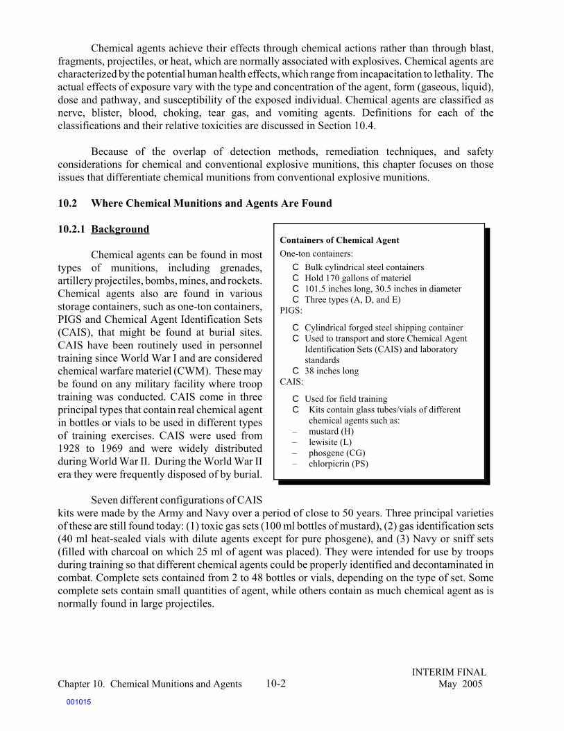
INTERIM FINALChapter 10. Chemical Munitions and Agents May 200510-2
Chemical agents achieve their effects through chemical actions rather than through blast,fragments, projectiles, or heat, which are normally associated with explosives. Chemical agents arecharacterized by the potential human health effects, which range from incapacitation to lethality. Theactual effects of exposure vary with the type and concentration of the agent, form (gaseous, liquid),dose and pathway, and susceptibility of the exposed individual. Chemical agents are classified asnerve, blister, blood, choking, tear gas, and vomiting agents. Definitions for each of theclassifications and their relative toxicities are discussed in Section 10.4.
Because of the overlap of detection methods, remediation techniques, and safetyconsiderations for chemical and conventional explosive munitions, this chapter focuses on thoseissues that differentiate chemical munitions from conventional explosive munitions.
10.2 Where Chemical Munitions and Agents Are Found
10.2.1 Background
Chemical agents can be found in mosttypes of munitions, including grenades,artillery projectiles, bombs, mines, and rockets.Chemical agents also are found in variousstorage containers, such as one-ton containers,PIGS and Chemical Agent Identification Sets(CAIS), that might be found at burial sites.CAIS have been routinely used in personneltraining since World War I and are consideredchemical warfare materiel (CWM). These maybe found on any military facility where trooptraining was conducted. CAIS come in threeprincipal types that contain real chemical agentin bottles or vials to be used in different typesof training exercises. CAIS were used from1928 to 1969 and were widely distributedduring World War II. During the World War IIera they were frequently disposed of by burial.
Seven different configurations of CAISkits were made by the Army and Navy over a period of close to 50 years. Three principal varietiesof these are still found today: (1) toxic gas sets (100 ml bottles of mustard), (2) gas identification sets(40 ml heat-sealed vials with dilute agents except for pure phosgene), and (3) Navy or sniff sets(filled with charcoal on which 25 ml of agent was placed). They were intended for use by troopsduring training so that different chemical agents could be properly identified and decontaminated incombat. Complete sets contained from 2 to 48 bottles or vials, depending on the type of set. Somecomplete sets contain small quantities of agent, while others contain as much chemical agent as isnormally found in large projectiles.
Containers of Chemical AgentOne-ton containers:
C Bulk cylindrical steel containersC Hold 170 gallons of materielC 101.5 inches long, 30.5 inches in diameterC Three types (A, D, and E)
PIGS:
C Cylindrical forged steel shipping containerC Used to transport and store Chemical Agent
Identification Sets (CAIS) and laboratorystandards
C 38 inches longCAIS:
C Used for field trainingC Kits contain glass tubes/vials of different
chemical agents such as:– mustard (H)– lewisite (L)– phosgene (CG)– chlorpicrin (PS)
001015

INTERIM FINALChapter 10. Chemical Munitions and Agents May 200510-3
Many munitions of the World War II era, such as 4.2 inch mortars, M47 and M70 bombs,Livens projectiles, 75 mm projectiles, 4 inch Stokes mortars, and others, had both lethal chemical fillsand smoke and/or incendiary fills, all of which are liquid. In addition, some industrial compoundswere used to produce lethal effects. These include phosgene, hydrogen cyanide, and cyanogenchloride.
10.2.2 Stockpile and Non-stockpile CWM Sites
There are two basic categories of sitescontaining CWM and agents which are designatedon the basis of how the materiel was stored:stockpile and non-stockpile CWM sites.
Stockpile CWM sites are those locations inthe United States where all chemical agents andmunitions that were available for use on thebattlefield (including those assembled in weaponsand in bulk one-ton containers) are stored. There arecurrently eight locations that the United States hascontrol of where stockpile CWM is found: UmatillaDepot, Oregon; Tooele Army Depot, Utah; PuebloDepot, Colorado; Newport Army Munition Plant,Indiana; Aberdeen Proving Ground, Maryland;Lexington Blue Grass Army Depot, Kentucky;Anniston Army Depot, Alabama; and Pine BluffArsenal, Arkansas. (Destruction of CWM atJohnston Atoll has been completed.)
In 1985, the U.S. Congress passed PublicLaw 99-145, which requires the destruction of thestockpile of lethal chemical warfare agents andmunitions in the United States. A 1997 decision toratify the Chemical Weapons Convention requiredthe destruction, by 2007, of all stockpiled CWM, andall non-stockpile CWM known at the time of thesigning. The United States and other signatories arein the process of moving aggressively to meet thisrequirement. However, the United States hasacknowledged difficulty in achieving this goal and has requested the allowed 5-year extension.
According to the Army’s Program Manager for Chemical Destruction, as of June 8, 2003, 26percent of the original stockpile of chemical agent in the United States had been destroyed, and 39percent of chemical munitions had been destroyed. More information can be found on their website:http://www.pmcd.army.mil.
Non-stockpile Chemical Materiel
Non-stockpile chemical materiel includes thefollowing categories, all of which could belocated at MRSs:
C Buried chemical materiel – materiel thatwas buried between World War I and atleast the late 1950s, during which timeburial was considered to be a final disposalsolution for obsolete chemical weapons.
C Binary chemical weapons – munitionsdesigned to use two relatively nontoxicchemicals that combine during functioningof the weapons system to produce achemical agent for release on target. (Theseweapons were neither widely produced nortested in the United States.)
C Recovered chemical weapons – thoseweapons retrieved from range-clearingoperations, research and test sites, andburial sites.
C Former chemical weapons productionfacilities – facilities that produced chemicalagents and other components for chemicalweapons.
C Other miscellaneous chemical warfarematerial – includes unfilled munitions anddevices; samples; and research,development, testing, and evaluationmaterials that were used for thedevelopment of chemical weapons.
001016

185Systems and Technologies for the Treatment of Non-stockpile Chemical Warfare Materiel, National ResearchCouncil, Board on Army Science and Technology, National Research Council, National Academy Press, 2003.
186Ibid.
INTERIM FINALChapter 10. Chemical Munitions and Agents May 200510-4
The second category of CWM and agents is referred to as non-stockpile chemical materiel(NSCM). This is a diverse category that includes all other chemical weapon-related items, such aslethal wastes from past disposal efforts, unserviceable munitions, and chemically contaminatedcontainers; chemical production facilities; newly located chemical munitions; known sites containingsignificant quantities of buried chemical weapons and waste; and binary weapons and components.
According to the National Research Council,185 as of 1996, the Army identified 168 potentialburial sites in 31 States and several territories (including the District of Columbia). Most are currentor former military facilities. The majority of sites are thought to include small quantities of material.The information reported as of 1996 is updated regularly and maintained by the Product Manager forthe Non- Stockpile Chemical Warfare Materiel (NSCWM) program.
NSCWM can be found in a range ofdifferent areas. It may be found at any sitethat manufactured or conducted testing ofchemical agent and/or weapons, stored suchmaterials as they were prepared for shipmentoverseas, or provided training to troops whoused CAIS kits to identify chemical agent.Since development and testing of chemicalweapons took place as early as the WorldWar 1 era, and many military test sites haveeither changed uses over time or have beentransferred out of military ownership, suchlocations are not always obvious. TheNational Research Council has asserted that“a major uncertainty for the non-stockpileprogram is the extent to which suspected burial sites will be excavated and what items will be foundand recovered.”186 Sites that have been transferred out of military ownership (formerly used defensesites – FUDS) may represent a particular challenge. For example, in the World War 1 era, a test siteowned by American University was the location of significant testing of chemical agent material bythe military. That location is now in residential use. Non-stockpile material has been recovered anddestroyed in ongoing investigations and cleanup activities likely to go on for a number of years.
10.3 Regulatory Requirements
The regulatory authorities for managing recovered CWM (RCWM) include all of theregulations that apply to explosive munitions, as described in Chapter 2. In addition, 50 USC1512-1521 provide specific guidance to DoD on transporting, testing, and/or disposing of lethalchemical agent. The principal regulatory programs under which cleanup of RCWM at MRSs isconducted include CERCLA, RCRA, the Defense Environmental Restoration Program (DERP), andthe safety standards of the DDESB. In addition, the Army, as the single manager for conventional
NSCWM in Residential Delaware
On July 19, 2004, Explosive Ordnance Disposal (EOD)personnel from Dover AFB recovered an explosivemunition embedded in a driveway made of clamshellpaving material. This material was dredged off the Mid-Atlantic coast. The EOD team detonated the munitionwith a shaped charge whereupon a black tar-likesubstance began to ooze from the munition. Mustardagent (HD) was detected in the tar-like substance. Thenext day, 3 members of the EOD team were stricken withHD-related blisters. Army records indicate that 1,700mustard filled rounds were dumped off the coast of CapeMay, NJ in 1964.
001017
187DoD Directive 5160.65, Single Manager for Conventional Ammunition, March 8, 1995. Many Armypolicies also are addressed in Army Regulation (AR) 50-6, Chemical Surety, February 1, 1995; AR 385-61, ArmyChemical Agent Safety Program, February 28, 1997; and Department of the Army Pamphlet (DA PAM) 385-61, ToxicChemical Agent Safety Standards, March 31, 1997.
INTERIM FINALChapter 10. Chemical Munitions and Agents May 200510-5
munitions (which includes chemical agents), has developed a number of regulations and guidancedocuments designed to specifically address the management of chemical agents.187
AR 50-6 outlines the policies, procedures, and responsibilities for the Army Chemical SuretyProgram, which is designed to provide tools to facilitate safe and secure operations involvingchemical agents. AR 50-6 describes the policies for the safe storage, handling, maintenance,transportation, inventory, treatment, and disposal of CWM. The policy also provides safety andsecurity control measures to ensure the safe conduct of chemical agent operations and personnelsafeguards for the recovery of CWM discovered during environmental remediation activities or bychance. AR 385-61 establishes policies and responsibilities for the Army’s chemical agent safetyprogram, and DA PAM 385-61 describes the safety criteria and standards for processing, handling,storing, transporting, disposal, and decontamination of chemical agents. These chemical munitions-specific safety regulations are discussed again in Section 10.7.) Additional regulations are listed in“Sources and Resources” at the end of this chapter. In addition to U.S. regulations, disposal of CWMmust also comply with the notification requirements of the CWC.
10.4 Classifications and Acute Effects of Chemical Agents
Chemical agents, such as blister, blood, choking, incapacitating, lacrimator (tear gas),vomiting, and nerve agents, are typically classified by the type of physiological action caused byexposure. A wide variety of chemical agents can be found on MRSs, either in their original form orin some deteriorated form.
The effects of these chemical agents include long-term chronic effects such as cancer or nervedamage and acute effects ranging from incapacitation to lethality. Effects vary with the type of agent,concentration, form, duration and route of exposure, and condition of the person exposed (e.g.,elderly, children). All of these agents can cause death, some more quickly than others. When certainchemical agents are used in combination with each other, the speed and likelihood of lethalityincreases. The following sections provide an overview of the acute health effects of the differentcategories of chemical agents. Subsequent sections provide more detail related to chronic healtheffects and toxicity.
C Blister agents (vesicants) – work by destroying individual cells that come in contactwith the agent. Blister agents, as the name implies, cause tissue damage, includingblisters, on the skin and produce severe effects in the eyes and lungs (if inhaled). Compared with some of the other chemical agents, blister agents take longer toproduce effects (4-24 hours) and are intended to cause incapacitation casualties for alonger duration (36 hours to several days). The following are considered blister agents:
– Lewisite / L– Mustard-Lewisite Mixture / HL– Nitrogen Mustard / HN-1
001018

INTERIM FINALChapter 10. Chemical Munitions and Agents May 200510-6
– Nitrogen Mustard / HN-2– Nitrogen Mustard / HN-3– Sulfur Mustard Agent / H, HD or HS– Mustard- T Mixture / Sulfur Mustard Agent / HT– Phenyldichloroarsine / PD– Ethyldichloroarsine / ED– Methyldichloroarsine / MD– Phosgene Oxime / CX
C Blood agents – affect bodily functions through action on an enzyme, resulting in theinability of cells to use oxygen normally. This interaction leads to rapid damage tobody tissues. Blood agents are absorbed into the body through inhalation. Thefollowing are considered blood agents:
– Hydrogen Cyanide /Prussic Acid / AC– Cyanogen Chloride / CK– Arsine / SA
C Choking agents – damage the respiratory tract, especially the lungs. Affected cells inthe respiratory tract become filled with liquid, and an oxygen deficiency results inchoking and asphyxia. The following are considered choking agents:
– Phosgene / CG– Diphosgene / DP
C Nerve agents – encompass a variety of compounds that have the capacity to inactivatethe enzyme acetylcholinesterase (AChE). They generally are divided into two families,the G agents and the V agents. The Germans developed the G agents (tabun [GA], GB,and GD) during World War II. They are volatile compounds that pose mainly aninhalation hazard. The nerve agent GB is quick acting (5-10 minutes to onset ofsymptoms after inhalation), and very low doses may incapacitate a person for 1-5days. The effects of higher doses include muscle contractions, suffocation, and death.V agents, which were developed later, are approximately 10 times more toxic than GBand are considered persistent agents, which means that they can remain on surfaces forlong periods. The consistency of V agents is oily, thus they mainly pose a contacthazard. A highly toxic nerve agent, VX, acts by absorption through the skin andcauses muscle contractions, suffocation, and death. The following are considerednerve agents:
– Tabun / GA– Sarin / GB– Soman / GD– V-Agent / VX– Cyclo-sarin / GF
001019

188Tear Gas is listed as a CWM when used in warfare. The U.S. implementing legislation exempts Tear gasfrom reporting requirements when found in concentrations of less than 80 percent.
INTERIM FINALChapter 10. Chemical Munitions and Agents May 200510-7
C Tear gas188 – irritates skin and eyes, causing short-term incapacitation. Prolongedexposure, such as in an indoor situation, can cause illness and death. The duration ofincapacitation is approximately 10 minutes. Symptoms of exposure include burning eyes,tearing, and irritation of the respiratory tract. The following are considered tear gasagents:
– Chloroacetophenone / CN– Chloropicrin / PS– Chloroacetophenone and chloropicrin in chloroform /CNS– Chloroacetophenone in benzene and carbon tetrachloride / CNB– Bromobenzylcyanide / CA– O-Chlorobenzylidene / CS also CS1 and CS2
C Incapacitation agents – block the action of acetylcholine both peripherally and centrally.The agent BZ, the only known incapacitation agent that is a central nervous systemdepressant, disturbs integrative functions of memory, problem-solving, andcomprehension.
C Vomiting agents – induce nausea and vomiting. Physiological actions of vomiting agentsinclude eye irritation, mucous discharge from the nose, severe headache, acute pain andtightness in the chest, nausea and vomiting. The following are considered vomitingagents:
– Diphenylchloroarsine / DA– Adamsite / DM– Diphenylcyanoarsine / DC
10.4.1 Chronic Human Health Effects of Chemical Agents
Although CWM is most commonly thought of in relation to acute effects, chronic healtheffects are also significant. For example, if an exposure occurs outside the range of acute toxicityduring an exposure event, or if a low level of exposure occurs due to the presence of small amountsof a particular chemical, then chronic effects such as cancer can occur.
Table 10-1 lists some of the common chemical agents and known chronic health effects. Thetable is organized by major category of chemical agent. Where no information on the chronic effectsof a particular agent was found in readily available literature, it is noted as “not available.”
Table 10-1. Chemical Agents and Their Potential Chronic Effects
Common Name Chemical Name /Formula/CAS# Potential Chronic EffectsBlister Agents/VesicantsLewisite/L Dichloro-(2-chlorovinyl)arsine Chronic respiratory and eye conditions may
001020
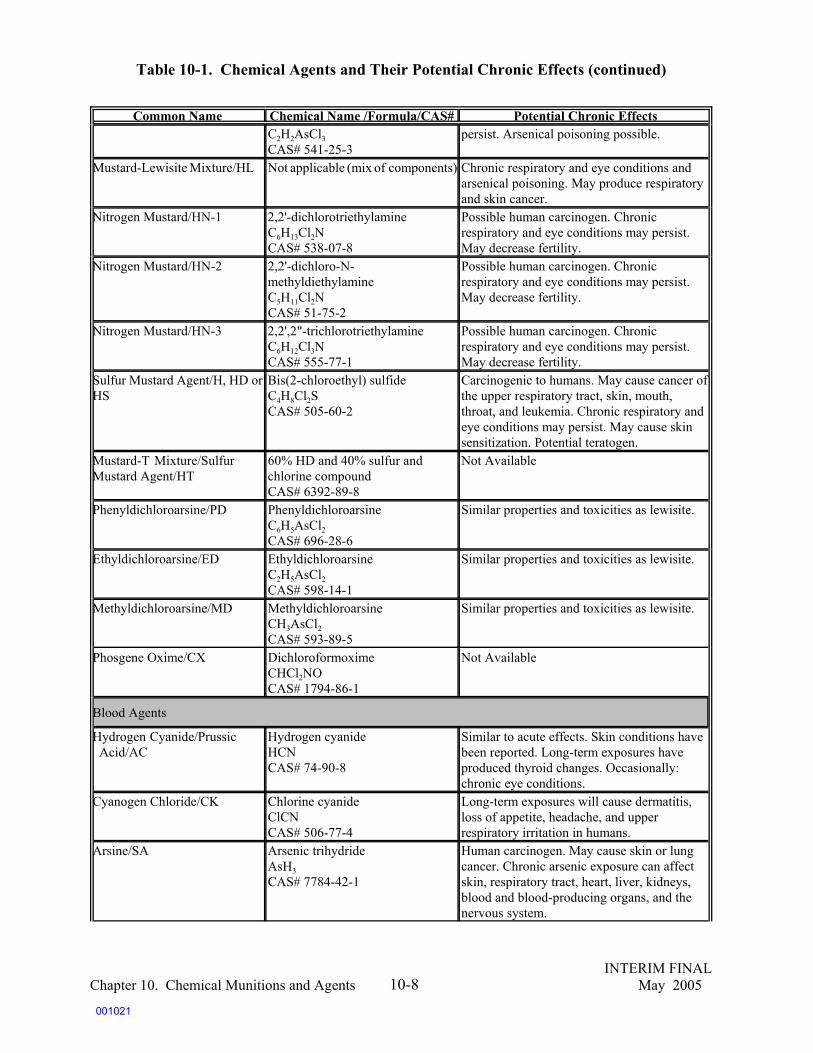
Table 10-1. Chemical Agents and Their Potential Chronic Effects (continued)
Common Name Chemical Name /Formula/CAS# Potential Chronic Effects
INTERIM FINALChapter 10. Chemical Munitions and Agents May 200510-8
C2H2AsCl3CAS# 541-25-3
persist. Arsenical poisoning possible.
Mustard-Lewisite Mixture/HL Not applicable (mix of components) Chronic respiratory and eye conditions andarsenical poisoning. May produce respiratoryand skin cancer.
Nitrogen Mustard/HN-1 2,2'-dichlorotriethylamineC6H13Cl2NCAS# 538-07-8
Possible human carcinogen. Chronicrespiratory and eye conditions may persist. May decrease fertility.
Nitrogen Mustard/HN-2 2,2'-dichloro-N-methyldiethylamineC5H11Cl2NCAS# 51-75-2
Possible human carcinogen. Chronicrespiratory and eye conditions may persist. May decrease fertility.
Nitrogen Mustard/HN-3 2,2',2"-trichlorotriethylamineC6H12Cl3NCAS# 555-77-1
Possible human carcinogen. Chronicrespiratory and eye conditions may persist. May decrease fertility.
Sulfur Mustard Agent/H, HD orHS
Bis(2-chloroethyl) sulfideC4H8Cl2SCAS# 505-60-2
Carcinogenic to humans. May cause cancer ofthe upper respiratory tract, skin, mouth,throat, and leukemia. Chronic respiratory andeye conditions may persist. May cause skinsensitization. Potential teratogen.
Mustard-T Mixture/Sulfur Mustard Agent/HT
60% HD and 40% sulfur andchlorine compoundCAS# 6392-89-8
Not Available
Phenyldichloroarsine/PD PhenyldichloroarsineC6H5AsCl2CAS# 696-28-6
Similar properties and toxicities as lewisite.
Ethyldichloroarsine/ED EthyldichloroarsineC2H5AsCl2 CAS# 598-14-1
Similar properties and toxicities as lewisite.
Methyldichloroarsine/MD MethyldichloroarsineCH3AsCl2CAS# 593-89-5
Similar properties and toxicities as lewisite.
Phosgene Oxime/CX DichloroformoximeCHCl2NOCAS# 1794-86-1
Not Available
Blood Agents
Hydrogen Cyanide/Prussic Acid/AC
Hydrogen cyanideHCNCAS# 74-90-8
Similar to acute effects. Skin conditions havebeen reported. Long-term exposures haveproduced thyroid changes. Occasionally:chronic eye conditions.
Cyanogen Chloride/CK Chlorine cyanideClCNCAS# 506-77-4
Long-term exposures will cause dermatitis,loss of appetite, headache, and upperrespiratory irritation in humans.
Arsine/SA Arsenic trihydrideAsH3CAS# 7784-42-1
Human carcinogen. May cause skin or lungcancer. Chronic arsenic exposure can affectskin, respiratory tract, heart, liver, kidneys,blood and blood-producing organs, and thenervous system.
001021

Table 10-1. Chemical Agents and Their Potential Chronic Effects (continued)
Common Name Chemical Name /Formula/CAS# Potential Chronic Effects
INTERIM FINALChapter 10. Chemical Munitions and Agents May 200510-9
Choking AgentsPhosgene/CG Dichloroformaldehyde
Carbonyl chlorideCCl2OCAS# 75-44-5
Chronic exposure may cause emphysema,fibrosis, skin, and eye conditions.
Diphosgene/DP Trichloromethyl chloroformateC2Cl4O2 CAS# 503-38-8
Not Available
Nerve AgentsTabun/GA Ethyl N,N-
dimethylphosphoramidocyanidateC5H11N2O2PCAS# 77-81-6
Weakness of skeletal musculature. In severecases: disabling condition (muscle weaknessand paralysis).
Sarin/GB Isopropylmethyl-phosphonofluoridateC4H10FO2PCAS# 107-44-8
Weakness of skeletal musculature. In severecases: disabling condition (muscle weaknessand paralysis).
Soman/GD Pinacolyl methyl-phosphonofluoridateC7H16FO2PCAS# 96-64-0
Weakness of skeletal musculature. In severecases: disabling condition (muscle weaknessand paralysis).
V-Agent/VX O-ethyl S-[2-(disopropylamine)ethyl]methylphosphonothiolateC11H26NO2PSCAS# 50782-69-9
Weakness of skeletal musculature. In severecases: disabling condition (muscle weaknessand paralysis).
Cyclo-sarin/GF CH3PO(F)OC6H11 Not AvailableIncapacitating AgentsAgent BZ 3-Quinuclidinyl benzilate
C21H23NO3CAS# 6581-06-2
Not Available
Lacrimators/Tear Gases*
Chloroacetophenone/CN 2-ChloroacetophenoneC6H5COCH2ClCAS# 532-27-4
Repeated or prolonged contact may causechronic skin conditions.
Chloropicrin/PS ChloropicrinCCl3NO2CAS# 76-06-2
Not Available
Chloroacetophenone andchloropicrin inchloroform/CNS
Mixture of CN, PS, andchloroformna
No known long-term effects
Chloroacetophenone inbenzene and carbontetrachloride/CNB
Mixture of CN, carbontetrachloride, and benzene
Not Available
Bromobenzylcyanide/CA BromobenzylcyanideC8H6BrNCAS# 5798-79-8
Not Available
001022

Table 10-1. Chemical Agents and Their Potential Chronic Effects (continued)Common Name Chemical Name /Formula/CAS# Potential Chronic Effects
INTERIM FINALChapter 10. Chemical Munitions and Agents May 200510-10
O-Chlorobenzylidene/CS alsoCS1 and CS2
O-chlorobenzylidene malononitrileC10H5ClN2CAS# 2698-41-1
Not Available
Vomiting AgentsDiphenylchloroarsine/DA Diphenylchloroarsine
C12H10AsClCAS# 712-48-1
Not Available
Adamsite/DM DiphenylaminechloroarsineC12H9AsClNCAS# 578-94-9
Not Available
Diphenylcyanoarsine/DC DiphenylcyanoarsineC13H10AsNCAS# 23525-22-6
Not Available
*The U.S. CWC implementing legislation exempts these chemicals (which appear in schedule 3 of the CWC Chemical Annex) from reportingrequirements if found in concentrations of less than 80 percent.
Sources:U.S. Army Field Manual FM 3-9 and the 1956 version of TM 3-215.Agency for Toxic Substances and Disease Registry (ATSDR). Medical Management Guidelines (MMGs) for Blister Agents.Mitretek Systems. Toxicological Properties of Vesicants; Toxicological Properties of Nerve Agents. Last Revised on May 15, 2003. http://www.mitretek.org/home.nsf/HomelandSecurity/ChemBioDefense.U.S. Army Soldier and Biological Chemical Command (SBCCOM). Material Safety Data Sheet: Distilled Mustard (HD).U.S. Army Center for Health Promotion and Preventive Medicine (USACHPPM). Detailed Facts About Blood Agent Cyanogen Cyanide (CK);Detailed Facts About Choking Agent Phosgene (CG). Last Revised on July 23, 1998.U.S. National Library of Medicine, Specialized Information Services. Hazardous Substances Data Bank (HSDB).University of Oklahoma College of Pharmacy. Arsine Fact Sheet. 2001-2002.Deployment Health Clinical Center (DHCC). Blister Agent Fact Sheet. Last Updated on May 21, 2003.
001023

189Munro, Nancy B. et al., “The Sources, Fate and Toxicity of Chemical Warfare Agent Degradation Products,”Environmental Health Perspectives, Vol 107, Number 12, 1999.
INTERIM FINALChapter 10. Chemical Munitions and Agents May 200510-11
10.4.2 Persistence of Chemical Agents
The persistence of chemical agents is determined by their rate of vaporization. Nonpersistentcompounds vaporize quickly and produce high-density clouds of chemical agent that evaporaterapidly. The hazards of these non-persistent agents result from brief contact with the clouds or frominhalation of vapors. The information on the persistence in the environment of the CW agentcompounds is scattered and fragmentary. With the exception of the sulfur mustards, CW agents aregenerally not considered highly persistent due to the action of various degradation processes such ashydrolysis, microbial degradation, oxidation, and photolysis. However, certain degradation productsmay themselves be highly persistent and/or toxic. Those persistent degradation products that are nothighly toxic may be important as an indicator of the former use of the site.189
Table 10-2 features data regarding the persistence of CWM on the battlefield. The data werederived by United States Army Center for Health Promotion and Preventative Medicine(USACHPPM) from material safety data sheets. Although the language used to describe persistenceof CWM relates to the battlefield, Table 10-2 may be helpful in obtaining an initial understandingof persistence of certain chemicals in the environment. There is no data from the USACHPPMdocument for chemicals listed in Table 10-1 that do not appear in Table 10-2.
Persistent chemical agents are liquids that vaporize slowly or viscous materials that adhereand do not spread or flow easily. The hazards posed by persistent compounds result either fromcontact with the liquids or from contact with or inhalation of vapors, which persist longer than thenon-persistent compounds. Persistent chemicals include mustard, lewisite, blister agents, and V-classnerve agents (VX).
Table 10-2 Persistence in the Environment of CW Agents
Common Name PersistenceBlister Agents/VesicantsLewisite/L Somewhat shorter than for HD (sulfur mustard agent); very short duration under
humid conditions.Mustard-Lewisite Mixture/HL Depends on munitions used and the weather. Somewhat shorter than that of HD,
heavily splashed liquid of which persists 1 to 2 days under average weatherconditions, and a week or more under very cold conditions.
Nitrogen Mustard/HN-1 Depends on munitions used and weather; somewhat shorter duration ofeffectiveness for HD, heavily splashed liquid of which persists 1 to 2 days underaverage weather conditions, and a week or more under very cold conditions.
Nitrogen Mustard/HN-2 Depends on munitions used and weather; somewhat shorter duration ofeffectiveness for HD, heavily splashed liquid of which persists 1 to 2 days underaverage weather conditions, and a week or more under very cold conditions.
Nitrogen Mustard/HN-3 Considerably longer than HD. HN-3 use is emphasized for terrain denial. It can beapproximately 2x or 3x the persistence of HD and adheres well to equipment andpersonnel, especially in cold weather.
Sulfur Mustard Agent/H, HD orHS
Depends on munition used and weather; heavily splashed liquid persists 1 to 2days in concentration to provide casualties of military significance under averageweather conditions, and a week to months under very cold conditions.
001024

Table 10-2 Persistence in the Environment of CW Agents (continued)
Common Name Persistence
INTERIM FINALChapter 10. Chemical Munitions and Agents May 200510-12
Mustard-T Mixture/Sulfur Mustard Agent/HT
Depends on munitions used and the weather; heavily splashed liquid persists 1 to2 days in concentration to provide casualties of military significance underaverage weather conditions, and a week to months under very cold conditions.
Blood AgentsHydrogen Cyanide/Prussic Acid/AC
Short; the agent is highly volatile, and in the gaseous state it dissipates quickly inthe air.
Cyanogen Chloride/CK Short; vapor may persist in the jungle for some time under suitable weatherconditions.
Arsine/SA No information from source document
Choking AgentsPhosgene/CG Short; however, vapor may persist for some time in low places under calm of light
winds and stable atmospheric conditions (inversion). Diphosgene/DP No information from source document
Nerve AgentsTabun/GA The persistency will depend upon munitions used and the weather. Heavily
splashed liquid persists 1 to 2 days under average weather conditions. Sarin/GB Evaporates at approximately the same rate as water; depends upon munitions used
and the weather. Soman/GD Depends upon the munitions used and the weather. Heavily splashed liquid persists
1 to 2 days under average weather conditions. V-Agent/VX Depends upon munitions used and the weather. Heavily splashed liquid persists for
long periods of time under average weather conditions. Incapacitating AgentsAgent BZ No information from source documentLacrimators/Tear GasesChloroacetophenone/CN Short because the compounds are disseminated as an aerosol. Chloropicrin/PS Short.Chloroacetophenone andchloropicrin inchloroform/CNS
Short.
Chloroacetophenone inbenzene and carbontetrachloride/CNB
Short.
Bromobenzylcyanide/CA Depends on munitions used and the weather; heavily splashed liquid persists one ortwo days under average weather conditions.
Vomiting AgentsAdamsite/DM Short, because compounds are disseminated as an aerosol. Soil - persistent. Surface
(wood, metal, masonry, rubber, paint) - persistent. Water - persistent; when materialis covered with water, an insoluble film forms which prevents further hydrolysis.
Source:
U.S. Army Center for Health Promotion and Preventative Medicine (UCACHPPM). Detailed and General Facts About Chemical Agents, TG 218.
001025

INTERIM FINALChapter 10. Chemical Munitions and Agents May 200510-13
10.4.3 Acute Toxicity of Persistent Chemical Agents
Acute toxicity values are useful in understanding the risk associated with exposure tochemical agents. Acute toxicity is defined as toxicity that results from short-term exposure to atoxicant. The acute toxicity of a chemical is commonly quantified as the LD50 (lethal dose that kills50 percent of the exposed population) or LCt50 (lethal concentration that kills 50 percent of theexposed population in a specified period of time). These values provide statistically sound andreproducible measures of the relative acute toxicity of chemicals.
Table 10-3 shows acute human toxicity data (LD50 and LCt50) for oral, dermal, andinhalational routes of exposure for the chemical warfare agents listed in Table 10-1. In cases whenhuman toxicity data were not available, data on exposure of laboratory animals (e.g., rats) to theagent(s) were substituted. Caution should be used in extrapolating this data to humans.
Table 10-3. Acute Human Toxicity Data for Chemical Warfare Agents
Chemical Agent LD50 LCt50
Blister Agents/Vesicants
Lewisite/L50 mg/kg (oral, rat) 100,000 mg-min/m3 (dermal, human)
24 mg/kg (dermal, rat) 1,200 to 2,500* mg-min/m3 (inhalation, human)
Mustard-LewisiteMixture/HL Not Available
about 10,000 mg-min/m3 (dermal, human)
about 1,500 mg-min/m3 (inhalation, human)
Nitrogen Mustard/HN-1 2.5 mg/kg (oral, rat) 20,000 mg-min/m3 (dermal, human)
17 mg/kg (dermal, rat) 1,500 mg-min/m3 (inhalation, human)
Nitrogen Mustard/HN-2 10 mg/kg (oral, rat)3,000 mg-min/m3 (inhalation, human)
12 mg/kg (dermal, rat)
Nitrogen Mustard/HN-3 5 mg/kg (oral, rat) 10,000 mg-min/m3 (dermal, human)
2 mg/kg (dermal, rat) 1,500 mg-min/m3 (inhalation, human)
Sulfur Mustard Agent/H,HD or HS
0.7 mg/kg (oral, human) 5,000 to 10,000* mg-min/m3 (dermal, human)
20 to 100* mg/kg (dermal,human) 900 to 1,500* mg-min/m3 (inhalation, human)
Mustard-T Mixture/SulfurMustard Agent / HT Not Available
Phenyldichloroarsine / PD16 mg/kg (dermal, rat) 2,600 mg-min/m3 (inhalation, human)
001026

Table 10-3. Acute Human Toxicity Data for Chemical Warfare Agents
Chemical Agent LD50 LCt50
INTERIM FINALChapter 10. Chemical Munitions and Agents May 200510-14
Ethyldichloroarsine/ED Not Available 1,555 mg/m3 for 10 min (inhalation, mouse)
Methyldichloroarsine/ MD Not AvailablePhosgene Oxime/CX Not Available 3,200 mg-min/m3 (estimated)(human)
Blood AgentsHydrogen Cyanide/ PrussicAcid/AC 100 mg/kg (dermal, human)
2,000 mg/m3 for 0.5 min (inhalation, human)
20,600 mg/m3 for 30 min (inhalation, human)
Cyanogen Chloride/CK 6 mg/kg (oral, cat) 11,000 mg-min/m3 (human)
Arsine/SA Not Available 390 mg/m3 for 10 min (inhalation, rat)
Choking Agents
Phosgene/CGNot Available 3,200 mg/m3 (inhalation, human)
Diphosgene/DP Not Available
Nerve Agents
Tabun/GA3.7 mg/kg (oral, rat) 135 mg/m3 for 0.5-2.0 min at RMV of 15 L/min
(inhalation, human)
14 to 15 mg/kg (dermal,human)
200 mg/m3 for 0.5-2.0 min at RMV of 10 L/min(inhalation, human)
Sarin/GB 0.55 mg/kg (oral, rat)70 mg-min/m3 at 15 L/min (inhalation, human)
24 mg/kg (dermal, human)
Soman/GD 5 mg/kg (dermal, human) 70 mg-min/m3 at 15 L/min (inhalation, human)
V-Agent/VX 0.142 mg/kg (dermal, human) 30 mg-min/m3 at 15 L/min (inhalation, human)
Incapacitating Agents
Agent BZ Not Available 200,000 mg-min/m3 (estimated)(human)
Lacrimators/Tear Gases
Chloroacetophenone/CN 50 to 1,820* mg/kg (oral, rat) 7,000 mg-min/m3 from solvent (human)
14,000 mg-min/m3 from grenade (human)
Chloropicrin/PS 250 mg/kg (oral, rat) 2,000 mg-min/m3 (human)
001027

Table 10-3. Acute Human Toxicity Data for Chemical Warfare Agents
Chemical Agent LD50 LCt50
INTERIM FINALChapter 10. Chemical Munitions and Agents May 200510-15
Chloroacetophenone &Chloropicrin inChloroform/CNS
Not Available 11,400 mg-min/m3 (human)
Chloroacetophenone inBenzene & Carbontetrachloride/CNB
Not Available 11,000 mg-min/m3 (human)
Bromobenzylcyanide Not Available 8,000 mg-min/m3 (estimated)(human)
O-Chlorobenzylidene/CSalso CS1and CS2
178 mg/kg (oral, rat) 61,000 mg-min/m3 (human)
Vomiting Agents
Diphenylchloroarsine Not Available
Adamsite/DM Not Available variable, average 11,000 mg-min/m3 (human)
Diphenylcyanoarsine Not Available*value varies depending on source.Notes:In cases where data on human exposure were not available, data on exposure of laboratory rats to the agent(s) were substituted. Caution should be used in extrapolating this data to humans.RMV – respiratory minute volumeLD50 – dose which kills 50% of the exposed population; typically expressed in units of mg/kg body weightLCt50 – concentration which kills 50% of the exposed population in a specified period of time; typically expressed as product of the chemical’s concentration in air (mg/m3) and the duration of exposure (min)Dermal – absorption through the skinOral – intake via mouthInhalation – intake via the lungsSources:Mitretek Systems. Toxicological Properties of Vesicants; Toxicological Properties of Nerve Agents. Last Revised on May 15, 2003. http://www.mitretek.org/home.nsf/HomelandSecurity/ChemBioDefenseU.S. Army Soldier and Biological Chemical Command (SBCCOM). Material Safety Data Sheet: Distilled Mustard (HD); Lethal Nerve Agent (GD); Lethal Nerve Agent (GB).U.S. Army Center for Health Promotion and Preventive Medicine (USACHPPM). Detailed Facts About Blood Agent Cyanogen Cyanide (CK), Hydrogen Cyanide (AC); Blister Agent Phosgene Oxime (CX), Mustard-Lewisite Mixture (HL), Nitrogen Mustard (HN-1), (HN-2), (HN-3), Lewisite (L), Sulfur Mustard Agents H and HD; Nerve Agent VX, Nerve Agent GA; Psychedelic Agent 3-Quinuclidinyl Benzilate (BZ); Tear Agent 2-Chloroacetophenone (CN), Chloropicrin (PS), Chloroacetophenone and Chloropicrin in Chloroform (CNS), Chloroacetophenone in Benzene and Carbon Tetrachloride (CNB), a-Bromobenzylcyanide (CA), o-Chlorobenzylidene Malonitrile (CS); Vomiting Agent Adamsite (DM). Last Revised on July 23, 1998.U.S. Army Chemical Biological Defense Command Edgewood. Material Safety Data Sheet: Lewisite. National Toxicology Program (NTP). NTP Chemical Repository. Last revised on June 3, 2003.U.S. Department of Labor. Occupational Safety & Health Administration. Occupational Safety and Health Guidelines. The Regisry of ToxicEffects of Chemical Substances (RTECS).U.S. National Library of Medicine, Specialized Information Services. Hazardous Substances Data Bank (HSDB).
001028

190Munro, N.B. et al., The Sources, Fate, and Toxicity of Chemical Warfare Agent Degradation Products,Environmental Health Perspectives, Vol. 107, No. 12, December 1999.
INTERIM FINALChapter 10. Chemical Munitions and Agents May 200510-16
10.4.4 Degradation Products of Chemical Munitions and Agents
Many chemical agents are broken down by weathering processes into both hazardous andnonhazardous materials. The weathering effects of sun, rain, and wind will dissipate, evaporate, ordecompose chemical agents. Specifically, sunlight causes catalytic decomposition and evaporation,rain or dew causes hydrolysis, and wind accelerates the natural process of evaporation.
When addressing the hazards of CWM at a site, special attention should be paid to thedecomposition products that often pose risks to human health and the environment as a result of theirtoxicity and persistence. While a number of degradation products exist, only a few of them arepersistent and highly toxic.190
The following text describes examples of some common chemical agent decompositionproducts of CWM and an overview of their persistence in the environment and toxicity. Theenvironmental conditions and the length of time that an agent has been exposed to the environmentwill determine the extent of the degradation and whether some or all of the degradation products andsubsequent daughter products (described in the following sections) will be present. Table 10-4provides more detail on toxicity of these degradation products.
C Sarin (GB) – reacts with water (hydrolyzes) under acidic conditions to form hydrofluoricacid, isopropyl methylphosphonic acid (IMPA), which slowly hydrolyzes to methylphonicacid (MPA). IMPA, although environmentally persistent has been shown to present lowacute oral toxicity to rats and mice. MPA is essentially nontoxic to mammalian andaquatic organisms.8 Hydrofluoric acid is an extremely corrosive material that must behandled with extreme caution unless copiously diluted. Sarin will hydrolyze underalkaline (basic) conditions to form sodium (or other metallic) isomethyl phosphonate salt.
C Tabun (GA) – produces a variety of hydrolysis products under acidic, basic, and neutralconditions, including hydrogen cyanide, ethylphosphoryl cyanidate, organic acids andesters, ethyl alcohol, dimethylamine, ethyl N,N-dimethylamido phosphoric acid andphosphoric acid.
C VX – forms a variety of degradation products. The most persistent products in weatheredsoil samples are bis(2-diisopropylaminoethyl)disulfide (EA 4196) and MPA. The mosttoxic is S-(2-diisopropylaminoethyl) methylphosphonothioic acid (EA 2192). Theintermediate VX hydrolysis product EA 2192 may be stable in water but is degradedrapidly in soil. It is nearly as toxic as VX. EMPA and MPA are final degradationproducts that exhibit relatively low toxicity to mammalian species.Other less toxicdegradation products include phosphorus-containing organic acids, sulfur-containingcompounds, organic phosphorus-containing esters, and ethyl alcohol.8
C Soman (GD) – hydrolyzes to form primarily pinacolyl methylphosphonic acid, which has
001029

191Materiel Safety Data Sheets, Edgewood Chemical Biological Center (ECBC), Department of the Army.
INTERIM FINALChapter 10. Chemical Munitions and Agents May 200510-17
a similar structure to IMPA. IMPA has even been shown to exhibit low mammaliantoxicity. GD also slowly hydrolyzes to MPA.8
C Mustard (HD) – hydrolyzes to form hydrochloric acid (a strong mineral acid),thiodiglycol (TDG) and 1,4-oxathiane. The most persistent degradation product is TDGbut it is suseptible to microbial degradation and has been demonstrated to be low toxicityto mammalic and aquatic species. At burial sites, a commonly found breakdown productis 1,4-dithiane.
C Lewisite – hydrolyzes under acidic conditions to form hydrochloric acid and thenonvolatile (solid) compound chlorovinylarsenious oxide (lewisite oxide). Although thiscompound is a much weaker blistering agent than Lewisite it is still highly toxic and hasvesicant properties. Hydrolysis in basic conditions, such as decontamination withalcoholic caustic or carbonate solution, produces acetylene, a very flammable gas, andtrisodium arsenate. Therefore, the decontamination solution would contain a toxic formof arsenic.191
Table 10-4 summarizes chemical agent degradation products that are known to havesignificant environmental persistence and toxicity. Environmental persistence refers to chemicals thatresist degradative processes and remain in the environment for very long periods of time. Significantpersistence refers to compounds that are stable in the environment for months to years.
Table 10-4. Summary of Known Persistent or Toxic Chemical Agent Degradation Products
Chemical Agent DegradationProcess Degradation Products Persistence Relevant Routes of
Exposure Toxicity, LD50 (mg/kg)
Sulfur mustard (HD) Hydrolysis ThiodiglycolC4H10O2SCAS# 111-48-8DithianeC4H8S2CAS# 505-23-7
Moderate Oral Rat oral: 6,610 guinea pig oral: 3,960
Lewisite (L) Hydrolysis, dehydration
2-Chlorovinyl arsenousoxide(Lewisite oxide)C2H2AsClOCAS# 3088-37-7ArsenicASCAS# 7440-38-2
High Dermal Unknown
V-Agent (VX)O-ethyl-S-[2-diisopro-pylaminoethyl]methyl-phosphonothionate
Hydrolysis S-(Diisopropylaminoethyl)methyl phosphonothionate(EA 2192)
Moderate Oral Rat oral LD50: 0.63
001030

Table 10-4. Summary of Known Persistent or Toxic Chemical Agent Degradation Products(continued)
Chemical Agent DegradationProcess Degradation Products Persistence Relevant Routes of
Exposure Toxicity, LD50 (mg/kg)
192The term detection is used in two ways in this section. The first discussion refers to locating discrete metallicitems through geophysical investigation. The second use refers to finding and identifying the chemical agent itself. Thedetection tools for locating discrete metallic items are discussed in Chapter 4.
INTERIM FINALChapter 10. Chemical Munitions and Agents May 200510-18
Ethyl methylphosphonicacid(EMPA)C3H9O3PCAS# 1832-53-7
Moderate Oral No data
Formed fromEMPA
Methylphosphonic acid(MPA)CH5O3PCAS# 993-13-5
High Oral Rat oral LD50: 5,000
Sarin (GB)Isopropyl methyl-phosphonofluoridate
Hydrolysis Isopropylmethylphosphonic acid(IMPA)C4H11O3PCAS#1832-54-8
High Oral Rat oral LD50: 6,070
Methylphosphonic acid(MPA)CH5O3PCAS# 993-13-5
High Oral Rat oral LD50: 5,000
Impurity Diisopropylmethylphosphonate(DIMP)C7H17PO3CAS# 1445-75-6
High Oral Rat oral LD50: 826
Soman (GD)Ethyl N,N-dimethyl-phosphoroamido-cyanidate
Hydrolysis Methylphosphonic acid(MPA)CH5O3PCAS# 993-13-5
High Oral Rat oral LD50: 5,000
Source:Munro, N.B.et. Al., The Sources, Fate, and Toxicity of Chemical Warfare Agent Degradation Products, Environmental Health Perspectives, Vol, 107.No.12, December 1999.
10.5 Detection of CWM
Techniques for locating buried chemical munitions and containers are the same as those forthe detection of conventional munitions. The appropriate geophysical detection technology shouldbe selected based on the container’s material (e.g., steel vs. glass). Chapter 4 described the variablesassociated with the selection of geophysical detection technologies. Once the presence of CWM orchemical agent(s) are suspected, they must be identified. Several methods for detecting andidentifying chemical agents exist. Some of the more common methods are discussed in Table 10-5.Each detection method has strengths and weaknesses that will need to be weighed against theconditions and the chemicals suspected at individual sites.192
001031
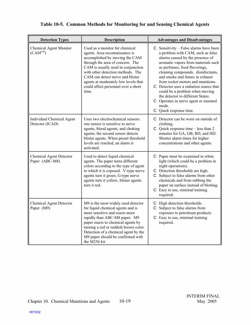
INTERIM FINALChapter 10. Chemical Munitions and Agents May 200510-19
Table 10-5. Common Methods for Monitoring for and Sensing Chemical Agents
Detection Types Description Advantages and Disadvantages
Chemical Agent Monitor(CAMTM)
Used as a monitor for chemicalagents. Area reconnaissance isaccomplished by moving the CAMthrough the area of concern. TheCAM is usually used in conjunctionwith other detection methods. TheCAM can detect nerve and blisteragents at moderately low levels thatcould affect personnel over a shorttime.
C Sensitivity – False alarms have beena problem with CAM, such as falsealarms caused by the presence ofaromatic vapors from materials suchas perfumes, food flavorings,cleaning compounds, disinfectants,and smoke and fumes in exhaustfrom rocket motors and munitions.
C Detector uses a radiation source thatcould be a problem when movingthe detector to different States.
C Operates in nerve agent or mustardmode.
C Quick response time.
Individual Chemical AgentDetector (ICAD)
Uses two electrochemical sensors:one sensor is sensitive to nerveagents, blood agents, and chokingagents; the second sensor detectsblister agents. When preset thresholdlevels are reached, an alarm isactivated.
C Detector can be worn on outside ofclothing.
C Quick response time – less than 2minutes for GA, GB, BD, and HD. Shorter alarm times for higherconcentrations and other agents.
Chemical Agent DetectorPaper (ABC-M8)
Used to detect liquid chemicalagents. The paper turns differentcolors according to the type of agentto which it is exposed. V-type nerveagents turn it green, G-type nerveagents turn it yellow, blister agentsturn it red.
C Paper must be examined in whitelight (which could be a problem innight operations).
C Detection thresholds are high.C Subject to false alarms from other
chemicals and from rubbing thepaper on surface instead of blotting.
C Easy to use, minimal trainingrequired.
Chemical Agent DetectorPaper (M9)
M9 is the most widely used detectorfor liquid chemical agents and ismore sensitive and reacts morerapidly than ABC-M8 paper. M9paper reacts to chemical agents byturning a red or reddish brown color. Detection of a chemical agent by theM9 paper should be confirmed withthe M256 kit.
C High detection thresholds.C Subject to false alarms from
exposure to petroleum products.C Easy to use, minimal training
required.
001032
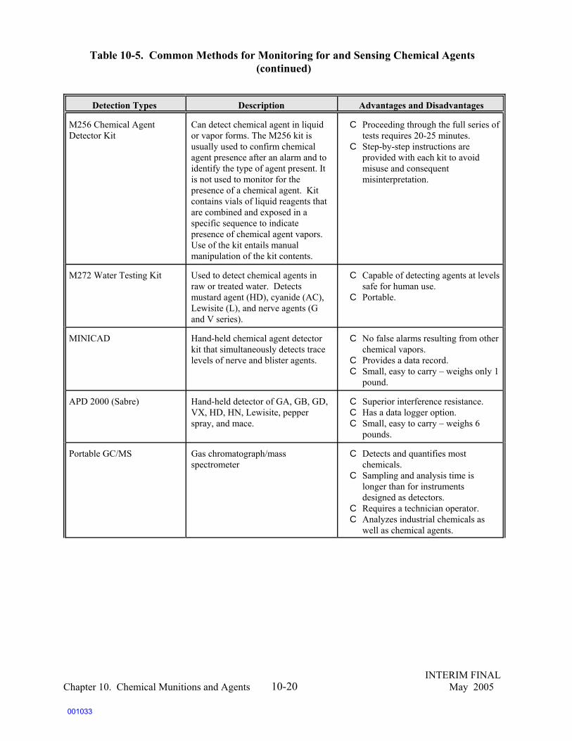
Table 10-5. Common Methods for Monitoring for and Sensing Chemical Agents (continued)
Detection Types Description Advantages and Disadvantages
INTERIM FINALChapter 10. Chemical Munitions and Agents May 200510-20
M256 Chemical Agent Detector Kit
Can detect chemical agent in liquidor vapor forms. The M256 kit isusually used to confirm chemicalagent presence after an alarm and toidentify the type of agent present. Itis not used to monitor for thepresence of a chemical agent. Kitcontains vials of liquid reagents thatare combined and exposed in aspecific sequence to indicatepresence of chemical agent vapors.Use of the kit entails manualmanipulation of the kit contents.
C Proceeding through the full series oftests requires 20-25 minutes.
C Step-by-step instructions areprovided with each kit to avoidmisuse and consequentmisinterpretation.
M272 Water Testing Kit Used to detect chemical agents inraw or treated water. Detectsmustard agent (HD), cyanide (AC), Lewisite (L), and nerve agents (Gand V series).
C Capable of detecting agents at levelssafe for human use.
C Portable.
MINICAD Hand-held chemical agent detectorkit that simultaneously detects tracelevels of nerve and blister agents.
C No false alarms resulting from otherchemical vapors.
C Provides a data record. C Small, easy to carry – weighs only 1
pound.
APD 2000 (Sabre) Hand-held detector of GA, GB, GD,VX, HD, HN, Lewisite, pepperspray, and mace.
C Superior interference resistance.C Has a data logger option. C Small, easy to carry – weighs 6
pounds.
Portable GC/MS Gas chromatograph/massspectrometer
C Detects and quantifies mostchemicals.
C Sampling and analysis time islonger than for instrumentsdesigned as detectors.
C Requires a technician operator.C Analyzes industrial chemicals as
well as chemical agents.
001033

Table 10-5. Common Methods for Monitoring for and Sensing Chemical Agents (continued)
Detection Types Description Advantages and Disadvantages
INTERIM FINALChapter 10. Chemical Munitions and Agents May 200510-21
MINICAMS (MiniatureChemical Agent MonitoringSystem)
Portable monitoring unit availablewith flame ionization detector (FID)or flame-photometric detector(FPD). Provides near real timeinformation. Various versions ofMINICAMS can detect somechemical agents and other airpollutants depending on the detectorand the sampling module that isinstalled. Sampling module may bea plug-in flow-through module,loop-sampling plug-in module, orsorbent sampling plug-in module.MINICAMS7 includes a gaschromatograph, which themanufacturer claims can detectchemical agent vapors in air to meetthe Surgeon General’s 8-hour TWAstandard.
C Portability of unit that can be usedto monitor areas or specific point.
C Programmable to sequentiallysample from a number of samplepoints.
JCAD Hand-held detector that uses anadvanced surface acoustic wave(SAW) technology. Capable ofdetecting the presence of nerveagents (G and V series), blisteragents (HD, HN3, L), blood agents(AC, CK), and toxic industrialchemicals.
C Compact size provides realadvantage for portability and use inthe field.
C Has multiagent detectioncapability.
C Can be mounted in a fixed locationand linked to RS 232communications port for feedbackfrom remote locations.
SAW MINICAD mk II Lightweight, solid-state detector,using surface acoustical wave sensortechnology. Capable ofsimultaneous detection of tracelevels of nerve and blister agents.
C Sensor is selective to the chemicalagents and does not give falsealarms due to other chemicalvapors.
C Unit is battery operated, can storedata from detection sensor, is fullyautomatic, and is lightweight.
Portable Isotopic NeutronSpectrometer (PINS)
Nondestructive chemical assay toolthat can identify previouslycataloged contents of munitions andchemical- storage containers use ofspecial fingerprinting algorithms.
C Portable C Easy to use C Rugged enough for military or civil
defense use C Assay times: 100 to 1,000 seconds
001034

Table 10-5. Common Methods for Monitoring for and Sensing Chemical Agents (continued)
Detection Types Description Advantages and Disadvantages
INTERIM FINALChapter 10. Chemical Munitions and Agents May 200510-22
Digital Radiography/Computed Tomography(DRCT)
Creates high-clarity X-rays of amunition’s interior. The DRCTsystem is used when information onthe contents, configuration, orcondition of the munition isconflicting or unknown.
C X-rays are so clear that analysts canoften determine the condition of thebomb’s firing mechanisms andwhether it has been damaged fromyears of storage or burial.
Mobile MunitionsAssessment Systems(MMAS)
Includes equipment fornonintrusively identifying munitionsand for assessing the condition andstability of fuzes, firing trains, andother potential safety hazards. ThePhase II MMAS is currently beingtested and qualified for use by theINEEL and the Army. The Phase IIsystem contains several newassessment systems that significantly enhance the ability to assess CWM.
C The system provides aself-contained, integrated commandpost, including an on-boardcomputer system, communicationsequipment, video and photographicequipment, weather monitoringequipment, and miscellaneoussafety-related equipment.
Market Survey and Literature Search of Monitoring Technologies; July 22, 1996; U.S. Army Program Manager forChemical DemilitarizationSite Monitoring Concept Study; September 15, 1993; U.S. Army Chemical Destruction AgencyU.S. Army Field Manual (FM) 3-4 NBC ProtectionDepartment of the Army (DA) Pamphlet 385-61 Toxic Chemical Agent Safety StandardsU.S. Army Technical Manual (TM) 43-0001-26-1 Army Equipment Data Sheets: Chemical Defense EquipmentU.S. Army Technical Manual (TM) 3-6665-225-12 Operator’s and Organizational Maintenance Manual: Alarm,Chemical Agent, Automatic: Portable, Manpack M8U.S. Army Technical Manual (TM) 3-6665-254-12 Operator’s and Organizational Maintenance Manual: Detector Kit,Chemical Agent, ABC-M18A2U.S. Army Technical Manual (TM) 3-6665-307-10 Operator’s Manual for Detector Kit, Chemical Agent, M256 andM256A1U.S. Army Technical Manual (TM) 3-6665-311-10 Operator’s Manual for Paper, Chemical Agent Detector: M9U.S. Army Technical Manual (TM) 3-6665-312-12andP Operator’s and Organization Maintenance Manual for the M8A1Automatic Chemical Agent Alarm
The most effective tool for determining the presence of CWM inside a suspected chemicalmunition or container is the Portable Isotopic Neutron Spectrometer (PINS). The PINS beamsneutrons into an enclosed container, yielding a spectrum that is collected and stored. The PINSAnalysis software analyzes the spectrum and determines the contents of the container. Another usefulinstrument is the Digital Radiography/Computed Tomography (DRCT) unit. A DRCT can effectivelyproduce a CAT scan of a munition or container. Both of these tools have been placed on mobileplatforms called Mobile Munitions Assessment Systems (MMAS) for identifying suspected chemicalweapons materials. The MMAS units are available from the U.S. Army Technical Escort Unit,Aberdeen Proving Ground, Maryland.
001035

193Interim Guidance for Biological Warfare Materiel (BWM) and Non-Stockpile Chemical Warfare Materiel(CWM) Response Activities, Department of the Army, 13 April 1998.
INTERIM FINALChapter 10. Chemical Munitions and Agents May 200510-23
In addition, the Army uses more sophisticated air-monitoring equipment on its mobiletreatment systems that achieves near real time monitoring results. An example of this equipment isthe Miniature Chemical Agent Monitoring System (MINICAMS), which is a device capable ofmonitoring for blister, nerve, and some other agents to well below their required acceptable exposurelimits (AELs). Devices such as MINICAMS are typically used in areas where excavations areongoing or where mobile destruction equipment is being operated.
10.5.1 Laboratory Analysis of CWM
When environmental samples from sites contaminated with CWM are sent to laboratories foranalysis, those samples may pose a threat to the laboratories that analyze them. For this reason, onlya few commercial laboratories are authorized for the analysis of CWM. All environmental samplesmust be sent to approved laboratories.
10.6 Response, Treatment, and Decontamination of Chemical Agents and Residues ofCWM
Because of the dual hazards of explosivecapability and potential lethality, CWM posessignificant response, treatment, remediation anddecontamination challenges. This sectionaddresses these components.
10.6.1 Response
Because of both the explosive and thechemical hazards, Army guidance specifies a hierarchy for conducting response actions at sitescontaining CWM alone or both CWM and conventional munitions. This hierarchy calls for explosivehazards to be addressed and mitigated first, followed by non-stockpile CWM hazards.193
At any site where chemical contamination is known or suspected, the Army Technical EscortUnit (TEU), a division of the U.S. Army Soldier and Biological Chemical Command (SBCCOM),must be called in to assess the CWM and determine how it can be handled. One of the ways in whichCWM is handled is destruction.
Procedures for the destruction of chemical weapons under controlled conditions are spelledout in detailed, case-by-case plans developed by the Army and submitted to State regulatory officials.The destruction of chemical weapons frequently involves the use of mobile equipment tested by theArmy and permitted by each State for exactly that purpose.
Decontamination
Decontamination is the process by which any person,object, or area is made safe through the absorption,destruction, neutralization, rendering harmless, orremoval of chemical or biological material, or theremoval of radioactive material clinging to or aroundthe materials.
001036

194Ibid. Systems and Technologies for the Treatment of Non-stockpile Chemical Warfare Materiel, Board onArmy Science and Technology, National Research Council, National Academy Press, 2002.
INTERIM FINALChapter 10. Chemical Munitions and Agents May 200510-24
10.6.2 Treatment
In 2003, the National Research Council, Board of Army Science and Technology, publishedthe results of their review of Systems and Technologies for the Treatment of Non-StockpileChemical Warfare Material. They concluded that the Army has or will shortly have a number ofoptions for the destruction and/or treatment of chemical agent, including the use of fixed facilitiesand mobile systems that can use one or a number of combinations of individual treatmenttechnologies. Like mobile systems, individual treatment technologies may be incorporated into alarger entity such as a fixed facility or mobile systems that are transported to the site of a find.
Table 10-6 represents an overview of facilities, mobile treatment systems, and individualtreatment technologies that were reviewed by the National Research Council committee. Because ofthe safety concerns associated with movement of CWM, Army guidance (based on 50 U.S.C. 1512-1521) expresses a preference for on-site treatment of CWM. However, if on-site treatment is not anoption, such as at a heavily populated FUDS, the Army preference is for on-site storage or storageat the nearest military facility within the State until the CWM or agent-contaminated material can betreated. Out-of-State storage is the Army’s least preferred option. The committee presented what theirrecommendations were from the review regarding the uses of these treatment options.194
The treatment options identified in Table 10-6 are not all currently in use for NSCWM. Forexample, the table lists treatment options for non-stockpile items that the Army has historically usedto effectively destroy stockpiled items. However, all were reviewed for their potential use as recentlegislation specifically allowed the use of stockpile facilities to destroy non-stockpile CWM. A fewof the key recommendations of the NRC are summarized below:
C Treatment facilities developed for the stockpile program may be very appropriate fortreatment of NSCWM, if regulatory agencies and other stakeholders can support this.
C The Rapid Response System for the destruction of CAIS PIGS and large numbers of looseCAIS vials and bottles is an expensive but adequate treatment for these items.
C The Explosive Destruction System (EDS) developed as a transportable system for thedestruction of chemical munitions in the field has performed well for its intended uses andshould be further developed for additional uses. However, given the amount of potentialNSCWM that may be buried in various sites around the country, it may not havesufficient throughput to be efficient in the future.
C The development and testing of the tent and foam system for controlling on-sitedetonation of unstable munitions should continue to be explored as an alternative to opendetonation.
C The Donovan Blast Chamber (developed for conventional munitions) is currently beingtested for CWM in Belgian. “If results are encouraging and it appears that the DBC can
001037

195Ibid.
INTERIM FINALChapter 10. Chemical Munitions and Agents May 200510-25
be permitted in the United States, it should be considered for use at sites where promptdisposal of large numbers of munitions is required.”195
The table is organized into three categories: facilities, mobile treatment systems, andindividual treatment technologies. The following sections provide a review of these categories.
Table 10-6. Potential Treatment Facilities for NSCWM
Treatment Option Description
Facilities
Non-stockpile facilitiesPine Bluff Non-Stockpile Facility (PBNSF)(in final design)
Munitions Assessment and Processing System (MAPS) (under construction)
Use of stockpile destruction facilities for disposal of non-stockpile materiel
Research and development facilitiesChemical Transfer Facility (CTF)
Chemical Agent Munitions Disposal System (CAMDS)
Treatment, storage, and disposal facilities
Designed to use chemical neutralization and associatedtechnologies to address the recovered non-stockpileitems stored at Pine Bluff Arsenal, Arkansas.
Designed to use chemical neutralization and associatedtechnologies to address the recovered non-stockpileitems found at Aberdeen Proving Ground, Maryland.
Equipped to open stockpile chemical munitions, drainand incinerate agent, and destroy energetics.
Research facility at Aberdeen Proving Ground,Maryland, capable of destroying stockpile and non-stockpile agents.
Research facility at Tooele, Utah, capable of destroyingnon-stockpile munitions that contain agent fills noteasily accommodated at other facilities (eg., lewisite).
Capable of high-temperature incineration of secondarywaste streams produced by the RRS, EDS, and othersystems.
001038

Table 10-6. Potential Treatment Facilities for NSCWM (continued)
Treatment Option Description
INTERIM FINALChapter 10. Chemical Munitions and Agents May 200510-26
Mobile Treatment Systems
Rapid Response System (RRS)
Single CAIS Accessing and Neutralization System (SCANS) (in design)
Explosive Destruction System (EDS)
Donovan Blast Chamber (DBC) (in testing for use with CWM)
Facilities
Non-stockpile facilities Pine Bluff Non-Stockpile Facility (PBNSF) (in final design) Munitions Assessment and Processing System (MAPS) (under construction) Use of stockpile destruction facilities for disposal of non-stockpile materiel
Research and development facilitiesChemical Transfer Facility (CTF) Chemical Agent Munitions Disposal System (CAMDS) Treatment, storage, and disposal facilities
Individual Treatment Technologies
Plasma arc
Chemical oxidation
Wet air oxidation
Batch supercritical water oxidation (SCWO)
Neutralization (chemcial hydrolysis)
Open burning/open detonation (OB/OD)
Tent and foam
High-temperature technology for direct destruction ofagent or for destruction of secondary waste streamsproduced by the RRS, EDS, and other systems.
Low-temperature technology potentially applicable todestruction of liquid secondary waste streams producedby the RRS, EDS, and other systems.
Moderate-temperature technology potentially applicableto the destruction of liquid secondary waste streamsproduced by the RRS, EDS, and other systems.
High-temperature technology potentially applicable tothe destruction of liquid secondary waste streamsproduced by the RRS, EDS, and other systems.
Low-temperature technology for hydrolysis of neatchemical agents and binary precursors.
Historic blow-in-place method for destroying dangerousmunitions.
Partially contained blow-in-place method for destroyingdangerous munitions.
001039

INTERIM FINALChapter 10. Chemical Munitions and Agents May 200510-27
10.6.2.1 Non-stockpile Facilities
Non-stockpile facilities are designed to destroy large quantity of dissimilar CWM andstockpile facilities are constructed to destroy large quantities of similar CWM.
The Munitions Assessment and Processing System (MAPs) mentioned in the table as a fixedfacility was under construction during the National Research Council’s (NRC) review. It wasdesigned to handle explosively configured chemical munitions and smoke rounds to be recoveredduring the Installation Restoration Program at APG.
The Pine Bluff non-stockpile facility is designed to process RCWM binary chemical weaponscomponents CAIS and chemical samples at PBA.
10.6.2.2 Research and Development Facilities
The Army has two R&D facilities in the United States; the Chemical Transfer Facility (CTF)at Aberdeen Proving Ground (APG) and the Chemical Agent Munitions Disposal System (CAMDS)at Desert Chemical Depot to destroy items containing Lewisite. The CT facility handles CWMrecovered from APG.
10.6.2.3 Treatment, Storage, and Disposal Facilities
A fourth type of fixed facility (treatment, storage, and disposal facilities, or TSDFs) differsfrom the rest in that commercial TSDFs cannot be used to treat CWM. They can accept secondarywaste generated by either mobile systems or individual treatment technologies if the waste no longercontains agent (except at de minimis levels).
10.6.2.4 Mobile Treatment Facilities
Table 10-5 lists four mobile treatment systems. The Explosive Destruction System (EDS) andthe Rapid Response System (RRS) are the primary systems used. The EDS is designed to treatmunitions that contain chemical agents with energetics equivalent to 3 pounds of TNT. These areconsidered too unstable to be transported and stored. The RRS is designed to treat recovered CAIS,which contain small amounts of various industrial SCANS (Single CAIS Accessing andNeutralization System) is under development to treat individual CAIS vials or bottles. The DonovanBlast Chamber (DBC), originally designed to treat conventional explosive munitions, was modifiedto treat explosively configured CWM and offers a higher rate of throughput than the EDS. It is notyet approved for use with CWM, by DDESB, but its’ use is under evaluation.
10.6.2.5 Individual Treatment Facilities
The treatment facilities and systems discussed involve a combination of technologies,including the preparation of the agent for processing, agent accessing, agent destruction, andtreatment of secondary waste materials. There are individual treatment technologies that can be usedon their own or integrated into the systems and facilities to accomplish specific tasks. Thesetechnologies such as plasma arc and chemical oxidation are listed and described in table 10-6. It is
001040
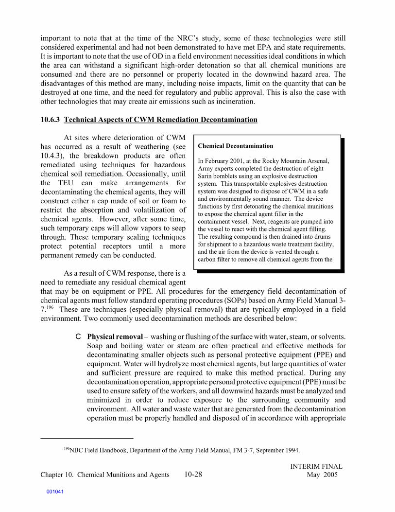
196NBC Field Handbook, Department of the Army Field Manual, FM 3-7, September 1994.
INTERIM FINALChapter 10. Chemical Munitions and Agents May 200510-28
important to note that at the time of the NRC’s study, some of these technologies were stillconsidered experimental and had not been demonstrated to have met EPA and state requirements.It is important to note that the use of OD in a field environment necessities ideal conditions in whichthe area can withstand a significant high-order detonation so that all chemical munitions areconsumed and there are no personnel or property located in the downwind hazard area. Thedisadvantages of this method are many, including noise impacts, limit on the quantity that can bedestroyed at one time, and the need for regulatory and public approval. This is also the case withother technologies that may create air emissions such as incineration.
10.6.3 Technical Aspects of CWM Remediation Decontamination
At sites where deterioration of CWMhas occurred as a result of weathering (see10.4.3), the breakdown products are oftenremediated using techniques for hazardouschemical soil remediation. Occasionally, untilthe TEU can make arrangements fordecontaminating the chemical agents, they willconstruct either a cap made of soil or foam torestrict the absorption and volatilization ofchemical agents. However, after some time,such temporary caps will allow vapors to seepthrough. These temporary sealing techniquesprotect potential receptors until a morepermanent remedy can be conducted.
As a result of CWM response, there is aneed to remediate any residual chemical agentthat may be on equipment or PPE. All procedures for the emergency field decontamination ofchemical agents must follow standard operating procedures (SOPs) based on Army Field Manual 3-7.196 These are techniques (especially physical removal) that are typically employed in a fieldenvironment. Two commonly used decontamination methods are described below:
C Physical removal – washing or flushing of the surface with water, steam, or solvents.Soap and boiling water or steam are often practical and effective methods fordecontaminating smaller objects such as personal protective equipment (PPE) andequipment. Water will hydrolyze most chemical agents, but large quantities of waterand sufficient pressure are required to make this method practical. During anydecontamination operation, appropriate personal protective equipment (PPE) must beused to ensure safety of the workers, and all downwind hazards must be analyzed andminimized in order to reduce exposure to the surrounding community andenvironment. All water and waste water that are generated from the decontaminationoperation must be properly handled and disposed of in accordance with appropriate
Chemical Decontamination
In February 2001, at the Rocky Mountain Arsenal,Army experts completed the destruction of eightSarin bomblets using an explosive destructionsystem. This transportable explosives destructionsystem was designed to dispose of CWM in a safeand environmentally sound manner. The devicefunctions by first detonating the chemical munitionsto expose the chemical agent filler in thecontainment vessel. Next, reagents are pumped intothe vessel to react with the chemical agent filling. The resulting compound is then drained into drumsfor shipment to a hazardous waste treatment facility,and the air from the device is vented through acarbon filter to remove all chemical agents from the
001041

INTERIM FINALChapter 10. Chemical Munitions and Agents May 200510-29
regulations. This is explained in more detail in the following section. C Chemical neutralization – triggers a chemical reaction between the chemical agent
and the decontaminant, usually resulting in the formation of a new compound thatmay be remediated using a RCRA-permitted incinerator. Generally, a chlorinatedbleach, such as supertropical bleach, chlorinated lime, bleaching powder, or chlorideof lime, is used for this purpose. Except under emergency situations, chemicalneutralization is conducted only in contained areas.
10.7 Safety Considerations at Sites Containing Chemical Agents
10.7.1 DoD Chemical Safety Requirements in the DoD Ammunition and Explosives SafetyStandards
The DoD Ammunition and Explosives Safety Standards (DoD 6055.9-STD, July 1999)contain strict safety requirements for properties currently or formerly owned by DoD that arecontaminated with CWM and require that all means possible be used to protect the public. Chapter11 of the DoD Explosives Safety Standard specifically addresses safety standards for chemical agentswhile acknowledging the explosive hazards accompanying CWM. Chapter 11 does not apply inemergency situations when disposal or decontamination needs are immediate and when delay willincrease the risk to human life or health.
In the event that an item is discovered that is suspected of containing CWM, the Army, aswell as each branch of military service, has specific reporting and emergency response proceduresthat need to be followed in order to ensure the safety of everyone in the vicinity of the possiblecontaminant. The first response is always to leave the area immediately, without touching ordisturbing the item, and to notify the agency indicated by the branch of service that has jurisdictionover the range. The Technical Escort Unit out of Aberdeen, Maryland, responds to all reports ofpossible CWM.
The safety requirements for CWM at MRSs are essentially the same as those for explosivessafety, with some modifications to address the unique safety considerations of chemical agents:
C Hazard Zone Determination - As required by the DoD Explosives Safety Standard, hazardzone calculations, or quantity-distance data, enable site planners to estimate damage orinjury potential based on a maximum credible event (MCE). Planners consider thepropagation characteristics of the ammunition, the amount of agent that could potentiallybe released, and the nature of the potential release (evaporation or aerosolization). Foragent-filled ammunition without explosives, the MCE factors should address the numberof items likely to be involved, the quantity of agent likely to be released in such an event,and the percentage of that agent that would be disseminated in an event. For combinedchemical and explosive components, the MCE should be based on the detonation of theexplosive components that will produce the maximum release of chemical agent.
C The DDESB must review and approve the chemical safety aspects of all plans for leasing,transferring, excessing, disposing of, or remediating DoD real property when chemicalagent contamination exists or is suspected to exist.
C The DDESB must review plans to remediate FUDS at which chemical agent
001042
197NBC Field Handbook, Department of the Army Field Manual (FM) 3-7, September 1994.
198Toxic Chemical Agent Safety Standards, Department of the Army Pamphlet (DA PAM) 385-61, March 31,1997.
INTERIM FINALChapter 10. Chemical Munitions and Agents May 200510-30
contamination exists or is suspected to exist.C Significant worker safety requirements should be followed to prevent exposure to
chemical agent, including measuring AELs, controlling exposures, and using protectiveequipment and clothing in areas known to contain or suspected of containing CWM.
C Medical surveillance, including annual health assessments, must be provided foremployees at sites where CWM is or is thought to be located.
C Personnel safety training must be provided to those who work with chemical agents andammunition, including agent workers, firefighters, and medical and security personnel,to maintain a safe working environment.
C Labeling and posting of hazards is required to warn personnel of potential hazards at sitescontaining or thought to contain CWM.
C Procedures for decontaminating protective equipment and clothing in the event of spillsmust be outlined.
C Transportation requirements for bulk chemical agent and materials contaminated withchemical agents must be followed.
10.7.2 Chemical Safety Requirements
In addition to the DoD Explosives Safety Standards, several other guidance documents andmanuals contain requirements for managing CWM at MRSs. These documents include ArmyRegulation 385-61, the Army Chemical Agent Safety Program, and Department of the ArmyPamphlet 385-61, Toxic Chemical Agent Safety Standards. All procedures for the decontaminationof chemical agents must follow SOPs based on Army Field Manual 3-7.197,198
When CWM is found or suspected at any MRS, the Army Technical Escort Unit (TEU), adivision of the U.S. Army Soldier and Biological Chemical Command (SBCCOM), will assess anyrecovered non-stockpile CWM to determine if the materiel is explosive, whether it is fuzed, what itschemical composition is, and whether it is safe for movement, storage, treatment, or disposal. Foreach recovered munition, data are developed from systems such as the PINS and the DRCT (seeTable 10-5). Data also are captured from any markings on the munition, the historical context of thefind (World War I, World War II, Korean war era, etc.) and any eyewitness information. The dataare then referred to a Materiel Assessment Review Board (MARB), chaired by the Commander ofTEU. The MARB is responsible for evaluating available assessment data on suspect recovered CWMand making a final expert determination as to its explosive configuration and chemical fill.
10.7.2.1 Preoperational Safety Surveys
Before a chemical agent investigation or decontamination activity can begin, a preoperationalsafety survey is required in order to ensure that all safety aspects of the activity will be achieved.During the survey, all facilities, equipment, and procedures are certified, and operator proficiencyin performing SOPs is demonstrated. This survey is conducted by the major command (MACOM)
001043

199Ibid.
INTERIM FINALChapter 10. Chemical Munitions and Agents May 200510-31
or its designee, often the Army Technical Center for Explosives Safety (USATCES) Toxic ChemicalAgent Team in the Chemical Safety and Data Division. The survey consists of a simulation of theplanned activity by the operational personnel and their first line supervisor using dummy (inert)material. All Army regulations and provisions of the site plan and safety submission must becomplied with during the survey.199
10.7.2.2 Personnel Protective Equipment
The DoD safety standard requires the use of administrative and engineering controls tominimize the personnel protective equipment (PPE) requirements (for example, the construction ofa temporary seal over soils contaminated with chemical agents to reduce or eliminate the exposurepotential to personnel). It is impossible to eliminate the need for PPE at all chemical agent sites. Thelevel and types of PPE required should be specified in the health and safety plan.
In order to protect workers who may be exposed to chemical agents and to determine theappropriate level and type of PPE, the Army has set certain limits of chemical agent that a workercan be exposed to in 8-hour and 72-hour time-weighted shifts. AR 385-61 and the DoD Ammunitionand Explosives Safety Standards (DoD 6055.9-STD) define these limits as the maximum permissibleconcentrations of chemical agent also known as the Airborne Exposure Limits (AELs), as establishedby the Army Surgeon General.
The levels of protection are identified in the regulatory requirements are as Levels A throughF., with Level A is used for the most hazardous situations and Level F used in the most benignsituations. Level A PPE involves wearing the maximum level of protection, which includes atoxicological agent protective (TAP) suit with a self-contained breathing apparatus, TAP boots, ahood, and gloves. Level F specifies that personnel carry a mask if they may be moving through cleanstorage or operating areas. Intermediate levels E through B require progressively more protection.These protection levels are designed by the Army and are specific to chemical agents. They do notmatch EPA’s A-D levels of protection for hazardous waste. For more information on the Army’sdesignation of PPE levels A through F see DA PAM 385-61.
10.7.3 Managing Chemical Agent Safety
Procedures for managing chemical safety require documentation of site safety and healthplans and site safety submissions. Site safety submissions for chemical agent sites follow the sameprocess as the explosives safety submission (ESS) review and approval process described in Chapter6. However, because the Army is the lead agency for chemical safety, all safety submissions mustbe prepared or formally endorsed by the installation safety director and sent to the U.S. ArmyTechnical Center for Explosive Safety (USATCES), which reviews, approves, and facilitates finalapproval by the DDESB.
001044
INTERIM FINALChapter 10. Chemical Munitions and Agents May 200510-32
10.8 Conclusion
In accordance with the Chemical Weapons Convention, all stockpile chemical weapons andnon-stockpile chemical warfare material and identified at the time of the ratification of the CWC andlocated in the United States must be destroyed by 2012. Although the United States is in the processof destroying all known stockpile and non-stockpile CWM, because of past disposal practices (e.g.,burial) it is possible that CWM may still be present at former ranges, test areas and other sites. Thepresence of this materiel may present acute and chronic risks to human health and the environment.
When considering appropriate methods for detection, destruction and treatment of CWM,there are unique challenges that are encountered. Although the most common and effective methodfor remediation of CWM is item separation and incineration, this method has been publicly opposedbecause of possible health risks from emissions. The safety hazards imposed by the chemical agentsand the explosive safety risks from the munition itself pose additional challenges. Safetyrequirements and common sense dictate that the explosive hazards be mitigated before the CWM isaddressed.
As a result, the Army has developed a number of safety requirements and protocols thatdictate how explosives CWM and RCWM are to be handled in order to minimize the risk to humanhealth and the environment and have established a national program to tackle the problem ofeliminating chemical weapons by 2012 and in so doing reducing the risks to human health and theenvironment.
Additionally, each service has regulatory requirements that follow the guidance provided tothem by DoD’s chemical and biological directives.
001045

INTERIM FINALChapter 10. Chemical Munitions and Agents May 200510-33
SOURCES AND RESOURCES
The following publications, offices, laboratories, and websites are provided as a guide for handbookusers to obtain additional information about the subject matter addressed in each chapter. Severalof these publications, offices, laboratories, or websites were also used in the development of thishandbook.
Publications
CBRNE – Nerve Agents, Binary: GB2, VX2, Velez-Daubon, Larissa I., MD, Fernando L Benitez,MD. eMedicine Journal 3:1, January 2002. 3:1, http://www.emedicine.com/emerg/topic900.htm.
Chemical Agent Data Sheets, Volumes I and II, Edgewood Arsenal Special Report No.EO-SR-74001, December 1974. Available through Defense Technical Information Center, DTIC No.AD B028222.
Hartman, H.M. Evaluation of Risk Assessment Guideline Levels for the Chemical Warfare AgentsMustard, GB, and VX. Regulatory Toxicology and Pharmacology, 35, pp. 347-356, 2002.
Munro, N.B. et al. The Sources, Fate, and Toxicity of Chemical Warfare Agent DegradationProducts. Environmental Health Perspectives, Vol. 107, No. 12, December 1999.
Munro, N.B. et al. Toxicity of the Organophosphate Chemical Warfare Agents GA, GB, and VX:Implications for Public Protection. Environmental Health Perspectives, Vol. 102, No. 1, January1994.
NAP (National Academy Press). Review of Acute Human-Toxicty Estimates for Selected Chemical-Warfare Agents. National Research Council, National Academy Press, 1997.
NAP. Review of the U.S. Army’s Health Risk Assessments for Oral Exposure to Six ChemicalWarfare Agents. National Research Council, National Academy Press, 2000.
NAP. Systems and Technologies for the Treatment of Non-Stockpile Chemical Warfare Agents.National Research Council, National Academy Press, 2002.
NAP. Veterans at Risk: The Health Effects of Mustard Gas and Lewisite. Institute of Medicine,National Academy Press, 1993.
Roberts, W.C., and W.R. Hartley. Drinking Water Health Advisory: Munitions. CRC Press, BocaRaton, FL, 1992.
Somani, S.M., and J. Romano, Chemical Warfare Agents: Toxicity at Low Levels. CRC Press, BocaRaton, FL, 2001.
U.S. Army. Non-Stockpile Chemical-Material Program, Survey and Analysis Report. U.S. ArmyChemical Materiel Destruction Agency, November 1993.
U.S. Army Armament, Munitions and Chemical Command Chemical Research, Development andEngineering Center. Material Safety Data Sheet: Lethal Nerve Agent Tabun (GA).
U.S. Army Center for Health Promotion and Preventive Medicine (USACHPPM). Detailed and
001046

INTERIM FINALChapter 10. Chemical Munitions and Agents May 200510-34
General Facts About Chemical Agents, TG 218.
U.S. Army Chemical Biological Defense Command Edgewood. Material Safety Data Sheet: Lewisite.Last Technical Review on May 5, 1999.
U.S. Army Corps of Engineers. Safety and Health Requirements Manual. EM 385-1-1, Washington,D.C., September 3, 1996.
U.S. Army Soldier and Biological Chemical Command (SBCCOM). Material Safety Data Sheets.Revised on August 13, 2001.
Information Sources
Agency for Toxic Substances and Disease Registry (ATSDR) ATSDR Region 1 1 Congress Street Suite 1100 HBTBoston, MA 02114 (617) 918-1494http://www.atsdr.cdc.gov/mmg.html
Deployment Health Clinical Center (DHCC) Blister Agent Fact Sheet http://pdhealth.mil/wot/chemical.asp
International Programme on Chemical Safety (IPCS INCHEM) World Health Organization (WHO) 20 Avenue Appia1211 Geneva, Switzerland http://www.inchem.org/pages/icsc.html
Mitretek Systems3150 Fairview Park DriveFalls Church, VA 22042-4519(703) 610-2002 http://mitretek.org/home.nsf/homelandsecurity/chembiodefense
National Institute for Occupational Safety and Health (NIOSH) (800) 35-NIOSH http://www.cdc.gov/niosh/homepage.html
National Toxicology Program (NTP) P.O. Box 12233, MD EC-03Research Triangle Park, NC 27709(919) 541-3419 http://ntp-server.niehs.nih.gov/
Organization for the Prohibition of Chemical Weapons, Chemical Weapons Conventionhttp://www.opcw.org/html/db/cwc/eng/cwc_frameset.html
001047

INTERIM FINALChapter 10. Chemical Munitions and Agents May 200510-35
University of Oklahoma, College of Pharmacy 1110 N. Stonewall Avenue Oklahoma City, OK 73117 (405) 271-6484 http://www.oklahomapoison,org/prevention/arsine.asp
U.S. Army Center for Explosives Safety (USATCES) 1 Tree Road, Building 35 McAlester, OK 74501 http://www.dac.army.mil/es/
U.S. Army Center for Health Promotion and Preventive Medicine (CHPPM) 5158 Blackhawk RoadAberdeen Proving Ground, MD 21010 (800) 222-9698 http://chppm-www.apgea.army.mil/
U.S. Army Chemical Materials Agency HeadquartersPublic AffairsAMSCM-SSP5183 Blackhawk RoadAberdeen Proving Ground-Edgewood Area, MD 21010-5424(800) 488-0648http://www.cma.army.mil/home.aspx
U.S. Department of Labor, Occupational, Safety and Health Administration (OSHA) 200 Constitution AvenueWashington, D.C. 20210 1-800-321-OSHA http://www.osha.gov
U.S. Army Engineering and Support Center, Huntsville Demilitarization Directorate of Chemical DemilitarizationATTN: CEHNC-CDP.O. Box 1600Huntsville, AL 35807-4301 (256) 895-1370 http://www.hnd.usace.army.mil/chemde/index.asp
U.S. National Library of Medicine, Specialized Information Services 2 Democracy Plaza Suite 510 6707 Democracy Boulevard, MSC 5467 Bethesda, MD 20892 (301) 496-1131 http://sis.nlm.nih.gov/
Guidance Documents
Chemical Accident or Incident Response and Assistance (CAIRA) Operations. DA PAM 50-6,Headquarters, Department of the Army, Washington, D.C., May 1991.
001048

INTERIM FINALChapter 10. Chemical Munitions and Agents May 200510-36
U.S. Army. Army Chemical Safety Program, AR 385-61, Headquarters, Department of the Army,Washington, D.C., February 1997.
U.S. Army. Chemical Surety, Army Regulation 50-6, Headquarters, Department of the Army,Washington, D.C., February 1995.
U.S. Army. DoD Ammunition and Explosives Safety Standards. DoD 6055.9-STD.
U.S. Army. Military Chemistry and Chemical Compounds. Army Field Manual (FM) 3-9, AirForce AFR 355-7, Headquarters, Department of the Army, October 1975.
U.S. Army. NBC Field Handbook, Field Manual (FM) 3-7, Headquarters, Department of theArmy, Washington, D.C., September 29, 1994.
U.S. Marine Corps. NBC Decontamination, FM 3-5, Headquarters, Department of the Army,MCWP 3-37.3, Commandant, Washington, D.C., July 28, 2000.
001049