Embed Size (px)
Citation preview

HART Loop Converter KFD2-HLC-Ex1.D(.**)
ISO9001
PROCESS AUTOMATION
MANUAL
With regard to the supply of products, the current issue of the following document is applicable:The General Terms of Delivery for Products and Services of the Electrical Industry,
published by the Central Association of the Electrical Industry(Zentralverband Elektrotechnik und Elektroindustrie (ZVEI) e.V.) in its most recent version
as well as the supplementary clause: "Expanded reservation of proprietorship"
HART Loop Converter KFD2-HLC-Ex1.D(.**)

HART Loop Converter KFD2-HLC-Ex1.D(.**)Contents
3157
0220
18-0
1
EN - 1
EN
1 Introduction . . . . . . . . . . . . . . . . . . . . . . . . . . . . . . . . . . . . . . . . 21.1 Manufacturer . . . . . . . . . . . . . . . . . . . . . . . . . . . . . . . . . . . . . . . . . . 21.2 Content of this Document . . . . . . . . . . . . . . . . . . . . . . . . . . . . . . . 21.3 Target Group, Personnel . . . . . . . . . . . . . . . . . . . . . . . . . . . . . . . . 31.4 Symbols Used . . . . . . . . . . . . . . . . . . . . . . . . . . . . . . . . . . . . . . . . . 3
2 Product Specifications . . . . . . . . . . . . . . . . . . . . . . . . . . . . . . . 52.1 Device Versions . . . . . . . . . . . . . . . . . . . . . . . . . . . . . . . . . . . . . . . . 52.2 Function . . . . . . . . . . . . . . . . . . . . . . . . . . . . . . . . . . . . . . . . . . . . . . 52.3 Assembly . . . . . . . . . . . . . . . . . . . . . . . . . . . . . . . . . . . . . . . . . . . . . 62.4 Dimensions . . . . . . . . . . . . . . . . . . . . . . . . . . . . . . . . . . . . . . . . . . . 8
3 Mounting and Installation. . . . . . . . . . . . . . . . . . . . . . . . . . . . . 93.1 DIN Mounting Rail . . . . . . . . . . . . . . . . . . . . . . . . . . . . . . . . . . . . . . 93.2 Power Rail . . . . . . . . . . . . . . . . . . . . . . . . . . . . . . . . . . . . . . . . . . . 103.3 Mounting . . . . . . . . . . . . . . . . . . . . . . . . . . . . . . . . . . . . . . . . . . . . . 113.4 Connection . . . . . . . . . . . . . . . . . . . . . . . . . . . . . . . . . . . . . . . . . . . 13
4 Configuration . . . . . . . . . . . . . . . . . . . . . . . . . . . . . . . . . . . . . 254.1 Configuration via Software . . . . . . . . . . . . . . . . . . . . . . . . . . . . . 254.2 Configuration via Keypad on the Device . . . . . . . . . . . . . . . . . . 26
5 Operation . . . . . . . . . . . . . . . . . . . . . . . . . . . . . . . . . . . . . . . . 525.1 Indicators during Operation . . . . . . . . . . . . . . . . . . . . . . . . . . . . 535.2 Fault Message . . . . . . . . . . . . . . . . . . . . . . . . . . . . . . . . . . . . . . . . 55
6 Dismounting, Maintenance, and Repair . . . . . . . . . . . . . . . 567 Technical Specifications . . . . . . . . . . . . . . . . . . . . . . . . . . . 59
7.1 Default Settings . . . . . . . . . . . . . . . . . . . . . . . . . . . . . . . . . . . . . . . 59
HART Loop Converter KFD2-HLC-Ex1.D(.**)

2
HART Loop Converter KFD2-HLC-Ex1.D(.**)Introduction
EN
HART Loop Converter KFD2-HLC-Ex1.D(.**)
3157
0220
18-0
1
1 Introduction1.1 Manufacturer
1.2 Content of this DocumentThis document contains information that you need in order to use your product throughout the applicable stages of the product life cycle. These can include the following:• Product identification• Delivery, transport, and storage• Mounting and installation• Commissioning and operation• Maintenance and repair• Troubleshooting• Dismounting• Disposal
Pepperl+Fuchs GmbHLilienthalstraße 200, 68307 Mannheim, GermanyInternet: www.pepperl-fuchs.com
Note!This document does not substitute the instruction manual.
Note!For full information on the product, refer to the instruction manual and further documentation on the Internet at www.pepperl-fuchs.com.
- EN

HART Loop Converter KFD2-HLC-Ex1.D(.**)Introduction
EN
3157
0220
18-0
1
The documentation consists of the following parts:• Present document• Instruction manual• DatasheetAdditionally, the following parts may belong to the documentation, if applicable:• EU-type examination certificate• EU declaration of conformity• Attestation of conformity• Certificates• Control drawings• Additional documents
1.3 Target Group, PersonnelResponsibility for planning, assembly, commissioning, operation, maintenance, and dismounting lies with the plant operator.Only appropriately trained and qualified personnel may carry out mounting, installation, commissioning, operation, maintenance, and dismounting of the product. The personnel must have read and understood the instruction manual and the further documentation.Prior to using the product make yourself familiar with it. Read the document carefully.
1.4 Symbols UsedThis document contains symbols for the identification of warning messages and of informative messages.
Warning MessagesYou will find warning messages, whenever dangers may arise from your actions. It is mandatory that you observe these warning messages for your personal safety and in order to avoid property damage.
EN - 3

4
HART Loop Converter KFD2-HLC-Ex1.D(.**)Introduction
EN
3157
0220
18-0
1
Depending on the risk level, the warning messages are displayed in descending order as follows:
Informative Symbols
ActionThis symbol indicates a paragraph with instructions. You are prompted to perform an action or a sequence of actions.
Danger!This symbol indicates an imminent danger.Non-observance will result in personal injury or death.
Warning!This symbol indicates a possible fault or danger.Non-observance may cause personal injury or serious property damage.
Caution!This symbol indicates a possible fault.Non-observance could interrupt the device and any connected systems and plants, or result in their complete failure.
Note!This symbol brings important information to your attention.
- EN
HART Loop Converter KFD2-HLC-Ex1.D(.**)Product Specifications
EN
HART Loop Converter KFD2-HLC-Ex1.D(.**)
3157
0220
18-0
1
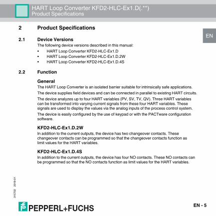
2 Product Specifications2.1 Device Versions
The following device versions described in this manual:• HART Loop Converter KFD2-HLC-Ex1.D• HART Loop Converter KFD2-HLC-Ex1.D.2W• HART Loop Converter KFD2-HLC-Ex1.D.4S
2.2 FunctionGeneralThe HART Loop Converter is an isolated barrier suitable for intrinsically safe applications.The device supplies field devices and can be connected in parallel to existing HART circuits.The device analyzes up to four HART variables (PV, SV, TV, QV). Three HART variables can be transformed into varying current signals from these four HART variables. These signals are used to display the values via the analog inputs of the process control system.The device is easily configured by the use of keypad or with the PACTware configuration software.
KFD2-HLC-Ex1.D.2WIn addition to the current outputs, the device has two changeover contacts. These changeover contacts can be programmed so that the changeover contacts function as limit values for the HART variables.
KFD2-HLC-Ex1.D.4SIn addition to the current outputs, the device has four NO contacts. These NO contacts can be programmed so that the NO contacts function as limit values for the HART variables.
EN - 5

6
HART Loop Converter KFD2-HLC-Ex1.D(.**)Product Specifications
EN
3157
0220
18-0
1
2.3 Assembly
Figure 2.1 Example front view KFD2-HLC-Ex1D.4S
Operating and indicating elements
ESC
OK
KFD2-HLC-Ex1.D.4S
RS232
PWRERR
1 2
3 4
OUT
19 21159
137
20148
22 241812
1610
231711
1 32 4 65
3
1
2
6
7
8
9
4
5
- EN

HART Loop Converter KFD2-HLC-Ex1.D(.**)Product Specifications
EN
3157
0220
18-0
1
1 Removable terminals, blue2 LC display Display for showing
• the measured values• the current output values• the fault messages• the parameterization mode
3 Keypad
ESCOK
Four keys for selecting the displayed values, the current output values and for setting the parameters of the deviceUpDownEscapeConfirmation
4 Place for labeling5 Removable terminals, green6 Programming socket Interface for connecting a computer for parameterization and
diagnostics of the device with the PACTware operating software, using the K-ADP-USB adapter
7 yellow LEDs Outputs Out 1 to 4, indicating relay status8 red LEDs Indicating faults9 green LEDs Indicating power supply
EN - 7

8
HART Loop Converter KFD2-HLC-Ex1.D(.**)Product Specifications
EN
3157
0220
18-0
1
2.4 Dimensions
Figure 2.2Number of terminal blocks max. 10• Dimension drawing with screw terminals• When using screw terminals with test sockets the device is 124 mm (4.9 inch) in height.• When using spring terminals the device is 131 mm (5.16 inch) in height.
Housing Type C2
40 mm (1.6 inch) 115 mm (4.5 inch)
46
mm
(1
.82
inc
h)
58
mm
(2
.28
inc
h)
11
9 m
m (
4.7
inc
h)
10
4 m
m (
4.1
inc
h)
- EN

HART Loop Converter KFD2-HLC-Ex1.D(.**)Mounting and Installation
EN
HART Loop Converter KFD2-HLC-Ex1.D(.**)
3157
0220
18-0
1
3 Mounting and Installation
3.1 DIN Mounting RailThe devices are mounted on a 35 mm DIN mounting rail according to EN 60715.
Figure 3.1 Example: DIN mounting rail UPR-MR (35 mm x 15 mm)
Danger!Explosion hazard from damaged electronic components Premature wear of electronic components in a device that was previously used in a general electrical installation can cause sparks that can ignite the surrounding potentially explosive atmosphere.Never install devices that have already been operated in general electrical installations in electrical installations used in combination with hazardous areas!
Danger!Explosion hazard from pollutionAn excessively polluted surface of the device can become conductive and consequently ignite a surrounding potentially explosive atmosphere.Ensure that you install the device only in environments with a pollution degree 2 or better according to IEC/EN 60664–1.
EN - 9

10
HART Loop Converter KFD2-HLC-Ex1.D(.**)Mounting and Installation
EN
3157
0220
18-0
1
3.2 Power RailTo reduce wiring and installation costs, Power Rail is the optimum solution. The Power Rail is a DIN mounting rail with plastic insert, that delivers power to the devices (24 V DC) and transfers bus signals and a collective error message.The Power Rail is factory-equipped with cover and end caps. These parts cover empty and open segments of the Power Rail. Thus, the Power Rail is protected from contamination. Additionally the cover and end caps prevent that electrically conductive parts come in contact with the Power Rail.
Power Rail UPR-03The Power Rail UPR–03 has 3 conductors.• 2 conductors for power• 1 conductor for collective error messaging
Figure 3.2 Example: Power Rail UPR-03
1 Cover UPR-COVER2 Insert UPR-INS-033 DIN mounting rail UPR-MR (35 mm x 15 mm)4 End cap UPR-E
1
2
34
- EN

HART Loop Converter KFD2-HLC-Ex1.D(.**)Mounting and Installation
EN
3157
0220
18-0
1
3.3 Mounting
Mounting in the Non-Hazardous AreaMounting the DeviceSnap the device onto the DIN mounting rail in a vertical downward movement. See figure below.
Mounting in Areas that Require the Equipment Protection Level Gc
Danger!Danger to life from electric shockAbsent or insufficient insulation can result in electric shock.Only connect supplies that provide protection against electric shock to power feed modules (e. g. SELV or PELV).
Caution!Property damage from use of isolators for Power Rail supplyUsing the isolators for Power Rail supply can damage the isolators and make the Power Rail fail.Do not supply the Power Rail via isolators.
Danger!Explosion hazard from live wiring of non-intrinsically safe circuitsIf you connect or disconnect energized non-intrinsically safe circuits in a potentially explosive atmosphere, sparks can ignite the surrounding atmosphere.Only connect or disconnect energized non-intrinsically safe circuits in the absence of a potentially explosive atmosphere.
EN - 11

12
HART Loop Converter KFD2-HLC-Ex1.D(.**)Mounting and Installation
EN
3157
0220
18-0
1
Mounting the DeviceSnap the device onto the DIN mounting rail in a vertical downward movement. See figure below.
Danger!Explosion hazard from wrong mountingThe device safety can be impaired by external environmental influences and by mechanical stress. This can lead to sparking that can ignite a surrounding potentially explosive atmosphere.Mount the device in a surrounding enclosure that complies with IEC/EN 60079–0and that is rated with the degree of protection IP54 according to IEC/EN 60529.
CORRECT: Device snapped on vertically. INCORRECT: Device snapped on from the side.Can damage the contacts and cause the device to fail.
Figure 3.3
�
- EN

HART Loop Converter KFD2-HLC-Ex1.D(.**)Mounting and Installation
EN
3157
0220
18-0
1
Mounting the Terminal BlocksConnect the terminal blocks or disconnect the terminal blocks.
3.4 ConnectionDanger!Danger to life from incorrect installationIncorrect installation of cables and connection lines can compromise the function and the electrical safety of the device.• Observe the permissible core cross section of the conductor.• When using stranded conductors, crimp wire end ferrules on the conductor ends.• Use only one conductor per terminal.• When installing the conductors the insulation must reach up to the terminal.• Observe the tightening torque of the terminal screws.
Danger!Explosion hazard from live wiring of non-intrinsically safe circuitsIf you connect or disconnect energized non-intrinsically safe circuits in a potentially explosive atmosphere, sparks can ignite the surrounding atmosphere.Only connect or disconnect energized non-intrinsically safe circuits in the absence of a potentially explosive atmosphere.
EN - 13

14
HART Loop Converter KFD2-HLC-Ex1.D(.**)Mounting and Installation
EN
3157
0220
18-0
1
Danger!Explosion hazard from wrong separation distancesIf you do not observe the minimum separation distances between intrinsically safe circuits of associated apparatus and non-intrinsically safe circuits, this can lead to added currents or voltages. This can result in a current/voltage flashover generating sparks. The sparks can ignite the surrounding potentially explosive atmosphere.Ensure that you observe the compliance of the separation distances to all non–intrinsically safe circuits according to IEC/EN 60079–14.
Danger!Danger to life from electric shockAbsent or insufficient insulation can result in electric shock.• Maintain sufficient distance between the connection lines, terminals, housing, and the
environment.• Insulate connection lines, terminals, and the housing from the environment.
Danger!Danger to life from electric shockAbsent or insufficient insulation can result in electric shock.Only connect supplies that provide protection against electric shock (e. g. SELV or PELV).
- EN

HART Loop Converter KFD2-HLC-Ex1.D(.**)Mounting and Installation
EN
3157
0220
18-0
1
The removable terminal blocks simplify connection and control cabinet construction significantly. These terminal blocks offer adequate space for the connection of leads with core cross-sections of up to 2.5 mm2 (14 AWG). The terminal blocks are coded with red coding pins so misconnection of terminal blocks are eliminated.
Connecting Circuits1. Connect the field circuit.2. Connect the control circuit.
Danger!Danger to life from electric shockWorking on live parts at voltages higher than 50 V AC or 120 V DC can result in electric shock.1. De-energize the device.2. Secure the circuit against reconnection.3. Verify that the device is de-energized at all poles.4. Provide protection from adjacent live parts, if present.
EN - 15

16
HART Loop Converter KFD2-HLC-Ex1.D(.**)Mounting and Installation
EN
3157
0220
18-0
1
3.4.1 Input Connection (Field Circuit)
Connecting the Field Circuit1. Connect the field circuit to the blue terminals.2. Observe the tightening torque of the terminal screws. The tightening torque is
0.5 Nm to 0.6 Nm.The intrinsically safe field circuit may be routed in the hazardous area with connection lines in accordance with DIN EN 60079-14. You can connect the following field devices:1. any separately supplied HART current circuit with transmitter or positioner connected in
parallelConnection to terminals 2 and 3
2. a HART-capable active current source, e. g., a separately supplied HART measuring transmitterConnection to terminals 2 and 3 with bridge between terminals 5 and 6
3. a 2-wire HART measuring transmitter, e. g., HART measuring transmitter with an analog output signal of 4 mA to 20 mAThe HART measuring transmitter is supplied by the isolated barrierConnection to terminals 1 and 3 with bridge between terminals 4 and 5
Danger!Explosion hazard from wrong separation distancesIf you do not observe the minimum separation distance between 2 intrinsically safe circuits, this can lead to added currents or voltages. This can result in a current/voltage flashover generating sparks. The sparks can ignite the surrounding potentially explosive atmosphere.Ensure that you observe all separation distances between 2 adjacent intrinsically safe circuits according to IEC/EN 60079-14.
- EN

HART Loop Converter KFD2-HLC-Ex1.D(.**)Mounting and Installation
EN
3157
0220
18-0
1
Figure 3.4
Power Rail
24 V DCFaultZone 0, 1, 2Div. 1, 2
HART
+
-HA
RT+
-
+
-
HA
RT
mA
1+
2+
3-
4
5
6250 Ω
EN - 17

18
HART Loop Converter KFD2-HLC-Ex1.D(.**)Mounting and Installation
EN
3157
0220
18-0
1
3.4.2 Output Connection (Control Circuit)Connecting the Control Circuit1. Connect the control circuit to the green terminals.2. Note the tightening torque of the terminal screws. The tightening torque is
0.5 Nm to 0.6 Nm.
Connection KFD2-HLC-Ex1.DThe following connections are available:• Terminals 7 to 9: output I, current output as source (7/8) or sink (7/9)• Terminals 13 to 15: output II, current output as source (13/14) or sink (13/15)• Terminals 19 to 21: output III, current output as source (19/20) or sink (19/21)• Terminals 22/24: connection of HART handheld• Terminals 23/24: power supply 24 VDC
Figure 3.5
KFD2-HLC-Ex1.D
78+9-
14+15-
13
20+21-
19
Zone 2Div. 2
24 V DC23+24-
22
Power Rail
24 V DCFault
HA
RT
II
III
ImA
mA
mA
+-V
+-V
+-V
250 Ω
- EN

HART Loop Converter KFD2-HLC-Ex1.D(.**)Mounting and Installation
EN
3157
0220
18-0
1
Connection KFD2-HLC-Ex1.D.2W
The following connections are available:• Terminals 10 to 12: output I (relay 1 (change-over contact))• Terminals 16 to 18: output II (relay 2 (change-over contact))• Terminals 7 to 9: output III, current output as source (7/8) or sink (7/9)• Terminals 13 to 15: output IV, current output as source (13/14) or sink (13/15)• Terminals 19 to 21: output V, current output as source (19/20) or sink (19/21)• Terminals 22/24: connection of HART handheld• Terminals 23/24: power supply 24 VDC
Danger!Danger to life from electric shockWorking on live parts at voltages higher than 50 V AC or 120 V DC can result in electric shock.1. De-energize the device.2. Secure the circuit against reconnection.3. Verify that the device is de-energized at all poles.4. Provide protection from adjacent live parts, if present.
EN - 19

20
HART Loop Converter KFD2-HLC-Ex1.D(.**)Mounting and Installation
EN
3157
0220
18-0
1
Figure 3.6
KFD2-HLC-Ex1.D.2W
78+9-
14+15-
13
20+21-
19
Zone 2Div. 2
I
II
101112161718
24 V DC23+24-
22
Power Rail
24 V DCFault
HA
RT
+
IV
V
III
-
mA
mA
mA
V
+-V
+-V
250 Ω
- EN

HART Loop Converter KFD2-HLC-Ex1.D(.**)Mounting and Installation
EN
3157
0220
18-0
1
Connection KFD2-HLC-Ex1.D.4S
The following connections are available:• Terminals 10/11: output I (relay 1 (NO contact))• Terminals 11/12: output II (relay 2 (NO contact))• Terminals 16/17: output III (relay 3 (NO contact))• Terminals 17/18: output IV (relay 4 (NO contact))• Terminals 7 to 9: output V, current output as source (7/8) or sink (7/9)• Terminals 13 to 15: output VI, current output as source (13/14) or sink (13/15)• Terminals 19 to 21: output VII, current output as source (19/20) or sink (19/21)• Terminals 22/24: connection of HART handheld• Terminals 23/24: power supply 24 VDC
Danger!Danger to life from electric shockWorking on live parts at voltages higher than 50 V AC or 120 V DC can result in electric shock.1. De-energize the device.2. Secure the circuit against reconnection.3. Verify that the device is de-energized at all poles.4. Provide protection from adjacent live parts, if present.
EN - 21

22
HART Loop Converter KFD2-HLC-Ex1.D(.**)Mounting and Installation
EN
3157
0220
18-0
1
Figure 3.7
KFD2-HLC-Ex1.D.4S
78+9-
14+15-
13
20+21-
19
Zone 2Div. 2
101112161718
I
III
24 V DC23+24-
22
Power Rail
24 V DCFault
HA
RT
IV
II
VI
VII
VmA
mA
mA
+-V
+-V
+-V
250 Ω
- EN
HART Loop Converter KFD2-HLC-Ex1.D(.**)Mounting and Installation
EN
3157
0220
18-0
1
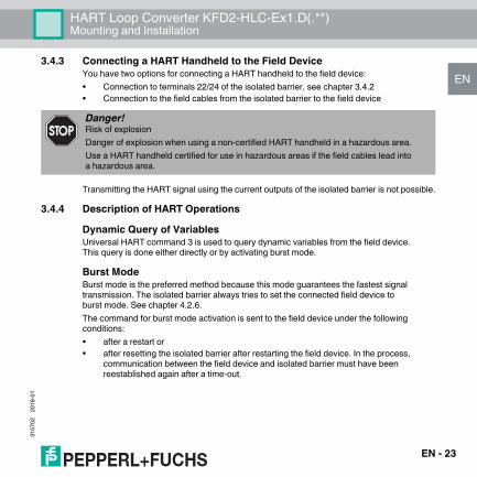
3.4.3 Connecting a HART Handheld to the Field DeviceYou have two options for connecting a HART handheld to the field device:• Connection to terminals 22/24 of the isolated barrier, see chapter 3.4.2• Connection to the field cables from the isolated barrier to the field device
Transmitting the HART signal using the current outputs of the isolated barrier is not possible.
3.4.4 Description of HART OperationsDynamic Query of VariablesUniversal HART command 3 is used to query dynamic variables from the field device. This query is done either directly or by activating burst mode.
Burst ModeBurst mode is the preferred method because this mode guarantees the fastest signal transmission. The isolated barrier always tries to set the connected field device to burst mode. See chapter 4.2.6.The command for burst mode activation is sent to the field device under the following conditions:• after a restart or• after resetting the isolated barrier after restarting the field device. In the process,
communication between the field device and isolated barrier must have been reestablished again after a time-out.
Danger!Risk of explosionDanger of explosion when using a non-certified HART handheld in a hazardous area.Use a HART handheld certified for use in hazardous areas if the field cables lead into a hazardous area.
EN - 23

24
HART Loop Converter KFD2-HLC-Ex1.D(.**)Mounting and Installation
EN
3157
0220
18-0
1
Polling Mode (Command and Answer)The isolated barrier deactivates the burst configuration of the field device. The isolated barrier performs the field device query using HART command 3. See chapter 4.2.6.
Procedure to Restore Burst ModeIf the isolated barrier does not receive any more data from the field device in burst mode, the following actions are taken:• The isolated barrier switches to polling mode.• The isolated barrier checks whether another HART master has started in the query
signal circuit. If the isolated barrier has detected a HART master, the restoring of burst mode is interrupted.
• If the isolated barrier does not detect any other HART masters, the isolated barrier attempts to activate burst mode.
• As soon as the isolated barrier receives a burst message from the field device, the isolated barrier switches from polling mode to burst mode.
This process enables other HART masters to deactivate burst mode momentarily for service work.
Time-out (Communication Loss)When the time-out time has been exceeded in the absence of communication, all outputs switch to the defined safe state. Time-out can be adjusted.
- EN

HART Loop Converter KFD2-HLC-Ex1.D(.**)Configuration
EN
HART Loop Converter KFD2-HLC-Ex1.D(.**)
3157
0220
18-0
1
4 Configuration4.1 Configuration via Software
The devices can configured using the PACTwareTM operating software.
Connection between Device and ComputerConnect the device and the computer using the K-ADP-USB adapter. This adapter can be ordered as an accessory.
Connecting the Device to the Computer via the USB Interface1. Mount the device.2. Connect the device to the power supply.3. Connect the device to the PC via the adapter.
- Connection on the device: front programming socket- Connection on the PC: USB interface
4. Refer to the "Installation and Configuration DTM Collection Conventional Interface Introduction" manual for further steps.
Danger!Explosion hazard from sparking when plugging or pulling the adapterPlugging or pulling the adapter in a potentially explosive atmosphere can cause sparks that can ignite the surrounding atmosphere.Only plug or pull the adapter in the absence of a potentially explosive atmosphere.
Caution!Fault in the plantChanging the device data changes the device function.Before entering new device data, make sure the plant is not endangered by changing the device data.
EN - 25

26
HART Loop Converter KFD2-HLC-Ex1.D(.**)Configuration
EN
3157
0220
18-0
1
The operating software and the necessary device and communication DTMs can be downloaded from our internet page www.pepperl-fuchs.com (product search, enter PACTware). The manual "Installation and Configuration DTM Collection Conventional Interface Introduction" guides you through the installation steps necessary to install the software. The manual can be found on our internet page www.pepperl-fuchs.com (product search, enter PACTware).
4.2 Configuration via Keypad on the Device
Note!The configuration and operation of the device via software is not described in this manual.
Danger!Explosion hazard from sparking when using operating elementsUsing operating elements in a potentially explosive atmosphere can cause sparks that can ignite the surrounding atmosphere. Only use operating elements (e.g., switch, slider, button, etc.) in the absence of a potentially explosive atmosphere.
Caution!Fault in the plantChanging the device data changes the device function.Before entering new device data, make sure the plant is not endangered by changing the device data.
- EN

HART Loop Converter KFD2-HLC-Ex1.D(.**)Configuration
EN
3157
0220
18-0
1
Configuring the DeviceConfigure the device using the buttons on the front side. Use the , , ESC, and OK buttons for navigation. The following chapters contain more detailed information about the menus.The navigation principle is shown using the following example:
The menu items from the lowest menu level are outlined in bold.
OK →
← ESC
← ESC
← ESC
← ESC
← ESC
OK →
← ESC
▼ ▲
▼ ▲
▼ ▲
▼ ▲
Iout1
4 - 20 NE43
Assignment
Characteristic
Start Value
End Value
Fault Current
Lowest menu level
EN - 27

28
HART Loop Converter KFD2-HLC-Ex1.D(.**)Configuration
EN
3157
0220
18-0
1
4.2.1 Parameterization ModeAfter being switched on, the device is in display mode. If you have password protection enabled, you must enter the password every time you transition from display mode to parameterization mode.
Calling up Parameterization ModePress the OK and ESC buttons simultaneously for approx. 1 second.
The device changes from display mode to parameterization mode.
Exiting Parameterization Mode1. Press the ESC once or multiple times. The number of times depends on which menu
level you are in. The device changes from parameterization mode to display mode.
2. If you have not pressed a button for 10 minutes in parameterization mode, the device switches back automatically to display mode.
▼ ▲
▼ ▲
▼ ▲
HARTcom
Unit
Main menu
parameterization mode
Output
Service
Display modeOK + ESC (simultaneously for 1 s) →
← ESC
- EN
HART Loop Converter KFD2-HLC-Ex1.D(.**)Configuration
EN
3157
0220
18-0
1
4.2.2 Password ProtectionYou can activate password protection to protect parameterization from unauthorized changes. If password protection is enabled, you can view the parameter settings but not change them. Password protection is deactivated during delivery. The password is preset and cannot be changed by the operator. The password is 1234. Information about enabling password protection see chapter 4.2.9.
Entering the Password1. As soon as you try to change the parameterization, the device switches automatically to
the input window for password access. The first digit of the password flashes.
2. Set the first digit of the password using the and buttons.3. Confirm your entry with OK.
The next digit flashes.4. Repeat steps 2 and 3, until all digits have been entered.5. Confirm your entry with OK.
If the password was correct, the device changes to parameterization mode. The device can now be parameterized.If the password was not correct, cancel password access and begin password entry again using step 1.
Canceling Password EntryYou can cancel password entry at any time.Press the ESC button.
The device switches to display mode.
EN - 29

30
HART Loop Converter KFD2-HLC-Ex1.D(.**)Configuration
EN
3157
0220
18-0
1
4.2.3 Entering NumbersAt the lowest menu level of the Parameter menu, you have the option of selecting or entering a numerical value.
Selecting a Numerical Value1. Select the parameter for which you want to change the numerical value.2. Press the OK button.
The current value flashes.3. Select a value from the list of values using the and buttons.
The new value flashes. The value is not stored.4. Confirm your selection with OK.
The new value does not flash. The value is stored.
Entering a Numerical Value1. Select the parameter where you want to enter the numerical value.2. Press the OK button.
The current value flashes.3. To change the value in steps, press the or button. or
To change the value more quickly, press and hold the or button. The new value flashes. The value is not stored.
4. Confirm your selection with OK. The new value is stored.
OK →
← ESC
OK ↓
← ESC
← ESC
▼ ▲ ↓
Parameter Current value, flashing
New value, flashing,
not stored
New value, not flashing,
stored
- EN

HART Loop Converter KFD2-HLC-Ex1.D(.**)Configuration
EN
3157
0220
18-0
1
4.2.4 Entering Floating Point FiguresAt the lowest menu level of the Parameter menu, you have the option of entering floating point figures.The floating point figures can have the following structure:
For a floating point figure, you must enter the following parameters:• four digits of the mantissa (decimals) for positive numbers• a minus sign and three digits for the mantissa for negative numbers• the position of the decimal point in or after the mantissa• the exponents
Positive number Input Negative number Input43210000 43.21 E06 -3210000 -3.21 E064321000 4321 E03 -321000 -321 E03432100 432.1 E03 -32100 -32.1 E0343210 43.21 E03 -3210 -3.21 E034321 4321 E00 -321 -321 E00432.1 432.1 E00 -32.1 -32.1 E0043.21 43.21 E00 -3.21 -3.21 E001.234 1.234 E00
0.1234 123.4 E-03 -0.123 -123 E-030.01234 12.34 E-03 -0.0123 -12.3 E-03
0.001234 1.234 E-03 -0.00123 -1.23 E-030.0001234 123.4 E-06 -0.000123 -123 E-06
Table 4.1
EN - 31

32
HART Loop Converter KFD2-HLC-Ex1.D(.**)Configuration
EN
3157
0220
18-0
1
Entering a Numerical Value1. Select the parameter for which you want to enter the numerical value.2. Press the OK button.
The current value from the mantissa and exponent flashes.3. Press the OK button.
With positive numbers, the first digit of the mantissa flashes.With negative numbers, the minus sign flashes.
4. To change the value in steps from 0 to 9, press the or button.To enter a minus sign, press the button until the first digit is less than 0.
5. Confirm your selection with OK. The next digit of the mantissa flashes.
6. Repeat steps 4 and 5, until all digits have been entered.7. Confirm your entry with OK.
The position of the decimal point flashes.8. Press the or button to specify the position of the decimal point.9. Confirm your entry with OK.
The exponent flashes.10. To specify the value of the exponent, press the or button. You can select the
exponents from E-33 to E33 in increments of three.11. Confirm your entry with OK.
The new value is stored.
- EN

HART Loop Converter KFD2-HLC-Ex1.D(.**)Configuration
EN
3157
0220
18-0
1
4.2.5 UnitAt the lowest menu level of the Unit menu, you have the option of selecting the unit type for the HART variables.• auto
The device displays the unit which is transferred from connected HART field devices for the HART variables PV, SV, TV, QV.
• customThe device displays the unit which was defined by you for the HART variables PV, SV, TV, QV in the Custom Tag menu.
OK →
← ESC
← ESC
← ESC
← ESC
OK →
← ESC
▼ ▲
▼ ▲
▼ ▲
auto
OK →
← ESC
OK →
← ESC
OK →
← ESC
OK →
← ESC
custom
Custom Tag
▼ ▲ ▼ ▲
PV
SV
OK →
← ESC
TV
QV
see below
Unit
same as PV
same as PV
same as PV
Type
EN - 33

34
HART Loop Converter KFD2-HLC-Ex1.D(.**)Configuration
EN
3157
0220
18-0
1
Changing the Custom Tag of HART Variables1. Select the HART variable for which you would like to change the custom tag.2. Press the OK button.3. Select the Custom Tag menu.
The device displays:if a value has not been defined: the insert mark and the symbol If a value is defined: the insert mark on the first character, the following character, and the symbol .
4. To select one of eight possible positions for the insert mark before the symbol , press the or button.
5. Confirm your selection with OK. The insert mark flashes.
6. To select a character, press the or button.7. Confirm your entry with OK.8. Repeat steps 4 and 7, until all characters have been entered. You can also define
spaces.9. To select the symbol , press the or button.10. Confirm your entry with OK.
The new value for Custom Tag has been stored.
Canceling the Value Input for HART VariablesYou can cancel the value entry at any time.Press the ESC button.
- EN

HART Loop Converter KFD2-HLC-Ex1.D(.**)Configuration
EN
3157
0220
18-0
1
4.2.6 HARTcomThe HARTcom menu offers the option of specifying the method for communication between device and field device. If available, the device activates burst mode of the HART field device for the fastest possible communication. To query variables (PV, SV, TV, QV, if present) the device uses the universal HART command 3.
OK →
← ESC
← ESC
← ESC
← ESC
OK →
← ESC
▼ ▲
▼ ▲
▼ ▲
secondary
OK →
← ESC
OK →
← ESC
OK →
← ESC
primary
▼ ▲
Mode
ShortAddress
← ESC
▼ ▲
OK →
← ESCTimeOut
LocateMethod
Rebuild
OFF Rebuild
▼ ▲
HARTcom
fixed
On Rebuild
search
▼ ▲
← ESC
▼ ▲
OK →
← ESCComControl auto detect
polling
▼ ▲
burst
▼ ▲
5 s to 60 s
0 to 15
EN - 35

36
HART Loop Converter KFD2-HLC-Ex1.D(.**)Configuration
EN
3157
0220
18-0
1
Selecting a ModeThe device functions as primary or secondary HART master according to the HART standard. The device is compatible with each HART handheld and for every other HART master.1. Use the or buttons to select whether the device should operate as a primary or
secondary HART master.2. Confirm your selection with OK.
Defining TimeOutIf the device does not receive a valid HART message within the specified time, the communication fault fault message is output.1. To change the time in steps, press the or buttons.
Set the time from 5 s to 60 s in increments of 5 seconds.2. Confirm your entry with OK.
Defining ComControlYou can specify the communication type between isolated barrier and field device. The change in communication type is effective immediately. It is not necessary to restart the isolated barrier. See chapter 3.4.4.1. Select the type of communication using the or buttons.2. Select auto detect.
If you select this type of communication, the burst configuration of the field device is not changed.
3. Choose polling. If you select this type of communication, the isolated barrier deactivates the
burst configuration of the field device. The isolated barrier performs the field device query using HART command 3.
4. Choose burst. If you choose this type of communication, the isolated barrier activates the
burst configuration of the field device for HART command 3.5. Confirm your entry with OK.
- EN
HART Loop Converter KFD2-HLC-Ex1.D(.**)Configuration
EN
3157
0220
18-0
1
Defining ShortAddressThe defined short address is needed for identification of the field device during the localization phase.1. To enter a short address between 0 to 15, press the or buttons.2. Confirm your entry with OK.
Selecting LocateMethodAccording to the HART standard, more than one HART field device can be present in a HART circuit. But the device can communicate only with a single HART field device. This HART field device is identified during the localization phase.1. Select the localization method with the or buttons.2. Select fixed.
The device communicates with the field device that has a short address defined under ShortAddress.
3. Choose search. During booting, the device searches for the field device with the smallest short
address, beginning with the short address defined under ShortAdress. The address of the field device found is stored by the device under ShortAddress. This accelerates the device starting when it boots again.
4. Confirm your entry with OK.
Note!Note that the field device can be put into burst mode, in accordance to the isolated barrier configuration. This also applies when a different HART master is in the HART circuit. If a different HART master changes the burst configuration of the field device, the isolated barrier waits until the other HART master logs out of the HART circuit. The isolated barrier assumes that the other HART master is logged off when it does not send a message for approximately 60 s. After this period of time, the isolated barrier activates the burst configuration of the field device.
EN - 37

38
HART Loop Converter KFD2-HLC-Ex1.D(.**)Configuration
EN
3157
0220
18-0
1
Activating RebuildIf the connection to the field device has been lost, the localization phase can be performed with Rebuild without switching the device off and on again.1. Select On Rebuild with the or buttons.2. Confirm your selection with OK.
The display On Rebuild flashes.3. Press the OK button.
The device searches for connected field devices when booting.4. Press the ESC button once or multiple times to switch to display mode.
4.2.7 Current OutputsIn the Output menu, you have the option of defining current outputs 1 to 3 of the device. The menu structure is identical for the three current outputs. Current output 1 is described as an example. For information on relay contact outputs, see chapter 4.2.8.
OK →
← ESC
OK →
← ESC
▼ ▲
disabled
PV
▼ ▲ ▼ ▲
Iout1OK →
← ESC
OK →
← ESC 4 - 20
unlimited
4 - 20 NE43
▼ ▲
SV
▼ ▲
TV
▼ ▲
QV
▼ ▲
OK →
← ESC
▼ ▲
▼ ▲
Output Assignment
Characteristic
Start Value see section
- EN

HART Loop Converter KFD2-HLC-Ex1.D(.**)Configuration
EN
3157
0220
18-0
1
Selecting an AssignmentThe values of the selected HART variable (PV, SV, TV, QV) are shown on the current output. The number of available variables depends on the HART field device. When selecting disabled, the downscale fault current of 0 mA or 2 mA is constantly present at the current output, depending on the characteristic.1. Select the desired HART variable using the or buttons.2. Confirm your selection with OK.
1 Relay contact outputs for KFD2-HLC-Ex1.D.4S2 Relay contact outputs for KFD2-HLC-Ex1.D.2W
▼ ▲
Iout2OK →
← ESC
▼ ▲
Iout3
▼ ▲
Rel1
▼ ▲
Rel2
▼ ▲
Rel3
Rel4
OK →
← ESC
down
up
▼ ▲
hold
▼ ▲
OK →
← ESC
▼ ▲OK →
← ESC
1 2
1 2
1
1
End Value see section
Fault Current
same as Iout1
same as Iout1
EN - 39

40
HART Loop Converter KFD2-HLC-Ex1.D(.**)Configuration
EN
3157
0220
18-0
1
Defining a CharacteristicThe choice of characteristic defines the limits for measuring underrange and overrange. Measuring underranges or overranges outside the specified range cannot be analyzed. If measuring ranges are undercut or exceeded, the minimum or maximum value is issued constantly.1. Select the characteristic using the or buttons.2. Select the characteristic 4 - 20 unlimited.
For the characteristic 4 - 20 unlimited, measuring underranges are analyzed linearly up to 0 mA, and measuring overranges are analyzed linearly up to approx. 23 mA by the device.
3. Select the characteristic 4 - 20 NE43. For the characteristic 4 - 20 NE43, measuring underranges are analyzed linearly
up to 3.8 mA, and measuring overranges are analyzed linearly up to 20.5 mA by the device.
4. Confirm your entry with OK.
Defining the Start ValueMake sure during configuration that the start value is at least 1% less than the end value. If the start value does not meet this requirement, the start value will not be accepted by the device.1. Enter the start value as a floating point figure. For entering floating point figures,
see chapter 4.2.4. The defined unit from the Unit menu is used as the unit. See chapter 4.2.5.
2. Confirm your entry with OK.
Define the End ValueMake sure during configuration that the end value is at least 1 % greater than the start value.1. Enter the end value as a floating point figure. For entering floating point figures,
see chapter 4.2.4. The defined unit from the Unit menu is used as the unit. See chapter 4.2.5.
2. Confirm your entry with OK.
- EN

HART Loop Converter KFD2-HLC-Ex1.D(.**)Configuration
EN
3157
0220
18-0
1
ExampleCharacteristic 4 - 20 NE43, start value 2 bar, end value 10 bar
Figure 4.1
Defining the Fault Current (fault message)The type of fault current chosen will define how the current output transmits the fault message to the controller.1. Select the type of fault current using the or buttons.2. Select the fault current down.
The fault message is indicated by a low current value.3. Select the fault current up.
The fault message is indicated by a high current value.4. Select the fault current hold.
The last measured value before the fault occurred is stored.5. Confirm your entry with OK.
1.9
4.03.8
0
20.020.5
2 10 bar10.25
mA
EN - 41

42
HART Loop Converter KFD2-HLC-Ex1.D(.**)Configuration
EN
3157
0220
18-0
1
4.2.8 Relay Contact OutputsIn the Output menu, you have the option of defining relay contact outputs 1 to 4 1 2 of the device. The menu structure of the four relay contact outputs is identical. Relay contact output 1 is described as an example. Information on the current outputs see chapter 4.2.7.
1 Relay contact outputs for KFD2-HLC-Ex1.D.4S2 Relay contact outputs for KFD2-HLC-Ex1.D.2W
▼ ▲
Iout2
▼ ▲
Iout1
OK →
← ESC
▼ ▲
Iout3
▼ ▲
Rel1
▼ ▲
Rel2
▼ ▲
Rel3
Rel4
OK →
← ESC
▼ ▲
OK →
← ESC
OK →
← ESC
OK →
← ESC
1
1 2
1 2
1
same as Rel1
same as Rel1
same as Rel1
Output
Trip
Fault
- EN

HART Loop Converter KFD2-HLC-Ex1.D(.**)Configuration
EN
3157
0220
18-0
1
Selecting Relay Contact Output Menus1. Select the desired relay contact output using the or buttons.2. Confirm your entry with OK.
The relay contact output menus Trip and Fault are displayed. The active menu is marked as On.
3. If you would like to activate the other menu, select this menu with or .4. Press the OK button twice.
The active menu is marked as On. The submenu is displayed.5. If you would like to cancel activation, press the ESC button after the first OK.
EN - 43

44
HART Loop Converter KFD2-HLC-Ex1.D(.**)Configuration
EN
3157
0220
18-0
1
Limit Value (Trip)Calling up a Limit Value1. Select the Trip menu with the or buttons.2. If the Trip menu is activated, press the OK button once.
The Assignment submenu is displayed.3. If the Trip menu is not activated, press the OK button twice.
The Assignment submenu is displayed. The Trip menu is activated and is marked as On.
OK →
← ESC disabled
PV
▼ ▲ ▼ ▲
OK →
← ESC
OK →
← ESC min
max
▼ ▲
SV
▼ ▲
TV
▼ ▲
QV
▼ ▲
OK →
← ESC
▼ ▲
▼ ▲
Min/Max
OK →
← ESC
▼ ▲
Assignment
Trip see section
Hyteresis see section
Trip (On)
- EN

HART Loop Converter KFD2-HLC-Ex1.D(.**)Configuration
EN
3157
0220
18-0
1
Selecting an AssignmentThe values of the HART variables selected here (PV, SV, TV, QV) are monitored using a relay contact output. The number of available variables depends on the HART field device. When disabled is selected, the relay remains constant in a de-energized state.1. Select the desired HART variable using the or buttons.2. Confirm your selection with OK.
Defining Switching CharacteristicsSelecting the switching characteristics defines the switching direction and the direction of operation. See applications.1. Select the switching direction min or max with the or buttons.2. Confirm your selection with OK.3. Select the direction of operation passive or active with the or buttons.4. Confirm your selection with OK.
OK →
← ESC
▼ ▲ ▼ ▲
OK →
← ESC On
OFF
▼ ▲
OK →
← ESC
▼ ▲
Mode
Delay
Restart Inhibit
passive
active
0 s to 250 s
EN - 45

46
HART Loop Converter KFD2-HLC-Ex1.D(.**)Configuration
EN
3157
0220
18-0
1
You can implement the following applications:• Switching direction max, direction of operation active: alarm if there is a
limit value overrange, e. g., sounder on• Switching direction max, direction of operation passive: switch off during
limit value overrange, e. g., pump, heating, ... off, for larger hysteresis Min-Max operation (pump, heater, ... on/off)
• Switching direction min, direction of operation active: alarm if there is a limit value underrange, e. g., sounder is on.
• Switching direction min, direction of operation passive: switch off during limit value underrange, e. g., pump, heating, ... off, for larger hysteresis Min-Max operation (pump, heater, ... off/on)
The exact switching characteristics of the device are shown in the following illustration:
Figure 4.2
Value
Max – hysteresis
Max
Min + hysteresis
Switching direction max, mode active:
energized
de-energized
Switching direction max, mode passive:
energized
de-energized
Switching direction min, mode active:
energized
de-energized
Switching direction min, mode passive:
energized
de-energized
Min
Time
- EN
HART Loop Converter KFD2-HLC-Ex1.D(.**)Configuration
EN
3157
0220
18-0
1
Defining the Trip Point1. Enter the starting point as a floating point figure. For entering floating point figures,
see chapter 4.2.4. The defined unit from the Unit menu is used as the unit. See chapter 4.2.5.
2. Confirm your entry with OK.
Defining HysteresisMake sure during input that the hysteresis is at least 1 % greater than the trip point. This avoids "fluttering" of the relay.1. Enter the hysteresis as a floating point figure. For entering floating point figures,
see chapter 4.2.4. The defined unit from the Unit menu is used as the unit. See chapter 4.2.5.
2. Confirm your entry with OK.
Activating the Restart InhibitThe restart inhibit is used to prevent momentary limit value violations from not being noticed by operating personnel.1. Use the or buttons to select On.2. Confirm your selection with OK.
The relay status is retained after switching the relay.3. If you would like to reset the relay status, press the ESC or
button or restart the device. The relay is reset. Exception: there is a limit value violation.
Defining the Response DelayInputting a response delay > 0 s prevents momentary limit value violations from triggering an alarm.1. To change the time in steps, press the or buttons.
Set the time from 0 s to 250 s in increments of 5 seconds.2. Confirm your entry with OK.
EN - 47

48
HART Loop Converter KFD2-HLC-Ex1.D(.**)Configuration
EN
3157
0220
18-0
1
Response delay has the following effects:• When the value of the trip point is out of range (exceeded or not reached) for a period
of time longer than the delay time, the relay switches.• When the value of the trip point ± hysteresis is in range (not reached or exceeded) for a
period of time longer than the delay time, the relay switches back.• Shorter overranges/underranges do not have an effect.The following illustration shows an example of switching characteristics with response delay
Figure 4.3
Value
Max – hysteresis
Max
Switching direction max, mode active, with delay:
energized
de-energized
Time
Delay Delay
- EN

HART Loop Converter KFD2-HLC-Ex1.D(.**)Configuration
EN
3157
0220
18-0
1
Fault MessageCalling up a Fault Message1. Use the or buttons to select the Fault message menu.2. If the fault message menu is activated, press the OK button once.
The Restart inhibit submenu is displayed.3. If the fault message menu is not activated, press the OK button twice.
The Restart inhibit submenu is displayed. The Fault message menu is activated and is marked as On.
Activating the Restart InhibitThe restart inhibit is used to prevent momentary limit value violations from not being noticed by operating personnel.1. Use the or buttons to select On.2. Confirm your selection with OK.
The relay status is retained after switching the relay.3. If you would like to reset the relay status, press the ESC or
button or restart the device. The relay is reset. Exception: there is a fault message.
OK →
← ESC On
OFF
▼ ▲
OK →
← ESC Restart InhibitFault (On)
EN - 49

50
HART Loop Converter KFD2-HLC-Ex1.D(.**)Configuration
EN
3157
0220
18-0
1
4.2.9 ServiceIn the Service menu, you have the option of specifying basic device parameters.
Select language1. Use the or buttons to select which language is used by the device display.2. Select ENG for English.3. Confirm your selection with OK.4. Select DE for German.5. Confirm your selection with OK.
OK →
← ESC
← ESC
OK →
← ESC
▼ ▲
OK →
← ESC
▼ ▲
← ESC
▼ ▲
OK →
← ESC
Reset
▼ ▲
Service
On Reset
OFF Reset
▼ ▲
← ESC
OK →
← ESCVersion
ENG
DE
▼ ▲
Language
Password
OFF Password
On Password
Version No.
- EN

HART Loop Converter KFD2-HLC-Ex1.D(.**)Configuration
EN
3157
0220
18-0
1
Activating Password ProtectionTo protect parameterization from unauthorized changes, you can enable password protection. Information about password protection see chapter 4.2.2.1. Use the or buttons to select the desired setting.2. To enable password protection, select On Password.3. Confirm your selection with OK.4. To disable password protection, select Off Password.5. Confirm your selection with OK.
Resetting the Device to Factory Settings1. Use the or buttons to select On Reset.
On Reset flashes.2. Confirm your selection with OK.
The device is reset to factory settings. All entries you have defined in parameterization mode will be lost.
Displaying the Software VersionUse the or buttons to display the version.
The software version of the device software is displayed.
EN - 51

52
HART Loop Converter KFD2-HLC-Ex1.D(.**)Operation
EN
HART Loop Converter KFD2-HLC-Ex1.D(.**)
3157
0220
18-0
1
5 OperationDanger!Explosion hazard from live wiring of non-intrinsically safe circuitsIf you connect or disconnect energized non-intrinsically safe circuits in a potentially explosive atmosphere, sparks can ignite the surrounding atmosphere.Only connect or disconnect energized non-intrinsically safe circuits in the absence of a potentially explosive atmosphere.
Danger!Explosion hazard from sparking when using operating elementsUsing operating elements in a potentially explosive atmosphere can cause sparks that can ignite the surrounding atmosphere. Only use operating elements (e.g., switch, slider, button, etc.) in the absence of a potentially explosive atmosphere.
- EN

HART Loop Converter KFD2-HLC-Ex1.D(.**)Operation
EN
3157
0220
18-0
1
5.1 Indicators during OperationThe isolated barrier displays the following operating modes and fault messages during operation.
Status IndicatorsLED Status DescriptionGreen LED Off No power supply
Flashes regularly Start-up phase, self-testOn Normal function
Red LED Flashes briefly Displays a single HART fault message received by the field deviceFlashes regularly Invalid HART data (missing communication or fault in the
field device)On Device self-test of isolated barrier detected a faultOn Isolated barrier is in reset state, all other LEDs are off
Yellow LEDs
On For KFD2-HLC-Ex1.D.2W and KFD2-HLC-Ex1D.4S:• Output Out 1, relay energized• Output Out 2, relay energizedFor KFD2-HLC-Ex1D.4S:• Output Out 3, relay energized• Output Out 4, relay energized
Table 5.1
EN - 53
54
HART Loop Converter KFD2-HLC-Ex1.D(.**)Operation
EN
3157
0220
18-0
1
Display IndicatorsIn normal operation, the display shows:• the current values of the HART variables PV, SV, TV, QV in the selected unit• the present current output values for the three current outputs in mA• the current device status
This display shows information about the device status of the field device (1 byte) and about the response code (1 byte) of the field device. These two bytes are displayed in the first line of the display in hexadecimal form with the code RC on the left side.
• the current setting of the type of communication• LOOP Locate
The isolated barrier reestablishes the HART circuit. The isolated barrier performs the field device query using the HART command 3.
• LOOP PollThe isolated barrier performs the field device query using the HART command 3.
• LOOP BurstThe isolated barrier receives the HART command 3 of the field device.
• LOOP MixedThe isolated barrier performs the field device query using the HART command 3 (polling). The field device is in burst mode, however it references a different HART command than 3.
In the event of a fault, the display shows:• Err Device Fault
Displays a device fault in the isolated barrier – red LED lights up.• Err Communication
Displays a communication fault – red LED flashes.• Err Field Device Malfunction
Displays a field device failure – red LED flashes.
- EN

HART Loop Converter KFD2-HLC-Ex1.D(.**)Operation
EN
3157
0220
18-0
1
Display Options for Current Output Values and HART Variables• To select the displayed measured values or current output values, use the
and buttons.• To select units for measured values, use the Unit menu. See chapter 4.2.5.• Every time the isolated barrier receives a HART command 3 message from the
field device, the display is updated.• The isolated barrier displays the current output values as a four-digit number. The
decimal point is set to provide the best possible resolution.• The isolated barrier shows the floating point value for HART variables as follows:
• If possible, as a four-digit number with decimal point and without exponent. Negative values are shown on the device with three digits because of the minus sign.
• A digit is rounded as necessary. For example, the number 0.3456 is shown as 0.346.
• If the isolated barrier cannot show the floating point value, the mantissa and exponent are shown in alternation.
5.2 Fault MessageThe following table shows which fault message the current outputs send to the controller, based on the characteristic.
Setting 4 - 20 unlimited 4 - 20 NE43down 0 mA
Cannot be distinguished from falling below the start value2.0 mA
up approx. 23 mACannot be distinguished from the end value being exceeded
21.5 mA
hold Last measured value before the faultTable 5.2
EN - 55

56
HART Loop Converter KFD2-HLC-Ex1.D(.**)Dismounting, Maintenance, and Repair
EN
HART Loop Converter KFD2-HLC-Ex1.D(.**)
3157
0220
18-0
1
6 Dismounting, Maintenance, and RepairDanger!Explosion hazard from live wiring of circuitsIf you connect or disconnect energized circuits in a potentially explosive atmosphere, sparks can ignite the surrounding atmosphere.Only connect or disconnect energized circuits in the absence of a potentially explosive atmosphere.
Danger!Danger to life from electric shockWorking on live parts at voltages higher than 50 V AC or 120 V DC can result in electric shock.1. De-energize the device.2. Secure the circuit against reconnection.3. Verify that the device is de-energized at all poles.4. Provide protection from adjacent live parts, if present.
Danger!Danger to life from using damaged or repaired devices.Using a defective or repaired device can compromise its function and its electrical safety.• Do not use a damaged or polluted device.• The device must not be repaired, changed or manipulated.• If there is a defect, always replace the device with an original device from
Pepperl+Fuchs.
- EN

HART Loop Converter KFD2-HLC-Ex1.D(.**)Dismounting, Maintenance, and Repair
EN
3157
0220
18-0
1
Disconnecting Circuits1. Disconnect the field circuit.2. Disconnect the control circuit.3. Disconnect the power supply.
Removing the DeviceUse for dismounting of the device a slotted screwdriver1. Insert the screwdriver (4) into the groove of the red mounting slider (3).2. Turn the screwdriver (4) in the groove until the red mounting slider (3) springs back.3. Repeat these steps on the other side of the device.4. Remove the device (2) from the DIN mounting rail (1).
EN - 57

58
HART Loop Converter KFD2-HLC-Ex1.D(.**)Dismounting, Maintenance, and Repair
EN
3157
0220
18-0
1
Figure 6.1 Dismounting of the device from the DIN mounting rail
1 35 mm DIN mounting rail2 Device3 Mounting slider4 Slotted screwdriver
3 1
4
4
2
- EN

HART Loop Converter KFD2-HLC-Ex1.D(.**)Technical Specifications
EN
HART Loop Converter KFD2-HLC-Ex1.D(.**)
3157
0220
18-0
1
7 Technical Specifications7.1 Default Settings
The following table provides an overview of the default settings. Information about resetting the device to the default setting see chapter 4.2.9.
TipIf the device parameters have changed, enter these changes in the "Custom Value" column. This provides an overview of your individual device settings.
Menu Parameters Default setting Custom valueUnit PV Type auto
SV Type autoTV Type autoQV Type auto
HARTcom Mode secondaryTimeOut 10 sComControl auto detectShortAddress 0LocateMethod search
Output Iout1 Assignment disabledCharacteristic 4 - 20 NE43Start value 0.000End value 100.0Fault current down
Output Iout2 Assignment disabledCharacteristic 4 - 20 NE43Start value 0.000End value 100.0Fault current down
EN - 59

60
HART Loop Converter KFD2-HLC-Ex1.D(.**)Technical Specifications
EN
3157
0220
18-0
1
Output Iout3 Assignment disabledCharacteristic 4 - 20 NE43Start value 0.000End value 100.0Fault current down
Output Rel1 1 2 Limit value (Trip) On (selected)Limit value Assignment disabledLimit value Min/Max minLimit value Trip point 80.00Limit value Hysteresis 10.00Limit value Operating mode passiveLimit value Restart inhibit OFFLimit value Response delay 0 sFault message not selected
Output Rel2 1 2 Limit value (Trip) On (selected)Limit value Assignment disabledLimit value Min/Max minLimit value Trip point 80.00Limit value Hysteresis 10.00Limit value Operating mode passiveLimit value Restart inhibit OFFLimit value Response delay 0 sFault message not selected
Menu Parameters Default setting Custom value
- EN

HART Loop Converter KFD2-HLC-Ex1.D(.**)Technical Specifications
EN
3157
0220
18-0
1
Output Rel3 1 Limit value (Trip) On (selected)Limit value Assignment disabledLimit value Min/Max minLimit value Trip point 80.00Limit value Hysteresis 10.00Limit value Operating mode passiveLimit value Restart inhibit OFFLimit value Response delay 0 sFault message not selected
Output Rel4 1 Limit value (Trip) On (selected)Limit value Assignment disabledLimit value Min/Max minLimit value Trip point 80.00Limit value Hysteresis 10.00Limit value Restart inhibit OFFLimit value Response delay 0 sFault message not selected
Service Language ENGPassword OFF
Table 7.11 Relay contact outputs for KFD2-HLC-Ex1.D.4S2 Relay contact outputs for KFD2-HLC-Ex1.D.2W
Menu Parameters Default setting Custom value
EN - 61

Subject to modificationsCopyright PEPPERL+FUCHS · Printed in Germany
www.pepperl-fuchs.com
Worldwide HeadquartersPepperl+Fuchs GmbH
68307 Mannheim · Germany
Tel. +49 621 776-0
E-Mail: [email protected]
For the Pepperl+Fuchs representative
closest to you check www.pepperl-fuchs.com/contact
PROCESS AUTOMATION –PROTECTING YOUR PROCESS
315702 DOCT-1377E01/2018