Embed Size (px)
Citation preview

Bootsheizsysteme LuftheizgeräteBoat heating systems Air heatersScheepsverwarmingssystemenLuchtverwarmingsapparaten
06/2009 1315133A
Einbauanweisung Installation Instructions Montagehandleiding
Air Top 2000 ST Air Top Evo 3900 Air Top Evo 5500
Handelsbezeichnungen /Trade names / Handelsnamen: Air Top 2000 ST D (Diesel/PME) (diesel/PME) Air Top Evo 3900 D (Diesel/PME) (diesel/PME) Air Top Evo 5500 D (Diesel/PME) (diesel/PME)

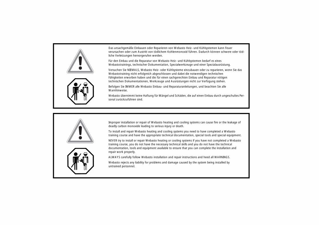
Das unsachgemäße Einbauen oder Reparieren von Webasto Heiz- und Kühlsystemen kann Feuer verursachen oder zum Austritt von tödlichem Kohlenmonoxid führen. Dadurch können schwere oder töd-liche Verletzungen hervorgerufen werden.
Für den Einbau und die Reparatur von Webasto Heiz- und Kühlsystemen bedarf es eines Webastotrainings, technischer Dokumentation, Spezialwerkzeuge und einer Spezialausrüstung.
Versuchen Sie NIEMALS, Webasto Heiz- oder Kühlsysteme einzubauen oder zu reparieren, wenn Sie das Webastotraining nicht erfolgreich abgeschlossen und dabei die notwendigen technischen Fähigkeiten erworben haben und die für einen sachgerechten Einbau und Reparatur nötigen technischen Dokumentationen, Werkzeuge und Ausrüstungen nicht zur Verfügung stehen.
Befolgen Sie IMMER alle Webasto Einbau- und Reparaturanleitungen, und beachten Sie alle Warnhinweise.
Webasto übernimmt keine Haftung für Mängel und Schäden, die auf einen Einbau durch ungeschultes Per-sonal zurückzuführen sind.
Improper installation or repair of Webasto heating and cooling systems can cause fire or the leakage of deadly carbon monoxide leading to serious injury or death.
To install and repair Webasto heating and cooling systems you need to have completed a Webasto training course and have the appropriate technical documentation, special tools and special equipment.
NEVER try to install or repair Webasto heating or cooling systems if you have not completed a Webasto training course, you do not have the necessary technical skills and you do not have the technical documentation, tools and equipment available to ensure that you can complete the installation and repair work properly.
ALWAYS carefully follow Webasto installation and repair instructions and heed all WARNINGS.
Webasto rejects any liability for problems and damage caused by the system being installed by untrained personnel.
Webasto Marine
Inhalt 1 Sicherheitshinweise . . . . . . . . . . . . . . . . . . . . . . . . . . . . . . . . 12 Allgemeines . . . . . . . . . . . . . . . . . . . . . . . . . . . . . . . . . . . . . . 33 Einbau des Heizgerätes . . . . . . . . . . . . . . . . . . . . . . . . . . . . . 64 Abgas . . . . . . . . . . . . . . . . . . . . . . . . . . . . . . . . . . . . . . . . . . 115 Brennluftzufuhr . . . . . . . . . . . . . . . . . . . . . . . . . . . . . . . . . . 156 Brennstoffversorgung . . . . . . . . . . . . . . . . . . . . . . . . . . . . . 177 Luftführung . . . . . . . . . . . . . . . . . . . . . . . . . . . . . . . . . . . . . 238 Elektrische Anschlüsse . . . . . . . . . . . . . . . . . . . . . . . . . . . . . 339 Abnahme und Inbetriebnahme . . . . . . . . . . . . . . . . . . . . . 4910 Bedienungshinweise . . . . . . . . . . . . . . . . . . . . . . . . . . . . . . 4911 Wartung und Service . . . . . . . . . . . . . . . . . . . . . . . . . . . . . . 5012 Technische Daten . . . . . . . . . . . . . . . . . . . . . . . . . . . . . . . . . 51
Contents 1 Safety Precautions . . . . . . . . . . . . . . . . . . . . . . . . . . . . . . . .552 General . . . . . . . . . . . . . . . . . . . . . . . . . . . . . . . . . . . . . . . . .573 Installing Heater Unit . . . . . . . . . . . . . . . . . . . . . . . . . . . . . .604 Exhaust . . . . . . . . . . . . . . . . . . . . . . . . . . . . . . . . . . . . . . . . .655 Combustion air supply . . . . . . . . . . . . . . . . . . . . . . . . . . . . .696 Fuel Supply . . . . . . . . . . . . . . . . . . . . . . . . . . . . . . . . . . . . . .717 Air ducting . . . . . . . . . . . . . . . . . . . . . . . . . . . . . . . . . . . . . .778 Electrical connections . . . . . . . . . . . . . . . . . . . . . . . . . . . . . .879 Approval and Commissioning . . . . . . . . . . . . . . . . . . . . . .10310 Operating Instructions . . . . . . . . . . . . . . . . . . . . . . . . . . . .10311 Maintenance and Service . . . . . . . . . . . . . . . . . . . . . . . . . .10412 Technical data . . . . . . . . . . . . . . . . . . . . . . . . . . . . . . . . . . .105
I
Boat heating systems Safety Precautions
1 Safety Precautions
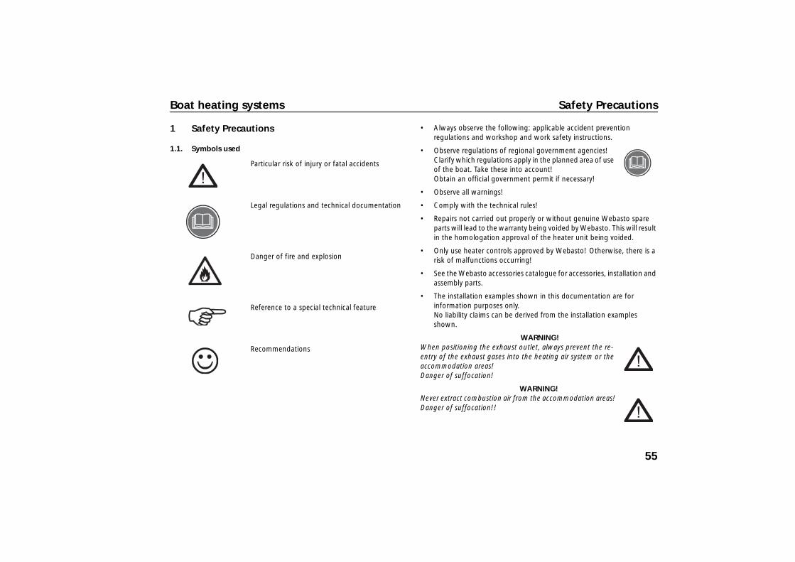
1.1. Symbols used
Particular risk of injury or fatal accidents
Legal regulations and technical documentation
Danger of fire and explosion
Reference to a special technical feature
Recommendations
• Always observe the following: applicable accident prevention regulations and workshop and work safety instructions.
• Observe regulations of regional government agencies! Clarify which regulations apply in the planned area of use of the boat. Take these into account! Obtain an official government permit if necessary!
• Observe all warnings!
• Comply with the technical rules!
• Repairs not carried out properly or without genuine Webasto spare parts will lead to the warranty being voided by Webasto. This will result in the homologation approval of the heater unit being voided.
• Only use heater controls approved by Webasto! Otherwise, there is a risk of malfunctions occurring!
• See the Webasto accessories catalogue for accessories, installation and assembly parts.
• The installation examples shown in this documentation are for information purposes only. No liability claims can be derived from the installation examples shown.
WARNING! When positioning the exhaust outlet, always prevent the re-entry of the exhaust gases into the heating air system or the accommodation areas! Danger of suffocation!
WARNING! Never extract combustion air from the accommodation areas! Danger of suffocation!!
55
Safety Precautions Boat heating systems
WARNING! The heating unit must be switched off while refuelling!
WARNING! Use only fire-resistant fuel lines and temperature-resistant, thermally insulated heating air hoses! Fire danger!!
WARNING! Do not blow hot air directly onto living creatures or temperature-sensitive parts!
56

Boat heating systems General
2 General
Using heater units Solely for use on ships: • For pre-heating and heating of ship's cabins, cargo holds, passenger
and crew transport areas • On inland waters and at sea • For sailing and motor boats of approximately 8 to 24 m in length
Not suitable for: • Continuous heating of living areas, houseboats, etc.! • For heating and/or drying living creatures
Permits Existing homologation approvals for Air Top heater units in accordance with EC Directives 72/245/EEC (electromagnetic compatibility) and 2001/56/EC (heating) with the following homologation approval numbers:
Air Top 2000ST:• e1*72/245*95/54*1085*00 for electromagnetic compatibility • e1*2001/56**0022*00 for heating
Air Top Evo 3900/5500: • e1*72/245*2006/28*5079*__ for electromagnetic compatibility• e1*2001/56*2006/119*0219*__ for heating Air Top Evo 3900 • e1*2001/56*2006/119*0220*__ for heating Air Top Evo 5500
The regulations of the Directive 2001/56/EC must be observed for installation.
CE symbol (prescribed in EU for new recreational craft from 2.5 to 24 m in length)
Relevant standards for installation – Recreational Craft Directive 94/25/EC – ISO 8845/46 - Protection against ignition of surrounding flammable
gases – ISO 7840 - Fire-resistant fuel hoses – ISO 9094 - Fire protection for small craft
57
General Boat heating systems
2.1. Mode of operation
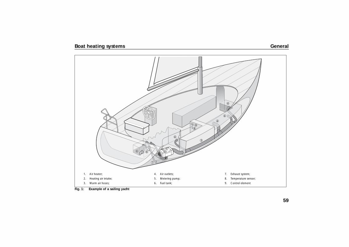
The air heater in the locker draws in outside air through the intake opening with an integrated fan. The air heated in the heater unit flows into the bow through connected warm air hoses. The warm air enters the cabins at the air outlets.
Fuel is supplied from the boat's fuel tank with a separate metering pump.
Power is supplied (for fan, electronics, etc.) form the boat's battery.
The combustion circuit is separated from the heating circuit. This results in a separate combustion air intake.
The exhaust gas is routed to the outside via the exhaust system including silencer.
The interior temperature is adjusted to the selected value with a cabin temperature sensor and the heater control.
The heater unit constantly compares the actual and the selected temperature and automatically adjusts the heating capacity accordingly.
58
Boat heating systems General
Fig. 1: Example of a sailing yacht
1. Air heater;
2. Heating air intake;
3. Warm air hoses;
4. Air outlets;
5. Metering pump;
6. Fuel tank;
7. Exhaust system;
8. Temperature sensor;
9. Control element
59
Installing Heater Unit Boat heating systems
3 Installing Heater Unit
3.1. Choosing installation location
WARNING! Do not install heater unit and exhaust system in accommodation areas! (Danger of suffocation in case of improper installation)
• Install the heater unit in a dry location, protected from the ingress of sea water, excessive vibrations, heat, engine exhaust gases and soiling by fuel or oil (requirement from 2001/56/EC).
• Design the installation to suit the requirements and type of boat. Take the following into account: all peripheral components, such as the maximum permissible exhaust system length, the position of the exhaust through hull, the combustion air intake, the routing of electrical wiring and cable lengths, the distance from the fuel tank, the routing of the warm air hoses, the fresh air intake, etc.
• Take the following into account: The maximum inclination of the ship may not result in the ingress of sea water through the exhaust outlet.
• The inclination may not cause the heater unit to come into contact with bilge water.
• No obstruction of moving parts (e.g. rudder assembly)!
• Every reasonable precaution should be taken in positioning the heater to minimise the risk of injury and damage to personal property (requirement from 2001/56/EC).
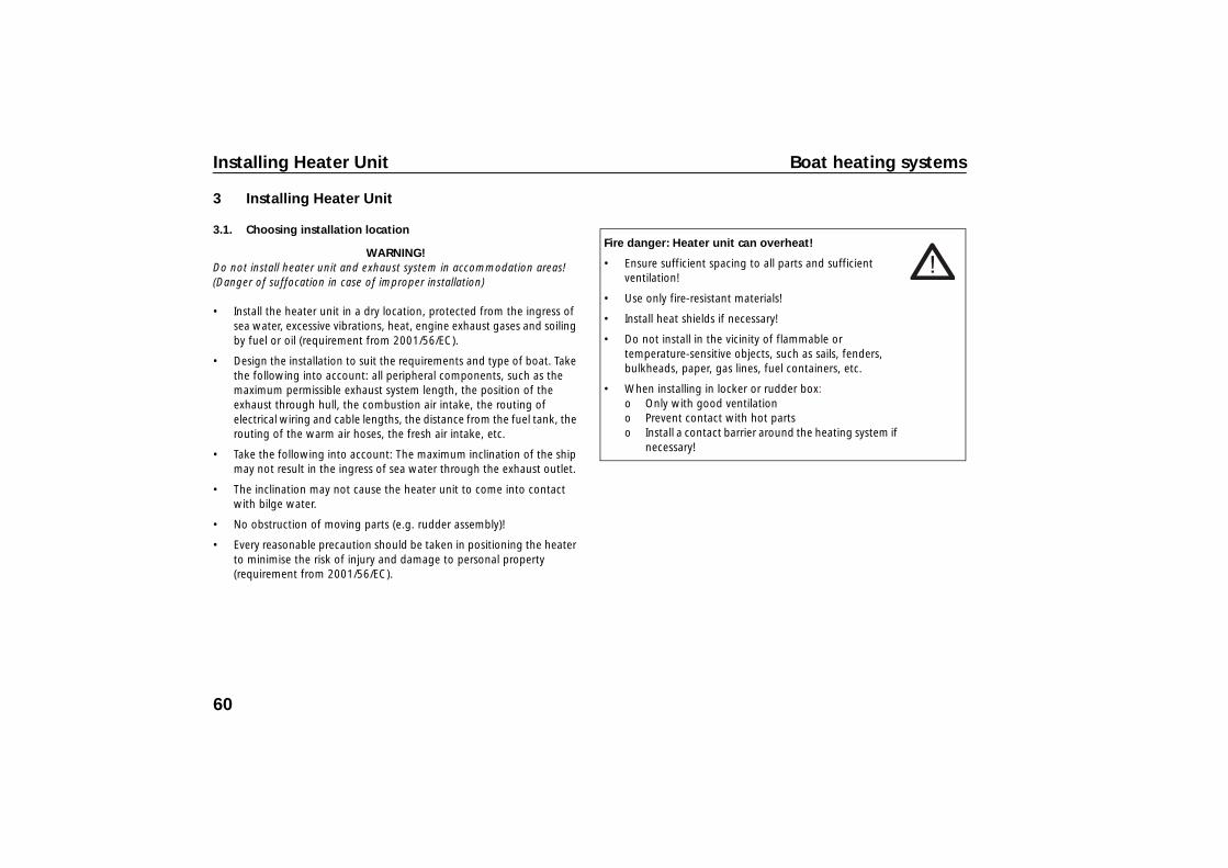
Fire danger: Heater unit can overheat!
• Ensure sufficient spacing to all parts and sufficient ventilation!
• Use only fire-resistant materials!
• Install heat shields if necessary!
• Do not install in the vicinity of flammable or temperature-sensitive objects, such as sails, fenders, bulkheads, paper, gas lines, fuel containers, etc.
• When installing in locker or rudder box: o Only with good ventilation o Prevent contact with hot parts o Install a contact barrier around the heating system if
necessary!
60
Boat heating systems Installing Heater Unit
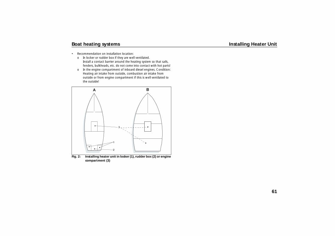
• Recommendation on installation location: o In locker or rudder box if they are well ventilated.
Install a contact barrier around the heating system so that sails, fenders, bulkheads, etc. do not come into contact with hot parts!
o In the engine compartment of inboard diesel engines. Condition: Heating air intake from outside, combustion air intake from outside or from engine compartment if this is well ventilated to the outside!
Fig. 2: Installing heater unit in locker (1), rudder box (2) or engine compartment (3)
61
Installing Heater Unit Boat heating systems
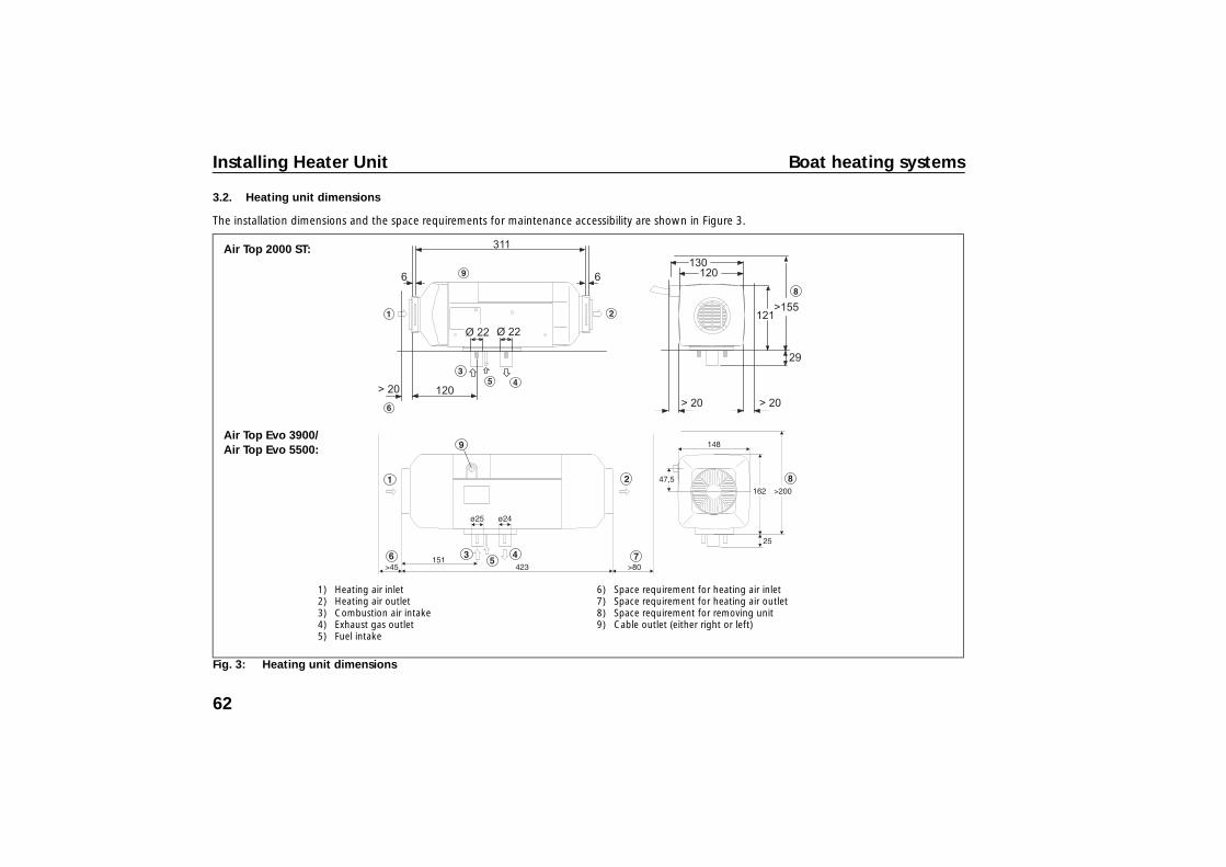
3.2. Heating unit dimensions
The installation dimensions and the space requirements for maintenance accessibility are shown in Figure 3.
Fig. 3: Heating unit dimensions
1) Heating air inlet2) Heating air outlet3) Combustion air intake4) Exhaust gas outlet5) Fuel intake
6) Space requirement for heating air inlet7) Space requirement for heating air outlet8) Space requirement for removing unit9) Cable outlet (either right or left)
Air Top Evo 3900/Air Top Evo 5500:
Air Top 2000 ST:
62

Boat heating systems Installing Heater Unit
3.3. Unit orientation
The specified horizontal and axial angles must not be exceeded.
• Installation positions: observe possible inclination of ship!
• Recommended installation position: Exhaust outlet routed downward; heater unit parallel to ship's longitudinal axis.
• Do not install transversely in sailboats! Exception: if heater unit is primarily operated when boat is moored, or in motorboats then installation transverse to longitudinal axis is also permissible.
3.4. Heater unit mounting
• Securely mount the unit (vibrations, swells)!• Use the bracket and rubber gasket provided under the unit base.• This rubber gasket must be replaced each time the heater unit is
installed.• The M6 nuts must be tightened to
6 Nm (–0 Nm, +1 Nm) to mount the unit base.
After installation, check that the casing is not in contact with any parts of the vehicle body. A failure to do this may result in the blocking of the heating air fan.
Fig. 4: Permissible installation positions for Air Top Diesel air heater units
Fig. 5: Install heater unit in longitudinal direction in sailboats!
0-90˚ 0-90˚ 0-90˚
Fig. 6: Mounting Air Top with angled retaining bracket
Fig. 7: Ensure that all moving parts can move easily.
63
Installing Heater Unit Boat heating systems
• Recommendation: elastic mounting (vibration decoupling, noise reduction)!
• Screw the heater unit onto the bracket with bolts.
• Recommendation when mounting on outer skin of FRP boats: laminate on a wooden sheet at the fastening location from the inside to prevent drilling through the outer wall.
WARNING! There is a danger of drowning when drilling into the ship's outer skin! Drilling below the water line can cause the ship to sink! If the boat is in the water: check the drilling location! Have leak sealing equipment available beforehand and familiarise yourself with possible escape routes!
64
Boat heating systems Exhaust
4 Exhaust
4.1. Exhaust system
Route the combustion gases out of the boat via the exhaust system.
4.2. Exhaust outlet
Outlet arrangement:
• Position the exhaust outlet where no splash-water can enter the boat. Recommendation: Sailboats: on stern transom. Motorboats: on side wall.
CAUTION! Do not position the exhaust outlet below or next to ventilation equipment, window openings or the heating air inlet (otherwise danger of suffocation)!
• At least 60 cm above the water line so that no water can enter when the boat heels
• Do not connect to the engine or generator exhaust system (higher pressures; damage to heater unit!)
• Not in the direction of movement of the boat (high wind pressure)
• Not where it can easily be covered, e.g. by the fender.
Exhaust through hull:
• Choice of design and installation position: Minimisation of rain water ingress!
• User only genuine Webasto exhaust through hulls! Fit insulating washers exactly for thermal insulation from the side wall (minimisation of water ingress)! If additional sealing is required: use only heat-resistant sealing compound!
• Exhaust through hull: Not closeable; not with self-opening valves!
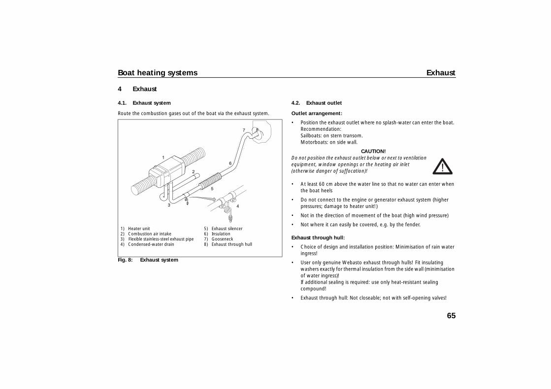
Fig. 8: Exhaust system
1) Heater unit 2) Combustion air intake 3) Flexible stainless-steel exhaust pipe 4) Condensed-water drain
5) Exhaust silencer 6) Insulation 7) Gooseneck 8) Exhaust through hull
65

Exhaust Boat heating systems
• Mount exhaust through hull with pipe socket angled facing upward. 4.3. Exhaust pipe
4.3.1. Exhaust pipes
• Keep the exhaust pipe as short as possible. • Route the exhaust pipe as straight as possible (permissible total bends
< 270°; smallest permissible bending radius 50 mm)!• No contact with/ sufficient spacing to temperature-sensitive objects,
such as electrical cables, water pipes, plastic parts, sails or boat hull! • Minimum distance from wall: ≥ 20 mm! • Minimum pipe diameter: 24 mm.
4.3.2. Length from exhaust to combustion-air pipe
The following maximum total lengths of the combustion air intake and exhaust pipe must be complied with for Air Top 2000 ST, Air Top Evo 3900/5500:
– with boat exhaust silencer: max. 2.5 m – without exhaust silencer: max. 5.0 m
Fig. 9: Exhaust through hull
3x ø
5.5m
m1x
ø40
mm
top
outside inside
1) Gasket 2) Counterflange 3) Bolt/washer/nut 4) Side wall 5) Webasto marking
66
Boat heating systems Exhaust
4.3.3. Exhaust pipes in accommodations
WARNING! Do not install heater unit and exhaust system in accommodation areas! (Danger of suffocation in case of improper installation)
• If this is unavoidable: use rigid stainless-steel pipes with a wall thickness of ≥ 1 mm!
• Replace pipes with new ones after ≤ 10 years! • Do not position detachable connection points in accommodation
areas! • Use sealing compound resistant to high temperatures!
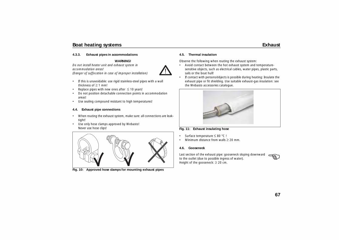
4.4. Exhaust pipe connections
• When routing the exhaust system, make sure: all connections are leak-tight!
• Use only hose clamps approved by Webasto! Never use hose clips!
4.5. Thermal insulation
Observe the following when routing the exhaust system: • Avoid contact between the hot exhaust system and temperature-
sensitive objects, such as electrical cables, water pipes, plastic parts, sails or the boat hull!
• If contact with persons/objects is possible during heating: Insulate the exhaust pipe or fit shielding. Use suitable exhaust-gas insulation: see the Webasto accessories catalogue.
• Surface temperature ≤ 80 °C ! • Minimum distance from walls ≥ 20 mm.
4.6. Gooseneck
Last section of the exhaust pipe: gooseneck sloping downward to the outlet (due to possible ingress of water). Height of the gooseneck: ≥ 20 cm.
Fig. 10: Approved hose clamps for mounting exhaust pipes
Fig. 11: Exhaust insulating hose
67
Exhaust Boat heating systems
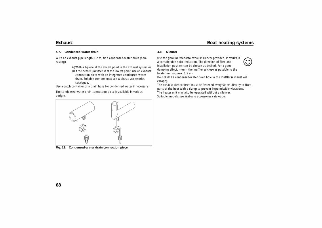
4.7. Condensed-water drain
With an exhaust pipe length > 2 m, fit a condensed-water drain (non-rusting).
A)With a T-piece at the lowest point in the exhaust system or B) If the heater unit itself is at the lowest point: use an exhaust
connection piece with an integrated condensed-water drain. Suitable components: see Webasto accessories catalogue.
Use a catch container or a drain hose for condensed water if necessary.
The condensed-water drain connection piece is available in various designs.
4.8. Silencer
Use the genuine Webasto exhaust silencer provided. It results in a considerable noise reduction. The direction of flow and installation position can be chosen as desired. For a good damping effect, mount the muffler as close as possible to the heater unit (approx. 0,5 m). Do not drill a condensed-water drain hole in the muffler (exhaust will escape). The exhaust silencer itself must be fastened every 50 cm directly to fixed parts of the boat with a clamp to prevent impermissible vibrations.The heater unit may also be operated without a silencer. Suitable models: see Webasto accessories catalogue.
Fig. 12: Condensed-water drain connection piece
68
Boat heating systems Combustion air supply
5 Combustion air supply
5.1. Combustion air circulation
Always observe the following:
• Intake from an area well ventilated to outside at ambient pressure and/or directly from outside
WARNING:Do not extract combustion air from accommodation areas/cabins! Danger of suffocation!
• Intake location: no intake of exhaust gases from heater unit and/or engine!
5.1.1. Intaking combustion air from an area well ventilated to outside (locker, storage area or engine compartment)
• No exhaust through hull required
• Intake area must be at ambient pressure and sufficiently ventilated to the outside.
• When intake is from the engine compartment: the ventilation fan of the engine compartment may not produce any gauge pressure or vacuum in the engine compartment.
5.1.2. Intaking combustion air directly from outside
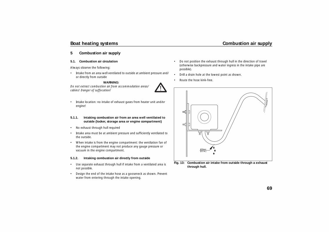
• Use separate exhaust through hull if intake from a ventilated area is not possible.
• Design the end of the intake hose as a gooseneck as shown. Prevent water from entering through the intake opening.
• Do not position the exhaust through hull in the direction of travel (otherwise backpressure and water ingress in the intake pipe are possible).
• Drill a drain hole at the lowest point as shown.
• Route the hose kink-free.
Fig. 13: Combustion air intake from outside through a exhaust through hull.
69

Combustion air supply Boat heating systems
5.2. Intake hose
• Ensure downhill routing from the heater unit or drill a 5 mm dia. condensed water opening at the lowest point or use a separate condensed-water drain, see Figure 13.
• Fit a cap over the end of the hose as protection against ingress (if no exhaust through hull is used).
• Air inlet arrangement: cannot be blocked by objects (requirement from 2001/56/EC).
• Keep intake hose as short as possible. For permissible lengths, see Section 4.3.2.
• Fasten the intake hose: with a hose clamp on the intake connection piece of the heater unit and with pipe clamps or cable ties on fixed built-in parts.
• Recommendation: Use intake silencers (intake noise). Supplied with Air Top heater units. With an intake hose length < 0.6 m, an intake silencer is mandatory.
• Please note: if the metering pump cable is routed out of the intake connection piece, prevent pinching off the cable when installing the intake hose. Do not use metal intake hoses.
• Route the hose kink-free.
70
Boat heating systems Fuel Supply
6 Fuel Supply
• During installation, be sure to observe: national or local guidelines. Ask your local authorised Webasto partner if necessary.
• The fuel filler neck may not be located in the interior of the boat and must be provided with a well-sealing cap to prevent fuel from escaping (requirement from 2001/56/EC).
• If the heater unit takes the fuel from a separate additional tank, then the fuel type and the filler neck must be clearly marked (requirement from 2001/56/EC).
• A notice, indicating that the heater must be shut down before refuelling, must be affixed to the fuelling point (requirement from 2001/56/EC).
• Protect the boat hull/components in the vicinity of the heater unit against the effect of heat/contamination by fuel/oil.
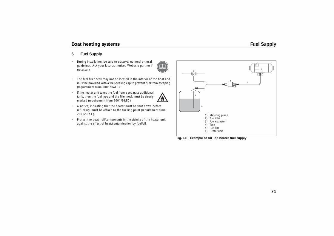
Fig. 14: Example of Air Top heater fuel supply
1) Metering pump 2) Fuel inlet 3) Fuel extractor 4) Tank 5) Fuel line 6) Heater unit
71
Fuel Supply Boat heating systems
6.1. Pipe lengths and lifting height
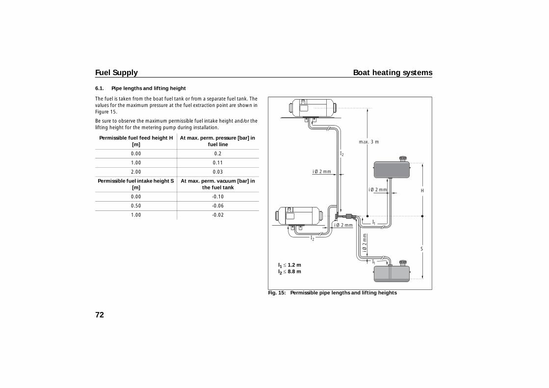
The fuel is taken from the boat fuel tank or from a separate fuel tank. The values for the maximum pressure at the fuel extraction point are shown in Figure 15.
Be sure to observe the maximum permissible fuel intake height and/or the lifting height for the metering pump during installation.
Permissible fuel feed height H [m]
At max. perm. pressure [bar] in fuel line
0.00 0.2
1.00 0.11
2.00 0.03
Permissible fuel intake height S [m]
At max. perm. vacuum [bar] in the fuel tank
0.00 -0.10
0.50 -0.06
1.00 -0.02
Fig. 15: Permissible pipe lengths and lifting heights
max. 3 m
H
S
I
I
2
2
i Ø 2 mm
i Ø 2 mm
i Ø 2 mm
i Ø 2
mm
I1
I1l1 ≤ 1.2 m l2 ≤ 8.8 m
72
Boat heating systems Fuel Supply
6.2. Fuel extraction
The following alternatives are available for extracting the fuel for the heater unit:
6.2.1. Fuel standpipe
• Fuel extraction directly from the boat's fuel tank. • Plastic tanks: install the fuel standpipe in the tank fitting.
Do not drill into a plastic tank. • Suitable fuel standpipe for metal tanks: see the accessories catalogue
and/or the delivery scope.
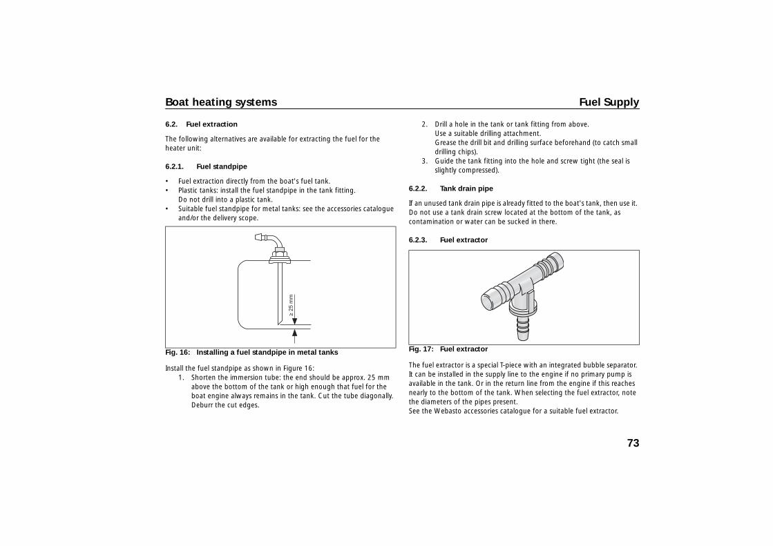
Install the fuel standpipe as shown in Figure 16: 1. Shorten the immersion tube: the end should be approx. 25 mm
above the bottom of the tank or high enough that fuel for the boat engine always remains in the tank. Cut the tube diagonally. Deburr the cut edges.
2. Drill a hole in the tank or tank fitting from above. Use a suitable drilling attachment. Grease the drill bit and drilling surface beforehand (to catch small drilling chips).
3. Guide the tank fitting into the hole and screw tight (the seal is slightly compressed).
6.2.2. Tank drain pipe
If an unused tank drain pipe is already fitted to the boat's tank, then use it. Do not use a tank drain screw located at the bottom of the tank, as contamination or water can be sucked in there.
6.2.3. Fuel extractor
The fuel extractor is a special T-piece with an integrated bubble separator. It can be installed in the supply line to the engine if no primary pump is available in the tank. Or in the return line from the engine if this reaches nearly to the bottom of the tank. When selecting the fuel extractor, note the diameters of the pipes present. See the Webasto accessories catalogue for a suitable fuel extractor.
Fig. 16: Installing a fuel standpipe in metal tanks Fig. 17: Fuel extractor
73

Fuel Supply Boat heating systems
6.3. Fuel line
Fuel line material (metal/plastic): Observe the regional/national regulations!
Fire danger! In the engine compartment, fuel lines must be metal and connecting hoses between individual components must be made of fire-resistant material (in accordance with DIN-EN-ISO 7840). For installation kits for metal fuel lines: see the accessories catalogue.
• Use only stainless-steel hose clamps to secure plastic lines. • Metal pipes: make sure the work area is clean! Remove all
contamination and burrs from the connection points prior to assembly.
• Do not over-tighten union nuts (otherwise leaks will occur). • Route the fuel line as straight as possible and at a slight incline so that
air bubbles escape toward the heater unit. • Secure the line at regular distances to prevent sagging; avoid kinks. • Keep away from heat sources. Use heat shielding if necessary! • Inside dia. of fuel line = 2 mm; larger diameters result in malfunctions
caused by gas bubbles.
6.4. Metering pump
The metering pump is controlled via a separate wiring harness and feeds the fuel into the combustion chamber of the heater unit depending on the required heating capacity. In the process, the separate metering pumps make a ticking noise due to the individual delivery strokes.
• Fit the metering pump near the tank. For the distance from the fuel standpipe, see Figure 15.
• Install the pump in a dry, cool area. Do not install in the bilge.• Note the pump flow direction. • Use an elastic mounting for the metering pump
(reduces the transmission of structure-borne noise/ticking).
Fig. 18: Stainless-steel hose clamps
Fig. 19: Elastic mounting of metering pump
74
Boat heating systems Fuel Supply
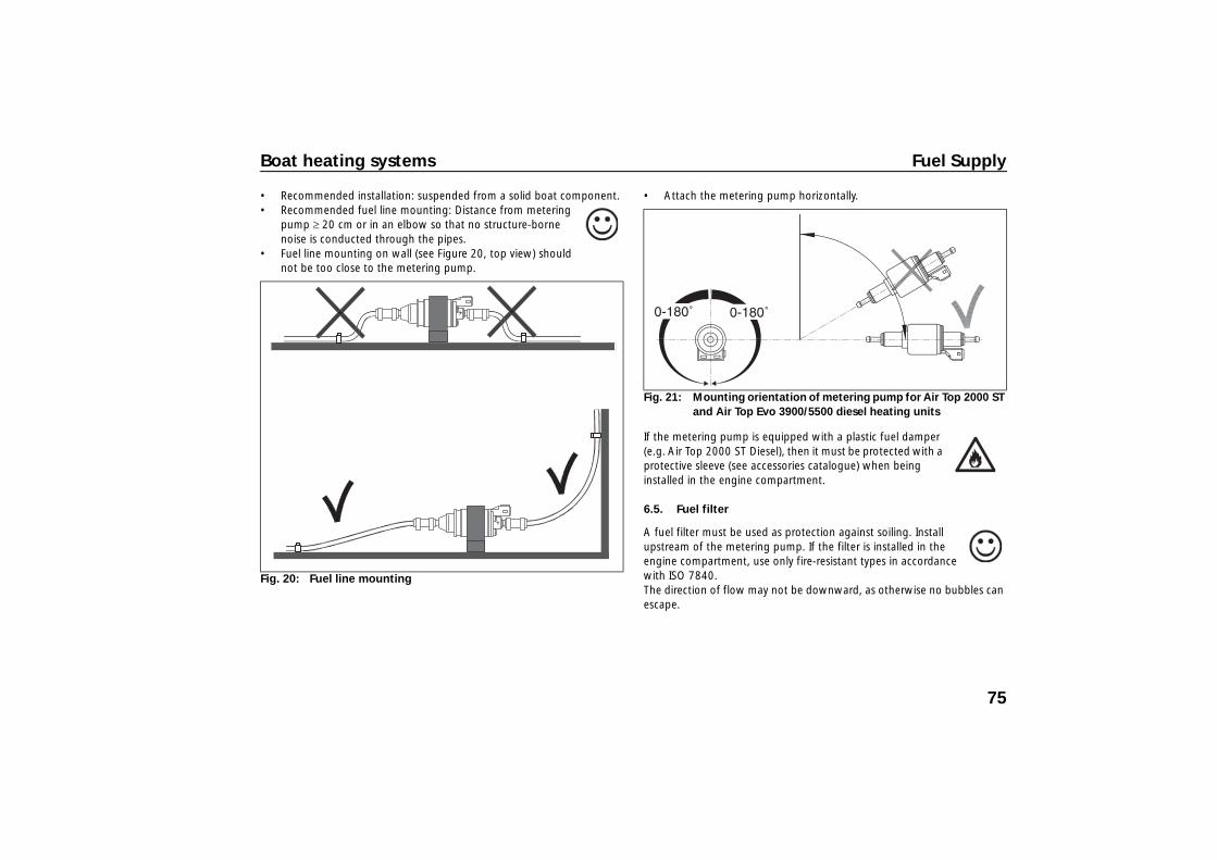
• Recommended installation: suspended from a solid boat component. • Recommended fuel line mounting: Distance from metering
pump ≥ 20 cm or in an elbow so that no structure-borne noise is conducted through the pipes.
• Fuel line mounting on wall (see Figure 20, top view) should not be too close to the metering pump.
• Attach the metering pump horizontally.
If the metering pump is equipped with a plastic fuel damper (e.g. Air Top 2000 ST Diesel), then it must be protected with a protective sleeve (see accessories catalogue) when being installed in the engine compartment.
6.5. Fuel filter
A fuel filter must be used as protection against soiling. Install upstream of the metering pump. If the filter is installed in the engine compartment, use only fire-resistant types in accordance with ISO 7840. The direction of flow may not be downward, as otherwise no bubbles can escape.
Fig. 20: Fuel line mounting
Fig. 21: Mounting orientation of metering pump for Air Top 2000 ST and Air Top Evo 3900/5500 diesel heating units
75
Fuel Supply Boat heating systems
6.6. Auxiliary tank
If an auxiliary tank is required for the heater unit fuel supply: it may only be installed by a specialist company for marine applications (with know-how on the required standards, regulations and directives).
6.7. Special information on petrol-driven heaters in boats
WARNING! Petrol-driven heaters are not permitted in recreational boats covered by ISO 9094. Local regulations and special safety measures must be complied with!
Improper installation of a petrol heating unit in a petrol-driven boat increases the fire hazard!
If local regulations permit the installation of petrol-driven heaters, then the following rules must be complied with:
• Do not install heater units where flammable vapours can form, i.e. in particular in engine compartments or tank compartments and rooms directly connected to them.
• Combustion air intake must come from the outside, and not from the engine compartment
• Do not route exhaust pipes through engine or tank compartments. • Install the metering pump in the coolest possible location < 20 °C.
The above requirements also apply to the installation of diesel-driven heater units. In this case the heater unit must be supplied from a separate diesel tank, which must comply with the valid regulations for diesel tanks in boats.
76
Boat heating systems Air ducting
7 Air ducting
7.1. Heating air intake
CAUTION! The heating air intake must be carried out in a clean area without exhaust gases. Never from the engine compartment!
• It must not be possible to block the intake opening with stowed articles (requirement from 2001/56/EC).
• Intake via an intake hose results in pressure loss. Take this into account in the resistance calculation.
• Use a grille or intake guard so that no foreign bodies can be drawn into the heater unit.
It is possible to use the heating air intake for fresh-air operation or recirculation:
7.1.1. Fresh air operation
Draw in heating air from the outside, heat and blow out into the interior areas. This renews the cabin air and reduces humidity. Ensure that there are enough ventilation openings in the cabins. An external temperature sensor must be mounted for temperature control, preferably in the saloon. In summer, ventilation is also possible (when the MC04 comfort heater control is used).
• Draw in heating air directly from lockers or rudder boxes if they are dry, clean and free of odours and exhaust gases. For proper ventilation, ensure an intake diameter of ≥ 1.5 x hose diameter of the heater unit.
• Otherwise, use an intake hose for intake from the outside.
• Prevent water from entering through the intake opening.
7.1.2. Circulation air
With recirculation, the air to be heated is taken from the interior area. The advantage to this is fast heating due to better heat utilisation. However, there is no reduction in the humidity or renewal of the room air. In this case, no external temperature sensor need be installed. The heater unit uses the sensor integrated in the control unit. For this purpose, the terminating resistor must be mounted on the control unit or the wiring harness.
Fig. 22: Air intake
Air intake from well-ventilated locker
Air intake with intake hose, directly from outside
77
Air ducting Boat heating systems
7.2. Heating air ducting
7.2.1. Routing hoses
WARNING! Fire danger! Use only temperature-resistant Webasto hot air hoses!
WARNING! Do not drill into the outer skin of the ship! Danger of drowning!
Danger of injury or damage! Route hot air hoses away from contact and insulate them!
• Heating air ducting: avoid compressing or pinching the heating air hoses!
• Do not route heating air hoses through bilge. • Heating air hoses in damp areas: use temperature-resistant,
flexible plastic hoses with metal spirals.
• In storage areas: protect the heating air hoses against damage by cargo, e.g. with a perforated metal cover.
• Recommendation: Routing through bulkheads: use wall ducts as shown in the illustration (protection against chafing). See the Webasto accessories catalogue.
• Secure the hoses: with hose clamps at all connecting elements.
Fig. 23: Recommended hose routing around corners
Fig. 24: Recommended hose duct through bulkheads with wall duct
78

Boat heating systems Air ducting
• Recommendation for routing hoses through area not to be heated: fit the hose sections with hose insulation to prevent heat loss (Webasto Thermoduct available as an accessory).
7.2.2. Silencers in air ducting
Recommendation: For Air Top Evo 5500 units with short heating air ducting, use silencers on the intake and/or exhaust side (reduction in noise level)! See the accessories catalogue.
7.2.3. Air distribution and outlets
All desired areas in the boat can be evenly heated with an appropriate air distribution. For this purpose, branch off several side branches from the main line to reach all cabins. The air, and therefore the heat flow, can be influenced by a suitable selection of branches and hose diameters. See the accessories catalogue for branches, connecting elements, Y-junctions, air outlets, etc. of temperature-resistant material.
WARNING! Danger of injury! Do not blow hot air directly onto living creatures or temperature-sensitive objects!
• Hoses: keep as short as possible (heat loss).
• Hose routing: straight if possible (large bending radii).
• Recommendation: use distributors with butterfly valves and Bowden cable adjustment (desired regulation of the air flows).
• Use the same hose diameter in the main line from the heater unit to the main air outlet.
• It must not be possible to close off the air outlets from the main line to avoid overheating of the heater unit. Side branches: closeable air outlets are possible.
• Note: arrange the air outlets so that they cannot be blocked (requirement from 2001/56/EC).
• A free flow of air into the cabins enables the best cabin heating and air circulation.
• Only use one or two air outlets per cabin.
• Position of the air outlets: just above the floor (best air circulation).
Fig. 25: Webasto Thermoduct
Fig. 26: Heating-air silencer for reducing noise level
79
Air ducting Boat heating systems
• Select the air outlet colour to match the interior, see the accessories catalogue.
When using air distributors, the principle that air always takes the path of least resistance applies. The type and orientation of the distributors have exactly the same effect as the diameter and the flow resistance of the connected air hose.
Rough orientation for the distributor selection:
7.2.4. Design using resistance points
Optimal heat output of an air heating system: air flows from the heater unit into the interior with as little restriction as possible. Air distribution on the intake and outlet sides presents flow resistance as follows. Keep this resistance as small as possible.
The heaters check the internal temperature rise automatically each time they are switched on. If this is above the defined limits, the start is cancelled and an error message is displayed.
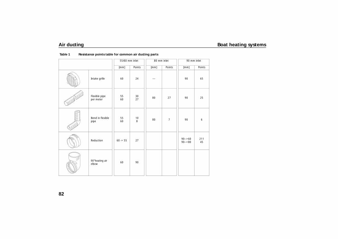
As a reference value for the maximum permissible air ducting, air ducting components have so-called "resistance points" that represent a flow resistance value. The greater the resistance point of an air ducting component, the more poorly the air flows through it. Table 1 lists common components and their resistance points. For the complete range of parts: see Webasto accessories catalogue.
Before installing the air ducting system, make sure: the permissible total sum of the resistance points in the main branch are not exceeded (otherwise there is a risk of the heater unit overheating or premature reduction of the heating capacity while the interior has not yet been warmed up).
Air Top 2000 ST: max. 325 points Air Top Evo 3900: max. 550 points Air Top Evo 5500: max. 375 points
Fig. 27: Principle of air distribution with branches
80
Boat heating systems Air ducting
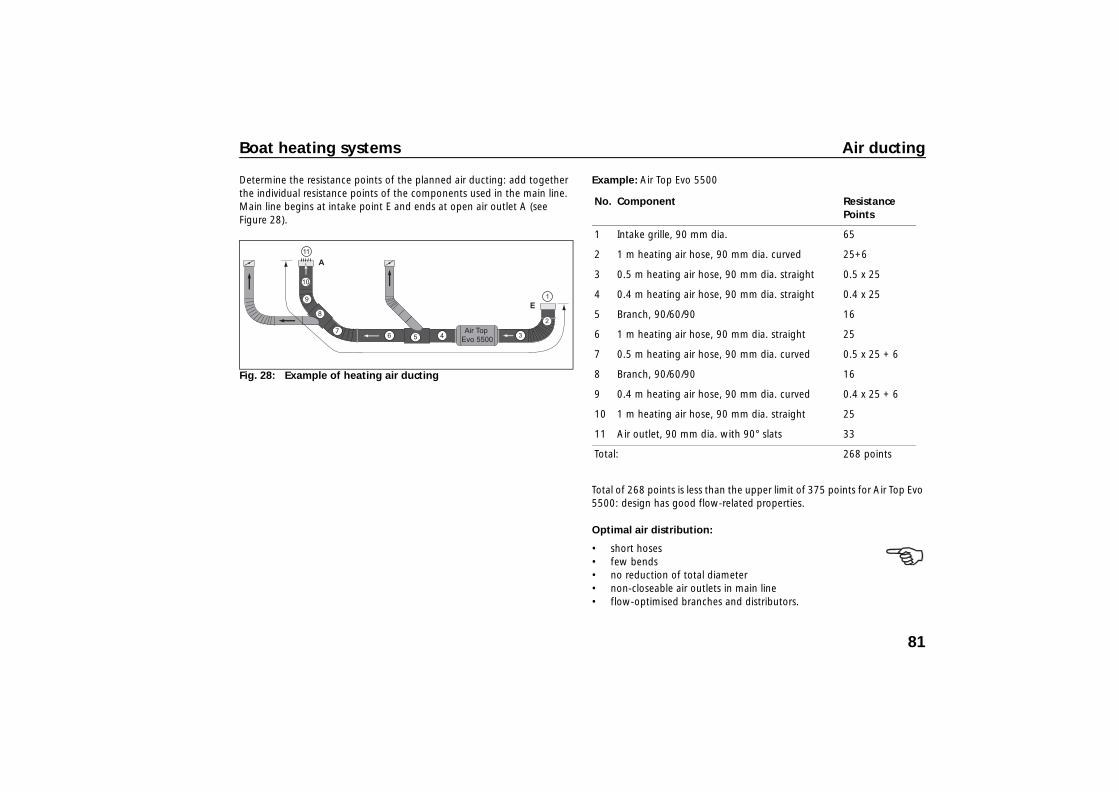
Determine the resistance points of the planned air ducting: add together the individual resistance points of the components used in the main line. Main line begins at intake point E and ends at open air outlet A (see Figure 28).
Example: Air Top Evo 5500
Total of 268 points is less than the upper limit of 375 points for Air Top Evo 5500: design has good flow-related properties.
Optimal air distribution:
• short hoses• few bends• no reduction of total diameter • non-closeable air outlets in main line• flow-optimised branches and distributors.
Fig. 28: Example of heating air ducting
No. Component Resistance Points
1 Intake grille, 90 mm dia. 65
2 1 m heating air hose, 90 mm dia. curved 25+6
3 0.5 m heating air hose, 90 mm dia. straight 0.5 x 25
4 0.4 m heating air hose, 90 mm dia. straight 0.4 x 25
5 Branch, 90/60/90 16
6 1 m heating air hose, 90 mm dia. straight 25
7 0.5 m heating air hose, 90 mm dia. curved 0.5 x 25 + 6
8 Branch, 90/60/90 16
9 0.4 m heating air hose, 90 mm dia. curved 0.4 x 25 + 6
10 1 m heating air hose, 90 mm dia. straight 25
11 Air outlet, 90 mm dia. with 90° slats 33
Total: 268 points
81
Air ducting Boat heating systems
Table 1 Resistance points table for common air ducting parts
55/60 mm inlet 80 mm inlet 90 mm inlet
[mm] Points [mm] Points [mm] Points
Intake grille 60 24 --- 90 65
Flexible pipe per meter
5560
3027 80 27 90 25
Bend in flexible pipe
5560
108 80 7 90 6
Reduction 60 -> 55 27 90-->6090-->80
21145
90°heating air elbow 60 90
82
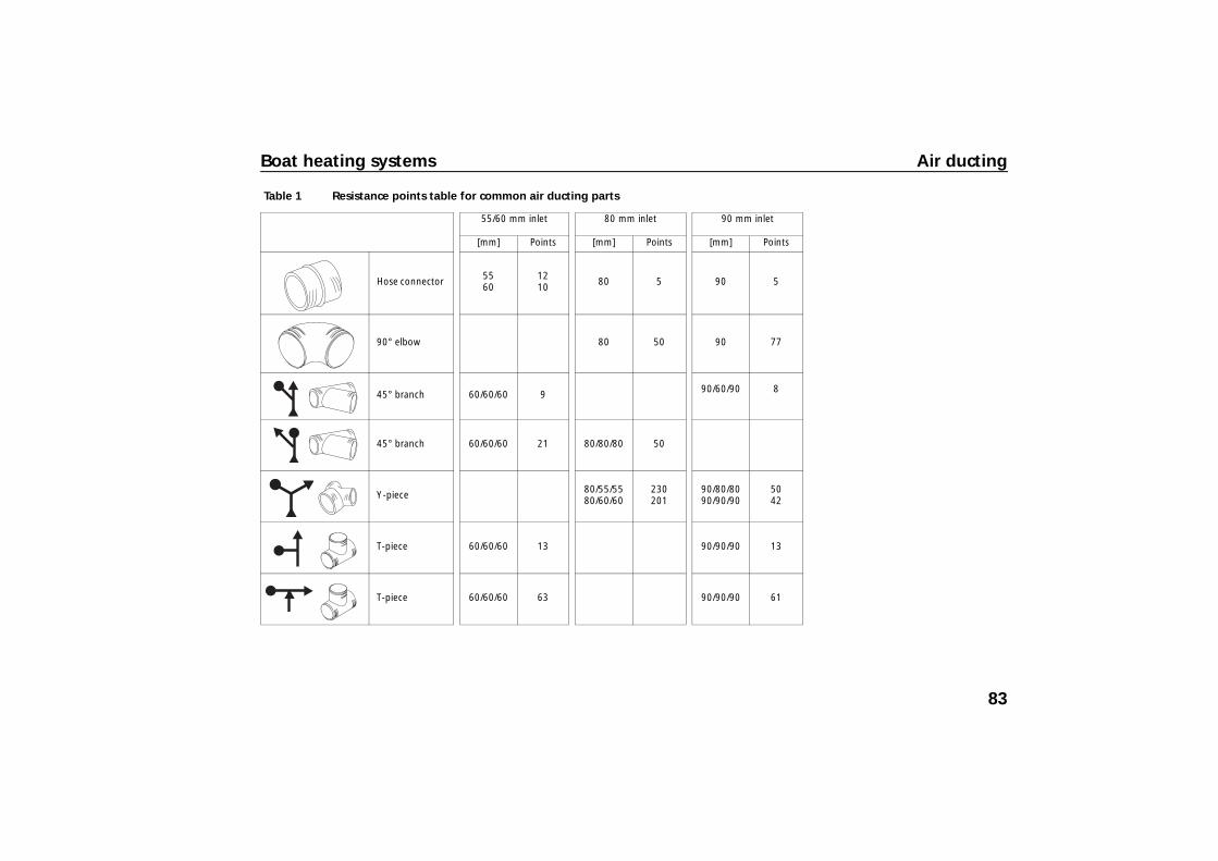
Boat heating systems Air ducting
Hose connector 5560
1210 80 5 90 5
90° elbow 80 50 90 77
45° branch 60/60/60 9 90/60/90 8
45° branch 60/60/60 21 80/80/80 50
Y-piece 80/55/5580/60/60
230201
90/80/8090/90/90
5042
T-piece 60/60/60 13 90/90/90 13
T-piece 60/60/60 63 90/90/90 61
Table 1 Resistance points table for common air ducting parts
55/60 mm inlet 80 mm inlet 90 mm inlet
[mm] Points [mm] Points [mm] Points
83
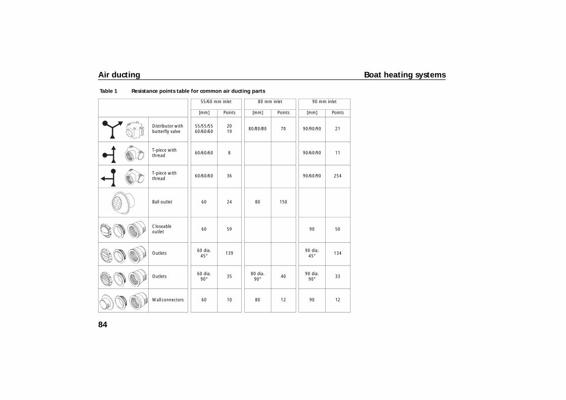
Air ducting Boat heating systems
Distributor with butterfly valve
55/55/5560/60/60
2019 80/80/80 70 90/90/90 21
T-piece with thread 60/60/60 8 90/60/90 11
T-piece with thread 60/60/60 36 90/60/90 254
Ball outlet 60 24 80 150
Closeable outlet 60 59 90 50
Outlets 60 dia.45° 139 90 dia.
45° 134
Outlets 60 dia.90° 35 80 dia.
90° 40 90 dia.90° 33
Wall connectors 60 10 80 12 90 12
Table 1 Resistance points table for common air ducting parts
55/60 mm inlet 80 mm inlet 90 mm inlet
[mm] Points [mm] Points [mm] Points
84
Boat heating systems Air ducting
7.2.5. Air ducting examples
A): Air Top 2000 ST Marine in 9 m sailboat:
B): Air Top Evo 3900 Marine in 11 m sailboat:
C): Air Top Evo 5500 Marine in 13 m sailboat:
Legend for Figure 29:
open
open or closeable
1) heating air intake
2) Y-branch or T-piece
3) Air outlet
With the Air Top Evo 5500, no reduction of main line from 90 to 80 mm. If continuous 90 mm is not possible, it is better to use a Y-piece 90/80/80 and produce two 80 mm main lines.
Fig. 29: Examples of heating air ducting
85
Air ducting Boat heating systems
7.2.6. Installation examples
Fig. 30: Installation examples
Air Top Evo 3900 Marine in 37' sailboat
Air Top Evo 5500 Marine in 43' sailboat
1. Branch, 90/60/90
2. Air outlet, 60 mm dia., closeable
3. Y-piece, 90/90/90;
4. Air outlet, 90 dia. open
5. Y-piece, 60/60/60
6. Air outlet, 90 mm dia., closeable
7. T-piece, 90/60/90
86
Boat heating systems Electrical connections
8 Electrical connections
8.1. General electrical system
• Note: observe all information and safety precautions!
• Mount an operation indicator clearly visible for operators which indicates whether the heating is switched on or off (requirement from 2001/56/EC). This is integrated in the Webasto heater controls.
• Route all wiring harnesses and electrical components in dry, protected areas.
• All lines that are not required must be insulated at their free end.
• If highly sensitive electronic devices are on board: special electrical interference suppression may be necessary. Contact an authorised Webasto partner.
• Do not touch the open PCBs of the unit (electrostatic discharges).
• For the connector designations, see the legend and the wiring diagrams, Page 96 ff.
8.2. Wiring harnesses
Figure 31 and Figure 32 show the wiring harnesses for Air Top 2000 ST and Air Top Evo 3900/5500.
Fig. 31: Wiring harness of Air Top 2000 ST
Air Top 2000 ST
X9
X12
X11
X8
X6
87

Electrical connections Boat heating systems
Connection of main wiring harness on heater unit Lever open the cover of the heater unit (with a blunt object) as shown in Figure 33.
Connect the wiring harness to the control unit of the heater unit (under grey cover). See Figure 34. Press the plug until a "click" is heard (locking). On the Air Top 2000 ST the plug must engage at point “a”.
Fig. 32: Wiring harness of Air Top Evo 3900/5500
Air Top Evo 3900/5500
X9a
X9b
X5
X7
K
X9c
X8
X12
X11
Fig. 33: Points for levering open control unit cover
Fig. 34: Connector to control unit of heater unit
“a”
Air Top 2000 ST Air Top Evo 3900/5500
X6X7
88

Boat heating systems Electrical connections
Air Top Evo 3900/5500: Pull the black terminating resistor off the control unit and discard it. Connect the connector X5 of the wiring harness for the external temperature sensor to this socket.
To ensure that the cable passage in the control unit cover seals perfectly, the cable grommet is to be adjusted appropriately on the wiring harness.
Route the wiring harness out of the heater unit and mount the cover (possible in both directions).
The heater must not be operated without the control unit cover (this will cause the heater unit to overheat).
8.3. Power Supply
• Heating unit power supply: from the boat's service battery (not the starter battery for the driving engine due to the risk of discharging). Connect the red cable to the “+” terminal of the battery. Always make this connection before the main switch to ensure heating run-on. Connect the brown cable to earth, directly on the battery.
• The wiring harness of the Air Top Evo 3900/5500 is equipped with cable K (Figure 32, colour rd/bk) for the optional control of a battery isolation switch or an additional operation indicator. If the cable is not necessary for this purpose, insulate the end of the cable.
• Power supply cables: keep them as short as possible. Shorten the cables if necessary.
• Connecting cable diameter: ≥ 4.0 mm². If the cable lengths > 7.5 m: ≥ 6.0 mm²
• When extending cables, ensure an adequate total diameter and insulation type.
Fig. 35: Connecting external temperature sensor to control unit
X5
ge
sw/blX5
Fig. 36: Fuse holder in main wiring harness
89
Electrical connections Boat heating systems
• The heater unit must be protected with a fuse (F1). F = 20 A (12 V) F = 15 A (24 V)
• If the MC04 heater control is used with the Air Top Evo 3900/5500, then a 1 A fuse (F3) must be inserted in the fuse holder.
• The fuse may only be installed splash-water protected in the interior. • Distance of the main fuse from the positive battery terminal: ≤ 1 m
8.4. Temperature control
Install external temperature sensors in the boat's interior (mandatory for fresh air operation). The heater unit continually compares the selected temperature (value set on the heater control) and the actual temperature (measured at the room temperature sensor) and automatically adjusts the heating capacity.
8.4.1. Installing external temperature sensor
Mount the sensor at a favourable/suitable location in the room to be heated. The distance to the heater control ≤ 2.5 m due to the cable length. Use a 5 m long temperature sensor at greater distances, see the Webasto accessories catalogue.
Position: essential for control behaviour.
Recommendations:
✓ in largest cabin to be heated
✓ in position with average room temperature
✓ if possible at moderate height (half the room height)
✓ if possible on a vertical inner wall, and not directly on an outside wall
– not in the air flow of hot air outlets
– not within the range of the companian way
– not in the vicinity of heat sources
– not behind cushions or curtains
– not in direct sunlight
90
Boat heating systems Electrical connections
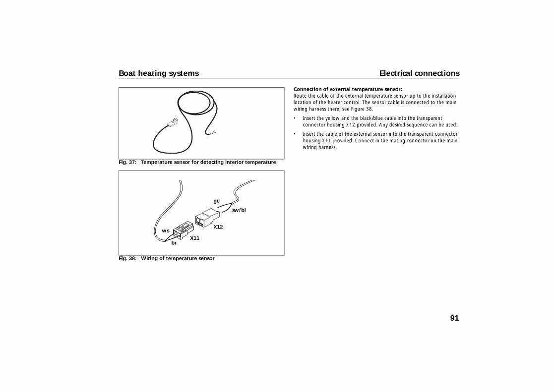
Connection of external temperature sensor: Route the cable of the external temperature sensor up to the installation location of the heater control. The sensor cable is connected to the main wiring harness there, see Figure 38.
• Insert the yellow and the black/blue cable into the transparent connector housing X12 provided. Any desired sequence can be used.
• Insert the cable of the external sensor into the transparent connector housing X11 provided. Connect in the mating connector on the main wiring harness.
Fig. 37: Temperature sensor for detecting interior temperature
Fig. 38: Wiring of temperature sensor
sw/bl
ge
ws
br
X12
X11
91
Electrical connections Boat heating systems
8.5. Control element
This switches the heater unit ON/OFF and specifies the setpoint value for the interior temperature.
Position: mount easily accessible, visible and protected from water in the interior. The position has no effect on the control behaviour.
Various heater controls with different operating ranges are available, see the accessories catalogue.
Simply pull on the connector housing to unplug the connector.
The connector housing can be locked (self-locking action) by simply pulling on the wiring harness.
92
Boat heating systems Electrical connections
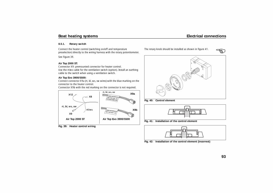
8.5.1. Rotary switch
Connect the heater control (switching on/off and temperature preselection) directly to the wiring harness with the rotary potentiometer.
See Figure 39.
Air Top 2000 ST: Connector X9: premounted connector for heater control. Use the rt/ws cable for the ventilation switch (option). Install an earthing cable to the switch when using a ventilation switch.
Air Top Evo 3900/5500: Connect connector X9a (rt, bl, ws, sw wires) with the blue marking on the connector to the heater control. Connector X9b with the red marking on the connector is not required.
The rotary knob should be installed as shown in figure 41.
Fig. 39: Heater control wiring
X9
rt/ws
ge, sw/bl gn/ws,
rt, bl, ws, sw
X12X8
rt, bl, ws, swX9a
X9b
Air Top 2000 ST Air Top Evo 3900/5500
Fig. 40: Control element
Fig. 41: Installation of the control element
Fig. 42: Installation of the control element (incorrect)
93

Electrical connections Boat heating systems
8.5.2. Air Top EVO MC04 Marine heater control
The MC04 heater control is equipped with additional operating modes like ECO, PLUS and VENTILATION. The MC04 can only be used in combination with Air Top Evo heater units.
– Produce a cut-out 98 mm wide x 63 mm high for the MC04. – Connect the controls to the two existing connectors on the heater-unit
wiring harness. When doing so, watch the sticker on the wiring harness and the colour coding on the connectors. See Figure 39 (connector X9a and X9b), and Figure 43.
– Premount the heater control in the cut-out. – Lightly press the fastening screws into the holes and screw in. – Carefully clip on the trim frame.
Fig. 43: Connection diagram for Air Top Evo 3900/5500 with MC04 heater control
Observe coloured markings
MC04 heater control
Heater units wiring harness
Optional connection for: – Telestart/Thermo Call – Webasto Thermo Test
diagnosis
Fig. 44: Installing MC04 heater control
94
Boat heating systems Electrical connections
8.5.3. Combination timer
Use the combination-timer adapter wiring harness for installation and connect in accordance with the wiring diagram (Figure 48 and 50). Use the fuses F2 and, if necessary, also F4 for separate display lighting.
8.5.4. Telestart/Thermo Call
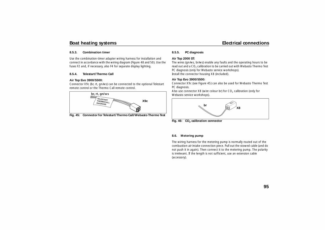
Air Top Evo 3900/5500:Connector X9c (br, rt, gn/ws) can be connected to the optional Telestart remote control or the Thermo Call remote control.
8.5.5. PC diagnosis
Air Top 2000 ST: The wires (gn/ws, br/ws) enable any faults and the operating hours to be read out and a CO2 calibration to be carried out with Webasto Thermo Test PC diagnosis (only for Webasto service workshops). Install the connector housing X8 (included).
Air Top Evo 3900/5500: Connector X9c (see Figure 45) can also be used for Webasto Thermo Test PC diagnosis. Also use connector X8 (wire colour br) for CO2 calibration (only for Webasto service workshops).
8.6. Metering pump
The wiring harness for the metering pump is normally routed out of the combustion-air intake connection piece. Pull out the stowed cable (and do not push it in again). Then connect it to the metering pump. The polarity is irrelevant. If the length is not sufficient, use an extension cable (accessory).
Fig. 45: Connector for Telestart/Thermo Call/Webasto Thermo Test
br, rt, gn/ws
X9c
Fig. 46: CO2 calibration connector
X8 br
95
Electrical connections Boat heating systems
8.7. Wiring diagram
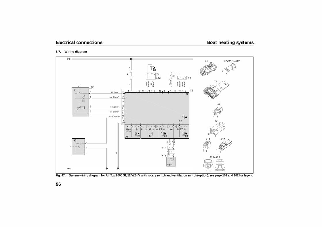
Fig. 47: System wiring diagram for Air Top 2000 ST, 12 V/24 V with rotary switch and ventilation switch (option), see page 101 and 102 for legend
96
Boat heating systems Electrical connections
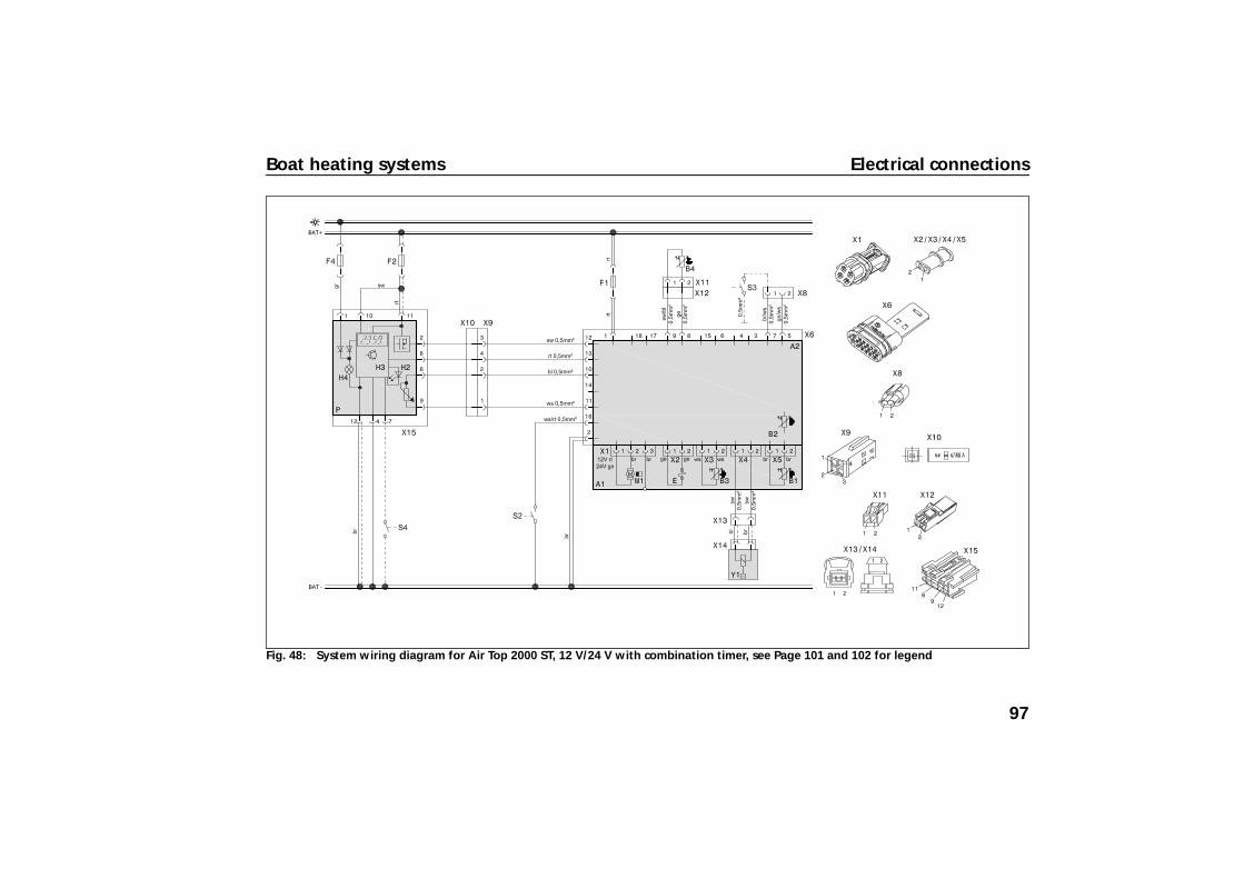
Fig. 48: System wiring diagram for Air Top 2000 ST, 12 V/24 V with combination timer, see Page 101 and 102 for legend
97
Electrical connections Boat heating systems
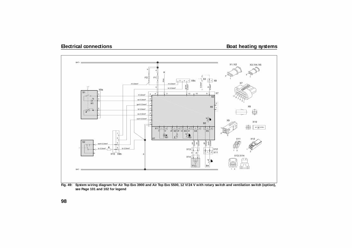
Fig. 49: System wiring diagram for Air Top Evo 3900 and Air Top Evo 5500, 12 V/24 V with rotary switch and ventilation switch (option), see Page 101 and 102 for legend
98

Boat heating systems Electrical connections
Fig. 50: System wiring diagram for Air Top Evo 3900 and Air Top Evo 5500, 12 V/24 V with combination timer, see page 101 and 102 for legend
99
Electrical connections Boat heating systems
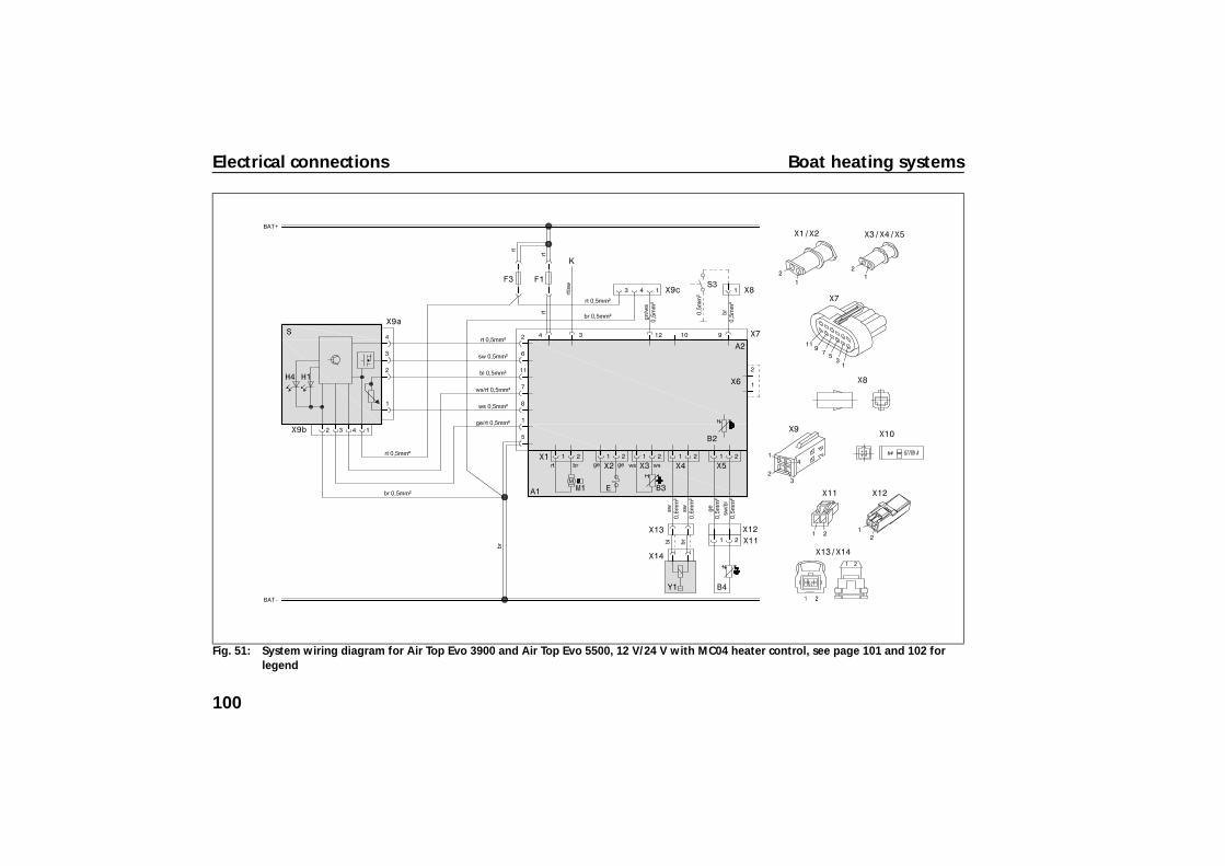
Fig. 51: System wiring diagram for Air Top Evo 3900 and Air Top Evo 5500, 12 V/24 V with MC04 heater control, see page 101 and 102 for legend
100
Boat heating systems Electrical connections
8.8. Legend for circuit diagrams
Cable cross-sections
< 7.5 m 7.5 - 15 m
0.75 mm2 1.0 mm2
1.0 mm2 1.5 mm2
1.5 mm2 2.5 mm2
2.5 mm2 4.0 mm2
4.0 mm2 6.0 mm2
Cable colours
blbrgegngrorrtswviws
bluebrownyellowgreengreyorangeredblackvioletwhite
101

Electrical connections Boat heating systems
Item Description CommentA1 Heater Air Top 2000 ST/
Air Top Evo 3900/5500 A2 Control module Control unit 1574
(for Air Top 2000 ST) Control unit 1580 (for Air Top Evo 3900/5500)
B1 Flame detector Only on Air Top 2000 ST petrol units
B2 Temperature sensor internal B3 Overheating sensor Overheating protectionB4 Temperature sensor ExternalE Glow plug/Flame detector On Air Top 2000 ST glow plug
only F1 Fuse 24 V 15 A/12 V 20 A Flat fuse SAE J 1284F2 Fuse 4 A Not contained in wiring harnessF3 Fuse 1 A Flat fuse SAE J 1284F4 Fuse 4 A Not contained in wiring harnessH1 LED green (in Pos. S1) Operation indicatorH2 LED red (in item P) Light in immediate heat button,
ready indicator, switch-on indicator
H3 Heating symbol in the display (in item P)
Operation indicator
H4 Lamps (in Pos. P and S) Display and button lightingK Wire for maintaining voltage Can be used optionally for
additional operation indicator (< 6 W) or battery isolation switch
M1 Motor Combustion and heating air fanP 1531 combination digital timer Timer and setpoint generatorR Resistor In adapter wiring harness
S MC04 heater control On button, selector switch for additional functions and setpoint generator
S1 Control element On switch and setpoint generator S2 Switch Ventilation S3 Switch CO2 settingS4 Push button External immediate heat button X1 - X7
Plug connection At Pos. A2
X8 - X13
Plug connection
X14 Plug connection to item Y1 X15 Plug connection to item P Y1 Metering pump
Item Description Comment
102
Boat heating systems Approval and Commissioning
9 Approval and Commissioning
Before commissioning, the heater unit must be approved by an authorised Webasto partner!
• Only put a heater unit into operation when the system has been completely installed.
• Carefully bleed the fuel supply system. As a result of the low fuel consumption, the heater must be switched on several times to fill the fuel line.
• Test run of the heater unit: check all air and fuel connections for leaks and firm seating.
• If there are any fault messages during operation: conduct troubleshooting.
• Apply the type label/duplicate type label so that they are easy to read. Mark the year of initial operation. (Requirement from 2001/56/EC)
10 Operating Instructions
• Before switching on the unit, check whether the exhaust through hull for exhaust is clear.
• The unit must be switched off while refuelling.• Do not operate in closed rooms, e.g. a shipyard - danger
of suffocation. • Set the adjustable hot air outlets so that they do not blow
hot air directly onto living creatures or temperature-sensitive objects.
• The area around the heater unit must be kept clear. Do not store highly flammable or temperature-sensitive objects, such as plastic containers, oil cans, spray cans, gas cartridges, fire extinguishers, cleaning cloths, clothing, paper, sails, fenders, etc. on or next to the heater unit or allow them to come into contact during rough sailing!
• If fuel escapes: repair the damage immediately! Do not use the heater unit again until it has been repaired!
• If sea water enters the heater unit: do not start, but instead contact an authorised Webasto partner.
• Do not prematurely end heater unit run-on (e.g. by actuating the battery isolation switch), except for emergency shut-down. Emergency shut-down:o Remove the fuse oro Disconnect the heater unit from the battery (actuate the battery
isolation switch).An emergency shut-down can damage the heater unit!
• Operate the heater unit roughly once a month (also in summer) for approx. 30 minutes to refresh the fuel in the line.
• Following installation (or acceptance by an authorised Webasto partner), return the guarantee card to Webasto! Keep the purchase receipt!
• Inform the insurance company of the installation (adjustment of the amount insured)!
103

Maintenance and Service Boat heating systems
11 Maintenance and Service
Heater units may only be repaired and maintained by an authorised Webasto partner.
Improper repairs can endanger life!
This is both for your own safety and for the safety of others. Regular maintenance of the heating system is required for trouble-free operation.
• Switch off the heater unit and allow all components to cool down before conducting repair work!
• Disconnect the battery before conducting repair work! • Electrical welding: disconnect the positive battery
terminal and connect to earth (control unit protection). • Do not modify any components relevant to the heating
system! • Replacing fuses: only use fuses with the prescribed rating! • Only use genuine accessories/genuine spare parts/parts
from other manufacturers approved by Webasto!
Maintenance and service work is due at the following intervals:
Annually:• Check electrical connectors and contacts for corrosion. • Clean or replace fuel filter. • Check fuel hoses for leaks. • Check exhaust system for corrosion and leaks. • Check combustion air intake, exhaust outlet, heating air intake and
heating air outlets for unobstructed inlet and outlet. • Check heating air hoses for damage.
Every 2 years:• Check exhaust values (CO, CO2).• Carry out PC diagnosis.
Every 10 years:• Replace heat exchanger of air heater units 10 years after initial start-
up! Enter installation date on plate provided. Affix plate on heater unit next to type plate.
DANGER
104
Boat heating systems Technical data
12 Technical data
Except where limit values are specified, the technical data refer to the usual heater tolerances of ± 10 % at an ambient temperature of + 20 °C and at the rated voltage and in rated conditions.
12.1. Electrical components:
Control unit, motor, metering pump, lamp in the timer and glow plug / flame monitor are designed for either 12 V or 24 V.
The timer, overheating sensor and temperature sensor component are not dependent on voltage.
12.2. Fuel
Diesel fuel according to the standard EN 590 is suitable for use as fuel for the diesel-driven heater units.
When changing to low-temperature fuel, the heater unit must be operated for approx. 15 minutes so that the fuel line and the fuel pump are filled with new fuel. The heaters are also licensed for use with PME (bio-diesel), which complies with DIN EN 14214 .
105
Technical data Boat heating systems
Heater Operation Air Top 2000 ST D Type test permit EMC
heater unit e1*72/245*95/54*1085*00
e1*2001/56*0022*00 E1* R122 00 0216*--
Model Air heater with evaporator burner Heat output Control range 0.9 - 2.0 kW Fuel Diesel EN 590
PME DIN EN 14214 Fuel consumption Control range 0.1 .. 0.21 kg/h (0.12 .. 0.24 l/h) Rated voltage 12/24 V Operating voltage range 10.5 - 16 / 21 - 32 V Rated power consumption Control range 14 - 29 W Max. ambient temperature: Heater: - Operation
- Storage Metering pump: - Operation
- Storage Heater control: - Operation
- Storage
-40... + 40 °C -40... + 85 °C -40... + 20 °C -40... + 85 °C -40... + 75 °C -40... + 85 °C
Maximum combustion air inlet temperature -40... + 20 °C Adjustment range for interior temperature Control range +5... + 35 °C Delivery rate for heating air at fan speed
against 0.5 bar max. 93 m3/h at 4,750 rpm
CO2 in exhaust gas (permitted function range) 1 kW 2 kW
5.0 ... 8.0 9.0 ... 12.5
Heater dimensions Length 311 ± 2 mmWidth 120 ± 1 mmHeight 121 ± 1 mm
Weight 2.6 kg
106
Boat heating systems Technical data
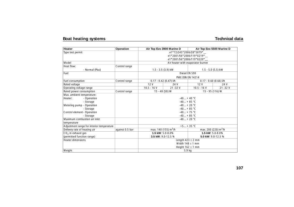
Heater Operation Air Top Evo 3900 Marine D Air Top Evo 5500 Marine D Type test permit e1*72/245*2006/28*5079*__
e1*2001/56*2006/119*0219*__ e1*2001/56*2006/119*0220*__
Model Air heater with evaporator burner Heat flow:
- Normal (Plus) Control range
1.5 - 3.5 (3.9) kW 1.5 - 5.0 (5.5) kW Fuel Diesel EN 590
PME DIN EN 14214 Fuel consumption Control range 0.17 - 0.42 (0.47) l/h 0.17 - 0.60 (0.66) l/h Rated voltage 12 V 24 V 12 V 24 V Operating voltage range 10.5 - 16 V 21 -32 V 10.5 - 16 V 21 -32 V Rated power consumption Control range 15 - 40 (50) W 15 - 95 (116) W Max. ambient temperature: Heater: - Operation
- StorageMetering pump - Operation
- StorageControl element - Operation
- Storage
-40... + 40 °C -40... + 85 °C -40... + 20 °C -40... + 85 °C -40... + 75 °C -40... + 85 °C
Maximum combustion air inlet temperature
-40... + 20 °C
Adjustment range for interior temperature +5... + 35 °C Delivery rate of heating air against 0.5 bar max. 140 (155) m3/h max. 200 (220) m3/h CO2 in exhaust gas (permitted function range)
1.5 kW: 5.0-8.0% 3.5 kW: 9.0-12.5 %
1.5 kW: 5.0-8.0% 5.0 kW: 9.0-12.5 %
Heater dimensions Length 423 ± 2 mmWidth 148 ± 1 mmHeight 162 ± 1 mm
Weight 5.9 kg
107
Webasto AG Kraillinger Strasse 5 82131 Stockdorf GERMANY
http://dealers.webasto.com http://www.webasto.com
Im Fall einer mehrsprachigen Version ist Deutsch verbindlich.
In multilingual versions the German language is binding.
Bij een meertalige versie is de Duitse versie bindend.
Iden
t.-N
r. 1
3151
33A
• 0
6/09
• E
rror
s an
d om
issi
ons
exce
pted
• P
rinte
d in
Ger
man
y •
© W
ebas
toA
G, G
CS
2009