Embed Size (px)
Citation preview

Hands on Relay SchoolBasic Track lab notes for testing an ABB RC reclosing relay along with a breaker simulator and a GE IAC overcurrent relay.
Lab 1 – Set and test the IAC overcurrent relay.Lab 2 - Set the RC relay de-energized out of the can on the bench.Lab 3 - Wire the RC relay to the breaker simulator and test the RC relay electrically.Lab 4 - Wire the GE IAC relay to simulate a feeder circuit with a protective relay and a reclosing relay.
Safety Considerations•Do all wiring with the breaker simulator’s power cord unplugged.•The T&SI on the IAC relay must be on the 0.2 amp tap.•Check resistance from the hot to the neutral prongs of power cord before plugging the power cord in. Resistance should be 400 ohms or greater.•Fused 120 VAC is present during testing.


General
Safety
Removing relay from service and
returning relay into service
Physical and visual inspection
Current shorting features of relay and
can
Trip circuit features of relay and can
Spiral spring and the need for a seal in
circuit
Time Disk
Test pickup (spiral spring tension)
Test time curve
Calibrate time curve (drag magnet)
T&SI
Test pickup
Test seal in
Inst
Test pickup

Hands on Relay SchoolBasic Track lab notes for testing an ABB RC reclosing relay along with a breaker simulator and a GE IAC overcurrent relay.
Lab 1 – Set and test the IAC overcurrent relay.Lab 2 - Set the RC relay de-energized out of the can on the bench.Lab 3 - Wire the RC relay to the breaker simulator and test the RC relay electrically.Lab 4 - Wire the GE IAC relay to simulate a feeder circuit with a protective relay and a reclosing relay.
Safety Considerations•Do all wiring with the breaker simulator’s power cord unplugged.•The T&SI on the IAC relay must be on the 0.2 amp tap.•Check resistance from the hot to the neutral prongs of power cord before plugging the power cord in. Resistance should be 400 ohms or greater.•Fused 120 VAC is present during testing.


12
0
52b
52
CC


INSPECTION
1.Take the cover off the relay, taking care to not shake or jar the relay or other
relays around it.
1.CAUTION: Shaking or jarring relays may cause inadvertent operations
2.Open the relay test switches to disable trip and close circuits. The order of
opening switches is not critical with the RC relay.
3.Lift the relay out of the case.
4.Visually check the relay for any obvious problems.
5.Clean the relay thoroughly.
6.Burnish the surfaces of all contacts, making sure to remove any tarnish.
7.Check that all relay connections are tight.
1.NOTE: The current input hardware on Westinghouse relays is frequently
loose and requires special attention.
8.Check that the resistor leads for the X and Y coil and motor are in the proper
configuration. The resistors are in series for 240 VAC operation and bypassed
for 120 VAC operation.
9.Check that the drum speed setting dial is correct per the setting sheet. To
adjust loosen the clamp screw and rotate the gear unit located behind the steel
plate with your hand. Retighten the clamp screw.

ADJUSTING THE INSTANTANEOUS TRIP SUPERVISION
1.The drum can be manually rotated by pushing the center button to disengage the
clutch. Rotate the drum slowly and adjust the Y13, 14 cam (cam 14, furthest cam
back) so Y13, 14 (instantaneous trip supervision) make up half way between the
lockout and start drum positions. Ensure that these contacts have adequate wipe by
the time the drum reaches the start position.
ADJUSTING THE RECLOSING IMPULSES
1.Cam 3 provides reclosing. Verify the desired reclosing sequence and timing from
the setting sheet. If a fast reclose is desired check that cam 3 closes 1 click of drum
rotation after the breaker opens. Experience has found that the very small delay
provides successful recloses by giving the breaker latch check switch time to close.
2.Verify that the plunger arm reset operates (controlled by the mounting screws in
cam 5) before any additional recloses on cam 3 are attempted.

Hands on Relay SchoolBasic Track lab notes for testing an ABB RC reclosing relay along with a breaker simulator and a GE IAC overcurrent relay.
Lab 1 – Set and test the IAC overcurrent relay.Lab 2 - Set the RC relay de-energized out of the can on the bench.Lab 3 - Wire the RC relay to the breaker simulator and test the RC relay electrically.Lab 4 - Wire the GE IAC relay to simulate a feeder circuit with a protective relay and a reclosing relay.
Safety Considerations•Do all wiring with the breaker simulator’s power cord unplugged.•The T&SI on the IAC relay must be on the 0.2 amp tap.•Check resistance from the hot to the neutral prongs of power cord before plugging the power cord in. Resistance should be 400 ohms or greater.•Fused 120 VAC is present during testing.

SIMPLIFIED SCHEMATIC
N
120
VAC
AGC10
amp fuse
TC CC
R G
52a 52b
CCTCTrip
PBClose
PB
HOT
52a 52b
B ACOM52b 52a
B ACOM52b 52a
B ACOM52b 52a
COMB A
COMB A
COMB A
HOT
NEUTRAL
TC
AGC 10A
CC
TO
120 VAC
FACE PLATE
BREAKER SIMULATOR

12
0
52b
52
CC

COMB A
COMB A
COMB A
HOT
NEUTRAL
TC
AGC 10A
CC
TO
120 VAC
TO
OHM METER
RC Relay Breaker Simulator

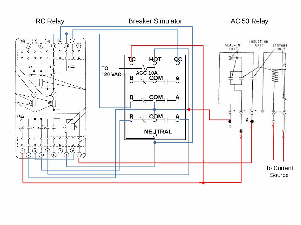
Hands on Relay SchoolBasic Track lab notes for testing an ABB RC reclosing relay along with a breaker simulator and a GE IAC overcurrent relay.
Lab 1 – Set and test the IAC overcurrent relay.Lab 2 - Set the RC relay de-energized out of the can on the bench.Lab 3 - Wire the RC relay to the breaker simulator and test the RC relay electrically.Lab 4 - Wire the GE IAC relay to simulate a feeder circuit with a protective relay and a reclosing relay.
Safety Considerations•Do all wiring with the breaker simulator’s power cord unplugged.•The T&SI on the IAC relay must be on the 0.2 amp tap.•Check resistance from the hot to the neutral prongs of power cord before plugging the power cord in. Resistance should be 400 ohms or greater.•Fused 120 VAC is present during testing.


12
0
52b
T&SI
IAC
51
T&SI
50/51
1
50/51
2
IAC
50
50/51
379
10
79
1
Y13
14
52
TC
52a
101
T
52
CC
COMB A
COMB A
COMB A
HOT
NEUTRAL
TC
AGC 10A
CC
TO
120 VAC
RC Relay Breaker Simulator IAC 53 Relay
To Current
Source

TESTING THE RC RELAY USING THE OUT OF SERVICE BREAKER
(PREFERRED)
1.Return the relay to the can if the breaker is out of service with the drum in mid
position. Close all switches.
2.With the breaker closed the drum will rotate to the start position. Monitor the
instantaneous trip supervision circuit (1 to 10) and observe that it makes up half way
between lockout and start.
3.Trip the breaker using an instantaneous protective relay contact that is in the
supervised path. Start the stopwatch at the same time. The breaker will reclose
after a very slight pause.
4.Observe the proper operation the anti pump scheme, especially the Y coil including
plunger latch and plunger reset.
5.Attempt to trip the breaker using an instantaneous protective relay contact that is in
the supervised path again. This time the instantaneous trip will be blocked. Trip the
breaker using the induction disk contact.
6.Observe the time of the second reclose (if applicable). Observe the anti pump
scheme in the same manner.
7.Repeat if needed until no additional recloses are in the sequence. The drum will
stop at lockout with the breaker open.
8.Close the breaker. The drum will rotate to start. Replace cover and return the
breaker into service.