Embed Size (px)
Citation preview

HARD FOLDING TONNEAU COVER
INSTALLATION GUIDE
Fold-a-Cover® is a division of Steffens Enterprises, Inc.4045 Karona Ct. Caledonia, MI 49316
phone: (616) 656.6886 fax: (616) 656.3771
3641C MAY/2008
1 of 12
2002-2007 DODGE RAM 1500, 2500 2002-2007 DODGE RAM 3500
TRUCK MODEL(S):GUIDE FOR FOLD-A-COVER®
DG2501, DG2502
* Truck model shown in images may or may not represent the truck referred to in this installation guide.
NOtEs tO INstAllER:
• Install Parts as shown in illustrations.
• Temperature should be no lower than 70° F when installing.
• Be sure the truck is setting on a level surface.
• Apply lock tight to each fastener during installation.
• some trimming of bed liner may be required for proper fit and function.
• Make sure the end user receives the warranty registration envelope, keys, and the operation instructions.
NOtEs tO CustOMER:
• For proper use and maintenance, refer to the operation and care label located on the underside of the rearmost panel on cover (driver’s side).

2 of 12
HARD FOLDING TONNEAU COVER INSTALLATION GUIDE
3641C MAY/2008
PARTS LIST:
RECOMMENDED TOOLS:
A 3505 ¼-20 x 1 ¾ BHCS
B 3682-10L LH Wind Seal
C 3682-10R RH Wind Seal
D 3447 Support Washer
E 3324A Stake Pocket Nut
F 3410 Hinge Bracket
G 3411 Hinge Bracket Shim
H 3509 #10-32 x ½ SHCS
I 3506 ¼-20 x 2 ¼ HHCS
J 3508 ¼-20 Jam Nut
K 3407C C-Clamp
L 3510 ¼” Lock Washer
M 3504 ¼-20 x 1 HHCS
N 3409SA C-Clamp Shim w/ Tape
O 3658 Flat Washer, ¼ USS
P 3652 Striker Clamp Bracket
Q 3651 Striker Bolt
R 3656 T-Nut 5/16–18
S 3653 Center Latch Clamp
T 3673 Inner Clamp Bracket
U 3674 Inner Clamp Bracket
V 2095 Adhesion Promoter
W 3689-70 Blade Seal
X 3614 Foam Tape, 1.00” x 6”
Y 2092 Foam Tape, 1.50 ” x 12”
Z 2069 Rivet, 3/16” x 3/8” SST
AA 2070 Catch (Footman’s Loop)
5/32”
7/16”5/16”3/8”
7/16”
A
B
C
D
E
F
G
H
I
J
M
N
K
l
O
P
Q
R
s
t
u
2x
2x
4x
4x
4x
2x
10x
2x
2x
4x
4x
4x
4x
*
*Ball end allen wrench recommended
1x
10x
14x
2x
6x 4xor
6x 4xor
V
6x 4xor
W
2x
X
Y
Z
AA
2x
1x
1x
1x
one notch
two notches

3 of 12
HARD FOLDING TONNEAU COVER INSTALLATION GUIDE
3641C MAY/2008
STEP ONE: WIND SEAL (SIDE RAIL) APPLICATION
A
D
D
B CB C
DD
D
E
APPLY LOCKTITE TO THREADS
DO NOT FULLY TIGHTEN DO NOT
FULLY TIGHTEN
8’ BOX ONLY
REARSTAKEPOCKET
FORWARDSTAKE POCKET
CENTERSTAKE
5/32”5/32”
A EA E
Note: 6’4” boxes have 2 stake pockets per side. 8’ boxes have 3 stake pockets per side.
REMOVE PROtECtIVE BACKER FROM WIND sEAl RAIls:Remove the protective film from the foam tape on the passenger and drivers side wind seal rails (B & C). Note: The foam tape is for surface protection and sealing on this application and is not adhesive.
Thread the stake pocket nuts (E) onto the bolts; thread the nut approximately five turns. Note: The deep groove in the stake pocket nut should face up toward the bottom of the wind seal rail as shown in the illustrations.
Insert the 1¾” socket head bolts (A) through the support washer and through the slotted hole in the wind seal rail. Note: Using your thumb hold the upper and lower rubber seals out of the way as you insert the bolt through the spacer and wind seal rail.
Insert the support washers (D) into the wind seal rails as pictured above.
Using a 5/32” allen wrench tighten the socket head bolt until the rail draws down and makes slight contact with the top of the box; only finger tight. Repeat these steps until all of the stake pocket nuts are finger tight on both the drivers and passenger side wind seal rails.
sECuRE WIND sEAl RAIl tO VEHIClE Align the completed wind seal rail assembly on the top of the box (see diagram above and picture to left) allowing the stake pocket bolts and nuts to drop into their respective stake pockets. Starting at the forward stake pocket on the driver’s side of the vehicle make sure the stake pocket nut engages the stake pocket lip and hold a slight upward pressure on the rail.
WIPE DOWN BOtH sIDE RAIlsUsing a clean cloth and 70% Isopropyl Alcohol, wipe down both side rails to ensure a clean surface for installation.
Note: Remove plastic stake pocket covers.
A
A
U
T
S
13mm
2XTORQUE
to93 in.lbs.
4 of 12
HARD FOLDING TONNEAU COVER INSTALLATION GUIDE
3641C MAY/2008
STEP TWO: INITIAL COVER PLACEMENT
A
TAILGATE LATCHBRACKET
A
TAILGATE LATCHBRACKET
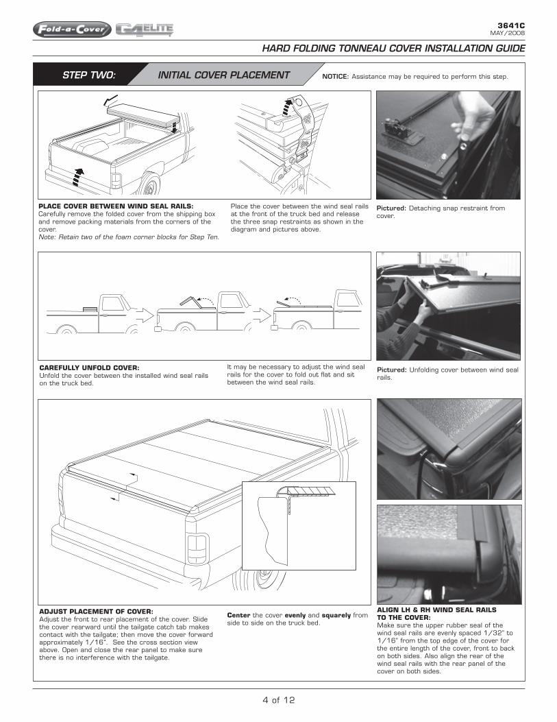
Pictured: Unfolding cover between wind seal rails.
CAREFullY uNFOlD COVER:Unfold the cover between the installed wind seal rails on the truck bed.
A
TAILGATE LATCHBRACKET
NOTICE: Assistance may be required to perform this step.
Pictured: Detaching snap restraint from cover.
PlACE COVER BEtWEEN WIND sEAl RAIls:Carefully remove the folded cover from the shipping box and remove packing materials from the corners of the cover. Note: Retain two of the foam corner blocks for Step Ten.
Place the cover between the wind seal rails at the front of the truck bed and release the three snap restraints as shown in the diagram and pictures above.
It may be necessary to adjust the wind seal rails for the cover to fold out flat and sit between the wind seal rails.
Center the cover evenly and squarely from side to side on the truck bed.
AlIGN lH & RH WIND sEAl RAIls tO tHE COVER:Make sure the upper rubber seal of the wind seal rails are evenly spaced 1/32” to 1/16” from the top edge of the cover for the entire length of the cover, front to back on both sides. Also align the rear of the wind seal rails with the rear panel of the cover on both sides.
ADJust PlACEMENt OF COVER:Adjust the front to rear placement of the cover. Slide the cover rearward until the tailgate catch tab makes contact with the tailgate; then move the cover forward approximately 1/16”. See the cross section view above. Open and close the rear panel to make sure there is no interference with the tailgate.

5 of 12
HARD FOLDING TONNEAU COVER INSTALLATION GUIDE
3641C MAY/2008
STEP THREE: SECURE COVER TO TRUCK BED
70in - lbs.(7.9 N.m)
70in - lbs.(7.9N.m)
TO FRONTOF VEHICLE
TO FRONTOF VEHICLE
TO FRONTOF VEHICLE
DO NOTFULLY TIGHTEN
7/16”
7/16”
5/32”
2xI
JN
K
K
2xJ
2xL
2xM
2xI
2xH
F
G
70in - lbs.(7.9 N.m)
70in - lbs.(7.9N.m)
TO FRONTOF VEHICLE
TO FRONTOF VEHICLE
TO FRONTOF VEHICLE
DO NOTFULLY TIGHTEN
7/16”
7/16”
5/32”
2xI
JN
K
K
2xJ
2xL
2xM
2xI
2xH
F
G
70in - lbs.(7.9 N.m)
70in - lbs.(7.9N.m)
TO FRONTOF VEHICLE
TO FRONTOF VEHICLE
TO FRONTOF VEHICLE
DO NOTFULLY TIGHTEN
7/16”
7/16”
5/32”
2xI
JN
K
K
2xJ
2xL
2xM
2xI
2xH
F
G
70in - lbs.(7.9 N.m)
70in - lbs.(7.9N.m)
TO FRONTOF VEHICLE
TO FRONTOF VEHICLE
TO FRONTOF VEHICLE
DO NOTFULLY TIGHTEN
7/16”
7/16”
5/32”
2xI
JN
K
K
2xJ
2xL
2xM
2xI
2xH
F
G
70in - lbs.(7.9 N.m)
70in - lbs.(7.9N.m)
TO FRONTOF VEHICLE
TO FRONTOF VEHICLE
TO FRONTOF VEHICLE
DO NOTFULLY TIGHTEN
7/16”
7/16”
5/32”
2xI
JN
K
K
2xJ
2xL
2xM
2xI
2xH
F
G
70in - lbs.(7.9 N.m)
70in - lbs.(7.9N.m)
TO FRONTOF VEHICLE
TO FRONTOF VEHICLE
TO FRONTOF VEHICLE
DO NOTFULLY TIGHTEN
7/16”
7/16”
5/32”
2xI
JN
K
K
2xJ
2xL
2xM
2xI
2xH
F
G
5/32”
2xH
25in - lbs.(2.8 N.m)
Pictured: Attaching Hinge Bracket to Cover.FOlD BACK FRONt PANEl:Carefully fold back the front panel. Note: Make sure cover does not move from its centered position on the truck bed.
AssEMBlE HINGE BRACKEt:Assemble drivers side and passengers side hinge brackets (F, G & H) finger tight as shown in the diagram and picture above.
Pictured: Attaching C-Clamp to truck bed and Hinge Clamp.
PREPARE C-ClAMP AssEMBlY:Assemble drivers side and passenger side C-Clamp units (I, J, & K). Thread the jam nut (J) all the way onto bolt (I) and thread them into C-Clamp (K) as shown in diagram above.
Pictured: Securing C-Clamp jam nut with 7/16” wrench.
INsERt C-ClAMP sHIM:Insert the C-Clamp shims (N) as shown in the diagrams above and thread the C-Clamp bolts in finger tight until the bolt contacts the center groove in the shim. Note: Make sure both of the C-Clamp bolts contact the shim and that the C-Clamp assembly and shim are parallel with the top of the truck bed. Avoid any downward pressure on the C-Clamp assemblies as they are tightened.
tIGHtEN BOlts AND JAM Nuts:Check the shim alignment and tighten the bolts to 70 in. lbs. (7.9 N. m) and then tighten the jam nuts.
AttACH C-ClAMP tO HINGE BRACKEt:Using bolts (M) attach the C-Clamp units to the hinge brackets and tighten the bolts to 70 in. lbs. (7.9 N. m.).
sECuRE HINGE BRACKEt BOlts:Tighten hinge bracket set bolts to 25 in. lbs. (2.8 N. m.)Note: Make sure hinge bracket shim (G) is seated to the bottom of the receiver groove in the hinge bracket.

6 of 12
HARD FOLDING TONNEAU COVER INSTALLATION GUIDE
3641C MAY/2008
STEP FOUR: STRIKER CLAMP BRACKET INSTALLATION
PlACE tHE REAR stRIKER ClAMP BRACKEts: Move the striker clamp bracket assembly into place allowing the inner clamp bracket to slip behind the vertical edge of the inner box rail; while the outer clamp rests on the top and outside of the vertical edge of the inner box rail as shown above. Tighten the assembly finger tight at this time.
PRE AssEMBlE tHE stRIKER ClAMP BRACKEt AssEMBlIEs:Pre assemble the striker clamp bracket (P) and the inner clamp brackets (U & T) with bolt and washers (M, L & O). Insert the bolt and washers through the slot in the striker clamp bracket; threading the bolt into the inner clamp bracket as shown. Start the bolt only a few threads. Assemble the four (4) striker clamp bracket assemblies.
POsItION AND INstAll REAR stRIKER ClAMP BRACKEt AssEMBlIEs:Using a tape measure locate the position of the rear striker clamp bracket assemblies approximately 47 1/8” from the rear edge of the installed C-Clamp as shown above.
PlACE tHE FRONt stRIKER ClAMP BRACKEts:Move the striker clamp bracket assembly into place allowing the inner clamp bracket to slip behind the vertical edge of the inner box rail; while the outer clamp rests on the top and outside of the vertical edge of the inner box rail as shown above. Tighten the assembly finger tight at this time.
POsItION AND INstAll FRONt stRIKER ClAMP BRACKEt AssEMBlIEs:Using a tape measure locate the position of the front striker clamp bracket assemblies approximately 9 3/16” from the front edge of the installed C-Clamp as shown above.
Using the 7/16” wrench, apply downward pressure to the clamp assembly while tightening striker clamp bracket assemblies to 70 in. lbs. (7.9 N. m.). Repeat for both rear clamp assemblies.
XY
P
S
AFFIX FOAM tAPE tO ClAMPsCut the foam tape (X & Y) into 3” inch lengths. Remove the backer from the tape exposing the adhesive and carefully place the tape on the inside surface of the striker clamp brackets (P) and center latch brackets (S) starting just above the slot in the clamp. Allow the tape to follow inner contour of clamps to the top of the clamp as pictured. Trim excess tape with the razor knife (foam tape protects the painted surface of the vehicle).
Fig.1: Front Striker Clamp Bracket Assembly
Fig.2: Rear Striker Clamp Bracket Assembly
Using the 7/16” wrench, apply downward pressure to the clamp assembly while tightening striker clamp bracket assemblies to 70 in. lbs. (7.9 N. m.). Repeat for both front clamp assemblies.
P
O
UL
M
P
O
TL
M

7 of 12
HARD FOLDING TONNEAU COVER INSTALLATION GUIDE
3641C MAY/2008
Pictured: Securing Side Rails by tightening bolts
in stake pocket nuts.
tIGHtEN BOlts tO sECuRE C-ClAMP:Tighten bolts to 70 in. lbs. (7.9 N.m).
STEP SIX: INSERT STRIKER BOLTS
Tighten the striker bolt finger tight and repeat this step for all four of the striker clamp brackets.
INsERt AND sECuRE stRIKER BOlts:Pre-assemble the striker bolt with 2 washers and thread it into the T-nut.
With the front and rear panels still in their fully open positions, install the striker bolts, T-nuts and washers (Q, R & O).
Slide the T-nut assembly into the T-slot in the striker clamp bracket as shown in the picture above.
QR O O
STEP FIVE: ATTACH CENTER LATCH CLAMPS
With the tailgate open and the rear cover panel closed, locate the center latch mechanism on the bottom of the number three panel.
Using masking tape, mark the center of the latch mechanism on truck bed rail as shown in the picture above. Repeat for both driver and passenger sides.
Open the cover to its fully open position and install the center latch clamps (S, T, L, M & O) as shown in the picture above.
Using the 7/16” wrench, apply downward pressure to the clamp assembly while tightening center latch clamps to 70 in. lbs. (7.9 N. m.).
With the center latch bracket in place and the tailgate in the open position, close the rear panel of the cover. Closing the rear panel engages the center latch mechanism. The center latch cam should operate freely when the rear panel is closed and the cam should rotate under the center latch bracket as picture above.
IMPORTANT NOTE: ALWAYS FULLY OPEN THE REAR PANEL FIRST AND CLOSE THE REAR PANEL LAST. To insure proper operation of the center latch mechanism always open and fold the rear panel of the cover to its fully open position before starting any folding motion of the second or third panels, continue the opening sequence by folding the second and third panel to the fully open position and secure the docking straps. To close the cover, reverse these steps in the same order, making sure to close the rear panel last.
8 of 12
HARD FOLDING TONNEAU COVER INSTALLATION GUIDE
3641C MAY/2008
STEP SEVEN: FOOTMANS LOOP INSTALLATION
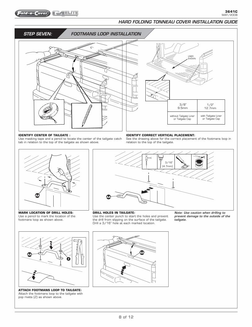
IDENtIFY CENtER OF tAIlGAtE :Use masking tape and a pencil to locate the center of the tailgate catch tab in relation to the top of the tailgate as shown above.
3/8”9.5mm
with Tailgate Lineror Tailgate Cap
without Tailgate Lineror Tailgate Cap
1/2”12.7mm
LINERSHOWN
3/16”(4.7mm)
.
3/8”9.5mm
with Tailgate Lineror Tailgate Cap
without Tailgate Lineror Tailgate Cap
1/2”12.7mm
LINERSHOWN
3/16”(4.7mm)
.
3/8”9.5mm
with Tailgate Lineror Tailgate Cap
without Tailgate Lineror Tailgate Cap
1/2”12.7mm
LINERSHOWN
3/16”(4.7mm)
.
3/8”9.5mm
with Tailgate Lineror Tailgate Cap
without Tailgate Lineror Tailgate Cap
1/2”12.7mm
LINERSHOWN
3/16”(4.7mm)
.
3/8”9.5mm
with Tailgate Lineror Tailgate Cap
without Tailgate Lineror Tailgate Cap
1/2”12.7mm
LINERSHOWN
3/16”(4.7mm)
.
IDENtIFY CORRECt VERtICAl PlACEMENt:See the drawing above for the correct placement of the footmans loop in relation to the top of the tailgate.
3/8”9.5mm
with Tailgate Lineror Tailgate Cap
without Tailgate Lineror Tailgate Cap
1/2”12.7mm
LINERSHOWN
3/16”(4.7mm)
.
MARK lOCAtION OF DRIll HOlEs:Use a pencil to mark the location of the footmans loop as shown above.
DRIll HOlEs IN tAIlGAtE:Use the center punch to start the holes and prevent the drill from slipping on the surface of the tailgate. Drill a 3/16” hole at each marked location.
Note: Use caution when drilling to prevent damage to the outside of the tailgate.
AttACH FOOtMANs lOOP tO tAIlGAtE:Attach the footmans loop to the tailgate with pop rivets (Z) as shown above.
Z
AA
AAAA
AA

9 of 12
HARD FOLDING TONNEAU COVER INSTALLATION GUIDE
3641C MAY/2008
STEP EIGHT: ALIGN & ADJUST ROTARY LATCHES
Open the tailgate of the truck. Make sure the rotary latches are in their open position on both panels.
Gently lower either the front or the rear panel toward its closed position making careful note of the alignment of the striker bolts on the truck and the U-shaped striker bolt receiver in the rotary latch on the cover.
The U-shaped groove on the latch should be centered directly over the striker bolt.
If the striker bolt is not centered adjust it as follows. Loosen the 3/8” nuts on the latch assembly to slide the latch fore or aft until it is centered over the striker bolt on the truck.
Note: (If the rotary latch can not be properly adjusted check the position of the striker clamp assemblies. Additional adjustment is available by loosening and repositioning the striker clamp bracket assembly)
Repeat until all four latches are centered over their respective striker bolts.
Close the tailgate of the truck and return the cover to its fully closed position on both the front and rear panels. Re-check the spacing and alignment of the wind seal rails with the cover.
Return the cover to the closed position to make the vertical adjustment of the striker bolts. Use the 5/16” wrench to adjust the striker bolt height as shown in the picture above.
With the front and rear panels in their closed positions the top of the cover should be adjusted flush with the top of wind seal rails. Tighten the four striker bolts to 70 in. lbs. (7.9 N. m.).
Note: Striker bolt setting may require readjustment after blade seals are installed in Step Eleven.
To close and latch the front or rear panels simply use a smooth, firm downward pressure on the panel. (Start the downward closing motion approximately 12 inches before the panel reaches its closed position)
OPEN POsItION CORRECt INCORRECt
Open the front and rear panel to expose the wind seal rail bolts and using the 5/32” allen wrench tighten the wind seal rails to 70 in. lbs. (7.9 N. m.)

10 of 12
HARD FOLDING TONNEAU COVER INSTALLATION GUIDE
3641C MAY/2008
STEP TEN: ADJUST LATCH TIMING
Hold the rear panel in an open position at approximately a 45 degree angle with one hand. With your other hand manually close both the driver and passenger side rotary latches.
If any adjustment is required simply adjust the cable length at either latch as shown.
Turning the cable end nut clockwise will make that latch release sooner; turning the cable end nut counter-clockwise will make that latch release later. When adjustments are complete, you may tighten the cable end jam nuts as pictured to the right.
lAtCH ClOsED lAtCH OPEN
With the cover in this suspended position operate the latch release handle. Both latches should open at the same time about half way through the travel of the latch release handle. If both latches release simultaneously no further adjustment is required, and you may tighten the cable end jam nuts as pictured below.
Using two small adjustable wrenches tighten the cable end jam nuts.
Repeat this adjustment sequence for the latches on the front panel.

11 of 12
HARD FOLDING TONNEAU COVER INSTALLATION GUIDE
3641C MAY/2008
STEP NINE: ATTACH FRONT & REAR BLADE SEALS
With the front and rear panels open and supported on the foam packing blocks; clean the seal surfaces with 70% isopropyl alcohol.Note: Surface must be free of dust, dirt, oil and moisture. Make sure to clean the seal mating surfaces with either isopropyl or denatured alcohol as these solvents leave no residue that could effect the bond strength. Apply the adhesion promoter (V) to both panels as shown in fig. 1. Allow the adhesion promoter to dry to the touch before starting the blade seal installation.
AttACH FRONt BlADE sEAlExpose a small section of the adhesive tape (4”-6”) on the blade seal (W) as shown in fig. 2. Align the seal with the end of the panel making sure the tongue on the panel and the groove in the seal fit together as shown in the line drawing (far left).
fig.2
Expose a small section of the adhesive tape (4”-6”) on the blade seal (W) and align the seal with the back edge of the channel starting 1/2” from the outside edge of the cover as shown in fig. 5.
Work across the panel exposing small sections of the adhesive and aligning the seal. When you reach the end of the panel trim the excess seal material 1/2” from the outside edge of the cover with the razor knife as shown above.
Note: Using 2 foam corner packing blocks support the open front and rear panels of the cover as shown.
REAR PANEl FRONt PANEl
fig.1bfig.1a
fig.3 fig.4
sIlICONE PROtECtANt
+ClEAN ClOtH
fig.5
fig.6
Work across the panel exposing small sections of the adhesive and aligning the seal.
Note: Do not stretch the seal as it is being placed on the cover.
When you reach the end of the panel trim the excess seal material flush with the end of the panel with the razor knife. Firmly press the seal in place across its entire length.
AttACH REAR BlADE sEAl
REAR sEAl FRONt sEAl
TONGUE
GROOVE
TONGUE
GROOVE
To ensure proper transfer of the adhesive use the box end of a combination wrench or a similar tool to apply concentrated pressure to the blade seal as shown in fig.7. Start at one end of the seal and work the tool across the panel applying firm even pressure. Repeat for both the front and the rear seal.
Note: Closing the cover requires a smooth, firm downward pressure on the panel. Due to the nature of the rubber blade seals, it will initially take extra closing pressure until the memory in the seal material conforms to the seals final shape in the closed position.
APPlY PROtECtANt tO uNDERsIDE OF BlADE sEAls usING A ClEAN ClOtH:With the seals completely installed apply a light coat of Armor All® or a similar silicone protectant to the underside of both the front and rear blade seals using a clean, dry cloth.
SURFACE TEMP
70˚F OR ABOVE
Surface temperatures below 70 degrees F will adversely effect the bond strength of the seal adhesive.
fig.7

12 of 12
3641C MAY/2008
HARD FOLDING TONNEAU COVER OPERATIONAL INSTRUCTIONS
To insure proper operation of the center latch mechanism always open and fold the rear panel of the cover to its fully open position before starting any folding motion of the second or third panels.
Continue the opening sequence by folding the second and third panel to the fully open position.
To close the cover, reverse these steps in the same order, making sure to close the rear panel last.
With the cover in the fully open and stacked position secure all three docking straps. It is important to secure the docking straps at all times when the cover is in the fully open position.
Note: Only operate the vehicle with the cover in the closed and latched position or the fully open position with the docking straps securely fastened. Operation of the vehicle with the cover in partially opened positions can cause severe damage to the cover and possibly the vehicle.
1 2
3 4
5
To open the cover lift the latch release handle and open the rear panel to the fully open position.