Embed Size (px)
Citation preview

Cut-offH1~H26H1~H26
H1
KTKF Lateral side screw clamp holder H8
KTKFS (For sub spindle tooling) Lateral side screw clamp holder H10
KGD Integral Toolholder H14
KGD-S Separate Toolholder H15
KGM (For automatic lathe) Integral Toolholder H18
KGM Integral Toolholder H19
KGM-T Integral Toolholder H19
KTKB-SS / KTKB-S Blade H22
KTKTB / KTKTBF Toolblock H23
KTKH-S Integral Toolholder H24
Recommended Cutting Conditions H25
Product Lineup H2
Guide for Cut-Off H3
Summary of Cut-Off H4~H5
Cut-Off Toolholders (for small diameter cut-off) H6~H11
Cut-Off Toolholders (for 2-edge insert) H12~H15
Cut-Off Toolholders (for 2-edge insert) Grooving / Plunge & Turn H16~H20
Technical Information H25~H26
Cut-Off Toolholders (for 1-edge insert) Cut-Off H21~H24
Alternative Toolholder Reference Table for Cut-off Toolholder H26
H1
H2
Width: 1.0~2.0 mm
Cut
-off
H
KGD
CERACUT Cut-Off(1-edge)
Product Lineup
Width: 1.5~4.0mm, 3~8mm Width: 2.0~6.0mm
CERACUT / Plunge & Turn
(2-edge)
For Small Diameter Cut-Off
Width: 0.5~2.0 mm
Toolholder (Long Shank for automatic lathe)
Cut-Off Dia.
ø5~ø12~ø16
For sub spindle tooling
Cut-Off Dia.
ø6~ø12ø14~ø16
Width: 1.6~9.6mmWidth: 2.2~5.1mm
Bolt ClampCut-Off Dia.
ø18~ø60
Toolholder TypeCut-Off Dia.
ø30~ø79
Blade typeCut-Off Dia.
ø32~ø120
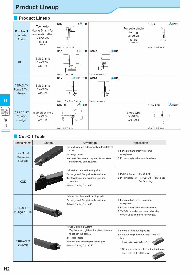
■ Product Lineup
Bolt ClampCut-Off Dia.
ø12~ø50
KGD ( H14)
Width: 2.0~4.0mm Width: 2.0~4.0mm
KGD-S ( H15)
■ Cut-Off ToolsSeries Name Shape Advantage Application
For Small Diameter Cut-Off
1) Insert clamp is side screw type from lateral side
2) 2-edge Insert
3) Cut-off Diameter is prepared for two sizes from ø5~ø12 and max.ø16.
1) For cut-off and grooving of small workpieces
2) For automatic lathe, small machine
KGD
1) Insert is clamped from top side.
2) 1-edge and 2-edge inserts available
3) Integral type and separate type are available.
4) Max. Cutting Dia.: ø50
1) PM Chipbreaker…For Cut-Off
2) PH Chipbreaker… For Cut-Off (High Feed)For Grooving
CERACUT / Plunge & Turn
1) Insert is clamped from top side
2) 1-edge and 2-edge inserts available
3) Max. Cutting Dia.: ø60
1) For cut-off and grooving of small workpieces
2) For automatic lathe, small machine
3) TMR-Chipbreaker provides stable chip control up to high feed rate ranges.
CERACUT Cut-Off
1) Self-Clamping SystemTap the insert lightly with a plastic hammer to set it in the pocket.
2) 1-edge insert
3) Blade type and Integral Shank type
4) Max. Cutting Dia.: ø120
1) For cut-off and deep grooving
2) Standard chipbreaker is general cut-off type.
Feed rate : over 0.1mm/rev
P-Chipbreaker is for cut-off at low feed rates
Feed rate : 0.03~0.08mm/rev
KTKF ( H8) KTKFS ( H10)
KGM ( H18~H19) KGM-T ( H19)
KTKH-S ( H24) KTKB-S(S) ( H22)

H3
Cut
-off
H
Guide for Cut-Off
θ
TKN
TKR
TKR
TKN
TKN
(L-hand)(R-hand)TKR TKL
θ
・Angled (θ) insert can reduce the burr size when cutting off.・When using a larger lead angle (θ), cutting
resistance becomes smaller, but the feed rate should be reduced.
Wrench
Plastic Hammer Insert's back end does not contact the toolholder.
■ How to Set Up (TKN / TK&)
1. Tap the insert lightly with a plastic hammer to push it in to the extent that it can not be removed by hand. 2. Remove the insert by using the supplied wrench.
- --
-
○ Fig.3
○ Fig.4
■ Tool Selection CERACUT / Plunge & Turn For Small Dia. Cut-Off CERACUT Cut-Off
Insert
Toolholder
1. Insert1-edge Insert … For Larger Dia. Workpiece (Max.ø120)2-edge Insert … For Smaller Dia. Workpiece
Cost per corner is reduced
1. Use a suitable toolholder (blade) for the workpiece dia.2. Use a more rigid toolholder (blade).3. Use a back clamp toolholder if there is no space for clamping tools from top side (Automatic Lathe).
2. Use a neutral angle insert if there is no limit to the finished shape.
3. Use angled insert to reduce the size of the remaining boss.
4. Use sharp-cornered lead-angled Insert to make the remaining boss much smaller when machining small parts and thin parts. 5. Use the minimum width insert suitable for the machining operation.
TKF...STKF...NBTKFS...S
-
○
GMM
-
GMM-&
○○○
○○
Fig.2
GMM-&Fig.2
-
○ ○
○○
○
TKF...DR
TKF...DR
○
-
TKN
TK&
-
-
○○○
Fig.1
■ Caution
○: Applicable : Not Applicable
●Do not rework the insert and toolholder (blade) to prevent damage.
3. Constant spindle revolution is recommended to obtain stable tool life.
1. Set the cutting edge height 0.1-0.2mm above the center height.2. Always apply sufficient coolant to the cutting edge.
●Overuse of insert and toolholder (blade) may cause insert breakage and toolholder (blade) damage.
●Clean the insert pocket well with compressed air when replacing insert.
4. Cut-off as close to the chuck as possible5. Decrease the feed rate from 1/2 to 1/3 at the near center to prevent chipping.
○○○○
○
○○
○
○○
KGD
-
-
-
GDMGDMS
Fig.2
GDM-R-6DGDMS-R-6D
○○○○
○
○○○○
○
○ Fig.5○ Fig.5○ Fig.5○ Fig.5
Fig.1
Fig.3
Fig.4
Example: Solid Workpiece
Example: Hollow Workpiece (Pipe)
Bigger Boss
Sharp Corner Lead AngledFig.2
Workpiece
Cut
ting
Edg
e H
eigh
t
Fig.5

H4
Chipbreaker forLow Feed Cut-Off
Chipbreaker forGeneral Cut-Off
Chipbreaker for Sharp Cutting
2-edge
Chipbreaker for Stability
2-edge
Low resistance cut-offChipbreaker
2-edge
Chipbreaker for Productivity
2-edge
CERACUT / Plunge & Turn (Top Clamp)
CERACUT Cut-Off (Self Clamp)
For Small Diameter Cut-Off (Lateral Side Clamp)
Chamfer + hone Sharp Edge HoneGeneral Cut-Off Low Feed Cut-OffCERACUT Cut-Off
Corner-R 0.05 Sharp Corner Corner-R 0.2-0.3 Corner-R 0.2-0.3Chamfer + hone Chamfer + hone Chamfer + hone Sharp Edge
Sharp Cutting (MT-Chipbreaker) Stable Cutting (TK-Chipbreaker)
Grooving / Plunge&Turn
H21
H16
H8
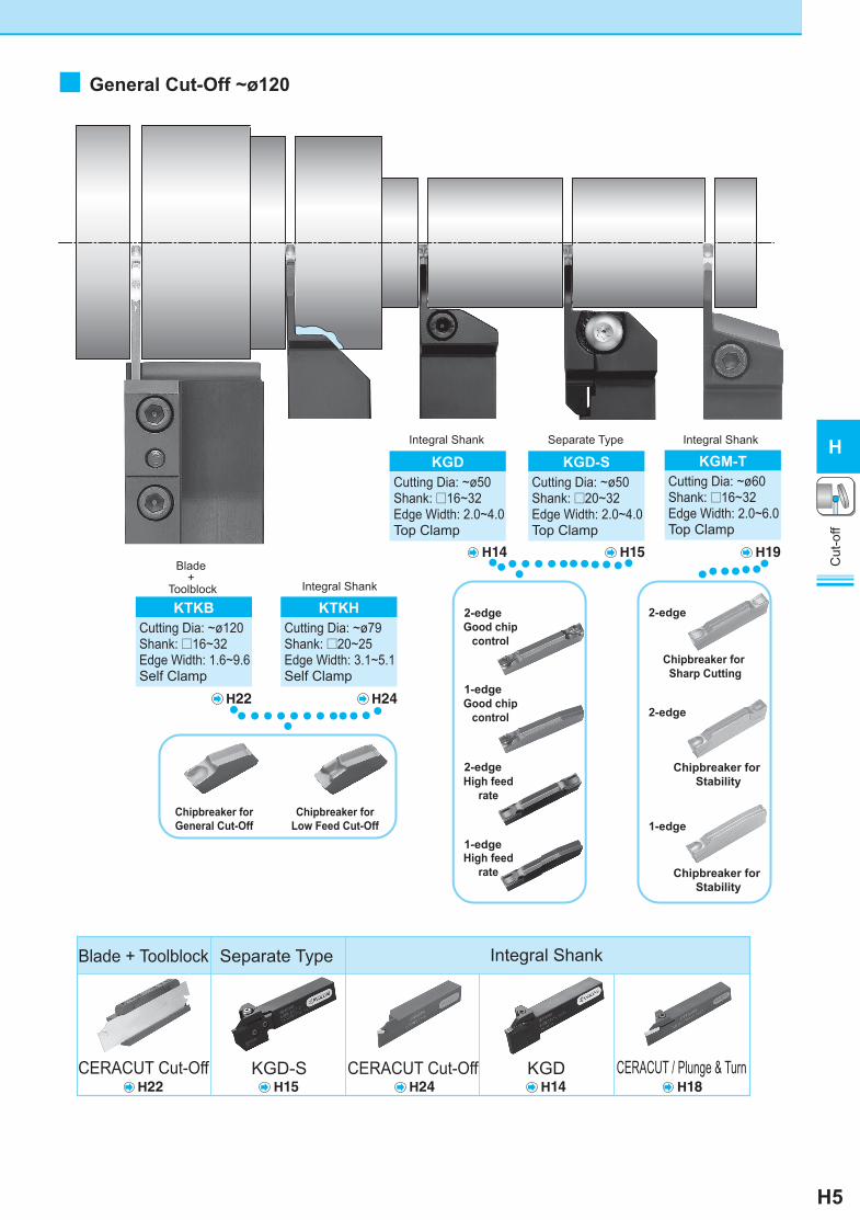
KTKFCutting Dia: ~ø16Shank: □10~16×20Edge Width: 0.5~2.0Lateral Side Clamp
KTKFSCutting Dia: ~ø16Shank: □10~12Edge Width: 1.0~2.0Lateral Side Clamp
H10H18
KGMCutting Dia: ~ø32Shank: □10~16Edge Width: 1.5~4.0Top Clamp
KTKHCutting Dia: ~ø45Shank: □10~25Edge Width: 2.2~4.1Self Clamp
KTKFKTKFS
Chipb
reak
er e
dge
shap
eCh
ipbr
eake
r edg
e sh
ape
Corner-R 0.2Chamfer + hone
Productivity Oriented(TMR-Chipbreaker)
Chipbreaker for Stability
1-edge
H24 H18 H8
H24
● : Std. Stock
Summary of Cut-Off
■ Small Dia. Cut-off ~ø45 Small Shank
■ GMM Chipbreaker MAP
TK
Sharp Cutting
MT
Stability
TMRHig
hFe
edin
gLo
w
Cut
-off
H
H5
Good chipcontrol
2-edge
1-edge
High feedrate
2-edge
1-edge
H22 H24
Separate Type
H15
KGD-SCutting Dia: ~ø50Shank: □20~32Edge Width: 2.0~4.0Top Clamp
H22 H24 H18KGD-S
H15KGD
H14
H14
KGDCutting Dia: ~ø50Shank: □16~32Edge Width: 2.0~4.0Top Clamp
Separate Type
Good chipcontrol
High feedrate
KGM-TCutting Dia: ~ø60Shank: □16~32Edge Width: 2.0~6.0Top Clamp
H19
Integral Shank
Chipbreaker for Sharp Cutting
2-edge
Chipbreaker for Stability
2-edge
Chipbreaker for Stability
1-edge
CERACUT Cut-Off
Integral Shank
CERACUT Cut-Off
Blade + Toolblock
CERACUT / Plunge & Turn
Chipbreaker forLow Feed Cut-Off
Chipbreaker forGeneral Cut-Off
KTKBCutting Dia: ~ø120Shank: □16~32Edge Width: 1.6~9.6Self Clamp
Blade +
Toolblock
KTKHCutting Dia: ~ø79Shank: □20~25Edge Width: 3.1~5.1Self Clamp
Integral Shank
Integral Shank
● : Std. Stock
■ General Cut-Off ~ø120
Cut
-off
H
chiprol
chiprol

H6
Cut
-off
H
Classification of usage P Carbon Steel / Alloy Steel Q
: Continuous-Low Interruption / 1st Choice : Continuous-Low Interruption / 2nd Choice● : Continuous / 1st Choice○ : Continuous / 2nd Choice
M Stainless Steel Q
K Cast Iron Q
N Non-ferrous Metals Q
Insert DescriptionDimension (mm) Angle
(°)Carbide
WøDmax rε T H ød θ
PR1225 PR1025 KW10R L R L R L
Right lead angle
TKF12& 050-S-16DR 0.5 5
0.03 3 8.7 5 16°
● ● ● ● ●
H8
070-S-16DR 0.7 8 ● ● ● ● ●100-S-16DR 1.0
12● ● ● ● ● ●
150-S-16DR 1.5 ● ● ● ● ● ●200-S-16DR 2.0 ● ● ● ● ● ●
TKF12& 050-S 0.5 5
0.03 3 8.7 5 0°
● ● ● ● ●070-S 0.7 8 ● ● ● ● ●100-S 1.0
12● ● ● ● ● ●
150-S 1.5 ● ● ● ● ● ●200-S 2.0 ● ● ● ● ● ●
Right lead angleTough Edge
TKF12& 100-T-16DR 1.0
12 0.08 3 8.7 5 16°
● ●
150-T-16DR 1.5 ● ●
200-T-16DR 2.0 ● ●
Tough Edge
TKF12& 100-T 1.0
12 0.08 3 8.7 5 0°
● ●
150-T 1.5 ● ●
200-T 2.0 ● ●
Right lead angle
TKF12& 050-NB-20DR 0.5 5
0 3 8.7 5 20°
● ● ● ●070-NB-20DR 0.7 8 ● ● ● ●100-NB-20DR 1.0
12● ● ● ●
150-NB-20DR 1.5 ● ● ● ●200-NB-20DR 2.0 ● ● ● ●
Without Chipbreaker
TKF12& 050-NB 0.5 5
0 3 8.7 5 0°
● ● ● ●070-NB 0.7 8 ● ● ● ●100-NB 1.0
12● ● ● ●
150-NB 1.5 ● ● ● ●200-NB 2.0 ● ● ● ●
Handed Insert shows Right-hand
Cut-Off Toolholders (for small diameter)
■ TKF
Cut
-off
H
φ
ε
ε θ
φ
φ
ε
ε
θ φ
φ
ε
ε θ
φ
φ
ε
φεθ
φ
ε
ε θ
φ
φ
ε
ε
θ φ
● Applicable Inserts (TKF12)
θ θ
ToolholderInsert
Lead Angle
R-hand (R) R-hand (R) R-hand (R)
ToolholderInsert
Lead Angle
L-hand (L)L-hand (L) R-hand (R)
Table1◆ Identification of Description (See Table.1)
TKF R050 S 16D12 RName of
Insert
Lead angle (θ)(Front cutting edge angle)
InsertSize
Groove Width
Insert HandR R-handL L-hand
Name of breakerS: S-Chipbreaker
NB: Without Chipbreaker
Lead Angle HandR R-handL L-hand
Chipbreaker S-Chipbreaker T-Chipbreaker(Tough Edge) NB-Chipbreaker
α Description α Description α Description
15° TKF12..-S
12°TKF..-TTKF..-T-16DR 0°
TKF..-NBTKF..-NB-20DR20°
TKF16..-STKF16..-S-16DR
25° TKF12..-S-16DR
● Descriptions of Chipbreaker Edge Shape
Inserts are sold in 10 piece boxes. ● : Std. Item □ : Check Availability
MEGACOAT
PVDCoated Carbide
・ Lead angle shows the angle when installed in toolholder.・ As Fig.1 of H8 shows, the cutting diameter of the insert is indicated when the top of the cutting edge progresses 1mm from the center.
Edge Shape
Ref.
Page
for T
oolh
olde
r
H7
Cut
-off
H
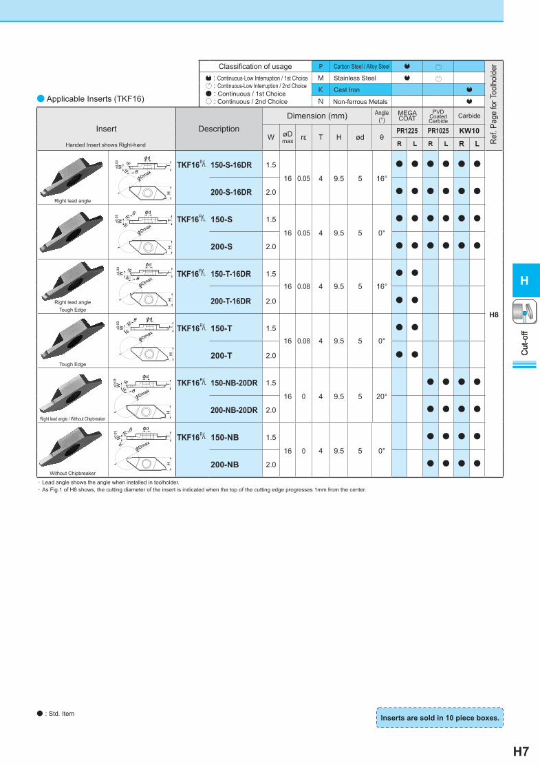
Classification of usage P Carbon Steel / Alloy Steel Q
: Continuous-Low Interruption / 1st Choice : Continuous-Low Interruption / 2nd Choice● : Continuous / 1st Choice○ : Continuous / 2nd Choice
M Stainless Steel Q
K Cast Iron Q
N Non-ferrous Metals Q
Insert DescriptionDimension (mm) Angle
(°)Carbide
W øDmax rε T H ød θ
PR1225 PR1025 KW10R L R L R L
Right lead angle
TKF16& 150-S-16DR 1.5
16 0.05 4 9.5 5 16°
● ● ● ● ● ●
H8
200-S-16DR 2.0 ● ● ● ● ● ●
TKF16& 150-S 1.5
16 0.05 4 9.5 5 0°
● ● ● ● ● ●
200-S 2.0 ● ● ● ● ● ●
Right lead angleTough Edge
TKF16& 150-T-16DR 1.5
16 0.08 4 9.5 5 16°
● ●
200-T-16DR 2.0 ● ●
Tough Edge
TKF16& 150-T 1.5
16 0.08 4 9.5 5 0°
● ●
200-T 2.0 ● ●
Right lead angle / Without Chipbreaker
TKF16& 150-NB-20DR 1.5
16 0 4 9.5 5 20°
● ● ● ●
200-NB-20DR 2.0 ● ● ● ●
Without Chipbreaker
TKF16& 150-NB 1.5
16 0 4 9.5 5 0°
● ● ● ●
200-NB 2.0 ● ● ● ●
MEGACOAT
PVDCoated Carbide
Handed Insert shows Right-hand
● Applicable Inserts (TKF16)
Cut
-off
H
Inserts are sold in 10 piece boxes. ● : Std. Item
φ
ε
ε θ
φ
φ
ε
εφθ
φ
ε
εφθ
φ
ε
εφ
θ
φ
ε
ε θ
φ
φ
ε
εφθ
・ Lead angle shows the angle when installed in toolholder.・ As Fig.1 of H8 shows, the cutting diameter of the insert is indicated when the top of the cutting edge progresses 1mm from the center.
Ref.
Page
for T
oolh
olde
r
Cut
-off
H
H8
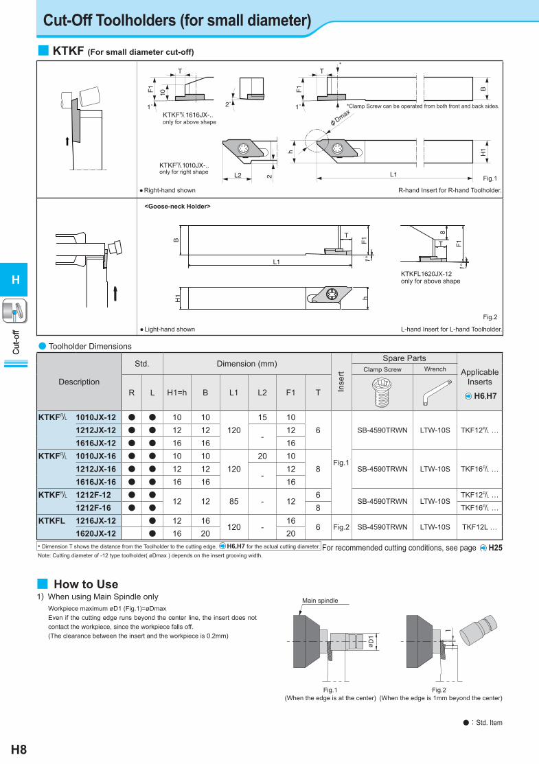
● Toolholder Dimensions
Description
Std. Dimension (mm)Spare Parts
Applicable Inserts
Clamp Screw Wrench
R L H1=h B L1 L2 F1 T
KTKF& 1010JX-12 ● ● 10 10120
15 106
Fig.1
SB-4590TRWN LTW-10S TKF12& …1212JX-12 ● ● 12 12-
121616JX-12 ● ● 16 16 16
KTKF& 1010JX-16 ● ● 10 10120
20 108 SB-4590TRWN LTW-10S TKF16& …1212JX-16 ● ● 12 12
-12
1616JX-16 ● ● 16 16 16KTKF& 1212F-12 ● ●
12 12 85 - 126
SB-4590TRWN LTW-10STKF12& …
1212F-16 ● ● 8 TKF16& …
KTKFL 1216JX-12 ● 12 16120 -
166 Fig.2 SB-4590TRWN LTW-10S TKF12L …
1620JX-12 ● 16 20 20
Cut-Off Toolholders (for small diameter)
ø D1
Fig.1(When the edge is at the center)
Main spindle
Fig.2 (When the edge is 1mm beyond the center)
1
1) When using Main Spindle only Workpiece maximum øD1 (Fig.1)=øDmax Even if the cutting edge runs beyond the center line, the insert does not
contact the workpiece, since the workpiece falls off. ( The clearance between the insert and the workpiece is 0.2mm)
Cut
-off
H
■ KTKF (For small diameter cut-off)
only for above shapeKTKF&1616JX-..
only for right shapeKTKF&1010JX-..
2˚ 1˚
L2 2
h
L1
H1
φDma
x
F1 B
1˚
F1
10
T T
*Clamp Screw can be operated from both front and back sides.
*
● Right-hand shown R-hand Insert for R-hand Toolholder.
● Light-hand shown L-hand Insert for L-hand Toolholder.
Fig.2
<Goose-neck Holder>
L1
T
BH1
H1 h
F1
T F1
8
1°
1°
Fig.1
KTKFL1620JX-12only for above shape
H6,H7
• Dimension T shows the distance from the Toolholder to the cutting edge. H6,H7 for the actual cutting diameter. Note: Cutting diameter of -12 type toolholder( øDmax ) depends on the insert grooving width.
For recommended cutting conditions, see page H25
● : Std. Item
■ How to Use
Inse
rt
Cut
-off
H
Classification of usage : Continuous-Low Interruption / 1st Choice : Continuous-Low Interruption / 2nd Choice
● : Continuous / 1st Choice○ : Continuous / 2nd Choice
NNonferrous Alloy(with interruption)Nonferrous Alloy(without interruption) ●
STitanium Alloy(with interruption)Titanium Alloy(without interruption) ●
Edge Preparation
PCD all models Sharp Edge
Insert Description
Dimension (mm) Angle(°) PCD
W øDmax
rε T H A ød S θ※ KPD0
01
R L
TKF12& 200-AS 2.0 10
0.1
3 8.7 7.7
5
5.0
0° 1
● ●
H8
250-AS 2.5 10 5.5 ● ●
TKF16& 250-AS 2.5 16 4 9.5 8.5 6.5 ● ●
TKF12& 150-NB 1.5 7
0.1 3 8.7 - 5
2.0
0° 1
● ●
200-NB 2.0 8 3.0 ● ●
250-NB 2.5 8 3.0 ● ●
250-NB4.5 2.5 10 4.5 ● ●
H9
Cut
-off
H
Main spindle Sub spindle
Fig.3(When the edge is at the center)
Fig.4(When the edge is 1mm beyond the center)
φD2
1
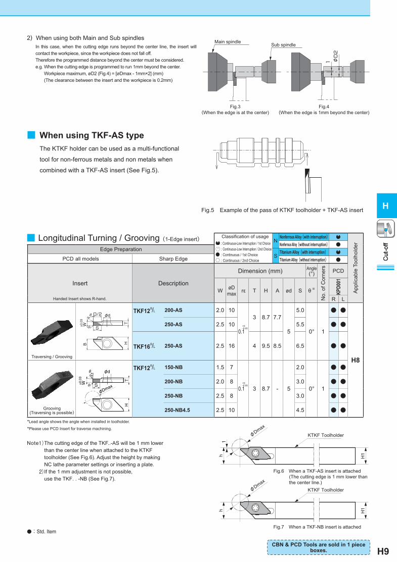
2) When using both Main and Sub spindles In this case, when the cutting edge runs beyond the center line, the insert will
contact the workpiece, since the workpiece does not fall off. Therefore the programmed distance beyond the center must be considered. e.g. When the cutting edge is programmed to run 1mm beyond the center.
Workpiece maximum, øD2 (Fig.4) = [øDmax - 1mm×2] (mm)( The clearance between the insert and the workpiece is 0.2mm)
■ When using TKF-AS type
Fig.5 Example of the pass of KTKF toolholder + TKF-AS insert
■ Longitudinal Turning / Grooving(1-Edge insert)
Handed Insert shows R-hand.
+0-0.05
*Lead angle shows the angle when installed in toolholder.
*Please use PCD Insert for traverse machining.
Grooving(Traversing is possible)
φ
ε
ε
φ
S
θ
Traversing / Grooving
h H1
φDma
x
h H1
φDma
x
1
KTKF Toolholder
KTKF Toolholder
Fig.6 When a TKF-AS insert is attached (The cutting edge is 1 mm lower than the center line.)
Fig.7 When a TKF-NB insert is attached
+0-0.05
H
θ
S±0.03
rεW
rε φd
T
B
D/2
Note1) The cutting edge of the TKF..-AS will be 1 mm lower than the center line when attached to the KTKF toolholder (See Fig.6). Adjust the height by making NC lathe parameter settings or inserting a plate.2) If the 1 mm adjustment is not possible,
use the TKF. . -NB (See Fig.7).
● : Std. Item
App
licab
le T
oolh
olde
r
No.
of C
orne
rs
The KTKF holder can be used as a multi-functional
tool for non-ferrous metals and non metals when
combined with a TKF-AS insert (See Fig.5).
CBN & PCD Tools are sold in 1 piece boxes.
Cut
-off
H
H10
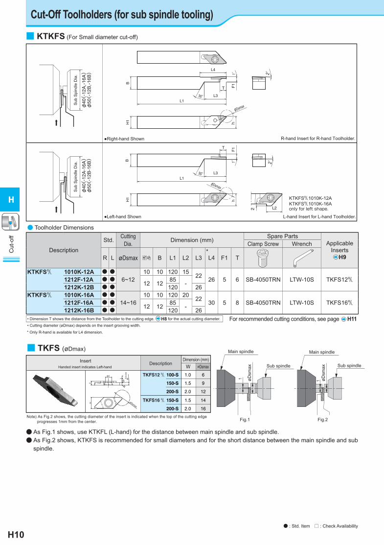
Cut-Off Toolholders (for sub spindle tooling)
1 øDsm
ax
Main spindle
Sub spindle
1
Main spindle
øDsm
ax Sub spindle
Fig.1 Fig.2
● As Fig.1 shows, use KTKFL (L-hand) for the distance between main spindle and sub spindle.● As Fig.2 shows, KTKFS is recommended for small diameters and for the short distance between the main spindle and sub
spindle.
● Toolholder Dimensions
Description
Std. Cutting Dia. Dimension (mm) Spare Parts
Applicable Inserts
H9
Clamp Screw Wrench
R L øDsmax H1=h B L1 L2 L3*L4 F1 T
KTKFS& 1010K-12A ● ●6~12
10 10 120 15 22 26 5 6 SB-4050TRN LTW-10S TKFS12&1212F-12A ● ●12 12 85 -1212K-12B ● ● 120 26
KTKFS& 1010K-16A ● ●14~16
10 10 120 20 22 30 5 8 SB-4050TRN LTW-10S TKFS16&1212F-16A ● ●12 12 85 -1212K-16B ● ● 120 26
• Dimension T shows the distance from the Toolholder to the cutting edge. H8 for the actual cutting diameter.
• Cutting diameter (øDmax) depends on the insert grooving width.
KTKFS&1010K-12AKTKFS&1010K-16Aonly for left shape.
φ40(-12A
-16A)
φ50(-12B
-16B)
Sub
Spi
ndle
Dia
.
h
φDsmax
T
2
L1L3
F1
2°1°BH1
L2
30°
φ40(-12A
,-16
A)
φ50(-12B
,-16
B)
Sub
Spi
ndle
Dia
.
h
φDsmax
L4
L1L3
T F1
2°1°
BH1
30°
●Right-hand Shown R-hand Insert for R-hand Toolholder.
●Left-hand Shown L-hand Insert for L-hand Toolholder.
■ KTKFS (For Small diameter cut-off)
Handed insert indicates Left-hand
TKFS12 100-S
150-S
200-S
1.0
1.5
2.0
6
9
12
W øDsmax
&
TKFS16 150-S
200-S
1.5
2.0
14
16
&
Insert DescriptionDimension (mm)
Note) As Fig.2 shows, the cutting diameter of the insert is indicated when the top of the cutting edge progresses 1mm from the center.
±0.03
θφd
T
W
H φDsmax
rε
rε
■ TKFS (øDmax)
For recommended cutting conditions, see page H11
* Only R-hand is available for L4 dimension.
● : Std. Item □ : Check Availability
H
Cut
-off
H
H11
Insert Description
Dimension (mm) Angle(°)
PVDCoated Carbide Ca
rbide
PCD
ApplicableToolholder
W øDsmax rε T H ød θ PR
1025
KW10
KPD0
01
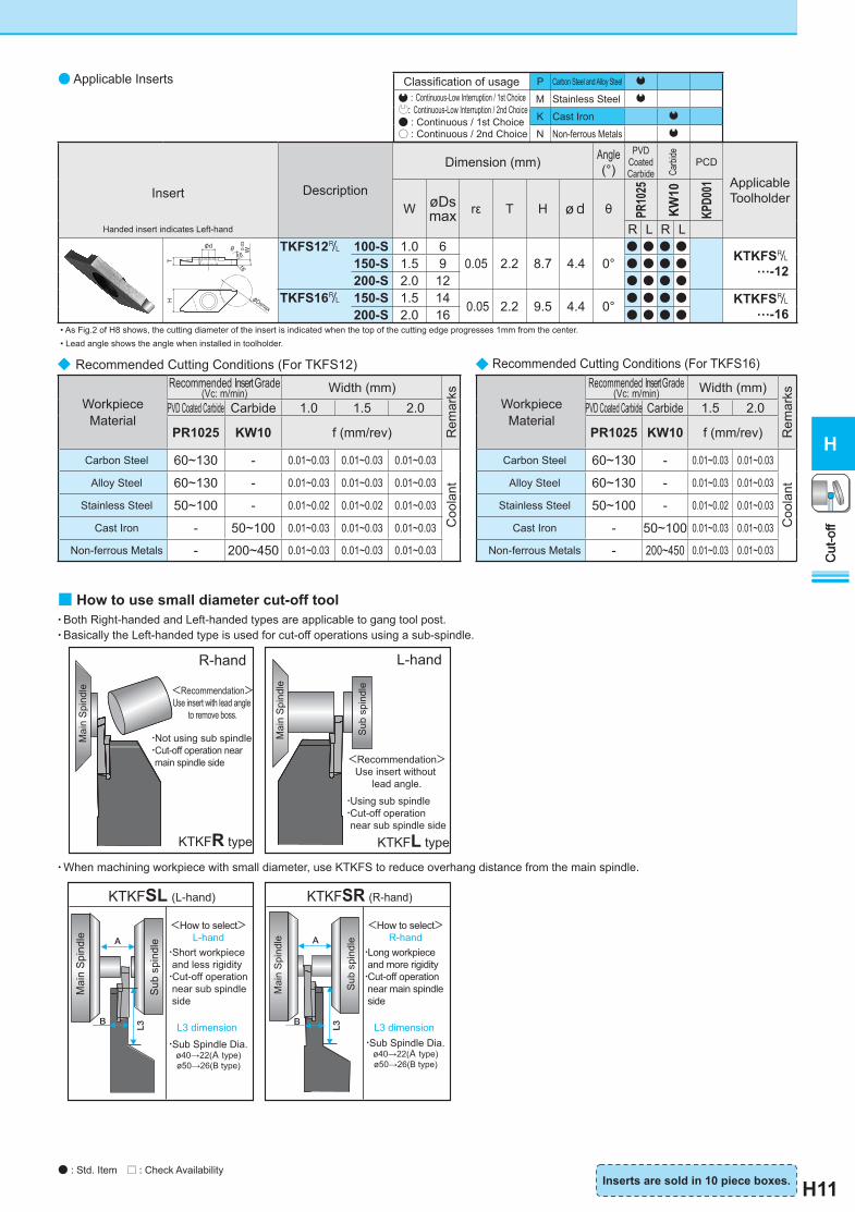
Handed insert indicates Left-hand R L R LTKFS12& 100-S 1.0 6
0.05 2.2 8.7 4.4 0°● ● ● ●
KTKFS&…-12 150-S 1.5 9 ● ● ● ●
200-S 2.0 12 ● ● ● ●TKFS16& 150-S 1.5 14 0.05 2.2 9.5 4.4 0°
● ● ● ● KTKFS&…-16 200-S 2.0 16 ● ● ● ●
• As Fig.2 of H8 shows, the cutting diameter of the insert is indicated when the top of the cutting edge progresses 1mm from the center. • Lead angle shows the angle when installed in toolholder.
◆ Recommended Cutting Conditions (For TKFS16)
Workpiece Material
Recommended Insert Grade(Vc: m/min) Width (mm)
Rem
arks
PVD Coated Carbide Carbide 1.5 2.0
PR1025 KW10 f (mm/rev)
Carbon Steel 60~130 - 0.01~0.03 0.01~0.03
Coo
lantAlloy Steel 60~130 - 0.01~0.03 0.01~0.03
Stainless Steel 50~100 - 0.01~0.02 0.01~0.03
Cast Iron - 50~100 0.01~0.03 0.01~0.03
Non-ferrous Metals - 200~450 0.01~0.03 0.01~0.03
◆ Recommended Cutting Conditions (For TKFS12)
Workpiece Material
Recommended Insert Grade (Vc: m/min) Width (mm)
Rem
arks
PVD Coated Carbide Carbide 1.0 1.5 2.0
PR1025 KW10 f (mm/rev)
Carbon Steel 60~130 - 0.01~0.03 0.01~0.03 0.01~0.03C
oola
ntAlloy Steel 60~130 - 0.01~0.03 0.01~0.03 0.01~0.03
Stainless Steel 50~100 - 0.01~0.02 0.01~0.02 0.01~0.03
Cast Iron - 50~100 0.01~0.03 0.01~0.03 0.01~0.03
Non-ferrous Metals - 200~450 0.01~0.03 0.01~0.03 0.01~0.03
Classifi cation of usage P Carbon Steel and Alloy Steel : Continuous-Low Interruption / 1st Choice : Continuous-Low Interruption / 2nd Choice ● : Continuous / 1st Choice ○ : Continuous / 2nd Choice
M Stainless Steel
K Cast Iron
N Non-ferrous Metals
● Applicable Inserts
T
W0.03
H
φd
φDsmax
rε
rε
θ
■ How to use small diameter cut-off tool• Both Right-handed and Left-handed types are applicable to gang tool post.• Basically the Left-handed type is used for cut-off operations using a sub-spindle.
• When machining workpiece with small diameter, use KTKFS to reduce overhang distance from the main spindle.
R-hand
Mai
n S
pind
le <Recommendation>Use insert with lead angle
to remove boss.
・Not using sub spindle・Cut-off operation near main spindle side
KTKFR type
KTKFSL (L-hand)
<How to select>L-hand
・Short workpiece and less rigidity・Cut-off operation near sub spindle side
L3 dimension ・Sub Spindle Dia.
ø40→22(A type)ø50→26(B type)
A
B
Mai
n S
pind
le
Sub
spi
ndle
L3
L-hand
<Recommendation>Use insert without
lead angle.
・Using sub spindle・Cut-off operation near sub spindle side
KTKFL type
Mai
n S
pind
le
Sub
spi
ndle
A
B
KTKFSR (R-hand)
<How to select>R-hand
・Long workpiece and more rigidity・Cut-off operation near main spindle side
L3 dimension ・Sub Spindle Dia.
ø40→22(A type)ø50→26(B type)
Mai
n S
pind
le
Sub
spi
ndle
L3
Inserts are sold in 10 piece boxes.
H
Cut
-off
● : Std. Item □ : Check Availability
H12
⑧Chipbreaker SymbolPM : Cut-OffPH : Groove and Cut-off
(High feed)
Classifi cation of usage P Carbon steel / Alloy steel Q P : Continuous-Low Interruption / 1st Choice : Continuous-Low Interruption / 2nd Choice● : Continuous / 1st Choice○ : Continuous / 2nd Choice
M Stainless Steel Q P
K Cast Iron Q
Shape Description
Dimension(mm) Angle(°) MEGACOAT
Wrε M L H θ
PR12
25
PR12
15
2-edge Insert
H
3°3°W
±0.
03
L
M rε
rε
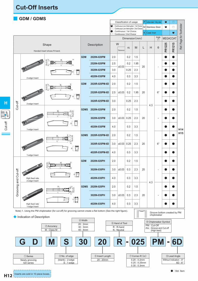
GDM 2020N-020PM 2.0
±0.03
0.2 1.5
20
4.3
-
● ●
H14H15
2520N-020PM 2.5 0.2 1.95 ● ●
3020N-025PM 3.0 0.25 2.3 ● ●
4020N-030PM 4.0 0.3 3.3 ● ●
2-edge Insert
H
L
M
rε
3°3°W
±0.
03
θ GDM 2020R-020PM-6D 2.0
±0.03
0.2 1.5
20 6°
● ●
2520R-020PM-6D 2.5 0.2 1.95 ● ●
3020R-025PM-6D 3.0 0.25 2.3 ● ●
1-edge Insert
H
rεL
M
3°3°
W±
0.03
GDMS 2020N-020PM 2.0
±0.03
0.2 1.5
20 -
● ●
3020N-025PM 3.0 0.25 2.3 ● ●
4020N-030PM 4.0 0.3 3.3 ● ●
1-edge Insert
H
L
M
rε
θ
3°3°
W±
0.03
GDMS 2020R-020PM-6D 2.0
±0.03
0.2 1.5
20 6°
● ●
3020R-025PM-6D 3.0 0.25 2.3 ● ●
4020R-030PM-6D 4.0 0.3 3.3 ● ●
High feed rate2-edge Insert
GDM 2020N-020PH 2.0
±0.03
0.2 1.5
20
4.3
-
● ●
3020N-030PH 3.0 0.3 2.3 ● ●
4020N-030PH 4.0 0.3 3.3 ● ●
High feed rate1-edge Insert
GDMS 2020N-020PH 2.0
±0.03
0.2 1.5
20 -
● ●
3020N-030PH 3.0 0.3 2.3 ● ●
4020N-030PH 4.0 0.3 3.3 ● ●
Note) 1. Using the PM chipbreaker (for cut-off) for grooving cannot create a fl at bottom (See the right fi gure).
Cut
-off
H
● : Std. ItemInserts are sold in 10 piece boxes.
Groove bottom created by PM chipbreaker
③No. of edge(blank) : 2-edge S : 1-edge
⑤ Insert Length20 : 20mm
⑦Corner-R(rε)0.20 : 0.2mm
0.25 : 0.25mm0.30 : 0.3mm
②AccuracyM : Class M
④Width20 : 2mm30 : 3mm40 : 4mm
⑥Hand of Tool R : R-hand N : Neutral
G D M 30 6DPM-①Series
Newly groovingGD series
-S 20 R 025⑨Lead Angle
Without Indication : 0° 6D : 6°
◆ Indication of Description
Cut-Off Inserts
■ GDM / GDMS
Handed Insert shows R-hand.
H
L
M rε
rεW±0
.031.5°
1.5°
M
L W±0
.03
1.5°
1.5°
H
rε
Ref.
Page
for T
oolh
olde
r
Cut
-off
Gro
ovin
g an
d C
ut-o
ff
Tolerance

H13
C45 (S45CF) 〈Result〉・The cutting edge of KGD Cut-off PM Chipbreaker (PR1225) shows good condition even after processing the same number of workpiece as Competitor L.・Longer product life can be expected.(Competitor L suffered from chipping of cutting blade).
(Evaluation by the user)
・Sleeve ・Vc=103 m/min・f=0.12 mm/rev・WET・GDM3020N-025PM
(PR1225)・KGDL2525X-3T20S
ø33
ø10
PM Chipbreaker(PR1225)
Competitor L(PVD Coated Carbide)
Cut
-off
H
Cut-Off
V
●Application Map
Cut-Off
PHHigh feed rate
Continuous
PMCut-Off for
General Use
InterruptionHigh feed rate
●Chipbreaker Selection
●Recommended Cutting Conditions
Workpiece Material
Recommended Insert Grade (Vc: m/min)
Feed Rate (mm/rev)
PM-Chipbreaker PH-Chipbreaker
MEGACOAT Width W(mm)
Width W(mm)
PR1225 PR1215 2~4 2 3~4
Carbon Steel(SxxC)
★80~200
☆100~200
0.08~0.18 0.10~0.25 0.15~0.28Alloy Steel
(SCM)★
70~180☆
80~180
Stainless Steel (SUS304)
★60~150
☆60~150 0.06~0.12 0.05~0.12 0.08~0.15
Cast Iron (FC、FCD) - ★
100~200 0.08~0.18 0.10~0.25 0.15~0.28
★:1st Recommendation ☆:2nd Recommendation
◆ Caution(Cut-Off)1.Be sure to perform wet processing. Apply enough coolant to the cutting edge.2.Keep a constant rate during processing so that optimal product life will be achieved.3.Cut off as close to the chuck as possible.4.Lower the feed rate to 1/2 to 1/3 at the near center to prevent impact caused by cutting.
250pcs/edge Chipping occurred
250 pcs/edge Can be extended
■ Case Studies (Cut-Off)
3~4
2
0.1 0.2 0.3
WidthWidth
(mm)
PH ChipbreakerPH Chipbreaker
f (mm/rev)f (mm/rev)Feed RateFeed Rate
(Carbon Steel S50C))
2~4
0.1 0.2 0.3
PM Chipbreaker (Carbon Steel S50C))
f (mm/rev)f (mm/rev)Feed RateFeed Rate
WidthWidth
(mm)
◆ Example of feed
For General Use
PM
High feed rate
PH
High
Low
Cutti
ngRe
sista
nce
LargeSmall Feed Rate
[■ in the graph indicates the center value of feed (f)]
Coo
lant
Rem
arks

H14
Cut
-off
H
■ KGD(Integral Type)
L3
H2
H3
W
L1
A
F1
T
L2
h
BH
1
● Toolholder Dimensions
Description
Std. Dimension(mm) Width W(mm)
Spare Parts
Clamp Bolt Wrench
R L H1=h H2 H3 B L1 L2 L3 F1 A T MIN MAX
2
6KGD& 1616H-2T06 ● ● 16 4.0
9.5
16 100 27.7 28.0 15.2
1.7
6
2.0 3.0
HH5X16
LW-4
2020K-2T06 ● ● 20-
20 12528.0 -
19.22525M-2T06 ● ● 25 25 150 24.2 HH5X25
10KGD& 1616H-2T10 ● ● 16 4.0 16 100 30.2 30.5 15.2
10HH5X16
2020K-2T10 ● ● 20-
20 12530.5 -
19.22525M-2T10 ● ● 25 25 150 24.2 HH5X25
17
KGD& 1616H-2T17 ● ● 16 4.0 16 100 31.2 31.5 15.2
17HH5X162012K-2T17 ● ●
20-
12 12532.5 -
11.22020K-2T17 ● ● 20 125 19.22525M-2T17 ● ● 25 25 150 24.2 HH5X25
3
6KGD& 1616H-3T06 ● ● 16 4.0 16 100 27.7 28.0 14.8
2.4
6
3.0 4.0
HH5X16
LW-4
2020K-3T06 ● ● 20-
20 12528.0 -
18.8 2525M-3T06 ● ● 25 25 150 23.8 HH5X25
10KGD& 1616H-3T10 ● ● 16 4.0 16 100 30.2 30.5 14.8
10HH5X16
2020K-3T10 ● ● 20-
20 12530.5 -
18.8 2525M-3T10 ● ● 25 25 150 23.8 HH5X25
20
KGD& 1616H-3T20 ● ● 16 4.0 16 100 34.2 34.5 14.8
20HH5X162012K-3T20 ● ●
20-
12 12534.5
-10.8
2020K-3T20 ● ● 20 125 18.8 2525M-3T20 ● ● 25 25 150 35.5 23.8 HH5X25
4
10KGD& 2020K-4T10 ● ● 20
-
20 12530.5
-
18.3
3.4
10
4.0 5.0
HH5X16
LW-42525M-4T10 ● ● 25 25 150 23.3 HH5X25
20KGD& 2020K-4T20 ● ● 20 20 125 34.5 18.3
20HH5X16
2525M-4T20 ● ● 25 25 150 35.5 23.3 HH5X25
25 KGD& 2525M-4T25 ● ● 25 25 150 40.5 23.3 25
5
10KGD& 2020K-5T10 ● ● 20
-
20 12530.5
-
17.8
4.4
10
5.0 6.0
HH5X16
LW-42525M-5T10 ● ● 25 25 150 22.8
HH5X2517KGD& 2020K-5T17 ● ● 20 20 125
37.517.8
172525M-5T17 ● ● 25 25 150 22.8
25 KGD& 2525M-5T25 ● ● 25 25 150 40.5 22.8 25
615 KGD& 2525M-6T15 ● ● 25
-25 150 32.5
-22.4
5.315
6.0 6.0 HH5X25 LW-430 KGD& 2525M-6T30 ● ● 25 25 150 45.5 22.4 30
8 25KGD& 2525M-8T25 ● ● 25 7.0 25 150
43.344.2 22.0
6.0 25 8.0 8.0 HH6X25 LW-53232P-8T25 ● ● 32 - 32 170 - 29.0
Note)1. Dimension T : Maximum depth to which processing can be made. (If the dimension T is 20 mm or more, the maximumgroove-depth made by the 2-edged insert will be 18 mm.)
2. Recommended tightening torque of clamp bolt: 6.5N•m (Groove width 2 - 6 mm), 8.0N•m (Groove width 8 mm)
Grooving / Cut-Off
● : Std. Item □ : Check Availability
・R-hand Shown
Recommended Cutting Conditions H13
Wid
th
(mm
)
Avai
labl
e G
roov
ing
D
epth
(mm
)

H15
Cut
-off
H
■ KGD-S(Straight : 0° , Separate Type)
B
T
WF1
h
L2
H3
H2
L1
H1
A
・R-hand Shown
● : Std. Item
● Toolholder Dimensions(Toolholder+Blade)
Assembly Number(Standard
Stock Number)
Std.
DescriptionG28
Blade Description
G28
Dimension(mm) Width W(mm)
R L H1=h H2 H3 B L1 L2 L3 F1 A T MIN MAX
0°
2 17KGD& 2020X-2T17S ● ● KGD&2020-C
KGD&-2T17-C20 12
11.6
20 12239.9
-
23.41.7 17 2.0 3.0
2525X-2T17S ● ● KGD&2525-C 25 7 25 147 28.4
3
10KGD& 2020X-3T10S ● ● KGD&2020-C
KGD&-3T10-C20 12 20 115
32.923.0
2.4
10
3.0 4.0
2525X-3T10S ● ● KGD&2525-C 25 7 25 140 28.0 3232X-3T10S ● ● KGD&3232-C 32 - 32 160 33.0
20KGD& 2020X-3T20S ● ● KGD&2020-C
KGD&-3T20-C20 12 20 125
42.923.0
202525X-3T20S ● ● KGD&2525-C 25 7 25 150 28.0 3232X-3T20S ● ● KGD&3232-C 32 - 32 170 33.0
4
10KGD& 2020X-4T10S ● ● KGD&2020-C
KGD&-4T10-C20 12 20 115
32.922.5
3.4
10
4.0 5.0
2525X-4T10S ● ● KGD&2525-C 25 7 25 140 27.5 3232X-4T10S ● ● KGD&3232-C 32 - 32 160 32.5
20KGD& 2020X-4T20S ● ● KGD&2020-C
KGD&-4T20-C20 12 20 125
42.922.5
202525X-4T20S ● ● KGD&2525-C 25 7 25 150 27.5 3232X-4T20S ● ● KGD&3232-C 32 - 32 170 32.5
25KGD& 2020X-4T25S ● ● KGD&2020-C
KGD&-4T25-C20 12 20 130
47.922.5
252525X-4T25S ● ● KGD&2525-C 25 7 25 155 27.5 3232X-4T25S ● ● KGD&3232-C 32 - 32 175 32.5
5
10KGD& 2020X-5T10S ● ● KGD&2020-C
KGD&-5T10-C20 12 20 115
32.922.0
4.4
10
5.0 6.0
2525X-5T10S ● ● KGD&2525-C 25 7 25 140 27.0 3232X-5T10S ● ● KGD&3232-C 32 - 32 160 32.0
25KGD& 2020X-5T25S ● ● KGD&2020-C
KGD&-5T25-C20 12 20 130
47.922.0
252525X-5T25S ● ● KGD&2525-C 25 7 25 155 27.0 3232X-5T25S ● ● KGD&3232 -C 32 - 32 175 32.0
Note) 1. In case of normal mounting position, the toolholder body may interfere with the tool presetter. 2. To olholder description and blade description are printed on the toolholder body. (Unit description is not indicated.)
KGD-S : R-hand Blade for R-hand Toolholder, L-hand Blade for L-hand Toolholder.Combination of the optional toolholder (KGD..-C) and blade (KGD..T..-C) (both separately sold) can make up the corresponding assembly part. Make sure of the “hand of toolholder” and “hand of blade”.
3. Dimension T: Maximum depth to which processing can be made. (If the dimension T is 20 mm or more, the maximum depth of groove made by the 2-edge insert will be 18 mm.)
4. Recommended tightening torque of clamp bolt for insert: 6.5N•m (Groove width 2 - 6 mm)
Recommended Cutting Conditions H13
Wid
th
(mm
)
Avai
labl
e G
roov
ing
D
epth
(mm
)
Sha
nk A
ngle
H16
Cut
-off
H
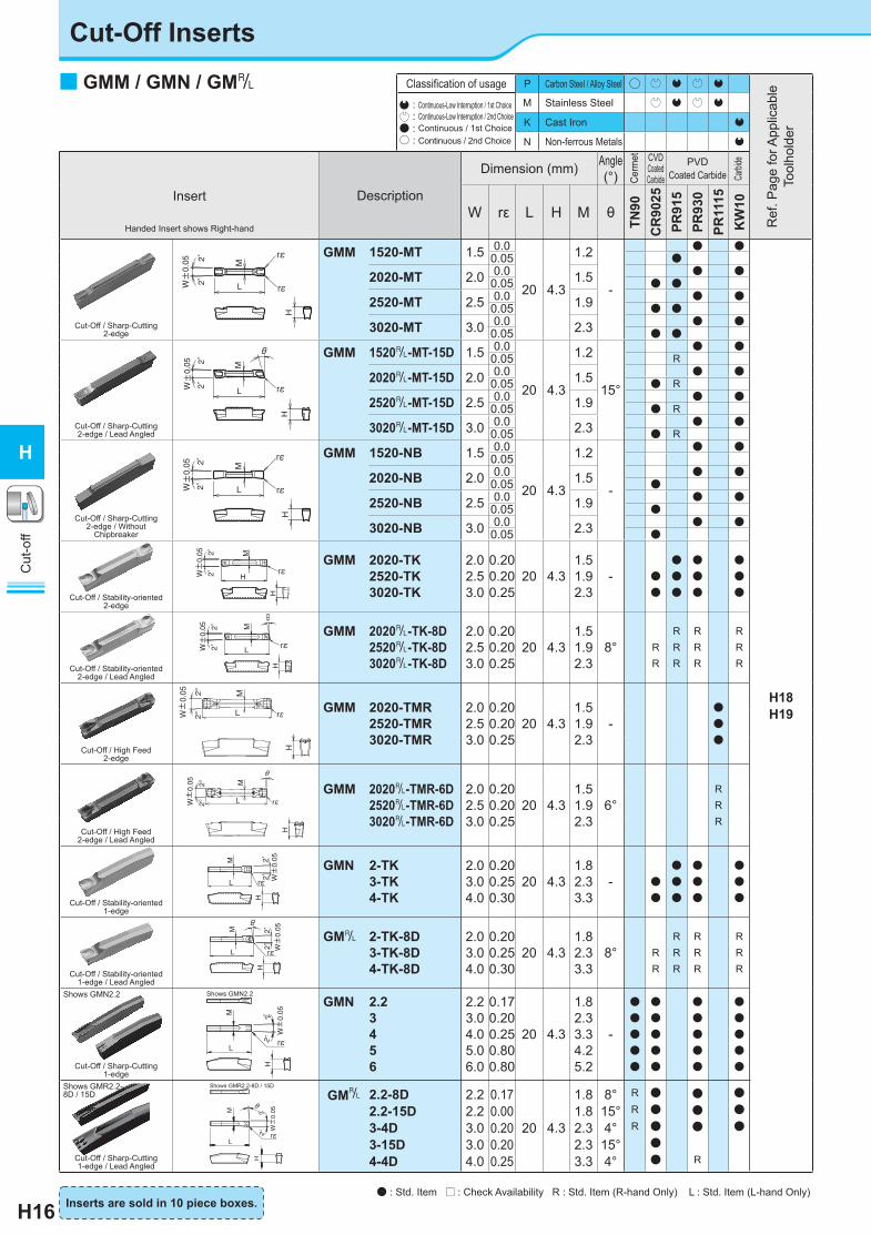
Cut-Off Inserts
Classification of usage P Carbon Steel / Alloy Steel ○ P Q P Q
: Continuous-Low Interruption / 1st Choice : Continuous-Low Interruption / 2nd Choice● : Continuous / 1st Choice○ : Continuous / 2nd Choice
M Stainless Steel P Q P Q
K Cast Iron Q
N Non-ferrous Metals Q
Insert
Handed Insert shows Right-hand
Description
Dimension (mm) Angle(°)
CVDCoated Carbide
PVDCoated Carbide
W rε L H M θ
TN90
CR
9025
PR91
5PR
930
PR11
15K
W10
Cut-Off / Sharp-Cutting2-edge
GMM 1520-MT 1.5 0.0
20 4.3
1.2
-
● ●
H18H19
0.05 ●
2020-MT 2.0 0.0 1.5 ● ●0.05 ● ●
2520-MT 2.5 0.0 1.9 ● ●0.05 ● ●
3020-MT 3.0 0.0 2.3 ● ●0.05 ● ●
Cut-Off / Sharp-Cutting2-edge / Lead Angled
GMM 1520&-MT-15D 1.5 0.0
20 4.3
1.2
15°
● ●0.05 R
2020&-MT-15D 2.0 0.0 1.5 ● ●0.05 ● R
2520&-MT-15D 2.5 0.0 1.9 ● ●0.05 ● R
3020&-MT-15D 3.0 0.0 2.3 ● ●0.05 ● R
Cut-Off / Sharp-Cutting2-edge / Without
Chipbreaker
GMM 1520-NB 1.5 0.0
20 4.3
1.2
-
● ●0.05
2020-NB 2.0 0.0 1.5 ● ●0.05 ●
2520-NB 2.5 0.0 1.9 ● ●0.05 ●
3020-NB 3.0 0.0 2.3 ● ●0.05 ●
Cut-Off / Stability-oriented2-edge
GMM 2020-TK2520-TK3020-TK
2.02.53.0
0.200.200.25
20 4.31.51.92.3
- ●●
●●●
●●●
●●●
Cut-Off / Stability-oriented2-edge / Lead Angled
GMM 2020&-TK-8D2520&-TK-8D3020&-TK-8D
2.02.53.0
0.200.200.25
20 4.31.51.92.3
8° RR
RRR
RRR
RRR
Cut-Off / High Feed2-edge
GMM 2020-TMR2520-TMR3020-TMR
2.02.53.0
0.200.200.25
20 4.31.51.92.3
-●●●
Cut-Off / High Feed2-edge / Lead Angled
GMM 2020&-TMR-6D2520&-TMR-6D3020&-TMR-6D
2.02.53.0
0.200.200.25
20 4.31.51.92.3
6°RRR
Cut-Off / Stability-oriented1-edge
GMN 2-TK3-TK4-TK
2.03.04.0
0.200.250.30
20 4.31.82.33.3
- ●●
●●●
●●●
●●●
Cut-Off / Stability-oriented1-edge / Lead Angled
GM& 2-TK-8D3-TK-8D4-TK-8D
2.03.04.0
0.200.250.30
20 4.31.82.33.3
8° RR
RRR
RRR
RRR
Cut-Off / Sharp-Cutting1-edge
GMN 2.23456
2.23.04.05.06.0
0.170.200.250.800.80
20 4.3
1.82.33.34.25.2
-
●●●●●
●●●●●
●●●●●
●●●●●
Cut-Off / Sharp-Cutting1-edge / Lead Angled
GM& 2.2-8D2.2-15D3-4D3-15D4-4D
2.22.23.03.04.0
0.170.000.200.200.25
20 4.3
1.81.82.32.33.3
8°15°4°
15°4°
RRR
●●●●●
●●●
R
●●●
Ref
. Pag
e fo
r App
licab
le
Tool
hold
er
Cerm
et
Carbi
de
L
M
W±
0.05
H
rε2゜2゜
L
H
M
W±
0.05
rε
2゜2゜
GMN¥U+25CB-TKθ
L
M
rε
H
W±
0.052゜
2゜
H
H
M
W±
0.05
2゜2゜
rε
HLW
±0.05 2゜
2゜
M
rε
rε
Shows GMN2.2
Shows GMR2.2-8D / 15D
W±
0.05 2゜
2゜
M
rεL
θ
H
LW±
0.05 2゜
2゜
M
rε
rε
H
Shows GMR2.2-8D / 15D
M
rε
W±
0.052゜
2゜
L
H
θ
M
rε
Shows GMN2.2
L
W±
0.052゜
2゜H
■ GMM / GMN / GM&
Inserts are sold in 10 piece boxes.
H
rε
M
W±
0.05 2°
2° L
±
rε
● : Std. Item □ : Check Availability R : Std. Item (R-hand Only) L : Std. Item (L-hand Only)

Series MT-Chipbreaker TK-Chipbreaker TMR-Chipbreaker Without Chipbreaker (NB)
Edge Specification
Chamfer + hone Chamfer + hone Chamfer + hone Sharp Edge Chamfer + hone Hone Sharp EdgeCorner-R0.05 Sharp Corner Corner-R0.2-0.3 Corner-R0.2-0.3 Corner-R0.2 Corner-R0.05 Sharp Corner
CR9025 / PR915 PR930 / KW10 CR9025 / PR915 PR930 / KW10 PR1115 CR9025 PR930 / KW10
H17
Cut
-off
H
Sharp Cutting Stability
Hig
hFe
edin
gLo
w
TK
MT
TMR
■ Edge Preparation
• Sharp Edge Spec. can reduce cutting resistance by 40% compared to chamfer edge.
Series Advantage
GMM-MT Specific chipbreaker for cut-off operations requiring sharp cutting performance.Minimizes the Boss.
GMM-NB Cutting edge is flat with no chipbreaker.Good performance for brass, etc.
GMM-TKStable design with chipbreaker for cut-off.Large corner-R.2-edge for economical performance.
GMN-TKSame chipbreaker geometry as GMM-TK.1-edge.Wide application range.
GMN (Std.) Mainly for deep grooving, but available for groove widening and turning due to projection near side cutting edge.1-edge and wide application range. Available for cut-off applications.
■ TMR-Chipbreaker● Chipbreaker Advantages ● GMM Chipbreaker MAP
● Recommended Cutting ConditionsWorkpiece Material Vc (m/min) f (mm/rev)
Carbon Steel 60~200
0.08~0.18Alloy Steel 60~150
Stainless Steel 50~140
Descriptionn=1060min-1(Vc=100m/min) n=2123min-1(Vc=200m/min)
f=0.12mm/rev f=0.18mm/rev f=0.12mm/rev f=0.18mm/rev
GMM3020-TMR
(Without Hand)
GMM3020R-TMR-6D
(R-hand)
(Cutting Condition: 15CrMo4 (SCM415), ø30, constant spindle revolution)
● TMR-Chipbreaker enables stable chip control also for high feed rates.
Good chip control even when cutting speed (spindle revolution) is increased.
● Workpiece Surface RoughnessTMR-Chipbreaker provides good surface roughness on the workpiece end face at high feed rate ranges.
Chip width < grooving width
Improved chip evacua-tion by squeezing chips
Special Curve Wall
Cut
ting
Spe
ed V
c (m
/min
)
f (mm/rev)
TMRChipbreaker
Application Range
2
4
6
8
Rou
ghne
ss R
z (μ
m)
f (mm/rev)
(Vc=200m/min)
2
4
6
8
Rou
ghne
ss R
z (μ
m)
f (mm/rev)
(Vc=200m/min)・ GMM2020R-TMR-6D ・ GMM2020-TMR
GMM2020R-TMR-6DCompetitor's Chipbreaker A
GMM2020R-TMRCompetitor's Chipbreaker A
Depression in center of cutting edge.
H18
Cut
-off
H
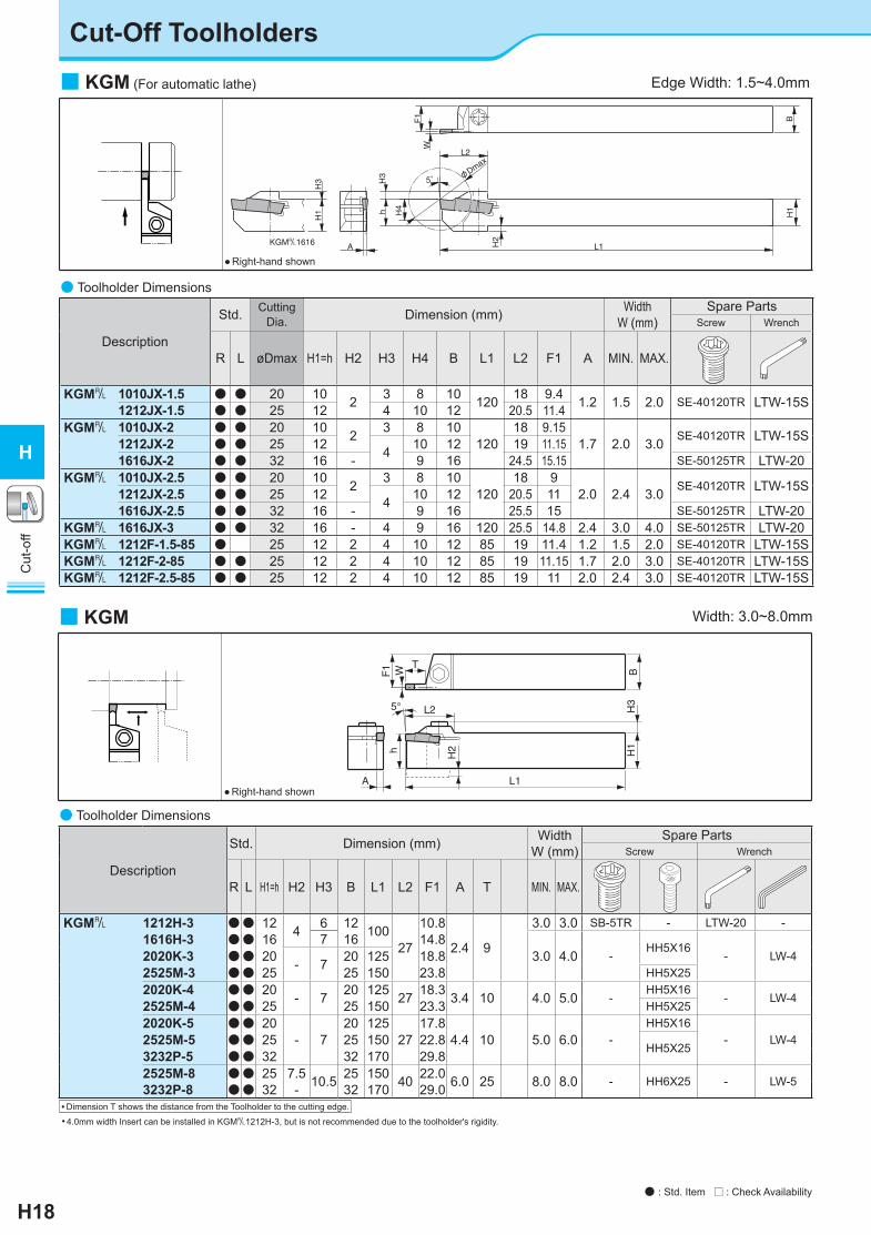
Cut-Off Toolholders
H3
H1
φDma
x
5°
F1
KGM&1616 A
hH3
L2
L1
H4
H2
H1
B
W
■ KGM (For automatic lathe)
● Right-hand shown
Edge Width: 1.5~4.0mm
• 4.0mm width Insert can be installed in KGM&1212H-3, but is not recommended due to the toolholder's rigidity.• Dimension T shows the distance from the Toolholder to the cutting edge.
Width: 3.0~8.0mm
● Right-hand shown
L2
A
h H2
5°
WF1 T
L1
H1
H3
B■ KGM
● Toolholder Dimensions
Description
Std. Dimension (mm) WidthW (mm)
Spare PartsScrew Wrench
R L H1=h H2 H3 B L1 L2 F1 A T MIN. MAX.
KGM& 1212H-3 ●● 12 4 67
12 10027
10.8
2.4 9
3.0 3.0 SB-5TR - LTW-20 -1616H-3 ●● 16 16 14.8
3.0 4.0 -HH5X16
- LW-42020K-3 ●● 20 - 7 20 125 18.82525M-3 ●● 25 25 150 23.8 HH5X252020K-4 ●● 20 - 7 20 125 27 18.3 3.4 10 4.0 5.0 -
HH5X16- LW-42525M-4 ●● 25 25 150 23.3 HH5X25
2020K-5 ●● 20- 7
20 12527
17.84.4 10 5.0 6.0 -
HH5X16- LW-42525M-5 ●● 25 25 150 22.8 HH5X253232P-5 ●● 32 32 170 29.8
2525M-8 ●● 25 7.5 10.5 25 150 40 22.0 6.0 25 8.0 8.0 - HH6X25 - LW-53232P-8 ●● 32 - 32 170 29.0
● : Std. Item □ : Check Availability
● Toolholder Dimensions
Description
Std. Cutting Dia. Dimension (mm) Width
W (mm)Spare Parts
Screw Wrench
R L øDmax H1=h H2 H3 H4 B L1 L2 F1 A MIN. MAX.
KGM& 1010JX-1.5 ● ● 20 10 2 3 8 10 120 18 9.4 1.2 1.5 2.0 SE-40120TR LTW-15S1212JX-1.5 ● ● 25 12 4 10 12 20.5 11.4KGM& 1010JX-2 ● ● 20 10 2 3 8 10
12018 9.15
1.7 2.0 3.0 SE-40120TR LTW-15S1212JX-2 ● ● 25 12 4 10 12 19 11.151616JX-2 ● ● 32 16 - 9 16 24.5 15.15 SE-50125TR LTW-20
KGM& 1010JX-2.5 ● ● 20 10 2 3 8 10120
18 92.0 2.4 3.0 SE-40120TR LTW-15S1212JX-2.5 ● ● 25 12 4 10 12 20.5 11
1616JX-2.5 ● ● 32 16 - 9 16 25.5 15 SE-50125TR LTW-20KGM& 1616JX-3 ● ● 32 16 - 4 9 16 120 25.5 14.8 2.4 3.0 4.0 SE-50125TR LTW-20KGM& 1212F-1.5-85 ● 25 12 2 4 10 12 85 19 11.4 1.2 1.5 2.0 SE-40120TR LTW-15SKGM& 1212F-2-85 ● ● 25 12 2 4 10 12 85 19 11.15 1.7 2.0 3.0 SE-40120TR LTW-15SKGM& 1212F-2.5-85 ● ● 25 12 2 4 10 12 85 19 11 2.0 2.4 3.0 SE-40120TR LTW-15S

H19
Cut
-off
H
CERACUT / Plunge & Turn
● : Std. Stock
■ KGM-T
h H2
A
W
5°
F1 T
L2
L1
H1
H3
B
● Toolholder Dimensions
Description
Std. Dimension (mm) WidthW (mm)
Spare PartsScrew Wrench
R L H1=h H2 H3 B L1 L2 F1 A T MIN. MAX.
KGM& 2012K-2T17 ●● 20- 7
12 12533
11.151.7 17 2.0 3.0
SB-5TR - LTW-20 -2020K-2T17 ●● 20 20 125 19.15 -
HH5X16- LW-42525M-2T17 ●● 25 25 150 24.15 HH5X25
1616H-3T20 ●● 16 4
7
16 100
36
14.8
2.4 20 3.0 4.0
- HH5X16 - LW-42012K-3T20 ●● 20 -
1220 125 10.8 SB-5TR - LTW-20 -
2020K-3T20 ●● 18.8-
HH5X16- LW-42525M-3T20 ●● 25 25 150 23.8 HH5X25
2020K-4T20 ●● 20- 7.5
20 125 36 18.33.4
204.0 5.0 -
HH5X16- LW-42525M-4T20 ●● 25 25 150 36 23.3 20 HH5X252525M-4T25 ●● 41 25
2525M-5T25 ●● 25 - 8.5 25 150 42 22.8 4.4 25 5.0 6.0 - HH5X25 - LW-43232P-5T25 ●● 32 32 170 29.82525M-6T30 ●● 25 - 9.5 25 150 45 22.4 5.2 30 6.0 6.0 - HH5X25 - LW-4
• Dimension T shows the distance from the Toolholder to the cutting edge. See the Table (H20) for the relationship between the Grooving Depth and the Cutting Dia..• When using GMG / GMM type (2-edge) Insert, set the grooving depth under 15mm.
Width: 2.0~6.0mm
● Right-hand shown
● : Std. Item □ : Check Availability
● : Std. Stock
Applications Grooving / Turning Grooving / Turning Grooving Full-R / Copying Full-R / Copying Cut-Off Cut-Off Cut-Off Cut-Off Cut-Off
Ref. Page G32 G32 G32 G32 G33 H16 H16 H16 H16 H16 Insert
Toolholder
MW
KGM&…1.5 - - - - -
GMM1520..MT GMM2020..MTGMM1520&..MT GMM2020&..MT
GMM1520..NBGMM2020..NB
GMM2020..T.GMM2020&..T.
GMN2..TK GM& 2..TK -
KGM&…2(T) GMM2420..MW GMM3020..MW
GMG3020..MSGMM3020..MS
GMG2520..MG GMG3020..MG
GMG3020..R GMM3020..R -
GMM2020..MTGMM2520..MTGMM3020..MTGMM2020&..MTGMM2520&..MTGMM3020&..MT
GMM2020..NBGMM2520..NBGMM3020..NB
GMM2020..T.GMM2520..T.GMM3020..T.GMM2020&..T.GMM2520&..T.GMM3020&..T.
GMN2..TKGMN3..TK GM&2..TKGM&3..TK
GMN2GMN2.2GMN3GM&2.2GM&3
KGM&…2.5 GMM2420..MW GMM3020..MW
GMG3020..MSGMM3020..MS
GMG2520..MG GMG3020..MG
GMG3020..R GMM3020..R -
GMM2520..MTGMM3020..MTGMM2520&..MTGMM3020&..MT
GMM2520..NBGMM3020..NB
GMM2520..T.GMM3020..T.GMM2520&..T.GMM3020&..T.
GMN3..TK GM&3..TK
GMN3GM&3
KGM&…3(T) GMM3020..MW GMM4020..MW
GMG3020..MSGMM3020..MS GMG4020..MSGMM4020..MS
GMG3020..MG GMG3520..MG GMG4020..MG
GMG3020..R GMM3020..R GMG4020..R GMM4020..R
- GMM3020..MTGMM3020&..MT GMM3020..NB GMM3020..T.
GMM3020&..T.
GMN3..TKGMN4..TK GM&3..TKGM&4..TK
GMN3GMN4GM&3GM&4
KGM&…4(T) GMM4020..MW GMM5020..MW
GMG4020..MSGMM4020..MS GMG5020..MSGMM5020..MS
GMG4020..MG GMG5020..MG
GMG4020..R GMM4020..R GMG5020..R GMM5020..R
- - - - GMN4..TKGM&4..TK
GMN4GMN5GM&4
KGM&…5T GMM5020..MW GMM6020..MW
GMG5020..MSGMM5020..MS GMG6020..MSGMM6020..MS
GMG5020..MG GMG6020..MG
GMG5020..R GMM5020..R GMG6020..R GMM6020..R
GMGA6020..R - - - - GMN5GMN6
KGM&…6T GMM6020..MW GMG6020..MSGMM6020..MS GMG6020..MG GMG6020..R
GMM6020..R GMGA6020..R - - - - GMN6
KGM&…8 GMM8030..MW - GMG8030..MG - GMGA8030..R - - - - -
● Applicable Inserts
For recommended cutting conditions, see page H25
MGMS MT TK TKNB
TMR

H20
Cut
-off
H
Cut-Off Toolholders
● : Std. Stock
Machining Example: KGMR2525M-3T20+GMN3
If the workpiece diameter is large, the possible groovingdepth becomes smaller due to interference with toolholder.
ø130
ø40 (ø
D: Cut-
Off Dia.
)
25
18
20 (Dimension t)
■ Possible cut-off diameter for KGM / KGM-T typeThere is a limit to the possible grooving depth depending on the workpiece diameter.
Toolholder øD (Cut-Off Dia.)KGM& 0810K-1.5-125 - - - - - - - - - - - - 10 14 16 32
∞
1010○ -1.5··· - - - - - - - 20 25 32 40 60∞ ∞ ∞ ∞1212○ -1.5··· - - - - 25 26 28 32 36 40 60 100
0810K-2-125 - - - - - - - - - - - - 10 14 16 321010○ -2··· - - - - - - - 20 25 32 40 60
∞ ∞ ∞ ∞
1212○ -2··· - - - - 25 26 28 50∞ ∞ ∞ ∞1616○ -2··· 32 40 50 60 80 100 ∞ ∞
1010○ -2.5··· - - - - - - - 20 25 32 40 601212○ -2.5··· - - - - 25 26 28 32 36 40 60 1001616○ -2.5··· 32 40 50 60 80 100
∞ ∞ ∞ ∞ ∞ ∞1616○ -3··· 32 40 50 60 80 100Grooving Depth t (mm) 16 15 14 13 12.5 12 11 10 9 8 7 6 5 4 3 2 1
Toolholder øD (Cutting Dia.)KGM& 2012K-2T17 -
--
---
---
---
---
---
---
---
66 80 130 260
∞
2020K-2T17 66 80 130 2602525M-2T17 66 80 130 2601616H-3T20 - - - - - 40 54 70 100 180
∞ ∞
2012K-3T20 -----
-----
-----
-----
-----
40 90 130 240
∞
2020K-3T20 40 90 130 2402525M-3T20 40 90 130 2402020K-4T20 40 90 130 2402525M-4T20 40 90 130 2402525M-4T25 -
--
---
50 140 240
∞ ∞ ∞ ∞2525M-5T25 50 140 2403232P-5T25 50 280 6002525M-6T30 100 300 ∞ ∞ ∞
Grooving Depth t (mm) 30 27 25 23 22 20 19 18 17 16 15 14 under 13
◆ KGM-T Possible Cutting Dia. Table (GMN, GM& type When using 1-edge inserts)
◆ KGM (For Automatic Lathe) Possible Cutting Dia. Table

H21
Cut
-off
H
Cut-Off Inserts
rε
θ
W±0.05
rε
rε W±0.05
rε
rε W±0.05
rεθ
W±0.05
Low Feed
Lead Angle
Low Feed / Lead-Angled
Cutting Range Chipbreaker Advantage
General Cut-OffStandard
(No Indication)
General cut-off type for feed rates over 0.1mm/rev.Superior chip evacuation
Low Feed Cut-Off P Chipbreaker specially designed for low feed machining on automatic lathes, etc. Chips are controlled at feed rate 0.03~0.08mm/rev.
Right-hand Shown
◆ Insert’s Edge Shape (CERACUT Cut-Off)
• Sharp Edge Spec. can reduce cutting resistance 40% less than that of chamfer edge.
Edge Shape
Std. Chipbreaker TN90CR9025 / PR660 PR930 / KW10 -
- - TN90 / CR9025PR660 / PR930 / KW10P-Chipbreaker
Chamfer + hone Sharp Edge Hone
■ TKN / TK& Classification of usage P Carbon Steel and Alloy Steel ○ ○
Ref
. Pag
e fo
r App
licab
le
Tool
hold
er
: Continuous-Low Interruption / 1st Choice : Continuous-Low Interruption / 2nd Choice● : Continuous / 1st Choice○ : Continuous / 2nd Choice
M Stainless Steel ○K Cast Iron
N Non-ferrous Metals
Insert Description
Dimension (mm)
Angle(°)
W rε θ
TN90
CR
9025
PR66
0
PR93
0
KW
10
TKN 1.622.4344.85689
1.62.22.43.14.14.85.16.48.09.6
0.150.200.200.250.300.300.300.350.400.45
-
●●●●●
●●●●●●●●●●
●●●●●
●●●●
●●●●●
●
●●●●●
●●
H22H24
TKN 1.6-P2-P3-P
1.62.23.1
0.200.200.25
- ●●
●●●
●●●
●●●
●●●
TK& 1.6 1.6 0.15
8°
● ● R ●2 2.2 0.20 R ● ● R ●2.4 2.4 0.20 ● ● R ●3 3.1 0.25 R ● ● ● ●4 4.1 0.30 R ● ● ●5 5.1 0.30 ● ● ●
TK& 1.6-P2-P3-P
1.62.23.1
0.200.200.25
8°R
RRR
●●●
RRR
RRR
◆ Cut-Off Tools
CVDCoated Carbide
PVDCoated Carbide
Carb
ide
For recommended cutting conditions, see page H25
Inserts are sold in 10 piece boxes
Handed Insert shows Right-hand
Cermet
● : Std. Item □ : Check Availability R : Std. Item (R-hand Only) L : Std. Item (L-hand Only)
H22
Cut
-off
H
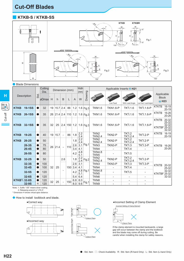
Cut-Off Blades
7゜
φD
150゜A
H h
W
L
hH
W
150゜
B
A
7゜
φD
L
W
KTKBRKTKB
15゜
15゜
150゜
hH
A
B
φD
A
hH
W
L
● Blade Dimensions
■ KTKB-S / KTKB-SS
Note) 1. Suffix “-SS” means silver coating.2. Releasing wrench is “LTK-5”.
* Dimension H shows virtual apex distance.
Fig.1
Fig.2 Fig.3
◆ How to install toolblock and blade.
Datum Plane
●Incorrect way
●Correct way
Datum Plane
●Incorrect Setting of Clamp Element
Inco
rrec
t Edg
e H
eigh
tE
dge
Hei
ght
If the clamp element is mounted backwards, a largegap will occur between the clamp and the toolblockand the blade may come off during cutting. Becareful when installing the clamp for safety reasons.
Incorrect Setting of Clamp Element
Datum Plane
Description Std
.
Cutting Dia. Dimension (mm) Width
(mm)
Dra
win
g Applicable Inserts H21
Applicable Block
H23øDmax H h B L A W
KTKB 19-1SS ● 32 19 15.7 2.4 86 1.2 1.6 Fig.3 TKN1.6 TKN1.6-P TK&1.6 TK&1.6-P KTKTB 16-19 20-19
KTKB 26-1SS ● 35 26 21.4 2.4 110 1.2 1.6 Fig.3 TKN1.6 TKN1.6-P TK&1.6 TK&1.6-P KTKTB 16-26 20-26
KTKB 32-1SS ● 35 32 25 2.4 150 1.2 1.6 Fig.3 TKN1.6 TKN1.6-P TK&1.6 TK&1.6-P
KTKTB 20-32 25-32 32-32KTKTBF 25-32 32-32
KTKB 19-2S ● 40 19 15.7 - 86 1.8 2.22.4
Fig.1
TKN2TKN2.4 TKN2-P TK&2
TK&2.4 TK&2-P KTKTB 16-19 20-19
KTKB 26-2S ● 50
26 21.4 - 110
1.8 2.22.4
TKN2TKN2.4 TKN2-P TK&2
TK&2.4 TK&2-P
KTKTB 16-26 20-26
26-3S ● 75 2.6 3.1 TKN3 TKN3-P TK&3 TK&3-P26-4S ● 80 3.4 4.1 TKN4 - TK&4 -26-5S ● 80 4.2 4.8
5.1TKN4.8TKN5 - TK&5 -
KTKB 32-2S ● 50
32 25
2.6
150
1.8 2.22.4 Fig.2 TKN2
TKN2.4 TKN2-P TK&2TK&2.4 TK&2-P
KTKTB 20-32 25-32 32-32KTKTBF 25-32 32-32
32-3S ● 100
-
2.6 3.1
Fig.1
TKN3 TKN3-P TK&3 TK&3-P32-4S ● 100 3.4 4.1 TKN4 - TK&4 -32-5S ● 120 4.2 4.8
5.1TKN4.8TKN5 - TK&5 -
32-6S ● 120 5.4 6.4 TKN6 - - -KTKB&32-8S ● 120 32 25 - 150 6.8 8.0
Fig.1TKN8 - - -
32-9S R 120 8.0 9.6 TKN9 - - -
Low Feed / Lead-AngledWith Lead AngleLow Feed
*
A
H
● : Std. Item □ : Check Availability R : Std. Item (R-hand Only) L : Std. Item (L-hand Only)

H23
Cut
-off
H
Toolblocks (for Holding Blade) CERACUT Cut-Off
● Toolblock Dimensions
■ KTKTB (Separate type)
■ KTKTBF (Separate / Perpendicular type)H2
H1
H3 H4
B1B2
Location of edge
L1
L2
L1
B2
H2
H1
H4
H3
B1
Location of edge
◆ How to mount the Toolblock
Tighten clamp set3
Mount the toolblock body to toolpost1
Install the blade in the toolblock2
When mounting the toolblock on a small lathe, the space to tighten the clampbolt may be narrow due to the H4 dimension.
H4
H4
Description Std
.
Dimension (mm) Spare Parts Applicable BladeClamp Set Screw Wrench Cut-off Face Grooving
H1 H2 H3 H4 B1 B2 L1 L2Separate Type Integral Type
KTKTB 16-19 ● 16 4 12 2 15.5 29.5 76 - - BCS-1 HH5X25 LW-4 KTKB19-○ SKTKB19-1SS -
20-19 ● 20 19 3416-26 ● 16 13 14 2.5 15.5 31.5 86 - BCS-2 - HH6X30 LW-5 KTKB26-○ S
KTKB26-1SS -20-26 ● 20 9 19 3620-32 ● 20 13
17 3.519 38 100
-BCS-3
- HH6X30 LW-5KTKB32-○ SKTKB32-1SSKTKB&32-○ S
KFTB&○○○○ -4SKFTB&○○○○ -5S25-32 ● 25 8 23 42 110 BCS-432-32 ● 32 5 29 48
KTKTBF 25-32 ● 25 9.5 17 3.5 25 48 102 84.5 - BCS-5 HH6X30 LW-5KTKB32-○ SKTKB32-1SSKTKB&32-○ S
KFTB&○○○○ -4SKFTB&○○○○ -5S32-32 ● 32 2.5 32 117 99.5
H22 G87
● : Std. Item □ : Check Availability R : Std. Item (R-hand Only) L : Std. Item (L-hand Only)

③① ② ④
(In order to prevent both corners' unequal wear)② ① ③ ⑤ ④ ⑥
ap
◆ Application Example of CERACUT Cut-Off 1. Cut-Off after Chamfering
①Grooving ②③ Chamfering ④ Cut-Off
2. Wide Grooving① ~⑤ Groove Widening⑥ Longitudinal Finishing (Value of “ap” shall be under the value of Corner-R)
● Applicable InsertsRef. Page H21
Insert
Toolholder
KTKH& ...-2... TKN2TKN2.4 TKN2-P TK&2
TK&2.4 TK&2-P
KTKH& ...-3... TKN3 TKN3-P TK&3 TK&3-P
KTKH& ...-4... TKN4 - TK&4 -
KTKH& ...-5... TKN4.8TKN5 - TK&5 -
Low Feed / Lead-AngledLead AngleLow Feed
For General Cut-Off (Self Clamp)
■ KTKH-S
BH1 h
H3 W
L2
L1
W
φD
Fig.2
BH1 h
H3
H2 L2
L1
W W
φD
Fig.1
● Right-hand shown
Description
Std. Cut-Off Dia. Dimension (mm) Width
(mm)Drawing
Spare PartsRef.Page for
Recommended Cutting
Conditions
Releasing Wrench
R L øDmax H1=h H2 H3 B L1 L2 W
KTKH& 1010F-2S1212H-2S1612H-2S1616H-2S2012K-2S2020K-2S
●●●●●●
●●●●●●
303333333838
101216162020
54----
453344
101212161220
80100100100125125
18.619.819.819.822.822.8
2.22.4 Fig.1
LTK-5 H251612H-3S1616H-3S2012K-3S2020K-3S2525M-3S
●●●
●●●
3636415253
1616202025
44---
44555
1216122025
100100125125150
21.721.725.331.031.5
3.1Fig.1
●●●● Fig.2
2012K-4S2020K-4S2525M-4S
● ● 446268
202025
---
555
122025
125125150
26.335.038.0
4.1Fig.1
●●●● Fig.2
2525M-5S ● ● 79 25 - 5 25 150 43.5 4.8, 5.1 Fig.2 KTKH& 2020K-3T17S
2525M-3T22S●●●●
3545
2025
--
55
2025
125150
21.826.8 3.1
Fig.1 LTK-5 H252020K-4T22S2525M-4T22S
●●●●
4545
2025
--
55
2025
125150
26.826.8 4.1
● Toolholder Dimensions
H24
Cut
-off
H
Cut-Off Toolholders (Integral Shank)
● : Std. Item □ : Check Availability
H25
Cut
-off
H
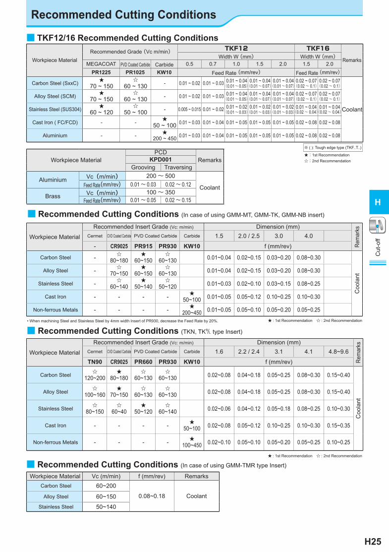
Workpiece MaterialRecommended Grade (Vc m/min) TKF12 TKF16
RemarksWidth W (mm) Width W (mm)MEGACOAT PVD Coated Carbide Carbide 0.5 0.7 1.0 1.5 2.0 1.5 2.0
PR1225 PR1025 KW10 Feed Rate (mm/rev) Feed Rate (mm/rev)
Carbon Steel (SxxC) ★70 ~ 150
☆60 ~ 130 - 0.01 ~ 0.02 0.01 ~ 0.03 0.01 ~ 0.04
(0.01~0.05)0.01 ~ 0.04(0.01~0.07)
0.01 ~ 0.04(0.01~0.07)
0.02 ~ 0.07(0.02~ 0.1)
0.02 ~ 0.07(0.02~ 0.1)
Alloy Steel (SCM) ★70 ~ 150
☆60 ~ 130 - 0.01 ~ 0.02 0.01 ~ 0.03 0.01 ~ 0.04
(0.01~0.05)0.01 ~ 0.04(0.01~0.07)
0.01 ~ 0.04(0.01~0.07)
0.02 ~ 0.07(0.02~ 0.1)
0.02 ~ 0.07(0.02~ 0.1)
Stainless Steel (SUS304) ★60 ~ 120
☆50 ~ 100 - 0.005 ~ 0.015 0.01 ~ 0.02 0.01 ~ 0.02
(0.01~0.03)0.01 ~ 0.02(0.01~0.03)
0.01 ~ 0.02(0.01~0.03)
0.01 ~ 0.04(0.02~ 0.04)
0.01 ~ 0.04(0.02~ 0.04)
Cast Iron ( FC/FCD) - - ★50 ~ 100 0.01 ~ 0.03 0.01 ~ 0.04 0.01 ~ 0.05 0.01 ~ 0.05 0.01 ~ 0.05 0.02 ~ 0.08 0.02 ~ 0.08
Aluminium - - ★200 ~ 450 0.01 ~ 0.03 0.01 ~ 0.04 0.01 ~ 0.05 0.01 ~ 0.05 0.01 ~ 0.05 0.02 ~ 0.08 0.02 ~ 0.08
■ TKF12/16 Recommended Cutting Conditions
★:1st Recommendation☆:2nd Recommendation
※ ( ): Tough edge type (TKF..T..)
Coolant
Workpiece MaterialPCD
RemarksKPD001Grooving Traversing
Aluminium Vc(m/min) 200~ 500
Coolant Feed Rate(mm/rev) 0.01 ~ 0.03 0.02 ~ 0.12
Brass Vc(m/min) 100~ 350Feed Rate(mm/rev) 0.01 ~ 0.05 0.02 ~ 0.15
■ Recommended Cutting Conditions (In case of using GMM-MT, GMM-TK, GMM-NB insert)
Workpiece Material
Recommended Insert Grade (Vc: m/min) Dimension (mm)
Rem
arks
Cermet CVD Coated Carbide PVD Coated Carbide Carbide 1.5 2.0 / 2.5 3.0 4.0
- CR9025 PR915 PR930 KW10 f (mm/rev)
Carbon Steel - ☆80~180
★60~150
☆60~130 0.01~0.04 0.02~0.15 0.03~0.20 0.08~0.30
Coo
lant
Alloy Steel - ☆70~150
★60~150
☆60~130 0.01~0.04 0.02~0.15 0.03~0.20 0.08~0.30
Stainless Steel - ☆60~140
★50~140
☆50~120 0.01~0.03 0.02~0.10 0.03~0.15 0.08~0.25
Cast Iron - - - - ★50~100 0.01~0.05 0.05~0.12 0.10~0.25 0.10~0.30
Non-ferrous Metals - - - - ★200~450 0.01~0.05 0.05~0.10 0.05~0.20 0.05~0.25
Workpiece Material Vc (m/min) f (mm/rev) RemarksCarbon Steel 60~200
0.08~0.18 CoolantAlloy Steel 60~150
Stainless Steel 50~140
■ Recommended Cutting Conditions (In case of using GMM-TMR type Insert)
■ Recommended Cutting Conditions (TKN, TK& type Insert)
Workpiece Material
Recommended Insert Grade (Vc: m/min) Dimension (mm)
Rem
arks
Cermet CVD Coated Carbide PVD Coated Carbide Carbide 1.6 2.2 / 2.4 3.1 4.1 4.8~9.6
TN90 CR9025 PR660 PR930 KW10 f (mm/rev)
Carbon Steel ☆120~200
★80~180
☆60~130
☆60~130 0.02~0.08 0.04~0.18 0.05~0.25 0.08~0.30 0.15~0.40
Coo
lant
Alloy Steel ☆100~160
★70~150
☆60~130
☆60~130 0.02~0.08 0.04~0.18 0.05~0.25 0.08~0.30 0.15~0.40
Stainless Steel ☆80~150
☆60~40
★50~120
☆60~140 0.02~0.06 0.04~0.12 0.05~0.18 0.08~0.25 0.10~0.30
Cast Iron - - - - ★50~100 0.02~0.08 0.05~0.12 0.10~0.25 0.10~0.30 0.15~0.35
Non-ferrous Metals - - - - ★100~450 0.02~0.10 0.05~0.10 0.05~0.20 0.05~0.25 0.10~0.25
★ : 1st Recommendation ☆ : 2nd Recommendation
• When machining Steel and Stainless Steel by 4mm width Insert of PR930, decrease the Feed Rate by 20%. ★ : 1st Recommendation ☆ : 2nd Recommendation
Recommended Cutting Conditions

H26
Cut
-off
H
Alternative Toolholder Reference Table for Cut-off Toolholder
Conventional Toolholder Alternative Toolholder
Description
Spare Parts
Description Remarks
Clamp Screw Wrench
KTKF& 1010K-12 125
SB-4590TRWN LTW-10S
KTKF& 1010JX-12 120
H8
KTKF& 1212M-12 150 KTKF& 1212JX-12 120KTKF& 1616M-12 150 KTKF& 1616JX-12 120KTKF& 1010K-16 125 KTKF& 1010JX-16 120KTKF& 1212M-16 150 KTKF& 1212JX-16 120KTKF& 1616M-16 150 KTKF& 1616JX-16 120KGM& 0810K-1.5-125 125
SE-40120TR LTW-15S- - No replacement
H18
KGM& 1010K-1.5-125 125 KGM& 1010JX-1.5 120KGM& 1212M-1.5-150 150 KGM& 1212JX-1.5 120KGM& 0810K-2-125 125
SE-40120TR LTW-15S- - No replacement
KGM& 1010K-2-125 125 KGM& 1010JX-2 120KGM& 1212M-2-150 150 KGM& 1212JX-2 120KGM& 1616M-2-150 150 SE-50125TR LTW-20 KGM& 1616JX-2 120KGM& 1010K-2.5-125 125
SE-40120TR LTW-15SKGM& 1010JX-2.5 120
KGM& 1212M-2.5-150 150 KGM& 1212JX-2.5 120KGM& 1616M-2.5-150 150 SE-50125TR LTW-20 KGM& 1616JX-2.5 120KGM& 1616M-3-150 150 SE-50125TR LTW-20 KGM& 1616JX-3 120
Ref
. Pag
e
■ Alternative Toolholder Reference Table for Cut-off Toolholder (KTKF / KGM)
Note) The corresponding alternative toolholder may be different from the conventional toolholder in insert clamping system or insert size. Make sure of their specifications by referring to the catalog or other documents.
Conventional Toolholder Alternative Toolholder
Description
Spare Parts
Description Remarks
Supplied wrench Clamp Bolt Wrench
KTKH& 0808K-1.6-125B φ10
- SE-40120TR FT-15
- - No replacement
H18
KTKH& 1010K-1.6-125B φ20 KGM& 1010JX-1.5 φ20KTKH& 1212M-1.6-150B φ25 KGM& 1212JX-1.5 φ25KTKH& 1414M-1.6-150B φ26 - - No replacementKTKH& 1010K-2-125B φ20
- SE-40120TR FT-15KGM& 1010JX-2 φ20
KTKH& 1212M-2-150B φ25 KGM& 1212JX-2 φ25KTKH& 1616M-2-150B φ32
- SE-50125TR LTW-20KGM& 1616JX-2 φ32
KTKH& 1616M-3-150B φ32 KGM& 1616JX-3 φ32KTKHR 1010K-2-125S φ30
LTK-5 - -
KGMR 1010JX-2 φ20 Processing diameter is small.KTKH& 1212M-2-150S φ30 KGM& 1212JX-2 φ25 Processing diameter is small.KTKH& 1616M-2-150S φ36 KGM& 1616JX-2 φ32 Processing diameter is small.KTKH& 1616M-3-150S φ45 KGM& 1616JX-3 φ32 Processing diameter is small.
■ Alternative Toolholder Reference Table for Cut-off Toolholder (KTKH-B / KTKH-S)
Note) The corresponding alternative toolholder may be different from the conventional toolholder in processing diameter or insert size. Make sure of their specifications by referring to the catalog or other documents.
FT
LTW
Ref
. Pag
e
Cut
-Off
Dia
met
er
Cut
-Off
Dia
met
erO
vera
ll le
ngth
(m
m)
Ove
rall
leng
th(m
m)