Embed Size (px)
Citation preview
IndustrialIT800xA - Control and I/O
System Version 4.1
AC 800M Controller HardwareHardware and Operation

IndustrialIT800xA - Control and I/O
System Version 4.1
AC 800M Controller HardwareHardware and Operation

NOTICEThe information in this document is subject to change without notice and should not beconstrued as a commitment by ABB. ABB assumes no responsibility for any errors thatmay appear in this document.
In no event shall ABB be liable for direct, indirect, special, incidental or consequentialdamages of any nature or kind arising from the use of this document, nor shall ABB beliable for incidental or consequential damages arising from use of any software or hard-ware described in this document.
This document and parts thereof must not be reproduced or copied without written per-mission from ABB, and the contents thereof must not be imparted to a third party nor usedfor any unauthorized purpose.
The software or hardware described in this document is furnished under a license andmay be used, copied, or disclosed only in accordance with the terms of such license.
This product meets the requirements specified in EMC Directive 89/336/EEC and in LowVoltage Directive 72/23/EEC.
Copyright © 1999 - 2004 by ABB. All rights reserved. Release: May 2005Document number: 3BSE036351R4101
TRADEMARKSRegistrations and trademarks used in this document include:
Windows Registered trademark of Microsoft Corporation.
Industrial IT Trademark of ABB.
INSUM Trademark of ABB.
FOUNDATION Fieldbus Trademark of Fieldbus Foundation.
PROFIBUS Registered trademark of PROFIBUS International.
ModBus Registered trademark of Modicon Inc.
Simatic Registered trademark of Siemens AG.
Genius Trademark of GE Fanuc Automation North America Inc.

Table of Contents
Table of Contents
About This BookGeneral ............................................................................................................................. 11
How to Use This Book................................................................................................ 11
Use of Warning, Caution, Information, and Tip Icons ..................................................... 13
Document Conventions .................................................................................................... 14
Terminology...................................................................................................................... 14
Applicable Specifications ................................................................................................. 17
EUROPEAN UNION DIRECTIVE COMPLIANCE ................................................ 17
UL LISTING............................................................................................................... 17
TÜV Approval ............................................................................................................ 17
Safety SummaryGeneral ............................................................................................................................. 19
Warnings and Information Symbols in the Text Margin .................................................. 19
Personnel and Process Safety ........................................................................................... 20
Machine Safety ................................................................................................................. 22
Before replacing Units ................................................................................................ 22
Maintenance................................................................................................................ 22
Operating Environment............................................................................................... 23
Section 1 – IntroductionProduct Overview ............................................................................................................. 25
AC 800M – General .................................................................................................... 25
PM8xx/TP830 Processor Unit – General.................................................................... 29
PM861/PM864/PM865/TP830 Processor Unit – Redundancy................................... 36
AC 800M High Integrity............................................................................................. 38
Control Software......................................................................................................... 39
Ethernet Address......................................................................................................... 40
3BSE036351R4101 53BSE036351R4101 5
Table of Contents
AC 800M Controller – Key Features ................................................................................ 41
Product Release History .................................................................................................... 42
Section 2 – InstallationSite Planning ..................................................................................................................... 43
Site Selection and Building Requirements .................................................................. 43
Cables .......................................................................................................................... 45
Power Supply............................................................................................................... 46
Enclosures.................................................................................................................... 48
Mounting AC 800M Units onto DIN-Rail ........................................................................ 49
Installing the PM8xx/TP830 Processor Unit in Single Configuration.............................. 57
Installing the PM861/PM864/PM865/TP830 Processor Unit in Redundant Configuration 66
Installing the CEX-Bus without BC810............................................................................ 70
Installing the CEX-Bus Interconnection Unit BC810/TP857........................................... 70
Installing SM810/TP855 ................................................................................................... 75
Installing the PROFIBUS DP-V0 Interface, CI851/TP851............................................... 78
Installing the FOUNDATION Fieldbus H1 Interface, CI852/TP852................................ 80
Installing the RS-232C Interface, CI853/TP853 ............................................................... 82
Installing the PROFIBUS DP-V1 Interface, CI854/CI854A/TP854................................. 84
Installing the Ethernet Interface for MasterBus 300, CI855/TP853 ................................. 87
Installing the S100 I/O Interface, CI856/TP856 ............................................................... 88
Installing the INSUM Interface, CI857/TP853 ................................................................. 89
Installing the DriveBus Interface, CI858/TP858............................................................... 90
Installing the FOUNDATION Fieldbus High Speed Ethernet Interface, CI860/TP860 ... 91
Installing the TRIO Fieldbus Interface CI862................................................................... 92
Unit to Baseplate Alpha Code Lock ............................................................................ 92
Bus Termination .......................................................................................................... 92
Installing the ModuleBus .................................................................................................. 94
Installing the SD82x Power Supply .................................................................................. 95
Installing the Mains Breaker Unit ..................................................................................... 96
Installing the SS822/SS823 Voting Unit ........................................................................... 98
Power Supply Supervision........................................................................................... 101
6 3BSE036351R4101
Table of Contents
Installing the SB821 External Battery Unit...................................................................... 103
Installation of I/O Units.................................................................................................... 104
Installation in Cabinets ..................................................................................................... 104
Mounting Dimensions for Proper Ventilation .................................................................. 108
Section 3 – ConfigurationGeneral Information ......................................................................................................... 109
Connecting Control Builder ............................................................................................. 110
Connection to a Control Network..................................................................................... 111
Communication Possibilities ............................................................................................ 112
Controller IP Addresses .............................................................................................. 114
I/O Systems ...................................................................................................................... 115
Drive System .................................................................................................................... 124
Power Supply System....................................................................................................... 128
Powering Units in the Cabinet .................................................................................... 129
Powering Field Equipment outside the Cabinet.......................................................... 129
Powering from an External Source ............................................................................. 131
Section 4 – OperationAC 800M Controller (PM8xx) ......................................................................................... 135
Start-up ............................................................................................................................. 138
Start-up in Redundant Configuration (CEX Bus Considerations) .............................. 138
Start Modes....................................................................................................................... 139
Automatic Switch-Over to Backup CPU.......................................................................... 140
Verification of Satisfactory AC 800M Operation ............................................................. 141
Verification of Single CPU ......................................................................................... 141
Verification of Redundant CPU .................................................................................. 144
Section 5 – MaintenancePreventive Maintenance Frequency Schedule .................................................................. 145
Changing the Battery ........................................................................................................ 146
Internal Battery ........................................................................................................... 146
SB821 External Battery Unit ...................................................................................... 149
3BSE036351R4101 73BSE036351R4101 7
Table of Contents
Unit Change Online........................................................................................................... 152
Exchange of CPU in Redundant Configuration without BC810....................................... 153
Exchange of CPU in Redundant Configuration with BC810............................................ 154
Corrective Maintenance Procedures.................................................................................. 156
Fault-Finding Procedures .................................................................................................. 157
PM8xx Processor Unit in Single CPU Configuration ................................................. 157
PM861/PM864/PM865 Processor Unit in Redundant Configuration ......................... 158
CEX-Bus Interconnection Unit - BC810..................................................................... 159
SM810 ......................................................................................................................... 160
Internal Battery / SB821 External Battery................................................................... 161
PROFIBUS DP-V0 – CI851........................................................................................ 162
FOUNDATION Fieldbus H1 – CI852 ......................................................................... 163
On-board RS-232C Channels – CI853 ........................................................................ 166
PROFIBUS DP-V1 – CI854/CI854A.......................................................................... 167
MasterBus 300 Interface – CI855................................................................................ 169
S100 I/O Interface – CI856 ......................................................................................... 170
INSUM Interface – CI857 ........................................................................................... 171
DriveBus Interface - CI858 ......................................................................................... 172
FOUNDATION Fieldbus High Speed Ethernet - CI860 ............................................ 174
TRIO Interface - CI862 ............................................................................................... 176
Appendix A – Hardware UnitsPM851/PM856/PM860 and TP830 – Processor Unit ....................................................... 177
Technical Data ............................................................................................................. 178
Performance Data ........................................................................................................ 182
PM861/PM861A and TP830 – Processor Unit ................................................................. 183
Technical Data ............................................................................................................. 184
Performance Data ........................................................................................................ 186
PM864/PM864A and TP830 – Processor Unit ................................................................. 187
Technical Data ............................................................................................................. 188
Performance Data ........................................................................................................ 190
PM865 and TP830 – Processor Unit ................................................................................. 191
Technical Data ............................................................................................................. 192
8 3BSE036351R4101
Table of Contents
Performance Data ....................................................................................................... 194
BC810 and TP857 - CEX-Bus Interconnection Unit ....................................................... 195
SM810 and TP855 ............................................................................................................ 198
CI851 and TP851 – PROFIBUS DP-V0 Interface ........................................................... 203
CI852 and TP852 – FOUNDATION Fieldbus H1 Interface ............................................ 207
CI853 and TP853 – RS-232C Interface............................................................................ 211
CI854/CI854A and TP854 – PROFIBUS DP-V1 Interface ............................................. 215
CI855 and TP853 – Ethernet Interface for MasterBus 300 .............................................. 220
CI856 and TP856 – S100 I/O Interface ............................................................................ 224
CI857 and TP853 – INSUM Interface.............................................................................. 228
CI858 and TP858 - DriveBus Interface ............................................................................ 232
CI860 and TP860 – FOUNDATION Fieldbus High Speed Ethernet ............................... 236
CI862 - TRIO/Genius Interface........................................................................................ 240
Power Supply Units – Types SD821, SD822 and SD823 ................................................ 247
SS822/SS823 Voting Unit – (for Redundant Power Supply) ........................................... 255
TC562 Modem Unit – (Westermo MD-12DC) ................................................................ 259
SB821 External Battery – AC 800M Memory Back-up................................................... 261
DIN-Rail – TS 35/7.5 ....................................................................................................... 262
Miscellaneous Equipment ................................................................................................ 263
TB850 Terminator for CEX-Bus (Male)..................................................................... 263
TB851 Terminator for CEX-Bus (Female) ................................................................. 265
TB807 ModuleBus Terminator Plug........................................................................... 266
TB852 RCU Link Terminator Plug............................................................................. 266
TK850 CEX-Bus Extension Cable ............................................................................. 266
TK851 RCU Link Cable ............................................................................................. 266
TK853 ......................................................................................................................... 267
TK212 Tool Cable....................................................................................................... 268
Al-Profile Support For DIN-Rail ................................................................................ 269
Appendix B – Power ConsumptionGeneral ............................................................................................................................. 271
Current Consumption and Power Dissipation .................................................................. 272
3BSE036351R4101 93BSE036351R4101 9
Table of Contents
Appendix C – Recommended ComponentsRecommended Components.............................................................................................. 275
Appendix D – Directive ConsiderationsElectro-Magnetic Compatibility (EMC) ........................................................................... 287
Low-Voltage Directive (LVD)........................................................................................... 287
Appendix E – StandardsHazardous Location Approval........................................................................................... 289
Appendix F – Environmental DataEnvironmental Data for AC 800M Products ..................................................................... 291
Climatic and Mechanical Environmental Conditions.................................................. 292
CE Compliance............................................................................................................ 294
Electromagnetic Compatibility and Main Voltage Conditions.................................... 295
Installation Requirements ............................................................................................ 297
Laying Field Cables..................................................................................................... 297
Types of Field Cable.................................................................................................... 297
Lightning Protection .................................................................................................... 298
Inductive Load Suppression ........................................................................................ 298
Index
10 3BSE036351R4101
About This Book General
About This Book
GeneralThis book describes the hardware platform AC 800M, together with the controllers and associated units that are used in the AC 800M Controller. It also describes in detail how to install, configure, operate and perform the necessary maintenance on all equipment making up the AC 800M Controller.
Control Builder is used to configure and program the AC 800M controller, and is referred to in this manual as Control Builder or CB. For information on the controller software, see controller software documentation.
How to Use This Book
Section 1, Introduction
Provides an overview of the hardware platform AC 800M. Also provided is a list of product versions, conventions, and a short glossary of related terms and acronyms.
Section 2, Installation
A guide to the various installation activities such as:
Planning the installation (including site selection)
• Building requirements
• Environmental considerations concerning hazardous locations
• Grounding requirements
• Mounting dimensions.
Always read the Release Notes, Control Software for AC 800M. This document contains important information about late changes and work-arounds for known problems.
3BSE036351R4101 11
How to Use This Book About This Book
Section 3, Configuration
Provides information on the hardware configuration for the AC 800M Controller.
Section 4, Operation
Includes information on start-up and shut-down procedures together with verification procedures for the AC 800M Controller.
Section 5, Maintenance
Contains information relating to the AC 800M maintenance requirements. It is intended to provide system and unit troubleshooting procedures together with unit-specific maintenance procedures. The information contained in this chapter is aimed at the Maintenance/Service Engineer level.
Appendix A, Hardware Units – Appendix F, Environmental Data
These appendices provide important information relating to:
• Unit/Component Technical Data Sheets
• Current Consumption/Heat Dissipation
• Commercially Available Components
• Standards
• EMC/LVD Directives.
Information relating to Load Calculation, Memory Calculation, Halt Codes and System Messages can be found in the Control Software documentation.
12 3BSE036351R4101
About This Book Use of Warning, Caution, Information, and Tip Icons
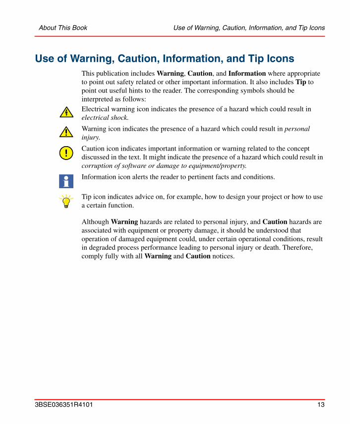
Use of Warning, Caution, Information, and Tip IconsThis publication includes Warning, Caution, and Information where appropriate to point out safety related or other important information. It also includes Tip to point out useful hints to the reader. The corresponding symbols should be interpreted as follows:
Although Warning hazards are related to personal injury, and Caution hazards are associated with equipment or property damage, it should be understood that operation of damaged equipment could, under certain operational conditions, result in degraded process performance leading to personal injury or death. Therefore, comply fully with all Warning and Caution notices.
Electrical warning icon indicates the presence of a hazard which could result in electrical shock.
Warning icon indicates the presence of a hazard which could result in personal injury.
Caution icon indicates important information or warning related to the concept discussed in the text. It might indicate the presence of a hazard which could result in corruption of software or damage to equipment/property.
Information icon alerts the reader to pertinent facts and conditions.
Tip icon indicates advice on, for example, how to design your project or how to use a certain function.
3BSE036351R4101 13
Document Conventions About This Book
Document ConventionsThe following conventions are used throughout this document for the presentation of material:
• In a syntax rule statement or example, a word in boldface represents a reserved keyword or string.
• References to other documents are in italic.
• Control Builder M is normally called just Control Builder or CB in this book.
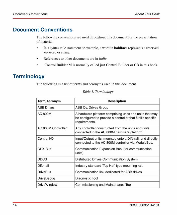
TerminologyThe following is a list of terms and acronyms used in this document.
Table 1. Terminology
Term/Acronym Description
ABB Drives ABB Oy, Drives Group
AC 800M A hardware platform comprising units and units that may be configured to provide a controller that fulfills specific requirements.
AC 800M Controller Any controller constructed from the units and units connected to the AC 800M hardware platform.
Central I/O Input/Output units, mounted onto a DIN-rail, and directly connected to the AC 800M controller via ModuleBus.
CEX-Bus Communication Expansion Bus, (for communication units).
DDCS Distributed Drives Communication System
DIN-rail Industry standard ‘Top Hat’ type mounting rail.
DriveBus Communication link dedicated for ABB drives.
DriveDebug Diagnostic Tool
DriveWindow Commissioning and Maintenance Tool
14 3BSE036351R4101
About This Book Terminology
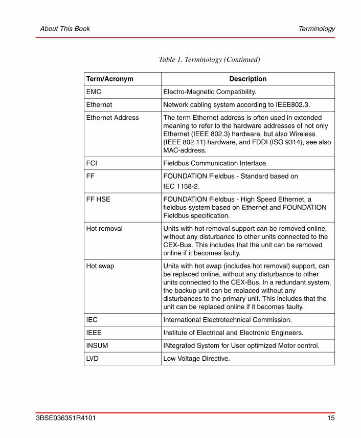
EMC Electro-Magnetic Compatibility.
Ethernet Network cabling system according to IEEE802.3.
Ethernet Address The term Ethernet address is often used in extended meaning to refer to the hardware addresses of not only Ethernet (IEEE 802.3) hardware, but also Wireless (IEEE 802.11) hardware, and FDDI (ISO 9314), see also MAC-address.
FCI Fieldbus Communication Interface.
FF FOUNDATION Fieldbus - Standard based on
IEC 1158-2.
FF HSE FOUNDATION Fieldbus - High Speed Ethernet, a fieldbus system based on Ethernet and FOUNDATION Fieldbus specification.
Hot removal Units with hot removal support can be removed online, without any disturbance to other units connected to the CEX-Bus. This includes that the unit can be removed online if it becomes faulty.
Hot swap Units with hot swap (includes hot removal) support, can be replaced online, without any disturbance to other units connected to the CEX-Bus. In a redundant system, the backup unit can be replaced without any disturbances to the primary unit. This includes that the unit can be replaced online if it becomes faulty.
IEC International Electrotechnical Commission.
IEEE Institute of Electrical and Electronic Engineers.
INSUM INtegrated System for User optimized Motor control.
LVD Low Voltage Directive.
Table 1. Terminology (Continued)
Term/Acronym Description
3BSE036351R4101 15
Terminology About This Book
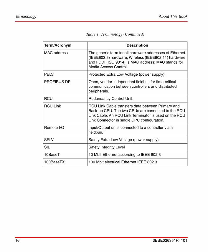
MAC address The generic term for all hardware addresses of Ethernet (IEEE802.3) hardware, Wireless (IEEE802.11) hardware and FDDI (ISO 9314) is MAC address; MAC stands for Media Access Control.
PELV Protected Extra Low Voltage (power supply).
PROFIBUS DP Open, vendor-independent fieldbus for time-critical communication between controllers and distributed peripherals.
RCU Redundancy Control Unit.
RCU Link RCU Link Cable transfers data between Primary and Back-up CPU. The two CPUs are connected to the RCU Link Cable. An RCU Link Terminator is used on the RCU Link Connector in single CPU configuration.
Remote I/O Input/Output units connected to a controller via a fieldbus.
SELV Safety Extra Low Voltage (power supply).
SIL Safety Integrity Level
10BaseT 10 Mbit Ethernet according to IEEE 802.3
100BaseTX 100 Mbit electrical Ethernet IEEE 802.3
Table 1. Terminology (Continued)
Term/Acronym Description
16 3BSE036351R4101

About This Book Applicable Specifications
Applicable Specifications
EUROPEAN UNION DIRECTIVE COMPLIANCE
Units mentioned in this document for which the product is marked with the logo comply with the electromagnetic compatibility directive 89/336/EEC and
the low-voltage directive 73/23/EEC. See Appendix D, Directive Considerations.
UL LISTING
Units mentioned in this document are UL listed if the product is marked with the UL logo.
indicates UL approval for the USA, and for both Canada and
the USA. The logo indicates UL approval for Canada only.
The applied standard is UL508, Industrial Control Equipment. Units approved for use at hazardous locations also comply with the standard UL60079-15. To fulfill the UL requirements for hazardous locations, the instructions in Appendix E, Standards must be followed.
TÜV Approval
Units mentioned in this document are TÜV qualified for IEC 61508 SIL2 if the
product is marked with the TÜV logo.
3BSE036351R4101 17

TÜV Approval About This Book
18 3BSE036351R4101
Safety Summary
GeneralIn order to minimize the risk of injury to personnel and/or damage to the equipment, always comply with the following safety instructions when installing and operating an AC 800M Controller system. Local, stricter statutory regulations must always take precedence over the safety instructions given here.
Warnings and Information Symbols in the Text MarginObserve the symbols for warnings and information located in other Chapters and Appendices of this book. The symbols are placed in the left-hand margin, adjacent to paragraphs requiring special attention. For an explanation of the symbols, see About This Book – Use of Warning, Caution, Information, and Tip Icons on page 13.
The Safety Instructions are classified as mandatory reading for all suitably qualified personnel intending to operate the AC 800M Controller.
3BSE036351R4101 19
Personnel and Process Safety Safety Summary
Personnel and Process Safety
A control system is a tool used to control various processes. Responsibility for attaining and maintaining a satisfactory level of safety rests with the personnel who engineer, operate and maintain the equipment. It is important to have an intimate knowledge of all control functions, the inherent safety risks that may be involved in the process, and to possess the imaginative ability to anticipate situations in which accidents may occur.
The following Safety Instructions must be observed:
• Take care when:
– fitting or removing units
– connecting or disconnecting cables
– resetting or switching units to manual operation
• For hazardous locations special restrictions apply, see Appendix E, Standards.
• Never connect the equipment to the mains power supply during installation work.
• Take extreme care when connecting the system to the mains power supply. Injury or death can be the result of incorrect procedures.
• Ensure that all personnel operating or maintaining the installation know the exact location of and how to operate the equipment isolating safety switch and the mains power supply isolating switch.
• When the process sub-sections have been checked and a test run has been performed, a person responsible must check the interlocking chains etc. All concerned personnel must be fully informed regarding test runs to be performed.
• Process technicians are to be present when testing and operating process objects.
TAKE CARE AT ALL TIMES – This will prevent accidents from occurring and help protect valuable equipment.
20 3BSE036351R4101
Safety Summary Personnel and Process Safety
• Never activate any System Initialization push-button if any uncertainty exists regarding exactly what occurs within the system during initialization. ALWAYS CHECK FIRST.
• Remember at all times, that the control system can be controlled from a remote engineering station, connected at another node via Control Network.
• Remember, the AC 800M Controller will start automatically when voltage is applied.
The level of safety can be improved considerably by taking steps to bring the process to a safe state should power supplies, communication links or parts of the control system fail. Such steps may require, for example, the installation of valves or relays that automatically return to a fail-safe position.
3BSE036351R4101 21

Machine Safety Safety Summary
Machine SafetyThe following safety rules must be observed at all times:
• To avoid discharging static electricity, ground both yourself and any tools before handling printed circuit boards and other sensitive pieces of the equipment
• All electronic devices are sensitive to ESD (electrostatic discharge). To avoid accidental damage while handling printed circuit boards, it is recommended to wear a wrist strap, grounded to the chassis. The strap must have a built-in protective resistor
• Anti-static, conductive plastic bags must be used for storage and transport of PC boards in transit.
Before replacing Units
Maintenance
All procedures for replacing units can be located by referring to the relevant documentation.
Removing or replacing units with system power connected can cause injury to personnel and damage to equipment. It is, therefore, of the utmost importance that the power supply be fully disconnected, on the process side, before removal or insertion of units takes place.
See Unit Change Online on page 152 and I/O documentation.
It is recommended that a stock of suitable spare components be maintained to avoid system downtime.
Ensure that back-up copies of the current application program are made at regular, predetermined intervals to avoid system downtime.
22 3BSE036351R4101
Safety Summary Operating Environment
Operating Environment
Before the AC 800M Controller system is brought online, investigate which environmental conditions are applicable. Take note in particular of the following:• The controller must not be exposed to conditions that exceed the values given
in the relevant technical specifications.
• The controller must not be used in an environment exposed to strong electrical interference. Electrical machines can produce interference that exceeds levels permitted for the equipment, for example during repair work.
• All products must be handled with appropriate precautions with regard to electrostatic damage.
• The controller must not be exposed to direct sunlight.
Important Software Check
• Use the system’s fault-monitoring facilities to prevent accidents or mishaps.
• When in doubt, ALWAYS CHECK before executing changes.
Important Hardware Notice
• DO NOT, under any circumstances, disconnect the power supply to a normally functioning system. Always use the correct system shut-down procedure prior to disconnecting the power supply.
Signal Noise Due to Cables
Cables which may cause electrical interference (for example, power supply cables) must not be installed adjacent to bus cables carrying fast digital signals. Ensure that a minimum distance of 10 cm (4 in.) is provided between cables installed inside cabinets.
Hazardous Electrical Supplies
Operational and maintenance procedures, during which personnel may come into contact with high voltage, should only be carried out by personnel fully trained in the maintenance of electrical equipment within those environments, and who are fully aware of all risks involved.
3BSE036351R4101 23

Operating Environment Safety Summary
24 3BSE036351R4101
Section 1 Introduction
Product Overview
AC 800M – General
AC 800M can be defined as a hardware platform to which individual hardware units may be connected and which, depending on the specific unit configuration and operating system selected, can be programmed to perform multiple functions.
Once configured, the AC 800M hardware platform effectively becomes the AC 800M Controller.
The hardware units that form the AC 800M Controller are:
• Processor units (including baseplate)(PM851/PM856/PM860/PM861/PM864/PM865)
• High Integrity Processor Unit(consist of PM865 and SM810 with corresponding baseplates)
• Communication interfaces for different protocols (including baseplates)(CI851/CI852/CI853/CI854/CI854A/CI855/CI856/CI857/CI858/CI860/ CI862)
• CEX-Bus Interconnection Unit(BC810)
• Power supply units, providing various power output levels(SD821/SD822/SD823/SS822/SS823)
• Battery back-up unit(SB821)
3BSE036351R4101 25

AC 800M – General Section 1 Introduction
When equipped with the specified Control Software, the AC 800M Controller will act either as a stand-alone process controller, or as a controller performing local control tasks in a control network consisting of many interconnected controllers, operator stations and servers.
Various I/O systems can be connected to the AC 800M Controller, either directly (S800 I/O) or via PROFIBUS DP or FOUNDATION Fieldbus.
The AC 800M is delivered without Control Software. To provide the controller with Control Software it will first be necessary to load the firmware and create the application separately using the Control Builder M engineering tool.
The AC 800M Controller consists of a selection of units mounted on horizontal DIN-rails, which can be housed within an enclosure. The majority of units consist of a base mounting plate and removable cover attached with screws. The baseplate, which is always mounted onto the DIN-rail, carries the majority of the connections to processor, the power supplies and communication interfaces, as well as to the external buses and systems.
The AC 800M Controller is designed to be a cost-effective, low-maintenance solution for applications ranging from small Programmable Logic Controller (PLC) to advanced Distributed Control Systems (DCS) control applications and combined DCS and High Integrity systems control applications.
In AC 800M High Integrity Controller it is possible to run both non-SIL and SIL classified applications. The AC 800M HI consist of PM865, SM810 and a High Integrity version of Control Software, and is also available in redundant configuration. AC 800M HI requires SIL certified S800 I/O units. S800 I/O units can be used with AC 800M HI while the application is not SIL certified.
PM851 is equivalent with PM856 unless stated otherwise.
PM861A is equivalent to PM861 unless stated otherwise.
PM864A is equivalent to PM864 unless stated otherwise.
26 3BSE036351R4101
Section 1 Introduction AC 800M – General
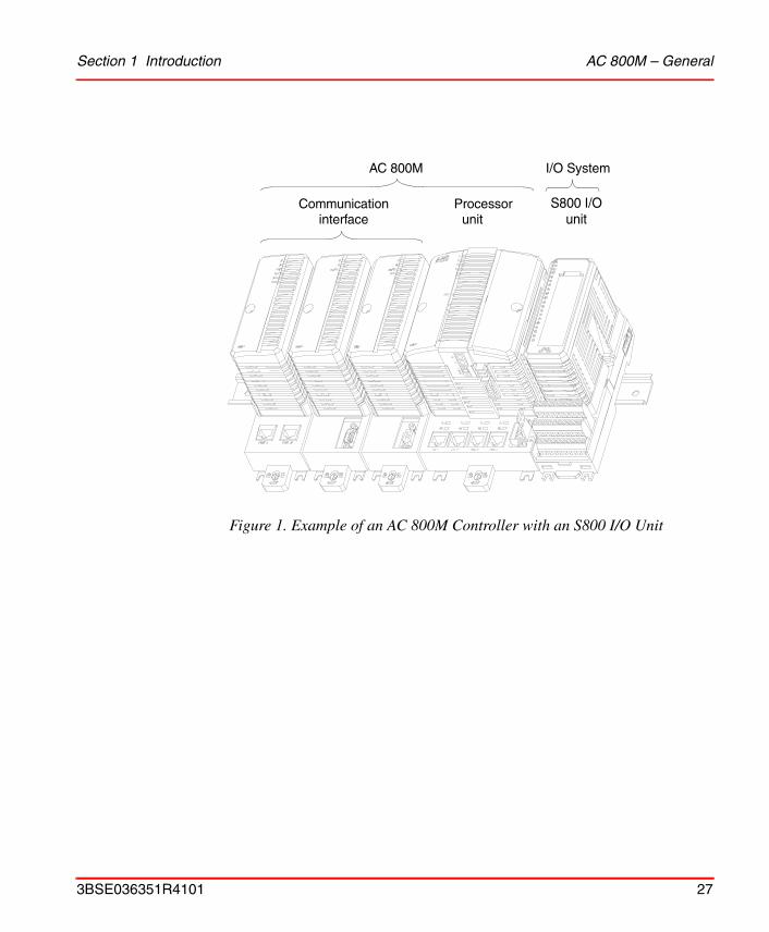
Figure 1. Example of an AC 800M Controller with an S800 I/O Unit
AC 800M I/O System
S800 I/Ounit
Processorunit
Communicationinterface
3BSE036351R4101 27

AC 800M – General Section 1 Introduction
Figure 2. Processor Unit – General View (here shown with PM861)
Tx/Rx Optical ModuleBus
External BatterySupply Socket
Power SupplyandSupervision SignalSocket (SS822/SS823)
COM3/COM4PortsDIN-rail
Locking Device
CN1/CN2Ports
Tx/RxStatus
INITPush button
LEDStatus
Indicators
Indicators
RCU LinkConnector(PM861/PM864/ Electrical
ModuleBus
CEX-Bus
PM865)
Compact Flash slot
28 3BSE036351R4101
Section 1 Introduction PM8xx/TP830 Processor Unit – General
PM8xx/TP830 Processor Unit – General
Physically the PM8xx/TP830 Processor Unit consists of two basic parts:
• Processor Unit (PM851/PM856/PM860/PM861/PM864/PM865) with processor and Power Supply boards
• Baseplate (TP830), housing the unit termination board
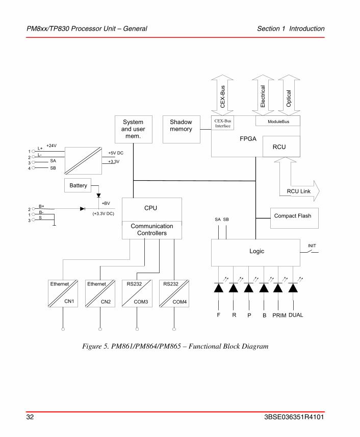
See Figure 4 on page 31 and Figure 5 on page 32, Functional Block Diagram. The CPU board contains the microprocessor and the RAM-memory, controllers for all built-in communication interfaces, real-time clock, LED indicators, INIT push button and a Compact Flash interface.
The main function of the power supply board is to generate isolated, circuit-proof +5 V and +3.3 V supplies to the CPU and I/O units. The board also contains opto-isolated RS-232C drivers/receivers for the service port, together with a back-up battery holder for memory/real time clock, (RTC).
The termination board, housed in the TP830 Baseplate, is where the majority of the external connections take place. The board is grounded to the DIN-rail through of the metallic components of the housing. The termination board is provided with screw terminals for power supply and redundant power supply monitoring, with RJ45 connectors for the control network and serial port, a connector for the service port, the electrical ModuleBus and the CEX-Bus.
24 V DC, connected to the TP830 Baseplate, power all units on the CEX-Bus and the electrical ModuleBus.
In single CPU configuration it is possible to connect an S800 I/O cluster directly to the built-in electrical ModuleBus plug located on the right hand side of the TP830 Baseplate.
The processor unit has a communication expansion bus connector located on the left-hand side of the TP830 Baseplate. This CEX-Bus provides for extending the on-board communication ports with additional communication interfaces. PROFIBUS DP-V0/V1, FOUNDATION Fieldbus H1, FOUNDATION Fieldbus High Speed Ethernet and dual RS-232C ports are some examples of unit types available for connection to the CEX-Bus. It is possible to use redundant communication interfaces, for example PROFIBUS DP-V1.
3BSE036351R4101 29
PM8xx/TP830 Processor Unit – General Section 1 Introduction
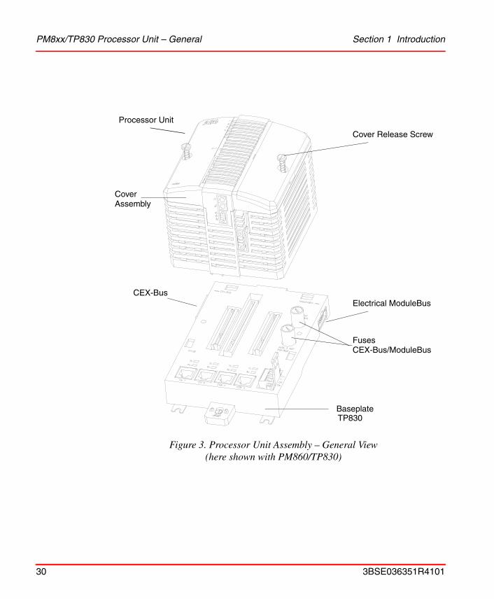
Figure 3. Processor Unit Assembly – General View(here shown with PM860/TP830)
Cover Release Screw
CoverAssembly
CEX-BusElectrical ModuleBus
FusesCEX-Bus/ModuleBus
BaseplateTP830
Processor Unit
30 3BSE036351R4101

Section 1 Introduction PM8xx/TP830 Processor Unit – General
Figure 4. PM851/PM856/PM860 – Functional Block Diagram
PM851 is restricted to one Ethernet (CN1) port.
4Power
+5V DC
+3.3V DC
Battery
(+3.3V)
System anduser mem.
CEX-buscontroller
ModuleBuscontroller
Ele
ctric
al
Opt
ical
DC
Compact Flash
Logic
Communicationcontrollers
CPU
INIT
F
B
R
Ethernet
CN1 CN2 COM3 COM4
RS232 RS232
4 4 8 4
Ethernet
+BVExternalbattery
CE
X-b
us
3
P
RTC
3BSE036351R4101 31
PM8xx/TP830 Processor Unit – General Section 1 Introduction
Figure 5. PM861/PM864/PM865 – Functional Block Diagram
RTCCPU
Communication
Controllers
System and user
mem.
Logic
2 1 3
L+ L-
SA
SB
1 2
4 3
B+ B- S
Ethernet Ethernet
CN1 CN2
FPGA
Shadow memory
CE
X-B
us
Ele
ctric
al
Opt
ical
RCU Link
RS232
COM4
RS232
COM4
RS232
COM3
+3.3V
Battery
+BV
(+3.3V DC) SB
Compact Flash
INIT
+24V
R
+5V DC RCU
ModuleBus CEX-Bus Interface
F P B PRIM DUAL
SA
32 3BSE036351R4101
Section 1 Introduction PM8xx/TP830 Processor Unit – General
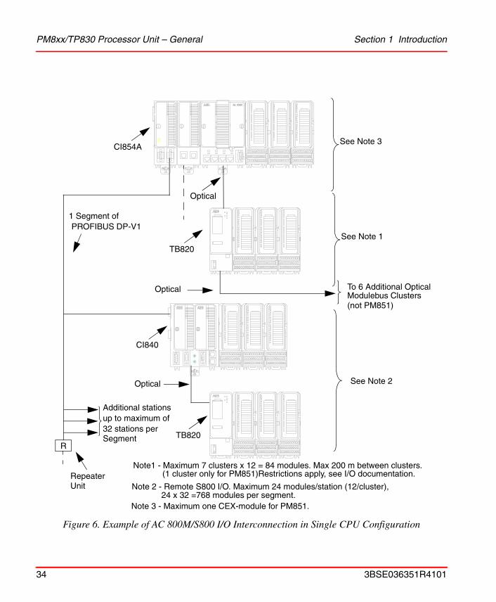
Figure 6 on page 34 provides examples of various ways to connect the S800 I/O units. It can be seen, at the top right-hand area of Figure 6 on page 34, that one cluster (or group) of units (maximum number of units per cluster is 12) is connected to the electrical ModuleBus of an AC 800M Controller. However, a further seven clusters (each comprising up to 12 units) can be added to the optical ModuleBus, thus achieving a total count of 96 units per AC 800M Controller when using only the ModuleBus.
To the left on Figure 6 on page 34, there is a PROFIBUS DP segment. This allows for a large increase in the numbers of units connected to each AC 800M Controller. Here the segment is shown as having an FCI unit (type CI840), connected to the PROFIBUS DP network. The use of FCI units allows the selection of units from several I/O families.
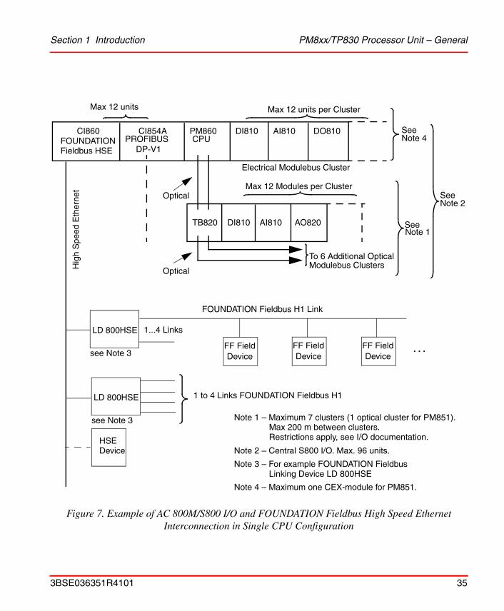
Figure 7 on page 35 shows another example for I/O units based on a FOUNDATION Fieldbus High Speed Ethernet (FF HSE).
For further examples refer to the relevant documentation for the I/O system in question.
Connecting S800 I/O units (using the ModuleBus) to an AC 800M Controller mounted with a PM851 processor unit is restricted to, one electrical ModuleBus cluster and one optical ModuleBus cluster.
3BSE036351R4101 33
PM8xx/TP830 Processor Unit – General Section 1 Introduction
Figure 6. Example of AC 800M/S800 I/O Interconnection in Single CPU Configuration
Note1 - Maximum 7 clusters x 12 = 84 modules. Max 200 m between clusters.
Note 2 - Remote S800 I/O. Maximum 24 modules/station (12/cluster),24 x 32 =768 modules per segment.
(1 cluster only for PM851)Restrictions apply, see I/O documentation.
Additional stationsup to maximum of32 stations per
Repeater
TB820
CI840
TB820
To 6 Additional OpticalModulebus Clusters
Optical
Segment R
Unit
Optical
Optical
CI854A
See Note 1
See Note 2
1 Segment ofPROFIBUS DP-V1
(not PM851)
Note 3 - Maximum one CEX-module for PM851.
See Note 3
34 3BSE036351R4101
Section 1 Introduction PM8xx/TP830 Processor Unit – General
Figure 7. Example of AC 800M/S800 I/O and FOUNDATION Fieldbus High Speed Ethernet Interconnection in Single CPU Configuration
DI810 AI810 DO810PM860CPU
CI854ACI860
Max 12 units per Cluster
TB820 DI810 AI810 AO820
To 6 Additional Optical
Electrical Modulebus Cluster
Max 12 Modules per Cluster
Modulebus Clusters
See Note 1
SeeNote 2
Note 3 – For example FOUNDATION Fieldbus
Optical
Optical
PROFIBUS
Max 12 units
FOUNDATIONFieldbus HSE
LD 800HSE
see Note 3
Hig
h S
peed
Eth
erne
t
FOUNDATION Fieldbus H1 Link
1...4 Links
FF FieldDevice
. . .
1 to 4 Links FOUNDATION Fieldbus H1
FF FieldDevice
FF FieldDevice
HSEDevice
DP-V1
Note 1 – Maximum 7 clusters (1 optical cluster for PM851).
Note 2 – Central S800 I/O. Max. 96 units.
Max 200 m between clusters.Restrictions apply, see I/O documentation.
SeeNote 4
Note 4 – Maximum one CEX-module for PM851.
Linking Device LD 800HSE
LD 800HSE
see Note 3
3BSE036351R4101 35
PM861/PM864/PM865/TP830 Processor Unit – Redundancy Section 1 Introduction
PM861/PM864/PM865/TP830 Processor Unit – Redundancy
Processor unit redundancy is available for PM861, PM864 and PM865. In this case, the controller contains two processor units, each including memory for system and application software. One unit is acting as primary, the other is backup (hot stand-by). The primary processor unit controls the process. The backup stands by, ready to take over in case of a fault in the primary. The changeover is done bumplessly and in less than 10 ms. During the changeover, the process outputs are frozen.
Following a changeover, the system operates as a system without redundancy with only one processor unit in operation. You can replace the malfunctioning processor unit while the system is running. After the replacement is carried out, the system once again has a redundant processor unit.
If an error arises in the backup unit, you can also replace the backup unit while the system is running.
Errors which occur in the backup unit can never affect the primary unit's operation. The primary unit and the backup unit are logically separated from one another. Hardware errors in the primary processor unit cause the system to perform a correct changeover. These hardware errors are single errors.
The application programming and the communication are totally unaffected by the redundancy.
The PM861/PM864/PM865 has an RCU Link Connector for connecting the RCU Link Cable (see Figure 2 on page 28). In a redundant system the two processor units are linked together with the RCU Link Cable (max 1 m). Both processor units are also connected to the same CEX-Bus and either of the two can control the expansion units (see Figure 18 on page 69).
S800 I/O units are connected to the two CPUs via the optical ModuleBus and two TB840 cluster modems on each S800 I/O cluster (see Figure 38 on page 118). The built-in electrical ModuleBus on the TP830 baseplate cannot be used for connecting S800 I/O in a redundant system.
The serial port, COM3 on the baseplate TP830, cannot be used in redundant CPU configuration.
36 3BSE036351R4101
Section 1 Introduction PM861/PM864/PM865/TP830 Processor Unit – Redundancy
Fault Tolerance Principle
The principle of fault tolerance in the redundant processor units is based on continuous updating of the backup unit to the same status as the primary unit. This enables the backup unit to assume control without affecting surrounding systems in a bumpless manner.
This principle involves dynamic division of the program execution into execution units and the creation of rollback points at which the processor unit's status is completely defined.
In this context, the processor unit's total status is defined as the processor unit's internal status, that is, the contents of the processor registers, plus the contents of the data memory.
The backup unit's status is updated each time the primary unit passes a rollback point, enabling the backup unit to resume program execution from the last rollback point passed, should the primary unit fail due to error.
In order to minimize the amount of information involved in the update, the backup unit is updated only with the changes taking place since the latest rollback point.
Between rollback points, these changes that writes in the data memory, are stored in a log buffer in the backup unit. At a rollback point, the processor's total register contents are also written into the data memory, so that this information is also logged. Once the rollback point is established, the logged write operations are transferred to the backup unit's data memory.
If the primary unit fails because of an error, the backup unit resumes execution from the last rollback point, which means the last execution unit is partially re-executed by the backup unit. In order to re-execute a portion of the execution unit without affecting the peripheral units (communication units on the CEX-Bus), the peripheral units' references are also logged between rollback points. During re-execution, the results of the peripheral units' references, which have already been executed, are used, rather than re-executing them. The results of read operations are retrieved from the log, and write operations pass without execution, since they have already been executed. The peripheral units' statuses, then, are not affected by the re-execution in any way, except for the time delay which occurs.
3BSE036351R4101 37

AC 800M High Integrity Section 1 Introduction
The RAM included in the processor unit provides an automatic double inverted memory function for detection of arbitrary bit errors in the memory.
• All memory updates are written to both the primary memory and to the double inverted memory in parallel.
• At every memory read cycle, the data from tho two memories is compared.
• If there is a mismatch in the data a changeover is forced.
The double inverted memory handling is done in hardware and without any delay to the memory cycle time.
AC 800M High Integrity
AC 800M can easily be configured for usage in safety critical applications. The main components of such a system are PM865, SM810, SS823 and the S800 I/O High Integrity system, running a High Integrity version of Control Software. The PM865 processor unit has higher HW fault tolerance, compared to PM864. The added functionality on PM865 includes
• Double over voltage protection on internal voltages
• A additional watchdog timer updated with data from SM810
• Increased oscillator supervision
• Support for S800 I/O High Integrity system
• Support for SM810
• Increased system diagnostic and online self tests.
The main function of the SM810 is to act as a monitor for the HW and SW execution of PM865 and these two modules together are a SIL2 compliant system according to IEC61508 and TÜV qualification is pending. The SM810 is running a SIL2 certified operating system and have a very high degree of self-diagnostic including:
• Double inverted memory
• Double over voltage protection on internal voltages
The following CEX modules cannot be used in a High Integrity controller: CI851, CI852, CI858, CI860, and CI862.
38 3BSE036351R4101
Section 1 Introduction Control Software
• Two independent watchdog timers
• Oscillator supervision
• Support for S800 I/O High Integrity system
• A high fault coverage on the internal diagnostics
• High fault coverage on online self tests.
The ModuleBus telegrams used in a High Integrity system use the concept of long frames. Long frames are ModuleBus telegrams that are extended with a High Integrity header, comprising data and CRC32. S800 ModuleBus telegrams sent to the S800 I/O High Integrity systems uses data from the PM865 and an inverted CRC32 from the SM810. The I/O module checks that CRC32 is correct. Data received from the S800 I/O High Integrity system over the ModuleBus have the CRC32 independently verified by both SM810 and PM865. Any CRC32 or other faults in the telegram will result in a retry transmission and, if repeated, a system shutdown, and the S800 I/O High Integrity system output units will go to safe state.
Control Software
The software used by the AC 800M Controller is named Control Software. This name does not stand for a specific software package; is merely a generic name for the scope of functions used in a controller. These functions are provided by:
• Hardware functions (supervision, communication buses, I/O buses)
• Firmware functions loaded into the controller (real time executive system, real time clock, redundant communication)
• Application programs loaded into the controller (library functions, communication protocols).
To produce an application, it is necessary to use the Control Builder M tool. This tool is extremely versatile, having many useful functions in addition to system configuration.
3BSE036351R4101 39
Ethernet Address Section 1 Introduction
Ethernet Address
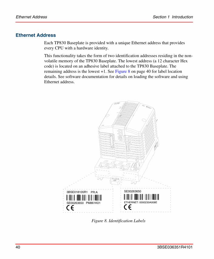
Each TP830 Baseplate is provided with a unique Ethernet address that provides every CPU with a hardware identity.
This functionality takes the form of two identification addresses residing in the non-volatile memory of the TP830 Baseplate. The lowest address (a 12 character Hex code) is located on an adhesive label attached to the TP830 Baseplate. The remaining address is the lowest +1. See Figure 8 on page 40 for label location details. See software documentation for details on loading the software and using Ethernet address.
Figure 8. Identification Labels
SE00263650
ETHERNET: 0000230A008E
3BSE018105R1
SE00263650 PM861K01
PR:A
40 3BSE036351R4101
Section 1 Introduction AC 800M Controller – Key Features
AC 800M Controller – Key Features• Modularity, allowing for step-by-step expansion
• Simple DIN-rail attachment/detachment procedures, using a unique slide and lock mechanism
• Fast, simple troubleshooting procedures available via unit/channel LEDs
• IP20 Class protection with no requirement for enclosures
• Allows for the use of low-cost, sealed enclosures due to extremely low unit heat dissipation, even at an ambient temperature of 40 ° C (104 ° F) outside the enclosure.
• All units are fully EMC certified
• Connection of up to 192 I/O signals, via Electrical ModuleBus, is available
• Connection of up to 1344 I/O signals, via Optical ModuleBus, is available
• Connection of S100 I/O is available
• Allows connecting a large number of I/Os, via PROFIBUS DP-V0 and PROFIBUS DP-V1.
• Connection to FOUNDATION Fieldbus High Speed Ethernet (FF HSE)
• Allows connecting custom protocols of a large amount of Serial communication RS-232C ports
• Connection to MasterBus 300 Networks
• Connection to INSUM via Gateway (Ethernet/LON)
• Connection to ABB Drives is available, over DriveBus and ModuleBus
• Built-in battery back-up of memory
• External battery back-up option available
• CPU Redundancy (PM861/PM864/PM865)
• Redundant/sectioned CEX-Bus using a pair of BC810
3BSE036351R4101 41

Product Release History Section 1 Introduction
• Safety Integrity Level 2 certified controller using PM865/SM810
• Support for hot swap of CEX-Bus units. The symbol on the front of the CEX-Bus unit indicates hot swap support.
Product Release HistoryThe AC 800M hardware platform has been allocated the initial version number 1.0. This number is required to keep the configuration of all units and components on the AC 800M platform together, and to act as a reference in the future between different documents. As the AC 800M hardware platform configuration grows in future releases, so the version number will increase accordingly.
See Table 2 on page 42 for the product version release history of AC 800M.
Table 2. AC 800M Release History
Version Description User Doc
4.1 New information about SS823 is added. SM810 and Compact Flash have been added.
3BSE036351R4101
4.0 CI862 is added. 3BSE036351R4001
3.1 PM851 is added 3BSE 036 351 R101
3.0 PM865, PM861A, PM864A, BC810, SM810, CI854A, CI858, CI860 and SS823 are added.
3BSE 030 827 R201
2.1 PM864 is added. 3BSE 027 941 R301
2.1 CI855 and CI856 are added. 3BSE 027 941 R101
2.0 PM861and CI854/CI857 are added. 3BSE 026 020 R101
1.1 PM856 and CI852 are added. 3BSE 019 193 R201
1.0 Initial AC 800M release. 3BSE 019 193 R101
42 3BSE036351R4101

Section 2 Installation
This section contains guidelines for planning the installation of an AC 800M controller system (see Site Selection and Building Requirements on page 43). A complete list of measures to be taken with respect to the environment and other on-site conditions is not given here.
The equipment should be adapted to the actual application by means of a thorough and correctly scoped system definition, ordering procedures and design requirements. This section also describes practical on-site installation procedures specific to AC 800M units (see Mounting AC 800M Units onto DIN-Rail on page 49).
Site Planning
Site Selection and Building Requirements
The AC 800M system is designed for use within demanding industrial environments. This section provides information on standard requirements regarding the location at which or the building(s) in which the AC 800M Controller system is to be stored or installed.
Most applications require no special arrangements regarding the environment, and so installation according to standard regulations will suffice. In certain situations however, consideration must be given to specific protective measures.
3BSE036351R4101 43
Site Selection and Building Requirements Section 2 Installation
When planning a control system installation, the following points must be considered:
• Temperature:
– It is important to note the ambient air temperature as well as that within enclosures. Lower temperatures increase system reliability and availability.
– If maximum permitted temperatures are exceeded, the anticipated lifetime of wet, electrolytic capacitors and most semiconductors will be greatly reduced.
• Vibration:
– Regarding routine vibration it is recommended that floor enclosures/cabinets stand on a sound, level surface, and that wall enclosures/cabinets are mounted on sound, vertical walls.
– Should the AC 800M system be installed in a control room, adjacent to large machinery such as shakers or large presses where frequent major vibration is expected, then shock absorbers or an isolation pad may be required to protect system equipment. Shock absorbers will normally protect the equipment from sustained low-level vibrations that are perceivable, but not unduly excessive.
– It is recommended that additional fastening screws be used to prevent vibration-generated noise.
– If vibrations or shock are a major factor, further consideration must be given to more extreme measures to reduce the problem.
• Cooling:
– Cooling the electronics is achieved by self-convection. The AC 800M units are designed for wall mounting and must be mounted horizontally onto a DIN-rail to avoid generating high temperatures within the units.
– ABB cabinets (RM550 or RE820) may be used up to an ambient temperature of 40 °C (104 °F), with no requirement for additional cooling equipment, such as fans.
44 3BSE036351R4101

Section 2 Installation Cables
• Other requirements:
– Room lighting independent of the equipment power source. A battery-powered emergency lighting system is recommended.
– A well-developed process connection, with or without marshalling facilities.
– Effective grounding through a net of copper bars
– Cable routing observing standard installation regulations.
– Availability of power and other necessary utilities.
– Observation of standards and legal regulations.
– Sufficient free space in front of the cabinet in order to fully open the doors. For safety reasons there must always be adequate space available, even with the doors in the fully open position.
For additional information regarding design considerations, see Appendix B, Power Consumption.
Electro-Magnetic Compatibility
The AC 800M units are intrinsically EMC compatible according to CE marking rules. For additional information regarding Electro-Magnetic Compatibility, see Appendix D, Directive Considerations.
Cables
Laying Field Cables
There are no special requirements for laying field and communication cables connected to AC 800M. However:
• Cables for short-distance communication without modems should always be routed at a distance of 10 cm (4 in) from other cables.
• All cables connected to AC 800M should be routed at a distance of 30cm (12 in) from all power cables and 10 cm (4 in) from cables belonging to the relevant international immunity standard, class 4.
3BSE036351R4101 45

Power Supply Section 2 Installation
Type of Field Cable
Always use shielded cables for the following applications:
• Communications
• High-frequency pulse transmission
• Low level analog signals, for example Pt100 and thermocouples
• Analog applications with a system accuracy of 12 bits or more.
Unshielded cables may be used for other applications. The signal and return conductor should be located in the same cable.
Lightning Protection
Industrial installations and power plants are normally provided with well-integrated grounding networks, installed as part of the power distribution system. Such installations do not require additional lightning protection unless using overhead wiring or suspended cables in an outdoor environment.
However, large dispersed plants such as water supply installations and oil refineries will have an inadequate grounding system where signal cables may be routed above ground. In such cases lightning protection equipment must be installed.
Should cables be discovered outside the grounding system (even at a short distance such as 10 m [9.1 yds]) lightning protection equipment must be installed.
Power Supply
Under normal circumstances, the power supply required by AC 800M Controller and associated field equipment can be obtained from the plant’s standard 120/230 VAC mains supply.
Mains Net Filter
It is not necessary to use mains net filters when using the SD821/822/823 power supply units.
46 3BSE036351R4101
Section 2 Installation Power Supply
Mains Breaker
A mains breaker must be installed in the immediate vicinity of a controller installation to allow for immediate total power supply disconnection to the equipment, should the need arise. However, the prime function of the mains breaker is to provide a means of isolating the power supply completely during maintenance.
The mains breaker must be installed in a location where it is both easily accessible and clearly visible, that is, outside any enclosure or cabinet.
Protective Ground
Always install a protective ground connection on equipment connected to a 230 VAC supply.
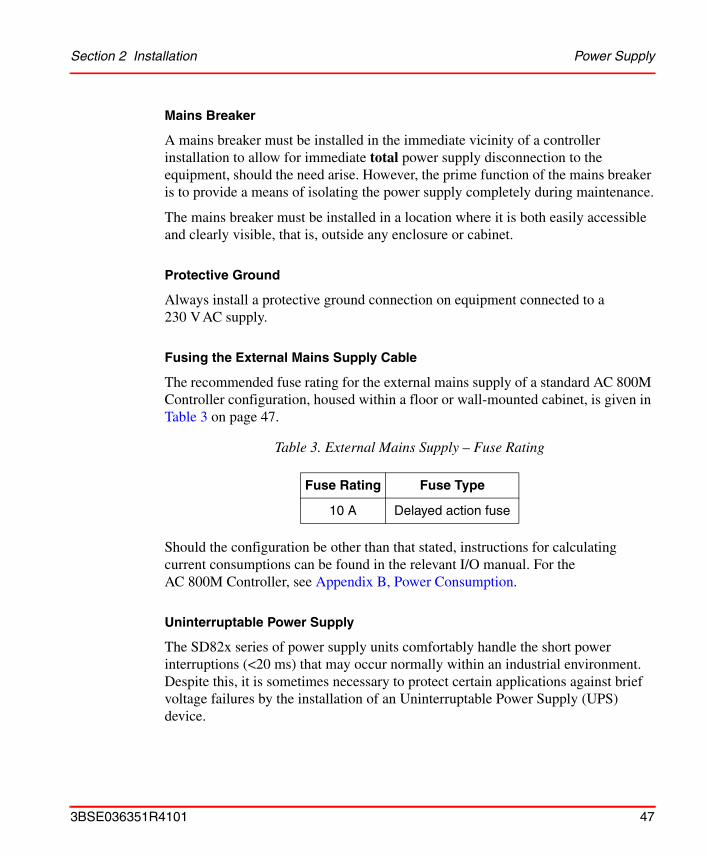
Fusing the External Mains Supply Cable
The recommended fuse rating for the external mains supply of a standard AC 800M Controller configuration, housed within a floor or wall-mounted cabinet, is given in Table 3 on page 47.
Should the configuration be other than that stated, instructions for calculating current consumptions can be found in the relevant I/O manual. For the AC 800M Controller, see Appendix B, Power Consumption.
Uninterruptable Power Supply
The SD82x series of power supply units comfortably handle the short power interruptions (<20 ms) that may occur normally within an industrial environment. Despite this, it is sometimes necessary to protect certain applications against brief voltage failures by the installation of an Uninterruptable Power Supply (UPS) device.
Table 3. External Mains Supply – Fuse Rating
Fuse Rating Fuse Type
10 A Delayed action fuse
3BSE036351R4101 47
Enclosures Section 2 Installation
The AC 800M controller will shut down safely in the event of a power failure. During down-time, the application memory and the system clock will be backed up by the internal battery. In systems subject to long non-operational periods, it is recommended that an external battery back-up unit be installed. When the power supply is reconnected, the AC 800M Controller will re-start and run the application as normal.
If the effects of unexpected shutdowns are not acceptable, it is highly recommended that the AC 800M Controller be fully protected by connection to an Uninterruptable Power Supply (UPS) source.
Enclosures
The AC 800M and S800 I/O units hold protection class IP20, with each unit being individually CE-marked. If a higher IP class is required, an additional enclosure is needed.
Normally the use of an additional enclosure will not influence the EMC characteristics of the controller.
Enclosure Mounting
When mounting the controller enclosure, it is important to provide certain minimum distances between the enclosure, the walls and the ceiling, in order to provide satisfactory ventilation.
If the enclosure is provided with removable wall cladding, it is important to ensure that this is not removed from any enclosure adjacent to other enclosures containing equipment not belonging to the AC 800M Controller and its connected S800 I/O.
48 3BSE036351R4101
Section 2 Installation Mounting AC 800M Units onto DIN-Rail
ABB Cabinets
As a suitable enclosure, ABB recommends the following two cabinets, both specially adapted for mounting the AC 800M Controller and S800 I/O. Both are sealed to protection class IP54 and can support the Controller and S800 I/O units with no requirement for additional cooling equipment:
• RM550 – Floor-mounted cabinet
• RE820 – Wall-mounted cabinet.
For further information on ABB cabinets, see Appendix C, Recommended Components.
Mounting AC 800M Units onto DIN-RailSince the AC 800M units (CPU and communication interfaces) are cooled by self-convection, it is important that they only be mounted onto a horizontal DIN- rail.
Each baseplate has a locking mechanism that contacts the metal backplate to the DIN-rail, providing an effective ground connection. The DIN-rail functions as a very effective ground for the system.
The additional screw lugs, located in the lower part of the baseplate, serve no electrical function. They are provided for use should extra fastening be required within environments subject to excessive vibration.
The DIN-rail must be firmly attached to a suitable conductive mounting surface, by means of suitable screws positioned at exact intervals of 100 mm (4 in) along the full length of the rail.
The AC 800M Controller and associated units must be electrically isolated before being mounted onto a DIN-rail!
3BSE036351R4101 49
Mounting AC 800M Units onto DIN-Rail Section 2 Installation
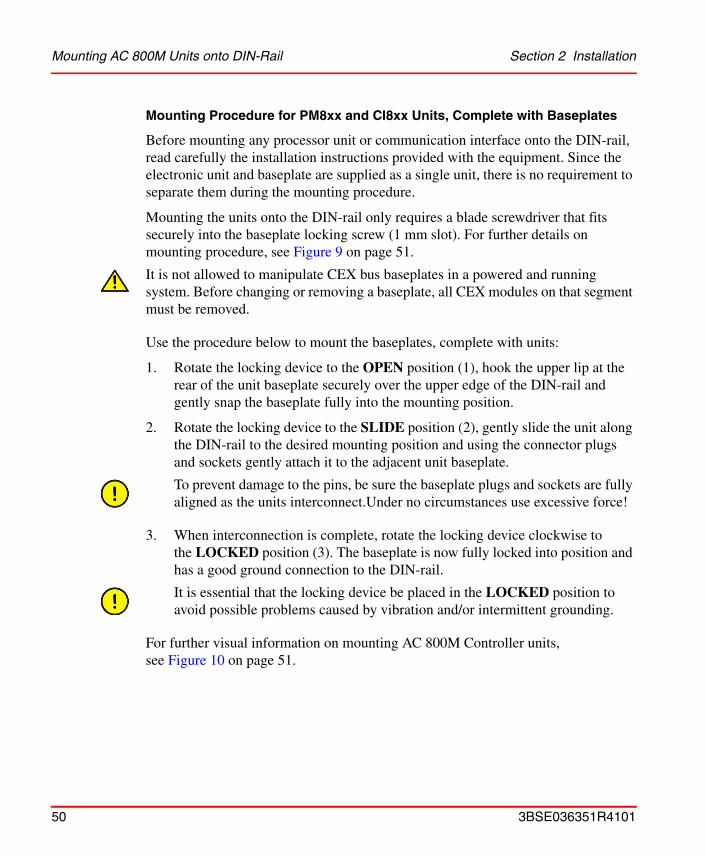
Mounting Procedure for PM8xx and CI8xx Units, Complete with Baseplates
Before mounting any processor unit or communication interface onto the DIN-rail, read carefully the installation instructions provided with the equipment. Since the electronic unit and baseplate are supplied as a single unit, there is no requirement to separate them during the mounting procedure.
Mounting the units onto the DIN-rail only requires a blade screwdriver that fits securely into the baseplate locking screw (1 mm slot). For further details on mounting procedure, see Figure 9 on page 51.
Use the procedure below to mount the baseplates, complete with units:
1. Rotate the locking device to the OPEN position (1), hook the upper lip at the rear of the unit baseplate securely over the upper edge of the DIN-rail and gently snap the baseplate fully into the mounting position.
2. Rotate the locking device to the SLIDE position (2), gently slide the unit along the DIN-rail to the desired mounting position and using the connector plugs and sockets gently attach it to the adjacent unit baseplate.
3. When interconnection is complete, rotate the locking device clockwise to the LOCKED position (3). The baseplate is now fully locked into position and has a good ground connection to the DIN-rail.
For further visual information on mounting AC 800M Controller units, see Figure 10 on page 51.
It is not allowed to manipulate CEX bus baseplates in a powered and running system. Before changing or removing a baseplate, all CEX modules on that segment must be removed.
To prevent damage to the pins, be sure the baseplate plugs and sockets are fully aligned as the units interconnect.Under no circumstances use excessive force!
It is essential that the locking device be placed in the LOCKED position to avoid possible problems caused by vibration and/or intermittent grounding.
50 3BSE036351R4101
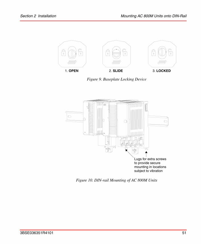
Section 2 Installation Mounting AC 800M Units onto DIN-Rail
Figure 9. Baseplate Locking Device
Figure 10. DIN-rail Mounting of AC 800M Units
1. OPEN 2. SLIDE 3. LOCKED
Lugs for extra screwsto provide securemounting in locationssubject to vibration
3BSE036351R4101 51
Mounting AC 800M Units onto DIN-Rail Section 2 Installation
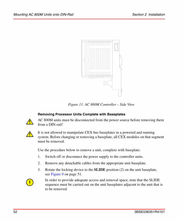
Removing Processor Units Complete with Baseplates
Use the procedure below to remove a unit, complete with baseplate:
1. Switch off or disconnect the power supply to the controller units.
2. Remove any detachable cables from the appropriate unit baseplate.
3. Rotate the locking device to the SLIDE position (2) on the unit baseplate, see Figure 9 on page 51.
Figure 11. AC 800M Controller – Side View
AC 800M units must be disconnected from the power source before removing them from a DIN-rail!
It is not allowed to manipulate CEX bus baseplates in a powered and running system. Before changing or removing a baseplate, all CEX modules on that segment must be removed.
In order to provide adequate access and removal space, note that the SLIDE sequence must be carried out on the unit baseplates adjacent to the unit that is to be removed.
52 3BSE036351R4101

Section 2 Installation Mounting AC 800M Units onto DIN-Rail
4. Gently ease the unit/baseplates sideways in order to release the contacts of the unit baseplate being removed.
5. Turn the locking device anti-clockwise to the OPEN position (1) and ease the unit baseplate outward and upward at the base. Lift the unit to remove it from the DIN-rail. The AC 800M units must be disconnected from the power source before removing them from the DIN-rail.
The unit baseplates are easily disconnected from each other by gently prying them apart with a blade screwdriver (see Figure 12 on page 53).
Figure 12. Separating the Baseplates
F
RRx/Tx
RTS
F
RRx1
Tx1
Rx2
Tx2
CI853
COM1 COM2
F
RP
INIT
B
PM860
CN1 CN2 COM3 COM4
CI851
3BSE036351R4101 53
Mounting AC 800M Units onto DIN-Rail Section 2 Installation
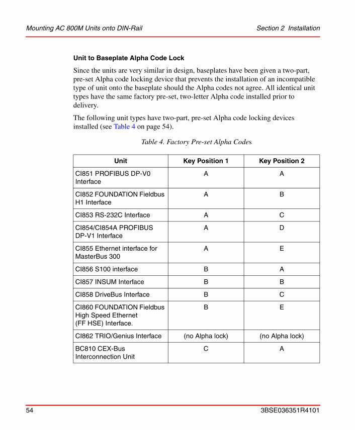
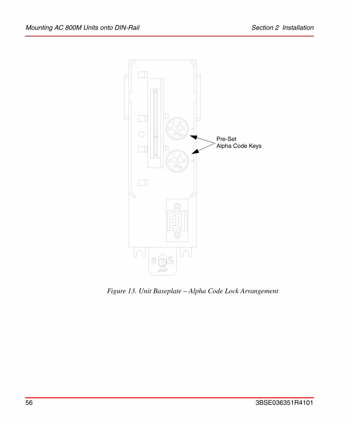
Unit to Baseplate Alpha Code Lock
Since the units are very similar in design, baseplates have been given a two-part, pre-set Alpha code locking device that prevents the installation of an incompatible type of unit onto the baseplate should the Alpha codes not agree. All identical unit types have the same factory pre-set, two-letter Alpha code installed prior to delivery.
The following unit types have two-part, pre-set Alpha code locking devices installed (see Table 4 on page 54).
Table 4. Factory Pre-set Alpha Codes
Unit Key Position 1 Key Position 2
CI851 PROFIBUS DP-V0 Interface
A A
CI852 FOUNDATION Fieldbus H1 Interface
A B
CI853 RS-232C Interface A C
CI854/CI854A PROFIBUS DP-V1 Interface
A D
CI855 Ethernet interface for MasterBus 300
A E
CI856 S100 interface B A
CI857 INSUM Interface B B
CI858 DriveBus Interface B C
CI860 FOUNDATION Fieldbus High Speed Ethernet (FF HSE) Interface.
B E
CI862 TRIO/Genius Interface (no Alpha lock) (no Alpha lock)
BC810 CEX-Bus Interconnection Unit
C A
54 3BSE036351R4101

Section 2 Installation Mounting AC 800M Units onto DIN-Rail
For further details on pre-set Alpha codes, refer to the relevant unit documentation.
See Figure 13 on page 56 for further details of the Alpha code lock arrangement.
The mechanical keys are delivered pre-set and must not be altered. This prevents the removable interface being placed on the wrong type of baseplate.
SM810 C B
S800 I/O Units Various – see S800 I/O Product/User’s Guide
Various – see S800 I/O Product/User’s Guide
Care must be taken to ensure that the correct unit is matched with the correct baseplate, or damage to the equipment will occur. If difficulty is experienced with installing a unit onto a baseplate, this is a positive indication that the Alpha code lock/unit compatibility is incorrect.
Do not manipulate the locking device. ABB will take no responsibility for errors caused by manipulating locking devices.
Table 4. Factory Pre-set Alpha Codes (Continued)
Unit Key Position 1 Key Position 2
3BSE036351R4101 55
Mounting AC 800M Units onto DIN-Rail Section 2 Installation
Figure 13. Unit Baseplate – Alpha Code Lock Arrangement
Pre-SetAlpha Code Keys
56 3BSE036351R4101

Section 2 Installation Installing the PM8xx/TP830 Processor Unit in Single Configuration
Installing the PM8xx/TP830 Processor Unit in Single Configuration
Use the procedure below to install the processor unit along the DIN-rail:
1. If already mounted, remove the CEX-Bus and ModuleBus terminations from the sides of the processor unit.
2. Mount the processor unit, the communication interfaces and the S800 I/O units (the communication interfaces on the CEX-Bus to the left of the processor unit and the S800 I/O units on the electrical ModuleBus to the right of the processor unit).
3. Press them gently together and make sure that the ModuleBus and the CEX-Bus are correctly connected, via baseplate connectors.
4. Reinsert the bus terminations into the communication units at farthest away from the processor unit.
a. For CEX-Bus TB850 (TB851 if cable TK850 is used), see Figure 14 on page 59 and Figure 15 on page 60. When using BC810, see Figure 16 on page 61. If no units are used on the CEX-Bus, no bus termination is required.
b. For ModuleBus TB807, refer to the S800 I/O documentation. If no units are used on the ModuleBus, no bus termination is required.
For PM861/PM864/PM865 insert the RCU Link Termination plug TB852, at the RCU Link connector. The termination plug must always be used for PM861/PM864/PM865 when running in single configuration.
When a redundant processor is running in a single configuration use the RCU Link Cable TK851, if the RCU Link Termination plug TB852 is not available.
3BSE036351R4101 57

Installing the PM8xx/TP830 Processor Unit in Single Configuration Section 2 Installation
5. TP830 Baseplate cable connections:
a. Connect the power leads and, if applicable, power supervision signals from SS82x to screw terminals SA and SB (see Figure 17 on page 62).
b. Connect the Control Network cables to CN1 (single connection) or CN1 + CN2 (redundant connection).
c. Connect the serial protocol to COM3.
d. Connect the Control Builder to COM4 with cable TK212 (if required for changing an IP address etc). Otherwise connect the Control Builder to the Control Network.
6. Connect the optical ModuleBus to the optical contacts on the processor unit (see Figure 2 on page 28 and Figure 25 on page 94). Information regarding optical cable selection and cable length is provided in the S800 I/O documentation.
7. The PM8xx is supplied with an internal back-up battery. When the battery is to be used, place it in the Internal Battery Holder (see Figure 45 on page 147). When the external SB821 battery unit is to be used, install it according to the instructions in Installing the SB821 External Battery Unit on page 103.
Note that a PM851 is restricted to one Ethernet (CN1) port, thus redundant Ethernet is not available.
Note that connection to the optical ModuleBus is identical to that for the processor unit and for the FCI in S800 I/O (see Figure 37 on page 117.)
Do not place the internal back-up battery in the battery holder until the AC 800M Controller has been powered-up normally and the memory back-up function has been activated. If no normal power supply is connected to the processor unit with the battery in place, then the CPU memory will immediately start to consume battery power.
Always install a fresh internal or external battery at the end of the installation phase. The original battery is heavily utilized due to frequent blackouts during system installation.
58 3BSE036351R4101
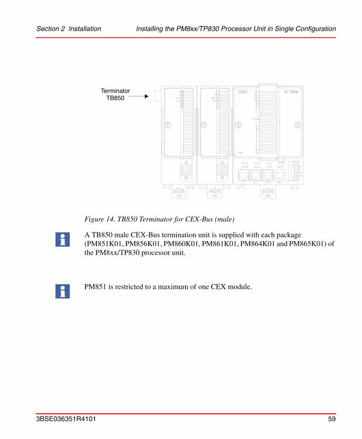
Section 2 Installation Installing the PM8xx/TP830 Processor Unit in Single Configuration
Figure 14. TB850 Terminator for CEX-Bus (male)
A TB850 male CEX-Bus termination unit is supplied with each package (PM851K01, PM856K01, PM860K01, PM861K01, PM864K01 and PM865K01) of the PM8xx/TP830 processor unit.
PM851 is restricted to a maximum of one CEX module.
TerminatorTB850
3BSE036351R4101 59
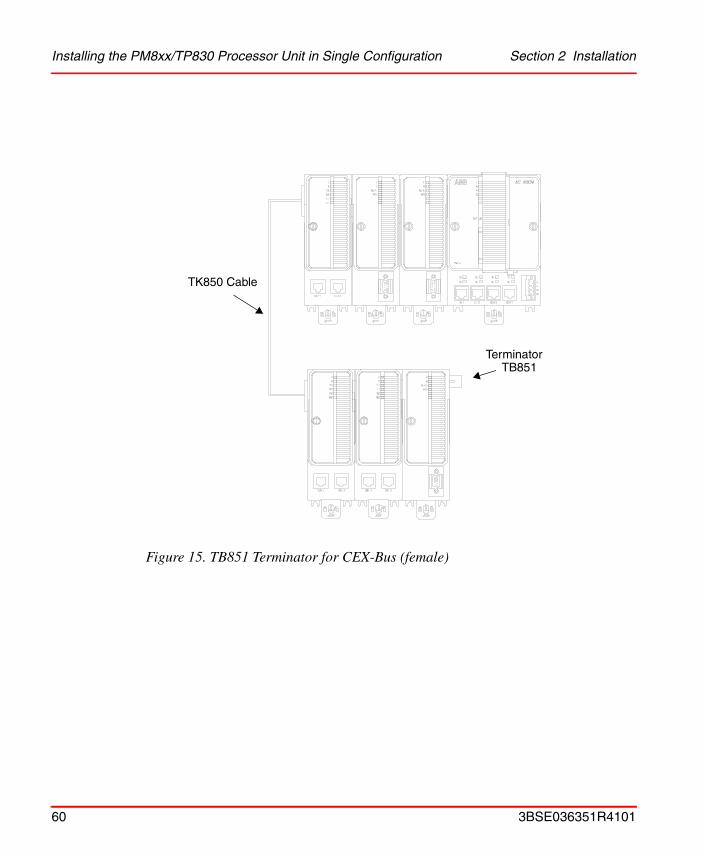
Installing the PM8xx/TP830 Processor Unit in Single Configuration Section 2 Installation
Figure 15. TB851 Terminator for CEX-Bus (female)
TerminatorTB851
TK850 Cable
60 3BSE036351R4101

Section 2 Installation Installing the PM8xx/TP830 Processor Unit in Single Configuration
Figure 16. CEX-Bus Terminator when using BC810
BC810
BC810
RCU LinkCable
PM861A/PM864A/PM865
TerminatorTB850
TerminatorTB850
3BSE036351R4101 61
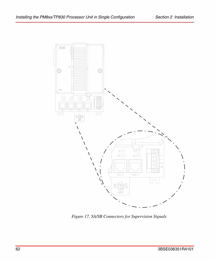
Installing the PM8xx/TP830 Processor Unit in Single Configuration Section 2 Installation
Figure 17. SA/SB Connectors for Supervision Signals
62 3BSE036351R4101
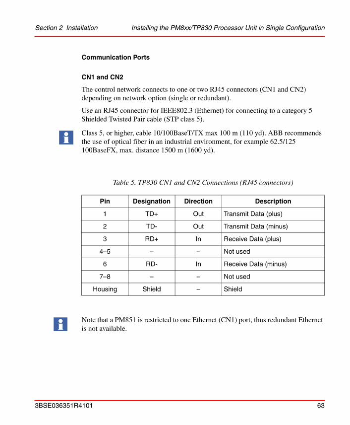
Section 2 Installation Installing the PM8xx/TP830 Processor Unit in Single Configuration
Communication Ports
CN1 and CN2
The control network connects to one or two RJ45 connectors (CN1 and CN2) depending on network option (single or redundant).
Use an RJ45 connector for IEEE802.3 (Ethernet) for connecting to a category 5 Shielded Twisted Pair cable (STP class 5).
Class 5, or higher, cable 10/100BaseT/TX max 100 m (110 yd). ABB recommends the use of optical fiber in an industrial environment, for example 62.5/125 100BaseFX, max. distance 1500 m (1600 yd).
Table 5. TP830 CN1 and CN2 Connections (RJ45 connectors)
Pin Designation Direction Description
1 TD+ Out Transmit Data (plus)
2 TD- Out Transmit Data (minus)
3 RD+ In Receive Data (plus)
4–5 – – Not used
6 RD- In Receive Data (minus)
7–8 – – Not used
Housing Shield – Shield
Note that a PM851 is restricted to one Ethernet (CN1) port, thus redundant Ethernet is not available.
3BSE036351R4101 63

Installing the PM8xx/TP830 Processor Unit in Single Configuration Section 2 Installation
COM3 Port
The COM3 is an RS-232C port with modem signals. This port is used for serial protocols such as Modbus, Siemens 3964R, COMLI or custom-design.
Table 6. TP830 COM3 Connections (RJ45 connector)
Pin Designation Direction Description
1 RTS Out Request To Send
2 DTR Out Data Terminal Ready
3 TD Out Transmit Data
4 0V - Signal ground
5 0V - Signal ground
6 RD In Receive Data
7 DCD In Data Carrier Detect
8 CTS In Clear To Send
Housing Shield - Shield
64 3BSE036351R4101
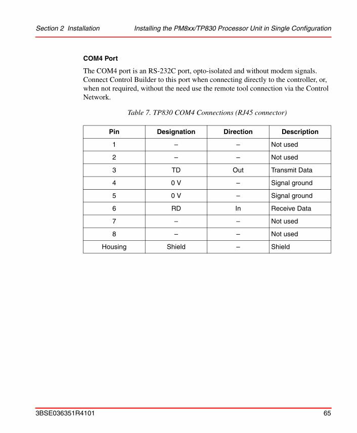
Section 2 Installation Installing the PM8xx/TP830 Processor Unit in Single Configuration
COM4 Port
The COM4 port is an RS-232C port, opto-isolated and without modem signals. Connect Control Builder to this port when connecting directly to the controller, or, when not required, without the need use the remote tool connection via the Control Network.
Table 7. TP830 COM4 Connections (RJ45 connector)
Pin Designation Direction Description
1 – – Not used
2 – – Not used
3 TD Out Transmit Data
4 0 V – Signal ground
5 0 V – Signal ground
6 RD In Receive Data
7 – – Not used
8 – – Not used
Housing Shield – Shield
3BSE036351R4101 65
Installing the PM861/PM864/PM865/TP830 Processor Unit in Redundant Configuration Section 2
Installing the PM861/PM864/PM865/TP830 Processor Unit in Redundant Configuration
In redundant configuration two PM861/PM864/PM865 units are mounted onto two separate DIN-rails. If sufficient space is available, the units can be mounted onto the same DIN-rail
Use the following procedure to install the processor units along the DIN-rail:
1. Mount the processor units.
2. Mount the communication interfaces on the CEX-Bus to the left of the processor unit. If BC810s are used, the configuration of the segments should be considered. If no BC810s are used, the interfaces can be divided between the two CPUs in any preferred way.
3. Press the units gently together and make sure that the CEX-Bus is correctly connected, via the connectors on the baseplates.
4. If BC810s are used, connect the RCU Link Cable to the two BC810s (Figure 19 on page 72). If no BC810s are used, mount the CEX-Bus extension cable TK850 to the units at farthest away from the processor units or, if no units are mounted, directly to the CEX-Bus on the processor unit. The CEX-Bus extension cable must be connected to both CPUs whether or not there are any other CEX-Bus units (Figure 18 on page 69).
5. Connect the RCU Link Cable TK851 to both CPUs. Note that in redundant CPU configuration, COM3 and the electrical ModuleBus on the baseplate can not be used.
Note that in redundant CPU configuration, COM3 and the electrical ModuleBus on the baseplate can not be used.
66 3BSE036351R4101

Section 2 Installation Installing the PM861/PM864/PM865/TP830 Processor Unit in Redundant
6. TP830 Baseplates cable connections:
a. Connect the power leads to both CPUs and the power supervision signals from SS82x to screw terminals SA and SB (see Figure 17 on page 62).
b. Connect the Control Network cables to CN1 (single bus connection) or CN1 + CN2 (redundant bus connection). The Control Network is connected to both CPUs.
c. Connect the Control Builder to COM4 with cable TK212 of the Primary CPU (if required for changing an IP address etc.). Otherwise connect the Control Builder to the Control Network.
7. Connect the optical ModuleBus to the optical contacts on the processor units (see Figure 2 on page 28 and Figure 25 on page 94). Information regarding optical cable selection and cable length is provided in the S800 I/O documentation.
8. The CPUs are supplied with internal back-up batteries. When the batteries are to be used, place them in the Internal Battery Holder (Figure 45 on page 147).
Note that the RCU Link Cable TK851 must be used and can not be replaced by a similar cable. Using another cable will disable the identification of the CPUs in the CB and Operator Station. When running in single configuration the RCU Link Cable TK851 might temporarily be used to perform the function of a termination plug.
The CPU connected to the RCU Link Cable connector marked “UPPER” will be defined as “UPPER” in the Control Builder and Operator Station. The marking has no relevance to the physical placement of the CPUs. Any CPU can become the Primary CPU. However at the first power on, the “UPPER” CPU will take the role of Primary CPU.
Both CPUs must be powered from the same supply (single or redundant). For redundant power supply, see Figure 29 on page 100.
Connection to the optical ModuleBus is identical to that for the processor unit and for the FCI in S800 I/O (Figure 38 on page 118).
3BSE036351R4101 67
Installing the PM861/PM864/PM865/TP830 Processor Unit in Redundant Configuration Section 2
When the external SB821 battery units are to be used, install them according to the instructions in Installing the SB821 External Battery Unit on page 103.
Communication Ports
Same as for single configuration (see Table 5 on page 63, Table 6 on page 64 and Table 7 on page 65).
Do not place the internal back-up battery in the battery holder until the AC 800M Controller has been powered-up normally and the memory back-up function has been activated. If no normal power supply is connected to the processor unit with the battery in place, then the CPU memory will immediately start to consume battery power.
Always install a fresh internal or external battery at the end of the installation phase. The original battery is heavily utilized due to frequent blackouts during system installation.
68 3BSE036351R4101

Section 2 Installation Installing the PM861/PM864/PM865/TP830 Processor Unit in Redundant
Figure 18. Connection of CPU redundancy
RCU Link cableTK851
CEX-Bus ext.cable TK850
3BSE036351R4101 69
Installing the CEX-Bus without BC810 Section 2 Installation
Installing the CEX-Bus without BC810The CEX-Bus, used for connection of communication interfaces to the processor unit, is located on the left-hand side of the processor unit baseplate (TP830).
A bus termination unit must always be fitted to the last unit on the CEX-Bus, as shown in Figure 14 on page 59. A TB850 male CEX-Bus termination unit is supplied with each PM8xx/TP830 processor unit.
However, should the configuration require the use of a TK850 extension cable, as shown in Figure 15 on page 60, then a TB851 female CEX-Bus termination unit is required and must be fitted to the last baseplate in the sequence. A TB851 female CEX-Bus termination unit is supplied with each TK850 extension cable.
TK850 CEX-Bus Extension Cable
Only one TK850 CEX-Bus extension cable may be used in any one CEX-Bus. Cable length: 0.7 m (2.3 in).
Installing the CEX-Bus Interconnection Unit BC810/TP857The BC810 units must be mounted directly to the CEX-Bus on the processor unit base plate. The SM810, if used, and communication interfaces are then mounted to the CEX-Bus on the BC810, and terminated in each end with TB850 male CEX-Bus termination unit. The two BC810 are connected with the interconnection cable TK851.
The maximum number of CEX-Bus units connected to a BC810 is six. The primary function of BC810 is to divide the CEX-Bus into two physically separate segments for increased system availability, a faulty CEX-Bus unit on one segment will not affect the processor unit or the other CEX-Bus segment. It is also important to note that when using the BC810 together with redundant CEX-Bus units these units shall be mounted on different BC810 CEX-Bus segments.
70 3BSE036351R4101

Section 2 Installation Installing the CEX-Bus Interconnection Unit BC810/TP857
See Figure 19 on page 72 and Figure 20 on page 73 for configuration examples. Use the configuration which coincides with the requirements for availability, redundancy and safety of your AC 800M controller system.
The BC810 is powered from the processor unit via the CEX-Bus or through its external connector for power supply. This external connector can also support the CEX-Bus with redundant power. Figure 21 on page 74 shows an example of the external power for BC810 and processor unit. See also Power Supply System on page 128.
Do not connect the two CEX-Bus segments, separated with BC810, to each other with CEX-Bus extension cable TK850.
Configuration restrictions apply to hot swap.
3BSE036351R4101 71

Installing the CEX-Bus Interconnection Unit BC810/TP857 Section 2 Installation
Figure 19. Redundant Communication Interface Units and Controllers
SM810(1) BC810 PM861A/PM864A/PM865
SM810(1) BC810 PM861A/PM864A/PM865
RCU LinkCables
(1) Only for High Integrity Systems
72 3BSE036351R4101
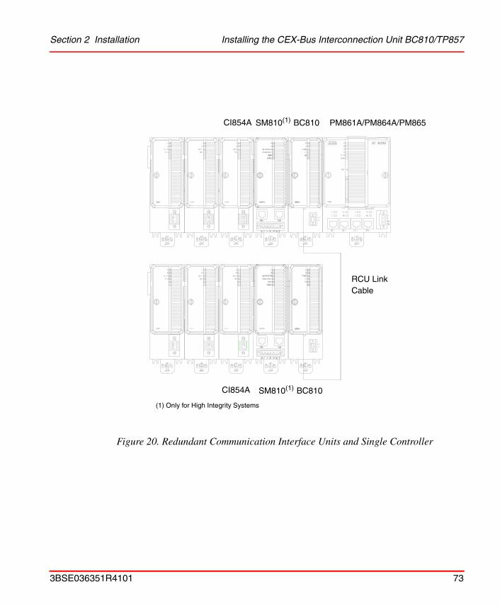
Section 2 Installation Installing the CEX-Bus Interconnection Unit BC810/TP857
Figure 20. Redundant Communication Interface Units and Single Controller
SM810(1) BC810 PM861A/PM864A/PM865
SM810(1) BC810
RCU LinkCable
CI854A
CI854A
(1) Only for High Integrity Systems
3BSE036351R4101 73
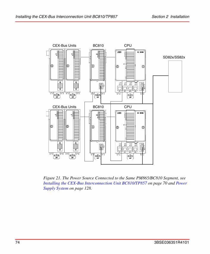
Installing the CEX-Bus Interconnection Unit BC810/TP857 Section 2 Installation
Figure 21. The Power Source Connected to the Same PM865/BC810 Segment, see Installing the CEX-Bus Interconnection Unit BC810/TP857 on page 70 and Power Supply System on page 128.
CEX-Bus Units
SD82x/SS82x
BC810 CPU
CEX-Bus Units BC810 CPU
74 3BSE036351R4101
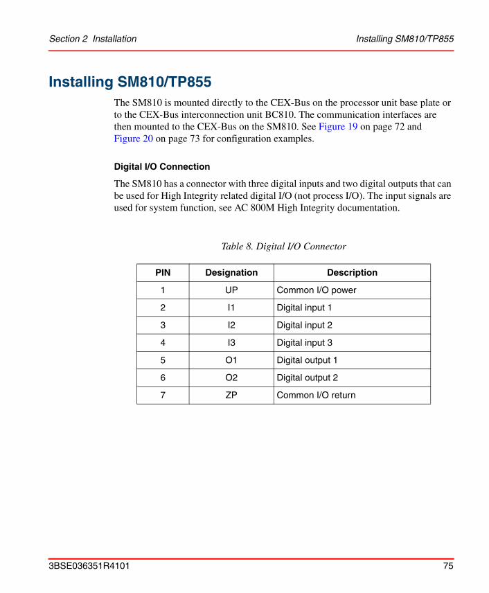
Section 2 Installation Installing SM810/TP855
Installing SM810/TP855The SM810 is mounted directly to the CEX-Bus on the processor unit base plate or to the CEX-Bus interconnection unit BC810. The communication interfaces are then mounted to the CEX-Bus on the SM810. See Figure 19 on page 72 and Figure 20 on page 73 for configuration examples.
Digital I/O Connection
The SM810 has a connector with three digital inputs and two digital outputs that can be used for High Integrity related digital I/O (not process I/O). The input signals are used for system function, see AC 800M High Integrity documentation.
Table 8. Digital I/O Connector
PIN Designation Description
1 UP Common I/O power
2 I1 Digital input 1
3 I2 Digital input 2
4 I3 Digital input 3
5 O1 Digital output 1
6 O2 Digital output 2
7 ZP Common I/O return
3BSE036351R4101 75
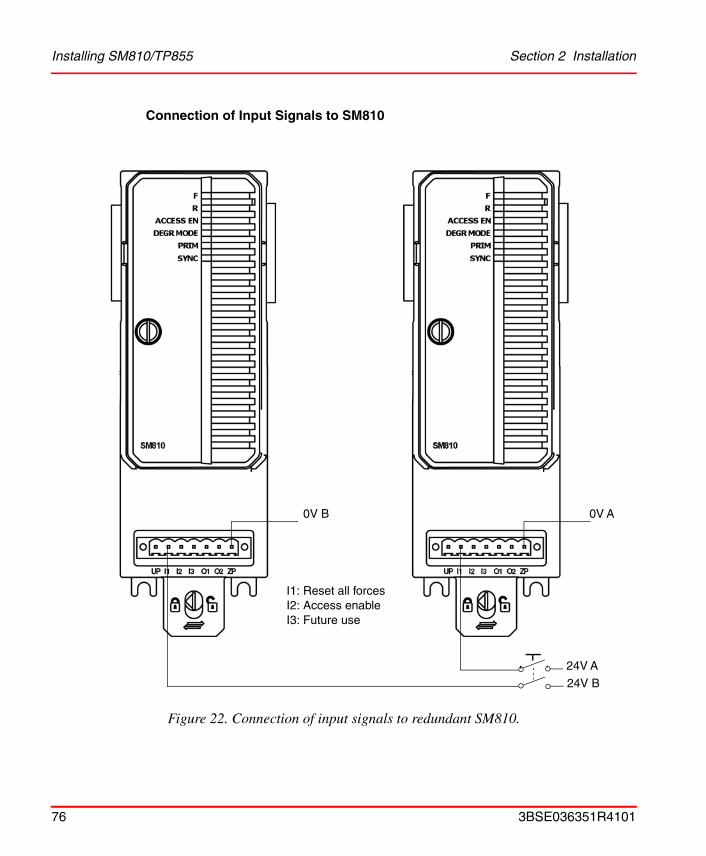
Installing SM810/TP855 Section 2 Installation
Connection of Input Signals to SM810
Figure 22. Connection of input signals to redundant SM810.
0V A0V B
24V A
24V B
I1: Reset all forcesI2: Access enableI3: Future use
76 3BSE036351R4101
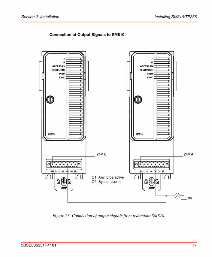
Section 2 Installation Installing SM810/TP855
Connection of Output Signals to SM810
Figure 23. Connection of output signals from redundant SM810.
24V A24V B
O1: Any force activeO2: System alarm
0V
3BSE036351R4101 77
Installing the PROFIBUS DP-V0 Interface, CI851/TP851 Section 2 Installation
Installing the PROFIBUS DP-V0 Interface, CI851/TP851The CI851 is powered from the processor unit via the CEX-Bus and requires therefore no additional external power source.
Use the following procedure to install the CI851/TP851:
1. Mount the unit onto the DIN-rail, see Mounting AC 800M Units onto DIN-Rail on page 49 and Installing the PM8xx/TP830 Processor Unit in Single Configuration on page 57.
2. Install a connector on the PROFIBUS DP-V0 cable. Connect the cable screen to the ground terminal within the connector to ground the screen via CI581. A connector with a switchable built-in bus termination is recommended.
3. Connect the PROFIBUS DP-V0 cable to the contact on the baseplate.
4. If this is at the end of the PROFIBUS DP-V0 cable, switch the bus termination ON. Otherwise leave the bus termination switched OFF.
PROFIBUS DP-V0 Connection
The PROFIBUS DP-V0 cable is connected via the 9-pin female D-type connector located on TP851.
78 3BSE036351R4101
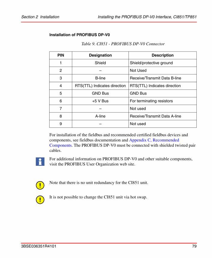
Section 2 Installation Installing the PROFIBUS DP-V0 Interface, CI851/TP851
Installation of PROFIBUS DP-V0
For installation of the fieldbus and recommended certified fieldbus devices and components, see fieldbus documentation and Appendix C, Recommended Components. The PROFIBUS DP-V0 must be connected with shielded twisted pair cables.
Table 9. CI851 - PROFIBUS DP-V0 Connector
PIN Designation Description
1 Shield Shield/protective ground
2 – Not Used
3 B-line Receive/Transmit Data B-line
4 RTS(TTL) Indicates direction RTS(TTL) Indicates direction
5 GND Bus GND Bus
6 +5 V Bus For terminating resistors
7 – Not used
8 A-line Receive/Transmit Data A-line
9 – Not used
For additional information on PROFIBUS DP-V0 and other suitable components, visit the PROFIBUS User Organization web site.
Note that there is no unit redundancy for the CI851 unit.
It is not possible to change the CI851 unit via hot swap.
3BSE036351R4101 79
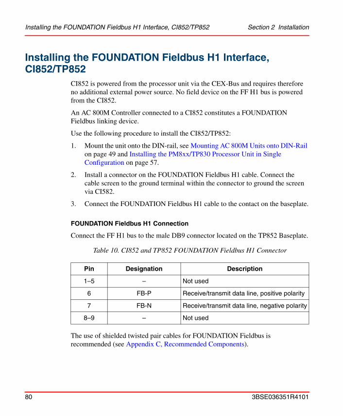
Installing the FOUNDATION Fieldbus H1 Interface, CI852/TP852 Section 2 Installation
Installing the FOUNDATION Fieldbus H1 Interface, CI852/TP852
CI852 is powered from the processor unit via the CEX-Bus and requires therefore no additional external power source. No field device on the FF H1 bus is powered from the CI852.
An AC 800M Controller connected to a CI852 constitutes a FOUNDATION Fieldbus linking device.
Use the following procedure to install the CI852/TP852:
1. Mount the unit onto the DIN-rail, see Mounting AC 800M Units onto DIN-Rail on page 49 and Installing the PM8xx/TP830 Processor Unit in Single Configuration on page 57.
2. Install a connector on the FOUNDATION Fieldbus H1 cable. Connect the cable screen to the ground terminal within the connector to ground the screen via CI582.
3. Connect the FOUNDATION Fieldbus H1 cable to the contact on the baseplate.
FOUNDATION Fieldbus H1 Connection
Connect the FF H1 bus to the male DB9 connector located on the TP852 Baseplate.
The use of shielded twisted pair cables for FOUNDATION Fieldbus is recommended (see Appendix C, Recommended Components).
Table 10. CI852 and TP852 FOUNDATION Fieldbus H1 Connector
Pin Designation Description
1–5 – Not used
6 FB-P Receive/transmit data line, positive polarity
7 FB-N Receive/transmit data line, negative polarity
8–9 – Not used
80 3BSE036351R4101
Section 2 Installation Installing the FOUNDATION Fieldbus H1 Interface, CI852/TP852
For additional information on designing a fieldbus (connectors, cables and devices), see fieldbus documentation.
A catalog referencing suppliers, devices, services and other fieldbus-related items, is available for FIELDBUS ONLINE via the Internet web site.
Powering Field Devices
Field devices requiring power from the fieldbus need special power supplies connected to the data wires (in the same way as a field device). To avoid short-circuiting of fieldbus signals, use only power supplies with impedance characteristics specifically designed for FOUNDATION Fieldbus.
Do not use SD82x power supply units for this purpose.
Note that there is no unit redundancy for the CI852 unit.
It is not possible to change the CI852 unit via hot swap.
3BSE036351R4101 81

Installing the RS-232C Interface, CI853/TP853 Section 2 Installation
Installing the RS-232C Interface, CI853/TP853CI853 is powered from the processor unit via the CEX bus and requires therefore no additional external power source.
Use the following procedure to install the CI853/TP853:
1. Mount the unit onto the DIN-rail, see Mounting AC 800M Units onto DIN-Rail on page 49 and Installing the PM8xx/TP830 Processor Unit in Single Configuration on page 57.
2. Connect the cable (maximum 15 m (16.4 yd)) to one of the contacts on the baseplate. Connect the cable screen to the ground terminal within the connector to ground the screen via CI583.
3. If cables longer than 15 m (16.4 yd.) are required, then a short distance modem TC562 must be used. In this case mount the modem onto a DIN-rail in a suitable position, connect a 24 V DC power supply to the modem and connect cable TK853 from CI853 to the TC562 modem input terminals
4. Connect the TC562 modem output terminals to the outgoing cable.
The TC562 modem can be used for the following distances/speeds:
• Up to 1000 m (1100 yd) with transmission speed 19200 bit/s
• Up to 12000 m (13100 yd) with transmission speed 1200 bit/s
Connectors
Connect the RS-232C channels to the RJ45 connectors marked COM1 and COM2 on the TP853 Baseplate.
Table 11. CI853 RS23-C Interface – COM1 and COM2 Connectors
Pin Designation Direction Description
1–9 – – See COM3 on TP830, Table 6 on page 64.
82 3BSE036351R4101
Section 2 Installation Installing the RS-232C Interface, CI853/TP853
Note that there is no unit redundancy for the CI853 unit.
It is not possible to change the CI853 unit via hot swap.
3BSE036351R4101 83

Installing the PROFIBUS DP-V1 Interface, CI854/CI854A/TP854 Section 2 Installation
Installing the PROFIBUS DP-V1 Interface, CI854/CI854A/TP854
The CI854/CI854A is powered from the processor unit via the CEX-Bus and requires therefore no additional external power source.
Use the following procedure to install the CI854/CI854A/TP854:
1. Mount the unit onto the DIN-rail, see Mounting AC 800M Units onto DIN-Rail on page 49 and Installing the PM8xx/TP830 Processor Unit in Single Configuration on page 57.
2. Install a connector on the PROFIBUS DP-V1 cable. A connector with a switchable built-in bus termination is recommended. Connect the cable screen to the metal case of the connector to ground the screen via CI854/CI854A. Connect the data cable wire A to the terminal PIN8 (RxD/TxD-N) and the data cable wire B to the terminal PIN3 (RxD/TxD-P). If the data transfer cable has data wires with red and green insulation, then the following assignment should be used:Data cable wire A: greenData cable wire B: red
3. Connect the cable shield for both lines to functional ground, for example by using a grounding clamp.
4. Connect the PROFIBUS DP-V1 cable to one of the connectors PROFIBUS A or PROFIBUS B on the baseplate. For support of Line Redundancy connect a second PROFIBUS DP-V1 cable to the other contact.
5. If the CI854/CI854A is at the end of the PROFIBUS DP-V1 cable, switch the bus termination ON. Otherwise leave the bus termination switched OFF.
The following applies for CI854A:
6. If the CI854A is installed in a redundant configuration connect the PROFIBUS DP-V1 cable to primary and backup module. Do it like described in Figure 24 on page 85. Switch the termination ON for the interface on primary or backup module that is at the end of the line.
84 3BSE036351R4101

Section 2 Installation Installing the PROFIBUS DP-V1 Interface, CI854/CI854A/TP854
PROFIBUS DP-V1 Connection
The PROFIBUS DP-V1 cable is connected via the 9-pin female D-type connector located on TP854.
Figure 24. Connection of Redundant PROFIBUS DP-V1 (CI854A)
F
R
RxA
RxB
CI854A
PR
OF
IBU
S B
PR
OF
IBU
S A
DUAL
PRIM
F
R
RxA
RxB
CI854A
PR
OF
IBU
S B
PR
OF
IBU
S A
DUAL
PRIM
Line A Line B
ON ON
3BSE036351R4101 85
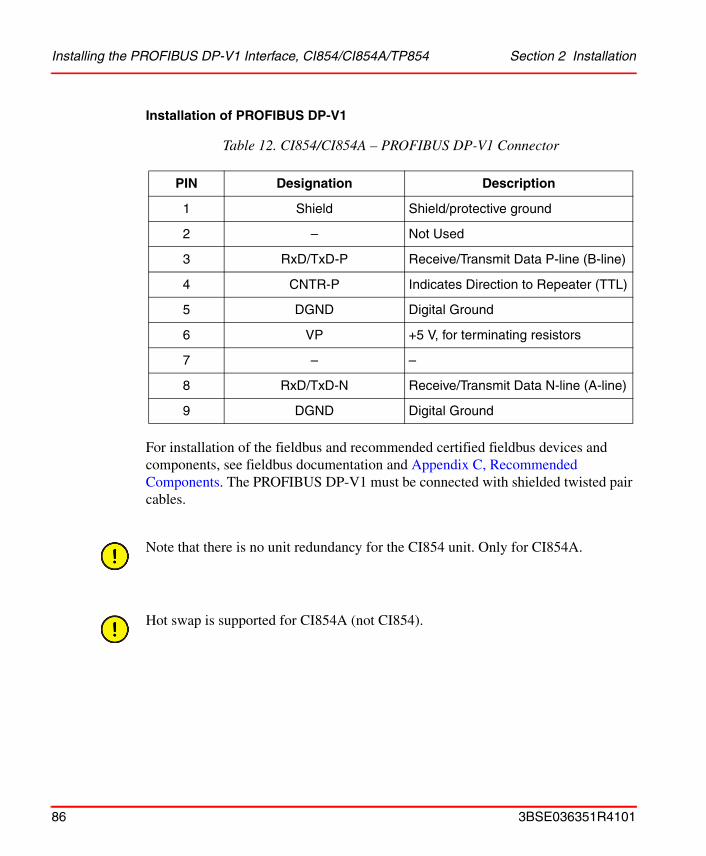
Installing the PROFIBUS DP-V1 Interface, CI854/CI854A/TP854 Section 2 Installation
Installation of PROFIBUS DP-V1
For installation of the fieldbus and recommended certified fieldbus devices and components, see fieldbus documentation and Appendix C, Recommended Components. The PROFIBUS DP-V1 must be connected with shielded twisted pair cables.
Table 12. CI854/CI854A – PROFIBUS DP-V1 Connector
PIN Designation Description
1 Shield Shield/protective ground
2 – Not Used
3 RxD/TxD-P Receive/Transmit Data P-line (B-line)
4 CNTR-P Indicates Direction to Repeater (TTL)
5 DGND Digital Ground
6 VP +5 V, for terminating resistors
7 – –
8 RxD/TxD-N Receive/Transmit Data N-line (A-line)
9 DGND Digital Ground
Note that there is no unit redundancy for the CI854 unit. Only for CI854A.
Hot swap is supported for CI854A (not CI854).
86 3BSE036351R4101
Section 2 Installation Installing the Ethernet Interface for MasterBus 300, CI855/TP853
Installing the Ethernet Interface for MasterBus 300, CI855/TP853
The CI855 is powered from the processor unit via the CEX-Bus and requires therefore no additional external power source.
The baseplate, TP853, provides two Ethernet ports for connection of redundant Ethernet network for MasterBus 300.
Use the following procedure to install the CI855/TP853:
1. Mount the unit on the DIN-rail, see Mounting AC 800M Units onto DIN-Rail on page 49 and Installing the PM8xx/TP830 Processor Unit in Single Configuration on page 57.
2. Connect the Ethernet twisted pair cable to the contact on the baseplate.
3. Connect the other end of the Ethernet cable to a HUB.
Ethernet twisted pair Connection
The Ethernet twisted pair is connected via the 10BaseT RJ45 connector located on TP853. For a description of the connector, see Table 5 on page 63.
If an interface to an AUI is required, a converter from 10BaseT to AUI is needed. The communication unit, CI855, can not provide power to the transceiver, therefore a separate power source must be used.
Note that there is no unit redundancy for the CI855 unit.
3BSE036351R4101 87
Installing the S100 I/O Interface, CI856/TP856 Section 2 Installation
Installing the S100 I/O Interface, CI856/TP856The CI856 is powered from the processor unit via the CEX-Bus and requires therefore no additional external power source.
Use the following procedure to install the CI856/TP856:
1. Mount the unit on the DIN-rail, see Mounting AC 800M Units onto DIN-Rail on page 49 and Installing the PM8xx/TP830 Processor Unit in Single Configuration on page 57.
2. Connect the S100 I/O cable, TK575/TK580, to the contact on the baseplate. A bus extender, DSBC174/DSBC176/DSBC173A, must be used.
S100 I/O Connection and Installation
Connect the S100 I/O rack cable TK575/TK580 to the “I/O-labeled” 36-pin centerline miniature ribbon connector located on TP856.
Installation of S100 I/O
For installation of the S100 I/O-related components, see S100 I/O documentation.
Note that there is no unit redundancy for the CI856 unit.
88 3BSE036351R4101
Section 2 Installation Installing the INSUM Interface, CI857/TP853
Installing the INSUM Interface, CI857/TP853The CI857 is powered from the processor unit via the CEX-Bus and requires therefore no additional external power source.
Use the following procedure to install the CI857/TP853:
1. Mount the unit onto the DIN-rail, see Mounting AC 800M Units onto DIN-Rail on page 49 and Installing the PM8xx/TP830 Processor Unit in Single Configuration on page 57.
2. Connect the Ethernet twisted pair cable to the COM1 connector on the baseplate (COM2 is not used for connection to INSUM).
3. Connect the other end of the Ethernet cable to the INSUM equipment via Ethernet/LON Gateway.
Ethernet Twisted Pair Connection
The Ethernet twisted pair is connected via the 10BaseT RJ45 connector located on TP853. For a description of the connector see Table 5 on page 63.
Note that there is no unit redundancy for the CI857 unit.
3BSE036351R4101 89
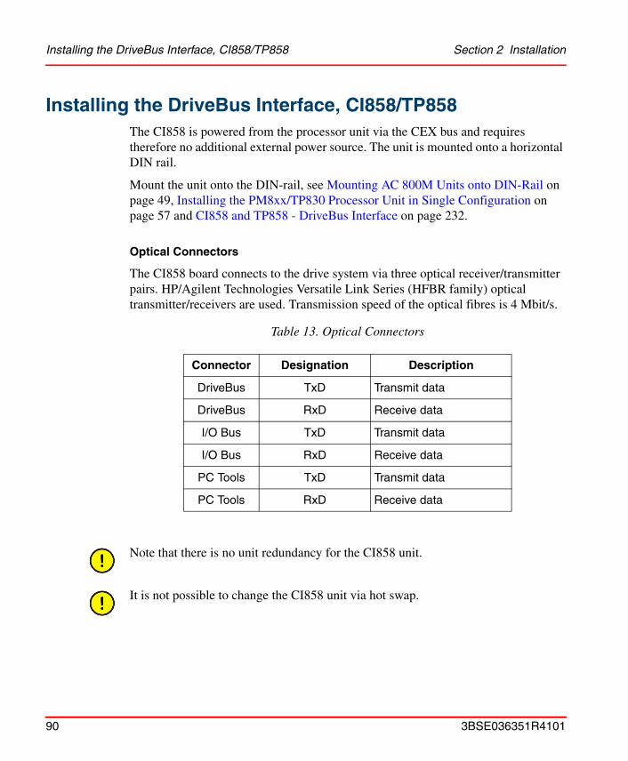
Installing the DriveBus Interface, CI858/TP858 Section 2 Installation
Installing the DriveBus Interface, CI858/TP858The CI858 is powered from the processor unit via the CEX bus and requires therefore no additional external power source. The unit is mounted onto a horizontal DIN rail.
Mount the unit onto the DIN-rail, see Mounting AC 800M Units onto DIN-Rail on page 49, Installing the PM8xx/TP830 Processor Unit in Single Configuration on page 57 and CI858 and TP858 - DriveBus Interface on page 232.
Optical Connectors
The CI858 board connects to the drive system via three optical receiver/transmitter pairs. HP/Agilent Technologies Versatile Link Series (HFBR family) optical transmitter/receivers are used. Transmission speed of the optical fibres is 4 Mbit/s.
Table 13. Optical Connectors
Connector Designation Description
DriveBus TxD Transmit data
DriveBus RxD Receive data
I/O Bus TxD Transmit data
I/O Bus RxD Receive data
PC Tools TxD Transmit data
PC Tools RxD Receive data
Note that there is no unit redundancy for the CI858 unit.
It is not possible to change the CI858 unit via hot swap.
90 3BSE036351R4101
Section 2 Installation Installing the FOUNDATION Fieldbus High Speed Ethernet Interface,
Installing the FOUNDATION Fieldbus High Speed Ethernet Interface, CI860/TP860
The CI860 is powered from the processor unit via the CEX-Bus and requires therefore no additional external power source.
Use the following procedure to install the CI860/TP860:
1. Mount the unit onto the DIN-rail, see Mounting AC 800M Units onto DIN-Rail on page 49 and Installing the PM8xx/TP830 Processor Unit in Single Configuration on page 57.
2. Connect the Ethernet twisted pair cable to the COM connector on the baseplate.
3. Connect the other end of the Ethernet cable to Ethernet network via standard Ethernet components.
4. Please make sure to meet the FOUNDATION Fieldbus High Speed Ethernet specification of the network and the network devices.
Ethernet Twisted Pair Connection
The Ethernet twisted pair is connected via the RJ45 connector located on TP860. For a description of the connector see Table 5 on page 63.
3BSE036351R4101 91

Installing the TRIO Fieldbus Interface CI862 Section 2 Installation
Installing the TRIO Fieldbus Interface CI862The CI862 is powered from the processor unit via the CEX-Bus and requires no additional external power source. No field device is powered from the CI862.
Use the following procedure to install the CI862:
1. Mount the unit onto the DIN-rail.
2. Connect the field bus cable to the LAN connector (right most connector). See the CI862 Installation book for TRIO field bus guidelines, cable types and length.
The Hand-Held Monitor, if used, is connected to the HHM connector.
Unit to Baseplate Alpha Code Lock
The CI862 unit and baseplate have the locking device removed because of the placement of the electronics inside the unit. The electronics will not allow the CI862 unit to be installed in any baseplate with a locking device. However, other units could be inserted into the CI862 baseplate.
Bus Termination
The appropriate terminating resistor must be attached to both the beginning and end of the bus. The characteristic impedance for each type of cable is listed in Table 94. If the CI862 is at either end of the bus, the characteristic resistance is set by a switch on the Field Bus Interface Module, Table 14. If a TRIO module is at the beginning or end of the bus, the bus can be terminated with a resistor or a terminating resistance plug, 6202FP00150 for 150 W or 6202FP00075 for 75 W. BSM stubs should not be terminated.
The CI862 baseplate has no locking device. Insert only the CI862 unit into this baseplate. Insertion of other unit types may cause damage to the equipment.
92 3BSE036351R4101
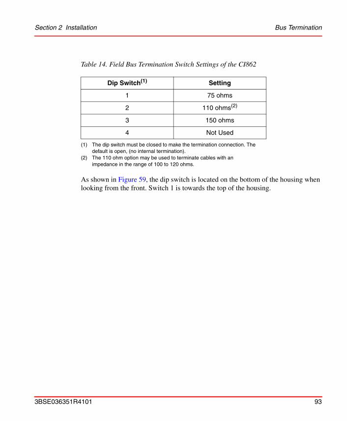
Section 2 Installation Bus Termination
As shown in Figure 59, the dip switch is located on the bottom of the housing when looking from the front. Switch 1 is towards the top of the housing.
Table 14. Field Bus Termination Switch Settings of the CI862
Dip Switch(1)
(1) The dip switch must be closed to make the termination connection. The default is open, (no internal termination).
Setting
1 75 ohms
2 110 ohms(2)
(2) The 110 ohm option may be used to terminate cables with an impedance in the range of 100 to 120 ohms.
3 150 ohms
4 Not Used
3BSE036351R4101 93
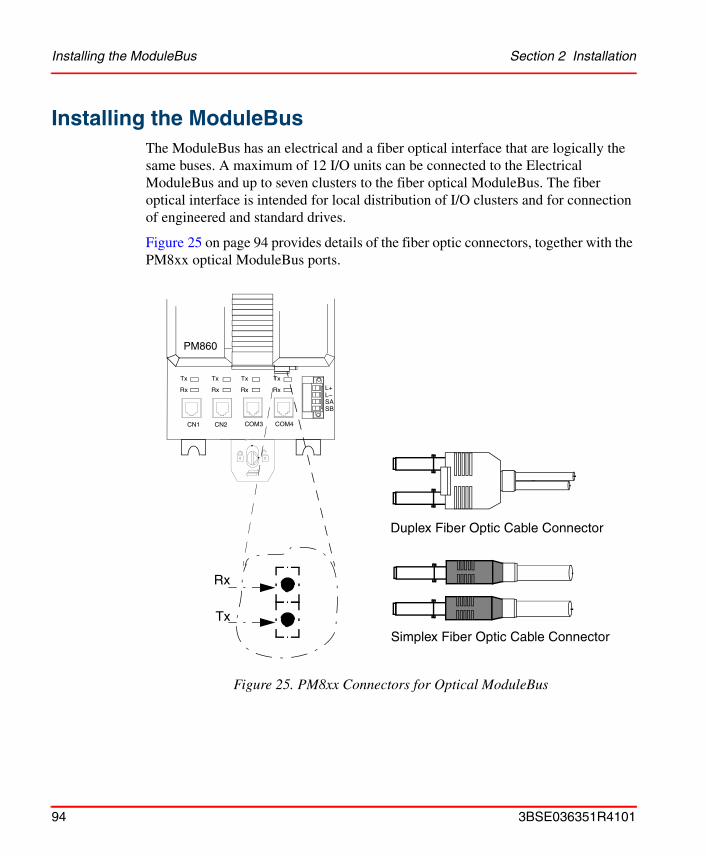
Installing the ModuleBus Section 2 Installation
Installing the ModuleBusThe ModuleBus has an electrical and a fiber optical interface that are logically the same buses. A maximum of 12 I/O units can be connected to the Electrical ModuleBus and up to seven clusters to the fiber optical ModuleBus. The fiber optical interface is intended for local distribution of I/O clusters and for connection of engineered and standard drives.
Figure 25 on page 94 provides details of the fiber optic connectors, together with the PM8xx optical ModuleBus ports.
Figure 25. PM8xx Connectors for Optical ModuleBus
PM860
CN1 CN2 COM3 COM4
Tx
Rx
Tx
Rx
Tx
Rx
Tx
Rx L+L–SASB
Rx
Tx
Duplex Fiber Optic Cable Connector
Simplex Fiber Optic Cable Connector
94 3BSE036351R4101
Section 2 Installation Installing the SD82x Power Supply
Installing the SD82x Power Supply Use the following procedure to install the SD821, SD822 and SD823 power supply units.
1. Mount the selected unit onto the DIN-rail at the required position.
2. Set the mains switch on the front of the power supply unit to the required voltage:
3. Connect the mains supply to the L(ive) and N(eutral) terminals.
4. Connect the protective ground to the PE terminal.
5. Connect the output cable to terminals L+ (+24 V) and L– (0 V).
• 115 V for 110–120 V AC
• 230 V for 220–240 V AC (default position on delivery).
The power supply unit’s L– output (0 V) can be used without being grounded. If grounding is required, the power supply unit’s L– output (0 V) can be grounded directly or via a suitable resistor.
All terminals marked L+ are internally connected within the power supply unit. The same applies for terminals marked L–.
The maximum cable length of the L+/L- distribution from one SD82x should not exceed 10 m.
3BSE036351R4101 95
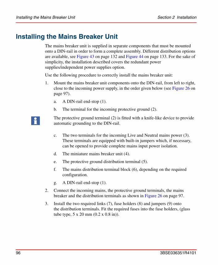
Installing the Mains Breaker Unit Section 2 Installation
Installing the Mains Breaker UnitThe mains breaker unit is supplied in separate components that must be mounted onto a DIN-rail in order to form a complete assembly. Different distribution options are available, see Figure 43 on page 132 and Figure 44 on page 133. For the sake of simplicity, the installation described covers the redundant power supplies/independent power supplies option.
Use the following procedure to correctly install the mains breaker unit:
1. Mount the mains breaker unit components onto the DIN-rail, from left to right, close to the incoming power supply, in the order given below (see Figure 26 on page 97).
a. A DIN-rail end-stop (1).
b. The terminal for the incoming protective ground (2).
c. The two terminals for the incoming Live and Neutral mains power (3). These terminals are equipped with built-in jumpers which, if necessary, can be opened to provide complete mains input power isolation.
d. The miniature mains breaker unit (4).
e. The protective ground distribution terminal (5).
f. The mains distribution terminal block (6), depending on the required configuration.
g. A DIN-rail end-stop (1).
2. Connect the incoming mains, the protective ground terminals, the mains breaker and the distribution terminals as shown in Figure 26 on page 97.
3. Install the two required links (7), fuse holders (8) and jumpers (9) onto the distribution terminals. Fit the required fuses into the fuse holders, (glass tube type, 5 x 20 mm (0.2 x 0.8 in)).
The protective ground terminal (2) is fitted with a knife-like device to provide automatic grounding to the DIN-rail.
96 3BSE036351R4101
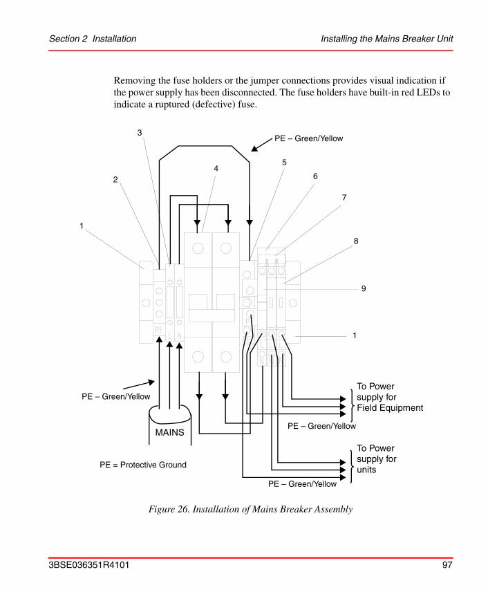
Section 2 Installation Installing the Mains Breaker Unit
Removing the fuse holders or the jumper connections provides visual indication if the power supply has been disconnected. The fuse holders have built-in red LEDs to indicate a ruptured (defective) fuse.
Figure 26. Installation of Mains Breaker Assembly
MAINS
To Power
1
2
3
45
6
7
8
9
1
PE – Green/Yellow
PE – Green/Yellow
PE – Green/Yellow
PE – Green/Yellow
supply forField Equipment
To Power supply forunitsPE = Protective Ground
3BSE036351R4101 97
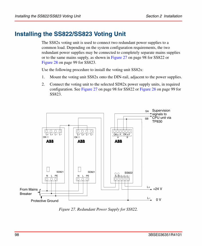
Installing the SS822/SS823 Voting Unit Section 2 Installation
Installing the SS822/SS823 Voting Unit The SS82x voting unit is used to connect two redundant power supplies to a common load. Depending on the system configuration requirements, the two redundant power supplies may be connected to completely separate mains supplies or to the same mains supply, as shown in Figure 27 on page 98 for SS822 or Figure 28 on page 99 for SS823.
Use the following procedure to install the voting unit SS82x:
1. Mount the voting unit SS82x onto the DIN-rail, adjacent to the power supplies.
2. Connect the voting unit to the selected SD82x power supply units, in required configuration. See Figure 27 on page 98 for SS822 or Figure 28 on page 99 for SS823.
Figure 27. Redundant Power Supply for SS822.
OK F OK
A+B+L+
SS822
F+ +A B
L+L–
L+ L+ L– L–
N L PE
OK
SD821
L+ L+ L– L–
N L PE
OK
SD821
SA
SB
L–
L+
Supervisionsignals toCPU unit via
+24 V
0 V
From MainsBreaker
Protective Ground
TP830
SS822
98 3BSE036351R4101
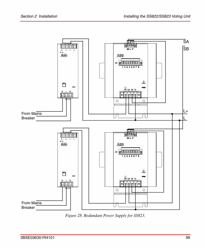
Section 2 Installation Installing the SS822/SS823 Voting Unit
Figure 28. Redundant Power Supply for SS823.
SA
SB
L+
LFrom MainsBreaker
From MainsBreaker
3BSE036351R4101 99
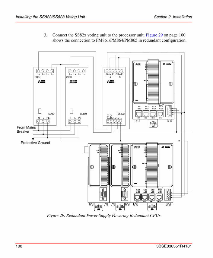
Installing the SS822/SS823 Voting Unit Section 2 Installation
3. Connect the SS82x voting unit to the processor unit. Figure 29 on page 100 shows the connection to PM861/PM864/PM865 in redundant configuration.
Figure 29. Redundant Power Supply Powering Redundant CPUs
From MainsBreaker
Protective Ground
100 3BSE036351R4101

Section 2 Installation Power Supply Supervision
Power Supply Supervision
The status of power supplies in redundant configuration can be supervised via the SS82x voting unit. The supervision signals SA and SB from the SS82x are connected to the corresponding terminals of the CPU.
+ 24 V on the SA/SB indicates working power supplies. 0 V on SA/SB indicates an error in the corresponding power supply and lack of redundancy. SA/SB signal connection is shown in Figure 27 on page 98, Figure 29 on page 100, Figure 30 on page 101 and Figure 31 on page 102.
Figure 27 on page 98 and Figure 29 on page 100 show redundant power supplies powering AC 800M units. Here the SA/SB signals also indicate physical power supplies.
Figure 31 on page 102 shows one redundant power supply powering the AC 800M units and one for powering field equipment. An SA/SB error indication can not indicate which physical power supply that has failed, only that there is a failure.
Figure 30. Connection of SA/SB using Single Power Supply
To avoid error indications from SA/SB when single power supply is used, it is recommended to connect the input terminals SA/SB on the CPU to +24 V, see Figure 30.
+24 V0 V
3BSE036351R4101 101
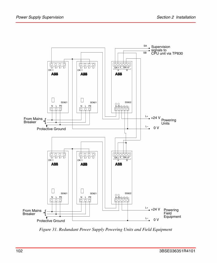
Power Supply Supervision Section 2 Installation
Figure 31. Redundant Power Supply Powering Units and Field Equipment
OK F OK
A+B+L+
SS822
F+ +A B
L+L–
L+ L+ L– L–
N L PE
OK
SD821
L+ L+ L– L–
N L PE
OK
SD821
OK F OK
A+B+L+
SS822
F+ +A B
L+L–
L+ L+ L– L–
N L PE
OK
SD821
L+ L+ L– L–
N L PE
OK
SD821
SA
SB
L–
L+
Supervisionsignals toCPU unit via TP830
+24 V
0 V
From MainsBreaker
Protective Ground
L–
L+ +24 V
0 VProtective Ground
PoweringFieldEquipment
PoweringUnits
From MainsBreaker
102 3BSE036351R4101

Section 2 Installation Installing the SB821 External Battery Unit
Installing the SB821 External Battery Unit Use the following procedure to connect the external battery unit:
1. Mount the SB821 external battery unit at a suitable position on the DIN-rail.
2. For connecting the SB821 external battery unit, use the 2 m (2.2 yd) cable TK821V020. Plug one end into the battery unit and the other into the external battery supply socket of the PM8xx processor unit (see Figure 2 on page 28).
3. In redundant CPU configuration containing two PM861/PM864/PM865 processor units, use also two SB821 battery units, one for each processor unit.
4. Due to the batteries being connected in parallel, it is necessary, when using the external battery, to remove the internal battery from the PM8xx in order to avoid reducing available memory back-up time.
Do not connect the TK821V020 cable until the AC 800M Controller has been powered-up normally and the memory back-up function has been activated. If no normal power supply is connected to the PM8xx processor unit, the CPU memory will immediately start to consume battery power when the cable is connected.
Always install a fresh internal or external battery at the end of the installation phase. The original battery is heavily utilized due to frequent blackouts during system installation.
3BSE036351R4101 103
Installation of I/O Units Section 2 Installation
Installation of I/O UnitsFor further information regarding mounting, removing and releasing procedures for I/O Units, refer to the appropriate I/O system documentation.
Installation in CabinetsThe figures listed below are examples of how the AC 800M Controllers, Power Supply units, Voting units and S800 I/O units can be configured and mounted within cabinets:
• Figure 32 on page 105: Wall Cabinet – Single Power Supply Arrangement
• Figure 33 on page 106: Wall Cabinet – Dual Power Supply (Local/Field) Arrangement
• Figure 34 on page 107: Floor Mounted Cabinet – Unit Arrangement (Redundant PSU)
The DIN-rails are using the supporting Al-profile to ensure rigidness. See Figure 75 on page 269.
The cabinets shown in the figures are ABB manufactured cabinets:
• RE820: Wall Cabinet
• RM550: Floor Cabinet
104 3BSE036351R4101
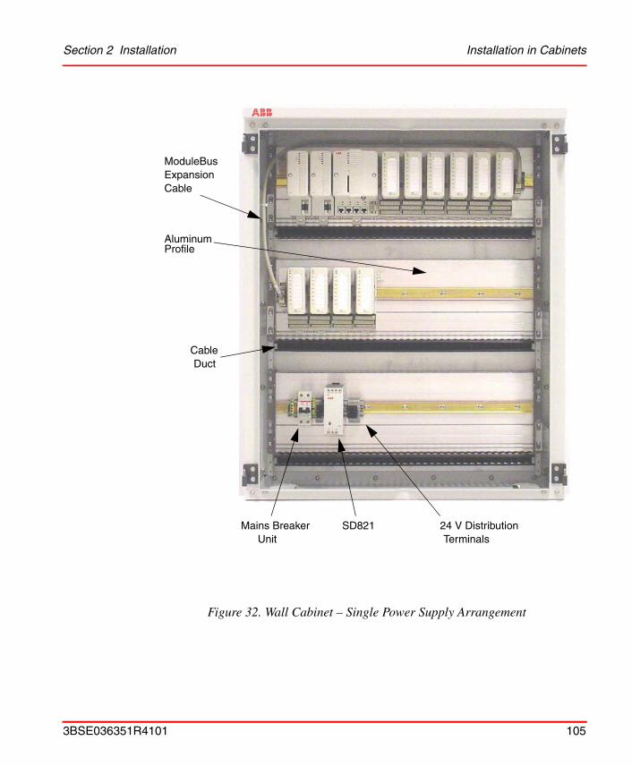
Section 2 Installation Installation in Cabinets
Figure 32. Wall Cabinet – Single Power Supply Arrangement
24 V DistributionTerminals
SD821Mains BreakerUnit
CableDuct
AluminumProfile
CableExpansionModuleBus
3BSE036351R4101 105
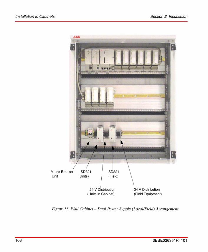
Installation in Cabinets Section 2 Installation
Figure 33. Wall Cabinet – Dual Power Supply (Local/Field) Arrangement
Mains BreakerUnit
SD821
24 V Distribution
(Units)
(Units in Cabinet)
SD821(Field)
24 V Distribution(Field Equipment)
106 3BSE036351R4101

Section 2 Installation Installation in Cabinets
Figure 34. Floor Mounted Cabinet (Horizontal Unit Arrangement)
VotingUnits
SS822BreakersMains
SD822 RedundantPower Supply Units
RedundantPower Supply Units(FieldEquipment)
SD822
3BSE036351R4101 107
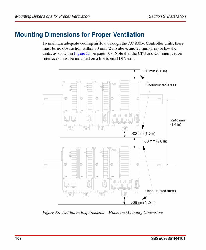
Mounting Dimensions for Proper Ventilation Section 2 Installation
Mounting Dimensions for Proper VentilationTo maintain adequate cooling airflow through the AC 800M Controller units, there must be no obstruction within 50 mm (2 in) above and 25 mm (1 in) below the units, as shown in Figure 35 on page 108. Note that the CPU and Communication Interfaces must be mounted on a horizontal DIN-rail.
Figure 35. Ventilation Requirements – Minimum Mounting Dimensions
>240 mm(9.4 in)
>50 mm (2.0 in)
>50 mm (2.0 in)
>25 mm (1.0 in)
>25 mm (1.0 in)
Unobstructed areas
Unobstructed areas
108 3BSE036351R4101
Section 3 Configuration
General InformationUsing the engineering tool Control Builder, it is possible to configure hardware (I/O and communication units) and make application programs with control languages according to IEC 61131-3. Programs can be compiled and run off-line as an aid to process simulation before finally downloading an application to the controller. The Control Builder offers a set of options, each with its own set of properties. Simply select the option that is closest to system requirements.
• Control Builder documentation – for configuration information
• Control Software documentation – for available functionality.
Control Builder Online Help provides detailed step-by-step information when creating an application for the AC 800M Controller.
3BSE036351R4101 109
Connecting Control Builder Section 3 Configuration
Connecting Control BuilderThe Control Builder is installed in a PC that is normally connected to the AC 800M Controller via the Control Network and the CN1 or CN2 ports on the controller (see Figure 36 on page 111).
Alternatively, the Control Builder may be connected via the COM4 port (RS-232C) on the AC 800M Controller. Use the tool cable TK212 and a serial port on the PC.
Note that a PM851 is restricted to one Ethernet (CN1) port, thus redundant Ethernet is not available.
In redundant configuration the Control Builder is connected to the Primary CPU COM4 port. The Backup CPU cannot communicate with Control Builder.
Note that if the firmware in the AC 800M is not running correctly, then it is likely that it will not be possible to use the CN1 and CN2 ports. However, the connection via the COM4 port is always available.
110 3BSE036351R4101
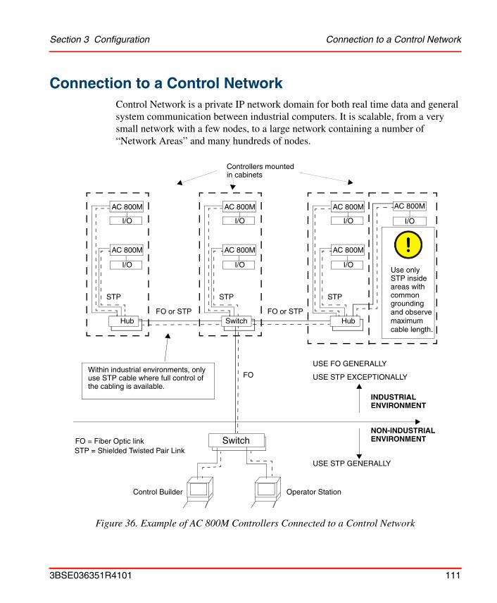
Section 3 Configuration Connection to a Control Network
Connection to a Control NetworkControl Network is a private IP network domain for both real time data and general system communication between industrial computers. It is scalable, from a very small network with a few nodes, to a large network containing a number of “Network Areas” and many hundreds of nodes.
Figure 36. Example of AC 800M Controllers Connected to a Control Network
I/O
AC 800M
I/O
AC 800M
STP
AC 800M
I/O
Switch
Hub
I/O
AC 800M
I/O
AC 800M
STP
Switch
I/O
AC 800M
I/O
AC 800M
STP
Hub
Within industrial environments, onlyuse STP cable where full control ofthe cabling is available.
Use only STP insideareas withcommongrounding
INDUSTRIALENVIRONMENT
NON-INDUSTRIALENVIRONMENT
FO
FO = Fiber Optic linkSTP = Shielded Twisted Pair Link
Controllers mountedin cabinets
Control Builder Operator Station
USE STP EXCEPTIONALLY
USE FO GENERALLY
USE STP GENERALLY
FO or STP FO or STP and observemaximumcable length.
3BSE036351R4101 111

Communication Possibilities Section 3 Configuration
The network can utilize different and mixed link implementations such as Fast Ethernet and PPP. It provides for full redundancy, in order to achieve high network availability.
The AC 800M controller is always connected to the Control Network via an STP (Shielded Twisted Pair) cable. Should the local environment be of an industrial nature, the AC 800M / Control Network connection must be converted over to a Fiber Optic (FO) cable. This is achieved by installing a Switch/Hub having both optical and electrical ports. See Figure 36 on page 111.
For more information on Control Network, see Control Network documentation.
Communication PossibilitiesThe processor unit (PM8xx/TP830) contains the following communication ports, offering the following functions:
• CN1 and CN2 are used for connection to the Control Network. Both are RJ45 ports for Ethernet (IEEE802.3) and connection is normally achieved using category 5 shielded twisted pair cable (STP class 5). However, as mentioned previously, within industrial environments it is recommended that all STP cables are converted to optical fiber.
– For single or redundant CPUs and single networks: All CN1 ports are connected to the network (CN2 can be used, but requires reconfiguration of the communication set-up for the concerned CPU).
– For single or redundant CPUs and redundant networks: All CN1 ports are connected to the primary network and all CN2 ports to the secondary network.
Details on cable selection, hubs, switches and so forth, are provided in Appendix C, Recommended Components.
• COM3 is an RJ45 port for RS-232C with modem signals. Examples of protocols are Modbus, Siemens 3964R, COMLI or custom-design. For more details, see protocol-specific documentation.
Note that a PM851 is restricted to one Ethernet (CN1) port, thus redundant Ethernet is not available.
112 3BSE036351R4101

Section 3 Configuration Communication Possibilities
• COM4 is an RJ45 port for connection of service tools (see Connecting Control Builder on page 110). The port has no modem signals.
By adding communication interfaces to the CEX-Bus, the number of protocols and processor unit ports can be expanded. The available CEX-Bus interface quantities are shown in Table 15 on page 113.
Table 15. Interfaces Available on the CEX-Bus
Interface
Number of Interfaces on CEX-Bus Number of
ports per Interface
Maximum of each
interface
Maximum total on
CEX-Bus(1)(2)
(1) PM851 is restricted to a maximum of one CEX module.(2) The maximum total limit on CEX-Bus is the electrical one, there might be further limitations due to
performance problems for a particular unit.
CI851 (PROFIBUS DP-V0) 12
12
1
CI852 (FOUNDATION Fieldbus H1) 12 1
CI853 (RS-232C) 12 2
CI854/CI854A(PROFIBUS DP-V1)
12 2
CI855(Ethernet for MasterBus 300)
12 2
CI856 (S100) 12 1
CI857 (INSUM) 6 1
CI858 (DriveBus) 2 3
CI860 (FOUNDATION Fieldbus HSE) 12 1
CI862 (TRIO) 4 1
3BSE036351R4101 113
Controller IP Addresses Section 3 Configuration
For information on available serial protocols for the CI853 interface, see COM3 above.
Controller IP Addresses
Single CPU Configurations
The IP address of the CN1 port on the controller is set using the IPConfig tool (this tool is installed together with the 800xA system). See IPConfig online help.
If network redundancy is used, make sure that the CN1 port is connected to the primary network, and the CN2 port is connected to the secondary network. In this case, you also have to set the IP address for the CN2 port. See IPConfig online help.
Redundant CPU Configurations
In configurations with redundant CPU, the IP address must be set as follows:
1. Switch off the backup CPU (power down).
2. Connect the IPConfig tool to the primary CPU and set the IP address of the CN1 port on the primary CPU. See IPConfig online help.
By using redundant communication interfaces max 6 pairs of interfaces are possible.
When setting the IP address of the primary CPU in Control Builder, the backup CPU must be turned off (powered down). Otherwise the backup CPU will take over and you get disconnected.
At the first power-up, the primary processor is always the one connected to the RCU Link connector marked “UPPER”.
If network redundancy is used, the IP address of the CN2 port of the primary processor cannot be set using IPConfig. This address must be set in Control Builder
114 3BSE036351R4101

Section 3 Configuration I/O Systems
3. Set the IP address of the CN1 port on the backup CPU. Use default settings (0.0.2.0 is added to the address of the primary CPU), unless your network administrator requires otherwise. See IPConfig online help.
4. Start your 800xA Workplace.
5. Create a representation of the controller in the Project Explorer hardware tree. Make sure the PM861/PM864/PM865 processor unit is defined as redundant. See Control Builder online help.
6. In Project Explorer, set the IP address of the controller to the IP address of the primary CPU. See Control Builder online help.
7. Switch on the secondary CPU. Check that you have communication with the controller.
I/O SystemsThere are several methods of connecting I/O systems to the AC 800M Controller:
• S100 I/O via CI856.
• S800 I/O units via the ModuleBus. Support for hot configuration during run, redundancy on all levels, HART routing, and Sequence-of-Events (SOE).
• S800 I/O units via CI854/CI854A and CI840, PROFIBUS DP-V0 and DP-V1. Support for HART routing, redundancy on all levels, and hot configuration during run.
• S800 I/O units via CI854/CI854A and CI801, PROFIBUS DP-V0 and DP-V1. Support for HART routing, and hot configuration during run.
• S900 I/O units can be connected to PROFIBUS DP-V1.
If network redundancy is used, you also have to set the IP address of the CN2 port of the backup processor using IPConfig. See IPConfig online help.
There is no need to set IP address(es) for the backup CPU in Control Builder. The IP address of the backup CPU CN1 and CN2 ports will only be used for internal communication between the primary and backup CPUs. When the backup CPU takes over, it also takes over the primary IP address that is defined in Control Builder. Other units on the control network will never notice the switchover.
3BSE036351R4101 115
I/O Systems Section 3 Configuration
• ABB Drives can be connected to the ModuleBus, via CI801. Some Drives equipment can be connected directly to PROFIBUS. Please refer to Drives-specific documentation for more information.
• Genius remote I/O (TRIO) via the CI862 Interface
For more information on supported I/O systems and units, see I/O documentation.
ModuleBus
The ModuleBus in the AC 800M controller consists of one electrical and one optical unit:
• Electrical ModuleBus, (see Figure 37 on page 117) – 1 cluster (group), with a maximum of 12 S800 I/O units connected.
• Optical ModuleBus (see Figure 37 on page 117) – 7 clusters (groups), with maximum 7 x 12 = 84 S800 I/O units connected.
Note that the electrical ModuleBus can only be used for connection of S800 I/O when AC 800M is running in single CPU configuration.
Note that a PM851 is restricted to one optical ModuleBus cluster.
Use of redundancy will reduce the maximum number of S800 channels. Each cluster may contain up to 12 single S800 I/O units or up to 6 redundant S800 I/O units.
116 3BSE036351R4101
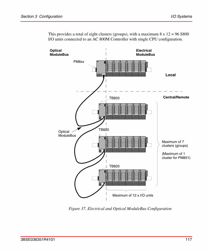
Section 3 Configuration I/O Systems
This provides a total of eight clusters (groups), with a maximum 8 x 12 = 96 S800 I/O units connected to an AC 800M Controller with single CPU configuration.
Figure 37. Electrical and Optical ModuleBus Configuration
Maximum of 7clusters (groups)
Maximum of 12 x I/O units
PM8xx
TB820
TB820
TB820Optical
Local
ModuleBus
Central/Remote
OpticalModuleBus
ElectricalModuleBus
(Maximum of 1cluster for PM851)
3BSE036351R4101 117
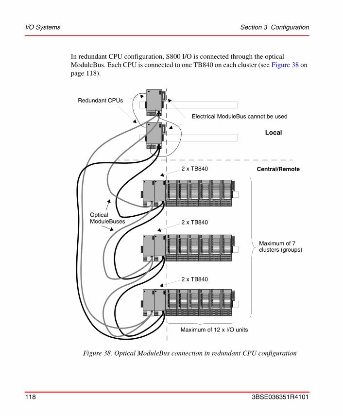
I/O Systems Section 3 Configuration
In redundant CPU configuration, S800 I/O is connected through the optical ModuleBus. Each CPU is connected to one TB840 on each cluster (see Figure 38 on page 118).
Figure 38. Optical ModuleBus connection in redundant CPU configuration
Maximum of 7clusters (groups)
Maximum of 12 x I/O units
2 x TB840
2 x TB840
2 x TB840Optical
Local
ModuleBuses
Central/Remote
Redundant CPUs
Electrical ModuleBus cannot be used
118 3BSE036351R4101
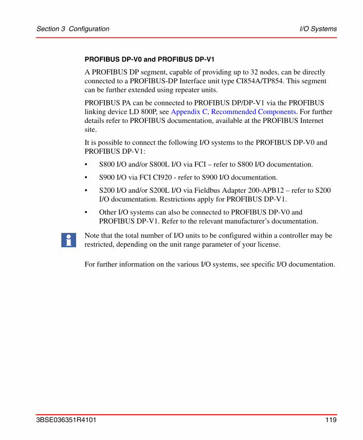
Section 3 Configuration I/O Systems
PROFIBUS DP-V0 and PROFIBUS DP-V1
A PROFIBUS DP segment, capable of providing up to 32 nodes, can be directly connected to a PROFIBUS-DP Interface unit type CI854A/TP854. This segment can be further extended using repeater units.
PROFIBUS PA can be connected to PROFIBUS DP/DP-V1 via the PROFIBUS linking device LD 800P, see Appendix C, Recommended Components. For further details refer to PROFIBUS documentation, available at the PROFIBUS Internet site.
It is possible to connect the following I/O systems to the PROFIBUS DP-V0 and PROFIBUS DP-V1:
• S800 I/O and/or S800L I/O via FCI – refer to S800 I/O documentation.
• S900 I/O via FCI CI920 - refer to S900 I/O documentation.
• S200 I/O and/or S200L I/O via Fieldbus Adapter 200-APB12 – refer to S200 I/O documentation. Restrictions apply for PROFIBUS DP-V1.
• Other I/O systems can also be connected to PROFIBUS DP-V0 and PROFIBUS DP-V1. Refer to the relevant manufacturer’s documentation.
For further information on the various I/O systems, see specific I/O documentation.
Note that the total number of I/O units to be configured within a controller may be restricted, depending on the unit range parameter of your license.
3BSE036351R4101 119
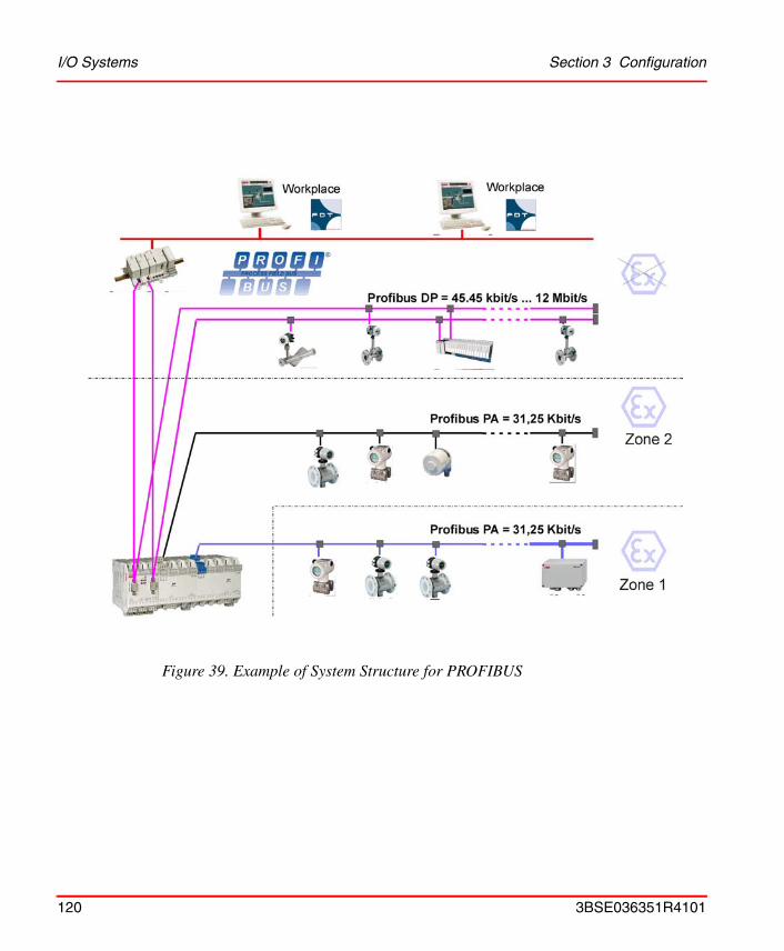
I/O Systems Section 3 Configuration
Figure 39. Example of System Structure for PROFIBUS
120 3BSE036351R4101
Section 3 Configuration I/O Systems
FOUNDATION Fieldbus High Speed Ethernet (FF HSE)
FOUNDATION Fieldbus (FF) is a fieldbus protocol based on international standards and designed for applications in the manufacturing industry, process automation and buildings automation. The guidelines for this fieldbus standard are published by the Fieldbus Foundation.
FF defines two communication profiles, H1 and HSE. The H1 profile allows a transmission rate of 31.25 kbit/s. It is preferably used for direct communication between field devices in one link (H1 link). The HSE profile is based on standard ethernet serves first and foremost as a powerful backbone for the link between H1 segments. Typically transmission rates are: 10 Mbit/s or 100 Mbit/s. The first devices that are already available on the market and support the HSE profile are FF linking devices (for example LD 800HSE). They serve as a gateway between the field devices on the H1 segments and the HSE backbone.
The FOUNDATION Fieldbus is linked to the AC 800M via the high-performance HSE bus using FF linking devices.
More detailed information on the HSE profile can be found in the FF specifications. The fundamental concepts behind HSE are explained in the FF specifications System Architecture (FF-581) and HSE Profiles (FF-941).
The FF subsystem consists of FF linking devices (for example LD 800HSE, see Appendix C, Recommended Components) which communicate with one another using the HSE protocol. An FF linking device usually provides more than one FOUNDATION Fieldbus H1 segments (H1 link). FF linking devices with a device class of 42c allow process data that have been published cyclically on the subsidiary H1 segments to be “republished” on the HSE segment. By using HSE republishing, it is possible to configure cyclical communication between field devices on different H1 segments and devices on the HSE segment.The FOUNDATION Fieldbus HSE and H1network and the devices are configured with the Fieldbus Builder FOUNDATION Fieldbus.
The FF subsystem is interfaced to the IEC 61131 controller (AC 800M) using a FF HSE unit CI860 in the AC 800M, see Figure 7 on page 35. From the perspective of FF the FF HSE unit is an HSE device which participates in the HSE communication.
3BSE036351R4101 121

I/O Systems Section 3 Configuration
FF linking devices operate as gateways between the AC 800M and the field devices on the H1segments both for the configuration data of the field devices and for the process data which is exchanged cyclically between AC 800M and the field devices.
Figure 40. Example of system structure for FOUNDATION Fieldbus HSE
122 3BSE036351R4101
Section 3 Configuration I/O Systems
TRIO/Genius Remote I/O
TRIO is a Genius remote I/O product that provides discrete, analog and high-speed counter blocks for connection to the AC 800M. Configuration of the I/O block units and the CI862 is done using Control Builder M.
3BSE036351R4101 123
Drive System Section 3 Configuration
Drive SystemABB Standard (Std) and Engineered (Eng) Drives can be connected to AC 800M via the optical ModuleBus, via CI851 and CI801or via CI858 DriveBus Interface.
ModuleBus
In single CPU configuration, ABB Drives can be connected to the processor unit via the optical ModuleBus. See Figure 41 on page 126. The number of ABB Drives which can be connected to the optical ModuleBus, can be described by the following equation:
(No. of ABB Drives) < 84 - (12 x (No. of TB820s))
that is, each Drive uses one ModuleBus cluster.
PROFIBUS DP-V0 and CI801
In single and redundant CPU configuration, ABB Drives can be connected via PROFIBUS DP-V0 and CI801. See Figure 41 on page 126. Only Standard Drives can be connected to CI801. Fourteen (14) Standard Drives can be connected to each CI801 if there are no I/O units connected. For the number of Drives that can be connected to the same CI801, when both I/O units (TB820) and Standard Drives are connected, refer to documentation about FCI for PROFIBUS DP.
For more information about ABB Drives and its types (Std and Eng) refer to S800 I/O documentation.
For information about Branching Unit (Figure 41 on page 126) see ABB Drive System documentation.
ABB drives can also be connected via PROFIBUS-DP (CI854/CI854A), with direct connection to ABB Drives PROFIBUS-DP slave modules NPBA-12 and RPB-01.
124 3BSE036351R4101

Section 3 Configuration Drive System
DriveBus Interface CI858
ABB drives can be connected to the AC 800M via the CI858 unit, see Figure 41 on page 126 and Figure 42 on page 127. The drive interface can be used for controlling up to 24 drives or inverter units.
Main communication functions of the drive connection are:
• Dataset communication
• Broadcast system time
• Supervision and diagnostics functions
The data exchange between the AC 800M and the CI858 consists of eight datasets. The drive connection is able to transfer at the maximum 8 datasets / 1 ms.
Connection of multiple drives requires the use of a branching unit, which enables the construction of a logical bus with physical star topology, see Figure 42 on page 127. The branching units can be chained.
The following drives are supported by the drive connection:
• ACS 600 single drive
• ACS 600 multi drive
• ACS 600 thyristor supply units
• ACS 600 IGBT supply units
• ACS 800 product family
• ACS 140-AC S400
• DCS 600 and DCS 400
• ACS 6000 product family / large drives
• ACS 1000 product family
See also CI858 and TP858 - DriveBus Interface on page 232
3BSE036351R4101 125
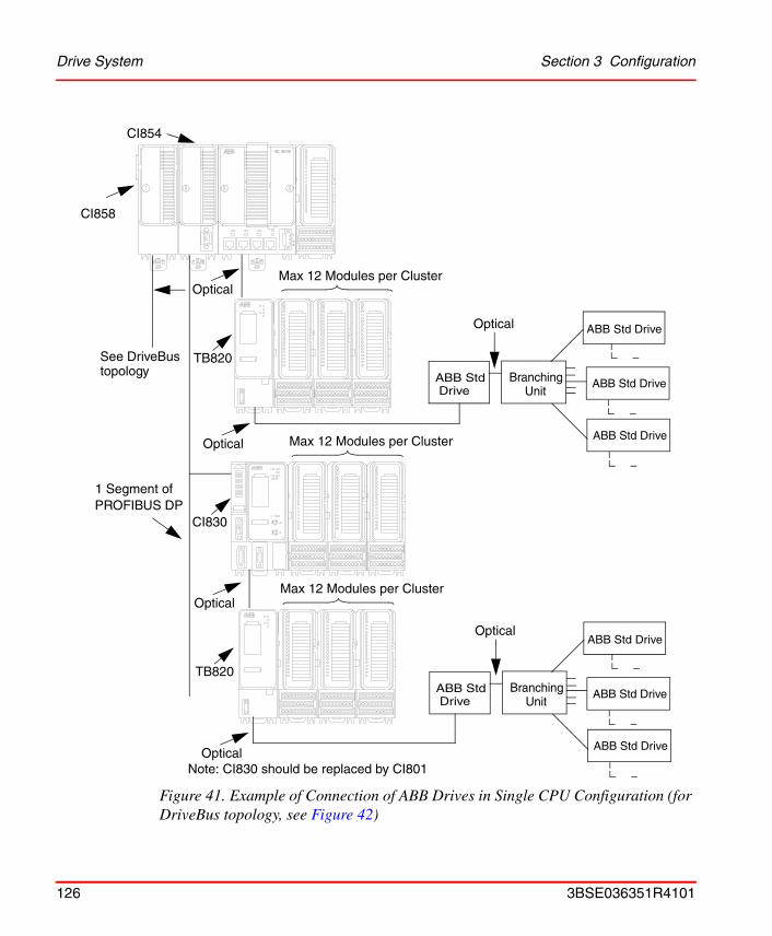
Drive System Section 3 Configuration
Figure 41. Example of Connection of ABB Drives in Single CPU Configuration (for DriveBus topology, see Figure 42)
1 Segment ofPROFIBUS DP
Optical
Optical
See DriveBustopology
Max 12 Modules per Cluster
ABB Std Branching ABB Std Drive
ABB Std Drive
ABB Std Drive
Drive Unit
CI858
CI854
Optical
ABB Std Branching ABB Std Drive
ABB Std Drive
ABB Std Drive
Drive Unit
Optical
TB820
CI830
TB820
Optical
Optical
Max 12 Modules per Cluster
Max 12 Modules per Cluster
Note: CI830 should be replaced by CI801
126 3BSE036351R4101

Section 3 Configuration Drive System
Figure 42. DriveBus Topology
DriveDrive
DRIVEBUS CI858
NDBU
Drive
CH1
MSTR
CH2 CH3
CH0CH0
CH0
DriveDrive
NDBU
Drive
CH1 CH2 CH3
CH0CH0
CH0
CH0 MSTR
. . . . . .
. . .
Up to 24 Drives
BranchingUnits
3BSE036351R4101 127
Power Supply System Section 3 Configuration
Power Supply SystemThe configuration of a power supply system for an AC 800M controller is very straightforward.
Configurations
Figure 43 on page 132 and Figure 44 on page 133 gives a series of simple circuit diagrams showing various possibilities for connecting the incoming mains power – via the mains breaker, the power supply units and the SS82x voting devices – to the 24 V DC distribution terminals.
The AC 800M Controller and its I/O system are normally located in one or several enclosures or cabinets. The cabinet housing the AC 800M Controller can also contain I/O units connected to the controller via the electrical ModuleBus, the optical ModuleBus or the communication interfaces for PROFIBUS DP-V0 and PROFIBUS DP-V1.
Cabinet Containing AC 800M Controller
From this cabinet power may be required for:
• Powering Units: power to the electronic circuitry for each unit in the cabinet.
• Powering Field Equipment: power to equipment, relay contacts etc. located outside the cabinet, but connected to the inputs/outputs of the I/O units in the cabinet.
Cabinet Containing I/O System
Use the recommendations given above if no other information is given in the I/O system documentation.
It is strongly recommended to:
• use a power supply in each cabinet for Powering Units (only when cabinets are mounted side by side, and the maximum cable length is less than 10 m, can power to the units be taken from another cabinet)
• use separate power supplies for Powering Units and Powering Field Equipment (see Figure 33 on page 106 and Figure 34 on page 107).
128 3BSE036351R4101

Section 3 Configuration Powering Units in the Cabinet
Powering Units in the Cabinet
This power supply is only connected to units within the cabinet such as:
• PM8xx, which also powers all communication interfaces (via the CEX-Bus) and all S800 I/O units connected to its electrical ModuleBus.
• BC810 powers all communication interfaces connected to its own segment.
• TB820V2/TB840 (optical modem for S800 I/O) which also powers all S800 I/O units connected to its electrical ModuleBus.
• CI830 (PROFIBUS DP-V0 interface for S800 I/O) which also powers all S800 I/O units connected to its electrical ModuleBus.
• PROFIBUS DP-V0 and PROFIBUS DP-V1 adapters for other I/O systems (depending on the supply arrangement for the I/O units, it may be necessary to connect power to each I/O unit).
• Communication modems located in the cabinet.
The main configuration rule for this power supply is to retain the 24 V cables within the cabinet.
Powering Field Equipment outside the Cabinet
This is intended for supplying power to process signals and equipment located outside the cabinet.
Interference
Powering field equipment from a power supply located in the AC 800M Controller cabinet often requires the use of long 24 V DC cables that can easily pick up local interference and direct it straight back to the power supply units. When installing the cables, follow the instructions for Field Cables, given under Cables on page 45.
Short-Circuit at Power Supply Output
The SD82x series power supply has no extra energy reservoir at its outputs. In the event of a short circuit the power supply output voltage will fall rapidly.
Short circuits (even with fuses installed in the 24 V DC distribution system) or large load changes can produce unwanted voltage dips in supply.
3BSE036351R4101 129

Powering Field Equipment outside the Cabinet Section 3 Configuration
To avoid the AC 800M Controller being influenced by field equipment, it is strongly recommended that separate power supplies be installed (see Figure 33 on page 106 and Figure 34 on page 107).
Sectioning Field Equipment
If field equipment connected to an AC 800M Controller is to be sectioned into groups – thus avoiding a power failure in one group from influencing the power to other groups – then it is recommended to use separate power supplies for each field equipment group.
The use of fuses in the 24 V DC distribution system is not a fail-safe measure. If a short circuit occurs in one group, then voltage will most likely drop before a fuse blows; consequently all groups will experience a drop in voltage.
Cable Protection
24 V DC distribution system cables must be fuse-protected. In order to allow for overload/short circuit situations, the power supply output current is limited. Allow the power supply an extra capacity of at least 3-4 times the rated current value of the largest connected fuse and remember to include long cable resistance in the calculation.
Connection Alternatives
The field equipment power supply can be connected in the same manner as that used for connecting and powering the AC 800M units (see Figure 43 on page 132 and Figure 44 on page 133). However, it should be noted that the same Mains Breaker Unit can be used to control and isolate both power supplies. Alternatively, independent Mains Breakers can be used on each spur (see Figure 44 on page 133).
130 3BSE036351R4101
Section 3 Configuration Powering from an External Source
Powering from an External Source
The AC 800M Controller can be powered from an external +24 V DC source. This source is often common for many different types of plant equipment, resulting in long power cables to the AC 800M Controller. Furthermore, heavy load changes can cause variations in controller supply voltage making it necessary to take precautions against low voltage in order to prevent controller malfunction.
Should there be a risk that the +24 V at the PM8xx power terminals could drop below 19.2 V for more than 1 ms, then an energy reservoir must be used for Powering Units.
ABB strongly recommends using a DC/DC converter and extra energy reservoir in case external DC-supply with longer cables than 10 m is used.
3BSE036351R4101 131
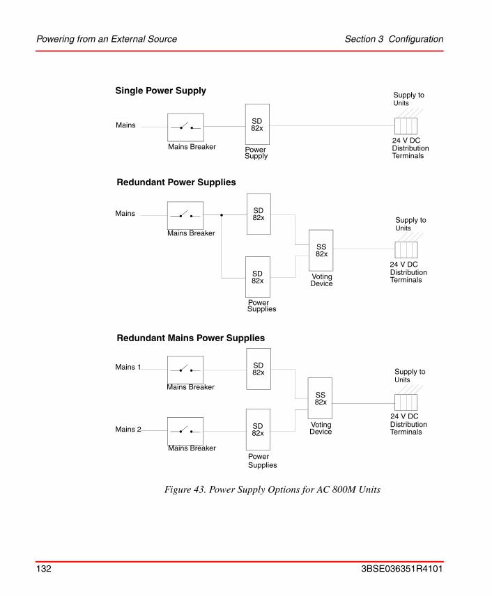
Powering from an External Source Section 3 Configuration
Figure 43. Power Supply Options for AC 800M Units
UnitsSupply to
Device 82x
SuppliesPower
Mains
24 V DCDistribution
SD Voting
Redundant Power Supplies
Redundant Mains Power Supplies
Terminals
24 V DCDistributionTerminals
24 V DCDistributionTerminals
82x
SupplyPower
SD
82xSD
82xSD
82xSS
Device Voting
82xSS
82xSD Mains
Mains 1
Mains 2
UnitsSupply to
UnitsSupply to
Mains Breaker
Mains Breaker
Mains Breaker
Mains Breaker
Single Power Supply
Power Supplies
132 3BSE036351R4101
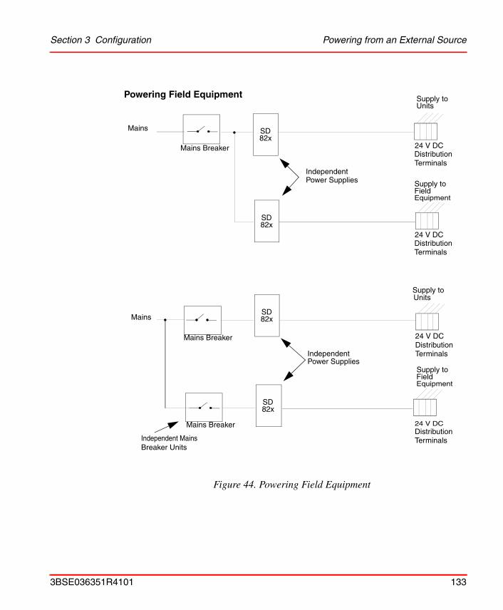
Section 3 Configuration Powering from an External Source
Figure 44. Powering Field Equipment
Field Equipment
82xSD
82xSD
UnitsSupply to
Supply to
24 V DCDistribution
24 V DCDistribution
Independent
82xSD
Mains
Mains Breaker
Mains Breaker
Supply toUnits
24 V DCDistribution
24 V DCDistribution
IndependentPower Supplies
Independent MainsBreaker Units
Mains Breaker
Mains
Terminals
Terminals
Terminals
Terminals
Power Supplies
Field Equipment
Supply to
82xSD
Powering Field Equipment
3BSE036351R4101 133
Powering from an External Source Section 3 Configuration
134 3BSE036351R4101
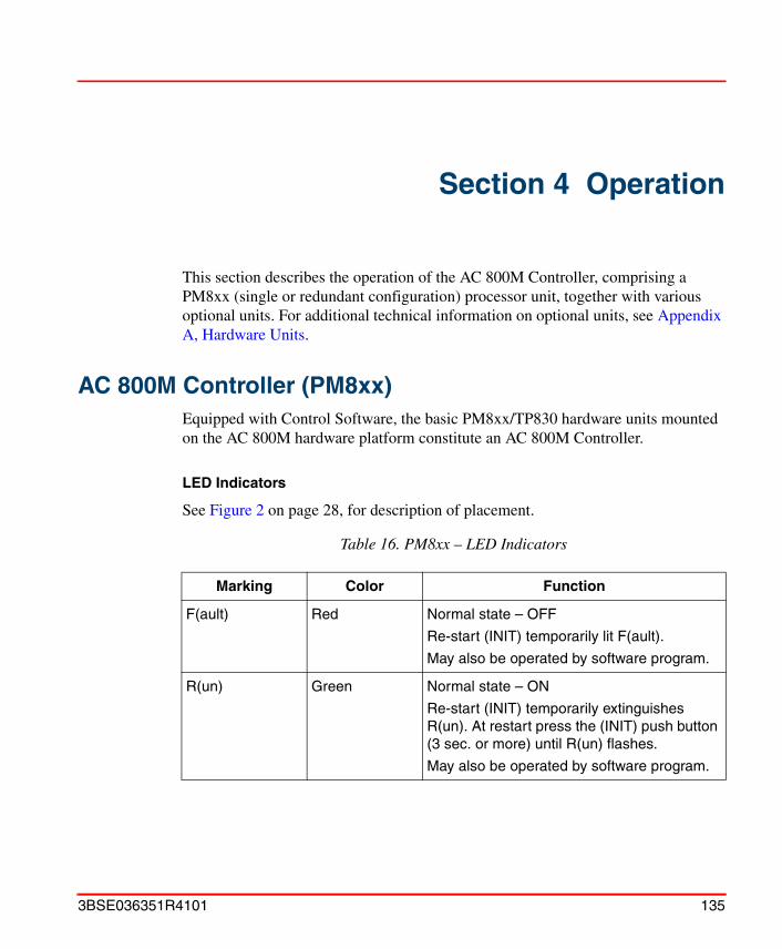
Section 4 Operation
This section describes the operation of the AC 800M Controller, comprising a PM8xx (single or redundant configuration) processor unit, together with various optional units. For additional technical information on optional units, see Appendix A, Hardware Units.
AC 800M Controller (PM8xx)Equipped with Control Software, the basic PM8xx/TP830 hardware units mounted on the AC 800M hardware platform constitute an AC 800M Controller.
LED Indicators
See Figure 2 on page 28, for description of placement.
Table 16. PM8xx – LED Indicators
Marking Color Function
F(ault) Red Normal state – OFF
Re-start (INIT) temporarily lit F(ault).
May also be operated by software program.
R(un) Green Normal state – ON
Re-start (INIT) temporarily extinguishes R(un). At restart press the (INIT) push button (3 sec. or more) until R(un) flashes.
May also be operated by software program.
3BSE036351R4101 135
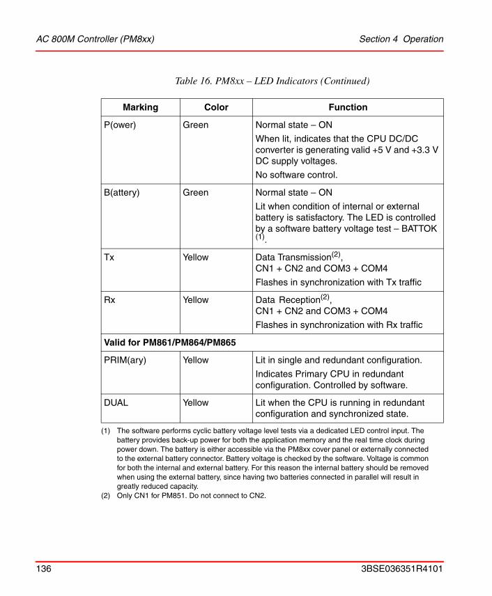
AC 800M Controller (PM8xx) Section 4 Operation
P(ower) Green Normal state – ON
When lit, indicates that the CPU DC/DC converter is generating valid +5 V and +3.3 V DC supply voltages.
No software control.
B(attery) Green Normal state – ON
Lit when condition of internal or external battery is satisfactory. The LED is controlled by a software battery voltage test – BATTOK (1).
Tx Yellow Data Transmission(2), CN1 + CN2 and COM3 + COM4
Flashes in synchronization with Tx traffic
Rx Yellow Data Reception(2), CN1 + CN2 and COM3 + COM4
Flashes in synchronization with Rx traffic
Valid for PM861/PM864/PM865
PRIM(ary) Yellow Lit in single and redundant configuration.
Indicates Primary CPU in redundant configuration. Controlled by software.
DUAL Yellow Lit when the CPU is running in redundant configuration and synchronized state.
(1) The software performs cyclic battery voltage level tests via a dedicated LED control input. The battery provides back-up power for both the application memory and the real time clock during power down. The battery is either accessible via the PM8xx cover panel or externally connected to the external battery connector. Battery voltage is checked by the software. Voltage is common for both the internal and external battery. For this reason the internal battery should be removed when using the external battery, since having two batteries connected in parallel will result in greatly reduced capacity.
(2) Only CN1 for PM851. Do not connect to CN2.
Table 16. PM8xx – LED Indicators (Continued)
Marking Color Function
136 3BSE036351R4101
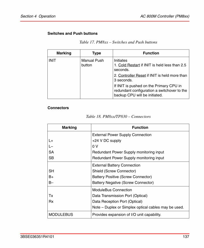
Section 4 Operation AC 800M Controller (PM8xx)
Switches and Push buttons
Connectors
Table 17. PM8xx – Switches and Push buttons
Marking Type Function
INIT Manual Push button
Initiates1. Cold Restart if INIT is held less than 2.5 seconds.
2. Controller Reset if INIT is held more than 3 seconds.
If INIT is pushed on the Primary CPU in redundant configuration a switchover to the backup CPU will be initiated.
Table 18. PM8xx/TP830 – Connectors
Marking Function
L+
L–
SA
SB
External Power Supply Connection
+24 V DC supply
0 V
Redundant Power Supply monitoring input
Redundant Power Supply monitoring input
SH
B+
B–
External Battery Connection
Shield (Screw Connector)
Battery Positive (Screw Connector)
Battery Negative (Screw Connector)
Tx
Rx
ModuleBus Connection
Data Transmission Port (Optical)
Data Reception Port (Optical)
Note – Duplex or Simplex optical cables may be used.
MODULEBUS Provides expansion of I/O unit capability.
3BSE036351R4101 137
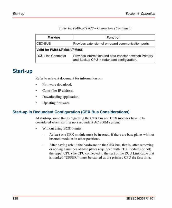
Start-up Section 4 Operation
Start-upRefer to relevant document for information on:
• Firmware download,
• Controller IP address,
• Downloading application,
• Updating firmware.
Start-up in Redundant Configuration (CEX Bus Considerations)
At start-up, some things regarding the CEX bus and CEX modules have to be considered when starting up a redundant AC 800M system:
• Without using BC810 units:
– At least one CEX module must be inserted, if there are base plates without inserted modules in other positions.
– After having rebuilt the hardware on the CEX bus, that is, after removing or adding a number of base plates (equipped with CEX modules or not) the upper CPU (the CPU connected to the part of the RCU Link cable that is marked “UPPER”) must be started as the primary CPU the first time.
CEX-BUS Provides extension of on-board communication ports.
Valid for PM861/PM864/PM865
RCU Link Connector Provides information and data transfer between Primary and Backup CPU in redundant configuration.
Table 18. PM8xx/TP830 – Connectors (Continued)
Marking Function
138 3BSE036351R4101
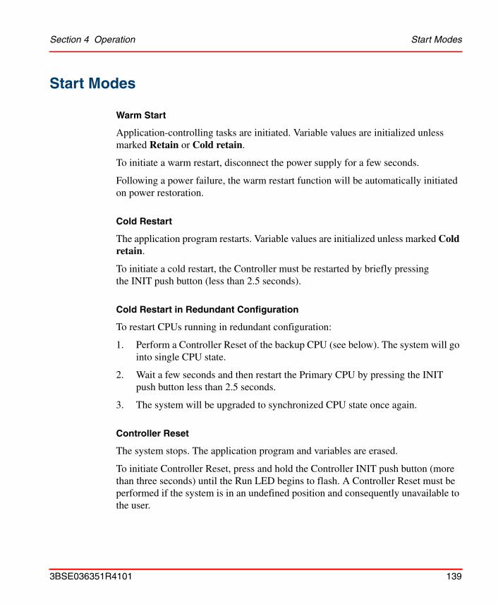
Section 4 Operation Start Modes
Start Modes
Warm Start
Application-controlling tasks are initiated. Variable values are initialized unless marked Retain or Cold retain.
To initiate a warm restart, disconnect the power supply for a few seconds.
Following a power failure, the warm restart function will be automatically initiated on power restoration.
Cold Restart
The application program restarts. Variable values are initialized unless marked Cold retain.
To initiate a cold restart, the Controller must be restarted by briefly pressing the INIT push button (less than 2.5 seconds).
Cold Restart in Redundant Configuration
To restart CPUs running in redundant configuration:
1. Perform a Controller Reset of the backup CPU (see below). The system will go into single CPU state.
2. Wait a few seconds and then restart the Primary CPU by pressing the INIT push button less than 2.5 seconds.
3. The system will be upgraded to synchronized CPU state once again.
Controller Reset
The system stops. The application program and variables are erased.
To initiate Controller Reset, press and hold the Controller INIT push button (more than three seconds) until the Run LED begins to flash. A Controller Reset must be performed if the system is in an undefined position and consequently unavailable to the user.
3BSE036351R4101 139

Automatic Switch-Over to Backup CPU Section 4 Operation
Controller Reset in Redundant Configuration
Follow the steps below to perform a Controller Reset in redundant configuration:
1. Perform a Controller Reset of the backup CPU. The system will go single CPU state.
2. Wait a few seconds and then perform a Controller Reset on the Primary CPU.
Automatic Switch-Over to Backup CPU In a redundant configuration an automatic switch-over from the Primary CPU to the Backup CPU occurs in the following situations, provided they are in synchronized state (DUAL LED is lit):
• Memory error in the Primary CPU.
• Other HW-error in the Primary CPU, which causes CPU crash.
• Severe communication errors on the Control network, that is, loss of both network ports in the Primary CPU.
• Severe communication errors on the ModuleBus (if ModuleBus is part of the HW configuration) that is, loss of clusters in the Primary CPU.
Note that a Backup CPU with severe communication errors on the ModuleBus will be rejected (if ModuleBus is part of the HW configuration) and synchronized state will never be reached as long as error remains.
140 3BSE036351R4101

Section 4 Operation Verification of Satisfactory AC 800M Operation
Verification of Satisfactory AC 800M OperationTo affirm, following start-up, that the AC 800M Controller and all associated units are operating correctly, see Table 19 on page 141.
Verification of Single CPU
Check the status of each LED indicator and compare it against the criteria listed in the table. If the status is other than that listed, see Fault-Finding Procedures on page 157.
Table 19. AC 800M Controller – Verification of Satisfactory System Operation
LED Indicator StatusAC 800M
ControllerStatus
PM8xx Processor Unit
F(ault) Red LED must be OFF OK
R(un) Green LED must be ON (steady) OK
P(owok) Green LED must be ON (steady) OK
B(attery) Green LED must be ON (steady) OK
BC810 CEX-Bus Interconnection Unit
F(ault) Red LED must be OFF OK
R(un) Green LED must be ON (steady) OK
EPOK Yellow LED must be ON (if external power is connected) OK
SM810
F(ault) Red LED must be OFF OK
R(un) Green LED must be ON (steady) OK
CI851 PROFIBUS DP-V0 Unit
F(ault) Red LED must be OFF OK
R(un) Green LED must be ON (steady) OK
3BSE036351R4101 141
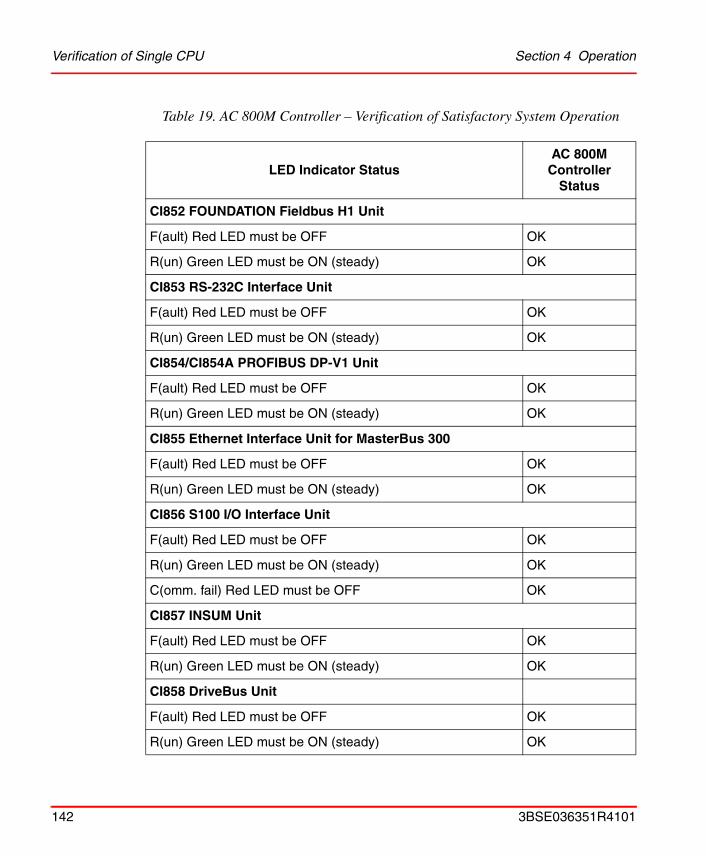
Verification of Single CPU Section 4 Operation
CI852 FOUNDATION Fieldbus H1 Unit
F(ault) Red LED must be OFF OK
R(un) Green LED must be ON (steady) OK
CI853 RS-232C Interface Unit
F(ault) Red LED must be OFF OK
R(un) Green LED must be ON (steady) OK
CI854/CI854A PROFIBUS DP-V1 Unit
F(ault) Red LED must be OFF OK
R(un) Green LED must be ON (steady) OK
CI855 Ethernet Interface Unit for MasterBus 300
F(ault) Red LED must be OFF OK
R(un) Green LED must be ON (steady) OK
CI856 S100 I/O Interface Unit
F(ault) Red LED must be OFF OK
R(un) Green LED must be ON (steady) OK
C(omm. fail) Red LED must be OFF OK
CI857 INSUM Unit
F(ault) Red LED must be OFF OK
R(un) Green LED must be ON (steady) OK
CI858 DriveBus Unit
F(ault) Red LED must be OFF OK
R(un) Green LED must be ON (steady) OK
Table 19. AC 800M Controller – Verification of Satisfactory System Operation
LED Indicator StatusAC 800M
ControllerStatus
142 3BSE036351R4101
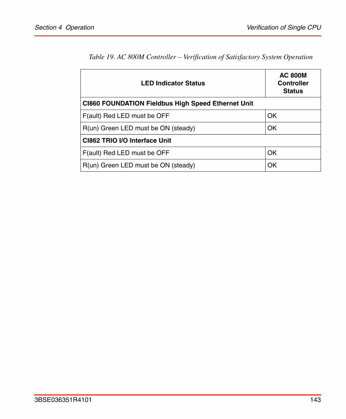
Section 4 Operation Verification of Single CPU
CI860 FOUNDATION Fieldbus High Speed Ethernet Unit
F(ault) Red LED must be OFF OK
R(un) Green LED must be ON (steady) OK
CI862 TRIO I/O Interface Unit
F(ault) Red LED must be OFF OK
R(un) Green LED must be ON (steady) OK
Table 19. AC 800M Controller – Verification of Satisfactory System Operation
LED Indicator StatusAC 800M
ControllerStatus
3BSE036351R4101 143
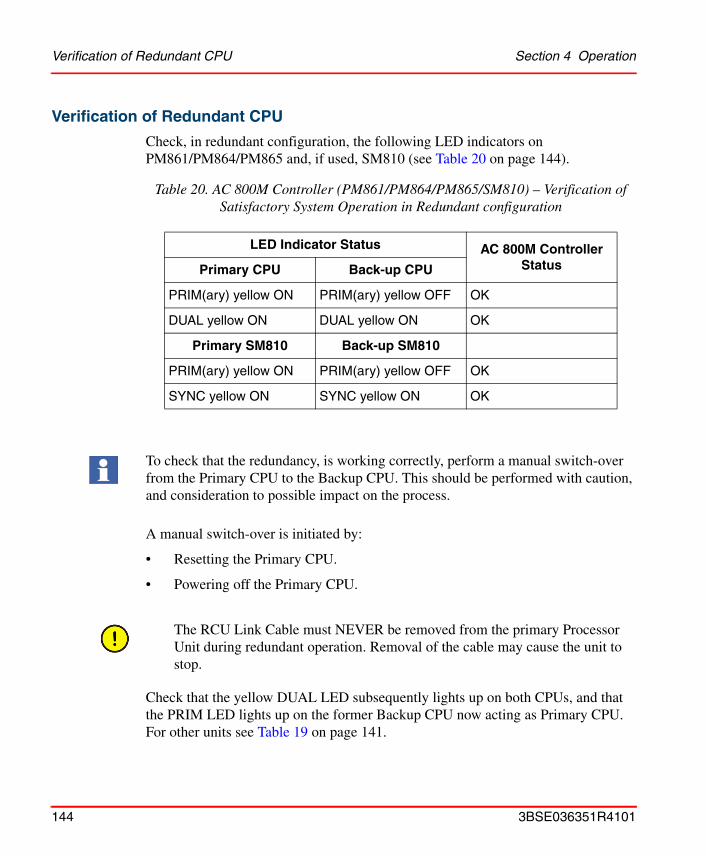
Verification of Redundant CPU Section 4 Operation
Verification of Redundant CPU
Check, in redundant configuration, the following LED indicators on PM861/PM864/PM865 and, if used, SM810 (see Table 20 on page 144).
A manual switch-over is initiated by:
• Resetting the Primary CPU.
• Powering off the Primary CPU.
Check that the yellow DUAL LED subsequently lights up on both CPUs, and that the PRIM LED lights up on the former Backup CPU now acting as Primary CPU. For other units see Table 19 on page 141.
Table 20. AC 800M Controller (PM861/PM864/PM865/SM810) – Verification of Satisfactory System Operation in Redundant configuration
LED Indicator Status AC 800M Controller StatusPrimary CPU Back-up CPU
PRIM(ary) yellow ON PRIM(ary) yellow OFF OK
DUAL yellow ON DUAL yellow ON OK
Primary SM810 Back-up SM810
PRIM(ary) yellow ON PRIM(ary) yellow OFF OK
SYNC yellow ON SYNC yellow ON OK
To check that the redundancy, is working correctly, perform a manual switch-over from the Primary CPU to the Backup CPU. This should be performed with caution, and consideration to possible impact on the process.
The RCU Link Cable must NEVER be removed from the primary Processor Unit during redundant operation. Removal of the cable may cause the unit to stop.
144 3BSE036351R4101
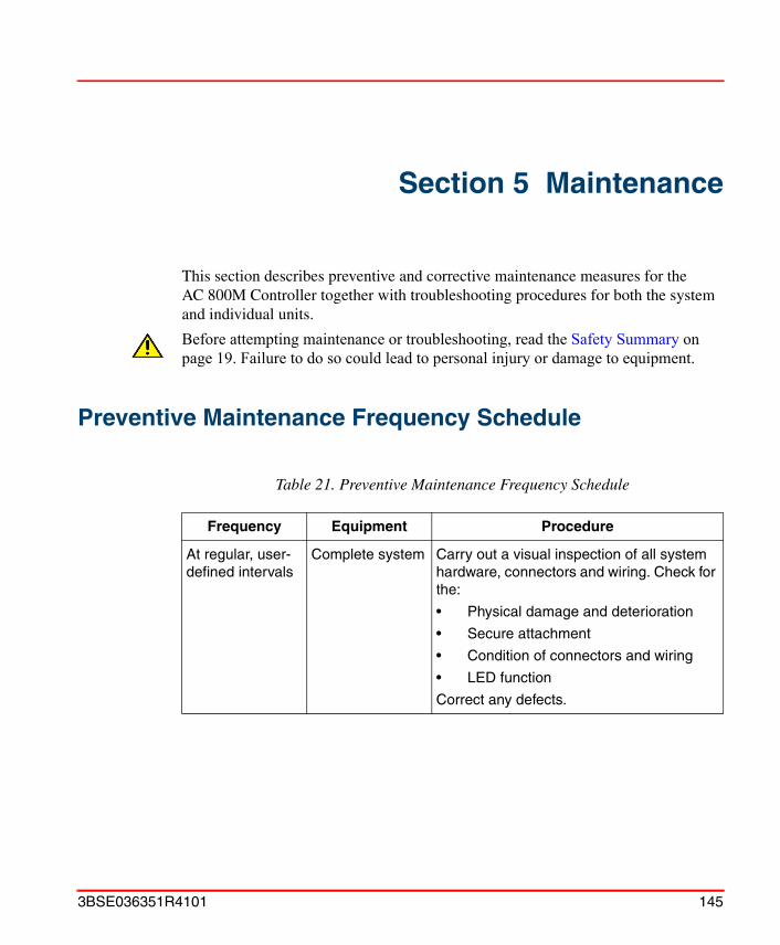
Section 5 Maintenance
This section describes preventive and corrective maintenance measures for the AC 800M Controller together with troubleshooting procedures for both the system and individual units.
Preventive Maintenance Frequency Schedule
Before attempting maintenance or troubleshooting, read the Safety Summary on page 19. Failure to do so could lead to personal injury or damage to equipment.
Table 21. Preventive Maintenance Frequency Schedule
Frequency Equipment Procedure
At regular, user-defined intervals
Complete system Carry out a visual inspection of all system hardware, connectors and wiring. Check for the:
• Physical damage and deterioration
• Secure attachment
• Condition of connectors and wiring
• LED function
Correct any defects.
3BSE036351R4101 145

Changing the Battery Section 5 Maintenance
Changing the Battery
Internal Battery
The internal battery is mounted inside the PM8xx processor unit. Since the battery is not rechargeable, it is important to exchange it on a regular basis (refer to the Maintenance Frequency Schedule for further details). For details of correct battery polarity, remove the right-hand cover from the battery housing (see see Figure 45 on page 147 and Figure 46 on page 148).
Specifications for the internal battery:
• Type: Low-rate lithium battery, 3.6 V, 950 mAh.
• Size: ANSI Size ½ AA / IEC size ½ R6
• Lithium contents: 0.3 g
2 Years PM8xx
Internal Battery
(if fitted)
Change battery
See Internal Battery on page 146
5 Years SB821
External Battery
(if fitted)
Change battery
See SB821 External Battery Unit on page 149
Due to the batteries being connected in parallel, it is necessary, when using the SB821 external battery, to remove the internal battery from the PM8xx in order to avoid reducing available memory back-up time. In addition, status monitoring is only provided for one battery.
It is possible to replace the internal battery with the AC 800M Controller online. However, be sure to observe standard safe working practices at all times.
Table 21. Preventive Maintenance Frequency Schedule (Continued)
Frequency Equipment Procedure
146 3BSE036351R4101
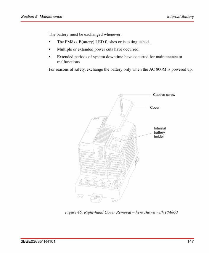
Section 5 Maintenance Internal Battery
The battery must be exchanged whenever:
• The PM8xx B(attery) LED flashes or is extinguished.
• Multiple or extended power cuts have occurred.
• Extended periods of system downtime have occurred for maintenance or malfunctions.
For reasons of safety, exchange the battery only when the AC 800M is powered up.
Figure 45. Right-hand Cover Removal – here shown with PM860
Cover
Captive screw
Internalbatteryholder
3BSE036351R4101 147

Internal Battery Section 5 Maintenance
To exchange the internal battery:
1. Using a blade screwdriver, release the captive screw from the PM8xx and remove the right-hand cover.
2. Identify and remove the internal battery.
3. When power is re-established, ensure that the B(attery) LED is illuminated
4. Replace the PM8xx right-hand cover and tighten the screw.
5. Dispose of the run-down Lithium battery in an approved manner.
Insert a serviceable battery and check that battery polarity and orientation are correct, according to the marking on the housing.
Figure 46. Internal Battery Location – here shown with PM860
FRPB
INIT
PM860
TxRx
CN1 CN2 COM3 COM4
+
–
Tx Tx TxRx Rx Rx
batteryInternal
148 3BSE036351R4101

Section 5 Maintenance SB821 External Battery Unit
SB821 External Battery Unit
The external battery is mounted inside the SB821 External Battery unit. Since the battery is not rechargeable, it is important to exchange it on a regular basis (refer to the Maintenance Frequency Schedule for further details). For access to the battery and housing, remove the cover (see Figure 47 on page 151). When replacing the battery, be sure to check that polarity and orientation are correct.
Specifications for the external battery:
• Type: Low-rate lithium battery, 3.6 V, 16 Ah
• Size: ANSI Size D / IEC R20
• Lithium contents: 5.6 g
The battery must be exchanged whenever:
• The PM8xx B(attery) LED flashes or is extinguished.
• Multiple or extended power cuts have occurred.
• Extended periods of system downtime have occurred for maintenance or malfunctions.
Due to the batteries being connected in parallel, it is necessary, when using the SB821 external battery, to remove the internal battery from the processor unit in order to avoid reducing available memory back-up time. In addition, status monitoring is only provided for one battery.
3BSE036351R4101 149
SB821 External Battery Unit Section 5 Maintenance
Changing the Battery in an SB821 External Battery Unit
To change an external battery:
1. Disconnect the SB821 unit cable connector.
2. Release the SB821 unit from the DIN-rail.
3. Carefully remove the SB821 unit cover and identify the external battery.
4. Read and comply with the Warning label/text on the external battery.
5. Carefully remove the battery.
6. Insert a serviceable battery and check that battery polarity and orientation are correct. For further battery details see SB821 External Battery – AC 800M Memory Back-up on page 261.
7. Replace the cover, mount the unit onto the DIN rail, and reconnect the cable.
8. When power is re-established, check that the B(attery) LED lights up.
9. Dispose of the run-down Lithium battery in an approved manner.
150 3BSE036351R4101
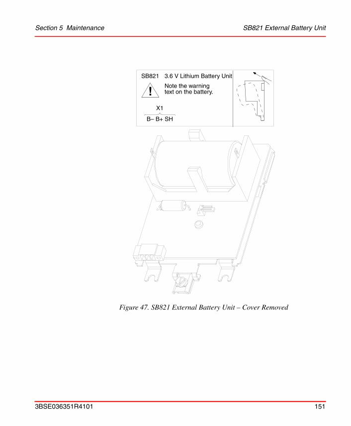
Section 5 Maintenance SB821 External Battery Unit
Figure 47. SB821 External Battery Unit – Cover Removed
!SB821 3.6 V Lithium Battery Unit
Note the warningtext on the battery.
X1
B– B+ SH
3BSE036351R4101 151

Unit Change Online Section 5 Maintenance
Unit Change OnlineChange online entails adding or removing units in a controller without disturbing the execution of the running application program. Units are connected to the CEX-Bus and the electrical ModuleBus (S800 I/O).
CEX-BusCommunication interfaces (CI8xx) Can be removed or replaced online.
Restrictions apply, refer to the installation section for each interface.
Baseplates for CI8xx (TP8xx) Must not be changed online.
ModuleBusS800 I/O units Can be removed or replaced online.
Module Terminal Units (MTU:s) Must not be changed online
Redundant CPUsProcessor unit Can be removed or replaced online
(see the next following pages)
It is not allowed to manipulate CEX bus baseplates in a powered and running system. Before changing or removing a baseplate, all CEX modules on that segment must be removed.
152 3BSE036351R4101
Section 5 Maintenance Exchange of CPU in Redundant Configuration without BC810
Exchange of CPU in Redundant Configuration without BC810
1. Disconnect the Power Supply Socket from the processor unit.
2. Disconnect the RCU Link Cable and optical ModuleBus cable from the processor unit to be exchanged.
3. Using a blade screwdriver, release the two spring-loaded captive screws on the processor unit cover.
4. Carefully remove the processor unit.
5. Fit the new processor unit and tighten the screws.
6. Reconnect the Power Supply Socket to the new processor unit.
7. Reconnect the optical ModuleBus and RCU Link Cable.
8. Press the INIT push button on the replaced processor unit. Observe the startup procedure and make sure that Dual mode is reached, that the Dual LED is lit on both processor units.
Only the PM86x can be exchanged during operation, not the associated baseplate.
Follow the steps below to exchange a halted processor unit:
You do not have to disconnect the RCU link cable completely in order to exchange a halted processor unit. Only disconnect the backup CPU, thus still keep the RCU link cable connected to the primary CPU (now running in a single state).
The just replaced (broken) CPU might still have the IP address of the primary CPU. If it, for example, is installed later on for testing on the same control network it might disturb the communication to the active system running the application. Therefore use the IP Config tool to modify the IP address of the just replaced CPU immediately.
3BSE036351R4101 153
Exchange of CPU in Redundant Configuration with BC810 Section 5 Maintenance
Exchange of CPU in Redundant Configuration with BC810If the BC810 is powered from an external power source, the entire CPU, with baseplate, can be replaced during operation.
1. Disconnect the Power Supply Socket from the processor unit.
2. Disconnect the RCU Link Cable and optical ModuleBus cable from the processor unit to be exchanged.
3. Disconnect the Control Network cables.
4. Rotate the locking device to the SLIDE position (2) on the unit baseplate, see Figure 9 on page 51.
5. Gently ease the unit/baseplate sideways in order to release the contacts of the unit.
6. Turn the locking device anti-clockwise to the OPEN position (1) and ease the unit baseplate outward and upward at the base. Lift the unit to remove it from the DIN-rail.
7. Mount the new unit, see Mounting AC 800M Units onto DIN-Rail on page 49, and fit it to BC810 CEX-Bus.
8. Reconnect the Power Supply Socket to the new processor unit.
9. Reconnect the optical ModuleBus and the RCU Link Cable.
10. Reconnect the Control Network cables.
Follow the steps below to exchange a halted processor unit:
Do not, under any circumstances, remove the RCU Link Cable from the primary CPU now running in a single state. Removing the cable might cause the CPU to stop.
The unit baseplates are easily disconnected from each other by gently prying them apart with a blade screwdriver (see Figure 12 on page 53).
154 3BSE036351R4101

Section 5 Maintenance Exchange of CPU in Redundant Configuration with BC810
11. Press the INIT push button on the replaced processor unit. Observe the startup procedure and make sure that Dual mode is reached, that the Dual LED is lit on both processor units.The just replaced (broken) CPU might still have the IP address of the primary CPU. If it, for example, is installed later on for testing on the same control network it might disturb the communication to the active system running the application. Therefore used the IP Config tool to modify the IP address of the just replaced CPU immediately.
3BSE036351R4101 155

Corrective Maintenance Procedures Section 5 Maintenance
Corrective Maintenance Procedures
Changing Fuses – ModuleBus and CEX-Bus
To change the TP830 internal ModuleBus and CEX-Bus fuses:
1. Using a blade screwdriver, release the two spring-loaded captive screws on the PM8xx cover.
2. Carefully remove the processor unit.
3. Identify both the ModuleBus and CEX-Bus fuse-holders to the right on the TP830 Baseplate.
4. Using a blade screwdriver, carefully unscrew the fuse-holder containing the defective fuse. Remove the fuse.
5. Insert a new fuse and replace the fuse holder.
6. Replace the processor unit and tighten the cover screws.
7. Check that the relevant LED lights up.
• Upper Fuse-holder – ModuleBus – fuse 2 AF
• Lower Fuse-holder – CEX-Bus – fuse 3.15 AF
• Upper Fuse-holder – ModuleBus – fuse 2 AF
• Lower Fuse-holder – CEX-Bus – fuse 3.15 AF
156 3BSE036351R4101
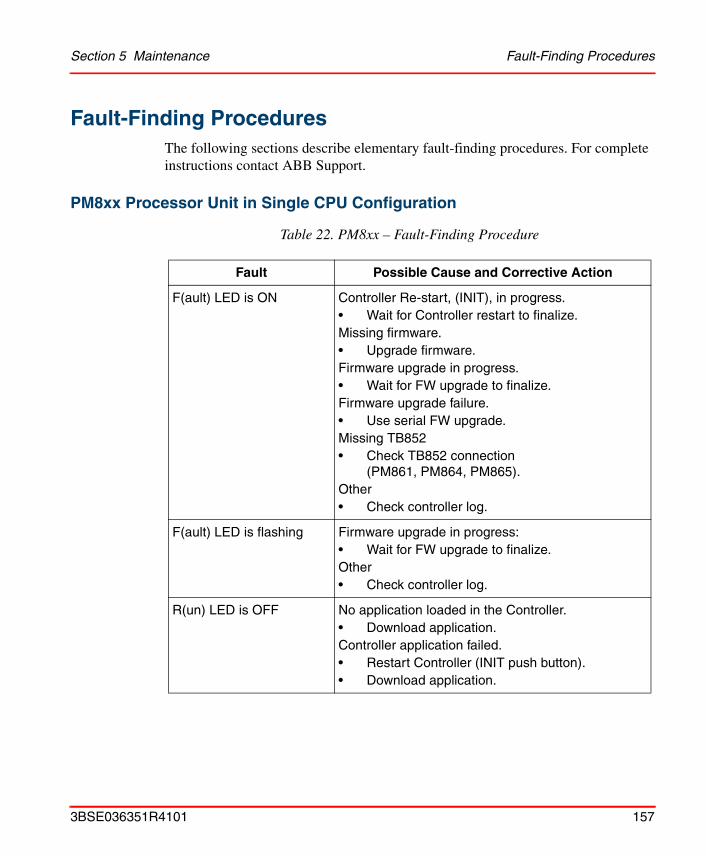
Section 5 Maintenance Fault-Finding Procedures
Fault-Finding ProceduresThe following sections describe elementary fault-finding procedures. For complete instructions contact ABB Support.
PM8xx Processor Unit in Single CPU Configuration
Table 22. PM8xx – Fault-Finding Procedure
Fault Possible Cause and Corrective Action
F(ault) LED is ON Controller Re-start, (INIT), in progress.• Wait for Controller restart to finalize.Missing firmware.• Upgrade firmware.Firmware upgrade in progress.• Wait for FW upgrade to finalize.Firmware upgrade failure.• Use serial FW upgrade.Missing TB852• Check TB852 connection
(PM861, PM864, PM865).Other• Check controller log.
F(ault) LED is flashing Firmware upgrade in progress:• Wait for FW upgrade to finalize.Other• Check controller log.
R(un) LED is OFF No application loaded in the Controller.• Download application.Controller application failed.• Restart Controller (INIT push button).• Download application.
3BSE036351R4101 157
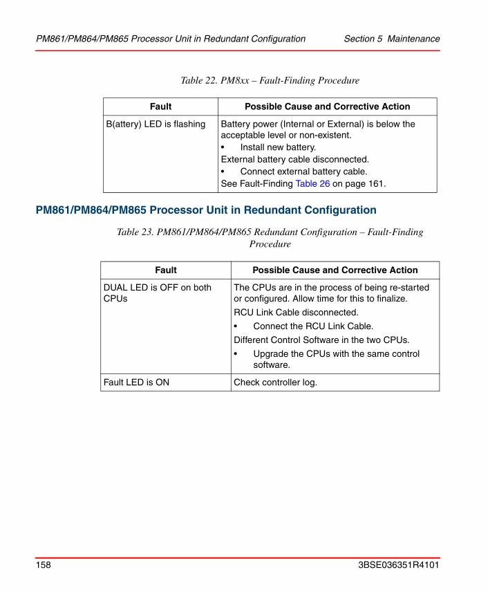
PM861/PM864/PM865 Processor Unit in Redundant Configuration Section 5 Maintenance
PM861/PM864/PM865 Processor Unit in Redundant Configuration
B(attery) LED is flashing Battery power (Internal or External) is below the acceptable level or non-existent.• Install new battery.External battery cable disconnected.• Connect external battery cable.See Fault-Finding Table 26 on page 161.
Table 23. PM861/PM864/PM865 Redundant Configuration – Fault-Finding Procedure
Fault Possible Cause and Corrective Action
DUAL LED is OFF on both CPUs
The CPUs are in the process of being re-started or configured. Allow time for this to finalize.
RCU Link Cable disconnected.
• Connect the RCU Link Cable.
Different Control Software in the two CPUs.
• Upgrade the CPUs with the same control software.
Fault LED is ON Check controller log.
Table 22. PM8xx – Fault-Finding Procedure
Fault Possible Cause and Corrective Action
158 3BSE036351R4101

Section 5 Maintenance CEX-Bus Interconnection Unit - BC810
CEX-Bus Interconnection Unit - BC810
Table 24. BC810 – Fault-Finding Procedure
Fault Possible Cause and Corrective Action
Fault LED is ON No 3.3 V caused by internal short circuit or overvoltage from power supply
• Check external 24 V voltage with voltmeter.
• Send unit for repair.
Run LED is OFF Hardware error.
• Send unit for repair.
Internal fuse blown (BC810)
External fuse blown (TP857)
EPOK LED is OFF when external power is connected
Hardware error.
External fuse blown (TP857)
• Send unit for repair.
C1 or C2 LED OFF despite accessing CEX-units
CEX-Bus units using no interrupt (for example CI851), no action is needed.
3BSE036351R4101 159
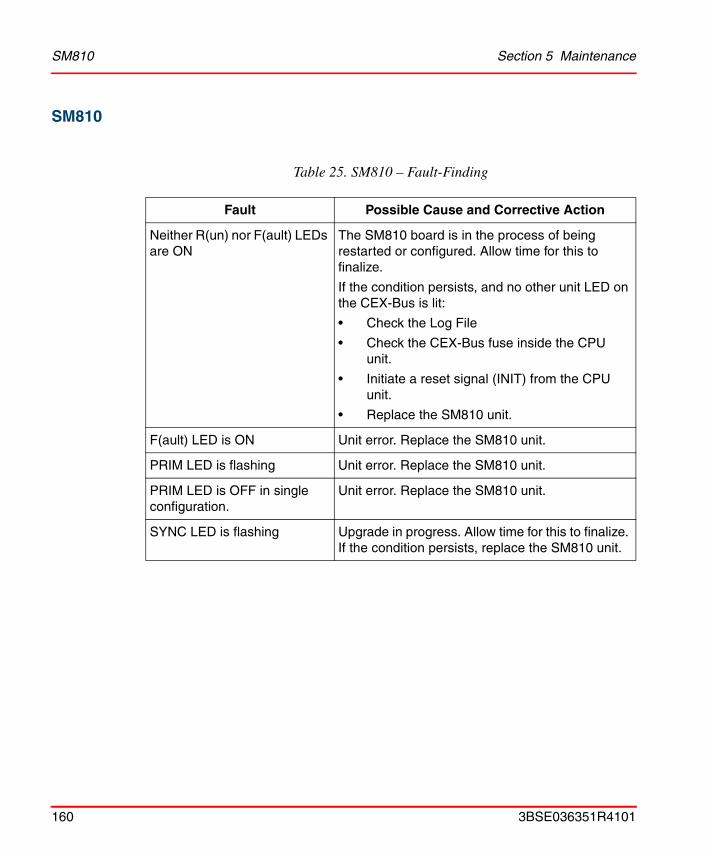
SM810 Section 5 Maintenance
SM810
Table 25. SM810 – Fault-Finding
Fault Possible Cause and Corrective Action
Neither R(un) nor F(ault) LEDs are ON
The SM810 board is in the process of being restarted or configured. Allow time for this to finalize.
If the condition persists, and no other unit LED on the CEX-Bus is lit:
• Check the Log File
• Check the CEX-Bus fuse inside the CPU unit.
• Initiate a reset signal (INIT) from the CPU unit.
• Replace the SM810 unit.
F(ault) LED is ON Unit error. Replace the SM810 unit.
PRIM LED is flashing Unit error. Replace the SM810 unit.
PRIM LED is OFF in single configuration.
Unit error. Replace the SM810 unit.
SYNC LED is flashing Upgrade in progress. Allow time for this to finalize. If the condition persists, replace the SM810 unit.
160 3BSE036351R4101

Section 5 Maintenance Internal Battery / SB821 External Battery
Internal Battery / SB821 External Battery
Table 26. Internal / SB821 External Battery – Fault-Finding
Fault Possible Cause and Corrective Action
B(attery) LED indicator on PM8xx processor unit is flashing
• Renew the PM8xx internal battery
or, (if fitted)
• Check external battery connections.
If condition persists
• Renew the External battery, see SB821 External Battery Unit on page 149.
The system time is incorrect following a power failure
• Ensure that the software installed supports the real-time clock.
• Renew the External Battery, see SB821 External Battery Unit on page 149.
3BSE036351R4101 161
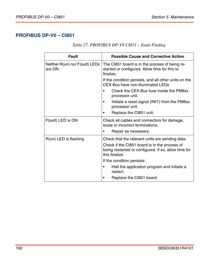
PROFIBUS DP-V0 – CI851 Section 5 Maintenance
PROFIBUS DP-V0 – CI851
Table 27. PROFIBUS DP-V0 CI851 – Fault-Finding
Fault Possible Cause and Corrective Action
Neither R(un) nor F(ault) LEDs are ON
The CI851 board is in the process of being re-started or configured. Allow time for this to finalize.
If the condition persists, and all other units on the CEX-Bus have non-illuminated LEDs:
• Check the CEX-Bus fuse inside the PM8xx processor unit.
• Initiate a reset signal (INIT) from the PM8xx processor unit.
• Replace the CI851 unit.
F(ault) LED is ON Check all cables and connectors for damage, loose or incorrect terminations.
• Repair as necessary.
R(un) LED is flashing Check that the relevant units are sending data.
Check if the CI851 board is in the process of being restarted or configured. If so, allow time for this finalize.
If the condition persists:
• Halt the application program and initiate a restart.
• Replace the CI851 board.
162 3BSE036351R4101
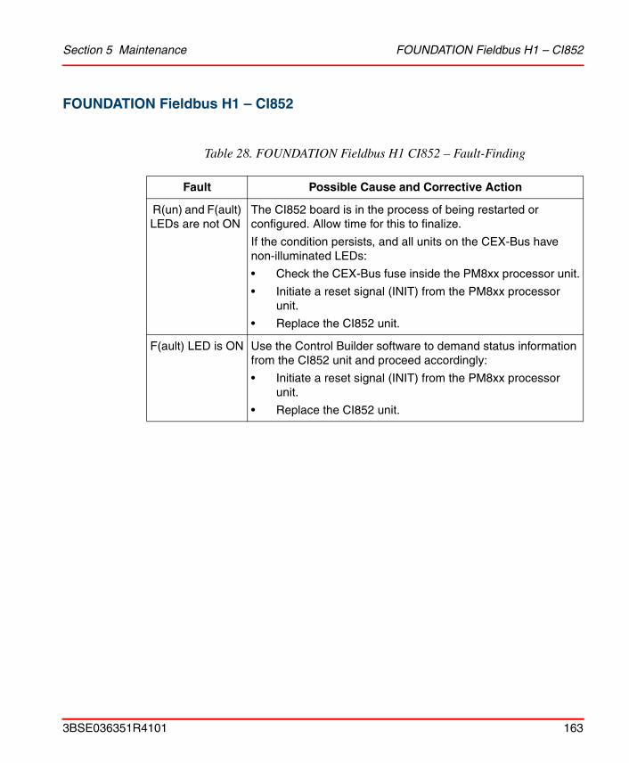
Section 5 Maintenance FOUNDATION Fieldbus H1 – CI852
FOUNDATION Fieldbus H1 – CI852
Table 28. FOUNDATION Fieldbus H1 CI852 – Fault-Finding
Fault Possible Cause and Corrective Action
R(un) and F(ault) LEDs are not ON
The CI852 board is in the process of being restarted or configured. Allow time for this to finalize.
If the condition persists, and all units on the CEX-Bus have non-illuminated LEDs:
• Check the CEX-Bus fuse inside the PM8xx processor unit.
• Initiate a reset signal (INIT) from the PM8xx processor unit.
• Replace the CI852 unit.
F(ault) LED is ON Use the Control Builder software to demand status information from the CI852 unit and proceed accordingly:
• Initiate a reset signal (INIT) from the PM8xx processor unit.
• Replace the CI852 unit.
3BSE036351R4101 163
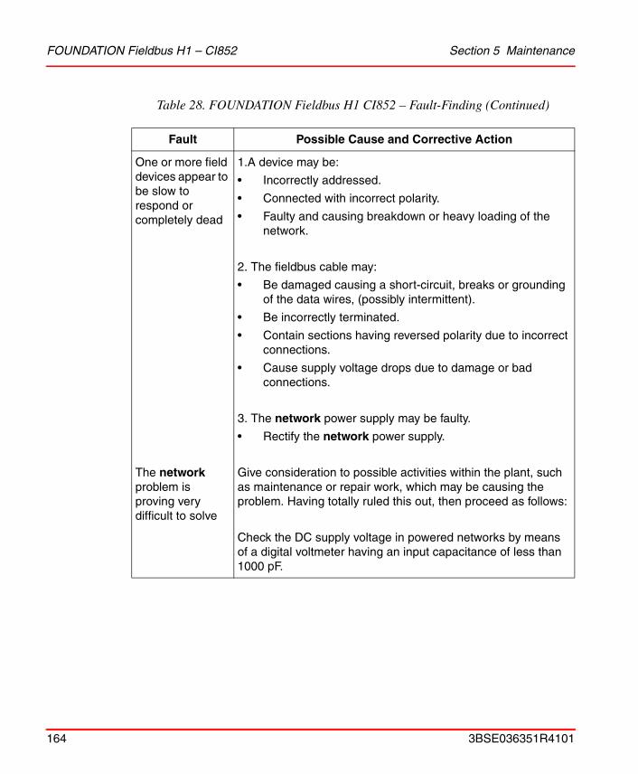
FOUNDATION Fieldbus H1 – CI852 Section 5 Maintenance
One or more field devices appear to be slow to respond or completely dead
The network problem is proving very difficult to solve
1.A device may be:
• Incorrectly addressed.
• Connected with incorrect polarity.
• Faulty and causing breakdown or heavy loading of the network.
2. The fieldbus cable may:
• Be damaged causing a short-circuit, breaks or groundingof the data wires, (possibly intermittent).
• Be incorrectly terminated.
• Contain sections having reversed polarity due to incorrect connections.
• Cause supply voltage drops due to damage or bad connections.
3. The network power supply may be faulty.
• Rectify the network power supply.
Give consideration to possible activities within the plant, such as maintenance or repair work, which may be causing the problem. Having totally ruled this out, then proceed as follows:
Check the DC supply voltage in powered networks by means of a digital voltmeter having an input capacitance of less than 1000 pF.
Table 28. FOUNDATION Fieldbus H1 CI852 – Fault-Finding (Continued)
Fault Possible Cause and Corrective Action
164 3BSE036351R4101
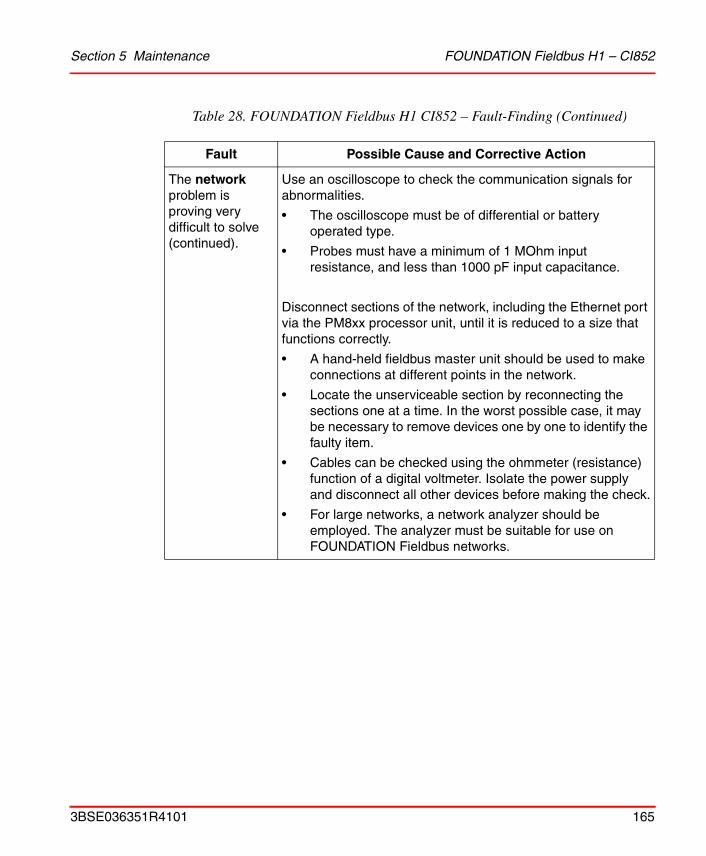
Section 5 Maintenance FOUNDATION Fieldbus H1 – CI852
The network problem is proving very difficult to solve (continued).
Use an oscilloscope to check the communication signals for abnormalities.
• The oscilloscope must be of differential or battery operated type.
• Probes must have a minimum of 1 MOhm input resistance, and less than 1000 pF input capacitance.
Disconnect sections of the network, including the Ethernet port via the PM8xx processor unit, until it is reduced to a size that functions correctly.
• A hand-held fieldbus master unit should be used to make connections at different points in the network.
• Locate the unserviceable section by reconnecting the sections one at a time. In the worst possible case, it may be necessary to remove devices one by one to identify the faulty item.
• Cables can be checked using the ohmmeter (resistance) function of a digital voltmeter. Isolate the power supply and disconnect all other devices before making the check.
• For large networks, a network analyzer should be employed. The analyzer must be suitable for use on FOUNDATION Fieldbus networks.
Table 28. FOUNDATION Fieldbus H1 CI852 – Fault-Finding (Continued)
Fault Possible Cause and Corrective Action
3BSE036351R4101 165
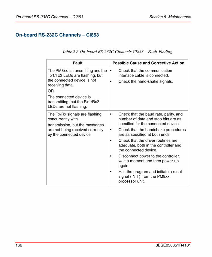
On-board RS-232C Channels – CI853 Section 5 Maintenance
On-board RS-232C Channels – CI853
Table 29. On-board RS-232C Channels CI853 – Fault-Finding
Fault Possible Cause and Corrective Action
The PM8xx is transmitting and the Tx1/Tx2 LEDs are flashing, but the connected device is not receiving data.
OR
The connected device is transmitting, but the Rx1/Rx2 LEDs are not flashing.
• Check that the communication interface cable is connected.
• Check the hand-shake signals.
The Tx/Rx signals are flashing concurrently with
transmission, but the messages are not being received correctly by the connected device.
• Check that the baud rate, parity, and number of data and stop bits are as specified for the connected device.
• Check that the handshake procedures are as specified at both ends.
• Check that the driver routines are adequate, both in the controller and the connected device.
• Disconnect power to the controller, wait a moment and then power-up again.
• Halt the program and initiate a reset signal (INIT) from the PM8xx processor unit.
166 3BSE036351R4101
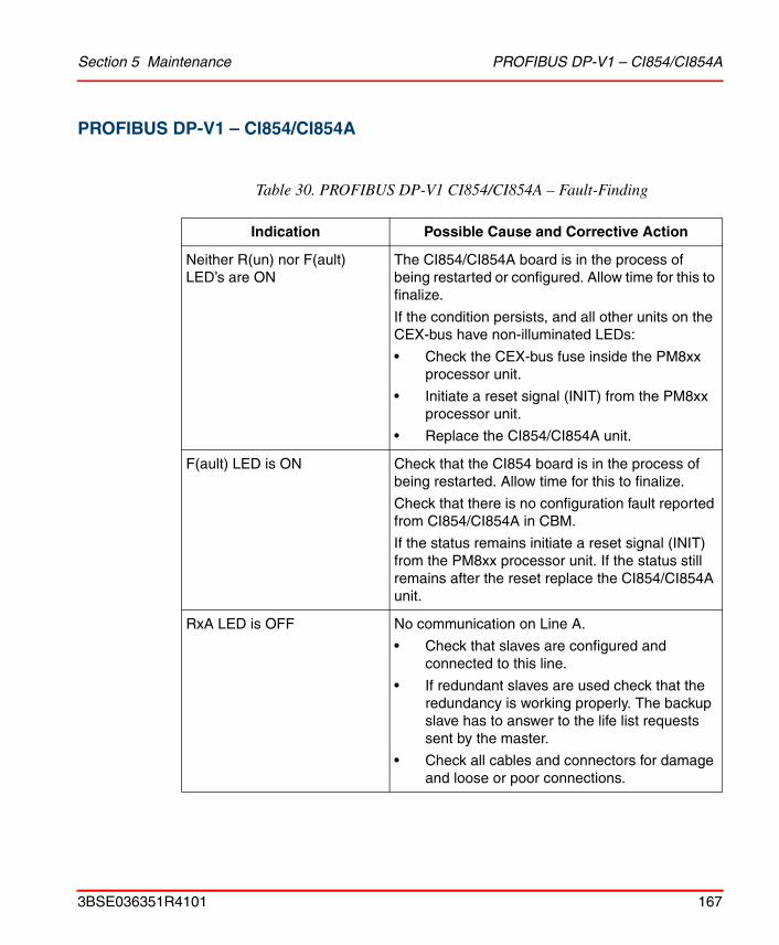
Section 5 Maintenance PROFIBUS DP-V1 – CI854/CI854A
PROFIBUS DP-V1 – CI854/CI854A
Table 30. PROFIBUS DP-V1 CI854/CI854A – Fault-Finding
Indication Possible Cause and Corrective Action
Neither R(un) nor F(ault) LED’s are ON
The CI854/CI854A board is in the process of being restarted or configured. Allow time for this to finalize.
If the condition persists, and all other units on the CEX-bus have non-illuminated LEDs:
• Check the CEX-bus fuse inside the PM8xx processor unit.
• Initiate a reset signal (INIT) from the PM8xx processor unit.
• Replace the CI854/CI854A unit.
F(ault) LED is ON Check that the CI854 board is in the process of being restarted. Allow time for this to finalize.
Check that there is no configuration fault reported from CI854/CI854A in CBM.
If the status remains initiate a reset signal (INIT) from the PM8xx processor unit. If the status still remains after the reset replace the CI854/CI854A unit.
RxA LED is OFF No communication on Line A.
• Check that slaves are configured and connected to this line.
• If redundant slaves are used check that the redundancy is working properly. The backup slave has to answer to the life list requests sent by the master.
• Check all cables and connectors for damage and loose or poor connections.
3BSE036351R4101 167
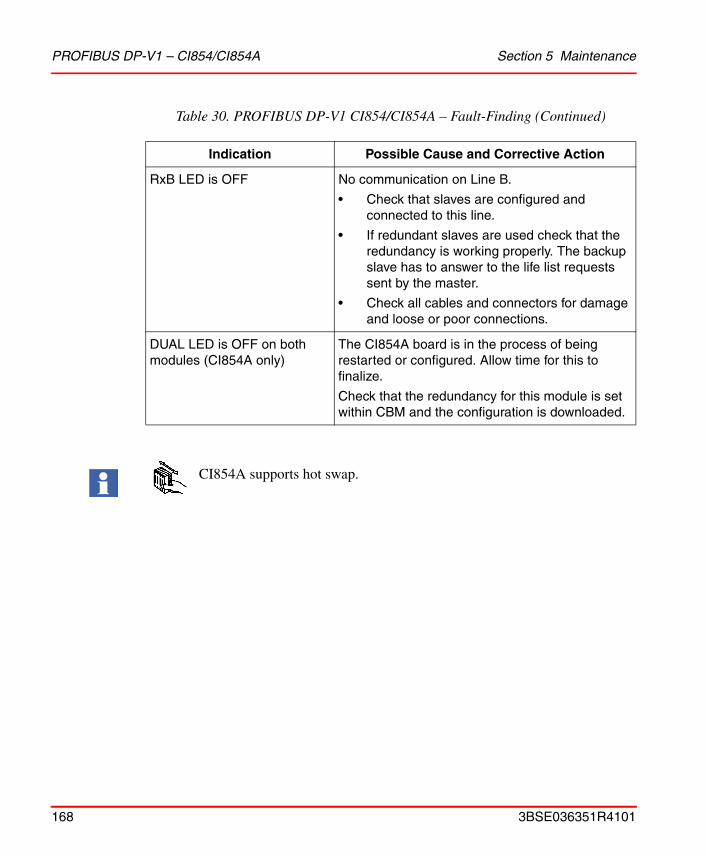
PROFIBUS DP-V1 – CI854/CI854A Section 5 Maintenance
RxB LED is OFF No communication on Line B.
• Check that slaves are configured and connected to this line.
• If redundant slaves are used check that the redundancy is working properly. The backup slave has to answer to the life list requests sent by the master.
• Check all cables and connectors for damage and loose or poor connections.
DUAL LED is OFF on both modules (CI854A only)
The CI854A board is in the process of being restarted or configured. Allow time for this to finalize.
Check that the redundancy for this module is set within CBM and the configuration is downloaded.
CI854A supports hot swap.
Table 30. PROFIBUS DP-V1 CI854/CI854A – Fault-Finding (Continued)
Indication Possible Cause and Corrective Action
168 3BSE036351R4101
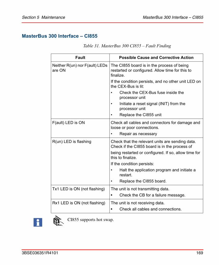
Section 5 Maintenance MasterBus 300 Interface – CI855
MasterBus 300 Interface – CI855
Table 31. MasterBus 300 CI855 – Fault Finding
Fault Possible Cause and Corrective Action
Neither R(un) nor F(ault) LEDs are ON
The CI855 board is in the process of being restarted or configured. Allow time for this to finalize.If the condition persists, and no other unit LED on the CEX-Bus is lit:• Check the CEX-Bus fuse inside the
processor unit• Initiate a reset signal (INIT) from the
processor unit• Replace the CI855 unit
F(ault) LED is ON Check all cables and connectors for damage and loose or poor connections.• Repair as necessary
R(un) LED is flashing Check that the relevant units are sending data. Check if the CI855 board is in the process ofbeing restarted or configured. If so, allow time for this to finalize.If the condition persists:• Halt the application program and initiate a
restart.• Replace the CI855 board.
Tx1 LED is ON (not flashing) The unit is not transmitting data.
• Check the CB for a failure message.
Rx1 LED is ON (not flashing) The unit is not receiving data.
• Check all cables and connections.
CI855 supports hot swap.
3BSE036351R4101 169

S100 I/O Interface – CI856 Section 5 Maintenance
S100 I/O Interface – CI856
Table 32. S100 I/O CI856 – Fault Finding
Fault Possible Cause and Corrective Action
Neither R(un) nor F(ault) LED’s are ON
The CI856 unit is in the process of being configured. Allow time for this to finalize.
If the condition persists, and no other unit LED on the CEX-Bus is lit:
• Check the CEX-Bus fuse inside the PM8xx processor unit
• Initiate a reset signal (INIT) from the PM8xx processor unit
• Replace the CI856 unit
F(ault) LED is ON The CI856 unit is in the process of being restarted. Allow time for this to finalize.
Replace unit if the condition persists.
CI856 supports hot swap.
170 3BSE036351R4101
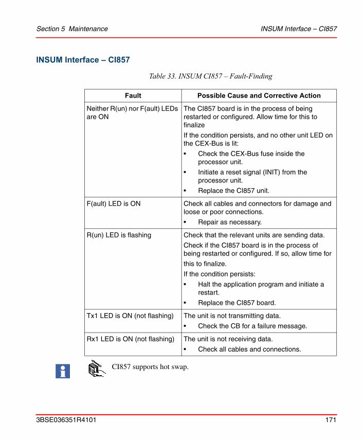
Section 5 Maintenance INSUM Interface – CI857
INSUM Interface – CI857
Table 33. INSUM CI857 – Fault-Finding
Fault Possible Cause and Corrective Action
Neither R(un) nor F(ault) LEDs are ON
The CI857 board is in the process of being restarted or configured. Allow time for this to finalize
If the condition persists, and no other unit LED on the CEX-Bus is lit:
• Check the CEX-Bus fuse inside the processor unit.
• Initiate a reset signal (INIT) from the processor unit.
• Replace the CI857 unit.
F(ault) LED is ON Check all cables and connectors for damage and loose or poor connections.
• Repair as necessary.
R(un) LED is flashing Check that the relevant units are sending data.Check if the CI857 board is in the process of being restarted or configured. If so, allow time for
this to finalize.
If the condition persists:
• Halt the application program and initiate a restart.
• Replace the CI857 board.
Tx1 LED is ON (not flashing) The unit is not transmitting data.
• Check the CB for a failure message.
Rx1 LED is ON (not flashing) The unit is not receiving data.
• Check all cables and connections.
CI857 supports hot swap.
3BSE036351R4101 171

DriveBus Interface - CI858 Section 5 Maintenance
DriveBus Interface - CI858
Table 34. DriveBus CI858 – Fault-Finding
Fault Possible Cause and Corrective Action
Neither R(un) nor F(ault) LEDs are ON
The CI858 board is in the process of being restarted or configured. Allow time for this to finalize
If the condition persists, and no other unit LED on the CEX-Bus is lit:
• Check the CEX-Bus fuse inside the processor unit.
• Initiate a reset signal (INIT) from the processor unit.
• Replace the CI858 unit.
F(ault) LED is ON Unit error or initializing.
Check all cables and connectors for damage and loose or poor connections.
• Repair as necessary.
Dbus;Rx1 LED is ON (not flashing)
The unit is not receiving data.
• Check all cables and connections.
• Replace the CI858 unit.
Dbus;Rx1 LED is OFF No signals are sent to the unit or unit error.
• Check all cables and connections.
• Replace the CI858 unit.
Dbus;Tx1 LED is ON (not flashing)
The unit is not transmitting data.
• Check the CB for a failure message.
• If there is no failure message in the CB replace the CI858 unit.
Dbus;Tx1 LED is OFF The unit is not properly configured or unit error.
• Check the CB for a failure message.
• If there is no failure message replace the CI858 unit.
172 3BSE036351R4101
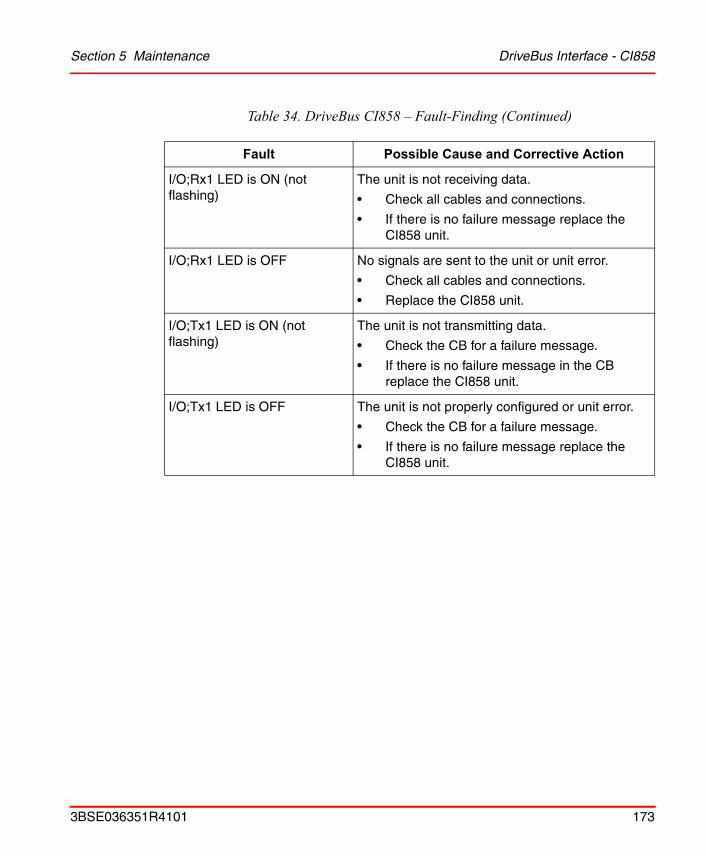
Section 5 Maintenance DriveBus Interface - CI858
I/O;Rx1 LED is ON (not flashing)
The unit is not receiving data.
• Check all cables and connections.
• If there is no failure message replace the CI858 unit.
I/O;Rx1 LED is OFF No signals are sent to the unit or unit error.
• Check all cables and connections.
• Replace the CI858 unit.
I/O;Tx1 LED is ON (not flashing)
The unit is not transmitting data.
• Check the CB for a failure message.
• If there is no failure message in the CB replace the CI858 unit.
I/O;Tx1 LED is OFF The unit is not properly configured or unit error.
• Check the CB for a failure message.
• If there is no failure message replace the CI858 unit.
Table 34. DriveBus CI858 – Fault-Finding (Continued)
Fault Possible Cause and Corrective Action
3BSE036351R4101 173
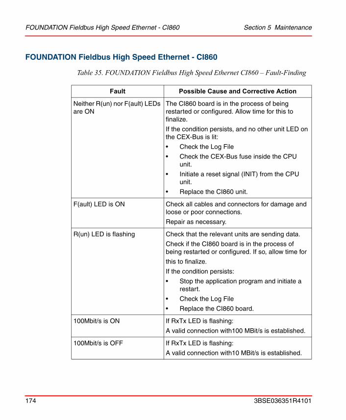
FOUNDATION Fieldbus High Speed Ethernet - CI860 Section 5 Maintenance
FOUNDATION Fieldbus High Speed Ethernet - CI860
Table 35. FOUNDATION Fieldbus High Speed Ethernet CI860 – Fault-Finding
Fault Possible Cause and Corrective Action
Neither R(un) nor F(ault) LEDs are ON
The CI860 board is in the process of being restarted or configured. Allow time for this to finalize.
If the condition persists, and no other unit LED on the CEX-Bus is lit:
• Check the Log File
• Check the CEX-Bus fuse inside the CPU unit.
• Initiate a reset signal (INIT) from the CPU unit.
• Replace the CI860 unit.
F(ault) LED is ON Check all cables and connectors for damage and loose or poor connections.
Repair as necessary.
R(un) LED is flashing Check that the relevant units are sending data.Check if the CI860 board is in the process of being restarted or configured. If so, allow time for
this to finalize.
If the condition persists:
• Stop the application program and initiate a restart.
• Check the Log File
• Replace the CI860 board.
100Mbit/s is ON If RxTx LED is flashing:
A valid connection with100 MBit/s is established.
100Mbit/s is OFF If RxTx LED is flashing:
A valid connection with10 MBit/s is established.
174 3BSE036351R4101

Section 5 Maintenance FOUNDATION Fieldbus High Speed Ethernet - CI860
RxTx LED is ON A link to the corresponding ethernet device is established. No Ethernet packages are sent/received.
RxTx LED is flashing A link to the corresponding ethernet device is established. Ethernet packages are sent/received
RxTx LED is OFF A link with the corresponding ethernet unit is not established
• Check the Log File
• Check the ethernet cable to the corresponding ethernet device.
• Check the corresponding ethernet device.
• Check CI860 unit.
PRIM A yellow LED for indicating the primary unit in redundant configuration.
DUAL The yellow LED indicates the redundant configuration.
CI860 supports hot swap.
Table 35. FOUNDATION Fieldbus High Speed Ethernet CI860 – Fault-Finding
Fault Possible Cause and Corrective Action
3BSE036351R4101 175
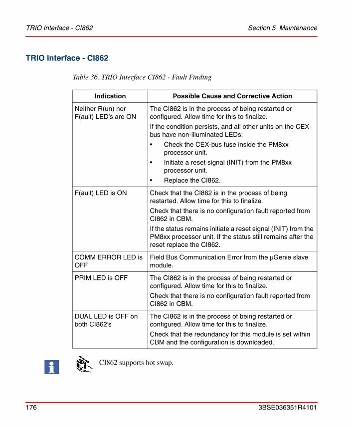
TRIO Interface - CI862 Section 5 Maintenance
TRIO Interface - CI862
Table 36. TRIO Interface CI862 - Fault Finding
Indication Possible Cause and Corrective Action
Neither R(un) nor F(ault) LED’s are ON
The CI862 is in the process of being restarted or configured. Allow time for this to finalize.
If the condition persists, and all other units on the CEX-bus have non-illuminated LEDs:
• Check the CEX-bus fuse inside the PM8xx processor unit.
• Initiate a reset signal (INIT) from the PM8xx processor unit.
• Replace the CI862.
F(ault) LED is ON Check that the CI862 is in the process of being restarted. Allow time for this to finalize.
Check that there is no configuration fault reported from CI862 in CBM.
If the status remains initiate a reset signal (INIT) from the PM8xx processor unit. If the status still remains after the reset replace the CI862.
COMM ERROR LED is OFF
Field Bus Communication Error from the µGenie slave module.
PRIM LED is OFF The CI862 is in the process of being restarted or configured. Allow time for this to finalize.
Check that there is no configuration fault reported from CI862 in CBM.
DUAL LED is OFF on both CI862’s
The CI862 is in the process of being restarted or configured. Allow time for this to finalize.
Check that the redundancy for this module is set within CBM and the configuration is downloaded.
CI862 supports hot swap.
176 3BSE036351R4101
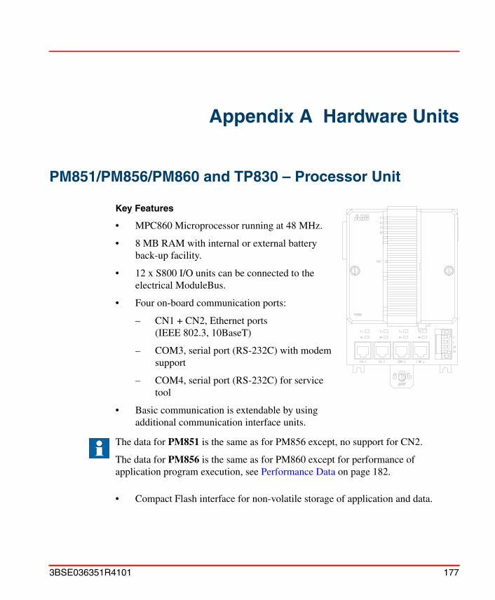
Appendix A Hardware Units
PM851/PM856/PM860 and TP830 – Processor Unit
Key Features
• MPC860 Microprocessor running at 48 MHz.
• 8 MB RAM with internal or external battery back-up facility.
• 12 x S800 I/O units can be connected to the electrical ModuleBus.
• Four on-board communication ports:
– CN1 + CN2, Ethernet ports (IEEE 802.3, 10BaseT)
– COM3, serial port (RS-232C) with modem support
– COM4, serial port (RS-232C) for service tool
• Basic communication is extendable by using additional communication interface units.
• Compact Flash interface for non-volatile storage of application and data.
The data for PM851 is the same as for PM856 except, no support for CN2.
The data for PM856 is the same as for PM860 except for performance of application program execution, see Performance Data on page 182.
3BSE036351R4101 177

Technical Data Appendix A Hardware Units
Technical Data
Technical data for PM851/PM856/PM860 and TP830 is described in Table 37 on page 178.
Table 37. PM851/PM856/PM860 and TP830 – Technical data
Item Value
Memory • 2 MB flash PROM (firmware storage).
• 8 MB of SDRAM.
Power Dissipation 5 W typical
10 W typical (incl. full supply to ModuleBus and CEX-Bus, see Appendix B, Power Consumption).
Current Consumption 180 mA typical (300 mA max.)
(excl. supply of ModuleBus and CEX-Bus, see Appendix B, Power Consumption).
Power Input Connector Four pin, screw connector L+, L–, SA and SB.
Power Supply Requirements
Inputs designated L+ and L– 24 V nominal, variation between 19.2V DC and 30V DC.
Redundant Power Supply Status Inputs
Inputs designated SA, SB
• Max input voltage 30 V
• Min. input voltage for high level 15 V
• Max input voltage for low level 8 V
These inputs are status inputs. The threshold levels are logical “0” or “1” input limits, not power fail limits.
Power Reservoir The processor unit has an internal 5ms power reservoir, sufficient for the CPU to make a controlled power down.
Protection Rating IP20 according to EN60529, IEC 529.
178 3BSE036351R4101
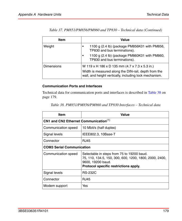
Appendix A Hardware Units Technical Data
Communication Ports and Interfaces
Technical data for communication ports and interfaces is described in Table 38 on page 179.
Weight • 1100 g (2.4 lb) (package PM856K01 with PM856, TP830 and bus terminations).
• 1100 g (2.4 lb) (package PM860K01 with PM860, TP830 and bus terminations).
Dimensions W 119 x H 186 x D 135 mm (4.7 x 7.3 x 5.3 in.)
Width is measured along the DIN-rail, depth from the wall, and height vertically, including lock mechanism.
Table 38. PM851/PM856/PM860 and TP830 Interfaces – Technical data
Item Value
CN1 and CN2 Ethernet Communication(1)
Communication speed 10 Mbit/s (half duplex)
Signal levels IEEE802.3, 10Base-T
Connector RJ45
COM3 Serial Communication
Communication speed Selectable in steps from 75 to 19200 baud.75, 110, 134.5, 150, 300, 600, 1200, 1800, 2000, 2400, 9600, 19200 baud.Protocol specific restrictions apply.
Signal levels RS-232C
Connector RJ45
Modem support Yes
Table 37. PM851/PM856/PM860 and TP830 – Technical data (Continued)
Item Value
3BSE036351R4101 179
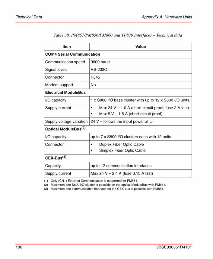
Technical Data Appendix A Hardware Units
COM4 Serial Communication
Communication speed 9600 baud
Signal levels RS-232C
Connector RJ45
Modem support No
Electrical ModuleBus
I/O capacity 1 x S800 I/O base cluster with up to 12 x S800 I/O units.
Supply current • Max 24 V – 1.0 A (short circuit proof, fuse 2 A fast)
• Max 5 V – 1.5 A (short circuit proof)
Supply voltage variation 24 V – follows the input power at L+
Optical ModuleBus(2)
I/O capacity up to 7 x S800 I/O clusters each with 12 units
Connector • Duplex Fiber Optic Cable
• Simplex Fiber Optic Cable
CEX-Bus(3)
Capacity up to 12 communication interfaces
Supply current Max 24 V – 2.4 A (fuse 3.15 A fast)
(1) Only (CN1) Ethernet Communication is supported for PM851.(2) Maximum one S800 I/O cluster is possible on the optical ModuleBus with PM851.(3) Maximum one communication interface on the CEX-bus is possible with PM851.
Table 38. PM851/PM856/PM860 and TP830 Interfaces – Technical data
Item Value
180 3BSE036351R4101
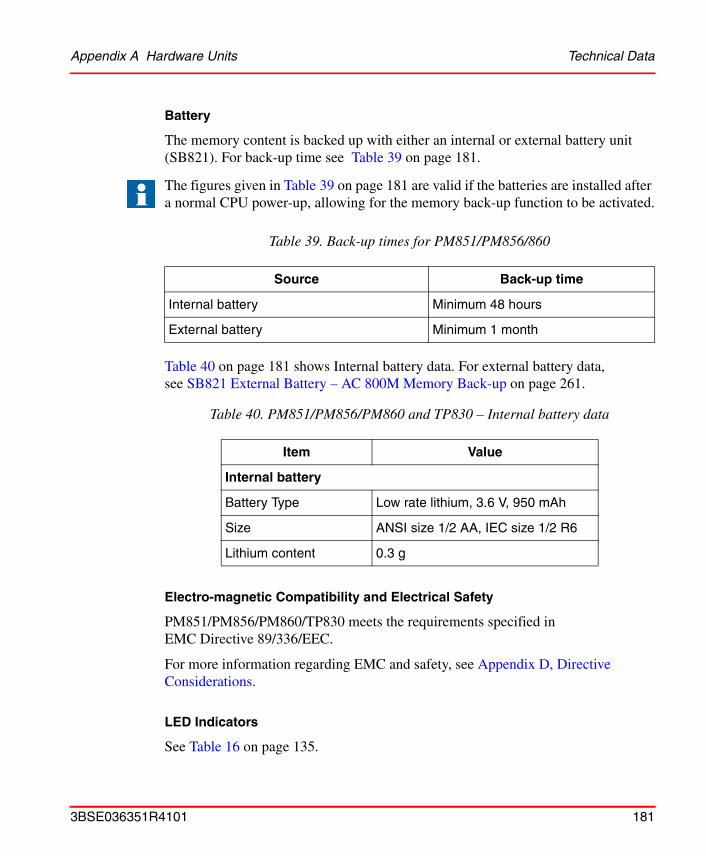
Appendix A Hardware Units Technical Data
Battery
The memory content is backed up with either an internal or external battery unit (SB821). For back-up time see Table 39 on page 181.
Table 40 on page 181 shows Internal battery data. For external battery data, see SB821 External Battery – AC 800M Memory Back-up on page 261.
Electro-magnetic Compatibility and Electrical Safety
PM851/PM856/PM860/TP830 meets the requirements specified in EMC Directive 89/336/EEC.
For more information regarding EMC and safety, see Appendix D, Directive Considerations.
LED Indicators
See Table 16 on page 135.
The figures given in Table 39 on page 181 are valid if the batteries are installed after a normal CPU power-up, allowing for the memory back-up function to be activated.
Table 39. Back-up times for PM851/PM856/860
Source Back-up time
Internal battery Minimum 48 hours
External battery Minimum 1 month
Table 40. PM851/PM856/PM860 and TP830 – Internal battery data
Item Value
Internal battery
Battery Type Low rate lithium, 3.6 V, 950 mAh
Size ANSI size 1/2 AA, IEC size 1/2 R6
Lithium content 0.3 g
3BSE036351R4101 181

Performance Data Appendix A Hardware Units
Performance Data
The PM851/PM856/PM860 differ in performance when executing an application program.
Using the same application program in PM851/PM856 and PM860, the difference in execution time can be expressed as:
Execution time in PM851/PM856 = 2 *Execution time in PM860
Example: If a certain application program has an execution time of 100 ms in PM860, the same application program will have an execution time of 200 ms in PM851/PM856.
182 3BSE036351R4101
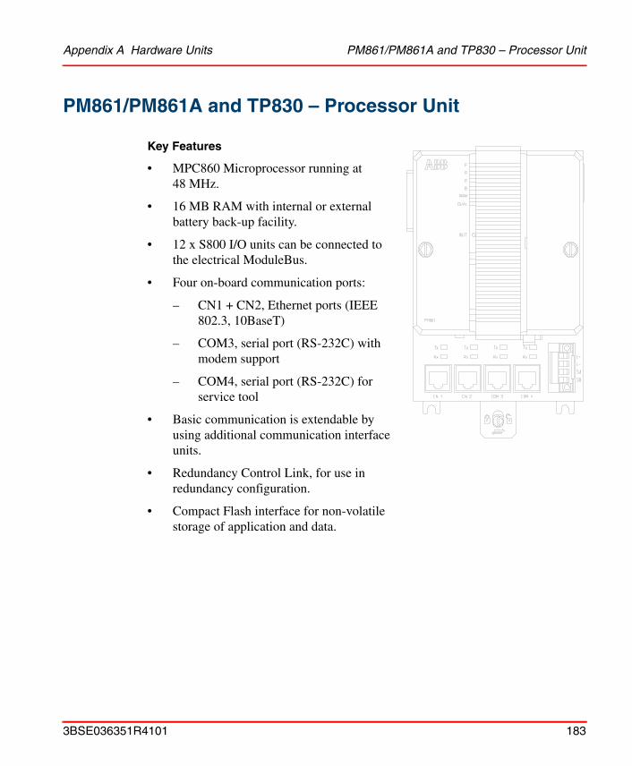
Appendix A Hardware Units PM861/PM861A and TP830 – Processor Unit
PM861/PM861A and TP830 – Processor Unit
Key Features
• MPC860 Microprocessor running at 48 MHz.
• 16 MB RAM with internal or external battery back-up facility.
• 12 x S800 I/O units can be connected to the electrical ModuleBus.
• Four on-board communication ports:
– CN1 + CN2, Ethernet ports (IEEE 802.3, 10BaseT)
– COM3, serial port (RS-232C) with modem support
– COM4, serial port (RS-232C) for service tool
• Basic communication is extendable by using additional communication interface units.
• Redundancy Control Link, for use in redundancy configuration.
• Compact Flash interface for non-volatile storage of application and data.
3BSE036351R4101 183
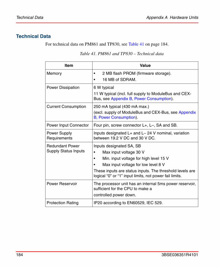
Technical Data Appendix A Hardware Units
Technical Data
For technical data on PM861 and TP830, see Table 41 on page 184.
Table 41. PM861 and TP830 – Technical data
Item Value
Memory • 2 MB flash PROM (firmware storage).
• 16 MB of SDRAM.
Power Dissipation 6 W typical
11 W typical (incl. full supply to ModuleBus and CEX-Bus, see Appendix B, Power Consumption).
Current Consumption 250 mA typical (430 mA max.)(excl. supply of ModuleBus and CEX-Bus, see Appendix B, Power Consumption).
Power Input Connector Four pin, screw connector L+, L–, SA and SB.
Power Supply Requirements
Inputs designated L+ and L– 24 V nominal, variation between 19.2 V DC and 30 V DC.
Redundant Power Supply Status Inputs
Inputs designated SA, SB
• Max input voltage 30 V
• Min. input voltage for high level 15 V
• Max input voltage for low level 8 V
These inputs are status inputs. The threshold levels are logical “0” or “1” input limits, not power fail limits.
Power Reservoir The processor unit has an internal 5ms power reservoir, sufficient for the CPU to make a
controlled power down.
Protection Rating IP20 according to EN60529, IEC 529.
184 3BSE036351R4101
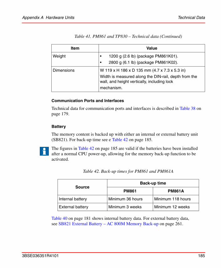
Appendix A Hardware Units Technical Data
Communication Ports and Interfaces
Technical data for communication ports and interfaces is described in Table 38 on page 179.
Battery
The memory content is backed up with either an internal or external battery unit (SB821). For back-up time see e Table 42 on page 185.
Table 40 on page 181 shows internal battery data. For external battery data, see SB821 External Battery – AC 800M Memory Back-up on page 261.
Weight • 1200 g (2.6 lb) (package PM861K01).
• 2800 g (6.1 lb) (package PM861K02).
Dimensions W 119 x H 186 x D 135 mm (4.7 x 7.3 x 5.3 in)
Width is measured along the DIN-rail, depth from the wall, and height vertically, including lock
mechanism.
The figures in Table 42 on page 185 are valid if the batteries have been installed after a normal CPU power-up, allowing for the memory back-up function to be activated.
Table 42. Back-up times for PM861 and PM861A
SourceBack-up time
PM861 PM861A
Internal battery Minimum 36 hours Minimum 118 hours
External battery Minimum 3 weeks Minimum 12 weeks
Table 41. PM861 and TP830 – Technical data (Continued)
Item Value
3BSE036351R4101 185
Performance Data Appendix A Hardware Units
Electro-magnetic Compatibility and Electrical Safety
PM861/TP830 meets the requirements specified in EMC Directive 89/336/EEC.
For more information regarding electrical safety, see Appendix D, Directive Considerations.
LED Indicators
See Table 16 on page 135.
Performance Data
The PM861 processor unit, in single configuration, has the same performance data as the PM860. In redundant configuration the execution performance is somewhat lower than in single configuration.
Switch over time from Primary CPU to Backup CPU, in redundant CPU configuration, is less than 10 ms.
186 3BSE036351R4101

Appendix A Hardware Units PM864/PM864A and TP830 – Processor Unit
PM864/PM864A and TP830 – Processor Unit
Key Features
• MPC862 Microprocessor running at 96 MHz.
• 32 MB RAM with internal or external battery back-up facility.
• 12 x S800 I/O units can be connected to the electrical ModuleBus.
• Four on-board communication ports:
– CN1 + CN2, Ethernet ports (IEEE 802.3, 10BaseT)
– COM3, serial port (RS-232C) with modem support
– COM4, serial port (RS-232C) for service tool
• Basic communication is extendable by using additional communication interface units.
• Redundancy Control Link, for use in redundancy configuration.
• Compact Flash interface for non-volatile storage of application and data.
3BSE036351R4101 187

Technical Data Appendix A Hardware Units
Technical Data
For technical data on PM864 and TP830, see Table 43 on page 188.
Table 43. PM864 and TP830 – Technical data
Item Value
Memory • 2 MB flash PROM (firmware storage).
• 32 MB of SDRAM.
Power Dissipation 6.9 W typical
11.9 W typical (incl. full supply to ModuleBus and CEX-Bus, see Appendix B, Power Consumption).
Current Consumption 287 mA typical (487 mA max.)(excl. supply of ModuleBus and CEX-Bus, see Appendix B, Power Consumption).
Power Input Connector Four pin, screw connector L+, L–, SA and SB.
Power Supply Requirements
Inputs designated L+ and L– 24 V nominal, variation between 19.2 V DC and 30 V DC.
Redundant Power Supply Status Inputs
Inputs designated SA, SB
• Max input voltage 30 V
• Min. input voltage for high level 15 V
• Max input voltage for low level 8 V
These inputs are status inputs. The threshold levels are logical "0" or "1" input limits, not power fail limits.
Power Reservoir The processor unit has an internal 5ms power reservoir, sufficient for the CPU to make a
controlled power down.
Protection Rating IP20 according to EN60529, IEC 529.
188 3BSE036351R4101
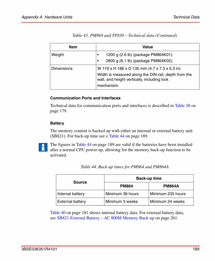
Appendix A Hardware Units Technical Data
Communication Ports and Interfaces
Technical data for communication ports and interfaces is described in Table 38 on page 179.
Battery
The memory content is backed up with either an internal or external battery unit (SB821). For back-up time see e Table 44 on page 189.
Table 40 on page 181 shows internal battery data. For external battery data, see SB821 External Battery – AC 800M Memory Back-up on page 261.
Weight • 1200 g (2.6 lb) (package PM864K01).
• 2800 g (6.1 lb) (package PM864K02).
Dimensions W 119 x H 186 x D 135 mm (4.7 x 7.3 x 5.3 in)
Width is measured along the DIN-rail, depth from the wall, and height vertically, including lock
mechanism.
The figures in Table 44 on page 189 are valid if the batteries have been installed after a normal CPU power-up, allowing for the memory back-up function to be activated.
Table 44. Back-up times for PM864 and PM864A
SourceBack-up time
PM864 PM864A
Internal battery Minimum 36 hours Minimum 235 hours
External battery Minimum 3 weeks Minimum 24 weeks
Table 43. PM864 and TP830 – Technical data (Continued)
Item Value
3BSE036351R4101 189

Performance Data Appendix A Hardware Units
Electro-magnetic Compatibility and Electrical Safety
PM864/TP830 meets the requirements specified in EMC Directive 89/336/EEC.
For more information regarding electrical safety, see Appendix D, Directive Considerations.
LED Indicators
See Table 16 on page 135.
Performance Data
The PM864 processor unit, in single configuration, has performance data which theoretically peaks at twice the performance compared to the PM860. The useful sustained performance improvement is, however, a bit lower and somewhat dependent on the actual application program but can be expected to be 10 to 50% compared to PM860. In redundant configuration the execution performance is somewhat lower than in single configuration.
Switch over time from Primary CPU to Backup CPU, in redundant configuration, is less than 10 ms.
190 3BSE036351R4101
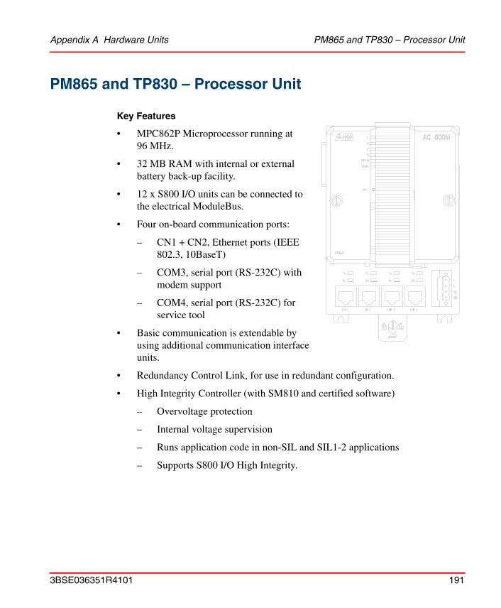
Appendix A Hardware Units PM865 and TP830 – Processor Unit
PM865 and TP830 – Processor Unit
Key Features
• MPC862P Microprocessor running at 96 MHz.
• 32 MB RAM with internal or external battery back-up facility.
• 12 x S800 I/O units can be connected to the electrical ModuleBus.
• Four on-board communication ports:
– CN1 + CN2, Ethernet ports (IEEE 802.3, 10BaseT)
– COM3, serial port (RS-232C) with modem support
– COM4, serial port (RS-232C) for service tool
• Basic communication is extendable by using additional communication interface units.
• Redundancy Control Link, for use in redundant configuration.
• High Integrity Controller (with SM810 and certified software)
– Overvoltage protection
– Internal voltage supervision
– Runs application code in non-SIL and SIL1-2 applications
– Supports S800 I/O High Integrity.
3BSE036351R4101 191

Technical Data Appendix A Hardware Units
Technical Data
For technical data on PM865 and TP830, see Table 45 on page 192.
Table 45. PM865 and TP830 – Technical data
Item Value
Memory • 4 MB flash PROM (firmware storage).
• 32 MB of SDRAM.
Power Dissipation 6.9 W typical
11.9 W typical (incl. full supply to ModuleBus and CEX-Bus, see Appendix B, Power Consumption).
Current Consumption 287 mA typical (487 mA max.)(excl. supply of ModuleBus and CEX-Bus, see Appendix B, Power Consumption).
Power Input Connector Four pin, screw connector L+, L–, SA and SB.
Power Supply Requirements
Inputs designated L+ and L– 24 V nominal, variation between 19.2 V DC and 30 V DC.
Redundant Power Supply Status Inputs
Inputs designated SA, SB
• Max input voltage 30 V
• Min. input voltage for high level 15 V
• Max input voltage for low level 8 V
These inputs are status inputs. The threshold levels are logical "0" or "1" input limits, not power fail limits.
Power Reservoir The processor unit has an internal 5ms power reservoir, sufficient for the CPU to make a
controlled power down.
Protection Rating IP20 according to EN60529, IEC 529.
192 3BSE036351R4101

Appendix A Hardware Units Technical Data
Communication Ports and Interfaces
Technical data for communication ports and interfaces is described in Table 38 on page 179.
Battery
The memory content is backed up with either an internal or external battery unit (SB821). For back-up time see Table 46 on page 193.
Table 40 on page 181 shows internal battery data. For external battery data, see SB821 External Battery – AC 800M Memory Back-up on page 261.
Weight • 1200 g (2.6 lb) (package PM865K01).
• 2800 g (6.1 lb) (package PM865K02).
Dimensions W 119 x H 186 x D 135 mm (4.7 x 7.3 x 5.3 in)
Width is measured along the DIN-rail, depth from the wall, and height vertically, including lock
mechanism.
The figures in Table 46 on page 193 are valid if the batteries have been installed after a normal CPU power-up, allowing for the memory back-up function to be activated.
Table 46. Back-up times for PM865
Source Back-up time
Internal battery Minimum 235 hours
External battery Minimum 24 weeks
Table 45. PM865 and TP830 – Technical data (Continued)
Item Value
3BSE036351R4101 193
Performance Data Appendix A Hardware Units
Electro-magnetic Compatibility and Electrical Safety
PM865/TP830 meets the requirements specified in EMC Directive 89/336/EEC.
For more information regarding electrical safety, see Appendix D, Directive Considerations.
LED Indicators
See Table 16 on page 135.
Performance Data
The PM865 processor unit, in single configuration, has performance data which theoretically peaks at twice the performance compared to the PM860. The useful sustained performance improvement is, however, a bit lower and somewhat dependent on the actual application program but can be expected to be 10 to 50% compared to PM860. In redundant configuration the execution performance is somewhat lower than in single configuration.
Switch over time from Primary CPU to Backup CPU, in redundant configuration, is less than 10 ms.
PM865 is designed for use in a High Integrity controller. If it is run as a non-SIL controller without any SIL applications, its performance will be the same as stated above, while performance will be lower when running SIL applications.
194 3BSE036351R4101
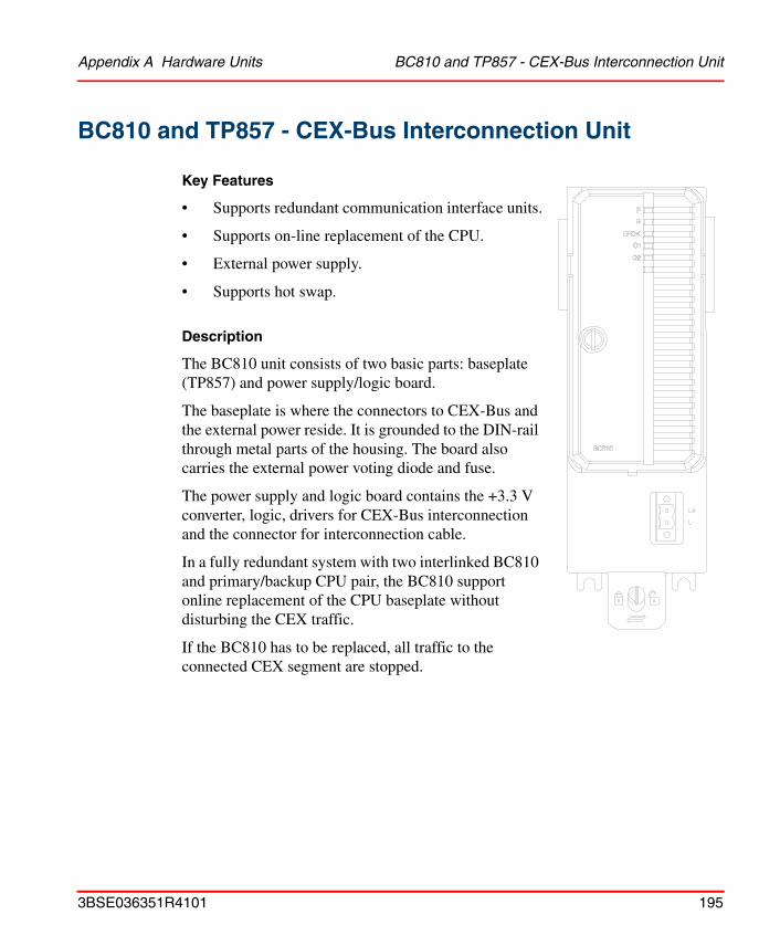
Appendix A Hardware Units BC810 and TP857 - CEX-Bus Interconnection Unit
BC810 and TP857 - CEX-Bus Interconnection Unit
Key Features
• Supports redundant communication interface units.
• Supports on-line replacement of the CPU.
• External power supply.
• Supports hot swap.
Description
The BC810 unit consists of two basic parts: baseplate (TP857) and power supply/logic board.
The baseplate is where the connectors to CEX-Bus and the external power reside. It is grounded to the DIN-rail through metal parts of the housing. The board also carries the external power voting diode and fuse.
The power supply and logic board contains the +3.3 V converter, logic, drivers for CEX-Bus interconnection and the connector for interconnection cable.
In a fully redundant system with two interlinked BC810 and primary/backup CPU pair, the BC810 support online replacement of the CPU baseplate without disturbing the CEX traffic.
If the BC810 has to be replaced, all traffic to the connected CEX segment are stopped.
3BSE036351R4101 195
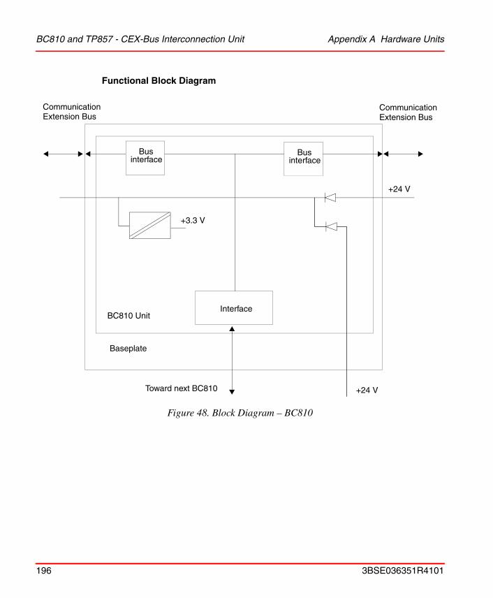
BC810 and TP857 - CEX-Bus Interconnection Unit Appendix A Hardware Units
Functional Block Diagram
Figure 48. Block Diagram – BC810
Interface
+3.3 V
+24 V
BC810 Unit
Baseplate
Toward next BC810
CommunicationExtension Bus
CommunicationExtension Bus
Bus interface
Bus interface
+24 V
196 3BSE036351R4101
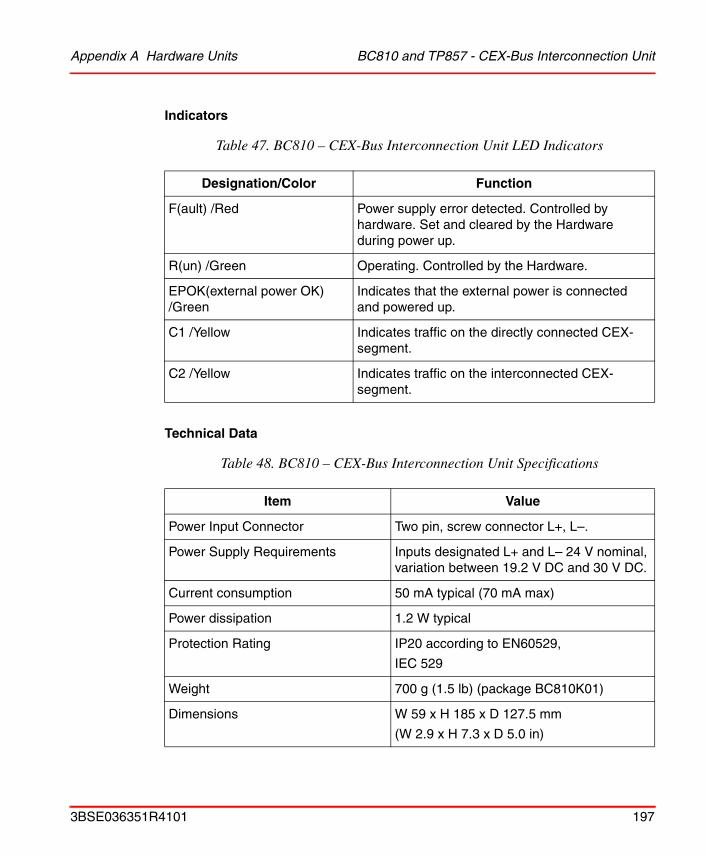
Appendix A Hardware Units BC810 and TP857 - CEX-Bus Interconnection Unit
Indicators
Technical Data
Table 47. BC810 – CEX-Bus Interconnection Unit LED Indicators
Designation/Color Function
F(ault) /Red Power supply error detected. Controlled by hardware. Set and cleared by the Hardware during power up.
R(un) /Green Operating. Controlled by the Hardware.
EPOK(external power OK)/Green
Indicates that the external power is connected and powered up.
C1 /Yellow Indicates traffic on the directly connected CEX-segment.
C2 /Yellow Indicates traffic on the interconnected CEX-segment.
Table 48. BC810 – CEX-Bus Interconnection Unit Specifications
Item Value
Power Input Connector Two pin, screw connector L+, L–.
Power Supply Requirements Inputs designated L+ and L– 24 V nominal, variation between 19.2 V DC and 30 V DC.
Current consumption 50 mA typical (70 mA max)
Power dissipation 1.2 W typical
Protection Rating IP20 according to EN60529,
IEC 529
Weight 700 g (1.5 lb) (package BC810K01)
Dimensions W 59 x H 185 x D 127.5 mm
(W 2.9 x H 7.3 x D 5.0 in)
3BSE036351R4101 197

SM810 and TP855 Appendix A Hardware Units
SM810 and TP855
Key Features
• MPC862P Microprocessor running at 96 MHz.
• 32 MB RAM with internal or external battery back-up facility.
• Provides supervision of the PM865 controller during SIL1-2 operations.
• Over voltage protection.
• Internal voltage monitoring.
• Supports hot swap.
Description
Physically SM810 Unit consists of two parts: Termination Plate (TP855) and SM810.
The SM810 contains two pc-boards. The main board contains the MPC862, SDRAM, Flash PROM, and CEX-Bus slave interface. A daughter board contains digital I/O, +3.3V supply with over-voltage protection and voltage monitoring. The termination plate contains CEX-Bus connectors and connectors for the digital I/O.
198 3BSE036351R4101

Appendix A Hardware Units SM810 and TP855
Functional Block Diagram
Figure 49. Block Diagram – SM810
text
DC/DCConverter
CPUMPC862
System and usermem. Double inverted
memory
FPGA
CEX-Bus Interface
Digital
Inputs
Digital
Outputs
CommunicationExtension Bus
CommunicationExtension Bus
Digital Inputs Digital Outputs
CommunicationExtensionBaseplate
CommunicationExtension Module
3BSE036351R4101 199
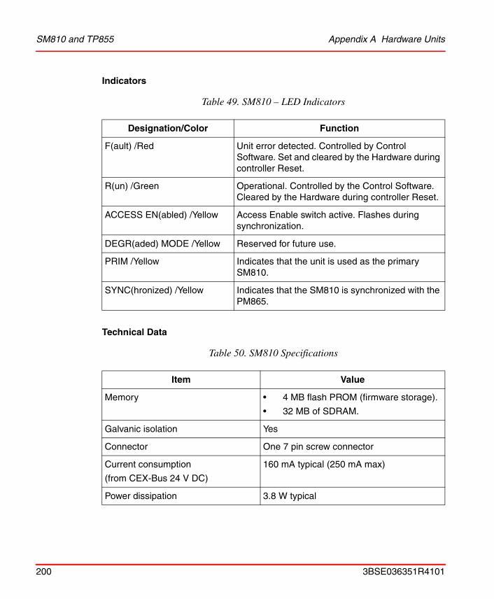
SM810 and TP855 Appendix A Hardware Units
Indicators
Technical Data
Table 49. SM810 – LED Indicators
Designation/Color Function
F(ault) /Red Unit error detected. Controlled by Control Software. Set and cleared by the Hardware during controller Reset.
R(un) /Green Operational. Controlled by the Control Software. Cleared by the Hardware during controller Reset.
ACCESS EN(abled) /Yellow Access Enable switch active. Flashes during synchronization.
DEGR(aded) MODE /Yellow Reserved for future use.
PRIM /Yellow Indicates that the unit is used as the primary SM810.
SYNC(hronized) /Yellow Indicates that the SM810 is synchronized with the PM865.
Table 50. SM810 Specifications
Item Value
Memory • 4 MB flash PROM (firmware storage).
• 32 MB of SDRAM.
Galvanic isolation Yes
Connector One 7 pin screw connector
Current consumption
(from CEX-Bus 24 V DC)
160 mA typical (250 mA max)
Power dissipation 3.8 W typical
200 3BSE036351R4101
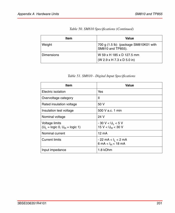
Appendix A Hardware Units SM810 and TP855
Weight 700 g (1.5 lb) (package SM810K01 with SM810 and TP855).
Dimensions W 59 x H 185 x D 127.5 mm
(W 2.9 x H 7.3 x D 5.0 in)
Table 51. SM810 - Digital Input Specifications
Item Value
Electric isolation Yes
Overvoltage category II
Rated insulation voltage 50 V
Insulation test voltage 500 V a.c. 1 min
Nominal voltage 24 V
Voltage limits(UL = logic 0, UH = logic 1)
- 30 V < UL < 5 V15 V < UH < 30 V
Nominal current 12 mA
Current limits - 22 mA < IL < 2 mA6 mA < IH < 18 mA
Input impedance 1.8 kOhm
Table 50. SM810 Specifications (Continued)
Item Value
3BSE036351R4101 201
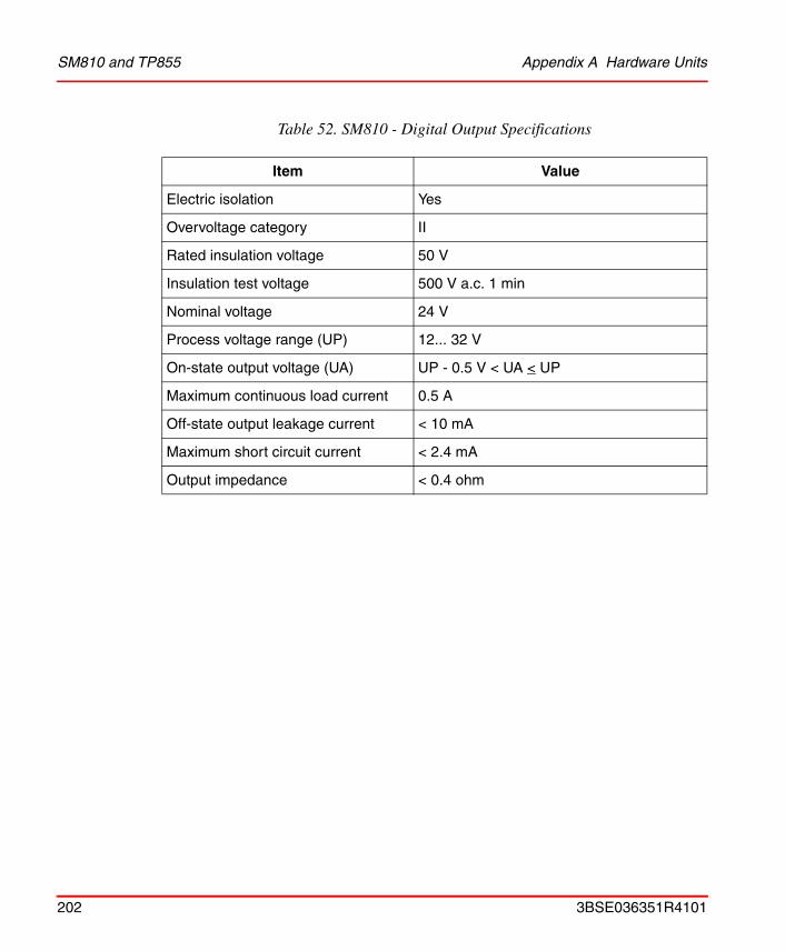
SM810 and TP855 Appendix A Hardware Units
Table 52. SM810 - Digital Output Specifications
Item Value
Electric isolation Yes
Overvoltage category II
Rated insulation voltage 50 V
Insulation test voltage 500 V a.c. 1 min
Nominal voltage 24 V
Process voltage range (UP) 12... 32 V
On-state output voltage (UA) UP - 0.5 V < UA < UP
Maximum continuous load current 0.5 A
Off-state output leakage current < 10 mA
Maximum short circuit current < 2.4 mA
Output impedance < 0.4 ohm
202 3BSE036351R4101
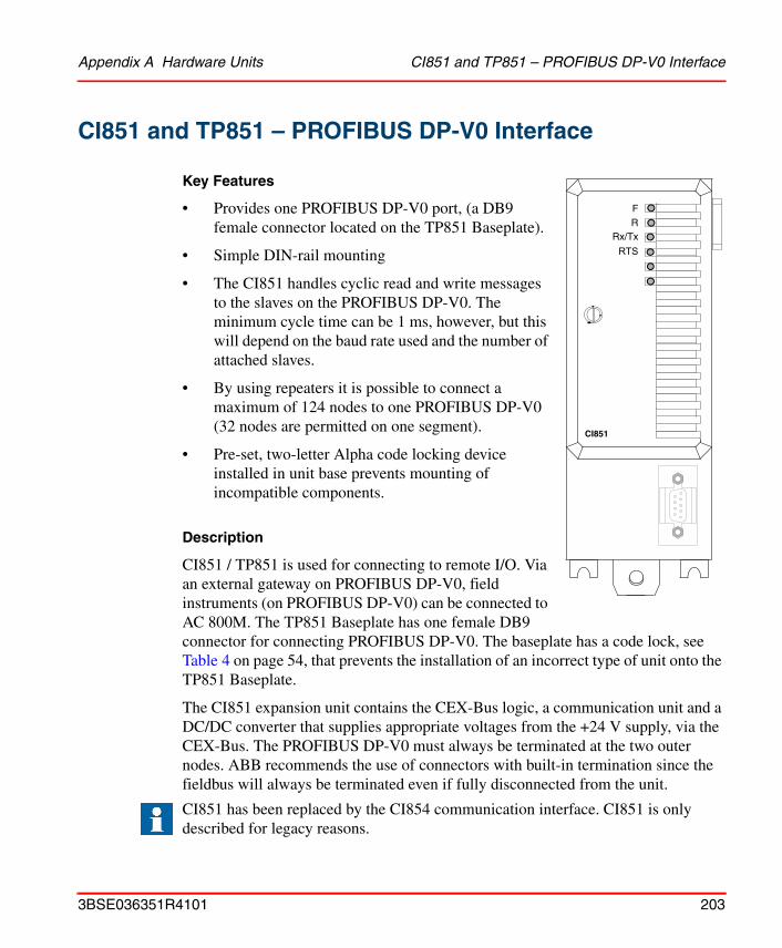
Appendix A Hardware Units CI851 and TP851 – PROFIBUS DP-V0 Interface
CI851 and TP851 – PROFIBUS DP-V0 Interface
Key Features
• Provides one PROFIBUS DP-V0 port, (a DB9 female connector located on the TP851 Baseplate).
• Simple DIN-rail mounting
• The CI851 handles cyclic read and write messages to the slaves on the PROFIBUS DP-V0. The minimum cycle time can be 1 ms, however, but this will depend on the baud rate used and the number of attached slaves.
• By using repeaters it is possible to connect a maximum of 124 nodes to one PROFIBUS DP-V0 (32 nodes are permitted on one segment).
• Pre-set, two-letter Alpha code locking device installed in unit base prevents mounting of incompatible components.
Description
CI851 / TP851 is used for connecting to remote I/O. Via an external gateway on PROFIBUS DP-V0, field instruments (on PROFIBUS DP-V0) can be connected to AC 800M. The TP851 Baseplate has one female DB9 connector for connecting PROFIBUS DP-V0. The baseplate has a code lock, see Table 4 on page 54, that prevents the installation of an incorrect type of unit onto the TP851 Baseplate.
The CI851 expansion unit contains the CEX-Bus logic, a communication unit and a DC/DC converter that supplies appropriate voltages from the +24 V supply, via the CEX-Bus. The PROFIBUS DP-V0 must always be terminated at the two outer nodes. ABB recommends the use of connectors with built-in termination since the fieldbus will always be terminated even if fully disconnected from the unit.
CI851 has been replaced by the CI854 communication interface. CI851 is only described for legacy reasons.
FR
Rx/Tx
RTS
CI851
3BSE036351R4101 203
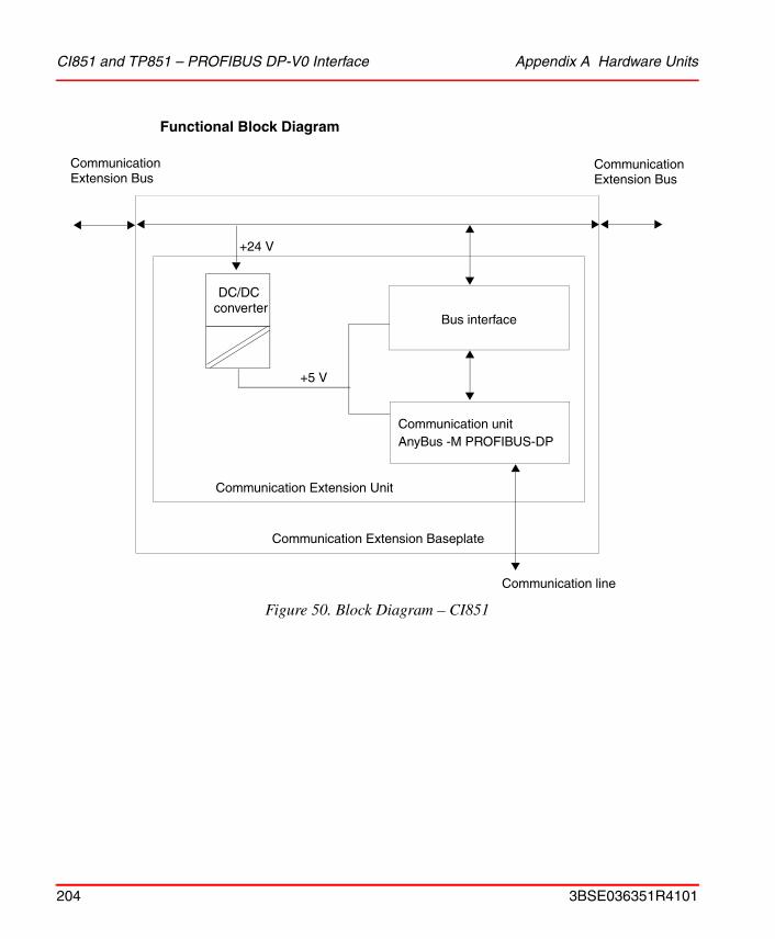
CI851 and TP851 – PROFIBUS DP-V0 Interface Appendix A Hardware Units
Functional Block Diagram
Figure 50. Block Diagram – CI851
Bus interface
Communication unitAnyBus -M PROFIBUS-DP
+5 V
+24 V
Communication Extension Unit
Communication Extension Baseplate
Communication line
CommunicationExtension Bus
CommunicationExtension Bus
DC/DC converter
204 3BSE036351R4101
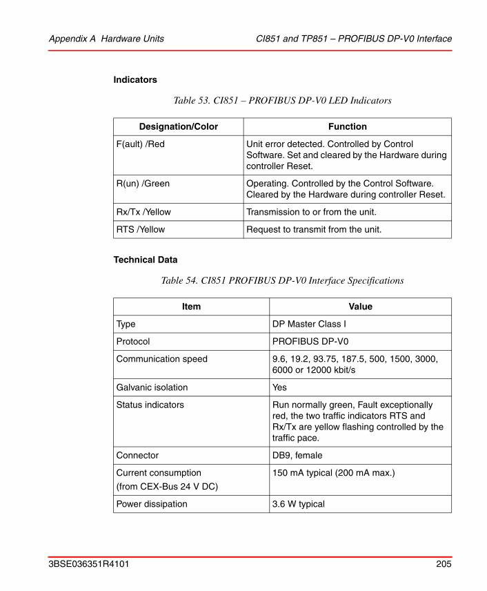
Appendix A Hardware Units CI851 and TP851 – PROFIBUS DP-V0 Interface
Indicators
Technical Data
Table 53. CI851 – PROFIBUS DP-V0 LED Indicators
Designation/Color Function
F(ault) /Red Unit error detected. Controlled by Control Software. Set and cleared by the Hardware during controller Reset.
R(un) /Green Operating. Controlled by the Control Software. Cleared by the Hardware during controller Reset.
Rx/Tx /Yellow Transmission to or from the unit.
RTS /Yellow Request to transmit from the unit.
Table 54. CI851 PROFIBUS DP-V0 Interface Specifications
Item Value
Type DP Master Class I
Protocol PROFIBUS DP-V0
Communication speed 9.6, 19.2, 93.75, 187.5, 500, 1500, 3000, 6000 or 12000 kbit/s
Galvanic isolation Yes
Status indicators Run normally green, Fault exceptionally red, the two traffic indicators RTS and Rx/Tx are yellow flashing controlled by the traffic pace.
Connector DB9, female
Current consumption
(from CEX-Bus 24 V DC)
150 mA typical (200 mA max.)
Power dissipation 3.6 W typical
3BSE036351R4101 205
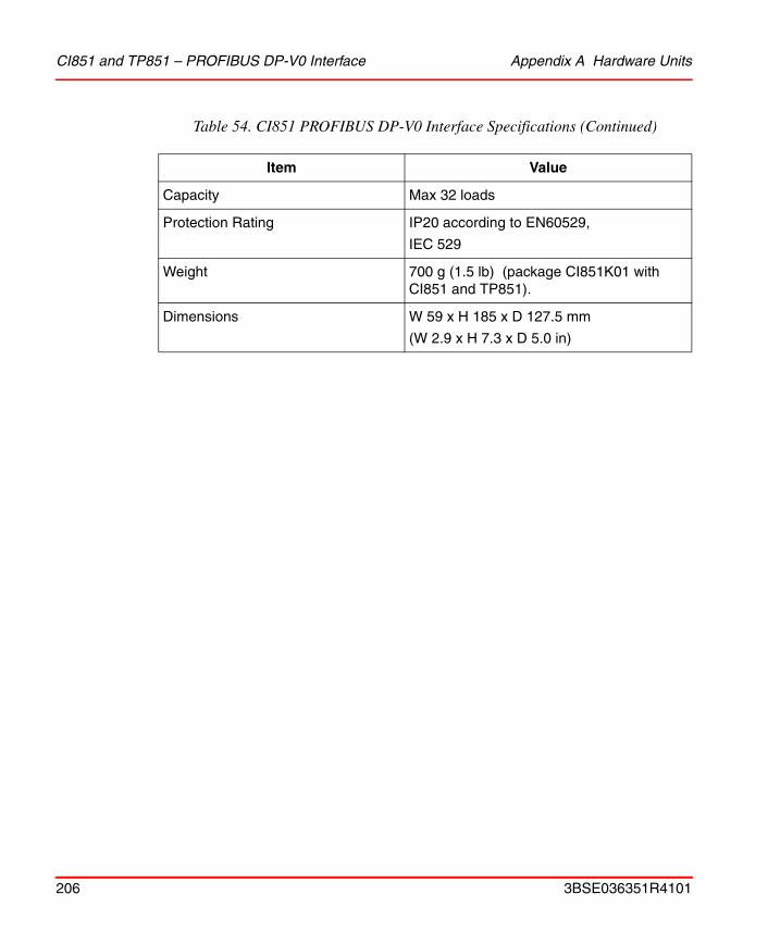
CI851 and TP851 – PROFIBUS DP-V0 Interface Appendix A Hardware Units
Capacity Max 32 loads
Protection Rating IP20 according to EN60529,
IEC 529
Weight 700 g (1.5 lb) (package CI851K01 with CI851 and TP851).
Dimensions W 59 x H 185 x D 127.5 mm
(W 2.9 x H 7.3 x D 5.0 in)
Table 54. CI851 PROFIBUS DP-V0 Interface Specifications (Continued)
Item Value
206 3BSE036351R4101
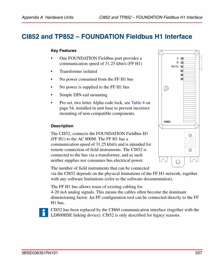
Appendix A Hardware Units CI852 and TP852 – FOUNDATION Fieldbus H1 Interface
CI852 and TP852 – FOUNDATION Fieldbus H1 Interface
Key Features
• One FOUNDATION Fieldbus port provides a communication speed of 31.25 kbit/s (FF H1)
• Transformer isolated
• No power consumed from the FF H1 bus
• No power is supplied to the FF H1 bus
• Simple DIN-rail mounting
• Pre-set, two letter Alpha code lock, see Table 4 on page 54, installed in unit base to prevent incorrect mounting of non-compatible components.
Description
The CI852, connects the FOUNDATION Fieldbus H1 (FF H1) to the AC 800M. The FF H1 has a communication speed of 31.25 kbit/s and is intended for remote connection of field instruments. The CI852 is connected to the bus via a transformer, and as such neither supplies nor consumes bus electrical power.
The number of field instruments that can be connected via the CI852 depends on the physical limitations of the FF H1 network, together with any software limitations (refer to the software documentation).
The FF H1 bus allows reuse of existing cabling for 4-20 mA analog signals. This means the cables often become the dominant dimensioning factor. An FF configuration tool can be connected directly to the FF H1 bus.
CI852 has been replaced by the CI860 communication interface (together with the LD800HSE linking device). CI852 is only described for legacy reasons.
FR
Rx/Tx
CI852
3BSE036351R4101 207

CI852 and TP852 – FOUNDATION Fieldbus H1 Interface Appendix A Hardware Units
Functional Block Diagram
Figure 51. Block Diagram – CI852
Bus interface
Communication unitwith FOUNDATION
+5 V
+24 V
Communication Extension Unit
Communication Extension Baseplate
Communication line
CommunicationExtension Bus
CommunicationExtension Bus
fieldbus interface
DC/DC converter
208 3BSE036351R4101
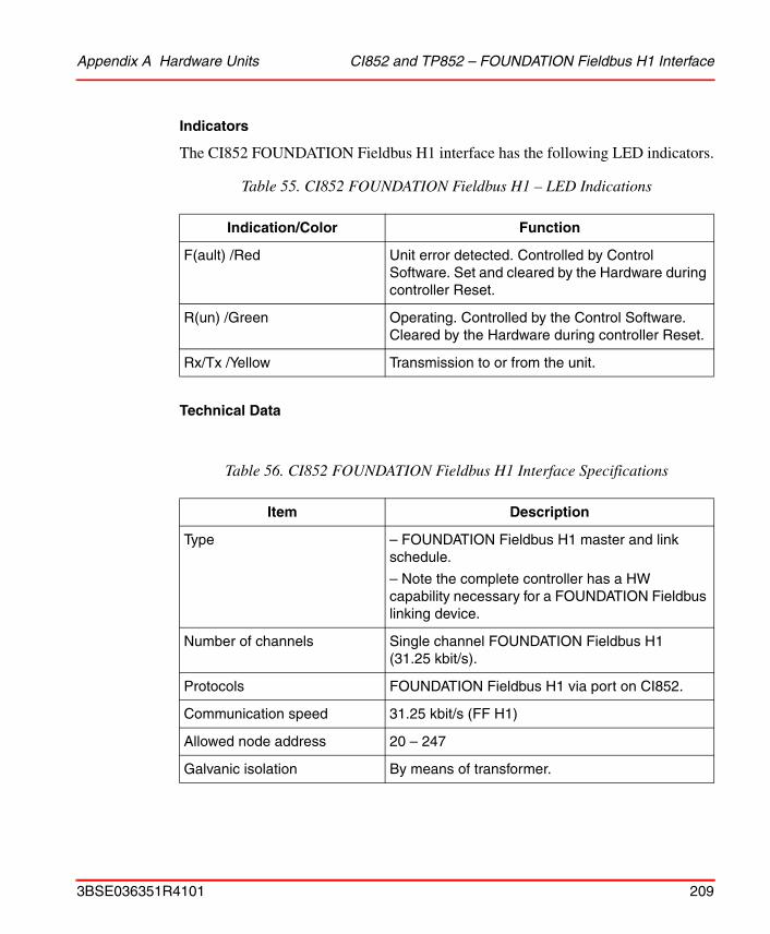
Appendix A Hardware Units CI852 and TP852 – FOUNDATION Fieldbus H1 Interface
Indicators
The CI852 FOUNDATION Fieldbus H1 interface has the following LED indicators.
Technical Data
Table 55. CI852 FOUNDATION Fieldbus H1 – LED Indications
Indication/Color Function
F(ault) /Red Unit error detected. Controlled by Control Software. Set and cleared by the Hardware during controller Reset.
R(un) /Green Operating. Controlled by the Control Software. Cleared by the Hardware during controller Reset.
Rx/Tx /Yellow Transmission to or from the unit.
Table 56. CI852 FOUNDATION Fieldbus H1 Interface Specifications
Item Description
Type – FOUNDATION Fieldbus H1 master and link schedule.
– Note the complete controller has a HW capability necessary for a FOUNDATION Fieldbus linking device.
Number of channels Single channel FOUNDATION Fieldbus H1 (31.25 kbit/s).
Protocols FOUNDATION Fieldbus H1 via port on CI852.
Communication speed 31.25 kbit/s (FF H1)
Allowed node address 20 – 247
Galvanic isolation By means of transformer.
3BSE036351R4101 209
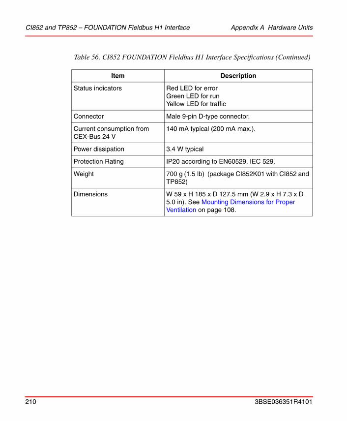
CI852 and TP852 – FOUNDATION Fieldbus H1 Interface Appendix A Hardware Units
Status indicators Red LED for errorGreen LED for runYellow LED for traffic
Connector Male 9-pin D-type connector.
Current consumption from CEX-Bus 24 V
140 mA typical (200 mA max.).
Power dissipation 3.4 W typical
Protection Rating IP20 according to EN60529, IEC 529.
Weight 700 g (1.5 lb) (package CI852K01 with CI852 and TP852)
Dimensions W 59 x H 185 x D 127.5 mm (W 2.9 x H 7.3 x D 5.0 in). See Mounting Dimensions for Proper Ventilation on page 108.
Table 56. CI852 FOUNDATION Fieldbus H1 Interface Specifications (Continued)
Item Description
210 3BSE036351R4101
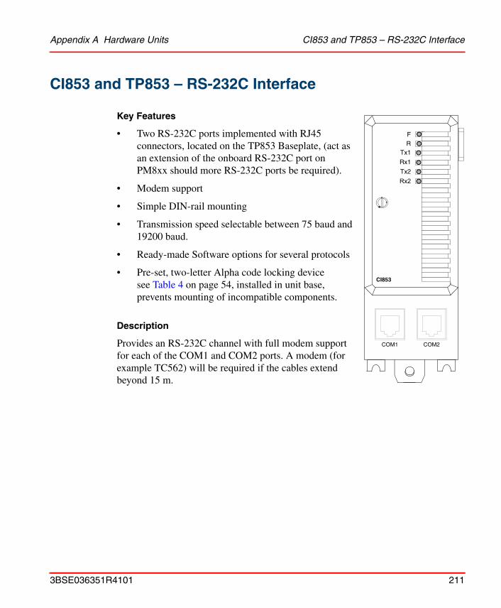
Appendix A Hardware Units CI853 and TP853 – RS-232C Interface
CI853 and TP853 – RS-232C Interface
Key Features
• Two RS-232C ports implemented with RJ45 connectors, located on the TP853 Baseplate, (act as an extension of the onboard RS-232C port on PM8xx should more RS-232C ports be required).
• Modem support
• Simple DIN-rail mounting
• Transmission speed selectable between 75 baud and 19200 baud.
• Ready-made Software options for several protocols
• Pre-set, two-letter Alpha code locking device see Table 4 on page 54, installed in unit base, prevents mounting of incompatible components.
Description
Provides an RS-232C channel with full modem support for each of the COM1 and COM2 ports. A modem (for example TC562) will be required if the cables extend beyond 15 m.
FR
Tx1
Rx1
Tx2
Rx2
CI853
COM1 COM2
3BSE036351R4101 211
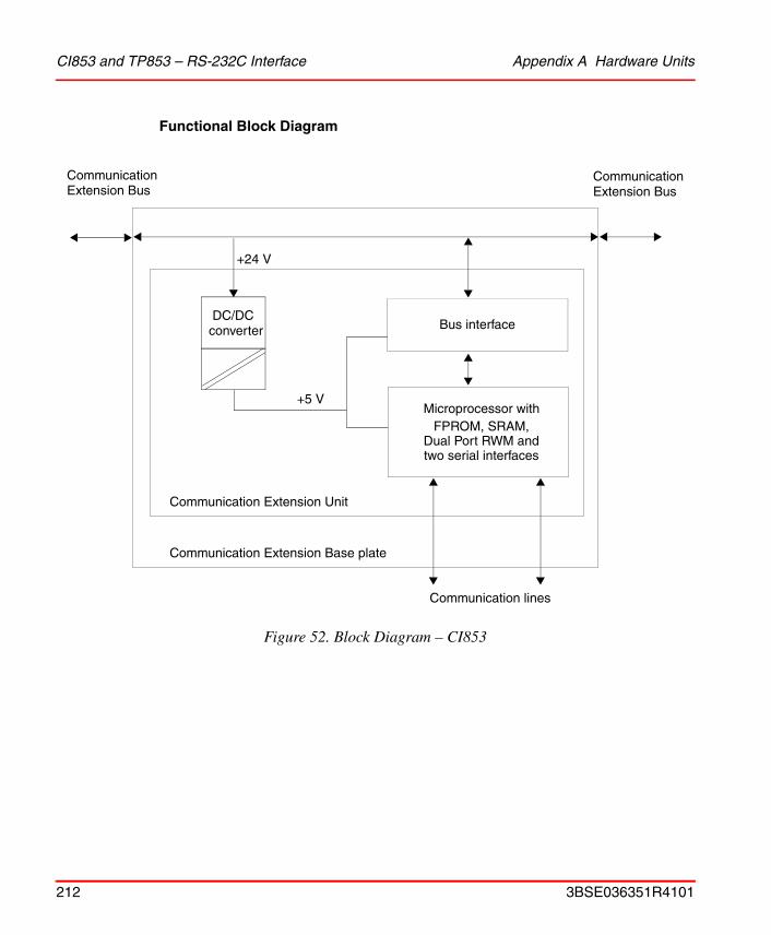
CI853 and TP853 – RS-232C Interface Appendix A Hardware Units
Functional Block Diagram
Figure 52. Block Diagram – CI853
DC/DC Bus interface
Microprocessor withFPROM, SRAM,
+5 V
+24 V
Communication Extension Unit
Communication Extension Base plate
Communication lines
CommunicationExtension Bus
CommunicationExtension Bus
Dual Port RWM andtwo serial interfaces
converter
212 3BSE036351R4101
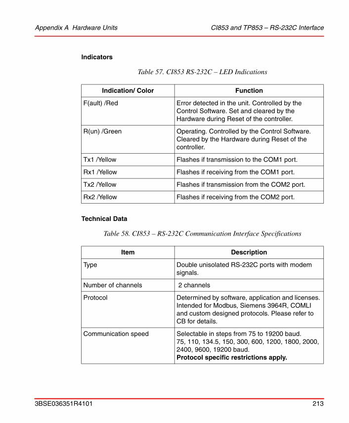
Appendix A Hardware Units CI853 and TP853 – RS-232C Interface
Indicators
Technical Data
Table 57. CI853 RS-232C – LED Indications
Indication/ Color Function
F(ault) /Red Error detected in the unit. Controlled by the Control Software. Set and cleared by the Hardware during Reset of the controller.
R(un) /Green Operating. Controlled by the Control Software. Cleared by the Hardware during Reset of the controller.
Tx1 /Yellow Flashes if transmission to the COM1 port.
Rx1 /Yellow Flashes if receiving from the COM1 port.
Tx2 /Yellow Flashes if transmission from the COM2 port.
Rx2 /Yellow Flashes if receiving from the COM2 port.
Table 58. CI853 – RS-232C Communication Interface Specifications
Item Description
Type Double unisolated RS-232C ports with modem signals.
Number of channels 2 channels
Protocol Determined by software, application and licenses. Intended for Modbus, Siemens 3964R, COMLI and custom designed protocols. Please refer to CB for details.
Communication speed Selectable in steps from 75 to 19200 baud.75, 110, 134.5, 150, 300, 600, 1200, 1800, 2000, 2400, 9600, 19200 baud.Protocol specific restrictions apply.
3BSE036351R4101 213

CI853 and TP853 – RS-232C Interface Appendix A Hardware Units
Galvanic isolation Unisolated
Status indicators Running normally: Green. Exceptional fault: Red. Four traffic indictors - Rx and Tx - controlled by traffic pace: Flashing yellow.
Connector Two RJ45 connectors on TP853.
Current consumption(from CEX-Bus 24 V DC)
100 mA typical (150 mA max.)
Power Dissipation 2.4 W typical
Protection Rating IP20 according to EN60529, IEC 529.
Weight 700 g (1.5 lb) (package CI853K01with CI853 and TP853)
Dimensions W 59 x H 185 x D 127.5 mm(W 2.9 x H 7.3 x D 5.0 in)For further information see Mounting Dimensions for Proper Ventilation on page 108.
Table 58. CI853 – RS-232C Communication Interface Specifications (Continued)
Item Description
214 3BSE036351R4101
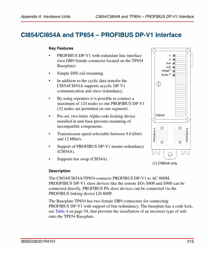
Appendix A Hardware Units CI854/CI854A and TP854 – PROFIBUS DP-V1 Interface
CI854/CI854A and TP854 – PROFIBUS DP-V1 Interface
Key Features
• PROFIBUS DP-V1 with redundant line interface (two DB9 female connector located on the TP854 Baseplate).
• Simple DIN-rail mounting.
• In addition to the cyclic data transfer the CI854/CI854A supports acyclic DP-V1 communication and slave redundancy.
• By using repeaters it is possible to connect a maximum of 124 nodes to one PROFIBUS DP-V1 (32 nodes are permitted on one segment).
• Pre-set, two-letter Alpha code locking device installed in unit base prevents mounting of incompatible components.
• Transmission speed selectable between 9.6 kbit/s and 12 Mbit/s.
• Support of PROFIBUS DP-V1 master redundancy (CI854A).
• Supports hot swap (CI854A).
Description
The CI854/CI854A/TP854 connects PROFIBUS DP-V1 to AC 800M. PRODFIBUS DP-V1 slave devices like the remote I/Os S800 and S900 can be connected directly. PROFIBUS PA slave devices can be connected via the PROFIBUS linking device LD 800P.
The Baseplate TP854 has two female DB9 connectors for connecting PROFIBUS DP-V1 with support of line redundancy. The baseplate has a code lock, see Table 4 on page 54, that prevents the installation of an incorrect type of unit onto the TP854 Baseplate.
F
R
RxA
RxB
CI854
PR
OF
IBU
SB
PR
OF
IBU
SA
PRIM(1)
DUAL(1)
CI854A
(1) CI854A only
3BSE036351R4101 215
CI854/CI854A and TP854 – PROFIBUS DP-V1 Interface Appendix A Hardware Units
The CI854/CI854A expansion unit contains the CEX-Bus logic, the CPU-kernel with memory, the PROFIBUS interface with line redundancy unit and a DC/DC converter that supplies the appropriate voltages from the +24V supply, via the CEX-Bus.
The PROFIBUS DP-V1 must always be terminated at the two outer nodes. This is usually done by using connectors with built-in termination. To guarantee a correct working termination the connector has to be plugged and power supplied.
The PROFIBUS DP-V1 requirements for screening/earthing have to be fulfilled. The PROFIBUS DP-V1 installation guideline requires that the cable shield should be connected to ground at both ends of the cable. This has to be done although the CI854/CI854A already connects the shield to ground via the connectors.
216 3BSE036351R4101

Appendix A Hardware Units CI854/CI854A and TP854 – PROFIBUS DP-V1 Interface
Functional Block Diagram
Figure 53. Block Diagram – CI854A. (CI854, same diagram without PRIM/DUAL LEDS)
CEX-Bus Interface
+5 V / +3.3 V
+24 V
Communication
CommunicationExtension Bus
DC/DC Converter
CPU-Kernel and Memory
PROFIBUS Master ASIC
Line Redundancy Unit
RS485
PR
OF
IBU
S A
PR
OF
IBU
S B
RxB
RxA
F
R
Extension Unit
Communication Extension Baseplate
DUAL
PRIM
3BSE036351R4101 217
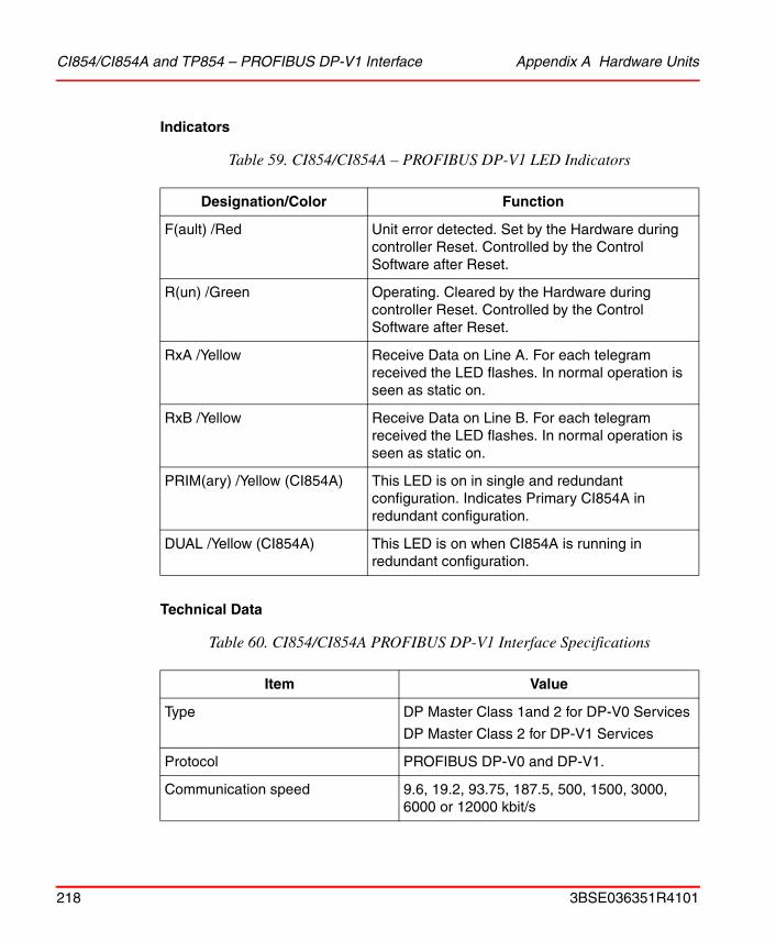
CI854/CI854A and TP854 – PROFIBUS DP-V1 Interface Appendix A Hardware Units
Indicators
Technical Data
Table 59. CI854/CI854A – PROFIBUS DP-V1 LED Indicators
Designation/Color Function
F(ault) /Red Unit error detected. Set by the Hardware during controller Reset. Controlled by the Control Software after Reset.
R(un) /Green Operating. Cleared by the Hardware during controller Reset. Controlled by the Control Software after Reset.
RxA /Yellow Receive Data on Line A. For each telegram received the LED flashes. In normal operation is seen as static on.
RxB /Yellow Receive Data on Line B. For each telegram received the LED flashes. In normal operation is seen as static on.
PRIM(ary) /Yellow (CI854A) This LED is on in single and redundant configuration. Indicates Primary CI854A in redundant configuration.
DUAL /Yellow (CI854A) This LED is on when CI854A is running in redundant configuration.
Table 60. CI854/CI854A PROFIBUS DP-V1 Interface Specifications
Item Value
Type DP Master Class 1and 2 for DP-V0 Services
DP Master Class 2 for DP-V1 Services
Protocol PROFIBUS DP-V0 and DP-V1.
Communication speed 9.6, 19.2, 93.75, 187.5, 500, 1500, 3000, 6000 or 12000 kbit/s
218 3BSE036351R4101
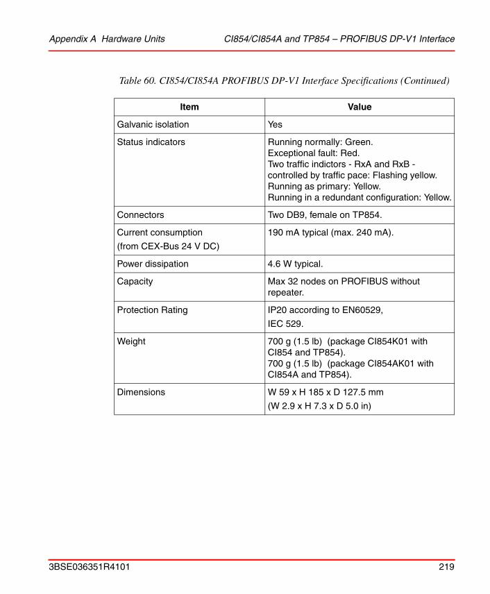
Appendix A Hardware Units CI854/CI854A and TP854 – PROFIBUS DP-V1 Interface
Galvanic isolation Yes
Status indicators Running normally: Green. Exceptional fault: Red.Two traffic indictors - RxA and RxB - controlled by traffic pace: Flashing yellow. Running as primary: Yellow.Running in a redundant configuration: Yellow.
Connectors Two DB9, female on TP854.
Current consumption
(from CEX-Bus 24 V DC)
190 mA typical (max. 240 mA).
Power dissipation 4.6 W typical.
Capacity Max 32 nodes on PROFIBUS without repeater.
Protection Rating IP20 according to EN60529,
IEC 529.
Weight 700 g (1.5 lb) (package CI854K01 with CI854 and TP854).700 g (1.5 lb) (package CI854AK01 with CI854A and TP854).
Dimensions W 59 x H 185 x D 127.5 mm
(W 2.9 x H 7.3 x D 5.0 in)
Table 60. CI854/CI854A PROFIBUS DP-V1 Interface Specifications (Continued)
Item Value
3BSE036351R4101 219
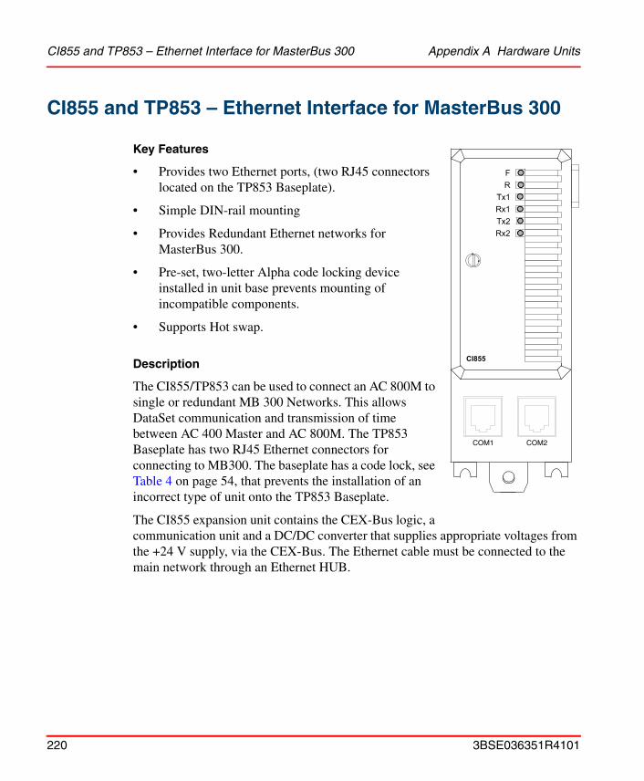
CI855 and TP853 – Ethernet Interface for MasterBus 300 Appendix A Hardware Units
CI855 and TP853 – Ethernet Interface for MasterBus 300
Key Features
• Provides two Ethernet ports, (two RJ45 connectors located on the TP853 Baseplate).
• Simple DIN-rail mounting
• Provides Redundant Ethernet networks for MasterBus 300.
• Pre-set, two-letter Alpha code locking device installed in unit base prevents mounting of incompatible components.
• Supports Hot swap.
Description
The CI855/TP853 can be used to connect an AC 800M to single or redundant MB 300 Networks. This allows DataSet communication and transmission of time between AC 400 Master and AC 800M. The TP853 Baseplate has two RJ45 Ethernet connectors for connecting to MB300. The baseplate has a code lock, see Table 4 on page 54, that prevents the installation of an incorrect type of unit onto the TP853 Baseplate.
The CI855 expansion unit contains the CEX-Bus logic, a communication unit and a DC/DC converter that supplies appropriate voltages from the +24 V supply, via the CEX-Bus. The Ethernet cable must be connected to the main network through an Ethernet HUB.
F
R
Tx1
Rx1
CI855
Tx2
Rx2
COM1 COM2
220 3BSE036351R4101
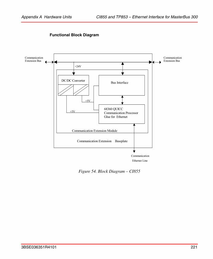
Appendix A Hardware Units CI855 and TP853 – Ethernet Interface for MasterBus 300
Functional Block Diagram
Figure 54. Block Diagram – CI855
Bus Interface
68360 QUICC Communication Processor Glue for Ethernet
DC/DC Converter
+5V
+5V
Communication Extension Module
Communication Extension Bus
Communication Extension Bus
+24V
CommunicationEthernet Line
Communication Extension Baseplate
3BSE036351R4101 221

CI855 and TP853 – Ethernet Interface for MasterBus 300 Appendix A Hardware Units
Indicators
Table 61. CI855 – MasterBus 300 LED Indicators
Designation/Color Function
F(ault) /Red Unit error detected. Controlled by Control Software. Set and cleared by the Hardware during controller Reset.
R(un) /Green Operating. Controlled by the Control Software. Cleared by the Hardware during controller Reset.
Tx1 /Yellow flashing A yellow LED indicating transmission from the communication unit COM1 port.
Rx1 /Yellow flashing A yellow LED flashes when data is being received from the COM1 port.
Tx2 /Yellow flashing A yellow LED indicating transmission from the communication unit COM2 port.
Rx2 /Yellow flashing A yellow LED flashes when data is being received from the COM2 port.
222 3BSE036351R4101
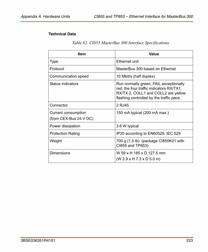
Appendix A Hardware Units CI855 and TP853 – Ethernet Interface for MasterBus 300
Technical Data
Table 62. CI855 MasterBus 300 Interface Specifications
Item Value
Type Ethernet unit
Protocol MasterBus 300 based on Ethernet
Communication speed 10 Mbit/s (half duplex)
Status indicators Run normally green, FAIL exceptionally red, the four traffic indicators RX/TX1, RX/TX 2, COLL1 and COLL2 are yellow flashing controlled by the traffic pace.
Connector 2 RJ45
Current consumption(from CEX-Bus 24 V DC)
150 mA typical (200 mA max.)
Power dissipation 3.6 W typical
Protection Rating IP20 according to EN60529, IEC 529
Weight 700 g (1.5 lb) (package CI855K01 with CI855 and TP853)
Dimensions W 59 x H 185 x D 127.5 mm(W 2.9 x H 7.3 x D 5.0 in)
3BSE036351R4101 223
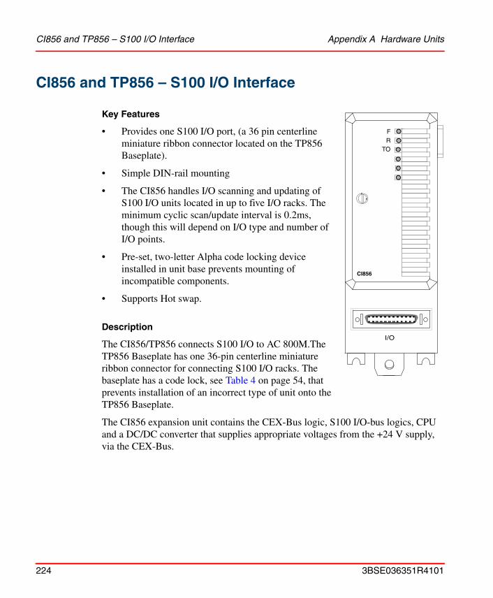
CI856 and TP856 – S100 I/O Interface Appendix A Hardware Units
CI856 and TP856 – S100 I/O Interface
Key Features
• Provides one S100 I/O port, (a 36 pin centerline miniature ribbon connector located on the TP856 Baseplate).
• Simple DIN-rail mounting
• The CI856 handles I/O scanning and updating of S100 I/O units located in up to five I/O racks. The minimum cyclic scan/update interval is 0.2ms, though this will depend on I/O type and number of I/O points.
• Pre-set, two-letter Alpha code locking device installed in unit base prevents mounting of incompatible components.
• Supports Hot swap.
Description
The CI856/TP856 connects S100 I/O to AC 800M.The TP856 Baseplate has one 36-pin centerline miniature ribbon connector for connecting S100 I/O racks. The baseplate has a code lock, see Table 4 on page 54, that prevents installation of an incorrect type of unit onto the TP856 Baseplate.
The CI856 expansion unit contains the CEX-Bus logic, S100 I/O-bus logics, CPU and a DC/DC converter that supplies appropriate voltages from the +24 V supply, via the CEX-Bus.
FR
TO
CI856
I/O
224 3BSE036351R4101
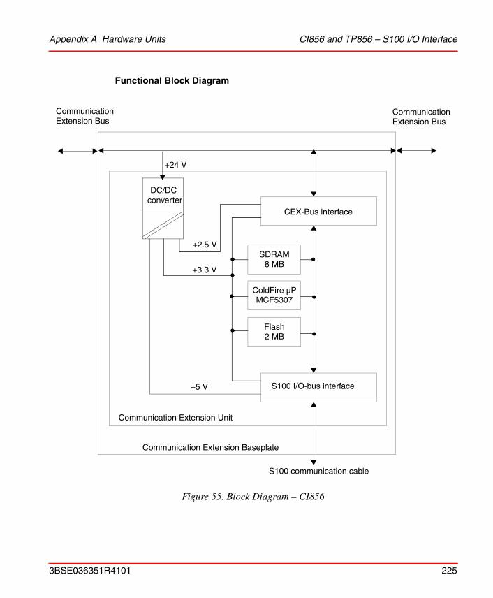
Appendix A Hardware Units CI856 and TP856 – S100 I/O Interface
Functional Block Diagram
Figure 55. Block Diagram – CI856
CEX-Bus interface
S100 I/O-bus interface+5 V
+24 V
Communication Extension Unit
Communication Extension Baseplate
S100 communication cable
CommunicationExtension Bus
CommunicationExtension Bus
DC/DC converter
+3.3 V
+2.5 V
ColdFire µPMCF5307
SDRAM8 MB
Flash2 MB
3BSE036351R4101 225

CI856 and TP856 – S100 I/O Interface Appendix A Hardware Units
Indicators
Technical Data
Table 63. CI856 – S100 I/O LED Indicators
Designation/Color Function
F(ault) /Red Unit error detected. Controlled by CI856 Software. Set by the Hardware during controller Reset. Cleared by the CI856 Software after successful startup.
R(un) /Green Operating. Controlled by the Control Software. Cleared by the Hardware during controller Reset.
TO /Yellow Flashes at S100 I/O access time-outs.
Table 64. CI856 S100 I/O Interface Specifications
Item Value
Type S100 I/O Communication Interface
Galvanic isolation No
Status indicators Run normally green, FAIL exceptionally red, the indicator TO are yellow flashing at S100 I/O access time-outs.
Connector 36 pin centerline miniature ribbon connector, female
Current consumption
(from CEX-Bus 24 V DC)
120 mA typical (200 mA max.)
Power dissipation 2.9 W typical
Capacity Max 5 I/O racks with 20 I/O units each
Protection Rating IP20 according to EN60529, IEC 529
226 3BSE036351R4101
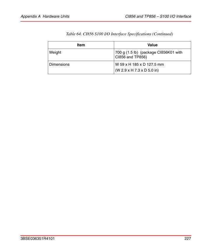
Appendix A Hardware Units CI856 and TP856 – S100 I/O Interface
Weight 700 g (1.5 lb) (package CI856K01 with CI856 and TP856)
Dimensions W 59 x H 185 x D 127.5 mm
(W 2.9 x H 7.3 x D 5.0 in)
Table 64. CI856 S100 I/O Interface Specifications (Continued)
Item Value
3BSE036351R4101 227
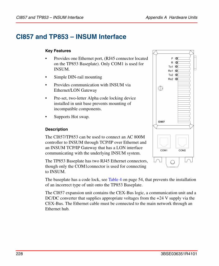
CI857 and TP853 – INSUM Interface Appendix A Hardware Units
CI857 and TP853 – INSUM Interface
Key Features
• Provides one Ethernet port, (RJ45 connector located on the TP853 Baseplate). Only COM1 is used for INSUM.
• Simple DIN-rail mounting
• Provides communication with INSUM via Ethernet/LON Gateway
• Pre-set, two-letter Alpha code locking device installed in unit base prevents mounting of incompatible components.
• Supports Hot swap.
Description
The CI857/TP853 can be used to connect an AC 800M controller to INSUM through TCP/IP over Ethernet and an INSUM TCP/IP Gateway that has a LON interface communicating with the underlying INSUM system.
The TP853 Baseplate has two RJ45 Ethernet connectors, though only the COM1connector is used for connecting to INSUM.
The baseplate has a code lock, see Table 4 on page 54, that prevents the installation of an incorrect type of unit onto the TP853 Baseplate.
The CI857 expansion unit contains the CEX-Bus logic, a communication unit and a DC/DC converter that supplies appropriate voltages from the +24 V supply via the CEX-Bus. The Ethernet cable must be connected to the main network through an Ethernet hub.
F
R
Tx1
Rx1
CI857
Tx2
Rx2
COM1 COM2
228 3BSE036351R4101
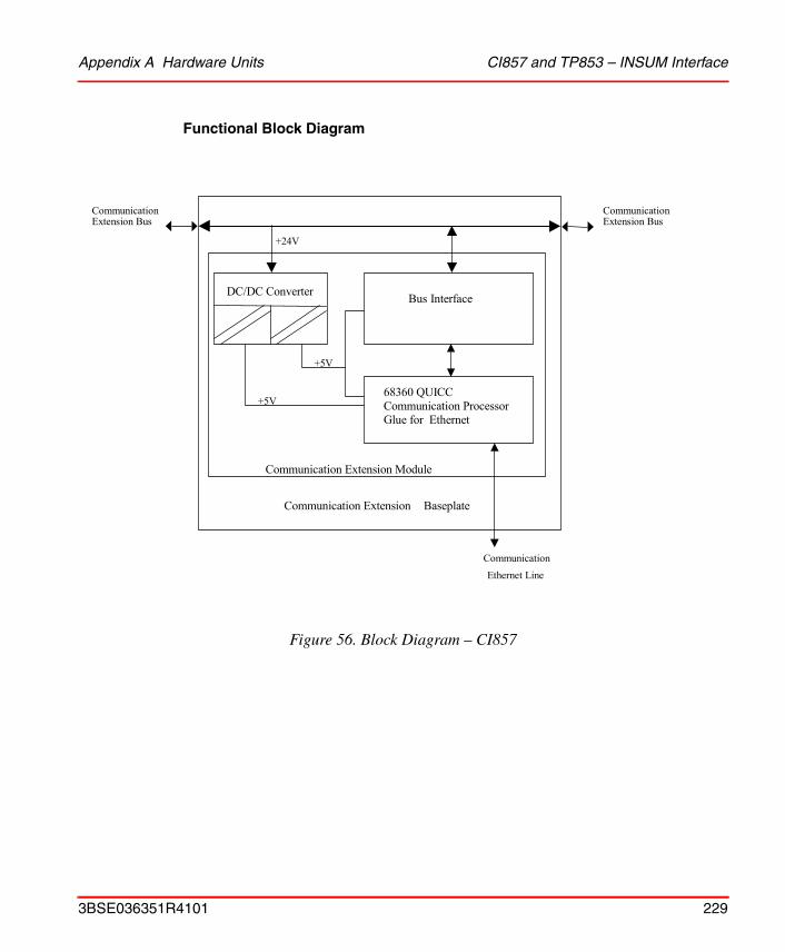
Appendix A Hardware Units CI857 and TP853 – INSUM Interface
Functional Block Diagram
Figure 56. Block Diagram – CI857
Bus Interface
68360 QUICC Communication Processor Glue for Ethernet
DC/DC Converter
+5V
+5V
Communication Extension Module
Communication Extension Bus
Communication Extension Bus
+24V
CommunicationEthernet Line
Communication Extension Baseplate
3BSE036351R4101 229

CI857 and TP853 – INSUM Interface Appendix A Hardware Units
Indicators
Technical Data
Table 65. CI857 – INSUM Interface LED Indicators
Designation/Color Function
F(ault) /Red Unit error detected. Controlled by Control Software. Set and cleared by the Hardware during controller Reset.
R(un) /Green Operating. Controlled by the Control Software. Cleared by the Hardware during controller Reset.
Tx1 /Yellow flashing A yellow LED indicating transmission from the communication unit COM1 port.
Rx1 /Yellow flashing A yellow LED flashes when data is being received from the COM1 port.
Tx2 OFF Not used.
Rx2 OFF Not used.
Table 66. CI857 INSUM Interface Specifications
Item Value
Type Ethernet unit.
Protocol TCP/IP
Communication speed 10 Mbit/s (half duplex)
Status indicators Running normally: Green. Exceptional fault: Red. Two traffic indictors - Tx1/Rx1 - controlled by traffic pace: Flashing yellow.
Connector 2 RJ45 (only COM1 is used).
230 3BSE036351R4101
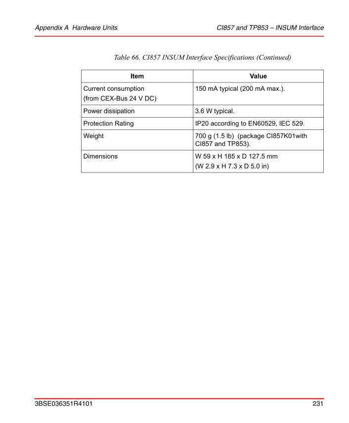
Appendix A Hardware Units CI857 and TP853 – INSUM Interface
Current consumption(from CEX-Bus 24 V DC)
150 mA typical (200 mA max.).
Power dissipation 3.6 W typical.
Protection Rating IP20 according to EN60529, IEC 529.
Weight 700 g (1.5 lb) (package CI857K01with CI857 and TP853).
Dimensions W 59 x H 185 x D 127.5 mm(W 2.9 x H 7.3 x D 5.0 in)
Table 66. CI857 INSUM Interface Specifications (Continued)
Item Value
3BSE036351R4101 231

CI858 and TP858 - DriveBus Interface Appendix A Hardware Units
CI858 and TP858 - DriveBus Interface
Key Features
• Provides three optical connectors for DriveBus, I/O bus and PC tools.
• Simple DIN-rail mounting.
• Pre-set, two-letter Alpha code locking device installed in unit base prevents mounting of incompatible components.
Description
The CI858 unit consists of a communication expansion base plate, a communication expansion unit. All electronic devices and all functions are located on the communication expansion unit board.
The CI858 has three connectors. DriveBus connector for connection of ABB Drives, see Drive System on page 124. Special I/O connection, see I/O Systems on page 115. A tool connection for downloading firmware to the communication unit with the ABB Drives tools DriveDebug or DriveWindow.
The baseplate has a code lock, see Table 4 on page 54, that prevents the installation of an incorrect type of unit onto the Baseplate.
The CI858 expansion unit contains the CEX-Bus logic, a communication unit and a DC/DC converter that supplies appropriate voltages from the +24 V supply via the CEX-Bus.
In order to use the tool connection, the PC must be equipped with a PCMCIA/DDCS (laptop) or an ISA/DDCS (desktop) interface.
FR
RxTx
CI858
RxTx
Dbus
I/O
232 3BSE036351R4101
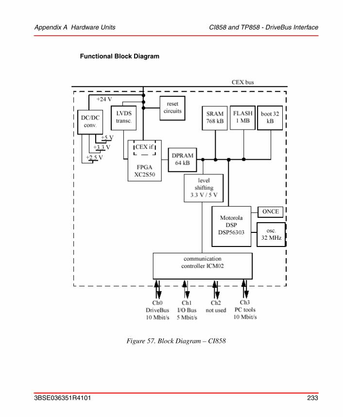
Appendix A Hardware Units CI858 and TP858 - DriveBus Interface
Functional Block Diagram
Figure 57. Block Diagram – CI858
3BSE036351R4101 233
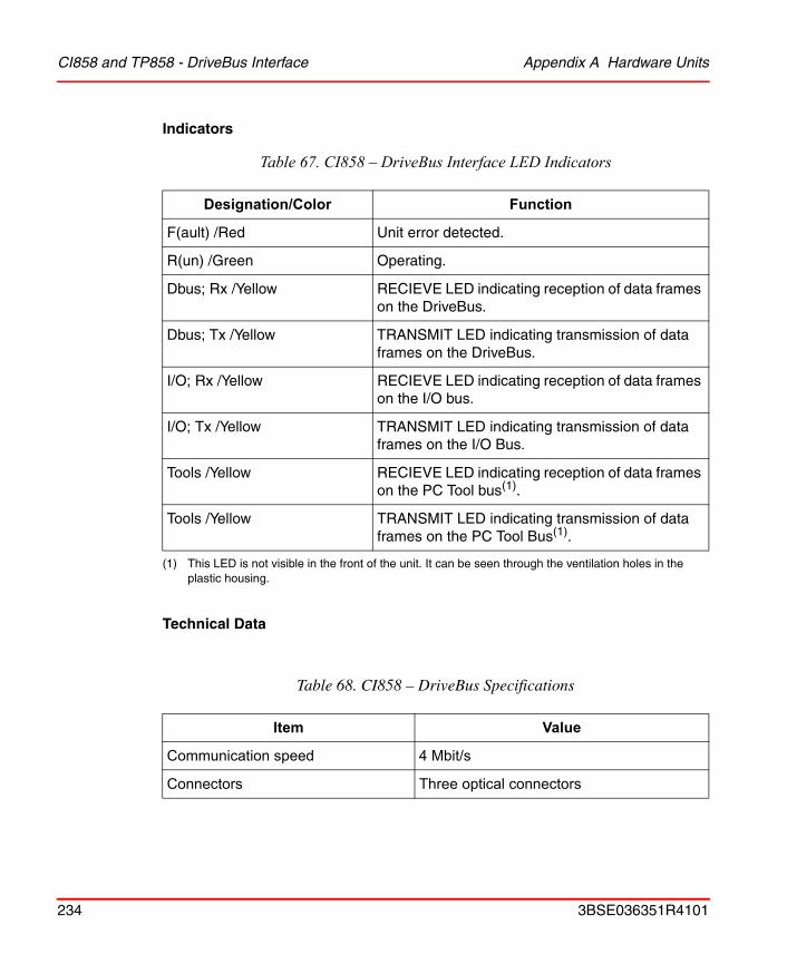
CI858 and TP858 - DriveBus Interface Appendix A Hardware Units
Indicators
Technical Data
Table 67. CI858 – DriveBus Interface LED Indicators
Designation/Color Function
F(ault) /Red Unit error detected.
R(un) /Green Operating.
Dbus; Rx /Yellow RECIEVE LED indicating reception of data frames on the DriveBus.
Dbus; Tx /Yellow TRANSMIT LED indicating transmission of data frames on the DriveBus.
I/O; Rx /Yellow RECIEVE LED indicating reception of data frames on the I/O bus.
I/O; Tx /Yellow TRANSMIT LED indicating transmission of data frames on the I/O Bus.
Tools /Yellow RECIEVE LED indicating reception of data frames on the PC Tool bus(1).
(1) This LED is not visible in the front of the unit. It can be seen through the ventilation holes in the plastic housing.
Tools /Yellow TRANSMIT LED indicating transmission of data frames on the PC Tool Bus(1).
Table 68. CI858 – DriveBus Specifications
Item Value
Communication speed 4 Mbit/s
Connectors Three optical connectors
234 3BSE036351R4101
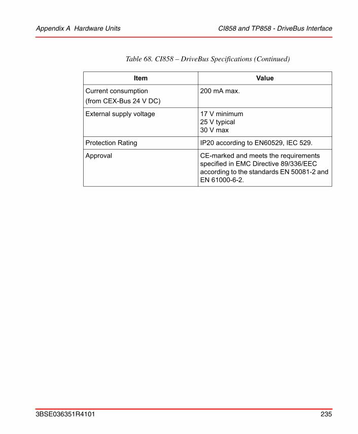
Appendix A Hardware Units CI858 and TP858 - DriveBus Interface
Current consumption(from CEX-Bus 24 V DC)
200 mA max.
External supply voltage 17 V minimum25 V typical30 V max
Protection Rating IP20 according to EN60529, IEC 529.
Approval CE-marked and meets the requirements specified in EMC Directive 89/336/EEC according to the standards EN 50081-2 and EN 61000-6-2.
Table 68. CI858 – DriveBus Specifications (Continued)
Item Value
3BSE036351R4101 235
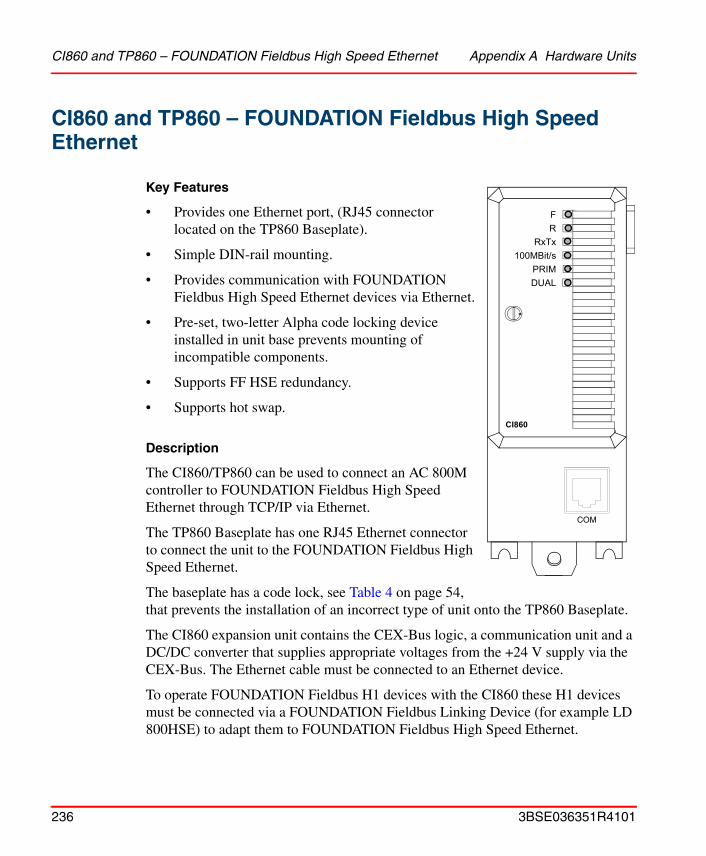
CI860 and TP860 – FOUNDATION Fieldbus High Speed Ethernet Appendix A Hardware Units
CI860 and TP860 – FOUNDATION Fieldbus High Speed Ethernet
Key Features
• Provides one Ethernet port, (RJ45 connector located on the TP860 Baseplate).
• Simple DIN-rail mounting.
• Provides communication with FOUNDATION Fieldbus High Speed Ethernet devices via Ethernet.
• Pre-set, two-letter Alpha code locking device installed in unit base prevents mounting of incompatible components.
• Supports FF HSE redundancy.
• Supports hot swap.
Description
The CI860/TP860 can be used to connect an AC 800M controller to FOUNDATION Fieldbus High Speed Ethernet through TCP/IP via Ethernet.
The TP860 Baseplate has one RJ45 Ethernet connector to connect the unit to the FOUNDATION Fieldbus High Speed Ethernet.
The baseplate has a code lock, see Table 4 on page 54, that prevents the installation of an incorrect type of unit onto the TP860 Baseplate.
The CI860 expansion unit contains the CEX-Bus logic, a communication unit and a DC/DC converter that supplies appropriate voltages from the +24 V supply via the CEX-Bus. The Ethernet cable must be connected to an Ethernet device.
To operate FOUNDATION Fieldbus H1 devices with the CI860 these H1 devices must be connected via a FOUNDATION Fieldbus Linking Device (for example LD 800HSE) to adapt them to FOUNDATION Fieldbus High Speed Ethernet.
FR
RxTx100MBit/s
CI860
PRIMDUAL
COM
236 3BSE036351R4101

Appendix A Hardware Units CI860 and TP860 – FOUNDATION Fieldbus High Speed Ethernet
Functional Block Diagram
Figure 58. Block Diagram – CI860
CEX-Bus Interface
+2.5 V / +3.3 V
+24 V
Communication
CommunicationExtension Bus
DC/DC Converter
CPU-Kernel and Memory
Ethernet Transceiver100 MBit/s
RxTx
F
R
Extension Unit
Communication Extension Baseplate
DUAL
PRIM
COM
3BSE036351R4101 237
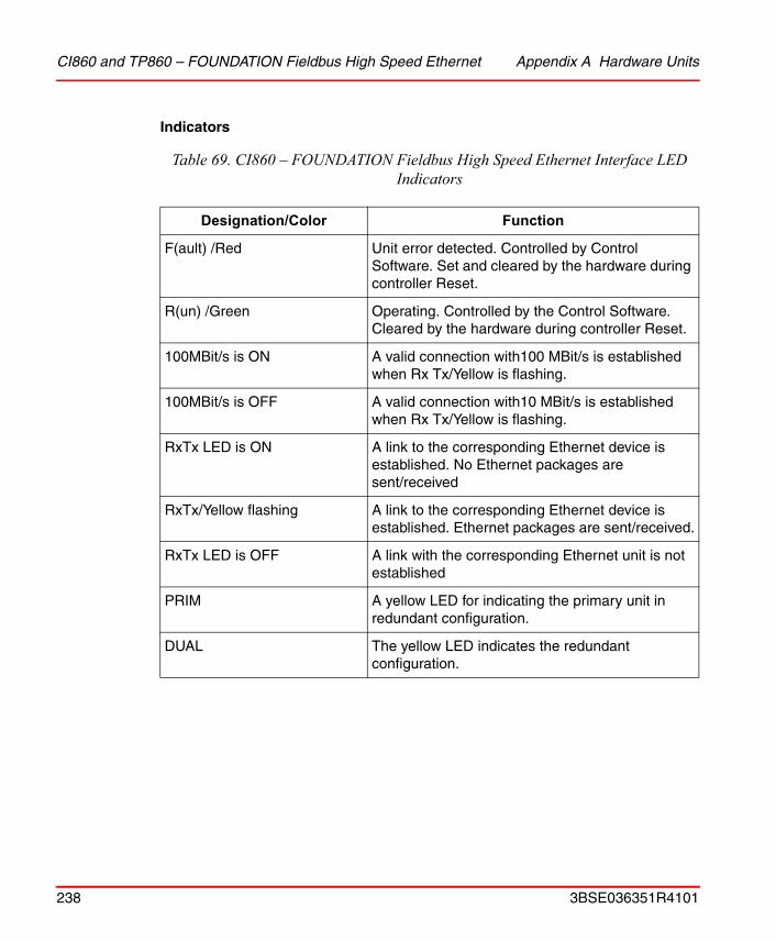
CI860 and TP860 – FOUNDATION Fieldbus High Speed Ethernet Appendix A Hardware Units
Indicators
Table 69. CI860 – FOUNDATION Fieldbus High Speed Ethernet Interface LED Indicators
Designation/Color Function
F(ault) /Red Unit error detected. Controlled by Control Software. Set and cleared by the hardware during controller Reset.
R(un) /Green Operating. Controlled by the Control Software. Cleared by the hardware during controller Reset.
100MBit/s is ON A valid connection with100 MBit/s is established when Rx Tx/Yellow is flashing.
100MBit/s is OFF A valid connection with10 MBit/s is established when Rx Tx/Yellow is flashing.
RxTx LED is ON A link to the corresponding Ethernet device is established. No Ethernet packages are sent/received
RxTx/Yellow flashing A link to the corresponding Ethernet device is established. Ethernet packages are sent/received.
RxTx LED is OFF A link with the corresponding Ethernet unit is not established
PRIM A yellow LED for indicating the primary unit in redundant configuration.
DUAL The yellow LED indicates the redundant configuration.
238 3BSE036351R4101
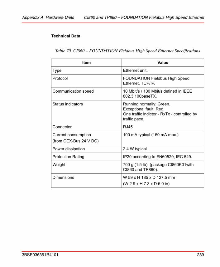
Appendix A Hardware Units CI860 and TP860 – FOUNDATION Fieldbus High Speed Ethernet
Technical Data
Table 70. CI860 – FOUNDATION Fieldbus High Speed Ethernet Specifications
Item Value
Type Ethernet unit.
Protocol FOUNDATION Fieldbus High Speed Ethernet, TCP/IP.
Communication speed 10 Mbit/s / 100 Mbit/s defined in IEEE 802.3 100baseTX.
Status indicators Running normally: Green. Exceptional fault: Red. One traffic indictor - RxTx - controlled by traffic pace.
Connector RJ45
Current consumption(from CEX-Bus 24 V DC)
100 mA typical (150 mA max.).
Power dissipation 2.4 W typical.
Protection Rating IP20 according to EN60529, IEC 529.
Weight 700 g (1.5 lb) (package CI860K01with CI860 and TP860).
Dimensions W 59 x H 185 x D 127.5 mm(W 2.9 x H 7.3 x D 5.0 in)
3BSE036351R4101 239
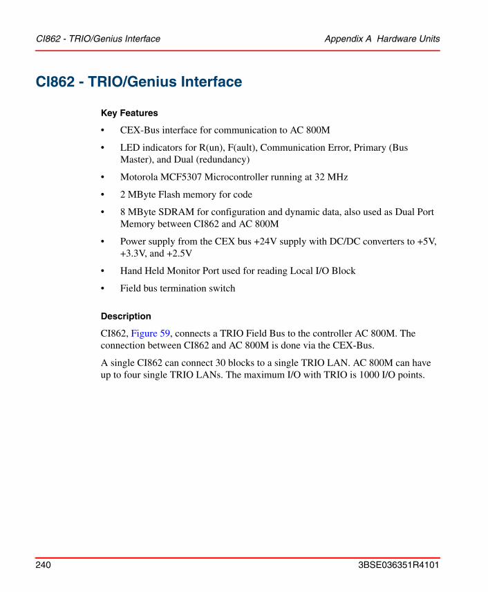
CI862 - TRIO/Genius Interface Appendix A Hardware Units
CI862 - TRIO/Genius Interface
Key Features
• CEX-Bus interface for communication to AC 800M
• LED indicators for R(un), F(ault), Communication Error, Primary (Bus Master), and Dual (redundancy)
• Motorola MCF5307 Microcontroller running at 32 MHz
• 2 MByte Flash memory for code
• 8 MByte SDRAM for configuration and dynamic data, also used as Dual Port Memory between CI862 and AC 800M
• Power supply from the CEX bus +24V supply with DC/DC converters to +5V, +3.3V, and +2.5V
• Hand Held Monitor Port used for reading Local I/O Block
• Field bus termination switch
Description
CI862, Figure 59, connects a TRIO Field Bus to the controller AC 800M. The connection between CI862 and AC 800M is done via the CEX-Bus.
A single CI862 can connect 30 blocks to a single TRIO LAN. AC 800M can have up to four single TRIO LANs. The maximum I/O with TRIO is 1000 I/O points.
240 3BSE036351R4101
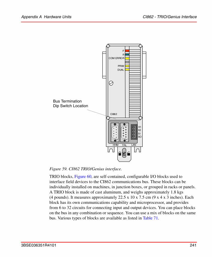
Appendix A Hardware Units CI862 - TRIO/Genius Interface
Figure 59. CI862 TRIO/Genius interface.
TRIO blocks, Figure 60, are self-contained, configurable I/O blocks used to interface field devices to the CI862 communications bus. These blocks can be individually installed on machines, in junction boxes, or grouped in racks or panels. A TRIO block is made of cast aluminum, and weighs approximately 1.8 kgs (4 pounds). It measures approximately 22.5 x 10 x 7.5 cm (9 x 4 x 3 inches). Each block has its own communications capability and microprocessor, and provides from 6 to 32 circuits for connecting input and output devices. You can place blocks on the bus in any combination or sequence. You can use a mix of blocks on the same bus. Various types of blocks are available as listed in Table 71.
COM ERROR
PRIM
R
F
X1
CI862
DUAL
X2SISO
HHM TRL LAN
Bus TerminationDip Switch Location
3BSE036351R4101 241
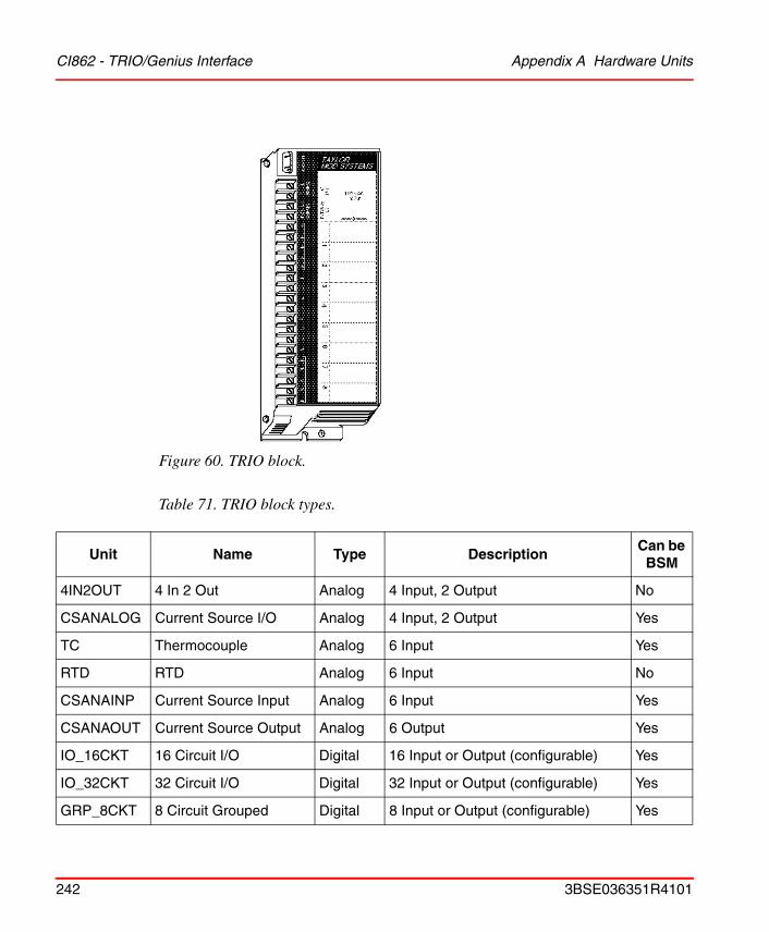
CI862 - TRIO/Genius Interface Appendix A Hardware Units
Figure 60. TRIO block.
Table 71. TRIO block types.
Unit Name Type DescriptionCan be
BSM
4IN2OUT 4 In 2 Out Analog 4 Input, 2 Output No
CSANALOG Current Source I/O Analog 4 Input, 2 Output Yes
TC Thermocouple Analog 6 Input Yes
RTD RTD Analog 6 Input No
CSANAINP Current Source Input Analog 6 Input Yes
CSANAOUT Current Source Output Analog 6 Output Yes
IO_16CKT 16 Circuit I/O Digital 16 Input or Output (configurable) Yes
IO_32CKT 32 Circuit I/O Digital 32 Input or Output (configurable) Yes
GRP_8CKT 8 Circuit Grouped Digital 8 Input or Output (configurable) Yes
242 3BSE036351R4101
Appendix A Hardware Units CI862 - TRIO/Genius Interface
ISO_8CKT 8 Circuit Isolated Digital 8 Input or Output (configurable) Yes
IN_16CKT 16 Circuit Input Digital 16 Input No
OP_16CKT 16 Circuit Output Digital 16 Output Yes
HSC_A High Speed Counter A Counter 4 16 bit Up/Down Counters No
HSC_B High Speed Counter B Counter 2 Bi-directional 24 bit Up/Down Counters
No
Table 71. TRIO block types.
Unit Name Type DescriptionCan be
BSM
3BSE036351R4101 243

CI862 - TRIO/Genius Interface Appendix A Hardware Units
Functional Block Diagram
A complete CI862K01 unit consists of a TP862 baseplate, a CI862 communication interface board, and their mechanics, Figure 61. All electronic devices and all functions are located on the board which also includes the µGenie slave module. The baseplate and CI862 are connected via an 80-pin edge connector. Connections to the outside world are made on the baseplate.
Figure 61. CI862 functionality
The baseplate contains only passive elements. It holds the input and output connectors for the CEX-Bus, a slot for the CI862 unit, a port used for the Genius Bus Hand Held Monitor, a high speed serial port used for module redundancy link communications and a port for the TRIO Field Bus connection.
FPGACEX BusInterface
ColdFire µpMCF5307/5407
32 MHz
Serial I/O
BDM I/O
SDRAM8 MByte
Flash Memory2 MByte
SWTWatchdog
ResetCircuits
Base-PlateTP862
CI862 Module
CEX-Bus
Power
Debug
TRIOLAN
GENIUSHHM
5V5V
3.3V2.5V
24V
CPU Bus
BaseConnector
BDM
µGenie LANCommunicat ion
ProcessorModule
FPGAPC-ISA
Interface &LVD Level
Shifter
................................................
FR
. .. .. .. .. .. .. .. .. .. .. .. .. .. .. .. .. .. .. .. .. .. .. .. .. .. .. .. .. .. .. .. .. .. .. .. .. .. .. .. .
....................
....................
RS422TRL
244 3BSE036351R4101

Appendix A Hardware Units CI862 - TRIO/Genius Interface
CI862 contains the Coldfire MCF5307 Microcontroller with Flash memory, RAM, LED indicators, power supply, and CEX-Bus interface with dual port memory, bridged to a GE/Fanuc µGenie Communication Module. The µGenie handles all data transfer between the CI862 Carrier module and the TRIO FIELD BUS, allowing the Carrier CPU to control the remote I/O.
Indicators
LED indicators for R(un), F(ault), Communication Error, Primary (Bus Master), and Dual (redundancy)
Technical Data
Table 72. TRIO/Genius interface CI862
Item Value
Bus Type Daisy-chained bus cable; single twisted pair plus shield or Twinax.
Protocol similar to the RS422 standard
Communication speed 153.6 ext, 38.4, 76.8, 153.6 std kbit/s
Bus Capacity (one segment) Max 32 devices. 16 devices at 38.4 Kbaud. Includes CI862 and Hand-held Monitor.
Bus Termination 75, 100, 120, or 150 ohm resistor at both ends of electrical bus cable.
Maximum Bus Length 7500 feet at 38.4 Kbaud, 4500 feet at 76.8 Kbaud, 3500 feet at 153.6 Kbaud extended, 2000 feet at 153.6 Kbaud, standard. Maximum length at each baud rate also depends on cable type.
Galvanic Isolation Yes
Status Indicators Red LED for errorGreen LED for runYellow LED for trafficYellow LED for primaryYellow LED for dual mode
3BSE036351R4101 245
CI862 - TRIO/Genius Interface Appendix A Hardware Units
Connector one 4 pin Phoenix style (connects TRIO FIELD BUS)
one DB9S (male) (connects Hand-held Monitor)
one DB9, female (connects CEX expansion bus)
Current Consumption from CEX-Bus 24 V d.c.
Typical 190 mA (max. 200 mA)
Dimensions W 58 x H 165 x D 122 mm (W 2.3 x H 6.4x D 4.81 inches)
Hot swap Supported
Table 72. TRIO/Genius interface CI862
Item Value
246 3BSE036351R4101

Appendix A Hardware Units Power Supply Units – Types SD821, SD822 and SD823
Power Supply Units – Types SD821, SD822 and SD823
Key Features
• Simple DIN-rail mounting
• Parallel connection permitted for load sharing
• Class I Equipment (when connected to Protective Ground, (PE))
• Overvoltage Category III for connection to primary main TN network of Installation Category III
• Protective separation of secondary circuit from primary circuit
• Secondary outputs;
– SD823 = 24 Volts DC regulated @ 10 A
– SD822 = 24 Volts DC regulated @ 5 A
– SD821 = 24 Volts DC regulated @ 2.5 A
• Accepted for SELV and PELV applications
• Switch for selection of 115 or 230 V AC
Safety Classification
The Power Supply Units (PSU) are designed to meet all applicable electrical safety data in accordance with EN 50178 harmonized European Standard Publication, and the additional safety and function data required by EN 61131-2 and UL 508.
The secondary output circuitry is accepted for SELV or PELV applications.
SELV according to EN 50178, EN 60950 and VDE 0100 Part 410.
For PELV applications; in accordance with EN 50178.
Protection Rating
IP20 according to EN 60529, IEC 529
Protective Class I according to EN 50718; 3.56
3BSE036351R4101 247
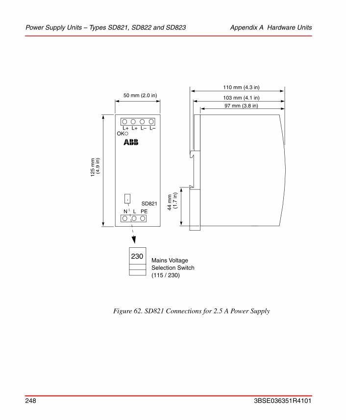
Power Supply Units – Types SD821, SD822 and SD823 Appendix A Hardware Units
Figure 62. SD821 Connections for 2.5 A Power Supply
L+ L+ L– L–
N L
103 mm (4.1 in)
97 mm (3.8 in)
PE
OK
SD821
110 mm (4.3 in)
230Mains VoltageSelection Switch(115 / 230)
125
mm
(4.9
in)
50 mm (2.0 in)
44m
m(1
.7in
)
248 3BSE036351R4101

Appendix A Hardware Units Power Supply Units – Types SD821, SD822 and SD823
Figure 63. SD822 Connections for 5 A Power Supply
44 m
m
L+ L+ L– L–
N L
65 mm (2.6 in)
PE
OK
SD822
230 Mains VoltageSelection Switch (115 / 230)
110 mm (4.3 in)
103 mm (4.1 in)
97 mm (3.8 in)
125
mm
(4.9
in)
(1.7
in)
3BSE036351R4101 249
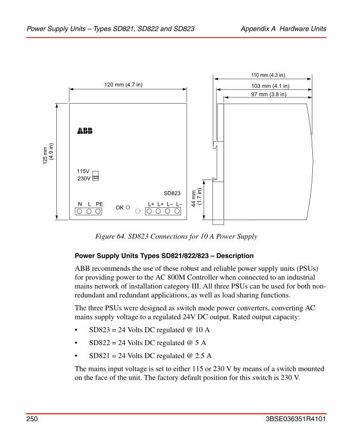
Power Supply Units – Types SD821, SD822 and SD823 Appendix A Hardware Units
Power Supply Units Types SD821/822/823 – Description
ABB recommends the use of these robust and reliable power supply units (PSUs) for providing power to the AC 800M Controller when connected to an industrial mains network of installation category III. All three PSUs can be used for both non-redundant and redundant applications, as well as load sharing functions.
The three PSUs were designed as switch mode power converters, converting AC mains supply voltage to a regulated 24V DC output. Rated output capacity:
• SD823 = 24 Volts DC regulated @ 10 A
• SD822 = 24 Volts DC regulated @ 5 A
• SD821 = 24 Volts DC regulated @ 2.5 A
The mains input voltage is set to either 115 or 230 V by means of a switch mounted on the face of the unit. The factory default position for this switch is 230 V.
Figure 64. SD823 Connections for 10 A Power Supply
103 mm (4.1 in)
44m
m
97 mm (3.8 in)
110 mm (4.3 in)
L+ L+ L– L–N L
120 mm (4.7 in)
PE OK
SD823
115V230V
125
mm
(4.9
in)
(1.7
in)
250 3BSE036351R4101
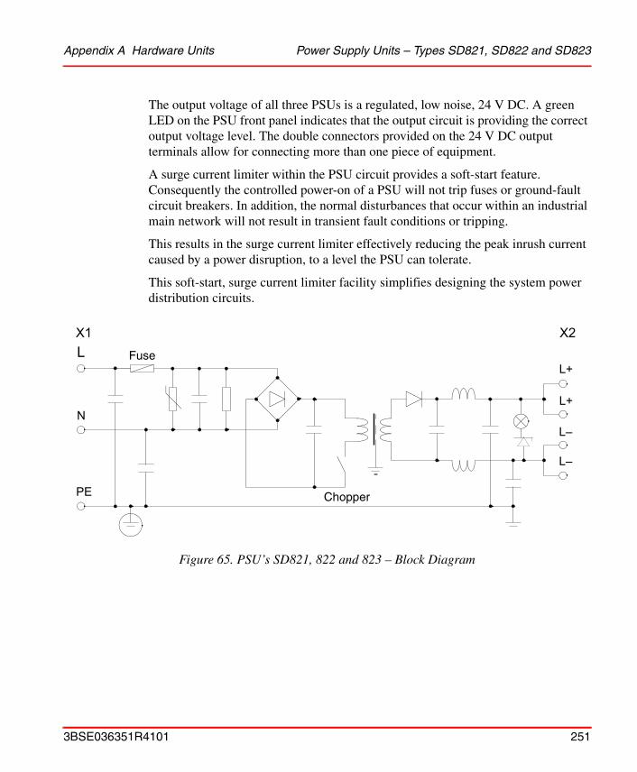
Appendix A Hardware Units Power Supply Units – Types SD821, SD822 and SD823
The output voltage of all three PSUs is a regulated, low noise, 24 V DC. A green LED on the PSU front panel indicates that the output circuit is providing the correct output voltage level. The double connectors provided on the 24 V DC output terminals allow for connecting more than one piece of equipment.
A surge current limiter within the PSU circuit provides a soft-start feature. Consequently the controlled power-on of a PSU will not trip fuses or ground-fault circuit breakers. In addition, the normal disturbances that occur within an industrial main network will not result in transient fault conditions or tripping.
This results in the surge current limiter effectively reducing the peak inrush current caused by a power disruption, to a level the PSU can tolerate.
This soft-start, surge current limiter facility simplifies designing the system power distribution circuits.
Figure 65. PSU’s SD821, 822 and 823 – Block Diagram
L
N
PE
L+
L+
L–
L–
Chopper
Fuse
X1 X2
3BSE036351R4101 251
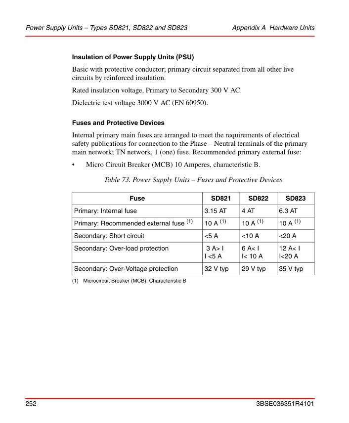
Power Supply Units – Types SD821, SD822 and SD823 Appendix A Hardware Units
Insulation of Power Supply Units (PSU)
Basic with protective conductor; primary circuit separated from all other live circuits by reinforced insulation.
Rated insulation voltage, Primary to Secondary 300 V AC.
Dielectric test voltage 3000 V AC (EN 60950).
Fuses and Protective Devices
Internal primary main fuses are arranged to meet the requirements of electrical safety publications for connection to the Phase – Neutral terminals of the primary main network; TN network, 1 (one) fuse. Recommended primary external fuse:
• Micro Circuit Breaker (MCB) 10 Amperes, characteristic B.
Table 73. Power Supply Units – Fuses and Protective Devices
Fuse SD821 SD822 SD823
Primary: Internal fuse 3.15 AT 4 AT 6.3 AT
Primary: Recommended external fuse (1)
(1) Microcircuit Breaker (MCB), Characteristic B
10 A (1) 10 A (1) 10 A (1)
Secondary: Short circuit <5 A <10 A <20 A
Secondary: Over-load protection 3 A> I I <5 A
6 A< II< 10 A
12 A< II<20 A
Secondary: Over-Voltage protection 32 V typ 29 V typ 35 V typ
252 3BSE036351R4101
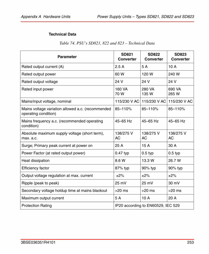
Appendix A Hardware Units Power Supply Units – Types SD821, SD822 and SD823
Technical Data
Table 74. PSU’s SD821, 822 and 823 – Technical Data
ParameterSD821
ConverterSD822
ConverterSD823
Converter
Rated output current (A) 2.5 A 5 A 10 A
Rated output power 60 W 120 W 240 W
Rated output voltage 24 V 24 V 24 V
Rated input power 160 VA70 W
280 VA135 W
690 VA265 W
Mains/input voltage, nominal 115/230 V AC 115/230 V AC 115/230 V AC
Mains voltage variation allowed a.c. (recommended operating condition)
85–110% 85–110% 85–110%
Mains frequency a.c. (recommended operating condition)
45–65 Hz 45–65 Hz 45–65 Hz
Absolute maximum supply voltage (short term), max. a.c.
138/275 V AC
138/275 V AC
138/275 V AC
Surge; Primary peak current at power on 25 A 15 A 30 A
Power Factor (at rated output power) 0.47 typ 0.5 typ 0.5 typ
Heat dissipation 8.6 W 13.3 W 26.7 W
Efficiency factor 87% typ 90% typ 90% typ
Output voltage regulation at max. current ±2% ±2% ±2%
Ripple (peak to peak) 25 mV 25 mV 30 mV
Secondary voltage holdup time at mains blackout >20 ms >20 ms >20 ms
Maximum output current 5 A 10 A 20 A
Protection Rating IP20 according to EN60529, IEC 529
3BSE036351R4101 253
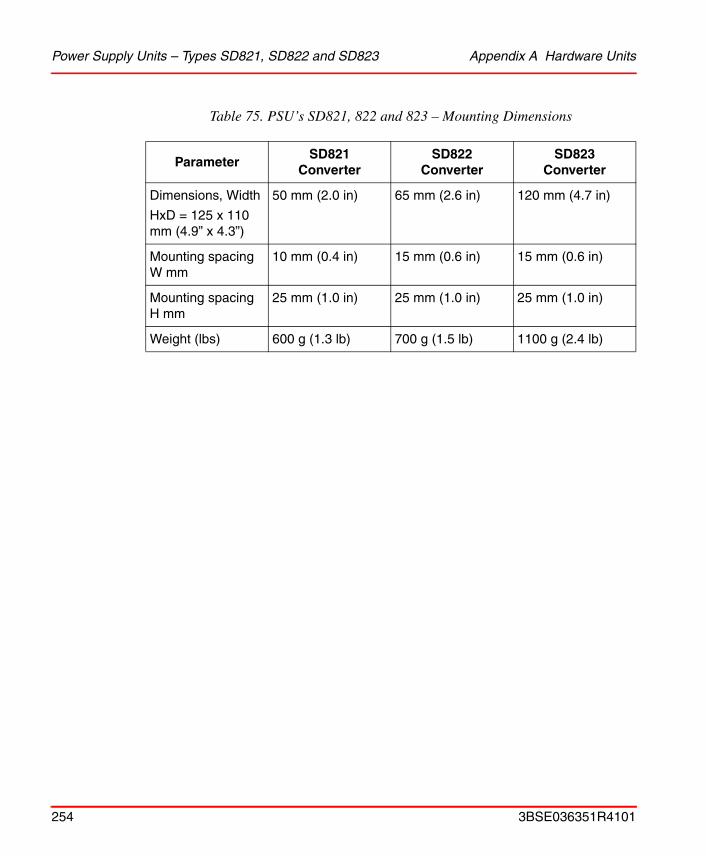
Power Supply Units – Types SD821, SD822 and SD823 Appendix A Hardware Units
Table 75. PSU’s SD821, 822 and 823 – Mounting Dimensions
ParameterSD821
ConverterSD822
ConverterSD823
Converter
Dimensions, Width
HxD = 125 x 110 mm (4.9” x 4.3”)
50 mm (2.0 in) 65 mm (2.6 in) 120 mm (4.7 in)
Mounting spacing W mm
10 mm (0.4 in) 15 mm (0.6 in) 15 mm (0.6 in)
Mounting spacing H mm
25 mm (1.0 in) 25 mm (1.0 in) 25 mm (1.0 in)
Weight (lbs) 600 g (1.3 lb) 700 g (1.5 lb) 1100 g (2.4 lb)
254 3BSE036351R4101

Appendix A Hardware Units SS822/SS823 Voting Unit – (for Redundant Power Supply)
SS822/SS823 Voting Unit – (for Redundant Power Supply)
Redundant Power Supply Configurations
The SS822/SS823 Voting Unit has been specifically designed for utilization as a control unit within a redundant power supply configuration. The output connections from two identical Power Supply Units (PSUs) are connected to the SS82x, see Figure 43 on page 132 and Figure 44 on page 133.
The SS82x Voting Unit separates the redundant power supply units, supervises the voltage supplied and generates supervision signals to be connected to the computer system.
Green LEDs, mounted on the SS82x front panel, provide a visual indication that the correct output voltage is being delivered. Immediately the green LED lights up, a voltage-free contact closes the path to the corresponding “OK connector”. The SS82x trip levels (2 off), are factory preset. For details see Table 76 on page 256 SS82x Voting Unit – Supervision Data.
The SS823 Voting Unit has double overvoltage protection circuit on both inputs. It is also able to detect both short and open circuit in the voting element. For details see Table 78 on page 258.
3BSE036351R4101 255

SS822/SS823 Voting Unit – (for Redundant Power Supply) Appendix A Hardware Units
Figure 66. SS822 Voting Unit Connections
Table 76. SS822 Voting Unit – Supervision Data
Supervision Data SS822
Voltage, low trip level(for decreasing voltage)
22 V
Voltage, low trip hysteresis 0.7 V
Voltage, high trip level for rising voltage 30 V
High trip hysteresis 0.7 V
OK F OK
A+B+L+
SS822
F+ +A B
L+L– 44m
m
97 mm (3.8 in)
110 mm (4.3 in)
103 mm (4.1 in)
(1.7
in)
125
mm
(4.9
in)
50 mm (2.0 in)
256 3BSE036351R4101
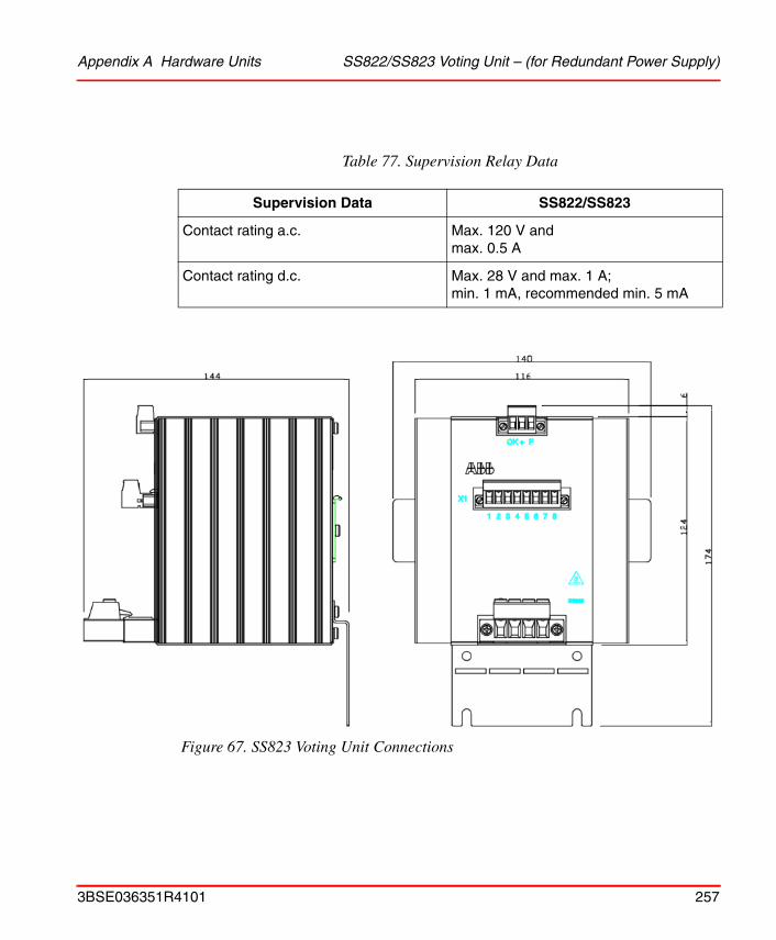
Appendix A Hardware Units SS822/SS823 Voting Unit – (for Redundant Power Supply)
Figure 67. SS823 Voting Unit Connections
Table 77. Supervision Relay Data
Supervision Data SS822/SS823
Contact rating a.c. Max. 120 V andmax. 0.5 A
Contact rating d.c. Max. 28 V and max. 1 A; min. 1 mA, recommended min. 5 mA
3BSE036351R4101 257
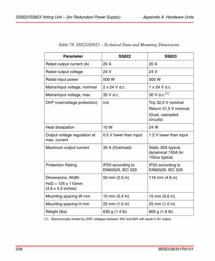
SS822/SS823 Voting Unit – (for Redundant Power Supply) Appendix A Hardware Units
Table 78. SS822/SS823 – Technical Data and Mounting Dimensions
Parameter SS822 SS823
Rated output current (A) 20 A 20 A
Rated output voltage 24 V 24 V
Rated input power 500 W 500 W
Mains/input voltage, nominal 2 x 24 V d.c. 1 x 24 V d.c.
Mains/input voltage, max 35 V d.c. 30 V d.c.(1)
(1) Electronically limited by OVP, voltages between 30V and 60V will result in 0V output.
OVP (overvoltage protection) n/a Trip 32,0 V nominal
Return 31,5 V nominal
(Dual, cascaded circuits)
Heat dissipation 10 W 24 W
Output voltage regulation at max. current
0.5 V lower than input 1.2 V lower than input
Maximum output current 35 A (Overload) Static 35A typical, dynamical 150A for 100us typical.
Protection Rating IP20 according to EN60529, IEC 529
IP20 according to EN60529, IEC 529
Dimensions, Width
HxD = 125 x 110mm(4.9 x 4.3 inches)
50 mm (2.0 in) 116 mm (4.6 in)
Mounting spacing W mm 10 mm (0.4 in) 15 mm (0.6 in)
Mounting spacing H mm 25 mm (1.0 in) 25 mm (1.0 in)
Weight (lbs) 630 g (1.4 lb) 800 g (1.8 lb)
258 3BSE036351R4101
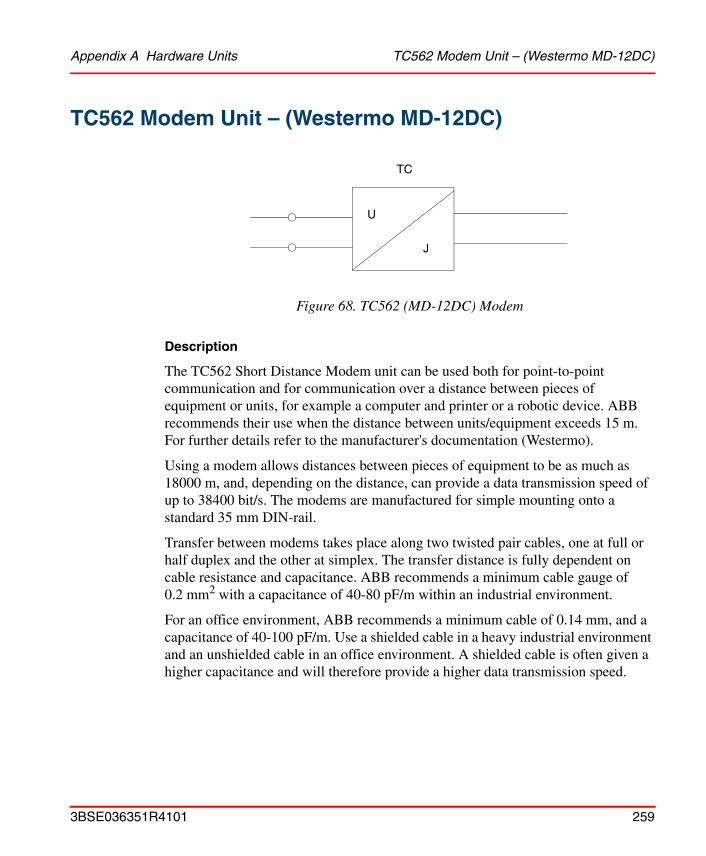
Appendix A Hardware Units TC562 Modem Unit – (Westermo MD-12DC)
TC562 Modem Unit – (Westermo MD-12DC)
Description
The TC562 Short Distance Modem unit can be used both for point-to-point communication and for communication over a distance between pieces of equipment or units, for example a computer and printer or a robotic device. ABB recommends their use when the distance between units/equipment exceeds 15 m. For further details refer to the manufacturer's documentation (Westermo).
Using a modem allows distances between pieces of equipment to be as much as 18000 m, and, depending on the distance, can provide a data transmission speed of up to 38400 bit/s. The modems are manufactured for simple mounting onto a standard 35 mm DIN-rail.
Transfer between modems takes place along two twisted pair cables, one at full or half duplex and the other at simplex. The transfer distance is fully dependent on cable resistance and capacitance. ABB recommends a minimum cable gauge of 0.2 mm2 with a capacitance of 40-80 pF/m within an industrial environment.
For an office environment, ABB recommends a minimum cable of 0.14 mm, and a capacitance of 40-100 pF/m. Use a shielded cable in a heavy industrial environment and an unshielded cable in an office environment. A shielded cable is often given a higher capacitance and will therefore provide a higher data transmission speed.
Figure 68. TC562 (MD-12DC) Modem
TC
U
J
3BSE036351R4101 259
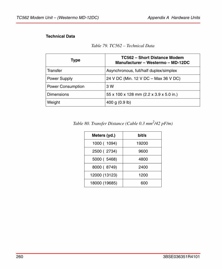
TC562 Modem Unit – (Westermo MD-12DC) Appendix A Hardware Units
Technical Data
Table 79. TC562 – Technical Data
TypeTC562 – Short Distance Modem
Manufacturer – Westermo – MD-12DC
Transfer Asynchronous, full/half duplex/simplex
Power Supply 24 V DC (Min. 12 V DC – Max 36 V DC)
Power Consumption 3 W
Dimensions 55 x 100 x 128 mm (2.2 x 3.9 x 5.0 in.)
Weight 400 g (0.9 lb)
Table 80. Transfer Distance (Cable 0.3 mm2/42 pF/m)
Meters (yd.) bit/s
1000 ( 1094) 19200
2500 ( 2734) 9600
5000 ( 5468) 4800
8000 ( 8749) 2400
12000 (13123) 1200
18000 (19685) 600
260 3BSE036351R4101
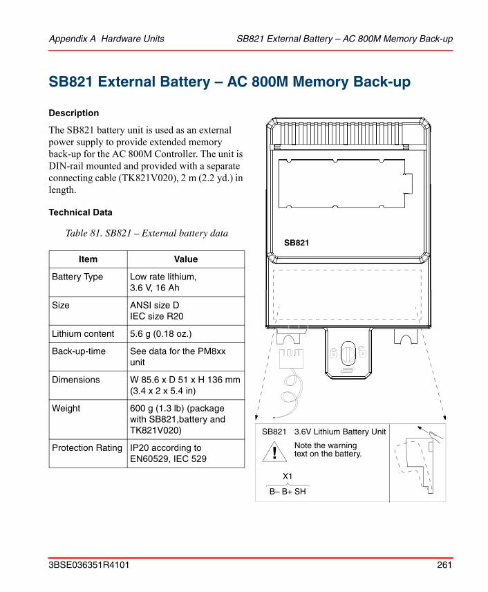
Appendix A Hardware Units SB821 External Battery – AC 800M Memory Back-up
SB821 External Battery – AC 800M Memory Back-up
Description
The SB821 battery unit is used as an external power supply to provide extended memory back-up for the AC 800M Controller. The unit is DIN-rail mounted and provided with a separate connecting cable (TK821V020), 2 m (2.2 yd.) in length.
Technical Data
Table 81. SB821 – External battery data
Item Value
Battery Type Low rate lithium,3.6 V, 16 Ah
Size ANSI size DIEC size R20
Lithium content 5.6 g (0.18 oz.)
Back-up-time See data for the PM8xx unit
Dimensions W 85.6 x D 51 x H 136 mm(3.4 x 2 x 5.4 in)
Weight 600 g (1.3 lb) (package with SB821,battery and TK821V020)
Protection Rating IP20 according to EN60529, IEC 529
SB821
!SB821 3.6V Lithium Battery Unit
Note the warningtext on the battery.
X1
B– B+ SH
3BSE036351R4101 261
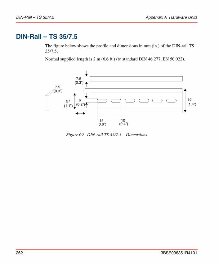
DIN-Rail – TS 35/7.5 Appendix A Hardware Units
DIN-Rail – TS 35/7.5The figure below shows the profile and dimensions in mm (in.) of the DIN-rail TS 35/7.5.
Normal supplied length is 2 m (6.6 ft.) (to standard DIN 46 277, EN 50 022).
Figure 69. DIN-rail TS 35/7.5 – Dimensions
1015
27
7.5
356
(0.6”)
(1.4”)(1.1”) (0.2”)
(0.3”)7.5
(0.3”)
(0.4”)
262 3BSE036351R4101

Appendix A Hardware Units Miscellaneous Equipment
Miscellaneous Equipment
TB850 Terminator for CEX-Bus (Male)
Figure 70. TB850 Terminator for CEX (male)
TerminatorTB850
3BSE036351R4101 263
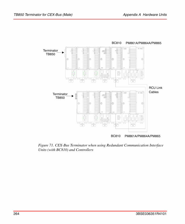
TB850 Terminator for CEX-Bus (Male) Appendix A Hardware Units
Figure 71. CEX-Bus Terminator when using Redundant Communication Interface Units (with BC810) and Controllers
BC810
BC810
RCU LinkCables
PM861A/PM864A/PM865
PM861A/PM864A/PM865
TerminatorTB850
TerminatorTB850
264 3BSE036351R4101
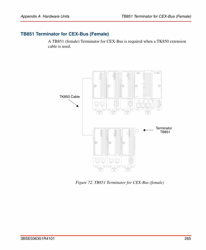
Appendix A Hardware Units TB851 Terminator for CEX-Bus (Female)
TB851 Terminator for CEX-Bus (Female)
A TB851 (female) Terminator for CEX-Bus is required when a TK850 extension cable is used.
Figure 72. TB851 Terminator for CEX-Bus (female)
TK850 Cable
TerminatorTB851
3BSE036351R4101 265

TB807 ModuleBus Terminator Plug Appendix A Hardware Units
TB807 ModuleBus Terminator Plug
The Terminator plug must always be mounted on the last I/O unit of the ModuleBus. If no units are used on the ModuleBus, no bus termination is required. No ModuleBus termination is required in redundant CPU configuration.
TB852 RCU Link Terminator Plug
The RCU Link Terminator Plug is required when the PM861/PM864 processor unit operates in single configuration.
TK850 CEX-Bus Extension Cable
A 0.7 m (2.3 ft.) extension cable, complete with connector (type DB25P-metal housing) provides connectivity to Communication Interface units between adjacent DIN-rails. It is always used in redundant CPU configuration for connecting the CEX-Bus between the two processor units.
TK851 RCU Link Cable
The Redundant Control Unit Link Cable is used to transfer log data from the Primary CPU to the Backup CPU, and to exchange status and control information between the Primary and Backup CPUs. The RCU Link uses 68-pole connectors, one of which is labeled “UPPER”. The CPU connected to this connector will be defined as the upper CPU in the Control Builder and Operator Station.
The RCU Link Cable is also used as interconnection cable between two BC810.
266 3BSE036351R4101

Appendix A Hardware Units TK853
TK853
Technical Data
Table 82. TK853 – Technical Data
Item Value
Connectors • One 9-pole male D-sub (DE9P)
• One 8-pole RJ45 plug
Weight 100 g (0.2 lb) (TK853V02)
Length 2.0 m (6.56’) (TK853V02)
Figure 73. TK853 – Cable Characteristics
7 RTS4 DTR3 TD5 0 V 2 RD1 DCD8 CTSShield
AC 800M
RJ45 plug
Modem
Male 9-pole,D-sub connector (DE9P)
RTSDTRTD0 V0 VRDDCDCTSShield
12345678
3BSE036351R4101 267
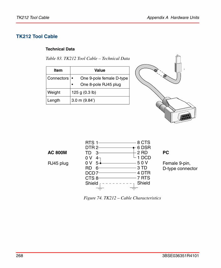
TK212 Tool Cable Appendix A Hardware Units
TK212 Tool Cable
Technical Data
Table 83. TK212 Tool Cable – Technical Data
Item Value
Connectors • One 9-pole female D-type
• One 8-pole RJ45 plug
Weight 125 g (0.3 lb)
Length 3.0 m (9.84’)
Figure 74. TK212 – Cable Characteristics
8 CTS6 DSR2 RD1 DCD5 0 V3 TD4 DTR7 RTSShield
AC 800M
RJ45 plug
PC
Female 9-pin,D-type connector
RTSDTRTD0 V0 VRDDCDCTSShield
12345678
268 3BSE036351R4101
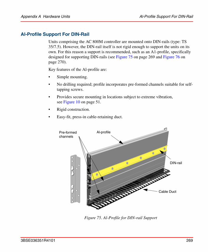
Appendix A Hardware Units Al-Profile Support For DIN-Rail
Al-Profile Support For DIN-Rail
Units comprising the AC 800M controller are mounted onto DIN-rails (type: TS 35/7.5). However, the DIN-rail itself is not rigid enough to support the units on its own. For this reason a support is recommended, such as an A1-profile, specifically designed for supporting DIN-rails (see Figure 75 on page 269 and Figure 76 on page 270).
Key features of the Al-profile are:
• Simple mounting.
• No drilling required; profile incorporates pre-formed channels suitable for self-tapping screws.
• Provides secure mounting in locations subject to extreme vibration, see Figure 10 on page 51.
• Rigid construction.
• Easy-fit, press-in cable-retaining duct.
Figure 75. Al-Profile for DIN-rail Support
Pre-formed
DIN-rail
Cable Duct
Al-profilechannels
3BSE036351R4101 269
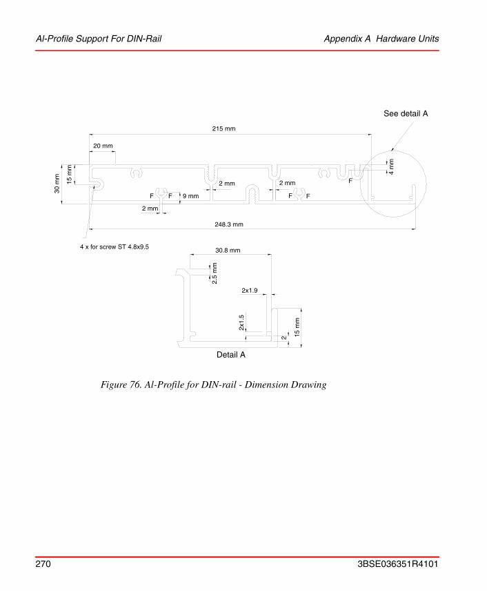
Al-Profile Support For DIN-Rail Appendix A Hardware Units
Figure 76. Al-Profile for DIN-rail - Dimension Drawing
215 mm
20 mm
15 m
m
30 m
m
9 mm
2 mm
F F
2 mm 2 mm
F F
4 m
m
See detail A
F
4 x for screw ST 4.8x9.5
248.3 mm
30.8 mm
2x1.9 15
mm
2
2x1.
5
2.5
mm
Detail A
270 3BSE036351R4101
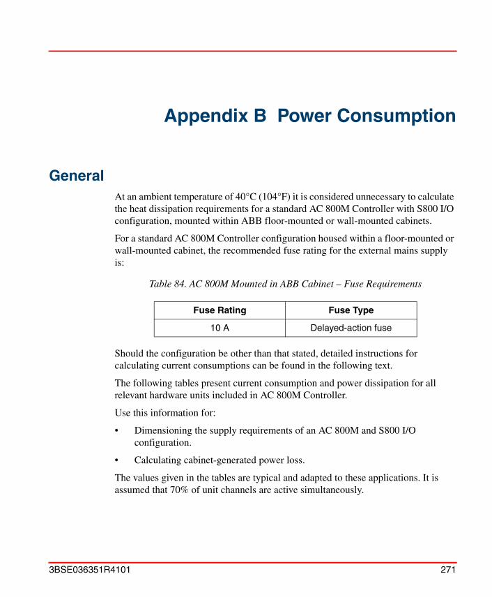
Appendix B Power Consumption
GeneralAt an ambient temperature of 40°C (104°F) it is considered unnecessary to calculate the heat dissipation requirements for a standard AC 800M Controller with S800 I/O configuration, mounted within ABB floor-mounted or wall-mounted cabinets.
For a standard AC 800M Controller configuration housed within a floor-mounted or wall-mounted cabinet, the recommended fuse rating for the external mains supply is:
Should the configuration be other than that stated, detailed instructions for calculating current consumptions can be found in the following text.
The following tables present current consumption and power dissipation for all relevant hardware units included in AC 800M Controller.
Use this information for:
• Dimensioning the supply requirements of an AC 800M and S800 I/O configuration.
• Calculating cabinet-generated power loss.
The values given in the tables are typical and adapted to these applications. It is assumed that 70% of unit channels are active simultaneously.
Table 84. AC 800M Mounted in ABB Cabinet – Fuse Requirements
Fuse Rating Fuse Type
10 A Delayed-action fuse
3BSE036351R4101 271

Current Consumption and Power Dissipation Appendix B Power Consumption
Current Consumption and Power DissipationSee Table 85 on page 272 for typical current consumption and power dissipation data for AC 800M units.
(1) These figures apply only to the PM8xx. For current-consumption data relating to the CEX-Bus and the ModuleBus units, see Table 86 on page 273. Due to transfer or conversion losses in the CPU when current supply to ModuleBus and CEX-Bus is utilized, the CPU power dissipation increases by maximum 5 W (3 W for PM851) in addition to the values given in Table 85 on page 272.
Table 85. Current Consumption and Power Dissipation Data for AC 800M Units
UnitCurrent at 24 V Power Dissipation
RemarksTypical Max Typical Max
PM851 180 mA 300 mA 5.0 W 8.0 W (1)
PM856 180 mA 300 mA 5.0 W 8.0 W (1)
PM860 180 mA 300 mA 5.0 W 8.0 W (1)
PM861 250 mA 430 mA 6.0 W 10.3 W (1)
PM864 287 mA 487 mA 6.9 W 11.4 W (1)
PM865 287 mA 487 mA 6.9 W 11.4 W (1)
BC810 50 mA 70 mA 1.2 W 1.7 W
SM810 160 mA 250 mA 3.8 W 6.0 W
CI851 150 mA 200 mA 3.6 W 5.0 W
CI852 140 mA 200 mA 3.4 W 5.0 W
CI853 100 mA 150 mA 2.4 W 3.6 W
CI854/854A 190 mA 240 mA 4.6 W 5.8 W
CI855 150 mA 200 mA 3.6 W 5.0 W
CI856 120 mA 200 mA 2.9 W 5.0 W
CI857 150 mA 200 mA 3.6 W 5.0 W
CI858 150 mA 200 mA 3.6 W 5.0 W
CI860 100 mA 150 mA 2.4 W 3.6 W
CI862 190 mA 200 mA 3.0 W 4.0 W
272 3BSE036351R4101
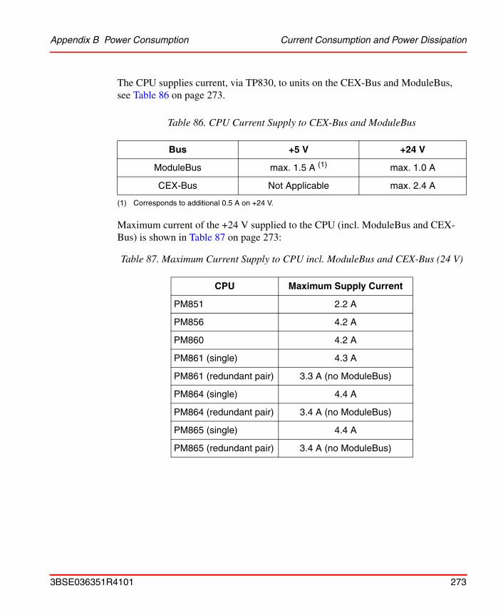
Appendix B Power Consumption Current Consumption and Power Dissipation
The CPU supplies current, via TP830, to units on the CEX-Bus and ModuleBus, see Table 86 on page 273.
Maximum current of the +24 V supplied to the CPU (incl. ModuleBus and CEX-Bus) is shown in Table 87 on page 273:
Table 86. CPU Current Supply to CEX-Bus and ModuleBus
Bus +5 V +24 V
ModuleBus max. 1.5 A (1)
(1) Corresponds to additional 0.5 A on +24 V.
max. 1.0 A
CEX-Bus Not Applicable max. 2.4 A
Table 87. Maximum Current Supply to CPU incl. ModuleBus and CEX-Bus (24 V)
CPU Maximum Supply Current
PM851 2.2 A
PM856 4.2 A
PM860 4.2 A
PM861 (single) 4.3 A
PM861 (redundant pair) 3.3 A (no ModuleBus)
PM864 (single) 4.4 A
PM864 (redundant pair) 3.4 A (no ModuleBus)
PM865 (single) 4.4 A
PM865 (redundant pair) 3.4 A (no ModuleBus)
3BSE036351R4101 273

Current Consumption and Power Dissipation Appendix B Power Consumption
Calculations
1. Calculate the current requirements for each bus (ModuleBus and CEX-Bus). Be sure not to exceed the limits given in Table 86 on page 273. Data relating to TB820, TB840 and CI830 is accessible from the S800 I/O documentation.
2. Calculate the current consumption at 24 V, for each electrical ModuleBus, by adding:
Im = I (24 V) + I (5 V) x 0.3
3. To calculate the requirement for a specific power supply unit, total the results of the 24V current consumption calculations, as follows:
Itot = Im1 + Im2 + .... + Iunits Table 85 + ICI830s + ITB820s + ITB840s
If redundant CPUs are used, current for both CPUs must be included.
274 3BSE036351R4101

Appendix C Recommended Components
Recommended ComponentsAll recommended components listed below were successfully utilized during exhaustive tests made by ABB, prior to launching the AC 800M Controller.
Table 88. Recommended Components – PROFIBUS DP
Component Description
PROFIBUS DP Due to the large selection of commercially available equipment manufactured to PROFIBUS DP Standard, there is no recommendation for specific PROFIBUS DP components.
For further details refer to PROFIBUS DP Web Site.
PROFIBUS DP-V1 No specific PROFIBUS DP-V1 components are recommended, see PROFIBUS DP above.
3BSE036351R4101 275
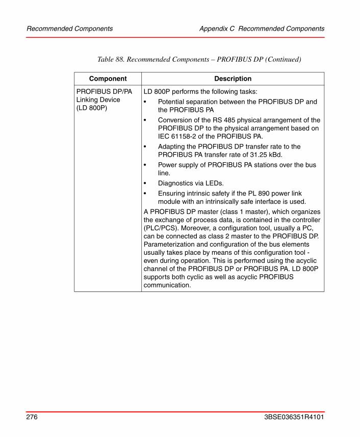
Recommended Components Appendix C Recommended Components
PROFIBUS DP/PA Linking Device(LD 800P)
LD 800P performs the following tasks:
• Potential separation between the PROFIBUS DP and the PROFIBUS PA
• Conversion of the RS 485 physical arrangement of the PROFIBUS DP to the physical arrangement based on IEC 61158-2 of the PROFIBUS PA.
• Adapting the PROFIBUS DP transfer rate to the PROFIBUS PA transfer rate of 31.25 kBd.
• Power supply of PROFIBUS PA stations over the bus line.
• Diagnostics via LEDs.
• Ensuring intrinsic safety if the PL 890 power link module with an intrinsically safe interface is used.
A PROFIBUS DP master (class 1 master), which organizes the exchange of process data, is contained in the controller (PLC/PCS). Moreover, a configuration tool, usually a PC, can be connected as class 2 master to the PROFIBUS DP. Parameterization and configuration of the bus elements usually takes place by means of this configuration tool - even during operation. This is performed using the acyclic channel of the PROFIBUS DP or PROFIBUS PA. LD 800P supports both cyclic as well as acyclic PROFIBUS communication.
Table 88. Recommended Components – PROFIBUS DP (Continued)
Component Description
276 3BSE036351R4101

Appendix C Recommended Components Recommended Components
PROFIBUS DP/PA Linking Device(LD 800P)(cont.)
The way in which LD 800P works is essentially transparent. This means that PROFIBUS DP masters have direct access to PROFIBUS PA slaves. This offers the following advantages:
• No configuration of the Linking Device is required
• PROFIBUS PA slaves can be treated like PROFIBUS DP slaves
• There is no PROFIBUS DP address setting on the Linking Device
• Because of this, there is no restriction on the amount of data to 244 bytes of I/O data per PROFIBUS PA segment for the PROFIBUS PA.
See Figure 77 on page 278 for LD 800P Interface. For more information see fieldbus documentation.
Table 88. Recommended Components – PROFIBUS DP (Continued)
Component Description
3BSE036351R4101 277
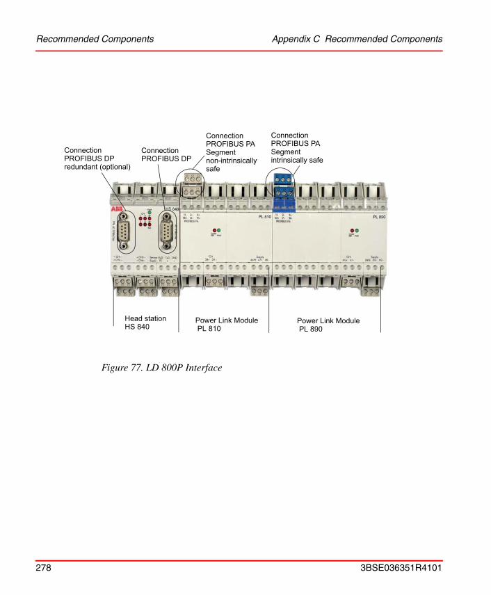
Recommended Components Appendix C Recommended Components
Figure 77. LD 800P Interface
Head station
ConnectionPROFIBUS DPredundant (optional)
ConnectionPROFIBUS DP
ConnectionPROFIBUS PASegmentnon-intrinsically
ConnectionPROFIBUS PASegmentintrinsically safe
HS 840Power Link Module PL 810
Power Link Module PL 890
safe
278 3BSE036351R4101
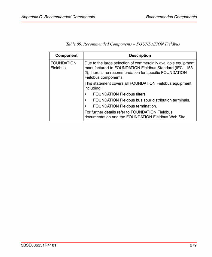
Appendix C Recommended Components Recommended Components
Table 89. Recommended Components – FOUNDATION Fieldbus
Component Description
FOUNDATION Fieldbus
Due to the large selection of commercially available equipment manufactured to FOUNDATION Fieldbus Standard (IEC 1158-2), there is no recommendation for specific FOUNDATION Fieldbus components.
This statement covers all FOUNDATION Fieldbus equipment, including:
• FOUNDATION Fieldbus filters.
• FOUNDATION Fieldbus bus spur distribution terminals.
• FOUNDATION Fieldbus termination.
For further details refer to FOUNDATION Fieldbus documentation and the FOUNDATION Fieldbus Web Site.
3BSE036351R4101 279
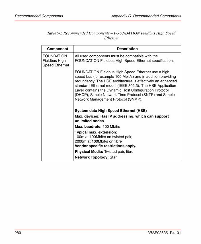
Recommended Components Appendix C Recommended Components
Table 90. Recommended Components – FOUNDATION Fieldbus High Speed Ethernet
Component Description
FOUNDATION Fieldbus High Speed Ethernet
All used components must be compatible with the FOUNDATION Fieldbus High Speed Ethernet specification.
FOUNDATION Fieldbus High Speed Ethernet use a high speed bus (for example 100 Mbit/s) and in addition providing redundancy. The HSE architecture is effectively an enhanced standard Ethernet model (IEEE 802.3). The HSE Application Layer contains the Dynamic Host Configuration Protocol (DHCP), Simple Network Time Protocol (SNTP) and Simple Network Management Protocol (SNMP).
System data High Speed Ethernet (HSE)
Max. devices: Has IP addressing, which can support unlimited nodes
Max. baudrate: 100 Mbit/s
Typical max. extension: 100m at 100Mbit/s on twisted pair, 2000m at 100Mbit/s on fibreVendor specific restrictions apply.
Physical Media: Twisted pair, fibre
Network Topology: Star
280 3BSE036351R4101
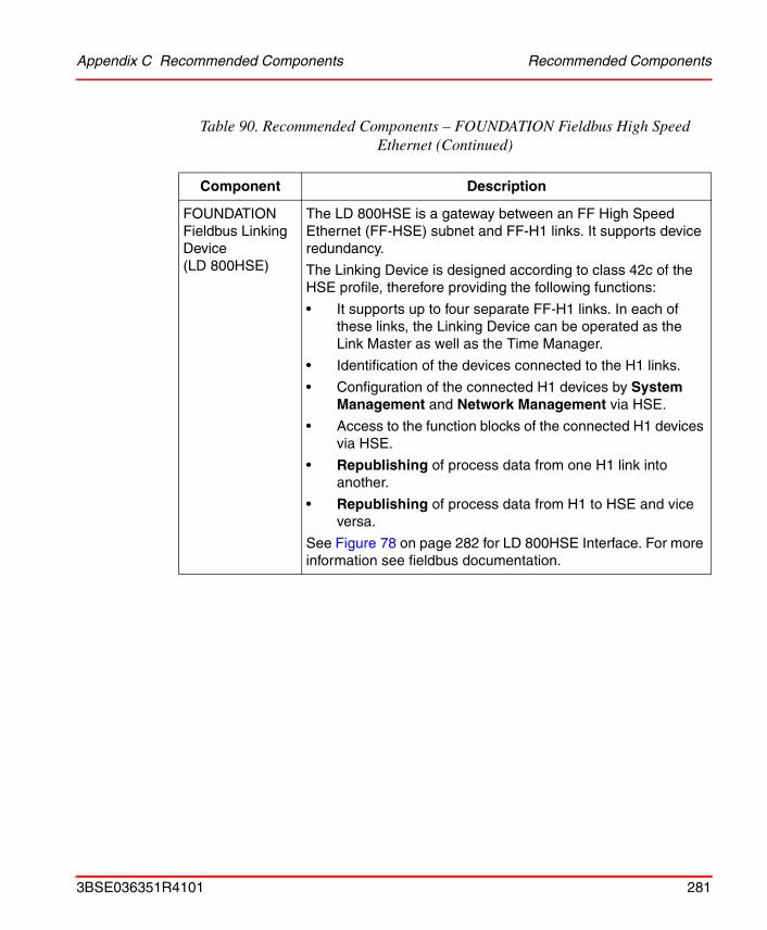
Appendix C Recommended Components Recommended Components
FOUNDATION Fieldbus Linking Device(LD 800HSE)
The LD 800HSE is a gateway between an FF High Speed Ethernet (FF-HSE) subnet and FF-H1 links. It supports device redundancy.
The Linking Device is designed according to class 42c of the HSE profile, therefore providing the following functions:
• It supports up to four separate FF-H1 links. In each of these links, the Linking Device can be operated as the Link Master as well as the Time Manager.
• Identification of the devices connected to the H1 links.
• Configuration of the connected H1 devices by System Management and Network Management via HSE.
• Access to the function blocks of the connected H1 devices via HSE.
• Republishing of process data from one H1 link into another.
• Republishing of process data from H1 to HSE and vice versa.
See Figure 78 on page 282 for LD 800HSE Interface. For more information see fieldbus documentation.
Table 90. Recommended Components – FOUNDATION Fieldbus High Speed Ethernet (Continued)
Component Description
3BSE036351R4101 281
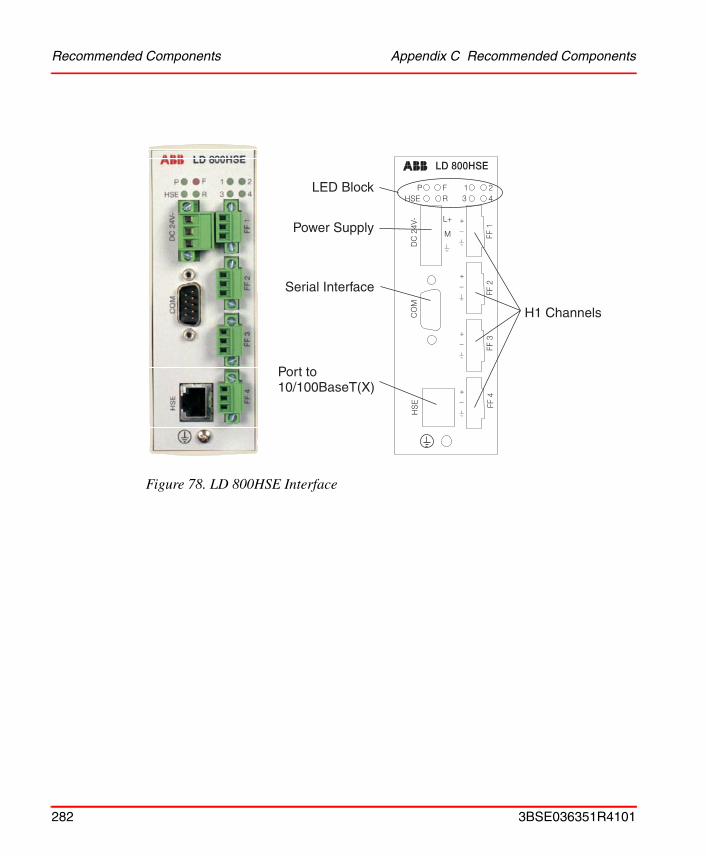
Recommended Components Appendix C Recommended Components
Figure 78. LD 800HSE Interface
282 3BSE036351R4101

Appendix C Recommended Components Recommended Components
Table 91. Recommended Components for Control Networks
Component Description
HUBS
(For Non-Industrial Environments)
3Com Hub, 8/TPO – (8 ports, RJ45)
BayStack, 350/24 – (24 port, Star topology, RJ45)
HUBS
(Industrial Environments)
Hirschmann Rail Hub RH1-TP– (4 ports, RJ45)
SWITCHES
(Industrial Environments
Hirschmann Rail Switch RS2 (8 ports, Ring, Bus or Star topology RJ45)
On-Time Switch (FSU100 series, FSU200 series, FSU208, FSR208, FST208)
CABLES Electrical – Class 5, or higher, STP
Optical – As recommended by Manufacturer of HUBS and SWITCHES
3BSE036351R4101 283

Recommended Components Appendix C Recommended Components
Table 92. Recommended Components – Miscellaneous
Component Description
DIN-rail Phoenix:
• TS 35/7.5
• Steel, yellow chromated with holes
• DIN 46 277, EN 50 022
DIN-rail Accessories
DIN-rail end support device
Phoenix: UK 4-TG+ST-BE
(Standard commercially available components)
Cabinets ABB Automation Technology Products, LV systems
Wall cabinet RE820
• For 3 DIN-rails
• W 800 x H 1200 x D 330 mm (31.5 x 40.1 x 13.0 in)
• IP54
Floor cabinet RM550
• For 6 DIN-rails
• W 840 x H 2125 x D 512 mm (33.1 x 83.7 x 20.2 in)
• IP54
See Figure 32 on page 105, Figure 33 on page 106 and Figure 34 on page 107.
284 3BSE036351R4101

Appendix C Recommended Components Recommended Components
Table 93. Recommended Components – Process Cables
Component Description
Mains Various Manufacturers, to Standard;
• RKFK 3x1.5 mm2
RS-232C Unitronic
• CY 3 x 0.25 mm2
• CY 7x 0.25 mm2
Belden
• Belden 8723 2 pair (0.34 mm2)
• Belden 9729 2 pair (0.22 mm2)
• Belden 9730 3 pair (0.34 mm2)
FOUNDATION Fieldbus Unitronic
• Suitable Commercially Available Cable.
Belden
• Suitable Commercially Available Cable.
FOUNDATION Fieldbus High Speed Ethernet
• All cables must correspond to ISO / IEC 11801 2nd edition. Use in minimum cable of category 5 / link class D (UTP cables).
• Max. length 100 m from CI860 to next Ethernet device (Twisted pair).
PROFIBUS DP Unitronic
• Twisted pair, 0.34 mm2
• Unitronic-Bus L2/F.I.P
Belden
• Twisted pair, 0.34 mm2
• Belden 3079A
TRIO Fieldbus CI862 • See Table 94
3BSE036351R4101 285
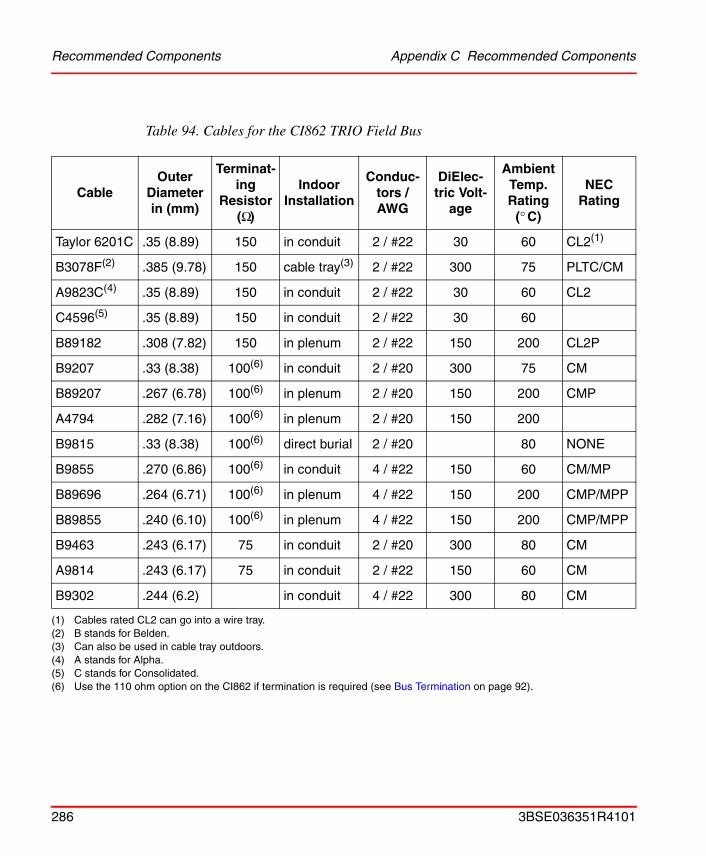
Recommended Components Appendix C Recommended Components
Table 94. Cables for the CI862 TRIO Field Bus
CableOuter
Diameter in (mm)
Terminat-ing
Resistor (Ω)
Indoor Installation
Conduc-tors / AWG
DiElec-tric Volt-
age
Ambient Temp. Rating
(° C)
NECRating
Taylor 6201C .35 (8.89) 150 in conduit 2 / #22 30 60 CL2(1)
(1) Cables rated CL2 can go into a wire tray.
B3078F(2)
(2) B stands for Belden.
.385 (9.78) 150 cable tray(3)
(3) Can also be used in cable tray outdoors.
2 / #22 300 75 PLTC/CM
A9823C(4)
(4) A stands for Alpha.
.35 (8.89) 150 in conduit 2 / #22 30 60 CL2
C4596(5)
(5) C stands for Consolidated.
.35 (8.89) 150 in conduit 2 / #22 30 60
B89182 .308 (7.82) 150 in plenum 2 / #22 150 200 CL2P
B9207 .33 (8.38) 100(6)
(6) Use the 110 ohm option on the CI862 if termination is required (see Bus Termination on page 92).
in conduit 2 / #20 300 75 CM
B89207 .267 (6.78) 100(6) in plenum 2 / #20 150 200 CMP
A4794 .282 (7.16) 100(6) in plenum 2 / #20 150 200
B9815 .33 (8.38) 100(6) direct burial 2 / #20 80 NONE
B9855 .270 (6.86) 100(6) in conduit 4 / #22 150 60 CM/MP
B89696 .264 (6.71) 100(6) in plenum 4 / #22 150 200 CMP/MPP
B89855 .240 (6.10) 100(6) in plenum 4 / #22 150 200 CMP/MPP
B9463 .243 (6.17) 75 in conduit 2 / #20 300 80 CM
A9814 .243 (6.17) 75 in conduit 2 / #22 150 60 CM
B9302 .244 (6.2) in conduit 4 / #22 300 80 CM
286 3BSE036351R4101
Appendix D Directive Considerations
Relevant products comply with EMC Directive 89/336/EEC and Low-Voltage Directive 73/23/EEC. The products are provided with a CE marking.
Electro-Magnetic Compatibility (EMC)Modules mentioned in this document, for which the product or packing is CE marked, are tested and approved according to the following standards:
• EN 61131-2 Product Standard, Programmable Controller- Industrial Environment
• EN 50081-2 EMC – Generic Emission Standard, Part 2 – Industrial Environment
• EN 61000-6-2 EMC – Generic Immunity Standard,Part 2 – Industrial Environment.
Low-Voltage Directive (LVD)Modules mentioned in this manual, for which product or packing is CE marked, comply with the LVD where applicable.
To fulfill the LVD for AC 800M and S800 I/O, the power supplies shall provide a secondary safety extra low voltage (SELV) or a protected extra low voltage (PELV). The power supplies described in this manual, SD821, SD822 and SD823, fulfill these requirements, see Power Supply Units – Types SD821, SD822 and SD823 on page 247.
If you use other power supplies, except SD821, SD822 or SD823, to provide the 24V d.c. for AC 800M we strongly recommend that they also are CE marked, UL listed and fulfill the LVD (SELV, PELV).
3BSE036351R4101 287

Low-Voltage Directive (LVD) Appendix D Directive Considerations
The AC 800M modules are IP20 semi-protected equipment and must be mounted in non-public localities.
288 3BSE036351R4101
Appendix E Standards
The information below is applicable to products approved for hazardous locations according to CSA and/or UL standards (UL60079-15).
Hazardous Location ApprovalTo comply with CSA and/or UL certification for use at hazardous locations, the following information is relevant for CSA and/or UL-certified ABB industrial control products.
• Equipment labeled with reference to Class I, Groups A, B, C and D, Division 2, hazardous locations is suitable for use in Class I, Division 2, Groups A, B, C, D or non-hazardous locations only.
Explosion hazard - Substitution of components may impair suitability for Class I, Division 2.
Explosion hazard - Do not replace batteries unless the power has been switched off or the area is known to be non-hazardous.
Explosion hazard - Do not disconnect equipment unless the power has been switched off or the area is known to be non-hazardous.
3BSE036351R4101 289

Hazardous Location Approval Appendix E Standards
290 3BSE036351R4101

Appendix F Environmental Data
Environmental Data for AC 800M ProductsThe immunity of products to environmental factors met during operation, transportation and storage is summarized in this section.
Industrial environment are supplied with power from a high-voltage or medium-voltage transformer dedicated to supplying installations feeding manufacturing or similar plants. The existence of industrial apparatus and heavy, frequently-switched inductive or capacitive loads characterize an Industrial environment. The associated magnetic fields are high.
Control products incl. I/O-systems are normally intended for Industrial environment.
Products manufactured by ABB and other companies are normally type-tested or evaluated to ensure compliance with the environmental standards specified below.
Environmental specifications applicable to peripheral equipment, for example printers, may differ. Please refer to the relevant product data sheets.
The degree to which the units resist environmental influence depends on their components and design. System enclosures, cable types and how these are routed determine the environmental specification of the entire system.
3BSE036351R4101 291
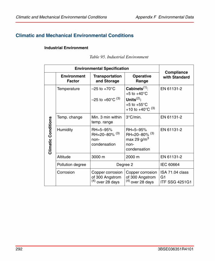
Climatic and Mechanical Environmental Conditions Appendix F Environmental Data
Climatic and Mechanical Environmental Conditions
Industrial Environment
Table 95. Industrial Environment
Environmental SpecificationCompliance
with StandardEnvironment Factor
Transportation and Storage
Operative Range
Clim
atic
Co
nd
itio
ns
Temperature –25 to +70°C
–25 to +60°C (3)
Cabinets(1): +5 to +40°C
Units(2): +5 to +55°C+10 to +40°C (3)
EN 61131-2
Temp. change Min. 3 min within temp. range
3°C/min. EN 61131-2
Humidity RH=5–95%RH=20–80% (3)
non-condensation
RH=5–95%RH=20–80% (3)
max 29 g/m3
non-condensation
EN 61131-2
Altitude 3000 m 2000 m EN 61131-2
Pollution degree Degree 2 IEC 60664
Corrosion Copper corrosion of 300 Angstrom (4) over 28 days
Copper corrosion of 300 Angstrom (4) over 28 days
ISA 71.04 class G1ITF SSG 4251G1
292 3BSE036351R4101

Appendix F Environmental Data Climatic and Mechanical Environmental Conditions
Mec
han
ical
Co
nd
itio
ns
Vibration 10< f <50 Hz, Continuous: 0.0375 mm amplitude
(Occasional: 0.075 mm amplitude)
50< f <150 Hz, Continuous: 0.5 g acceleration
(Occasional: 1.0 g acceleration)5< f <500 Hz, Continuous: 0.2 g acceleration (3)
EN 61131-2
Emitted noise – <55dB (A)
Shock, no package
150 m/s2, 11 ms
20 g, 3 ms (3)
DAT drives; 5 g, 3 ms
150 m/s2, 11 ms
20 g, 3 ms (3)
DAT drives; 5 g, 3 ms
EN 61131-2
Fall in package <10 kg: 1 m
10–40 kg: 0.5 m
>40 kg: 0.25 m
>100 kg: 0.025 m
EN 61131-2
(1) Cabinets = Enclosures, Cases, Consoles(2) Units = Subracks, plug-in units, printed circuit boards(3) Workstation, PC computers and peripherals, for example printers(4) 1000 Angstrom for S800 I/O-family
Table 95. Industrial Environment (Continued)
Environmental SpecificationCompliance
with StandardEnvironment Factor
Transportation and Storage
Operative Range
3BSE036351R4101 293
CE Compliance Appendix F Environmental Data
CE Compliance
All products comply with EMC Directive 89/336/EEC and Low Voltage Directive 73/23/EEC (relevant products also comply with the Teleterminal Directive). Products are CE-marked. Some products require enclosures, as specified in User Guides, to meet the EMC Directives.
Compliance is verified through conformity with the following minimum standards:
• EMC Directive 89/336/EEC.
• EN 61131-2 Product standard, Programmable controllers.
• EN 50081-2 Generic emission standard.
• EN 61000-6-2 Generic immunity standard.
• Low Voltage Directive 73/23/EEC.
• EN 50178 for all new products; for example the S100 and S800 family, or good electrical safety practices based on EN 60950, EN 61010, EN 50178, EN60439 and IEC60255, depending on the product.
• Teleterminal Directive 91/263/EE.
294 3BSE036351R4101
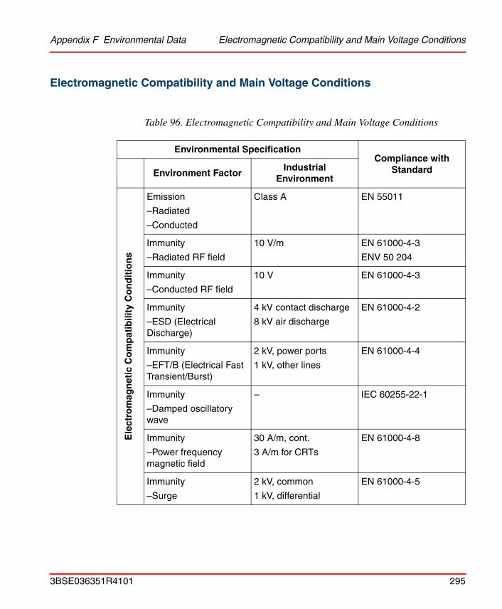
Appendix F Environmental Data Electromagnetic Compatibility and Main Voltage Conditions
Electromagnetic Compatibility and Main Voltage Conditions
Table 96. Electromagnetic Compatibility and Main Voltage Conditions
Environmental SpecificationCompliance with
StandardEnvironment FactorIndustrial
Environment
Ele
ctro
mag
net
ic C
om
pat
ibili
ty C
on
dit
ion
s
Emission
–Radiated
–Conducted
Class A EN 55011
Immunity
–Radiated RF field
10 V/m EN 61000-4-3
ENV 50 204
Immunity
–Conducted RF field
10 V EN 61000-4-3
Immunity
–ESD (Electrical Discharge)
4 kV contact discharge
8 kV air discharge
EN 61000-4-2
Immunity
–EFT/B (Electrical Fast Transient/Burst)
2 kV, power ports
1 kV, other lines
EN 61000-4-4
Immunity
–Damped oscillatory wave
– IEC 60255-22-1
Immunity
–Power frequency magnetic field
30 A/m, cont.
3 A/m for CRTs
EN 61000-4-8
Immunity
–Surge
2 kV, common
1 kV, differential
EN 61000-4-5
3BSE036351R4101 295

Electromagnetic Compatibility and Main Voltage Conditions Appendix F Environmental Data
Ele
ctro
mag
net
ic C
om
pat
ibili
ty C
on
dit
ion
s Main voltage a.c Unom: –15% to +0%
Main voltage DC –15% to 20% of rated value
Main frequency a.c. 47–63 Hz, ±5% IEC 60255-6
Main voltage interruption, a.c.
Max 10 ms EN 61000-4-11
Overvoltage
Category
–Permanently connected equipment
Class III
Overvoltage
Category
–Non-permanently connected equipment
Class II
Table 96. Electromagnetic Compatibility and Main Voltage Conditions (Continued)
Environmental SpecificationCompliance with
StandardEnvironment FactorIndustrial
Environment
296 3BSE036351R4101
Appendix F Environmental Data Installation Requirements
Installation Requirements
Installation regulations for all products are included in relevant product documentation. Some general installation rules and applications are given below.
Laying Field Cables
There are no special requirements for laying field and communication cables connected to products. However:
Cables for short-distance communication without modems should always be routed at a distance of 10 cm (4 in.) from other cables.
All product-connected cables should be routed at a distance of 30 cm (12 in.) from non-product power cables (heavy current cables) and 10 cm (4 in.) from class 4 cables of relevant international immunity standards.
Types of Field Cable
Shielded cables are always necessary for:
• Communications (see product documentation for cable type)
• High-frequency pulse transmission (see product documentation for cable type)
• Low-level analog signals, for example Pt100 and thermocouples
• Analog application with a system accuracy > 12 bits
For other applications unshielded cables may be used. Digital and analog signals of the same type can be run on the same cable.
Signal and return conductors should be located on the same cable.
3BSE036351R4101 297
Lightning Protection Appendix F Environmental Data
Lightning Protection
Industrial installations and power plants are normally provided with well-integrated grounding networks, installed as part of the power distribution system. Such installations do not require additional lightning protection.
Additional lightning protection is always necessary when:
• Cables extend beyond the area covered by the ground line network
• Cables are located above ground
• Overhead cables are used.
Inductive Load Suppression
Inductive loads, such as relays and contactors connected directly to products, do not require suppression. The necessary suppression components (varistors or snubbers-RC units) are installed on the circuit boards.
298 3BSE036351R4101
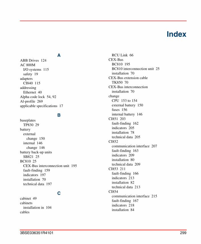
Index
AABB Drives 124AC 800M
I/O systems 115safety 19
adaptersCI840 115
addressingEthernet 40
Alpha code lock 54, 92Al-profile 269applicable specifications 17
Bbaseplates
TP830 29battery
externalchange 150
internal 146change 146
battery back-up unitsSB821 25
BC810 25CEX-Bus interconnection unit 195fault-finding 159indicators 197installation 70technical data 197
Ccabinet 49cabinets
installation in 104cables
RCU Link 66CEX-Bus
BC810 195BC810 interconnection unit 25installation 70
CEX-Bus extension cableTK850 70
CEX-Bus interconnectioninstallation 70
changeCPU 153 to 154external battery 150fuses 156internal battery 146
CI851 203fault-finding 162indicators 205installation 78technical data 205
CI852communication interface 207fault-finding 163indicators 209installation 80technical data 209
CI853 211fault-finding 166indicators 213installation 82technical data 213
CI854communication interface 215fault-finding 167indicators 218installation 84
3BSE036351R4101 299
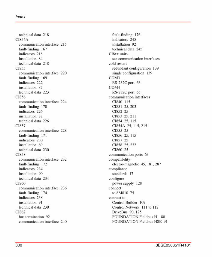
Index
technical data 218CI854A
communication interface 215fault-finding 167indicators 218installation 84technical data 218
CI855communication interface 220fault-finding 169indicators 222installation 87technical data 223
CI856communication interface 224fault-finding 170indicators 226installation 88technical data 226
CI857communication interface 228fault-finding 171indicators 230installation 89technical data 230
CI858communication interface 232fault-finding 172indicators 234installation 90technical data 234
CI860communication interface 236fault-finding 174indicators 238installation 91technical data 239
CI862bus termination 92communication interface 240
fault-finding 176indicators 245installation 92technical data 245
CI8xx unitssee communication interfaces
cold restartredundant configuration 139single configuration 139
COM3RS-232C port 63
COM4RS-232C port 65
communication interfacesCI840 115CI851 25, 203CI852 25CI853 25, 211CI854 25, 115CI854A 25, 115, 215CI855 25CI856 25, 115CI857 25CI858 25, 232CI860 25
communication ports 63compatibility
electro-magnetic 45, 181, 287compliance
standards 17configure
power supply 128connect
to SM810 75connect to
Control Builder 109Control Network 111 to 112DriveBus 90, 125FOUNDATION Fieldbus H1 80FOUNDATION Fieldbus HSE 91
300 3BSE036351R4101

Index
INSUM 89MasterBus 300 87PROFIBUS DP 78PROFIBUS DP-V1 85RS-232C 82S100 I/O 88
Control Builder 26connect to 109
Control Networkconnect to 111 to 112
Control Software 39controller
reset in single configuration 139set IP address 114
controller resetredundant configuration 140
CPUchange 153 to 154
CPU unitshigh integrity 25PM851 25, 29PM856 25, 29, 177PM860 25, 29, 177PM861 25, 29, 183PM861A 26PM864 25, 29, 187PM864A 26PM865 25, 29, 191
current consumption 272
DDIN-rail
mounting 49mounting dimensions 108technical data 262
directivesEU 17
document conventions 14DriveBus
connect to 90, 125
installation 90
Eearthing 47electro-magnetic compatibility 45, 181, 287Ethernet address 40EU directives 17
low-voltage 287extension cable
CEX-Bus 70external battery
change 150SB821 149
external battery unitinstallation 103
external mains supply cablefusing 47
external power source 131
Ffault-finding
BC810 159CI851 162CI852 163CI853 166CI854 167CI854A 167CI855 169CI856 170CI857 171CI858 172CI860 174CI862 176DriveBus 172external battery 161FOUNDATION Fieldbus 163FOUNDATION Fieldbus HSE 174INSUM 171internal battery 161MasterBus 300 169
3BSE036351R4101 301
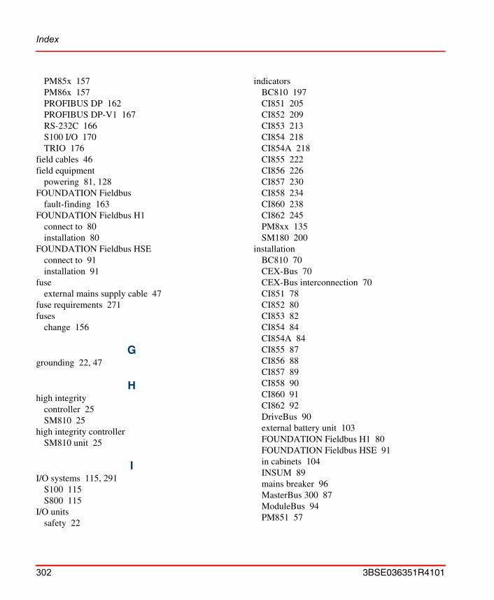
Index
PM85x 157PM86x 157PROFIBUS DP 162PROFIBUS DP-V1 167RS-232C 166S100 I/O 170TRIO 176
field cables 46field equipment
powering 81, 128FOUNDATION Fieldbus
fault-finding 163FOUNDATION Fieldbus H1
connect to 80installation 80
FOUNDATION Fieldbus HSEconnect to 91installation 91
fuseexternal mains supply cable 47
fuse requirements 271fuses
change 156
Ggrounding 22, 47
Hhigh integrity
controller 25SM810 25
high integrity controllerSM810 unit 25
II/O systems 115, 291
S100 115S800 115
I/O unitssafety 22
indicatorsBC810 197CI851 205CI852 209CI853 213CI854 218CI854A 218CI855 222CI856 226CI857 230CI858 234CI860 238CI862 245PM8xx 135SM180 200
installationBC810 70CEX-Bus 70CEX-Bus interconnection 70CI851 78CI852 80CI853 82CI854 84CI854A 84CI855 87CI856 88CI857 89CI858 90CI860 91CI862 92DriveBus 90external battery unit 103FOUNDATION Fieldbus H1 80FOUNDATION Fieldbus HSE 91in cabinets 104INSUM 89mains breaker 96MasterBus 300 87ModuleBus 94PM851 57
302 3BSE036351R4101
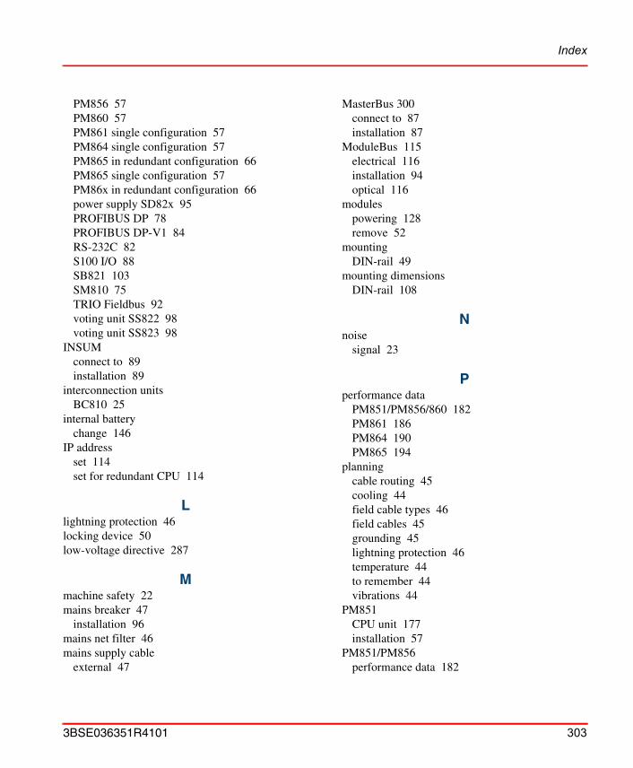
Index
PM856 57PM860 57PM861 single configuration 57PM864 single configuration 57PM865 in redundant configuration 66PM865 single configuration 57PM86x in redundant configuration 66power supply SD82x 95PROFIBUS DP 78PROFIBUS DP-V1 84RS-232C 82S100 I/O 88SB821 103SM810 75TRIO Fieldbus 92voting unit SS822 98voting unit SS823 98
INSUMconnect to 89installation 89
interconnection unitsBC810 25
internal batterychange 146
IP addressset 114set for redundant CPU 114
Llightning protection 46locking device 50low-voltage directive 287
Mmachine safety 22mains breaker 47
installation 96mains net filter 46mains supply cable
external 47
MasterBus 300connect to 87installation 87
ModuleBus 115electrical 116installation 94optical 116
modulespowering 128remove 52
mountingDIN-rail 49
mounting dimensionsDIN-rail 108
Nnoise
signal 23
Pperformance data
PM851/PM856/860 182PM861 186PM864 190PM865 194
planningcable routing 45cooling 44field cable types 46field cables 45grounding 45lightning protection 46temperature 44to remember 44vibrations 44
PM851CPU unit 177installation 57
PM851/PM856performance data 182
3BSE036351R4101 303
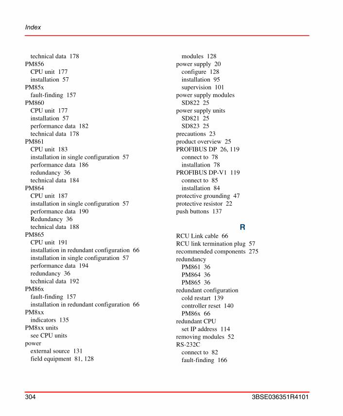
Index
technical data 178PM856
CPU unit 177installation 57
PM85xfault-finding 157
PM860CPU unit 177installation 57performance data 182technical data 178
PM861CPU unit 183installation in single configuration 57performance data 186redundancy 36technical data 184
PM864CPU unit 187installation in single configuration 57performance data 190Redundancy 36technical data 188
PM865CPU unit 191installation in redundant configuration 66installation in single configuration 57performance data 194redundancy 36technical data 192
PM86xfault-finding 157installation in redundant configuration 66
PM8xxindicators 135
PM8xx unitssee CPU units
powerexternal source 131field equipment 81, 128
modules 128power supply 20
configure 128installation 95supervision 101
power supply modulesSD822 25
power supply unitsSD821 25SD823 25
precautions 23product overview 25PROFIBUS DP 26, 119
connect to 78installation 78
PROFIBUS DP-V1 119connect to 85installation 84
protective grounding 47protective resistor 22push buttons 137
RRCU Link cable 66RCU link termination plug 57recommended components 275redundancy
PM861 36PM864 36PM865 36
redundant configurationcold restart 139controller reset 140PM86x 66
redundant CPUset IP address 114
removing modules 52RS-232C
connect to 82fault-finding 166
304 3BSE036351R4101
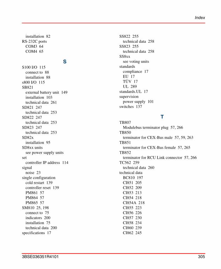
Index
installation 82RS-232C ports
COM3 64COM4 65
SS100 I/O 115
connect to 88installation 88
s800 I/O 115SB821
external battery unit 149installation 103technical data 261
SD821 247technical data 253
SD822 247technical data 253
SD823 247technical data 253
SD82xinstallation 95
SD8xx unitssee power supply units
setcontroller IP address 114
signalnoise 23
single configurationcold restart 139controller reset 139PM861 57PM864 57PM865 57
SM810 25, 198connect to 75indicators 200installation 75technical data 200
specifications 17
SS822 255technical data 258
SS823 255technical data 258
SS8xxsee voting units
standardscompliance 17EU 17TÜV 17UL 289
standards.UL 17supervision
power supply 101switches 137
TTB807
Modulebus terminator plug 57, 266TB850
terminator for CEX-Bus male 57, 59, 263TB851
terminator for CEX-Bus female 57, 265TB852
terminator for RCU Link connector 57, 266TC562 259
technical data 260technical data
BC810 197CI851 205CI852 209CI853 213CI854 218CI854A 218CI855 223CI856 226CI857 230CI858 234CI860 239CI862 245
3BSE036351R4101 305
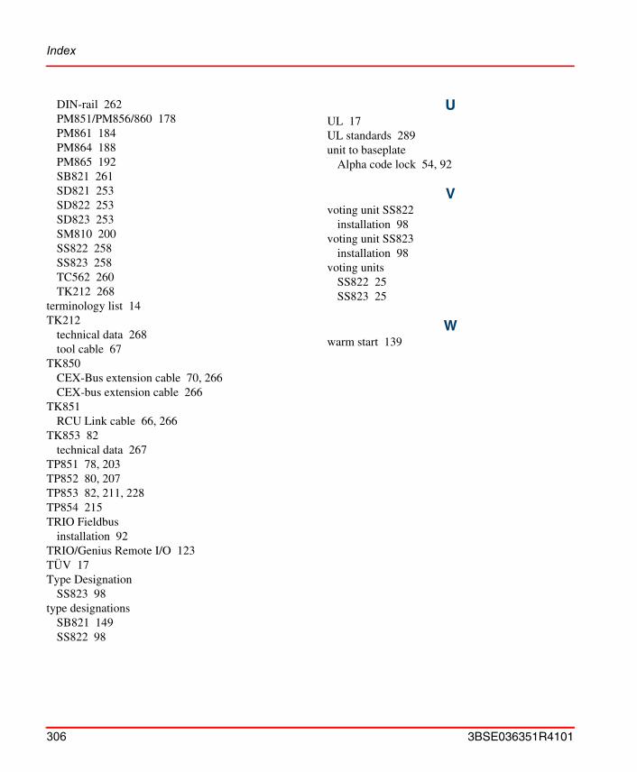
Index
DIN-rail 262PM851/PM856/860 178PM861 184PM864 188PM865 192SB821 261SD821 253SD822 253SD823 253SM810 200SS822 258SS823 258TC562 260TK212 268
terminology list 14TK212
technical data 268tool cable 67
TK850CEX-Bus extension cable 70, 266CEX-bus extension cable 266
TK851RCU Link cable 66, 266
TK853 82technical data 267
TP851 78, 203TP852 80, 207TP853 82, 211, 228TP854 215TRIO Fieldbus
installation 92TRIO/Genius Remote I/O 123TÜV 17Type Designation
SS823 98type designations
SB821 149SS822 98
UUL 17UL standards 289unit to baseplate
Alpha code lock 54, 92
Vvoting unit SS822
installation 98voting unit SS823
installation 98voting units
SS822 25SS823 25
Wwarm start 139
306 3BSE036351R4101


3BSE036351R4101. Printed in Sweden May 2005Copyright © 1999 - 2004 by ABB. All Rights Reserved® Registered Trademark of ABB.™ Trademark of ABB.
Automation Technology ProductsMannheim, Germanywww.abb.de/processautomationemail: marketing.control-prod-
Automation Technology Products Västerås, Swedenwww.abb.com/processautomationemail: [email protected]
Automation Technology ProductsWickliffe, Ohio, USAwww.abb.com/processautomationemail: [email protected]
http://www.abb.com/control