Embed Size (px)
Citation preview
Powder Technology 288 (2016) 422–434
Contents lists available at ScienceDirect
Powder Technology
j ourna l homepage: www.e lsev ie r .com/ locate /powtec
Hardware-in-the-loop simulation platform for supervisory control ofmineral grinding process
Wei Dai a,b,⁎, Ping Zhou b, Dayong Zhao c, Shaowen Lu b, Tianyou Chai b
a School of Information and Electrical Engineering, China University of Mining and Technology, Xuzhou 221116, Chinab State Key Laboratory of Synthetical Automation for Process Industries, Northeastern University, Shenyang 110819, Chinac Shenyang Institute of Automation, Chinese Academy of Sciences, Shenyang 110016, China
⁎ Corresponding author at: School of Information anUniversity of Mining and Technology, Xuzhou 221116, Ch
E-mail address: [email protected] (W. Dai).
http://dx.doi.org/10.1016/j.powtec.2015.11.0320032-5910/© 2015 Elsevier B.V. All rights reserved.
a b s t r a c t
a r t i c l e i n f oArticle history:Received 5 November 2014Received in revised form 10 November 2015Accepted 12 November 2015Available online 15 November 2015
Supervisory control technology is widely used to improve product quality inmineral grinding process (MGP). Toensure safety, new supervisory control method needs to be fully tested before practical application. However,conducting tests in a running process is costly andmay put the process equipment in danger, which necessitatesextensive simulations to ensure the stability and performance of supervisory controllers. Comparing with thefield based test, the numerical simulation is more economic and safer. However, numerical simulations cannotcapture all aspects of controlled object, such as sensors, actuators, process, control systems themselves and signaltransmissions, which are important to evaluate the control performances. To solve this problem, this paper pre-sents a novel hardware-in-the-loop simulation (HILS) platform for the supervisory control ofMGP. By integratinga supervisory control system, a basic loop control system, a virtual actuator and sensor system, and a virtual plantsystem in to a coherent whole, the HILS platform provides a full-scope simulation environment for the supervi-sory control. The supervisory control system and the basic loop control system adopt real control systems. Thedetailed process dynamics are modeled and visualized by the virtual plant system. Further, as an interfacebetween the physical controllers and virtual plant, the virtual actuator and sensor system is used to realize thesignal conversion and to simulate the dynamics and faults of the actuators and sensors using data acquisition(DAQ) hardware and configuration software. Effectiveness of platform is demonstrated with a case study,where an intelligent supervisory control method for a typical one stage MGP is tested.
© 2015 Elsevier B.V. All rights reserved.
Keywords:Mineral grinding processSupervisory controlHardware-in-the-loop simulation (HILS)
1. Introduction
As a crucial component of the beneficiation process, mineral grind-ing process (MGP) is used to grind the run-of-mine ore into suitableparticle size such that the valuable mineral constituent can be exposedto be recovered in the subsequent classification process [1,2]. In thepast, the process control research of the MGP was focused on the basicloop control methods to ensure the process variables follow theirsetpoints in a stable operation. In order to realize the basic loop controlmethod easily, distributed control systems are widely used.
Long term production practice, however, shows that it is difficult toobtain the desired production only using the basic loop controller. Thisis because that the inappropriate control loop setpoints will make theMGP work under a non-optimized economic status, thereby leading tohigh cost and low quality of products. Therefore, a high-performanceprocess control system should ensure that not only process variablescan follow their setpoints stably, but also these setpoints are suitable forthe optimal process operation. For this reason, a hierarchical approach
d Electrical Engineering, Chinaina.
as shown in Fig. 1 is proposed in [3]. In this framework, a supervisorycontrol system is installed on top of the basic loop control to optimizethe control loop setpoints online. The development of a new supervisorycontrol system usually needs to undergo intensive experiments until thecontrol performance meets with the technical requirements.
Experiment in an industrial environment is effective, direct but ex-pensive and often unsafe. Hence, the alternative approach of modelingand simulation is cheap, quick and conclusive. The modeling of mineralprocess has been discussed for many years [4–7], but the simulationdoesn't play a role until personal computers became available in aboutmid-1980s [8]. The first generation of simulation uses steady statemodels to offer the best and cheapest way to handle the difficultproblems of flowsheet design and optimization. In this period, becauseof the success of simulation it is also necessary to have a reservoir ofprofessional skills and models, some commercial simulators, such asJKSimMet and USIM Pac, have thus been developed to provide welltechnical supports [9]. By 1990s, new requirements for high-capacityand high-quality have led mineral processing industry to be concernedwith the operation process control and optimization, which requiresthemodeling of the dynamic relationship between theprocess variablesand themanipulated variables. Hence, a number of researchers began tostudy the dynamicmodeling and simulation [10–14]. Today, there have
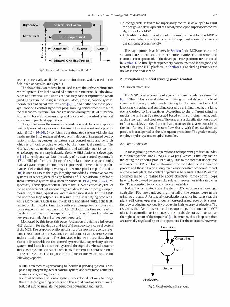
Fig. 1. Hierarchical control strategy for the MGP.
Fig. 2. Flowsheet of grinding process.
423W. Dai et al. / Powder Technology 288 (2016) 422–434
been commercially available dynamic simulators widely used in thisfield, such as MetSim and SysCAD.
The above simulators have been used to test the software simulatedcontrol system. This is the so-called numerical simulation. But the draw-backs of numerical simulation are that they cannot capture the wholegrinding system including sensors, actuators, process, control systemsthemselves and signal transmissions [6,15], and neither do these pack-ages provide a control algorithm programming environment similar tothe real control system. This leads to unconvincing results of numericalsimulation because programming and testing of the controller are stillnecessary in practical application.
The gap between the numerical simulation and the actual applica-tion had persisted for years until the use of hardware-in-the-loop simu-lation (HILS) [16–24]. By combining the simulated systemwith physicalhardware, the HILS realizes a full-scope simulation of integrated controlsystem including sensors, actuators, real control units and so forth,which is difficult to achieve solely by the numerical simulator. TheHILS has been as an effective verification and validation tool for control-ler to be applied in many industrial fields. A HILS platform is developedin [16] to verify and validate the safety of nuclear control systems. In[17], a HILS platform consisting of a simulated power system and areal hardware propulsion motor set is proposed to research the perfor-mance of electrical ship power system. A HILS platform performed in[18] is used to assess the high-integrity embedded automotive controlsystems. In recent years, the applications of HILS platform in roboticsand automotive systems have been discussed in [19,20] and [21–24], re-spectively. These applications illustrate the HILS can effectively reducethe risk of accidents at various stages of development: design, imple-mentation, testing, operation, and maintenance stages. For the MGP,the improper loop setpoints will result in the unsatisfying product aswell as some faults such asmill overload or underload faults. If the faultscannot be eliminated in time, theywill cause damage to devices or evencause suspension of the operation. A HILS platform is thus required forthe design and test of the supervisory controller. To our knowledge,however, such platform has not been reported.
Motivated by this issue, this paper focuses on providing a full-scopeHILS platform for the design and test of the supervisory control systemof theMGP. The proposed platform consists of a supervisory control sys-tem, a basic loop control system, a virtual actuator and sensor system,and a virtual plant system. The simulated grinding process (i.e., virtualplant) is linked with the real control systems (i.e., supervisory controlsystem and basic loop control system) through the virtual actuatorand sensor system, so that the whole platform can be operated similarto the real system. The major contributions of this work include thefollowing aspects:
• A HILS architecture approaching to industrial grinding system is pro-posed by integrating actual control system and simulated actuators,sensors and grinding process.
• A virtual actuator and sensor system is developed not only to bridgethe simulated grinding process and the actual control system undertest, but also to simulate the equipment dynamics and faults.
• A configurable software for supervisory control is developed to assistthedesign anddevelopment of a newlydeveloped supervisory controlalgorithm for a MGP.
• A flexible modular based simulation environment for the MGP isproposed, where a 3-D visualization component is used to visualizethe grinding process vividly.
The paper proceeds as follows. In Section 2, the MGP and its controlsituation are introduced. The structure, hardware, software andcommunication protocols of the developed HILS platform are presentedin Section 3. An intelligent supervisory control method is designed andtested using the HILS platform in Section 4. Concluding remarks aredrawn in the final section.
2. Description of mineral grinding process control
2.1. Process description
The MGP usually consists of a great mill and grader as shown inFig. 2. The mill is a metal cylinder rotating around its axis at a fixedspeed with heavy media inside. Owing to the combined effect ofknocking, chipping, and tumbling caused by grinding media, the lumpore is crushed to fine particles. According to the different grindingmedia, the mill can be categorized based on the grinding media, suchas the steel balls and steel rods. The grader is a classification unit usedto filter particles grinded from mill and transfer the coarse particles tothe mill for regrinding. The overflow slurry with finer particles, asproduct, is transported to the subsequent procedure. The grader usuallyemploys hydro-cyclone or spiral classifier.
2.2. Control situation
Inmost grindingprocess operations, the important production indexis product particle size (PPS) (% b 74 μm), which is the key metricindicating the grinding product quality. Due to the fact that undersizedand oversized PPS are both unfavorable for the subsequent separationprocess and those situationsmay even cause negative economic impacton the whole plant, the control objective is to maintain the PPS withinspecified range. To realize the above objective, some control loopshave to be deployed to ensure the relevant process variables stable, asthe PPS is sensitive to some key process variables.
Today, the distributed control systems (DCS) or programmable logiccontroller (PLC) are deployed in almost all of the control loops in thegrinding process. Unfortunately, production practice indicates that theplant still often operates under a non-optimized economic status,thereby producing low quality product in high-energy production. Thereason is that “with respect to the economic performance of a MGPplant, the controller performance is most probably not as important asthe right selection of the setpoints” [1]. In practice, these loop setpointsare normally regulated by on-site operators. For the operators, however,
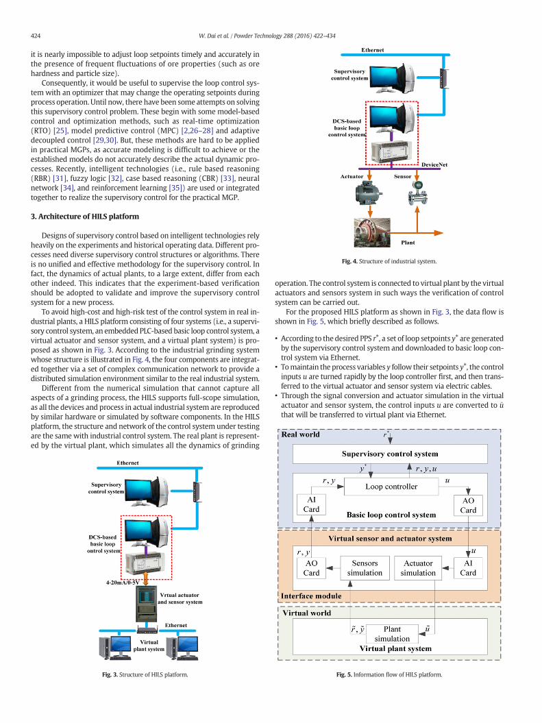
Fig. 4. Structure of industrial system.
424 W. Dai et al. / Powder Technology 288 (2016) 422–434
it is nearly impossible to adjust loop setpoints timely and accurately inthe presence of frequent fluctuations of ore properties (such as orehardness and particle size).
Consequently, it would be useful to supervise the loop control sys-tem with an optimizer that may change the operating setpoints duringprocess operation. Until now, there have been some attempts on solvingthis supervisory control problem. These begin with some model-basedcontrol and optimization methods, such as real-time optimization(RTO) [25], model predictive control (MPC) [2,26–28] and adaptivedecoupled control [29,30]. But, these methods are hard to be appliedin practical MGPs, as accurate modeling is difficult to achieve or theestablished models do not accurately describe the actual dynamic pro-cesses. Recently, intelligent technologies (i.e., rule based reasoning(RBR) [31], fuzzy logic [32], case based reasoning (CBR) [33], neuralnetwork [34], and reinforcement learning [35]) are used or integratedtogether to realize the supervisory control for the practical MGP.
3. Architecture of HILS platform
Designs of supervisory control based on intelligent technologies relyheavily on the experiments and historical operating data. Different pro-cesses need diverse supervisory control structures or algorithms. Thereis no unified and effective methodology for the supervisory control. Infact, the dynamics of actual plants, to a large extent, differ from eachother indeed. This indicates that the experiment-based verificationshould be adopted to validate and improve the supervisory controlsystem for a new process.
To avoid high-cost and high-risk test of the control system in real in-dustrial plants, a HILS platform consisting of four systems (i.e., a supervi-sory control system, an embedded PLC-based basic loop control system, avirtual actuator and sensor system, and a virtual plant system) is pro-posed as shown in Fig. 3. According to the industrial grinding systemwhose structure is illustrated in Fig. 4, the four components are integrat-ed together via a set of complex communication network to provide adistributed simulation environment similar to the real industrial system.
Different from the numerical simulation that cannot capture allaspects of a grinding process, the HILS supports full-scope simulation,as all the devices and process in actual industrial system are reproducedby similar hardware or simulated by software components. In the HILSplatform, the structure and network of the control system under testingare the same with industrial control system. The real plant is represent-ed by the virtual plant, which simulates all the dynamics of grinding
Fig. 3. Structure of HILS platform.
operation. The control system is connected to virtual plant by the virtualactuators and sensors system in such ways the verification of controlsystem can be carried out.
For the proposed HILS platform as shown in Fig. 3, the data flow isshown in Fig. 5, which briefly described as follows.
• According to the desired PPS r⁎, a set of loop setpoints y⁎ are generatedby the supervisory control system and downloaded to basic loop con-trol system via Ethernet.
• Tomaintain the process variables y follow their setpoints y⁎, the controlinputs u are turned rapidly by the loop controller first, and then trans-ferred to the virtual actuator and sensor system via electric cables.
• Through the signal conversion and actuator simulation in the virtualactuator and sensor system, the control inputs u are converted to ~uthat will be transferred to virtual plant via Ethernet.
Fig. 5. Information flow of HILS platform.
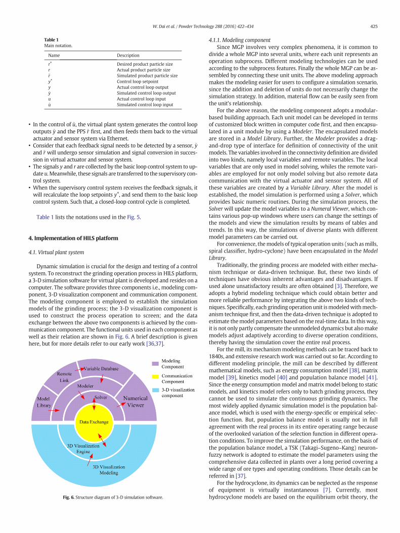
Table 1Main notation.
Name Description
r⁎ Desired product particle sizer Actual product particle size~r Simulated product particle sizey⁎ Control loop setpointy Actual control loop output~y Simulated control loop outputu Actual control loop input~u Simulated control loop input
425W. Dai et al. / Powder Technology 288 (2016) 422–434
• In the control of ~u, the virtual plant system generates the control loopoutputs ~y and the PPS ~r first, and then feeds them back to the virtualactuator and sensor system via Ethernet.
• Consider that each feedback signal needs to be detected by a sensor, ~yand ~r will undergo sensor simulation and signal conversion in succes-sion in virtual actuator and sensor system.
• The signals y and r are collected by the basic loop control system to up-date u. Meanwhile, these signals are transferred to the supervisory con-trol system.
• When the supervisory control system receives the feedback signals, itwill recalculate the loop setpoints y⁎, and send them to the basic loopcontrol system. Such that, a closed-loop control cycle is completed.
Table 1 lists the notations used in the Fig. 5.
4. Implementation of HILS platform
4.1. Virtual plant system
Dynamic simulation is crucial for the design and testing of a controlsystem. To reconstruct the grinding operation process in HILS platform,a 3-D simulation software for virtual plant is developed and resides on acomputer. The software provides three components i.e., modeling com-ponent, 3-D visualization component and communication component.The modeling component is employed to establish the simulationmodels of the grinding process; the 3-D visualization component isused to construct the process operation to screen; and the dataexchange between the above two components is achieved by the com-munication component. The functional units used in each component aswell as their relation are shown in Fig. 6. A brief description is givenhere, but for more details refer to our early work [36,37].
Fig. 6. Structure diagram of 3-D simulation software.
4.1.1. Modeling componentSince MGP involves very complex phenomena, it is common to
divide a whole MGP into several units, where each unit represents anoperation subprocess. Different modeling technologies can be usedaccording to the subprocess features. Finally the whole MGP can be as-sembled by connecting these unit units. The above modeling approachmakes the modeling easier for users to configure a simulation scenario,since the addition and deletion of units do not necessarily change thesimulation strategy. In addition, material flow can be easily seen fromthe unit's relationship.
For the above reason, the modeling component adopts a modular-based building approach. Each unit model can be developed in termsof customized block written in computer code first, and then encapsu-lated in a unit module by using a Modeler. The encapsulated modelsare stored in a Model Library. Further, the Modeler provides a drag-and-drop type of interface for definition of connectivity of the unitmodels. The variables involved in the connectivity definition are dividedinto two kinds, namely local variables and remote variables. The localvariables that are only used in model solving, whiles the remote vari-ables are employed for not only model solving but also remote datacommunication with the virtual actuator and sensor system. All ofthese variables are created by a Variable Library. After the model isestablished, the model simulation is performed using a Solver, whichprovides basic numeric routines. During the simulation process, theSolverwill update the model variables to a Numeral Viewer, which con-tains various pop-up windows where users can change the settings ofthe models and view the simulation results by means of tables andtrends. In this way, the simulations of diverse plants with differentmodel parameters can be carried out.
For convenience, themodels of typical operation units (such asmills,spiral classifier, hydro-cyclone) have been encapsulated in the ModelLibrary.
Traditionally, the grinding process are modeled with either mecha-nism technique or data-driven technique. But, these two kinds oftechniques have obvious inherent advantages and disadvantages. Ifused alone unsatisfactory results are often obtained [3]. Therefore, weadopts a hybrid modeling technique which could obtain better andmore reliable performance by integrating the above two kinds of tech-niques. Specifically, each grinding operation unit ismodeledwithmech-anism technique first, and then the data-driven technique is adopted toestimate themodel parameters based on the real-time data. In this way,it is not only partly compensate the unmodeled dynamics but alsomakemodels adjust adaptively according to diverse operation conditions,thereby having the simulation cover the entire real process.
For themill, its mechanismmodelingmethods can be traced back to1840s, and extensive research work was carried out so far. According todifferent modeling principle, the mill can be described by differentmathematical models, such as energy consumption model [38], matrixmodel [39], kinetics model [40] and population balance model [41].Since the energy consumptionmodel andmatrixmodel belong to staticmodels, and kinetics model refers only to batch grinding process, theycannot be used to simulate the continuous grinding dynamics. Themost widely applied dynamic simulation model is the population bal-ance model, which is used with the energy-specific or empirical selec-tion function. But, population balance model is usually not in fullagreement with the real process in its entire operating range becauseof the overlooked variation of the selection function in different opera-tion conditions. To improve the simulation performance, on the basis ofthe population balance model, a TSK (Takagi–Sugeno–Kang) neuron-fuzzy network is adopted to estimate the model parameters using thecomprehensive data collected in plants over a long period covering awide range of ore types and operating conditions. Those details can bereferred in [37].
For the hydrocyclone, its dynamics can be neglected as the responseof equipment is virtually instantaneous [7]. Currently, mosthydrocyclone models are based on the equilibrium orbit theory, the
426 W. Dai et al. / Powder Technology 288 (2016) 422–434
residence time theory or the turbulent two-phase flow theory. In thissystem, the model of hydrocyclone is derived from the empiricalmodel of Lynch and Rao [42], which includes some mass balance equa-tions, a classification efficiency function, a corrected cut-size functionand a sharpness of classification function. Themodel parameters are de-termined through a Radial Basis Function Neural Network (RBFNN)which is trained with the actual data collected from the plant [37].
For the spiral classifier, its model is similar to the hydrocyclonemodel [43]. But the classification efficiency function becomes morecomplex because of mixture effects [44]. Besides, a time delay is addedin its recycle output because the particles sinking to the bottom needtime to be transported to the upper end of the spiral classifier bymetal spiral slices. Similar to the hydrocyclonemodel, its model param-eters are also evaluated by using RBFNN.
4.1.2. 3-D visualization componentThemodeling component canmake it easy for users to graphically de-
velop the flowsheet models of complex processes. But when it is used totrain new operators, it may be ineffective, since the flowsheetmodel can-not visually and directly display the operation condition of the equip-ment. Consequently, the 3-D visualization component is developed.
In this component, the 3-D visualizationmodels for operation unitesare created first using the commercial package MultiGen Creator. Andthen a VTree-based visualization engine is employed to fulfill the visualsimulation of plant. Furthermore, the engine provides an interface forthe communication component to read and write its data from and tothe modeling component.
4.1.3. Communication componentThis component is a data transmission channel between the model-
ing component and 3-D visualization component. Since OPC (Ole forProcess Control) [45] can facilitate integration and communicationamong heterogeneous networks, it has been served as an interoperabil-ity standard for the industry control. In our platform, an OPC server isdeveloped and available for both the modeling component and 3-Dvisualization component with individual OPC client. Such that, whenthe data in any OPC client change, OPC server will immediately detectit and update the data on the server correspondingly. Then, the OPCserver will send the updated data to the other OPC clients. In this way,the data exchange is performed effectively.
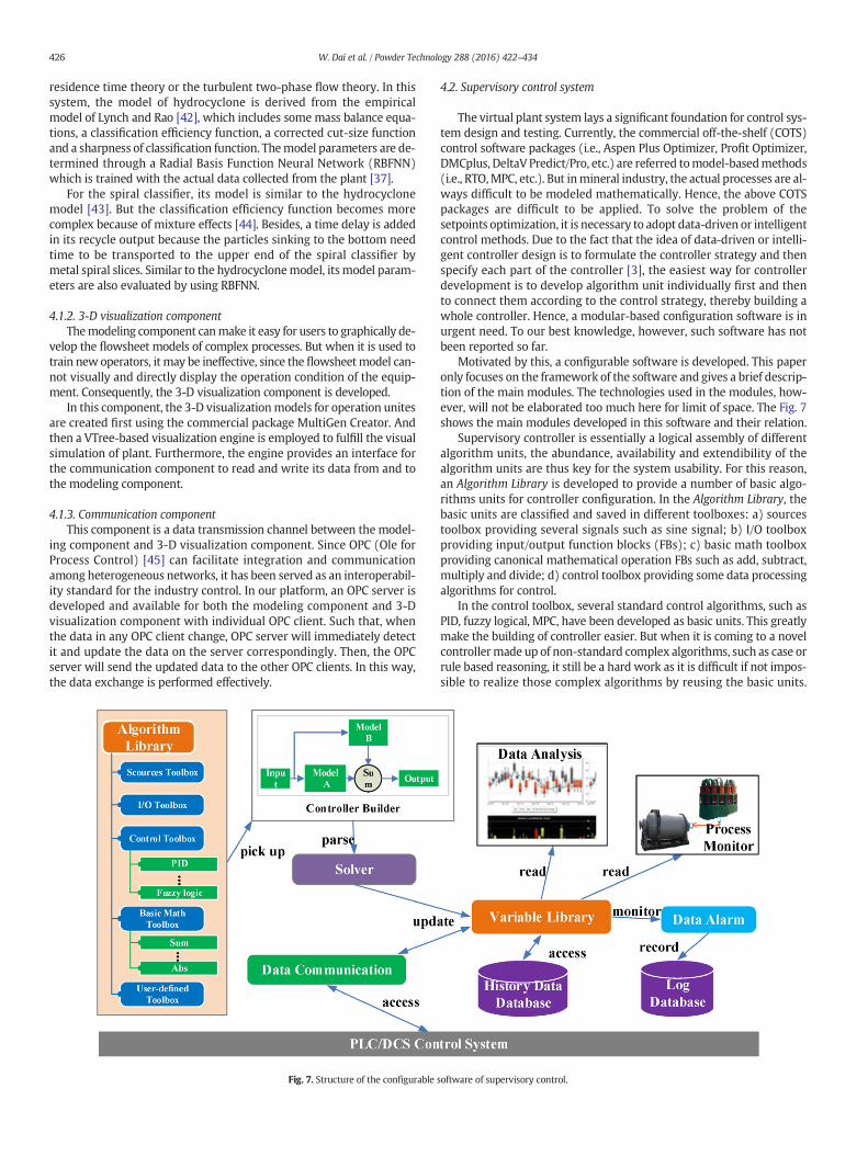
Fig. 7. Structure of the configurable
4.2. Supervisory control system
The virtual plant system lays a significant foundation for control sys-tem design and testing. Currently, the commercial off-the-shelf (COTS)control software packages (i.e., Aspen Plus Optimizer, Profit Optimizer,DMCplus, DeltaV Predict/Pro, etc.) are referred tomodel-basedmethods(i.e., RTO,MPC, etc.). But inmineral industry, the actual processes are al-ways difficult to be modeled mathematically. Hence, the above COTSpackages are difficult to be applied. To solve the problem of thesetpoints optimization, it is necessary to adopt data-driven or intelligentcontrol methods. Due to the fact that the idea of data-driven or intelli-gent controller design is to formulate the controller strategy and thenspecify each part of the controller [3], the easiest way for controllerdevelopment is to develop algorithm unit individually first and thento connect them according to the control strategy, thereby building awhole controller. Hence, a modular-based configuration software is inurgent need. To our best knowledge, however, such software has notbeen reported so far.
Motivated by this, a configurable software is developed. This paperonly focuses on the framework of the software and gives a brief descrip-tion of the main modules. The technologies used in the modules, how-ever, will not be elaborated too much here for limit of space. The Fig. 7shows the main modules developed in this software and their relation.
Supervisory controller is essentially a logical assembly of differentalgorithm units, the abundance, availability and extendibility of thealgorithm units are thus key for the system usability. For this reason,an Algorithm Library is developed to provide a number of basic algo-rithms units for controller configuration. In the Algorithm Library, thebasic units are classified and saved in different toolboxes: a) sourcestoolbox providing several signals such as sine signal; b) I/O toolboxproviding input/output function blocks (FBs); c) basic math toolboxproviding canonical mathematical operation FBs such as add, subtract,multiply and divide; d) control toolbox providing some data processingalgorithms for control.
In the control toolbox, several standard control algorithms, such asPID, fuzzy logical, MPC, have been developed as basic units. This greatlymake the building of controller easier. But when it is coming to a novelcontrollermade up of non-standard complex algorithms, such as case orrule based reasoning, it still be a hard work as it is difficult if not impos-sible to realize those complex algorithms by reusing the basic units.
software of supervisory control.
427W. Dai et al. / Powder Technology 288 (2016) 422–434
Therefore, the system provides a user-defined toolbox for extending thefunctionality of the algorithmunits by adding routines. The routines canbe developed directly using MATLAB platform according to algorithms,or encapsulated as dynamic link library (DLL) files using C++. Toachieve the purpose of the reuse of algorithm resources, the user-defined algorithm units are allowed to be embedded in AlgorithmLibrary.
When starting up the controller, the Controller Builderwill call a Com-putational Engine to execute the FBs one by one according to data flow,meanwhile the Variables Librarywill update the data for Process Monitor,Data Analysis and Data Alarm. Process Monitor can monitor the processoperation situations in the supervisory control system. The Data Analysisprovides control performance statistics and data visualization for user tojudge the effectiveness of the supervisory control algorithms. Data Alarmis used to detect the abnormal variableswhose values exceed the normaloperating range, and also give users a piece of warning message to docorresponding responses. With regard to abnormal variable, it is usuallycaused by either control algorithms or sensors faults. This is because thatimproper control algorithms maybe generate a set of incorrect loopsetpoints out of the normal operating ranges. In the condition of sensorfaults such as interruption and short-circuit, the measured data will al-ways become zero or less than zero, as output of sensor will be lessthan the minimum of industrial standard signal (standard range isoften 4 ~ 20 mA or 1–5 V). Therefore, the Data Alarm, to a certain extent,can diagnosis some faults in control algorithms or sensors by detectingthe abnormal variables, therebywarning the operators to switch the con-troller ormanually set the loop setpoints to keep the grinding process op-eration safe and successive. Thewarningmessagewill be recorded into aLog Database for analysis.
4.3. Basic loop control system
The aim of the basic loop controller is to force the control loop out-puts to track their setpoints downloaded from the supervisory controlsystem, while maintaining safe process operations. Any control plat-form supporting OPC protocol could be used in this platform. IndustrialPLC is the best as it could make the HILS platform more close to the ac-tual system. But, the use of industrial PLCwillmake cost significantly in-crease. Compared with the industrial PLC, embedded soft PLC (ES-PLC)has the advent-ages of smaller size, faster computation speed, andlower price. Therefore, an ES-PLC-based basic loop controller isemployed to make the platform more economical and convenient touse.
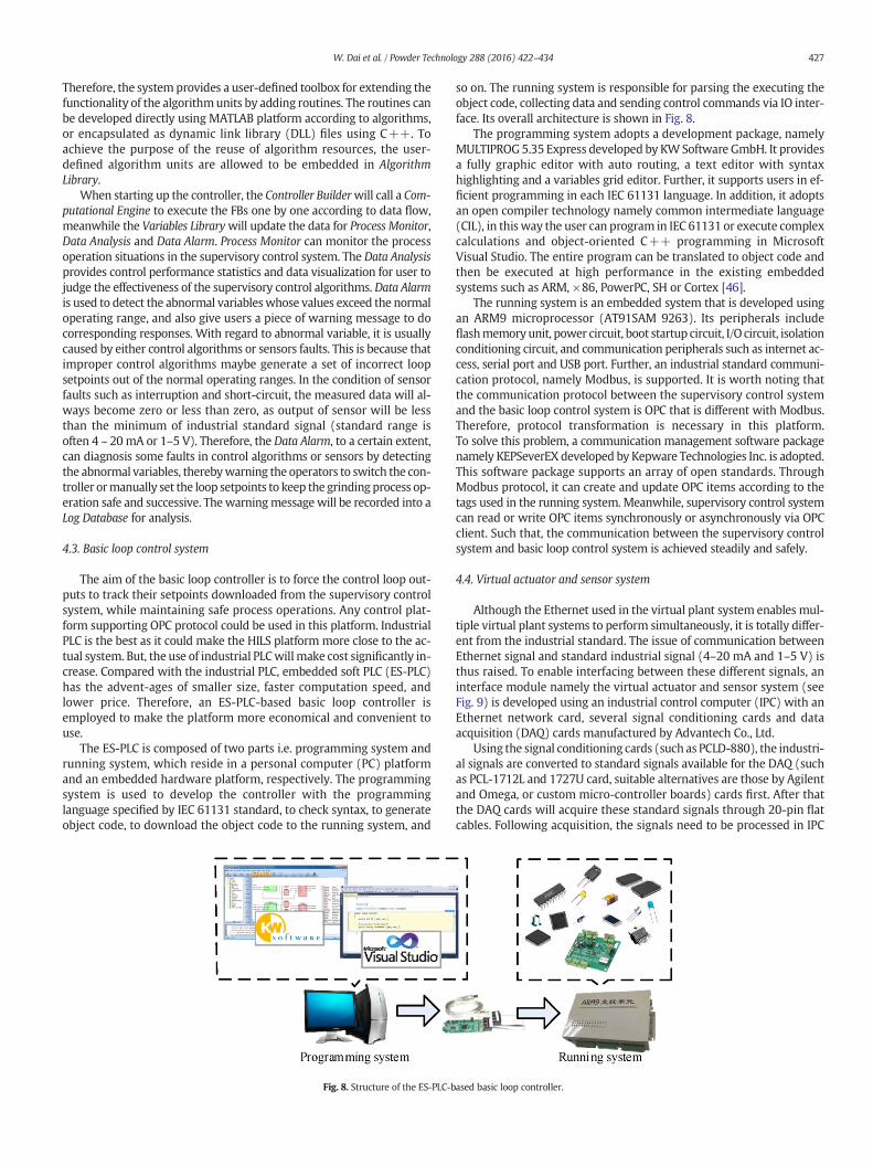
The ES-PLC is composed of two parts i.e. programming system andrunning system, which reside in a personal computer (PC) platformand an embedded hardware platform, respectively. The programmingsystem is used to develop the controller with the programminglanguage specified by IEC 61131 standard, to check syntax, to generateobject code, to download the object code to the running system, and
Fig. 8. Structure of the ES-PLC-b
so on. The running system is responsible for parsing the executing theobject code, collecting data and sending control commands via IO inter-face. Its overall architecture is shown in Fig. 8.
The programming system adopts a development package, namelyMULTIPROG5.35 Express developed by KWSoftware GmbH. It providesa fully graphic editor with auto routing, a text editor with syntaxhighlighting and a variables grid editor. Further, it supports users in ef-ficient programming in each IEC 61131 language. In addition, it adoptsan open compiler technology namely common intermediate language(CIL), in this way the user can program in IEC 61131 or execute complexcalculations and object-oriented C++ programming in MicrosoftVisual Studio. The entire program can be translated to object code andthen be executed at high performance in the existing embeddedsystems such as ARM, ×86, PowerPC, SH or Cortex [46].
The running system is an embedded system that is developed usingan ARM9 microprocessor (AT91SAM 9263). Its peripherals includeflashmemoryunit, power circuit, boot startup circuit, I/O circuit, isolationconditioning circuit, and communication peripherals such as internet ac-cess, serial port and USB port. Further, an industrial standard communi-cation protocol, namely Modbus, is supported. It is worth noting thatthe communication protocol between the supervisory control systemand the basic loop control system is OPC that is different with Modbus.Therefore, protocol transformation is necessary in this platform.To solve this problem, a communication management software packagenamely KEPSeverEX developed by Kepware Technologies Inc. is adopted.This software package supports an array of open standards. ThroughModbus protocol, it can create and update OPC items according to thetags used in the running system. Meanwhile, supervisory control systemcan read or write OPC items synchronously or asynchronously via OPCclient. Such that, the communication between the supervisory controlsystem and basic loop control system is achieved steadily and safely.
4.4. Virtual actuator and sensor system
Although the Ethernet used in the virtual plant system enables mul-tiple virtual plant systems to perform simultaneously, it is totally differ-ent from the industrial standard. The issue of communication betweenEthernet signal and standard industrial signal (4–20 mA and 1–5 V) isthus raised. To enable interfacing between these different signals, aninterface module namely the virtual actuator and sensor system (seeFig. 9) is developed using an industrial control computer (IPC) with anEthernet network card, several signal conditioning cards and dataacquisition (DAQ) cards manufactured by Advantech Co., Ltd.
Using the signal conditioning cards (such as PCLD-880), the industri-al signals are converted to standard signals available for the DAQ (suchas PCL-1712L and 1727U card, suitable alternatives are those by Agilentand Omega, or custom micro-controller boards) cards first. After thatthe DAQ cards will acquire these standard signals through 20-pin flatcables. Following acquisition, the signals need to be processed in IPC
ased basic loop controller.
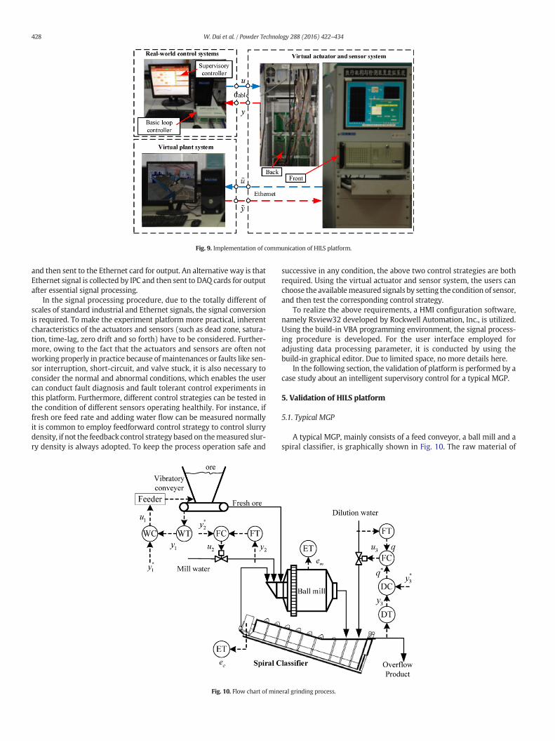
Fig. 9. Implementation of communication of HILS platform.
428 W. Dai et al. / Powder Technology 288 (2016) 422–434
and then sent to the Ethernet card for output. An alternative way is thatEthernet signal is collected by IPC and then sent to DAQ cards for outputafter essential signal processing.
In the signal processing procedure, due to the totally different ofscales of standard industrial and Ethernet signals, the signal conversionis required. To make the experiment platform more practical, inherentcharacteristics of the actuators and sensors (such as dead zone, satura-tion, time-lag, zero drift and so forth) have to be considered. Further-more, owing to the fact that the actuators and sensors are often notworking properly in practice because ofmaintenances or faults like sen-sor interruption, short-circuit, and valve stuck, it is also necessary toconsider the normal and abnormal conditions, which enables the usercan conduct fault diagnosis and fault tolerant control experiments inthis platform. Furthermore, different control strategies can be tested inthe condition of different sensors operating healthily. For instance, iffresh ore feed rate and adding water flow can be measured normallyit is common to employ feedforward control strategy to control slurrydensity, if not the feedback control strategy based on themeasured slur-ry density is always adopted. To keep the process operation safe and
Fig. 10. Flow chart of min
successive in any condition, the above two control strategies are bothrequired. Using the virtual actuator and sensor system, the users canchoose the availablemeasured signals by setting the condition of sensor,and then test the corresponding control strategy.
To realize the above requirements, a HMI configuration software,namely Rsview32 developed by Rockwell Automation, Inc., is utilized.Using the build-in VBA programming environment, the signal process-ing procedure is developed. For the user interface employed foradjusting data processing parameter, it is conducted by using thebuild-in graphical editor. Due to limited space, no more details here.
In the following section, the validation of platform is performed by acase study about an intelligent supervisory control for a typical MGP.
5. Validation of HILS platform
5.1. Typical MGP
A typical MGP, mainly consists of a feed conveyor, a ball mill and aspiral classifier, is graphically shown in Fig. 10. The raw material of
eral grinding process.
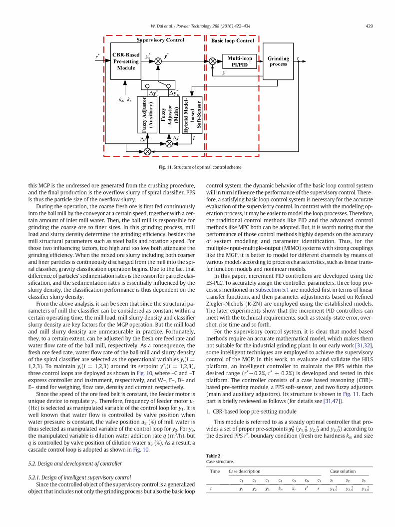
Fig. 11. Structure of optimal control scheme.
Table 2Case structure.
Time Case description Case solution
c1 c2 c3 c4 c5 c6 c7 s1 s2 s3
t y1 y2 y3 km kr r⁎ r y1,0⁎ y2,0⁎ y3,0⁎
429W. Dai et al. / Powder Technology 288 (2016) 422–434
this MGP is the undressed ore generated from the crushing procedure,and the final production is the overflow slurry of spiral classifier. PPSis thus the particle size of the overflow slurry.
During the operation, the coarse fresh ore is first fed continuouslyinto the ball mill by the conveyor at a certain speed, together with a cer-tain amount of inlet mill water. Then, the ball mill is responsible forgrinding the coarse ore to finer sizes. In this grinding process, millload and slurry density determine the grinding efficiency, besides themill structural parameters such as steel balls and rotation speed. Forthose two influencing factors, too high and too low both attenuate thegrinding efficiency. When the mixed ore slurry including both coarserand finer particles is continuously discharged from themill into the spi-ral classifier, gravity classification operation begins. Due to the fact thatdifference of particles' sedimentation rates is the reason for particle clas-sification, and the sedimentation rates is essentially influenced by theslurry density, the classification performance is thus dependent on theclassifier slurry density.
From the above analysis, it can be seen that since the structural pa-rameters of mill the classifier can be considered as constant within acertain operating time, the mill load, mill slurry density and classifierslurry density are key factors for the MGP operation. But the mill loadand mill slurry density are unmeasurable in practice. Fortunately,they, to a certain extent, can be adjusted by the fresh ore feed rate andwater flow rate of the ball mill, respectively. As a consequence, thefresh ore feed rate, water flow rate of the ball mill and slurry densityof the spiral classifier are selected as the operational variables yi(i =1,2,3). To maintain yi(i = 1,2,3) around its setpoint y⁎i(i = 1,2,3),three control loops are deployed as shown in Fig. 10, where –C and –Texpress controller and instrument, respectively, and W–, F–, D– andE– stand for weighing, flow rate, density and current, respectively.
Since the speed of the ore feed belt is constant, the feeder motor isunique device to regulate y1. Therefore, frequency of feeder motor u1(Hz) is selected as manipulated variable of the control loop for y1. It iswell known that water flow is controlled by valve position whenwater pressure is constant, the valve position u2 (%) of mill water isthus selected as manipulated variable of the control loop for y2. For y3,the manipulated variable is dilution water addition rate q (m3/h), butq is controlled by valve position of dilution water u3 (%). As a result, acascade control loop is adopted as shown in Fig. 10.
5.2. Design and development of controller
5.2.1. Design of intelligent supervisory controlSince the controlled object of the supervisory control is a generalized
object that includes not only the grinding process but also the basic loop
control system, the dynamic behavior of the basic loop control systemwill in turn influence the performance of the supervisory control. There-fore, a satisfying basic loop control system is necessary for the accurateevaluation of the supervisory control. In contrast with themodeling op-eration process, it may be easier tomodel the loop processes. Therefore,the traditional control methods like PID and the advanced controlmethods like MPC both can be adopted. But, it is worth noting that theperformance of those control methods highly depends on the accuracyof system modeling and parameter identification. Thus, for themultiple-input-multiple-output (MIMO) systemswith strong couplingslike the MGP, it is better to model for different channels by means ofvariousmodels according to process characteristics, such as linear trans-fer function models and nonlinear models.
In this paper, increment PID controllers are developed using theES-PLC. To accurately assign the controller parameters, three loop pro-cesses mentioned in Subsection 5.1 are modeled first in terms of lineartransfer functions, and then parameter adjustments based on RefinedZiegler-Nichols (R-ZN) are employed using the established models.The later experiments show that the increment PID controllers canmeet with the technical requirements, such as steady-state error, over-shot, rise time and so forth.
For the supervisory control system, it is clear that model-basedmethods require an accurate mathematical model, which makes themnot suitable for the industrial grinding plant. In our early work [31,32],some intelligent techniques are employed to achieve the supervisorycontrol of the MGP. In this work, to evaluate and validate the HILSplatform, an intelligent controller to maintain the PPS within thedesired range (r⁎−0.2%, r⁎ + 0.2%) is developed and tested in thisplatform. The controller consists of a case based reasoning (CBR)-based pre-setting module, a PPS soft-sensor, and two fuzzy adjustors(main and auxiliary adjustors). Its structure is shown in Fig. 11. Eachpart is briefly reviewed as follows (for details see [31,47]).
1. CBR-based loop pre-setting module
This module is referred to as a steady optimal controller that pro-vides a set of proper pre-setpoints y0⁎ (y1,0⁎, y2,0⁎ and y3,0⁎) according tothe desired PPS r⁎, boundary condition (fresh ore hardness km and size
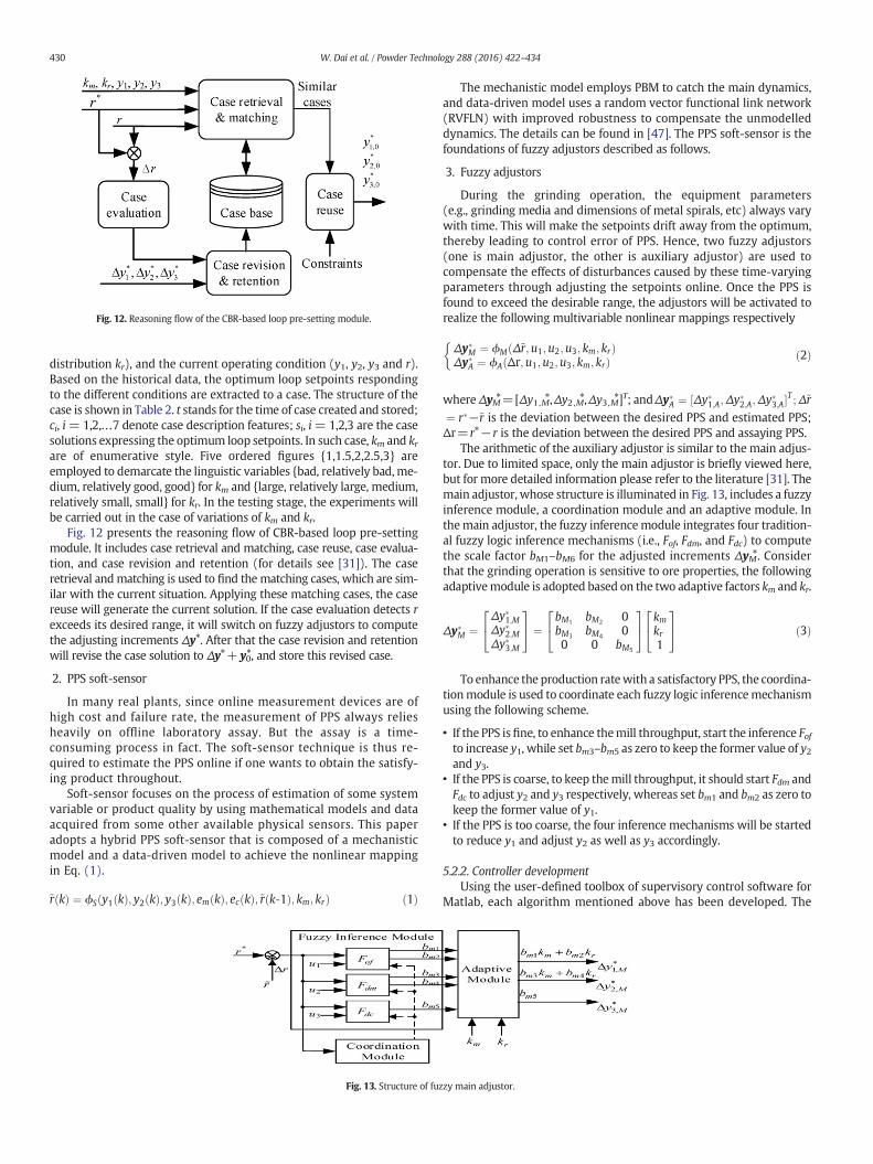
Fig. 12. Reasoning flow of the CBR-based loop pre-setting module.
430 W. Dai et al. / Powder Technology 288 (2016) 422–434
distribution kr), and the current operating condition (y1, y2, y3 and r).Based on the historical data, the optimum loop setpoints respondingto the different conditions are extracted to a case. The structure of thecase is shown in Table 2. t stands for the time of case created and stored;ci, i= 1,2,…7 denote case description features; si, i= 1,2,3 are the casesolutions expressing the optimum loop setpoints. In such case, km and krare of enumerative style. Five ordered figures {1,1.5,2,2.5,3} areemployed to demarcate the linguistic variables {bad, relatively bad,me-dium, relatively good, good} for km and {large, relatively large, medium,relatively small, small} for kr. In the testing stage, the experiments willbe carried out in the case of variations of km and kr.
Fig. 12 presents the reasoning flow of CBR-based loop pre-settingmodule. It includes case retrieval and matching, case reuse, case evalua-tion, and case revision and retention (for details see [31]). The caseretrieval andmatching is used to find thematching cases, which are sim-ilar with the current situation. Applying these matching cases, the casereuse will generate the current solution. If the case evaluation detects rexceeds its desired range, it will switch on fuzzy adjustors to computethe adjusting increments Δy⁎. After that the case revision and retentionwill revise the case solution to Δy⁎+ y0⁎, and store this revised case.
2. PPS soft-sensor
In many real plants, since online measurement devices are ofhigh cost and failure rate, the measurement of PPS always reliesheavily on offline laboratory assay. But the assay is a time-consuming process in fact. The soft-sensor technique is thus re-quired to estimate the PPS online if one wants to obtain the satisfy-ing product throughout.
Soft-sensor focuses on the process of estimation of some systemvariable or product quality by using mathematical models and dataacquired from some other available physical sensors. This paperadopts a hybrid PPS soft-sensor that is composed of a mechanisticmodel and a data-driven model to achieve the nonlinear mappingin Eq. (1).
~r kð Þ ¼ ϕS y1 kð Þ; y2 kð Þ; y3 kð Þ; em kð Þ; ec kð Þ;~r k‐1ð Þ; km; krð Þ ð1Þ
Fig. 13. Structure of fuz
The mechanistic model employs PBM to catch the main dynamics,and data-driven model uses a random vector functional link network(RVFLN) with improved robustness to compensate the unmodelleddynamics. The details can be found in [47]. The PPS soft-sensor is thefoundations of fuzzy adjustors described as follows.
3. Fuzzy adjustors
During the grinding operation, the equipment parameters(e.g., grinding media and dimensions of metal spirals, etc) always varywith time. This will make the setpoints drift away from the optimum,thereby leading to control error of PPS. Hence, two fuzzy adjustors(one is main adjustor, the other is auxiliary adjustor) are used tocompensate the effects of disturbances caused by these time-varyingparameters through adjusting the setpoints online. Once the PPS isfound to exceed the desirable range, the adjustors will be activated torealize the following multivariable nonlinear mappings respectively
Δy�M ¼ ϕM Δ~r;u1;u2;u3; km; krð ÞΔy�A ¼ ϕA Δr;u1;u2;u3; km; krð Þ
�ð2Þ
whereΔyM⁎=[Δy1,M⁎,Δy2,M⁎,Δy3,M⁎]T; andΔy�A ¼ ½Δy�1;A;Δy�2;A;Δy�3;A�T ;Δ~r¼ r�−~r is the deviation between the desired PPS and estimated PPS;Δr=r⁎−r is the deviation between the desired PPS and assaying PPS.
The arithmetic of the auxiliary adjustor is similar to the main adjus-tor. Due to limited space, only the main adjustor is briefly viewed here,but for more detailed information please refer to the literature [31]. Themain adjustor, whose structure is illuminated in Fig. 13, includes a fuzzyinference module, a coordination module and an adaptive module. Inthemain adjustor, the fuzzy inferencemodule integrates four tradition-al fuzzy logic inference mechanisms (i.e., Fof, Fdm, and Fdc) to computethe scale factor bM1–bM6 for the adjusted increments ΔyM⁎. Considerthat the grinding operation is sensitive to ore properties, the followingadaptivemodule is adopted based on the two adaptive factors km and kr.
Δy�M ¼Δy�1;MΔy�2;MΔy�3;M
24
35 ¼
bM1 bM2 0bM3 bM4 00 0 bM5
24
35 km
kr1
24
35 ð3Þ
To enhance the production ratewith a satisfactory PPS, the coordina-tionmodule is used to coordinate each fuzzy logic inferencemechanismusing the following scheme.
• If the PPS isfine, to enhance themill throughput, start the inference Fofto increase y1, while set bm3–bm5 as zero to keep the former value of y2and y3.
• If the PPS is coarse, to keep themill throughput, it should start Fdm andFdc to adjust y2 and y3 respectively, whereas set bm1 and bm2 as zero tokeep the former value of y1.
• If the PPS is too coarse, the four inference mechanisms will be startedto reduce y1 and adjust y2 as well as y3 accordingly.
5.2.2. Controller developmentUsing the user-defined toolbox of supervisory control software for
Matlab, each algorithm mentioned above has been developed. The
zy main adjustor.
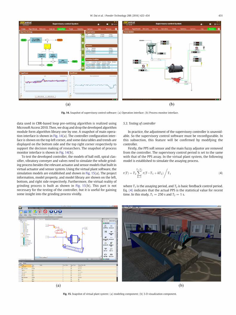
Fig. 14. Snapshot of supervisory control software: (a) Operation interface; (b) Process monitor interface.
431W. Dai et al. / Powder Technology 288 (2016) 422–434
data used in CBR-based loop pre-setting algorithm is realized usingMicrosoft Access 2010. Then,we drag and drop the developed algorithmmodule form algorithm library one by one. A snapshot of main opera-tion interface is shown in Fig. 14(a). The controller configuration inter-face is shown on the top left corner, and some data tables and trends aredisplayed on the bottom side and the top right corner respectively tosupport the decision making of researchers. The snapshot of processmonitor interface is shown in Fig. 14(b).
To test the developed controller, the models of ball mill, spiral clas-sifier, vibratory conveyer and valves need to simulate the whole grind-ing process besides the relevant actuator and sensormodels that built invirtual actuator and sensor system. Using the virtual plant software, thesimulation models are established and shown in Fig. 15(a). The projectinformation, model property, and model library are shown on the left,bottom, and right side respectively. Furthermore, the virtual reality ofgrinding process is built as shown in Fig. 15(b). This part is notnecessary for the testing of the controller, but it is useful for gainingsome insight into the grinding process vividly.
Fig. 15. Snapshot of virtual plant system: (a) modelin
5.3. Testing of controller
In practice, the adjustment of the supervisory controller is unavoid-able. So the supervisory control software must be reconfigurable. Inthis subsection, this feature will be confirmed by modifying thecontroller.
Firstly, the PPS soft sensor and the main fuzzy adjustor are removedfrom the controller. The supervisory control period is set to the samewith that of the PPS assay. In the virtual plant system, the followingmodel is established to simulate the assaying process.
r Tð Þ ¼ T2
XT1=T2
k¼1
r T−T1 þ kT2ð Þ,
T1 ð4Þ
where T1 is the assaying period, and T2 is basic feedback control period.Eq. (4) indicates that the actual PPS is the statistical value for recenttime. In this study, T1 = 250 s and T2 = 1 s.
g component; (b) 3-D visualization component.
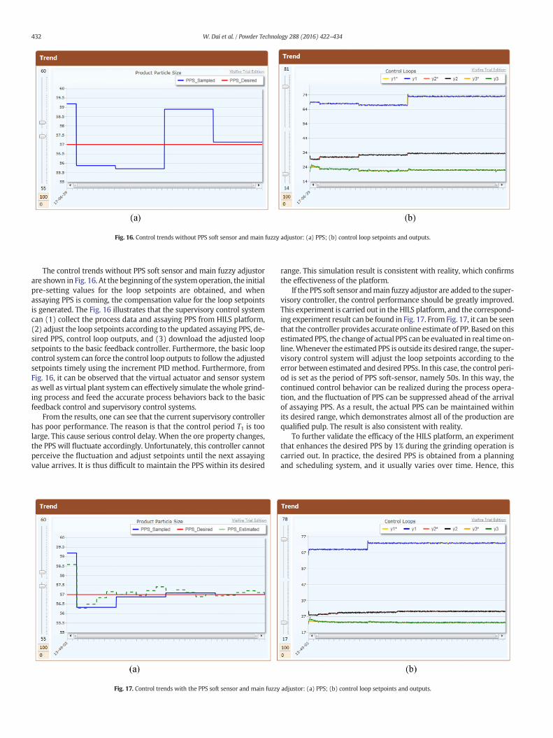
Fig. 16. Control trends without PPS soft sensor and main fuzzy adjustor: (a) PPS; (b) control loop setpoints and outputs.
432 W. Dai et al. / Powder Technology 288 (2016) 422–434
The control trends without PPS soft sensor and main fuzzy adjustorare shown in Fig. 16. At the beginning of the systemoperation, the initialpre-setting values for the loop setpoints are obtained, and whenassaying PPS is coming, the compensation value for the loop setpointsis generated. The Fig. 16 illustrates that the supervisory control systemcan (1) collect the process data and assaying PPS from HILS platform,(2) adjust the loop setpoints according to the updated assaying PPS, de-sired PPS, control loop outputs, and (3) download the adjusted loopsetpoints to the basic feedback controller. Furthermore, the basic loopcontrol system can force the control loop outputs to follow the adjustedsetpoints timely using the increment PID method. Furthermore, fromFig. 16, it can be observed that the virtual actuator and sensor systemaswell as virtual plant system can effectively simulate the whole grind-ing process and feed the accurate process behaviors back to the basicfeedback control and supervisory control systems.
From the results, one can see that the current supervisory controllerhas poor performance. The reason is that the control period T1 is toolarge. This cause serious control delay. When the ore property changes,the PPS will fluctuate accordingly. Unfortunately, this controller cannotperceive the fluctuation and adjust setpoints until the next assayingvalue arrives. It is thus difficult to maintain the PPS within its desired
Fig. 17. Control trends with the PPS soft sensor and main fuzzy
range. This simulation result is consistent with reality, which confirmsthe effectiveness of the platform.
If the PPS soft sensor andmain fuzzy adjustor are added to the super-visory controller, the control performance should be greatly improved.This experiment is carried out in the HILS platform, and the correspond-ing experiment result can be found in Fig. 17. From Fig. 17, it can be seenthat the controller provides accurate online estimate of PP. Based on thisestimated PPS, the change of actual PPS can be evaluated in real timeon-line.Whenever the estimated PPS is outside its desired range, the super-visory control system will adjust the loop setpoints according to theerror between estimated and desired PPSs. In this case, the control peri-od is set as the period of PPS soft-sensor, namely 50s. In this way, thecontinued control behavior can be realized during the process opera-tion, and the fluctuation of PPS can be suppressed ahead of the arrivalof assaying PPS. As a result, the actual PPS can be maintained withinits desired range, which demonstrates almost all of the production arequalified pulp. The result is also consistent with reality.
To further validate the efficacy of the HILS platform, an experimentthat enhances the desired PPS by 1% during the grinding operation iscarried out. In practice, the desired PPS is obtained from a planningand scheduling system, and it usually varies over time. Hence, this
adjustor: (a) PPS; (b) control loop setpoints and outputs.
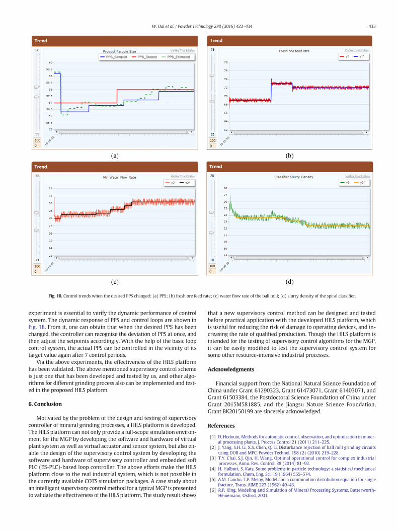
Fig. 18. Control trends when the desired PPS changed: (a) PPS; (b) fresh ore feed rate; (c) water flow rate of the ball mill; (d) slurry density of the spiral classifier.
433W. Dai et al. / Powder Technology 288 (2016) 422–434
experiment is essential to verify the dynamic performance of controlsystem. The dynamic response of PPS and control loops are shown inFig. 18. From it, one can obtain that when the desired PPS has beenchanged, the controller can recognize the deviation of PPS at once, andthen adjust the setpoints accordingly. With the help of the basic loopcontrol system, the actual PPS can be controlled in the vicinity of itstarget value again after 7 control periods.
Via the above experiments, the effectiveness of the HILS platformhas been validated. The above mentioned supervisory control schemeis just one that has been developed and tested by us, and other algo-rithms for different grinding process also can be implemented and test-ed in the proposed HILS platform.
6. Conclusion
Motivated by the problem of the design and testing of supervisorycontroller of mineral grinding processes, a HILS platform is developed.The HILS platform can not only provide a full-scope simulation environ-ment for the MGP by developing the software and hardware of virtualplant system as well as virtual actuator and sensor system, but also en-able the design of the supervisory control system by developing thesoftware and hardware of supervisory controller and embedded softPLC (ES-PLC)-based loop controller. The above efforts make the HILSplatform close to the real industrial system, which is not possible inthe currently available COTS simulation packages. A case study aboutan intelligent supervisory controlmethod for a typicalMGP is presentedto validate the effectiveness of theHILS platform. The study result shows
that a new supervisory control method can be designed and testedbefore practical application with the developed HILS platform, whichis useful for reducing the risk of damage to operating devices, and in-creasing the rate of qualified production. Though the HILS platform isintended for the testing of supervisory control algorithms for the MGP,it can be easily modified to test the supervisory control system forsome other resource-intensive industrial processes.
Acknowledgments
Financial support from the National Natural Science Foundation ofChina under Grant 61290323, Grant 61473071, Grant 61403071, andGrant 61503384, the Postdoctoral Science Foundation of China underGrant 2015M581885, and the Jiangsu Nature Science Foundation,Grant BK20150199 are sincerely acknowledged.
References
[1] D. Hodouin, Methods for automatic control, observation, and optimization inminer-al processing plants, J. Process Control 21 (2011) 211–225.
[2] J. Yang, S.H. Li, X.S. Chen, Q. Li, Disturbance rejection of ball mill grinding circuitsusing DOB and MPC, Powder Technol. 198 (2) (2010) 219–228.
[3] T.Y. Chai, S.J. Qin, H. Wang, Optimal operational control for complex industrialprocesses, Annu. Rev. Control. 38 (2014) 81–92.
[4] H. Hulburt, S. Katz, Some problems in particle technology: a statistical mechanicalformulation, Chem. Eng. Sci. 19 (1964) 555–574.
[5] A.M. Gaudin, T.P. Meloy, Model and a comminution distribution equation for singlefracture, Trans. AIME 223 (1962) 40–43.
[6] R.P. King, Modeling and Simulation of Mineral Processing Systems, Butterworth-Heinemann, Oxford, 2001.
434 W. Dai et al. / Powder Technology 288 (2016) 422–434
[7] R.K. Rajamani, J.A. Herbst, Optimal control of a ball mill grinding circuit — part I &part II, Chem. Eng. Sci. 46 (3) (1991) 861–879.
[8] A.J. Lynch, R.D. Morrison, Simulation in mineral processing history, present statusand possibilities, J. South. Afr. Inst. Min. Metall. 99 (6) (1999) 283–288.
[9] K.V.S. Sastry, G. Adel, A survey of computer simulation software for mineral process-ing systems, Control 84 (1985) 49–53.
[10] Y. Liu, S. Spencer, Dynamic simulation of grinding circuits, Miner. Eng. 17 (11–12)(2004) 1189–1198.
[11] B.K. Mishra, Monte Carlo simulation of particle breakage process during grinding,Powder Technol. 110 (2000) 246–252.
[12] D. Sbárbaro, R.D. Villar, Advanced Control and Supervision of Mineral ProcessingPlants, Springer, New York, 2010.
[13] M. Ramasamy, Model based supervisory control of a ball mill grinding circuit,J. Process Control 9 (3) (1999) 195–211.
[14] J.L. Salazar, L. Magne, G. Acuna, F. Cubillos, Dynamic modelling and simulation ofsemi-autogenous mills, Miner. Eng. 22 (1) (2008) 70–77.
[15] J.A. Herbst, D.W. Fuerstenau, Scale-up procedure for continuous grindingmill designusing population balance models, Int. J. Miner. Process. 7 (1) (1980) 1–31.
[16] D.J. Rankin, J. Jiang, A hardware-in-the-loop simulation platform for the verificationand validation of safety control systems, IEEE Trans. Nucl. Sci. 58 (2) (2011)468–478.
[17] W. Ren, M. Steurer, S.Woodruff, M. Andrus, Demonstrating the power hardware-in-the-loop through simulation of a notional destroyer-class all-electric ship systemduring crashback, Proc. Adv. Naval Propuls. Symp. 2006 (ASNE), Arlington, 102006, pp. 30–31.
[18] M. Short, M.J. Pont, Assessment of high-integrity embedded automotive control sys-tems using hardware in the loop simulation, J. Syst. Softw. 81 (2008) 1163–1183.
[19] O. Ma, A. Flores-Abad, T. Boge, Use of industrial robots for hardware-in-the-loopsimulation of satellite rendezvous and docking, Acta Astronaut. 81 (2012) 334–347.
[20] R. Chhabra, M.R. Emami, A holistic concurrent design approach to robotics usinghardware-in-the-loop simulation, Mechatronics 23 (2013) 335–345.
[21] A. Martin, M.R. Emami, Dynamic load emulation in hardware-in-the-loop simula-tion of robot manipulators, IEEE Trans. Ind. Electron. 58 (7) (2011) 2980–2987.
[22] N.R. Gans, W.E. Dixon, R. Lind, A. Kurdila, A hardware in the loop simulationplatform for vision-based control of unmanned air vehicles, Mechatronics 19 (7)(2009) 1043–1056.
[23] W.B. Huang, Q. Zhang, The hardware-in-the-loop simulation on the control systemof a small launch vehicle, Proc. Eng. 29 (2012) 1867–1871.
[24] I.R. Kendall, R.P. Jones, An investigation into the use of hardware-in-the-loop simu-lation testing for automotive electronic control systems, Control. Eng. Pract. 7 (11)(1999) 1343–1356.
[25] R. Lestage, A. Pomerleau, D. Hodouin, Constrained real-time optimization of a grind-ing circuit using steady-state linear programming supervisory control, PowderTechnol. 124 (3) (2002) 254–263.
[26] A. Pomerleau, D. Hodouin, A. Desbiens, E. Gagnon, A survey of grinding circuitcontrol methods: from decentralized PID controllers to multivariable predictivecontrollers, Powder Technol. 108 (2) (2000) 103–115.
[27] M. Ramasamy, S.S. Narayanan, C.D.P. Rao, Control of ball mill grinding circuit usingmodel predictive control scheme, J. Process Control 15 (3) (2005) 273–283.
[28] A.J. Niemi, L. Tian, R. Ylinen, Model predictive control for grinding systems, Control.Eng. Pract. 5 (2) (1997) 271–278.
[29] X.S. Chen, J. Yang, S.H. Li, Q. Li, Disturbance observer based multi-variable control ofball mill grinding circuits, J. Process Control 19 (2009) 1205–1213.
[30] P. Zhou, T.Y. Chai, Grinding circuit control. A hierarchical approach using extended2-DOF decoupling and model approximation, Powder Technol. 213 (3) (2009)14–26.
[31] P. Zhou, T.Y. Chai, H. Wang, Intelligent optimal-setting control for grinding circuitsof mineral processing process, IEEE Trans. Autom. Sci. Eng. 6 (4) (2009) 730–743.
[32] P. Zhou, T.Y. Chai, J. Sun, Intelligence-based supervisory control for optimizing theoperation of a DCS-controlled grinding system, IEEE Trans. Control Syst. Technol.21 (1) (2013) 162–175.
[33] X.S. Chen, Q. Li, S.M. Fei, Supervisory expert control for ball mill grinding circuits,Expert Syst. Appl. 34 (3) (2008) 1877–1885.
[34] W. Dai, T.Y. Chai, S. Yang, Data-driven optimization control for safety operation ofhematite grinding process, IEEE Trans. Ind. Electron. 62 (5) (2015) 2930–2941.
[35] A.V.E. Conradie, C. Aaldrich, Neurocontrol of a ball mill grinding circuit usingevolutionnary reinforcement learning, Miner. Eng. 14 (10) (2001) 1277–1294.
[36] S.W. Lu, P. Zhou, T.Y. Chai, W. Dai, Modeling and simulation of whole ball mill grind-ing plant for integrated control, IEEE Trans. Autom. Sci. Eng. 11 (4) (2014)1004–1019.
[37] M. Tie, J. Bi, Y. Fan, Hybrid intelligent modeling approach for the ball mill grindingprocess, Advances in Neural Networks- ISNN 2007, pp. 609–617.
[38] R.J. Charles, Energy-size reduction relationships in comminution, Trans. AIME 208(1957) 80–88.
[39] B. Epstein, Logarithmico-normal distribution in breakage of solids, Ind. Eng. Chem.40 (12) (1948) 2289–2292.
[40] D.W. Fuerstenau, P.B. Phatak, P.C. Kapur, A.Z. Abouzeid, Simulation of the grinding ofcoarse/fine (heterogeneous) systems in a ball mill, Int. J. Miner. Process. 99 (1)(2011) 32–38.
[41] J.A. Herbst, M. Siddique, K. Rajamani, E. Sanchez, Population based approach to ballmill scale-up: bench and pilot scale investigations, Trans. Soc. Min. Eng. AIME 272(1983) 1945–1954.
[42] A. Lynch, T. Rao, Modelling and scale-up of hydrocyclone classifiers, 11th Int. Min.Proc. Cong. Cagliari, 9 1975, pp. 245–269.
[43] B.C. Chen, Elements of Grinding Process, Metallurgical Industry Press, Beijing, 1989(in Chinese).
[44] S.R. Li, Q.P. Huang, Mathematical model of classification, Met. Miner. 1 (1989) 30–34(in Chinese).
[45] OPC Foundation, http://www.opcfoundation.org/2013.[46] https://www.kw-software.com/en/iec-61131-control.[47] W. Dai, Q. Liu, T.Y. Chai, Particle size estimate of grinding processes using random
vector functional link networks with improved robustness, Neurocomputing 169(2015) 361–372.