Embed Size (px)
Citation preview

Turin Networks Inc.
TraverseEdge 2020 System
Documentation
Software Release 5.0.xPublication Date: April 2007
Document Number: 800-0017-50 Rev. A
Hardware Installation Guide

Copyright © 2007 Turin Networks, Inc.
All rights reserved. This document contains proprietary and confidential information of Turin Networks, Inc., and may not be used, reproduced, or distributed except as authorized by Turin Networks. No part of this publication may be reproduced in any form or by any means or used to make any derivative work (such as translation, transformation or adaptation) without written permission from Turin Networks, Inc.
Turin Networks reserves the right to revise this publication and to make changes in content from time to time without obligation on the part of Turin Networks to provide notification of such revision or change. Turin Networks may make improvements or changes in the product(s) described in this manual at any time.
Turin Networks Trademarks
Turin Networks, the Turin Networks logo, Traverse, TraverseEdge, Traverse PacketEdge, TransAccess, TransNav, Traverse PacketEdge, TPE-1200, TE-2020 (VLX2020), TE-206 (VLX2006), TN-Xpert (VLXpert), TN-Xsight (VLXsight), TN-Xconnect, TN-Xtend, TN-Xrelay, and Creating The Broadband Edge are trademarks of Turin Networks, Inc. or its affiliates in the United States and other countries. All other trademarks, service marks, product names, or brand names mentioned in this document are the property of their respective owners. Inquiries concerning such products, services, or marks should be made directly to those companies.
Product Use
The TraverseEdge 2020 (VLX2020) is part of a family of products designed and manufactured by Turin Networks for the telecommunications industry.
Government Use
Use, duplication, or disclosure by the U.S. Government is subject to restrictions as set forth in FAR 12.212 (Commercial Computer Software-Restricted Rights) and DFAR 227.7202 (Rights in Technical Data and Computer Software), as applicable.

Release 5.0.x Turin Networks Page iii
PREFACE
Revision History The following lists the sections of this document affected by any informational changes:
Section Issue Date Reason For Change
All 01 4/2007 First Release 5.0 Version (Preliminary)
Related Documents The following documents pertain to Turin’s TraverseEdge 2020 (TE-2020) optical transport equipment. For online documentation, go to www.force10networks.com
Table 1 TE-2020™ Document List
Document Title Description
TE-2020 Ordering Guide Provides a brief description of each module available for the TE-2020 system, part numbers, compatibility information, and the contact information required to order them.
TE-2020 Users Guide Provides information vital for proper operation and maintenance of Turin Networks TE-2020 system. Information provided deals with processes and procedures for turn-up, test, maintenance duties, input command sequences, valid parameters, and expected responses in TL-1 and TN-Sight.
TE-2020 Applications Engineering Guide
Provides information vital for the proper deployment of a Turin Networks TE-2020 system. Information provided deals with environmental requirements, specifications, and applications.
TE-2020 Hardware Installation Guide
Provides information vital for proper installation of Turin Networks TE-2020 equipment. Information provided deals with site layout, required hardware, power connections, cable connections, and interfaces that must be hardwired.
TE-2020 TL-1 Reference Guide
Provides information vital for proper communication with Turin Networks TE-2020 system. Information provided deals with all TL-1 command structures, valid parameters, and expected responses, and error codes.
TE-2020 Hardware Description Guide
Provides detailed information for each card, shelf and accessory for a Turin Networks TE-2020 system. Information provided includes card level diagrams, operational requirements, specifications, and applications.
Table 2 TN-Xpert™ Document List
Document Title Description
TN-Xpert Installation Guide Provides information required to properly install and maintain TN-Xpert Client and Server for both Solaris and Windows Environments. Information provided deals with Operation System configuration, database installation, user account configuration, TN-Xpert software installation and Network Element IP connectivity

Page iv Turin Networks Release 5.0.x
PrecautionsThroughout this document, there are important precautionary statements used to warn of possible hazards to persons or equipment. A precaution identifies a possible hazard and then explains what may happen if the hazard is not avoided. The Danger, Warning, and Caution statements should be followed at all times to ensure safe and proper installation, operation, and reliability of the product. When multiple precautions are present, they are listed in order of severity as follows:
Danger! Indicates that a certain risk is associated with the task that will cause severe per-sonal injury, death, or substantial property damage if the procedure is not adhered to as written.
Warning! Indicates that a certain risk is associated with the task that can cause personal injury, death, or substantial property damage if the procedure is not adhered to as written.
Caution! Indicates that a certain risk is associated with the task that can or will cause per-sonal injury or property damage if the procedure is not adhered to as written.
General Safety PrecautionsThese precautions will be found throughout the document whenever the optical cards or other system components are being discussed.
Danger! Never look into the end of an optical fiber. Exposure to invisible LASER radiation can cause serious and/or permanent damage to the eye or even blindness. Verify the optical source is disabled through the use of an optical power meter before handling optical fibers. Use of controls, adjustments, or procedures other than those specified within this document may result in hazardous laser radiation expo-sure.
Caution! Electrostatic Discharge (ESD) sensitive devices. ESD can cause catastrophic fail-ure or degraded life and performance of a device. Use an anti-static wrist strap connected to a properly grounded source before contacting any electronic devices.
Standards ComplianceNEBS Level 3 per SR-3580 (ref. GR-63 & GR-1089)
UL 60950, 3rd Edition
CDRH Laser Certification
FCC Part 15 Class B
ANSI Z136.1 - 1993 - American National Standard for the Safe Use of Lasers
TN-Xpert Users Guide Provides information vital for proper operation and maintenance of Turin Networks TE-2020 and TE-206 systems. Information provided deals with processes and procedures for turn-up, test, maintenance duties, input command sequences, valid parameters, and expected responses using TN-Xpert™.
Table 2 TN-Xpert™ Document List
Document Title Description

Release 5.0.x Turin Networks Page v
FCC WarningThe TE-2020 system has been tested and found to comply with the limits for a Class A digital device, pursuant to Part 15 of the FCC Rules. These limits are designed to provide reasonable protection against harmful interference when this equipment is operated in a commercial environment. This equipment generates, uses, and can radiate radio frequency energy and, if not installed and used in accordance with the instructions, may cause harmful interference to radio and television communications. Operation of this equipment in a residential area is likely to cause interference, in which case the user will be required to correct the interference at his or her own expense. Shielded cables must be used with this unit to ensure compliance with the Class A FCC limits.
Contact Information
This section contains the addresses and phone numbers of Turin Networks offices. For sales and technical assistance, go to www.force10networks.com.
Query and Contact Information Matrix
Query Contact Group
Contact Information
• Warranty Issues
• Part Issues
• Repair Service
• Upgrades
• Installation and Test
• Training
Technical Assistance Center (TAC)
Inside the U.S., toll-free 1-888-887-4638Outside the U.S. 707-665-4335E-mail [email protected]

Page vi Turin Networks Release 5.0.x
If You Need Assistance
If you need assistance while working with the TE-1200 product, contact the Technical Assistance Center (TAC). See the “Query and Contact Information Matrix” table above. TAC is available 24 hours a day, 7 days a week. E-mail support (24-hour response) is also available through: [email protected].
Calling for Repairs
If repair is necessary, call Technical Assistance at 1-866-948-7625 for a Return Material Authorization (RMA) number before sending the unit. The RMA number must be prominently displayed on all equipment cartons.
When calling outside the United States, use the appropriate international access code, and then call 707-665-4355 to contact the Repair Facility.
When shipping equipment for repair, follow these steps:1. Pack the unit securely.
2. Enclose a note describing the exact problem.
3. Enclose a copy of the invoice that verifies the warranty status.
4. Ship the unit PREPAID to the following address:
Force10 Networks, Inc.Attn: RMA # ________700 N. Glenville Dr.Richardson, TX 75081 USA
Acronyms
ACO Alarm Cut-offADM Add/Drop MultiplexerBITS Building Integrated Timing SupplyBLSR Bi-directional Line Switched RingCCT Common Control and TimingCDRH Center for Devices and Radiological HealthCLI Command Line InterfaceCO Central OfficeD&C Drop and ContiunueDCC Data Communications ChannelDS3 Digital Signal Level 3 at 45 MbpsDWDM Dense Wave Division MultiplexingEC1 Electrical Carrier Level 1EMS Element Management SystemEoS Ethernet Over SONETFCC Federal Communications Commission

Release 5.0.x Turin Networks Page vii
FTP File Transfer ProtocolGbE Giga-bit EthernetGFP Generic Framing ProcedureGMPLS Generalized Multi-Protocol Label Switching GNE Gateway Network ElementGUI Graphical User InterfaceHTTP Hyper-text Transfer ProtocolIR Intermediate ReachLAN Local Area NetworkLDCC Line Data Communications ChannelLDF Lightwave Distribution FrameLEI Local Equipment InterconnectLR Long ReachLSP Label Switched PathLTE Line Terminating EquipmentMAC Media Access ControlMMF Multi-mode FiberNEBS Network Equipment - Building SystemsNE Network ElementNTP Network Time ProtocolNUT Non-Preemptable Unprotected TrafficO-ADM Optical Add Drop MultiplexerOAM&P Operations, Administration, Maintenance and ProvisioningOC Optical CarrierOC-12 Optical Carrier Level 12 at 622 MbpsOC-192 Optical Carrier Level 192 at 9.6 GbpsOC-3 Optical Carrier Level 3 at 155 MbpsOC-48 Optical Carrier Level 48 at 2.4 GbpsOS Operating SystemOSPF Open Shortest Path FirstOSS Operation Support SystemPCA Protected Channel AccessPLM Physical Layer ModulePOH Path OverheadRST ResetRU Rack Unit (1 RU = 1.75”)RX ReceiveSONET Synchronous Optical NetworkSLA Service Level AgreementSMF Single Mode FiberSR Short ReachSTAT StatusSTS Concatenated Synchronous Transport SignalSTS-1c Concatenated Synchronous Transport Signal Level 1 at 52 MbpsSTS-12c Concatenated Synchronous Transport Signal Level 12 at 622 MbpsSTS-3c Concatenated Synchronous Transport Signal Level 3 at 155 MbpsSTS-48c Concatenated Synchronous Transport Signal Level 48 at 2.4 Gbps

Page viii Turin Networks Release 5.0.x
TBD To Be DeterminedTCP/IP Transport Control Protocol/Internet ProtocolTID Target IdentifierTL-1 Transaction Language Level 1TX TransmitUL Underwriters LaboratoriesUPSR Unidirectional Path Switched RingVC Virtual ConcatenationVdc Voltage - Direct CurrentVLAN Virtual LanVPN Virtual Private NetworkVR Very Long ReachWDM Wave Division Multiplexing
TraverseEdge 2020 Hardware Installation Guide
Release 5.0.x Turin Networks Page ix
Table of Contents
Item Page
Chapter 1 Introduction ............................................................................................................................................ 1-1Chapter 2 Installation Requirements ..................................................................................................................... 2-1
2.1 Temperature ................................................................................................................................................. 2-1
2.2 Access .......................................................................................................................................................... 2-1
2.3 Wiring ........................................................................................................................................................... 2-1
2.3.1 Grounding ........................................................................................................................................... 2-12.3.2 Power .................................................................................................................................................. 2-2
2.4 Laser Safety ................................................................................................................................................. 2-2
2.5 General Safety Admonishments ................................................................................................................... 2-2
Chapter 3 Equipment Inspection ........................................................................................................................... 3-1Chapter 4 TE-2020 Main Shelf Installation ............................................................................................................ 4-1
4.1 Installing the TE-2020 Main Shelf - 19" ........................................................................................................ 4-3
4.2 Installing the TE-2020 Main Shelf - 23" ........................................................................................................ 4-4
4.3 Providing Power to the Shelf ........................................................................................................................ 4-6
4.3.1 Preparing and Testing the Power Distribution Unit.............................................................................. 4-64.3.2 Installing the Frame Ground Wire ....................................................................................................... 4-74.3.3 Installing -48Vdc Supply and Return Wires......................................................................................... 4-84.3.4 Replacing Fuses in the Power Distribution Unit ................................................................................ 4-10
4.4 Connecting the Wire-wrap Pin Field (Optional) .......................................................................................... 4-11
4.4.1 BITS Input (Optional) ........................................................................................................................ 4-134.4.2 Derived BITS Output (Optional) ........................................................................................................ 4-154.4.3 Environmental Input (Optional) ......................................................................................................... 4-164.4.4 External Output Control (Optional) .................................................................................................... 4-194.4.5 Alarm Cut-Off (Optional) ................................................................................................................... 4-204.4.6 Audible Alarms (Optional) ................................................................................................................. 4-234.4.7 Visual Alarms (Optional) ................................................................................................................... 4-24
4.5 Connecting the Management Ports (Optional) ........................................................................................... 4-25
4.5.1 Rear Shelf 10/100 Ethernet Management Ports ............................................................................... 4-254.5.2 Rear Serial Communications Port..................................................................................................... 4-27
Chapter 5 TE-2020 Main Shelf Plug-In Installation ................................................................................................................................................................ 5-1
5.1 Installing the TE-2020 Main Fan Tray .......................................................................................................... 5-1
5.1.1 Installing the 2 RU Fan Filter............................................................................................................... 5-35.1.2 Fan Tray Craft User Port ..................................................................................................................... 5-5
5.2 Installing the TE-2020 Main CCT ................................................................................................................. 5-5
Chapter 6 OTS2 Shelf Installation .......................................................................................................................... 6-16.1 Installing the OTS2 - 19" .............................................................................................................................. 6-2
6.2 Installing the OTS2 - 23" .............................................................................................................................. 6-3
6.3 Providing Power to the Shelf ........................................................................................................................ 6-5
6.3.1 Preparing and Testing the Power Distribution Unit.............................................................................. 6-56.3.2 Installing the Frame Ground Wire ....................................................................................................... 6-66.3.3 Installing -48Vdc Supply and Return Wires......................................................................................... 6-86.3.4 Replacing Fuses in the Power Distribution Unit ................................................................................ 6-10
Chapter 7 OTS2 Plug-In Installation ....................................................................................................................... 7-17.1 Installing the OTS2 Fan Tray ........................................................................................................................ 7-1
7.1.1 Installing the 2 RU Fan Filter............................................................................................................... 7-37.2 Installing the OTS2 CCT .............................................................................................................................. 7-4
7.3 Installing the OC-192 x2 Blank ..................................................................................................................... 7-8
Chapter 8 Optical PLM Installation ........................................................................................................................ 8-18.1 Installing an OC-192 or OC-48 x4 PLM ........................................................................................................ 8-3

TraverseEdge 2020 Hardware Installation Guide
Page x Turin Networks Release 5.0.x
8.2 Installing an OC-48 x1 or OC-48 x2 PLM ..................................................................................................... 8-5
8.3 Installing an OC-12 PLM .............................................................................................................................. 8-8
8.4 Installing an OC-3 x4 PLM ........................................................................................................................... 8-9
8.5 Installing a GbE x2 PLM ............................................................................................................................. 8-11
8.6 Installing Blank Panels ............................................................................................................................... 8-12
Chapter 9 Connecting Fibers to Optical PLMs ............................................................................................................................................................ 9-1
9.1 Installing Fibers with MPO Connectors ........................................................................................................ 9-1
9.2 Installing Fibers with LC Connectors ............................................................................................................ 9-6
9.3 Installing Fibers with SC Connectors ........................................................................................................... 9-8
9.4 Fiber Optic Connector and Receptacle Cleaning ....................................................................................... 9-11
9.4.1 Cleaning an Un-Mated Connector (Fiber) ......................................................................................... 9-119.4.2 Cleaning an Un-Mated Bulkhead Connector (PLM).......................................................................... 9-129.4.3 Cleaning a Mated Connector ............................................................................................................ 9-12
Chapter 10 DS3/EC1 Tributary Shelf (ETS1) Installation .................................................................................... 10-110.1 Installing the ETS1 - 19" ........................................................................................................................... 10-2
10.2 Installing the ETS1 - 23" ........................................................................................................................... 10-4
10.3 Providing Power to the Shelf .................................................................................................................... 10-7
10.3.1 Preparing and Testing the Power Distribution Unit.......................................................................... 10-710.3.2 Installing the Frame Ground Wire ................................................................................................... 10-810.3.3 Installing -48Vdc Supply and Return Wires..................................................................................... 10-910.3.4 Replacing Fuses In the Power Distribution Unit ............................................................................ 10-11
Chapter 11 DS3/EC1 Tributary Shelf (ETS1) Plug-In Installation ....................................................................... 11-111.1 Installing the ETS Fan Tray ...................................................................................................................... 11-1
11.1.1 Installing the 3 RU Fan Filter ........................................................................................................... 11-311.2 Installing the ETS1 CCT ........................................................................................................................... 11-5
Chapter 12 DS3/EC1 PLM Installation .................................................................................................................. 12-112.1 Installing a DS3/EC1 PLM ........................................................................................................................ 12-1
Chapter 13 ETS2 Installation ................................................................................................................................ 13-113.1 Installing the ETS2 - 19" ........................................................................................................................... 13-2
13.2 Installing the ETS2 - 23" ........................................................................................................................... 13-4
13.3 Providing Power to the Shelf .................................................................................................................... 13-7
13.3.1 Preparing and Testing the Power Distribution Unit.......................................................................... 13-713.3.2 Installing the Frame Ground Wire ................................................................................................... 13-813.3.3 Installing -48Vdc Supply and Return Wires..................................................................................... 13-913.3.4 Replacing Fuses In the Power Distribution Unit ............................................................................ 13-11
Chapter 14 ETS2 Plug-In Installation ................................................................................................................... 14-114.1 Installing the ETS Fan Tray ...................................................................................................................... 14-1
14.1.1 Installing the 3 RU Fan Filter........................................................................................................... 14-314.2 Installing the ETS2 CCT ........................................................................................................................... 14-5
Chapter 15 ETS2 PLM Installation ........................................................................................................................ 15-115.1 Installing a DS3/EC1 PLM ........................................................................................................................ 15-1
15.2 Installing a DS1 PLM ................................................................................................................................ 15-3
15.3 Installing a FastE PLM ............................................................................................................................. 15-5
Chapter 16 Connecting Electrical Interface Cables ........................................................................................... 16-116.1 ETS1 BNC Connectors ............................................................................................................................ 16-1
16.2 ETS2 ........................................................................................................................................................ 16-2
16.2.1 DS1 Connectors.............................................................................................................................. 16-316.2.2 DS3 Connectors.............................................................................................................................. 16-416.2.3 FastE Connectors ........................................................................................................................... 16-6
Chapter 17 LEI Installation .................................................................................................................................... 17-117.1 LEI Overview ............................................................................................................................................ 17-1

TraverseEdge 2020 Hardware Installation Guide
Release 5.0.x Turin Networks Page xi
17.2 LEI Routing (Optional) .............................................................................................................................. 17-1
17.3 Connecting LEI Cables ............................................................................................................................. 17-4
Chapter 18 Front Cover Installation ..................................................................................................................... 18-118.1 TE-2020 Main Shelf and OTS2 Front Cover Installation .......................................................................... 18-1
18.2 DS3/EC1 Tributary Shelf (ETS1) or ETS2 Front Cover Installation ............................................................................................................................................................... 18-4
Chapter 19 Wire Gauge, Fuse Sizes and Power Calculations ........................................................................... 19-119.1 Shelf Power Calculations ......................................................................................................................... 19-1
19.2 Wire Gauge and Fuse Rating ................................................................................................................... 19-4

TraverseEdge 2020 Hardware Installation Guide
Page xii Turin Networks Release 5.0.x

TraverseEdge 2020 Hardware Installation Guide
Release 5.0.x Turin Networks Page i
List of Figures
Item Page
Chapter 1 IntroductionChapter 2 Installation RequirementsChapter 3 Equipment InspectionChapter 4 TE-2020 Main Shelf Installation
Figure 4-1 TE-2020 Main Shelf - 19" .................................................................................................................. 4-1
Figure 4-2 TE-2020 Main Shelf - 23" .................................................................................................................. 4-2
Figure 4-3 Chassis Filter Location ..................................................................................................................... 4-5
Figure 4-4 Chassis Filter Removed ................................................................................................................... 4-5
Figure 4-5 TE-2020 Main Shelf - Rear View - Connectors ................................................................................. 4-8
Figure 4-6 Ground Wire Installation.................................................................................................................... 4-8
Figure 4-7 Power Connectors........................................................................................................................... 4-10
Figure 4-8 Wire-wrap Pin Field ......................................................................................................................... 4-12
Figure 4-9 BITS Input/Output and Frame Ground ............................................................................................ 4-15
Figure 4-10 Example External Environmental Input Configuration..................................................................... 4-17
Figure 4-11 Environment Input Pins ................................................................................................................... 4-19
Figure 4-12 External Output Control Pins........................................................................................................... 4-20
Figure 4-13 Alarm Cut-Off Control Pins.............................................................................................................. 4-22
Figure 4-14 Alarm Control Pins .......................................................................................................................... 4-24
Figure 4-15 Rear Management Ports ................................................................................................................. 4-27
Figure 4-16 Rear Serial Interface Port ................................................................................................................ 4-27
Chapter 5 TE-2020 Main Shelf Plug-In Installation
Figure 5-1 TE-2020 Main Shelf Assembly .......................................................................................................... 5-1
Figure 5-2 TE-2020 Main Fan Tray .................................................................................................................... 5-2
Figure 5-3 Air Filter Directional Indicator ............................................................................................................ 5-4
Figure 5-4 TE-2020 Main Fan Tray with 2 RU Fan Filter.................................................................................... 5-4
Figure 5-5 Installing a TE-2020 Main CCT ......................................................................................................... 5-6
Figure 5-6 Extending Ejector Ear Tabs............................................................................................................... 5-7
Figure 5-7 Rotating CCT Ejector Ear Tabs......................................................................................................... 5-7
Figure 5-8 Seating the CCT Card Ejector Ear .................................................................................................... 5-8
Figure 5-9 Fully Seating the CCT into the Backplane......................................................................................... 5-8
Figure 5-10 TE-2020 Main Fan Tray LEDs........................................................................................................... 5-9
Chapter 6 OTS2 Shelf InstallationFigure 6-1 OTS2 - 19" ........................................................................................................................................ 6-1
Figure 6-2 OTS2 - 23" ........................................................................................................................................ 6-2
Figure 6-3 Chassis Filter Location ...................................................................................................................... 6-4
Figure 6-4 Chassis Filter Removed ................................................................................................................... 6-5
Figure 6-5 TE-2020 Main Shelf - Rear View - Connectors ................................................................................. 6-7
Figure 6-6 Ground Wire Installation.................................................................................................................... 6-8
Figure 6-7 Power Connectors........................................................................................................................... 6-10
Chapter 7 OTS2 Plug-In InstallationFigure 7-1 OTS2 Shelf Assembly ....................................................................................................................... 7-1
Figure 7-2 OTS2 Fan Tray.................................................................................................................................. 7-2
Figure 7-3 Air Filter Directional Indicator ............................................................................................................ 7-3
Figure 7-4 OTS2 Fan Tray with 2 RU Fan Filter ................................................................................................. 7-4
Figure 7-5 Installing an OTS2 CCT .................................................................................................................... 7-5
Figure 7-6 Extending Ejector Ear Tabs............................................................................................................... 7-6

TraverseEdge 2020 Hardware Installation Guide
Page ii Turin Networks Release 5.0.x
Figure 7-7 Rotating CCT Ejector Ear Tabs......................................................................................................... 7-6
Figure 7-8 Seating the CCT Card Ejector Ear .................................................................................................... 7-7
Figure 7-9 Fully Seating the CCT into the Backplane......................................................................................... 7-7
Figure 7-10 OTS2 Fan Tray LEDs........................................................................................................................ 7-8
Figure 7-11 Installing an OC-192x2 Blank PLM ................................................................................................... 7-9
Chapter 8 Optical PLM InstallationFigure 8-1 Installing Optical PLMs...................................................................................................................... 8-1
Figure 8-2 Installing a TE-2020 OC-192 PLM .................................................................................................... 8-4
Figure 8-3 OC-48 x1 PLM with LC Connectors .................................................................................................. 8-5
Figure 8-4 OC-48 x2 PLM with a single MPO Connector ................................................................................... 8-6
Figure 8-5 OC-48 x1 SFP PLM with LC Connectors .......................................................................................... 8-6
Figure 8-6 Inserting an SFP module................................................................................................................... 8-7
Figure 8-7 OC-12 x4 PLM with MPO Connector ................................................................................................ 8-8
Figure 8-8 OC-3 x4 PLM with MPO Connector ................................................................................................ 8-10
Figure 8-9 GbE x2 PLM with MPO Connector.................................................................................................. 8-11
Figure 8-10 Optical PLM Blank Identification...................................................................................................... 8-13
Figure 8-11 Installing an OC-192 Blank PLM ..................................................................................................... 8-13
Figure 8-12 OC-192 x2 PLM Blank Install .......................................................................................................... 8-14
Chapter 9 Connecting Fibers to Optical PLMs
Figure 9-1 MPO, LC, and CC Connectors .......................................................................................................... 9-1
Figure 9-2 MPO Connector Features ................................................................................................................. 9-2
Figure 9-3 MPO Connector on a Four Port PLM ................................................................................................ 9-4
Figure 9-4 Releasing the OC-48 x4 Fiber Connector Access Panel .................................................................. 9-4
Figure 9-5 MPO Connector on an OC-48 x4 PLM.............................................................................................. 9-5
Figure 9-6 TE-2020 Main Shelf or OTS2 Fiber Routing ..................................................................................... 9-5
Figure 9-7 LC Connector Features ..................................................................................................................... 9-6
Figure 9-8 LC Connector on a Single Port PLM ................................................................................................. 9-7
Figure 9-9 TE-2020 Main Shelf or OTS2 Fiber Routing ..................................................................................... 9-8
Figure 9-10 SC Connector Features..................................................................................................................... 9-8
Figure 9-11 Releasing the OC-192 Fiber Connector Access Panel ..................................................................... 9-9
Figure 9-12 SC Connectors on an OC-192 PLM ................................................................................................ 9-10
Figure 9-13 OC-192 Fiber Routing ..................................................................................................................... 9-11
Chapter 10 DS3/EC1 Tributary Shelf (ETS1) InstallationFigure 10-1 ETS1 - 19” ....................................................................................................................................... 10-1
Figure 10-2 ETS1 - 23” ....................................................................................................................................... 10-2
Figure 10-3 ETS1 - 19" Rack Installation............................................................................................................ 10-4
Figure 10-4 ETS1 - 23" Rack Installation............................................................................................................ 10-5
Figure 10-5 Chassis Filter................................................................................................................................... 10-6
Figure 10-6 Chassis Filter Removed ................................................................................................................. 10-6
Figure 10-7 ETS1 Rear View - Power and Ground Connectors ......................................................................... 10-9
Figure 10-8 Power Connectors........................................................................................................................ 10-11
Chapter 11 DS3/EC1 Tributary Shelf (ETS1) Plug-In InstallationFigure 11-1 ETS1 Shelf Assembly...................................................................................................................... 11-1
Figure 11-2 . ETS Fan Tray ................................................................................................................................ 11-2
Figure 11-3 Air Filter Directional Indicator .......................................................................................................... 11-3
Figure 11-4 ETS Fan Tray with 3 RU Fan Filter ................................................................................................. 11-4
Figure 11-5 ETS1 CCTs ..................................................................................................................................... 11-6
Chapter 12 DS3/EC1 PLM InstallationFigure 12-1 DS3/EC1 x12 PLM .......................................................................................................................... 12-1

TraverseEdge 2020 Hardware Installation Guide
Release 5.0.x Turin Networks Page iii
Figure 12-2 Installing a DS3/EC1 PLM into an ETS1 ......................................................................................... 12-2
Figure 12-3 Installing a DS3/EC1 PLM into an ETS2 ......................................................................................... 12-3
Figure 12-4 Installing DS3/EC1 PLM Blank into an ETS1 .................................................................................. 12-4
Chapter 13 ETS2 InstallationFigure 13-1 ETS2 - 19” ....................................................................................................................................... 13-1
Figure 13-2 ETS2 - 23” ....................................................................................................................................... 13-2
Figure 13-3 ETS2 - 19" Rack Installation............................................................................................................ 13-4
Figure 13-4 ETS2 - 23" Rack Installation............................................................................................................ 13-5
Figure 13-5 Chassis Filter................................................................................................................................... 13-6
Figure 13-6 Chassis Filter Removed .................................................................................................................. 13-6
Figure 13-7 ETS2 Rear Power and Ground Connectors .................................................................................... 13-9
Figure 13-8 Power Connectors......................................................................................................................... 13-11
Chapter 14 ETS2 Plug-In InstallationFigure 14-1 ETS2 Shelf ...................................................................................................................................... 14-1
Figure 14-2 ETS Fan Tray .................................................................................................................................. 14-2
Figure 14-3 Air Filter Directional Indicator .......................................................................................................... 14-3
Figure 14-4 ETS Fan Tray with 3 RU Fan Filter ................................................................................................. 14-4
Figure 14-5 ETS2 CCT Installation..................................................................................................................... 14-6
Chapter 15 ETS2 PLM InstallationFigure 15-1 DS3/EC1 x12 PLM .......................................................................................................................... 15-1
Figure 15-2 Installing a DS3/EC1 PLM............................................................................................................... 15-2
Figure 15-3 Installing a DS1 PLM....................................................................................................................... 15-4
Figure 15-4 Installing a FastE PLM .................................................................................................................... 15-5
Chapter 16 Connecting Electrical Interface CablesFigure 16-1 Standard BNC Connector................................................................................................................ 16-1
Figure 16-2 Eight - 12-Cable Bundle Installation ................................................................................................ 16-1
Figure 16-3 Four - 24-Cable Bundle Installation................................................................................................. 16-2
Figure 16-4 ETS1 Backplane.............................................................................................................................. 16-2
Figure 16-5 Left Rear TX DS1 Connections on an ETS2 ................................................................................... 16-3
Figure 16-6 Right Rear RX DS1 Connections on an ETS2 ................................................................................ 16-4
Figure 16-7 Standard BNC Connector................................................................................................................ 16-5
Figure 16-8 ETS2 Backplane.............................................................................................................................. 16-5
Figure 16-9 FastE Connections on an ETS2 ...................................................................................................... 16-6
Figure 16-10 10/100 Ethernet Patch Panel .......................................................................................................... 16-7
Chapter 17 LEI InstallationFigure 17-1 TE-2020 Main Shelf and OTS2 LEI Routing Directions .................................................................. 17-2
Figure 17-2 ETS1 LEI Routing Directions........................................................................................................... 17-2
Figure 17-3 LEI Cable Bend Radius ................................................................................................................... 17-2
Figure 17-4 Four ETS1 Shelf LEI Routing Directions ......................................................................................... 17-3
Figure 17-5 Bend Radius Routing Violation........................................................................................................ 17-4
Figure 17-6 LEI Slide Connector ........................................................................................................................ 17-5
Chapter 18 Front Cover InstallationFigure 18-1 TE-2020 Main Shelf Fiber Retaining Channel ................................................................................. 18-2
Figure 18-2 TE-2020 Main Shelf Front Cover Panel Installation ........................................................................ 18-3
Figure 18-3 ETS1 or ETS2 Front Cover Installation ........................................................................................... 18-5
Chapter 19 Wire Gauge, Fuse Sizes and Power Calculations

TraverseEdge 2020 Hardware Installation Guide
Page iv Turin Networks Release 5.0.x

TraverseEdge 2020 Hardware Installation Guide
Release 5.0.x Turin Networks Page v
List of Tables
Item Page
Chapter 1 IntroductionChapter 2 Installation RequirementsChapter 3 Equipment InspectionChapter 4 TE-2020 Main Shelf Installation
Table 4-1 Wire-wrap Pin Field Definitions ......................................................................................................... 4-12Table 4-2 Housekeeping Pin Group Function Definitions.................................................................................. 4-13Table 4-3 Rear Management RJ-45 Port Pinouts.............................................................................................. 4-26
Chapter 5 TE-2020 Main Shelf Plug-In Installation
Table 5-1 Front Management RJ-45 Port Pinout................................................................................................. 5-5Table 5-1 Main SHelf CCT Part Numbers ........................................................................................................... 5-6
Chapter 6 OTS2 Shelf InstallationChapter 7 OTS2 Plug-In Installation
Table 7-1 OTS2 CCT Part Numbers.................................................................................................................... 7-5
Chapter 8 Optical PLM InstallationTable 8-1 Optical PLM Part Numbers.................................................................................................................. 8-2
Chapter 9 Connecting Fibers to Optical PLMs
Table 9-1 4-Port PLM Fiber Mapping .................................................................................................................. 9-2Table 9-2 2-Port PLM Fiber Mapping .................................................................................................................. 9-2
Chapter 10 DS3/EC1 Tributary Shelf (ETS1) InstallationChapter 11 DS3/EC1 Tributary Shelf (ETS1) Plug-In InstallationChapter 12 DS3/EC1 PLM InstallationChapter 13 ETS2 InstallationChapter 14 ETS2 Plug-In InstallationChapter 15 ETS2 PLM InstallationChapter 16 Connecting Electrical Interface CablesChapter 17 LEI InstallationChapter 18 Front Cover InstallationChapter 19 Wire Gauge, Fuse Sizes and Power Calculations
Table 19-1 TE-2020 Main Shelf Power Summary Worksheet ............................................................................. 19-1Table 19-2 OTS2 Power Summary Worksheet ................................................................................................... 19-2Table 19-3 ETS1 Power Summary Worksheet.................................................................................................... 19-3Table 19-4 ETS2 Power Summary Worksheet.................................................................................................... 19-4Table 19-5 Min. and Max Currents for Min. and Max Voltages ........................................................................... 19-5

TraverseEdge 2020 Hardware Installation Guide
Page vi Turin Networks Release 5.0.x

Release 5.0.x Turin Networks Page 1-1
Chapter 1 Introduction
This document provides all of the necessary information required for the installation of a TraverseEdge
2020 system. A TE-2020® system must always include a Main Shelf, and can optionally include OTS2s, ETS2s, and DS3/EC1 Tributary Shelves in the following valid configurations:
• Single Main Shelf
• Single Main Shelf with up to four (4) of the following Tributary Shelves in any combination: - OTS2 Tributary Shelves
- ETS1 Tributary Shelves
- ETS2 Tributary Shelves
By following the installation chapters in order, the complete TE-2020 system and its associated tributary shelves can be completely installed and ready for configuration.
This Hardware Installation Guide is meant to be used by skilled installation professionals for the installa-tion of theTE-2020 system according to standard telecommunications industry practices and any specific local procedures or practices.
The following is a high-level list of the procedures that are covered in this guide.
• Chapter 3 - Equipment Inspection • Chapter 4 - TE-2020 Main Shelf Installation
• Chapter 5 - TE-2020 Main Shelf Plug-In Installation
• Chapter 6 - OTS2 Shelf Installation • Chapter 7 - OTS2 Plug-In Installation
• Chapter 8 - Optical PLM Installation • Chapter 9 - Connecting Fibers to Optical PLMs
• Chapter 10 - DS3/EC1 Tributary Shelf (ETS1) Installation • Chapter 11 - DS3/EC1 Tributary Shelf (ETS1) Plug-In Installation
• Chapter 12 - DS3/EC1 PLM Installation • Chapter 13 - ETS2 Installation
• Chapter 14 - ETS2 Plug-In Installation • Chapter 15 - ETS2 PLM Installation
• Chapter 16 - Connecting Electrical Interface Cables • Chapter 17 - LEI Installation
• Chapter 18 - Front Cover Installation • Chapter 19 - Wire Gauge, Fuse Sizes and Power Calculations

TraverseEdge 2020 Hardware Installation Guide, Chapter 1: Introduction
Page 1-2 Turin Networks Release 5.0.x

Release 5.0.x Turin Networks Page 2-1
Chapter 2 Installation Requirements
The TE-2020 family of products is designed to allow the network designer flexibility when developing an installation plan for the equipment. In accordance with regulatory guidelines, the following installation requirements must be met.
2.1 TemperatureThe TE-2020 and associated tributary shelves must only be installed in an environment with a maximum ambient temperature of 55 degrees C (0 to 40C if utilizing DWDM PLMs).
Caution This equipment has a maximum operating temperature of 55 degrees C. The ambi-ent temperature in the rack shall not exceed this temperature.
2.2 AccessThe TE-2020 and associated tributary shelves must only be installed in a restricted access location.
Caution This equipment to be installed in restricted access locations only.
NOTE: “Restricted Access Location” refers to a location for equipment where both of the following paragraphs apply:
• access can only be gained by service personnel or by users who have been instructed about the reasons for the restrictions applied to the location and about any precautions that shall be taken; and
• access is through the use of a tool or lock and key, or other means of security, and is controlled by the authority responsible for the location.
2.3 WiringThe circuits used to wire the TE-2020 and associated tributary shelves must be in compliance with the fol-lowing warnings.
2.3.1 Grounding
The following warnings are directed towards the installation of the ground wiring.
Caution! This equipment must be connected to a reliably grounded SELV (Safety Extra Low Voltage) source.
Caution! This equipment has a connection between the earthed conductor of the DC supply circuit and the earthing conductor.
Caution! This equipment shall be connected directly to the DC supply system earthing elec-trode conductor or to a bonding jumper from an earthing terminal bar or bus to which the DC supply system earthing electrode conductor is connected.
Caution! This equipment shall be located in the same immediate area (e.g., adjacent cabi-nets) as any other equipment that has a connection between the earthed conductor

TraverseEdge 2020 Hardware Installation Guide, Chapter 2: Installation Requirements
Page 2-2 Turin Networks Release 5.0.x
of the same DC supply circuit and the earthing conductor, and also the point of earthing of the DC system. The DC system shall not be earthed elsewhere.
Caution! The DC supply source is to be located within the same premises as this equipment. Switching or disconnecting devices shall not be in the earthed circuit conductor between the DC source and the point of the connection of the earthing electrode conductor.
Caution! A ground cable must be connected from the chassis' to the frame and any paint or nonconductive coatings must be removed on the surfaces between the mounting hardware and the framework or cabinet. It is also required that the surfaces are cleaned and an anti-oxidant applied before being joined.
Caution! Category 5 shielded cable must be used for DS1 and Ethernet interfaces. Both ends of the Category 5 cable must be grounded.
NOTE: For Intra-Building lightning surge protection, the shield on both ends of the FastE and DS1 cables must be connected to chassis ground.
2.3.2 Power
The following warning is directed towards the installation of the power wiring.
Caution! A readily accessible disconnect device that is suitably approved and rated shall be incorporated in the field wiring.
2.4 Laser SafetyWhen installing and using this equipment, it is important to follow the procedures given exactly as stated.
Caution! The use of controls or adjustments or performance of procedures other than those specified herein may result in hazardous LASER radiation exposure.
2.5 General Safety AdmonishmentsCaution! The use of controls or adjustments or performance of procedures other than those
specified herein may result in hazardous radiation exposure.

Release 5.0.x Turin Networks Page 3-1
Chapter 3 Equipment Inspection
It is important to inspect all packaging for signs of damage before unpacking the equipment. The packag-ing for the TE-2020 components is designed to withstand a moderate amount of handling during the ship-ping process. All equipment boxes are in excellent condition when shipped, and any boxes that are punctured, torn or show significant signs of damage should not be accepted at the customer location.
Do not unpack equipment until the equipment is needed. The packaging material serves as protection against physical and electrostatic damage when not in use. Because the packaging is specifically designed to protect the TE-2020 equipment, it should be retained in case the equipment should ever be moved or shipped again in the future.
When the equipment is unpacked it should be visually inspected for damage caused during shipping. Look for dents or scratches or other visible damage to the equipment. Look for component parts that may have become dislodged during the shipping process and may be loose in the electrostatic bag or caught within the equipment itself.
Step 1 Visually inspect all boxes for punctures, tears or significant signs of damage.
Step 2 If packaging does not pass visual inspection, do not accept from the shipping company.
Step 3 If packaging does pass visual inspection, continue to Chapter 4 - “TE-2020 Main Shelf Installation”.
NOTE: The power connectors that will mate to the TE-2020 Main Shelf and Tributary shelves are packaged and tie-wrapped to the ground lug on the rear of each chassis.
Stop! You have completed this procedure.

TraverseEdge 2020 Hardware Installation Guide, Chapter 3: Equipment Inspection
Page 3-2 Turin Networks Release 5.0.x

TraverseEdge 2020 Hardware Installation Guide, Chapter 4: TE-2020 Main Shelf Installation
Release 5.0.x Turin Networks Page 4-1
Chapter 4 TE-2020 Main Shelf Installation
There are two versions of the TE-2020 Main Shelf meant for installation requirements in different width racks. The WR-M2020-001-00000 is meant to be installed in a 19" channel rack or similar rack that does not inhibit the exhaust air flow into or out of the shelf. The 19" shelf is designed to be flush mounted to the front of a channel rack as shown in Figure 4-1.
Figure 4-1 TE-2020 Main Shelf - 19"
The WR-M2020-002-00000 is designed for installation in a standard 23" network bay. The 23" shelf is identical to the 19" shelf with two additional extensions attached at the factory. Refer to Figure 4-2. The extension on the left side of the shelf (air intake side) is for extending the width of the shelf and also serves as a duct for directing additional air into the fan unit. The extension on the right side of the shelf (air exhaust side) is for extending the width of the shelf and also directs the exhaust air flow to the back of the shelf. This design does not impose any limitations on the mounting position or type of 23" network bay used for installation.

TraverseEdge 2020 Hardware Installation Guide, Chapter 4: TE-2020 Main Shelf Installation
Page 4-2 Turin Networks Release 5.0.x
Figure 4-2 TE-2020 Main Shelf - 23"
The 23" TE-2020 Main Shelf is shipped with mounting brackets that set the shelf in a 5-inch recessed mounting position.
The step-by-step procedures required to complete the installation of the 19" and 23" versions of the TE-2020 Main Shelf are detailed in the sections below. By following the steps in these sections, the user is able to complete the hardware installation process for the TE-2020 Main Shelf.
This chapter has step-by-step descriptions of the following procedures:
• Section 4.1 - Installing the TE-2020 Main Shelf - 19"
• Section 4.2 - Installing the TE-2020 Main Shelf - 23"• Section 4.3 - Providing Power to the Shelf
• Section 4.3.1 - Preparing and Testing the Power Distribution Unit • Section 4.3.2 - Installing the Frame Ground Wire
• Section 4.3.3 - Installing -48Vdc Supply and Return Wires • Section 4.3.4 - Replacing Fuses in the Power Distribution Unit
• Section 4.4 - Connecting the Wire-wrap Pin Field (Optional)

TraverseEdge 2020 Hardware Installation Guide, Chapter 4: TE-2020 Main Shelf Installation
Release 5.0.x Turin Networks Page 4-3
• Section 4.4.1 - BITS Input (Optional)• Section 4.4.2 - Derived BITS Output (Optional)
• Section 4.4.3 - Environmental Input (Optional)• Section 4.4.4 - External Output Control (Optional)
• Section 4.4.5 - Alarm Cut-Off (Optional) • Section 4.4.6 - Audible Alarms (Optional)
• Section 4.4.7 - Visual Alarms (Optional)• Section 4.5 - Connecting the Management Ports (Optional)
• Section 4.5.1 - Rear Shelf 10/100 Ethernet Management Ports
4.1 Installing the TE-2020 Main Shelf - 19"The TE-2020 Main Shelf is shipped empty and should be installed empty to avoid damage to plug-in cards. For a description of the TE-2020 Main Shelf, refer to the TE-2020 Hardware Description Guide (WR-D2020-HWD-040000).
The following step-by-step procedure details the tasks required to complete the installation of a TE-2020 Main Shelf - 19".
Required tools and supplies
• 1/4-inch Phillips-head or flat head screw driver
• 4 mounting screws (provided with the shelf)
Step 1 If a 23" version of the Main Shelf is required, proceed to Section 4.2 - Installing the TE-2020 Main Shelf - 23".
Step 2 Verify shelf width and part number for the TE-2020 Main Shelf - 19", WR-M2020-001-00000.
Step 3 Verify that the location for TE-2020 Main Shelf installation is free of obstructions, has available power from the shelf PDU, and has the proper mounting holes for this applica-tion.
Warning! Care should be taken not to compromise the stability of the rack by the installation of this equipment.
Step 4 Mount the TE-2020 Main Shelf to the rack using four screws, two on each side of the chassis as shown in Figure 4-1.
Step 5 Verify that the front-left and left side air intake vents and right side exhaust vent of the shelf are free of obstructions, allowing for proper air flow through the 19" chassis.
Step 6 Procedure completed. Proceed to Section 4.3 - Providing Power to the Shelf.
Stop! You have completed this procedure.

TraverseEdge 2020 Hardware Installation Guide, Chapter 4: TE-2020 Main Shelf Installation
Page 4-4 Turin Networks Release 5.0.x
4.2 Installing the TE-2020 Main Shelf - 23" The TE-2020 Main Shelf is shipped empty and should be installed empty to avoid damage to plug-in cards. For a description of the TE-2020 Main Shelf, see the TE-2020 Hardware Description Guide (WR-D2020-HWD-040000).
The following step-by-step procedure details the tasks required to complete the installation of a TE-2020 Main Shelf - 23".
Required tools and supplies
• 1/4-inch Phillips-head or flat head screw driver• 4 mounting screws (provided with the shelf)
Step 1 Verify shelf width and part number for the TE-2020 Main Shelf - 23", WR-M2020-002-00000.
Step 2 Verify that the installation location is free of obstructions, has available power from the shelf PDU and has the proper mounting holes for this application.
Warning! Care should be taken not to compromise the stability of the rack by the installation of this equipment.
Step 3 Mount the TE-2020 Main Shelf to the rack using four screws, two on each side of the chassis as shown in Figure 4-2.
Step 4 Verify that the left side air intake vents and right-rear side exhaust vent of the shelf are free of obstruction, allowing for proper air flow through the 23" chassis.
Chassis filters may be used on 23” rack mount applications when environmental conditions dictate higher filtration requirements for the equipment (environments exceeding GR-63 specifications for environmen-tally controlled spaces). The chassis filters are optional for these conditions and not part of a standard 23” chassis assembly. If ordered, follow these steps for installation.
Step 5 The chassis filter attaches to the left front corner of the chassis, covering the additional shelf spacer for 23” rack applications. Refer to Figure 4-3 Small metal retaining clips hold

TraverseEdge 2020 Hardware Installation Guide, Chapter 4: TE-2020 Main Shelf Installation
Release 5.0.x Turin Networks Page 4-5
the chassis filter securly to the chassis. Refer to Figure 4-4
Figure 4-3 Chassis Filter Location
Figure 4-4 Chassis Filter Removed
NOTE: The next step is optional.
Step 6 Install the chassis filter (WR-KFLTR-2RU-00000) on the left side of the chassis as shown in Figure 4-3 Install by snapping the filter onto the chassis.
Step 7 Procedure completed. Proceed to Section 4.3 - Providing Power to the Shelf.
Stop! You have completed this procedure.

TraverseEdge 2020 Hardware Installation Guide, Chapter 4: TE-2020 Main Shelf Installation
Page 4-6 Turin Networks Release 5.0.x
4.3 Providing Power to the ShelfThe TE-2020 Main Shelf has redundant -48Vdc supply and return power connectors on the rear of the shelf. These two connectors are labeled (-48A, RTN) and (-48B, RTN). To install redundant power feeds, four power cables and one ground cable are required (see Chapter 19 Wire Gauge, Fuse Sizes and Power Calculations for information on determining wire gauge). Use only copper conductors for shelf power. The Frame Ground is located next to the two power connectors and is a threaded #6 connector pin with an installation nut and washer pre-installed.
Danger! Disconnect power from the source before connecting any of the power feed wires.
Warning! It is important to attach the Frame Ground wire to the shelf before attaching any of the other power connectors.
Caution! Always use insulated tools and extreme caution when working with power connec-tors. Do not allow tools, wires or any metal objects to come in contact with more than one terminal at a time.
4.3.1 Preparing and Testing the Power Distribution Unit
All power feeds that are supplied to any of the shelves must be individually fused and wired for each shelf. See Chapter 19 Wire Gauge, Fuse Sizes and Power Calculations for information on selecting fuse size. This procedure for configuring the Power Distribution Unit (PDU) will result in fully tested power distri-bution through the PDU.
Prerequisites
The PDU must be installed according to manufacturers recommendations and local procedures and prac-tices. The proper fuse size must be calculated prior to preparing and testing the PDU.
• Section 4.1 - Installing the TE-2020 Main Shelf - 19"
• Section 4.2 - Installing the TE-2020 Main Shelf - 23" • Chapter 19 - Wire Gauge, Fuse Sizes and Power Calculations
Required tools and supplies
• Two appropriately sized fuses • Properly installed Power Distribution Unit (PDU)
• Digital Multimeter (DMM)• Copper conductors
After performing the prerequisite procedures and gathering the proper tools and supplies, follow the step-by-step procedure to prepare the PDU. Because PDUs vary based on manufacturer, the following proce-dure provides general guidelines that should apply for all PDUs.
Step 1 Put appropriately sized fuses in the two PDU ports to be used for the A and B power feeds to the shelf.
Step 2 Use the DMM to verify that the voltage differential at the outputs of the PDU is in the proper range (-42.5Vdc to -56.5Vdc) for the shelf.
Step 3 Remove A and B feed fuses from the PDU.

TraverseEdge 2020 Hardware Installation Guide, Chapter 4: TE-2020 Main Shelf Installation
Release 5.0.x Turin Networks Page 4-7
Step 4 Use the DMM to verify that the voltage differential at the outputs of the PDU is zero.
Warning! It is extremely important to remove the fuses and verify a lack of electrical poten-tial across the PDU leads and to avoid the possibility of personal injury or dam-age to the equipment. The fuses should only be installed later and power applied to the shelf in a controlled manner.
Step 5 Procedure completed. Proceed to Section 4.3.2 - Installing the Frame Ground Wire.
Stop! You have completed this procedure.
4.3.2 Installing the Frame Ground Wire
The frame ground wire must be the first connection made to the shelf to provide maximum safety for the installer and equipment.
Prerequisites
The shelf must be installed and wire gauge calculated prior to installing the frame ground wire.
• Section 4.1 - Installing the TE-2020 Main Shelf - 19"
• Section 4.2 - Installing the TE-2020 Main Shelf - 23"
• Chapter 19 - Wire Gauge, Fuse Sizes and Power Calculations • Section 4.3.1 - Preparing and Testing the Power Distribution Unit
Required tools and supplies
• Insulated, 1/4-inch, open ended wrench • Insulated, stranded wire in 12 AWG (refer to Chapter 19) in the appropriate color according to
local procedures and practices.
After performing the prerequisite procedures and gathering the proper tools and supplies, follow the step-by-step procedure to install the frame ground wire.
Step 1 Measure the distance from the rack Frame Ground to the shelf and prepare the appropriate wire by determining the gauge (see Chapter 19), cutting the wire to the proper length, and preparing the ends for attachment to the shelf (appropriately sized #6 lug) and building ground.
Step 2 The shelf has a threaded frame ground pin on the back with a nut and washer pre-installed. Remove this nut and washer from the Frame Ground pin. Refer to Figure 4-5.
TraverseEdge 2020 Hardware Installation Guide, Chapter 4: TE-2020 Main Shelf Installation
Page 4-8 Turin Networks Release 5.0.x
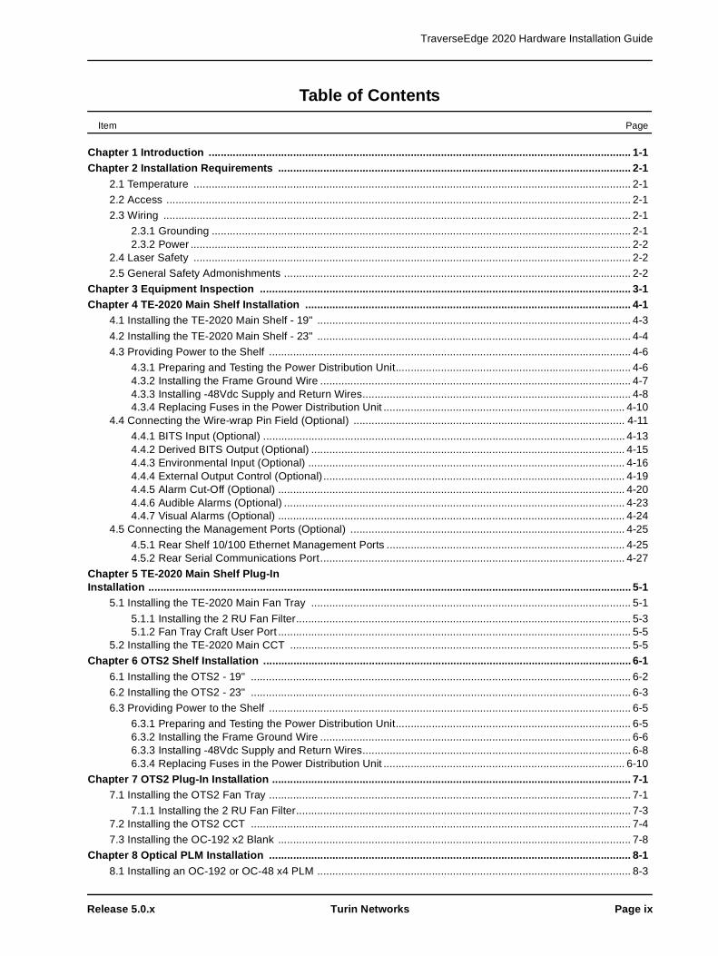
Step 3 Attach the previously prepared chassis ground wire to the Frame Ground pin. See Figure 4-5 for the Frame Ground location.
Figure 4-5 TE-2020 Main Shelf - Rear View - Connectors
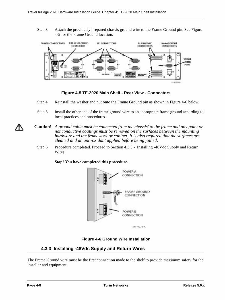
Step 4 Reinstall the washer and nut onto the Frame Ground pin as shown in Figure 4-6 below.
Step 5 Install the other end of the frame ground wire to an appropriate frame ground according to local practices and procedures.
Caution! A ground cable must be connected from the chassis' to the frame and any paint or nonconductive coatings must be removed on the surfaces between the mounting hardware and the framework or cabinet. It is also required that the surfaces are cleaned and an anti-oxidant applied before being joined.
Step 6 Procedure completed. Proceed to Section 4.3.3 - Installing -48Vdc Supply and Return Wires.
Stop! You have completed this procedure.
Figure 4-6 Ground Wire Installation
4.3.3 Installing -48Vdc Supply and Return Wires
The Frame Ground wire must be the first connection made to the shelf to provide maximum safety for the installer and equipment.

TraverseEdge 2020 Hardware Installation Guide, Chapter 4: TE-2020 Main Shelf Installation
Release 5.0.x Turin Networks Page 4-9
Warning: A suitably approved branch overcurrent protection shall be rated at minimum 60V, Max. 20A. Refer to Chapter 19 Wire Gauge, Fuse Sizes and Power Calculations for more information.
Prerequisites
The PDU must be prepared, the Frame Ground wire installed, and wire gauge calculated prior to installing the power wire.
• Section 4.1 - Installing the TE-2020 Main Shelf - 19" • Section 4.2 - Installing the TE-2020 Main Shelf - 23"
• Chapter 19 - Wire Gauge, Fuse Sizes and Power Calculations • Section 4.3.1 - Preparing and Testing the Power Distribution Unit
• Section 4.3.2 - Installing the Frame Ground Wire
Required tools and supplies
• 1/8-inch flat head screw driver
• Shielded, stranded wire in 12 AWG (refer to Chapter 19) in the appropriate colors according to local procedures and practices.
• Connectors provided in shipping package with chassis
After performing the prerequisite procedures and gathering the proper tools and supplies, follow the step-by-step procedure to install the -48Vdc supply and return wires.
Step 1 Measure the distance from the PDU to the shelf and prepare the appropriate wire by deter-mining the gauge (see Chapter 19), cutting the four wires to the proper length. Prepare the ends for attachment to the shelf (stripping back insulation approximately 1/4-inch) and PDU.
Step 2 Locate the modular power connectors shown in Figure 4-7. They are included in the pack-aging with the chassis.
Step 3 Use the flat head screwdriver to adjust the opening of the receptors (using wire clamp screws) to accept the power wires.
Step 4 Insert the previously prepared -48 volt return copper power wire into the top receptor and secure using the wire clamp screws.
Caution! It is important to ensure proper tightening of the receptor screws to prevent disrup-tion of power to the shelf.
Step 5 Insert the previously prepared -48 volt supply copper power wire into the bottom receptor and secure using the receptor adjustment screws.
Step 6 Use the flat head screwdriver to remove the plugs from the modular connector marked -48B and RTN.
Step 7 Use the flat head screwdriver to adjust the size of the receptors (using receptor adjustment screws) to accept the power wires.

TraverseEdge 2020 Hardware Installation Guide, Chapter 4: TE-2020 Main Shelf Installation
Page 4-10 Turin Networks Release 5.0.x
Step 8 Insert the previously prepared -48 volt return copper power wire into the top receptor and secure using the wire clamp screws.
Caution! It is important to ensure proper tightening of the receptor screws to prevent disrup-tion of power to the shelf.
Step 9 Insert the previously prepared -48 volt supply copper power wire into the bottom receptor and secure using the wire clamp screws.
Step 10 Reinstall the -48V removable plugs in the shelf as shown in Figure 4-7
Warning! It is extremely important to remove the fuses and verify a lack of electrical poten-tial across the PDU leads to avoid the possibility of personal injury or damage to the equipment. The fuses should only be installed later and power applied to the shelf under control of the installer.
Step 11 Screw in the retaining screws located at the rear of the connector to secure it to the shelf.
Step 12 Install the other end of the A and B power wires to the appropriate points on the Power Distribution Unit.
Step 13 Procedure completed. Proceed to Section 4.3.4 - Replacing Fuses in the Power Distribu-tion Unit.
Stop! You have completed this procedure.
Figure 4-7 Power Connectors
4.3.4 Replacing Fuses in the Power Distribution Unit
Once all of the power connections have been properly installed, the fuses should be re-installed in the PDU to provide power to the shelf.

TraverseEdge 2020 Hardware Installation Guide, Chapter 4: TE-2020 Main Shelf Installation
Release 5.0.x Turin Networks Page 4-11
Warning! It is extremely important to verify a lack of electrical potential across the PDU leads with the fuses removed. This will avoid the possibility of personal injury or damage to the equipment. The fuses should be installed later and power applied to the shelf in a controlled manner.
Prerequisites
The PDU must be prepared, the frame ground wire installed, wire gauge calculated and power wires con-nected prior to replacing fuses in the PDU.
• Section 4.1 - Installing the TE-2020 Main Shelf - 19"
• Section 4.2 - Installing the TE-2020 Main Shelf - 23" • Chapter 19 - Wire Gauge, Fuse Sizes and Power Calculations
• Section 4.3.1 - Preparing and Testing the Power Distribution Unit• Section 4.3.2 - Installing the Frame Ground Wire
• Section 4.3.3 - Installing -48Vdc Supply and Return Wires
Required tools and supplies
• Two fuses per shelf (typically 10 Amp fuses, see worksheet)
• Properly installed PDU
• Digital Multimeter (DMM)
After performing the prerequisite procedures and gathering the proper tools and supplies, follow the step-by-step procedure to replace the fuses in the PDU.
Step 1 Put an appropriately sized fuse in the PDU port to be used for the A power feed to the shelf. Install the indicator fuse for the PDU (if equipped).
Step 2 Use the DMM to verify that the voltage differential at the shelf for the -48V A connector is in the proper range (-42.5Vdc to -56.5Vdc) for the shelf.
Step 3 Put an appropriately sized fuse in the PDU port to be used for the B power feed to the shelf.
Step 4 Use the DMM to verify that the voltage differential at the shelf for the -48V B connector is in the proper range (-42.5Vdc to -56.5Vdc).
Step 5 Procedure completed. Proceed to Section 4.4 - Connecting the Wire-wrap Pin Field (Optional).
Stop! You have completed this procedure.
4.4 Connecting the Wire-wrap Pin Field (Optional)The wire-wrap pin-field is located on the back of the shelf on the right-hand side when looking at the back of the shelf, as shown in Figure 4-8. The wire-wrap posts are used for access to many functions which are described in detail in the TE-2020 Applications and Engineering Guide (WR-D2020-APP-040000).

TraverseEdge 2020 Hardware Installation Guide, Chapter 4: TE-2020 Main Shelf Installation
Page 4-12 Turin Networks Release 5.0.x
Figure 4-8 Wire-wrap Pin Field
The following sections give a specific map of the pin-field as well as brief description of the uses for each pin. Step-by-step instructions for connecting to wire-wrap pins are given for each type of wire-wrap con-nector.
All of the wire-wrap connections are optional and should be configured to match the requirements of the particular installation. Wire-wrap pins are not used on the OTS2, so all connections must be made at the TE-2020 Main Shelf.
Table 4-1 below shows the 10 x 5 pin-field with connectors (J4-J8) and pin numbers with brief definitions of their functions.
Table 4-1 Wire-wrap Pin Field Definitions
Pin 10 Pin 9 Pin 8 Pin 7 Pin 6 Pin 5 Pin 4 Pin 3 Pin 2 Pin 1
J4
Cont. Out #2
Cont. Out #1
DS1 TX Ring 1
DS1 TX Tip 1
FRMGND
Not Used
Not Used
DS1 RX Ring 1
DS1 RX Tip 1
FRMGND
J5
ACO Out
ACO In
DS1 TX Ring 2
DS1 TX Tip 2
FRMGND
Not Used
Not Used
DS1 RX Ring 2
DS1 RX Tip 2
FRMGND
J6
CR Aud. Alarm Out (–)
CR Aud. Alarm In (+)
CR Vis. Alarm Out (–)
CR Vis. Alarm In (+)
MJ Vis. Alarm Out (–)
MJ Vis. Alarm In(+)
MN Vis. Alarm Out(–)
MN Vis. Alarm In(+)
Not Used
Not Used
J7
MJ Aud. Alarm Out (–)
MJ Aud. Alarm In (+)
Env In#8
Env In#7
Env In#6
Env In#5
Env In#4
Env In#3
Env In#2
Env In#1

TraverseEdge 2020 Hardware Installation Guide, Chapter 4: TE-2020 Main Shelf Installation
Release 5.0.x Turin Networks Page 4-13
Table 4-2 below shows groupings of pins by functions, defines the number of pins, and gives a brief description of the pins and their functionality.
4.4.1 BITS Input (Optional)
The TE-2020 can use up to two DS1 BITS input sources as selectable timing references for the entire Net-work Element. These BITS sources are connected to the TE-2020 Main Shelf through wire-wrap connec-tors in the wire-wrap pin-field on the back of the shelf. Up to 5 shelves may have the BITS inputs daisy chained if local practices permit.
J8
MN Aud. Alarm Out (–)
MN Aud. Alarm In(+)
Env In#16
Env In#15
Env In#14
Env In#13
Env In#12
Env In#11
Env In#10
Env In#9
Table 4-2 Housekeeping Pin Group Function Definitions
Pin Count
Description Notes
2 BITS #1 Input Connector J4 - Pin 2 (Tip), Pin 3 (Ring) and Frame Ground (Pin 1)
2 BITS #1 Output Connector J4 - Pin 7 (Tip), Pin 8 (Ring) and Frame Ground (Pin 6)
2 BITS #2 Input Connector J5 - Pin 2 (Tip), Pin 3 (Ring) and Frame Ground (Pin 1)
2 BITS #2 Output Connector J5 - Pin 7 (Tip), Pin 8 (Ring) and Frame Ground (Pin 6)
2 Critical Alarm - Visual Connector J6 - Pin 7 (In), Pin 8 (Out)
2 Critical Alarm - Audible Connector J6 - Pin 9 (In), Pin 10 (Out)
2 Major Alarm - Visual Connector J6 - Pin 5 (In), Pin 6 (Out)
2 Major Alarm - Audible Connector J7 - Pin 9 (In), Pin 10 (Out)
2 Minor Alarm - Visual Connector J6 - Pin 3 (In), Pin 4 (Out)
2 Minor Alarm - Audible Connector J8 - Pin 9 (In), Pin 10 (Out)
16 Environmental Alarm Input Connector J7 - Pins 1-8 (Inputs 1 to 8)Connector J8 - Pins 1-8 (Inputs 9 to 16)
2 Control Output Connector J4 - Pin 9, Pin 10
2 Frame Ground Connector J4 - Pins 1 and 8 to be used for Shield for DS1 Interfaces Connector J5 - Pins 1 and 8 to be used for Shield for DS1 Interfaces
8 Not Used Connector J4 - Pins 4 and 5Connector J5 - Pins 4 and 5Connector J6 - Pins 1 and 2
1 ACO Input Connector J5 - Pin 9
1 ACO Output Connector J5 - Pin 10
Table 4-1 Wire-wrap Pin Field Definitions
Pin 10 Pin 9 Pin 8 Pin 7 Pin 6 Pin 5 Pin 4 Pin 3 Pin 2 Pin 1

TraverseEdge 2020 Hardware Installation Guide, Chapter 4: TE-2020 Main Shelf Installation
Page 4-14 Turin Networks Release 5.0.x
The BITS input pins can be connected at any time, but are generally installed at the time of initial installa-tion. The BITS input must be a DS1 format; see the TE-2020 Hardware Description Guide (WR-D2020-HWD-040000) for a description of the electrical specifications for the BITS input.
NOTE: The default status for a new CCT is to expect primary and secondary timing reference sources to be DS1 ESF BITS inputs.
Prerequisites
The shelf must be installed in the rack prior to connecting the BITS inputs.
• Section 4.1 - Installing the TE-2020 Main Shelf - 19"
• Section 4.2 - Installing the TE-2020 Main Shelf - 23"
Required tools and supplies
• Wire-wrap tool• Shielded 24 - 28 gauge solid wire
After gathering the proper tools and supplies, follow the step-by-step procedure to install the BITS inter-faces.
Step 1 If BITS inputs are not required for this installation, proceed to Section 4.4.2 - Derived BITS Output (Optional). Otherwise, continue to Step 2.
Step 2 For the primary BITS inputs, wire-wrap the wire from the corresponding BITS source “Tip” Interface to connector J4, Pin 2.
Step 3 Wire-wrap the wire from the corresponding BITS source “Ring” Interface to connector J4, Pin 3.
Step 4 Wire-wrap the Shield from the corresponding BITS source interface to the Frame Ground connector J4, Pin 1.
Step 5 If a secondary BITS input is not required skip to step 8, otherwise continue. Wire-wrap the wire from the corresponding BITS source “Tip” Interface to connector J5, Pin 2.
Step 6 Wire-wrap the wire from the corresponding BITS source “Ring” Interface to connector J5, Pin 3.
Step 7 Wire-wrap the Shield from the corresponding BITS source interface to the Frame Ground connector J5, Pin 1.
Step 8 Attach the other ends of the BITS input connector wire to the appropriate BITS source (i.e., sight clock source).
Step 9 Procedure completed. Proceed to Section 4.4.2 - Derived BITS Output (Optional).
Stop! You have completed this procedure.

TraverseEdge 2020 Hardware Installation Guide, Chapter 4: TE-2020 Main Shelf Installation
Release 5.0.x Turin Networks Page 4-15
Figure 4-9 BITS Input/Output and Frame Ground
4.4.2 Derived BITS Output (Optional)
The TE-2020 can source two DS1 derived BITS outputs to be used by other equipment at the same loca-tion. The BITS outputs are available from the TE-2020 Main Shelf through wire-wrap connectors in the wire-wrap pin-field on the back of the shelf.
The BITS output pins can be connected at any time, but are generally installed at the time of initial instal-lation. The BITS output is DS1 format, see the TE-2020 Hardware Description Guide (WR-D2020-HWD-040000) for a description of the electrical specifications for the BITS output.
Prerequisites
The shelf must be installed in the rack prior to connecting the derived BITS outputs.
• Section 4.1 - Installing the TE-2020 Main Shelf - 19"
• Section 4.2 - Installing the TE-2020 Main Shelf - 23"
Required tools and supplies
• Wire-wrap tool• Shielded 24 - 28 gauge solid wire
After gathering the proper tools and supplies, follow the step-by-step procedure to install Derived DS1 BITS output interfaces.
Step 1 If BITS outputs are not required for this installation, proceed to Section 4.4.3 - Environmental Input (Optional). Otherwise, continue to Step 2.

TraverseEdge 2020 Hardware Installation Guide, Chapter 4: TE-2020 Main Shelf Installation
Page 4-16 Turin Networks Release 5.0.x
Step 2 Wire-wrap the wire to one of the BITS source “Tip” Interfaces to connector J4, Pin 7.
Step 3 Wire-wrap the wire to one of the BITS source “Ring” Interfaces to connector J4, Pin 8.
Step 4 Wire-wrap the Shield from one of the BITS output interfaces to the Frame Ground con-nector J4, Pin 6.
Step 5 If a secondary BITS output is not required skip to step 8, otherwise continue. Wire-wrap the wire to one of the BITS source “Tip” Interfaces to connector J5, Pin 7.
Step 6 Wire-wrap the wire to one of the BITS source “Ring” Interfaces to connector J5, Pin 8.
Step 7 Wire-wrap the Shield from one of the BITS output interfaces to the Frame Ground con-nector J5 Pin 6.
Step 8 Attach the non-TE-2020 end of the BITS output connector wires to the appropriate BITS inputs on required equipment.
Step 9 Procedure completed. Proceed to Section 4.4.3 - Environmental Input (Optional).
Stop! You have completed this procedure.
4.4.3 Environmental Input (Optional)
The TE-2020 can monitor up to 16 pieces of external equipment at the same location by using the Environ-mental Input connectors. These connectors are single ended connectors that can monitor an external device for contact closure to a ground source.

TraverseEdge 2020 Hardware Installation Guide, Chapter 4: TE-2020 Main Shelf Installation
Release 5.0.x Turin Networks Page 4-17
Figure 4-10 Example External Environmental Input Configuration
The Environmental Inputs can be connected at any time, but are generally installed at the time of initial installation. See the TE-2020 Hardware Description Guide (WR-D2020-HWD-040000) for a description of the electrical specifications for the Environmental Inputs.
Prerequisites
The shelf must be installed in the rack prior to connecting the environmental inputs.
• Section 4.1 - Installing the TE-2020 Main Shelf - 19" • Section 4.2 - Installing the TE-2020 Main Shelf - 23"
Required tools and supplies

TraverseEdge 2020 Hardware Installation Guide, Chapter 4: TE-2020 Main Shelf Installation
Page 4-18 Turin Networks Release 5.0.x
• Wire-wrap tool• Shielded, 24 - 28 gauge solid wire
After gathering the proper tools and supplies, follow the step-by-step procedure to install the Environmen-tal Input interfaces.
Step 1 If External Environmental Inputs are not required for this installation, proceed to Section 4.4.4 - External Output Control (Optional). Otherwise, continue to Step 2. If fewer than 16 inputs are being utilized, skip the appropriate steps.
Step 2 Wire-wrap the wire for the first external environmental input to the Environmental Input #1 pin on connector J7, Pin 1.
Step 3 Wire-wrap the wire for the second external environmental input to the Environmental Input #2 pin on connector J7, Pin 2.
Step 4 Wire-wrap the wire for the third external environmental input to the Environmental Input #3 pin on connector J7, Pin 3.
Step 5 Wire-wrap the wire for the fourth external environmental input to the Environmental Input #4 pin on connector J7, Pin 4.
Step 6 Wire-wrap the wire for the fifth external environmental input to the Environmental Input #5 pin on connector J7, Pin 5.
Step 7 Wire-wrap the wire for the sixth external environmental input to the Environmental Input #6 pin on connector J7, Pin 6.
Step 8 Wire-wrap the wire for the seventh external environmental input to the Environmental Input #7 pin on connector J7, Pin 7.
Step 9 Wire-wrap the wire for the eigth external environmental input to the Environmental Input #8 pin on connector J7, Pin 8.
Step 10 Wire-wrap the wire for the ninth external environmental input to the Environmental Input #9 pin on connector J8, Pin 1.
Step 11 Wire-wrap the wire for the tenth external environmental input to the Environmental Input #10 pin on connector J8, Pin 2.
Step 12 Wire-wrap the wire for the eleventh external environmental input to the Environmental Input #11 pin on connector J8, Pin 3.
Step 13 Wire-wrap the wire for the twelfth external environmental input to the Environmental Input #12 pin on connector J8, Pin 4.
Step 14 Wire-wrap the wire for the thirteenth external environmental input to the Environmental Input #13 pin on connector J8, Pin 5.

TraverseEdge 2020 Hardware Installation Guide, Chapter 4: TE-2020 Main Shelf Installation
Release 5.0.x Turin Networks Page 4-19
Step 15 Wire-wrap the wire for the fourteenth external environmental input to the Environmental Input #14 pin on connector J8, Pin 6.
Step 16 Wire-wrap the wire for the fifteenth external environmental input to the Environmental Input #15 pin on connector J8, Pin 7.
Step 17 Wire-wrap the wire for the sixteenth external environmental input to the Environmental Input #16 pin on connector J8, Pin 8.
Step 18 Attach the other end of the Environmental Input connector wires to the appropriate equip-ment connectors.
Step 19 Procedure completed. Proceed to Section 4.4.4 - External Output Control (Optional).
Stop! You have completed this procedure.
Figure 4-11 Environment Input Pins
4.4.4 External Output Control (Optional)
The TE-2020 can control up to two pieces of external equipment at the same location by using the external output control connectors. These connectors are single ended connectors that can control an external device by changing from an open circuit to a connection to ground.
The External Output Controls can be connected at any time, but are generally installed at the time of initial installation. See the TE-2020 Hardware Description Guide (WR-D2020-HWD-040000) for a description of the electrical specifications for the external output controls.
Prerequisites
The shelf must be installed in the rack prior to connecting the external output control inputs.

TraverseEdge 2020 Hardware Installation Guide, Chapter 4: TE-2020 Main Shelf Installation
Page 4-20 Turin Networks Release 5.0.x
• Section 4.1 - Installing the TE-2020 Main Shelf - 19" • Section 4.2 - Installing the TE-2020 Main Shelf - 23"
Required tools and supplies
• Wire-wrap tool
• Shielded 24 to 28 gauge wire
After gathering the proper tools and supplies, follow the step-by-step procedure to install the Environmen-tal Input interfaces. If no external controls are used or less than two are used, the associated steps below can be skipped.
Step 1 If External Output Controls are not required for this installation, proceed to Section 4.4.5 - Alarm Cut-Off (Optional). Otherwise, continue to Step 2.
Step 2 Wire-wrap the wire for the first external control to the External Output Control #1 pin on connector J4, Pin 9.
Step 3 Wire-wrap the wire for the second external control to the External Output Control #2 pin on connector J4, Pin 10.
Step 4 Attach the other end of the External Output Control connector wires to the appropriate equipment connectors.
Step 5 Procedure completed. Proceed to Section 4.4.5 - Alarm Cut-Off (Optional).
Stop! You have completed this procedure.
Figure 4-12 External Output Control Pins
4.4.5 Alarm Cut-Off (Optional)
The TE-2020 can silence the audible alarms for critical, major and minor alarms by an external piece of

TraverseEdge 2020 Hardware Installation Guide, Chapter 4: TE-2020 Main Shelf Installation
Release 5.0.x Turin Networks Page 4-21
equipment at the same location by using the Alarm Cut-Off (ACO) feature. This ACO interface is a single ended connector that is controlled by an external device by changing from an open circuit to a closed cir-cuit to ground. If the external circuit is open, a normal state exists. If the circuit is grounded (closed), then the environmental alarm is sounded.
This function is also available by pressing the ACO button on the front of the fan tray on the TE-2020 Main Shelf. The Alarm Cut-Off can be connected at any time, but is generally installed at the time of initial installation. See the TE-2020 Hardware Description Guide (WR-D2020-HWD-040000) for a description of the electrical specifications for the ACO interface.
An ACO output is also provided so the purchaser may have a remote indication that an ACO has been acti-vated. In this instance, the ACO Out would be wired to a remote alarm panel of some sort.
Prerequisites
The shelf must be installed in the rack prior to connecting the ACO connections.
• Section 4.1 - Installing the TE-2020 Main Shelf - 19"
• Section 4.2 - Installing the TE-2020 Main Shelf - 23"
Required tools and supplies
• Wire-wrap tool• Shielded 24 to 28 gauge wire.
After gathering the proper tools and supplies, follow the step-by-step procedure to install the Alarm Cut-Off interface.
Step 1 If Alarm Cut-Off is not required for this installation, proceed to Section 4.4.6 - Audible Alarms (Optional). Otherwise, continue to Step 2.
Step 2 Wire-wrap the wire for the output from ACO to the Alarm Cut-Off Input pin on connector J5, Pin 9.
Step 3 Attach the other end of the Alarm Cut-Off connector wire to the appropriate equipment connectors.
Step 4 To connect the ACO Out to a remote alarm panel, wire-wrap the wire for the remote alarm panel to the Alarm Cut-Off Output pin on connector J5, Pin 10.
Step 5 Attach the other end of the Alarm Cut-Off Output connector wire to the appropriate alarm panel equipment connectors.
Step 6 Procedure completed. Proceed to Section 4.4.6 - Audible Alarms (Optional).

TraverseEdge 2020 Hardware Installation Guide, Chapter 4: TE-2020 Main Shelf Installation
Page 4-22 Turin Networks Release 5.0.x
Stop! You have completed this procedure.
Figure 4-13 Alarm Cut-Off Control Pins

TraverseEdge 2020 Hardware Installation Guide, Chapter 4: TE-2020 Main Shelf Installation
Release 5.0.x Turin Networks Page 4-23
4.4.6 Audible Alarms (Optional)
The TE-2020 can trigger an audible alarm for critical, major and minor alarms to an external piece of equipment at the same location by using the audible alarm connectors. Each of these alarm interfaces com-prises dual ended connectors that can control an external device by changing from an open circuit to a closed circuit between the input and output pins.
The audible alarms can be connected at any time, but are generally installed at the time of initial installa-tion. See the TE-2020 Hardware Description Guide (WR-D2020-HWD-040000) for a description of the electrical specifications for the audible alarm interfaces.
Prerequisites
The shelf must be installed in the rack prior to connecting the Audible Alarms connections.
• Section 4.1 - Installing the TE-2020 Main Shelf - 19"
• Section 4.2 - Installing the TE-2020 Main Shelf - 23"
Required tools and supplies
• Wire-wrap tool• Shielded 24 to 28 gauge wire
After gathering the proper tools and supplies, follow the step-by-step procedure to install the audible alarm interfaces. If no audible alarm controls are used or less than three are used, the associated steps below can be skipped.
Step 1 If audible alarms are not required for this installation, proceed to Section 4.4.7 - Visual Alarms (Optional). Otherwise, continue to Step 2.
Step 2 Wire-wrap the wire from the output of the minor audible alarm source to the Minor Audi-ble Alarm Input pin on connector J8, Pin 9.
Step 3 Wire-wrap the wire to the minor audible alarm source (or ground source) to the Minor Audible Alarm Output pin on connector J8, Pin 10.
Step 4 Wire-wrap the wire from the output of the major audible alarm source to the Major Audi-ble Alarm Input pin on connector J7, Pin 9.
Step 5 Wire-wrap the wire to the major audible alarm source (or ground source) to the Major Audible Alarm Output pin on connector J7, Pin 10.
Step 6 Wire-wrap the wire from the output of the critical audible alarm source to the Critical Audible Alarm Input pin on connector J6, Pin 9.
Step 7 Wire-wrap the wire to the critical audible alarm source (or ground source) to the Critical Audible Alarm Output pin on connector J6, Pin 10.

TraverseEdge 2020 Hardware Installation Guide, Chapter 4: TE-2020 Main Shelf Installation
Page 4-24 Turin Networks Release 5.0.x
Step 8 Attach the other end of the audible alarm connector wires to the appropriate equipment connectors.
Step 9 Proceed to Section 4.4.7 - Visual Alarms (Optional).
Stop! You have completed this procedure.
Figure 4-14 Alarm Control Pins
4.4.7 Visual Alarms (Optional)
The TE-2020 can trigger a visual alarm for critical, major and minor alarms to an external piece of equip-ment at the same location by using the visual alarm connectors. Each of these alarm interfaces comprises dual ended connectors that can control an external device by changing from an open circuit to a closed cir-cuit between the input and output pins.
The visual alarms can be connected at any time, but are generally installed at the time of initial installation. See the TE-2020 Hardware Description Guide (WR-D2020-HWD-040000) for a description of the electri-cal specifications for the visual alarm interfaces.
Prerequisites
The shelf must be installed in the rack prior to connecting the visual alarm connections.
• Section 4.1 - Installing the TE-2020 Main Shelf - 19"
• Section 4.2 - Installing the TE-2020 Main Shelf - 23"
Required tools and supplies

TraverseEdge 2020 Hardware Installation Guide, Chapter 4: TE-2020 Main Shelf Installation
Release 5.0.x Turin Networks Page 4-25
• Wire-wrap tool• Shielded 24 to 28 gauge wire
After gathering the proper tools and supplies, follow the step-by-step procedure to install the Visual Alarm interfaces. If no alarm contacts are used or less than three are used, the associated steps below can be skipped.
Step 1 If visual alarms are not required for this installation, proceed to Section 4.5 - Connecting the Management Ports (Optional). Otherwise, continue to Step 2.
Step 2 Wire-wrap the wire from the output of the minor visual alarm source to the Minor Visual Alarm Input pin on connector J6, Pin 3.
Step 3 Wire-wrap the wire back to the input of the minor visual alarm source (or ground source) to the Minor Visual Alarm Output pin on connector J6, Pin 4.
Step 4 Wire-wrap the wire from the output of the major visual alarm source to the Major Visual Alarm Input pin on connector J6, Pin 5.
Step 5 Wire-wrap the wire back to the input of the major visual alarm source (or ground source) to the Major Visual Alarm Output pin on connector J4, Pin 6.
Step 6 Wire-wrap the wire from the output of the critical visual alarm to the Critical Visual Alarm Input pin on connector J6, Pin 7.
Step 7 Wire-wrap the wire back to the input of the critical visual alarm (or ground source) to the Critical Visual Alarm Output pin on connector J6, Pin 8.
Step 8 Attach the other end of the visual alarm connector wires to the appropriate equipment con-nectors.
Step 9 Procedure completed. Proceed to Section 4.5 - Connecting the Management Ports (Optional).
Stop! You have completed this procedure.
4.5 Connecting the Management Ports (Optional)The TE-2020 has four external management ports in addition to the internal DCC management channel. On the front of the fan tray there is an Ethernet port in a form of an RJ-45 connector. On the back are two Ethernet 10/100 ports and a DB-9 RS-232 serial interface port. For additional information on the manage-ment ports, see the TE-2020 Hardware Description Guide (WR-D2020-HWD-040000).
4.5.1 Rear Shelf 10/100 Ethernet Management Ports
The management ports on the rear of the TE-2020 are primarily used for:
• Connection to EMS/NMS Systems• TN-Relay™ Feature

TraverseEdge 2020 Hardware Installation Guide, Chapter 4: TE-2020 Main Shelf Installation
Page 4-26 Turin Networks Release 5.0.x
• TE-2020 Node Management Interconnection Through External DCN
For each of these applications, the installation procedure is the same. Software configuration of the node will define the functionality of each port. The exact pinout of the RJ-45 connectors is shown in Table 4-3 .
Prerequisites
The TE-2020 Main Shelf must be installed prior to performing this procedure. Refer to the appropriate pro-cedure listed below.
• Section 4.1 - Installing the TE-2020 Main Shelf - 19" • Section 4.2 - Installing the TE-2020 Main Shelf - 23"
Required tools and supplies
• Standard Ethernet Cable
After performing the prerequisite procedures and gathering the proper tools and supplies, follow the step-by-step procedure to install the rear communications cable.
Step 1 Insert one male RJ-45 connector from the standard Ethernet cable into the top RJ-45 female connector on the rear of the shelf (R1). Refer to Figure 4-15. Insert the opposite end into the appropriate hub, switch, or other Ethernet device.
Step 2 If an additional Ethernet connection is required, insert one male RJ-45 connector from the standard Ethernet cable into the bottom RJ-45 female connector on the rear of the shelf (R2). Insert the opposite end into the appropriate hub, switch, or other Ethernet device.
Table 4-3 Rear Management RJ-45 Port Pinouts
Pin # Function Description
1 Ethernet Ethernet Transmit Pos
2 Ethernet Ethernet Transmit Neg
3 Ethernet Ethernet Receive Pos
6 Ethernet Ethernet Receive Neg

TraverseEdge 2020 Hardware Installation Guide, Chapter 4: TE-2020 Main Shelf Installation
Release 5.0.x Turin Networks Page 4-27
Step 3 Procedure completed. Proceed to Chapter 5 TE-2020 Main Shelf Plug-In Installation.
Figure 4-15 Rear Management Ports
Stop! You have completed this procedure.
4.5.2 Rear Serial Communications Port
A serial communications port is provided at the rear of the shelf between the two Ethernet ports. Refer to Figure 4-16. This is a male DB-9 sub-miniature connection that may be used with a “straight-through” cable to connect to a users laptop computer. Using a “roll-over” cable the user can connect a modem to the serial interface port to remotely access the system. Refer to the TE-2020 Ordering Guide (WR-D2020-ORD-000000) for cable part numbers and ordering information.
Figure 4-16 Rear Serial Interface Port
Prerequisites
The TE-2020 Main Shelf must be installed prior to performing this procedure. Refer to the appropriate procedure listed below.
• Section 4.1 - Installing the TE-2020 Main Shelf - 19" • Section 4.2 - Installing the TE-2020 Main Shelf - 23"
Required tools and supplies
• Standard User Interface DB-9 “Straight-Through” cable

TraverseEdge 2020 Hardware Installation Guide, Chapter 4: TE-2020 Main Shelf Installation
Page 4-28 Turin Networks Release 5.0.x
After performing the prerequisite procedures and gathering the proper tools and supplies, follow the step-by-step procedure to install the rear communications cable.
Step 1 Insert one female DB-9 connector from the user interface cable into the male connector on the rear of the shelf.
Step 1 Insert the opposite end into the appropriate computer interface, or other interface device (modem, etc.).
Stop! You have completed this procedure.

Release 5.0.x Turin Networks Page 5-1
Chapter 5 TE-2020 Main Shelf Plug-In Installation
Although the TE-2020 Main Shelf comes in 19” and 23” versions, the plug-ins for both are identical. There are three main types of plug-in modules for each of these shelves as shown in Figure 5-1.
• Fan Tray Plug-in• Common Control and Timing (CCT) Plug-ins
• Various Physical Layer Module (PLM) Plug-ins (covered in Chapter 8)
The sections below briefly discuss the appropriate plug-in modules for the TE-2020 Main Shelf and give step-by-step instructions on how to properly install each module.
Figure 5-1 TE-2020 Main Shelf Assembly
5.1 Installing the TE-2020 Main Fan TrayThe fan tray is required in every TE-2020 Main Shelf. It provides forced air cooling to maintain an appro-priate system temperature within the shelf and to the components on the boards.
The TE-2020 Main Fan Tray is shown in Figure 5-2 below. It is a single unit with multiple individual fans. A single fan can fail and the remaining fans will continue to work, allowing time for a service technician to

TraverseEdge 2020 Hardware Installation Guide, Chapter 5: TE-2020 Main Shelf Plug-In Installation
Page 5-2 Turin Networks Release 5.0.x
replace the fan tray.
Figure 5-2 TE-2020 Main Fan Tray
The following step-by-step procedure details the tasks required to complete the installation of a TE-2020 Main Fan Tray.
Prerequisites
The TE-2020 Main Shelf must be installed prior to performing this procedure. Refer to the appropriate pro-cedure below for shelf installation.
• Section 4.1 - Installing the TE-2020 Main Shelf - 19"
• Section 4.2 - Installing the TE-2020 Main Shelf - 23"

TraverseEdge 2020 Hardware Installation Guide, Chapter 5: TE-2020 Main Shelf Plug-In Installation
Release 5.0.x Turin Networks Page 5-3
Caution! Electrostatic Discharge (ESD) sensitive devices. ESD can cause catastrophic fail-ure or degraded life and performance of a device. Use an anti-static wrist strap connected to a properly grounded source before contacting any electronic devices.
Step 1 Verify the part number of the TE-2020 Main Fan Tray prior to installation. The part num-ber should be WR-PFAN0-004-00000.
Step 2 Verify that the 2 RU Fan Filter (part number WR-PFLTR-002-00000) is in the Fan Tray to the left of the fans if facing the front of the fan tray.
Step 3 Insert the TE-2020 Main Fan Tray into the left side of the TE-2020 Main Shelf.
Step 4 Pull the ejector handle down so the unit can slide fully into the shelf.
Step 5 Push the fan tray into the shelf until resistance is met (approximately 1-inch from back of shelf).
Warning! If excessive resistance is met, remove the unit and check for obstructions, bent pins or bent metal. Do not force the fan into place if excessive resistance is felt.
Step 6 Use the ejector handle to fully seat the module.
NOTE: If no other equipment is installed in the shelf (i.e. CCTs, PLMs), then no LEDs should illu-minate on the Fan Tray. If CCTs (with or without PLMs) are already installed, the LEDs will reflect the status of the system within a few minutes.
Step 7 Procedure completed. Proceed to Section 5.2 - Installing the TE-2020 Main CCT.
Stop! You have completed this procedure.
5.1.1 Installing the 2 RU Fan Filter
The TE-2020 Main Fan Tray is shipped with the 2 RU Fan Filter (WR-PFLTR-002-00000) already installed, and runs the length of the fan tray in-between the fans and the air intake as shown in Figure 5-4. The filter is designed for optimal performance in the shelf and only this filter should be used. The fan filter will need to be changed every six months. If for some reason the filter becomes dislodged during shipment or is being replaced as part of periodic maintenance practices, the following step-by-step procedure details the tasks required to complete the installation of a 2 RU Fan Filter.
Caution! Electrostatic Discharge (ESD) sensitive devices. ESD can cause catastrophic fail-ure or degraded life and performance of a device. Use an anti-static wrist strap connected to a properly grounded source before contacting any electronic devices.
Step 1 Observe the frame of the filter, primarily the text that informs the installer the direction of the airflow. Refer to Figure 5-3.

TraverseEdge 2020 Hardware Installation Guide, Chapter 5: TE-2020 Main Shelf Plug-In Installation
Page 5-4 Turin Networks Release 5.0.x
Figure 5-3 Air Filter Directional Indicator
Step 2 Insert the 2 RU Fan Filter into the bottom of the TE-2020 Main Fan Tray until it locks into place under tension. Ensure that the arrow on the frame points towards the fans.
Figure 5-4 TE-2020 Main Fan Tray with 2 RU Fan Filter
Stop! You have completed this procedure.

TraverseEdge 2020 Hardware Installation Guide, Chapter 5: TE-2020 Main Shelf Plug-In Installation
Release 5.0.x Turin Networks Page 5-5
5.1.2 Fan Tray Craft User Port
The management port on the front of the TE-2020 fan tray is primarily used for local craftperson access, not for permanent installation. The front user interface port can be accessed directly using a standard Ethernet cable (or by using a Turin Networks cable, part number WR-CUSPT-002-00000). The exact pinout of the RJ-45 connector is shown in Table 5-1
Prerequisites
The TE-2020 Main Shelf and Fan Tray must be installed prior to performing this procedure. Refer to the appropriate procedure below for fan tray installation.
• Section 4.1 - Installing the TE-2020 Main Shelf - 19"
• Section 4.2 - Installing the TE-2020 Main Shelf - 23"• Section 5.1 - Installing the TE-2020 Main Fan Tray
Required tools and supplies
• Standard straight through wiring Ethernet cable
After performing the prerequisite procedures and gathering the proper tools and supplies, follow the step-by-step procedure to install the front communications cable.
Step 1 If an Ethernet connection is required (either direct or crossover), insert one end of the standard RJ-45 cable into the RJ-45 female connector on the Fan Tray and insert the oppo-site end into the appropriate hub or other device. This completes the Front Management Port installation for Ethernet.
Step 2 Procedure completed. Proceed to Section 5.2 - Installing the TE-2020 Main CCT.
Stop! You have completed this procedure.
5.2 Installing the TE-2020 Main CCTThe TE-2020 Main Shelf has slots for two TE-2020 Main Shelf Common Control and Timing (CCT) mod-ules. Each CCT has two slots for installing various optical Physical Layer Modules (PLMs). The CCTs may be installed in any order, but they should be installed prior to installing any PLMs.
The TE-2020 Main CCT may additionally be equipped with an Optical PLM Blank. This blank PLM is
Table 5-1 Front Management RJ-45 Port Pinout
Pin # Function Description
1 Ethernet Ethernet Transmit Pos
2 Ethernet Ethernet Transmit Neg
3 Ethernet Ethernet Receive Pos
6 Ethernet Ethernet Receive Neg

TraverseEdge 2020 Hardware Installation Guide, Chapter 5: TE-2020 Main Shelf Plug-In Installation
Page 5-6 Turin Networks Release 5.0.x
meant to maintain a sealed environment for the shelf to ensure proper air flow in the event that all slots are not initially populated with real PLMs.
Warning! A TE-2020 Main Fan Tray must be installed prior to installation of any shelf mod-ules (CCTs, PLMs).
Warning! Failure to equip all empty slots with blank PLMs may result in system failure due to lack of proper air flow.
Caution! Electrostatic Discharge (ESD) sensitive devices. ESD can cause catastrophic fail-ure or degraded life and performance of a device. Use an anti-static wrist strap connected to a properly grounded source before contacting any electronic devices.
Step 1 Verify the part number of the TE-2020 Main CCT prior to installation. The part number should be one of the versions defined below.
Step 2 Partially insert the upper TE-2020 Main CCT into the TE-2020 Main Shelf using the guides. Refer to Figure 5-5.
Figure 5-5 Installing a TE-2020 Main CCT
Table 5-1 Main SHelf CCT Part Numbers
Part Number Description
WR-PCCT0-0A4-00000, New ASIC CCT must have a special sofware load to work
WR-PCCTV-004-00000, TE-2020 Enhanced Main CCT
WR-PCCTV-024-00000, TE-2020 Main CCT w/2.5G VT Fabric
WR-PCCTV-054-00000, TE-2020 Main CCT w/5G VT Fabric

TraverseEdge 2020 Hardware Installation Guide, Chapter 5: TE-2020 Main Shelf Plug-In Installation
Release 5.0.x Turin Networks Page 5-7
Step 3 The CCTs are comprised of two stage ejector ears. Using both pointer fingers, pull the ejector ear tabs away from the ejectors towards the center of the shelf and hold in place (spring loaded tabs will return to resting position otherwise). Refer to Figure 5-6.
Figure 5-6 Extending Ejector Ear Tabs
Step 4 With the ejector ear tabs fully extended, hold them and pull them away from the center of the CCT. This will cause the ejectors to fully open allowing for insertion into the shelf. Refer to Figure 5-7.
Figure 5-7 Rotating CCT Ejector Ear Tabs

TraverseEdge 2020 Hardware Installation Guide, Chapter 5: TE-2020 Main Shelf Plug-In Installation
Page 5-8 Turin Networks Release 5.0.x
Step 5 Push the CCT into the shelf until resistance is met. Ensure that the ejector ears are inserted far enough into the shelf that they bite onto the rail as shown in Figure 5-8.
Figure 5-8 Seating the CCT Card Ejector Ear
Step 6 Pull the ejector ear tabs toward the center of the card to seat it into the backplane as shown in Figure 5-9.
Warning! Do not force the CCT into place. If excessive resistance is met, remove the unit and check for obstructions, bent pins, or bent metal. Repair any problems if found and try again.
Figure 5-9 Fully Seating the CCT into the Backplane

TraverseEdge 2020 Hardware Installation Guide, Chapter 5: TE-2020 Main Shelf Plug-In Installation
Release 5.0.x Turin Networks Page 5-9
Step 7 When the card is fully seated into the shelf, either the upper (U) or lower (L) CCT LED on the TE-2020 Main Fan Tray will illuminate. Refer to Figure 5-10 for LED locations). They will alternate colors during the card boot cycle and eventually (3-4 minutes depend-ing on system configuration) settle to green when the card is properly installed and fully booted. If the light does not turn green, an error has occurred and the card should be removed and both the shelf and CCT should be inspected. Return to Step 1 with either a new CCT or the original CCT with the problem repaired.
NOTE: The NE Status LED will reflect the status of the NE. On initial installation, this LED will turn red if the BITS inputs are not connected. The default status for a new CCT is to expect primary and secondary timing reference sources to be DS1 ESF BITS inputs. The red LED can be cleared by either connecting the DS1 BITS inputs or updating the shelf configuration.
Figure 5-10 TE-2020 Main Fan Tray LEDs
Step 8 If another CCT is to be installed, return to Step 1. If both CCTs are already installed, pro-ceed to Step 7. If only a single CCT will be installed, continue with Step 7.
Step 9 Required CCTs should be installed and the upper and lower LEDs on the Main Shelf Fan Tray should be green. Proceed to Chapter 8 Optical PLM Installation.
Stop! You have completed this procedure.

TraverseEdge 2020 Hardware Installation Guide, Chapter 5: TE-2020 Main Shelf Plug-In Installation
Page 5-10 Turin Networks Release 5.0.x

TraverseEdge 2020 Hardware Installation Guide, Chapter 6: OTS2 Shelf Installation
Release 5.0.x Turin Networks Page 6-1
Chapter 6 OTS2 Shelf Installation
There are two versions of the OTS2 meant for installation requirements in different width racks. The WR-TOPT2-001-00000 is meant to be installed in a 19" channel rack or similar rack that does not inhibit the exhaust air flow into or out of the shelf. The 19" shelf is designed to be flush mounted to the front of a channel rack as shown in Figure 6-1.
Figure 6-1 OTS2 - 19"
The WR-TOPT2-002-00000 is designed for installation in a standard 23" network bay. The 23" shelf dif-fers from the 19" shelf in that it has integral air flow management extensions attached at the factory. Refer to Figure 6-2. The extension on the left side of the shelf (air intake side) is for extending the width of the shelf and also serves as a duct for directing additional air into the fan unit. The extension on the right side of the shelf (air exhaust side) is for extending the width of the shelf and also directs the exhaust air flow to the back of the shelf. This design does not impose any limitations on the mounting position or type of 23" network bay used for installation.
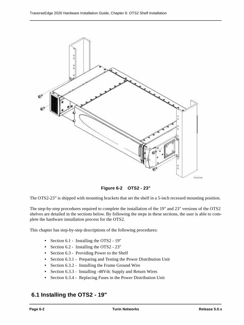
TraverseEdge 2020 Hardware Installation Guide, Chapter 6: OTS2 Shelf Installation
Page 6-2 Turin Networks Release 5.0.x
Figure 6-2 OTS2 - 23"
The OTS2-23” is shipped with mounting brackets that set the shelf in a 5-inch recessed mounting position.
The step-by-step procedures required to complete the installation of the 19" and 23" versions of the OTS2 shelves are detailed in the sections below. By following the steps in these sections, the user is able to com-plete the hardware installation process for the OTS2.
This chapter has step-by-step descriptions of the following procedures:
• Section 6.1 - Installing the OTS2 - 19"
• Section 6.2 - Installing the OTS2 - 23"• Section 6.3 - Providing Power to the Shelf
• Section 6.3.1 - Preparing and Testing the Power Distribution Unit • Section 6.3.2 - Installing the Frame Ground Wire
• Section 6.3.3 - Installing -48Vdc Supply and Return Wires • Section 6.3.4 - Replacing Fuses in the Power Distribution Unit
6.1 Installing the OTS2 - 19"

TraverseEdge 2020 Hardware Installation Guide, Chapter 6: OTS2 Shelf Installation
Release 5.0.x Turin Networks Page 6-3
The OTS2 is shipped empty and should be installed empty to avoid damage to plug-in cards. For a descrip-tion of the OTS2 shelf, refer to the TE-2020 Hardware Description Guide (WR-D2020-HWD-040000).
The following step-by-step procedure details the tasks required to complete the installation of a OTS2 - 19".
Required tools and supplies
• 1/4-inch Phillips-head or flat head screw driver• 4 mounting screws (provided with the shelf)
Step 1 If a 23" version of the OTS2 is required, proceed to Section 6.2 - Installing the OTS2 - 23".
Step 2 Verify shelf width and part number for the OTS2 - 19", WR-TOPT2-001-00000.
Step 3 Verify that the location for OTS2 installation is free of obstructions, has available power from the shelf PDU, and has the proper mounting holes.
Warning! Care should be taken not to compromise the stability of the rack by the installation of this equipment.
Step 4 Mount the OTS2 to the rack using four screws, two on each side of the chassis as shown in Figure 6-1.
Step 5 Verify that the front-left and left side air intake vents and right side exhaust vent of the shelf are free of obstructions, allowing for proper air flow through the 19" chassis.
Step 6 Procedure completed. Proceed to Section 6.3 - Providing Power to the Shelf.
Stop! You have completed this procedure.
6.2 Installing the OTS2 - 23" The OTS2-23” is shipped empty and should be installed empty to avoid damage to plug-in cards. For a description of the OTS2, see the TE-2020 Hardware Description Guide (WR-D2020-HWD-040000).
The following step-by-step procedure details the tasks required to complete the installation of a OTS2 - 23".
Required tools and supplies
• 1/4-inch Phillips-head or flat head screw driver• 4 mounting screws (provided with the shelf)
Step 1 Verify shelf width and part number for the OTS2 - 23", WR-TOPT2-002-00000.

TraverseEdge 2020 Hardware Installation Guide, Chapter 6: OTS2 Shelf Installation
Page 6-4 Turin Networks Release 5.0.x
Step 2 Verify that the installation location is free of obstructions, has available power from the shelf PDU and has the proper mounting holes.
Warning! Care should be taken not to compromise the stability of the rack by the installation of this equipment.
Step 3 Mount the OTS2 to the rack using four screws, two on each side of the chassis as shown in Figure 6-2.
Step 4 Verify that the left side air intake vents and right-rear side exhaust vent of the shelf are free of obstruction, allowing for proper air flow through the 23" chassis.
Chassis filters may be used on 23” rack mount applications when environmental conditions dictate higher filtration requirements for the equipment (environments exceeding GR-63 specifications for environmen-tally controlled spaces). The chassis filters are pptional for these conditions and not part of a standard 23” chassis assembly. If ordered, follow these steps for installation.
Step 5 The chassis filter attaches to the left front corner of the chassis, covering the additional shelf spacer for 23” rack applications. Refer to Figure 6-3 Small metal retaining clips hold the chassis filter securly to the chassis. Refer to Figure 6-4
Figure 6-3 Chassis Filter Location

TraverseEdge 2020 Hardware Installation Guide, Chapter 6: OTS2 Shelf Installation
Release 5.0.x Turin Networks Page 6-5
Figure 6-4 Chassis Filter Removed
NOTE: The next step is optional.
Step 6 Install the chassis filter (WR-KFLTR-2RU-00000) on the left side of the chassis as shown in Figure 6-3 by snapping the filter onto the chassis.
Step 7 Procedure completed. Proceed to Section 6.3 - Providing Power to the Shelf.
Stop! You have completed this procedure.
6.3 Providing Power to the ShelfThe OTS2 has redundant -48Vdc supply and return power connectors on the rear of the shelf. These two connectors are labeled (-48A, RTN) and (-48B, RTN). To install redundant power feeds, four power cables and one ground cable are required (see Chapter 19 Wire Gauge, Fuse Sizes and Power Calculations for information on determining wire gauge). Use only copper conductors for shelf power. The Frame Ground is located next to the two power connectors and is a threaded #6 connector pin with an installation nut and washer pre-installed.
Danger! Disconnect power from the source before connecting any of the power feed wires.
Warning! It is important to attach the Frame Ground wire to the shelf before attaching any of the other power connectors.
Caution! Always use insulated tools and extreme caution when working with power connec-tors. Do not allow tools, wires or any metal objects to come in contact with more than one terminal at a time.
6.3.1 Preparing and Testing the Power Distribution Unit
All power feeds that are supplied to any of the shelves must be individually fused and wired for each shelf. See Chapter 19 Wire Gauge, Fuse Sizes and Power Calculations for information on selecting fuse size. This procedure for configuring the Power Distribution Unit (PDU) will result in fully tested power distri-

TraverseEdge 2020 Hardware Installation Guide, Chapter 6: OTS2 Shelf Installation
Page 6-6 Turin Networks Release 5.0.x
bution through the PDU.
Prerequisites
The PDU must be installed according to manufacturers recommendations and local procedures and prac-tices. The proper fuse size must be calculated prior to preparing and testing the PDU.
• Section 6.1 - Installing the OTS2 - 19"• Section 6.2 - Installing the OTS2 - 23"
• Chapter 19 - Wire Gauge, Fuse Sizes and Power Calculations
Required tools and supplies
• Two appropriately sized fuses • Properly installed Power Distribution Unit (PDU)
• Digital Multimeter (DMM)• Copper conductors
After performing the prerequisite procedures and gathering the proper tools and supplies, follow the step-by-step procedure to prepare the PDU. Because PDUs vary based on manufacturer, the following proce-dure provides general guidelines that should apply for all PDUs.
Step 1 Put appropriately sized fuses in the two PDU ports to be used for the A and B power feeds to the shelf.
Step 2 Use the DMM to verify that the voltage differential at the outputs of the PDU is in the proper range (-42.5Vdc to -56.5Vdc) for the shelf.
Step 3 Remove A and B feed fuses from the PDU.
Step 4 Use the DMM to verify that the voltage differential at the outputs of the PDU is zero.
Warning! It is extremely important to remove the fuses and verify a lack of electrical poten-tial across the PDU leads and to avoid the possibility of personal injury or damage to the equipment. The fuses should only be installed later and power applied to the shelf in a controlled manner.
Step 5 Procedure completed. Proceed to Section 6.3.2 - Installing the Frame Ground Wire.
Stop! You have completed this procedure.
6.3.2 Installing the Frame Ground Wire
The frame ground wire must be the first connection made to the shelf to provide maximum safety for the installer and equipment.
Prerequisites
The shelf must be installed and wire gauge calculated prior to installing the frame ground wire.
• Section 6.1 - Installing the OTS2 - 19"

TraverseEdge 2020 Hardware Installation Guide, Chapter 6: OTS2 Shelf Installation
Release 5.0.x Turin Networks Page 6-7
• Section 6.2 - Installing the OTS2 - 23" • Chapter 19 - Wire Gauge, Fuse Sizes and Power Calculations
• Section 6.3.1 - Preparing and Testing the Power Distribution Unit
Required tools and supplies
• Insulated, 1/4-inch, open ended wrench
• Insulated, stranded wire in 12 AWG (refer to Chapter 19) in the appropriate color according to local procedures and practices.
After performing the prerequisite procedures and gathering the proper tools and supplies, follow the step-by-step procedure to install the frame ground wire.
Step 1 Measure the distance from the rack Frame Ground to the shelf and prepare the appropriate wire by determining the gauge (see Chapter 19), cutting the wire to the proper length, and preparing the ends for attachment to the shelf (appropriately sized #6 lug) and building ground.
Step 2 The shelf has a threaded frame ground pin on the back with a nut and washer pre-installed. Remove this nut and washer from the Frame Ground pin. Refer to Figure 6-5.
Step 3 Attach the previously prepared chassis ground wire to the Frame Ground pin. See Figure 6-5 for the Frame Ground location.
Figure 6-5 TE-2020 Main Shelf - Rear View - Connectors
Step 4 Reinstall the washer and nut onto the Frame Ground pin as shown in Figure 6-6 below.
Step 5 Install the other end of the frame ground wire to an appropriate frame ground according to local practices and procedures.
Caution! A ground cable must be connected from the chassis' to the frame and any paint or nonconductive coatings must be removed on the surfaces between the mounting hardware and the framework or cabinet. It is also required that the surfaces are cleaned and an anti-oxidant applied before being joined.
Step 6 Procedure completed. Proceed to Section 6.3.3 - Installing -48Vdc Supply and Return Wires.
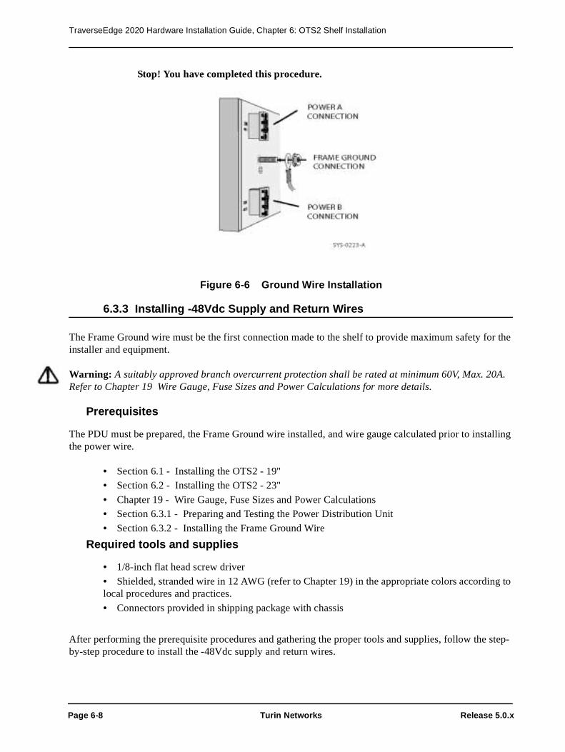
TraverseEdge 2020 Hardware Installation Guide, Chapter 6: OTS2 Shelf Installation
Page 6-8 Turin Networks Release 5.0.x
Stop! You have completed this procedure.
Figure 6-6 Ground Wire Installation
6.3.3 Installing -48Vdc Supply and Return Wires
The Frame Ground wire must be the first connection made to the shelf to provide maximum safety for the installer and equipment.
Warning: A suitably approved branch overcurrent protection shall be rated at minimum 60V, Max. 20A. Refer to Chapter 19 Wire Gauge, Fuse Sizes and Power Calculations for more details.
Prerequisites
The PDU must be prepared, the Frame Ground wire installed, and wire gauge calculated prior to installing the power wire.
• Section 6.1 - Installing the OTS2 - 19" • Section 6.2 - Installing the OTS2 - 23"
• Chapter 19 - Wire Gauge, Fuse Sizes and Power Calculations • Section 6.3.1 - Preparing and Testing the Power Distribution Unit
• Section 6.3.2 - Installing the Frame Ground Wire
Required tools and supplies
• 1/8-inch flat head screw driver
• Shielded, stranded wire in 12 AWG (refer to Chapter 19) in the appropriate colors according to local procedures and practices.
• Connectors provided in shipping package with chassis
After performing the prerequisite procedures and gathering the proper tools and supplies, follow the step-by-step procedure to install the -48Vdc supply and return wires.

TraverseEdge 2020 Hardware Installation Guide, Chapter 6: OTS2 Shelf Installation
Release 5.0.x Turin Networks Page 6-9
Step 1 Measure the distance from the PDU to the shelf and prepare the appropriate wire by deter-mining the gauge (see Chapter 19), cutting the four wires to the proper length. Prepare the ends for attachment to the shelf (stripping back insulation approximately 1/4-inch) and PDU.
Step 2 Locate the modular power connectors shown in Figure 6-7. They are included in the pack-aging with the chassis.
Step 3 Use the flat head screwdriver to adjust the opening of the receptors (using wire clamp screws) to accept the power wires.
Step 4 Insert the previously prepared -48 volt return copper power wire into the top receptor and secure using the wire clamp screws.
Caution! It is important to ensure proper tightening of the receptor screws to prevent disrup-tion of power to the shelf.
Step 5 Insert the previously prepared -48 volt supply copper power wire into the bottom receptor and secure using the receptor adjustment screws.
Step 6 Use the flat head screwdriver to remove the plugs from the modular connector marked -48B and RTN.
Step 7 Use the flat head screwdriver to adjust the size of the receptors (using receptor adjustment screws) to accept the power wires.
Step 8 Insert the previously prepared -48 volt return copper power wire into the top receptor and secure using the wire clamp screws.
Caution! It is important to ensure proper tightening of the receptor screws to prevent disrup-tion of power to the shelf.
Step 9 Insert the previously prepared -48 volt supply copper power wire into the bottom receptor and secure using the wire clamp screws.
Step 10 Reinstall the -48V removable plugs in the shelf as shown in Figure 6-7
Warning! It is extremely important to remove the fuses and verify a lack of electrical poten-tial across the PDU leads to avoid the possibility of personal injury or damage to the equipment. The fuses should only be installed later and power applied to the shelf under control of the installer.
Step 11 Screw in the retaining screws located at the rear of the connector to secure it to the shelf.
Step 12 Install the other end of the A and B power wires to the appropriate points on the Power Distribution Unit.
Step 13 Procedure completed. Proceed to Section 6.3.4 - Replacing Fuses in the Power Distribu-tion Unit.

TraverseEdge 2020 Hardware Installation Guide, Chapter 6: OTS2 Shelf Installation
Page 6-10 Turin Networks Release 5.0.x
Stop! You have completed this procedure.
Figure 6-7 Power Connectors
6.3.4 Replacing Fuses in the Power Distribution Unit
Once all of the power connections have been properly installed, the fuses should be re-installed in the PDU to provide power to the shelf.
Warning! It is extremely important to verify a lack of electrical potential across the PDU leads with the fuses removed. This will avoid the possibility of personal injury or damage to the equipment. The fuses should be installed later and power applied to the shelf in a controlled manner.
Prerequisites
The PDU must be prepared, the frame ground wire installed, wire gauge calculated and power wires con-nected prior to replacing fuses in the PDU.
• Section 6.1 - Installing the OTS2 - 19" • Section 6.2 - Installing the OTS2 - 23"
• Chapter 19 - Wire Gauge, Fuse Sizes and Power Calculations • Section 6.3.1 - Preparing and Testing the Power Distribution Unit
• Section 6.3.2 - Installing the Frame Ground Wire• Section 6.3.3 - Installing -48Vdc Supply and Return Wires
Required tools and supplies
• Two fuses per shelf (typically 10 Amp fuses, see worksheet)
• Properly installed PDU• Digital Multimeter (DMM)

TraverseEdge 2020 Hardware Installation Guide, Chapter 6: OTS2 Shelf Installation
Release 5.0.x Turin Networks Page 6-11
After performing the prerequisite procedures and gathering the proper tools and supplies, follow the step-by-step procedure to replace the fuses in the PDU.
Step 1 Put an appropriately sized fuse in the PDU port to be used for the A power feed to the shelf. Install the indicator fuse for the PDU (if equipped).
Step 2 Use the DMM to verify that the voltage differential at the shelf for the -48V A connector is in the proper range (-42.5Vdc to -56.5Vdc) for the shelf.
Step 3 Put an appropriately sized fuse in the PDU port to be used for the B power feed to the shelf.
Step 4 Use the DMM to verify that the voltage differential at the shelf for the -48V B connector is in the proper range (-42.5Vdc to -56.5Vdc).
Stop! You have completed this procedure.

TraverseEdge 2020 Hardware Installation Guide, Chapter 6: OTS2 Shelf Installation
Page 6-12 Turin Networks Release 5.0.x

Release 5.0.x Turin Networks Page 7-1
Chapter 7 OTS2 Plug-In Installation
Although the OTS2 comes in 19” and 23” versions, the plug-ins for both are identical. There are three main types of plug-in modules for each of these shelves as shown in Figure 7-1.
• Fan Tray Plug-in• Common Control and Timing (CCT) Plug-ins
• Various Physical Layer Module (PLM) Plug-ins (covered in Chapter 8)
The sections below briefly discuss the appropriate plug-in modules for the OTS2 and give step-by-step instructions on how to properly install each module.
Figure 7-1 OTS2 Shelf Assembly
7.1 Installing the OTS2 Fan TrayThe OTS2 Fan Tray is required in every OTS2 shelf. It provides forced air cooling to maintain an appropri-ate system temperature within the shelf and to the components on the boards.
The OTS2 Fan Tray is shown in Figure 7-2 below. The OTS2 Fan Tray is a single unit with multiple indi-vidual fans. A single fan can fail and the remaining fans will continue to work, allowing time for a service technician to replace the fan tray.

TraverseEdge 2020 Hardware Installation Guide, Chapter 7: OTS2 Plug-In Installation
Page 7-2 Turin Networks Release 5.0.x
.
Figure 7-2 OTS2 Fan Tray
The following step-by-step procedure details the tasks required to complete the installation of a OTS2 Fan Tray.
Prerequisites
The OTS2 shelf must be installed prior to performing this procedure. Refer to the appropriate procedure below for shelf installation.
• Chapter 6 OTS2 Shelf Installation
Caution! Electrostatic Discharge (ESD) sensitive devices. ESD can cause catastrophic fail-ure or degraded life and performance of a device. Use an anti-static wrist strap connected to a properly grounded source before contacting any electronic devices.
Step 1 Verify the part number of the OTS2 Fan Tray prior to installation. The part number should be WR-PFAN0-005-00000.
Step 2 Verify that the 2 RU Fan Filter (part number WR-PFLTR-002-00000) is in the Fan Tray to the left of the fans if facing the front of the fan tray.
Step 3 Insert the OTS2 Fan Tray into the left side of the OTS2.
Step 4 Pull the ejector handle down so the unit can slide fully into the shelf.
Step 5 Push the fan tray into the shelf until resistance is met (approximately 1-inch from back of shelf).
Warning! If excessive resistance is met, remove the unit and check for obstructions, bent pins or bent metal. Do not force the fan into place if excessive resistance is felt.

TraverseEdge 2020 Hardware Installation Guide, Chapter 7: OTS2 Plug-In Installation
Release 5.0.x Turin Networks Page 7-3
Step 6 Use the ejector handle to fully seat the module.
NOTE: If no other equipment is installed in the shelf (i.e. CCTs, PLMs), then no LEDs should illu-minate on the fan tray. If CCTs (with or without PLMs) are already installed, the LEDs will reflect the status of the system within a few minutes.
Step 7 Procedure completed. Proceed to Section 7.2 - Installing the OTS2 CCT.
Stop! You have completed this procedure.
7.1.1 Installing the 2 RU Fan Filter
The OTS2 Fan Tray is shipped with the 2 RU Fan Filter (WR-PFLTR-002-00000) already installed, and runs the length of the fan tray in-between the fans and the air intake as shown in Figure 7-4. The filter is designed for optimal performance in the shelf and only this filter should be used. The fan filter will need to be changed every six months. If for some reason the filter becomes dislodged during shipment or is being replaced as part of periodic maintenance practices, the following step-by-step procedure details the tasks required to complete the installation of a 2 RU Fan Filter.
Caution! Electrostatic Discharge (ESD) sensitive devices. ESD can cause catastrophic fail-ure or degraded life and performance of a device. Use an anti-static wrist strap connected to a properly grounded source before contacting any electronic devices.
Step 1 Observe the frame of the filter, primarily the text that informs the installer the direction of the airflow. Refer to Figure 7-3.
Figure 7-3 Air Filter Directional Indicator

TraverseEdge 2020 Hardware Installation Guide, Chapter 7: OTS2 Plug-In Installation
Page 7-4 Turin Networks Release 5.0.x
Step 2 Insert the 2 RU Fan Filter into the bottom of the OTS2 Fan Tray until it locks into place under tension. Ensure that the arrow on the frame points towards the fans.
Figure 7-4 OTS2 Fan Tray with 2 RU Fan Filter
Stop! You have completed this procedure.
7.2 Installing the OTS2 CCTThe OTS2 has slots for two OTS2 Common Control and Timing (CCT) modules. Each CCT has two slots for installing various optical Physical Layer Modules (PLMs). The CCTs may be installed in any order, but they should be installed prior to installing any PLMs.
The OTS2 CCT may additionally be equipped with an Optical PLM Blank. This blank PLM is meant to maintain a sealed environment for the shelf to ensure proper air flow in the event that all slots are not ini-tially populated with real PLMs.
Warning! Failure to equip all empty slots with blank PLMs may result in system failure due to lack of proper air flow.
Caution! Electrostatic Discharge (ESD) sensitive devices. ESD can cause catastrophic fail-ure or degraded life and performance of a device. Use an anti-static wrist strap connected to a properly grounded source before contacting any electronic devices.

TraverseEdge 2020 Hardware Installation Guide, Chapter 7: OTS2 Plug-In Installation
Release 5.0.x Turin Networks Page 7-5
Step 1 Verify the part number of the OTS2 CCT prior to installation. The part number should be one of the numbers listed below..
Step 2 Partially insert the upper OTS2 CCT into the OTS2 shelf using the guides. The first CCT installed, whether upper or lower, will be the primary CCT. Refer to Figure 7-5.
Figure 7-5 Installing an OTS2 CCT
Step 3 The CCTs are comprised of two stage ejector ears. Using both pointer fingers, pull the ejector ear tabs away from the ejectors towards the center of the shelf and hold in place (spring loaded tabs will return to resting position otherwise). Refer to Figure 7-6.
Table 7-1 OTS2 CCT Part Numbers
Part Number Description
WR-PCCT0-0A5-00000, New ASIC CCT must have a special sofware load to work
WR-PCCTV-005-00000, TE-2020 Enhanced Main CCT
WR-PCCTV-025-00000, TE-2020 Main CCT w/2.5G VT Fabric
WR-PCCTV-055-00000, TE-2020 Main CCT w/5G VT Fabric
ONE OF TWO OTS2 CCTs

TraverseEdge 2020 Hardware Installation Guide, Chapter 7: OTS2 Plug-In Installation
Page 7-6 Turin Networks Release 5.0.x
Figure 7-6 Extending Ejector Ear Tabs
Step 4 With the ejector ear tabs fully extended, hold them and pull them away from the center of the CCT. This will cause the ejectors to fully open allowing for insertion into the shelf. Refer to Figure 7-7.
Figure 7-7 Rotating CCT Ejector Ear Tabs
Step 5 Push the CCT into the shelf until resistance is met. Ensure that the ejector ears are inserted far enough into the shelf that they bite onto the rail as shown in Figure 7-8.

TraverseEdge 2020 Hardware Installation Guide, Chapter 7: OTS2 Plug-In Installation
Release 5.0.x Turin Networks Page 7-7
Figure 7-8 Seating the CCT Card Ejector Ear
Step 6 Pull the ejector ear tabs toward the center of the card to seat it into the backplane as shown in Figure 7-9.
Warning! Do not force the CCT into place. If excessive resistance is met, remove the unit and check for obstructions, bent pins, or bent metal and try again.
Figure 7-9 Fully Seating the CCT into the Backplane
Step 7 When the card is fully seated into the shelf, either the upper (U) or lower (L) CCT LED on the OTS2 Fan Tray will illuminate. Refer to Figure 7-10 for LED locations). They will alternate colors during the card boot cycle and eventually (3-4 minutes depending on sys-tem configuration) settle to green when the card is properly installed and fully booted. If

TraverseEdge 2020 Hardware Installation Guide, Chapter 7: OTS2 Plug-In Installation
Page 7-8 Turin Networks Release 5.0.x
the light does not turn green, an error has occurred and the card should be removed and both the shelf and CCT should be inspected. Return to Step 1 with either a new CCT or the original CCT with the problem repaired.
Figure 7-10 OTS2 Fan Tray LEDs
Step 8 If another CCT is to be installed, return to Step 1. If both CCTs are already installed, pro-ceed to Step 7. If only a single CCT will be installed, continue with Step 7.
Step 9 Required CCTs should be installed and the upper and lower LEDs on the OTS2 Fan Tray should be green. Proceed to Chapter 8 Optical PLM Installation.
Stop! You have completed this procedure.
7.3 Installing the OC-192 x2 BlankThe OTS2 has two slots for for future PLMs. A blank PLM is meant to maintain a sealed environment for the shelf to ensure proper air flow in the event that all slots are not initially populated with real PLMs.
Warning! Failure to equip all empty slots with blank PLMs may result in system failure due to lack of proper air flow.
Caution! Electrostatic Discharge (ESD) sensitive devices. ESD can cause catastrophic fail-ure or degraded life and performance of a device. Use an anti-static wrist strap connected to a properly grounded source before contacting any electronic devices.
Step 1 Verify the part number of the OC-192 x2 Blank prior to installation. The part number should be WR-PCCT0-007-00000.

TraverseEdge 2020 Hardware Installation Guide, Chapter 7: OTS2 Plug-In Installation
Release 5.0.x Turin Networks Page 7-9
Step 2 Align the edges of the blank PLM with the shelf guides and slide the card partially into the shelf.
Step 3
Figure 7-11 Installing an OC-192x2 Blank PLM
Stop! You have completed this procedure.

TraverseEdge 2020 Hardware Installation Guide, Chapter 7: OTS2 Plug-In Installation
Page 7-10 Turin Networks Release 5.0.x

Release 5.0.x Turin Networks Page 8-1
Chapter 8 Optical PLM Installation
The TE-2020 Main Shelf and the OTS2 can accept some of the same optical Physical Layer Modules (PLMs). For information regarding bandwidth management and protection arrangements, consult the TE-2020 Applications and Engineering Guide (WR-D2020-APP-040000).
There are two different form factors of optical PLMs that may be utilized in the TE-2020 Main Shelf. The OC-192 PLM and 4-Port OC-48 PLM are larger PLMs that can only be installed in the lower two slots of the TE-2020 Main Shelf. The smaller form factor optical PLMs (OC-48, OC-12, OC-3, GbE) all can be inserted into the TE-2020 Main CCT or OTS2 CCT cards located in the upper two slots of the respective shelves. These CCTs provide two slots each (4 total per shelf) for the smaller form factor PLMs. Refer to Figure 8-1 below. In this example, the TE-2020 Main Shelf is shown equipped with two OC-192 PLMs in the lower slots, and four smaller form factor PLMs awaiting installation into the CCTs. The lower two slots of the OTS2 will be used for future high density optical PLMs.
NOTE: When utilizing attenuators, it is recommended to install them at a fiber patch panel and not connect them to the optical PLMs directly. Connecting them to the PLMs will cause congestion at the faceplate and on some PLMs the covers will not be able to close.
Figure 8-1 Installing Optical PLMs
To install specific optical PLMs, refer to the appropriate procedure within this chapter:
• Section 8.1 - Installing an OC-192 or OC-48 x4 PLM• Section 8.2 - Installing an OC-48 x1 or OC-48 x2 PLM
• Section 8.3 - Installing an OC-12 PLM• Section 8.4 - Installing an OC-3 x4 PLM

TraverseEdge 2020 Hardware Installation Guide, Chapter 8: Optical PLM Installation
Page 8-2 Turin Networks Release 5.0.x
• Section 8.5 - Installing a GbE x2 PLM• Section 8.6 - Installing Blank Panels
The optical PLMs utilized in the TE-2020 system are listed in the following table and referenced through-out this chapter.
Table 8-1 Optical PLM Part Numbers
Unit Name Part Number
OC-192 x1 LR 1550 PLM WR-19201-L01-55000
OC-192 x1 IR 1550 PLM WR-19201-I01-55000
OC-192 x1 SR 1310 PLM WR-19201-S01-31000
OC-192 x1 25GHz Widely Tunable PLM WR-19201-T0W-52877
OC-192 x1 25GHz Widely Tunable High Power PLM WR-19201-T1W-52877
OC-48 x4 IR 1310 PLM WR-04804-I01-31000
OC-48 x4 LR 1310 PLM WR-04804-L01-31000
OC-48 x4 LR 1550 PLM WR-04804-L01-55000
OC-48 x1 LR 1310 PLM WR-04801-L01-31000
OC-48 x1 IR 1310 PLM WR-04801-I01-31000
OC-48 x1 LR 1550 PLM WR-04801-L01-55000
OC-48 x1 VR 1310 PLM WR-04801-V01-31000
OC-48 x1 SFP Base PLM WR-04801-SFP-00000
OC-48 x2 IR 1310 PLM WR-04802-I01-31000
OC-48 x2 LR 1310 PLM WR-04802-L01-31000
OC-12 x2 IR 1310 PLM WR-01202-I01-31000
OC-12 x2 LR 1310 PLM WR-01202-L01-31000
OC-12 x2 LR 1550 PLM WR-01202-L01-55000
OC-12 x4 IR 1310 PLM WR-01204-I01-31000
OC-12 x4 LR 1310 PLM WR-01204-L01-31000
OC-12 x4 LR 1550 PLM WR-01204-L01-55000
OC-3 x4 IR 1310 PLM WR-00304-I01-31000
OC-3 x4 LR 1310 PLM WR-00304-L01-31000
OC-3 x4 LR 1550 PLM WR-00304-L01-55000
1000Base-SX x2 MMF 850 PLM WR-GBE02-S01-85000
1000Base-LX x2 SMF 1310 PLM WR-GBE02-L01-31000
1000Base-ZX x2 SMF 1550 PLM WR-GBE02-Z01-55000
1000Base-SX x2 MMF 850 ENH PLM WR-GBE02-S11-85000

TraverseEdge 2020 Hardware Installation Guide, Chapter 8: Optical PLM Installation
Release 5.0.x Turin Networks Page 8-3
8.1 Installing an OC-192 or OC-48 x4 PLM The TE-2020 Main Shelf has slots for two OC-192 or OC-48 x4 PLMs. These PLMs may only be installed in the TE-2020 Main Shelf and not the OTS2. An OC-192 PLM Blank may be purchased and must be uti-lized if one or both of these lower slots are not populated.
NOTE: If OC-192 or OC-48 x4 PLMs are not utilized in the shelf, an OC-192 x2 PLM Blank (WR-PBLNK-007-00000) or two OC-192 PLM Blanks (WR-PBLNK-005-00000) must be used in the bottom slots of the shelf for EMI and air flow considerations.
Danger! Never look into the end of an optical fiber. Exposure to invisible LASER radiation can cause serious and/or permanent damage to the eye or even blindness. Verify the optical source is disabled through the use of an optical power meter before handling optical fibers. Use of controls, adjustments, or procedures other than those specified within this document may result in hazardous laser radiation expo-sure.
Warning! Failure to equip empty slots with blank PLMs may result in system failure due to lack of proper air flow.
Caution! Electrostatic Discharge (ESD) sensitive devices. ESD can cause catastrophic fail-ure or degraded life and performance of a device. Use an anti-static wrist strap connected to a properly grounded source before contacting any electronic devices.
Step 1 Verify the part number of the TE-2020 OC-192 PLM prior to installation. The part number will vary according to wavelength and reach required. Refer to Table 8-1
Step 2 The OC-192 slots are located at the bottom of the shelf in a left-right arrangement. Refer to Figure 8-2.
1000Base-LX x2 SMF 1310 ENH PLM WR-GBE02-L11-31000
1000Base-ZX x2 SMF 1550 ENH PLM WR-GBE02-Z11-55000
Table 8-1 Optical PLM Part Numbers
Unit Name Part Number

TraverseEdge 2020 Hardware Installation Guide, Chapter 8: Optical PLM Installation
Page 8-4 Turin Networks Release 5.0.x
Figure 8-2 Installing a TE-2020 OC-192 PLM
Step 3 Insert the PLMs into the TE-2020 Main Shelf one at a time. If only one PLM is to be uti-lized, install it in the right slot and use the OC-192 PLM Blank in the left slot.
Step 4 Align the card with the card rails inside the shelf. Push the card into the chassis until resis-tance is met.
Step 5 Gently continue to insert the card into the shelf using the ejector handles until the card is fully seated.
Warning! Do not force the PLM into place. If excessive resistance is met, remove the unit and check for obstructions, bent pins, or bent metal and try again.
Step 6 When the card is fully seated into the shelf, the system automatically provisions the equip-ment. The facility will remain Out-of-Service (OOS) until a valid frame is detected via fiber connectivity.
NOTE: When a “Widely Tunable” module is inserted into the backplane, its "wavelength tuning time" for cold start is 60 seconds. This means the laser power won't be available until 60 seconds later.
Step 7 Repeat this procedure for the next OC-192 or OC-48 x4 PLM or OC-192 PLM Blank (WR-PBLNK-005-00000).
Stop! You have completed this procedure.

TraverseEdge 2020 Hardware Installation Guide, Chapter 8: Optical PLM Installation
Release 5.0.x Turin Networks Page 8-5
8.2 Installing an OC-48 x1 or OC-48 x2 PLMThe OC-48 PLM is available as a single port PLM with LC female connectors or as a dual port PLM with an MPO female connector protruding through the front panel, or as an SFP module with a separate LASER device that can be installed or changed out in the field. Refer to Figure 8-3. These PLMs may be utilized in the TE-2020 Main Shelf or the OTS2. The single port OC-48 PLM has LC connectors which have hinged doors that must be opened prior to installing the LC male fiber connector. The 2-port OC-48 PLM shown in Figure 8-4 has a single MPO connector equipped with multiple terminations (2 transmit, 2 receive). The OC-48 x1 SFP PLM has LC connectors located in the SFP plug in module. Refer to Figure 8-3 through Figure 8-5.
NOTE: The MPO connector can terminate multiple fibers with a single connector. The MPO con-nector used for the OC-12 x4 PLM has 8 fiber connections (4 transmit and 4 receive). Likewise the 2 port PLM has 4 fibers (2 transmit and 2 receive).
Danger! Never look into the end of an optical fiber. Exposure to invisible LASER radiation can cause serious and/or permanent damage to the eye or even blindness. Verify the optical source is disabled through the use of an optical power meter before handling optical fibers. Use of controls, adjustments, or procedures other than those specified within this document may result in hazardous laser radiation expo-sure.
Figure 8-3 OC-48 x1 PLM with LC Connectors
LC CONNECTORS
OPEN HINGED DOORS

TraverseEdge 2020 Hardware Installation Guide, Chapter 8: Optical PLM Installation
Page 8-6 Turin Networks Release 5.0.x
Figure 8-4 OC-48 x2 PLM with a single MPO Connector
Figure 8-5 OC-48 x1 SFP PLM with LC Connectors
The following step-by-step procedure details the tasks required to complete the installation of an OC-48 Physical Layer Module.
Warning! Electrostatic Discharge (ESD) sensitive devices. ESD can cause catastrophic fail-ure or degraded life and performance of a device. Use an anti-static wrist strap connected to a properly grounded source before contacting any electronic devices.
Step 1 Verify the part number of the OC-48 PLM against the part number in Table 8-1 . For WDM applications, it is important to have the correct wavelength PLM installed in the correct slot.
Step 2 Refer to Figure 8-1 for appropriate slot locations for the OC-48 PLM.
LC CONNECTORS

TraverseEdge 2020 Hardware Installation Guide, Chapter 8: Optical PLM Installation
Release 5.0.x Turin Networks Page 8-7
Step 3 Pull the ejector handle away from the faceplate to enable the card to slide fully into the shelf.
Step 4 Push the card into the chassis until resistance is met.
Step 5 Gently continue to insert the card into the shelf closing the ejector handles until the card is fully seated.
Step 6 If installing an OC-48 SFP PLM, the SFP needs to be inserted into the PLM before the PLM is inserted into the shelf. This is due to the right ejector ear needing to be in the open position in order to align the SFP with its slot. Refer to Figure 8-6.
Figure 8-6 Inserting an SFP module
Warning! Do not force the PLM into place. If excessive resistance is met, remove the unit and check for obstructions, bent pins or bent metal.
Step 7 When the card is fully seated in the shelf, the appropriate Status LED on the PLM will illuminate alternating colors during the card boot cycle and eventually (less than 60 sec-onds) settle to green when the card is properly installed and fully booted. If the light does not turn green, an error has occurred and the card should be removed and both the shelf and PLM should be inspected. Return to Step 1 with either a new PLM or the original PLM with the problem repaired.
Step 8 If only one PLM slot is populated on the CCT card, it should be installed in the right most slot for future fiber managemnet considerations. An Optical PLM Blank must be installed in the other slot to maintain proper system operating temperature. Refer to Section 8.6 - Installing Blank Panels.
Stop! You have completed this procedure.
Open Ejector Ear
Insert SFP

TraverseEdge 2020 Hardware Installation Guide, Chapter 8: Optical PLM Installation
Page 8-8 Turin Networks Release 5.0.x
8.3 Installing an OC-12 PLMThe OC-12 PLM is either a two port or a four port PLM with a female MPO multi-fiber connector protrud-ing through the front panel. These PLMs may be utilized in the TE-2020 Main Shelf, the OTS1, or the OTS2 shelf. Refer to Figure 8-7.
NOTE: The MPO connector can terminate multiple fibers with a single connector. The MPO con-nector used for the OC-12 x4 PLM has 8 fiber connections (4 transmit and 4 receive). Likewise the 2 port PLM has 4 fibers (2 transmit and 2 receive).
Danger! Never look into the end of an optical fiber. Exposure to invisible LASER radiation can cause serious and/or permanent damage to the eye or even blindness. Verify the optical source is disabled through the use of an optical power meter before handling optical fibers. Use of controls, adjustments, or procedures other than those specified within this document may result in hazardous laser radiation expo-sure.
Figure 8-7 OC-12 x4 PLM with MPO Connector
The following step-by-step procedure details the tasks required to complete the installation of an OC-12 x4 Physical Layer Module.
Caution! Electrostatic Discharge (ESD) sensitive devices. ESD can cause catastrophic fail-ure or degraded life and performance of a device. Use an anti-static wrist strap connected to a properly grounded source before contacting any electronic devices.
Step 1 Verify the part number of the OC-12 PLM against the part numbers in Table 8-1 .
Step 2 Refer to Figure 8-1 for appropriate slot locations for the OC-12 PLM.
Step 3 Pull the ejector handle down from the faceplate to enable the card to slide fully into the shelf.
Step 4 Push the card into the chassis until resistance is met.
MPO CONNECTOR

TraverseEdge 2020 Hardware Installation Guide, Chapter 8: Optical PLM Installation
Release 5.0.x Turin Networks Page 8-9
Step 5 Gently continue to insert the card into the shelf using the ejector handles until the card is fully seated.
Warning! Do not force the PLM into place. If excessive resistance is met, remove the unit and check for obstructions, bent pins or bent metal.
Step 6 When the card is fully seated in the shelf, the appropriate Status LED on the PLM will illuminate alternating colors during the card boot cycle and eventually (less than 60 sec-onds) settle to green when the card is properly installed and fully booted. If the light does not turn green, an error has occurred and the card should be removed and both the shelf and PLM should be inspected. Return to Step 1 with either a new PLM or the original PLM with the problem repaired.
Step 7 If only one PLM slot is populated on the CCT card, it should be installed in the right most slot. An Optical PLM Blank must be installed in the left most slot to maintain proper sys-tem operating temperature. Refer to Section 8.6 - Installing Blank Panels.
Stop! You have completed this procedure.
8.4 Installing an OC-3 x4 PLMThe OC-3 x4 PLM is a four port PLM with a female MPO connector protruding through the front panel. These PLMs may be utilized in the TE-2020 Main Shelf, the OTS1, or the OTS2. Refer to Figure 8-8.
NOTE: The MPO connector can terminate multiple fibers with a single connector. The MPO con-nector used for the OC-3 x4 PLM has 8 fiber connections (4 transmit and 4 receive).
Danger! Never look into the end of an optical fiber. Exposure to invisible LASER radiation can cause serious and/or permanent damage to the eye or even blindness. Verify the optical source is disabled through the use of an optical power meter before handling optical fibers. Use of controls, adjustments, or procedures other than those specified within this document may result in hazardous laser radiation expo-

TraverseEdge 2020 Hardware Installation Guide, Chapter 8: Optical PLM Installation
Page 8-10 Turin Networks Release 5.0.x
sure.
Figure 8-8 OC-3 x4 PLM with MPO Connector
The following step-by-step procedure details the tasks required to complete the installation of an OC-3 x4 Physical Layer Module.
Caution! Electrostatic Discharge (ESD) sensitive devices. ESD can cause catastrophic fail-ure or degraded life and performance of a device. Use an anti-static wrist strap connected to a properly grounded source before contacting any electronic devices.
Step 1 Verify the part number of the OC-3 PLM against the part numbers in Table 8-1 .
Step 2 Refer to Figure 8-1 for appropriate slot locations for the OC-3 PLM.
Step 3 Pull the ejector handle down from the faceplate to enable the card to slide fully into the shelf.
Step 4 Push the card into the chassis until resistance is met.
Step 5 Gently continue to insert the card into the shelf using the ejector handles until the card is fully seated.
Warning! If excessive resistance is met, remove the unit and check for obstructions, bent pins or bent metal. Do not force the PLM into place if excessive resistance is felt.
Step 6 When the card is fully seated in the shelf, the appropriate Status LED on the PLM will illuminate alternate colors during the card boot cycle and eventually (less than 60 seconds) settle to green when the card is properly installed and fully booted. If the light does not turn green, an error has occurred and the card should be removed and both the shelf and PLM should be inspected. Return to Step 1 with either a new PLM or the original PLM with the problem repaired.

TraverseEdge 2020 Hardware Installation Guide, Chapter 8: Optical PLM Installation
Release 5.0.x Turin Networks Page 8-11
Step 7 If only one PLM slot is populated on the CCT card, an Optical PLM Blank must be installed to maintain proper system operating temperature. Refer to Section 8.6 - Installing Blank Panels.
Stop! You have completed this procedure.
8.5 Installing a GbE x2 PLMThe GbE x2 PLM is a two port PLM with a female MPO connector protruding through the front panel. These PLMs may be utilized in the TE-2020 Main Shelf or the OTS2 shelf. Refer to Figure 8-8.
NOTE: The MPO connector can terminate multiple fibers with a single connector. The MPO con-nector used for the GbE x2 PLM has 4 fiber connections (2 transmit and 2 receive).
Danger! Never look into the end of an optical fiber. Exposure to invisible LASER radiation can cause serious and/or permanent damage to the eye or even blindness. Verify the optical source is disabled through the use of an optical power meter before handling optical fibers. Use of controls, adjustments, or procedures other than those specified within this document may result in hazardous laser radiation expo-sure.
Figure 8-9 GbE x2 PLM with MPO Connector
The following step-by-step procedure details the tasks required to complete the installation of a GbE x2 Physical Layer Module.
Caution! Electrostatic Discharge (ESD) sensitive devices. ESD can cause catastrophic fail-ure or degraded life and performance of a device. Use an anti-static wrist strap connected to a properly grounded source before contacting any electronic devices.
Step 1 Verify the part number of the GbE PLM against the part numbers in Table 8-1 .

TraverseEdge 2020 Hardware Installation Guide, Chapter 8: Optical PLM Installation
Page 8-12 Turin Networks Release 5.0.x
Step 2 Refer to Figure 8-1 for appropriate slot locations for the GbE PLM.
Step 3 Pull the ejector handle down from the faceplate to enable the card to slide fully into the shelf.
Step 4 Push the card into the chassis until resistance is met.
Step 5 Gently continue to insert the card into the shelf using the ejector handles until the card is fully seated.
Warning! If excessive resistance is met, remove the unit and check for obstructions, bent pins or bent metal. Do not force the PLM into place if excessive resistance is felt.
Step 6 When the card is fully seated in the shelf, the appropriate Status LED on the PLM will illuminate alternate colors during the card boot cycle and eventually (less than 60 seconds) settle to green when the card is properly installed and fully booted. If the light does not turn green, an error has occurred and the card should be removed and both the shelf and PLM should be inspected. Return to Step 1 with either a new PLM or the original PLM with the problem repaired.
Step 7 If only one PLM slot is populated on the CCT card, an Optical PLM Blank must be installed to maintain proper system operating temperature. Refer to Section 8.6 - Installing Blank Panels.
Stop! You have completed this procedure.
8.6 Installing Blank PanelsNOTE: To maintain proper air flow and cooling through the system, the optical shelves must have all slots fully populated. If all PLM slots are not populated, an OC192 x1 PLM Blank, OC-192 x2 PLM Blank, or an Optical PLM Blank must be installed in its place. Refer to Figure 8-10, and Figure 8-12.
Step 1 If installing an Optical PLM Blank, ensure the CCT is fully inserted into the shelf before installing/removing PLMs.
Step 2 Insert the Optical PLM Blank in the empty PLM slot (Figure 8-10), or the OC-192 x1 blank into the empty lower slot in the TE-2020 Main Shelf (Figure 8-11). The OC-192 x2 PLM Blank is installed into a TE-2020 Main Shelf that is not equipped with any OC-192 or 4-port OC-48 PLMs, or in an OTS2 which has the bottom two slots reserved for future high density optical PLMs. Refer to Figure 8-12.
Step 3 Press the blank PLM into the fully installed position and it will lock in place by tension when it is fully seated.
NOTE: The Optical PLM Blanks can be installed in either a TE-2020 Main Shelf or OTS2.
Stop! You have completed this procedure.

TraverseEdge 2020 Hardware Installation Guide, Chapter 8: Optical PLM Installation
Release 5.0.x Turin Networks Page 8-13
Figure 8-10 Optical PLM Blank Identification
Figure 8-11 Installing an OC-192 Blank PLM

TraverseEdge 2020 Hardware Installation Guide, Chapter 8: Optical PLM Installation
Page 8-14 Turin Networks Release 5.0.x
Figure 8-12 OC-192 x2 PLM Blank Install

Release 5.0.x Turin Networks Page 9-1
Chapter 9 Connecting Fibers to Optical PLMs
The TE-2020 Main Shelf and the OTS2 can both accept some of the same Optical Physical Layer Modules (PLMs). The Optical PLMs use one of three connector types, either MPO, LC, or SC as seen in Figure 9-1. The sections below describe how to connect the different connector types, how to manage the fibers and how to clean fibers.
9.1 - “Installing Fibers with MPO Connectors” 9.2 - “Installing Fibers with LC Connectors” 9.3 - “Installing Fibers with SC Connectors” 9.4 - “Fiber Optic Connector and Receptacle Cleaning”
Figure 9-1 MPO, LC, and CC Connectors
Caution! Care should be taken when inserting optical fibers into the optical PLMs. Ensure that optical power level input levels do not exceed the maximum input levels speci-fied for the PLM (See the TE-2020 Applications Engineering Guide for details). Input optical measurements must be taken and attenuation adjustments must be made before inserting the fibers, otherwise permanent damage could occur to the optical receivers. Damaged optical receivers due to application of power levels in excess of those defined in Turin's specifications are not covered by Turin Net-works’ product warranty.
9.1 Installing Fibers with MPO ConnectorsThe OC-48 x4 PLMs, OC-48 x2 PLMs, OC-12 PLMs, and the OC-3 PLMs all use an MPO style connector to attach the fiber to the PLM. The MPO Connector has either four (2 port cards) or eight (4 port cards) actual fibers within a protective sheath. These fibers support up to four transmit and four receive fibers needed to support either a two or four port card.
An MPO connector on the fiber has a white tab on the left side to indicate pin #1. This, and other features of an MPO connector, can be seen in Figure 9-2.

TraverseEdge 2020 Hardware Installation Guide, Chapter 9: Connecting Fibers to Optical PLMs
Page 9-2 Turin Networks Release 5.0.x
Figure 9-2 MPO Connector Features
The fibers within a standard MPO connector are broken out at the opposite fiber end into another matching MPO or individual fibers with another connector type (i.e. LC, SC, ST, FC) on each end. Consult the “TE-2020 Ordering Guide” (WR-D2020-ORD-040000) for a list of breakout fibers offered from Turin Net-works for this application. The tables below define the functions for each fiber within the sheath of a single MPO connector.
Table 9-1 4-Port PLM Fiber Mapping
Fiber # Function
1 Port 1 - Transmit
2 Port 1 - Receive
3 Port 2 - Transmit
4 Port 2 - Receive
5 Port 3 - Transmit
6 Port 3 - Receive
7 Port 4 - Transmit
8 Port 4 - Receive
Table 9-2 2-Port PLM Fiber Mapping
Fiber # Function
1 Not Used
2 Not Used
3 Port 1 - Transmit

TraverseEdge 2020 Hardware Installation Guide, Chapter 9: Connecting Fibers to Optical PLMs
Release 5.0.x Turin Networks Page 9-3
The following step-by-step procedure details the tasks required to complete the installation of a Physical Layer Module with an MPO connector.
Required tools and supplies
• Appropriate Fiber with MPO connector
Danger! Never look into the end of an optical fiber. Exposure to invisible LASER radiation can cause serious and/or permanent damage to the eye or even blindness. Verify the optical source is disabled through the use of an optical power meter before handling optical fibers. Use of controls, adjustments, or procedures other than those specified within this document may result in hazardous laser radiation expo-sure.
Caution! Electrostatic Discharge (ESD) sensitive devices. ESD can cause catastrophic fail-ure or degraded life and performance of a device. Use an anti-static wrist strap connected to a properly grounded source before contacting any electronic devices.
Step 1 Verify that the selected fiber has an MPO connector at the PLM location, the fiber is long enough to reach to the fiber termination location, and the fiber has the correct terminating connector(s) at the opposite end.
Step 2 Pull back on the ejector handles of the PLM and pull it back approximately one-inch from the installed position.
Step 3 Push the MPO connector on the fiber into the connector on the PLM shown in Figure 9-3 until it clicks into place. The white stripe on the connector will be facing the installer.
4 Port 1 - Receive
5 Port 2 - Transmit
6 Port 2 - Receive
7 Not Used
8 Not Used
Table 9-2 2-Port PLM Fiber Mapping
Fiber # Function

TraverseEdge 2020 Hardware Installation Guide, Chapter 9: Connecting Fibers to Optical PLMs
Page 9-4 Turin Networks Release 5.0.x
Figure 9-3 MPO Connector on a Four Port PLM
Step 4 In the instance of the OC-48 x4 PLM, the front panel must be opened to access the MPO connector. Refer toFigure 9-4.
Figure 9-4 Releasing the OC-48 x4 Fiber Connector Access Panel
Step 5 Once the OC-48 x4 iber connector access panel is open, the user can access the MPO con-nector for fiber installation. Refer to Figure 9-5.
MPO CONNECTOR

TraverseEdge 2020 Hardware Installation Guide, Chapter 9: Connecting Fibers to Optical PLMs
Release 5.0.x Turin Networks Page 9-5
Figure 9-5 MPO Connector on an OC-48 x4 PLM
Step 6 Push the card back into the chassis until resistance is met.
NOTE: If only one optical PLM is installed on any CCT, it should be inserted into the right side first. The reason for this is to minimize fiber movement when expanding the system.
Step 7 Gently continue to insert the card into the shelf by closing the ejector handles until the card is fully seated.
Warning! Do not force the PLM into place. If excessive resistance is met, remove the unit and check for obstructions, bent pins or bent metal.
Step 8 The fiber from the PLM should be placed on top of the ejector handles and directed from the left side of the shelf to the right side as shown in the following figures. The shelves have fiber routing hooks that secure the fibers up away from front panel interference. Refer to Figure 9-6 for TE-2020 Main Shelf or OTS2 fiber routing (OTS2 will have blank panels in lower two slots).
Figure 9-6 TE-2020 Main Shelf or OTS2 Fiber Routing
Step 9 If additional optical PLMs require fiber installation, return to Step 1.

TraverseEdge 2020 Hardware Installation Guide, Chapter 9: Connecting Fibers to Optical PLMs
Page 9-6 Turin Networks Release 5.0.x
Step 10 This completes the Fiber Installation procedure for PLMs with MPO connectors.
Stop! You have completed this procedure.
9.2 Installing Fibers with LC ConnectorsThe OC-48 x1 PLM or SFP PLM uses an LC style connector to attach the fibers to the PLM. The LC Con-nector has a single fiber within the protective sheath. The features of an LC connector can be seen in Fig-ure 9-7.
Figure 9-7 LC Connector Features
The fiber with a standard LC connector can be equipped at the opposite fiber end with a matching LC con-nector or another connector type (e.g. FC, SC, ST). Consult the TE-2020 Ordering Guide (WR-D2020-ORD-040000) for a list of fibers offered from Turin Networks for this application.
The following step-by-step procedure details the tasks required to complete the installation of a Physical Layer Module with LC connectors.
Required tools and supplies
• Appropriate fiber with LC connectors
Danger! Never look into the end of an optical fiber. Exposure to invisible LASER radiation can cause serious and/or permanent damage to the eye or even blindness. Verify the optical source is disabled through the use of an optical power meter before handling optical fibers. Use of controls, adjustments, or procedures other than those specified within this document may result in hazardous laser radiation expo-sure.
Caution! Electrostatic Discharge (ESD) sensitive devices. ESD can cause catastrophic fail-ure or degraded life and performance of a device. Use an anti-static wrist strap
Single Fiber in a Sheath

TraverseEdge 2020 Hardware Installation Guide, Chapter 9: Connecting Fibers to Optical PLMs
Release 5.0.x Turin Networks Page 9-7
connected to a properly grounded source before contacting any electronic devices.
Step 1 Verify that the selected fibers have LC connectors on the PLM side, the fibers are long enough to reach to the fiber termination location, and they have the appropriate connectors at the opposite end.
Step 2 Pull back on the ejector handles of the PLM and pull it back approximately one-inch from the installed position.
Step 3 Pull down the hinged doors that cover the fiber connectors and insert the fiber into the PLM as shown in Figure 9-8. The faceplate is marked on the top edge for TX and RX. TX is the closest connector to the installer. The SFP PLM may require the removal of a dust shield before fibers can be inserted.
Figure 9-8 LC Connector on a Single Port PLM
Step 4 Push the card back into the chassis until resistance is met.
NOTE: If only one optical PLM is installed on any CCT, it should be inserted into the right side first. The reason for this is to minimize fiber movement when expanding the system.
Step 5 Gently continue to insert the card into the shelf using the ejector handles until the card is fully seated.
Warning! If excessive resistance is met, remove the unit and check for obstructions, bent pins or bent metal. Do not force the PLM into place if excessive resistance is felt.
Step 6 The fiber from the PLM should be placed on top of the ejector handles and directed from the left side of the shelf to the right side as shown in the following figures.
LC CONNECTORS WITHTRAP DOORS OPEN
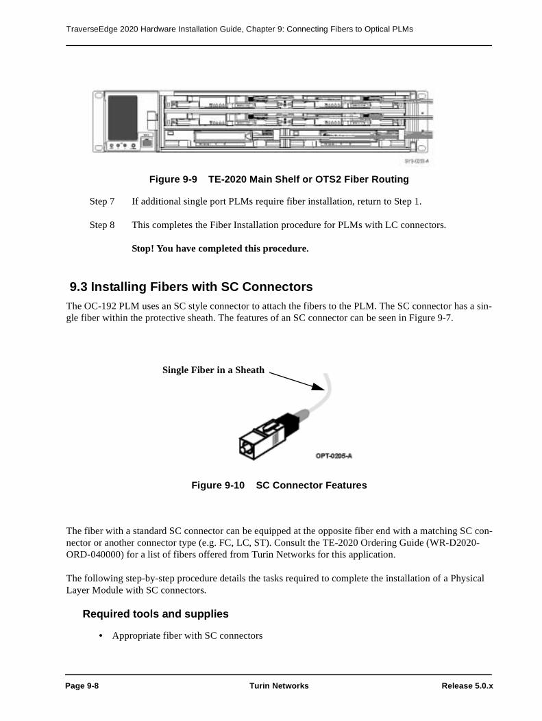
TraverseEdge 2020 Hardware Installation Guide, Chapter 9: Connecting Fibers to Optical PLMs
Page 9-8 Turin Networks Release 5.0.x
Figure 9-9 TE-2020 Main Shelf or OTS2 Fiber Routing
Step 7 If additional single port PLMs require fiber installation, return to Step 1.
Step 8 This completes the Fiber Installation procedure for PLMs with LC connectors.
Stop! You have completed this procedure.
9.3 Installing Fibers with SC ConnectorsThe OC-192 PLM uses an SC style connector to attach the fibers to the PLM. The SC connector has a sin-gle fiber within the protective sheath. The features of an SC connector can be seen in Figure 9-7.
Figure 9-10 SC Connector Features
The fiber with a standard SC connector can be equipped at the opposite fiber end with a matching SC con-nector or another connector type (e.g. FC, LC, ST). Consult the TE-2020 Ordering Guide (WR-D2020-ORD-040000) for a list of fibers offered from Turin Networks for this application.
The following step-by-step procedure details the tasks required to complete the installation of a Physical Layer Module with SC connectors.
Required tools and supplies
• Appropriate fiber with SC connectors
Single Fiber in a Sheath

TraverseEdge 2020 Hardware Installation Guide, Chapter 9: Connecting Fibers to Optical PLMs
Release 5.0.x Turin Networks Page 9-9
Danger! Never look into the end of an optical fiber. Exposure to invisible LASER radiation can cause serious and/or permanent damage to the eye or even blindness. Verify the optical source is disabled through the use of an optical power meter before handling optical fibers. Use of controls, adjustments, or procedures other than those specified within this document may result in hazardous laser radiation expo-sure.
Caution! Electrostatic Discharge (ESD) sensitive devices. ESD can cause catastrophic fail-ure or degraded life and performance of a device. Use an anti-static wrist strap connected to a properly grounded source before contacting any electronic devices.
Step 1 Verify that the selected fibers have SC connectors on the PLM side and that the fibers are long enough to reach to the fiber termination location.
Step 2 Pull back on the ejector handles of the PLM and pull it back approximately one-inch from the installed position.
Step 3 Press the faceplate ejector button located at the top left side of the OC-192 PLM. Refer to Figure 9-11.
Figure 9-11 Releasing the OC-192 Fiber Connector Access Panel
Step 4 Once the OC-192 fiber connector access panel is open, the user can access the SC connec-tors for fiber installation. Refer to Figure 9-12.

TraverseEdge 2020 Hardware Installation Guide, Chapter 9: Connecting Fibers to Optical PLMs
Page 9-10 Turin Networks Release 5.0.x
Figure 9-12 SC Connectors on an OC-192 PLM
Step 5 The printed circuit board is marked on the top exposed edge as Left TX and Right RX. Install the SC connectors accordingly.
Step 6 Gently press the fiber connector access panel closed, ensuring that the fibers are not being pinched between the metal panels.
Step 7 Route the fibers through the retaining clip as shown in Figure 9-13.
Step 8 Push the card back into the chassis until resistance is met.
Step 9 Gently continue to insert the card into the shelf using the ejector handles until the card is fully seated.
Warning! If excessive resistance is met, remove the unit and check for obstructions, bent pins or bent metal. Do not force the PLM into place if excessive resistance is felt.
Step 10 If additional OC-192 PLMs require fiber installation, return to Step 1.
Step 11 This completes the Fiber Installation procedure for OC-192 PLMs with SC connectors.
Stop! You have completed this procedure.

TraverseEdge 2020 Hardware Installation Guide, Chapter 9: Connecting Fibers to Optical PLMs
Release 5.0.x Turin Networks Page 9-11
Figure 9-13 OC-192 Fiber Routing
9.4 Fiber Optic Connector and Receptacle CleaningTo provide the highest quality data transmission over a fiber, it is prudent to clean the fiber at installation time. It is also sometimes necessary to clean fibers to fix a bit error condition on an interface that may show up over time. This section describes procedures for cleaning fiber connectors and receptacles.
A simple connector cleaning kit includes:
• Lint free tissues (wipes)
• Superpolite Alcohol of >90% purity • Swabs with Urethane Foam Heads with a head diameter less than 2.2mm
• Pressurized Optical Duster (sometimes called “canned air”)
Turin Networks has a fiber cleaning kit available (WR-KFIBR-001-00000) which includes 50 Cletop cleaning swabs and a single Universal Connector Cleaning Cassette. Refer to instructions provided on the cassette for proper usage.
9.4.1 Cleaning an Un-Mated Connector (Fiber)
Danger! Never look into the end of an optical fiber. Exposure to invisible LASER radiation can cause serious and/or permanent damage to the eye or even blindness. Verify the optical source is disabled through the use of an optical power meter before handling optical fibers. Use of controls, adjustments, or procedures other than those specified within this document may result in hazardous laser radiation expo-sure.
Caution! Electrostatic Discharge (ESD) sensitive devices. ESD can cause catastrophic fail-

TraverseEdge 2020 Hardware Installation Guide, Chapter 9: Connecting Fibers to Optical PLMs
Page 9-12 Turin Networks Release 5.0.x
ure or degraded life and performance of a device. Use an anti-static wrist strap connected to a properly grounded source before contacting any electronic devices.
Step 1 Using the pressurized duster, blow away any dust particles that may be on the exterior sur-face of the connector, particularly the sides and endface of the ferrule. This is easily done by holding the can approximately 2 inches from the surface to be cleaned and applying 3-5 short blasts of air.
Step 2 Next, fold a paper wipe over itself and place it on a hard flat surface.
Step 3 Place about 1/2 teaspoon of alcohol in the center of the wipe.
Step 4 Gently place the end face of the connector plug on the moistened portion of the wipe and slowly (and gently) slide it across the moistened area in one sweeping move.
Step 5 Repeat step 4 one more time.
Stop! You have completed this procedure.
9.4.2 Cleaning an Un-Mated Bulkhead Connector (PLM)
Danger! Never look into the end of an optical fiber. Exposure to invisible LASER radiation can cause serious and/or permanent damage to the eye or even blindness. Verify the optical source is disabled through the use of an optical power meter before handling optical fibers. Use of controls, adjustments, or procedures other than those specified within this document may result in hazardous laser radiation expo-sure.
Caution! Electrostatic Discharge (ESD) sensitive devices. ESD can cause catastrophic fail-ure or degraded life and performance of a device. Use an anti-static wrist strap connected to a properly grounded source before contacting any electronic devices.
Step 1 Using the pressurized duster, blow away any dust particles that may be on the interior sur-face of the receptacle, particularly the inside walls of the alignment sleeve. This is easily done by holding the can approximately 2 inches from the surface to be cleaned and apply-ing 3-5 short blasts of air.
Step 2 Moisten the end of a swab with alcohol and insert it into one side of the receptacle. Move the swab in and out two or three times and then remove it.
Step 3 Dry the inside of the receptacle by holding the duster approximately 2 inches from the end of the receptacle and applying 3-5 short blasts of air.
Stop! You have completed this procedure.
9.4.3 Cleaning a Mated Connector
Danger! Never look into the end of an optical fiber. Exposure to invisible LASER radiation
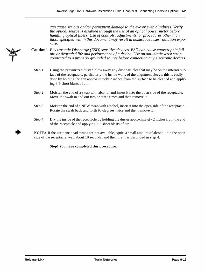
TraverseEdge 2020 Hardware Installation Guide, Chapter 9: Connecting Fibers to Optical PLMs
Release 5.0.x Turin Networks Page 9-13
can cause serious and/or permanent damage to the eye or even blindness. Verify the optical source is disabled through the use of an optical power meter before handling optical fibers. Use of controls, adjustments, or procedures other than those specified within this document may result in hazardous laser radiation expo-sure.
Caution! Electrostatic Discharge (ESD) sensitive devices. ESD can cause catastrophic fail-ure or degraded life and performance of a device. Use an anti-static wrist strap connected to a properly grounded source before contacting any electronic devices.
Step 1 Using the pressurized duster, blow away any dust particles that may be on the interior sur-face of the receptacle, particularly the inside walls of the alignment sleeve. this is easily done by holding the can approximately 2 inches from the surface to be cleaned and apply-ing 3-5 short blasts of air.
Step 2 Moisten the end of a swab with alcohol and insert it into the open side of the receptacle. Move the swab in and out two or three times and then remove it.
Step 3 Moisten the end of a NEW swab with alcohol, insert it into the open side of the receptacle. Rotate the swab back and forth 90-degrees twice and then remove it.
Step 4 Dry the inside of the receptacle by holding the duster approximately 2 inches from the end of the receptacle and applying 3-5 short blasts of air.
NOTE: If the urethane head swabs are not available, squirt a small amount of alcohol into the open side of the receptacle, wait about 10 seconds, and then dry it as described in step 4.
Stop! You have completed this procedure.

TraverseEdge 2020 Hardware Installation Guide, Chapter 9: Connecting Fibers to Optical PLMs
Page 9-14 Turin Networks Release 5.0.x

Release 5.0.x Turin Networks Page 10-1
Chapter 10 DS3/EC1 Tributary Shelf (ETS1) Installation
The ETS1 Shelf comes in two versions meant for different rack width size installation requirements. The WR-TDS30-001-00000 is meant to be installed in a 19" channel rack or similar rack that does not inhibit the exhaust air flow out of the shelf. The 19" shelf is designed to be flush mounted to the front of the chan-nel rack as shown in Figure 10-1..
Figure 10-1 ETS1 - 19”
The WR-TDS30-002-00000 is designed for installation in a standard 23" network bay. The 23" rack is identical to the 19" rack with two additional extensions attached at the factory. The extension on the left side of the shelf (air intake side) is for extending the width of the shelf and also serves as a duct for direct-ing additional air into the fan unit. The extension on the right side of the shelf (air exhaust side) is for extending the width of the shelf and also directs the exhaust air flow to the back of the shelf. This design does not impose any limitations on the mounting position or type of 23" network bay used for installation. The 23" shelf is shown in Figure 10-2.

TraverseEdge 2020 Hardware Installation Guide, Chapter 10: DS3/EC1 Tributary Shelf (ETS1) Installation
Page 10-2 Turin Networks Release 5.0.x
Figure 10-2 ETS1 - 23”
The ETS1 - 23" is shipped with the mounting brackets in the 5-inch offset mounting position. The step-by-step procedures required to complete the installation of the 19" and 23" versions of the ETS1 are detailed in the sections below. By following the steps in these sections, the user is able to complete the hardware installation process for the ETS1.
This chapter has step-by-step descriptions of the following procedures:
• Section 10.1 - Installing the ETS1 - 19"
• Section 10.2 - Installing the ETS1 - 23"• Section 10.3 - Providing Power to the Shelf
• Section 10.3.1 - Preparing and Testing the Power Distribution Unit• Section 10.3.2 - Installing the Frame Ground Wire
• Section 10.3.3 - Installing -48Vdc Supply and Return Wires• Section 10.3.4 - Replacing Fuses In the Power Distribution Unit
10.1 Installing the ETS1 - 19"The ETS1 is shipped empty and should be installed empty to avoid damage to plug-in cards. For a descrip-tion of the ETS1, see the TE-2020 Hardware Description Guide (WR-D2020-HWD-040000).

TraverseEdge 2020 Hardware Installation Guide, Chapter 10: DS3/EC1 Tributary Shelf (ETS1) Installation
Release 5.0.x Turin Networks Page 10-3
The following step-by-step procedure details the tasks required to complete the installation of a ETS1 - 19”.
Required tools and supplies
• 1/4-inch Phillips-head or flat head screw driver
• 4 mounting screws (included with the shelf)
Step 1 If a 23" version of the ETS1 is required, proceed to Section 10.2 - Installing the ETS1 - 23".
Step 2 Verify the shelf width and part number for the ETS1 - 19", WR-TDS30-001-00000.
Step 3 Verify that the location for ETS1 installation is free of obstructions, has available power from the shelf PDU, and has the proper mounting holes.
Step 4 Mount the ETS1 to the rack using four screws, two on each side of the chassis as shown in Figure 10-3.
Warning Care should be taken not to compromise the stability of the rack during installa-tion.
Step 5 Verify that the front-left and left side air intake vents and right side exhaust vent of the shelf are free of obstruction, allowing for proper air flow through the 19" chassis.
Step 6 Procedure completed. Proceed to Section 10.3 - Providing Power to the Shelf.
Stop! You have completed this procedure.

TraverseEdge 2020 Hardware Installation Guide, Chapter 10: DS3/EC1 Tributary Shelf (ETS1) Installation
Page 10-4 Turin Networks Release 5.0.x
Figure 10-3 ETS1 - 19" Rack Installation
10.2 Installing the ETS1 - 23"The ETS1 is shipped empty and should be installed empty to avoid damage to plug-in cards. For a descrip-tion of the ETS1, see the TE-2020 Hardware Description Guide (WR-D2020-HWD-040000).
The following step-by-step procedure details the tasks required to complete the installation of a ETS1 - 23".
Required tools and supplies
• 1/4-inch Phillips-head or flat head screw driver• 4 mounting screws (included with the shelf)
Step 1 Verify the shelf width and part number for the ETS1 - 23", WR-TDS30-002-00000.
Step 2 Verify that the location for ETS1 installation is free of obstructions, has available power from the shelf PDU and has the proper mounting holes.

TraverseEdge 2020 Hardware Installation Guide, Chapter 10: DS3/EC1 Tributary Shelf (ETS1) Installation
Release 5.0.x Turin Networks Page 10-5
Warning Care should be taken not to compromise the stability of the rack during installa-tion.
Step 3 Mount ETS1 to the rack using four screws, two on each side of the chassis as shown in Figure 10-4.
Figure 10-4 ETS1 - 23" Rack Installation
Step 4 Verify that the left side air intake vents and right-rear side exhaust vent of the shelf are free of obstruction, allowing for proper air flow through the 23" chassis.
Chassis filters may be used on 23” rack mount applications when environmental conditions dictate higher filtration requirements for the equipment (environments exceeding GR-63 specifications for environmen-tally controlled spaces). The chassis filters are optional for these conditions and not part of a standard 23” chassis assembly. If ordered, follow these steps for installation.
Step 5 The chassis filter attaches to the left front corner of the chassis, covering the additional shelf spacer for 23” rack applications. Refer to Figure 10-5 Small metal retaining clips hold the chassis filter securly to the chassis. Refer to Figure 10-6

TraverseEdge 2020 Hardware Installation Guide, Chapter 10: DS3/EC1 Tributary Shelf (ETS1) Installation
Page 10-6 Turin Networks Release 5.0.x
Figure 10-5 Chassis Filter
Figure 10-6 Chassis Filter Removed
NOTE: The next step is optional.
Step 6 Install the chassis filter (WR-KFLTR-2RU-00000) on the left side of the chassis as shown in Figure 10-5 Install by snapping the filter onto the chassis.

TraverseEdge 2020 Hardware Installation Guide, Chapter 10: DS3/EC1 Tributary Shelf (ETS1) Installation
Release 5.0.x Turin Networks Page 10-7
Step 7 Procedure completed. Proceed to Section 10.3 - Providing Power to the Shelf.
Stop! You have completed this procedure.
10.3 Providing Power to the ShelfThe ETS1 has redundant -48Vdc and return power connectors on the rear of the shelf. These two connec-tors are labeled (-48A, RTN) and (-48B, RTN). To install redundant power feeds, four power cables and one ground cable are required (see Chapter 19 for information on determining wire gauge). The Frame Ground is located next to the two power connectors and is a #6 connector with a nut pre-installed. Refer to Figure 10-7.
Danger! Disconnect power from the source before connecting any of the power feed wires.
Warning! It is important to attach the Frame Ground wire to the shelf before attaching any of the other power connectors.
Warning! Always use insulated tools and extreme caution when working with power connec-tors. Do not allow tools, wires or any metal objects to come in contact with more than one terminal at a time.
10.3.1 Preparing and Testing the Power Distribution Unit
All power feeds that are supplied to any of the shelves must be individually fused and wired for each shelf. See Chapter 19 for information on selecting fuse size. This procedure for configuring the Power Distribu-tion Unit (PDU) will result in fully tested voltage distribution through the PDU.
Prerequisites
The PDU must be installed according to manufacturers recommendations and local procedures and prac-tices. The proper fuse size must be calculated prior to preparing and testing the PDU.
Required tools and supplies
• Two appropriately sized fuses • Properly installed Power Distribution Unit (PDU)
• Digital Multimeter (DMM)
After performing the prerequisite procedures and gathering the proper tools and supplies, follow the fol-lowing step-by-step procedure to prepare the PDU. Because PDU specific qualities vary based on manu-facturer, the following procedure provides general guidelines that should apply for all PDUs.
Step 1 Put appropriately sized fuses in the two frame ground location ports to be used for the A and B power feeds to the shelf.
Step 2 Use the DMM to verify that the voltage differential at the outputs of the PDU is in the proper range (-42.5Vdc to -56.5Vdc) for the shelf.
Step 3 Remove the fuses.

TraverseEdge 2020 Hardware Installation Guide, Chapter 10: DS3/EC1 Tributary Shelf (ETS1) Installation
Page 10-8 Turin Networks Release 5.0.x
Step 4 Use the DMM to verify that the voltage differential at the outputs of the PDU is zero.
Step 5 Procedure completed. Proceed to Section 10.3.2 - Installing the Frame Ground Wire.
Stop! You have completed this procedure.
Warning! It is extremely important to remove the fuses and verify a lack of electrical poten-tial across the PDU leads and to avoid the possibility of personal injury or damage to the equipment. The fuses should only be installed later and power applied to the shelf under control of the installer.
10.3.2 Installing the Frame Ground Wire
The Frame Ground wire must be the first connection made to the shelf to provide maximum safety for the installer and equipment.
Warning: A suitably approved branch overcurrent protection shall be rated at minimum 60V, Max. 20A. Refer to Chapter 19 Wire Gauge, Fuse Sizes and Power Calculations for more details.
Prerequisites
The shelf must be installed and wire gauge calculated prior to installing Frame Ground wire. Refer to the appropriate procedure below for installing a shelf.
• Section 10.1 - Installing the ETS1 - 19"
• Section 10.2 - Installing the ETS1 - 23"
Required tools and supplies
• Insulated, 1/4-inch, open ended wrench
• Insulated, stranded wire in 12AWG (refer to Chapter 19 ) in the appropriate color according to local procedures and practices.
After performing the prerequisite procedures and gathering the proper tools and supplies, follow the fol-lowing step-by-step procedure to install the Frame Ground wire.
Step 1 Measure the distance from the Frame Ground location to the shelf and prepare the appro-priate wire by determining the gauge (see Chapter 19 ), cutting the wire to the proper length, and preparing the ends for attachment to the shelf (appropriately sized lug) and building ground.
Step 2 The shelf has a threaded Frame Ground pin on the back with a nut pre-installed. Remove this nut from the Frame Ground pin.
Step 3 Attach the previously prepared chassis ground wire to the Frame Ground stud (see Figure 10-7).
Step 4 Reinstall the washer and nut onto the Frame Ground pin.

TraverseEdge 2020 Hardware Installation Guide, Chapter 10: DS3/EC1 Tributary Shelf (ETS1) Installation
Release 5.0.x Turin Networks Page 10-9
Step 5 Install the other end of the Frame Ground wire to an appropriate building ground accord-ing to local practices and procedures.
Caution! A ground cable must be connected from the chassis' to the frame and any paint or nonconductive coatings must be removed on the surfaces between the mounting hardware and the framework or cabinet. It is also required that the surfaces are cleaned and an anti-oxidant applied before being joined.
Step 6 Procedure completed. Proceed to Section 10.3.3 - Installing -48Vdc Supply and Return Wires.
Stop! You have completed this procedure.
Figure 10-7 ETS1 Rear View - Power and Ground Connectors
10.3.3 Installing -48Vdc Supply and Return Wires
Once the shelf is grounded, the -48Vdc power supply can safely be connected to the shelf. Both supply and return wires need to be connected for both the A and B feeds.
Prerequisites
The PDU must be prepared, the Frame Ground wire installed, and wire gauge calculated prior to Installing Frame Ground wire.
• Section 10.1 - Installing the ETS1 - 19"
• Section 10.2 - Installing the ETS1 - 23"• Section 10.3.1 - Preparing and Testing the Power Distribution Unit
• Section 10.3.2 - Installing the Frame Ground Wire • Chapter 19 Wire Gauge, Fuse Sizes and Power Calculations
Required tools and supplies

TraverseEdge 2020 Hardware Installation Guide, Chapter 10: DS3/EC1 Tributary Shelf (ETS1) Installation
Page 10-10 Turin Networks Release 5.0.x
• 1/8-inch flat head screw driver• Insulated, stranded wire in 12 AWG (refer to Chapter 19 ) in the appropriate colors according to local procedures and practices.• Connectors provided in shipping package with chassis
After performing the prerequisite procedures and gathering the proper tools and supplies, follow the fol-lowing step-by-step procedure to install the -48Vdc supply and return wires.
Step 1 Measure the distance from the PDU to the shelf and prepare the appropriate wire by deter-mining the gauge (see Chapter 19 ), cutting the four wires to the proper length. Prepare the ends for attachment to the shelf (stripping back insulation approximately 1/4-inch) and PDU.
Step 2 Locate the modular power connectors shown in Figure 10-8. They are included in the packaging with the chassis.
Step 3 Use the flat head screwdriver to adjust the size of the receptors (using receptor adjustment screws) to accept the power wires.
Step 4 Insert the previously prepared -48 volt supply power wire into the right receptor and secure using the receptor adjustment screws.
Caution! It is important to ensure proper tightening of the receptor screws to prevent disrup-tion of power to the shelf.
Step 5 Insert the previously prepared -48 volt return power wire into the left receptor and secure using the receptor adjustment screws.
Step 6 Use the flat head screwdriver to remove the removable plugs from the modular connector for the -48B volt supply and return.
Step 7 Use the flat head screwdriver to adjust the size of the receptors (using receptor adjustment screws) to accept the power wires.
Step 8 Insert the previously prepared -48 volt supply power wire into the right receptor and secure using the receptor adjustment screws.
Caution! It is important to ensure proper tightening of the receptor screws to prevent disrup-tion of power to the shelf.
Step 9 Insert the previously prepared -48 volt return power wire into the left receptor and secure using the receptor adjustment screws.
Step 10 Reinstall the -48Vdc removable plugs in the shelf.
Warning! It is extremely important to remove the fuses and verify a lack of electrical poten-tial across the PDU leads and to avoid the possibility of personal injury or damage to the equipment. The fuses should only be installed later and power applied to the shelf under control of the installer.

TraverseEdge 2020 Hardware Installation Guide, Chapter 10: DS3/EC1 Tributary Shelf (ETS1) Installation
Release 5.0.x Turin Networks Page 10-11
Step 11 Screw in the two screws at the back of each connector to secure the plug to the shelf.
Step 12 Install the other end of the A and B power wires to the appropriate leads on the PDU.
Figure 10-8 Power Connectors
This completes the procedure for installation of the -48 volt supply and return power wires. Proceed to power sections.
Stop! You have completed this procedure.
10.3.4 Replacing Fuses In the Power Distribution Unit
Once all of the power connections have been properly installed, the fuses should be re-installed in the PDU to provide power to the shelf.
Prerequisites
The PDU must be prepared, the Frame Ground wire installed, and wire gauge calculated prior to replacing the fuses in the PDU.
Warning! It is extremely important to verify a lack of electrical potential across the PDU leads with the fuses removed. This will avoid the possibility of personal injury or damage to the equipment. The fuses should be installed later and power applied to the shelf in a controlled manner.
• Section 10.3.1 - Preparing and Testing the Power Distribution Unit
• Section 10.3.2 - Installing the Frame Ground Wire • Chapter 19 Wire Gauge, Fuse Sizes and Power Calculations
Required tools and supplies
• Two appropriately sized fuses • Properly installed PDU

TraverseEdge 2020 Hardware Installation Guide, Chapter 10: DS3/EC1 Tributary Shelf (ETS1) Installation
Page 10-12 Turin Networks Release 5.0.x
• Digital Multimeter (DMM)
After performing the prerequisite procedures and gathering the proper tools and supplies, follow the step-by-step procedure to replace the fuses in the PDU.
Step 1 Put an appropriately sized fuse in the PDU port to be used for the A power feed to the shelf. Install the indicator fuses as well (if equipped).
Step 2 Use the DMM to verify that the voltage differential at the shelf for the -48V A connector is in the proper range (-42.5Vdc to -56.5Vdc) for the shelf.
Step 3 Put an appropriately sized fuse in the PDU port to be used for the B power feed to the shelf.
Step 4 Use the DMM to verify that the voltage differential at the shelf for the -48V B connector is in the proper range (-42.5Vdc to -56.5Vdc) for the shelf.
Warning! It is extremely important to remove the fuses and verify a lack of electrical poten-tial across the PDU leads and to avoid the possibility of personal injury or damage to the equipment. The fuses should only be installed later and power applied to the shelf in a controlled manner.
Step 5 Procedure completed.
Stop! You have completed this procedure.

Release 5.0.x Turin Networks Page 11-1
Chapter 11 DS3/EC1 Tributary Shelf (ETS1) Plug-In Installation
Although the DS3/EC1 Tributary Shelf (ETS1) comes in 19” and 23” versions, the plug-ins for both are identical. There are three main types of plug-in modules for each of these shelves as shown in Figure 11-1 below.
• Fan Tray Plug-in• Common Control and Timing (CCT) Plug-ins
• Physical Layer Module (PLM) Plug-ins
The sections below briefly discuss the appropriate Plug-in modules for the ETS1 and give step-by-step instructions on how to properly install each module.
Figure 11-1 ETS1 Shelf Assembly
11.1 Installing the ETS Fan TrayThe ETS Fan Tray is required in every ETS1 and ETS2. It provides forced air cooling to maintain an appropriate system temperature within the shelf and to the components on the boards.
The ETS Fan Tray is shown in Figure 11-2. It is a single unit with multiple individual fans. A single fan can fail and the remaining fans will continue to work, allowing time for a service technician to replace the fan tray.

TraverseEdge 2020 Hardware Installation Guide, Chapter 11: DS3/EC1 Tributary Shelf (ETS1) Plug-In Installation
Page 11-2 Turin Networks Release 5.0.x
Figure 11-2 . ETS Fan Tray
The following step-by-step procedure details the tasks required to complete the installation of a ETS Fan Tray.
Prerequisites
The ETS1 must be installed to complete this procedure. Refer to the appropriate procedure below for proper shelf installation.
• Section 10.1 - Installing the ETS1 - 19"
• Section 10.2 - Installing the ETS1 - 23"
Caution! Electrostatic Discharge (ESD) sensitive devices. ESD can cause catastrophic failure or degraded life and performance of a device. Use an anti-static wrist strap connected to a properly grounded source before contacting any electronic devices.
Step 1 Verify the part number of the ETS Fan Tray prior to installation. The part number should be WR-PFAN0-002-00000.
Step 2 Verify that the 3 RU Fan Filter (part number WR-PFLTR-003-00000) is in the Fan Tray to the left of the fans if facing the front of the fan tray.

TraverseEdge 2020 Hardware Installation Guide, Chapter 11: DS3/EC1 Tributary Shelf (ETS1) Plug-In Installation
Release 5.0.x Turin Networks Page 11-3
Step 3 Insert the ETS Fan Tray into the left side of the ETS1.
Step 4 Pull the ejector handle down away from the faceplate to allow the fan tray to slide fully into the shelf.
Step 5 Push the fan tray into the shelf until resistance is met (approximately 1-inch from back of shelf).
Warning! If excessive resistance is met, remove the unit and check for obstructions, bent pins or bent metal. Do not force the fan into place if excessive resistance is felt.
Step 6 Use the ejector handle to fully seat the fan tray in the shelf.
Step 7 Procedure completed.
NOTE: If no other equipment is installed in the shelf (i.e. CCTs, PLMs), then the LED should not illuminate on the fan tray. If CCTs (with or without PLMs) are already installed, the LED will reflect the status of the shelf.
Stop! You have completed this procedure.
11.1.1 Installing the 3 RU Fan Filter
The 3 RU Fan Filter (WR-PFLTR-003-00000) is shipped with the ETS Fan Tray and runs the across the front of the fan tray in-between the fans and the air intake as can be seen in Figure 11-4. The filter is designed for optimal performance in the shelf and only this filter should be used. The fan filter will need to be changed every six months.
The following step-by-step procedure details the tasks required to complete the installation of a 3 RU Fan Filter.
Step 1 Observe the frame of the filter, primarily the text that informs the installer the direction of the airflow. Refer to Figure 11-3.
Figure 11-3 Air Filter Directional Indicator

TraverseEdge 2020 Hardware Installation Guide, Chapter 11: DS3/EC1 Tributary Shelf (ETS1) Plug-In Installation
Page 11-4 Turin Networks Release 5.0.x
Step 2 Insert the 3 RU Fan Filter into the top of the ETS Fan Tray until it locks into place under tension. Refer to Figure 11-4.
Figure 11-4 ETS Fan Tray with 3 RU Fan Filter
Step 3 This completes the procedure for 3 RU Fan Filter installation. Proceed to Section 11.1 - Installing the ETS Fan Tray.
Stop! You have completed this procedure.

TraverseEdge 2020 Hardware Installation Guide, Chapter 11: DS3/EC1 Tributary Shelf (ETS1) Plug-In Installation
Release 5.0.x Turin Networks Page 11-5
11.2 Installing the ETS1 CCTThe ETS1 has slots for two DS3/EC1 Tributary Shelf Common Control and Timing (CCT) modules. The CCTs may be installed in any order, but they should be installed prior to installing any PLMs.
Warning! Failure to equip empty slots with blank PLM covers may result in system failure due to lack of proper air flow.
Caution! Electrostatic Discharge (ESD) sensitive devices. ESD can cause catastrophic fail-ure or degraded life and performance of a device. Use an anti-static wrist strap connected to a properly grounded source before contacting any electronic devices.
Step 1 Verify the part number of the DS3/EC1 Tributary CCT prior to installation. The part num-ber should be WR-PCCT0-002-00000.
Step 2 Pull the ejector handles out away from the faceplate to enable the cards to slide fully into the shelf.
Step 3 Insert the first ETS1 CCT into ETS1 shelf using the guides. Refer to Figure 11-5. The first CCT installed, whether left or right, will be the primary CCT.
Step 4 Push the card into the chassis until resistance is met.
Step 5 Gently continue to insert the card into the shelf using the ejector handles until the card is fully seated.
Warning! If excessive resistance is met, remove the unit and check for obstructions, bent pins or bent metal. Do not force the CCT into place if excessive resistance is felt.
Step 6 When the card is fully seated in the shelf, the CCT LED will illuminate alternating colors during the card boot cycle and eventually settle to green when the card is properly installed and fully booted. If the light does not turn green, an error has occurred and the card should be removed and both the shelf and CCT should be inspected. Return to Step 1 with either a new CCT or the original CCT with the problem repaired.
Step 7 If another CCT is to be installed, return to Step 1. If both CCTs are already installed, pro-ceed to Step 8.
Step 8 Both CCTs should be installed and the LED on the ETS Fan Tray should be green. This completes the procedure to install the DS3/EC1 Tributary CCTs.
NOTE: To maintain proper air flow and cooling through the system, the ETS1 shelf must have all slots fully populated. Ensure both CCTs are installed.
Stop! You have completed this procedure.

TraverseEdge 2020 Hardware Installation Guide, Chapter 11: DS3/EC1 Tributary Shelf (ETS1) Plug-In Installation
Page 11-6 Turin Networks Release 5.0.x
Figure 11-5 ETS1 CCTs

Release 5.0.x Turin Networks Page 12-1
Chapter 12 DS3/EC1 PLM Installation
The DS3/EC1 x12 Physical Layer Module (PLM) shown in Figure 12-1 comes in three different versions. The first version (part number WR-DS312-001-00000) provides twelve DS3/EC-1 ports per card with monitor only ports.
The second version (part number WR-DS312-011-00000) provides twelve DS3/EC-1 ports per card with intrusive test access ports.
The third version (part number WR-DS312-T01-00000) supports DS3 trans-multiplexing. This PLM can be installed in any regular DS3 PLM slot, but if utilizing protection for a mix of regular DS3 PLMs and DS3 Transmux PLMs, the Transmux version must be installed in the protection slot. A regular DS3 PLM in the protection slot will not protect the DS3 Transmux.
Up to 4 working cards and one protect card may be utilized in each ETS1 shelf for 1:N protection (N <= 4), or 1 working and 1 protect in an ETS2 shelf.
For information regarding bandwidth management and protection arrangements, consult the TE-2020 Applications and Engineering Guide (WR-D2020-APP-040000).
Figure 12-1 DS3/EC1 x12 PLM
The DS3/EC1 PLMs plug into the DS3/EC1 Tributary Shelf from top to bottom with the top card being the protect card.
Warning! Every shelf must be fully populated with either active boards or Blank cards in order to maintain both the air flow through the shelf and maintain the proper tem-perature for the components.
12.1 Installing a DS3/EC1 PLM

TraverseEdge 2020 Hardware Installation Guide, Chapter 12: DS3/EC1 PLM Installation
Page 12-2 Turin Networks Release 5.0.x
Caution! Electrostatic Discharge (ESD) sensitive devices. ESD can cause catastrophic fail-ure or degraded life and performance of a device. Use an anti-static wrist strap connected to a properly grounded source before contacting any electronic devices.
Step 1 Verify the part numbers of the DS3/EC1 PLM cards. The part number may be WR-DS312-001-00000, WR-DS312-011-00000, or WR-DS312-T01-00000 DS3 Transmux card for either shelf.
Step 2 Pull the ejector handles out away from the faceplate to enable the card to slide fully into the shelf.
Figure 12-2 Installing a DS3/EC1 PLM into an ETS1
Step 3 If installing into an ETS1 shelf, insert the top DS3/EC1 PLM card using the guides pro-vided. Refer to Figure 12-2. This is the protect card. If protection is not being utilized, populate the top slot with a blank PLM card. If installing into an ETS2 shelf, insert the PLM into either the bottom right or bottom left slot. Refer to Figure 12-3.

TraverseEdge 2020 Hardware Installation Guide, Chapter 12: DS3/EC1 PLM Installation
Release 5.0.x Turin Networks Page 12-3
Figure 12-3 Installing a DS3/EC1 PLM into an ETS2
NOTE: If utilizing protection for a working DS3 Transmux card, teh protect slot must be populated with the same part number PLM. This DS3 Transmux will support the regular DS3 PLMs but a reg-ular DS3 PLM in the protect slot will not protect the DS3 Transmux PLM.
Step 4 Push the DS3/EC1 PLM into the shelf until resistance is met (approximately 1-inch from back of shelf).
Warning! If excessive resistance is met, remove the unit and check for obstructions, bent pins or bent metal. Do not force the fan into place if excessive resistance is felt.
Step 5 Use the ejector handle to fully seat the PLM in the shelf.
Step 6 Press the ejectors on each side of the card into a locked position.
Step 7 The PLM STAT LED should light up green momentarily if installed properly. If not, an error has occurred or an alarm exists on the card. If the card has no alarms, remove the PLM and return to Step 2 with either a new PLM or the original PLM with the problem repaired.
Step 8 Insert as many PLMs as are required by the application by repeating Steps 2-8 for each PLM.

TraverseEdge 2020 Hardware Installation Guide, Chapter 12: DS3/EC1 PLM Installation
Page 12-4 Turin Networks Release 5.0.x
NOTE: The DS3/EC1 PLMs must be installed from top to bottom to function properly. Any miss-ing PLMs in the contiguous configuration will cause the PLM below the vacant slot to be unpro-tected. Consult the TE-2020 Applications and Engineering Guide (WR-D2020-APP-040000) for details on DS3/EC-1 protection.
Step 9 If needed, install DS3/EC1 PLM Blank cards into the shelf to occupy any unequipped slots in the ETS1 or ETS2.
Figure 12-4 Installing DS3/EC1 PLM Blank into an ETS1
Stop! You have completed this procedure.
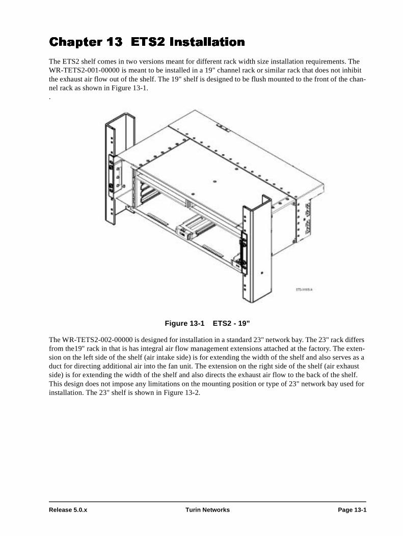
Release 5.0.x Turin Networks Page 13-1
Chapter 13 ETS2 Installation
The ETS2 shelf comes in two versions meant for different rack width size installation requirements. The WR-TETS2-001-00000 is meant to be installed in a 19" channel rack or similar rack that does not inhibit the exhaust air flow out of the shelf. The 19" shelf is designed to be flush mounted to the front of the chan-nel rack as shown in Figure 13-1..
Figure 13-1 ETS2 - 19”
The WR-TETS2-002-00000 is designed for installation in a standard 23" network bay. The 23" rack differs from the19" rack in that is has integral air flow management extensions attached at the factory. The exten-sion on the left side of the shelf (air intake side) is for extending the width of the shelf and also serves as a duct for directing additional air into the fan unit. The extension on the right side of the shelf (air exhaust side) is for extending the width of the shelf and also directs the exhaust air flow to the back of the shelf. This design does not impose any limitations on the mounting position or type of 23" network bay used for installation. The 23" shelf is shown in Figure 13-2.

TraverseEdge 2020 Hardware Installation Guide, Chapter 13: ETS2 Installation
Page 13-2 Turin Networks Release 5.0.x
Figure 13-2 ETS2 - 23”
The ETS2 - 23" is shipped with the mounting brackets in the 5-inch offset mounting position. The step-by-step procedures required to complete the installation of the 19" and 23" versions of theETS2 are detailed in the sections below. By following the steps in these sections, the user is able to complete the hardware installation process for the ETS2.
This chapter has step-by-step descriptions of the following procedures:
• Section 13.1 - Installing the ETS2 - 19"
• Section 13.2 - Installing the ETS2 - 23"• Section 13.3 - Providing Power to the Shelf
• Section 13.3.1 - Preparing and Testing the Power Distribution Unit• Section 13.3.2 - Installing the Frame Ground Wire
• Section 13.3.3 - Installing -48Vdc Supply and Return Wires• Section 13.3.4 - Replacing Fuses In the Power Distribution Unit
13.1 Installing the ETS2 - 19"The ETS2 is shipped empty and should be installed empty to avoid damage to plug-in cards. For a descrip-tion of the ETS2, see the TE-2020 Hardware Description Guide (WR-D2020-HWD-040000).
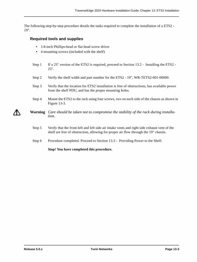
TraverseEdge 2020 Hardware Installation Guide, Chapter 13: ETS2 Installation
Release 5.0.x Turin Networks Page 13-3
The following step-by-step procedure details the tasks required to complete the installation of a ETS2 - 19”.
Required tools and supplies
• 1/4-inch Phillips-head or flat head screw driver
• 4 mounting screws (included with the shelf)
Step 1 If a 23" version of the ETS2 is required, proceed to Section 13.2 - Installing the ETS2 - 23".
Step 2 Verify the shelf width and part number for the ETS2 - 19", WR-TETS2-001-00000.
Step 3 Verify that the location for ETS2 installation is free of obstructions, has available power from the shelf PDU, and has the proper mounting holes.
Step 4 Mount the ETS2 to the rack using four screws, two on each side of the chassis as shown in Figure 13-3.
Warning Care should be taken not to compromise the stability of the rack during installa-tion.
Step 5 Verify that the front-left and left side air intake vents and right side exhaust vent of the shelf are free of obstruction, allowing for proper air flow through the 19" chassis.
Step 6 Procedure completed. Proceed to Section 13.3 - Providing Power to the Shelf.
Stop! You have completed this procedure.

TraverseEdge 2020 Hardware Installation Guide, Chapter 13: ETS2 Installation
Page 13-4 Turin Networks Release 5.0.x
Figure 13-3 ETS2 - 19" Rack Installation
13.2 Installing the ETS2 - 23"The ETS2 is shipped empty and should be installed empty to avoid damage to plug-in cards. For a descrip-tion of the ETS2, see the TE-2020 Hardware Description Guide (WR-D2020-HWD-040000).
The following step-by-step procedure details the tasks required to complete the installation of a ETS2 - 23".
Required tools and supplies
• 1/4-inch Phillips-head or flat head screw driver• 4 mounting screws (included with the shelf)
Step 1 Verify the shelf width and part number for the ETS2 - 23", WR-TETS2-002-00000.
Step 2 Verify that the location for ETS2 installation is free of obstructions, has available power from the shelf PDU and has the proper mounting holes.

TraverseEdge 2020 Hardware Installation Guide, Chapter 13: ETS2 Installation
Release 5.0.x Turin Networks Page 13-5
Warning Care should be taken not to compromise the stability of the rack during installa-tion.
Step 3 Mount ETS2 to the rack using four screws, two on each side of the chassis as shown in Figure 13-4.
Figure 13-4 ETS2 - 23" Rack Installation
Step 4 Verify that the left side air intake vents and right-rear side exhaust vent of the shelf are free of obstruction, allowing for proper air flow through the 23" chassis.
Chassis filters may be used on 23” rack mount applications when environmental conditions dictate higher filtration requirements for the equipment (environments exceeding GR-63 specifications for environmen-tally controlled spaces). The chassis filters are an optional upgrade for these conditions and not part of a standard 23” chassis assembly. If ordered, follow these steps for installation.
Step 5 The chassis filter attaches to the left front corner of the chassis, covering the additional shelf spacer for 23” rack applications. Refer to Figure 13-5. Small metal retaining clips hold the chassis filter securely to the chassis. Refer to Figure 13-6

TraverseEdge 2020 Hardware Installation Guide, Chapter 13: ETS2 Installation
Page 13-6 Turin Networks Release 5.0.x
Figure 13-5 Chassis Filter
Figure 13-6 Chassis Filter Removed
NOTE: The next step is optional.
Retaining Clips

TraverseEdge 2020 Hardware Installation Guide, Chapter 13: ETS2 Installation
Release 5.0.x Turin Networks Page 13-7
Step 6 Install the chassis filter (WR-KFLTR-2RU-00000) on the left side of the chassis as shown in Figure 13-5 Install by snapping the filter onto the chassis.
Step 7 Procedure completed. Proceed to Section 13.3 - Providing Power to the Shelf.
Stop! You have completed this procedure.
13.3 Providing Power to the ShelfThe ETS2 has redundant -48Vdc and return power connectors on the rear of the shelf. These two connec-tors are labeled (-48A, RTN) and (-48B, RTN). To install redundant power feeds, four power cables and one ground cable are required (see Chapter 19 for information on determining wire gauge). The Frame Ground is located next to the two power connectors and is a #6 connector with a nut pre-installed. Refer to Figure 13-7.
Danger! Disconnect power from the source before connecting any of the power feed wires.
Warning! It is important to attach the Frame Ground wire to the shelf before attaching any of the other power connectors.
Warning! Always use insulated tools and extreme caution when working with power connec-tors. Do not allow tools, wires or any metal objects to come in contact with more than one terminal at a time.
13.3.1 Preparing and Testing the Power Distribution Unit
All power feeds that are supplied to any of the shelves must be individually fused and wired for each shelf. See Chapter 19 for information on selecting fuse size. This procedure for configuring the Power Distribu-tion Unit (PDU) will result in fully tested voltage distribution through the PDU.
Prerequisites
The PDU must be installed according to manufacturers recommendations and local procedures and prac-tices. The proper fuse size must be calculated prior to preparing and testing the PDU.
Required tools and supplies
• Two appropriately sized fuses • Properly installed Power Distribution Unit (PDU)
• Digital Multimeter (DMM)
After performing the prerequisite procedures and gathering the proper tools and supplies, follow the fol-lowing step-by-step procedure to prepare the PDU. Because PDU specific qualities vary based on manu-facturer, the following procedure provides general guidelines that should apply for all PDUs.
Step 1 Put appropriately sized fuses in the two frame ground location ports to be used for the A and B power feeds to the shelf.
Step 2 Use the DMM to verify that the voltage differential at the outputs of the PDU is in the proper range (-42.5Vdc to -56.5Vdc) for the shelf.

TraverseEdge 2020 Hardware Installation Guide, Chapter 13: ETS2 Installation
Page 13-8 Turin Networks Release 5.0.x
Step 3 Remove the fuses.
Step 4 Use the DMM to verify that the voltage differential at the outputs of the PDU is zero.
Step 5 Procedure completed. Proceed to Section 13.3.2 - Installing the Frame Ground Wire.
Stop! You have completed this procedure.
Warning! It is extremely important to remove the fuses and verify a lack of electrical poten-tial across the PDU leads and to avoid the possibility of personal injury or damage to the equipment. The fuses should only be installed later and power applied to the shelf under control of the installer.
13.3.2 Installing the Frame Ground Wire
The Frame Ground wire must be the first connection made to the shelf to provide maximum safety for the installer and equipment.
Prerequisites
The shelf must be installed and wire gauge calculated prior to installing Frame Ground wire. Refer to the appropriate procedure below for installing a shelf.
• Section 13.1 - Installing the ETS2 - 19"
• Section 13.2 - Installing the ETS2 - 23"
Required tools and supplies
• Insulated, 1/4-inch, open ended wrench • Insulated, stranded wire in 12AWG (refer to Chapter 19 ) in the appropriate color according to local procedures and practices.
After performing the prerequisite procedures and gathering the proper tools and supplies, follow the fol-lowing step-by-step procedure to install the Frame Ground wire.
Step 1 Measure the distance from the Frame Ground location to the shelf and prepare the appro-priate wire by determining the gauge (see Chapter 19 ), cutting the wire to the proper length, and preparing the ends for attachment to the shelf (appropriately sized lug) and building ground.
Step 2 The shelf has a threaded Frame Ground pin on the back with a nut pre-installed. Remove this nut from the Frame Ground pin.
Step 3 Attach the previously prepared chassis ground wire to the Frame Ground stud (see Figure 13-7).
Step 4 Reinstall the washer and nut onto the Frame Ground pin.

TraverseEdge 2020 Hardware Installation Guide, Chapter 13: ETS2 Installation
Release 5.0.x Turin Networks Page 13-9
Step 5 Install the other end of the Frame Ground wire to an appropriate building ground accord-ing to local practices and procedures.
Caution! A ground cable must be connected from the chassis' to the frame and any paint or nonconductive coatings must be removed on the surfaces between the mounting hardware and the framework or cabinet. It is also required that the surfaces are cleaned and an anti-oxidant applied before being joined.
Step 6 Procedure completed. Proceed to Section 13.3.3 - Installing -48Vdc Supply and Return Wires.
Stop! You have completed this procedure.
Figure 13-7 ETS2 Rear Power and Ground Connectors
13.3.3 Installing -48Vdc Supply and Return Wires
Once the shelf is grounded, the -48Vdc power supply can safely be connected to the shelf. Both supply and return wires need to be connected for both the A and B feeds.
Warning: A suitably approved branch overcurrent protection shall be rated at minimum 60V, Max. 20A. Refer to Chapter 19 Wire Gauge, Fuse Sizes and Power Calculations for more details.
Prerequisites
The PDU must be prepared, the Frame Ground wire installed, and wire gauge calculated prior to Installing Frame Ground wire.
• Section 13.1 - Installing the ETS2 - 19" • Section 13.2 - Installing the ETS2 - 23"
• Section 13.3.1 - Preparing and Testing the Power Distribution Unit• Section 13.3.2 - Installing the Frame Ground Wire
• Chapter 19 Wire Gauge, Fuse Sizes and Power Calculations

TraverseEdge 2020 Hardware Installation Guide, Chapter 13: ETS2 Installation
Page 13-10 Turin Networks Release 5.0.x
Required tools and supplies
• 1/8-inch flat head screw driver• Insulated, stranded wire in 12 AWG (refer to Chapter 19 ) in the appropriate colors according to local procedures and practices.• Connectors provided in shipping package with chassis
After performing the prerequisite procedures and gathering the proper tools and supplies, follow the fol-lowing step-by-step procedure to install the -48Vdc supply and return wires.
Step 1 Measure the distance from the PDU to the shelf and prepare the appropriate wire by deter-mining the gauge (see Chapter 19 ), cutting the four wires to the proper length. Prepare the ends for attachment to the shelf (stripping back insulation approximately 1/4-inch) and PDU.
Step 2 Locate the modular power connectors shown in Figure 13-8. They are included in the packaging with the chassis.
Step 3 Use the flat head screwdriver to adjust the size of the receptors (using receptor adjustment screws) to accept the power wires.
Step 4 Insert the previously prepared -48 volt supply power wire into the right receptor and secure using the receptor adjustment screws.
Caution! It is important to ensure proper tightening of the receptor screws to prevent disrup-tion of power to the shelf.
Step 5 Insert the previously prepared -48 volt return power wire into the left receptor and secure using the receptor adjustment screws.
Step 6 Use the flat head screwdriver to remove the removable plugs from the modular connector for the -48B volt supply and return.
Step 7 Use the flat head screwdriver to adjust the size of the receptors (using receptor adjustment screws) to accept the power wires.
Step 8 Insert the previously prepared -48 volt supply power wire into the right receptor and secure using the receptor adjustment screws.
Caution! It is important to ensure proper tightening of the receptor screws to prevent disrup-tion of power to the shelf.
Step 9 Insert the previously prepared -48 volt return power wire into the left receptor and secure using the receptor adjustment screws.
Step 10 Reinstall the -48Vdc removable plugs in the shelf.
Warning! It is extremely important to remove the fuses and verify a lack of electrical poten-tial across the PDU leads and to avoid the possibility of personal injury or damage to the equipment. The fuses should only be installed later and power applied to the

TraverseEdge 2020 Hardware Installation Guide, Chapter 13: ETS2 Installation
Release 5.0.x Turin Networks Page 13-11
shelf under control of the installer.
Step 11 Screw in the two screws at the back of each connector to secure the plug to the shelf.
Step 12 Install the other end of the A and B power wires to the appropriate leads on the PDU.
Figure 13-8 Power Connectors
This completes the procedure for installation of the -48 volt supply and return power wires. Proceed to power sections.
Stop! You have completed this procedure.
13.3.4 Replacing Fuses In the Power Distribution Unit
Once all of the power connections have been properly installed, the fuses should be re-installed in the PDU to provide power to the shelf.
Prerequisites
The PDU must be prepared, the Frame Ground wire installed, and wire gauge calculated prior to replacing the fuses in the PDU.
Warning! It is extremely important to verify a lack of electrical potential across the PDU leads with the fuses removed. This will avoid the possibility of personal injury or damage to the equipment. The fuses should be installed later and power applied to the shelf in a controlled manner.
• Section 13.3.1 - Preparing and Testing the Power Distribution Unit
• Section 13.3.2 - Installing the Frame Ground Wire • Chapter 19 Wire Gauge, Fuse Sizes and Power Calculations
Required tools and supplies
• Two appropriately sized fuses • Properly installed PDU

TraverseEdge 2020 Hardware Installation Guide, Chapter 13: ETS2 Installation
Page 13-12 Turin Networks Release 5.0.x
• Digital Multimeter (DMM)
After performing the prerequisite procedures and gathering the proper tools and supplies, follow the step-by-step procedure to replace the fuses in the PDU.
Step 1 Put an appropriately sized fuse in the PDU port to be used for the A power feed to the shelf. Install the indicator fuses as well (if equipped).
Step 2 Use a DMM to verify that the voltage differential for the -48V A connector is in the proper range (-42.5Vdc to -56.5Vdc) for the shelf.
Step 3 Put an appropriately sized fuse in the PDU port to be used for the B power feed to the shelf.
Step 4 Use a DMM to verify that the voltage differential for the -48V B connector is in the proper range (-42.5Vdc to -56.5Vdc) for the shelf.
Warning! It is extremely important to remove the fuses and verify a lack of electrical poten-tial across the PDU leads and to avoid the possibility of personal injury or damage to the equipment. The fuses should only be installed later and power applied to the shelf in a controlled manner.
Step 5 Procedure completed.
Stop! You have completed this procedure.

Release 5.0.x Turin Networks Page 14-1
Chapter 14 ETS2 Plug-In Installation
Although the ETS2 comes in 19” and 23” versions, the plug-ins for both are identical. There are three main types of plug-in modules for each of these shelves as shown in Figure 14-1 below.
• Fan Tray Plug-in• Common Control and Timing (CCT) Plug-ins
• Physical Layer Module (PLM) Plug-ins
The sections below briefly discuss the appropriate Plug-in modules for the ETS2 and give step-by-step instructions on how to properly install each module.
Figure 14-1 ETS2 Shelf
14.1 Installing the ETS Fan TrayThe fan tray is required in every ETS2. It provides forced air cooling to maintain an appropriate system temperature within the shelf and to the components on the boards.
The ETS Fan Tray is shown in Figure 14-2. It is a single unit with multiple individual fans that can be uti-lized in either the ETS1 or ETS2. A single fan can fail and the remaining fans will continue to work, allow-ing time for a service technician to replace the fan tray.

TraverseEdge 2020 Hardware Installation Guide, Chapter 14: ETS2 Plug-In Installation
Page 14-2 Turin Networks Release 5.0.x
Figure 14-2 ETS Fan Tray
The following step-by-step procedure details the tasks required to complete the installation of a ETS Fan Tray.
Prerequisites
The ETS2 shelf must be installed to complete this procedure. Refer to the appropriate procedure below for proper shelf installation.
• Section 13.1 - Installing the ETS2 - 19" • Section 13.2 - Installing the ETS2 - 23"
Caution! Electrostatic Discharge (ESD) sensitive devices. ESD can cause catastrophic fail-ure or degraded life and performance of a device. Use an anti-static wrist strap connected to a properly grounded source before contacting any electronic devices.
Step 1 Verify the part number of the ETS Fan Tray prior to installation. The part number should be WR-PFAN0-002-00000.
Step 2 Verify that the 3 RU Fan Filter (part number WR-PFLTR-003-00000) is in the Fan Tray to the left of the fans if facing the front of the fan tray.
Step 3 Insert the ETS Fan Tray into the left side of the ETS2.
Step 4 Pull the ejector handle down away from the faceplate to allow the fan tray to slide fully into the shelf.

TraverseEdge 2020 Hardware Installation Guide, Chapter 14: ETS2 Plug-In Installation
Release 5.0.x Turin Networks Page 14-3
Step 5 Push the fan tray into the shelf until resistance is met (approximately 1-inch from back of shelf).
Warning! If excessive resistance is met, remove the unit and check for obstructions, bent pins or bent metal. Do not force the fan into place if excessive resistance is felt.
Step 6 Use the ejector handle to fully seat the fan tray in the shelf.
Step 7 Procedure completed.
NOTE: If no other equipment is installed in the shelf (i.e. CCTs, PLMs), then the LED should not illuminate on the fan tray. If CCTs (with or without PLMs) are already installed, the LED will reflect the status of the shelf.
Stop! You have completed this procedure.
14.1.1 Installing the 3 RU Fan Filter
The 3 RU Fan Filter (WR-PFLTR-003-00000) is shipped with the ETS Fan Tray, and runs across the front of the fan tray in-between the fans and the air intake as can be seen in Figure 14-4. The filter is designed for optimal performance in the shelf and only this filter should be used. The fan filter will need to be changed approximately every six months.
The following step-by-step procedure details the tasks required to complete the installation of a 3 RU Fan Filter.
Step 1 Observe the frame of the filter, primarily the text that informs the installer the direction of the airflow. Refer to Figure 14-3.
Figure 14-3 Air Filter Directional Indicator

TraverseEdge 2020 Hardware Installation Guide, Chapter 14: ETS2 Plug-In Installation
Page 14-4 Turin Networks Release 5.0.x
Step 2 Insert the 3 RU Fan Filter into the top of the ETS Fan Tray until it locks into place under tension. Refer to Figure 14-4.
Figure 14-4 ETS Fan Tray with 3 RU Fan Filter
Step 3 This completes the procedure for 3 RU Fan Filter installation. Proceed to Section 14.1 - Installing the ETS Fan Tray.
Stop! You have completed this procedure.

TraverseEdge 2020 Hardware Installation Guide, Chapter 14: ETS2 Plug-In Installation
Release 5.0.x Turin Networks Page 14-5
14.2 Installing the ETS2 CCTThe ETS2 has slots for two ETS2 Common Control and Timing (CCT) modules. The CCTs may be installed in any order, but they should be installed prior to installing any PLMs.
Warning! Failure to equip empty slots with blank PLM covers may result in system failure due to lack of proper air flow.
Caution! Electrostatic Discharge (ESD) sensitive devices. ESD can cause catastrophic fail-ure or degraded life and performance of a device. Use an anti-static wrist strap connected to a properly grounded source before contacting any electronic devices.
Step 1 Verify the part number of the ETS2 CCT prior to installation. The part number should be WR-PCCT0-006-00000.
Step 2 Pull the ejector handles out away from the faceplate to enable the cards to slide fully into the shelf.
Step 3 Insert the first ETS2 CCT into ETS2 shelf using the guides. Refer to Figure 14-5. The first CCT installed, whether left or right, will be the primary CCT.
Step 4 Push the card into the chassis until resistance is met.
Step 5 Gently continue to insert the card into the shelf using the ejector handles until the card is fully seated.
Warning! If excessive resistance is met, remove the unit and check for obstructions, bent pins or bent metal. Do not force the CCT into place if excessive resistance is felt.
Step 6 When the card is fully seated in the shelf, the CCT LED will illuminate alternating colors during the card boot cycle and eventually settle to green when the card is properly installed and fully booted. If the light does not turn green, an error has occurred and the card should be removed and both the shelf and CCT should be inspected. Return to Step 1 with either a new CCT or the original CCT with the problem repaired.
Step 7 If another CCT is to be installed, return to Step 1. If both CCTs are already installed, pro-ceed to Step 8.
Step 8 Both CCTs should be installed and the LED on the ETS Fan Tray should be green. This completes the procedure to install the ETS2 CCTs.

TraverseEdge 2020 Hardware Installation Guide, Chapter 14: ETS2 Plug-In Installation
Page 14-6 Turin Networks Release 5.0.x
NOTE: To maintain proper air flow and cooling through the system, the ETS2 shelf must have all slots fully populated. Ensure both CCTs are installed.
Stop! You have completed this procedure.
Figure 14-5 ETS2 CCT Installation

Release 5.0.x Turin Networks Page 15-1
Chapter 15 ETS2 PLM Installation
There are three PLM types available for the ETS2 shelf; the DS3/EC1 x12 PLM, the FastE PLM, and the DS1 PLM. For information regarding bandwidth management and protection arrangements, consult the TE-2020 Applications and Engineering Guide (WR-D2020-APP-040000).
Figure 15-1 DS3/EC1 x12 PLM
The DS3/EC1 PLMs plug into the bottom two slots of the ETS2 in a 1:1 protection configuration.
Warning! Every shelf must be fully populated with either active boards or Blank cards in order to maintain both the air flow through the shelf and maintain the proper tem-perature for the components.
15.1 Installing a DS3/EC1 PLMCaution! Electrostatic Discharge (ESD) sensitive devices. ESD can cause catastrophic fail-
ure or degraded life and performance of a device. Use an anti-static wrist strap connected to a properly grounded source before contacting any electronic devices.
Step 1 Verify the part numbers of the DS3/EC1 PLM cards. The part number should be WR-DS312-011-00000 for PLMs with test access ports, or WR-DS312-T01-00000 for Trans-mux PLMs.

TraverseEdge 2020 Hardware Installation Guide, Chapter 15: ETS2 PLM Installation
Page 15-2 Turin Networks Release 5.0.x
Step 2 Pull the ejector handles out away from the faceplate to enable the card to slide fully into the shelf.
Figure 15-2 Installing a DS3/EC1 PLM
Step 3 Insert the DS3/EC1 PLM card into ETS2 using the guides provided. This is the protect card. If protection is not being utilized, populate the slot with a blank PLM card.
Step 4 Push the DS3/EC1 PLM into the shelf until resistance is met (approximately 1-inch from back of shelf).
Warning! If excessive resistance is met, remove the unit and check for obstructions, bent pins or bent metal. Do not force the fan into place if excessive resistance is felt.
Step 5 Use the ejector handle to fully seat the PLM in the shelf.
Step 6 Press the ejectors on each side of the card into a locked position.
Step 7 The PLM STAT LED should light up green if installed properly. If not, an error has occurred or an alarm exists on the card. If the card has no alarms, remove the PLM and return to Step 2 with either a new PLM or the original PLM with the problem repaired.
Step 8 Insert as many PLMs as are required by the application by repeating Steps 2-8 for each PLM.

TraverseEdge 2020 Hardware Installation Guide, Chapter 15: ETS2 PLM Installation
Release 5.0.x Turin Networks Page 15-3
Step 9 If needed, install DS3/EC1 PLM Blank cards into the shelf to occupy any unequipped slots.
Stop! You have completed this procedure.
15.2 Installing a DS1 PLMCaution! Electrostatic Discharge (ESD) sensitive devices. ESD can cause catastrophic fail-
ure or degraded life and performance of a device. Use an anti-static wrist strap connected to a properly grounded source before contacting any electronic devices.
Up to four DS1 PLMs can be installed in each ETS2 shelf in a working/protect arrangement. Slots 3 and 5 are for protect cards and slots 4 and 6 are for working cards. The DS1 PLMs may be configured in unpro-tected arrangements as well by not populating slots 3 and 5 with another DS1 PLM. If a slot is not popu-lated, then a DS1/FE PLM Blank (WR-PBLNK-006-00000) must be installed in the vacant PLM position.The ETS2 supports the following DS1 protection options:
• Unprotected• 1:1 Protected
• Mix of Protected and Unprotected Step 1 Verify the part numbers of the DS1 PLM cards. The part number should be WR-DS128-
001-00000 for a 28 port DS1 PLM, or WR-DS184-001-00000 for an 84 port DS1 PLM.
Step 2 Pull the ejector handles out away from the faceplate to enable the card to slide fully into the shelf.

TraverseEdge 2020 Hardware Installation Guide, Chapter 15: ETS2 PLM Installation
Page 15-4 Turin Networks Release 5.0.x
Figure 15-3 Installing a DS1 PLM
Step 3 Insert the DS1 PLM card into ETS2 using the guides provided.
Step 4 Push the DS1 PLM into the shelf until resistance is met (approximately 1-inch from back of shelf).
Warning! If excessive resistance is met, remove the unit and check for obstructions, bent pins or bent metal. Do not force the fan into place if excessive resistance is felt.
Step 5 Use the ejector handle to fully seat the PLM in the shelf.
Step 6 Press the ejectors on each side of the card into a locked position.
Step 7 The STAT LED should light up green if installed properly. If not, an error has occurred or an alarm exists on the card. If the card has no alarms, remove the PLM and return to Step 2 with either a new PLM or the original PLM with the problem repaired.
Step 8 Insert as many PLMs as are required by the application by repeating Steps 2-8 for each PLM.
Step 9 If needed, install a DS1/FE PLM Blank (WR-PBLNK-006-00000) into the shelf to occupy any unequipped slots.
Stop! You have completed this procedure.

TraverseEdge 2020 Hardware Installation Guide, Chapter 15: ETS2 PLM Installation
Release 5.0.x Turin Networks Page 15-5
15.3 Installing a FastE PLMCaution! Electrostatic Discharge (ESD) sensitive devices. ESD can cause catastrophic fail-
ure or degraded life and performance of a device. Use an anti-static wrist strap connected to a properly grounded source before contacting any electronic devices.
Step 10 Verify the part numbers of the FastE PLM cards. The part number should be WR-FE012-001-00000.
Step 11 Pull the ejector handles out away from the faceplate to enable the card to slide fully into the shelf.
Figure 15-4 Installing a FastE PLM
Step 12 Insert the FastE PLM card into ETS2 using the guides provided.
Step 13 Push the FastE PLM into the shelf until resistance is met (approximately 1-inch from back of shelf).
Warning! If excessive resistance is met, remove the unit and check for obstructions, bent pins or bent metal. Do not force the fan into place if excessive resistance is felt.
Step 14 Use the ejector handle to fully seat the PLM in the shelf.
Step 15 Press the ejectors on each side of the card into a locked position.

TraverseEdge 2020 Hardware Installation Guide, Chapter 15: ETS2 PLM Installation
Page 15-6 Turin Networks Release 5.0.x
Step 16 The STAT LED should light up green if installed properly. If not, an error has occurred or an alarm exists on the card. If the card has no alarms, remove the PLM and return to Step 2 with either a new PLM or the original PLM with the problem repaired.
Step 17 Insert as many PLMs as are required by the application by repeating Steps 2-8 for each PLM. FastE PLMs do not have a protection mechanism and may have up to 4 installed in a single ETS2 shelf.
Step 18 If needed, install a DS1/FE PLM Blank (WR-PBLNK-006-00000) into the shelf to occupy any unequipped slots.
Stop! You have completed this procedure.

Release 5.0.x Turin Networks Page 16-1
Chapter 16 Connecting Electrical Interface Cables
This chapter deals with installation of all electrical interface cables on the TE-2020 system. The cables covered can be found in the following sections:
16.1 ETS1 BNC Connectors16.2 ETS2
16.2.1 DS1 Connectors16.2.2 DS3 Connectors
16.2.3 FastE Connectors
16.1 ETS1 BNC ConnectorsThe DS3/EC1 Tributary Shelf (ETS1) requires the coaxial cables to be installed on the back of the shelf. The connectors on the shelf are standard sized BNC designed to mate with the cable connector shown in Figure 16-1.
Figure 16-1 Standard BNC Connector
In order to facilitate the high density applications that the DS3/EC1 Tributary Shelf can support, the cables available from Turin Networks are thin diameter, 735-coax cable in bundles of either 12 or 24. Consult the TE-2020 Ordering Guide (WR-D2020-ORD-040000) for details on this cable. Examples of installation of both cable bundles are shown in the figures below. Standard type 734 coax cable may also be utilized.
Figure 16-2 Eight - 12-Cable Bundle Installation

TraverseEdge 2020 Hardware Installation Guide, Chapter 16: Connecting Electrical Interface Cables
Page 16-2 Turin Networks Release 5.0.x
Figure 16-3 Four - 24-Cable Bundle Installation
The top row on the back side connector is labeled Row 3 and is associated with the top working PLM in Row 3. Refer to Figure 16-4. The second row on the back side connector is labeled Row 4 and is associated with the second working PLM in Row 4 at the front of the shelf. The third row on the back side connector is labeled Row 5 and is associated with the third working PLM Row 5. The fourth and bottom row on the back side connector field is labeled Row 6 and is associated with the fourth working PLM in Row 6 at the front of the shelf (bottom slot).
Transmit and receive BNC connectors are clearly labeled on the back of the shelf. The far right column of connectors are all Receive connectors, and every other column of connectors (moving to the left) are Receive connectors. The column of BNC connectors second from the right are all Transmit connectors, and every other column of connector (moving to the left) are Transmit connectors.
Figure 16-4 ETS1 Backplane
16.2 ETS2

TraverseEdge 2020 Hardware Installation Guide, Chapter 16: Connecting Electrical Interface Cables
Release 5.0.x Turin Networks Page 16-3
In order to avoid running into a problem with a cable maintenance on an ETS2 (ex. a cable having to be removed which could be carrying traffic, to install a new cable) the installer should follow the cable instal-lation procedures in the order given below (i.e., install all DS1 cables, then DS3's, then FastE).
16.2.1 DS1 Connectors
DS1 interfaces are only available in the ETS2 tributary shelf. The shelf can have up to four DS1 PLMs working in a 1:1 protection arrangement. Row 2 and 3 are for protect/working operation only when equipped with DS1 PLMs. Rows 4 and 5 are for protect/working only when equipped with DS1 PLMs. TX and RX DS1 64-pin Champ connectors are split up across the rear of the shelf. The Transmit Out (TX) connectors are on the left side of the shelf. Refer to Figure 16-5.
Figure 16-5 Left Rear TX DS1 Connections on an ETS2
The top three 64-pin Champ connectors correspond to slots 2 and 3 and the bottom three connectors corre-spond to slots 4 and 5. The top connector in each group corresponds to facilities 1-28, the middle connector in each group corresponds to facilities 29-56, and the bottom connector in each group corresponds to facil-ities 57-85. All connectors are clearly marked on the rear panel.
The Receive In (RX) connectors are on the right side of the shelf. Refer to Figure 16-6. They maintain the same structure as the TX connectors.

TraverseEdge 2020 Hardware Installation Guide, Chapter 16: Connecting Electrical Interface Cables
Page 16-4 Turin Networks Release 5.0.x
Figure 16-6 Right Rear RX DS1 Connections on an ETS2
Installing DS1 Cables
This installation procedure covers the installation of individual DS1 cables with standard 64-pin Champ connectors equipped on the equipment end. Refer to the TE-2020 Ordering Guide (WR-D2020-ORD-040000) for cable part numbers and configurations. The following step-by-step procedure details the tasks required to complete the installation of the DS1 cables to the appropriate backplane connector.
Required tools and supplies
• Appropriate DS1 Cable with Standard 64-pin Champ connectors
Caution! Electrostatic Discharge (ESD) sensitive devices. ESD can cause catastrophic fail-ure or degraded life and performance of a device. Use an anti-static wrist strap connected to a properly grounded source before contacting any electronic devices.
Step 1 Verify that the selected cable is long enough to reach to the cable termination location.
Step 2 Determine the equipment requirements within the shelf to ensure proper termination. If only Slot 3 is equipped with a DS1 PLM, then plan on installing the DS1 cable on the upper three sets of backplane connectors (unless wiring the slots out for future DS1 PLMs). If only slot 5 is equipped (or 4 and 5 for protection operation), prepare to only equip the lower set of backplane connectors.
Step 3 Place the Transmit cable connector over the appropriate Transmit connector on the shelf and press until the connector seats in place.
Step 4 Using a screwdriver, carefully secure the connector in place on one end.
Step 5 Place the corresponding Receive cable connector over the appropriate Recieve connector on the shelf and press until the connector seats in place.
Step 6 Using a screwdriver, carefully secure the connector in place on one end using the screw retainer.
Step 7 Repeat Steps 1-6 until all necessary DS1 cables are installed.
Stop! You have completed this procedure.
16.2.2 DS3 Connectors
The ETS2 requires the coaxial cables to be installed on the back of the shelf. The connectors on the shelf
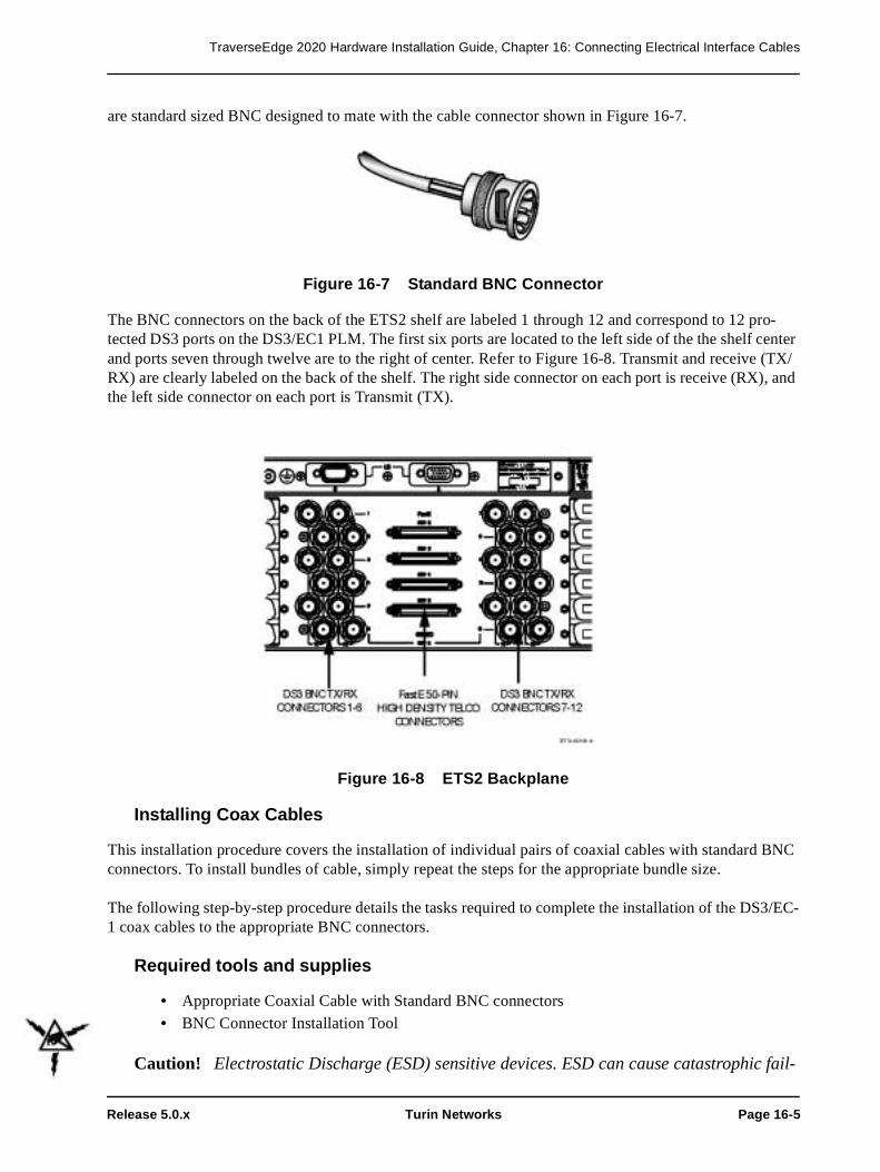
TraverseEdge 2020 Hardware Installation Guide, Chapter 16: Connecting Electrical Interface Cables
Release 5.0.x Turin Networks Page 16-5
are standard sized BNC designed to mate with the cable connector shown in Figure 16-7.
Figure 16-7 Standard BNC Connector
The BNC connectors on the back of the ETS2 shelf are labeled 1 through 12 and correspond to 12 pro-tected DS3 ports on the DS3/EC1 PLM. The first six ports are located to the left side of the the shelf center and ports seven through twelve are to the right of center. Refer to Figure 16-8. Transmit and receive (TX/RX) are clearly labeled on the back of the shelf. The right side connector on each port is receive (RX), and the left side connector on each port is Transmit (TX).
Figure 16-8 ETS2 Backplane
Installing Coax Cables
This installation procedure covers the installation of individual pairs of coaxial cables with standard BNC connectors. To install bundles of cable, simply repeat the steps for the appropriate bundle size.
The following step-by-step procedure details the tasks required to complete the installation of the DS3/EC-1 coax cables to the appropriate BNC connectors.
Required tools and supplies
• Appropriate Coaxial Cable with Standard BNC connectors
• BNC Connector Installation Tool
Caution! Electrostatic Discharge (ESD) sensitive devices. ESD can cause catastrophic fail-

TraverseEdge 2020 Hardware Installation Guide, Chapter 16: Connecting Electrical Interface Cables
Page 16-6 Turin Networks Release 5.0.x
ure or degraded life and performance of a device. Use an anti-static wrist strap connected to a properly grounded source before contacting any electronic devices.
Step 1 Verify that the selected cable has a standard BNC connector on the shelf side and that the cable is long enough to reach to the cable termination location.
Step 2 Place the BNC Connector Installation Tool around the end of the transmit BNC connector on the cable, place the connector over the appropriate Transmit connector on the shelf and turn clockwise one quarter turn (or until the BNC locks in place).
Step 3 Remove the BNC Connector Installation Tool from around the end of the BNC connector.
Step 4 Place the BNC Connector Installation Tool around the end of the receive BNC connector on the cable, place the connector over the appropriate Receive connector on the shelf and turn clockwise one quarter turn (or until the BNC locks in place).
Step 5 Remove the BNC Connector Installation Tool from around the end of the BNC connector.
Step 6 Repeat Steps 1-5 until all necessary coaxial cables are installed.
Stop! You have completed this procedure.
16.2.3 FastE Connectors
FastE interfaces are only available in the ETS2 tributary shelf. The shelf can be equipped with up to four FastE PLMs. FastE interface connectors are centered on the rear of the shelf. Refer to Figure 16-5.
Figure 16-9 FastE Connections on an ETS2
The top connector corresponds to the FastE PLM installed in slot 2. Then next connector is slot 3, and the bottom two connectors correspond to slots 4 and 5. All connectors are clearly marked on the rear panel.

TraverseEdge 2020 Hardware Installation Guide, Chapter 16: Connecting Electrical Interface Cables
Release 5.0.x Turin Networks Page 16-7
Installing FastE Cables
This installation procedure covers the installation of individual FastE cables with 50-pin High-Density Telco connectors equipped on the equipment end, and standard 50-pin Telco connectors at the patch panel end. 10/100 Ethernet patch panels shown in Figure 16-10 are available from Turin Networks. Refer to the TE-2020 Ordering Guide for part number and ordering information (WR-D2020-ORD-040000). They pro-vide a 50-pin Telco interface connector on the rear of the panel and RJ-45 connectors on the front of the panel.
Figure 16-10 10/100 Ethernet Patch Panel
The following step-by-step procedure details the tasks required to complete the installation of the FastE cables to the appropriate backplane connector. Refer to the TE-2020 Ordering Guide (WR-D2020-ORD-040000) for cable part numbers and configurations.
Required tools and supplies
• Appropriate FastE cable with 50-pin mini Telco connectors
Caution! Electrostatic Discharge (ESD) sensitive devices. ESD can cause catastrophic fail-ure or degraded life and performance of a device. Use an anti-static wrist strap connected to a properly grounded source before contacting any electronic devices.
Step 1 Verify that the selected cable is long enough to reach to the cable termination location.
Step 2 Determine the equipment requirements within the shelf to ensure proper termination. If only Slot 2 is equipped with a FastE PLM, then plan on installing the FastE cable on the upper FastE backplane connector. If only slot 5 is equipped, prepare to only equip the lower backplane connector, etc.
Step 3 Place the cable connector over the appropriate connector on the shelf and press until the connector seats in place.

TraverseEdge 2020 Hardware Installation Guide, Chapter 16: Connecting Electrical Interface Cables
Page 16-8 Turin Networks Release 5.0.x
Step 4 Using a screwdriver, carefully secure the connector in place on both ends using the screw retainers.
Step 5 Repeat Steps 1-4 until all necessary FastE cables are installed.
Stop! You have completed this procedure.

Release 5.0.x Turin Networks Page 17-1
Chapter 17 LEI Installation
LEIs are required for all Tributary Shelf installations. This chapter discusses LEI terminology, makes rec-ommendations on LEI routing and gives a step-by-step procedure for installing LEI cables between a TE-2020 Main Shelf and a tributary shelf.
17.1 LEI OverviewThe Local Equipment Interconnect (LEI) is needed for both management traffic and data traffic between the TE-2020 Main Shelf and a tributary shelf. It takes a properly installed LEI cable pair to create a fully redundant link between the TE-2020 Main Shelf and the tributary shelf.
The following definitions are used throughout this section.
LEI: Local Equipment Interconnect. The LEI consists of the LEI ports on the shelves and the LEI cables that connect those ports.
LEI Port # (i.e. LEI Port 1): Combination of an LEI port A and an LEI port B between the TE-2020 Main Shelf and OTS2, ETS1, or ETS2.
LEI port A: A female DB-15 connector located on either the TE-2020 Main Shelf, OTS2, ETS1, or ETS2. Makes up one half of an LEI # (ex. LEI#4).
LEI port B: A male DB-15 connector located on either the TE-2020 Main Shelf, OTS2, ETS1, or ETS2. Makes up one half of an LEI # (ex. LEI#4).
LEI cable pair: A set of two LEI cables used to create a redundant data and management link between the TE-2020 and a tributary shelf.
LEI A cable: One half of an LEI cable pair. This cable has male DB-15 connectors on both ends of the cable. The LEI A cable is made to be used only on the LEI port A connector on either the TE-2020 or trib-utary shelf.
LEI B cable: One half of an LEI cable pair. This cable has female DB-15 connectors on both ends of the cable. The LEI B cable is made to be used only on the LEI port B connector on either the TE-2020 or trib-utary shelf.
The TE-2020 Main Shelf supports up to four LEI connections to other tributary shelves. The ETS1 and ETS2 support a single LEI connection to the main shelf. The OTS2 suports up to four LEI connections to the main shelf.
NOTE: The maximum supported LEI cable length is 10 meters. Ensure that the tributary shelf is installed close enough to the main shelf to ensure this restriction is met.
17.2 LEI Routing (Optional)LEI cables have a fixed DB-15 connector and a metal housing at the end of each cable. The LEI ports on the shelves are also DB-15 connectors that are mounted in a fixed position with different polarities based on shelf type and LEI number. This combination of fixed connectors results in LEI cables designed to route

TraverseEdge 2020 Hardware Installation Guide, Chapter 17: LEI Installation
Page 17-2 Turin Networks Release 5.0.x
in a particular direction as shown in Figure 17-1 and Figure 17-2. the ETS1 and ETS2 have the same LEI routing scheme.
Figure 17-1 TE-2020 Main Shelf and OTS2 LEI Routing Directions
Figure 17-2 ETS1 LEI Routing Directions
In addition to the fixed LEI routing directions, LEI cables have a minimum bend radius of 1.4 inches (approximately the size of a baseball). Refer to Figure 17-3.
Figure 17-3 LEI Cable Bend Radius
This combination of fixed connectors and bend radius sometimes requires that the LEI cable be routed

TraverseEdge 2020 Hardware Installation Guide, Chapter 17: LEI Installation
Release 5.0.x Turin Networks Page 17-3
from the Main Shelf to the edge of the rack, back across the rack and finally across to the tributary shelf LEI. An example of this LEI routing is in the TE-2020 Main Shelf and four ETS1 applications as illus-trated in Figure 17-4.
Figure 17-4 Four ETS1 Shelf LEI Routing Directions
Cable tie brackets may be required to properly install the LEI cables in this type of an installation.
Without proper LEI route planning, an installer may be tempted to install an LEI cable with an extremely tight bend as shown in Figure 17-5. This is a violation of installation procedures and will result in an instal-lation that cannot be expected to perform reliably, potentially causing bit errors.

TraverseEdge 2020 Hardware Installation Guide, Chapter 17: LEI Installation
Page 17-4 Turin Networks Release 5.0.x
Figure 17-5 Bend Radius Routing Violation
It is recommended that LEI cable routing be planned for all tributary shelves prior to the installation of any LEI cables.
17.3 Connecting LEI CablesThe following set of step-by-step procedures illustrates how to properly connect LEI cables to a tributary shelf.
Prerequisites
The TE-2020 Main Shelf must be installed as well as some combination of tributary shelves that require LEI connectivity.
• Chapter 4 TE-2020 Main Shelf Installation
• Chapter 6 OTS2 Shelf Installation (Optional)• Chapter 10 DS3/EC1 Tributary Shelf (ETS1) Installation (Optional)
• Chapter 13 ETS2 Installation (Optional)
Required tools and supplies
• Appropriate number of LEI cable pairs• Cable ties (or other appropriate material for securing cables)
• Cable tie brackets or equivalent (Optional)
After performing the prerequisite procedures and gathering the proper tools and supplies, follow the step-

TraverseEdge 2020 Hardware Installation Guide, Chapter 17: LEI Installation
Release 5.0.x Turin Networks Page 17-5
by-step procedure below to install the LEI cables.
NOTE: Before proceeding with the following procedure, it is recommended that the installer read Chapter 17.2 - LEI Routing (Optional).
Step 1 Identify an unused LEI on the TE-2020 Main Shelf (LEI #1, LEI #2, LEI #3), or LEI #4). This will be referred to as “Main Shelf LEI”.
NOTE: A tributary shelf connected to the main shelf LEI #1 will be designated by auto provision-ing as shelf #2. A tributary shelf connected to LEI #2 will be designated by auto provisioning as shelf #3, and so on.
NOTE: Ensure the matched A & B connectors from a single LEI number on a given shelf (ex., LEI #1 A and B) are connected to the same tributary shelf. If a cable designated as “Tributary A” is con-nected to the “Tributary B” input, unpredictable alarms may result.
Step 2 Identify an unused LEI on the tributary shelf (either LEI #1 or LEI #2). This will be referred to as “Tributary Shelf LEI”.
Step 3 Determine a route for the LEI cables (including excess cable) and verify that the LEI cables are long enough to reach from the TE-2020 Main Shelf to the tributary shelf and still maintain proper local procedures for cable distribution.
Step 4 Verify that the LEI cables will not require a bend radius smaller than 1.4 inches (approxi-mately the size of a baseball) using the cable routing from Step 3.
Step 5 Connect one end of the LEI A cable (male) to LEI port A (female) on the TE-2020 Main Shelf.
Figure 17-6 LEI Slide Connector
Step 6 Use the slide connector as shown in Figure 17-6 to secure the cable end to the LEI port.
Step 7 Route the LEI cable along the route determined in Step 3.
Step 8 Connect the remaining end of the LEI A cable (male) to LEI port A (female) on the tribu-tary shelf.

TraverseEdge 2020 Hardware Installation Guide, Chapter 17: LEI Installation
Page 17-6 Turin Networks Release 5.0.x
Step 9 Use the slide connector as shown in Figure 17-6 to secure the cable end to the LEI port.
Step 10 Secure the LEI cable according to local practices and procedures. Verify that the minimum bend radius of 1.4 inches has not been violated.
Step 11 Connect one end of the LEI B cable (female) to LEI port A (male) on the TE-2020 Main Shelf.
Step 12 Use the slide connector as shown in Figure 17-6 to secure the cable end to the LEI port.
Step 13 Route the LEI cable along the route determined in Step 3.
Step 14 Connect the remaining end of the LEI B cable (female) to LEI port B (male) on the tribu-tary shelf.
Step 15 Use the slide connector as shown in Figure 17-6 to secure the cable end to the LEI port.
Step 16 Secure the LEI cable according to local practices and procedures. Verify that the minimum bend radius of 1.4 inches has not been violated.
Stop! You have completed this procedure.

Release 5.0.x Turin Networks Page 18-1
Chapter 18 Front Cover Installation
The TE-2020 Main Shelf, OTS2, DS3/EC1 Tributary Shelf (ETS1), and ETS2 all have front cov-ers to protect the plug-in cards, protect the fiber on optical shelves and to give the installation a completed look.
18.1 TE-2020 Main Shelf and OTS2 Front Cover InstallationThe front cover for the TE-2020 Main Shelf and OTS2 covers the area from the far right edge of the PLM card slots to the fan unit on the left. The front cover covers the exposed plug-in modules and provides for fiber routing.
The front cover has tabs on the right side that must be inserted into the slots on the shelf. The front cover has a raised indention that gets larger as it goes from the left side to the right side, finally ter-minating in an opening on the right side for the fiber to exit the shelf. The left side of the front cover has two thumb screws for attaching the front cover to the shelf and completing the installa-tion.
The same front cover is used for both the 19" and 23" TE-2020 Main Shelves.
Prerequisites
The shelves must be installed as well as the Fan Tray and any required CCTs. All required PLMs and blanks should be installed and the fibers must be connected.
• Chapter 4 TE-2020 Main Shelf Installation • Chapter 5 TE-2020 Main Shelf Plug-In Installation
• Chapter 6 OTS2 Shelf Installation• Chapter 7 OTS2 Plug-In Installation
• Chapter 8 Optical PLM Installation• Chapter 9 Connecting Fibers to Optical PLMs
After performing the prerequisite procedures, follow the step-by-step procedure to install the front cover on the TE-2020 Main Shelf or on an OTS2.
Step 1 Verify that the front cover is the proper version by verifying that it has the words “TE-2020 Main Shelf” or “OTS2” on the bottom right front corner on the appro-priate shelf type.
Step 2 Ensure the fibers are routed through the fiber retaining channel on the right front side of the shelf so they will not get pinched by the front panel installation. Refer to Figure 18-1.

TraverseEdge 2020 Hardware Installation Guide, Chapter 18: Front Cover Installation
Page 18-2 Turin Networks Release 5.0.x
Figure 18-1 TE-2020 Main Shelf Fiber Retaining Channel
Step 3 Align the panel to the front of the shelf at a slight angle so the right of the panel is touching but the left is pulled away about one inch from the front of the shelf. Refer to Figure 18-2.
Step 4 Line up the bottom of the panel under the front lip of the shelf about one inch to the left of the panel tab retainers.
Step 5 Roll the top of the panel up and over the top lip of the shelf.
Step 6 Slide the panel to the right sliding the tabs into the panel clip retainers, again insuring that the fibers are out of harms way.
Caution! Using an extreme angle on the front cover during installation may cause the tab on the far right side of the front cover to contact the installed fibers, possibly resulting in damaged fibers. Tilt the front cover only as much as is needed to get the tabs in the slots.
Step 7 Gently push the left side of the front cover towards the shelf until it reaches the installed position. Turn the thumb screws clockwise to secure the front cover.
Step 8 This concludes the installation of the front cover. This also concludes the installa-tion of the TE-2020 Main Shelf or OTS2 shelf.
Stop! You have completed this procedure.

TraverseEdge 2020 Hardware Installation Guide, Chapter 18: Front Cover Installation
Release 5.0.x Turin Networks Page 18-3
Figure 18-2 TE-2020 Main Shelf Front Cover Panel Installation

TraverseEdge 2020 Hardware Installation Guide, Chapter 18: Front Cover Installation
Page 18-4 Turin Networks Release 5.0.x
18.2 DS3/EC1 Tributary Shelf (ETS1) or ETS2 Front Cover Installation
The front cover for the ETS1 or ETS2 covers the area from the far right edge of the shelf to the fan unit on the left. The front cover covers the exposed Plug-in modules.
The front cover has tabs on the right side that must be inserted into the slots on the shelf about one-inch from the top and bottom of the shelf. The front cover is flat and is designed to cover the plug-in modules. The left side of the front cover has two thumb screws for attaching the front cover to the shelf and completing the installation.
The same front cover is used for both the 19" and 23" version of each ETS shelf.
Prerequisites
The ETS must be installed as well as the ETS Fan Tray and the appropriate CCTs. All required PLMs and blanks should be installed.
• Chapter 10 DS3/EC1 Tributary Shelf (ETS1) Installation• Chapter 11 DS3/EC1 Tributary Shelf (ETS1) Plug-In Installation
• Chapter 12 DS3/EC1 PLM Installation• Chapter 13 ETS2 Installation
• Chapter 14 ETS2 Plug-In Installation• Chapter 15 ETS2 PLM Installation
• Chapter 16 Connecting Electrical Interface Cables
After performing the prerequisite procedures, follow the step-by-step procedure to install the front cover on the ETS1 or ETS2 shelves.
Step 1 Verify that the front cover is the proper version by verifying that it has the appro-priate words “DS3/EC1 Tributary Shelf” or “ETS2”on the bottom right corner, facing the front.
Step 2 Slide the slots on the right hand side of the front cover into the slots on the right hand side of the shelf.
Step 3 Gently push the left side of the front cover towards the shelf until it reaches the installation position. Turn the thumb screws clockwise to secure the front cover.
Step 4 This concludes the installation of the front cover. This also concludes the installa-tion of the shelf.
Stop! You have completed this procedure.

TraverseEdge 2020 Hardware Installation Guide, Chapter 18: Front Cover Installation
Release 5.0.x Turin Networks Page 18-5
Figure 18-3 ETS1 or ETS2 Front Cover Installation

TraverseEdge 2020 Hardware Installation Guide, Chapter 18: Front Cover Installation
Page 18-6 Turin Networks Release 5.0.x

Release 5.0.x Turin Networks Page 19-1
Chapter 19 Wire Gauge, Fuse Sizes and Power Calculations
19.1 Shelf Power CalculationsPrior to installation it is important to know how much power a TE-2020 Main Shelf, OTS2, ETS1, or ETS20 will require in a particular configuration. This information can be used to calculate cooling require-ments, wire gauges and fuse sizes. The following work sheets are provided to aid in the calculation of total power per shelf in a specific configuration.
It is important to verify that the power values in the worksheets match the latest versions of fan trays, CCTs, PLMs etc. to be used in the system. All of the power values have been rounded to the nearest integer values for these calculations.
Warning: A suitably approved branch overcurrent protection shall be rated at minimum 60V, Max. 10A.
Table 19-1 TE-2020 Main Shelf Power Summary Worksheet
Plug-in Qty Power
(Watts)
Total
(Watts)
TE-2020 Main CCT 83
TE-2020 Enhanced Main CCT 75
TE-2020 Main CCT w/2.5G VT Fabric 81
TE-2020 Main CCT w/5G VT Fabric 86
TE-2020 Main Fan Tray 40
OC-192 x1 SR 1310 PLM 37
OC-192 x1 IR 1550 PLM 39
OC-192 x1 LR2 1550 PLM 4
OC-192 x1 LR Tunable PLM (all) 47
OC-48 x1 LR 1310 PLM 14
OC-48 x1 IR 1310 PLM 12
OC-48 x1 LR 1550 PLM 14
OC-48 x1 VR 1310 PLM 14
OC-48 x1 SFP Base PLM 15
OC-48 x2 IR 1310 PLM 22
OC-48 x2 LR 1310 PLM 22
OC-48 x4 IR 1310 PLM 37

TraverseEdge 2020 Hardware Installation Guide, Chapter 19: Wire Gauge, Fuse Sizes and Power Calculations
Page 19-2 Turin Networks Release 5.0.x
OC-48 x4 LR PLM (LR1 and LR-2) 37
OC-12 x2 IR 1310 PLM 9
OC-12 x2 LR PLM (LR1 and LR-2) 11
OC-12 x4 IR 1310 PLM 14
OC-12 x4 LR PLM (LR1 and LR-2) 16
OC-3 x4 IR 1310 PLM 8
OC-3 x4 LR PLM (LR1 and LR-2) 13
1000Base-SX x2 MMF 850 PLM 17
1000Base-LX x2 SMF 1310 PLM 18
1000Base-ZX x2 SMF 1550 PLM 19
1000Base-SX x2 MMF 850 Enhanced PLM 15
1000Base-LX x2 SMF 1310 Enhanced PLM 17
1000Base-ZX x2 SMF 1550 Enhanced PLM 17
Total Power
Table 19-2 OTS2 Power Summary Worksheet
Plug-in Qty Power
(Watts)
Total
(Watts)
OTS2 CCT 83
OTS2 Enhanced CCT 75
OTS2 CCT w/2.5G VT Fabric 81
OTS2 CCT w/5G VT Fabric 86
OTS2 CCT 83
OTS2 Fan Tray 40
OC-48 x1 LR 1310 PLM 14
OC-48 x1 IR 1310 PLM 12
OC-48 x1 LR 1550 PLM 14
OC-48 x1 VR 1310 PLM 14
Table 19-1 TE-2020 Main Shelf Power Summary Worksheet
Plug-in Qty Power
(Watts)
Total
(Watts)

TraverseEdge 2020 Hardware Installation Guide, Chapter 19: Wire Gauge, Fuse Sizes and Power Calculations
Release 5.0.x Turin Networks Page 19-3
OC-48 x1 SFP Base PLM 15
OC-48 x2 IR 1310 PLM 22
OC-48 x2 LR 1310 PLM 22
OC-48 x4 IR 1310 PLM 37
OC-48 x4 LR PLM (LR1 and LR-2) 37
OC-12 x2 IR 1310 PLM 9
OC-12 x2 LR PLM (LR1 and LR-2) 11
OC-12 x4 IR 1310 PLM 14
OC-12 x4 LR PLM (LR1 and LR-2) 16
OC-3 x4 IR 1310 PLM 8
OC-3 x4 LR PLM (LR1 and LR-2) 13
1000Base-SX x2 MMF 850 PLM 17
1000Base-LX x2 SMF 1310 PLM 18
1000Base-ZX x2 SMF 1550 PLM 19
1000Base-SX x2 MMF 850 Enhanced PLM 15
1000Base-LX x2 SMF 1310 Enhanced PLM 17
1000Base-ZX x2 SMF 1550 Enhanced PLM 17
Total Power
Table 19-3 ETS1 Power Summary Worksheet
Plug-in Qty Power
(Watts)
Total
(Watts)
ETS1 CCT 25
Fan Tray 20
DS3/EC1 x12 PLM 24
DS3/EC1 x12 PLM with Test Access 20
DS3/EC1 x12 Transmux PLM 20
Total Power
Table 19-2 OTS2 Power Summary Worksheet
Plug-in Qty Power
(Watts)
Total
(Watts)

TraverseEdge 2020 Hardware Installation Guide, Chapter 19: Wire Gauge, Fuse Sizes and Power Calculations
Page 19-4 Turin Networks Release 5.0.x
19.2 Wire Gauge and Fuse RatingLocal procedures and guidelines should always be used as the primary determining factor when calculating wire gauge and fuse sizes for individual shelves. The information in this section is made available for instances where local procedures and guidelines either do not exist or do not cover equipment with the space and power requirements of the TE-2020 Main Shelf, OTS2, ETS1, or ETS2. Copper conductors should always be used as a standard for this equipment.
The TE-2020 Main Shelf, OTS2, ETS1, or ETS2 have fairly stable power requirements regardless of con-figuration. Because of this, 12 AWG copper wire can always be used for all installations to provide -48 volt supply and return, as well as chassis ground. The approved branch circuit for over-current protection shall have a 60 Volt minimum and 10 Amp maximum rating.
A more rigorous calculation of power requirements is recommended for determining fuse size. In order to determine the fuse size for each installed shelf, the worksheets in this chapter must first be filled out and total power configuration of each shelf must be calculated.
Once the total power for each application has been determined, the tables below can be used to determine fuse size. These tables are provided only as a guideline, local procedures for determining the Wire Gauge and Fuse Sizes should always override the guidelines given in this section (within the 60V min., 10A max requirement).
The table below shows ranges of input voltage and associated currents based on power in Watts calculated from the tables below. If the input voltage can be guaranteed at the average or maximum values, then those values should be used. Otherwise, the worst case voltage input of -42.5 Volts should be used. A typical configuration will only require 10 Amp fuses per shelf. Only one shelf should be wired to any one fused power source.
Table 19-4 ETS2 Power Summary Worksheet
Plug-in Qty Power
(Watts)
Total
(Watts)
ETS2 CCT 25
Fan Tray 20
DS3/EC1 x12 PLM 24
DS3/EC1 x12 PLM with Test Access 20
DS3/EC1 x12 Transmux PLM 20
FastE PLM 20
DS1 x28 PLM 13
DS1 x84 PLM 35
Total Power

TraverseEdge 2020 Hardware Installation Guide, Chapter 19: Wire Gauge, Fuse Sizes and Power Calculations
Release 5.0.x Turin Networks Page 19-5
Table 19-5 Min. and Max Currents for Min. and Max Voltages
Power Min Ave Max Min Ave Max100 42.5 48 56.5 1.77 2.08 2.35125 42.5 48 56.5 2.21 2.60 2.94150 42.5 48 56.5 2.65 3.13 3.53175 42.5 48 56.5 3.10 3.65 4.12200 42.5 48 56.5 3.54 4.17 4.71225 42.5 48 56.5 3.98 4.69 5.29250 42.5 48 56.5 4.42 5.21 5.88275 42.5 48 56.5 4.87 5.73 6.47300 42.5 48 56.5 5.31 6.25 7.06325 42.5 48 56.5 5.75 6.77 7.65350 42.5 48 56.5 6.19 7.29 8.24

TraverseEdge 2020 Hardware Installation Guide, Chapter 19: Wire Gauge, Fuse Sizes and Power Calculations
Page 19-6 Turin Networks Release 5.0.x


Visit our website at:www.turinnetworks.com
Release 5.0.x
TraverseEdge 2020 System Documentation
800-0017-50 (WR-D2020-HWI-040000 Issue 03)


![Dossier Empresa Edse Inventiva Sl [Rev.a]](https://img.pdfslide.net/doc/110x75/55cf9cd2550346d033ab2b75/dossier-empresa-edse-inventiva-sl-reva.jpg)


