Embed Size (px)
Citation preview

References: LE2708 (76-0201)
Version: V04/11/2014
Hardware User’s Manual
Avoidance programmer with shocker
Active & passive avoidance boxes
Panlab, s.l.u C/Energía, 112 08940 Cornellà de Ll.(Barcelona) Spain www.panlab.com
International Calls: +34 934 750 697 Domestic Call: 934 190 709 Fax: +34 934 750 699 [email protected]
Limitation of Liability PANLAB does not accept responsibility, under any circumstances, for any harm or damage caused directly or indirectly by the incorrect interpretation of what is expressed in the pages of this manual. Some symbols may have more than one interpretation by professionals unaccustomed to their usage. PANLAB reserves the right to modify, in part or in total, the contents of this document without notice.

1. SYMBOLS TABLE
Recognising the symbols used in the manual will help to understand their meaning:
DESCRIPTION SYMBOL Warning about operations that must not be done because they can damage the equipment Warning about operations that must be done, otherwise the user can be exposed to a hazard. Protection terminal ground connection.
Warning about a hot surface which temperature may exceed 65ºC
Warning about a metal surface that can supply electrical shock when it’s touched. Decontamination of equipments prior to disposal at the end of their operative life Waste Electrical and Electronic Equipment Directive (WEEE)
2. GOOD LABORATORY PRACTICE
Check all units periodically and after periods of storage to ensure they are still fit for purpose. Investigate all failures which may indicate a need for service or repair. Good laboratory practice recommends that the unit be periodically serviced to ensure the unit is suitable for purpose. You must follow preventive maintenance instructions. In case equipment has to be serviced you can arrange this through your distributor. Prior to Inspection, Servicing, Repair or Return of Laboratory Equipment the unit must be cleaned and decontaminated.
Decontamination prior to equipment disposal In use this product may have been in contact with bio hazardous materials and might therefore carry infectious material. Before disposal the unit and accessories should all be thoroughly decontaminated according to your local environmental safety laws.
Avoidance programmer with shocker 2

3. UNPACKING AND EQUIPMENT INSTALATION
WARNING: Failure to follow the instructions in this section may cause equipment faults or injury to the user.
A. No special equipment is required for lifting but you should consult your local regulations for safe handling and lifting of the equipment.
B. Inspect the instrument for any signs of damage caused during transit. If any damage is discovered, do not use the instrument and report the problem to your supplier.
C. Ensure all transport locks are removed before use. The original packing has been especially designed to protect the instrument during transportation. It is therefore recommended to keep the original carton with its foam parts and accessories box for re-use in case of future shipments. Warranty claims are void if improper packing results in damage during transport.
D. Place the equipment on a flat surface and leave at least 10 cm of free space between the rear panel of the device and the wall. Never place the equipment in zones with vibration or direct sunlight.
E. Once the equipment is installed in the final place, the main power switch must be easily accessible.
F. Only use power cords that have been supplied with the equipment. In case that you have to replace them, the spare ones must have the same specs that the original ones.
G. Make sure that the AC voltage in the electrical network is the same as the voltage selected in the equipment. Never connect the equipment to a power outlet with voltage outside these limits.
The manufacturer accepts no responsibility for improper use of the equipment or the consequences of use other than that for which it has been designed.
WARNING
For electrical safety reasons you only can connect equipment to
power outlets provided with earth connections . This equipment can be used in installations with category II over-voltage according to the General Safety Rules.
Avoidance programmer with shocker 3

WARNING
PC Control
Some of these instruments are designed to be controlled from a PC. To preserve the integrity of the equipment it is essential that the attached PC itself conforms to basic safety and EMC standards and is set up in accordance with the manufacturers’ instructions. If in doubt consult the information that came with your PC. In common with all computer operation the following safety precautions are advised.
• To reduce the chance of eye strain, set up the PC display with the correct viewing position, free from glare and with appropriate brightness and contrast settings
• To reduce the chance of physical strain, set up the PC display, keyboard and mouse with correct ergonomic positioning, according to your local safety guidelines.
Avoidance programmer with shocker 4
4. MAINTENANCE
WARNING: Failure to follow the instructions in this section may cause equipment fault.
• PRESS KEYS SOFTLY – Lightly pressing the keys is sufficient to activate them. • Equipments do not require being disinfected, but cleaned for removing urine,
faeces and odour. To do so, we recommend using a wet cloth or paper with soap (which has no strong odour). NEVER USE ABRASIVE PRODUCTS OR DISSOLVENTS.
• NEVER pour water or liquids on the equipment. • Once you have finished using the equipment turn it off with the main switch. Clean
and check the equipment so that it is in optimal condition for its next use. • The user is only authorised to replace fuses with the specified type when necessary.
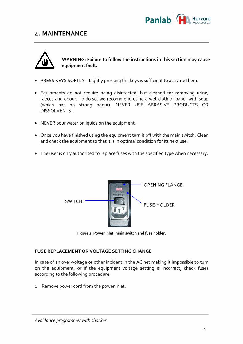
Figure 1. Power inlet, main switch and fuse holder.
FUSE REPLACEMENT OR VOLTAGE SETTING CHANGE
In case of an over-voltage or other incident in the AC net making it impossible to turn on the equipment, or if the equipment voltage setting is incorrect, check fuses according to the following procedure.
1 Remove power cord from the power inlet.
SWITCH FUSE-HOLDER
OPENING FLANGE
Avoidance programmer with shocker 5
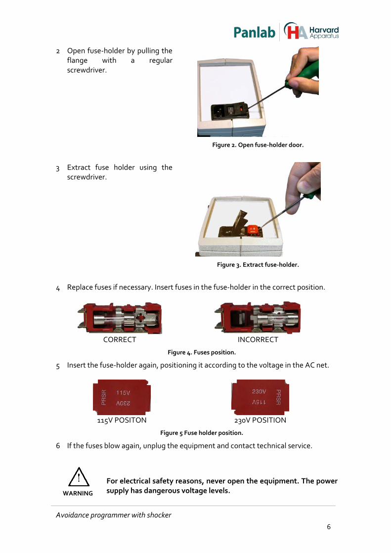
2 Open fuse-holder by pulling the flange with a regular screwdriver.
Figure 2. Open fuse-holder door.
3 Extract fuse holder using the
screwdriver.
Figure 3. Extract fuse-holder.
4 Replace fuses if necessary. Insert fuses in the fuse-holder in the correct position.
CORRECT INCORRECT Figure 4. Fuses position.
5 Insert the fuse-holder again, positioning it according to the voltage in the AC net.
115V POSITON 230V POSITION Figure 5 Fuse holder position.
6 If the fuses blow again, unplug the equipment and contact technical service.
WARNING
For electrical safety reasons, never open the equipment. The power supply has dangerous voltage levels.
Avoidance programmer with shocker 6
5. TABLE OF CONTENTS
1. SYMBOLS TABLE 2
2. GOOD LABORATORY PRACTICE 2
3. UNPACKING AND EQUIPMENT INSTALATION 3
4. MAINTENANCE 5
5. TABLE OF CONTENTS 7
6. INTRODUCTION 9
7. GENERAL DESCRIPTION 10
7.1. LE 2708 10
8. EQUIPMENT DESCRIPTION 12
8.1. LE 2708 FRONT PANEL 12
8.2. LE 2708 REAR PANEL 14
9. MODES 16
9.1. PROGRAMMING TOPICS 17
10. EQUIPMENT CONNECTION 18
10.1. PASSIVE AVOIDANCE 18
10.2. ACTIVE AVOIDANCE 20
10.3. MODULAR OPERANT CHAMBER 22
10.4. CONNECTING TO THE COMPUTER COM PORT 24
11. WORKING WITH THE EQUIPMENT 25
11.1. CONDUCTING AN EXPERIMENT 25
11.2. CLEANING THE CAGE 25
12. WORKING WITH THE SEDACOM SOFTWARE 26
Avoidance programmer with shocker 7

13. TROUBLESHOOTING 27
14. PREVENTIVE MAINTENANCE 29
15. TECHNICAL SPECIFICATIONS 30
Avoidance programmer with shocker 8
6. INTRODUCTION
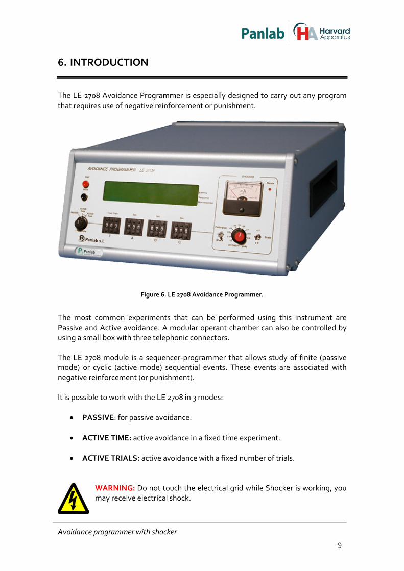
The LE 2708 Avoidance Programmer is especially designed to carry out any program that requires use of negative reinforcement or punishment.
Figure 6. LE 2708 Avoidance Programmer.
The most common experiments that can be performed using this instrument are Passive and Active avoidance. A modular operant chamber can also be controlled by using a small box with three telephonic connectors. The LE 2708 module is a sequencer-programmer that allows study of finite (passive mode) or cyclic (active mode) sequential events. These events are associated with negative reinforcement (or punishment). It is possible to work with the LE 2708 in 3 modes:
• PASSIVE: for passive avoidance.
• ACTIVE TIME: active avoidance in a fixed time experiment.
• ACTIVE TRIALS: active avoidance with a fixed number of trials.
WARNING: Do not touch the electrical grid while Shocker is working, you may receive electrical shock.
Avoidance programmer with shocker 9

7. GENERAL DESCRIPTION
7.1. LE 2708
The LE 2708 structure consists of:
• 3 digital timers labelled A, B and C. They can be programmed with response and non-response counters.
• 1 timer (labelled T) with several functions. o Timer (passive mode). o Time counter of experiment duration in minutes (active mode). o Time counter of experiment duration in trials (active mode).
• A constant current shock generator with an automatic scrambler. This generator keeps the current constant regardless of the load resistance. This shock generator is associated to timer C.
Each timer can work independently, and can be set up in different modes (depending on the program) using controls located on the rear panel of the LE 2708. The LE 2708 has three timers that allow the programming of several different types of behavioural study, as each one can be associated to one of the intervals usually used in this kind of experiment.
• Intertrial or pause interval. • Discrimination or avoidance interval. • Escape or punishment interval.
7.1.1. TIMER BLOCK DIAGRAM The timer is activated when a TTL signal is applied in the START input and it will work during the time selected in the front panel. While the timer is active it gives a continuous signal in the output labelled OUTPUT. This signal is normally assigned to connections labelled LIGHT, SOUND or DOOR. Once the selected time has elapsed, a pulse appears in the END PULSE output and the NON RESPONSE counter on the display increases by one unit.
Avoidance programmer with shocker 10
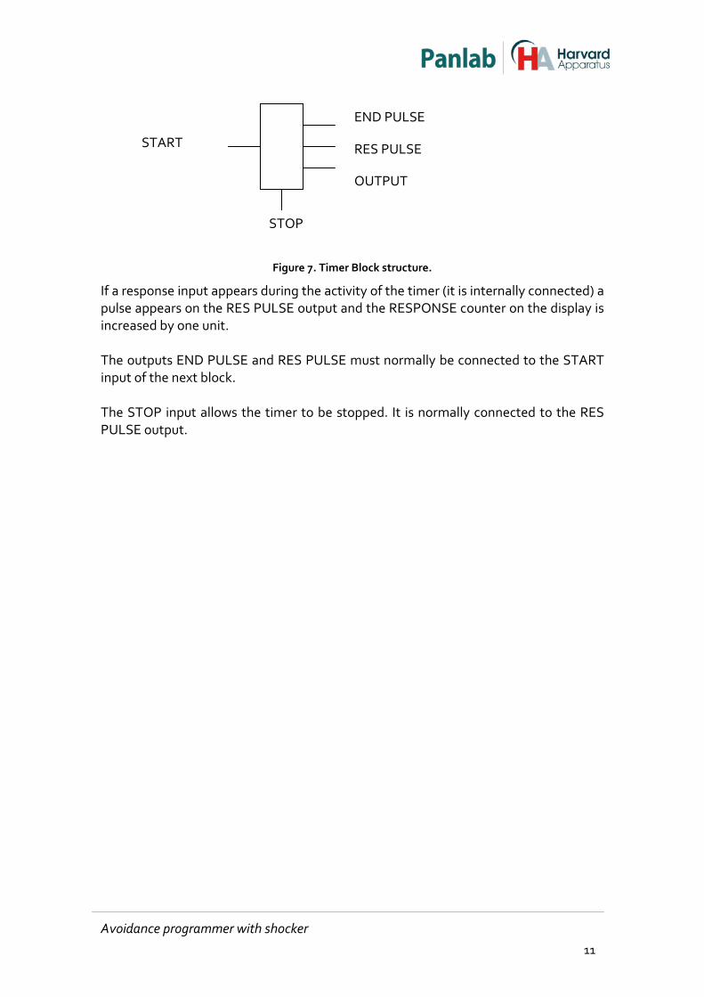
Figure 7. Timer Block structure.
If a response input appears during the activity of the timer (it is internally connected) a pulse appears on the RES PULSE output and the RESPONSE counter on the display is increased by one unit. The outputs END PULSE and RES PULSE must normally be connected to the START input of the next block. The STOP input allows the timer to be stopped. It is normally connected to the RES PULSE output.
START
END PULSE
RES PULSE
OUTPUT
STOP
Avoidance programmer with shocker 11
8. EQUIPMENT DESCRIPTION
8.1. LE 2708 FRONT PANEL
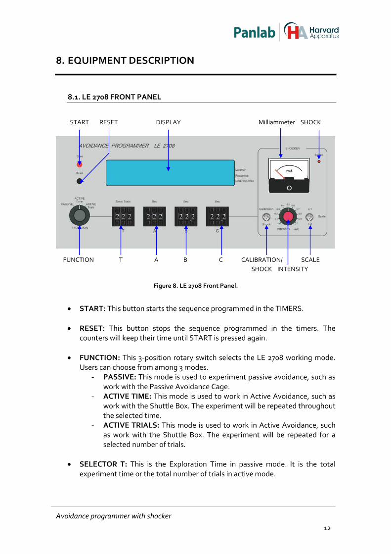
Figure 8. LE 2708 Front Panel.
• START: This button starts the sequence programmed in the TIMERS.
• RESET: This button stops the sequence programmed in the timers. The
counters will keep their time until START is pressed again.
• FUNCTION: This 3-position rotary switch selects the LE 2708 working mode. Users can choose from among 3 modes.
- PASSIVE: This mode is used to experiment passive avoidance, such as work with the Passive Avoidance Cage.
- ACTIVE TIME: This mode is used to work in Active Avoidance, such as work with the Shuttle Box. The experiment will be repeated throughout the selected time.
- ACTIVE TRIALS: This mode is used to work in Active Avoidance, such as work with the Shuttle Box. The experiment will be repeated for a selected number of trials.
• SELECTOR T: This is the Exploration Time in passive mode. It is the total
experiment time or the total number of trials in active mode.
START RESET DISPLAY Milliammeter SHOCK
FUNCTION T A B C CALIBRATION/ SCALE SHOCK INTENSITY
Avoidance programmer with shocker 12
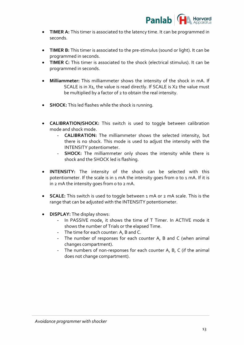
• TIMER A: This timer is associated to the latency time. It can be programmed in seconds.
• TIMER B: This timer is associated to the pre-stimulus (sound or light). It can be
programmed in seconds. • TIMER C: This timer is associated to the shock (electrical stimulus). It can be
programmed in seconds.
• Milliammeter: This milliammeter shows the intensity of the shock in mA. If SCALE is in X1, the value is read directly. If SCALE is X2 the value must be multiplied by a factor of 2 to obtain the real intensity.
• SHOCK: This led flashes while the shock is running.
• CALIBRATION/SHOCK: This switch is used to toggle between calibration mode and shock mode.
- CALIBRATION: The milliammeter shows the selected intensity, but there is no shock. This mode is used to adjust the intensity with the INTENSITY potentiometer.
- SHOCK: The milliammeter only shows the intensity while there is shock and the SHOCK led is flashing.
• INTENSITY: The intensity of the shock can be selected with this
potentiometer. If the scale is in 1 mA the intensity goes from 0 to 1 mA. If it is in 2 mA the intensity goes from 0 to 2 mA.
• SCALE: This switch is used to toggle between 1 mA or 2 mA scale. This is the
range that can be adjusted with the INTENSITY potentiometer.
• DISPLAY: The display shows: - In PASSIVE mode, it shows the time of T Timer. In ACTIVE mode it
shows the number of Trials or the elapsed Time. - The time for each counter: A, B and C. - The number of responses for each counter A, B and C (when animal
changes compartment). - The numbers of non-responses for each counter A, B, C (if the animal
does not change compartment).
Avoidance programmer with shocker 13
8.2. LE 2708 REAR PANEL
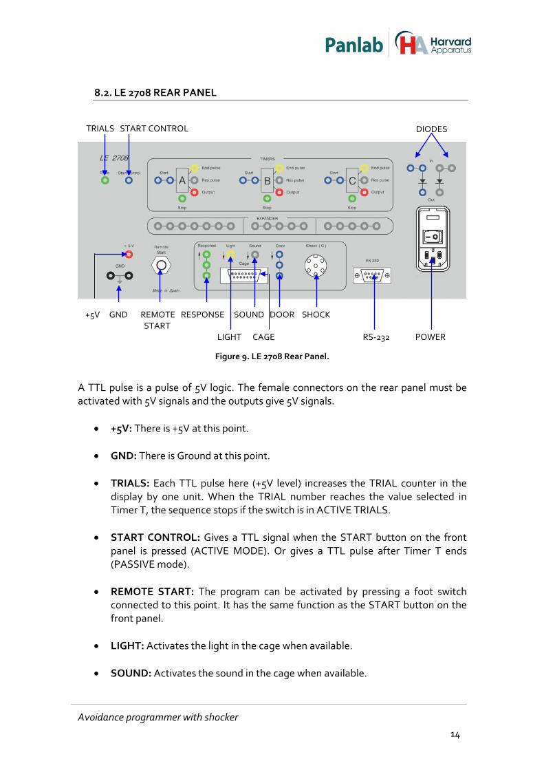
Figure 9. LE 2708 Rear Panel.
A TTL pulse is a pulse of 5V logic. The female connectors on the rear panel must be activated with 5V signals and the outputs give 5V signals.
• +5V: There is +5V at this point.
• GND: There is Ground at this point.
• TRIALS: Each TTL pulse here (+5V level) increases the TRIAL counter in the display by one unit. When the TRIAL number reaches the value selected in Timer T, the sequence stops if the switch is in ACTIVE TRIALS.
• START CONTROL: Gives a TTL signal when the START button on the front
panel is pressed (ACTIVE MODE). Or gives a TTL pulse after Timer T ends (PASSIVE mode).
• REMOTE START: The program can be activated by pressing a foot switch
connected to this point. It has the same function as the START button on the front panel.
• LIGHT: Activates the light in the cage when available.
• SOUND: Activates the sound in the cage when available.
TRIALS START CONTROL DIODES
+5V GND REMOTE RESPONSE SOUND DOOR SHOCK START LIGHT CAGE RS-232 POWER
Avoidance programmer with shocker 14
• DOOR: Activates the Door in the cage when available. If this signal is not present the door will be closed.
• SHOCK: This connector sends the shock to the grid. • RESPONSE: Output signal that comes from the cage. It is internally connected
to the 3 timer blocks.
• CAGE: This connector connects the LE 2708 with the control unit of the cage, facilitating communication.
• RS-232: This connector can be used to send data to the PC through the
Sedacom software (these software options are not included, they should be purchased separately).
• DIODES: Diodes are used when we need to isolate signals.
8.2.1. TIMER
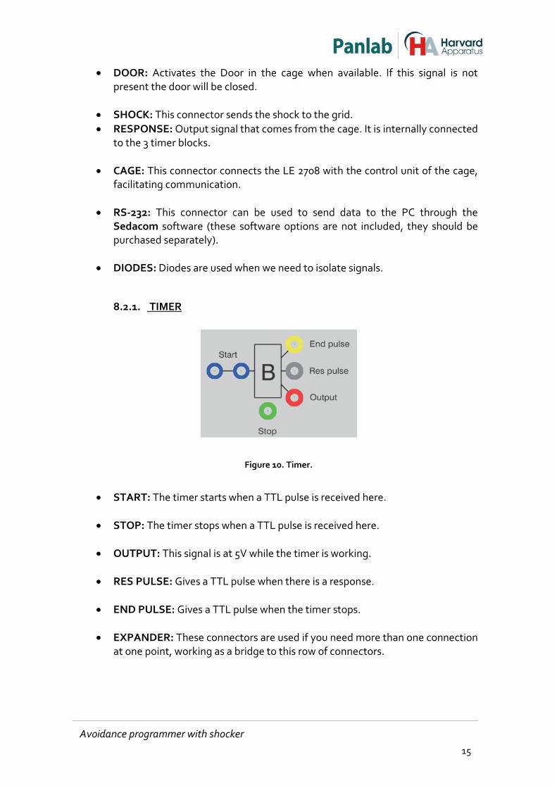
Figure 10. Timer.
• START: The timer starts when a TTL pulse is received here.
• STOP: The timer stops when a TTL pulse is received here.
• OUTPUT: This signal is at 5V while the timer is working.
• RES PULSE: Gives a TTL pulse when there is a response.
• END PULSE: Gives a TTL pulse when the timer stops.
• EXPANDER: These connectors are used if you need more than one connection
at one point, working as a bridge to this row of connectors.
Avoidance programmer with shocker 15
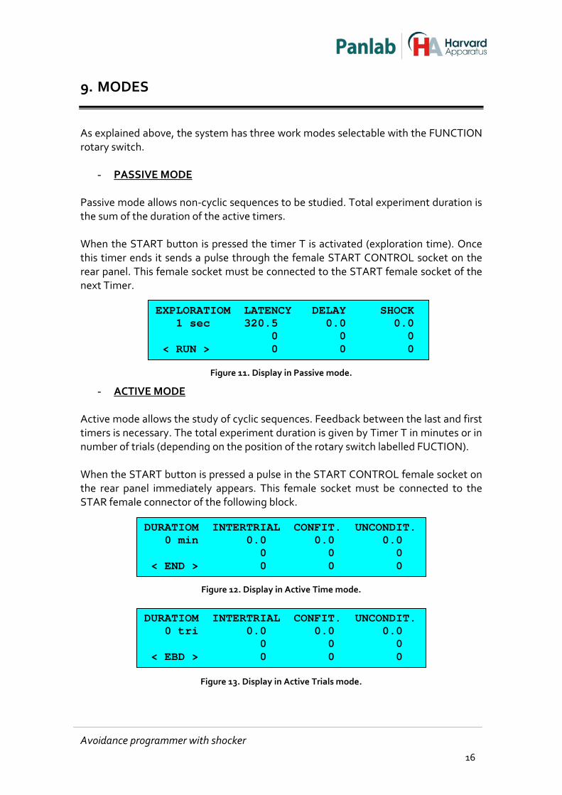
9. MODES
As explained above, the system has three work modes selectable with the FUNCTION rotary switch.
- PASSIVE MODE Passive mode allows non-cyclic sequences to be studied. Total experiment duration is the sum of the duration of the active timers. When the START button is pressed the timer T is activated (exploration time). Once this timer ends it sends a pulse through the female START CONTROL socket on the rear panel. This female socket must be connected to the START female socket of the next Timer.
Figure 11. Display in Passive mode.
- ACTIVE MODE Active mode allows the study of cyclic sequences. Feedback between the last and first timers is necessary. The total experiment duration is given by Timer T in minutes or in number of trials (depending on the position of the rotary switch labelled FUCTION). When the START button is pressed a pulse in the START CONTROL female socket on the rear panel immediately appears. This female socket must be connected to the STAR female connector of the following block.
Figure 12. Display in Active Time mode.
Figure 13. Display in Active Trials mode.
EXPLORATIOM LATENCY DELAY SHOCK 1 sec 320.5 0.0 0.0 0 0 0 < RUN > 0 0 0
DURATIOM INTERTRIAL CONFIT. UNCONDIT. 0 min 0.0 0.0 0.0 0 0 0 < END > 0 0 0
DURATIOM INTERTRIAL CONFIT. UNCONDIT. 0 tri 0.0 0.0 0.0 0 0 0 < EBD > 0 0 0
Avoidance programmer with shocker 16
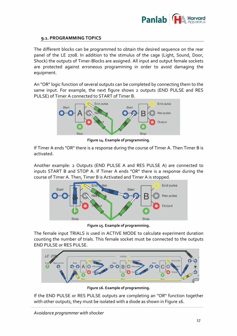
9.1. PROGRAMMING TOPICS
The different blocks can be programmed to obtain the desired sequence on the rear panel of the LE 2708. In addition to the stimulus of the cage (Light, Sound, Door, Shock) the outputs of Timer-Blocks are assigned. All input and output female sockets are protected against erroneous programming in order to avoid damaging the equipment. An "OR" logic function of several outputs can be completed by connecting them to the same input. For example, the next figure shows 2 outputs (END PULSE and RES PULSE) of Timer A connected to START of Timer B.
Figure 14. Example of programming.
If Timer A ends "OR" there is a response during the course of Timer A. Then Timer B is activated. Another example: 2 Outputs (END PULSE A and RES PULSE A) are connected to inputs START B and STOP A. If Timer A ends "OR" there is a response during the course of Timer A. Then, Timer B is Activated and Timer A is stopped.
Figure 15. Example of programming.
The female input TRIALS is used in ACTIVE MODE to calculate experiment duration counting the number of trials. This female socket must be connected to the outputs END PULSE or RES PULSE.
Figure 16. Example of programming.
If the END PULSE or RES PULSE outputs are completing an "OR" function together with other outputs, they must be isolated with a diode as shown in Figure 16.
Avoidance programmer with shocker 17
10. EQUIPMENT CONNECTION
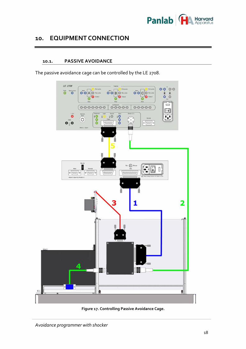
10.1. PASSIVE AVOIDANCE
The passive avoidance cage can be controlled by the LE 2708.
Figure 17. Controlling Passive Avoidance Cage.
Avoidance programmer with shocker 18
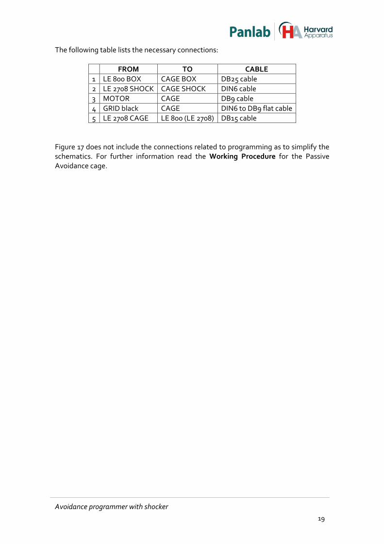
The following table lists the necessary connections:
FROM TO CABLE 1 LE 800 BOX CAGE BOX DB25 cable 2 LE 2708 SHOCK CAGE SHOCK DIN6 cable 3 MOTOR CAGE DB9 cable 4 GRID black CAGE DIN6 to DB9 flat cable 5 LE 2708 CAGE LE 800 (LE 2708) DB15 cable
Figure 17 does not include the connections related to programming as to simplify the schematics. For further information read the Working Procedure for the Passive Avoidance cage.
Avoidance programmer with shocker 19
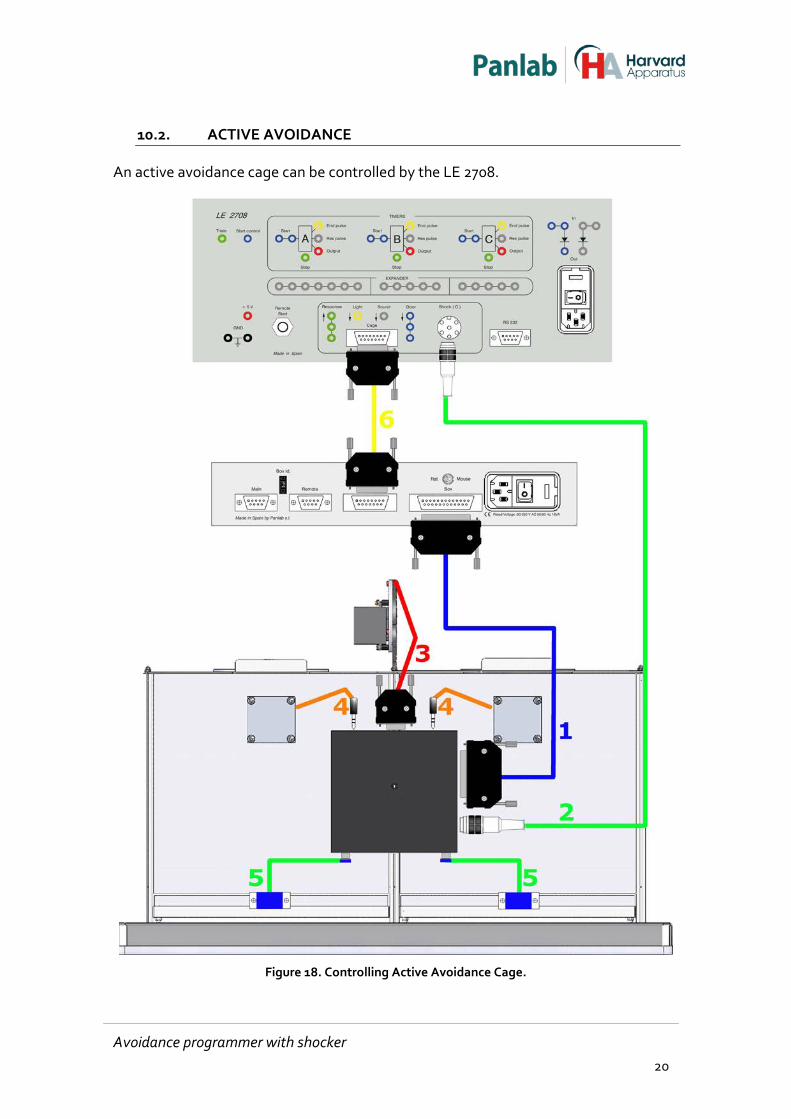
10.2. ACTIVE AVOIDANCE
An active avoidance cage can be controlled by the LE 2708.
Figure 18. Controlling Active Avoidance Cage.
Avoidance programmer with shocker 20
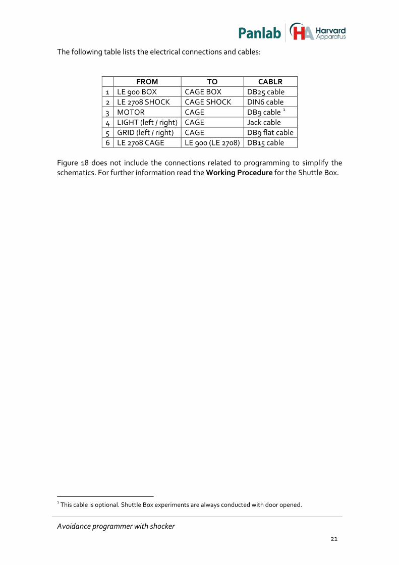
The following table lists the electrical connections and cables:
FROM TO CABLR 1 LE 900 BOX CAGE BOX DB25 cable 2 LE 2708 SHOCK CAGE SHOCK DIN6 cable 3 MOTOR CAGE DB9 cable 1 4 LIGHT (left / right) CAGE Jack cable 5 GRID (left / right) CAGE DB9 flat cable 6 LE 2708 CAGE LE 900 (LE 2708) DB15 cable
Figure 18 does not include the connections related to programming to simplify the schematics. For further information read the Working Procedure for the Shuttle Box.
1 This cable is optional. Shuttle Box experiments are always conducted with door opened.
Avoidance programmer with shocker 21
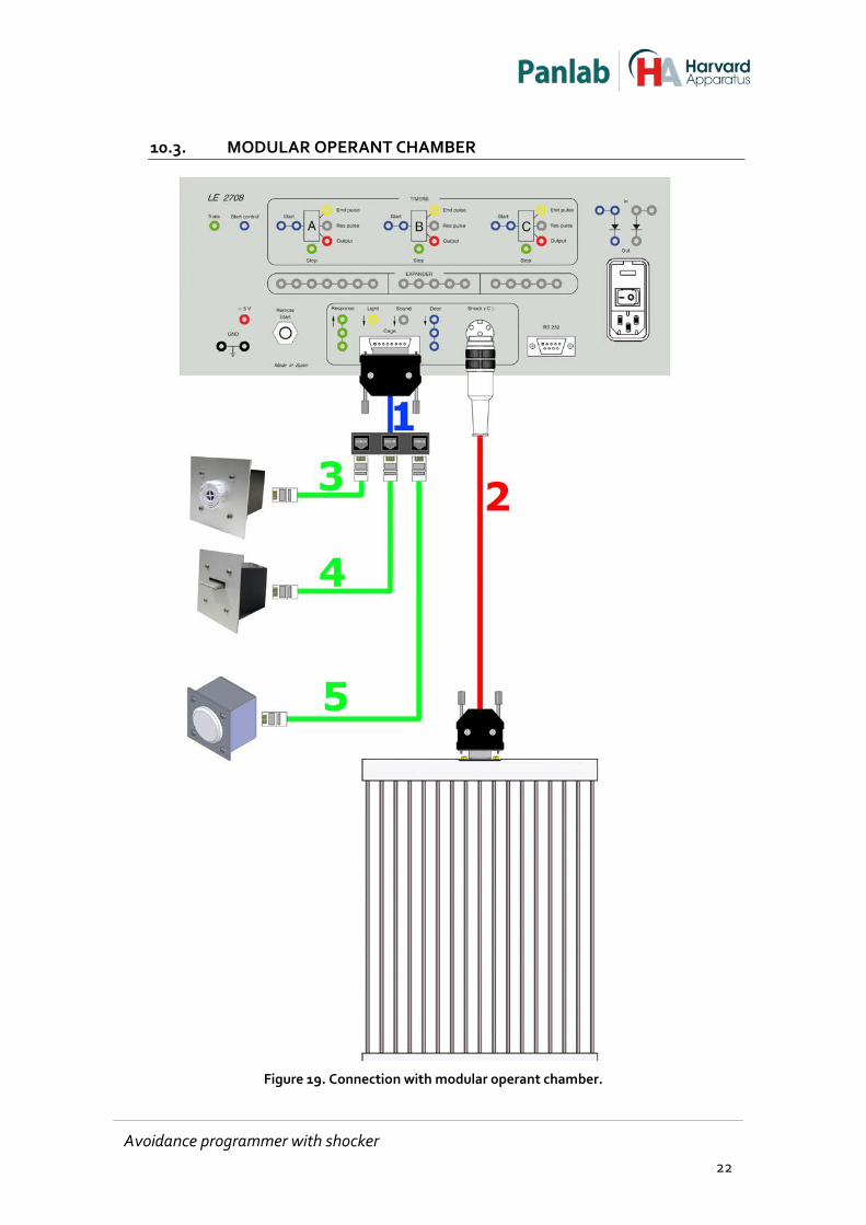
10.3. MODULAR OPERANT CHAMBER
Figure 19. Connection with modular operant chamber.
Avoidance programmer with shocker 22
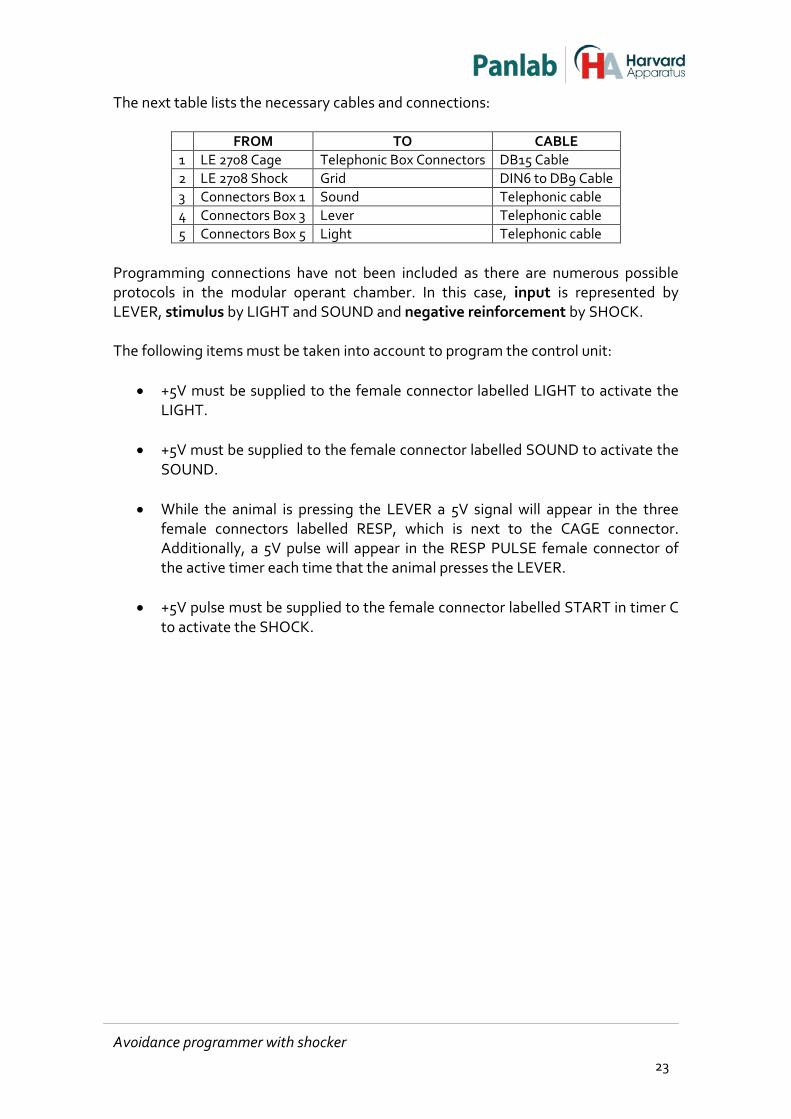
The next table lists the necessary cables and connections:
FROM TO CABLE 1 LE 2708 Cage Telephonic Box Connectors DB15 Cable 2 LE 2708 Shock Grid DIN6 to DB9 Cable 3 Connectors Box 1 Sound Telephonic cable 4 Connectors Box 3 Lever Telephonic cable 5 Connectors Box 5 Light Telephonic cable
Programming connections have not been included as there are numerous possible protocols in the modular operant chamber. In this case, input is represented by LEVER, stimulus by LIGHT and SOUND and negative reinforcement by SHOCK. The following items must be taken into account to program the control unit:
• +5V must be supplied to the female connector labelled LIGHT to activate the LIGHT.
• +5V must be supplied to the female connector labelled SOUND to activate the
SOUND. • While the animal is pressing the LEVER a 5V signal will appear in the three
female connectors labelled RESP, which is next to the CAGE connector. Additionally, a 5V pulse will appear in the RESP PULSE female connector of the active timer each time that the animal presses the LEVER.
• +5V pulse must be supplied to the female connector labelled START in timer C
to activate the SHOCK.
Avoidance programmer with shocker 23
10.4. CONNECTING TO THE COMPUTER COM PORT
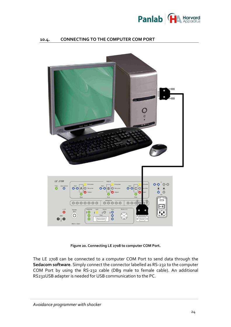
Figure 20. Connecting LE 2708 to computer COM Port.
The LE 2708 can be connected to a computer COM Port to send data through the Sedacom software. Simply connect the connector labelled as RS-232 to the computer COM Port by using the RS-232 cable (DB9 male to female cable). An additional RS232USB adapter is needed for USB communication to the PC.
Avoidance programmer with shocker 24
11. WORKING WITH THE EQUIPMENT
11.1. CONDUCTING AN EXPERIMENT
1. Connect the equipment (see Chapter 10) as corresponds to the selected cage.
2. Program the bridges in the rear-panel as explained in the Working Procedure
of the cage model selected.
3. Turn- on the control units.
4. Set the T FUNCTION selector in the mode according to the cage model you are working with.
5. Place the animal in the cage.
6. Push the START button as to begin the experiment.
7. Once the experiment has ended remove the animal from the cage.
8. Turn off all the control units.
9. Clean the cage so that it is in good condition for the next experiment.
11.2. CLEANING THE CAGE
The cleaning procedure is detailed in the user’s manual of the cage model selected.
Avoidance programmer with shocker 25

12. WORKING WITH THE SEDACOM SOFTWARE
The purchase of the Sedacom software is needed for transferring the data to a computer (please contact your local sales delegate for more information). The Sedacom’s software reference is composed by a USB Flash key containing the software Installer, a License for use and Sedacom’s User’s Manual. Follow the next instructions:
• Please refer to the Sedacom’s User’s Manual for instructions on how to install and use the software with the present device. For the LE2708 device, the GENERIC mode has to be used. Once the experiment ends the DATA is sent to the computer. The identification number is increased sequentially with each experiment. The counter can be reset by keeping pressed the RESET button on the front panel of the LE 2708 for 3 seconds.
• A serial port (RS232) communication cable (provided with the present device) is needed for the connection of the present device to the computer in which the Sedacom software is installed. Please refer to the present User’s Manual chapter 10 for instructions on how to connect this cable to the device.
• If the computer does not have any serial port, the RS232/USB adapter is needed (ref. CONRS232USB, contact your local sales delegate for more information)
WARNING: the RS232 communication cable provided with the device is used for connecting the device to any associated software (Sedacom, etc.). Even when the device is used without software at first instance, this cable is to be preserved and kept in a secure place in case the need of using the system with a software arises in the future. In this last case, if the user lost the cable, a new one should be purchased to his local sales delegate, ref. CONRS232). The warranty time of this cable is the same than the warranty time of the device.
Avoidance programmer with shocker 26
13. TROUBLESHOOTING
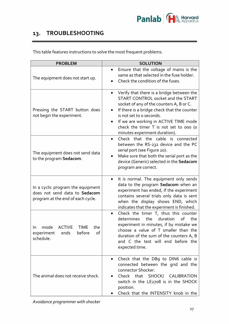
This table features instructions to solve the most frequent problems.
PROBLEM SOLUTION
The equipment does not start up.
• Ensure that the voltage of mains is the same as that selected in the fuse holder.
• Check the condition of the fuses.
Pressing the START button does not begin the experiment.
• Verify that there is a bridge between the START CONTROL socket and the START socket of any of the counters A, B or C.
• If there is a bridge check that the counter is not set to 0 seconds.
• If we are working in ACTIVE TIME mode check the timer T is not set to 000 (0 minutes experiment duration).
The equipment does not send data to the program Sedacom.
• Check that the cable is connected between the RS-232 device and the PC serial port (see Figure 20).
• Make sure that both the serial port as the device (Generic) selected in the Sedacom program are correct.
In a cyclic program the equipment does not send data to Sedacom program at the end of each cycle.
• It is normal. The equipment only sends data to the program Sedacom when an experiment has ended, if the experiment contains several trials only data is sent when the display shows END, which indicates that the experiment is finished.
In mode ACTIVE TIME the experiment ends before of schedule.
• Check the timer T, thus this counter determines the duration of the experiment in minutes, if by mistake we choose a value of T smaller than the duration of the sum of the counters A, B and C the test will end before the expected time.
The animal does not receive shock.
• Check that the DB9 to DIN6 cable is connected between the grid and the connector Shocker.
• Check that SHOCK/ CALIBRATION switch in the LE2708 is in the SHOCK position.
• Check that the INTENSITY knob in the
Avoidance programmer with shocker 27

LE2708 is set to a value higher than 0mA. • Check that the grid is clean (urine and
excrements can conduct current).
Avoidance programmer with shocker 28
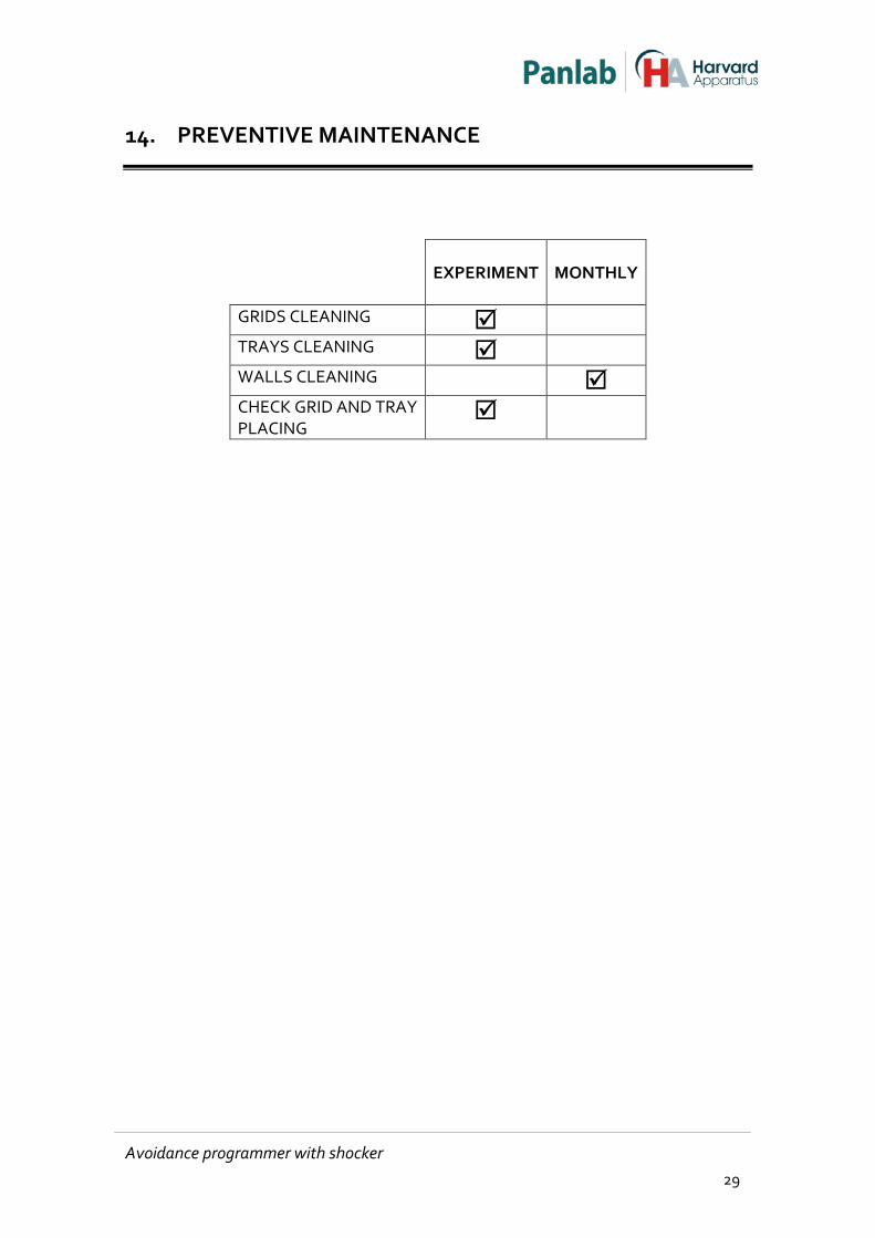
14. PREVENTIVE MAINTENANCE
EXPERIMENT
MONTHLY
GRIDS CLEANING
TRAYS CLEANING
WALLS CLEANING CHECK GRID AND TRAY PLACING
Avoidance programmer with shocker 29

15. TECHNICAL SPECIFICATIONS
POWER SUPPLY Input voltage: Frequency: Fuse: Maximum Power: Conducted Noise:
115/230 VAC 50/60 Hz 2 fuses 5mm*20mm 500mA 250V Fast 16W EN55011 /CISPR11 class B
ENVIRONMENTAL CONDITIONS Operating temperature: Operating Relative Humidity: Storage temperature:
10°C to +40°C 0% to 85% RH, non-condensing 0°C to +50°C, non-condensing
COMUNICATIONS OUTPUT Standard Interface: Connector:
RS232C Delta 9-contact female connector
CONNECTOR CAGE (DB15) Pin 1 2 3 7 10 11 15
Function Door Sound Light Response +24V DC +5V DC GND
CONNECTOR SHOCK (DIN6) Pin 1 2 3 4 5 6
Function Bar 1 Bar 2 Bar 3 Bar 4 Bar 5 Bar 6
DIMENSIONS Width x Height x Depth: Weight:
340mm x 156mm x 340 mm 6.5 kg
Avoidance programmer with shocker 30
Avoidance programmer with shocker 31