Embed Size (px)
Citation preview
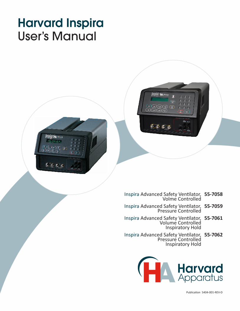
Publication 5404-001-REV-D
Harvard Inspira User’s Manual
Inspira Advanced Safety Ventilator, Volme Controlled
55-7058
Inspira Advanced Safety Ventilator, Pressure Controlled
55-7059
Inspira Advanced Safety Ventilator, Volume Controlled
Inspiratory Hold
55-7061
Inspira Advanced Safety Ventilator, Pressure Controlled
Inspiratory Hold
55-7062
1 www.harvardapparatus.comPublication 5404-001-REV-D
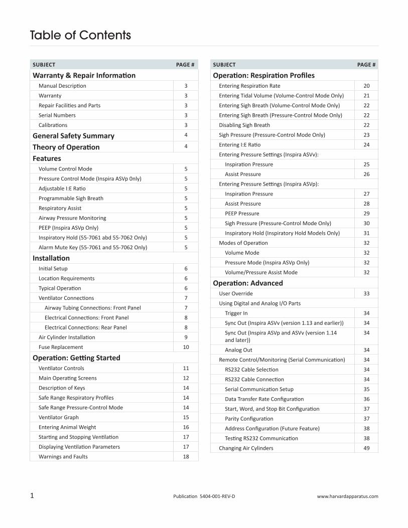
Table of Contents
SUBJECT PAGE #
Warranty & Repair InformationManual Description 3
Warranty 3
Repair Facilities and Parts 3
Serial Numbers 3
Calibrations 3
General Safety Summary 4
Theory of Operation 4
FeaturesVolume Control Mode 5
Pressure Control Mode (Inspira ASVp 0nly) 5
Adjustable I:E Ratio 5
Programmable Sigh Breath 5
Respiratory Assist 5
Airway Pressure Monitoring 5
PEEP (Inspira ASVp Only) 5
Inspiratory Hold (55-7061 abd 55-7062 Only) 5
Alarm Mute Key (55-7061 and 55-7062 Only) 5
InstallationInitial Setup 6
Location Requirements 6
Typical Operation 6
Ventilator Connections 7
Airway Tubing Connections: Front Panel 7
Electrical Connections: Front Panel 8
Electrical Connections: Rear Panel 8
Air Cylinder Installation 9
Fuse Replacement 10
Operation: Getting StartedVentilator Controls 11
Main Operating Screens 12
Description of Keys 14
Safe Range Respiratory Profiles 14
Safe Range Pressure-Control Mode 14
Ventilator Graph 15
Entering Animal Weight 16
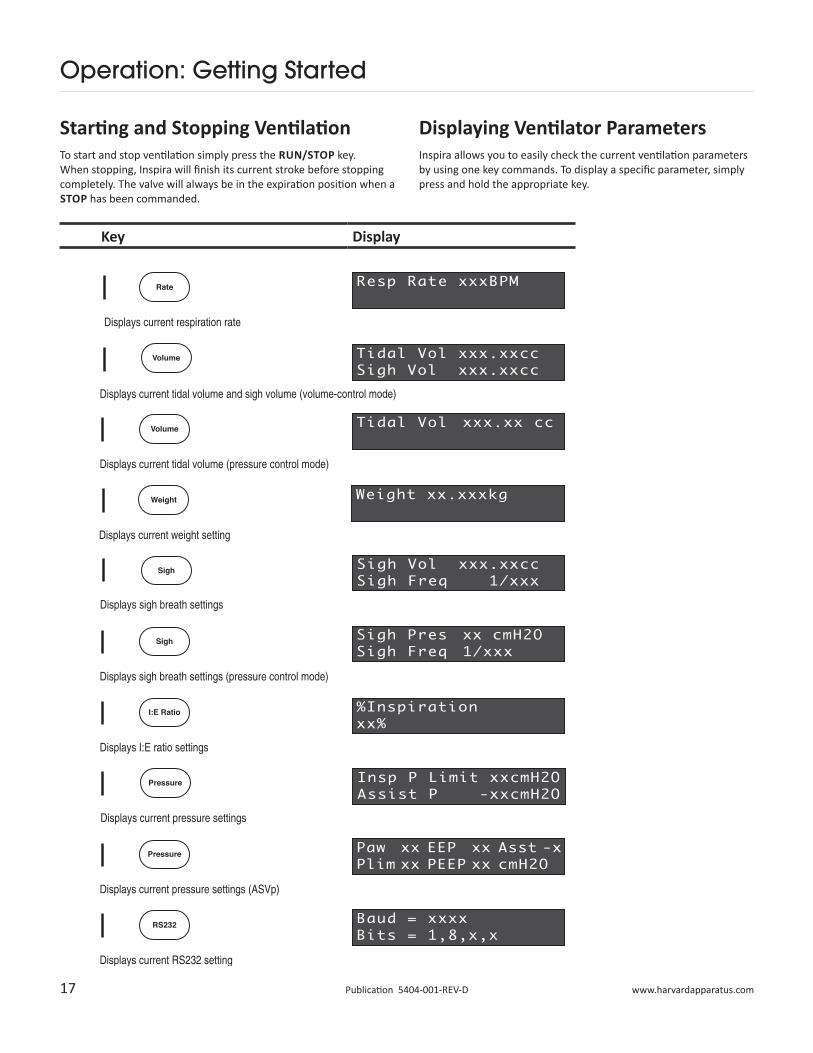
Starting and Stopping Ventilation 17
Displaying Ventilation Parameters 17
Warnings and Faults 18
SUBJECT PAGE #
Operation: Respiration ProfilesEntering Respiration Rate 20
Entering Tidal Volume (Volume-Control Mode Only) 21
Entering Sigh Breath (Volume-Control Mode Only) 22
Entering Sigh Breath (Pressure-Control Mode Only) 22
Disabling Sigh Breath 22
Sigh Pressure (Pressure-Control Mode Only) 23
Entering I:E Ratio 24
Entering Pressure Settings (Inspira ASVv):
Inspiration Pressure 25
Assist Pressure 26
Entering Pressure Settings (Inspira ASVp):
Inspiration Pressure 27
Assist Pressure 28
PEEP Pressure 29
Sigh Pressure (Pressure-Control Mode Only) 30
Inspiratory Hold (Inspiratory Hold Models Only) 31
Modes of Operation 32
Volume Mode 32
Pressure Mode (Inspira ASVp Only) 32
Volume/Pressure Assist Mode 32
Operation: AdvancedUser Override 33
Using Digital and Analog I/O Parts
Trigger In 34
Sync Out (Inspira ASVv (version 1.13 and earlier)) 34
Sync Out (Inspira ASVp and ASVv (version 1.14 and later))
34
Analog Out 34
Remote Control/Monitoring (Serial Communication) 34
RS232 Cable Selection 34
RS232 Cable Connection 34
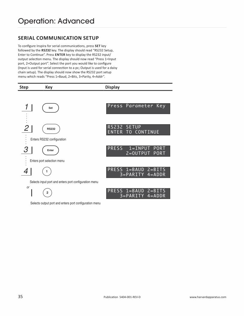
Serial Communication Setup 35
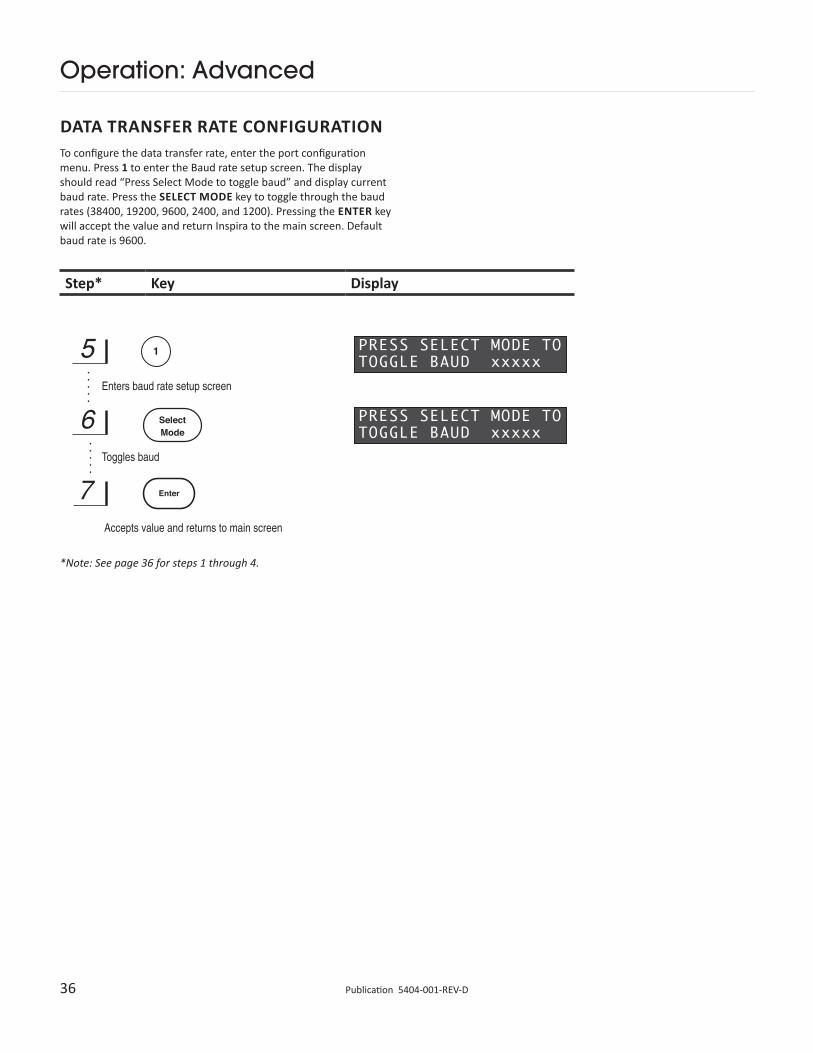
Data Transfer Rate Configuration 36
Start, Word, and Stop Bit Configuration 37
Parity Configuration 37
Address Configuration (Future Feature) 38
Testing RS232 Communication 38
Changing Air Cylinders 49
2 Publication 5404-001-REV-D
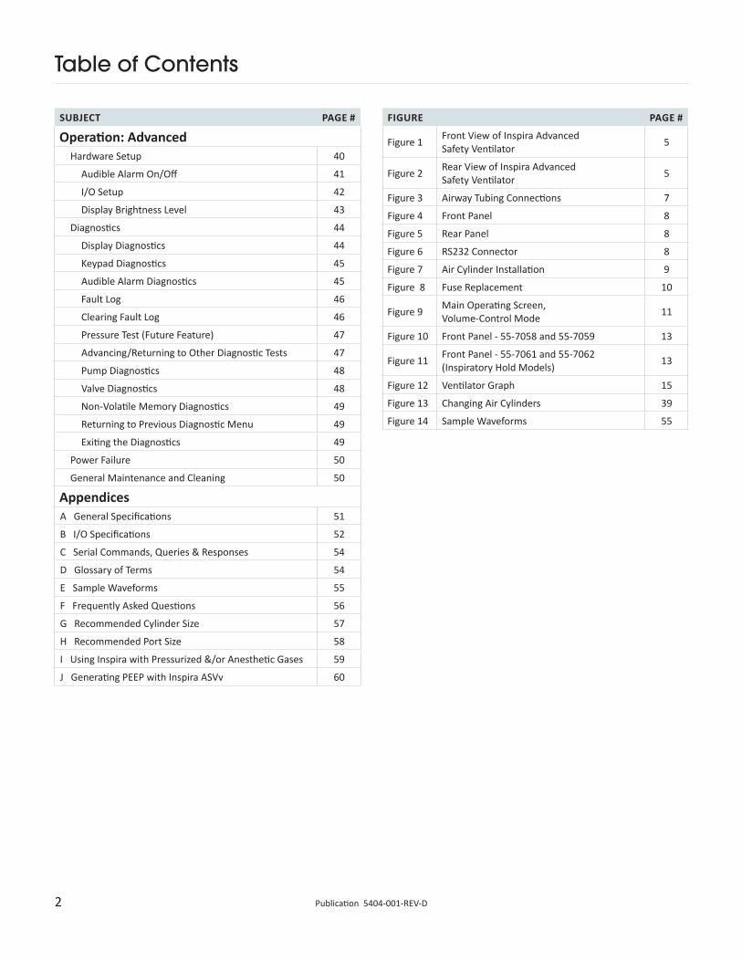
Table of Contents
FIGURE PAGE #
Figure 1 Front View of Inspira Advanced Safety Ventilator 5
Figure 2 Rear View of Inspira Advanced Safety Ventilator 5
Figure 3 Airway Tubing Connections 7
Figure 4 Front Panel 8
Figure 5 Rear Panel 8
Figure 6 RS232 Connector 8
Figure 7 Air Cylinder Installation 9
Figure 8 Fuse Replacement 10
Figure 9 Main Operating Screen, Volume-Control Mode 11
Figure 10 Front Panel - 55-7058 and 55-7059 13
Figure 11 Front Panel - 55-7061 and 55-7062 (Inspiratory Hold Models) 13
Figure 12 Ventilator Graph 15
Figure 13 Changing Air Cylinders 39
Figure 14 Sample Waveforms 55
SUBJECT PAGE #
Operation: AdvancedHardware Setup 40
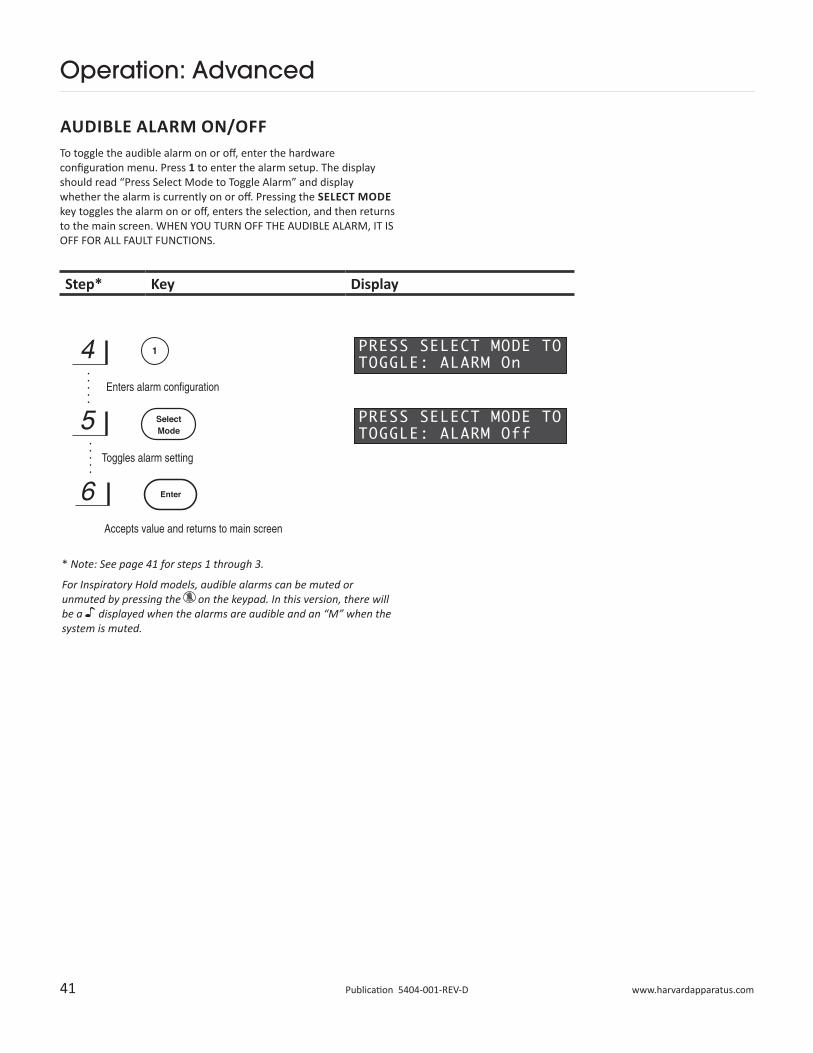
Audible Alarm On/Off 41
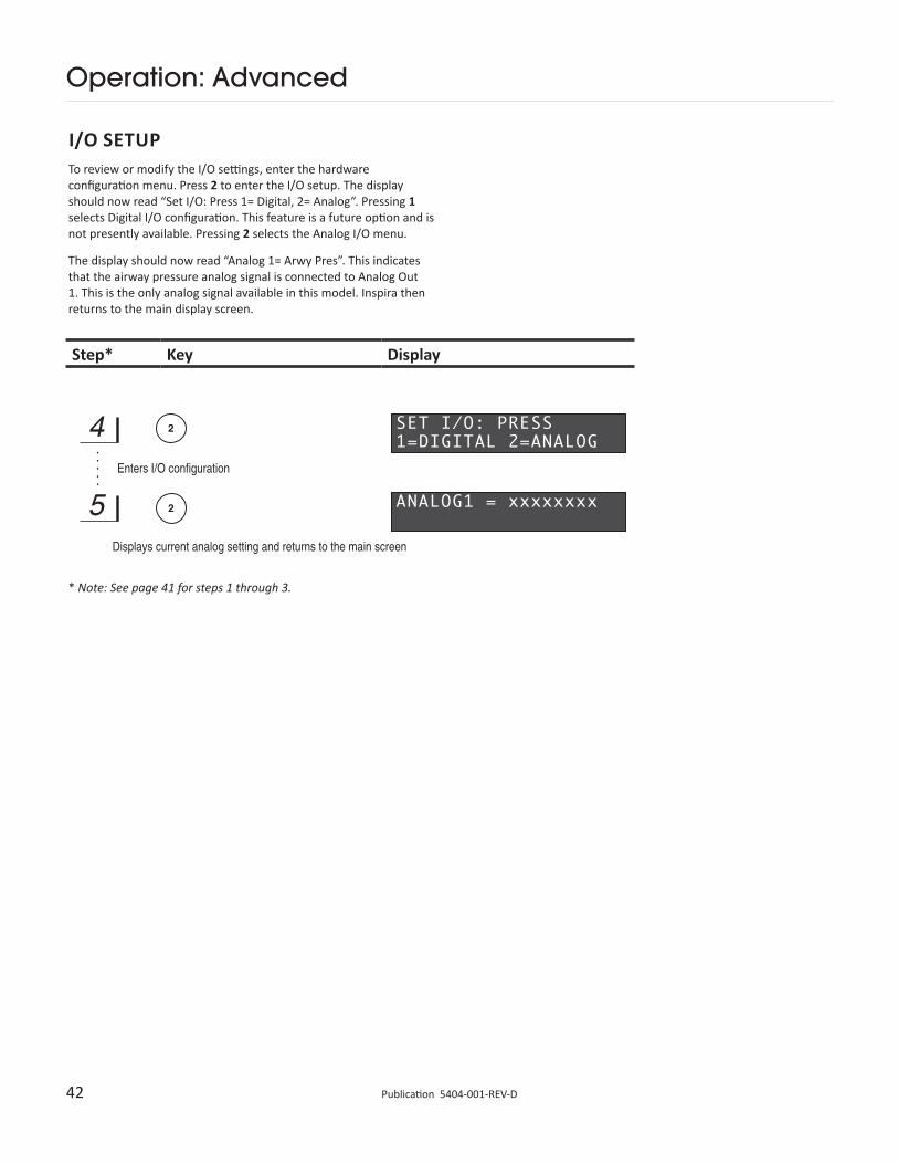
I/O Setup 42
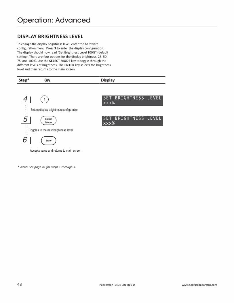
Display Brightness Level 43
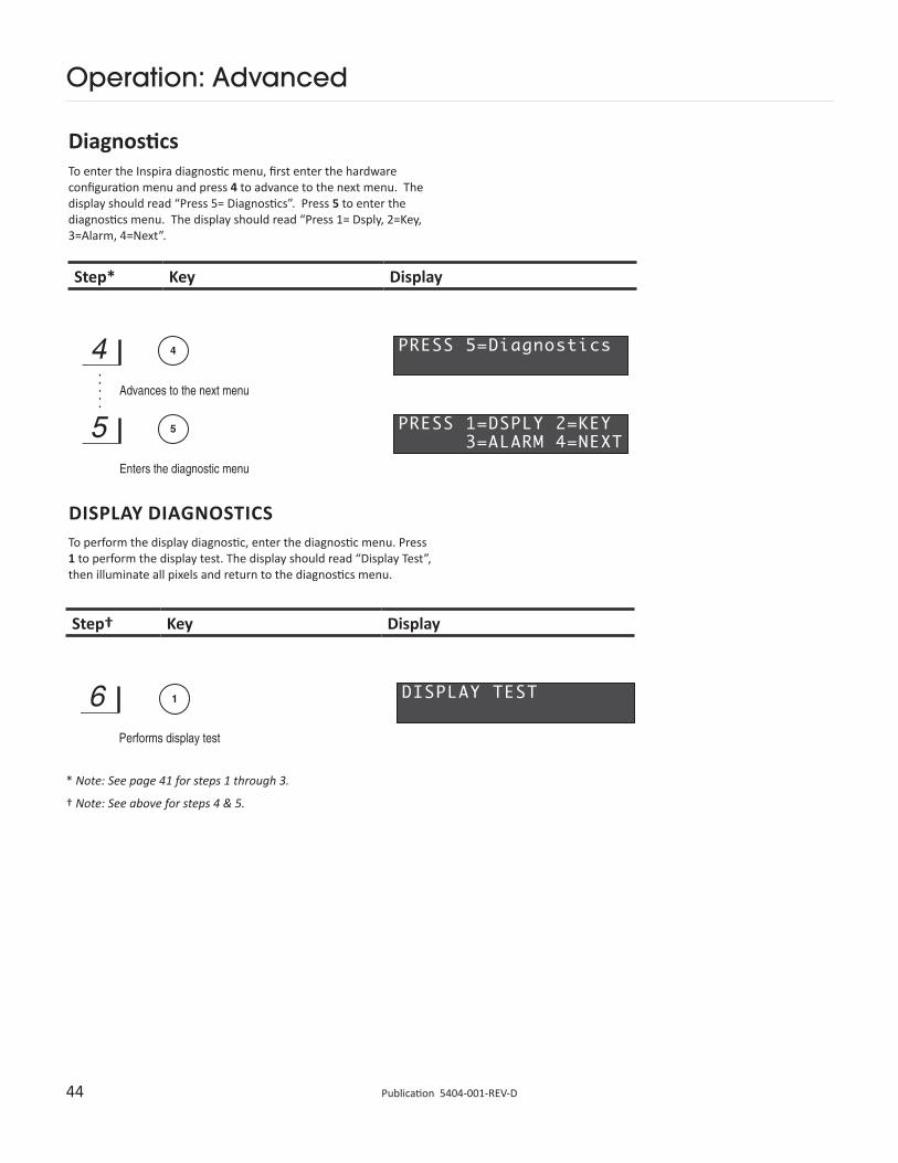
Diagnostics 44
Display Diagnostics 44
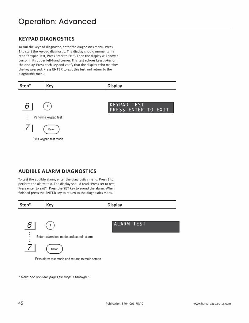
Keypad Diagnostics 45
Audible Alarm Diagnostics 45
Fault Log 46
Clearing Fault Log 46
Pressure Test (Future Feature) 47
Advancing/Returning to Other Diagnostic Tests 47
Pump Diagnostics 48
Valve Diagnostics 48
Non-Volatile Memory Diagnostics 49
Returning to Previous Diagnostic Menu 49
Exiting the Diagnostics 49
Power Failure 50
General Maintenance and Cleaning 50
AppendicesA General Specifications 51
B I/O Specifications 52
C Serial Commands, Queries & Responses 54
D Glossary of Terms 54
E Sample Waveforms 55
F Frequently Asked Questions 56
G Recommended Cylinder Size 57
H Recommended Port Size 58
I Using Inspira with Pressurized &/or Anesthetic Gases 59
J Generating PEEP with Inspira ASVv 60
3 www.harvardapparatus.comPublication 5404-001-REV-D
Warranty & Repair Information
CAUTION: Refer to page 7, Initial Setup, before plugging in Inspira ASV
CAUTION: For research only. Not for clinical use on human patients
MANUAL DESCRIPTIONThis manual is designed to provide all operational and program information required to operate and maintain the Inspira ASV. The functions and features are described in the Features section.
WARRANTYHarvard Apparatus warranties this instrument for a period of one years from date of purchase. At its option, Harvard Apparatus will repair or replace the unit if it is found to be defective as to workmanship or materials. This warranty does not extend to damage resulting from misuse, neglect or abuse, normal wear and tear, or accident. This warranty extends only to the original consumer purchaser.
IN NO EVENT SHALL HARVARD APPARATUS BE LIABLE FOR INCIDENTAL OR CONSEQUENTIAL DAMAGES. Some states do not allow the exclusion or limitation of incidental or consequential damages so the above limitation or exclusion may not apply to you. THERE ARE NO IMPLIED WARRANTIES OF MERCHANTABILITY, OR FITNESS FOR A PARTICULAR USE, OR OF ANY OTHER NATURE. Some states do not allow this limitation on an implied warranty, so the above limitation may not apply to you.
If a defect arises within the one-year warranty period, promptly contact Harvard Apparatus, 84 October Hill Road, Holliston, Massachusetts 01746 using our toll free number 1–800–272–2775, or outside the U.S. call 508-893-8999. Our E-mail address is [email protected]. Goods will not be accepted for return unless an RMA (returned materials authorization) number has been issued by our customer service department. The customer is responsible for shipping charges. Please allow a reasonable period of time for completion of repairs or replacement. If the unit is replaced, the replacement unit is covered only for the remainder of the original warranty period dating from the purchase of the original device.
This warranty gives you specific rights, and you may also have other rights which vary from state to state.
REPAIR FACILITIES AND PARTSHarvard Apparatus stocks replacement and repair parts. When ordering, please describe parts as completely as possible, preferably using a part number obtained from our Customer Service department. If practical, enclose a sample part or sketch. We offer a complete reconditioning service.
SERIAL NUMBERSAll inquiries concerning our product should refer to the serial number of the unit, located on the rear panel.
CALIBRATIONSAll electrical apparatus is calibrated at rated voltage and frequency. While the flow and volume will stay calibrated the peak pressure may vary.
4 Publication 5404-001-REV-D
General Safety Summary
Please read the following safety precautions to ensure proper use of your Inspira ventilator. To avoid potential hazards and product damage, use this product only as instructed in this manual.
To Prevent Hazard or Injury:Use Proper Line CordUse only the specified line cord for this product and make sure the line cord is certified for the country of use.
Ground the ProductThis product is grounded through the grounding conductor of the power cord. To avoid electric shock, the grounding conductor must be connected to earth ground. Before making any connections to the input or output terminals of the product, ensure that the product is properly grounded.
Make Proper ConnectionsMake sure all connections are made properly and securely. Any signal wire connections to the unit must be no longer than three meters.
Observe all Terminal RatingsReview the operating manual to learn the ratings on all connections.
Use Proper FuseUse only specified fuses with product.
Avoid Exposed CircuitryDo not touch any electronic circuitry inside of the product.
Do Not Operate with Suspected FailuresIf damage is suspected on or to the product do not operate the product. Contact qualified service personnel to perform inspection.
Place Product in Proper EnvironmentReview the operating manual for guidelines for proper operating environments.
Observe all Warning Labels on ProductRead all labels on product to ensure proper usage.
CAUTIONRefer to Manual
Protective Ground Terminal
Theory of Operation
The Inspira is Harvard’s first ventilator that can ventilate animals from mice to cats using the same machine. Its versatility and ease of use allow safer and superior ventilation. The Inspira Ventilator uses an advanced piston/cylinder assembly and a microprocessor controlled actuation mechanism to precisely control respiration profiles. Two interchangeable piston/cylinder assemblies are available to provide a wide range of tidal volumes. The ventilator auto-detects which cylinder, or if no cylinder, is installed. Variable flow valves control the gas flow for inhalation and exhalation.
The Inspira ASV Volume Controlled Ventilator delivers the desired tidal volume to the animal by precisely controlling the stroke of the piston. Since actual stroke length (and therefore tidal volume) may be modified for a given stroke, sigh breaths are supported. Since stroke speed is precisely controllable during inspiration and expiration, variable inspiration-to-expiration ratios are also supported. A pressure sensor continuously monitors the airway pressure to prevent over-pressure conditions. Most volume-controlled ventilators presently available do not support sigh breaths and do not provide any pressure monitoring as a safety feature.
The Inspira ASVp pressure-controlled ventilator adds pressure control capability to the ASVv volume-controlled platform. Inspiration pressure is limited to the user-entered pressure setting. Flow rates are automatically adjusted by the microcontroller by changing the tidal volume while keeping the inspiration time constant.
The flow rate is adjusted so that the inspiration pressure limit is reached near the end of the piston stroke, ensuring that animals with a higher airway resistance receive the majority of the expected tidal volume and that the ventilator does not prematurely terminate the piston stroke. No manual adjustment of inspiratory flow rates is required.
The ASVp also adds on board PEEP capability for both the volume and pressure-control modes. The machine allows a PEEP setting up to 10cmH2O.
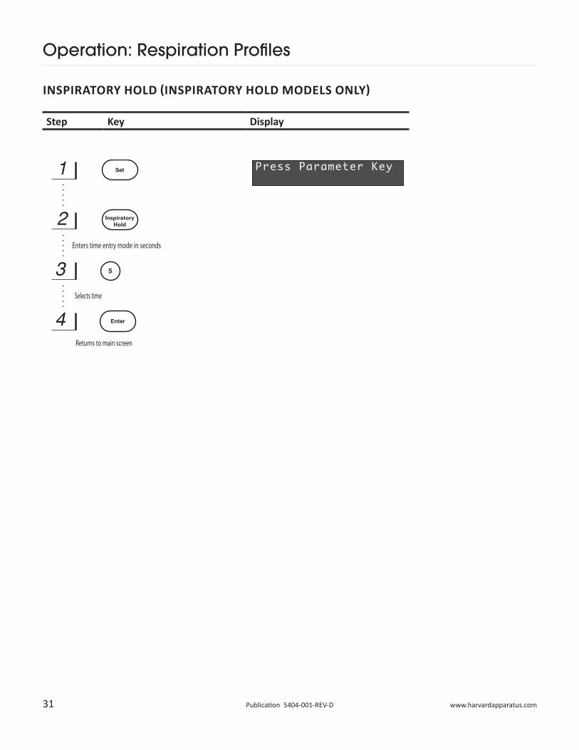
The newest addition to the Inspira family offers an Inspiratory Hold feature. This is available in both the volume and pressure controlled models. The user can enter their desired hold time and initiate the hold simply by pressing the “Inspiratory Hold” button on the keypad.
The hold will initiate following the next inspiration cycle and be maintained for the time entered by the user. Early termination of an inspiratory hold is possible by simply pushing the Inspiratory Hold button on the keypad. In the pressure controlled Inspiratory Hold model, the pressure will be maintained through the hold by delivering additional volume until the end of the hold time or until the unit reaches the end of travel. If the full piston stroke is traveled, the unit will no longer be able to maintain the pressure, although the hold will continue until a time-out or manual termination.
Inspiratory hold is also able to be initiated following a sigh breath.
5 www.harvardapparatus.comPublication 5404-001-REV-D
Features
Volume Control ModeThe ventilator delivers a known volume of gas to the patient on each inspiration stroke. Respiration frequency and I:E Ratio determine amount of time for inspiration and expiration phases.
Pressure Control Mode (Inspira ASVp Only)The ventilator delivers gas to the patient until the user-selected pressure limit is reached. Flow rate is automatically adjusted by the machine so that the pressure limit is reached near the end of the inspiration time. Respiration frequency and I:E Ratio determine the amount of time for inspiration and expiration phases.
Adjustable I:E RatioThis option allows the user to select the ratio of inhalation to exhalation times when advanced respiratory control is needed. This feature is intended to allow greater respiratory control for research. The default I:E Ratio is 50%.
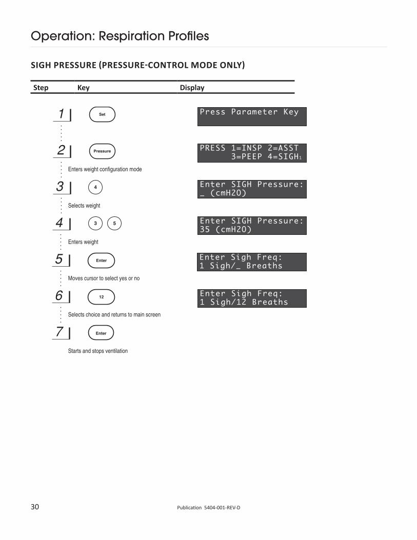
Programmable Sigh BreathContinuous, long-term ventilation combined with the force of gravity will cause the animal’s lungs to begin to collapse. Introducing a larger than normal tidal volume over-inflates the animal’s lungs, replicating a natural sigh. It allows the lungs to expand and opens the collapsed alveoli. Sigh breaths are supported in both modes. In the volume-controlled mode, a sigh tidal volume is used. In the pressure-controlled mode, a sigh pressure limit is used. The frequency and volume of the sigh breath are user selectable in volume-controlled mode. In the pressure-controlled mode, the frequency and pressure of the sigh breaths are selectable.
Respiratory AssistThe Inspira ventilator supports Respiratory Assist in both volume and pressure-controlled modes. This feature is used to wean an animal off the ventilator. When the animal attempts to initiate a breath on its own, a pressure sensor detects the drop in airway pressure. This drop initiates a ventilation cycle. The sensitivity of the Assist Mode is adjustable from –1 to –10 cmH2O.
The ventilator lets the animal initiate breaths independently as long as its breathing rate is greater than the respiration rate set by the user or calculated by the microprocessor. If the animal does not try to initiate a breath, Inspira warns the user.
Airway Pressure MonitoringThe ventilator monitors the pressure of gas delivered to the animal being ventilated. This safety feature prevents the operator from over or under pressurizing the lungs of the animal. When Inspira detects an over-pressurization condition it sounds an alarm, stops the inspiration stroke, and then cycles to expiration. Inspira continues to ventilate but does not deliver enough gas to over-pressurize the lungs. Overpressure conditions may result from occluded or restricted airways. When Inspira detects an under-pressurization condition it sounds an alarm. This condition could result from an airway disconnect or large leaks. Once again, Inspira continues to ventilate while requesting user intervention. These features ensure that the animal is kept safe from improper ventilator setup.
PEEP (Inspira ASVp Only)Positive end-expiratory pressure (PEEP) is settable in the Inspira ASVp in both volume and pressure-controlled modes. The PEEP is adjustable from 0 to 10 cm H2O.
Inspiratory Hold (55-7061 and 55-7062 Only)The Inspiratory Hold models of the Inspira allow the inspiratory breath to be held for a user-defined length of time (1 second to 120 seconds). This maintains peak tidal volume (and pressure in the 55-7062 version) in the animal’s lungs.
Alarm Mute Key (55-7061 and 55-7062 Only) Muting of all audible alarms is allowed. All errors are still visually indicated by flashing on the display.
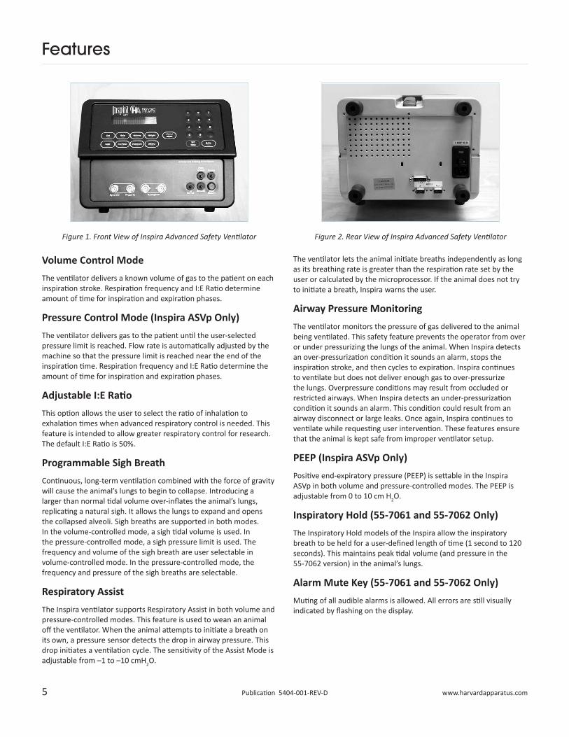
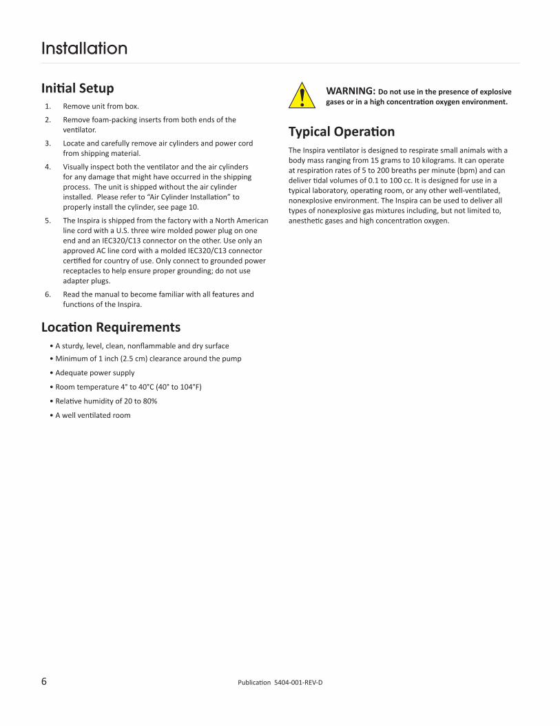
Figure 1. Front View of Inspira Advanced Safety Ventilator Figure 2. Rear View of Inspira Advanced Safety Ventilator
6 Publication 5404-001-REV-D
Installation
Initial Setup1. Remove unit from box.
2. Remove foam-packing inserts from both ends of the ventilator.
3. Locate and carefully remove air cylinders and power cord from shipping material.
4. Visually inspect both the ventilator and the air cylinders for any damage that might have occurred in the shipping process. The unit is shipped without the air cylinder installed. Please refer to “Air Cylinder Installation” to properly install the cylinder, see page 10.
5. The Inspira is shipped from the factory with a North American line cord with a U.S. three wire molded power plug on one end and an IEC320/C13 connector on the other. Use only an approved AC line cord with a molded IEC320/C13 connector certified for country of use. Only connect to grounded power receptacles to help ensure proper grounding; do not use adapter plugs.
6. Read the manual to become familiar with all features and functions of the Inspira.
Location Requirements• A sturdy, level, clean, nonflammable and dry surface• Minimum of 1 inch (2.5 cm) clearance around the pump
• Adequate power supply
• Room temperature 4° to 40°C (40° to 104°F)
• Relative humidity of 20 to 80%
• A well ventilated room
WARNING: Do not use in the presence of explosive gases or in a high concentration oxygen environment.
Typical OperationThe Inspira ventilator is designed to respirate small animals with a body mass ranging from 15 grams to 10 kilograms. It can operate at respiration rates of 5 to 200 breaths per minute (bpm) and can deliver tidal volumes of 0.1 to 100 cc. It is designed for use in a typical laboratory, operating room, or any other well-ventilated, nonexplosive environment. The Inspira can be used to deliver all types of nonexplosive gas mixtures including, but not limited to, anesthetic gases and high concentration oxygen.
7 www.harvardapparatus.comPublication 5404-001-REV-D
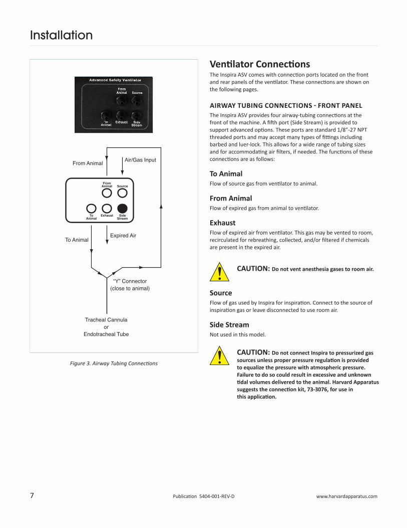
Ventilator ConnectionsThe Inspira ASV comes with connection ports located on the front and rear panels of the ventilator. These connections are shown on the following pages.
AIRWAY TUBING CONNECTIONS - FRONT PANELThe Inspira ASV provides four airway-tubing connections at the front of the machine. A fifth port (Side Stream) is provided to support advanced options. These ports are standard 1/8”-27 NPT threaded ports and may accept many types of fittings including barbed and luer-lock. This allows for a wide range of tubing sizes and for accommodating air filters, if needed. The functions of these connections are as follows:
To AnimalFlow of source gas from ventilator to animal.
From AnimalFlow of expired gas from animal to ventilator.
ExhaustFlow of expired air from ventilator. This gas may be vented to room, recirculated for rebreathing, collected, and/or filtered if chemicals are present in the expired air.
SourceFlow of gas used by Inspira for inspiration. Connect to the source of inspiration gas or leave disconnected to use room air.
Side StreamNot used in this model.
Installation
CAUTION: Do not vent anesthesia gases to room air.
CAUTION: Do not connect Inspira to pressurized gas sources unless proper pressure regulation is provided to equalize the pressure with atmospheric pressure. Failure to do so could result in excessive and unknown tidal volumes delivered to the animal. Harvard Apparatus suggests the connection kit, 73-3076, for use in this application.
Figure 3. Airway Tubing Connections
8 Publication 5404-001-REV-D
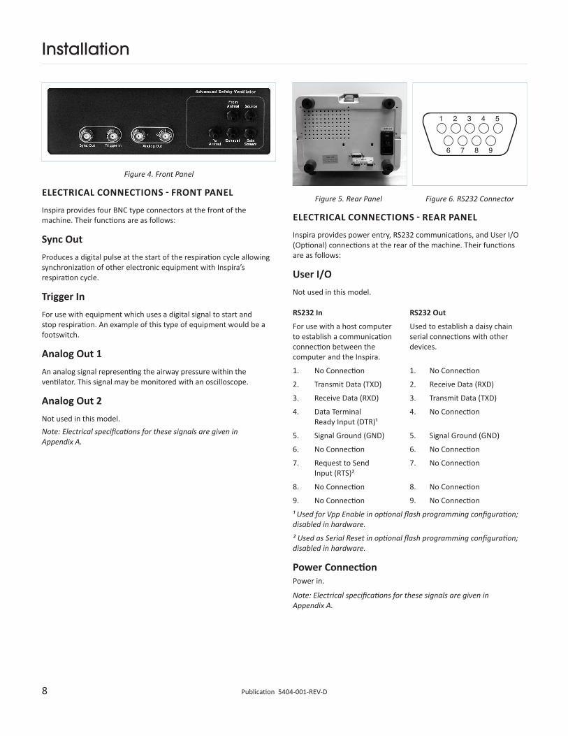
Installation
Figure 4. Front Panel
Figure 5. Rear Panel Figure 6. RS232 ConnectorELECTRICAL CONNECTIONS - FRONT PANEL
Inspira provides four BNC type connectors at the front of the machine. Their functions are as follows:
Sync OutProduces a digital pulse at the start of the respiration cycle allowing synchronization of other electronic equipment with Inspira’s respiration cycle.
Trigger InFor use with equipment which uses a digital signal to start and stop respiration. An example of this type of equipment would be a footswitch.
Analog Out 1An analog signal representing the airway pressure within the ventilator. This signal may be monitored with an oscilloscope.
Analog Out 2Not used in this model.Note: Electrical specifications for these signals are given in Appendix A.
ELECTRICAL CONNECTIONS - REAR PANEL
Inspira provides power entry, RS232 communications, and User I/O (Optional) connections at the rear of the machine. Their functions are as follows:
User I/ONot used in this model.
RS232 In RS232 Out
For use with a host computer to establish a communication connection between the computer and the Inspira.
Used to establish a daisy chain serial connections with other devices.
1. No Connection 1. No Connection
2. Transmit Data (TXD) 2. Receive Data (RXD)
3. Receive Data (RXD) 3. Transmit Data (TXD)
4. Data Terminal Ready Input (DTR)¹
4. No Connection
5. Signal Ground (GND) 5. Signal Ground (GND)
6. No Connection 6. No Connection
7. Request to Send Input (RTS)²
7. No Connection
8. No Connection 8. No Connection
9. No Connection 9. No Connection
¹ Used for Vpp Enable in optional flash programming configuration; disabled in hardware.
² Used as Serial Reset in optional flash programming configuration; disabled in hardware.
Power ConnectionPower in.
Note: Electrical specifications for these signals are given in Appendix A.
9 www.harvardapparatus.comPublication 5404-001-REV-D
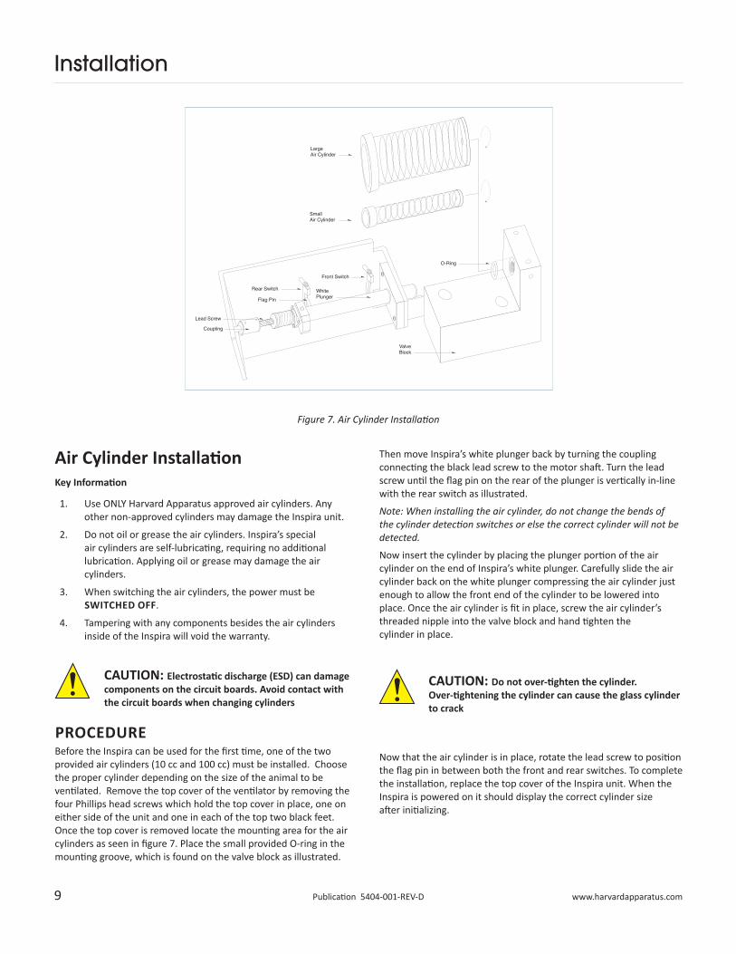
Then move Inspira’s white plunger back by turning the coupling connecting the black lead screw to the motor shaft. Turn the lead screw until the flag pin on the rear of the plunger is vertically in-line with the rear switch as illustrated.
Note: When installing the air cylinder, do not change the bends of the cylinder detection switches or else the correct cylinder will not be detected.
Now insert the cylinder by placing the plunger portion of the air cylinder on the end of Inspira’s white plunger. Carefully slide the air cylinder back on the white plunger compressing the air cylinder just enough to allow the front end of the cylinder to be lowered into place. Once the air cylinder is fit in place, screw the air cylinder’s threaded nipple into the valve block and hand tighten the cylinder in place.
Now that the air cylinder is in place, rotate the lead screw to position the flag pin in between both the front and rear switches. To complete the installation, replace the top cover of the Inspira unit. When the Inspira is powered on it should display the correct cylinder size after initializing.
Air Cylinder Installation Key Information
1. Use ONLY Harvard Apparatus approved air cylinders. Any other non-approved cylinders may damage the Inspira unit.
2. Do not oil or grease the air cylinders. Inspira’s special air cylinders are self-lubricating, requiring no additional lubrication. Applying oil or grease may damage the air cylinders.
3. When switching the air cylinders, the power must be SWITCHED OFF.
4. Tampering with any components besides the air cylinders inside of the Inspira will void the warranty.
PROCEDUREBefore the Inspira can be used for the first time, one of the two provided air cylinders (10 cc and 100 cc) must be installed. Choose the proper cylinder depending on the size of the animal to be ventilated. Remove the top cover of the ventilator by removing the four Phillips head screws which hold the top cover in place, one on either side of the unit and one in each of the top two black feet. Once the top cover is removed locate the mounting area for the air cylinders as seen in figure 7. Place the small provided O-ring in the mounting groove, which is found on the valve block as illustrated.
Figure 7. Air Cylinder Installation
Installation
CAUTION: Electrostatic discharge (ESD) can damage components on the circuit boards. Avoid contact with the circuit boards when changing cylinders
CAUTION: Do not over-tighten the cylinder. Over-tightening the cylinder can cause the glass cylinder to crack
10 Publication 5404-001-REV-D
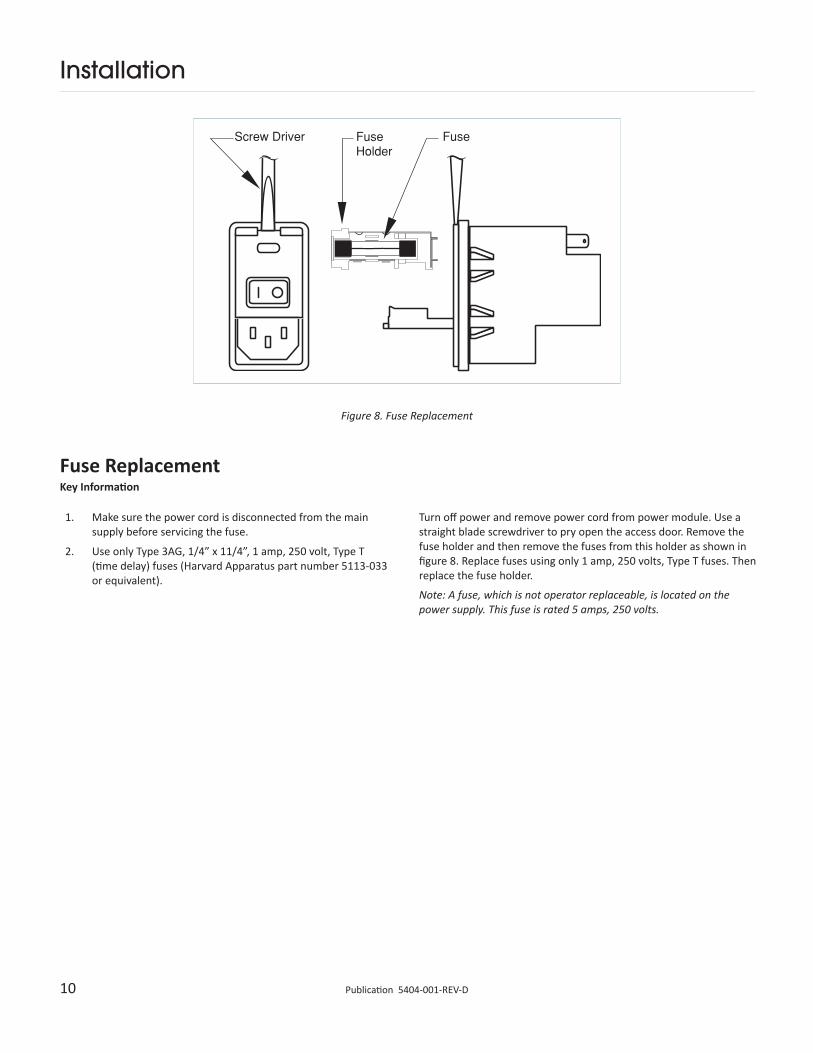
Figure 8. Fuse Replacement
Fuse ReplacementKey Information
1. Make sure the power cord is disconnected from the main supply before servicing the fuse.
2. Use only Type 3AG, 1/4” x 11/4”, 1 amp, 250 volt, Type T (time delay) fuses (Harvard Apparatus part number 5113-033 or equivalent).
Installation
Turn off power and remove power cord from power module. Use a straight blade screwdriver to pry open the access door. Remove the fuse holder and then remove the fuses from this holder as shown in figure 8. Replace fuses using only 1 amp, 250 volts, Type T fuses. Then replace the fuse holder.
Note: A fuse, which is not operator replaceable, is located on the power supply. This fuse is rated 5 amps, 250 volts.
11 www.harvardapparatus.comPublication 5404-001-REV-D
Operation: Getting Started
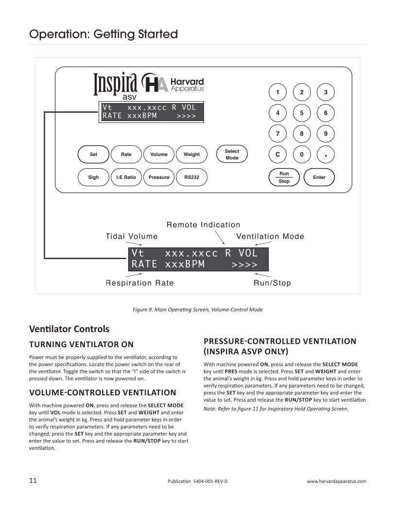
Figure 9. Main Operating Screen, Volume-Control Mode
Ventilator ControlsTURNING VENTILATOR ONPower must be properly supplied to the ventilator, according to the power specifications. Locate the power switch on the rear of the ventilator. Toggle the switch so that the “I” side of the switch is pressed down. The ventilator is now powered on.
VOLUME-CONTROLLED VENTILATIONWith machine powered ON, press and release the SELECT MODE key until VOL mode is selected. Press SET and WEIGHT and enter the animal’s weight in kg. Press and hold parameter keys in order to verify respiration parameters. If any parameters need to be changed, press the SET key and the appropriate parameter key and enter the value to set. Press and release the RUN/STOP key to start ventilation.
PRESSURE-CONTROLLED VENTILATION (INSPIRA ASVP ONLY)With machine powered ON, press and release the SELECT MODE key until PRES mode is selected. Press SET and WEIGHT and enter the animal’s weight in kg. Press and hold parameter keys in order to verify respiration parameters. If any parameters need to be changed, press the SET key and the appropriate parameter key and enter the value to set. Press and release the RUN/STOP key to start ventilationNote: Refer to figure 11 for Inspiratory Hold Operating Screen.
12 Publication 5404-001-REV-D
Operation: Getting Started
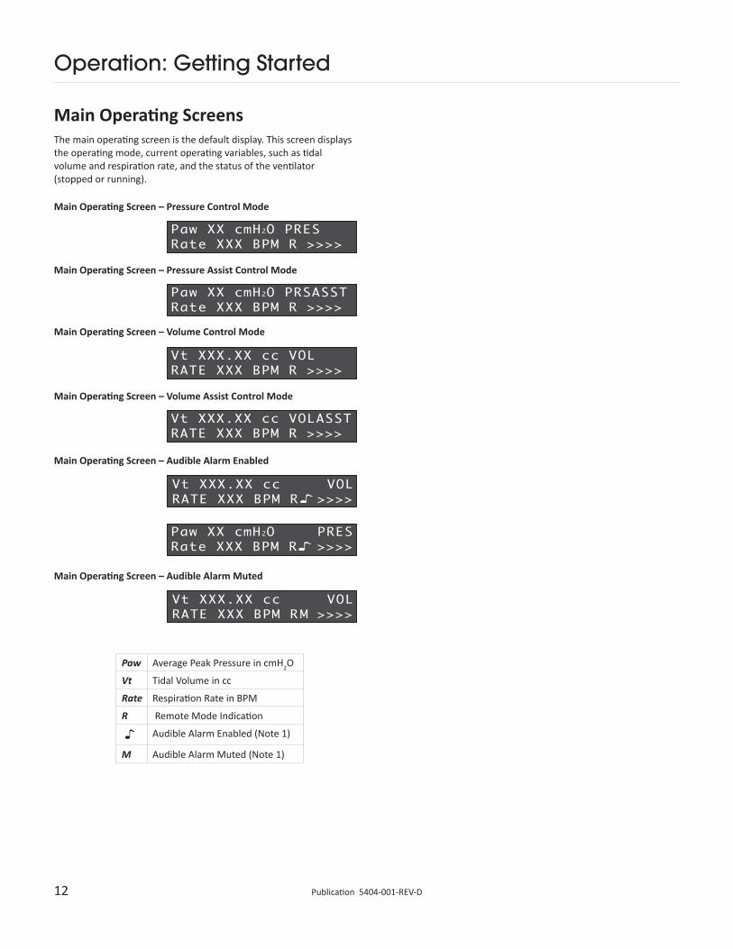
Main Operating ScreensThe main operating screen is the default display. This screen displays the operating mode, current operating variables, such as tidal volume and respiration rate, and the status of the ventilator (stopped or running).
Main Operating Screen – Pressure Control Mode
Main Operating Screen – Pressure Assist Control Mode
Main Operating Screen – Volume Control Mode
Main Operating Screen – Volume Assist Control Mode
Main Operating Screen – Audible Alarm Enabled
Main Operating Screen – Audible Alarm Muted
Paw Average Peak Pressure in cmH2O
Vt Tidal Volume in cc
Rate Respiration Rate in BPM
R Remote Mode Indication
Audible Alarm Enabled (Note 1)
M Audible Alarm Muted (Note 1)
13 www.harvardapparatus.comPublication 5404-001-REV-D
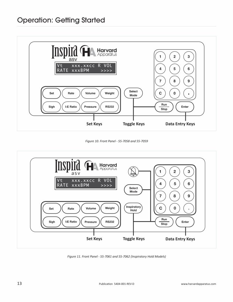
Set Rate Volume Weight
Sigh I:E Ratio Pressure RS232
InspiratoryHold
SelectMode
Run
StopEnter
1 2 3
4 5 6
7 8 9
0C .
asv
Operation: Getting Started
Set Keys
Set Keys
Toggle Keys
Toggle Keys
Data Entry Keys
Data Entry Keys
Figure 10. Front Panel - 55-7058 and 55-7059
Figure 11. Front Panel - 55-7061 and 55-7062 (Inspiratory Hold Models)
14 Publication 5404-001-REV-D
Operation: Getting Started
Description of KeysSet KeysSET – Allows modification of a data item in this group of keys. To modify a data item, press the relevant key after pressing the SET key. Pressing Set with an appropriate data entry key will also allow the selection of special features.
RATE – Displays/sets current respiration rate.
VOLUME – Displays/sets current tidal volume in volume mode.
WEIGHT – Displays/sets current animal weight.
SIGH – Displays/sets sigh parameters and manually triggers a sigh breath.
I:E RATIO – Displays/sets the current inspiration to expiration (I:E) ratio.
PRESSURE – Displays/sets pressure limits.
RS232 – Displays/sets current RS232 device(s) attached.
INSPIRATORY HOLD (Inspiratory Hold model only) – Initiates Inspiratory Hold feature, can be set using SET, then Inspiratory Hold.
ALARM MUTE (Inspiratory Hold model only) – Disables/enables all system audible alarms.
Toggle KeysPressing these keys toggle through the successive states of the key’s function.
RUN/STOP – Starts/stops the ventilator. When stopping, the ventilator will finish its current stroke before ceasing ventilation.
SELECT MODE – Toggles through available run modes with each press of the key. It is also used to select entry choices in hardware setup.
Data Entry Keys1, 2, 3, 4, 5, 6, 7, 8, 9, 0, . – Used to enter numeric data values or access special features.
C – Clear; clears numeric data values prior to entry.
ENTER – Saves and stores displayed data value in memory when setting a data item.
Safe Range Respiratory ProfilesSetting up the ASV ventilator is both easy and safe thanks to the Safe Range software. Once the animal’s body weight has been entered the software computes the median settings for tidal volume and respiratory rate. These same equations are used to calculate a Safe Range around the median values. Inspira uses the entered weight to calculate the correct tidal volume and respiratory rate for the animal. The tidal volume (in liters) is determined by the equation 0.0062 x Mb
1.01 where Mb is the animal mass in kilograms.
The respiratory rate (in min-1) is determined by the equation 53.5 x Mb
-0.26. The Safe Range™ is established by computing a range of acceptable values, which are less than or equal to ±10% of the calculated tidal volume and respiratory rate. All the default parameter settings can be overridden. If you enter a setting outside of the Safe Range™ for the body mass of the animal to be ventilated you are warned that the value is outside the Safe Range™ and asked to confirm the setting.
Safe Range Pressure-Control ModeInspiration Pressure Range
Safe Range: 15 to 25 cmH2O
Full Range: 5 to 50 cmH2O
Sigh Pressure Range
Safe Range: Insp. Pressure to (Insp. Pressure + 10cmH2O)
or 35cmH2O, whichever is less
Full Range: Insp. Pressure to 50cmH2O
15 www.harvardapparatus.comPublication 5404-001-REV-D
Operation: Getting Started
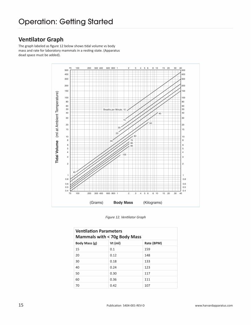
Ventilator GraphThe graph labeled as figure 12 below shows tidal volume vs body mass and rate for laboratory mammals in a resting state. (Apparatus dead space must be added).
Ventilation Parameters Mammals with < 70g Body MassBody Mass (g) Vt (ml) Rate (BPM)
15 0.1 159
20 0.12 148
30 0.18 133
40 0.24 123
50 0.30 117
60 0.36 111
70 0.42 107
Figure 12. Ventilator Graph
16 Publication 5404-001-REV-D
Operation: Getting Started
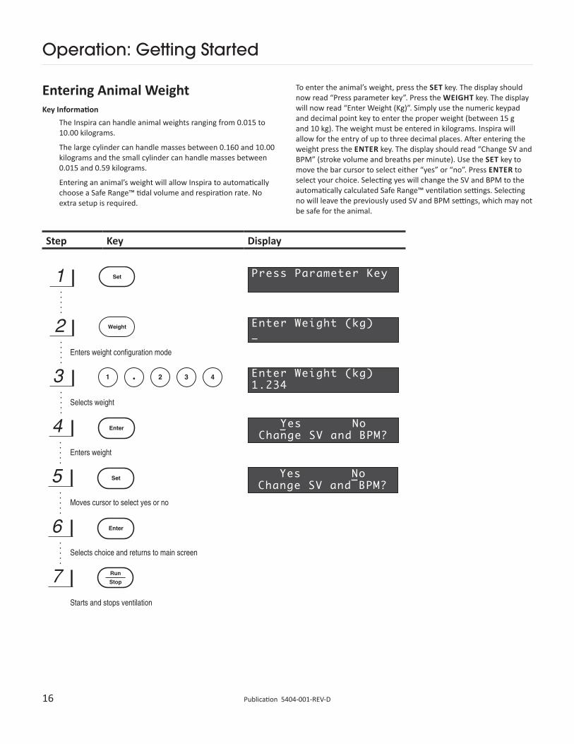
Entering Animal WeightKey Information
The Inspira can handle animal weights ranging from 0.015 to 10.00 kilograms.
The large cylinder can handle masses between 0.160 and 10.00 kilograms and the small cylinder can handle masses between 0.015 and 0.59 kilograms.
Entering an animal’s weight will allow Inspira to automatically choose a Safe Range™ tidal volume and respiration rate. No extra setup is required.
�
To enter the animal’s weight, press the SET key. The display should now read “Press parameter key”. Press the WEIGHT key. The display will now read “Enter Weight (Kg)”. Simply use the numeric keypad and decimal point key to enter the proper weight (between 15 g and 10 kg). The weight must be entered in kilograms. Inspira will allow for the entry of up to three decimal places. After entering the weight press the ENTER key. The display should read “Change SV and BPM” (stroke volume and breaths per minute). Use the SET key to move the bar cursor to select either “yes” or “no”. Press ENTER to select your choice. Selecting yes will change the SV and BPM to the automatically calculated Safe Range™ ventilation settings. Selecting no will leave the previously used SV and BPM settings, which may not be safe for the animal.
Step Key Display
17 www.harvardapparatus.comPublication 5404-001-REV-D
Operation: Getting Started
Starting and Stopping VentilationTo start and stop ventilation simply press the RUN/STOP key. When stopping, Inspira will finish its current stroke before stopping completely. The valve will always be in the expiration position when a STOP has been commanded.
Displaying Ventilator ParametersInspira allows you to easily check the current ventilation parameters by using one key commands. To display a specific parameter, simply press and hold the appropriate key.
Key Display
18 Publication 5404-001-REV-D
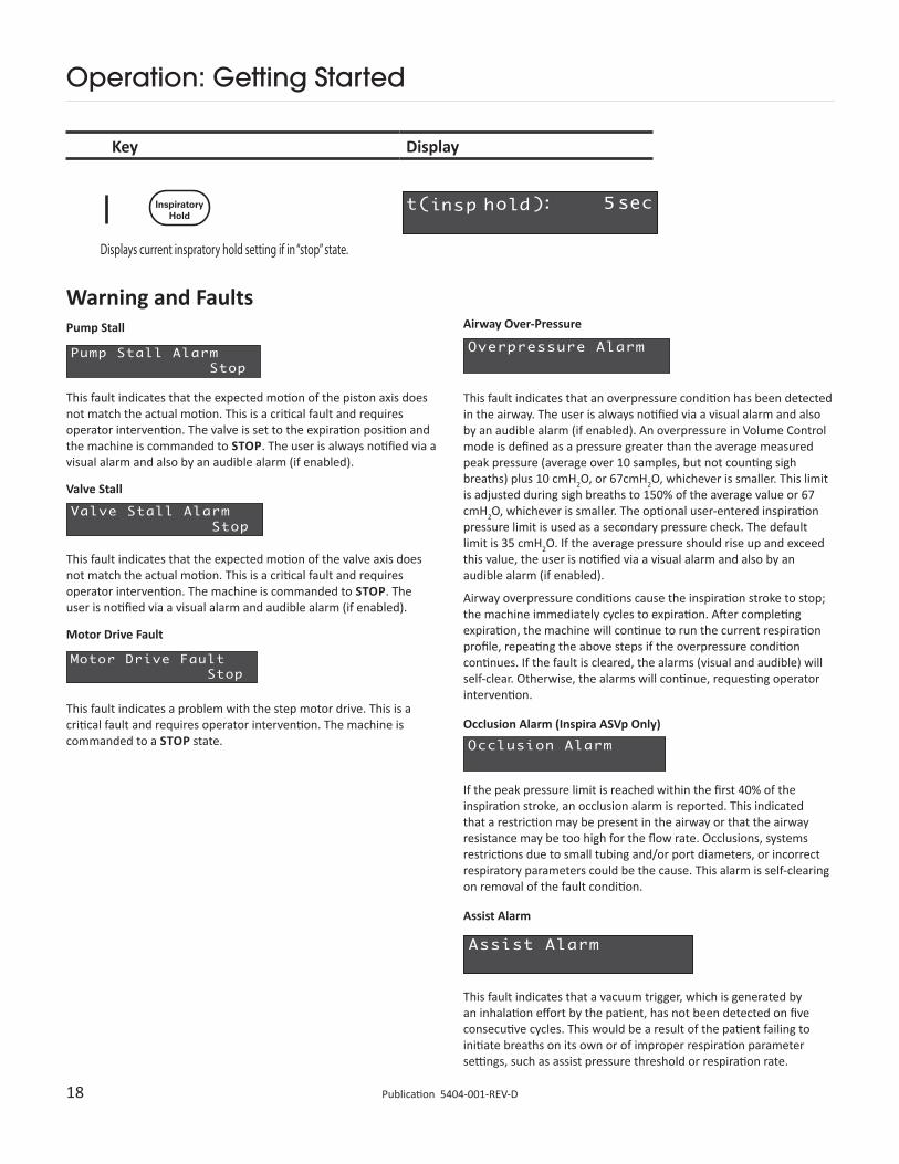
Warning and FaultsPump Stall
This fault indicates that the expected motion of the piston axis does not match the actual motion. This is a critical fault and requires operator intervention. The valve is set to the expiration position and the machine is commanded to STOP. The user is always notified via a visual alarm and also by an audible alarm (if enabled).
Valve Stall
This fault indicates that the expected motion of the valve axis does not match the actual motion. This is a critical fault and requires operator intervention. The machine is commanded to STOP. The user is notified via a visual alarm and audible alarm (if enabled).
Motor Drive Fault
This fault indicates a problem with the step motor drive. This is a critical fault and requires operator intervention. The machine is commanded to a STOP state.
Operation: Getting Started
Key Display
Airway Over-Pressure
This fault indicates that an overpressure condition has been detected in the airway. The user is always notified via a visual alarm and also by an audible alarm (if enabled). An overpressure in Volume Control mode is defined as a pressure greater than the average measured peak pressure (average over 10 samples, but not counting sigh breaths) plus 10 cmH2O, or 67cmH2O, whichever is smaller. This limit is adjusted during sigh breaths to 150% of the average value or 67 cmH2O, whichever is smaller. The optional user-entered inspiration pressure limit is used as a secondary pressure check. The default limit is 35 cmH2O. If the average pressure should rise up and exceed this value, the user is notified via a visual alarm and also by an audible alarm (if enabled).
Airway overpressure conditions cause the inspiration stroke to stop; the machine immediately cycles to expiration. After completing expiration, the machine will continue to run the current respiration profile, repeating the above steps if the overpressure condition continues. If the fault is cleared, the alarms (visual and audible) will self-clear. Otherwise, the alarms will continue, requesting operator intervention.
Occlusion Alarm (Inspira ASVp Only)
If the peak pressure limit is reached within the first 40% of the inspiration stroke, an occlusion alarm is reported. This indicated that a restriction may be present in the airway or that the airway resistance may be too high for the flow rate. Occlusions, systems restrictions due to small tubing and/or port diameters, or incorrect respiratory parameters could be the cause. This alarm is self-clearing on removal of the fault condition.
Assist Alarm
This fault indicates that a vacuum trigger, which is generated by an inhalation effort by the patient, has not been detected on five consecutive cycles. This would be a result of the patient failing to initiate breaths on its own or of improper respiration parameter settings, such as assist pressure threshold or respiration rate.
19 www.harvardapparatus.comPublication 5404-001-REV-D
Operation: Getting Started
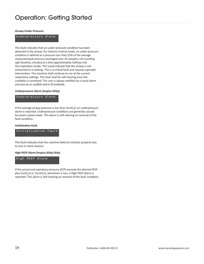
Airway Under-Pressure
This fault indicates that an under-pressure condition has been detected in the airway. For Volume Control mode, an under-pressure condition is defined as a pressure less than 25% of the average measured peak pressure (averaged over 10 samples, not counting sigh breaths), checked at a time approximately halfway into the inspiration stroke. This could indicate that the airway is not connected or is leaking. This is a critical fault and requires operator intervention. The machine shall continue to run at the current respiratory settings. This fault shall be self-clearing once the condition is corrected. The user is always notified via a visual alarm and also by an audible alarm (if enabled).
Underpressure Alarm (Inspira ASVp)
If the average airway pressure is less than 3cmH20, an underpressure alarm is reported. Underpressure conditions are generally caused by severe system leaks. This alarm is self-clearing on removal of the fault condition.
Initialization Fault
This fault indicates that the machine failed to initialize properly due to one or more reasons.
High PEEP Alarm (Inspira ASVp Only)
If the actual end-expiratory pressure (EEP) exceeds the desired PEEP plus 5cmH2O or 11cmH2O, whichever is less, a High PEEP Alarm is reported. This alarm is self-clearing on removal of the fault condition.
20 Publication 5404-001-REV-D
Operation: Respiration Profiles
�
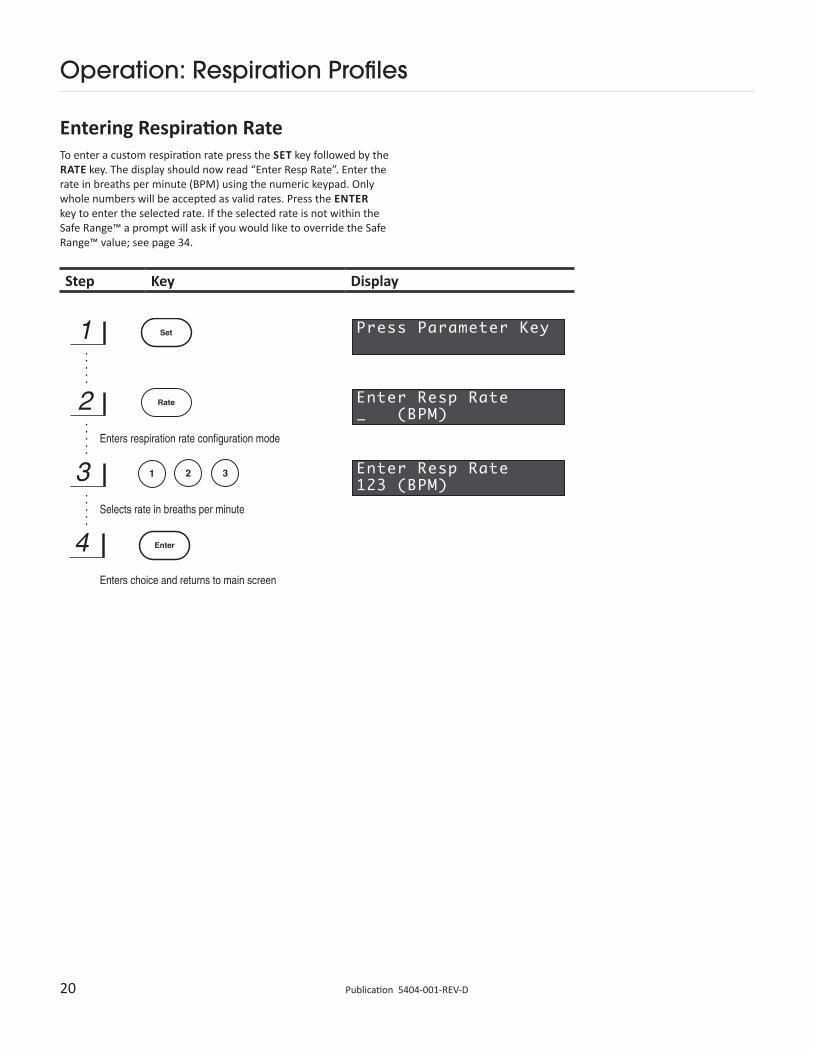
Entering Respiration RateTo enter a custom respiration rate press the SET key followed by the RATE key. The display should now read “Enter Resp Rate”. Enter the rate in breaths per minute (BPM) using the numeric keypad. Only whole numbers will be accepted as valid rates. Press the ENTER key to enter the selected rate. If the selected rate is not within the Safe Range™ a prompt will ask if you would like to override the Safe Range™ value; see page 34.
Step Key Display
21 www.harvardapparatus.comPublication 5404-001-REV-D
Operation: Respiration Profiles
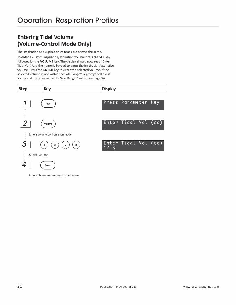
Entering Tidal Volume (Volume-Control Mode Only)The inspiration and expiration volumes are always the same.To enter a custom inspiration/expiration volume press the SET key followed by the VOLUME key. The display should now read “Enter Tidal Vol”. Use the numeric keypad to enter the inspiration/expiration volume. Press the ENTER key to enter the selected volume. If the selected volume is not within the Safe Range™ a prompt will ask if you would like to override the Safe Range™ value; see page 34.
Step Key Display
22 Publication 5404-001-REV-D
Operation: Respiration Profiles
Step Key Display
Entering Sigh Breath (Pressure-Control Mode Only)A sigh pressure and sigh frequency must be set in order to activate the sigh breath function in pressure-control mode.
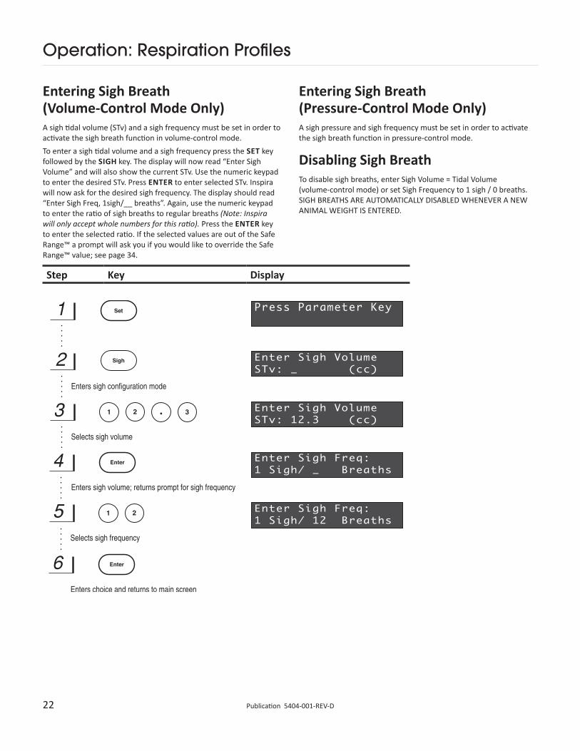
Disabling Sigh BreathTo disable sigh breaths, enter Sigh Volume = Tidal Volume (volume-control mode) or set Sigh Frequency to 1 sigh / 0 breaths. SIGH BREATHS ARE AUTOMATICALLY DISABLED WHENEVER A NEW ANIMAL WEIGHT IS ENTERED.
Entering Sigh Breath (Volume-Control Mode Only)A sigh tidal volume (STv) and a sigh frequency must be set in order to activate the sigh breath function in volume-control mode.To enter a sigh tidal volume and a sigh frequency press the SET key followed by the SIGH key. The display will now read “Enter Sigh Volume” and will also show the current STv. Use the numeric keypad to enter the desired STv. Press ENTER to enter selected STv. Inspira will now ask for the desired sigh frequency. The display should read “Enter Sigh Freq, 1sigh/__ breaths”. Again, use the numeric keypad to enter the ratio of sigh breaths to regular breaths (Note: Inspira will only accept whole numbers for this ratio). Press the ENTER key to enter the selected ratio. If the selected values are out of the Safe Range™ a prompt will ask you if you would like to override the Safe Range™ value; see page 34.
23 www.harvardapparatus.comPublication 5404-001-REV-D
Operation: Respiration Profiles
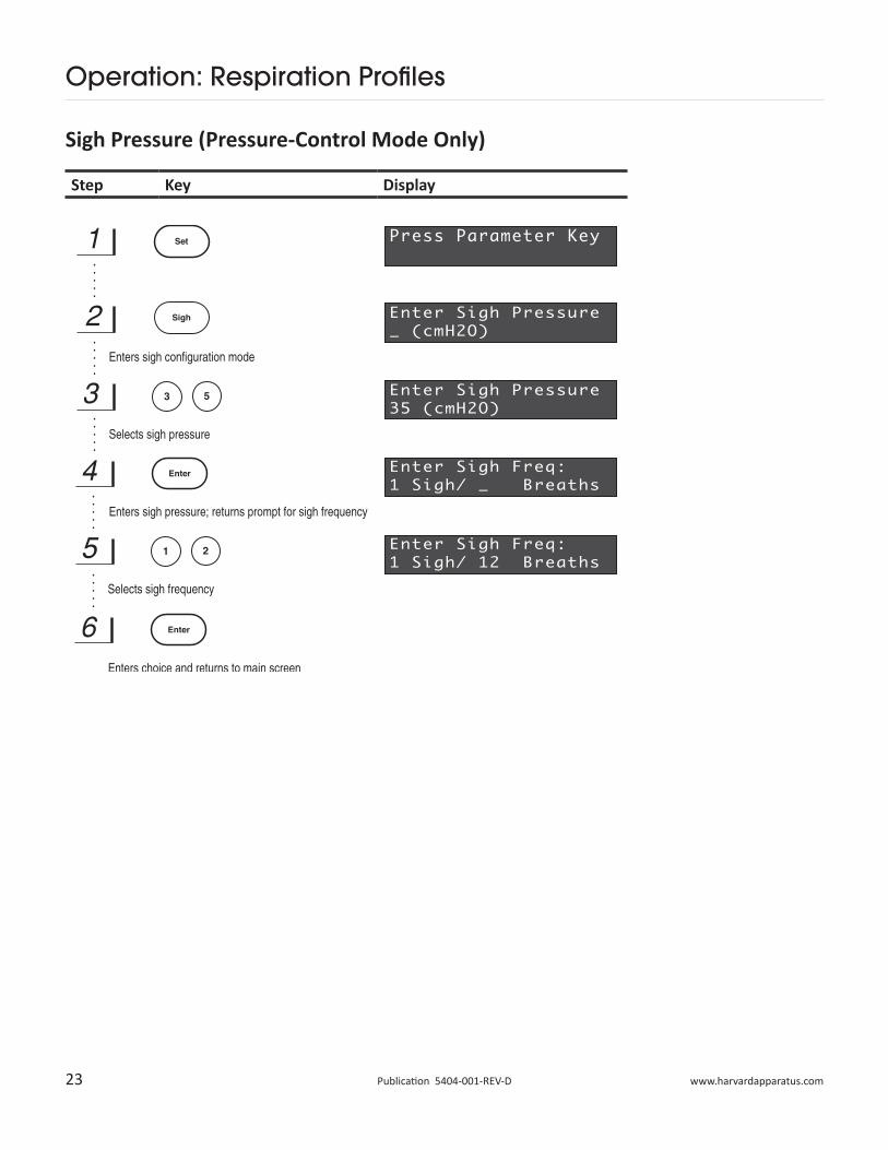
Sigh Pressure (Pressure-Control Mode Only)
Step Key Display
24 Publication 5404-001-REV-D
Operation: Respiration Profiles
Step Key Display
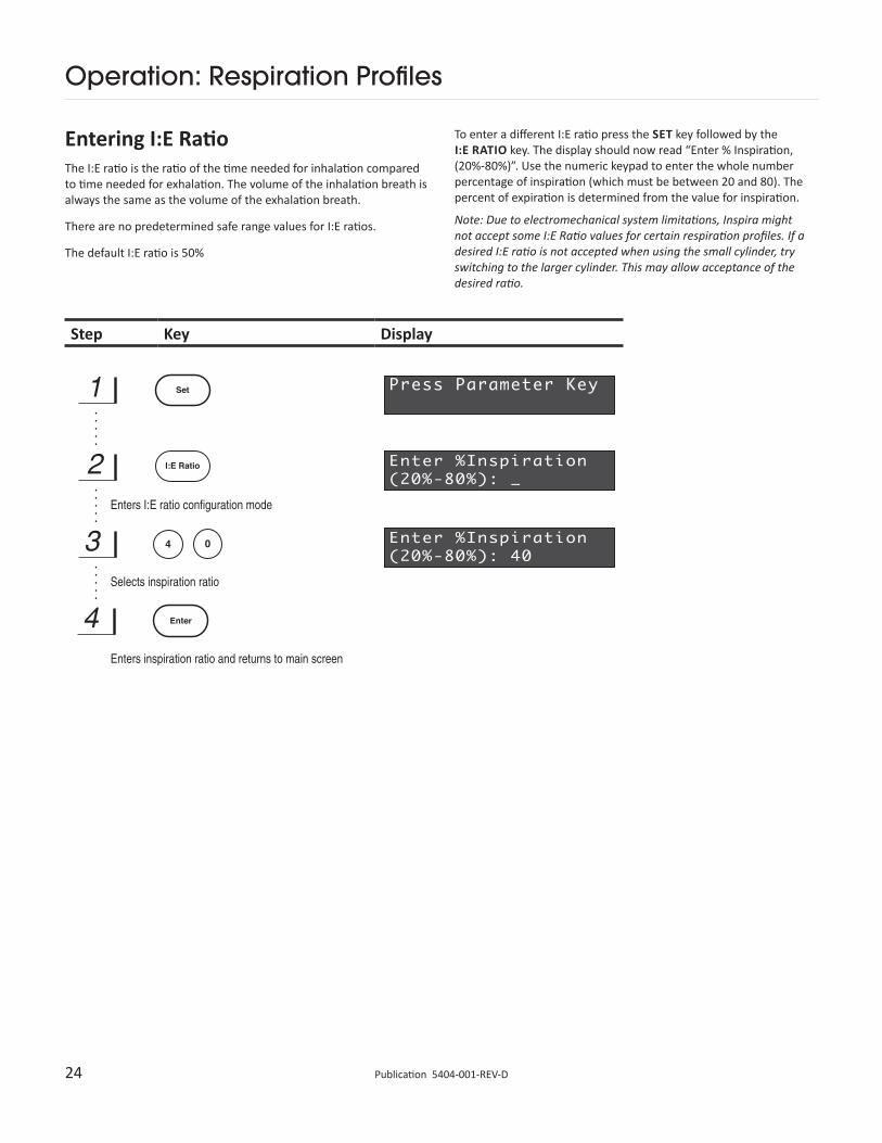
Entering I:E RatioThe I:E ratio is the ratio of the time needed for inhalation compared to time needed for exhalation. The volume of the inhalation breath is always the same as the volume of the exhalation breath.
There are no predetermined safe range values for I:E ratios.
The default I:E ratio is 50%
To enter a different I:E ratio press the SET key followed by the I:E RATIO key. The display should now read “Enter % Inspiration, (20%-80%)”. Use the numeric keypad to enter the whole number percentage of inspiration (which must be between 20 and 80). The percent of expiration is determined from the value for inspiration.
Note: Due to electromechanical system limitations, Inspira might not accept some I:E Ratio values for certain respiration profiles. If a desired I:E ratio is not accepted when using the small cylinder, try switching to the larger cylinder. This may allow acceptance of the desired ratio.
25 www.harvardapparatus.comPublication 5404-001-REV-D
Operation: Respiration Profiles
Step Key Display
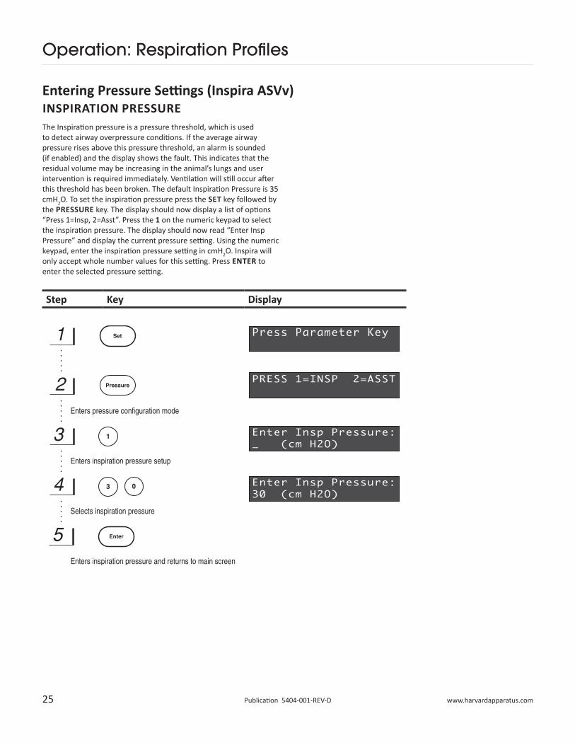
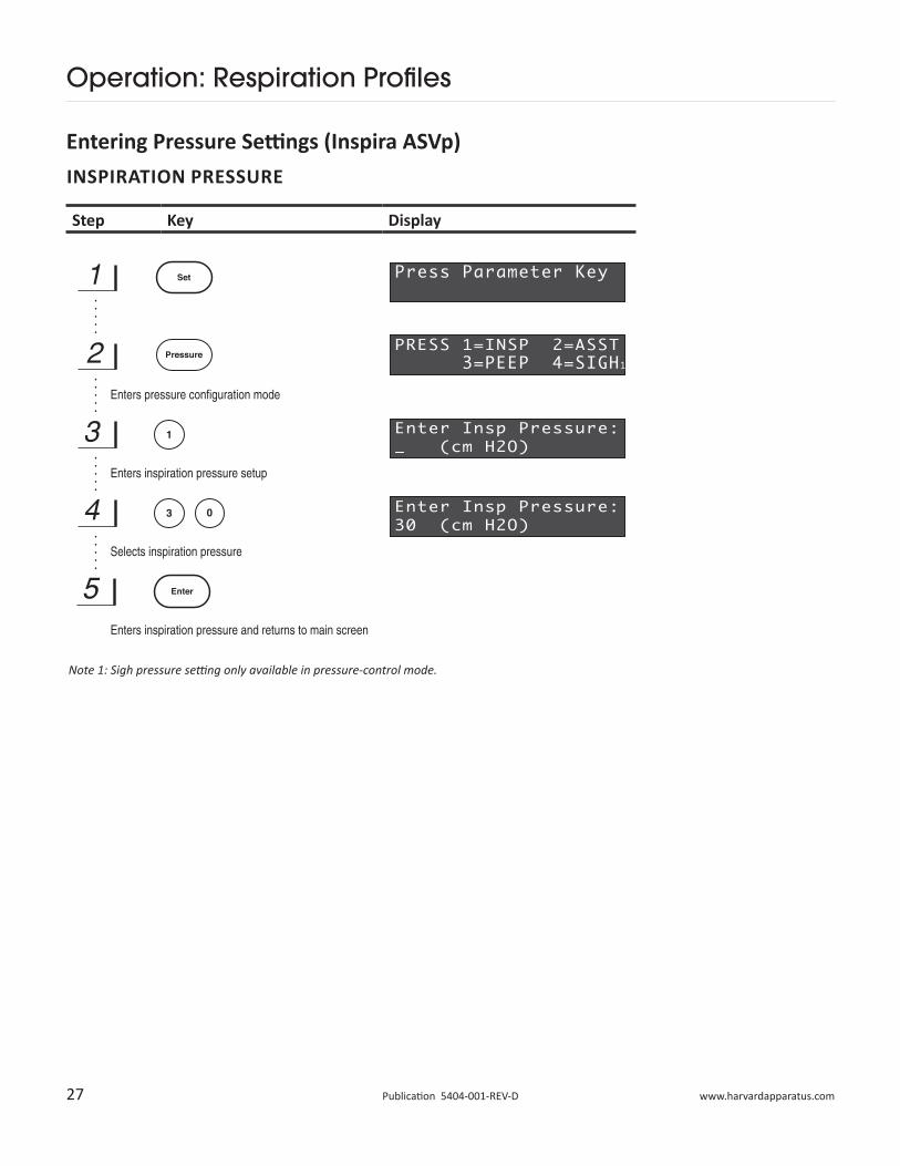
INSPIRATION PRESSUREThe Inspiration pressure is a pressure threshold, which is used to detect airway overpressure conditions. If the average airway pressure rises above this pressure threshold, an alarm is sounded (if enabled) and the display shows the fault. This indicates that the residual volume may be increasing in the animal’s lungs and user intervention is required immediately. Ventilation will still occur after this threshold has been broken. The default Inspiration Pressure is 35 cmH2O. To set the inspiration pressure press the SET key followed by the PRESSURE key. The display should now display a list of options “Press 1=Insp, 2=Asst”. Press the 1 on the numeric keypad to select the inspiration pressure. The display should now read “Enter Insp Pressure” and display the current pressure setting. Using the numeric keypad, enter the inspiration pressure setting in cmH2O. Inspira will only accept whole number values for this setting. Press ENTER to enter the selected pressure setting.
Entering Pressure Settings (Inspira ASVv)
26 Publication 5404-001-REV-D
Operation: Respiration Profiles
Step Key Display
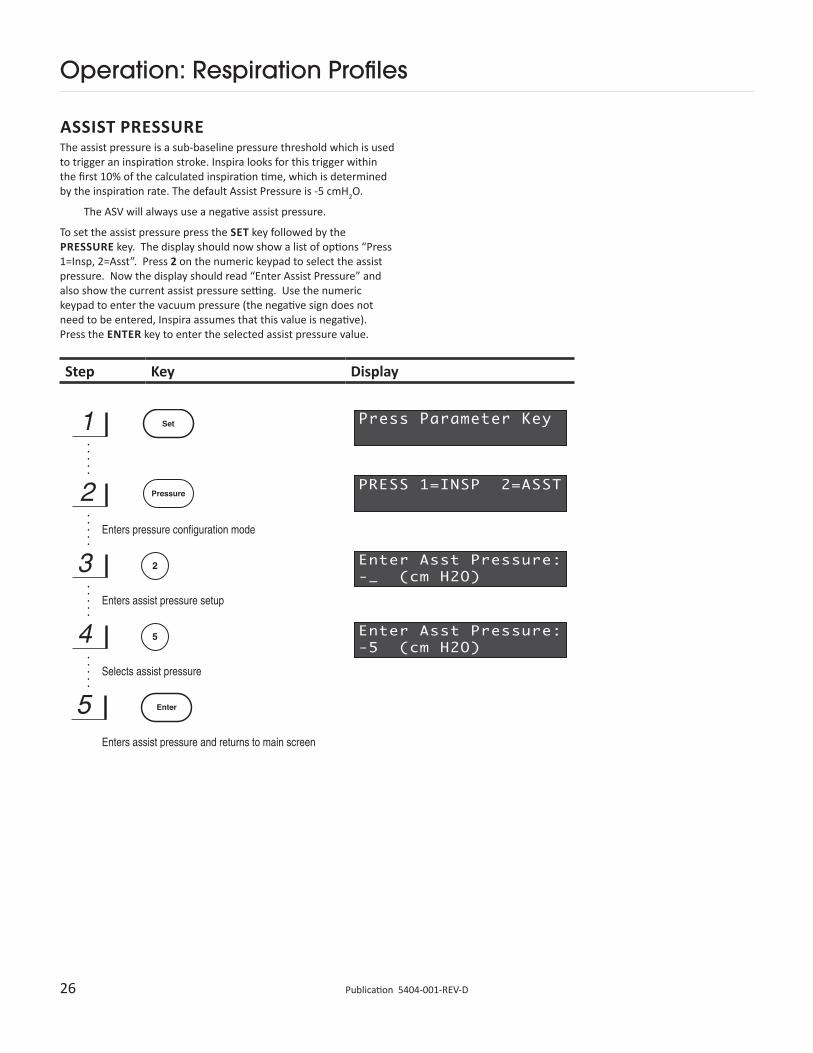
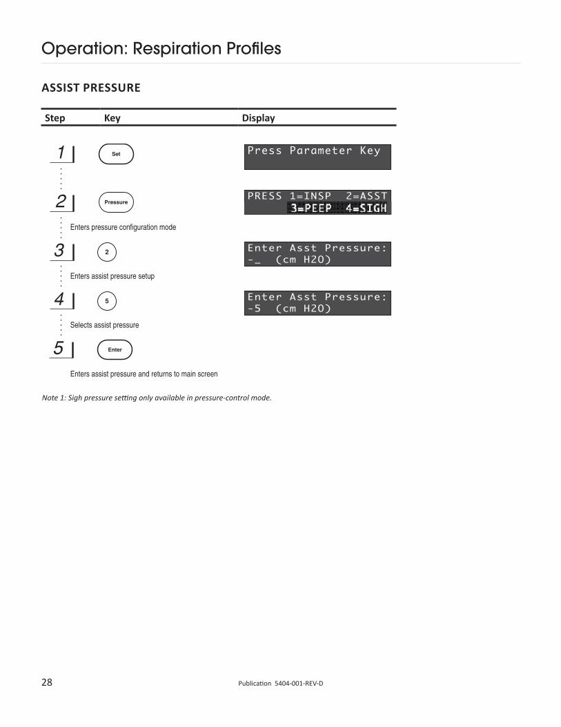
ASSIST PRESSUREThe assist pressure is a sub-baseline pressure threshold which is used to trigger an inspiration stroke. Inspira looks for this trigger within the first 10% of the calculated inspiration time, which is determined by the inspiration rate. The default Assist Pressure is -5 cmH2O.
The ASV will always use a negative assist pressure.
To set the assist pressure press the SET key followed by the PRESSURE key. The display should now show a list of options “Press 1=Insp, 2=Asst”. Press 2 on the numeric keypad to select the assist pressure. Now the display should read “Enter Assist Pressure” and also show the current assist pressure setting. Use the numeric keypad to enter the vacuum pressure (the negative sign does not need to be entered, Inspira assumes that this value is negative). Press the ENTER key to enter the selected assist pressure value.
27 www.harvardapparatus.comPublication 5404-001-REV-D
Operation: Respiration Profiles
Step Key Display
Entering Pressure Settings (Inspira ASVp)INSPIRATION PRESSURE
Note 1: Sigh pressure setting only available in pressure-control mode.
28 Publication 5404-001-REV-D
Operation: Respiration Profiles
Step Key Display
ASSIST PRESSURE
Note 1: Sigh pressure setting only available in pressure-control mode.
29 www.harvardapparatus.comPublication 5404-001-REV-D
Operation: Respiration Profiles
Step Key Display
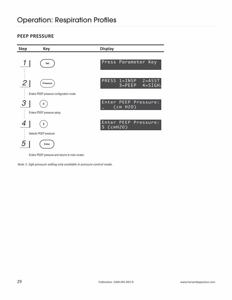
PEEP PRESSURE
Note 1: Sigh pressure setting only available in pressure-control mode.
P
P
P
Enters PEEP pressure configuration mode
Enters PEEP pressure setup
Selects PEEP pressure
Enters PEEP pressure and returns to main screen
30 Publication 5404-001-REV-D
Operation: Respiration Profiles
Step Key Display
SIGH PRESSURE (PRESSURE-CONTROL MODE ONLY)
31 www.harvardapparatus.comPublication 5404-001-REV-D
Operation: Respiration Profiles
InspiratoryHold
Enters time entry mode in seconds
Selects time
Returns to main screen
Step Key Display
INSPIRATORY HOLD (INSPIRATORY HOLD MODELS ONLY)
32 Publication 5404-001-REV-D
Key
Operation: Respiration Profiles
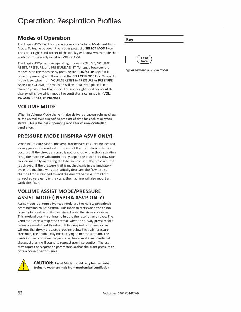
Modes of OperationThe Inspira ASVv has two operating modes, Volume Mode and Assist Mode. To toggle between the modes press the SELECT MODE key. The upper right hand corner of the display will show which mode the ventilator is currently in, either VOL or ASST.
The Inspira ASVp has four operating modes – VOLUME, VOLUME ASSIST, PRESSURE, and PRESSURE ASSIST. To toggle between the modes, stop the machine by pressing the RUN/STOP key (if it is presently running) and then press the SELECT MODE key. When the mode is switched from VOLUME ASSIST to PRESSURE or PRESSURE ASSIST to VOLUME, the machine will re-initialize to place it in its “home” position for that mode. The upper right hand corner of the display will show which mode the ventilator is currently in - VOL, VOLASST, PRES, or PRSASST.
VOLUME MODEWhen in Volume Mode the ventilator delivers a known volume of gas to the animal over a specified amount of time for each respiration stroke. This is the basic operating mode for volume-controlled ventilation.
PRESSURE MODE (INSPIRA ASVP ONLY)When in Pressure Mode, the ventilator delivers gas until the desired airway pressure is reached or the end of the inspiration cycle has occurred. If the airway pressure is not reached within the inspiration time, the machine will automatically adjust the inspiratory flow rate by incrementally increasing the tidal volume until the pressure limit is achieved. If the pressure limit is reached early in the inspiratory cycle, the machine will automatically decrease the flow rate so that the limit is reached toward the end of the cycle. If the limit is reached very early in the cycle, the machine will also report an Occlusion Fault.
VOLUME ASSIST MODE/PRESSURE ASSIST MODE (INSPIRA ASVP ONLY)Assist mode is a more advanced mode used to help wean animals off of mechanical respiration. This mode detects when the animal is trying to breathe on its own via a drop in the airway pressure. This mode allows the animal to initiate the respiration strokes. The ventilator starts a respiration stroke when the airway pressure falls below a user-defined threshold. If five respiration strokes occur without the airway pressure dropping below the assist pressure threshold, the animal may not be trying to initiate a breath. The ventilator will continue to operate in the current assist mode but the assist alarm will sound to request user intervention. The user may adjust the respiration parameters and/or the assist pressure to obtain correct performance.
CAUTION: Assist Mode should only be used when trying to wean animals from mechanical ventilation
33 www.harvardapparatus.comPublication 5404-001-REV-D
Key
Operation: Advanced
WARNING: Overriding Safe Range™ may be harmful to the patient
User OverrideThe user has the option of overriding the machine’s “Safe Range™” limits to allow for more advanced respiratory control. The Safe Range™ is defined as ±10% of the machine’s recommended tidal volume and ±10% of the machine’s recommended respiration rate. When you would like to change a respiration parameter simply enter the value according to the steps provided in the Getting Started section. If the value is outside of the Safe Range™, Inspira will ask you if you would like to override the current Safe Range™ parameter. On this prompt screen press 1 to select “Yes” or 2 for “No”.
Note: Some parameters may not be valid due to current respiration profile, cylinder size, and electromechanical limitations.
Key Display
34 Publication 5404-001-REV-D
Operation: Advanced
Remote Control / Monitoring (Serial Communication)The Inspira is equipped for serial communication through two RS232 ports. Inspira uses a Harvard Apparatus Command Line protocol as the basis of its serial commands. These serial commands can be found in Appendix C.
RS232 CABLE SELECTIONTo connect PC/At or laptop computers you will need a 9-pin male to 9-pin female shielded cable; Harvard Apparatus part number 5154-353. For PCs with a 25-pin serial port connection, use a 9-pin male to 25-pin female shielded cable; 5154-527. Note: Do not use a “Null-Modem” type cable.
RS232 CABLE CONNECTIONUse correct cable.
The recommended cable length is 3 meters maximum.
Turn power off to Inspira and to the external device before connecting the cable into the connectors.
Check that the Inspira signal ground (pin 5) is connected to the external device signal ground.
Use shielded cabling to connect Inspira’s chassis ground to the chassis ground of the external device.
Using Digital and Analog I/O PortsTRIGGER INThis is an active low, digital signal, used to trigger the ventilator between the RUN and STOP modes. Each pulse given to Inspira through this channel will toggle the machine to the next state. This optional signal is input by the user through the use of a footswitch or other device connected to the front panel BNC connector. Minimum input pulse width = 1 ms.
SYNC OUT (INSPIRA ASVV (VERSION 1.13 AND EARLIER))This is an active-low, open-collector, digital signal generated at the start of each inspiration stroke. This signal is available at the front panel through a BNC connector. The pulse width equals 20 ms ±10 ms. This signal can be used in conjunction with other devices, which need to operate in sync with the ventilator’s respiration stroke. The falling edge must be used for sync timing.
SYNC OUT (INSPIRA ASVP & ASVV (VERSION 1.14 AND LATER))The sync signal is a logic high for the duration of the inspiration time and a logic low during the expiration time. The rising edge corresponds to the start of the inspiration cycle and the falling edge corresponds to the start of expiration.
ANALOG OUTThe analog out (ANALOG OUT 1) is used to measure the ventilator’s airway pressure. This output can be monitored using a data acquisition system or by an oscilloscope. To view or record this signal, connect the data acquisition system or oscilloscope to the analog out BNC connector on Inspira’s front panel.
35 www.harvardapparatus.comPublication 5404-001-REV-D
Operation: Advanced
�
Step Key Display
SERIAL COMMUNICATION SETUPTo configure Inspira for serial communications, press SET key followed by the RS232 key. The display should read “RS232 Setup, Enter to Continue”. Press ENTER key to display the RS232 input/output selection menu. The display should now read “Press 1=Input port, 2=Output port”. Select the port you would like to configure (Input is used for serial connection to a pc; Output is used for a daisy chain setup). The display should now show the RS232 port setup menu which reads “Press 1=Baud, 2=Bits, 3=Parity, 4=Addr”.
36 Publication 5404-001-REV-D
Operation: Advanced
Step* Key Display
DATA TRANSFER RATE CONFIGURATIONTo configure the data transfer rate, enter the port configuration menu. Press 1 to enter the Baud rate setup screen. The display should read “Press Select Mode to toggle baud” and display current baud rate. Press the SELECT MODE key to toggle through the baud rates (38400, 19200, 9600, 2400, and 1200). Pressing the ENTER key will accept the value and return Inspira to the main screen. Default baud rate is 9600.
*Note: See page 36 for steps 1 through 4.
37 www.harvardapparatus.comPublication 5404-001-REV-D
Operation: Advanced
Step* Key Display
Step* Key Display
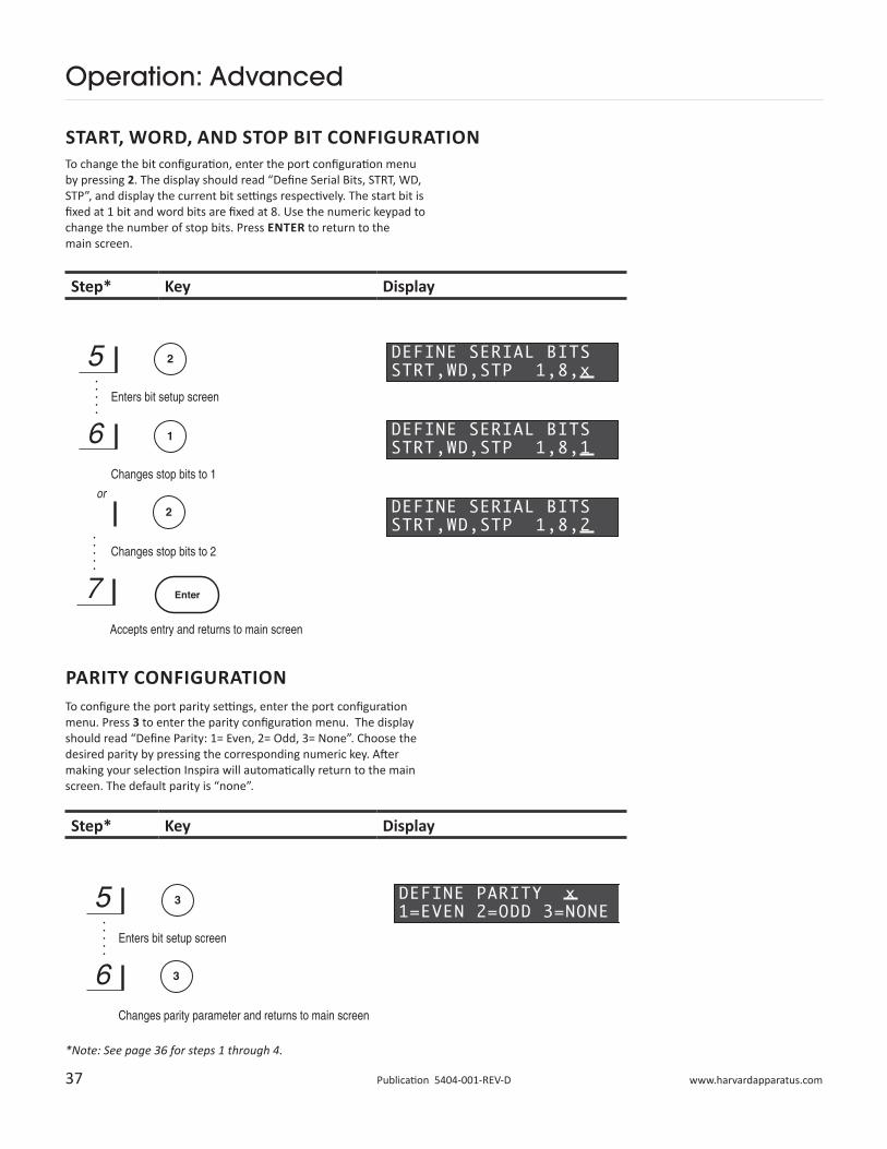
To change the bit configuration, enter the port configuration menu by pressing 2. The display should read “Define Serial Bits, STRT, WD, STP”, and display the current bit settings respectively. The start bit is fixed at 1 bit and word bits are fixed at 8. Use the numeric keypad to change the number of stop bits. Press ENTER to return to the main screen.
PARITY CONFIGURATIONTo configure the port parity settings, enter the port configuration menu. Press 3 to enter the parity configuration menu. The display should read “Define Parity: 1= Even, 2= Odd, 3= None”. Choose the desired parity by pressing the corresponding numeric key. After making your selection Inspira will automatically return to the main screen. The default parity is “none”.
*Note: See page 36 for steps 1 through 4.
START, WORD, AND STOP BIT CONFIGURATION
38 Publication 5404-001-REV-D
Operation: Advanced
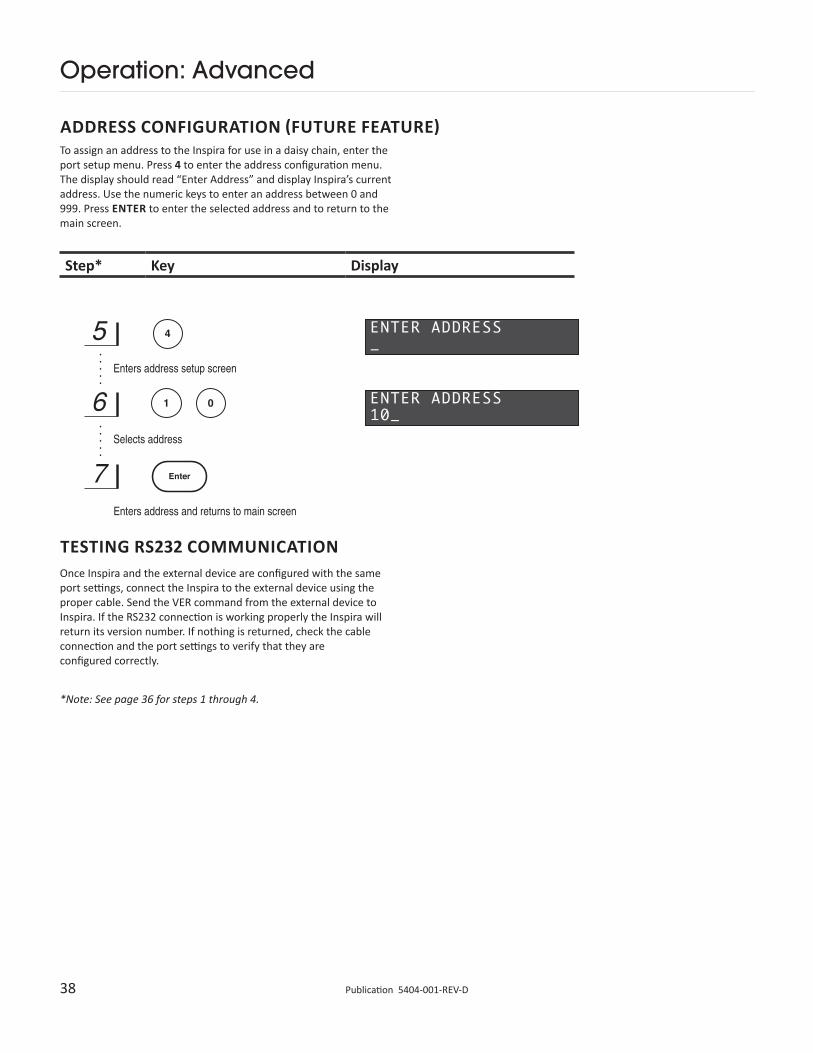
To assign an address to the Inspira for use in a daisy chain, enter the port setup menu. Press 4 to enter the address configuration menu. The display should read “Enter Address” and display Inspira’s current address. Use the numeric keys to enter an address between 0 and 999. Press ENTER to enter the selected address and to return to the main screen.
Step* Key Display
TESTING RS232 COMMUNICATIONOnce Inspira and the external device are configured with the same port settings, connect the Inspira to the external device using the proper cable. Send the VER command from the external device to Inspira. If the RS232 connection is working properly the Inspira will return its version number. If nothing is returned, check the cable connection and the port settings to verify that they are configured correctly.
*Note: See page 36 for steps 1 through 4.
ADDRESS CONFIGURATION (FUTURE FEATURE)
39 www.harvardapparatus.comPublication 5404-001-REV-D
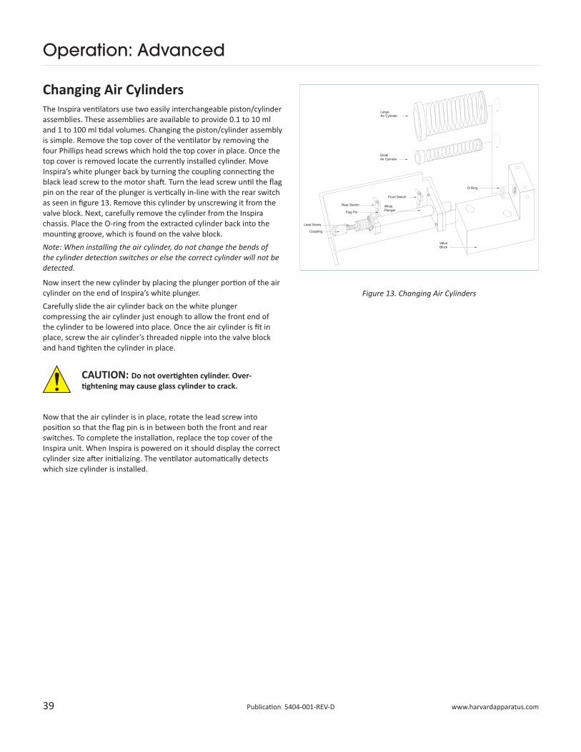
Changing Air CylindersThe Inspira ventilators use two easily interchangeable piston/cylinder assemblies. These assemblies are available to provide 0.1 to 10 ml and 1 to 100 ml tidal volumes. Changing the piston/cylinder assembly is simple. Remove the top cover of the ventilator by removing the four Phillips head screws which hold the top cover in place. Once the top cover is removed locate the currently installed cylinder. Move Inspira’s white plunger back by turning the coupling connecting the black lead screw to the motor shaft. Turn the lead screw until the flag pin on the rear of the plunger is vertically in-line with the rear switch as seen in figure 13. Remove this cylinder by unscrewing it from the valve block. Next, carefully remove the cylinder from the Inspira chassis. Place the O-ring from the extracted cylinder back into the mounting groove, which is found on the valve block. Note: When installing the air cylinder, do not change the bends of the cylinder detection switches or else the correct cylinder will not be detected.
Now insert the new cylinder by placing the plunger portion of the air cylinder on the end of Inspira’s white plunger. Carefully slide the air cylinder back on the white plunger compressing the air cylinder just enough to allow the front end of the cylinder to be lowered into place. Once the air cylinder is fit in place, screw the air cylinder’s threaded nipple into the valve block and hand tighten the cylinder in place.
Now that the air cylinder is in place, rotate the lead screw into position so that the flag pin is in between both the front and rear switches. To complete the installation, replace the top cover of the Inspira unit. When Inspira is powered on it should display the correct cylinder size after initializing. The ventilator automatically detects which size cylinder is installed.
Operation: Advanced
CAUTION: Do not overtighten cylinder. Over-tightening may cause glass cylinder to crack.
Figure 13. Changing Air Cylinders
40 Publication 5404-001-REV-D
Operation: Advanced
Step Key Display
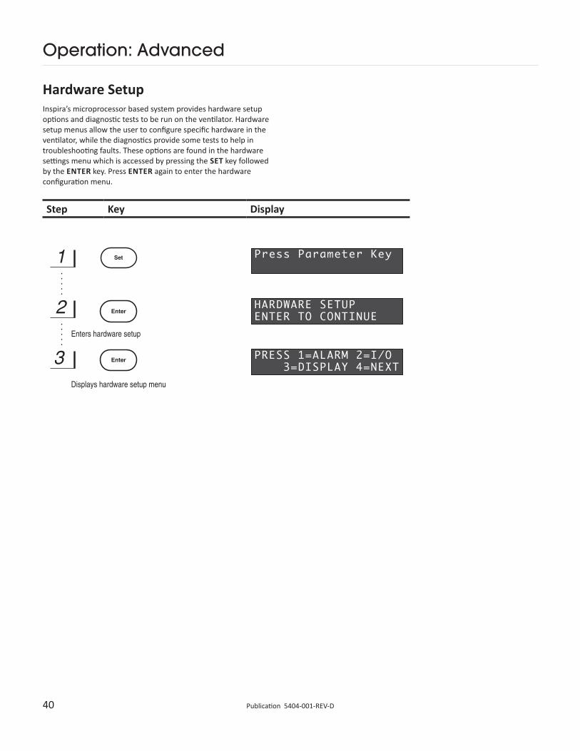
Hardware SetupInspira’s microprocessor based system provides hardware setup options and diagnostic tests to be run on the ventilator. Hardware setup menus allow the user to configure specific hardware in the ventilator, while the diagnostics provide some tests to help in troubleshooting faults. These options are found in the hardware settings menu which is accessed by pressing the SET key followed by the ENTER key. Press ENTER again to enter the hardware configuration menu.
41 www.harvardapparatus.comPublication 5404-001-REV-D
Operation: Advanced
AUDIBLE ALARM ON/OFFTo toggle the audible alarm on or off, enter the hardware configuration menu. Press 1 to enter the alarm setup. The display should read “Press Select Mode to Toggle Alarm” and display whether the alarm is currently on or off. Pressing the SELECT MODE key toggles the alarm on or off, enters the selection, and then returns to the main screen. WHEN YOU TURN OFF THE AUDIBLE ALARM, IT IS OFF FOR ALL FAULT FUNCTIONS.
Step* Key Display
* Note: See page 41 for steps 1 through 3.
For Inspiratory Hold models, audible alarms can be muted or unmuted by pressing the on the keypad. In this version, there will be a displayed when the alarms are audible and an “M” when the system is muted.
42 Publication 5404-001-REV-D
Operation: Advanced
Step* Key Display
I/O SETUPTo review or modify the I/O settings, enter the hardware configuration menu. Press 2 to enter the I/O setup. The display should now read “Set I/O: Press 1= Digital, 2= Analog”. Pressing 1 selects Digital I/O configuration. This feature is a future option and is not presently available. Pressing 2 selects the Analog I/O menu.
The display should now read “Analog 1= Arwy Pres”. This indicates that the airway pressure analog signal is connected to Analog Out 1. This is the only analog signal available in this model. Inspira then returns to the main display screen.
* Note: See page 41 for steps 1 through 3.
43 www.harvardapparatus.comPublication 5404-001-REV-D
Operation: Advanced
Step* Key Display
DISPLAY BRIGHTNESS LEVELTo change the display brightness level, enter the hardware configuration menu. Press 3 to enter the display configuration. The display should now read “Set Brightness Level 100%” (default setting). There are four options for the display brightness, 25, 50, 75, and 100%. Use the SELECT MODE key to toggle through the different levels of brightness. The ENTER key selects the brightness level and then returns to the main screen.
* Note: See page 41 for steps 1 through 3.
44 Publication 5404-001-REV-D
Operation: Advanced
Step* Key Display
DiagnosticsTo enter the Inspira diagnostic menu, first enter the hardware configuration menu and press 4 to advance to the next menu. The display should read “Press 5= Diagnostics”. Press 5 to enter the diagnostics menu. The display should read “Press 1= Dsply, 2=Key, 3=Alarm, 4=Next”.
DISPLAY DIAGNOSTICSTo perform the display diagnostic, enter the diagnostic menu. Press 1 to perform the display test. The display should read “Display Test”, then illuminate all pixels and return to the diagnostics menu.
Step† Key Display
* Note: See page 41 for steps 1 through 3.
† Note: See above for steps 4 & 5.
45 www.harvardapparatus.comPublication 5404-001-REV-D
Operation: Advanced
Step* Key Display
Step* Key Display
KEYPAD DIAGNOSTICSTo run the keypad diagnostic, enter the diagnostics menu. Press 2 to start the keypad diagnostic. The display should momentarily read “Keypad Test, Press Enter to Exit”. Then the display will show a cursor in its upper left-hand corner. This test echoes keystrokes on the display. Press each key and verify that the display echo matches the key pressed. Press ENTER to exit this test and return to the diagnostics menu.
AUDIBLE ALARM DIAGNOSTICSTo test the audible alarm, enter the diagnostics menu. Press 3 to perform the alarm test. The display should read “Press set to test, Press enter to exit”. Press the SET key to sound the alarm. When finished press the ENTER key to return to the diagnostics menu.
* Note: See previous pages for steps 1 through 5.
46 Publication 5404-001-REV-D
Operation: Advanced
* Note: See previous pages for steps 1 through 5.
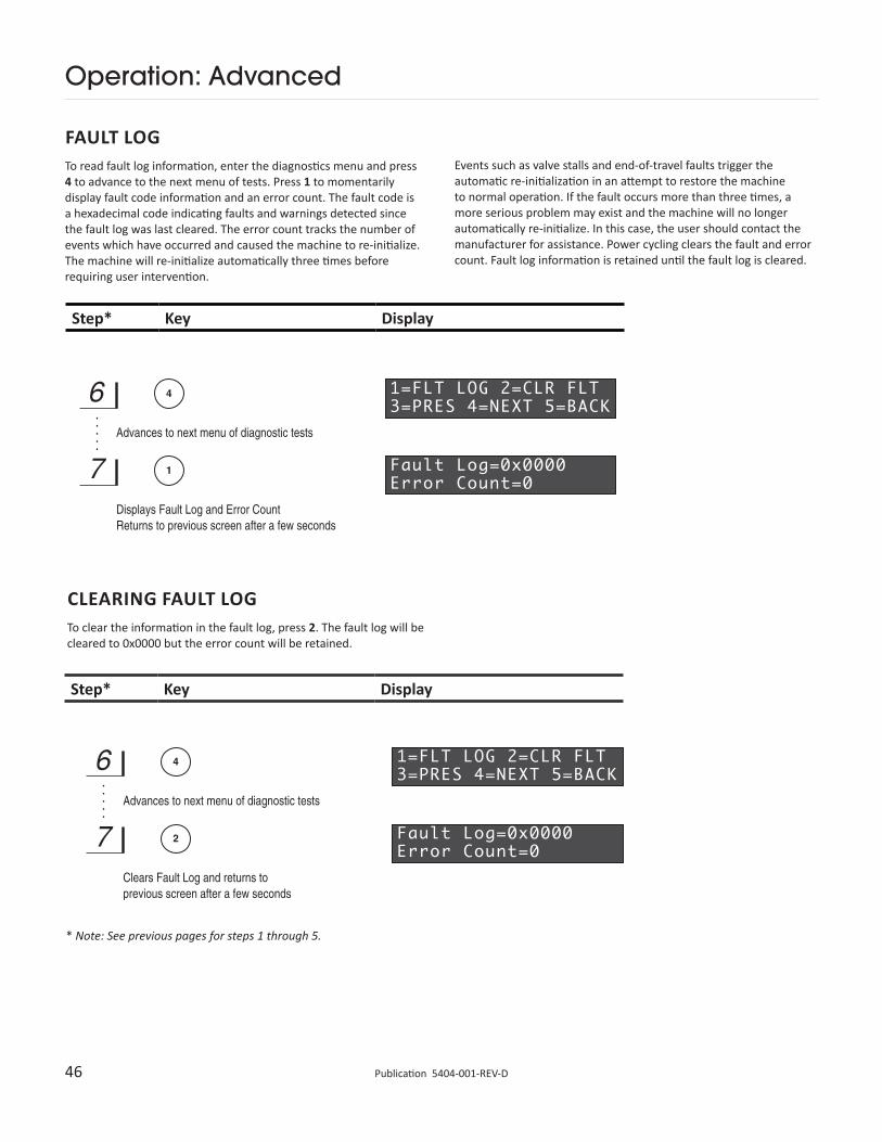
FAULT LOGTo read fault log information, enter the diagnostics menu and press 4 to advance to the next menu of tests. Press 1 to momentarily display fault code information and an error count. The fault code is a hexadecimal code indicating faults and warnings detected since the fault log was last cleared. The error count tracks the number of events which have occurred and caused the machine to re-initialize. The machine will re-initialize automatically three times before requiring user intervention.
Events such as valve stalls and end-of-travel faults trigger the automatic re-initialization in an attempt to restore the machine to normal operation. If the fault occurs more than three times, a more serious problem may exist and the machine will no longer automatically re-initialize. In this case, the user should contact the manufacturer for assistance. Power cycling clears the fault and error count. Fault log information is retained until the fault log is cleared.
Step* Key Display
Step* Key Display
CLEARING FAULT LOGTo clear the information in the fault log, press 2. The fault log will be cleared to 0x0000 but the error count will be retained.
47 www.harvardapparatus.comPublication 5404-001-REV-D
Operation: Advanced
Step* Key Display
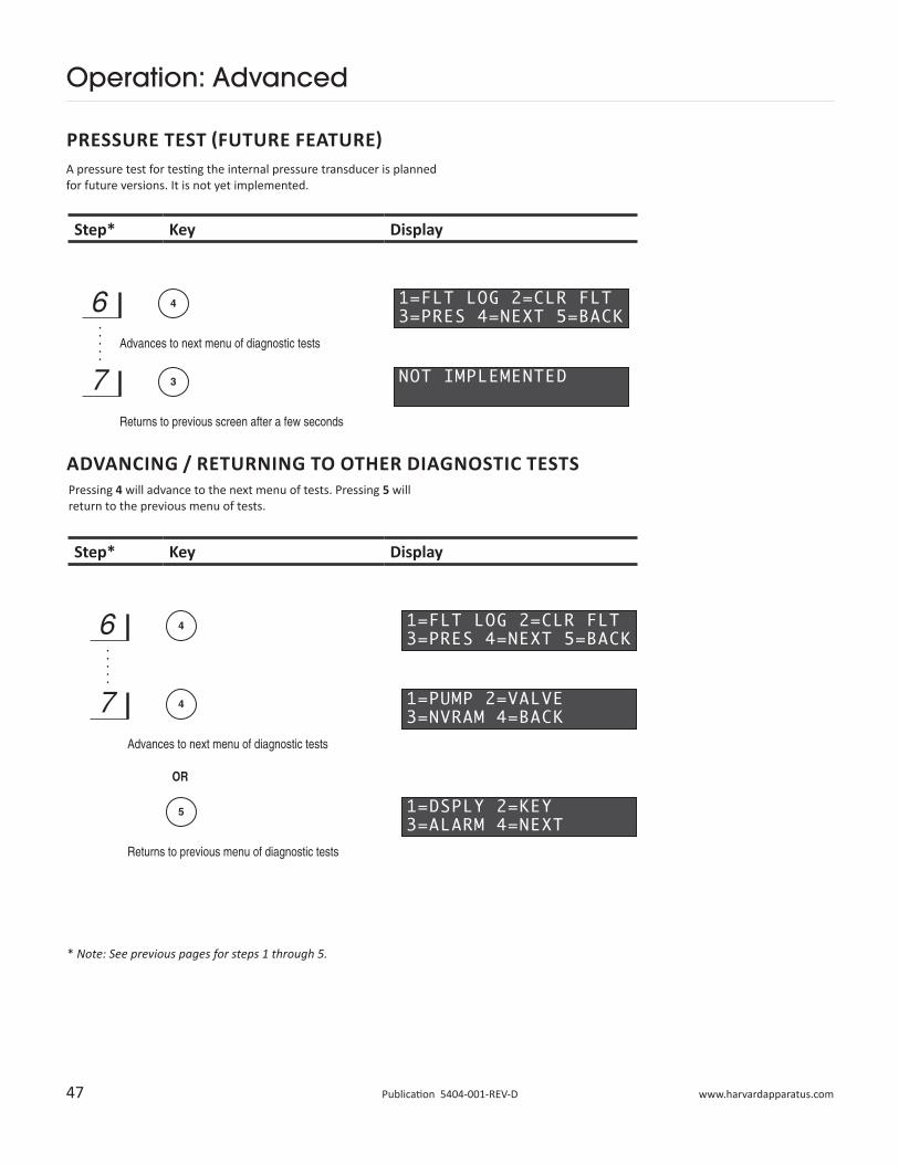
PRESSURE TEST (FUTURE FEATURE)A pressure test for testing the internal pressure transducer is planned for future versions. It is not yet implemented.
Step* Key Display
Pressing 4 will advance to the next menu of tests. Pressing 5 will return to the previous menu of tests.
* Note: See previous pages for steps 1 through 5.
ADVANCING / RETURNING TO OTHER DIAGNOSTIC TESTS
48 Publication 5404-001-REV-D
Operation: Advanced
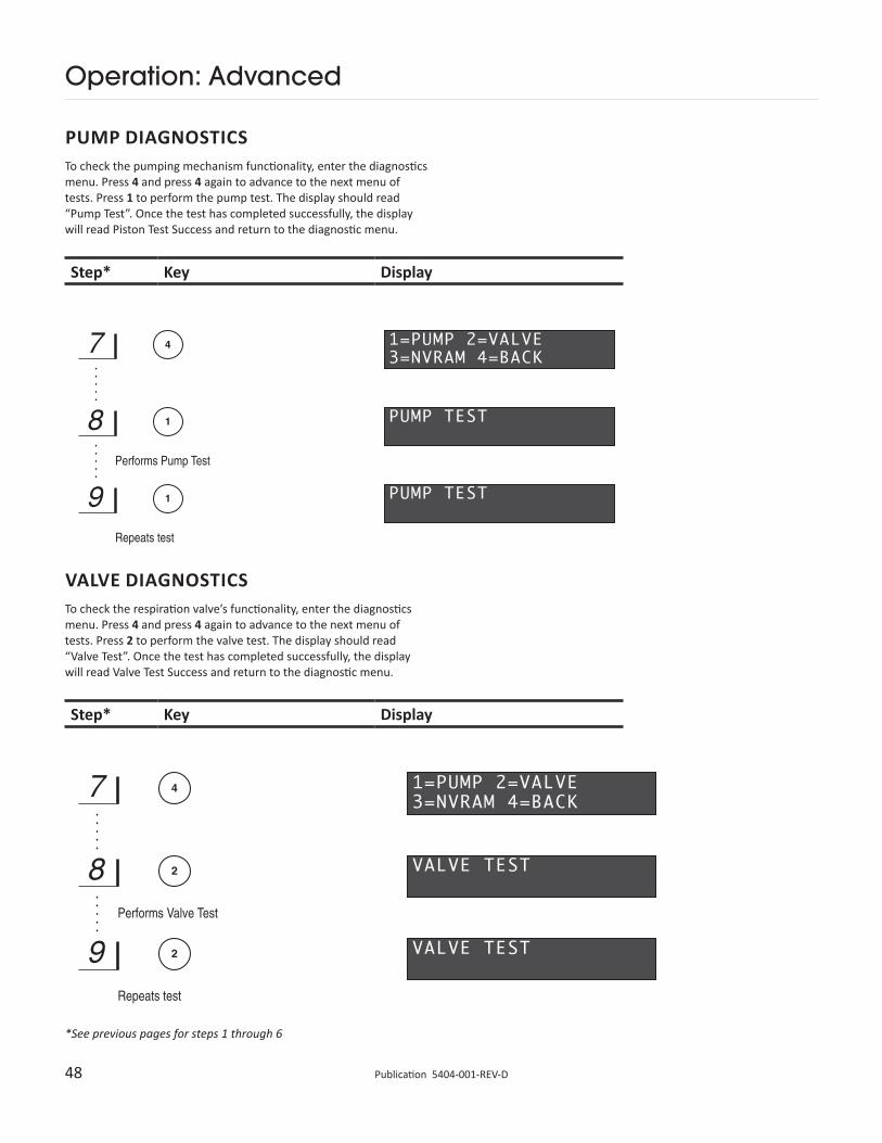
PUMP DIAGNOSTICSTo check the pumping mechanism functionality, enter the diagnostics menu. Press 4 and press 4 again to advance to the next menu of tests. Press 1 to perform the pump test. The display should read “Pump Test”. Once the test has completed successfully, the display will read Piston Test Success and return to the diagnostic menu.
Step* Key Display
Step* Key Display
VALVE DIAGNOSTICSTo check the respiration valve’s functionality, enter the diagnostics menu. Press 4 and press 4 again to advance to the next menu of tests. Press 2 to perform the valve test. The display should read “Valve Test”. Once the test has completed successfully, the display will read Valve Test Success and return to the diagnostic menu.
*See previous pages for steps 1 through 6
49 www.harvardapparatus.comPublication 5404-001-REV-D
Operation: Advanced
Step* Key Display
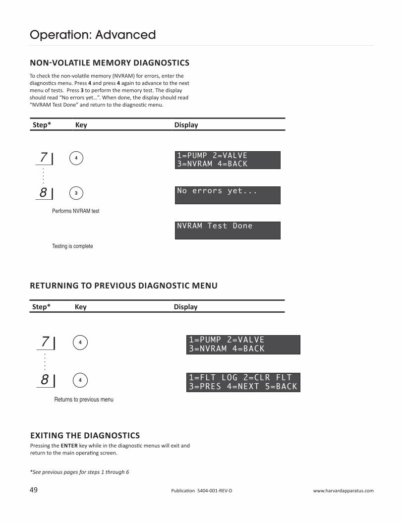
NON-VOLATILE MEMORY DIAGNOSTICSTo check the non-volatile memory (NVRAM) for errors, enter the diagnostics menu. Press 4 and press 4 again to advance to the next menu of tests. Press 3 to perform the memory test. The display should read “No errors yet…”. When done, the display should read “NVRAM Test Done” and return to the diagnostic menu.
Step* Key Display
RETURNING TO PREVIOUS DIAGNOSTIC MENU
EXITING THE DIAGNOSTICSPressing the ENTER key while in the diagnostic menus will exit and return to the main operating screen.
*See previous pages for steps 1 through 6
50 Publication 5404-001-REV-D
Operation: Advanced
Power FailureThe Inspira ventilator may be connected to an uninterruptable power source (UPS), such as a battery backup, to protect against power failures. Choose a UPS that has an output power capacity sufficient to power a 75 watt load for the desired length of time to protect. A UPS rated at 650 VA will typically provide more than 1 hour of operation on a fully charged battery. If a UPS is not used, the machine will stop ventilating for the duration of the power failure. When the power is restored, the machine will power up in its last commanded state. If that state was RUN, it will continue ventilation with the last entered respiratory parameters. Harvard Apparatus recommends use of a UPS device or other backup power source when performing unmonitored ventilation. Note: There are many manufacturers of UPS devices. Some examples are American Power Conversion (www.apc.com) and Belkin (www.belkin.com). Contact the UPS manufacturer for help in choosing the right sized unit.
General Maintenance and CleaningTo ensure that your Inspira operates correctly only use the ventilator according to the guidelines provided in this operating manual. If the ventilator does not work properly contact Harvard Apparatus for appropriate instructions.To clean the exterior surfaces, use a lint-free cloth to remove loose dust. Use care to avoid scratching the clear display window. For more efficient cleaning, use a soft cloth dampened with water or an aqueous solution of 75% isopropyl alcohol.
51 www.harvardapparatus.comPublication 5404-001-REV-D
Appendix A: General Specifications
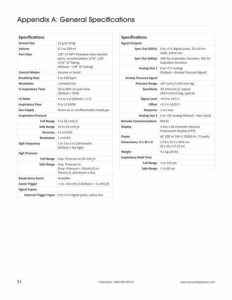
SpecificationsSignal Outputs
Sync Out (ASVv) 0 to +5 V digital pulse, 20 ±10 ms wide, active low
Sync Out (ASVp) V0H for Inspiration Duration, V0L for Expiration Duration
Analog Out 1 0 to +5 V analog (Default = Airway Pressure Signal)
Airway Pressure Signal
Pressure Range ±67 cmH2O (±50 mm Hg)
Sensitivity 30 mV/cmH2O, typical (40.0 mV/mmHg, typical)
Signal Level +0.5 to +4.5 V
Offset +2.5 V ±0.05 V
Response 1 ms max
Analog Out 2 0 to +5V analog (Default = Not Used)
Remote Communications RS232
Display 2 line x 20 character Vacuum Fluorescent Display (VFD)
Power AC 100 to 240 V, 50/60 Hz, 75 watts
Dimensions, H x W x D 17.8 x 25.4 x 40.6 cm (8 x 10 x 17.25 in)
Weight 9.1 kg (20 lb)
Inspiratory Hold Time
Full Range 1 to 120 sec
Safe Range 1 to 60 sec
SpecificationsAnimal Size 15 g to 10 kg
Volume 0.1 to 100 ml
Port Sizes 1/8”-27 NPT threaded nylon barbed ports, accommodates 1/16”, 1/8”, 3/16” ID Tubing (Default = 1/8” ID Tubing)
Control Modes Volume or Assist
Breathing Rate 5 to 200 bpm
Resolution 1 breath/min
% Inspiratory Time 20 to 80% of cycle time (Default = 50%)
I:E Ratio 4:1 to 1:4 (Default = 1:1)
Inspiratory Flow 0 to 12 SLPM
Gas Supply Room air or nonflammable mixed gas
Inspiration Pressure
Full Range 5 to 50 cmH2O
Safe Range 15 to 25 cmH2O
Accuracy ±1 cmH2O
Resolution 1 cmH2O
Sigh Frequency 1 in 5 to 1 in 250 breaths (Default = No Sigh)
Sigh Pressure
Full Range Insp. Pressure to 50 cmH2O
Safe Range Insp. Pressure to (Insp. Pressure + 10cmH2O) or 35cmH2O, whichever is less
Respiratory Assist Available
Assist Trigger -1 to -10 cmH2O (Default = -5 cmH2O)
Signal Inputs
External Trigger Input 0 to +5 V digital pulse, active low
52 Publication 5404-001-REV-D
Appendix B: I/O Specifications
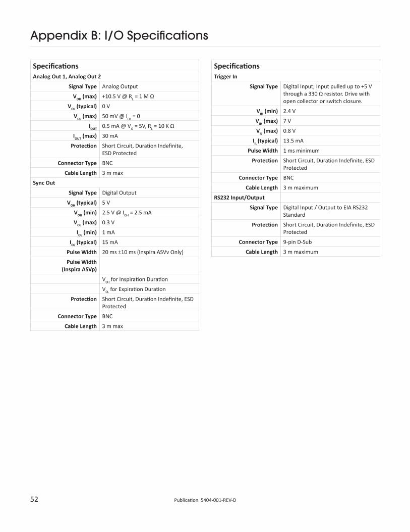
SpecificationsAnalog Out 1, Analog Out 2
Signal Type Analog Output
VOH (max) +10.5 V @ RL = 1 M Ω
VOL (typical) 0 V
VOL (max) 50 mV @ IOL = 0
IOUT 0.5 mA @ VO = 5V, RL = 10 K Ω
IOUT (max) 30 mA
Protection Short Circuit, Duration Indefinite, ESD Protected
Connector Type BNC
Cable Length 3 m max
Sync Out
Signal Type Digital Output
VOH (typical) 5 V
VOH (min) 2.5 V @ IOH = 2.5 mA
VOL (max) 0.3 V
IOL (min) 1 mA
IOL (typical) 15 mA
Pulse Width 20 ms ±10 ms (Inspira ASVv Only)
Pulse Width (Inspira ASVp)
V0H for Inspiration Duration
V0L for Expiration Duration
Protection Short Circuit, Duration Indefinite, ESD Protected
Connector Type BNC
Cable Length 3 m max
SpecificationsTrigger In
Signal Type Digital Input; Input pulled up to +5 V through a 330 Ω resistor. Drive with open collector or switch closure.
VIH (min) 2.4 V
VIH (max) 7 V
VIL (max) 0.8 V
IIL (typical) 13.5 mA
Pulse Width 1 ms minimum
Protection Short Circuit, Duration Indefinite, ESD Protected
Connector Type BNC
Cable Length 3 m maximum
RS232 Input/Output
Signal Type Digital Input / Output to EIA RS232 Standard
Protection Short Circuit, Duration Indefinite, ESD Protected
Connector Type 9-pin D-Sub
Cable Length 3 m maximum
53 www.harvardapparatus.comPublication 5404-001-REV-D
Appendix C: Serial Commands, Queries & Responses
Each command sent to the Inspira is a string of ASCII characters. Commands are not case sensitive and spaces are optional. After a transmission to the Inspira terminating with a <cr> character, the Inspira enters remote mode and responds with the three character sequence:
<cr><lf>prompt
<cr> carriage return ASCII 13 decimal
<lf> line feed ASCII 10 decimal
Prompts
: Stopped ASCII 58 decimal > Running ASCII 62 decimal
* Fault ASCII 42 decimal
The following symbols are used in describing the commands:
CommandsFormat: command<cr>
Response: <cr><lf>prompt
KEY Return to keyboard control, exit remote mode
RUN Start ventilation
STP Stop ventilation
SIGH Commands SIGH Breath
OVRD Override Safe Range™ checking
SAFE Enable Safe Range™ checking
HLD Inspiratory Hold models only. Commands ventilator to hold at the end of the next inspiratory cycle, or to cancel a hold.
Commands with Input DataFormat: command data<cr>
Response: <cr><lf>prompt
SETRAT nnn Sets respiration rate in BPM (breaths per min)
SETVOL nnn.nn Sets tidal volume in cc
SETIE nn Sets I:E Ratio as % inspiration
SETSTV nnn.nn Sets sigh tidal volume in cc
SETSFREQ nnn Sets sigh frequency as 1 breath per nnn breaths
SETPRS nn Sets inspiration pressure limit in cmH2O
SETWGT nn.nnn Sets animal’s weight in kg
SELMOD mode Selects operation mode (mode = VOL or ASST)
SETHLD nnn Inspiratory Hold models only. Sets inspiratory hold time in seconds.
Commands with Input Data (Inspira ASVp Only)Format: command data<cr>Response: <cr><lf>promptSETPRS nn Sets inspiration pressure in cmH2O (Pressure-control mode) or pressure limit in cmH2O (Volume-control mode)SETSPRS nn Sets Sigh pressure in cmH2O(Pressure-control mode only)SETPEEP nn Sets PEEP pressure in cmH2OSELMOD mode Selects operation mode(mode = VOL, VOLASST, PRES, or PRESASST)
QueriesFormat: query<cr>Response: <cr><lf>value<cr><lf>promptRAT Return respiration rate in BPM (breaths per min) as integer valueVOL Return tidal volume in cc to 2 decimal placesIE Return I:E Ratio as % inspirationSTV Return Sigh Tidal Volume in cc to 2 decimal placesSFREQ Return Sigh Frequency as 1 breath per xxx breathsPRS Return inspiration pressure limit in cmH2OMOD Return operation mode (VOL, AST)WGT Return animal weight in kg to three decimal places of precisionVER Return model (ASVv, ASVp, ARV) and firmware version numberAIRPRS Returns airway pressure in cmH2OHLD Inspiratory Hold models only. If the ventilator is in the “stop” state, returns the inspiratory hold time in seconds t(insphold) = nnn secFLT Returns a 2 digit fault code (xx), defined as follows:00 No Fault01 Overpressure02 Under pressure03 Motor Drive Fault04 Pump Stall05 Valve Stall
Queries (Inspira ASVp Only)Format: query<cr>Response: <cr><lf>value<cr><lf>promptValue is a string of characters of varying length.PRS Returns requested inspiration pressure (Pressure-control mode) or pressure limit (Volume-control mode) in cmH2OSPRS Returns requested sigh pressure (Pressure-control mode only) in cmH2OPEEP Returns requested PEEP pressure in cmH2OMOD Returns operation mode (VOL, VOLASST, PRES, or PRESASST)BSLNPRS Returns actual baseline pressure (EEP) in cmH2OAVGPRS Returns actual average peak pressure in cmH2OError Responses:<cr><lf>?<cr><lf>prompt Unrecognized command<cr><lf>OOR<cr><lf>prompt Out Of Range
54 Publication 5404-001-REV-D
Appendix D: Glossary of Terms
Assist
Respiratory assist mode, whereby a subject is aided in regaining normal breathing after artificial respiration (weaning), or for respiration of a non-paralyzed, anesthetized subject. Ventilation is triggered when the device detects a slight vacuum in the airway.
Expiration
The process of breathing out (exhaling) a gas or gases.
Flow Rate
The rate of gas flow, expressed in L/min or mL/min.
I:E Ratio
The ratio of inspiration to expiration times. As used in this context, however, it is expressed as the percent of inspiration time to total respiration period. An I:E Ratio of 1:1 is equivalent to 50% inspiration time. An I:E Ratio of 1:4 is equivalent to 20% inspiration time
Inspiration
The process of breathing in (inhaling) a gas or gases.
Inspiration Pressure
The pressure to which the subject’s lungs are inflated during inspiration.
PEEP
Positive End-Expiratory Pressure.
Residual Volume
The smallest volume to which the subject’s lungs can slowly be deflated.
Respiration Rate
Breathing rate, expressed in breaths per minute (BPM).
Sigh
A deeper than usual breath, which expands the lungs to a greater capacity and redistributes the lung surfactant that tends to puddle in the alveoli during normal respiration.
Sigh Volume
The inspiration volume during a sigh breath (some percentage greater than normal tidal volume for the subject).
Sigh Pressure
The inspiration pressure during a sigh breath (some percentage greater than normal inspiration pressure for the subject).
55 www.harvardapparatus.comPublication 5404-001-REV-D
Appendix E: Sample Waveforms
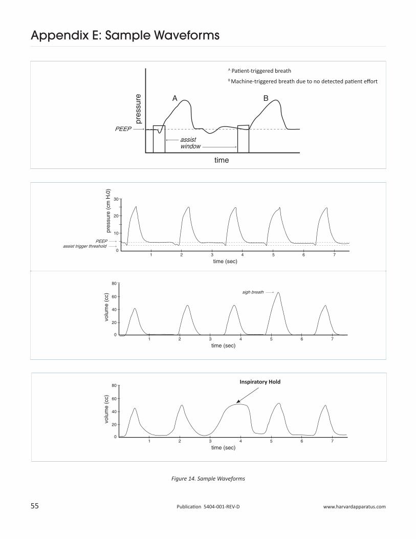
A Patient-triggered breathB Machine-triggered breath due to no detected patient effort
Figure 14. Sample Waveforms
Inspiratory Hold
56 Publication 5404-001-REV-D
Appendix F: Frequently Asked Questions
4. How do I create a PEEP pressure with the Inspira ASVv?To create a PEEP pressure when using the Inspira ASVv, simply connect a length of tubing to the “Exhaust” port and submerge the other end in a column of water. The depth of the end of the tubing (in cm) below the water surface will give the PEEP pressure in cmH2O. See Appendix J.
5. How do I connect the Inspira to pressurized gas sources?When connecting any volume-controlled, piston/cylinder type ventilator to a pressurized gas source, that gas must be equalized with atmospheric pressure before being drawn into the ventilator. If it is not, unknown and possibly lethal tidal volumes will be delivered to the animal. A set-up as shown in Appendix I may be used for this purpose.
6. How do I use anesthetic gases with the Inspira?Refer to Appendix I for setting up the Inspira with a vaporizer and pressurized gases. When using anesthetic gases, keep in mind that total system volume will impact delay times in getting a change in gas mixtures to the animal. Vent or scrub expired gases; do not vent to room air.
7. How do I use the Inspira with MRI equipment?Since the Inspira has a ferrous metal chassis and components, it will be attracted to the MRI’s magnetic field. Also, the machine will create its own electromagnetic fields, which could impact measurements made with the MRI. It is therefore highly recommended that the machine be located far from the MRI equipment (more than ten feet). If the machine is located in the same room as the MRI system, tying the unit down to the floor or other immovable object may be required. Long lengths of tubing will be required to connect with the animal’s airway, so total system volume, compliance, and flow restrictions must be considered when choosing the tubing diameter, wall thickness, and adapters. If anesthetic gases are to be used, delay times in getting an adjusted gas mixture to the animal will be significant and should be determined.
1. When I start ventilation, why is underpressure constantly displayed?If no connection is made to the “To Animal” port, this is the proper indication. The fault will clear when airway pressure is detected.
If proper connections have been made, there is most likely a leak in the system. Make sure that the O-ring has been installed properly before installing the glass cylinder. Verify that the cylinder has been tightened properly.
If barbed ports at the front of the machine have been replaced make sure that they are fully tightened to be flush with the front bezel
Finally, check for leaks in the tubing and at the animal’s airway.
If you are using the Inspira ASVp in pressure-control mode and the average airway pressure is greater than 3 cmH2O, the machine will attempt to adjust the flow rate to increase the airway pressure.If an underpressure condition continues (Paw much less than desired) and the tidal volume is larger than expected, check for system leaks.
2. When I change or install a cylinder, why is it not detected properly?The Inspira uses two micro-switches to detect the two different cylinder sizes. The rear-most switch actuates when the 10cc cylinder is installed. Both switches actuate when the 100cc cylinder is installed. If the 10cc cylinder is not being detected, first make sure that the rear-most actuator arm is resting against the side of the cylinder. If it isn’t, just reposition the actuator arm. Next, make sure that the switches are actuating. Gently pull back on the actuator arm(s) contacting the installed cylinder and listen for a click. If the switch clicks it had not been actuated. This indicates that the actuator arm’s bend angle has not been set properly. This may be easily corrected by gently increasing the bend angle of the actuator arm(s).
3. Why does it seem like the volume delivered is too low?It is possible that there is a system leak. Check for leaks as described in the answer to question 1.
In volume-control mode, if the inspiration pressure limit is reached, the machine will cycle to expiration before total tidal volume is delivered. Make sure that restrictions in the airway circuit are minimized and make sure that the pressure limit is not set too low.
If you are using side-stream gas monitoring, tidal volume will need to be adjusted (increased) to account for the sample volume.
If system dead space is high, tidal volume will need to be adjusted to account for it.
Please note that the machine’s calculations for tidal volume and respiration rate based on the animal’s weight are for healthy mammals in a resting state and do not account for additional dead space which may be introduced by the user’s system set-up. Dead-space volume should be calculated and the tidal volume should be increased accordingly. The animal’s respiratory health must also be considered when adjusting respiratory parameters.
WARNING: Do not vent anesthetic gases to room air!
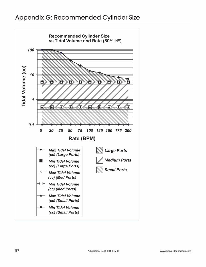
57 www.harvardapparatus.comPublication 5404-001-REV-D
Appendix G: Recommended Cylinder Size
Recommended Cylinder Size vs Tidal Volume and Rate (50% I:E)
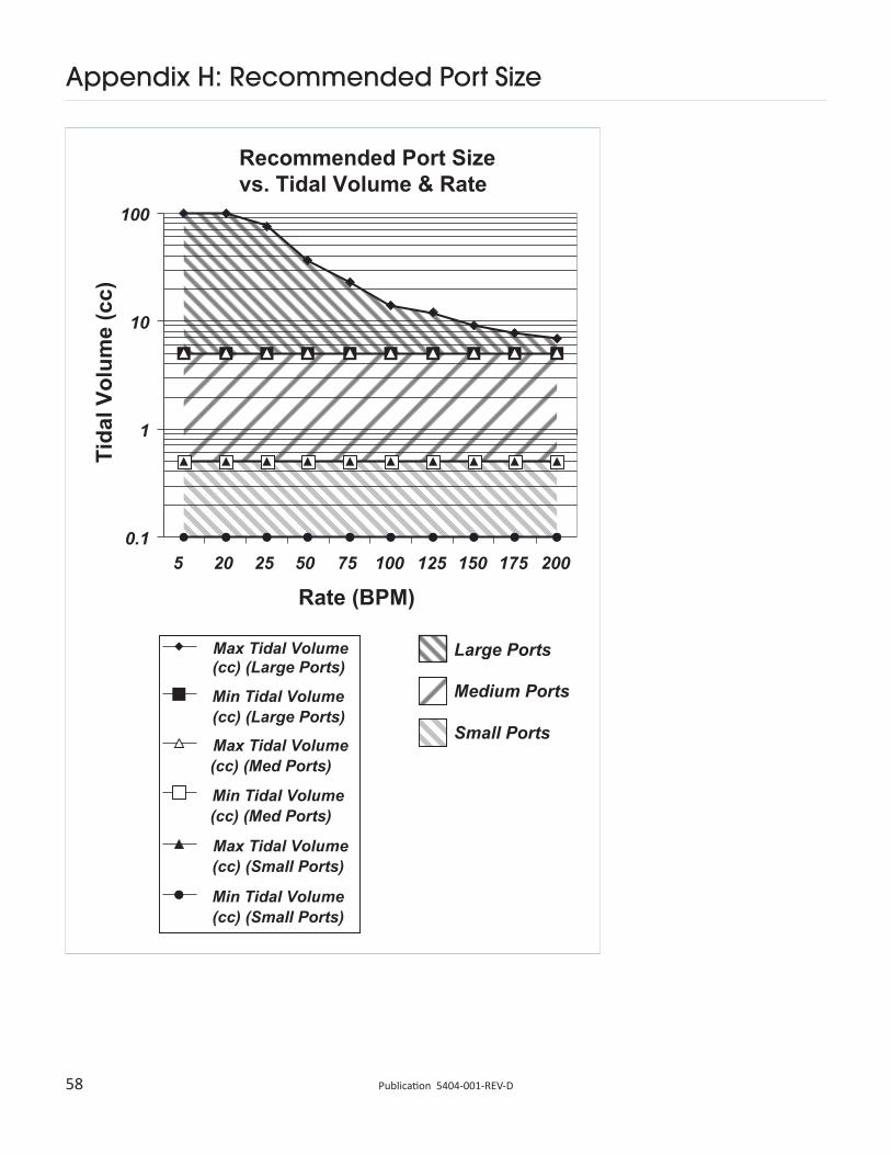
58 Publication 5404-001-REV-D
Appendix H: Recommended Port Size
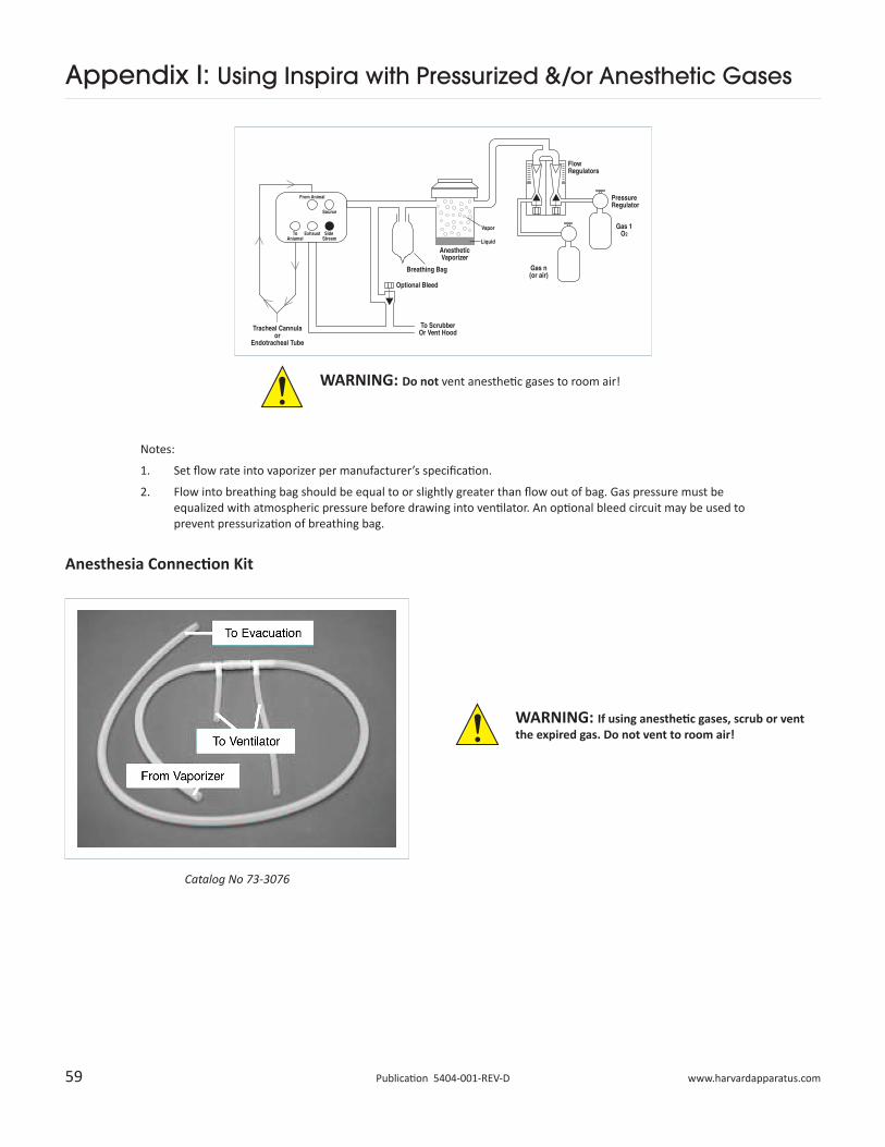
59 www.harvardapparatus.comPublication 5404-001-REV-D
Appendix I: Using Inspira with Pressurized &/or Anesthetic Gases
WARNING: Do not vent anesthetic gases to room air!
WARNING: If using anesthetic gases, scrub or vent the expired gas. Do not vent to room air!
Anesthesia Connection Kit
Notes:
1. Set flow rate into vaporizer per manufacturer’s specification.
2. Flow into breathing bag should be equal to or slightly greater than flow out of bag. Gas pressure must be equalized with atmospheric pressure before drawing into ventilator. An optional bleed circuit may be used to prevent pressurization of breathing bag.
Catalog No 73-3076
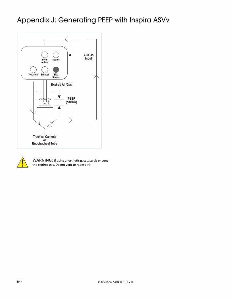
60 Publication 5404-001-REV-D
Appendix J: Generating PEEP with Inspira ASVv
WARNING: If using anesthetic gases, scrub or vent the expired gas. Do not vent to room air!
Declaration of Conformity
Application of Council Directive(s): 2006/95/EC, 89/336/EEC
Standard(s) to which conformity is declared: IEC 61010 – 1:2010 Ed. 3 EN61326:1998, Class B
Manufacturer’s Name: Harvard Apparatus, Inc.
Manufacturer’s Address: 84 October Hill Road Holliston, Massachusetts 01746 U.S.A.
Type of Equipment: Animal Ventilator
Model No.: Inspira ASV
I, the undersigned, hereby declare that the equipment specified above conforms to the above Directive(s) and Standard(s).
Place: United States of America
Date: July 11, 2014
(Signature)
(Full Name)
(Position)
Beth Bauman
VP Engineering / Operations

U.K.
BiochromFircroft Way, Edenbridge Kent TN8 6HEPhone (44) 1732-864-001Fax (44) 1732-863-356E-mail [email protected]
www.harvardapparatus.co.uk
France
Harvard Apparatus, S.A.R.L.6 Avenue des Andes Miniparc – Bat. 8 F-91952, Les Ulis CedexPhone (33) 1-64-46-00-85Fax (33) 1-64-46-94-38E-mail [email protected]
Germany
Hugo Sachs ElektronikHarvard Apparatus GmbH Gruenstrasse 1 D-79232, March - Hugstetten Phone (49) 0 7665-92-00-0Fax (49) 0 7665-92-00-90E-mail [email protected]
www.hugo-sachs.de
U.S.A.
Harvard Apparatus84 October Hill Road Holliston, Massachusetts 01746Phone (508) 893-8999Toll Free (800) 272-2775Fax (508) 429-5732E-mail bioscience@
harvardapparatus.comwww.harvardapparatus.com
Warner Instruments, Inc.1125 Dixwell Avenue Hamden, CT 06514 Phone (203) 776-0664Toll Free (800) 599-4203Fax (203) 776-1278E-mail [email protected]
www.warneronline.com
Canada
Harvard Apparatus, Canada6010 Vanden Abeele Street Saint Laurent, Quebec, H4S 1R9Phone (514) 335-0792Toll Free (800) 361-1905Fax (514) 335-3482Toll Free (800) 335-0792E-mail [email protected]
www.harvardapparatus.ca