Embed Size (px)
Citation preview
HAWKESBURY DEVELOPMENT CONTROL PLAN
Appendix E
Civil Works Specification

CONTENTS PART I DESIGN SPECIFICATION PART II CONSTRUCTION SPECIFICATION PART III STANDARD DRAWINGS


PART I
DESIGN SPECIFICATION


PART I hawkesbury development control plan ____________________________________________________________________________________
CONTENTS 1. GENERAL SUBMISSION PROCEDURES AND REQUIREMENTS ................................. 1
1.1 APPROVALS PROCESS ......................................................................................... 1 1.2 DEFINITIONS ........................................................................................................... 1 1.3 PROCESS FOR THE DEVELOPER ........................................................................ 2 1.4 ENGINEERING SURVEY......................................................................................... 3 1.5 ENGINEERING DRAWINGS.................................................................................... 3 1.6 PERSONS QUALIFIED ............................................................................................ 4 1.7 CONSULTATION...................................................................................................... 4 1.8 INSPECTION OF WORKS ....................................................................................... 4 1.9 ENVIRONMENTAL AND VEGETATION PROTECTION ......................................... 4 1.10 STREET TREES....................................................................................................... 5 1.11 EROSION AND SEDIMENTATION CONTROL ....................................................... 5 1.12 ENGINEERING FEES .............................................................................................. 5
2. ENGINEERING DESIGN DRAWINGS............................................................................... 6 2.1 SCOPE ..................................................................................................................... 6 2.2 GENERAL REQUIREMENTS................................................................................... 6 2.3 PLAN CONTENT ...................................................................................................... 6
2.3.1 Title Blocks ................................................................................................ 6 2.3.2 Title Sheet ................................................................................................. 7 2.3.3 Road and Drainage Drawings ................................................................... 7 2.3.4 On-Site Stormwater Detention Drawings .................................................. 8 2.3.5 Detail Plan ................................................................................................. 8 2.3.6 Road Long Section(s)................................................................................ 9 2.3.7 Road Cross Sections................................................................................. 9 2.3.8 Typical Road Cross Section(s)................................................................ 10 2.3.9 Kerb Return Details ................................................................................. 10 2.3.10 Traffic Calming Devices, Pathways and Other Miscellaneous Road
Details...................................................................................................... 11 2.3.11 Drainage Catchment Plan ....................................................................... 11 2.3.12 Drainage Calculations ............................................................................. 11 2.3.13 Drainage Longitudinal Section(s) ............................................................ 11 2.3.14 Other Drainage Details ............................................................................ 12 2.3.15 Erosion and Sedimentation Control Plan ................................................ 13 2.3.16 Traffic Management Plan ........................................................................ 13 2.3.17 Site Regrading Plans............................................................................... 14
2.4 SHEET SIZES......................................................................................................... 15 2.5 SCALES.................................................................................................................. 15 2.6 DIMENSIONS ......................................................................................................... 16 2.7 ENVIRONMENTAL................................................................................................. 16
____________________________________________________________________________________________________________TABLE OF CONTENTS
E–i
PART I ____________________________________________________________________________________ hawkesbury development control plan
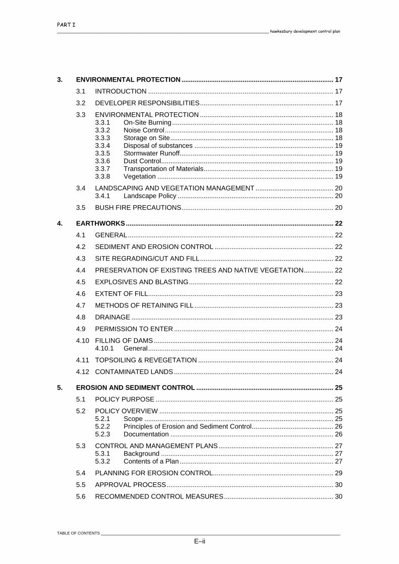
3. ENVIRONMENTAL PROTECTION.................................................................................. 17 3.1 INTRODUCTION .................................................................................................... 17 3.2 DEVELOPER RESPONSIBILITIES........................................................................ 17 3.3 ENVIRONMENTAL PROTECTION ........................................................................ 18
3.3.1 On-Site Burning ....................................................................................... 18 3.3.2 Noise Control........................................................................................... 18 3.3.3 Storage on Site........................................................................................ 18 3.3.4 Disposal of substances ........................................................................... 19 3.3.5 Stormwater Runoff................................................................................... 19 3.3.6 Dust Control............................................................................................. 19 3.3.7 Transportation of Materials...................................................................... 19 3.3.8 Vegetation ............................................................................................... 19
3.4 LANDSCAPING AND VEGETATION MANAGEMENT .......................................... 20 3.4.1 Landscape Policy .................................................................................... 20
3.5 BUSH FIRE PRECAUTIONS.................................................................................. 20
4. EARTHWORKS ................................................................................................................ 22 4.1 GENERAL............................................................................................................... 22 4.2 SEDIMENT AND EROSION CONTROL ................................................................ 22 4.3 SITE REGRADING/CUT AND FILL........................................................................ 22 4.4 PRESERVATION OF EXISTING TREES AND NATIVE VEGETATION................ 22 4.5 EXPLOSIVES AND BLASTING.............................................................................. 22 4.6 EXTENT OF FILL.................................................................................................... 23 4.7 METHODS OF RETAINING FILL ........................................................................... 23 4.8 DRAINAGE ............................................................................................................. 23 4.9 PERMISSION TO ENTER ...................................................................................... 24 4.10 FILLING OF DAMS................................................................................................. 24
4.10.1 General.................................................................................................... 24 4.11 TOPSOILING & REVEGETATION ......................................................................... 24 4.12 CONTAMINATED LANDS ...................................................................................... 24
5. EROSION AND SEDIMENT CONTROL .......................................................................... 25 5.1 POLICY PURPOSE ................................................................................................ 25 5.2 POLICY OVERVIEW .............................................................................................. 25
5.2.1 Scope ...................................................................................................... 25 5.2.2 Principles of Erosion and Sediment Control............................................ 26 5.2.3 Documentation ........................................................................................ 26
5.3 CONTROL AND MANAGEMENT PLANS.............................................................. 27 5.3.1 Background ............................................................................................. 27 5.3.2 Contents of a Plan................................................................................... 27
5.4 PLANNING FOR EROSION CONTROL................................................................. 29 5.5 APPROVAL PROCESS.......................................................................................... 30 5.6 RECOMMENDED CONTROL MEASURES........................................................... 30
TABLE OF CONTENTS ___________________________________________________________________________________________________________
E–ii
PART I hawkesbury development control plan ____________________________________________________________________________________
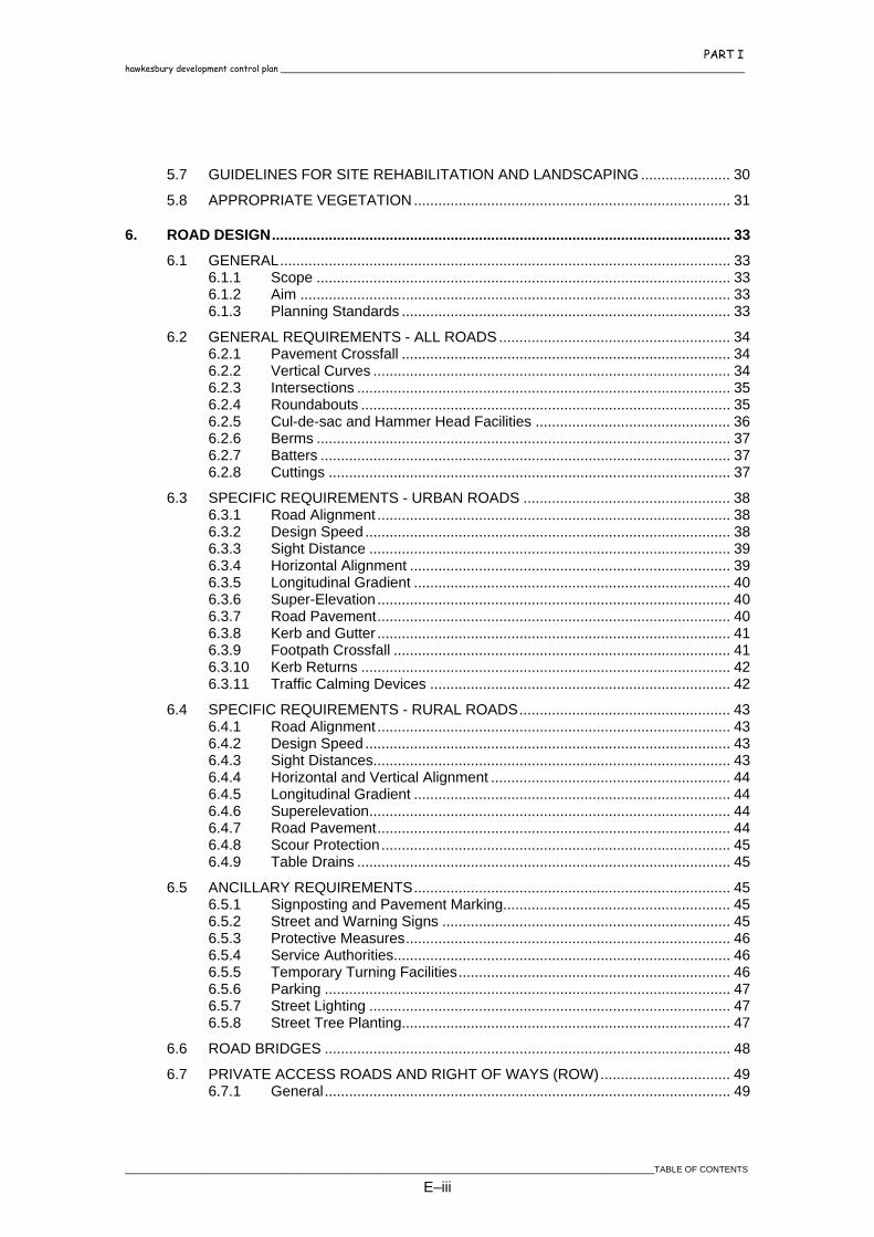
5.7 GUIDELINES FOR SITE REHABILITATION AND LANDSCAPING ...................... 30 5.8 APPROPRIATE VEGETATION .............................................................................. 31
6. ROAD DESIGN................................................................................................................. 33 6.1 GENERAL............................................................................................................... 33
6.1.1 Scope ...................................................................................................... 33 6.1.2 Aim .......................................................................................................... 33 6.1.3 Planning Standards ................................................................................. 33
6.2 GENERAL REQUIREMENTS - ALL ROADS ......................................................... 34 6.2.1 Pavement Crossfall ................................................................................. 34 6.2.2 Vertical Curves ........................................................................................ 34 6.2.3 Intersections ............................................................................................ 35 6.2.4 Roundabouts ........................................................................................... 35 6.2.5 Cul-de-sac and Hammer Head Facilities ................................................ 36 6.2.6 Berms ...................................................................................................... 37 6.2.7 Batters ..................................................................................................... 37 6.2.8 Cuttings ................................................................................................... 37
6.3 SPECIFIC REQUIREMENTS - URBAN ROADS ................................................... 38 6.3.1 Road Alignment ....................................................................................... 38 6.3.2 Design Speed .......................................................................................... 38 6.3.3 Sight Distance ......................................................................................... 39 6.3.4 Horizontal Alignment ............................................................................... 39 6.3.5 Longitudinal Gradient .............................................................................. 40 6.3.6 Super-Elevation ....................................................................................... 40 6.3.7 Road Pavement....................................................................................... 40 6.3.8 Kerb and Gutter ....................................................................................... 41 6.3.9 Footpath Crossfall ................................................................................... 41 6.3.10 Kerb Returns ........................................................................................... 42 6.3.11 Traffic Calming Devices .......................................................................... 42
6.4 SPECIFIC REQUIREMENTS - RURAL ROADS.................................................... 43 6.4.1 Road Alignment ....................................................................................... 43 6.4.2 Design Speed .......................................................................................... 43 6.4.3 Sight Distances........................................................................................ 43 6.4.4 Horizontal and Vertical Alignment ........................................................... 44 6.4.5 Longitudinal Gradient .............................................................................. 44 6.4.6 Superelevation......................................................................................... 44 6.4.7 Road Pavement....................................................................................... 44 6.4.8 Scour Protection...................................................................................... 45 6.4.9 Table Drains ............................................................................................ 45
6.5 ANCILLARY REQUIREMENTS.............................................................................. 45 6.5.1 Signposting and Pavement Marking........................................................ 45 6.5.2 Street and Warning Signs ....................................................................... 45 6.5.3 Protective Measures................................................................................ 46 6.5.4 Service Authorities................................................................................... 46 6.5.5 Temporary Turning Facilities................................................................... 46 6.5.6 Parking .................................................................................................... 47 6.5.7 Street Lighting ......................................................................................... 47 6.5.8 Street Tree Planting................................................................................. 47
6.6 ROAD BRIDGES .................................................................................................... 48 6.7 PRIVATE ACCESS ROADS AND RIGHT OF WAYS (ROW)................................ 49
6.7.1 General.................................................................................................... 49
____________________________________________________________________________________________________________TABLE OF CONTENTS
E–iii
PART I ____________________________________________________________________________________ hawkesbury development control plan
6.8 CONCRETE PAVING, FOOTPATHS AND CYCLEWAYS..................................... 51 6.8.1 Pathways ................................................................................................. 51
6.8.1.1 Path Paving.............................................................................. 51 6.8.1.2 Overland Flow Paths................................................................ 51
6.8.2 Cycleways ............................................................................................... 51 6.8.3 Pram Ramps............................................................................................ 52 6.8.4 Concrete Steps........................................................................................ 52
6.8.4.1 Gradient ................................................................................... 52 6.8.4.2 Handrails .................................................................................. 52
6.8.5 Service Locations .................................................................................... 53
7. PAVEMENTS.................................................................................................................... 54 7.1 GENERAL............................................................................................................... 54 7.2 DESIGN TRAFFIC LOADINGS .............................................................................. 54 7.3 EVALUATION OF SUBGRADE STRENGTH......................................................... 54 7.4 SUBSURFACE DRAINAGE ................................................................................... 55 7.5 PAVEMENT THICKNESS DESIGN........................................................................ 55
7.5.1 General.................................................................................................... 55 7.5.2 Sub-Base Course .................................................................................... 56 7.5.3 Base Course............................................................................................ 56 7.5.4 Stabilisation of Insitu and Imported Materials ......................................... 56 7.5.5 Shoulders ................................................................................................ 57 7.5.6 Accessway Pavements ........................................................................... 57
7.5.6.1 Rigid Pavements...................................................................... 57 7.5.7 Roundabout Pavements.......................................................................... 57
7.5.7.1 Full Depth Asphalt Pavement .................................................. 57 7.5.7.2 Rigid Pavement........................................................................ 57
7.5.8 Carpark Pavements................................................................................. 58 7.6 WEARING COURSE .............................................................................................. 58
8. STORMWATER DRAINAGE............................................................................................ 59 8.1 SCOPE ................................................................................................................... 59 8.2 AIM.......................................................................................................................... 59 8.3 GENERAL REQUIREMENTS................................................................................. 59
8.3.1 Drainage in Urban Areas......................................................................... 60 8.3.2 Drainage in Rural Areas .......................................................................... 61
8.4 LAWFUL POINT OF DISCHARGE......................................................................... 62 8.5 DRAINAGE RESERVES/EASEMENTS ................................................................. 63 8.6 HYDROLOGY......................................................................................................... 64 8.7 DESIGN AVERAGE RECURRENCE INTERVALS (ARI)....................................... 64 8.8 TIME OF CONCENTRATION................................................................................. 65 8.9 RAINFALL INTENSITIES ....................................................................................... 65
8.9.1 Read from Tables .................................................................................... 65 8.9.2 Calculate using AR&R Method................................................................ 66
8.10 RUNOFF COEFFICIENT........................................................................................ 66 8.11 CATCHMENT AREA............................................................................................... 66
TABLE OF CONTENTS ___________________________________________________________________________________________________________
E–iv
PART I hawkesbury development control plan ____________________________________________________________________________________
8.12 HYDRAULICS......................................................................................................... 67 8.13 MINOR DRAINAGE SYSTEM CRITERIA .............................................................. 67 8.14 MAJOR DRAINAGE SYSTEM CRITERIA.............................................................. 68 8.15 ROADWAY FLOW CAPACITY............................................................................... 68 8.16 PITS ........................................................................................................................ 69 8.17 CULVERTS............................................................................................................. 70 8.18 HYDRAULIC LOSSES............................................................................................ 72 8.19 OPEN CHANNELS ................................................................................................. 72 8.20 BRIDGES AND CULVERTS................................................................................... 74 8.21 ON-SITE STORMWATER DETENTION ................................................................ 74
8.21.1 Policy ....................................................................................................... 74 8.21.2 Design of Systems................................................................................... 75 8.21.3 Permissible Site Discharge ..................................................................... 76 8.21.4 Site Storage Volume ............................................................................... 76 8.21.5 Outlet Control .......................................................................................... 76 8.21.6 Basin Configuration ................................................................................. 77 8.21.7 Work-As-Executed Plan .......................................................................... 78
8.22 INTER-ALLOTMENT DRAINAGE .......................................................................... 79 8.23 STORMWATER DISCHARGE ............................................................................... 79 8.24 RUNOFF WATER QUALITY .................................................................................. 80
9. SEWERAGE ..................................................................................................................... 82 9.1 INTRODUCTION .................................................................................................... 82
9.1.1 Purpose ................................................................................................... 82 9.1.2 Authority .................................................................................................. 82 9.1.3 Community Title Subdivisions ................................................................. 82 9.1.4 National Sewer Code .............................................................................. 82 9.1.5 Fees......................................................................................................... 82 9.1.6 Works As Executed ................................................................................. 83 9.1.7 Defects Liability and Security .................................................................. 83
9.2 PROCEDURE FOR APPLICATION ....................................................................... 83 9.3 SEWER DESIGN CRITERIA .................................................................................. 84
9.3.1 Subdivisions ............................................................................................ 84 9.3.2 Future Development................................................................................ 85 9.3.3 Plans........................................................................................................ 85
9.3.3.1 Plan View ................................................................................. 85 9.3.3.2 Longitudinal Section................................................................. 85
9.3.4 Sewer Alignment ..................................................................................... 86 9.3.4.1 General .................................................................................... 86 9.3.4.2 Crossing Empty Blocks ............................................................ 86 9.3.4.3 Crossing Roads, Rails and Waterways ................................... 87 9.3.4.4 Crossing Hillsides .................................................................... 87 9.3.4.5 Crossing Services .................................................................... 87 9.3.4.6 Small Lots ................................................................................ 87
9.3.5 Sewer Depth............................................................................................ 87 9.3.5.1 General .................................................................................... 87 9.3.5.2 Minimum Cover Requirements ................................................ 88
____________________________________________________________________________________________________________TABLE OF CONTENTS
E–v

PART I ____________________________________________________________________________________ hawkesbury development control plan
9.3.6 Manholes ................................................................................................. 88 9.3.6.1 General .................................................................................... 88 9.3.6.2 Maximum Spacings Between Manholes.................................. 88 9.3.6.3 Fall Through Manholes ............................................................ 89 9.3.6.4 Drop Manholes......................................................................... 89
9.3.7 Deadends and Sidelines ......................................................................... 89 9.3.7.1 Maximum length....................................................................... 89
9.3.8 Hydraulic Load and Pipe Size ................................................................. 89 9.3.8.1 General .................................................................................... 89 9.3.8.2 Hydraulic Load - Residential Sewers....................................... 89 9.3.8.3 Hydraulic Load - Commercial and Industrial............................ 90 9.3.8.4 Pipe Sizes ................................................................................ 90
9.4 BUILDING OVER COUNCIL’S SEWER MAINS .................................................... 90 9.4.1 General.................................................................................................... 90 9.4.2 Approval .................................................................................................. 90 9.4.3 Indemnity ................................................................................................. 90 9.4.4 Clearances .............................................................................................. 91
9.4.4.1 Horizontal Clearance To Sewers ............................................. 91 9.4.4.2 Vertical Clearance over Sewers............................................... 91 9.4.4.3 Length of Tunnelling from Open Space ................................... 91
9.4.5 Building Adjacent to Sewers.................................................................... 91 9.4.6 Building Over Sewers.............................................................................. 92
9.4.6.1 General Restrictions ................................................................ 92 9.4.6.2 Lightweight Removable Structures / Outdoor Living Areas ..... 92 9.4.6.3 Substantial Structures.............................................................. 92 9.4.6.4 Second-storey Additions .......................................................... 93
10. INTENSITY-FREQUENCY-DURATION TABLES............................................................ 94
TABLE OF CONTENTS ___________________________________________________________________________________________________________
E–vi

PART I hawkesbury development control plan ____________________________________________________________________________________
1. GENERAL SUBMISSION PROCEDURES AND REQUIREMENTS
1.1 APPROVALS PROCESS
In December 1997 amendments to the Environmental Planning and Assessment Act were passed by the NSW Parliament. These amendments introduced two new categories of development into the development approvals system in New South Wales being “exempt” and “complying” development. “Exempt development” is minor development where there will be no need to seek any approval from Council, provided that certain preset standards are met. “Complying development” is routine development, which may be certified in its entirety as complying with predetermined standards and policies that will ensure minimum environmental impact. That is to say, the traditional approval of Council will not be required and proponents will be able to obtain a complying development certificate either from Council or an outside accredited certifier in order to proceed with development. If development does not meet any of the predetermined standards, it will not constitute exempt or complying development and will therefore require development consent from Council. For the purposes of complying development, the certifying authority is a person authorised under Section 85A of the Environmental Planning and Assessment Act to issue certificates for complying development. This person may be Council or an accredited certifier. An accredited certifier is a person who is accredited under Section 109T of the Environmental Planning and Assessment Act to certify complying development.
1.2 DEFINITIONS
The certifying authority refers to either Council or an accredited certifier.
Engineer refers to the Director; Asset Services and Recreation, or his appointed representative.
Council refers to persons in Council responsible for approving development.
The consent authority is Council as it applies non complying development.
The Developer refers to the owner or a nominated person with authority to make decisions, usually the Project Manager.
The Contractor is those engaged by the Developer to carry out work for the Developer to Council's requirements.
________________________________________________________________________________________________________________________DESIGN
E–1

PART I ____________________________________________________________________________________ hawkesbury development control plan
"Approved" refers to any materials or treatments determined to be suitable by either the consent or certifying authority.
On all subdivisions and developments the owner or developer must nominate a specific person to act as Project Manager for the entire project. This person must be readily available and have sufficient authority and ability to discuss and resolve any operational problems that occur during the development.
1.3 PROCESS FOR THE DEVELOPER
When a development certificate or consent has been granted the Developer should:
Read the certificate or consent - where you are unsure of the meaning or extent of any condition contact the Consent Authority or Certifying Authority and seek clarification (Consent No./File No. will assist in your enquiries).
Engage an Engineering Consultant/Project Manager - satisfy yourself that the consultant has the required expertise.
Give the Consultant a copy of the whole certificate or consent, together with any approved plans or other documents.
Let the Consultant work for you - the Certifier will have only one contact with whom correspondence relating to the technical aspect of the development will be exchanged.
The Consultant prepares the Engineering Plans - your Consultant should arrange survey and engineering designs that will fulfil the conditions of the certificate or consent.
Lodge the Engineering Plans and Assessment Fee together with any other documents/information required to satisfy the conditions of the certificate or consent - The Certifying Authority will check the engineering plans to ensure compliance with conditions of consent and other Council requirements.
Consultant advised of Amendments required to the Engineering Plan, and any other outstanding items required prior to the release of the approved engineering plans.
Approval of the Construction Certificate - when the Certifying Authority is satisfied that the engineering plans will enable work to be constructed with a minimum of field supervision a Construction Certificate is issued in accordance with the consent conditions.
Construction - the Consultant will engage a Contractor to carry out the works in accordance with the approved plans, conditions of consent and Council's Civil Works Specification Part 2 Construction.
Inspecting the Works - inspections required for road and drainage works that will become Council's asset shall be in accordance with Council's Civil Works Specification Part 2 Construction.
DESIGN ________________________________________________________________________________________________________________________
E–2

PART I hawkesbury development control plan ____________________________________________________________________________________
Lodge the Works-As-Executed, together with any compliance certificates, prior to requesting the final inspection.
Final Inspection – the Certifying Authority is to be requested to inspect the works when the Developer believes that all works are complete. The Developer will be advised of any defects required to be rectified. The Certifying Authority is to be advised when all the defects have been rectified to carry out the final inspection.
Check the Conditions of Consent - ensure that all conditions of consent have been complied with prior to the issue of the Subdivision Certificate (Linen Plan) in the case of subdivisions or issue of the Occupation Certificate in other cases.
Lodge the Final Plan of Subdivision - Council will not accept the final plan of subdivision and accompanying legal documents until all conditions of consent have generally been complied with.
Release of the Final Plan of Subdivision - when all conditions have been complied with, including payment of all fees and contributions the documents will be prepared for signature. The documents will then be sent for signature and the Developer will be contacted when they are ready to be picked up.
Liability Period - the liability period shall be in accordance with Council's Civil Works Specification Part 2 Construction for all civil works becoming (or existing as) a Council asset.
1.4 ENGINEERING SURVEY
The engineering survey shall be carried out using the MGA co-ordinate reference system and all levels shall be on Australian Height Datum (A.H.D.). The Engineer’s approval shall be obtained if another datum is to be adopted. The survey shall accurately show the existing conditions including topography, flora, fauna habitats, archaeological sites and existing man made features to facilitate the best possible design and construction of works consistent with minimum interference to the existing amenity of the area. Bench Marks shall be established at intervals not greater than 600 metres and are to be placed where they will not be disturbed.
1.5 ENGINEERING DRAWINGS
Engineering Drawings shall be submitted in quadruplicate, with an application for Construction Certificate and the appropriate fees, by the Consultant. Two (2) sets of approved plans will be returned to the Consultant with a Construction Certificate. It is suggested that two (2) sets of plans be submitted for an initial check by the certifying authority, followed by the submission of the full four (4) sets upon completion of any amendments.
________________________________________________________________________________________________________________________DESIGN
E–3

PART I ____________________________________________________________________________________ hawkesbury development control plan
The preparation of engineering drawings for developments and subdivisions shall be carried out in accordance with Section 2 - Engineering Drawings. The civil engineering drawings will be checked by the certifying authority for compliance with these guidelines. It is the responsibility of the Consultant to ensure that the designs, calculations and specifications comply with Consent Conditions, Engineering Guidelines, relevant Australian Standards and other Council Codes. Approval of the drawings does not relieve the Developer from rectifying any errors or omissions which become evident during construction or the liability period.
1.6 PERSONS QUALIFIED
Engineering design plans shall be prepared to Council's standards by a person holding qualifications acceptable for Corporate Membership of the Institution of Engineers, Australia, preferably with NPER registration, or equivalent qualifications acceptable for membership of the Institution of Surveyors, Australia. Design plans may be accepted from other persons where appropriate experience and expertise is demonstrated.
1.7 CONSULTATION
The Consultant and Developer are encouraged to consult with Council and other relevant authorities during the preparation of design plans.
1.8 INSPECTION OF WORKS
The whole of the works that will become Council's asset, which the Developer is required to carry out in respect of a development shall be inspected in accordance with Council's Civil Works Specification Part 2 Construction.
1.9 ENVIRONMENTAL AND VEGETATION PROTECTION
The works shall be designed to minimise the adverse impacts on the environment and to maximise the positive benefits of the works to the environment. Council requires the preservation of trees in accordance with Council's Tree Preservation Order which prohibits the ringbarking, cutting down, topping, lopping or wilful destruction of trees except with the prior approval of Council. All trees to be retained are to be protected by paraweb or similar fencing, firmly staked at the dripline of the tree or a minimum of four (4) metres from
DESIGN ________________________________________________________________________________________________________________________
E–4

PART I hawkesbury development control plan ____________________________________________________________________________________
the trunk of the tree whichever is the greater. This fencing is to be erected prior to the commencement of any site works and is to be maintained in position for the duration of the works. The area within the dripline of the tree should not be used for the stockpiling of new or demolition material, nor for vehicular or pedestrian convenience or uses that would compact the soil in this area. Developments which contain any trees are required to provide a detailed plan of the trees to be retained and clearly defining any trees proposed for removal in accordance with Council's policies.
1.10 STREET TREES
Street trees and tree guards shall be provided in accordance with Section 6.5.8.
1.11 EROSION AND SEDIMENTATION CONTROL
All developments, where the site is disturbed, shall provide Erosion and Sedimentation Control in accordance with the requirements of the Department of Housing guidelines, Department of Land and Water Conservation, the Environmental Protection Authority and Council (refer Section 5). Design plans shall be in accordance with the Council's Civil Works Specification Part 2 Construction.
1.12 ENGINEERING FEES
Engineering fees are payable to Council. The fees and charges will be in accordance with those adopted in Council’s Management Plan. Where a private certifier is selected by the Developer, then its fees and charges will be negotiated between the two parties. The timing of payment of fees and charges to Council is detailed in Table 1.1.
TABLE 1.1 ENGINEERING FEES FOR SUBDIVISIONS AND DEVELOPMENTS
Engineering plan assessment fee Paid at lodgement of application for construction certificate
Inspection Fee for Road, Drainage and other Civil Works
Paid prior to commencement of works
Bond assessment fee Paid prior to assessment of bond Issue of subdivision certificate fee Paid with application for subdivision certificate
________________________________________________________________________________________________________________________DESIGN
E–5
PART I ____________________________________________________________________________________ hawkesbury development control plan
2. ENGINEERING DESIGN DRAWINGS
2.1 SCOPE
This section of the Civil Works Specification sets out Council's general requirements for the preparation of Engineering Drawings.
2.2 GENERAL REQUIREMENTS
All engineering drawings are to address all relevant conditions of consent. Drawings are to be submitted on standard size drawing sheets, stapled and bound. Four (4) full sets of the engineering drawings are to be submitted and two (2) stamped sets will be returned with the Construction Certificate.
2.3 PLAN CONTENT
2.3.1 Title Blocks
All engineering drawings submitted to Council for approval are to have a title block showing the following:
Developers Name.
Consultants Name, Address, Phone No. and Contact Name.
Drawing Number, Sheet Number and Amendment Number.
Schedule showing Date and Nature of Amendments.
Site Address, including Lot and Deposited Plan (DP) Number.
Council's File Reference.
Stage Number.
Drawing Title.
Scale with Scale Bar.
Signature of Authorised Person .
Datum Used.
Date of Drawing.
DESIGN ________________________________________________________________________________________________________________________
E–6
PART I hawkesbury development control plan ____________________________________________________________________________________
2.3.2 Title Sheet
The location of the Development shall be identified by lot, DP, street name and suburb and by clearly marking the site on a Locality Plan. A layout plan shall be provided showing the layout of roads, road numbers, allotment layout (with lot numbers as per the approved plan of subdivision), Bench Marks (to A.H.D.) and North Point. The origin, nature and value of the datum used to establish the bench marks is to be indicated, e.g. Permanent Mark or State Survey Mark and number. Where the plan shows layouts for past or future stages, a bold and clearly defined stage border is to be shown. For small developments, where all of these details can be shown on the detail plan, the layout plan may be omitted. The title sheet should also include construction notes and an index of the sheets provided in the set of drawings.
2.3.3 Road and Drainage Drawings
Plans for Road and Drainage works shall be presented to Council generally in the following format:
Title Sheet.
Detail Plan(s).
Road Longitudinal Section(s).
Typical Road Cross Section(s).
Road Cross Sections.
Kerb Return Details.
Traffic Calming Devices, Pathways and Other Miscellaneous Road Details.
Drainage Catchment Plan.
Drainage Longitudinal Section(s).
Drainage Calculations.
Other Drainage Details.
Erosion and Sediment Control Plan.
Traffic Management Plan.
________________________________________________________________________________________________________________________DESIGN
E–7
PART I ____________________________________________________________________________________ hawkesbury development control plan
2.3.4 On-Site Stormwater Detention Drawings
Engineering drawings showing on-site stormwater detention details for developments shall generally include the following :
Catchment Plan showing contours, area of site affected and area of site not collected.
Drainage design summary details.
Calculations to confirm volumes and pipe sizes, and details of any software used.
Detail Plan and sections (see Section 2.3.14).
Design Levels for top water/overflow; inverts of all drainage pits, pipelines and storage areas; overflow weir; centreline of orifice; surface of all drainage pits; and surfaces designed to detain and direct stormwater.
Dimensions of storage areas, drainage pits, overflow weirs, orifice size, maximum head, high early discharge head and depth of storage.
2.3.5 Detail Plan
Prior to any layout design all physical features that may affect construction are to be located, levelled and plotted on the plan. These include but shall not be limited to:
North point.
Lot details, including numbers, easements and any road widenings.
Existing contours extending beyond the boundary of the site for a distance sufficient to show any constraints.
Existing natural features including trees, water courses, ditches, dams, mounds, etc. - these details are not to be limited to the site and are to include any feature which has an impact on the development.
Rock outcrops (including cliffs, caves etc).
The canopy spread of individual trees 0.3m diameter and larger measured 1.0m above the ground unless the tree forms part of a group planting, in which case show the group canopy spread.
Watercourses, ponds, springs etc.
Contours generally at 0.5m intervals or as the terrain dictates.
Top and bottom of banks.
Existing constructed features including fences, kerb & gutter, pipes, pits. headwalls, road pavements, buildings, road furniture, etc.- these details are not to be limited to the site and are to include any feature which has an impact on the development.
Existing services including sewer, water, telephone, gas, electricity, etc., together with all associated pits, poles and other structures.
DESIGN ________________________________________________________________________________________________________________________
E–8
PART I hawkesbury development control plan ____________________________________________________________________________________
Road centrelines showing chainages, bearings, and intersection points. Pavement and footpath widths.
Curve information including tangent point chainages, radii, arc and chord lengths, superelevation (if applicable).
Edge of pavement where no kerb is constructed. Kerb return numbers.
Location of proposed gutter crossings, footpaving, cycleways, pedestrian ramps and any required access driveways including adjustments to existing driveways.
Drainage pits including chainage, lintel length and pit number. Pipeline locations including pipe size, type and class.
Cut and fill areas clearly identifying depths and final levels.
Stormwater quality control measures.
Extent of proposed works.
Street furniture.
Linemarking.
2.3.6 Road Long Section(s)
Road long section(s) should include the following:
Road Number or Name.
Centreline chainage.
Existing centreline surface level.
Design centreline level (seal level).
Design grades.
Length of vertical curves.
Chainage and levels at grade intersection points and vertical curve tangent points.
Extended levels and grading to depict future works and/or match to existing roads.
Drainage and services conduits showing levels where they intersect the road centreline.
Where half road or shoulder construction is required, existing and design kerb longitudinal sections shall be shown for both sides of the road.
2.3.7 Road Cross Sections
A cross section for each centreline chainage (typically 15.0 metre intervals), with additional cross sections as required, should include the following:
________________________________________________________________________________________________________________________DESIGN
E–9
PART I ____________________________________________________________________________________ hawkesbury development control plan
Road Number or Name.
Centreline chainage.
Existing surface levels, extending beyond any proposed batters.
Design surface levels.
Offset distances to centreline.
Crossfalls, batter slopes and dimensions.
Drainage and services as per Section 2.3.6.
2.3.8 Typical Road Cross Section(s)
The relevant typical cross sections shall be provided on each of the road long section sheets. Where typical cross sections are provided separately to the road cross sections, general details shall comply with Section 2.3.7. The additional detail for a typical road cross section should include the following:
Road reserve width (existing and proposed).
Road width between face of kerbs or where no kerb is constructed pavement and shoulder widths.
Location and width of any proposed concrete footpaving or cycle paths.
Kerb and gutter type or table drain details.
Grades/slopes of pavements, footpaths and batters, with offsets to changes of grade.
Type and thickness of surfacing.
Thickness of pavement layers, using Council's minimum pavement thicknesses and a note advising that pavement thicknesses shall be designed in accordance with Section 7.
Traffic loading in accordance with Section 6.3.7.
2.3.9 Kerb Return Details
Plans showing kerb returns at intersections, junctions and turning heads should include the following:
Design kerb levels at tangent points, quarter points, high and low points, and wherever necessary to ensure accurate construction.
Contours for pavement design.
Kerb or table drain radius.
Long Section along top of kerb or invert of table drain.
Kerb return numbers.
DESIGN ________________________________________________________________________________________________________________________
E–10

PART I hawkesbury development control plan ____________________________________________________________________________________
Kerb chainage and where appropriate centreline chainage.
Instantaneous kerb grades at tangent points. Cul-de-sac head details shall be provided generally in accordance with the abovementioned requirements.
2.3.10 Traffic Calming Devices, Pathways and Other Miscellaneous Road Details
Plans showing traffic calming devices should show design levels, design contours, signposting and line marking. Pathway and other miscellaneous road details should be shown clearly on typical sections.
2.3.11 Drainage Catchment Plan
A plan showing all internal and external catchments effecting the development and their breakdown into sub-catchments should include the following:
Road numbers or names.
Existing and proposed property and road boundaries.
All catchments / sub-catchments labelled according to the drainage calculation sheet.
Catchment / sub-catchment boundaries indicated by a bold line.
Proposed / existing contours at a suitable interval.
Direction of waterflow along the flow paths of the longest times of concentration.
Any features that may effect catchment boundaries.
Drainage lines and pit numbers.
Areas of all catchments / sub-catchments.
2.3.12 Drainage Calculations
A comprehensive drainage calculation table shall be provided complete with all hydrological and hydraulic data as detailed in Section 8 - Drainage Design.
2.3.13 Drainage Longitudinal Section(s)
A longitudinal section of each drainage pipeline is to be shown including the following information on each:
Chainages.
________________________________________________________________________________________________________________________DESIGN
E–11

PART I ____________________________________________________________________________________ hawkesbury development control plan
Existing and design surface levels.
Design invert levels.
Drainage structures (including numbering, pit type, lintel size, headwall details).
Drainage line numbers.
Grade, diameter, class and material of each pipe section.
Services conduits as per Section 2.3.6.
Hydraulic grade lines and levels.
Pipe flows and capacities.
A blank row for the insertion of work as executed details at a later date.
2.3.14 Other Drainage Details
Details of the following are to be provided on a drainage detail plan where not shown on the roadworks detail plan:
Details of pipe junctions.
Full details, including reinforcing, of non standard structures.
Invert levels, surface levels and locations of all drainage structures.
Pipe details.
Pit schedule showing size, type, lintel and grate size. Where open drains are designed additional details shall be provided including the following:
Cross sections (usually 15.0 metre intervals).
Details of drop structures, energy dissipaters, etc. (plan and sectional views).
Lining or grassing details. Where detention basins or water quality control devices are required, full construction details shall be provided including the following:
Plan view.
Sectional views.
Details of basin wall construction (including stabilisation methods).
Details of outlet structures.
Extent of storage.
Maximum storage level.
DESIGN ________________________________________________________________________________________________________________________
E–12

PART I hawkesbury development control plan ____________________________________________________________________________________
Extent and nature of any landscaping.
2.3.15 Erosion and Sedimentation Control Plan
A plan shall be provided showing relevant site characteristics and design criteria of erosion and sediment controls in accordance with the “Blue Book” (refer Section 5) and should include the following:
Locality of the site, north point and scale.
Existing and design contours.
Existing site drainage and vegetation.
Staging of works.
Limit of clearing, grading and filling.
Extent of works including cut/fill and roadworks.
Grades / slopes of site.
Critical natural areas (natural watercourses, swamps, cliffs, etc.).
Location of topsoil stockpiles, roads and all impervious surfaces.
Distance to nearest natural watercourse or drainage line.
Catchment area boundaries.
Sediment basin calculations.
Location of any fuel storage areas.
Erosion and sediment controls, including diversions of uncontaminated runoff.
Construction / revegetation notes.
Outline of program for maintenance of erosion and sediment controls.
Temporary construction exits.
Site rehabilitation proposals.
Delineation of traffic and work exclusion zones.
Geotechnical data to justify design parameters and assumptions.
Potential for saline groundwater intrusions.
2.3.16 Traffic Management Plan
A plan shall be provided showing traffic control measures for each stage of a proposed development and should include the following:
________________________________________________________________________________________________________________________DESIGN
E–13
PART I ____________________________________________________________________________________ hawkesbury development control plan
The total area of works showing all existing adjacent features affected by traffic management proposals.
Delineation of temporary traffic paths.
Position of warning devices.
After hours traffic arrangements.
Instructions for the installation, operation, between stage rearrangements, and removal of traffic control devices.
Identification of the various construction stages resulting in changed provisions for both pedestrian and vehicular traffic.
A separate plan for each of these stages of construction detailing signposting, barricading, pavement marking, temporary works etc as necessary.
Any need for reduction of vehicle speed. This may be carried out through liaison with the local Roads and Traffic Authority (RTA) Branch or Depot and if successful the installation of reduced speed advisory signs.
Part or full road closure through liaison with Council, the RTA and the Traffic Committee as appropriate. All works are to be in accordance with AS 1742.3and the RTA manual “Traffic Control at Work Sites”.
The provision of adequate lead time prior to construction to ensure that the required signage is available.
The Traffic Management Plan may be altered at anytime, prior to or during construction by the certifying authority where considered necessary. No works will be permitted prior to the installation of all traffic management controls in accordance with the certificate and consent plan and conditions and any required modifications by the certifying authority.
2.3.17 Site Regrading Plans
Where the existing surface level will be raised or lowered in conjunction with subdivision or development works, other than nominal topsoiling, a site regrading plan shall be included with the Engineering Drawings. The site regrading plan shall include the following:
Road numbers and road names.
Road reserve boundaries.
Allotment layout, including easements and lots numbered in accordance with the final plan of subdivision.
Extent of cut/fill.
DESIGN ________________________________________________________________________________________________________________________
E–14
PART I hawkesbury development control plan ____________________________________________________________________________________
Cut/fill area hatched, and hatching shown in a legend.
Existing and proposed or design contours, including existing and design spot levels in appropriate locations.
The location and type of all proposed retaining structures.
Cross sections of all regraded areas.
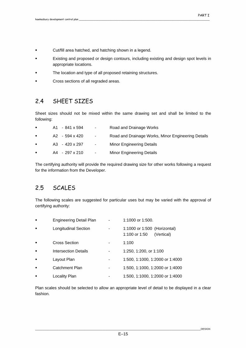
2.4 SHEET SIZES
Sheet sizes should not be mixed within the same drawing set and shall be limited to the following:
A1 - 841 x 594 - Road and Drainage Works
A2 - 594 x 420 - Road and Drainage Works, Minor Engineering Details
A3 - 420 x 297 - Minor Engineering Details
A4 - 297 x 210 - Minor Engineering Details The certifying authority will provide the required drawing size for other works following a request for the information from the Developer.
2.5 SCALES
The following scales are suggested for particular uses but may be varied with the approval of certifying authority:
Engineering Detail Plan - 1:1000 or 1:500.
Longitudinal Section - 1:1000 or 1:500 (Horizontal) 1:100 or 1:50 (Vertical)
Cross Section - 1:100
Intersection Details - 1:250, 1:200, or 1:100
Layout Plan - 1:500, 1:1000, 1:2000 or 1:4000
Catchment Plan - 1:500, 1:1000, 1:2000 or 1:4000
Locality Plan - 1:500, 1:1000, 1:2000 or 1:4000 Plan scales should be selected to allow an appropriate level of detail to be displayed in a clear fashion.
________________________________________________________________________________________________________________________DESIGN
E–15

PART I ____________________________________________________________________________________ hawkesbury development control plan
2.6 DIMENSIONS
Linear dimensions on all engineering plans shall be in metres, with the exception of detail plans which may be in millimetres. Methods of dimensioning will be in accordance with the current Australian Standard. Chainage shall be expressed to the nearest 0.0lm, levels shall be reduced to Australian Height Datum (AHD) and expressed to the nearest 0.01m (except Bench Marks, PM's and SSM's which will be expressed to the nearest 0.00lm).
2.7 ENVIRONMENTAL
These plans shall show kerblines, drainage, sewer and any other civil infrastructure that will require disturbance to the natural environment. These plans shall show "NO GO AREAS" and proposed fencelines and types to ensure there is no disturbance outside the construction corridors. Other details to be included are specified in Section 3. These details may be shown on the plan sheets if clarity permits, otherwise schedules should be attached to outline the proposed protection measures.
DESIGN ________________________________________________________________________________________________________________________
E–16

PART I hawkesbury development control plan ____________________________________________________________________________________
3. ENVIRONMENTAL PROTECTION
3.1 INTRODUCTION
Environmental protection requirements apply to the design of all engineering works which will disturb the soil surface, vegetation (including grasses, shrubs, trees), fauna habitat, air quality, noise levels, visual amenity, horticultural features, relic or material evidence of settlement, etc. covered by the Heritage Act 1977 or native vegetation and critical habitat under the Threatened Species Conservation Act 1995. It is Council policy to conserve native vegetation, flora and fauna (terrestrial and aquatic), minimise noise and dust to acceptable levels, minimise damage to trees and to control sediment runoff in all new developments.
3.2 DEVELOPER RESPONSIBILITIES
In the design of any works, the Developer and the Consultant have a responsibility to protect the environment. Issues which may affect the engineering design of a subdivision or development are outlined below. Items of the built or natural environment which have conservation significance are protected by Acts of Parliament, State Environmental Planning Policies and State Regional Environmental Plans. A full listing of these plans and policies is given in Chapter 1 of the Hawkesbury DCP. Where a known item or site is affected by or adjacent to a development, specific measures should be incorporated into the design to minimise any impacts. These must be strictly adhered to or severe penalties (fines or imprisonment or both) may result from action under the Heritage Act, the Environmental Planning and Assessment Act, and the National Parks and Wildlife Act. For the purposes of the Heritage Act a relic is any object or material evidence of settlement of the area which is 50 or more years old, but specifically excluding Aboriginal relics. The Developer shall ensure that the works are designed to conform to the Protection of the Environment Operations Act, 1997 which is administered by the Environment Protection Authority. Severe penalties are imposed for contravening this legislation which deals with water, noise and air pollution. Drainage works shall be designed to ensure that flows and discharges are adequately controlled to avoid adverse impacts on downstream creek bank stability and flood behaviour, ecological features and property. Also runoff from a development should be treated such that the pollutant load exiting the site does not exceed that for existing conditions or does not adversely affect downstream flora and fauna during both construction and post development
________________________________________________________________________________________________________________________DESIGN
E–17

PART I ____________________________________________________________________________________ hawkesbury development control plan
phases. The incorporation of source control measures for pollutants in runoff should be maximised in the design of works. The area of impervious surfaces and site disturbances should be minimised. Clean runoff should be diverted around the worksite. Works should be consistent with Council’s Stormwater Management Plan. Drainage channels should, where possible, be designed to mimic natural creek/streams. The design should maximise the ecological, visual and recreational opportunities in a drainage channel with the use of low flow on the surface and inclusion of pools, riffle zones and a range of vegetation. The purpose of these provisions is not to restrict development unnecessarily, but to ensure that the environment is not adversely affected. Environmental benefits should be achieved through development. There is no advantage to be gained by ignoring the above requirements and proceeding with designs and works which result in adverse environmental impacts. Failure to comply with the provisions of the environmental legislation may result in severe penalties (fines or imprisonment or both).
3.3 ENVIRONMENTAL PROTECTION
The design of the subdivision or development shall take into account the following requirements to minimise adverse environmental impacts.
3.3.1 On-Site Burning
The Developer shall comply with all statutory requirements and ordinances that regulate the lighting of fires or where damage to the environment could result. Appropriate approval is to be obtained prior to any onsite burning. Alternative disposal methods are preferred for plant debris.
3.3.2 Noise Control
The Developer shall comply with the statutory regulations and take all practical precautions to minimise noise levels from the development site.
3.3.3 Storage on Site
The location of materials and equipment stored on site shall be approved by the certifying authority in order to prevent damage to the site and minimise hazards to persons, materials, equipment and the environment.
DESIGN ________________________________________________________________________________________________________________________
E–18
PART I hawkesbury development control plan ____________________________________________________________________________________
3.3.4 Disposal of substances
The Developer shall properly dispose of all solids, liquids and gaseous contaminants in accordance with all statutory requirements.
3.3.5 Stormwater Runoff
During construction, runoff from the site shall not adversely impact on the downstream ecology and it may be necessary for the Developer to obtain a licence from the Environment Protection Authority to permit discharges from the site. Following development, both the runoff flow rate and pollutant load should be controlled to avoid destabilising the downstream creek bed and adversely affecting the ecology. The peak flow rates of runoff from the site should be controlled so as not to exceed existing rates for all severity of storms. The average annual pollutant load in runoff (suspended sediment, nutrients and bacteria) from the development should be controlled so as to not exceed existing levels. If the receiving waters are in a poor condition, it may be necessary to achieve a reduction in the annual pollutant load below existing conditions. These control works should be designed in accordance with the Department of Housing publication “Managing Urban Stormwater - Soils and Construction” and the Hawkesbury DCP.
3.3.6 Dust Control
The Developer shall comply with the statutory regulations and restrict the dust levels caused by the development to the recommended values.
3.3.7 Transportation of Materials
Any transportation of earth, sand, road construction material, loose debris and any loose materials to or from the development site shall be in a manner that will prevent the dropping of material on surrounding streets. The Developer shall ensure that the design of control measures allows for the wheels, tracks and body surface of all vehicles and plant leaving the site to be free of mud and that mud is not carried onto adjacent streets or other areas.
3.3.8 Vegetation
The works shall be designed to maximise the retention of native vegetation or vegetation which is recognised as significant in a local or regional context.
________________________________________________________________________________________________________________________DESIGN
E–19
PART I ____________________________________________________________________________________ hawkesbury development control plan
3.4 LANDSCAPING AND VEGETATION MANAGEMENT
3.4.1 Landscape Policy
Before lodging an application for subdivision or development, all aspects of the landscaping proposal should be investigated in order to best integrate the proposed development with the existing landscape and significant vegetation. It is essential that landscaping and vegetation management proposals are based on a satisfactory initial site analysis including an assessment of the useful life of existing vegetation. Once a consent or certificate has been issued, landscaping opportunities will be restricted due to fixing the location of roads, lots and reserves. Aspects to be considered in the design include but are not limited to:
Appraisal of trees for preservation and removal of inappropriate trees.
Areas to be left undisturbed include wetlands, rock outcrops, rare, protected and significant vegetation, steep land, proposed public reserves especially semi-natural areas, buffer and filtration strips.
Where required by the Consent, all the relevant details of the landscape design must be incorporated in the engineering design. The landscape design plan must be approved by the certifying authority prior to the issue of the Construction Certificate. Details of the Landscape Policy and the information required to be submitted under the various landscape categories are available from Council.
3.5 BUSH FIRE PRECAUTIONS
Careful consideration must be given to the possible bush fire hazard in the design of a subdivision or development. The Developer shall follow the various recommendations of the Bush Fire Council and the Department of Bush Fire Services in their publication "Planning for Bush Fire Protection" and Council Policies. Where a subdivision abuts bushland in a bushfire prone area (as classified by Council) the following is required.
An all weather perimeter road (fire trail) of a minimum 4m trafficable width adequately drained, within a minimum cleared width of 6m.
Any perimeter road is to be located within a nominated fuel reduction zone on the site of the development immediately between the subdivision lots and the bushland.
The width of the fuel reduction zone will be determined by Council and will vary depending on the slope of the land, prevailing winds and adjoining flora types. Such fuel reduction zones will serve as a basis for fire protection. It will not be considered as part of the open space dedication required for the subdivision. All bush fire protection
DESIGN ________________________________________________________________________________________________________________________
E–20
PART I hawkesbury development control plan ____________________________________________________________________________________
measures, including perimeter roads and fuel reduction zones, shall be located on the site of the development requiring that protection and not on adjoining land.
Access to be provided to the fuel reduction zone from the local road system at regular intervals.
The Developer and/or Council may be required to identify safe building zones within a subdivision.
During and after construction sediment and erosion controls must be provided.
Where a potential fire hazard exists, applicants should consult with Council prior to final preparation of engineering plans.
Subdivisions in areas historically subject to bushfires or areas likely to experience an increase in fire hazard arising from development shall require the provision of an alternative emergency vehicular access. The submission of recorded incidence of bushfires in the area and a report from a suitably qualified Fire Control Officer shall assist in determining whether alternative means of vehicular access to the subdivision is required.
________________________________________________________________________________________________________________________DESIGN
E–21

PART I ____________________________________________________________________________________ hawkesbury development control plan
4. EARTHWORKS
4.1 GENERAL
This section provides details and references to specific standards to be observed in the design of earthworks for development and subdivisional construction.
4.2 SEDIMENT AND EROSION CONTROL
Prior to the commencement of any works, the design shall conform to the requirements specified in Section 5.
4.3 SITE REGRADING/CUT AND FILL
Continuous embankments of cut or fill extending over two or more lots and/or repeated for more than two consecutive lots is discouraged and will generally require the provision of houses designed as other than slab on ground construction. All details regarding proposed lot reshaping shall be shown on the engineering plans submitted for approval in accordance with Section 2.3.17. Where cut and fill batters exceed 1 metre in height then a report from a qualified Geotechnical Engineer is required to certify the stability of the resulting slope and adequacy of the retention method.
4.4 PRESERVATION OF EXISTING TREES AND NATIVE VEGETATION
Selected trees and native vegetation communities are to be preserved to prevent the destruction normally caused by placement of conventional filling and by other earthworks within the critical root zone.
4.5 EXPLOSIVES AND BLASTING
The use of explosives and blasting will only be permitted in specific situations and must be carried out in accordance with the Civil Works Specification Part 2 Construction.
DESIGN ________________________________________________________________________________________________________________________
E–22
PART I hawkesbury development control plan ____________________________________________________________________________________
4.6 EXTENT OF FILL
Where a lot is to be filled in isolation the toe of the batter shall merge with the existing surface a minimum of one metre from the adjoining property boundary within or adjoining the development.
4.7 METHODS OF RETAINING FILL
Fill shall be retained by either stabilised batters or retaining walls as recommended and certified by Geotechnical Engineers and/or approved by the certifying authority. Terracing of lots shall be regarded as filling of lots, whether in isolation or not and the requirements of Sections 4.3 and 4.6 shall apply. The face of the wall can be erected on the boundary subject to no drainage works being required as the result of filling. No part of any structure is to encroach onto adjoining properties. The renewal of any existing fence is the responsibility of the Developer unless a formal agreement has been obtained from affected land owners. Retaining walls shall have a minimum design life of 40 years, unless there is a possibility of future structures located such that they impose additional loads on these retaining walls, then the design life shall be a minimum of 80 years. The design and construction shall be certified by a practising Structural Engineer with NPER registration. The design shall be submitted to the certifying authority for approval. Retaining walls required for overland flow pathways shall be provided with adequate catch drains and subsurface drainage benefiting both the high and low side properties. Permission to enter adjacent private property must be obtained.
4.8 DRAINAGE
Filled areas shall be shaped and graded at a minimum of 0.5% to avoid ponding and to generally direct surface flow to the drainage system designed for that catchment. Where possible filling should be graded at a minimum of 1.0%. The existing overland flow paths shall be maintained for trees which are to be retained. Filling across natural drainage lines shall not allow water to back up and drown roots of upstream trees to be retained. The diversion of natural drainage flows away from existing trees to be retained shall be avoided. Where possible treatments shall be provided to maintain such existing flows without affecting allotments or road pavements. Provisions shall be made along the toe of the fill batters or base of retaining walls to permit the free passage of stormwater and subsurface water away from adjoining properties. Ponding or the reduction in stormwater disbursement is not permitted. Catch drains and/or interallotment drainage shall be provided to adequately drain such areas.
________________________________________________________________________________________________________________________DESIGN
E–23

PART I ____________________________________________________________________________________ hawkesbury development control plan
Adequate permanent or temporary intercept drains shall be provided to minimise stormwater run-on to downstream properties.
4.9 PERMISSION TO ENTER
Where it is proposed to fill or access is required over adjoining land, written proof of consent of affected landowners shall be supplied to the certifying authority prior to the issue of the Construction Certificate.
4.10 FILLING OF DAMS
4.10.1 General
The following engineering details shall be submitted to the certifying authority and approved, before any dam can be filled in, whether in a rural or urban area. The plans must indicate:
1. The manner of dewatering and its potential effect on downstream facilities and properties. 2. Any information required by the Consent. 3. The extent and type of fill. 4. The tonnage of fill to be imported.
4.11 TOPSOILING & REVEGETATION
All disturbed areas shall be topsoiled, stabilised and revegetated in accordance with Section 4.17 and Section 12 of the Civil Works Specification Part 2 Construction. Details are to be shown on the design plans.
4.12 CONTAMINATED LANDS
Any contaminated lands shall be managed in accordance with the Contaminated Land Management Act and the EPA guidelines.
DESIGN ________________________________________________________________________________________________________________________
E–24
PART I hawkesbury development control plan ____________________________________________________________________________________
5. EROSION AND SEDIMENT CONTROL
5.1 POLICY PURPOSE
The purpose of this policy is to:
Minimise soil erosion and sedimentation resulting from site disturbing activities;
Promote the protection and enhancement of the natural environment and maintain compatibility with the built environment; and
Promote consistency and fairness in the application and regulation of erosion and sedimentation control measures.
This policy applies to the following activities:
Any development activity requiring the approval of a certifying authority;
Any activity on public land, including Council activities (by or on behalf of Council); and
Any activity which involves disturbance of the soil surface or placement of fill on any allotment which will change the shape of the land.
This policy does not apply to the following activities:
Any activity subsequent to a Crown approval or activity on Crown land;
Single dwellings and ancillary buildings on vegetated allotments exceeding 1 ha where no site disturbance is to take place within 40m of any watercourse or allotment boundary; and
Agricultural activities and land management practices on land zoned "Rural" where such activity is more than 40m from any watercourse or more than 5m from any allotment boundary.
5.2 POLICY OVERVIEW
5.2.1 Scope
This section deals with the design of structures to control erosion and sedimentation. These structures may be temporary or permanent. The Contractor shall plan and carry out the whole of the works to avoid erosion and sedimentation of the site, surrounding areas, watercourses, waterbodies and wetlands.
________________________________________________________________________________________________________________________DESIGN
E–25

PART I ____________________________________________________________________________________ hawkesbury development control plan
5.2.2 Principles of Erosion and Sediment Control
Construction activity generally requires the disturbance of the soil surface and the existing vegetation, exposing the construction site to erosion. This in turns leads to sediment loss in the resultant runoff water. Since such soil disturbance is a necessary part of development, it is essential therefore to develop measures which reduce the erosion hazard of any particular construction activity. Having done that, runoff water which carries the sediment must be controlled, in such a way as to reduce the amount of that soil leaving the site. This is achieved by:
Limiting the amount of site disturbance.
Isolating the site by diverting clean upstream “run-on” water around or separately through the development where possible.
Providing an effective major stormwater system economical in terms of operation and maintenance, incorporating water quality controls.
Retaining topsoil for effective revegetation works.
Controlling runoff and sediment movement at its point source rather than only at one final point.
Progressive revegetation of the site where possible during on-going construction to reduce the area contributing sediment. This in turn increases the efficiency and effectiveness of the entire sediment control system.
Construction of larger sediment trapping systems of a size relevant to the catchment of the site.
Filtering of the sediment in the trapped water prior to its release to the drainage system.
5.2.3 Documentation
All erosion and sediment control, pollution control and rehabilitation measures shall conform to the specifications and standards contained in “Managing Urban Stormwater - Soils and Construction" - 1998, NSW Department of Housing (known as the “Blue Book”). The Contractor shall prepare either an Erosion and Sediment Control Plan (ESCP) or a Soil and Water Management Plan (SWMP). An ESCP is required for a development site area of less than 2,500 m2 while a SWMP is required for sites with an area greater than 2,500 m2. The design is to be site specific and not a generalisation of erosion control philosophy.
DESIGN ________________________________________________________________________________________________________________________
E–26

PART I hawkesbury development control plan ____________________________________________________________________________________
5.3 CONTROL AND MANAGEMENT PLANS
5.3.1 Background
The requirements for ESCPs and SWMPs are presented in detail in the Blue Book and only overview detail is provided in these specifications. The plans are documents which detail the control measures to be implemented on a site to minimise the potential for erosion and sedimentation. A plan can vary from a simple statement for minor activities to complex engineering plans and associated documentation for major activities, and shall be submitted as part of the design plan. The following sections identify the minimum controls for site disturbing works. A plan is required to ensure that:
A strategy to manage erosion and sedimentation is considered at an early stage in the planning process;
There is minimal disturbance of the site and minimal erosion and sedimentation;
Erosion and sediment control measures and practices are an integral part of the initial site development plan; and
Construction activities and erosion and sediment control measures and practices are implemented within a co-ordinated framework.
5.3.2 Contents of a Plan
A plan shall:
Demonstrate an understanding of the limitations of the site and/or the watercourses that may affect the type of controls used;
Co-ordinate construction works to minimise disturbance of the site by limiting the extent of works and the time the disturbed area is exposed;
Control water from where it enters the site, through and beyond the lowest point of the site;
Minimise, and where possible prevent, sediment leaving the site;
Schedule the rehabilitation of the disturbed areas of the site; and
Detail the maintenance procedures for all of the control measures. The plan shall address all aspects of site disturbance, flow rate changes, erosion and sediment control and site rehabilitation for the duration of the project from initial clearing to project completion. If, at the project's completion, there is any area that is in an erosion-prone state, or permanent structures are in need of maintenance, then the plan shall be reviewed with respect to the additional works required.
________________________________________________________________________________________________________________________DESIGN
E–27

PART I ____________________________________________________________________________________ hawkesbury development control plan
A plan shall be prepared by a person with a demonstrated knowledge of soil and water management. The format of a plan will vary depending upon the complexity of the proposal and its potential environmental impact. A plan shall incorporate the following components:
Plan(s);
Supporting information; and
Construction details, calculations and notations.
Drawing Component The drawing component of a plan shall be prepared in accordance with Section 2.3.15.
Supporting Information Supporting information shall be in the form of a brief description of the overall erosion and sediment control strategy. This information may be shown on the plan or as a separate document, and shall include:
A brief description of existing conditions, such as soils, proposed works, impact on the site and adjacent areas;
Supporting geotechnical data for design parameters and assumptions;
A description of any areas within the site that have potential for serious erosion and/or sedimentation, together with their proposed management strategy and details;
The construction sequence over the duration of the works;
A brief description of the overall site rehabilitation program;
A maintenance strategy for all control measures, including the nomination of responsibility for the follow-up maintenance required on any permanent measures; and
Construction details, calculations and notations, including construction drawings and written specifications, shall be provided on each type of structural erosion and sediment control measure.
Specifications for all rehabilitation and revegetation components shall be included. Where possible native vegetation should be used to stabilise and revegetate disturbed areas.
DESIGN ________________________________________________________________________________________________________________________
E–28
PART I hawkesbury development control plan ____________________________________________________________________________________
5.4 PLANNING FOR EROSION CONTROL
Recommended steps and checklists suggested to be used in the development and implementation of an acceptable plan are documented below. This information should provide the necessary tools to gain approval of construction activities for all types of construction sites and developments.
STEP 1: Identify Site Characteristics Existing:
Topography/contours.
Drainage patterns upstream and downstream of the site.
Site soils.
Sensitive areas or other areas of concern, e.g. wetlands and
Creeks, etc. Future:
Site contours.
Drainage system, type and location.
Impervious areas.
STEP 2: Pre-construction Plan and Proposed Base Measures Determine the construction timing and sequence.
Establish primary site access point(s) for construction traffic.
Lay out limits of clearing and construction activities.
Establish base protection measures including sediment barriers and stabilised construction entrances.
Establish maintenance procedures for erosion control measures.
STEP 3: Measures During Construction Continue establishment of the site base measures as disturbance occurs, including
stockpile protection and sediment filters.
If during construction there is the likelihood of rain (summer, long-range forecasts, etc.) then a suitable action plan must be in place prior to the rain occurring.
Establish and schedule wet weather measures including the establishment of vegetation on exposed soils.
Establish maintenance procedures for erosion control measures.
________________________________________________________________________________________________________________________DESIGN
E–29
PART I ____________________________________________________________________________________ hawkesbury development control plan
STEP 4: Post Construction Measures Maintain erosion and sediment control measures for the duration of the specified
maintenance period.
An established stabilised ground cover must be in place and approval from the certifying authority received before removing erosion control measures.
5.5 APPROVAL PROCESS
A plan will be assessed by the certifying authority. In some cases, principally urban subdivisions, approval from the Environment Protection Authority under Section 19 of the Clean Waters Act 1970 may be required. Subdivisions in excess of 10 ha or 50 lots shall be referred to the NSW Environment Protection Authority in addition to any application which the certifying authority deems appropriate because of environmental sensitivity or community concerns. An unsatisfactory plan will be rejected and work will not be able to commence until the certifying authority approves a revised plan. Approval of a plan by the certifying authority does not relieve the Developer to ensure that erosion and sedimentation control measures are constructed and maintained to contain sediment on the site.
5.6 RECOMMENDED CONTROL MEASURES
The recommended control measures are contained in the Department of Housing Guidelines (Blue Book) which present the required construction dimensions, placement, nature and application criteria for the various control measures.
5.7 GUIDELINES FOR SITE REHABILITATION AND LANDSCAPING
To ensure that the landscape and scenic quality of the locality is maintained and improved, and to ensure that the completed development will not result in the degradation of downstream water quality, the following shall apply:
the site shall be rehabilitated with all disturbed ground stabilised;
on lands where shaping has finished, rehabilitation shall be completed within a specified time, usually 20 working days. Where final shaping has not been finished but works are unlikely to proceed for periods of 14 days or more, temporary revegetation works for erosion and sediment control shall be installed with use of mulches, annual grasses, sediment fences, etc;
DESIGN ________________________________________________________________________________________________________________________
E–30

PART I hawkesbury development control plan ____________________________________________________________________________________
planting of native trees and shrubs utilising endemic seed collected before clearing of site shall be required where deemed appropriate;
approval shall be obtained from the Department of Land and Water Conservation prior to the removal or injury of any tree from:
- land within the bed of or within 40m of the banks of any river or creek; or
- land designated "protected land" under the Soil Conservation Act 1938.
5.8 APPROPRIATE VEGETATION
To provide quick soil surface stabilisation, either turf or a cover crop of grasses should be immediately established as the work progresses. The following seed types are provided as a guideline only and allowances should be made for the type of flow which may cause erosion. Type Spring/Summer Autumn/Winter
Japanese Millet 4kg/ha - Couch (hulled/unhulled) 4kg/ha 4kg/ha Ryecorn/Barley - 30kg/ha Red Clover 4kg/ha 4kg/ha White Clover 4kg/ha 4kg/ha Wimmera Rye 10kg/ha - Perennial Rye - 10kg/ha Kikuyu 4kg/ha - For medium to long term site stabilisation and protection of the integrity of the surrounding ecology, local native trees and shrub species best suited to the Hawkesbury soils are as follows: Very hardy and suited to exposed sites: Snappy Gum Figs Narrow Leaved Apple Smooth Barked Apple Drooping Oak Red Bloodwood Silvertop Ash Yellow Bloodwood Cypress Pine Mountain Blue Mallee Coast Tea Tree Woody Pear Scribbly Gum Stringybark Dwarf Apple Myrtle She-Oak Bottlebrushes Kunzea Bracelet Honeymyrtle Paperbark Privet-Leaved Stringybark Bottlebrushes Coast Rosemary Round Leaf Tea Tree
________________________________________________________________________________________________________________________DESIGN
E–31

PART I ____________________________________________________________________________________ hawkesbury development control plan
Local native trees and shrub species best suited to clay soils and exposed sites and are very hardy: River She-Oak Cedar Wattle Lilly Pilly Belah Forest She Oak Lemon Scented Gum Grey Ironbark Tallowwood Silky Oak Brush Box Ribbon Gum Paddy's River Box Turpentine Kurrajong Drooping Bottlebrush Grey Gum White Cedar Swamp Oak Willow Gum Glory Wattle She Oak Westringia Silver Cassia Mudgee Wattle
DESIGN ________________________________________________________________________________________________________________________
E–32

PART I hawkesbury development control plan ____________________________________________________________________________________
6. ROAD DESIGN
6.1 GENERAL
6.1.1 Scope
This section of the manual sets out Council's requirements for the design of roads. It is in no way a comprehensive design manual and it is intended to be read in conjunction with and as a supplement to:
AUSTROADS (1988) - Guide to Traffic Engineering Practice, Parts 1-14;
AUSTROADS (1993) - Rural Road Design, Guide to the Geometric Design of Rural Roads;
AUSTROADS (1992) - Pavement Design, A Guide to the Structural Design of Road Pavements;
ARRB, Transport Research (1995) Sealed Local Roads Manual - Guidelines to Good Practice for the Construction, Maintenance and Rehabilitation of Pavements;
AMCORD - A National Resource Document for Residential Development;
Department of Housing Road Manual; and
Roads and Traffic Authority Road Design Guide.
6.1.2 Aim
The design and construction of a road system that provides the following:
a high level of safety for all users;
acceptable levels of amenity and protection from the impact of traffic;
a reasonable level of convenience for all users; and
economy of construction and maintenance.
6.1.3 Planning Standards
The road layout and widths shall be based on a hierarchy of street and road types (refer Table 6.3 and Table 6.11).
________________________________________________________________________________________________________________________DESIGN
E–33

PART I ____________________________________________________________________________________ hawkesbury development control plan
6.2 GENERAL REQUIREMENTS - ALL ROADS
6.2.1 Pavement Crossfall
The normal cross-fall of pavement and shoulders on a straight alignment shall be 3%. There are many controls, particularly in urban areas which may force departures from the above values. Should it be necessary to increase or decrease cross-fall, it shall remain within the range of 1.0% to 7.0%. However, where the longitudinal gradient is less than 2% the minimum permissible crossfall shall be 2% and where the longitudinal gradient is greater than 12%, the maximum permissible crossfall shall be 5%.
6.2.2 Vertical Curves
Vertical curves of the form of simple parabolas shall be provided at all changes of grade exceeding the following:
Local Access and Collector 1.0% Rural, Sub-arterial and Arterial 0.6%
Every effort should be made to provide vertical curves as long as possible for improved appearance, however, surface drainage should be maintained in proximity to sag points. The design of vertical curves shall be in accordance with the RTA Design Guide and the following:
A minimum design speed of 60 km/h shall be adopted even if the horizontal alignment is not satisfactory for that speed.
The minimum length of a crest vertical curve is governed by sight distance requirements.
The desirable minimum length of a sag vertical curve is that providing minimum headlight sight distance and this length should be provided wherever possible.
The absolute minimum length of a sag vertical curve is based on the consideration of riding comfort and shall be such that the maximum vertical acceleration is 0.1 G.
In addition to the minimum length requirements mentioned above, from a consideration of appearance the minimum length of a vertical curve in urban areas shall not be less than that shown in Table 6.1.
TABLE 6.1 MINIMUM VERTICAL CURVE LENGTHS
Road Type General Minimum Curve Length (m)
Minimum Curve Length at Road Junctions (m)
Access Roads 25 6 Collector Roads 35 12 Sub-arterial/Arterial 50 20 Industrial/Commercial 35 20
DESIGN ________________________________________________________________________________________________________________________
E–34
PART I hawkesbury development control plan ____________________________________________________________________________________
The tangent point of a vertical curve in the side road should be located at, or behind, the kerb line of the through road.
Vertical curves on kerb returns must be treated in such a manner as to make construction practical.
6.2.3 Intersections
The design of intersections or junctions shall be in accordance with AUSTROADS -Guide to Traffic Engineering Practice, PART 5, Intersections at Grade and R.T.A. Road Design Guide. Intersections should generally be located so that streets intersect at right angles and at not less than 70°. Adequate stopping and sight distances should be provided on each of the approach legs of an intersection and for any horizontal or vertical curves. Turning movements shall be accommodated by using AUSTROADS Design Vehicles and Turning Templates as follows:
for turning movements involving major and medium collector streets, the "design semi-trailer" with turning path radius 15 metres shall be used to enable turns to be made in a single forward movement.
for turning movements involving access streets and collector streets, the Austroads "Design Single Unit Truck" 12.5m long with 13m turning path radius shall be used to enable turns to be made in a single forward movement.
for turning movements on access streets, the garbage collection vehicle used by Council. (Austroads Design Service Vehicle 8.8m long).
for turning movements at the head of cul-de-sac streets, sufficient area shall be provided for the "design single unit" truck to make a three (3) point turn.
6.2.4 Roundabouts
The design of roundabouts shall be in accordance with AUSTROADS - Guide to Traffic Engineering Practice, Part 6, Roundabouts and shall be approved by the Council and the Roads and Traffic Authority. Roundabouts are to be generally designed in accordance with the current Austroads Guide to Traffic Engineering Practice and the RTA document "Roundabouts Geometric Design Method" paying particular attention to the following requirements.
Adequate capacity for projected future volumes for it's design life.
Adequate sight distance for vehicles approaching and entering the roundabout, pedestrians and cyclists.
________________________________________________________________________________________________________________________DESIGN
E–35

PART I ____________________________________________________________________________________ hawkesbury development control plan
Provisions for service authorities future needs.
Geometry to satisfy deflection and driver guidance requirements. It is preferable to attain deflection prior to entering the roundabout.
Adequate drainage.
Site specific designed street lighting.
Signposting and pavement marking.
The provision for pedestrians and cyclists.
Adequate turning paths for design vehicles specified in Section 6.2.3.
The provision of suitable landscaping. Roundabouts on RTA classified roads are to be designed and constructed in accordance with RTA requirements. RTA approval is mandatory.
6.2.5 Cul-de-sac and Hammer Head Facilities
The following minimum requirements will apply to turning facilities. a) Cul-de-sacs
Cul-de-sacs shall be constructed with the following minimum radii.
TABLE 6.2 Cul-de-Sac Minimum Radii
Road Type Minimum Kerb/Pavement Radii (m) Minimum Boundary Radii (m)
Residential 8.5 12 Industrial/Commercial 13.5 17 Rural 12.0 17
b) Hammer Heads Variations of hammer head turning facilities will be permitted where specified in the
Consent. Turning paths for these facilities must be submitted and approved by the Certifier.
c) Grades and Crossfalls The range of allowable grades and crossfalls are a minimum of 1% and maximum of
6%. d) Manoeuvring Manoeuvring within the turning facility shall be designed in accordance with Section
6.2.3.
DESIGN ________________________________________________________________________________________________________________________
E–36

PART I hawkesbury development control plan ____________________________________________________________________________________
6.2.6 Berms
Berms shall extend 0.3 metres in fill or in cut beyond the property boundary at the same grade as the footpath.
6.2.7 Batters
Batters shall be designed as stable slopes at the edge of the berm in accordance with Table 6.3.
TABLE 6.3 MAXIMUM BATTER SLOPES
Batter Type Maximum Slope (V:H)
Earth – Fill 1:3
Earth – Cut 1:3
Rock 1:0.25
Steeper batters will only be permitted where the Certifier is satisfied that the long term stability of the batter will not be compromised and that the batter can be appropriately revegetated, stabilised and maintained. The abovementioned slopes for rock batters refer only to cut batters in solid rock with few clay bands. Rock material should be certified by a qualified Geotechnical Engineer. The need for constructing retaining walls should be avoided wherever possible. Should a retaining wall be necessary the Developer must provide full engineering details of the proposed structure, including elevation, typical cross-section and structural certification.
6.2.8 Cuttings
On the top side of cuttings, where shown on the plans, catch drains shall be provided with a cross-sectional area not less than 0.2 square metres, side slopes not steeper than the adjacent road batter, and a minimum depth of 300mm over a width of at least 300mm. The minimum gradient of catch drains shall be 1 in 100. The catch drain shall be located a minimum 2.5 metres from the edge of the cutting. Where the grade of the catch drain exceeds 5%, scour protection shall be provided. Proper outlet drains shall be provided leading to culverts and, in earth cuttings pitching of the outlet drain is to be provided to prevent scour.
________________________________________________________________________________________________________________________DESIGN
E–37

PART I ____________________________________________________________________________________ hawkesbury development control plan
The applicant may construct an embankment not less than 500mm high, 300m wide on top, with 1:1 slopes in lieu of cutting catch drains.
6.3 SPECIFIC REQUIREMENTS - URBAN ROADS
This section details Council’s specific requirements to be followed in the design of urban roads.
6.3.1 Road Alignment
The standard road layout and alignment widths for various classifications of roads are given in Table 6.4 These values are to be used for new and existing roads and must not be varied except in the situation where existing kerblines already define a carriageway width which does not match those listed below.
TABLE 6.4 URBAN ROAD ALIGNMENT AND WIDTHS
Road Type Description Widths (m) Carriage-
way Footway Road
Reserve Residential Roads major collector - major bus routes and inter
precinct traffic 13 3.5 20
medium collector - through roads serving open space, shops etc possible bus route
11 3.5 18
minor collector - through roads 8 3.5 15
local - cul-de-sacs and short through roads
8 3.5 15
local access roads - less than 10 properties 6 3.5 13
cul-de-sacs Refer to Table 6.10
Industrial/Commercial 13 3.5 20 A typical urban road cross section is shown on Standard Drawing No. SD2
6.3.2 Design Speed
Design speed is the speed applied to the design of a road's geometric elements to create and maintain a speed environment for 85% of drivers.
DESIGN ________________________________________________________________________________________________________________________
E–38

PART I hawkesbury development control plan ____________________________________________________________________________________
Generally the following design speeds should be adopted:
Local Access Road 40 km/hr Local Road 50 km/hr Collector Road 60 km/hr
6.3.3 Sight Distance
Refer to the RTA Design Guide Section 2.1 The Absolute Minimum sight distance is that required for a driver to observe an object on the road surface ahead, and to stop the vehicle before reaching the object. This sight distance shall be available at every point on every road and at intersections to provide sufficient distance for an approaching vehicle to stop before an obstruction in the roadway using the approved design speed. The appropriate value of sight distance for various vehicle speeds are presented in Table 6.5
TABLE 6.5 ABSOLUTE MINIMUM SIGHT DISTANCES
Design Speed (km/h) Sight Distance (m) 40 39 50 52 60 68 70 86 80 108
6.3.4 Horizontal Alignment
Drivers react to restrictive horizontal alignment by slowing to an appropriate speed, hence the desired maximum design speed is maintained by deliberately designing a restrictive horizontal alignment. The minimum horizontal deflection angle for which a curve is needed is 1.0 degree. Where possible the radii of the curve shall be maximised to reduce the necessity of centreline shift and widening of the carriageway. The minimum radii for various design speeds shall be in accordance with Table 6.6.
TABLE 6.6 MINIMUM CURVE RADII
Design Speed (km/h) Minimum Radii (m) 40 35 50 50 60 90 70 150 80 240
________________________________________________________________________________________________________________________DESIGN
E–39
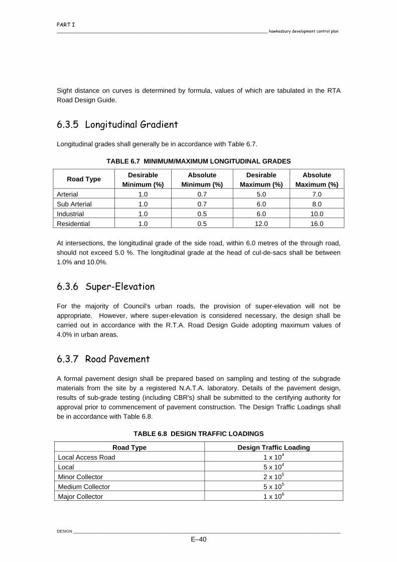
PART I ____________________________________________________________________________________ hawkesbury development control plan
Sight distance on curves is determined by formula, values of which are tabulated in the RTA Road Design Guide.
6.3.5 Longitudinal Gradient
Longitudinal grades shall generally be in accordance with Table 6.7.
TABLE 6.7 MINIMUM/MAXIMUM LONGITUDINAL GRADES
Road Type Desirable Minimum (%)
Absolute Minimum (%)
Desirable Maximum (%)
Absolute Maximum (%)
Arterial 1.0 0.7 5.0 7.0 Sub Arterial 1.0 0.7 6.0 8.0 Industrial 1.0 0.5 6.0 10.0 Residential 1.0 0.5 12.0 16.0 At intersections, the longitudinal grade of the side road, within 6.0 metres of the through road, should not exceed 5.0 %. The longitudinal grade at the head of cul-de-sacs shall be between 1.0% and 10.0%.
6.3.6 Super-Elevation
For the majority of Council’s urban roads, the provision of super-elevation will not be appropriate. However, where super-elevation is considered necessary, the design shall be carried out in accordance with the R.T.A. Road Design Guide adopting maximum values of 4.0% in urban areas.
6.3.7 Road Pavement
A formal pavement design shall be prepared based on sampling and testing of the subgrade materials from the site by a registered N.A.T.A. laboratory. Details of the pavement design, results of sub-grade testing (including CBR's) shall be submitted to the certifying authority for approval prior to commencement of pavement construction. The Design Traffic Loadings shall be in accordance with Table 6.8.
TABLE 6.8 DESIGN TRAFFIC LOADINGS
Road Type Design Traffic Loading Local Access Road 1 x 10⁴
Local 5 x 10⁴
Minor Collector 2 x 10⁵
Medium Collector 5 x 10⁵
Major Collector 1 x 10⁶
DESIGN ________________________________________________________________________________________________________________________
E–40

PART I hawkesbury development control plan ____________________________________________________________________________________
Road Type Design Traffic Loading Commercial / Light Industrial (dead end) 2 x 10⁶
Light Industrial (through road) 5 x 10⁶
Heavy Industrial (dead end) 5 x 10⁶
Heavy Industrial (through road) 1 x 10⁷
The minimum pavement thickness and wearing course appropriate for each road classification is detailed in Section 7.
6.3.8 Kerb and Gutter
Concrete kerb and gutter shall be provided on both sides of urban roads and shall be provided generally in accordance with Table 6.9 and Council's Civil Works Specification Part 2 Construction.
TABLE 6.9 Kerb And Gutter Types
Road Type/Location Kerb and Gutter Type
Local Access Roads Roll Kerb and Gutter Local Roads 150mm Integral Kerb and Gutter Minor Collector 150mm Integral Kerb and Gutter Other Collector 150mm Integral Kerb and Gutter Sub-Arterial Roads 150mm Integral Kerb and Gutter Arterial Roads 150mm Integral Kerb and Gutter Adjacent to Public Open Space 150mm Integral Kerb and Gutter Roundabout Kerb Returns 150mm Integral Kerb and Gutter Industrial/Commercial Areas 150mm Integral Kerb and Gutter For infill development, or where new kerb & gutter joins existing works, the kerb & gutter type shall match the existing unless otherwise specified. The desirable minimum grade of the kerb and gutter shall be 1% with an absolute minimum of 0.5% for lengths less than 50m. Subsoil drainage shall be provided beneath kerb and gutter where specified in Section 5.18 of Council’s Civil Works Specification Part 2 Construction.
6.3.9 Footpath Crossfall
Footpath areas shall be sloped towards the road so that water does not drain onto adjoining properties. A desirable grade of 3% shall be provided.
________________________________________________________________________________________________________________________DESIGN
E–41

PART I ____________________________________________________________________________________ hawkesbury development control plan
6.3.10 Kerb Returns
The general design of a kerb shall be by dividing the kerb return into quarters between tangent points and using two vertical curves radii for kerb returns shall generally be in accordance with Table 6.10.
TABLE 6.10 KERB RETURN AND CUL-DE-SAC MINIMUM RADII
Road Type Minimum Kerb Radii (m) Minimum Boundary Radii (m)
Residential 8.5 12
Industrial/Commercial 13.5 17
6.3.11 Traffic Calming Devices
The design of traffic calming devices shall be in accordance with AUSTROADS - Guide to Traffic Engineering Practice, Part 10, Local Area Traffic Management and shall be provided where specified in the Consent. Traffic control devices shall be provided to reduce travel speeds in accordance with design speeds generally where road geometry cannot provide this requirement. They are also used in conjunction with landscaping to identify road classes within the road hierarchy. Control device design should generally consider and cater for the following:
Design vehicle turning paths.
Pedestrians and cyclists.
Drainage.
Street lighting.
Be part of an overall scheme (Local Area Traffic Management).
Sight distance.
Signposting and pavement marking.
Emergency vehicles.
Private accesses.
Landscaping and streetscaping. Special consideration is to be provided for bus routes, including the use of low floor buses.
DESIGN ________________________________________________________________________________________________________________________
E–42
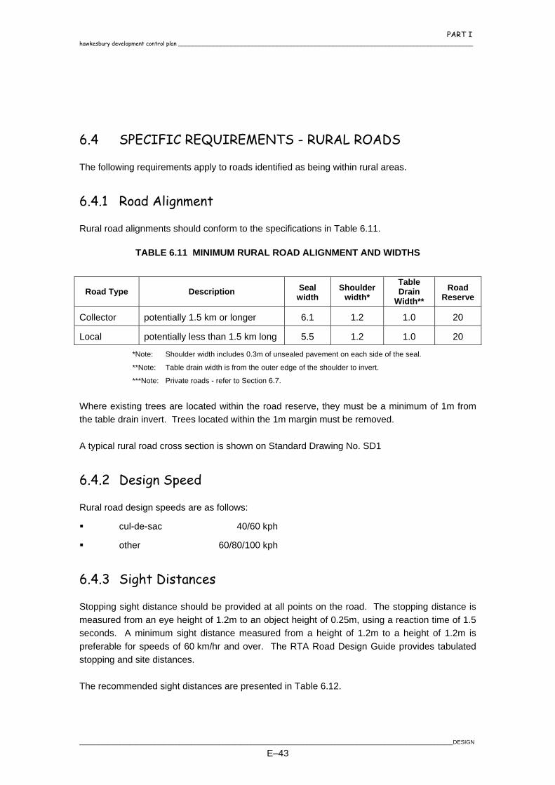
PART I hawkesbury development control plan ____________________________________________________________________________________
6.4 SPECIFIC REQUIREMENTS - RURAL ROADS
The following requirements apply to roads identified as being within rural areas.
6.4.1 Road Alignment
Rural road alignments should conform to the specifications in Table 6.11.
TABLE 6.11 MINIMUM RURAL ROAD ALIGNMENT AND WIDTHS
Road Type
Description Seal width
Shoulder width*
Table Drain
Width** Road
Reserve
Collector potentially 1.5 km or longer 6.1 1.2 1.0 20
Local potentially less than 1.5 km long 5.5 1.2 1.0 20
*Note: Shoulder width includes 0.3m of unsealed pavement on each side of the seal.
**Note: Table drain width is from the outer edge of the shoulder to invert.
***Note: Private roads - refer to Section 6.7. Where existing trees are located within the road reserve, they must be a minimum of 1m from the table drain invert. Trees located within the 1m margin must be removed. A typical rural road cross section is shown on Standard Drawing No. SD1
6.4.2 Design Speed
Rural road design speeds are as follows:
cul-de-sac 40/60 kph
other 60/80/100 kph
6.4.3 Sight Distances
Stopping sight distance should be provided at all points on the road. The stopping distance is measured from an eye height of 1.2m to an object height of 0.25m, using a reaction time of 1.5 seconds. A minimum sight distance measured from a height of 1.2m to a height of 1.2m is preferable for speeds of 60 km/hr and over. The RTA Road Design Guide provides tabulated stopping and site distances. The recommended sight distances are presented in Table 6.12.
________________________________________________________________________________________________________________________DESIGN
E–43
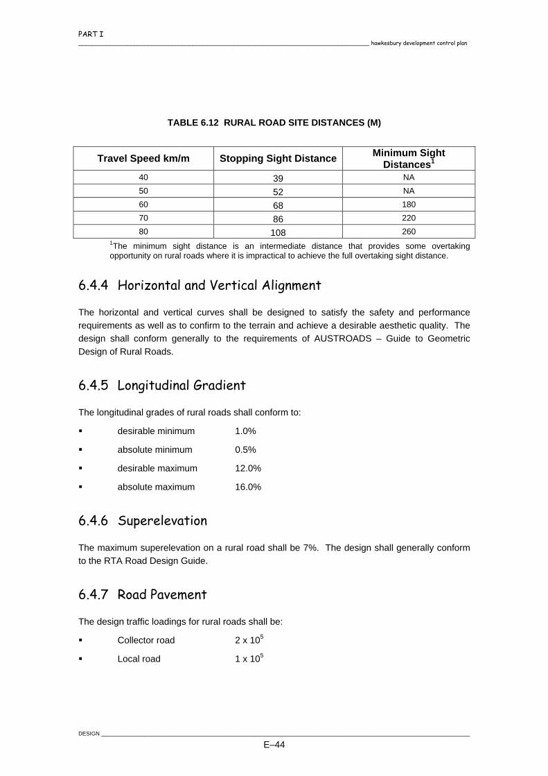
PART I ____________________________________________________________________________________ hawkesbury development control plan
TABLE 6.12 RURAL ROAD SITE DISTANCES (M)
Travel Speed km/m Stopping Sight Distance Minimum Sight Distances1
40 39 NA 50 52 NA 60 68 180 70 86 220 80 108 260
1The minimum sight distance is an intermediate distance that provides some overtaking opportunity on rural roads where it is impractical to achieve the full overtaking sight distance.
6.4.4 Horizontal and Vertical Alignment
The horizontal and vertical curves shall be designed to satisfy the safety and performance requirements as well as to confirm to the terrain and achieve a desirable aesthetic quality. The design shall conform generally to the requirements of AUSTROADS – Guide to Geometric Design of Rural Roads.
6.4.5 Longitudinal Gradient
The longitudinal grades of rural roads shall conform to:
desirable minimum 1.0%
absolute minimum 0.5%
desirable maximum 12.0%
absolute maximum 16.0%
6.4.6 Superelevation
The maximum superelevation on a rural road shall be 7%. The design shall generally conform to the RTA Road Design Guide.
6.4.7 Road Pavement
The design traffic loadings for rural roads shall be:
Collector road 2 x 10⁵
Local road 1 x 10⁵
DESIGN ________________________________________________________________________________________________________________________
E–44
PART I hawkesbury development control plan ____________________________________________________________________________________
The minimum pavement thickness and wearing course appropriate for each road classification is detailed in Section 7.
6.4.8 Scour Protection
Roadside drainage and table drains shall be designed to accommodate runoff and scour protection shall be provided as required due to the nature of the soils, gradients and volume of runoff. Protection works shall involve lined channels, turfing, rock pitching, grass seeding or any combination of these.
6.4.9 Table Drains
Table drains shall be aligned and graded parallel to the shoulders of the roadway and diverted at intervals not exceeding 150 metres or as may be shown on the plans, into culverts, side drains or watercourses. Where the grade of the table drain exceeds 5%, scour protection shall be provided.
6.5 ANCILLARY REQUIREMENTS
6.5.1 Signposting and Pavement Marking
Signposting and pavement marking should generally be provided to roads, intersections, traffic control devices, cycleways and carparks in accordance with AS 1742.1 - 13 Manual of Uniform Traffic Control Devices and the RTA "Interim Guide to Signs and Markings".
6.5.2 Street and Warning Signs
Street name signs shall be provided for all new roads and shall be erected at locations shown on the approved plans. Street name signs shall generally be in accordance with Section 13.1 of Council’s Civil Works Specification Part 2 Construction. “No Through Roads”, except those designated “Place” or “Close”, shall be provided with 200mm blades complete with the wording “NO THROUGH ROAD”. Regulatory signs shall be installed in locations shown on the approved plans and shall be made of Class 1 reflective material. Warning and/or advisory signs shall be erected at locations shown on the approved plans. Warning and advisory signs shall comply with AS 1742 Part 2 – “Traffic Control Devices for General Use” and AS 1743 – “Road Signs Specifications”.
________________________________________________________________________________________________________________________DESIGN
E–45

PART I ____________________________________________________________________________________ hawkesbury development control plan
6.5.3 Protective Measures
The term "guardrail" refers to any approved type of safety barrier. Safety barrier systems shall be provided in accordance with the current RTA Road Design Guide or where shown on the approved engineering plans. They shall conform to the RTA QA Specification R132 – Safety Barrier Systems and AS3845-1999:Road Safety Barrier Systems. Guide posts shall be erected at locations shown on the approved plans. The guide posts shall be painted white and be fitted with retro-reflective delineators. Guide posts shall comply with the requirements of RTA QA Specification R131 – Guideposts. The spacing and location of guide posts shall be in accordance with Cl. 3.2 of AS 1742.2.
6.5.4 Service Authorities
The Developer shall provide all Service Authorities with finished surface levels and/or up and down measurements from the top of kerb at the proposed property boundary and/or the proposed location of the Service Authorities pit, marker, etc. to ensure that:
All Service Authority conduits have correct cover.
All Service Authority pits, markers etc do not require future costly adjustments to suit driveways, footpaths etc.
It is advisable the Developer liaise with Service Authorities at any early stage of the development process to ensure that engineering designs are compatible with Service Authority's requirements.
6.5.5 Temporary Turning Facilities
Bus Routes When a designated bus route road is constructed in stages and the accumulated or initial length warrants a bus service, a temporary turning facility shall be provided at the end of the road in each stage. The turning facility must allow the bus to make a complete turn without the need to carry out a reversing manoeuvre.
Residential Streets When there is the likelihood of a delay in the construction of a further stage of a subdivision which creates dead ends of minimum 90 metres in length, a temporary 2 coat sealed gravel
DESIGN ________________________________________________________________________________________________________________________
E–46
PART I hawkesbury development control plan ____________________________________________________________________________________
turning facility shall be provided, preferably a hammer head or a turning circle in accordance with this Specification.
6.5.6 Parking
Generally parking areas shall designed in accordance with best industry practice and AS 2890 Parking Facilities. Particular attention should be made to the following design requirements.
Grades and crossfalls to be an absolute minimum of 1%, desirably 3% and an absolute maximum of 5%.
Drainage aspects, especially where the carpark area is used for on-site detention of stormwater and where pedestrian movements will be high.
Car space yield.
Circulation and aisle length.
Ingress and egress requirements.
6.5.7 Street Lighting
Street lighting shall be provided to all internal and perimeter subdivision or development roads generally in accordance with the current Integral Energy document "Design and Construction Standards for URD Subdivisions" or it's adopted replacement. Intersections, roundabouts and traffic control devices shall be adequately lit in accordance with the above requirements. Lighting of pedestrian underpasses, particularly ramp areas and overpasses/bridges where street lighting overspill is insufficient is required. All major collector roads shall have standard street lighting to reinforce the primary function of such roads. It is the Developer's responsibility to meet all costs associated with the design, supply and installation of the decorative street lighting fixtures in the nominated urban release areas.
6.5.8 Street Tree Planting
Generally, a tree shall be planted every seven (7) metres of road frontage. Where required by the Consent, a street tree planting plan shall be included as part of the landscape report submitted in accordance with Council's Landscape Policy requirements and conditions of consent or certificate.
________________________________________________________________________________________________________________________DESIGN
E–47

PART I ____________________________________________________________________________________ hawkesbury development control plan
The proposed street tree species shall be approved by Council's Arborist. Street trees planted by the Developer shall be maintained for 12 months following planting. The 12 month period will commence on receipt by Council of a letter from the approved landscape consultant advising that street trees have been planted in accordance with the Landscape Plan and Council's specification. Maintenance shall be in accordance with those practices identified in Council's Landscape Policy Guidelines. In lieu of street tree planting, the Developer may pay a contribution to Council in accordance with the fees and charges schedule in Council’s Management Plan for Council to supply, plant and establish the trees when housing construction is generally more than 70% complete. This procedure will significantly reduce the loss or damage of trees caused by builders and sub-contractors. Developers should be aware that Council has the power to impose on the spot fines of $200 under Section 629 of the Local Government Act for the injury, removal or destruction of trees on public land including road reserves.
6.6 ROAD BRIDGES
The design of structures such as bridges and retaining walls shall be carried out in accordance with the current relevant guidelines and standards (eg Austroads Bridge Design Code 1996) by a practising Civil/Structural Engineer with NPER certification. Certification from an independent Practising Civil/Structural Engineer with NPER certification will be required stating that the design has been carried out in accordance with the required guidelines and standards. Certification shall include the adequacy of the proposed formwork and construction methodology. Separate certification that construction has been carried out in accordance with the approved design will also be required. Bridges located in roadways shall be designed to convey the flood flows from the storm event identified in Section 8. Where no inundation of the bridge is permitted, an appropriate afflux dimension shall be adopted together with a 300mm freeboard to the underside of the deck. All bridges shall be certified as capable of withstanding the inundation loadings including debris loading for up to the 100 year ARI storm event. For strategic bridges, this design standard may be revised to less frequent storm events. Bridges which are inundated shall be designed to achieve a velocity times depth value which does not exceed values recommended in the Australian Rainfall and Runoff (IEAust) for vehicle stability in all storms up to the 100 year ARI event.
DESIGN ________________________________________________________________________________________________________________________
E–48

PART I hawkesbury development control plan ____________________________________________________________________________________
6.7 PRIVATE ACCESS ROADS AND RIGHT OF WAYS (ROW)
6.7.1 General
The requirements for accesses to private lots are shown in Table 6.13 below:
TABLE 6.13 REQUIREMENTS FOR ACCESS TO PRIVATE LOTS Pavement
Access Type Min.
Width Type Thickness Reinforcement Seal
Max. Grade
Residential A. Battle Axe (Single lot) 1. Within Road Reserve 3 2. Within Property
3.0m 2.5m
Concrete Concrete
100mm 100mm
1 x F72 1 x F72
N/A N/A
12% 25%
B. Multiple (Duplex & Battle Axe) 1. Within Road Reserve 4 2. Within Property
3.0m 2.5m
Concrete Concrete
150mm 150mm
2 x F72 2 x F72
N/A N/A
12% 25%
Industrial/Commercial
1. Within Road Reserve 4 2. Within Property
6.0m 6.0m
Concrete Concrete
150mm 150mm
2 x F72 2 x F72
N/A N/A
8% 16%
Rural A. Battle Axe/ Single Right of Way 5 1. Within Road Reserve 4 2. Within Property
3.5m
3.5m 3.5m 3.5m
3.5m 3.5m
Crushed Rock 2
Flexible Concrete Crushed Rock 2
Flexible Concrete
150mm Pavement Design 1 X 10⁴ 150mm 150mm Pavement Design 1 X 10⁴ 150mm
N/A N/A 2 x F72 N/A N/A 2 x F72
Unsealed Flush Seal N/A Unsealed Flush Seal N/A
8% 8% 8% 16% 20% 25%
B Multiple Right Of Way 6 1. Within Road Reserve 4
4.5m
4.5m
Crushed Rock 2
Flexible
150mm Pavement Design 1 x 10⁴
N/A N/A
Unsealed Flush Seal
8% 8%
________________________________________________________________________________________________________________________DESIGN
E–49
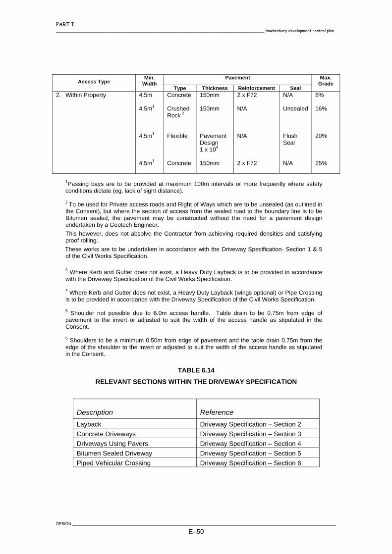
PART I ____________________________________________________________________________________ hawkesbury development control plan
Pavement Access Type
Min. Width
Type Thickness Reinforcement Seal
Max. Grade
2. Within Property 4.5m 4.5m1 4.5m1
4.5m1
Concrete Crushed Rock 2
Flexible Concrete
150mm 150mm Pavement Design 1 x 10⁴ 150mm
2 x F72 N/A N/A 2 x F72
N/A Unsealed Flush Seal N/A
8% 16% 20% 25%
1Passing bays are to be provided at maximum 100m intervals or more frequently where safety conditions dictate (eg. lack of sight distance). 2 To be used for Private access roads and Right of Ways which are to be unsealed (as outlined in the Consent), but where the section of access from the sealed road to the boundary line is to be Bitumen sealed, the pavement may be constructed without the need for a pavement design undertaken by a Geotech Engineer. This however, does not absolve the Contractor from achieving required densities and satisfying proof rolling. These works are to be undertaken in accordance with the Driveway Specification- Section 1 & 5 of the Civil Works Specification. 3 Where Kerb and Gutter does not exist, a Heavy Duty Layback is to be provided in accordance with the Driveway Specification of the Civil Works Specification. 4 Where Kerb and Gutter does not exist, a Heavy Duty Layback (wings optional) or Pipe Crossing is to be provided in accordance with the Driveway Specification of the Civil Works Specification. 5 Shoulder not possible due to 6.0m access handle. Table drain to be 0.75m from edge of pavement to the invert or adjusted to suit the width of the access handle as stipulated in the Consent. 6 Shoulders to be a minimum 0.50m from edge of pavement and the table drain 0.75m from the edge of the shoulder to the invert or adjusted to suit the width of the access handle as stipulated in the Consent.
TABLE 6.14
RELEVANT SECTIONS WITHIN THE DRIVEWAY SPECIFICATION
Description Reference Layback Driveway Specification – Section 2 Concrete Driveways Driveway Specification – Section 3 Driveways Using Pavers Driveway Specification – Section 4 Bitumen Sealed Driveway Driveway Specification – Section 5 Piped Vehicular Crossing Driveway Specification – Section 6
DESIGN ________________________________________________________________________________________________________________________
E–50

PART I hawkesbury development control plan ____________________________________________________________________________________
6.8 CONCRETE PAVING, FOOTPATHS AND CYCLEWAYS
6.8.1 Pathways
Concrete pathways shall be provided where required by the Consent. Such pathways are generally used to link common destinations, schools, shops and as overland flow paths. The following shall apply when designing pathways.
6.8.1.1 Path Paving
A minimum width of 1.2m generally parallel to the kerb and property line positioned 0.6m from the property line.
A desirable crossfall of 3% for pathways located on the nature strip.
Expansion joints of bitumen impregnated jointing material shall be provided at intervals not exceeding 6m with dummy joints provided every 1.2m.
Have a minimum grade of 0.5% and maximum grade of 25%.
Where grades exceed 16% pause platforms shall be provided.
6.8.1.2 Overland Flow Paths
Pathways between properties that generally link roads with other roads or developments shall be a minimum of 2.5m wide with a minimum crossfall of 2%
Overland flow paths shall generally have an integral 150mm kerb on the low side unless flows are of such a magnitude to warrant special treatment.
Overland flow paths shall have sufficient capacity to carry the flows with nominated freeboard.
Be provided with footpath barriers at either end at the property boundary line unless otherwise specified.
Have a minimum grade of 0.5% and maximum grade of 16%.
Where grades exceed 16% steps are required.
6.8.2 Cycleways
Consideration shall be given for cyclists in all aspects of road design. Cycleways and other provisions shall be included in the design where specifically nominated in the consent or the Council's Bicycle Strategy Plan.
________________________________________________________________________________________________________________________DESIGN
E–51
PART I ____________________________________________________________________________________ hawkesbury development control plan
Such designs shall generally comply with the requirements of the current Austroads Guide to Traffic Engineering Practice and the requirements of the RTA. Due consideration shall be given to the following:
Location, horizontal and vertical alignment.
Width and crossfall.
Drainage.
Signage.
Clearance to structures, vertical and lateral.
Projections into the cycleway (service pits etc) are to be avoided.
Maintenance and access crossings: thickening, reinforcing and highlighting of such areas.
The provision of adequate railings to bridges or similar structures including collapsible bollards to limit vehicular access.
6.8.3 Pram Ramps
Pram ramps shall be shown on the design plans at all street intersections, public reserves, pedestrian crossings. Pram ramps shall be constructed in accordance with Standard Drawing SD62 and shall have no lip at the invert level.
6.8.4 Concrete Steps
6.8.4.1 Gradient
Where natural or proposed surface gradient exceeds 16%, concrete steps are required. Any intermediate ramp section of pathway shall not exceed a longitudinal grade of 16% and shall be level in cross section unless otherwise specified. The number of steps required shall be determined generally to fit the ground profile.
6.8.4.2 Handrails
Handrails shall generally be required where any bank of steps exceeds four in number or where any grade adjacent to the pathway poses a potential danger to pedestrians. Handrailing shall also be provided where the fall height is greater than 1.5m and for large drainage pipe headwalls for pipe diameters of 1050mm or greater. Approved supporting posts are to be securely attached to the concrete and evenly spaced at not more than 2.4m intervals.
DESIGN ________________________________________________________________________________________________________________________
E–52

PART I hawkesbury development control plan ____________________________________________________________________________________
6.8.5 Service Locations
Where services cross roads, the face of kerb shall be marked directly over the service crossing and the kerb face painted as scheduled below.
Service Mark Colour Water W Blue Electricity E Red Telstra/Optus T/O Yellow Gas G Green
Marks shall be impressions in green concrete on the kerb, formed with 6mm diameter rod bent to the required letter shape.
________________________________________________________________________________________________________________________DESIGN
E–53
PART I ____________________________________________________________________________________ hawkesbury development control plan
7. PAVEMENTS
7.1 GENERAL
This section outlines the requirements for the design of road and carpark pavements. Pavement designs shall be calculated on a minimum design life of:
Flexible pavements, either unbound granular or containing one or more modified layers - 20 years.
Segmental block pavements - 20 years.
Rigid pavements (concrete) - 40 years. Pavement design criteria shall include but not be limited to the following:
Projected traffic loadings.
Subgrade evaluation.
Environmental factors.
Materials.
Construction methods. The road pavement shall be designed in accordance with the Austroads “Pavement Design Guide”. In deep cuttings, deep fills or other instances where testing of subgrade is possible only after bulk earthworks, a pavement design shall be required during construction and other pavement designs shall be reviewed upon reaching subgrade level.
7.2 DESIGN TRAFFIC LOADINGS
The design traffic loads for urban roads are specified in Table 6.8, and for rural roads in Table 6.11.
7.3 EVALUATION OF SUBGRADE STRENGTH
Investigation and testing shall be undertaken by a qualified practising Geotechnical Engineer through a NATA registered laboratory of the anticipated subgrade material and submission of a subsequent pavement design.
DESIGN ________________________________________________________________________________________________________________________
E–54
PART I hawkesbury development control plan ____________________________________________________________________________________
Assessment of the strength of the supporting subgrade shall be in accordance with Australian Road Research Board Special Report 41 (ARRB SR.41) Section 2. For minor works involving shoulder construction and/or kerb and gutter and the length of works does not exceed 15 metres in length and 2 metres in width the following pavement design procedure shall apply:
Two readings within 1 metre of each other at either end of the proposed works (4 readings total) of the exposed subgrade with a dynamic cone penetrometer shall be taken. The readings at either end shall be averaged and the lowest determined CBR shall be adopted for the pavement design.
The pavement thickness shall be designed in accordance with Section 7.5.
Pavement design reports shall include a discussion of the relevant matters under ARRB SR.41 with particular reference to extent of testing (Table ii) and site investigation and assessments (Table iv).
Written certification (on a NATA endorsed certificate) of the exposed subgrade conditions, their conformity with the original pavement investigation and design, material description, CBR value, requirements for replacement or modification of subgrade, extent of replacement and any other relevant information shall be required immediately following assessment and testing of the actual subgrade. If required the amended pavement design shall be submitted for approval.
7.4 SUBSURFACE DRAINAGE
Consideration must be given to the effects of moisture changes in the pavement and subgrade. Such variations will affect the design subgrade CBR and design life of the pavement. It is essential to provide adequate subsurface drainage.
7.5 PAVEMENT THICKNESS DESIGN
7.5.1 General
All public road pavements shall comprise of at least one sub-base and one base course layer. The minimum total pavement thickness shall be derived from this requirement and as specified below. It should be noted that where asphaltic concrete surfacing will be provided and this surfacing will be bonded for construction at a future date, then the total pavement thickness shall be designed excluding any contribution that the asphaltic concrete may provide towards the pavement strength.
________________________________________________________________________________________________________________________DESIGN
E–55

PART I ____________________________________________________________________________________ hawkesbury development control plan
7.5.2 Sub-Base Course
The sub-base shall consist of crushed or ripped sandstone, either 75mm or 100mm nominal size, derived from a well cemented, medium grained quartz sandstone free from overburden, clay seams, shale and other deleterious material. Alternatively, a sub-base material satisfying the requirement for a class “DGS” material as specified in RTA QA Specification 3051 – Unbound and Modified Base and Sub-base Materials for Surfaced Road Pavements and RTA QA Specification 3052 – Material to be Bound for Base and Sub-base Materials for Surface Road Pavements. The minimum compacted thickness of the sub-base course shall be 200mm of sandstone or 175mm of “DGS” material.
7.5.3 Base Course
The base course material shall satisfy the requirements for a class “DGB 20” material as specified in Section 7.3 of the Civil Works Specification Part 2 Construction. Alternatively, where shown in the Documents, the base course material shall consist of crushed or ripped sandstone, either 50mm of 75mm nominal size, derived from a well cemented medium grained quartz sandstone free from overburden, clay seams, shale and other deleterious material. Crushed sandstone however, may only be used as a base course material where the wearing surface consists of a single coat flush seal and a minimum of 25m of asphaltic concrete or the sandstone is stabilised using cement or lime as determined from test results from a NATA registered geotechnical laboratory. The minimum compacted thickness of the base course shall be 100mm for “DGB 20” material or 150mm for sandstone.
7.5.4 Stabilisation of Insitu and Imported Materials
In the construction of roads in rural areas, it may be possible to stabilise the pavement material to provide the required pavement. A pavement design shall be submitted to the certifying authority for consideration, and shall include details of the type and quantity of stabilising agent to be used to obtain an Unconfined Compressive Strength of 1.5 MPa and the proposed depth of stabilising. The minimum thickness of any stabilised pavement shall be 250mm.
DESIGN ________________________________________________________________________________________________________________________
E–56

PART I hawkesbury development control plan ____________________________________________________________________________________
7.5.5 Shoulders
For roads in rural areas, road shoulders shall consist of the road pavement sub-base material, with the exception of the top 100mm which shall consist of either DGB20 or a nominal 200mm crushed shale material.
7.5.6 Accessway Pavements
Accessways by definition will serve up to 10 dwellings and shall only be permitted where specified by the Consent, and shall be constructed from stencilled concrete or pavers only. Accessways shall be designed in accordance with Austroads APRG Rpt 21-A Guide to the Design of Pavements for Light Traffic.
7.5.6.1 Rigid Pavements
Design requirements shall be in accordance with the Cement and Concrete Association of Australia document "Concrete Street and Parking Area Pavement Design" (1984).
Minimum sub-base courses of 125mm bound or 150mm unbound and minimum concrete pavement thickness of 150mm with two layers of F72 mesh shall apply.
The use of bound pavement layers shall only be permitted under concrete pavements.
Joint layout and types for concrete accessways and thresholds shall be in accordance with Section 6.8 of the Civil Works Specification Part 2 Construction.
7.5.7 Roundabout Pavements
7.5.7.1 Full Depth Asphalt Pavement
Roundabouts may have pavements constructed in full depth asphalt (FDA) where the design traffic does not exceed 5 x 10⁵ ESAs (before factoring). Austroads Pavement Design Manual 1992 shall be used for thickness design. A wearing surfacing of minimum thickness 60mm SBS polymer modified asphalt and a bottom course of high bitumen content asphalt shall be used. The pavement design report shall include justification of the selection of asphalt modulus values used in the design.
7.5.7.2 Rigid Pavement
Where the design traffic exceeds 5 x 10⁵ ESAs and where the design subgrade CBR is less than 5, the required pavement shall be a rigid pavement, consisting of a steel fibre reinforced concrete (SFRC) base course over a lean mix concrete sub-base course in accordance with the RTA Guide to Design and Construction of Concrete Roundabouts. The wearing surface shall be
________________________________________________________________________________________________________________________DESIGN
E–57

PART I ____________________________________________________________________________________ hawkesbury development control plan
a minimum of 50mm AC10. The Austroads Pavement Design Manual 1992 shall be used for thickness design. The use of unbound or bound granular materials shall not be permitted for roundabout pavements.
7.5.8 Carpark Pavements
Wearing surfaces shall only comprise of either:
Asphaltic Concrete.
Rigid pavement.
Segmental block paving. Particular attention shall be made to the following:
Carpark geometry shall not place undue loading to bituminous surfacing. Modified asphalt may be warranted.
Correct design traffic shall be used where aisles within carparks will service other adjacent commercial, retail, industrial centres or loading zones.
All loading zones shall be constructed in concrete or concrete segmental block paving to resist damage from diesel and fuel spills. Paving colours should be mottled to mask spill marks.
7.6 WEARING COURSE
The wearing course shall be applied in accordance with the approved pavement design. The minimum wearing course to be provided for the various road hierarchy levels is detailed in Table 7.1.
TABLE 7.1 MINIMUM WEARING COURSE
Land Use Road Classification Wearing Course Residential Local – Collector 25mm AC10 Roundabout 50mm AC10 Cul-de-sac 50mm AC10 Sub-arterial, Arterial 50mm AC10 Commercial All 30mm AC10 Industrial All 50mm AC10 Rural All 2 coat flush seal 14/10mm
DESIGN ________________________________________________________________________________________________________________________
E–58

PART I hawkesbury development control plan ____________________________________________________________________________________
8. STORMWATER DRAINAGE
8.1 SCOPE
This section details Council's requirements for the design of stormwater drainage for urban and rural areas. It is in no way a comprehensive design manual and it is intended to be read in conjunction with and as a supplement to the 1987 edition of Australian Rainfall and Runoff (AR&R) and the DOH Managing Urban Stormwater (1998) Guidelines.
8.2 AIM
The design and construction of a drainage system that provides the following:
a high level of safety for all users;
acceptable levels of amenity and protection from the impact of flooding; and
economy of construction and maintenance.
8.3 GENERAL REQUIREMENTS
All drainage, whether internal or external to the site, relevant or reasonably required in respect of the proposed development shall be provided to Council's requirements at the Developer's cost. A stormwater drainage system shall be provided in accordance with the "major/minor" system concept set out in Chapter 14 of AR&R (1987); that is, the "major" system shall provide safe, well-defined overland flow paths for rare and extreme storm runoff events while the "minor" system shall be capable of carrying and controlling flows from frequent storm runoff events. All drainage is to be designed in accordance with this specification, and to satisfy the specific requirements of the Consent. Drainage lines shall be constructed so that their centreline coincides with the centreline of the wall of the drainage structure or as detailed on the approved plans. Where constructed under the kerb and gutter, pipes shall not extend beyond the back edge of the kerb. Drainage lines within proposed drainage easements shall be centrally located and no segment of a pipe, culvert or drainage structure shall be constructed outside the easement boundaries.
________________________________________________________________________________________________________________________DESIGN
E–59

PART I ____________________________________________________________________________________ hawkesbury development control plan
Notwithstanding the extent of the drainage shown on the approved plans, additional drainage may be required if, during construction of the works, undisclosed features affect the proposed drainage. One class of pipe only shall be used in constructing or extending any culvert or pipeline section, or between any two structures. In general, drainage works shall be constructed by the Developer in accordance with the following:
8.3.1 Drainage in Urban Areas
Minor System The general requirements of a minor urban system are.
Kerb and gutter shall be provided on both sides of all roads except where the consent or certificate advises otherwise.
Kerb inlets shall be provided at locations such that the flow in the gutter does not exceed the specified limits.
Where allotments slope to the rear, inter-allotment drainage shall be provided at the lowest point of all allotments, together with the creation of an easement over all downstream pipework to the legal point of discharge.
Full piped drainage from all kerb inlets and other inlets shall be provided to the boundary of the subdivision, or approved point of discharge, or as required by the Consent.
Minimum pipe sizes shall be:
100mm diameter for pipes draining roofwater; and
150mm diameter for pipes draining paved areas such as driveways and car parks and any landscaped areas, where a surcharge path exists.
225mm diameter for pipes draining paved areas such as driveways and car parks and any landscaped areas, where a surcharge path does not exist.
Plans shall show existing and proposed surface levels, as well as levels of adjoining lots where there is to be site filling. Plans shall show pipe sizes and grades and invert levels, including point of connection to Council's stormwater system.
DESIGN ________________________________________________________________________________________________________________________
E–60

PART I hawkesbury development control plan ____________________________________________________________________________________
Cover requirements shall be:
100mm and thickness of the slab in any area where pipes will be protected by reinforced concrete pavement.
300mm in any unpaved area subjected only to pedestrian traffic or paved traffic areas.
600mm in any unpaved area likely to be traversed by motor vehicles. Pipes 300mm diameter or greater shall be reinforced concrete, sewer grade PVC or fibre reinforced cement.
Major System An overland flow system shall be provided for runoff in excess of the capacity of the
pipe system, such that the design flow is carried safely through the subdivision or development clear of, and with the required freeboard, to allotments.
Overland flow paths will not be permitted within urban allotments, unless required by the consent or certificate.
The Consent may require the submission of a flood study in the following circumstances:
To determine whether the proposed method of stormwater discharge would have a detrimental effect upon neighbouring lands.
To determine whether the existing or proposed stormwater discharge shall have the potential to cause overland flood inundation problems on the property.
Where the proposed development will divert runoff from its existing catchment to a different catchment.
The Developer shall to submit a flood study that calculates the 1 in 100 year Average Recurrence Interval flood level. The study shall be carried out by a qualified Civil Engineer with documented experience in hydraulic analysis. Design calculations shall be submitted showing the impact of the proposal on the adjacent area, and shall be accompanied by a catchment plan, showing contours, at a scale of 1:2000 or 1:4000, together with survey cross sections of the overland flow path.
8.3.2 Drainage in Rural Areas
Minor System Pipe or concrete box culverts, bridges or concrete causeways shall be provided at
road crossings over natural watercourses or where dictated by the capacity of the table drain. Where the flow is discharged into private property, the structure shall be extended to the property line and the outlet headwall or structure placed at the property line. Where the system is to discharge into a table drain to flow to a mitre
________________________________________________________________________________________________________________________DESIGN
E–61

PART I ____________________________________________________________________________________ hawkesbury development control plan
drain further downstream, the outlet structure shall be placed at the invert of the table drain. Where services are underground, then these services shall be carried over the structure in a services corridor. The drainage design shall consider the possible blockage caused by debris load from the catchment.
Table drains and letterbox style grated surface inlet pits shall be provided on the cut side of roads, within the road reserve, together with stone pitching or concrete lining where required for scour protection.
Minimum pipe sizes shall be:
300mm in private access ways and driveways;
375mm in public roads.
Major System An overland flow system shall be provided for runoff in excess of the capacity of the
pipe system, such that the design flow is carried safely through the subdivision or development clear of, and with the required freeboard, to building platforms.
Where a development involves site regrading in a flood plain or adjacent to a natural watercourse where the ground level is below the 1 in 100 year recurrence interval, a flood study shall be submitted in accordance with Section 8.3.1.
8.4 LAWFUL POINT OF DISCHARGE
Urban development generally modifies the naturally occurring drainage regime by increasing the volume and rate of runoff, sometimes diverting flow between natural catchments, modifying existing flow paths and concentrating flow along drainage paths and at outlets. These changes may affect the safety, amenity and enjoyment of persons and property and may result in legal disputes. Legal problems arising from the planning and proposed construction of drainage works need to be negotiated and resolved with adjoining owners, and any other landowners who could be detrimentally affected, before approval of the works can be granted by Council. In this regard, Council will require that a lawful point of discharge exists prior to approval of a development. In order to determine whether a lawful point of discharge exists at a particular location the following two points must be satisfied: (a) That the location of the discharge is under the lawful control of Council or other
statutory authority from whose permission to discharge has been received. This will include drainage reserve, road reserve, or stormwater drainage easement; and
DESIGN ________________________________________________________________________________________________________________________
E–62

PART I hawkesbury development control plan ____________________________________________________________________________________
(b) That in discharging in that location, the discharge will not cause an actionable nuisance (i.e. a nuisance for which the current or some future neighbouring proprietor may bring an action or claim for damages arising out of the nuisance).
Where the conditions of the first test have not been satisfied prior to development, it will be necessary to obtain a lawful point of discharge. This will usually be achieved by the creation of a drainage reserve, or acquisition of a drainage easement over one or more downstream properties until the conditions of the second test have been met. It should be noted that a natural watercourse may not necessarily constitute a lawful point of discharge, unless the requirements of the above two tests can be satisfied.
8.5 DRAINAGE RESERVES/EASEMENTS
Where a natural open channel or similar overland flowpath exists in a proposed development, a drainage reserve shall be provided to contain the design flow within the actual drainage reserve area. The minimum width of the reserve shall be 5 metres. Where stormwater drainage has been approved within allotments, a drainage easement shall be created or acquired. The width of easements benefiting Council shall be in accordance with Table 8.1 and the width of inter-allotment drainage shall be in accordance with Table 8.2.
TABLE 8.1 MINIMUM EASEMENT WIDTH FOR COUNCIL DRAINAGE
Drainage Width Easement Width (m)
375mm - 600mm diameter 2.5
700mm - 900mm diameter 3.0
1050mm – 1350mm diameter 3.5
>1350mm diameter Width of the system plus 2.0 metres
TABLE 8.2 MINIMUM EASEMENT WIDTH FOR INTER-ALLOTMENT DRAINAGE
Drainage Width Easement Width (m)
150mm - 225mm diameter 1.2
300mm diameter 2.5
________________________________________________________________________________________________________________________DESIGN
E–63

PART I ____________________________________________________________________________________ hawkesbury development control plan
8.6 HYDROLOGY
A number of methods are available for the determination of flow rate, runoff, volume and catchment response.
The Rational Method - This method provides a simple means for the assessment of design peak flow rate (peak discharge).The rational method is not acceptable for the design of detention basins.
ILSAX or DRAINS - These are computer based models which involve the routing of the time-area relationship developed for the sub-catchments under consideration. They are suitable for use in urban catchments but require calibration with available flow data. Technical Note 7 in Chapter 14 of AR&R (1987) provides an example of the use of ILSAX.
RAFTS - This is a proprietary computer model based upon the Regional Stormwater Model (RSWM). It includes separate routing of impervious and pervious areas; sophisticated loss models; urban runoff modelling and detention basin design; and provision for river basin analysis.
Other models used are AWBM, XP-UDD and RORB. Other hydrological models may be used as long as the requirements of AR&R (1987) are met. Council will require the submission of detailed calculations, together with details of all program inputs and outputs in digital and hard copy form.
8.7 DESIGN AVERAGE RECURRENCE INTERVALS (ARI)
For drainage design under the "major/minor" concept, the ARI's shall be in accordance with Table 8.3.
TABLE 8.3 DESIGN AVERAGE RECURRENCE INTERVALS
Location Minor System (Years) Major System (Years)
Residential 5 100
Commercial/Industrial 20 100
An overland flow path shall be provided for drainage systems even where the 100 year ARI flows can be maintained within the pipe system.
DESIGN ________________________________________________________________________________________________________________________
E–64
PART I hawkesbury development control plan ____________________________________________________________________________________
8.8 TIME OF CONCENTRATION
The time of concentration (tc) of a catchment is defined as the time required for the stormwater runoff to flow from the most remote part (relative to time) of the catchment to its outlet. In determining the time of concentration, the Developer should assume that the catchments under consideration are fully developed in accordance with the land use shown on the relevant Zoning Maps. In a typical urban drainage system it will be necessary to calculate the time of concentration for inlet location and pipe sizing. Regardless of the purpose of the time of concentration calculation, it will include one or a number of the following components:
Overland or 'sheet' flow time.
Roof to drainage system flow time.
Gutter or channel flow time.
Pipe flow time. Where the flow path is through areas having different flow characteristics, the flow time of each portion of the flow path shall be calculated separately. The minimum time of concentration should not be less than 5 minutes for the total flow travel time from any catchment to its point of entry into the drainage network. The maximum time of concentration in urban areas shall be 20 minutes unless sufficient evidence is provided to justify a greater time. For commercial, industrial and medium density developments, the time of concentration shall be taken as 6 minutes.
8.9 RAINFALL INTENSITIES
The Design Intensity-Frequency-Duration (IFD) Rainfall is required as input to the hydrological model used for the drainage design.
8.9.1 Read from Tables
The IFD values to be used for hydrological design across the Hawkesbury LGA are covered by two tables. The first table is for areas on or adjacent to the floodplain, and covers all localities from St. Albans in the north-east to Kurrajong in the west. The second table covers the localities in the foothills of the Great Dividing Range, namely Bowen Mountain, Kurrajong Heights, Bilpin, Berambing, Mountain Lagoon and adjacent localities. The IFD values for the above regions are listed in Tables A1 and A2 in Section 10.
________________________________________________________________________________________________________________________DESIGN
E–65

PART I ____________________________________________________________________________________ hawkesbury development control plan
8.9.2 Calculate using AR&R Method
Alternatively, the IFD Rainfall for the catchment under consideration may be derived in accordance with Chapter 2 (Volume 1) of AR&R (1987). The nine basic parameters read from the Maps in Volume 2 of AR&R (1987) shall be shown in the calculations submitted to Council, unless the Bureau of Meteorology provides a polynomial relationship for the catchment. For commercial, industrial and medium density developments, the design rainfall intensity shall be the 20 year 6 minute event calculated at 157mm/hour.
8.10 RUNOFF COEFFICIENT
The coefficient of runoff (C) is the coefficient used in the Rational Method and is the ratio of the peak rate of runoff to the average rainfall intensity during the critical rainfall period for the catchment area under consideration. The value of C is a statistical composite not only for the infiltration and other losses, but also the effects of channel storage and initial loss. The coefficient of runoff adopted shall account for the future development of the catchment in accordance with the land use shown on the relevant Zoning Maps. For urban and rural areas the coefficient of runoff shall be calculated in accordance with the methods given in AR&R (1987). For commercial, industrial and medium density developments, the coefficient of runoff shall be 0.95 unless site conditions dictate differently (eg large landscaped areas).
8.11 CATCHMENT AREA
The catchment area of any point may be determined from contour plans obtained from the detailed survey of the site. Where no detailed survey is available, 1:4000 orthophoto maps may be used to determine catchment boundaries and areas. The determination of sub-catchments within urban subdivisions requires accurate contour information and a catchment plan shall be provided with the calculations. The design should take into account realistic future road patterns where the contributing catchment includes areas subject to future development. Where a site presently drains to two or more catchments, and the proposed development involves regrading which will change the percentages of the site which drain to each of the catchments, the variation of runoff patterns must be addressed at the development assessment stage, and a flood study prepared in accordance with Section 8.3.
DESIGN ________________________________________________________________________________________________________________________
E–66
PART I hawkesbury development control plan ____________________________________________________________________________________
8.12 HYDRAULICS
Hydraulic calculations shall generally be carried out in accordance with Australian Rainfall and Runoff(1987). The detailed hydraulic grade line method is recommended for the analysis of stormwater pipe systems based on an analysis proceeding from downstream to upstream through the system. Calculations shall substantiate the hydraulic grade line adopted for the system and shown on the drawings. The downstream water surface level shall be in accordance with the following:
The hydraulic grade line level from downstream calculations including pit losses at the starting pit in the design storm event, or
A level of 0.15 metres below the invert of the pit inlet in the downstream pit where the downstream starting point is a pit and the hydraulic grade line level is unknown; or
The top of the outlet pipe for the minor event where the outlet is an open channel, or
The top of the outlet pipe for the major event where the outlet is an open channel and the flood levels are not known; or
The 1 :100 year flood level for the major event where the outlet is an open channel and the downstream flood levels are known.
The Certifier shall require the submission of detailed calculations, together with details of all program inputs and outputs in both digital and hard copy format.
8.13 MINOR DRAINAGE SYSTEM CRITERIA
The minor drainage system shall be capable of controlling flows from frequent runoff events up to and including the ARI's shown in Section 8.7. The roadway flow width shall not exceed 0.45 metres at bus stops, pedestrian ramps and kerb returns, and 2.5 metres at other locations. The widths mentioned above shall be measured from invert of the kerb. The product of depth (dg) and velocity (Vave) for flow in the gutter should not exceed 0.6 m2/s (AR&R - 1987) to reduce the hazard for pedestrians within the roadway. However, where there is an obvious danger of injury or loss of life, the dgVave product should be limited to 0.4 m2/s. The water surface level for inlet pits shall be 0.15 metres below the invert of the gutter or 0.15 metres below the underside of the lid for junction pits.
________________________________________________________________________________________________________________________DESIGN
E–67

PART I ____________________________________________________________________________________ hawkesbury development control plan
8.14 MAJOR DRAINAGE SYSTEM CRITERIA
The major drainage system in the form of overland flowpaths shall be capable of controlling flows which exceed the capacity of the minor drainage system from runoff events up to and including the ARI's shown in Section . Minor system blockages shall be assessed when designing for the major event. The product of depth (dg) and velocity (Vave) in the kerb and gutter should not exceed 0.6 m2/s (AR&R - 1987) to reduce hazard for pedestrians within the roadway. However, where there is an obvious danger of injury or loss of life, the dgVave product should be limited to 0.4 m2/s. The following requirements shall be provided in open channels, roadways and stormwater surcharge paths.
Generally Overland flow paths shall not be located in private property.
Roadways/Pathways Total flow shall be contained within the road reserve.
Flow depths in roadways/pathways shall not exceed 200mm.
A minimum freeboard of 300mm shall be provided between the 100 year flood level in the roadway or pathway and habitable floor levels.
Where a road is in fill, a freeboard of 100mm shall be provided between the 100 year flood level in the road and the lowest point in the footpath.
Open Channels A minimum freeboard of 500mm shall be provided between the 100 year flood level in
the channel and habitable floor levels. Where the above requirements can not be met for "in-fill" type subdivisions, the Developer may make a submission justifying why the above requirements, could be relaxed.
8.15 ROADWAY FLOW CAPACITY
Roadway flow capacity shall be calculated by the method presented by Technical Note 4 in Chapter 14 of AR&R (1987). Table 8.4 provides the recommended values for Manning's Roughness Coefficient (n) and Flow Correction Factor (F).
DESIGN ________________________________________________________________________________________________________________________
E–68

PART I hawkesbury development control plan ____________________________________________________________________________________
TABLE 8.4 MANNINGS ROUGHNESS COEFFICIENT (N) AND FLOW CORRECTION FACTOR (F)
Roadway Surface Type n
Concrete 0.013
Asphaltic Concrete 0.015
Sprayed Seal 0.018
Kerb and Gutter Type F
Roll over 0.9
150mm Integral 0.9
8.16 PITS
There are generally six types of drainage structures accepted by Council for use in public land, they are:
Kerb Sag Pits;
Kerb Inlet Pits;
Surface Inlet Pits (grated or letterbox style);
Junction Pits;
Discharge Control Pits; and
Headwalls. Pits shall be located at junctions, kerb returns, sag points and changes in grade, level, direction, pipe size or pipe class. Kerb inlet pits shall be located so that the gutter flow width is in accordance with the requirements of Section 8.13 and at a maximum spacing of 90 metres where flow widths are not critical. Kerb inlet pits shall not be located within kerb returns, or permitted to encroach over the kerb return tangent point. Surface inlet pits shall be located in drainage reserves, overland flow paths and parks. The theoretical inflow capacity of the drainage pits shall be estimated in accordance with AR&R, 1987. A blockage factor should be applied to the theoretical inflow capacity obtained in accordance with Table 8.5.
________________________________________________________________________________________________________________________DESIGN
E–69

PART I ____________________________________________________________________________________ hawkesbury development control plan
TABLE 8.5 PROVISION FOR BLOCKAGE IN DRAINAGE PITS
Condition Pit Type Theoretical Capacity Allowed
Continuous Grade Kerb Inlet Pit 80%
Sag Kerb Sag Pit 50%
Surface Inlet Pit Cover Surface Inlet Pit 50%
Surface Inlet Pit Cover with legs Letterbox Inlet 80% Pit sizes shall be in accordance with Table 8.6.
TABLE 8.6 MINIMUM SIZES FOR DRAINAGE PITS
Pit Type Minimum Size
Urban (kerb and gutter)
-depth to invert up to 1500mm 900mm x 600mm
-depth to invert greater than 1500mm 900mm x 900mm
Rural 900mm x 900mm Internal (within developments)
-depth to invert up to 750mm 450mm x 450mm
-depth to invert greater than 750mm 900mm x 600mm
A minimum opening of 1.8 metres shall be provided for kerb inlet pits.
The use of precast pits shall only be permitted within development sites. All external drainage pits must be cast in-situ.
Step irons shall be provided in all pits deeper than 1.2m.
Reinforcement shall be provided in pit walls where the depth to the pit invert exceeds 1.8m, and where the depth exceeds 3.0m, the design of such reinforcement shall be certified by a Practising Structural Engineer.
8.17 CULVERTS
Piped and box culverts shall be constructed where specified on the approved plans and should be designed in accordance with the following:
As an overall gravity system with due regard to the upstream and downstream system and inlet/outlet controls.
DESIGN ________________________________________________________________________________________________________________________
E–70

PART I hawkesbury development control plan ____________________________________________________________________________________
Pipes shall be determined using the Colebrook-White formula with the recommended roughness coefficients referred to in Table 8.7.
Table 8.7 Recommended Roughness Coefficients (K)
Pipe Material Recommended K value (mm)
UPVC 0.03
VCP 0.04
RHS 0.046
FRC 0.06
RCP 0.06
Minimum pipe culvert size in Council property of 375mm diameter.
Minimum box culvert size in Council property of 600mm wide by 300mm high.
A minimum grade of 0.5 % shall be provided for self cleansing purposes under low flow velocities.
The maximum grade of pipelines shall be in accordance with Table 8.8.
TABLE 8.8 Acceptable Maximum Pipe Grades
Pipe Diameter (mm) Maximum Grade (%)
375 15.0
450 11.0
525 9.0
600 7.5
675 6.5
750 5.5
900 4.5
1050 3.5
1200 3.0
1380 2.5
1500 2.2
1650 2.0
1800 1.7
1950 1.5
2100 1.4
2250 1.3
2400 1.2
________________________________________________________________________________________________________________________DESIGN
E–71
PART I ____________________________________________________________________________________ hawkesbury development control plan
Where grades exceed 15.0 %, bulkheads shall be provided in accordance with Section 5.12 of Council's Civil Works Specification Part 2 Construction.
The minimum velocity in the pipe and box culverts shall be 0.6m/s for self cleansing purposes.
The maximum velocity of shall be 6m/s for scouring protection.
Pipelines within roadways shall be generally located under the face of kerb.
A downstream pipeline of smaller diameter than the upstream shall not be permitted.
All pipe inlets shall enter the main pipe system at junction pits and shall be cut flush and grouted into the pit wall.
8.18 HYDRAULIC LOSSES
Hydraulic losses shall be determined for the following:
The pressure change coefficient (Ke) for pit losses.
Obstruction or penetration losses. Pipe friction losses shall be determined using the Colebrook-White formula with the acceptable roughness coefficients mentioned in Table 8.7.
8.19 OPEN CHANNELS
Open channels shall be provided to convey flows from the major storm event from a development site to the receiving water body. The design shall be generally in accordance with Chapter 14 of AR&R (1987). Friction losses shall be determined using the recommended Manning’s "n" values (where applicable) referred to in Table 8.9. The typical numerical models used to simulate the open channel and culvert hydraulics are RATHGL (RAT 2000), XP-UDD, HEC-RAS, RMA, MIKE 11, CULVERT, EXTRAN and SWMM. Other models may be used as long as the requirements of AR & R (1987) are met.
DESIGN ________________________________________________________________________________________________________________________
E–72
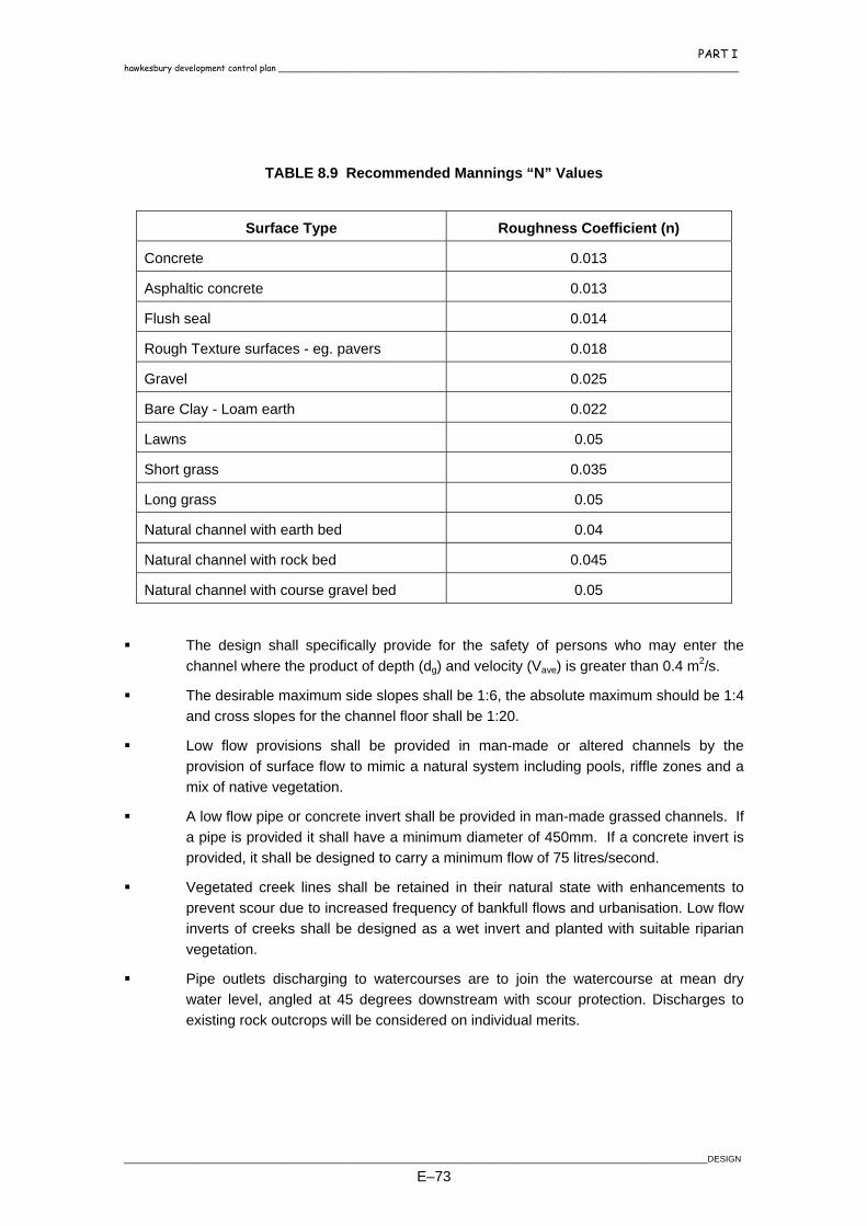
PART I hawkesbury development control plan ____________________________________________________________________________________
TABLE 8.9 Recommended Mannings “N” Values
Surface Type Roughness Coefficient (n)
Concrete 0.013
Asphaltic concrete 0.013
Flush seal 0.014
Rough Texture surfaces - eg. pavers 0.018
Gravel 0.025
Bare Clay - Loam earth 0.022
Lawns 0.05
Short grass 0.035
Long grass 0.05
Natural channel with earth bed 0.04
Natural channel with rock bed 0.045
Natural channel with course gravel bed 0.05
The design shall specifically provide for the safety of persons who may enter the channel where the product of depth (dg) and velocity (Vave) is greater than 0.4 m2/s.
The desirable maximum side slopes shall be 1:6, the absolute maximum should be 1:4 and cross slopes for the channel floor shall be 1:20.
Low flow provisions shall be provided in man-made or altered channels by the provision of surface flow to mimic a natural system including pools, riffle zones and a mix of native vegetation.
A low flow pipe or concrete invert shall be provided in man-made grassed channels. If a pipe is provided it shall have a minimum diameter of 450mm. If a concrete invert is provided, it shall be designed to carry a minimum flow of 75 litres/second.
Vegetated creek lines shall be retained in their natural state with enhancements to prevent scour due to increased frequency of bankfull flows and urbanisation. Low flow inverts of creeks shall be designed as a wet invert and planted with suitable riparian vegetation.
Pipe outlets discharging to watercourses are to join the watercourse at mean dry water level, angled at 45 degrees downstream with scour protection. Discharges to existing rock outcrops will be considered on individual merits.
________________________________________________________________________________________________________________________DESIGN
E–73

PART I ____________________________________________________________________________________ hawkesbury development control plan
8.20 BRIDGES AND CULVERTS
Bridges and major culverts shall be designed for the 100 year ARI storm event without afflux in urban areas. A minimum clearance of 0.3 metres should be provided between the major flow level and the underside of a major structure to allow for passage of storm debris.
8.21 ON-SITE STORMWATER DETENTION
8.21.1 Policy
Onsite detention of stormwater runoff shall be provided for certain developments to avoid the incidence of flooding arising from increased flows discharging into the piped drainage system. These increased flows result from the construction of developments that have a greater impervious area and higher development densities than those that were considered when the piped systems were initially designed. On-site detention shall be provided in the catchments and locations for the developments specified below in Table 8.10.
TABLE 8.10 DEVELOPMENTS REQUIRING ON-SITE DETENTION
Type of Development
Location Indu
stria
l
Com
mer
cial
Med
ium
D
ensi
ty &
D
ual
Occ
upan
cy
Res
iden
tial
(whe
re
incr
ease
in
impe
rvio
us
area
> 5
0 sq
.m)
McGraths Hill Yes Yes Yes Yes Mulgrave industrial area No N/A N/A N/A Windsor, South Windsor Yes Yes Yes Yes Wilberforce Yes Yes Yes Yes East Richmond Residential areas Yes Yes Yes Yes Bowman Street industrial area Yes Yes N/A N/A Lukis Avenue industrial area Yes Yes N/A N/A
Richmond within S94 Catchment No. 1 No No No No outside S94 Catchment No. 1 Yes Yes Yes Yes
North Richmond within S94 Catchment No. 6 No No No No outside S94 Catchment No. 6 Yes Yes Yes Yes
DESIGN ________________________________________________________________________________________________________________________
E–74

PART I hawkesbury development control plan ____________________________________________________________________________________
8.21.2 Design of Systems
Unlike the majority of Council areas who use on-site detention to reduce the impact of development on the trunk drainage systems for major storm events (up to 100 year ARI), the majority of developed areas within the Hawkesbury LGA are surrounded by floodplain and hence do not suffer trunk drainage impacts from developments. The major impact is seen in the piped drainage systems, most of which were designed decades ago when the “quarter acre block” was the standard lot layout. Therefore, in the design of on-site detention systems for developments within the Hawkesbury LGA, consideration must not only be given to the higher recurrence interval storms, but special consideration needs to be given to ensure that the post-development flowrates for the lower recurrence interval storms are kept below the specified values. Detention basins may be designed as above ground (driveways, landscaped or recreation areas), or as below ground (underground tanks or pipelines) systems. The requirements for each of these types of systems are set out in Section 8.21.6. In the preparation of an on-site detention design, designers must consider not only the flows from the site, but where significant, flows from adjoining and upstream properties must be incorporated into the design. To provide designers with flexibility in the preparation of on-site detention designs, two options are available for the sizing of storage volumes and site discharges. These are: Option 1: Prepare the design from first principles, using a recognised method or software
package, and match the pre-development flowrate to the post-development flowrate for all recurrence intervals from the 1 year event to the 100 year event. That is, the 1 year post-development flowrate must be restricted to the 1 year pre-development flowrate, the 2 year post-development flowrate must be restricted to the 2 year pre-development flowrate, and so on up to the 100 year post-development flowrate being restricted to the 100 year pre-development flowrate.
Option 2: Use pre-determined rates for both the PSD and the SSV detailed in the following table:
TABLE 8. 11 ON SITE DETENTION DESIGN VALUES FOR PSD AND SSV
Land Use Residential/
Medium Density/ Commercial
Industrial
Permissible Site Discharge (l/s/ha) 65 39 Site Storage Volume (cu.m/ha) 200 283
Note that the area to be used in this method is the total site area, not just the area of the dwellings and driveways.
________________________________________________________________________________________________________________________DESIGN
E–75
PART I ____________________________________________________________________________________ hawkesbury development control plan
The use of Option 1 for the design will generally result in lower values for the SSV, however it is likely that design costs will be greater, and a more complex discharge control pit will be required, usually with a combination orifice/weir arrangement, to cater for flows for all recurrence intervals.
8.21.3 Permissible Site Discharge
If Option 1 above is adopted for the design, the PSD shall be derived in accordance with AR&R, 1987, based on the pre-development use of the site and its existing fraction impervious. Particular attention should be given to sites where the existing topography causes only part of the site to drain to the outlet that will be used by the development. In this case, the PSD can only be calculated on that portion of the site that currently drains to that outlet, and no PSD credit can be claimed for the portion of the site draining to a different outlet. In the above situation, where a site drains to two separate outlets or catchments, unless specifically provided for in the consent, the re-direction of runoff from one catchment to another shall not be allowed, and the requirements of Section 8.11 shall apply. If Option 2 is adopted for the design, then the value specified in Table 8. 11 shall be used.
8.21.4 Site Storage Volume
If Option 1 is adopted for the design, then the Site Storage Volume (SSV) shall be calculated using the post-development design flowrate and the PSD, for each of the required recurrence intervals. The maximum volume calculated from these recurrence intervals shall be the SSV provided for the development. Acceptable methods for calculating the SSV include spreadsheet systems and software packages such as ILSAX, DRAINS and XP-UDD. Whichever method is used for calculating the SSV, full details of the calculations and/or printouts from the software packages must be submitted for approval by the Certifier. If Option 2 is adopted for the design, then the value specified in Table 8. 11 shall be used.
8.21.5 Outlet Control
Outlet control from the detention system must be achieved through the use of an orifice, weir or levee, or a combination of these devices. Where the design has been prepared in accordance with Option 1, the outlet control device must be sized to provide the allowable PSD for each of the recurrence intervals mentioned in Section 8.21.2. Generally, this will require a combination of devices, because it is unlikely that
DESIGN ________________________________________________________________________________________________________________________
E–76

PART I hawkesbury development control plan ____________________________________________________________________________________
an orifice sized to restrict outlet flows to a 100 year PSD, will provide any restriction to lower recurrence interval flows of say 1 to 5 years. The most common solution to this situation is the use of an orifice plate within the discharge control unit (DCU) pit, to restrict the lower recurrence interval events and a weir system either within the DCU pit or built into the driveway system to restrict in combination with the orifice, the higher recurrence interval events. A typical combination DCU pit is shown in Standard Drawing No. 49. Where the design has been prepared in accordance with the values specified in Option 2, an orifice must be designed to limit the discharge to the PSD value specified, given the available head above the orifice plate. The orifice plate shall be constructed of stainless steel with the hole machined to a tolerance of 0.5mm. The plate shall be secured to the pit with stainless steel fixings to match the invert level of the outlet pipe. Following installation of the orifice plate, the base of the DCU pit shall be filled with cement mortar so that the invert of the pit matches the invert of the orifice, and the possibility of ponding in the pit is eliminated. All on-site detention systems must incorporate a surcharge path to allow flow to be discharged in the event that the outlet of the system becomes blocked, or the inflow to the system exceeds the design capacity of the basin. The surcharge path must direct flow towards the kerb and gutter or a recognised watercourse and not towards adjoining properties. Full details of calculations used to size the outlet control devices must be submitted for approval by the certifier.
8.21.6 Basin Configuration
The configuration of detention basins shall be in accordance with the following requirements:
Above Ground Systems A maximum depth of 600mm shall be permitted in above ground systems, with a
maximum 200mm depth in driveways, car parking areas and walkways.
Desirable maximum side slopes of 1:6 for above ground basins, the absolute maximum should be 1:4 and minimum slope of floor should be 1:50.
The discharge from an above ground system must be achieved through positive fall to the kerb and gutter or the street drainage system. The use of infiltration systems or charged lines as a means of discharge will not be permitted.
Discharge control pits and grated access pits shall be 600mm x 600mm for depths up to 750mm and 900mm x 900mm for depths greater than 750mm.
A minimum freeboard of 150mm to the finished floor level of the development.
A trash rack shall be located across all outlets.
________________________________________________________________________________________________________________________DESIGN
E–77
PART I ____________________________________________________________________________________ hawkesbury development control plan
Below Ground Systems The minimum depth of underground systems shall be 600mm. Where levels dictate, a
minimum depth of 300mm will be acceptable, provided a bank of pipes is used instead of a tank.
The minimum floor slope of an underground tank shall be 1:50, and the outlet of the tank shall be placed at the lowest point of the structure. Ponding in tanks shall not be permitted.
The structural integrity of an underground tank shall be certified by a practising structural engineer.
Underground tanks shall have two external access points secured by “bolt down” grated lids and be able to be cleaned of accumulated silt and debris.
The locating of underground tanks beneath habitable floor levels shall not be permitted. The use of underground tanks beneath non-habitable floor levels will only be permitted if adequate overflow, surcharge and maintenance provisions can be demonstrated.
An underground system must have a positive fall to a pit or pipe in the street drainage system or an interallotment system if the appropriate permissions are obtained. The use of infiltration systems, charged lines or pump out systems from underground tanks will not be permitted.
Discharge control pits and grated access pits shall be 600mm x 600mm for depths up to 750mm and 900mm x 900mm for depths greater than 750mm.
A trash rack shall be located across all outlets.
8.21.7 Work-As-Executed Plan
Following completion of works and prior to the issue of an occupation certificate for the development, a work-as-executed plan shall be submitted for the detention system. The plans shall be certified by the system designer and shall contain the following information as a minimum:
Invert and surface levels of the discharge control unit pit and other drainage structures within the development.
The diameter of the orifice plate and verification of its correct installation.
Finished surface levels of all driveways and landscaped areas.
Finished floor levels of all dwellings on the site, as well as those on adjoining sites where appropriate.
Levels and dimensions to confirm the location and volume of the basin or tank.
DESIGN ________________________________________________________________________________________________________________________
E–78

PART I hawkesbury development control plan ____________________________________________________________________________________
Verification of the correct orifice diameter, storage volume and freeboards for the system.
8.22 INTER-ALLOTMENT DRAINAGE
Inter-allotment drainage shall be provided to every allotment which does not drain directly to the street or to a lawful point of discharge. The minimum pipe grade shall be 1.0 % and pipes shall be designed to accept concentrated drainage from the on-site detention system or, where no on-site detention is required, the concentrated drainage from buildings and paved areas for flow rates having a design ARI the same as the minor street drainage system. Table 8.12 provides the general minimum pipe sizes for inter-allotment drainage.
TABLE 8.12 GENERAL MINIMUM PIPE SIZE REQUIREMENTS FOR INTER-ALLOTMENT DRAINAGE
Number of Allotments Minimum Pipe Size (mm)
1 - 4 lots 150
5 - 8 lots 225
9 - 1 5 lots 300
16 – 25 lots 375 Inter-allotment drainage pits shall be located at changes of grade, pipe size or direction and spaced a maximum of two allotments.
8.23 STORMWATER DISCHARGE
Outlet drains and structures shall be designed to ensure that stormwater flow is discharged into existing natural water courses, kerb and gutter or channels in a manner that:
Flow velocities are reduced below scouring velocity.
Scouring at the structure is prevented.
Provides safety measures alleviating hazardous conditions at the outlet. The discharge to kerb and gutter shall be located so that stormwater flows are maintained within Councils flow width requirements. Energy dissipators shall be provided to outlet structures at natural water courses and open channels in accordance with Section 8 of the RTA Road Design Guide or the DOH publication
________________________________________________________________________________________________________________________DESIGN
E–79

PART I ____________________________________________________________________________________ hawkesbury development control plan
“Managing Urban Stormwater – Soils and Construction” where the permissible velocities in Table 8.13 are exceeded. Energy dissipators shall be provided at the outlet of all piped systems where the velocity in the outlet pipe exceeds 2.0 metres/second.
TABLE 8.13 PERMISSIBLE VELOCITIES FOR VEGETATED CHANNELS
Channel Gradient (%) Permissible Velocity (m/s)
1 2.1
2 1.9
3 1.8
4 1.7
5 1.6
6 1.6
8 1.5
10 1.5
15 1.4
20 1.3
8.24 RUNOFF WATER QUALITY
Consideration shall be given to the impact of development on stormwater and receiving water quality during design of a project. The minimum requirement shall be that the average annual pollutant load discharged from the developed site shall be no greater than for existing conditions. For the Hawkesbury Nepean River catchment, the recent Healthy Rivers Commission has established environmental objectives which need to be met in terms of controlling runoff water quality. In instances where the receiving water is degraded, it may mean that the runoff following development has to be better than for existing conditions. This will gradually permit an improvement in the receiving water quality. The Hawkesbury-Nepean River Catchment Trust has established a range of guidelines for control of runoff water quality during construction and following development. Development shall comply with these guidelines as well as:
Department of Housing – Blue Book
EPA Management Urban Stormwater
Council’s Stormwater Management Plan
DESIGN ________________________________________________________________________________________________________________________
E–80
PART I hawkesbury development control plan ____________________________________________________________________________________
The EPA document specifies a range of best management practices for stormwater management and identifies the most appropriate applications for the practices. The most cost effective long term option for management of pollutants in stormwater is source control within developments. Primary emphasis should be given to source control in developments. In order to facilitate this, the development shall:
minimise the impervious surfaces such that they do not exceed 50% of the site in residential areas and 60% in commercial/industrial areas;
maximise stormwater infiltration through the use of grass swales, diversion of flows over grass areas, pervious pavers etc.
Maintenance of the stormwater control measures is a significant cost factor and designs of these measures should ensure that maintenance is practical, does not require special equipment, does not require work in confined spaces and is cost effective given Councils existing maintenance activities.
________________________________________________________________________________________________________________________DESIGN
E–81
PART I ____________________________________________________________________________________ hawkesbury development control plan
9. SEWERAGE
9.1 INTRODUCTION
9.1.1 Purpose
The purpose of this document is to provide some guidance to Developers submitting sewer designs for assessment and approval. It covers how to determine whether a project is a major or minor work, procedures regarding application, design criteria that differ from Sydney Water or the Department of Land and Water Conservation and items that are frequently overlooked when preparing a design.
9.1.2 Authority
The Authority controlling the Windsor Sewer Catchment is Hawkesbury City Council. This catchment includes Windsor, Pitt Town, McGrath's Hill, Mulgrave, Bligh Park, Windsor Downs and Clarendon. The construction or alteration of sewer mains within this catchment can only be done by consent from Council's Wastewater Operations Branch. Applications for major and minor works are included in this document.
9.1.3 Community Title Subdivisions
Sewer mains proposed for Community Title subdivisions that do not discharge to Sydney Water or Hawkesbury City sewers must still be constructed to a standard specification. The applicant must either submit Sydney Water or Department of Land and Water Conservation approved plans with the Subdivision or Development Application or submit plans to Hawkesbury City's Wastewater Operations Branch for approval.
9.1.4 National Sewer Code
While Hawkesbury City Council adopts the National Sewer Code in principle, much of the content is left to the "discretion of the approving Authority". It is therefore preferred that in addition to specific design criteria mentioned in this document Developers use Sydney Water or DLWC design specifications when submitting sewer plans for approval.
9.1.5 Fees
Fees apply and are set out in the current edition of Council's Revenue Pricing Policy. A copy of the Revenue Pricing Policy is available for perusal at the Environment and Development enquiries counter. Fees for minor works must be paid when lodging application and plans. Fees
DESIGN ________________________________________________________________________________________________________________________
E–82
PART I hawkesbury development control plan ____________________________________________________________________________________
for major works are on a per metre rate with a set minimum. They will be calculated at time of assessment and must be paid to council prior to the applicant receiving approved plans. In addition to application fees any of the following fees may apply: WAE bond, road opening fees and / or security for defects liability.
9.1.6 Works As Executed
All work is subject to Works as Executed. Requirements can be found in Item 6 of the Short Specification attached to the appropriate application. Details of the Works As Executed package can be found in Clause 1.3 of the Standard Civil Works Specification Part 2 Construction for Sewerage Works.
9.1.7 Defects Liability and Security
All major work is subject to some form of Security and Defects Liability period. Details for larger projects where Council is not a Principal to the Contract can be found in Clause 1.4 of the Standard Civil Works Specification Part 2 Construction for Sewerage Works. The Defects Liability and Security is defined in Tender and Contract documentation where Council is a Principal to the Contract. The minimum size project where Security is required is when the sewer works serves a subdivision of eight (8) lots or more, where the work is greater than two (2) metres in depth or where the total length of sewer mains laid exceeds eighty (80) metres. Security is calculated as set out in Clause 1.4 of the Standard Civil Works Specification Part 2 Construction for Sewerage Works with a minimum security of $1000.00. The Defects Liability period for these and smaller projects still classed as major works will be assessed on a case by case basis.
9.2 PROCEDURE FOR APPLICATION
Minor Works consists of a new junction cut into an existing sewer main or laying a new side line up to five (5) metres in length or a new branch line with a manhole up to twenty (20) metres in length or laying up to (20) metres of new sewer mains or construction of a new manhole over an existing sewer main or concrete encasing sewer mains or building over a sewer. Major Works generally consists of supplying a gravity sewer service to subdivisions or any works where the total length of the new sewer or affected existing sewer exceeds twenty (20) metres. Building Over Sewers is generally classified as minor works, but, this depends on the length of affected main.
________________________________________________________________________________________________________________________DESIGN
E–83

PART I ____________________________________________________________________________________ hawkesbury development control plan
The procedure for submitting an application and plan to make an alteration to Council's sewer mains or to construct new mains is as follows:
Project classification. Determine whether the project is classified minor or major works from the descriptions above.
Complete application. Fill in and the appropriate form.
Sign the application. Read and sign the short specification. The application and short specification is an agreement that you will comply with the HCC Standard Specification for the Design and Construction of Roadwork, Drainage and Sewerage.
Pay the appropriate fees. Fees are payable at the cashier's counter. Fees for minor works must be paid when lodging application and plan. Fees for major works are on a per metre rate with a set minimum, they will be calculated at time of assessment and must be paid prior to return of approved plans.
Pay bond. In addition to the application fee, the applicant must pay a $150.00 bond for both minor and major works (other than when a linen release and / or security is required), which will be refunded when Works As Executed information has been submitted. Where a bond applies the Works As Executed information must be forwarded to the Branch Manager, of Wastewater Operations within fourteen (14) days of inspection, otherwise the bond is forfeit.
Return application. Return the form and three (3) copies of the plan to the Enquiries Counter or the Wastewater Operations Manager. The application and plan will be assessed and approved as is or as amended or rejected with comment, in which case the plan will need to be amended and resubmitted.
Approval. Once the plan has been approved a copy of the application and two (2) copies of stamped, signed plan will be returned to the applicant. The nominated contractor may then proceed in accordance with the Short Specification.
9.3 SEWER DESIGN CRITERIA
9.3.1 Subdivisions
In a Torrens Title subdivision, current legislation indicates that each lot to be sewered must have a separate connection to the Council's sewer. When a dual occupancy or a community title development is to be subdivided under the Torrens Title system, a separate junction or connection to Council's sewer must be provided for each lot. It is worthwhile considering future use when developing dual occupancies and community titles, as converting the sewer to suit Torrens Title may prove expensive.
DESIGN ________________________________________________________________________________________________________________________
E–84

PART I hawkesbury development control plan ____________________________________________________________________________________
9.3.2 Future Development
Where subdivision development is located downstream of potential future development, the sewer must be designed to accommodate loadings from the upstream areas.
9.3.3 Plans
Sewer plans submitted to Hawkesbury City Council for approval must be drawn to a recognised standard, preferably Supplement 3 Part 401 of AS1100. However, plans drawn to Sydney Water or Public Works standards will be accepted. The scale of the plan must either 1:500 or 1:1,000. The horizontal scale of the longitudinal sections must be drawn to 1:500 or 1:1000 with a 5:1 horizontal: vertical ratio.
9.3.3.1 Plan View
The plan must include the following:
A numbered lot layout.
Proposed sewer layout.
Any existing sewer.
Manhole to boundary dimensions as either a square off (SO) or an each way (EW) value and a distance between the manhole and the nearest boundary corner.
An arrow for each lot to be served generally positioned in the downstream corner of the lot.
Arrows indicating direction of flow of proposed sewer mains.
Any existing or proposed easements, stormwater systems, services and driveways that cross the path of the proposed mains.
Any existing or proposed easements, stormwater systems, service and driveways adjacent to proposed sewer.
Contours at intervals that accurately represent the final surface.
AHD levels and show origin of levels on the plan.
Areas of lots not served if applicable.
Labels on all sewer lines and manholes and distinguish between existing and proposed mains.
9.3.3.2 Longitudinal Section
The longitudinal sections must include the following:
Datum RL.
Pipe chainage at manholes and dead end.
________________________________________________________________________________________________________________________DESIGN
E–85

PART I ____________________________________________________________________________________ hawkesbury development control plan
Finished surface levels.
Design invert levels.
Depth of sewer.
Line and manhole labels.
Pipe size, class, type and material.
Grades as a percent.
Drops through manholes.
Any special bedding if required.
Spacing of bulkheads and trench stops.
All roads, driveway crossings, fences and any other structures and obstructions in the path of the proposed mains.
All underground services and drainage lines in the path of the proposed mains.
9.3.4 Sewer Alignment
9.3.4.1 General
Where possible the alignment of sewers should be such as to serve the maximum number of lots with the minimum length of mains. Sewer mains are generally laid parallel to boundaries as follows:
1.0m from rear boundary to centreline of pipe.
1.5m from rear boundary to centreline of pipe when laid parallel to interallotment drainage.
1.0m from side boundaries to centreline of pipe.
1.0 - 4.0m from front boundary to centreline of pipe. NB: Where sewer lines are laid alongside boundaries they may have to be concrete
encased through the building zone at time of construction. This will depend on the size of the lot.
Where significant vegetation interferes with general sewer alignment, variations to proposed construction may be required and written approval necessary.
9.3.4.2 Crossing Empty Blocks
If crossing an empty block cannot be avoided, the sewer line must cross the block as near as possible to a right angle. Care must be taken to avoid the area, which is most likely to be built upon. Future use must be thoroughly checked.
DESIGN ________________________________________________________________________________________________________________________
E–86
PART I hawkesbury development control plan ____________________________________________________________________________________
9.3.4.3 Crossing Roads, Rails and Waterways
Road, rail, and waterway crossings should be, if possible, at right angles to the obstruction. Crossing waterways should be below bed level.
9.3.4.4 Crossing Hillsides
Where possible, sewer mains are to be constructed at an acute angle to the contours. This is to avoid washouts in the trench (see clause 6.3.3 of the standard Civil Works Specification Part 2 Construction) and scars on a hillside.
9.3.4.5 Crossing Services
Sewers should cross large services or banks of services as close to right angles as possible. Sewer mains crossing above or below other services must be designed so that there is adequate clearance between the main and the other service. The minimum clearances desirable are:
(a) 0.08m for existing services.
(b) 0.15m for proposed services.
9.3.4.6 Small Lots
Where small lots are involved, such as 450-500 square metres, consideration in design must be given to access to and maintenance of manholes in the rear of properties. If access will be a problem with proposed housing, then sewer mains must serve lots along the front boundary.
9.3.5 Sewer Depth
9.3.5.1 General
For a given number of tenements the designer has a range of pipe sizes and gradient combinations of which many will be acceptable hydraulically. The selection of pipe size and gradient is governed by the following considerations:
The sewer should be as shallow as possible, but of sufficient depth to drain the properties it serves.
The pipe must have adequate cover or be protected.
Initially, the sewer must have a sufficient number of connections to ensure that self-cleansing occurs.
________________________________________________________________________________________________________________________DESIGN
E–87

PART I ____________________________________________________________________________________ hawkesbury development control plan
The pipe must be of a size and gradient that will allow it to carry the expected flow from the ultimate number of connections.
The pipe must be located to avoid other services that cannot be reasonably relocated.
9.3.5.2 Minimum Cover Requirements
Minimum cover over sewer pipes without special protection is set out as follows: In Private Property, Reserve or Open Space
150mm 0.50m
225mm 0.60m
300mm 0.70m
375mm 0.90m
450mm 1.00m
525mm 1.10m
600mm 1.10m In Footpaths
All sizes 1.10m In Roadways In roads not subjected to heavy traffic and where all other services exist and these services and road levels are not likely to change.
All sizes 1.20m Other Roads
All sizes 1.35m
9.3.6 Manholes
9.3.6.1 General
Manholes are placed on gravity sewers at changes in direction, grade or pipe size.
9.3.6.2 Maximum Spacings Between Manholes
Spacings between manholes are set out as follows:
150 - 300mm pipe 100 metres
Greater than 300mm pipe 120 metres
DESIGN ________________________________________________________________________________________________________________________
E–88
PART I hawkesbury development control plan ____________________________________________________________________________________
9.3.6.3 Fall Through Manholes
0 to 45º deflection 50mm
45 to 90º deflection 100mm
9.3.6.4 Drop Manholes
Where the difference in levels of the inlet and outlet are greater than can be accommodated with a fall through the invert of a manhole, an external drop must be constructed.
9.3.7 Deadends and Sidelines
9.3.7.1 Maximum length
Deadend 50 metres
Sideline 5 metres
Sideline connected to MS 20 metres
9.3.8 Hydraulic Load and Pipe Size
9.3.8.1 General
The following design load is based on research and measurement and has been used for the hydraulic design of the South Windsor Wastewater Treatment Plant. Developers may submit plans for assessment based on either Sydney Water or Department of Land and Water Conservation's hydraulic load and grade tables. Tables provided by the DLWC produce results closer to local design flows.
9.3.8.2 Hydraulic Load - Residential Sewers
Hydraulic loading for design of sewers in the Windsor Sewerage Catchment is based on 240 litres per person per day, with an occupancy rate of 3.5 people per household.
1 person = 1EP = 240 l/d
3.5 people = 1T = 840 l/d
EP = Equivalent Population
T = Tenement Average Dry Weather Flow = 0.010 litres per second per tenement
________________________________________________________________________________________________________________________DESIGN
E–89

PART I ____________________________________________________________________________________ hawkesbury development control plan
9.3.8.3 Hydraulic Load - Commercial and Industrial
Where land has been zoned for commercial and industrial activities and the use is unknown, minimum sewer design must be the same as for residential.
9.3.8.4 Pipe Sizes
Residential (minimum) 150mm Commercial and Industrial (minimum) 225mm
9.4 BUILDING OVER COUNCIL’S SEWER MAINS
9.4.1 General
Council’s general policy is not to allow building over sewer mains. However, when circumstances indicate that the economic use of the property may be restricted as a result of sewer location, Developer/Owners may make written application for approval to build adjacent to or over sewer mains.
9.4.2 Approval
Where approval is granted, the Developer/Owner must forward to Council an Identification Survey. The survey must show accurate position of the main and the completed structure built over the main. These measurements must be related to the property boundary. A Registered Surveyor must conduct the Identification Survey.
9.4.3 Indemnity
Where an indemnity applies, it will be recorded on Council’s property file. With regard to lightweight removable structures, the property owner must indemnify Council against all costs associated with the removal and or subsequent re-erection of the subject structure, and give an undertaking to remove the structure when required to do so by Council. In case of an emergency, Council may remove the structure to gain access to the sewer and Council shall not be held responsible for damage to the structure. The cost of such removal and subsequent re-erection of the subject structure will be borne by the property owner. With regard to substantial structures, Council will not be held responsible for any damage to the structure built over or adjacent to a sewer main, in the event the main needs to be repaired.
DESIGN ________________________________________________________________________________________________________________________
E–90

PART I hawkesbury development control plan ____________________________________________________________________________________
9.4.4 Clearances
9.4.4.1 Horizontal Clearance To Sewers
For open trench access, regardless of whether or not shoring is required, the face of any footing or pier must be a minimum 600mm clear of the edge of the sewer main. The Superintendent or his representative must approve any variation on the minimum clearance in writing In the case of deep-shored excavations, minimum clearance may have to be increased to 900mm. Sufficient headroom must be maintained to drive the trench shoring, ie; headroom equal to the minimum depth of trench plus 600mm. Where access will be by a shored drive or tunnel, the footings are to be designed so that an excavation, at least 1.2 metres wide (more for larger size pipes) can be carried out. This area need not necessarily be concentric with the centreline of the conduit but no footing should be closer than 600mm to the outside of the conduit (See Standard Drawing SM5-2 and 3).
9.4.4.2 Vertical Clearance over Sewers
Where a structure is built over a sewer main, sufficient headroom must be maintained to drive trench shoring or for tunnelling (See Standard Drawing SM5-1 and 3)
9.4.4.3 Length of Tunnelling from Open Space
This must not exceed 6 metres, ie, a maximum of 12 metres of the sewer may be built over if access is available from both ends. Where the likelihood of future work is minimal, approval may be granted to increase, in single distance, from 6 to 7.5 metres for 225mm diameter mains, and to 10 metres for 300mm diameter or larger mains.
9.4.5 Building Adjacent to Sewers
When building adjacent to Council sewer mains the Contractor must consider the following: In order to maintain the structural integrity of Council’s sewer main, adjacent footings must be designed and constructed so that the footings descend at least 900mm below the zone of influence of the trench. Zone of influence is measured from a point starting 600mm from the centreline and at the invert level of the sewer main. The angle of repose shall be assumed to be 1:1 (45°) in undisturbed clay or similar material, and 1:2 (30°) from horizontal in sand or filled ground, whether compacted or not. All supporting piers adjacent to the sewer main must be reinforced for subsequent tying into the strip footing or perimeter beam. Details of the proposed footings system must be submitted for approval prior to commencement of work. The contractor must accurately locate the position of the main prior to commencement of work (See Standard Drawing SM5-2).
________________________________________________________________________________________________________________________DESIGN
E–91
PART I ____________________________________________________________________________________ hawkesbury development control plan
When boring holes for footings adjacent to sewer mains, the Contractor/Developer must ensure the drilling equipment has not damaged the sewer main.
9.4.6 Building Over Sewers
9.4.6.1 General Restrictions
There are some general restrictions that must be considered when building over a sewer main. They are as follows:
(a) Building over manholes, lampholes, vertical shafts or any rodding points will not be permitted.
(b) Building over sewer rising mains (pumping mains) will not be permitted.
(c) Unimpeded access must be maintained to manholes, inspection shafts vertical shafts, lampholes or any sewer main rodding points at all times.
9.4.6.2 Lightweight Removable Structures / Outdoor Living Areas
Lightweight removable structures may include but are not limited to carports, pergolas, aboveground swimming pools, decking, garden sheds, or awnings.
The above structures may be built over any reticulation main, subject to the following:
(a) General restrictions apply. See Section 9.3.6.1.
(b) Where applicable, that portion of the structure, which projects over the sewer main, must be constructed as to be readily detachable from the remainder of the structure.
(c) In case of an emergency, Council may remove the structure to gain access to the sewer and Council will not be held responsible for damage to the structure. The cost of such removal and re-erection will be borne by the property owner.
(d) Indemnity applies. See Section 9.3.3.
9.4.6.3 Substantial Structures
Substantial structures may include but are not limited to inground swimming pools; residential, commercial, industrial buildings and outbuildings, such as residences, garages, house extensions, home units, commercial buildings and factories. If approval is granted construction is subject to the following conditions:
(a) General restrictions apply. See Section 9.3.6.1.
DESIGN ________________________________________________________________________________________________________________________
E–92

PART I hawkesbury development control plan ____________________________________________________________________________________
(b) The structure must be piered and supported in accordance with Council's specifications to maintain structural stability should the sewer main require excavation. (See Standard Drawing SM5-1)
(c) To minimise the need for future work on the sewer, the main built over must be encased in concrete in accordance with Council’s Specification. (See Standard Drawing SM5-1 and Clause 6.6.3 in the Standard Specification)
(d) Indemnities apply. See Section 9.3.3.
9.4.6.4 Second-storey Additions
Where the footings of the existing building are to be used, and these were taken below the zone of influence under Council's supervision when the original building was erected, an Engineer's Certificate, stating that the original footings are satisfactory to carry the additional building loads, is to be submitted to Council. If Council has no record of the original footings, an additional storey may be added only if Council's requirements, such as encasement and underpinning, are observed. Council must be satisfied of the structural adequacy of the building. Approval will be withheld if the sewer or access to the sewer is not considered satisfactory.
________________________________________________________________________________________________________________________DESIGN
E–93
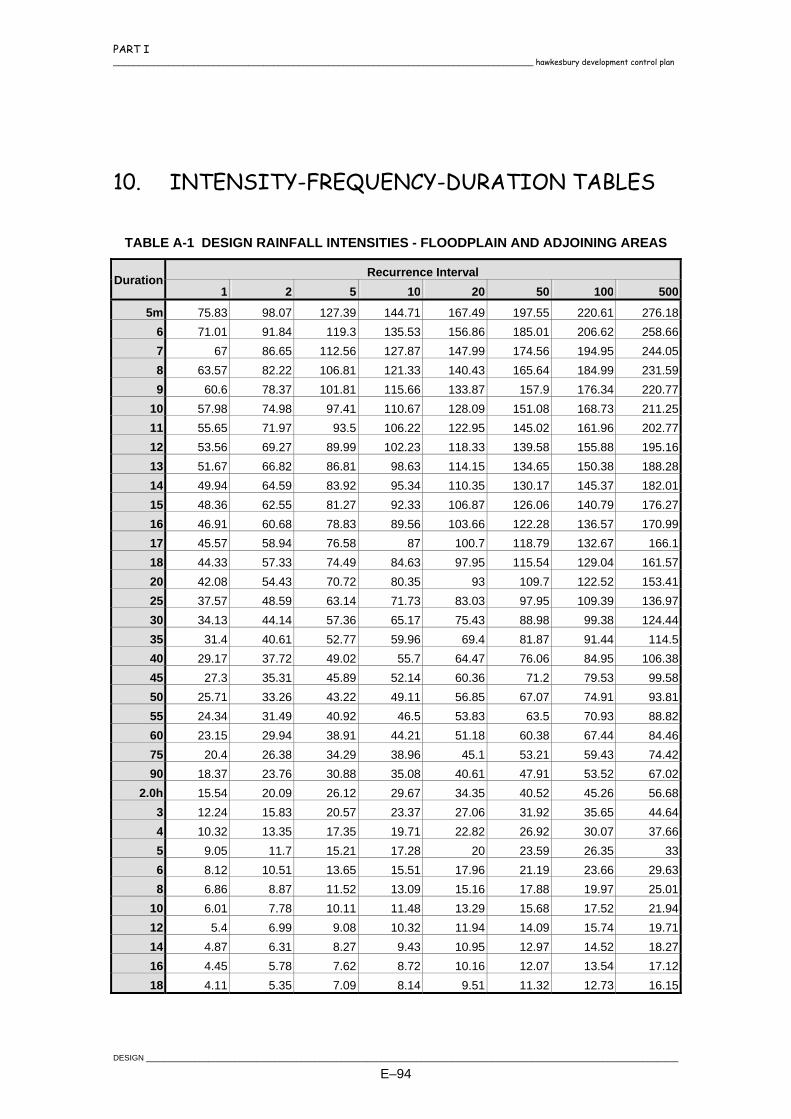
PART I ____________________________________________________________________________________ hawkesbury development control plan
10. INTENSITY-FREQUENCY-DURATION TABLES
TABLE A-1 DESIGN RAINFALL INTENSITIES - FLOODPLAIN AND ADJOINING AREAS
Recurrence Interval Duration 1 2 5 10 20 50 100 500
5m 75.83 98.07 127.39 144.71 167.49 197.55 220.61 276.186 71.01 91.84 119.3 135.53 156.86 185.01 206.62 258.667 67 86.65 112.56 127.87 147.99 174.56 194.95 244.058 63.57 82.22 106.81 121.33 140.43 165.64 184.99 231.599 60.6 78.37 101.81 115.66 133.87 157.9 176.34 220.77
10 57.98 74.98 97.41 110.67 128.09 151.08 168.73 211.2511 55.65 71.97 93.5 106.22 122.95 145.02 161.96 202.7712 53.56 69.27 89.99 102.23 118.33 139.58 155.88 195.1613 51.67 66.82 86.81 98.63 114.15 134.65 150.38 188.2814 49.94 64.59 83.92 95.34 110.35 130.17 145.37 182.0115 48.36 62.55 81.27 92.33 106.87 126.06 140.79 176.2716 46.91 60.68 78.83 89.56 103.66 122.28 136.57 170.9917 45.57 58.94 76.58 87 100.7 118.79 132.67 166.118 44.33 57.33 74.49 84.63 97.95 115.54 129.04 161.5720 42.08 54.43 70.72 80.35 93 109.7 122.52 153.4125 37.57 48.59 63.14 71.73 83.03 97.95 109.39 136.9730 34.13 44.14 57.36 65.17 75.43 88.98 99.38 124.4435 31.4 40.61 52.77 59.96 69.4 81.87 91.44 114.540 29.17 37.72 49.02 55.7 64.47 76.06 84.95 106.3845 27.3 35.31 45.89 52.14 60.36 71.2 79.53 99.5850 25.71 33.26 43.22 49.11 56.85 67.07 74.91 93.8155 24.34 31.49 40.92 46.5 53.83 63.5 70.93 88.8260 23.15 29.94 38.91 44.21 51.18 60.38 67.44 84.4675 20.4 26.38 34.29 38.96 45.1 53.21 59.43 74.4290 18.37 23.76 30.88 35.08 40.61 47.91 53.52 67.02
2.0h 15.54 20.09 26.12 29.67 34.35 40.52 45.26 56.683 12.24 15.83 20.57 23.37 27.06 31.92 35.65 44.644 10.32 13.35 17.35 19.71 22.82 26.92 30.07 37.665 9.05 11.7 15.21 17.28 20 23.59 26.35 336 8.12 10.51 13.65 15.51 17.96 21.19 23.66 29.638 6.86 8.87 11.52 13.09 15.16 17.88 19.97 25.01
10 6.01 7.78 10.11 11.48 13.29 15.68 17.52 21.9412 5.4 6.99 9.08 10.32 11.94 14.09 15.74 19.7114 4.87 6.31 8.27 9.43 10.95 12.97 14.52 18.2716 4.45 5.78 7.62 8.72 10.16 12.07 13.54 17.1218 4.11 5.35 7.09 8.14 9.51 11.32 12.73 16.15
DESIGN ________________________________________________________________________________________________________________________
E–94
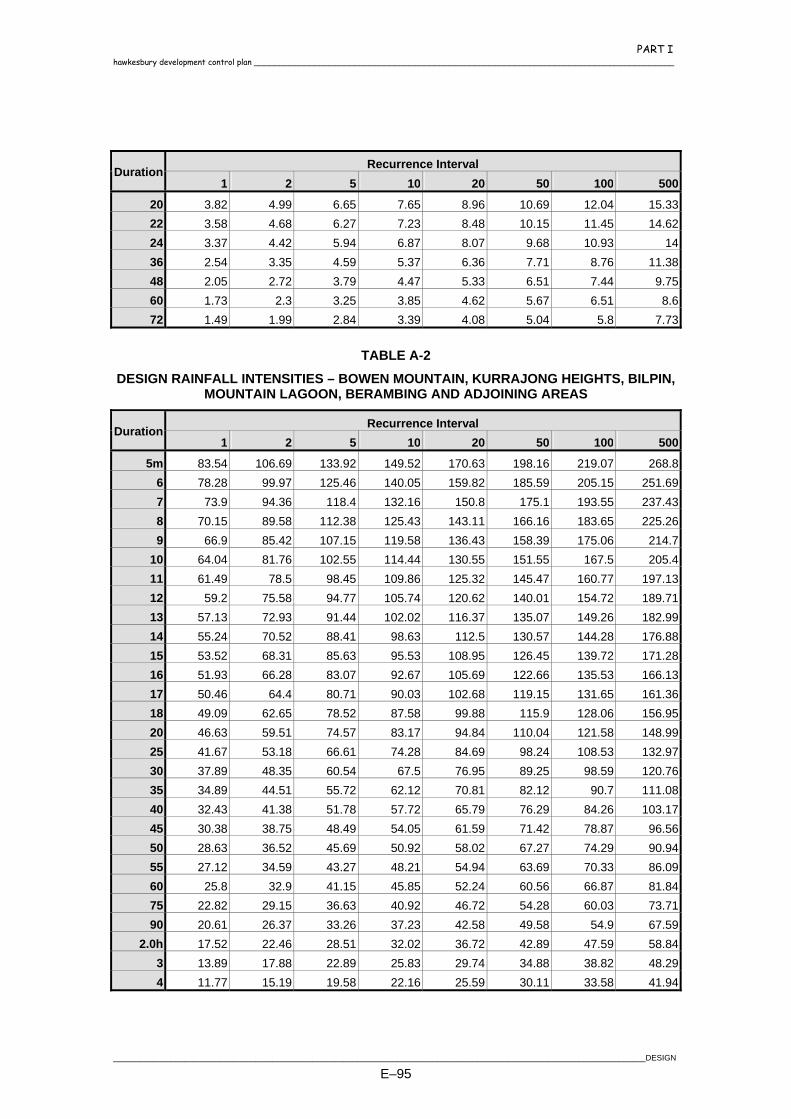
PART I hawkesbury development control plan ____________________________________________________________________________________
Recurrence Interval Duration 1 2 5 10 20 50 100 500
20 3.82 4.99 6.65 7.65 8.96 10.69 12.04 15.3322 3.58 4.68 6.27 7.23 8.48 10.15 11.45 14.6224 3.37 4.42 5.94 6.87 8.07 9.68 10.93 1436 2.54 3.35 4.59 5.37 6.36 7.71 8.76 11.3848 2.05 2.72 3.79 4.47 5.33 6.51 7.44 9.7560 1.73 2.3 3.25 3.85 4.62 5.67 6.51 8.672 1.49 1.99 2.84 3.39 4.08 5.04 5.8 7.73
TABLE A-2
DESIGN RAINFALL INTENSITIES – BOWEN MOUNTAIN, KURRAJONG HEIGHTS, BILPIN, MOUNTAIN LAGOON, BERAMBING AND ADJOINING AREAS
Recurrence Interval Duration 1 2 5 10 20 50 100 500
5m 83.54 106.69 133.92 149.52 170.63 198.16 219.07 268.86 78.28 99.97 125.46 140.05 159.82 185.59 205.15 251.697 73.9 94.36 118.4 132.16 150.8 175.1 193.55 237.438 70.15 89.58 112.38 125.43 143.11 166.16 183.65 225.269 66.9 85.42 107.15 119.58 136.43 158.39 175.06 214.7
10 64.04 81.76 102.55 114.44 130.55 151.55 167.5 205.411 61.49 78.5 98.45 109.86 125.32 145.47 160.77 197.1312 59.2 75.58 94.77 105.74 120.62 140.01 154.72 189.7113 57.13 72.93 91.44 102.02 116.37 135.07 149.26 182.9914 55.24 70.52 88.41 98.63 112.5 130.57 144.28 176.8815 53.52 68.31 85.63 95.53 108.95 126.45 139.72 171.2816 51.93 66.28 83.07 92.67 105.69 122.66 135.53 166.1317 50.46 64.4 80.71 90.03 102.68 119.15 131.65 161.3618 49.09 62.65 78.52 87.58 99.88 115.9 128.06 156.9520 46.63 59.51 74.57 83.17 94.84 110.04 121.58 148.9925 41.67 53.18 66.61 74.28 84.69 98.24 108.53 132.9730 37.89 48.35 60.54 67.5 76.95 89.25 98.59 120.7635 34.89 44.51 55.72 62.12 70.81 82.12 90.7 111.0840 32.43 41.38 51.78 57.72 65.79 76.29 84.26 103.1745 30.38 38.75 48.49 54.05 61.59 71.42 78.87 96.5650 28.63 36.52 45.69 50.92 58.02 67.27 74.29 90.9455 27.12 34.59 43.27 48.21 54.94 63.69 70.33 86.0960 25.8 32.9 41.15 45.85 52.24 60.56 66.87 81.8475 22.82 29.15 36.63 40.92 46.72 54.28 60.03 73.7190 20.61 26.37 33.26 37.23 42.58 49.58 54.9 67.59
2.0h 17.52 22.46 28.51 32.02 36.72 42.89 47.59 58.843 13.89 17.88 22.89 25.83 29.74 34.88 38.82 48.294 11.77 15.19 19.58 22.16 25.59 30.11 33.58 41.94
________________________________________________________________________________________________________________________DESIGN
E–95
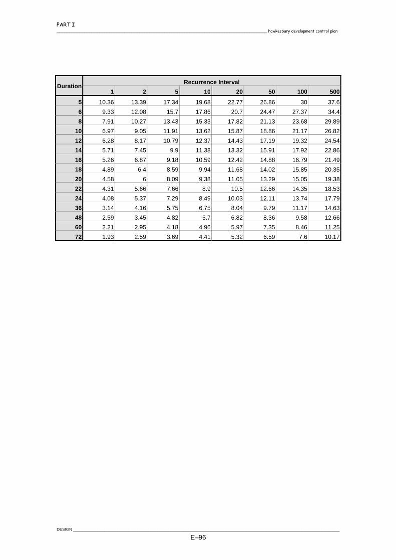
PART I ____________________________________________________________________________________ hawkesbury development control plan
Recurrence Interval Duration 1 2 5 10 20 50 100 500
5 10.36 13.39 17.34 19.68 22.77 26.86 30 37.66 9.33 12.08 15.7 17.86 20.7 24.47 27.37 34.48 7.91 10.27 13.43 15.33 17.82 21.13 23.68 29.89
10 6.97 9.05 11.91 13.62 15.87 18.86 21.17 26.8212 6.28 8.17 10.79 12.37 14.43 17.19 19.32 24.5414 5.71 7.45 9.9 11.38 13.32 15.91 17.92 22.8616 5.26 6.87 9.18 10.59 12.42 14.88 16.79 21.4918 4.89 6.4 8.59 9.94 11.68 14.02 15.85 20.3520 4.58 6 8.09 9.38 11.05 13.29 15.05 19.3822 4.31 5.66 7.66 8.9 10.5 12.66 14.35 18.5324 4.08 5.37 7.29 8.49 10.03 12.11 13.74 17.7936 3.14 4.16 5.75 6.75 8.04 9.79 11.17 14.6348 2.59 3.45 4.82 5.7 6.82 8.36 9.58 12.6660 2.21 2.95 4.18 4.96 5.97 7.35 8.46 11.2572 1.93 2.59 3.69 4.41 5.32 6.59 7.6 10.17
DESIGN ________________________________________________________________________________________________________________________
E–96
PART II
CONSTRUCTION SPECIFICATION

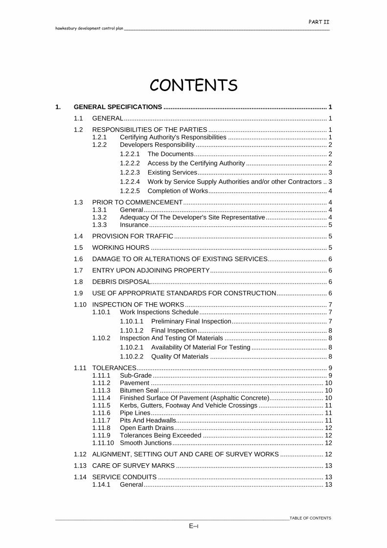
PART II hawkesbury development control plan ____________________________________________________________________________________
CONTENTS 1. GENERAL SPECIFICATIONS ........................................................................................... 1
1.1 GENERAL................................................................................................................. 1 1.2 RESPONSIBILITIES OF THE PARTIES .................................................................. 1
1.2.1 Certifying Authority's Responsibilities ....................................................... 1 1.2.2 Developers Responsibility ......................................................................... 2
1.2.2.1 The Documents.......................................................................... 2 1.2.2.2 Access by the Certifying Authority ............................................. 2 1.2.2.3 Existing Services........................................................................ 3 1.2.2.4 Work by Service Supply Authorities and/or other Contractors .. 3 1.2.2.5 Completion of Works.................................................................. 4
1.3 PRIOR TO COMMENCEMENT................................................................................ 4 1.3.1 General...................................................................................................... 4 1.3.2 Adequacy Of The Developer's Site Representative.................................. 4 1.3.3 Insurance................................................................................................... 5
1.4 PROVISION FOR TRAFFIC ..................................................................................... 5 1.5 WORKING HOURS .................................................................................................. 5 1.6 DAMAGE TO OR ALTERATIONS OF EXISTING SERVICES................................. 6 1.7 ENTRY UPON ADJOINING PROPERTY................................................................. 6 1.8 DEBRIS DISPOSAL.................................................................................................. 6 1.9 USE OF APPROPRIATE STANDARDS FOR CONSTRUCTION............................ 6 1.10 INSPECTION OF THE WORKS............................................................................... 7
1.10.1 Work Inspections Schedule....................................................................... 7 1.10.1.1 Preliminary Final Inspection..................................................... 7 1.10.1.2 Final Inspection........................................................................ 8
1.10.2 Inspection And Testing Of Materials ......................................................... 8 1.10.2.1 Availability Of Material For Testing .......................................... 8 1.10.2.2 Quality Of Materials ................................................................. 8
1.11 TOLERANCES.......................................................................................................... 9 1.11.1 Sub-Grade ................................................................................................. 9 1.11.2 Pavement ................................................................................................ 10 1.11.3 Bitumen Seal ........................................................................................... 10 1.11.4 Finished Surface Of Pavement (Asphaltic Concrete).............................. 10 1.11.5 Kerbs, Gutters, Footway And Vehicle Crossings .................................... 11 1.11.6 Pipe Lines................................................................................................ 11 1.11.7 Pits And Headwalls.................................................................................. 11 1.11.8 Open Earth Drains................................................................................... 12 1.11.9 Tolerances Being Exceeded ................................................................... 12 1.11.10 Smooth Junctions.................................................................................... 12
1.12 ALIGNMENT, SETTING OUT AND CARE OF SURVEY WORKS ........................ 12 1.13 CARE OF SURVEY MARKS .................................................................................. 13 1.14 SERVICE CONDUITS ............................................................................................ 13
1.14.1 General.................................................................................................... 13
____________________________________________________________________________________________________________TABLE OF CONTENTS
E–I
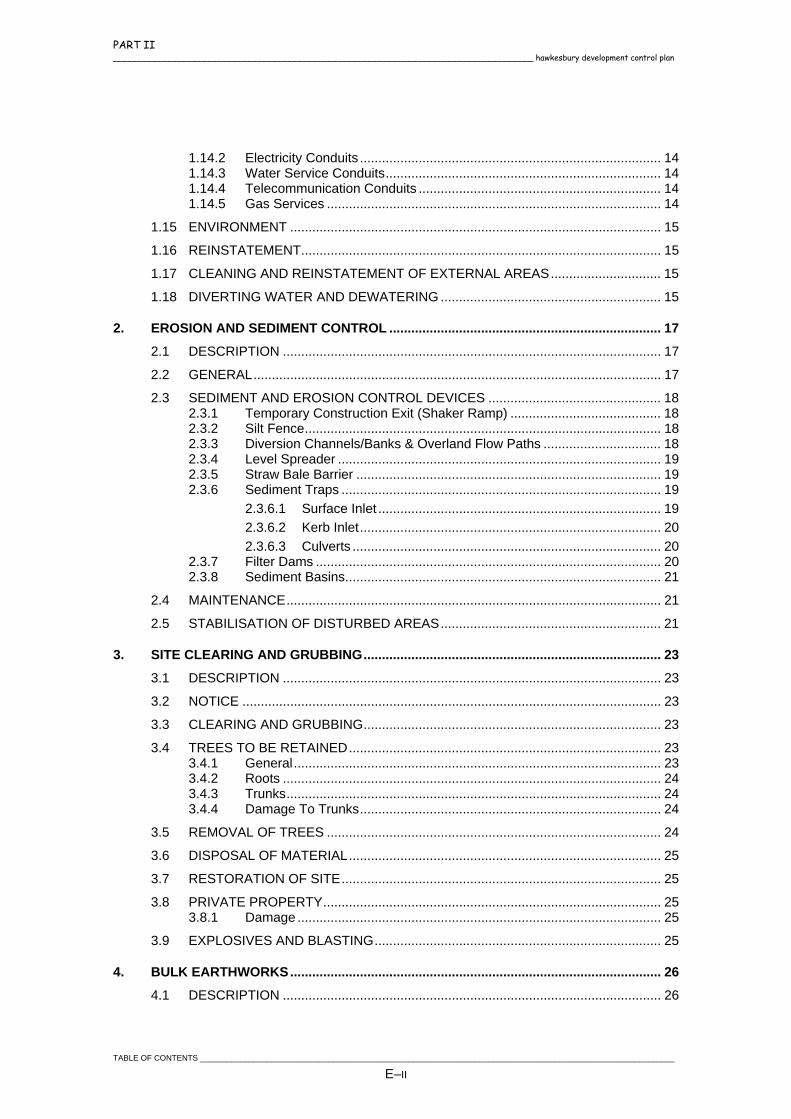
PART II ____________________________________________________________________________________ hawkesbury development control plan
1.14.2 Electricity Conduits .................................................................................. 14 1.14.3 Water Service Conduits........................................................................... 14 1.14.4 Telecommunication Conduits .................................................................. 14 1.14.5 Gas Services ........................................................................................... 14
1.15 ENVIRONMENT ..................................................................................................... 15 1.16 REINSTATEMENT.................................................................................................. 15 1.17 CLEANING AND REINSTATEMENT OF EXTERNAL AREAS.............................. 15 1.18 DIVERTING WATER AND DEWATERING ............................................................ 15
2. EROSION AND SEDIMENT CONTROL .......................................................................... 17 2.1 DESCRIPTION ....................................................................................................... 17 2.2 GENERAL............................................................................................................... 17 2.3 SEDIMENT AND EROSION CONTROL DEVICES ............................................... 18
2.3.1 Temporary Construction Exit (Shaker Ramp) ......................................... 18 2.3.2 Silt Fence................................................................................................. 18 2.3.3 Diversion Channels/Banks & Overland Flow Paths ................................ 18 2.3.4 Level Spreader ........................................................................................ 19 2.3.5 Straw Bale Barrier ................................................................................... 19 2.3.6 Sediment Traps ....................................................................................... 19
2.3.6.1 Surface Inlet ............................................................................. 19 2.3.6.2 Kerb Inlet.................................................................................. 20 2.3.6.3 Culverts .................................................................................... 20
2.3.7 Filter Dams .............................................................................................. 20 2.3.8 Sediment Basins...................................................................................... 21
2.4 MAINTENANCE...................................................................................................... 21 2.5 STABILISATION OF DISTURBED AREAS............................................................ 21
3. SITE CLEARING AND GRUBBING................................................................................. 23 3.1 DESCRIPTION ....................................................................................................... 23 3.2 NOTICE .................................................................................................................. 23 3.3 CLEARING AND GRUBBING................................................................................. 23 3.4 TREES TO BE RETAINED..................................................................................... 23
3.4.1 General.................................................................................................... 23 3.4.2 Roots ....................................................................................................... 24 3.4.3 Trunks...................................................................................................... 24 3.4.4 Damage To Trunks.................................................................................. 24
3.5 REMOVAL OF TREES ........................................................................................... 24 3.6 DISPOSAL OF MATERIAL..................................................................................... 25 3.7 RESTORATION OF SITE....................................................................................... 25 3.8 PRIVATE PROPERTY............................................................................................ 25
3.8.1 Damage ................................................................................................... 25 3.9 EXPLOSIVES AND BLASTING.............................................................................. 25
4. BULK EARTHWORKS..................................................................................................... 26 4.1 DESCRIPTION ....................................................................................................... 26
TABLE OF CONTENTS ___________________________________________________________________________________________________________
E–II

PART II hawkesbury development control plan ____________________________________________________________________________________
4.2 REMOVAL OF TOPSOIL........................................................................................ 26 4.3 REMOVAL OF UNSUITABLE MATERIALS ........................................................... 26 4.4 COMPACTION PRIOR TO PLACING OF FILL...................................................... 27 4.5 EXCAVATION......................................................................................................... 27 4.6 SURPLUS SPOIL ................................................................................................... 28 4.7 IMPORTED FILLING .............................................................................................. 28 4.8 EMBANKMENTS .................................................................................................... 28 4.9 PLACING AND COMPACTION OF FILL................................................................ 28 4.10 GRADING AND/OR FILLING OF LOTS................................................................. 29 4.11 BOXING .................................................................................................................. 29 4.12 TRIMMING AND COMPACTION OF EARTHWORKS AND SUBGRADES .......... 30 4.13 BATTERS ............................................................................................................... 31 4.14 CATCH DRAINS..................................................................................................... 31 4.15 TABLE DRAINS...................................................................................................... 31 4.16 SITE REGRADING ................................................................................................. 32 4.17 REPLACEMENT OF TOPSOIL .............................................................................. 32 4.18 ENTRANCE TO SIDE ROADS AND ADJACENT PROPERTY ............................. 33
5. STORMWATER DRAINAGE............................................................................................ 34 5.1 DESCRIPTION ....................................................................................................... 34 5.2 DRAINAGE LINE LOCATION................................................................................. 34 5.3 TYPE OF PIPES..................................................................................................... 35
5.3.1 Reinforced Concrete Pipes ..................................................................... 35 5.3.2 Fibre Reinforced Cement Pipes .............................................................. 35 5.3.3 UPVC Pipes............................................................................................. 35 5.3.4 Precast Reinforced Concrete Box Culverts............................................. 36 5.3.5 Flexible Pipes .......................................................................................... 36
5.4 DRAINAGE PITS .................................................................................................... 36 5.5 EXCAVATION......................................................................................................... 36 5.6 ALLOWANCES IN EXCAVATION QUANTITIES ................................................... 37 5.7 PIPE BEDDING MATERIAL ................................................................................... 38 5.8 PIPE LAYING.......................................................................................................... 38 5.9 SUBSOIL PIPES IN STORMWATER DRAINAGE TRENCHES ............................ 39 5.10 METHOD OF JOINTING ........................................................................................ 39 5.11 CONCRETE ENCASING........................................................................................ 40 5.12 CONCRETE BULKHEADS..................................................................................... 40 5.13 DIRECT CONNECTIONS....................................................................................... 40 5.14 PRECAST CONCRETE BOX CULVERTS............................................................. 41 5.15 INSPECTION PRIOR TO BACKFILLING............................................................... 41
____________________________________________________________________________________________________________TABLE OF CONTENTS
E–III

PART II ____________________________________________________________________________________ hawkesbury development control plan
5.16 BACKFILLING......................................................................................................... 41 5.17 INTERALLOTMENT DRAINAGE............................................................................ 42 5.18 SUB-SOIL DRAINS................................................................................................. 43
5.18.1 Materials .................................................................................................. 43 5.18.1.1 Pipes ...................................................................................... 43 5.18.1.2 Filter socks ............................................................................. 43 5.18.1.3 Filter fabric ............................................................................. 43 5.18.1.4 Filter material ......................................................................... 43
5.18.2 Trench Excavation................................................................................... 44 5.18.3 Laying of Pipe.......................................................................................... 44 5.18.4 Backfilling ................................................................................................ 44 5.18.5 Other Type Systems................................................................................ 44
6. CONCRETE STRUCTURES ............................................................................................ 45 6.1 DESCRIPTION ....................................................................................................... 45 6.2 CONCRETE MATERIALS AND SLUMP ................................................................ 45 6.3 CONCRETE TESTING AND STRENGTH.............................................................. 46 6.4 FOUNDATIONS...................................................................................................... 46 6.5 REINFORCEMENT................................................................................................. 47 6.6 FORMWORK .......................................................................................................... 47 6.7 CONCRETE PLACING........................................................................................... 48 6.8 JOINTS ................................................................................................................... 49
6.8.1 Construction Joints .................................................................................. 49 6.8.2 Contraction Joints.................................................................................... 49
6.8.2.1 Sawcutting Joints ..................................................................... 49 6.8.2.2 Formed Grooves (Dummy Joints)............................................ 49
6.8.3 Expansion joints ...................................................................................... 49 6.9 REMOVAL OF FORMS .......................................................................................... 50 6.10 CONCRETE FINISHING ........................................................................................ 50 6.11 CURING.................................................................................................................. 50 6.12 KERB AND GUTTER.............................................................................................. 51
6.12.1 Base ........................................................................................................ 51 6.12.2 Kerb Moulding Machines......................................................................... 51 6.12.3 Finish ....................................................................................................... 51 6.12.4 Joints ....................................................................................................... 51 6.12.5 Vehicular Crossings................................................................................. 52 6.12.6 Pedestrian Ramp (Pram Ramp) .............................................................. 52 6.12.7 Curing ...................................................................................................... 52 6.12.8 Provision For Drainage............................................................................ 52 6.12.9 Backfilling ................................................................................................ 53 6.12.10 Replacement of Incorrect and/or Damaged Construction ....................... 53 6.12.11 Testing..................................................................................................... 54 6.12.12 Subsoil Drainage ..................................................................................... 54
6.13 FOOTPAVING AND CYCLEWAYS........................................................................ 54 6.13.1 General.................................................................................................... 54 6.13.2 Subgrade ................................................................................................. 54
TABLE OF CONTENTS ___________________________________________________________________________________________________________
E–IV

PART II hawkesbury development control plan ____________________________________________________________________________________
6.13.3 Sub-Base................................................................................................. 54 6.13.4 Reinforcement ......................................................................................... 55 6.13.5 Finish ....................................................................................................... 55 6.13.6 Joints ....................................................................................................... 55 6.13.7 Protection ................................................................................................ 55 6.13.8 Cleaning Up............................................................................................. 55
6.14 DRAINAGE PITS .................................................................................................... 56 6.14.1 Excavation ............................................................................................... 56 6.14.2 Structure .................................................................................................. 56 6.14.3 Steel Fittings............................................................................................ 57 6.14.4 Kerb Inlets ............................................................................................... 57
6.15 PRECAST CONCRETE SECTIONS (PIT AND HEADWALLS) ............................. 58 6.16 DISH CROSSING ................................................................................................... 58 6.17 SPRAY CONCRETE............................................................................................... 58 6.18 PATTERN STENCILLED CONCRETE PAVEMENT FOR MEDIAN ISLANDS &
ROUNDABOUTS.................................................................................................... 58
7. FLEXIBLE ROAD PAVEMENTS...................................................................................... 59 7.1 DESCRIPTION ....................................................................................................... 59 7.2 CRUSHED OR RIPPED SANDSTONE - (SUB-BASE COURSE) ......................... 59
7.2.1 Material Requirements ............................................................................ 60 7.2.2 Variations................................................................................................. 60 7.2.3 Sampling and Testing of Materials .......................................................... 61
7.3 CRUSHED ROCK (DGB 20) - (BASE COURSE)................................................... 61 7.4 STABILISATION OF IN SITU AND IMPORTED MATERIALS............................... 63 7.5 SHOULDERS.......................................................................................................... 63 7.6 DELIVERY .............................................................................................................. 64 7.7 BOXING AND SUBGRADE .................................................................................... 64 7.8 SPREADING........................................................................................................... 65 7.9 COMPACTING AND TRIMMING............................................................................ 65 7.10 PAVEMENT TESTING............................................................................................ 66
7.10.1 General.................................................................................................... 66 7.10.2 Density Testing........................................................................................ 67 7.10.3 Proof Testing ........................................................................................... 67 7.10.4 Benkleman Beam Testing ....................................................................... 67
7.11 DEFECTIVE MATERIAL......................................................................................... 67 7.12 COMPLETED PAVEMENT SURFACE .................................................................. 67 7.13 OPENING PAVEMENT TO TRAFFIC .................................................................... 68 7.14 MAINTENANCE...................................................................................................... 68 7.15 RESTORATION OF TRENCHES........................................................................... 68
8. WEARING COURSE ........................................................................................................ 69 8.1 GENERAL............................................................................................................... 69 8.2 SPRAYED BITUMINOUS SEALING ...................................................................... 69
____________________________________________________________________________________________________________TABLE OF CONTENTS
E–V
PART II ____________________________________________________________________________________ hawkesbury development control plan
8.2.1 Application Rates..................................................................................... 70 8.2.1.1 Application rate for a single coat flush seal are: ...................... 70 8.2.1.2 Application rate for a two coat flush seal are: .......................... 70
8.3 ASPHALTIC CONCRETE....................................................................................... 70
9. PAVEMENTS FOR ROUNDABOUTS AND CARPARKS ............................................... 72 9.1 ROUNDABOUTS.................................................................................................... 72 9.2 CARPARKS ............................................................................................................ 72
10. RIGID AND SEGMENTAL PAVEMENTS ........................................................................ 73 10.1 DESCRIPTION ....................................................................................................... 73 10.2 PAVING UNITS....................................................................................................... 73
10.2.1 Concrete .................................................................................................. 73 10.2.2 Clay ......................................................................................................... 73
10.3 SUBGRADE............................................................................................................ 73 10.4 BASE COURSE FOR ROADS, DRIVEWAYS AND COMMUNITY TITLE ROADS74 10.5 EDGE RESTRAINT ................................................................................................ 74 10.6 SURFACE DRAINAGE........................................................................................... 74 10.7 BEDDING SAND..................................................................................................... 75
10.7.1 Material.................................................................................................... 75 10.7.2 Moisture Content ..................................................................................... 75 10.7.3 Spreading ................................................................................................ 75
10.8 PLACEMENT OF PAVING UNITS ......................................................................... 76 10.9 COMPACTION OF PAVING UNITS AND JOINT FILLING .................................... 76 10.10 PAVERS IN FOOTWAYS ....................................................................................... 78
10.10.1 Paving Units ............................................................................................ 78 10.10.2 Dimensions.............................................................................................. 78 10.10.3 Edge Treatment....................................................................................... 78 10.10.4 Base Course And Laying......................................................................... 78
10.11 TESTING ................................................................................................................ 79
11. PRIVATE ACCESS ROADS AND RIGHT OF WAYS (ROW) ......................................... 80 11.1 GENERAL............................................................................................................... 80
12. VEGETATION AND REVEGETATION ............................................................................ 82 12.1 DESCRIPTION ....................................................................................................... 82 12.2 PREPARATION ...................................................................................................... 82 12.3 GRASSING BY SEEDING...................................................................................... 82
12.3.1 Grass Seed.............................................................................................. 82 12.4 SOWING ................................................................................................................. 84 12.5 HYDROSEEDING................................................................................................... 84 12.6 HYDROMULCHING................................................................................................ 84 12.7 CONVENTIONAL SOWING AND MULCHING WITH BITUMEN........................... 85
TABLE OF CONTENTS ___________________________________________________________________________________________________________
E–VI

PART II hawkesbury development control plan ____________________________________________________________________________________
12.8 GRASSING BY TURFING ...................................................................................... 85 12.9 FERTILISERS......................................................................................................... 86 12.10 CARE OF GRASSED AREAS ................................................................................ 86 12.11 MOWING ................................................................................................................ 86 12.12 ESTABLISHMENT.................................................................................................. 87 12.13 MAINTENANCE...................................................................................................... 87 12.14 STREET TREES..................................................................................................... 87 12.15 REVEGETATION OF BUSHLAND AREAS............................................................ 88
13. STREET FURNITURE ...................................................................................................... 89 13.1 STREET NAME SIGNS .......................................................................................... 89
13.1.1 Sign Blades ............................................................................................. 89 13.1.1.1 Background............................................................................ 89 13.1.1.2 Legend ................................................................................... 90 13.1.1.3 Letter Series........................................................................... 90 13.1.1.4 Abbreviations ......................................................................... 90
13.1.2 Posts........................................................................................................ 90 13.1.3 Fixing Of Blades ...................................................................................... 91
13.2 WARNING ,REGULATORY AND OTHER SIGNS................................................. 91 13.3 PATHWAY BARRIERS, BOLLARDS AND BICYCLE RAILS................................. 91 13.4 GUIDE POSTS AND PROTECTION FENCES ...................................................... 91
14. MISCELLANEOUS WORKS ............................................................................................ 92 14.1 PAVEMENT MARKINGS AND DEVICES .............................................................. 92 14.2 MAINROADS .......................................................................................................... 92 14.3 CLEANING UP........................................................................................................ 92
15. COMPLETION OF THE WORKS ..................................................................................... 93 15.1 FINAL INSPECTION............................................................................................... 93 15.2 WORK-AS-EXECUTED PLANS............................................................................. 93 15.3 DEFECTS LIABILITY PERIOD............................................................................... 94
15.3.1 Maintenance ............................................................................................ 94 15.3.2 Description............................................................................................... 95 15.3.3 Subdivisions ............................................................................................ 95 15.3.4 All Other Developments .......................................................................... 95
15.4 BONDING ............................................................................................................... 95 15.4.1 General.................................................................................................... 95 15.4.2 A.C. Sealing............................................................................................. 95 15.4.3 Path Paving ............................................................................................. 96 15.4.4 Maintenance ............................................................................................ 96
15.5 CONTRIBUTIONS / MONETARY PAYMENT ........................................................ 96 15.5.1 A.C. Sealing............................................................................................. 96 15.5.2 Path Paving ............................................................................................. 97
____________________________________________________________________________________________________________TABLE OF CONTENTS
E–VII

PART II hawkesbury development control plan ____________________________________________________________________________________
1. GENERAL SPECIFICATIONS
1.1 GENERAL
This Specification has been compiled to outline Council's general procedures and practices in respect of all the associated construction requirements. Council's basic objective is to preserve, enhance and develop the amenity of the area with specific reference to safety, convenience and long term cost effectiveness. This specification informs the Developer of Council's requirements with respect to construction of assets, which will eventually be vested in and be maintained by Council. The Documents referred to in this specification shall include but not be limited to engineering plans approved by the Certifying Authority, Council's Design Specifications, Australian Standards, Australian Rainfall and Runoff, Institution of Engineers, 1987 and the Statutes, Acts and By-Laws of the governments of New South Wales and Australia. All of these documents compliment each other and shall be referenced in conjunction with this specification. This document is the specification defining construction details and the obligations of Council and the Developer. These obligations are inherent and binding once the Developer's Engineering Plans have been approved and a Construction Certificate is issued by the Certifying Authority. No departure or change will be permitted from approved Engineering Plans during construction except by written consent or on-site approval from Certifying Authority. The Documents including any written directions issued by Council to the Developer are binding on the Developer. Council neither accepts responsibility nor implies or guarantees any directions given to the developer for any subsequent physical or contractual damages received by the Developer.
1.2 RESPONSIBILITIES OF THE PARTIES
It should be noted clearly by all parties that the Contractor is contracting to the Developer and not the Council or the Certifying Authority. It is the responsibility of the Developer to ensure that all works are carried out in a sound, efficient and workmanlike manner and in accordance with sound engineering practice and principles, and are completed in accordance with the Documents and this specification.
1.2.1 Certifying Authority's Responsibilities
Final approval of the works rests with the Certifying Authority, on the assurance that the Documents and specification have been complied with and the construction satisfactorily completed.
____________________________________________________________________________________________________CONSTRUCTION
E–1
PART II ____________________________________________________________________________________ hawkesbury development control plan
Inspections undertaken by the Certifying Authority in no way limits the Developer's full responsibility for completing the works in accordance with sound engineering practice and principles and in accordance with the intent and purpose of the Documents. It should be noted that inspections by the Certifying Authority do not relieve the Developer’s responsibility to supervise, or arrange the supervision of, the work as indicated. The Certifying Authority's inspection is for the purpose of enabling, when the works have been completed, certification to the Council that the works have been properly carried out in accordance with the Documents and specification, and they are in a satisfactory state for the Council to take them over. Consequently, any defects that develop before the work is finally accepted by the Council shall have to be rectified, even though the defective work may have been previously inspected by the Certifying Authority. The whole of the work shall be carried out to the entire satisfaction of the Certifying Authority. If irregularities occur and are not rectified to the Certifying Authority's satisfaction, or if work is covered before inspection has been made, no guarantee is given that the works will be approved when application is made.
1.2.2 Developers Responsibility
1.2.2.1 The Documents
It is the Developer’s responsibility to complete, or to cause the completion of, the works in accordance with the terms of approval, the approved plans and specifications (the documents). After obtaining approved Construction plans and Construction Certificate from the Certifying Authority, and any consents required from Statutory Authorities, the Developer may commence construction of the works. Before the construction is commenced the Developer shall ensure that adequate supervising staff to control the work is employed so that it is carried out fully in accordance with the requirements of the approved plans and specifications. The Works shall be completed in accordance with the intent and purpose of the Documents. The latest copies of the Documents must be kept on-site at all times and be available for inspection by the Certifying Authority.
1.2.2.2 Access by the Certifying Authority
The Developer shall allow complete and unhindered access to the Certifying Authority to the Works for the purpose of inspecting materials and the Works.
CONSTRUCTION ___________________________________________________________________________________________________
E–2

PART II hawkesbury development control plan ____________________________________________________________________________________
The Developer, when required by the Certifying Authority, shall provide all particulars as to the mode and place of manufacture and source of supply of any of the materials to be used. The Developer shall, at the direction of the Certifying Authority, submit any materials or work for testing and shall, when required, open up and supply samples of any work which has been covered, whether or not same shall have been previously approved by the Certifying Authority. All expenses incurred in moving such material from the works or in making good the works after such removal shall be borne by the Developer. Failure by the Developer to comply with all reasonable requests and directions from the Certifying Authority will be sufficient reason for the Certifying Authority to withhold final approval to the works. Where inspections are required outside normal working hours, it shall be necessary to request such inspections in writing and shall be conditional upon the applicant accepting all costs involved in the Certifying Authority undertaking such inspections.
1.2.2.3 Existing Services
Prior to the commencement of the works, the Developer shall ascertain from the appropriate Public Utility Authority and/or the Council, the position and depth of all existing services which may be interfered with during the excavation and/or construction of the works. The Developer shall take every precaution to avoid damage to any utility service within, or adjacent to, the limits of the works and shall be held responsible for any such damage caused directly or indirectly. If, during the conduct of the works, any alteration or damage to existing services is occasioned, it shall be the responsibility of the Developer to make the necessary arrangements for rectification with the appropriate authority. All alterations and repairs shall be carried out to the requirements of the Engineer and the appropriate authority. A written clearance shall be obtained from the relevant authority prior to the final inspection.
1.2.2.4 Work by Service Supply Authorities and/or other Contractors
It should be anticipated by the Developer that the construction of mains and/or services by Service Authorities and/or work by other Contractors may proceed during the currency of the Works. The Developer must permit and maintain access by traffic to such construction and/or work and shall not obstruct the execution of work by the various Service Authorities and/or other Contractors and/or Builders.
____________________________________________________________________________________________________CONSTRUCTION
E–3

PART II ____________________________________________________________________________________ hawkesbury development control plan
1.2.2.5 Completion of Works
It is the Developer's responsibility to complete or to cause the completion of the Works in accordance with the Documents and in a workmanlike manner. Inspection by the Certifying Authority does not relieve the Developer of his responsibility to supervise or to arrange the supervision of the Works. Inspections are for the purpose of enabling the Certifying Authority to be satisfied that the Works have been properly carried out in accordance with the Documents and that the Works are in a suitable state for Council to take over. Where works have been undertaken without inspection by the Certifying Authority, the Developer is to arrange for a CPEng to certify that the works have been constructed in accordance with the approved documents or reconstruct the relevant sections of work. Consequently, any defects that develop before the Works are finally accepted by the Certifying Authority will be required to be adjusted even though the defective work may have previously been approved.
1.3 PRIOR TO COMMENCEMENT
1.3.1 General
The Certifying Authority shall approve for construction all Documents prepared for the Works. The Developer shall obtain consents from all relevant Statutory Authorities as required by the Certifying Authority prior to any works being commenced. Where necessary, approval from adjoining landholders for access and/or right of way shall be obtained in writing prior to approval of the Documents. A copy of this approval shall be forwarded to the Certifying Authority. The Certifying Authority shall be given 24 hours notice prior to the commencement of any Works. A site meeting between the Certifying Authority and Developer shall take place before construction activities commence.
1.3.2 Adequacy Of The Developer's Site Representative
Before construction is commenced the Developer shall ensure that adequately qualified supervisory staff are available to control the Works. The Developer shall advise the Certifying Authority the name of the person appointed as his representative for the Works (hereinafter known as the Project Manager).
CONSTRUCTION ___________________________________________________________________________________________________
E–4
PART II hawkesbury development control plan ____________________________________________________________________________________
1.3.3 Insurance
The Developer is responsible to ensure that all Contractors are covered for Public Liability Insurance for a minimum $10million and full Workers Compensation Insurance on all works, as requested by NSW Statute. Insurances must be kept current for the duration of the works.
1.4 PROVISION FOR TRAFFIC
The Developer shall not obstruct and shall be held responsible for, the safety of traffic, vehicular and pedestrian and shall provide all watchmen, lights, barriers, signs and fences necessary to prevent any accident or public or private damage or loss and shall regulate traffic during the progress of the Work, in accordance with the requirements of AS 1742-3(1996) and the approved Traffic Management Plan. If necessary, the Developer shall provide for traffic by its diversion to an alternative route approved by the Certifying Authority or by the formation of side tracks alongside the Works, or by the construction of one half of the road at a time leaving the other half available for traffic. The Developer shall not, by his operations, obstruct any side road or branch track, nor shall he break down any fences, or damage public or private utilities, nor obstruct any drain or watercourse. When such obstructions or breakages cannot be entirely avoided the Developer shall at once remove such obstructions and make adequate provision for traffic or immediately repair such breakages. In the event of failing to rectify any of the abovementioned causes, the Certifying Authority reserves the right to do so after giving the Developer 24 hours notice in writing of its intention and the whole of the cost of such work incurred by the Certifying Authority shall be a legitimate charge payable by the Developer. Any variation from the Approved Traffic Management Plan requires approval from the Certifying Authority prior to implementation.
1.5 WORKING HOURS
The works shall be carried out within the hours of 7:00am to 5:00pm Mondays to Fridays and 8:00am to 1:00pm Saturdays or in accordance with the Development Consent. No work shall be undertaken on Sundays or public holidays.
____________________________________________________________________________________________________CONSTRUCTION
E–5

PART II ____________________________________________________________________________________ hawkesbury development control plan
1.6 DAMAGE TO OR ALTERATIONS OF EXISTING SERVICES
The Developer shall exercise the greatest care during the progress of the Works to avoid damage to any utility service and shall be responsible for any damage caused by him or his agents directly or indirectly. If, as a result of the Works, any alterations to existing utility services are considered necessary by the Certifying Authority, it shall be the responsibility of the Developer to make the necessary arrangements with the appropriate Authority at their total cost and at no cost to the Certifying Authority.
1.7 ENTRY UPON ADJOINING PROPERTY
The Developer or his representative shall not commit any act of trespass and shall effectively protect all adjoining properties and owners against any loss, damage or injury that may occur through the carrying out of the Works. If instructed by the Certifying Authority, the Developer shall implement the instruction given by the Certifying Authority. All property which has been disturbed as a result of the Developer's activities shall be reinstated. The reinstated property, in surface finishes or fences or other property, shall be reinstated to a finish similar to that which existed prior to disturbance and to the satisfaction of the property owner.
1.8 DEBRIS DISPOSAL
Burning off by open fire is prohibited. Advice on acceptable methods of debris disposal may be obtained from the Metropolitan Waste Disposal Authority.
1.9 USE OF APPROPRIATE STANDARDS FOR CONSTRUCTION
It is the responsibility of the Developer to complete all works according to Australian Standard except where the Documents specifically override the Australian Standard.
CONSTRUCTION ___________________________________________________________________________________________________
E–6

PART II hawkesbury development control plan ____________________________________________________________________________________
1.10 INSPECTION OF THE WORKS
1.10.1 Work Inspections Schedule
The Developer shall give the following notices, as listed in Table 1.1, to the Certifying Authority.
TABLE 1.1 TABLE OF INSPECTIONS
Inspection
Pre-requisite Prior Notice Days Before Inspection
Prior to commencement of Work Erosion Controls in Place 1 working day
Traffic control to AS 1742-3 (1996) Prior to opening of roads 1 working day
Bedding of pipes in trenches Pipes laid and jointed 1 working day
Trench backfill within roads Sand backfilled and compacted to subgrade level 1 working day
Formwork for concrete structures Prior to pour 1 working day
Subgrade proof roller test Subgrade placed, levelled, compacted 1 working day
Proof roller test for kerb Pavement placed, levelled and trimmed 1 working day
Sub-base Course proof roller test Pavement placed, levelled and trimmed, kerbs in place 1 working day
Base Course proof roller test Pavement placed levelled and trimmed 1 working day
Prior to placing of fill Surface ready for filling, fill material inspected 1 working day
Road crossing Service in excavated trench, bulkheads in place 1 working day
Preliminary Final Inspection All works practically complete survey pegs placed 5 working days
Final Inspection All works practically complete and submissions of W.A.E. plans
5 working days
Asphaltic Concrete Surfacing Road ready for surfacing 1 working day
1.10.1.1 Preliminary Final Inspection
A preliminary final inspection shall be arranged upon completion of the Works excluding deferred Works that are to be bonded. The Works shall be fully in compliance with the Documents. The following work shall be completed prior to the preliminary inspection.
Work-as-Executed Plans as required.
All lots pegged.
Street signs erected at approved locations.
____________________________________________________________________________________________________CONSTRUCTION
E–7
PART II ____________________________________________________________________________________ hawkesbury development control plan
1.10.1.2 Final Inspection
A final inspection shall be arranged upon completion of any defects encountered in the preliminary inspection.
1.10.2 Inspection And Testing Of Materials
1.10.2.1 Availability Of Material For Testing
The Developer shall at the direction of the Certifying Authority submit any material or work for testing and shall "open up" and supply samples of any work which has been covered whether the work has or has not previously been approved by the Certifying Authority. All expenses incurred in providing such materials from the Works or in making good the Works after such removal shall be borne by the Developer. Such directions must be complied with within 24 hours, or such time frame as agreed by the Certifying Authority. The cost of all tests and certifications required by the Certifying Authority shall be borne by the Developer.
1.10.2.2 Quality Of Materials
All materials incorporated in the Works shall be new and comply with the relevant Australian Standard (refer Table 1.2). All materials shall be subject to inspection testing and approval by the Certifying Authority. If any materials fail to comply with the documents then that material represented by the failure and all materials of similar manufacture or supply shall be rejected.
CONSTRUCTION ___________________________________________________________________________________________________
E–8

PART II hawkesbury development control plan ____________________________________________________________________________________
TABLE 1.2 SCHEDULE OF MATERIAL TESTS
Except where specifically overridden by the Documents. Material to be Tested Standard to be
Complied With Prior to Type of Work Form of Test Verification
Compacted Subgrade AS 1289 Placing Sub-Base Proof rolling, (Note 1) NATA Certificate and Plan.
Compacted Sub-Base AS 1289 Placing Base Course Proof rolling, (Note 1) NATA Certificate and Plan.
Compacted Base Course AS 1289 Road Surfacing Proof rolling, (Note 1) NATA Certificate and Plan.
Asphaltic Concrete Surfacing AS 2891 & RTA 1013 Pt K
Completion of Part of Work NATA Certificate
Earth Fill AS 1289 Spreading topsoil NATA Certificate and Plan Supply and ordering ready mixed concrete
AS 1379-1991 Concrete Pour NATA Certificate
Concrete AS 1012 Completion of Part of Work NATA Certificate Reinforcing Bars and Wires AS. 1302, AS 1303 &
AS 1304 Concrete Pour Site Inspection
Interlocking concrete paving units
AS 1012 Completion of Part of Work Site Inspection
Pre-cast reinforced concrete Box Culvert
AS 1597 Taking delivery Site Inspection
Pipes As for relevant type of pipe
Taking delivery Site Inspection
Crushed Rock RTA T114, T213, T215 & T221
Taking delivery NATA Certificate
Natural Gravel RTA, T106, T171, T114, T108, T109 & T215
Taking delivery NATA Certificate
Note 1 Proof rolling with 3 point self propelled static roller, minimum ten (10) tonne. Note 2 Depending on Works some of these Tests and Certificates may not be required.
1.11 TOLERANCES
1.11.1 Sub-Grade
The tolerances as listed need to be met as a minimum. Where deviations occur outside of the tolerances outlined, the contractor/developer needs to refer this immediately to the Certifying Authority to have this or an amendment approved. The tolerance on the Reduced Level of the sub-grade shall be as follows:
minus, no limit.
plus 15mm.
____________________________________________________________________________________________________CONSTRUCTION
E–9
PART II ____________________________________________________________________________________ hawkesbury development control plan
1.11.2 Pavement
The tolerances on completed pavement thickness, measured at time of preparation for bituminous surface treatment, shall be as follows:
Total thickness minus 5mm; plus no limit Pavement thickness minus 5mm; plus 5mm Sub-Base minus 5mm; plus 10mm WAE levels are to be provided for all pavement layers including the sub-grade. Pavement thicknesses can be checked by drilling or digging of holes by the Developer in the finished pavement at positions determined by the Certifying Authority. Holes shall be filled after measurement with damp material as specified for the surface course, well rammed to the satisfaction of the Certifying Authority. The cost of digging and repairing the test holes shall be borne by the Developer.
Width of pavement (where not in contact with concrete gutter) minus 25mm, plus 150mm
1.11.3 Bitumen Seal
The tolerances of the finished surface of pavement (neglecting the thickness of the final 25mm layer of bituminous surface treatment) measured at the time of preparation for surface treatment shall be as follows: Level - Finished level at any point minus 5mm, plus 10mm Grading in any direction in 3m or less minus 5mm, plus 10mm Grading in any direction per 3 metres minus 5mm, plus 10mm Width of seal (where not in contact with concrete gutter) minus 25mm, plus 150mm
1.11.4 Finished Surface Of Pavement (Asphaltic Concrete)
The tolerances on the finished surface level shall be as follows: Wearing Course minus 5mm, plus 5mm Grading in any direction in 3 m or less minus 5mm, plus 5mm On vertical curves, similar standards shall apply with an allowance made for the vertical curvature. Widths - Edge of bitumen surface (where not in contact with concrete gutter) minus 25mm, plus 50mm
CONSTRUCTION ___________________________________________________________________________________________________
E–10

PART II hawkesbury development control plan ____________________________________________________________________________________
1.11.5 Kerbs, Gutters, Footway And Vehicle Crossings
Tolerances on the level of kerb, gutter and footway and vehicle crossings shall be plus 10mm, minus 10mm In all cases, variations in level shall not be local and shall be over a length of 15 metres or more. The tolerances on the horizontal shall be as follows: Dimensions of vehicle crossing 25mm Reinforcement Overall length minus 15mm plus zero Cover minus zero plus 5mm
1.11.6 Pipe Lines
The tolerances of the invert level of the pipe lines shall be as follows: Finished level of the invert at any point minus 15mm, plus 15mm provided that no point is at a higher level than a corresponding point upstream.
Grading minus 0.2%, plus 0.2% at any point
1.11.7 Pits And Headwalls
The tolerances for pits and headwalls shall be as follows: Finished level of inverts, soffits and upper surfaces minus 15mm, plus 15mm
Other dimensions minus 25mm plus 25mm
Chainage of pit centre line of pits minus 150mm plus 150mm
Deflection of exposed edges 10mm
Cover to steel reinforcement minus zero plus 5mm:
____________________________________________________________________________________________________CONSTRUCTION
E–11
PART II ____________________________________________________________________________________ hawkesbury development control plan
LONGITUDINAL DIMENSIONS OF STEEL REINFORCEMENT:
Length overall as bent minus 15mm, plus zero Other dimensions minus 15mm plus 25mm Cover minus zero, plus 5mm
1.11.8 Open Earth Drains
The tolerances for open earth drains shall be: Depth minus zero plus 50mm Width at all parts of cross-section minus zero plus 300mm
1.11.9 Tolerances Being Exceeded
In the event of the tolerances being exceeded, the Certifying Authority may at its absolute discretion, order the Developer to carry out any reconstruction or remedial measures considered necessary or desirable.
1.11.10 Smooth Junctions
Smooth junctions shall be made with all existing work.
1.12 ALIGNMENT, SETTING OUT AND CARE OF SURVEY WORKS
The Developer shall arrange for the setting out of the works by a Surveyor. The centrelines of all roads together with all lot pegs, drainage easements and interallotment drainage lines, where appropriate, shall be marked and recovered by pegs or other marks as shown in the Documents. The Developer shall construct the works in strict conformity with the surveyed centreline and location approved, except where otherwise shown in the Documents or instructed in writing by the Certifying Authority.
CONSTRUCTION ___________________________________________________________________________________________________
E–12
PART II hawkesbury development control plan ____________________________________________________________________________________
If at any time during the progress of the work, any error is discovered in the position, level, dimensions or alignment, the Developer shall immediately on discovery of the error notify the Certifying Authority. and shall, unless the Certifying Authority otherwise directs, arrange for the error to be corrected by a Registered Surveyor.
1.13 CARE OF SURVEY MARKS
The Developer shall preserve and maintain in their true position all State Survey Marks (SSM) and Permanent Marks (PM) whether or not the marks are to be used for the purpose of setting out, checking or measuring the work. Should any SSM or PM be disturbed or obliterated, the Developer shall immediately notify the Certifying Authority and shall, unless the Certifying Authority otherwise determines, arrange for a Registered Surveyor to rectify such disturbance or obliteration. The cost of rectification shall be borne by the Develop
1.14 SERVICE CONDUITS
1.14.1 General
Prior to the commencement of the works, the applicant shall obtain from the various Public Utility Authorities details of their requirements for service conduits in the work area. Service conduits shall be provided at locations specified by the relevant Authority and in accordance with their requirements. Conduits within the road reserve shall be laid normal to the road centre line and be of sufficient length to extend beyond the back edge of the kerb. The conduits shall be laid prior to the construction of the pavement sub-base, and shall have a minimum cover of 500mm. The location and type of conduit shall be clearly and permanently marked on the kerb and gutter. Water conduits shall be marked "WC", electricity conduits marked "EC" and telecommunications conduits marked "T". All conduit trenches shall be at a grade of not less than one percent (1%) in the direction nominated by the Relevant Service Authority. Conduits under roads shall be laid prior to the construction of the initial course of the pavement and shall consist of 100mm diameter, UPVC heavy duty duct pipe jointed to the manufacturer's requirements.
____________________________________________________________________________________________________CONSTRUCTION
E–13
PART II ____________________________________________________________________________________ hawkesbury development control plan
Backfill material under road pavements and compaction shall comply with the requirements of pipe bedding for stormwater drainage.
1.14.2 Electricity Conduits
Electricity service conduits shall be excavated for, supplied unless otherwise specified, bedded, laid, jointed and backfilled in locations directed by and to that Authority's requirements. The ends of the conduits shall be plugged or suitably sealed to preclude entry of soil and shall be connected with approved fittings. The Developer shall arrange for all conduits to be inspected and approved by the Authority. NOTE: The Authority requires certification by a Registered Surveyor or Chartered Engineer. Crossings may comprise single, multiple or multiple layer conduits. Kerb faces shall be permanently marked at conduit crossings directly above the conduit.
1.14.3 Water Service Conduits
The Developer shall supply, excavate for, lay, joint and backfill water service conduits in carriageways and pathways in accordance with the Authority's regulations as applicable. The conduits shall be laid with a minimum cover of 300mm below road subgrade level and shall extend to a point 300mm behind the kerb faces or concrete edges. The location of the conduits shall be permanently marked on the kerb face.
1.14.4 Telecommunication Conduits
The Developer shall liase direct with the local construction office of the Authority to ensure that the necessary conduits are installed by the Authority in conjunction with the Electricity Authority. Kerb faces shall be permanently at the conduit crossings.
1.14.5 Gas Services
The Developer shall make arrangements for the laying of conduits with the Natural Gas Company.
CONSTRUCTION ___________________________________________________________________________________________________
E–14

PART II hawkesbury development control plan ____________________________________________________________________________________
1.15 ENVIRONMENT
The Developer shall ensure at all times that the requirements of all the relevant Acts concerning noise, air, water, dust and other pollutants are fully observed. Trucks carting material to or from the site are to have their loads covered to prevent spillage. In regard to dust nuisance, the Developer shall regularly sweep all haul roads and water, access tracks and construction areas. The Certifying Authority may direct that work cease until such time as any particular dust nuisance has been controlled. All costs associated with control of dust shall be borne by the Developer.
1.16 REINSTATEMENT
Prior to final inspection by the Certifying Authority, all surplus material and rubbish shall be removed and the whole of the site left clean and neat in appearance. Any road pavement, footway or kerb and gutter disturbed or damaged during construction shall be reinstated to a condition at least equal to that existing before commencement of operations. Similarly, the whole work shall be left in a neat and tidy condition at the end of the Maintenance Period.
1.17 CLEANING AND REINSTATEMENT OF EXTERNAL AREAS
The Developer shall ensure that deleterious material deposited as a result of the Works is removed from external roads, footpaths and public areas. Any damage to external areas of the site as a result of the Works shall be reinstated by the Developer as directed by the Certifying Authority.
1.18 DIVERTING WATER AND DEWATERING
The Developer shall take all necessary action to prevent any surface and/or sub-soil water from interfering with the progress of the works. The work shall be kept free from such water. All reasonable measures shall be taken to prevent any damage to the works by water due to flood, seepage or other causes. Any work or material damaged by water from any source shall be removed, replaced with fresh material and reconstructed by the Developer.
____________________________________________________________________________________________________CONSTRUCTION
E–15

PART II ____________________________________________________________________________________ hawkesbury development control plan
Provision shall be made for the temporary drainage of any road boxing excavation or pavement in the event of rain. The Developer shall ensure that this temporary drainage does not cause erosion or siltation of any pipelines. Appropriate arrangements musk be made to provide anti-siltation measurements to prevent any deleterious matters entering the stormwater system.
CONSTRUCTION ___________________________________________________________________________________________________
E–16

PART II hawkesbury development control plan ____________________________________________________________________________________
2. EROSION AND SEDIMENT CONTROL
2.1 DESCRIPTION
All erosion and sediment control, pollution control and rehabilitation measures shall conform to the specifications and standards contained in “Managing Urban Stormwater – Soils and Construction" - 1998, NSW Department of Housing (known as the “Blue Book”). The Contractor shall prepare either an Erosion and Sediment Control Plan (ESCP) or a Soil and Water Management Plan (SWMP). An ESCP is required for a development site area of less than 2,500 m2 while a SWMP is required for sites with an area greater than 2,500 m2. The Contractor shall provide and maintain controls in accordance with the approved ESCP or SWMP. Where a licence has been obtained from the EPA for the works then construction works shall also be in accordance with the licence conditions. No work shall commence until the Certifying Authority has approved the erosion and sediment control plan. Such approval does not relieve the Contractor of the full responsibility to provide whatever measures are required for effective erosion and sediment control at all times. There will be a pre-commencement inspection of the erosion and sediment control devices by the Certifying Authority prior to approval being given to commencement of construction. The Contractor shall adhere to the erosion and sediment control plan unless the Certifying Authority considers such measures are ineffective. Continual reappraisal of the site is absolutely necessary and the Contractor must ensure that effective erosion and sediment control is provided at all times. The Contractor is to submit a revised plan if directed by the Certifying Authority.
2.2 GENERAL
Perimeter control measures shall be placed prior to or in conjunction with the first phase of earthworks. Construction shall be phased if directed by the Certifying Authority so that land disturbance is confined to areas of workable size. This limits the duration for which disturbed areas are exposed to erosion. Stabilisation measures shall be applied on the first disturbed section prior to commencement of works on the adjoining section. Topsoil stockpiles shall be located outside hazard areas such as drainage depressions.
____________________________________________________________________________________________________CONSTRUCTION
E–17
PART II ____________________________________________________________________________________ hawkesbury development control plan
Where site regrading or filling is to be undertaken, surface water shall be directed away from the face of batters and stockpiles. All areas not subject to construction works shall be retained free from disturbance or damage during the currency of the works. Should these areas become disturbed or damaged they shall be reinstated by the Developer.
2.3 SEDIMENT AND EROSION CONTROL DEVICES
Where shown in the Plan or Document or otherwise specified, sediment and erosion control devices shall be constructed and maintained as directed by the Certifying Authority. Unless the device is a permanent structure, it shall be removed when the areas upstream of it have been stabilised. The control devices shall be constructed in the locations shown in the Plan or Documents unless an alternative location is directed by the Certifying Authority. The following devices are to be constructed in accordance with the Department of Housing Blue Book.
2.3.1 Temporary Construction Exit (Shaker Ramp)
The temporary construction exit shall be provided to shake off site material from exiting vehicles and shall consist of a pad of coarse crushed rock, (75mm to 150mm range) having a minimum depth of 200mm, a minimum length of 15m and a width as nominated on the Documents or be of precast "cattle grid" type.
2.3.2 Silt Fence
Silt fences shall be placed downstream from all disturbed areas or as directed by the Certifying Authority. The fabric shall be embedded 200mm into the ground and extend 600mm maximum above the ground. It shall be staked at a maximum of 3.0m intervals. Silt fences shall be placed prior to any earthwork construction.
2.3.3 Diversion Channels/Banks & Overland Flow Paths
Diversion channels are earth channels with a minor ridge on their lower side constructed across the slope. The channel shall have side slopes not steeper than three horizontal to one vertical (3:1).
CONSTRUCTION ___________________________________________________________________________________________________
E–18

PART II hawkesbury development control plan ____________________________________________________________________________________
Where flows are too large to be contained by a simple channel, a diversion bank shall be constructed below the channel. The bank shall have a compacted height of at least 500mm with batter slopes no greater than two horizontal to one vertical (2:1) and a top width of 600mm. The channel behind the bank shall fall to the outlet point. Diversions shall be stabilised by the method nominated on the Plan and Documents or otherwise specified and shall be located where directed by the Certifying Authority so that runoff will discharge onto stable disposal areas without causing erosion. Overland flow paths are to be provided with turf laid over the full width of the channel.
2.3.4 Level Spreader
Level spreaders shall be used as outlets for diversion channels or at other areas of concentrated flow of runoff where conversion to sheet flow onto stable areas is required. The level spreader shall be excavated at zero grade, the length shall be as shown in the Plan or Documents or otherwise specified. The approach grade of the diversion channel shall not exceed 1 per cent for at least 6 metres before it enters the spreader. The Developer shall pay particular attention to the sill to ensure that it remains stable and a vigorous vegetative cover is maintained below it. The channel behind the sill shall be de-silted on a regular basis.
2.3.5 Straw Bale Barrier
Straw bale barriers shall consist of wire bound bales laid lengthwise in an excavated trench nominally 100mm deep. Each bale shall be securely anchored by two stakes or star pickets skewer driven through its centre into the ground such that the top of the stake or star picket is level with the top of the bale. The barrier shall be constructed on that part of the perimeter of the site or at other locations within the site where shown on the Documents or where directed by the Certifying Authority.
2.3.6 Sediment Traps
Temporary de-silting structures shall be constructed at inlets to stormwater systems to trap sediment runoff. They shall consist of the following types:
2.3.6.1 Surface Inlet
The surface inlet pit shall be completed to throat level and then topped off with one or more courses of standard masonry construction blocks, nominal 150mm thickness laid on side in accordance with the detail shown on the Plan or Documents. Aggregate in the 50 to 75mm size range shall be placed around the outside of the blocks.
____________________________________________________________________________________________________CONSTRUCTION
E–19
PART II ____________________________________________________________________________________ hawkesbury development control plan
2.3.6.2 Kerb Inlet
Kerb inlet traps shall be provided to pits in areas of high erosion susceptibility and shall be constructed by modifying the kerb inlet to allow sediment filtration. Fabric silt bags (sausages), of a minimum 100mm diameter filled with aggregate in the 50 to 75mm size range shall be placed across the pit entry in accordance with the detail shown on the Plan or Documents.
2.3.6.3 Culverts
Existing road embankments with culverts beneath shall be converted to temporary sediment traps by building around the entrance to the culvert a box of unmortared standard masonry construction blocks nominal 150mm thickness, placed on side in accordance with the detail shown on the Plan or Documents. A filter of gravel or coarse aggregate (50 to 75mm size range) shall be placed against the modified inlet. The filter material shall batter at three horizontal to one vertical (3:1) from the top of the blockwork. The width and height of the blockwork shall be as specified in the Plan or Documents.
2.3.7 Filter Dams
Existing road embankments with culverts beneath shall be converted to temporary sediment traps by building around the entrance to the culvert a box of unmortared standard masonry construction blocks nominal 150mm thickness, placed on side in accordance with the detail shown on the Plan or Documents. A filter of gravel or coarse aggregate (50 to 75mm size range) shall be placed against the modified inlet. The filter material shall batter at three horizontal to one vertical (3:1) from the top of the blockwork. The width and height of the blockwork shall be as specified in the Plan or Documents. Filter dams built of pervious materials such as straw bales, washed aggregate, gabions, or sandbags filled with aggregate and covered with suitable filter fabric shall be placed across minor drainage channels while ground cover is being established, to steady flow velocity and to trap sediment. In grassed channels they shall be embedded at least 100mm in the soil to prevent water tunnelling beneath them. Aggregate filled sandbags shall be stacked in an interlocking fashion. The Developer shall check the dam after each storm for structural damage or clogging by silt and other debris and make prompt repairs or replacements to the satisfaction of the Certifying Authority.
CONSTRUCTION ___________________________________________________________________________________________________
E–20
PART II hawkesbury development control plan ____________________________________________________________________________________
2.3.8 Sediment Basins
Sediment basins, where specified, shall be constructed to the details shown on the Plan or Documents. The basin shall be constructed as the first phase of the earthworks operation.
2.4 MAINTENANCE
All sediment and erosion control devices shall be maintained in a satisfactory working order throughout the Maintenance Period or until such earlier time as the area upstream has been stabilised and the Certifying Authority directs that the device be removed. The Developer shall inspect the devices after each storm for structural damage or clogging by silt and other debris and make prompt repairs or replacement. All sediment deposited within ponded areas shall be periodically removed to a disposal area as directed by the Certifying Authority. Filter materials shall be cleaned and re-stacked or replaced when directed by the Certifying Authority to maintain effective performance. In the case of the temporary construction exit, the contractor shall undertake weekly surface cleaning by drag broom or equivalent, to remove all build up of foreign material. To control bank growth and to maintain healthy ground cover in channels and on banks, mowing shall be undertaken at regular intervals or when directed by the Certifying Authority.
2.5 STABILISATION OF DISTURBED AREAS
Stabilisation of disturbed areas shall be carried out in accordance with Section 12 of this specification and Section 5 in the Civil Works Design Specifications. Where practical the following principles shall be applied for the control of erosion and sedimentation:
Stabilisation of denuded areas shall commence within seven days of the areas being disturbed.
Stabilisation of the area over all stormwater drainage lines and sewer mains not within road reservations shall commence within seven days of backfilling.
____________________________________________________________________________________________________CONSTRUCTION
E–21
PART II ____________________________________________________________________________________ hawkesbury development control plan
All temporary earth diversion channels/banks and sediment basin embankments shall be seeded within seven days of completion of their earthworks.
Stabilisation of all cut and fill slopes shall be commenced within seven days of completion of formation.
On completion of kerb and gutter and subsequent backfilling/trimming of the footpath areas, the Developer shall provide a strip of turf adjacent to the kerb and gutter. Turfing shall be laid and maintained to provide a dense cover to act as a siltation barrier. Stockpiles which need to exist in excess of one week or if directed by the Certifying Authority, shall be stabilised as per Section 12. All stockpiles shall have sediment control devices constructed downstream to ensure sediment does not enter stormwater drainage systems, other properties and public areas. The devices shall be constructed prior to stockpiling and shall be maintained whilst the stockpile exists.
CONSTRUCTION ___________________________________________________________________________________________________
E–22

PART II hawkesbury development control plan ____________________________________________________________________________________
3. SITE CLEARING AND GRUBBING
3.1 DESCRIPTION
This Specification provides for the clearing, grubbing and removal of prescribed materials from that part of the area of the site shown on the Documents.
3.2 NOTICE
One days notice of the Developers intention to commence clearing operation must be given to the Certifying Authority. No work shall be commenced within that period unless approval to do so has been given by the Certifying Authority.
3.3 CLEARING AND GRUBBING
For the full area of the road reserve, drainage easements or where otherwise shown in the Documents, all materials such as fences, concrete and/or brick foundations and/or floors, structures of all descriptions, trees, shrubs, scrub, stumps, logs, boulders and roots except those items which the Certifying Authority may direct to be retained shall be cleared and/or wholly grubbed. All lying fallen timber, rubbish and debris of every description shall be disposed of off site.
3.4 TREES TO BE RETAINED
3.4.1 General
Council's Tree Preservation Order and Tree Management Plan must be complied with. Prior to the commencement of any works, the Developer shall mark or otherwise indicate to the Certifying Authority those trees and/or shrubs to be removed and approval granting this must be obtained. All trees that are to be retained shall be adequately protected at all times and particular care shall be taken to avoid any damage to the roots, trunks and branches.
____________________________________________________________________________________________________CONSTRUCTION
E–23

PART II ____________________________________________________________________________________ hawkesbury development control plan
3.4.2 Roots
Before any excavation is carried out over the roots of trees and/or shrubs to be retained, the Developer shall obtain a direction from the Certifying Authority as to whether the levels in the vicinity of the tree can be adjusted to protect the roots. When any excavation is required in the vicinity of trees to be retained, hand excavation first shall be made to locate any roots. Roots which are then seen to be affected by the line of the proposed work shall be cleanly severed clear of the work before machine excavation commences.
3.4.3 Trunks
Certain trees to be retained may have to be protected. This protection shall be given by lashing pine or other suitable off-cuts upright around the trunks leaving gaps of no more than 150mm. The off-cuts shall be 1.5 metres high and shall extend down to ground level so as to protect the boles. The flat side of the offcuts shall face outwards and if necessary shall be painted white.
3.4.4 Damage To Trunks
Where the trunks of trees are damaged by plant and/or equipment, the Certifying Authority may direct the Developer to effectively cover the damaged portion of the trunk with approved tree paint. Alternatively the Certifying Authority may require advanced type replacement trees to be provided. Council's Tree Preservation Order shall be strictly observed.
3.5 REMOVAL OF TREES
Removal of trees is limited to those directly affected by road and/or drainage construction or as specified herein. Trees which, in the opinion of the Certifying Authority, are considered to be dangerous or may damage any part of the road, proposed road or public place, drainage structure or any public utility installation, or may affect visibility, shall be removed or trimmed as directed by the Certifying Authority at no cost to the Certifying Authority. The removal of trees in fill areas may only be undertaken with the express permission of the Engineer, and will be dependent upon the depth of fill and/or the type of tree. The Certifying Authority reserves the right to direct the Developer to clear, grub and remove any tree and/or shrub from the site.
CONSTRUCTION ___________________________________________________________________________________________________
E–24
PART II hawkesbury development control plan ____________________________________________________________________________________
3.6 DISPOSAL OF MATERIAL
All material cleared and/or grubbed in accordance with this Specification shall become the property of the Developer, who shall adhere to the provisions of the Protection of the Environment Operations Act 1997.
3.7 RESTORATION OF SITE
All holes or depressions caused by the clearing and/or grubbing work shall be backfilled with approved material and the area compacted to the satisfaction of the Certifying Authority. Prior to being back-filled the holes or depressions shall be inspected by the Certifying Authority.
3.8 PRIVATE PROPERTY
Every precaution shall be taken to prevent timber or other materials falling on and/or being deposited on private property and the Developer shall remove, at their cost, any timber or other materials so fallen and/or deposited.
3.8.1 Damage
All damage of every kind, including damage to fencing, caused by the execution of the work shall be made good by the Developer at his expense and to the satisfaction of the Certifying Authority.
3.9 EXPLOSIVES AND BLASTING
The use of explosives and blasting will only be permitted in specific situations and must be carried out in accordance with the Construction Specification.
____________________________________________________________________________________________________CONSTRUCTION
E–25
PART II ____________________________________________________________________________________ hawkesbury development control plan
4. BULK EARTHWORKS
4.1 DESCRIPTION
This Specification provides for the formation by cut and/or fill of the earthworks for the construction of roads, pathways, miscellaneous works and concrete structures.
4.2 REMOVAL OF TOPSOIL
Topsoil shall be stripped from within the formation areas of roads, driveways, parking areas, pathways, miscellaneous pavements and other works inclusive of batters and shall be placed in stockpiles where shown in the Documents and/or in locations approved by the Certifying Authority for the later top dressing of formed footways, berms, batters and site regarding areas. The thickness of the topsoil stripping shall be as specified in the Documents. Where not specified the thickness of topsoil stripping shall be not less than 100mm. The Developer shall maintain all topsoil stockpiles in a neat and tidy condition and ensure that suitable silt control measures are provided until replacement of topsoil is carried out. Care shall be taken to avoid contamination by any other matter. Replacement of topsoil shall be in accordance with the provisions of Section 4.17.
4.3 REMOVAL OF UNSUITABLE MATERIALS
Following the stripping of topsoil as specified in Section 4.2 and before excavation, filling or other works are commenced in any area, all exposed silt and other deleterious material, which in the opinion of the Certifying Authority is unsuitable for the placing of filling, shall be removed and disposed of. Minor pockets of unsound material such as those caused by tree stumps etc shall be removed. If in the opinion of the Certifying Authority, unsound or unsuitable material is encountered at the specified excavation level or embankment base in other than minor pockets, additional excavation and its replacement with compacted approved material shall be provided. All unsound or unsuitable material excavated in accordance with the provisions of this paragraph shall be disposed of by the Developer.
CONSTRUCTION ___________________________________________________________________________________________________
E–26
PART II hawkesbury development control plan ____________________________________________________________________________________
4.4 COMPACTION PRIOR TO PLACING OF FILL
In areas to be site regraded by filling and after removal of the materials as described in Sections 4.2 and 4.3 and before any filling material is placed, the stripped surface shall be compacted for a depth of 200mm to a density not less than 98% of its standard maximum dry density as specified in Section 4.9.
4.5 EXCAVATION
"Excavation" shall mean excavation in all classes of materials and shall include the removal of loose earth, sand, clay, all vegetation, shale, igneous, metamorphic and sedimentary rock, ironstone, concrete, masonry, pipes, conduits, and any other obstruction, material, matter or substance. The Developer shall excavate to the depths and dimensions shown or implied in the Documents, or to such greater depths and dimensions, as will ensure sound, permanent foundations. All excavation shall be passed by the Certifying Authority before any materials or structures are placed thereon. Any additional excavation shall be made good by the Developer with granular or other approved filling placed in layers not exceeding 300mm thickness in loose measurement and compacted to 98% of the standard maximum dry density in accordance with the relevant Australian Standard. Excavated material, if deemed suitable by the Certifying Authority, shall be used in the formation of embankments and for site filling. No excavation shall be commenced until, in the opinion of the Certifying Authority, the necessary plant is on the site to ensure the uninterrupted progress and continuance of the cut and fill operation. In carrying out excavation work, the Developer shall take all reasonable precautions against mishap or accident, whether arising from insufficient strength of timberings, bad workmanship, breakage of machinery or plant, inefficient caulking or packing of open joints or spaces, flood, or any other cause whatsoever and shall be held solely responsible for all damage, injury, or loss that may occur to buildings, structures, bridges, railways, roadways, streets and other surfaces above and adjacent to the excavations, to all persons whether employed by the Developer, by the Certifying Authority or otherwise and to the Developer’s own and other works and the cost of all such damage, injury and loss and any compensation shall be met by the Developer.
____________________________________________________________________________________________________CONSTRUCTION
E–27

PART II ____________________________________________________________________________________ hawkesbury development control plan
4.6 SURPLUS SPOIL
Surplus spoil shall be disposed of off site as specified in the Documents unless otherwise specified the Certifying Authority.
4.7 IMPORTED FILLING
All imported filling provided shall be approved by the Certifying Authority. Filling shall be of sound clean material, and free from large rocks, stumps, organic matter and other debris. Such material will require prior approval from the Certifying Authority.
4.8 EMBANKMENTS
Placing of filling on the prepared areas shall not commence until approval to do so has been obtained from the Certifying Authority. Embankments shall be constructed from approved sound excavated material and shall be placed in horizontal layers extending across the full width of the embankment of not greater than 300mm in thickness, loose measurement and each layer shall be compacted in accordance with the provisions of Section 4.12. Where the cross slope of the natural surface is steeper than 3H:1V, (that is three horizontal to one vertical), the base of the entire embankment shall be suitably stepped, scarified or roughened to prevent shipping and benched to hold the toe of the embankment or to the satisfaction of the Certifying Authority. Before an existing embankment is widened, the slopes shall be ploughed thoroughly to give a bond with the new material. The construction of any section of an embankment shall not be commenced until the seating has been approved by the Certifying Authority.
4.9 PLACING AND COMPACTION OF FILL
Placing of filling on the prepared areas shall not commence until the authority to so do has been obtained from the Certifying Authority. No fill is to be placed around base of trees. Filling shall be carried up in horizontal layers, extending the full width of the areas being filled, not more than 300mm thick loose measurement. Each layer shall be compacted to a density of at least 98% of the density obtainable in accordance with AS 1289 E1.1 or E1.2
CONSTRUCTION ___________________________________________________________________________________________________
E–28

PART II hawkesbury development control plan ____________________________________________________________________________________
"Determination of the Dry Density/Moisture Content Relation of a Soil Using Standard Compaction". All fill areas shall be certified by a NATA registered Geotechnical Laboratory and the testing of such areas shall be carried out in accordance with AS 1289. The moisture content of each layer shall be maintained near optimum during compaction. Where it is necessary to increase the moisture content, each layer shall be watered by means of an approved sprayer delivering a uniform distribution of water over the area to be wetted. Adequate watering equipment shall be available during all compaction operations.
4.10 GRADING AND/OR FILLING OF LOTS
The lots shall be graded to produce a surface which will discharge water to the roads or an approved drainage system and which shall not impound or concentrate water on adjoining property. The minimum gradient shall be 1% or in special circumstances such flatter gradients as permitted by the Certifying Authority. Upon completion of the grading, topsoil shall be spread uniformly to a depth of at least 50mm over the excavated and filled parts of the land. Placing of filling on the prepared areas shall not commence until the approval to do so has been obtained from the Certifying Authority. The application shall arrange for levels to be taken on the prepared surface prior to the placing of filling. Filling shall be carried out in horizontal layers, extending the full width of the area being filled, of not more than 300mm consolidated thickness. Each layer shall be compacted to a density of at least 98% of the density obtainable in accordance with As 1289 E1.1 or E1.2 "Determination of the Dry Density/Moisture Content Relation of a Soil Using Standard Compaction". The depths of fill and the compaction thereof are to be verified by the submission of compaction certificates and a plan showing contoured depths of fill in relation to lot boundaries. A minimum of two compaction tests per lot per layer are to be carried out.
4.11 BOXING
The formation of roads, accessways, parking areas, pathways and miscellaneous pavements shall be boxed out for the construction of the pavement as shown in the Documents. The boxing shall extend 150mm behind the back of kerbs and vehicular crossings, edges of shoulders or edges for concrete pavements.
____________________________________________________________________________________________________CONSTRUCTION
E–29
PART II ____________________________________________________________________________________ hawkesbury development control plan
Boxing in excavations shall be formed by removal of material from the solid. Boxing in embankments may be formed by building up and compacting by rolling the footway or shoulder area and then trimming the inside edges vertically to correct line. The developer shall make temporary provision for drainage and diversion of stormwater where water may tend to accumulate. Care shall be taken to guard against scour of any part of the construction. All temporary provisions for drainage, unless otherwise directed to be retained for use as catch or shoulder drains, shall be restored to the satisfaction of the Certifying Authority before pavement materials are placed.
4.12 TRIMMING AND COMPACTION OF EARTHWORKS AND SUBGRADES
The earthworks and subgrades shall be thoroughly compacted by rolling near optimum moisture content to achieve the specified compaction density. All soft or unstable patches that may develop during the compaction operation shall be removed, filled with approved sound material and blended into the surrounding material, moistened and rolled until thoroughly compacted. Where rock or shale is exposed at subgrade level, it shall be ripped to a depth of 300mm below subgrade level, trimmed and compacted as specified. A formal pavement design is to be submitted to the Certifying Authority for approval prior to the subgrade inspection. Where pavement has been constructed or commenced in contravention of this Clause, the Developer, when ordered by the Certifying Authority, shall remove the pavement so commenced or constructed. Compaction of subgrades shall continue until a dry density has been achieved of not less than 100% of the standard maximum dry density when tested in accordance with Australian Standard AS 1289 Tests E. 1.1. or E. 1.2. The Developer shall make available to the Certifying Authority a 3 wheeled (minimum 10 tonne) self propelled roller and carry out proof loading by rolling the subgrade. After compaction, the subgrade profile shall be prepared parallel to the finished surface at the specified depth below the detailed cross sectional and grade lines and over the required widths. The subgrade profile shall be inspected by the Certifying Authority. Any irregularities found shall be adjusted by the Developer by the addition or the removal of material followed by further trimming and rolling to achieve the specified profile shape and compaction. All footpaths are to be excavated to a depth of 150mm below designed levels, and this deficiency in depth shall be made up with approved topsoil which shall be consolidated and trimmed to provide a crossfall of between 2% and 4%.
CONSTRUCTION ___________________________________________________________________________________________________
E–30

PART II hawkesbury development control plan ____________________________________________________________________________________
Footpath grading shall extend 300mm inside allotments for both cuts and fills. Where sewer mains are to be laid within allotments, the footpath grading shall be extended to 1,200mm inside allotments to facilitate the sewer construction.
4.13 BATTERS
Unless otherwise specified or directed by the Certifying Authority the sides of cuttings and embankments, shall be trimmed to a slope of three horizontal to one vertical (3:1). Where batters are formed within proposed drainage reserves, drainage channels or overland flow paths the batters shall be trimmed to a slope of six horizontal to one vertical (6:1). Where batters exceed 1.0m in height access ramps at a maximum slope of four and a half horizontal to one vertical, are to be provided opposite each kerb layback.
4.14 CATCH DRAINS
On the top side of cuttings, where shown on the Documents or directed by the Engineer, catch drains shall be provided with a cross-sectional area not less than 0.2 square metres, side slopes not steeper than adjacent road batter, and a minimum depth of 300mm over a width of at least 300mm. The minimum gradient of catch drains shall be 1%. The catch drain shall be located a minimum 2.5 metres from the edge of the cutting. Where the grade of the catch drain exceeds 5%, scour protection shall be provided. The type of scour protection provided shall be as directed by the Certifying Authority. Proper outlet drains shall be provided leading to culverts and, in earth cuttings pitching of the outlet drain is to be provided to prevent scour. The Developer may, with the approval of the Certifying Authority, construct an embankment not less than 500mm high, 300mm wide on top, with 1:1 slopes in lieu of cutting catch drains.
4.15 TABLE DRAINS
The minimum table drain width from the shoulder to the invert is 1.0m. The overall width of the table drain is 2.0m. Table drains shall be aligned and graded parallel to the shoulders of the roadway and diverted at intervals not exceeding 150 metres or as may be shown on the plans, or as may be directed by the Certifying Authority, into culverts, side drains or watercourses.
____________________________________________________________________________________________________CONSTRUCTION
E–31

PART II ____________________________________________________________________________________ hawkesbury development control plan
Where the grade of the table drain exceeds 5%, scour protection shall be provided. The type of scour protection provided shall be as directed by the Certifying Authority. All Table Drains are to be turfed for their entire length and width with turf (preferably couch) with all tailout/mitre drains turfed for a minimum 30m or where it meets a drainage structure, dam or water course. A Concrete Dish Drain is to be provided, as per Drawing No. SD4 sheet 2 type ‘SC’ or ‘SK’, where the table drain exceeds 16% or is less than 1%. The adjacent road shoulder and part table drain is to be sealed up to the edge of the Dish Crossing/Drain – Refer to Section 7.5
4.16 SITE REGRADING
Site regrading work shall be carried out as shown in the Documents by cut and/or fill operations and/or by utilisation of surplus approved spoil material available from road formation and drainage works. Where insufficient material is available from these sources for filling purposes, approved imported material shall be used to complete the site regarding work. The areas specified to be regraded shall be finished to the levels, with allowances for topsoil replacement and/or grades shown in the Documents, without abrupt changes of slope and/or depressions, which may hold surface waters. The regraded surface after the specified compaction, shall present a good true surface, free from rocks, clods and rubbish of all description. All areas not subject to construction works shall be retained free from disturbance or damage during the currency of the works. Should these areas become disturbed or damaged they shall be reinstated by the Developer.
4.17 REPLACEMENT OF TOPSOIL
Where topsoil is required to be imported, it shall conform to the following:
To be of a friable porous nature.
Be free of weeds and weed seeds.
Contain no refuse or materials toxic to plant growth.
Contain no stumps, roots, clay lumps or stones larger than 50mm in size.
Have an organic content of at least 5% by mass.
Have a pH neither less than 5.0 or greater than 6.0.
Have a soluble salt content not exceeding 0.06% by mass.
CONSTRUCTION ___________________________________________________________________________________________________
E–32

PART II hawkesbury development control plan ____________________________________________________________________________________
The Developer shall not commence placing the topsoil on the prepared areas until the authority to do so has been obtained from the Certifying Authority. After the Certifying Authority has authorised the placing of topsoil, the Developer shall spread the stockpile and/or imported topsoil to the specified depth, or where no depth is specified, to a minimum depth of 100mm. Topsoil, shall then be compacted with a light roller and trimmed so that the finished surface of the topsoil conforms to the design levels and grades. Topsoiled areas, when finished, shall present smooth surfaces free of stones and lumps of soil and blend into adjoining undisturbed ground. All areas denied of vegetation shall be grassed by approved means as directed by the Certifying Authority. A dense grass cover must be established upon completion of the earthworks and be maintained during the Maintenance Period.
4.18 ENTRANCE TO SIDE ROADS AND ADJACENT PROPERTY
Should any alteration to levels be made opposite entrances to side roads or opposite vehicular entrances to adjacent property, adjustment shall be made by the Developer to restore access.
____________________________________________________________________________________________________CONSTRUCTION
E–33
PART II ____________________________________________________________________________________ hawkesbury development control plan
5. STORMWATER DRAINAGE
5.1 DESCRIPTION
This Specification provides for the excavation and backfilling of trenches and the supply, bedding, laying and jointing of reinforced concrete, vitrified clay and UPVC pipe drainage lines and precast reinforced concrete box culverts. Where indicated in the Documents, culverts and pipelines shall be constructed complete with connections to the required headwalls and/or pits. Notwithstanding the extent of the drainage shown in the Documents, additional drainage may be required if, during construction of the works, undisclosed features affect the proposed drainage. One class of pipe only shall be used in constructing or extending any culvert or pipeline section, or between any two structures. Inspections of all drainage lines shall be as detailed in this Specification.
5.2 DRAINAGE LINE LOCATION
The location of each drainage line shall be determined from the details in the Documents, standard drainage structure drawings, longitudinal profiles of drainage lines and ancillary special drawings. The pegging of survey marks showing the location of drainage easements shall be arranged by a suitably qualified surveyor. Drainage lines shall be constructed so that the prolongation of their centreline coincides with the centreline of the outlet pipe at the downstream internal face of the pit structure. Drainage lines within proposed drainage easements shall be centrally located and no portion of a pipe, culvert or drainage structure shall be constructed outside the easement boundaries. Should trees exist along the proposed drainage line, or so close to the trench that damage to trees would be unavoidable, the Developer shall seek direction from the Certifying Authority before excavation commences.
CONSTRUCTION ___________________________________________________________________________________________________
E–34

PART II hawkesbury development control plan ____________________________________________________________________________________
5.3 TYPE OF PIPES
Pipes and box culverts shall not be placed in position in the work until passed for this purpose by the Certifying Authority either with, or without testing, at the Certifying Authority's discretion. The fact that pipes are passed by the Certifying Authority shall in no way limit their rejection subsequently by the Certifying Authority in the event of it being found that they do not conform to the Specification.
5.3.1 Reinforced Concrete Pipes
Reinforced concrete pipes shall conform to AS 4058 - 1992 "Precast Concrete Drainage Pipes" for classes 2(X), 3(Y) and 4(Z) etc. All pipes must be Rubber Ring jointed (Spigot and Socket) pipes. The pipes shall be of the class and type specified in the Documents. The Class, Size, manufacturers name and date of manufacture shall be indelibly marked on the obvert of every pipe length. Pipes and specials such as bends and off-takes, shall conform to AS 4058-1992 Precast Concrete Drainage Pipes for classes "2", "3", "4" and "6", etc, respectively and Council reserves the right at any time to call for any or all of the specified tests, viz Load, Hydrostatic, or Absorption to be carried out on each size of consignment of pipes prior to the pipes being used in the work.
5.3.2 Fibre Reinforced Cement Pipes
Fibre reinforced cement pipes shall conform to RTA Form No 861 - "Specification for Fibre Reinforced Cement Drainage Pipes". All pipes must be Rubber Ring jointed (Spigot and Socket) pipes. The pipes shall be of the class and type specified in the Documents.
5.3.3 UPVC Pipes
Unplasticised PVC pipes and fittings used for internal drainage lines shall conform to AS 1254 - "Unplasticised PVC Pipes and Fittings for Storm or Surface Water Applications" and shall be of heavy duty stormwater type. Where UPVC pipes are used to cross footway areas, they shall conform to AS 1260 - "PVC Pipes and Fittings for Drains, Waste and Vent Applications" and shall be non-pressure sewerage grade. Pipes and fittings shall be jointed by either solvent welded bonding or flexible rubber ring joints. These pipes cannot be used in roadways.
____________________________________________________________________________________________________CONSTRUCTION
E–35

PART II ____________________________________________________________________________________ hawkesbury development control plan
All stored PVC pipes shall always be protected from direct sunlight by stacking in the shade or under cover.
5.3.4 Precast Reinforced Concrete Box Culverts
Precast Box Culverts shall conform to the requirements, including load tests and water absorption tests to AS 1597.2-1996 "Precast Reinforcement Concrete Box Culverts". The Certifying Authority reserves the right at any time to arrange for testing in accordance with this Australian Standard.
5.3.5 Flexible Pipes
Flexible pipes shall be those covered by Australian Standard AS2566 – “Buried flexible pipelines”. Other pipe types shall be submitted to the Certifying Authority for consideration and approval.
5.4 DRAINAGE PITS
Refer to Section 6.14.
5.5 EXCAVATION
Wherever appearing in the Specification, "excavation" shall mean excavation in all classes of material. Excavation shall be carried out in accordance with the provisions of Section 4.5 of the Specification. The Developer shall excavate drainage line trenches to the lines and levels shown in the Documents, with allowance for bedding in accordance with Section 5.6. Should the Developer excavate trenches to depths greater than that necessary, the excess excavation shall be backfilled to the correct level with properly compacted approved bedding material and compacted to 98% standard maximum dry density. Trenches shall be excavated to a sufficient width so that a minimum space of 150mm is created between the side of the trench and the outside of the pipe collar. Where necessary to allow the proper handling, jointing and placing of all types of pipes specified, additional excavation may be carried out. Unless otherwise specified or directed by the Certifying Authority, the trench shall be excavated over its full width for bedding on rock to a minimum of 200mm or earth to a minimum of 100mm below the underside of the pipe barrel for pipes up to 1500mm diameter with 250mm and 150mm respectively for pipes over 1500mm diameter before bedding material is placed. All
CONSTRUCTION ___________________________________________________________________________________________________
E–36

PART II hawkesbury development control plan ____________________________________________________________________________________
loose material shall be removed from the bottoms of trenches prior to the placing of approved granular bedding material. Subject to any Legislation, Ordinance or Regulation, the Developer shall satisfy himself as to the necessity of timbering or shoring any excavation and shall accept the sole responsibility as to its being required and to its use in the works. The execution of any additional excavation by benching or battering to offset the necessity of timbering or shoring may be approved by the Certifying Authority on written request. Where pipes are required to be placed in filled ground, or in any case where the top of the pipe would be less than 300mm below the natural surface, filling shall first be placed and thoroughly compacted to at least 300mm above the top of the proposed pipeline. The trench shall then be excavated in the normal manner to the required levels and after laying and jointing of pipes, the line shall be backfilled in accordance with the requirements of Section 5.16 of this Specification.
5.6 ALLOWANCES IN EXCAVATION QUANTITIES
The following allowances shall be made for drainage excavation: Width:
Single cell pipelines - 300 plus external collar diameter.
Multiple cell pipelines - 300mm plus external collar diameters, with a 300mm spacing between the pipe collars.
Excavation level: For Pipes up to 1500mm
100mm below underside of pipe collar in other than rock.
200mm below underside of pipe collar in shale or rock. For Pipes over 1500mm
150mm below underside of pipe collar in other than rock.
250mm below underside of pipe collar in shale or rock. The surface level adjacent to the trench sides shall be:
Excavated subgrade level for pipes under paved areas.
Finished surface level for pipes in open areas, open earth drains retention basins and similar.
____________________________________________________________________________________________________CONSTRUCTION
E–37

PART II ____________________________________________________________________________________ hawkesbury development control plan
Natural surface level less stripped topsoil for pipes under embankment formation but fully contained in trenches below natural surface.
Finished embankment surface level for pipes partly or fully contained in embankment formation.
5.7 PIPE BEDDING MATERIAL
Bedding material shall consist of non-cohesive granular material having high permeability, high stability when saturated and free of organic material such as sand and/or gravel complying with the requirements of AS 3725 - "Loads on Buried Concrete Pipes". The thickness of the bed shall be 100mm for pipes up to 1500mm nominal diameter and 150mm for larger diameters for other than rock with thickness of the bed being 200mm and 250mm respectively for rock. The bed material shall extend over the full width of the trench and shall be compacted by tamping, rolling and/or vibration. The bedding type is to be in accordance with AS 3725. Samples of the types of materials intended to be used shall be submitted to and approved by the Certifying Authority prior to their use. No bedding material shall be placed until the excavation has been inspected and passed by the Certifying Authority. After acceptance by the Certifying Authority, bedding material shall be placed and compacted to the correct level for pipe laying. Prior to placing of the pipes, the bedding material between pipe and trench edges shall be at least 50mm above the proposed pipe invert levels. Where the trench is excavated in waterlogged ground, a layer of crushed rock, 20mm to 40mm size, or other material approved by the Certifying Authority, shall be laid 300m thick below the pipe and shall extend the full width of the trench and half way up the sides of the pipe. Where in the opinion of the Certifying Authority, the crushed rock would not form a suitable foundation for the pipe, a concrete cradle may be used instead.
5.8 PIPE LAYING
Pipes shall be laid with lifting holes, if provided, to the top or in accordance with the manufacturers requirements and shall have their full length in contact with the prepared bedding as specified, the pipes being placed to form drainage lines true to line, level and grade as shown in the Documents and/or as otherwise detailed and in a straight line. Where two or more lines of pipe are to be laid in parallel the space between the outside of each pipe collar shall be a minimum of 300mm.
CONSTRUCTION ___________________________________________________________________________________________________
E–38
PART II hawkesbury development control plan ____________________________________________________________________________________
Any pipe which is not laid on true alignment or to design level and/or grade or which shows any settlement after laying or which is damaged during subsequent backfilling or compaction operations, shall be taken up by the Developer, replaced with a new pipe, if damaged and the drainage line completed to the satisfaction of the Certifying Authority. Where a pipeline of 1050mm or larger in diameter is laid in a trench beneath an area to be paved and where the depth of backfill cover between the obvert of pipes and the subgrade level above is less than 0.5m, all pipes shall be temporarily strutted internally in the vertical axis at each pipe joint. Struts shall be of timber or other materials of dimensions approved by the Certifying Authority and shall bear against sills and caps tightly wedged against the pipes. Strutting shall be removed following completion of the construction of road, driveway or pathway pavement sub-base. Where a drainage line is to be constructed on a curve, arc or an angled bend, standard and/or curved pipes, angle bends and specials shall be supplied and laid to the details shown in the Document and in accordance with the provisions of this Specification.
5.9 SUBSOIL PIPES IN STORMWATER DRAINAGE TRENCHES
Subsoil drainage pipes 100mm diameter shall be provided adjacent to every inlet stormwater pipe for a distance upstream of 3 metres at each pit. The subsoil pipe shall be fitted with a filter sock and shall comply with the requirements of Section 5.18. The filter sock shall be appropriately tied at the upstream end of the subsoil pipe to preclude the entry of filter material. The subsoil pipeline shall be laid at the same grade as the stormwater pipeline. For pipelines greater than 525mm subsoil drainage shall be provided on both sides of the trench. Where shown in the Documents or directed by the Certifying Authority, subsoil pipes shall be laid for the full length along stormwater drainage lines between kerb inlet pits. The subsoil pipe shall be laid on the kerb side of the stormwater drainage trench unless otherwise directed. The subsoil pipe shall be fitted with a filter sock and shall comply with the requirements of Section 5.18. The pipe shall extend to the upstream pit and shall be connected through the pit wall at a level above the obvert of the outlet pipe. Refer to Drawing No. SD3.
5.10 METHOD OF JOINTING
All pipes shall be jointed in accordance with the manufacturers requirements. Care must be taken to ensure that the joint is free from dirt or other obstructions and that the rubber ring is placed evenly in the joint.
____________________________________________________________________________________________________CONSTRUCTION
E–39
PART II ____________________________________________________________________________________ hawkesbury development control plan
All holes provided in concrete pipes for lifting or handling purposes shall be plugged by precast concrete plugs set in mortar, PVC plugs or other approved method before backfilling of the trenches is commenced.
5.11 CONCRETE ENCASING
Concrete encasement, where shown in the Documents, or where directed, shall have a minimum thickness of 150mm above and below the pipe and shall extend the full width of the trench.
5.12 CONCRETE BULKHEADS
Where shown in the Documents or where the grade of the pipeline is greater than 15%, concrete bulkheads shall be constructed at every second joint. The axis of the bulkhead shall be vertical with a minimum top width of 200mm. Unless otherwise directed the top of bulkheads shall extend to within 300mm of finished surface level or to the subgrade level where the pipeline is under a road pavement. On each side of the pipe at the level of the trench invert 100mm diameter pipes shall pass through the bulkhead. Such pipes shall be filled with fibreglass wool or other approved filter material. The bulkhead shall be located directly behind the downstream collar so as not to encase the joint. Refer to Drawing No. SD38.
5.13 DIRECT CONNECTIONS
Where direct pipe connections are shown in the Documents, both pipes shall be carefully cut or manufactured so that a neat junction is obtained. The inside joints shall be neatly and tightly finished off with cement mortar so that the internal shapes of the pipes are maintained. Bandage joints shall be placed on the outside of the connection so that all exposed external joints are lapped at least 100mm by the bandage.
The maximum junction pipe diameter to be jointed by this method shall be 375mm.
The minimum main pipe diameter to be jointed to by this method to be 600mm.
Maximum angle to the main line of flow to be 600. Where PVC pipes are used for the direct connection a saddle, epoxied to the main pipeline shall be provided. For junction pipes of 225mm to 375mm diameter, supporting concrete pedestals shall be constructed and founded on a solid foundation. Refer to Drawing No. SD36.
CONSTRUCTION ___________________________________________________________________________________________________
E–40

PART II hawkesbury development control plan ____________________________________________________________________________________
5.14 PRECAST CONCRETE BOX CULVERTS
Crown units shall be positioned true to line, level and grade on precast or cast insitu bases as shown in the Documents and the sections closely butted together. The sides and top of the crown units for the full length of the butt joint shall be covered with a 300mm wide strip of polypropylene fabric bonded to the crown units with coal tar epoxy or similar so as not to allow backfill material into the joint. All joints shall be tightly fitted. The crown unit legs shall be set on a nominal 5mm thickness of 3 to 1 wet cement mortar or other approved grouting material. In all cases care shall be taken to ensure that the interior of the crown units have a neat, smooth and uniform surface at the joints. The trenches at the sides of the precast crown units shall be carefully packed and compacted with non cohesive sand or metal dust in uniform layers to the top of the precast section.
5.15 INSPECTION PRIOR TO BACKFILLING
All drainage lines shall be inspected and approved by the Certifying Authority after laying and jointing and prior to the placing of any backfilling.
5.16 BACKFILLING
Backfilling of pipes shall be carried out in accordance with the Documents and AS 3725 - "Loads on Buried Concrete Pipes" and is dependent upon the type of pipe support specified. In general, pipes shall be backfilled with compacted material conforming to the requirements of AS 3725 to a point not less than 0.3 of their diameter above the bedding. Backfilling to a point 300mm above the pipe shall be carried out using selected material less than 150mm in size. Selected backfilling above this height shall be placed and compacted by mechanical means in layers not exceeding 150mm compacted thickness. Where drainage lines of any description are laid wholly or in part under road carriageways or kerb and gutter, the trench shall be backfilled with granular material conforming to the requirements of Section 5.7 of this specification, compacted by watering or other approved methods, up to subgrade level of the pavement. Compaction shall be achieved by flooding of the backfilled trench and the effective use of a 75mm diameter concrete vibrator, or other equipment approved by the Certifying Authority to expel all trapped air voids within the backfilled material and to ensure that the granular material is adequately compacted around and under the barrels and collars of the pipes. The Developer
____________________________________________________________________________________________________CONSTRUCTION
E–41

PART II ____________________________________________________________________________________ hawkesbury development control plan
shall take all precautions necessary to avoid possible flotation of pipelines. Compaction shall continue until a dry density ratio of not less than 100% standard has been achieved. Proof testing is to be undertaken by the Certifying Authority on the backfilled trench prior to covering with pavement material. During subsequent pavement construction, the Contractor shall ensure that the specified granular backfill is brought to the subgrade surface or a topping layer of pavement material is placed and compacted to complete the trench backfill, to final levels. No lumps or layers of clay, silt or unsuitable material are to be left in place separating the pavement material from the granular trench backfill. Upon completion of pipe laying, jointing and backfilling of the drainage line, the whole of the drainage line including junction pits, inlet pits, etc. shall be thoroughly cleaned to the satisfaction of Council's Engineer.
5.17 INTERALLOTMENT DRAINAGE
Where roof waters cannot be discharged to a road or directly into a stormwater drainage system or a defined natural watercourse, interallotment drainage shall be provided for individual allotments. Materials shall comply with the requirements of Section 5.3 and pipe joints shall be of the rubber ring type unless otherwise specified, jointing being carried out in accordance with Section 5.10. Unless otherwise specified the pipes shall be laid centrally within the easement at a minimum grade of 1 percent and having a minimum cover of 300mm. Pits shall be constructed at changes of grade, pipe size or direction but not farther spaced than two (2) lots. When an interallotment line is connected to the kerb, a pit shall also be constructed inside the property boundary. Pipes as per Section 5.3.3 shall be laid on a minimum of 50mm of approved sand bedding. Inspection pits of 450mm x 450mm size for up to 750mm deep lines and 600 x 900mm size for deeper lines shall be constructed within the proposed drainage easement. Precast pits are acceptable on interallotment drainage lines. Slope junctions shall be provided at the low point of the drainage line within each allotment where no pit is provided and shall be fitted with a plug or cap. Where the interallotment drainage lines are laid at a depth greater than 1.0m risers are to be provided to the satisfaction of the Certifying Authority. Where the interallotment drainage line is to be connected to the kerb the conduit shall consist of a rectangular hollow section (galvanised steel) of equivalent area.
CONSTRUCTION ___________________________________________________________________________________________________
E–42

PART II hawkesbury development control plan ____________________________________________________________________________________
All lines shall be inspected and approved by the Certifying Authority after laying and jointing and prior to backfilling. Selected material from the trench excavation shall be used for backfilling unless directed otherwise by the Certifying Authority. Trench backfill shall be compacted to the satisfaction of the Certifying Authority and the trench area shall be finally trimmed to restore the surface to final levels.
5.18 SUB-SOIL DRAINS
Sub-soil drainage shall be provided under the kerbs on both sides of those areas fully in cut and the high side of other roads or in the positions nominated by the Certifying Authority and be constructed in accordance with the following requirements. Refer to Drawing No. SD3.
5.18.1 Materials
5.18.1.1 Pipes
Perforated corrugated or smooth wall uPVC pipe, Class 400, conforming to AS 2439 Part 1-1981 “Perforated Drainage Pipes and Associated Fittings” or slotted fibre-reinforced cement and shall be fitted with filter socks. The pipes shall be a minimum 100mm diameter.
5.18.1.2 Filter socks
Shall be stretch or non-stretch of approved manufacture.
5.18.1.3 Filter fabric
Shall be of woven or non-woven type of approved manufacture and shall comply with the relevant AS requirements.
5.18.1.4 Filter material
Shall be approved clean metal of 5-10mm (nom) size.
____________________________________________________________________________________________________CONSTRUCTION
E–43
PART II ____________________________________________________________________________________ hawkesbury development control plan
5.18.2 Trench Excavation
Trenches shall be excavated to a width of 300mm and a depth of 600mm measured from the design level of the subgrade (250mm in solid rock), or to a depth such that the pipe can be laid below any service conduit. Trenches shall be excavated at a minimum grade of 1.0% with the trench bottom constructed so that no localised ponding of water occurs.
5.18.3 Laying of Pipe
The corrugated perforated plastic piping shall be laid on a filter material bed 50mm in thickness to the required line and grade. Pipes shall be bedded on coarse washed sand or 10mm aggregate. Joints in the pipe line shall be kept to a minimum and where required shall be made using an approved external joint coupling. The pipe shall be covered in a seamless tubular filter fabric. The inlet end of the line shall be constructed to form a flushing point as shown on the Standard drawings. Further flushing points are to be provided in the subsoil drainage line at approximately 60 metre intervals along the drain or elsewhere as directed by the Certifying Authority. Each flushing point is to be fitted with a standard cover and the location of each point is to be marked by cutting the letters "SS" 75mm high in the concrete kerb face and painted with an approved blue paint.
5.18.4 Backfilling
The trench shall be backfilled with the filter material to the level of the subgrade. The backfilled filter material shall then be covered with a double thickness filter fabric.
5.18.5 Other Type Systems
Other type systems shall be submitted to the Certifying Authority for consideration and may be approved.
CONSTRUCTION ___________________________________________________________________________________________________
E–44
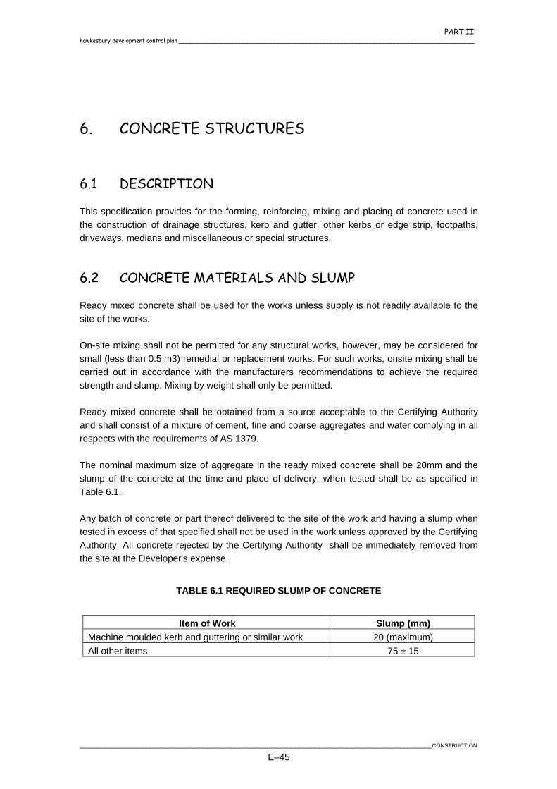
PART II hawkesbury development control plan ____________________________________________________________________________________
6. CONCRETE STRUCTURES
6.1 DESCRIPTION
This specification provides for the forming, reinforcing, mixing and placing of concrete used in the construction of drainage structures, kerb and gutter, other kerbs or edge strip, footpaths, driveways, medians and miscellaneous or special structures.
6.2 CONCRETE MATERIALS AND SLUMP
Ready mixed concrete shall be used for the works unless supply is not readily available to the site of the works. On-site mixing shall not be permitted for any structural works, however, may be considered for small (less than 0.5 m3) remedial or replacement works. For such works, onsite mixing shall be carried out in accordance with the manufacturers recommendations to achieve the required strength and slump. Mixing by weight shall only be permitted. Ready mixed concrete shall be obtained from a source acceptable to the Certifying Authority and shall consist of a mixture of cement, fine and coarse aggregates and water complying in all respects with the requirements of AS 1379. The nominal maximum size of aggregate in the ready mixed concrete shall be 20mm and the slump of the concrete at the time and place of delivery, when tested shall be as specified in Table 6.1. Any batch of concrete or part thereof delivered to the site of the work and having a slump when tested in excess of that specified shall not be used in the work unless approved by the Certifying Authority. All concrete rejected by the Certifying Authority shall be immediately removed from the site at the Developer's expense.
TABLE 6.1 REQUIRED SLUMP OF CONCRETE
Item of Work Slump (mm)
Machine moulded kerb and guttering or similar work 20 (maximum) All other items 75 ± 15
____________________________________________________________________________________________________CONSTRUCTION
E–45
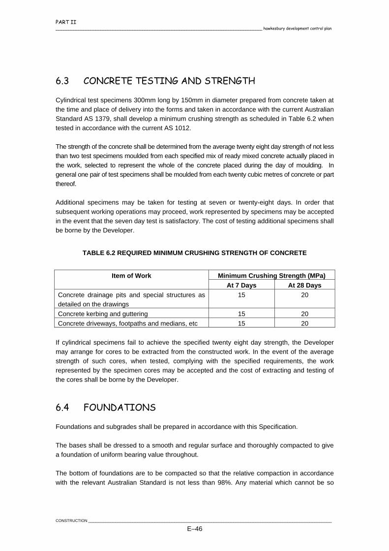
PART II ____________________________________________________________________________________ hawkesbury development control plan
6.3 CONCRETE TESTING AND STRENGTH
Cylindrical test specimens 300mm long by 150mm in diameter prepared from concrete taken at the time and place of delivery into the forms and taken in accordance with the current Australian Standard AS 1379, shall develop a minimum crushing strength as scheduled in Table 6.2 when tested in accordance with the current AS 1012. The strength of the concrete shall be determined from the average twenty eight day strength of not less than two test specimens moulded from each specified mix of ready mixed concrete actually placed in the work, selected to represent the whole of the concrete placed during the day of moulding. In general one pair of test specimens shall be moulded from each twenty cubic metres of concrete or part thereof. Additional specimens may be taken for testing at seven or twenty-eight days. In order that subsequent working operations may proceed, work represented by specimens may be accepted in the event that the seven day test is satisfactory. The cost of testing additional specimens shall be borne by the Developer.
TABLE 6.2 REQUIRED MINIMUM CRUSHING STRENGTH OF CONCRETE
Item of Work Minimum Crushing Strength (MPa)
At 7 Days At 28 Days Concrete drainage pits and special structures as detailed on the drawings
15 20
Concrete kerbing and guttering 15 20 Concrete driveways, footpaths and medians, etc 15 20
If cylindrical specimens fail to achieve the specified twenty eight day strength, the Developer may arrange for cores to be extracted from the constructed work. In the event of the average strength of such cores, when tested, complying with the specified requirements, the work represented by the specimen cores may be accepted and the cost of extracting and testing of the cores shall be borne by the Developer.
6.4 FOUNDATIONS
Foundations and subgrades shall be prepared in accordance with this Specification. The bases shall be dressed to a smooth and regular surface and thoroughly compacted to give a foundation of uniform bearing value throughout. The bottom of foundations are to be compacted so that the relative compaction in accordance with the relevant Australian Standard is not less than 98%. Any material which cannot be so
CONSTRUCTION ___________________________________________________________________________________________________
E–46
PART II hawkesbury development control plan ____________________________________________________________________________________
compacted shall be removed by the Contractor when directed by the Certifying Authority and replaced with 20mm gauge clean metal or other suitable approved material, compacted in accordance with the above requirement. No concrete shall be placed until the foundations have been inspected and approved by the Certifying Authority.
6.5 REINFORCEMENT
Reinforcing bars shall be of mild steel conforming to the current Australian Standard "Hard-drawn Steel Reinforcing Wire" and "Hard-drawn Steel Wire Reinforcing Fabric" and shall conform to the current Australian Standards AS 1302, 1303 and 1304. All steel reinforcement shall be free from mill scale, grease, tar, paint, oil, mud, mortar or other foreign substance and shall be true to size. If in the opinion of the Certifying Authority the steel is coated with more than a thin film of rust it may be rejected for use in the work and shall be immediately removed from the site by the Developer. When required by the Certifying Authority, the Developer shall submit samples of the reinforcement cut to a suitable length or section for testing purposes. All reinforcement shall be accurately spaced in situ to the spacing and positions shown in the Documents with bends and hooks located at the points shown. Reinforcement shall be secured in position by being tied a sufficient number of times with suitable wire at laps and crossings to prohibit displacement during the pouring and working of the concrete. Reinforcement in concrete slabs and similar work shall be supported on chairs of approved manufacture, height and spacing. No alternatives shall be accepted.
6.6 FORMWORK
Formwork shall be so designed and assembled that it can be removed without damage to the concrete. Materials used in the formwork shall be of approved timber free from loose knots and other defects, board or metal plate. All formwork shall conform to AS3610. Timber forms for exposed surfaces shall be dressed on at least one surface and shall be either dressed or tongued and grooved at connecting edges. Forms for unexposed surfaces of walls, slabs etc. may be of undressed timber, board or metal plate. Metal plate forms for exposed surfaces shall be clean, smooth, undented and unmarked and devoid of holes. Where bolt, screw or rivet heads are used for connections, such connections shall be countersunk.
____________________________________________________________________________________________________CONSTRUCTION
E–47
PART II ____________________________________________________________________________________ hawkesbury development control plan
Forms shall be assembled true to line, level and grade, held rigidly to maintain position and shape and shall be butted so as to be mortar tight. Forms shall be chamfered or filleted to the details shown in the Documents. Prior to the pouring and placing of concrete, the internal surfaces of the forms including chamfers, fillets, removable ducting and similar shall be uniformly coated with a thin film of oil, soap or other approved formwork compound to avoid adhesion of cement mortar and the staining and discolouration of exposed surfaces of the concrete. Any oil, soap etc adhering to the reinforcement shall be thoroughly removed or the reinforcement taken from the forms and replaced with the specified quantity of clean, undamaged material all to the requirements of the Certifying Authority. Any bolts, spacers or similar, supporting or separating forms shall be suitably greased and placed so that they may be later removed without damage to the concrete. Formwork and forms shall be inspected by the Certifying Authority immediately prior to the placing of concrete and any bulging, warping or displacement of any kind shall be rectified before pouring commences. If during the placing of any concrete the formwork or forms show any signs of displacement, that portion of the concrete shall be removed immediately, the formwork or forms re-secured rigidly to the satisfaction of the Certifying Authority and the concrete pour completed within the requirements of this Specification.
6.7 CONCRETE PLACING
Subgrade, formwork, forms and reinforcement shall be approved by the Certifying Authority before concrete is ordered for placing. All sawdust, shavings, pools of water and debris shall be removed from the space to be occupied by the concrete. Concrete shall be placed in the forms by chute in a uniform continuous flow, the length and inclination of the chute being such as to prevent separation of the concrete ingredients. Concrete shall not be dropped into place from a height greater than one and a half metres. Prior to placing, the full area to be occupied by the concrete shall be thoroughly moistened. Concrete shall be deposited and spread in horizontal layers and shall be compacted by vibration or other approved means. Care shall be taken to fill every space in the forms, to work coarse aggregate uniformly throughout the mix and away from form faces and to force concrete under and around the reinforcement without it being displaced.
CONSTRUCTION ___________________________________________________________________________________________________
E–48

PART II hawkesbury development control plan ____________________________________________________________________________________
6.8 JOINTS
6.8.1 Construction Joints
Where a construction joint is necessary in a concrete pour, it shall be provided in accordance with the details shown on the Documents, or if not shown the joint shall be formed in a slab with rigid bulkhead and dowels in a manner approved by the Certifying Authority, or in the case of a vertical section, by finishing the concrete to a level plane with a roughened surface. Prior to the resumption of a concrete pour, the surface of the joint shall be cleaned of all laitance, loose and foreign material, care being taken not to disturb reinforcement or to damage adjoining concrete surfaces. The joint shall be thoroughly saturated with water and fresh concrete shall be carefully worked against the surface of the concrete previously placed and around reinforcement at the joint.
6.8.2 Contraction Joints
Contraction joints shall be constructed as shown on the approved plan. Contraction joints shall consist of weakened planes created by either sawcutting or formed vertical grooves in the top of the concrete to a minimum (¼) one quarter depth of the slab thickness and spaced in accordance with Drawing No. SD61.
6.8.2.1 Sawcutting Joints
Sawcutting contraction joints shall be inserted by cutting of the slab to a minimum (¼) one quarter depth of the slab thickness for unreinforced or 10mm for reinforced.
6.8.2.2 Formed Grooves (Dummy Joints)
Formed grooves (dummy joints) shall be made by depressing into the wet concrete an approved tool or device vertically to a (¼) one quarter of the slab thickness for unreinforced or 10mm for reinforced.
6.8.3 Expansion joints
Expansion joints shall be constructed as shown on the approved plan. The jointing material in expansion joints shall extend for the full depth of the concrete.
____________________________________________________________________________________________________CONSTRUCTION
E–49
PART II ____________________________________________________________________________________ hawkesbury development control plan
Expansion Joints are to be provided between the concrete and all abutting and penetrating structures e.g. poles, gully pits, utilities etc. Also referred to as Isolation Joints.
6.9 REMOVAL OF FORMS
All forms shall remain in position for a period not less than twenty four hours after concrete has been placed, earlier removal being permitted only on the authorisation of the Certifying Authority. Should the air shade temperature fall below ten degrees or rise above twenty seven degrees Celsius, the minimum period may be varied as the Certifying Authority directs. Curing of concrete shall commence immediately forms are removed.
6.10 CONCRETE FINISHING
All concrete surfaces shall be finished true and even, free from air and stone pockets, depressions or projections. All arises shall be sharp and true and moulding shall be evenly mitred, care being exercised in removing forms to ensure this result. Immediately on removal of formwork all rough surfaces, holes and honeycombed areas shall be repaired by removing loose material and defective work, wetting the affected area, filling depressions with fresh cement-sand mortar having the same proportions of cement and sand as used in the base concrete and brought to an even surface with a wooden or steel trowel as required to produce the specified finished surface. Wire ties protruding from the concrete after removal of the forms shall be cut back and any chipping of the concrete in executing this requirement shall be repaired with cement-sand mortar as previously specified. Holes left by the removal of bolts, spreaders or the like shall be similarly treated. Additional treatment in some locations may be required as directed. When directed, exposed surfaces shall be wetted with clean water and rubbed down with an approved Carborundum or sandstone block until all repaired areas, rough surfaces and joint marks of forms are removed leaving the surfaces clean and smooth and uniform in colour and appearance. Finishing work shall be completed within two days following removal of the forms.
6.11 CURING
Where necessary, the completed concrete shall be protected from extremes of temperature for a period of seven days during which time the concrete shall be kept continuously moist and covered with canvas, plastic or hessian sheets, chemical curing compounds, sand at least 50mm thick or other approved means.
CONSTRUCTION ___________________________________________________________________________________________________
E–50

PART II hawkesbury development control plan ____________________________________________________________________________________
New work shall be adequately protected from damage by weather conditions, traffic or other causes and all necessary barriers and signs for the control of vehicular and pedestrian traffic shall be erected and maintained for the specified period of concrete curing.
6.12 KERB AND GUTTER
6.12.1 Base
The base for kerb and gutter shall be formed at the required depth, on an approved pavement sub-base in accordance with Section 7 of this Specification. A sub-base of compacted thickness not less than the road pavement sub-base shall be provided on the compacted subgrade. Immediately prior to the placing of the concrete, the surface shall be moistened, checked for uniformity and all irregularities made good. The sub-base materials under the kerb and gutter shall be protected from stormwater scour prior to backfilling and/or placing of the pavement materials. The sub-base shall extend to a point at least 150mm beyond the back of the kerb to the satisfaction of the Certifying Authority. Refer to Drawing No. SD4.
6.12.2 Kerb Moulding Machines
Unless otherwise specified, kerb moulding machines are to be used for the construction of kerb and gutter and profiles are to be in accordance with the Drawing No. SD4. The speed of the kerb moulding machine shall not exceed 2.5 metres per minute unless otherwise approved in writing by the Certifying Authority. The Contractor may apply for approval to construct kerb and gutter by the use of formwork or to vary the kerb and gutter profile.
6.12.3 Finish
All exposed concrete surfaces shall be finished clean, smooth and uniform in colour and appearance. All corners, joints and edges shall be left neatly rounded. Service conduit markings are to be provided where required.
6.12.4 Joints
Vertical expansion joints of approved bitumen impregnated jointing material shall be placed at intervals of not more than 6.0 metres at the end of each day’s construction, at each end of vehicular crossings and pedestrian ramps, at the junctions with the existing old work and at the commencement of each 0.6 metre kerb transition adjacent to gully pits.
____________________________________________________________________________________________________CONSTRUCTION
E–51
PART II ____________________________________________________________________________________ hawkesbury development control plan
For hand formed Kerb & Gutter, contraction joints are required at 3.0 metre intervals with expansion joints at 6.0 metre intervals. For machine poured Kerb and Gutter, provide Guillotine joints at 3 metre intervals. A grooving tool is permitted where the groove extends into the kerb and gutter faces, a minimum of 75mm. A dummy joint shall be cut at the centre of double vehicle crossings. Joints shall be located at least 0.5 metres clear from any drainage holes (roof water outlets).
6.12.5 Vehicular Crossings
Where kerb and gutter construction fronts proposed allotments or where else directed, the kerb shall be discontinued to allow for vehicles crossing the footpath. At such points a layback shall be constructed as per Council's Driveway Specification, in the position as shown on the Approved Drawing. Crossings are to have a minimum separation of 1.0 metre and generally shall be located 1.0 metre from the lower side of the respective Lot boundary. All gutter crossings are to be constructed clear of service conduits, hydrants and pit lintels. Where existing kerb is to be removed for the provision of laybacks, pedestrian ramps or the replacement of redundant laybacks, both the kerb and gutter shall be removed and replaced. Refer to Drawing Nos. SD66 to SD70.
6.12.6 Pedestrian Ramp (Pram Ramp)
At all intersections or where directed, the kerb shall be discontinued and pedestrian ramps (no lip) constructed in accordance with Drawing No. SD62.
6.12.7 Curing
Curing shall be carried out in accordance with Section 6.11 except that when kerb moulding machines are used, an approved chemical curing compound shall be applied to all exposed surfaces on the day of moulding.
6.12.8 Provision For Drainage
Outlets through the kerb shall be provided as specified or directed for each house to drain roof water into the gutter.
CONSTRUCTION ___________________________________________________________________________________________________
E–52
PART II hawkesbury development control plan ____________________________________________________________________________________
One drainage outlet shall be provided on the lower side of each lot and clear of the vehicular entrance, where provided. The Developer shall fit the outlets into the kerb in a workmanlike manner ensuring that they are firmly secured in the concrete and fall towards the gutter. The surface shall be refinished to match the balance of the work. Where kerb moulding machines are used, the outlets shall be placed in position immediately after the passing of the kerb moulding machine. Outlets in roll kerbs shall be of approved manufacture and made of extruded aluminium or galvanised steel. The shape and size of the outlets, shall conform to that shown on Drawing No. SD39. The outlets in roll kerbs shall be of approved rectangular section cut to match the kerb profile. In barrier kerb, tapered hole 90mm in diameter at the kerb face and 100 m diameter at the back of the kerb shall be provided. Refer to Drawing No. SD39. Notwithstanding the levels shown on the Drawings for gully pits, kerb returns and low points, the Contractor shall ensure that the gutter near or adjacent to the gully pit is properly drained and under no circumstances shall the kerb and gutter be allowed to pond water.
6.12.9 Backfilling
After the concrete has set sufficiently, but no sooner than three days after placing, the area behind kerbs and/or gutters shall be backfilled with sound approved material. It shall be thoroughly compacted in layers not exceeding 150mm in thickness, without displacement of the adjacent construction and left in a neat and workmanlike manner. Backfilling and/or the placement of pavement material shall only be undertaken with the prior approval of the Certifying Authority.
6.12.10 Replacement of Incorrect and/or Damaged Construction
The Developer shall construct all kerbs and gutters or similar work in a sound workmanlike manner so that it will resist damage or displacement by weather conditions, road construction, builders and Service Authorities' plant, or undermining by the scouring away of the sub-base materials. Where kerbs and gutters are damaged or displaced by such agencies after construction due to fault by the Developer, or is not constructed to specified line and level, it shall be removed and reconstructed.
____________________________________________________________________________________________________CONSTRUCTION
E–53
PART II ____________________________________________________________________________________ hawkesbury development control plan
6.12.11 Testing
Where kerbing and guttering is constructed using a self-propelled moulding machine, the developer accepts responsibility for the taking and testing of core samples in accordance with the relevant section of the current AS 1012, at maximum 100m spacing, the submission of results to the Certifying Authority and removal of all kerb and gutter where the minimum specified 28 day compressive strength of 20MPa is not achieved. Cores shall be 75mm diameter and drilled vertically through the top of herb. Following removal of the sample, the core hole is to be restored to the satisfaction of the Certifying Authority.
6.12.12 Subsoil Drainage
Sub-soil drainage shall be provided under the Kerb and Gutter on both sides of those areas fully in cut and the high side of other roads or in the positions nominated by the Certifying Authority and be constructed in accordance with the details as provided in Drawing No. SD3.
6.13 FOOTPAVING AND CYCLEWAYS
6.13.1 General
Footpaths and cycleways shall be located 600mm from the property boundary and fall to the top of kerb of 1-3%. Footpaths shall be 75mm thick except when the construction is to be undertaken prior to the completion of the dwellings where the footpaving is to be 100mm thick with F72 mesh (25mm cover) for Light Duty and 150mm with 2 x F72 (25mm cover top and bottom) mesh for Heavy Duty. Cycleways shall be 100mm thick with F72 mesh (25mm cover).
6.13.2 Subgrade
The subgrade for concrete pavement shall be formed at the required depth below the base in accordance with Section 7 of this specification. The paving shall be aligned in straight lines and circular curves and be parallel to the kerb.
6.13.3 Sub-Base
Approved sub-base material of the type shown in the Documents shall be spread, levelled and compacted on the prepared sub-grade in accordance with Section 7 of this Specification. The minimum compacted thickness of the sub-base material shall be 50mm or as indicated in the Documents. Immediately prior to placing of the concrete the sub-base shall be lightly watered.
CONSTRUCTION ___________________________________________________________________________________________________
E–54
PART II hawkesbury development control plan ____________________________________________________________________________________
6.13.4 Reinforcement
Reinforcement shall be in accordance with Section 6.5 of this Specification and as shown in the Documents and shall be supported above the subgrade by approved chairs. All splicing of the reinforcement shall have a minimum overlap of 300mm and be securely tied.
6.13.5 Finish
The concrete shall be struck off with a screed and finished with wooden floats, followed by light brooming at right angles to the alignment of the pavement to give a uniform non-slip surface. All edges and joints shall be finished off with an approved edging tool forming a minimum 50mm margin in a neat workmanlike manner.
6.13.6 Joints
In footpaving, transverse joints (dummy Joints) shall be constructed at intervals of 1.20 metres and expansion joints shall generally be at intervals of 6.0 metres. In cycleways, transverse joints shall be constructed at intervals equal to the width of the cycleway and expansion joints at intervals of every 3 panels.
6.13.7 Protection
Where there is any likelihood of access by the public, barriers and lights shall be provided and erected at the start and end of the works in accordance with Australian Standard AS 1742.
6.13.8 Cleaning Up
All spoil shall be removed concurrently with the work of excavation and backfilling. Trimming of footpath areas shall be completed within seven days of the concrete being placed. An additional days deferment of backfilling at gateways may be permitted to avoid damage to footpaving by vehicular traffic. All footpath areas for the full width adjacent to constructed paving shall be trimmed by cutting or filling where required and all areas of loose material lightly compacted to the specified crossfalls and grades as shown in the Documents. On completion of kerb and gutter and subsequent backfilling/trimming of the footway, a strip of turf (min. 500mm wide) shall be placed adjacent to the kerb. The turfing strip shall be maintained to provide a dense cover to act as a siltation barrier during the Defects Liability period.
____________________________________________________________________________________________________CONSTRUCTION
E–55

PART II ____________________________________________________________________________________ hawkesbury development control plan
6.14 DRAINAGE PITS
6.14.1 Excavation
The foundations shall be excavated to the neat lines and formed at the required depth in accordance with the Drawings. All soft and yielding and other unsuitable material shall be removed and the bed shall be thoroughly compacted and finished to a firm smooth surface of uniform bearing value. If the bed is dry it shall be sprinkled with as much water as it will readily absorb before concrete is placed.
6.14.2 Structure
Drainage pits shall be constructed to the levels and locations indicated in the Documents. All pits shall be constructed to finish flush with the design surface levels. Where drainage pits exceed 1.2 metres in depth, galvanised step irons must be installed with a 350mm vertical spacing. Refer to Drawing No. SD41. Where drainage pits exceed 1.8 metres in depth, the pit shall be constructed of reinforced concrete, including the base. Refer to Drawing No. SD35, for reinforcing details for pits up to 3.0 metres in depth. For pits greater than 3.0 metres in depth, reinforcing details are to be provided on the design plans and be certified by a structural Engineer. Pits shall be constructed of sufficient internal dimensions to avoid "birdsmouthing" of pipes. The minimum internal dimensions of all drainage pits in Kerb and Gutter shall be 600mm x 900mm for depths up to 1500mm and 900mm x 900mm for depths greater than 1500mm. For pits in Non Kerb and Gutter situations, the minimum internal dimension is 900mm x 900mm. Pit walls and are to be a minimum 150mm thick and shall be formed on both the inside and outside faces. Pit floors are to be a minimum 150mm thick. For interallotment drainage refer to Section 5.17. Precast concrete lintels of a size indicated in the Documents or as directed by the Certifying Authority shall be used and all grates shall be of galvanised steel. A minimum opening of 1.8 metres shall be provided. Where pits are not part of the Kerb and Gutter, all lids must be either a Gatic style within the road pavement or Grate style elsewhere. In general, pits with the unsealed table drain will be a Grated Surface Inlet Pit (GSIP) – letter box style.
CONSTRUCTION ___________________________________________________________________________________________________
E–56

PART II hawkesbury development control plan ____________________________________________________________________________________
The use of precast concrete pits shall only be permitted within development sites. All external drainage pits must be cast in-situ. Subsoil drainage pipes shall be connected through the upstream pit wall and shall extend through any mass concrete benching so as to provide a free outlet. Where pits are constructed in sags, drainage holes shall be provided in the wall to drain the boxing as shown on Drawing Nos. SD30 & SD35. Inlet or outlet pipes shall be neatly finished off flush with the interior surfaces of the gullies. Drainage pits shall be benched internally with mass concrete to not less than one third of the outlet pipe diameter, notwithstanding that such benching may not be shown in the relevant Documents.
6.14.3 Steel Fittings
Steel gratings, frames and other fittings are to be to the requirements of AS 1657-1985 Ordinary Structural Steels - Ordinary Weldable Grades, and they shall be hot-dipped galvanised in accordance with AS 1650-1989 "Galvanised Coatings" AS 1650-1989. Gully grates in kerb and gutter are to be supplied with a flat skirt base. Fittings shall be to the grade and dimension shown in the Documents and/or Standard Drawings. Mild steel frames shall be firmly and evenly bedded and shall be placed so that the hinged grates can be fully opened. Gratings shall be secured by means of "J" bolts or other approved method.
6.14.4 Kerb Inlets
As shown on Drawing No. SD30, the kerb inlets for extended kerb inlet pits are to be precast and in accordance with an approved design. Lintels with clear opening widths as shown on the approved engineering drawings are to be used. Where no opening width is specified, a lintel of minimum 1.8 metre opening is to be used on grade and 2.4 metre opening in sag. Where pits are located on curves or bends, precast lintels shall be provided to suit the kerb radius.
____________________________________________________________________________________________________CONSTRUCTION
E–57
PART II ____________________________________________________________________________________ hawkesbury development control plan
6.15 PRECAST CONCRETE SECTIONS (PIT AND HEADWALLS)
Where indicated on the Documents or where authorised by the Certifying Authority, precast concrete components shall be provided to the form and dimensions shown in the Documents and shall be constructed in the positions specified in all cases.
6.16 DISH CROSSING
Where shown on the Documents, concrete dish crossings 0.9 metres wide shall be constructed at intersections with integral concrete aprons as directed by the Certifying Authority. The dish crossing shall have a crossfall of 40mm from lip to invert level and a minimum concrete thickness of 150mm. The concrete shall be reinforced with two (2) layers of F72 reinforcing fabric.
6.17 SPRAY CONCRETE
Concrete lining for open drains shall be either cast-in-place concrete or sprayed concrete. The minimum thickness of the concrete shall be 100mm. Sprayed concrete lining shall not be permitted less than 1 metre in width. Sprayed concrete shall have a minimum cement content of 380 kg/m3 as discharged from the nozzle and must have a minimum compressive strength of 25 MPa at 28 days when measured by testing 75mm diameter cores taken from in-place sprayed concrete.
6.18 PATTERN STENCILLED CONCRETE PAVEMENT FOR MEDIAN ISLANDS & ROUNDABOUTS
Pattern Stencilled Pavement shall consist of a concrete base reinforced as specified, with F72 having 25mm cover and set on approved stools laid on an approved subgrade of granular material. After screeding of the concrete the specified patterned paper moulding shall be placed and stamped in place. The colouring shall be suppled at the application rate and method specified by the manufacturer to a nominal 3mm thickness. Surplus colour agent shall be removed by mechanical means. A curing agent shall then be applied as required by the specific method of colour application followed by the sealer. The sealer shall be of a non-slip type suitable for public roadways. Contraction/expansion joints shall be constructed where directed or show on the plan.
CONSTRUCTION ___________________________________________________________________________________________________
E–58
PART II hawkesbury development control plan ____________________________________________________________________________________
7. FLEXIBLE ROAD PAVEMENTS
7.1 DESCRIPTION
A formal pavement design shall be prepared by a registered N.A.T.A. laboratory based on sampling and testing of the subgrade materials from the site. Details of the pavement design, results of subgrade testing (including design California Bearing Ratio values for the subgrade) and design traffic loadings are to be submitted to the Certifying Authority for approval prior to commencement of pavement construction. The pavement materials for flexible roads shall consist of approved crushed or ripped sandstone and DGB 20 or other materials approved by the Certifying Authority. Alternatively the pavement may consist of "deep lift" asphaltic concrete laid on a bound or unbound base course. Asphaltic Concrete shall conform with RTA Specification 1013 - Asphalt Part K. The materials shall be spread on the subgrade or sub-base in uniform layers to provide the specified pavement thickness. The minimum unbound granular pavement thickness shall be 300mm, comprising of a 200mm thick sub-base and 100mm thick base. In Rural roads, a two coat hot bitumen seal shall be provided following the completion and testing of the base course. The cul-de-sac is to have a minimum of 50mm of Asphaltic Concrete. In all other applications, a wearing course shall be a minimum of 25mm of asphaltic concrete. The cul-de-sac is to have a minimum of 50mm of Asphaltic Concrete. Final AC shall only be placed after inspection and approval by the Certifying Authority. For rural road construction the base course is to be provided with a cut-back bitumen primer coat. Within 24 hours the wearing surface, comprising a two coat hot bitumen seal is to be applied.
7.2 CRUSHED OR RIPPED SANDSTONE - (SUB-BASE COURSE)
All material shall be delivered from approved quarries. Any approval given to the source of supply of materials may be withdrawn if a significant number of samples taken from the pavement after compaction fail to comply with this Specification.
____________________________________________________________________________________________________CONSTRUCTION
E–59

PART II ____________________________________________________________________________________ hawkesbury development control plan
Crushed or ripped sandstone shall be either 75mm or 100mm nominal size derived from a well cemented medium grained quartz sandstone free from overburden, clay seams, shale and other deleterious material and shall meet the following requirements.
7.2.1 Material Requirements
Linear Shrinkage: Text Method AS1289.C.4.1 – 1977 Max Linear Shrinkage – 5%
CBR - Min 30%
Grading: Table 7.1 below sets out the desirable grading limits.
TABLE 7.1 GRADING REQUIREMENTS FOR CRUSHED SANDSTONE
Nominal Size Percentage Passing
75.00mm 85-100 53.00mm 75- 100 37.50mm 65-100 26.50mm 57-94 19.00mm 50-88 9.50mm 37-76 4.75mm 27-65 2.36mm 20-52 1.18mm 15-42 425,µm 10-28 75,µm 5-17 2,µm 0-5
7.2.2 Variations
Where the grading and linear shrinkage tests vary outside the above limits and there is evidence that the subject material (or material similar in composition to it) has given satisfactory performance under similar conditions to the construction in question, then the following requirements shall be applied.
% Passing 425µm Maximum Limits 15 - 45
Linear Shrinkage % x % Passing 425um Maximum 160
Plasticity Index % x % Passing 75,µm Maximum 200
CONSTRUCTION ___________________________________________________________________________________________________
E–60
PART II hawkesbury development control plan ____________________________________________________________________________________
CBR - Min 30% of the Min. 19mm fraction when compacted to 100% of the standard max. dry density to AS 1289-5.1.1- 1993 is obtained. Alternatively, a sub-base material satisfying the requirements for a class "DGS" material as specified in RTA QA Specification 3051 - Unbound Base and Subbase Materials for Surfaced Road Pavements and RTA QA Specification 3052 - Material to be Bound for Base and Subbase Materials for Surfaced Road Pavements, may be used subject to approval from the Certifying Authority. The minimum compacted thickness of the sub-base course shall be 200mm of sandstone or 175mm of "DGS" material.
7.2.3 Sampling and Testing of Materials
The Developer shall arrange for a sample load of the proposed sandstone material from the approved quarry to be delivered and stored on site after approval of the source. Samples for testing shall be taken from the sample load by the Certifying Authority to assess the conformity with this Specification. No other deliveries of sandstone shall be made without the Certifying Authority's approval of the sample load meeting the Specification requirements. Where in the opinion of the Certifying Authority any materials do not meet the requirements of this Specification the Developer shall, on instructions from the Certifying Authority, remove such materials from the site.
7.3 CRUSHED ROCK (DGB 20) - (BASE COURSE)
Crushed rock (DGB 20) shall be unbound granular material and may consist of a blend of two or more materials. When the primary material is deficient in fine particles, material may be added and blended as necessary to meet the requirements of the Specification. Material produced by blending shall be uniform in grading and physical characteristics. The material shall comply with RTA QA Specification 3051 - Unbound Base and Subbase Materials for Surfaced Road Pavements.
____________________________________________________________________________________________________CONSTRUCTION
E–61
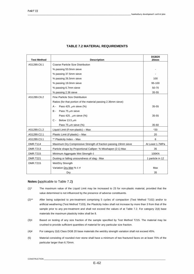
PART II ____________________________________________________________________________________ hawkesbury development control plan
TABLE 7.2 MATERIAL REQUIREMENTS
Test Method Description DGB20 20mm
AS1289.C6.1 Coarse Particle Size Distribution
% passing 53.0mm sieve -
% passing 37.5mm sieve -
% passing 26.5mm sieve 100
% passing 19.0mm sieve 95-100
% passing 6.7mm sieve 50-70
% passing 2.36 sieve 35-55
AS1289.C6.2 Fine Particle Size Distribution
Ratios (for that portion of the material passing 2.36mm sieve)
A - Pass 425 ,µm sieve (%) 35-55
B - Pass 75 µm sieve
Pass 425 , µm sieve (%) 35-55
C - Below 13.5 µm
Pass 75 µm sieve (%) 35-60
AS1289.C1.2 Liquid Limit (if non-plastic) – Max *20
AS1289.C2.1 Plastic Limit (if plastic) – Max 20
AS1289.C3.1 ** Plasticity Index – Max 6
DMR.T114 Maximum Dry Compressive Strength of fraction passing 19mm sieve At Least 1.7MPa
DMR.T213 Particle shape by Proportional Calliper- % Misshapen (2:1) Max 35
DMR.T215 Minimum Aggregate Wet Strength ¢ 100KN
DMR.T221 Dusting or falling unsoundness of slag - Max 1 particle in 12
DMR.T215 Wet/Dry Strength
Variation Dry-Wet % ¢ # Max
Dry 35
Notes (applicable to Table 7.2)
(1)* The maximum value of the Liquid Limit may be increased to 23 for non-plastic material, provided that the
value determined is not influenced by the presence of adverse constituents.
(2)** After being subjected to pre-treatment comprising 5 cycles of compaction (Test Method T102) and/or to
artificial weathering (Test Method T103), the Plasticity Index shall not increase by more than 3 from that of the
sample prior to any pre-treatment and shall not exceed the values of at Table 7.2. For category 2(d) base
materials the maximum plasticity index shall be 8.
(3)¢ Based on testing of any size fraction of the sample specified by Test Method T215. The material may be
crushed to provide sufficient quantities of material for any particular size fraction.
(4)# For category 2(d) Class DGB 20 base materials the wet/dry strength variation shall not exceed 45%.
(5) Material consisting of rounded river stone shall have a minimum of two fractured faces on at least 75% of the
particular larger than 6.70mm.
CONSTRUCTION ___________________________________________________________________________________________________
E–62

PART II hawkesbury development control plan ____________________________________________________________________________________
Alternatively, where shown in the Documents, the base course material shall consist of crushed or ripped sandstone, either 50mm or 75mm nominal size, derived from a well cemented medium grained quartz sandstone free from overburden, clay seams, shale and other deleterious material. Crushed sandstone however, may only be used as a base course material where the wearing surface consists of a single coat flush seal and a minimum of 25mm of asphaltic concrete or the sandstone is stabilised using cement or lime as determined from test results from an approved soils laboratory. Refer to Section 7.4. Where stabilised crushed rock is used as the base material, it shall be spread and compacted within twenty-four (24) hours of delivery. The minimum compacted thickness of the base course shall be 100mm for "DGB 20" material or 150mm for sandstone. The base course shall, adjacent to kerb and gutter and/or existing pavement, be finished to a level which will permit placement of the specified thickness of the wearing course.
7.4 STABILISATION OF IN SITU AND IMPORTED MATERIALS
In the construction of roads in rural areas, it may be possible to stabilise the pavement material to provide the required pavement. A pavement design shall be submitted to the Certifying Authority for consideration, and shall include details of the type and quantity of stabilising agent to be used to obtain an Unconfined Compressive Strength of 1.5 MPa and the proposed depth of stabilising. The minimum thickness of any stabilised pavement shall be 250mm.
7.5 SHOULDERS
(Table Drain details refer to Section 4.15). The subgrade level must extend to the invert of the table drain on both sides as per Drawing No. SD1. The shoulder shall consist of the road pavement subbase material with the exception of the top 100mm, which shall consist of either a DGB20 or 20mm nominal Crushed Shale material. The material shall be uniformly compacted at required moisture content and graded and trimmed to the designed finished levels.
____________________________________________________________________________________________________CONSTRUCTION
E–63

PART II ____________________________________________________________________________________ hawkesbury development control plan
The minimum width of the Shoulder is to be 1.2m. A Concrete Dish Drain is to be provided where the table drain exceeds 16% or is less than 1%. The adjacent road shoulder is to be sealed.
7.6 DELIVERY
The pavement material shall be transported from the source to the work in vehicles which are constructed so as to prevent the loss of material. Material shall be supplied with a moisture content (uniformly distributed) between the optimum moisture content and 3% below the optimum moisture content.
7.7 BOXING AND SUBGRADE
The formation shall be finished with a boxing for the reception of the pavement. The boxing is to extend a minimum 300mm behind the nominal kerb line or 300mm outside the edge of seal in rural construction. The finished subgrade shall be graded parallel to the designed finished surface of the roadway and at a depth below grade line equal to the finished thickness of pavement. Shoulders and/or footpaths shall be finished true to profile as shown in the Documents. The subgrade shall be inspected by the Certifying Authority and the placement of pavement material shall not commence until approval to do so has been obtained from the Certifying Authority and testing has been undertaken in accordance with Section 7.10. Permission to construct a stabilised subgrade shall only be given where, in the opinion of the Certifying Authority, the subgrade soil lends itself to this type of construction. Results of all soil tests carried out on the subgrade material shall be submitted to the Certifying Authority along with details of the type and quantity of stabilising material to be used. At points on the road where, by reason of the design grading and the boxing, water would tend to accumulate, temporary provision for drainage shall be made by cutting the shoulder at suitable and frequent points and diverting the drainage. Care shall be taken to prevent scour of any part of the construction. All cuts for temporary drainage, unless otherwise directed to be retained as catch or shoulder drains, shall be restored to the satisfaction of the Certifying Authority prior to the placement of pavement materials. Alternatively, with the Certifying Authority's permission, temporary connection may be made to the pipe drainage system, provided all necessary restoration is carried out under the direction of the Certifying Authority, and adequate filter surrounds are provided to the pipe system inlet, to intercept sediment.
CONSTRUCTION ___________________________________________________________________________________________________
E–64

PART II hawkesbury development control plan ____________________________________________________________________________________
7.8 SPREADING
Pavement material shall be spread in uniform layers of not more than 150mm nor less than 75mm so that after compaction the total pavement thickness is as specified. Spreading shall be undertaken by a method which will ensure that segregation does not occur. All pavement layers shall extend a minimum 300mm behind the kerb line or 300mm outside the edge of seal in rural construction. Prior to compaction, the moisture content of material, shall be adjusted to optimum moisture content. Where necessary, water shall be added by an approved method and shall be mixed uniformly with the pavement material by an approved mechanical device. If there is existing excess moisture in the material, it shall be dried to the specified moisture content by loosening and aerating. Where the compacted surface is below the specified level the defective area shall be scarified to the full depth of the layer, new material added as required and the area recompacted to required levels. Pavement material shall not be spread upon a water-logged subgrade or sub-base. If at any time the subgrade or sub-base material should become rutted, or mixed with the pavement material, the Developer shall remove the material, reshape and compact the subgrade or sub-base material and replace the pavement material with fresh material if required.
7.9 COMPACTING AND TRIMMING
During compaction operations the moisture content of the material of a layer or course shall be uniformly adjusted throughout, so as not to exceed Optimum Moisture Content or be less than Optimum minus 3%, or as otherwise approved. Water may be added in an approved manner to achieve or to maintain the required moisture content. After the moisture has been brought to the specified moisture content, it shall be compacted immediately with approved equipment. The compaction shall begin at the sides and progress to the centre, parallel with the centre line of the roadway, uniformly lapping each preceding pass and covering the surface completely. The surface of any compacted layer of material shall, on completion of compaction and immediately before preparation for the overlaying with the next layer, be of a roughened texture, free from compaction planes (false pavement), ridges, cracks, or loose material. All segregated or otherwise defective areas shall be removed to the full thickness of the layer, re-laid with new material and recompacted to the satisfaction of the Certifying Authority. After the first course has been completed to the specified depth and tested, the second course shall be uniformly spread on the prepared surface and similarly treated. The top of each course
____________________________________________________________________________________________________CONSTRUCTION
E–65

PART II ____________________________________________________________________________________ hawkesbury development control plan
shall be graded and trimmed generally to line and level and the profiles checked by the Certifying Authority. Variations in the compacted thickness of each course shall be in accordance with Section 1.11. Any irregularities in excess of the stated tolerances shall be corrected by loosening the surfaces, removing or adding pavement material as required and compacting the area to a uniform surface conforming to the designed cross section and grade. In no case shall quarry dust or other fine materials be used to build up depressions. Compaction of pavement material shall continue until there is no visible movement of the pavement under the proof roller as specified in Section 7.10.3.
7.10 PAVEMENT TESTING
7.10.1 General
The Developer shall arrange and bear the cost of all pavement testing as required by this Section. Test results for each pavement layer shall be submitted to the Certifying Authority for approval. Approval to construct subsequent pavement layers may be given only after the Certifying Authority has reviewed the test results. The pavement compaction requirements shall be as follows: Minimum Dry Density Ratios (AS1289 5.4.1-1993):
Base course 98% Modified
Sub-base course 98% Modified
Subgrade 100% Standard (a) All testing shall be carried out by a NATA registered laboratory. (b) All testing shall be in accordance with test procedures as detailed in AS 1289 (c) CBR testing shall be carried out on a sample which has undergone four days
soaking in the test mould. The Certifying Authority shall be notified prior to all testing and construction.
CONSTRUCTION ___________________________________________________________________________________________________
E–66

PART II hawkesbury development control plan ____________________________________________________________________________________
7.10.2 Density Testing
Density testing shall be carried out on the basis of:
One (1) test every 50 metres of pavement, taken 1.0m from the face of kerb on alternate sides of pavement.
7.10.3 Proof Testing
The Developer shall make available an approved 3-wheeled self-propelled roller (minimum 10 tonne in accordance with Section 4.12) and shall carry out proof loading of each pavement layer to the satisfaction of the Certifying Authority before proceeding to the next stage of construction. Alternatively a single rear axle water cart with a minimum Gross weight of 10 tonne may be permitted by the Certifying authority.
7.10.4 Benkleman Beam Testing
Benkleman Beam testing at 15m intervals per lane shall be carried out as required by the Certifying Authority in accordance with the requirements of ARRB Special Report number 41 at the top of the base course level. The maximum tolerable deflection at any point on top of the base course shall be as shown in Figure 20 ARRB Special Report 41, or for traffic loadings outside the range of Figure 20 ARRB Special Report 41, as specified by the Certifying Authority.
7.11 DEFECTIVE MATERIAL
If at any time during the progress of the work, any material supplied is found to be not in accordance with this Specification, the Certifying Authority will direct the Developer to remove the unsuitable material and replace it with satisfactory material. Previous acceptance of the whole or part of the material by the Certifying Authority, shall not restrict its right to direct removal and replacement of material subsequently found to be unsatisfactory. The Developer shall carry out such remedial work immediately.
7.12 COMPLETED PAVEMENT SURFACE
The completed pavement shall have a uniform, hard, monolithic surface, which shows no visible movement under the roller and in which the pavement particles are tightly and uniformly embedded in a gritty, cementitious matrix. Final sweeping of the pavement shall be carried out immediately prior to the application of bituminous surfacing materials. The coarse particles of the surface course shall be bared but not dislodged and shall be free of all slurry and/or dust which, in the opinion of the Certifying
____________________________________________________________________________________________________CONSTRUCTION
E–67

PART II ____________________________________________________________________________________ hawkesbury development control plan
Authority, may interfere with the proper adherence of the bituminous materials to the pavement surface. Prior to the application of the bituminous wearing course, the Developer shall maintain the pavement in a smooth sound condition to the satisfaction of the Certifying Authority.
7.13 OPENING PAVEMENT TO TRAFFIC
If required during the progress of the works, the Developer shall freely and without undue obstruction permit traffic to use the constructed pavement prior to the preparation for and the application of bituminous surfacing material. Where such use cannot be provided, the Developer shall construct adequate side-tracks or detours.
7.14 MAINTENANCE
During the construction period and throughout the duration of the Maintenance Period, completed pavements shall be maintained by the Developer in a clean and sound condition. In the event of any defect appearing in a pavement and whether before or after the application of surfacing material, the defect shall immediately be made good by the Developer. The defect area being scarified as required, defective material removed, fresh pavement material added and the area re-compacted and trimmed and surfaced to produce a pavement which conforms with the requirements of the Specification and which blends evenly in with adjoining construction, all to the satisfaction of the Certifying Authority.
7.15 RESTORATION OF TRENCHES
Upon completion of trench excavation for the installation of services and laying of ducts, all surplus material shall be removed from the site. All footpath areas shall be returned to the standard crossfall and any vegetation replaced. Where sewer and water crossings are to be provided in existing roads, the trenches shall be backfilled and compacted with a sand/cement blend 20:1 mix to subgrade level, then DGB20 to within 50mm of the road surface. The final 50mm shall be AC10 with an emulsion tack coat applied to both the top of the DGB and the sides of the trench. All openings shall be saw-cut prior to backfilling to eliminate all irregular edges.
CONSTRUCTION ___________________________________________________________________________________________________
E–68

PART II hawkesbury development control plan ____________________________________________________________________________________
8. WEARING COURSE
8.1 GENERAL
The placement of the wearing course shall not commence until all field tests and geotech test results have been successful and approval to do so has been given by the Certifying Authority. The surface of the pavement shall be in accordance with Section 7.12, swept free of loose stones, dust, dirt and foreign matter. All necessary precautions shall be taken to prevent bituminous materials from entering gratings or drainage outlets. During spraying and spreading operations, hydrant boxes, sewer manholes and the like shall be adequately protected with sand and shall, on completion of the work, be cleaned off and left in a satisfactory condition. After the completion of the placement of the wearing course, all material swept into the gutters and onto the footpath area is to be removed and disposed off immediately.
8.2 SPRAYED BITUMINOUS SEALING
This specification provides for the spraying of hot bitumen and the application of suitable precoated aggregate to an existing sealed surface or an unsealed prepared surface in a two coat application. All works in accordance with RTA Specifications QC1012 - Sprayed Bituminous Surfacing and RTA Specification 1151 - Specification for Supply and Delivery of Cover Aggregate for Sprayed Bituminous Surfacing. Each application of binder shall be covered with aggregate and rolled as specified, before the subsequent application of binder. Unless otherwise authorised, no sealing work shall be carried out while the pavement temperature is less than ten degrees (10°C) in the shade, or during periods of wet weather. Where the seal adjoins an existing pavement, the second coat shall overlap that pavement by a minimum of 500mm.
____________________________________________________________________________________________________CONSTRUCTION
E–69
PART II ____________________________________________________________________________________ hawkesbury development control plan
8.2.1 Application Rates
8.2.1.1 Application rate for a single coat flush seal are:
Class 170 hot bitumen sprayed at 1.20 litres per square metre 10mm precoated aggregate spread at 1 tonne per 80 square metres. Where directed by the Certifying Authority, the flush seal shall be protected from scour by the application of a second seal coat 1.0-1.5 metres wide in front of the lip of the gutter and/or the placement of cold mix deflectors or sand bags.
8.2.1.2 Application rate for a two coat flush seal are:
Option 1: 20mm/10mm
First Coat: Class 170 hot bitumen sprayed at 1.10 litres per square metre 20mm precoated aggregate spread at 1 tonne per 50 square metres,
Second Coat: Class 170 hot bitumen sprayed at 1.65 litres per square metre 10mm precoated aggregate spread at 1 tonne per 80 square metres.
or Option 2: 14mm/10mm
First Coat: Class 170 hot bitumen sprayed at 1.10 litres per square metre 14mm precoated aggregate spread at 1 tonne per 60 square metres,
Second Coat: Class 170 hot bitumen sprayed at 1.35 litres per square metre 10mm
precoated aggregate spread at 1 tonne per 80 square metres.
8.3 ASPHALTIC CONCRETE
The minimum thickness of the asphaltic concrete wearing course shall be 25mm and 50mm in turning areas and cul-de-sacs. A 7mm primer seal or single coat seal is required under all asphalt. In new roads, the placement of the asphaltic concrete shall not be undertaken until the placement of all services has been completed and permission obtained from the Certifying Authority.
CONSTRUCTION ___________________________________________________________________________________________________
E–70

PART II hawkesbury development control plan ____________________________________________________________________________________
Supply, spreading, jointing and compaction of the asphaltic concrete shall be in accordance with the requirements of RTA Specification 1013 - Part K Asphalt. Any depressions or uneven areas are to be brought up to the general level of the surrounding seal by the application of a compacted correction course before the main AC course is laid. The asphaltic concrete wearing course shall be finished flush with any kerb and gutter and/or existing pavements, hydrant boxes, sewer manholes and the like. The use of a Residential Type B 'gap' graded 10mm mix shall be provided on all roads with a design traffic loading of 2x10^5 or less.
____________________________________________________________________________________________________CONSTRUCTION
E–71

PART II ____________________________________________________________________________________ hawkesbury development control plan
9. PAVEMENTS FOR ROUNDABOUTS AND CARPARKS
9.1 ROUNDABOUTS
The use of unbound or bound granular materials shall not be permitted for roundabout pavements. Roundabouts shall consist of one of the following pavement types: a) Full Depth Asphalt Pavement Roundabouts may have pavements constructed in full depth asphalt (FDA) where the design traffic does not exceed 5 x 10⁵ ESAs. Austroads Pavement Design Manual 1992 shall be used for thickness design. A wearing surfacing of minimum thickness 50mm SBS polymer modified asphalt and a bottom course of high bitumen content asphalt shall be used. Alternatively the pavement may consist of full depth asphaltic concrete on a concrete base dependant upon approved pavement design. The pavement design report shall include justification of the selection of asphalt modulus values used in the design. b) Rigid Pavement Where the design traffic exceeds 5 x 10⁵ ESAs and where the design subgrade CBR is less than 6, the required pavement shall be a rigid pavement, consisting of a steel fibre reinforced concrete (SFRC) basecourse over a lean mix concrete sub-basecourse in accordance with the RTA Guide to Design and Construction of Concrete Roundabouts. The wearing surface shall be a minimum of 50mm AC10. Austroads Pavement Design Manual 1992 shall be used for thickness design.
9.2 CARPARKS
Flexible or rigid pavements are permitted for carparks. Pavements shall be constructed in accordance with Section 7. The wearing course shall only consist of Asphaltic Concrete with a minimum thickness of 50mm for flexible pavements. All loading zones shall be constructed in concrete or concrete segmental block paving to resist damage from diesel and fuel spills. Paving colours should be mottled to mask spill marks.
CONSTRUCTION ___________________________________________________________________________________________________
E–72
PART II hawkesbury development control plan ____________________________________________________________________________________
10. RIGID AND SEGMENTAL PAVEMENTS
10.1 DESCRIPTION
A Formal pavement design shall be prepared by a registered NATA laboratory based on sampling and testing of the subgrade materials from the site. Details of the pavement design, results of subgrade testing (including design California Bearing Ratio values for the subgrade) and design traffic loadings are to be submitted to the Certifying Authority for approval prior to commencement of pavement construction. Paving units shall be provided to areas shown in the Documents true to all grades, levels, curves etc as required and laid to give uniform and regular pattern and shall conform to the relevant Australian Standard or MA 15 "Interim Specification for Interlocking Concrete Paving Units", MA20 & T35 as per the Cement and Concrete Association of Australia.
10.2 PAVING UNITS
10.2.1 Concrete
Paving units shall be 80mm thick Type A units complying with "Interim Specification for Interlocking Concrete Paving Units" published by the Concrete Masonry Association of Australia and shall have a characteristic compressive strength of 45 MPa when sampled and tested in accordance with MA15, MA20 & T35 as per the Cement and Concrete Association of Australia, unless otherwise approved by the Certifying Authority.
10.2.2 Clay
Paving units shall be 65mm thick fired Clay Pavers Class 4 and shall comply with the relevant Australian Standards, Paver Note One "Specifying and Laying Clay Pavers" and shall have round arrises to (4) four sides of the wearing surface but not exceeding (5) five mm radius.
10.3 SUBGRADE
The subgrade shall be formed at the required depth and in general shall be cut from the solid. However, when over cut it may be built up to the correct level by the addition of material approved by the Certifying Authority. All subgrades shall be thoroughly compacted to the requirements of Section 4.12 and finished to a firm, smooth surface of uniform bearing value.
____________________________________________________________________________________________________CONSTRUCTION
E–73

PART II ____________________________________________________________________________________ hawkesbury development control plan
Where this form of pavement abuts a flexible pavement, a subsoil drain shall be laid for the full width of the road pavement join. The subsoil drain shall be within the subgrade with the aggregate backfill finishing at the bottom of the sub-base and shall be fully under the rigid/segmental pavement with its trench edge aligned with the join between the two types of pavement. Pavement construction shall not proceed until the subgrade has been inspected and approved by the Certifying Authority.
10.4 BASE COURSE FOR ROADS, DRIVEWAYS AND COMMUNITY TITLE ROADS
The base course shall consist of concrete of a strength of 20MPa, 150mm thickness, (100mm for a residential driveway), and reinforced with a layer of F72 Fabric having 25mm top cover laid on a 100mm minimum thickness of sandstone sub-base course, (30mm sand/cement sub-base for a residential driveway). The base course and sub-base course shall extend to the rear face of all edge restraints, unless otherwise specified, and shall be inspected and approved by the Certifying Authority prior to commencing the placement of the sand bedding course and the laying of the units. Control joints shall be constructed at 12m maximum intervals. These joints shall be dowelled and have an approved expansion material separating the slabs. Dummy joints shall be provided at every 3m, sawcut to a depth of 25mm.
10.5 EDGE RESTRAINT
Concrete kerbs and gutters, kerbs and edge strips shall be constructed to the details shown in the Documents and in accordance with Section 6.12. 25mm drainage holes shall be provided at 2m centres in the concrete edge restraints. Refer to Drawing Nos. SD15 and SD65.
10.6 SURFACE DRAINAGE
After compaction of the paving units, their upper surface shall finish sufficiently above the levels of adjacent surface drainage channels, edge strips or drainage inlet pits to ensure positive drainage from the grooves formed between adjacent units. Where this is not detailed in the Documents, the units shall be laid ensuring that the lower edges of chamfers finish not less than 10mm above the lip of edge restraints.
CONSTRUCTION ___________________________________________________________________________________________________
E–74

PART II hawkesbury development control plan ____________________________________________________________________________________
10.7 BEDDING SAND
10.7.1 Material
Bedding sand shall be well graded angular, non-cohesive sand passing a 4.75mm sieve and conforming to the following grading limits:
Sieve Size % Passing 9.52mm 4.75mm 2.36mm 1.18mm 600µm 300µm 150µm 75µm
100 95-100 80-100 50-85 25-60 10-30 5-15 0-10
The bedding sand shall be free of deleterious soluble salts or other contaminants likely to cause efflorescence, or otherwise leading to reduced skid resistance. Bricklayers sand and single sized dune sands are not suitable.
10.7.2 Moisture Content
The sand shall be uniform moisture content when spread and shall be protected from rain when stockpiled on site prior to spreading. Moisture content shall be in the range of 4% to 8%.
10.7.3 Spreading
The bedding sand shall be spread and screeded in a loose condition to the design profile and levels, plus necessary surcharge to achieve a uniformly 20mm thick layer following final compaction of the pavement. The spread sand shall be carefully maintained in a loose condition and protected against pre-compaction both prior to and following screeding. Any pre-compacted sand or sand left overnight shall be loosened before further paving units are placed. Sand shall be lightly screeded in a loose condition to the predetermined depths only slightly ahead of the laying of paving units. Under no circumstances shall the sand be screeded in advance of the laying face to an extent to which paving will not be completed on that day.
____________________________________________________________________________________________________CONSTRUCTION
E–75

PART II ____________________________________________________________________________________ hawkesbury development control plan
10.8 PLACEMENT OF PAVING UNITS
Paving units shall be placed so that they do not come into contact with adjoining units, whilst maintaining correct joint alignment using a grid of stringlines. Paving units shall be laid with a nominal joint width of 2mm to 3mm. Should it be necessary to manipulate individual paving units to ensure correct joint alignment and that no paving units are in point contact with each other, a brick bolster shall be used. Under no circumstances shall screw drivers or other implements likely to cause edge damage to the paving units be used. All full units shall be laid first. It is the contractor’s responsibility to ensure the best laying face is chosen when laying double-faced units. Paving units shall be blended from various packs to ensure uniform spread of colour. The first row shall be laid at a suitable angle to achieve the required orientation of paving units in the completed pavement. Edge or closure units shall be neatly cut to fill gaps. Such units shall consist of not less than 25% of full unit surface area. Cutting of units to less than 25% of size shall be avoided by using insertions of half or three quarter batts as shown Drawing No. SD65. Pavers shall be laid in either 45 or 90 degree herringbone with a joint width of 2mm-3mm. All full pavers should be laid first. Closure pavers (cut to fill gaps adjacent to edge) should then be laid subsequently. The finished pavement shall conform to the construction tolerances and be free draining at all times. The applicable finished surface tolerance is a maximum deviation of 10mm from the bottom of a 3m straight edge and the level of adjacent pavers shall not differ by greater than 2mm. To infill spaces between 25mm and 50mm wide a concrete having a 1:2:4 (cement : sand : coarse aggregate) mix and having a colour similar to the paving units may be used. The nominal aggregate size should not exceed one third the smallest dimension of the infill space. For smaller spaces dry packed mortar may be used.
10.9 COMPACTION OF PAVING UNITS AND JOINT FILLING
A thin layer of joint filling sand should be spread evenly over the paving units prior to compaction to aid the movement of the compactor and minimise surface damage.
CONSTRUCTION ___________________________________________________________________________________________________
E–76
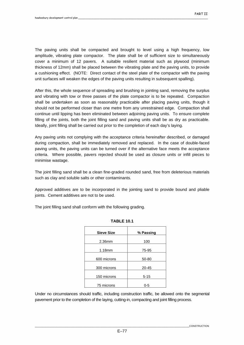
PART II hawkesbury development control plan ____________________________________________________________________________________
The paving units shall be compacted and brought to level using a high frequency, low amplitude, vibrating plate compactor. The plate shall be of sufficient size to simultaneously cover a minimum of 12 pavers. A suitable resilient material such as plywood (minimum thickness of 12mm) shall be placed between the vibrating plate and the paving units, to provide a cushioning effect. (NOTE: Direct contact of the steel plate of the compactor with the paving unit surfaces will weaken the edges of the paving units resulting in subsequent spalling). After this, the whole sequence of spreading and brushing in jointing sand, removing the surplus and vibrating with tow or three passes of the plate compactor is to be repeated. Compaction shall be undertaken as soon as reasonably practicable after placing paving units, though it should not be performed closer than one metre from any unrestrained edge. Compaction shall continue until lipping has been eliminated between adjoining paving units. To ensure complete filling of the joints, both the joint filling sand and paving units shall be as dry as practicable. Ideally, joint filling shall be carried out prior to the completion of each day’s laying. Any paving units not complying with the acceptance criteria hereinafter described, or damaged during compaction, shall be immediately removed and replaced. In the case of double-faced paving units, the paving units can be turned over if the alternative face meets the acceptance criteria. Where possible, pavers rejected should be used as closure units or infill pieces to minimise wastage. The joint filling sand shall be a clean fine-graded rounded sand, free from deleterious materials such as clay and soluble salts or other contaminants. Approved additives are to be incorporated in the jointing sand to provide bound and pliable joints. Cement additives are not to be used. The joint filling sand shall conform with the following grading.
TABLE 10.1
Sieve Size % Passing
2.36mm 100
1.18mm 75-95
600 microns 50-80
300 microns 20-45
150 microns 5-15
75 microns 0-5
Under no circumstances should traffic, including construction traffic, be allowed onto the segmental pavement prior to the completion of the laying, cutting-in, compacting and joint filling process.
____________________________________________________________________________________________________CONSTRUCTION
E–77

PART II ____________________________________________________________________________________ hawkesbury development control plan
Where traffic volumes and/or the frequency of heavy vehicles is anticipated to be high, additional compaction by approved multi-wheeled pneumatic tyre road rollers may be required.
10.10 PAVERS IN FOOTWAYS
Paving units shall be provided to areas shown in Documents.
10.10.1 Paving Units
Pavers shall comply, and be laid, to the following requirements:
10.10.2 Dimensions
The pavers may be concrete or clay of rectangular shape and nominally 230mm long, 114mm wide and a minimum 60mm thick. The actual dimensions measured shall be such that the following tolerances are not exceeded.
± 400mm on the length of 20 pavers
± 400mm on the width of 20 pavers
± 40mm on the depth of pavers
10.10.3 Edge Treatment
The pavers shall have chamfered or rounded edges on all four sides in the finished pavement surface. The radius of the rounded edge, however, shall not exceed 5mm.
10.10.4 Base Course And Laying
The sub-grade shall be prepared to grades and crossfall indicated on the documents and in accordance with Section 10.3. A layer of 100mm thick reinforced concrete (F72) of a strength of 20 MPa shall be placed upon this prepared sub-grade. A layer of fine, non-adhesive sand 30mm (loose) max, shall be placed on the concrete base, screeded and trimmed to level and grade. The sand shall be in accordance with Section 10.7. Placement, compaction and joint filling shall be in accordance with Sections 10.8 and 10.9. Damaged units shall be taken up and replaced with new units.
CONSTRUCTION ___________________________________________________________________________________________________
E–78

PART II hawkesbury development control plan ____________________________________________________________________________________
10.11 TESTING
The pavers shall carry a certificate from a registered NATA laboratory to show the compliance with the following requirements:
Abrasion Resistance shall not exceed a loss of 3.0cm³ on any one unit when tested in accordance with the South Sydney City Council test method.
Characteristic Compressive Strength shall be a minimum value of 45 Mpa.
Cold Water Absorption shall not exceed 8.0%.
Efflorescence shall be nil.
Lime Pitting shall be nil. Polished Frictional Value (PFV) -shall achieve a minimum value of 45 or greater when tested in accordance with the South Sydney City Council test method. Slip/Skid Resistance - shall achieve a BPN of 50 or greater. Transverse Breaking Load - shall be a minimum value of 5.0 KN.
____________________________________________________________________________________________________CONSTRUCTION
E–79
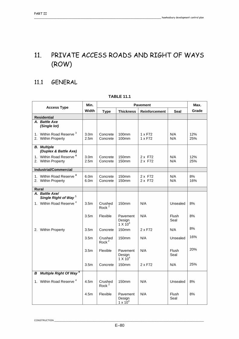
PART II ____________________________________________________________________________________ hawkesbury development control plan
11. PRIVATE ACCESS ROADS AND RIGHT OF WAYS (ROW)
11.1 GENERAL
TABLE 11.1
Pavement Access Type Min. Width Type Thickness Reinforcement Seal
Max. Grade
Residential A. Battle Axe (Single lot) 1. Within Road Reserve 3 2. Within Property
3.0m 2.5m
Concrete Concrete
100mm 100mm
1 x F72 1 x F72
N/A N/A
12% 25%
B. Multiple (Duplex & Battle Axe) 1. Within Road Reserve 4 2. Within Property
3.0m 2.5m
Concrete Concrete
150mm 150mm
2 x F72 2 x F72
N/A N/A
12% 25%
Industrial/Commercial
1. Within Road Reserve 4 2. Within Property
6.0m 6.0m
Concrete Concrete
150mm 150mm
2 x F72 2 x F72
N/A N/A
8% 16%
Rural A. Battle Axe/ Single Right of Way 5
1. Within Road Reserve 4 2. Within Property
3.5m
3.5m 3.5m 3.5m
3.5m 3.5m
Crushed Rock 2
Flexible Concrete Crushed Rock 2
Flexible Concrete
150mm Pavement Design 1 X 10⁴ 150mm 150mm Pavement Design 1 X 10⁴ 150mm
N/A N/A 2 x F72 N/A N/A 2 x F72
Unsealed Flush Seal N/A Unsealed Flush Seal N/A
8% 8% 8% 16% 20%
25%
B Multiple Right Of Way 6 1. Within Road Reserve 4
4.5m
4.5m
Crushed Rock 2
Flexible
150mm Pavement Design 1 x 10⁴
N/A N/A
Unsealed Flush Seal
8% 8%
CONSTRUCTION ___________________________________________________________________________________________________
E–80

PART II hawkesbury development control plan ____________________________________________________________________________________
Pavement Access Type Min. Width Type Thickness Reinforcement Seal
Max. Grade
2. Within Property
4.5m 4.5m1 4.5m1
4.5m1
Concrete Crushed Rock 2
Flexible Concrete
150mm 150mm Pavement Design 1 x 10⁴ 150mm
2 x F72 N/A N/A 2 x F72
N/A Unsealed Flush Seal N/A
8% 16% 20% 25%
1Passing bays are to be provided at maximum 100m intervals or more frequently where safety
conditions dictate (eg. lack of sight distance). 2To be used for Private access roads and Right of Ways which are to be unsealed (as outlined in the
Consent), but where the section of access from the sealed road to the boundary line is to be Bitumen sealed, the pavement may be constructed without the need for a pavement design undertaken by a Geotech Engineer. This however does not absolve the Contractor from achieving required densities and satisfying proof rolling. These works are to be undertaken in accordance with the Driveway Specification – Section 1 and 5 of the Civil Works Specification.
3Where Kerb and Gutter does not exist, a Heavy Duty Layback is to be provided in accordance with the
Driveway Specification of the Civil Works Specification. 4Where Kerb and Gutter does not exist, a Heavy Duty Layback (wings optional) or Pipe Crossing is to
be provided in accordance with the Driveway Specification of the Civil Works Specification. 5Shoulder not possible due to 6.0m access handle. Table drain to be 0.75m from edge of pavement to
the invert or adjusted to suit the width of the access handle as stipulated in the Consent. 6Shoulders to be a minimum 0.50m from edge of pavement and the table drain 0.75m from the edge of
the shoulder to the invert or adjusted to suit the width of the access handle as stipulated in the Consent.
TABLE 11.2 RELEVANT SECTIONS WITHIN THE DRIVEWAY SPECIFICATION.
Description Reference Layback Driveway Specification – Section 2 Concrete Driveways Driveway Specification – Section 3 Driveways Using Pavers Driveway Specification – Section 4 Bitumen Sealed Driveway Driveway Specification – Section 5 Piped Vehicular Crossing Driveway Specification – Section 6
____________________________________________________________________________________________________CONSTRUCTION
E–81
PART II ____________________________________________________________________________________ hawkesbury development control plan
12. VEGETATION AND REVEGETATION
12.1 DESCRIPTION
This Specification provides for the preparation, fertilising, sowing, surfing, watering, mowing and generally caring for grasses on defined areas so as to provide a dense uniform distribution of the various varieties of grasses specified and the provision of street trees to Hawkesbury City Council's requirements.
12.2 PREPARATION
Areas to be grassed shall be ripped along the contour to a depth of 200mm prior to topsoiling to provide a key for the topsoil and improve infiltration of water. Following ripping, the areas shall be topsoiled. On steep slopes and on other areas of high erosion hazard a rough surface shall be developed. A fine filth shall be acceptable only on areas of low slope. Light grading may be necessary to effect the required surface profile and shall be carried out by the Developer if so directed. The topsoil of areas to be grassed by turfing shall be compacted with a light roller. All weeds and the roots of all noxious weeds shall be thoroughly cleared from the site. Trees existing on the site shall not be disturbed other than by being trimmed as directed.
12.3 GRASSING BY SEEDING
12.3.1 Grass Seed
The seed used shall be of the best quality available, shall have good germination characteristics and be true to variety. The seed shall be obtained from reputable suppliers and the Developer shall produce satisfactory evidence to prove the compliance. Until used, any seed in the possession of the Developer shall be stored off the ground in a cool, dry place and shall not be stored any longer than possible before being used.
CONSTRUCTION ___________________________________________________________________________________________________
E–82
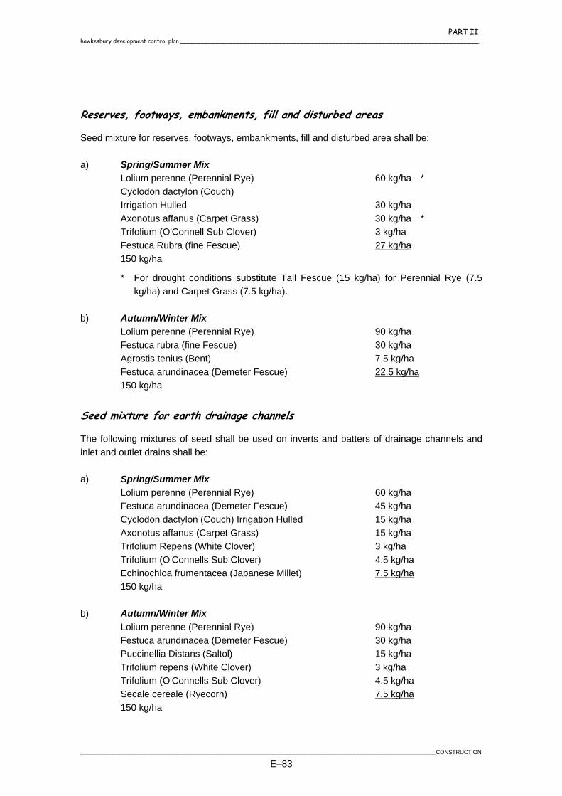
PART II hawkesbury development control plan ____________________________________________________________________________________
Reserves, footways, embankments, fill and disturbed areas
Seed mixture for reserves, footways, embankments, fill and disturbed area shall be: a) Spring/Summer Mix Lolium perenne (Perennial Rye) 60 kg/ha * Cyclodon dactylon (Couch) Irrigation Hulled 30 kg/ha Axonotus affanus (Carpet Grass) 30 kg/ha * Trifolium (O'Connell Sub Clover) 3 kg/ha Festuca Rubra (fine Fescue) 27 kg/ha 150 kg/ha
* For drought conditions substitute Tall Fescue (15 kg/ha) for Perennial Rye (7.5 kg/ha) and Carpet Grass (7.5 kg/ha).
b) Autumn/Winter Mix Lolium perenne (Perennial Rye) 90 kg/ha Festuca rubra (fine Fescue) 30 kg/ha Agrostis tenius (Bent) 7.5 kg/ha Festuca arundinacea (Demeter Fescue) 22.5 kg/ha 150 kg/ha
Seed mixture for earth drainage channels
The following mixtures of seed shall be used on inverts and batters of drainage channels and inlet and outlet drains shall be: a) Spring/Summer Mix Lolium perenne (Perennial Rye) 60 kg/ha Festuca arundinacea (Demeter Fescue) 45 kg/ha Cyclodon dactylon (Couch) Irrigation Hulled 15 kg/ha Axonotus affanus (Carpet Grass) 15 kg/ha Trifolium Repens (White Clover) 3 kg/ha Trifolium (O'Connells Sub Clover) 4.5 kg/ha Echinochloa frumentacea (Japanese Millet) 7.5 kg/ha 150 kg/ha b) Autumn/Winter Mix Lolium perenne (Perennial Rye) 90 kg/ha Festuca arundinacea (Demeter Fescue) 30 kg/ha Puccinellia Distans (Saltol) 15 kg/ha Trifolium repens (White Clover) 3 kg/ha Trifolium (O'Connells Sub Clover) 4.5 kg/ha Secale cereale (Ryecorn) 7.5 kg/ha 150 kg/ha
____________________________________________________________________________________________________CONSTRUCTION
E–83

PART II ____________________________________________________________________________________ hawkesbury development control plan
12.4 SOWING
When the area to be sown has been brought to a condition suitable for the sowing of grass seed, the seeding mixture shall be proportioned in accordance with the requirements of clause 12.3 of this Specification. After proportioning, the various quantities of seeds shall be thoroughly mixed so that each variety will be uniformly distributed throughout the whole. The seed mixture then shall be uniformly distributed at the prescribed rate of application per hectare and unless otherwise specified, the prescribed quantity per hectare of fertiliser shall be distributed at the same time. After sowing, the whole of the area shall be uniformly watered. The volume of water to be applied at the time shall be equivalent to 10mm of rain unless weather conditions dictate otherwise, in which case the Certifying Authority shall determine the volume of water to be applied. The Developer shall take care to avoid the formation of rills on the surface by a too rapid application of the water. Sowing shall be carried out by the method indicated in the Documents or otherwise specified.
12.5 HYDROSEEDING
When sowing is to be carried out by hydroseeding, a hydromulching machine approved by the Certifying Authority shall be used to mix and spray a slurry of seed mixture, fertiliser, mulch and water onto the area to be grassed. Sufficient mulch material shall be contained in the slurry to carry and stick the seed mixture and fertiliser to the prepared surface.
12.6 HYDROMULCHING
Where hydromulching is to be undertaken a heavy covering of mulch, usually hay/straw mulch and an anionic bitumen emulsion, is spread with the seed.
CONSTRUCTION ___________________________________________________________________________________________________
E–84
PART II hawkesbury development control plan ____________________________________________________________________________________
12.7 CONVENTIONAL SOWING AND MULCHING WITH BITUMEN
When sowing is to be carried out by conventional methods the seed and fertiliser may be distributed uniformly by means of a mechanical seed sower to be followed by an application of bitumen emulsion. No area shall be sown with seed whilst it is in such a softened state due to excessive moisture that it cannot support the weight of the loaded bitumen sprayer. The seeds shall be covered by 5mm of soil by means of rolling or other methods acceptable to the Certifying Authority. As soon as practicable after the application of the water, the area shall be sprayed with bitumen emulsion by means of an approved power sprayer fitted with a fixed spray bar set at the maximum width per row. An approved solution of slow-breaking anionic bitumen emulsion and water mixed in the ratio 1:1 shall be used for this purpose. The application rate shall be 1.0 litre per square metre for general work and four litres per square metre for drainage channels subject to concentrated water flows. In areas where it is impracticable to utilise the fixed spray bar of the sprayer, the bitumen emulsion may be applied by means of an approved hand spray attached to the power sprayer. Any areas deformed and/or rutted shall be repaired and resown by the Contractor, at his expense, to the satisfaction of the Certifying Authority. All concrete structures shall be protected from overspray with emulsion and any surfaces sprayed shall be cleaned to the satisfaction of the Certifying Authority.
12.8 GRASSING BY TURFING
The sods shall be of couch grass unless otherwise specified. They shall show healthy growth and to be of even thickness when delivered to site. The area from which the supply of grass is to be obtained shall be mowed before the sods are cut. The placing of the sods shall be commenced immediately the soil has been watered and fertilised. On completion of the laying of the sods, they shall be compacted by watering and rolling with a 100 to 150 kg roller. Each sod shall be butted against the previously laid sod and no gaps shall remain between the sods after laying.
____________________________________________________________________________________________________CONSTRUCTION
E–85
PART II ____________________________________________________________________________________ hawkesbury development control plan
Sites too steep for this compaction treatment shall be covered with a locating mesh of a type approved by the Certifying Authority. Immediately after the sods have been rolled, approved topsoil shall be spread to a depth of 10mm over the whole area and thoroughly watered.
12.9 FERTILISERS
The fertiliser to be used shall be an approved Nitrogen, Phosphoric Acid, Potash compound starter fertiliser. Unless otherwise specified, fertiliser shall be spread at the rate of 200kg/ha for footways, embankments and reserves and 250kg/ha for drainage channels. Where clay panning is evident or where hard packing river loams are used, then the Certifying Authority may direct that Gypsum be spread at the rate of 200-500kg/ha.
12.10 CARE OF GRASSED AREAS
The Developer shall regularly care for the sown and turfed areas and shall regularly maintain the moisture content of the ground at a level sufficient to allow, where applicable, proper germination of the seed to take place, to assist the rooting of the runners and generally to encourage the subsequent growth of the grasses. This regular care by the Developer shall be continued throughout the currency of the Maintenance Period. Two months after the sowing of the grass seeds and three to four weeks after laying turf, the Developer shall make an application of Sulphate of Ammonia at the rate of 250kg per hectare which shall be well watered into the soil. The Certifying Authority may direct the Developer to defer this second application of fertiliser to a later date if he is of the opinion that the grass growth would benefit by such deferment. If so directed, the Developer shall defer the application of the fertiliser until the later date nominated by the Certifying Authority.
12.11 MOWING
From time to time during the currency of the Maintenance Period the Developer shall mow the grassed area with an approved power grass mower. The height of cut shall be nominated by the Certifying Authority.
CONSTRUCTION ___________________________________________________________________________________________________
E–86

PART II hawkesbury development control plan ____________________________________________________________________________________
If the Certifying Authority so directs, the Developer shall mow the grass within 48 hours of being so directed.
12.12 ESTABLISHMENT
A uniformly distributed dense grass cover of the specified varieties of grass shall be established over the whole of the area specified to be grassed so as to eliminate wind and water erosion of the surface. The Developer shall take all steps necessary to establish the dense grass cover and will not be regarded as having fully discharged obligations until such time as the required dense grass cover has been established.
12.13 MAINTENANCE
The Developer shall maintain the grass cover established for the period of the Maintenance Period. If necessary, during the period of the contract, the Developer shall take all action necessary to re-establish areas of grass damaged or destroyed by adverse weather conditions, fire, floodwaters, vandalism or any other cause. The Developer shall make good any damage that may be caused to any finished surfaces, fences or paved areas by his plant or trucks used during the progress of the work.
12.14 STREET TREES
Where street trees are to be provided by the Developer, the species selection and planting shall be in accordance with Hawkesbury City Council's Tree Management Guideline and pop 13 - Landscaping. Street trees are to be provided as follows:
Corner Lots - 4 trees per lot
Single Frontage Lots - 2 trees per lot
Cul-de-sac or Turning Head Lots - 1 tree per lot
____________________________________________________________________________________________________CONSTRUCTION
E–87

PART II ____________________________________________________________________________________ hawkesbury development control plan
12.15 REVEGETATION OF BUSHLAND AREAS
Where works are undertaken within bushland, restricted development areas or other areas as determined by Hawkesbury City Council, revegetation shall be carried out in accordance with Hawkesbury City Council's requirements and guidelines.
CONSTRUCTION ___________________________________________________________________________________________________
E–88
PART II hawkesbury development control plan ____________________________________________________________________________________
13. STREET FURNITURE
13.1 STREET NAME SIGNS
Street name signs shall be provided for all new and existing roads as required, and shall be erected in accordance with AS 1742.5 at locations shown on the approved plans or as directed by the Certifying Authority. Refer to Drawing Nos. SD80 and SD81. "No Through Roads", except those designated "Place" or "Close", shall be provided with 200mm blades complete with the wording "NO THROUGH ROAD".
13.1.1 Sign Blades
Signs shall be manufactured from an approved marine grade high tensile strength aluminium extrusion, with a pointer shaped end. The length of the signs shall not be less than 500mm or more than 750mm. The profile of the blade shall be of a typical “I” beam shape. The web shall be 2.5mm minimum thickness and the flanges 18mm minimum width. Street name signs shall be white on blue, Class Two (2) Engineer Grade reflective and, depending on location, be single or double sided. The height of the blades shall be either 150mm or 200mm light gauge blades. The letters and background shall be provided on both sides of the plate.
13.1.1.1 Background
The background sheeting shall be 3M Blue 3275 Class 2 Engineer Grade reflective sheeting bonded to the prepared extruded aluminium blades by the 3M approved method to meet AS 1906.1, applicable for a 7 year warranty. The sheeting shall extend for the full length of the blade and be unspliced along its length. The minimum width of background material shall be:
170mm for 200mm blades
126mm for 150mm blades
____________________________________________________________________________________________________CONSTRUCTION
E–89

PART II ____________________________________________________________________________________ hawkesbury development control plan
13.1.1.2 Legend
Letters shall be made from 3M White 3200 Series Class 2 material and as detailed below:
150mm light gauge blade. 100mm high Highway Series B Font Style lettering for street names.
200mm light gauge blade. 100mm high Highway Series B Font Style lettering for street names with 30mm high
Times Bold white Class 2 supplementary text upper and lower case "No Through Road" suitably positioned under street name.
13.1.1.3 Letter Series
Highway Series B Font Style lettering for street names shall be used.
13.1.1.4 Abbreviations
Abbreviations for road suffixes are to be the same size and font as that used for the street name. Standard abbreviations to the requirements of clause 6.4 of AS 1742.5 shall be used.
13.1.2 Posts
Metal posts shall be to AS 1074 galvanised with cap, 3.25m in length with 65mm nominal bore and 3.6mm wall thickness. The posts shall be sunk into the ground to a depth of 600mm below the existing finished surface. An galvanised or mild steel locking pin shall penetrate through the post within the lean mix concrete zone. The pin shall be 10mm diameter x 150mm long and shall be located 300mm from the bottom of the post. The excavation (250mm) around the post shall be rammed and back filled with lean-mix concrete (proportions 1 part cement to 20 parts aggregate, by volume) to within 50mm of the finished ground surface. If located in the verge, the remaining 50mm shall be backfilled and rammed with top soil or selected excavated material free from rocks, etc. The surface shall be levelled and neatly trimmed. When placed in a sealed surface such as concrete, pavers etc, a "Loc-Socket" or equivalent is to be installed prior to placing the post.
CONSTRUCTION ___________________________________________________________________________________________________
E–90

PART II hawkesbury development control plan ____________________________________________________________________________________
13.1.3 Fixing Of Blades
The sign blades shall be fixed at right angles to the post by mild steel brackets or cast aluminium brackets and secured to the post by an adequate number of galvanised nuts and bolts. The top of the sign blade shall be at least 5mm clear from the top of the post (excluding cap). The standard height to the underside of the sign from ground level shall be between 2.5m and 3.0m. Where two street name signs are to be carried on a single post, they should not be mounted on the same horizontal plane.
13.2 WARNING ,REGULATORY AND OTHER SIGNS
Warning and Regulatory and other signs such as hazard markers, directional signs etc shall be provided and erected in accordance with the AS 1742 and AS 1743 at locations as shown on the approved drawings or as directed by the Certifying Authority.
13.3 PATHWAY BARRIERS, BOLLARDS AND BICYCLE RAILS
Galvanised metal posts painted white shall be to AS 1074, with nominal bore, shape and dimensions complying with the relevant standard drawing. Pathway barriers shall be placed at the ends of pedestrian access ways as per Drawing No. SD61. Bicycle rails shall be placed at the road end of cycleways and at road intersections as per the Drawing No. SD61.
13.4 GUIDE POSTS AND PROTECTION FENCES
Guide posts shall be supplied and erected in accordance with AS 1742 and RTA QA Specification R131 - Guideposts, at locations shown on the approved plans or as directed by the Certifying Authority. The guide posts shall be painted white and be fitted with retro-reflective delineators. Protection fences shall be erected at locations shown on the approved plans or as directed by the Certifying Authority. Guard Rail shall be designed and erected in accordance with RTA Specification R132 - Safety Barrier Systems and RTA Road Design Guide - May 1996 Section 6 " Safety Barriers For Roads and Bridges".
____________________________________________________________________________________________________CONSTRUCTION
E–91

PART II ____________________________________________________________________________________ hawkesbury development control plan
14. MISCELLANEOUS WORKS
14.1 PAVEMENT MARKINGS AND DEVICES
A system of clear and effective pavement markings and devices is essential for the proper guidance and control of vehicles and pedestrians an is to be in accordance with AS 1742.2. All linemarking is to be thermoplastic and shall be provided in accordance with AS1742.2 and as shown on the approved plan or as directed by the Certifying Authority.. Raised pavement markers shall be provided in accordance with AS1742.2 and as shown on the approved plan or as directed by the Certifying Authority. The type of RPM being either Non-retroreflective or Retroreflective will depend on the nature of the linemarking.
14.2 MAINROADS
All works on or adjacent to Main Roads shall be constructed and inspected to the requirements of the Road and Traffic Authority.
14.3 CLEANING UP
Prior to the final clearance of the works, all surplus material and rubbish shall be removed and the whole of the site left in a clean and tidy condition. Any road pavement, footpath or kerb and gutter damaged or destroyed during construction shall be reinstated to a condition to the satisfaction of the Certifying Authority.
CONSTRUCTION ___________________________________________________________________________________________________
E–92

PART II hawkesbury development control plan ____________________________________________________________________________________
15. COMPLETION OF THE WORKS
15.1 FINAL INSPECTION
Prior to the final inspection being undertaken, the following information is to be provided to the Certifying Authority:
Work-As-Executed Plans. Refer to Section 15.2.
All Geotech information such as density tests.
All other Certificates relating to the construction works or as requested by the Certifying Authority. Refer to Section 15.2.
15.2 WORK-AS-EXECUTED PLANS
Following the completion of engineering works in a subdivision or development, Work-As-Executed plans are required to be prepared by a Registered Surveyor and the Consultant and forwarded to the Certifying Authority prior to the Final Inspection. The Work-as-Executed plan is to be undertaken on a copy of the approved plan. The Work-As-Executed plans should include the following:
Certification that all works including pavement depths have been completed generally in accordance with the approved plans.
Levels taken at all pavement layers including the sub-grade.
Certification that all pipes and drainage structures are located within proposed drainage easements.
Certification of works on private property based on information originally submitted on approved plan.
Any departures from the approved plans.
Any additional work that has been undertaken.
Stripped and finished levels.
Length of lintels and pit types shown on plan and long sections.
Location of all service conduits.
Location of flushing points and subsoil drains.
Location of start and end of construction.
____________________________________________________________________________________________________CONSTRUCTION
E–93

PART II ____________________________________________________________________________________ hawkesbury development control plan
Top of kerb levels shown on cross sections and kerb return details.
Footpath levels at boundary shown on cross sections.
Road centreline levels shown on long and cross sections.
Invert of pipes at pits and pit surface levels.
Certification for any structural works.
Location of gutter crossings.
Width of road and footpath at regular intervals.
Location and details of Permanent Marks (PM's) and State Survey Marks (SSM's).
Top and toe of batter levels.
Certification of the plan by a Registered Surveyor and Consultant where necessary, having the following note on every sheet:
"I certify that:
1. All construction has been carried out in accordance with the attached
engineering plans and the specification and with regard to location and level, is as shown ticked in red ink or with variations shown in red ink thereon.
2. All drainage works are situated within drainage easements and/or
reserves as shown on the Deposited Plan.
3. All construction within private land has appropriate easement, right of way or like restriction over the whole of the structure.
Date………………………… Signed……………………………….……………… Registered Surveyor".
15.3 DEFECTS LIABILITY PERIOD
15.3.1 Maintenance
It shall be the responsibility of the Developer to maintain the works until Council has released the final plan of subdivision. For building works it shall be the responsibility of the Developer to maintain the works until final inspection of the works by the Certifying Authority or final clearance of the works whichever is the later.
CONSTRUCTION ___________________________________________________________________________________________________
E–94

PART II hawkesbury development control plan ____________________________________________________________________________________
15.3.2 Description
The Defects Liability Period shall have a duration of six (6) months. At any time during the Defects Liability Period, the Certifying Authority or Council may direct the Developer to rectify any defects, which become evident within the constructed works.
15.3.3 Subdivisions
The Defects Liability Period shall commence from the release of the final plan of subdivision. Prior to the release of the final plan of subdivision a maintenance bond in the form of a bank guarantee or cash security representing 5% of the total cost of the subdivision works, with a minimum amount of $5,000, is to be lodged with Council.
15.3.4 All Other Developments
The Defects Liability Period shall commence from the date of the final clearance by the Certifying Authority. A maintenance bond shall be assessed and lodged with Council prior to the final clearance.
15.4 BONDING
15.4.1 General
Where works cannot be carried out immediately for reasons beyond the Developer’s control, or where the Developer wishes to delay the works and submits good reasons therefore, the Council may accept a bank guarantee, together with an appropriate deed of agreement prepared by Council’s Solicitor, or a cash security to allow deferral of the works (particularly in respect to minor works). Bonding fees and all Council costs to be met by the Developer. Bond amounts shall be provided upon request.
15.4.2 A.C. Sealing
Developers shall lodge a bond to cover the cost of the final 25mm/50mm layer of Asphaltic Concrete (A.C.). Works cannot commence until a minimum of 75% of the blocks are fully developed.
____________________________________________________________________________________________________CONSTRUCTION
E–95

PART II ____________________________________________________________________________________ hawkesbury development control plan
During this time the Developer is responsible for maintenance of the sealed surface. Any failure on his behalf may lead to call-up of all or part of the security to enable remedial works to be undertaken by Council. Alternatively provide a two coat seal (14/10) in lieu of the single coat seal as outlined in Section 8.3.
15.4.3 Path Paving
Path paving construction shall be deferred for a period following practical completion of the roadworks. The option available to the Developer is to Bond the Works, by lodging an appropriate security with a Deed of Agreement. Works cannot commence until a minimum of 75% of the blocks are fully developed.
15.4.4 Maintenance
Prior to the release of the Final Plan of Subdivision, a Bank Guarantee or Cash Security, representing 5% of the total cost of the subdivision works, with a minimum amount of $5,000, is to be lodged with Council. This is to provide for the satisfactory performance of works and the replacement of any failed or unsatisfactory work and any repairs required, inclusive of the maintenance of any traffic control facilities. The bond will be held by the Council for a period of at least six (6) months from the date of subdivision certificate or compliance certificate for that portion of works. During this time the Developer is responsible for maintenance of the works. Any failure on his behalf may lead to call-up of all or part of the security to enable remedial works to be undertaken by Council. Upon satisfactory completion of this Maintenance period, the Bank Guarantor Cash Security, or any amount remaining, will be refunded to the Developer.
15.5 CONTRIBUTIONS / MONETARY PAYMENT
Contributions and/or monetary payments for certain outstanding items must be lodged prior to release of the subdivision certificate as detailed in the Development Consent. Council may accept a contribution covering the cost of minor works. Subsequently, the work will be carried out by Council as soon as practical, as staff and finances permit, but no guarantee is given that the work will be completed prior to sale or development of the land.
15.5.1 A.C. Sealing
Developers shall lodge a cash payment to cover the cost of the final 25mm/50mm layer of Asphaltic Concrete (A.C.) following installation of services by the various authorities. Such
CONSTRUCTION ___________________________________________________________________________________________________
E–96

PART II hawkesbury development control plan ____________________________________________________________________________________
payment is assessed by Council after submission of Work-As-Executed plans and is based on Council's current construction rates. However a two coat seal (14/10) is required in lieu of a single coat seal as outlined in Section 8.3 to protect the pavement.
15.5.2 Path Paving
A cash contribution may be lodged as an alternative to the bonding of these works. Council will use the monies for the construction of paths at a later, appropriate time.
____________________________________________________________________________________________________CONSTRUCTION
E–97


PART III
DRAWINGS

PART III hawkesbury development control plan ____________________________________________________________________________________
CONTENTS
1. LIST OF STANDARD DRAWINGS .................................................................................... 1
Road Construction, Kerb and Gutter................................................................................... 1 Drainage.............................................................................................................................. 2 Footpaths, Driveways and Private Access.......................................................................... 3 Signage and Street Furniture.............................................................................................. 3
____________________________________________________________________________________________________________TABLEOF CONTENTS
E-i

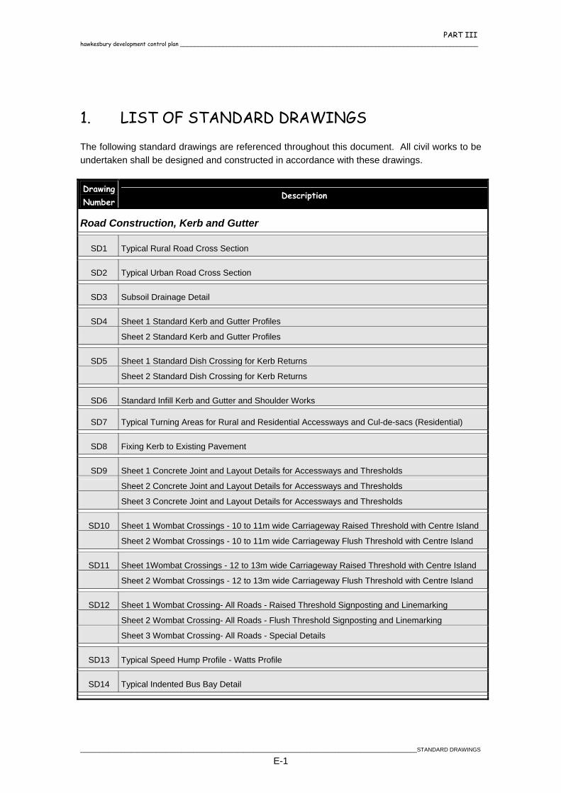
PART III hawkesbury development control plan ____________________________________________________________________________________
1. LIST OF STANDARD DRAWINGS
The following standard drawings are referenced throughout this document. All civil works to be undertaken shall be designed and constructed in accordance with these drawings. Drawing Number
Description
Road Construction, Kerb and Gutter
SD1 Typical Rural Road Cross Section
SD2 Typical Urban Road Cross Section
SD3 Subsoil Drainage Detail
SD4 Sheet 1 Standard Kerb and Gutter Profiles
Sheet 2 Standard Kerb and Gutter Profiles
SD5 Sheet 1 Standard Dish Crossing for Kerb Returns
Sheet 2 Standard Dish Crossing for Kerb Returns
SD6 Standard Infill Kerb and Gutter and Shoulder Works
SD7 Typical Turning Areas for Rural and Residential Accessways and Cul-de-sacs (Residential)
SD8 Fixing Kerb to Existing Pavement
SD9 Sheet 1 Concrete Joint and Layout Details for Accessways and Thresholds
Sheet 2 Concrete Joint and Layout Details for Accessways and Thresholds
Sheet 3 Concrete Joint and Layout Details for Accessways and Thresholds
SD10 Sheet 1 Wombat Crossings - 10 to 11m wide Carriageway Raised Threshold with Centre Island
Sheet 2 Wombat Crossings - 10 to 11m wide Carriageway Flush Threshold with Centre Island
SD11 Sheet 1Wombat Crossings - 12 to 13m wide Carriageway Raised Threshold with Centre Island
Sheet 2 Wombat Crossings - 12 to 13m wide Carriageway Flush Threshold with Centre Island
SD12 Sheet 1 Wombat Crossing- All Roads - Raised Threshold Signposting and Linemarking Sheet 2 Wombat Crossing- All Roads - Flush Threshold Signposting and Linemarking
Sheet 3 Wombat Crossing- All Roads - Special Details
SD13 Typical Speed Hump Profile - Watts Profile
SD14 Typical Indented Bus Bay Detail
___________________________________________________________________________________________________________STANDARD DRAWINGS
E-1
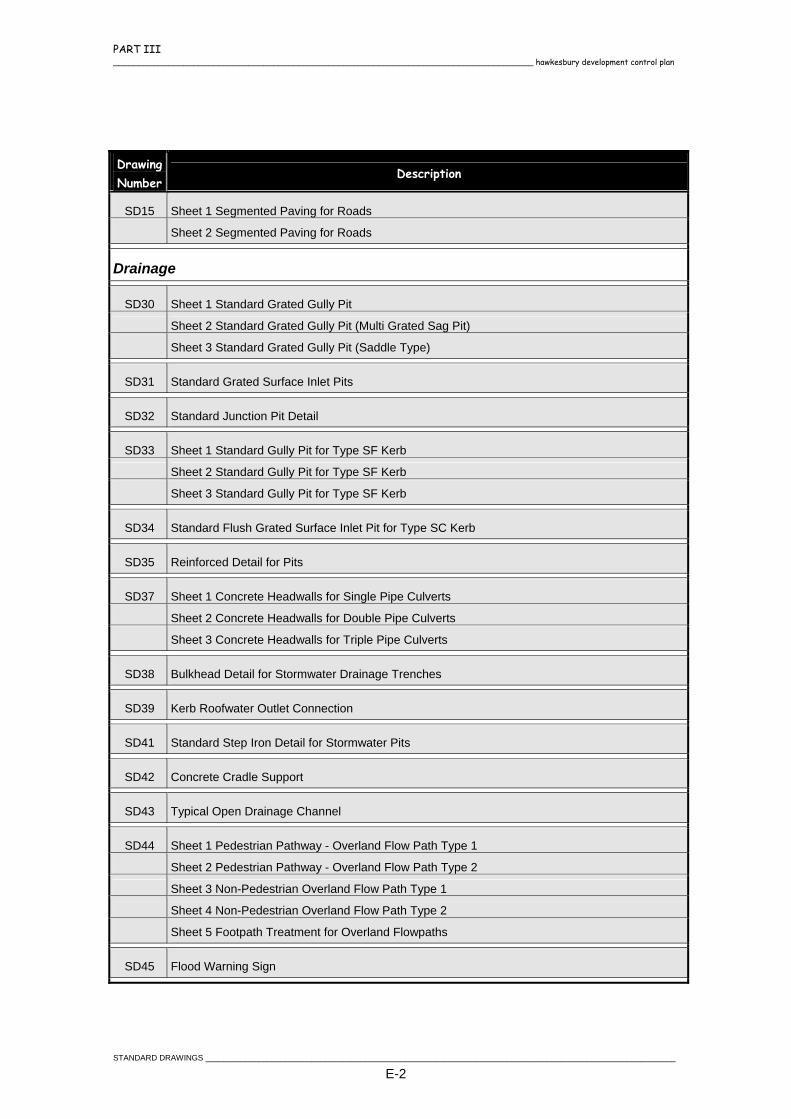
PART III ____________________________________________________________________________________ hawkesbury development control plan
Drawing Number
Description
SD15 Sheet 1 Segmented Paving for Roads
Sheet 2 Segmented Paving for Roads
Drainage
SD30 Sheet 1 Standard Grated Gully Pit
Sheet 2 Standard Grated Gully Pit (Multi Grated Sag Pit)
Sheet 3 Standard Grated Gully Pit (Saddle Type)
SD31 Standard Grated Surface Inlet Pits
SD32 Standard Junction Pit Detail
SD33 Sheet 1 Standard Gully Pit for Type SF Kerb
Sheet 2 Standard Gully Pit for Type SF Kerb
Sheet 3 Standard Gully Pit for Type SF Kerb
SD34 Standard Flush Grated Surface Inlet Pit for Type SC Kerb
SD35 Reinforced Detail for Pits
SD37 Sheet 1 Concrete Headwalls for Single Pipe Culverts
Sheet 2 Concrete Headwalls for Double Pipe Culverts
Sheet 3 Concrete Headwalls for Triple Pipe Culverts
SD38 Bulkhead Detail for Stormwater Drainage Trenches
SD39 Kerb Roofwater Outlet Connection
SD41 Standard Step Iron Detail for Stormwater Pits
SD42 Concrete Cradle Support
SD43 Typical Open Drainage Channel
SD44 Sheet 1 Pedestrian Pathway - Overland Flow Path Type 1
Sheet 2 Pedestrian Pathway - Overland Flow Path Type 2
Sheet 3 Non-Pedestrian Overland Flow Path Type 1
Sheet 4 Non-Pedestrian Overland Flow Path Type 2
Sheet 5 Footpath Treatment for Overland Flowpaths
SD45 Flood Warning Sign
STANDARD DRAWINGS __________________________________________________________________________________________________________
E-2

PART III hawkesbury development control plan ____________________________________________________________________________________
Drawing Number
Description
Footpaths, Driveways and Private Access
SD60 Vehicular Crossing for High and Low Level Access
SD61 Sheet 1 Standard Footpath and Cycleway Details - Joint Detail
Sheet 2 Standard Footpath and Cycleway Details - Handrail Detail
Sheet 3 Standard Footpath and Cycleway Details - Pedestrian Pathway Barrier
SD62 Standard Pram Ramp Crossing
SD63 Pathway Steps
SD64 Footpath Treatment for Overland Flow Pathways
SD65 Sheet 1 Segmental Footpaving Sheet 2 Segmental Footpavings
SD66 Concrete Drive Slab Detail
SD67 Pavers Driveway Detail
SD68 Layback Crossing Detail
SD69 Piped Vehicular Crossing
SD70 Prohibited Location of Driveways
Signage and Street Furniture
SD80 Standard Street Sign
SD81 Standard Street Sign Locations
SD82 Street Tree Planting Detail
___________________________________________________________________________________________________________STANDARD DRAWINGS
E-3