Embed Size (px)
Citation preview

March, 97 P/N 4202686REV. B
HBA10 & HBA11 HOT BEVERAGE MACHINE
CONVERTIBLE HOT BEVERAGE VENDOR
SERVICEMANUAL


2
TABLE OF CONTENTS:INTRODUCTION: .......................................... 3SPECIFICATIONS: ........................................ 4UNPACKING:................................................. 4INITIAL INSTALLATION: ............................ 4
PACKAGED LOOSE PARTS:........................................ 5FRONT SKIRT ASSEMBLY (OPTIONAL): ............... 5INSTALL WATER PURIFIER (FILTER): ................... 5WATER TANK LID ASSEMBLY:............................... 5
CONNECT TO WATER SUPPLY:................................ 6CONNECT TO POWER SUPPLY:................................ 6WATER TEMPERATURE CONTROL: ....................... 6INSTALL COIN MECHANISM: ................................... 7SET PRICES:.................................................................... 8
AUTOMATIC COPY PRICE FEATURE: .................... 8MANUAL COPY PRICE MODE:................................. 8
INSTALL PRICE LABELS:............................................ 8PRODUCT CANISTERS:................................................ 9CUP MECHANISM:........................................................ 9INSTALLATION CHECK LIST: ................................. 10
OPERATING INSTRUCTIONS: GENERAL . 10WATER TANK LID ASSEMBLY:............................... 10
CHECK & ADJUST LOW LEVEL SWITCH: ........... 10CHECK WATER LEVEL SWITCH: .......................... 10
WATER TEMPERATURE CONTROL: ..................... 11WATER HEATER ELEMENT: ................................... 11WATER TANK: ............................................................. 11WATER VALVES:......................................................... 12INGREDIENT CANISTERS:........................................ 12INGREDIENT MOTORS:............................................. 12MIXING BOWLS:.......................................................... 12INGREDIENT HEATERS: ........................................... 14CUP MECHANISM:...................................................... 14CUP MECHANISM - MOTOR: ................................... 14CHANGING CUP SIZE:................................................ 15
CONTROLLER FUNCTIONS &PROGRAMMING:........................................ 15
SERVICE MODE:.......................................................... 16COIN DISPENSE MODE:............................................. 16SET SECURITY CODE: ............................................... 17ALARM CONTROL:..................................................... 17MACHINE CONFIGURATION MODE: .................... 17VEND OPTIONS MODE: ............................................. 17
FORCE VEND OPTION: ............................................ 17MULTI VEND OPTION: ............................................ 18LOTTO - OCCURRENCE PROGRAMMING: .......... 18NO CUP DISCOUNT OPTION: ................................. 19
MESSAGE EDIT/PROGRAMMING: ......................... 19MESSAGE EDITING:................................................. 20
SET PRICE MODE:....................................................... 20AUTOMATIC COPY PRICE FEATURE: .................. 21MANUAL COPY PRICE MODE:................................ 21
ACCOUNTABILITY INFORMATION:......................21ACCESS ACCOUNTABILITY: ..................................21
TOTAL VENDS:.....................................................21TOTAL CASH: .......................................................21VENDS BY SELECTION:......................................21CASH BY SELECTION: ........................................21TOTAL LOTTO CASH: .........................................22TOTAL BILLS COLLECTED:...............................22TOTAL NO-CUP CASH:........................................22
SET DISPENSE TIME:..................................................22TEST VEND BY SELECTION: .....................24
SANITIZER CYCLE:.....................................................24BREW FLUSH TIMER (FRESH BREW MODE: ......24
THE BREW CYCLE: ....................................24BREWING (BLEND) TIME:.........................................25
CLEANING INSTRUCTIONS: ......................25CABINET EXTERIOR: .................................................25CABINET INTERIOR: ..................................................25
3
INTRODUCTION:This manual contains service and installationguidelines and instructions for the HBA10A &HBA11A Hot Beverage Vendors along with variousoptional equipment and accessories that are offeredwithin the product line.
Each vendor is equipped with an electronic controlsystem that includes a variety of features andfunctions that can be programmed and used by thecustomer as needs arise for specific locations. Someof the features are “programmable message center”,cash and vend accountability “by” selection andmachine, programmable to offer each selection intwo (2) ingredient strengths or portions for fullcustomer satisfaction, Multiple-Pricing and “FreeVend” capabilities. Keyboard Programming thatallow changing programs and functions at thelocation.
Provisions for vending International Coffee Blendscan be included as optional equipment whenshipped from the factory. Kits are available foradding in the field if not included with originalequipment. Details and functions of all features aredefined throughout this manual.
The electronics within the controller will allow allselections to be priced separately at various vendprices, ranging from $.00 to $99.95 in five-cent (5¢)increments. All programming of the vend functions,pricing and features are done at the controller andchanges to the different programs can be made, orinformation can be retrieved, without the need ofany additional accessories or remote parts.
Service requirements and malfunctions are detectedby the controller and stored in memory. “Call forService” will be scrolled in the display when themachine becomes in-operable. Optionalprogramming allows for the phone number to beincluded for notification of problems. The servicerequired or malfunction will be displayed to theservice person when the controller is placed in theService Mode.
Each machine will be identified by a model numberand a specific serial number. These identificationnumbers will appear on the Serial Number Plateattached to the inside and rear of the vendor. Record
these numbers for your records. All inquiries andcorrespondence pertaining to this vendor shouldreference the model number and serial numbers.
It is recommended that this manual be readthoroughly to familiarize the service person with thefunctions of all components along with the featuresthat are available. The initial set-up of a machine isa very important step of insuring that the equipmentoperates in a trouble-free manner and by followingthe instructions at the initial installation of themachine, service problems can be avoided and set-up time will be minimized.
Should you have any questions pertaining toinformation in this manual, replacement parts, or theoperation of the vendor you should contact yourlocal distributor or:
Selectivend ServiceP.O. Box 488165 North StreetWaukee, Iowa 50263-0488
Phone: 800-833-4411

4
SPECIFICATIONS:ELECTRICAL:
Power Supply: Must be a minimum20 Amp isolated circuitPower Requirements: 115 Volts AC,60 Cycle 16 AmpsTransformer: 117 Volts AC Primary,24 Volts AC, Secondary
WATER SUPPLY:20 TO 125 Lbs. P.S.I. - 3/8” WaterConnection6 Gallon Hot Water Tank (1500 wattheater element)
COIN MECHANISM:Coinco = Model 9302LMars = Model TRC6010or Equivalent
PRICING:Individual Prices for each selectionFree Vend CapabilityLotto Capability
CUP CAPACITY:600 - 7 Oz. Squat CupsCan handle 7, 8 ¼, 9, & 12 oz.
MACHINE DIMENSIONS:HEIGHT: 72” high (includes 6” legs)DEPTH: 32” DeepWIDTH: 30” WideWEIGHT: Net - 400 Lbs.
Shipping - 429 Lbs.
PRODUCT CANISTER CAPACITY
PRODUCTFRESHBREW
FREEZE DRY
Coffee 4.5 Pounds ** 36 OuncesDecaf Coffee 2 Pounds ** 36 OuncesCreme 4 Pounds 4 PoundsSugar 7 Pounds 7 PoundsChocolate 7.5 Pounds 7.5 PoundsSoup 3 Pounds 3 PoundsTea 24 Ounces 24 Ounces
** For best performance of the Fresh Brew Unit it isrecommended that a 17 Grind Vending Grade Coffeeproduct be used.
UNPACKING:This machine has been thoroughly inspected beforeleaving the factory and the delivering carrier hasaccepted this vendor as their responsibility. Anydamage or irregularities should be noted at the timeof delivery and reported to the carrier. Request awritten inspection report from the claims inspectorto file any claim for damage. File the claim with theCARRIER (NOT THE MANUFACTURER) within15 days after receipt of the machine.
Carefully remove the outside packing material in amanner not to damage the finish or exterior of themachine. Inspect the machine for concealedshipping damage. Report any damage hidden by theshipping material directly to the delivering carrieron a hidden damage report.
Record the model number and serial number of thevendor for your records. These numbers can befound on the Serial Plate located on the rear of thecabinet and/or inside the vendor. Refer to thesenumbers on all correspondence and inquiriespertaining to this vendor.
To minimize installation time and to avoid serviceproblems due to improper installation, follow theinstructions outlined in this manual.
INITIAL INSTALLATION:To unlock the door, on machines furnished with thelock installed, the key will be taped inside the coinreturn cup. On machines furnished without a lock,“press down” on the upper leg of the Spring Clipand “PULL”.
Position the vendor in its place of operation nofurther than 6 feet from the power outlet orreceptacle and check that the door will open fullywithout interference. Leave at least six (6) inches ofspace between the back of the machine and any wallor obstruction for proper air circulation and exhaust.
Level the vendor, making sure all leg levelers aretouching the floor. (See Figure 1) The vendorMUST be level to obtain proper operation andproper acceptance of coins through the coinmechanism. When the vendor is level, the door can

5
be opened to any position and not move by itself.Try the door half closed, straight out and in the wideopen position before deciding the vendor is level.
FIGURE 1Remove all packing material, shipping screws (tagsattached) and tape from inside the vendor. Variousparts are taped for shipment to prevent damage intransit. To try to operate the vendor withoutremoving the tape from the moving parts may resultin damage.
CAUTION:Do not connect the water heater to thecontrol box until the water tank has filledwith water.
PACKAGED LOOSE PARTS:Various parts are shipped disassembled to preventdamage during transit. These parts will be packedinside the machine. Remove and identify allpackaged parts.
FRONT SKIRT ASSEMBLY (OPTIONAL):The front skirt assembly will not be supplied as partof the basic machine, however, it will be supplied asan option or accessory upon request. Installationinstructions will be furnished with the Front SkirtAssembly when ordered.
INSTALL WATER PURIFIER (FILTER):The water filter will be shipped packaged in thewaste bucket. The water filter mount is a standard“twisting ring” type. Removal and Instructions arepackaged with each cartridge. See FIGURE 2
The cartridge reduces the lime scale build-up andprotects the drink taste by filtering out fine particles.
Each cartridge should filter approximately 1,500gallons of water, but this will vary depending onlocal water conditions. Fifteen hundred (1,500)gallons of water would provide 20,000 to 30,000drinks per filter, depending on cup size. Since nofeasible “test” of cartridge conditions is available,replacement frequency should be routine based onknowledge of local water conditions and number ofunits vended.
CAUTION:Leave the manual water valve in the UP-(OFF) position until you are ready for thewater tank to be filled.
FIGURE 2
WATER TANK LID ASSEMBLY:The water tank lid assembly is shipped packaged inthe waste bucket. Install the water tank lid andsecure with two thumb nuts. Connect the harness tothe cabinet harness. Connect the Safety Thermostatharness to the Safety Thermostat on the water tanklid.

6
CONNECT TO WATER SUPPLY:Located on the rear of the cabinet is a 3/8” standardpipe connection to be used for the water supply. Toconnect the water line to the pipe connection, useeither a 3/8” pipe to flare fitting or a 3/8” pipe tocompression fitting. An installation kit, Part No.1200137-133, is available from Selectivend partsdepartment.
Make sure the manual water valve on the filterinstallation is in the UP (off) position before turningon the water supply. It is always advisable to installa water supply cut-off valve in the external watersupply line.
CONNECT TO POWER SUPPLY:(115 VOLT AC, 20 AMP SERVICE)
The electrical power supply for this vendor must bea minimum 20 Amp isolated circuit. The powercord for the vendor is equipped with a 20 ampmolded, polarized and grounded plug. To verify thata receptacle is properly grounded and polarized, usea voltmeter or test light as shown in Figure 3. Insertone probe of the test device in the receptacle groundterminal and the other probe in the nearest “singleslot” or “hot” terminal. (The double slot or “cross”terminal should be “neutral”). You should read 115volts on the volt-meter or the light should light.
If these requirements are not met you should contacta licensed electrician to properly polarize and/orground the power source to insure proper operation.Consult local, state and federal codes forcompliance before installation of the vendor.
CAUTION:When the water and power have been turned“ON” the water tank should fillautomatically. Do not connect the waterheater to the control box until the watertank has filled with water.
FIGURE 3
INSTALL INGREDIENT HEATERS:Install Ingredient Heater panel in front of thecanisters. Connect ingredient heater harness to themain cabinet harness. The ingredient heaters willnot be powered up until the outer door is closed.
WATER TEMPERATURE CONTROL:The Temperature Control has been preset at thefactory to keep the water temperature atapproximately 195° but may be re-set if needed.Refer to Page #11 for adjustments and additionalinformation.
CAUTION:The water in the tank should not boil - 1/4turn of the adjustment screw will change thetemperature approximately 25° F
FIGURE 4

7
INSTALL COIN MECHANISM:This vendor is designed to use Coinco Model 9302Lor Mars TRC6010 coin changers or equivalent. Toinstall the changer, remove the acceptor (upper)portion from the coin mechanism. Position thethree (3) “keyhole” slots in the back of the coinmechanism over the screws on the door panel andtighten the screws. Replace the acceptor and plugthe changer in the coinage receptacle on the doorharness.
The controller circuitry is designed to receivesignals from the coin mechanism as the coins areaccumulated and all totals are maintained by thecontroller. When proper credit has been established,the controller will allow a vend to be made.
The acceptance of coins through the coinmechanism is controlled by the controller. The coinmechanism should refuse to accept coins when:
1. Vendor is out of cups.2. Water supply absent or insufficient.3. Water Waste Bucket full.4. Credit equal to or exceeding highest vend
price.When the coin mechanism is disabled by either theSold Out Switch, Low Level Switch or the WasteBucket Switch, the controller will disable all vendcircuits and the message “Call for Service” will bedisplayed.
Load the coin changer coin tubes with nickels,dimes and quarters. (See FIGURE 5) After a fewseconds the credit display will begin to scroll the“Point of Sales” Message. The changer optionswitches have been factory set in the followingpositions:
#1 = OFF#2 = OFF#3 = OFF
OPTION SWITCH SETTINGSSW DESCRIPTION POS. FUNCTION1 USA/CAN ON U.S. AND CANADIAN COINS
WILL BE ACCEPTEDOFF CANADIAN COINS WILL BE
REJECTED2 LO 25¢ ON QUARTERS ARE DIVERTED TO
CASH BOX WHEN THE CHANGETUBE HAS INVENTORIEDAPPROXIMATELY 8 QUARTERS
OFF QUARTERS ARE DIVERTED TOCHANGE TUBE UNTIL THECHANGE TUBE IS FULL
3 $ ACCEPT ON DOLLAR COINS WILL BEACCEPTED
OFF DOLLAR COINS WILL BEREJECTED
COIN TUBE CAPACITY25¢ OPTION
5¢ 10¢ HI 25¢ LOW 25$FULL LEVELLOW LEVEL
68 - 697 - 8
98 - 9910 - 11
66 - 678 - 9
9 - 109 - 10
FIGURE 5
NOTE:
Obtain service manuals and operationalfunctions of the coin changer from thecoinage manufacturer.

8
SET PRICES:Vend prices are controlled by the controller andmust be programmed into the controllers memory.The controller must be placed in the “ServiceMode” to alter any programming and establish newprograms. Vend prices are programmed into thecontrollers memory using the Selection Key Pad.
To access the “Service Mode”, press the “ServiceMode Switch” on the controller. This will advancethe controller into the “Root” menu of theprogramming, indicated by a “<“ in the display.Press key “5” to place the controller in the “setprice mode”. The display will scroll “MakeSelection” then display “??=Selection”. The “??”will be flashing. Enter the selection to be priced.After the selection has been entered, the currentvend price for that selection will be displayed. Anew price can be set by direct entry. (Note: Thecharacter to the left flashes until an entry is made.Then the next character to the right flashes insuccession until the price is set and stored inmemory). To store the price, press the “#” key. Thecontroller will scroll the “Make Selection”message in expectation of another price change. Toreturn to the “root” menu, the “#” key must beentered while the “Make Selection” message isbeing scrolled.
AUTOMATIC COPY PRICE FEATURE:The controller automatically copies prices stored incertain selections to facilitate price setting asfollows:
When selection “AO” is priced the same price willbe copied and stored in the following selections
A1 C0 D2 F1 G1A2 C1 D3 F2 G2A3 D0 E0 F3 G3B0 D1 F0 G0 H0
When selection “A4” is priced the same price willbe copied and stored in the following selections
A5 C2 D6 F5 G5A6 C3 D7 F6 G6A7 D4 E1 F7 G7B1 D5 F4 G4 H1
After the primary prices (A0 & A4) have been set,individual selections in the automatic copy groupscan be edited and set to a desired price by followingthe instructions outlined in the proceedingparagraphs.
MANUAL COPY PRICE MODE:To copy a price from one selection to another,follow the above mentioned price setting procedure,but instead of storing the price, via the “#” key,press the “*” key. This will place the controller inthe “copy price” mode and the display will scroll“Copy Price”, then scroll “Make Selection”, thendisplay “??=Selection”. Selections may be enteredone after the other. All selections entered willreceive this price. To store all of the copiedselections and return to the “root” menu, press the“#” key.
INSTALL PRICE LABELS:Price Labels are provided with the machine anddisplay the vend prices of each selection. Pricelabels may be affixed by following theseinstructions:
1. Remove the thumb nut below the display lightand lift up on the Menu Label Panel andremove panel.
2. Affix price labels in designated areas for eachselection. Make sure labels are square andmatch the area provided and agree with theprices programmed for each selection.
3. Replace the Menu Label Panel and securewith thumb nut.
IMPORTANT:Check vend prices of each selection tomake sure the price label located on themenu label agrees with the priceprogrammed into the controller. With thecontroller in the “Sales Mode”, the vendprice will be displayed when a selection ismade without adequate credit established.
If desired, the following features should beprogrammed into the controller. Details and

9
functions of these features are described underController Functions & Programming.
1. Set Force Vend Feature2. Set Multi-Vend Feature3. Set Lotto Option4. Set Discount for Vend Without Cup5. Edit Sales & Service Message
PRODUCT CANISTERS:When installing the Product canisters they should beinstalled in locations shown in FIGURE 7. Wheninstalling the canisters make certain the MotorDrive Pin engages with the Canister Drive Link(See FIGURE 6). The Motor Drive Pin should behorizontal to the shelf, and the Canister Drive Linkshould be vertical to permit ease of installation.
Each product canister is identified by a label toindicate the product to be loaded. Load theappropriate quantity of product in each canister. Donot strike the side of the canisters to enable you toput in a little more ingredient. Avoid overfilling toprevent ingredient packing.
All canisters are placed so the feet enter the keyholeslots. Push the canisters toward the rear of themachine making sure they are properly latched inplace. To remove the canisters, push downward onthe latch, pull the canister forward and lift out of thekeyhole slots.
FIGURE 6
FIGURE 7
CUP MECHANISM:The cup mechanism tilts out for easy loading. Cupsare dispensed from an entire tube and the turret willbe indexed in a clockwise direction when a tubebecomes empty. If at any time all tubes are notbeing loaded, tubes counter clockwise from thedispensing position should be loaded first. Makesure cups in the dispensing area are fully seated inthe cup ring.
FIGURE 8

10
INSTALLATION CHECK LIST:1. All packing material and tape removed from
moving parts?2. All loose parts properly installed?3. Water filter, electrical and water connections
properly installed?4. Vend Prices and vend options programmed
and price labels affixed?5. Product canisters properly loaded?6. Cups loaded in Cup Mechanism?7. Adequate change in Changer pay-out tubes?8. Water Heater Harness connected to control
box.Scrolling message should be displayed in the digitalread-out.
OPERATING INSTRUCTIONS:GENERAL
WATER TANK LID ASSEMBLY:The water level in the tank is controlled by two (2)switches mounted on the water tank lid. The “WaterLevel Switch” will maintain a “full” tank condition.This switch will open and close the inlet water valvewhen operated. A float attached to the lid andsuspended in the top of the tank operates the waterlevel switch.
The water level must be maintained below the over-flow outlet. When water is drawn from the tank, theinlet water valve must open before the float dropsfar enough to operate the “Low Level Switch”. Thewater level switch should operate to refill the tankany time approximately 215 ml (7 oz.) of water isdrawn from the tank.
If for any reason water is not available to the tank(waste bucket full or water supply shut off), the“Low Level Switch”, mounted on the lid, willoperate after approximately 430 ml (14.3 oz.) ofwater is removed. If this action occurs the coinmechanism will be disabled and the message“CALL FOR SERVICE” will scroll on the displayto alert the customer and the machine will notfunction. The low level switch must operate beforethe water level
reaches the water valve port. The “Low LevelSwitch” is adjustable by loosening its mountingscrews.
CHECK & ADJUST LOW LEVEL SWITCH:1. Turn the water inlet valve at the filter cap to
the “OFF” position. (See FIGURE 2)2. Using the Rinse Hose, slowly drain water
from the tank until the “Call for Service”message is displayed.
3. Place the controller in the “Service Mode”and test vend Selection #E0. Water shouldstill be available.
4. If little or no water is available, adjust thelow level switch. See FIGURE 9
5. Turn the water inlet valve at the filter cap tothe “ON” position.
CHECK WATER LEVEL SWITCH:The “Water Level Switch” is not adjustable. If thewater level in the tank is not correct:
1. Check the float condition. (Leaks orcorrosion build-up)
2. Check the float pivot rod to be sure it movesfreely.
3. If the above conditions are good, reform thefloat rod to obtain the correct water level.
CAUTION:Always check the low level switchadjustment if the float rod has beenreformed.
FIGURE 9

11
WATER TEMPERATURE CONTROL:The Temperature Control is pre-set at the factory tokeep the temperature of the water in the water tankat approximately 195°°°° F (90.5° C). The drinktemperature in the cup should be 155° to 160° (68° -71° C) even under casual conditions (30 minutes ormore between drinks). The temperature of repeateddrinks will vary from 160° to 175° (71° - 79° C) asthe lines and bowls absorb heat.
To check the water temperature in the tank todetermine if the thermostat is operating within the195° range, insert a thermometer through the self-closing grommet port at the top of the water tank.The temperature should be approximately 195° F
To change the water temperature, rotate thethermostat adjusting screw, clockwise to raise, orcounter clockwise to lower the temperature.
Adjusting the thermostat to a higher setting will notaccelerate heating of the water in the tank. Thethermostat’s function is to maintain a constant watertemperature.
FIGURE 10
CAUTION:A one-fourth (1/4) turn of this screw changes thetemperature approximately 25°F. If thethermostat is set too high, the water will boil.Steam or moisture within the cabinet area causesthe ingredients to pack or harden.
If it becomes necessary to replace a thermostat, besure the sensing bulb is inserted correctly. It isimportant that no portion of the capillary tubetouches the water tank. (See Figure 11.)
Figure 11
WATER HEATER ELEMENT:The heating element for the water tank is a 1500watt immersion heater mounted through the bottomof the tank and secured in place by four (4) hexnuts. The gasket is part of the heater assembly andis mounted on the “outside” of the tank.
WATER TANK:The water tank is stainless steel and has a capacityof 6 gallons. Water enters the tank through the portin the bottom of the tank. Water to all drinks issupplied by “gravity force” through solenoidoperated water valves mounted to a manifold nearthe top of the water tank. An overflow (open to theatmosphere) is provided to direct excess water tothe liquid waste bucket. A spray hose is alsoprovided for cleaning and servicing the vendor.

12
WATER VALVES:There are four (4) water valves mounted on amanifold on the water tank which supply the liquidfor the various drinks. The valves are solenoidoperated with the power being supplied by thecontroller. The water volume or drink level isdetermined by the time the controller will supplypower to the solenoid. (Refer to “Set DispenseTime” outlined later in this manual) The water flowor volume can also be altered by the “needle valve”adjusting screw on the front of the water valve. Ifthis becomes necessary, the dispense timeprogrammed in the controller will have to bechanged accordingly.
Periodic replacement of the “O” Ring andDiaphragm may be necessary to prevent leaks.
FIGURE 12
INGREDIENT CANISTERS:The Ingredient Canisters used on both Freeze Dryand Fresh Brew Models are identical with theexception of the “Fresh Brew” coffee canister. Eachhas a stainless steel “strap” type agitator that isdeflected by a rotary actuator to prevent bridging ofthe product.
When removing or installing any canisters, the drivelink on the canister and ingredient motor drive pinmust be positioned as shown in FIGURE 6, Page 9,to allow proper engagement and prevent bendingthe drive link.
To remove a canister, press down on the latchingdevice, pull forward on the canister and lift out.
PREVENTATIVE MAINTENANCESUGGESTIONS
1. Be sure that the exhaust system is clean andclear of obstruction and that the exhaustmotor is running.
2. Be sure all canister lids are properly replacedafter servicing.
3. Do not strike sides of canisters to enable youto put in a little more ingredient. The normal“load” of ingredient should be more thanenough to last until the next service. Properloading keeps fresh products available andprevents ingredient “packing” and “bridging”in the canisters.
INGREDIENT MOTORS:All ingredient motors are 115 volts AC, 50/60 cycle.The total run time is controlled by the controller.Timing can be changed to vary the amount ofingredient throw. As the motor turns, the drive linkon the canister is engaged by the motor drive pin,turning the auger to dispense the product. As theauger is turning the agitator and strap is engaged,which keeps the ingredient near the dispensing arealoose to prevent “bridging” and “packing” to insurea constant volume of product.
INGREDIENT MOTORSPART NUMBER R.P.M. APPLICATION8366620-1 80 TEA, SOUP, CREME, SUGAR, FREEZE
DRY COFFEE & DECAF8330173-3 120 CHOCOLATE, FRESH BREW COFFEE
& FRESH BREW DECAF
MIXING BOWLS:All selections have individual mixing bowls wherethe ingredients are mixed with water. Coffee,decaffeinated coffee and tea are then routed throughthe center or main mixing bowl to receive cremeand/or sugar if selected. These products are thenrouted through a single hose and spout to the cup orcup station. All other products are routed directly to
13
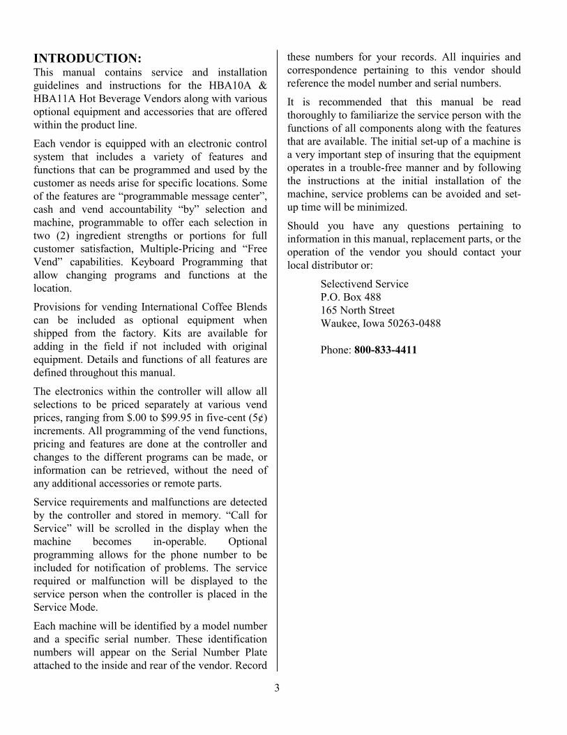
the cup station from their individual mixing bowls.See FIGURE 13 for a Flow Diagram showing thewater and ingredient routing of the variousselections.
It is important that all hoses are properly routed ordressed in a manner to be free of restrictions and not“kinked” in any way to restrict the flow of water.Water should enter the mixing bowl at or before anyingredients are deposited. All start times arecontrolled by the controller and cannot be altered.
FLOW DIAGRAM - FRESH BREW
FIGURE 13The chocolate ingredients and water are mixedthoroughly in an aeration chamber directly under themixing bowl. This bowl and aeration chamber maybe removed for inspection and/or cleaning by liftingthe water inlet spout out of it’s slot, pressing thebowl toward the motor and rotating counterclock-wise. The paddle is not permanently attached to themotor shaft. Pull to remove. There is a slinger discon the motor shaft between the paddle and the sealgasket and another slinger disc for added protectionon the motor shaft between the motor bracket andassembly bracket. These discs must rotate with themotor shaft and should be replaced if loose or
damaged. The seal gasket may be reversed if it iscompressed at the seal surface and causing leaks.Periodic replacement of the slinger disc and sealgasket may be necessary to prevent leaks. (SeeFigure 14).
FIGURE 14Each time the vendor is serviced, the flush cyclesshould be used to clean all bowls, product tubes andspouts.
The coffee bowl (freeze dry) and the main mixingbowl may be removed for cleaning by pressing“UP” on the bowl and rotating clockwise.
The soup bowl and tea bowl are removed bydismounting the inlet water spout and loosening thetwo thumb nuts.
To protect the product taste and for sanitary reasons,the product tubes from the bowls to the spoutsabove the cup station should be cleaned thoroughly,no less often than once a month, or replaced.

14
INGREDIENT HEATERS:There are two (2) 20 Watt strip heater elementsdirectly in front of the canister outlets for chocolate,soup, tea, sugar & creme canister spouts to helpkeep these outlets as dry as possible.
Each of these heaters create enough heat in themetal to which they are attached that a “HOT”label is provided as a safety warning. Alwaysdisconnect electrically and allow these parts to coolbefore handling during servicing the vendor withthe power “ON”.
When the outer door is opened, the power to theseheaters is removed. If the area in any of the heaterlocations is not hot, check for the reason and replacethe heaters if they have failed.
CUP MECHANISM:The cup turret consists of six (6) columns and/ortubes assembled in a frame with a base that has“teeth” or “lobes” on its outside perimeter. Theturret simply rests on a cone-shaped turret shaft andmay be lifted off without disconnecting any parts. Aspring-loaded “detent” pin in the cup rest platformserves to maintain the turret in position, once it hasbeen moved to align a column over the dispensingring.
The cup mechanism (base and turret) tilts out foreasing loading. By disconnecting the latch typesupport arm (rotate the thumb screw until the springpin disengages the latch arm), the base may berotated, on its hinge, approximately 180º for easyaccess to all parts. See FIGURE 8.
The index lever is mounted to the ring gear andspring loaded to move toward the turret when cupsare not present in the dispensing position. The leverwill move each time the ring gear rotates todispense a cup. With cups in the dispensingposition, the index lever is held away from theturret. When cups in the dispensing position dropbelow the index lever, the lever is allowed to engagea tooth on the turret base and will advance the turretthe distance of one tooth length during each vendcycle. This will occur four (4) times (4 drinks
vended) at which time another column of cups willbe deposited into the cup dispensing position.
There will normally be six or seven cups in thedispensing position when the index lever isreleased. If an empty column arrives at thedispensing position, the vendor will go into a “Callfor Service” condition, since the cup sensing switchwill be released before a second column can bemoved into position.
CUP MECHANISM - MOTOR:The Cup Mechanism Motor is started by thecontroller. When the spring loaded ring gear isreleased to the low side of the main drive cam, itrotates the seven dispensing cams to release a cup tothe cup station. As the main drive cam is rotated tostandby, the dispensing ring gear is reset and theseven cams rotate to separate another cup from thebottom of the column.
Once the controller starts the Cup MechanismMotor, the Cup Drop Motor Switch will rotate theCup Mechanism to the “stand-by” position. Theswitch should be adjusted to stop the motor with thedispensing ring gear lobe seated in the notch at thehighest point of the cam gear. (See FIGURE 15)
FIGURE 15
15
CHANGING CUP SIZE:If it becomes necessary to change the size of cupsused in the cup mechanism, it will be necessary tomatch the seven dispensing cams to the size of thecup to be used. The cams have been color coded foreasy identification.
CUP SIZE COLOR OF CAM CAM PARTNO.
7 OR 8 1/4 OZ(SQUAT)
RED D1-3006
7 OZ. (TALL) PINK D1-30059 OZ, 10 OZ, 12 OZ GREEN D1-3007
1. Remove the Index Lever by removing itsretaining shoulder screw and spring. Lift thelever off the ring gear casting.
2. Remove all cups from the turret and remove theturret.
A. If the turret is empty it may be lifted offthe base. Disconnect the thumb screwfrom the latch arm and rotate the base onits hinge to the position shown inFIGURE 8.
B. If the turret contains cups, disconnect thelatch arm from the base and allow thecomplete assembly to rotate toward you,while retaining the lid of the turret toremove the cups and turret together.
3. With the base assembly in this position, removethree (3) Phillips Screws and lift the dispensingring assembly from the base.
4. Remove the ring gear spring and the “E” ringretainers and lift the cam cover off.
5. The original cams may now be removed andnew cams installed.
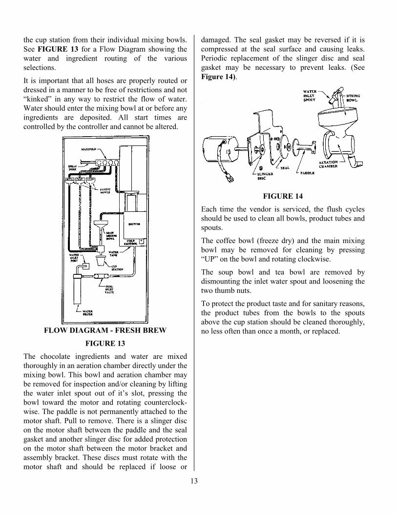
Place the ring gear on the mounting ring with thetiming marks aligned as shown. Install Cam No. 1on the pin between the timing marks and MountingPost No. 1. The notches must face the post shown.
Be sure the timing marks are not shifted, and placeCams No. 2 and No. 3 in position as shown (notchesfacing post). Install the other four cams with theirnotches aligned as shown. Place two cups in theassembly and operate the ring gear manually to“check” cam timing.
FIGURE 16Replace cover and retainers. Replace the ring gearspring. Re-install the dispensing ring. Return thebase assembly to its loading position and connectthe latch arm. Install the indexing lever and cupturret. The Index Lever must be moved to allow theturret to seat properly.
Load approximately six or seven of the new cupsinto the column over the dispensing ring and alsoone tube of cups into the first column counterclock-wise from the dispensing ring.
Operate the vendor to allow the cup dropper to“index” and dispense several cups before reloadingthe turret and putting the vendor into operation.
CONTROLLER FUNCTIONS &PROGRAMMING:
The controller must be placed in the “ServiceMode” to alter any programming, establish newprograms, retrieve diagnostic information and otherfeatures.
When the controller is placed in the “ServiceMode”, Service Diagnostic information will bedisplayed if any failure or malfunction has occurredsince the last time the controller was placed in theService Mode. Any information displayed should berecorded immediately.
When in the “Service Mode” the keys on the keypad perform different functions depending on thespecific mode, or requirements of the programs to

16
be accomplished. The “KEY” functions are definedin detail under each mode description throughoutthis manual. Furnished in the service packet is a keypad “over lay” that can be placed over the key padto illustrate the programming functions.
The chart below can be used as a “Quick Reference”for entering or changing programs. Complete detailsare outlined under each mode in this manual.
CONTROLLER FUNCTIONS WHILE IN SERVICE MODEMODEKEY CONTROLLER FUNCTION
KEY PAD INPUT
1 COIN DISPENSE 1NICKEL DISPENSE 1 + ADIME DISPENSE 1 + BQUARTER DISPENSE 1 + CDOLLAR COIN DISPENSE 1 + D
2 SECURITY & MACHINE CONFIG 2SECURITY ID 2 + A + (ID)CONFIG - FREEZE DRY 2 + B + 0CONFIG - FRESH BREW 2 + B + 1
3 VEND OPTIONS 3FORCE VEND “ON” 3 + AFORCE VEND “OFF” 3 + AMULTI VEND “ON” 3 + BMULTI VEND “OFF” 3 + BOCCURRENCE/LOTTO “ON” 3 + COCCURRENCE/LOTTO “OFF” 3 + CNO CUP DISCOUNT 3 + D + (AMT) + “#”LOTTO OCCURRENCE 3 + E + (No.) + ”#”
4 MESSAGE EDIT 4ENGLISH ONLY 4 + EBILINGUAL 4 + BFOREIGN 4 + F
5 SET PRICE 5 + SEL + (PRICE)+ “#”
COPY PRICE 5 + SEL + (PRICE) +* + (SEL) + (SEL) +“#”
6 CASH ACCOUNTABILITY 6TOTAL VENDS 6 + ATOTAL CASH 6 + BVENDS/SELECTION 6 + C, REPEAT CCASH/SELECTION 6 + D, REPEAT DOCCURRENCE/LOTTO VALUE 6 + EBILLS 6 + FTOTAL “NO CUP” CASH 6 + G
7 SET DISPENSE TIME 7 + (SEL) + TIME +“#”
8 TEST VEND SELECTIONS 88 TEST VEND PRODUCT 8 + A + (SEL)
TEST VEND WATER ONLY 8 + B + (SEL)SANITIZE (FRESH BREW) 8 + C
SERVICE MODE:To place the controller in the “Service Mode”depress the service mode button located on the doorto the right of the coin mechanism.
Record any diagnostics that appear in the display. Ifno diagnostics are displayed the readout will display“STATUS OK”, then “<“ which indicates thecontroller is ready to receive service commands.
NOTE:The controller will automatically exit the“Service Mode” and enter the “Sales Mode”in 25 seconds if no input or depression ofthe key pad is made during that time. Anydepression or input will allow another 25seconds before the controller times out.
COIN DISPENSE MODE:In the “Coin Dispense Mode”, coins that are storedin the coin mechanism payout tubes can beremoved. To access the “Coin Dispense Mode” thecontroller must be placed in the “Service Mode” bydepressing the service mode button.
Press Key “1” when at the “<“ menu to place thecontroller in the dispense coin mode. The displaywill show “Dispense $”. Coins may be removed bypressing the following keys:
“A” Will dispense a coin of the lowestdenomination (usually a Nickel in a UScoin mech)
“B” Will dispense a coin of the next higherdenomination (usually a Dime in a UScoin mech
“C” Will dispense a coin of the next higherdenomination (usually a Quarter in a UScoin mech
“D” Will dispense the next higherdenomination if the coin mech has thecapability of dispensing four (4) coins
The controller will remain in the dispense coinmode until another key entry is made. Holding adispense key down will result in a coin payout rateof approximately 2 coins per second. Enter “#” toexit coin dispense mode and return to the “root”menu.

17
SET SECURITY CODE:If the Alarm option is to be used it is necessary toprogram a security code into the controller to de-activate the alarm circuit when servicing themachine. The security code must be entered prior toopening the outer door.
To set security code the controller must be placed inthe service mode by depressing the service modebutton on the control board.
Press key “2” when at the “<“ menu to place thecontroller in the set security code mode. The displaywill flash “A” or “B”. Enter “A”. The display willshow “ID=“. A four (4) digit numeric code is to beentered. As the numbers are entered they aredisplayed. After the fourth character is entered allfour characters will be flashed for five seconds.After that period the controller will revert to the“root” menu.
ALARM CONTROL:The controller is equipped with a circuitry toenergize a relay or alarm device to sound an alarm.
Under normal operation conditions, with the powerto the controller, the output to the alarm is turnedoff. If the door is opened without the correct four(4) digit numeric code being entered prior toopening the outer door, the output to the alarm willbe turned on. If an alarm is connected, the alarmwill sound. If the correct code is entered when thedoor is opened, the output of the alarm will be heldin the “OFF” state for 30 minutes. The alarm willnot sound. The alarm override number can beprogrammed in the service mode. See “Set SecurityCode”.
ALARM OUTPUT SPECIFICATIONS:
Current sinking NPN transistorTemperature Range: 0º to 50º CMaximum Current: 100 MAMaximum Voltage: 30 VDC
MACHINE CONFIGURATION MODE:Press key “2” when at the “<“ menu in the ServiceMode. The display will flash “A” or “B”. Press key“B” to place the controller in the machineconfiguration mode. The display will show “FreshBrew” or “Freeze Dry” indicating in which modethe controller is currently set. To change the mode,enter the appropriate character.
Configuration Modes are:0 = Freeze Dry1 = Fresh Brew
VEND OPTIONS MODE:Vend options are available that can be programmedinto the controller. The options allow the machineto be programmed to function as a changer withoutmaking a purchase, make multiple selections withsingle deposits, make a “Free Vend” for theoccurrence number assigned or discount the price ofany beverage selected when the customer uses theirpersonal cup or mug.
The options that are available are:A = “Force Vend”B = “Multi Vend”C = “Lotto”D = “Set Discount”E = “Lotto Odds”
Each time the individual modes are entered, thecontroller will first display the current condition,then alternate from the “ON” or “OFF” conditioneach time the specific alpha character is entered, ordisplay the amount set for the “No Cup Discount”or to the number set for “Free Vend Occurrence”.
FORCE VEND OPTION:Press key “3” when at the “<“ menu to place thecontroller in the “Vend Options Mode”. The displaywill read “V Options”. Press key “A” to enter theforce vend option. The display will show the presentcondition of the machine (“FV On” or “FV Off”).To change the condition, press key “A” again. Thedisplay will show the new condition. The conditionwill alternate from “ON” to “OFF” or from “OFF”to “ON” each time “A” is entered. Press the “#”key when the condition desired is displayed.

18
Waiting 5 seconds without pressing the “#” key, thecontroller will abort the “Force Vend” mode and noprogram changes will be made.
When the “Force Vend ON Mode” is selected, thecontroller will force the buying customer to make apurchase when a dollar bill is inserted, overridingthe “Coin Return” command. Coin return of creditaccumulated with coins only is not affected.
When the “Force Vend OFF Mode” is selected, thecontroller will allow the buying customer to receivechange from a dollar bill insertion when the coinreturn button is pressed. A purchase is notnecessary.
When a validator that has an “Escrow” feature isused and the controller is placed in the “Force VendOff” mode, the bill will be returned.
MULTI VEND OPTION:Press key “3” when at the “<“ menu to place thecontroller in the “Vend Options Mode”. The displaywill read “V Options”. Press key “B” to enter“Multi Vend” option. The display will show thepresent condition of the machine (“MV On” or“MV Off”). To change the condition, press key “B”again. The display will show the new condition. Thecondition will alternate from “ON” to “OFF” orfrom “OFF” to “ON” each time “B” is entered.Press the “#” key when the condition desired isdisplayed. Waiting 5 seconds without pressing the“#” key, the controller will abort the “Multi Vend”mode and no program changes will be made.
When in the “Multi Vend On Mode”, if the vendprice of a selection is smaller than the establishedcredit and that selection is vended, the change willbe retained for 20 seconds before a payout is made.The amount of credit and “Make Selection” will bealternately displayed in the digital readout. Thebuying customer can use the remaining credit topurchase other beverages, or push “Coin Return” toreceive the balance. Multiple vends can be made aslong as adequate credit is available. When in thismode, to receive change on an over-deposit, the“Coin Return” button must be pushed, or waitapproximately 20 seconds for change to be returned.
When in the “Multi Vend Off Mode”, the controlleris set in a single selection vend mode, or normaloperation. Change will be returned immediately ifthe established credit exceeds the vend price eachtime a vend is completed.
LOTTO - OCCURRENCE PROGRAMMING:Press key “3” when at the “<“ menu to place thecontroller in the “Vend Options Mode”. The displaywill read “V Options”. Press key “C” to enter“Lotto” programming option. The display will showthe present condition of the machine (“Lotto On” or“Lotto Off”). To change the condition, press key“C” again. The display will show the newcondition. The condition will alternate from “ON”to “OFF” or from “OFF” to “ON” each time “C” isentered. Press the “#” key when the conditiondesired is displayed. Waiting 5 seconds withoutpressing the “#” key, the controller will abort the“Lotto” mode and no program changes will bemade.
When the “LOTTO ON” mode is selected, uponreaching the pre set number of vends, the controllerwill return the money deposited for that vend. Thedisplay will flash “You Win” five (5) times, the“beeper” will sound for 3 seconds.
To set the occurrence, press key “3” when at the“<“ menu, press key “E” to place the controller inthe occurrence odds mode. The display will show“Odds = XXXX”. (XXXX denotes the last valueset). The allowed occurrence range is 0000 to 9999.A new occurrence rate is entered and then stored bypressing the “#” key. The controller will revert tothe “root” menu.
NOTE:The “Lotto On” mode must be set forthe Free Vend to occur. If thecontroller is set in the “Lotto Off”,the controller will not free vendregardless of the “Odds” value.

19
NO CUP DISCOUNT OPTION:This function gives the owner/operator the option todiscount the vend price of the beverage when thebuying customer uses his own personal cup or mug,there-by not requiring dispensing a cup. For thebuying customer to receive the discount and to vendthe beverage without dispensing the cup the ”tree”selection button must be pressed prior to insertingcredit.
Press key “3” when at the “<“ menu to place thecontroller in the “Vend Options Mode”. The displaywill read “V Options”. Press key “D” to enter “NoCup Discount” programming option. The displaywill scroll “Set Discount” followed by the amountof discount currently programmed in the controller.The amount can be changed in .05¢ incrementsfrom 00.00 to 99.95. The vend price of the selecteditem will be reduced by the amount programmed.When the discount amount is changed, press the “#”key to store the new amount in memory.
MESSAGE EDIT/PROGRAMMING:The controller provides the owner/operator thecapability to customize the “point of salesmessage”, display service phone number andprogram messages in Foreign or multiple languages.The sales message can be changed on location byaccessing the message edit mode. Messages caninclude up to 130 characters including spaces.While in the programming mode the key pad willfunction similar to a type writer keyboard. (SeeFigure 17) A key pad overlay is furnished in theservice packet that will identify the key functionswhile in this mode. By placing the overlay over theselection panel, the owner/operator can “type” thenew message into the controller’s memory.
All machines shipped from the factory will have thefollowing point of sales message:
TREAT YOURSELF TO A TASTY HOTBEVERAGE NOW
CAUTION:When in the editing mode, if any of thecharacters in the messages are overwritten(even to correct a spelling error) thecontroller assumes that a new message isbeing written. The user must place thecursor past the end of the new messagebefore exiting the message, since all themessage string beyond and including thecursor will be erased. If no characters havebeen overwritten, the message will not bechanged regardless of the cursor position inthe message.
KEY PAD FUNCTIONS WHILE IN EDITMODE
FIGURE 17
NOTE:The upper characters in each block are accesseddirectly by depressing the desired key, while thebottom characters in each block can only beaccessed by depressing the “NEXT MENU”key each time those characters are needed.

20
MESSAGE EDITING:Press key “4” when at the “<“ menu to place thecontroller in the “Edit Message Mode”. The displaywill scroll “Edit Messages”, then flash “E”, “F”, or“B”.
E = EnglishB = Bilingual (English & Foreign)F = Foreign only
If “E” is selected, only the “point of sales” and the“Call for Service” messages may be modified. If“B” or “F” is selected both the Sales Messages andService Messages can be edited. To move forwardin any message without typing, hold down on the“NEXT MENU” key for 2 seconds. After 2seconds, it will advance 1 character every 0.5seconds. To move backward in the message the“BACK SPACE” key is used.
Press the “NEXT MENU” key twice (ENTER) tosave the message as edited. This will advance you tothe next message.
The following is a list of messages that areprogrammed into the controller when shipped fromthe factory.
WARNING:It is important to remember that thecontroller’s micro processor has beenprogrammed to display these messages atspecific times during the normaloperation of this vendor. This cannot bechanged, so any messages altered will bedisplayed as changed when needed duringthe operation of the machine.
The following messages will be displayed at variousintervals or time while the vendor is in the normalsales or operating mode:
00 POINT OF SALES MESSAGE01 CALL FOR SERVICE (PHONE NUMBER)02 MAKE SELECTION03 PREPARING BEVERAGE04 REMOVE BEVERAGE05 THANK YOU06 USE CORRECT CHANGE07 USE COINS ONLY08 SELECT OTHER ITEM09 YOU WIN
After editing and/or entering message 09, “YouWin” mode., the readout will alternately scroll“Service? “A=Yes” & “B=No”. Enter “A” to editthe messages displayed in the service mode. Enter“B” to end the edit message program and return tothe root menu.
To exit the message editing mode without changingany text or advancing through the editing program,press the service mode button to return to the SalesMode. This will leave any un-edited messages intactas stored in the controller’s memory.
The following messages will be displayed at variousintervals or time while the vendor is in the ServiceMode:
10 CUP DROPPER EMPTY11 WASTE TANK FULL12 WATER LEVEL LOW13 BATTERY BACKED MEMORY FAILURE14 STATUS OK15 TOTAL CASH16 TOTAL VENDS17 CASH BY SELECTION18 VENDS BY SELECTION19 TOTAL LOTTO CASH20 TOTAL BILLS COLLECTED21 TOTAL NO-CUP CASH
SET PRICE MODE:Press Service Mode Switch to place the controller inthe Service Mode.
When “<“ appears in the display, press key “5” toplace the controller in the “set price mode”. Thedisplay will scroll “Make Selection” then display“??=Selection”. The “??” flashes. After a selectionhas been entered, the current vend price for thatselection will be displayed. A new price can be setby direct entry. (Note: The character to the leftflashes until an entry is made. Then the nextcharacter to the right flashes in succession until theprice is set and stored in memory). To store theprice, press the “#” key. The controller will scrollthe “Make Selection” message in expectation ofanother price to be set. To return to the “root”menu, the “#” key must be entered while the “MakeSelection” message is being scrolled.

21
AUTOMATIC COPY PRICE FEATURE:The controller copies prices stored in certainselections to facilitate price setting as follows:
AO Price will be copied and stored in the followingselections
A1, A2, A3, B0, C0, C1, D0, D1, D2, D3,E0, F0, F1, F2, F3, G0, G1, G2, G3, H0
A4 Price will be copied and stored in the followingselections:
A5, A6, A7, B1, C2, C3, D4, D5, D6, D7,E1, F4, F5, F6, F7, G4, G5, G6, G7, H1
After the primary prices (A0, A4, etc.) has been set,any other price in the group can be reset to anydesired price by following the instructions outlinedin the preceding paragraph.
MANUAL COPY PRICE MODE:To copy a price from one selection to another,follow the above mentioned price setting procedure,but instead of storing the price, via the “#” key,press the “*” key which stores the price for thatselection and places the controller in the “copyprice” mode. The readout will display “CopyPrice”, then scroll “Make Selection”, then display“??”=Selection”. Selections may be entered oneafter the other. To store all of the copied selectionsand return to the “root” menu, press the “#” key.
ACCOUNTABILITY INFORMATION:Accountability information will be stored and willbe accessible when the controller is in the servicemode.
The controller will keep track of the total vends andsales for all selections in the coffee machine.
The controller will keep track of the total cashaccumulated as well as the total lotto paid out andno cup discounts for the vending machine.
Accountability information is never cleared frommemory. This prevents accounting information frombeing lost if the accounting printout is not recorded.
ACCESS ACCOUNTABILITY:Press the service mode switch to place the controllerin the service mode. When “>“ appears, press key“6” to place the controller in the displayaccountability data mode. The following menu willbe scrolled. A = total vends, B = total cash, C =vends by selection, D = cash by selection, E =total lotto cash, F = total bills collected, G = totalno-cup cash.
TOTAL VENDS:Press key “A” - The display will scroll “TotalVends” followed by the number of vends recordedon the machine to date.
NOTE: When the total vends reach99999 the number will reset to 0when another vend is made.
TOTAL CASH:Press key “B” - The display will scroll “Total Cash”followed by the amount of cash recorded on themachine to date.
NOTE: When the total vends reach$99,999.95 the number will reset to$00.00 when another vend is made.
VENDS BY SELECTION:Press key “C” - The display will scroll “Vends bySelection” followed by “A0 XXXXX”, the numberof vends made on Selection A0. Press key “C” againto advance to “A1”. Each time key “C” is pressed,the display advances through all selectionsavailable.
Repetitively pressing “C” will increment through allvalid selections. The display will show the selectionin the left two digits and the vend total in the fiveright digits. (I.e., “A0 00631”)
CASH BY SELECTION:Press key “D” - The display will scroll “Cash BySelection” followed by “AO XXXXX”, the cashaccumulated by vends made on selection “AO”.Press key “D” again to advance to “A1”, cash
22
accumulated. Each time key “D” is pressed, thedisplay will advance one selection and display allselections available.
Repetitively pressing “D” will increment through allvalid selections. The display will show the selectionin the left two digits and the cash total in the sevenright digits. (I.E. “AO 0000995).
TOTAL LOTTO CASH:Press key “E”. The display will scroll “Total LottoCash” followed by the amount of cash returned as aresult of the lotto occurrence programmed into thecontroller.
TOTAL BILLS COLLECTED:Press key “F”. The display will scroll “Total BillsCollected” followed by the number of bills collectedin the bill validator.
TOTAL NO-CUP CASH:Press key “G”. The display will scroll “Total No-Cup Cash” followed by the value of cash returnedas a result of “No-Cup” discount refunds made.
SET DISPENSE TIME:Press the Service Mode button to place thecontroller in the Service Mode. When “<“ appears,press key “7” to place the controller in the “setdispense time” mode. The display will scroll“Make Selection”.
After a selection has been entered, available optionswill be displayed as you advance through the timingprogram. The current setting may be accepted bypressing the “#” key. The controller will incrementthrough the program menu by repetitively pressing“#”. The controller will “beep” indicating thedisplayed time is stored. (If the # key is not pressed,the time will not be changed). Available optionswill be displayed in the following format.
“Ingredient” will be displayed followed by thecurrent dispense time in seconds and tenths of asecond. A new dispense time can be entered bypressing the number digits on the key pad. Thecharacter to the left flashes until an entry is made.
Then, the next character to the right flashes insuccession until the time is set and stored inmemory. To store the time, press the “#” key Thecontroller will then scroll “Water” followed by thecurrent water time in seconds and tenths of asecond. A new dispense time can be entered bypressing the number digits on the key pad. To storethe time, press the # key.
The controller will then scroll “Light” followed bythe current “Light” (creme) time in seconds andtenths of a second. A new time can be entered bypressing the number digits on the key pad. To storethe time, press the # key.
The controller will then scroll “Sweet” followed bythe current “Sweet” time in seconds and tenths of asecond. A new dispense time can be entered bypressing the number digits on the key pad. To storethe time, press the # key.
NOTE:Extra sweet and extra light timing isprogrammed by pressing key “*” at the“Make Selection” prompt. The timedisplayed is a percent that is added to theregular sweet and/or light time programmedfor each specific ingredient in the menu.
To return to the root menu, enter “#” while the“Make Selection” message is being scrolled.
Dispense time setting can be interrupted at any timeby pressing the “Service Mode Switch” to exit theservice mode.
The timing chart on Page 23 indicates the factoryrecommended settings for the ingredients on variousselections. It may be necessary to change certainsettings to satisfy customer’s taste.

23
TIM
ING
CH
AR
T:
FRE
EZE
DR
Y T
IME
IN S
EC
ON
DS
FRE
SH B
RE
W T
IME
IN S
EC
ON
DS
SEL
FUN
CT
ION
7 oz
8.25
oz
9 oz
12 o
z7
oz8.
25 o
z9
oz12
oz
A0
CO
FFE
E00
.400
.500
.500
.702
.002
.402
.603
.4W
AT
ER
04.8
05.7
06.2
08.2
04.8
05.7
06.2
08.2
LIG
HT
00.5
00.6
00.6
00.9
00.5
00.6
00.6
00.9
SWE
ET
00.5
00.6
00.6
00.9
00.5
00.6
00.6
00.9
BR
EW
03.0
03.5
03.9
05.1
PUM
P03
.003
.503
.905
.1B
LE
ND
ER
07.5
08.8
09.6
12.9
09.0
10.6
11.6
15.4
A4
CO
FFE
E00
.200
.200
.300
.301
.802
.102
.303
.1W
AT
ER
04.8
05.7
06.2
08.2
04.8
05.7
06.2
08.2
LIG
HT
00.5
00.6
00.6
00.9
00.5
00.6
00.6
00.9
SWE
ET
00.5
00.6
00.6
00.9
00.5
00.6
00.6
00.9
BR
EW
02.0
02.4
02.6
03.4
PUM
P02
.002
.402
.603
.4B
LE
ND
ER
07.5
08.8
09.6
12.9
09.0
10.6
11.6
15.4
BO
CH
OC
OL
AT
E02
.502
.903
.204
.302
.502
.903
.204
.3W
AT
ER
05.5
06.5
07.1
09.4
05.5
06.5
07.1
09.4
B1
CH
OC
OL
AT
E02
.002
.402
.603
.402
.002
.402
.603
.4W
AT
ER
05.5
06.5
07.1
09.4
05.5
06.5
07.1
09.4
C0
CO
FFE
E00
.300
.400
.400
.502
.002
.402
.603
.4W
AT
ER
03.0
03.5
03.9
05.1
03.0
03.5
03.9
05.1
LIG
HT
00.3
00.4
00.4
00.5
00.3
00.4
00.4
00.5
SWE
ET
00.3
00.4
00.4
00.5
00.3
00.4
00.4
00.5
BR
EW
03.0
03.5
03.9
05.1
PUM
P00
.000
.000
.000
.0C
HO
CO
LA
TE
00.9
01.1
01.2
01.5
00.9
01.1
01.2
01.5
WA
TE
R 2
02.4
02.8
03.1
04.1
02.4
02.8
03.1
04.1
BL
EN
DE
R05
.005
.906
.408
.607
.508
.809
.612
.9C
2C
OFF
EE
00.2
00.2
00.3
00.3
01.8
02.1
02.3
03.1
WA
TE
R03
.003
.503
.905
.103
.003
.503
.905
.1L
IGH
T00
.200
.200
.300
.300
.200
.200
.300
.3SW
EE
T00
.200
.200
.300
.300
.200
.200
.300
.3B
RE
W02
.002
.402
.603
.4PU
MP
00.0
00.0
00.0
00.0
CH
OC
OL
AT
E00
.500
.600
.600
.900
.500
.600
.600
.9W
AT
ER
203
.003
.503
.905
.103
.003
.503
.905
.1B
LE
ND
ER
05.0
05.9
06.4
08.6
07.5
08.8
09.6
12.9
D0
CO
FFE
E00
.600
.700
.801
.002
.202
.602
.803
.8W
AT
ER
03.0
03.5
03.9
05.1
03.0
03.5
03.9
05.1
LIG
HT
00.7
00.8
00.9
01.2
00.7
00.8
00.9
01.2
SWE
ET
00.7
00.8
00.9
01.2
00.7
00.8
00.9
01.2
BR
EW
04.0
04.7
05.1
06.9
PUM
P00
.000
.000
.000
.0B
LE
ND
ER
05.0
05.9
06.4
08.6
07.7
09.1
09.9
13.2
FRE
EZE
DR
Y T
IME
IN S
EC
ON
DS
FRE
SH B
RE
W T
IME
IN S
EC
ON
DS
SEL
FUN
CT
ION
7 oz
8.25
oz
9 oz
12 o
z7
oz8.
25 o
z9
oz12
oz
D4
CO
FFE
E00
.400
.500
.500
.702
.002
.402
.603
.4W
AT
ER
03.0
03.5
03.9
05.1
03.0
03.5
03.9
05.1
LIG
HT
00.5
00.6
00.6
00.9
00.5
00.6
00.6
00.9
SWE
ET
00.5
00.6
00.6
00.9
00.5
00.6
00.6
00.9
BR
EW
03.0
03.5
03.9
05.1
PUM
P00
.000
.000
.000
.0B
LE
ND
ER
05.0
05.9
06.4
08.6
07.5
08.8
09.6
12.9
F0D
EC
AF
00.4
00.5
00.5
00.7
02.0
02.4
02.6
03.4
WA
TE
R04
.805
.706
.208
.204
.805
.706
.208
.2L
IGH
T00
.700
.800
.901
.200
.700
.800
.901
.2SW
EE
T00
.700
.800
.901
.200
.700
.800
.901
.2B
RE
W03
.003
.503
.905
.1PU
MP
03.0
03.5
03.9
05.1
BL
EN
DE
R07
.508
.809
.612
.909
.010
.611
.615
.4F4
DE
CA
F00
.200
.200
.300
.301
.802
.102
.303
.1W
AT
ER
04.8
05.7
06.2
08.2
04.8
05.7
06.2
08.2
LIG
HT
00.5
00.6
00.6
00.9
00.5
00.6
00.6
00.9
SWE
ET
00.5
00.6
00.6
00.9
00.5
00.6
00.6
00.9
BR
EW
02.0
02.4
02.6
03.4
PUM
P02
.002
.402
.603
.4B
LE
ND
ER
07.5
08.8
09.6
12.9
09.0
10.6
11.6
15.4
G0
TE
A00
.400
.500
.500
.700
.400
.500
.500
.7W
AT
ER
05.4
06.4
06.9
09.3
04.8
05.7
06.2
08.2
LIG
HT
00.7
00.8
00.9
01.2
00.7
00.8
00.9
01.2
SWE
ET
00.7
00.8
00.9
01.2
00.7
00.8
00.9
01.2
G4
TE
A00
.300
.400
.400
.500
.300
.400
.400
.5W
AT
ER
05.4
06.4
06.9
09.3
05.4
06.4
06.9
09.3
LIG
HT
00.5
00.6
00.6
00.9
00.5
00.6
00.6
00.9
SWE
ET
00.5
00.6
00.6
00.9
00.5
00.6
00.6
00.9
H0
SOU
P01
.501
.801
.902
.601
.501
.801
.902
.6W
AT
ER
05.4
06.4
06.9
09.3
04.8
05.7
06.2
08.2
H1
SOU
P01
.201
.401
.502
.101
.201
.401
.502
.1W
AT
ER
05.4
06.4
06.9
09.3
04.8
05.7
06.2
08.2
*SW
EE
T, %
00.4
00.5
00.5
00.7
00.4
00.5
00.5
00.7
#L
IGH
T, %
00.4
00.5
00.5
00.7
00.4
00.5
00.5
00.7

24
TEST VEND BY SELECTION:Press the Service Mode Switch to place thecontroller in the Service Mode. When “<“ isdisplayed, press key “8” to place the controller inthe Test Vend Mode. The display will flash “A”,“B”, & “C”. The options are as follows:
A= Test Vend entire cycle: Cup Dropperplus product plus water
B= Rinse Cycle, Water Only
C= Sanitizer Cycle for Coffee Brewer
Press key “A”, the display will scroll “MakeSelection”. Once the selection is entered, a vendwill be made on that selection. A complete vendcycle will be performed and a beverage will bedispensed. If the vend fails, the “beeper” will soundthree times. After a successful vend or a failed vend,the readout will scroll “Make Selection” inanticipation of another test vend.
Press key “B”, the display will scroll “MakeSelection”. Enter selection. Only water will bedispensed for the time interval programmed for thatselection.
The Accounting information recorded in thecontroller is not affected or altered during the testvend operations.
SANITIZER CYCLE:On machines configured as “Fresh Brew” vendorsthe sanitizer circuit may be activated. To sanitizeyour coffee brewing system, open one (1) packet ofsanitizing solution and empty the contents in thebrewer water chamber on the brew unit prior toinitiating the sanitizer cycle.
When at the “<“menu of the service mode, press“8” to advance to the “Test Vend Section”. Presskey “C” to start the sanitizer cycle. The sanitizercircuit provides the following sequence ofoperation:
A. Water valve opens. Time = setting for “A0”B. Brew start circuit energized, cycle extended for
30 seconds through brew delay circuit. Delay
circuit re-starts brew motor and exhaustssanitizer fluid.
B. Water valve opens second time.D. Brew unit starts and runs normal cycle (15
seconds)E. C & D are repeated four (4) more times.F. Sanitizing cycle ends.G. Controller returns to the “root” menu.
NOTE:The brew unit should be sanitizedmonthly for normal operation
BREW FLUSH TIMER (FRESH BREW MODE:The controller contains a timer that willautomatically cycle the coffee water valve and brewmotor after any 14 hour period during which nocoffee selection has been made. The timer will bereset to zero if any coffee selection requiring thebrewer operation is made.
THE BREW CYCLE:When a coffee selection is made, the brewer motorwill start to run (from a signal from the controller)lifting the strainer plate upward toward the bottomof the brewer cylinder causing the cylinder to close.In the same movement, the yoke attached to thebrewer piston is lifted. This causes the piston tomove up into the cylinder and the valve in thepiston is opened so that water and coffee can befilled.
Coffee and water is deposited into the brew cylinderand mixed on their way down into the cylinder.
The brewer motor continues to run moving thepiston down into the cylinder. The valve located inthe brewer piston will close. The brewing pressureis generated by the downward movement of thepiston, pressing the coffee water through thegrounds, through the strainer plate.
Air is generated by the movement of the piston andas pressed through the coffee grounds, dries thegrounds making them easily removed.
The lifting fork and the strainer plate is moveddownward out of the cylinder. The scraper slidesforward and back across the face of the strainer

25
plate scraping the grounds into the waste containercompleting the brewer cycle.
BREWING (BLEND) TIME:The blend time is the time during which coffee andwater are in contact with each other in the brewerbefore the piston presses the coffee through thestrainer. The infusion time, along with theingredient/water volume determines the strength ofthe coffee.
Coffee and water are mixed together on their waydown into the cylinder. The timing for theingredients and water volumes has been factorypreset for 7 ounce cup sizes. Timing will have to bechanged if cups other than 7 ounces are used, oradjusted slightly to satisfy locations. Refer to“Timing Chart”, page #23 for recommendedsettings.
CLEANING INSTRUCTIONS:Care should be taken when cleaning the interior ofthe vendor as high temperatures may be present oncomponents and liquids.
CAUTION: Always disconnect the power sourcebefore cleaning the vendor.
CABINET EXTERIOR:Wash with a mild detergent and water, rinse and drythoroughly. Wax occasionally with a quality carwax. Plastic exterior parts may be cleaned with aquality plastic cleaner.
CABINET INTERIOR:Wash with a mild detergent and water. Odors maybe eliminated by including baking soda or ammoniain the cleaning solution.
Use hot water for cleaning and avoid using soapydetergents. Spots on stainless steel surfaces can beremoved by using alcohol. When cleaning areassuch as the mixing bowls, cup chute, etc., that comein contact with the cup or product, use onlychemical sanitizers that are approved for use onfood contact surfaces.
The following procedure should be used each timethe vendor is serviced.
1. Either unplug the vendor or turn the powerswitch to the “OFF” position.
2. Fill the cup turret.3. Remove the ingredient canisters as follows:
A. Coffee - Remove the coffee chute (freshbrew only). Push the latch release andpull canister forward. Lift clear of thekeyhole slots.
B. Chocolate - Push the latch release andpull canister forward. Lift clear of thekeyhole slots.
C. Set the canisters aside. Clean and refillthem prior to replacing them in thevendor. See step 10.
4. Clean around the ingredient drive motors and thecup mechanism with a small brush or withfiltered compressed air if available.
5. Wipe the canister shelves with a clean dampcloth.
6. Clean the interior of the vendor including the topand side walls.
7. Rinse the brew cylinder and wiper blade area ofthe brewer.
8. Using the rinse hose, rinse all mixing bowls andhoses thoroughly to remove any residue.Periodically remove mixing bowls and cleanthoroughly using warm water and detergent.Rinse thoroughly before replacing bowls.
9. Clean the cup housing, cup chute, grille and otherareas which the cup might contact. Clean thevend door and vend door trim panel.
10. Clean each canister in the following manner.(This procedure can be followed for full orpartially filled canisters).
A. With the cover in place on the canister,place the covered end of the canisteragainst your chest with the dispensingspout up.
B. Rotate the auger so that the ingredientsare forced back into the canister.
C. Set the canister upside down on a tablewith the cover still in place.
D. Clean the spout with a small brush orpiece of clean terry cloth.

26
E. Holding the canister upside down withthe cover in place, shake the canister toloosen and aerate the ingredients.
F. Set the canister right side up on the table.Remove the cover and fill the canister.Do not jar the canister or slap the sides.This causes the ingredients to pack in theauger and may jam the mechanism.
G. Turn the auger to fill the spout to insurethe proper amount of ingredient on thefirst vend.
H. Replace the canister on the canister shelf.Be sure the studs are in the keyhole slotsand the drive motor is engaging the auger.
11. Empty and clean the waste buckets. Use Cloroxor Zonite to retard bacterial growth. Do not rinsebucket after anti-bacterial solution is used, thiswill defeat the purpose. When replacing thewaste buckets, make sure the floats are hangingfree and all hoses are in their proper location.
12. Return the power to the vendor and operate thebrew unit through at least one flush cycle.
13. Brewer System: Disassemble the brewer forcleaning as illustrated in Figure 18. Put thedisassembled parts into hot water or flush them.Remove possible coffee remnants from thebrewer. Wipe plates and screens. Assemble thebrewer in the same way as it was disassembled,but in reverse order.
01. Push the upper rail upwards and pull thevertical rod outwards.
02. Use this hand position and push upwards withyour forefinger.
03. Grasp the cylinder, lift up the hasp, and takeoff the cylinder.
04. Tilt the filter plate so that the pins are free, liftand pull outwards.
05. Use these hand positions and pull outwards.The spring loaded scraper can be removed.
06. Pull the piston a little upwards, lift up theupper rail, push the yoke aside, and the yokeis free.
FIGURE 18

27
SANITIZING THE BREW UNIT:Sanitize the Fresh Brew Coffee System using theautomatic sanitizer:
A. Empty one packet (3 grams) of urncleaner into the coffee brew bowl.
B. Start the sanitizer circuit: Enter the“Service Mode”. When “>“ appearsenter “8 + C”.
C. The sanitizing cycle continues forapproximately thirty seconds. Five rinsecycles are then completed for a totalsanitizing time of approximately two andone half minutes.
D. Rinse and wipe the upper area of thebrew cylinder to remove any sanitizingcompound that may have accumulated.
Frequent cleaning of the machine increases itsreliability in operation. Inspection should be madeat suitable intervals, and the cup mechanism andingredient canisters should be filled accordingly.Use hot water for cleaning and avoid soapydetergents. Spots on stainless steel surfaces can beremoved by using alcohol.
Always test the machine for proper operation beforeit is put into service.
NOTES:____________________________________________________________________________________________________________________________________________________________________________________________________________________________________________________________________________________________________________________________________________________________________________________________________________________________________________________________________________________________________________________________________________________________________________________________________________________________________________________________________________________________________________________________________________________________________________________________________________________________________________________________________________________________________________________________________________________________________________________________________________________________________________________________________________________________________________________________________________________________________________________________________________________________________________________________________________________________________________
____________________________________________________________________________________________________________________________________________________________________________________________________________________________________________________________________________________________________________________________________________________________________________________________________________________________________________________________________________________________________________________________________________________________________________________________________________________________________________________________________________________________________________________________________________________________________________________________________________________________________________________________________________________________________________________________________________________________________________________________________________________________________________________________________________________________________________________________________

28